Comprehensive review of surgical microscopes: technology ...
74
Comprehensive review of surgical microscopes: technology development and medical applications Ling Ma a and Baowei Fei a,b, * a University of Texas at Dallas, Department of Bioengineering, Richardson, Texas, United States b University of Texas Southwestern Medical Center, Department of Radiology, Dallas, Texas, United States Abstract Significance: Surgical microscopes provide adjustable magnification, bright illumination, and clear visualization of the surgical field and have been increasingly used in operating rooms. State-of-the-art surgical microscopes are integrated with various imaging modalities, such as optical coherence tomography (OCT), fluorescence imaging, and augmented reality (AR) for image-guided surgery. Aim: This comprehensive review is based on the literature of over 500 papers that cover the technology development and applications of surgical microscopy over the past century. The aim of this review is threefold: (i) providing a comprehensive technical overview of surgical micro- scopes, (ii) providing critical references for microscope selection and system development, and (iii) providing an overview of various medical applications. Approach: More than 500 references were collected and reviewed. A timeline of important milestones during the evolution of surgical microscope is provided in this study. An in-depth technical overview of the optical system, mechanical system, illumination, visualization, and integration with advanced imaging modalities is provided. Various medical applications of sur- gical microscopes in neurosurgery and spine surgery, ophthalmic surgery, ear-nose-throat (ENT) surgery, endodontics, and plastic and reconstructive surgery are described. Results: Surgical microscopy has been significantly advanced in the technical aspects of high- end optics, bright and shadow-free illumination, stable and flexible mechanical design, and ver- satile visualization. New imaging modalities, such as hyperspectral imaging, OCT, fluorescence imaging, photoacoustic microscopy, and laser speckle contrast imaging, are being integrated with surgical microscopes. Advanced visualization and AR are being added to surgical micro- scopes as new features that are changing clinical practices in the operating room. Conclusions: The combination of new imaging technologies and surgical microscopy will en- able surgeons to perform challenging procedures and improve surgical outcomes. With advanced visualization and improved ergonomics, the surgical microscope has become a powerful tool in neurosurgery, spinal, ENT, ophthalmic, plastic and reconstructive surgeries. © The Authors. Published by SPIE under a Creative Commons Attribution 4.0 Unported License. Distribution or reproduction of this work in whole or in part requires full attribution of the original pub- lication, including its DOI. [DOI: 10.1117/1.JBO.26.1.010901] Keywords: surgical microscope; optics; illumination; mechanical; visualization; image-guided surgery; augmented reality; fluorescence imaging; optical coherence tomography; hyperspectral imaging. Paper 200292VRR received Sep. 10, 2020; accepted for publication Dec. 4, 2020; published online Jan. 4, 2021. 1 Introduction 1.1 Background Various diseases, including cancer, require surgery as a prime treatment method. 1–7 One key factor for surgeons to operate accurately is a clear visualization of the anatomical *Address all correspondence to Baowei Fei, E-mail: [email protected], www.fei-lab.org REVIEW Journal of Biomedical Optics 010901-1 January 2021 • Vol. 26(1) Downloaded From: https://www.spiedigitallibrary.org/journals/Journal-of-Biomedical-Optics on 31 Jan 2022 Terms of Use: https://www.spiedigitallibrary.org/terms-of-use
-
Upload
khangminh22 -
Category
Documents
-
view
1 -
download
0
Transcript of Comprehensive review of surgical microscopes: technology ...

Comprehensive review of surgical microscopes:technology development and medical applications
Ling Ma a and Baowei Fei a,b,*aUniversity of Texas at Dallas, Department of Bioengineering, Richardson, Texas, United StatesbUniversity of Texas Southwestern Medical Center, Department of Radiology, Dallas, Texas,
United States
Abstract
Significance: Surgical microscopes provide adjustable magnification, bright illumination, andclear visualization of the surgical field and have been increasingly used in operating rooms.State-of-the-art surgical microscopes are integrated with various imaging modalities, such asoptical coherence tomography (OCT), fluorescence imaging, and augmented reality (AR) forimage-guided surgery.
Aim: This comprehensive review is based on the literature of over 500 papers that cover thetechnology development and applications of surgical microscopy over the past century. The aimof this review is threefold: (i) providing a comprehensive technical overview of surgical micro-scopes, (ii) providing critical references for microscope selection and system development, and(iii) providing an overview of various medical applications.
Approach: More than 500 references were collected and reviewed. A timeline of importantmilestones during the evolution of surgical microscope is provided in this study. An in-depthtechnical overview of the optical system, mechanical system, illumination, visualization, andintegration with advanced imaging modalities is provided. Various medical applications of sur-gical microscopes in neurosurgery and spine surgery, ophthalmic surgery, ear-nose-throat (ENT)surgery, endodontics, and plastic and reconstructive surgery are described.
Results: Surgical microscopy has been significantly advanced in the technical aspects of high-end optics, bright and shadow-free illumination, stable and flexible mechanical design, and ver-satile visualization. New imaging modalities, such as hyperspectral imaging, OCT, fluorescenceimaging, photoacoustic microscopy, and laser speckle contrast imaging, are being integratedwith surgical microscopes. Advanced visualization and AR are being added to surgical micro-scopes as new features that are changing clinical practices in the operating room.
Conclusions: The combination of new imaging technologies and surgical microscopy will en-able surgeons to perform challenging procedures and improve surgical outcomes. With advancedvisualization and improved ergonomics, the surgical microscope has become a powerful tool inneurosurgery, spinal, ENT, ophthalmic, plastic and reconstructive surgeries.
© The Authors. Published by SPIE under a Creative Commons Attribution 4.0 Unported License.Distribution or reproduction of this work in whole or in part requires full attribution of the original pub-lication, including its DOI. [DOI: 10.1117/1.JBO.26.1.010901]
Keywords: surgical microscope; optics; illumination; mechanical; visualization; image-guidedsurgery; augmented reality; fluorescence imaging; optical coherence tomography; hyperspectralimaging.
Paper 200292VRR received Sep. 10, 2020; accepted for publication Dec. 4, 2020; publishedonline Jan. 4, 2021.
1 Introduction
1.1 Background
Various diseases, including cancer, require surgery as a prime treatment method.1–7 One keyfactor for surgeons to operate accurately is a clear visualization of the anatomical
*Address all correspondence to Baowei Fei, E-mail: [email protected], www.fei-lab.org
REVIEW
Journal of Biomedical Optics 010901-1 January 2021 • Vol. 26(1)
Downloaded From: https://www.spiedigitallibrary.org/journals/Journal-of-Biomedical-Optics on 31 Jan 2022Terms of Use: https://www.spiedigitallibrary.org/terms-of-use

structures.8 However, this has never been easy. On the one hand, some anatomical structures arevery small, varying from millimeters to microns,9 and they might have close proximity to otherorgans or tissue.10 A clear view of these structures requires a resolution well beyond that ofhuman eyes.11 On the other hand, the lack of illumination in narrow cavities and deep channels,which are very common in neurosurgery, ear-nose-throat (ENT) surgery, and endodontics,results in a dim visualization with shadows.10,12,13 Poor visualization may lead to inappropriateoperation on anatomical structures or a nearby organ, which will affect the surgical outcome,reduce organ preservation, or even cause life-threatening consequences.14 Therefore, sufficientmagnification and proper illumination are vital for the success of surgery.
Before the advent of the surgical microscope, surgeons had been using various magnifyingsystems mounted on spectacles or headbands. These systems can be grouped into three catego-ries, namely single-lens magnifiers, prismatic binocular magnifiers, and telescopic systems.15,16
Single-lens loupes used convex lenses for magnifying with a fixed magnification and a very shortworking distance. With the desire to have more magnification at a longer working distance,telescopic systems came into use. One of the first closed Galilean telescope systems had a3× magnification and a working distance of 15 cm. The Keeler Galilean system introducedin 1952 had a 2× magnification at 25 cm. In addition, a set of five different telescopes, whichcould be separately fixed on a spectacle frame via screws, offered a choice of magnification from1.75× to 9× and a working distance from 34 to 16.5 cm. The binocular loupe, which uses prismoculars and lenses to achieve stereopsis, was first developed by Westien and modified by vonZehender for the examination of the eye. Later, the Carl Zeiss company presented a binocularloupe with a working distance of 25 cm, which opened the door to modern microsurgery.16
However, a head-mounted magnifying system suffers from unstable focusing due to the absenceof the supporting structure. In addition, increasing the magnification or adding a light source canalso increase the size and weight of the system, making it less comfortable for surgeons to wear.
A surgical microscope, also known as an operating microscope, is an optical microscopespecifically designed to be used in a surgical setting, especially requisite for microsurgery.17
Although the compound microscope had been invented in 159018,19 and was used for exami-nation of wounds and scars in the late 17th century,16 it had several limitations including theheavy weight, large size, and low image quality due to chromatic and spherical aberrations.Therefore, despite the high magnification, it was not widely adopted in clinical applicationsuntil the solutions to the aberrations were found. In the late 19th century, Ernst Abbe proposednumerical aperture and greatly enhanced the resolution of microscopes. Later on, the monocularand binocular microscopes were merged with tripods and attached light sources and were usedfor various examinations.15 However, it was not until 1921 that a monocular microscope trulyentered the operating room for an aural surgery. One year later, this idea was modified usinga binocular microscope.20 Ever since, surgical microscopes have been evolving with a widerrange of magnification, longer working distance, better illumination, and more stable supportingstructures. The benefits were soon acknowledged by otolaryngology surgeons and graduallyrecognized by surgeons in other fields.
Surgical microscopes of the time have been refined to a precision instrument with severalappealing features.19 They have high-precision optics and high-power coaxial illumination,which provide surgeons with adjustable magnifications, proper working distance, and anunobstructed view of the entire operating field.10 The well-designed mechanical system offersstability and maneuverability, while the heads-up display improves ergonomics.19,21–25
Stereopsis provides the third dimension of the field of view (FOV) thereby increasing the safetyfor surgery.26 Multiple optical ports are available on the microscope for assistant observers oradaptation of video cameras. Moreover, contemporary surgical microscopes are enriched withvarious intraoperative imaging modules such as fluorescence imaging27–35 and optical coherencetomography (OCT),36–42 and they are open for adaptation of other imaging modalities includinghyperspectral imaging (HSI), photoacoustic microscopy (PAM),43–48 and laser speckle contrastimaging (LSCI). Augmented reality (AR)49–54 has been actively evaluated on the surgicalmicroscope and has offered huge convenience for surgery as an intraoperative diagnostic tool.Furthermore, high-definition (HD) display,22,55,56 image injection techniques,50,57,58 andthree-dimensional (3D) display facilitate better visualization of both the surgical field andthe multimodality images.
Ma and Fei: Comprehensive review of surgical microscopes: technology development. . .
Journal of Biomedical Optics 010901-2 January 2021 • Vol. 26(1)
Downloaded From: https://www.spiedigitallibrary.org/journals/Journal-of-Biomedical-Optics on 31 Jan 2022Terms of Use: https://www.spiedigitallibrary.org/terms-of-use

With numerous advantages such as clear and bright visualization, easy documentation andadaptation, stability, maneuverability, and improved ergonomics, surgical microscopes havebeen applied in various types of surgeries, including neuro and spine surgery,8,10,50,59–61 ENTsurgery,5,20,51,62–64 dentistry,11,13,65–77 ophthalmology,15,36–38,40–42,78–80 and plastic and reconstruc-tive surgery.14,81–86 For example, they have been used for brain tumor resection,27 aneurysmsurgery,87 nasal surgery,88 head and neck cancer resection,89 corneal keratoplasty,37 vitreoretinalmacular hole repair,90 root therapy,91 root coverage procedure,92 craniosynostosis surgery,93 andhepatic artery reconstruction.94 For different applications, microscopes are modified into slightlydifferent optical configurations and equipped with specific imaging modalities. The end-usersof surgical microscopes include hospitals, dental clinics, other outpatient settings, and someresearch institutes.95
1.2 Perspective on Surgical Microscopes
Surgical microscopes have gone through a long evolution and development. Because of numer-ous attractive features and new imaging modalities, surgical microscopes will not stop here butwill continue to thrive. The limitations of large volume, high cost, and potential tissue damage byhigh-power illumination will be further addressed with robotic positioning, increasing utiliza-tion, and better light management. Three main future directions of the surgical microscopeinclude being integrated with more advanced technologies, launching new ways for visualiza-tion, and being increasingly used in more clinical applications.
First, the integration of HSI, LSCI, PAM, and polarization imaging with surgical micro-scopes and the related imaging processing methods will become more mature and well-devel-oped, to provide surgical guidance in addition to that of fluorescence imaging and OCT. HSI andLSCI are particularly promising since they are noncontact and label-free, not requiring any injec-tion of any contrast or dye. They can be used anytime during the surgery without administrationtime and provide abundant quantitative diagnostic information in real-time. Meanwhile, bothHSI and LSCI have a very simple system for adaptation and an easy interpretation of images.Therefore, it takes minimal effort for physicians to adopt these methods. The endoscopic tool inthe newest robotic visualization system also opens opportunities for some imaging modalitiesthat are not as easy to be adapted with conventional surgical microscopes, such as confocalmicroscopy and Raman spectroscopy. Second, the visualization of surgical microscopes willbe expanded. It will not be limited to a clear view shared only by the team in the operatingroom. New ways of visualization will give surgeons the freedom to visualize the proceduresanywhere through monitors, headsets, smartphones, and large screens in the conference room.With advanced communication technologies and well-developed AR-assisted platforms, a largergroup will be able to participate in the procedures remotely. Finally, it is anticipated that surgicalmicroscopes will be increasingly used in more applications such as orthopedic spine surgery andcataract surgery. In particular, surgical microscopes have brought a revolution in dentistry,but they were mainly used in endodontics. Therefore, it is promising for surgical microscopesto be more adopted in other dental applications such as periodontal surgery. In addition, the newendoscopic tool and the picture-in-picture visualization mode give users access to more deepstructures, which greatly increases the competitiveness of surgical microscopes in variousENT surgeries.
1.3 Organization of the Following Sections
We aim to introduce and explain the surgical microscope and to give an overview of the literatureon surgical microscope history, technologies, and applications. (1) We start with the history ofthe surgical microscope and give a timeline of milestones during the development of the surgicalmicroscope. (2) We introduce the surgical microscope from technical aspects, including itsoptical system, illumination system, mechanical system, visualization system, and combinationwith other technologies, such as AR, fluorescence imaging, and OCT. (3) The section on appli-cations refers to the available literature on how surgical microscopes are utilized in surgery.These applications mainly cover neurosurgeries and spine surgeries, ENT surgeries, ophthalmic
Ma and Fei: Comprehensive review of surgical microscopes: technology development. . .
Journal of Biomedical Optics 010901-3 January 2021 • Vol. 26(1)
Downloaded From: https://www.spiedigitallibrary.org/journals/Journal-of-Biomedical-Optics on 31 Jan 2022Terms of Use: https://www.spiedigitallibrary.org/terms-of-use

surgeries, dental operations, as well as plastic and reconstructive surgeries. (4) We conclude witha discussion about the limitations and future directions of surgical microscopes.
2 History
2.1 Microscope Entering Operating Rooms
In 1921, Carl Olof Nylén (1892–1978), a young otolaryngology surgeon at the University ofStockholm, used a monocular Brinell–Leitz microscope during surgery on a patient with chronicotitis.20,96 It was reported as the first surgical microscope in the operating room. One year later,Gunnar Holmgren modified this idea with a binocular microscope attached with a lightsource.19,20 The binocular microscope provided depth perception that was absent in a monocularmicroscope, and the attached light source overcame the dimness of the image with increasedmagnification.19,20,97 Figure 1 shows Nylén’s first surgical monocular microscope and the bin-ocular microscope of Holmgren. After being used in ENT surgeries, the binocular surgicalmicroscope was then introduced into ophthalmology by the ophthalmologic surgeon RichardA. Perritt in 1946.98 Although nowadays neurosurgeries form the leading market of surgicalmicroscopes, this instrument was not introduced in the neurosurgical operating room until1957, when Theodor Kurze at the University of Southern California, Los Angeles, removeda neurilemoma from cranial nerve VII in a 5-year-old patient.19 Kurze was inspired byHouse, who removed an acoustic neurinoma and published his experience in 1963.10,16 Twoyears later, Pool and Colton used the microscope for intracranial aneurysmal surgery.10 In1955, Fritz Zöllner reported using a binocular surgical microscope in 120 attic-antrotomies withplastic operations.99 In 1959, Wolfgang Walz from Heidenheim (Brenz), Germany, reported hisexperience with microsurgical reconstructive surgery of an occluded fallopian tube.16,17 Theintroduction of the surgical microscope in endodontics was the latest. In 1978, the first dentalsurgical microscope (DSM) was produced by Apotheker and Jako,100 and in 1981 the design wasincorporated into the first commercially available surgical microscope for dentistry.101
2.2 System Refinement
The advent of the surgical microscope and its early applications in aural surgeries offered bettersurgical outcomes, and the improved vision helped relieve other diseases in the temporalbone.20 Nevertheless, surgical microscopes in the early times had several weaknesses. The lowstability of the tripod decreased the quality of images at high magnification,19 and the fixed
Fig. 1 The earliest surgical microscopes in the operating room: (a) Brinell–Leitz monocularmicroscope used by Carl Olof Nylen and the modified Brinell microscope and (b) Zeiss binocularmicroscope adapted by Holmgren.20
Ma and Fei: Comprehensive review of surgical microscopes: technology development. . .
Journal of Biomedical Optics 010901-4 January 2021 • Vol. 26(1)
Downloaded From: https://www.spiedigitallibrary.org/journals/Journal-of-Biomedical-Optics on 31 Jan 2022Terms of Use: https://www.spiedigitallibrary.org/terms-of-use

magnification, small FOV, as well as insufficient illumination limited the effective vision ofthe surgical field.20 Furthermore, the old microscopes only allowed one surgeon to view thesurgical field, which was inconvenient for assistance. In the following years, refinements havebeen made for surgical microscopes and made it a real precision and fundamental instrument inthe operating room.
The first modern surgical microscope tripod was built in 1938 when P. Tullio and P. Calicettiat the University of Parma constructed a heavy tripod with counterweights for the opticalunit. The tripod was able to hang the optical unit freely above the surgical table and stabilizethe image, thus it offered comfortable distance and mobility during the procedures.16 In 1951,the V. Mueller & Co. started to market a microscope with a suspension system consisting ofa weighted table stand, then a ceiling-mount microscope suspension system was designedby Joaquin Barraquer in 1956.19 In addition, Horst L. Wullstein from Gottingen, Germany, builta microscope mounted on a stand equipped with a rotating arm. This idea greatly improvedthe mechanical flexibility of the microscope and was employed in the “Zeiss OPMI 1” (ZeissOperating Microscope 1),19,102 which was a milestone in the history of the surgical microscope.
In addition to the heavy tripod, Tullio and Calicetti’s invention in 1938 also included mount-ing prisms between the oculars and objectives, so that the identical view of the surgical fieldwas successfully shared to an assistant surgeon.16 And in 1964, Littman adapted a beam splitterto a Zeiss microscope to allow a second surgeon to assist and named the microscope“Diploscope.”19
The working distance of a surgical microscope gives a surgeon space to handle surgicalinstruments. The working distance of the first monocular microscope was 60 mm, and thefirst binocular microscope had a working distance of 75 mm. They were acceptable but shorterthan the ideal length of 200 mm proven by most otology operators at that time.20 In 1946, theavailable working distance was improved to 228 mm, and 250 mm in 1948. Zeiss OPMI 1 cameout in 1953 and had a working distance of 100 to 405 mm.19 Since then, working distance hasbeen improving to meet the need of different types of surgeries varying from 200 to500 mm.10,103–105
A changeable magnification, which is a primary feature of modern surgical microscopes, wasfirst achieved in 1948 by changing the eyepieces on a modified Bausch & Lomb slit-lampmicroscope.19 This microscope had a working distance of 127 mm and variable magnificationsof 3×, 5×, 7×, or 10.5×. In 1953, Hans Littman (1907–1991) invented the microscope thatwas capable of changing magnifications without changing the focal length.19,20 The so-called“Zeiss-Opton” microscope (Fig. 2) with a working distance of 200 mm and magnificationoptions of 4×, 6×, 10×, 16×, 25×, 40×, and 63× was a start of a new era.
Fig. 2 Zeiss-Opton microscope by Hans Littman had various magnification options and one work-ing distance.20
Ma and Fei: Comprehensive review of surgical microscopes: technology development. . .
Journal of Biomedical Optics 010901-5 January 2021 • Vol. 26(1)
Downloaded From: https://www.spiedigitallibrary.org/journals/Journal-of-Biomedical-Optics on 31 Jan 2022Terms of Use: https://www.spiedigitallibrary.org/terms-of-use

2.3 Evolution of Handling and Practical Operation
The invention of Zeiss OPMI 1 in 1953 was a momentum in the development history of surgicalmicroscope.19 Its coaxial illumination had superior performance than other contemporaneousmicroscopes.18 Afterward, lots of refinements have been made to improve the operation of thesurgical microscope including stability, flexibility, documentation, and share of view.
The OPMI 1 microscope had a detachable binocular tube that could be replaced by an angledbinocular tube. For the stand, which contained a counterbalancing weight and rotating arm,Littman adopted Wullstein’s idea but achieved better stability and operability. Later, an electricmotor was added to the stand to provide up-and-down motion with a foot pedal. The microscopewas capable of being attached with cameras or a second eyepiece with a beam divider betweenthe optical head and the binocular tube. In the same year, three ophthalmological surgeons usedthis model for surgery.102 Figure 3 shows the photo and optical diagram of Zeiss OPMI 1.
Zeiss OPMI 2, which featured motorized zoom and focus, was manufactured in 1965.19 Thecomponents of OPMI 1 and OPMI 2 were interchangeable. One year later, OPMI 3 was pro-duced,15 and then several accessories were attached to it, including a measurement scale in theslit, a rotating prism, suturing reticules in the eyepiece, the rotary Galilean device of the OPMI 1for magnification switch, and a device to sterilize the microscope.19 Figure 4 shows the OPMI 2and OPMI 3 microscopes.
Fig. 3 Surgical microscope Zeiss OPMI 1: (a) Zeiss OPMI 1 on its stand with motorized head,(b) Zeiss OPMI 1 with a camera, and (c) Zeiss OPMI 1 optical diagram.10,26
Fig. 4 Surgical microscope OPMI 2 and OPMI 3.10,15
Ma and Fei: Comprehensive review of surgical microscopes: technology development. . .
Journal of Biomedical Optics 010901-6 January 2021 • Vol. 26(1)
Downloaded From: https://www.spiedigitallibrary.org/journals/Journal-of-Biomedical-Optics on 31 Jan 2022Terms of Use: https://www.spiedigitallibrary.org/terms-of-use

The OPMI 4 featured a deeper field focusing and 16-mm motion picturing, while OPMI 5was produced in 1966 to overcome the large size of the Zeiss Diploscope.19 The OPMI 7P/H wascapable of allowing three surgeons to work simultaneously with its stereoscopic co-observeraccessory.97 With the increase of observer amount, the light that goes to each observer decreases.Therefore, the OPMI 7P/H applied a high-intensity light source to prevent dimness of theimages.
2.4 Further Developments
In the later generations of microscopes, a trend of integrating a navigation system and advancedimaging techniques became popular. In 1989, a frameless navigation system based on AR wasdeveloped for the surgical microscope in neurosurgery.106 In 1994, a frameless navigationdevice, namely the multicoordinate manipulator,107 came into use as an accessory of the OPMIES neurosurgical microscope. In addition, another navigation system called Multivision wasequipped in OPMI Neuro in 2000. OCTas a noncontact optical imaging technique was evaluatedwith an ophthalmic surgical microscope in 1996.108 A surgical microscope was modified forfluorescence imaging in 1997.6 In the following 20 years, the AR-based navigation systems andvarious imaging techniques were gradually transferred into microscope-integrated modules,which have greatly facilitated image-guided surgery, such as fluorescence-guided brain tumorremoval,109 indocyanine green (ICG)-based intraoperative angiography,32 and OCT-assistedkeratoplasty.42 Images from intraoperative imaging modules or preoperative magnetic resonanceimaging (MRI) and computed tomography (CT) images can be displayed in oculars or onmonitors to help surgeons to make fast and accurate decisions.50,110 Meanwhile, more imagingmodalities such as HSI43 and photoacoustic imaging44 have been evaluated with the surgicalmicroscope.
Contemporary microscopes have wide magnification options, sufficient illumination, satis-fying balance and stability, and multiple choices of documentation. They are integrated withhigh-precision automation, as well as sophisticated imaging capabilities, some of them asFig. 5 shows. All these developments led to a terminology evolution as a “robotic visualizationplatform,” which indicates the system with significantly more functionalities than a conventionalsurgical microscope.60 The new system uses a camera to capture the whole surgical field andreplaces the direct interrogation of the light path by a high-resolution, all-digital way of visu-alization. This gives the surgeon additional freedom of movement and enables the whole oper-ating room team to appreciate the detailed structures. It is particularly beneficial in minimallyinvasive robotic surgery so the surgeon can be reassured to operate standing by the robot. In thissystem, endoscopic assistance with a micro-inspection tool is integrated, which helps the sur-geon to observe the deep structures and resection cavities and identify blind spots. Moreover, thesurgeon-controlled robots make it possible to “bookmark” a position of the surgical field as wellas to visualize the same structure at different angles, providing advantages in time, functionality,and ergonomics. The advent of this new system not only enriches the concept of a surgicalmicroscope with multiple cutting-edge technologies but also unlocks many other improvementsand new potential technologies. For example, the simplification of the optical head increases
Fig. 5 Microscope-integrated (MI) imaging for image-guided surgery: (a) 5-ALA fluorescence-guided tumor resection,111 (b) ICG fluorescence for vessel anastomosis,112 and (c) micro-scope-integrated OCT during keratoplasty.42
Ma and Fei: Comprehensive review of surgical microscopes: technology development. . .
Journal of Biomedical Optics 010901-7 January 2021 • Vol. 26(1)
Downloaded From: https://www.spiedigitallibrary.org/journals/Journal-of-Biomedical-Optics on 31 Jan 2022Terms of Use: https://www.spiedigitallibrary.org/terms-of-use

the working distance, providing more space for the use of various microsurgical instruments andthe adaptation of imaging modules. The absence of oculars reduces the amount of light requiredfor the assistant observers, thus lowering the intensity of illumination, which in current surgicalmicroscopes may cause damage to underlying tissue. The endoscopic micro-inspection tooloffers possibilities for the adaptation and intraoperative use of more imaging modalities suchas confocal microscopy and Raman spectroscopy. Moreover, robotic surgery is able to overcomethe preexisting limitations of minimally invasive procedures and has led to the possibilityof remote surgery. However, the cost of robotic systems greatly limits the popularization ofremote surgery. An AR platform developed for virtual surgical collaboration has enabled thecost-effective AR-assisted remote surgery.113 If integrated with such platforms, this digital visu-alization system may promote remote surgery in more clinical applications.
3 Technical Aspects of Surgical Microscope
A surgical microscope can be roughly divided into a microscope body, a light source, and asupporting structure,72,73,114 and each of these is vital for the performance of the microscope.Besides these three conventional parts, modern microscopes have adopted advanced technolo-gies to facilitate visualization and surgical navigation.
The microscope body has all the high-precision optics that provide a clear magnified imagewith the minimum distortion.115 The binoculars mounted on the microscope head offerstereopsis.116 Multiple optical ports are open for adaptation of imaging devices such as videocameras or for assistants to share the identical FOV.25,117
The light source is installed away from the microscope to avoid heating the microscope opticsor the surgical site.8 Commonly used light sources for surgical microscope are xenon light bulbs,halogen light bulbs, or light-emitting diodes (LED).118–120 Illumination from the light source istransmitted to the microscope through a fiber guide, then passes through the objective lens andilluminates the surgical site at a distance that is subject to the focal length.115 A good illuminationarrangement, such as coaxial illumination, overcomes the shadow and dimness of the FOV.74,114
Meanwhile, the advanced light management ensures the stability of illumination as well as thesafety of tissue.
Based on the configuration, there are four types of surgical microscopes: (i) on casters,(ii) wall mounted, (iii) table top, and (iv) ceiling mounted. The on-caster stand is the most popu-lar supporting structure due to its better mobility, but a ceiling mount or wall mount can help withspace management.73,95 The supporting structure of a modern microscope has precision motor-ized mechanics so the microscope can be balanced easily and adjusted flexibly to the right posi-tion. It is also a fundamental task for supporting structure to keep the microscope stable. Variouscontrolling methods have been developed for “hands-free” operation, and the improved ergo-nomics reduces surgeons’ strain during long surgery hours. Furthermore, some new microscopestands have HD display and documentation devices that facilitate the sharing of the operationprocess.
The adoption and modularization of advanced technologies for image-guided surgery havebeen actively evaluated in recent decades. On the one hand, the intraoperative imaging modal-ities have been evaluated with surgical microscopes to provide real-time diagnostic information.The imaging modalities utilize certain properties of human tissue and reveal information that isbeyond what human eyes can see, even the deeper structures beneath the tissue surface. To applythese imaging modalities, certain system adaptations have been done for the microscope.The goal of system adaptation is to enable and disable these imaging functions easily withoutinterrupting the surgical workflow or decrease the performance of the microscope. On the otherhand, AR has been playing an important role in new generation microscopes, especially with thedevelopment of minimally invasive surgery. It helps surgeons relate the preoperative two-dimensional (2D) images with the real 3D surgical site intraoperatively for navigation. AR canwork with various image modalities, either preoperative or intraoperative, and overlay theimages onto the surgical site so the surgeons do not need to switch their sight between thesurgical site and images. In addition, the overlay of images reveals not only the 3D modelbut also the anatomical structures beneath the patient’s skin. With proper system adaptation,
Ma and Fei: Comprehensive review of surgical microscopes: technology development. . .
Journal of Biomedical Optics 010901-8 January 2021 • Vol. 26(1)
Downloaded From: https://www.spiedigitallibrary.org/journals/Journal-of-Biomedical-Optics on 31 Jan 2022Terms of Use: https://www.spiedigitallibrary.org/terms-of-use

accurate calibration and registration, and convenient visualization methods, AR could greatly aidin the clinic for surgery.
In this section, we provide detailed technical descriptions of a surgical microscope, includingits optical system, illumination, mechanical system, and visualization. Advanced technologiesemployed with surgical microscopes for image-guided surgery will be explained, namely theAR, intraoperative fluorescence imaging, microscope-mounted OCT, HSI, and photoacousticimaging. The purpose of this section is to provide a comprehensive explanation of the principleof the surgical microscope and how advanced technologies are adopted. It provides referencesfor microscope selection and system development.
3.1 Optical System
The optical system of the microscope is the main determinant of the imaging quality that a sys-tem can achieve. It is basically a binocular (with eyepieces on top) with a close-up lens, namelythe optical components including the objective lens and the magnification changer (or zoomchanger).26,115 The focal length of the objective lens fully determines the value of working dis-tance, which is the distance from the objective lens to the point of focus of the optical system.The zoom changer is either a series of lenses moving in and out of the viewing axis or a systemthat changes the relative positions of lens elements.115 The binocular is equivalent to two tele-scopes hinged together, wherein prisms are used for a compact size of the unit. Stereopsis, whichintroduces the depth information into the surgeon’s vision, is an important feature brought bybinocular and will be discussed in the visualization section.
3.1.1 Magnification
Clinicians from different fields have recognized the usefulness ofmagnification.10,25,62,72,82,103,114,121
The total magnification (Mtotal) of a surgical microscope is determined by all the four opticalcomponents in the microscope, namely the focal length of the objective lens (fOBJ), zoom value(MZOOM), the focal length of binocular (fTUBE), and the magnifying power of eyepieces(MEP),
115 as Eq. (1)
EQ-TARGET;temp:intralink-;e001;116;362Mtotal ¼fTUBEfOBJ
×MEP ×MZOOM: (1)
Magnification of modern surgical microscopes varies from 4× to 40× 10,73,122 and is usuallyselected through a manual or motorized magnification changer. The zoom value is usually 6:1but can be as high as 8:1.123 For some microscopes, an additional magnification multiplieris applicable, which provides 40% more magnification.124 Resolution measures the acuityimproved by magnification. It is the ability of an optical system to distinguish two separateentities.74 Human eyes have an inherent resolution of 0.2 mm125 but with 20× magnification,it can be increased to 0.01 mm.126 This can add more confidence to surgeons, enhance theadvanced surgical skills, and enable the use of many fine surgical instrumentations when theyoperate on fine anatomical structures.121
3.1.2 Optics
The design of optics is vital to the image quality of a surgical microscope. Aberration is aninherent property of optical systems, and it causes the blur or distortion of images, which isadverse to the desire for a clear view. Monochromatic aberrations such as spherical aberration,coma, and astigmatism can be corrected but usually only for one color.127 Chromatic aberrationis a failure of a lens to focus all colors to the same point, because of which images show colorfringes and lose sharpness. Chromatic aberration correction is necessary for optics in a surgicalmicroscope not only because of the wide-band light source used but also due to the imageenhancement in cameras, such as sharpening and edge enhancement, which enhances the imageedge as well as the color fringes.128 Achromatic lens, which is a combination of converging and
Ma and Fei: Comprehensive review of surgical microscopes: technology development. . .
Journal of Biomedical Optics 010901-9 January 2021 • Vol. 26(1)
Downloaded From: https://www.spiedigitallibrary.org/journals/Journal-of-Biomedical-Optics on 31 Jan 2022Terms of Use: https://www.spiedigitallibrary.org/terms-of-use

diverging lens elements, was employed in early surgical microscopes to correct the primaryspectrum, leaving the secondary spectrum being the main factor limiting the imagequality.16,19 The apochromatic lens is the answer to that problem. It not only corrects for twowavelengths (red and blue) to reduce spherical aberration but also utilizes the exceptional qualityoptical materials that have unusual and desirable characteristics to reduce chromatic aberrationfor three wavelengths (red, green, and blue).19,129
3.1.3 Focusing
Focusing is essential for a clear view. Surgeons would want the surgical site to be in focusthroughout the surgery. However, the shape of organs or the deep cavities makes it impossiblefor the whole surgical site to be perfectly on the focal plane. Depth of focus, in other words,depth of field (DOF), is a term that indicates the area in front of and behind the point of perfectfocus where the sharp focus is maintained. It depends on many factors, including but not limitedto the quality of optical design, the size of objective lens aperture relative to the focal length ofthe objective lens, and the magnification of the object, and it is reciprocal of the resolution.115
A good surgical microscope should have an adequate depth of focus without sacrificing toomuch resolution to keep the scene sharp. Another important term is parfocal, which meansan optical system can stay in focus even with magnification changes.130 Due to the need ofswitching magnification during surgery, a surgical microscope being parfocal saves surgeonsfrom repeated refocusing.
Microscopes need to be well focused before the operation, and when the position of themicroscope is adjusted during surgery, refocus is needed. A fast focusing capability can savesetup time for surgery. Various methods have been proposed for the automatic focusing of thesurgical microscope. Nohda131 proposed an automatic focusing device for a stereoscopic micro-scope, which detects the position of the reflected image of infrared LED (IR-LED) using a focus-ing screen. The positions of the IR-LED and the focusing screen are conjugate with the in-focusposition of the sample; hence, the reflected image of the infrared diode is at the center of thefocusing screen when the sample is in focus. Jorgens and Faltermeier132 proposed using theinteraction of an active light-projecting system and a passive video system to focus on bothcovered and uncovered objects illuminated by the transmitted and reflected lights. Vry et al.133
proposed a high-precision optical arrangement for stereomicroscope autofocusing, where a cyl-inder optic is employed to project a bar-shaped mark onto the object. Many current microscopesare equipped with fast autofocusing optics, which uses two laser beams acting as a focusingreference to find a focus point rapidly. The focus point works for not only the main viewingposition but also the assistant position and camera. Furthermore, methods have been developedto maintain the surgical microscope in focus at different viewing points. For example, Heller134
proposed a mechanical control unit for a surgical microscope support stand, and the unitconstrains the microscope to move along a spherical surface so the focusing status can bemaintained.
3.2 Illumination System
Illumination is another key factor besides the optical system for the imaging quality of a micro-scope. Successful surgical illumination has four key factors, namely the luminance, shadowmanagement, volume of light, and heat. A bright view of the whole surgical site throughoutthe surgery is always desired. The original illuminator in the earliest surgical microscopes wasan independent bulb externally mounted on the side of the microscope. Light transmitted tothe surgical site likely creates shadows, and thus illumination of deep cavities was hardlypossible.20,115 Modern microscopes have adopted high-power light sources with stable lightintensity and close-to-sunlight color temperature.73,122,135 With the built-in coaxial illuminator,light is rerouted to the viewing axis and projected down through the objective lens.115 It is ben-eficial to remove shadows in cavities and complex structures and especially cause a red glow ofthe retina that assists cataract surgery. Light management methods have also been developed toguarantee a stable and relatively safe illumination regardless of any change of magnification orworking distance. In addition, some modern surgical microscopes offer an option to set up
Ma and Fei: Comprehensive review of surgical microscopes: technology development. . .
Journal of Biomedical Optics 010901-10 January 2021 • Vol. 26(1)
Downloaded From: https://www.spiedigitallibrary.org/journals/Journal-of-Biomedical-Optics on 31 Jan 2022Terms of Use: https://www.spiedigitallibrary.org/terms-of-use

various lighting profiles for different tissues, so by controlling the light sensitivity of the inte-grated recording camera, a change of color temperature may appear as images of the surgicalfield are displayed on the monitor.
Despite numerous advantages of surgical microscope illumination, it is still worth noting thatmany up-to-date neuro and spine surgical microscopes use light sources of the highest intensityto provide the best brightness and clearness for human eyes regardless of magnification andworking distance. However, the high power can damage the underlying tissue. Though manu-facturers of surgical microscopes provide safety warnings of possible damage, specific settingsof the illumination are not regulated.136 Nevertheless, the International Organization forStandardization (ISO) 10936-2 standard and the American National Standards Institute(ANSI) Z80.38 standard have set requirements for the maximum retinal exposure limit and thestability of light intensity of ophthalmic surgical microscopes.137,138 Besides, the InternationalElectrotechnical Commission (IEC) has set general requirements for the characteristics of sur-gical lighting, including a central illuminance of 40,000 to 160,000 lux, a color rendering indexbetween 85 and 100 Ra, and a color temperature of 3000 to 6700 K. This standard does not applyto the lights for surgical microscopes since they are excluded as “special purpose lights withdifferent conditions of use,” but these requirements may offer a general idea for the requirementof surgical illumination.
3.2.1 Light source
Except for the traditional incandescent bulbs used in old surgical microscopes, there are mainlythree types of light sources, i.e., xenon lamp, halogen lamp, and the LED. LED can provideillumination in the visible wavelength range with good brightness, good stability, longer life,less power consumption, and extremely low heat; therefore, it is preferred in many ophthalmicand ENT microscopes.139 However, LED as a surgical light source also has disadvantages: thehigher color temperature and narrower wavelength range make the light not as close to sunlight;its spectrum is insufficient for fluorescence-guided applications especially ICG imaging, wherean excitation light in the NIR range is needed; moreover, it is not easy to replace.
Xenon lamp and halogen lamp are two options to address these needs. Xenon lamp emitslight with a broad spectrum from ultraviolet (UV) (185 nm) to infrared (2000 nm). The spectrumis relatively smooth in the visible range, but it has some spikes in the near-infrared (NIR) range.Xenon light has a color temperature of 4000 to 6000 K, which is similar to sunlight. Therefore,the bright-white light is able to offer a naturally colored view of the anatomy. Halogen lamp alsocovers a wide and continuous spectrum including visible and NIR light, but it has a slightly lowercolor temperature (3200 to 5000 K), which means the light does not look as “white” as xenonlight. Both xenon and halogen lamps can provide a stable illumination with DC regulation poweremployed. Nevertheless, the surgical microscopes do not use all the wavelength range of xenonlamp or halogen lamp. Actually, UV light and infrared light above ∼1100 nm are filtered out forsurgical microscopes to avoid various possible damages to the patient’s skin or eye caused byexposure in this wavelength range.140,141 Xenon and halogen light sources are commonly used inneurosurgical microscopes because of the need for intraoperative fluorescence imaging. They arealso utilized in some ophthalmic and plastic microscopes. For example, some ophthalmic micro-scopes may employ a dual-illumination system combining LED and halogen for Red Reflex andnormal illumination. Both halogen lamps and xenon lamps emit much heat. Therefore, in a sur-gical microscope, the light source is installed away from optics, and a fiber guide is used totransmit light from the light source to optics without carrying the heat.
3.2.2 Illumination arrangement
The tissue surface being viewed under a surgical microscope during operation is usually wet andhighly reflective. The light that comes from an angle can be easily reflected away and cause adark view, as Fig. 6(a) shows. Coaxial illumination is the solution to this situation. Different fromlateral illumination where light comes from the side, coaxial illumination matches the opticalaxes of illumination and visualization (lens).142,143 Illumination from the light source that locateson the side is diverted and projected almost parallel to the axis of the lens, as shown in Fig. 6(b).
Ma and Fei: Comprehensive review of surgical microscopes: technology development. . .
Journal of Biomedical Optics 010901-11 January 2021 • Vol. 26(1)
Downloaded From: https://www.spiedigitallibrary.org/journals/Journal-of-Biomedical-Optics on 31 Jan 2022Terms of Use: https://www.spiedigitallibrary.org/terms-of-use

Therefore, light vertically illuminates the tissue surface and is reflected directly to the lens,not having much loss. Coaxial illumination reduces the diameter of the illuminated area,144
moreover, it can be directed into narrow and deep cavities, which is helpful for neurosurgery,ENT surgery, and endodontics.72,144
The light path for coaxial illumination in nonophthalmic surgical microscopes, such asneuro or ENT microscopes, usually forms a small angle with the observation axis in the rangeof 6°.144–146 In some contemporary surgical microscopes, it is called small angle illumination(SAI),124 which provides a concentrated and evenly distributed light beam, a bright view, andan improved depth perception, as Fig. 7 shows. With SAI, the shadow that appears at the edge ofthe viewing field is significantly reduced. Illumination with an even smaller angle is importantwhen it comes to certain ophthalmic interventions especially cataract operations, where the ver-tically impinging light gets diffusely reflected by the fundus and the pupil under operation shinesreddish, which is called red reflex.144,145,147 The production of red reflex requires a small anglebetween the illumination beam path and observation beam path, in the range of 0 deg to2 deg.144,146 Although the red reflex helps under certain circumstances, it does not help as muchin revealing good plasticity without the shadows on the structures in the interior eye.145
Therefore, both types of illumination, namely the 6 deg and the 0 deg illumination, are usuallyequipped in ophthalmic surgical microscopes.
3.2.3 Light management
A desirable illumination for a surgical microscope should provide a stable brightness for theviewing area regardless of the change of working distance or magnification. In fact, irradiance(irradiation of a surface,W∕m2) of a microscope light source increases with decreasing spot sizeand decreasing working distance.136 With an unchanged illumination setting, the increased work-ing distance can cause insufficient irradiance, while the decreased working distance excessiveirradiance. Insufficient irradiance makes the view unclear, while excessive irradiance may causesoft tissue burns.148 Similarly, decreased magnification, which enlarges the FOV, may lead to the
Fig. 6 Illustration of coaxial illumination and comparison with side illumination: (a) side illuminationand (b) coaxial illumination.
Fig. 7 Comparison of illumination effect with and without SAI.124
Ma and Fei: Comprehensive review of surgical microscopes: technology development. . .
Journal of Biomedical Optics 010901-12 January 2021 • Vol. 26(1)
Downloaded From: https://www.spiedigitallibrary.org/journals/Journal-of-Biomedical-Optics on 31 Jan 2022Terms of Use: https://www.spiedigitallibrary.org/terms-of-use

dimness, while increased magnification may burn tissue outside of the FOV. To address thisissue, many contemporary surgical microscopes are equipped with smart light management,which adjusts light intensity automatically with the change of working distance [Fig. 8(a)]or magnification [Fig. 8(b)].
3.3 Mechanical System and Automation
The structure of the whole surgical microscope system can be delicate and complicated. It assem-bles every part of the system and makes them work together harmoniously. A well-designedsystem can assist surgeons with good stability, sterility, easy operation, as well as comfort.Mechanical stability is the second most important criterion in selecting a surgical microscope.130
The drift or vibrating of a microscope after positioning distracts surgeons’ focus on the surgicalsite. Therefore, superior suspension and balancing mechanisms are important. Microscope drap-ing is a necessary requirement for sterilization in the OR. A good draping design saves the setuptime for the microscope and avoids the effect of glare.149 Various controlling methods have beendeveloped to enable hands-free operation for surgeons.134,150–152 Moreover, different parts of asurgical microscope have been designed to improve its ergonomics and maneuverability.60,153
This section will discuss some important features that affect the operation of surgical micro-scopes involving its mechanical design and electrical automation.
3.3.1 Balancing and positioning
As is known, surgical microscopes should be quick and effortless to move and remain stationaryonce the position is established.130 Balancing of the forces and moments from all directionsshould be achieved, otherwise, brakes or bracing devices are needed to hold the microscopein its position.154 Many suspension structures and balancing apparatus have been developed fora fast and reliable balancing of microscope.154–160 Modern surgical microscopes have made it aneasy and time-saving process to balance. All six axes can get fully balanced with two pushes of abutton, and intraoperative rebalance can be quickly and accurately accomplished with a singlepush of button on handgrip.
In recent years, a robotic autopositioning feature has been added to state-of-art surgicalmicroscopes.161–163 The robotic ability enables the microscope to orient the angle or change itsfocal length so surgeons can target a specific point of interest, which is probably identified in apreoperative imaging study. Oppenlander et al.162 developed the automatic positioning move-ment control with three options. The first option is “auto lock current point,” which makes sur-geons lock onto a target by changing the angle and focal length of the microscope to keep it infocus at one point while being manually moved. The second option is “align parallel to plan,”
Fig. 8 Light management related to working distance and spot size: (a) automatic adaption of lightintensity with decreased working distance and (b) automatic adjustment of the illuminating areawith increased magnification.
Ma and Fei: Comprehensive review of surgical microscopes: technology development. . .
Journal of Biomedical Optics 010901-13 January 2021 • Vol. 26(1)
Downloaded From: https://www.spiedigitallibrary.org/journals/Journal-of-Biomedical-Optics on 31 Jan 2022Terms of Use: https://www.spiedigitallibrary.org/terms-of-use

which positions the microscope to a preset angle and focus without any need to adjust the micro-scope. The last one is “point to plan target,” which automatically adjusts the focus on a pre-defined target. In a newly developed robotic visualization system, two robotic positioningfeatures, namely “point lock” and “position memory,” have brought many advantages in time,functionality, and ergonomics.60 With “point lock,” the microscope head stays in focus whenbeing manually or automatically moved during surgery, so the surgeon can visualize differentangles of the same structure. “Position memory”makes the system able to “bookmark” positionsand transit quickly and smoothly back to these positions with no need to rediscover. In somecircumstances where the scope needs to be moved around to observe different structures or betemporarily removed to get an x-ray, “position memory” can save plenty of time getting thescope back to the same position. Previously, it was reported that around 40% of surgical durationwas spent on adjusting the microscope. But with all these robotic positioning features, the sur-gical duration can be greatly reduced.60
3.3.2 Draping
Microscope drape is a very thin, transparent, and heat-resistant plastic film that houses the wholesurgical microscope, and it includes a transparent optical lens enclosing objective lens and ocu-lar-housing extensions.164–166 The drape is seamed for sterile packaging to assure the microscopesterility during surgery.167 To save the setup time of a surgical microscope, instant readiness isrequired. Meanwhile, the drape must have adequate ocular pockets, not reduce the working dis-tance, not interfere with surgeons’ operation or obstruct the view. Bala168 invented a microscopedrape assembly, which has four ocular pockets for different needs and does not affect the work-ing distance or visualization by locating the objective lens window support within the objectivelens barrel.
Glare is one problem that comes with draping and illumination. As light passes through theobjective lens and illuminates the surgical field, some of the light would be reflected by the lenscover on the drape, which can cause chromatic and spherical aberrations.149 Removing the cover,however, can cause the contamination of surgical instruments. A dome-shaped objective lenscover169 can not only reduce the reflection but also compromises the magnifying performance.Surgical microscope manufacturer has brought up a solution by replacing the sterile lens coverwith a slanted one, and another attempt solution is to include the slanted lens cover in the sterilemicroscope drape. Both methods can eliminate glare, with the price of increased costs or systemcomplexity. Langley149 has invented a glare elimination device for surgical microscopes. Thedevice includes three parts: the first part is to be attached to the surgical microscope, the secondpart is for the sterile drape, and the third part is a body to connect the other two and provide anangular offset. The device can be semipermanently attached to a surgical microscope with moreconvenience. Weaver et al.170 proposed an apparatus that provides a secondary holder for a coverto be applied to the objective lens barrel. The additional cover can be rocked and rotated easily toa position where the view is not affected by glare.
3.3.3 Control
Surgical microscopes can be controlled in various ways to facilitate easy use of the microscopeand to free surgeons’ hands during surgery. Contemporary surgical microscopes are oftenequipped with footswitch devices171 for generating control commands, touch-screen58,172,173 foroperation mode selection or switching images intraoperatively, or joystick control174 for highlyprecise micropositioning. Mouth switch175–177 is a commonly employed controlling method.Surgeons can use the mouth switch to change signals simply by holding the levers with a mouth,in which way operation errors can be reduced, even with a large number of functions tocontrol.175 Eye controlling is another trend for surgical microscopes. Charlier et al.178 proposedan eye-controlled surgical microscope, which used an IR-LED to illuminate the surgeon’s eyeand a charge-coupled device (CCD) sensor to detect the reflected infrared light from the sur-geon’s eye for movement tracking. Similarly, Roduit et al.152 proposed an eye-guided controllingtechnology, which used a CCD camera mounted on the right ocular of a microscope and con-tinuously monitored the surgeon’s eye. With the eye-guided control function, surgeons can use
Ma and Fei: Comprehensive review of surgical microscopes: technology development. . .
Journal of Biomedical Optics 010901-14 January 2021 • Vol. 26(1)
Downloaded From: https://www.spiedigitallibrary.org/journals/Journal-of-Biomedical-Optics on 31 Jan 2022Terms of Use: https://www.spiedigitallibrary.org/terms-of-use

their eyes to perform multiple tasks including access to built-in data display, laser aiming, andcontrol of autofocusing. Voice control is a sterile remote control that facilitates operator in eithersterile or nonsterile region and does not require the operator to take action.151 Furthermore,Pitskhelauri et al.150 developed a device named Mari, which allows hands-free utilization ofsurgical microscopes. The device was attached to the eyepieces of a surgical microscope, andoperators can use the joystick and electric switch to do multifunction control of the microscope.
3.3.4 Ergonomics and maneuverability
Except premium optics, good illumination, and various image-guided surgical functions, onenonnegligible benefit of surgical microscope compared with traditional loupes is the ergonom-ics,25,73,130 which guarantees a comfortable and flexible working position for surgeons andreduces the risk of back and neck musculoskeletal injuries.25 Meanwhile, maneuverability isvalued for the simplification of microscope operations.130 Therefore, the microscopes of the timeare equipped with a full range of movement and tilt of the optics carrier, as well as a selectionof binoculars with full 360-deg rotation for different heights and positioning needs. Somemicroscopes have large HD monitors so that surgeons can all work with an upright position.Eye-to-object distance115 indicates the distance from the observer’s eye to the focus point ofthe microscope. Surgeons are likely to be more comfortable with a longer eye-to-object distance.In addition, new designs of surgical microscopes are trying to provide longer working distancesup to 600 mm179 to offer better ergonomics, easy maneuvering, and more working space thatallows long instruments. For example, Horizontal Optics Technology, which is employed in thestate-of-art surgical microscope, enables a compact optics carrier and further ergonomics.180
Figure 9 shows how a surgical microscope can improve ergonomics for an endodontic surgeonas an example.
3.4 Visualization System
Clear and bright visualization of the surgical site is the ultimate goal of using a surgical micro-scope. Except the good image quality provided by high-precision optics and sufficient illumi-nation, the stereoscopic view that offers depth information is another non-negligible benefit ofthe binocular surgical microscope. Despite that stereopsis is the result of optical design, itinfluences how surgeons obtain information from and feel about what they see.
Users of surgical microscopes can observe the surgical site in various ways. A microscopehead usually has one main observation port and one rear or lateral port for co-observers, who canbe assistants, students, or trainees. Cameras182 or other imaging systems183 can also be adapted tothese optical ports for video recording or photography of the ongoing surgery. All optical portsoffer an identical FOV, which beats surgical loupes and enables “cosurgery.”25,184 With the image
Fig. 9 Illustration of improved ergonomics with surgical microscope.181
Ma and Fei: Comprehensive review of surgical microscopes: technology development. . .
Journal of Biomedical Optics 010901-15 January 2021 • Vol. 26(1)
Downloaded From: https://www.spiedigitallibrary.org/journals/Journal-of-Biomedical-Optics on 31 Jan 2022Terms of Use: https://www.spiedigitallibrary.org/terms-of-use

injection technique, not only the white-light image of patient tissue but also pre- and intraoper-ative images can be overlaid accurately with the white-light image for navigation.57,58 HDdisplay105,185 and 3D display22 have been employed in the surgical microscope for sharingof the view with high resolution and enlarged stereoscopic images. Other visual methods, suchas using smartphones for recording and virtual reality (VR) headsets for visualization, have alsobeen developed.186 With the advanced technologies applied, surgical microscopes can helpsurgeons see much easier than ever before.
3.4.1 Stereopsis
Stereopsis is a key feature of binocular surgical microscopes. While the monocular depthcues lie in perspective projection, occlusion, size, shading, and motion parallax, the stereoscopicdepth is based on the slight disparities between two images presented to two eyes.187 Stereomicroscopes use two afocal relay zoom lens systems for the two channels of a binocular tube,and their axes are parallel to and offset from the axis of the objective lens.188 The light comingout of the objective lens is divided into two parts and forms two slightly different images into twochannels. In surgery, especially when working with magnification, perspective, and size cuesmay be lost; therefore, the stereopsis brought by binocular is essential to provide a 3D impressionof the surgical field. The depth information can aid the detection of diagnostically relevantshapes, orientations, and positions of anatomical features, especially when monocular cues areabsent or unreliable.187 For example, it is vital for dentists to construct 3D structures in patients’mouth74 and for neurosurgeons to understand complex volumetric relationships of neuroana-tomical structures.60
An optical design that enhances stereo visualization for surgical microscopes isFushionOptics technology,189 which sets two separate beam paths in the optical head, providingthe DOF and high resolution, respectively. The two paths are then merged in the observer’s braininto a single, optical spatial image. Because of this combination of depth and resolution, theinterruptions for refocusing can be avoided.
3.4.2 Share of view
There is usually more than one observer during surgery, which makes the “share of view” animportant and necessary feature for surgical microscopes. In some procedures, meaningful as-sistance has to be given by a cosurgeon sharing the same view with surgical microscope.25,117,190
It aids not only assistance but also teaching and participation of trainees.25 The simplest way toshare the identical surgical view is to use an optical splitter to split the light into two eyepieces.142
Nowadays, surgical microscopes can have multiple optical ports for the main observer, assistantobserver, and external cameras. Some models have integrated HD cameras and monitors so thewhole team can share the view on the screen.19,25,117,191
3.4.3 High-definition display and 3D visualization
Many new surgical microscope models, especially neurosurgical microscopes and ophthalmicmicroscopes, are equipped with HD video cameras and large HD monitors, so subtle details canbe viewed more clearly and shared by the whole team.56,58 In addition, 3D screens, which employpassive linear polarization technology, have been brought to the operating room to deliver depthperception.22,192–194 Observers need to wear goggles to have a real-time 3D view, which gives arealistic appraisal of certain features. It was reported that screens possibly offer better contrast ofthe visual field than eyepieces and image injection in some cases.58 Moreover, utilizing screensenables the heads-up display, which is beneficial for surgeons’ spinal health during longprocedures.
A screen can show not only the white-light image of the surgical site but also other images,such as intraoperative OCT images, for surgical guidance. The images can be shown separately,overlaid on the white-light image,58 or even in picture-in-picture endoscopic assistance view60
for endoscopic microinspection tools, as shown in Fig. 10.
Ma and Fei: Comprehensive review of surgical microscopes: technology development. . .
Journal of Biomedical Optics 010901-16 January 2021 • Vol. 26(1)
Downloaded From: https://www.spiedigitallibrary.org/journals/Journal-of-Biomedical-Optics on 31 Jan 2022Terms of Use: https://www.spiedigitallibrary.org/terms-of-use

3.5 Augmented Reality
During surgeries, especially neurosurgeries, image-guided surgical navigation systems are criti-cal for surgical outcomes.195,196 Although surgeons can obtain the knowledge of anatomicalstructures of patients via preoperative images such as CT images, they have to work with radi-ologists to build up the anatomical structure model in mind preoperatively.197 Moreover, there isdifficulty for them to relate the preoperative x-ray information to the appearance of the surgicalview.63 Surgical navigation systems that only display 2D images on screens require that surgeonsperform the 2D-to-3D transformation themselves in mind, and surgeons need to switch viewsconstantly between screen and patient, which disturbs the surgical workflow.196,198,199
AR can be very helpful with preoperative planning and intraoperative surgical navigation.It provides the visualization of anatomical structures beneath human skin intraoperatively byoverlaying segmented preoperative images to the corresponding area on the human body.Attempts to apply AR in neurosurgery, general surgery, orthopedic surgery, maxillofacialsurgery, otolaryngology, and cardiovascular and thoracic surgery have been proved successfuland promising.200 The concept of AR is to overlay real-life structures with artificialelements.196,197,201 Not only the 3D model but also the detailed anatomical structures can beillustrated by the overlaid image. The images to be overlaid with the real-life environment canbe CT, MRI, and angiography,52,63,198,199,202–207 ultrasound,199,201 NIR fluorescence,54,208,209 or
Fig. 10 Screens for visualization during surgery: (a) intraoperative OCT images shown separatelyon 6.5-in screen, with white-light image simultaneously on 21.5-in screen, and injected in ocu-lars,58 (b) surgeons using the 3D display in a seated position with goggles,22 and (c) picture-in-picture 3D visualization of endoscopic assistance.60
Ma and Fei: Comprehensive review of surgical microscopes: technology development. . .
Journal of Biomedical Optics 010901-17 January 2021 • Vol. 26(1)
Downloaded From: https://www.spiedigitallibrary.org/journals/Journal-of-Biomedical-Optics on 31 Jan 2022Terms of Use: https://www.spiedigitallibrary.org/terms-of-use

OCT images,51 depending on the operation target. The representation of virtual images can besurface mesh, transparency, texture map, or wireframe.203,206,210 AR differs from VR, with whichthe user is surrounded by a virtual world (immersion) and interacts with the virtual world(presence).211 In surgery, VR refers to a virtual patient on a physical model of the pathology,surgical instruments, and connectors of all VR–reality interfaces.197
There are three core components of AR.212 The first one is a virtual image or environment,which refers to the computer-generated 3D reconstruction of a subsurface target with color ortexture-coded differentiation between anatomical structures. The other two core components arethe registration of the virtual environment with real space, and the display technology to combinethe virtual and real environment, respectively. In clinical use, the overlaid images can bedisplayed on many surfaces: monitors,213–216 optics (i.e., microscope),50–52,57,63,199,205,217,218
head-mounted devices (i.e., smart glasses),219–222 semitransparent surfaces,223–225 and thepatient.207,226–228 Using AR with a surgical microscope facilitates navigation with multiplemagnifications and would not require additional AR system cost since surgical microscopes areavailable in most modern operating rooms.210 In this review, we focus on the allocation ofAR with surgical microscopes.
3.5.1 Augmented surgical microscope
The microscope-based AR systems have been found particularly useful in neurosurgery, which isthe earliest adopter of AR.210,212 The majority of applications for recent neurosurgical AR istumor resection, followed by neurovascular surgery and spinal procedures.7 For tumor resection,AR with the segmented CT or MRI image helps with the margin definition during surgery, ARoverlay of volumetric CT/MRI data with no additional surgical time or complications reducesboth intensive care unit and hospital length of stay.229 AR for vascular neurosurgery has focusedon the augmentation of stereomicroscopes,212 with either fluorescence from intraoperativeICG angiography or segmented preoperative CTA/MRA/digital subtraction angiography(DSA).57,209,230,231 The overlay of the target vasculature optimizes craniotomy placement, duralopening, and skin incision.57,212,230,231 Moreover, it is significant that the microscope-based ARsystem does not require the bayonet pointer typical for common neuronavigational systems.210
The first augmented monoscopic surgical microscope,106 which was used for cranial surgery,was proposed in 1985. The segmented 2D preoperative CT images were displayed in monocularand were registered to the operating table using an acoustic localizer system, but this system wasunable to track tools in real time. The first augmented stereoscopic operating microscope wasproposed in 1995.63 It achieved multicolor displaying of segmented 3D cross-sectional MRI/CTdata into both microscope oculars via a beam-splitter, either as solid or wire-mesh overlays.Fiducials on the skin surface were used for patient registration. The overlay accuracy was 2to 3 mm, and the interactive update rate was 2 Hz. The system used an LED-based 3D localizerfor calibration, microscope pose tracking, and patient tracking. Therefore, the microscope wascapable of free movement while maintaining the overlay accuracy. Later in 2000,232 severalimprovements were achieved to the system, including automated calibration, the bone-implantedfiducial added for registration, and the locking acrylic dental stent for patient tracking. The clini-cal overlay errors were 0.5 to 1.0 mm on bone fiducials and 0.5 to 4.0 mm on target structures. In1996,233 the S.M.N. system developed by Carl Zeiss (Germany) as a neuronavigational systemwas first installed at Rennes Pontchaillou Hospital. The system was integrated with an OPMI ESsurgical microscope, and it utilized a 3D optical localizer for tracking, which was comprised ofinfrared emitters and three linear 1D cameras. Fiducial markers such as bone or skin markerswere used for registration. The virtual images were either MRI/CT slices or 3D rendered images,and they were both injected into the microscope ocular and displayed on the monitor. Inside ofthe microscope ocular, surgeons had access to menus, so they could interact with the userinterface.
3.5.2 Technical implement of augmented surgical microscopes
The procedures of an augmented surgical microscope include calibration of the optical system,tracking, registration, and display.232 The AR accuracy mostly depends on the accuracy of the
Ma and Fei: Comprehensive review of surgical microscopes: technology development. . .
Journal of Biomedical Optics 010901-18 January 2021 • Vol. 26(1)
Downloaded From: https://www.spiedigitallibrary.org/journals/Journal-of-Biomedical-Optics on 31 Jan 2022Terms of Use: https://www.spiedigitallibrary.org/terms-of-use

tracking technology, the registration procedure, the camera calibration, and the image scanningdevice (e.g., CT or MRI scanner).198 Registration is the process of relating two or more data setsto each other to match their content.234 It is essential for augmented surgical microscopes becausethe system is very sensitive to misalignments of the virtual image and the real environment (thepatient tissue). Calibration of binocular optics and registration limit application accuracymostly.232 The term tracking for AR refers to the pose estimation of objects in real time.234
The display of an augmented surgical microscope mostly refers to the image injection intomicroscope oculars but also the monitors that are equipped in some new-generation surgicalmicroscopes.
Early image overlay in a microscope-based neuronavigational system injects 2D contoursinto one eyepiece.202 Therefore, surgeons needed to either scroll through different image planesand merge them in mind or look away from the microscope for a 3D impression.205 The con-ceptual description of the AR idea of 3D stereoscopic overlay of the operating field in a surgicalmicroscope appeared in 2003 proposed by Aschke et al.205 The process is divided into twophases, namely the preoperative phase and the intraoperative phase. In the preoperative phase,calibrations under different magnifications are accomplished to obtain lens error values. Patientimage data, e.g., from MRI, fMRI, or ultrasound image are segmented manually and a referencemodel is generated. Then, the image data and the reference model are matched to patient’sanatomy by the registration process. In the intraoperative phase, new intraoperative image datasuch as intraoperative MRI are registered to the reference model, and the coordinates of intra-operative image data are utilized to segment edges.
The aim of calibration is to produce a projection matrix that will give the pixel position in theinjected image of any 3D point relative to the frame of reference of the microscope.63 The proc-ess determines all camera parameters including the correction of optical errors generated bynonperfect lenses.205 Usually, several calibrations need to be done under different magnificationsbecause the lens error values change with zooms,199,205,235 and the preoperative calibrationprocess takes about 10 to 20 min.57 Edwards et al.63 used a calibration object that consistedof a number of localizer LEDs within the working region to enable the calculation of roomcoordinates. Mun et al.221 proposed a calibration algorithm that uses image intensity rather thanfiducials and is adaptable for different lens distortion models. In some recent papers, the checker-board patterns were used to calibrate the stereo camera integrated into the microscope head,as Fig. 11 shows.218,236
There are several tracking methods based on different devices. Friets et al.202 used an ultra-sound range finding system, while Doyle237 used a magnetic field digitizer instead. However,optical tracking is the most popular way63,199,206,210,232,233,235,238 and has been in use in modernoperating rooms for intraoperative navigation. It is facilitated by the widely available cameras,and it does not require any wire connection between the system and the tracked object. LEDs,IR-LEDs, or other optical trackers can be attached to both the microscope and the patient, asshown in Fig. 12(a), and a 3D optical localizer is utilized to track these light points.63,206,235
An acrylic dental stent with imaging and physical locators was developed and attached firmly
Fig. 11 Illustration of the calibration method using checkerboard pattern: (a) system setup and(b) various transforms involved with the calibration method.236
Ma and Fei: Comprehensive review of surgical microscopes: technology development. . .
Journal of Biomedical Optics 010901-19 January 2021 • Vol. 26(1)
Downloaded From: https://www.spiedigitallibrary.org/journals/Journal-of-Biomedical-Optics on 31 Jan 2022Terms of Use: https://www.spiedigitallibrary.org/terms-of-use

to the patient’s upper teeth so the tracker was brought close to the volume of interest, andit allowed free movement of the patient’s head within the line-of-sight.232 Garcia Giraldezet al.199 integrated a 3D tracking camera onto the housing of a surgical microscope tube, andthe camera tracked the movements of surgical tools and the patient, as shown in Fig. 12(b). Gardet al.218 used an image-based method to track a green-colored instrument tip under a surgicalmicroscope for trajectory creation in tympanoplasty.
Registration is most commonly accomplished with fiducial markers,57,207,235 skin surface,63
and manual procedures238 as well as skull-implanted or dental-fixed fiducials.239,240 It is reportedthat fiducial markers or skin surface registration are the easiest, fastest, and most accurate wayswith respect to manual registration,210 and they are less invasive and laborious than skull-implanted or dental-fixed fiducials.210 Overall, the registration errors for clinical AR range from0.3 to 4.2 mm, mostly 2 to 3 mm.199,206,207,212,218,232,235,241
When combined with surgical microscopes, the display method of AR is usually imageinjection57,208 into either one microscope ocular or both. Displaying the bright-field image andthe augmented image in two separate oculars may cause strain and fatigue since there is no cuefor spatial coregistration of two types of images. Two embodiments of an augmented stereo-scopic microscope using ICG fluorescence images were proposed by Romanowski et al.242
In the single-channel embodiment, the objective lens receives both NIR and visible bright-fieldimages of the examined object simultaneously. The augmentation module (beam splitter betweenthe objective lens and ocular lenses) separates the NIR image from the visible image, and thenthe NIR image is processed to generate a synthetic image. The synthetic image is directed into aneyepiece, while the visible image is shown in two eyepieces with different light intensity pro-portions. In the dual-channel embodiment, two cameras capture the NIR image and the visiblebright-field image, respectively. After image processing, the ICG fluorescence image is overlaidonto the optical image of the same FOV, and the combined image can be directed into botheyepieces. Figure 13 shows the schematic of a single-channel design of an augmented surgicalmicroscope for NIR fluorescence imaging. Furthermore, the three ways for 3D datarepresentation234 are slice rendering (one slice of the volume data), surface rendering that showsthe transition between structures, or volume rendering. Figure 14 shows the overlay of injected2D and 3D models during bypass surgery.
3.5.3 Challenges
Although AR has been a fast-developed technology, challenges still exist for it in clinical use,such as the registration error from compounded sources, the visual and tactile temporal asyn-chrony caused by system latency, the inattentional obstructed view by virtual component, and thetime consumption for registration and verification.210 Injection of 3D images into microscopeoculars alleviates the visual fatigue caused by the accommodation-divergence discrepancy, butthe focal plane of the virtual image remains incongruent with that of the target.212 The impaired
Fig. 12 Tracking methods: (a) surgical microscope with optical tracker (yellow arrow)235 and(b) surgical microscope with integrated tracking camera.199
Ma and Fei: Comprehensive review of surgical microscopes: technology development. . .
Journal of Biomedical Optics 010901-20 January 2021 • Vol. 26(1)
Downloaded From: https://www.spiedigitallibrary.org/journals/Journal-of-Biomedical-Optics on 31 Jan 2022Terms of Use: https://www.spiedigitallibrary.org/terms-of-use

depth perception has been a problem for all AR systems.243,244 Binocular cues, partially offeredby 3D stereoscopic displays, are not always sufficient for inferring the spatial relationshipsbetween objects in a 3D scene.210 Another challenge is the organ and tissue shift, such as thebrain shift when the arachnoid is opened, which compromises the reliability of the virtual modelof the AR system and navigation. Furthermore, in some surgeries such as arteriovenous mal-formation (AVM) resection, the role of AR is still limited because arterial feeders in most AVMsare not resolvable with current systems.212 The future direction of clinical AR involves theimprovement of the AR system, the refinement of virtual models, and the adaptation of newimaging techniques such as magnetoencephalography and transcranial magnetic stimulation.210
3.6 Fluorescence Imaging
In neurosurgeries, it is difficult to distinguish different types of tissue, even with outstandingoptics. For diseases such as malignant gliomas, MRI would suggest it as well-circumscribedtumors but fail to detect the wide margin of infiltrating tumor cells around. Moreover, the goalof removing all contrast-enhancing tumor on MRI is only achieved in <30% of cases.245,246
Fluorescence is an important method to aid visualization. Because different types of tissueabsorb different amounts of fluorophores when exposed to the excitation light, the surgicalfield will appear in certain colors with an observation optical filter, and different tissues can beseparated by human eyes due to the contrast provided by exogenous fluorescent dyes.
Before the fluorescence system was integrated into surgical microscopes, it had to be usedindividually. The surgical microscope had to be removed to place the fluorescence system, andthe long-pass optical filter for fluorescence observation needed to be held manually.247 In thisway, it was inevitable to interrupt the operation, and the use of intraoperative fluorescencebecame complicated. With the combination of intraoperative fluorescence imaging and surgicalmicroscope, information of the surgical field can be provided in real time with accustomed mag-nification and no concern of organ shift.248 There are certain drawbacks of fluorescence imaging.For example, the limited dimension (2D information only) reduces the stereopsis of the FOV, and
Fig. 13 Schematic of the optical pathway in an augmented microscope, augmentation provided inthe right ocular.208
Ma and Fei: Comprehensive review of surgical microscopes: technology development. . .
Journal of Biomedical Optics 010901-21 January 2021 • Vol. 26(1)
Downloaded From: https://www.spiedigitallibrary.org/journals/Journal-of-Biomedical-Optics on 31 Jan 2022Terms of Use: https://www.spiedigitallibrary.org/terms-of-use

fluorescence can be obscured by overhanging tissue or blood.248 Nevertheless, the outstandingcontrast and the lower cost compared with MRI or CT still make it popular in multiple surgicalapplications. Nowadays, with the various commercial modules available for integration withcontemporary surgical microscopes, microscope-integrated intraoperative fluorescence has beenwidely used for tumor demarcation or video angiography.
3.6.1 Fluorescence dyes
Although endogenous fluorescence (autofluorescence) of human tissue has attracted much atten-tion in the biomedical imaging field, it requires UV-visible or NIR light source and probablyneeds to be combined with other techniques such as single-photon detection.249,250 On the otherhand, various fluorescent dyes have been invented for different surgical applications and put intouse. Most invented dyes generate visible fluorescence, so that with the help of visible exogenousfluorescence, surgeons are provided with a high contrast of visualization, and they are able toseparate different tissues with human eyes. Besides the visible exogenous fluorescence, somedyes that emit fluorescence in the NIR wavelength range, such as the ICG, are also helpful duringsurgery.
5-aminolevulinic acid (5-ALA) is a polar molecule to which the blood–brain barrier isvirtually impermeable.251,252 It induces accumulation of protoporphyrin IX (PpIX), which isa kind of porphyrin, in the malignant tissues.247 The accumulated PpIX has a strong absorptionband in the violet spectral range (380 to 420 nm) and emits red fluorescence (620 to 710 nm)with peaks at 635 and 704 nm in tissue.31,253–255 At the same time, there exists a broad bandof endogenous fluorescence peaking at 520 nm. The excited fluorescence and endogenousfluorescence are superimposed, composing a spectrum, as Fig. 15 shows. Although the use of
Fig. 14 Image injection of the occipital artery allows detailed appreciation of its sinuous course.(a) This image overlay indicates where the incision should be performed and guides the dissectionof the artery. (b) The accurate superposition of the real and virtual arteries.230
Ma and Fei: Comprehensive review of surgical microscopes: technology development. . .
Journal of Biomedical Optics 010901-22 January 2021 • Vol. 26(1)
Downloaded From: https://www.spiedigitallibrary.org/journals/Journal-of-Biomedical-Optics on 31 Jan 2022Terms of Use: https://www.spiedigitallibrary.org/terms-of-use

5-ALA might cause minor side effects such as skin sensitization,109,256–259 it has been proved tobe helpful for brain tumor resection. 31,260
Fluorescein sodium is an older compound that has been receiving new attention. It is a kind offluorescent dye that accumulates in tumor tissues via disrupted blood–brain barrier.27,248
The fluorescence is based on passive permeability,248 and it is usually used in brain surgeriesto distinguish the bright yellow-stained tumor and pinkish brain tissue. Although fluorescein cancause some adverse reactions, the use of sodium fluorescein (Na-Fl) in fluorescence-guidedbrain surgery has been reported as safe and effective.27,109,261
ICG is a cyanine dye that absorbs light ranging from 600 to 900 nm with an absorption peakabove 800 nm.262,263 The fluorescence is also based on passive permeability,248 and it has a verywide spectrum in the NIR range. Because of the longer wavelength of fluorescence, ICG angi-ography is capable of achieving a deeper imaging depth than fluorescein angiography.Furthermore, it can be eliminated from the body by the liver within several minutes, thus itis safe to use. Nowadays, ICG is commonly used in cardiac, circulatory, hepatic, and ophthalmicconditions.54,264–269
3.6.2 Integration of fluorescence imaging and microscope
The integration of the intraoperative fluorescence system and surgical microscope frees sur-geons’ hands and achieves an uninterrupted operating flow. The fluorescence system usuallyconsists of an excitation light source, one short-pass filter for excitation light, one long-passfilter for fluorescence signal, and a camera to capture the fluorescence (for image-injectionobservation or recording), as Fig. 16 shows. The excitation filter is positioned in front of thelight source, and the barrier filter is in the observation optical path. The fluorescence signal thatpasses the barrier filter can either go to the eyepieces and be observed by surgeons or be capturedby a CCD camera mounted on the surgical microscope. One basic requirement is that surgeonscan switch from white to excitation light (i.e., violet-blue) illumination directly under the micro-scope without interrupting the operation.247 Moreover, a certain level of excitation light irradi-ance is needed to ensure the adequate intensity of the fluorescence signal. It is said that irradianceof 40 mW∕cm2 is sufficient with an individual light source that is close to the human tissue.247
However, when the light source is integrated into the microscope, it has a distance of ∼250 mm
to the surgical field, which reduces the excitation light irradiance that falls in the surgical field;the fluorescence observed by the main surgeon can also be weakened due to the share of view.
Kabuto et al.6 evaluated the effectiveness of fluorescence imaging by a surgical microscopewith sodium fluorescein. A 380- to 500-nm band-pass filter and a 520-nm long-pass filter wereapplied for excitation and emission, respectively. The surgical microscope could be easily modi-fied for fluorescent microscopy simply by inserting the blue filter [arrow in Fig. 17(b)] in thepathway of the light from a xenon or halogen lamp and inserting the yellow filter [double arrowsin Fig. 17(b)] in the pathway of the reflected and excited lights. The optical filters and theirinstallation are shown in Fig. 17.
Fig. 15 Fluorescence spectrum of malignant glioma superimposed with protoporphyrin IXspectrum.247
Ma and Fei: Comprehensive review of surgical microscopes: technology development. . .
Journal of Biomedical Optics 010901-23 January 2021 • Vol. 26(1)
Downloaded From: https://www.spiedigitallibrary.org/journals/Journal-of-Biomedical-Optics on 31 Jan 2022Terms of Use: https://www.spiedigitallibrary.org/terms-of-use

Kuroiwa et al.271,272 demonstrated a surgical microscope system, in which the microscope(Zeiss OPMI CS-NC or Zeiss OPMI MD) was equipped with a glass interference filter as exci-tation filter and a Kodak Wratten No. 12 filter as a barrier (observation) filter. The switchbetween white light and fluorescence modes was realized via a switching apparatus in whichthe filters can be inserted. The system, as Fig. 18 shows, was proved to be useful during malig-nant glioma surgeries.
Similarly, Stummer et al.247 demonstrated a Zeiss OPMI CS-NC surgical microscope with amodified varioscope for fluorescence observation. The violet-blue illumination irradiance was40 mW∕cm2 at a working distance of 250 mm. An electromagnetic filter switcher was employedto introduce the long-pass observation filters into the two observer light paths of the stereo sur-gical microscope. Because beam splitters were used in both light paths for a second observer orcamera recording, the main surgeon could obtain 50% of the fluorescence signal.
Fig. 16 Schematic of a surgical microscope integrated with an intraoperative fluorescenceimaging device.270
Fig. 17 Two optical filters and their installation in the surgical microscope: (a) One (right) is a 380-to 500-nm wavelength band-pass filter (blue) for the excitation of fluorescein, and the other (left) isa 520-nm wavelength long-pass filter (yellow) for emission. (b) The surgical microscope can beeasily modified for fluorescent microscopy simply by inserting the blue filter (arrow) in the pathwayof the light from a xenon or halogen lamp and inserting the yellow filter (double arrows) in thepathway of the reflected and excited light.6
Ma and Fei: Comprehensive review of surgical microscopes: technology development. . .
Journal of Biomedical Optics 010901-24 January 2021 • Vol. 26(1)
Downloaded From: https://www.spiedigitallibrary.org/journals/Journal-of-Biomedical-Optics on 31 Jan 2022Terms of Use: https://www.spiedigitallibrary.org/terms-of-use

Elliott et al.273 customized an illumination and imaging module enabling picomolar-sensitiveNIR fluorescence imaging on a commercial Zeiss OPMI Pentero surgical microscope, as Fig. 19shows. A continuous-wave 760-nm laser diode was employed as the excitation light source, anda dichroic mirror is used in combination with a long-pass filter to allow only light above 780 nmto enter the fluorescence-channel camera sensor. The customized system was tested with a newfluorescent agent named ABY-029 in live craniotomies in orthotropic tumor-bearing rats.Furthermore, Richter et al.274 combined fluorescence spectroscopy-based hand-held probe(HHF-probe) with fluorescence-guided resection surgical microscope (FGR-microscope) fortumor identification and resection. The surgical microscope adopted in this system wasLeica M720 OH5 with the FL400 fluorescence module. The HHF-probe system included anexcitation laser of 405 nm and a spectrometer operating in the range of 240 to 850 nm. TheHHF-probe and FGR-microscope were used for the detection of 5-ALA-induced PpIX fluores-cence in brain tissue. During surgery, the probe could be held very close to tissue. Clinical resultsshow a better sensitivity of the probe and a better specificity of the microscope-integratedfluorescence module, and the combination of HHF-probe and FGR-microscope was provedto be beneficial especially in the tumor marginal zone.
Fig. 19 The detection module (blue) and the illumination model (yellow) are attached to theZeiss Pentero OPMI head and can be used without affecting the standard operation of themicroscope.273
Fig. 18 Photograph and diagram of fluorescein surgical microscope system.271
Ma and Fei: Comprehensive review of surgical microscopes: technology development. . .
Journal of Biomedical Optics 010901-25 January 2021 • Vol. 26(1)
Downloaded From: https://www.spiedigitallibrary.org/journals/Journal-of-Biomedical-Optics on 31 Jan 2022Terms of Use: https://www.spiedigitallibrary.org/terms-of-use

3.7 Intraoperative Optical Coherence Tomography
OCT is a noncontact and minimally invasive imaging modality that measures the scattered lightfrom tissue.275,276 It is able to provide submillimeter-scale spatial resolution as well as subsurfaceinformation,51,275 which is vital for structural evaluation and instrument positioning during sur-gical procedures. Because OCT is based on optical communication technology, it is also morecost-effective.275 Compared with other tomographic imaging modalities, such as MRI and CT,OCT has much better intraoperative performance, such as higher resolution, no danger ofionizing radiation, and more compatibility with surgical instruments.275,277
OCT was first demonstrated for cross-sectional retinal imaging by Fujimoto’s team atMassachusetts Institute of Technology.276 Since the first perioperative study of OCTon epiretinalmembranes,278 OCT has been proved to be capable of structural assessment, not only for thepathological structures but also surgically induced alternations.279–285 Nowadays, OCT is com-monly used in ocular surgeries, since it can provide high-resolution images of tissue layers inboth anterior and posterior segment that are poorly visualized with other conventional imagingmodalities.23 Specifically, OCT has become critical for the diagnosis and management ofocular pathology80 and have been used widely in ophthalmic surgeries for the visualizationof keratoplasty,37,42,286–289 epiretinal membranes,90,290 macular holes,38,39,90,290,291 retinal detach-ments,38,80,292 and vitreomacular traction.38,39,291,293 Moreover, it can also be used for breastcancer imaging,277 brain tumor imaging,294 nerve and microvascular biopsy,279 and otolaryngol-ogy,51,295–298 especially during tumor resection when noneffective evaluation of subsurface struc-ture would cause improper margin assessment.275 Over the years, this technique has advancedwith the improvement of laser sources, beam delivery instrument, and detection schemes,299 andhas gradually become mature for clinical use. The integration of intraoperative OCTand surgicalmicroscope not only enables the visualization of delicate structures but also keep the surgicalworkflow uninterrupted.300
3.7.1 Intraoperative OCT and its applications
The principle of OCT is basically low-coherence interferometry. It typically uses NIR low-coher-ence (in other words, broad-band) light source, which can be superluminescent diodes, ultrashortpulsed lasers, or supercontinuum lasers.277,301 The light in the OCT system is split into two arms,namely the reference arm and the sample arm. After the light being reflected from tissue, the lightbeams from two arms form an interference pattern only if the difference of distances they havetraveled is less than a coherence length. To take advantage of this interference, scanning isneeded to obtain the location of the microstructure of the sample. According to the domain inwhich scanning is fulfilled, OCT is classified as time-domain OCT (TD-OCT), and frequency-domain OCT (FD-OCT) also known as spectral-domain OCT (SD-OCT). In TD-OCT, the pathlength of the reference arm changes with time, while in FD-OCT (SD-OCT) the broadbandinterference is acquired with a spectral variation using either a spectrally scanning light sourceor a dispersive detector. The reflective profile from a single axial depth scan is called A-scan.To achieve a 2D visualization of the FOV, a lateral combination of a series of A-scans is requiredfor a cross-sectional tomography (B-scan).
Intraoperative OCT has three types of devices: handheld OCT (HHOCT), needle-basedprobes, and microscope-integrated OCT (MIOCT).275,286,302 When using HHOCT devices, sur-geons have to remove the surgical microscope to place the HHOCT device over the patient’s eye.Needle-based probes overcome the above problem; however, it requires an assistant to hold.275
Microscope integration is a key advancement of OCT. Since this technology is now availableintegrated to ophthalmic surgical microscopes with an HD display to view intraoperative OCTimages, it is possible for surgeons to give real-time feedback during the surgery. The integrationachieves increased stability that handheld devices do not possess. Moreover, the X-Y-Z-foot-pedal control enabled by the microscope foot pedal facilitates rapid imaging with enhancedimage reproducibility.303 Considering the fast scanning time of MIOCT, the minimal surgicalpause is needed to switch between the surgical microscope and other OCT devices during theprocedure, which greatly facilitates a smooth workflow. Furthermore, MIOCT would benefitprocedures (1) with a reduced anterior chamber view, (2) where transparent or very thin
Ma and Fei: Comprehensive review of surgical microscopes: technology development. . .
Journal of Biomedical Optics 010901-26 January 2021 • Vol. 26(1)
Downloaded From: https://www.spiedigitallibrary.org/journals/Journal-of-Biomedical-Optics on 31 Jan 2022Terms of Use: https://www.spiedigitallibrary.org/terms-of-use

structures are not readily visible with a surgical microscope, (3) that need to be monitored, and(4) where the intraoperative projection of preoperative imaging data is preferred.300
The early reported MIOCT systems have the limitation of an A-scan rate of <2 kHz,296–298,304,305 then it was improved to about 20 kHz.306–308 Although they achieved axial resolutionas good as 7 μm297 and imaging depth of 2 mm,298 an acquisition time of 1 to 4 s was still requiredfor a densely sampled volume. Moreover, they were incapable of real-time rendering of the volu-metric data. Using a continuous high-resolution B-scan system, which consists of either twoorthogonal B-scans or one single B-scan, live images could be generated of surgical proceduresand maneuvers.289,298,306,308–311 With the outstanding computational speed of graphics processingunits (GPU), live 3D OCT has been enabled for real-time volumetric data rendering.312–314 Four-dimensional MIOCT (4D MIOCT) system with dual-channel head-up display was reported since2015 to be capable of live volumetric imaging through time at the speed of up to 10-μm-scalevolumes per second,78,315,316 which is promising for ophthalmic surgery improvement.
3.7.2 Integration of OCT with surgical microscope optics
The essentials of a microscope-integrated iOCT system are the microscope integration, a HUDs,and the scan control of OCT. The integration of the OCT module with a microscope is a chal-lenging job, as it compromises the performance of either the OCT or the microscope to someextent.
In the first demonstrated MIOCT system, the optics of iOCTwere separate from those of themicroscope, and the MIOCT system was coupled to the surgical microscope with a dichroicmirror after the microscope objective lens, which resulted in a reduction of workingdistance.275,317 In the following designs, the MIOCT system (or part of the system) was coupledinto the microscope using either a dichroic mirror or a beam splitter cube. Based on the positionof the dichroic mirror (or beam splitter) in the microscope and the optics shared by MIOCT andmicroscope, the integration method of MIOCT can be divided into two types.
The first design couples the MIOCT system using a dichroic mirror located prior to themicroscope zoom module.296,318,319 The optical beam of MIOCT is folded by the dichroic mirrorinto the path of one of the oculars, and then the merged beam goes through the zoom system andthe main objective lens. Specifically, a real-time projection unit can be applied to project thegenerated OCT image to the other eyepiece.319 The MIOCT beam can be coupled from a cameraport of the microscope. Therefore, the MIOCT system does not change the height and the work-ing distance of the microscope. This design can achieve a lateral resolution of 23 to 47 μm andan FOV (lateral scan size) of 4 to 28 mm, with the microscope working distance in the range of232 to 290 mm. The resolution and FOV are mainly limited by the diffraction, the sharedmagnification, and the working distance of the microscope.296
In the second design, the MIOCT beam is coupled into the microscope using a dichroicmirror prior to the objective lens but after the zoom module, as Fig. 20shows.23,108,188,309,310,318,320–327 In this way, the MIOCT beam is decoupled from the microscopeocular path, and the objective lens is the only optic that is shared by the microscope and theMIOCT. In some designs, the OCT is integrated with the illumination module, so the OCT beamis coupled into the illuminating beam path.108,320–322 The other form of MIOCT is an independentunit that is assembled onto the microscope.188,323,324,327 Since the MIOCT does not utilizethe microscope magnification anymore, independent control of beam waist diameter andbeam waist position is usually added.188 Moreover, a telescope made of a reduction lens and amagnifier lens is applied after the microscope objective lens to magnify and provide wide-fieldimage.23,188,309,310,325 Furthermore, using reflective elements and a tunable focus lens can helpimprove the transmission and the integration of MIOCT to the microscope.23,310 However, thisapproach increases the height of the microscope and the distance between the surgical field andmicroscope ocular, both of which could have an adverse effect on the microscope ergonomics.275
3.8 Hyperspectral Imaging
HSI, or multispectral imaging (MSI), is an emerging optical imaging technique, which is non-contact, noninvasive, nonionizing, and label-free.328 It acquires a 3D data cube, namely the
Ma and Fei: Comprehensive review of surgical microscopes: technology development. . .
Journal of Biomedical Optics 010901-27 January 2021 • Vol. 26(1)
Downloaded From: https://www.spiedigitallibrary.org/journals/Journal-of-Biomedical-Optics on 31 Jan 2022Terms of Use: https://www.spiedigitallibrary.org/terms-of-use

hypercube, which contains a series of 2D grayscale images across a wide electromagnetic spec-trum from UV to mid-infrared (MIR).329,330 The main difference between HSI and MSI is thenumber of spectral bands within the data cube. A data cube acquired by MSI usually contains3 to 10 bands, while that acquired by HSI has tens or even hundreds of narrow spectral bands.HSI was originally developed for remote sensing, but it has been gaining attention in the medicalimaging field. HSI utilizes the optical properties of human tissue such as reflectance andfluorescence, which are related to tissue microenvironment or biochemical constitutes.330 It canextend surgeons’ vision beyond the visible region,331 deliver near real-time biomarker informa-tion, and provide tissue pathophysiology through spectral characteristics.330 Therefore, it ispromising for disease diagnosis and surgical guidance.328,330,332
One important application of HSI in the medical field is to extract the spectral signature of therecorded fluorescence signal to improve the accuracy of disease detection or differentiation andintraoperative metastatic diagnosis.333 On the one hand, HSI can be used to differentiate multipledistinct yet spectrally overlaid emissions of different dyes via spectral decomposition. On theother hand, it can be used to compute the quantitative estimates of fluorophore concentrationthrough the processing of the recorded signal, so it can increase the system sensitivity to thefluorophore, enhance the contrast of fluorescence image, and improve the accuracy of diseasedetection or tissue differentiation.333–335
Meanwhile, various studies have revealed the potential of HSI as a dye-free imaging methodto provide surgical guidance.332,336–352 The heterogeneous composition of biological tissueresults in the spatial variations of optical properties, yielding distinct spectral signatures of tissuereflectance. With appropriate data processing methods, HSI alone is able to serve as an intra-operative tool to help surgeons visualize the surgical bed under the blood, facilitate residualtumor detection, monitor the tissue oxygen saturation, and enable the visualization of theanatomy of vasculature and organs.330 Without the requirement of any injection of contrastor dye, it can be used on-demand as many times as needed during surgery.
HSI can be classified into four types according to its acquisition mode, namely point-scan-ning, spectral scanning (wavelength-scanning), line-scanning (push-broom), and snapshot.353,354
The point-scanning mode is to scan the object point-by-point, which is slow and not commonlyused anymore. Line-scanning mode is for the camera to scan the object along one spatial axis,and each time it acquires a complete spectrum for each pixel in a row of pixels. Line-scanninghyperspectral cameras have a good spatial and spectral resolution; however, it requires relativemotion between the camera and the object (patient). The spectral-scanning method steps throughthe wavelength range and captures one grayscale image of the whole FOVat each step. Snapshot
Fig. 20 Microscope integration method of an iOCT system, the MIOCT beam is coupled into themicroscope prior to the object lens but after the zoom.23
Ma and Fei: Comprehensive review of surgical microscopes: technology development. . .
Journal of Biomedical Optics 010901-28 January 2021 • Vol. 26(1)
Downloaded From: https://www.spiedigitallibrary.org/journals/Journal-of-Biomedical-Optics on 31 Jan 2022Terms of Use: https://www.spiedigitallibrary.org/terms-of-use

hyperspectral camera has filters integrated on the imaging sensor, and it is able to capture thespatial and spectral information simultaneously. The resolution of hyperspectral images dependson the imaging system, but generally, the spectral-scanning method achieves better spatial andspectral resolution than snapshot, while the snapshot method has a fast, video-rate acquisitionspeed. Both methods are applicable for adaptation with surgical microscopes.
Snapshot hyperspectral camera is small in size and light-weighted, and it can be easilyadapted to the surgical microscope through a video adapter. Pichette et al.45 mounted a 16-bandsnapshot camera on the side port of a surgical microscope for intraoperative hemodynamicresponse assessment. The camera covered a 481- to 632-nm range with an image size of256 × 512, and it was operated at 20 frame per second (fps) during the intraoperative imaging.
Spectral scanning HSI systems are made of a monochromatic sensor and a spectral-scanningcomponent, which can be either electrical tunable filter46,183,355,356 or filter wheel.43,48,357,358
When a tunable filter is used, the imaging system (tunable filter and monochromatic sensor)is mounted on one of the microscope optical ports via a video adapter. Van Brakel et al.183 fitteda tunable filter and a high-resolution camera onto a surgical microscope for the observation oforal mucosa. The system could capture hypercube within 30 s with an image size of 1392 × 1024
and a wavelength range of 440 to 720 nm. Martin et al.46 developed a similar system for in vivolarynx imaging, which acquired images with 30 bands within 390 to 680 nm. For a filter wheel, itcan be placed after the illuminator or in front of the imaging sensor. Roblyer et al.358 developed aspectral-scanning multispectral fluorescence surgical microscope using two four-filter wheels fororal neoplasia detection. The first illumination filter wheel was placed after the external mercuryarc lamp to provide narrow-band illumination, and the second emitting filter wheel was mountedon the microscope optical port in front of the CCD camera to select autofluorescence signal.Wisotzky et al.47 employed a digital surgical microscope and a filter wheel with 19 band-passfilters for HSI within 400 to 700 nm. The wheel was located after the light source. Specificwavelength bands were selected by the filters, then the filtered light was transmitted to the micro-scope optics through a fiber guide to illuminate the surgical site. For comparison, the tunablefilter is faster and easier for adaptation than a filter wheel, and it is capable of scanning morespectral bands. However, a filter wheel can provide higher resolution in some cases.43 Figure 21shows three surgical microscopes adapted with different kinds of HSI systems.
3.9 Photoacoustic Microscopy
PAM, also named optoacoustic imaging, is a promising optical imaging method, which com-bines laser irradiation and acoustic wave to reveal subsurface structural, functional, and molecu-lar information at microscale in real-time.44,359 The tissue being irradiated by nanosecond-rangelaser pulses absorbs the light and has a local temperature rise. The heat induces the thermalelastic expansion namely the photoacoustic effect and generates an acoustic wave, which is thenreceived by an ultrasound detector.359,360 With some data processing methods, the distribution oflight absorption can be obtained, which reflects the distribution of reflectors.361 During surgery,PAM can be helpful for the observation of fine structures under surface, such as microvascularmapping362 and ocular structure.363
Fig. 21 Surgical microscopes with HSI systems: (a) spectral-scanning HSI using filter wheel,358
(b) spectral-scanning HSI using tunable filter,183 and (c) snapshot hyperspectral camera.45
Ma and Fei: Comprehensive review of surgical microscopes: technology development. . .
Journal of Biomedical Optics 010901-29 January 2021 • Vol. 26(1)
Downloaded From: https://www.spiedigitallibrary.org/journals/Journal-of-Biomedical-Optics on 31 Jan 2022Terms of Use: https://www.spiedigitallibrary.org/terms-of-use

Han and Lee44,364,365 combined a commercial surgical microscope with a laser scanning PAMsystem for surgical guidance in ex vivo and in vivo studies. The PAM system shared the sameoptical path with the microscope, thus both the photoacoustic image and the white-light micro-scopic image were obtained simultaneously. The PAM scanning system was mounted under themicroscope objective lens, consisting of two galvo scanners, an objective lens, and a beam split-ter. The photoacoustic signal was detected by a needle-type transducer, which facilitates theapplication in the real surgery environment. In the first version, a laser of 532 nm was applied,and an axial resolution of 131 μm and a lateral resolution of 17 μm were achieved. The maxi-mum penetration depth tested in a living mouse thigh was ∼900 μm. However, a portion ofthe green laser was projected to the oculars, which appears as a green spot in the microscopicimages and disturbed the surgeon’s vision. Afterward, they adopted a 1064-nm pulsed laser andachieved an axial resolution of 65 μm and a lateral resolution of 41 μm. The invisible laserresolved the sight interrupt problem and laser safety concern for surgeons. Moreover, the
Fig. 22 The NIR-VISPAOCT system and the FOV in ocular overlaid with PAM and OCT images.(a) schematic of NIR-VISPAOCT. (b) Photograph of the NIR-VISPAOCT probe. (c) Surgical micro-scope image overlaid with B-scan PAM and OCT images. SLED, superluminescent diode; C, col-limator; M, mirror; G, galvanometer; OL, objective lens; OC, optical coupler; BS, beam splitter;AMP, amplifier; UT, ultrasound transducer; BP, beam projector; OCL, ocular lens; PD, photodiode;D, dichromic mirror; OCT, optical coherence tomography; and PAM, photoacoustic microscope.366
Ma and Fei: Comprehensive review of surgical microscopes: technology development. . .
Journal of Biomedical Optics 010901-30 January 2021 • Vol. 26(1)
Downloaded From: https://www.spiedigitallibrary.org/journals/Journal-of-Biomedical-Optics on 31 Jan 2022Terms of Use: https://www.spiedigitallibrary.org/terms-of-use

2D cross-sectional B-scan PAM images were projected onto the microscope view plan for AR.One year later, Lee et al.366 improved the aforementioned system by combining OCT and PAMaltogether with a conventional surgical microscope. The presented near-infrared virtual intrao-perative photoacoustic optical coherence tomography (NIR-VISPAOCT) system is shown inFig. 22. The NIR-VISPAOCT system utilized both light absorption and scattering, and it wasable to provide real-time information about tumor margins and tissue structure, as well as amagnified view of the region of interest. In an in vivo mouse melanoma resection surgery, thehighly scattering skin layers were clearly shown in the OCT images, while the light-absorbingmelanoma was very obvious in the PAM images. The surgical instruments were clearly seen inboth images. The PAM system had an axial and lateral resolution of 63 and 35 μm, and those ofthe OCT system were 7.8 and 23 μm. By synchronizing both imaging systems, a real-timedisplay with 23 fps was achieved for the B-scan PAOCT images.
3.10 Laser Speckle Contrast Imaging
LSCI, also named laser speckle imaging, laser speckle perfusion imaging, or laser speckle con-trast analysis,367–369 is a technique that can be used for real-time assessment of perfusion. It isbased on a phenomenon, where the backscattered light from a scattering medium that is illumi-nated by coherent light forms a random interference pattern, namely the speckle pattern. Themovement of the scattering particles inside the medium causes fluctuations in the speckle pat-tern, which may result in blurring of speckle images.370–372 When illuminating tissue with acoherent laser and acquiring images of the tissue with adequate exposure time, the movementof red blood cells can cause fluctuation in speckle patterns, thus the blurring of the images can berelated to the blood flow.373 This blurring of the recorded pattern is used to calculate the specklecontrast, which is useful for the quantitative analysis of blood flow. The speckle contrast of eachpixel can be calculated in the spatial domain or the temporal domain. The spatial contrast of apixel location is calculated using the intensity of all pixels in a defined neighborhood in oneframe, while the temporal contrast is calculated using the same pixel in multiple frames in atime window.374 LSCI is noninvasive, relatively simple, and cost-effective.370 Most importantly,compared with the single-point laser Doppler flowmetry and the laser Doppler imaging that isrelatively slow, LSCI is fast and full-field, providing a 2D perfusion map without scanning.375
Therefore, it can be very useful for intraoperative and postoperative visualization of tissueperfusion and measurement of blood flow velocity for retina,376 brain,368,377 skin microvascu-lature,375 liver,378 large intestine,379,380 and oral cavity.381,382
Richards et al.383 combined LSCI with a surgical microscope by attaching a laser adapter tothe bottom of the microscope head and connecting a camera to one of the side ports. The laseradapter contained a laser diode of 660-nm wavelength and a curved mirror to diffuse the laserlight. The system could achieve an FOVof ∼2 × 1.5 cm with the maximum zoom of the micro-scope and a frame rate of 100 fps with an exposure time of 5 ms. Moreover, the laser adapter andthe camera, which were attached to the microscope preoperatively, did not interfere with steriledraping or normal use of the microscope. In this study, the system was used to image the corticalarea of 10 patients. LSCI images were recorded for 10 to 15 min for each patient. The patient’selectrocardiogram (ECG) waveform, as well as camera exposure signal, were recorded simulta-neously during the image acquisition. With a retrospective motion correction by ECG filteringand image registration, the system achieved satisfying accuracy and sensitivity and could facili-tate clear visualization of small cerebral blood flow (CBF) changes.
Mangraviti et al.384 developed the SurgeON system, which could continuously monitor theCBF and display the high-resolution LSCI images directly onto the eyepiece of the surgicalmicroscope, as shown in Fig. 23. The components that were attached to the surgical microscopeinclude a laser adapter with a laser source of 830-nm wavelength, a custom NIR camera module,and an LSCI projection module. The system had a lateral resolution of 512 × 512 and a circularFOV with a diameter of 10 to 40 mm, which is determined by the microscope zoom. The LSCIimages captured by the NIR camera were processed in a GPU-based computer in real-time toestimate the blood flow velocity index (BFVI) of each pixel, and then the generated BFVIimages were projected onto the microscope eyepiece. The frame rate of the system was con-tinuously >60 Hz. The results of a series of preclinical studies show that the SurgeON system
Ma and Fei: Comprehensive review of surgical microscopes: technology development. . .
Journal of Biomedical Optics 010901-31 January 2021 • Vol. 26(1)
Downloaded From: https://www.spiedigitallibrary.org/journals/Journal-of-Biomedical-Optics on 31 Jan 2022Terms of Use: https://www.spiedigitallibrary.org/terms-of-use

could enable the detection of acute perfusion changes as well as temporal response patterns anddegrees of flow changes in various microvascular settings. Furthermore, by comparing LSCIwith ICG videoangiography, this study demonstrated that the dye-free LSCI could not only pro-vide more information such as the CBF variation but also guide the surgery in real-time.
4 Clinical Applications
A surgical microscope is able to provide a clear, bright, and magnified view of the surgical site,and its integrated or adapted advanced technologies can greatly facilitate surgical navigation.Moreover, the use of a surgical microscope could potentially reduce trauma26,385 and hospitali-zation time.14 Therefore, surgical microscopes have been widely used in various surgical fields,such as brain tumor resection,31,260 thyroidectomy,64 retinal detachment,38 root canal therapy,91
and lymphaticovenular anastomosis (LVA).86 In the following section, we will discuss the appli-cations of the surgical microscope in neuro and spine surgery, ENT surgery, ophthalmic surgery,dentistry, and plastic surgery.
4.1 Neurosurgery and Spine Surgery
Visualization of fine texture in neuro and spine surgery is crucial. A bright, clear, and magnifiedview of the surgical site is essential especially when surgeons need to deal with the small vessels,the nerves proximal to the brain and spine cord, and the narrow cavities.9,10 The microscope canbe applied in many neuro and spine surgeries, such as neuromuscular neurotization,386 paroti-dectomy,387 and dura surgery.388 The high magnification provided by the microscope, sometimescombined with intraoperative imaging methods, can enable total resection of tumor,389 safe andprecise manipulate of vessels,390 and minimally invasive operation of the spinal cord.25 AR andmicroscope-integrated fluorescence modules are widely adopted in neuro and spine surgeries to
Fig. 23 SurgeON system schematic and specifications. (a) As shown in the schematic, theSurgeON System comprises a surgical microscope modified to include the following key compo-nents: an NIR laser source irradiates the target ROI images which are then captured by theNIR camera. This camera is connected to a computer via MATLAB environment where theseacquired laser speckle data are processed in real-time and a video-feed of the resulting bloodflow information is transferred to the LSCI projector to be seen by the operator through the micro-scope eyepiece. (b) The SurgeON System has imaging specifications that are suitable forneurosurgery.384
Ma and Fei: Comprehensive review of surgical microscopes: technology development. . .
Journal of Biomedical Optics 010901-32 January 2021 • Vol. 26(1)
Downloaded From: https://www.spiedigitallibrary.org/journals/Journal-of-Biomedical-Optics on 31 Jan 2022Terms of Use: https://www.spiedigitallibrary.org/terms-of-use

aid visualization and provide the intraoperative diagnosis. For example, the AR navigation sys-tem could facilitate complicated spine keyhole surgeries,50 sodium fluorescein-guidance canimprove the total removal of brain tumor,109 and the ICG videoangiography is able to assistvisualization of small vessels during aneurysm surgery.391 In this section, we will discuss howsurgical microscopes are applied in neuro and spine surgeries, mainly the neuro-oncology andneurovascular microsurgeries.
4.1.1 Neuro-oncology
Surgical microscopes can aid the visualization of tumor margin during resection surgery and helpachieve total resection of the tumor.27,109,389 It has been widely used for the surgical treatment ofprimary and metastatic brain tumors, as well as spinal tumors.
Brain tumor resection. Surgical microscope is essential for the resection of brain tumors,such as glioma,52,260,272 meningioma,31 intracranial aneurysm (IA),57,391,392 supratentorial tumor,pineal tumor, infratentorial tumor,261 metastasis tumor,393 and pituitary tumor.394 Compared withgross-total resection, microscopic total resection has better local control of tumor, and potentiallydecrease the risk of local recurrence.395 Because of the macroscopically unclear tumor margin,imaging techniques are usually required to locate the tumor, such as intraoperative 5-ALA fluo-rescence or AR with MRI images. A neuronavigation system combined with a surgical micro-scope can also offer great help. A surgical microscope in brain tumor resection not only offersclear and bright visualization as a routinely used instrument but also works as a framework thatfacilitates imaging-guided resections.
Kabuto et al.6 produced two filters for the excitation and emission of fluorescein and fittedthem with a Zeiss surgical microscope for the detection of glioma during resection. In the in vivostudy on rats, the tumors were stained with clear yellowish-green color, the adjacent brain wasweakly stained later than the tumor, and the normal brain was not stained. In the clinical study ofpatients, the glioblastomas that were enhanced in MR images were stained with a yellowish-green color, the peripheral area where invaded glioma cells existed was stained later and moreweakly, and the normal brain was not stained at all. Kuroiwa et al.271 developed a fluoresceinsurgical microscope with a BP450-490 filter and a Kodak Wratten No. 12 filter for malignantglioma resection. They tested the system on 10 malignant glioma patients. The results show thatthe system could enable adequate removal of the tumor within a short time. Later in 2016, theyperformed surgery on 30 cases of malignant glioma resection with their fluorescein surgicalmicroscope,272 and the operative finding coincided with historical ones, which proved the fluo-rescein surgical microscope a useful aid in glioma surgery. Similarly, Stummer et al.247 employeda Zeiss OPMI CS-NC surgical microscope for 5-ALA-induced PpIX fluorescence observation inover 50 glioma resections. The xenon light source had strong light intensity, which yielded hightumor fluorescence. The electromagnetic filter switcher enabled the easy introduction of theemission filter without disturbing the surgical flow. Vital tumor regions and tumor-normalboarder was easily recognized with the help of microscope-mounted fluorescence. Acerbiet al.396 performed surgeries for grade IV gliomas in 15 patients using the Zeiss OPMIPENTERO microscope with BLUE 400 or YELLOW 560 for visualization. 5-ALA-guidedresection of gliomas using BLUE 400, which is a fluorescence kit of Zeiss with a maximumexcitation of 494 nm and maximum emission at 521 nm, was performed in the first several cases.Then, another fluorescence kit YELLOW 560, which excites in 460 to 500 nm and observes in540 to 690 nm, was employed in the rest of the patients. Both kits allowed good visualization oftumor, but YELLOW 560 offered improved visualization of the nonfluorescent normal tissue inthe fluorescence mode, as well as a better quality of video reproduction. The contrast-enhancedtumor was completely removed in 75% of the patients, and the remaining patients had a meantumor resection of 90.5%. Twenty biopsies at the tumor-normal margin in five patients showed ahigh sensitivity (91%) and specificity (100%) of fluorescein tumor identification. Richter et al.274
combined a Leica M720 OH5 surgical microscope with a handheld fluorescence-spectroscopyprobe (HHF-probe), which detected the 5-ALA-PpIX fluorescence for tumor identification andFGR. The system was evaluated in 18 operations on 16 patients with suspected high-grade glio-mas, and the HHF-probe was compared with FL400, which is a commercial fluorescence module
Ma and Fei: Comprehensive review of surgical microscopes: technology development. . .
Journal of Biomedical Optics 010901-33 January 2021 • Vol. 26(1)
Downloaded From: https://www.spiedigitallibrary.org/journals/Journal-of-Biomedical-Optics on 31 Jan 2022Terms of Use: https://www.spiedigitallibrary.org/terms-of-use

of Leica. Results showed better sensitivity of the probe than a normal FGR surgical microscope,especially with low fluorescence ratios, which is beneficial for complete tumor removal. Whiteet al.397 developed a microscopic navigation system combined with the Viewsite Brain AccessSystem (VBAS) technique for deep brain lesions and employed this system in high-grade gliomasurgery. After craniotomy, the microscope with the navigation system was registered to the posi-tion and placed over the exposed surgical site. The crosshairs seen through microscope eyepieceswere used to target the deep lesion, and the VBAS was carefully inserted into the brain for asmooth deep tumor dissection with minimal associated morbidity. Göker and Kırıs29 evaluatedthe safety and feasibility of sodium fluorescein-guided surgery with Zeiss OPMI PENTERO 900surgical microscope and YELLOW 560 filter in pediatric brain tumor surgery. The 23 pediatricpatients had different intracranial pathologies, including seven gliomas, six supratentorialtumors, four intraventricular tumors, two infratentorial tumors, two pineal tumors, one clivustumor, and one tumor with supra and infratentorial extensions in the current series. The fluo-rescence was helpful for tumor identification in 20 cases, and total resection was achieved in11 cases. Figure 24 shows the tumor differentiation with YELLOW 560.
Microscope-integrated fluorescence-guided surgery was also applied for metastatic braintumor resection. Okuda et al.393 performed 38 metastatic brain tumor resections with the aidof yellow fluorescence for visualization, and the results showed the potential to decrease therecurrence rate. Schebesch et al.109 used a surgical microscope with YELLOW 560 for the resec-tion of 35 malignant brain tumors including gliomas, cerebral metastases, nonmalignant astro-gliosis, and postradiation necrosis. The fluorescence signal was accessible very fast andwas helpful to improve visualization of tumor margin in 28 cases. It was noted that the fluo-rescence effect was the most obvious in grade III and IV glioma without previous treatment.Hamamcıoglu et al.27 employed YELLOW 560 in 30 surgeries of 28 patients with high-gradeor metastatic brain tumors. Sodium-fluorescein was found helpful in 29 of 30 operations, anda total resection was achieved in 23 out of 29 operations. Furthermore, Kim et al.390 applied32 times of intraoperative ICG videoangiography to brain tumor surgery in 23 patients,
Fig. 24 Intraoperative view of fluorescein-guided pediatric brain tumor surgery: (a) under micro-scope white light illumination and (b) fluorescein enhancement under YELLOW 560 filter.29
Ma and Fei: Comprehensive review of surgical microscopes: technology development. . .
Journal of Biomedical Optics 010901-34 January 2021 • Vol. 26(1)
Downloaded From: https://www.spiedigitallibrary.org/journals/Journal-of-Biomedical-Optics on 31 Jan 2022Terms of Use: https://www.spiedigitallibrary.org/terms-of-use

who had brain tumors including meningioma, metastasis, glioma, and hemangioblastoma.A Zeiss surgical microscope was used with the INFRARED 800 fluorescence module, whichis designed for excitation in the wavelength range of 700 to 780 nm and fluorescence visuali-zation in 820 to 900 nm. Benefiting from the high image quality and spatial resolution providedby the microscope, blood vessels were visualized with the ICG videoangiography, and importantinformation about blood patency, blood direction, and small perforating arteries were obtained.It was proven to be extremely useful for decreasing operative morbidity and unexpected deterio-ration by ensuring safe manipulation of tumor-related and normal brain vessels.
Pituitary tumors happen in the pituitary gland, and transsphenoidal surgery is the mostcommon way to remove the tumor.398 Fatemi et al.399 described their 10-year experience of directendonasal transsphenoidal approach to the sella with the operating microscope. They had 881operations in 812 patients with mainly pituitary adenoma, but also Rathke’s cleft cyst, cranio-pharyngioma, parasellar meningioma, chordoma, and others. The microscope was used for visu-alization of the nostril during the nasal portion and sphenoidotomy with a hand speculum, thecavernous sinus contralateral to the nostril of approach during adenoma removal, and the residualtumor with angled ring curettes. Besides, the microscope and the handheld speculum were usedto explore the nasal cavities for nasal closure. The microscope could provide an effective andminimally invasive route for tumor removal. However, there were times when the microscopeoffered suboptimal visualization, and then endoscopic assistance could be used. The same groupalso investigated endonasal microscopic removal of clival chordomas,400 which is a skull-basedtumor. The microscope was used with frameless surgical navigation in eight cases and endo-scopic assistance in four cases for visualization. In addition, the microscope and the speculumwere used in the direct endonasal approach, which yielded excellent access to the clivus, medialcavernous sinus, and intradural space anterior to the brainstem. The tumor removal operationusing the microscope was proven to be safe and effective with gross total removal or near-totalremoval in 86% of patients.
Spine tumors. It is reported that during decompression of the spinal cord and nerve root inanterior cervical spine approaches, surgical microscopes with good illumination and magnifi-cation are helpful for surgeons to avoid complications.25,401 Microscopes can aid dural defectsrepairing and the safe use of drill and Kerrison rongeurs in bony decompression.25 Besides thesurgical outcome, the use of microscopes in spinal surgeries also benefits surgeons’ spinal andneck health, as well as allows cosurgeons to provide meaningful assistance.25 Nishio et al.402
performed surgery of spinal cord gliomas including spinal cord astrocytic and ependymaltumors, which count for 65% of intramedullary tumors. Xu et al.403 performed microscopic key-hole surgery to remove thoracic spinal meningioma with a Leica M525 F40 surgical microscope.Yu et al.404 investigated the less invasive hemilaminectomy and hemisemilaminectomy for intra-spinal extramedullary tumors of the cervical spine with a surgical microscope. Acerbi et al.389
reported the first experience of fluorescein-guided intramedullary spinal cord tumor (IMSCT)resection employing a Zeiss Pentero 900 microscope with the YELLOW 560 fluorescencemodule on 11 patients. The tumors included ependymomas, hemangioblastomas, astrocytoma,pilocytic astrocytoma, and rosette-forming glioneuronal tumors. Good fluorescent staining wasobtained in nine patients, except for the astrocytoma and the glioneuronal tumor. The resultshave shown the feasibility of using microscope-integrated sodium-fluorescence to view theIMSCTs intraoperatively and to help achieve gross total resection.
4.1.2 Neurovascular surgery
The surgical microscope is also very useful in surgeries for neurovascular diseases, such as aneu-rysms and arteriovenous malformation.32,34,231,405 The high magnification of the microscope ena-bles safe and confident manipulation of vessels smaller than 3 mm.406 Microscope-integratedfluorescence modules are commonly used tools in these applications, as they are able to aidintraoperative visualization of the blood vessels and the patency of blood flow in both arteriesand veins. For example, ICG videoangiography can be used for intraoperative diagnosis ofsigmoid sinus thrombosis during vestibular schwannoma removal,407 and sodium fluoresceincan be helpful for solitary brain abscess removal.408
Ma and Fei: Comprehensive review of surgical microscopes: technology development. . .
Journal of Biomedical Optics 010901-35 January 2021 • Vol. 26(1)
Downloaded From: https://www.spiedigitallibrary.org/journals/Journal-of-Biomedical-Optics on 31 Jan 2022Terms of Use: https://www.spiedigitallibrary.org/terms-of-use

Aneurysms. IA is a hazardous cerebral vascular disease that causes a high risk of mortality.The key to a successful aneurysm surgery is a complete occlusion of the aneurysm while main-taining the normal circulation.87 Dashti et al.87 performed intraoperative ICG videoangiography(ICG-VA) during microneurosurgical clipping of 239 IAs in 190 patients with a Zeiss OPMIPentero microscope. The microscope-integrated ICG-VA with the magnification of microscopeenabled assessment of the blood flow in the cerebral vasculature. All aneurysm domes werecompletely occluded in this study, with an unexpected neck residual rate of 6% and an unex-pected branch occlusion rate of 6%. Rey-Dios and Cohen-Gadol135 used the Zeiss Pentero 900microscope with the YELLOW 560 module to confirm aneurysm exclusion from the circulationafter exposing and ligating the aneurysm. The fluorescent angiogram was able to demonstratepatency of the parent vessel and surrounding perforators as well as occlusion of the aneurysmafter 20 s of fluorescein injection. De Oliveira et al.392 utilized ICG-VA in 60 patients with aneu-rysms for analyzing the presence and involvement of perforating arteries. Wang et al.391
employed a surgical microscope (Zeiss Pentero or Leica OH4) with the ICG-VA module on129 patients harboring 152 IAs. They assessed the cerebral circulation in real time, and the post-operative angiographic results coincided with the intraoperative findings. Murai et al.266
employed a Zeiss Pentero 800 with the integrated ICG-VA module to confirm the patencyof anterior communicating artery (AcomA) in five cases of aneurysm surgeries, and the surgeonshave got high-quality view under the microscope in all patients. Lane et al.409 analyzed twomicroscope-integrated videoangiography techniques, namely the ICG videoangiography andfluorescein videoangiogrphy (FL-VA), for clip ligation of complex cerebral aneurysms. All22 patients underwent both FL-VA followed by ICG-VA using the surgical microscope withYELLOW 560 and INFRARED 800 modules. The performance of the two techniques differedin patients. Compared with ICG-VA, FL-VA provided more details of perforating arteries anddistal branches as well as superior image quality for the assessment of aneurysm obliteration, andit offered the advantage of real-time manipulation of the vessels. ICG-VA, on the other hand,offered better visualization of posterior communicating artery aneurysm occlusion, and it wasmore practical for repeat usage.
Cabrilo et al.57,231 reported their experience of using AR in cerebral aneurysm surgery andcerebral arteriovenous malformation surgery. They used 3D image data sets (angio-MRI, angio-CT, and 3D DSA) to create virtual segmentations, which were injected intraoperatively into theeyepieces of the surgical microscope and assisted the performance of surgical approach andoptimal clipping, as shown in Fig. 25. Furthermore, Matsumura et al.123 described using an oper-ating microscope system (Mitaka MM50/YOH or MM51/YOH) with higher magnifying powerto improve a high-quality microsurgical clipping method for cerebral aneurysm. With the highmagnification (more than 30× at any working distance, maximum 62×), the distinctiveness ofthe object could be as high as 7 μm. The system was applied for microsurgical clipping ofcerebral aneurysms in 11 patients, and all aneurysms were treated without complications.The microscope with high magnification was proposed to be beneficial for safe and preciseoperation. The system was also evaluated in extracranial-intracranial bypass surgery, where thehigh magnification allowed visualization and manipulation of small vessels.410
Arteriovenous malformation. Fukuda et al.34 performed seven cerebral arteriovenousmalformation surgeries with Zeiss Pentero surgical microscope and FLOW 800 for ICG video-angiography. By assessing the transit time at different phases and the fluorescence intensity, theyhave concluded that FLOW 800 analysis with ICG-VA is feasible for a more safely and con-vincingly resection of AVM. Similarly, Takagi et al.405 performed 27 ICG videoangiographyprocedures in 11 patients with FLOW 800 and obtained an improved visualization especiallyof the nides and superficial drains, as well as the flow changes after clipping or coagulating offeeders, as shown in Fig. 26. Killory et al.265 evaluated microscope-integrated ICG angiographyintraoperatively, and the results showed less favor of ICG for deep-seated lesions and AVMvessels under surface. Rey-Dios and and Cohen-Gadol135 investigated using Zeiss Pentero900 and YELLOW 560 in AVM surgery. Fluorescence appeared after 20 s of fluoresceinadministration, demonstrating the angioarchitecture of the AVM. The lack of cortical arterialfeeders was confirmed with the first injection, and the presence of additional arterial feederswas recognized with a second fluorescein injection.
Ma and Fei: Comprehensive review of surgical microscopes: technology development. . .
Journal of Biomedical Optics 010901-36 January 2021 • Vol. 26(1)
Downloaded From: https://www.spiedigitallibrary.org/journals/Journal-of-Biomedical-Optics on 31 Jan 2022Terms of Use: https://www.spiedigitallibrary.org/terms-of-use

Arteriovenous fistulas. Killory et al.411 employed an NIR video-integrated surgical micro-scope with integrated ICG fluorescent angiography function in three cases of spinal duralarteriovenous fistulae (dAVF) surgeries, where the intradural vein draining the fistula wasrapidly and clearly distinguished from the artery or uninvolved medullary vein. Hanggi et al.412
also evaluated microscope-integrated intraoperative ICG-VA for dAVF and AVM. Out of46 ICG-VAs, 41 investigations had excellent image quality and spatial resolution to analyzedifferent structures, and additional information was obtained in two cases to change thesurgical strategy.
Fig. 26 Intraoperative ICG videoangiography during arteriovenous malformation surgery.(a, d) Surgical view and (b, c, e, f) ICG videoangiography at the time ofoperation. IntraoperativeICG videoangiography disclosed the arteriovenous malformation clearly (b, 7 seconds aftercerebral circulation was visualized by ICG; c, 30 seconds after that). After detection of the nidus,ICG videoangiography indicated no filling of the nidus and to-and-fro filling of the drainer(e, 7 seconds after cerebral circulation was visualized by ICG; f, 30 seconds after that; arrowsindicate the drainer).
Fig. 25 AR aneurysm surgery with image injection of the patient’s head: (a) image injection ofthe patient’s head in 2D, (b) image injection of the patient’s head in 3D, and (c) image injectionof a right middle cerebral artery bifurcation aneurysm in 3D and of the underlying bony sphenoidridge in 2D.57
Ma and Fei: Comprehensive review of surgical microscopes: technology development. . .
Journal of Biomedical Optics 010901-37 January 2021 • Vol. 26(1)
Downloaded From: https://www.spiedigitallibrary.org/journals/Journal-of-Biomedical-Optics on 31 Jan 2022Terms of Use: https://www.spiedigitallibrary.org/terms-of-use

Cavernous malformation. Ungersböck et al.413 performed surgery on CMs using an oper-ating microscope with frameless stereotactic guidance. They have reported advantages of usingframeless stereotactic localization as sufficient accuracy, utility, ease of integration, and detailedanatomical information. Endo et al.414 investigated ICG videoangiography in eight cases of intra-medullary CM surgeries, where CMs were seen as avascular areas and venous structures weredelineated on ICG videoangiography. The results have shown the potential for ICG to assist safeand complete removal of CMs.
Moyamoya disease. It is a cerebrovascular disorder caused by blocked arteries at the baseof the brain. Yabumoto et al.415 reported a surgery of moyamoya disease associated with multipleIAs. A surgical microscope was used after a right frontotemporal craniotomy to recognize a fewabnormal vascular networks consisting of small arteries and veins. Then, the aneurysms wereclipped and unruptured to recover the blood flow to moyamoya vessels.
Stroke. Stroke happens when the blood flow gets a sudden interruption due to obstruction orrupture of the arteries supplying the brain. Kruijff et al.416 reported an operation for stroke byjoining an artery in the scalp to one on the surface of the brain using an operating microscope andmicroinstruments. The microscope was used to examine the cortex, prepare the end of the donorartery, and join the arteries. Magnification of 16× to 25×was used for making an oval opening ofthe donor artery, and high magnification of 25× to 40× was for the anastomosis. The blood flowwas then redirected from the artery in the scalp into the arteries that supply the brain.
4.2 ENT
Otorhinolaryngology surgery, in other words, ENT surgery, is another surgical field where sur-gical microscopes are used. Because of the deep cavities and subtle structures existing in theseareas, magnification and bright illumination are vital for the surgical outcome. The microscopealso offers a variable working distance that is appropriate to the depth of approaches in the ENTsurgeries.387 Despite that endoscopes sometimes can offer a better view of the narrow operatingfield,417,418 binocular surgical microscopes provide depth perception and the possibility of bima-nual manipulation of tissue.7,88 Furthermore, with the operations becoming more complicatedand sophisticated, AR and various imaging modalities are combined with surgical microscopesfor surgeons to conduct image-guided surgery.238
4.2.1 Otology
Surgical microscope was first applied in aural surgery20 in 1921, and it has then been utilized fora large portion of otology operations,26 including diagnosis of the tumor in middle ear,419 dissectionof the temporal bone,420 examination of the drum position in atelectatic ears,421 and lasersurgery for chronic ear disease and otosclerosis treatment.422 Its main advantage is the improvedvisualization, which results in other benefits including precise surgical manipulation, smallerinstruments, and less trauma.26 It enabled the discovery of the minute structures in the middleand inner ear and offered the possibility to master the complicated surgical anatomy of the temporalbone.26,423
Nowadays, new technologies combined with surgical microscopes are being evaluated for earsurgery to aid the visualization of ear structures. Lankenau and Pau296,424 investigated usinga surgical microscope with microscope-mounted OCT (MMOCT) for anatomical orientation incochlear implant surgery. The system was able to reveal the cochlear morphology without open-ing the enveloping membranes. The OCT images supplied information about inner ear structures,showing the potential of providing an orientation guide to precisely localize the scala tympanibefore opening the fluid-filled inner ear. Cho et al.295 developed an AR system combining OCTwith a surgical microscope. The system was able to simultaneously acquire in vivo microscopicand OCT images of middle-ear and inner-ear microstructures. AR technique was utilized to showboth images overlaid in the left eyepiece. The system was tested on a mouse and was able toshow monolayers of each microstructure in real time.
Ma and Fei: Comprehensive review of surgical microscopes: technology development. . .
Journal of Biomedical Optics 010901-38 January 2021 • Vol. 26(1)
Downloaded From: https://www.spiedigitallibrary.org/journals/Journal-of-Biomedical-Optics on 31 Jan 2022Terms of Use: https://www.spiedigitallibrary.org/terms-of-use

4.2.2 Rhinology
The development of surgical microscopes has opened new ways for functional approaches andless radical surgery of rhinology.425 The nasal fossa and paranasal sinus, where the narrow port ofentry, deep situation, and complicated anatomy exist, are ideal areas for microsurgery.426 The useof a surgical microscope in nasal surgery was evaluated and proposed to be an alternative to thetraditional endoscopic method.88 The surgical outcome and the feedback from patients provedthat microscopic surgery was well tolerable and superior to other surgical procedures. With theaid of an autostatic speculum, surgeons were able to work bimanually, which was the mainadvantage. In addition, the widefield stereoscopic vision, magnified operating field, excellentillumination, as well as adequate exposure of nasal and paranasal cavities, allow a more pano-ramic view and additional precision with good healthy tissue preservation and less surgical com-plication. Amedee et al. performed microscopic endonasal surgery for the treatment of paranasalsinus427 and chronic sinusitis with polyps.428 In addition to the aforementioned advantages, theyalso mentioned the easy control of operative hemorrhage with appropriate tools as well as theoutstanding opportunity for resident teaching. Teatine et al.429 performed transnasal sinusectomywith either a microscope technique or a combined microscopic and endoscopic technique. Thesurgical microscope was used in ethmoidectomy and to open the sphenoid sinus and the antralwindow, while the endoscope was used for cleaning and drainage. Surgeries carried out with themicroscope technique had minor complications, and the combination technique resulted in trivialcomplications. Testa et al.430 coupled a carbon dioxide laser with a surgical microscope forturbinate surgery. The laser was sighted through the microscope and cut the obstructive rhinitistissue with a small wound. Dietrich et al.431 employed a surgical microscope instead of anendoscope in endonasal dacryocystorhinostomy, due to its advantage of increased precisionby allowing bimanually work while drilling bone from the frontal process of the maxilla.Kumar et al.5 performed preauricular sinus surgery using an operating microscope. The mag-nification of microscope, used along with other instruments, was helpful to provide a bloodlessfield and enable precise dissection without any epithelial breach.
4.2.3 Laryngology
Surgical microscopes can aid visualization during laryngeal surgery, for example, Hazarikaet al.432 used a surgical microscope in KTP laser-assisted cricopharyngeal for observation ofposterior muscular bar. Welham et al.433 used a surgical microscope in graft implantation surgeryfor the treatment of vocal scar and pathologic sulcus vocalis. After exposing the true vocal foldsuperior surface, the microscope was used in all subsequent procedures, including the incision, asharp dissection, and graft material implantation. Various imaging techniques have also beenevaluated for laryngeal applications. Just et al.298 employed MMOCT intraoperatively in thehuman larynx. Images of the true vocal folds were acquired, where surgeons identified basementmembrane, gelatinous fluid, and regions with remaining fluid chambers. It was noted thatMMOCT could describe the microanatomy of the healthy larynx and benign lesions, as wellas enable early detection of microinvasive carcinoma. Martin et al.46 developed a hyperspectralsurgical microscope and captured hyperspectral images of in vivo human laryngeal mucosa offive patients. With the image classification algorithms, they achieved automatic detection of thehemorrhagic polyp and leukoplakia in the vocal cord and showed the potential of this system toprovide noncontact optical biopsy.
4.2.4 Head and neck surgery
Surgical microscopes can be used for the resection of various head and neck tumors, as well asthe head and neck endocrine surgeries for thyroid and parathyroid. The advantages of the sur-gical microscope for head and neck surgeries, except for the magnification, illumination, andstereoscopic view, lie in the safe manipulation of the to-be-resected tissue while achieving goodpreservation of the normal tissue or nerve.
Head and neck cancer. Surgical microscope has been utilized in the surgical treatment ofvarious head and neck cancers, such as the resection of nasopharyngeal tumor,89 oropharyngeal
Ma and Fei: Comprehensive review of surgical microscopes: technology development. . .
Journal of Biomedical Optics 010901-39 January 2021 • Vol. 26(1)
Downloaded From: https://www.spiedigitallibrary.org/journals/Journal-of-Biomedical-Optics on 31 Jan 2022Terms of Use: https://www.spiedigitallibrary.org/terms-of-use

tumor,434 parotid tumor,387 and the submucosal microdissection of laryngeal chondrosarcoma.435
The use of the surgical microscope provides superior visualization of the surgical site, whichresults in an ideal tumor dissection with satisfying preservation of healthy tissue.435
Jang et al.89 studied the feasibility of performing open nasopharyngectomy with an operatingmicroscope (NOM) via the maxillary swing approach for the resection of nasopharyngealtumors. After exposing the posterior nasal space, the microscope was positioned directly overthe surgical site, of which surgeons could have a direct view, as Fig. 27 shows. The use of themicroscope aided better visualization of the tumor margin and critical structures, thus enabledadequate resection margin and fewer surgical complications.
Transoral surgery is an attractive approach for the treatment of oropharyngeal cancer.434
Surgical microscopes can be coupled with CO2 laser for transoral laser microsurgery,7,434 whichis a minimally invasive option for complete primary tumor resection and maximal preservation ofhealthy tissue.436 Because the transoral method can only reach the small oropharyngeal tumors inthe tonsil, soft palate and posterior pharyngeal wall, surgical microscopes in this situation canprovide necessary magnification for excellent direct visualization of the exposed surgicalsite.7,436 Surgeons therefore can discern clearly between the healthy tissue and tumor at theperimeter of the resection bed, which enables precise manipulation and excision of tumor.437
Surgery at parotid involves peripheral nerves. Magnification is essential for the identificationof exposed nerve fascicles.438 Carta et al.387 reported performing microscope-assisted parotidec-tomy for parotid tumor resection with the aid of intraoperative nerve monitoring. The surgicalmicroscope was utilized during facial nerve dissection, where the terminal branches of the facialnerve were finely discriminated from the vessels and the salivary ducts. It resulted in a finedissection and reduced postoperative facial nerve dysfunction rate. Rigante et al.438 used a sur-gical microscope during the intracapsular enucleation for the treatment of intraparotid facialnerve schwannoma (IFNS), which resulted in good nerve functionality preservation.
Head and neck endocrine surgery. Microscope-assisted thyroidectomy has beenreported as a reliable, safe, and potentially advantageous method.439,440 Using the surgical micro-scope in thyroidectomy can aid visualization of recurrent laryngeal nerves (RLNs), as well asfacilitate diligent dissection, which results in significantly lower rates of transient hypocalcemiaand reduced rate of RLN injury than conventional thyroidectomy.441,442 It could also preventinadvertent injury to adjacent structures during crucial dissection steps, notably around parathy-roid glands and their vascular pedicles.440,443 Davidson et al.64 evaluated the safety and efficiencyof adopting a surgical microscope in thyroidectomy. The superior magnification and illuminationwere more than adequate to replace the surgical loupes and headlight. Although the operatingtime of using the surgical microscope in the malignant cases was longer, they did not observe anysignificant difference in operating time in the benign cases.64,440 Nielsen et al.444 were able toexpose the nerve in its full length and remove all thyroid tissue with no residual by using the
Fig. 27 Direct view of the nasopharyngeal tumor under a surgical microscope.89
Ma and Fei: Comprehensive review of surgical microscopes: technology development. . .
Journal of Biomedical Optics 010901-40 January 2021 • Vol. 26(1)
Downloaded From: https://www.spiedigitallibrary.org/journals/Journal-of-Biomedical-Optics on 31 Jan 2022Terms of Use: https://www.spiedigitallibrary.org/terms-of-use

microscope. Besides, the microscope could bring ergonomic benefits, which helped surgeonsmaintain an upright posture with a neutral cervical position.
4.3 Ophthalmology
Human eyes are sophisticated, thus ophthalmic surgery requires delicate work, which hasbrought high standard technical requirements for ophthalmic surgical microscopes. The highmagnification of the microscope provides surgeons with better visualization and more exactsurgical operation of the small structures and the incision.121,445 For example, in femtosecondlaser keratotomy, surgical microscopes can offer high magnification to observe the anteriorchamber,446 center the eye447 for incision, and check the position of cut.448 In ophthalmic surgery,illumination is critical, not only to provide the best visualization with low light intensity but alsoto create red reflex, which is a specific reddish reflection of light that helps throughout cataractprocedures. In addition, OCT is widely used in ophthalmic procedures for subsurface visuali-zation. It provides cross-sectional images that overcome the deficiency visibility of the delicatetissue with the microscope itself due to its en face view. With the optional magnifications of themicroscope, iOCT can acquire images of different lateral sizes depending on the need oftarget.449 Ophthalmic microscopes are often equipped with intraoperative OCT functions so thatno cessation of procedures will be required for imaging. Ophthalmic surgical microscopes andMIOCT systems have been actively investigated in various applications, such as cataract intra-ocular implantation,450 corneal penetrating keratoplasty,37 and vitreoretinal macular hole repair.90
Here, we discuss two big applications of ophthalmic surgical microscope and MIOCT, namelycorneal surgery and vitreoretinal surgery.
4.3.1 Corneal surgery
Ophthalmic surgeries of the anterior segment of the eye require clear visualization of the delicatestructures such as the iris and cornea. Besides, safe surgical manipulations such as incision andunfolding demand real-time image guidance. Geerling et al.305 coupled a commercial OCTsystem with a surgical microscope (Hi-R 900, Moller-Wedel) and tested it for intraoperativevisualization of sclera and cornea during lamellar keratoplasty and trabeculectomy. The anteriorsegment structures such as cornea, conjunctiva, sclera, and iris were seen through the micro-scope-mounted OCT. During a trabeculectomy, the thickness of the scleral flap could bemeasured with the MMOCT; and during deep lamellar keratoplasty, the MMOCT was ableto show the abnormal cornea and the lamellar interface. Steven et al.172,449 employed a commer-cial microscope-mounted SDOCT system (iOCT, OptoMedical Technologies GmbH) with asurgical microscope (Hi-R 900 A NIR, Moeller-Wedel), as shown in Fig. 28(a), and evaluatedthe system in 26 patients under-going Descemet’s membrane endothelial keratoplasty (DMEK)and 6 patients undergoing deep anterior lamellar keratoplasty (DALK). All procedures in DMEKwere benefited by the MMOCT, particularly the visualization of crucial steps such as graft roll-ing, unfolding, and orientation, as shown in Fig. 28(b). In DSLK, iOCT was helpful to verifytrephination depth and needle insertion for identification of the accurate preparation depth, thusto assist in manual trephination. Furthermore, Siebelmann et al.58 mounted an SDOCT camera(iOCT, OptoMedical Technologies GmbH, Lübeck, Germany) on a Hi-R Neo 900A NIR sur-gical microscope (Haag-Streit Surgical GmbH, Wedel, Germany) and evaluated the MMOCT intwo Boston keratoprosthesis (KPro) surgery cases.58 All parts of the prosthesis and the interfacesbetween corneal graft and implantation were well visualized. Moreover, the iOCT revealed twogaps that were not visible with a microscope alone.
Since microscope-integrated iOCT systems became commercially available, several studieshave been evaluating MIOCT in different ophthalmic applications. Cost et al.288 employeda Zeiss surgical microscope and RESCAN 700 for iOCT imaging in eight cases of DMEKsurgeries during the host and donor tissue preparation, graft orientation, graft apposition, andtissue interface fluid dynamics. Pasricha et al.289 reported using RESCAN 700 in two cases ofDescemet’s stripping automated endothelial keratoplasty (DSAEK). The MIOCT helped sur-geons to see the structures past the anterior cornea that was negligible with standard microscopeillumination. In addition, surgical maneuvers such as graft insertion, unfolding, tamponade, and
Ma and Fei: Comprehensive review of surgical microscopes: technology development. . .
Journal of Biomedical Optics 010901-41 January 2021 • Vol. 26(1)
Downloaded From: https://www.spiedigitallibrary.org/journals/Journal-of-Biomedical-Optics on 31 Jan 2022Terms of Use: https://www.spiedigitallibrary.org/terms-of-use

attachment were clearly visualized. Kobayashi et al.37 used RESCAN 700 for rapid visualizationand rough evaluation of the donor tissue for penetrating keratoplasty (PK), precut DSAEK, andprestripped DMEK donor tissue. Sharma et al.451 used RESCAN 700 for the management ofDescemet’s membrane detachment after DALK. In addition, direct visualization through themicroscope was utilized when surgeons injected gas and monitored the height of the detachedDescemet’s membrane. Eguchi et al.42 performed PK and DALK and used Zeiss Lumera 700microscope with RESCAN 700 to detect iris incarceration and iridocorneal adhesions intraoper-atively. Furthermore, Sharma reported a new surgical technique as MIOCT-guided small-incisionlenticule extraction. During the surgery, MIOCT showed the location and thickness of the lenticule,revealed the relationship of the anterior-posterior lamellar planes, and helped surgeons achieve thedesired plane of dissection by tracking the instrument tip in the intraoperative images.
4.3.2 Vitreoretinal surgery
It is considered routine to use the surgical microscope in modern vitreous and retinal surgeries.452
For the posterior segment, the ophthalmic surgical microscope, as well as MIOCT, is useful tovisualize the morphological changes of the retina, for which typical clinical applications includescleral wound, proliferative retinopathy, vitreomacular traction, myopic foveoschisis, macularhole, retinopathy of prematurity, and retinal detachment.38
Zhang et al.452 investigated the feasibility of performing scleral bucklings for retinal detach-ment with a surgical microscope instead of the routinely used ophthalmoscope. The clear,upright image with controllable magnification enabled easy observation and examination ofretinal breaks and degenerations. In the total 342 cases of surgeries performed under the surgicalmicroscope, surgeons found 39 eyes where additional or new retinal breaks were found.Moreover, it was said that the routine use of surgical microscopes could help surgeons protectthe vortex and prevent inadvertent scleral perforation. Fleming et al.9 developed an AR surgicalmicroscope system for retinal surgery, which fused preoperative fundus image and OCT imagewith intraoperative video to increase targeting accuracy. Ray et al.90 mounted a handheldSDOCT device, i.e. the Bioptigen system (Bioptigen, Inc; InVivoVue Clinic v1.2), onto an oph-thalmic surgical microscope. The system was used to image the macular hole and the epiretinalmembrane of 25 eyes in 24 patients who underwent macular surgery. It captured images pre-incision, post-hyaloid elevation, post-residual epiretinal membrane peel, and post-internal limit-ing membrane peel. After image analysis, the intraoperative change of macular hole dimensionand retinal thickness that were caused by surgical manipulation could be measured. Grewalet al.453 performed an Argus II implantation with a prototype microscope-integrated SDOCTsystem. The system was used for the visualization of preretinal tack placement, retinal tackplacement, and postretinal tack placement. It was said that MIOCTallowed confirmation of array
Fig. 28 Microscope-mounted intraoperative OCT in ophthalmic surgery: (a) MMOCT setup in pos-terior lamellar keratoplasty and (b) iOCT improves visualization of all the procedures in descemetmembrane endothelial keratoplasty.449
Ma and Fei: Comprehensive review of surgical microscopes: technology development. . .
Journal of Biomedical Optics 010901-42 January 2021 • Vol. 26(1)
Downloaded From: https://www.spiedigitallibrary.org/journals/Journal-of-Biomedical-Optics on 31 Jan 2022Terms of Use: https://www.spiedigitallibrary.org/terms-of-use

position placement and confirmed the adequacy of tacking in securing the array. Chen et al.454
performed intraoperative MIOCT angiography on a 2-year old kid who underwent vitrectomyand a 7-month-old infant who was diagnosed with familial exudative vitreoretinopathy. Jayadevet al.38 and Kumar et al.455 reported using RESCAN 700 as a surgical tool to image surgicalmaneuvers during vitreoretinal surgery. For example, it has the capability to image the anatomi-cal configuration of the scleral wound, determine residual traction membranes in proliferativeretinopathy, assess the strength of vitreomacular adhesions in vitreomacular traction, avoid iatro-genic break of myopic retinae in myopic foveoschisis, and avoid inadvertent nerve fiber break byproviding real-time imaging of membrane peeling in the cases of macular holes. For retinaldetachment, the MIOCT can detect residual subretinal fluid and completion of fluid airexchange. As for retinopathy of prematurity, it is able to assist surgeons to determine the extentof horizontal and anteroposterior tractional elements.
A group at Duke University and Duke University Medical Center has done massive work onmicroscope-mounted OCT imaging. They have demonstrated the use of a surgical microscopewith a microscope-mounted SD-OCT prototype for the visualization of vitreoretinal surgicalprocedures,307 including retinal effects of surgical contact, primary static surgical steps,306 andsurgical instrument as well as their intraoperative motions.308 In the study of retinal imaging,306
the MMOCT system acquired in vivo human retinal SDOCT images for observation of the pos-terior pole. Retinal architecture as well as macula and optic nerve could be well visualized in theB-scans. Nonmetallic instruments were better visualized than metallic ones in the B-scans.Intraoperative manipulations of the retina as well as the retina effects were successfully imaged.The PIONEER study456,457 evaluated a microscope-mounted portable SDOCT system for bothanterior and posterior segment surgeries. DSAEK and vitrectomy with membrane peeling werethe most common surgeries performed for anterior and posterior segments, respectively. Duringpars plana vitrectomy surgery, iOCT could help reveal epiretinal membrane, macular edema,posterior hyaloidal traction, and retinal detachment. It was noted that in 48% of lamellar kerato-plasty cases and 43% membrane peeling cases, surgeons were informed of surgical decisionmaking by the MMOCT, and their understanding of underlying tissue configurations wasaltered. In addition, the microscope afforded iOCT axial stability as well as good control of theX-Y-Z translation movement by a foot pedal.
Furthermore, in a 3-year DISCOVER study,36,290 an MIOCT was used in ophthalmic sur-geries of both anterior and posterior segments. Among three commercially available prototypeMIOCT systems, namely Zeiss RESCAN 700, Leica EnFocus, and Cole Eye iOCT, theRESCAN 700 MIOCT system was evaluated with a Zeiss Lumera 700 surgical microscopeby multiple surgeons in 244 eyes with anterior segment cases and 593 eyes with posterior seg-ment cases. The Z-tracking and focus control of RESCAN 700 provided good image quality andstability. For imaging of the anterior segment, a standard microscope viewing system was used,while for the posterior segment, the RESIGHT lens system or a contact lens was used. Theimages were captured to evaluate corneal incision, scleral closure, phacoemulsification groovedepth, intraocular lens position, epiretinal membrane, vitreomacular traction, and hyaloid releasewith triamcinolone and completeness of peel in the macular hole. It was reported that the iOCTinformation impacted surgeons’ decision making in 43.4% of anterior segment surgeries andaltered surgical decision making during the procedure in 29.2% of posterior segment surgeries.
4.4 Dentistry
The adoption of magnification in dentistry was slower than that in neurology and otolaryngologyuntil the improvement of ergonomics and treatment outcome was commonly recognized. DSMsbeing the most important revolution in dentistry,72,130,458 have greatly improved dentists’ differ-entiation ability, comfort, and reliability of diagnosis therapy.11,73,130,459,460 Meanwhile, it madethe procedures minimally invasive, less painful, and less trauma to patients.130 Moreover, it ena-bles easy digital documentation and the use of finer instruments76,126 and achieves superioresthetic outcomes.73 The high magnification (20× to 25×) of a DSM can provide over 10 timesthe information as that of a 3X loupe,126 and the distinct coaxial illumination brought by surgicalmicroscopes is superb solutions for deep cavities and shadows.130,459 A microscope with astraight tube binocular can facilitate clinicians to look down the axial plane of the root in
Ma and Fei: Comprehensive review of surgical microscopes: technology development. . .
Journal of Biomedical Optics 010901-43 January 2021 • Vol. 26(1)
Downloaded From: https://www.spiedigitallibrary.org/journals/Journal-of-Biomedical-Optics on 31 Jan 2022Terms of Use: https://www.spiedigitallibrary.org/terms-of-use

maxillary teeth and up the axial plane of the root in mandibular teeth, providing direct visionregardless of the position of patient.130 Two surveys indicate that the accessibility and use ofDSM by endodontists increased from 52% in 1999 to 90% in 2008.459 Applications of surgicalmicroscopes in dentistry include diagnosis, nonsurgical and surgical endodontics,114,130,461 aswell as periodontics.122 In nonsurgical procedures, microscopes aid easy observation and man-agement; while for surgical endodontics, it allows thorough examination, enhances resection,and allows easy preparation.
4.4.1 Endodontics
DSM can be employed diagnostically for multiple applications, such as visualizing the root canalsystem in fine detail, examining dental caries and insufficient crown margins, assessing marginalintegrity of restorations, detecting cracks or microfractures, locating canal orifices, observingsub-gingival defects, and observing complex anatomical situations, etc.11,72,114,130,460,462 Highmagnifications of DSM is beneficial in nonsurgical procedures for identification of canalbifurcations, identification and removal of canal obliteration and calcifications, andobturation.11,130,181,459 The color and texture of dentin become apparent under the microscope,guiding practitioners to root canal orifices or allowing safer dentin removal.114,130,459
Magnification allows endodontics to better visualize pulp chamber463,464 and canal orifices andimproves the efficiency of instrumentation.76,130 Moreover, surgical microscopes can help withthe retrieval of broken instruments in the canal and pinpoint precisely.72,75
For surgical endodontics, DSM has become one of the state-of-art landmarks and an invalu-able instrument,11,130 especially in difficult treatments where high-level magnification is needed,such as root-end preparations and root-end fillings.74,465 It is predominately recommended forosteotomy, curettage, apicoectomy, apical preparation, and retro filling.130 Other endodonticmicrosurgery steps carried out under various magnifications including root-end resection andinspection of resected surface, detection of apical perforation, microsurgical flap preparation,and microsurgical suturing were also greatly enhanced by the microscopic approaches.130 Inaddition, the microscope is helpful in endodontic retreatment procedures to identify and removeleftover filling materials, and in nonsurgical perforation repair procedure to place the perforationrepair material more precisely.459,460 The goal of utilizing a microscope in surgical endodontics isto achieve the highest possible precision as well as the maximum protection to healthy tissue.130
Figure 29 shows some of the important applications of a dental surgical microscope. DSM andmicroscopic approaches have completely transformed surgical endodontics from a blindfold workto a vision-based work.74,182,459 The advantages are rapid wound healing, fewer postoperative pain,and better prognosis. In addition, two reviews of surgical endodontic outcomes466,467 showed thatthe utilization of microscopes is associated with significantly better outcomes than loupes.
During root canal therapy, microscopes can greatly aid caries removal, calcificationremoval,91 canal orifices localization,464,468 and internal resorption treatment with magnificationand illumination.459 In a study of 184 cases of necrotic teeth with chronic periapical lesions, theimpact of the DSM was evaluated with two groups (using a microscope and conservative), andthe microscope was proved to be helpful with a significant statistical difference of outcomes(p ¼ 0.0078). In addition, it was reported to be extremely useful in removing obstacles fromthe pulp chamber or root canal system and locating calcified or missed canals.458 Wu et al.91
evaluated the clinical application of the surgical microscope in the management of root canaltherapy of 546 root canals. A Zeiss OPMI pico microscope, as well as a rubber dam and anultrasonic instrument, was used in the therapy. Under the microscope, the calcified canal orificeswere located, and the colors of the normal chamber floor and the calcified dentine were iden-tified, which were the first key aspects in the treatment. It also aided the detection of perforationand instrument separation. With the help of the microscope, 33 out of 40 root orifices that werenot detected with naked eyes were successfully detected. Karapinar-Kazandag et al.469 assessedthe ability to detect and negotiate the accessory mesial canals in mandibular molars using either asurgical microscope or loupes. Comparing with loupes, the use of the microscope increased thenumber of detected accessory mesial canals by 6% in the second molar and 2% in the first molar,while comparing with no magnification, the number increased by 17% in the first molar and 5%in the second molar. The microscope also benefited the negotiation of accessory mesial canals
Ma and Fei: Comprehensive review of surgical microscopes: technology development. . .
Journal of Biomedical Optics 010901-44 January 2021 • Vol. 26(1)
Downloaded From: https://www.spiedigitallibrary.org/journals/Journal-of-Biomedical-Optics on 31 Jan 2022Terms of Use: https://www.spiedigitallibrary.org/terms-of-use
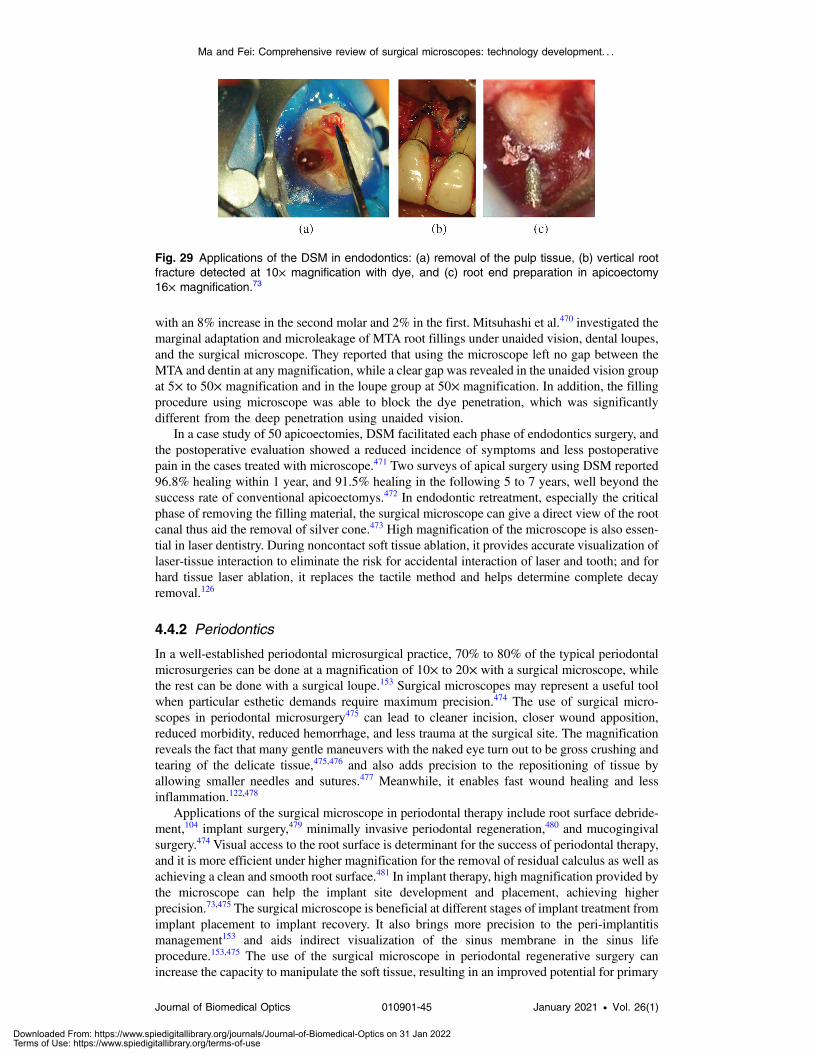
with an 8% increase in the second molar and 2% in the first. Mitsuhashi et al.470 investigated themarginal adaptation and microleakage of MTA root fillings under unaided vision, dental loupes,and the surgical microscope. They reported that using the microscope left no gap between theMTA and dentin at any magnification, while a clear gap was revealed in the unaided vision groupat 5× to 50× magnification and in the loupe group at 50× magnification. In addition, the fillingprocedure using microscope was able to block the dye penetration, which was significantlydifferent from the deep penetration using unaided vision.
In a case study of 50 apicoectomies, DSM facilitated each phase of endodontics surgery, andthe postoperative evaluation showed a reduced incidence of symptoms and less postoperativepain in the cases treated with microscope.471 Two surveys of apical surgery using DSM reported96.8% healing within 1 year, and 91.5% healing in the following 5 to 7 years, well beyond thesuccess rate of conventional apicoectomys.472 In endodontic retreatment, especially the criticalphase of removing the filling material, the surgical microscope can give a direct view of the rootcanal thus aid the removal of silver cone.473 High magnification of the microscope is also essen-tial in laser dentistry. During noncontact soft tissue ablation, it provides accurate visualization oflaser-tissue interaction to eliminate the risk for accidental interaction of laser and tooth; and forhard tissue laser ablation, it replaces the tactile method and helps determine complete decayremoval.126
4.4.2 Periodontics
In a well-established periodontal microsurgical practice, 70% to 80% of the typical periodontalmicrosurgeries can be done at a magnification of 10× to 20× with a surgical microscope, whilethe rest can be done with a surgical loupe.153 Surgical microscopes may represent a useful toolwhen particular esthetic demands require maximum precision.474 The use of surgical micro-scopes in periodontal microsurgery475 can lead to cleaner incision, closer wound apposition,reduced morbidity, reduced hemorrhage, and less trauma at the surgical site. The magnificationreveals the fact that many gentle maneuvers with the naked eye turn out to be gross crushing andtearing of the delicate tissue,475,476 and also adds precision to the repositioning of tissue byallowing smaller needles and sutures.477 Meanwhile, it enables fast wound healing and lessinflammation.122,478
Applications of the surgical microscope in periodontal therapy include root surface debride-ment,104 implant surgery,479 minimally invasive periodontal regeneration,480 and mucogingivalsurgery.474 Visual access to the root surface is determinant for the success of periodontal therapy,and it is more efficient under higher magnification for the removal of residual calculus as well asachieving a clean and smooth root surface.481 In implant therapy, high magnification provided bythe microscope can help the implant site development and placement, achieving higherprecision.73,475 The surgical microscope is beneficial at different stages of implant treatment fromimplant placement to implant recovery. It also brings more precision to the peri-implantitismanagement153 and aids indirect visualization of the sinus membrane in the sinus lifeprocedure.153,475 The use of the surgical microscope in periodontal regenerative surgery canincrease the capacity to manipulate the soft tissue, resulting in an improved potential for primary
Fig. 29 Applications of the DSM in endodontics: (a) removal of the pulp tissue, (b) vertical rootfracture detected at 10× magnification with dye, and (c) root end preparation in apicoectomy16× magnification.73
Ma and Fei: Comprehensive review of surgical microscopes: technology development. . .
Journal of Biomedical Optics 010901-45 January 2021 • Vol. 26(1)
Downloaded From: https://www.spiedigitallibrary.org/journals/Journal-of-Biomedical-Optics on 31 Jan 2022Terms of Use: https://www.spiedigitallibrary.org/terms-of-use

closure of the wound to 92% of microsurgery from 70% of regular surgery.482 It also allows asmaller incision to gain surgical access and debride the periodontal defect prior to placing thegraft.483 Mucogingival surgery is also called periodontal plastic surgery.484 For some proceduresin periodontal plastic surgery that can be very difficult with naked eyes, such as papilla recon-struction, the DSM can turn it into an easy one by increasing visibility, eliminating unnecessaryincision, and facilitating access.475,485 Besides, it enables minimally invasive techniques that canminimize trauma, allow primary wound closure, and improve facial esthetics.486
The use of the surgical microscope has been actively evaluated in root coverage procedure,which is a type of mucogingival surgery for the treatment of gingival recession. It enables excel-lent visualization and an atraumatic surgical approach in root coverage procedures, which resultsin satisfying cosmetic outcomes such as better searing and marginal profile.474 When the pro-cedure is combined with coronal flaps, the microscope also makes the advancement of flapseasier and tension free.476,481,487 Bittencourt et al.92 compared surgical outcomes of root coverageprocedure with subepithelial connective tissue graft with or without a surgical microscope. Thetest group using the microscope significantly outperformed regarding the average percentage ofroot coverage, complete root coverage, and patient esthetics satisfaction. Thankkappan et al.488
performed root coverage procedures using subepithelial connective tissue graft andcollagen membrane with a surgical microscope. The 6× magnification delivered precision andvisual acuity, which guaranteed precise control of the gingiva. Burkhardt and Lang489 employeda Zeiss OPMI Pro magis DSM for recession coverage at 15× magnification, while the graft andpalatal closure ahead of it were performed with a prism loupe at 5×. Meanwhile, surgical micro-scope OPMI FR was used for fluorescence angiography. The microscopic approach was comparedin the study with a conventional macrosurgical approach. The results showed that the microscopeimproved visual and tactile approach, and it enabled the use of finer instruments and suture mate-rials, which reduced tissue damage. In addition, the magnification was able to help split a flap ina well-defined thickness, which resulted in decreased vessel injury. The angiography revealeda better vascularization of microscopic approach than the macrosurgical one.
4.5 Plastic and Reconstructive Surgery
Plastic and reconstructive surgery is another big area where the surgical microscope is employed.The surgical microscope does not necessarily offer significantly better surgical outcomes inevery plastic application,93,490,491 but it stands out with some advantages that other methodsdo not possess. Actually, the high and varied magnification and the excellent illumination pro-vided by the microscope are critical and beneficial in many cases, such as the optimal alignmentof nerve ends,492 the precise reconstruction of uterine tube,81 and fallopian tube,493 as well as theminimally invasive excision of small structures such as ingrown toenails.85 Besides, other fea-tures including the share of view with assistant and staff team, recording, and position of comfortcan also facilitate a smooth surgical workflow.117,494 In this section, we will discuss several appli-cations of the surgical microscope in plastic and reconstructive surgeries, including craniofacialsurgery, reconstructive microsurgery, and dental plastic surgery.
4.5.1 Craniofacial surgery
Craniofacial surgery involves the congenital or acquired deformities of the skull, head, face,neck, jaws, and the associated structures, such as craniosynostosis, facial fractures, and cleftpalate.495 The use of a microscope enables minimally invasive incision, clear visualization ofthe complicated and delicate surgical site, as well as precise operation. Here, we discuss severalapplications of the surgical microscope in craniofacial surgeries.
Craniosynostosis. The use of a surgical microscope in a minimally invasive approach tocraniosynostosis provides excellent visualization, illumination, and control of the surgical field,which potentially results in shorter operative time, hospitalization, and less blood loss.496
Teichgraeber et al.93 tested a microscopic approach and an open approach on 67 infants withcraniosynostosis. A surgical microscope was used on 40 infants to perform appropriate synos-tectomy after placing incisions over the premature suture in the microscopic approach, while acoronal incision with cranial vault reconstruction was used in the open approach. Although the
Ma and Fei: Comprehensive review of surgical microscopes: technology development. . .
Journal of Biomedical Optics 010901-46 January 2021 • Vol. 26(1)
Downloaded From: https://www.spiedigitallibrary.org/journals/Journal-of-Biomedical-Optics on 31 Jan 2022Terms of Use: https://www.spiedigitallibrary.org/terms-of-use

surgical outcomes of both approaches were equal, the microscopic approach resulted in lessoperative time (108 versus 210 min), less blood loss (75 versus 220 mL), and shorter hospitalstay (2 versus 4 days). Later, Teichgraeber et al.497 reported his long-term comparison of themicroscopic minimally invasive approach and the open approach for nonsyndromic craniosy-nostosis on 180 consecutive patients. The microscopic approach had equal surgical outcomeswith the open approach and remained to be the treatment method for sagittal lambdoidalcraniosynostosis, while for unicoronal or metopic patients it showed less favor.
Congenital defect. Kumar et al.5 reported their surgical treatment method of preauricularsinuses using a surgical microscope and evaluated the effect of the microscope on surgical out-comes. After incisions were used to expose the surgical site, magnification of the surgical micro-scope was employed for visualization during the blood removal and the meticulous ramificationdissection. The magnification was useful for precise dissection to avoid any epithelial breach,which may lead to recurrence in preauricular sinus excision. Park and Diaz498 described a sur-gical approach to repair pediatric orbital floor fractures. The surgical microscope was broughtinto the field midway because of the suboptimal depth of vision and the inability to use twohands provided by the endoscope. The major role of the microscope was to provide excellentvisualization of the entire orbital floor defect and to facilitate placement of a polyethyleneimplant with great ease. The authors also anticipated the advantages of the microscopic tech-nique such as enhanced cosmesis and better exposure of orbital fracture without increased globalretraction. Cleft palate repair and rerepair, which involve a deep and small surgical site, oftenrequire the use of a surgical microscope to aid visualization.499 Sommerlad494,500 performed pal-ate repair and rerepair surgeries with radical dissection and retropositioning using a surgicalmicroscope. The microscope allowed surgeons to perform a more precise dissection of the velarmusculature and radical retropositioning of the levator palati muscle. In addition, the high mag-nification, which enabled visualization of the deep nasal mucosa and small vessels, facilitatedthe dissection of muscles off the nasal mucosa while preserving the submucosal vessels. Katoet al.117 performed 18 cleft lip operations and palatoplasty using either loupes or microscopy. Theresults show that microscope is more helpful than loupes in delicate operations such as cleftsurgery because of the clearly observable surgical field, ensured precise procedures, comfortablepositions, as well as the convenient share of view with the team provided by the microscope,without significantly increased preoperative preparation time or operating time. Furthermore,Mehendale et al.501 used the microscope for direct evaluation of the velar muscles in the surgeryof velopharyngeal incompetence. The anatomy of velar muscles, which was assessed with themicroscope, was used to make a final decision whether radical dissection and retropositioning orHynes pharyngoplasty would be performed.
4.5.2 Microsurgery
Surgical microscope has a great impact on reconstructive microsurgery. Its applications includehand surgery,502 head and neck reconstruction using free tissue transfer,14 nerve repair,492 anas-tomosis and duct reconstruction,503,504 lymphatic reconstruction,86 etc. The microscope can notonly aid visualization and precise operation but also reduce surgical complications.
Hand microsurgery. High magnification provided by microscope such as 10× or more isnecessary for hand surgery to see the tissue structures. It was said that the microsurgical tech-niques with the use of a microscope could yield a markedly improved success rate than loupes inthe anastomoses of vessels smaller than 3.5 mm.502 It also has an important role for flexor tendonrepair,505 nerve repair,492 finger replantation, and toe transplantation.
Nerve repair. Surgical microscope can offer high magnification for surgeons to see the nerveends and to perform neurorrhaphy with suture for peripheral nerve repair. In a study of digitalnerve repair,506 45 patients were operated on using a microscope with a magnification of 14×.Normal two-point discrimination was achieved in 9 cases, 6 to 10 mm discrimination in 22 cases,and 11 to 15 mm discrimination with protective sensation in 18 cases. A review of six studiesabout cadaveric digital nerve repair492 concluded that the use of the microscope produces
Ma and Fei: Comprehensive review of surgical microscopes: technology development. . .
Journal of Biomedical Optics 010901-47 January 2021 • Vol. 26(1)
Downloaded From: https://www.spiedigitallibrary.org/journals/Journal-of-Biomedical-Optics on 31 Jan 2022Terms of Use: https://www.spiedigitallibrary.org/terms-of-use

superior quality repair than loupes (60% versus 29%). In addition, the superiority of a micro-scope lies in the easier access to fascicles when digital nerves that are not expediently repairedlead to scarring and neuroma formation. Furthermore, the surgical microscope is helpful for thetreatment of nerve palsy. Slooff507 performed intraplexal and/or extraplexal neurotizations withthe aid of a surgical microscope on the brachial plexus, the weakness of which can lead to dif-ficulty in the motion of arm.508 Geissler et al.509 operated on anterior interosseous nerve palsy,which was a complication of closed bone forearm fracture. A surgical microscope was used toopen the epineurium longitudinally, to remove the bone spike perforating the median filter.
Finger replantation and toe transplantation. Surgical microscope can aid visualizationof vessels and nerves during replantation and transplantation. Tamai et al.510 performed replan-tation of a completely amputated little finger in a 20-month-old child. The surgical microscopewas used to observe the amputated part and to identify the volar digital artery, after which a fineblunt needle was inserted to the cut end of the artery for repair. Chen in Shanghai performedfinger reattachment with both loupes (351 cases) and a surgical microscope (106 cases). Thesuccess rate of using loupe was 51% while that of using the microscope was 91.5%.502
Ohmori and Harii511 transplanted a second toe to an index finger using microvascular anasto-mosis. The microscope was used for anastomoses of the vessels and nerves, as well as theapproximation of nerve with sutures after revascularization. The operation was successful inboth function and cosmetic ways.
Head and neck reconstruction. Reconstruction operation of the head and neck area isusually required due to oncologic resection of head and neck cancer. Surgical microscope hasbeen widely used during reconstruction to facilitate visualization and ensure the patency ofmicrovascular anastomoses. Ross et al.14 did a 7-year retrospective review of 151 consecutivemicrovascular-free tissue transfer in head and neck reconstruction where they compared the useof a surgical microscope (84 cases) and loupes (67 cases). The vessels involved in reconstructionincluded arteries (external carotid artery, superior thyroid artery, the high branch of the externalcarotid artery) and veins (internal jugular vein, facial vein, external jugular vein, temporal vein),and the reconstructed sites included oral cavity, mandible, tongue, pharynx, maxilla or orbita,temporal bone, and parotid. Although the surgical microscope did not yield a significantly betteroutcome than loupes, it did result in a 97.6% success rate and a shorter hospitalization time.
Lymphatic reconstruction. Yamamoto et al.86 performed 40 cases of LVA on 12 patientswith lower extremity lymphedema using a surgical microscope (OME-9000, Olympus) equippedwith infrared illumination for intraoperative microscopic ICG lymphography guidance. The ICGguidance was used in 24 LVAs, where lymphatic vessels were enhanced in 22 cases. In addition,ICG guidance significantly shortened the time for detection and dissection of lymphatic vessels.In another study of 11 microsurgical free flaps, microscope-integrated ICG angiography wasperformed to visualize the flow over microanastomoses and to assess the transit time of bloodflow between arterial and venous anastomosis.267 It was reported that the ICG imaging andits integration into the surgical microscope allow an “angiographic patency test” and providea new level of safety in flap design.
Liver transplantation. Hepatic artery complication and biliary complication are two of themajor concerns during living donor liver transplantation (LDLT). The high magnification pro-vided by the surgical microscope is helpful for the reconstruction of vessels and small ducts,which can reduce complications during liver transplantation.
Hepatic artery reconstruction. Surgical microscope was found helpful with arterialanastomosis and to decrease hepatic artery thrombosis (HAT) during liver transplantation. Ina 20-year study of liver transplants reported by Bade et al.,512 252 transplants were performedwithout microsurgery, and in 23 cases microscope was used for microsurgical hepatic arteryreconstruction. The group using the microscope had a lower incidence of HAT, a lower retrans-plantation rate, and increased 1-year survival. Guarrera et al.94 used a surgical microscope with amagnification of 12× to 16× for hepatic artery anastomosis in 14 segmental liver transplantations
Ma and Fei: Comprehensive review of surgical microscopes: technology development. . .
Journal of Biomedical Optics 010901-48 January 2021 • Vol. 26(1)
Downloaded From: https://www.spiedigitallibrary.org/journals/Journal-of-Biomedical-Optics on 31 Jan 2022Terms of Use: https://www.spiedigitallibrary.org/terms-of-use

of children with no cases of HAT happened. Lee et al.504 reviewed their 325 LDLT using asurgical microscope (Leica M520 F40) with a magnification of 10× to 15× from 2008 to2015. The microscope assistance enabled risk-free hepatic artery anastomoses, which yielded84.8% 1-year survival, 75.2% 5-year survival, and only one episode of HAT. They indicated theadvantage of using the surgical microscope beyond performing actual anastomosis as to surveyfor risk factors that can cause the HAT. Besides, the microscope assistance surpasses surgicalloupe because it can avoid iatrogenic tearing of the vessel wall or compression of the vessellumen. Seda-Neto et al.513 used Zeiss OPMI PENTERO 900 and OPMI Vario S88 surgicalmicroscopes in the majority of 656 cases of pediatric liver transplantation for microvascularanastomosis. Each operation of arterial anastomosis took 20 to 30 min under 10×magnification.In addition, Zuo et al.514 reported 83 end-to-end hepatic artery anastomoses in 77 LDLT using anoperating microscope, achieving a 1-year survival rate of 94% and a 5-year survival rate of 90%,with only two cases of HAT.
Biliary reconstruction. Surgical microscope used in biliary reconstruction can potentiallyreduce the incidence of biliary complications associated with LDLT. Yan et al.503 performed 32LDLTs, where a surgical microscope was used for nine cholangiojejunostomies in small hepaticducts of four donors. The diameter of the graft hepatic duct was smaller than 2 mm in seven casesand 2 to 3 mm in two instances. Magnification of 10× provided by the microscope was con-tinuously used in these nine biliary reconstructions. The application of microsurgical techniquewith the microscope ensured the stability of the small operative field under high magnificationand smooth handling of the ducts. Although the operating time using the microscope was almosttwice that using loupes, it was concluded that the surgical microscope can help reduce the inci-dence of biliary complications of LDLT.
5 Discussion and Future Directions
Although first invented for otolaryngology, the surgical microscopes started to thrive after beingintroduced into neurosurgery. Compared with the early models, modern surgical microscopeshave developed tremendously, with a large range of magnification options, stable and brightilluminations, well-designed optics and longer working distances, stabilized stands with goodmaneuverability and ergonomics, high-resolution visualization options, and especially the inte-gration with various imaging modalities and AR technology that can facilitate image-guidedsurgery. The robotic feature added to the newest model is a new milestone in the developmentof surgical microscopes. Meanwhile, all-digital visualization offers additional freedom of move-ment and unlocks many new potential technologies. Nowadays, the surgical microscope hasbecome a fundamental tool in many fields, including neuro and spine surgery, otolaryngology,ophthalmology, endodontics, and plastic and reconstruction surgery. It provides surgeonswith clear, bright, and stabilized visualization of the surgical field and reveals more detailsof the delicate structures with its high magnification and integrated imaging modalities.Microsurgery with the operating microscope allows small incision, less muscle dissection, andless trauma. Decreased length of hospital stay and better cosmetic outcomes improve patients’satisfaction after surgery.
Despite many advantages, there still exist some challenges for surgical microscopes. The factof being cumbersome is the main limitation of the surgical microscope. Due to the large volumeand heavy weight, the transportation of the surgical microscopes between ORs and the positionof the microscope in the OR without interrupting surgery are of great concern. In addition, somestudies indicated that setting up the microscope and repositioning during the surgery might pro-long the duration of procedures.25,73 Fortunately, designs of modern surgical microscopes haveimproved the maneuverability to a great degree. Optics carrier and binocular tubes are capable ofa wide range of tilt and rotation, enabling surgeons to view with convenient and comfortablepostures. The integrated intraoperative imaging modules eliminated the interruption of surgicalworkflow since there is no need to remove the surgical microscope to capture images.Autofocusing is developed and added to the microscope so the surgeons can operate with anyposition and stay in focus easier and faster than before. With the high-precision motorizedmechanics, moving the microscope becomes weightless; with the new robotic positioning
Ma and Fei: Comprehensive review of surgical microscopes: technology development. . .
Journal of Biomedical Optics 010901-49 January 2021 • Vol. 26(1)
Downloaded From: https://www.spiedigitallibrary.org/journals/Journal-of-Biomedical-Optics on 31 Jan 2022Terms of Use: https://www.spiedigitallibrary.org/terms-of-use

features, surgeons can visualize the anatomy from different angles and no longer need to spendlots of time looking for the right position. Furthermore, a lightweight head-mount microscope,namely the Varioscope, is an option when mobility and maneuverability are required.25 It hasswitchable magnifications, autofocusing, and foot panel control.515 The adaptation with AR byBirkfellner219 empowered it for surgical guidance. It is a less complicated instrument so it has ashorter set-up time. Its good mobility enables the view of some structures that are hard to accesswith a common microscope.73 However, because of the absence of supporting structure, it hasless stability than the common surgical microscope, thus it needs refocusing more often.
Another challenge of the surgical microscope is the skin burn caused by high-power illumi-nation. To provide a bright visualization, especially when there are multiple viewers or cameras,the light source has to emit strong light, which may burn patients’ tissue. Skin burn can happen invarious surgeries including ENT surgery,148,516 hand surgery,517 and plastic surgery,518 but ENTwas the majority of all cases. Most cases happened in procedures that last for 3 h or more.Ophthalmic surgical microscope has also been reported to cause phototoxicity of the ocular sur-face and tear film,519,520 which results in decreased functionality of ocular cells. Light manage-ment has been developed in new models regarding spot size and working distance so theintensity of light that comes out of the light source changes with the magnification and the work-ing distance of the surgical microscope. However, there are still several cases516,518,521 of skinburn being reported even using the new microscope models. Therefore, light management tech-niques need to be improved. The new robotic visualization system only uses one camera tocapture the whole surgical field, and all observers can visualize the field through monitors.In this system, the reflected light no longer needs to be split to separate light paths for differentobservers. Hence, the intensity of illumination can be greatly reduced. Nevertheless, it is stillworth exploring the appropriate level of illumination through clinical studies, which will serve asguidance for microscope users.
The high cost is also a big challenge for surgical microscopes to be commonly used. Theprice of a surgical microscope can be hundreds of thousands of dollars, depending on differentconfigurations and features. The utilization of surgical microscopes in procedures is associatedwith added cost.73 Therefore, it is used in hospitals more than clinics considering financialcapability. Nevertheless, the surgical microscope is a lifelong investment. It can benefit manyprocedures with various attractive features, meanwhile aid resident training and documentation.The enabled microsurgical techniques, improved surgical outcomes, and decreased hospital staymake it an invaluable tool.
Other challenges of using a surgical microscope include the potential intraoperative contami-nation,25,522 the steep learning curve,73,459 and the required extra skill and training.11 Some stud-ies say that the surgical microscope is a potential source of infection in spinal surgery,25 whileothers say the opposite.523 It may depend on different surgical techniques, operations, and drap-ing options. It is also very important for the surgical microscope to have a safe and convenientdraping design. As for the learning curve and skill training, situations might change with theincreased adoption of surgical microscope. The microscope has been reported to offer greatassistance for resident training, enabled by its lateral observation ports, HD display, and high-resolution documentation. When it is adopted in more applications with its value being affirmed,hopefully it will provide more chances for education and get increased exposure to training.
For the future development of the surgical microscope, one important direction is to improveits modularity and adaptability.130 The requirement for the microscope changes with the users’needs and the evolution of surgical techniques. The microscope should be ready for more sophis-ticated features to be added. The adaptation of fluorescence imaging filters and iOCT systemsto surgical microscopes, which evolved from preliminary studies to commercially availablemodules, have proved their value in various intraoperative applications. The benefits of opticalimaging lie in that they are minimally invasive and nonionizing.360 The next step is to utilize theadaptability of the microscope and investigate more advanced technologies, especially moreoptical imaging modalities, for surgical guidance.
Photoacoustic imaging, HSI, and LSCI are three promising imaging modalities that havebeen evaluated with surgical microscopes in a few studies. The depth-resolved photoacousticimage can not only provide subsurface information of the tissue as OCT but also reveal differentstructures that might be less visible in OCT images. However, its current adaptation with the
Ma and Fei: Comprehensive review of surgical microscopes: technology development. . .
Journal of Biomedical Optics 010901-50 January 2021 • Vol. 26(1)
Downloaded From: https://www.spiedigitallibrary.org/journals/Journal-of-Biomedical-Optics on 31 Jan 2022Terms of Use: https://www.spiedigitallibrary.org/terms-of-use

microscope reduces the working distance. HSI acquires the spatial and spectral information ofthe tissue simultaneously; it not only aids intraoperative detection of tissue disorders and cancerbut also provides surgical guidance such as dynamic oxygen saturation measurement and nar-row-band visualization. LSCI, as a simple and low-cost method, can obtain the 2D perfusionmap of the whole field and provide detailed spatiotemporal dynamics of blood flow changes inreal-time, hence it can serve as an intraoperative blood flow monitoring tool. HSI and LSCI aretwo imaging modalities that are particularly advantageous to be integrated into the surgical flowthrough the surgical microscope. Although fluorescence imaging is the current most popularintraoperative imaging modality for tumor delineation and vasculature visualization, it requiresa certain administration time of the injected dye, and it is liable to false positive findings due toincomplete clearness of the dye at end of the surgery. Besides, the interpretation of the brightnessof fluorescence can also affect the diagnosis. HSI has been vastly evaluated with fluorescenceimaging to improve its detection sensitivity and accuracy. However, it is worth noting that HSIalone is capable of serving as an intraoperative tool for various applications including tumordetection and microvascular visualization. Compared with fluorescence imaging, both HSI andLSCI are noncontact and label-free, not requiring any injection of contrast or dye. Hence, theycan be used on-demand at any time during the surgery. Despite different principles, both tech-nologies have a very simple system and relatively fast imaging speed. With well-developedimage processing methods, they can provide a quantitative and dynamic assessment of the fullfield in real-time. Therefore, the integration of HSI and LSCI with the surgical microscope addsvery little complexity to the system, takes minimal effort for physicians to adopt, and providesmore information.
Polarization imaging is another imaging technique that is anticipated to be evaluated with thesurgical microscope. Its implementation is simple and low-cost by applying two polarizers infront of the light source and detecting array. Polarization imaging can be used together withwhite light, fluorescence imaging, or even OCT to improve visualization and tissue differentia-tion during the surgery. For example, polarized light imaging was able to provide greater reli-ability for intraoperative nerve identification than normal visual inspection,524 dye-enhancedfluorescence polarization imaging could aid intraoperative delineation of cancer,525–527 andpolarization-sensitive OCT as an extension function of OCT could yield higher contrast betweendifferent tissue types as well as aid the diagnosis of cancer.526,528 In addition to polarizationimaging, the use of the endoscopic probe in the state-of-art robotic visualization system hasrevealed opportunities for integration of some imaging modalities that are not as easily adaptedwith conventional surgical microscopes, such as two-photon excited fluorescence, confocalmicroscopy, and Raman spectroscopy. The combination of the abovementioned imaging meth-ods with surgical microscopes can reveal more information about biomarkers and anatomicalstructures than what can be seen from a merely magnified white-light image with minimal inter-ruption of the surgical workflow. Furthermore, structured light was evaluated with a fluores-cence-guided surgical microscope by Rodriguez for 3D shape reconstruction of the brain.529
The obtained 3D surface profile was used for light intensity correction of the autofluorescencesignals, but with future development, this method is also potential to add depth perception in ARand aid accurate localization of anatomical structures.
Another expected future improvement of surgical microscopes is the capability of displayingthe procedures. The high-end optics, high-resolution recording, and HD display have opened uptremendous abilities to share the information with trainees and colleagues, either during surgeryor at a conference. It not only benefits education but also helps with the discussion for techniqueimprovement. The 3D display and stereo headset even added depth perception to the sharedview. Nowadays, the internet plays an important role in information sharing, and it opensup the possibility of live streaming of the procedures.76 Combining the documentation abilityof surgical microscopes with live streaming and other advanced communication technologies,procedures become viewable in real-time through smartphones, computers, headsets, and largescreens in a lecture room. A large team will be able to observe the operations and offer moreassistance and feedback for the surgery. This might also be a great promotion of remote surgery,which allows the expertise of specialized surgeons to be available to patients worldwide.Although robotic surgery also enables the surgeon to operate remotely through a robot system,the expense to purchase and run the robot system is a huge drawback of robot-assisted remote
Ma and Fei: Comprehensive review of surgical microscopes: technology development. . .
Journal of Biomedical Optics 010901-51 January 2021 • Vol. 26(1)
Downloaded From: https://www.spiedigitallibrary.org/journals/Journal-of-Biomedical-Optics on 31 Jan 2022Terms of Use: https://www.spiedigitallibrary.org/terms-of-use

surgery. Current AR-assisted platforms have made remote surgery much more cost-effective, butonly with laptops or tablets, it is hard to conduct microsurgeries that require high magnifications.The integration of the surgical microscope with advanced communication technologies andAR-assisted platforms will definitely push the limit of remote surgery and bring a lot of changeto the operating room.
Finally, surgical microscopes are expected to be adopted in more applications. Despite thefact that the surgical microscope is valued in various surgery types including neurosurgery, ENT,ophthalmology, dentistry, and plastic surgery, it might be more popular in some subspecialtiesand less embraced in others. For example, the neurosurgical microscope is commonly used byneurosurgeons in intradural, intramedullary, and extramedullary surgeries, but is less employedby orthopedic spine surgeons.25 The magnification of microscopes has brought a revolution inendodontics, while other fields in dentistry have not used it as much. Possible reasons includelack of exposure in training, low rates of utilization in general procedures, and less emphasis onmicrosurgical techniques. With the intrinsic capability of providing good visualization and theadded imaging modules, the role of surgical microscopes in more clinical applications is waitingto be revealed. For instance, DSMs can be further evaluated for oral examination and periodontalsurgery. The use of ophthalmic surgical microscopes can be more studied in cataract and glau-coma procedures. If integrated with HSI, surgical microscopes have the potential to aid theobservation of seizures and larynx disorders.355,530 In some ENT surgeries, surgeons preferan endoscope because it offers visualization of structures that are less visible under a microscope.Since integrated with iOCT, surgical microscopes have gained a better capability to revealminute structures in the ear and larynx, which may increase the popularity of surgical micro-scopes in ENT surgery in the future. In addition, the endoscopic tool in the new robotic visu-alization system is a solution to this concern—surgeons are able to visualize the full field andthe deep structure simultaneously in a picture-in-picture view. This is opening opportunities forsurgical microscopes to be employed in more ENT surgeries.
In conclusion, the surgical microscope is a powerful tool that can offer optional magnifica-tions, bright illumination, and clear visualization. It has been used in different types of surgeriesand has improved surgical outcomes as well as surgeons’ ergonomics. It is anticipated that theintegration of surgical microscopes with state-of-the-art optical imaging technologies willchange the clinical practice in the operating room and benefit patients.
Disclosures
The authors have no relevant financial interests in this article and no potential conflicts of interestto disclose.
Acknowledgments
This research was supported in part by the U.S. National Institutes of Health (NIH) grantsR01CA156775, R01CA204254, R01HL140325, and R21CA231911, and by the CancerPrevention and Research Institute of Texas (CPRIT) grant RP190588.
References
1. A. Bozec et al., “Current role of primary surgical treatment in patients with head and necksquamous cell carcinoma,” Curr. Opin. Oncol. 31(3), 138–145 (2019).
2. P. R. Egbert et al., “Diode laser transscleral cyclophotocoagulation as a primary surgicaltreatment for primary open-angle glaucoma,” Arch. Ophthalmol. 119(3), 345–350 (2001).
3. J. L. Gutmann and J. W. Harrison, Surgical Endodontics, Blackwell ScientificPublications, Boston (1991).
4. J. M. Torossian et al., “Extracranial cephalic schwannomas: a series of 15 patients,”J. Craniofac. Surg. 10(5), 389–394 (1999).
5. K. K. Kumar et al., “Preauricular sinus: operating microscope improves outcome,” IndianJ. Otolaryngol. Head Neck Surg. 58(1), 6–8 (2006).
Ma and Fei: Comprehensive review of surgical microscopes: technology development. . .
Journal of Biomedical Optics 010901-52 January 2021 • Vol. 26(1)
Downloaded From: https://www.spiedigitallibrary.org/journals/Journal-of-Biomedical-Optics on 31 Jan 2022Terms of Use: https://www.spiedigitallibrary.org/terms-of-use

6. M. Kabuto et al., “Experimental and clinical study of detection of glioma at surgery usingfluorescent imaging by a surgical microscope after fluorescein administration,” Neurol.Res. 19(1), 9–16 (1997).
7. G. Tirelli et al., “Transoral surgery (TOS) in oropharyngeal cancer: different tools, a singlemini-invasive philosophy,” Surg. Oncol. 27(4), 643–649 (2018).
8. C. Krampe, “Zeiss operating microscopes for neurosurgery,” Neurosurg. Rev. 7(2-3),89–97 (1984).
9. I. N. Fleming et al., “Intraoperative visualization of anatomical targets in retinal surgery,” inIEEE Workshop Appl. Comput. Vision, pp. 1–6 (2008).
10. M. G. Yasargil, Microsurgery: Applied to Neurosurgery, Academic Press, New York(1969).
11. R. V. Vineet, “Dental operating microscope: the third dimension in dentistry,” Adv. Dent.Oral Health 1(3), 555562 (2016).
12. T. M. Research, “Surgical microscopes market—global industry analysis, size, share,growth, trends, and forecast, 2019—2027,” Transparency Market Research (2019).
13. A. Castellucci, “Magnification in endodontics: the use of the operating microscope,” Pract.Proced. Aesthet. Dent. 15(5), 377–84 (2003).
14. D. A. Ross et al., “Use of the operating microscope and loupes for head and neck freemicrovascular tissue transfer: a retrospective comparison,” Arch. Otolaryngol. HeadNeck Surg. 129(2), 189–193 (2003).
15. R. Keeler, “The evolution of the ophthalmic surgical microscope,” Hist. Ophthal. Intern.1, 35–66 (2015).
16. D. Schultheiss and J. Denil, “History of the microscope and development of microsurgery:a revolution for reproductive tract surgery,” Andrologia 34(4), 234–241 (2002).
17. A. F. Mavrogenis et al., “The history of microsurgery,” Eur. J. Orthop. Surg. Traumatol.29, 247–254 (2019).
18. T. C. Kriss and V. M. Kriss, “History of the operating microscope: from magnifying glassto microneurosurgery,” Neurosurgery 42(4), 899–907 (1998).
19. K. Uluç, G. C. Kujoth, and M. K. Baskaya, “Operating microscopes: past, present, andfuture,” Neurosurg. Focus 27(3), E4 (2009).
20. C. O. Nylean, “The microscope in aural surgery, its first use and later development,” ActaOto-Laryngol. 43(Suppl. 116), 226–240 (1954).
21. C. T. Tang et al., “Quantitative analysis of surgical exposure and maneuverability asso-ciated with the endoscope and the microscope in the retrosigmoid and various posteriorpetrosectomy approaches to the petroclival region using computer tomograpy-based frame-less stereotaxy. A cadaveric study,” Clin. Neurol. Neurosurg. 115(7), 1058–1062 (2013).
22. B. M. Mendez et al., “Heads-up 3D microscopy: an ergonomic and educational approachto microsurgery,” Plast. Reconstr. Surg. 4(5), e717 (2016).
23. Y. K. Tao, S. K. Srivastava, and J. P. Ehlers, “Microscope-integrated intraoperative OCTwith electrically tunable focus and heads-up display for imaging of ophthalmic surgicalmaneuvers,” Biomed. Opt. Express 5(6), 1877–1885 (2014).
24. L. Shen et al., “Novel microscope-integrated stereoscopic heads-up display for intrasur-gical optical coherence tomography,” Biomed. Opt. Express 7(5), 1711–1726 (2016).
25. O. Damodaran, J. Lee, and G. Lee, “Microscope in modern spinal surgery: advantages,ergonomics and limitations,” ANZ J. Surg. 83(4), 211–214 (2013).
26. A. Mudry, “The history of the microscope for use in ear surgery,” Otol. Neurotol. 21(6),877–886 (2000).
27. M. K. Hamamcioglu et al., “The use of the YELLOW 560 nm surgical microscope filter forsodium fluorescein-guided resection of brain tumors: our preliminary results in a series of28 patients,” Clin. Neurol. Neurosurg. 143, 39–45 (2016).
28. N. Zhang et al., “Sodium fluorescein-guided resection under the YELLOW 560 nm sur-gical microscope filter in malignant gliomas: our first 38 cases experience,” Biomed. Res.Int. 2017, 7865747 (2017).
29. B. Göker and T. Kırıs, “Sodium fluorescein-guided brain tumor surgery under theYELLOW-560-nm surgical microscope filter in pediatric age group: feasibility and pre-liminary results,” Child’s Nervous Syst. 35(3), 429–435 (2019).
Ma and Fei: Comprehensive review of surgical microscopes: technology development. . .
Journal of Biomedical Optics 010901-53 January 2021 • Vol. 26(1)
Downloaded From: https://www.spiedigitallibrary.org/journals/Journal-of-Biomedical-Optics on 31 Jan 2022Terms of Use: https://www.spiedigitallibrary.org/terms-of-use

30. Carl Zeiss Meditec AG, “YELLOW 560 fluorescence-based visualization,” https://www.zeiss.com/meditec/us/products/neurosurgery/intraoperative-fluorescence/tumor/yellow-560.html (accessed 2020).
31. P. A. Valdes et al., “5-aminolevulinic acid induced protoporphyrin IX (ALA-PpIX) fluo-rescence guidance in meningioma surgery,” J. Neuro-Oncol. 141(3), 555–565 (2019).
32. S. S. Jhawar et al., “FLOW 800-assisted surgery for arteriovenous malformation,” J. Clin.Neurosci. 18(11), 1556–1557 (2011).
33. M. A. Kamp et al., “Microscope-integrated quantitative analysis of intraoperative indoc-yanine green fluorescence angiography for blood flow assessment: first experience in30 patients,” Neurosurgery 70(1 Suppl. Operative), 65–73; discussion 73-74 (2012).
34. K. Fukuda et al., “Efficacy of FLOW 800 with indocyanine green videoangiography for thequantitative assessment of flow dynamics in cerebral arteriovenous malformation surgery,”World Neurosurg. 83(2), 203–210 (2015).
35. Leica Microsystems, “Intra-operative fluorescence-guided blood flow view 820 nm/NIRLeica FL800,” https://www.leica-microsystems.com/products/surgical-microscopes/p/leica-fl800/ (accessed 2020).
36. J. P. Ehlers et al., “The DISCOVER study 3-year results: feasibility and usefulness ofmicroscope-integrated intraoperative OCT during ophthalmic surgery,” Ophthalmology125(7), 1014–1027 (2018).
37. A. Kobayashi et al., “Visualization of precut DSAEK and pre-stripped DMEK donorcorneas by intraoperative optical coherence tomography using the RESCAN 700,”BMC Ophthalmol. 16, 135 (2016).
38. C. Jayadev et al., “Microscope-integrated optical coherence tomography: a new surgicaltool in vitreoretinal surgery,” Indian J. Ophthalmol. 63(5), 399–403 (2015).
39. P. Hahn et al., “Intrasurgical human retinal imaging with manual instrument tracking usinga microscope-integrated spectral-domain optical coherence tomography device,” Transl.Vis. Sci. Technol. 4(4), 1 (2015).
40. J. P. Ehlers et al., “Determination of feasibility and utility of microscope-integrated opticalcoherence tomography during ophthalmic surgery: the DISCOVER study RESCANresults,” JAMA Ophthalmol. 133(10), 1124–1132 (2015).
41. N. Pahuja et al., “Intraoperative optical coherence tomography using the RESCAN 700:preliminary results in collagen crosslinking,” Biomed. Res. Int. 2015, 1–7 (2015).
42. H. Eguchi et al., “Intraoperative optical coherence tomography (RESCAN((R)) 700)for detecting iris incarceration and iridocorneal adhesion during keratoplasty,” Int.Ophthalmol. 37(3), 761–765 (2017).
43. D. Roblyer et al., “In vivo fluorescence hyperspectral imaging of oral neoplasia,” Proc.SPIE 7169, 71690J (2009).
44. C. Lee et al., “Virtual intraoperative surgical photoacoustic microscopy,” Proc. SPIE 9539,95390E (2015).
45. J. Pichette et al., “Intraoperative video-rate hemodynamic response assessment in humancortex using snapshot hyperspectral optical imaging,” Neurophotonics 3(4), 045003 (2016).
46. R. Martin, B. Thies, and A. O. H. Gerstner, “Hyperspectral hybrid method classification fordetecting altered mucosa of the human larynx,” Int. J. Health Geographics 11(1), 21(2012).
47. E. L. Wisotzky et al., “Intraoperative hyperspectral determination of human tissue proper-ties,” J. Biomed. Opt. 23(9), 091409 (2018).
48. E. L. Wisotzky et al., “Validation of two techniques for intraoperative hyperspectral humantissue determination,” Proc. SPIE 10951, 109511Z (2019).
49. J. R. Watson, “Development of an augmented microscope for image guided surgery inthe brain,” The University of Arizona (2018).
50. D. Umebayashi et al., “Augmented reality visualization-guided microscopic spine surgery:transvertebral anterior cervical foraminotomy and posterior foraminotomy,” J. Am. Acad.Orthop. Surg. Glob. Res. Rev. 2(4), e008 (2018).
51. J. Lee et al., “Clinical utility of intraoperative tympanomastoidectomy assessment using asurgical microscope integrated with an optical coherence tomography,” Sci. Rep. 8(1),17432–17439 (2018).
Ma and Fei: Comprehensive review of surgical microscopes: technology development. . .
Journal of Biomedical Optics 010901-54 January 2021 • Vol. 26(1)
Downloaded From: https://www.spiedigitallibrary.org/journals/Journal-of-Biomedical-Optics on 31 Jan 2022Terms of Use: https://www.spiedigitallibrary.org/terms-of-use

52. G. C. Sun et al., “Impact of virtual and augmented reality based on intraoperative magneticresonance imaging and functional neuronavigation in glioma surgery involving eloquentareas,” World Neurosurg. 96, 375–382 (2016).
53. J. T. Elliott et al., “Review of fluorescence guided surgery visualization and overlay tech-niques,” Biomed. Opt. Express 6(10), 3765–3782 (2015).
54. N. L. Martirosyan et al., “Integration of indocyanine green videoangiography with oper-ative microscope: augmented reality for interactive assessment of vascular structures andblood flow,” Neurosurgery 11(Suppl. 2), 252–257; discussion 257–258 (2015).
55. D. Kotsougiani et al., “The learning rate in three dimensional high definition video assistedmicrovascular anastomosis in a rat model,” J. Plast. Reconstr. Aesthet. Surg. 69(11), 1528–1536 (2016).
56. M. D. Moisi et al., “Advancement of surgical visualization methods: comparison studybetween traditional microscopic surgery and a novel robotic optoelectronic visualizationtool for spinal surgery,” World Neurosurg. 98, 273–277 (2017).
57. I. Cabrilo, P. Bijlenga, and K. Schaller, “Augmented reality in the surgery of cerebral aneu-rysms: a technical report,” Neurosurgery 10, 252–260 (2014).
58. S. Siebelmann et al., “Advantages of microscope-integrated intraoperative online opticalcoherence tomography: usage in Boston keratoprosthesis type I surgery,” J. Biomed. Opt.21(1), 016005 (2016).
59. D. Athanasopoulos, “Visualization of vascular structures of the brain through a novel mul-tispectral fluorescence microscope after intravenous application of ICG,” Neurosurgery64, 226–226 (2017).
60. E. G. Belykh et al., “Laboratory evaluation of a robotic operative microscope—visualization platform for neurosurgery,” Cureus 10(7), e3072 (2018).
61. H. Osman et al., “In vivo microscopy in neurosurgical oncology,” World Neurosurg. 115,110–127 (2018).
62. J. C. Rice, “The microsurgical revolution in otolaryngology,” Med. J. Aust. 2(18),1011–1014 (1972).
63. P. J. Edwards et al., “Augmentation of reality using an operating microscope for otolaryn-gology and neurosurgical guidance,” Comput. Aided Surg. 1(3), 172–178 (1995).
64. B. J. Davidson, E. Guardiani, and A. Wang, “Adopting the operating microscope in thyroidsurgery: safety, efficiency, and ergonomics,” Head Neck 32(2), 154–159 (2010).
65. P. Michaelides, “Use of the operating microscope in dentistry,” J. California Dent. Assoc.24(6), 45–50 (1996).
66. R. Rubinstein, “Endodontic microsurgery and the surgical operating microscope,”Compend. Contin. Educ. Dent. 18(7), 659–664, 666, 668 passim; quiz 674 (1997).
67. M. Friedman, A. Mora, and R. Schmidt, “Microscope-assisted precision dentistry,”Compend. Contin. Educ. Dent 20(8), 723–728, 730–721, 735–726; quiz 737 (1999).
68. D. Clark, “Microscope-enhanced aesthetic dentistry,” Dent. Today 23(11), 96, 98–101(2004).
69. R. Mounce, “The surgical operating microscope: pushing the boundaries of the possible indentistry,” Dent. Today 25(10), 108, 110, 112–105 (2006).
70. M. G. Calderón et al., “The application of microscopic surgery in dentistry,” Med. OralPatol. Oral Cirugía Bucal 12(4), 311–316 (2007).
71. J. R. Moura, Jr., “Operating microscopes in restorative dentistry: the pursuit of excellence,”J. Min. Intervention Dent. 2(4), 241–247 (2009).
72. S. Pradeep and R. Vinoddhine, “The role of magnification in endodontics,” Ann. EssencesDent. 6(2), 38–43 (2014).
73. R. Hegde and V. Hegde, “Magnification-enhanced contemporary dentistry: gettingstarted,” J. Interdiscip. Dent. 6(2), 91 (2016).
74. G. B. Carr and C. A. F. Murgel, “The use of the operating microscope in endodontics,”Dent. Clin. 54(2), 191–214 (2010).
75. R. Kumar and N. Khambete, “Surgical operating microscopes in endodontics: enlargedvision and possibility,” Int. J. Stomatological Res. 2(1), 11–15 (2013).
76. U. Das and S. Das, “Dental operating microscope in endodontics: a review,” J. Dent. Med.Sci. 5(6), 1–8 (2013).
Ma and Fei: Comprehensive review of surgical microscopes: technology development. . .
Journal of Biomedical Optics 010901-55 January 2021 • Vol. 26(1)
Downloaded From: https://www.spiedigitallibrary.org/journals/Journal-of-Biomedical-Optics on 31 Jan 2022Terms of Use: https://www.spiedigitallibrary.org/terms-of-use

77. C. C. D. S. A. Lins et al., “Operating microscope in endodontics: a systematic,” Open J.Stomatol. 3, 1–5 (2013).
78. O. Carrasco-Zevallos et al., “4D microscope-integrated OCT improves accuracy ofophthalmic surgical maneuvers,” Proc. SPIE 9693, 969306 (2016).
79. B. Todorich et al., “Impact of microscope-integrated OCT on ophthalmology resident per-formance of anterior segment surgical maneuvers in model eyes,” Invest. Ophthalmol.Visual Sci. 57(9), OCT146–OCT153 (2016).
80. C. D. Lu et al., “Microscope-integrated intraoperative ultrahigh-speed swept-source opticalcoherence tomography for widefield retinal and anterior segment imaging,” Ophthalm.Surg. Lasers Imaging Retina 49(2), 94–102 (2018).
81. E. Diamond, “Microsurgical reconstruction of the uterine tube in sterilized patients,” Fertil.Steril. 28(11), 1203–1210 (1977).
82. J. Araico-Laguillo, “Microsurgery in plastic and reconstructive surgery,” Gaceta Med.Mexico 115(1), 17 (1979).
83. J. M. Serletti et al., “Comparison of the operating microscope and loupes for free micro-vascular tissue transfer,” Plast. Reconstr. Surg. 95(2), 270–276 (1995).
84. A. P. Sclafani, S. A. McCormick, and R. Cocker, “Biophysical and microscopic analysis ofhomologous dermal and fascial materials for facial aesthetic and reconstructive uses,”JAMA Facial Plast. Surg. 4(3), 164–171 (2002).
85. T. Yabe and M. Takahashi, “A minimally invasive surgical approach for ingrown toenails:partial germinal matrix excision using operative microscope,” J. Plast. Reconstr. Aesthet.Surg. 63(1), 170–173 (2010).
86. T. Yamamoto et al., “Near-infrared illumination system-integrated microscope for super-microsurgical lymphaticovenular anastomosis,” Microsurgery 34(1), 23–27 (2014).
87. R. Dashti et al., “Microscope-integrated near-infrared indocyanine green videoangiogra-phy during surgery of intracranial aneurysms: the Helsinki experience,” Surg. Neurol.71(5), 543–550; discussion 550 (2009).
88. A. D. Karatzanis et al., “Microscopic endonasal surgery of nasal and paranasal cavities,”Auris Nasus Larynx 35(4), 509–514 (2008).
89. J. H. Jang et al., “Nasopharyngectomy with operating microscope: a case series,” Am. J.Otolaryngol. 38(1), 82–86 (2017).
90. R. Ray et al., “Intraoperative microscope-mounted spectral domain optical coherencetomography for evaluation of retinal anatomy during macular surgery,” Ophthalmology118(11), 2212–2217 (2011).
91. D. Wu et al., “The clinical treatment of complicated root canal therapy with the aid ofa dental operating microscope,” Int. Dent. J. 61(5), 261–266 (2011).
92. S. Bittencourt et al., “Surgical microscope may enhance root coverage with subepithelialconnective tissue graft: a randomized-controlled clinical trial,” J. Periodontol. 83(6),721–730 (2012).
93. J. F. Teichgraeber et al., “Microscopic minimally invasive approach to nonsyndromiccraniosynostosis,” J. Craniofacial Surg. 20(5), 1492–1500 (2009).
94. J. V. Guarrera et al., “Microvascular hepatic artery anastomosis in pediatric segmental livertransplantation: microscope vs loupe,” Transpl. Int. 17(10), 585–588 (2004).
95. Grand View Research, “Surgical microscopes market size, share and trends analysisreport by type (on caster, wall-mounted), by application (oncology, ophthalmology,neurosurgery and spine), by end-use, and segment forecasts, 2018—2025,” https://www.grandviewresearch.com/industry-analysis/surgical-microscopes-market (accessed2020).
96. G. F. Dohlman, “Carl Olof Nylen and the birth of the otomicroscope and microsurgery,”Arch Otolaryngol. 90(6), 813–817 (1969).
97. R. Gelberman, “Microsurgery and the development of the operating microscope,”Contemp. Surg. 13(6), 43–46 (1978).
98. R. A. Perritt, “Micro-ophthalmic surgery,”XVIII, International Council of Ophthalmology,Belgica (1958).
99. F. Zöllner, “The principles of plastic surgery of the sound-conducting apparatus,”J. Laryngol. Otol. 69(10), 637–652 (1955).
Ma and Fei: Comprehensive review of surgical microscopes: technology development. . .
Journal of Biomedical Optics 010901-56 January 2021 • Vol. 26(1)
Downloaded From: https://www.spiedigitallibrary.org/journals/Journal-of-Biomedical-Optics on 31 Jan 2022Terms of Use: https://www.spiedigitallibrary.org/terms-of-use

100. H. Apotheker and G. J. Jako, “A microscope for use in dentistry,”Microsurgery 3(1), 7–10(1981).
101. H. S. Selden, “The dental-operating microscope and its slow acceptance,” J. Endodontics28(3), 206–207 (2002).
102. J. I. Barraquer, “The history of the microscope in ocular surgery,” Microsurgery 1(4),288–299 (1980).
103. M. Roper-Hall, “Microsurgery in ophthalmology,” Br. J. Ophthal. 51(6), 408 (1967).104. R. Hegde, S. Sumanth, and A. Padhye, “Microscope-enhanced periodontal therapy:
a review and report of four cases,” J. Contemp. Dent. Pract. 10(5), E088–E087 (2009).105. F. H. Ebner et al., “Optical requirements on magnification systems for intracranial video
microsurgery,” Microsurgery 31(7), 559–563 (2011).106. D. W. Roberts et al., “A frameless stereotaxic integration of computerized tomographic
imaging and the operating microscope,” J. Neurosurg. 65(4), 545–549 (1986).107. L. Zamorano et al., “Advanced neurosurgical navigation using a robotic microscope inte-
grated with an infrared-based system,” in Computer-Assisted Neurosurgery, N. Tamaki andK. Ehara, Eds., pp. 43–55, Springer, Tokyo (1997).
108. J. Wei and T. Hellmuth, “Optical coherence tomography assisted ophthalmologic surgicalmicroscope,” Carl Zeiss, Inc. (1996).
109. K. M. Schebesch et al., “Sodium fluorescein-guided resection under the YELLOW 560 nmsurgical microscope filter in malignant brain tumor surgery—a feasibility study,” ActaNeurochir. 155(4), 693–699 (2013).
110. K. J. Shah and A. A. Cohen-Gadol, “The application of FLOW 800 ICG videoangiographycolor maps for neurovascular surgery and intraoperative decision making,” WorldNeurosurg. 122, e186–e197 (2019).
111. Carl Zeiss Meditec AG, “See more,” https://www.zeiss.com/meditec/int/product-portfolio/intraoperative-fluorescence-modules/blue-400.html (accessed 2020).
112. Carl Zeiss Meditec AG, “INFRARED 800 from ZEISS,” https://www.zeiss.com/meditec/int/product-portfolio/intraoperative-fluorescence-modules/infrared-800.html (accessed 2020).
113. M. J. Greenfield et al., “Demonstration of the effectiveness of augmented reality telesur-gery in complex hand reconstruction in Gaza,” Plast. Reconstr. Surg. Glob. Open 6(3),e1708–e1708 (2018).
114. B. G. Khayat, “The use of magnification in endodontic therapy: the operating microscope,”Pract. Periodont. Aesthet. Dent. 10(1), 137–144 (1998).
115. C. L. Crain, “Basic principles of the surgical microscope,” https://www.scribd.com/document/358089541/Microscope-Basics/ (2006).
116. K. Schwab et al., “Evolution of stereoscopic imaging in surgery and recent advances,”World J. Gastrointest. Endosc. 9(8), 368–377 (2017).
117. M. Kato et al., “Cleft lip and palate repair using a surgical microscope,” Arch. Plast. Surg.44(6), 490 (2017).
118. H. Deutsch, “Microscopes and endoscopes,” in Minimally Invasive Spine Surgery,F. Phillips et al., Eds., pp. 61–67, Springer, Cham (2019).
119. U. Sander, “Light-emitting diode illumination system for an optical observation device,in particular a stereoscope or stereo surgical microscope,” US20050047172A1, LeicaMicrosystems (2007).
120. A. Obrebski et al., “Surgical microscope system,” Carl Zeiss Surgical GmbH (2007).121. R. C. Troutman, “The operating microscope in ophthalmic surgery,” Trans. Am.
Ophthalmol. Soc. 63, 335 (1965).122. R. Burkhardt and M. Hürzeler, “Utilization of the surgical microscope for advanced plastic
periodontal surgery,” Pract. Periodontics Aesthet. Dent. 12(2), 171–180; quiz 182 (2000).123. N. Matsumura et al., “An operating microscope with higher magnification and higher
resolution for cerebral aneurysm surgery: preliminary experience—technical note,”Neurol. Med. 54(6), 497–501 (2014).
124. Leica Microsystems, “Stay focus,” https://www.leica-microsystems.com/products/surgical-microscopes/p/leica-m530-oh6/ (accessed 2020).
125. G. Carr, “Magnification and illumination in endodontics,” Clark’s Clin. Dent. 4, 1–14(1998).
Ma and Fei: Comprehensive review of surgical microscopes: technology development. . .
Journal of Biomedical Optics 010901-57 January 2021 • Vol. 26(1)
Downloaded From: https://www.spiedigitallibrary.org/journals/Journal-of-Biomedical-Optics on 31 Jan 2022Terms of Use: https://www.spiedigitallibrary.org/terms-of-use

126. G. A. van As, “Extreme magnification and laser dentistry: seeing the light,” https://endoexperience.com/documents/vanaslaserdent.PDF (accessed 2020).
127. M. W. Burke, Image Acquisition: Handbook of Machine Vision Engineering, SpringerScience & Business Media, London (1996).
128. M. Abramowitz and M. W. Davidson. “Optical aberrations,” https://www.olympus-lifescience.com/zh/microscope-resource/primer/anatomy/aberrations/ (accessed 2020).
129. T. L. Lentz, “Lentz microscopy and histology collection: peabody museum of naturalhistory at Yale University,” Yale University School of Medicine (2013).
130. S. Shetty, S. Tejaswi, and T. Nagaraj, “Magnification—an endodontic review,” J. Adv. Clin.Res. Insights 5(6), 178–182 (2018).
131. M. Nohda, “Automatic focusing device in a stereoscopic microscope,” US4639587A,Nippon Kogaku K.K. (1984).
132. R. Jorgens and B. Faltermeier, “Process and apparatus for the automatic focusing of micro-scopes,” US4958920A, Carl-Zeiss Stiftung (1990).
133. U. Vry et al., “Autofocusing arrangement for a stereomicroscope which permits automaticfocusing on objects on which reflections occur,” US Patent 5288987, Carl-Zeiss-Stiftung(1994).
134. R. Heller, “Mechanical control unit for a surgical microscope connected to a stand,”Carl-Zeiss-Stiftung (1994).
135. R. Rey-Dios and A. A. Cohen-Gadol, “Technical principles and neurosurgical applicationsof fluorescein fluorescence using a microscope-integrated fluorescence module,” ActaNeurochir. 155(4), 701–706 (2013).
136. C. A. Schutt et al., “The illumination characteristics of operative microscopes,” Am. J.Otolaryngol. 36(3), 356–360 (2015).
137. ANSI, “American National Standard for Ophthalmics—light hazard from operation micro-scopes used in ocular surgery (ANSI Z80.38),” ANSI Z80.38-2017, The Vision Council(2017).
138. ISO, “International Standard ISO 10936-2 optics and photonics—operation microscopes—part 2: light hazard from operation microscopes used in ocular surgery,” ISO 10936-2:2010,International Organization of Standardization (2010).
139. A. Weiss et al., “Illumination device for a microscope including two light sources,” GooglePatents (2002).
140. International Commission on Non-Ionizing Radiation Protection, “Guidelines on limits ofexposure to ultraviolet radiation of wavelengths between 180 nm and 400 nm (incoherentoptical radiation),” Health Phys. 87(2), 171–186 (2004).
141. International Commission on Non-Ionizing Radiation Protection, “ICNIRP guidelines onlimits of exposure to incoherent visible and infrared radiation,”Health Phys. 105(1), 74–96(2013).
142. W. H. Lang, U. Lemcke, and U. Sander, “Surgical microscope for two surgeons,” Carl-Zeiss-Stiftung (1986).
143. KEYENCE, “Coaxial illumination,” https://www.keyence.com/ss/products/microscope/glossary/cat5/coaxial_illumination/ (accessed 2020).
144. K. Biber, “Illumination system for a surgical microscope,” US5126877A (1992).145. J. Koetke, “Illuminating device for a surgical microscope,” Moller-Wedel GmbH
(2003).146. M. Kuster and H. Suhner, “Illuminating device for an operating microscope,” LEICA
MICROSYSTEMS (SCHWEIZ) AG (2011).147. M. Kazutoshi and A. Hiroshi, “A surgical microscope apparatus,” EP2063305A2 (2009).148. R. F. Latuska et al., “Auricular burns associated with operating microscope use during
otologic surgery,” Otol. Neurotol. 35(2), 227–233 (2014).149. N. M. Langley, “Glare elimination device for surgical microscopes,” US20050063058A1
(2007).150. D. I. Pitskhelauri et al., “A novel device for hands-free positioning and adjustment of the
surgical microscope,” J. Neurosurg. 121(1), 161–164 (2014).151. U. Sander et al., “Voice control system for surgical microscopes,” US7286992B2 (2004).152. R. Roduit et al., “Eye-guided surgical microscope,” in Biomed. Opt., CTuB4 (1999).
Ma and Fei: Comprehensive review of surgical microscopes: technology development. . .
Journal of Biomedical Optics 010901-58 January 2021 • Vol. 26(1)
Downloaded From: https://www.spiedigitallibrary.org/journals/Journal-of-Biomedical-Optics on 31 Jan 2022Terms of Use: https://www.spiedigitallibrary.org/terms-of-use

153. V. Yadav et al., “Periodontal microsurgery: reaching new heights of precision,” J. IndianSoc. Periodontol. 22, 5–11 (2018).
154. S. Enge, “Balancing apparatusfor a surgical microscope,” Leica Instruments (Singapore)Pte. Ltd. (2013).
155. G. S. Tigliev, “Balanced suspension system for surgical microscope,” US5288043A (1994).156. K. Nakamura, “Automatic balancing mechanism for medical stand apparatus,” Mitaka
Kohki Co., Ltd. (2000).157. K. Nakamura and M. Doi, “Automatic balancing apparatus for balancing stand,” Mitaka
Kohki Co., Ltd. (2001).158. M. Doi and Y. Nakata, “Automatic balancing structure of medical balancing stand,”Mitaka
Kohki Co., Ltd. (2015).159. A. Metelski, “Balancing apparatus for a surgical microscope,” US20090218455A1 (2009).160. S. Enge, “Balancing apparatus for a surgical microscope,” US20090219613A1 (2009).161. M. A. Bohl, M. E. Oppenlander, and R. Spetzler, “A prospective cohort evaluation of
a robotic, auto-navigating operating microscope,” Cureus 8(6), e662 (2016).162. M. E. Oppenlander et al., “Robotic autopositioning of the operating microscope,”
Neurosurgery 10(Suppl. 2), 214–219 (2014).163. S. R. Kantelhardt et al., “Evaluation of a completely robotized neurosurgical operating
microscope,” Neurosurgery 72(Suppl. 1), A19–A26 (2013).164. D. L. Walchle, R. G. Smith, and J. L. Geraci, “Drape for operating microscope,” Xomox
Corporation (1972).165. L. Heinrich, “Surgical drape for an operating microscope,” Carl Zeiss, Inc. (1997).166. K. L. Vought, “Surgical microscope operating drape and methods of operation and manu-
facture thereof,” Deka Medical, Inc. (1998).167. K. P. Luloh and M. Annen, “Drape assembly for surgical microscope assembly,”
US20070064309A1 (2007).168. A. J. Bala, “Surgical microscope drape assembly,” US6902278B2 (2005).169. L. K. Kleinberg and N. E. John, “Drape for a surgical microscope with anti-halation
window,” Global Surgical Corporation (2001).170. R. A. Weaver, J. M. Wright, and N. M. Sokolowski, “Microscope drape lens protective
cover assemply,” Contour Fabricators, Inc. (2005).171. M. Hocke, “Medical technical apparatus including a footswitch device,” LEICA
MICROSYSTEMS (SCHWEIZ) AG (2016).172. P. Steven et al., “Optimising deep anterior lamellar keratoplasty (DALK) using intraoperative
online optical coherence tomography (iOCT),” Br. J. Ophthalmol. 98(7), 900–904 (2014).173. F. Rudolph et al., “Operating menu for a surgical microscope,”US20050041282A1 (2009).174. J. P. Ehlers, Y. K. Tao, and S. K. Srivastava, “The value of intraoperative optical coherence
tomography imaging in vitreoretinal surgery,” Curr. Opin. Ophthalmol. 25(3), 221–227(2014).
175. K. Nakamura, “Mouth switch mechanism for operation microscope,” Mitaka Kohki Co.,Ltd. (2005).
176. R. F. Spetzler, H.-J. Miesner, and F. Rudolph, “Mouth switch arrangement and microscopysystem having a mouth switch,” Carl Zeiss Surgical GmbH (2011).
177. R. Muller and J. Schlosser, “Mouth switch arrangement and microscope with mouth switcharrangement,” Carl Zeiss Stiftung (2003).
178. J. Charlier et al., “Eye-controlled microscope for surgical applications,” Dev. Ophthalmol.22, 154–158 (1991).
179. Leica Microsystems, “See more, simply,” https://www.leica-microsystems.com/products/surgical-microscopes/p/provido-1/ (accessed 2020).
180. Leica Microsystems, “Advanced surgical microscope Leica M720 OH5,” https://www.leica-microsystems.com/products/surgical-microscopes/p/leica-m720-oh5/ (accessed2020).
181. G. A. Van As, “Magnification alternatives: seeing is believing, part I,” Dent. Today 32(6),82 (2013).
182. G. A. van As, “Digital documentation and the dental operating microscope: what you see iswhat you get,” Int. J. Microdent. 1, 30–41 (2009).
Ma and Fei: Comprehensive review of surgical microscopes: technology development. . .
Journal of Biomedical Optics 010901-59 January 2021 • Vol. 26(1)
Downloaded From: https://www.spiedigitallibrary.org/journals/Journal-of-Biomedical-Optics on 31 Jan 2022Terms of Use: https://www.spiedigitallibrary.org/terms-of-use

183. R. van Brakel et al., “The effect of zirconia and titanium implant abutments on light reflec-tion of the supporting soft tissues,” Clin. Oral Implants Res. 22(10), 1172–1178 (2011).
184. M. A. Arriaga and K. Scrantz, “Four-handed, two-surgeon microsurgery in neurotology,”Laryngoscope 121(7), 1483–1485 (2011).
185. M. Moisi et al., “Training medical novices in spinal microsurgery: does the modalitymatter? A pilot study comparing traditional microscopic surgery and a novel robotic opto-electronic visualization tool,” Cureus 8(1), e469 (2016).
186. K. Gallagher, S. Jain, and N. Okhravi, “Making and viewing stereoscopic surgical videoswith smartphones and virtual reality headset,” Eye 30(4), 503–504 (2016).
187. R. T. Held and T. T. Hui, “A guide to stereoscopic 3D displays in medicine,” Acad. Radiol.18(8), 1035–1048 (2011).
188. E. L. Buckland et al., “Surgical microscopes using optical coherence tomography andrelated methods,” Bioptigen, Inc. (2014).
189. D. Goeggel, A. Schué, and D. Kiper, “FusionOptics—combines high resolution and depthof field for ideal 3D optical images,” https://www.leica-microsystems.com/science-lab/fusionoptics-combines-high-resolution-and-depth-of-field-for-ideal-3d-optical-images/.
190. K. D. Riew et al., “Microsurgery for degenerative conditions of the cervical spine,”Instruct. Course Lect. 52, 497–508 (2003).
191. B. C. Sommerlad, “The use of the operating microscope for cleft palate repair and phar-yngoplasty,” Plast. Reconstr. Surg. 112(6), 1540–1541 (2003).
192. Leica Microsystems, “The new perspective,” https://www.leica-microsystems.com/products/surgical-microscopes/p/truevision-3d-visualization-system-ophthalmology/(accessed 2020).
193. Leica Microsystems, “HD visualization and recording truevision integrated 3D,” https://www.leica-microsystems.com/products/surgical-microscopes/p/truevision-integrated-3d/(accessed 2020).
194. J. A. Trias, “Real-time high-resolution 3-D large-screen display using laser-activated liquidcrystal light valves,” US4623219A (1986).
195. A. P. Mitha et al., “Simulation and augmented reality in endovascular neurosurgery:lessons from aviation,” Neurosurgery 72(Suppl. 1), A107–A114 (2013).
196. R. Tagaytayan, A. Kelemen, and C. Sik-Lanyi, “Augmented reality in neurosurgery,” Arch.Med. Sci. 14(3), 572–578 (2018).
197. C. Lee and G. K. C. Wong, “Virtual reality and augmented reality in the management ofintracranial tumors: a review,” J. Clin. Neurosci. 62, 14–20 (2019).
198. A. Pandya, M. R. Siadat, and G. Auner, “Design, implementation and accuracy of a proto-type for medical augmented reality,” Comput. Aided Surg. 10(1), 23–35 (2005).
199. J. Garcia Giraldez et al., “Multimodal augmented reality system for surgical microscopy,”Proc. SPIE 6141, 61411S (2006).
200. J. H. Shuhaiber, “Augmented reality in surgery,” Arch. Surg. 139(2), 170–174 (2004).201. F. Mahmood et al., “Augmented reality and ultrasound education: initial experience,”
J. Cardiothorac. Vasc. Anesth. 32(3), 1363–1367 (2018).202. E. M. Friets et al., “A frameless stereotaxic operating microscope for neurosurgery,” IEEE
Trans. Biomed. Eng. 36(6), 608–617 (1989).203. Y. Masutani et al., “Augmented reality visualization system for intravascular neurosur-
gery,” Comput. Aided Surg. 3(5), 239–247 (1998).204. R. Souzaki et al., “An augmented reality navigation system for pediatric oncologic surgery
based on preoperative CT and MRI images,” J. Pediatr. Surg. 48(12), 2479–2483 (2013).205. M. Aschke et al., “Augmented reality in operating microscopes for neurosurgical interven-
tions,” in First Int. IEEE EMBS Conf. Neural Eng., Proc., pp. 652–655 (2003).206. P. Paul, O. Fleig, and P. Jannin, “Augmented virtuality based on stereoscopic reconstruc-
tion in multimodal image-guided neurosurgery: methods and performance evaluation,”IEEE Trans. Med. Imaging 24(11), 1500–1511 (2005).
207. M. Mahvash and L. B. Tabrizi, “A novel augmented reality system of image projection forimage-guided neurosurgery,” Acta Neurochir. 155(5), 943–947 (2013).
208. J. R. Watson et al., “Augmented microscopy: real-time overlay of bright-field and near-infrared fluorescence images,” J. Biomed. Opt. 20(10), 106002 (2015).
Ma and Fei: Comprehensive review of surgical microscopes: technology development. . .
Journal of Biomedical Optics 010901-60 January 2021 • Vol. 26(1)
Downloaded From: https://www.spiedigitallibrary.org/journals/Journal-of-Biomedical-Optics on 31 Jan 2022Terms of Use: https://www.spiedigitallibrary.org/terms-of-use
209. J. R. Watson et al., “Augmented microscopy with near-infrared fluorescence detection,”Proc. SPIE 9311, 93110I (2015).
210. A. Meola et al., “Augmented reality in neurosurgery: a systematic review,” Neurosurg. Rev.40(4), 537–548 (2017).
211. A. Alaraj et al., “Virtual reality training in neurosurgery: review of current status and futureapplications,” Surg. Neurol. Int. 2, 52 (2011).
212. D. Guha et al., “Augmented reality in neurosurgery: a review of current concepts andemerging applications,” Can. J. Neurol. Sci. 44(3), 235–245 (2017).
213. W. Deng et al., “Easy-to-use augmented reality neuronavigation using a wireless tabletPC,” Stereotactic Funct. Neurosurg. 92(1), 17–24 (2014).
214. W. E. L. Grimson et al., “An automatic registration method for frameless stereotaxy, imageguided surgery, and enhanced reality visualization,” IEEE Trans. Med. Imaging 15(2),129–140 (1996).
215. Y. Sato et al., “Image guidance of breast cancer surgery using 3-D ultrasound images andaugmented reality visualization,” IEEE Trans. Med. Imaging 17(5), 681–693 (1998).
216. S. Nicolau et al., “An accuracy certified augmented reality system for therapy guidance,”Lect. Notes Comput. Sci. 3023, 79–91 (2004).
217. Y. Özbek, “Stereo augmented reality in a navigated surgical microscope,” InnsbruckMedical University (2000).
218. N. Gard et al., “Image-based measurement by instrument tip tracking for tympanoplastyusing digital surgical microscopy,” Proc. SPIE 10951, 1095119 (2019).
219. W. Birkfellner et al., “A head-mounted operating binocular for augmented reality visuali-zation in medicine-design and initial evaluation,” IEEE Trans. Med. Imaging 21(8),991–997 (2002).
220. Y. Tako et al., “Augmented reality surgical navigation,” WO2017066373A1 (2017).221. S. K. Mun, D. Rueckert, and J. C. R. Maurer, “Automated camera calibration for
image-guided surgery using intensity-based registration,” Proc. SPIE 4681, 463–471(2002).
222. S. K. Mun et al., “Augmented-reality visualization in iMRI operating room: systemdescription and preclinical testing,” Proc. SPIE 4681, 446–454 (2002).
223. H. Liao et al., “Intra-Operative real-time 3-D information display system based on integralvideography,” Lect. Notes Comput. Sci. 2208, 392–400 (2001).
224. L. Hongen et al., “Surgical navigation by autostereoscopic image overlay of integralvideography,” IEEE Trans. Inf. Technol. Biomed. 8(2), 114–121 (2004).
225. M. Blackwell et al., “An image overlay system for medical data visualization,”Med. ImageAnal. 4(1), 67–72 (2000).
226. N. Glossop et al., “Laser projection augmented reality system for computer assistedsurgery,” Lect. Notes Comput. Sci. 2879, 239–246 (2003).
227. T. Sasama et al., “A novel laser guidance system for alignment of linear surgical tools: itsprinciples and performance evaluation as a man-machine system,” Lect. Notes Comput.Sci. 2489, 125–132 (2002).
228. A. C. Colchester et al., “Craniotomy simulation and guidance using a stereo video basedtracking system (VISLAN),” Proc. SPIE 2359, 541–551 (1994).
229. P. L. Gildenberg and J. Labuz, “Use of a volumetric target for image-guided surgery,”Neurosurgery 59(3), 651–659 (2006).
230. I. Cabrilo, K. Schaller, and P. Bijlenga, “Augmented reality-assisted bypass surgery:embracing minimal invasiveness,” World Neurosurg. 83(4), 596–602 (2015).
231. I. Cabrilo, P. Bijlenga, and K. Schaller, “Augmented reality in the surgery of cerebralarteriovenous malformations: technique assessment and considerations,” Acta Neurochir.156(9), 1769–1774 (2014).
232. P. J. Edwards et al., “Design and evaluation of a system for microscope-assisted guidedinterventions (MAGI),” IEEE Trans. Med. Imaging 19(11), 1082–1093 (2000).
233. P. Jannin et al., “Visual matching between real and virtual images in image-guided neuro-surgery,” Proc. SPIE 3031, 518–526 (1997).
234. T. Sielhorst, M. Feuerstein, and N. Navab, “Advanced medical displays: a literature reviewof augmented reality,” J. Disp. Technol. 4(4), 451–467 (2008).
Ma and Fei: Comprehensive review of surgical microscopes: technology development. . .
Journal of Biomedical Optics 010901-61 January 2021 • Vol. 26(1)
Downloaded From: https://www.spiedigitallibrary.org/journals/Journal-of-Biomedical-Optics on 31 Jan 2022Terms of Use: https://www.spiedigitallibrary.org/terms-of-use

235. M. Yoshino et al., “A microscopic optically tracking navigation system that uses high-resolution 3D computer graphics,” Neurol. Med. Chir. 55(8), 674–679 (2015).
236. S. Drouin et al., “IBIS: an OR ready open-source platform for image-guided neurosurgery,”Int. J. Comput. Assist. Radiol. Surg. 12(3), 363–378 (2017).
237. W. K. Doyle, “Low end interactive image-directed neurosurgery. Update on rudimentaryaugmented reality used in epilepsy surgery,” Stud. Health Technol. Inf. 29, 1–11 (1996).
238. K. Wong et al., “Applications of augmented reality in otolaryngology: a systematicreview,” Otolaryngol. Head Neck Surg. 159(6), 956–967 (2018).
239. P. J. Edwards et al., “Clinical experience and perception in stereo augmented realitysurgical navigation,” Lect. Notes Comput. Sci. 3150, 369–376 (2004).
240. A. P. King et al., “A system for microscope-assisted guided interventions,” StereotacticFunct. Neurosurg. 72(2-4), 107–111 (1999).
241. M. Caversaccio et al., “Image-guided surgical microscope with mounted minitracker,”J. Laryngol. Otol. 121(2), 160–162 (2007).
242. M. Romanowski, J. R. Watson, and C. F. Gainer, “Augmented stereoscopic microscopy,”WO2016130424A1 (2018).
243. S. Reichelt et al., “Depth cues in human visual perception and their realization in 3Ddisplays,” Proc. SPIE 7690, 76900B (2010).
244. E. Kruijff, J. E. Swan, and S. Feiner, “Perceptual issues in augmented reality revisited,” inIEEE Int. Symp. Mixed and Augmented Reality, pp. 3–12 (2010).
245. F. K. Albert et al., “Early postoperative magnetic resonance imaging after resection ofmalignant glioma: objective evaluation of residual tumor and its influence on regrowthand prognosis,” Neurosurgery 34(1), 45–61 (1994).
246. A. Kowalczuk et al., “Quantitative imaging study of extent of surgical resection andprognosis of malignant astrocytomas,” Neurosurgery 41(5), 1028–1038 (1997).
247. W. Stummer et al., “Technical principles for protoporphyrin-IX-fluorescence guidedmicrosurgical resection of malignant glioma tissue,” Acta Neurochirurgica 140(10),995–1000 (1998).
248. W. Stummer and E. Suero Molina, “Fluorescence imaging/agents in tumor resection,”Neurosurg. Clin. N. Am. 28(4), 569–583 (2017).
249. A. C. Croce and G. Bottiroli, “Autofluorescence spectroscopy and imaging: a tool forbiomedical research and diagnosis,” Eur. J. Histochem. 58(4), 2461 (2014).
250. D. S. Kepshire et al., “Imaging of glioma tumor with endogenous fluorescence tomogra-phy,” J. Biomed. Opt. 14(3), 030501 (2009).
251. S. Ennis et al., “Transport of 5-aminolevulinic acid between blood and brain,” Brain Res.959(2), 226–234 (2003).
252. A. Novotny and W. Stummer, “5-Aminolevulinic acid and the blood-brain barrier—areview,” Med. Laser Appl. 18(1), 36–40 (2003).
253. W. Grant et al., “Photodynamic therapy of oral cancer: photosensitisation with systemicaminolaevulinic acid,” The Lancet 342(8864), 147–148 (1993).
254. C. Loh et al., “Endogenous porphyrin distribution induced by 5-aminolaevulinic acid inthe tissue layers of the gastrointestinal tract,” J. Photochem. Photobiol. B 20(1), 47–54(1993).
255. R. Pottier et al., “Non-invasive technique for obtaining fluorescence excitation and emis-sion spectra in vivo,” Photochem. Photobiol. 44(5), 679–687 (1986).
256. P. Mĺkvy et al., “Sensitization and photodynamic therapy (PDT) of gastrointestinal tumorswith 5-aminolaevulinic acid (ALA) induced protoporphyrin IX (PPIX). A pilot study,”Neoplasma 42(3), 109–113 (1995).
257. J. Regula et al., “Photosensitisation and photodynamic therapy of oesophageal, duodenal,and colorectal tumours using 5 aminolaevulinic acid induced protoporphyrin IX: a pilotstudy,” Gut 36(1), 67–75 (1995).
258. K. F. Fan et al., “Photodynamic therapy using 5-aminolevulinic acid for premalignant andmalignant lesions of the oral cavity,” Cancer 78(7), 1374–1383 (1996).
259. I. W. Chung and S. Eljamel, “Risk factors for developing oral 5-aminolevulinic acid-induced side effects in patients undergoing fluorescence guided resection,” Photodiagn.Photodyn. Ther. 10(4), 362–367 (2013).
Ma and Fei: Comprehensive review of surgical microscopes: technology development. . .
Journal of Biomedical Optics 010901-62 January 2021 • Vol. 26(1)
Downloaded From: https://www.spiedigitallibrary.org/journals/Journal-of-Biomedical-Optics on 31 Jan 2022Terms of Use: https://www.spiedigitallibrary.org/terms-of-use

260. D. T. M. Chan, H. Y.-P. Sonia, and W. S. Poon, “5-Aminolevulinic acid fluorescenceguided resection of malignant glioma: Hong Kong experience,” Asian J. Surg. 41(5),467–472 (2018).
261. B. Göker and T. Kırıs, “Sodium fluorescein-guided brain tumor surgery under theYELLOW-560-nm surgical microscope filter in pediatric age group: feasibility and pre-liminary results,” Childs Nerv. Syst. 35, 429–435 (2019).
262. B. Yuan, N. Chen, and Q. Zhu, “Emission and absorption properties of indocyanine greenin Intralipid solution,” J. Biomed. Opt. 9(3), 497–503 (2004).
263. C. Jonak et al., “Intradermal indocyanine green for in vivo fluorescence laser scanningmicroscopy of human skin: a pilot study,” PLoS One 6, 8 e23972 (2011).
264. A. Raabe et al., “Prospective evaluation of surgical microscope-integrated intraoperativenear-infrared indocyanine green videoangiography during aneurysm surgery,” J.Neurosurg. 103(6), 982 (2005).
265. B. D. Killory et al., “Prospective evaluation of surgical microscope-integrated intraoper-ative near-infrared indocyanine green angiography during cerebral arteriovenous malfor-mation surgery,” Neurosurgery 65(3), 456–462; discussion 462 (2009).
266. Y. Murai et al., “Intraoperative Matas test using microscope-integrated intraoperativeindocyanine green videoangiography with temporary unilateral occlusion of the A1 seg-ment of the anterior cerebral artery,” World Neurosurg. 76(5), 477.e7–477.e10 (2011).
267. T. Holzbach et al., “Microscope-integrated intraoperative indocyanine green angiographyin plastic surgery,” Handchir. Mikr. 44(2), 84–88 (2012).
268. Y. P. Ng et al., “Uses and limitations of indocyanine green videoangiography for flowanalysis in arteriovenous malformation surgery,” J. Clin. Neurosci. 20(2), 224–232 (2013).
269. M. Sharma et al., “The utility and limitations of intraoperative near-infrared indocyaninegreen videoangiography in aneurysm surgery,”World Neurosurg. 82(5), e607–e613 (2014).
270. V. Ntziachristos, J. S. Yoo, and G. M. van Dam, “Current concepts and future perspectiveson surgical optical imaging in cancer,” J. Biomed. Opt. 15(6), 066024 (2010).
271. T. Kuroiwa, Y. Kajimoto, and T. Ohta, “Development of a fluorescein operative micro-scope for use during malignant glioma surgery—a technical note and preliminary report,”Surg. Neurol. 50(1), 41–49 (1998).
272. T. Kuroiwa, Y. Kajimoto, and T. Ohta, “Comparison between operative findings on malig-nant glioma by a fluorescein surgical microscopy and histological findings,” Neurol. Res.21(1), 130–134 (2016).
273. J. T. Elliott et al., “Microdose fluorescence imaging of ABY-029 on an operating micro-scope adapted by custom illumination and imaging modules,” Biomed. Opt. Express 7(9),3280–3288 (2016).
274. J. C. O. Richter et al., “Combination of hand-held probe and microscopy for fluorescenceguided surgery in the brain tumor marginal zone,” Photodiagn. Photodyn. Ther. 18, 185–192 (2017).
275. O. M. Carrasco-Zevallos et al., “Review of intraoperative optical coherence tomography:technology and applications,” Biomed. Opt. Express 8(3), 1607–1637 (2017).
276. D. Huang et al., “Optical coherence tomography,” Science 254(5035), 1178–1181 (1991).277. S. A. Boppart et al., “Optical coherence tomography: feasibility for basic research and
image-guided surgery of breast cancer,” Breast Cancer Res. Treat. 84, 85–97 (2004).278. J. R. Wilkins et al., “Characterization of epiretinal membranes using optical coherence
tomography,” Ophthalmology 103(12), 2142–2151 (1996).279. M. E. Brezinski et al., “Optical biopsy with optical coherence tomography: feasibility for
surgical diagnostics,” J. Surg. Res. 71, 32–40 (1997).280. C. A. Toth et al., “Argon laser retinal lesions evaluated in vivo by optical coherence tomog-
raphy,” Am. J. Ophthalmol. 123(2), 188–198 (1997).281. G. Ripandelli et al., “Morphological evaluation of full-thickness idiopathic macular holes
by optical coherence tomography,” Eur. J. Ophthalmol. 9(3), 212–216 (1999).282. K. Mikajiri et al., “Analysis of vitrectomy for idiopathic macular hole by optical coherence
tomography,” Am. J. Ophthalmol. 128(5), 655–657 (1999).283. P. Massin et al., “Optical coherence tomography of idiopathic macular epiretinal mem-
branes before and after surgery,” Am. J. Ophthalmol. 130(6), 732–739 (2000).
Ma and Fei: Comprehensive review of surgical microscopes: technology development. . .
Journal of Biomedical Optics 010901-63 January 2021 • Vol. 26(1)
Downloaded From: https://www.spiedigitallibrary.org/journals/Journal-of-Biomedical-Optics on 31 Jan 2022Terms of Use: https://www.spiedigitallibrary.org/terms-of-use

284. C. I. Falkner-Radler et al., “Spectral-domain optical coherence tomography for monitoringepiretinal membrane surgery,” Ophthalmology 117(4), 798–805 (2010).
285. R. P. McNabb et al., “Optical coherence tomography accurately measures corneal powerchange from laser refractive surgery,” Ophthalmology 122(4), 677–686 (2015).
286. P. B. Knecht et al., “Use of intraoperative Fourier-domain anterior segment optical coher-ence tomography during descemet stripping endothelial keratoplasty,” Am. J. Ophthalmol.150(3), 360–365.e2 (2010).
287. L. De Benito-Llopis et al., “Intraoperative anterior segment optical coherence tomography:a novel assessment tool during deep anterior lamellar keratoplasty,” Am. J. Ophthalmol.157(2), 334–341.e3 (2014).
288. B. Cost et al., “Intraoperative optical coherence tomography-assisted descemet membraneendothelial keratoplasty in the DISCOVER study,” Am. J. Ophthalmol. 160(3), 430–437(2015).
289. N. D. Pasricha et al., “Real-time microscope-integrated OCT to improve visualization inDSAEK for advanced bullous keratopathy,” Cornea 34(12), 1606–1610 (2015).
290. J. P. Ehlers, P. K. Kaiser, and S. K. Srivastava, “Intraoperative optical coherence tomog-raphy utilizing the RESCAN 700: preliminary results from the DISCOVER study,” Br. J.Ophthalmol. 98(10), 1329–1332 (2014).
291. J. P. Ehlers et al., “Intrasurgical dynamics of macular hole surgery: an assessment of sur-gery-induced ultrastructural alterations with intraoperative optical coherence tomography,”Retina 34(2), 213–221 (2014).
292. J. P. Ehlers et al., “Novel microarchitectural dynamics in rhegmatogenous retinaldetachments identified with intraoperative optical coherence tomography,” Retina 33(7),1428–1434 (2013).
293. J. P. Ehlers et al., “Utility of intraoperative optical coherence tomography duringvitrectomy surgery for vitreomacular traction syndrome,” Retina 34(7), 1341–1346(2014).
294. O. Assayag et al., “Imaging of non-tumorous and tumorous human brain tissues withfull-field optical coherence tomography,” Neuroimage Clin. 2, 549–557 (2013).
295. N. H. Cho et al., “In vivo imaging of middle-ear and inner-ear microstructures of a mouseguided by SD-OCT combined with a surgical microscope,”Opt. Express 22(8), 8985–8995(2014).
296. E. Lankenau et al., “Combining optical coherence tomography (OCT) with an operatingmicroscope,” in Advances in Medical Engineering, T. M. Buzug et al., Eds., pp. 343–348,Springer, Berlin, Heidelberg (2007).
297. D. E. Vokes et al., “Optical coherence tomography—enhanced microlaryngoscopy:preliminary report of a noncontact optical coherence tomography system integrated witha surgical microscope,” Ann. Otol. Rhinol. Laryngol. 117(7), 538–547 (2008).
298. T. Just et al., “Intra-operative application of optical coherence tomography with an oper-ating microscope,” J. Laryngol. Otol. 123(9), 1027–1030 (2009).
299. A. M. Zysk et al., “Optical coherence tomography: a review of clinical development frombench to bedside,” J. Biomed. Opt. 12(5), 051403 (2007).
300. S. Siebelmann, P. Steven, and C. Cursiefen, “Intraoperative optical coherence tomography:ocular surgery on a higher level or just nice pictures?” JAMA Ophthalmol. 133(10), 1133–1134 (2015).
301. S. Moon and D. Y. Kim, “Ultra-high-speed optical coherence tomography with a stretchedpulse supercontinuum source,” Opt. Express 14(24), 11575–11584 (2006).
302. K. M. Joos and J. H. Shen, “Miniature real-time intraoperative forward-imaging opticalcoherence tomography probe,” Biomed. Opt. Express 4(8), 1342–1350 (2013).
303. J. P. Ehlers, “Intraoperative optical coherence tomography: past, present, and future,” Eye30(2), 193–201 (2016).
304. H. Hoerauf et al., “Transscleral optical coherence tomography: a new imaging method forthe anterior segment of the eye,” Arch. Ophthalmol. 120(6), 816–819 (2002).
305. G. Geerling et al., “Intraoperative 2-dimensional optical coherence tomography as a newtool for anterior segment surgery,” Arch. Ophthalmol. 123(2), 253–257 (2005).
Ma and Fei: Comprehensive review of surgical microscopes: technology development. . .
Journal of Biomedical Optics 010901-64 January 2021 • Vol. 26(1)
Downloaded From: https://www.spiedigitallibrary.org/journals/Journal-of-Biomedical-Optics on 31 Jan 2022Terms of Use: https://www.spiedigitallibrary.org/terms-of-use

306. J. P. Ehlers et al., “Integration of a spectral domain optical coherence tomography systeminto a surgical microscope for intraoperative imaging,” Invest. Ophthalmol. Visual Sci.52(6), 3153–3159 (2011).
307. Y. K. Tao et al., “Visualization of vitreoretinal surgical manipulations using intraoperativespectral domain optical coherence tomography,” Proc. SPIE 7889, 78890F (2011).
308. J. P. Ehlers et al., “Visualization of real-time intraoperative maneuvers with a microscope-mounted spectral domain optical coherence tomography system,” Retina 33(1), 232–236(2013).
309. Y. K. Tao et al., “Intraoperative spectral domain optical coherence tomography for vitre-oretinal surgery,” Opt. Lett. 35(20), 3315–3317 (2010).
310. J. P. Ehlers et al., “Integrative advances for OCT-guided ophthalmic surgery and intrao-perative OCT: microscope integration, surgical instrumentation, and heads-up displaysurgeon feedback,” PLoS One 9(8), e105224 (2014).
311. P. Hahn et al., “Unprocessed real-time imaging of vitreoretinal surgical maneuvers usinga microscope-integrated spectral-domain optical coherence tomography system,” GraefesArch. Clin. Exp. Ophthalmol. 251(1), 213–220 (2013).
312. Y. Jian, K. Wong, and M. V. Sarunic, “Graphics processing unit accelerated optical coher-ence tomography processing at megahertz axial scan rate and high resolution video ratevolumetric rendering,” J. Biomed. Opt. 18(2), 026002 (2013).
313. B. Keller et al., “Real-time acquisition, processing, and 3D visualization of anterior seg-ment swept source optical coherence tomography (SSOCT) at 10 volumes (275 MVoxels)per second,” Invest. Ophthalmol. Visual Sci. 55, 1631 (2014).
314. W. Wieser et al., “High definition live 3D-OCT in vivo: design and evaluation of a 4D OCTengine with 1 GVoxel∕s,” Biomed. Opt. Express 5(9), 2963–2977 (2014).
315. O. M. Carrasco-Zevallos et al., “Live volumetric (4D) visualization and guidance of in vivohuman ophthalmic surgery with intraoperative optical coherence tomography,” Sci. Rep.6, 31689 (2016).
316. O. Carrasco-Zevallos et al., “Real-time 4D stereoscopic visualization of human opthalmicsurgery with swept-source microscope integrated optical coherence tomography,” Invest.Ophthalmol. Visual Sci. 56, 4085 (2015).
317. S. A. Boppart et al., “Intraoperative assessment of microsurgery with three-dimensionaloptical coherence tomography,” Radiology 208(1), 81–86 (1998).
318. P. Reimer et al., “Surgical microscope having an OCT-system,” US20080304144A1, CarlZeiss Surgical GmbH (2010).
319. T. Heeren et al., “Surgical microscope with integrated OCT and display system,”WO2017029561 (2017).
320. J. Wei and T. Hellmuth, “Optical coherence tomography assisted surgical apparatus,” CarlZeiss, Inc. (1999).
321. T. Helmuth et al., “OCT-assisted surgical microscope with multi-coordinate manipulator,”Carl Zeiss, Inc. (1998).
322. P. Reimer et al., “Surgical microscope having an OCT-system and a surgical microscopeilluminating module having an OCT-system,” U.S. Patent No. US7889423B2, Carl ZeissSurgical GmbH (2008).
323. J. A. Zatt, Y. K. Tao, and C. A. Toth, “Systems and methods for surgical microscope andoptical coherence tomography (OCT) imaging,” Duke University (2013).
324. P. Reimer et al., “Ophthalmic surgical microscope having an OCT-system,” Carl ZeissSurgical GmbH (2011).
325. C. Hauger and A. Högele, “Optical system, comprising a microscopy system and an OCTsystem,” CARL ZEISS MEDITEC AG (2017).
326. J. Probst et al., “Optical coherence tomography with online visualization of more thanseven rendered volumes per second,” J. Biomed. Opt. 15(2), 026014 (2010).
327. P. Hahn et al., “Preclinical evaluation and intraoperative human retinal imaging with ahigh-resolution microscope-integrated spectral domain optical coherence tomographydevice,” Retina 33(7), 1328–1337 (2013).
328. M. Halicek et al., “In-vivo and ex-vivo tissue analysis through hyperspectral imaging tech-niques: revealing the invisible features of cancer,” Cancers 11(6), 756 (2019).
Ma and Fei: Comprehensive review of surgical microscopes: technology development. . .
Journal of Biomedical Optics 010901-65 January 2021 • Vol. 26(1)
Downloaded From: https://www.spiedigitallibrary.org/journals/Journal-of-Biomedical-Optics on 31 Jan 2022Terms of Use: https://www.spiedigitallibrary.org/terms-of-use

329. S. Ortega et al., “Use of hyperspectral/multispectral imaging in gastroenterology. sheddingsome–different–light into the dark,” J. Clin. Med. 8(1), 36 (2019).
330. G. Lu and B. Fei, “Medical hyperspectral imaging: a review,” J. Biomed. Opt. 19(1),010901 (2014).
331. G. Lu et al., “Hyperspectral imaging for cancer surgical margin delineation: registration ofhyperspectral and histological images,” Proc. SPIE 9036, 90360S (2014).
332. H. Fabelo et al., “Surgical aid visualization system for glioblastoma tumor identificationbased on deep learning and in-vivo hyperspectral images of human patients,” Proc. SPIE10951, 1095110 (2019).
333. L. Zhou and W. S. El-Deiry, “Multispectral fluorescence imaging,” J. Nucl. Med. 50(10),1563–1566 (2009).
334. J. J. Bravo et al., “Hyperspectral data processing improves PpIX contrast during fluores-cence guided surgery of human brain tumors,” Sci. Rep. 7(1), 9455 (2017).
335. P. A. Valdés et al., “Quantitative, spectrally-resolved intraoperative fluorescence imaging,”Sci. Rep. 2(1), 798 (2012).
336. G. Lu et al., “Framework for hyperspectral image processing and quantification for cancerdetection during animal tumor surgery,” J. Biomed. Opt. 20(12), 126012 (2015).
337. G. Lu et al., “Quantitative wavelength analysis and image classification for intraoperativecancer diagnosis with hyperspectral imaging,” Proc. SPIE 9415, 94151B (2015).
338. G. Lu et al., “Detection of head and neck cancer in surgical specimens using quantitativehyperspectral imaging,” Clin. Cancer Res. 23(18), 5426–5436 (2017).
339. B. Fei et al., “Label-free reflectance hyperspectral imaging for tumor margin assessment:a pilot study on surgical specimens of cancer patients,” J. Biomed. Opt. 22(8), 086009(2017).
340. B. Fei et al., “Tumor margin assessment of surgical tissue specimen of cancer patientsusing label-free hyperspectral imaging,” Proc. SPIE 10054, 100540E (2017).
341. B. Fei et al., “Label-free hyperspectral imaging and quantification methods for surgicalmargin assessment of tissue specimens of cancer patients,” in 39th Annu. Int. Conf.IEEE Eng. Med. and Biol. Soc., pp. 4041–4045 (2017).
342. L. Ma et al., “Deep learning based classification for head and neck cancer detection withhyperspectral imaging in an animal model,” Proc. SPIE 10137, 101372G (2017).
343. M. Halicek et al., “Optical biopsy of head and neck cancer using hyperspectral imaging andconvolutional neural networks,” Proc. SPIE 10469, 104690X (2018).
344. M. Halicek et al., “Tumor margin classification of head and neck cancer using hyperspec-tral imaging and convolutional neural networks,” Proc. SPIE 10576, 1057605 (2018).
345. L. Ma et al., “Adaptive deep learning for head and neck cancer detection using hyperspec-tral imaging,” Visual Comput. Ind. Biomed. Art 2(1), 18 (2019).
346. M. Halicek et al., “Optical biopsy of head and neck cancer using hyperspectral imaging andconvolutional neural networks,” J. Biomed. Opt. 24(3), 036007 (2019).
347. M. Halicek et al., “Hyperspectral imaging for head and neck cancer detection: specularglare and variance of the tumor margin in surgical specimens,” J. Med. Imaging 6(3),035004 (2019).
348. M. Halicek et al., “Cancer detection using hyperspectral imaging and evaluation of thesuperficial tumor margin variance with depth,” Proc. SPIE 10951, 109511A (2019).
349. M. Halicek et al., “Hyperspectral imaging of head and neck squamous cell carcinoma forcancer margin detection in surgical specimens from 102 patients using deep learning,”Cancers 11(9), 1367 (2019).
350. H. Fabelo et al., “Deep learning-based framework for in vivo identification of glioblastomatumor using hyperspectral images of human brain,” Sensors 19(4), 920 (2019).
351. M. Halicek et al., “Tumor detection of the thyroid and salivary glands using hyperspectralimaging and deep learning,” Biomed. Opt. Express 11(3), 1383–1400 (2020).
352. J. Huang et al., “Augmented reality visualization of hyperspectral imaging classificationsfor image-guided brain tumor resection,” Proc. SPIE 11315, 113150U (2020).
353. L. Gao and R. T. Smith, “Optical hyperspectral imaging in microscopy and spectroscopy–areview of data acquisition,” J. Biophotonics 8(6), 441–456 (2015).
354. N. T. Clancy et al., “Surgical spectral imaging,” Med. Image Anal. 63, 101699 (2020).
Ma and Fei: Comprehensive review of surgical microscopes: technology development. . .
Journal of Biomedical Optics 010901-66 January 2021 • Vol. 26(1)
Downloaded From: https://www.spiedigitallibrary.org/journals/Journal-of-Biomedical-Optics on 31 Jan 2022Terms of Use: https://www.spiedigitallibrary.org/terms-of-use

355. H. J. Noordmans et al., “Imaging the seizure during surgery with a hyperspectral camera,”Epilepsia 54(11), E150–E154 (2013).
356. P. A. Valdes et al., “System and methods for wide-field quantitative fluorescence imagingduring neurosurgery,” Opt. Lett. 38(15), 2786–2788 (2013).
357. D. Roblyer et al., “Multispectral and hyperspectral in vivo imaging of the oral cavity forneoplastic tissue detection,” in Biomed. Opt. (2007).
358. D. Roblyer et al., “Multispectral optical imaging device for in vivo detection of oral neo-plasia,” J. Biomed. Opt. 13(2), 024019 (2008).
359. V. Ntziachristos, “Going deeper than microscopy: the optical imaging frontier in biology,”Nat. Methods 7(8), 603–614 (2010).
360. National Institute of Biomedical Imaging and Bioengineering, “Optical imaging,” https://www.nibib.nih.gov/science-education/science-topics/optical-imaging#pid-1216 (accessed2020).
361. J. Aguirre et al., “The potential of photoacoustic microscopy as a tool to characterize thein vivo degradation of surgical sutures,” Biomed. Opt. Express 5(8), 2856–2869 (2014).
362. S. Hu and L. V. Wang, “Photoacoustic imaging and characterization of the microvascu-lature,” J. Biomed. Opt. 15(1), 011101 (2010).
363. R. H. Silverman et al., “High-resolution photoacoustic imaging of ocular tissues,”Ultrasound Med. Biol. 36(5), 733–742 (2010).
364. S. Han et al., “In vivo virtual intraoperative surgical photoacoustic microscopy,” Appl.Phys. Lett. 103(20), 203702 (2013).
365. C. Lee et al., “Intraoperative surgical photoacoustic microscopy (IS-PAM) using aug-mented reality,” Proc. SPIE 8943, 89431Z (2014).
366. D. Lee et al., “In vivo near infrared virtual intraoperative surgical photoacoustic opticalcoherence tomography,” Sci. Rep. 6, 35176 (2016).
367. K. R. Forrester et al., “Comparison of laser speckle and laser Doppler perfusion imaging:measurement in human skin and rabbit articular tissue,” Med. Biol. Eng. Comput. 40(6),687–697 (2002).
368. N. Hecht et al., “Laser speckle imaging allows real-time intraoperative blood flow assess-ment during neurosurgical procedures,” J. Cereb. Blood Flow Metab. 33(7), 1000–1007(2013).
369. N. Hecht et al., “Intraoperative monitoring of cerebral blood flow by laser speckle contrastanalysis,” Neurosurg. Focus 27(4), E11 (2009).
370. W. Heeman et al., “Clinical applications of laser speckle contrast imaging: a review,”J. Biomed. Opt. 24(8), 080901 (2019).
371. D. Briers et al., “Laser speckle contrast imaging: theoretical and practical limitations,”J. Biomed. Opt. 18(6), 066018 (2013).
372. J. Senarathna et al., “Laser speckle contrast imaging: theory, instrumentation and appli-cations,” IEEE Rev. Biomed. Eng. 6, 99–110 (2013).
373. E. Tkaczyk, “Innovations and developments in dermatologic non-invasive optical imagingand potential clinical applications,” Acta Derm. Venereol. Suppl. 218, 5–13 (2017).
374. S. M. S. Kazmi et al., “Expanding applications, accuracy, and interpretation of laserspeckle contrast imaging of cerebral blood flow,” J. Cereb. Blood Flow Metab. 35(7),1076–1084 (2015).
375. M. Roustit et al., “Excellent reproducibility of laser speckle contrast imaging to assess skinmicrovascular reactivity,” Microvasc. Res. 80(3), 505–511 (2010).
376. A. Ponticorvo et al., “Laser speckle contrast imaging of blood flow in rat retinas using anendoscope,” J. Biomed. Opt. 18(9), 090501 (2013).
377. C. Wang et al., “Visualization of cortical cerebral blood flow dynamics during craniotomyin acute subdural hematoma using laser speckle imaging in a rat model,” Brain Res. 1742,146901 (2020).
378. S. Eriksson et al., “Laser speckle contrast imaging for intraoperative assessment of livermicrocirculation: a clinical pilot study,” Med. Dev. 7, 257–261 (2014).
379. T. Kaneko et al., “Noninvasive assessment of bowel blood perfusion using intraoperativelaser speckle flowgraphy,” Langenbeck’s Arch. Surg. 405(6), 817–826 (2020).
Ma and Fei: Comprehensive review of surgical microscopes: technology development. . .
Journal of Biomedical Optics 010901-67 January 2021 • Vol. 26(1)
Downloaded From: https://www.spiedigitallibrary.org/journals/Journal-of-Biomedical-Optics on 31 Jan 2022Terms of Use: https://www.spiedigitallibrary.org/terms-of-use

380. S. Kojima et al., “Laser speckle contrast imaging for intraoperative quantitative assessmentof intestinal blood perfusion during colorectal surgery: a prospective pilot study,” Surg.Innovation 26(3), 293–301 (2019).
381. C. Regan et al., “Design and evaluation of a miniature laser speckle imaging device toassess gingival health,” J. Biomed. Opt. 21(10), 104002 (2016).
382. E. Molnár et al., “Evaluation of laser speckle contrast imaging for the assessment of oralmucosal blood flow following periodontal plastic surgery: an exploratory study,” BiomedRes. Int. 2017, 1–11 (2017).
383. L. Richards et al., “Intraoperative laser speckle contrast imaging with retrospective motioncorrection for quantitative assessment of cerebral blood flow,” Neurophotonics 1(1),015006 (2014).
384. A. Mangraviti et al., “Intraoperative laser speckle contrast imaging for real-time visuali-zation of cerebral blood flow in cerebrovascular surgery: results from pre-clinical studies,”Sci. Rep. 10(1), 7614 (2020).
385. L. S. Tibbetts and D. Shanelec, “Principles and practice of periodontal microsurgery,”Int. J. Microdent. 1(1), 2–12 (2009).
386. M. Keles and A. Aykan, “Effect of axonal length on direct neuromuscular neurotization: anexperimental study,” Turkish Neurosurg. 29(1), 110–114 (2019).
387. F. Carta et al., “Parotid tumours: clinical and oncologic outcomes after microscope-assistedparotidectomy with intraoperative nerve monitoring,” Acta Otorhinolaryngol. Ital. 37(5),375–386 (2017).
388. J.-J. Sun et al., “Wrapping a man-made dura around reconstructed nerve sleeve avoidresidue or recurrence of sacral Tolav cysts,” Interdiscip. Neurosurg. 15, 113–120 (2019).
389. F. Acerbi et al., “Fluorescein-guided resection of intramedullary spinal cord tumors: resultsfrom a preliminary, multicentric, retrospective study,” World Neurosurg. 108, 603–609(2017).
390. E. H. Kim et al., “Application of intraoperative indocyanine green videoangiography tobrain tumor surgery,” Acta Neurochirurgica 153(7), 1487–1495 (2011).
391. S. Wang et al., “Evaluation of surgical microscope-integrated intraoperative near-infraredindocyanine green videoangiography during aneurysm surgery,” Neurosurg. Rev. 34(2),209–215 (2010).
392. J. G. de Oliveira et al., “Assessment of flow in perforating arteries during intracranial aneu-rysm surgery using intraoperative near-infrared indocyanine green videoangiography,”Oper. Neurosurg. 61(Suppl. 3), ONS-63–ONS-73 (2007).
393. T. Okuda et al., “Fluorescence-guided surgery of metastatic brain tumors using fluoresceinsodium,” J. Clin. Neurosci. 17(1), 118–121 (2010).
394. H. Singh et al., “Resection of pituitary tumors: endoscopic versus microscopic,”J. Neurooncol. 130(2), 309–317 (2016).
395. H. Yoo et al., “Reduced local recurrence of a single brain metastasis through microscopictotal resection,” J. Neurosurg. 110(4), 730 (2009).
396. F. Acerbi et al., “Fluorescein-guided surgery for grade IV gliomas with a dedicated filteron the surgical microscope: preliminary results in 12 cases,” Acta Neurochir. 155(7),1277–1286 (2013).
397. T. White et al., “Frameless stereotactic insertion of viewsite brain access system withmicroscope-mounted tracking device for resection of deep brain lesions: technical report,”Cureus 9(2), e1012 (2017).
398. American Cancer Society, “Pituitary tumors,” https://www.cancer.org/cancer/pituitary-tumors.html (accessed 2020).
399. N. Fatemi et al., “The endonasal microscopic approach for pituitary adenomas and otherparasellar tumors: a 10-year experience,” Oper. Neurosurg. 63(suppl_4), ONS244–ONS256 (2008).
400. N. Fatemi et al., “Endonasal microscopic removal of clival chordomas,” Surg. Neurol.69(4), 331–338 (2008).
401. R. Spetzler, R. Roski, and W. Selman, “The microscope in anterior cervical spine surgery,”Clin. Orthop. Relat. Res. 168, 17–23 (1982).
Ma and Fei: Comprehensive review of surgical microscopes: technology development. . .
Journal of Biomedical Optics 010901-68 January 2021 • Vol. 26(1)
Downloaded From: https://www.spiedigitallibrary.org/journals/Journal-of-Biomedical-Optics on 31 Jan 2022Terms of Use: https://www.spiedigitallibrary.org/terms-of-use

402. S. Nishio et al., “Spinal cord gliomas: management and outcome with reference to adjuvanttherapy,” J. Clin. Neurosci. 7(1), 20–23 (2000).
403. J. Xu et al., “Microscopic keyhole technique for surgical removal of thoracic spinalmeningiomas,” World Neurosurg. 124, e373–e379 (2019).
404. Y. Yu et al., “Minimally invasive microsurgical treatment of cervical intraspinal extrame-dullary tumors,” J. Clin. Neurosci. 18(9), 1168–1173 (2011).
405. Y. Takagi et al., “Evaluation of serial intraoperative surgical microscope-integrated intra-operative near-infrared indocyanine green videoangiography in patients with cerebralarteriovenous malformations,” Neurosurgery 70(1 Suppl Operative), 34–42; discussion42–43 (2012).
406. S. Tamai et al., “Microvascular surgery in orthopaedics and traumatology,” J. Bone JointSurg. 54(4), 637–647 (1972).
407. L. D. Hachem et al., “Feasibility of real-time intraoperative fluorescence imaging of duralsinus thrombosis,” J. Clin. Neurosci. 52, 153–155 (2018).
408. J. Höhne, A. Brawanski, and K.-M. Schebesch, “Fluorescence-guided surgery of brainabscesses,” Clin. Neurol. Neurosurg. 155, 36–39 (2017).
409. B. Lane, B. N. Bohnstedt, and A. A. Cohen-Gadol, “A prospective comparative study ofmicroscope-integrated intraoperative fluorescein and indocyanine videoangiography forclip ligation of complex cerebral aneurysms,” J. Neurosurg. 122(3), 618–626 (2015).
410. N. Matsumura et al., “Extracranial-intracranial bypass surgery at high magnification usinga new high-resolution operating microscope: technical note,” Surg. Neurol. 72(6), 690–694(2009).
411. B. D. Killory et al., “Evaluation of angiographically occult spinal dural arteriovenousfistulae with surgical microscope-integrated intraoperative near-infrared indocyanine greenangiography: report of 3 cases,” Neurosurgery 68(3), 781–787; discussion 787 (2011).
412. D. Hanggi, N. Etminan, and H. J. Steiger, “The impact of microscope-integrated intrao-perative near-infrared indocyanine green videoangiography on surgery of arteriovenousmalformations and dural arteriovenous fistulae,” Neurosurgery 67(4), 1094–1103; discus-sion 1103–1094 (2010).
413. K. Ungersböck et al., “Cavernous malformations: from frame-based to frameless stereo-tactic localization,” Min. Invasive Neurosurg. 40(4), 134–138 (1997).
414. T. Endo et al., “Use of microscope-integrated near-infrared indocyanine green videoan-giography in the surgical treatment of intramedullary cavernous malformations: reportof 8 cases,” J. Neurosurg. Spine 18(5), 443 (2013).
415. M. Yabumoto et al., “Moyamoya disease associated with intracranial aneurysms,” Surg.Neurol. 20(1), 20–24 (1983).
416. J. M. Fein, “Microvascular surgery for stroke,” Sci. Am. 238(4), 58–67 (1978).417. H. Kojima et al., “Comparison between endoscopic and microscopic stapes surgery,”
The Laryngoscope 124(1), 266–271 (2013).418. T. S. Karhuketo et al., “Endoscopy and otomicroscopy in the estimation of middle ear
structures,” Acta Oto-Laryngol. 117(4), 585–589 (1997).419. G. E. Valvassori and R. A. Buckingham, “Middle ear masses mimicking glomus tumors:
radiographic and otoscopic recognition,” Ann. Otol. Rhinol. Laryngol. 83(5), 606–612(1974).
420. K. Mori et al., “Modification of three-dimensional prototype temporal bone model fortraining in skull-base surgery,” Neurosurg. Rev. 32(2), 233–239 (2009).
421. M. Luntz and J. Sadé, “Daily fluctuations of middle ear pressure in atelectatic ears,” Ann.Otol. Rhinol. Laryngol. 99(3), 201–204 (1990).
422. T. M. Mcgee, “The argon laser in surgery for chronic ear disease and otosclerosis,” TheLaryngoscope 93(9), 1177–1182 (1983).
423. L. A. Storrs, “Acoustic neurinomas presenting as middle ear tumors,” The Laryngoscope84(7), 1175–1180 (1974).
424. H. W. Pau et al., “Imaging of cochlear structures by optical coherence tomography(OCT). Temporal bone experiments for an OCT-guided cochleostomy technique,”Laryngorhinootologie 87(9), 641–646 (2008).
Ma and Fei: Comprehensive review of surgical microscopes: technology development. . .
Journal of Biomedical Optics 010901-69 January 2021 • Vol. 26(1)
Downloaded From: https://www.spiedigitallibrary.org/journals/Journal-of-Biomedical-Optics on 31 Jan 2022Terms of Use: https://www.spiedigitallibrary.org/terms-of-use

425. H. Stammberger, “History of rhinology: anatomy of the paranasal sinuses,” Rhinology27(3), 197–210 (1989).
426. F. Bagatella and A. Mazzoni, “Microsurgery in nasal polyposis transnasal ethmoidec-tomy,” Acta Oto-Laryngol. 103(sup431), 1–19 (1987).
427. R. G. Amedee, W. J. Mann, and J. M. Gilsbach, “Microscopic endonasal surgery of theparanasal sinuses and the parasellar region,” Arch. Otolaryngol. Head Neck Surg. 115(9),1103–1106 (1989).
428. R. G. Amedee, W. J. Mann, and J. M. Gilsbach, “Microscopic endonasal surgery: clinicalupdate for treatment of chronic sinusitis with polyps,” Am. J. Rhinol. 4(6), 203–205 (1990).
429. G. P. Teatine, F. Stomeo, and C. Bozzo, “Transnasal sinusectomy with combined micro-scopic and endoscopic technique,” J. Laryngol. Otol. 105(8), 635–637 (1991).
430. B. Testa et al., “Carbon dioxide laser turbinate surgery for chronic obstructive rhinitis,”Lasers Surg. Med. 27(1), 49–54 (2000).
431. C. Dietrich et al., “Long-term follow-up of patients with microscopic endonasal dacryo-cystorhinostomy,” Am. J. Rhinol. 17(1), 57–61 (2003).
432. P. Hazarika et al., “KTP laser assisted microendoscopic cricopharyngeal myotomy and webexcision for dysphagia management,” Indian J. Otolaryngol. Head Neck Surg. 57(4), 290(2005).
433. N. V. Welham et al., “Prospective multi-arm evaluation of surgical treatments for vocal foldscar and pathologic sulcus vocalis,” The Laryngoscope 121(6), 1252–1260 (2011).
434. D. G. Grant et al., “Oropharyngeal cancer: a case for single modality treatment with transo-ral laser microsurgery,” Arch. Otolaryngol. Head Neck Surg. 135(12), 1225–1230 (2009).
435. R. S. Jackson, M. E. Leon, and T. V. McCaffrey, “Chondrosarcoma of the subglotticlarynx,” The Laryngoscope 123(5), 1216–1219 (2013).
436. J. T. Rich et al., “Transoral laser microsurgery (TLM) ± adjuvant therapy for advancedstage oropharyngeal cancer,” The Laryngoscope 119(9), 1709–1719 (2009).
437. B. H. Haughey et al., “Transoral laser microsurgery as primary treatment for advanced-stage oropharyngeal cancer: a united states multicenter study,” Head Neck 33(12), 1683–1694 (2011).
438. M. Rigante et al., “Intracapsular microenucleation technique in a case of intraparotid facialnerve schwannoma. Technical notes for a conservative approach,” Acta Otorhinolaryngol.Italica 35(1), 49–52 (2015).
439. V. D’Orazi et al., “Use of loupes magnification and microsurgical technique in thyroidsurgery: ten years experience in a single center,” G Chir 37(3), 101–107 (2016).
440. H. Seven et al., “Microscopic thyroidectomy: a prospective controlled trial,” Eur. Arch.Oto-Rhino-Laryngol. Head Neck 262(1), 41–44 (2005).
441. I. Y. Doikov, I. P. Yovchev, and S. S. Konsulov, “Microsurgical technique as a method forprevention of recurrent laryngeal nerve injury in thyroid surgery. Review of seven con-secutive cases,” Folia Med. 43(4), 5–9 (2001).
442. G. Cavallaro et al., “Usefulness of microsurgery to isolation of recurrent laryngeal nerveand parathyroid during thyroidectomy operations,” Microsurgery 18(8), 460–461 (1998).
443. S. P. Williams, M. D. Wilkie, and J. Tahery, “Microscope-assisted thyroidectomy: ourexperience in one hundred and twenty-one consecutive cases,” Clin. Otolaryngol.39(5), 307–311 (2014).
444. T. R. Nielsen et al., “Microsurgical technique in thyroid surgery: a 10-year experience,”J. Laryngol. Otol. 112(6), 556–560 (1998).
445. B.-H. Kim, “Lightless cataract surgery using a near-infrared operating microscope,”J. Cataract Refract. Surg. 32(10), 1683–1690 (2006).
446. D. G. Cherfan and S. A. Melki, “Corneal perforation by an astigmatic keratotomy per-formed with an optical coherence tomography-guided femtosecond laser,” J. CataractRefract. Surg. 40(7), 1224–1227 (2014).
447. C. Cleary et al., “Beveled femtosecond laser astigmatic keratotomy for the treatment ofhigh astigmatism post-penetrating keratoplasty,” Cornea 32(1), 54–62 (2013).
448. T. Rückl et al., “Femtosecond laser-assisted intrastromal arcuate keratotomy to reducecorneal astigmatism,” J. Cataract Refract. Surg. 39(4), 528–538 (2013).
Ma and Fei: Comprehensive review of surgical microscopes: technology development. . .
Journal of Biomedical Optics 010901-70 January 2021 • Vol. 26(1)
Downloaded From: https://www.spiedigitallibrary.org/journals/Journal-of-Biomedical-Optics on 31 Jan 2022Terms of Use: https://www.spiedigitallibrary.org/terms-of-use

449. P. Steven et al., “Optimizing descemet membrane endothelial keratoplasty using intraoper-ative optical coherence tomography,” JAMA Ophthalmol. 131(9), 1135–1142 (2013).
450. K. Watanabe et al., “Simple and accurate alignment of toric intraocular lenses and evalu-ation of their rotation errors using anterior segment optical coherence tomography,” Jpn. J.Ophthalmol. 56(1), 31–37 (2012).
451. N. Sharma et al., “Continuous intraoperative OCT guided management of post-deep ante-rior lamellar keratoplasty descemet’s membrane detachment,” Saudi J. Ophthalmol. 30(2),133–136 (2016).
452. Z. Zhang et al., “The scleral buckling of primary rhegmatogenous retinal detachmentunder the surgical microscope,” Ophthalm. Surg. Lasers Imaging Retina 42(2), 96–101(2011).
453. D. S. Grewal et al., “Intra-operative microscope-integrated swept-source optical coherencetomography guided placement of Argus II retinal prosthesis,” Acta Ophthalmol. 95(5),e431–e432 (2017).
454. X. Chen et al., “Microscope-integrated optical coherence tomography angiography in theoperating room in young children with retinal vascular disease,” JAMA Ophthalmol.135(5), 483–486 (2017).
455. V. Kumar et al., “Intraoperative optical coherence tomography (OCT): a new Frontier invitreo-retinal surgery,” Delhi J. Ophthalmol. 26(3), 192–194 (2015).
456. J. P. Ehlers et al., “The prospective intraoperative and perioperative ophthalmic imagingwith optical coherence tomography (PIONEER) study: 2-year results,” Am. J. Ophthalmol.158(5), 999–1007.e1 (2014).
457. J. P. Ehlers, J. F. Griffith, and S. K. Srivastava, “Intraoperative optical coherence tomog-raphy during citreoretinal surgery for dense vitreous hemorrhage in the PIONEER study,”Retina 35(12), 2537–2542 (2015).
458. M. Monea et al., “The impact of operating microscope on the outcome of endodontic treat-ment performed by postgraduate students,” Eur. Sci. J. 11(27), 305–311 (2015).
459. F. C. Setzer, “The dental operating microscope in endodontics,” 2016, Endodontics:Colleague for Excellence, American Association of Endodontists, Winter, 1–8 (accessed2020).
460. T. Clauder, “The dental microscope: an indispensable tool in endodontic practice,” CarlZeiss Surgical GmbH, Oberkochen, Germany, pp. 16–19 (2007).
461. D. J. Clark, C. G. Sheets, and J. M. Paquette, “Definitive diagnosis of early enamel anddentin cracks based on microscopic evaluation,” J. Esthetic Restor. Dent. 15(7), 391–401(2003).
462. L. A. Baldassari-Cruz, J. P. Lilly, and E. M. Rivera, “The influence of dental operatingmicroscope in locating the mesiolingual canal orifice,” Oral Surg. Oral Med. Oral Pathol.Oral Radiol. Endodontol. 93(2), 190–194 (2002).
463. H. Kato, “Non-surgical endodontic treatment for dens invaginatus type III using cone beamcomputed tomography and dental operating microscope: a case report,” Bull. Tokyo Dent.Coll. 54(2), 103–108 (2013).
464. G. N. Tzanetakis, T. A. Lagoudakos, and E. G. Kontakiotis, “Endodontic treatment of amandibular second premolar with four canals using operating microscope,” J. Endodontics33(3), 318–321 (2007).
465. P. Mines et al., “Use of the microscope in endodontics: a report based on a questionnaire,”J. Endodontics 25(11), 755–758 (1999).
466. I. Tsesis et al., “Outcomes of surgical endodontic treatment performed by a moderntechnique: an updated meta-analysis of the literature,” J. Endodontics 39(3), 332–339(2013).
467. F. C. Setzer et al., “Outcome of endodontic surgery: a meta-analysis of the literature—part2: comparison of endodontic microsurgical techniques with and without the use of highermagnification,” J. Endodontics 38(1), 1–10 (2012).
468. E. G. Kontakiotis and G. N. Tzanetakis, “Four canals in the mesial root of a mandibularfirst molar. A case report under the operating microscope,” Aust. Endodontic J. 33(2),84–88 (2007).
Ma and Fei: Comprehensive review of surgical microscopes: technology development. . .
Journal of Biomedical Optics 010901-71 January 2021 • Vol. 26(1)
Downloaded From: https://www.spiedigitallibrary.org/journals/Journal-of-Biomedical-Optics on 31 Jan 2022Terms of Use: https://www.spiedigitallibrary.org/terms-of-use

469. M. Karapinar-Kazandag, B. R. Basrani, and S. Friedman, “The operating microscopeenhances detection and negotiation of accessory mesial canals in mandibular molars,”J. Endodontics 36(8), 1289–1294 (2010).
470. A. Mitsuhashi, “Precision treatment with the dental operating microscope: analysis ofmicroleakage and marginal adaptation using MTA cement,” Micro 1, 56–60 (2009).
471. G. Pecora and S. Andreana, “Use of dental operating microscope in endodontic surgery,”Oral Surg. Oral Med. Oral Pathol. 75(6), 751–758 (1993).
472. R. A. Rubinstein and S. Kim, “Long-term follow-up of cases considered healed one yearafter apical microsurgery,” J. Endodontics 28(5), 378–383 (2002).
473. M. Prado, M. Araújo, and H. Gusman, “Removal of a silver cone by using clinical micro-scope and ultrasound: case report,” Dent. Press Endod. 2(4), 46–50 (2012).
474. P. G. Jaiswal, S. S. Puri, and M. L. Bhongade, “Evaluation of effectiveness of subepithelialconnective tissue graft in combination with coronally positioned flap in the treatment ofisolated gingival recession in esthetic areas by using surgical microscope,” J. Datta MegheInst. Med. Sci. Univ. 12(1), 79 (2017).
475. P. P. Suryavanshi and M. Bhongade, “Periodontal microsurgery: a new approach toperiodontal surgery,” Int. J. Sci. Res. 6(3), 785–789 (2017).
476. J. A. Kapadia, S. Y. Bhedasgoankar, and S. D. Bhandari, “Periodontal microsurgery: a casereport,” J. Indian Soc. Periodontol. 17(6), 790–792 (2013).
477. R. Jain et al., “Periodontal microsurgery-magnifying facts, maximizing results,” J. Adv.Med. Dent. Sci. Res. 2(3), 24–34 (2014).
478. S. Kahn, W. J. D. P. R. Rodrigues, and M. D. O. Barceleiro, “Periodontal plastic micro-surgery in the treatment of deep gingival recession after orthodontic movement,” Case Rep.Dent. 2013, 851413 (2013).
479. G. Duello, “The use of surgical microscopes in contemporary implant therapy,” Pract.Proced. Aesthetic Dent. 17(10), 717 (2005).
480. P. Cortellini, “Minimally invasive surgical techniques in periodontal regeneration,” J. Evid.Based Dent. Pract. 12(Suppl. 3), 89–100 (2012).
481. D. Deepa, D. Mehta, and V. Munjal, “Periodontal microsurgery: a must for perio-aesthetics,” Indian J. Oral Sci. 5, 103–108 (2014).
482. P. Cortellini and M. S. Tonetti, “Microsurgical approach to periodontal regeneration. initialevaluation in a case cohort,” J. Periodontol. 72(4), 559–569 (2001).
483. P. Gupta et al., “Periodontal microsurgery: a review,” IOSR J. Dent. Med. Sci. 13, 12–17(2014).
484. P. D. Miller, Jr. and E. P. Allen “The development of periodontal plastic surgery,”Periodontology 11(1), 7–17 (1996).
485. K. Akiyama, “Papilla reconstruction using the dental operating microscope,” Micro1, 25–29 (2009).
486. W. Nordland, “The role of periodontal plastic microsurgery in oral facial esthetics,”J. California Dent. Assoc. 30(11), 831–837 (2002).
487. S. Pandey and D. S. Mehta, “Treatment of localized gingival recession using the freerotated papilla autograft combined with coronally advanced flap by conventional (macro-surgery) and surgery under magnification (microsurgical) technique: a comparative clinicalstudy,” J. Indian Soc. Periodontol. 17(6), 765–770 (2013).
488. P. Thankkappan, S. Roy, and V. B. Mandlik, “Comparative evaluation of management ofgingival recession using subepithelial connective tissue graft and collagen membrane byperiodontal microsurgical technique: a clinical study of 40 cases,” J. Indian Soc.Periodontol. 20(2), 189–194 (2016).
489. R. Burkhardt and N. P. Lang, “Coverage of localized gingival recessions: comparison ofmicro- and macrosurgical techniques,” J. Clin. Periodontol. 32(3), 287–293 (2005).
490. D. Marsh and N. Barton, “Does the use of the operating microscope improve the results ofperipheral nerve suture?” J. Bone Joint Surg. 69-B(4), 625–630 (1987).
491. T. Ehanire et al., “Safety of microsurgery under loupes versus microscope: a head-to-headcomparison of 2 surgeons with similar experiences,” Ann. Plast. Surg. 80(6S), S340–S342(2018).
Ma and Fei: Comprehensive review of surgical microscopes: technology development. . .
Journal of Biomedical Optics 010901-72 January 2021 • Vol. 26(1)
Downloaded From: https://www.spiedigitallibrary.org/journals/Journal-of-Biomedical-Optics on 31 Jan 2022Terms of Use: https://www.spiedigitallibrary.org/terms-of-use

492. D. T. Bernstein et al., “Comparison of magnification in primary digital nerve repair:literature review, survey of practice trends, and assessment of 90 cadaveric repairs: nota clinical study,” J. Hand Surg. 38(10), e40–e41 (2013).
493. V. Gomel, “Reconstructive tubal microsurgery and assisted reproductive technology,”Fertil. Steril. 105(4), 887–890 (2016).
494. B. Sommerlad, “Surgery of the cleft palate: repair using the operating microscope withradical muscle retropositioning-the GostA approach,” B ENT 2(Suppl. 4), 32–34 (2006).
495. American Society of Craniofacial Surgeons, “What is craniofacial surgery?” https://ascfs.org/Patients/ (accessed 2020).
496. J. E. Baumgartner et al., “Microscopic approach to craniosynostosis,” J. Craniofac. Surg.16(6), 997–1005 (2005).
497. J. F. Teichgraeber et al., “Microscopic versus open approach to craniosynostosis: a long-term outcomes comparison,” J. Craniofac. Surg. 25(4), 1245 (2014).
498. A. H. Park and J. A. Diaz, “A different approach to orbital blow out fractures: microscope-assisted reconstruction of the orbital floor,” Int. J. Pediatr. Otorhinolaryngol. 72(5), 707–710 (2008).
499. R. A. Hopper et al., “Cleft palate repair and velopharyngeal dysfunction,” Plast. Reconstr.Surg. 133(6), 852e–864e (2014).
500. B. C. Sommerlad et al., “Palate re-repair revisited,” Cleft Palate-Craniofac. J. 39(3),295–307 (2002).
501. F. V. Mehendale et al., “Surgical management of velopharyngeal incompetence invelocardiofacial syndrome,” Cleft Palate-Craniofac. J. 41(2), 124–135 (2004).
502. V. Meyer, “The place of the microscope in hand surgery,” J. Hand Surg. Br. 12(2),155–157 (1987).
503. L. Yan et al., “Introduction of microsurgical technique to biliary reconstruction in livingdonor liver transplantation,” Transpl. Proc. 39(5), 1513–1516 (2007).
504. C.-F. Lee et al., “Microscope-Assisted hepatic artery reconstruction in adult living donorliver transplantation—a review of 325 consecutive cases in a single center,” Clin. Transpl.31(2), e12879 (2017).
505. C. A. Kavouksorian and R. B. Noone, “Flexor tendon repair in the neonate,” Ann. Plast.Surg. 9(5), 415–418 (1982).
506. D. Efstathopoulos et al., “Clinical assessment of primary digital nerve repair,” ActaOrthopaed. Scand. 66(sup264), 45–47 (1995).
507. A. C. J. Slooff, “Obstetric brachial plexus lesions and their neurosurgical treatment,” Clin.Neurol. Neurosurg. 95, 73–77 (1993).
508. American Academy of Orthopaedic Surgeons, “Erb’s palsy (brachial plexus birth palsy),”https://orthoinfo.aaos.org/en/diseases--conditions/erbs-palsy-brachial-plexus-birth-palsy(accessed 2020).
509. W. B. Geissler, D. L. Fernandez, and R. Graca, “Anterior interosseous nerve palsycomplicating a forearm fracture in a child,” J. Hand Surg. 15(1), 44–47 (1990).
510. S. Tamai et al., “Little finger replantation in a 20-month-old child: a case report,” Br. J.Plast. Surg. 27(1), 1–4 (1974).
511. K. Ohmori and K. Harii, “Transplantation of a toe to an amputated finger,” Hand 7(2),134–138 (1975).
512. S. A. Bade et al., “Microsurgical hepatic artery reconstruction in paediatric liver transplan-tation,” Hepatogastroenterology 56(94–95), 1414–1416 (2009).
513. J. Seda-Neto et al., “Twenty years of experience in pediatric living donor liver trans-plantation: focus on hepatic artery reconstruction, complications, and outcomes,”Transplantation 100(5), 1066–1072 (2016).
514. K. J. Zuo et al., “Microvascular hepatic artery anastomosis in pediatric living donor livertransplantation: 73 consecutive cases performed by a single surgeon,” Plast. Reconstr.Surg. 142(6), 1609–1619 (2018).
515. H. Ohdan et al., “Microsurgical hepatic artery reconstruction during living-donor livertransplantation by using head-mounted surgical binocular system,” Transpl. Int. 20(11),970–973 (2007).
Ma and Fei: Comprehensive review of surgical microscopes: technology development. . .
Journal of Biomedical Optics 010901-73 January 2021 • Vol. 26(1)
Downloaded From: https://www.spiedigitallibrary.org/journals/Journal-of-Biomedical-Optics on 31 Jan 2022Terms of Use: https://www.spiedigitallibrary.org/terms-of-use

516. M. Parodi et al., “Using a new otologic operating microscope: unexpected complications,”Int. J. Pediatr. Otorhinolaryngol. 79(5), 755–757 (2015).
517. I. K. Choudhry, J. Kyriakedes, and M. B. Foad, “Iatrogenic burn caused by an operatingmicroscope: case report,” J. Hand Surg. 38(3), 545–547 (2013).
518. J. Lopez et al., “Iatrogenic surgical microscope skin burns: a systematic review of theliterature and case report,” Burns 42(4), e74–e80 (2016).
519. H. B. Hwang and H. S. Kim, “Phototoxic effects of an operating microscope on the ocularsurface and tear film,” Cornea 33(1), 82–90 (2014).
520. H. R. McDonald and M. J. Harris, “Operating microscope-induced retinal phototoxicityduring pars plana vitrectomy,” Arch. Ophthalmol. 106(4), 521–523 (1988).
521. R. Hibst et al., “Thermal effects of white light illumination during microsurgery: clinicalpilot study on the application safety of surgical microscopes,” J. Biomed. Opt. 15(4),048003 (2010).
522. J. E. Bible et al., “Implant contamination during spine surgery,” Spine J. 13(6), 637–640(2013).
523. B. A. Basques et al., “Use of an operating microscope during spine surgery is associatedwith minor increases in operating room times and no increased risk of infection,” Spine39(22), 1910 (2014).
524. K. W. T. K. Chin et al., “Evaluation of collimated polarized light imaging for real-timeintraoperative selective nerve identification in the human hand,” Biomed. Opt. Express8(9), 4122–4134 (2017).
525. E. Salomatina et al., “Multimodal optical imaging and spectroscopy for the intraoperativemapping of nonmelanoma skin cancer,” J. Appl. Phys. 105(10), 102010 (2009).
526. R. Patel et al., “Polarization-sensitive multimodal imaging for detecting breast cancer,”Cancer Res. 74(17), 4685 (2014).
527. R. Patel et al., “Multimodal optical imaging for detecting breast cancer,” J. Biomed. Opt.17(6), 066008 (2012).
528. K. S. Yashin et al., “Cross-polarization optical coherence tomography for brain tumorimaging,” Front. Oncol. 9, 201 (2019).
529. L. A. Rodriguez, “Development of phase-shifting profilometry for 3D brain cavity recon-struction and in vivo detection of intrinsic fluorescnence through a neurosurgical micro-scope,” Institut de génie biomédical, École Polytechnique de Montréal (2018).
530. R. Martin, B. Thies, and A. O. Gerstner, “Hyperspectral hybrid method classification fordetecting altered mucosa of the human larynx,” Int. J. Health Geogr. 11, 21 (2012).
Ling Ma is a graduate research assistant in the Department of Bioengineering at the Universityof Texas at Dallas. She received her BS degree in measuring and controlling technology andinstruments from Tianjin University in 2015. Her current research interests include in vivo hyper-spectral imaging and hyperspectral microscopic imaging for head and neck cancer detection.She is a student member of SPIE.
Baowei Fei: is Cecil H. and Ida Green Chair in Systems Biology Science and professor ofBioengineering at the University of Texas at Dallas, and professor of Radiology at UTSouthwest Medical Center. He is director of the Quantitative BioImaging Laboratory(https://fei-lab.org/). He is a fellow of the International Society for Optics and Photonics(SPIE) and a fellow of the American Institute for Medical and Biological Engineering (AIMBE).
Ma and Fei: Comprehensive review of surgical microscopes: technology development. . .
Journal of Biomedical Optics 010901-74 January 2021 • Vol. 26(1)
Downloaded From: https://www.spiedigitallibrary.org/journals/Journal-of-Biomedical-Optics on 31 Jan 2022Terms of Use: https://www.spiedigitallibrary.org/terms-of-use