Lecture 22 - Classification of Coupling
19
Software Engineering Prof. Rajib Mall Department of Computer Science and Engineering Indian Institute of Technology, Kharagpur Lecture – 22 Classification of Coupling Welcome to this lecture. In the last lecture we are trying to classify the cohesiveness and the coupling adjusting between different modules, because that will give us a hint is to how good is the design, whether it is functionally independent or not. If, it is a functionally independent design then we will have a case of very high cohesion and low coupling. And, in the last lecture we had discussed that by looking at a module structure can we identify, what is the class of cohesion that exists in the module. Then we looked at 7 classes of cohesion and we said that by examining the functions in module, we can say approximately the two which class of cohesion does the module belong or the module has which class of cohesion. And, then we are trying to do the same thing with respect to coupling between two modules. And, we said that coupling is the degree of dependence between two modules or the degree to which they interact or exchange data which is together. If there is no interaction between two modules then there is no coupling. If, they interact only by exchanging some very simple data items like a integer or a character, then there is very low coupling called as a data coupling. But if they interact by exchanging complex data like; arrays, trees, least’s, very complex structures and so on then called it as a stamp coupling. Now, let us proceed that can we buy ident by looking at the structure of two modules that are given to us, can we say that how good or bad is the coupling between these two modules. So, let us proceed from that point.
-
Upload
khangminh22 -
Category
Documents
-
view
0 -
download
0
Transcript of Lecture 22 - Classification of Coupling

Software EngineeringProf. Rajib Mall
Department of Computer Science and EngineeringIndian Institute of Technology, Kharagpur
Lecture – 22Classification of Coupling
Welcome to this lecture. In the last lecture we are trying to classify the cohesiveness and
the coupling adjusting between different modules, because that will give us a hint is to
how good is the design, whether it is functionally independent or not. If, it is a
functionally independent design then we will have a case of very high cohesion and low
coupling.
And, in the last lecture we had discussed that by looking at a module structure can we
identify, what is the class of cohesion that exists in the module. Then we looked at 7
classes of cohesion and we said that by examining the functions in module, we can say
approximately the two which class of cohesion does the module belong or the module
has which class of cohesion. And, then we are trying to do the same thing with respect to
coupling between two modules. And, we said that coupling is the degree of dependence
between two modules or the degree to which they interact or exchange data which is
together. If there is no interaction between two modules then there is no coupling.
If, they interact only by exchanging some very simple data items like a integer or a
character, then there is very low coupling called as a data coupling. But if they interact
by exchanging complex data like; arrays, trees, least’s, very complex structures and so on
then called it as a stamp coupling. Now, let us proceed that can we buy ident by looking
at the structure of two modules that are given to us, can we say that how good or bad is
the coupling between these two modules. So, let us proceed from that point.
(Refer Slide Time: 02:41)
We said that the coupling existing between two modules can be classified into 5 classes,
data coupling, stamp coupling, control coupling, common coupling and content coupling.
Content coupling is the worst form of coupling and nowadays the modern program in
languages, they do not allow programmers to write program, where module have content
coupling. Now, let us look at these different forms of coupling and we even look at the
case of content coupling just to be aware of the issues involved.
(Refer Slide Time: 03:24)
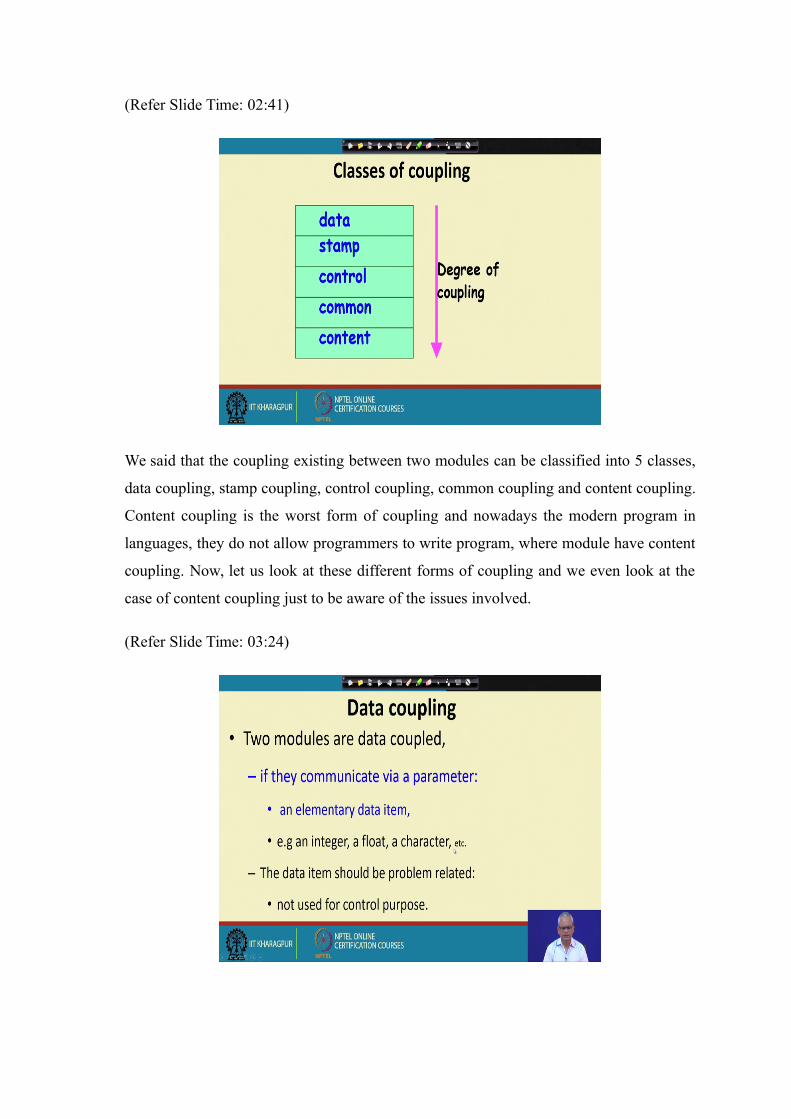
In data coupling two modules they interact, but then they exchange only very simple data
items. For example, just a integer, a two integers may be a floating point number may be
some character and so on. And of course, one thing we must be sure that these are used
like data members in the other module to which, it is invoked and this should not be used
to set a control parameter in the other module. In that case we call it as a data coupling.
(Refer Slide Time: 04:11)
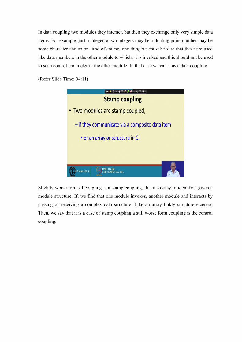
Slightly worse form of coupling is a stamp coupling, this also easy to identify a given a
module structure. If, we find that one module invokes, another module and interacts by
passing or receiving a complex data structure. Like an array linkly structure etcetera.
Then, we say that it is a case of stamp coupling a still worse form coupling is the control
coupling.

(Refer Slide Time: 04:44)
Here, the two modules pass data items between each other, but then the data item passed
by one module is used as a control element in another module. For example, it may they
send a integer which is used as a flag tested in another module. So, let us say we have
two modules here. And, let us say this module invokes a function let us say f 1 and f 1
pass passes a, let us say integer i and here this integer i is let us say switch on integer i;
one of the functions switches an integer i and depending on the integer value i it does
different things.
So, the value that is passed here is used as a control element in the other module. And,
this also a bad case of coupling, it makes understanding the design very difficult and we
call this a case of control coupling.

(Refer Slide Time: 06:19)
Another bad form of coupling is the common coupling. Here two modules are coupled,
but they are coupled through some global data. Normally, if we have a module here and
another module here; they have their own data and the different functions here, they use
this data here the data that is defined in the module.
And, this module, let us say this module is M 1 and this module is M 2 and this module
has some data that is visible within the module and there are functions let us say, f 5 f 6
and so on. Now, they use this data, but sometimes we can have some global data here.
And, this different functions they access the global data and communicate among by
using the global data and this is bad case of coupling.
Where, we have the modules communicating with the help of some global data. And, this
we call as the common coupling and it is a bad case of coupling, then we say that the
modules are highly coupled; if there is a common coupling.

(Refer Slide Time: 07:53)
And, the worst form of coupling is the content coupling and modern programming
languages, this allow this kind of coupling you cannot even write a code using modern
programming languages, where they do have content coupling. But earlier in machine
language and assembly language program in old computers, because possible to have
two modules.
The share code that is we have one module here and another module here M 1 and M 2
and it is possible for M 1 to execute some piece of code here come back here. So, just
because do not want to write this much code here, we just had a jump here to this module
and use this code here. And, then again jump back.
So, this a very bad form of coupling, it makes understanding this module extremely
difficult. And, it is a bad programming this allowed in the modern languages, you cannot
just jump into another module executes some parts here. Let us say we have a function
here f 1 and you jump into the middle of this function and run few statements here come
back here.
So, that form of thing is not permissible. Either you call the full function or do not use
anything here. You can just jump into one module run part of the function and come
back. So, this is the case of a content coupling and largely this allowed in modern
programming languages.

(Refer Slide Time: 09:46)
Now, let us look at other aspects of a good design; one is the hierarchal design. Here, if
we look at how the modules call each other and represent that that we call as the control
hierarchy. So, we say that this module, it calls these two modules and these two modules
in turn they call other modules. And, this we call as the control hierarchy and this is also
called as the program structure and typically represented by a structure chart.
We look at the structure chart in next couple of lectures. And, this program structure is a
tree like structure and it is hierarchical and this is have a good design is organized. So,
we say that a good design as a hierarchical module structure and it has a well-defined
control hierarchy.

(Refer Slide Time: 11:05)
But, then given a control structure, how do we say that whether the control structure is
good or bad? For that we need to define two terms fan out abstraction fan in and so on. A
good design should have low fan out it should have abstraction let us see, what we mean
by that?
(Refer Slide Time: 11:33)
Let us say this is a control structure of a application this is the module structure, how
they call each other? And, depth is a easily defined term that how many to into how
many layers they are organized or levels of controlled?

And, then width this is the span here. And, the fan out of every module is a how many
other modules it calls? For example, M 1 the module M 1 the fan out is 2 here. For
module M 2 the fan out is 3 here, for module M 3 the it is 0. So, the term fan out says
how many other module it invokes in a hierarchical structure?
(Refer Slide Time: 12:39)
Now, what about fan in? Fan in is how many different modules call this module? For
example, here the fan in of every module is 1, but let us say we also had M 3 calling this.
Then the fan in of module M 6 will be 2. Now, one thing to remember is that a very high
a fan out let us say this is 3, we can have a case where there is let us say 5 or 7. So, sorry
if M 2 calls let us say several modules, then we say that 1 2 3 4 5 6.
So, the fan out of module M 2 is 6. A high a fan out is bad because M 2 is depending on
too many other modules. And, it is a hint or it is likely that M 2 has a very bad cohesion.
It just doing too many things and that is why it is, needing many modules. A high a fan
out is bad, but a high fan in is a good thing, because there are many modules which are
depending on M 5 let us say there are other modules also, which are depending on M 5.
So, a high fan in is good because it means that we are able to achieve re used of code and
that is a good design. High a fan out is bad, but a high fan in is good.

(Refer Slide Time: 14:35)
This is an example where the fan out of this M 1 is 2 for this M 3 fan out is 1 and fan in
is also 1 for M 6 fan out is 0 and fan in is 2.
(Refer Slide Time: 14:53)
A good design, good design structure we can compute the fan in and fan out and if we
have a very fan out for some modules, we will say that it indicates that the design lacks
cohesion. But, if there is high a fan in then there is not bad it is actually good design. If
there is a high fan in and good re use can be observed in that application.

(Refer Slide Time: 15:31)
A large fan out as you are mentioning is that it is a indication, that a module having a
very large fan out is doing very different things it is cohesion will be poor. Because, it is
needing too many other functions it is invoking them different modules.
(Refer Slide Time: 15:54)
There are few other terminology with respect to the control relationship. We say that M 1
is superordinate of M 2 and M 3 or we can say that M 1 controls M 2 and M 3. In other
words we can say that M 2 and M 2 are subordinate of M 1 and M 4 M 5 and M 6 are
subordinate of M 2.

(Refer Slide Time: 16:26)
M 1 calls M 2 and M 3 and therefore, M 2 and M 3 are visible to M 1, but M 1 is not
visible to M 2 and M 3 M 2 the visibility is M 4 M 5 M 6. So, we say that the
superordinate modules, they are actually abstractions of M 2 M 3, they are not visible
here. M 1 is the most abstract module and M 4 is the most concrete module and this is a
layered structure, first of all to have a good design we must have a layered structure. That
is the control hierarchy, we should be able to organize into distinct layers and then we
can identify the fan on fan in fan out and so on.
(Refer Slide Time: 17:38)

This is the bad case of the design first of all there is no layering and also it is not a simple
trim, like structure and it violet us the principle of abstraction. For example, M 5 is the
most concrete module M 4 M 5 M 6. And, they should not be able to see that a higher
level modules M 1 etcetera it should not be visible here, but see here M 5 is invoking M
1 say M 1 is visible to M one M 5. So, this will be a very bad case of design where it will
be very difficult to debug, because just see here there is the cyclical relation here given a
bug. We can just go round and round and still not be able to trust the bug.
But, if it was a strict tree like structure with layering, if we observe a bug here then that
is either here or with it is subordinate modules. So, understandability de bugging re use
etcetera are facilitated by a layered design. And, if we have a design like this which
violates the principle of abstraction and layering it is a case of bad design.
(Refer Slide Time: 19:16)
In a good design the modules are layered and the top level modules here, the abstract
modules. They do more managerial function they just invoke the lower level modules to
do some work. And, they in turn invoke these are the middle managers, they invoke other
modules and the lowest level modules, they do input output. So, the input output that are
they do some processing here.
(Refer Slide Time: 20:01)
So, M 1 calls M 2 M 3 and these do some processing get data from M 4 M 5 M 6 and do
some processing and pass it onto a M 1 and so on. In a good layered design a lower
layered design should not be able to invoke an upper level design and that is invisible,
that should be invisible to the lower level modules.
(Refer Slide Time: 20:23)
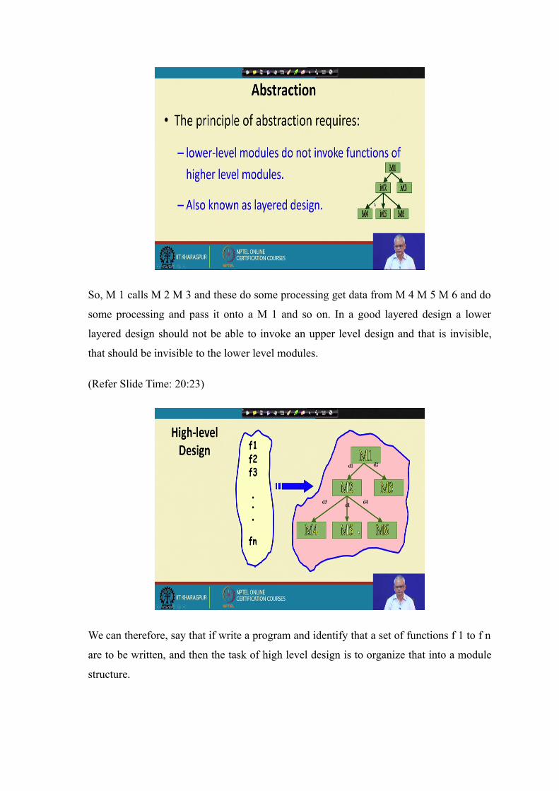
We can therefore, say that if write a program and identify that a set of functions f 1 to f n
are to be written, and then the task of high level design is to organize that into a module
structure.

We should be able to assign these functions to different module such that each module
has high cohesion and there is low coupling among modules and also they are organized
in a tree like expression. And, this is the crux of the procedural design approach even the
object oriented design approach this principle is used. So, here observe that we identify
what are the functions in our applications to be written, and then these functions are
organized into different modules such that each module has high cohesion and low
coupling among modules. And also these are organized in a nice tree like expression.
We look at a methodology; I think within a next lecture next to next lecture where we
will do a procedural design; we will identify the functions here by using a data flow
diagram structured analysis principle. And, then by using a structure chart structure
design, we will be able to come up with this module structure and a tree like diagram.
(Refer Slide Time: 22:03)
Two design approaches are popular one is the function oriented design and other is the
object oriented design. Given that we know now by now that what are desirable of a
design? That is it should be functionally independent tree like structure layered and so
on. We look at two approaches the function oriented design and object oriented design, to
arrive at a good design structure, but before we look at the nitty gritty of these two
design techniques. Let us have some very over all understanding of what is involved in
functionally oriented design and object oriented design.

(Refer Slide Time: 22:50)
These two design techniques even though popularly they are believed that they are
computing approaches, but not really as we proceed we will see that they are
complimentary approaches, because object oriented design also uses the principles of
procedural design. So, it is not that the object oriented design technique has made
procedural design redundant no sorry, the procedural design techniques are also used as
part of the object oriented design, we will examine those results.
(Refer Slide Time: 23:29)

First let us looks at the function oriented design. Here, by looking at the description of
the problem we will identify the set of functions with these needs to perform. Once you
identify the set of functions, then we will map this into a module structure. Identifying
the set of functions to be performed is called as the structure analysis. And, then this set
of functions will identify into will map it into a module structure. And, that module
structure will arriving at the module structure we will call it as a structural design. We
will also call it as the top down principle, because initially we consider the system as
performing a various small set of grass functions are very large granularity functions.
And, then we will split this into small functions will successively define into more
detailed functions or smaller functions. And, then there will be a large number of
functions and each of those we will map into the module structure. And, that is the
reason why it is called as a top down decomposition principle? As, we will study this
functions oriented design techniques in more detail to it will become clear why it is
called a top down decomposition? Once, we achieve the top down decomposition we
map the function structure into a module structure.
(Refer Slide Time: 25:20)
Just to give an example of a top down decomposition, let say in a library software we
have a function named as create new library member. Now, we can see that the, create
new library member requires some activities to be performed. For example, we need to

first create a record for the new member. We will have to assign a membership number
and also we will have to print a bill towards the membership.
So, we can consider that the function create new library member to be consisting of
smaller functions or sub functions, that is create record assign a unique membership id
and then print bill. Similarly, for every function we can study that what are the activities
to be performed under that? And, we can split that into simpler set of functions. And, we
can do that recursively in since that we can again look at the sub functions and find if
this can be split into still simpler functions.
(Refer Slide Time: 26:40)
And, that is one of the important principle of function oriented design; that we looked at
what are the functions that the system performs and then split those into simpler
functions. And, the other thing that to notice about function oriented design is that all this
functions, they operated some centralized data structure. For example, in a library system
all the functions may be needing to operated the set of books or the set of member
records and so on.
So, these are two distinguish characteristic of a function oriented design. That we need to
identify the functions that the systems performs break those function into simpler
functions and also identify the data that are centralized and all these functions operated
on that. We will take one example and see how do we go about doing the function
oriented design. And of course, later we will look at this technique in more detail we will

look at the data flow diagram in technique to do the structured analysis. And, then we
take the structure chart and see how to do the structure design we will stop here and
continue from this point in the next lecture.
Thank you.