
Lecture Slides
16
1 Chapter 8 Screws, Fasteners, and the Design of Nonpermanent Joints Lecture Slides The McGraw-Hill Companies © 2012 2 Tensile Stress Area • The tensile stress area, A t , is the area of an unthreaded rod with the same tensile strength as a threaded rod. • It is the effective area of a threaded rod to be used for stress calculations. • The diameter of this unthreaded rod is the average of the pitch diameter and the minor diameter of the threaded rod. Shigley’s Mechanical Engineering Design
-
Upload
khangminh22 -
Category
Documents
-
view
5 -
download
0
Transcript of Lecture Slides

1
Chapter 8
Screws, Fasteners,
and the Design of
Nonpermanent Joints
Lecture Slides
The McGraw-Hill Companies © 2012
2
Tensile Stress Area
• The tensile stress area, At , is the area of an unthreaded rod
with the same tensile strength as a threaded rod.
• It is the effective area of a threaded rod to be used for stress
calculations.
• The diameter of this unthreaded rod is the average of the
pitch diameter and the minor diameter of the threaded rod.
Shigley’s Mechanical Engineering Design

3
Tension Loaded Bolted Joints
� During bolt preload
◦ bolt is stretched
◦ members in grip are compressed
� When external load P is applied
◦ Bolt stretches an additional
amount d
◦ Members in grip uncompress same
amount d
Shigley’s Mechanical Engineering Design
Fig. 8–13
4
Stiffness Constant
� Since P = Pb + Pm,
� C is defined as the stiffness constant of the joint
� C indicates the proportion of external load P that the bolt will
carry. A good design target is around 0.2.
Shigley’s Mechanical Engineering Design

5
Bolt and Member Loads
� The resultant bolt load is
� The resultant load on the members is
� These results are only valid if the load on the members remains
negative, indicating the members stay in compression.
Shigley’s Mechanical Engineering Design
Axial Stress:
6
Relating Bolt Torque to Bolt Tension
� The relation between applied torque and bolt preload
� T is measured using a torque wrench
� Some recommended values for K for various bolt finishes is
given in Table 8–15
� Use K = 0.2 for other cases
Shigley’s Mechanical Engineering Design

7
Example 8-3
Shigley’s Mechanical Engineering Design
8
Example 8-3
Table 8–2

9
Example 8-3
10
Tension Loaded Bolted Joints: Static Factors of Safety
Shigley’s Mechanical Engineering Design
Axial Stress:
Yielding Factor of Safety:
Number of bolts required:
Recommended preload:
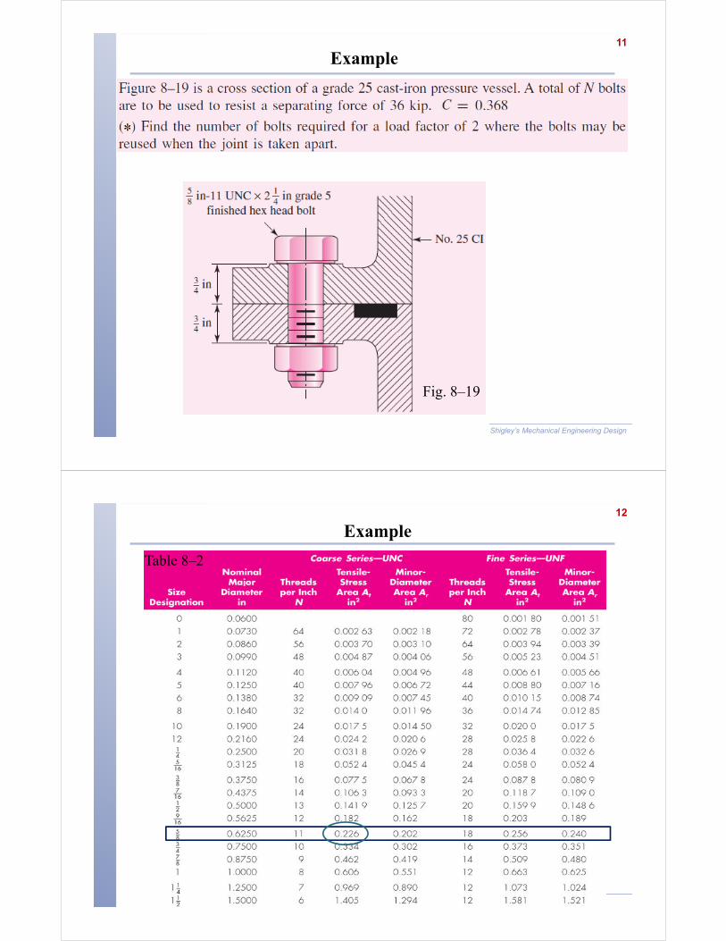
11
Example
Shigley’s Mechanical Engineering Design
Fig. 8–19
12
Example
Table 8–2

13
Example
Shigley’s Mechanical Engineering Design
Table 8–9
14
Continued..
Shigley’s Mechanical Engineering Design

15
Fatigue Loading of Tension Joints
� Fatigue methods of Ch. 6 are directly applicable
� With an external load on a per bolt basis fluctuating between
Pmin and Pmax, the mean and alternating stresses can be calculated
from
Shigley’s Mechanical Engineering Design
16
Endurance Strength for Bolts
� Bolts are standardized, so endurance strengths are known by
experimentation, including all modifiers. See Table 8–17.
� Fatigue stress-concentration factor Kf is also included as a
reducer of the endurance strength, so it should not be applied to
the bolt stresses.
Shigley’s Mechanical Engineering Design

17
Fatigue Factor of Safety
� Fatigue factor of safety based on Goodman line and constant
preload load line:
Shigley’s Mechanical Engineering Design
18
Example*
Shigley’s Mechanical Engineering Design
Fig. 8–19
Find the fatigue
Safety factor for
Fluctuating force of
Fmin=0
Fmax=20 kip

19
Continued..
Shigley’s Mechanical Engineering Design
20
Bolted and Riveted Joints Loaded in Shear
� Several failure modes are considered
(a) Bearing in the bolts
(b) Bearing in members
(c) Shear in bolts
(d) Tensile yielding of the members across the bolt holes
Shigley’s Mechanical Engineering Design

21
Failure by Bearing Stress
� Failure by crushing known as bearing stress
� Bolt or member with lowest strength will crush first
� Customary to assume uniform distribution over projected
contact area, A = td
� t is the thickness of the thinnest plate and d is the bolt diameter
Shigley’s Mechanical Engineering Design
22
Failure by Shear of Bolt
� Simple direct shear
� Use the total cross sectional area of bolts that carry the load.
Shigley’s Mechanical Engineering Design

23
Failure by Tensile Rupture of Member
� Simple tensile failure
� Use the smallest net area of the member, with holes removed
Shigley’s Mechanical Engineering Design
24
Example 8-6
Shigley’s Mechanical Engineering Design
Fig. 8–24

25
Continued..
Shigley’s Mechanical Engineering Design
26
Continued..
Shigley’s Mechanical Engineering Design
27
Shear Joints with Eccentric Loading
� Eccentric loading is when the load does not pass along a line of
symmetry of the fasteners.
� Requires finding moment about centroid of bolt pattern
� Centroid location
Shigley’s Mechanical Engineering Design
Fig. 8–27a
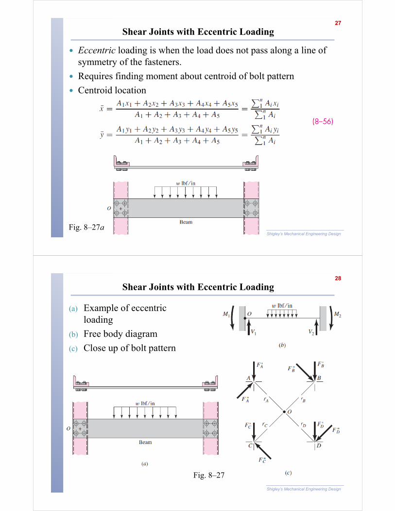
28
Shear Joints with Eccentric Loading
Shigley’s Mechanical Engineering Design
(a) Example of eccentric
loading
(b) Free body diagram
(c) Close up of bolt pattern
Fig. 8–27

29
Shear Joints with Eccentric Loading
Shigley’s Mechanical Engineering Design
� Direct Shear (Primary Shear)
� Primary shear is divided equally among
the bolts.
� Moment (Secondary Shear)
� Secondary shear is not divided equally.
The force taken by each bolt depends
upon its radial distance from the centroid.
� Moment is equal to
� Combining the above two equations
30
Example 8-7
Shigley’s Mechanical Engineering Design
� Compute the shear stresses in each bolt for the loading shown.
Bolt diameters are 16 mm each.

31
Continued..
Shigley’s Mechanical Engineering Design
32
Continued..
Shigley’s Mechanical Engineering Design