A domain decomposition method for the simulation of fracture in polysilicon MEMS
10
A domain decomposition method for the simulation of fracture in polysilicon MEMS Federica Confalonieri, Giuseppe Cocchetti, Aldo Ghisi, Alberto Corigliano ⇑ Dipartimento di Ingegneria Strutturale, Politecnico di Milano, Piazza Leonardo da Vinci 32, 20133 Milano, Italy article info Article history: Received 14 September 2012 Received in revised form 4 February 2013 Accepted 23 February 2013 Available online 3 May 2013 abstract To overcome the computational burden associated to the three-dimensional finite element simulation of fracture phenomena in polysilicon MEMS during dynamic loading, like e.g. impacts, a domain decompo- sition technique is used. The approach extends a method developed for linear elastic materials, by includ- ing cohesive crack propagation and it allows for the simulation of inter and trans-granular fracture initiation and propagation in polycrystals and it is a step forward in the construction of a complete sim- ulation tool for the description of fracture phenomena in microsystems. Applications to critical MEMS details show encouraging results in reproducing local failure mechanisms. Ó 2013 Elsevier Ltd. All rights reserved. 1. Introduction The study of failure phenomena of MEMS sensors under dy- namic conditions (i.e. drop [1–5]) is a typical multiscale problem; for example, three scales can be identified, ranging from those of the whole device (macroscale) to the microsystem (mesoscale) and critical structural parts composing the MEMS (microscale). A simplified decoupled top-down approach can be envisaged to sim- ulate the mechanical response of polysilicon [6–8]. However, the numerical simulation of crack propagation in polycrystalline silicon (polysilicon) microsystems at the microscale can question the hypothesis of material homogeneity when the dimensions of the silicon grain become comparable with those of critical components, like, e.g., suspension springs in inertial accel- erometer [8–11]. It is worthwhile to emphasize that, because of the industrial drive to shrinking the electronic devices, this issue will appear more frequently in the future. It is, in fact, well known that, as every brittle material, polysilicon is susceptible to defects, as more as they are placed in critical regions inside the microsystem, so that the fatigue lifetime or the resistance to shock loads is of concern, both of which phenomena involve cracks and their prop- agation. While several approaches can be followed to avoid the full resolution of this not trivial mechanical problem from the de- signer’s perspective [12,13], when we aim to comprehend the ef- fects of fracture at this scale, it is natural to adopt a continuum mechanics approach and fulfil a numerical discretization with fi- nite elements combined with a cohesive description of the crack through a zero-thickness interface elements. However, to correctly represent the problem it is often necessary to recur to models of several millions of degrees of freedom (dofs), even if the focus is only towards critical components where several hundreds of grains (assuming a grain size on the order of 0.5 1 lm for polysilicon) have to be considered; therefore, the computational cost becomes prohibitive [7]. As a consequence, we need numerical methods able to deal with large systems, i.e. with efficient sparse solvers, parallel com- puting, and large matrix storage. As far as this issue is concerned, one of the most developed ideas in the computational world in the past years has been the domain decomposition, i.e., to simplify, the possibility to exploit a subdivision of the model in order to solve more manageable problems and afterwards to reconstruct the whole solution. It is not the objective of this paper to describe the numerous different approaches, but the interested reader can refer to [14,15] for a review. Here, we adopt a domain decomposition approach both in space and time, as described in Section 2, defined by a ‘‘divide et impera’’ strategy, allowing also for crack propagation inside each domain. Then, in Section 3, we show the advantages of this approach by addressing the nonlinear dynamic response of polysilicon MEMS components subject to impacts and possible failure by crack initi- ation and propagation. We focus on critical details in microsystems (mostly polysilicon inertial accelerometers) of the order of tens or hundreds of micrometers, where the material is modeled as an assembly of silicon grains, and we allow for inter-granular and trans-granular fracture [8–11]. The conclusions of this work and the perspectives for future developments are detailed in Section 4. Concerning the notation, throughout the paper uppercase bold letters denote matrices, while lowercase bold letters denote col- umn vectors; T stands for transpose. 2. Outline of the proposed algorithm The proposed approach develops from the work already pre- sented in [6–11], based on a finite element analysis of the nonlinear 0026-2714/$ - see front matter Ó 2013 Elsevier Ltd. All rights reserved. http://dx.doi.org/10.1016/j.microrel.2013.02.021 ⇑ Corresponding author. Tel.: +39 02 23994274; fax: +39 02 23994220. E-mail addresses: [email protected] (F. Confalonieri), cocchett@ stru.polimi.it (G. Cocchetti), [email protected] (A. Ghisi), alberto.corigliano@ polimi.it (A. Corigliano). Microelectronics Reliability 53 (2013) 1045–1054 Contents lists available at SciVerse ScienceDirect Microelectronics Reliability journal homepage: www.elsevier.com/locate/microrel
Transcript of A domain decomposition method for the simulation of fracture in polysilicon MEMS
Microelectronics Reliability 53 (2013) 1045–1054
Contents lists available at SciVerse ScienceDirect
Microelectronics Reliability
journal homepage: www.elsevier .com/locate /microrel
A domain decomposition method for the simulation of fracture in polysilicon MEMS
Federica Confalonieri, Giuseppe Cocchetti, Aldo Ghisi, Alberto Corigliano ⇑Dipartimento di Ingegneria Strutturale, Politecnico di Milano, Piazza Leonardo da Vinci 32, 20133 Milano, Italy
a r t i c l e i n f o
Article history:Received 14 September 2012Received in revised form 4 February 2013Accepted 23 February 2013Available online 3 May 2013
0026-2714/$ - see front matter � 2013 Elsevier Ltd. Ahttp://dx.doi.org/10.1016/j.microrel.2013.02.021
⇑ Corresponding author. Tel.: +39 02 23994274; faxE-mail addresses: [email protected] (
stru.polimi.it (G. Cocchetti), [email protected] (Apolimi.it (A. Corigliano).
a b s t r a c t
To overcome the computational burden associated to the three-dimensional finite element simulation offracture phenomena in polysilicon MEMS during dynamic loading, like e.g. impacts, a domain decompo-sition technique is used. The approach extends a method developed for linear elastic materials, by includ-ing cohesive crack propagation and it allows for the simulation of inter and trans-granular fractureinitiation and propagation in polycrystals and it is a step forward in the construction of a complete sim-ulation tool for the description of fracture phenomena in microsystems. Applications to critical MEMSdetails show encouraging results in reproducing local failure mechanisms.
� 2013 Elsevier Ltd. All rights reserved.
1. Introduction only towards critical components where several hundreds of grains
The study of failure phenomena of MEMS sensors under dy-namic conditions (i.e. drop [1–5]) is a typical multiscale problem;for example, three scales can be identified, ranging from those ofthe whole device (macroscale) to the microsystem (mesoscale)and critical structural parts composing the MEMS (microscale). Asimplified decoupled top-down approach can be envisaged to sim-ulate the mechanical response of polysilicon [6–8].
However, the numerical simulation of crack propagation inpolycrystalline silicon (polysilicon) microsystems at the microscalecan question the hypothesis of material homogeneity when thedimensions of the silicon grain become comparable with those ofcritical components, like, e.g., suspension springs in inertial accel-erometer [8–11]. It is worthwhile to emphasize that, because of theindustrial drive to shrinking the electronic devices, this issue willappear more frequently in the future. It is, in fact, well known that,as every brittle material, polysilicon is susceptible to defects, asmore as they are placed in critical regions inside the microsystem,so that the fatigue lifetime or the resistance to shock loads is ofconcern, both of which phenomena involve cracks and their prop-agation. While several approaches can be followed to avoid the fullresolution of this not trivial mechanical problem from the de-signer’s perspective [12,13], when we aim to comprehend the ef-fects of fracture at this scale, it is natural to adopt a continuummechanics approach and fulfil a numerical discretization with fi-nite elements combined with a cohesive description of the crackthrough a zero-thickness interface elements. However, to correctlyrepresent the problem it is often necessary to recur to models ofseveral millions of degrees of freedom (dofs), even if the focus is
ll rights reserved.
: +39 02 23994220.F. Confalonieri), cocchett@. Ghisi), alberto.corigliano@
(assuming a grain size on the order of 0.5 � 1 lm for polysilicon)have to be considered; therefore, the computational cost becomesprohibitive [7].
As a consequence, we need numerical methods able to dealwith large systems, i.e. with efficient sparse solvers, parallel com-puting, and large matrix storage. As far as this issue is concerned,one of the most developed ideas in the computational world inthe past years has been the domain decomposition, i.e., to simplify,the possibility to exploit a subdivision of the model in order tosolve more manageable problems and afterwards to reconstructthe whole solution. It is not the objective of this paper to describethe numerous different approaches, but the interested reader canrefer to [14,15] for a review.
Here, we adopt a domain decomposition approach both in spaceand time, as described in Section 2, defined by a ‘‘divide et impera’’strategy, allowing also for crack propagation inside each domain.Then, in Section 3, we show the advantages of this approach byaddressing the nonlinear dynamic response of polysilicon MEMScomponents subject to impacts and possible failure by crack initi-ation and propagation. We focus on critical details in microsystems(mostly polysilicon inertial accelerometers) of the order of tens orhundreds of micrometers, where the material is modeled as anassembly of silicon grains, and we allow for inter-granular andtrans-granular fracture [8–11]. The conclusions of this work andthe perspectives for future developments are detailed in Section 4.
Concerning the notation, throughout the paper uppercase boldletters denote matrices, while lowercase bold letters denote col-umn vectors; T stands for transpose.
2. Outline of the proposed algorithm
The proposed approach develops from the work already pre-sented in [6–11], based on a finite element analysis of the nonlinear

Fig. 2. Partition in subdomains.
Fig. 3. Generic subdomain.
1046 F. Confalonieri et al. / Microelectronics Reliability 53 (2013) 1045–1054
dynamics response of polycrystalline solids. The numerical methodadopts an implicit-explicit time integration scheme for the solutionof semi-discretized equation of motion. Each grain of the artificialpolycrystal behaves elastically and cracks are allowed when a crit-ical value is deterministically reached at some integration point.The fracture is represented by cohesive interface elements, insertedon the fly during the calculation (see also [16,17]).
An artificial polycrystal is obtained through a Voronoi tessella-tion algorithm [7–10], then the domain X is partitioned in subdo-mains. Even if it is partially dependent on polysilicon mechanicalproperties, typically very refined meshes are required for a goodresolution of the fracture: namely, the mesh edge size must be afraction of the characteristics cohesive length, which is of the orderof 50 � 100 nm for this material. Since this requirement is com-bined with the Courant-Friedrichs-Levy stability condition limitingthe maximum time step allowed, the overall outcome is the highcomputational cost of this kind of analyses.
To overcome this drawback, starting from the approach pre-sented in Combescure and co-workers in [18,19], we adopt a do-main decomposition both in space and time. In space: we dividethe domain X in subdomains, exploiting for each one of them asensibly reduced (in terms of degrees-of-freedom) linear systemto be solved at each time step. In time: we switch from an implicitto an explicit time scheme after a crack arises inside a subdomainwhile, in the remainder of X, we update the implicit solution onlyat the original, larger time steps; the solution in time is, instead,interpolated in correspondence of the smallest explicit time steps.In the following, first the formulation for the linear elastic materialis recalled, then our extension to include fracture is discussed.
Let us therefore consider a continuum body X crossed by a dis-continuity surface C and subjected to a dynamic loading condition(see Fig. 1). The governing equations can thus be written as:Z
Xq€uTdudXþ
ZXrTðeðuÞÞdeðuÞdXþ
ZC
tTð½u�Þd½u�dC
¼Z
XbTdudXþ
Z@Xf
f TdudS 8du; du ¼ 0 on @Xu ð1Þ
where u and €u are the displacement and the acceleration vectorfields in X,r and e are the vectors containing the independent com-ponents of the stress and the strain tensors, b is the vector collect-ing the body forces acting in X and f the vector of the surfacetractions assigned on the boundary @ Xf, t and [u] represent respec-tively the displacement discontinuity and the traction vectors alongthe interface C. Introducing a finite element spatial discretization,the previous equation can be written in semi-discretized form as:
M€dðtÞ þ f intðdðtÞÞ þ f cohesð½d�ðtÞÞ ¼ f extðtÞ t 2 ½0; T� ð2Þ
being d and €d the nodal displacement and the nodal accelerationvectors, [d] the nodal displacement discontinuity vector along C,M the mass matrix, f int the internal force vector, f cohes the vectorequivalent to the tractions acting along the interface C and f ext
the external force vector.
Fig. 1. Elastic continuum subject to fracture.
Once a time discretization has been introduced, at the generictime step [tn, tn+1], Eq. (2) can be written as:
M€dnþ1 þ f intðdnþ1Þ þ f cohesð½d�nþ1Þ ¼ f extnþ1: ð3Þ
Fig. 4. (a) a virtual polysilicon generated by an artificial Voronoi tessellation,partitioned (b) in set of grains, and (c) with the automatic partition technique from[20].

explicit integration scheme
implicit integration scheme
explicit integration scheme
implicit integration scheme
explicit integration scheme
implicit integration scheme
(a)
(b)
(c)Fig. 5. Scheme of the domain decomposition approach: (a) crack completely insidea subdomain, (b) crack developing at the interface between subdomains, and (c)crack crossing through a subdomain boundary. For each one of the three cases thesubdomains switching to the explicit time integration scheme are evidenced.
Fig. 6. The multi-time step algorithm is enforced through (a) the interpolationbetween the asynchronous time integration schemes and (b) a step back whencrack inception first occurs in a subdomain.
F. Confalonieri et al. / Microelectronics Reliability 53 (2013) 1045–1054 1047
As usual for a non-overlapping domain decomposition approach,the algorithm proposed in [18] starts from the subdivision of thedomain in Ns subdomains (see Fig. 2).
For the sth subdomain (see Fig. 3) the governing equation is rep-resented by the following:
Ms€ds nþ1 þ K sds nþ1 ¼ f ext
nþ1 þ Csknþ1 s ¼ 1;Ns ð4Þ
where Cs is a Boolean connectivity matrix, which links the degreesof freedom of the whole subdomain to those belonging to the geo-metrical interface between subdomains, and for each subdomainthe appropriate mass matrix Ms and stiffness matrix Ks (assuming
linear elastic behavior for the silicon grain) are considered. Lagrangemultipliers are collected in kn+1, representing the interface forces,i.e. the forces exchanged by each subdomain with the surroundingones. The second term at the right hand side has to be introduced toaccount for the partition of the domain.
Ii is possible to interpret Eq. (4) as the superposition of an‘‘unconstrained’’ or ‘‘free problem’’ and of a ‘‘constrained’’ or ‘‘linkproblem’’ [18]. The first one corresponds to the free motion of eachunconnected subdomain, subjected only to the external loads,while the second one derives from the application of interfaceforces at the geometrical interface to restore continuity.
Unconstrained problem
Ms€dfree
s nþ1 þ K sdfrees nþ1 ¼ f ext
nþ1
ð5Þ
Constrained problem
Ms€dlink
s nþ1 þ K sdlinks nþ1 ¼ Csknþ1:
ð6Þ
The kinematical fields are given by the sum of the solutions of thetwo problems of Eqs. (5) and (6), respectively marked by thesuper-scripts ‘‘free’’ and ‘‘link’’.
ds nþ1 ¼ dfrees nþ1 þ dlink
s nþ1
_ds nþ1 ¼ _dfrees nþ1 þ _dlink
s nþ1
€ds nþ1 ¼ €dfrees nþ1 þ €dlink
s nþ1:
ð7Þ
A further condition, imposing the continuity of velocities at theinterface between subdomains, has to be added to Eqs. (5), (6). Thisleads to the formulation of an interface problem in the form:
Hknþ1 ¼ �X
s
Cs_dfree
s nþ1 ð8Þ
being H the so-called interface operator. The right hand side ofEq. (8) depends on the difference between the ‘‘free’’ velocitiesof subdomains. Introducing a time discretization by means ofthe Newmark scheme with parameters b and c, H results to begiven by:
H ¼X
s
csCs Ms þ bsDt2K s� ��1
CTs : ð9Þ

Fig. 7. Flowchart of the numerical procedure.
1048 F. Confalonieri et al. / Microelectronics Reliability 53 (2013) 1045–1054
Since we aim to simulate the heterogeneous response of polysiliconMEMS details, it could seem appropriate to choose sets of grains assubdomains in the domain decomposition. Actually, even if this is apossibility easily available with our implementation, we also ex-plored the automatic mesh decomposer proposed in [20]: it allows,in fact, for the optimization of the element partition with an eye ona further parallelization. Examples are shown in Fig. 4b for thegrain-based partition method and in Fig. 4c for the automatic gen-eration of subdomains, respectively. It is worthwhile to emphasizethat other partition methods can be adopted, here we limit ourattention to these two alternatives as an example.
In order to include fracture for polycrystalline materials(namely polysilicon) in the procedure introduced in [18], aftercrack inception in an elastic subdomain, because of the polysilicon
brittleness in a wide range of temperatures, we assume that thenon-linearity is concentrated along the fracture surfaces, whilethe bulk material remains linear elastic. Then, as already men-tioned, therein the time integration scheme switches to explicit,while the other uncracked subdomains remain implicit.
The cohesive model adopted for the crack propagation is basedon the discrete crack approach, by inserting on-the-fly during theanalysis zero-thickness interface elements, whereas an openingcriterion is satisfied. The fracture is forced to belong to the originalelement faces, an acceptable approximation if the mesh is refinedenough (even if this increases the computational cost). The inter-face constitutive model implemented in our code relies on a effec-tive traction t - effective displacement discontinuity [u] softeninglaw [21,22]:
u
u
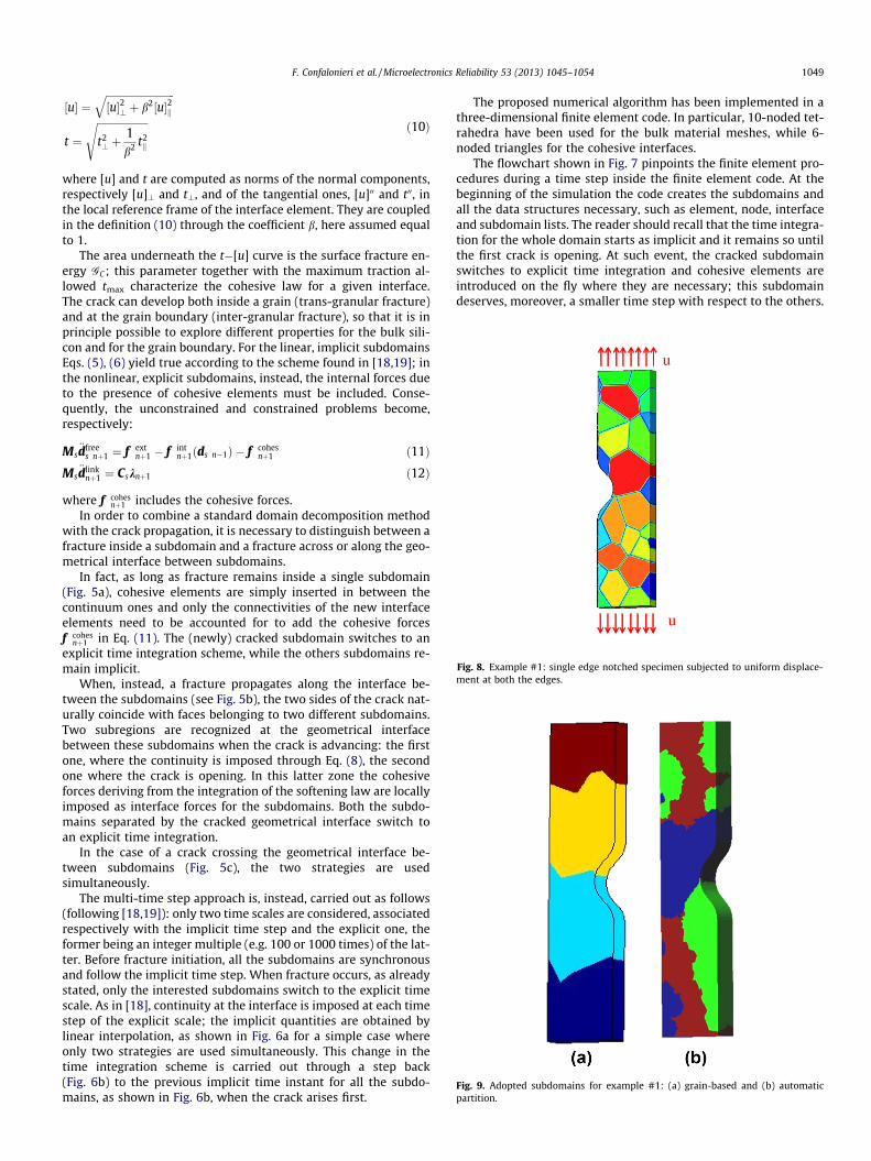
Fig. 8. Example #1: single edge notched specimen subjected to uniform displace-ment at both the edges.
Fig. 9. Adopted subdomains for example #1: (a) grain-based and (b) automaticpartition.
F. Confalonieri et al. / Microelectronics Reliability 53 (2013) 1045–1054 1049
½u� ¼ffiffiffiffiffiffiffiffiffiffiffiffiffiffiffiffiffiffiffiffiffiffiffiffiffiffiffi½u�2? þ b2½u�2k
q
t ¼ffiffiffiffiffiffiffiffiffiffiffiffiffiffiffiffiffiffiffiffit2? þ
1b2 t2
k
s ð10Þ
where [u] and t are computed as norms of the normal components,respectively [u]\ and t\, and of the tangential ones, [u]00 and t00, inthe local reference frame of the interface element. They are coupledin the definition (10) through the coefficient b, here assumed equalto 1.
The area underneath the t�[u] curve is the surface fracture en-ergy GC; this parameter together with the maximum traction al-lowed tmax characterize the cohesive law for a given interface.The crack can develop both inside a grain (trans-granular fracture)and at the grain boundary (inter-granular fracture), so that it is inprinciple possible to explore different properties for the bulk sili-con and for the grain boundary. For the linear, implicit subdomainsEqs. (5), (6) yield true according to the scheme found in [18,19]; inthe nonlinear, explicit subdomains, instead, the internal forces dueto the presence of cohesive elements must be included. Conse-quently, the unconstrained and constrained problems become,respectively:
Ms€dfree
s nþ1 ¼ f extnþ1 � f int
nþ1ðds n�1Þ � f cohesnþ1 ð11Þ
Ms€dlink
nþ1 ¼ Csknþ1 ð12Þ
where f cohesnþ1 includes the cohesive forces.
In order to combine a standard domain decomposition methodwith the crack propagation, it is necessary to distinguish between afracture inside a subdomain and a fracture across or along the geo-metrical interface between subdomains.
In fact, as long as fracture remains inside a single subdomain(Fig. 5a), cohesive elements are simply inserted in between thecontinuum ones and only the connectivities of the new interfaceelements need to be accounted for to add the cohesive forcesf cohes
nþ1 in Eq. (11). The (newly) cracked subdomain switches to anexplicit time integration scheme, while the others subdomains re-main implicit.
When, instead, a fracture propagates along the interface be-tween the subdomains (see Fig. 5b), the two sides of the crack nat-urally coincide with faces belonging to two different subdomains.Two subregions are recognized at the geometrical interfacebetween these subdomains when the crack is advancing: the firstone, where the continuity is imposed through Eq. (8), the secondone where the crack is opening. In this latter zone the cohesiveforces deriving from the integration of the softening law are locallyimposed as interface forces for the subdomains. Both the subdo-mains separated by the cracked geometrical interface switch toan explicit time integration.
In the case of a crack crossing the geometrical interface be-tween subdomains (Fig. 5c), the two strategies are usedsimultaneously.
The multi-time step approach is, instead, carried out as follows(following [18,19]): only two time scales are considered, associatedrespectively with the implicit time step and the explicit one, theformer being an integer multiple (e.g. 100 or 1000 times) of the lat-ter. Before fracture initiation, all the subdomains are synchronousand follow the implicit time step. When fracture occurs, as alreadystated, only the interested subdomains switch to the explicit timescale. As in [18], continuity at the interface is imposed at each timestep of the explicit scale; the implicit quantities are obtained bylinear interpolation, as shown in Fig. 6a for a simple case whereonly two strategies are used simultaneously. This change in thetime integration scheme is carried out through a step back(Fig. 6b) to the previous implicit time instant for all the subdo-mains, as shown in Fig. 6b, when the crack arises first.
The proposed numerical algorithm has been implemented in athree-dimensional finite element code. In particular, 10-noded tet-rahedra have been used for the bulk material meshes, while 6-noded triangles for the cohesive interfaces.
The flowchart shown in Fig. 7 pinpoints the finite element pro-cedures during a time step inside the finite element code. At thebeginning of the simulation the code creates the subdomains andall the data structures necessary, such as element, node, interfaceand subdomain lists. The reader should recall that the time integra-tion for the whole domain starts as implicit and it remains so untilthe first crack is opening. At such event, the cracked subdomainswitches to explicit time integration and cohesive elements areintroduced on the fly where they are necessary; this subdomaindeserves, moreover, a smaller time step with respect to the others.

Fig. 10. Crack pattern and contour plot of the stress along the applied displacement direction at two time instants. Stresses are expressed in GPa.
Fig. 11. Example #1: comparison between (a) monolithical and (b) domain decomposition model crack patterns and stresses along the applied displacement direction atcrack inception.
u
u
P
yP = 2.8 µm
Fig. 12. Example #1: comparison between monolithical and domain decomposition model displacement at point P.
Table 1Example #1: degrees of freedom for each subdomain for automatic partition.
Subdomain Elements Dofs
1 19,252 88,2272 19,252 92,9793 19,252 92,0764 19,252 92,796
Table 2Example #1: degrees of freedom for each subdomain for grain-based partition.
Subdomain Elements Dofs
1 14,359 63,0212 21,492 96,1003 22,171 98,9854 18,983 83,346
Table 3Example #1: comparison between the monolithical and the proposed algorithmoverall analysis time.
Partitiontechnique
Time(monolithical)
Time (d.d.) Computationalgain
Automatic 134 h 102 h �24%Grain-based 134 h 105 h �21%
1050 F. Confalonieri et al. / Microelectronics Reliability 53 (2013) 1045–1054
Here, during a generic time step, the free problem is first addressedand the displacement/velocities for the interior nodes are re-trieved; then, the interface problem is tackled and the H matrixis calculated. After that, it becomes possible to solve the link prob-lem and to obtain the displacement and velocities at the interfacenodes.
Once the first-attempt solution has been achieved, it is possibleto check whether the fracture propagates. The crack could advance

Fig. 13. Example #2: dog-bone specimen.
Fig. 14. Adopted subdomains for example #2: (a) grain-based and (b) automaticpartition.
Fig. 15. Crack patterns at times (a) t = 0.07 ls and (b) t = 0.10 ls.
Fig. 16. Example #2: comparison between (a) monolithical and (b) domaindecomposition model crack pattern.
F. Confalonieri et al. / Microelectronics Reliability 53 (2013) 1045–1054 1051
into one of the already fractured (explicit) subdomains (typically,the one where it was already propagated) or it could involve an un-cracked subdomain, where the time integration is implicit. In theformer case, there would be only an updating of the data structurefor the explicit subdomains, in order to describe the new fracturesurface through new cohesive elements, therefore the program in-creases the current time to the next step. In the latter case, instead,it is necessary to change the time integration algorithm for thesubdomains interested by the crack into an explicit time integra-tion, through a step back (see Fig. 6b), as well as to add the cohe-
sive elements inside. Even if it can appear unlikely, there is thepossibility of a crack propagating exactly along the interface be-tween subdomains: in this case both the subdomains sharing theinterface will switch to explicit time integration. It is also worth-while to emphasize that when a crack intersect an interface, be-sides adding the new cohesive elements, the treatment of theinterface nodes complicates and it gets entangled at the cornersbetween several domains: we only signal that these special casesrequire careful attention, but they are not discussed here.
3. Applications to the simulation of MEMS structures
In this Section we show the advantages of the domain decom-position formulation in the case of the dynamic simulation ofMEMS details subjected to impacts. We apply the approach tothree examples representing critical details of polysilicon MEMSfracturing because of an impact loading.
In the examples, only a single realization of the grain morphol-ogy has been considered: even if a statistical investigation of themechanical properties of polysilicon is necessary to afford a rigor-ous numerical simulation of the mechanical reliability of a realMEMS components, the aim here is only to show the potentiality ofthe proposed numerical technique. The extension to a probabilistic

Δd
(a)Fig. 17. Example #3: critical detail for a uniaxial MEMS accelerometer subject to drop.
Fig. 18. Example #3: countour plot of stresses (in GPa) along the slender beam axisfor the cracked detail at rupture.
1052 F. Confalonieri et al. / Microelectronics Reliability 53 (2013) 1045–1054
approach is straightforward and has been, for example, treated in aMonte Carlo framework in [11].
Each grain is modeled as transversely isotropic because of thetypical columnar structure of our polysilicon. In a local referencesystem with the axis x3 of transversal isotropy aligned with thegrowth direction, i.e. perpendicular to the substrate plane, and ran-dom orientation of the other two axes x1 and x2, the elastic stiffnessmatrix of the single crystal can be written as:
De ¼
s11 s12 s12 0 0 0s12 s11 s12 0 0 0s12 s12 s11 0 0 00 0 0 s44 0 00 0 0 0 s44 00 0 0 0 0 s44
2666666664
3777777775: ð13Þ
The values of the elastic constants are taken from [23]:s11 = 165.7 GPa, s12 = 63.9 GPa, and s44 = 79.6 GPa. Furthermore,the polysilicon mass density q = 2330 kg/m3 is assigned.
The first example considers the notched specimen of Fig. 8,elongated at both ends by a linear increasing displacement of100 nm in 10�3 ls. The specimen is 8 lm long, 1 lm wide and0.4 lm thick. The analysis domain has been meshed with 77,005tetrahedral elements and 112,930 nodes. The three subdomainsmesh partitions, shown in Fig. 9, have been considered, in the fig-ure each color represents a single domain.
Two partition methods, one based on the collection of silicongrains, and the other derived by the automatic partition algorithmfrom [20], have been explored.
The assumed cohesive interface law is characterized by an iso-tropic fracture energy GC ¼ 7:0 � 10�3 N/mm and a maximum ten-sile stress tmax = 3.75 GPa, both for the grain and for the grainboundaries [24,25].
The implicit time step has been taken equal 100 times the expli-cit one, i.e. 2 � 10�14s.
Fig. 10 shows the crack patterns at three subsequent time in-stants, superposed at the grain morphology, and the contour plotof the stress in the load direction. As expected, the crack starts topropagate at the notch and develops inside a grain.
A comparison between the contour plot of the stress in the loaddirection obtained respectively with the proposed domain decom-
F. Confalonieri et al. / Microelectronics Reliability 53 (2013) 1045–1054 1053
position algorithm and with a standard monolithic finite elementapproach is proposed in Fig. 11. The instant of crack initiationhas been considered. The same kind of comparison is repeated interms of a displacement - time plot for a point P and it is depictedin Fig. 12.
Tables 1 and 2 show the number of elements and degrees offreedom per subdomain, obtained respectively with an automaticand with a grain-based partition of the body into four subdomains.
Table 3 gives the analysis times and the computational gain ob-tained with the two partition techniques. It is worth to underlinethat the proposed numerical procedure allows for a reduction ofthe 24% of the total analysis time with respect to a standard finiteelement simulation. This result can be further improved optimiz-ing the mesh partition and introducing a parallelization of thecode.
The second numerical example regards the dog-bone specimen,shown in Fig. 13, constrained at the bottom and elongated at theupper surface by a displacement linearly increasing up to 100 nmand applied in 0.1 ls. The specimen is 10 lm long, 1 lm wideand 0.2 lm thick. The analysis domain has been meshed with44,265 tetrahedral elements. The mesh has been subdivided intofour subdomains. Fig. 14 displays the mesh partition, where thefour subdomains are shown in different colors. Three subdomainsare formed by 11,067 elements, while the last one has 11,064 ele-ments. The implicit time step has been taken equal to 100 timesthe explicit one, i.e 2 � 10�14 s.
The same cohesive law used for the first example has been con-sidered. Differently than the previous example, a defect has beenintroduced, assigning a reduced strength, i.e. tmax = 1.50 GPa, tothe grains crossed by the middle section of the specimen. As ex-pected, fracture starts to propagate in the weak grains. The crackpattern at two subsequent time instants, respectively at 0.07 lsand at 0.10 ls, is reported in Fig. 15. In this second example, thegain in terms of analysis time reaches the 26%. As in the previouscase, the number of subdomains, here fixed a priori, should be cho-sen in order to optimize the efficiency of the computation, balanc-ing the reduction in the size of each subdomain and the dimensionof the geometrical interface between them.
The solution has been compared to that obtained with a mono-lithic finite element analysis. Fig. 16 shows the agreement betweenthe two crack patterns at the end of the analysis.
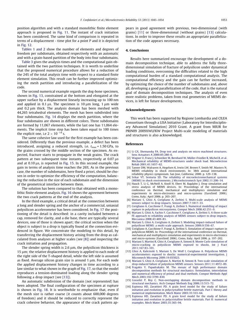
In the third example, a critical detail at the connection betweena long and slender spring and the anchor of a commercial, uniaxialpolysilicon accelerometer has been considered. In Fig. 17 the posi-tioning of the detail is described: in a cavity included between acap, removed for clarity, and a die base, there are typically severaldevices, one of those is shown apart; the critical section when theobject is subject to a drop is typically found at the connection evi-denced in figure. We concentrate the modeling to this detail, bytransferring the displacement history arising from the drop as cal-culated from analyses at higher scales (see [8]) and inspecting thecrack initiation and propagation.
The slender spring width is 2.6 lm, the polysilicon thickness is15 lm; the relative displacement history is applied to each node ofthe right side of the T-shaped detail, while the left side is assumedas fixed. Average silicon grain size is around 1 lm. For each nodethe applied displacement history changes in time according to alaw similar to what shown in the graph of Fig. 17, so that the modelreproduces a tension-dominated loading along the slender springfollowing a drop impact (see [13]).
An automatic subdivision of the domain (not represented) hasbeen adopted. The final configuration of the specimen at ruptureis shown in Fig. 18. It is worthwhile to emphasize that, even ifthe mesh size is rather coarse (it counts about 600,000 degreesof freedom) and it should be reduced to correctly represent thecrack cohesive behavior, the appearance of the crack pattern ap-
pears in good agreement with previous, two-dimensional (withgrains) [11] or three-dimensional (without grains) [13] calcula-tions. In order to improve these results an appropriate paralleliza-tion of the code appears necessary.
4. Conclusions
Results here summarized encourage the development of a do-main decomposition technique, able to address the fully three-dimensional simulation of fracture of polysilicon under dynamicalloading conditions, overcoming the difficulties related to the highcomputational burden of a standard computational analysis. Thecomputational efficiency and the gain can be further increased,by optimizing the choice of the number of subdomains and, aboveall, developing a good parallelization of the code, that is the naturalgoal of domain decomposition techniques. The analysis of evenmore realistic problems, taken from real geometries of MEMS de-vices, is left for future developments.
Acknowledgments
This work has been supported by Regione Lombardia and CILEAConsortium through a LISA Initiative (Laboratory for Interdisciplin-ary Advanced Simulation) 2010 Grant. A grant from MIUR forPRIN09 2009XWLFKW Project Multi-scale modeling of materialsand structures is also acknowledged.
References
[1] Li GX, Shemansky FA. Drop test and analysis on micro machined structures.Sens Actuators A 2000;85:280–6.
[2] Wagner U, Franz J, Schweiker M, Bernhard W, Müller-Friedler R, Michel B, et al.Mechanical reliability of MEMS-structures under shock load. MicroelectronReliab 2001;41:1657–62.
[3] Tanner DM, Walraven A, Hegelsen K, Irwin LW, Brown F, Smith NF, Masters N.MEMS reliability in shock environments. In: 38th annual internationalreliability physics symposium. San Jose, California; 2000. p. 129–138.
[4] Srikar VT, Senturia SD. The reliability of microelectromechanical systems(MEMS) in shock environments. J Microelectromech Syst 2002;11:206–14.
[5] Hauck T, Li G, McNeill A, Knoll H, Ebert M, Bagdahn J. Drop simulation andstress analysis of MEMS devices. In: Proceedings of the internationalconference on thermal, mechanical and multiphysics simulation andexperiments in micro-electronics and micro-systems (EuroSimE 2006).Como, Italy; April 2006. p. 203–207.
[6] Mariani S, Ghisi A, Corigliano A, Zerbini S. Multi-scale analysis of MEMSsensors subject to drop impacts. Sensors 2007;7:1817–33.
[7] Corigliano A, Cacchione F, Frangi A, Zerbini S. Numerical modelling of impactrupture in polysilicon microsystems. Comput Mech 2008;42:251–9.
[8] Mariani S, Ghisi A, Fachin F, Cacchione F, Corigliano A, Zerbini S. A three-scaleFE approach to reliability analysis of MEMS sensors subject to drop impacts.Meccanica 2008;43:469–83.
[9] Mariani S, Ghisi A, Corigliano A, Zerbini S. Modeling impact-induced failure ofpolysilicon MEMS: a multi-scale approach. Sensors 2009;9:556–67.
[10] Corigliano A, Cacchione F, Frangi A, Zerbini S. Simulation of impact rupture inpolysilicon MEMS. In: Proceedings of the international conference on thermal,mechanical and multiphysics simulation and experiments in micro-electronicsand micro-systems (EuroSimE 2006). Como, Italy; April 2006. p. 197–202.
[11] Mariani S, Martini R, Ghisi A, Corigliano A, Simoni B. Monte Carlo simulation ofmicro-cracking in polysilicon MEMS exposed to shocks. Int J Fract2011;167:83–101.
[12] Ghisi A, Kalicinski S, Mariani S, De Wolf I, Corigliano A. Polysilicon MEMSaccelerometers exposed to shocks: numerical-experimental investigation. JMicromech Microeng 2009;19:035023.
[13] Mariani S, Ghisi A, Corigliano A, Martini R, Simoni B. Two-scale simulation ofdrop-induced failure of polysilicon MEMS sensors. Sensors 2011;11:4972–89.
[14] Fragakis Y, Papadrakakis M. The mosaic of high performance domaindecomposition methods for structural mechanics: formulation, interrelationand numerical efficiency of primal and dual methods. Comput Methods ApplMech 2003;192:3799–830.
[15] Gosselet P, Rey C. Non-overlapping domain decomposition methods instructural mechanics. Arch Comput Methods Eng 2006;13:515–72.
[16] Espinosa HD, Zavattieri PD. A grain level model for the study of failureinitiation and evolution in polycrystalline brittle materials. Part I: theory andnumerical implementation. Mech Mater 2003;35:333–64.
[17] Espinosa HD, Zavattieri PD. A grain level model for the study of failureinitiation and evolution in polycristalline brittle materials. Part II: numericalexamples. Mech Mater 2003;35:365–94.

1054 F. Confalonieri et al. / Microelectronics Reliability 53 (2013) 1045–1054
[18] Gravouil A, Combescure A. Multi-time-step explicit-implicit method for non-linear structural dynamics. Int J Numer Methods Eng 2001;50(1):199–225.
[19] Mahjoubi N, Gravouil A, Combescure A. Coupling subdomains withheterogeneous time integrators and incompatible time steps. Comput Mech2009;44:825–43.
[20] Farhat C. A simple and efficient automatic FEM domain decomposer. ComputStruct 1988;28(5):579–602.
[21] Camacho GT, Ortiz M. Computational modelling of impact damage in brittlematerials. Int J Solids Struct 1996;33:2899–938.
[22] Ortiz M, Pandolfi A. Finite-deformation irreversible cohesive elements forthree-dimensional crack-propagation analysis. Int J Numer Methods Eng1999;44:1267–82.
[23] Brantley WA. Calculated elastic constants for stress problems associated withsemiconductor devices. J Appl Phys 1973;44:534–5.
[24] Jadaan OM, Nemeth NN, Bagdhan J, Sharpe WN. Probabilistic weibull behaviorand mechanical properties of MEMS brittle materials. J Mater Sci2003;38:4087–113.
[25] Cho SW, Jonnalagadda K, Chasiotis I. Mode I and mixed mode fracture ofpolysilicon for MEMS. Fatigue Fract Eng Mater Struct 2007;30(1):21–31.