A Computational Study of the Hemodynamic Impact of Open- Versus Closed-Cell Stent Design in Carotid...
11
A Computational Study of the Hemodynamic Impact of Open- Versus Closed-Cell Stent Design in Carotid Artery Stenting *†Gianluca De Santis, †Bram Trachet, †‡Michele Conti, *†Matthieu De Beule, §Umberto Morbiducci, *†Peter Mortier, †Patrick Segers, †Pascal Verdonck, and *†Benedict Verhegghe *R&D, FEops bvba; †bioMMeda-IBiTech, Ghent University, Ghent, Belgium; ‡Department of Structural Mechanics, Università degli Studi di Pavia, Pavia; and §Department of Mechanical and Aerospace Engineering, Politecnico di Torino, Turin, Italy Abstract: The aim of this study is to analyze the shape and flow changes of a patient-specific carotid artery after carotid artery stenting (CAS) performed using an open-cell (stent-O) or a closed-cell (stent-C) stent design. First, a stent reconstructed from micro-computed tomography (microCT) is virtually implanted in a left carotid artery reconstructed from CT angiography. Second, an objective analysis of the stent-to-vessel apposition is used to quantify the lumen cross-sectional area and the incomplete stent apposition (ISA). Third, the carotid artery lumen is virtu- ally perfused in order to quantify its resistance to flow and its exposure to atherogenic or thrombogenic hemodynamic conditions.After CAS, the minimum cross-sectional area of the internal carotid artery (ICA) (external carotid artery [ECA]) changes by +54% (-12%) with stent-O and +78% (-17%) with stent-C; the resistance to flow of the ICA (ECA) changes by -21% (+13%) with stent-O and -26% (+18%) with stent-C. Both stent designs suffer from ISA but the malapposed stent area is larger with stent-O than stent-C (29.5 vs. 14.8 mm 2 ). The untreated vessel is not exposed to atherogenic flow conditions whereas an area of 67.6 mm 2 (104.9) occurs with stent-O (stent-C). The area of the stent surface exposed to thrombogenic risk is 5.42 mm 2 (7.7) with stent-O (stent-C). The computer simulations of stenting in a patient’s carotid artery reveal a trade-off between cross-sectional size and flow resistance of the ICA (enlarged and circularized) and the ECA (narrowed and ovalized). Such a trade-off, together with malapposition, atherogenic risk, and thrombogenic risk is stent-design dependent. Key Words: Carotid artery stenting— Stent—Open-cell design—Closed-cell design—Patient- specific simulation Hemodynamics—Flow resistance. Together with the (systemic) antiplatelet or antico- agulant treatment of large artery atherosclerosis manifestations, a (local) surgical intervention is often required to treat a stenotic lesion and restore the flow of oxygenated blood to the downstream tissues. The choice for the (invasive) surgical intervention or the (minimally invasive) endovascular intervention strongly depends on the location of the disease. The endovascular procedure, stenting in particular, is the preferred treatment of cerebral artery stenoses and aneurysms (1,2) due to a limited surgical access, and coronary artery stenoses, only accessible via open- chest surgery (3). In case of carotid artery stenosis, carotid endarterectomy (i.e., the surgical inter- vention) remains the standard treatment, despite important risks of complications (e.g., surgical site infection, peri-procedural bleeding, injury to various nervous structures in the neck and jaw, injury to the thyroidal blood vessels, acute rupture of the carotid sutures and restenosis). A reason for the lower per- formance is the lack of standardization of the carotid doi:10.1111/aor.12046 Received July 2012; revised October 2012. Address correspondence and reprint requests to Dr. Gianluca De Santis, R&D, FEops bvba, Technologiepark 3, Ghent 9052, Belgium. E-mail: [email protected] © 2013, Copyright the Authors Artificial Organs © 2013, International Center for Artificial Organs and Transplantation and Wiley Periodicals, Inc. Artificial Organs 2013, ••(••):••–••
-
Upload
independent -
Category
Documents
-
view
0 -
download
0
Transcript of A Computational Study of the Hemodynamic Impact of Open- Versus Closed-Cell Stent Design in Carotid...
A Computational Study of the HemodynamicImpact of Open- Versus Closed-Cell Stent Design in Carotid
Artery Stenting
*†Gianluca De Santis, †Bram Trachet, †‡Michele Conti, *†Matthieu De Beule,§Umberto Morbiducci, *†Peter Mortier, †Patrick Segers, †Pascal Verdonck,
and *†Benedict Verhegghe
*R&D, FEops bvba; †bioMMeda-IBiTech, Ghent University, Ghent, Belgium; ‡Department of Structural Mechanics,Università degli Studi di Pavia, Pavia; and §Department of Mechanical and Aerospace Engineering, Politecnico di Torino,
Turin, Italy
Abstract: The aim of this study is to analyze the shape andflow changes of a patient-specific carotid artery aftercarotid artery stenting (CAS) performed using an open-cell(stent-O) or a closed-cell (stent-C) stent design. First, astent reconstructed from micro-computed tomography(microCT) is virtually implanted in a left carotid arteryreconstructed from CT angiography. Second, an objectiveanalysis of the stent-to-vessel apposition is used to quantifythe lumen cross-sectional area and the incomplete stentapposition (ISA). Third, the carotid artery lumen is virtu-ally perfused in order to quantify its resistance to flow andits exposure to atherogenic or thrombogenic hemodynamicconditions.After CAS, the minimum cross-sectional area ofthe internal carotid artery (ICA) (external carotid artery[ECA]) changes by +54% (-12%) with stent-O and +78%(-17%) with stent-C; the resistance to flow of the ICA
(ECA) changes by -21% (+13%) with stent-O and -26%(+18%) with stent-C. Both stent designs suffer from ISAbut the malapposed stent area is larger with stent-O thanstent-C (29.5 vs. 14.8 mm2). The untreated vessel is notexposed to atherogenic flow conditions whereas an area of67.6 mm2 (104.9) occurs with stent-O (stent-C). The area ofthe stent surface exposed to thrombogenic risk is 5.42 mm2
(7.7) with stent-O (stent-C). The computer simulations ofstenting in a patient’s carotid artery reveal a trade-offbetween cross-sectional size and flow resistance of the ICA(enlarged and circularized) and the ECA (narrowed andovalized). Such a trade-off, together with malapposition,atherogenic risk, and thrombogenic risk is stent-designdependent. Key Words: Carotid artery stenting—Stent—Open-cell design—Closed-cell design—Patient-specific simulation Hemodynamics—Flow resistance.
Together with the (systemic) antiplatelet or antico-agulant treatment of large artery atherosclerosismanifestations, a (local) surgical intervention is oftenrequired to treat a stenotic lesion and restore theflow of oxygenated blood to the downstream tissues.The choice for the (invasive) surgical intervention orthe (minimally invasive) endovascular intervention
strongly depends on the location of the disease. Theendovascular procedure, stenting in particular, is thepreferred treatment of cerebral artery stenoses andaneurysms (1,2) due to a limited surgical access, andcoronary artery stenoses, only accessible via open-chest surgery (3). In case of carotid artery stenosis,carotid endarterectomy (i.e., the surgical inter-vention) remains the standard treatment, despiteimportant risks of complications (e.g., surgical siteinfection, peri-procedural bleeding, injury to variousnervous structures in the neck and jaw, injury to thethyroidal blood vessels, acute rupture of the carotidsutures and restenosis). A reason for the lower per-formance is the lack of standardization of the carotid
doi:10.1111/aor.12046
Received July 2012; revised October 2012.Address correspondence and reprint requests to Dr. Gianluca
De Santis, R&D, FEops bvba, Technologiepark 3, Ghent 9052,Belgium. E-mail: [email protected]
bs_bs_banner
© 2013, Copyright the AuthorsArtificial Organs © 2013, International Center for Artificial Organs and Transplantation and Wiley Periodicals, Inc.
Artificial Organs 2013, ••(••):••–••
artery stenting (CAS) procedure, including clear indi-cations for the choice of the appropriate device totreat a particular lesion (4–9).
Dedicated modeling “tools” have been developedto judge the suitability of a combination of a givencarotid artery lesion and a stent model. Patient-specific prosthesis analysis applied to CAS has exten-sively proven its potential to forecast the effect ofstenting (e.g., the shape of the stent and vessel afterstenting, the stresses in the arterial wall) using finiteelement analysis (FEA) (10,11). In addition to thestructural simulation, computational fluid dynamics(CFD) can then be applied to predict the blood flowestablished after stenting (12).
In the present study, this complementary approachis combined with a patient-specific (image-based)vessel geometry in order to investigate the carotidartery hemodynamics that would establish afterimplanting two different stent models (an open- orclosed-cell design) in a carotid artery. As in mostclinical applications, where the atheroscleroticlesions are located at the entrance of the internalcarotid artery (ICA), the external carotid artery(ECA) is bridged, with the stent placed across thebifurcation, between the common carotid artery(CCA) and the ICA (13). The outcome of the virtualCAS is evaluated using different parameters describ-ing the (stented) vessel geometry (luminal cross-sectional area and stent strut malapposition) and flow(resistance to flow and near-wall hemodynamics).
METHODS
Image-based reconstruction and stentingA computer model of the left carotid artery of an
83-year-old man was constructed based on DigitalImaging and Communications in Medicine files ofcomputer tomography angioplasty images by using acommercial segmentation software (Mimics, Materia-lise, Leuven, Belgium). A mild stenosis correspond-ing to 24% of area reduction was located in the ICA.The arterial wall was not visible from the angio-graphic images and was reconstructed by assigning awall thickness equal to 30% of the local radius in thehealthy regions, and by proximal to distal surfaceinterpolation in the stenotic region (thicker wall).
Two laser-cut, self-expanding stents, one with anopen-cell design (stent-O, resembling the ACCU-LINK commercial model, Abbott, Santa Clara, CA,USA) and the other with a closed-cell design(stent-C, resembling the XACT commercial model,Abbott), were virtually deployed in the left carotidartery using the image-based FEA procedurereported in (10), recently validated against an experi-
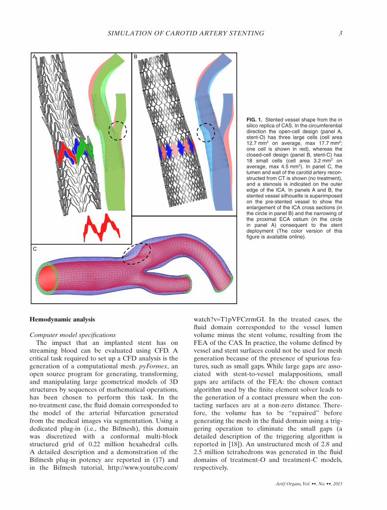
mental counterpart (11). The stent deployment simu-lation reproducing CAS both with stent-O andstent-C is summarized in the Supporting InformationAppendix S1. In this study, the (stented) vessel geom-etry, resulting from the structural analysis, is taken asstarting point (Fig. 1).
Geometrical analysis
Local vessel radius and lumen patencyIn the stented geometry, the CCA-ICA and CCA-
ECA centerlines were defined as centers of themaximal inscribed spheres and computed using thevascular modeling toolkit (VMTK), a collection oflibraries and tools for three-dimensional (3D) recon-struction, geometric analysis, mesh generation, andsurface data analysis for image-based cardiovascularhemodynamics modeling ([14], VMTK, http://www.vmtk.com). In detail, the high-level user interactionroutine vmtkcenterlines was used to detect the cen-terlines: by selecting one point on each inlet/outletboundary, the routine returns both the centerlines’points and, for each point, the radius of the largestinscribed sphere. This radius was taken as a continu-ous descriptor of the local vessel size. Because thisapproach is not particularly accurate in describingthe vessel patency in case of non-tubularity of thelumen, an additional measurement was performed,that is, the vessel surface was sliced and the cross-sectional area was measured into the pyFormex envi-ronment (http://www.pyformex.org). To standardizethe slicing operation in the three vessel geometries,slicing planes were positioned at 30, 50, and 70% ofthe CCA-ICA centerline and at 70, 80, and 90% ofthe CCA-ECA centerline, using the VMTK, as shownin Fig. 2 (left panel).
Stent-to-vessel appositionThe outer surface of the stent can potentially
contact the vessel wall and represents the potentialapposable area (PAA). However, when a stent isdeployed in a complex vessel domain, such as a bifur-cation, incomplete stent apposition (ISA) necessarilyoccurs because of the limited stent flexibility. Fromthe postimplantation geometry, the apposition of thestent struts onto the vessel wall was quantified as thelocal distance between the outer stent surface andthe vessel endothelium, as recently proposed byMortier et al. (16). Using a fifth of the strut thickness(0.048 mm) as a threshold value of the stent-to-vesseldistance to discriminate between apposition and mal-apposition, the ratio of malapposed area to PAA wascomputed to define the percentage of malapposedarea (PMA).
G. DE SANTIS ET AL.2
Artif Organs, Vol. ••, No. ••, 2013
Hemodynamic analysis
Computer model specificationsThe impact that an implanted stent has on
streaming blood can be evaluated using CFD. Acritical task required to set up a CFD analysis is thegeneration of a computational mesh. pyFormex, anopen source program for generating, transforming,and manipulating large geometrical models of 3Dstructures by sequences of mathematical operations,has been chosen to perform this task. In theno-treatment case, the fluid domain corresponded tothe model of the arterial bifurcation generatedfrom the medical images via segmentation. Using adedicated plug-in (i.e., the Bifmesh), this domainwas discretized with a conformal multi-blockstructured grid of 0.22 million hexahedral cells.A detailed description and a demonstration of theBifmesh plug-in potency are reported in (17) andin the Bifmesh tutorial, http://www.youtube.com/
watch?v=T1pVFCzrmGI. In the treated cases, thefluid domain corresponded to the vessel lumenvolume minus the stent volume, resulting from theFEA of the CAS. In practice, the volume defined byvessel and stent surfaces could not be used for meshgeneration because of the presence of spurious fea-tures, such as small gaps. While large gaps are asso-ciated with stent-to-vessel malappositions, smallgaps are artifacts of the FEA: the chosen contactalgorithm used by the finite element solver leads tothe generation of a contact pressure when the con-tacting surfaces are at a non-zero distance. There-fore, the volume has to be “repaired” beforegenerating the mesh in the fluid domain using a trig-gering operation to eliminate the small gaps (adetailed description of the triggering algorithm isreported in [18]). An unstructured mesh of 2.8 and2.5 million tetrahedrons was generated in the fluiddomains of treatment-O and treatment-C models,respectively.
FIG. 1. Stented vessel shape from the insilico replica of CAS. In the circumferentialdirection the open-cell design (panel A,stent-O) has three large cells (cell area12.7 mm2 on average, max 17.7 mm2;one cell is shown in red), whereas theclosed-cell design (panel B, stent-C) has18 small cells (cell area 3.2 mm2 onaverage, max 4.5 mm2). In panel C, thelumen and wall of the carotid artery recon-structed from CT is shown (no treatment),and a stenosis is indicated on the outeredge of the ICA. In panels A and B, thestented vessel silhouette is superimposedon the pre-stented vessel to show theenlargement of the ICA cross sections (inthe circle in panel B) and the narrowing ofthe proximal ECA ostium (in the circlein panel A) consequent to the stentdeployment (The color version of thisfigure is available online).
SIMULATION OF CAROTID ARTERY STENTING 3
Artif Organs, Vol. ••, No. ••, 2013
The CFD simulations were performed using thefinite volume general purpose commercial softwareFluent (Ansys, Canonsburg, PA, USA), setting theSIMPLE scheme, second order upwind and leastsquare cell-based discretization for the momentumand the pressure equation, respectively. A no-slipcondition was applied to the boundary wall andblood was treated as Newtonian fluid (density1050 kg/m3 and viscosity 0.0035 Pa·s). A mesh sensi-tivity analysis was performed in steady state condi-tions by applying (i) an inlet flow rate of 6 mL/s (19)and (ii) a zero pressure condition at outlet sectionsboth on the no-treatment case and treatment-O case.A mesh resolution was considered to be adequate ifafter doubling the number of cells the area-averagedwall shear stress (WSS) changed by less than 5%.
Resistance to flow of the stented and non-stentedcarotid bifurcation
As blood flows through arteries, mean blood pres-sure gradually drops because of the energy losses dueto viscous dissipation.The vessel geometry may influ-ence the pressure drop. For example, the presence of
a stenosis represents an additional resistance to theblood flow and a further source of dissipation if tur-bulence is turned on. While it is straightforward todefine and compute the hydraulic resistance in a one-inlet and one-outlet vessel, it is not trivial to charac-terize the resistance of a bifurcation, as the totalpressure is generally not equal at both outlets anddepends on the distal vascular beds. Therefore, wehave isolated the carotid artery bifurcation and ana-lyzed the resistance using three sets of boundary con-ditions. First, a steady state flow rate (6 mL/s as from[19]) was applied at the CCA inlet and zero totalpressure at the outlets (bifurcation resistance).Second, the ECA outlet was closed, forcing the bloodentering the CCA to exit from the ICA. Third, theICA outlet was closed, forcing the blood entering theCCA to exit from the ECA. It is worth noticing thata zero total pressure could not be directly applied asa boundary condition at the outlets but it needed tobe set by iteratively adapting the static pressureduring the simulation. The resistance was calculatedby dividing the CCA pressure (area-averaged pres-sure on the most proximal cross section of the CCA)
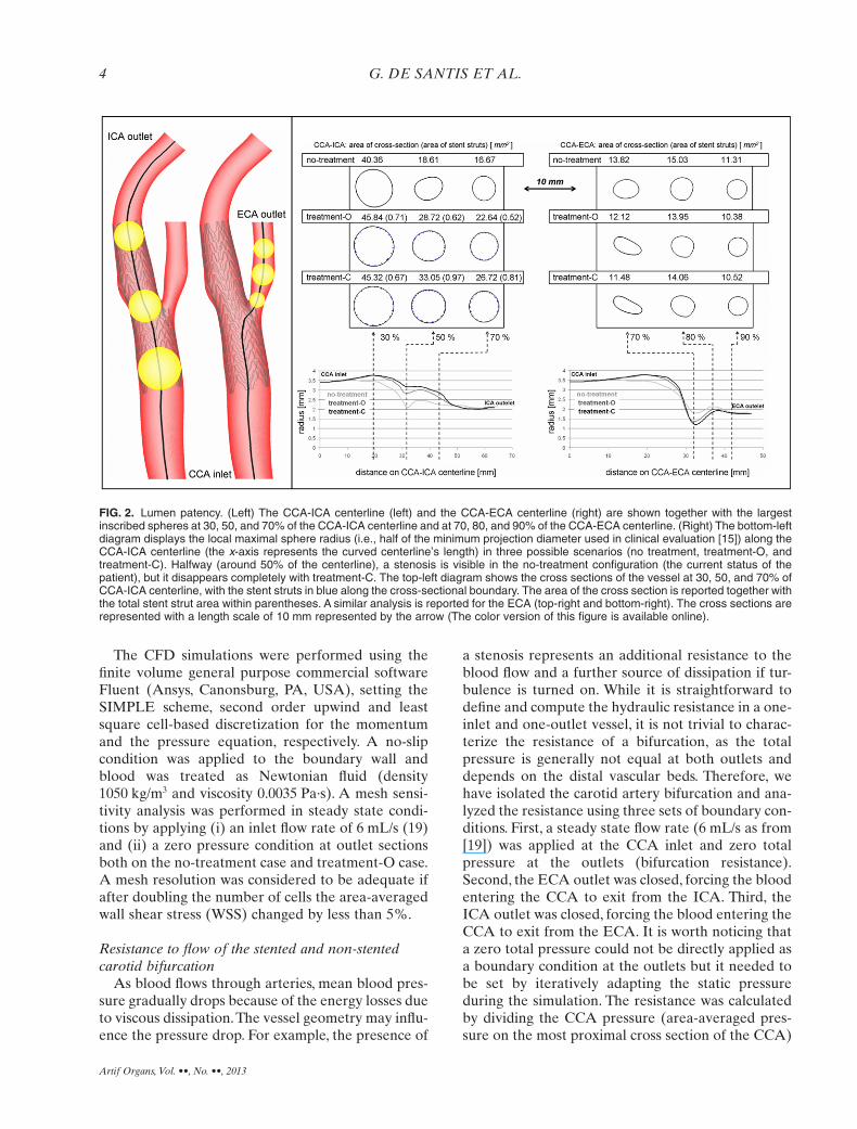
FIG. 2. Lumen patency. (Left) The CCA-ICA centerline (left) and the CCA-ECA centerline (right) are shown together with the largestinscribed spheres at 30, 50, and 70% of the CCA-ICA centerline and at 70, 80, and 90% of the CCA-ECA centerline. (Right) The bottom-leftdiagram displays the local maximal sphere radius (i.e., half of the minimum projection diameter used in clinical evaluation [15]) along theCCA-ICA centerline (the x-axis represents the curved centerline’s length) in three possible scenarios (no treatment, treatment-O, andtreatment-C). Halfway (around 50% of the centerline), a stenosis is visible in the no-treatment configuration (the current status of thepatient), but it disappears completely with treatment-C. The top-left diagram shows the cross sections of the vessel at 30, 50, and 70% ofCCA-ICA centerline, with the stent struts in blue along the cross-sectional boundary. The area of the cross section is reported together withthe total stent strut area within parentheses. A similar analysis is reported for the ECA (top-right and bottom-right). The cross sections arerepresented with a length scale of 10 mm represented by the arrow (The color version of this figure is available online).
G. DE SANTIS ET AL.4
Artif Organs, Vol. ••, No. ••, 2013
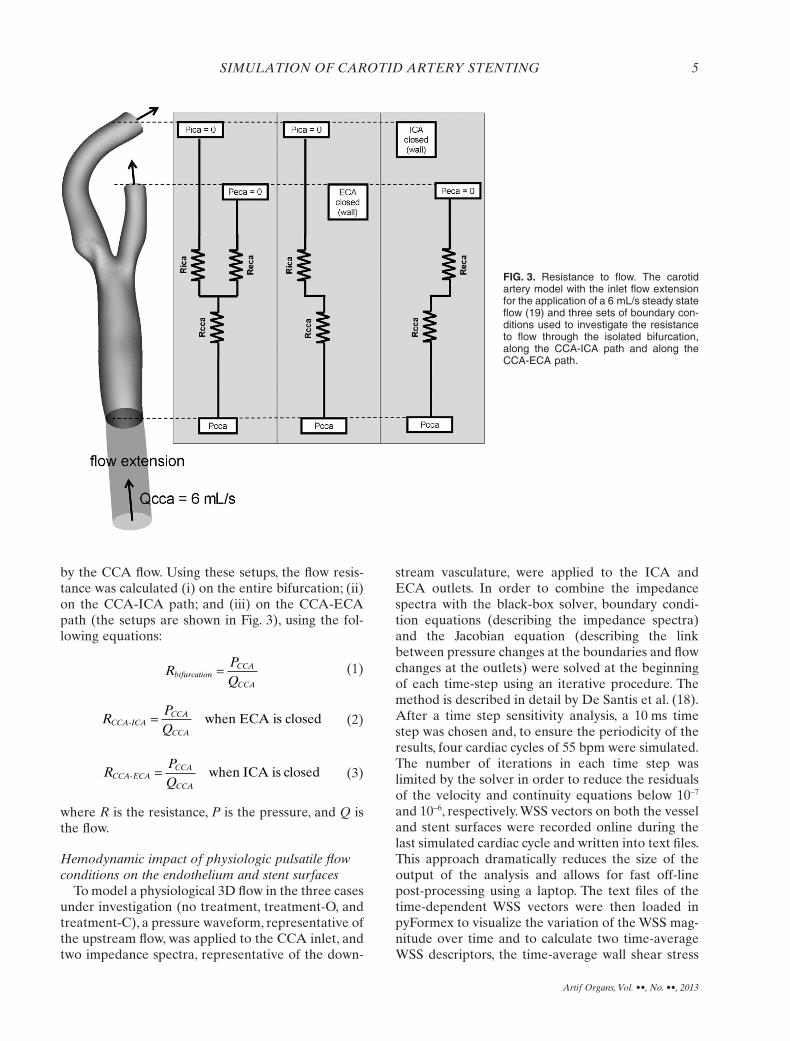
by the CCA flow. Using these setups, the flow resis-tance was calculated (i) on the entire bifurcation; (ii)on the CCA-ICA path; and (iii) on the CCA-ECApath (the setups are shown in Fig. 3), using the fol-lowing equations:
RPQ
bifurcationCCA
CCA
= (1)
RPQ
CCA ICACCA
CCA- when ECA is closed= (2)
RPQ
CCA-ECACCA
CCA
= when ICA is closed (3)
where R is the resistance, P is the pressure, and Q isthe flow.
Hemodynamic impact of physiologic pulsatile flowconditions on the endothelium and stent surfaces
To model a physiological 3D flow in the three casesunder investigation (no treatment, treatment-O, andtreatment-C), a pressure waveform, representative ofthe upstream flow, was applied to the CCA inlet, andtwo impedance spectra, representative of the down-
stream vasculature, were applied to the ICA andECA outlets. In order to combine the impedancespectra with the black-box solver, boundary condi-tion equations (describing the impedance spectra)and the Jacobian equation (describing the linkbetween pressure changes at the boundaries and flowchanges at the outlets) were solved at the beginningof each time-step using an iterative procedure. Themethod is described in detail by De Santis et al. (18).After a time step sensitivity analysis, a 10 ms timestep was chosen and, to ensure the periodicity of theresults, four cardiac cycles of 55 bpm were simulated.The number of iterations in each time step waslimited by the solver in order to reduce the residualsof the velocity and continuity equations below 10-7
and 10-6, respectively. WSS vectors on both the vesseland stent surfaces were recorded online during thelast simulated cardiac cycle and written into text files.This approach dramatically reduces the size of theoutput of the analysis and allows for fast off-linepost-processing using a laptop. The text files of thetime-dependent WSS vectors were then loaded inpyFormex to visualize the variation of the WSS mag-nitude over time and to calculate two time-averageWSS descriptors, the time-average wall shear stress
FIG. 3. Resistance to flow. The carotidartery model with the inlet flow extensionfor the application of a 6 mL/s steady stateflow (19) and three sets of boundary con-ditions used to investigate the resistanceto flow through the isolated bifurcation,along the CCA-ICA path and along theCCA-ECA path.
SIMULATION OF CAROTID ARTERY STENTING 5
Artif Organs, Vol. ••, No. ••, 2013
(TAWSS, Eq. 4), and the relative residence time(RRT, Eq. 5):
TAWSST
s t dtT
= ( ) ⋅∫1
0
WSS , (4)
RRTT
s t dtT=
( )⋅∫ WSS ,0
(5)
where T is the overall interval of the cardiac cycle, t isthe time of the last cardiac cycle, s is the position of anode on the vessel wall or stent surface, and WSS isthe wall shear stress vector.
The distribution over the luminal surface of theWSS-based descriptor RRT was used to identifyatheroprotective/susceptible regions on the vesselwall, which are related to the occurrence of abnormalflow. In detail, low RRT values, representingsustained and well-oriented shear forces, identifyluminal regions where an atheroprotective endothe-lium phenotype is stimulated. On the contrary, highRRT values, representing low intensity and oscillat-ing shear forces, identify regions where a proathero-genic endothelial phenotype is stimulated.This is dueto the fact that high RRT values are representative ofthe action of fluid forces that induce perturbedendothelial alignment and increase the intima-mediathickness (20–23). As such, RRT was taken as anindex to quantify the local atherogenic risk. Similarly,the distribution over the stent strut surface of theWSS-based descriptor TAWSS was used to detectthrombogenic flow conditions (20).
RESULTS
Stent cell dimensionsThe stent design and the size of the stent cells have
an impact on the final shape of the vessel, includingpatency and curvature. Large stent cells correspondto a weak structure (low radial strength and highflexibility), while small cells correspond to a stiffstructure. In the deformed configuration, stent-O hascells of 9.1 mm2 on average (max 17.6 mm2), whereasstent-C has cells of 2.7 mm2 on average (max3.5 mm2).
Local vessel radius and lumen patencyAfter CAS, the cross sections of the ICA are
enlarged and deformed into a nearly circular shape.In the proximity of the stenosis (~50% of the CCA-ICA centerline), the lumen gain (increase of cross-sectional area) of the ICA was 54% with stent-O and
78% with stent-C. While the stent deploys in theCCA-ICA lumen, the carina is pushed away by thestent (toward the ECA) and the entire bifurcation isstretched, with the final effect of locally narrowingand ovalizing the ECA. As a result, the lumen loss(decrease of cross-sectional area) of the ECA in thevicinity of the bifurcation (~70% of the CCA-ECAcenterline) is 12% with stent-O and 17% withstent-C. This geometrical trade-off (ICA lumen gainand ECA lumen loss) occurs with both stents but isaccentuated with stent-C (the stiffer stent). Thevessel radius along the centerlines and the cross-sectional lumen area at specific locations arereported in Fig. 2 (right). Notice that the vessel radiusprovides a continuous measure of the cross-sectionalvessel size along the centerlines, but underestimatesthe lumen cross-sectional area where the vessel isnon-tubular (not circular cross sections) (Fig. 2).
Stent-to-vessel appositionStent-O and stent-C have PAA of 83.51 and
112.26 mm2, respectively. After deployment,treatment-O yielded 35.3% PMA (29.5 mm2), whiletreatment-C yielded 13.2% PMA (14.8 mm2). Thismeans that stent-C is better apposed than stent-O tothe vessel wall of the investigated carotid artery. Acut view examination shows that a number of strutsof both stents remain floating in the proximal ECAostium: 3 stent cells in case of stent-O and 10 cells incase of stent-C (Fig. 4).
Resistance to flowAfter CAS, both the CCA-ICA and CCA-ECA
resistances change, as shown by virtually perfusingthe isolated branches: (i) the CCA-ICA resistance toflow decreases by 21% with stent-O and 26% withstent-C, whereas (ii) the CCA-ECA resistance toflow increases by 13% with stent-O and 18% withstent-C. This resistance trade-off occurs with bothstents but is accentuated with stent-C (the stifferstent). When both outlets are open a similar value ofresistance is found in the three cases (difference<3%) (Table 1).
Hemodynamic effects on the endotheliumThe highest values of the RRT in the unstented
vessel bifurcation occur on the outer edges of thedaughter branches, spotting typical atheroprone loca-tions (20). In the stented vessel, the RRT peaksaround the stress struts, especially at the strut inter-connections, and under the malapposed struts. In thelatter case, the “valley” distal to the ICA stenosis isnot fully straightened by either of the stent models:the residual concave profile and the gap between the
G. DE SANTIS ET AL.6
Artif Organs, Vol. ••, No. ••, 2013
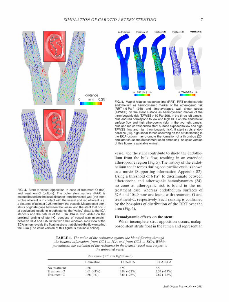
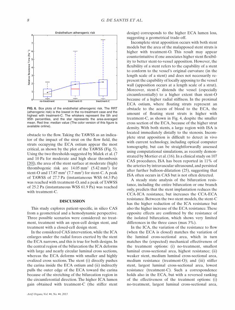
vessel and the stent contribute to shield the endothe-lium from the bulk flow, resulting in an extendedatheroprone region (Fig. 5). The history of the endot-helium shear forces during one cardiac cycle is shownin a movie (Supporting information Appendix S2).Using a threshold of 6 Pa-1 to discriminate betweenatheroprone and atherogenic hemodynamics (24),no zone at atherogenic risk is found in the no-treatment case, whereas endothelium surfaces of67.6 and 104.9 mm2 are found with treatment-O andtreatment-C, respectively. Such ranking is confirmedby the box-plots of distribution of the RRT over thearea (Fig. 6).
Hemodynamic effects on the stentWhen incomplete strut apposition occurs, malap-
posed stent struts float in the lumen and represent an
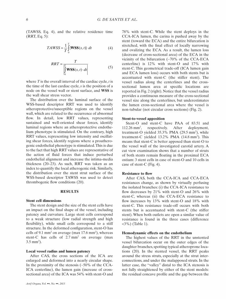
FIG. 4. Stent-to-vessel apposition in case of treatment-O (top)and treatment-C (bottom). The outer stent surface (PAA) iscolored based on the local distance from the vessel wall (the stentis blue where it is in contact with the vessel and red where it is ata distance of at least 0.25 mm from the vessel). Malapposed stentstruts originate gaps between the vessel and the stent that occurat equivalent locations in both stents: the “valley” distal to the ICAstenosis and the ostium of the ECA. ISA is also visible on theproximal ending of stent-C, because of vessel size mismatchbetween CCA and ICA. In the two small windows, a cut view of theECA lumen reveals the floating struts that disturb the flow enteringthe ECA (The color version of this figure is available online).
TABLE 1. The value of the resistance against the blood flowing throughthe isolated bifurcation, from CCA to ICA and from CCA to ECA. Within
parentheses, the variation of the resistance in the treated vessel with respect tothe untreated vessel
Resistance (10-3 mm Hg/mL/min)
Bifurcation CCA-ICA CCA-ECA
No treatment 1.66 4.92 6.5Treatment-O 1.61 (-3%) 3.89 (-21%) 7.33 (+13%)Treatment-C 1.66 (0%) 3.64 (-26%) 7.67 (+18%)
FIG. 5. Map of relative residence time (RRT). RRT on the carotidendothelium as hemodynamic marker of the atherogenic risk(RRT > 6 Pa-1 (24)) and time-averaged wall shear stress(TAWSS) on the stent surface as hemodynamic marker of thethrombogenic risk (TAWSS > 10 Pa (20)). In the three left panels,blue and red correspond to low and high RRT on the endothelialsurface (low and high atherogenic risk). In the two right panels,blue and red correspond to stent surface exposed to low and highTAWSS (low and high thrombogenic risk). If stent struts endot-helialize (36), high shear forces occurring on the struts floating inthe ECA ostium may promote the formation of a thrombus (20)and later cause the detachment of an embolus (The color versionof this figure is available online).
SIMULATION OF CAROTID ARTERY STENTING 7
Artif Organs, Vol. ••, No. ••, 2013
obstacle to the flow. Taking the TAWSS as an indica-tor of the impact of the strut on the flow field, thestruts occupying the ECA ostium appear the mostcritical, as shown by the plot of the TAWSS (Fig. 5).Using the two thresholds suggested by Malek et al. (7and 10 Pa for moderate and high shear thrombosis[20]), the area of the stent surface at moderate (high)thrombogenic risk are 14.05 mm2 (5.42 mm2) forstent-O and 17.87 mm2 (7.7 mm2) for stent-C. A peakof TAWSS of 27.7 Pa (instantaneous WSS 64.3 Pa)was reached with treatment-O, and a peak of TAWSSof 25.2 Pa (instantaneous WSS 61.9 Pa) was reachedwith treatment-C.
DISCUSSION
This study explores patient-specific, in silico CASfrom a geometrical and a hemodynamic perspective.Three possible scenarios were considered: no treat-ment, treatment with an open-cell design stent, andtreatment with a closed-cell design stent.
In the considered CAS intervention, while the ICAenlarges under the radial forces exerted by the stentthe ECA narrows, and this is true for both designs. Inthe central region of the bifurcation the ICA deformswith large and nearly circular luminal cross sections,whereas the ECA deforms with smaller and highlyovalized cross sections. The stent (i) directly pushesthe carina inside the ECA ostium and (ii) indirectlypulls the outer edge of the ECA toward the carinabecause of the stretching of the bifurcation region inthe circumferential direction. The higher ICA lumengain obtained with treatment-C (the stiffer stent
design) corresponds to the higher ECA lumen loss,suggesting a geometrical trade-off.
Incomplete strut apposition occurs with both stentmodels but the area of the malapposed stent struts ishigher with treatment-O. This result may appearcounterintuitive if one associates higher stent flexibil-ity to better stent-to-vessel apposition. However, theflexibility of a stent refers to the capability of a stentto conform to the vessel’s original curvature (in thelength scale of a stent) and does not necessarily re-present the capability of locally apposing to the vesselwall (apposition occurs at a length scale of a strut).Moreover, stent-C distends the vessel (especiallycircumferentially) to a higher extent than stent-Obecause of a higher radial stiffness. In the proximalECA ostium, where floating struts represent anobstacle to the access of blood to the ECA, theamount of floating stent struts is higher withtreatment-C, as shown in Fig. 4, despite the smallercross section of the ECA, because of the higher strutdensity. With both stents, a large region with ISA islocated immediately distally to the stenosis. Incom-plete strut apposition is difficult to detect in vivowith current technology, including optical computertomography, but can be straightforwardly assessedusing computational simulations, as recently demon-strated by Mortier et al. (16). In a clinical study on 107CAS procedures, ISA has been reported in 11% ofthe arteries by intravascular ultrasound, and persistedafter further balloon-dilatation (25), suggesting thatISA often occurs in CAS but is not often detected.
A steady state analysis of the bifurcation resis-tance, including the entire bifurcation or one branchonly, predicts that the stent implantation reduces theCCA-ICA resistance, but increases the CCA-ECAresistance. Between the two stent models, the stent-Chas the higher reduction of the ICA resistance butalso the higher increase of the ECA resistance. Theseopposite effects are confirmed by the resistance ofthe isolated bifurcation, which shows very limiteddifferences in the three cases (max 3%).
In the ICA, the variation of the resistance to flow(when the ECA is closed) matches the variation ofthe luminal cross-sectional area, which in turnmatches the (expected) mechanical effectiveness ofthe treatment options: (i) no-treatment, smallestluminal cross-sectional area, highest resistance; (ii)weaker stent, medium luminal cross-sectional area,medium resistance (treatment-O); and (iii) stifferstent, largest luminal cross-sectional area, lowestresistance (treatment-C). Such a correspondenceholds also in the ECA, but with a reversed rankingof the effectiveness of the treatment options: (i)no-treatment, largest luminal cross-sectional area,
FIG. 6. Box plots of the endothelial atherogenic risk. The RRT(atherogenic risk) is the lowest in the no-treatment case and thehighest with treatment-C. The whiskers represent the 5th and95th percentiles, and the star represents the area-averagedmean. Red line: median value (The color version of this figure isavailable online).
G. DE SANTIS ET AL.8
Artif Organs, Vol. ••, No. ••, 2013
lowest resistance; (ii) weaker stent, medium luminalcross-sectional area, medium resistance (treatment-O); and (iii) stiffer stent, smallest luminal cross-sectional area, highest resistance (treatment-C).
A four-dimensional simulation of the carotidhemodynamics (i.e., including the temporal variationof a 3D hemodynamics) describes a realistic scenariooccurring before and after CAS. The carotid endot-helium in the no-treatment case is subjected to shearforces that are generally high and have a local pref-erential direction during the cardiac cycle. The analy-sis of the RRT shows that there are no regionsexposed to critical shear forces (RRT > 6 Pa-1). Con-versely, when a stent is implanted, atherogenic shearforces are found to act on specific regions of theendothelium. Particles, or cells, remain sometimesover several cycles in recirculation zones with lowWSS (high RRT) and may stick more easily to thewall and to existing stenoses because substrateexchange, thrombocyte activity, and endothelialsurface structure are pathologically altered (26–31).These areas are predisposed to atherosclerotic lesiondevelopment and occupy similar locations with bothstent models, for example, the endothelium in thevicinity of ISA and strut interconnections. A largerrisk area is found in case of treatment-C as comparedwith treatment-O. This can be ascribed to the highernumber of struts and the smaller cell size of theclosed-cell design stent and matches with the obser-vation of Greil et al. (32) who, based on the analysisof a silicon carotid artery model using Laser DopplerAnemometry, reported that larger cell stents maylower the flow disturbance in the bifurcation. Besidesthe primary role played by the stent cell size, vesselstraightening may also contribute. The analysis ofAuricchio et al. shows that the tortuosity is reducedwith stent-O (1.4%) as compared to the no treatment(2.9%) and is further reduced with stent-C (1.3%)(10). The difference between the two stents dependson the lower flexibility, but also lower adaptabilityand conformability of stent-C as compared tostent-O. A straightened vessel loses 3D geometricalfeatures such as bending and twisting and, conse-quently, reduces 3D fluid dynamics features such ashelical flow in the bulk, which is supposed to improvethe arterial hemodynamics (33,34). As an extremecase, vessel straightening may be responsible forstenosis formation distal to the stent after the proce-dure (32).
The malapposed stent struts floating in the lumenrepresent an obstacle to the flow, and the higher thedistance from the vessel wall the more the vicinity tothe centerline, where the highest velocity is expected.As a result, the larger the gap due to ISA, the more
dramatic is the impact on the hemodynamics (thestruts slow down the blood in the surroundingvolume). From our analyses, blood flow around thosestruts can be subjected to time-average shear forcesabove 25 Pa, with instantaneous peaks above 60 Pa,exposing the cell membranes of thrombocytes toenormous stresses (35). Additionally, floating stentstruts, including the struts in the proximal ECAostium, can potentially be endothelialized, as sug-gested by Tanigawa et al. (36). If this happens, thehigh shear forces are likely to stimulate a thrombo-genic phenotype of the endothelial cells coveringmalapposed struts. Then, after the thrombus forma-tion, the high shear forces may detach some frag-ments of the thrombus (emboli), which may fly eitherin the ECA or in the ICA depending on the velocitypatterns of the blood stream at the time of thedetachment, with the risk of stroke.
The modeling strategy presented in this studyrelies on a number of assumptions that simplify themodel construction and may limit the validity of thecomputational results:
• the vessel wall material properties and the wallthickness were based on average population data.In a clinical application, ultrasound imaging can beused to tailor material properties and thickness tothe patient’s carotid artery;
• the stenosis chosen in this study was mild and didnot require clinical treatment. Moreover, it did notinclude hard calcified plaques;
• the prestress of the vessel was not included in theFEA simulation. It is important to realize that thelack of prestress may result in (i) a softer-than-physiologic behavior and (ii) a reduced contact(contact force and contact area) between stent andvessel (37). With respect to the malapposition, theprestress of the vessel wall and the presence ofhard calcified plaques may lead to a different con-clusion when comparing open- and closed-cellstent designs;
• the analysis was performed on a single image-based model of carotid bifurcation. For this reason,the findings of this study could not be directlytransferred to other single cases. On the contrary,the numerical setup can be easily applied toanalyze different patient/stent specific cases;
• the imposition of boundary conditions for the pul-satile flow was based on average population dataand not extrapolated from patient data. In a clini-cal setting, a simultaneous acquisition of pressureand flow would allow to extrapolate patient-specific boundary conditions and, potentially, theimpedance of the distal vascular bed;
SIMULATION OF CAROTID ARTERY STENTING 9
Artif Organs, Vol. ••, No. ••, 2013
• the vessel wall motion due to blood flow wasneglected. A more complex fluid-structure interac-tion analysis could be performed to assess theimpact of this assumption;
• the mesh generation required to convert a FEAmesh into a CFD mesh required extensive opera-tor intervention. For larger studies (more stentsand more patients) more automated methodologyare advisable, such as the Octree-algorithm (38).
CONCLUSION
This study describes the application of technologi-cally advanced patient-specific computer simulations.While the method is far from being a preoperativeplanning tool, it can be used to better understand theinteraction between a stent model and a specificcarotid artery. A trade-off between common carotidartery-internal carotid artery opening and externalcarotid artery narrowing has been highlighted butclinical cases are needed to check whether it has animpact on the long-term outcome of coronary arterystenting.
Acknowledgments: The first author’s research wassupported by a BOF grant from the Ghent Univer-sity. The research of Bram Trachet was supported byan IWT Flemish scholarship.
REFERENCES
1. Qureshi AI, Janardhan V, Hanel RA, Lanzino G. Comparisonof endovascular and surgical treatments for intracranial aneu-rysms: an evidence-based review. Lancet Neurol 2007;9:816–25.
2. Klopfenstein JD, Ponce FA, Kim LJ, Albuquerque FC, NakajiP, Spetzler RF. Middle cerebral artery stenosis: endovascularand surgical options. Skull Base 2005;3:175–89.
3. Michaels AD, Chatterjee K. Angioplasty versus bypass surgeryfor coronary artery disease. Circulation 2002;106:187–90.
4. Wholey M, Wholey M, Mathias K, et al. Global experience incervical carotid artery stent placement. Catheter CardiovascInterv 2000;50:160–7.
5. Cremonesi A, Manetti R, Setacci F, Setacci C, Castriota F.Protected carotid stenting: clinical advantages and complica-tions of emboli protection devices in 442 consecutive patients.Stroke 2003;34:1936–41.
6. Sherif C, Dick P, Sabeti A, et al. Neurological outcome aftercarotid artery stenting compared to medical therapy inpatients with asymptomatic high grade carotid artery stenosis.J Endovasc Ther 2005;12:145–55.
7. Boltuch J, Sabeti S, Amighi J, et al. Procedure-related com-plications and neurological adverse events after protectedvs. unprotected carotid stenting. J Endovasc Ther 2005;12:538–47.
8. Bosiers M, Peeters P, Deloose K, et al. Does carotid arterystenting work on the long run: 5-year results in high-volumecenters (ELOCAS Registry). J Cardiovasc Surg 2005;46:241–7.
9. Stockx L. Techniques in carotid artery stenting. Eur J Radiol2006;60:11–3.
10. Auricchio F, Conti M, De Beule M, De Santis G, Verhegghe B.Carotid artery stenting simulation: from patient-specific
images to finite element analysis. Med Eng Phys 2011;33:281–9.
11. Conti M, Van Loo D, Auricchio F, et al. Impact of carotid stentcell design on vessel scaffolding: a case study comparingexperimental investigation and numerical simulations. J Endo-vasc Ther 2011;18:397–406.
12. Morlacchi S, Chiastra C, Gastaldi D, Pennati G, Dubini G,Migliavacca F. Sequential structural and fluid dynamicnumerical simulations of a stented bifurcated coronary artery.J Biomech Eng 2011;133:121010.
13. Mathias KD. Angioplasty and stenting for carotid lesions: anargument for. Adv Surg 1999;32:225–43.
14. Antiga L, Piccinelli M, Botti L, Ene-Iordache B, Remuzzi A,Steinman DA. An image-based modeling framework forpatient-specific computational hemodynamics. Med Biol EngComput 2008;46:1097–112.
15. Yim PJ, Mullick R, Summers RM, et al. Measurement of steno-sis from magnetic resonance angiography using vessel skel-etons. Proc SPIE 2000;3978:245–55.
16. Mortier P, Van Beusekom H, De Beule M, et al. Improvedunderstanding of stent malapposition using virtual benchtesting. Intervent Cardiol 2011;6:106–9.
17. De Santis G, De Beule M, Segers P, Verdonck P, Verhegghe B.Patient-specific computational haemodynamics: generation ofstructured and conformal hexahedral meshes from triangu-lated surfaces of vascular bifurcations. Comput MethodsBiomech Biomed Engin 2011;14:797–802.
18. De Santis G, Conti M, Trachet B, et al. Haemodynamic impactof stent-vessel (mal)apposition following carotid artery stent-ing: mind the gaps! Comput Methods Biomech Biomed Engin2012. doi: 10.1080/10255842.2011.629997
19. Holdsworth DW, Norley CJ, Frayne R, Steinman DA, RuttBK. Characterization of common carotid artery blood-flowwaveforms in normal human subjects. Physiol Meas 1999;20:219–40.
20. Malek AM, Alper SL, Izumo S. Hemodynamic shear stress andits role in atherosclerosis. JAMA 1999;282:2035–42.
21. He X, Ku DN. Pulsatile flow in the human left coronary arterybifurcation: average conditions. ASME J Biomech Eng 1996;118:74–82.
22. Lee SW, Antiga L, Steinman DA. Correlations among indica-tors of disturbed flow at the normal carotid bifurcation. ASMEJ Biomech Eng 2009;131:061013.
23. Morbiducci U, Gallo D, Massai D, et al. Outflow conditions forimage-based hemodynamic models of the carotid bifurcation:implications for indicators of abnormal flow. J Biomech Eng2010;132:091005.
24. Gallo D, De Santis G, Negri F, et al. On the use of in vivomeasured flow rates as boundary conditions for image-basedhemodynamic models of the human aorta: implications forindicators of abnormal flow. Ann Biomed Eng 2012;40:729–41.
25. Clark DJ, Lessio S, O’Donoghue M, Schainfeld R, RosenfieldK. Safety and utility of intravascular ultrasound-guided carotidartery stenting. Catheter Cardiovasc Interv 2004;63:355–62.
26. Glagov S, Zarins C, Giddens DP, Ku DN. Hemodynamics andatherosclerosis. Insights and perspectives gained from studiesof human arteries. Arch Pathol Lab Med 1988;112:1018–31.
27. Ma P, Li X, Ku DN. Connective mass transfer at the carotidbifurcation. J Biomechan 1997;30:565–71.
28. Zhao SZ, Xu XY, Hughes AD, et al. Blood flow and vesselmechanics in a physiologically realistic model of a humancarotid arterial bifurcation. J Biomechan 2000;33:975–84.
29. Davies PF. Flow-mediated endothelial mechanotransduction.Physiol Rev 1995;75:519–50.
30. Davies PF. Mechanisms involved in endothelial responsesto hemodynamic forces. Atherosclerosis 1997;131(Suppl.):S15–17.
31. Barbee KA, Davies PF, Lal R. Shear stress-induced reorgani-sation of the surface topography of living endothelial cellsimaged by atomic force microscopy. Circ Res 1994;74:163–71.
G. DE SANTIS ET AL.10
Artif Organs, Vol. ••, No. ••, 2013
32. Greil O, Pflugbeil G, Weigand K, et al. Changes in carotidartery flow velocities after stent implantation: a fluid dynamicsstudy with laser Doppler anemometry. J Endovasc Ther 2003;10:275–84.
33. Morbiducci U, Ponzini R, Grigioni M, Redaelli A. Helical flowas fluid dynamic signature for atherogenesis risk in aortocoro-nary bypass. A numeric study. J Biomech 2007;3:519–34.
34. Gallo D, Steinman DA, Bijari PB, Morbiducci U. Helical flowin carotid bifurcation as surrogate marker of exposure to dis-turbed shear. J Biomech 2012;49:2398–404.
35. Liepsch D, Pflugbeil G, Matsuo T, Lesniak B. Flow visualisa-tion and 1- and 3-D laser-Doppler-anemometer measurementsin models of human carotid arteries. Clin Hemorheol Micro-circ 1998;18:1–30.
36. Tanigawa J, Barlis P, Di Mario C. Do unapposed stent strutsendothelialise? In vivo demonstration with optical coherencetomography. Heart 2007;93:378.
37. Gee MW, Reeps C, Eckstein HH, Wall WA. Prestressing infinite deformation abdominal aortic aneurysm simulation.J Biomech 2009;42:1732–9.
38. Chiastra C, Morlacchi S, Pereira S, Dubini G, MigliavaccaF. Computational fluid dynamics of stented coronary bifurca-tions studied with a hybrid discretization method. Eur J MechB/Fluids 2012;35:76–84.
SUPPORTING INFORMATION
Additional Supporting Information may be found inthe online version of this article at the publisher’sweb-site:
Appendix S1. Image-based finite element analysis ofCAS.
Appendix S2. Animation of the wall shear stresson the carotid artery endothelium during a cardiaccycle.
SIMULATION OF CAROTID ARTERY STENTING 11
Artif Organs, Vol. ••, No. ••, 2013