Advanced techniques for nanocharacterization of polymeric coating surfaces
Upload
khangminh22Category
view
5download
0
Evaluation of Fibrous Polymeric Coating over Vascular
Stent Material
by
Parnaz Boodagh
M.Sc., University of Colorado Boulder, 2015
A thesis submitted to the
Faculty of the Graduate School of the
University of Colorado in partial fulfillment
of the requirements for the degree of
Doctor of Philosophy
Department of Civil, Environmental and Architectural Engineering
2017

This thesis entitled:Evaluation of Fibrous Polymeric Coating over Vascular Stent Material
written by Parnaz Boodaghhas been approved for the Department of Civil, Environmental and Architectural
Engineering
Prof. Wei Tan
Prof. Fernando Rosario-Ortiz
Prof. Yunping Xi
Prof. Lupita Montoya
Prof. Yifu Ding
Date
The final copy of this thesis has been examined by the signatories, and we find that boththe content and the form meet acceptable presentation standards of scholarly work in the
above mentioned discipline.

iii
Boodagh, Parnaz (Ph.D. Civil Engineering)
Evaluation of Fibrous Polymeric Coating over Vascular Stent Material
Thesis directed by Prof. Wei Tan
The field of percutaneous coronary intervention has seen a plethora of advances over the
past few decades, which have allowed for its development into safe and effective treatments for
patients suffering from cardiovascular diseases. However, in-stent thrombosis and restenosis
remain clinically significant problems.
This dissertation proposes a methodology to potentially overcome in-stent thrombo-
sis and restenosis by designing and fabricating a polymeric coating with mechanical and
surface properties inert to cell adhesion and platelet attachment. First, conventional elec-
trospinning technique was used to fabricate polyethylene glycol dimethacrylate/ poly l-
lactide acid (PEGDMA/PLLA) blend fiber substrate with different composition ratios. Next,
coaxial electrospinning techniques were used to fabricate PLLA, the hydrophobic core and
PEGDMA, the hydrophilic sheath with tunable elasticity and controlled surface chemistry
for use as stent coatings.
Conventional electrospinning with three blend PEGDMA/PLLA ratios of 1-1, 2-1, and
4-1 were assessed for attachment of platelets and arterial smooth muscle cells (SMC) as well
as the secretory effect of mesenchymal stem cells cultured on the coatings on the proliferation
and migration of arterial endothelial cells and SMCs. It was demonstrated that electrospun
PEGDMA/PLLA coating with 1-1 ratio on the nitinol stent material reduced platelet and
SMC attachment and increased stem cell secretory factors that enhance endothelial prolif-
eration.
Coaxial electrospinning with three UV photopolymerization times of 2, 15, and 60
min were selected to compare coatings in terms of mechanical properties and biological re-
sponses. Attenuated total reflection-Fourier transformed infrared spectroscopy demonstrated

iv
PEGDMA coated around PLLA. Transmission electron microscopy images illustrated the
core-sheath structures in PLLA-PEGDMA nanofibers, and scanning electron microscopy
images exhibited a similar uniform fibrous structure from all conditions. Tensile testing
demonstrated that the elastic modulus of the hydrated matrices varied with polymerization
time. Attachment and spreading of arterial SMCs and platelet adhesion onto the coatings
were found to be affected by the material stiffness.
We show the impact of substrate’s elasticity on SMC and platelet attachment reduc-
tion. We postulate that electrospun PEGDMA fibrous coatings would enhance hemocom-
patibility of nitinol stents and truncate the potential stent failure caused by restenosis and
thrombosis.

Dedication
To my parents, Dr. Mahdi Boudagh and Dr. Saleheh Tirabadi, for their love and hope,
countless sacrifices, and encouragement in every step of my achievements.

vi
Acknowledgements
Special thanks and sincere appreciation go to my research advisor, professor Wei Tan,
for her caring, guidance,and her faith in my abilities and strengths throughtout this long
path to PhD.
My appreciation is extended to my faculty advisor, professor Fernando Rosario-Ortiz,
for his helps and assistance.
I would like to thank Dr. Laura Border and Dr. Margaret Asirvatham for their
continuous support, faith, and encourangment.
I also would like to thank my committee members, professor Yunping Xi, professor
Yifu Ding, and professor Lupita Montoya for their constant guidance throughout my Ph.D.
Many thanks to my colleagues Dr. Mike Floren, Dr. Dong-Jie Guo, Richard Johnson,
Dr. Yonghui Ding, Elliott Winston, and Anirudh Dharmarajan, for their valuable discus-
sions, help and awesome company.
This thesis was partially supported by a Dissertation Completion Fellowship from the
Civil, Environmental, and Architectural Engineering department at the University of Col-
orado Boulder. Special thanks goes to professor Rajagopalan Balaji, department chair.

Contents
Chapter
1 Introduction 1
1.1 Motivation . . . . . . . . . . . . . . . . . . . . . . . . . . . . . . . . . . . . . 1
1.2 Objectives . . . . . . . . . . . . . . . . . . . . . . . . . . . . . . . . . . . . . 1
1.3 Outline . . . . . . . . . . . . . . . . . . . . . . . . . . . . . . . . . . . . . . . 2
2 Literature Review 3
2.1 Cardiovascular Diseases and Treatment Solutions . . . . . . . . . . . . . . . 3
2.2 Vascular Tissue Engineering Approach . . . . . . . . . . . . . . . . . . . . . 5
2.3 Tissue-Engineered Scaffold Requirements . . . . . . . . . . . . . . . . . . . . 6
2.4 Material Choice . . . . . . . . . . . . . . . . . . . . . . . . . . . . . . . . . . 6
2.5 PLLA and PEG for Use in Biomedical Field . . . . . . . . . . . . . . . . . . 7
2.6 Fabrication of Fibrous Scaffolds for Vascular Tissue Engineering . . . . . . . 10
2.7 Blood Vessels . . . . . . . . . . . . . . . . . . . . . . . . . . . . . . . . . . . 13
2.8 Polymer Covered Endovascular Stents . . . . . . . . . . . . . . . . . . . . . . 14
2.9 Coating Vascular Stent Material . . . . . . . . . . . . . . . . . . . . . . . . . 15
2.10 Surface Treatments of Polymers for Biocompatibilty . . . . . . . . . . . . . . 19
3 Blend PLLA / PEGDMA Electrospun Stent Coating 20
3.1 Introduction . . . . . . . . . . . . . . . . . . . . . . . . . . . . . . . . . . . . 20
3.2 Experimental Material and Methods . . . . . . . . . . . . . . . . . . . . . . 22
viii
3.2.1 Materials . . . . . . . . . . . . . . . . . . . . . . . . . . . . . . . . . 22
3.2.2 Preparation of Stent Material and Polymer Coating . . . . . . . . . . 22
3.2.3 Fabrication of Electrospun Fibers . . . . . . . . . . . . . . . . . . . . 23
3.2.4 Material Characterization of Scaffolds: Physical, Mechanical and Ther-
mal Properties Scanning Electron Microscopy Imaging . . . . . . . . 24
3.2.5 Water Contact Angle Measurement . . . . . . . . . . . . . . . . . . . 24
3.2.6 Fiber Structure of Blended Polymers . . . . . . . . . . . . . . . . . . 24
3.2.7 Mechanical Testing . . . . . . . . . . . . . . . . . . . . . . . . . . . . 24
3.2.8 ATR-FTIR Spectroscopy . . . . . . . . . . . . . . . . . . . . . . . . . 25
3.2.9 Thermogravimetric Analysis . . . . . . . . . . . . . . . . . . . . . . . 25
3.2.10 Differential Scanning Calorimetry . . . . . . . . . . . . . . . . . . . . 25
3.2.11 Vascular Cell Attachment Study . . . . . . . . . . . . . . . . . . . . . 25
3.2.12 Platelet Adhesion Assay . . . . . . . . . . . . . . . . . . . . . . . . . 26
3.2.13 Secretory Function of MSCs on Vascular Cells . . . . . . . . . . . . . 26
3.2.14 Proliferation Assay . . . . . . . . . . . . . . . . . . . . . . . . . . . . 27
3.2.15 Chemotaxis Migration Assay . . . . . . . . . . . . . . . . . . . . . . . 28
3.3 Results and Discussion . . . . . . . . . . . . . . . . . . . . . . . . . . . . . . 28
3.3.1 Coating microstructure shown with SEM imaging . . . . . . . . . . . 28
3.3.2 Water Contact Angle Measurements . . . . . . . . . . . . . . . . . . 30
3.3.3 Mechanical properties of blended coating scaffolds . . . . . . . . . . . 32
3.3.4 Thermal properties of blended fibers . . . . . . . . . . . . . . . . . . 34
3.3.5 Attachment of Vascular SMCs and Platelets . . . . . . . . . . . . . . 37
3.3.6 Secretory Function of MSCs on Proliferation and Chemotaxis Vascular
Cells . . . . . . . . . . . . . . . . . . . . . . . . . . . . . . . . . . . . 44
4 Coaxially Structured PEGDMA/PLLA Nanofibrous Hydrogel As Novel Vascular Stent
Coating 47

ix
4.1 Introduction . . . . . . . . . . . . . . . . . . . . . . . . . . . . . . . . . . . . 47
4.2 Materials and Methods . . . . . . . . . . . . . . . . . . . . . . . . . . . . . . 50
4.2.1 Materials . . . . . . . . . . . . . . . . . . . . . . . . . . . . . . . . . 50
4.2.2 Preparation of Stent Material and Polymer Coating . . . . . . . . . . 50
4.2.3 Fabrication of coaxially electrospun fibers . . . . . . . . . . . . . . . 50
4.2.4 Scanning electron microscopy imaging . . . . . . . . . . . . . . . . . 51
4.2.5 Transmission electron spectroscopy imaging . . . . . . . . . . . . . . 52
4.2.6 Water contact angle measurement . . . . . . . . . . . . . . . . . . . . 52
4.2.7 Mechanical testing . . . . . . . . . . . . . . . . . . . . . . . . . . . . 52
4.2.8 ATR-FTIR spectroscopy . . . . . . . . . . . . . . . . . . . . . . . . . 54
4.2.9 Thermogravimetric analysis . . . . . . . . . . . . . . . . . . . . . . . 54
4.2.10 Differential scanning calorimetry . . . . . . . . . . . . . . . . . . . . 54
4.2.11 Smooth muscle cell attachment and spreading study . . . . . . . . . . 55
4.2.12 Platelet adhesion assay . . . . . . . . . . . . . . . . . . . . . . . . . . 55
4.2.13 Statistical analysis . . . . . . . . . . . . . . . . . . . . . . . . . . . . 56
4.2.14 Fabrication Description . . . . . . . . . . . . . . . . . . . . . . . . . . 56
4.3 Results . . . . . . . . . . . . . . . . . . . . . . . . . . . . . . . . . . . . . . . 57
4.3.1 SEM and TEM imaging of coaxially electrospun PEGDMA/PLLA
coatings showing their micro- and nano- structure as well as their hy-
drogel nature . . . . . . . . . . . . . . . . . . . . . . . . . . . . . . . 57
4.3.2 ATR-FTIR spectroscopy results showing the PEGDMA sheath of coax-
ially electrospun fibers varies with photopolymerization time . . . . . 58
4.3.3 Mechanical properties of coaxially electrospun fibrous scaffolds im-
prove with increased photopolymerization time . . . . . . . . . . . . . 60
4.3.4 Thermal properties of coaxially electrospun fibers . . . . . . . . . . . 63
4.3.5 Attachment of vascular SMCs and platelets . . . . . . . . . . . . . . 67
4.3.6 Coaxially-structured fibers for stent coating . . . . . . . . . . . . . . 70

x
4.4 Discussion . . . . . . . . . . . . . . . . . . . . . . . . . . . . . . . . . . . . . 70
4.5 Conclusion . . . . . . . . . . . . . . . . . . . . . . . . . . . . . . . . . . . . . 75
5 Conclusions and Future Research Needs 76
5.1 Summary and Conclusion . . . . . . . . . . . . . . . . . . . . . . . . . . . . 76
5.2 Future Research Needs . . . . . . . . . . . . . . . . . . . . . . . . . . . . . . 77
Bibliography 80
Appendix
A Computation of Elastic Modulus 89
A.1 Step-by-step Procedure . . . . . . . . . . . . . . . . . . . . . . . . . . . . . . 89
A.2 Matlab Script . . . . . . . . . . . . . . . . . . . . . . . . . . . . . . . . . . . 93

Tables
Table
2.1 Summary of covering materials used in the development of covered stent.
Table was adopted from Farhatnia et al. (2013). . . . . . . . . . . . . . . . . 18
4.1 Analysis of FTIR data taken in absorbance mode from 400 cm−1 to 4000 cm−1
wavelengths for coaxially electrospun fibers with various photopolymerization
times, showing the peak areas of C=O and C=C peaks, as well as the ratio
of C=C to C=O peak. . . . . . . . . . . . . . . . . . . . . . . . . . . . . . . 60
4.2 Mechanical properties of coaxially spun scaffolds . . . . . . . . . . . . . . . . 63

Figures
Figure
2.1 Left: an overview of a heart and coronary artery showing damage (dead heart
muscle) caused by a heart attack. Right: a cross-section of the coronary artery
with plaque buildup and a blood clot. Figure was adopted from National
Heart, Lung, and Blood Institute (NHLBI). . . . . . . . . . . . . . . . . . . 3
2.2 PCI procedure; Left: Balloon angioplasty, Figure was adopted from www.Biology-Forums.com;
Right: Balloon and stent angioplasty, Figure was adopted from Healthwise,
Incorporated. . . . . . . . . . . . . . . . . . . . . . . . . . . . . . . . . . . 4
2.3 Schematic overview of coaxial electrospinning procedure; Figure was adopted
from www.yflow.com. . . . . . . . . . . . . . . . . . . . . . . . . . . . . . . . 12
2.4 Schematic illustration of stent with coating. Figure was adopted from www.pyramed.com. 15
2.5 Schematic illustration shows the electrospinning procedure for fabricating
stents with PU nanofibers; Figure was adopted from Kuraishi et al. (2009). . 16
2.6 Different techniques for the development of autologous covered stent. (A)
Suturing.(B) covering the entire structure by folding both ends of the graft
along the external surface of the stent (C) stabilization of the graft by reversing
the connecting arms attached to both ends of the stent to its external surface;
Figure was adopted from Farhatnia et al. (2013). . . . . . . . . . . . . . . . 17
3.1 SEM images showing the fiber structure for different fiber composition ratios,
including (a) 1-1, (b) 2-1, and (c) 4-1. . . . . . . . . . . . . . . . . . . . . . . 29

xiii
3.2 Comparison of the coating scaffolds in terms of fiber diameter. ∗: denotes
significant difference of the denoted column from all others with p <0.05. . . 30
3.3 Comparison of the coating scaffolds in terms of water contact angle. ∗: denotes
significant difference of the denoted column from all others with p <0.05. . . 31
3.4 Comparison of the coating scaffolds in terms of elastic modulus. ∗: denotes
significant difference of the denoted column from all others with p <0.05. . . 32
3.5 Microscopic images illustrating fiber structure before (a) and after (b) soaking
in water for 48 hours; images were taken in the same area. . . . . . . . . . . 33
3.6 FTIR spectra of pure PLLA, pure PEGDMA and blend fibers with varied
composition ratios. . . . . . . . . . . . . . . . . . . . . . . . . . . . . . . . . 34
3.7 Thermoanalyses of PEGDMA, PLLA, and their blended fibers, as shown with
(a) Differential scanning calorimetry curves in the second heating processes,
and (b) Thermogravimetric curves. . . . . . . . . . . . . . . . . . . . . . . . 36
3.8 SEM images showing attachment of SMCs on materials with different fiber
composition ratios, (a) 1-1, (b) 2-1. . . . . . . . . . . . . . . . . . . . . . . . 38
3.9 SEM images showing attachment of SMCs on materials with different fiber
composition ratios, (a) 4-1, and (b) bare nitinol (∗: indicates the nitinol sur-
faces with no cell coverage). . . . . . . . . . . . . . . . . . . . . . . . . . . . 39
3.10 SEM images showing adhesion of platelets on materials with different fiber
composition ratios, (a) 1-1, (b) 2-1. . . . . . . . . . . . . . . . . . . . . . . . 41
3.11 SEM images showing adhesion of platelets on materials with different fiber
composition ratios, (a) 4-1, and (b) bare nitinol. . . . . . . . . . . . . . . . . 42
3.12 Comparisons of the attachment area ratios for SMC (a) and platelet (b) on
the bare nitinol and coating materials with different PLLA/PEGDMA fiber
ratios. ∗: denotes significant difference of the denoted column from all others
with p <0.05. ∗∗: denotes significant difference of the denoted column from
all others with p <0.10. . . . . . . . . . . . . . . . . . . . . . . . . . . . . . . 43

xiv
3.13 Comparisons of the effects of MSC secretory functions on vascular activities,
including (a) EC proliferation, (b) EC migration. ∗ denotes significant differ-
ence of the denoted column from all others with p <0.05. . . . . . . . . . . . 45
3.14 Comparisons of the effects of MSC secretory functions on vascular activities,
including (a) SMC proliferation, and (b) SMC migration, on the bare nitinol
and coating materials with different PLLA/PEGDMA fiber ratios. ∗ denotes
significant difference of the denoted column from all others with p <0.05. . . 46
4.1 Micro-/nano-structure of coaxially electrospun fibers. (A-F) SEM images
showing the fiber structure in the dry state (A-C) or in the hydrated state (D-
F), for different UV photopolymerization times including 2 min (A, D), 15 min
(B, E), and 60 min (C, F). (G) Comparison of the coaxial PLLA/PEGDMA
fiber diameter in dry and hydrated states. (H) TEM image of PLLA/PEGDMA
coaxial fiber. . . . . . . . . . . . . . . . . . . . . . . . . . . . . . . . . . . . . 59
4.2 Typical FTIR spectra of the pure PLLA, PEGDMA, and coaxial PLLA/PEGDMA
fibers in the entire scanned range (A), and in a specific range of 1600 to 1800
cm−1 (B). . . . . . . . . . . . . . . . . . . . . . . . . . . . . . . . . . . . . . 61
4.3 Mechanical characterization results of the coaxial PLLA/PEGDMA fibers.
(A) Elastic modulus results from tensile test for samples with different UV
photopolymerization times. (B) Representative tensile stress-strain curves.
(C) Storage modulus results from rheometer test for samples with different UV
photopolymerization times. (D) Complex modulus. “*” denotes significant
difference of the denoted column from all the others with p < 0.05. . . . . . . 62
4.4 Thermoanalyses of PEGDMA, PLLA, and their coaxial fibers, as shown with
(A) representative differential scanning calorimetry (DSC) curves during the
second heating process, and (B) representative thermogravimetric analysis
(TGA) curves. . . . . . . . . . . . . . . . . . . . . . . . . . . . . . . . . . . . 66
xv
4.5 Fluorescent images showing the attachment of SMCs stained with F-actin
(green) and DAPI (blue) on nitinol pieces coated with coaxial PCL-PEGDMA
fibers with different UV photopolymerization times, including 2 min (A), 15
min (B), and 60 min (C), as well as on a bare nitinol piece (D). (E) Compar-
isons of the SMC attachment area ratios. “**”: denotes significant difference
of the denoted column from all others with p < 0.05 . . . . . . . . . . . . . . 68
4.6 SEM images showing the adhesion of platelets on nitinol pieces coated with
coaxial PCL-PEGDMA fibers with different UV photopolymerization times,
including 2min (A), 15min (B), and 60min (C), as well as on a bare nitinol
piece (D). (E) Comparisons of the platelet attachment area ratios. “**”:
denotes significant difference of the denoted column from all others with p <
0.05. . . . . . . . . . . . . . . . . . . . . . . . . . . . . . . . . . . . . . . . . 69
4.7 Illustration of the process and result using coaxially spun PCL-PEGDMA
fibers to coat all the surfaces of a small-diameter vascular stent. (A) Using
fiber-coated mandrel to carry the stent as fiber collector. (B) An illustration of
the spinning system. (C) Representative pictures showing the cross-sectional
and longitudinal views of the uniform fibrous coatings in the lumen and over
the abluminal surfaces. . . . . . . . . . . . . . . . . . . . . . . . . . . . . . . 71
A.1 Sample of smoothing the stress and strain data . . . . . . . . . . . . . . . . 89
A.2 Sensitivity analysis over the optimal span size . . . . . . . . . . . . . . . . . 90
A.3 Calculation of mean and standard deviation of smoothing error . . . . . . . . 91
A.4 Computation of elastic modulus . . . . . . . . . . . . . . . . . . . . . . . . . 92

Chapter 1
Introduction
1.1 Motivation
Deployment of stents has renovated the field of interventional cardiology extensively.
In spite of their distinguished clinical results, there is still complications occuring after stent
implantation such as restenosis and thrombosis that needs to be addresses. A number of
novel solutions to overcome the drawback of stent deployment have emerged, including us-
ing polymers as coating over stent materials. This research investigates the role of polymer
coatings that assist in the prevention or reduction of restenosis and thrombosis after percu-
taneous coronary intervention (PCI) procedure. This study will thus help to evaluate the
coating material physiochemical properties, their design, manufacturing process and biolog-
ical behaviors of the vascular smooth muscle cell (SMC) and platelets.
1.2 Objectives
The aim of this research for inhibiting stent implant’s adverse responses of thrombosis,
and restenosis is to: (a) employ different coating fabrication techniques namely electro-
spinning and coaxial electrospinning using hydrophilic polyethylene glycol dimethacrylate
(PEGDMA) polymer for surface modified coating, and (b) hinder SMC and platelet attach-
ment and proliferation. Our hypothesis was that these potential strategies would be able to
provide a promising stent coating substrate to modulate the structure and surface property
of coatings while reducing SMC and platelet formations, both of which would inhibit the

2
implants adverse responses toward the vascular stenting.
The main objective of this thesis is to develop thin polymer coating composed of poly-L-
lactic acid (PLLA) and PEGDMA for tissue engineering application. Also it was the interest
of this research to design the fabrication process of novel coaxially-structured nanofibers for
tunable elasticity recapitulating soft tissue property. To pursue this goal, this study first
develops two methods of fabrication technique through electropsinning of PLLA/PEGDMA
as coating vascular stent material. Different fabrication techniques were evaluated for their
material and mechanical properties as well as their bio-response.
Specifically, the fabrication of PLLA-PEGDMA electrospun coatings were designed,
optimized and implemented a novel coaxially-structured nanofibers to screen a diversity
of engineered microenvironments on soft, 2D substrates to probe SMC. Also the prepared
substrates were evaluated for their hemocompatibility.
1.3 Outline
This research includes a detailed materials characterization of the novel material includ-
ing Fourier transform infrared spectroscopy (FTIR), scanning electron microscopy (SEM),
differential scanning calorimetry (DSC), thermogravimetric analysis (TGA) and mechanical
tensile and rheometery. Furthermore, the effects of material properties, matrix elasticity
through in vitro bio study, evaluating cell adhesion and cell morphology were investigated.
Finally, two different fabrication techniques were evaluated for their potential as im-
plantable stent coatings. For that purpose, their properties were assessed to be anti throm-
bosis and anti-restenosis for vascular stent application.

Chapter 2
Literature Review
2.1 Cardiovascular Diseases and Treatment Solutions
Cardiovascular disease (CVD) is the leading cause of death in the United States asso-
ciated with one out of every four deaths as reported in 2009 (Kochanek et al., 2011), Figure
2.1.
Coronary arteries
supply blood and
oxygen to heart tissue
Common areas of coronary artery blockage
resulting in damage to heart muscle Dead heart muscle
Figure 2.1: Left: an overview of a heart and coronary artery showing damage (dead heartmuscle) caused by a heart attack. Right: a cross-section of the coronary artery with plaquebuildup and a blood clot. Figure was adopted from National Heart, Lung, and Blood Insti-tute (NHLBI).

4
Current therapies rely on surgical intervention using autologous vascular bypass grafts
such as the saphenous vein; however, these therapies are restricted in practice as they require
surgical harvest and may be limited by a prior disease state or previous use (Weintraub et al.,
1994).
Fragmentation of endothelial layer due to percutanaous coronery intervention (PCI)
procedure such as balloon angioplasty often results in restenosis, Figure 2.2. PCI or angio-
plasty is a non-surgical procedure to widen the locally occluded or narrowed blood vessel
which has restricted the blood flow. Injury within the arerial wall due to balloon inflation
can cause smooth muscle cell injury. Smooth muscle cell proliferation, migration, and depo-
sition of more extracellular matrix because of factors released by platelet as well as direct
injury can induce neointimal hyperplasia.
Figure 2.2: PCI procedure; Left: Balloon angioplasty, Figure was adopted fromwww.Biology-Forums.com; Right: Balloon and stent angioplasty, Figure was adopted fromHealthwise, Incorporated.
Using stents in the cardiovascular intervention procedures has advanced the field of
interventional cardiology, reducing but not eliminating the problems of vascular stenosis
and throumbosis. In fact, it has initiated new problems of in-stent thrombosis and in-stent
restenosis due to delayed or ineffective re-endothelialization resulting from injury, rupture or
perforation of the vessel wall during stent placement. Restenosis is reoccurance of stenosis or

5
renarrowing of the blood vessel, causing localized blackage of blood flow. If restenosis occurs
after stent placement, it is called in-stent restenosis. The formation of blood clot inside a
blood vessel is called thrombosis, leading to restricting blood flow.
The stenting procedure involves the mechanical widening of a partially blocked artery
through the use of a collapsed stent that is expanded to a fixed size in the artery. The
implementation of coronary stents has become the standard of care for patients requiring
coronary intervention. In fact, by 2008, greater than 96% of the 800,000 PCI procedures
involved the implementation of coronary stents (Wilson and Cruden, 2013).
During stent placement, the blood vessel wall undergoes significant expansion leading
to the de-endothelialisation of the intima layer, and compression of the plaque, which often
leads to dissection of the vessel wall causing rupture and perforation (Inoue and Node, 2009).
Therefore, methods to alleviate the contributing factors in in-stent thrombosis and in-stent
restenosis would be of a clinically great importance.
Biomaterials play a pivotal role in this approach on the construction of biocompatible
substrates over stent materials that provide the cover structure and functionality. Manu-
facturing techniques such as drawing, template synthesis, phase separation, self-assembly
and electrospinning have been used to prepare biomaterial fibrous substrates in recent years.
Electrospinning is a simple, versatile fabricating method applicable to many types of polymer
solutions.
2.2 Vascular Tissue Engineering Approach
“Tissue Engineering” is an interdisciplinary field that applies the principles of engi-
neering and life sciences toward the repair and the restoration of damaged tissue functions
(Langer and Vacanti, 1993). The three main parameters in tissue engineering to achieve
successful tissue regeneration are cells, scaffolds and specific signalling factors (Lavik and
Langer, 2004). An effective interaction between these three parameters have been proven to
be a critical factors for the process of scaffold-tissue integration and, eventually, for tissue

6
regeneration. Scaffolds have to provide adequate structural and mechanical support and
to direct cell activity toward the regeneration of a new physiological tissue by providing
chemical, biological and physical cues.
Tissue engineering has emerged as a promising strategy for vascular tissue regeneration.
When in 1986, Weinberg and Bell (1986) claimed the construction of new blood vessel
in vitro, with bovine aortic endothelial cells, smooth muscle cells and fibroblasts seeded
on a collagen matrix, they signed the road that would inspire the research strategies for
tissue regeneration until the present days. Vascular tissue engineering offers a promising
alternative approach to address the needs for small-diameter vascular grafts by overcoming
the mechanical and/or biological issues associated with the current materials (Ratcliffe,
2000).
2.3 Tissue-Engineered Scaffold Requirements
The design of substrates is essential to the success of an engineered tissue in order
to permit cell adhesion, proliferation, differentiation, permeability for nutrients as well as
structural support for tissue growth (Langer and Vacanti, 1993). To achieve this, a scaf-
fold should include several criteria such as appropriate porosity, pore size, permeability for
nutrients, material biocompatibility and degradation, as well as imitating the mechanical
behavior of the intended tissue (Yang et al., 2001; Stevens and George, 2005).
Careful balance between mechanical factors and biological responses must be considered
when designing a tissue scaffold. Particularly with biodegradable polymers, as the material
degrades mechanical properties diminish. Therefore; presenting the necessity to prepare
scaffolds that maintain the required support for tissue growth before degradation.
2.4 Material Choice
Material properties, such as chemistry, surface properties, and biocompatibility, are
important factors that must be considered when preparing a tissue scaffold. In particular,

7
when a material is implanted within the body a cascade of chemical signaling is initiated as
the body recognizes the material as “foreign”.
Most notably these events are recognized by local inflammation and the formation of
a fibrous capsule encasing the foreign material. By adjusting the properties of the mate-
rial utilized, the body’s response to foreign materials can be controlled such that cells can
proliferate and infiltrate.
Synthetic polymers offer several advantages as materials for developing tissue engineer-
ing scaffolds including the ability to tailor mechanical properties to meet various applications.
Specifically, synthetic polymers are attractive because they can be fabricated into various
shapes with desired morphologies and features which can be permissive for cell maintenance
and ingrowth (Gunatillake and Adhikari, 2003).
In particular, synthetic and biological covering or coating materials have been investi-
gated at different developmental stages during their manufacture. The overall aim has been
to reduce the incidence of early and late stage thrombosis and restenosis during stent place-
ment. Some of the most commonly used synthetic and biological covering materials in the
development of covered stents are synthetic polymers, biological materials. polytetrafluo-
roethylene PTFE, polyethylene terephthalate (PET), and polyurethane (PU) are commonly
used synthetic polymers used as cover materials for stent devices within the vasculature.
Also, using composite materials which are combinations of at least two constituent materials
have found to enhance physical or chemical properties of materials considerably (Ghanbari
et al., 2011; Farhatnia et al., 2013).
2.5 PLLA and PEG for Use in Biomedical Field
Poly (l-lactic acid) (PLLA) has received significant attention among the biomaterials
(biopolymers) used in medical application. It is produced from lactic acid, a naturally
occurring organic acid that can be produced by fermentation (Lasprilla et al., 2012; Adsul
et al., 2007; Gupta et al., 2007). PLLA and its copolymers are being used in biomedical area

8
in the form of implants or devices due to its excellent biocompatibility and biodegradability
as well as offering attractive price and commercial availability.
PLLA is a biodegradable thermo-plastic polyester and being used in biomedical area
in the form of implants or devices due to its excellent biocompatibility and mechanical
properties (Grijpma and Pennings, 1994; Horacek and Kalısek, 1994). The PLLA is a semi-
crystalline polymer with glass transition temperature around 55 to 59oC and melting point
174-184 oC. It shows a good mechanical strength, high Young’s modulus, thermal plasticity
and has good processability (Lasprilla et al., 2011; Auras et al., 2011).
PEGs of molecular weight lower than 6,000 has proved to be suitable as a material to
provide surface hydrophilicity. These PEGs are widely used in the biomedical field because
of their unique properties, including lack of toxicity and good biocompatibility; in addition
they are easily eliminated from the human body.
Poly (ethylene glycol) methacrylate (PEGMA) is one of the most usually used oligomers
for preparing or modifying biomaterials (Wang et al., 2012; Feng et al., 2009). PEGDMA has
received attention in the literature in the areas of coatings, adhesives, dental and cartilage
repair (Killion et al., 2011; Karmaker et al., 1997; Bryant and Anseth, 2003; Elisseeff et al.,
1999; Lin-Gibson et al., 2004; Zhang et al., 2005).
PEGDMA is an unsaturated linear polyether with methacrylate double bonds that can
be crosslinked in situ. Cross-linked PEGDMA, which have been successfully used by several
groups both in vitro and in vivo as scaffold materials, have been shown to be biocompatible
with the unreacted dimethacrylates having relatively low cytotoxicity (Lin-Gibson et al.,
2004; Zhang et al., 2005).
Biodegradable and bioabsorbable properties of these polymers provide an excellent
characteristic for certain applications as resorbable polymers can be dissolved and eliminated
through the kidneys or other means.
Changing the concentration of PEGDMA in PLLA solution can have considerably effect
on the rheological properties of the solution and, hence influence on the fiber diameters and

9
morphology obtained. For this reason the effect of the concentration and PLLA/PEGDMA
ratio on the fiber morphology was investigated. It was found that on increasing the total
polymer concentration of the spinning solutions, the average fiber diameter increased. This
increase is probably due to the increase of the solution viscosity. It is known that in the
more viscous solutions that there are a greater number of entanglements per polymer chain
which is a prerequisite for the formation of a stable jet compensating the effect of the surface
tension which shrinks the jet.
PEO and PEG are hydrophilic polymers that can be photocrosslinked by modifying
each end of the polymer with either acrylates or methacrylates (Cruise et al., 1998; West
and Hubbell, 1999; Mann et al., 2001). Hydrogels can then be prepared when the modified
PEO or PEG is mixed with the appropriate photoinitiator and crosslinked via UV exposure
(West and Hubbell, 1999; Bryant and Anseth, 2001). Synthetic hydrogels are often attractive
materials for their inert properties since they lack cell adhesion receptors and proteins often
do not readily absorb to them. Specifically, PEG has been used to prevent post-operative
adhesions (West et al., 1996) and to prevent intimal thickening of arteries after damage (West
et al., 1996). However, while synthetic materials are attractive for their cost, reproducible
fabrication and facile manufacturing, their lack of cell-recognition sites as well as potential
for toxic degradation products causing undesirable inflammation are often disadvantageous
(Seo et al., 2013).
Material choice of PLLA and PEGDMA for stent coating was based on their unique
properties to be widely used in biomedial field. PLLA has gained significant attention among
biomaterials due to its excellent biocompatibility and biodegradability, material properties,
as well as attractive price and commercially availability. PEGDMA has unique proper-
ties such as lack of toxicity, good compatibility and can easily eliminate from body. Also
PEGDMA has been used as coatings and adhesives in dental and cartliage repair. PEGDMA
3,000 was selected for its high elasticity, cytocompatibility, and ability to be photopolymer-
ized (Hwang et al., 2011; Ifkovits and Burdick, 2007; LaNasa et al., 2011; Wingate et al.,

10
2012).
2.6 Fabrication of Fibrous Scaffolds for Vascular Tissue Engineering
Recent developments in nanofiber fabrication technology provide tremendous oppor-
tunities to improve vascular implant performances, because diverse fabrication methods and
functionalization strategies allow one to design optimal material properties and environ-
ments for desired short-term and long-term performances that meet the needs of a specific
treatment (Mironov et al., 2008; Vasita and Katti, 2006; Miller et al., 2004). A particularly
interesting and promising area of electrospinning is creating composite scaffolds with mixed
nanofibers or with a blended composition of polymers in the nanofiber.
The benefit of scaffolds formed with a combination of different polymers is in the
possibility of synergizing the favorable characteristics of each individual component to ob-
tain a composite with superior mechanical and/or biological properties required for vascular
grafts. Nanofibers with different physical or biological properties, such as hydrophobic/hy-
drophilic fibers, fibers with different degradation rates, and synthetic/biological fibers, can
be combined to form hybrid fibers with desired properties. The hydrophilic/hydrophobic
characteristic is a critical factor that affects protein adhesion thus influencing blot clotting
formation and cell adhesion. It also affects biomolecule release and mechanical properties.
Therefore, a composite made of hydrophobic and hydrophilic polymers can combine supe-
rior mechanical properties, better hydrolytic resistance and better thrombo-resistance that
hydrophobic polymers provide with higher molecule incorporation potential that hydrophilic
polymers provide (Boland et al., 2004).
In order to mimic the structure and function of the extracellar matrix (ECM), cur-
rent methods for fabrication of covered stent material rely on electrospinning, layer-by-layer
(LBL) assembly, casting and LangmuirBlodgett techniques, and polymer sleeve braiding
(Farhatnia et al., 2013). Of these various methods used, electrospinning has proven to be a
simple and versatile method for generating micron and nanofibers from a variety of materials,

11
including polymers, composites, and ceramics (Spasova et al., 2006).
Fabrication of micro- and nanosized porous scaffolds from biodegradable polymers,
either natural or synthetic by electrospinning, is a great challenge because of their possible
applications, including tissue engineering, tissue repair, wound healing, and drug delivery
(Gibson and Schreuder-Gibson, 2003).
Electrospinning involves the application of a high voltage through chargecharge and
electrostatic attraction between the syringe needle and the earth to generate an electrically
charged jet of polymer solution in the form of nanofibers while the stent is axially rotated.
The deposition and thickness of the nanofibers can be altered by changing the concentration
of the polymer, and can be used in the production of thin and flexible membranes for covered
stents. This technique cannot be applied to fluorinated polymers such as PTFE due to its
inherent insolubility in appropriate solvent systems (Nagai et al., 2009; Schachinger et al.,
2003).
The electrospinning process allows for control over material composition, fiber diam-
eter, and mechanical properties, making it a powerful tool for vascular tissue engineering
(Nisbet et al., 2008). Xu et al. (2004) found that vascular SMC adhered to a PLCL elec-
trospun nanofiber scaffold and differentiated to a contractile phenotype. Vascular ECs that
were seeded on collagen coated PLLA scaffolds demonstrated good viability and morphology
similar to that of EC under flow (He et al., 2005). All these studies suggest electrospun
nanofiber scaffolds are good platforms for vascular tissue engineering. Replicating the vas-
cular environment requires nanofibers with a tunable elasticity and composition. PEGDM is
a material commonly utilized in tissue engineering as it is biocompatiable and the modulus
can be adjusted by varying the molecular weight or weight percent (Bryant and Anseth,
2002; Peyton et al., 2006; Lynn et al., 2010). PEGDM and PEGDA can be crosslinked by
photo-initiated chain polymerization, a process commonly utilized in tissue engineering to
fabricate a hydrogel substrate with tunable elasticity.
Coaxial electrospinning is another type of electrospinning method, Figure 2.3. Coax-

12
ially electrospun fibers in comparison with coated and blended fibers have been proved to
have enhanced biocompatible and mechanical properties for tissue engineerng and regenera-
tive application (Arumuganathar et al., 2008). In coaxial electrospinnig, two compartments
containing either different polymer solutions or a polymer solution (shell or sheath) and a
non-polymeric Newtonian Liquid or even powder (core), is used to initiate a core-shell jet. As
a result, the core-shell jet solidifies and core-shell fibers are depositing on a counter/grounded
electrode (Lee et al., 2010).
Sheath Solution
Core Solution
Coaxial cone
High Voltage Supply
Sheath
Core
Grounded
Collector
Whipping
Coaxial Jet
Coaxial
Capillary
Figure 2.3: Schematic overview of coaxial electrospinning procedure; Figure was adoptedfrom www.yflow.com.
In most fabrication conditions, the shell fluid is able to be processed with electrospin-
ning while the core fluid is not electrospinnable (Zeng et al., 2003). Biocompatible and
biodegradable hydrophobic polymers like polycaprolactone (PCL), PU and PLA have been

13
used in myriad tissue engineering applications including vascular regeneration (Fu et al.,
2014). In site of the high mechanical stability of these polymers, they lack the innate reac-
tive sites for cell adhesion.
The hydrophobic nature of polymers such as PCL, PU and PLA tend to attract platelet
and plasma protein adhesion results in the aggregation and intimal hyperplasia of the arti-
ficial blood vessels (Zilla et al., 2007). The hydrophobic core would provide the mechanical
stability of the scaffold while the sheath ensures its enhanced biocompatibility. An ideal
scaffold should withstand the conditions in vivo and must simultaneously aid in regener-
ation. Hence, a combination of biocompatible hydrophilic and hydrophobic polymer have
been theorized to be a suitable scaffold.
2.7 Blood Vessels
The blood vessels are the part of the circulatory system that transports blood through-
out the human body. There are three major types of blood vessels: the arteries, which carry
the blood away from the heart; the capillaries, which enable the actual exchange of water
and chemicals between the blood and the tissues; and the veins, which carry blood from the
capillaries back toward the heart.
The blood vessel is composed of three layers, the intimal, media and adventitia. The
innermost layer, the intimal, is composed of a single layer of endothelial cells held together by
an intracellular matrix surrounded by connective tissue with elastic lamina woven through.
The middle layer is the thickest layer. It consists of smooth muscle cells, elastin fibers, and
collagen. The adventitial, the outer layer, is composed entirely of connective tissue and
fibroblasts. Large elastic arteries are closest to the heart; these arteries act as a pressure
reservoir that provides the driving force for blood flow. The elasticity or compliance of these
arteries enables them to expand to hold the large volume of blood pumped directly from the
heart. As soon as the heart relaxes, the arterial walls recoil and push blood into downstream
vessels. Elastic arteries normally act as a buffer to dampen the pulsatile flow pumped by

14
the heart into steady flow in distal smaller arteries.
2.8 Polymer Covered Endovascular Stents
Deployment of stents has renovated the field of interventional cardiology extensively.
This innovation has been the most significant milestones in the treatment of patients with
vascular disorders (Sigwart et al., 1987). There are a range of different types of endovascular
stent such as bare metal stents (BMS), material-coated stents (Mani et al., 2007), drug
eluting stents (DES) (Kabir et al., 2011), and stents with polymer coating or covered stents.
Each one of these stent types has its own application ranges for treating vessels within the
vasculature.
Commonly used stent materials include stainless steel, tantalum and nitinol alloys
(Ozaki et al., 1996; Nicholson, 1999; Cleveland and Gaines, 1999). Nitinol (an acronym for
shape memory nickel-titanium (nitinol) was developed by the Naval Ordnance Laboratory in
the U.S. in the 1960s) offers superelastic and thermal shape memory properties, which allow
stent self-expansion at deployment, and thermally-induced collapse for theoretical removal
procedures (Barras and Myers, 2000). Metal stents have engineered from relatively stiff,
difficult to deploy structures intended to prevent wall dissection and collapse, to more flexible,
open architectures which can negotiate tortuous channels and also overlay vessel branches
whilst maintaining their patency.
In-stent restenosis (ISR) incidence in BMS stenting tested patients (Acharya and Park,
2006; Okner et al., 2009) resulted in DES stenting development. DES consists of three
main components: the metal stent backbone, a degradable polymer coating, and the drug
contained in the polymer. Deployment of DES has proved to reduce ISR but it can cause late
stent thrombosis and causing long-term failure (Teirstein, 2010). The reason could be the
localized allergic to polymers releasing therapeutic drug occurring at the vessel wall, resulting
in thrombosis (Teirstein, 2010; Steffel et al., 2008), especially using antiproliferative drugs
such as Sirolimus or Paclitaxel (PTx) has reported to affect not only affect SMCs, but also

15
endothelial cells (ECs) and impair the wound healing response (Wu et al., 2011).
With the above mentioned limitations in the deployment of BMS and DES, next gen-
eration of stenting has been introduced as stents with polymer coating. Stents with coatings
usually have a thin membrane sleeve that either covers the interior lumen or the adluminal
surface (outside surface against the vessel wall) of the 3D metallic scaffold of the stent or
completely covers the stent in a sandwich like configuration,Figure 2.4.
Figure 2.4: Schematic illustration of stent with coating. Figure was adopted fromwww.pyramed.com.
2.9 Coating Vascular Stent Material
Electrospinning has been applied to various materials such as vascular grafts, tissue
engineering scaffolds and drug delivery systems. This technique cannot be applied to fluori-
nated polymers such as PTFE due to its inherent insolubility in appropriate solvent systems
(Nagai et al., 2009; Schachinger et al., 2003), Figure 2.5.
There are very few approaches used in the development of biological tissue covered
stents. Among them (Farhatnia et al., 2013):
• The first method covers the external surface of metal stent with harvested arterial
or venous grafts stabilized by sutures at each end of the stent, Figure 2.6(a).

16
to the film membrane. Although, the drug release profile was differentfor each method, the drug actively inhibited the viability of U937human macrophages (Sydow-Plum et al., 2008). This result demon-strated that the HA coatings have the potential to improve thethrombogenicity of CH-PEO materials (Sydow-Plum and Tabrizian,2008). In a further study, the nitric oxide donor sodium nitroprusside(SNP) incorporated in to a CH-PEO-HA-Heparin membrane can sig-nificantly reduce platelet adhesion and could be used as an effectivedrug delivery platform. Mechanical assessment of the membrane con-firmed that it can withstand stresses applied to it during deploymentof SES. The water permeation resistance of this membrane was high(1 ml/cm2/min−1 at 120 mm Hg) and the burst pressure pointwas >500 mm Hg. An ex vivo study confirmed that heparin and HAsurfaces improved the haemocompatibility of this material by reducingplatelet adhesion by 63% (Shanmugasundaram et al., 2004; Thierry etal., 2005).
4. Manufacturing strategies of covered stents
According to the nature of the covering membrane materials in theproduction of covered stents current technologies rely on electrospinning,layer-by-layer (LBL) assembly, casting and Langmuir–Blodgett tech-niques, and polymer sleeve braiding.
4.1. Fabrication of synthetic covered stent
Electrospinning involves the application of a high voltage throughcharge–charge and electrostatic attraction between the syringe needleand the earth to generate an electrically charged jet of polymer solutionin the form of nanofibers while the stent is axially rotated. The deposi-tion and thickness of the nanofibers can be adjusted by changing theconcentration of the polymer, and can be used in the production ofthin and flexible membranes for covered stents. Electrospinning hasbeen applied to various materials such as vascular grafts, tissue engi-neering scaffolds and drug delivery systems. This technique cannot beapplied to fluorinated polymers such as PTFE due to its inherent insolu-bility in appropriate solvent systems (Nagai et al., 2009; Schachinger et
al., 2003; Yu et al., 2009) (Fig. 5). LBL self-assembly techniques involvethe deposit of oppositely charged polymers through electrostatic coat-ings, and charge–charge interactions to obtain a micrometre-scalethin film membrane. This technique is used in the preparation of com-plex polymermembranes, and it preserves the original physicochemicalproperties of each of the polymer components. Langmuir–Blodgett thinfilms and solvent casting techniques both involve the immersion of astainless steel mandrel or glass rod mounting the stent, and placedwithin a mould filled with polymer (Fig. 6-A), and casting of the poly-mer on to the stent surface, while the rod rotates at a controlled andpre-defined rate (Fig. 6-B). The film thickness of this dip-coating proce-dure can be varied by applying additional polymers to the coating(Gordon et al., 2008b; Schwartz et al., 1992). Polymer wrapping orbraiding involves covering the outer surface of the stent with a previ-ously prepared polymeric thin film followed by suturing and gluingon to the BMS surface (Fig. 7). This technique has been used inpre-clinical studies, however as the membrane covers the externalsurface of the stent, the uncovered struts on the luminal surface are ex-posed to theblood andpose substantial risks of thrombosis, and as a resultof complications this approachmay not be suitable for clinical application(Sarkar et al., 2006).
4.2. Manufacturing strategies for drug eluting covered stents
Drug incorporation and delivery is one of the crucial characteris-tics, which is in high demand for modern stenting systems (Mani etal., 2007). Covered stents can act as effective drug delivery platformsfor localised release of therapeutic agents. While covered stentscause greater restenosis when compared with BMS, covered stentsmodified with anticoagulants such as heparin or anti-proliferativeagents and immunosuppressant drugs such as sirolimus, paclitaxel,and zotarolimus have been used extensively for clinical application.Such drugs have the added advantage in smaller arteries, where theycan prevent restenosis from the polymer cover. In addition, DES hasbeen associated with perforations, and hence, the initial use of acovered drug-eluting stent would not require a second interventionfor treatment. Applying drugs on covered stents in general may
Bare metal stent
Covered stent
Fig. 5. Schematic illustration shows the electrospinning procedure for fabricating stents with PU nanofibers. Figure was adopted from (Kuraishi et al., 2009).
532 Y. Farhatnia et al. / Biotechnology Advances 31 (2013) 524–542
Figure 2.5: Schematic illustration shows the electrospinning procedure for fabricating stentswith PU nanofibers; Figure was adopted from Kuraishi et al. (2009).
• The second method includes covering the entire structure by folding both ends of
the graft along the external surface of the stent and joining them by suturing, Figure
2.6(b).
• The third method eliminates the requirement for suturing. It includes reversing the
connecting arms attached to both ends which bends over on adluminal surface of
the graft, Figure 2.6(c).
Farhatnia et al. (2013) has reported a different synthetic and biological materials to
be used as stent coatings, Table 2.1. The aim of stent coatings are to reduce the incidence
of early and late stage thrombosis and restenosis during stent placement.

17
stabilised by sutures at each end of the stent (Stefanadis et al., 1999)(Fig. 9-A) or covering the entire structure by folding both ends of thegraft along the external surface of the stent and joining them bysuturing (Stefanadis et al., 2000) (Fig. 9-B). The deployment pres-sure of covered stent is in the range of 12 to 16 atm (1215900–1621200 N/m2), and the duration of the procedure is 20 min, whichremain as a significant drawback in emergency treatments. To addressthis issue and eliminate the requirement for suturing, Stefanadis et al.developed a newly designed autologous covered stent by reversing theconnecting arms attached to both ends which bends over on adluminalsurface of the graft (surrounding the stent) for graft stabilisation(Fig. 9-C). This technique reduced the procedure time to 15 min. Theimmediate and long-term results show promise, however, larger scaleclinical trials are necessary to examine the feasibility of this new design(Stefanadis et al., 2002).
A further strategy for the development of biologically derivedcoatings involves in vivo tissue engineering techniques. Nakayamaet al. has developed a BES covered stent with SC films by implanting acrimped stent on a silicon rod in to the dorsal subcutaneous tissue in a
rabbitmodel. Following the removal of the silicon rod, histological exam-ination revealed a membranous connective tissue composed mainly ofcells, collagen (Type I), SC and fibroblasts with a thickness of b200 μm.The luminal surface of the tubular scaffold was flat and smooth, andhad a burst pressure of 1000 mm Hg. Based on their initial reports, thistechnique does not require complex in vitro cell management, and itcan be applied to SES and BES. Other related studies by this group haveshown that the thickness of the covered stent can be controlled fromseveral μm to 1 mm. However, since the luminal surface of the stentis in direct contact with the silicon rod, EC seeding is required forendothelialisation (Nakayama et al., 2007).
Another method in the development of tissue engineered coverstents is the fabrication of a dual layer of hybrid tissues on the exter-nal surface of a BMS. In this method, BMS are inflated inside a thincollagenous EPC tubular tissue following by insertion of the EPChybrid tissue-covered stent into a tubular hybrid vascular medialtissue inoculated with smooth muscle cells (SMCs) fabricated withthe same method. The EPCs in the hybrid tissue will then migrateand proliferate on the luminal surface of the stent as well as on the
A B
Introducing stent
Suturing both ends
Folding on the external surface of the stent
Suturing both ends
stent with four arms attached to both ends
reversing the arms
C
Fig. 9. Different techniques for the development of autologous covered stent. (A) Suturing.(B) covering the entire structure by folding both ends of the graft along the externalsurface of the stent (C) stabilisation of the graft by reversing the connecting arms attached to both ends of the stent to its external surface.
535Y. Farhatnia et al. / Biotechnology Advances 31 (2013) 524–542
Figure 2.6: Different techniques for the development of autologous covered stent. (A) Su-turing.(B) covering the entire structure by folding both ends of the graft along the externalsurface of the stent (C) stabilization of the graft by reversing the connecting arms attachedto both ends of the stent to its external surface; Figure was adopted from Farhatnia et al.(2013).

18
Table 2.1: Summary of covering materials used in the development of covered stent. Tablewas adopted from Farhatnia et al. (2013).
and Tabrizian, 2008) and has been extensively applied to a variety ofmedical devices. PTFE covered stents have been widely developed bymany commercial companies worldwide (Table 1) for a variety of appli-cations. Clinical studies have shown that utilization of PTFE-coveredstents can successfully seal 91% of perforated vessels and reduce theneed for emergency surgery compared to BMS. The deployment timefor PTFE covered stents is relatively short (4 to 15 min), reducing theprobability of fluid effusion during vessel perforation and hence,minimising the risk of cardiac tamponade. After 15 months follow-up,none of the patients experienced any MACE (Briguori et al., 2000).However, other trials have failed to support the positive outcome ofsuch studies. Further concerns over the lack of endothelialisationpotential of PTFE have been shown in several follow-up studies. A highrate of restenosis and frequency of thrombotic events with delayedendothelialisation potential has been reported after implantation ofJostent (Abbott Vascular) for treatment of coronary aneurysms (Takanoet al., 2009). Despite the poor endothelialisation of PTFE materials, thereare a few desirable results. A study using Atrium PTFE covered stents(Atrium Medical Corporation) in a porcine abdominal aorta and inferiorvena cava (IVC) model showed the formation of a uniform neointimallayer in the aorta after 30–40 days. The IVC had significant ISR withincreased development of IH (Gordon et al., 2008a). While this studysuggests that PTFE is desirable for aortic applications, it contained only asmall sample of animal models and lack of statistical analysis to provide
insights in to the short-term benefit with no follow-up or comparativestudies.
3.2.1.2. Polyethylene terephthalate (PET). PET (or Dacron), consists ofethylene glycol (C10H8O4)n and terephthalic acid (Jamshidi et al.,2008) (Fig. 3-B). Dacron ismanufactured as a tightlywoven (non-porous)or knitted (porous) fabric to yield enhanced mechanical properties withhigh tensile strength. Dacron fibres are susceptible to slow hydrolyticdegradation resulting in unfavourable biological reactions, and aremostlyused for larger diameter (≥10 mm) endovascular stent grafts. Once usedas an endovascular implant, a fibrous capsule develops on the exteriorsurface of the graft causing an accumulation of granulomatous tissuewith excessive extracellular matrix (ECM) penetrating the PET fabricleading to a compactedfibrinotic luminal surface devoid of an endothelialcell (EC) lining. The tissue is comprised of foreign body giant cells andconcentric layers of white blood cells (WBCs) comprised of eosinophilsand lymphocytes that result in narrowing of the luminal diameter, andrepeat episodes of thrombosis and inflammation. As a result, they arenot suitable for small calibre conduits such as bypass grafts and coveredstents (Jamshidi et al., 2008). However, recent studies on the applicationof PETmembrane as an ultra-thinmesh sleeve on the external surface ofCEmarkedMguard stents for embolic (Costa et al., 2011) and perforationprotection (Romaguera et al., 2012) and percutaneous management ofsaphenous vein graft (Pieniazek et al., 2010) showed no midterm
Table 2Summary of covering membrane materials used in the development of covered stent.
Material Size ID(mm) Advantage Disadvantage Stage of development
PTFE 2–7 Biocompatible Commercialised
PET ≥10 Commercialised as stentgraft and not covered stent
PU Preclinical trial
POSS-PCU 3–4 Clinical trial as bypass graft
PVA 5–7 Research stage ofdevelopment
Fibrin Animal trials
Collagen 3–5 Animal trials
Chitosan Research stage ofdevelopment
Autologoustissues
3–4 Animal trials
Good durability
High tensile strength
BiocompatibleExcellent endothelialisation support
Anti-thrombogenic, biocompatible, non-toxic, cause no inflammatory responseHas the potential to prevent restenosis and thrombosis Promoting endothelialisationLittle tissue reactionPotential to act as a delivery vehicle
Rapid endothelialisation
Biocompatible, non-toxic, non-immunogenic, biodegradable,Bioadhesive
Good mechanical properties.Biocompatibility,No toxicityNo inflammatory reactionsEnhances antithrombogenecityAccelerates the endothelialisation
Low flexibility and poorly compliantHigh profile
Poor endothelialisation supportThrombogenic at small diameterThrombosisGeneration of fibrous capsulesGeneration of fibrinotic luminal surface with an absent endothelial lining.Not suitable for small calibre conduits such as covered stents. Biodegradability
Mechanical properties are required to be improved
Long term studies are required for better evaluation of the stent performanceWhen in contact with blood, CH can stimulate thrombosis and embolization unless blended with water soluble polymer
Long stent preparation periodLarger clinical trials are required to examine the feasibility
528 Y. Farhatnia et al. / Biotechnology Advances 31 (2013) 524–542
Stents with coating were originally developed to seal perforated and ruptured arteries
without the need for fully invasive surgery (Farhatnia et al., 2013). The thin membrane de-
creases the radial pressure of the stent, and reduces the incidence of ISR and re-embolisation
by sealing the endoluminal layer using a physical barrier between the vessel wall and the
blood flow to limit tissue ingrowth and prevent the release of thromboemboli (Satler and
Mintz, 2000). Advantage of stenting with coating:
• Stent coating provide a physical barrier or sealing ability to the injured vessel, and
are necessary in emergency situations to rescue perforated vessels, particularly where
balloon inflation and vessel dilation has failed, or in cases where invasive surgery is
19
not possible (Farhatnia et al., 2013).
• Stents with coating have found to be a safe and effective alternative to surgical inter-
vention. Successful clinical outcome and relatively few post-interventional problems
have been reported (Kiernan et al., 2009).
2.10 Surface Treatments of Polymers for Biocompatibilty
Synthesized nonbiological materials interact with the cells of the body after implanta-
tion through biological interactions, namely proteins from the body. Because proteins are
present dissolved in all body fluids and are a primary source of information for biological
recognition, protein adsorption to polymer surfaces is an important issue in biocompatibility.
To engineer a cell-biomaterial interaction, it is necessary to understand protein ad-
sorption in order to alter material properties that can reduce or enhance protein adsorption.
Therefore, materials modification to reduce the extent of protein adsorption, accomplished
with the surface display of hydrophilic polymers is of the interest to confer direct biological
recognition in synthetic materials, through the inclusion of biologically motivated synthetic
structures into the polymeric material (Elbert and Hubbell, 1996).
Of the water-soluble polymers, PEG has received much attention in the biomaterials
community in recent years. PEG surfactants have been used mainly for surface modification,
and these treatments have effectively reduced protein adsorption, prevented platelet inter-
action with surfaces, increased residence time of colloids in circulation, and prevented white
blood cell uptake (Amiji and Park, 1994; Moghimi et al., 1993; Elbert and Hubbell, 1996).
Using hydrophilic polymer to modify the substrate surface in a way that its differential,
affinities in the adsorption of proteins, and an affinity for less thrombogenic proteins, will
lead to a more blood-compatible surface.

Chapter 3
Blend PLLA / PEGDMA Electrospun Stent Coating
This chapter is based on:
Boodagh, P., Guo, D.J., Nagiah, N., and Tan, W. (2016), Evaluation of Electrospun
PLLA / PEGDMA Polymer Coatings for Vascular Stent Material, Journal of Biomaterials
Science, Polymer Edition, pp.1-25.
3.1 Introduction
Cardiovascular disease is currently the leading cause of worldwide deaths. With this in
mind, methods of PCI have undergone significant advancement over the past few decades.
These methods, in particular arterial stenting, circumvent the invasive procedure of revas-
cularization of the coronary arteries through bypass surgery, and in turn reduce the risk in
the surgery-related complications for patients (Wilson and Cruden, 2013).
The stenting procedure involves the mechanical widening of a partially blocked artery
through the use of a collapsed stent that is expanded to a fixed size in the artery. The imple-
mentation of coronary stents has become the standard of care for patients requiring coronary
intervention. In fact, by 2008, greater than 96% of the 800,000 PCI procedures involved the
implementation of coronary stents (Wilson and Cruden, 2013). However, coronary stents
have complications of their own (Stefanini and Holmes Jr, 2013; Garg et al., 2010). The
introduction of bare metal stent (BMS) has led to the emergence of both stent thrombosis

21
(abrupt thrombotic occlusion) and in-stent restenosis (luminal narrowing due to neointimal
proliferation) (Wilson and Cruden, 2013; Stefanini and Holmes Jr, 2013).
Stent thrombosis, while rare, is a serious complication which has resulted in death
in more than 70% of cases (Wilson and Cruden, 2013). Thrombosis or blood clotting can
occur through platelet aggregation, fibrin formation and cell accumulation around injured
blood vessel. After implantation of BMS for the PCI procedure, thrombosis may happen
as BMS deployment always creates vascular injury in either short term or long term. Stent
restenosis, the narrowing of the arterial wall through the proliferation and migration of
smooth muscle cells (SMCs) into the arterial lumen, affects a clinically significant portion
(22-32%) of patients receiving coronary stent implantation (Wilson and Cruden, 2013).
Hyperplasia or increase in the amount of blood vessel tissue, in particular smooth
muscle tissue which results from the abnormal cell proliferation and migration, initiates a
potential for abrupt blood occlusion after BMS implantation (Curcio et al., 2011). As part of
acute injury response, cell proliferation, mostly proliferation of SMCs, occurs after stenting
and continues around stent struts. Although formation of neointima is essential for initial
healing after stent implantation, for covering stent within the vessel wall and for inhibiting
metallic stent exposure to the blood flow, further formation of neointima results in lumen
occlusion (Curcio et al., 2011; Uchida et al., 2010).
To better manage the issues of stent thrombosis and stent restenosis, it is important to
regulate activity of platelets, SMCs and the endothelium. The endothelium plays a central
role in maintaining vascular health by virtue of the endothelial cells’ anti-inflammatory and
anticoagulant properties (Curcio et al., 2011; Fuke et al., 2007). In an “ideal” stent, it is
of substantial importance that there are minimal platelet aggregation, SMC adhesion and
proliferation, as well as rapid re-endothelialization around the injured area in prevention of
thrombosis and restenosis (Lally et al., 2005).
Recently, cell therapy using stem cells such as mesenchymal stem cells (MSCs) to
promote tissue regeneration including vascular tissues is increasingly noted. The purpose of

22
this study is to evaluate a new polymeric fibrous coating composed of PLLA/PEGDMA blend
fibers, which covers arterial stenting material, nitinol, by measuring biological responses to
the coated materials. The underlying hypothesis of this study is that the designed coating
possesses enhanced surface hydrophilicity to inhibit adhesion and aggregation of platelet and
SMC attachment as well as promote MSC secretory function (or paracrine signaling) to EC
regeneration, all of which are important indicators related to thrombosis and/or restenosis
response of stent in vivo.
Biomaterials play a pivotal role in this approach on the construction of biocompatible
substrates over stent materials that provide the cover structure and functionality. Manu-
facturing techniques such as drawing, template synthesis, phase separation, self-assembly
and electrospinning have been used to prepare biomaterial fibrous substrates in recent years.
Electrospinning is a simple, versatile fabricating method applicable to many types of poly-
mer solutions. Electrospun fibers structurally mimimc the ECM and have high surface to
volume ratio which would enable enhanced adhesion and proliferation of cell for complete
healing. The mechanical stability of the fibers can also be modulated accordingly to engineer
the differentiation of stem cells to endothelial progenitor cells (Wingate et al., 2012).
3.2 Experimental Material and Methods
3.2.1 Materials
All reagents were purchased from Sigma Aldrich US, unless otherwise stated. PEGDMA
was synthesized from poly (ethylene glycol) or PEG purchased from Fisher Scientific Inc.
(San Francisco, CA) and methacrylic acid purchased from Sigma Inc. (St. Louis, MO).
3.2.2 Preparation of Stent Material and Polymer Coating
Stents are small, mesh-like device made of metal act as support keeping the vessel
open. They are made from stainless steel, tantalum and nitinol alloys (an acronym for nickel-

23
titanium) widely used for self-expanding vascular stents. In the present research nitinol alloys
are used due to the fact that they are shape memory, super elastic and widely used in clinical
practice.
Nitinol samples was sent to Water jet Inc. (Longmont, CO) to be cut into 5 mm × 10
mm pieces prior to treatment. The thickness is 1000 µm. Segments of nitinol were cleaned
ultrasonically by placing the plastic centrifuge tube containing nitinol pieces with no cap,
filled with acetone in water for 10 minutes, and then treated with oxygen plasma at about
1-2 cm oxygen atmosphere for 5 minutes. Treated nitinol pieces were further coated with
PLLA/PEGDMA polymer blends with varied ratios through electrospinning.
3.2.3 Fabrication of Electrospun Fibers
PEGDMA with a molecular weight of 3000 was synthesized with approximately 90% of
the end groups modified with methacrylates as determined by 1H NMR analysis (Lin-Gibson
et al., 2004). Electrospinning solutions composed of 15% w/v PLLA and 15% w/v PEGDMA
were prepared by dissolving respective polymers in 2, 2, 2 trifluororethanol from Alfa Aesar
(Sparks, NV) and stirred overnight until complete dissolution. Volumetric compositions of
50/50 (1-1), 67/33 (2-1), and 80/20 (4-1) PLLA/PEGDMA were mixed and stirred overnight.
Then, 0.4% weight of Irgacure 2959 (I2959, 0.6 mg/ml in deionzied H2O; Ciba, Tarry-
town, NY) was added to the solution for about 30 minutes before electrospinning. Polymer
solutions were loaded in 5ml syringes and were extruded at a flow rate of 1 ml/h. Electrospun
fibers were deposited on the nitinol surfaces placed on a grounded aluminum foil. Electric
potential of minimum 1kV/cm was required to obtain fibers when the distance between the
tip and collector was 12 cm. The coated nitinol specimens with fibrous PLLA/PEGDMA
coating were placed in plastic centrifuge tube under vacuum for 15 min, followed by ultra-
violet (UV) polymerization. The PEGDMA of the blended mats were photopolymerized at
365 nm at an average intensity of 15wW/cm2 for 15 minutes. The mean thickness of the
fibers is about 200 µm.

24
3.2.4 Material Characterization of Scaffolds: Physical, Mechanical and Ther-
mal Properties Scanning Electron Microscopy Imaging
The nitinol substrates coated with the electrospun fibers were mounted on brass stubs
and observed under a scanning electron microscope (SEM) JEOL JSM 6480 LV (Peabody,
MA) operating at an accelerating voltage of 5-20 kV. The diameters of about 50 different
fibers were measured in each of the above case using the ImageJ tool to obtain their average
diameter.
3.2.5 Water Contact Angle Measurement
Water contact angle was conducted using GBX Instruments (Bourg de Peage, France)
apparatus to determine wettability or hydrophobicity of PLLA/PEGDMA blends. To carry
out this test, a minimal amount (∼ 3µl) of distilled water droplet was dropped onto the
surface of the electrospun mats. Water contact angle were then measured from the images
of the droplet.
3.2.6 Fiber Structure of Blended Polymers
As it is important to know whether the PLLA and PEGDMA components were simul-
taneously present in single fibers or formed separate fibers during spinning, the electrospun
PLLA/PEGDMA scaffold was prepared without photopolymerization step and soaked in wa-
ter for 48 hours. Image of scaffold before and after soaking in water were taken by upright
phase-contrast microscopy (Zeiss, Germany).
3.2.7 Mechanical Testing
Samples of electrospun nanofibrous membranes of dimension 50 × 5 mm2 (strip-type
cut) were tested for their mechanical strength. Using 5 N load cell, load-elongation measure-
ment was carried out at a crosshead speed of 10 mm/min, 25oC temperature and relative

25
humidity of 65% respectively. Elastic modulus was calculated from tensile testing measure-
ments using a universal testing machine (INSTRON model 1405, Shakopee, MN).
3.2.8 ATR-FTIR Spectroscopy
Attenuated total reflection-fourier transform infrared spectroscopy (ATR-FTIR) mea-
surements were carried out on peeled fibrous membranes using Nicolet 6700 FTIR spectrom-
eter (Thermo Fisher Scientific, USA) equipped with a diamond ATR crystal. Typically,
30 scans were signal-averaged to reduce spectral noise. The spectrum of the samples was
recorded from 600 to 4000 cm−1.
3.2.9 Thermogravimetric Analysis
Thermogravimetric analysis (TGA) of the fibers was performed using universal Net-
zsch 204 F1 Phoenix, USA. About 5 mg of the samples were heated at 10oC min−1 in a
temperature range of 0-500oC using platinum crucibles.
3.2.10 Differential Scanning Calorimetry
Differential scanning calorimetry (DSC) analysis of the fibers was performed from 0 to
180oC at 10oC min−1 using Netzsch 204 F1 Phoenix, USA. The instrument was calibrated
using an indium standard and the calorimeter cell was flushed with liquid nitrogen at 20 ml
min−1.
3.2.11 Vascular Cell Attachment Study
Rat pulmonary artery smooth muscle cells (SMCs) were seeded on nitinol pieces at a
density of 2.8×10 4-cells/cm2 in 10% fetal bovine serum (FBS) media and incubated for 24
hours. After 24 hours, the cells were transferred to phenol red-free DMEM supplemented
with 1% FBS and allowed to incubate for 48 hours. After 48 hours of incubation, the nitinol
pieces were fixed in 10% neutral buffered formalin (Mallinckrodt, St. Louis, MO), containing

26
10% formaldehyde and 90% distilled water solution, and incubated at room temperature for
24 hours. The samples were then rinsed with nanopure water for 50 minutes. Samples were
dehydrated using graded alcohol solution before SEM imaging.
3.2.12 Platelet Adhesion Assay
The blood compatibility of implantable materials can be assessed by platelet adhesion
study. The adhesion of platelet onto vascular stent and stent coating was studied by adding
300 µl of bovine platelet-rich plasma to a 48-well tissue culture plate with samples on the
bottom and incubating at 37oC for 1 hour. Samples were rinsed three times with phosphate-
buffered saline (PBS) to remove the unattached platelets. The specimens were stored in
formalin for fixation for a minimum of 24 hours at room temperature, and then washed with
nanopure water on a rotating table for 10 minutes repeating up to 5 times. Samples were
frozen in a -80oC freezer and then dehydrated using lyophilizer (Labconco, Kansas City,
MO). The platelets adhering to the surface were observed with SEM imaging.
3.2.13 Secretory Function of MSCs on Vascular Cells
Rat mesenchymal stem cells (MSC) (Lonza, Basel, Switzerland) of passage 6 or lower
were cultured at 37oC with 5% CO2 in high glucose-Dulbecco’s modified Eagle’s medium
(Corning, Corning, NY) supplemented with 10% defied fetal bovine serum (Hyclone, Lo-
gan, UT), 2 mM of glutamine (Corning, Corning, NY) and antibiotic/antimycotic solution
(Hyclone, Logan, UT) (with final concentrations of 100 U/ml Penicillin G, 100 U/ml Strep-
tomycin and 0.25 µg/ml Amphotericin B) which were passaged before becoming confluent
using trypsin/EDTA solution (Lonza). MSCs were seeded on nitinol pieces at a density of
2.8×10 4 cells/cm2 in 10% FBS media and incubated for 24 hours. After 24 hours, the
cells were transferred to phenol red-free medium supplemented with 1% FBS and allowed to
incubate for 48 hours.
After 48 hours, the MSC-cultured medium was removed, briefly centrifuged, and sub-

27
jected to one freeze-thaw cycle at -80oC. A 3-(4,5-Dimethyl-2-thiazolyl)-2,5-diphenyl-2H-
tetrazolium bromide (MTT) assay was performed to correct the differences in cell attach-
ment between pieces by normalizing to the sample with the lowest absorbance at 570 nm and
diluting accordingly. Briefly, MTT was dissolved into phenol red-free medium and added to
samples for a final concentration of 0.5 mg/ml. An MTT assay is run on the nitinol samples
with MSCs, in order to compare relative attachments of MSCs to the nitinol pieces. Based
on the MTT results, the culture media were diluted to the sample with the lowest absorbance
value which it was the samples with the least amount of cell attachment.
The dilution factor for each sample was determined by taking the ratio of the ab-
sorbance of that sample to the absorbance of the sample with the poorest cell attachment.
This is to ensure that there is no effect on vascular cell proliferation and migration due to
different MSC attachment to various nitinol samples. After incubation at 37oC with 5% CO2
for 20 hours, the dye was solubilized using dimethyl sulfoxide and absorbance was measured
at 570 nm using a Bio-Tek ELx800 plate reader (Vinooski, VT). In this experiment, both
ECs and SMCs were cultured with MSC-conditioned media using the same protocol.
3.2.14 Proliferation Assay
SMCs of passage 15 and below or ECs of passage 20 and below were cultured at
37oC with 5% CO2. EC culture medium contains high glucose-Dulbecco’s modified Eagle’s
medium (Corning, Corning, NY) supplemented with 10% FBS (Atlanta Biologicals, Flowery
Branch, GA), 2 mM l-glutamine and antibiotic/antimycotic solution. Cells were seeded in
96-well plates at a concentration of 1.0 × 10 4 cells/cm2 in complete media and incubated
for 24 hours, after which the cells were starved for 24 hours in 1% FBS media.
The media were replaced with MSC-conditioned media and incubated for 72 hours. Af-
ter 72 hours, the media were aspirated and the cells were subjected to one freeze-thaw cycle
at -80oC to lyse the cells. Cell proliferation was then quantified with Cyquant GR Dye (Life
Technologies, Grand Island, NY) using a Safire2 reader (Tecan Group, Mnnedorf, Switzer-

28
land) according to the manufacturers protocols. Statistical comparisons were performed with
paired-sample two-tailed t-tests and a Tukey means comparison test.
3.2.15 Chemotaxis Migration Assay
SMCs of passage 15 and below or ECs of passage 20 and below were initially cultured
as described above. Cells were starved in 1% FBS media for 24 hours prior to being seeded
on 6.5 mm-diameter and 3µm-pore polyester Transwell inserts (Corning Inc.) coated with
2% w/v porcine gelatin at a concentration of (1-1.5) × 104 cells/cm2. Cells were seeded in
serum-free medium on the insert membrane, while the receiver well below was filled with
MSC-conditioned media from stent materials. After incubation at 37oC with 5% CO2 for
20 hours, cells remaining on the top of the insert membrane were gently scraped off. Cells
that migrated through the membrane were fixed using 1% formaldehyde and 1% methanol,
and stained with 0.1% v/v crystal violet solution in Dulbecco’s phosphate buffered saline
(Corning, Corning, NY).
Cells were then stained with 4’,6-Diamidino-2-phenylindole dihydrochloride (DAPI)
according to manufacturer’s protocols. Cell were imaged under fluorescent light with a UV
filter on a Nikon Eclipse Ti inverted microscope and quantified by manually counting cells in
five regions of interest along the insert using the Cell Counter plugin (Kurt De Vos, University
of Sheffield) in ImageJ. Statistical comparisons were performed with paired-sample two-tailed
t-tests and a Tukey means comparison test.
3.3 Results and Discussion
3.3.1 Coating microstructure shown with SEM imaging
The morphology of the fibrous mats was observed using SEM imaging, as shown in
Figures 3.1(a)-3.1(c). The fiber diameters were measured using ImageJ software from each
SEM image, as shown in Figure 3.2. Fluoroalcohols, such as 2, 2, 2 triflurorethanol and

29
1,1,1,3,3,3 hexafluoro-2-propanol, have been used in the past for successful blending and
electrospinning for even and continuous fibers (Nagiah et al., 2012).
1
3000 1800 1600 1400 1200 1000 800
1-1
2-1
Pure PEGDMATran
smitt
ance
/ A
rb. U
nit
Wavenumbers /cm-1
Pure PLLA
4-1
Figure 1. Physical, mechanical and chemical characterizations of the PLLA/PEGDMA fibrous coating. (a-c) SEM images showing the fiber structure for different fiber composition ratios, including 1-1(a), 2-1(b), and 4-1(c). (d-f) Comparison of the coating scaffolds in terms of fiber diameter (d), water contact angle (e), and elastic modulus (f). (g-h) Microscopic images illustrating fiber structure before (g) and after (h) soaking in water for 48 hours; images were taken in the same area. (i) FTIR spectra of pure PLLA, pure PEGDMA and blend fibers with varied composition ratios. “*”: denotes significant difference of the denoted column from all others with p<0.05.
a b c
d e f
g h
*
*
*
**
i
100 m 100 m
(a)
1
1 -1 2 -1 4 -10 .0
0 .5
1 .0
1 .5
Dia
me
ter
( µm
)
b a r e 1 -1 2 -1 4 -10
5 0
1 0 0
1 5 0
Wa
ter
Co
nta
ct
An
gle
(°
C)
1 -1 2 -1 4 -10
1 0 0 0
2 0 0 0
3 0 0 0
Ela
sti
c M
od
ulu
s (
kP
a)
3000 1800 1600 1400 1200 1000 800
1-1
2-1
Pure PEGDMATran
smitt
ance
/ A
rb. U
nit
Wavenumbers /cm-1
Pure PLLA
4-1
Figure 1. Physical, mechanical and chemical characterizations of the PLLA/PEGDMA fibrous coating. (a-c) SEM images showing the fiber structure for different fiber composition ratios, including 1-1(a), 2-1(b), and 4-1(c). (d-f) Comparison of the coating scaffolds in terms of fiber diameter (d), water contact angle (e), and elastic modulus (f). (g-h) Microscopic images illustrating fiber structure before (g) and after (h) soaking in water for 48 hours; images were taken in the same area. (i) FTIR spectra of pure PLLA, pure PEGDMA and blend fibers with varied composition ratios. “*”: denotes significant difference of the denoted column from all others with p<0.05.
a b c
d e f
g h
*
*
*
* *
i
100 m 100 m
(b)
1
1 -1 2 -1 4 -10 .0
0 .5
1 .0
1 .5
Dia
me
ter
( µm
)
b a r e 1 -1 2 -1 4 -10
5 0
1 0 0
1 5 0
Wa
ter
Co
nta
ct
An
gle
(°
C)
1 -1 2 -1 4 -10
1 0 0 0
2 0 0 0
3 0 0 0
Ela
sti
c M
od
ulu
s (
kP
a)
3000 1800 1600 1400 1200 1000 800
1-1
2-1
Pure PEGDMATran
smitt
ance
/ A
rb. U
nit
Wavenumbers /cm-1
Pure PLLA
4-1
Figure 1. Physical, mechanical and chemical characterizations of the PLLA/PEGDMA fibrous coating. (a-c) SEM images showing the fiber structure for different fiber composition ratios, including 1-1(a), 2-1(b), and 4-1(c). (d-f) Comparison of the coating scaffolds in terms of fiber diameter (d), water contact angle (e), and elastic modulus (f). (g-h) Microscopic images illustrating fiber structure before (g) and after (h) soaking in water for 48 hours; images were taken in the same area. (i) FTIR spectra of pure PLLA, pure PEGDMA and blend fibers with varied composition ratios. “*”: denotes significant difference of the denoted column from all others with p<0.05.
a b c
d e f
g h
*
*
*
* *
i
100 m 100 m
(c)
Figure 3.1: SEM images showing the fiber structure for different fiber composition ratios,including (a) 1-1, (b) 2-1, and (c) 4-1.
Fluoroalcohols impart a high charge density on the surface of the polymers and have
low boiling point thereby aiding in preparation of continuous defect-free electrospun fibers
(Nagiah et al., 2012). The average diameter of blended electrospun fibers of PEGDMA
and PLLA was found to decrease with increasing composition of PLLA. The major reasons

30
contributing to this change in diameter might be either due to increase in surface tension
or decrease in charge density of the PLLA polymer solution or both (Nagiah et al., 2013).
Coalescence of fibers was found to be more pronounced with increasing compositions of
PEGDMA, which might signify a decrease in surface charge density of the polymer solu-
tion while electrospining. Coalescence of fibers might aid in increasing the stiffness of the
electropsun mat (Ishii et al., 2007).
1
1 -1 2 -1 4 -10 .0
0 .5
1 .0
1 .5
Dia
me
ter
( µm
)
b a r e 1 -1 2 -1 4 -10
5 0
1 0 0
1 5 0
Wa
ter
Co
nta
ct
An
gle
(°
C)
1 -1 2 -1 4 -10
1 0 0 0
2 0 0 0
3 0 0 0
Ela
sti
c M
od
ulu
s (
kP
a)
3000 1800 1600 1400 1200 1000 800
1-1
2-1
Pure PEGDMATran
smitt
ance
/ A
rb. U
nit
Wavenumbers /cm-1
Pure PLLA
4-1
Figure 1. Physical, mechanical and chemical characterizations of the PLLA/PEGDMA fibrous coating. (a-c) SEM images showing the fiber structure for different fiber composition ratios, including 1-1(a), 2-1(b), and 4-1(c). (d-f) Comparison of the coating scaffolds in terms of fiber diameter (d), water contact angle (e), and elastic modulus (f). (g-h) Microscopic images illustrating fiber structure before (g) and after (h) soaking in water for 48 hours; images were taken in the same area. (i) FTIR spectra of pure PLLA, pure PEGDMA and blend fibers with varied composition ratios. “*”: denotes significant difference of the denoted column from all others with p<0.05.
a b c
d e f
g h
*
*
*
* *
i
100 m 100 m
Figure 3.2: Comparison of the coating scaffolds in terms of fiber diameter. ∗: denotessignificant difference of the denoted column from all others with p <0.05.
3.3.2 Water Contact Angle Measurements
As shown in Figure 3.3, the electrospun mats with PLLA/PEGDMA ratios of 1-1 and
2-1 are highly hydrophilic, meaning that the water drop is immediately absorbed to the
substrate and in these cases the water contact angles are judged to be zero. However, the
4-1 coating scaffold was very hydrophobic with the water contact angle of around 120oC,
whereas the bare nitinol showed a water contact angle of around 60oC. This shows that

31
the 4-1 PLLA/PEGDMA mat is much more hydrophobic than nitinol without coating. The
higher value of water contact angle for the 4-1 scaffold can be explained by the dominant role
of the hydrophobic PLLA macromolecules at the surface of electrospun mat to contact with
air and water. The hydrophobicity of the coating can be largely attributed to the properties
of material component and material fiber topography. The higher nanotopographic surface
also tends to be more hydrophobic (Lim et al., 2005). Increasing the hydrophilicity of stent
coating enhances material similarity to biological tissues and likely produces minimal blood
interface tension. This may also suppress attachment of cells and proteins that come into
contact with polymeric coating, minimizing protein adsorption and platelet adhesion to the
surface.
1
1 -1 2 -1 4 -10 .0
0 .5
1 .0
1 .5
Dia
me
ter
( µm
)
b a r e 1 -1 2 -1 4 -10
5 0
1 0 0
1 5 0
Wa
ter
Co
nta
ct
An
gle
(°
C)
1 -1 2 -1 4 -10
1 0 0 0
2 0 0 0
3 0 0 0
Ela
sti
c M
od
ulu
s (
kP
a)
3000 1800 1600 1400 1200 1000 800
1-1
2-1
Pure PEGDMATran
smitt
ance
/ A
rb. U
nit
Wavenumbers /cm-1
Pure PLLA
4-1
Figure 1. Physical, mechanical and chemical characterizations of the PLLA/PEGDMA fibrous coating. (a-c) SEM images showing the fiber structure for different fiber composition ratios, including 1-1(a), 2-1(b), and 4-1(c). (d-f) Comparison of the coating scaffolds in terms of fiber diameter (d), water contact angle (e), and elastic modulus (f). (g-h) Microscopic images illustrating fiber structure before (g) and after (h) soaking in water for 48 hours; images were taken in the same area. (i) FTIR spectra of pure PLLA, pure PEGDMA and blend fibers with varied composition ratios. “*”: denotes significant difference of the denoted column from all others with p<0.05.
a b c
d e f
g h
*
*
*
* *
i
100 m 100 m
Figure 3.3: Comparison of the coating scaffolds in terms of water contact angle. ∗: denotessignificant difference of the denoted column from all others with p <0.05.

32
3.3.3 Mechanical properties of blended coating scaffolds
The results of elastic modulus were shown in Figure 3.3.3. Elastic modulus increases
with the increasing amount of PLLA in the polymer fiber blends. The addition of low
molecular weight PEGDMA leads to an increase in polymer chain unentanglement in the
polymer solution. Further, electrostatic stretching of the polymer fluid during electrospinning
also can lead to lesser molecular packing of the polymer, causing a decrease in elastic modulus
of materials with low PLLA composition. Therefore, the scaffold becomes softer when the
PEGDMA content increases in the mixed polymer.
1
1 -1 2 -1 4 -10 .0
0 .5
1 .0
1 .5
Dia
me
ter
( µm
)
b a r e 1 -1 2 -1 4 -10
5 0
1 0 0
1 5 0
Wa
ter
Co
nta
ct
An
gle
(°
C)
1 -1 2 -1 4 -10
1 0 0 0
2 0 0 0
3 0 0 0
Ela
sti
c M
od
ulu
s (
kP
a)
3000 1800 1600 1400 1200 1000 800
1-1
2-1
Pure PEGDMATran
smitt
ance
/ A
rb. U
nit
Wavenumbers /cm-1
Pure PLLA
4-1
Figure 1. Physical, mechanical and chemical characterizations of the PLLA/PEGDMA fibrous coating. (a-c) SEM images showing the fiber structure for different fiber composition ratios, including 1-1(a), 2-1(b), and 4-1(c). (d-f) Comparison of the coating scaffolds in terms of fiber diameter (d), water contact angle (e), and elastic modulus (f). (g-h) Microscopic images illustrating fiber structure before (g) and after (h) soaking in water for 48 hours; images were taken in the same area. (i) FTIR spectra of pure PLLA, pure PEGDMA and blend fibers with varied composition ratios. “*”: denotes significant difference of the denoted column from all others with p<0.05.
a b c
d e f
g h
*
*
*
* *
i
100 m 100 m
Figure 3.4: Comparison of the coating scaffolds in terms of elastic modulus. ∗: denotessignificant difference of the denoted column from all others with p <0.05.
To further confirm that the polymer mixture yields mixed fibers of PLLA and PEGDMA,
the electrospun mats with no post-spinning photopolymerization were soaked in water and
the fiber images before and after soaking in water for 48 hours were shown in Figure 3.5(a)
and Figure 3.5(b), respectively.
The polymer fibers were devoid of any chemical interactions between individual fibers,

33
1
3000 1800 1600 1400 1200 1000 800
1-1
2-1
Pure PEGDMATran
smitt
ance
/ A
rb. U
nit
Wavenumbers /cm-1
Pure PLLA
4-1
Figure 1. Physical, mechanical and chemical characterizations of the PLLA/PEGDMA fibrous coating. (a-c) SEM images showing the fiber structure for different fiber composition ratios, including 1-1(a), 2-1(b), and 4-1(c). (d-f) Comparison of the coating scaffolds in terms of fiber diameter (d), water contact angle (e), and elastic modulus (f). (g-h) Microscopic images illustrating fiber structure before (g) and after (h) soaking in water for 48 hours; images were taken in the same area. (i) FTIR spectra of pure PLLA, pure PEGDMA and blend fibers with varied composition ratios. “*”: denotes significant difference of the denoted column from all others with p<0.05.
a b c
d e f
g h
*
*
*
**
i
100 m 100 m
(a)
1
3000 1800 1600 1400 1200 1000 800
1-1
2-1
Pure PEGDMATran
smitt
ance
/ A
rb. U
nit
Wavenumbers /cm-1
Pure PLLA
4-1
Figure 1. Physical, mechanical and chemical characterizations of the PLLA/PEGDMA fibrous coating. (a-c) SEM images showing the fiber structure for different fiber composition ratios, including 1-1(a), 2-1(b), and 4-1(c). (d-f) Comparison of the coating scaffolds in terms of fiber diameter (d), water contact angle (e), and elastic modulus (f). (g-h) Microscopic images illustrating fiber structure before (g) and after (h) soaking in water for 48 hours; images were taken in the same area. (i) FTIR spectra of pure PLLA, pure PEGDMA and blend fibers with varied composition ratios. “*”: denotes significant difference of the denoted column from all others with p<0.05.
a b c
d e f
g h
*
*
*
**
i
100 m 100 m
(b)
Figure 3.5: Microscopic images illustrating fiber structure before (a) and after (b) soakingin water for 48 hours; images were taken in the same area.

34
as observed through both optical microscopy and FTIR results shown in Figure 3.6. Although
the PLLA-characteristic peaks are predominant in FTIR curves, PEGDMA-characteristic
peaks are also present in the curves for blend fibers. Decreasing the PEGDMA amount from
1-1 coating to 4-1 coating clearly reduces the intensity absorption of the peak around the
wavelength of 2800 cm−1.
1
3000 1800 1600 1400 1200 1000 800
1-1
2-1
Pure PEGDMATran
smitt
ance
/ A
rb. U
nit
Wavenumbers /cm-1
Pure PLLA
4-1
Figure 1. Physical, mechanical and chemical characterizations of the PLLA/PEGDMA fibrous coating. (a-c) SEM images showing the fiber structure for different fiber composition ratios, including 1-1(a), 2-1(b), and 4-1(c). (d-f) Comparison of the coating scaffolds in terms of fiber diameter (d), water contact angle (e), and elastic modulus (f). (g-h) Microscopic images illustrating fiber structure before (g) and after (h) soaking in water for 48 hours; images were taken in the same area. (i) FTIR spectra of pure PLLA, pure PEGDMA and blend fibers with varied composition ratios. “*”: denotes significant difference of the denoted column from all others with p<0.05.
a b c
d e f
g h
*
*
*
**
i
100 m 100 m
Figure 3.6: FTIR spectra of pure PLLA, pure PEGDMA and blend fibers with varied com-position ratios.
3.3.4 Thermal properties of blended fibers
To characterize the thermal behaviors of the polymer fiber blends, DSC and TGA
analyses were used. Figure 3.7 represents the thermal behavior of the blended electrospun
mats. Based on the DSC curves, all PLLA/PEGDMA blends seem fully miscible. A sharp
exothermic peak observed for pure PEGDMA at about 50oC indicates the melting transition

35
of crystalline PEGDMA (Lee and Lee, 1998). The enthalpy change was found to decrease
with increasing concentration of PLLA. A slight shift in melting enthalpy temperature from
50oC was also observed with blending. In all calorimetric techniques, the crystallinity is
assumed to be linearly proportional to the area under the peak observed in the heat flow
curves. As shown in Figure 3.7(a), there is a noticeable decrease in the endothermic peak and
hence the crystallinity of the PEGDMA constituent, with the increasing amount of PLLA
in the blend system. The exothermic peak areas changed from 117.5 for pure PEGDMA
to 31.6, 8.1, and 2.2 for 1-1, 2-1, and 4-1 PLLA/PEGDMA blends. Therefore, with the
increasing amount of PLLA, the crystallinity of PLLA/PEGDMA blends decreases.
Figure 3.7(b) shows TGA results of the blended mats. A single step weight loss was
found for nascent PLLA and PEGDMA while a two-step weight loss was found for each of
their blends. It is found that PLLA is stable up to 300oC and a rapid weight loss happens
at 300-350oC. On the other hand, PEGDMA is stable up to 380oC and a rapid weight
loss happens at 380-430oC. The rapid degradations of PLLA and PEGDMA at the above-
mentioned temperatures are due largely to the ester linkages in the polymer chain and the
thermal stability variation may be due to the difference in the number of the ester chain
linkages obtained after polymerization. Such rapid weight loss for both polymers points out
a very rapid decomposition process and fast migration of degradation products from the
remaining mass (Zhang et al., 2005). The onset temperatures of the first degradation step of
the 1-1 and 2-1 blends are close to that of PLLA, while the onset temperatures of the second
degradation step of these blends are close to that of PEGDMA. Therefore, the first step can
be clearly assigned to the decomposition of the PLLA, while the second one is attributed to
the decomposition of PEGDMA. It is noted that, for the ratio of 4-1, because of the coupled
effect of PEGDMA and PLLA, the degradation temperature from the first degradation step
is higher by around 20oC than pure PLLA.
This result reveals that this blend exists a higher thermal stability due to the dope
of PEGDMA. The percent of weight loss, ∼45% loss for 1-1, ∼70% for 2-1, and ∼80% for

36
2
Figure 2. Thermoanalyses of PEGDMA, PLLA, and their blended fibers, as shown with (a) Differential scanning calorimetry curves in the second heating processes, and (b) Thermogravimetric curves.
0 20 40 60 80 100 120 140 160
Hea
t Flo
w
/a. u
.
Temperature /C
PLLA/PEGDMA 1-1
PLLA/PEGDMA 2-1
PLLA/PEGDMA 4-1
PEGDMA
PLLA
a
0 100 200 300 400 500
0
20
40
60
80
100
Wei
ght P
erce
nt /
%
Temperature /C
PLLA PLLA/PEGDMA 4 to 1 PLLA/PEGDMA 2 to 1 PLLA/PEGDMA 1 to 1 PEGDMA
b
(a)
2
Figure 2. Thermoanalyses of PEGDMA, PLLA, and their blended fibers, as shown with (a) Differential scanning calorimetry curves in the second heating processes, and (b) Thermogravimetric curves.
0 20 40 60 80 100 120 140 160
Hea
t Flo
w
/a. u
.
Temperature /C
PLLA/PEGDMA 1-1
PLLA/PEGDMA 2-1
PLLA/PEGDMA 4-1
PEGDMA
PLLA
a
0 100 200 300 400 500
0
20
40
60
80
100
Wei
ght P
erce
nt /
%
Temperature /C
PLLA PLLA/PEGDMA 4 to 1 PLLA/PEGDMA 2 to 1 PLLA/PEGDMA 1 to 1 PEGDMA
b
(b)
Figure 3.7: Thermoanalyses of PEGDMA, PLLA, and their blended fibers, as shown with(a) Differential scanning calorimetry curves in the second heating processes, and (b) Ther-mogravimetric curves.

37
4-1, seems well correlated to the weight ratio. Therefore, PLLA and PEGDMA blends show
homogenous mixture in the structure. Also, the blended electrospun fibers exhibits sufficient
thermal stability for its application as body implants.
Both PLLA and PEGDMA are highly biodegradable because they contain some degrad-
able groups such as ester group (O-C=O) and hydroxyl (-OH). Under UV irradiation, PLLA
and PEGDMA will take crosslink, thus a new product of PLLA-PEGDMA with improved
mechanical properties is generated. However, the newly formed covalent bonds only account
for a small proportion, and those degradable groups such as ester group and hydroxyl are
still exposed to the outside, microorganisms, acid, alkali will take interactions with those
active groups, and release small molecules such as carboxylic acids, aldehydes, and lactic
acid. Therefore, PLLA-PEGDMA still shows highly biodegradable characteristics.
3.3.5 Attachment of Vascular SMCs and Platelets
To evaluate the potential of the coating of polymer fiber blends for stent application,
the attachment of vascular SMCs and blood platelets were studied. SMC attachments on
coating materials with different PLLA/PEGDMA ratios are shown in Figures 3.8 and 3.9.
The SMC coverage area on 1-1 blend coatings was the least among all the coating
materials including bare nitinol. Platelet attachment results shown in Figures 3.10 and
3.11, suggests that platelets are more attached to bare nitinol and coating with a ratio of
4-1. Platelets appear to be more aggregated, glued together to form “plug” in bare nitinol
and more clustered on the coating with 4-1 ratio. In comparison, small area of the 1-1
PLLA/PEGDMA coating was covered with platelets (Figure 3.10(a)). Coating with a ratio
of 2-1 attracted slightly more platelets than that with 1-1 coating, and platelets clustered
and stretched on the coating. Therefore, the results demonstrate the role of the PEGDMA
composition in reducing the adverse reactivity of the stent surface with the blood or the
artery. PEG-based material is well known to prevent protein and platelet from attachment
(Chen et al., 2010). It is noteworthy that the similar images to Figures 3.10 and 3.11 are

38
2
Figure 3. SEM images showing attachment of SMCs on materials with different
fiber composition ratios, (a) 1-1, (b) 2-1, (c) 4-1, and (d) bare nitinol (*: indicates
the nitinol surfaces with no cell coverage)
* * *
(a)
2
Figure 3. SEM images showing attachment of SMCs on materials with different
fiber composition ratios, (a) 1-1, (b) 2-1, (c) 4-1, and (d) bare nitinol (*: indicates
the nitinol surfaces with no cell coverage)
* * *
(b)
Figure 3.8: SEM images showing attachment of SMCs on materials with different fibercomposition ratios, (a) 1-1, (b) 2-1.

39
2
Figure 3. SEM images showing attachment of SMCs on materials with different
fiber composition ratios, (a) 1-1, (b) 2-1, (c) 4-1, and (d) bare nitinol (*: indicates
the nitinol surfaces with no cell coverage)
* * *
(a)
2
Figure 3. SEM images showing attachment of SMCs on materials with different
fiber composition ratios, (a) 1-1, (b) 2-1, (c) 4-1, and (d) bare nitinol (*: indicates
the nitinol surfaces with no cell coverage)
* * *
(b)
Figure 3.9: SEM images showing attachment of SMCs on materials with different fibercomposition ratios, (a) 4-1, and (b) bare nitinol (∗: indicates the nitinol surfaces with no cellcoverage).
40
already reported by Oberholzer et al. (2009), Jackson (2007), and Yao et al. (2014).
Figure 3.12 demonstrates the quantitative results and compares the results of SMC and
platelet attachment areas among different coating surfaces. PLLA/PEGDMA coating with
1-1 ratio discourages attachments of SMCs and platelets the most among all the coatings.
SMCs and platelets tend to stay away from the 1-1 coating, showing statistically significant
difference when compared to other coatings. Reduction of SMC and platelet attachments
on a biomaterial surface is an effective approach to prevent incidences of in-stent restenosis
and stent thrombosis from happening.
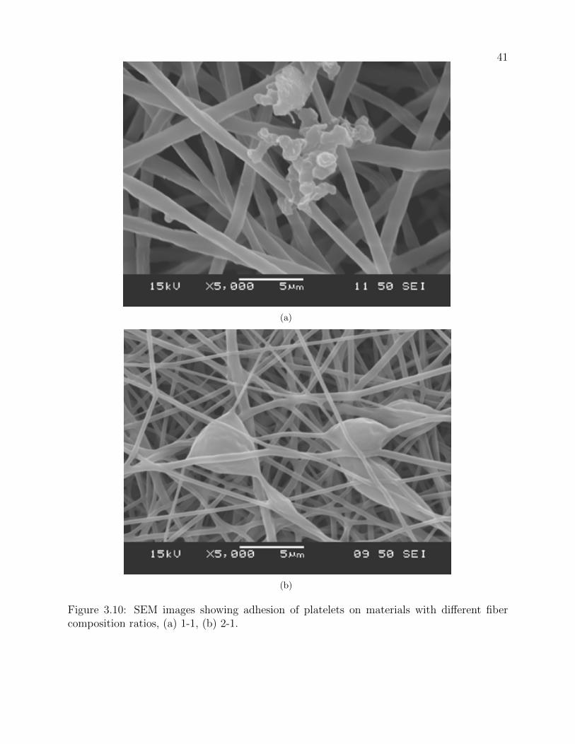
41
3
Figure 4. SEM images showing adhesion of platelets on materials with different fiber composition ratios, (a) 1-1, (b) 2-1, (c) 4-1, and (d) bare nitinol
(a)
3
Figure 4. SEM images showing adhesion of platelets on materials with different fiber composition ratios, (a) 1-1, (b) 2-1, (c) 4-1, and (d) bare nitinol
(b)
Figure 3.10: SEM images showing adhesion of platelets on materials with different fibercomposition ratios, (a) 1-1, (b) 2-1.

42
3
Figure 4. SEM images showing adhesion of platelets on materials with different fiber composition ratios, (a) 1-1, (b) 2-1, (c) 4-1, and (d) bare nitinol
(a)
3
Figure 4. SEM images showing adhesion of platelets on materials with different fiber composition ratios, (a) 1-1, (b) 2-1, (c) 4-1, and (d) bare nitinol
(b)
Figure 3.11: SEM images showing adhesion of platelets on materials with different fibercomposition ratios, (a) 4-1, and (b) bare nitinol.

43
4
B a r e 1 -1 2 -1 4 -10 .0
0 .2
0 .4
0 .6
0 .8
1 .0
SM
C a
tta
ch
me
nt
are
a r
ati
o
B a r e 1 -1 2 -1 4 -10 .0
0 .2
0 .4
0 .6
0 .8
1 .0
Pla
tele
t a
tta
ch
me
nt
are
a r
ati
o
Figure 5. Comparisons of the attachment area ratios for SMC (a) and platelet (b) on the bare nitinol and coating materials with different PLLA-PEGDMA fiber ratios. “*”: denotes significant difference of the denoted column from all others with p<0.05. “**”: denotes significant difference of the denoted column from all others with p<0.10.
b
**
a
* *
(a)
4
B a r e 1 -1 2 -1 4 -10 .0
0 .2
0 .4
0 .6
0 .8
1 .0
SM
C a
tta
ch
me
nt
are
a r
ati
o
B a r e 1 -1 2 -1 4 -10 .0
0 .2
0 .4
0 .6
0 .8
1 .0
Pla
tele
t a
tta
ch
me
nt
are
a r
ati
o
Figure 5. Comparisons of the attachment area ratios for SMC (a) and platelet (b) on the bare nitinol and coating materials with different PLLA-PEGDMA fiber ratios. “*”: denotes significant difference of the denoted column from all others with p<0.05. “**”: denotes significant difference of the denoted column from all others with p<0.10.
b
**
a
* *
(b)
Figure 3.12: Comparisons of the attachment area ratios for SMC (a) and platelet (b) on thebare nitinol and coating materials with different PLLA/PEGDMA fiber ratios. ∗: denotessignificant difference of the denoted column from all others with p <0.05. ∗∗: denotessignificant difference of the denoted column from all others with p <0.10.

44
3.3.6 Secretory Function of MSCs on Proliferation and Chemotaxis Vascular
Cells
Stem cells are increasingly used as novel cell therapy tools for cardiovascular diseases
(Suma et al., 2015), in particular, the secretory function or paracrine signaling of MSCs
becomes well recognized recently (Suma et al., 2015; Wingate et al., 2012). Therefore, we
further evaluated how the coating composition influenced secretory function of MSCs, which
in turn affected vascular cell activities. The EC proliferation results using the conditioned
media from MSCs cultures on different nitinol coatings are presented in Figure 3.13(a), which
shows a small increase in proliferation for cells on the 4-1 coating when compared to 1-1.
Because the only change in fiber composition ratios from 4-1 to 1-1 is that the amount of
hydrophilic PEGDMA polymer increases, the results suggest PEGDMA composition in the
blend might only have small influence on MSC secretory function to affect EC proliferation.
Migration of ECs is presented in Figure 3.13(b) which shows no significant difference
among all the surfaces. This suggests that increasing PEGDMA component is not helpful
in modulating MSCs signaling functions in attracting ECs toward the coating material.
Therefore, regeneration of vascular tissue may be not very significantly affected by the soft,
hydrophilic PEGDMA that adds into PLLA fibers. The SMC proliferation and migration
results using the conditioned media from MSC cultures on different nitinol coatings are
presented in Figure 3.14(a) and Figure 3.14(b), respectively, which shows no significant
differences were found in the activities of SMCs.

45
5
.
B a r e 1 -1 2 -1 4 -10
1 0 0 0 0
2 0 0 0 0
3 0 0 0 0
4 0 0 0 0
5 0 0 0 0
RF
U
B a r e 1 -1 2 -1 4 -10
1 0
2 0
3 0
Ce
ll C
ou
nt
B a r e 1 -1 2 -1 4 -10
2 0 0 0 0
4 0 0 0 0
6 0 0 0 0
8 0 0 0 0
RF
U
B a r e 1 -1 2 -1 4 -1
0
5 0
1 0 0
1 5 0
2 0 0
2 5 0
Ce
ll C
ou
nt
Figure 6. Comparisons of the effects of MSC secretory functions on vascular activities, including (a) EC proliferation, (b) EC migration, (c) SMC proliferation, and (d) SMC migration, on the bare nitinol and coating materials with different PLLA/PEGDMA fiber ratios. “*” denotes significant difference of the denoted column from all others with p<0.05.
*
(a)
5
.
B a r e 1 -1 2 -1 4 -10
1 0 0 0 0
2 0 0 0 0
3 0 0 0 0
4 0 0 0 0
5 0 0 0 0
RF
U
B a r e 1 -1 2 -1 4 -10
1 0
2 0
3 0
Ce
ll C
ou
nt
B a r e 1 -1 2 -1 4 -10
2 0 0 0 0
4 0 0 0 0
6 0 0 0 0
8 0 0 0 0
RF
U
B a r e 1 -1 2 -1 4 -1
0
5 0
1 0 0
1 5 0
2 0 0
2 5 0
Ce
ll C
ou
nt
Figure 6. Comparisons of the effects of MSC secretory functions on vascular activities, including (a) EC proliferation, (b) EC migration, (c) SMC proliferation, and (d) SMC migration, on the bare nitinol and coating materials with different PLLA/PEGDMA fiber ratios. “*” denotes significant difference of the denoted column from all others with p<0.05.
*
(b)
Figure 3.13: Comparisons of the effects of MSC secretory functions on vascular activities,including (a) EC proliferation, (b) EC migration. ∗ denotes significant difference of thedenoted column from all others with p <0.05.

46
5
.
B a r e 1 -1 2 -1 4 -10
1 0 0 0 0
2 0 0 0 0
3 0 0 0 0
4 0 0 0 0
5 0 0 0 0
RF
U
B a r e 1 -1 2 -1 4 -10
1 0
2 0
3 0
Ce
ll C
ou
nt
B a r e 1 -1 2 -1 4 -10
2 0 0 0 0
4 0 0 0 0
6 0 0 0 0
8 0 0 0 0
RF
U
B a r e 1 -1 2 -1 4 -1
0
5 0
1 0 0
1 5 0
2 0 0
2 5 0
Ce
ll C
ou
nt
Figure 6. Comparisons of the effects of MSC secretory functions on vascular activities, including (a) EC proliferation, (b) EC migration, (c) SMC proliferation, and (d) SMC migration, on the bare nitinol and coating materials with different PLLA/PEGDMA fiber ratios. “*” denotes significant difference of the denoted column from all others with p<0.05.
*
(a)
5
.
B a r e 1 -1 2 -1 4 -10
1 0 0 0 0
2 0 0 0 0
3 0 0 0 0
4 0 0 0 0
5 0 0 0 0
RF
U
B a r e 1 -1 2 -1 4 -10
1 0
2 0
3 0
Ce
ll C
ou
nt
B a r e 1 -1 2 -1 4 -10
2 0 0 0 0
4 0 0 0 0
6 0 0 0 0
8 0 0 0 0
RF
U
B a r e 1 -1 2 -1 4 -1
0
5 0
1 0 0
1 5 0
2 0 0
2 5 0
Ce
ll C
ou
nt
Figure 6. Comparisons of the effects of MSC secretory functions on vascular activities, including (a) EC proliferation, (b) EC migration, (c) SMC proliferation, and (d) SMC migration, on the bare nitinol and coating materials with different PLLA/PEGDMA fiber ratios. “*” denotes significant difference of the denoted column from all others with p<0.05.
*
(b)
Figure 3.14: Comparisons of the effects of MSC secretory functions on vascular activities,including (a) SMC proliferation, and (b) SMC migration, on the bare nitinol and coatingmaterials with different PLLA/PEGDMA fiber ratios. ∗ denotes significant difference of thedenoted column from all others with p <0.05.

Chapter 4
Coaxially Structured PEGDMA/PLLA Nanofibrous Hydrogel As Novel
Vascular Stent Coating
This chapter is based on:
Boodagh, P. Durante, L., Ding, Y., Guo, D.J., Johnson R., Rosario-Ortiz, F., and
Tan, W. (2017), Coaxially Structured PEGDMA/PLLA Nanofibrous Hydrogel As Novel Vas-
cular Stent Coating, Submitted to Journal of Langmuir
4.1 Introduction
Cardiovascular disease has been the leading cause of death and morbidity in many
developed countries. Among cardiovascular diseases, atherosclerosis, the narrowing of the
vessel lumen due to fatty plaque buildup inside arteries, is the most common disease con-
dition. To treat such cardiovascular condition, the stenting method is often used, and it
has undergone significant advancement over the past few decades, in particular with the
emergence of various stent coatings to elute drugs or to capture endothelial progenitor cells
(Stefanini and Holmes Jr, 2013; Garg et al., 2010; Wilson and Cruden, 2013). However,
the artery stent, such as coronary stent implanted through percutaneous coronary interven-
tion, is associated with two major complications: (a) in-stent thrombosis which leads to
thrombotic occlusion, and (b) in-stent restenosis which decreases arterial lumen space due
to neointimal proliferation(Wilson and Cruden, 2013). Thrombosis results from the accu-

48
mulation of blood components such as platelets and fibrin around the injured blood vessel,
whereas restenosis results mainly from abnormal overgrowth of smooth muscle cells (SMCs)
around stent struts (Curcio et al., 2011; Uchida et al., 2010). It is well known that the com-
position, structure, and elasticity of the extra-cellular matrix (ECM) can regulate protein
adhesion and cell attachment, proliferation, migration, or differentiation. Therefore, iden-
tifying key environmental factors that inhibit platelet adhesion and SMC growth is critical
for the improvement of artery stents and other cardiovascular implants.
Recent studies have highlighted the influence of mechanical properties of ECM on cel-
lular behaviors, such as cell-matrix adhesions, motility, differentiation, and viability (Park
et al., 2007; Dahan et al., 2011). Emerging evidence supports the hypothesis that cells sense
their mechanical environments and amend their behaviors in response to local changes in
the matrix stiffness. ECM stiffness can be modulated by a wide array of methods includ-
ing varying chemical cross-linking, hydrogel density, and scaffold composition(Brown et al.,
2010; Duncombe et al., 2016; Boodagh et al., 2016). Replicating the elasticity of the vessel
basement membrane and medial layers in vitro could produce an engineered environment to
articulate the in-vivo bio-response. For soft tissues like blood vessels, nanofibers with low
elasticity (i.e. in the range of 2-15 kPa) are needed(Peloquin et al., 2011). Recent studies
have accentuated the significance of the microenvironment elasticity on cell function (Wen
et al., 2014; Wingate et al., 2012), mostly focus on muscle, neural or bone tissues (Byfield
et al., 2009). However, little has been done to translate these important environmental
controls into the design of vascular implants.
Among the artificial materials used for biomedical applications, biocompatible and
biodegradable hydrophobic polymers such as poly L-lactic acid (PLLA) have been favorably
used in tissue engineering applications (Fu et al., 2014; Zhu et al., 2014; Jia et al., 2013). It
has also been often used as the material for controlled drug release on drug-eluting stents. In
spite of the high mechanical stability, hydrophobic nature of PLLA tend to trigger platelet
and plasma protein adhesion, causing platelet aggregation and intimal hyperplasia of the

49
artificial blood vessels (Zilla et al., 2007). By contrast, polyethylene glycol dimethacrylate
(PEGDMA) is a well-recognized non-toxic and bioinert polymer hydrogel, has been widely
used as a coating material due to its compatibility with biological system while low protein,
cell, and bacterial adhesion on surfaces. PEGDMA is very hydrophilic, which plays an im-
portant role in its blood compatibility. Therefore, the combination of hydrophobic polymer
of PLLA with hydrophilic PEGDMA may provide appropriate material strength and elas-
ticity with anti-thrombotic and anti-proliferative properties for vascular implants. Material
design efforts should be taken to integrate them so that the stiff PLLA core could provide
the mechanical strength and stability of the scaffold as well as potential reservoir for drugs
while the soft PEGDMA sheath ensures its enhanced anti-thrombosis, anti-proliferation and
mimetic viscoelasticity.
To that end, this study attempts to coaxially electrospin two physically and mechan-
ically different materials into fibers composed of low fouling, non-immunogenic hydrophilic
PEGDMA sheathing with the hydrophobic core made of PLLA. These hybrid fibers, as a
coating material, might hold potentials for a variety of vascular implant applications. We
seek a pathway to control in-stent thrombosis and in-stent restenosis, modulating the activ-
ity of platelets and SMCs by designing fiber coating around stent with anticoagulant and
anti-proliferative properties. The main focus is on examining how the elasticity, composition,
and structure of fibrous matrix interact to inhibit in-stent thrombosis and in-stent resteno-
sis. Herein, the physical, mechanical, and biological performances of the hybrid fibrous stent
coatings were evaluated, using nitinol a widely-used stent material. For this purpose, elastic-
ity of coaxially electrospun coatings was altered by adjusting the UV photopolymerization
time. Three UV polymerization times of 2, 15, and 60 min were selected. Mechanical and
material characterizations were performed and attachment of platelets and arterial SMCs
onto the coatings were assessed in vitro.

50
4.2 Materials and Methods
4.2.1 Materials
All reagents were purchased from Sigma Inc. (St. Louis, MO), unless otherwise stated.
PEGDMA was synthesized from poly (ethylene glycol) (PEG) which is purchased from Fisher
Scientific Inc. (San Francisco, CA).
4.2.2 Preparation of Stent Material and Polymer Coating
In order to simulate stent implant modification in-vitro, nitinol stent materials (Kel-
loggs research labs, Hudson, NH) were used. They were prepared by cutting a nitinol plate
with water jet by Waterjet Inc. (Longmont, CO) into 5 mm × 10 mm pieces. The thickness
of each nitinol stent sample was 1 mm. Segments of nitinol were cleaned with the ultrasonic
method by first placing the nitinol pieces in an uncapped plastic centrifuge tube filled with
acetone for 10 minutes and then with water. After cleaning, the nitinol pieces were treated
with oxygen plasma at about 1-2 cm H2O oxygen pressure for 5 minutes. The activated niti-
nol pieces were immediately used to collect coaxially electrospun PEGDMA/PLLA polymers.
The coated samples were finally placed under UV lamp and allowed photo-polymerization
to occur at three different times (2, 15, and 60 min).
4.2.3 Fabrication of coaxially electrospun fibers
PEGDMA with a molecular weight of 3,000 was synthesized with approximately 90% of
the end groups modified with methacrylates as determined by 1H NMR analysis PEGDMA
(3000 Da) was synthesized using the method described in our previous paper (Boodagh et al.,
2016) with approximately 90% of the end groups modified with methacrylates as determined
by 1H NMR analysis.
Electrospinning solution for the core is composed of 3% w/v PLLA dissolved in 2, 2,
2 trifluororethanol (TFE) (Alfa Aesar, Sparks, NV). Electrospinning solution for sheath is

51
composed of 50% w/v PEGDMA and 3% w/v polyethylene oxide (PEO, 40 kDa) with mix-
ing volume ratio of 7 and 3, respectively, and 0.4% w/v Irgacure 2959 (I2959, 0.6 mg/mL
in deionized water; Ciba, Tarrytown, NY) dissolved in TFE. PEGDMA and PEO are hy-
drophilic polymers dissolvable in water. The reason that water was chosen as the solvent for
PEGDMA but TFE for both PLLA and PEGDMA-PEO was to eliminate possible incom-
patibility problems through coaxial electrospinning of core and sheath. The apparatus used
for obtaining coaxial fibers was developed in house. The solution of the core hydrophobic
polymer, PLLA, was passed through the inner needle of 22 gauge (0.71 mm in internal di-
ameter), and the sheath PEGDMA-PEO solution was passed through the outer needle of 16
gauge (1.65 mm in internal diameter). A dual syringe holder was used to place the syringes
loaded with polymer solutions. This design allows the solutions to be extruded simultane-
ously. The core and sheath solutions were loaded in 5 ml syringes connected to the positive
terminal of a high voltage ES30P 13 W power supply (Gamma High Voltage Research, Or-
mond Beach, FL). The core and sheath polymer solutions were extruded at 0.7 ml/h and
1.1 ml/h, respectively, using syringe pumps (Pump 11 Plus, Harvard Apparatus, Boston,
MA), and were subjected to an electric potential of 1 kV/cm. The fibers were deposited
onto a grounded static aluminum substrate placed at a distance of 17 cm perpendicular to
the needle. The coated nitinol specimens with fibrous PLLA/PEGDMA-PEO coating were
placed in plastic centrifuge tube under vacuum for 15 min, followed by UV polymerization
at 365 nm with an average intensity of 5 mW/cm2 for 2, 15, or 60 min.
4.2.4 Scanning electron microscopy imaging
Samples were then dehydrated through an ethanol series (30, 50, 75, 90, and 100%;
15 min each), and subsequently maintained in 100% ethyl alcohol until drying. They were
dried overnight in a vacuum chamber and sputter-coated with gold before scanning electron
microscope (SEM) to examine their average diameter. The nitinol substrates coated with the
electrospun fibers were mounted on brass stubs and observed under a SEM (JEOL JSM-6480

52
LV, Peabody, MA) operating at an accelerating voltage of 15 kV. The diameters of about
10 different fibers were measured in each of the above case using the Image-J tool to obtain
their average diameter. For hydrated state, samples were photopolymerized for 5, 15 and 60
min, and submerged in DI H2O for 24 h.
4.2.5 Transmission electron spectroscopy imaging
Microstructures of coaxially electrospun fibers were observed using H7650 transmission
electron microscope (TEM; Hitachi Ltd., Tokyo, Japan) operated at 100 kV to characterize
the core-sheath morphology. The coaxially electrospun samples for TEM observation were
prepared by directly depositing an ultrathin layer of fibers on carbon-coated copper TEM
grids.
4.2.6 Water contact angle measurement
The water contact angle measurement was conducted using GBX Instrument (Bourg
de Peage, France) apparatus, which determines the wettability of coaxially electrospun sub-
strate. To start this, a minimal amount (∼ 3µl) of distilled water droplet was dropped onto
the surface of an electrospun mat. The water contact angle was then measured from the
image of the droplet.
4.2.7 Mechanical testing
Uni-axial tensile testing was performed using electromechanical testing system (MTS
Exceed E42, Eden Prairie, MN) with 500 N load cell. Samples of coaxially electrospun
scaffolds were punched into the dog bone shape with a width of 4 mm and gauge length of 20
mm using ASTM dog-bone D638-V cutter. The samples were secured in the grips of a tensile
tester with 15 mm space between grips and loaded until failure. Samples were submerged in
DI H2O for 24 hr before mounted to wedge grips and the tensile testing was performed on
them in the hydrated state. Using 150 N load cell, load-elongation measurement was carried

53
out at a speed of 0.03 mm/sec, 25oC temperature and relative humidity of 65%. Samples
with data indicating slip- page or excessive noise were not used. A classic heel-toe stress-
strain curve was observed for hydrated coaxial structured electrospun samples. The hydrated
elastic modulus of samples was determined from the low-strain linear region (0-25%) of the
curve.
The viscoelastic properties of coaxially-spun scaffolds were investigated under shear
deformation using an ARES rheometer (TA Instrument, New Castle, DE). Coaxially elec-
trospun fibers were collected on 3-(trimethoxysilyl)-propyl methacrylate (TMPMA) treated
cover-slip with 18 mm in diameter and at least 0.3 mm in thickness. Prior to testing, samples
were submerged in DI water for 24 hr. Variations in the storage modulus, G’, of samples
due to increased photopolymerization time were characterized by running a strain sweep
at 1 rad/s frequency using a parallel plate configuration rheometer. A vertical load of 16
g was also applied to all samples to prevent slippage. The storage modulus, G’, and loss
modulus, G”, of scaffolds as well as tan δ (where tan δ = G′/G′′) were determined in the
linear viscoelastic region. The complex modulus, G∗, can be calculated using G∗ = G′+ iG′′.
Shear modulus was determined with constant strain application, reflecting the difference
in material viscosity. In order to avoid sample slippage during rheometer measurement,
the coverslips were treated with TMPMA before electrospun sample deposition. Briefly,
cover-slips were placed in tube filled with acetone and ultrasound was applied for 45 min.
Subsequently, the coverslips were immersed in 70% ethanol for 2-5 minutes, which helped to
separate coverslips, and were then dried over kimwipes. After that, they were treated with
oxygen plasma for 2 min, and then immediately placed in tubes filled with TMPMA solution
(100 ml of 95% ethanol, 3 ml of diluted acetic acid with 1:10 of glacial acetic acid-to-water
ratio, and 500 µl of TMPMA). The tubes with coverslips in TMPMA solution were placed
over shaker table for 30 min to ensure uniform coating. The coverslips were then rinsed in
95% ethanol twice, dried over kimwipes, and stored at -20oC freezer or immediately used as
the substrate for nanofiber collection.

54
4.2.8 ATR-FTIR spectroscopy
Attenuated total reflection-Fourier transform infrared spectroscopy (ATR-FTIR) measure-
ments were carried out on peeled fibrous membranes using Nicolet 5700 FTIR spectrometer
(Thermo Fisher Scientific, Logan, UT) equipped with a diamond ATR crystal. Typically,
30 scans were signal-averaged to reduce spectral noise. The spectrum of the samples ranged
from 600 to 4000 cm−1.
ATR-FTIR was used to evaluate coaxially electrospun scaffolds for double bond con-
version by inspecting the disappearance of the C=C peak occurring at around 1635 cm−1
within the acrylate group. Samples with three photopolymerzation times, 2, 15 and 60 min,
were examined with ATR-FTIR. ATR-FTIR spectra were normalized with the C=O peak
located in the range of 1650-1726 cm−1 in order to render sample background variation as
the peak is independent of photopolymerization. Also, ATR-FTIR was used to probe the
surface property of samples, hence demonstrating the coaxially structured electrospun fibers.
Data were analyzed using “OriginPro” software (Northampton, MA).
4.2.9 Thermogravimetric analysis
Thermogravimetric analysis (TGA) of the fibers was performed using universal Netzsch
204 F1 (Phoenix, AZ). About 5 mg of the samples were heated at the rate of 10oC min−1 in
an inert atmosphere with temperature ranging 0-500oC using platinum crucibles. Differential
thermal curves were obtained from the TGA curves by plotting a graph of derivative weight
percentage as a function of temperature.
4.2.10 Differential scanning calorimetry
Differential scanning calorimetry (DSC) was performed to obtain thermal transitions
and properties of materials using DSC Q2000 (TA Instruments, New Castle, DE). The
procedure started with a first heating ramp to reach 250oC, which was followed by a cooling
55
step to 0oC, and then a second heating reaching 250oC again. Heating and cooling rate was
kept at 10oC min−1 under the nitrogen flow of 20 ml min−1.
4.2.11 Smooth muscle cell attachment and spreading study
Rat pulmonary artery SMCs with passage of 6-10 were used for all the experiments.
Cells were cultured in Dulbecco’s Modified Eagle Medium (DMEM) (Corning, Corning, NY)
with 10% FBS (Atlanta Biologicals, Flowery Branch, GA), 2% L-glutamine, 1% non-essential
amino acids and 1% Penicillin/Streptomycin at 37C with 5% CO2 in T75 flasks. Upon
confluency of SMCs, they were seeded on nitinol pieces coated with coaxially electrospun
fibers as well as bare nitinol at a density of 3.3×10⁴ cells/ cm2 in the complete culture media.
Cell attachment was evaluated based on the cell number on the stent material after 2
hr incubation. To perform the evaluation, samples were first washed with warm phosphate
buffer solution (PBS) after aspiration of the media. Subsequently, samples were fixed with
4% paraformaldehyde (PFA; Sigma-Aldrich) in PBS for 20 min at room temperature, which
was followed by washing twice in PBS for 5 min. The cells were then permeabilized with 0.5%
Triton X-100 in PBS for 15 min. Subsequently, the cells were stained for F-actin with FITC-
phalloidin (26.5 nM; Sigma-Aldrich) and 4’, 6-diamidino-2-phenylindole (DAPI, 1 µg/mL;
Sigma-Aldrich) diluted in 1.5% BSA in PBS for 30 min at room temperature. The samples
were finally washed three times in PBS and mounted on microscope slides for examination
using a fluorescent microscope. Cell count was analyzed with the “Analyze particles” tool in
Image-J (National Institutes of Health). For quantification of cell numbers, the image was
converted to 8 bit, and adjusted with a threshold.
4.2.12 Platelet adhesion assay
The blood compatibility of implantable materials was assessed by platelet adhesion
study. The adhesion of platelet onto samples was studied by adding 300 µl of bovine platelet-
rich plasma (Innovative Research, Novi, MI) to a 48-well tissue culture plate with samples

56
on the bottom and incubating at 37oC for 2 hr on a rotating table. After washing in PBS
to remove unattached platelets, the samples were fixed using 2.5% glutaraldehyde at 4oC
for 2hr, and then rinsed twice in PBS. Samples were then dehydrated through an ethanol
series (30, 50, 75, 90, and 100%; 15 min each), and subsequently maintained in 100% ethyl
alcohol until drying. They were dried overnight in a vacuum chamber and sputter-coated
with gold before SEM (JEOL JSM6480 LV) to examine the number and morphology of
platelets adhering to the surface.
4.2.13 Statistical analysis
Statistical study was performed at least three substrates were used for each assay,
and all assays were repeated in triplicate. All data are expressed as mean ± standard
deviation (SD). One-way analysis of variance (ANOVA) test was used to measure difference
for experiments with multiple data sets with a Tukey multiple comparison tests performed
between groups with significant difference. A pvalue of ≤ 0.05 was considered statistically
significant.
4.2.14 Fabrication Description
A PEO-coated 20G needle (1.25 mm in diameter) was first attached to an aluminum
rod used as a rotating mandrel in the electrospinning system. The needle was then used as
the substrate to collect fibers at a rotational speed of 150 rpm for 15 minutes. Electrospinning
setup was established with designated distance, voltage and flow rates with fiber solutions
prepared as outlined above. Once coated, the needle was removed from the aluminum rod.
Then, a plasma treated vascular stent was carefully slided over the fiber-coated 20G needle.
The needle/stent complex was re-attached to the end of the aluminum rod mandrel. Using
the needle/stent complex as the substrate to collect fibers on the mandrel, the electrospinning
system ran additional 20 minutes following the same parameters as the first step of fiber
coating, to allow complete coverage of fibers on the surface. After the process was complete,

57
the coated graft/stent complex was placed under UV for photo-polymerization. Finally, the
complex was submerged in PBS for 1 hour to hydrate the fiber and dissolve the PEO layer
for easy removal of the fiber-coated stent from the needle.
4.3 Results
4.3.1 SEM and TEM imaging of coaxially electrospun PEGDMA/PLLA
coatings showing their micro- and nano- structure as well as their hy-
drogel nature
Figure 4.1 shows the SEM images of the coaxially electrospun fibers made of PEGDMA-
sheathed PLLA. Fibers are displayed in their dry state (Figures 4.1(a)-4.1(c)) and in their
hydrated state (Figures 4.1(d)-4.1(f)). Images show that the 3D fiber networks have been
formed and there are no apparent differences in the fiber morphology among samples poly-
merized with different UV exposure times. All the fibers exhibit obvious swelling after
hydration, indicating the hydrogel nature of the PEGDMA sheath layer. Using Image-J
software to analyze SEM images, fiber diameters were quantitatively determined (Figure
4.1(g)). It was noted that the average diameter of coaxially electrospun fibers in hydrated
samples with 2 min photopolymerization was slightly higher than those with 15 min or 60
min photopolymerization, likely due to the higher cross-linking degree under longer UV ex-
posure time yielding less swollen fibers. In terms of material processing, the sheath solution
is important to stabilize the core formation. Here we have used PEGDMA in TFE with addi-
tion of PEO as the sheath solution. PEO was included as a carrier polymer to improve fiber
formation during electrospinning. In order to obtain a stable fiber formation, varied concen-
trations of PEGDMA and PEO in the sheath solution were experimented. Smooth beadless
coaxial PEGDMA/PLLA fibers with complete evaporation of solvent from the surface of the
fibers were ultimately achieved, as demonstrated in Figures 4.1(a)-4.1(c).
The nanostructure of the core-sheath coaxial electrospun fiber was visualized under

58
TEM (Figure 4.1(h)). The different structural density between the PLLA core and PEGDMA
sheath resulted in distinct contrast in the TEM image. The inner darker region is corre-
sponding to the PLLA core layer while the outside lighter region is to the PEGDMA sheath
material. The core-to-fiber diameter ratio is 0.646 ± 0.10, respectively. Previous work on
electrospun coaxial fibers made of different types of materials also showed clear edges between
core and sheath fibers (Nagiah et al., 2015).
To confirm the hydrophilicity of the coaxially electrospun PLLA/PEGDMA coatings,
the coated surfaces were analyzed using water contact angle measurements. In all electro-
spun mats with varying UV photopolymerization times, the water drop, upon exposure to
the surface, was immediately absorbed into the coated nitinol pieces, indicating their high hy-
drophilicity. Collectively, these results suggested the successful coaxial PEGDMA-sheathed
PLLA fibers, having PEGDMA entirely covered the hydrophobic PLLA core and resulting
in hydrophilic hydrogel coating on top of nitinol stent material.
4.3.2 ATR-FTIR spectroscopy results showing the PEGDMA sheath of
coaxially electrospun fibers varies with photopolymerization time
To determine the effect of UV polymerization time on the chemical composition of the
fibrous coating, FTIR analysis was carried out on coaxially electrospun PEGDMA/PLLA
samples photopolymerized for 2, 15 and 60 min. Several functional groups of the products
were examined. The infrared (IR) spectrum of coaxially-structured fibers, as shown in Figure
4.2, illustrated a series of characteristic bands of PEGDMA at 2800-3300 cm−1 (O-H stretch),
1650-1739 cm−1 (C=O stretch), 1635-1637 cm−1 (C=C stretch), 1100-1150 cm−1 (C-O acyl),
and 960 cm−1 (C-H bend). The fact that coaxially-structured fibers show all PEGDMA
peaks, further confirm the coating of PEGDMA over PLLA fibers. The intensity of reactive
acrylate peak (C=C) at 1635 cm−1 decreased with the increase in the UV exposure time,
and almost disappeared after 60 min. Table 4.1 summarizes the calculated peak areas of
C=O and C=C peaks, as well as the ratio of C=C to C=O peak.
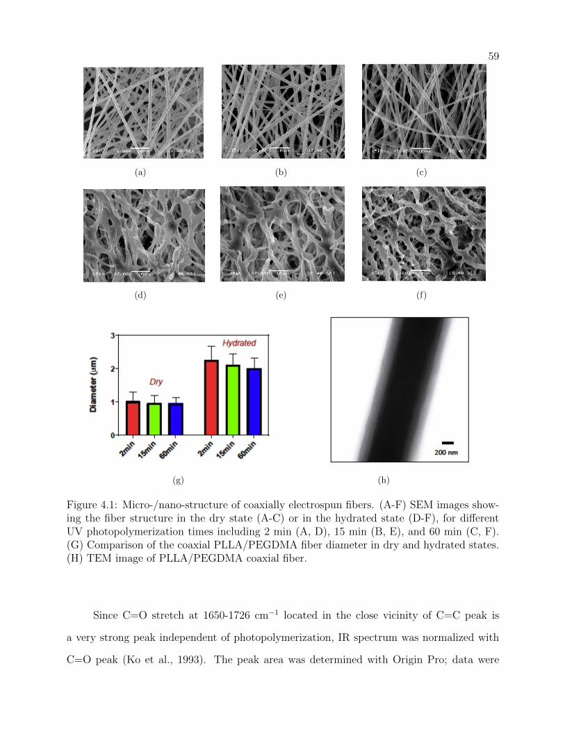
59
B C
D E F
G H
(a)
A C
D E F
G H
(b)
A B
D E F
G H
(c)
A B C
E F
G H(d)
A B C
D F
G H (e)
A B C
D E
G H (f)
A B C
D E F
H
(g)
A B C
D E F
G
(h)
Figure 4.1: Micro-/nano-structure of coaxially electrospun fibers. (A-F) SEM images show-ing the fiber structure in the dry state (A-C) or in the hydrated state (D-F), for differentUV photopolymerization times including 2 min (A, D), 15 min (B, E), and 60 min (C, F).(G) Comparison of the coaxial PLLA/PEGDMA fiber diameter in dry and hydrated states.(H) TEM image of PLLA/PEGDMA coaxial fiber.
Since C=O stretch at 1650-1726 cm−1 located in the close vicinity of C=C peak is
a very strong peak independent of photopolymerization, IR spectrum was normalized with
C=O peak (Ko et al., 1993). The peak area was determined with Origin Pro; data were

60
Table 4.1: Analysis of FTIR data taken in absorbance mode from 400 cm−1 to 4000 cm−1
wavelengths for coaxially electrospun fibers with various photopolymerization times, showingthe peak areas of C=O and C=C peaks, as well as the ratio of C=C to C=O peak.
Photopolymerization time[min]
Peak area: 1739-1675 cm−1
Peak area: 1650-1607 cm−1
Ratio [%]
2 2.27 0.29 12.7815 2.04 0.24 11.8860 2.03 0.17 8.29
taken in absorbance mode from 400 cm−1 to 4,000 cm−1 wavelengths. The samples with 15
min and 60 min photopolymerization times showed 12% and 33% decrease, respectively, in
the acrylate peak area, when compared with those polymerized for 2 min. The analysis of
ATR- FTIR curves shows that the majority of C=C bonds break to cross-link at two end
methacrylate groups after 60 min of UV exposure due to the nearly completed polymerization
reaction. The result agrees with our previous study utilizing PEGDMA alone with varied
photopolymerization times (Wingate et al., 2012). Because a low concentration of reactive
acrylates is present for the high molecular weight (3,000 Da) PEGDMA, the acrylate peak
in the FTIR spectra displays low intensity.
4.3.3 Mechanical properties of coaxially electrospun fibrous scaffolds improve
with increased photopolymerization time
Figure 4.3(a) shows the results from tensile tests on hydrated samples. The average
elastic moduli of hydrated samples with 2, 15, and 60 min UV exposure times are 172, 366,
and 729 kPa, respectively. Among the three types of PEGDMA samples with varied poly-
merization times (i.e. 2, 15, and 60 min), the hydrated sample with a photopolymerization
time of 60 min shows the highest value in elastic modulus. Stress and strain values as well as
the Young’s modulus of the fibrous coatings were determined from load-displacement curves.
Figure 4.3(b) illustrates the representative stress-strain curves of samples.
Figure 4.3(c) demonstrates the storage modulus for each sample and Figure 4.3(d)

61
B
(a)
A
(b)
Figure 4.2: Typical FTIR spectra of the pure PLLA, PEGDMA, and coaxialPLLA/PEGDMA fibers in the entire scanned range (A), and in a specific range of 1600to 1800 cm−1 (B).

62
shows changes of the average complex modulus, G∗. Storage moduli vary from 6.5 kPa
for 2 min samples to 14.5 kPa for 60 min samples, with the modulus increasing with the
photopolymerization time.
1 00 0
800 *
600
400
200
0 60min 15min 2 min
Ela
stic
Mo
du
lus
( kP
a)
B
C D
0 10 20 30 40 50 600.0
0.2
0.4
0.6
Tens
ileSt
ress
(MPa
)
15min60min2min
Strain(%)
(a)
1 00 0
800 * 600
400
200
0 60min 15min 2 min
Ela
stic
Mo
du
lus
(kP
a)
A
C D
0 10 20 30 40 50 600.0
0.2
0.4
0.6
Tens
ile S
tres
s (M
Pa)
15min 60min 2min
Strain(%)
(b)
1 00 0
800 * 600
400
200
0 60min 15min 2 min
Ela
stic
Mo
du
lus
(kP
a)
A B
D
0 10 20 30 40 50 600.0
0.2
0.4
0.6
Tens
ileSt
ress
(MPa
)
15min60min2min
Strain(%)
(c)
1 00 0
800 * 600
400
200
0 60min 15min 2 min
Ela
stic
Mo
du
lus
(kP
a)
A B
C
0 10 20 30 40 50 600.0
0.2
0.4
0.6
Tens
ileSt
ress
(MPa
)
15min60min2min
Strain(%)
(d)
Figure 4.3: Mechanical characterization results of the coaxial PLLA/PEGDMA fibers. (A)Elastic modulus results from tensile test for samples with different UV photopolymerizationtimes. (B) Representative tensile stress-strain curves. (C) Storage modulus results fromrheometer test for samples with different UV photopolymerization times. (D) Complexmodulus. “*” denotes significant difference of the denoted column from all the others withp < 0.05.
The results are in good agreement with our previous findings that reported the pho-
topolymerziation times of PEGDMA produced scaffolds with varying stiffness (Wingate
et al., 2012).The storage modulus values of coaxially-structured fibers are around 3 folds

63
of those PEGDMA fibers for each polymerization time. Rheometry tests in strain sweep
showed the linear viscoelastic regions located in the similar strain ranges for all three sam-
ples with varied photopolymerization time, indicating similar dynamic mechanical responses
for all samples. It is likely that the increase in the UV exposure time of PEGDMA leads
to an increase in the crosslinking density of PEGDMA and interfibrillar connection as well
as physical entanglement of the polymer chains, leading to an increase in elastic modulus
of materials with constant PLLA core material. By performing rheometry tests, dynamic
viscoelastic properties including the storage modulus, G’, the average complex modulus, G∗,
and shear stress values under the constant strain were determined. The rheometry results
were in agreement with the tensile testing results, showing the highest values for 60 min UV
polymerized samples and the lowest values for 2 min UV polymerized ones, though the mod-
ulus values from mechanical tests are more than 10 times of those yielded from rheometry
test. Overall, our results on the mechanical property characterizations of coaxially electro-
spun fibers including average tensile modulus and dynamic modulus (G’ and G”) are listed
in the Table 4.2.
Table 4.2: Mechanical properties of coaxially spun scaffolds
Photopolymerization time [min]2 15 60
Average elastic modulus, E (kPa) 172± 15 366 ± 41 729 ± 95Average storage modulus, G’ (kPa) 6.0 ± 0.71 8.4 ± 3.1 14.5 ± 1.5Average loss modulus, G” (kPa) 0.36±0.28 0.78±0.42 1.4±0.39Average stress at break, σb (kPa) 82 ±7 157 ± 10 325 ± 30Average strain at break, Eb (%) 48.3 ± 5 43.6 ± 4 48.4 ± 5
4.3.4 Thermal properties of coaxially electrospun fibers
The thermal stability of the coaxially electrospun PEGDMA/PLLA coatings with var-
ied polymerization times was evaluated using DSC and TGA. Figures 4.3(a) and 4.3(b)show
representative thermal behaviors of the coaxially electrospun mats as well as pure PLLA and

64
PEGDMA mats. The pure polymers showed different transition temperatures when com-
pared to coaxially-structured fibers. As shown in Figure 4.4(a), a sharp endothermic melting
peak around 50 oC was found for pure PEGDMA (Boodagh et al., 2016), while the glass tran-
sition, crystallization, and melting peaks of PLLA were recorded at 52oC, 135oC, and 175oC,
respectively. A slight shift to lower values for the PEGDMA melting temperature was found
for all three types of coaxial fibers, as compared to that of the pure PEGDMA polymer. The
decrease in the PEGDMA peak for PEGDMA/PLLA coaxial blends indicates the decreased
crystallinity in the coaxial fibers as compared to pure PEGDMA. This might be due to the
fast evaporation of the solvent during the electrospinning process, preventing the complete
crystal formation. In the DSC thermogram of the coaxial blends, the only existing peaks
are the ones representative respectively of PEGDMA and PLLA (though slightly shifted),
which suggests the limited interaction between these two constituents. Interestingly, the
intensity of PLLA melting peak is reduced with the increase of the UV exposure time, and
nearly diminished for coaxial blends with 60 min UV exposure. This might be due to the
fact that with increasing polymerization degree of PEGDMA sheathe (proportional to the
UV exposure time), heat transfer from and towards the PLLA core could be obstructed. A
more polymerized PEGDMA sheath serves as a better thermal insulator, so that the melting
temperature of encapsulated PLLA likely increases to the region out of this specific DSC de-
tection range. Hence, the interconnections between PEGDMA/PLLA fibers with longer UV
exposure become stronger and denser. Because no additional peak formation was found, we
may conclude that there is no chemical bond formation between core and sheath polymers so
that the PLLA core and PEGDMA sheath are likely physically attached and/or mechanical
interlocked.
To further elucidate the core-sheath interactions within the PEGDMA/PLLA coaxial
electrospun systems with three different photopolymerization times, TGA was performed.
The results in4.4(b) showed a single-step weight loss for individual polymers of PEGDM and
PLLA, while the coaxial blends with UV polymerization times of 2 min and 15 min underwent

65
a two-step weight loss. The two-step degradation profiles of coaxial electrospun fibers can be
attributed to the combination of two diversely different materials in a composite nanofiber
structure. As each step is related to a certain material degradation temperature, individual
polymers present only one step degradation. Additionally, it was found that individual PLLA
and PEGDMA polymers had endured much higher thermal stability than the coaxial blends
with short UV polymerization times (2 min and 15 min). PLLA is stable up to 300oC and
a rapid weight loss occurs at 300-350oC, whereas PEGDMA is stable up to 380oC and a
rapid weight loss occurs at 380-430oC. Nevertheless, all coaxial counterparts were found to
be quite stable at least till 100oC. Therefore, all coaxial electrospun fibers exhibit sufficient
thermal stability for their applications as body implants. The two coaxial blends with 2 min
and 5 min polymerization times exhibited the first step weight loss at a similar temperature
range of 130oC to 150oC, which might correspond to the decomposition of the PLLA core
since they were sharing the same core materials with the same concentration, core-to-sheath
ratio and spun diameter. The highly reduced weight loss temperature of PLLA in the
coaxial system might be due to the pressure built up in the PLLA core, which lowers the
degradation temperature. The onset temperatures of the second degradation step for the 2
and 15 min coaxial blends are close to that of PEGDMA. Therefore, the second step can
be clearly assigned to the decomposition of the PEGDMA. Importantly, it was found that
there was an increase in thermal stability of 60 min coaxial system with respect to that of 2
min and 15 min, possibly resulting from the high cross-linking density of PEGDMA. For the
sample with UV exposure time of 60 min, high polymerization reached in the sheath might
effectively prevent the PLLA degradation products from escaping the wrapped PEGDMA
sheath, and thus no weight loss was detected. Therefore, the coaxial blend with 60 min UV
polymerization follows the trend of the pure PEGDMA showing even further improvement in
the thermal stability, as it is decomposed with the degradation temperature slightly higher
than pure PEGDMA.

66
B
(a)
A
(b)
Figure 4.4: Thermoanalyses of PEGDMA, PLLA, and their coaxial fibers, as shown with(A) representative differential scanning calorimetry (DSC) curves during the second heatingprocess, and (B) representative thermogravimetric analysis (TGA) curves.

67
4.3.5 Attachment of vascular SMCs and platelets
The attachment of SMCs and platelets were studies in order to evaluate the potential of
the coaxially-structured fiber coatings for vascular stent implants. The SMCs were cultured
on the nitinol pieces coated with coaxially electrospun fibers as well as on the bare nitinol
piece. After 24 hours of culture, the cells were stained with DAPI for cell nuclei and F-
actin, and representative fluorescent images were shown in 4.5. The bare nitinol showed
considerable cell attachment and spreading. By contrast, all nitinol pieces coated with coaxial
PEGDMA/PLLA fiber matrices displayed much lower cell attachment and the attached cells
were less spreaded. The quantification of the cell area coverage shown in ?? confirmed the
strong inhibitory effects of the PEGDMA/PLLA matrices on the attachment and spreading
of SMCs when compared to the bare nitinol. It was also interesting to note that the coaxial
PEGDMA/PLLA fiber matrix with 60 min UV exposure showed slightly higher cell coverage
than 15 min and 2 min ones, which might be due to the matrix stiffness effects on promoting
cell attachment and spreading.
Platelet attachment results, as shown under SEM imaging (Figure 4.6), demonstrate
that more platelets are attached to bare nitinol when compared to nitinol pieces coated
with coaxial fibers after 60 min, 15 min or 2 min UV polymerization. In addition, the
shape change of platelets is an indicative of platelet activation, and according to (Ko et al.,
1993), can be classified into five stages in the following order: discoid or round, dendritic,
spread-dendritic, spreading, and fully spreading. In this study, we found that platelets were
more aggregated, accumulated together and fully spreaded on the bare nitinol, indicating
that a high degree of platelet activation on the bare nitinol. By contrast, smaller-sized, less-
spreaded platelets on nitinol pieces with PEGDMA/PLLA coatings with 2, 15 and 60 min UV
polymerization times were found. Platelets on these polymeric coatings remained spherical
and separated. The low attachment and low activation level of platelets demonstrate the
role of the photopolymerizable PEGDMA in truncating the adverse reactivity of the stent

68
B E
C D(a)
A E
C D(b)
A B E
D
(c)
A B E
C
(d)
A B
C D
(e)
Figure 4.5: Fluorescent images showing the attachment of SMCs stained with F-actin (green)and DAPI (blue) on nitinol pieces coated with coaxial PCL-PEGDMA fibers with differentUV photopolymerization times, including 2 min (A), 15 min (B), and 60 min (C), as wellas on a bare nitinol piece (D). (E) Comparisons of the SMC attachment area ratios. “**”:denotes significant difference of the denoted column from all others with p < 0.05

69
surface with the blood components especially platelets.
B E
C D(a)
A E
C D(b)
A B E
D
(c)
A B E
C
(d)
A B
C D
(e)
Figure 4.6: SEM images showing the adhesion of platelets on nitinol pieces coated withcoaxial PCL-PEGDMA fibers with different UV photopolymerization times, including 2min(A), 15min (B), and 60min (C), as well as on a bare nitinol piece (D). (E) Comparisonsof the platelet attachment area ratios. “**”: denotes significant difference of the denotedcolumn from all others with p < 0.05.

70
4.3.6 Coaxially-structured fibers for stent coating
To demonstrate the feasibility of coaxially-structured PEGDMA/PLLA fibers as a
potential coating material on vascular stents for future implantation studies, a small-diameter
vascular stent was used for the development of coating protocol. As shown in Figure 4.7,
we have successfully developed a new coating process, yielding a thin coating of coaxially-
structured fibers uniformly deposited on both the interior lumen and abluminal surface
of a vascular stent. Our protocol is quite different from the few approaches used in the
development of biological tissue covered stents (Farhatnia et al., 2013).The complete coverage
of bioinert, mechanically stable hybrid fiber coating on metallic stents in a sandwich like
conguration provides a novel method to control biological responses, which may be further
designed for drug-eluting function.
4.4 Discussion
This study has reported the development of new coating materials made of nano/micro-
sized coaxially hybrid fibers which may be used to improve the performance of vascular im-
plants. A hydrophilic sheath PEGDMA was used to coaxially cover a hydrophobic core made
of PLLA polymer, in favor of creating surfaces with an excellent combination of mechanical
stability, surfaces with tunable elasticity, and desired biological properties which strongly
reduce SMC overgrowth and discourage platelet adhesion and activation, when compared to
bare nitinols. The new PEGDMA/PLLA coatings with varied UV polymerization times are
gel-like, having a high water content and soft surface, just like PEGDMA, while displaying
much higher mechanical strength when compared to pure PEGDMA fibers. These structure
and property features are comparable with vascular tissues. To study the effects of material
surface mechanics on cell behaviors, the coaxial PEGDMA/PLLA systems with varied UV
polymerization times were examined in this study. The coaxial fibers, including samples
photopolymerized for 2, 15, and 60 min, provide three-dimensional growth with only altered

71
Fiber Coated Exterior
Fiber Coated Mandrel
Stent
Pump
Needle Rotating motor
Fiber Coated Lumen
B
C
(a)
Fiber Coated Exterior
Fiber Coated Mandrel
Stent
Pump
Needle Rotating motor
Fiber Coated Lumen
A
C (b)
Fiber Coated Exterior
Fiber Coated Mandrel
Stent
Pump
Needle Rotating motor
Fiber Coated Lumen
A
B
(c)
Figure 4.7: Illustration of the process and result using coaxially spun PCL-PEGDMA fibersto coat all the surfaces of a small-diameter vascular stent. (A) Using fiber-coated mandrelto carry the stent as fiber collector. (B) An illustration of the spinning system. (C) Repre-sentative pictures showing the cross-sectional and longitudinal views of the uniform fibrouscoatings in the lumen and over the abluminal surfaces.

72
scaffold stiffness, with no changes in other scaffold properties such as 3D structure, fiber di-
ameter and fiber density. Therefore, the coaxial fibrous coatings were assessed with respect
to their mechanical and biological properties.
Previous study correlated tensile modulus of coaxial fibers with their core diameter
rather than their core material (Vroman and Tighzert, 2009). As the diameter and material
of the core for the samples UV polymerized for 2, 15 or 60 min are similar, the difference
in the mechanical testing results presented here is attributed largely to the mechanical dif-
ferences in the sheath characteristic of coaxial PEGDMA/PLLA systems. The rheometry
and tensile testing results both showed that the mechanical modulus and strength were the
highest for 60 min UV polymerized samples and lowest for 2 min UV polymerized ones.
Therefore, the gel-like fibrous coating is softer when less cross-linking of PEGDMA occurs
with shorter UV exposure time. Different photopolymerization times may also affect the
interface diffusion between the core and sheath as well as the interaction between PEGDMA
and PLLA during coaxial electrospinning, which further contributes to distinct elasticity of
the matrix. Interestingly, the tensile modulus and storage modulus obtained from our 3D
fibrous coaxially-structured materials did not follow the equation that is often used to relate
the two moduli for a variety of materials:
E ′ = 2G′(1 + ν) (4.1)
where E represents elastic modulus, G′ represents storage modulus, and ν is the Poisson’s
ratio with a value between 0 and 1, e.g. ν=0.5. This equation was often used to corre-
late modulus obtained from different measurements in the application of solid polymers or
composite materials, but mechanical properties the materials presented here are 3D scaf-
folds with hybrid composite nanofibers. They do not show similar correlation, which might
be due to the hierarchical interfaces of the materials, offering novel mechanical behaviors.
Such mechanical behaviors simulating vascular tissue characteristics, might be important to
tissue engineering applications, where both macroscale mechanical strength and microscale

73
softness are needed to ensure the overall structural strength to withstand mechanical forces
as well as the local hydrated and elastic environments for proper cell functions. One major
application field for our developed PEGDMA/PLLA fibers lies in the coating of vascular
stents. Due to existing limitations in the deployment of bare metal stent and drug-eluting
stent, the next generation of stents could be those with multi-functional coating designed to
create favorable stenting micro-environments that cater to desired short-term and long-term
biological responses from neighboring vessels (Farhatnia et al., 2013).The selection of PLLA
and PEGDMA for potential stent coating materials was based on their unique properties
and their wide uses in the biomedical field. PLLA has gained significant attention due to
its excellent biocompatibility and biodegradability, its use for drug eluting, as well as com-
mercial availability. PEGDMA has unique properties such as lack of toxicity and excellent
antifouling capability that prevents protein adhesion, and it can be easily eliminated from
body. The benefit of composite coating scaffold using a combination of diverse polymeric
materials lies in the possibility of synergizing the favorable characteristics of each individual
component to obtain superior mechanical and/or biological properties required for specific
medical challenges such as vascular stenting. Using micro-/nano-fibers with different phys-
ical properties such as hydrophobic/hydrophilic properties and degradation rates, we have
combined PEGDMA and PLLA into a coaxial structure to form hybrid fibers, providing
unprecedented characteristics. The hydrophilic/hydrophobic characteristic is a critical fac-
tor that affects protein adhesion and thus influences blot clot formation and cell adhesion.
It also affects biomolecule release and mechanical properties. The hydrophobic nature of
polymers such as PCL, PU and PLA tend to attract platelet and plasma protein adhesion,
which results in the platelet aggregation and intimal hyperplasia of the artificial blood ves-
sels (Zilla et al., 2007). To that end, the material design uses the hydrophobic, degradable
core to provide the mechanical stability of the scaffold, while the sheath enhances biocom-
patibility. The composite nanofiber made of hydrophobic PLLA and hydrophilic PEGDMA
synergizes the advantages of two polymers and gives rise to better thrombotic resistance

74
that hydrophilic polymers can offer together with superior mechanical properties and higher
molecule incorporation potential that hydrophobic polymers may provide. It may also im-
prove hydrolytic resistance when compared to pure PLLA. With the hydrogel characteristic,
our PEGDMA/PLLA coaxial system can also be immediately integratable with biological
systems.
Stenting procedures has advanced the field of interventional cardiology, but problems,
with most prominent ones being stent-induced vascular stenosis and thrombosis, often occur
in clinic. During the stent placement, the vascular wall undergoes significant expansion lead-
ing to the de-endothelialization of the tunica intima and in turn SMC growth in the lumen,
which often causes thrombosis, reoccurrence of lumen narrowing and dissection of the vessel
wall (Inoue and Node, 2009). Fragmentation of endothelial layer due to stenting often results
in restenosis or the overgrowth of SMCs. Stenting-induced injury within the arterial wall
can cause SMC injury, followed by SMC proliferation, migration, and extracellular matrix
deposition. Therefore, methods to alleviate the contributing factors towards in-stent throm-
bosis and in-stent restenosis would be of great clinical importance. To inhibit protein and
platelet from attaching to the material surface, PEG-based materials are frequently utilized
by previous researchers (Chen et al., 2010). An effective interplay and a synergistic coopera-
tion between cells and stent surfaces have been proven to be a critical factor for the process
of stent-tissue integration and, eventually, for vascular tissue regeneration over or around
the stent. Specifically, synthetic polymers are attractive because they can be fabricated
into various shapes with desired morphologies and features which can be permissive for cell
maintenance and ingrowth. In addition, these polymers can be fabricated reproducibly with
specific molecular weights, block structures, degradable moieties, and cross-linking mecha-
nism. These properties in turn, govern material formation dynamics, cross-linking density,
and material mechanical and degradation properties. To further the studies, our future ma-
terial development may incorporate anti-proliferation drugs and specific signaling molecules
such as peptides into the existing coaxial systems. Specifically, the hydrophobic, degradable

75
core could provide controlled drug release and the sheath may further be designed to inte-
grate surface signaling mechanism that simultaneously aid in regeneration. This may also
extend to in vivo studies which use our developed protocol to coat stents and evaluate coated
implants on experimental animals.
4.5 Conclusion
Taken together, the fabricated coaxially electrospun coatings on the stent are mechan-
ically stable and have highly-hydrophilic, non-adhesive, non-interacting and inert surface,
hindering the attachment of SMCs and platelets, suggesting the potential of the coaxial
PEGDMA/PLLA fibers as a coating for vascular stents. Truncation of SMC overgrowth and
platelet adhesion on a biomaterial surface is a competent advent to hamper restenosis and
thrombosis incidents after stent implantation.

Chapter 5
Conclusions and Future Research Needs
5.1 Summary and Conclusion
We have developed electrospun vascular stent coating scaffolds with two fabrication
techniques using the a hydrophobic, synthetic, biodegradable polymer (PLLA) and a hy-
drophilic, lab-synthesized PEGDMA. Both blend and coaxially structured fibours coatings
though electrospinning technique were evaluated for their potential in reducing in-stent
restenosis and in-stent thrombosis.
Using conventional blend electrospun with three PEGDMA/PLLA ratio as vascular
stent coating, we report low levels of attachment response of SMCs and platelets to a stent
coating material (i.e., 1-1 coating of PLLA/PEGDMA), indicating better hemocompatibility
and bioinertness of the material, which likely reduces thrombus formation under blood flow
and attenuates growth of neointima tissues in the lumen of the stent. Our results suggest that
the PLLA/PEGDMA with 1-1 ratio that has the highest amount of PEGDMA in the blend
is a promising coating material in reducing the chance of in-stent restenosis and thrombosis.
We further designed and developed coaxially electrospun vascular stent coating with
three UV photopo,erization time of 2, 15, 60 min, using a hydrophobic biodegradable polymer
(PLLA) and a hydrophilic, laboratory synthesized PEGDMA. The hybrid coaxially struc-
tured coatings demonstrate a successful, encapsulated hydrophobic core with PLLA and a
hydrophilic sheath with PEGDMA. Varying photopolymerization times led to the difference
in the material and mechanical properties of fabricated vascular stent coatings.

77
In vitro evaluations of structured stent coatings were evaluated in the hope of truncat-
ing stent restenosis and thrombosis after implantation. Inclusion of PEGDMA as a sheath
into stent coatings greatly improved surface property, led to the formation of non-interactive,
inert, and non-adhesive surface preventing attachment of SMC and platelets. Furthermore,
the coating scaolds exhibit enough thermal stability suitable for vascular tissue engineering
applications.
Among the three types of fabricated coaxially spun coatings, photopolymerized coat-
ings with 15 and 60 min exhibit higher modulus and inertness to attract SMC and platelet
adhesion; thereby, indicating promising coating substrates for vascular stent construction.
5.2 Future Research Needs
Further studies concerning the PLLA/PEGDMA polymer coating must address the
biocompatibility of the stent material while it is under arterial flow conditions to stimuli
the real vascular condition. In addition, developed PLLA/PEGDMA polymer coating must
be evaluated in vivo. However, a step before these evaluations will be fabricating the 3D
coating scaffold around nitinol stent. The fabrication of 3D coating will be easily follow the
requirement of the tissue engineering vascular graft(TEVG). The requirement for TEVG, in
particular small diameter vessels, will be the ones we have accomplished in this study plus
some far future studies listed here.
(1) Biocompatibility
• Nontoxicity: Co-culture material/graft with cells to measure cell toxicity via
live/dead cell assay.
• Non-thrombogenicity: Platelet Adhesion assay to measure platelet activation
(thrombogenicity) due to material.
• Nonimmunogenicity.

78
• Nonthrombogenicity.
• Nonsusceptibility to infection.
• Ability to grow for pediatric patients.
• Maintenance of a functional endothelium.
(2) Mechanical properties
• Compliance similar to native vessel: Through measuring the continual change in
diameter of graft in response to pulsatile pressures one can calculate compliance
and thus compare the graft compliance to that of native vessels unique to the
implantation site.
• Burst pressure similar to native vessel: Pressure at which the graft burst as
compared to that of native vessels unique to the implantation site.
• Kink and compression resistance: Radius of mandrel in which the graft can
be bent around without occlusion of fluid flow through graft at a continual
pressure of 100 mmHg.
• Good suture retention: Tensile force measurement at failure in which a suture
that has been sewn into the graft is pulled out.
(3) Processability
• Low manufacturing costs.
• Readily available with a large variety of lengths and diameters.
• Sterilizable.
• Easy storage.
Continued future studies further will be in vivo studies, which will be implanting stent
with coating on experimental animal such as rat and post implant studies such as ultrasound
of blood flow through graft: for turbulence, flow confirmation as well as histology.

79
A further prospective concerning the project and development of vascular grafts by
coaxial electrospinning (which is an on-going research) could consist on coupling a very
mechanical-efficient core (as PCL or PLLA ) with a very promising biofriendly sheath (as
PEG-NB). This sheath material has already been developed, showing an excellent behaviour
concerning cell adhesion so being a serious candidate of sheath material in an electrospun
coaxial fiber. These kind of material could meet the need of being coupled with a backbone
material, probably not as much biofriendly as it but with better mechanical properties.
This material could be PCL or PLLA. Once a good equilibrium between core and sheath
solution is reached, the goal will be to modulate the process parameter to obtain a graft
with interesting mechanical properties that is able to communicate with endothelial cells.

Bibliography
Acharya, G. and Park, K. (2006). Mechanisms of controlled drug release from drug-elutingstents. Advanced drug delivery reviews, 58(3):387–401.
Adsul, M. G., Varma, A. J., and Gokhale, D. V. (2007). Lactic acid production from wastesugarcane bagasse derived cellulose. Green Chemistry, 9(1):58–62.
Amiji, M. M. and Park, K. (1994). Analysis on the surface adsorption of peo/ppo/peotriblock copolymers by radiolabelling and fluorescence techniques. Journal of appliedpolymer science, 52(4):539–544.
Arumuganathar, S., Irvine, S., McEwan, J. R., and Jayasinghe, S. N. (2008). A novel di-rect aerodynamically assisted threading methodology for generating biologically viablemicrothreads encapsulating living primary cells. Journal of applied polymer science,107(2):1215–1225.
Auras, R. A., Lim, L.-T., Selke, S. E., and Tsuji, H. (2011). Poly (lactic acid): synthesis,structures, properties, processing, and applications, volume 10. John Wiley & Sons.
Barras, C. and Myers, K. (2000). Nitinol–its use in vascular surgery and other applications.European Journal of Vascular and Endovascular Surgery, 19(6):564–569.
Boland, E. D., Matthews, J. A., Pawlowski, K. J., Simpson, D. G., Wnek, G. E., and Bowlin,G. L. (2004). Electrospinning collagen and elastin: preliminary vascular tissue engineering.Front Biosci, 9(1422):e32.
Boodagh, P., Guo, D.-J., Nagiah, N., and Tan, W. (2016). Evaluation of electrospunplla/pegdma polymer coatings for vascular stent material. Journal of Biomaterials Science,Polymer Edition, (just-accepted):1–25.
Brown, B. N., Barnes, C. A., Kasick, R. T., Michel, R., Gilbert, T. W., Beer-Stolz, D.,Castner, D. G., Ratner, B. D., and Badylak, S. F. (2010). Surface characterization ofextracellular matrix scaffolds. Biomaterials, 31(3):428–437.
Bryant, S. J. and Anseth, K. S. (2001). The effects of scaffold thickness on tissue engineeredcartilage in photocrosslinked poly (ethylene oxide) hydrogels. Biomaterials, 22(6):619–626.

81
Bryant, S. J. and Anseth, K. S. (2002). Hydrogel properties influence ecm production bychondrocytes photoencapsulated in poly (ethylene glycol) hydrogels. Journal of biomedicalmaterials research, 59(1):63–72.
Bryant, S. J. and Anseth, K. S. (2003). Controlling the spatial distribution of ecm compo-nents in degradable peg hydrogels for tissue engineering cartilage. Journal of biomedicalmaterials research Part A, 64(1):70–79.
Byfield, F. J., Reen, R. K., Shentu, T.-P., Levitan, I., and Gooch, K. J. (2009). Endothe-lial actin and cell stiffness is modulated by substrate stiffness in 2d and 3d. Journal ofbiomechanics, 42(8):1114–1119.
Chen, S., Li, L., Zhao, C., and Zheng, J. (2010). Surface hydration: principles and applica-tions toward low-fouling/nonfouling biomaterials. Polymer, 51(23):5283–5293.
Cleveland, T. J. and Gaines, P. (1999). Stenting in peripheral vascular disease. Hospitalmedicine (London, England: 1998), 60(9):630.
Cruise, G. M., Scharp, D. S., and Hubbell, J. A. (1998). Characterization of permeabilityand network structure of interfacially photopolymerized poly (ethylene glycol) diacrylatehydrogels. Biomaterials, 19(14):1287–1294.
Curcio, A., Torella, D., and Indolfi, C. (2011). Mechanisms of smooth muscle cell prolifera-tion and endothelial regeneration after vascular injury and stenting-approach to therapy.Circulation Journal, 75(6):1287–1296.
Dahan, N., Zarbiv, G., Sarig, U., Karram, T., Hoffman, A., and Machluf, M. (2011). Porcinesmall diameter arterial extracellular matrix supports endothelium formation and mediaremodeling forming a promising vascular engineered biograft. Tissue Engineering Part A,18(3-4):411–422.
Duncombe, T. A., Kang, C.-C., Maity, S., Ward, T. M., Pegram, M. D., Murthy, N., andHerr, A. E. (2016). Hydrogel pore-size modulation for enhanced single-cell western blot-ting. Advanced Materials, 28(2):327–334.
Elbert, D. L. and Hubbell, J. A. (1996). Surface treatments of polymers for biocompatibility.Annual Review of Materials Science, 26(1):365–394.
Elisseeff, J., Anseth, K., Sims, D., McIntosh, W., Randolph, M., and Langer, R. (1999).Transdermal photopolymerization for minimally invasive implantation. Proceedings ofthe National Academy of Sciences, 96(6):3104–3107.
Farhatnia, Y., Tan, A., Motiwala, A., Cousins, B. G., and Seifalian, A. M. (2013). Evolutionof covered stents in the contemporary era: clinical application, materials and manufactur-ing strategies using nanotechnology. Biotechnology advances, 31(5):524–542.
Feng, Y., Xue, Y., Guo, J., Cheng, L., Jiao, L., Zhang, Y., and Yue, J. (2009). Synthesis andcharacterization of poly (carbonate urethane) networks with shape-memory properties.Journal of applied polymer science, 112(1):473–478.

82
Fratzl, P. and Weinkamer, R. (2007). Natures hierarchical materials. Progress in MaterialsScience, 52(8):1263–1334.
Fu, W., Liu, Z., Feng, B., Hu, R., He, X., Wang, H., Yin, M., Huang, H., Zhang, H., andWang, W. (2014). Electrospun gelatin/pcl and collagen/plcl scaffolds for vascular tissueengineering. Int J Nanomedicine, 9:2335–2344.
Fuke, S., Maekawa, K., Kawamoto, K., Saito, H., Sato, T., Hioka, T., and Ohe, T.(2007). Impaired endothelial vasomotor function after sirolimus-eluting stent implantation.Circulation Journal, 71(2):220–225.
Garg, S., Duckers, H. J., and Serruys, P. W. (2010). Endothelial progenitor cell capturestents: will this technology find its niche in contemporary practice? European heartjournal, 31(9):1032–1035.
Ghanbari, H., Marashi, S. M., Rafiei, Y., Chaloupka, K., and Seifalian, A. M.(2011). Biomedical application of polyhedral oligomeric silsesquioxane nanoparticles. InApplications of polyhedral oligomeric silsesquioxanes, pages 363–399. Springer.
Gibson, L. J. and Ashby, M. F. (1982). The mechanics of three-dimensional cellular materials.In Proceedings of the Royal Society of London A: Mathematical, Physical and EngineeringSciences, volume 382, pages 43–59. The Royal Society.
Gibson, P. and Schreuder-Gibson, H. (2003). Patterned electrospun polymer fiber structures.e-Polymers, 2:1–15.
Grijpma, D. W. and Pennings, A. J. (1994). (co) polymers of l-lactide, 2. mechanical prop-erties. Macromolecular Chemistry and Physics, 195(5):1649–1663.
Gunatillake, P. A. and Adhikari, R. (2003). Biodegradable synthetic polymers for tissueengineering. Eur Cell Mater, 5(1):1–16.
Gupta, B., Revagade, N., and Hilborn, J. (2007). Poly (lactic acid) fiber: an overview.Progress in polymer science, 32(4):455–482.
He, W., Yong, T., Teo, W. E., Ma, Z., and Ramakrishna, S. (2005). Fabrication and en-dothelialization of collagen-blended biodegradable polymer nanofibers: potential vasculargraft for blood vessel tissue engineering. Tissue engineering, 11(9-10):1574–1588.
Horacek, I. and Kalısek, V. (1994). Polylactide. i. continuous dry spinning–hot drawingpreparation of fibers. Journal of applied polymer science, 54(11):1751–1757.
Hwang, N. S., Varghese, S., Li, H., and Elisseeff, J. (2011). Regulation of osteogenic andchondrogenic differentiation of mesenchymal stem cells in peg-ecm hydrogels. Cell andtissue research, 344(3):499–509.
Ifkovits, J. L. and Burdick, J. A. (2007). Review: photopolymerizable and degradablebiomaterials for tissue engineering applications. Tissue engineering, 13(10):2369–2385.

83
Inoue, T. and Node, K. (2009). Molecular basis of restenosis and novel issues of drug-elutingstents. Circulation Journal, 73(4):615–621.
Ishii, D., Lee, W.-K., Kasuya, K.-I., and Iwata, T. (2007). Fine structure and enzymaticdegradation of poly [(r)-3-hydroxybutyrate] and stereocomplexed poly (lactide) nanofibers.Journal of biotechnology, 132(3):318–324.
Jackson, S. P. (2007). The growing complexity of platelet aggregation. Blood, 109(12):5087–5095.
Jia, L., Prabhakaran, M. P., Qin, X., Kai, D., and Ramakrishna, S. (2013). Biocompatibilityevaluation of protein-incorporated electrospun polyurethane-based scaffolds with smoothmuscle cells for vascular tissue engineering. Journal of Materials Science, 48(15):5113–5124.
Kabir, A. M., Selvarajah, A., and Seifalian, A. M. (2011). How safe and how good aredrug-eluting stents? Future cardiology, 7(2):251–270.
Kakisis, J. D., Liapis, C. D., Breuer, C., and Sumpio, B. E. (2005). Artificial blood vessel:the holy grail of peripheral vascular surgery. Journal of Vascular Surgery, 41(2):349–354.
Karmaker, A., T DIBENEDETTO, A., and Goldberg, A. (1997). Extent of conversion and itseffect on the mechanical performance of bis-gma/pegdma-based resins and their compositeswith continuous glass fibres. Journal of Materials Science: Materials in Medicine, 8(6):369–374.
Kiernan, T., Yan, B., Ruggiero, N., Eisenberg, J., Bernal, J., Cubeddu, R., Witzke, C., Don,C., Cruz-Gonzalez, I., Rosenfield, K., et al. (2009). Coronary artery perforations in thecontemporary interventional era. Journal of interventional cardiology, 22(4):350–353.
Killion, J. A., Geever, L. M., Devine, D. M., Kennedy, J. E., and Higginbotham, C. L.(2011). Mechanical properties and thermal behaviour of pegdma hydrogels for potentialbone regeneration application. Journal of the mechanical behavior of biomedical materials,4(7):1219–1227.
Ko, T.-M., Lin, J.-C., and Cooper, S. L. (1993). Surface characterization and plateletadhesion studies of plasma-carboxylated polyethylene. Journal of colloid and interfacescience, 156(1):207–217.
Kochanek, K. D., Xu, J., Murphy, S. L., Minino, A. M., and Kung, H.-C. (2011). Deaths:final data for 2009. National vital statistics reports: from the Centers for Disease Controland Prevention, National Center for Health Statistics, National Vital Statistics System,60(3):1–116.
Kuraishi, K., Iwata, H., Nakano, S., Kubota, S., Tonami, H., Toda, M., Toma, N., Mat-sushima, S., Hamada, K., Ogawa, S., et al. (2009). Development of nanofiber-coveredstents using electrospinning: In vitro and acute phase in vivo experiments. Journal ofBiomedical Materials Research Part B: Applied Biomaterials, 88(1):230–239.

84
Lally, C., Dolan, F., and Prendergast, P. (2005). Cardiovascular stent design and vesselstresses: a finite element analysis. Journal of biomechanics, 38(8):1574–1581.
LaNasa, S. M., Hoffecker, I. T., and Bryant, S. J. (2011). Presence of pores and hy-drogel composition influence tensile properties of scaffolds fabricated from well-definedsphere templates. Journal of biomedical materials research part b: applied biomaterials,96(2):294–302.
Langer, R. and Vacanti, J. P. (1993). R tic l e. SCIENCE, 260:14.
Lasprilla, A. J., Martinez, G. A., Lunelli, B. H., Jardini, A. L., and Maciel Filho, R. (2012).Poly-lactic acid synthesis for application in biomedical devicesa review. Biotechnologyadvances, 30(1):321–328.
Lasprilla, A. J. R., Martinez, G. A. R., and Hoss, B. (2011). Synthesis and characterizationof poly (lactic acid) for use in biomedical field. Chem. Eng, 24:985–990.
Lavik, E. and Langer, R. (2004). Tissue engineering: current state and perspectives. Appliedmicrobiology and biotechnology, 65(1):1–8.
Lee, G. H., Song, J.-C., and Yoon, K.-B. (2010). Controlled wall thickness and poros-ity of polymeric hollow nanofibers by coaxial electrospinning. Macromolecular Research,18(6):571–576.
Lee, J. H. and Lee, H. B. (1998). Platelet adhesion onto wettability gradient surfaces inthe absence and presence of plasma proteins. Journal of biomedical materials research,41(2):304–311.
Lee, K. Y., Peters, M. C., Anderson, K. W., and Mooney, D. J. (2000). Controlled growthfactor release from synthetic extracellular matrices. Nature, 408(6815):998–1000.
Lim, J. Y., Hansen, J. C., Siedlecki, C. A., Hengstebeck, R. W., Cheng, J., Winograd,N., and Donahue, H. J. (2005). Osteoblast adhesion on poly (l-lactic acid)/polystyrenedemixed thin film blends: effect of nanotopography, surface chemistry, and wettability.Biomacromolecules, 6(6):3319–3327.
Lin-Gibson, S., Bencherif, S., Cooper, J. A., Wetzel, S. J., Antonucci, J. M., Vogel, B. M.,Horkay, F., and Washburn, N. R. (2004). Synthesis and characterization of peg dimethacry-lates and their hydrogels. Biomacromolecules, 5(4):1280–1287.
Lynn, A. D., Kyriakides, T. R., and Bryant, S. J. (2010). Characterization of the in vitromacrophage response and in vivo host response to poly (ethylene glycol)-based hydrogels.Journal of Biomedical Materials Research Part A, 93(3):941–953.
Mani, G., Feldman, M. D., Patel, D., and Agrawal, C. M. (2007). Coronary stents: amaterials perspective. Biomaterials, 28(9):1689–1710.

85
Mann, B. K., Gobin, A. S., Tsai, A. T., Schmedlen, R. H., and West, J. L. (2001).Smooth muscle cell growth in photopolymerized hydrogels with cell adhesive and prote-olytically degradable domains: synthetic ecm analogs for tissue engineering. Biomaterials,22(22):3045–3051.
Miller, D. C., Webster, T. J., and Haberstroh, K. M. (2004). Technological advances innanoscale biomaterials: the future of synthetic vascular graft design. Expert review ofmedical devices, 1(2):259–268.
Mironov, V., Kasyanov, V., and Markwald, R. R. (2008). Nanotechnology in vasculartissue engineering: from nanoscaffolding towards rapid vessel biofabrication. Trends inbiotechnology, 26(6):338–344.
Moghimi, S. M., Muir, I., Illum, L., Davis, S. S., and Kolb-Bachofen, V. (1993). Coatingparticles with a block co-polymer (poloxamine-908) suppresses opsonization but permitsthe activity of dysopsonins in the serum. Biochimica et Biophysica Acta (BBA)-MolecularCell Research, 1179(2):157–165.
Nagai, N., Nakayama, Y., Nishi, S., and Munekata, M. (2009). Development of novel coveredstents using salmon collagen. Journal of Artificial Organs, 12(1):61–66.
Nagiah, N., Johnson, R., Anderson, R., Elliott, W., and Tan, W. (2015). Highly com-pliant vascular grafts with gelatin-sheathed coaxially structured nanofibers. Langmuir,31(47):12993–13002.
Nagiah, N., Madhavi, L., Anitha, R., Srinivasan, N. T., and Sivagnanam, U. T. (2013).Electrospinning of poly (3-hydroxybutyric acid) and gelatin blended thin films: fabrication,characterization, and application in skin regeneration. Polymer bulletin, 70(8):2337–2358.
Nagiah, N., Sivagnanam, U. T., Mohan, R., Srinivasan, N. T., and Sehgal, P. K. (2012).Development and characterization of electropsun poly (propylene carbonate) ultrathinfibers as tissue engineering scaffolds. Advanced Engineering Materials, 14(4):B138–B148.
Nicholson, T. (1999). Stents: an overview. Hospital medicine (London, England: 1998),60(8):571.
Nisbet, D., Forsythe, J. S., Shen, W., Finkelstein, D., and Horne, M. K. (2008). Reviewpaper: a review of the cellular response on electrospun nanofibers for tissue engineering.Journal of biomaterials applications.
Oberholzer, H. M., Vieira, W. A., Pretorius, E., et al. (2009). Investigating the effect of thehomeopathic immunomodulator, modul8 R© on blood count, bronchial lavage and fibrinultrastructure on experimental asthmatic balb/c mice.
Okner, R., Oron, M., Tal, N., Nyska, A., Kumar, N., Mandler, D., and Domb, A. (2009).Electrocoating of stainless steel coronary stents for extended release of paclitaxel. Journalof Biomedical Materials Research Part A, 88(2):427–436.
86
Ozaki, Y., Violaris, A. G., and Serruys, P. W. (1996). New stent technologies. Progress incardiovascular diseases, 39(2):129–140.
Park, J. S., Huang, N. F., Kurpinski, K. T., Patel, S., Hsu, S., and Li, S. (2007). Mechanobi-ology of mesenchymal stem cells and their use in cardiovascular repair. Front Biosci,12(1093-4715):5098–116.
Peloquin, J., Huynh, J., Williams, R. M., and Reinhart-King, C. A. (2011). Indentation mea-surements of the subendothelial matrix in bovine carotid arteries. Journal of biomechanics,44(5):815–821.
Peyton, S. R., Raub, C. B., Keschrumrus, V. P., and Putnam, A. J. (2006). The use of poly(ethylene glycol) hydrogels to investigate the impact of ecm chemistry and mechanics onsmooth muscle cells. Biomaterials, 27(28):4881–4893.
Ratcliffe, A. (2000). Tissue engineering of vascular grafts. Matrix Biology, 19(4):353–357.
Sahoo, S., Ang, L. T., Goh, J. C.-H., and Toh, S.-L. (2010). Growth factor deliverythrough electrospun nanofibers in scaffolds for tissue engineering applications. Journalof biomedical materials research Part A, 93(4):1539–1550.
Satler, L. F. and Mintz, G. (2000). Promises, promises: the covered stent. Catheterizationand Cardiovascular Interventions, 50(1):89–89.
Schachinger, V., Hamm, C. W., Munzel, T., Haude, M., Baldus, S., Grube, E., Bonzel,T., Konorza, T., Koster, R., Arnold, R., et al. (2003). A randomized trial ofpolytetrafluoroethylene-membrane-covered stents compared with conventional stents inaortocoronary saphenous vein grafts. Journal of the American College of Cardiology,42(8):1360–1369.
Seo, J.-H., Sakai, K., and Yui, N. (2013). Adsorption state of fibronectin on poly (dimethyl-siloxane) surfaces with varied stiffness can dominate adhesion density of fibroblasts. Actabiomaterialia, 9(3):5493–5501.
Sigwart, U., Puel, J., Mirkovitch, V., Joffre, F., and Kappenberger, L. (1987). Intravascularstents to prevent occlusion and re-stenosis after transluminal angioplasty. New EnglandJournal of Medicine, 316(12):701–706.
Spasova, M., Mincheva, R., Paneva, D., Manolova, N., and Rashkov, I. (2006). Perspec-tives on: criteria for complex evaluation of the morphology and alignment of electrospunpolymer nanofibers. Journal of Bioactive and Compatible Polymers, 21(5):465–479.
Stefanini, G. G. and Holmes Jr, D. R. (2013). Drug-eluting coronary-artery stents. NewEngland Journal of Medicine, 368(3):254–265.
Steffel, J., Eberli, F. R., Luscher, T. F., and Tanner, F. C. (2008). Drug-eluting stentswhatshould be improved? Annals of medicine, 40(4):242–252.

87
Stevens, M. M. and George, J. H. (2005). Exploring and engineering the cell surface interface.Science, 310(5751):1135–1138.
Suma, G., Arora, M. P., Lakhanpal, M., et al. (2015). Stem cell therapy: A novel treatmentapproach for oral mucosal lesions. Journal of Pharmacy And Bioallied Sciences, 7(1):2.
Teirstein, P. S. (2010). Drug-eluting stent restenosis an uncommon yet pervasive problem.Circulation, 122(1):5–7.
Uchida, Y., Uchida, Y., Matsuyama, A., Koga, A., Kanai, M., and Sakurai, T. (2010). For-mation of web-and membrane-like structures on the edges of bare-metal coronary stents.Circulation Journal, 74(9):1830–1836.
Vasita, R. and Katti, D. S. (2006). Nanofibers and their applications in tissue engineering.International Journal of nanomedicine, 1(1):15.
Vroman, I. and Tighzert, L. (2009). Biodegradable polymers. Materials, 2(2):307–344.
Wang, H., Feng, Y., Yuan, W., Zhao, H., Fang, Z., Khan, M., and Guo, J. (2012). Fabricationand characterization of electrospun biocompatible pu/pegma hybrid nanofibers by in-situuv photopolymerization. Science China Physics, Mechanics and Astronomy, 55(7):1189–1193.
Weinberg, C. B. and Bell, E. (1986). A blood vessel model constructed from collagen andcultured vascular cells. Science, 231(4736):397–400.
Weintraub, W. S., Jones, E. L., Graver, J. M., and Guyton, R. A. (1994). Frequencyof repeat coronary bypass or coronary angioplasty after coronary artery bypass surgeryusing saphenous venous grafts. The American journal of cardiology, 73(2):103–112.
Wen, J. H., Vincent, L. G., Fuhrmann, A., Choi, Y. S., Hribar, K. C., Taylor-Weiner, H.,Chen, S., and Engler, A. J. (2014). Interplay of matrix stiffness and protein tethering instem cell differentiation. Nature materials, 13(10):979–987.
West, J. L., Chowdhury, S. M., Sawhney, A. S., Pathak, C. P., Dunn, R. C., and Hubbell,J. A. (1996). Efficacy of adhesion barriers. resorbable hydrogel, oxidized regeneratedcellulose and hyaluronic acid. The Journal of reproductive medicine, 41(3):149–154.
West, J. L. and Hubbell, J. A. (1999). Polymeric biomaterials with degradation sites forproteases involved in cell migration. Macromolecules, 32(1):241–244.
Wilson, W. M. and Cruden, L. (2013). Advances in coronary stent technology: currentexpectations and new developments. Dovepress, 4:85–96.
Wingate, K., Bonani, W., Tan, Y., Bryant, S. J., and Tan, W. (2012). Compressive elas-ticity of three-dimensional nanofiber matrix directs mesenchymal stem cell differentiationto vascular cells with endothelial or smooth muscle cell markers. Acta biomaterialia,8(4):1440–1449.

88
Wu, X., Wang, G., Tang, C., Zhang, D., Li, Z., Du, D., and Zhang, Z. (2011). Mesenchy-mal stem cell seeding promotes reendothelialization of the endovascular stent. Journal ofbiomedical materials research Part A, 98(3):442–449.
Xu, C., Inai, R., Kotaki, M., and Ramakrishna, S. (2004). Aligned biodegradable nanofibrousstructure: a potential scaffold for blood vessel engineering. Biomaterials, 25(5):877–886.
Yang, S., Leong, K.-F., Du, Z., and Chua, C.-K. (2001). The design of scaffolds for use intissue engineering. part i. traditional factors. Tissue engineering, 7(6):679–689.
Yao, Y., Wang, J., Cui, Y., Xu, R., Wang, Z., Zhang, J., Wang, K., Li, Y., Zhao, Q., andKong, D. (2014). Effect of sustained heparin release from pcl/chitosan hybrid small-diameter vascular grafts on anti-thrombogenic property and endothelialization. Actabiomaterialia, 10(6):2739–2749.
Zeng, J., Xu, X., Chen, X., Liang, Q., Bian, X., Yang, L., and Jing, X. (2003). Biodegradableelectrospun fibers for drug delivery. Journal of Controlled Release, 92(3):227–231.
Zhang, Y., Ouyang, H., Lim, C. T., Ramakrishna, S., and Huang, Z.-M. (2005). Electrospin-ning of gelatin fibers and gelatin/pcl composite fibrous scaffolds. Journal of BiomedicalMaterials Research Part B: Applied Biomaterials, 72(1):156–165.
Zhu, C., Ma, X., Xian, L., Zhou, Y., and Fan, D. (2014). Characterization of a co-electrospun scaffold of hlc/cs/pla for vascular tissue engineering. Bio-medical materialsand engineering, 24(6):1999–2005.
Zilla, P., Bezuidenhout, D., and Human, P. (2007). Prosthetic vascular grafts: wrong models,wrong questions and no healing. Biomaterials, 28(34):5009–5027.

Appendix A
Computation of Elastic Modulus
A.1 Step-by-step Procedure
This appendix explains the step by step procedure to compute the modulus of elasticity
in the samples. For this purpose a Matlab code is developed which includes the following
major features:
0 500 1000 1500 2000 25000
0.1
0.2
0.3
0.4
0.5
Increment
Str
ain
(mm
/mm
)
Strain vs. Inc
Raw dataSmoothed data
0 500 1000 1500 2000 25000
100
200
300
Increment
Str
ess
(kP
a)
Stress vs. Inc
Raw dataSmoothed data
0 200 400 600 800 10000
0.1
0.2
0.3
0.4
0.5
Increment
Str
ain
(mm
/mm
)
Strain vs. Inc (Zoomed)
Raw dataSmoothed data
0 200 400 600 800 10000
100
200
300
Increment
Str
ess
(kP
a)
Stress vs. Inc (Zoomed)
Raw dataSmoothed data
Figure A.1: Sample of smoothing the stress and strain data

90
• Copy data in the excel sheet (file.xlsx) which results from the experimental tests.
• Load the file in Matlab and generate two column vectors associated with stress and
strain results.
• Initialize two vectors in a way they start from zero values.
• Further modify the length of the vectors by omitting the tail (associated with post-
failure results).
• The raw data usually includes noise and outliers which make them inappropriate for
engineering calculations. They should be smoothed before further using.
• Figure A.1 shows sample strain and stress data and also the smoothed version.
100 200 300 400 500
−20
−15
−10
−5
0
5x 10
−9 Strain, Mean
Span N
Str
ain
erro
r (m
m/m
m)
100 200 300 400 500
0
2
4
6
8
x 10−4 Stress, Mean
Span N
Str
ess
erro
r (k
Pa)
100 200 300 400 5000
0.5
1
1.5
2x 10
−5 Strain, STD
Span N
Str
ain
erro
r (m
m/m
m)
100 200 300 400 5000
0.005
0.01
0.015
0.02
0.025
Stress, STD
Span N
Str
ess
erro
r (k
Pa)
Figure A.2: Sensitivity analysis over the optimal span size

91
• In this thesis, smoothing is performed based on “local regression” using weighted
linear least-squares technique. To do that, a span number is required so the program
take the regression over the span size.
• A sensitivity analysis is performed with different span size to quantify the optimal
number of span. Figure A.2 shows a sample of sensitivity analysis where the mean
and standard deviation of the errors are compared. Considering all the four sub-
plots, we decided to use span number equal to 300 in this example.
• The mean and standard deviation of the errors are computed based on averaged
local and cumulative over all the smoothing range, see Figure A.3.
0 500 1000 1500 2000 2500−4−2
024
x 10−5
Inc
Str
ain
erro
r (m
m/m
m) Mean = 5.736242E−09 , STD = 2.046191E−05
Local error
0 500 1000 1500 2000 2500
−0.1
0
0.1
Inc
Str
ess
erro
r (k
Pa)
Mean = 3.692144E−04 , STD = 2.144633E−02
Local error
0 500 1000 1500 2000 2500
2468
10x 10
−7
Inc
Err
or (
(mm
/mm
)2 )
Cumulative error
0 500 1000 1500 2000 2500
0.20.40.60.8
1
Inc
Err
or (
(kP
a)2 )
Cumulative error
−1 −0.5 0 0.5 1
x 10−4
0
50
100
150
Strain error (mm/mm)
# of
dat
a po
ints
−0.2 −0.1 0 0.1 0.20
200
400
Stress error (kPa)
# of
dat
a po
ints
Figure A.3: Calculation of mean and standard deviation of smoothing error
• Having the smoothed strain and stress data, they are plotted versus each other to
make the so-called “stress-strain curve”. Two methods are then used to compute
the modulus of elasticity, Figure A.4:

92
∗ Averaged value: in which E is computed a slope of the line passing from origin
and the upper yield stress point (blue dashed line).
∗ Initial value: in which E is computed a slope of the line passing from origin
and the point associated with ε = 0.002 (red dashed line). The averaged value
is selected in this thesis as the results are consistent with those reported in the
literature.
0.1 0.2 0.3 0.4 0.50
50
100
150
200
250
300
Mean stress−strain curve
Strain (mm/mm)
Str
ess
(kP
a)
0 0.1 0.2 0.3 0.4 0.50
50
100
150
200
250
300
350
Mean stress−strain curve (Zoomed)
Strain (mm/mm)
Str
ess
(kP
a)
Figure A.4: Computation of elastic modulus

93
A.2 Matlab Script� �1 %% −−−−−−−−−−−−−−−−−−−−−−−−−−−−−−−−−−−−−−−−−−−−−−−−−−−−−−−−−−−−−−−−−−−−−−−−
2 % Stres s−s t r a i n ana l y s i s and determinat ion o f modulus o f e l a s t i c i t y
3 % Inc lude s : curve smoothing , e r r o r ana ly s i s , and data s t a t i s t i c s
4 % Written by : Parnaz Boodagh
5 % Unive r s i ty o f Colorado , Boulder , USA
6 % Last modi f ied : 01 July 2016
7 %% −−−−−−−−−−−−−−−−−−−−−−−−−−−−−−−−−−−−−−−−−−−−−−−−−−−−−−−−−−−−−−−−−−−−−−−−
8 c l c ;
9 c l e a r ;
10 c l o s e a l l ;
11 % −−−−−−−−−−−−−−−−−−−−−−−−−−−−−−−−−−−−−−−−−−−−−−−−−−−−−−−−−−−−−−−−−−−−−−−−−
12 % Read the exc e l f i l e
13 f i l ename = ’ Tensile Summary 3 . xlsx ’ ;
14 sheet = 5 ;
15 xlRange = ’E250 : F2801 ’ ;
16 S S Data = x l s r ead ( f i l ename , sheet , xlRange ) ;
17 Npts = length ( S S Data ) ; % t o t a l number o f data po int s
18 S t r e s s da t a = S S Data ( : , 1 ) ;
19 St ra in data = S S Data ( : , 2 ) ;
20 % −−−−−−−−−−−−−−−−−−−−−−−−−−−−−−−−−−−−−−−−−−−−−−−−−−−−−−−−−−−−−−−−−−−−−−−−−
21 % Data p roc e s s i ng
22 % Find the i n i t i a l va lues
23 S t r e s s d a t a i n i = St r e s s da t a ( 1 , 1 ) ;
24 S t r a i n d a t a i n i = St ra in data ( 1 , 1 ) ;
25 % Modify the vec to r s ( i n i t i a l i z e to zero )
26 % Note : We may l o s s one data point in t h i s method ; however i t i s n e g l i g i b l e
27 Stre s s data mdfy = St r e s s da t a + (− S t r e s s d a t a i n i )∗ ones (Npts , 1 ) ;
28 Stra in data mdfy = St ra in data + (−S t r a i n d a t a i n i )∗ ones (Npts , 1 ) ;
29 % Mofidy the length and de l e t e the end t a i l
30 Cutof f = 2550; % User−de f ined point
31 Stres s data mdfy2 = Stres s data mdfy ( 1 : Cutoff , 1 ) ;
32 Stra in data mdfy2 = Stra in data mdfy ( 1 : Cutoff , 1 ) ;
33 Npts2 = length ( Stres s data mdfy2 ) ; % t o t a l number o f data po int s
34 % −−−−−−−−−−−−−−−−−−−−−−−−−−−−−−−−−−−−−−−−−−−−−−−−−−−−− Type o f Ana lys i s
35 AnalysisType = 3 ; % 1=s ing l e , 2=s e n s i t i v i t y , 3=Errors
36 %% −−−−−−−−−−−−−−−−−−−−−−−−−−−−−−−−−−−−−−−−−−−−−−−−−−−−− Type 1
37 i f AnalysisType == 1 ;
38 % Data smoothing ( Local r e g r e s s i o n us ing weighted l i n e a r l e a s t squares )
39 Nspan = 300 ;
40 DegreeType = 2 ; % 1=1s t order , 2=2nd order
41 i f DegreeType == 1 ;
42 % 1 s t degree polynomial
43 Stre s s data smooth = smooth ( Stress data mdfy2 , Nspan , ’ lowess ’ ) ;
44 Stra in data smooth = smooth ( Stra in data mdfy2 , Nspan , ’ lowess ’ ) ;
45 e l s e i f DegreeType == 2 ;
46 % 2nd degree polynomial
47 Stre s s data smooth = smooth ( Stress data mdfy2 , Nspan , ’ l o e s s ’ ) ;
48 Stra in data smooth = smooth ( Stra in data mdfy2 , Nspan , ’ l o e s s ’ ) ;
49 end
50 % Error ana l y s i s and quan t i f i c a t i o n
51 % Error vec to r s ( l o c a l )
52 S t r e s s d a t a e r r = Stres s data mdfy2 − Stres s data smooth ;

94
53 S t r a i n d a t a e r r = Stra in data mdfy2 − Stra in data smooth ;
54 % Error vec to r s ( cumulative )
55 % Note : the e r r o r s are used by power o f 2 to e l im ina t e +/− e f f e c t
56 S t r e s s da ta e r r cum = zero s (Npts2 , 1 ) ;
57 Sum junk Stress data = 0 ;
58 for i = 1 : Npts2 ;
59 Sum junk Stress data = Sum junk Stress data + S t r e s s d a t a e r r ( i , 1 ) ˆ 2 ;
60 S t r e s s da ta e r r cum ( i , 1 ) = Sum junk Stress data ;
61 end
62
63 St ra in data e r r cum = zero s (Npts2 , 1 ) ;
64 Sum junk Stra in data = 0 ;
65 for i = 1 : Npts2 ;
66 Sum junk Stra in data = Sum junk Stra in data + S t r a i n da t a e r r ( i , 1 ) ˆ 2 ;
67 St ra in data e r r cum ( i , 1 ) = Sum junk Stra in data ;
68 end
69 % Mean and STD of e r r o r vec tor
70 St r e s s da ta e r r mean = mean( S t r e s s d a t a e r r ) ;
71 S t r e s s d a t a e r r s t d = std ( S t r e s s d a t a e r r ) ;
72 St ra in data e r r mean = mean( S t r a i n d a t a e r r ) ;
73 S t r a i n d a t a e r r s t d = std ( S t r a i n d a t a e r r ) ;
74 % −−−−−−−−−−−−−−−−−−−−−−−−−−−−−−−−−−−−−−−−−−−−−−−−−−−−− Type 2
75 e l s e i f AnalysisType == 2 ;
76 %% Data smoothing ( Local r e g r e s s i o n us ing weighted l i n e a r l e a s t squares )
77 DegreeType = 2 ; % 1=1s t order , 2=2nd order
78 % Span c h a r a c t e r i s t i c s
79 Span min = 1 ;
80 Span max = 600 ;
81 Span inc = 30 ;
82 Span no = (Span max − Span min )/ Span inc +1;
83 Span sens = ze ro s ( f l o o r ( Span no ) , 5 ) ;
84 Span junk = 0 ;
85 for Nspan = Span min : Span inc : Span max ;
86 Span junk = Span junk +1;
87 i f DegreeType == 1 ;
88 % 1 s t degree polynomial
89 Stre s s data smooth = smooth ( Stress data mdfy2 , Nspan , ’ lowess ’ ) ;
90 Stra in data smooth = smooth ( Stra in data mdfy2 , Nspan , ’ lowess ’ ) ;
91 e l s e i f DegreeType == 2 ;
92 % 2nd degree polynomial
93 Stre s s data smooth = smooth ( Stress data mdfy2 , Nspan , ’ l o e s s ’ ) ;
94 Stra in data smooth = smooth ( Stra in data mdfy2 , Nspan , ’ l o e s s ’ ) ;
95 end
96 % Error ana l y s i s and quan t i f i c a t i o n
97 % Error vec to r s ( l o c a l )
98 S t r e s s d a t a e r r = Stres s data mdfy2 − Stres s data smooth ;
99 S t r a i n d a t a e r r = Stra in data mdfy2 − Stra in data smooth ;
100 % Mean and STD of e r r o r vec tor
101 St r e s s da ta e r r mean = mean( S t r e s s d a t a e r r ) ;
102 S t r e s s d a t a e r r s t d = std ( S t r e s s d a t a e r r ) ;
103 St ra in data e r r mean = mean( S t r a i n d a t a e r r ) ;
104 S t r a i n d a t a e r r s t d = std ( S t r a i n d a t a e r r ) ;
105 % Assign to matrix
106 Span sens ( Span junk , 1) = Nspan ;
107 Span sens ( Span junk , 2) = St r e s s da ta e r r mean ;

95
108 Span sens ( Span junk , 3) = S t r e s s d a t a e r r s t d ;
109 Span sens ( Span junk , 4) = Stra in data e r r mean ;
110 Span sens ( Span junk , 5) = S t r a i n d a t a e r r s t d ;
111 end
112 % −−−−−−−−−−−−−−−−−−−−−−−−−−−−−−−−−−−−−−−−−−−−−−−−−−−−− Type 3
113 e l s e i f AnalysisType == 3 ;
114 %% −−−−−−−−−−−−−−−−−−−−−−−−−−− s t r e s s and s t r a i n
115 % Data smoothing
116 Nspan = 300 ;
117 DegreeType = 2 ; % 1=1s t order , 2=2nd order
118 i f DegreeType == 1 ;
119 % 1 s t degree polynomial
120 Stre s s data smooth = smooth ( Stress data mdfy2 , Nspan , ’ lowess ’ ) ;
121 Stra in data smooth = smooth ( Stra in data mdfy2 , Nspan , ’ lowess ’ ) ;
122 e l s e i f DegreeType == 2 ;
123 % 2nd degree polynomial
124 Stre s s data smooth = smooth ( Stress data mdfy2 , Nspan , ’ l o e s s ’ ) ;
125 Stra in data smooth = smooth ( Stra in data mdfy2 , Nspan , ’ l o e s s ’ ) ;
126 end
127 % Mean vector
128 Mean Strain data = Stra in data smooth ;
129 Mean Stress data = Stres s data smooth ;
130 % −−−−−−−−−−−−−−−−−−−−−−−−−−− S t r e s s
131 Mean stress = Mean Stress data ; % MPa
132 Mean stress ( Mean stress <0) = 0 ;
133 Stress max = max( Mean stress ) ;
134 % −−−−−−−−−−−−−−−−−−−−−−−−−−− St ra in
135 Mean strain = Mean Strain data ; % mm/mm
136 Mean strain ( Mean strain <0) = 0 ;
137 % −−−−−−−−−−−−−−−−−−−−−−−−−−− Modulus o f e l a s t i c i t y
138 Mean E = ze ro s (Npts2 , 1 ) ;
139 for i =1:Npts2−1;
140 Mean E( i , 1 ) = ( Mean stress ( i +1,1)−Mean stress ( i , 1 ) ) / ( Mean strain ( i +1,1)−Mean strain ( i , 1 ) ) ;
141 end
142 % Trick to take care o f the l a s t c e l l ! ! !
143 Mean E(Npts2 , 1 ) = Mean E(Npts2 −1 ,1);
144 % −−−−−−−−−−−−−−−−−−−−−−−−−−− S imp l i f i e d s t r e s s−s t r a i n curve
145 S t r a i n o f f s e t = 0 . 0 02 ; % user−de f ined !
146 % −−−−−−−−−−−−−−−−−−−−−−−−−−− Propor t i ona l l im i t
147 PL = inte rp1 ( Mean strain , Mean stress , S t r a i n o f f s e t ) ; % Ksi
148 Index PL = f ind ( Mean stress >= PL, 1 ) ;
149 % −−−−−−−−−−−−−−−−−−−−−−−−−−− Linear e l a s t i c E
150 E LE = PL/ S t r a i n o f f s e t ; % E unit
151 % −−−−−−−−−−−−−−−−−−−−−−−−−−− Upper y i e l d s t r e s s po int
152 S t r e s s e r r = ze ro s (Npts2 , 1 ) ;
153 for i i =1:Npts2−1;
154 S t r e s s e r r ( i i , 1 ) = Mean stress ( i i +1, 1) − Mean stress ( i i , 1 ) ;
155 end
156 Index Y U = f ind ( S t r e s s e r r <= 0 , 1 ) ;
157 E AVE = Mean stress ( Index Y U , 1) / Mean strain ( Index Y U , 1 ) ; % E unit
158 Y i e l d s t r e s s upp e r = Mean stress ( Index Y U , 1 ) ;
159 Y i e l d s t r a i n uppe r = Mean strain ( Index Y U , 1 ) ;
160 % −−−−−−−−−−−−−−−−−−−−−−−−−−− Lower y i e l d s t r e s s po int
161 Index Y L = f ind ( S t r e s s e r r ( Index Y U : end , 1) > 0 , 1 ) ; % not con s i d e r s f i r s t part
162 Index Y L = Index Y L + Index Y U − 1 ;

96
163 Y i e l d s t r e s s l ow e r = Mean stress ( Index Y L , 1 ) ;
164 Y i e l d s t r a i n l owe r = Mean strain ( Index Y L , 1 ) ;
165 % −−−−−−−−−−−−−−−−−−−−−−−−−−− Ultimate and f r a c t u r e po int
166 S t r e s s e r r r e v = f l i p ud ( S t r e s s e r r ) ;
167 Index Ul t r ev = f ind ( S t r e s s e r r r e v >= 0 , 2 ) ;
168 Index Ult = Npts2 − Index Ul t r ev ;
169 U l t imat e s t r a i n = Mean strain ( Index Ult ( 2 , 1 ) , 1 ) ;
170 U l t ima t e s t r e s s = Mean stress ( Index Ult ( 2 , 1 ) , 1 ) ;
171 F ra c tu r e s t r a i n = Mean strain ( Index Ult ( 1 , 1 ) , 1 ) ;
172 F r a c t u r e s t r e s s = Mean stress ( Index Ult ( 1 , 1 ) , 1 ) ;
173 end� �
Copyright © 2022 FDOKUMEN