Matrix free fiber reinforced polymeric composites via high ...
171
University of Massachusetts Amherst University of Massachusetts Amherst ScholarWorks@UMass Amherst ScholarWorks@UMass Amherst Doctoral Dissertations 1896 - February 2014 1-1-2004 Matrix free fiber reinforced polymeric composites via high- Matrix free fiber reinforced polymeric composites via high- temperature high-pressure sintering. temperature high-pressure sintering. Tao, Xu University of Massachusetts Amherst Follow this and additional works at: https://scholarworks.umass.edu/dissertations_1 Recommended Citation Recommended Citation Xu, Tao,, "Matrix free fiber reinforced polymeric composites via high-temperature high-pressure sintering." (2004). Doctoral Dissertations 1896 - February 2014. 1058. https://doi.org/10.7275/v7z9-bg22 https://scholarworks.umass.edu/dissertations_1/1058 This Open Access Dissertation is brought to you for free and open access by ScholarWorks@UMass Amherst. It has been accepted for inclusion in Doctoral Dissertations 1896 - February 2014 by an authorized administrator of ScholarWorks@UMass Amherst. For more information, please contact [email protected].
-
Upload
khangminh22 -
Category
Documents
-
view
1 -
download
0
Transcript of Matrix free fiber reinforced polymeric composites via high ...
University of Massachusetts Amherst University of Massachusetts Amherst
ScholarWorks@UMass Amherst ScholarWorks@UMass Amherst
Doctoral Dissertations 1896 - February 2014
1-1-2004
Matrix free fiber reinforced polymeric composites via high-Matrix free fiber reinforced polymeric composites via high-
temperature high-pressure sintering. temperature high-pressure sintering.
Tao, Xu University of Massachusetts Amherst
Follow this and additional works at: https://scholarworks.umass.edu/dissertations_1
Recommended Citation Recommended Citation Xu, Tao,, "Matrix free fiber reinforced polymeric composites via high-temperature high-pressure sintering." (2004). Doctoral Dissertations 1896 - February 2014. 1058. https://doi.org/10.7275/v7z9-bg22 https://scholarworks.umass.edu/dissertations_1/1058
This Open Access Dissertation is brought to you for free and open access by ScholarWorks@UMass Amherst. It has been accepted for inclusion in Doctoral Dissertations 1896 - February 2014 by an authorized administrator of ScholarWorks@UMass Amherst. For more information, please contact [email protected].

MATRIX FREE FIBER REINFORCED POLYMERIC COMPOSITES
VIA HIGH-TEMPERATURE HIGH-PRESSURE SINTERING
A Dissertation Presented
by
TAO XU
Submitted to the Graduate School of the
University of Massachusetts Amherst in partial fulfillment
of the requirements for the degree of
DOCTOR OF PHILOSOPHY
May 2004
Polymer Science and Engineering
© Copyright by Tao Xu 2004
All Rights Reserved
MATRIX FREE FIBER REINFORCED POLYMERIC COMPOSITES
VIA HIGH-TEMPERATURE HIGH-PRESSURE SINTERING
A Dissertation Presented
by
TAO XU
Approved as to style and content by:
Shaw Ling Hsu, department Head
Polymer Science and Engineering

DEDICATION
To my loving parents and uncle
ACKNOWLEDGMENTS
I would like express my sincere gratitude to my advisor Richard J. Farris for his
continuous, patient guidance and support throughout my graduate study. His direction
and encouragement has been invaluable to me and will be forever appreciated. I would
also like to thank the members of my committee Alan J. Lesser and Thomas J. Lardner
for their thoughtful comments and useful suggestions.
I want to extend my appreciation to the past and current members of the Farris
and Lesser research groups for their help, discussions and suggestions. My Ph.D study in
the Polymer Science and Engineering Department was a pleasant and rewarding journey.
We have a wonderful group of faculty, staff, and students. Thanks to Eileen Besse, Lou
Raboin, Alan Waddon, and John Domian for their expertise and patience in helping me.
I want to thank the US Army Natick Center for funding this research. The
generous help from Philip Cunniff, Janet Ward and Heidi Schreuder-Gibson is greatly
appreciated. Thanks to Honeywell Corporation for providing research materials. The
discussions with Ashok Bhatnagar and Lori Wagner were very helpful.
Finally, I would like to thank my parents and uncle for the support and
encouragement that they have provided me throughout my academic studies. My special
thanks go to Maohua Cao, for her love and support that constantly motivates me to
achieve excellence.
v
ABSTRACT
MATRIX FREE FIBER REINFORCED POLYMERIC COMPOSITES
VIA HIGH-TEMPERATURE HIGH-PRESSURE SINTERING
MAY 2004
TAO XU, B.S., FUDAN UNIVERSITY
Ph.D., UNIVERSITY OF MASSACHUSETTS AMHERST
Directed by: Professor Richard J. Farris
A novel manufacturing process called high-temperature high-pressure sintering
was studied and explored. Solid fiber reinforced composites are produced by
consolidating and compacting layers of polymeric fabrics near their melting temperature
under high pressure. There is no need to use an additional matrix as a bonding material.
Partial melting and recrystallization of the fibers effectively fuse the material together.
The product is called a "matrix free" fiber reinforced composite and essentially a one-
polymer composite in which the fiber and the matrix have the same chemical
composition. Since the matrix is eliminated in the process, it is possible to achieve a high
fiber volume fraction and light weight composite. Interfacial adhesion between fibers
and matrix is very good due to the molecular continuity throughout the system and the
material is thermally shapeable. Plain woven Spectra® cloth made of Spectra® fiber1
was
used to comprehensively study the process. The intrinsic properties of the material
demonstrate that matrix free Spectra® fiber reinforced composites have the potential to
make ballistic shields such as body armor and helmets.
vi
The properties and structure of the original fiber and the cloth were carefully
examined. Optimization of the processing conditions started with the probing of
sintering temperatures by Differential Scanning Calorimetry. Coupled with the
information from structural, morphological and mechanical investigations on the samples
sintered at different processing conditions, the optimal processing windows were
determined to ensure that the outstanding original properties of the fibers translate into
high ballistic performance of the composites. Matrix free Spectra® composites exhibit
excellent ballistic resistance in the V50 tests conducted by the US Army. In the research,
process-structure-property relationship is established and correlations between various
properties and structures are understood. Thorough knowledge is obtained for this
creative process regarding the procedures, outcomes, advantages and capabilities. Two
other ultra high molecular weight polyethylene fiber containing materials, Dyneema
Fraglight® nonwoven felt2 "3
and Spectra Shield® Plus PCR4prepreg, were also carefully
studied using the process of high-temperature high-pressure sintering. Their structures,
morphologies and thermo-mechanical properties were compared with consolidated
Spectra® cloth. The results clearly demonstrate that Spectra® cloth is the best candidate
for making ballistic protective shields.
vii
TABLE OF CONTENTS
Page
ACKNOWLEDGMENTS v
ABSTRACT v j
LIST OF TABLES xii
LIST OF FIGURES xiv
CHAPTER
1 . BACKGROUND AND INTRODUCTION 1
1.1 Fiber Reinforced Composites 1
1 .2 Ultra High Molecular Weight Polyethylene (UHMWPE) Fibers 6
1.3 Spectra® Fiber Reinforced Composites 13
1 .4 One-polymer Composites 17
1.5 Project Overview 19
2. THERMO-MECHANICAL PROPERTIES, STRUCTURE ANDMORPHOLOGY OF SPECTRA® FIBER, YARN, AND CLOTH 22
2.1 Introduction 22
2.2 Experimental 24
2.2.1 Materials 24
2.2.2 Testing methods and instruments 24
2.2.2.1 Tensile properties 24
2.2.2.2 Thermal analysis 25
2.2.2.3 Structure and morphology 26
2.3 Results and Discussion 27
2.3.1 Tensile properties of single fibers and yarns at ambient
and elevated temperatures 27
2.3.2 Thermal shrinkage of single filaments 34
2.3.3 Thermal mechanical analysis of a single filament 35
2.3.4 Differential scanning calorimetry of the unconstrained and
constrained filaments and the as-received Spectra® cloth 37
2.3.5 Scanning electron microscopy images of Spectra® fiber 900
and Spectra® cloth 903 40
viii
2.3.6 Wide angle X-ray diffraction of unidirectionally aligned
Spectra® fiber and the as-received Spectra® cloth 42
2.4 Conclusion 44
3. OPTIMIZATION OF THE HIGH-TEMPERATURE HIGH-PRESSURESINTERING PROCESS FOR CONSOLIDATING SPECTRA® CLOTH.. 46
3.1 Introduction 4^3.2 Experimental 47
3.2.1 Materials 473.2.2 Processing procedures 473.2.3 Measurement of crystallinity changes by DSC 483.2.4 Measurement of orientation changes by WAXD 483.2.5 Measurement of impact properties by puncture test 49
3.3 Results and Discussion 49
3.3.1 Overall and original crystallinity 49
3.3.2 WAXD patterns and Hermans orientation function 55
3.3.3 Correlation between crystallinity and orientation 58
3.3.4 Normalized to thickness total energy of impact 61
3.4 Conclusion 66
4. EVALUATION OF CONSOLIDATED STRUCTURES: PROCESS-STRUCTURE-PROPERTY RELATIONSHIP 67
4.1 Introduction 67
4.2 Experimental 68
4.2.1 Materials 68
4.2.2 Density measurement 68
4.2.3 T-peeltest 69
4.2.4 Three-point bend test 70
4.2.5 Ballistic test 70
4.2.6 SEM and sample preparation 70
4.2.7 WAXD of multilayer consolidated Spectra® cloth 71
4.2.8 Studies on the surface and center layers 72
4.3 Results and Discussion 72
4.3.1 Density of the multilayer consolidated structure 72
4.3.2 Interlayer adhesion 73
4.3.3 Flexural properties 77
ix
4.3.4 Ballistic performance 794.3.5 Morphology and sintering mechanism 824.3.6 Molecular orientation 854.3.7 Comparison of the surface and center layers 87
4.4 Conclusion 92
5. THERMOFORMING OF SPECTRA® CLOTH AND THE PROPERTIES OFHEMISPHERICAL DOME STRUCTURES 94
5.1 Introduction 945.2 Experimental 94
5.2.1 Materials 94
5.2.2 Mold design 95
5.2.3 Molding schemes 96
5.2.4 Typical procedures 97
5.2.5 Property measurements 99
5.3 Results and Discussion 99
5.3.1 Thermoformability 99
5.3.2 Dome dimensions and thermal dimensional stability 100
5.3.3 Compressive properties 102
5.3.4 DSC studies of dome top and edge 103
5.4 Conclusion 105
6. STUDIES ON DYNEEMA FRAGLIGHT® NONWOVEN FELT ANDSPECTRA SHIELD® PLUS PCR PREPREG 106
6.1 Introduction 106
6.2 Experimental 106
6.2.1 Materials 106
6.2.2 Material processing and property measurements 107
6.2.2.1 Processing procedure 107
6.2.2.2 Measurement of crystallinity changes by DSC 108
6.2.2.3 Measurement of orientation changes by WAXD 108
6.2.2.4 Measurement of impact properties by puncture test 1 08
6.2.2.5 Measurement of interlayer adhesion by T-peel test 109
6.2.2.6 Measurement of flexural properties
by three-point bend test '09
6.2.3 Thermoforming of Dyneema Fraglight " and
Spectra Shield "' Plus PCR 109
6.3 Results and Discussion 1 10
6.3.1 Dyneema Fraglight~}
nonwoven felt 1 10
6.3.1.1 Crystallinity change Ill
6.3.1.2 Impact properties 1 14
6.3.1.3 Interlayer adhesion 115
6.3.1.4 Flexural properties 116
6.3.1.5 Thermoformability 117
6.3.2 Spectra Shield® Plus PCR prepreg 1 1
8
6.3.2.1 Crystallinity change 118
6.3.2.2 Orientation change 122
6.3.2.2 Impact properties 123
6.3.2.3 Interlayer adhesion 125
6.3.2.4 Flexural properties 126
6.3.2.5 Thermoformability 127
6.3.3 Comparison of consolidated Spectra® cloth, Dyneema Fraglight®
and Spectra Shield® Plus PCR 128
6.3.3.1 Crystallinity 128
6.3.3.2 Molecular orientation 130
6.3.3.3 Impact properties 132
6.3.2.3 Interlayer adhesion 134
6.3.2.4 Flexural properties 137
6.4 Conclusion 138
7. CONCLUSIONS AND FUTURE WORK 140
7.1 Matrix free Spectra® fiber reinforced composites 140
7.2 Potential Applications 144
7.3 Processable Polymers 145
BIBLIOGRAPHY 146
xi
LIST OF TABLES
Table Page
1.1 Properties of common high performance fibers 12
1 .2 Comparison of Spectra® fiber and Kevlar® fiber unidirectional composites 15
2.1 Tensile properties of Spectra® fiber 900 at ambient temperature 28
2.2 Tensile properties of Spectra® 900 filament at ambient and elevated
temperatures 30
2.3 Tensile properties of Spectra® 900 yarn at ambient and elevated temperatures 31
2.4 Tensile properties of Spectra® 900 filament annealed at elevated temperatures 34
2.5 Thermal shrinkage of Spectra® 900 single filaments at elevated temperatures 35
2.6 Hermans orientation function of unidirectionally aligned Spectra® fiber 900
and the as-received Spectra® cloth 903 44
3.1 Overall crystallinity of the as-received and consolidated Spectra® cloth 903
sintered under 7.6MPa for 30 minutes at different sintering temperatures 52
3.2 Changes in crystallinity corresponding to the original crystals for single layer
Spectra® cloth 903 sintered under 7.6MPa for 30 minutes at different sintering
temperatures 54
3.3 Hermans orientation function for unidirectional fibers, as-received Spectra
cloth, and Spectra® cloth consolidated under 7.6MPa for 30 minutes at
different processing temperatures 57
3.4 Degree of crystallinity and Hermans orientation function of the as-received
Spectra® cloth and Spectra® cloth consolidated under 7.6MPa for 30 minutes
at different processing temperatures 59
3.5 NTT total impact energy (KJ/m) and failure mode of Spectra® cloth
consolidated under different processing conditions, as-received Spectra"
cloth, and unoriented UHMWPE sheet 63
4.1 T-peel strength of two layers of Spectra® cloth 903 bonded under 7.6MPa for
30 minutes at different temperatures 75
4.2 Flexural modulus (GPa) of twelve layers of Spectra® cloth 903 sintered at
different processing conditions and unoriented UHMWPE panel 77
xii
4.3 V 50 ballistic limits of matrix free Spectra® composite, Spectra® fiber/vinyl
ester matrix composites, and Spectra® cloth against different sized projectiles 80
4.4 Overall crystallinity for the surface and center layers from twelve-layer
Spectra® cloth panels sintered under 17.2MPa for 30 minutes at different
processing temperatures 90
4.5 Hermans orientation function for the surface and center layers from twelve-
layer Spectra® cloth panels sintered under 17.2MPa for 30 minutes at different
processing temperatures 9 ]
6.1 Overall crystallinity of single layer as-received and consolidated Dyneema®felt sintered under 7.6MPa for 30 minutes at different processing temperatures ... 1 1
3
6.2 Changes in crystallinity corresponding to the original crystals for single layer
consolidated Dyneema00
felt sintered under 7.6MPa for 30 minutes at different
processing temperatures 1 13
6.3 Overall crystallinity and retained original crystallinity for the as-received
Spectra Shield00
Plus PCR and single layer Spectra Shield® Plus PCRconsolidated under 7.6MPa for 30 minutes at different temperatures 121
6.4 Overall crystallinity of the as-received and consolidated single layer Spectra®
cloth, Dyneema Fraglight , and Spectra Shield" Plus PCR sintered under
7.6MPa for 30 minutes at different processing temperatures 129
6.5 Hermans orientation function of the as-received and consolidated single layer
Spectra00
cloth and Spectra Shield10
Plus PCR sintered under 7.6MPa for 30
minutes at different processing temperatures 131
6.6 NTT total impact energy (KJ/m) of the as-received and consolidated single
layer Spectra00
cloth, Dyneema Fraglight00
, and Spectra Shield00Plus PCR
sintered under 7.6MPa for 30 minutes at different processing temperatures 133
6.7 T-peel strength (N/cm) of bilayer Spectra00
cloth, Dyneema Fraglight®, and
Spectra Shield00Plus PCR bonded under 7.6MPa for 30 minutes at different
temperatures 135
6.8 T-peel strength (N/cm) of Spectra00
cloth bilayer, Dyneema Fraglight®, bilayer
and Spectra00
cloth- Dyneema Fraglight00
bilayer bonded under 7.6MPa for 30
minutes at different temperatures 136
Xlll
LIST OF FIGURES
Figure Page
1.1 Morphology of PE fibers: (i) extended chain PE fiber, (ii) conventional melt-
spun PE fiber 7
1.2 Model of microfibrils in Spectra® fibers 9
1.3 Generalized models for fibrous materials 10
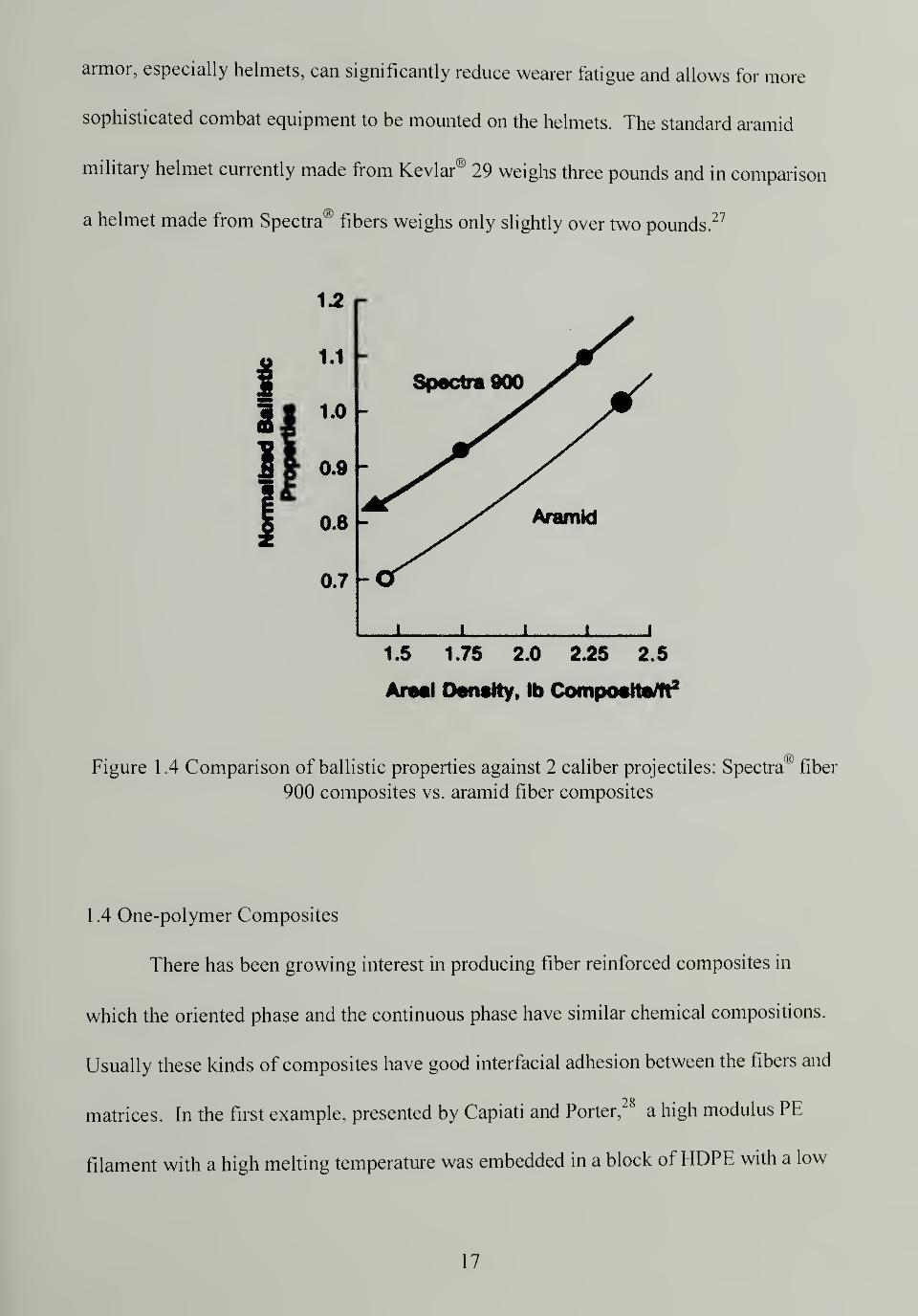
1 .4 Comparison of ballistic properties against 2 caliber projectiles: Spectra® fiber
900 composites vs. aramid fiber composites 17
1.5 Schematic of high-temperature high-pressure sintering coupled with
thermoforming process 21
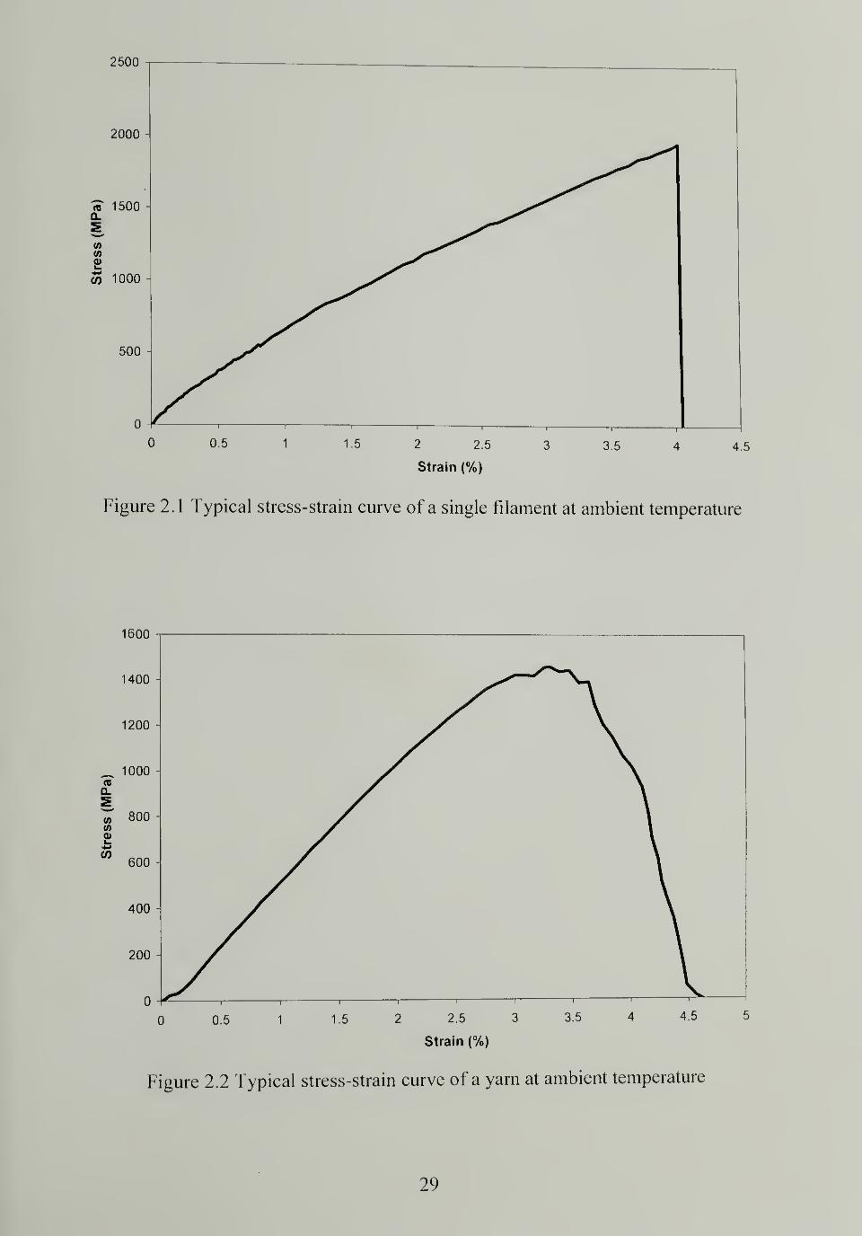
2.1 Typical stress-strain curve of a single filament at ambient temperature 29
2.2 Typical stress-strain curve of a yarn at ambient temperature 29
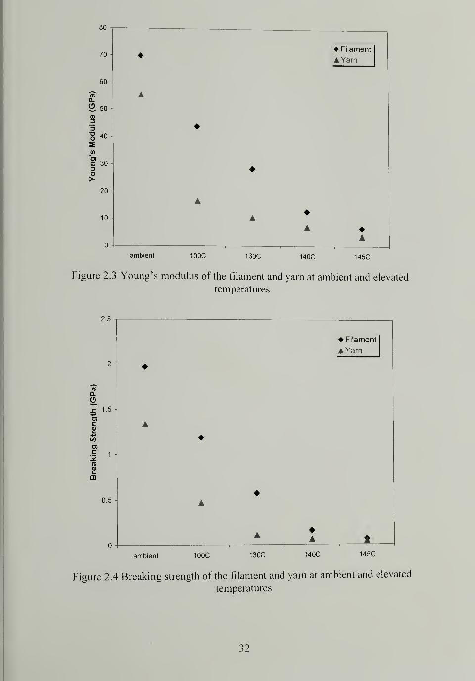
2.3 Young's modulus of the filament and yarn at ambient and elevated
temperatures 32
2.4 Breaking strength of the filament and yarn at ambient and elevated
temperatures 32
2.5 Strain at break of the filament and yarn at ambient and elevated temperatures 33
2.6 Thermal shrinkage of Spectra® 900 single filaments at elevated temperatures 35
2.7 The observed shrinkage force of a Spectra® 900 single filament with
increasing temperature 36
2.8 DSC traces of Spectra® fiber 900 in unconstrained and constrained states 38
2.9 The first run DSC trace of Spectra® cloth 903 39
2. 1 0 The second run DSC trace of Spectra® cloth 903 after quenching 40
2. 1 1 SEM image of a bundle of Spectra® fibers in the cloth 4
1
2.12 SEM image of Spectra® cloth 903 42
2.13 WAXD pattern of unidirectionally aligned Spectra® 900 fiber 43
2.14 WAXD pattern of the as-received Spectra® cloth 903 43
xiv
2.15 Hermans orientation function 44
3.1 DSC trace overlay for single layer Spectra® cloth 903 sintered under 7.6MPafor 30 minutes at different temperatures 50
3.2 Overall crystallinity of the as-received and consolidated Spectra® cloth 903sintered under 7.6MPa for 30 minutes at different sintering temperatures 52
3.3 Picture of single layer Spectra® cloth 903 sintered under 7.6MPa for 30minutes at different sintering temperatures 53
3.4 Changes in crystallinity corresponding to the original crystals for consolidated
Spectra" cloth 903 sintered under 7.6MPa for 30 minutes at different sintering
temperatures 54
3.5 WAXD patterns for the as-received Spectra® cloth and Spectra® cloth
consolidated under 7.6MPa for 30 minutes at different processing
temperatures 56
3.6 Degree of orientation calculated using Hermans orientation function for
unidirectional fibers, as-received Spectra® cloth, and Spectra® cloth
consolidated under 7.6MPa for 30 minutes at different processing
temperatures 58
3.7 Schematic of Spectra® fiber microfibrils 59
3.8 Linear correlation between the degree of crystallinity and Hermans orientation
function 60
3.9 Typical Load vs. Deflection curve from an impact test of single layer of
consolidated Spectra® cloth 62
3.10 NTT total impact energy vs. temperature and time for single layer of
consolidated Spectra® cloth 903 under 7.6MPa 64
3.11 NTT total impact energy of single layer of consolidated Spectra® cloth 903
at 150°C for 30 minutes under various pressures 65
4.1 Density of multilayer Spectraa<)
cloth panels sintered under 17.2MPa for 30
minutes at various processing temperatures 73
4.2 Typical load vs. detachment curve in a T-peel test 74
4.3 SEM images of peeled surfaces for specimens sintered under 7.6MPa for 30
minutes at different processing temperatures 76
xv
4.4 Flexural modulus of twelve layers of Spectra® cloth 903 sintered at different
processing conditions (sintering pressure = 17.2MPa) and unoriented
UHMWPE panel 7g
4.5 Ballistic performance of the multilayer consolidated Spectra® cloth comparedwith other composites (from the US Army) 82
4.6 Low magnification SEM images showing the cross sections of multilayer
Spectra® cloth sintered under 17.2MPa for 30 minutes at different processing
temperatures 83
4.7 High magnification SEM images showing the cross sections of multilayer
Spectra cloth sintered under 17.2MPa for 30 minutes at different processing
temperatures 84
4.8 SEM images of the boundary between two orthogonal yarns in a multilayer
consolidated Spectra cloth and schematic of consolidation mechanism 85
4.9 Hermans orientation function for single and six layer Spectra® cloth sintered
under 7.6MPa for 30 minutes at different processing temperatures 87
4.10 DSC trace overlay for the surface layers from twelve-layer Spectra® cloth
panels sintered under 17.2MPa for 30 minutes at different processing
temperatures 88
4.1 1 DSC trace overlay for the center layers from twelve-layer Spectra® cloth
panels sintered under 17.2MPa for 30 minutes at different processing
temperatures 89
4.12 Hermans orientation function for the surface and center layers from twelve-
layer Spectra® cloth panels sintered under 17.2MPa for 30 minutes at different
processing temperatures 91
5.1 The design of the hemispherical mold 95
5.2 Typical molding procedures using a twenty-five layer consolidated Spectra
cloth flat panel 98
5.3 Dimension and thickness of the dome 101
5.4 Compressive properties of the dome 103
5.5 DSC trace overlay for samples taken from the top and edge regions of the
dome 104
6.1 DSC trace overlay for single layer as-received and consolidated Dyneema
felt sintered under 7.6MPa for 30 minutes at different processing temperatures ... 1 12
xvi
6.2 Changes in overall crystallinity and erystallinity from the original crystals for
single layer as-received and consolidated Dyneema® felt sintered under7.6MPa for 30 minutes at different processing temperatures 1 14
6.3 NTT total impact energy (KJ/m) of the as-received Dyneema"0
felt and single
layer consolidated Dyneema10
felt sintered under 7.6MPa for 30 minutes at
different processing temperatures1 ] 5
6.4 T-peel strength for Dyneema®-Dyneema® bilayers sintered under 7.6MPa for
30 minutes at different temperatures1 16
6.5 Flexural modulus of 14 layers Dyneema10
felt panels consolidated under
1 7.2MPa for 30 minutes at different temperatures 1 1
7
6.6 DSC trace overlay of the as-received Spectra Shield10
Plus PGR and single
layer Spectra Shield10
Plus PGR consolidated under 7.6MPa for 30 minutes at
different processing temperatures 1 19
6.7 Overall and original crystallinity of the as-received Spectra Shield" Plus PGRand single layer Spectra Shield
10
Plus PGR consolidated under 7.6MPa for 30
minutes at different processing temperatures 121
6.8 Hermans orientation function of the as-received Spectra Shield'0
Plus PGR and
single layer Spectra Shield'0
Plus PGR consolidated under 7.6MPa for 30
minutes at different processing temperatures 123
6.9 NTT total impact energy (KJ/m) of the as-received Spectra Shield " Plus PGRand single layer Spectra Shield" Plus PGR consolidated under 7.6MPa for 30
minutes at different processing temperatures 124
6.10 T-peel strength for Spectra Shield'0
Plus PGR bilayers sintered under 7.6MPa
for 30 minutes at different processing temperatures 125
6.1 1 Flexural properties of 32 layers Spectra Shield" Plus PGR panels
consolidated under 17.2MPa for 30 minutes at different processing
temperatures 127
6.12 Overall crystallinity of the as-received and consolidated single layer
Spectra00
cloth, Dyneema Fraglight*', and Spectra Shield"' Plus PGR sintered
under 7.6MPa for 30 minutes at different processing temperatures 130
6.13 Hermans orientation function of the as-received and consolidated single
layer Spectra® cloth and Spectra Shield00
Plus PGR sintered under 7.6MPa for
30 minutes at different processing temperatures 132
6.14 NTT total impact energy (KJ/m) of the as-received and consolidated single
layer Spectra"0cloth, Dyneema Fraglight™ and Spectra Shield"
0
Plus PGR
sintered under 7.6MPa for 30 minutes at different processing temperatures 134
xvii
6.15 T-peel strength of bilayer Spectra® cloth, Dyneema Fraglight00
, and SpectraShield* Plus PCR bonded under 7.6MPa for 30 minutes at different
temperatures1 35
6.16 T-peel strength of Spectra® cloth bilayer, Dyneema Fraglight® bilayer, andSpectra® cloth- Dyneema Fraglight*
1
bilayer bonded under 7.6MPa for 30minutes at different temperatures 137
6.17 Flexural modulus of multilayer consolidated Spectra® cloth, DyneemaFraglight®, Spectra Shield'
0
Plus PCR, and UHMWPE panels sintered under17.2MPa for 30 minutes at different processing temperatures 138
xviii
CHAPTER 1
BACKGROUND AND INTRODUCTION
1 . 1 Fiber Reinforced Composites
Webster's dictionary shows that the word "composite" came from the Latin term
cornpositus. Originally the word was used as an adjective that meant "made up of distinct
parts", but later, it was used as a noun. A composite is a solid material which is
composed of two or more substances having different physical characteristics and in
which each substance retains its identity while contributing desirable properties to the
whole.
Traditionally, a composite material is a combination of two or more chemically
different materials with a distinct interface between them.5Composites consist of two
phases; one is continuous and is called a matrix, and the other is discontinuous and is in
form of fibers or particulates. The discontinuous phase is well dispersed in the matrix
and acts as a reinforcement or modifier, to improve and alter the matrix properties.
Matrix materials used in composites are typically ceramics, metals, or polymers.
Fibers are the common reinforcements due to their effectiveness, although particulates of
various geometries are also used. Polymer matrix composites, with fiber reinforcement,
are the most commonly used high performance composites and are widely used in many
applications because of their unique properties and characteristics. Fiber reinforced
polymeric composites consist of high strength and modulus fibers embedded in or bonded
to a polymer matrix with distinct interfaces between them.6
Fiber reinforced polymeric
composites have many distinctive advantages over traditional materials; the most
significant one being their light weight. Low density leads to high specific strength and
1
specific stiffness. Polymer matrices and reinforcing fibers have densities between 0.9 -
1 .5g/cm and 1 .0 - 2.7g/cm\ respectively, and the resulting composites have densities
between 0.9 - 2g/cm3
. Compared to steel and aluminum alloys with a density of 7.9
g/cm3and 2.7 g/cm
3
,respectively, polymer composites offer a large advantage in weight-
sensitive applications such as those in aerospace and military.
Another benefit of polymer composites is their design flexibility and freedom. By
varying the fiber type, the fiber direction and volume fraction, and adopting different
manufacturing processes, the composites1
properties and characteristics can be easily
controlled and adjusted. Anisotropic materials with direction dependent properties, rather
than isotropic materials, may be produced. Materials with hybrid properties can be
prepared by using two or more different types of fibers. Since some fibers have negative
coefficients of thermal expansion, materials with zero coefficients of thermal expansion
can be made by combining these reinforcements with appropriate matrices.
Fiber reinforced polymers have many advantages over conventional composite
materials, which make them very attractive for various applications. Polymeric
composites do not exhibit catastrophic failure mechanically, as opposed to ceramics or
metals, instead they damage and fail progressively. They have good corrosion and
electrical resistance and have high damping factors against noise and vibrations. Also,
polymeric composites have low coefficients of thermal expansion and thus have good
dimensional stability.
2
Matrices used in fiber reinforced polymeric composites are either thermosets or
thermoplastics. They play several important roles in the composites:5
• Hold the fibers in place
• Transfer stress between fibers
• Protect fibers from adverse environment or mechanical abrasion
The matrix contributes little in tensile load-carrying capacity, although it affects the
interlaminar shear and in-plane shear properties of the composites. The matrix provides
support for the fibers under compression, thus influencing the compressive properties of
the composites. In unidirectional fiber composites, transverse tensile modulus and
strength are largely determined by the properties of the matrix.
Traditionally the matrices of fiber reinforced polymers are thermosets, such as
epoxies, vinyl esters and phenolics, as they are usually low viscosity prepolymers and
their wettability to fibers is generally good. In addition, thermosets have high Tg,good
thermal stability and chemical resistance, and exhibit low creep and stress relaxation
behavior. However, thermosets have long fabrication time due to the slow crosslinking
and solidifying processes. Also, thermoset matrices can be brittle and fail at low strain
and as a result, resistance to microcracks and impact can be poor.
The most important benefit of thermoplastic matrices is their high fracture
resistance and impact strength, due to their high strain to failure; these are desirable
properties in certain applications like ballistic shields. Thermoplastics have short
fabrication times, are thermoformable and can be easily repaired by welding or solvent
bonding. Since thermoplastic matrices are not crosslinked polymers, they are easily
3
recycled and reused. However, their wettability to fibers is relatively poor because of
their high viscosities and there is no direct chemical bonding between matrix and fiber.
Fibers are the major component that occupies the largest volume fraction in fiber
reinforced polymer composites. They are the principal load-bearing constituents that
dominate the characteristics and properties of the composites. It is important to select the
proper fibers in order to meet the requirements for the final product. The following
factors are usually considered when designing a composite with fiber reinforcement:
• Density
• Tensile modulus and strength
• Compressive strength
• Fatigue strength and mechanism
• Resistance to fracture and impact
• Chemical resistance
• Electrical and thermal conductivity
• Adhesion to the selected matrix
• Chemical compatibility with the selected matrix
There are a large variety of commercially available fibers with different properties
that can be used as reinforcements: glass fibers, carbon/graphite fibers, aramid fibers,
polyethylene fibers, boron fibers, silicon carbide (SiC), aluminum oxide (AI2O3) and
metal fibers. Glass fibers are the most common reinforcement due to their low cost, high
tensile strength, high chemical resistance and excellent insulating properties. The
disadvantages of glass fibers are their low tensile modulus, high density, low resistance to
abrasion and fatigue, and high hardness.6They are mostly used in automotives, durable
4
goods and consumer goods. Carbon fibers have the advantage of high specific tensile
modulus and strength, high fatigue performance and low coefficient of thermal
expansion. The disadvantages include low impact resistance and high electrical
conductivity. Their main application is limited in the field of aerospace because of their
high cost. Aramid fibers, such as Kevlar® family7
, have higher specific tensile strength
and strain to failure than carbon fibers, which offers them good damage tolerance against
impact. Kevlar® fibers have good chemical and thermal stability, and poor compressive
properties. They are widely used in aerospace, marine and military applications.
The fibers used in composites can adopt many forms; they can be used as
continuous filaments or yarns, as well as discontinuous chopped fibers. Two- and three-
dimensional fabrics can be made from continuous fibers using textile processes such as
weaving, knitting, braiding and needle-punching. Fabrics are easy to handle and provide
good control over the fiber orientation and placement. The alignment of fibers in
composites can be unidirectional, bidirectional, multidirectional or random.
Unidirectional fiber composites use fibers most effectively if the loading direction
coincides with fiber direction; the strength and modulus is poor in other directions,
especially in the transversal direction. Two dimensional fabrics create somewhat equal
properties in the longitudinal and transversal directions. The multi-dimensional
arrangement gives them quasi-isotropic materials in the fiber plane. Isotropic properties
can only be achieved by incorporating randomly oriented fibers in the composites and
overall mechanical properties are lower.
Fiber volume fraction V/is an important parameter that dictates the composites'
properties. Fiber volume fraction should be as high as possible to maximize the strength
5
of the composites. Theoretically, the highest achievable fiber volume fraction is 90.7% if
the fibers are uniform in diameters and hexagonally close-packed. The actual volume
fraction can be calculated from the fiber weight fraction according to Equation 1.1.
Wf/P/+Wm /Pul
where wf = fiber weight fraction pf= fiber density
wm = matrix weight fraction pm = matrix density
Another important aspect of fiber reinforced composites is the interfacial adhesion
between fibers and matrices; good bonding strength is needed for fibers to achieve good
reinforcement. The influence of interfacial adhesion on composites properties is
profound; compression strength, flexural strength, transverse tensile strength, in-plane
shear strength, interlaminar shear strength, mode I fracture toughness and impact damage
resistance increase with the level of adhesion. Tensile strength is either independent of or
decreases with increasing bonding strength and elastic constants, such as Young's
modulus, are unaffected by adhesion. Interestingly, ballistic resistance decreases with
increase in bonding strength. Relatively poor adhesion makes interfiber and interlaminar
debonding easier, thus ballistic energy is efficiently dissipated laterally, and resistance to
penetration is enhanced.5
1 .2 Ultra High Molecular Weight Polyethylene (UHMWPE) Fibers
Historically, polyethylene (PE) is known as a low strength, low stiffness material.
Conventional methods to make polyethylene fibers, such as melt-spinning, yield only
6
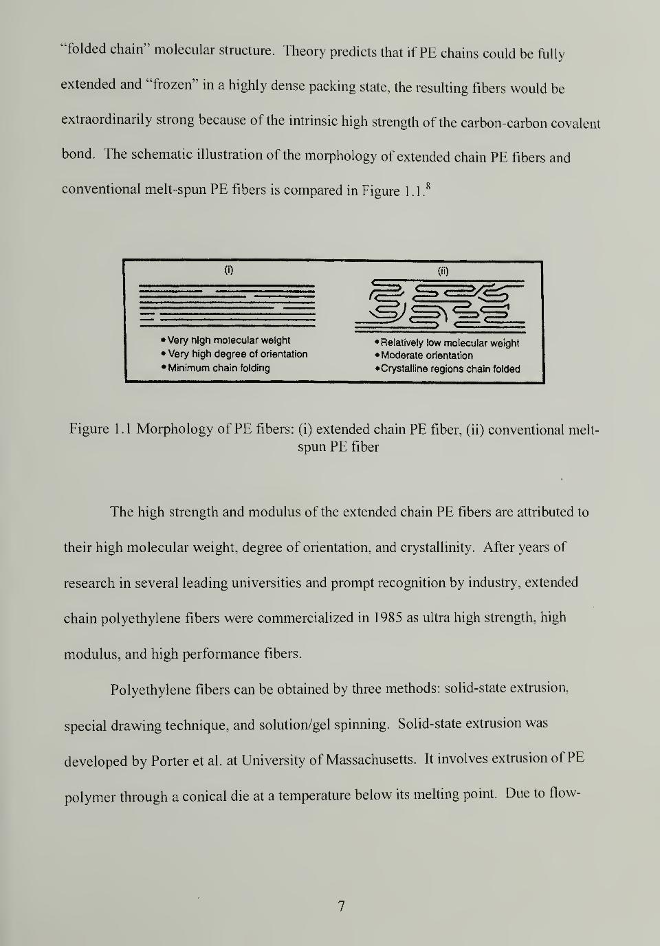
"folded chain" molecular structure. Theory predicts that if PE chains could be fully
extended and "frozen" in a highly dense packing state, the resulting fibers would be
extraordinarily strong because of the intrinsic high strength of the carbon-carbon covalent
bond. The schematic illustration of the morphology of extended chain PE fibers and
conventional melt-spun PE fibers is compared in Figure 1.1.8
n
• Very high molecular weight
• Very high degree of orientation
• Minimum chain folding
Figure 1.1 Morphology of PE fibers: (i) extended chain PE fiber, (ii) conventional melt-
spun PE fiber
The high strength and modulus of the extended chain PE fibers are attributed to
their high molecular weight, degree of orientation, and crystallinity. After years of
research in several leading universities and prompt recognition by industry, extended
chain polyethylene fibers were commercialized in 1985 as ultra high strength, high
modulus, and high performance fibers.
Polyethylene fibers can be obtained by three methods: solid-state extrusion,
special drawing technique, and solution/gel spinning. Solid-state extrusion was
developed by Porter et al. at University of Massachusetts. It involves extrusion of PE
polymer through a conical die at a temperature below its melting point. Due to flow-
• Relatively low molecular weight
Moderate orientation
Crystalline regions chain folded
7
induced orientation and pressure effects, the extruded material has a high modulus and
strength.9
The special drawing technique utilizes a melting spinning method combined with
a unique drawing process at a temperature close to the polymer melting point to yield a
high modulus fiber. This technique was developed by Ward at University of Leeds and is
currently licensed to Celanese in the United States and Snia BVP in Europe.10
The principles for solution/gel spinning of ultra high molecular weight
polyethylene were developed by Pennings and his students Smith, Lemstra and Kalb at
University of Groeningen1
1
and the practical processes were refined by many other
researchers such as Kavesh and Prevorsek. In solution spinning, typically 2-5 wt%
solution ofUHMWPE (MW 1-5 million) in decalin is extruded at 130-150°C into a cold
water bath. The fiber forms a gel and contains as much as 98% solvent and is therefore
referred to as "gel spinning". The solvent is evaporated from the fiber under the vacuum
and the fiber is ultra-drawn between 100-135°C. Typical draw ratios are between 30x -
100x and the strength and modulus of the fiber is determined by the draw.5
Currently,
ultra high molecular weight extended chain polyethylene fibers on the market are all
made by solution/gel spinning technology and are represented by Honeywell's Spectra'
fibers, DSM-Toyobo's Dyneema® fibers and Mitsui's Tekmilon® fibers.12
Since all three brands ofUHMWPE gel-spun fibers resemble each other. Spectra
fibers are chosen as the example to illustrate their common characteristics and properties
in this thesis. The microscopic structure of Spectra® fibers is typical of all organic
fibrous materials. The microfibrils are about 5nm in diameter and have finite length, and
the aggregated macrofibrils are about 50nm in diameter. Schaper13showed that the
longitudinal dimension of the microfibrils is about 1 000-2000nm and they have an aspect
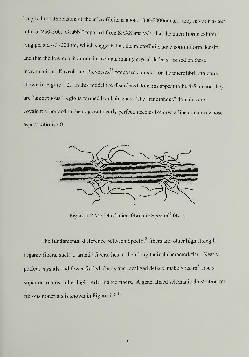
ratio of 250-500. Grubb 14reported from SAXS analysis, that the microfibrils exhibit a
long period of ~200nm, which suggests that the microfibrils have non-uniform density
and that the low density domains contain mainly crystal defects. Based on these
investigations, Kavesh and Prevorsek15proposed a model for the microfibril structure
shown in Figure 1 .2. In this model the disordered domains appear to be 4-5nm and they
are "amorphous" regions formed by chain ends. The "amorphous" domains are
covalently bonded to the adjacent nearly perfect, needle-like crystalline domains whose
aspect ratio is 40.
Figure 1.2 Model of microfibrils in Spectra" fibers
The fundamental difference between Spectra" fibers and other high strength
organic fibers, such as aramid fibers, lies in their longitudinal characteristics. Nearly
perfect crystals and fewer folded chains and localized defects make Spectra® fibers
superior to most other high performance fibers. A generalized schematic illustration for
fibrous materials is shown in Figure 1.3.
9
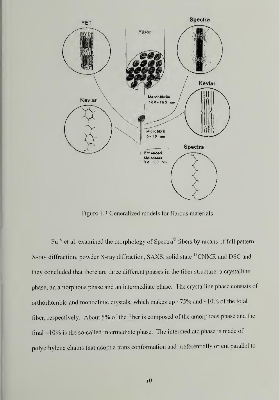
Figure 1.3 Generalized models for fibrous materials
Fu16
et al. examined the morphology of Spectra® fibers by means of full pattern
X-ray diffraction, powder X-ray diffraction, SAXS, solid statel3CNMR and DSC and
they concluded that there are three different phases in the fiber structure: a crystalline
phase, an amorphous phase and an intermediate phase. The crystalline phase consists of
orthorhombic and monoclinic crystals, which makes up -75% and -10% of the total
fiber, respectively. About 5% of the fiber is composed of the amorphous phase and the
final -10% is the so-called intermediate phase. The intermediate phase is made of
polyethylene chains that adopt a trans conformation and preferentially orient parallel to
10
the fiber axis. The axial distance between layers of neighboring carbon atoms is similar
to that of the crystalline domain. However, the lateral packing is not as perfect and
ordered as it is within the crystals. The mobility of the chains in the intermediate phase is
one order of magnitude higher than that of the crystalline phase and one order of
magnitude lower than that of the amorphous phase. Based on the three-phase model, the
initial modulus is governed by the crystalline phase. The crystalline phase consists of
predominately fully extended chains and has low strains at break, therefore the
intermediate phase becomes the primary load-carrying component at increased strains
and determines the ultimate strength of the fibers.
Spectra® fibers possess extraordinary physical and mechanical properties, such as
low specific gravity, high modulus and strength, high impact resistance, high abrasion
tolerance, excellent chemical resistance, low dielectric constant, good UV resistance, low
moisture absorption, etc. Spectra® fibers have the lowest density of all the fibers. The
density of Spectra® fibers is 0.97 g/cm,approximately 2/3 of that of aramid fibers and
1/2 of that of carbon fibers. The low density of Spectra® fibers gives them the highest
specific tensile strength and the second highest specific tensile modulus (only below
carbon fibers) among all high performance fibers. The cross section of Spectra® fibers is
non-circular and irregular. The overall crystallinity of Spectra® fibers is between 80%
and 95% depending on the manufacturing condition and the measuring methods, and the
degree of crystalline orientation is as high as 95% - 99%. The melting point of Spectra®
fibers is about 150°C; almost 15 degrees higher than that of unoriented polyethylene.
This superheating phenomenon is due to different crystal sizes in the unoriented and
1 1
highly oriented polyethylene, as well as, high orientation and close packing that impose
constraints on the crystals and reduce their mobility.
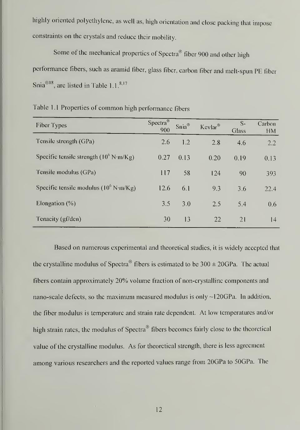
Some of the mechanical properties of Spectra® fiber 900 and other high
performance fibers, such as aramid fiber, glass fiber, carbon fiber and melt-spun PE fiber
Snia®18
, are listed in Table 1 . 1
,
817
Table 1 . 1 Properties of common high performance fibers
Fiber Types Spectra®
900Snia® Kevlar®
S-
Glass
Carbon
MM
Tensile strength (GPa) 2.6 1.2 2.8 4.6 2.2
Specific tensile strength (\0() Nm/Kg) 0.27 0.13 0.20 0.19 0.13
Tensile modulus (GPa) 117 58 124 90 393
Specific tensile modulus (106 N m/Kg) 12.6 6.1 9.3 3.6 22.4
Elongation (%) 3.5 3.0 2.5 5.4 0.6
Tenacity (gf/den) 30 13 22 21 14
Based on numerous experimental and theoretical studies, it is widely accepted that
the crystalline modulus of Spectra® fibers is estimated to be 300 ± 20GPa. The actual
fibers contain approximately 20% volume fraction of non-crystalline components and
nano-scale defects, so the maximum measured modulus is only ~120GPa. In addition,
the fiber modulus is temperature and strain rate dependent. At low temperatures and/or
high strain rates, the modulus of Spectra® fibers becomes fairly close to the theoretical
value of the crystalline modulus. As for theoretical strength, there is less agreement
among various researchers and the reported values range from 20GPa to 50GPa. The
12
actual achieved strength of Spectra® fiber is about 3-4GPa at ambient temperature and
normal strain rate.
Apart from the outstanding tensile properties of Spectra® fibers, they also have
excellent abrasion and cut resistance. Ropes made of Spectra® fibers are eight times
better than aramid ropes in accelerated sheave and wear tests.17
Spectra® fibers exhibit
higher chemical resistance than aramid fibers in various corrosive solvents. They have
excellent vibration damping capability, flex fatigue properties, self-lubricating properties
and a low coefficient of friction. Low dielectric constant makes them virtually
transparent to radar. Despite the impressive list of properties, Spectra® fibers also have
their limitations; low Tgand relatively low melting point prevent them from being used at
high temperatures. Due to their chemical inertness and lack of functional groups.
Spectra® fibers are difficult to bond to most materials, which makes it difficult to make
Spectra® fiber reinforced polymer composites. Their compressive properties are among
the lowest of all high performance fibers and they are weak in wear and tension fatigue.
1.3 Spectra® Fiber Reinforced Composites
Since Spectra® fibers were introduced to the market, there have been tremendous
efforts put to make Spectra® fiber reinforced composites. The fiber yarns can be
impregnated unidirectionally in composites by conventional prepreg routes. Fibers can
be cross-plied, angle-plied and quasi-isotropically arranged using the wet/dry lay-up
process. Fabrics in the form of woven cloth or nonwoven felt can also be used in
composites. Both thermoset and thermoplastic matrices have been adopted, e.g., epoxy
resin, polyester and urethane, for use with Spectra® fibers and fabrics.
13
In order to translate the outstanding properties of Spectra® fibers into the
composites, good interfacial adhesion between fibers and matrices is required. 1 Iowever,
because Spectra® fibers are nonpolar and have no reactive surface chemical groups, they
stick to virtually no common matrices. The way to overcome this obstacle is by means of
various fiber pre-treatments. Spectra® fibers can be chemically etched by chromic acid1"
or oxidi/.ed by polypyrrole20
to increase the surface roughness. Plasma and corona
treatments in 02 or C02 introduce chemical groups onto the fiber surface through chain
scission and substitution, and etch and roughen the fiber surface.21,22 Cohen et al.
23,24
developed a novel method to make Spectra® fiber based composites using UHMWPH as
matrix. They treated Spectra® fibers with a hot Ul IMWPH solution. Surface swelling of
the fibers and consequent physical entanglement with the UHMWPH molecules in the
solution formed a "brush" layer around the individual fibers and upon cooling the
"brush" layer crystallized. The treated fibers were aligned unidirectionally and subjected
to heat and pressure. The product was essentially a preprcg with Ul IMWPH as matrix.
The final composite can be fabricated by compression molding or calendaring into any
desired shape. All the liber pre-treatments mentioned previously are proven to
significantly improve the bonding of Spectra® fibers to matrices but generally degrade
the fiber properties.
The mechanical properties of Spectra® fiber reinforced composites have been
investigated by many researchers; unidirectional laminated epoxy matrix composites
reinforced by Spectra® fibers and Kevlar00
fibers are compared in fable 1 2 bIn terms of
longitudinal tensile strength. Spectra00
fiber composites are almost as good as Kevlar®
fiber composites. However, Kevlar® fiber composites out-perform Spectra® fiber
14
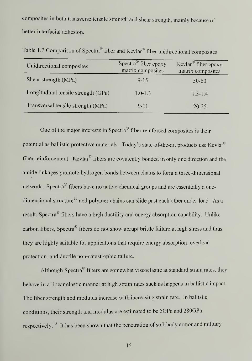
composites in both transverse tensile strength and shear strength, mainly because of
better interfacial adhesion.
Table 1 .2 Comparison of Spectra® fiber and Kevlar® fiber unidirectional composites
Unidirectional compositesSpectra® fiber epoxy Kevlar® fiber epoxymatrix composites matrix composites
Shear strength (MPa) 9-15 50-60
Longitudinal tensile strength (GPa) 1.0-1.3 1.3-1.4
Transversal tensile strength (MPa) 9-11 20-25
One of the major interests in Spectra''
fiber reinforced composites is their
potential as ballistic protective materials. Today's state-of-the-art products use Kevlar®
fiber reinforcement. Kevlar® fibers are covalently bonded in only one direction and the
amide linkages promote hydrogen bonds between chains to form a three-dimensional
network. Spectra® fibers have no active chemical groups and are essentially a one-
dimensional structure ' and polymer chains can slide past each other under load. As a
result, Spectra® fibers have a high ductility and energy absorption capability. Unlike
carbon fibers. Spectra® fibers do not show abrupt brittle failure at high stress and thus
they are highly suitable for applications that require energy absorption, overload
protection, and ductile non-catastrophic failure.
Although Spectra® fibers are somewhat viscoelastic at standard strain rates, they
behave in a linear elastic manner at high strain rates such as happens in ballistic impact.
The fiber strength and modulus increase with increasing strain rate. In ballistic
conditions, their strength and modulus are estimated to be 5GPa and 280GPa,
respectively.15
It has been shown that the penetration of soft body armor and military
15
helmets happens primarily by breaking in tension, cutting and lateral displacement of the
filaments.15
Spectra® fibers have substantially higher cut resistance than Kevlar®. The
velocity of the strain wave propagating through a material is in proportion to the square
root of the Young's modulus to density ratio ( ^Ifp ). The wave speed determines how
fast the impact energy can be transported away for the impact site. In a laminated
structure, like a helmet, the wave propagation speed is slower through thickness direction
compared to the laminate plane. Increased wave velocity in the plane rapidly spreads out
the impact energy laterally and results in a high volume of material involved in energy
absorption in a short time. Due to Spectra® fibers' high modulus and low density, the
value of ^E/p is higher than for other fibers (e.g. 17.8 km/s for Spectra® vs. 12.3 km/s
for aramid).26
Spectra® fibers have excellent damage tolerance. Repetitive impact tests
show increased rigidity of the samples.15
Contrary to the expectation of weakening.
Spectra® fiber composites actually enhance their properties after impact. The lack of
adhesive bond between Spectra® fiber and matrix, a drawback in other applications, is
actually desirable in ballistic applications. The extensive delamination and debonding in
the composites when subject to ballistic impact provides excellent channels to dissipate
high energy.
Another huge advantage of Spectra® fiber based armor is its light weight without
sacrificing the high level of protection. As shown in Figure 1.4,15
Spectra® fiber 900
based composites have better ballistic properties compared to aramid fiber composites for
the same areal density. Composite armor produced from Spectra® fibers weighs 30%-
50% less than for the same performance level aramid composite armor. Lower weight
16
armor, especially helmets, can significantly reduce wearer fatigue and allows for more
sophisticated combat equipment to be mounted on the helmets. The standard aramid
military helmet currently made from Kevlar® 29 weighs three pounds and in comparison
a helmet made from Spectra® fibers weighs only slightly over two pounds27
0.7
Aramid
l l J
1.5 1.75 2.0 2.25 2.5
Areal Density, lb CompotHa/ft2
Figure 1.4 Comparison of ballistic properties against 2 caliber projectiles: Spectra* fiber
900 composites vs. aramid fiber composites
1 .4 One-polymer Composites
There has been growing interest in producing fiber reinforced composites in
which the oriented phase and the continuous phase have similar chemical compositions.
Usually these kinds of composites have good interfacial adhesion between the fibers and
matrices. In the first example, presented by Capiati and Porter, a high modulus PE
filament with a high melting temperature was embedded in a block of HDPE with a low
17
melting temperature and they called it a "one-polymer composite". The interfacial shear
strength was fairly high due to the epitaxial transcrystallinity developed in the interphase
region of the fiber and matrix. Later, other researchers extended this technique and
developed the film stacking method.29,30
Other approaches to make one-polymer
composites have included powder impregnation31
and solvent impregnation.32
Most
recently, Cohen et al. invented a unique method to produce UHMWPE fiber/UHMWPE
matrix composites, as mentioned in the previous section.
In the above cases a secondary polymer, besides the polymeric fibers, is used as a
binder or matrix to form the continuous phase. Ward at the University of Leeds has
developed a new process called "hot compaction" which utilizes only one starting
component (a highly oriented fiber or tape) and applies sufficient heat and pressure so
that the surface of the oriented phase melts partially and recrystallizes on cooling to form
the matrix phase. Since only a small portion of the oriented phase is melted to fill the
interstice and serve as a binder, the majority of the original properties of the oriented
phase are preserved. There is strong adhesion bonding between the two phases because
of the molecular continuity throughout the composites. The challenge is to find the
proper processing window in terms of time, temperature, and pressure. Since the lateral
adhesion and strength are developed at the cost of the longitudinal strength, it is critical to
strictly control the processing conditions so as to achieve a balanced overall mechanical
integrity. Melt-spun polyethylene fiber was the first system studied by Ward, where the
compaction scheme adopted is a two-stage process. First the fibers are pressed under a
relatively low contact pressure at the "compaction temperature". The "soaking time" is
several minutes in order to allow for the selective melting of the fiber surface. Then a
18
substantially higher pressure is applied for a short period to consolidate the structure and
upon cooling a stiff, strong sheet with one chemical composition is formed.
Subsequently, similar research was carried out using other materials, such as PET, PP,
Spectra®, and Vectran® LCP fibers.33-42
Meanwhile, a parallel study conducted by Farris et al. at the University of
Massachusetts introduced a similar process. The initial motivation was to make a
protective coating for optics on military airplanes that could sustain the supersonic impact
of rain and dust and be transparent to IR. Spectra® plain woven cloth was chosen as the
starting material because of its desired properties. The process involves constraint of the
cloth under lateral pressure to prevent shrinking and then increase of temperature near or
slightly above the melting point of the Spectra® fiber. Upon cooling, while pressure is
maintained, the cloth fuses together and forms a strong sheet. This research has led to
several patents regarding the making of high strength, high modulus polymeric materials
c • i • 43-47tor impact resistant application.
1.5 Project Overview
High strength, high impact resistant polymeric composites are very useful
materials. They have numerous applications in the fields of aerospace, automotive,
marine, military, industry, and sporting goods, etc. Usually they are made of a high
performance fiber and an appropriate resin matrix. The objective of this research is to
explore a novel method to make "matrix free" polymeric composites.48
The approach
involves the consolidation of fabrics using only heat and pressure without the addition of
resin matrices or bonding agents. The surface melting of the fibers and subsequent
19
recrystallization upon cooling serves as the bonding mechanism. By eliminating the
matrices, the composite achieves a high fiber volume fraction, which leads to better
properties. Also the overall weight of the composites is significantly reduced, which is
an enormous advantage for applications such as airplane structures and ballistic shields.
The motivation for the work is to make ballistic armor and helmets using fabrics
made of ultra high molecular weight polyethylene (UHMWPE) fibers (trade name:
Spectra®). It is well known that at elevated temperatures polyethylene is "rubbery" and
can be subjected to considerable stretching. If layers of cloth are properly confined to
prevent shrinkage, exposed to an appropriate heating and stretching sequence,
consolidated and allowed to cool, it is feasible to produce a thick, rigid ballistic shield
with curvatures and shapes. The schematic of this method is illustrated in Figure 1 .5.
Currently, ballistic hard armors are made of multiple layers of tightly woven cloth of high
performance fibers and an adhesive matrix. When complex shapes involving double
curvature are required, such as helmets or body armor, specially cut patterns are needed
for lay-up to create the complex geometries since the materials used are not extensible.
The proposed method does not involve the cutting of complex patterns or the use of any
adhesive matrices, therefore simplifies the manufacturing process. A detailed method of
fabrication, such as heating and stretching sequence, was developed and the optimal
processing conditions, in terms of molding time, temperature and pressure, were
established for Spectra® cloth. Thermo-mechanical properties, microstructures and
morphologies, and ballistic performance of the products were investigated and evaluated.
The results were correlated and reflected in the process-structure-property relationship.
Two other commercial products that consist of the extended chain UHMWPE fibers,
20
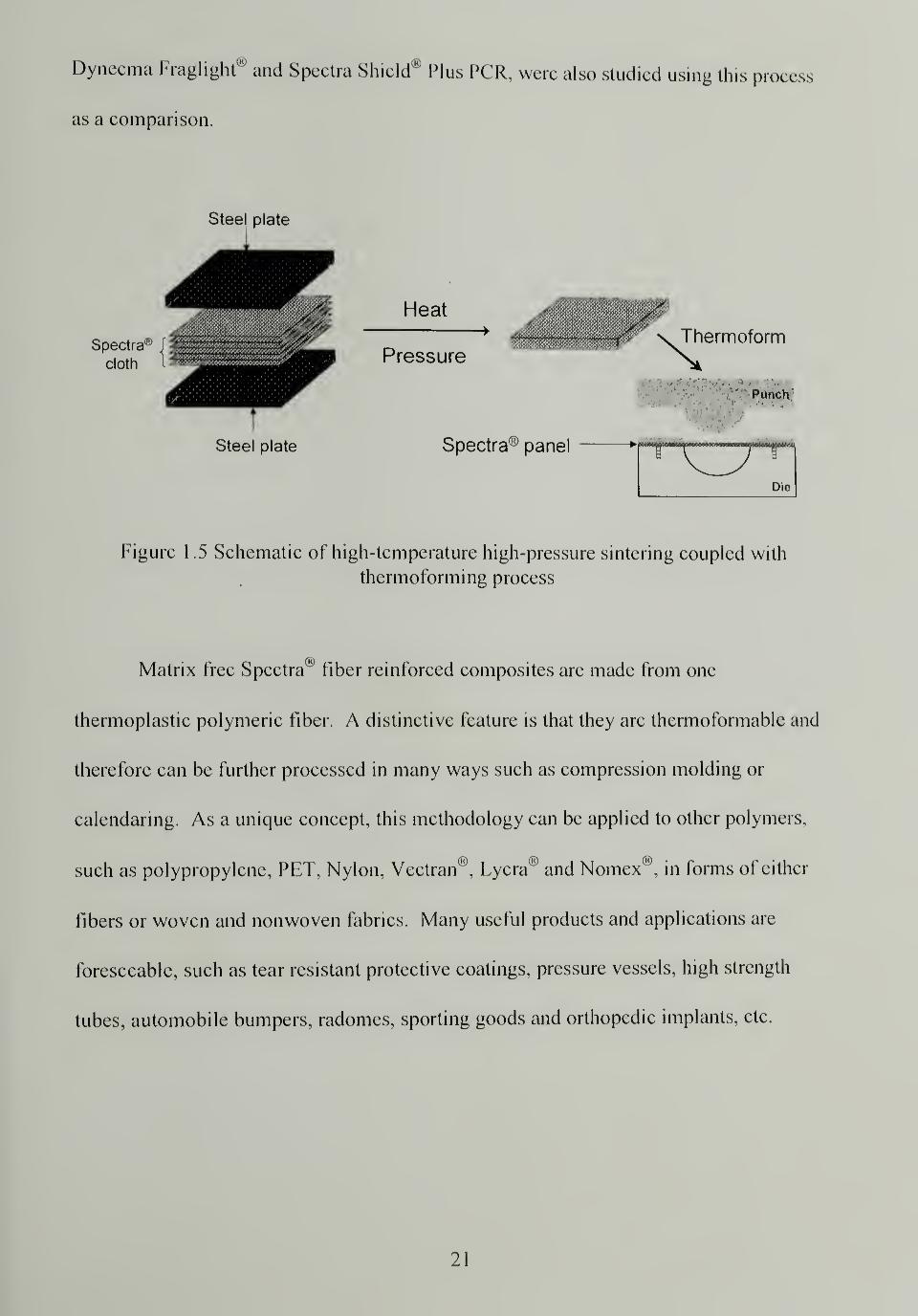
Dyneema Fraglight" and Spectra Shield® Plus PCR, were also studied using this process
as a comparison.
Steel plate
Spectra
cloth
Heat
Pressure
0'Thermoform
'
' Punch
Steel plate Spectra^ panel
Figure 1.5 Schematic of high-temperature high-pressure sintering coupled with
thermoforming process
Matrix free Spectra® fiber reinforced composites are made from one
thermoplastic polymeric fiber. A distinctive feature is that they are thermoformable and
therefore can be further processed in many ways such as compression molding or
calendaring. As a unique concept, this methodology can be applied to other polymers,
such as polypropylene, PET, Nylon, Vectran®, Lycra® and Nomex®, in forms of either
fibers or woven and nonwoven fabrics. Many useful products and applications are
foreseeable, such as tear resistant protective coatings, pressure vessels, high strength
tubes, automobile bumpers, radomes, sporting goods and orthopedic implants, etc.
21
CHAPTER 2
THERMO-MECHANICAL PROPERTIES, STRUCTURE AND MORPHOLOGYOF SPECTRA® FIBER, YARN, AND CLOTH
2.1 Introduction
Since the commercialization of ultra high molecular weight polyethylene fibers in
the mid 1980s, their structures and properties have been the subject of numerous
researchers.16 '49 "56
Their common properties as high performance fibers were briefly
described in the previous chapter. Honeywell produces Spectra® fiber in several grades
with different properties due to different manufacturing processes. In order to
investigate property evolution during the high-temperature high-pressure sintering
process, it is crucial to thoroughly study the properties of the virgin materials, including
the single filament, yarn and woven cloth. The structure and morphology are important
factors in determining the final properties of the material and also need to be carefully
examined.
This chapter describes the measurement of various thermo-mechanical properties
and studies of the structure and morphology of Spectra® single fiber, yarn and woven
cloth. Property and structural information are necessary in order to understand, apply,
and optimize the sintering process. Tensile modulus and strength are among the most
important mechanical properties associated with the fibers, since they indicate the load
carrying capacity of the fibers. As a thermoplastic material, the tensile properties of
Spectra® fiber are expected to have a strong dependence on temperature. Experiments
were conducted to measure the tensile properties of Spectra® single fibers and yarns at
both ambient and elevated temperatures. The tensile properties of annealed Spectra®
22

fibers were measured at ambient temperature to determine the influence of thermal
histories on the mechanical properties. Spectra® fiber is "ultra-drawn" during
manufacturing (the draw ratio can be over lOOx) and the result is highly oriented polymer
molecules in an extended chain conformation. At elevated temperatures the extended
chains tend to relax towards the entropically favorable random coil conformation;
macroscopically the fiber shrinks and if constrained a shrinking force develops within the
fiber. Thermal shrinkage was determined by soaking filaments in a hot bath at various
temperatures and measuring the change in length. The shrinkage force developed with
increasing temperature for the single filament under iso-strain condition was monitored
using a Thermal Mechanical Analyzer (TMA) until the filament broke. Polyethylene is a
semicrystalline polymer and its melting behavior can be monitored by Differential
Scanning Calorimetry (DSC). The peak melting temperatures were identified, the
crystalline melting enthalpy was measured, and the degree of crystallinity was calculated
for Spectra® fiber and cloth. The fibers are under lateral pressure and constrained during
the sintering process. Efforts were made to simulate the constrained state of the fibers
and study the constraining effect on the fiber melting by DSC. Spectra® fiber is highly
oriented polyethylene and the extended chains are parallel to each other. The molecular
orientation of unidirectionally aligned fibers and the as-received cloth was investigated
using Wide Angle X-ray Diffraction (WAXD) and the Hermans orientation function
values were calculated. The microscopic features of Spectra® fiber and the weaving
patterns of the cloth were examined by Scanning Electron Microscopy (SEM).
23
2.2 Experimental
2.2.1 Materials
Spectra® fiber was obtained from Honeywell and designated as Spectra® 900.57
The yarn contains 120 filaments per tow and has a linear density of 1200 denier. The
density of the fiber is 0.97g/cm3
. Spectra® cloth was also provided by Honeywell and
designated as Spectra® cloth 903. It is a plain woven cloth with an average thickness of
0.5mm and an areal density of 0.024g/cm2
. Both materials were sampled and tested in
the as-received state without any further treatments. Spectra® cloth 903 is the material of
choice for ballistic protective hard armor.
2.2.2 Testing methods and instruments
2.2.2.1 Tensile properties
The tensile properties of the single filament and yarn were tested on an Instron®
5564 equipped with an environmental chamber according to ASTM standard D2256.
The specimen gauge length was 1 50mm and the strain rate was 10% per minute.
Spectra® fiber tends to slip from the grips, so a set of special homemade grips were used.
The grips consist of an aluminum rod and two aluminum gripping pieces with matching
faces. The fiber was wrapped tightly around the aluminum rod and then sandwiched
between the two gripping pieces using four screws to fasten. The novel grips provide a
locking mechanism that prevents fiber slippage during tensile deformation. The
specimens were tested at ambient and elevated temperatures. An environmental
chamber, which encases both the upper and lower grip, enabled specimens to be tested at
100°C, 130°C, 135°C, 140°C, and 145°C. A fiber specimen was mounted in grips and
24
the environmental chamber was heated. A thermal controller was used to monitor the
temperature of the chamber. A thermal couple was placed into the chamber near the
middle of the specimen to monitor the temperature experienced by the specimen. Once
the specimen reached the final temperature, the test was begun and run until the specimen
broke. Annealing of the specimen was achieved by heating the mounted fiber in the
environmental chamber and then holding the fiber at set temperatures for two minutes.
The specimen was rapidly cooled to room temperature in air. The tensile test was
performed on the annealed specimens at ambient temperature. The fiber diameter was
measured by optical microscopy and calculated from the linear density of the fiber. The
tensile modulus, breaking strength and strain at break were determined.
2.2.2.2 Thermal analysis
Thermal shrinkage
Free shrinkage of the filament at 130°C, 135°C, 140°C, 142°Cs, and 145°C was
determined. The filament was immersed into a preheated oil bath for a period of time,
removed, and the final filament length was measured. The free shrinkage is calculated
from the change in length relative to the initial filament length. The initial filament
length was 300 mm and a soak time of 10 minutes was used at 130°C, 135°C, 140°C and
142°C, and 5 seconds at 145°C.
Thermal mechanical analysis
A TA Instrument TMA 2940 was used to monitor the shrinkage force developed
during heating of a constrained fiber. A specimen gauge length was 12.5mm and an
25
initial load of 0.008N was used. The specimen was heated at 10°C/min. under an iso-
strain condition in nitrogen (35 ml/min.) and the change in load with temperature was
recorded.
Differential scanning calorimetry
A TA Instrument DSC 2910 was used to observe the melting behavior of chopped
Spectra® fiber and Spectra® cloth and to study the influence of constraint on fiber
melting. -10 mg of the samples in hermetically sealed pans were heated at 10°C/min.
from room temperature to 200°C under nitrogen (50 ml/min.). Two methods of
constraining were used: winding and knotting. The fiber was wound tightly around a
small piece of aluminum and the ends were fastened, or the fiber was tied into a series of
tight knots.
2.2.2.3 Structure and morphology
Scanning Electron Microscopy
Spectra® cloth was mounted onto a SEM plate, sputter-coated with gold, and
examined using a Field Emission Scanning Electron Microscope (FESEM JEOL JSM-
6320FXV).
Wide Angle X-ray Diffraction
Wide Angle X-ray Diffraction (WAXD) patterns were collected using pin hole
collimated, monochromatic Cu Ka radiation and a Bruker® "High Star" two dimensional
detector. Unidirectionally aligned fiber samples were prepared by winding fiber around
26
metal frame which had two aligned notches. The unidirectionally aligned fiber was
oriented perpendicular to the X-ray beam and the diffraction pattern was collected. The
diffraction pattern from the as-received Spectra® cloth 903 was also collected. The cloth
was oriented "flat-on" so that the incident X-ray beam was perpendicular to the cloth and
the weft or warp yarn was aligned parallel to the horizon. A radiation time of 300
seconds was used and diffraction patterns were captured digitally. The integration of the
intensity was preformed using GADDS commercial software.
2.3 Results and Discussion
2.3.1 Tensile properties of single fibers and yarns at ambient and elevated temperatures
Spectra® 900 is a high performance fiber with a high modulus and strength. Yet,
it is hard to believe that polyethylene, a material typically found in items such as "milk
jug" plastics, possesses such outstanding tensile properties. Made by the gel-spinning
process, Spectra ' fiber has extremely high molecular orientation and crystallinity
resulting from its extended chain conformation which provides its unique properties. The
crystalline orientation is also very high and needle-like crystals align parallel to the fiber
• 15axis.
Testing, at ambient temperature
Single filaments measured at ambient temperature have better tensile properties
than those of yarns measured under similar conditions. The measured Young's modulus,
breaking strength, and strain at break for the single filaments are close to the values
reported by other researchers, suggesting that our homemade grips effectively prevented
27
fiber slippage and quality data were collected. A yarn consists of bundles of fibers which
have had a few twists applied during the manufacturing to ease handling. During tensile
testing, each fiber within a yarn is not as perfectly aligned as a single fiber would be
when it is mounted in the grips and there is greater possibility of slippage for the yarn.
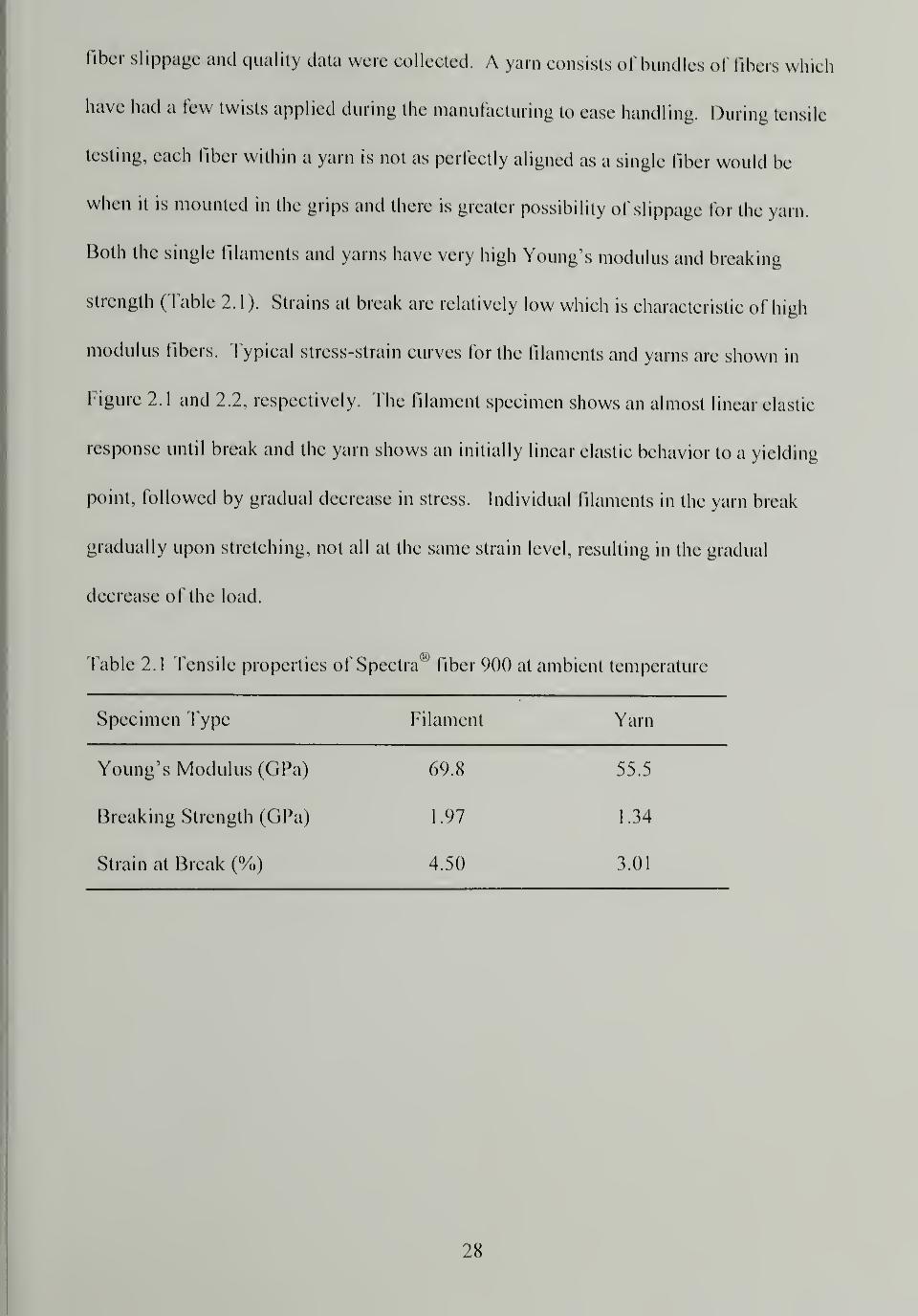
Both the single filaments and yarns have very high Young's modulus and breaking
strength (Table 2.1). Strains at break are relatively low which is characteristic of high
modulus fibers. Typical stress-strain curves for the filaments and yarns are shown in
Figure 2.1 and 2.2, respectively. The filament specimen shows an almost linear elastic
response until break and the yarn shows an initially linear elastic behavior to a yielding
point, followed by gradual decrease in stress. Individual filaments in the yarn break
gradually upon stretching, not all at the same strain level, resulting in the gradual
decrease of the load.
Table 2.1 Tensile properties of Spectra00
fiber 900 at ambient temperature
Specimen Type Filament Yarn
Young's Modulus (GPa) 69.8 55.5
Breaking Strength (GPa) 1 .97 1 .34
Strain at Break (%) 4.50 3.01
28
2500
2000 -
0 0.5 1 1.5 2 2.5 3 3.5 4 4.5
Strain (%)
Figure 2.1 Typical stress-strain curve of a single filament at ambient temperature
1600
0 0.5 1 1.5 2 2.5 3 3.5 4 4.5
Strain (%)
Figure 2.2 Typical stress-strain curve of a yarn at ambient temperature
29
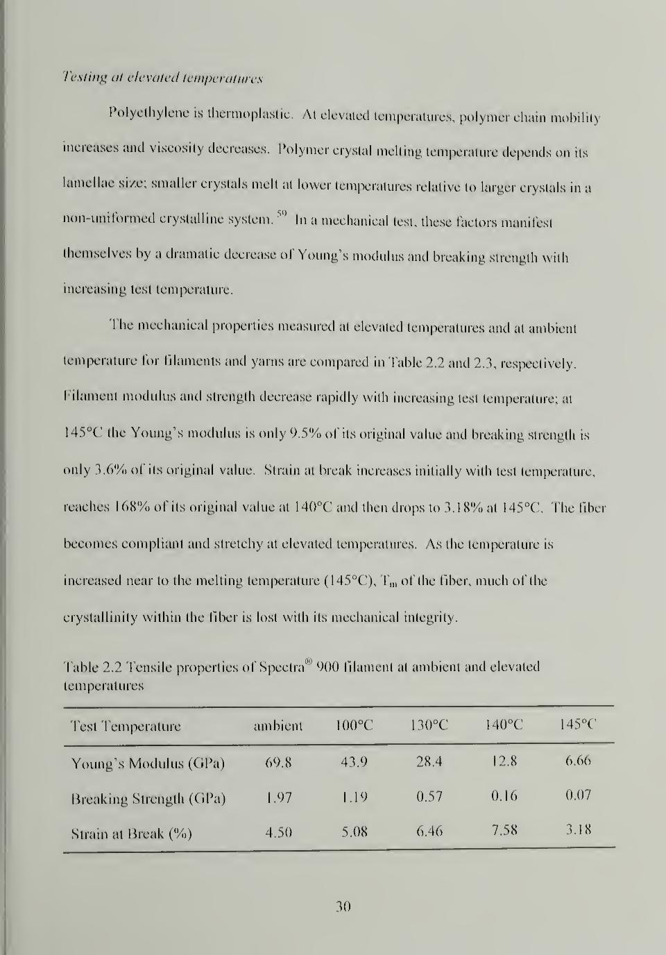
Testing at elevated temperatures
Polyethylene is thermoplastic. At elevated temperatures, polymer chain mobilit)
increases and viscosity decreases. Polymer crystal melting temperature depends on its
lamellae size; smaller crystals mell at lower temperatures relative to larger crystals in a
non-uniformed crystalline system,59
In a mechanical test, these factors manifest
themselves by a dramatic decrease of Young's modulus and breaking strength with
increasing test temperature.
The mechanical properties measured at elevated temperatures and at ambient
temperature for filaments and yarns arc compared in Table 2.2 and 2.3, respectively.
Filament modulus and strength decrease rapidly with increasing test temperature; at
145°C the Young's modulus is only 9.5% of its original value and breaking strength is
only 3.6% of its original value. Strain at break increases initially with test temperature,
reaches I (>X% of its original value at 140°C and then drops to 3.18% at 145°C. The fiber
becomes compliant and stretchy at elevated temperatures. As the temperature is
increased near to the melting temperature ( 145°C), Tm of the fiber, much of the
crystallinity within the fiber is lost with its mechanical integrity.
Table 2.2 Tensile properties of Spectra' 900 filament at ambient and elevated
temperatures
l est Temperature ambient I00°C 130°C 140°C 145°C
Young's Modulus (GPa) 69.8 43.9 28.4 12.8 6.66
breaking Strength (GPa) 1.97 1.19 0.57 0.16 0.07
Strain at Break (%) 4.50 5.08 6.46 7.58 3.18
30

Table 2.3 Tensile properties of Spectra® 900 yarn at ambient and elevated temperatures
Test Temperature ambient 100°C 130°C 140°C 145°C
Young's Modulus (GPa) 55.5 16.5 10.5 7.10 3.55
Breaking Strength (GPa) 1.34 0.47 0.11 0.06 0.04
Strain at Break (%) 3.01 7.93 5.85 4.32 3.50
The yarn modulus and strength decrease quickly with increasing test temperature
compared to that of the filament. At 145°C the Young's modulus is 6.4% of its original
value and strength 3%. The strain at break at 100°C is more than double the original
value, but decreases with increasing temperature due to crystal melting. The Young's
modulus, breaking strength, and strain at break for the filament and yarn at ambient and
elevated temperatures are compared in Figure 2.3, 2.4 and 2.5, respectively.
31
80
70
60
(0
a.
£ 50</)
3
E 40
o
30
20
10 -
ambient
Filament
A Yarn
AA
100C 130C HOC 145C
Figure 2.3 Young's modulus of the filament and yarn at ambient and elevated
temperatures
ambient 100C 130C 140C 145C
Figure 2.4 Breaking strength of the filament and yarn at ambient and elevated
temperatures
32

9
~ 6
Cm
2CO o
Filament
A Yarn
ambient 100C 130C HOC 145C
Figure 2.5 Strain at break of the filament and yarn at ambient and elevated temperatures
Testing at ambient temperature after annealing at elevated temperatures
During fiber annealing, a single filament was clamped between grips and a small
initial force was applied to the fiber prior to heating. As the temperature was increased,
the specimen was allowed slack due to the thermal expansion of the aluminum grips and
connecting rod. After annealing for two minutes, the specimen was rapidly cooled, it
returned to its original taut position in the grips and the tensile test was begun. The
filament was capable of shrinkage during the annealing process which was detrimental
the tensile properties of the filament (Table 2.4). Due to experimental difficulties the
fibers could not be constrained during annealing. If the filament had been held under
constraint tension during annealing the tensile properties would have been preserved.
Constraint of the fibers can raise the melting temperature of the fibers, as will be
discussed later in the chapter (Section 2.3.4). The highest annealing temperature at which
33
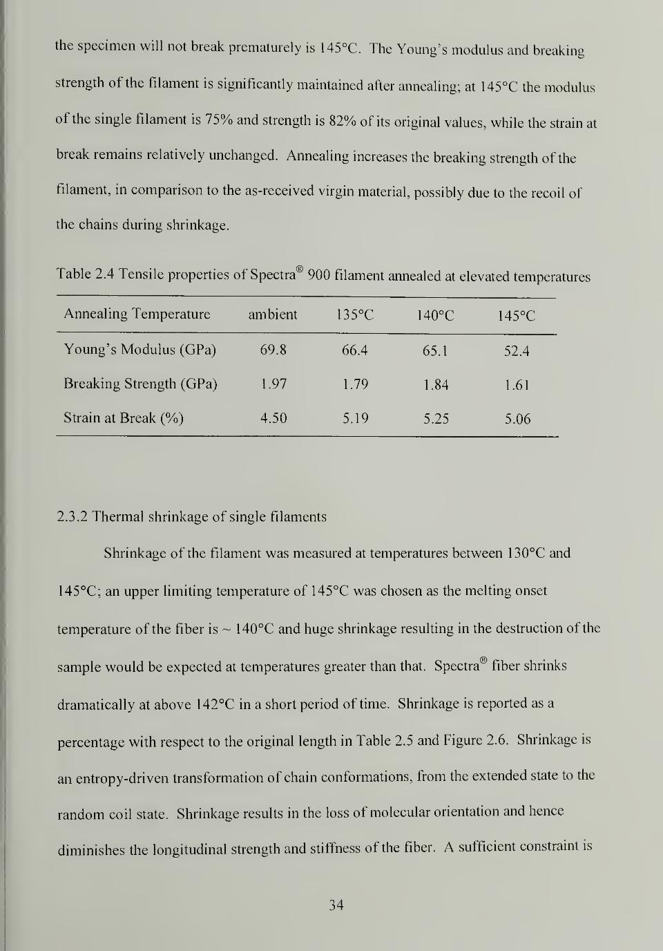
the specimen will not break prematurely is 145°C. The Young's modulus and breaking
strength of the filament is significantly maintained after annealing; at 145°C the modulus
of the single filament is 75% and strength is 82% of its original values, while the strain at
break remains relatively unchanged. Annealing increases the breaking strength of the
filament, in comparison to the as-received virgin material, possibly due to the recoil of
the chains during shrinkage.
Table 2.4 Tensile properties of Spectra® 900 filament annealed at elevated temperatures
Annealing Temperature ambient 135°C 140°C 145°C
Young's Modulus (GPa) 69.8 66.4 65.1 52.4
Breaking Strength (GPa) 1.97 1.79 1.84 1.61
Strain at Break (%) 4.50 5.19 5.25 5.06
2.3.2 Thermal shrinkage of single filaments
Shrinkage of the filament was measured at temperatures between 130°C and
145°C; an upper limiting temperature of 145°C was chosen as the melting onset
temperature of the fiber is ~ 140°C and huge shrinkage resulting in the destruction of the
sample would be expected at temperatures greater than that. Spectra® fiber shrinks
dramatically at above 142°C in a short period of time. Shrinkage is reported as a
percentage with respect to the original length in Table 2.5 and Figure 2.6. Shrinkage is
an entropy-driven transformation of chain conformations, from the extended state to the
random coil state. Shrinkage results in the loss of molecular orientation and hence
diminishes the longitudinal strength and stiffness of the fiber. A sufficient constraint is
34
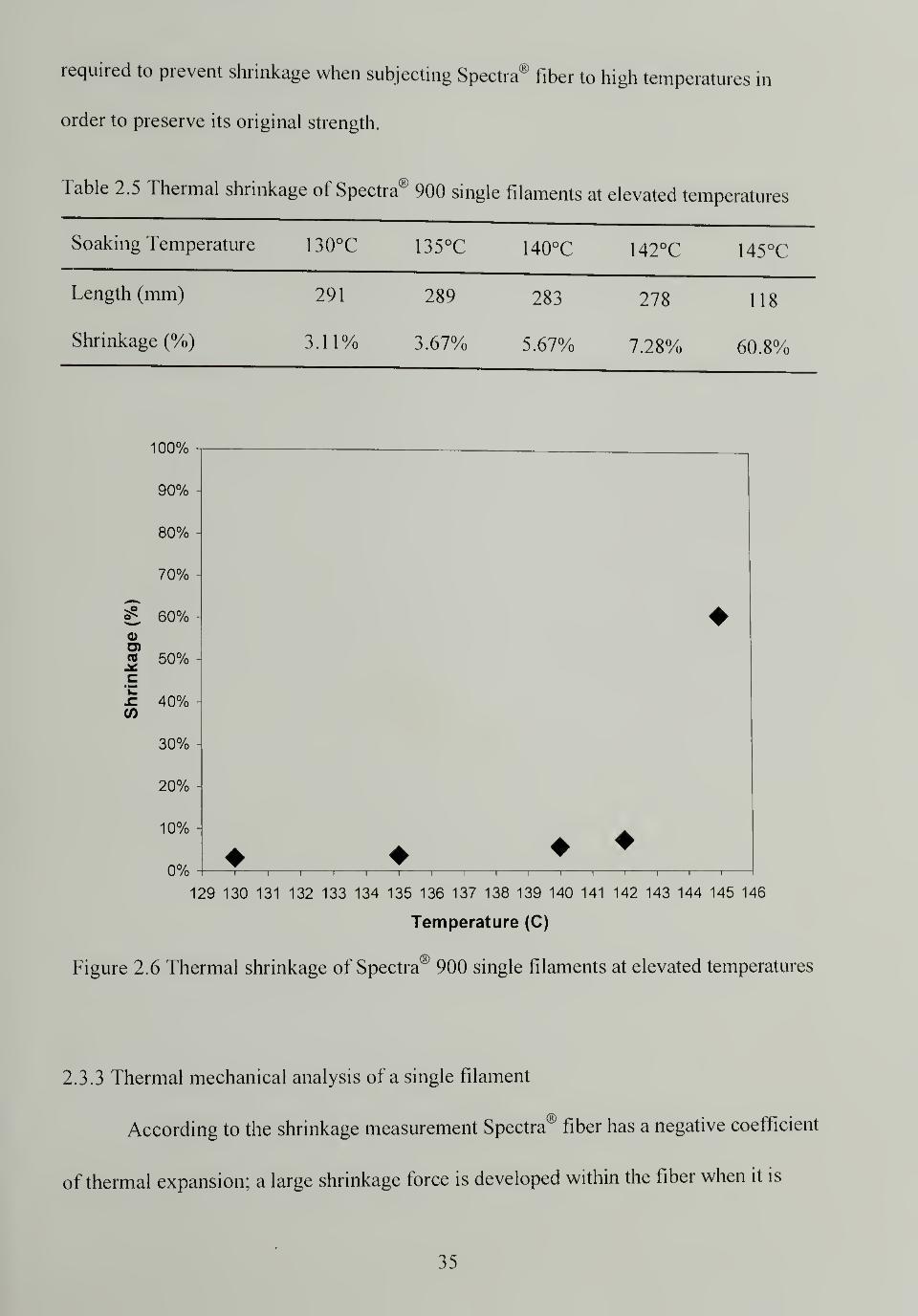
required to prevent shrinkage when subjecting Spectra® fiber to high temperatures in
order to preserve its original strength.
Table 2.5 Thermal shrinkage of Spectra® 900 single filaments at elevated temperatures
Soaking Temperature 130°C 135°C 140°C 142°C 145°C
Length (mm) 291 289 283 278 118
Shrinkage (%) 3.11% 3.67% 5.67% 7.28% 60.8%
100%
"i1 1 r
129 130 131 132 133 134 135 136 137 138 139 140 141 142 143 144 145 146
Temperature (C)
Figure 2.6 Thermal shrinkage of Spectra® 900 single filaments at elevated temperatures
2.3.3 Thermal mechanical analysis of a single filament
According to the shrinkage measurement Spectra® fiber has a negative coefficient
of thermal expansion; a large shrinkage force is developed within the fiber when it is
35
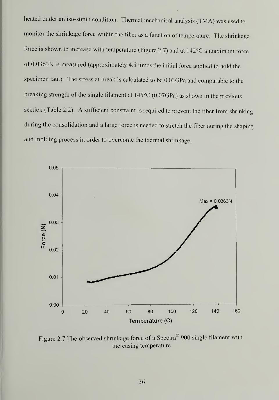
heated under an iso-strain condition. Thermal mechanical analysis (TMA) was used to
monitor the shrinkage force within the fiber as a function of temperature. The shrinkage
force is shown to increase with temperature (Figure 2.7) and at 142°C a maximum force
of 0.0363N is measured (approximately 4.5 times the initial force applied to hold the
specimen taut). The stress at break is calculated to be 0.03GPa and comparable to the
breaking strength of the single filament at 145°C (0.07GPa) as shown in the previous
section (Table 2.2). A sufficient constraint is required to prevent the fiber from shrinking
during the consolidation and a large force is needed to stretch the fiber during the shaping
and molding process in order to overcome the thermal shrinkage.
0.05
0.04
_ 0.03 -
O
0.02
0.01
0.00
20 40 60 80 100
Temperature (C)
120 140 160
Figure 2.7 The observed shrinkage force of a Spectra® 900 single filament with
increasing temperature
36
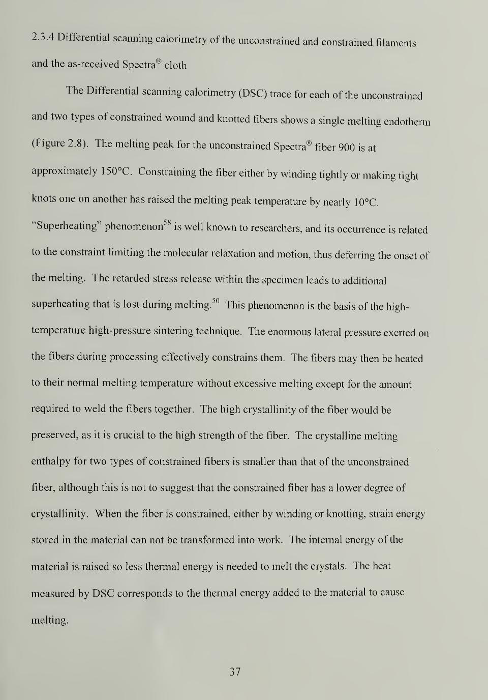
2.3.4 Differential scanning calorimetry of the unconstrained and constrained filaments
and the as-received Spectra® cloth
The Differential scanning calorimetry (DSC) trace for each of the unconstrained
and two types of constrained wound and knotted fibers shows a single melting endotherm
(Figure 2.8). The melting peak for the unconstrained Spectra® fiber 900 is at
approximately 1 50°C. Constraining the fiber either by winding tightly or making tight
knots one on another has raised the melting peak temperature by nearly 10°C.
"Superheating" phenomenon58is well known to researchers, and its occurrence is related
to the constraint limiting the molecular relaxation and motion, thus deferring the onset of
the melting. The retarded stress release within the specimen leads to additional
superheating that is lost during melting.50
This phenomenon is the basis of the high-
temperature high-pressure sintering technique. The enormous lateral pressure exerted on
the fibers during processing effectively constrains them. The fibers may then be heated
to their normal melting temperature without excessive melting except for the amount
required to weld the fibers together. The high crystallinity of the fiber would be
preserved, as it is crucial to the high strength of the fiber. The crystalline melting
enthalpy for two types of constrained fibers is smaller than that of the unconstrained
fiber, although this is not to suggest that the constrained fiber has a lower degree of
crystallinity. When the fiber is constrained, either by winding or knotting, strain energy
stored in the material can not be transformed into work. The internal energy of the
material is raised so less thermal energy is needed to melt the crystals. The heat
measured by DSC corresponds to the thermal energy added to the material to cause
melting.
37
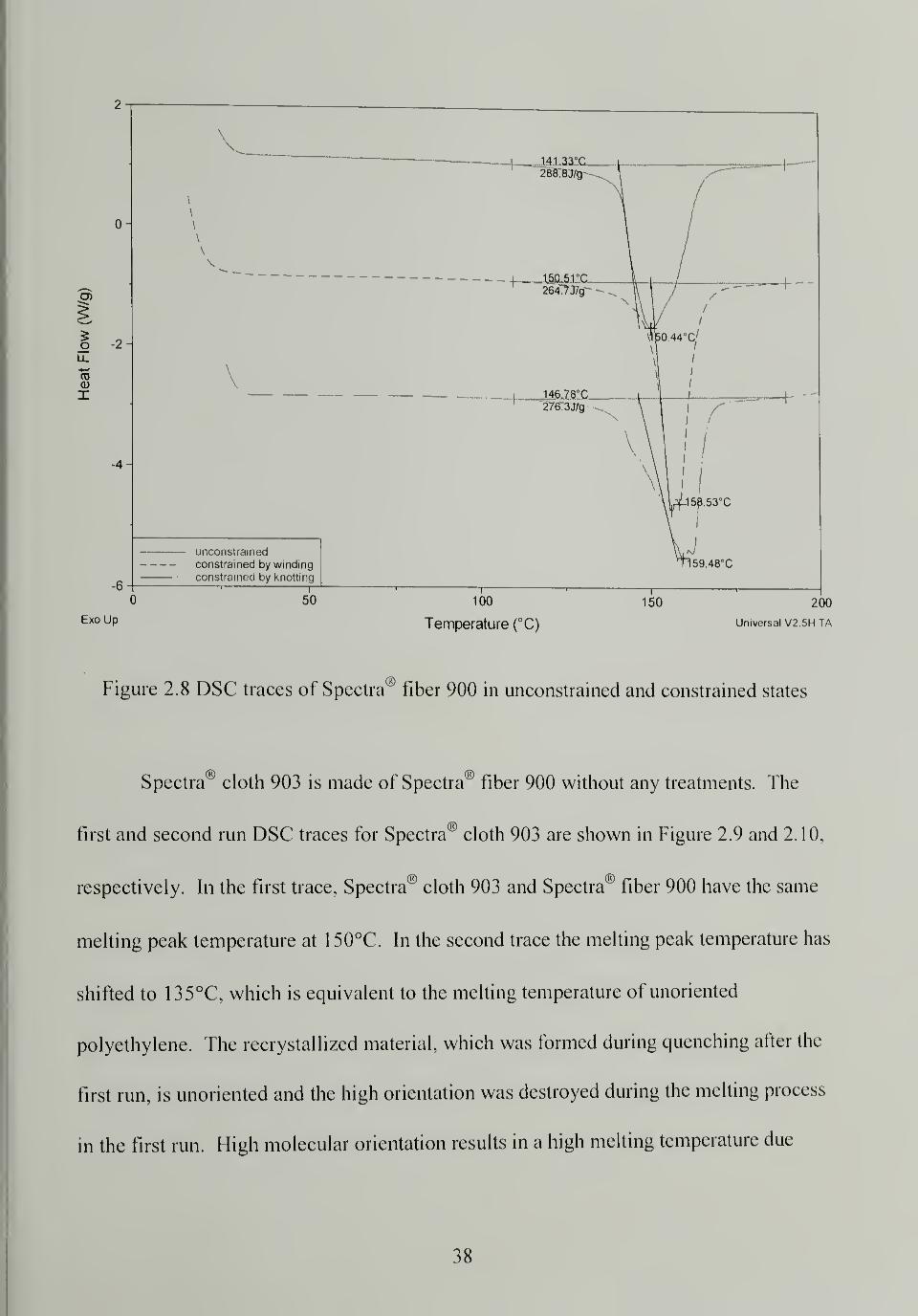
Figure 2.8 DSC traces of Spectra " fiber 900 in unconstrained and constrained states
Spectra" cloth 903 is made of Spectra® fiber 900 without any treatments. The
first and second run DSC traces for Spectra® cloth 903 are shown in Figure 2.9 and 2.10,
respectively. In the first trace. Spectra® cloth 903 and Spectra® fiber 900 have the same
melting peak temperature at 1 50°C. In the second trace the melting peak temperature has
shifted to 135°C, which is equivalent to the melting temperature of unoriented
polyethylene. The recrystallized material, which was formed during quenching after the
first run, is unoriented and the high orientation was destroyed during the melting process
in the first run. I Iigh molecular orientation results in a high melting temperature due
38
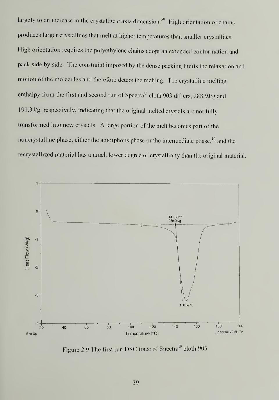
largely to an increase in the crystallite c axis dimension.59
High orientation of chains
produces larger crystallites that melt at higher temperatures than smaller crystallites.
1 ligh orientation requires the polyethylene chains adopt an extended conformation and
pack side by side. The constraint imposed by the dense packing limits the relaxation and
motion of the molecules and therefore deters the melting. The crystalline melting
enthalpy from the first and second run of Spectra® cloth 903 differs, 288.9J/g and
191 .3J/g, respectively, indicating that the original melted crystals are not fully
transformed into new crystals. A large portion of the melt becomes part of the
noncrystalline phase, either the amorphous phase or the intermediate phase,16and the
recrystallized material has a much lower degree of crystallinity than the original material
CD -1
ILa-
raQ)
X 2-
20
Exo Up
40r
60 80 100 120
Temperature (°C)
141,33°C
288,9J/g
150.67X
140 160I '
I
180 200
Universal V2.5H TA
Figure 2.9 The first run DSC trace of Spectra® cloth 903
39
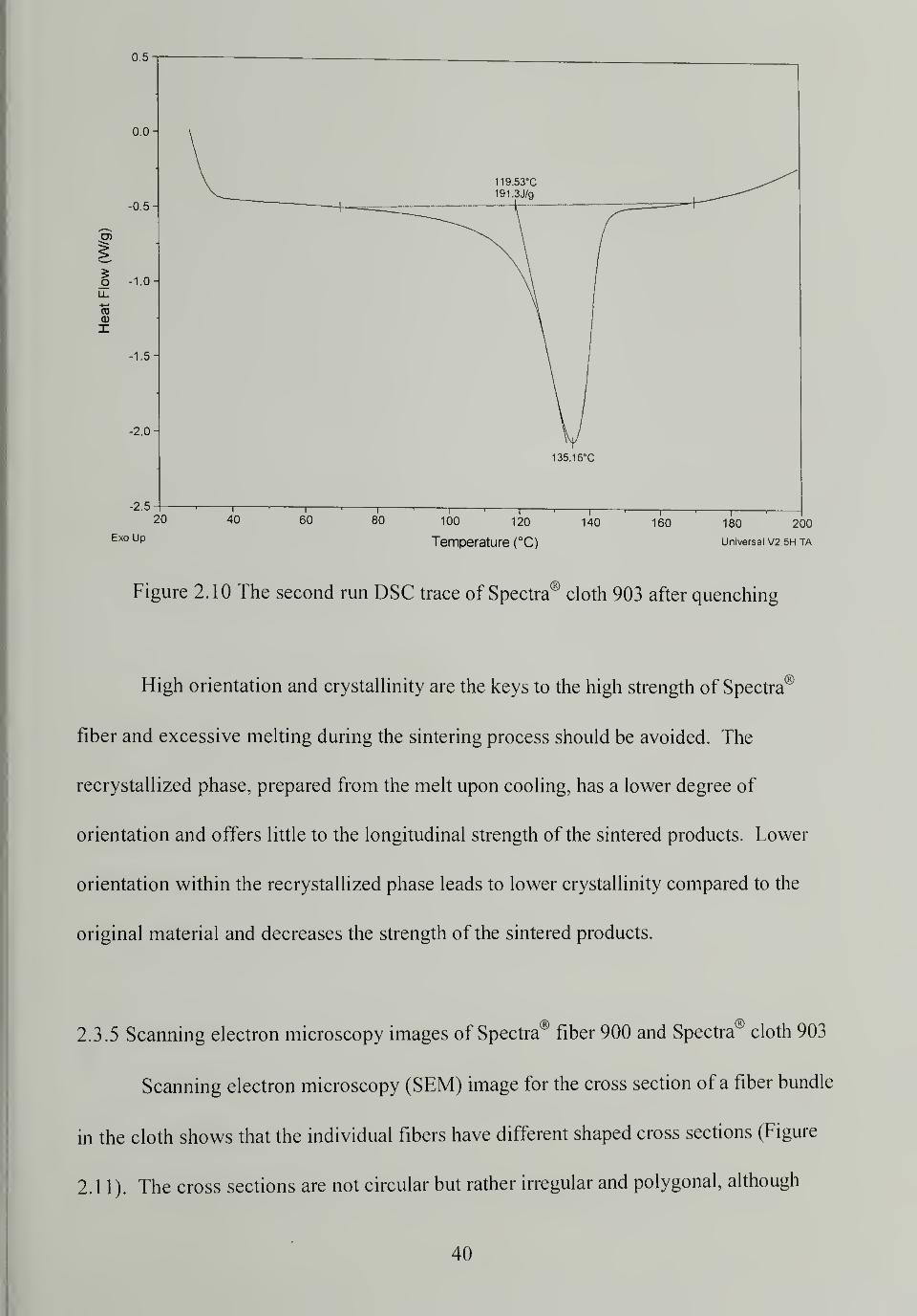
135 16°C
2 5
20 40 60
Exo Up
80 100 120
Temperature (°C)
140 160 180 200
Universal V2 5H TA
Figure 2. 1 0 The second run DSC trace of Spectra cloth 903 after quenching
High orientation and crystallinity are the keys to the high strength of Spectra
fiber and excessive melting during the sintering process should be avoided. The
recrystallized phase, prepared from the melt upon cooling, has a lower degree of
orientation and offers little to the longitudinal strength of the sintered products. Lower
orientation within the recrystallized phase leads to lower crystallinity compared to the
original material and decreases the strength of the sintered products.
2.3.5 Scanning electron microscopy images of Spectra® fiber 900 and Spectra® cloth 903
Scanning electron microscopy (SEM) image for the cross section of a fiber bundle
in the cloth shows that the individual fibers have different shaped cross sections (Figure
2.11). The cross sections are not circular but rather irregular and polygonal, although
40
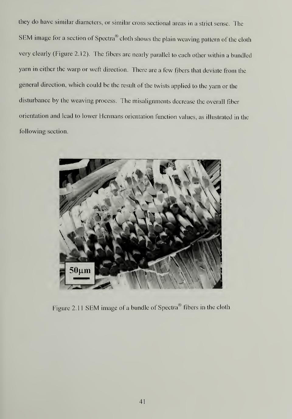
they do have similar diameters, or similar cross sectional areas in a strict sense. The
SEM image for a section of Spectra"9cloth shows the plain weaving pattern of the cloth
very clearly (Figure 2.12). The fibers are nearly parallel to each other within a bundled
yarn in either the warp or weft direction. There are a few libers that deviate from the
general direction, which could be the result of the twists applied to the yarn or the
disturbance by the weaving process. The misalignments decrease the overall fiber
orientation and lead to lower Hermans orientation function values, as illustrated in the
following section.
41
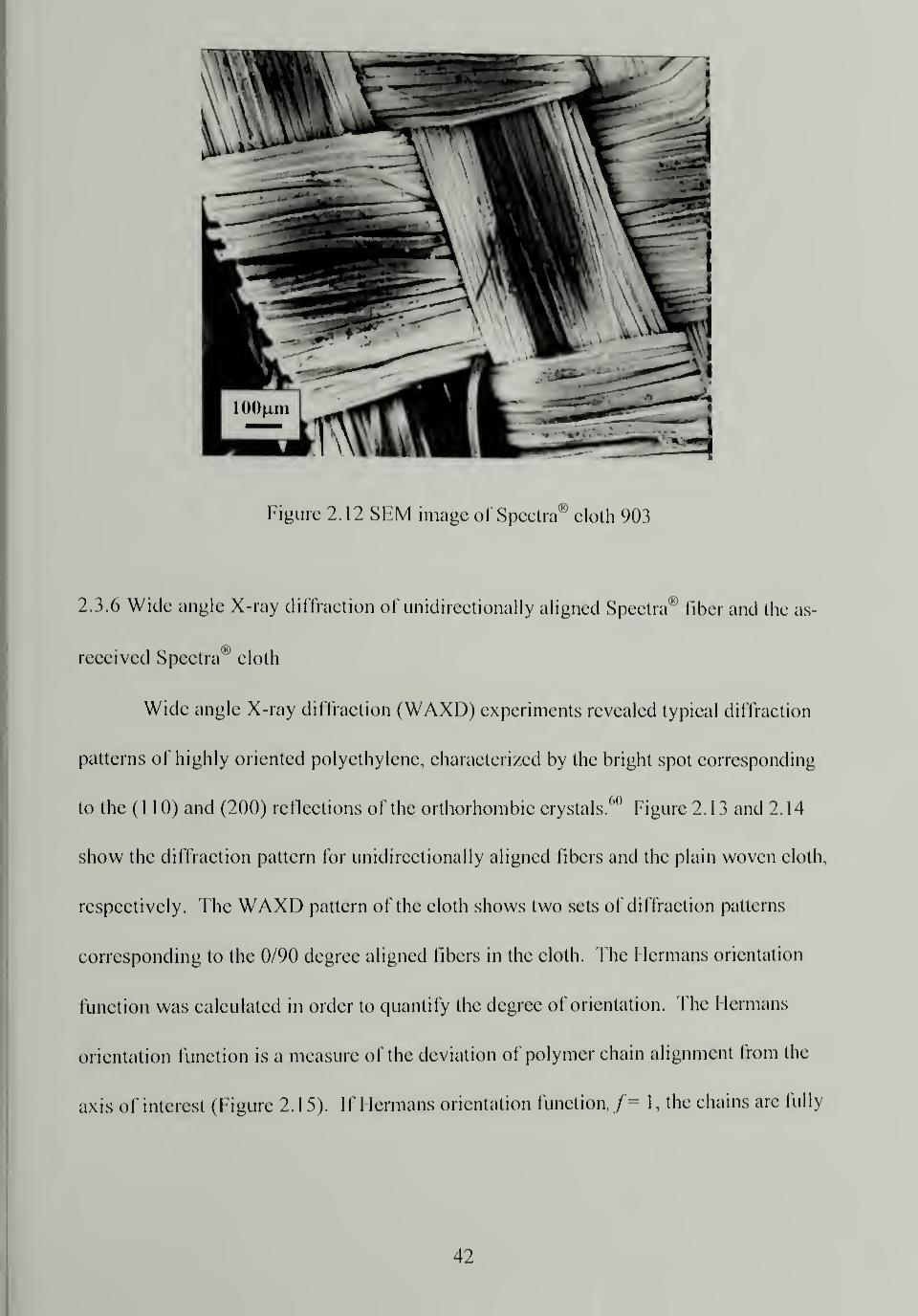
2.3.6 Wide angle X-ray diffraction of unidirectionally aligned Speetra® fiber and the as-
reeeived Spectra00
eloth
Wide angle X-ray diflraetion (WAXD) experiments revealed typieal diflraetion
patterns of highly oriented polyethylene, eharaeterized by the bright spot corresponding
to the (1 10) and (200) reflections of the orlhorhombic crystals.60
Figure 2.13 and 2.14
show the diffraction pattern for unidirectionally aligned fibers and the plain woven cloth,
respectively. The WAXD pattern of the cloth shows two sets of diffraction patterns
corresponding to the 0/90 degree aligned fibers in the cloth. The 1 lermans orientation
function was calculated in order to quantify the degree of orientation. The Hermans
orientation function is a measure of the deviation of polymer chain alignment from the
axis of interest (figure 2. 1 5). If I lermans orientation function, / = 1, the chains are fully
42
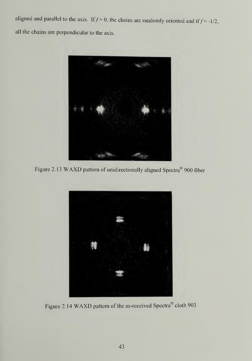
aligned and parallel to the axis. If/= 0, the chains are randomly oriented and if / =
all the chains are perpendicular to the axis.
Figure 2.13 WAXD pattern of unidirectionally aligned Spectra® 900 fiber
Figure 2.14 WAXD pattern of the as-received Spectra cloth 903
43
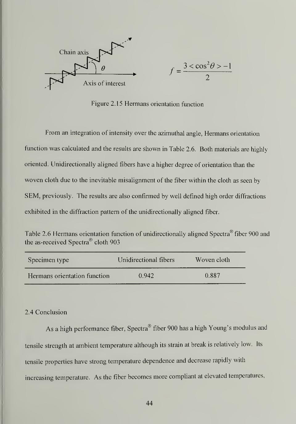
/3<cos 26>>-1
2
Figure 2.15 Hermans orientation function
From an integration of intensity over the azimuthal angle, Hermans orientation
function was calculated and the results are shown in Table 2.6. Both materials are highly
oriented. Unidirectionally aligned fibers have a higher degree of orientation than the
woven cloth due to the inevitable misalignment of the fiber within the cloth as seen by
SEM previously. The results are also confirmed by well defined high order diffractions
exhibited in the diffraction pattern of the unidirectionally aligned fiber.
Table 2.6 Hermans orientation function of unidirectionally aligned Spectra® fiber 900 and
the as-received Spectra" cloth 903
Specimen type Unidirectional fibers Woven cloth
Hermans orientation function 0.942 0.887
2.4 Conclusion
As a high performance fiber, Spectra® fiber 900 has a high Young's modulus and
tensile strength at ambient temperature although its strain at break is relatively low. Its
tensile properties have strong temperature dependence and decrease rapidly with
increasing temperature. As the fiber becomes more compliant at elevated temperatures,
44
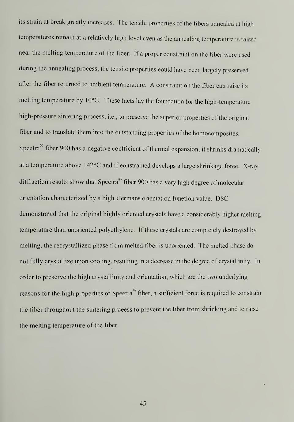
its strain at break greatly increases. The tensile properties of the fibers annealed at high
temperatures remain at a relatively high level even as the annealing temperature is raised
near the melting temperature of the fiber. If a proper constraint on the fiber were used
during the annealing process, the tensile properties could have been largely preserved
after the fiber returned to ambient temperature. A constraint on the fiber can raise its
melting temperature by 1 0°C. These facts lay the foundation for the high-temperature
high-pressure sintering process, i.e., to preserve the superior properties of the original
fiber and to translate them into the outstanding properties of the homocomposites.
Spectra® fiber 900 has a negative coefficient of thermal expansion, it shrinks dramatically
at a temperature above 142°C and if constrained develops a large shrinkage force. X-ray
diffraction results show that Spectra® fiber 900 has a very high degree of molecular
orientation characterized by a high Hermans orientation function value. DSC
demonstrated that the original highly oriented crystals have a considerably higher melting
temperature than unoriented polyethylene. If these crystals are completely destroyed by
melting, the recrystallized phase from melted fiber is unoriented. The melted phase do
not fully crystallize upon cooling, resulting in a decrease in the degree of crystallinity. In
order to preserve the high crystallinity and orientation, which are the two underlying
reasons for the high properties of Spectra® fiber, a sufficient force is required to constrain
the fiber throughout the sintering process to prevent the fiber from shrinking and to raise
the melting temperature of the fiber.
45
CHAPTER 3
OPTIMIZATION OF THE HIGH-TEMPERATURE HIGH-PRESSURESINTERING PROCESS FOR CONSOLIDATING SPECTRA® CLOTH
3.1 Introduction
In the previous chapter, it was discovered that Spectra® fiber can sustain relatively
high temperatures yet maintain its overall structure and properties, especially if it is
constrained during heating. A constraint on the fiber can shift its melting temperature
upwards by almost 1 0 degrees. It was proposed that Spectra® fiber and cloth could be
consolidated using heat and pressure. If the processing conditions are tuned correctly,
only small amount of the fiber will melt and recrystallize on cooling to fuse the material.
The resulting product is a high modulus and strength "one-polymer" composite and this
kind of material is a highly favorable candidate for ballistic shields. In a bid to explore a
simple and effective approach to make body armor and helmets, a novel processing
method called high-temperature high-pressure sintering was developed.
This chapter describes the processing procedures to consolidate Spectra® cloth
903 using high-temperature high-pressure sintering. Three key processing parameters are
temperature, time and pressure and their influence on the structure and properties of the
consolidated material were studied. The high temperature is in the vicinity of the fiber's
normal melting point so as to induce adequate but not excessive melting. The time is
important to allow for adequate heat transfer to promote interfiber and interlayer adhesion
while conserving the fiber's high crystallinity and orientation. The high pressure exerted
laterally on the fiber and cloth is required to constrain them and prevent shrinkage, as
well as eliminate the voids and consolidate the materials. The crystallinity changes for
46
specimens processed under different conditions were measured by DSC; molecular
orientation changes were studied by WAXD; and the impact properties were measured by
puncture tests. The established process-structure-property relationship was used as a
guideline to tune the processing conditions. Since impact resistance is important to
ballistic protective apparatus, the processing conditions were optimized to achieve the
best possible impact properties.
3.2 Experimental
3.2.1 Materials
Spectra® fiber was obtained from Honeywell and designated as Spectra® 900.57
The yarn contains 120 filaments per tow and has a linear density of 1200 denier. The
density of the fiber is 0.97g/cm3
. Spectra® cloth was also provided by Honeywell and
designated as Spectra® cloth 903. It is a plain woven cloth with an average thickness of
0.5mm and an areal density of 0.024g/cm . Both materials were sampled and tested in
the as-received state without any further treatments. Spectra® cloth 903 is the material of
choice for ballistic protective hard armor.
3.2.2 Processing procedures
A single layer of cloth was sandwiched within aluminum foils and placed in
between two steel plates. The hot press was preheated to a desired processing
temperature, the temperature was allowed to equilibrate, and the sandwiched cloth was
placed in the hot press. The upper and lower platens of the press were closed onto the
specimen and the pressure was raised to the desired processing pressure. The pressure
47
and temperature were held constant for a period of processing time to execute the
sintering process. The hot press and the specimen were quenched by running tap water
through the press platens while pressure was maintained. The sintered specimen was
removed from the press at ambient temperature and separated from the aluminum foil; no
mold release agent was used.
3.2.3 Measurement of crystallinity changes by DSC
A TA Instrument DSC 2910 was used to observe the melting behavior of single
layers Spectra® cloth consolidated under various processing conditions. -10 mg of the
samples in hermetically sealed pans were heated at 10°C/min from room temperature to
200°C under nitrogen (50 ml/min.).
3.2.4 Measurement of orientation changes by WAXD
Wide Angle X-ray Diffraction (WAXD) patterns were collected using pin hole
collimated, monochromatic Cu Ka radiation and a Bruker® "High Star" two dimensional
detector. The diffraction patterns of a series of single layer Spectra® cloth sintered under
different processing conditions were collected. The cloth was oriented "flat-on" so that
the incident X-ray beam was perpendicular to the cloth and the weft or warp yarn was
aligned parallel to the horizon. A radiation time of 300 seconds was used and diffraction
patterns were captured digitally. The integration of the intensity was preformed using
GADDS commercial software.
48
3.2.5 Measurement of impact properties by puncture test
Impact tests were performed using a dynatup® 8250 with the pneumatically
powered shooting dart mode of puncture test since the consolidated Spectra® cloths are
rather strong. The dart weighs 2.38kg and is pneumatically assisted by house nitrogen.
The dart speed at penetration into the specimen was approximately 10 m/s. The
specimens were 100mm x 150mm consolidated single layer Spectra® cloth 903 sheets
which had experienced different processing conditions. Each specimen was secured on
the sample stage by pneumatic clamps, the dart was then fired perpendicular to the
surface of the specimen, and the cloth was punctured. The instrument recorded the load
detected on the dart tip and the deflection of the specimen as soon as the shooting dart
touched the specimen until total penetration. The total energy of impact was calculated
from the integrated area under the load vs. deflection curve.
3.3 Results and Discussion
3.3.1 Overall and original crystallinity
There is a certain amount of fiber melting associated with the high-temperature
high-pressure sintering process and the processing temperature plays a major role in
determining the extent of the melting. A small amount of surface melting is needed to
bond the fibers and cloth to develop the lateral strength of the structure. Excessive
melting destroys the original highly oriented crystals and forms less oriented crystals that
offer much less in the longitudinal strength of the structure. The goal was to find the
proper sintering temperature at which a compromise between longitudinal and lateral
strength was achieved. Single layer cloth specimens were sintered at temperatures
49
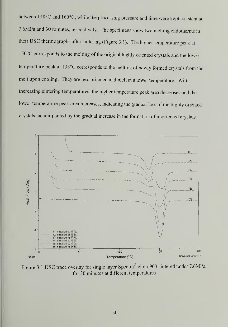
between 148°C and 160°C, while the processing pressure and time were kept constant at
7.6MPa and 30 minutes, respectively. The specimens show two melting endotherms in
their DSC thermographs after sintering (Figure 3.1). The higher temperature peak at
150°C corresponds to the melting of the original highly oriented crystals and the lower
temperature peak at 135°C corresponds to the melting of newly formed crystals from the
melt upon cooling. They are less oriented and melt at a lower temperature. With
increasing sintering temperatures, the higher temperature peak area decreases and the
lower temperature peak area increases, indicating the gradual loss of the highly oriented
crystals, accompanied by the gradual increase in the formation of unoriented crystals.
03Q)
X
-4
-6
Exo Up
Figure 3.1
(1) sintered at 160C(2) sintered at 156C(3) sintered at 154C(4) sintered at 152C
(5) sintered at 150C(6) sintered at 148C
50
Temperature (°C)
200
Universal V2 5H TA
DSC trace overlay for single layer Spectra® cloth 903 sintered under 7.6MPa
for 30 minutes at different temperatures
50
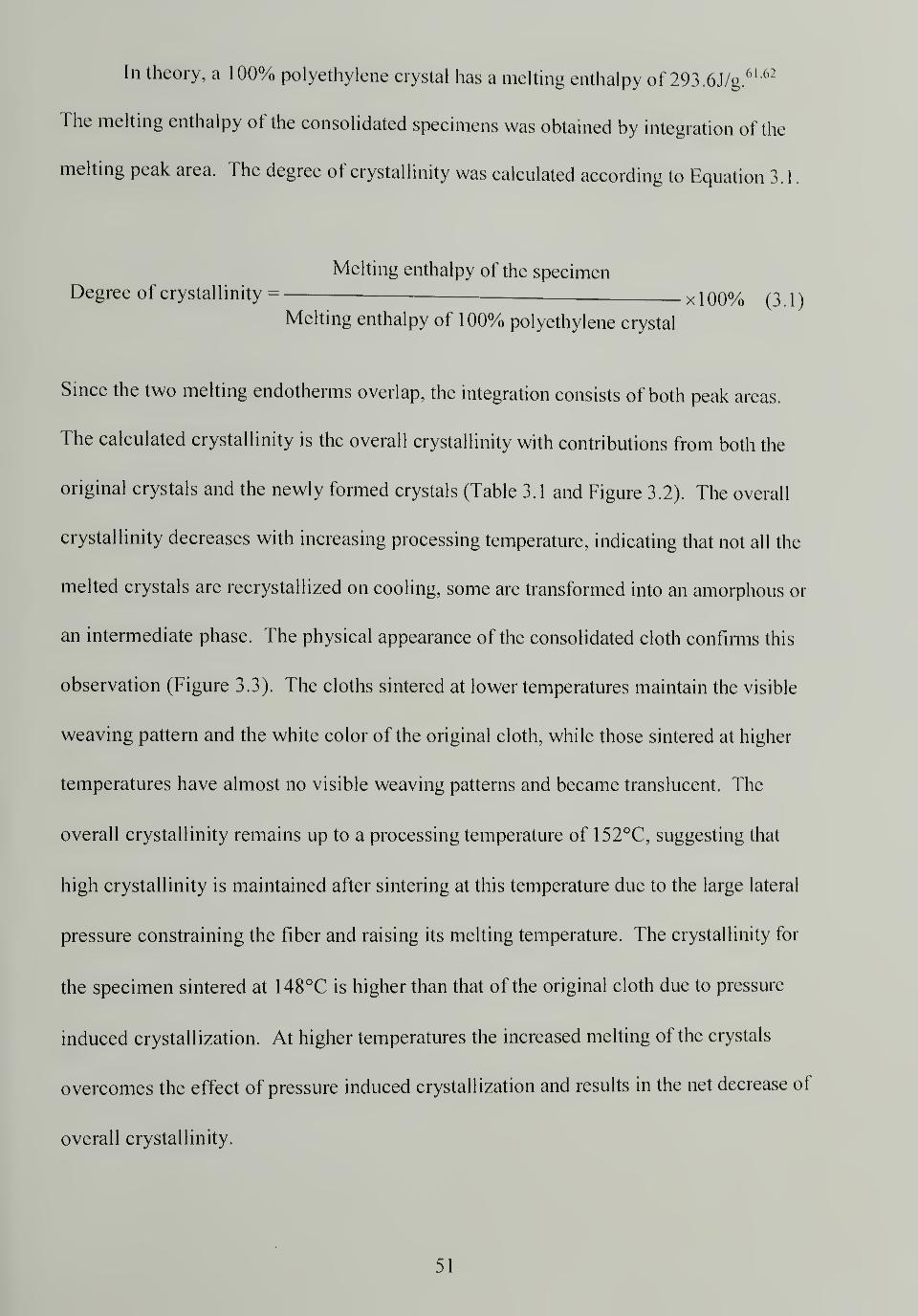
In theory, a 100% polyethylene crystal has a melting enthalpy of 293.6J/g.61 '62
The melting enthalpy of the consolidated specimens was obtained by integration of the
melting peak area. The degree of crystallinity was calculated according to Equation 3.1.
Melting enthalpy of the specimenDegree of crystallinity = x j 00o
/o ^A)Melting enthalpy of 100% polyethylene crystal
Since the two melting endotherms overlap, the integration consists of both peak areas.
The calculated crystallinity is the overall crystallinity with contributions from both the
original crystals and the newly formed crystals (Table 3.1 and Figure 3.2). The overall
crystallinity decreases with increasing processing temperature, indicating that not all the
melted crystals are recrystallized on cooling, some are transformed into an amorphous or
an intermediate phase. The physical appearance of the consolidated cloth confirms this
observation (Figure 3.3). The cloths sintered at lower temperatures maintain the visible
weaving pattern and the white color of the original cloth, while those sintered at higher
temperatures have almost no visible weaving patterns and became translucent. The
overall crystallinity remains up to a processing temperature of 152°C, suggesting that
high crystallinity is maintained after sintering at this temperature due to the large lateral
pressure constraining the fiber and raising its melting temperature. The crystallinity for
the specimen sintered at 148°C is higher than that of the original cloth due to pressure
induced crystallization. At higher temperatures the increased melting of the crystals
overcomes the effect of pressure induced crystallization and results in the net decrease of
overall crystallinity.
51
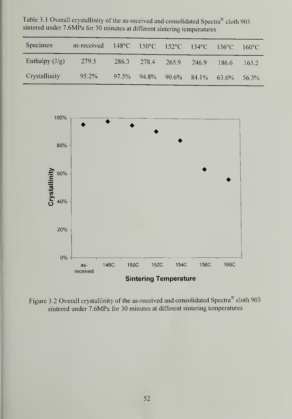
Table 3.1 Overall crystallinity of the as-received and consolidated Spectra® cloth 903sintered under 7.6MPa for 30 minutes at different sintering temperatures
Specimen as-received 148°C 150°C 152°C 154°C 156°C 160°C
Enthalpy (J/g) 279.5 286.3 278.4 265.9 246.9 186.6 165.2
Crystallinity 95.2% 97.5% 94.8% 90.6% 84.1% 63.6% 56.3%
100%
80%
60%
TO
(0
O 40%
20%
0%
Sintering Temperature
Figure 3.2 Overall crystallinity of the as-received and consolidated Spectra® cloth 903
sintered under 7.6MPa for 30 minutes at different sintering temperatures
52
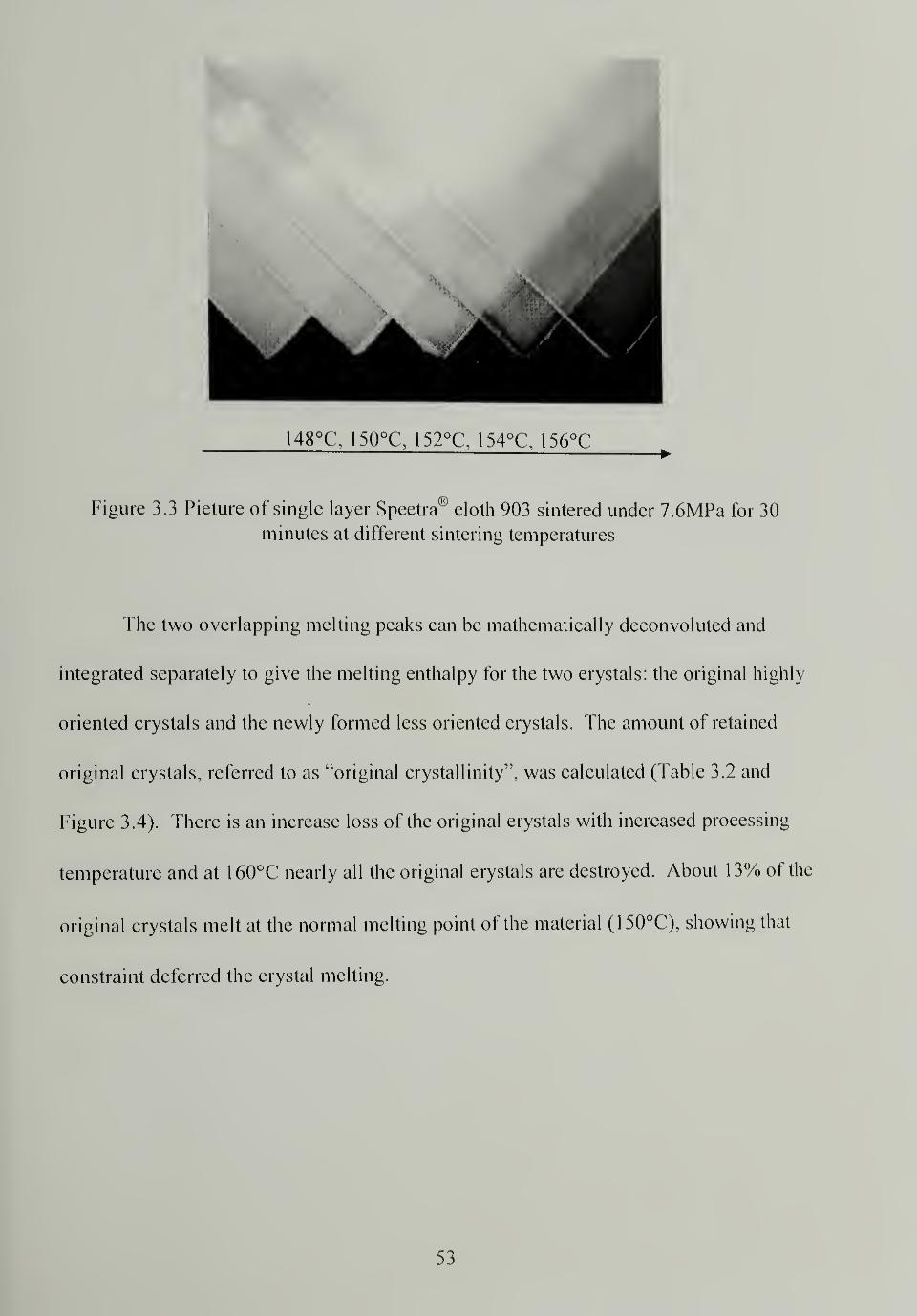
148°C\ 150°C, 152°C, 154°C\ 1%°C^
Figure 3.3 Picture of single layer Spectra® cloth 903 sintered under 7.6MPa for 30
minutes at different sintering temperatures
The two overlapping melting peaks can be mathematically deconvolved and
integrated separately to give the melting enthalpy for the two crystals: the original highly
oriented crystals and the newly formed less oriented crystals. The amount of retained
original crystals, referred to as "original crystallinity", was calculated (Table 3.2 and
Figure 3.4). There is an increase loss of the original crystals with increased processing
temperature and at 160°C nearly all the original crystals are destroyed. About 13% of the
original crystals melt at the normal melting point of the material (150°C), showing that
constraint deferred the crystal melting.
53
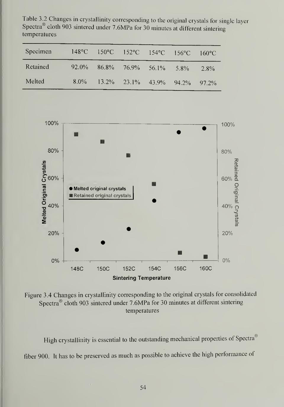
Table 3.2 Changes in crystallinity corresponding to the original crystals for single layer
Spectra® cloth 903 sintered under 7.6MPa for 30 minutes at different sintering
temperatures
Specimen 1 48°C 1 50°C 1 52°C 1 54°C 1 56°C 1 60°C
Retained 92.0% 86.8% 76.9% 56.1% 5.8% 2.8%
Melted 8.0% 13.2% 23.1% 43.9% 94.2% 97.2%
100%
80%
J2«*+»</>
£ 60%
15c"5>
O
40%
20%
0%
Melted original crystals
Retained original crystals
148C 150C 152C 154C 156C
Sintering Temperature
160C
100%
80%
3D0)
0)
60% a
IDHI3SB
40% ow
20%
0%
Figure 3.4 Changes in crystallinity corresponding to the original crystals for consolidated
Spectra® cloth 903 sintered under 7.6MPa for 30 minutes at different sintering
temperatures
High crystallinity is essential to the outstanding mechanical properties of Spectral,K)
fiber 900. It has to be preserved as much as possible to achieve the high performance of
54
the sintered products. DSC suggests that the temperature range of 150°C - 152°C would
be an ideal processing temperature; at these temperatures a minimum of 13% of the
original crystals are melted and a 95% overall crystallinity is maintained after
consolidation. The melted phase is sufficient to serve as the bonding mechanism to hold
the consolidated structure together upon cooling and recrystallization.
3.3.2 WAXD patterns and Hermans orientation function
In the high-temperature high-pressure sintering, the molecules tend to relax
towards their preferential random coil conformation at high temperatures even though
they are under substantial constraint. The outcome is the loss of crystalline and chain
orientation, resulting in a decrease of longitudinal strength. WAXD patterns for
consolidated single layer Spectra® cloths sintered at different temperatures under constant
pressure and time of 7.6MPa and 30 minutes are compared (Figure 3.5). Specimens
sintered at lower temperatures, up to 1 50°C, have diffraction patterns similar to those of
the as-received cloth, suggesting that high orientation is preserved even after the
specimens experienced near-melting temperatures due to effective constraint. As the
sintering temperature increases, the diffraction pattern of the consolidated cloth
undergoes a series of changes. The spot-like diffraction pattern becomes arcs, the arcs
broaden, and distinct diffraction rings eventually emerge due to the loss of molecular
orientation.
55
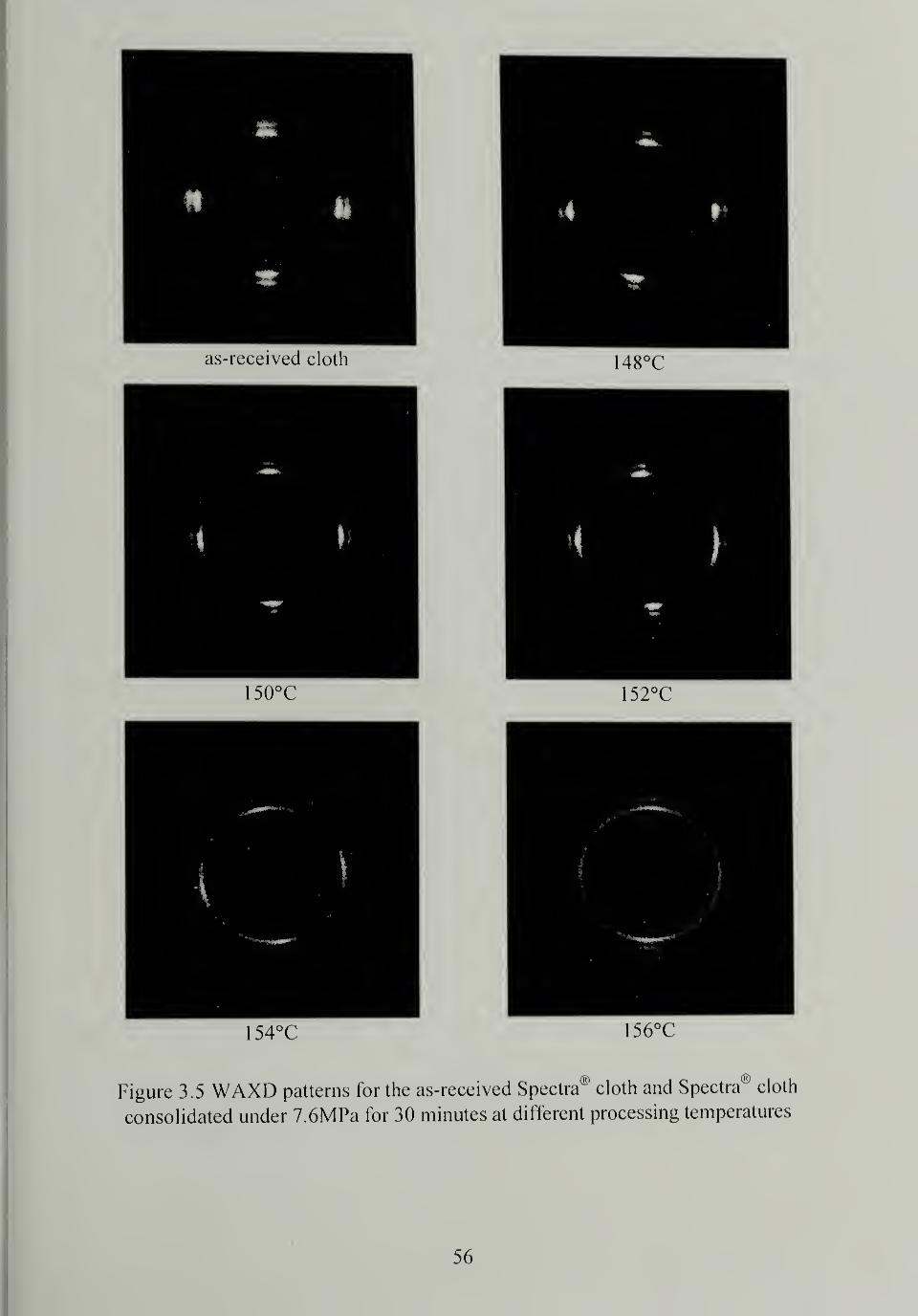
as-received cloth 148°C
150°C 152°C
1 54°C 156°C
Figure 3.5 WAXD patterns for the as-received Spectra® cloth and Spectra1
* cloth
consolidated under 7.6MPa for 30 minutes at different processing temperatures
56
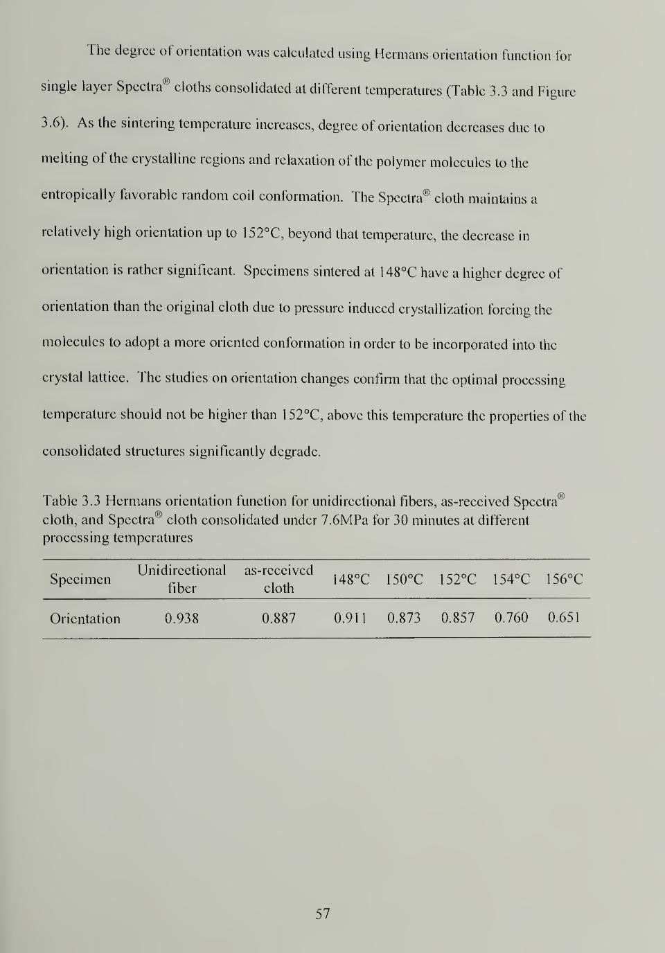
The degree of orientation was calculated using Hermans orientation function for
single layer Spectra® cloths consolidated at different temperatures (Table 3.3 and Figure
3.6). As the sintering temperature increases, degree of orientation decreases due to
melting of the crystalline regions and relaxation of the polymer molecules to the
entropically favorable random coil conformation. The Spectra® cloth maintains a
relatively high orientation up to 1 52°C, beyond that temperature, the decrease in
orientation is rather significant. Specimens sintered at 148°C have a higher degree of
orientation than the original cloth due to pressure induced crystallization forcing the
molecules to adopt a more oriented conformation in order to be incorporated into the
crystal lattice. The studies on orientation changes confirm that the optimal processing
temperature should not be higher than 152°C, above this temperature the properties of the
consolidated structures significantly degrade.
Table 3.3 Hermans orientation function for unidirectional fibers, as-received Spectra
cloth, and Spectra® cloth consolidated under 7.6MPa for 30 minutes at different
processing temperatures
SpecimenUnidirectional
fiber
as-received
cloth148°C 150°C 152°C 154°C 156°C
Orientation 0.938 0.887 0.911 0.873 0.857 0.760 0.65
1
57
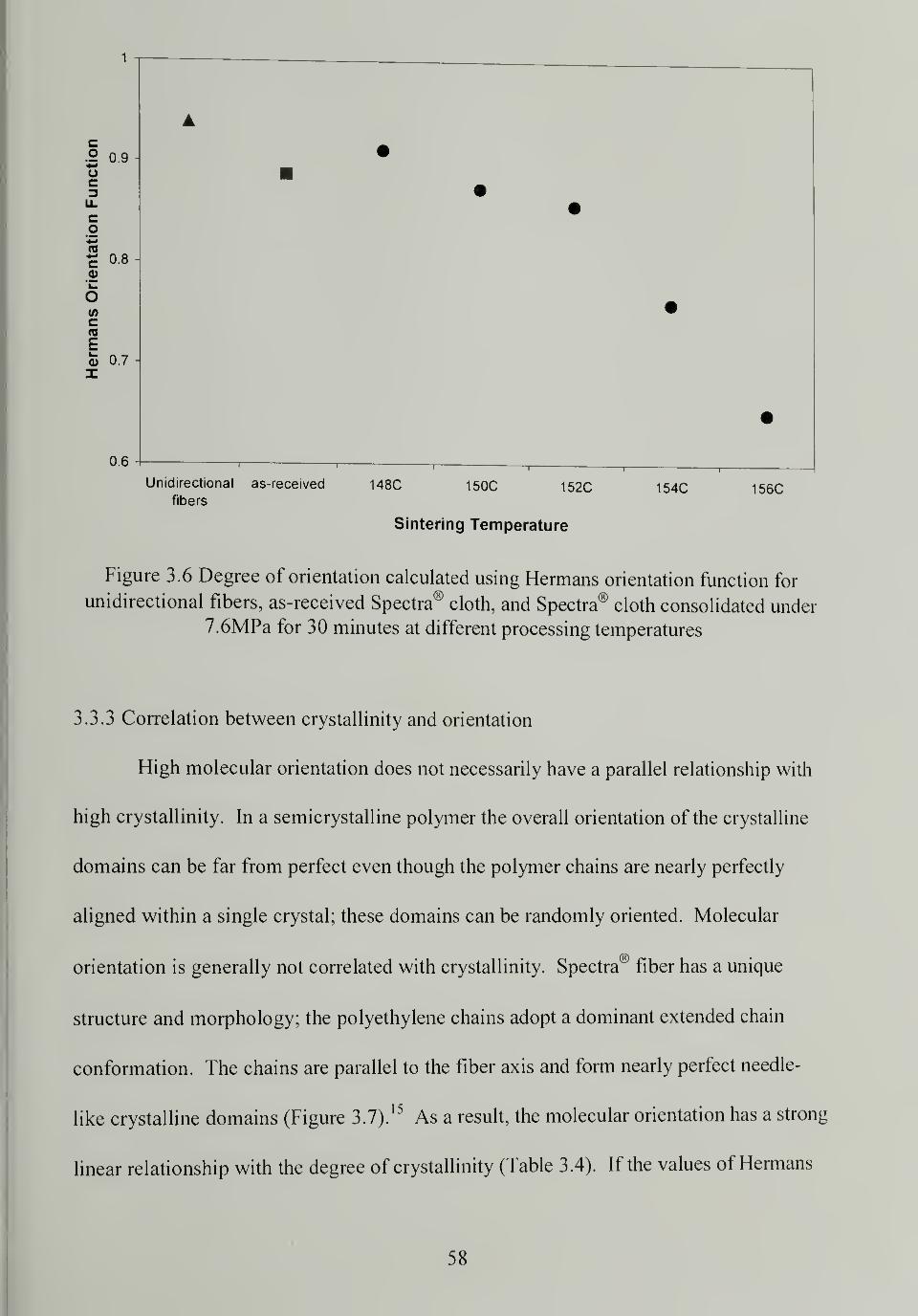
1
c.2 0.9 A
0.8
(/>
c
Ea> 0.7
0.6
Unidirectional as-received 148C 150C 152C 154C 156Cfibers
Sintering Temperature
Figure 3.6 Degree of orientation calculated using Hermans orientation function for
unidirectional fibers, as-received Spectra® cloth, and Spectra® cloth consolidated under
7.6MPa for 30 minutes at different processing temperatures
3.3.3 Correlation between crystallinity and orientation
High molecular orientation does not necessarily have a parallel relationship with
high crystallinity. In a semicrystalline polymer the overall orientation of the crystalline
domains can be far from perfect even though the polymer chains are nearly perfectly
aligned within a single crystal; these domains can be randomly oriented. Molecular
orientation is generally not correlated with crystallinity. Spectra® fiber has a unique
structure and morphology; the polyethylene chains adopt a dominant extended chain
conformation. The chains are parallel to the fiber axis and form nearly perfect needle-
like crystalline domains (Figure 3. 7).15
As a result, the molecular orientation has a strong
linear relationship with the degree of crystallinity (Table 3.4). If the values of Hermans
58
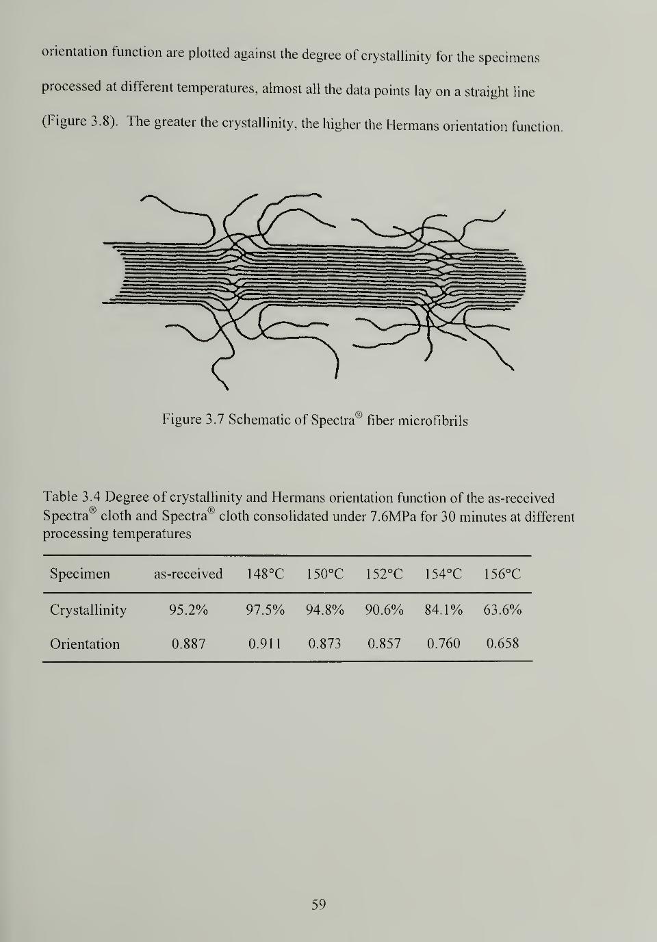
orientation function are plotted against the degree of crystallinity for the specimens
processed at different temperatures, almost all the data points lay on a straight line
(Figure 3.8). The greater the crystallinity, the higher the Hermans orientation function.
Table 3.4 Degree of crystallinity and Hermans orientation function of the as-received
Spectra® cloth and Spectra® cloth consolidated under 7.6MPa for 30 minutes at different
processing temperatures
Specimen as-received 148°C 150°C 152°C 154°C 156°C
Crystallinity
Orientation
95.2%
0.887
97.5%
0.911
94.8%
0.873
90.6%
0.857
84.1%
0.760
63.6%
0.658
59
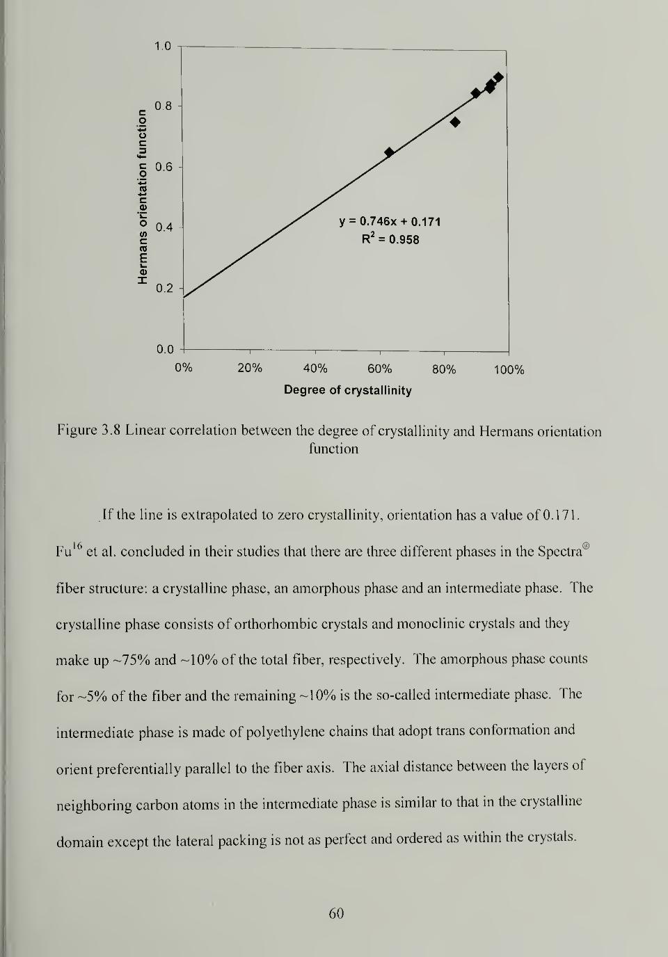
1.0
0% 20% 40% 60% 80% 100%
Degree of crystallinity
Figure 3.8 Linear correlation between the degree of crystallinity and Hermans orientation
function
If the line is extrapolated to zero crystallinity, orientation has a value of 0.171
.
Fu6et al. concluded in their studies that there are three different phases in the Spectra®
fiber structure: a crystalline phase, an amorphous phase and an intermediate phase. The
crystalline phase consists of orthorhombic crystals and monoclinic crystals and they
make up -75% and -10% of the total fiber, respectively. The amorphous phase counts
for -5% of the fiber and the remaining -10% is the so-called intermediate phase. The
intermediate phase is made of polyethylene chains that adopt trans conformation and
orient preferentially parallel to the fiber axis. The axial distance between the layers of
neighboring carbon atoms in the intermediate phase is similar to that in the crystalline
domain except the lateral packing is not as perfect and ordered as within the crystals.
60
The mobility of the chains in the intermediate phase is one order of magnitude higher
than and one order of magnitude lower than the crystalline and amorphous phase,
respectively. Based on Fu's model, the extrapolated orientation at zero crystallinity
comes from the orientation of the intermediate phase.
3.3.4 Normalized to thickness total energy of impact
The total energy of impact, the work done to puncture a consolidated Spectra®
cloth was calculated from the load vs. deflection curve (Figure 3.9). Only the first peak
is considered as the remaining responses are artifacts caused by the bouncing of the dart
in the test. Since the specimen thickness is one of the factors that determine the total
energy, the results were normalized to thickness (NTT). The NTT impact energy was
used as the measure for impact resistance.
61
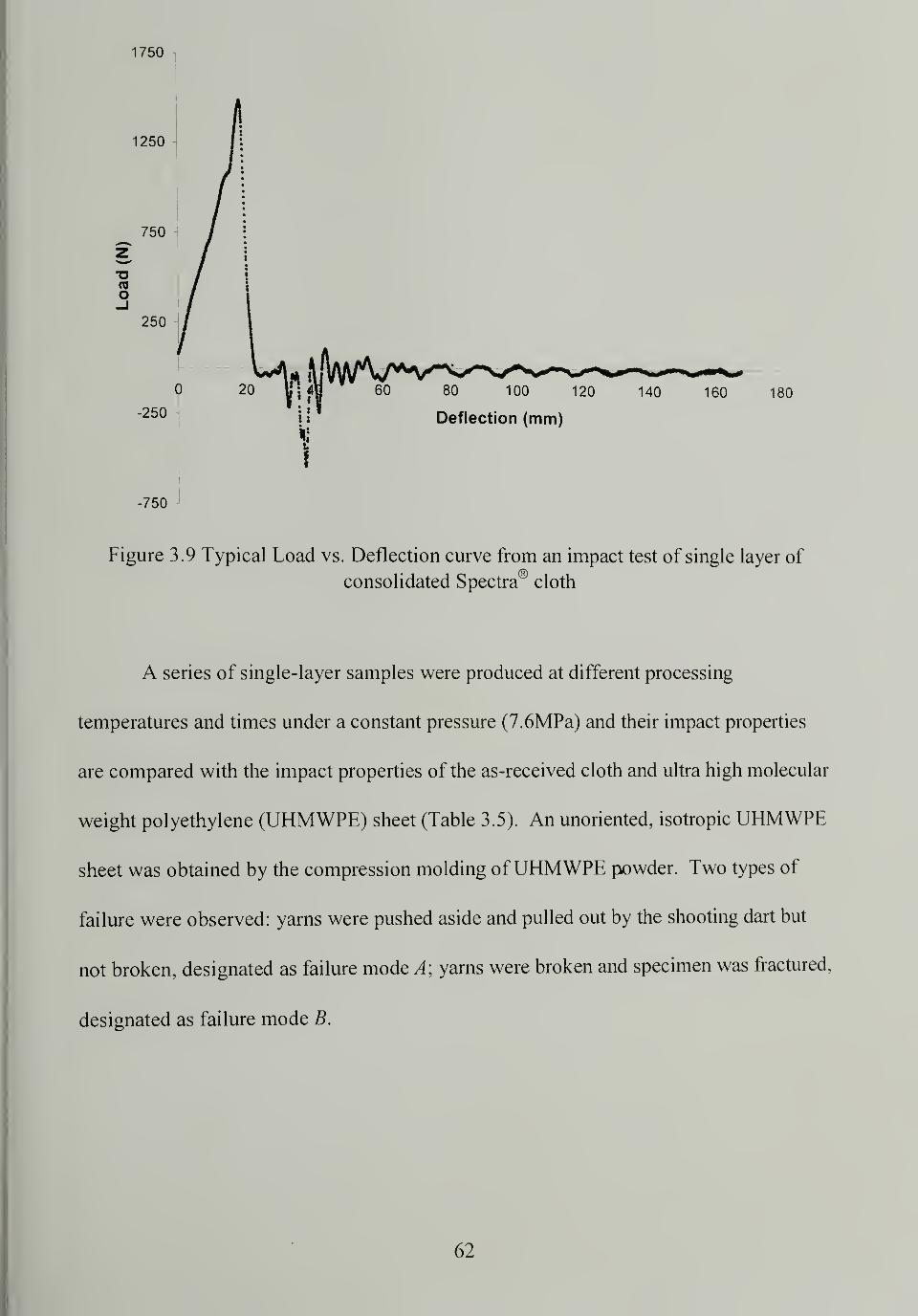
1750
Figure 3.9 Typical Load vs. Deflection curve from an impact test of single layer of
consolidated Spectra® cloth
A series of single-layer samples were produced at different processing
temperatures and times under a constant pressure (7.6MPa) and their impact properties
are compared with the impact properties of the as-received cloth and ultra high molecular
weight polyethylene (UHMWPE) sheet (Table 3.5). An unoriented, isotropic UHMWPE
sheet was obtained by the compression molding ofUHMWPE powder. Two types of
failure were observed: yarns were pushed aside and pulled out by the shooting dart but
not broken, designated as failure mode A\ yarns were broken and specimen was fractured,
designated as failure mode B.
62
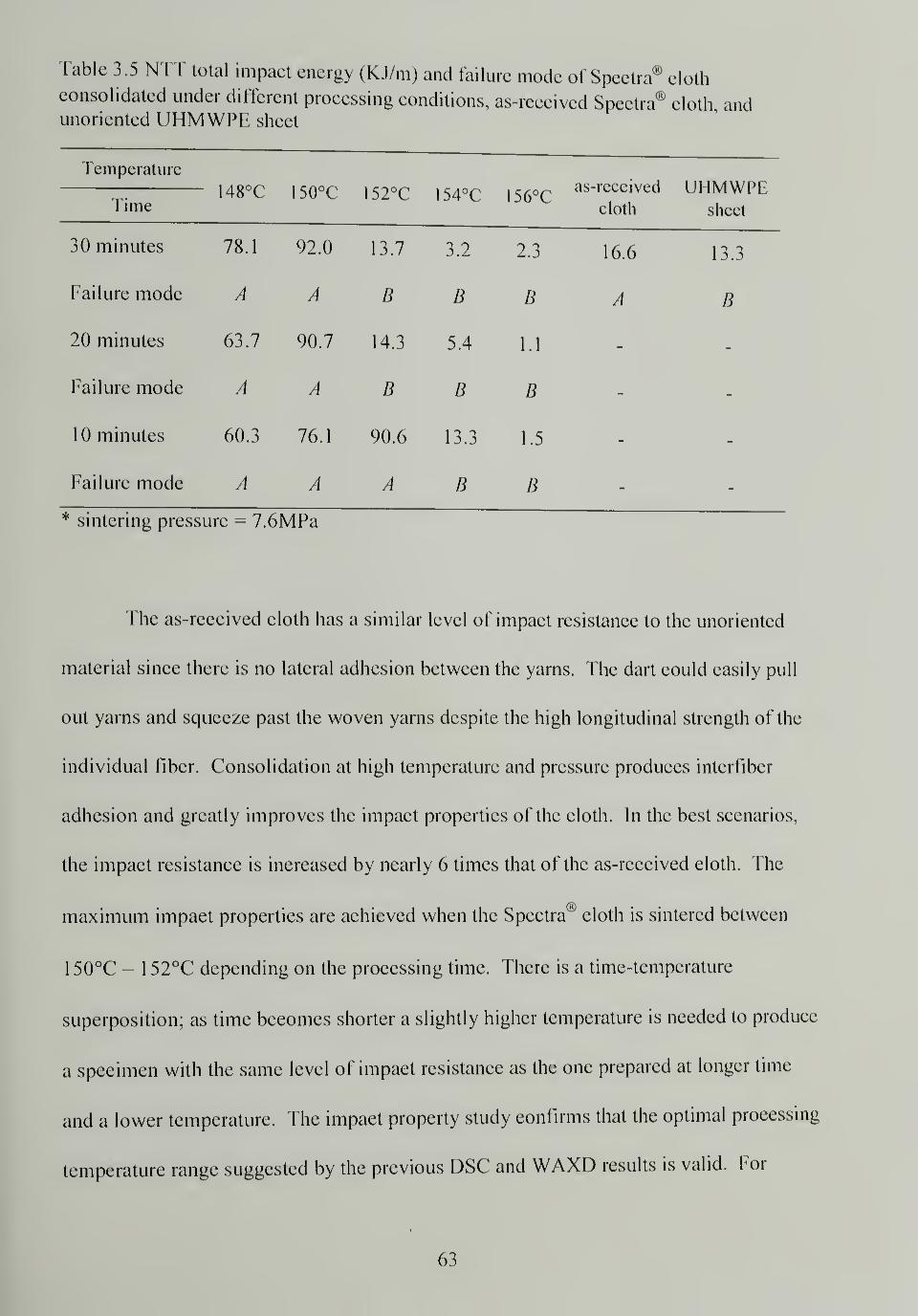
Table 3.5 NTT total impact energy (KJ/m) and failure mode of Spectra® clothconsolidated under different processing conditions, as-received Spectra® cloth, andunoriented UHMWPE sheet
Time148°C 150°C 152°C 154°C 156°C
as-received
cloth
UHMWPEsheet
30 minutes 78.1 92.0 13.7 3.2 2.3 16.6 13.3
Failure mode A A B B B A B
20 minutes 63.7 90.7 14.3 5.4 1.1 - _
Failure mode A A B B B m
10 minutes 60.3 76.1 90.6 13.3 1.5
Failure mode A A A B B —
* sintering pressure = 7.6MPa
The as-received cloth has a similar level of impact resistance to the unoriented
material since there is no lateral adhesion between the yarns. The dart could easily pull
out yarns and squeeze past the woven yarns despite the high longitudinal strength of the
individual fiber. Consolidation at high temperature and pressure produces interfiber
adhesion and greatly improves the impact properties of the cloth. In the best scenarios,
the impact resistance is increased by nearly 6 times that of the as-received cloth. The
maximum impact properties are achieved when the Spectra00
cloth is sintered between
1 50°C - 1 52°C depending on the processing time. There is a time-temperature
superposition; as time becomes shorter a slightly higher temperature is needed to produce
a specimen with the same level of impact resistance as the one prepared at longer time
and a lower temperature. The impact property study confirms that the optimal processing
temperature range suggested by the previous DSC and WAXD results is valid. For
63
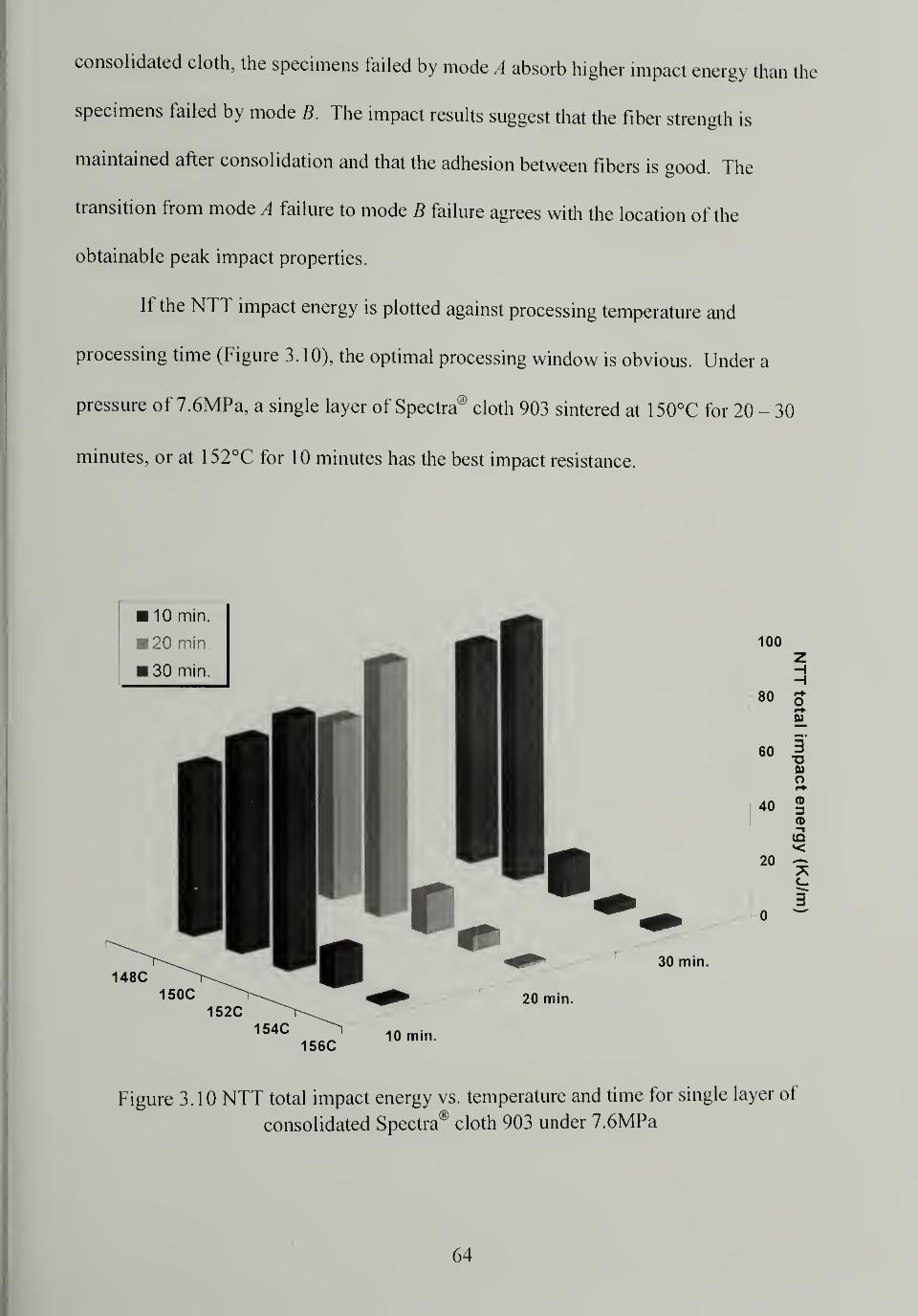
consolidated cloth, the specimens failed by mode A absorb higher impact energy than the
specimens failed by mode B. The impact results suggest that the fiber strength is
maintained after consolidation and that the adhesion between fibers is good. The
transition from mode A failure to mode B failure agrees with the location of the
obtainable peak impact properties.
If the NTT impact energy is plotted against processing temperature and
processing time (Figure 3. 10), the optimal processing window is obvious. Under a
pressure of 7.6MPa, a single layer of Spectra® cloth 903 sintered at 1 50°C for 20 - 30
minutes, or at 152°C for 10 minutes has the best impact resistance.
Figure 3.10 NTT total impact energy vs. temperature and time for single layer of
consolidated Spectra® cloth 903 under 7.6MPa
64
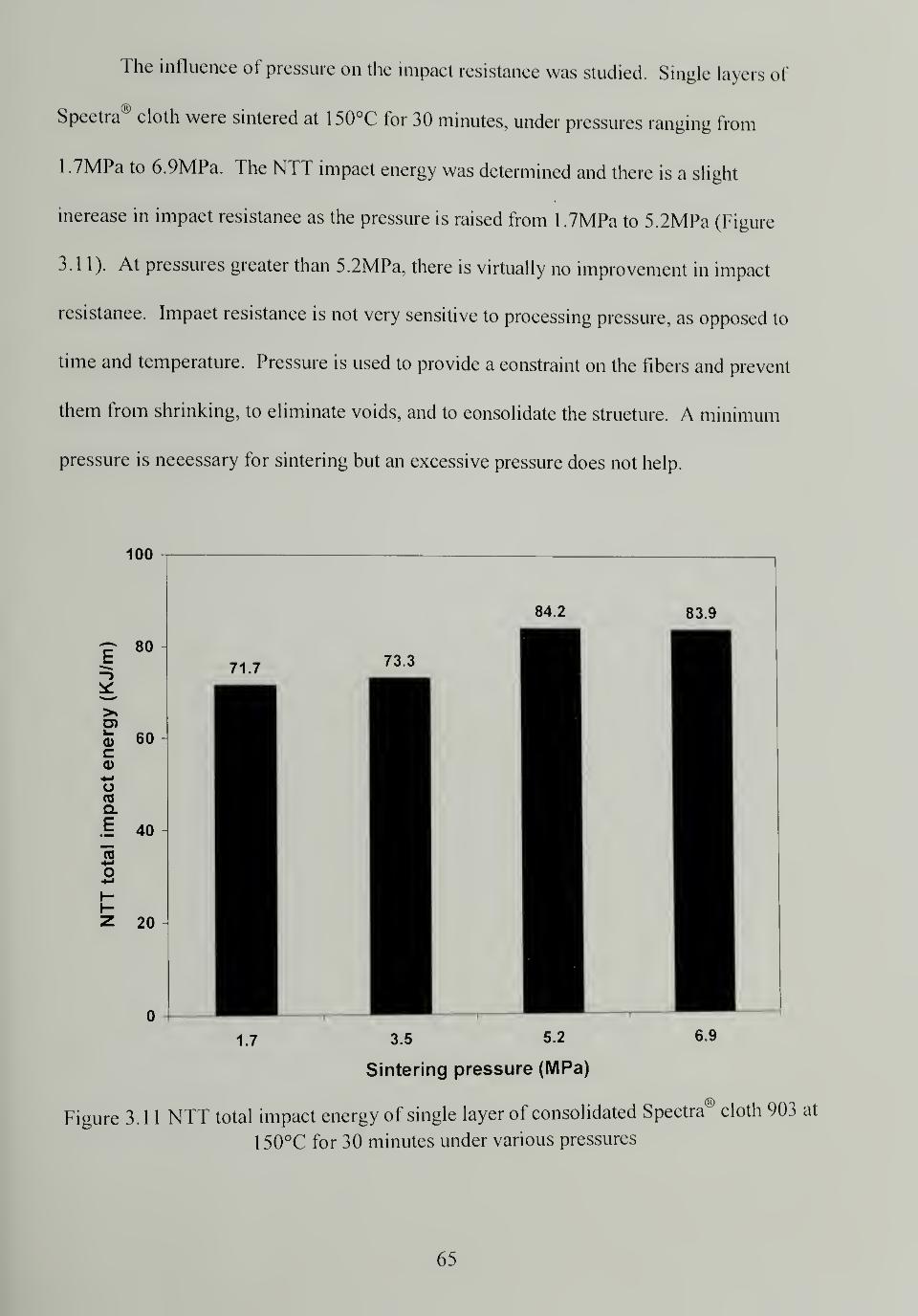
The influence of pressure on the impact resistance was studied. Single layers of
Spectra® cloth were sintered at 1 50°C for 30 minutes, under pressures ranging from
1 .7MPa to 6.9MPa. The NTT impact energy was determined and there is a slight
increase in impact resistance as the pressure is raised from 1.7MPa to 5.2MPa (Figure
3.11). At pressures greater than 5.2MPa, there is virtually no improvement in impact
resistance. Impact resistance is not very sensitive to processing pressure, as opposed to
time and temperature. Pressure is used to provide a constraint on the fibers and prevent
them from shrinking, to eliminate voids, and to consolidate the structure. A minimum
pressure is necessary for sintering but an excessive pressure does not help.
100
1.7 3.5 5.2
Sintering pressure (MPa)
Figure 3.1 1 NTT total impact energy of single layer of consolidated Spectra® cloth 903 at
150°C for 30 minutes under various pressures
65
3.4 Conclusion
Single layers of Spectra® cloth were consolidated under various processing
conditions by high-temperature high-pressure sintering. The resulting products have
largely different physical properties and microstructure. At a given pressure and time,
the extent of melting and recrystallization of the fiber increases with increasing
processing temperature. Since not all of the melted phase recrystallizes on cooling, some
is transformed to the amorphous and intermediate phase, the overall crystallinity
decreases with increasing processing temperature. The original highly oriented crystals
can be preserved if the sintering temperature is lower than 152°C. The relaxation of the
molecular chains occurs at higher temperatures and becomes severe, indicated by the
deceasing Hermans orientation function, with increasing processing temperature. The
phenomenon of pressure induced crystallization happens to some extent as suggested by
both DSC and WAXD. The I Iermans orientation function shows a nearly perfect linear
relationship with the degree of crystallinity due to the unique structure of Spectra® fiber.
The impact resistance of Spectra® cloth is significantly improved after consolidation due
to the development of interfiber adhesion. The processing temperature and time have a
strong influence on the impact properties of the consolidated cloth while the processing
pressure has little effect. The maximum impact properties are obtained when the cloths
are sintered at 150°C - 152°C. The optimal processing windows is determined to be at
1 50°C for 20 - 30 minutes, or 1 52°C for 1 0 minutes under 7.6MPa. Under these
conditions the consolidated cloths have the best impact resistance, indicative of the
successful balance between the loss of longitudinal strength and the development of
lateral strength.
66
CHAPTER 4
EVALUATION OF CONSOLIDATED STRUCTURES: PROCESS-STRUCTURE-PROPERTY RELATIONSHIP
4.1 Introduction
The crystallinity and orientation of the consolidated Spectra® cloth determine the
thermo-mechanical properties of the consolidated structures. They are greatly influenced
by the processing conditions as confirmed by impact resistance observations. In this
chapter, the consolidated Spectra® cloth is physically, thermally, mechanically,
structurally, and morphologically characterized. Various characterization methods are
used including mechanical testing, scanning electron microscopy (SEM), differential
scanning calorimetry (DSC), and wide angle X-ray diffraction (WAXD) in this
investigation.
The density of the sintered multilayer panels was measured to provide
information on how well Spectra® cloth was consolidated under different processing
conditions. The interlayer adhesion for sintered cloth was measured by T-peel test to
characterize the lateral strength of the consolidated structures under different processing
conditions. Flexural properties for multilayer Hat panels sintered under different
processing conditions were evaluated by three-point bend test to quantitatively illustrate
the rigidity and stiffness of the consolidated structures. Ballistic performance of the flat
panels was examined and compared with conventional matrix-containing Spectra®
composites and other high performance fiber composites. The microstructure and
morphology of the sintered cloth was investigated by SEM. Hermans orientation
function was calculated for multilayer consolidated structures from WAXD results.
67
Differences between the surface and center layer of the multilayer sintered structure was
probed by DSC and WAXD. The process-structure-property relationship is established to
give an in-depth and better understanding of the high-temperature high-pressure sintering
process for consolidating Spectra® cloth.
4.2 Experimental
4.2.1 Materials
Spectra® cloth 903 is made from Spectra® fiber 900 and was provided by
Honeywell. It is a plain woven cloth with an average thickness of 0.5mm and an areal
density of 0.024g/cm . The material was sampled and tested in the as-received state
without any further treatments. Spectra® cloth 903 is the material of choice for ballistic
protective hard armor.
4.2.2 Density measurement
The effective consolidation of the Spectra® cloth was determined by comparing
the literature value for the density of the Spectra® fiber with the determined density of the
sintered structures. The weight of a specimen was measured both in air and immersed in
2-Propanol by a precision balance, then the density was calculated using Equation 4.1. 2-
Propanol was used since its density (0.785g/cm3) is less than that of Spectra® fiber
(0.97g/cm3).
68
(4.1)
Where p is the specimen density
ps is the solvent density
w is the specimen weight in air
ws is the specimen weight immersed in solvent
4.2.3 T-peel test
Thermally bonded bilayer Spectra® cloth was prepared by sandwiching a 40mm x
150mm sheet of aluminum foil between two layers of 150mm x 150mm Spectra® cloth
so that the aluminum foil was in line with one side of the cloth. The bilayer was
consolidated by high-temperature high-pressure sintering, the aluminum foil was
removed, and a 40mm wide gap was left with the remaining areas sintered. A series of
bilayers were produced at different processing temperatures under constant pressure and
time (7.6MPa and 30 minutes). Test specimens consisted of rectangular bilayer strips
(12.5mm x 1 50mm) which had two "arms" due to the initial opening. T-peel tests were
conducted on an Instron 5500R according to ASTM standard D1876. The two arms of
the strip were attached to the upper and lower grips, and the crosshead was separated at
the speed of 157mm/min. The peeling load and displacement distance were recorded. T-
peel strength is reported as a measure of interlayer adhesion.
69
4.2.4 Three-point bend test
Rectangular bars (100mm x 12.5mm x 3.2mm) prepared from twelve-layer
Spectra® cloth panels consolidated under different processing conditions were used for
three-point bend tests. The test was conducted using an Instron 5500R according to
ASTM standard D790. A support span of 50mm and a crosshead speed of 1.35mm/min
were used. The testing limit of 5% strain was used to ensure reliability of the data and
the flexural modulus is reported as a measure of stiffness.
4.2.5 Ballistic test
Ballistic tests on flat panels of consolidated Spectra® cloth were performed by the
US Army at the Natick Soldier Center, MA. The panels were made from Spectra® cloth
903 according to our processing procedures and conditions and the testing protocol used
was U.S. Military Standard 662F, a modified version ofNATO V50 ballistic test
standard.63
Multilayer sintered flat panels were shot by several different sized projectiles
and the results were studied using a dimensionless analysis. The V50 ballistic limits are
related to the ratio of the area density of the armor systems to the presented area density
of the projectiles.64
The results are provided in comparison to composites using the same
Spectra® cloth and a vinyl ester matrix, PBO fiber, and Kevlar® fiber reinforced
composite armor systems.
4.2.6 SEM and sample preparation
Consolidated Spectra® panels were etched according to Olley et al.65
using 7%
w/v potassium permanganate in a mixture of fuming sulfuric acid and phosphoric acid
70
mixture (1/2 v/v). Twelve-layer sintered Spectra® cloth panels prepared under different
processing conditions were cut using a diamond knife to expose the cross section and
were etched for one hour. At the end of the etching, the specimens were washed in a
mixture of sulfuric acid and water (2/7 v/v) cooled near to its freezing point with dry ice.
The solution was decanted and the specimens were washed in hydrogen peroxide,
distilled water several times, and acetone for two minutes each. The specimens dried in
air, were sputter-coated with gold, and examined under SEM. Peeled surfaces resulting
from bonded bilayers which underwent the T-peel test were coated with gold and
examined under SEM. JEOL 35CF and FESEM JEOL JSM-6320FXV were used in this
study at magnifications of lOOx, lOOOx, and 1200x.
4.2.7 WAXD of multilayer consolidated Spectra® cloth
Wide angle X-ray diffraction (WAXD) patterns were collected using pin hole
collimated, monochromatic Cu Ka radiation and a Bruker® "High Star" two dimensional
detector. The diffraction patterns of a series of six-layer Spectra® cloth sintered under
different processing conditions were collected. The cloth was oriented "flat-on" so that
the incident X-ray beam was perpendicular to the cloth and the weft or warp yarn was
aligned parallel to the horizon. A radiation time of 300 seconds was used and diffraction
patterns were captured digitally. The integration of the intensity was preformed using
GADDS commercial software.
71
4.2.8 Studies on the surface and center layers
Surface and center layers were peeled and separated from the consolidated
twelve-layer of Spectra® cloth prepared under different processing conditions. The
crystallinity of the layers was determined by a TA Instrument DSC 2910 under nitrogen
atmosphere (50 ml/min.). Hermetic pans containing -10 mg samples of the peeled layers
were heated at a rate of 10°C/min. from room temperature to 200°C. The molecular
orientation of the layers was determined by WAXD and the procedure is described in the
previous section.
4.3 Results and Discussion
4.3.1 Density of the multilayer consolidated structure
Twelve layers of Spectra"" cloth were sintered under 17.2MPa for 30 minutes at
various temperatures and densities were calculated according to Equation 4.1 . Figure 4.1
shows that the densities of the panels initially increase with increasing sintering
temperature to a maximum at a sintering temperature of 154°C, and then decrease as the
temperature increases above 1 54°C. Panels sintered at different temperatures have the
densities similar to that of the original fiber (0.97g/cm3
), suggesting that multilayer cloths
are well consolidated with few voids; panels sintered at 1 54°C are nearly void-free
(0.969g/cm3). The rise in density with sintering temperature from 1 50°C to 154°C is due
to an increase in fiber lateral deformation which filled interstices. The drop in density
with sintering temperature greater than 1 54°C is attributed to excessive fiber melting.
The original highly oriented, dense crystalline regions of the fibers were destroyed during
melting and the less dense amorphous regions were produced upon cooling. A large
72
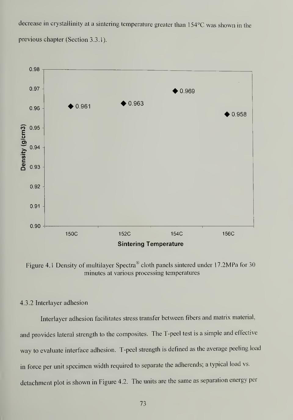
decrease in crystallinity at a sintering temperature greater than 154°C was shown in the
previous chapter (Section 3.3.1).
0.98
0.97 -
0.96
co 0.95Eo
r; 0.94
cg 0.93
0.92
0.91
0.90
0.961
150C
0.963
0.969
152C 154C
Sintering Temperature
0.958
156C
Figure 4.1 Density of multilayer Spectra® cloth panels sintered under 17.2MPa for 30
minutes at various processing temperatures
4.3.2 Interlayer adhesion
Interlayer adhesion facilitates stress transfer between fibers and matrix material,
and provides lateral strength to the composites. The T-peel test is a simple and effective
way to evaluate interface adhesion. T-peel strength is defined as the average peeling load
in force per unit specimen width required to separate the adherends; a typical load vs.
detachment plot is shown in Figure 4.2. The units are the same as separation energy per
73

unit area debonded. The fluctuation of data points in Figure 4.2 is due to non-uniform
bonding. Since the surface of a woven cloth is not flat, with the yarns going up and down
alternatively, the best adhesion is achieved when the high points of two cloths contact,
the worst adhesion is suffered when the low points contact. Medium adhesion occurs
when a high point and a low point are in contact.
o
10 20 30 40 50 60
Detachment (mm)70 80 90 100
Figure 4.2 Typical load vs. detachment curve in a T-peel test
T-peel strengths for Spectra cloth bilayers sintered at different processing
temperatures are compared in Table 4. 1 . The peel strength increases monotonically over
the temperature range since higher temperatures results in increased melting and
recrystallization on cooling, hence better bonding. One would anticipate that
consolidation at higher temperatures is required to make a good composite material as the
better adhesion results in better load transfer. However, for laminated materials made for
ballistic purposes, the stronger the adhesion the poorer the ballistic performance. When a
74
high speed projectile hits a target, its kinetic energy needs to be consumed in order to
stop it and delamination between layers and fibers provides a good channel for the
dissipation of energy. Excellent interface adhesion between layers and fibers worsens the
ballistic protection and comes at the expense of the longitudinal strength since more
crystalline melting and orientation loss happens at higher temperatures. It has been
shown that the tensile failure of the fibers during ballistic impact absorbs a large portion
of the kinetic energy,66
therefore the preservation of the fibers' longitudinal strength is of
great importance. A certain level of adhesive strength is desired to bond the material but
excessive adhesion should be avoided.
Table 4.1 T-peel strength of two layers of Spectra® cloth 903 bonded under 7.6MPa for
30 minutes at different temperatures
Sintering Temperature 148°C 150°C 152°C 154°C 156°C
T-Peel Strength (N/cm) 1.7 2.0 3.5 11.4 13.3
Peeled surfaces were examined under SEM (Figure 4.3) for the specimens
sintered at different processing temperatures. At sintering temperatures between 148°C -
1 50°C, there is little adhesion between the bonded layers and few residues or
detachments are left on the peeled surfaces. Individual fibers in the cloth are visible with
no signs of fiber disturbance or lift, suggesting that the adhesion is only from the strength
of the recrystallized thin layers between fibers. Adhesion becomes stronger at
temperatures between 152°C - 156°C as indicated by the severe fibrillation resulted from
peeling. Individual fibers are smeared out and not discernible.
75
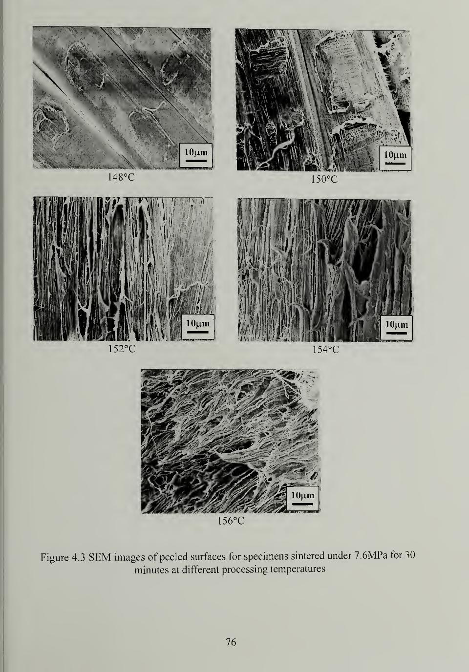
156°C
Figure 4.3 SEM images of peeled surfaces for specimens sintered under 7.6MPa for 30
minutes at different processing temperatures
76

4.3.3 Flexural properties
Flexural properties were measured by three-point bend tests to characterize the
rigidity and stiffness of the materials. No specimens exhibited any failure or yield within
the 5% strain limit set by ASTM D790, so no ultimate strength or yield strength is
reported. At a much higher strain than 5%, the specimens sintered at lower temperatures
showed delamination between the layers while the specimens sintered at higher
temperatures showed no visible damage. Flexural modulus (Table 4.2 and Figure 4.4)
was calculated by initial slope method according to Equation 4.2:
F _ sL3
'4W,
3 (4-2)
where E is the tangent modulus of elasticity
s is the initial slope of the load-deflection curve
L is the support span
w is the specimen width
/ is the specimen thickness
Table 4.2 Flexural modulus (GPa) of twelve layers of Spectra cloth 903 sintered at
different processing conditions and unoriented UHMWPE panel
Processing condition 150°C 152°C 154°C 156°C 160°C UHMWPE
30 minutes 3.33 4.52 5.18 4.31 0.80 0.74
45 minutes 3.57 5.23 4.24 3.27 0.81 M
60 minutes 4.87 5.98 4.45 1.95 0.78
* Sintering pressure = 17.2MPa
77
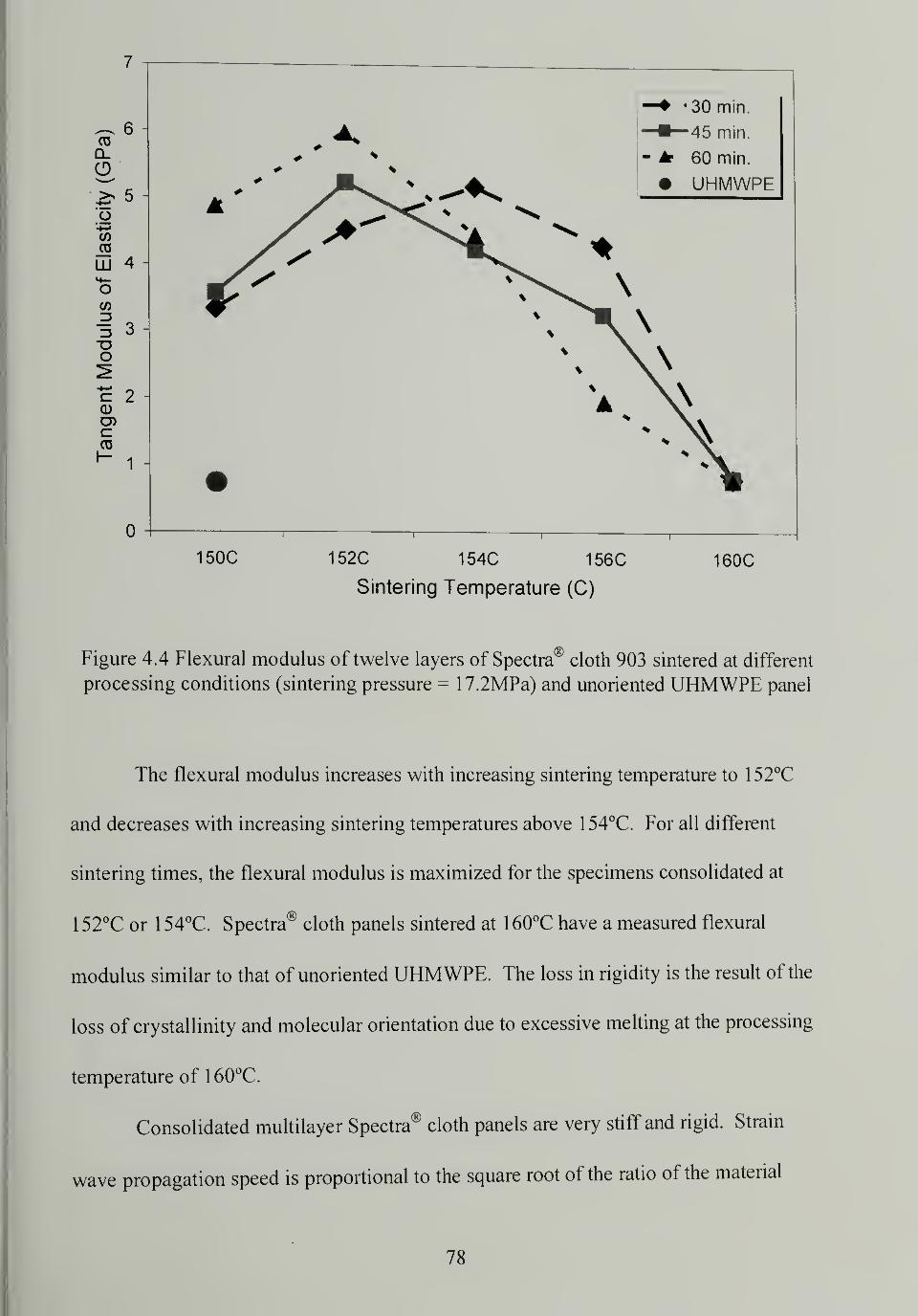
150C 152C 154C 156C
Sintering Temperature (C)
160C
Figure 4.4 Flexural modulus of twelve layers of Spectra® cloth 903 sintered at different
processing conditions (sintering pressure = 17.2MPa) and unoriented UHMWPE panel
The flexural modulus increases with increasing sintering temperature to 152°C
and decreases with increasing sintering temperatures above 154°C. For all different
sintering times, the flexural modulus is maximized for the specimens consolidated at
152°C or 154°C. Spectra® cloth panels sintered at 160°C have a measured flexural
modulus similar to that of unoriented UHMWPE. The loss in rigidity is the result of the
loss of crystallinity and molecular orientation due to excessive melting at the processing
temperature of 160°C.
Consolidated multilayer Spectra® cloth panels are very stiff and rigid. Strain
wave propagation speed is proportional to the square root of the ratio of the material
78
modulus and density ( Je[~p ).
1
5
The high modulus and low density of Spectra® material
allows for fast wave propagation; the impact energy generated by a projectile can spread
quickly and more material will be involved in the energy dissipation process. If a bullet
hits an isotropic target material, the shock wave caused by impact travels in all directions
at the same speed. A fiber reinforced armor system is highly anisotropic; the modulus in
plane is much higher than the modulus through the thickness. A large ^E/p value
means the impact energy can spread quickly in the plane rather than through the thickness
which is very good for ballistic protection.
In comparison to the tensile modulus 70GPa for the original Spectra® fiber 900,
the measured flexural modulus seems low. The flexural modulus is limited by the 0790°
weave of the cloth, since the fibers perpendicular to the specimens long direction do not
significantly contribute to their rigidity based on the test geometry. Also, fibers in the
cloth are not straight but nearly sinusoidal, there are voids in the specimens, and the
partial melting of the fibers degrade their properties.
4.3.4 Ballistic performance
Ballistic tests were performed using the V50 standard test: V50 ballistic limit is the
velocity at which the probability of penetration of an armor material is 50 percent. V50
ballistic limits of matrix free Spectra® fiber composite, Spectra® fiber and vinyl ester
matrix composites and plain woven Spectra® cloth against different projectiles are
compared in Table 4.3. Matrix free Spectra® fiber composite was made by consolidation
of 62 layers of Spectra® cloth according to our procedures, designated as "62-ply no
resin". Four Spectra® fiber/vinyl ester composites were also tested, designated as "66-ply
79
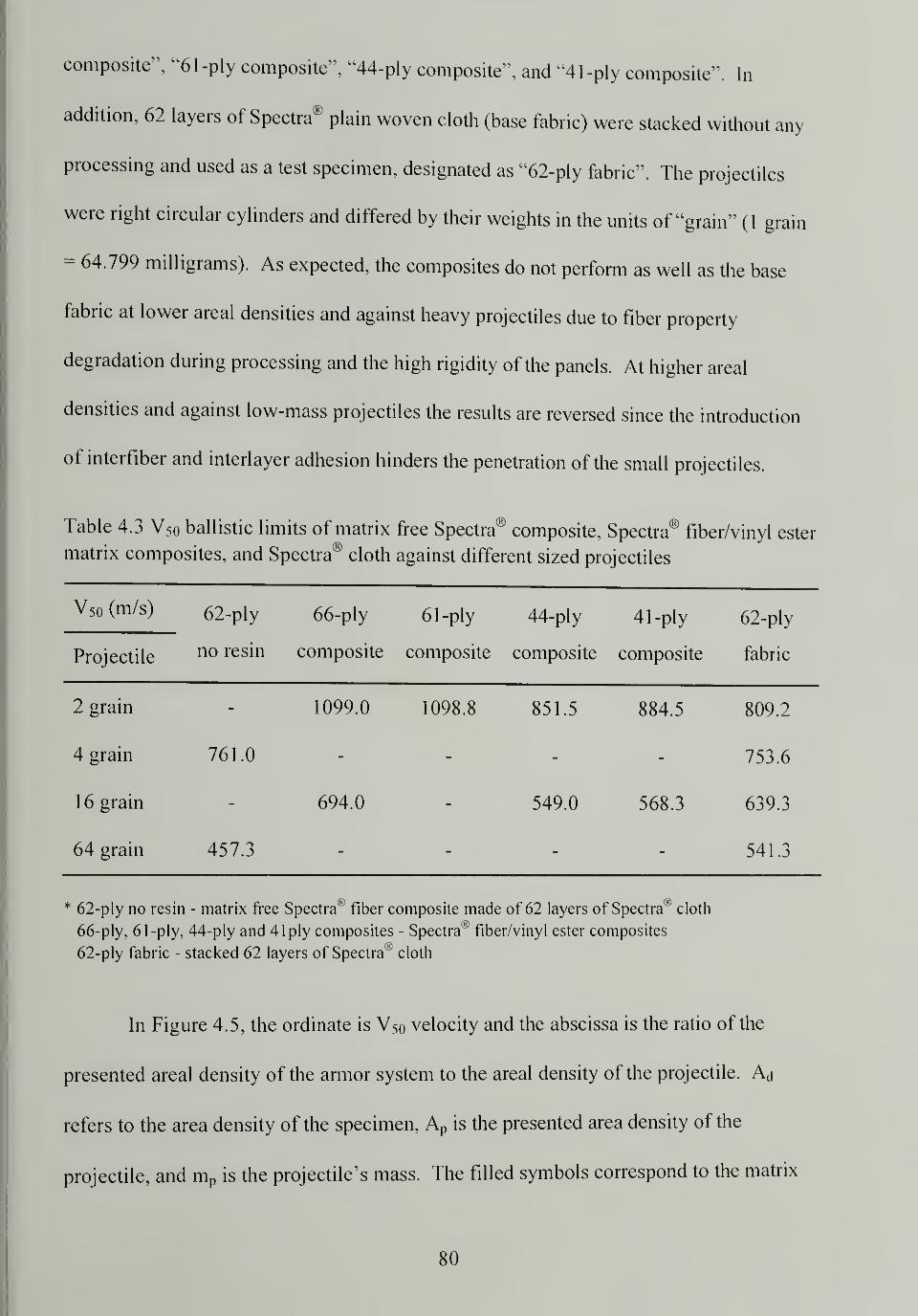
composite", "61 -ply composite", "44-ply composite", and "41 -ply composite". In
addition, 62 layers of Spectra® plain woven cloth (base fabric) were stacked without any
processing and used as a test specimen, designated as "62-ply fabric". The projectiles
were right circular cylinders and differed by their weights in the units of "grain" (1 grain
= 64.799 milligrams). As expected, the composites do not perform as well as the base
fabric at lower areal densities and against heavy projectiles due to fiber property
degradation during processing and the high rigidity of the panels. At higher areal
densities and against low-mass projectiles the results are reversed since the introduction
of interfiber and interlayer adhesion hinders the penetration of the small projectiles.
Table 4.3 V50 ballistic limits of matrix free Spectra® composite, Spectra® fiber/vinyl ester
matrix composites, and Spectra® cloth against different sized projectiles
V50 (m/s) 62-ply 66-ply 61 -ply 44-ply 41 -ply 62-ply
Projectile no resin composite composite composite composite fabric
2 grain 1099.0 1098.8 851.5 884.5 809.2
4 grain 761.0 m 753.6
16 grain 694.0 549.0 568.3 639.3
64 grain 457.3 541.3
* 62-ply no resin - matrix free Spectra^1
fiber composite made of 62 layers of SpectralH
cloth
66-ply, 61 -ply, 44-ply and 41 ply composites - Spectra® fiber/vinyl ester composites
62-ply fabric - stacked 62 layers of Spectra® cloth
In Figure 4.5, the ordinate is V50 velocity and the abscissa is the ratio of the
presented areal density of the armor system to the areal density of the projectile. Aj
refers to the area density of the specimen, Ap
is the presented area density of the
projectile, and mp
is the projectile's mass. The filled symbols correspond to the matrix
80
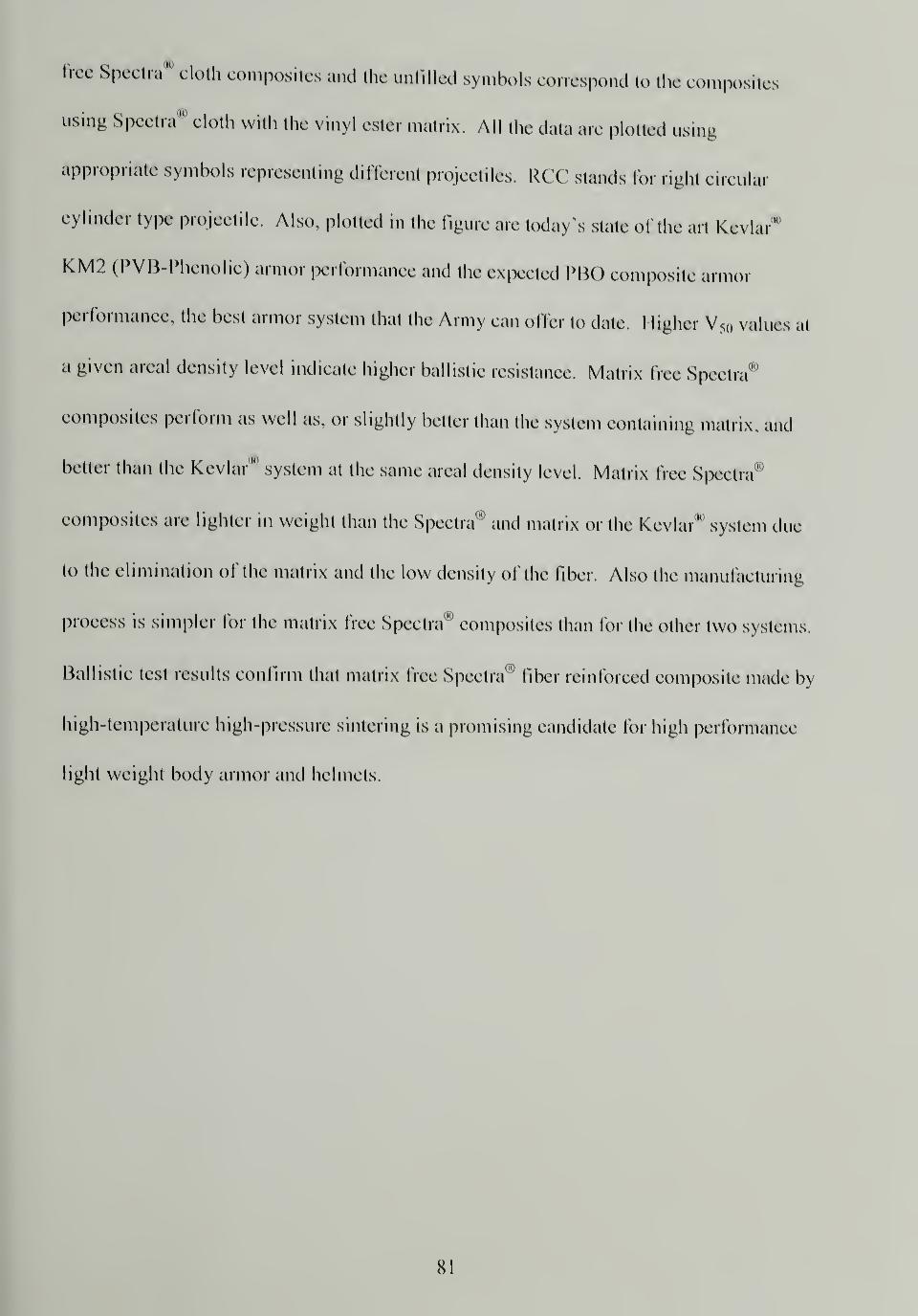
free Spectra cloth composites and the unfilled symbols correspond to the composites
using Spectra* cloth with the vinyl ester matrix. All the data are plotted using
appropriate symbols representing different projectiles. RCC stands for right circular
cylinder type projectile. Also, plotted in the figure are today's state of the art Kevlar"
KM2 (PVB-Phenolic) armor performance and the expected PBO composite armor
performance, the best armor system that the Army can offer to date. 1 ligher V50 values al
a given areal density level indicate higher ballistic resistance. Matrix free Spectra®
composites perform as well as, or slightly better than the system containing matrix, and
belter than the Kevlar'" system at the same areal density level. Matrix lice Spectra'
composites are lighter in weight than the Spectra0'1
and matrix or the Kevlar*1
system due
to the elimination of the matrix and the low density of the fiber. Also the manufacturing
process is simpler for the matrix lice Spectra® composites than for the other two systems.
Ballistic test results confirm that matrix free Spectra® fiber reinforced composite made by
high-temperature high-pressure sintering is a promising candidate for high performance
light weight body armor and helmets.
SI
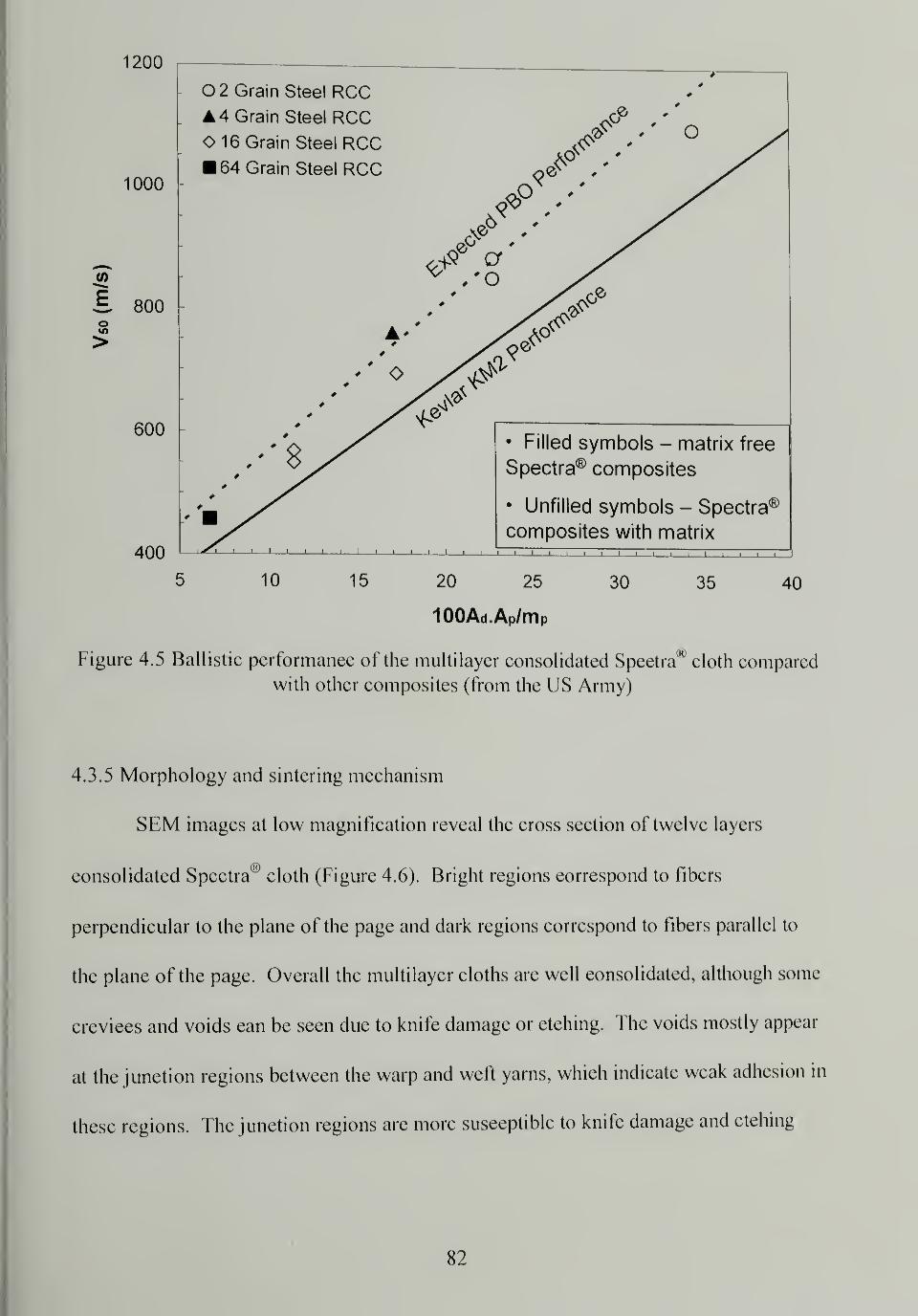
1200
O 2 Grain Steel RCC. A 4 Grain Steel RCC
O
400
5 10 15 20 25 30 35 40
100Ad.Ap/m P
Figure 4.5 Ballistic performance of the multilayer consolidated Spectra00
cloth compared
with other composites (from the US Army)
4.3.5 Morphology and sintering mechanism
SEM images at low magnification reveal the cross section of twelve layers
consolidated Spectra® cloth (Figure 4.6). Bright regions correspond to fibers
perpendicular to the plane of the page and dark regions correspond to fibers parallel to
the plane of the page. Overall the multilayer cloths are well consolidated, although some
crevices and voids can be seen due to knife damage or etching. The voids mostly appear
at the junction regions between the warp and weft yarns, which indicate weak adhesion in
these regions. The junction regions are more susceptible to knife damage and etching
82
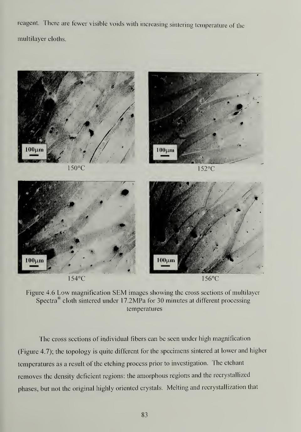
reagent. There are fewer visible voids with increasing sintering temperature of the
multilayer cloths.
temperatures
The cross sections of individual fibers can be seen under high magnification
(Figure 4.7); the topology is quite different for the specimens sintered at lower and higher
temperatures as a result of the etching process prior to investigation. The etchant
removes the density deficient regions: the amorphous regions and the recrystallized
phases, but not the original highly oriented crystals. Melting and recrystallization that
83
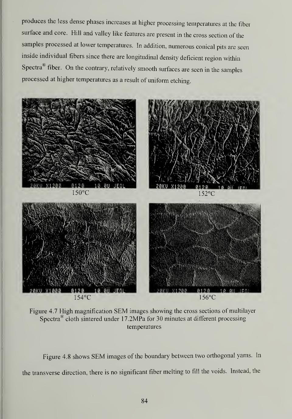
produces the less dense phases increases at higher processing temperatures at the fiber
surface and core. Hill and valley like features are present in the cross section of the
samples processed at lower temperatures. In addition, numerous conical pits are seen
inside individual fibers since there are longitudinal density deficient region within
Spectra® fiber. On the contrary, relatively smooth surfaces are seen in the samples
processed at higher temperatures as a result of uniform etching.
154°C 156°C
Figure 4.7 High magnification SEM images showing the cross sections of multilayer
Spectra® cloth sintered under 17.2MPa for 30 minutes at different processing
temperatures
Figure 4.8 shows SEM images of the boundary between two orthogonal yarns. In
the transverse direction, there is no significant fiber melting to fill the voids. Instead, the
84
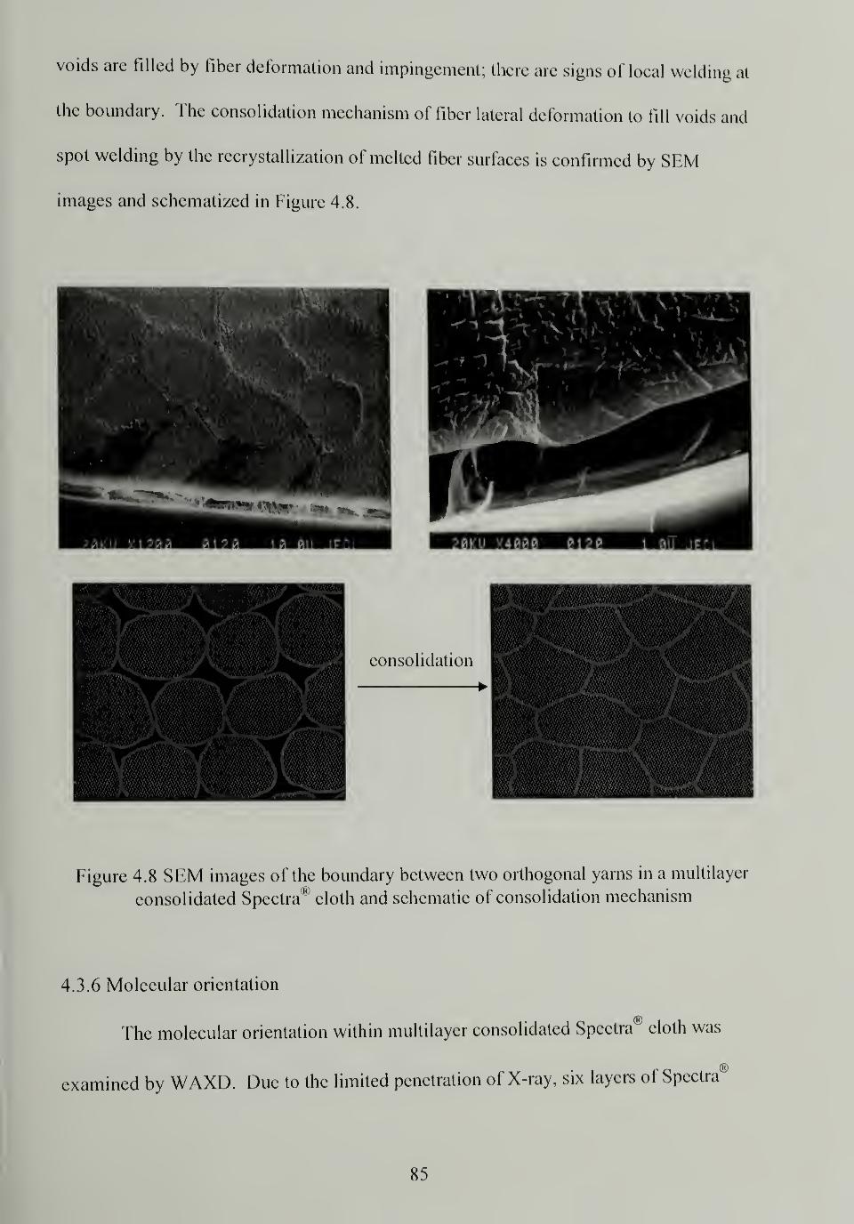
voids are filled by fiber deformation and impingement; there are signs of local welding at
the boundary. The consolidation mechanism of fiber lateral deformation to fill voids and
spot welding by the recrystallization of melted fiber surfaces is confirmed by SEM
images and schematized in Figure 4.8.
Figure 4.8 SEM images of the boundary between two orthogonal yarns in a multilayer
consolidated Spectra* cloth and schematic of consolidation mechanism
4.3.6 Molecular orientation
The molecular orientation within multilayer consolidated Spectra® cloth was
examined by WAXD. Due to the limited penetration of X-ray, six layers of Spectra®
85
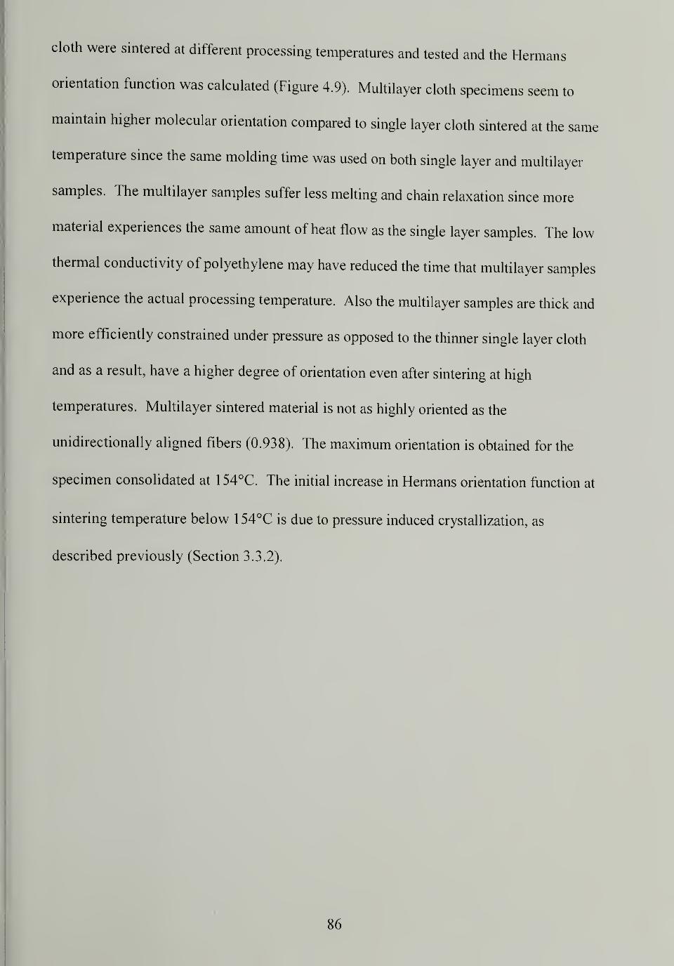
cloth were sintered at different processing temperatures and tested and the Hermans
orientation function was calculated (Figure 4.9). Multilayer cloth specimens seem to
maintain higher molecular orientation compared to single layer cloth sintered at the same
temperature since the same molding time was used on both single layer and multilayer
samples. The multilayer samples suffer less melting and chain relaxation since more
material experiences the same amount of heat flow as the single layer samples. The low
thermal conductivity of polyethylene may have reduced the time that multilayer samples
experience the actual processing temperature. Also the multilayer samples are thick and
more efficiently constrained under pressure as opposed to the thinner single layer cloth
and as a result, have a higher degree of orientation even after sintering at high
temperatures. Multilayer sintered material is not as highly oriented as the
unidirectionally aligned fibers (0.938). The maximum orientation is obtained for the
specimen consolidated at 154°C. The initial increase in Hermans orientation function at
sintering temperature below 1 54°C is due to pressure induced crystallization, as
described previously (Section 3.3.2).
86
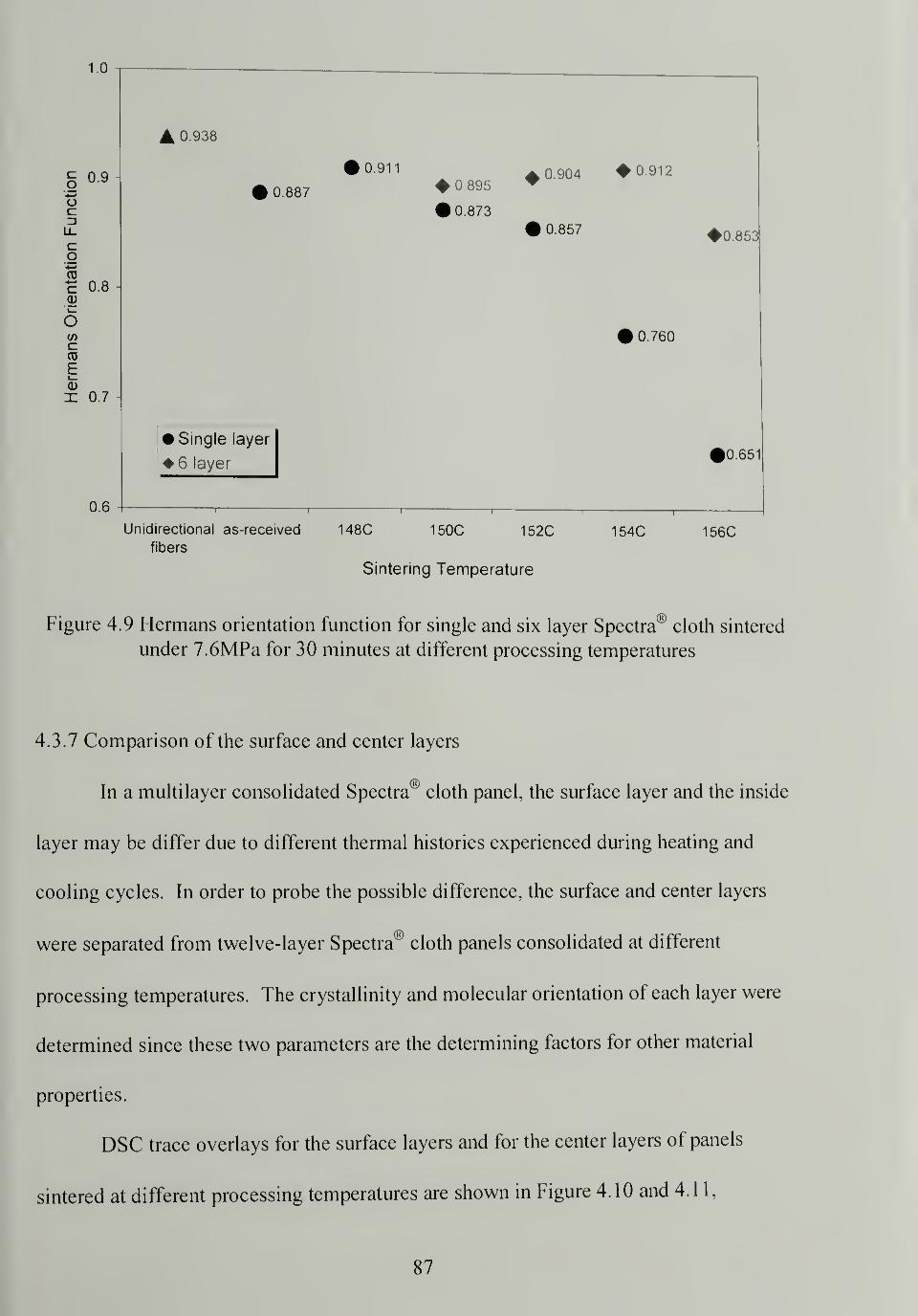
1.0
109
c3
CoCD
c 0.8CD
eCD
E
X 07
06
A 0.938
0.911
0.8870 895
#0.873
• Single layer
6 layer
0.904 0.912
0.857
0.760
0.853
0.65
150CUnidirectional as-received 148Cfibers
Sintering Temperature
152C 154C 156C
Figure 4.9 Hermans orientation function for single and six layer Spectra® cloth sintered
under 7.6MPa for 30 minutes at different processing temperatures
4.3.7 Comparison of the surface and center layers
In a multilayer consolidated Spectra® cloth panel, the surface layer and the inside
layer may be differ due to different thermal histories experienced during heating and
cooling cycles. In order to probe the possible difference, the surface and center layers
were separated from twelve-layer Spectra® cloth panels consolidated at different
processing temperatures. The crystallinity and molecular orientation of each layer were
determined since these two parameters are the determining factors for other material
properties.
DSC trace overlays for the surface layers and for the center layers of panels
sintered at different processing temperatures are shown in Figure 4.10 and 4.1 1,
87
respectively. The melting enthalpy for each specimen is listed on the figures. The
melting and recrystallization increases with increasing sintering temperature, as seen
previously for single layer consolidated cloth. The extent of the change in melting and
recrystallization is not as dramatic as the single layer consolidated cloth since the twelve-
layer samples had the same sintering time as the single layer samples. As more material
is involved, less melting happens at the same temperature.
-1
-2-
-4OJ
HCD
X
-7-
-8
(11
20
Exo Up
J2J.
13)
.(4)_
(1) 156C surface layer
(2) 154C surface layer
(3) 152C surface layer
(4) 150C surface layer
T40 60
142.62°C
\142.90°C
|
253.1J/Q
142.82°C
2S2JJA)
143.4TC262.3J/q
80 100 120
Temperature (°C)
140 160 180 200
Universal V2.5H TA
Figure 4.10 DSC trace overlay for the surface layers from twelve-layer Spectra® cloth
panels sintered under 17.2MPa for 30 minutes at different processing temperatures
88
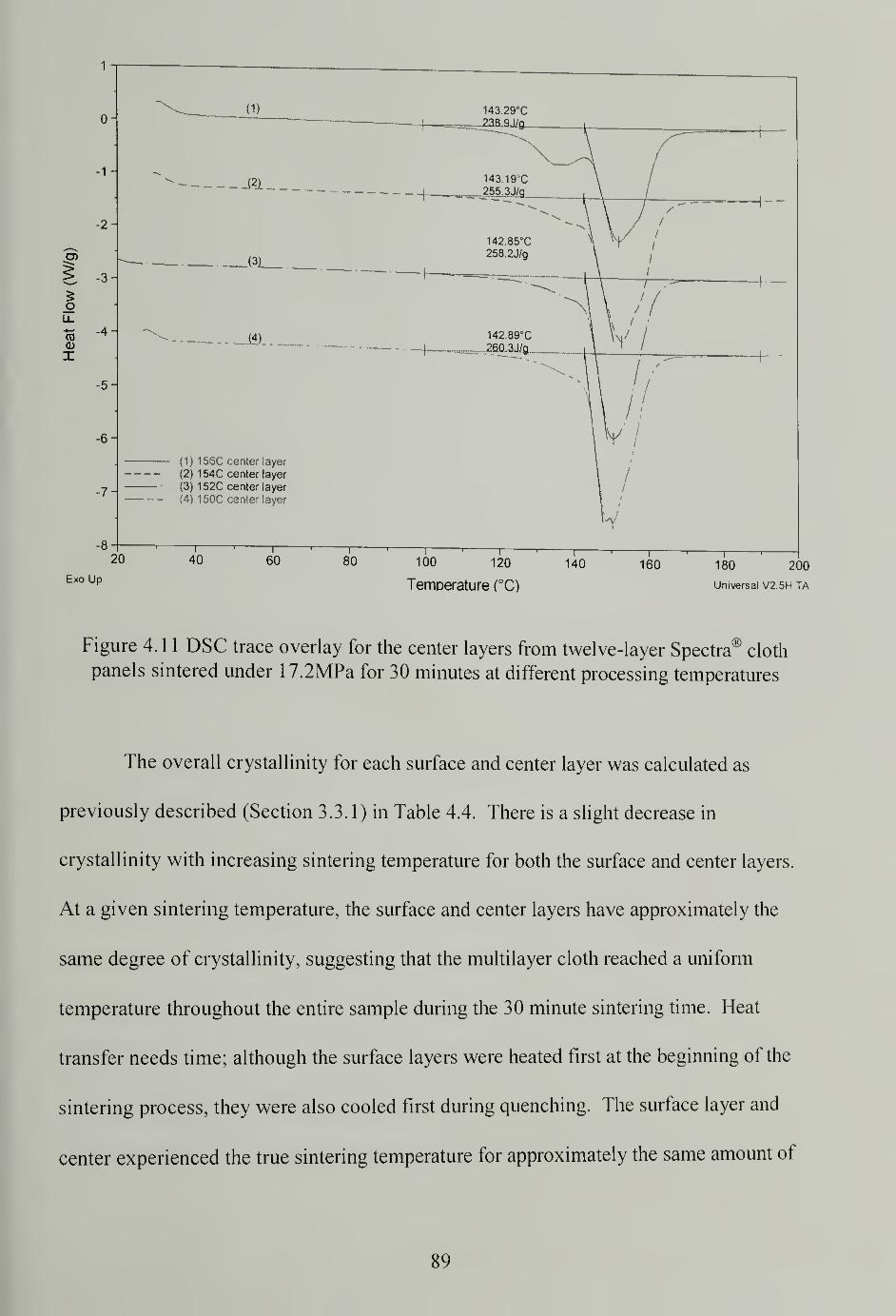
1
2003 p Temperature (°C) universal v2.sh ta
Figure 4. 1 1 DSC trace overlay for the center layers from twelve-layer Spectra® cloth
panels sintered under 17.2MPa for 30 minutes at different processing temperatures
The overall crystallinity for each surface and center layer was calculated as
previously described (Section 3.3.1) in Table 4.4. There is a slight decrease in
crystallinity with increasing sintering temperature for both the surface and center layers.
At a given sintering temperature, the surface and center layers have approximately the
same degree of crystallinity, suggesting that the multilayer cloth reached a uniform
temperature throughout the entire sample during the 30 minute sintering time. Heat
transfer needs time; although the surface layers were heated first at the beginning of the
sintering process, they were also cooled first during quenching. The surface layer and
center experienced the true sintering temperature for approximately the same amount of
89
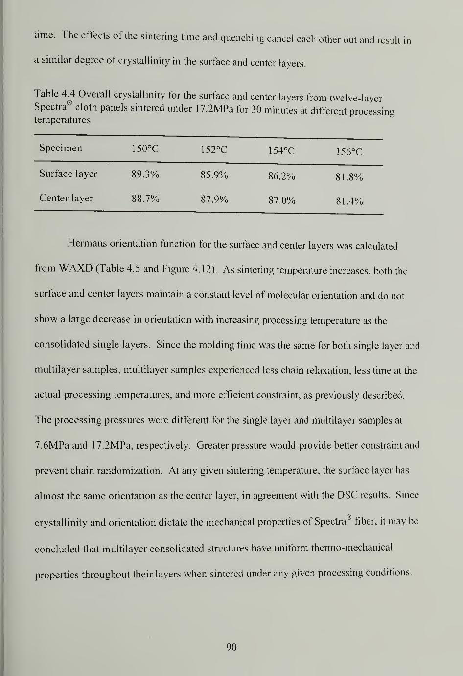
time. The effects of the sintering time and quenching cancel each other out and result in
a similar degree of crystallinity in the surface and center layers.
Table 4.4 Overall crystallinity for the surface and center layers from twelve-layerSpectra® cloth panels sintered under 17.2MPa for 30 minutes at different processitemperatures
Specimen 150°C 152°C 154°C 156°C
Surface layer 89.3% 85.9% 86.2% 81.8%
Center layer 88.7% 87.9% 87.0% 8 1 .4%
Hermans orientation function for the surface and center layers was calculated
from WAXD (Table 4.5 and Figure 4.12). As sintering temperature increases, both the
surface and center layers maintain a constant level of molecular orientation and do not
show a large decrease in orientation with increasing processing temperature as the
consolidated single layers. Since the molding time was the same for both single layer and
multilayer samples, multilayer samples experienced less chain relaxation, less time at the
actual processing temperatures, and more efficient constraint, as previously described.
The processing pressures were different for the single layer and multilayer samples at
7.6MPa and 17.2MPa, respectively. Greater pressure would provide better constraint and
prevent chain randomization. At any given sintering temperature, the surface layer has
almost the same orientation as the center layer, in agreement with the DSC results. Since
crystallinity and orientation dictate the mechanical properties of Spectra® fiber, it may be
concluded that multilayer consolidated structures have uniform thermo-mechanical
properties throughout their layers when sintered under any given processing conditions.
90
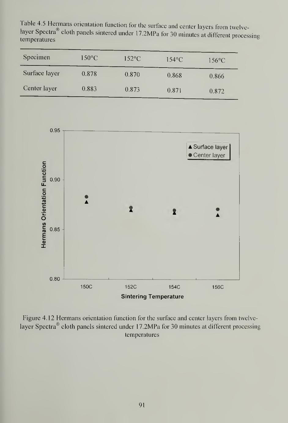
Table 4.5 Hermans orientation function for the surface and center layers from twelve-layer Spectra cloth panels sintered under 1 7.2MPa for 30 minutes at different processingtemperatures fc
Specimen 150°C 152°C 154°C 156°C
Surface layer 0.878 0.870 0.868 0.866
Center layer 0.883 0.873 0.871 0.872
t/>
cTO
E
0.95
coo§ 0.90u.
co+-J
03
c
0.85
0.80
A Surface layer
• Center layer
150C 152C 154C
Sintering Temperature
156C
Figure 4.12 Hermans orientation function for the surface and center layers from twelve-
ayer Spectra® cloth panels sintered under 1 7.2MPa for 30 minutes at different processing
temperatures
91
4.4 Conclusion
The mechanical properties of multilayer consolidated Spectra® cloths were
studied. Interlayer adhesion increases with increasing sintering temperature although
medium adhesion may be sufficient for ballistic application. The multilayer cloth panels
are very stiff and strong, and their flexural properties achieve maxima between 152°C -
154°C. The specimens did not fail three-point bed test within 5% strain limit, however
samples sintered at low temperature exhibited shear failure at higher strains indicated by
delamination, agreeing with results from T-peel tests indicating low interlayer adhesion.
Ballistic performance for sintered multilayer thick panels shows that they are as good as
the Spectra® fiber/matrix system and better than Kevlar® system at the same density
level. Matrix free Spectra® fiber reinforced composites is very promising for making
ballistic shields. The microstructure and morphology of multilayer consolidated Spectra®
cloth was investigated and the cross section of the sintered structures shows good
consolidation with few voids. Selective etching of the consolidated structures reveals
that more melting and recrystallization, accompanied by chain relaxation leading to less
oriented and dense regions, happen significantly at higher processing temperatures. SEM
studies also prove that the consolidation occurs by fiber lateral deformation to fill voids
and that fiber surface melting and recrystallization fuses the fibers together. Multilayer
consolidated Spectra® cloth shows very high molecular orientation even after sintering at
high processing temperatures due to less relaxation and more efficient constraint.
Finally, the surface and center layers of consolidated Spectra® cloth have similar
crystallinity and orientation at given sintering conditions which suggest that the layers
have similar structure and properties. Based on these comprehensive studies, a better
92

understanding is established regarding the process-structure-property relationship for
making matrix free Spectra® fiber reinforced composites using this high-temperature
high-pressure sintering process.
93
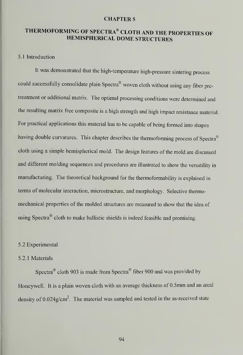
CHAPTER 5
THERMOFORMING OF SPECTRA® CLOTH AND THE PROPERTIES OFHEMISPHERICAL DOME STRUCTURES
5.1 Introduction
It was demonstrated that the high-temperature high-pressure sintering process
could successfully consolidate plain Spectra® woven cloth without using any fiber pre-
treatment or additional matrix. The optimal processing conditions were determined and
the resulting matrix free composite is a high strength and high impact resistance material.
For practical applications this material has to be capable of being formed into shapes
having double curvatures. This chapter describes the thermoforming process of Spectra®
cloth using a simple hemispherical mold. The design features of the mold are discussed
and different molding sequences and procedures are illustrated to show the versatility in
manufacturing. The theoretical background for the thermoformability is explained in
terms of molecular interaction, microstructure, and morphology. Selective thermo-
mechanical properties of the molded structures are measured to show that the idea of
using Spectra® cloth to make ballistic shields is indeed feasible and promising.
5.2 Experimental
5.2.1 Materials
Spectra® cloth 903 is made from Spectra® fiber 900 and was provided by
Honeywell. It is a plain woven cloth with an average thickness of 0.5mm and an areal
density of 0.024g/cm2
. The material was sampled and tested in the as-received state
94
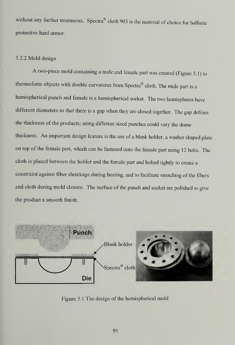
without any further treatments. Spectra® cloth 903 is the material of choice for ballistic
protective hard armor.
5.2.2 Mold design
A two-piece mold containing a male and female part was created (Figure 5.1) to
thermoform objects with double curvatures from Spectra® cloth. The male part is a
hemispherical punch and female is a hemispherical socket. The two hemispheres have
different diameters so that there is a gap when they are closed together. The gap defines
the thickness of the products; using different sized punches could vary the dome
thickness. An important design feature is the use of a blank holder, a washer shaped plate
on top of the female part, which can be fastened onto the female part using 12 bolts. The
cloth is placed between the holder and the female part and bolted tightly to create a
constraint against fiber shrinkage during heating, and to facilitate stretching of the fibers
and cloth during mold closure. The surface of the punch and socket are polished to give
the product a smooth finish.
Punch
Blank holder
Spectra" cloth
Figure 5.1 The design of the hemispherical mold
95
IS
5.2.3 Molding schemes
Spectra® fiber is a thermoplastic polyethylene. An advantage of thermoplastics
their ability to be repeatedly heated, softened, and shaped provided the temperatures are
not too high. In the previous sections we have demonstrated that in the optimum
processing window, the fiber can be deformed without loss of orientation or crystallinity.
Different shaping and molding schemes were proposed and used:
• Consolidate layers of Spectra® cloth to a thick flat panel, clamp the panel onto the
mold, and apply heat and pressure to develop the shape
• Consolidate each layer of Spectra® cloth individually to make flat sheets, lay the
consolidated sheets one on top of another and clamp them onto the mold, and
apply heat and pressure to shape
• Shape individual layers of Spectra® cloth using the mold, stack the shaped layers
one on top of another, and sinter them in the mold
• Consolidate and shape layers of Spectra® cloth directly in the mold to form the
structure
In each approach the total time for the Spectra® cloth to experience heat and pressure was
30 minutes. The time for consolidating and/or shaping the cloth in the first stage was
combined with the time for molding or sintering in the second stage for the first three
methods. There is no need to use any type of mold release agent, since polyethylene is
self-lubricating and does not stick to the steel mold.
96
5.2.4 Typical procedures
A typical sequence is illustrated by the set of pictures using the "flat panel firsr
router as an example in Figure 5.2. A pre-consolidated Oat panel, which consisted of 25
layers of cloth, was drilled and bolted tightly between the blank holder and the socket die.
Meanwhile, the press was heated to the desired sintering temperature, for example 1 50°C.
The punch was placed on top of the panel and carefully aligned in the press. A small
initial force was applied to secure the position of the mold. Once the mold and the cloth
reached the desired sintering temperature (about 10 minutes) the force was gradually
increased up to 10 tons over a 5-minute period. The cloth conformed fully to the
hemispherical shape of the mold and after 5 minutes was consolidated. The mold
assembly was rapidly cooled to ambient temperature, by running tap water through the
press's platens, while maintaining pressure. The hemispherical dome could be easily
removed after pressure was released and the blank holder was lifted away.
97
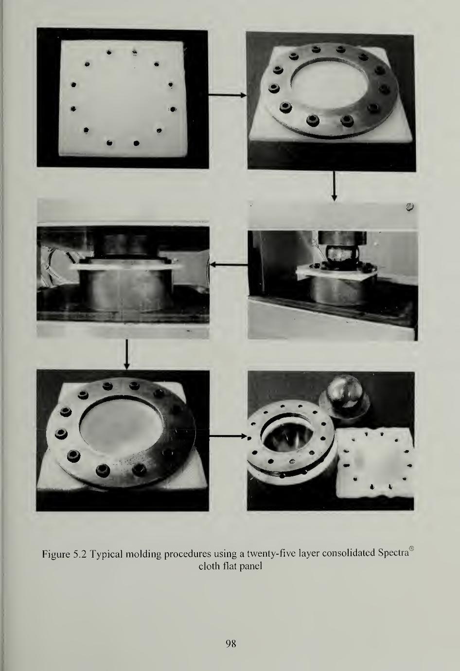
Figure 5.2 Typical molding procedures using a twenty-five layer consolidated Spectra
cloth flat panel
98
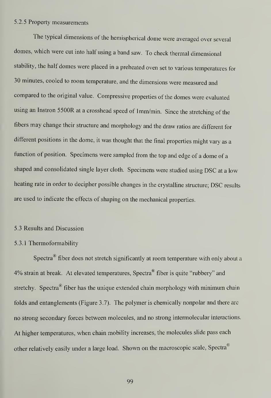
5.2.5 Property measurements
The typical dimensions of the hemispherical dome were averaged over several
domes, which were cut into half using a band saw. To check thermal dimensional
stability, the half domes were placed in a preheated oven set to various temperatures for
30 minutes, cooled to room temperature, and the dimensions were measured and
compared to the original value. Compressive properties of the domes were evaluated
using an Instron 5500R at a crosshead speed of lmm/min. Since the stretching of the
fibers may change their structure and morphology and the draw ratios are different for
different positions in the dome, it was thought that the final properties might vary as a
function of position. Specimens were sampled from the top and edge of a dome of a
shaped and consolidated single layer cloth. Specimens were studied using DSC at a low
heating rate in order to decipher possible changes in the crystalline structure; DSC results
are used to indicate the effects of shaping on the mechanical properties.
5.3 Results and Discussion
5.3.1 Thermoformability
Spectra® fiber does not stretch significantly at room temperature with only about a
4% strain at break. At elevated temperatures, Spectra® fiber is quite "rubbery" and
stretchy. Spectra® fiber has the unique extended chain morphology with minimum chain
folds and entanglements (Figure 3.7). The polymer is chemically nonpolar and there are
no strong secondary forces between molecules, and no strong intermolecular interactions.
At higher temperatures, when chain mobility increases, the molecules slide pass each
other relatively easily under a large load. Shown on the macroscopic scale, Spectra®
99
fiber can accommodate high deformation such as those produced in the formation of a
hemispherical structure without failing.
Spectra® fiber pressurized at an elevated temperature induces a polyethylene
crystal transformation, an orthorhombic phase to hexagonal phase transition (o-h
transition) as reported by many researchers.68 "70
The pressure and temperature at which
the transition occurs depends on the crystal dimension, viz., fold length.71
Hexagonal
crystals possess a relatively low viscosity compared to orthorhombic crystals and chain
mobility is rather high in this so-called "mobile phase". Due to the o-h transition at high
pressure and temperature, Spectra® fiber is capable of undergoing large axial strains with
relative ease via this metastable, transient hexagonal phase.
Due to its excellent thermoformability, all the aforementioned molding schemes
work well with Spectra® cloth to produce stiff and strong solid domes, indicating the
versatility in manufacturing schemes.
5.3.2 Dome dimensions and thermal dimensional stability
The dimensions of the domes were measured and a typical set of values measured
on different positions of the dome is shown (Figure 5.3). The thickness of the dome is
not uniform since the center section of the dome underwent increased stretching. The
dome thickness decreases gradually from 4.05mm at the periphery to 2.85mm at the top,
roughly 30% reduction. The variation of the thickness is symmetric with respect to the
center of the dome. A uniform dome thickness can be achieved by adding compensating
layers to the top area during molding.
100
Outer diameter R = 70.7mm Thickness A = 4.05mm C = 4.05Inner diameter r = 62.6mm B = 2.85mm
Figure 5.3 Dimension and thickness of the dome
The dome halves were annealed in a precision oven at different temperatures
starting from 1 50°C. At the end of the annealing, their dimensions were checked and the
dimensions of the domes did not change much compared with the original dimension
values. The domes have good thermal dimensional stability even after annealing at
temperatures as high as 1 56°C and they had become soft. Based on the previous TMA
and DSC studies (Section 2.3.3 and 3.3.1, respectively), it was expected that the dome
size would change because of the development of a large shrinkage force and the partial
melting at higher temperatures. It is possible that the annealing time was not long enough
to allow for heat conduction. Relaxation of the molecular chains may require a longer
time scale, or the structural stability of the dome geometry and the sufficient interlay
adhesion maintain the shape.
101
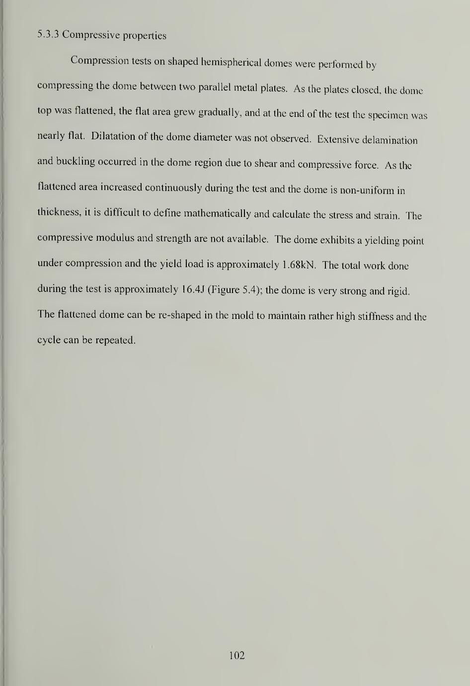
5.3.3 Compressive properties
Compression tests on shaped hemispherical domes were performed by
compressing the dome between two parallel metal plates. As the plates closed, the dome
top was flattened, the flat area grew gradually, and at the end of the test the specimen was
nearly flat. Dilatation of the dome diameter was not observed. Extensive delamination
and buckling occurred in the dome region due to shear and compressive force. As the
flattened area increased continuously during the test and the dome is non-uniform in
thickness, it is difficult to define mathematically and calculate the stress and strain. The
compressive modulus and strength are not available. The dome exhibits a yielding point
under compression and the yield load is approximately 1 .68kN. The total work done
during the test is approximately 16.4J (Figure 5.4); the dome is very strong and rigid.
The flattened dome can be re-shaped in the mold to maintain rather high stiffness and the
cycle can be repeated.
102
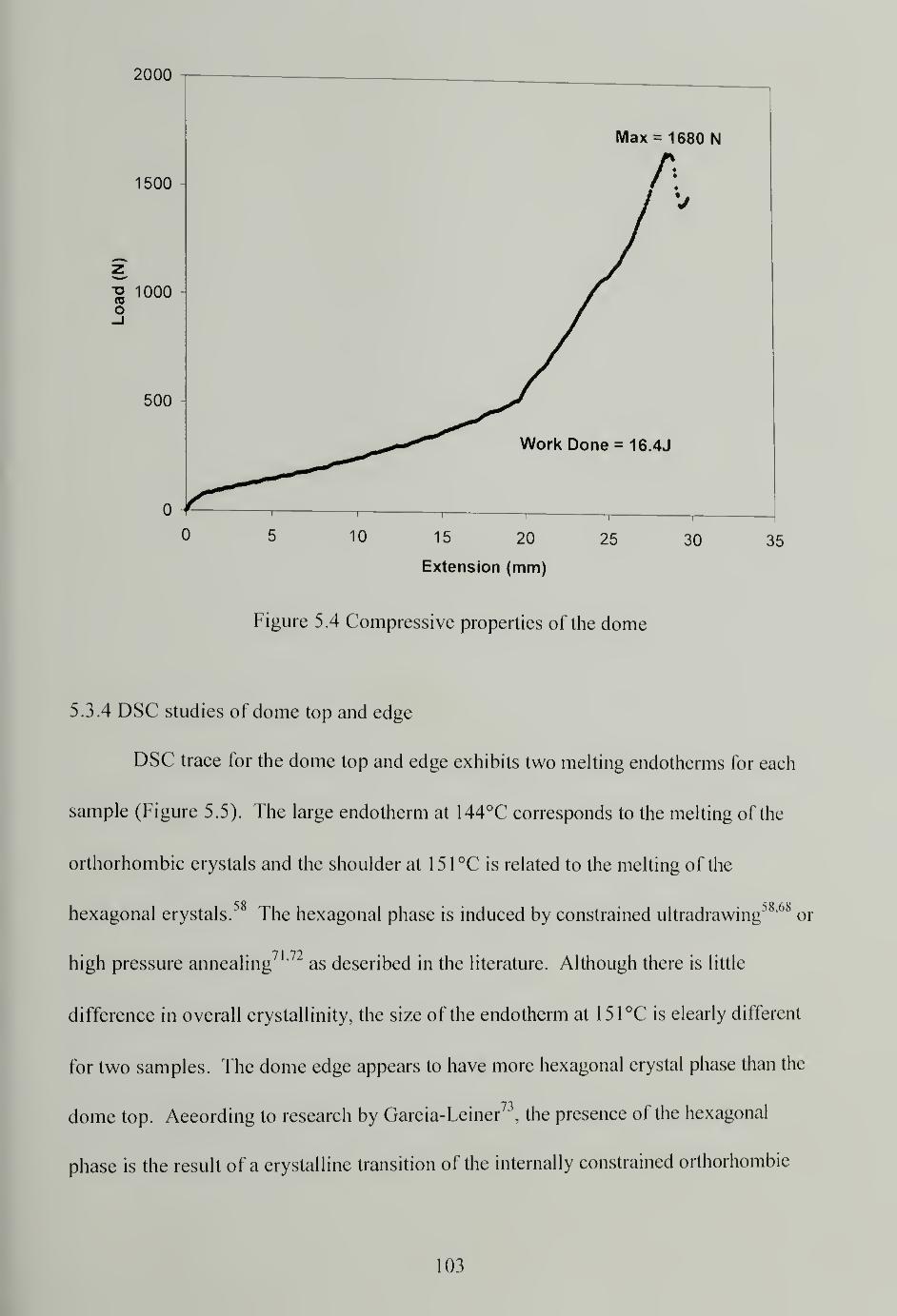
2000
Max = 1680 N
0 5 10 15 20 25 30 35
Extension (mm)
Figure 5.4 Compressive properties of the dome
5.3.4 DSC studies of dome top and edge
DSC trace for the dome top and edge exhibits two melting endotherms for each
sample (Figure 5.5). The large endotherm at 144°C corresponds to the melting of the
orthorhombic crystals and the shoulder at 151°C is related to the melting of the
hexagonal crystals.58
The hexagonal phase is induced by constrained ultradrawing58 '68
or
• 7 1 72high pressure annealing ' as described in the literature. Although there is little
difference in overall crystallinity, the size of the endotherm at 151°C is clearly different
for two samples. The dome edge appears to have more hexagonal crystal phase than the
dome top. According to research by Garcia-Leiner73
, the presence of the hexagonal
phase is the result of a crystalline transition of the internally constrained orthorhombic
103
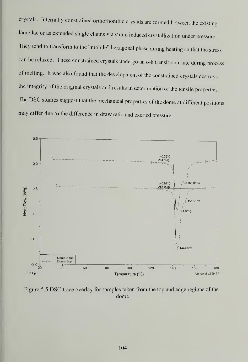
crystals. Internally constrained orthorhombic crystals are formed between the existing
lamellae or as extended single chains via strain induced crystallization under pressure.
They tend to transform to the "mobile" hexagonal phase during heating so that the stress
can be relaxed. These constrained crystals undergo an o-h transition route during process
of melting. It was also found that the development of the constrained crystals destroys
the integrity of the original crystals and results in deterioration of the tensile properties.
The DSC studies suggest that the mechanical properties of the dome at different posit
may differ due to the difference in draw ratio and exerted pressure.
ions
0.5
0.0
cn -0 5
x 1.0
1.5
-2.0
Dome EdgeDome Top
140.22°C
,264.8J/g
140.87°C
258.9J/g
^+151.81 0C
tM51.51°C
^144.05°C
V144.66°C
20
Exo Up
40 60 80 100 120
Temperature (°C)
140 160 180
Universal V2.5H TA
Figure 5.5 DSC trace overlay for samples taken from the top and edge regions of the
dome
104
5.4 Conclusion
A two-piece hemispherical mold was designed to thermoform Spectra® cloth.
Spectra® cloth was successfully molded to form a doubly curved structure using different
shaping schemes. The exceptional thermoformability of Spectra® cloth is due to the
unique microstructure and physical properties of the fiber as well as solid state crystal
transformations during processing. Ballistic shields using Spectra® cloth and no matrix
or cutting patterns has been proven to be possible. The dome-like products have non-
uniform wall thickness due to different stretching ratios across the structure which can be
corrected. The domes have good thermal dimensional stability even at 156°C and
compressive properties of the domes are good. DSC studies of the dome reveal the o-h
crystalline transition and imply that the mechanical properties of the dome at different
positions may vary due to the spatial variation of degree of crystallinity and crystal type
throughout the dome.
105
CHAPTER 6
STUDIES ON DYNEEMA FRAGLIGHT® NONWOVEN FELT AND SPECTRASHIELD® PLUS PCR PREPREG
6.1 Introduction
Matrix free Spectra® fiber reinforced composite made of Spectra® cloth 903 via
high-temperature high-pressure sintering has been shown to be a promising approach to
produce materials for ballistic shields. Various properties of the consolidated structures
were analyzed and characterized and the optimal processing conditions were determined
through the investigation of process-structure-property relationship. To complete the
study, Dyneema Fraglight® nonwoven felt and Spectra Shield® Plus PCR74prepreg,
commercially available materials designed specifically for ballistic applications, were
chosen for parallel comparisons. The high-temperature high-pressure sintering process
was applied, and the physical, thermo-mechanical and microstructural properties of the
consolidated products were determined and compared to those of the sintered Spectra®
cloth 903. It is concluded that matrix free Spectra® fiber reinforced composite has
dominant advantages over the other two materials.
6.2 Experimental
6.2.1 Materials
Dyneema Fraglight®, a needle punched nonwoven felt with an areal density of
190 - 220g/m2
, is made from Dyneema® fiber and designed for protection against
fragments of exploding bombs and artillery shells. Dyneema® fiber is an UHMWPE
fiber commercialized by DSM with similar properties to Spectra® fiber.
106
Spectra Shield" Plus PCR is a non-woven thermoplastic composite consisting of
two plies of unidirectional Spectra® fiber tapes cross-plied at 0790° and impregnated in a
matrix. Spectra Shield® Plus PCR is made by Honeywell and is used in applications such
as rigid armor and breast plates, vehicle and architectural armor, blast containment and
shields. Its areal density is 95±15g/m2and thickness is 0.13±0.05mm. The fiber weight
faction of Spectra Shield® Plus PCR is approximately 80%. The matrix is an undisclosed
proprietary material.
6.2.2 Material processing and property measurements
6.2.2.1 Processing procedure
A single layer of felt or prepreg was sandwiched within aluminum foils and
placed in between two steel plates. The hot press was preheated to a desired processing
temperature, the temperature was allowed to equilibrate, and the sandwiched felt or
prepreg was placed in the hot press. The upper and lower platens of the press were
closed onto the specimen and the pressure was raised to the desired processing pressure.
The pressure and temperature were held constant for a period of processing time to
execute the sintering process. The hot press and the specimen were quenched by running
tap water through the press platens while pressure was maintained. The sintered
specimen was removed from the press at ambient temperature and separated from the
aluminum foil; no mold release agent was used.
107
6.2.2.2 Measurement of crystallinity changes by DSC
A TA Instrument DSC 2910 was used to observe the melting behavior of single
layers felt or prepreg consolidated under various processing conditions. -10 mg of the
samples in hermetically sealed pans were heated at 10°C/min from room temperature to
200°C under nitrogen (50 ml/min.).
6.2.2.3 Measurement of orientation changes by WAXD
Wide Angle X-ray Diffraction (WAXD) patterns were collected using pin hole
collimated, monochromatic Cu Ka radiation and a Bruker® "High Star" two dimensional
detector. The diffraction patterns of a series of single layer Spectra Shield® Plus PCR
sintered under different processing conditions were collected. The specimen was
oriented "flat-on" so that the incident X-ray beam was perpendicular to the prepreg. A
radiation time of 300 seconds was used and diffraction patterns were captured digitally.
The integration of the intensity was preformed using GADDS commercial software.
6.2.2.4 Measurement of impact properties by puncture test
Impact tests were performed using a dynatup* 8250 with the pneumatically
powered shooting dart mode of puncture test since the consolidated felt or prepreg are
rather strong. The dart weighs 2.38kg and is pneumatically assisted by house nitrogen.
The dart speed at penetration into the specimen was approximately 10 m/s. The
specimens were 100mm x 150mm consolidated single layer felt or prepreg sheets which
had experienced different processing conditions. Each specimen was secured on the
sample stage by pneumatic clamps, the dart was then fired perpendicular to the surface c
108
the specimen, and the specimen was punctured. The instrument recorded the load
detected on the dart tip and the deflection of the specimen as soon as the shooting dart
touched the specimen until total penetration. The total energy of impact was calculated
from the integrated area under the load vs. deflection curve.
6.2.2.5 Measurement of interlayer adhesion by T-peel test
Thermally bonded bilayers were prepared from two layers of Dyneema® felt, two
layers of Spectra® prepreg, and one layer of Spectra80
cloth and one layer of Dyneema®
felt for T-peel tests. A series of bilayers were produced at different processing
temperatures under constant pressure and time (7.6MPa and 30 minutes) and the T-peel
tests were conducted on an Instron 5500R according to ASTM standard D1876 as
described previously, Section 4.2.3.
6.2.2.6 Measurement of flexural properties by three-point bend test
The flexural properties of multilayer consolidated Dyneema® felt and
consolidated Spectra® prepreg sintered under different processing conditions were
determined by three-point bend tests according to ASTM standard D790 with a support
span of 50mm and a crosshead speed of 1 .35mm/min, as described previously, Section
4.2.4. A testing limit of 5% strain was used to ensure the reliability of the data.
6.2.3 Thermoforming of Dyneema Fraglight and Spectra Shield "' Plus PCR
Thermoforming of Dyneema Fraglight® and Spectra Shield® Plus PCR to make
hemispherical domes was done by first making 250mm x 250mm multilayer flat panels at
150°C under 6.9MPa for 30 minutes. The resulting flat panels were cut into four 125mm
x 125mm squares, twelve holes were then drilled into the panels, and they were bolted
onto the hemispherical mold. The molding procedures and conditions were followed as
described previously. Section 5.2.4.
6.3 Results and Discussion
6.3.1 Dyneema Fraglight® nonwoven felt
Dyneema Fraglight® felt is made of continuous Dyneema® fiber which has
comparable mechanical properties to Spectra® fiber. Dyneema Fraglight® is a nonwoven
felt and the fibers are unoriented and randomly aligned. It is an in-plane isotropic
material and therefore it is expected that the consolidated structures of this material
would have a lower rigidity and stiffness than the more oriented consolidated Spectra®
cloth. The needle punching process, used to manufacture the felt, has introduced physical
entanglements of the fibers. Good impact resistance is expected for the consolidated
materials as these entanglements should make penetration difficult. Good interlayer
adhesion is anticipated since the entanglements would hinder the separation of bonded
layers. Studies on Dyneema Fraglight® felt were carried out by monitoring the
crystallinity change with processing, measuring the impact properties, interlayer adhesion
and flexural properties of the consolidated products and investigating the
thermoformability of the felt.
110
6.3.1.1 Crystallinity change
A single layer of Dyneema® felt was consolidated at a processing temperature
ranging from 140°C to 1 56°C under a pressure of 7.6MPa for 30 minutes. DSC
thermographs for the as-received Dyneema® felt and the consolidated felts are overlaid in
Figure 6. 1.As-received Dyneema® felt shows a distinct melting peak at 1 50°C as does
Spectra cloth. With increasing processing temperature, a lower temperature shoulder on
the melting peak emerges and eventually evolves into a distinct peak at 135°C. The two
endotherms correspond to the melting of the original highly oriented crystals and the
newly formed crystals formed upon cooling, respectively. With increasing sintering
temperature, the higher temperature endotherm decreases and the lower temperature
endotherm increases, indicating the gradual loss of the original highly oriented crystals
accompanied by the gradual formation of unoriented crystals.
Ill
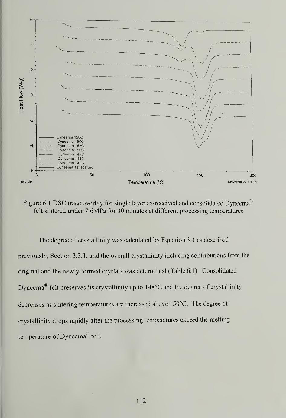
2-
5oLL
"SCD
X
-2
— Dyneema 156CDyneema 1 54CDyneema 152CDyneema 150C
— Dyneema 148C— Dyneema 145C
Dyneema 140C— Dyneema as received
50
Exo Up
100
Temperature (°C)
150 200
Universal V2.5H TA
Figure 6.1 DSC trace overlay for single layer as-received and consolidated Dyneema1
felt sintered under 7.6MPa for 30 minutes at different processing temperatures
The degree of crystallinity was calculated by Equation 3.1 as described
previously, Section 3.3.1, and the overall crystallinity including contributions from the
original and the newly formed crystals was determined (Table 6.1). Consolidated
Dyneema® felt preserves its crystallinity up to 148°C and the degree of crystallinity
decreases as sintering temperatures are increased above 150°C. The degree of
crystallinity drops rapidly after the processing temperatures exceed the melting
temperature of Dyneema® felt.
112
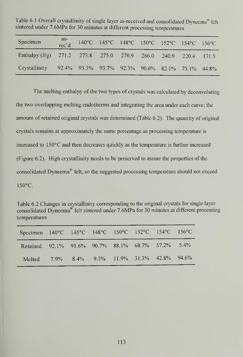
Table 6.1 Overall crystallinity of single layer as-received and consolidated Dyneema* felt
sintered under 7.6MPa for 30 minutes at different processing temperatures
CISpecimen
as-
rec'd140°C 145°C 148°C 150°C 152°C 154°C 156°C
Enthalpy (J/g) 271.2 273.8 275.0 270.9 266.0 240.9 220.4 131.5
Crystallinity 92.4% 93.3% 93.7% 92.3% 90.6% 82.1% 75.1% 44.8%
The melting enthalpy of the two types of crystals was calculated by deconvolving
the two overlapping melting endotherms and integrating the area under each curve; the
amount of retained original crystals was determined (Table 6.2). The quantity of original
crystals remains at approximately the same percentage as processing temperature is
increased to 150°C and then decreases quickly as the temperature is further increased
(Figure 6.2). High crystallinity needs to be preserved to assure the properties of the
consolidated Dyneema^ felt, so the suggested processing temperature should not exceed
150°C.
Table 6.2 Changes in crystallinity corresponding to the original crystals for single layer
consolidated Dyneema® felt sintered under 7.6MPa for 30 minutes at different processing
temperatures
Specimen 140°C 145°C 148°C 150°C 152°C 154°C 156°C
Retained
Melted
92.1%
7.9%
91.6%
8.4%
90.7%
9.3%
88.1%
1 1 .9%
68.7%
31.3%
57.2%
42.8%
5.4%
94.6%
113
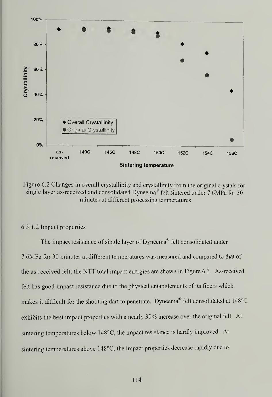
100%
80%
60%
O 40%
20%
0%
Overall Crystallinity
• Original Crystallinity
as- 140C 145C 148C 150C 152C 154C 156Creceived
Sintering temperature
Figure 6.2 Changes in overall crystallinity and crystallinity from the original crystals for
single layer as-received and consolidated Dyneema® felt sintered under 7.6MPa for 30
minutes at different processing temperatures
6.3.1.2 Impact properties
The impact resistance of single layer of Dyneema® felt consolidated under
7.6MPa for 30 minutes at different temperatures was measured and compared to that of
the as-received felt; the NTT total impact energies are shown in Figure 6.3. As-received
felt has good impact resistance due to the physical entanglements of its fibers which
makes it difficult for the shooting dart to penetrate. Dyneema® felt consolidated at 148°C
exhibits the best impact properties with a nearly 30% increase over the original felt. At
sintering temperatures below 148°C, the impact resistance is hardly improved. At
sintering temperatures above 148°C, the impact properties decrease rapidly due to
114
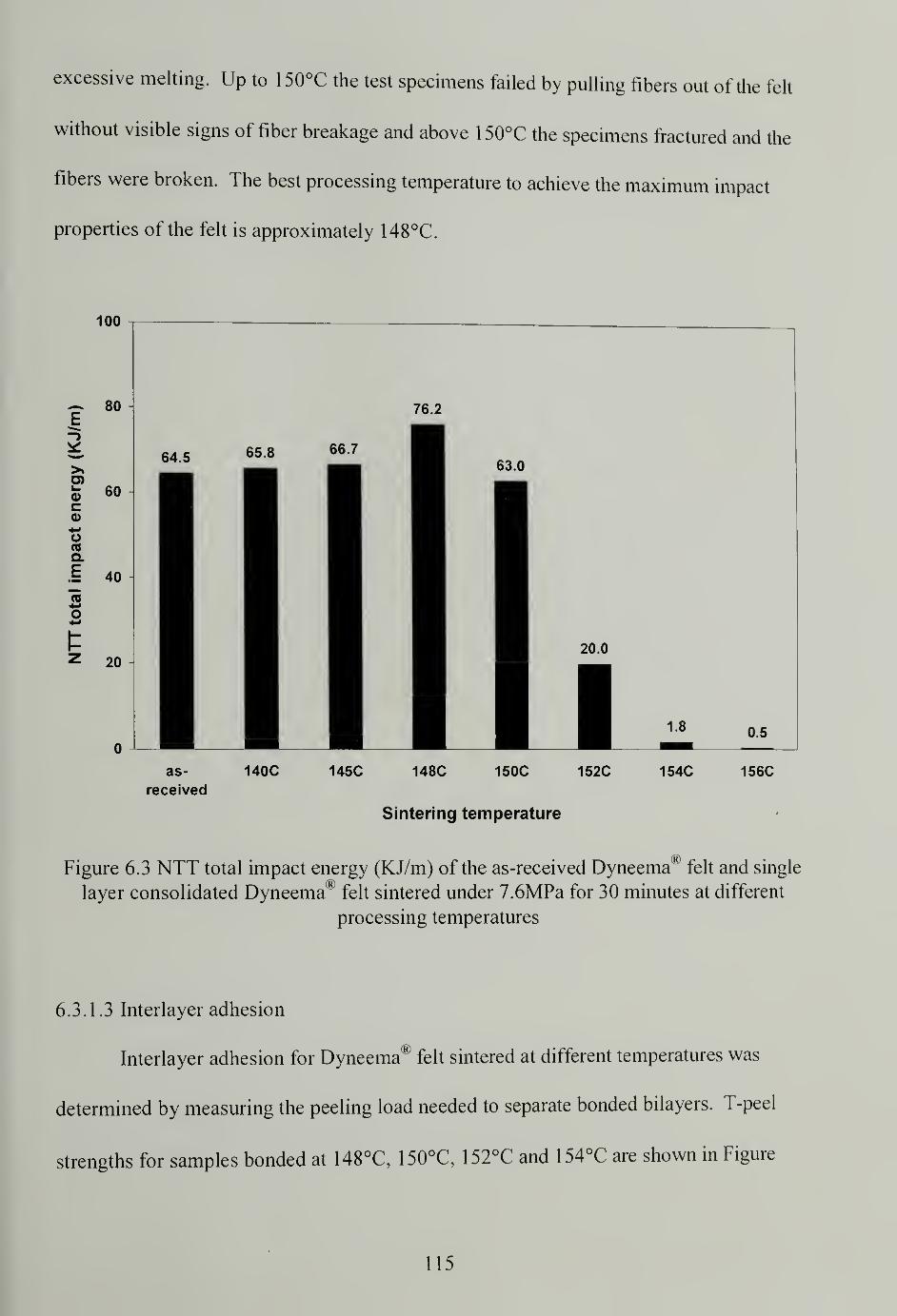
excessive melting. Up to 150°C the test specimens failed by pulling fibers out of the felt
without visible signs of fiber breakage and above 150°C the specimens fractured and the
fibers were broken. The best processing temperature to achieve the maximum impact
properties of the felt is approximately 148°C.
100
as-
received
140C 145C 148C 150C 152C
Sintering temperature
154C 156C
®Figure 6.3 NTT total impact energy (KJ/m) of the as-received Dyneema felt and single
layer consolidated Dyneema* felt sintered under 7.6MPa for 30 minutes at different
processing temperatures
6.3.1.3 Interlayer adhesion
Interlayer adhesion for Dyneema felt sintered at different temperatures was
determined by measuring the peeling load needed to separate bonded bilayers. T-peel
strengths for samples bonded at 148°C, 150°C, 152°C and 154°C are shown in Figure
115
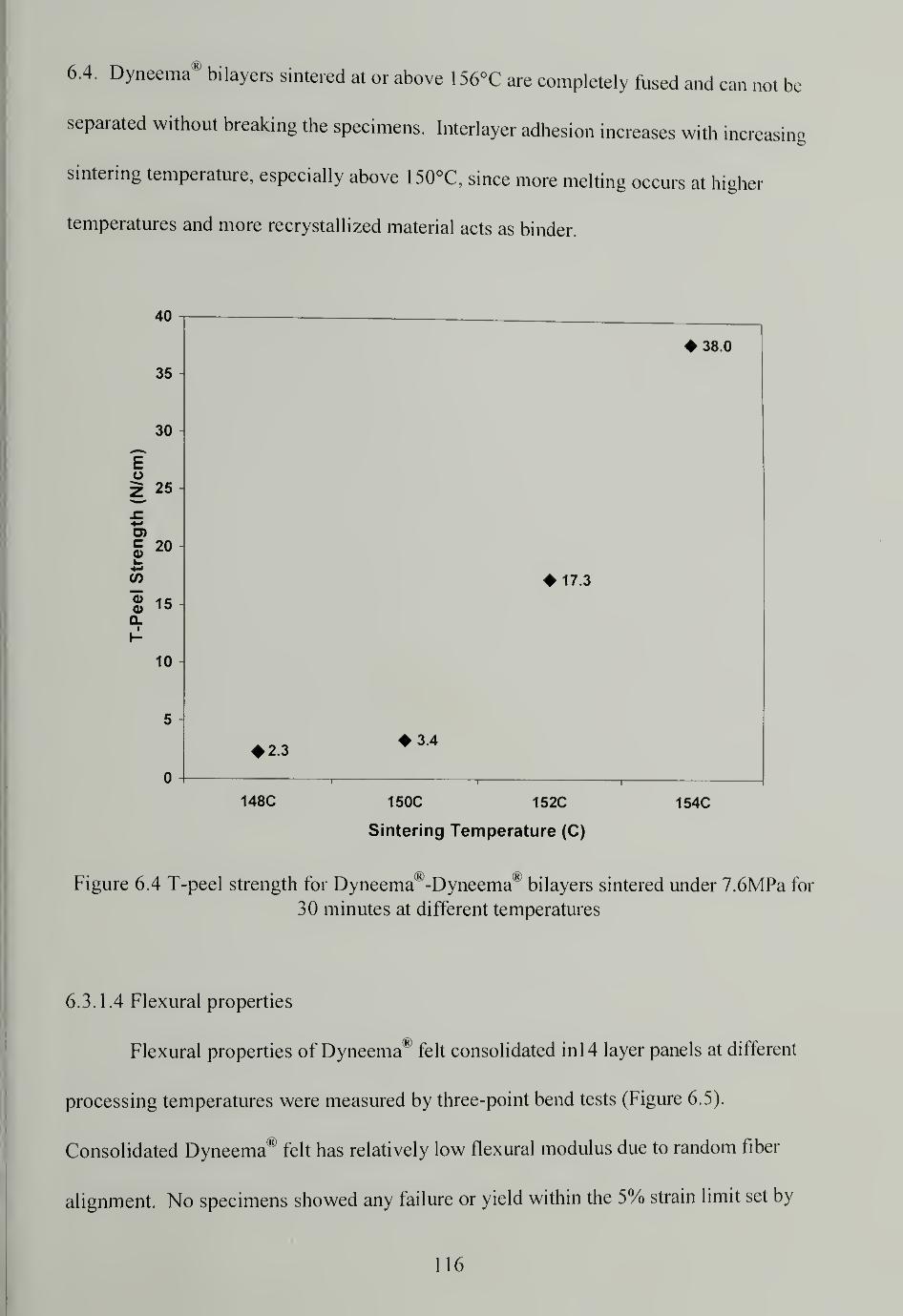
6.4. Dyneema® bilayers sintered at or above 156°C are completely fused and can not be
separated without breaking the specimens. Interlayer adhesion increases with increasing
sintering temperature, especially above 150°C, since more melting occurs at higher
temperatures and more recrystallized material acts as binder.
148C 150C 152C
Sintering Temperature (C)
154C
Figure 6.4 T-peel strength for Dyneema®-Dyneema* bilayers sintered under 7.6MPa for
30 minutes at different temperatures
6.3.1.4 Flexural properties
Flexural properties of Dyneema 1" felt consolidated in 14 layer panels at different
processing temperatures were measured by three-point bend tests (Figure 6.5).
Consolidated Dyneema® felt has relatively low flexural modulus due to random fiber
alignment. No specimens showed any failure or yield within the 5% strain limit set by
116
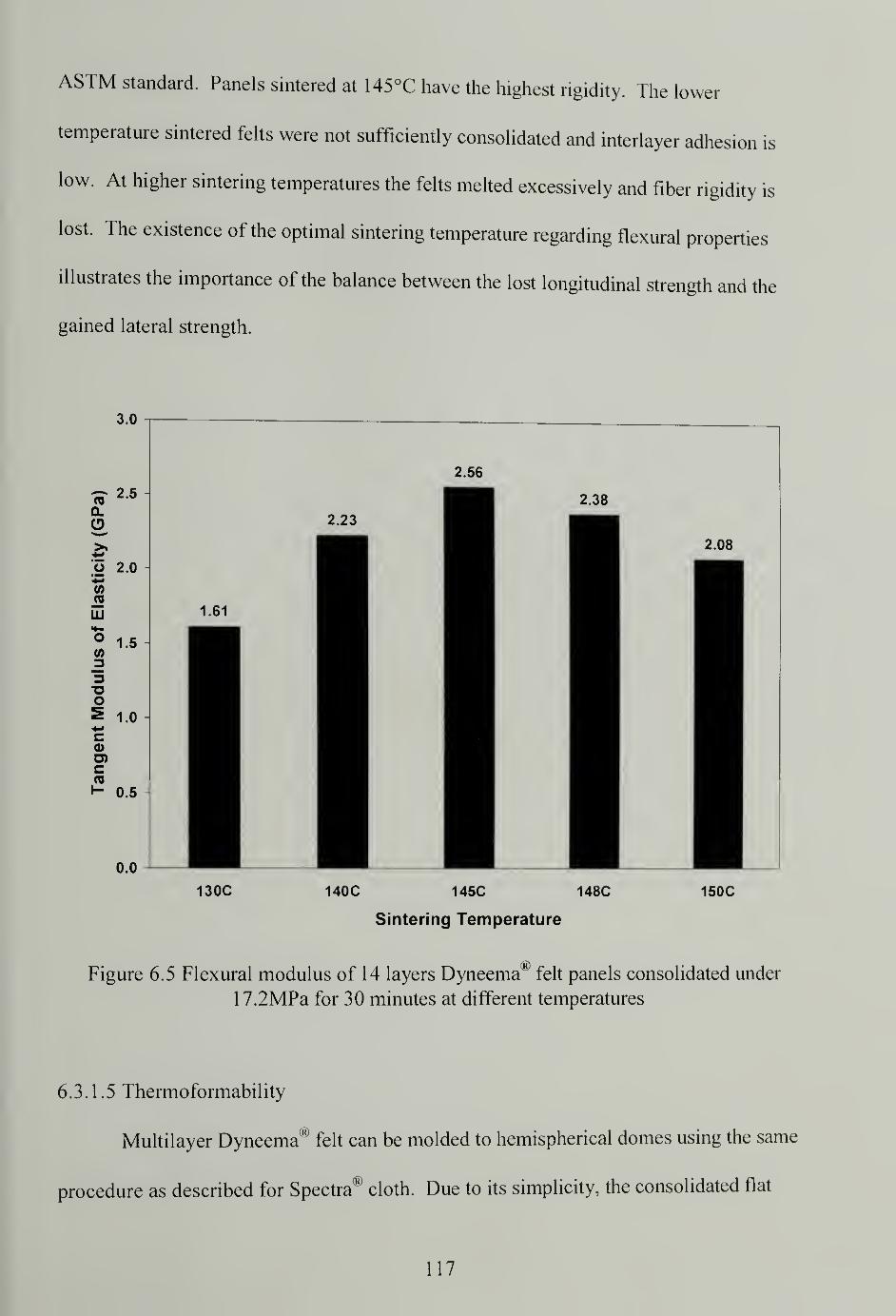
ASTM standard. Panels sintered at 145°C have the highest rigidity. The lower
temperature sintered felts were not sufficiently consolidated and interlayer adhesion is
low. At higher sintering temperatures the felts melted excessively and fiber rigidity is
lost. The existence of the optimal sintering temperature regarding flexural properties
illustrates the importance of the balance between the lost longitudinal strength and the
gained lateral strength.
130C 140C 145C 148C
Sintering Temperature
150C
Figure 6.5 Flexural modulus of 14 layers Dyneema® felt panels consolidated under
17.2MPa for 30 minutes at different temperatures
6.3.1.5 Thermoformability
Multilayer Dyneema® felt can be molded to hemispherical domes using the same
procedure as described for Spectra® cloth. Due to its simplicity, the consolidated flat
117
panel was prepared and then shaped, although other shaping schemes would also have
worked. Due to the thickness of the felt, 20 layers of Dyneema® felt were used to
produce a dome having dimensions similar to that of 25 layers of Spectra00
cloth. Domes
made from Dyneema® felt are strong and stiff. Looseness of the fibers in the felt resulted
in the straightening of the previously curled fibers rather than the actual stretching of the
fibers by the deformation of the felt in the mold. As a result, a relatively smaller force
was used for molding as compared to the Spectra® cloth. Dyneema® felt has good
thermoformability.
6.3.2 Spectra Shield® Plus PCR prepreg
Spectra Shield'" Plus PCR is a nonwoven prepreg which contains two chemically
different materials: Spectra00
fiber and matrix. The matrix is used as a binding agent and
good interfiber and interlayer adhesion is expected. In each layer of prepreg, either in the
0° or 90° direction, the fibers are aligned relative to each other. The ordered fiber
alignment should be reflected in a high Hermans orientation function parameter. The
unidirectional fiber alignment can also contribute positively to the impact resistance and
flexural properties. However the soft matrix would contribute negatively to the impact
and flexural properties. The net outcomes are difficult to predict and have to be carefully
studied.
6.3.2.1 Crystallinity change
A single layer of Spectra Shield00
Plus PCR prepregs was consolidated under
7.6MPa for 30 minutes at various processing temperatures. The DSC thermographs are
118
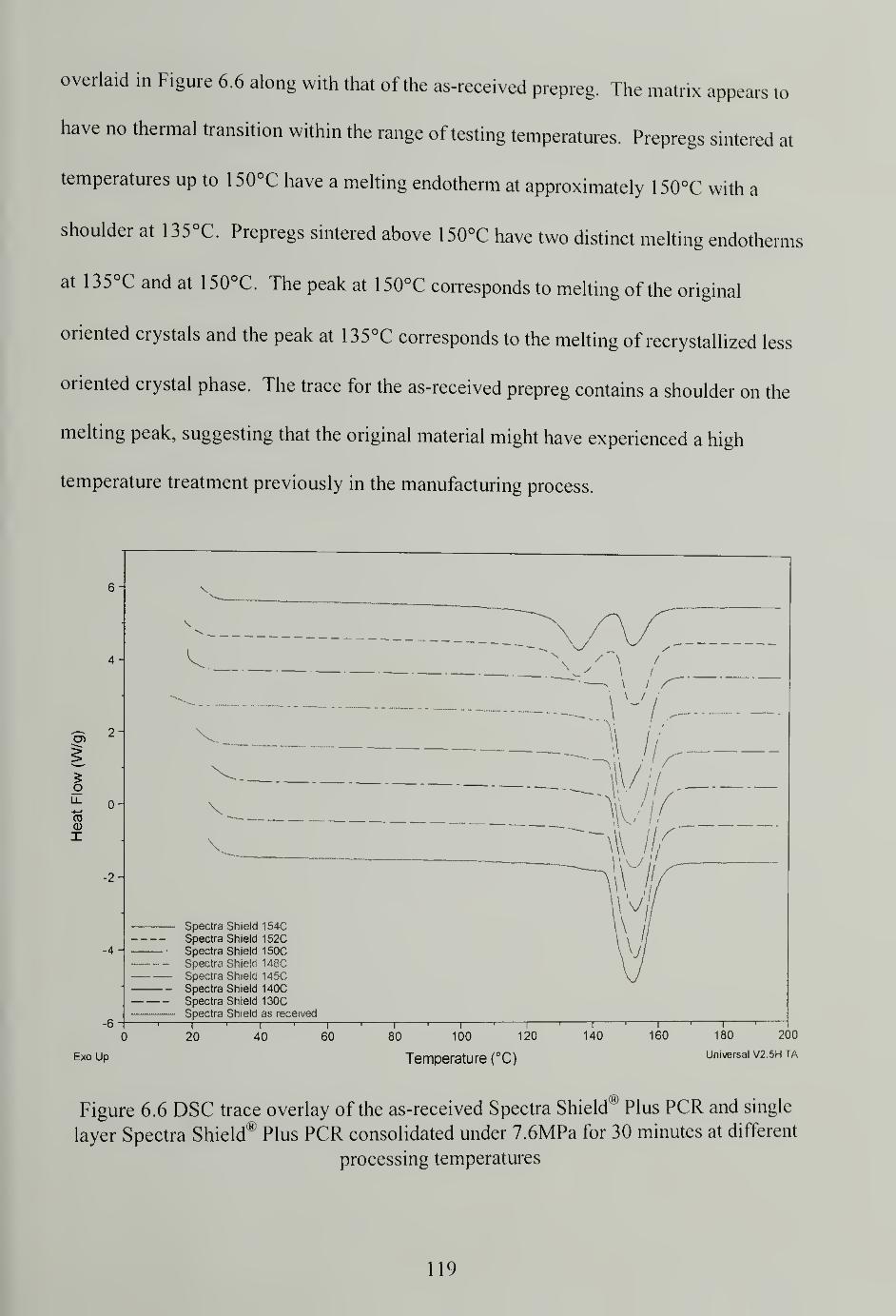
overlaid in Figure 6.6 along with that of the as-received prepreg. The matrix appears to
have no thermal transition within the range of testing temperatures. Prepregs sintered at
temperatures up to 150°C have a melting endotherm at approximately 150°C with a
shoulder at 135°C. Prepregs sintered above 150°C have two distinct melting endotherms
at 135°C and at 150°C. The peak at 150°C corresponds to melting of the original
oriented crystals and the peak at 135°C corresponds to the melting of recrystallized less
oriented crystal phase. The trace for the as-received prepreg contains a shoulder on the
melting peak, suggesting that the original material might have experienced a high
temperature treatment previously in the manufacturing process.
o -
V
Spectra Shield 154CSpectra Shield 152CSpectra Shield 150CSpectra Shield 148CSpectra Shield 145CSpectra Shield 140CSpectra Shield 130CSpectra Shield as received
—i1 1 1
160 180 200
Universal V2.5H TA
20 40 60 80
Exo Up
100 120
Temperature (°C)
140
Figure 6.6 DSC trace overlay of the as-received Spectra Shield® Plus PCR and single
layer Spectra Shield® Plus PCR consolidated under 7.6MPa for 30 minutes at different
processing temperatures
119
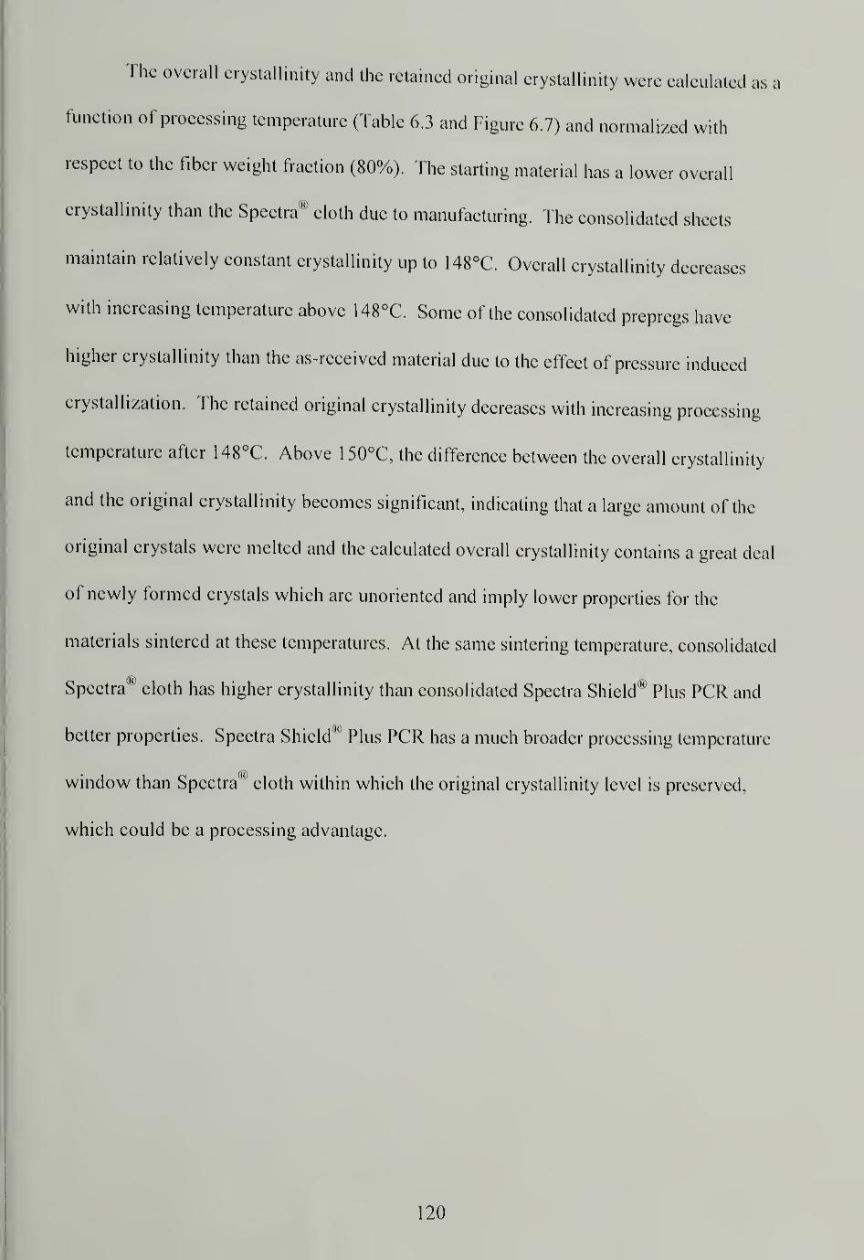
The overall crystallinity and the retained original crystallinity were calculated as a
function of processing temperature (Table 6.3 and Figure 6.7) and normalized with
respect to the fiber weight fraction (80%). The starting material has a lower overall
crystallinity than the Spectra® cloth due to manufacturing. The consolidated sheets
maintain relatively constant crystallinity up to 148°C. Overall crystallinity decreases
with increasing temperature above 148°C. Some of the consolidated prepregs have
higher crystallinity than the as-received material due to the effect of pressure induced
crystallization. The retained original crystallinity decreases with increasing processing
temperature after 148°C. Above 150°C, the difference between the overall crystallinity
and the original crystallinity becomes significant, indicating that a large amount of the
original crystals were melted and the calculated overall crystallinity contains a great deal
of newly formed crystals which are unoriented and imply lower properties for the
materials sintered at these temperatures. At the same sintering temperature, consolidated
Spectra® cloth has higher crystallinity than consolidated Spectra Shield*' Plus PCR and
better properties. Spectra Shield ""
Plus PCR has a much broader processing temperature
window than Spectra*' cloth within which the original crystallinity level is preserved,
which could be a processing advantage.
120
Table 6.3 Overall crystallinity and retained original crystallinity for the as-received
Spectra Shield® Plus PCR and single layer Spectra Shield® Plus PCR consolidated under7.6MPa for 30 minutes at different temperatures
Specimenas-
received130°C 140°C 145°C 148°C 150°C 152°C 154°C
Overall
crystallinity
90.3% 93.9% 92.8% 92.0% 90.7% 85.9% 80.8% 70.0%
Original
crystallinity
89.6% 90.9% 90.5% 88.1% 87.9% 83.5% 49.2% 27.9%
100%
80%
60%
5
O 40%
20%
0%
Overall crystallinity
Original crystallinity
Sintering temperature
as- 130C 140C 145C 148C 150C 152C 154C
received
Figure 6.7 Overall and original crystallinity of the as-received Spectra Shield® Plus PCR
and single layer Spectra Shield® Plus PCR consolidated under 7.6MPa for 30 minutes at
different processing temperatures
121
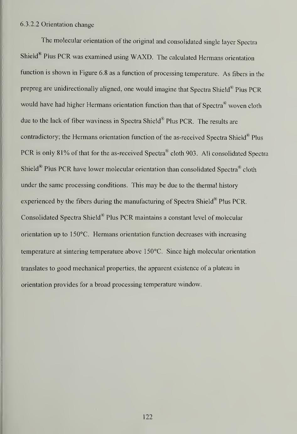
6.3.2.2 Orientation change
The molecular orientation of the original and consolidated single layer Spectra
Shield® Plus PCR was examined using WAXD. The calculated Hermans orientation
function is shown in Figure 6.8 as a function of processing temperature. As fibers in the
prepreg are unidirectionally aligned, one would imagine that Spectra Shield® Plus PCR
would have had higher Hermans orientation function than that of Spectra® woven cloth
due to the lack of fiber waviness in Spectra Shield® Plus PCR. The results are
contradictory; the Hermans orientation function of the as-received Spectra Shield® Plus
PCR is only 81% of that for the as-received Spectra® cloth 903. All consolidated Spectra
Shield® Plus PCR have lower molecular orientation than consolidated Spectra® cloth
under the same processing conditions. This may be due to the thermal history
experienced by the fibers during the manufacturing of Spectra Shield® Plus PCR.
Consolidated Spectra Shield "' Plus PCR maintains a constant level of molecular
orientation up to 150°C. Hermans orientation function decreases with increasing
temperature at sintering temperature above 150°C. Since high molecular orientation
translates to good mechanical properties, the apparent existence of a plateau in
orientation provides for a broad processing temperature window.
122
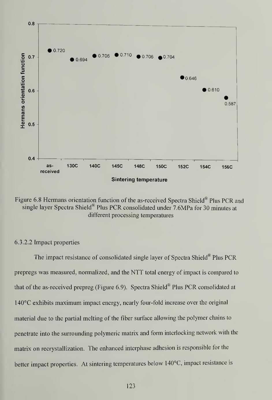
0.8
O 0.7
oc
co
'-4-*
|j 0.60)
owc«E
5 0.5
0.4
0.720
0.6940.706 •0.710 $0,706 * 704
0.646
0.610
0.587
as- 130C 140C 145C 148C 150C 152C 154C 156Creceived
Sintering temperature
Figure 6.8 Hermans orientation function of the as-received Spectra Shield® Plus PCR and
single layer Spectra Shield® Plus PCR consolidated under 7.6MPa for 30 minutes at
different processing temperatures
6.3.2.2 Impact properties
The impact resistance of consolidated single layer of Spectra Shield® Plus PCR
prepregs was measured, normalized, and the NTT total energy of impact is compared to
that of the as-received prepreg (Figure 6.9). Spectra Shield® Plus PCR consolidated at
140°C exhibits maximum impact energy, nearly four-fold increase over the original
material due to the partial melting of the fiber surface allowing the polymer chains to
penetrate into the surrounding polymeric matrix and form interlocking network with the
matrix on recrystallization. The enhanced interphase adhesion is responsible for the
better impact properties. At sintering temperatures below 140°C, impact resistance is
123
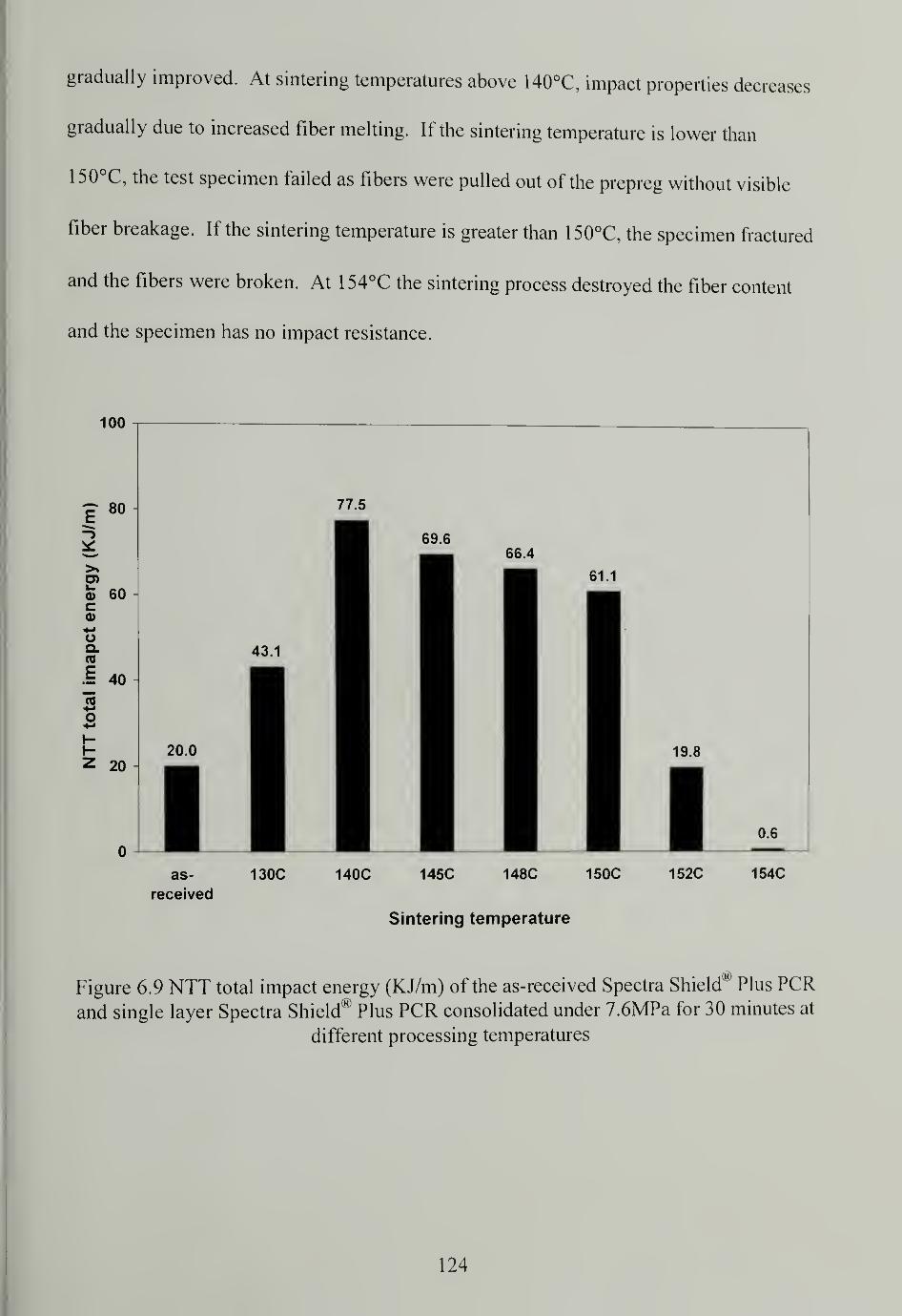
gradually improved. At sintering temperatures above 140°C, impact properties decreases
gradually due to increased fiber melting. If the sintering temperature is lower than
1 50°C, the test specimen failed as fibers were pulled out of the prepreg without visible
fiber breakage. If the sintering temperature is greater than 150°C, the specimen fractured
and the fibers were broken. At 1 54°C the sintering process destroyed the fiber content
and the specimen has no impact resistance.
100
as-
received
130C 140C 145C 148C 150C 152C 154C
Sintering temperature
Figure 6.9 NTT total impact energy (KJ/m) of the as-received Spectra Shield® Plus PCR
and single layer Spectra Shield® Plus PCR consolidated under 7.6MPa for 30 minutes at
different processing temperatures
124
6.3.2.3 Interlayer adhesion
Interlayer adhesion for Spectra Shield® Plus PCR was measured as the peel load
needed to separate the bonded bilayers (Figure 6.10). Interlayer adhesion increases
steadily with increasing sintering temperature. At sintering temperatures between 130°C
and 140°C, the interlayer adhesion does not improve significantly. Above 140°C, the
interlayer adhesion increases at a faster rate due to partial melting and recrystallization of
the Spectra® fibers, which adds to the adhesive strength in addition to that generated by
the matrix.
130C 140C 145C
Sintering Temperature (C)
148C
Figure 6.10 T-peel strength for Spectra Shield® Plus PCR bilayers sintered under 7.6MPa
for 30 minutes at different processing temperatures
125
6.3.2.4 Flexural properties
The flexural modulus and strength of 32 layer Spectra Shield® Plus PCR flat
panels sintered at different processing temperatures for 30 minutes under a pressure of
17.2MPa were determined (Figure 6.1 1). The Spectra Shield® Plus PCR panels are more
flexible than those made from Spectra® cloth 903 or Dyneema® felt. Low determined
flexural modulus results from the use of a soft matrix and lower modulus fibers.
Although the prepreg possesses straight and unidirectional fibers, the flexural properties
of the consolidated panels are offset by the use of a soft matrix. All test specimens
exhibited a yielding point within the 5% strain and flexural strength is reported. At
higher strains all test specimens developed delamination between the layers, indicating
relatively low interlayer adhesion. The flexural modulus reaches a maximum value at a
sintering temperature of 140°C and flexural strength remains predominantly constant
over the entire processing temperature range.
126
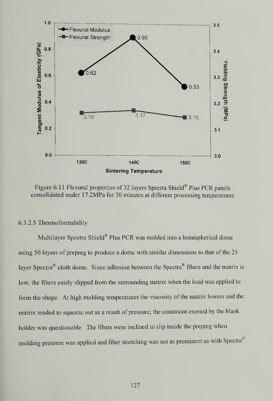
1.0
re
Q. 0.8O
oW
0.6
LU
3
5 0.4O
0)
S O- 2
0.0
--Flexural Modulus
-•-Flexural Strength J|0.90
#1x62
#0.53
—3.16
1
—
3*17 ——
-
" — 3.15
130C 140C
Sintering Temperature
150C
3.5
3.4
<5a.
3-33"
(/)
3(Q
3.2 3-
"D
3.1
3.0
Figure 6.1 1 Flexural properties of 32 layers Spectra Shield® Plus PCR panels
consolidated under 17.2MPa for 30 minutes at different processing temperatures
6.3.2.5 Thermoformability
Multilayer Spectra Shield® Plus PCR was molded into a hemispherical dome
using 50 layers of prepreg to produce a dome with similar dimensions to that of the 25
layer Spectra® cloth dome. Since adhesion between the Spectra® fibers and the matrix is
low, the fibers easily slipped from the surrounding matrix when the load was applied to
form the shape. At high molding temperatures the viscosity of the matrix lowers and the
matrix tended to squeeze out as a result of pressure; the constraint exerted by the blank
holder was questionable. The fibers were inclined to slip inside the prepreg when
molding pressure was applied and fiber stretching was not as prominent as with Spectra
127
cloth. Spectra Shield Plus PCR is not a good material for direct shaping and would be
better processed using the conventional method of cutting patterns and laying-up.
6.3.3 Comparison of consolidated Spectra® cloth, Dyneema Fraglight® and Spectra
Shield® Plus PCR
Spectra® cloth, Dyneema Fraglight® and Spectra Shield® Plus PCR are all
extended chain UHMWPE fiber products of different forms: woven fabric, nonwoven
felt, and nonwoven prepreg, respectively. Spectra® cloth and Dyneema Fraglight® are
single component materials containing only fibers and Spectra Shield® Plus PCR is a two
component material containing fibers and matrix. Studies of high-temperature high-
pressure sintering on each material and their physical, thermo-mechanical, structural
properties of the resulting products have been discussed. The load bearing component in
all three materials is highly oriented UMMWPE fibers. Spectra® fiber and Dyneema®
fiber have similar properties. The properties of the consolidated structures are dependent
on the structural and morphological properties of the load bearing fibers, although fiber
alignment and the introduction of the matrix influence the final properties of the
composite.
6.3.3.1 Crystallinity
Extended chain UHMWPE fibers have high crystallinity, which is essential to
obtain their outstanding properties. High-temperature high-pressure sintering process
involves a series of structural changes including: partial melting of the fibers, molecular
reorientation due to increasing molecular relaxation at high temperatures, orthorhombic
128
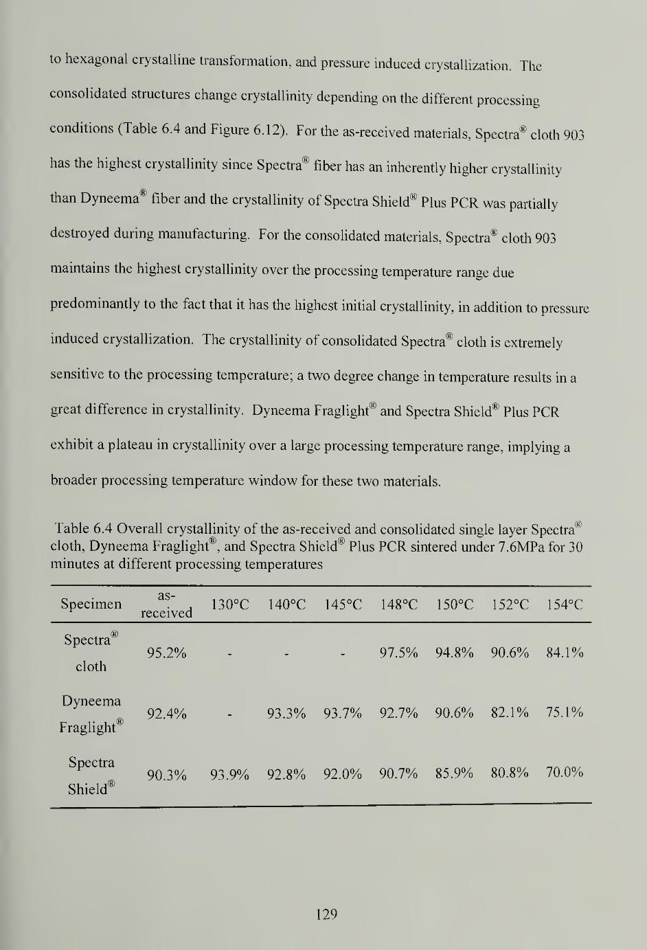
to hexagonal crystalline transformation, and pressure induced crystallization. The
consolidated structures change crystallinity depending on the different processing
conditions (Table 6.4 and Figure 6.12). For the as-received materials, Spectra® cloth 903
has the highest crystallinity since Spectra® fiber has an inherently higher crystallinity
than Dyneema® fiber and the crystallinity of Spectra Shield® Plus PCR was partially
destroyed during manufacturing. For the consolidated materials, Spectra® cloth 903
maintains the highest crystallinity over the processing temperature range due
predominantly to the fact that it has the highest initial crystallinity, in addition to pressure
induced crystallization. The crystallinity of consolidated Spectra® cloth is extremely
sensitive to the processing temperature; a two degree change in temperature results in a
great difference in crystallinity. Dyneema Fraglight® and Spectra Shield® Plus PCR
exhibit a plateau in crystallinity over a large processing temperature range, implying a
broader processing temperature window for these two materials.
Table 6.4 Overall crystallinity of the as-received and consolidated single layer Spectra®
cloth, Dyneema Fraglight®, and Spectra Shield® Plus PCR sintered under 7.6MPa for 30
minutes at different processing temperatures
Specimenas-
received130°C 140°C 145°C 148°C 150°C 152°C 154°C
Spectra®
cloth
95.2% 97.5% 94.8% 90.6% 84.1%
Dyneema
Fraglight®92.4% 93.3% 93.7% 92.7% 90.6% 82.1% 75.1%
Spectra
Shield®90.3% 93.9% 92.8% 92.0% 90.7% 85.9% 80.8% 70.0%
129
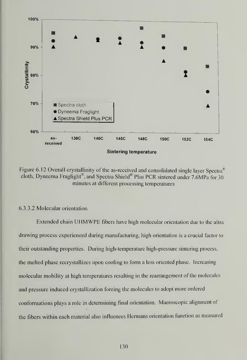
100%
90%
C
w 80%t/>
O
70%
60%
Spectra cloth
• Dyneema Fraglight
Spectra Shield Plus PCR
as- 130C 140C 145C 148C 150C 152C 154Creceived
Sintering temperature
Figure 6.12 Overall crystallinity of the as-received and consolidated single layer Spectra'1
cloth, Dyneema Fraglight®, and Spectra Shield® Plus PCR sintered under 7.6MPa for 30
minutes at different processing temperatures
6.3.3.2 Molecular orientation
Extended chain UHMWPE fibers have high molecular orientation due to the ultra
drawing process experienced during manufacturing, high orientation is a crucial factor to
their outstanding properties. During high-temperature high-pressure sintering process,
the melted phase recrystallizes upon cooling to form a less oriented phase. Increasing
molecular mobility at high temperatures resulting in the rearrangement of the molecules
and pressure induced crystallization forcing the molecules to adopt more ordered
conformations plays a role in determining final orientation. Macroscopic alignment of
the fibers within each material also influences Hermans orientation function as measured
130
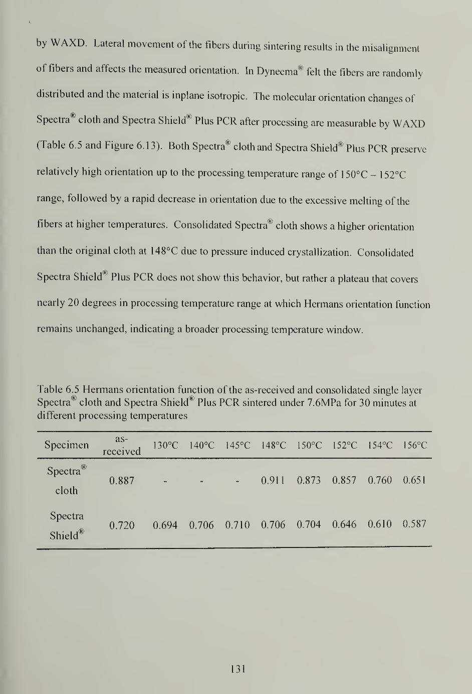
by WAXD. Lateral movement of the fibers during sintering results in the misalignment
of fibers and affects the measured orientation. In Dyneema® felt the fibers are randomly
distributed and the material is inplane isotropic. The molecular orientation changes of
Spectra® cloth and Spectra Shield® Plus PCR after processing are measurable by WAXD
(Table 6.5 and Figure 6.13). Both Spectra® cloth and Spectra Shield® Plus PCR preserve
relatively high orientation up to the processing temperature range of 150°C - 152°C
range, followed by a rapid decrease in orientation due to the excessive melting of the
fibers at higher temperatures. Consolidated Spectra® cloth shows a higher orientation
than the original cloth at 148°C due to pressure induced crystallization. Consolidated
Spectra Shield® Plus PCR does not show this behavior, but rather a plateau that covers
nearly 20 degrees in processing temperature range at which Hermans orientation function
remains unchanged, indicating a broader processing temperature window.
Table 6.5 Hermans orientation function of the as-received and consolidated single layer
Spectra5cloth and Spectra Shield* Plus PCR sintered under 7.6MPa for 30 minutes at
different processing temperatures
Specimen,
130°C 140°C 145°C 148°C 150°C 152°C 154°C 156°Creceived
Spectra®0.887 - - - 0.911 0.873 0.857 0.760 0.651
cloth
Spectra0.720 0.694 0.706 0.710 0.706 0.704 0.646 0.610 0.587
Shield®
131
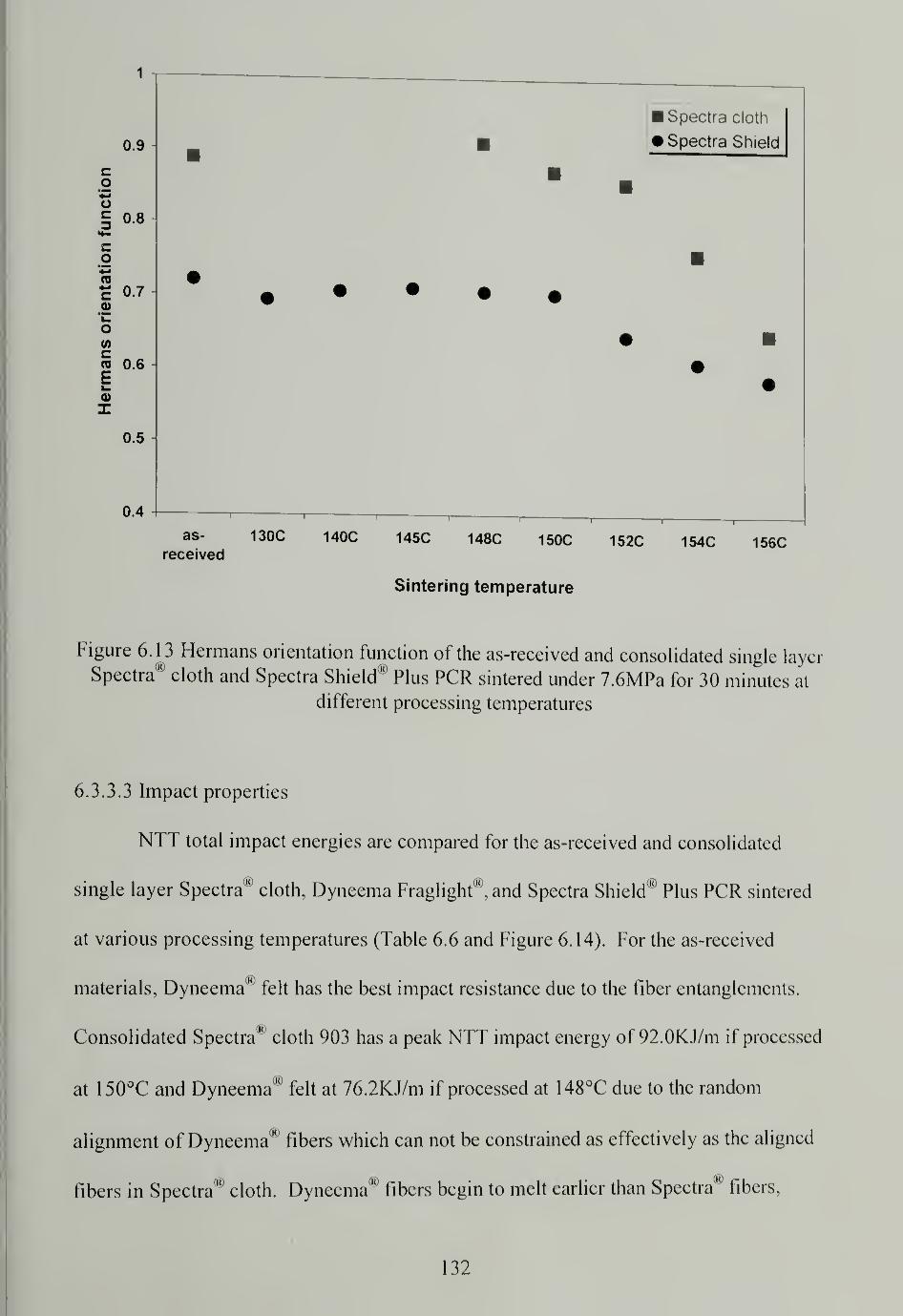
1
0.9
o§ 0.8
0.7
« 0.6
0.5
0.4
Spectra cloth
Spectra Shield
as- 130C 140C 145C 148C 150C 152C 154C 156Creceived
Sintering temperature
Figure 6.13 Hermans orientation function of the as-received and consolidated single layer
Spectra® cloth and Spectra Shield® Plus PCR sintered under 7.6MPa for 30 minutes at
different processing temperatures
6.3.3.3 Impact properties
NTT total impact energies are compared for the as-received and consolidated
single layer Spectra® cloth, Dyneema Fraglight®, and Spectra Shield® Plus PCR sintered
at various processing temperatures (Table 6.6 and Figure 6.14). For the as-received
materials, Dyneema® felt has the best impact resistance due to the fiber entanglements.
Consolidated Spectra® cloth 903 has a peak NTT impact energy of 92.0KJ/m if processed
at 150°C and Dyneema® felt at 76.2KJ/m if processed at 148°C due to the random
alignment of Dyneema® fibers which can not be constrained as effectively as the aligned
fibers in Spectra® cloth. Dyneema® fibers begin to melt earlier than Spectra® fibers,
132
therefore, their maximum impact properties occur at a lower temperature. For Spectra
Shield® Plus PCR, the optimal processing temperature, in terms of the highest attained
impact resistance 77.5KJ/m, is 140°C which is considerably lower than the other two
materials. The matrix of Spectra Shield® Plus PCR has a relatively low viscosity at high
temperatures and when under a large pressure tends to flow; so the pressure can not to be
effectively exerted onto the fibers. The fibers in Spectra Shield® Plus PCR are not as
sufficiently constrained as those in Spectra® cloth and Dyneema® felt and consequently
lose crystallinity and orientation during sintering, resulting in lower impact properties.
Consolidated Spectra® cloth has the best maximum impact resistance among the three
materials and proves to be the best candidate for making high strength, high impact
resistant composites. The impact properties of Dyneema® felt and Spectra Shield® Plus
PCR sintered at a temperature slightly below or above their respective optimal
temperatures do not drop greatly when compared to Spectra® cloth and these materials
have somewhat broader processing temperature window.
Table 6.6 NTT total impact energy (KJ/m) of the as-received and consolidated single
layer Spectra* cloth, Dyneema Fraglight®, and Spectra Shield® Plus PCR sintered under
7.6MPa for 30 minutes at different processing temperatures
Specimenas-
received140°C 145°C 148°C 1 50°C 152°C 154°C 156°C
Spectra®
cloth
16.6 78.1 92.0 13.7 3.2 2.3
Dyneema
Fraglight®64.5 65.8 66.7 76.2 63.0 20.0 1.8 0.5
Spectra
Shield®20.0 77.5 69.6 66.4 61.1 19.8 0.6
133
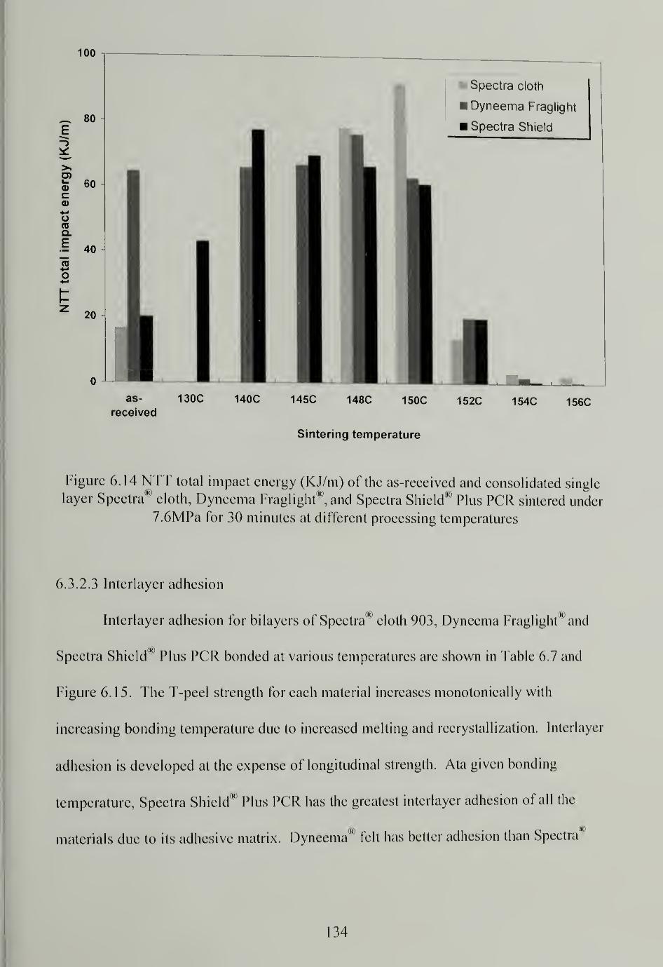
100
as- 130C 140C 145C 148C 150C 152C 154C 156Creceived
Sintering temperature
Figure 6. 14 NTT total impact energy (KJ/m) of the as-received and consolidated single
layer Spectra00
cloth, Dyneema Fraglight°°,and Spectra Shield10
Plus PCR sintered under
7.6MPa for 30 minutes at different processing temperatures
6.3.2.3 Interlayer adhesion
Interlayer adhesion for bilayers of Spectra00
cloth 903, Dyneema Fraglight and
Spectra Shield10
Plus PCR bonded at various temperatures are shown in Table 6.7 and
Figure 6.15. The T-peel strength for each material increases monotonically with
increasing bonding temperature due to increased melting and recrystallization. Interlayer
adhesion is developed at the expense of longitudinal strength. Ata given bonding
temperature, Spectra Shield'"1
Plus PCR has the greatest interlayer adhesion of all the
materials due to its adhesive matrix. Dyneema00
felt has better adhesion than Spectra'1
134
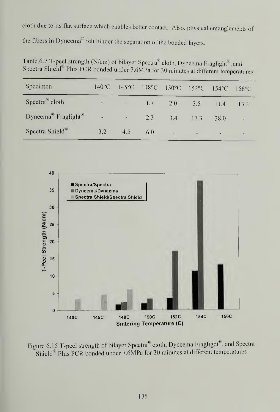
cloth due to its flat surface which enables better contact. Also, physical entanglements of
the fibers in Dyneema*' fell hinder the separation of the bonded layers.
Fable 6.7 T-peel strength (N/cm) of bilayer Spectra00
cloth, Dyneema Fraglight*1
, andSpectra Shield* Plus PGR bonded under 7.6MPa for 30 minutes at different tempera!
Specimen 140°C 145°C 148°C 150°C 152°C 154°C 156°C
Spectra* cloth 1.7 2.0 3.5 11.4 13.3
Dyneema* Fraglight" 2.3 3.4 17.3 38.0
Spectra Shield00
3.2 4.5 6.0 — _
40
140C 145C 148C 150C 152C 154C 156C
Sintering Temperature (C)
Figure 6. 15 T-peel strength of bilayer Spectra® cloth, Dyneema Fraglight0", and Spectra
Shield" Plus PCR bonded under 7.6MPa for 30 minutes at different temperatures
135
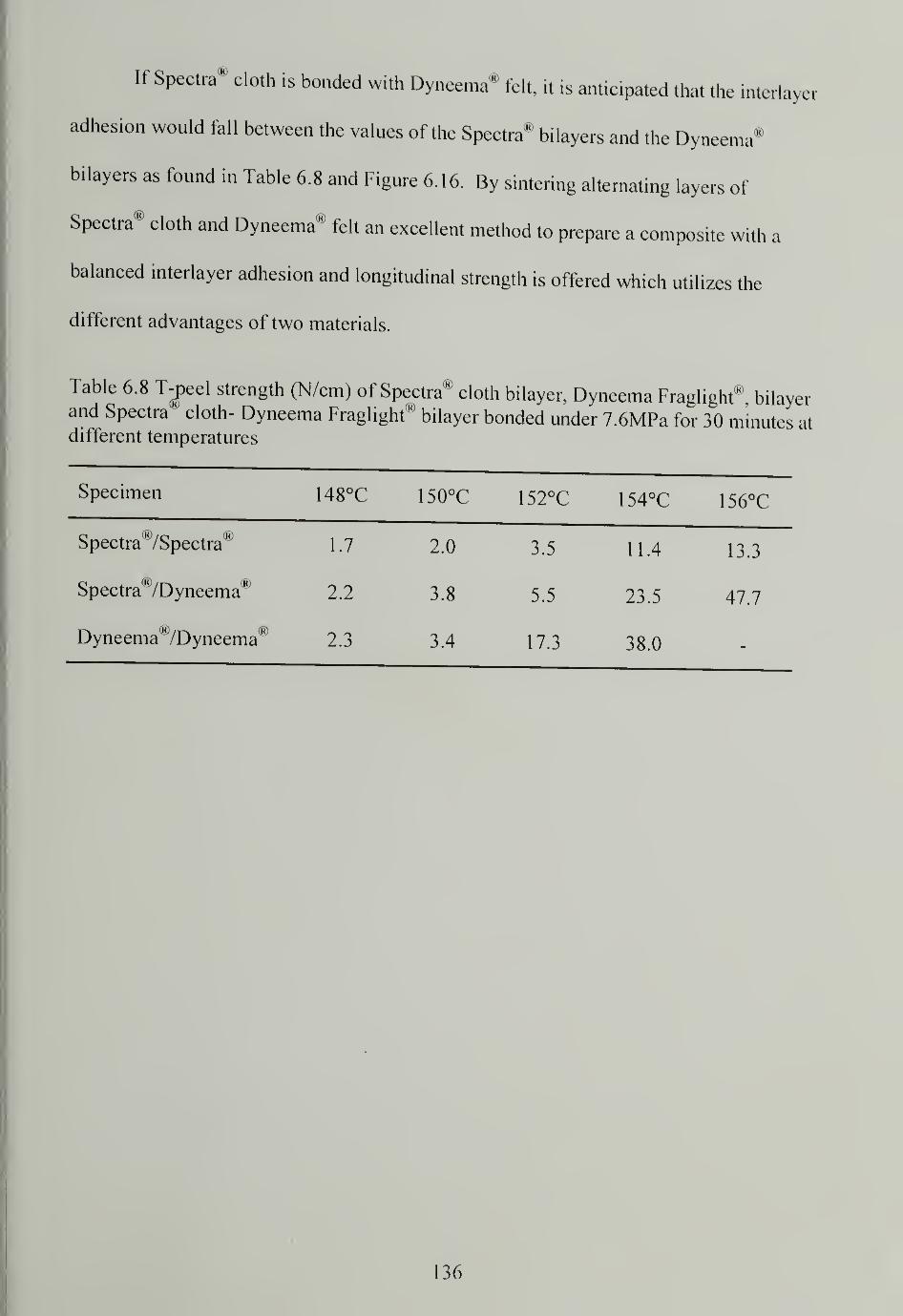
If Spectra® cloth is bonded with Dyneema* felt, it is anticipated that the interlayer
adhesion would fall between the values of the Spectra" bilayers and the Dyneema®
bilayers as found in Table 6.8 and Figure 6.16. By sintering alternating layers of
Spectra® cloth and Dyneema® felt an excellent method to prepare a composite with a
balanced interlayer adhesion and longitudinal strength is offered which utilizes the
different advantages of two materials.
Table 6.8 T-peel strength (N/cm) of Spectra® cloth bilayer, Dyneema Fraglight®, bilayerand Spectra cloth- Dyneema Fraglight"
<,
bilayer bonded under 7.6MPa for 30 minutes atdifferent temperatures
Specimen 148°C 150°C 152°C 154°C 156°C
Spectra®/Spectra® 1.7 2.0 3.5 11.4 13.3
Spectra "/Dyneema® 2.2 3.8 5.5 23.5 47.7
Dyneema(K)
/Dyneema® 2.3 3.4 17.3 38.0
136

60
50
U 40
D)
g 30
CO
"55
SO. 20
10
Spectra/Spectra
Spectra/Dyneema
Dyneema/Dyneema
148C 150C 152C 154C
Sintering Temperature (C)
156C
Figure 6.16 T-peei strength of Spectra0" cloth bilayer, Dyneema Fraglight® bilayer, and
Spectra® cloth- Dyneema Fraglight0" bilayer bonded under 7.6MPa for 30 minutes at
different temperatures
6.3.2.4 Flexural properties
Flexural modulus for multilayer consolidated Spectra00
cloth 903, Dyneema
(Hi
Fraglightw
,Spectra Shield'" Plus PGR, and unoriented UHMWPE sintered at various
temperatures is shown in Figure 6. 1 7. Consolidated Spectra'" cloth panels have much
higher flexural moduli than the other two UHMWPE fiber materials. Consolidated
Dyneema00
felt has about half the rigidity of Spectra'0
cloth 903, if their achieved maxima
are compared. Consolidated Spectra Shield'"
Plus PCR has rigidity comparable to
unoriented UHMWPE panel due to its soft matrix, despite its better fiber alignment
which illustrates one of the advantages of eliminating the use of matrix by making matrix
137
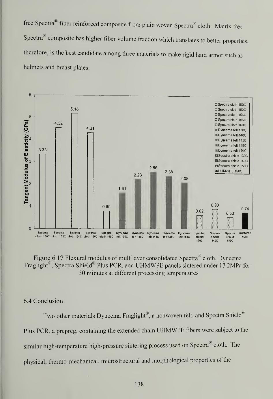
free Spectra® fiber reinforced composite from plain woven Spectra® cloth. Matrix free
Spectra® composite has higher fiber volume fraction which translates to better properties,
therefore, is the best candidate among three materials to make rigid hard armor such as
helmets and breast plates.
TO
Q.
$>(/)
ss.
LU
03
3o
coU)c
5.18
4.52
3.33
4.31
2.562.38
1.61
0.80
0,62
Spectra cloth 150C
Spectra cloth 152C
Spectra cloth 154C
Spectra cloth 156C
Spectra cloth 160C
Dyneema felt 130C
w Dyneema felt 140C
Dyneema felt 145C
Dyneema felt 148C
• Dyneema felt 150C
Spectra shield 130C
Spectra shield 140C
Spectra shield 150C
UHMWPE 150C
0.900.74
0.53
Spectra Spectra Spectra Spectra Spectra Dyneema Dyneema Dyneema Dyneema Dyneema Spectra Spectra Spectra UHMWPEcloth 150C cloth 152C cloth 154C cloth 156C cloth 160C felt 130C felt 140C felt 145C felt148C felt 150C shield shield shield 150C
130C 140C 150C
Figure 6.17 Flexural modulus of multilayer consolidated Spectra® cloth, DyneemaFraglight®, Spectra Shield® Plus PCR, and UHMWPE panels sintered under 17.2MPa for
30 minutes at different processing temperatures
6.4 Conclusion
Two other materials Dyneema Fraglight00
, a nonwoven felt, and Spectra Shield"
Plus PCR, a prepreg, containing the extended chain UHMWPE fibers were subject to the
similar high-temperature high-pressure sintering process used on Spectra® cloth. The
physical, thermo-mechanical, microstructural and morphological properties of the
138
ra"consolidated products were comprehensively investigated and compared to Specti
cloth. Differences in the materials and their structures are reflected in the properties of
the final products. Also, the influence of processing conditions on the properties of the
consolidated products is different.
Consolidated Spectra10
cloth 903 achieves the highest crystallinity and better
molecular orientation than consolidated Spectra Shield® Plus PCR. Consolidated
Spectra® cloth 903 also shows the best impact resistance and the highest flexural modulus
since fibers were effectively constrained during sintering and the possibility of excessive
fiber melting and orientation loss was reduced. Consolidated Dyneema Fraglight® is not
as rigid as consolidated Spectra® cloth and consolidated Spectra Shield® Plus PCR
suffers the lowest stiffness. In terms of interlayer adhesion, Dyneema Fraglight90
has an
advantage which prompts the use of alternative layers of Spectra00
cloth and Dyneema®
felt to make composites having both high longitudinal and lateral strengths. The
properties of consolidated Spectra® cloth are very sensitive to the processing temperature
which is not the case for Dyneema Fraglight® and Spectra Shield® Plus PCR. All the
studied materials are thermoformable; Dyneema Fraglight'0
is the easiest to shape while
Spectra Shield® Plus PCR has difficulty in molding because the flow of the matrix at high
temperatures.
Matrix free Spectra00
fiber reinforced composite made of Spectra'0cloth is proven
to be the best material to make body armor and helmets. It has the lowest density and
extraordinary impact resistance and ballistic performance, and the simplest
manufacturing processing by eliminating the need to cut patterns and add matrix.
139
CHAPTER 7
CONCLUSIONS AND FUTURE WORK
7.1 Matrix free Spectra® fiber reinforced composites
Spectra® cloth 903 can be consolidated using high-temperature high-pressure
sintering and resulting in a one-polymer composite. The partially melted fibers
recrystallize on cooling and form the matrix phase. Since no additional matrix is used in
the process, the product is dubbed as a "matrix free" composite. Three important
processing parameters are temperature, time, and pressure. Too low a sintering
temperature does not induce sufficient surface melting to provide adhesion to consolidate
the cloth. Too high a temperature results in excessive melting that leads to a decrease in
crystallinity and orientation. Time is critical to heat transfer to allow fiber lateral
deformation and achieve adequate adhesion between the layers and fibers with minimum
loss of the original fiber strength. High pressure is required to constrain the fibers from
shrinking, losing orientation, and to consolidate the material. Among these three
parameters, temperature and time are the most important to determine the properties of
the final structures because they influence the degree of crystallinity and orientation of
the consolidated material. Higher temperature and shorter time may achieve the same
effect on the consolidated material as a lower temperature and longer time, which may be
considered as a time-temperature superposition. The properties of the sintered structure
are very sensitive to the processing conditions; two degree difference in sintering
temperature results in a large difference in material properties. Process-structure-
property relationship was carefully studied using various analysis and characterization
methods including: thermal analysis, microscopic investigation and mechanical testing.
140
The optimal processing window was determined to maximize impact resistance and
balance other properties of the consolidated structure.
Spectra® fiber has a high degree of crystallinity and consolidation at high
temperatures destroys the crystals to some extent even with constraint, although pressure
induced crystallization makes up for some loss in crystallinity. High crystallinity can be
preserved if Spectra® cloth is sintered in the optimal processing window.
Spectra® fiber has very high crystalline orientation and molecular orientation. At
high processing temperatures, polymer chains tend to recoil as driven by an entropy gain
and orientation loss is inevitable. High orientation can be preserved if Spectra® cloth is
sintered in the optimal processing window. Pressure induced crystallization manifests
itself again in the unusual increase of orientation for some sintered cloths by forcing the
molecules to reorient and participate in forming ordered crystalline lattices. The highest
crystallinity and orientation are obtained for the cloth consolidated at 148°C. In fact
there is a linear relationship between the crystallinity and orientation for cloths sintered at
different temperatures.
The ability to maintain high crystallinity and orientation of the cloth after
processing enables the composites to have outstanding mechanical properties. Sintered
Spectra® cloth has exceptional impact resistance. The processing temperature at which
the best impact property is obtained is just two degrees higher than the temperature at
which the highest crystallinity and orientation are obtained, indicating that the
preservation of the longitudinal strength and development of the lateral adhesion are the
reasons behind their high impact resistance. Multilayer consolidated Spectra® cloth is
very rigid and the flat panels have a high flexural modulus. High modulus and low
141
density of the cloth are beneficial for fast strain wave propagation and impact energy
transportation67
,especially for the anisotropic composite in which the in-plane modulus is
an order of magnitude larger than the modulus through the thickness. Superior impact
and flexural properties make Spectra® cloth a very promising candidate for light weight
high performance ballistic shields.
Interlayer adhesion between sintered Spectra® cloth is sufficient but not high.
Inferior adhesion is actually good for ballistic performance by offering an energy
dissipation mechanism through delamination. Interlayer adhesion is developed at the cost
of fiber melting, and the loss of longitudinal properties. If interlayer adhesion is desired
in applications other than ballistic shields, consolidating alternative layers of Spectra®
cloth and Dyneema® felt would be a good approach. Surface treatment of Spectra® fiber,
such as by chemical etching or plasma treatment, used together with an adhesive matrix
is another way to promote interlayer adhesion.
The evaluation of ballistic performance of matrix free Spectra® fiber composites
was conducted and the V50 results show that multilayer sintered Spectra® cloth has
superb ballistic resistance. Matrix free Spectra® fiber composites perform better than
Spectra® fiber containing a matrix and Kevlar® composites at the same areal density
level. Also, matrix free Spectra® fiber composites are lighter and easier to manufacture.
Spectra® cloth can be thermoformed into complex shaped objects with double curvatures
providing that a proper mold and appropriate molding sequences are used. There is no
need to cut complex patterns and the cloth can sustain large deformation to conform to
the shape. Different shaping schemes were used to make hemispherical domes, analog to
actual helmets and manufacturing versatility was demonstrated. It is clear that matrix
142

free Spectra® fiber reinforced composites produced by high-temperature high-pressure
sintering has high potential in ballistic application.
Microscopic examination of the multilayer sintered Spectra® cloth shows that
consolidation was excellent. During the sintering process, the fibers deform laterally and
fill the void space. Selectively melted fiber surface recrystallizes upon cooling and welds
the fibers together; there is molecular continuity through the fibers and the recrystallized
phase. It is also expected, based on other researchers1
work, that transcrystallinity28-29 75
developing in the region near the fiber surface would promote interfiber and intcrlayer
adhesion. The adhesive strength is good for polyethylene which is notoriously self-
lubricating. Spectra® fibers are not circular but rather polygonal, the structure is not
uniform across the fiber diameter, and there are density deficient regions which grow and
eventually populate the entire volume if the fibers are treated at high temperatures.
The surface and center layers of the consolidated multilayer Spectra® cloth have
essentially the same crystallinity and orientation when sintered under optimal processing
conditions, suggesting homogenous consolidation and uniform properties throughout the
entire structure.
Dyneema Fraglight'" and Spectra Shield
'" Plus PCR can also be consolidated by
high-temperature high-pressure sintering. Intcrlayer adhesion between sintered
Dyneema® felt is great. Impact resistance of consolidated felt and prepreg is not as good
as consolidated Spectra® cloth, mainly due to their lower degree of crystallinity and
molecular orientation. Flat panels made by multilayer felts or prepregs show lower
flexural properties than that of Spectra® cloth, which is due to the random fiber
orientation in Dyneema® felt and the incorporation of a soft matrix in Spectra Shield"
143
Plus PCR. Dyneema Fraglight® and Spectra Shield® Plus PCR are not as good
candidates as Spectra® cloth to make high strength and high impact resistance
composites, although they exhibit a broader processing window to obtain relatively
constant properties.
7.2 Potential Applications
Besides the potential for ballistic protective shields, there are many other
prospective applications for matrix free Spectra® fiber reinforced composites such as:
orthopedic implants such as artificial joints, pressure vessels, high strength tubes,
automobile parts, sporting goods such as kayaks, tennis racquets, tear and cut resistant
protective coatings similar to Tyvek®, sailcloth, and radomes.
Orthopedic implants are used to replace fractured bones as well as to reconstruct
various degenerated joints in the human body. The most commonly used implant today
is the artificial hip joint. Fiber reinforced polymer composites have already demonstrated
great advantages over traditional metal implants since they are chemically and
biologically more compatible to bones than metals. There is less of a possibility of
developing hypersensitivity and allergic reactions to polymeric composites and in
addition polymeric composites distribute the load and stress more evenly than metals.
Currently, people are using powder sintering ofUHMWPE to make joints and there are
problems associated with wear, fatigue and creep, etc. Using carefully designed molds
and processing techniques, it should be possible to make better bone replacement by
consolidating Spectra® cloth.
144
Radomes safeguard the inside equipment against environmental concern, such as
wind, blowing sand, snow, ice, rain, ultra violet sun light, temperature, fungus and
corrosion. Matrix free Spectra® fiber composite is an excellent candidate for the
construction of radomes due to its high impact resistance, high abrasion tolerance, low
dielectric constant, radar transparency, good UV resistance, low moisture absorption, and
hydrophobicity. Light weight is another attribute superior to the currently used glass
fiber or aramid fiber composites. The manufacturing of consolidated Spectra® cloth is
simpler compared to the wet/dry lay-up or prepreg routes and the product is ballistic
resistant. To make small radomes, direct molding can be used to manufacture them to
precise specifications. For large radomes, individual panels can be molded to doubly
curved shapes and then welded together by thermal or laser welding to yield a faceted
geodesic or spherical smooth appearance.
In conclusion, matrix free Spectra® fiber reinforced composites made by high-
temperature high-pressure sintering process offer a novel and promising approach to
make products with light weight and extraordinary performance.
7.3 Processable Polymers
Apart from Spectra® fibers and Dyneema® fibers, other materials may be also
consolidated by this high-temperature high-pressure sintering technique such as: PET
fibers, PP fibers, Vectran® LCP fibers, Nomex® papers, Lycra® fibers, Nylon fibers and
fabrics, etc. Theoretically, any thermoplastic fibrous material should work, especially
high molecular weight materials. Mixed compatible materials can also be sintered to
prepare products with combined properties and multiple functions.
145
BIBLIOGRAPHY
1.
SpectraR
is a trademark of Honeywell.
2. Dyneema® is a trademark of DSM.
3.
Dyneema Fraglight® is a trademark of DSM.
4. Spectra Shield® Plus PCR is a trademark of Honeywell.
5. Mallick P K, Composites Engineering Handbook, Marcel Dekker, 1997
6. Mallick P K, Fiber-reinforced Composites: Materials, Manufacturing and DesignMarcel Dekker, 1998
7. Kevlar® is a trademark of DuPont.
8. Weedon G C, Tarn T Y, Modern Plastics, March, 64-68, 1986
9. Southern J H, Porter R S, J. Appl. Polym. Sci. , 14, 2305-23 1 7, 1970
10. Capaccio G, Ward I M, Polym. Eng. Sci, 15(3), 219-224, 1975
11. Smith P, Lemstra P J, Kalb B, Pennings A J, Polym. Bull., 1(11), 733-736, 1979
12. Tekmilon® is a trademark of Mitsui.
13. Schaper A, Zenke D, Schultz E, Hirte A, Taege M, Phys. Status Solidi. A: Appl.
Res., 116(1), 179-195, 1989
14. Grubb D T, Prasad K, Macromolecules, 25(18), 4575-4582, 1992
1 5 . Kavesh S, Prevorsek D C, Int. J. Polym. Mater. ,30,1 5-56, 1995
16. Fu Y G, Chen W, Pyda M, Londono D, Annis B, Boiler A, Habenschuss A, Cheng J
L, Wunderlich B, J. Macromol. Sci. Phys., B35(l), 37-87, 1996
17. Tarn T Y, Boone M B, Weedon G C, Polym. Eng. Sci., 28(13), 871-874, 1988
18. Snia® is a trademark of Snia BVP.
19. Silverstein M S, Breuer O, Dodiuk H, J. Appl. Polym. Sci., 52(12), 1785-1795. 1994
146
20. Chiu H-T, Wang J-H, J. Appl. Polym. Set, 68, 1387-1395, 1998
21.
Kaplan S L, Rose P W. Nguyen H X, Chang H-W, SAMPE, Quarterly, 19(4) 55-59, 1988
y v h
22. Tissington B, Pollard G, Ward I M, ./. Mater. Set, 26, 82-92, 1991
23. Cohen Y, Rein D M, Vaykhansky L, Compos. Sci. Technol, 57, 1 149-1 154. 1997
24. Cohen Y, Rein D M, Vaykhansky L, Porter R S, Composites, Part A 30 19-251999
25. Sloan F, Nguyen H, J. Compos. Mater., 29(16), 2092-2107, 1995
26. Lin L C, Bhatnagar A, Chang H W, Proc. 22nd Int. SAMPE Tech. Conf., 1 -1 3, 1990
27. Vigo T L, Turbak A F, High-Tech Fibrous Materials: Composites, BiomedicalMaterials, Protective Clothing, and Geotextiles, ACS Symposium Series 457, 1991
28. Capiati N J, Porter R S, J. Mater. Sci., 10, 1671-1677, 1975
29. Teishev A, Incardona S, Migliaresi C, Marom G, J. Appl. Polym. Sci., 50, 503-512,
1993
30. Marais C, Feillard P, Compos. Sci. Technol, 45, 247-255, 1992
3 1 . Hinrichsen G, Kreuzberger S, Pan Q, Rath M, Proceedings ofthe Ninth
International Conference on the Mechanics ofComposite Materials, Riga, 719-728,
1996
32. Lacroix F V, Werwer M, Schulte K, Composites, Part A, 29A, 371-376, 1998
33. Morye S S, Hine P J, Duckett, R A, Carr D J, Ward I M, Composites, Part A, 30,
649-660, 1999
34. Yan R J, Hine P J, Ward I M, Olley R H, Bassett D C, J. Mater. Sci. , 32, 482 1-
4831,1997
35. Hine P J, Ward I M, Abo El Maaty M I, Olley R H, Bassett D C, ./. Mater. Sci., 35,
5091-5099, 2000
36. Hine P J, Ward I M, Olley R H, Bassett D C, J. Mater. Sci., 28, 316-324, 1993
37. Ward I M, Hine P J, Polym. Eng. Sci., 37(1 1), 1809-1814, 1997
147
38. Kabeel M A, Bassett D C, Olley R H, Hine P J, Ward I M, J. Mater Sci 29 4694-4699,1994 " '
39. Bonner M J, Hine P J, Ward I M, Plast. Rubber Compos. Process Appl VQ) 59-64, 1998
w'
40. Hine P J; Ward I M; Jordan N D; Olley R H; Bassett D C, J. Macromol Sci PhysB40(5), 959-989, 2001 ' '
"
41.
Rasburn J, Hine P J, Ward I M, Olley R H, Bassett D C, Kabeel M A, J Mater Sci30,615-622,1995
42. El-Maaty M I A, Bassett D C, Olley R H, Hine P J, Ward I M, , J. Mater Sci 3
1
1157-1163, 1996
43. Klocek P.; MacKnight W. J.; Farris R. J.; Lietzau C. (Texas Instruments; Universityof Massachusetts) U.S. Patent 5,573,824, November 12, 1996
44. Klocek P.; MacKnight W. J.; Farris R. J.; Lietzau C. (Raytheon TI Systems;University of Massachusetts) U.S. Patent 5,879,607, March 9, 1999
45. Klocek P.; MacKnight W. J.; Farris R. J.; Lietzau C. (Raytheon TI Systems;University of Massachusetts) U.S. Patent 5,935,651, August 10, 1999
46. Klocek P.; MacKnight W. J.; Farris R. J.; Lietzau C. (Raytheon Company) U.S.
Patent 6,077,381, June 20, 2000
47. Klocek P.; MacKnight W. J.; Farris R. J.; Lietzau C. (Raytheon Company;University of Massachusetts) U.S. Patent 6,083,583, July 04, 2000
48. Xu T, Farris R J, Plastics Country USA, Proceedings of the Society of Plastic
Engineers Annual Technical Conference ANTEC 2003, Nashville, Tennessee, May4-8, 2003
49. Fischer L, Haschberger A, Ziegeldorf A, Ruland W, Colloid Polym. Sci. , 260, 1 74-
181, 1982
50. Sajkiewicz P, Wasiak A, Colloid Polym. Sci. , 277, 646-657, 1999
5 1 . Boiler A, Wunderlich B, J. Therm. Anal., 49, 343-349, 1997
52. Capaccio G, Ward I M, Colloid Polym. Sci. , 260, 46-55, 1982
53. Amornsakchai T, Unwin A P, Ward I M, Batchelder D N, Macromolecules, 30,
5034-5044, 1997
148
54'
F1°reS A'Calleja F J B
'Bassett D C ' J
-
Polym-Sci PoL Phys -
, 37(21), 3 15 1-3 158,
55. Calleja F J B, Flores A, Ania F, Bassett D C, ./. Mater. Sci., 35(6), 1315-1319, 2000
56. Flores A, Calleja F J B, Attenburrow G E, Bassett D C, Polymer 41 04) 5431-5435,2000
'
57. http://www.spectrafiber.com/products/spectra_900.html
58. Wunderlich B, Macromolecular Physics, Vol. 3, Crystal Melting, Academic PressNew York, 1980
59. Peacock A J,Handbook ofPolyethylene: Structures, Properties and Applications,
Marcel Dekker, New York, 2000
60. van Aerie N A J M, Lemstra P J, Polym. J., 20, 131-141, 1988
61. Flory P J, Vrij A, J. Amer. Chem. Soc, 85, 3548-3553, 1963
62. Nakajima A, Hamada F, Koll. Z. Z. Polymere, 205, 55, 1965
63.
Department of Defense Test Method Standard, MIL-STD-662F, December 1 8, 1997
64. Cunniff, P M, Proceeding ofthe 18th International Symposium on Ballistics, SanAntonio, Texas, Nov, 1999
65. Olley R H, Bassett D C, Polymer, 23, 1707-1710, 1982
66. Morye S S, Hine P J, Duckett R A. Carr D J, Ward I M, Compos. Sci. Technol, 60.
2631-2642, 2000
67. Prevorsek D C, Kwon Y D, Chin H B, Polym. Eng. Sci., 34(2), 141-152, 1994
68. Pennings A J, Zwijnenburg A, J. Polym. Phys., 17(6), 101 1-1032, 1979
69. van Aerie N A J M, Lemstra P J, Braam A W M, Polym. Commun., 30(1), 7-10,
1989
70. Kurelec L, Rastogi S, Meier R J, Lemstra P J, Macromolecules, 33, 5593-5601,
2000
71 . Rastogi S, Kurelec L, Lemstra P J, Macromolecules, 3 1 , 5022-503 1 , 1998
72. Tsubakihara S, Nakamura A, Yasuniwa M, Polym. J., 23(1 1), 1317-1324, 1991
149
73. Garcia-Leiner M, Song J, Lesser A J, J. Polym. Sci. Part B, 41, 1375-1386, 2003
74. http://www.spectrafiber.com/products/ssplus_pcr.html
75. Ishida H, Bussi P, Macromolecules, 24, 3569-3577, 1991
150