
Fiber-Reinforced Composites - Taylor & Francis eBooks
138
-
Upload
khangminh22 -
Category
Documents
-
view
1 -
download
0
Transcript of Fiber-Reinforced Composites - Taylor & Francis eBooks


FIBER-REINFORCEDCOMPOSITESMaterials, Manufacturing,and Design
TH IRD ED I T ION
Mallick/Fiber-Reinforced Composites: Materials, Manufacturing, and Design 4205_C000 Final Proof page i 12.10.2007 9:18pm Compositor Name: VBalamugundan

Mallick/Fiber-Reinforced Composites: Materials, Manufacturing, and Design 4205_C000 Final Proof page ii 12.10.2007 9:18pm Compositor Name: VBalamugundan

CRC Press is an imprint of theTaylor & Francis Group, an informa business
Boca Raton London New York
FIBER-REINFORCEDCOMPOSITESMaterials, Manufacturing,and Design
P.K. MallickDepartment of Mechanical EngineeringUniversity of Michigan-DearbornDearborn, Michigan
TH IRD ED I T ION
Mallick/Fiber-Reinforced Composites: Materials, Manufacturing, and Design 4205_C000 Final Proof page iii 12.10.2007 9:18pm Compositor Name: VBalamugundan

CRC PressTaylor & Francis Group6000 Broken Sound Parkway NW, Suite 300Boca Raton, FL 33487-2742
© 2007 by Taylor & Francis Group, LLCCRC Press is an imprint of Taylor & Francis Group, an Informa business
No claim to original U.S. Government worksVersion Date: 20140113
International Standard Book Number-13: 978-1-4200-0598-1 (eBook - PDF)
This book contains information obtained from authentic and highly regarded sources. Reasonable efforts have been made to publish reliable data and information, but the author and publisher cannot assume responsibility for the validity of all materials or the consequences of their use. The authors and publishers have attempted to trace the copyright holders of all material reproduced in this publication and apologize to copyright holders if permission to publish in this form has not been obtained. If any copyright material has not been acknowledged please write and let us know so we may rectify in any future reprint.
Except as permitted under U.S. Copyright Law, no part of this book may be reprinted, reproduced, transmit-ted, or utilized in any form by any electronic, mechanical, or other means, now known or hereafter invented, including photocopying, microfilming, and recording, or in any information storage or retrieval system, without written permission from the publishers.
For permission to photocopy or use material electronically from this work, please access www.copyright.com (http://www.copyright.com/) or contact the Copyright Clearance Center, Inc. (CCC), 222 Rosewood Drive, Danvers, MA 01923, 978-750-8400. CCC is a not-for-profit organization that provides licenses and registration for a variety of users. For organizations that have been granted a photocopy license by the CCC, a separate system of payment has been arranged.
Trademark Notice: Product or corporate names may be trademarks or registered trademarks, and are used only for identification and explanation without intent to infringe.
Visit the Taylor & Francis Web site athttp://www.taylorandfrancis.com
and the CRC Press Web site athttp://www.crcpress.com

To
my parents
Mallick/Fiber-Reinforced Composites: Materials, Manufacturing, and Design 4205_C000 Final Proof page v 12.10.2007 9:18pm Compositor Name: VBalamugundan

Mallick/Fiber-Reinforced Composites: Materials, Manufacturing, and Design 4205_C000 Final Proof page vi 12.10.2007 9:18pm Compositor Name: VBalamugundan

Contents
Preface to the Third Edition............................................................................xv
Author...........................................................................................................xvii
Chapter 1 Introduction ................................................................................. 1
1.1 Definition ................................................................................................ 1
1.2 General Characteristics ........................................................................... 2
1.3 Applications ............................................................................................ 6
1.3.1 Aircraft and Military Applications .............................................. 6
1.3.2 Space Applications......................................................................12
1.3.3 Automotive Applications............................................................12
1.3.4 Sporting Goods Applications .....................................................18
1.3.5 Marine Applications ...................................................................20
1.3.6 Infrastructure ..............................................................................21
1.4 Material Selection Process .....................................................................23
References ......................................................................................................26
Problems.........................................................................................................27
Chapter 2 Materials .....................................................................................31
2.1 Fibers .....................................................................................................33
2.1.1 Glass Fibers ................................................................................42
2.1.2 Carbon Fibers.............................................................................46
2.1.3 Aramid Fibers.............................................................................54
2.1.4 Extended Chain Polyethylene Fibers ..........................................55
2.1.5 Natural Fibers ............................................................................56
2.1.6 Boron Fibers...............................................................................57
2.1.7 Ceramic Fibers............................................................................58
2.2 Matrix ....................................................................................................60
2.2.1 Polymer Matrix...........................................................................60
2.2.1.1 Thermoplastic and Thermoset Polymers ...................... 62
2.2.1.2 Unique Characteristics of Polymeric Solids ................. 63
2.2.1.3 Creep and Stress Relaxation ........................................ 65
2.2.1.4 Heat Deflection Temperature....................................... 65
2.2.1.5 Selection of Matrix: Thermosets
vs. Thermoplastics ........................................................ 67
Mallick/Fiber-Reinforced Composites: Materials, Manufacturing, and Design 4205_C000 Final Proof page vii 12.10.2007 9:18pm Compositor Name: VBalamugundan
vii

2.2.2 Metal Matrix ..............................................................................69
2.2.3 Ceramic Matrix...........................................................................70
2.3 Thermoset Matrix ..................................................................................71
2.3.1 Epoxy..........................................................................................71
2.3.2 Polyester .....................................................................................76
2.3.3 Vinyl Ester ..................................................................................81
2.3.4 Bismaleimides and Other Thermoset Polyimides........................83
2.3.5 Cyanate Ester..............................................................................84
2.4 Thermoplastic Matrix ............................................................................85
2.4.1 Polyether Ether Ketone ..............................................................85
2.4.2 Polyphenylene Sulfide.................................................................87
2.4.3 Polysulfone .................................................................................87
2.4.4 Thermoplastic Polyimides...........................................................88
2.5 Fiber Surface Treatments.......................................................................89
2.5.1 Glass Fibers ................................................................................89
2.5.2 Carbon Fibers.............................................................................93
2.5.3 Kevlar Fibers ..............................................................................94
2.6 Fillers and Other Additives....................................................................94
2.7 Incorporation of Fibers into Matrix ......................................................95
2.7.1 Prepregs ......................................................................................96
2.7.2 Sheet-Molding Compounds ........................................................96
2.7.3 Incorporation of Fibers into Thermoplastic Resins....................99
2.8 Fiber Content, Density, and Void Content..........................................102
2.9 Fiber Architecture................................................................................105
References ....................................................................................................108
Problems.......................................................................................................110
Chapter 3 Mechanics..................................................................................119
3.1 Fiber–Matrix Interactions in a Unidirectional Lamina .......................120
3.1.1 Longitudinal Tensile Loading...................................................120
3.1.1.1 Unidirectional Continuous Fibers.............................. 120
3.1.1.2 Unidirectional Discontinuous Fibers ......................... 125
3.1.1.3 Microfailure Modes in Longitudinal Tension ............ 134
3.1.2 Transverse Tensile Loading ......................................................138
3.1.3 Longitudinal Compressive Loading..........................................144
3.1.4 Transverse Compressive Loading .............................................146
3.2 Characteristics of a Fiber-Reinforced Lamina.....................................147
3.2.1 Fundamentals ...........................................................................147
3.2.1.1 Coordinate Axes......................................................... 147
3.2.1.2 Notations.................................................................... 148
3.2.1.3 Stress and Strain Transformations in a Thin
Lamina under Plane Stress......................................... 150
3.2.1.4 Isotropic, Anisotropic, and Orthotropic Materials .... 151
Mallick/Fiber-Reinforced Composites: Materials, Manufacturing, and Design 4205_C000 Final Proof page viii 12.10.2007 9:18pm Compositor Name: VBalamugundan
viii

3.2.2 Elastic Properties of a Lamina..................................................155
3.2.2.1 Unidirectional Continuous Fiber 08 Lamina.............. 155
3.2.2.2 Unidirectional Continuous Fiber
Angle-Ply Lamina ...................................................... 160
3.2.2.3 Unidirectional Discontinuous Fiber 08 Lamina ......... 161
3.2.2.4 Randomly Oriented Discontinuous Fiber Lamina..... 163
3.2.3 Coefficients of Linear Thermal Expansion ...............................166
3.2.4 Stress–Strain Relationships for a Thin Lamina ........................167
3.2.4.1 Isotropic Lamina........................................................ 167
3.2.4.2 Orthotropic Lamina ................................................... 168
3.2.5 Compliance and Stiffness Matrices...........................................173
3.2.5.1 Isotropic Lamina........................................................ 173
3.2.5.2 Specially Orthotropic Lamina (u¼ 08 or 908) ............. 1743.2.5.3 General Orthotropic Lamina (u 6¼ 08 or 908) .............. 175
3.3 Laminated Structure ............................................................................180
3.3.1 From Lamina to Laminate .......................................................180
3.3.2 Lamination Theory...................................................................183
3.3.2.1 Assumptions............................................................... 183
3.3.2.2 Laminate Strains ........................................................ 183
3.3.2.3 Laminate Forces and Moments ................................. 184
3.3.2.4 Elements in Stiffness Matrices.................................... 186
3.3.2.5 Midplane Strains and Curvatures .............................. 194
3.3.2.6 Lamina Strains and Stresses
Due to Applied Loads................................................ 200
3.3.2.7 Thermal Strains and Stresses...................................... 203
3.4 Interlaminar Stresses ............................................................................211
References ....................................................................................................217
Problems.......................................................................................................218
Chapter 4 Performance ..............................................................................233
4.1 Static Mechanical Properties................................................................233
4.1.1 Tensile Properties......................................................................233
4.1.1.1 Test Method and Analysis ......................................... 233
4.1.1.2 Unidirectional Laminates ........................................... 238
4.1.1.3 Cross-Ply Laminates................................................... 239
4.1.1.4 Multidirectional Laminates ........................................ 242
4.1.1.5 Woven Fabric Laminates ........................................... 245
4.1.1.6 Sheet-Molding Compounds........................................ 248
4.1.1.7 Interply Hybrid Laminates......................................... 249
4.1.2 Compressive Properties.............................................................253
4.1.3 Flexural Properties....................................................................257
4.1.4 In-Plane Shear Properties .........................................................261
4.1.5 Interlaminar Shear Strength .....................................................267
Mallick/Fiber-Reinforced Composites: Materials, Manufacturing, and Design 4205_C000 Final Proof page ix 12.10.2007 9:18pm Compositor Name: VBalamugundan
ix

4.2 Fatigue Properties ................................................................................269
4.2.1 Fatigue Test Methods ...............................................................270
4.2.2 Fatigue Performance.................................................................273
4.2.2.1 Tension–Tension Fatigue ........................................... 273
4.2.2.2 Flexural Fatigue ......................................................... 276
4.2.2.3 Interlaminar Shear Fatigue ........................................ 278
4.2.2.4 Torsional Fatigue ....................................................... 279
4.2.2.5 Compressive Fatigue .................................................. 279
4.2.3 Variables in Fatigue Performance.............................................281
4.2.3.1 Effect of Material Variables ....................................... 281
4.2.3.2 Effect of Mean Stress ................................................. 283
4.2.3.3 Effect of Frequency.................................................... 286
4.2.3.4 Effect of Notches........................................................ 288
4.2.4 Fatigue Damage Mechanisms in Tension–
Tension Fatigue Tests ...............................................................290
4.2.4.1 Continuous Fiber 08 Laminates ................................. 290
4.2.4.2 Cross-Ply and Other Multidirectional Continuous
Fiber Laminates ......................................................... 292
4.2.4.3 SMC-R Laminates ..................................................... 294
4.2.5 Fatigue Damage and Its Consequences ....................................295
4.2.6 Postfatigue Residual Strength...................................................301
4.3 Impact Properties.................................................................................303
4.3.1 Charpy, Izod, and Drop-Weight Impact Test ..........................304
4.3.2 Fracture Initiation and Propagation Energies ..........................307
4.3.3 Material Parameters .................................................................309
4.3.4 Low-Energy Impact Tests.........................................................313
4.3.5 Residual Strength After Impact................................................316
4.3.6 Compression-After-Impact Test ...............................................317
4.4 Other Properties...................................................................................318
4.4.1 Pin-Bearing Strength.................................................................318
4.4.2 Damping Properties ..................................................................321
4.4.3 Coefficient of Thermal Expansion............................................321
4.4.4 Thermal Conductivity...............................................................324
4.5 Environmental Effects..........................................................................325
4.5.1 Elevated Temperature...............................................................325
4.5.2 Moisture ...................................................................................327
4.5.2.1 Moisture Concentration ............................................. 328
4.5.2.2 Physical Effects of Moisture Absorption ................... 332
4.5.2.3 Changes in Performance Due to Moisture
and Temperature ........................................................ 333
4.6 Long-Term Properties..........................................................................337
4.6.1 Creep.........................................................................................337
4.6.1.1 Creep Data ................................................................. 338
Mallick/Fiber-Reinforced Composites: Materials, Manufacturing, and Design 4205_C000 Final Proof page x 12.10.2007 9:18pm Compositor Name: VBalamugundan
x

4.6.1.2 Long-Term Creep Behavior ....................................... 339
4.6.1.3 Schapery Creep and Recovery Equations .................. 342
4.6.2 Stress Rupture ..........................................................................343
4.7 Fracture Behavior and Damage Tolerance ..........................................345
4.7.1 Crack Growth Resistance .........................................................345
4.7.2 Delamination Growth Resistance .............................................349
4.7.2.1 Mode I Delamination................................................. 350
4.7.2.2 Mode II Delamination ............................................... 352
4.7.3 Methods of Improving Damage Tolerance...............................354
4.7.3.1 Matrix Toughness ...................................................... 354
4.7.3.2 Interleaving ................................................................ 355
4.7.3.3 Stacking Sequence ...................................................... 356
4.7.3.4 Interply Hybridization................................................ 356
4.7.3.5 Through-the-Thickness Reinforcement ...................... 356
4.7.3.6 Ply Termination.......................................................... 357
4.7.3.7 Edge Modification...................................................... 357
References ....................................................................................................358
Problems.......................................................................................................364
Chapter 5 Manufacturing...........................................................................377
5.1 Fundamentals ......................................................................................377
5.1.1 Degree of Cure..........................................................................378
5.1.2 Viscosity....................................................................................381
5.1.3 Resin Flow................................................................................384
5.1.4 Consolidation............................................................................386
5.1.5 Gel-Time Test ...........................................................................387
5.1.6 Shrinkage ..................................................................................388
5.1.7 Voids.........................................................................................389
5.2 Bag-Molding Process ...........................................................................389
5.3 Compression Molding..........................................................................394
5.4 Pultrusion.............................................................................................403
5.5 Filament Winding ................................................................................408
5.6 Liquid Composite Molding Processes..................................................416
5.6.1 Resin Transfer Molding............................................................416
5.6.2 Structural Reaction Injection Molding.....................................418
5.7 Other Manufacturing Processes ...........................................................420
5.7.1 Resin Film Infusion ..................................................................420
5.7.2 Elastic Reservoir Molding ........................................................421
5.7.3 Tube Rolling .............................................................................422
5.8 Manufacturing Processes for Thermoplastic Matrix Composites ........422
5.9 Quality Inspection Methods.................................................................427
5.9.1 Raw Materials ..........................................................................427
5.9.2 Cure Cycle Monitoring .............................................................428
Mallick/Fiber-Reinforced Composites: Materials, Manufacturing, and Design 4205_C000 Final Proof page xi 12.10.2007 9:18pm Compositor Name: VBalamugundan
xi

5.9.3 Cured Composite Part ............................................................429
5.9.3.1 Radiography............................................................. 430
5.9.3.2 Ultrasonic ................................................................. 430
5.9.3.3 Acoustic Emission .................................................... 433
5.9.3.4 Acousto-Ultrasonic .................................................. 435
5.9.3.5 Thermography .......................................................... 436
5.10 Cost Issues .........................................................................................438
References ....................................................................................................440
Problems.......................................................................................................442
Chapter 6 Design .......................................................................................451
6.1 Failure Prediction...............................................................................451
6.1.1 Failure Prediction in a Unidirectional Lamina.......................451
6.1.1.1 Maximum Stress Theory .......................................... 453
6.1.1.2 Maximum Strain Theory .......................................... 456
6.1.1.3 Azzi–Tsai–Hill Theory.............................................. 459
6.1.1.4 Tsai–Wu Failure Theory .......................................... 460
6.1.2 Failure Prediction for Unnotched Laminates .........................463
6.1.2.1 Consequence of Lamina Failure............................... 464
6.1.2.2 Ultimate Failure of a Laminate................................ 466
6.1.3 Failure Prediction in Random Fiber Laminates .....................467
6.1.4 Failure Prediction in Notched Laminates ...............................468
6.1.4.1 Stress Concentration Factor..................................... 468
6.1.4.2 Hole Size Effect on Strength .................................... 469
6.1.5 Failure Prediction for Delamination Initiation.......................474
6.2 Laminate Design Considerations .......................................................475
6.2.1 Design Philosophy ..................................................................475
6.2.2 Design Criteria........................................................................476
6.2.3 Design Allowables...................................................................478
6.2.4 General Design Guidelines......................................................481
6.2.4.1 Laminate Design for Strength .................................. 482
6.2.4.2 Laminate Design for Stiffness .................................. 484
6.2.5 Finite Element Analysis ..........................................................485
6.3 Joint Design .......................................................................................486
6.3.1 Mechanical Joints ...................................................................487
6.3.2 Bonded Joints .........................................................................490
6.4 Design Examples ................................................................................492
6.4.1 Design of a Tension Member..................................................492
6.4.2 Design of a Compression Member .........................................494
6.4.3 Design of a Beam....................................................................496
6.4.4 Design of a Torsional Member ...............................................501
6.5 Application Examples ........................................................................504
Mallick/Fiber-Reinforced Composites: Materials, Manufacturing, and Design 4205_C000 Final Proof page xii 12.10.2007 9:18pm Compositor Name: VBalamugundan
xii

6.5.1 Inboard Ailerons on Lockheed L-1011 Aircraft .......................504
6.5.2 Composite Pressure Vessels ......................................................507
6.5.3 Corvette Leaf Springs ...............................................................509
6.5.4 Tubes for Space Station Truss Structure ..................................511
References ....................................................................................................516
Problems.......................................................................................................518
Chapter 7 Metal, Ceramic, and Carbon Matrix Composites .....................523
7.1 Metal Matrix Composites ....................................................................524
7.1.1 Mechanical Properties ..............................................................524
7.1.1.1 Continuous-Fiber MMC............................................ 526
7.1.1.2 Discontinuously Reinforced MMC............................ 528
7.1.2 Manufacturing Processes ..........................................................533
7.1.2.1 Continuously Reinforced MMC ................................ 533
7.1.2.2 Discontinuously Reinforced MMC............................ 534
7.2 Ceramic Matrix Composites ................................................................538
7.2.1 Micromechanics ........................................................................539
7.2.2 Mechanical Properties ..............................................................542
7.2.2.1 Glass Matrix Composites ........................................... 542
7.2.2.2 Polycrystalline Ceramic Matrix.................................. 544
7.2.3 Manufacturing Processes ..........................................................545
7.2.3.1 Powder Consolidation Process ................................... 545
7.2.3.2 Chemical Processes..................................................... 547
7.3 Carbon Matrix Composites .................................................................548
References ....................................................................................................551
Problems.......................................................................................................553
Chapter 8 Polymer Nanocomposites..........................................................557
8.1 Nanoclay..............................................................................................557
8.2 Carbon Nanofibers ..............................................................................561
8.3 Carbon Nanotubes...............................................................................564
8.3.1 Structure ...................................................................................564
8.3.2 Production of Carbon Nanotubes ............................................567
8.3.3 Functionalization of Carbon Nanotubes ..................................569
8.3.4 Mechanical Properties of Carbon Nanotubes...........................570
8.3.5 Carbon Nanotube–Polymer Composites ..................................571
8.3.6 Properties of Carbon Nanotube–Polymer
Composites ...............................................................................572
References ....................................................................................................576
Problems.......................................................................................................578
Mallick/Fiber-Reinforced Composites: Materials, Manufacturing, and Design 4205_C000 Final Proof page xiii 12.10.2007 9:18pm Compositor Name: VBalamugundan
xiii

Appendixes
A.1 Woven Fabric Terminology ..............................................................581
A.2 Residual Stresses in Fibers and Matrix in a Lamina
Due to Cooling .................................................................................583
Reference......................................................................................................585
A.3 Alternative Equations for the Elastic and Thermal
Properties of a Lamina......................................................................586
References ....................................................................................................586
A.4 Halpin–Tsai Equations......................................................................587
References ....................................................................................................588
A.5 Typical Mechanical Properties of Unidirectional
Continuous Fiber Composites ..........................................................589
A.6 Properties of Various SMC Composites ...........................................590
A.7 Finite Width Correction Factor for Isotropic Plates ........................591
A.8 Determination of Design Allowables ................................................592
A.8.1 Normal Distribution ...........................................................592
A.8.2 Weibull Distribution ...........................................................592
Reference......................................................................................................593
A.9 Typical Mechanical Properties of Metal Matrix Composites ...........594
A.10 Useful References..............................................................................595
A.10.1 Text and Reference Books ..................................................595
A.10.2 Leading Journals on Composite Materials .........................596
A.10.3 Professional Societies Associated with Conferences
and Publications on Composite Materials ..........................596
A.11 List of Selected Computer Programs ................................................597
Index.............................................................................................................599
Mallick/Fiber-Reinforced Composites: Materials, Manufacturing, and Design 4205_C000 Final Proof page xiv 12.10.2007 9:18pm Compositor Name: VBalamugundan
xiv
Preface to the Third Edition
Almost a decade has gone by since the second edition of this book was
published. The fundamental understanding of fiber reinforcement has not
changed, but many new advancements have taken place in the materials area,
especially after the discovery of carbon nanotubes in 1991. There has also been
increasing applications of composite materials, which started mainly in the
aerospace industry in the 1950s, but now can be seen in many nonaerospace
industries, including consumer goods, automotive, power transmission, and
biomedical. It is now becoming a part of the ‘‘regular’’ materials vocabulary.
The third edition is written to update the book with recent advancements
and applications.
Almost all the chapters in the book have been extended with new informa-
tion, example problems and chapter-end problems. Chapter 1 has been rewrit-
ten to show the increasing range of applications of fiber-reinforced polymers
and emphasize the material selection process. Chapter 2 has two new sections,
one on natural fibers and the other on fiber architecture. Chapter 7 has a new
section on carbon–carbon composites. Chapter 8 has been added to introduce
polymer-based nanocomposites, which are the most recent addition to the
composite family and are receiving great attention from both researchers as
well as potential users.
As before, I have tried to maintain a balance between materials, mechanics,
processing and design of fiber-reinforced composites. This book is best-suited
for senior-level undergraduate or first-level graduate students, who I believe
will be able to acquire a broad knowledge on composite materials from this
book. Numerous example problems and chapter-end problems will help them
better understand and apply the concepts to practical solutions. Numerous
references cited in the book will help them find additional research information
and go deeper into topics that are of interest to them.
I would like to thank the students, faculty and others who have used the
earlier editions of this book in the past. I have received suggestions and
encouragement from several faculty on writing the third edition—thanks to
them. Finally, the editorial and production staff of the CRC Press needs to be
acknowledged for their work and patience—thanks to them also.
P.K. Mallick
Mallick/Fiber-Reinforced Composites: Materials, Manufacturing, and Design 4205_C000 Final Proof page xv 12.10.2007 9:18pm Compositor Name: VBalamugundan
xv

Mallick/Fiber-Reinforced Composites: Materials, Manufacturing, and Design 4205_C000 Final Proof page xvi 12.10.2007 9:18pm Compositor Name: VBalamugundan

Author
P.K. Mallick is a professor in the Department of Mechanical Engineering and
the director of Interdisciplinary Programs at the University of Michigan-Dear-
born. He is also the director of the Center for Lightweighting Automotive
Materials and Processing at the University. His areas of research interest are
mechanical properties, design considerations, and manufacturing process
development of polymers, polymer matrix composites, and lightweight alloys.
He has published more than 100 technical articles on these topics, and also
authored or coauthored several books on composite materials, including
Composite Materials Handbook and Composite Materials Technology. He is a
fellow of the American Society of Mechanical Engineers. Dr Mallick received
his BE degree (1966) in mechanical engineering from Calcutta University,
India, and the MS (1970) and PhD (1973) degrees in mechanical engineering
from the Illinois Institute of Technology.
Mallick/Fiber-Reinforced Composites: Materials, Manufacturing, and Design 4205_C000 Final Proof page xvii 12.10.2007 9:18pm Compositor Name: VBalamugundan
xvii

Mallick/Fiber-Reinforced Composites: Materials, Manufacturing, and Design 4205_C000 Final Proof page xviii 12.10.2007 9:18pm Compositor Name: VBalamugundan

1 Introduction
1.1 DEFINITION
Fiber-reinforced composite materials consist of fibers of high strength and
modulus embedded in or bonded to a matrix with distinct interfaces (bound-
aries) between them. In this form, both fibers and matrix retain their physical
and chemical identities, yet they produce a combination of properties that cannot
be achieved with either of the constituents acting alone. In general, fibers are the
principal load-carrying members, while the surrounding matrix keeps them in the
desired location and orientation, acts as a load transfer medium between them,
and protects them from environmental damages due to elevated temperatures
and humidity, for example. Thus, even though the fibers provide reinforcement
for the matrix, the latter also serves a number of useful functions in a fiber-
reinforced composite material.
The principal fibers in commercial use are various types of glass and carbon
as well as Kevlar 49. Other fibers, such as boron, silicon carbide, and aluminum
oxide, are used in limited quantities. All these fibers can be incorporated into a
matrix either in continuous lengths or in discontinuous (short) lengths. Thematrix
material may be a polymer, a metal, or a ceramic. Various chemical composi-
tions and microstructural arrangements are possible in each matrix category.
The most common form in which fiber-reinforced composites are used in
structural applications is called a laminate, which is made by stacking a number
of thin layers of fibers and matrix and consolidating them into the desired
thickness. Fiber orientation in each layer as well as the stacking sequence of
various layers in a composite laminate can be controlled to generate a wide
range of physical and mechanical properties for the composite laminate.
In this book, we focus our attention on the mechanics, performance,
manufacturing, and design of fiber-reinforced polymers. Most of the data
presented in this book are related to continuous fiber-reinforced epoxy lamin-
ates, although other polymeric matrices, including thermoplastic matrices, are
also considered. Metal and ceramic matrix composites are comparatively new,
but significant developments of these composites have also occurred. They are
included in a separate chapter in this book. Injection-molded or reaction
injection-molded (RIM) discontinuous fiber-reinforced polymers are not dis-
cussed; however, some of the mechanics and design principles included in this
book are applicable to these composites as well. Another material of great
Mallick/Fiber-Reinforced Composites: Materials, Manufacturing, and Design 4205_C001 Final Proof page 1 30.9.2007 8:15pm Compositor Name: BMani
1

commercial interest is classified as particulate composites. The major constitu-
ents in these composites are particles of mica, silica, glass spheres, calcium
carbonate, and others. In general, these particles do not contribute to the load-
carrying capacity of the material and act more like a filler than a reinforcement
for the matrix. Particulate composites, by themselves, deserve a special atten-
tion and are not addressed in this book.
Another type of composites that have the potential of becoming an import-
ant material in the future is the nanocomposites. Even though nanocomposites
are in the early stages of development, they are now receiving a high degree of
attention from academia as well as a large number of industries, including
aerospace, automotive, and biomedical industries. The reinforcement in nano-
composites is either nanoparticles, nanofibers, or carbon nanotubes. The effect-
ive diameter of these reinforcements is of the order of 10�9m,whereas the effective
diameter of the reinforcements used in traditional fiber-reinforced composites
is of the order of 10�6 m. The nanocomposites are introduced in Chapter 8.
1.2 GENERAL CHARACTERISTICS
Many fiber-reinforced polymers offer a combination of strength and modulus
that are either comparable to or better than many traditional metallic materials.
Because of their low density, the strength–weight ratios and modulus–weight
ratios of these composite materials are markedly superior to those of metallic
materials (Table 1.1). In addition, fatigue strength as well as fatigue damage
tolerance of many composite laminates are excellent. For these reasons, fiber-
reinforced polymers have emerged as a major class of structural materials and
are either used or being considered for use as substitution for metals in many
weight-critical components in aerospace, automotive, and other industries.
Traditional structural metals, such as steel and aluminum alloys, are consid-
ered isotropic, since they exhibit equal or nearly equal properties irrespective of the
direction of measurement. In general, the properties of a fiber-reinforced compos-
ite depend strongly on the direction of measurement, and therefore, they are not
isotropic materials. For example, the tensile strength and modulus of a unidirec-
tionally oriented fiber-reinforced polymer aremaximumwhen these properties are
measured in the longitudinal direction of fibers. At any other angle of measure-
ment, these properties are lower. The minimum value is observed when they are
measured in the transverse direction of fibers, that is, at 908 to the longitudinal
direction. Similar angular dependence is observed for other mechanical and
thermal properties, such as impact strength, coefficient of thermal expansion
(CTE), and thermal conductivity. Bi- or multidirectional reinforcement yields a
more balanced set of properties. Although these properties are lower than the
longitudinal properties of a unidirectional composite, they still represent a
considerable advantage over common structural metals on a unit weight basis.
The design of a fiber-reinforced composite structure is considerably more
difficult than that of a metal structure, principally due to the difference in its
Mallick/Fiber-Reinforced Composites: Materials, Manufacturing, and Design 4205_C001 Final Proof page 2 30.9.2007 8:15pm Compositor Name: BMani
2 Fiber-Reinforced Composites: Materials, Manufacturing, and Design

TABLE
1.1
Ten
sile
Properties
ofSo
meMetallican
dStructuralComposite
Materials
Materiala
Den
sity,
g=cm
3
Modulus,
GPa(M
si)
Ten
sile
Strength,
MPa(ksi)
Yield
Strength,
MPa(ksi)
Ratio
ofModulus
toW
eigh
t,b106m
Ratio
ofTen
sile
Strengthto
Weigh
t,b103m
SAE1010steel(cold-w
orked)
7.87
207(30)
365(53)
303(44)
2.68
4.72
AISI4340steel(quenched
andtempered)
7.87
207(30)
1722(250)
1515(220)
2.68
22.3
6061-T6aluminum
alloy
2.70
68.9
(10)
310(45)
275(40)
2.60
11.7
7178-T6aluminum
alloy
2.70
68.9
(10)
606(88)
537(78)
2.60
22.9
Ti-6A1-4V
titanium
alloy(aged)
4.43
110(16)
1171(170)
1068(155)
2.53
26.9
17-7
PH
stainless
steel(aged)
7.87
196(28.5)
1619(235)
1515(220)
2.54
21.0
INCO
718nickel
alloy(aged)
8.2
207(30)
1399(203)
1247(181)
2.57
17.4
High-strength
carbonfiber–epoxy
matrix
(unidirectional)a
1.55
137.8
(20)
1550(225)
—9.06
101.9
High-m
oduluscarbonfiber–epoxy
matrix
(unidirectional)
1.63
215(31.2)
1240(180)
—13.44
77.5
E-glass
fiber–epoxymatrix
(unidirectional)
1.85
39.3
(5.7)
965(140)
—2.16
53.2
Kevlar49fiber–epoxymatrix
(unidirectional)
1.38
75.8
(11)
1378(200)
—5.60
101.8
Boronfiber-6061A1alloymatrix
(annealed)
2.35
220(32)
1109(161)
—9.54
48.1
Carbonfiber–epoxymatrix
(quasi-isotropic)
1.55
45.5
(6.6)
579(84)
—2.99
38
Sheet-moldingcompound(SMC)
composite
(isotropic)
1.87
15.8
(2.3)
164(23.8)
0.86
8.9
aForunidirectionalcomposites,thefibersare
unidirectionalandthereported
modulusandtensile
strength
values
are
measuredin
thedirectionoffibers,
thatis,thelongitudinaldirectionofthecomposite.
bThemodulus–weightratioandthestrength–weightratiosare
obtained
bydividingtheabsolute
values
withthespecificweightoftherespectivematerial.
Specific
weightisdefined
asweightper
unitvolume.
Itisobtained
bymultiplyingdensity
withtheaccelerationdueto
gravity.
Mallick/Fiber-Reinforced Composites: Materials, Manufacturing, and Design 4205_C001 Final Proof page 3 30.9.2007 8:15pm Compositor Name: BMani
Introduction 3

properties in different directions. However, the nonisotropic nature of a fiber-
reinforced composite material creates a unique opportunity of tailoring its
properties according to the design requirements. This design flexibility can be
used to selectively reinforce a structure in the directions of major stresses,
increase its stiffness in a preferred direction, fabricate curved panels without
any secondary forming operation, or produce structures with zero coefficients
of thermal expansion.
The use of fiber-reinforced polymer as the skin material and a lightweight
core, such as aluminum honeycomb, plastic foam, metal foam, and balsa wood,
to build a sandwich beam, plate, or shell provides another degree of design
flexibility that is not easily achievable with metals. Such sandwich construction
can produce high stiffness with very little, if any, increase in weight. Another
sandwich construction in which the skin material is an aluminum alloy and the
core material is a fiber-reinforced polymer has found widespread use in aircrafts
and other applications, primarily due to their higher fatigue performance and
damage tolerance than aluminum alloys.
In addition to the directional dependence of properties, there are a number
of other differences between structural metals and fiber-reinforced composites.
For example, metals in general exhibit yielding and plastic deformation. Most
fiber-reinforced composites are elastic in their tensile stress–strain character-
istics. However, the heterogeneous nature of these materials provides mechan-
isms for energy absorption on a microscopic scale, which is comparable to the
yielding process. Depending on the type and severity of external loads, a
composite laminate may exhibit gradual deterioration in properties but usually
would not fail in a catastrophic manner. Mechanisms of damage development
and growth in metal and composite structures are also quite different and must
be carefully considered during the design process when the metal is substituted
with a fiber-reinforced polymer.
Coefficient of thermal expansion (CTE) for many fiber-reinforced composites
is much lower than that for metals (Table 1.2). As a result, composite structures
may exhibit a better dimensional stability over a wide temperature range. How-
ever, the differences in thermal expansion betweenmetals and compositematerials
may create undue thermal stresses when they are used in conjunction, for example,
near an attachment. In some applications, such as electronic packaging, where
quick and effective heat dissipation is needed to prevent component failure or
malfunctioning due to overheating and undesirable temperature rise, thermal
conductivity is an important material property to consider. In these applications,
some fiber-reinforced composites may excel over metals because of the combin-
ation of their high thermal conductivity–weight ratio (Table 1.2) and lowCTE.On
the other hand, electrical conductivity of fiber-reinforced polymers is, in general,
lower than that of metals. The electric charge build up within the material because
of low electrical conductivity can lead to problems such as radio frequency
interference (RFI) and damage due to lightning strike.
Mallick/Fiber-Reinforced Composites: Materials, Manufacturing, and Design 4205_C001 Final Proof page 4 30.9.2007 8:15pm Compositor Name: BMani
4 Fiber-Reinforced Composites: Materials, Manufacturing, and Design

Another unique characteristic of many fiber-reinforced composites is their
high internal damping. This leads to better vibrational energy absorption
within the material and results in reduced transmission of noise and vibrations
to neighboring structures. High damping capacity of composite materials can
be beneficial in many automotive applications in which noise, vibration, and
harshness (NVH) are critical issues for passenger comfort. High damping
capacity is also useful in many sporting goods applications.
An advantage attributed to fiber-reinforced polymers is their noncorroding
behavior. However, many fiber-reinforced polymers are capable of absorbing
moisture or chemicals from the surrounding environment, which may create
dimensional changes or adverse internal stresses in the material. If such behav-
ior is undesirable in an application, the composite surface must be protected
from moisture or chemicals by an appropriate paint or coating. Among other
environmental factors that may cause degradation in the mechanical properties
of some polymer matrix composites are elevated temperatures, corrosive fluids,
and ultraviolet rays. In metal matrix composites, oxidation of the matrix as well
as adverse chemical reaction between fibers and the matrix are of great concern
in high-temperature applications.
The manufacturing processes used with fiber-reinforced polymers are dif-
ferent from the traditional manufacturing processes used for metals, such as
casting, forging, and so on. In general, they require significantly less energy and
lower pressure or force than the manufacturing processes used for metals. Parts
integration and net-shape or near net-shape manufacturing processes are also
great advantages of using fiber-reinforced polymers. Parts integration reduces
the number of parts, the number of manufacturing operations, and also, the
number of assembly operations. Net-shape or near net-shape manufacturing
TABLE 1.2Thermal Properties of a Few Selected Metals and Composite Materials
Material
Density
(g=cm3)
Coefficient
of Thermal
Expansion
(10�6=8C)
Thermal
Conductivity
(W=m8K)
Ratio of
Thermal
Conductivity
to Weight
(10�3 m4=s3 8K)
Plain carbon steels 7.87 11.7 52 6.6
Copper 8.9 17 388 43.6
Aluminum alloys 2.7 23.5 130–220 48.1–81.5
Ti-6Al-4V titanium alloy 4.43 8.6 6.7 1.51
Invar 8.05 1.6 10 1.24
K1100 carbon fiber–epoxy matrix 1.8 �1.1 300 166.7
Glass fiber–epoxy matrix 2.1 11–20 0.16–0.26 0.08–0.12
SiC particle-reinforced aluminum 3 6.2–7.3 170–220 56.7–73.3
Mallick/Fiber-Reinforced Composites: Materials, Manufacturing, and Design 4205_C001 Final Proof page 5 30.9.2007 8:15pm Compositor Name: BMani
Introduction 5
processes, such as filament winding and pultrusion, used for making many
fiber-reinforced polymer parts, either reduce or eliminate the finishing oper-
ations such as machining and grinding, which are commonly required as
finishing operations for cast or forged metallic parts.
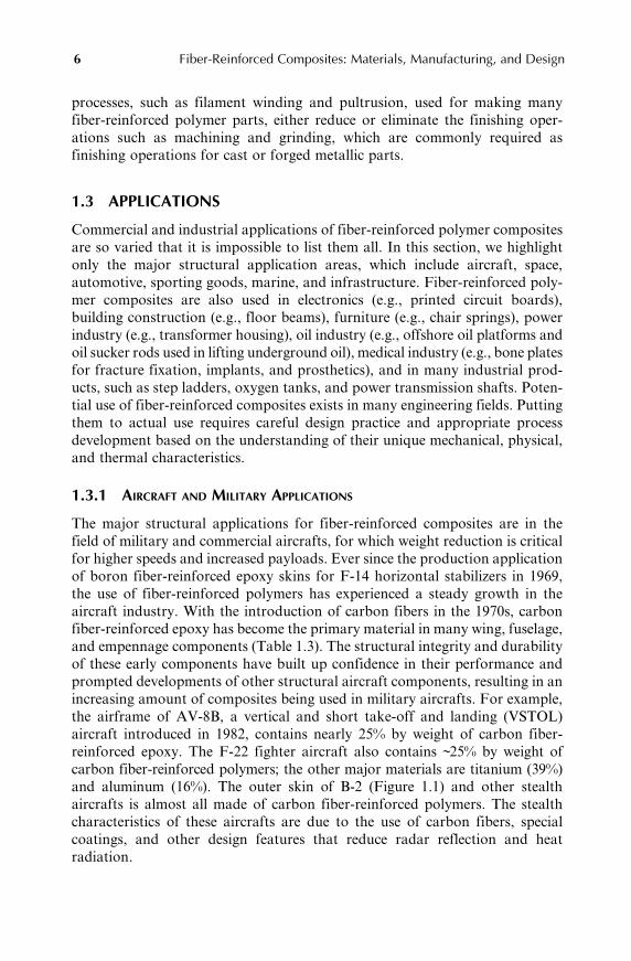
1.3 APPLICATIONS
Commercial and industrial applications of fiber-reinforced polymer composites
are so varied that it is impossible to list them all. In this section, we highlight
only the major structural application areas, which include aircraft, space,
automotive, sporting goods, marine, and infrastructure. Fiber-reinforced poly-
mer composites are also used in electronics (e.g., printed circuit boards),
building construction (e.g., floor beams), furniture (e.g., chair springs), power
industry (e.g., transformer housing), oil industry (e.g., offshore oil platforms and
oil sucker rods used in lifting underground oil), medical industry (e.g., bone plates
for fracture fixation, implants, and prosthetics), and in many industrial prod-
ucts, such as step ladders, oxygen tanks, and power transmission shafts. Poten-
tial use of fiber-reinforced composites exists in many engineering fields. Putting
them to actual use requires careful design practice and appropriate process
development based on the understanding of their unique mechanical, physical,
and thermal characteristics.
1.3.1 AIRCRAFT AND MILITARY APPLICATIONS
The major structural applications for fiber-reinforced composites are in the
field of military and commercial aircrafts, for which weight reduction is critical
for higher speeds and increased payloads. Ever since the production application
of boron fiber-reinforced epoxy skins for F-14 horizontal stabilizers in 1969,
the use of fiber-reinforced polymers has experienced a steady growth in the
aircraft industry. With the introduction of carbon fibers in the 1970s, carbon
fiber-reinforced epoxy has become the primary material in many wing, fuselage,
and empennage components (Table 1.3). The structural integrity and durability
of these early components have built up confidence in their performance and
prompted developments of other structural aircraft components, resulting in an
increasing amount of composites being used in military aircrafts. For example,
the airframe of AV-8B, a vertical and short take-off and landing (VSTOL)
aircraft introduced in 1982, contains nearly 25% by weight of carbon fiber-
reinforced epoxy. The F-22 fighter aircraft also contains ~25% by weight of
carbon fiber-reinforced polymers; the other major materials are titanium (39%)
and aluminum (16%). The outer skin of B-2 (Figure 1.1) and other stealth
aircrafts is almost all made of carbon fiber-reinforced polymers. The stealth
characteristics of these aircrafts are due to the use of carbon fibers, special
coatings, and other design features that reduce radar reflection and heat
radiation.
Mallick/Fiber-Reinforced Composites: Materials, Manufacturing, and Design 4205_C001 Final Proof page 6 30.9.2007 8:15pm Compositor Name: BMani
6 Fiber-Reinforced Composites: Materials, Manufacturing, and Design

The composite applications on commercial aircrafts began with a few
selective secondary structural components, all of which were made of a high-
strength carbon fiber-reinforced epoxy (Table 1.4). They were designed and
produced under the NASA Aircraft Energy Efficiency (ACEE) program and
were installed in various airplanes during 1972–1986 [1]. By 1987, 350 compos-
ite components were placed in service in various commercial aircrafts, and over
the next few years, they accumulated millions of flight hours. Periodic inspec-
tion and evaluation of these components showed some damages caused by
ground handling accidents, foreign object impacts, and lightning strikes.
TABLE 1.3Early Applications of Fiber-Reinforced Polymers in Military Aircrafts
Aircraft Component Material
Overall Weight
Saving Over
Metal Component (%)
F-14 (1969) Skin on the horizontal stabilizer
box
Boron fiber–epoxy 19
F-11 Under the wing fairings Carbon fiber–epoxy
F-15 (1975) Fin, rudder, and stabilizer skins Boron fiber–epoxy 25
F-16 (1977) Skins on vertical fin box, fin
leading edge
Carbon fiber–epoxy 23
F=A-18 (1978) Wing skins, horizontal and
vertical tail boxes; wing and
tail control surfaces, etc.
Carbon fiber–epoxy 35
AV-8B (1982) Wing skins and substructures;
forward fuselage; horizontal
stabilizer; flaps; ailerons
Carbon fiber–epoxy 25
Source: Adapted from Riggs, J.P., Mater. Soc., 8, 351, 1984.
FIGURE 1.1 Stealth aircraft (note that the carbon fibers in the construction of the
aircraft contributes to its stealth characteristics).
Mallick/Fiber-Reinforced Composites: Materials, Manufacturing, and Design 4205_C001 Final Proof page 7 30.9.2007 8:15pm Compositor Name: BMani
Introduction 7

Apart from these damages, there was no degradation of residual strengths due
to either fatigue or environmental exposure. A good correlation was found
between the on-ground environmental test program and the performance of the
composite components after flight exposure.
Airbus was the first commercial aircraft manufacturer to make extensive
use of composites in their A310 aircraft, which was introduced in 1987. The
composite components weighed about 10% of the aircraft’s weight and
included such components as the lower access panels and top panels of the
wing leading edge, outer deflector doors, nose wheel doors, main wheel leg
fairing doors, engine cowling panels, elevators and fin box, leading and
trailing edges of fins, flap track fairings, flap access doors, rear and forward
wing–body fairings, pylon fairings, nose radome, cooling air inlet fairings, tail
leading edges, upper surface skin panels above the main wheel bay, glide slope
antenna cover, and rudder. The composite vertical stabilizer, which is 8.3 m
high by 7.8 m wide at the base, is about 400 kg lighter than the aluminum
vertical stabilizer previously used [2]. The Airbus A320, introduced in 1988,
was the first commercial aircraft to use an all-composite tail, which includes
the tail cone, vertical stabilizer, and horizontal stabilizer. Figure 1.2 schemat-
ically shows the composite usage in Airbus A380 introduced in 2006. About
25% of its weight is made of composites. Among the major composite com-
ponents in A380 are the central torsion box (which links the left and right
wings under the fuselage), rear-pressure bulkhead (a dome-shaped partition
that separates the passenger cabin from the rear part of the plane that is not
pressurized), the tail, and the flight control surfaces, such as the flaps, spoilers,
and ailerons.
TABLE 1.4Early Applications of Fiber-Reinforced Polymers in Commercial Aircrafts
Aircraft Component Weight (lb)
Weight
Reduction (%) Comments
Boeing
727 Elevator face sheets 98 25 10 units installed in 1980
737 Horizontal stabilizer 204 22
737 Wing spoilers — 37 Installed in 1973
756 Ailerons, rudders,
elevators, fairings, etc.
3340 (total) 31
McDonnell-Douglas
DC-10 Upper rudder 67 26 13 units installed in 1976
DC-10 Vertical stabilizer 834 17
Lockheed
L-1011 Aileron 107 23 10 units installed in 1981
L-1011 Vertical stabilizer 622 25
Mallick/Fiber-Reinforced Composites: Materials, Manufacturing, and Design 4205_C001 Final Proof page 8 30.9.2007 8:15pm Compositor Name: BMani
8 Fiber-Reinforced Composites: Materials, Manufacturing, and Design

Starting with Boeing 777, which was first introduced in 1995, Boeing has
started making use of composites in the empennage (which include horizontal
stabilizer, vertical stabilizer, elevator, and rudder), most of the control surfaces,
engine cowlings, and fuselage floor beams (Figure 1.3). About 10% of Boeing
777’s structural weight is made of carbon fiber-reinforced epoxy and about 50%
is made of aluminum alloys. About 50% of the structural weight of Boeing’s
Outer wing
Ailerons
Flap track fairings
Outer flap
Radome
Fixed leading edgeupper and lower panels
Main landinggear leg fairing
door
Main andcenter landing
gear doors
Nose landinggear doors
Central torsion box
Pylonfairings,nacelles,
andcowlings
Pressurebulkhead
Keel beam
Tail cone
Verticalstabilizer
Horizontalstabilizer
Outer boxes
Over-wing panelBelly fairing skins
Trailing edge upper and lowerpanels and shroud box
Spoilers
Wing box
FIGURE 1.2 Use of fiber-reinforced polymer composites in Airbus 380.
Rudder
Fin torque box
Elevator
Stabilizer torque box
Floor beams
Wing landing gear doors
FlapsFlaperon
Inboard andoutboard spoilers
Engine cowlingsNose gear doorsNose radome
Strut–Fwd and aft fairing
Wing fixedleading edge
Outboard aileron
Outboard flap
Trailing edge panels
Leading andtrailing
edge panels
FIGURE 1.3 Use of fiber-reinforced polymer composites in Boeing 777.
Mallick/Fiber-Reinforced Composites: Materials, Manufacturing, and Design 4205_C001 Final Proof page 9 30.9.2007 8:15pm Compositor Name: BMani
Introduction 9

next line of airplanes, called the Boeing 787 Dreamliner, will be made of carbon
fiber-reinforced polymers. The other major materials in Boeing 787 will be
aluminum alloys (20%), titanium alloys (15%), and steel (10%). Two of the
major composite components in 787 will be the fuselage and the forward
section, both of which will use carbon fiber-reinforced epoxy as the major
material of construction.
There are several pioneering examples of using larger quantities of com-
posite materials in smaller aircrafts. One of these examples is the Lear Fan
2100, a business aircraft built in 1983, in which carbon fiber–epoxy and Kevlar
49 fiber–epoxy accounted for ~70% of the aircraft’s airframe weight. The
composite components in this aircraft included wing skins, main spar, fuselage,
empennage, and various control surfaces [3]. Another example is the Rutan
Voyager (Figure 1.4), which was an all-composite airplane and made the first-
ever nonstop flight around the world in 1986. To travel 25,000 miles without
refueling, the Voyager airplane had to be extremely light and contain as much
fuel as needed.
Fiber-reinforced polymers are used in many military and commercial heli-
copters for making baggage doors, fairings, vertical fins, tail rotor spars, and so
on. One key helicopter application of composite materials is the rotor blades.
Carbon or glass fiber-reinforced epoxy is used in this application. In addition to
significant weight reduction over aluminum, they provide a better control over
the vibration characteristics of the blades. With aluminum, the critical flopping
FIGURE 1.4 Rutan Voyager all-composite plane.
Mallick/Fiber-Reinforced Composites: Materials, Manufacturing, and Design 4205_C001 Final Proof page 10 30.9.2007 8:15pm Compositor Name: BMani
10 Fiber-Reinforced Composites: Materials, Manufacturing, and Design

and twisting frequencies are controlled principally by the classical method of
mass distribution [4]. With fiber-reinforced polymers, they can also be con-
trolled by varying the type, concentration, distribution, as well as orientation of
fibers along the blade’s chord length. Another advantage of using fiber-
reinforced polymers in blade applications is the manufacturing flexibility of
these materials. The composite blades can be filament-wound or molded into
complex airfoil shapes with little or no additional manufacturing costs, but
conventional metal blades are limited to shapes that can only be extruded,
machined, or rolled.
The principal reason for using fiber-reinforced polymers in aircraft and
helicopter applications is weight saving, which can lead to significant fuel
saving and increase in payload. There are several other advantages of using
them over aluminum and titanium alloys.
1. Reduction in the number of components and fasteners, which results in
a reduction of fabrication and assembly costs. For example, the vertical
fin assembly of the Lockheed L-1011 has 72% fewer components and
83% fewer fasteners when it is made of carbon fiber-reinforced epoxy
than when it is made of aluminum. The total weight saving is 25.2%.
2. Higher fatigue resistance and corrosion resistance, which result in a
reduction of maintenance and repair costs. For example, metal fins
used in helicopters flying near ocean coasts use an 18 month repair
cycle for patching corrosion pits. After a few years in service, the
patches can add enough weight to the fins to cause a shift in the center
of gravity of the helicopter, and therefore the fin must then be rebuilt or
replaced. The carbon fiber-reinforced epoxy fins do not require any
repair for corrosion, and therefore, the rebuilding or replacement cost
is eliminated.
3. The laminated construction used with fiber-reinforced polymers allows
the possibility of aeroelastically tailoring the stiffness of the airframe
structure. For example, the airfoil shape of an aircraft wing can be
controlled by appropriately adjusting the fiber orientation angle in
each lamina and the stacking sequence to resist the varying lift and
drag loads along its span. This produces a more favorable airfoil
shape and enhances the aerodynamic characteristics critical to the air-
craft’s maneuverability.
The key limiting factors in using carbon fiber-reinforced epoxy in aircraft
structures are their high cost, relatively low impact damage tolerance (from
bird strikes, tool drop, etc.), and susceptibility to lightning damage. When they
are used in contact with aluminum or titanium, they can induce galvanic
corrosion in the metal components. The protection of the metal components
from corrosion can be achieved by coating the contacting surfaces with a
corrosion-inhibiting paint, but it is an additional cost.
Mallick/Fiber-Reinforced Composites: Materials, Manufacturing, and Design 4205_C001 Final Proof page 11 30.9.2007 8:15pm Compositor Name: BMani
Introduction 11

1.3.2 SPACE APPLICATIONS
Weight reduction is the primary reason for using fiber-reinforced composites in
many space vehicles [5]. Among the various applications in the structure of
space shuttles are the mid-fuselage truss structure (boron fiber-reinforced alu-
minum tubes), payload bay door (sandwich laminate of carbon fiber-reinforced
epoxy face sheets and aluminum honeycomb core), remote manipulator arm
(ultrahigh-modulus carbon fiber-reinforced epoxy tube), and pressure vessels
(Kevlar 49 fiber-reinforced epoxy).
In addition to the large structural components, fiber-reinforced polymers are
used for support structures for many smaller components, such as solar arrays,
antennas, optical platforms, and so on [6]. A major factor in selecting them for
these applications is their dimensional stability over a wide temperature range.
Many carbon fiber-reinforced epoxy laminates can be ‘‘designed’’ to produce a
CTE close to zero. Many aerospace alloys (e.g., Invar) also have a comparable
CTE. However, carbon fiber composites have a much lower density, higher
strength, as well as a higher stiffness–weight ratio. Such a unique combination
ofmechanical properties andCTEhas led to a number of applications for carbon
fiber-reinforced epoxies in artificial satellites. One such application is found in
the support structure for mirrors and lenses in the space telescope [7]. Since the
temperature in space may vary between �1008C and 1008C, it is critically
important that the support structure be dimensionally stable; otherwise, large
changes in the relative positions of mirrors or lenses due to either thermal
expansion or distortion may cause problems in focusing the telescope.
Carbon fiber-reinforced epoxy tubes are used in building truss structures for
low earth orbit (LEO) satellites and interplanetary satellites. These truss structures
support optical benches, solar array panels, antenna reflectors, and othermodules.
Carbon fiber-reinforced epoxies are preferred over metals or metal matrix com-
posites because of their lower weight as well as very lowCTE.However, one of the
major concerns with epoxy-based composites in LEO satellites is that they are
susceptible to degradation due to atomic oxygen (AO) absorption from the
earth’s rarefied atmosphere. This problem is overcome by protecting the tubes
from AO exposure, for example, by wrapping them with thin aluminum foils.
Other concerns for using fiber-reinforced polymers in the space environ-
ment are the outgassing of the polymer matrix when they are exposed to
vacuum in space and embrittlement due to particle radiation. Outgassing can
cause dimensional changes and embrittlement may lead to microcrack forma-
tion. If the outgassed species are deposited on the satellite components, such as
sensors or solar cells, their function may be seriously degraded [8].
1.3.3 AUTOMOTIVE APPLICATIONS
Applications of fiber-reinforced composites in the automotive industry can be
classified into three groups: body components, chassis components, and engine
Mallick/Fiber-Reinforced Composites: Materials, Manufacturing, and Design 4205_C001 Final Proof page 12 30.9.2007 8:15pm Compositor Name: BMani
12 Fiber-Reinforced Composites: Materials, Manufacturing, and Design

components. Exterior body components, such as the hood or door panels,
require high stiffness and damage tolerance (dent resistance) as well as a
‘‘Class A’’ surface finish for appearance. The composite material used for
these components is E-glass fiber-reinforced sheet molding compound (SMC)
composites, in which discontinuous glass fibers (typically 25 mm in length) are
randomly dispersed in a polyester or a vinyl ester resin. E-glass fiber is used
instead of carbon fiber because of its significantly lower cost. The manufactur-
ing process used for making SMC parts is called compression molding. One of
the design requirements for many exterior body panels is the ‘‘Class A’’ surface
finish, which is not easily achieved with compression-molded SMC. This prob-
lem is usually overcome by in-mold coating of the exterior molded surface with
a flexible resin. However, there are many underbody and under-the-hood com-
ponents in which the external appearance is not critical. Examples of such
components in which SMC is used include radiator supports, bumper beams,
roof frames, door frames, engine valve covers, timing chain covers, oil pans, and
so on. Two of these applications are shown in Figures 1.5 and 1.6.
SMC has seen a large growth in the automotive industry over the last
25 years as it is used for manufacturing both small and large components,
such as hoods, pickup boxes, deck lids, doors, fenders, spoilers, and others, in
automobiles, light trucks, and heavy trucks. The major advantages of using
SMC instead of steel in these components include not only the weight reduc-
tion, but also lower tooling cost and parts integration. The tooling cost for
compression molding SMC parts can be 40%–60% lower than that for stamping
steel parts. An example of parts integration can be found in radiator supports
in which SMC is used as a substitution for low carbon steel. The composite
FIGURE 1.5 Compression-molded SMC trunk of Cadillac Solstice. (Courtesy of
Molded Fiber Glass and American Composites Alliance. With permission.)
Mallick/Fiber-Reinforced Composites: Materials, Manufacturing, and Design 4205_C001 Final Proof page 13 30.9.2007 8:15pm Compositor Name: BMani
Introduction 13

radiator support is typically made of two SMC parts bonded together by an
adhesive instead of 20 or more steel parts assembled together by large number
of screws. The material in the composite radiator support is randomly oriented
discontinuous E-glass fiber-reinforced vinyl ester. Another example of parts
integration can be found in the station wagon tailgate assembly [9], which has
significant load-bearing requirements in the open position. The composite
tailgate consists of two pieces, an outer SMC shell and an inner reinforcing
SMC piece. They are bonded together using a urethane adhesive. The compos-
ite tailgate replaces a seven-piece steel tailgate assembly, at about one-third its
weight. The material for both the outer shell and the inner reinforcement is a
randomly oriented discontinuous E-glass fiber-reinforced polyester.
Another manufacturing process for making composite body panels in the
automotive industry is called the structural reaction injection molding (SRIM).
The fibers in these parts are usually randomly oriented discontinuous E-glass
fibers and the matrix is a polyurethane or polyurea. Figure 1.7 shows the
photograph of a one-piece 2 m long cargo box that is molded using this process.
The wall thickness of the SRIM cargo box is 3 mm and its one-piece construc-
tion replaces four steel panels that are joined together using spot welds.
Among the chassis components, the first major structural application of
fiber-reinforced composites is the Corvette rear leaf spring, introduced first in
FIGURE 1.6 Compression-molded SMC valve cover for a truck engine. (Courtesy of
Ashland Chemicals and American Composites Alliance. With permission.)
Mallick/Fiber-Reinforced Composites: Materials, Manufacturing, and Design 4205_C001 Final Proof page 14 30.9.2007 8:15pm Compositor Name: BMani
14 Fiber-Reinforced Composites: Materials, Manufacturing, and Design

1981 [10]. Unileaf E-glass fiber-reinforced epoxy springs have been used to
replace multileaf steel springs with as much as 80% weight reduction. Other
structural chassis components, such as drive shafts and road wheels, have been
successfully tested in laboratories and proving grounds. They have also been
used in limited quantities in production vehicles. They offer opportunities for
substantial weight savings, but so far they have not proven to be cost-effective
over their steel counterparts.
The application of fiber-reinforced composites in engine components has
not been as successful as the body and chassis components. Fatigue loads at
very high temperatures pose the greatest challenge in these applications. Devel-
opment of high-temperature polymers as well as metal matrix or ceramic matrix
composites would greatly enhance the potential for composite usage in this area.
Manufacturing and design of fiber-reinforced composite materials for auto-
motive applications are significantly different from those for aircraft applica-
tions. One obvious difference is in the volume of production, which may range
from 100 to 200 pieces per hour for automotive components compared with a
few hundred pieces per year for aircraft components. Although the labor-
intensive hand layup followed by autoclave molding has worked well for
fabricating aircraft components, high-speed methods of fabrication, such as
compression molding and SRIM, have emerged as the principal manufacturing
process for automotive composites. Epoxy resin is the major polymer matrix
FIGURE 1.7 One-piece cargo box for a pickup truck made by the SRIM process.
Mallick/Fiber-Reinforced Composites: Materials, Manufacturing, and Design 4205_C001 Final Proof page 15 30.9.2007 8:15pm Compositor Name: BMani
Introduction 15

used in aerospace composites; however, the curing time for epoxy resin is very
long, which means the production time for epoxy matrix composites is also
very long. For this reason, epoxy is not considered the primary matrix
material in automotive composites. The polymer matrix used in automotive
applications is either a polyester, a vinyl ester, or polyurethane, all of which
require significantly lower curing time than epoxy. The high cost of carbon
fibers has prevented their use in the cost-conscious automotive industry.
Instead of carbon fibers, E-glass fibers are used in automotive composites
because of their significantly lower cost. Even with E-glass fiber-reinforced
composites, the cost-effectiveness issue has remained particularly critical, since
the basic material of construction in present-day automobiles is low-carbon
steel, which is much less expensive than most fiber-reinforced composites on a
unit weight basis.
Although glass fiber-reinforced polymers are the primary composite mater-
ials used in today’s automobiles, it is well recognized that significant vehicle
weight reduction needed for improved fuel efficiency can be achieved only with
carbon fiber-reinforced polymers, since they have much higher strength–weight
and modulus–weight ratios. The problem is that the current carbon fiber price,
at $16=kg or higher, is not considered cost-effective for automotive applica-
tions. Nevertheless, many attempts have been made in the past to manufacture
structural automotive parts using carbon fiber-reinforced polymers; unfortu-
nately most of them did not go beyond the stages of prototyping and structural
testing. Recently, several high-priced vehicles have started using carbon fiber-
reinforced polymers in a few selected components. One recent example of this is
seen in the BMW M6 roof panel (Figure 1.8), which was produced by a process
called resin transfer molding (RTM). This panel is twice as thick as a compar-
able steel panel, but 5.5 kg lighter. One added benefit of reducing the weight of
the roof panel is that it slightly lowers the center of gravity of the vehicle, which
is important for sports coupe.
Fiber-reinforced composites have become the material of choice in motor
sports where lightweight structure is used for gaining competitive advantage of
higher speed [11] and cost is not a major material selection decision factor. The
first major application of composites in race cars was in the 1950s when glass
fiber-reinforced polyester was introduced as replacement for aluminum body
panels. Today, the composite material used in race cars is mostly carbon fiber-
reinforced epoxy. All major body, chassis, interior, and suspension components
in today’s Formula 1 race cars use carbon fiber-reinforced epoxy. Figure 1.9
shows an example of carbon fiber-reinforced composite used in the gear box
and rear suspension of a Formula 1 race car. One major application of carbon
fiber-reinforced epoxy in Formula 1 cars is the survival cell, which protects the
driver in the event of a crash. The nose cone located in front of the survival cell
is also made of carbon fiber-reinforced epoxy. Its controlled crush behavior is
also critical to the survival of the driver.
Mallick/Fiber-Reinforced Composites: Materials, Manufacturing, and Design 4205_C001 Final Proof page 16 30.9.2007 8:15pm Compositor Name: BMani
16 Fiber-Reinforced Composites: Materials, Manufacturing, and Design

FIGURE 1.8 Carbon fiber-reinforced epoxy roof panel in BMW M6 vehicle. (Photo-
graph provided by BMW. With permission.)
FIGURE 1.9 Carbon fiber-reinforced epoxy suspension and gear box in a Formula 1
race car. (Courtesy of Bar 1 Formula 1 Racing Team. With permission.)
Mallick/Fiber-Reinforced Composites: Materials, Manufacturing, and Design 4205_C001 Final Proof page 17 30.9.2007 8:15pm Compositor Name: BMani
Introduction 17

1.3.4 SPORTING GOODS APPLICATIONS
Fiber-reinforced polymers are extensively used in sporting goods ranging
from tennis rackets to athletic shoes (Table 1.5) and are selected over such
traditional materials as wood, metals, and leather in many of these applications
[12]. The advantages of using fiber-reinforced polymers are weight reduction,
vibration damping, and design flexibility. Weight reduction achieved by substi-
tuting carbon fiber-reinforced epoxies for metals leads to higher speeds and
quickmaneuvering in competitive sports, such as bicycle races and canoe races.
In some applications, such as tennis rackets or snow skis, sandwich construc-
tions of carbon or boron fiber-reinforced epoxies as the skin material and a
soft, lighter weight urethane foam as the corematerial produces a higher weight
reduction without sacrificing stiffness. Faster damping of vibrations provided
by fiber-reinforced polymers reduces the shock transmitted to the player’s arm
in tennis or racket ball games and provides a better ‘‘feel’’ for the ball. In
archery bows and pole-vault poles, the high stiffness–weight ratio of fiber-
reinforced composites is used to store high elastic energy per unit weight, which
helps in propelling the arrow over a longer distance or the pole-vaulter to jump
a greater height. Some of these applications are described later.
Bicycle frames for racing bikes today are mostly made of carbon fiber-
reinforced epoxy tubes, fitted together by titanium fittings and inserts. An
example is shown in Figure 1.10. The primary purpose of using carbon fibers is
TABLE 1.5Applications of Fiber-Reinforced Polymers
in Sporting Goods
Tennis rackets
Racket ball rackets
Golf club shafts
Fishing rods
Bicycle frames
Snow and water skis
Ski poles, pole vault poles
Hockey sticks
Baseball bats
Sail boats and kayaks
Oars, paddles
Canoe hulls
Surfboards, snow boards
Arrows
Archery bows
Javelins
Helmets
Exercise equipment
Athletic shoe soles and heels
Mallick/Fiber-Reinforced Composites: Materials, Manufacturing, and Design 4205_C001 Final Proof page 18 30.9.2007 8:15pm Compositor Name: BMani
18 Fiber-Reinforced Composites: Materials, Manufacturing, and Design

weight saving (the average racing bicycle weight has decreased from about 9 kg in
the 1980s to 1.1 kg in 1990s); however, to reduce material cost, carbon fibers are
sometimes combined with glass or Kevlar 49 fibers. Fiber-reinforced polymer
wrapped around thin-walled metal tube is not also uncommon. The ancillary
components, such as handlebars, forks, seat post, and others, also use carbon
fiber-reinforced polymers.
Golf clubs made of carbon fiber-reinforced epoxy are becoming increasingly
popular among professional golfers. The primary reason for the composite golf
shaft’s popularity is its low weight compared with steel golf shafts. The average
weight of a composite golf shaft is 65–70 g compared with 115–125 g for steel
shafts. Weight reduction in the golf club shaft allows the placement of add-
itional weight in the club head, which results in faster swing and longer drive.
Glass fiber-reinforced epoxy is preferred over wood and aluminum in pole-
vault poles because of its high strain energy storage capacity. A good pole must
have a reasonably high stiffness (to keep it from flapping excessively during
running before jumping) and high elastic limit stress so that the strain energy of
the bent pole can be recovered to propel the athlete above the horizontal bar.
As the pole is bent to store the energy, it should not show any plastic deform-
ation and should not fracture. The elastic limit of glass fiber-reinforced epoxy
is much higher than that of either wood or high-strength aluminum alloys.
With glass fiber-reinforced epoxy poles, the stored energy is high enough to
clear 6 m or greater height in pole vaulting. Carbon fiber-reinforced epoxy is
not used, since it is prone to fracture at high bending strains.
FIGURE 1.10 Carbon fiber-reinforced epoxy bicycle frame. (Photograph provided by
Trek Bicycle Corporation. With permission.)
Mallick/Fiber-Reinforced Composites: Materials, Manufacturing, and Design 4205_C001 Final Proof page 19 30.9.2007 8:15pm Compositor Name: BMani
Introduction 19

Glass and carbon fiber-reinforced epoxy fishing rods are very common
today, even though traditional materials, such as bamboo, are still used. For
fly-fishing rods, carbon fiber-reinforced epoxy is preferred, since it produces a
smaller tip deflection (because of its higher modulus) and ‘‘wobble-free’’ action
during casting. It also dampens the vibrations more rapidly and reduces the
transmission of vibration waves along the fly line. Thus, the casting can be
longer, quieter, and more accurate, and the angler has a better ‘‘feel’’ for the
catch. Furthermore, carbon fiber-reinforced epoxy rods recover their original
shape much faster than the other rods. A typical carbon fiber-reinforced epoxy
rod of No. 6 or No. 7 line weighs only 37 g. The lightness of these rods is also a
desirable feature to the anglers.
1.3.5 MARINE APPLICATIONS
Glass fiber-reinforced polyesters have been used in different types of boats (e.g.,
sail boats, fishing boats, dinghies, life boats, and yachts) ever since their
introduction as a commercial material in the 1940s [13]. Today, nearly 90% of
all recreational boats are constructed of either glass fiber-reinforced polyester or
glass fiber-reinforced vinyl ester resin. Among the applications are hulls, decks,
and various interior components. The manufacturing process used for making a
majority of these components is called contact molding. Even though it is
a labor-intensive process, the equipment cost is low, and therefore it is afford-
able to many of the small companies that build these boats. In recent years,
Kevlar 49 fiber is replacing glass fibers in some of these applications because of its
higher tensile strength–weight and modulus–weight ratios than those of glass
fibers. Among the application areas are boat hulls, decks, bulkheads, frames,
masts, and spars. The principal advantage is weight reduction, which translates
into higher cruising speed, acceleration, maneuverability, and fuel efficiency.
Carbon fiber-reinforced epoxy is used in racing boats in which weight
reduction is extremely important for competitive advantage. In these boats,
the complete hull, deck, mast, keel, boom, and many other structural compon-
ents are constructed using carbon fiber-reinforced epoxy laminates and sand-
wich laminates of carbon fiber-reinforced epoxy skins with either honeycomb
core or plastic foam core. Carbon fibers are sometimes hybridized with other
lower density and higher strain-to-failure fibers, such as high-modulus poly-
ethylene fibers, to improve impact resistance and reduce the boat’s weight.
The use of composites in naval ships started in the 1950s and has grown
steadily since then [14]. They are used in hulls, decks, bulkheads, masts,
propulsion shafts, rudders, and others of mine hunters, frigates, destroyers,
and aircraft carriers. Extensive use of fiber-reinforced polymers can be seen in
Royal Swedish Navy’s 72 m long, 10.4 m wide Visby-class corvette, which is the
largest composite ship in the world today. Recently, the US navy has commis-
sioned a 24 m long combat ship, called Stiletto, in which carbon fiber-
reinforced epoxy will be the primary material of construction. The selection
Mallick/Fiber-Reinforced Composites: Materials, Manufacturing, and Design 4205_C001 Final Proof page 20 30.9.2007 8:15pm Compositor Name: BMani
20 Fiber-Reinforced Composites: Materials, Manufacturing, and Design

of carbon fiber-reinforced epoxy is based on the design requirements of light-
weight and high strength needed for high speed, maneuverability, range, and
payload capacity of these ships. Their stealth characteristics are also important
in minimizing radar reflection.
1.3.6 INFRASTRUCTURE
Fiber-reinforced polymers have a great potential for replacing reinforced con-
crete and steel in bridges, buildings, and other civil infrastructures [15]. The
principal reason for selecting these composites is their corrosion resistance,
which leads to longer life and lower maintenance and repair costs. Reinforced
concrete bridges tend to deteriorate after several years of use because of
corrosion of steel-reinforcing bars (rebars) used in their construction. The
corrosion problem is exacerbated because of deicing salt spread on the bridge
road surface in winter months in many parts of the world. The deterioration
can become so severe that the concrete surrounding the steel rebars can start to
crack (due to the expansion of corroding steel bars) and ultimately fall off, thus
weakening the structure’s load-carrying capacity. The corrosion problem does
not exist with fiber-reinforced polymers. Another advantage of using fiber-
reinforced polymers for large bridge structures is their lightweight, which
means lower dead weight for the bridge, easier transportation from the pro-
duction factory (where the composite structure can be prefabricated) to the
bridge location, easier hauling and installation, and less injuries to people in
case of an earthquake. With lightweight construction, it is also possible to
design bridges with longer span between the supports.
One of the early demonstrations of a composite traffic bridge was made in
1995 by Lockheed Martin Research Laboratories in Palo Alto, California. The
bridge deck was a 9 m long3 5.4 m wide quarter-scale section and the material
selected was E-glass fiber-reinforced polyester. The composite deck was a
sandwich laminate of 15 mm thick E-glass fiber-reinforced polyester face sheets
and a series of E-glass fiber-reinforced polyester tubes bonded together to form
the core. The deck was supported on three U-shaped beams made of E-glass
fabric-reinforced polyester. The design was modular and the components were
stackable, which simplified both their transportation and assembly.
In recent years, a number of composite bridge decks have been constructed
and commissioned for service in the United States and Canada. The Wickwire
Run Bridge located in West Virginia, United States is an example of one such
construction. It consists of full-depth hexagonal and half-depth trapezoidal
profiles made of glass fabric-reinforced polyester matrix. The profiles are
supported on steel beams. The road surface is a polymer-modified concrete.
Another example of a composite bridge structure is shown in Figure 1.11,
which replaced a 73 year old concrete bridge with steel rebars. The replacement
was necessary because of the severe deterioration of the concrete deck, which
reduced its load rating from 10 to only 4.3 t and was posing safety concerns. In
Mallick/Fiber-Reinforced Composites: Materials, Manufacturing, and Design 4205_C001 Final Proof page 21 30.9.2007 8:15pm Compositor Name: BMani
Introduction 21

the composite bridge, the internal reinforcement for the concrete deck is a two-
layer construction and consists primarily of pultruded I-section bars (I-bars) in
the width direction (perpendicular to the direction of traffic) and pultruded
round rods in the length directions. The material for the pultruded sections is
glass fiber-reinforced vinyl ester. The internal reinforcement is assembled by
inserting the round rods through the predrilled holes in I-bar webs and keeping
them in place by vertical connectors.
Besides new bridge construction or complete replacement of reinforced
concrete bridge sections, fiber-reinforced polymer is also used for upgrading,
retrofitting, and strengthening damaged, deteriorating, or substandard concrete
or steel structures [16]. For upgrading, composite strips and plates are
attached in the cracked or damaged areas of the concrete structure using adhe-
sive, wet layup, or resin infusion. Retrofitting of steel girders is accomplished
View from the top showing roundcomposite cross-rods inserted in thepredrilled holes in composite I-bars
placed in the direction of trafffic
FIGURE 1.11 Glass fiber-reinforced vinyl ester pultruded sections in the construction of
a bridge deck system. (Photograph provided by Strongwell Corporation.With permission.)
Mallick/Fiber-Reinforced Composites: Materials, Manufacturing, and Design 4205_C001 Final Proof page 22 30.9.2007 8:15pm Compositor Name: BMani
22 Fiber-Reinforced Composites: Materials, Manufacturing, and Design

by attaching composite plates to their flanges, which improves the flange stiff-
ness and strength. The strengthening of reinforced concrete columns in earth-
quake prone areas is accomplished by wrapping them with fiber-reinforced
composite jackets in which the fibers are primarily in the hoop direction. They
are found to be better than steel jackets, since, unlike steel jackets, they do not
increase the longitudinal stiffness of the columns. They are also much easier to
install and they do not corrode like steel.
1.4 MATERIAL SELECTION PROCESS
Material selection is one of the most important and critical steps in the
structural or mechanical design process. If the material selection is not done
properly, the design may show poor performance; may require frequent main-
tenance, repair, or replacement; and in the extreme, may fail, causing damage,
injuries, or fatalities. The material selection process requires the knowledge of
the performance requirements of the structure or component under consider-
ation. It also requires the knowledge of
1. Types of loading, for example, axial, bending, torsion, or combination
thereof
2. Mode of loading, for example, static, fatigue, impact, shock, and so on
3. Service life
4. Operating or service environment, for example, temperature, humidity
conditions, presence of chemicals, and so on
5. Other structures or components with which the particular design under
consideration is required to interact
6. Manufacturing processes that can be used to produce the structure or
the component
7. Cost, which includes not only the material cost, but also the cost of
transforming the selected material to the final product, that is, the
manufacturing cost, assembly cost, and so on
The material properties to consider in the material selection process depend on
the performance requirements (mechanical, thermal, etc.) and the possible
mode or modes of failure (e.g., yielding, brittle fracture, ductile failure, buck-
ling, excessive deflection, fatigue, creep, corrosion, thermal failure due to over-
heating, etc.). Two basic material properties often used in the preliminary
selection of materials for a structural or mechanical design are the modulus
and strength. For a given design, the modulus is used for calculating the
deformation, and the strength is used for calculating the maximum load-carrying
capacity. Which property or properties should be considered in making a
preliminary material selection depends on the application and the possible
failure modes. For example, yield strength is considered if the design of
a structure requires that no permanent deformation occurs because of the
Mallick/Fiber-Reinforced Composites: Materials, Manufacturing, and Design 4205_C001 Final Proof page 23 30.9.2007 8:15pm Compositor Name: BMani
Introduction 23

application of the load. If, on the other hand, there is a possibility of brittle
failure because of the influence of the operating environmental conditions,
fracture toughness is the material property to consider.
In many designs the performance requirement may include stiffness, which
is defined as load per unit deformation. Stiffness should not be confused with
modulus, since stiffness depends not only on the modulus of the material
(which is a material property), but also on the design. For example, the stiffness
of a straight beam with solid circular cross section depends not only on the
modulus of the material, but also on its length, diameter, and how it is
supported (i.e., boundary conditions). For a given beam length and support
conditions, the stiffness of the beam with solid circular cross section is propor-
tional to Ed 4, where E is the modulus of the beam material and d is its diameter.
Therefore, the stiffness of this beam can be increased by either selecting a higher
modulus material, or increasing the diameter, or doing both. Increasing the
diameter is more effective in increasing the stiffness, but it also increases
the weight and cost of the beam. In some designs, it may be possible to increase
the beam stiffness by incorporating other design features, such as ribs, or by
using a sandwich construction.
In designing structures with minimum mass or minimum cost, material
properties must be combined with mass density (r), cost per unit mass ($=kg),and so on. For example, if the design objective for a tension linkage or a tie bar
is to meet the stiffness performance criterion with minimum mass, the material
selection criterion involves not just the tensile modulus of the material (E), but
also the modulus–density ratio (E=r). The modulus–density ratio is a material
index, and the material that produces the highest value of this material index
should be selected for minimum mass design of the tension link. The material
index depends on the application and the design objective. Table 1.6 lists the
material indices for minimum mass design of a few simple structures.
As an example of the use of the material index in preliminary material
selection, consider the carbon fiber–epoxy quasi-isotropic laminate in Table 1.1.
Thin laminates of this type are considered well-suited for many aerospace
applications [1], since they exhibit equal elastic properties (e.g., modulus) in
all directions in the plane of load application. The quasi-isotropic laminate
in Table 1.1 has an elastic modulus of 45.5 GPa, which is 34% lower than that
of the 7178-T6 aluminum alloy and 59% lower than that of the Ti-6 Al-4V
titanium alloy. The aluminum and the titanium alloys are the primary metallic
alloys used in the construction of civilian and military aircrafts. Even though
the quasi-isotropic carbon fiber–epoxy composite laminate has a lower modulus,
it is a good candidate for substituting the metallic alloys in stiffness-critical
aircraft structures. This is because the carbon fiber–epoxy quasi-isotropic
laminate has a superior material index in minimum mass design of stiffness-
critical structures. This can be easily verified by comparing the values of
the material index E1=3
r of all three materials, assuming that the structure can
be modeled as a thin plate under bending load.
Mallick/Fiber-Reinforced Composites: Materials, Manufacturing, and Design 4205_C001 Final Proof page 24 30.9.2007 8:15pm Compositor Name: BMani
24 Fiber-Reinforced Composites: Materials, Manufacturing, and Design

Weight reduction is often the principal consideration for selecting fiber-
reinforced polymers over metals, and for many applications, they provide a
higher material index than metals, and therefore, suitable for minimum mass
design. Depending on the application, there are other advantages of using fiber-
reinforced composites, such as higher damping, no corrosion, parts integration,
control of thermal expansion, and so on, that should be considered as well, and
some of these advantages add value to the product that cannot be obtained
with metals. One great advantage is the tailoring of properties according to the
design requirements, which is demonstrated in the example of load-bearing
orthopedic implants [17]. One such application is the bone plate used for bone
fracture fixation. In this application, the bone plate is attached to the bone
fracture site with screws to hold the fractured pieces in position, reduce the
mobility at the fracture interface, and provide the required stress-shielding of
the bone for proper healing. Among the biocompatible materials used for
orthopedic implants, stainless steel and titanium are the two most common
materials used for bone plates. However, the significantly higher modulus of
both of these materials than that of bone creates excessive stress-shielding, that is,
they share the higher proportion of the compressive stresses during healing than
the bone. The advantage of using fiber-reinforced polymers is that they can be
designed to match the modulus of bone, and indeed, this is the reason for
TABLE 1.6Material Index for Stiffness and Strength-Critical Designs at Minimum Mass
Structure Constraints
Design
Variable
Material Index
Stiffness-Critical
Design
Strength-Critical
Design
Round tie bar loaded
in axial tension
Length fixed DiameterE
r
Sf
r
Rectangular beam loaded
in bending
Length and
width fixed
HeightE1=3
r
S1=2f
r
Round bar or shaft loaded
in torsion
Length fixed DiameterG1=2
r
S2=3f
r
Flat plate loaded in
bending
Length and
width fixed
ThicknessE1=3
r
S1=2f
r
Round column loaded
in compression
Length DiameterE1=2
r
Sf
r
Source: Adapted from Ashby, M.F., Material Selection in Mechanical Design, 3rd Ed., Elsevier,
Oxford, UK, 2005.
Note: r¼mass density, E¼Young’s modulus, G¼ shear modulus, and Sf¼ strength.
Mallick/Fiber-Reinforced Composites: Materials, Manufacturing, and Design 4205_C001 Final Proof page 25 30.9.2007 8:15pm Compositor Name: BMani
Introduction 25

selecting carbon fiber-reinforced epoxy or polyether ether ketone (PEEK) for
such an application [18,19].
REFERENCES
1. C.E. Harris, J.H. Starnes, Jr., and M.J. Shuart, Design and manufacturing of
aerospace composite structures, state-of-the-art assessment, J. Aircraft, 39:545
(2002).
2. C. Soutis, Carbon fiber reinforced plastics in aircraft applications, Mater. Sci. Eng.,
A, 412:171 (2005).
3. J.V. Noyes, Composites in the construction of the Lear Fan 2100 aircraft, Compos-
ites, 14:129 (1983).
4. R.L. Pinckney, Helicopter rotor blades, Appl. Composite Mat., ASTM STP, 524:108
(1973).
5. N.R. Adsit, Composites for space applications, ASTM Standardization News,
December (1983).
6. H. Bansemir and O.Haider, Fibre composite structures for space applications—recent
and future developments, Cryogenics, 38:51 (1998).
7. E.G. Wolff, Dimensional stability of structural composites for spacecraft applica-
tions, Metal Prog., 115:54 (1979).
8. J. Guthrie, T.B. Tolle, and D.H. Rose, Composites for orbiting platforms, AMP-
TIAC Q., 8:51 (2004).
9. D.A. Riegner, Composites in the automotive industry, ASTM Standardization
News, December (1983).
10. P. Beardmore, Composite structures for automobiles, Compos. Struct., 5:163 (1986).
11. G. Savage, Composite materials in Formula 1 racing, Metals Mater., 7:617 (1991).
12. V.P. McConnell, Application of composites in sporting goods, Comprehensive Com-
posite Materials, Vol. 6, Elsevier, Amsterdam, pp. 787–809 (2000).
13. W. Chalmers, The potential for the use of composite materials in marine structures,
Mar. Struct., 7:441 (1994).
14. A.P. Mouritz, E. Gellert, P. Burchill, and K. Challis, Review of advanced composite
structures for naval ships and submarines, Compos. Struct., 53:21 (2001).
15. L.C. Hollaway, The evolution of and the way forward for advanced polymer
composites in the civil infrastructure, Construct. Build. Mater., 17:365 (2003).
16. V.M. Karbhari, Fiber reinforced composite bridge systems—transition from the
laboratory to the field, Compos. Struct., 66:5 (2004).
17. S.L. Evans and P.J. Gregson, Composite technology in load-bearing orthopedic
implants, Biomaterials, 19:1329 (1998).
18. M.S. Ali, T.A. French, G.W. Hastings, T. Rae, N. Rushton, E.R.S. Ross, and
C.H. Wynn-Jones, Carbon fibre composite bone plates, J. Bone Joint Surg.,
72-B:586 (1990).
19. Z.-M. Huang and K. Fujihara, Stiffness and strength design of composite bone
plate, Compos. Sci. Tech., 65:73 (2005).
Mallick/Fiber-Reinforced Composites: Materials, Manufacturing, and Design 4205_C001 Final Proof page 26 30.9.2007 8:15pm Compositor Name: BMani
26 Fiber-Reinforced Composites: Materials, Manufacturing, and Design

PROBLEMS*
P1.1. The modulus and tensile strength of a SMC composite are reported as
15 GPa and 230 MPa, respectively. Assuming that the density of the
SMC is 1.85 g=cm3, calculate the strength–weight ratio and modulus–
weight ratio for the composite.
P1.2. The material of a tension member is changed from AISI 4340 steel to a
unidirectional high-modulus (HM) carbon fiber-reinforced epoxy.
1. Calculate the ratio of the cross-sectional areas, axial stiffnesses, and
weights of these two members for equal load-carrying capacities
2. Calculate the ratio of the cross-sectional areas, load-carrying cap-
acities, and weights of these two members for equal axial stiffness
(Hint: Load¼ strength3 cross-sectional area, and axial stiffness¼modulus 3 cross-sectional area)
P1.3. Compare the heights and weights of three rectangular beams made of
aluminum alloy 6061-T6, titanium alloy Ti-6Al-4V, and a unidirectional
high-strength (HS) carbon fiber-reinforced epoxy designed to posses (a)
equal bending stiffness and (b) equal bending moment carrying capacity.
Assume that all three beams have the same length and width. (Hint: The
bending stiffness is proportional to Eh3 and the bending moment is
proportional to Sh2, where E, S, and h are the modulus, strength, and
height, respectively.)
P1.4. Calculate the flexural (bending) stiffness ratio of two cantilever beams
of equal weight, one made of AISI 4340 steel and the other made of a
unidirectional high-modulus carbon fiber–epoxy composite. Assume
that both beams have the same length and width, but different heights.
If the beams were simply supported instead of fixed at one end like a
cantilever beam, how will the ratio change?
P1.5. In a certain application, a steel beam of round cross section (dia-
meter¼ 10 mm) is to be replaced by a unidirectional fiber-reinforced
epoxy beam of equal length. The composite beam is designed to have a
natural frequency of vibration 25% higher than that of the steel beam.
Among the fibers to be considered are high-strength carbon fiber, high-
modulus carbon fiber, and Kevlar 49 (see Table 1.1). Select one of these
fibers on the basis of minimum weight for the beam.
Note that the natural frequency of vibration of a beam is given by
the following equation:
*Use Table 1.1 for material properties if needed.
Mallick/Fiber-Reinforced Composites: Materials, Manufacturing, and Design 4205_C001 Final Proof page 27 30.9.2007 8:15pm Compositor Name: BMani
Introduction 27

wn ¼ CEI
mL4
� �1=2
,
where
wn¼ fundamental natural frequency
C ¼ a constant that depends on the beam support conditions
E ¼modulus of the beam material
I ¼moment of inertia of the beam cross section
m ¼mass per unit length of the beam
L ¼ beam length
P1.6. The material of a thin flat panel is changed from SAE 1010 steel panel
(thickness¼ 1.5 mm) an E-glass fiber-reinforced polyester SMC panel
with equal flexural stiffness. Calculate the percentage weight and cost
differences between the two panels. Note that the panel stiffness is
Eh3
12(1� n2), where E is the modulus of the panel material, n is the
Poisson’s ratio of the panel material, and h is the panel thickness. The
following is known for the two materials:
Steel SMC
Modulus (GPa) 207 16
Poisson’s ratio 0.30 0.30
Density (g=cm3) 7.87 1.85
Cost ($=kg) 0.80 1.90
Suggest an alternative design approach by which the wall thickness of the
flat SMC panel can be reduced without lowering its flexural stiffness.
P1.7. To reduce the material cost, an engineer decides to use a hybrid beam
instead of an all-carbon fiber beam. Both beams have the same overall
dimensions. The hybrid beam contains carbon fibers in the outer layers
and either E-glass or Kevlar 49 fibers in the core. The matrix used is an
epoxy. Costs of these materials are as follows:
Carbon fiber–epoxy matrix: $25.00=lbE-glass fiber–epoxy matrix: $1.20=lbKevlar 49 fiber–epoxy matrix: $8.00=lb
The total carbon fiber–epoxy thickness in the hybrid beam is equal to the
core thickness. Compare the percentage weight penalty and cost savings
for each hybrid beam over an all-carbon fiber beam. Do you expect both
all-carbon and hybrid beams to have the same bending stiffness? If the
answer is ‘‘no,’’ what can be done to make the two stiffnesses equal?
Mallick/Fiber-Reinforced Composites: Materials, Manufacturing, and Design 4205_C001 Final Proof page 28 30.9.2007 8:15pm Compositor Name: BMani
28 Fiber-Reinforced Composites: Materials, Manufacturing, and Design

P1.8. The shear modulus (G) of steel and a quasi-isotropic carbon fiber–
epoxy is 78 and 17 GPa, respectively. The mean diameter (D) of a
thin-walled steel torque tube is 25 mm and its wall thickness (t) is 3 mm.
Knowing that the torsional stiffness of a thin-walled tube is propor-
tional to D3tG, calculate:
1. Mean diameter of a composite tube that has the same torsional
stiffness and wall thickness as the steel tube
2. Wall thickness of a composite tube that has the same torsional
stiffness and mean diameter as the steel tube
3. Difference in weight (in percentage) between the steel tube and the
composite tube in each of the previous cases, assuming equal length
for both tubes
P1.9. Using the information in Problem P1.8, design a composite torque tube
that is 30% lighter than the steel tube but has the same torsional
stiffness. Will the axial stiffnesses of these two tubes be the same?
P1.10. Write the design and material selection considerations for each of the
following applications and discuss why fiber-reinforced polymers can
be a good candidate material for each application.
1. Utility poles
2. Aircraft floor panels
3. Aircraft landing gear doors
4. Household step ladders
5. Wind turbine blades
6. Suspension arms of an automobile
7. Drive shaft of an automobile
8. Underground gasoline storage tanks
9. Hydrogen storage tanks for fuel cell vehicles
10. Leg prosthetic
11. Flywheel for energy storage
Mallick/Fiber-Reinforced Composites: Materials, Manufacturing, and Design 4205_C001 Final Proof page 29 30.9.2007 8:16pm Compositor Name: BMani
Introduction 29

Mallick/Fiber-Reinforced Composites: Materials, Manufacturing, and Design 4205_C001 Final Proof page 30 30.9.2007 8:16pm Compositor Name: BMani

References
1 Chapter 1. Introduction
1. C.E. Harris, J.H. Starnes, Jr., and M.J. Shuart, Designand manufacturing of aerospace composite structures,state-of-the-art assessment, J. Aircraft, 39:545 (2002).
2. C. Soutis, Carbon fiber reinforced plastics in aircraftapplications,Mater. Sci. Eng., A, 412:171 (2005).
3. J.V. Noyes, Composites in the construction of the LearFan 2100 aircraft, Composites, 14:129 (1983).
4. R.L. Pinckney, Helicopter rotor blades, Appl. CompositeMat., ASTM STP, 524:108 (1973).
5. N.R. Adsit, Composites for space applications, ASTMStandardization News, December (1983).
6. H. Bansemir and O.Haider, Fibre composite structures forspace applications—recent and future developments,Cryogenics, 38:51 (1998).
7. E.G. Wolff, Dimensional stability of structuralcomposites for spacecraft applications, Metal Prog., 115:54(1979).
8. J. Guthrie, T.B. Tolle, and D.H. Rose, Composites fororbiting platforms, AMPTIAC Q., 8:51 (2004).
9. D.A. Riegner, Composites in the automotive industry,ASTM Standardization News, December (1983).
10. P. Beardmore, Composite structures for automobiles,Compos. Struct., 5:163 (1986).
11. G. Savage, Composite materials in Formula 1 racing,Metals Mater., 7:617 (1991).
12. V.P. McConnell, Application of composites in sportinggoods, Comprehensive Composite Materials, Vol. 6, Elsevier,Amsterdam, pp. 787–809 (2000).
13. W. Chalmers, The potential for the use of compositematerials in marine structures, Mar. Struct., 7:441 (1994).
14. A.P. Mouritz, E. Gellert, P. Burchill, and K. Challis,Review of advanced composite structures for naval ships andsubmarines, Compos. Struct., 53:21 (2001).
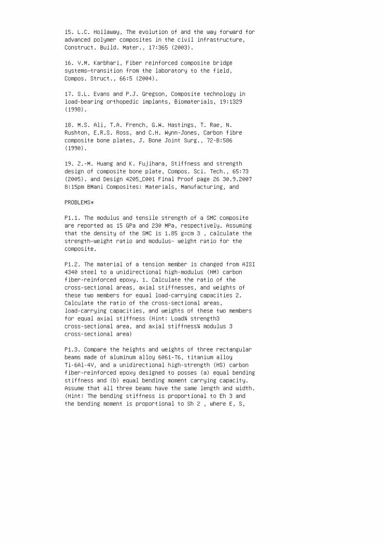
15. L.C. Hollaway, The evolution of and the way forward foradvanced polymer composites in the civil infrastructure,Construct. Build. Mater., 17:365 (2003).
16. V.M. Karbhari, Fiber reinforced composite bridgesystems—transition from the laboratory to the field,Compos. Struct., 66:5 (2004).
17. S.L. Evans and P.J. Gregson, Composite technology inload-bearing orthopedic implants, Biomaterials, 19:1329(1998).
18. M.S. Ali, T.A. French, G.W. Hastings, T. Rae, N.Rushton, E.R.S. Ross, and C.H. Wynn-Jones, Carbon fibrecomposite bone plates, J. Bone Joint Surg., 72-B:586(1990).
19. Z.-M. Huang and K. Fujihara, Stiffness and strengthdesign of composite bone plate, Compos. Sci. Tech., 65:73(2005). and Design 4205_C001 Final Proof page 26 30.9.20078:15pm BMani Composites: Materials, Manufacturing, and
PROBLEMS*
P1.1. The modulus and tensile strength of a SMC compositeare reported as 15 GPa and 230 MPa, respectively. Assumingthat the density of the SMC is 1.85 g=cm 3 , calculate thestrength–weight ratio and modulus– weight ratio for thecomposite.
P1.2. The material of a tension member is changed from AISI4340 steel to a unidirectional high-modulus (HM) carbonfiber-reinforced epoxy. 1. Calculate the ratio of thecross-sectional areas, axial stiffnesses, and weights ofthese two members for equal load-carrying capacities 2.Calculate the ratio of the cross-sectional areas,load-carrying capacities, and weights of these two membersfor equal axial stiffness (Hint: Load¼ strength3cross-sectional area, and axial stiffness¼ modulus 3cross-sectional area)
P1.3. Compare the heights and weights of three rectangularbeams made of aluminum alloy 6061-T6, titanium alloyTi-6Al-4V, and a unidirectional high-strength (HS) carbonfiber-reinforced epoxy designed to posses (a) equal bendingstiffness and (b) equal bending moment carrying capacity.Assume that all three beams have the same length and width.(Hint: The bending stiffness is proportional to Eh 3 andthe bending moment is proportional to Sh 2 , where E, S,

and h are the modulus, strength, and height, respectively.)
P1.4. Calculate the flexural (bending) stiffness ratio oftwo cantilever beams of equal weight, one made of AISI 4340steel and the other made of a unidirectional high-moduluscarbon fiber–epoxy composite. Assume that both beams havethe same length and width, but different heights. If thebeams were simply supported instead of fixed at one endlike a cantilever beam, how will the ratio change?
P1.5. In a certain application, a steel beam of round crosssection (diameter¼ 10 mm) is to be replaced by aunidirectional fiber-reinforced epoxy beam of equal length.The composite beam is designed to have a natural frequencyof vibration 25% higher than that of the steel beam. Amongthe fibers to be considered are high-strength carbon fiber,highmodulus carbon fiber, and Kevlar 49 (see Table 1.1).Select one of these fibers on the basis of minimum weightfor the beam. Note that the natural frequency of vibrationof a beam is given by the following equation:
*Use Table 1.1 for material properties if needed. andDesign 4205_C001 Final Proof page 27 30.9.2007 8:15pm BManiw n ¼ C EI mL 4 1=2 , where w n ¼ fundamental naturalfrequency C ¼ a constant that depends on the beam supportconditions E ¼modulus of the beam material I ¼moment ofinertia of the beam cross section m ¼mass per unit lengthof the beam L ¼ beam length
P1.6. The material of a thin flat panel is changed from SAE1010 steel panel (thickness¼ 1.5 mm) an E-glassfiber-reinforced polyester SMC panel with equal flexuralstiffness. Calculate the percentage weight and costdifferences between the two panels. Note that the panelstiffness is Eh 3 12(1� n 2 ) , where E is the modulus ofthe panel material, n is the Poisson’s ratio of the panelmaterial, and h is the panel thickness. The following isknown for the two materials: Steel SMC Modulus (GPa) 207 16Poisson’s ratio 0.30 0.30 Density (g=cm 3 ) 7.87 1.85 Cost($=kg) 0.80 1.90 Suggest an alternative design approach bywhich the wall thickness of the flat SMC panel can bereduced without lowering its flexural stiffness.
P1.7. To reduce the material cost, an engineer decides touse a hybrid beam instead of an all-carbon fiber beam. Bothbeams have the same overall dimensions. The hybrid beamcontains carbon fibers in the outer layers and eitherE-glass or Kevlar 49 fibers in the core. The matrix used isan epoxy. Costs of these materials are as follows: Carbonfiber–epoxy matrix: $25.00=lb E-glass fiber–epoxy matrix:

$1.20=lb Kevlar 49 fiber–epoxy matrix: $8.00=lb The totalcarbon fiber–epoxy thickness in the hybrid beam is equal tothe core thickness. Compare the percentage weight penaltyand cost savings for each hybrid beam over an all-carbonfiber beam. Do you expect both all-carbon and hybrid beamsto have the same bending stiffness? If the answer is‘‘no,’’ what can be done to make the two stiffnesses equal?and Design 4205_C001 Final Proof page 28 30.9.2007 8:15pmBMani Composites: Materials, Manufacturing, and
P1.8. The shear modulus (G) of steel and a quasi-isotropiccarbon fiber– epoxy is 78 and 17 GPa, respectively. Themean diameter (D) of a thin-walled steel torque tube is 25mm and its wall thickness (t) is 3 mm. Knowing that thetorsional stiffness of a thin-walled tube is proportionalto D 3 tG, calculate: 1. Mean diameter of a composite tubethat has the same torsional stiffness and wall thickness asthe steel tube 2. Wall thickness of a composite tube thathas the same torsional stiffness and mean diameter as thesteel tube 3. Difference in weight (in percentage) betweenthe steel tube and the composite tube in each of theprevious cases, assuming equal length for both tubes
P1.9. Using the information in Problem P1.8, design acomposite torque tube that is 30% lighter than the steeltube but has the same torsional stiffness. Will the axialstiffnesses of these two tubes be the same?
P1.10. Write the design and material selectionconsiderations for each of the following applications anddiscuss why fiber-reinforced polymers can be a goodcandidate material for each application. 1. Utility poles2. Aircraft floor panels 3. Aircraft landing gear doors 4.Household step ladders 5. Wind turbine blades 6. Suspensionarms of an automobile 7. Drive shaft of an automobile 8.Underground gasoline storage tanks 9. Hydrogen storagetanks for fuel cell vehicles 10. Leg prosthetic 11.Flywheel for energy storage and Design 4205_C001 FinalProof page 29 30.9.2007 8:16pm BMani and Design 4205_C001Final Proof page 30 30.9.2007 8:16pm BMani

2 Chapter 2. Materials
1. T.-W. Chou, Microstructural Design of Fiber Composites,Cambridge University Press, Cambridge, UK (1992).
2. V.V. Kozey, H. Jiang, V.R. Mehta, and S. Kumar,Compressive behavior of materials: Part II. Highperformance fibers, J. Mater. Res., 10:1044 (1995).
3. J.F. Macdowell, K. Chyung, and K.P. Gadkaree, Fatigueresistant glass and glassceramic macrofiber reinforcedpolymer composites, 40th Annual Technical Conference,Society of Plastics Industry, January (1985).
4. J.-B. Donnet and R.C. Bansal, Carbon Fibers, MarcelDekker, New York (1984).
5. S. Chand, Carbon fibres for composites, J. Mater. Sci.,35:1303 (2000).
6. M.L. Minus and S. Kumar, The processing, properties, andstructure of carbon fibers, JOM, 57:52 (2005).
7. R.J. Morgan and R.E. Allred, Aramid fiberreinforcements, Reference Book for Composites Technology,Vol. 1 (S.M. Lee, ed.), Technomic PublishingCompany,Lancaster, PA (1989).
8. D. Nabi Saheb and J.P. Jog, Natural fiber polymercomposites: a review, Adv. Polym. Tech., 18:351 (1999). (i)(ii) (iii) (iv)
FIGURE 2.44 Examples of three-dimensional fiberarchitecture. (i) 3D, (ii) 2D or angle
interlock, (iii) 3X, and (iv) 3X with warp stuffer yarns.(From Wilson, S., Wenger, W.,
Simpson, D. and Addis, S., ‘‘SPARC’’ 5 Axis, 3D Woven, LowCrimp Performs, Resin
Transfer Molding, SAMPE Monograph 3, SAMPE, 1999. Withpermission.) and Design 4205_C002 Final Proof page 1089.10.2007 9:35pm VBalamugundan Composites: Materials,Manufacturing, and
9. J.G. Morley, Fibre reinforcement of metals and alloys,Int. Metals Rev., 21:153
(1976).
10. C.-H. Andersson and R. Warren, Silicon carbide fibersand their potential for use in
composite materials, Part 1, Composites, 15:16 (1984).
11. A.K. Dhingra, Alumina Fibre FP, Phil. Trans. R. Soc.Lond., A, 294:1 (1980).
12. A.R. Bunsell, Oxide fibers for high-temperaturereinforcement and insulation,
JOM, 57, 2:48 (2005).
13. C.D. Armeniades and E. Baer, Transitions andrelaxations in polymers, Introduction
to Polymer Science and Technology (H.S. Kaufman and J.J.Falcetta, eds.), John
Wiley & Sons, New York (1977).
14. J.E. Schoutens, Introduction to metal matrix compositematerials, MMCIAC
Tutorial Series, DOD Metal Matrix Composites InformationAnalysis Center,
Santa Barbara, CA (1982).
15. M.U. Islam and W. Wallace, Carbon fibre reinforcedaluminum matrix composites:
a critical review, Report No. DM-4, National ResearchCouncil, Canada (1984).
16. P.R. Smith and F.H. Froes, Developments in titaniummetal matrix composites,
J. Metal, March (1984).
17. H.G. Recker et al., Highly damage tolerant carbon fiberepoxy composites for
primary aircraft structural applications, SAMPE Q., October(1989).
18. D.A. Scola and J.H. Vontell, High temperaturepolyimides: chemistry and proper

ties, Polym. Compos., 9:443 (1988).
19. R.H. Pater, Improving processing and toughness of ahigh performance composite
matrix through an interpenetrating polymer network, Part 6,SAMPE J., 26 (1990).
20. I. Hamerton and J.H. Nay, Recent technologicaldevelopments in cyanate ester
resins, High Perform. Polym., 10:163 (1998).
21. H.X. Nguyen and H. Ishida,Poly(aryl-ether-ether-ketone) and its advanced com
posites: a review, Polym. Compos., 8:57 (1987).
22. J.P. Bell, J. Chang, H.W. Rhee, and R. Joseph,Application of ductile polymeric
coatings onto graphite fibers, Polym. Compos., 8:46 (1987).
23. E.H. Rowe, Developments in improved crack resistance ofthermoset resins and com
posites, 37th Annual Technical Conference, Society ofPlastics Engineers, May (1979).
24. Modern Plastics Encyclopedia, McGraw-Hill, New York(1992).
25. P.K. Mallick, Sheet Molding Compounds, CompositeMaterials Technology
(P.K. Mallick and S. Newman, eds.), Hanser Publishers,Munich (1990).
26. J.D. Muzzy, Processing of advanced thermoplasticcomposites, The Manufacturing
Science of Composites (T.G. Gutowski, ed.), ASME, New York(1988).
27. L.T. Drzal, Composite property dependence on the fiber,matrix, and the inter
phase, Tough Composite Materials: Recent Developments,Noyes Publications, Park

Ridge, NJ, p. 207 (1985). and Design 4205_C002 Final Proofpage 109 9.10.2007 9:35pm VBalamugundan PROBLEMS P2.1. Thelinear density of a dry carbon fiber tow is 0.198 g=m. Thedensity of the carbon fiber is 1.76 g=cm 3 and the averagefilament diameter is 7 mm. Determine the number offilaments in the tow. P2.2. Glass fiber rovings arecommonly designated by the term yield, which is the lengthof the roving per unit weight (e.g., 1275 yd=lb). Estimatethe yield for a glass fiber roving that contains 20 ends(strands) per roving. Each strand in the roving is made of204 filaments, and the average filament diameter is 403 105 in. P2.3. The strength of brittle fibers is expressed bythe well-known Griffith’s formula: s fu ¼ 2E f g f pc 1=2 ,where s fu ¼ fiber tensile strength E f ¼ fiber tensilemodulus g f ¼ surface energy c ¼ critical flaw size 1. Theaverage tensile strength of as-drawn E-glass fibers is 3.45GPa, and that of commercially available E-glass fibers is1.724 GPa. Using Griffith’s formula, compare the criticalflaw sizes in these two types of fibers. Suggest a fewreasons for the difference. 2. Assuming that the criticalflaw size in the as-drawn E-glass fiber is 10 �4 cm,estimate the surface energy of E-glass fibers. P2.4.Scanning electron microscope study of fracture surfaces ofcarbon fibers broken in tension shows that they fail eitherat the surface flaws (pits) or at the internal voids. Thesurface energy of graphite is 4.2 J=m 2 . Assuming this asthe surface energy of carbon fibers, estimate the range ofcritical flaw size in these fibers if the observed strengthvalues vary between 1.3 and 4.3 GPa. The fiber modulus intension is 230 GPa. Use Griffith’s formula in Problem P2.3.P2.5. The filament strength distribution of a carbon fiberis represented by the Weibull distribution function givenby Equation 2.4. The following Weibull parameters are knownfor this particular carbon fiber: a¼ 6.58 and s o ¼ 2.56GPa at L f ¼ 200 mm. Determine the and Design 4205_C002Final Proof page 110 9.10.2007 9:35pm VBalamugundanComposites: Materials, Manufacturing, and filament strengthat which 99% of the filaments are expected to fail if thefilament length is (a) 20 mm, (b) 100 mm, (c) 200 mm, and(d) 500 mm. P2.6. A carbon fiber bundle containing 2000parallel filaments is being tested in tension. The filamentlength is 100 mm. The strength distribution of individualfilaments is described in Problem P2.5. Compare the meanfilament strength and the mean fiber bundle strength.Schematically show the tensile stress–strain diagram of thecarbon fiber bundle and compare it with that of the carbonfilament. (Note: For a¼ 6.58, G 1þ 1 a ffi 0:93.) P2.7. TheWeibull parameters for the filament strength distributionof an E-glass fiber are a¼ 11.32 and s o ¼ 4.18 GPa at L f¼ 50 mm. Assume that the filament stress–strain

relationship obeys Hooke’s law, that is, s f ¼E f « f ,where E f ¼ fiber modulus¼ 69 GPa, and the tensile loadapplied on the bundle in a fiber bundle test is distributeduniformly among the filaments, develop the tensileload–strain diagram of the fiber bundle. State anyassumption you may make to determine the load–straindiagram. P2.8. It has been observed that the strength of amatrix-impregnated fiber bundle is significantly higherthan that of a dry fiber bundle (i.e., without matriximpregnation). Explain. P2.9. The strength of glass fibersis known to be affected by the time of exposure at a givenstress level. This phenomenon, known as the static fatigue,can be modeled by the following equation: s ¼ A� B log (tþ1), where A and B are constants and t is the time ofexposure (in minutes) under stress. For an as-drawn E-glassfiber, A¼ 450,000 psi and B¼ 20,000 psi. Determine thetensile strength of an as-drawn E-glass fiber after 1000 hof continuous tensile loading at 238C. Using the results ofProblem P2.3, determine the rate of increase of thecritical flaw size in this fiber at 1, 10, and 1000 h.
P2.10. Kevlar 49 fiber strands are used in many highstrength cable applications where its outstandingstrength–weight ratio leads to a considerable weight savingover steel cables. and Design 4205_C002 Final Proof page111 9.10.2007 9:35pm VBalamugundan 1. Compare the breakingloads and weights of Kevlar 49 and steel cables, each witha 6.4 mm diameter 2. Compare the maximum stresses andelongations in 1000 m long Kevlar 49 and steel cables dueto their own weights P2.11. The smallest radius to which afiber can be bent or knotted without fracturing is anindication of how easily it can be handled in amanufacturing operation. The handling characteristic of afiber is particularly important in continuous manufacturingoperations, such as filament winding or pultrusion, inwhich continuous strand rovings are pulled through a numberof guides or eyelets with sharp corners. Frequent breakageof fibers at these locations is undesirable since it slowsdown the production rate. Using the following relationshipbetween the bending radius r b and the maximum tensilestrain in the fiber, r b ¼ d f 2« max , compare thesmallest radii to which various glass, carbon, and Kevlarfibers in Table 2.1 can be bent without fracturing. P2.12.During a filament winding operation, T-300 carbon fibertows containing 6000 filaments per tow are pulled over aset of guide rollers 6 mm in diameter. The mean tensilestrength of the filaments is 3000 MPa, and the standarddeviation is 865 MPa (assuming a standard normaldistribution for filament strength). Determine thepercentage of filaments that may snap as the tows are

pulled over the rollers. The fiber modulus is 345 GPa, andthe filament diameter is 7 mm. P2.13. The energy requiredto snap (break) a brittle fiber is equal to the strainenergy stored (which is equal to the area under thestress–strain diagram) in the fiber at the time of itsfailure. Compare the strain energies of E-glass, T-300,IM-7, GY-70, Kevlar 49, and Spectra 900 fibers. P2.14.Assume that the area under the stress–strain diagram of amaterial is a measure of its toughness. Using thestress–strain diagrams shown in the following figure,compare the toughness values of the three matrix resinsconsidered. and Design 4205_C002 Final Proof page 1129.10.2007 9:35pm VBalamugundan Composites: Materials,Manufacturing, and Matrix 1 Matrix 2 Matrix 3 210 0 25 75100 125 150 175 50 3 5 6 8 12111097 4 S t r e s s ( M P a )Strain (percent)
P2.15. Assuming that the unidirectional continuous fibersof round cross section are arranged in a simple squarearray as shown in the accompanying figure, calculate thetheoretical fiber volume fraction in the composite lamina.What is the maximum fiber volume fraction that can bearranged in this fashion? a a r f and Design 4205_C002Final Proof page 113 9.10.2007 9:35pm VBalamugundan P2.16.Using the simple square arrangement in the earlier figure ,show that fibers with square or hexagonal cross sectionscan be packed to higher fiber volume fractions than fiberswith round cross sections. Compare the fiber surface areaper unit volume fraction for each cross section.What is thesignificance of the surface area calculation? (a) Round 2rf 2r f 2r f (b) Square (c) Hexagonal P2.17. Assuming thatthe fibers in a bundle are arranged in a simple squarearray, calculate the interfiber spacings in terms of thefiber radius r f for a fiber volume fraction of 0.6. P2.18.Assuming that the fibers in a unidirectional continuousfiber composite are arranged in a hexagonal packing asshown in the accompanying figure, show that the fibervolume fraction is given by 3.626 (r f =a) 2 . Calculatethe maximum volume fraction of fibers that can be packed inthis fashion. a r f P2.19. Assume that the unit cell of acomposite containing commingled filaments of E-glass andT-300 carbon fibers can be represented by a and Design4205_C002 Final Proof page 114 9.10.2007 9:35pmVBalamugundan Composites: Materials, Manufacturing, andsquare array shown in the following figure. The diametersof the E-glass filaments and T-300 filaments are 73 10 �6 mand 103 10 �6 m, respectively. 1. Determine the unit celldimension if the fiber volume fraction is 60% 2. Determinethe theoretical density of the composite E-glass filamentT-300 filament a a

P2.20. The following data were obtained in a resin burn-offtest of an E-glass–polyester sample: Weight of an emptycrucible¼ 10.1528 g Weight of crucible þ sample beforeburn-off¼ 10.5219 g Weight of crucible þ sample afterburn-off¼ 10.3221 g Calculate the fiber weight fraction,the fiber volume fraction, and the density of the compositesample. Assume r f ¼ 2.54 g=cm 3 and r m ¼ 1.25 g=cm 3 . Doyou expect the calculated value to be higher or lower thanthe actual value?
P2.21. An interply hybrid composite contains 30 wt% AS-4carbon fibers, 30 wt% Kevlar 49 fibers, and 40 wt% epoxyresin. Assume that the density of the epoxy resin is 1.2g=cm 3 . Calculate the density of the composite.
P2.22. The fiber content in an E-glass fiber-reinforcedpolypropylene is 30% by volume. 1. How many kilograms ofE-glass fibers are in the composite for every 100 kg ofpolypropylene? The density of polypropylene is 0.9 g=cm 3 .2. Assume that half of the E-glass fibers (by weight) inpart (1) is replacedwith T-300 carbon fibers. Howwill thedensity of the new composite compare with the density ofthe original composite?
P2.23. The density, r m , of a semicrystalline polymermatrix, such as PEEK, can be expressed as and Design4205_C002 Final Proof page 115 9.10.2007 9:35pmVBalamugundan r m ¼ r mc v mc þ r ma v ma , where r mc andr ma are the densities of the crystalline phase and theamorphous phase in the matrix, respectively, and, v mc andv ma are the corresponding volume fractions. The density ofan AS-4 carbon fiber-reinforced PEEK is reported as 1.6g=cm 3 . Knowing that the fiber volume fraction is 0.6,determine the volume and weight fractions of thecrystalline phase in the matrix. For PEEK, r mc ¼ 1.401g=cm 3 and r ma ¼ 1.263 g=cm 3 . P2.24. A carbonfiber–epoxy plate of thickness t was prepared by curing Nprepeg plies of equal thickness. The number of fiber yarnsper unit prepreg width is n, and the yarn weight per unitlength is W y . Show that the fiber volume fraction in theplate is v f ¼ W y nN tr f g , where r f is the fiberdensity g is the acceleration due to gravity P2.25.Determine the weight and cost of prepreg required toproduce a hollow composite tube (outside diameter¼ 50 mm,wall thickness¼ 5 mm, and length¼ 4 m) if it contains 60vol% AS-4 carbon fibers (at $60=kg) in an epoxy matrix (at$8=kg). The tube is manufactured by wrapping the prepregaround a mandrel, and the cost of prepregging is $70=kg.P2.26. The material in a composite beam is AS-1 carbon

fiber-reinforced epoxy (v f ¼ 0.60). In order to save cost,carbon fibers are being replaced by equal volume percent ofE-glass fibers. To compensate for the lower modulus ofE-glass fibers, the thickness of the beam is increasedthreefold. Assuming that the costs of carbon fibers,E-glass fibers, and epoxy are $40=kg, $4=kg, and $6=kg,respectively, determine the percent material cost saved.The density of epoxy is 1.25 g=cm 3 . P2.27. Calculate theaverage density of an interply hybrid beam containing mlayers of T-300 carbon fiber–epoxy and n layers of E-glassfiber–epoxy. The thickness of each carbon fiber layer is tc and that of each glass layer is t g . The fiber volumefractions in carbon and glass layers are v c and v g ,respectively. and Design 4205_C002 Final Proof page 1169.10.2007 9:35pm VBalamugundan Composites: Materials,Manufacturing, and
P2.28. An interply hybrid laminate contains 24 layers ofGY-70 carbon fiber–epoxy and 15 layers of Kevlar 49fiber–epoxy. The fiber weight fraction in both carbon andKevlar 49 layers is 60%. Determine 1. Overall volumefraction of carbon fibers in the laminate 2. Volumefraction of layers containing carbon fibers and Design4205_C002 Final Proof page 117 9.10.2007 9:35pmVBalamugundan and Design 4205_C002 Final Proof page 1189.10.2007 9:35pm VBalamugundan

3 Chapter 3. Mechanics
1. G.S. Holister and C. Thomas, Fibre Reinforced Materials,Elsevier Publishing Co., London (1966).
2. C.C. Chamis, Micromechanics strength theories, CompositeMaterials, Vol. 5, Fracture and Fatigue (L.J. Broutman,ed.), Academic Press, New York, p. 93 (1974).
3. A.N. Netravali, P. Schwartz, and S.L. Phoenix, Study ofinterfaces of high performance glass fibers and DGEBA-basedepoxy resins using single-fiber-composite test, Polym.Compos., 6:385 (1989).
4. H.L. Cox, The elasticity and strength of paper and otherfibrous materials, Br. J. Appl. Phys., 3:72 (1952).
5. J. Cook and J.E. Gordon, A mechanism for the control ofcrack propagation in all brittle systems, Proc. R. Soc.Lond., A, 282:508 (1964).
6. D.C. Phillips, The fracture energy of carbon fibrereinforced glass, J. Mater. Sci., 7 (1972).
7. J.O. Outwater and M.C. Murphy, The fracture energy ofunidirectional laminates, Proc. 24th Annual TechnicalConference, Society of the Plastics Industry (1969).
8. A. Kelly, Interface effects and the work of fracture ofa fibrous composite, Proc. R. Soc. Lond., A, 319:95 (1970).
9. G.A. Cooper, Micromechanics aspects of fracture andtoughness, Composite Materials, Vol. 5, Fracture andFatigue (L.J. Broutman, ed.), Academic Press, New York, p.415 (1974).
10. D.F. Adams and D.R. Doner, Transverse normal loading ofa unidirectional composite, J. Compos. Mater., 1:152(1967).
11. L.B. Greszczuk, Theoretical and experimental studies onproperties and behavior of filamentary composites, Proc.21st Annual Technical Conference, Society of the PlasticsIndustry (1966).
12. B.W. Rosen, Mechanics of composite strengthening, FiberComposite Materials, American Society for Metals, MetalsPark, OH, p. 37 (1965).
13. C.R. Schultheisz and A.M. Waas, Compressive failure of

composites, Part I: Testing and micromechanical theories,Prog. Aerospace Sci., 32:1 (1996).
14. B. Budiansky and N.A. Fleck, Compressive failure offibre composites, J. Mech. Phys. Solids., 41:183 (1993).
15. T.A. Collings, Transverse compressive behavior ofunidirectional carbon fibre reinforced plastics,Composites, 5:108 (1974).
16. R.M. Jones, Mechanics of Composite Materials, 2nd Ed.,Taylor & Francis, Philadelphia (1999).
17. R.M. Christensen, The numbers of elastic properties andfailure parameters for fiber composites, J. Eng. Mater.Technol., 120:110 (1998). and Design 4205_C003 Final Proofpage 217 30.9.2007 8:27pm Name: BMani
18. N.J. Pagano and P.C. Chou, The importance of signs ofshear stress and shear strain in composites, J. Compos.Mater., 3:166 (1969).
19. C.C. Chamis and G.P. Sendeckyj, Critique on theoriespredicting thermoelastic properties of fibrous composites,J. Compos. Mater., 2:332 (1968).
20. R.M. Jones, Stiffness of orthotropic materials andlaminated fiber-reinforced composites, AIAA J., 12:112(1974).
21. R.A. Schapery, Thermal expansion coefficients ofcomposite materials based on energy principles, J. Compos.Mater., 2:280 (1968).
22. L.B. Greszczuk, Effect of material orthotropy on thedirections of principal stresses and strains, OrientationEffects in the Mechanical Behavior of AnisotropicStructural Materials, ASTM STP, 405:1 (1966).
23. S.W. Tsai and N.J. Pagano, Invariant properties ofcomposite materials, Composite Materials Workshop (S.W.Tsai, J.C. Halpin, and N.J. Pagano, eds.), TechnomicPublishing Co., Stamford, CT, p. 233 (1968).
24. R.B. Pipes, J.R. Vinson, and T.W. Chou, On thehygrothermal response of laminated composite systems, J.Compos. Mater., 10:129 (1976).
25. H.T. Hahn, Residual stresses in polymer matrixcomposite laminates, J. Compos. Mater., 10:266 (1976).

26. M.W. Hyer, Some observations on the cured shape of thinunsymmetric laminates, J. Compos. Mater., 15:175 (1981).
27. M.W. Hyer, Calculations of room-temperature shapes ofunsymmetric laminates, J. Compos. Mater., 15:295 (1981).
28. R.B. Pipes and N.J. Pagano, Interlaminar stresses incomposite laminates under uniform axial extension, J.Compos. Mater., 4:538 (1970).
29. G. Isakson and A. Levy, Finite-element analysis ofinterlaminar shear in fiberous composites, J. Compos.Mater., 5:273 (1971).
30. E.F. Rybicki, Approximate three-dimensional solutionsfor symmetric laminates under inplane loading, J. Compos.Mater., 5:354 (1971).
31. J.M. Whitney, Free-edge effects in the characterizationof composite materials, Analysis of the Test Methods forHigh Modulus Fibers and Composites, ASTM STP, 521:167(1973).
32. P. Conti and A.D. Paulis, A simple model to simulatethe interlaminar stresses generated near the free edge of acomposite laminate, Delamination and Debonding ofMaterials, ASTM STP, 876:35 (1985).
PROBLEMS
P3.1. Calculate the longitudinal modulus, tensile strength,and failure strain of a unidirectional continuous fibercomposite containing 60 vol% of T-800 carbon fibers (E f ¼294 GPa and s fu ¼ 5.6 GPa) in an epoxy matrix (E m ¼ 3.6GPa, s mu ¼ 105 MPa, and « mu ¼ 3.1%). Compare these valueswith the experimentally determined values of E L ¼ 162 GPa,s Ltu ¼ 2.94 GPa, and « Ltu ¼ 1.7%. Suggest three possiblereasons for the differences. What fraction of load iscarried by the fibers in this composite? and Design4205_C003 Final Proof page 218 30.9.2007 8:27pm Name: BManiComposites: Materials, Manufacturing, and
P3.2. The material of a tension link is changed from aTi-6A1-4V (aged) titanium alloy to a unidirectionalcontinuous GY-70 carbon fiber– epoxy. The stress–straincurve of the epoxy resin is shown in the following figure.Calculate the volume fraction of GY-70 fibers required inthe composite link to match the modulus of the titaniumalloy. In addition, estimate the tensile strength of the

composite link and compare its strength–weight ratio withthat of the titanium alloy. 10 s (ksi) e (Percent) 8 6 4 20 0 1 2
P3.3. To increase the longitudinal tensile modulus of aunidirectional continuous E-glass fiber-reinforced epoxy,some of the E-glass fibers are replaced with T-300 carbonfibers. The total fiber volume fraction is kept unchangedat 60%. Assume that the E-glass and T-300 carbon fibers inthe new composite are uniformly distributed. 1. Calculatethe volume fraction of T-300 carbon fibers needed in thenew composite to double the longitudinal tensile modulus 2.Compare the longitudinal tensile strength of the newcomposite with that of the original composite 3.Schematically compare the stress–strain diagrams of thefibers, the matrix, and the composite The tensile modulusand strength of the epoxy are 5 GPa and 50 MPa,respectively. Assume that the tensile stress–strain diagramof the epoxy is linear up to the point of failure. andDesign 4205_C003 Final Proof page 219 30.9.2007 8:27pmName: BMani
P3.4. Consider a unidirectional continuous fiber laminacontaining brittle, elastic fibers in an elastic-perfectlyplastic matrix. The stress–strain diagrams for the fibersand the matrix are shown as follows: Fiber Matrix e fu e mys my s fu s e 1. Calculate the longitudinal modulus of thecomposite lamina before and after the matrix yielding 2.Calculate the failure stress for the lamina 3. Draw thestress–strain diagram for the lamina, and explain how itmay change if the matrix has the capacity for strainhardening 4. Compare the loads carried by the fibers beforeand after the matrix yields
P3.5. Compare E T =E L vs. v f of a unidirectionalcontinuous IM-7 carbon fiberreinforced epoxy and aunidirectional continuous fiber E-glass-reinforced epoxy.Assume E m ¼ 2.8 GPa. What observations will you make fromthis comparison?
P3.6. A unidirectional continuous fiber lamina is subjectedto shear stress as shown in the following figure.Using the‘‘slab’’model, show that the shear modulus G LT of thelamina can be represented by the following equation. 1 G LT¼ v f G f þ (1� v f ) G m : and Design 4205_C003 FinalProof page 220 30.9.2007 8:27pm Name: BMani Composites:Materials, Manufacturing, and Matrix Fiber Unidirectionalcontinuous fiber-reinforced composite and the equivalentslab model in in-plane shear loading

P3.7. Compare the minimum critical fiber aspect ratios forE-glass, T-300 carbon, P-100 carbon, and Kevlar 49 fibersin an epoxy matrix. Assume that the epoxy matrix behaves asan elastic, perfectly plastic material with a tensile yieldstrength of 10,000 psi.
P3.8. Compare the failure strength of a unidirectionalalumina whisker (l f =d f ¼ 200)-reinforced epoxy with thatof a unidirectional continuous alumina fiber-reinforcedepoxy. The tensile strength of alumina whiskers is1,000,000 psi, but that of continuous alumina fibers is275,000 psi. Assume v f ¼ 0.5 and t my ¼ 4,800 psi.
P3.9. A unidirectional discontinuous E-glassfiber-reinforced vinyl ester composite is required to havea longitudinal tensile strength of 1000MPa. The fibervolume fraction is 60%. Fiber length and fiber bundlediameter are 12 and 1 mm, respectively. Determine thefiber–matrix interfacial shear strength needed to achievethe required longitudinal tensile strength. The fiber andmatrix properties are as follows: Fiber: Modulus¼ 72.4 GPa,tensile strength¼ 2500 MPa Matrix: Modulus¼ 2.8 GPa,tensile strength¼ 110 MPa.
P3.10. Derive an expression for the critical fiber volumefraction in a unidirectional discontinuous fiber composite.On a plot of the composite tensile strength vs. fibervolume fraction, indicate how the critical fiber volumefraction depends on the fiber length.
P3.11. In deriving Equation 3.13, the interfacial shearstress has been assumed constant. Instead, assume that t i¼ 3000� 6000 x l t psi for 0 x 1 2 l t ¼ 0 for 1 2 l t x 12 l f and Design 4205_C003 Final Proof page 221 30.9.20078:27pm Name: BMani (a) Show how the fiber stress varieswith x, (b) Calculate the critical fiber length, and (c)Calculate the average fiber stress.
P3.12. Using Equation 3.20, derive an expression for theaverage longitudinal stress in a discontinuous fiber.Assuming a simple square array of AS-1 carbon fibers in anepoxy matrix (G m ¼ 1.01 GPa), plot the averagelongitudinal fiber stress as a function of l f =d f for v f¼ 0.2, 0.4, and 0.6.
P3.13. The interfacial shear strength of a fiber–matrixjoint is often measured by a pullout test. This involvespulling a fiber bundle out of a resin disk cast around asmall length of the bundle. A typical load–displacementcurve obtained in a pullout test is shown. 1. Calculate the

average interfacial shear strength of the joint 2. Whatmust the maximum thickness of the resin disk be so that thefiber bundle pulls out before it breaks within the disk? Lo a d ( P ) Displacement Fiber bundle Resin disk P h d f Pmax
P3.14. Using the equations for the fiber pullout energies(Table 3.2) show that the maximum energy dissipation byfiber pullout occurs at l f ¼ l c . How do the fibertensile strength and fiber–matrix interfacial strengthaffect the pullout energy?
P3.15. Longitudinal tensile tests of single-fiber specimenscontaining AS-1 carbon fiber in epoxy and HMS-4 carbonfiber in epoxy produce cleavage cracks (normal to the fiberdirection) in the matrix adjacent to the fiber rupture.However, the cleavage crack in the AS specimen is longerthan in the HMS specimen. Furthermore, the longitudinaltensile strength of the AS specimen increases significantlywith increasing matrix ductility, but that of the HMScarbon specimen remains and Design 4205_C003 Final Proofpage 222 30.9.2007 8:27pm Name: BMani Composites:Materials, Manufacturing, and unaffected. Explain bothphenomena in terms of the energy released on fiberfracture.
P3.16. A fiber breaks at a location away from the matrixcrack plane and pulls out from the matrix with the openingof the matrix crack. Assuming that the embedded fiberlength l in the figure is less than half the criticallength l c , show that the work required to pull out thefiber is W po ¼ p 2 d f l 2 t i , where t i is theinterfacial shear stress (assumed constant). What might beexpected if the embedded fiber length l is greater than 1 2l c ? dy t i y Fiber crack Matrix crack plane
P3.17. Using the rule of mixture approach as was done forlongitudinal tensile loading, derive equations for thelongitudinal compressive modulus and strength of aunidirectional continuous fiber composite for the followingcases: 1. « fc < « myc 2. « fc > « myc where « fc ¼ fiber‘‘fracture’’ strain in compression « myc ¼matrix yieldstrain in compression and Design 4205_C003 Final Proof page223 30.9.2007 8:27pm Name: BMani Compare the rule ofmixtures approach with Rosen’s microbuckling approach for acarbon fiber-reinforced epoxy composite using the followinginformation: E fc ¼ 517 GPa, « fc ¼ 0.25%, E mc ¼ 2.1 GPa,« myc ¼ 2.85%, n m ¼ 0.39, and v f ¼ 0.4, 0.5, 0.6.
P3.18. Under longitudinal compressive loads, a

unidirectional continuous fiber-reinforced brittle matrixcomposite often fails by longitudinal matrix cracks runningparallel to the fibers. Explain this failure mode in termsof the stress and strain states in the matrix, and, derivean equation for the longitudinal compressive strength ofthe composite for this failure mode.
P3.19. A 500 mm long 3 25 mm wide 3 3 mm thick compositeplate contains 55% by weight of unidirectional continuousT-300 carbon fibers in an epoxy matrix parallel to itslength. 1. Calculate the change in length, width, andthickness of the plate if it is subjected to an axialtensile force of 75 kN in the length direction 2. Calculatethe change in length, width, and thickness of the plate ifit subjected to an axial tensile force of 75 kN in thewidth direction Assume that the density, modulus, andPoisson’s ratio of the epoxy matrix are 1.25 g=cm 3 , 3.2GPa, and 0.3, respectively.
P3.20. A round tube (outside diameter¼ 25 mm, wallthickness¼ 2.5 mm, and length¼ 0.5 m) is made by wrappingcontinuous AS-4 carbon fiberreinforced epoxy layers, all inthe hoop direction. The fiber volume fraction is 60%. 1.Determine the change in length and diameter of the tube ifit is subjected to an axial tensile load of 2 kN 2.Determine the maximum axial tensile load that can beapplied on the tube? 3. Suppose the tube is used in atorsional application. What will be its torsional stiffness(torque per unit angle of twist)? The modulus, tensilestrength, and Poisson’s ratio of the epoxy matrix are 5GPa, 90 MPa, and 0.34, respectively.
P3.21. The normal stress s xx of 100 MPa and shear stress txy of 25 MPa are applied on a unidirectional angle-plylamina containing fibers at an angle u as shown in thefigure. Determine the stresses in the principal materialdirections for u¼ 08, 158, 308, 458, 608, 758, and 908. Dothese stresses remain the same (a) if the direction for theshear stress t xy is reversed and (b) if the fiberorientation angles are reversed? and Design 4205_C003 FinalProof page 224 30.9.2007 8:27pm Name: BMani Composites:Materials, Manufacturing, and y s xx s xx t xy t xy x 2 1 q
P3.22. A tubular specimen containing fibers at a helixangle a with the tube axis is tested in a combinedtension–torsion test. Determine the ratio of s xx and t xyas well as the required helix angle a that will createbiaxial principal stresses s 11 and s 22 of ratio m. Notethat the shear stress t 12 in the principal stressdirections is zero.
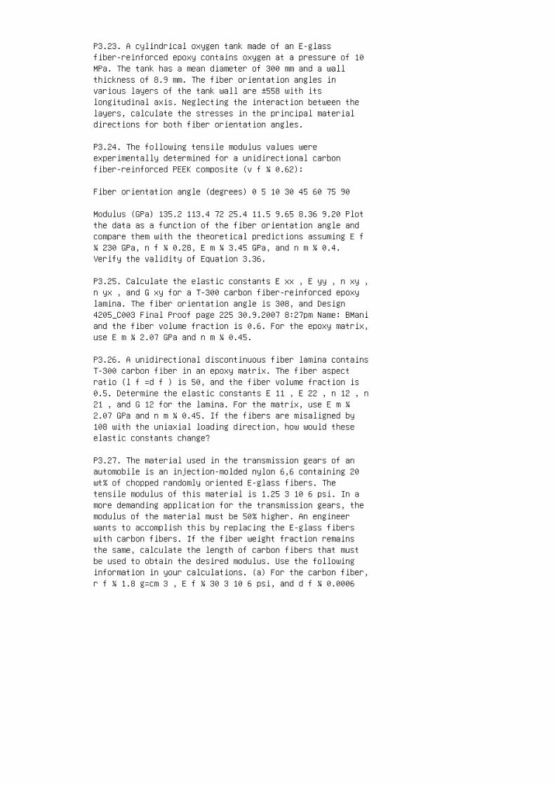
P3.23. A cylindrical oxygen tank made of an E-glassfiber-reinforced epoxy contains oxygen at a pressure of 10MPa. The tank has a mean diameter of 300 mm and a wallthickness of 8.9 mm. The fiber orientation angles invarious layers of the tank wall are ±558 with itslongitudinal axis. Neglecting the interaction between thelayers, calculate the stresses in the principal materialdirections for both fiber orientation angles.
P3.24. The following tensile modulus values wereexperimentally determined for a unidirectional carbonfiber-reinforced PEEK composite (v f ¼ 0.62):
Fiber orientation angle (degrees) 0 5 10 30 45 60 75 90
Modulus (GPa) 135.2 113.4 72 25.4 11.5 9.65 8.36 9.20 Plotthe data as a function of the fiber orientation angle andcompare them with the theoretical predictions assuming E f¼ 230 GPa, n f ¼ 0.28, E m ¼ 3.45 GPa, and n m ¼ 0.4.Verify the validity of Equation 3.36.
P3.25. Calculate the elastic constants E xx , E yy , n xy ,n yx , and G xy for a T-300 carbon fiber-reinforced epoxylamina. The fiber orientation angle is 308, and Design4205_C003 Final Proof page 225 30.9.2007 8:27pm Name: BManiand the fiber volume fraction is 0.6. For the epoxy matrix,use E m ¼ 2.07 GPa and n m ¼ 0.45.
P3.26. A unidirectional discontinuous fiber lamina containsT-300 carbon fiber in an epoxy matrix. The fiber aspectratio (l f =d f ) is 50, and the fiber volume fraction is0.5. Determine the elastic constants E 11 , E 22 , n 12 , n21 , and G 12 for the lamina. For the matrix, use E m ¼2.07 GPa and n m ¼ 0.45. If the fibers are misaligned by108 with the uniaxial loading direction, how would theseelastic constants change?
P3.27. The material used in the transmission gears of anautomobile is an injection-molded nylon 6,6 containing 20wt% of chopped randomly oriented E-glass fibers. Thetensile modulus of this material is 1.25 3 10 6 psi. In amore demanding application for the transmission gears, themodulus of the material must be 50% higher. An engineerwants to accomplish this by replacing the E-glass fiberswith carbon fibers. If the fiber weight fraction remainsthe same, calculate the length of carbon fibers that mustbe used to obtain the desired modulus. Use the followinginformation in your calculations. (a) For the carbon fiber,r f ¼ 1.8 g=cm 3 , E f ¼ 30 3 10 6 psi, and d f ¼ 0.0006

in. and (b) for nylon 6,6, r m ¼ 1.14 g=cm 3 and E m ¼ 0.43 10 6 psi.
P3.28. A unidirectional discontinuous E-glassfiber-reinforced polyphenylene sulfide (PPS) compositeneeds to be developed so that its longitudinal tensilemodulus is at least 25 GPa and its longitudinal tensilestrength is at least 950 MPa. Through the use of propercoupling agent on the glass fiber surface, it would bepossible to control the interfacial shear strength between10 and 30 MPa. The fiber bundle diameter is 0.30 mm and thefiber weight fraction is 60%. Determine the fiber lengthrequired for this composite. The matrix properties are: r m¼ 1.36 g=cm 3 , E m ¼ 3.5 GPa, and S mu ¼ 165 MPa.
P3.29. A unidirectional continuous fiber lamina containscarbon fibers in an epoxy matrix. The fiber volume fractionis 0.55. The coefficient of longitudinal thermal expansionfor the lamina is measured as �0.61 3 10 �6 per 8C, andthat for the matrix at the same temperature is 54 3 10 �6per 8C. Estimate the coefficient of thermal expansion forthe fiber. The longitudinal modulus of the lamina is 163.3GPa and the matrix modulus is 3.5 GPa.
P3.30. Coefficients of axial and transverse thermalexpansion of 08 unidirectional Spectra 900 fiber-reinforcedepoxy composite (v f ¼ 60%) are and Design 4205_C003 FinalProof page 226 30.9.2007 8:27pm Name: BMani Composites:Materials, Manufacturing, and �9 3 10 �6 and 100 3 10 �6per 8C, respectively. For the same composite, the majorPoisson’s ratio is 0.32. The matrix properties are E m ¼2.8 GPa, n m ¼ 0.38, and a m ¼ 60 3 10 �6 per 8C. Usingthese values, estimate (a) the Poisson’s ratio of thefiber, (b) coefficients of thermal expansion of the fiberin longitudinal and radial directions, and (c) the fibervolume fraction at which the composite has a zero CTE.
P3.31. A 1 m long thin-walled composite tube has a meandiameter of 25 mm and its wall thickness is 2 mm. Itcontains 60 vol% E-glass fibers in a vinyl ester matrix.Determine the change in length and diameter of the tube ifthe temperature is increased by 508C. The matrix propertiesare E m ¼ 3.5 GPa, n m ¼ 0.35, a m ¼ 70 3 10 �6 per 8C.
P3.32. An E-glass fiber–epoxy laminate has the followingconstruction: [0=30=� 30=45=� 45=90=� 45=45=� 30=30=0]: Thefollowing are known: v f ¼ 0.60, E f ¼ 10 3 10 6 psi, E m ¼0.34 3 10 6 psi, n f ¼ 0.2, n m ¼ 0.35, a f ¼ 53 10 �6 per8C, and a m ¼ 603 10 �6 per 8C. Determine the coefficientsof thermal expansion in the x and y directions for each

lamina.
P3.33. Consider a unidirectional continuous fiber lamina.Applying s 11 , s 22 , and t 12 separately, show that theengineering elastic constants E 11 , E 22 , n 12 , n 21 ,and G 12 can be expressed in terms of the elements in thelamina stiffness matrix as E 11 ¼ Q 11 Q 2 12 Q 22 , E 22 ¼Q 22 Q 2 12 Q 11 , n 12 ¼ Q 12 Q 22 , n 21 ¼ Q 12 Q 11 , G12 ¼ Q 66 :
P3.34. A T-300 carbon fiber–epoxy lamina (v f ¼ 0.60) witha fiber orientation angle of 458 is subjected to a biaxialstress state of s xx ¼ 100 MPa and s yy ¼�50 MPa. Determine(a) the strains in the x�y directions, (b) the strains inthe 1–2 directions, and (c) the stresses in the 1–2directions. Use the material property data of Example 3.6.and Design 4205_C003 Final Proof page 227 30.9.2007 8:27pmName: BMani
P3.35. Plot and compare the coefficients of mutualinfluence as functions of fiber orientation angle u inT-300 carbon fiber–epoxy laminas containing fibers at theþu and �u orientations. For what fiber orientation angle udo the coefficients of mutual influence have the maximumvalues? Use the material property data of Example 3.6.
P3.36. The elastic constants of a 08 unidirectional carbonfiber-reinforced PEEK lamina are E 11 ¼ 132.2 GPa, E 22 ¼9.2 GPa, G 12 ¼ 4.90 GPa, and n 12 ¼ 0.35. Write thecompliance and stiffness matrices for the same material ifthe fiber orientation angle is (a) 308, (b) �308, (c) 608,and (d) 908.
P3.37. A T-300 carbon fiber–epoxy lamina (v f ¼ 0.6) issubjected to a uniaxial normal stress s xx . Compare thestrains in the x�y directions as well as in the 1–2directions for u¼ 08, þ458, �458, and 908. Use the materialproperty data of Example 3.6 and Problem P3.35.
P3.38. Compare the stiffness matrices of three-layered[0=60=�60], [�60=0=60], and [�60=60=�60] laminates. Whichof these laminates can be considered quasi-isotropic, andwhy? Assume that each layer has the same thickness t 0 .
P3.39. Compare the stiffness matrices of two-layered,three-layered, and fourlayered angle-ply laminatescontaining alternating u and �u laminas. Assume that eachlayer has the same thickness t 0 .
P3.40. Show that the extensional stiffness matrices for

quasi-isotropic [0= ±60] S , [±60=0] S , and [60=0=�60] Slaminates are identical, while their bending stiffnessmatrices are different.
P3.41. The modulus of a [0 m =90 n ] laminate can becalculated using the following ‘‘averaging’’ equation. E xx¼ m mþ n E 11 þ n mþ n E 22 : Suppose a [0=90=0] 3Slaminate is constructed using continuous T-300 fibers in anepoxy matrix. Verify that the modulus of the laminatecalculated by the averaging equation is the same ascalculated by the lamination theory. Use the materialproperties given in Example 3.6.
P3.42. The [A] matrix for a boron fiber–epoxy [±45] Slaminate of thickness h is and Design 4205_C003 Final Proofpage 228 30.9.2007 8:27pm Name: BMani Composites:Materials, Manufacturing, and [A] ¼ 0:99h 0:68h 0 0:68h0:99h 0 0 0 0:72h 2 4 3 5 10 7 lb=in: 1. Calculate theengineering elastic constants for the laminate 2. Calculatethe strains in the þ458 and �458 laminas owing to averagelaminate stresses N xx =h¼N yy =h¼ p and N xy =h¼ 0. Assumethat each lamina has a thickness of h=4
P3.43. The elastic properties of unidirectional carbonfiber–epoxy lamina are E 11 ¼ 181.3 GPa, E 22 ¼ 10.27 GPa,G 12 ¼ 7.17 GPa, and n 12 ¼ 0.28. Compare the engineeringelastic constants of the [±45=0] S and [±45=0=90] Slaminates manufactured from this carbon fiber–epoxymaterial.
P3.44. Show that the shear modulus of a thin [±45] nS plateis given by G xy ¼ 1 4 E 11 þ E 22 2n 12 E 22 1� n 12 n 21:
P3.45. Show that the elements in the bending stiffnessmatrix of [0=�60=60] S and [0=90=45=�45] S laminates aregiven by D ij ¼ h 3 12 ( Q ij ) 60 þ 7( Q ij ) �60 þ 19( Qij ) 0 27 and D ij ¼ h 3 12 ( Q ij ) �45 þ 7( Q ij ) 45 þ19( Q ij ) 90 þ 37( Q ij ) 0 64 , respectively. Here, hrepresents the laminate thickness.
P3.46. A torsional momentM xy applied to a symmetriclaminated plate creates a bending curvature as well as atwisting curvature. Find an expression for the additionalbending moment M xx that must be applied to the plate tocreate a pure twisting curvature k xy .
P3.47. An ARALL-4 laminate contains three layers of 2024-T8aluminum alloy sheet (each 0.3 mm thick) and two layers of08 unidirectional Kevlar 49-epoxy in an alternate sequence,

[A1=0 K =A1=0 K =A1]. Elastic properties of the aluminumalloy are E¼ 73 GPa and n¼ 0.32, whereas and Design4205_C003 Final Proof page 229 30.9.2007 8:27pm Name: BManithose for the Kevlar layers are E 11 ¼ 56.2 GPa, E 22 ¼4.55 GPa, n 12 ¼ 0.456, and G 12 ¼ 1.85 GPa. The nominalthickness of the laminate is 1.3 mm. Calculate the elasticproperties of the ARALL-4 laminate.
P3.48. Using the basic ply level properties of Example 3.6,determine the stresses in each layer of a [±45] 32Slaminate subjected to N xx ¼ 0.1 N=mm. The ply thickness is0.013 mm.
P3.49. Using the material properties in Example 3.16,determine the residual thermal stresses in each lamina of(i) a [90 2 =0] S and (ii) a [0=90=0] S laminate. Bothlaminates are slowly cooled down from a curing temperatureof 1908C to 238C.
P3.50. The following thermomechanical properties are knownfor a carbon fiber–epoxy composite: E 11 ¼ 145 GPa, E 22 ¼9 GPa, G 12 ¼ 4.5 GPa, n 12 ¼ 0.246, a 11 ¼�0.25 3 10 �6per 8C, and a 22 ¼ 34.1 3 10 �6 per 8C. Determine thecoefficients of thermal expansion of a [45=�45] S laminateof this material.
P3.51. Using the ply level thermomechanical propertiesgiven in Problem 3.49, determine the coefficients ofthermal expansion of a [0=45=�45=90] S laminate of thismaterial.
P3.52. An approximate expression for the maximuminterlaminar shear stress t xz in a [u=�u] nS class oflaminates* is Max t xz ¼ 1 2n A 22 Q 16 A 12 Q 26 A 11 A 22A 2 12 N xx h , where N xx =h is the average tensile stresson the laminate in the x direction. Using this expression,compare the maximum interlaminar shear stress t xz in[15=�15] 8S and [45=�45] 8S T-300 carbon–epoxy laminates.Use Example 3.6 for the basic material property data.
P3.53. Following is an approximate expression* for themaximum interlaminar normal stress, s zz , at an interfaceposition z from the midplane of a symmetric [0=90] S typelaminate:
* J.M. Whitney, I.M. Daniel, and R.B. Pipes, ExperimentalMechanics of Fiber Reinforced Com
posite Materials, Society for Experimental Mechanics,Brookfield Center, CT (1984). and Design 4205_C003 Final

Proof page 230 30.9.2007 8:27pm Name: BMani Composites:Materials, Manufacturing, and Maxs zz (z) ¼ 90�s xx 7Ah X jA 22 Q 12 j �A 12 Q 22 j h i t j (h j z), where s xx ¼applied normal stress in the x direction A ¼A 11 A 22 A 122 h ¼ laminate thickness h j ¼ distance from the midplaneof the laminate to the midplane of the jth lamina t j ¼thickness of the jth lamina and the summation extends overall the laminas above the interface position z. Thisequation is valid for thin laminas in which the variationof in-plane stresses is assumed to be negligible over thethickness of each lamina. Using this approximateexpression, compare the maximum interlaminar normalstresses at the midplanes of [0=90=90=0] and [90=0=0=90]laminates. and Design 4205_C003 Final Proof page 23130.9.2007 8:28pm Name: BMani and Design 4205_C003 FinalProof page 232 30.9.2007 8:28pm Name: BMani

4 Chapter 4. Performance
1. N.J. Pagano and J.C. Halpin, Influence of end constraintin the testing of anisotropic bodies, J. Compos. Mater.,2:18 (1968).
2. R.R. Rizzo, More on the influence of end constraints onoff-axis tensile tests, J. Compos. Mater., 3:202 (1969).
3. B.E. Kaminski, Effects of specimen geometry on thestrength of composite materials, Analysis of the TestMethods for High Modulus Fibers and Composites, ASTM STP,521:181 (1973).
4. M.R. Piggott and B. Harris, Compression strength ofcarbon, glass and Kevlar 49 fibre reinforced polyesterresins, J. Mater. Sci., 15:2523 (1980).
5. C.D. Shirrell, Variability in static strengths of sheetmolding compounds (SMC), Polym. Compos., 4:172 (1983).
6. H.T. Hahn and S.W. Tsai, On the behavior of compositelaminates after initial failure, J. Compos. Mater., 8:288(1974).
7. P.A. Lagace, Nonlinear stress–strain behavior ofgraphite=epoxy laminates, AIAA J., 23:1583 (1985).
8. J.E. Masters and K.L. Reifsnider, An investigation ofcumulative damage development in quasi-isotropicgraphite=epoxy laminates, Damage in Composite Materials,ASTM STP, 775:40 (1982).
9. T. Watanabe and M. Yasuda, Fracture behavior of sheetmolding compounds. Part 1: Under tensile load, Composites,13:54 (1982).
10. J. Aveston and A. Kelly, Tensile first cracking strainand strength of hybrid composites and laminates, Phil.Trans. R. Soc. Lond., A, 294:519 (1980).
11. P.W. Manders and M.G. Bader, The strength of hybridglass=carbon fiber composites. Part 1: Failure strainenhancement and failure mode, J. Mater. Sci., 16:2233(1981).
12. J.M. Whitney, I.M. Daniel, and R.B. Pipes, ExperimentalMechanics of Fiber Reinforced Composite Materials, Societyfor Experimental Mechanics, Brookfield Center, CT (1984).

13. C. Zweben, W.S. smith, and M.M. Wardle, Test methodsfor fiber tensile strength, composite flexural modulus, andproperties of fabric-reinforced laminates, CompositeMaterials: Testing and Design (Fifth Conference), ASTM STP,674:228 (1979).
14. R.E. Bullock, Strength ratios of composite materials inflexure and in tension, J. Compos. Mater., 8:200 (1974).
15. J.M. Whitney andM. Knight, The relationship betweentensile strength and flexure strength in fiber-reinforcedcomposites, Exp. Mech., 20:211 (1980). and Design 4205_C004Final Proof page 358 30.9.2007 8:36pm Name: BManiComposites: Materials, Manufacturing, and
16. Y.T. Yeow and H.F. Brinson, A comparison of simpleshear characterization methods for composite laminates,Composites, 9:49 (1978).
17. C.C. Chiao, R.L. Moore, and T.T. Chiao, Measurement ofshear properties of fibre composites. Part 1: Evaluation oftest methods, Composites, 8:161 (1977).
18. C.C. Chamis and J.J. Sinclair, Ten-deg off-axis testfor shear properties in fiber composites, Exp. Mech.,17:339 (1977).
19. D.E. Walrath and D.F. Adams, The Iosipescu shear testas applied to composite materials, Exp. Mech., 23:105(1983).
20. D.W. Wilson, Evaluation of V-notched beam shear testthrough an interlaboratory study, J. Compos. Technol. Res.,12:131 (1990).
21. J.M. Whitney, D.L. Stansberger, and H.B. Howell,Analysis of the rail shear test— applications andlimitations, J. Compos. Mater., 5:24 (1971).
22. R. Garcia, T.A. Weisshaar, and R.R. McWithey, Anexperimental and analytical investigation of the railshear-test method as applied to composite materials, Exp.Mech., 20:273 (1980).
23. B.K. Daniels, N.K. Harakas, and R.C. Jackson, Shortbeam shear tests of graphite fiber composites, Fibre Sci.Technol., 3:187 (1971).
24. W.W. Stinchcomb, E.G. Henneke, and H.L. Price, Use ofthe short-beam shear test for quality control of

graphite-polyimide laminates, Reproducibility and Accuracyof Mechanical Tests, ASTM STP, 626:96 (1977).
25. C.A. Berg, T. Tirosh, and M. Israeli, Analysis of theshort beam bending of fiber reinforced composites,Composite Materials: Testing and Design (SecondConference), ASTM STP, 497:206 (1972).
26. L.L. Lorenzo and H.T. Hahn, Fatigue failure mechanismsin unidirectional composites, Composite Materials—Fatigueand Fracture, ASTM STP, 907: 210 (1986).
27. H.T. Hahn and R.Y. Kim, Fatigue behavior of compositelaminates, J. Compos. Mater., 10:156 (1976).
28. B.D. Agarwal and J.W. Dally, Prediction of low-cyclefatigue behavior of GFRP: an experimental approach, J.Mater. Sci., 10:193 (1975).
29. H.T. Hahn and R.Y. Kim, Proof testing of compositematerials, J. Compos. Mater., 9:297 (1975).
30. D.A. Riegner and B.A. Sanders, A characterization studyof automotive continuous and random glass fiber composites,Proceedings National Technical Conference, Society ofPlastics Engineers, November (1979).
31. R.A. Heimbuch and B.A. Sanders, Mechanical propertiesof automotive chopped fiber reinforced plastics, CompositeMaterials in the Automobile Industry, ASME, New York(1978).
32. P.K. Mallick, Fatigue characteristics of high glasscontent sheet molding compound (SMC) materials, Polym.Compos., 2:18 (1981).
33. R.B. Pipes, Interlaminar shear fatigue characteristicsof fiber reinforced composite materials, CompositeMaterials: Testing and Design (Third Conference), ASTM STP,546:419 (1974).
34. C.K.H. Dharan, Interlaminar shear fatigue of pultrudedgraphite fibre–polyester composites, J. Mater. Sci.,13:1243 (1978).
35. M.J. Owen and S. Morris, Some interlaminar-shearfatigue properties of carbonfibre-reinforced plastics,Plast. Polym., 4:209 (1972). and Design 4205_C004 FinalProof page 359 30.9.2007 8:36pm Name: BMani

36. D.W. Wilson, Characterization of the interlaminar shearfatigue properties of SMC-R50, Technical Report No. 80–05,Center for Composite Materials, University of Delaware,Newark, DE (1980).
37. D.C. Phillips and J.M. Scott, The shear fatigue ofunidirectional fibre composites, Composites, 8:233 (1977).
38. J.D. Conners, J.F. Mandell, and F.J. McGarry,Compressive fatigue in glass and graphite reinforcedcomposites, Proceedings 34th Annual Technical Conference,Society of the Plastics Industry (1979).
39. Z. Hashin and A. Rotem, A fatigue failure criterion forfiber reinforced materials, J. Compos. Mater., 7:448(1973).
40. K.H. Boller, Fatigue characteristics of RP laminatessubjected to axial loading, Mod. Plast., 41:145 (1964).
41. J.W. Davis, J.A. McCarthy, and J.N. Schrub, The fatigueresistance of reinforced plastics, Materials in DesignEngineering, p. 87 (1964).
42. M.J. Owen and R.G. Rose, Polyester flexibility versusfatigue behavior of RP, Mod. Plast., 47:130 (1970).
43. T. Tanimoto and S. Amijima, Progressive nature offatigue damage of glass fiber reinforced plastics, J.Compos. Mater., 9 (1975).
44. C.K.H. Dharan, Fatigue failure in graphite fibre andglass fibre-polymer composites, J. Mater. Sci., 10:1665(1975).
45. K.H. Boller, Effect of tensile mean stresses on fatigueproperties of plastic laminates reinforced with unwovenglass fibers, U.S. Air Force Materials Laboratory, ReportNo. ML-TDR-64–86, June (1964).
46. S.V. Ramani and D.P. Williams, Axial fatigue of [0=±30]6S graphite=epoxy, Failure Mode in Composites III, AIME, p.115 (1976).
47. T.R. Smith and M.J. Owen, Fatigue properties of RP,Mod. Plast., 46:124 (1969).
48. J.W. Dally and L.J. Broutman, Frequency effects on thefatigue of glass reinforced plastics, J. Compos. Mater.,1:424 (1967).

49. J.F. Mandell and U. Meier, Effects of stress ratio,frequency, and loading time on the tensile fatigue ofglass-reinforced epoxy, Long-Term Behavior of Composites,ASTM STP, 813:55 (1983).
50. C.T. Sun and W.S. Chan, Frequency effect on the fatiguelife of a laminated composite, Composite Materials, Testingand Design (Fifth Conference), ASTM STP, 674:418 (1979).
51. C.R. Saff, Effect of load frequency and lay-up onfatigue life of composites, LongTerm Behavior ofComposites, ASTM STP, 813:78 (1983).
52. K.L. Reifsnider, W.W. Stinchcomb, and T.K. O’Brien,Frequency effects on a stiffness-based fatigue failurecriterion in flawed composite specimens, Fatigue ofFilamentary Composite Materials, ASTM STP, 636: 171 (1977).
53. J.H. Underwood and D.P. Kendall, Fatigue damage innotched glass–epoxy sheet, Proceedings InternationalConference on Composite Materials, Vol. 2, AIME, p. 1122(1975).
54. C.K.H. Dharan, Fatigue failure mechanisms in aunidirectionally reinforced composite material, Fatigue ofComposite Materials, ASTM STP, 569:171 (1975).
55. H.C. Kim and L.J. Ebert, Axial fatigue failure sequenceand mechanisms in unidirectional fiberglass composites, J.Compos. Mater., 12:139 (1978).
56. R. Talreja, Fatigue of composite materials: damagemechanisms and fatigue-life diagrams, Proc. R. Soc. Lond.,A, 378:461 (1981). and Design 4205_C004 Final Proof page360 30.9.2007 8:36pm Name: BMani Composites: Materials,Manufacturing, and
57. L.J. Broutman and S. Sahu, Progressive damage of aglass reinforced plastic during fatigue, Proceedings 20thAnnual Technical Conference, Society of the PlasticsIndustry (1969).
58. K. Reifsnider, K. Schultz, and J.C. Duke, Long-termfatigue behavior of composite materials, Long-Term Behaviorof Composites, ASTM STP, 813:136 (1983).
59. S.S. Wang and E.S.M. Chim, Fatigue damage anddegradation in random shortfiber SMC composite, J. Compos.Mater., 17:114 (1983).

60. T.R. Smith and M.J. Owen, Progressive nature of fatiguedamage in RP, Mod. Plast., 46:128 (1969).
61. P.K. Mallick, A fatigue failure warning method forfiber reinforced composite structures, Failure Preventionand Reliability—1983 (G. Kurajian, ed.), ASME, New York(1983).
62. H.W. Whitworth, Cumulative damage in composites, ASMEJ. Eng. Mater. Technol., 112:358 (1990).
63. L.J. Broutman and S. Sahu, A new theory to predictcumulative fatigue damage in fiberglass reinforcedplastics, Composite Materials: Testing and Design (SecondConference), ASTM STP, 497:170 (1972).
64. J.N. Yang, Fatigue and residual strength degradationfor graphite=epoxy composites under tension–compressioncyclic loadings, J. Compos. Mater., 12:19 (1978).
65. M.G. Bader and R.M. Ellis, The effect of notches andspecimen geometry on the pendulum impact strength ofuniaxial CFRP, Composites, 6:253 (1974).
66. R.H. Toland, Failure modes in impact-loaded compositematerials, Symposium on Failure Modes in Composites, AIMESpring Meeting, May (1972).
67. P.K. Mallick and L.J. Broutman, Static and impactproperties of laminated hybrid composites, J. Test. Eval.,5:190 (1977).
68. J.L. Perry and D.F. Adams, Charpy impact experiments ongraphite=epoxy hybrid composites, Composites, 7:166 (1975).
69. N.L. Hancox, Izod impact testing ofcarbon-fibre-reinforced plastics, Composites, 3:41 (1971).
70. M.G. Bader, J.E. Bailey, and I. Bell, The effect offibre–matrix interface strength on the impact and fractureproperties of carbon-fibre-reinforced epoxy resincomposites, J. Phys. D: Appl. Phys., 6:572 (1973).
71. P. Yeung and L.J. Broutman, The effect of glass-resininterface strength on the impact strength of fiberreinforced plastics, Polym. Eng. Sci., 18:62 (1978).
72. P.K. Mallick and L.J. Broutman, Impact properties oflaminated angle ply composites, Eng. Fracture Mech., 8:631

(1976).
73. G.R. Sidey and F.J. Bradshaw, Some investigations oncarbon-fibre-reinforced plastics under impact loading, andmeasurements of fracture energies, Carbon Fibres: TheirComposites and Applications, Plastics Institute, London, p.208 (1971).
74. M.D. Rhodes, J.G. Williams, and J.H. Starnes, Jr.,Low-velocity impact damage in graphite-fiber reinforcedepoxy laminates, Proceedings 34th Annual TechnicalConference, Society of the Plastics Industry (1979).
75. R.L. Ramkumar, Effect of low-velocity impact damage onthe fatigue behavior of graphite=epoxy laminates, Long-TermBehavior of Composites, ASTM STP, 813:116 (1983).
76. J. Morton and E.W. Godwin, Impact response of toughcarbon fibre composites, Compos. Struct., 13:1 (1989). andDesign 4205_C004 Final Proof page 361 30.9.2007 8:36pmName: BMani
77. G.E. Husman, J.M. Whitney, and J.C. Halpin, Residualstrength characterization of laminated composites subjectedto impact loading, Foreign Object Impact Damage toComposites, ASTM STP, 568:92 (1975).
78. G. Kretsis and F.L. Matthews, The strength of boltedjoints in glass fibre=epoxy laminates, Composites, 16:92(1985).
79. P.K. Mallick and R.E. Little, Pin bearing strength offiber reinforced composite laminates, Proceedings AdvancedComposites, American Society for Metals (1985).
80. T.A. Collings, The strength of bolted joints inmulti-directional cfrp laminates, Composites, 8:43 (1977).
81. W.J. Quinn and F.L. Matthews, The effect of stackingsequence on the pin-bearing strength in glass fibrereinforced plastic, J. Compos. Mater., 11:139 (1977).
82. S. Nilsson, Increasing strength of graphite=epoxybolted joints by introducing an adhesively bonded metallicinsert, J. Compos. Mater., 23:641 (1989).
83. J.H. Stockdale and F.L. Matthews, The effect ofclamping pressure on bolt bearing loads in glassfibre-reinforced plastics, Composites, 7:34 (1976).

84. J.R. Strife and K.M. Prewo, The thermal expansionbehavior of unidirectional and bidirectional Kevlar=epoxycomposites, J. Compos. Mater., 13:264 (1979).
85. S.F.H. Parker, M. Chandra, B. Yates, M. Dootson, andB.J. Walters, The influence of distribution between fibreorientations upon the thermal expansion characteristics ofcarbon fibre-reinforced plastics, Composites, 12:281(1981).
86. J.R. Kerr and J.F. Haskins, Effects of 50,000 h ofthermal aging on graphite=epoxy and graphite=polyimidecomposites, AIAA J., 22:96 (1982).
87. F.E. Devine, Polyester moulding materials in automotiveunderbonnet environments, Composites, 14:353 (1983).
88. C.H. Shen and G.S. Springer, Moisture absorption anddesorption of composite materials, J. Compos. Mater., 10:2(1976).
89. G.S. Springer, B.A. Sanders, and R.W. Tung,Environmental effects on glass fiber reinforced polyesterand vinyl ester composites, J. Compos. Mater., 14:213(1980).
90. W.W. Wright, The effect of diffusion of water intoepoxy resins and their carbonfibre reinforced composites,Composites, 12:201 (1981).
91. O. Gillat and L.J. Broutman, Effect of an externalstress on moisture diffusion and degradation in agraphite-reinforced epoxy laminate, Advanced CompositeMaterials—Environmental Effects, ASTM STP, 658:61 (1978).
92. G. Marom and L.J. Broutman, Moisture in epoxy resincomposites, J. Adhes., 12:153 (1981).
93. E.L. McKague, Jr., J.E. Halkias, and J.D. Reynolds,Moisture in composites: the effect of supersonic service ondiffusion, J. Compos. Mater., 9:2 (1975).
94. M.J. Adamson, A conceptual model of the thermal-spikemechanism in graphite= epoxy laminates, Long-Term Behaviorof Composites, ASTM STP, 813:179 (1983).
95. H.T. Hahn, Hygrothermal damage in graphite=epoxylaminates, J. Eng. Mater. Technol., 109:1 (1987).
96. C.H. Shen and G.S. Springer, Effects of moisture and

temperature on the tensile strength of composite materials,J. Compos. Mater., 11:2 (1977).
97. C.H. Shen and G.S. Springer, Environmental effects onthe elastic moduli of composite materials, J. Compos.Mater., 11:250 (1977).
98. O.K. Joshi, The effect of moisture on the shearproperties of carbon fibre composites, Composites, 14 :196(1983).
99. C.J. Jones, R.F. Dickson, T. Adam, H. Reiter, and B.Harris, Environmental fatigue of reinforced plastics,Composites, 14:288 (1983). and Design 4205_C004 Final Proofpage 362 30.9.2007 8:36pm Name: BMani Composites:Materials, Manufacturing, and
100. P.T. Curtis and B.B. Moore, The effects ofenvironmental exposure on the fatigue behavior of CFRPlaminates, Composites, 14:294 (1983).
101. C.C. Chamis, R.R. Lark, and J.H. Sinclair, Integratedtheory for predicting the hygrothermomechanical response ofadvanced composite structural components, AdvancedCompositeMaterial—Environmental Effects, ASTMSTP, 658:160(1978).
102. J.B. Sturgeon, Creep of fibre reinforced thermosettingresins, Creep of Engineering Materials (C.D. Pomeroy, ed.),Mechanical Engineering Publishing Ltd., London (1978).
103. J.S. Cartner, W.I. Griffith, and H.F. Brinson, Theviscoelastic behavior of composite materials for automotiveapplications, Composite Materials in the AutomotiveIndustry (S.V. Kulkarni, C.H. Zweben, and R.B. Pipes,eds.), American Society of Mechanical Engineers, New York(1978).
104. Y.T. Yeow, D.H. Morris, and H.F. Brinson,Time–temperature behavior of a unidirectionalgraphite=epoxy composite, Composite Materials: Testing andDesign (Fifth Conference), ASTM STP, 674:263 (1979).
105. Y.C. Lou and R.A. Schapery, Viscoelasticcharacterization of a non-linear fiberreinforced plastic,J. Compos. Mater., 5:208 (1971).
106. M.E. Tuttle and H.F. Brinson, Prediction of thelong-term creep compliance of general composite laminates,Exp. Mech., 26:89 (1986).

107. M.G. Phillips, Prediction of long-term stress-rupturelife for glass fibre-reinforced polyester composites in airand in aqueous environments, Composites, 14:270 (1983).
108. R.E. Glaser, R.L. Moore, and T.T. Chiao, Lifeestimation of an S-glass=epoxy composite under sustainedtensile loading, Compos. Technol. Rev., 5:21 (1983).
109. R.E. Glaser, R.L. Moore, and T.T. Chiao, Lifeestimation of aramid=epoxy composites under sustainedtension, Compos. Technol. Rev., 6:26 (1984).
110. C.E. Harris and D.H. Morris, A damage tolerant designparameter for graphite= epoxy laminated composites, J.Compos. Technol. Res., 7:77 (1985).
111. J.F. Mandell, S.S. Wang, and F.J. McGarry, Theextension of crack tip damage zones in fiber reinforcedplastic laminates, J. Compos. Mater., 9:266 (1975).
112. S.K. Gaggar and L.J. Broutman, Crack growth resistanceof random fiber composites, J. Compos. Mater., 9:216(1975).
113. C.E. Harris and D.H. Morris, Role of delamination anddamage development on the strength of thick notchedlaminates, Delamination and Debonding of Materials, ASTMSTP, 876:424 (1985).
114. D.J. Wilkins, J.R. Eisenmann, R.A. Camin, W.S.Margolis, and R.A. Benson, Characterizing delaminationgrowth in graphite–epoxy, Damage in Composite Materials,ASTM STP, 775:168 (1980).
115. D.F. Adams, L.A. Carlsson, and R.B. Pipes,Experimental Characterization of Advanced CompositeMaterials, 3rd Ed., CRC Press, Boca Raton, FL (2003).
116. T.K. O’Brien, Characterization of delamination onsetand growth in a composite laminate, Damage in CompositeMaterials, ASTM STP, 775:140 (1982).
117. C. Schuecker and B.D. Davidson, Evaluation of theaccuracy of the four-point end-notched flexure test formode II delamination toughness determination, Compos. Sci.Tech., 60:2137 (2000).
118. O. Ishai, H. Rosenthal, N. Sela, and E. Drukker,Effect of selective adhesive interleaving on interlaminar
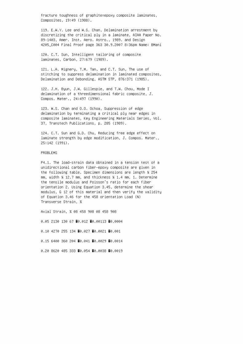
fracture toughness of graphite=epoxy composite laminates,Composites, 19:49 (1988).
119. E.W.Y. Lee and W.S. Chan, Delamination arrestment bydiscretizing the critical ply in a laminate, AIAA Paper No.89-1403, Amer. Inst. Aero. Astro., 1989. and Design4205_C004 Final Proof page 363 30.9.2007 8:36pm Name: BMani
120. C.T. Sun, Intelligent tailoring of compositelaminates, Carbon, 27:679 (1989).
121. L.A. Mignery, T.M. Tan, and C.T. Sun, The use ofstitching to suppress delamination in laminated composites,Delamination and Debonding, ASTM STP, 876:371 (1985).
122. J.H. Byun, J.W. Gillespie, and T.W. Chou, Mode Idelamination of a threedimensional fabric composite, J.Compos. Mater., 24:497 (1990).
123. W.S. Chan and O.O. Ochoa, Suppression of edgedelamination by terminating a critical ply near edges incomposite laminates, Key Engineering Materials Series, Vol.37, Transtech Publications, p. 285 (1989).
124. C.T. Sun and G.D. Chu, Reducing free edge effect onlaminate strength by edge modification, J. Compos. Mater.,25:142 (1991).
PROBLEMS
P4.1. The load–strain data obtained in a tension test of aunidirectional carbon fiber–epoxy composite are given inthe following table. Specimen dimensions are length ¼ 254mm, width ¼ 12.7 mm, and thickness ¼ 1.4 mm. 1. Determinethe tensile modulus and Poisson’s ratio for each fiberorientation 2. Using Equation 3.45, determine the shearmodulus, G 12 of this material and then verify the validityof Equation 3.46 for the 458 orientation Load (N)Transverse Strain, %
Axial Strain, % 08 458 908 08 458 908
0.05 2130 130 67 �0.012 �0.00113 �0.0004
0.10 4270 255 134 �0.027 �0.0021 �0.001
0.15 6400 360 204 �0.041 �0.0029 �0.0014
0.20 8620 485 333 �0.054 �0.0038 �0.0019

0.25 — 565 396 — �0.0048 �0.0025
P4.2. The following tensile modulus (E xx ) values werecalculated from the tensile stress–strain diagrams of 308carbon fiber–epoxy off-axis specimens: L=w E xx (10 6 psi)2 2.96 4 2.71 8 2.55 and Design 4205_C004 Final Proof page364 30.9.2007 8:36pm Name: BMani Composites: Materials,Manufacturing, and Using the following material properties,calculate the corrected tensile modulus values at each L=wand compare them with the theoretical modulus: E 11 ¼ 20310 6 psi, E 22 ¼ 13 10 6 psi, n 12 ¼ 0.25, and G 12 ¼ 0.6310 6 psi.
P4.3. The following longitudinal tensile strength data (inMPa) were obtained for a [0=±45=90] S E-glass fiber–epoxylaminate: 520.25, 470.27, 457.60, 541.18, 566.35, 489.82,524.55, 557.87, 490.00, 498.99, 496.95, 510.84, and 558.76.(a) Determine the average tensile strength, the standarddeviation, and coefficient of variation (b) Determine theWeibull parameters for the given strength distribution (c)Using the Weibull parameters in (b), determine the meanstrength for the material
P4.4. The tensile stress–strain diagram for a [(0=90) 2=0=90] S E-glass fiber– epoxy laminate is shown in thefigure. Determine the initial modulus, the stress at theknee point, the secondary modulus, and the failure strengthfor the laminate. Compare these experimental values withthe theoretical estimates. C B A A: 0� C: 90� B: [(0/90) 2/0/90] S Strain S t r e s s 1 0 k s i 0.01 in./in. andDesign 4205_C004 Final Proof page 365 30.9.2007 8:36pmName: BMani
P4.5. Tensile stress–strain diagram of a [0=90 4 ] S AS-4carbon fiber–epoxy laminate is shown in the figure. Thelongitudinal modulus and transverse modulus of a 08unidirectional laminate of the same material are 142 and10.3 GPa, respectively. 1. Determine the initial axialmodulus of the [0=90 4 ] S laminate and compare it with thetheoretical value. How would this value change if the 908layers are at the outside or the laminate construction ischanged to [0 2 =90 3 ] S ? 2. The knee in thestress–strain diagram is at a strain of 0.005 mm=mm.However, the ultimate longitudinal and transverse strainsof the 08 unidirectional laminate are at 0.0146 and 0.006mm=mm, respectively. Explain what might have caused a lowerstrain at the knee 3. Describe the reason for the nonlinearportion of the stress–strain diagram 0 0 100 200 300 400500 0.3 0.6 0.9 1.2 Strain (percent) S t r e s s ( M P a )1.5 1.8
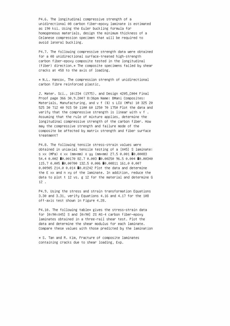
P4.6. The longitudinal compressive strength of aunidirectional 08 carbon fiber–epoxy laminate is estimatedas 190 ksi. Using the Euler buckling formula forhomogeneous materials, design the minimum thickness of aCelanese compression specimen that will be required toavoid lateral buckling.
P4.7. The following compressive strength data were obtainedfor a 08 unidirectional surface-treated high-strengthcarbon fiber–epoxy composite tested in the longitudinal(fiber) direction.* The composite specimens failed by shearcracks at 458 to the axis of loading.
* N.L. Hancox, The compression strength of unidirectionalcarbon fibre reinforced plastic,
J. Mater. Sci., 10:234 (1975). and Design 4205_C004 FinalProof page 366 30.9.2007 8:36pm Name: BMani Composites:Materials, Manufacturing, and v f (%) s LCU (MPa) 10 325 20525 30 712 40 915 50 1100 60 1250 70 1750 Plot the data andverify that the compressive strength is linear with v f .Assuming that the rule of mixture applies, determine thelongitudinal compressive strength of the carbon fiber. Howmay the compressive strength and failure mode of thecomposite be affected by matrix strength and fiber surfacetreatment?
P4.8. The following tensile stress–strain values wereobtained in uniaxial tensile testing of a [±45] S laminate:s xx (MPa) « xx (mm=mm) « yy (mm=mm) 27.5 0.001 �0.0008354.4 0.002 �0.00170 82.7 0.003 �0.00250 96.5 0.004 �0.00340115.7 0.005 �0.00700 132.5 0.006 �0.00811 161.0 0.0070.00905 214.0 0.014 �0.01242 Plot the data and determinethe E xx and n xy of the laminate. In addition, reduce thedata to plot t 12 vs. g 12 for the material and determine G12 .
P4.9. Using the stress and strain transformation Equations3.30 and 3.31, verify Equations 4.16 and 4.17 for the 108off-axis test shown in Figure 4.28.
P4.10. The following table* gives the stress–strain datafor [0=90=±45] S and [0=90] 2S AS-4 carbon fiber–epoxylaminates obtained in a three-rail shear test. Plot thedata and determine the shear modulus for each laminate.Compare these values with those predicted by the lamination
* S. Tan and R. Kim, Fracture of composite laminatescontaining cracks due to shear loading, Exp.

Mech., 28:364 (1988). and Design 4205_C004 Final Proof page367 30.9.2007 8:36pm Name: BMani theory based on thefollowing material properties: E 11 ¼ 143.92 GPa, E 22 ¼11.86 GPa, G 12 ¼ 6.68 GPa, and n 12 ¼ 0.326. Shear Stress(MPa) Shear Strain (%) [0=90=±45] S [0=90] 2S 0.2 40 13.60.4 91 24.5 0.6 128.6 37 0.8 155 47.3 1.0 178 54.5 1.2 20862 1.4 232 65.4 1.6 260 70
P4.11. The following figure shows the schematic of anasymmetric four-point bend (AFPB) test developed formeasuring the shear properties of composite laminates. Asin the Iosipescu shear test, it uses a V-notched beamspecimen. Derive an expression for the shear stress at thecenter of the specimen and compare it with that in theIosipescu shear test. V-notched specimen w P L a
P4.12. Torsion of a thin-walled tube is considered the bestmethod of creating a pure shear stress state in a material.Describe some of the practical problems that may arise inthe torsion test of a laminated composite tube. and Design4205_C004 Final Proof page 368 30.9.2007 8:36pm Name: BManiComposites: Materials, Manufacturing, and
P4.13. Using Equation 4.12, develop a correction factor forthe modulus measurements in a three-point flexure test witha small span–thickness ratio and plot the ratio ofcorrected modulus and measured modulus as a function of thespan–thickness ratio.
P4.14. Using the homogeneous beam theory, develop equationsfor flexural strength and modulus calculations from theload–deflection diagram in a four-point static flexuretest.
P4.15. Using the lamination theory, develop the flexuralload–deflection diagram (up to the point of first failure)of a sandwich hybrid beam containing 08 T-300 carbonfiber-reinforced epoxy in the two outer layers and 08E-glass fiber-reinforced epoxy in the core. Describe thefailure mode expected in flexural loading of such a beam.
P4.16. Unidirectional 08 Kevlar 49 composites exhibit alinear stress–strain curve in a longitudinal tension test;however, their longitudinal compressive stress–strain curveis similar to that of an elastic, perfectly plastic metal(see the figure). Furthermore, the compressive proportionallimit for a Kevlar 49 composite is lower than its tensilestrength. Explain how these two behaviors may affect thestress distribution across the thickness of a

unidirectional Kevlar 49 composite beam as the transverselyapplied load on the beam is increased. Estimate thetransverse load at which the flexural load–deflectiondiagram of aKevlar 49 beam becomes nonlinear. (Hint: Assumethat the strain distribution through the thickness of thebeam remains linear at all load levels.) TensionCompression Strain S t r e s s
P4.17. The flexural strength of a unidirectional 08E-glass–vinyl ester beam is 95 ksi, and the estimated ILSSfor the material is 6 ksi. Determine the maximumspan–thickness ratio for a short-beam shear specimen inwhich interlaminar shear failure is expected. and Design4205_C004 Final Proof page 369 30.9.2007 8:36pm Name: BMani
P4.18. Some investigators have proposed using a four-pointflexure test for ILSS measurements. Using the homogeneousbeam theory, develop equations for ILSS in a four-pointflexure test and discuss the merits of such a test over athree-point short-beam shear test.
P4.19. Using Table 4.8, compare the fatigue strengths ofT-300 carbon–epoxy and E-glass–epoxy composites at 10 4 and10 7 cycles.
P4.20. The Weibull parameters for the tension–tensionfatigue life distribution of a [0=90=±45] S T-300 carbonfiber–epoxy composite are as follows: at s max ¼ 340 MPa, L0 ¼ 1,000,000, and a f ¼ 1.6. At s max ¼ 410 MPa, L 0 ¼40,000, and a f ¼ 1.7. 1. Determine the mean fatigue livesat 340 and 410 MPa 2. What is the expected probability ofsurviving 50,000 cycles at 410MPa?
P4.21. Fatigue lives (numbers of cycles to failure) oftwelve 08 Kevlar 49 fiberreinforced composite specimens intension–tension cycling at 90% UTS, R ¼ 0.1, 0.5 Hzfrequency, and 238C are reported as 1,585; 25; 44,160;28,240; 74,140; 47; 339,689; 50,807; 320,415; 865; 5,805;and 4,930. Plot the Weibull distribution curve for thesefatigue lives and determine the Weibull parameters for thisdistribution.
P4.22. For the major portion of the fatigue life of acomposite laminate, the instantaneous modulus can bemodeled as E ¼ E 0 (1� c logN) where E 0 ¼ initial modulusat N ¼ 1 N ¼ number of fatigue cycles c ¼ an experimentallydetermined damage-controlling factor Using this model,determine the number of cycles that a simply supportedcentrally loaded beam can endure before its deflectionbecomes 50% higher than its initial value.

P4.23. For the quasi-isotropic laminate described inExample 4.2, suppose the loading sequence is 10,000 cyclesat 437 MPa followed by cycling to failure at 382 MPa.Estimate the total life expected in this high– low stresssequence using (a) the Whitworth model and (b) the Miner’srule.
P4.24. The mean fatigue lives of [0=90] S E-glassfiber–epoxy laminates at maximum stress levels of 56,000and 35,000 psi are 1,500 and 172,000, respectively. Thestatic tensile strength of this material is 65,000 psi. andDesign 4205_C004 Final Proof page 370 30.9.2007 8:36pmName: BMani Composites: Materials, Manufacturing, and 1.Determine the residual static strength of this materialafter 50% of the fatigue life at each stress level 2. Aftercycling for 50% of the fatigue life at 35,000 psi, themaximum stress level in a fatigue specimen is increased to56,000 psi. Estimate the number of cycles the specimenwould survive at 56,000 psi 3. If the first stress level is56,000 psi, which is then followed by 35,000 psi, estimatethe number of cycles at the second stress level
P4.25. Adam et al.* have found that, depending on the fibertype, the postfatigue residual strength of [0=90]cross-plied composites may show either a gradual decreasewith increasing number of cycles (usually after a rapidreduction in the first few cycles) or virtually no changeuntil they fail catastrophically (sudden death). Theyproposed the following empirical equation to predict theresidual strength: s res ¼ s max (s U s max )(1� r x ) 1=y, where r ¼ logN log 0:5 logN f log 0:5 x, y ¼ parametersobtained by fitting the residual strength equation to theexperimental data (both varywithmaterial and environmentalconditions) Graphically compare the residual strength afterfatigue for the following [(0=90) 2 =0=90] S epoxylaminates at s max ¼ 0.9, 0.7, and 0.5 s U : Fiber s U(MPa) x y HTS carbon 944 1.8 23.1 E-glass 578 1.5 4.8Kevlar 49 674 2.1 8.8
P4.26. Poursartip et al. y have proposed the followingempirical equation to represent the fatigue damage(delamination) growth rate at R ¼ 0.1 in [±45=90=45=0] Scarbon fiber–epoxy laminate: dD dN ¼ k 1 Ds s U k 2 ,
* T. Adam, R.F. Dickson, C.J. Jones, H. Reiter, and B.Harris, A power law fatigue damage model
for fibre-reinforced plastic laminates, Proc. Inst. Mech.Eng., 200:155 (1986).

y A. Poursartip, M.F. Ashby, and P.W.R. Beaumont, Thefatigue damage mechanics of fibrous
composites, Polymer NDE (K.H.G. Ashbee, ed.), TechnomicPub. Co. (1986). and Design 4205_C004 Final Proof page 37130.9.2007 8:37pm Name: BMani where D ¼ damage (ratio ofdelaminated area to total surface area) Ds ¼ stress range sU ¼ ultimate tensile strength k 1 , k 2 ¼ constantsdetermined by fitting a least-square regression line todamage growth rate vs. stress range data Assuming that thedamage can be represented by D ¼ k 3 (1� E=E 0 ), where Eis the modulus after N cycles E 0 is the initial modulus k3 is a constant Find expressions for the terminal damageand the number of cycles to failure in terms of Ds.
P4.27. The following figure shows the load–time curverecorded during the instrumented Charpy impact testing ofan unnotched 08 T-300 carbon– epoxy specimen. The pendulumvelocity just before impacting the specimen was 16.8 ft.=s.The specimen dimensions were as follows: length betweenspecimen supports¼ 1.6 in.; thickness¼ 0.125 in.; andwidth¼ 0.5 in. Calculate the dynamic flexural strength,dynamic flexural modulus, initiation energy, propagationenergy, and total impact energy for the specimen. Stateyour assumptions and critically evaluate your answers. 100lb L o a d 1 ms Time and Design 4205_C004 Final Proof page372 30.9.2007 8:37pm Name: BMani Composites: Materials,Manufacturing, and
P4.28. In a drop-weight impact test, a 1 in. diameterspherical ball weighing 0.15 lb is dropped freely on 0.120in. thick [0=±45=90] 3S carbon fiber–epoxy beam specimensand the rebound heights are recorded. The beam specimensare simply supported, 0.5 in. wide and 6 in. long betweenthe supports. The drop heights, rebound heights, andspecimen deflections in three experiments are as follows:Drop Height (ft) Rebound Height (ft) Measured MaximumDeflection (in.) 1 0.72 0.056 4 2.20 0.138 6 3.02 0.150 (a)Calculate the energy lost by the ball in each case. (b)Assuming that all of the energy lost by the ball istransformed into strain energy in the beam, calculate themaximum deflection of the specimen in each case. Theflexural modulus of the laminate is 20 3 10 6 psi. (c)Explain why the measured maximum deflections are less thanthose calculated in (b).
P4.29. The following table* gives the tensile strength andCharpy impact energy data of a unidirectional hybridcomposite containing intermingled carbon and Spectra 1000

polyethylene fibers in an epoxy matrix. The polyethylenefibers were either untreated or surface-treated to improvetheir adhesion with the epoxy matrix. Plot the data as afunction of the polyethylene fiber volume fraction andcompare them with the rule of mixture predictions. Explainthe differences in impact energy in terms of the failuremodes that might be expected in untreated and treated fibercomposites. Will you expect differences in other mechanicalproperties of these composites?
* A.A.J.M. Peijs, P. Catsman, L.E. Govaert, and P.J.Lemstra, Hybrid composites based on
polyethylene and carbon fibres, Part 2: Influence ofcomposition and adhesion level of polyethylene
fibers on mechanical properties, Composites, 21:513 (1990).and Design 4205_C004 Final Proof page 373 30.9.2007 8:37pmName: BMani Polyethylene Fiber Volume Fraction (%) TensileStrength (MPa) Charpy Impact Energy (kJ=m 2 ) UntreatedTreated Untreated Treated 0 1776 1776 90.8 98.8 20 16231666 206 100 40 1367 1384 191 105.1 60 1222 1282 171.2118.2 80 928 986 140.8 124.8 100 1160 1273 116.7 145.3
P4.30. Show that the time required for a material to attainat least 99.9% of its maximum possible moisture content isgiven by t ¼ 0:679c 2 D z , where t is time in seconds c isthe laminate thickness
P4.31. The maximum possible moisture content in a[0=90=±45] S T-300 carbon fiber–epoxy composite (v f ¼ 0.6)is given by M m ¼ 0:000145(RH) 1:8 : A 6.25 mm thick panelof this material is exposed on both sides to air with 90%relative humidity at 258C. The initial moisture content inthe panel is 0.01%. (a) Estimate the time required for themoisture content to increase to the 0.1% level (b) If thepanel is painted on one side with a moisture-imperviousmaterial, what would be the moisture content in the panelat the end of the time period calculated in (a)?
P4.32. Following Equation 4.43, design an experiment fordetermining the diffusion coefficient, D z of a compositelaminate. Be specific about any calculations that may berequired in this experiment.
P4.33. Estimate the transverse tensile strength, transversemodulus, and shear modulus of a 08 unidirectional T-300carbon fiber-reinforced epoxy composite (v f ¼ 0.55) at508C and 0.1% moisture content. The matrix and Design4205_C004 Final Proof page 374 30.9.2007 8:37pm Name: BMani

Composites: Materials, Manufacturing, and tensile strength,modulus, and Poisson’s ratio at 238C and dry conditions are56 MPa, 2.2 GPa, and 0.43, respectively; T gd for thematrix is 1778C.
P4.34. Shivakumar and Crews* have proposed the followingequation for the bolt clamp-up force F t between tworesin-based laminates: F t ¼ F 0 1þ 0:1126(t=a th ) 0:20 ,where F 0 ¼ initial (elastic) clamp-up force t ¼ elapsedtime (weeks) a th ¼ a shift factor corresponding to aspecific steady-state temperature or moisture 1. At 238C,the a th values for an epoxy resin are 1, 0.1, 0.01, and0.001 for 0%, 0.5%, 1%, and 1.5% moisture levels,respectively. Using these a th values, estimate the timefor 20%, 50%, 80%, and 100% relaxation in bolt clamp-upforce. 2. At 668C and 0.5% moisture level, the boltclamp-up force relaxes to 80% of its initial value in 3weeks. Calculate the a th value for this environmentalcondition.
P4.35. A quasi-isotropic [0=±45=90] 8S panel of T-300carbon fiber–epoxy develops a 12 mm long sharp crack at itscenter. The panel width and thickness are 200 and 8 mm,respectively. The unnotched tensile strength of thelaminate is 565 MPa. Determine the safe load that can beapplied normal to the crack plane before an unstablefracture occurs. Describe the possible fracture modes forthe cracked panel.
P4.36. The load–displacement record shown in the figure wasobtained in a double-cantilever beam (DCB) test of aunidirectional 08 carbon fiber– epoxy laminate. The initialcrack length was 25 mm and the specimen wasunloaded–reloaded after crack extension of every 5 mm. Plot(a) compliance vs. crack length and (b) strain energyrelease rate G 1 vs. crack length for this specimen. Whatis the Mode I interlaminar fracture toughness of thismaterial? The specimen width was 25 mm.
* K.N. Shivakumar and J.H. Crews, Jr., Bolt clamp-uprelaxation in a graphite=epoxy laminate,
Long-Term Behavior of Composites, ASTM STP, 813:5 (1983).and Design 4205_C004 Final Proof page 375 30.9.2007 8:37pmName: BMani 0 0 70 140 L o a d , P ( N ) 210 280 350 0.51.0 1.5 2.0 Crack opening displacement, d (mm) 2.5
P4.37. The compliance data obtained in a 4-ENF test of a 08unidirectional carbon fiber–epoxy laminate are given in thefollowing table. The specimen width was 25.4 mm and the

initial crack length was 50 mm. The load at which theinitial crack was observed to grow was 700 N. Determine theMode II interlaminar fracture toughness of the material.Crack Length (mm) Compliance (mm=N) 60 5.85 3 10 �3 65 6.203 10 �3 70 6.60 3 10 �3 75 6.96 3 10 �3 and Design4205_C004 Final Proof page 376 30.9.2007 8:37pm Name: BManiComposites: Materials, Manufacturing, and

5 Chapter 5. Manufacturing
1. W.I. Lee, A.C. Loos, and G.S. Springer, Heat ofreaction, degree of cure, and viscosity of Hercules 3501-6resin, J. Compos. Mater., 16:510 (1982).
2. K.W. Lem and C.D. Han, Thermokinetics of unsaturatedpolyester and vinyl ester resins, Polym. Eng. Sci., 24:175(1984).
3. D.S. Lee and C.D. Han, Chemorheology and curing behaviorof low-profile polyester resin, Proceedings 40th AnnualTechnical Conference, Society of the Plastics Industry,January (1985).
4. M.R. Kamal and S. Sourour, Kinetics and thermalcharacterization of thermoset cure, Polym. Eng, Sci., 13:59(1973).
5. M.R. Kamal, Thermoset characterization for moldabilityanalysis, Polym. Eng. Sci., 14:231 (1974).
6. B.R. Gebart, Permeability of unidirectionalreinforcements in RTM, J. Compos. Mater., 26:1100 (1992).
7. P. Hubert and A. Poursartip, A review of flow andcompaction modelling relevant to thermoset matrix laminateprocessing, J. Reinf. Plast. Compos., 17:286 (1998).
8. T.G. Gutowski, T. Morgaki, and Z. Cai, The consolidationof laminate composites, J. Compos. Mater., 21:172 (1987).
9. A.C. Loos and G.S. Springer, Curing of epoxy matrixcomposites, J. Compos. Mater., 17:135 (1983).
10. Structural Composites Fabrication Guide, Vol. 1,Manufacturing Technology Division, U.S. Air Force MaterialsLaboratory (1982).
11. P.K. Mallick, Compression molding, Composite MaterialsTechnology (P.K. Mallick and S. Newman, eds.), HanserPublishers, New York (1990).
12. L.F. Marker and B. Ford, Flow and curing behavior ofSMC during molding,Mod. Plast., 54:64 (1977).
13. P.J. Costigan, B.C. Fisher, and M. Kanagendra, Therheology of SMC during compression molding and resultantmaterial properties, Proceedings 40th Annual Conference,Society of the Plastics Industry, January (1985).

14. M.R. Barone and D.A. Caulk, Kinematics of flow in sheetmolding compounds, Polym. Compos., 6:105 (1985).
15. R.M. Griffith and H. Shanoski, Reducing blistering inSMC molding, Plast. Des. Process., 17:10 (1977).
16. P.K. Mallick, Effect of fiber misorientation on thetensile strength of compression molded continuous fibercomposites, Polym. Compos., 7:14 (1986).
17. R.B. Jutte, SMC-sink mechanisms and techniques ofminimizing sing, International Automotive EngineeringCongress, Detroit, Paper No. 730171, Society of AutomotiveEngineers (1973).
18. K.L. Smith and N.P. Suh, An approach towards thereduction of sink marks in sheet molding compound, Polym.Eng. Sci., 19:829 (1979). and Design 4205_C005 Final Proofpage 440 30.9.2007 9:16pm Name: BMani Composites:Materials, Manufacturing, and
19. A.N. Dharia and N.R. Schott, Resin pick-up and fiberwet-out associated with
coating and pultrusion processes, Proceedings 44th AnnualTechnical Conference,
Society of Plastics Engineers, p. 1321, April (1986).
20. J.E. Sumerak, Understanding pultrusion processvariables,Mod. Plast., 62:58 (1985).
21. M.A. Bibbo and T.G. Gutowski, An analysis of thepulling force in pultrusion,
Proceedings 44th Annual Technical Conference, Society ofPlastics Engineers,
p. 1430, April (1986).
22. C.D. Hermansen and R.R. Roser, Filament windingmachine: which type is best for
your application? Proceedings 36th Annual Conference,Society of the Plastics Indus
try, February (1981).
23. J.F. Kober, Microprocessor-controlled filament winding,

Plastics Machinery Equip
ment, June (1979).
24. D. Brosius and S. Clarke, Textile preforming techniquesfor low cost structural
composites, Advanced Composite Materials: New Developmentsand Applications,
ASM International (1991).
25. C.W. Macosko, Fundamentals of Reaction InjectionMolding, Hanser Publishers,
New York (1989).
26. R.K. Okine, Analysis of forming parts from advancedthermoplastic composite
sheet materials, SAMPE J., 25:9 (1989).
27. F.N. Cogswell, The processing science of thermoplasticstructural composites, Int.
Polym. Proc., 1:157 (1987).
28. L.S. Penn, Physiochemical characterization ofcomposites and quality control of
raw materials, Composite Materials: Testing and Design(Fifth Conference), ASTM
STP, 674:519 (1979).
29. R. Burns, K.S. Gandhi, A.G. Hankin, and B.M. Lynskey,Variability in sheet
molding compound (SMC). Part I. The thickening reaction andeffect of raw
materials, Plast. Polym., 43:228 (1975).
30. C.M. Tung and P.J. Dynes, Chemorheologicalcharacterization of B-stage printed
wiring board resins, Composite Materials: Quality Assuranceand Processing, ASTM
STP, 797:38 (1983).

31. M.L. Bromberg, Application of dielectric measurementsto quality control, Pro
ceedings Annual Technical Conference, Society of PlasticsEngineers, p. 403, April
(1986).
32. W.H. Pfeifer, Computed tomography of advanced compositematerials, Proceedings
Advanced Composites Conference, American Society forMetals, December (1985).
33. W.N. Reynolds, Nondestructive testing (NDT) offibre-reinforced composite mater
ials, Mater. Des., 5:256 (1985).
34. T.J. Fowler, Acoustic emission testing of fiberreinforced plastics, American Society
of Civil Engineers Fall Convention, Preprint 3092, October(1977).
35. J. Awerbuch, M.R. Gorman, and M. Madhukar, Monitoringacoustic emission
during quasi-static loading=unloading cycles offilament-wound graphite=epoxy
laminate coupons, First International Symposium on AcousticEmission from
Reinforced Composites, Society of the Plastics Industry,July (1983).
36. C.H. Adams, Recommended practice for acoustic emissiontesting of fiberglass
reinforced plastic tanks=vessels, Proceedings 37th AnnualConference, Society of
the Plastics Industry, January (1982).
37. M.A. Hamstad, A review: acoustic emission, a tool forcomposite materials studies,
Exp. Mech., 26:7 (1986). and Design 4205_C005 Final Proof

page 441 30.9.2007 9:16pm Name: BMani
38. A. Vary, Acousto-ultrasonics, Non-Destructive Testingof Fibre-Reinforced Plastics Composites, Vol. 2 (J.Summerscales, ed.), Elsevier Applied Science, London(1990).
39. D.J. Hillman and R.L. Hillman, Thermographic inspectionof carbon epoxy structures, Delamination and Debonding ofMaterials, ASTM STP, 873:481 (1985).
40. E.G. Henneke, II and T.S. Jones, Detection of damage incomposite materials by vibrothermography, NondestructiveEvaluation and Flaw Criticality of Composite Materials,ASTM STP, 696:83 (1979).
41. T.G. Gutowski, Cost, automation, and design, AdvancedComposites Processing (T.G. Gutowski, ed.), John Wiley &Sons, New York, NY (1997).
PROBLEMS
P5.1. The following isothermal cure rate equation was foundto fit the DSC data for a thermoset resin: da c dt ¼ k(1� ac ) 2 , where k is a temperature-dependent constant. Solvethis differential equation to show that time required toachieve a cure level a c is given by t ¼ a c k(1� a c ) :
P5.2. In Problem 5.1, the constant k (per minute) is givenby the following Arrhenius equation: k ¼ 2:3� 10 6 exp 14:8RT , where R is the universal gas constant (kcal=molK) T isthe absolute temperature (K) Calculate the cure times for50%, 80%, and 99.9% cure levels in the thermoset resin at1008C and 1508C. State the observations you will make fromthese calculations.
P5.3. The degree of cure of a vinyl ester resin used forRTM as a function of cure time is given by the followingequation. a c ¼ kt 1þ kt , and Design 4205_C005 Final Proofpage 442 30.9.2007 9:16pm Name: BMani Composites:Materials, Manufacturing, and where k ¼ 1:25� 10 6 exp 5000T t is the cure time in minutes T is the temperature in 8K(a) Assuming that the presence of fibers does not influencethe cure kinetics, determine the temperature that should beused to achieve 80% cure in 1 min cure time. (b) What isthe cure rate at 80% cure in (a)? (c) What temperatureshould be used if the cure rate needs to be doubled at 80%cure? What will be the cure time now?
P5.4. The isothermal rate of cure for a thermoset polyester

system is given by the following equation: da c dt ¼ ka m c(1� a c ) n : Show that the maximum rate of cure for thispolyester system is obtained at a cure level a c ¼ m mþ n :
P5.5. The isothermal cure rate of a DGEBA epoxy cured withm-phenylene diamine is given by Equation 5.4. The kineticparameters, determined from DSC data, are m ¼ 0:45 n ¼ 1:55k 1 ¼ 2:17� 10 6 exp (�E 1 =RT) per minute k 2 ¼ 1:21� 10 6exp (�E 2 =RT) per minute E 1 ¼ 13,600 cal=mol E 2 ¼ 13,700cal=mol 1. Graphically compare the cure rates of this epoxyresin at 1008C, 1258C, and 1508C as a function of thedegree of cure, a c . State the observations you will makefrom the graphs. 2. Determine the maximum cure rate at eachtemperature. and Design 4205_C005 Final Proof page 44330.9.2007 9:16pm Name: BMani
P5.6. The following isothermal viscosity data were obtainedin a parallel-plate viscometer for an epoxy system cured at1258C: Time (min) Viscosity (cP) 0 79.5 20 100 40 148 60162 80 263 100 512 120 1,480 140 6,160 160 44,600 180513,000 200 14,781,000 Plot the data on a semilog scale andschematically show how the nature of this curve may changeif (a) the curing temperature is 1508C, (b) the curingtemperature is 1008C, and (c) the epoxy system is B-stagedbefore curing at 1258C.
P5.7. Lee et al. [1] fitted the following equation to theviscosity (h) data (in Pa s) for an epoxy system: h ¼ 7:9�10 �14 exp E RT þ 14a c for a c < 0:5, where E ¼ activationenergy for viscosity ¼ 9 3 10 4 J=mol R ¼ universal gasconstant (J=molK) T ¼ absolute temperature (K) a c ¼ degreeof cure Using this equation, estimate the viscosity of theepoxy system at 1008C and 1508C (a) at the beginning of thecuring reaction, (b) at 20% cure, and (c) at 40% cure.
P5.8. Roller* has represented the isothermal viscosity datafor a B-staged epoxy resin, by the following four-parameterequation:
* M.B. Roller, Characterization of thetime–temperature–viscosity behavior of curing B-staged
epoxy resin, Polym. Eng. Sci., 15:406 (1975). and Design4205_C005 Final Proof page 444 30.9.2007 9:16pm Name: BManiComposites: Materials, Manufacturing, and lnh ¼ lnh 1 þ E 1RT þ tk exp E 2 RT , where E 1 and E 2 are activationenergies k is a kinetic parameter (which depends on theresin type, curing agent concentration, and other factors)h 1 is the calculated viscosity at T¼1 T is the absolutetemperature t is the time at temperature T R is the

universal gas constant For a particular B-staged epoxyresin, the four parameters in the isothermal viscosityequation are: E 1 ¼ 27,000 cal=mol, E 2 ¼ 19,000 cal= mol,k ¼ 6.4 3 10 7 per second, and h 1 ¼ 2 3 10 �11 cP.Determine the gel-time viscosity of the resin at 1708C ifthe gel time is 200 s at this temperature.
P5.9. A gel-time test on an epoxy resulted in the followingdata: T (8C) Time (min) 140 4 130 7.5 120 14 110 25 10534.3 1. Plot ln(gel time) vs. 1=T is (where T is thetemperature in K). 2. Assume that gel time can berepresented by Arrhenius equation: t gel ¼ A exp E RT ,where E ¼ activation energy R ¼ universal gas constant A ¼constant Determine the values of A and E. 3. Determine thegel time at 1008C and 1508C using the Arrhenius equation.and Design 4205_C005 Final Proof page 445 30.9.2007 9:16pmName: BMani
P5.10. The following figure shows two cure cycles and thecorresponding viscosity–time curves for an epoxy-basedprepreg. Which of these two cure cycles is expected toproduce better and more uniform mechanical properties, andwhy? 10,000 1,000 A A B B 100 10 0 40 80 120 Time (min) V is c o s i t y ( p o i s e ) T e m p e r a t u r e ( C )Temperature Viscosity Pressure applied Pressure applied 160200 240 170 130 90 50 1
P5.11. The following figure shows the viscosity andgel-time curves for two epoxy resin systems. Which of thetwo resin systems will be more suitable for a bag-moldingprocess, and why? Temperature Temperature A A B B (a) (b) Vi s c o s i t y G e l t i m e and Design 4205_C005 FinalProof page 446 30.9.2007 9:16pm Name: BMani Composites:Materials, Manufacturing, and
P5.12. The following figure shows a typical isothermal DSCcurve for a polyester resin system. It contains t-butylperbenzoate (TBPB) as the initiator for the curingreaction. The three important time parameters relevant forthe compression-molding cycle of this material are alsoindicated in the figure. Explain how these time parametersmay be affected by (a) an increase in cure temperature, (b)an increase in the initiator concentration, (c) thepresence of an inhibitor, (d) the use of a lowertemperature initiator, and (e) a combination of TBPB and alower temperature initiator. From the standpoint of flow inthe mold, which one of these changes would be moredesirable? Time R e a c t i o n r a t e 110�C t i t i =Induction time t m = Time to reach maximum reactionrate t c t m t c = Cure time

P5.13. As a part of themanufacturing study of anSMC-Rmaterial, you are asked to investigate the effects ofSMC machine variables as well as molding variables on themechanical properties of compression-molded flat plaques.The study was instigated by the wide variation in tensilestrengths and failure locations observed in a prototypemolded part. Select the experimental variables that mightbe of primary importance in this investigation, and designan experimental program (including test methods, specimenlocation, and so on) for this study.
P5.14. A thin-walled cylinder with closed ends containsoxygen at a high internal pressure, which creates a hooptensile stress twice the axial tensile stress in its wall.Assume that the fibers carry all load and there is nointeraction between the layers. Show that the optimum helixangle in the filament-wound cylinder is 54.748.
P5.15. The price of carbon fibers is lower when there are25,000–50,000 filaments per tow instead of 1,000–5,000filaments per tow. Discuss the advantages and disadvantagesof using such large tows in filament winding. and Design4205_C005 Final Proof page 447 30.9.2007 9:16pm Name: BMani
P5.16. One common specimen used in testing the quality ofmaterials in filament winding is the Naval OrdnanceLaboratory (NOL) ring, which contains only circumferentialfibers. The specimen dimensions are shown in the figure. Db d d = 1.52 mm (0.06 in.) b = 6.35 mm (0.25 in.) D =146.05 mm (5.75 in.) Develop a method of producing NOL ringspecimens and the test techniques that can be used tomeasure the tensile, compressive, interlaminar shear, andin-plane shear strengths using such specimens. Discuss theadvantages and disadvantages of NOL ring tests comparedwith the test methods presented in Chapter 4.
P5.17. List material (both resin and preform), process, andtool design parameters that may influence the quality of aresin transfer molded part.
P5.18. In an LCM process, liquid resin is injected underisothermal condition through a dry-fiber bed at a constantpressure P o . Assuming that the flow is one-dimensionaland is in the x direction, show that the fill time t isproportional to x 2 , where x is the fill distance in timet.
P5.19. RTM is used to mold 500mm long3 50mmwide3 2.5 mmthick E-glass fiber-reinforced epoxy plates. The following
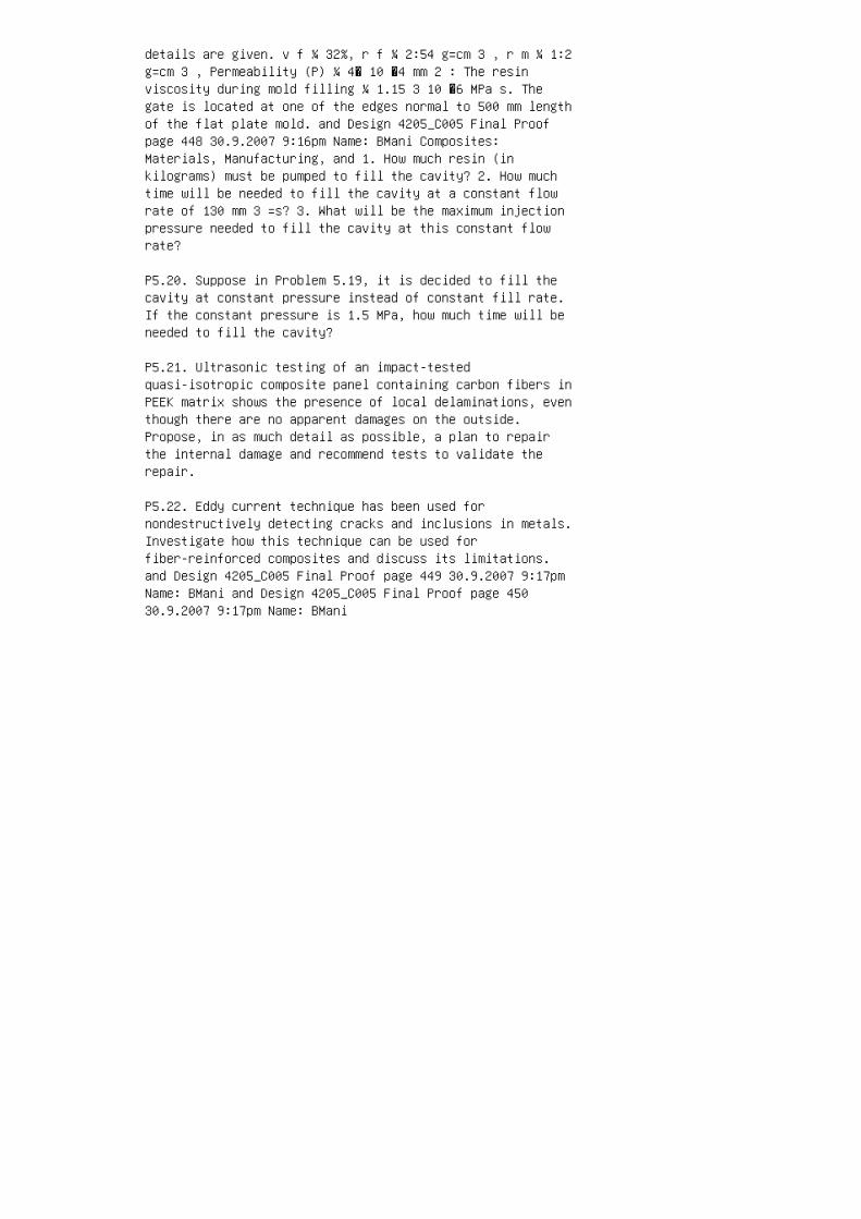
details are given. v f ¼ 32%, r f ¼ 2:54 g=cm 3 , r m ¼ 1:2g=cm 3 , Permeability (P) ¼ 4� 10 �4 mm 2 : The resinviscosity during mold filling ¼ 1.15 3 10 �6 MPa s. Thegate is located at one of the edges normal to 500 mm lengthof the flat plate mold. and Design 4205_C005 Final Proofpage 448 30.9.2007 9:16pm Name: BMani Composites:Materials, Manufacturing, and 1. How much resin (inkilograms) must be pumped to fill the cavity? 2. How muchtime will be needed to fill the cavity at a constant flowrate of 130 mm 3 =s? 3. What will be the maximum injectionpressure needed to fill the cavity at this constant flowrate?
P5.20. Suppose in Problem 5.19, it is decided to fill thecavity at constant pressure instead of constant fill rate.If the constant pressure is 1.5 MPa, how much time will beneeded to fill the cavity?
P5.21. Ultrasonic testing of an impact-testedquasi-isotropic composite panel containing carbon fibers inPEEK matrix shows the presence of local delaminations, eventhough there are no apparent damages on the outside.Propose, in as much detail as possible, a plan to repairthe internal damage and recommend tests to validate therepair.
P5.22. Eddy current technique has been used fornondestructively detecting cracks and inclusions in metals.Investigate how this technique can be used forfiber-reinforced composites and discuss its limitations.and Design 4205_C005 Final Proof page 449 30.9.2007 9:17pmName: BMani and Design 4205_C005 Final Proof page 45030.9.2007 9:17pm Name: BMani

6 Chapter 6. Design
1. V.D. Azzi and S.W. Tsai, Anisotropic strength ofcomposites, Exp. Mech., 5:283 (1965).
2. S.W. Tsai and E.M. Wu, A general theory of strength foranisotropic materials, J. Compos. Mater., 5:58 (1971).
3. E.M. Wu, Optimal experimental measurements ofanisotropic failure tensors, J. Compos. Mater., 6:472(1972).
4. S.W. Tsai and H.T. Hahn, Failure analysis of compositematerials, Inelastic Behavior of Composite Materials (C.T.Herakovich, ed.), American Society of Mechanical Engineers,New York, p. 73 (1975).
5. P.H. Petit and M.E. Waddoups, A method of predicting thenon-linear behavior of laminated composites, J. Compos.Mater., 3:2 (1969).
6. R.E. Rowlands, Flow and failure of biaxially loadedcomposites: experimental– theoretical correlation,Inelastic Behavior of Composite Materials (C.T. Herakovich,ed.), American Society of Mechanical Engineers, New York,p. 97 (1975).
7. S.R. Soni, A comparative study of failure envelopes incomposite laminates, J. Reinforced Plast. Compos., 2:34(1983).
8. R.C. Burk, Standard failure criteria needed for advancedcomposites, Astronaut. Aeronaut., 21:6 (1983).
9. H.T. Hahn, On approximations for strength of randomfiber composites, J. Compos. Mater., 9:316 (1975).
10. J.C. Halpin and J.L. Kardos, Strength of discontinuousreinforced composites: I. Fiber reinforced composites,Polym. Eng. Sci., 18:6 (1978).
11. C.S. Hong and J.H. Crews, Jr., Stress concentrationfactors for finite orthotropic laminates with a circularhole and uniaxial loading, NASATechnical Paper No. 1469(1979).
12. B. Pradhan, Effect of width and axial to transverseelastic stiffness ratio on SCF in uniaxially loaded FRPcomposite plates containing circular holes, Fibre Sci.Technol., 17:245 (1982).

13. J.M. Whitney, I.M. Daniel, and R.B. Pipes, ExperimentalMechanics of Fiber Reinforced Composite Materials, Societyfor Experimental Mechanics, Brookfield Center, CT (1984).
14. M.E. Waddoups, J.R. Eisenmann, and B.E. Kaminski,Macroscopic fracture mechanics of advanced compositematerials, J. Compos. Mater., 5:446 (1971).
15. J.M. Whitney and R.J. Nuismer, Stress fracture criteriafor laminated composites containing stress concentrations,J. Compos. Mater., 8:253 (1974).
16. R.J. Nuismer and J.M. Whitney, Uniaxial failure ofcomposite laminates containing stress concentrations,Fracture Mechanics of Composites, ASTM STP, 593:117 (1975).
17. H.J. Konish and J.M. Whitney, Approximate stresses inan orthotropic plate containing a circular hole, J. Compos.Mater., 9:157 (1975).
18. J.C. Brewer and P.A. Lagace, Quadratic stress criterionfor initiation of delamination, J. Compos. Mater., 22:1141(1988).
19. S.G. Zhou and C.T. Sun, Failure analysis of compositelaminates with free edge, J. Compos. Tech. Res., 12:91(1990). and Design 4205_C006 Final Proof page 516 30.9.20079:30pm Name: BMani Composites: Materials, Manufacturing,and
20. H. Kulkarni and P. Beardmore, Design methodology forautomotive components using continuous fibre-reinforcedcomposite materials, Composites, 11:225 (1980).
21. J.C. Ekvall and C.F. Griffin, Design allowables forT300=5208 graphite=epoxy composite materials, J. Aircraft,19:661 (1982).
22. M.J. Rich and D.P. Maass, Developing design allowablesfor composite helicopter structures, Test Methods andDesign Allowables for Fibrous Composites, ASTM STP, 734:181(1981).
23. C.T. Herakovich, Influence of layer thickness on thestrength of angle-ply laminates, J. Compos. Mater., 16:216(1982).
24. S.L. Donaldson, Simplified weight saving techniques forcomposite panels, J. Reinforced Plast. Compos., 2:140

(1983).
25. T.N. Massard, Computer sizing of composite laminatesfor strength, J. Reinforced Plast. Compos., 3:300 (1984).
26. W.J. Park, An optimal design of simple symmetriclaminates under first ply failure criterion, J. Compos.Mater., 16:341 (1982).
27. J.M. Whitney and A.W. Leissa, Analysis of heterogeneousanisotropic plates, J. Appl. Mech., 36:261 (1969).
28. J.M. Whitney, Bending–extensional coupling in laminatedplates under transverse loading, J. Compos. Mater., 3:20(1969).
29. R.M. Jones, H.S. Morgan, and J.M. Whitney, Buckling andvibration of antisymmetrically laminated angle-plyrectangular plates, J. Appl.Mech., 40:1143 (1973).
30. O.H. Griffin, Evaluation of finite-element softwarepackages for stress analysis of laminated composites,Compos. Technol. Rev., 4:136 (1982).
31. J.R. Eisenmann and J.L. Leonhardt, Improving compositebolted joint efficiency by laminate tailoring, Joining ofComposite Materials, ASTM STP, 749:117 (1979).
32. L.J. Hart-Smith, Designing to minimize peel stresses inadhesive-bonded joints, Delamination and Debonding ofMaterials, ASTM STP, 876:238 (1985).
33. D.P. Maass, Tubular composite compressionmembers—design considerations and practices, Proceedings41st Annual Conference, Society of the Plastics Industry,January (1986).
34. J.M. Whitney, C.E. Browning, and A. Mair, Analysis ofthe flexural test for laminated composite materials,Composite Materials: Testing and Design (Third Conference),ASTM STP, 546:30 (1974).
35. J.M. Whitney and J.C. Halpin, Analysis of laminatedanisotropic tubes under combined loading, J. Compos.Mater., 2:360 (1968).
36. G.J. Simitses, Instability of orthotropic cylindricalshells under combined torsion and hydrostatic pressure,AIAA J., 5:1463 (1967).

37. C.F. Griffin, Design development of an advancedcomposite aileron, Paper No. 791807, AIAA Aircraft Systemsand Technology Meeting, August (1979).
38. E.E. Morris, W.P. Patterson, R.E. Landes, and R.Gordon, Composite pressure vessels for aerospace andcommercial applications, Composites in Pressure Vessels andPiping (S.V. Kulkarni and C.H. Zweben, eds.), AmericanSociety of Mechanical Engineers, New York, PVP-PB-021(1977).
39. B.E. Kirkham, L.S. Sullivan, and R.E. Bauerie,Development of the Liteflex suspension leaf spring, Societyof Automotive Engineers, Paper No. 820160 (1982).
40. D.E. Bowles and D.R. Tenney, Composite tubes for thespace station truss structure, SAMPE J., 23:49 (1987). andDesign 4205_C006 Final Proof page 517 30.9.2007 9:30pmName: BMani
PROBLEMS
P6.1. A Kevlar 49–epoxy composite has the followingmaterial properties: E 11 ¼ 11 3 10 6 psi, E 22 ¼ 0.8 3 106 psi, G 12 ¼ 0.33 3 10 6 psi, n 12 ¼ 0.34, S Lt ¼ 203 ksi,S Tt ¼ 1.74 ksi, S Lc ¼ 34 ksi, S Tc ¼ 7.7 ksi, and S LTs ¼4.93 ksi. A unidirectional laminate of this material issubjected to uniaxial tensile loading in the x direction.Determine the failure stress of the laminate using (a) themaximum stress theory, (b) the maximum strain theory, and(c) the Azzi–Tsai–Hill theory for u ¼ 08, 308, 458, 608,and 908.
P6.2. The Kevlar 49–epoxy composite in Problem P6.1 has afiber orientation angle of 458 and is subjected to abiaxial normal stress field (t xy ¼ 0). Determine thefailure stress of the laminate using (a) the maximum stresstheory, (b) the maximum strain theory, and (c) theAzzi–Tsai–Hill theory for the normal stress ratios of 0, 1,and 2.
P6.3. Biaxial tension–compression tests on closed-ended 908tubes (with fibers oriented in the hoop direction of thetube) are performed to determine the normal stressinteraction parameter F 12 , which appears in the Tsai– Wufailure criterion. The desired stress state is created by acombination of the internal pressure and axial compressiveload. In one particular experiment with carbon fiber–epoxycomposites, the biaxial stress ratio s 11 =s 22 was �9. Theinternal tube diameter was 2 in. and the tube wall

thickness was 0.05 in. If the burst pressure was recordedas 2700 psi, determine (a) the axial compressive load atthe time of failure and (b) the value of F 12 for thiscarbon fiber–epoxy composite. The following strengthproperties for the material are known: S Lt ¼ 185ksi,S Tt ¼7.5ksi,S Lc ¼ 127ksi,S Tc ¼ 34ksi, andS LTs ¼ 11ksi.
P6.4. Average tensile strengths of 158, 458, and 608boron–epoxy off-axis tensile specimens are 33.55, 12.31,and 9.28 ksi, respectively. Determine F 12 for these threecases using the Tsai–Wu failure theory. Which of the threeF 12 values is in the permissible range?What conclusion canbemade about the use of an off-axis tensile test fordetermining the F 12 value? The following properties areknown for the boron–epoxy system: S Lt ¼ 188 ksi, S Lc ¼361 ksi, S Tt ¼ 9 ksi, S Tc ¼ 45 ksi, and S LTs ¼ 10 ksi.
P6.5. A [0=45] 8S T-300 carbon fiber–epoxy laminate issubjected to a uniaxial tensile force F xx . Each ply inthis laminate is 0.1 mm thick. The laminate is 100 mm wide.The ply-level elastic properties of the material are givenin Example 3.6. The basic strength properties of thematerial are as follows: and Design 4205_C006 Final Proofpage 518 30.9.2007 9:30pm Name: BMani Composites:Materials, Manufacturing, and S Lt ¼ S Lc ¼ 1447.5 MPa, STt ¼ S Tc ¼ 44.8 MPa, and S LTs ¼ 62 MPa. Assuming that themaximum stress failure theory applies to this material,determine F xx at (a) FPF and (b) ultimate failure.
P6.6. A [0=90=±45] S T-300 carbon fiber–epoxy laminate issubjected to the following in-plane loads: N xx ¼ 1000lb=in., N yy ¼ 200 lb=in., and N xy ¼ �500 lb=in. Each plyin the cured laminate is 0.006 in. thick. The basic elasticand ultimate properties of the material are as follows: E11 ¼ 203 10 6 psi,E 22 ¼ 1.33 10 6 psi,G 12 ¼ 1.033 10 6psi, n 12 ¼ 0.3, « Lt ¼ 0.0085, « Lc ¼ 0.0098, « Tt ¼0.0045, « Tc ¼ 0.0090, and g LTs ¼ 0.015. Using the maximumstrain theory, determine whether any of the laminas in thislaminate would fail at the specified load.
P6.7. If the laminate in Problem P6.6 is subjected to anincreasing unaxial load in the x direction, determine theminimum load at which the FPF would occur.
P6.8. Show that, for an isotropic material, Equation 6.8gives a hole stress concentration factor of 3.
P6.9. Show that the hole stress concentration factor for a08 laminate is K T ¼ 1þffiffiffiffiffiffiffiffiffiffiffiffiffiffiffiffiffiffiffiffiffiffiffiffiffiffiffiffiffiffiffiffiffiffiffiffiffiffiffiffiffiffiffiffiffiffi 2 ffiffiffiffiffiffiffi E

11 E 22 r n 12 þ E 11 G 12 s :
P6.10. Compare the hole stress concentration factors of[0=90] 4S , [0=90=±45] 2S , and [0=90=±60] 2S T-300 carbonfiber–epoxy laminates. The basic lamina properties are: E11 ¼ 21 3 10 6 psi, E 22 ¼ 1.35 3 10 6 psi, n 12 ¼ 0.25,and G 12 ¼ 0.83 3 10 6 psi.
P6.11. A 10 mm diameter hole is drilled at the center ofthe 100 mm wide [0=45] 8S laminate in Problem P6.5.Calculate the hole stress concentration factor of thelaminate, and state how it may change if (a) some of the458 layers are replaced with �458 layers, (b) some of the458 layers are replaced with 908 layers, and (c) some ofthe 458 layers are replaced with 08 layers.
P6.12. Using the point stress criterion, estimate thenotched tensile strength of a [0=±30=90] 8S T-300 carbonfiber–epoxy laminate containing a central hole of (a) 0.25in. diameter and (b) 1 in. diameter. Assume that thecharacteristic distance d 0 for the material is 0.04 in.The basic elastic properties for the material are given inProblem P6.10. Assume s Ut ¼ 61 ksi. and Design 4205_C006Final Proof page 519 30.9.2007 9:30pm Name: BMani
P6.13. Rework Problem P6.12 using the average stresscriterion. Assume that the characteristic distance a 0 is0.15 in.
P6.14. A 300 mm wide SMC-R65 panel contains a 12 mmdiameter hole at its center. The unnotched tensile strengthof the material is 220 MPa. During the service operation,the panel may be subjected to an axial force of 25 kN.Using a characteristic distance d 0 of 0.8 mm in the pointstress criterion, estimate the notched tensile strength ofthe material and determine the minimum safe thickness ofthe panel.
P6.15. A T-300 carbon fiber–epoxy panel is made ofalternate layers of fibers at right angles to each other.For the various loading conditions shown in the figure,determine the proportion of the two types of layers andtheir orientations with the x axis. The total laminatethickness may not exceed 0.100 in. (a) (b) (d)(c) y y y y xx x x 20 ksi 40 ksi 40 ksi 20 ksi 25 ksi 25 ksi 25 ksi 40ksi 25 ksi
P6.16. The primary load on a rectangular plate, 1 m long 30.25 m wide, is a 1000 N load acting parallel to itslength. The plate is to be made of a symmetric cross-plied
T-300 carbon fiber–epoxy laminate with 08 and Design4205_C006 Final Proof page 520 30.9.2007 9:30pm Name: BManiComposites: Materials, Manufacturing, and outside layers.Assuming that the plate is pinned along its width,determine the minimum number of 08 and 908 plies requiredto avoid failure due to buckling. Each cured layer in thelaminate is 0.125 mm thick. Basic elastic properties of thematerial are given in Appendix A.5.
P6.17. A 20 in. long E-glass–polyester pultruded rod (v f ¼50%) with a solid round cross section is designed to carrya static tensile load of 1000 lb. The longitudinalextension of the rod may not exceed 0.05 in. Determine theminimum diameter of the rod. Laboratory tests have shownthat the tensile strength and tensile modulus for thematerial is 100,000 psi and 5.5 3 10 6 psi, respectively.Assume a factor of safety of 2.0.
P6.18. A 1 m tension bar of solid round cross section is tobe designed using unidirectional GY-70 carbonfiber-reinforced epoxy with 60% fiber volume fraction. Themaximum load on the rod is expected to be 445 kN. The rodmay be subjected to tension–tension fatigue cycling at anaverage cycling rate of 10 cycles=s for a total time periodof 10 years in an environment where the temperature mayfluctuate between �208C and 1008C. The elongation of therod should not exceed 0.2 mm. 1. Determine the diameter ofthe rod using a factor of safety of 3. 2. Assume the rodwill be pin-connected at each end to another structure,propose two conceptual designs for the end fittings for therod and discuss their applicability.
P6.19. A [0=±45=90] 4S T-300 carbon fiber–epoxy laminate isused in a beam application. Each layer in the curedlaminate is 0.005 in. thick. The beam is 0.5 in. wide.Using the basic elastic properties in Problem P6.10,calculate the effective bending stiffness of the laminatedbeam.
P6.20. Determine the effective bending stiffness and thefailure load of a [(0=90) 8 =0] S E-glass–epoxy beam havinga rectangular cross section, 12.7 mm wide 3 4.83 mm thick.Assume that each layer in the beam has the same curedthickness. Use Appendix A.5 for the basic materialproperties.
P6.21. A cantilever beam, 0.1 m long 3 50 mm wide 3 10 mmthick, has a sandwich construction with [0=±45=90] S carbonfiber–epoxy facings and an aluminum honeycomb core. Eachlayer in the cured laminate is 0.125 mm thick. Assuming

that the core has a negligible bending stiffness, determinethe end deflection of the beam if it is subjected to a 2000N load at its free end. Basic ply-level elastic propertiesof the material are the same as in Example 3.6. and Design4205_C006 Final Proof page 521 30.9.2007 9:30pm Name: BMani
P6.22. A 2 m long, 100 mm wide, simply supportedrectangular beam is subjected to a central load of 5 kN.The beam material is pultruded E-glass–polyester containing60 wt% continuous fibers and 20 wt% mat. Determine thethickness of the beam so that its central deflection doesnot exceed 70 mm. Laboratory tests have shown that thetensile modulus of the material is 35.2 GPa. Assume itsflexural modulus to be 20% less than the tensile modulus.
P6.23. A 30 in. long automotive transmission member has ahat section with uniform thickness. It is connected to theframe by means of two bolts at each end. The maximum loadacting at the center of the member is estimated not toexceed 600 lb during its service life. The materialconsidered for its construction is SMC-C20R30. Modeling thetransmission member as a simply supported beam, determineits thickness and the maximum deflection at its center.What special attention must be given at the ends of thetransmission member where it is bolted to the frame? Thefatigue strength of the SMC material at 10 6 cycles is 45%of its static tensile strength.
P6.24. Using the same material and design requirements asin Example 6.10, design the wall thickness of an automotivedrive shaft with a [±15] nS T-300 carbon fiber–epoxylaminate.
P6.25. Design a constant stress cantilever leaf spring ofuniform width (70 mm) using (a) E-glass–epoxy and (b) AScarbon–epoxy. Free length of the spring is 500 mm. It issubjected to a reversed fatigue load of ±10 kN. What willbe a suitable manufacturing method for this spring? andDesign 4205_C006 Final Proof page 522 30.9.2007 9:30pmName: BMani Composites: Materials, Manufacturing, and

7 Chapter 7. 'Metal, Ceramic, and CarbonMatrix Composites
1. R.K. Everett and R.J. Arsenault (eds.), Metal MatrixComposites: Mechanisms and
Properties, Academic Press, San Diego (1991).
2. R.K. Everett and R.J. Arsenault (eds.), Metal MatrixComposites: Processing and
Interfaces, Academic Press, San Diego (1991).
3. T.W. Clyne and P.J. Withers, An Introduction to MetalMatrix Composites, Cam
bridge University Press, Cambridge, UK (1993).
4. N. Chawla andK.K. Chawla,MetalMatrix Composites,Springer, NewYork (2006).
5. A. Kelly and G.J. Davies, The principles of the fibrereinforcement of metals,
Metall. Rev., 10:1 (1965). and Design 4205_C007 Final Proofpage 551 30.9.2007 8:51pm Name: BMani Matrix Composites
6. A. Toy, Mechanical properties of berylliumfilament-reinforced aluminum compos
ites, J. Mater., 3:43 (1968).
7. M. Taya and R.J. Arsenault, Metal Matrix Composites:Thermomechanical Behav
ior, Pergamon Press, Oxford (1989).
8. S.V. Nair, J.K. Tien, and R.C. Bates, SiC-reinforcedaluminum metal matrix
composites, Int. Metals Rev., 30:275 (1985).
9. D.L. McDanels, Analysis of stress–strain, fracture, andductility behavior of alumi
num matrix composites containing discontinuous siliconcarbide reinforcement,
Metall. Trans., 16A:1105 (1985).

10. W.S. Johnson and M.J. Birt, Comparison of somemicromechanics models for
discontinuously reinforced metal matrix composites, J.Compos. Technol. Res.,
13:168 (1991).
11. A.L. Geiger and J. Andrew Walker, The processing andproperties of discontinu
ously reinforced aluminum composites, J. Metals, 43:8(1991).
12. K. Schmidt, C. Zweben, and R. Arsenault, Mechanical andthermal properties of
silicon-carbide particle-reinforced aluminum, Thermal andMechanical Behavior of
Metal Matrix and Ceramic Matrix Composites, ASTM STP,1080:155 (1990).
13. J.J. Lewandowski, C. Liu, and W.H. Hunt, Jr.,Microstructural effects on the
fracture mechanisms in 7xxx A1 P=M-SiC particulate metalmatrix composites,
Processing and Properties for Powder Metallurgy Composites(P. Kumar, K. Vedula,
and A. Ritter, eds.), TMS, Warrendale, PA (1988).
14. M. Karayaka and H. Sehitoglu, Thermomechanical fatigueof particulate-reinforced
aluminum 2xxx-T4, Metall. Trans. A, 22A:697 (1991).
15. T. Morimoto, T. Yamaoka, H. Lilholt, and M. Taya,Second stage creep of
whisker=6061 aluminum composites at 573K, J. Eng. Mater.Technol., 110:70
(1988).
16. R.K. Everett, Diffusion bonding, Metal MatrixComposites: Processing and Inter

faces, Chapter 2 (R.K. Everett and R.J. Arsenault, eds.),Academic Press, San Diego
(1991).
17. A. Mortensen, J.A. Cornie, and M.C. Flemings,Solidification processing of metal
matrix composites, J. Metals, 40:12 (1988).
18. A. Mortensen, M.N. Gungor, J.A. Cornie, and M.C.Flemings, Alloy microstruc
tures in cast metal matrix composites, J. Metals, 38:30(1986).
19. P. Rohatgi and R. Asthana, The solidification ofmetal-matrix particulate compos
ites, J. Metals, 43:35 (1991).
20. P. Rohatgi, Cast aluminum-matrix composites forautomotive applications,
J. Metals, 43:10 (1991).
21. C.R. Cook, D.I. Yun, and W.H. Hunt, Jr., Systemoptimization for squeeze cast
composites, Cast Reinforced Metal Composites (S.G. Fishmanand A.K. Dhingra,
eds.), ASM International, Metals Park, OH (1988).
22. T. Kobayashi, M. Yosino, H. Iwanari, M. Niinomi, and K.Yamamoto, Mechanical
properties of SiC whisker reinforced aluminum alloysfabricated by pressure casting
method, Cast Reinforced Metal Composites (S.G. Fishman andA.K. Dhingra, eds.),
ASM International, Metals Park, OH (1988).
23. H. Fukunaga, Squeeze casting processes for fiberreinforced metals and their
mechanical properties, Cast Reinforced Metal Composites(S.G. Fishaman and

A.K. Dingra, eds.), ASM International, Metal Park, OH(1988).
24. K.K. Chawla, Ceramic Matrix Composites, Chapman & Hall,London (1993). and Design 4205_C007 Final Proof page 55230.9.2007 8:51pm Name: BMani Composites: Materials,Manufacturing, and
25. J. Aveston, G.A. Cooper, and A. Kelly, Single andmultiple fracture, The Properties
of Fiber=Composites, IPC Science and Technology Press,Surrey, England (1971).
26. A.G. Evans and D.B. Marshall, The mechanical behaviorof ceramic matrix com
posites, Acta Metall., 37:2567 (1989).
27. R.A.J. Sambell, D.H. Bowen, and D.C. Phillips, Carbonfibre composites with
ceramic and glass matrices, Part 1: Discontinuous fibres,J. Mater. Sci., 7:663 (1972).
28. R.A.J. Sambell, A. Briggs, D.C. Phillips, and D.H.Bowen, Carbon fibre composites
with ceramic and glass matrices, Part 2: Continuous fibres,J. Mater. Sci., 7:676
(1972).
29. K.M. Prewo and J.J. Brennan, Fiber reinforced glassesand glass ceramics for high
performance applications, Reference Book for CompositesTechnology, Vol. 1 (S.M.
Lee, ed.), Technomic Pub. Co., Lancaster, PA (1989).
30. J.J. Brennan and K.M. Prewo, Silicon carbide fibrereinforced glass-ceramic matrix
composites exhibiting high strength and toughness, J.Mater. Sci., 17:2371 (1982).
31. T.Mah,M.G.Mendiratta, A.P. Katz, andK.S.Mazdiyasni,Recent developments in

fiber-reinforced high temperature ceramic composites,Ceramic Bull., 66:304 (1987).
32. R.W. Rice and D. Lewis III, Ceramic fiber compositesbased upon refractory
polycrystalline ceramic matrices, Reference Book forComposites Technology, Vol.
1 (S.M. Lee, ed.), Technomic Pub. Co., Lancaster, PA (1989).
33. B. Thomson and J.F. LeCostaonec, Recent developments inSiC monofilament
reinforced Si 3 N 4 composites, SAMPE Q., 22:46 (1991).
34. R.L. Lehman, Ceramic matrix fiber composites,Structural Ceramics (J.B. Wacht
man, Jr., ed.), Academic Press, San Diego (1989).
35. J.E. Sheehan, K.W. Buesking, and B.J. Sullivan,Carbon–carbon composites, Annu.
Rev. Mater. Sci., 24:19 (1994).
36. J.D. Buckley and D.D. Edie, Carbon–Carbon Materials andComposites, William
Andrews Publishing, Norwich, NY (1993).
37. D.L. Chung, Carbon Fiber Composites,Butterworth-Heinemann, Newton, MA
(1994).
PROBLEMS
P7.1. Experimentally determined elastic properties of aunidirectional continuous P-100 carbon fiber-reinforced6061-T6 aluminumalloy areE 11 ¼ 403 GPa, E 22 ¼ 24 GPa, v12 ¼ 0.291, and G 12 ¼ 18.4 GPa. Fiber volume fraction inthe composite is 0.5. 1. Compare these values withtheoretical predictions and explain the differences, ifany. 2. Using the experimental values, determine theoff-axis elastic modulus, E xx , at u ¼ 158 and 458 andcompare them with the experimental values of 192 and 41GPa, respectively.

P7.2. Suppose both fibers and matrix in a unidirectionalcontinuous fiber MMC are ductile, and their tensilestress–strain equations are given by the general form: s ¼K « m , and Design 4205_C007 Final Proof page 553 30.9.20078:51pm Name: BMani Matrix Composites where K and m arematerial constants obtained from experimentally determinedstress–strain data. K and m for the fibers are differentfrom K and m for the matrix. Assuming that the longitudinalstress–strain relationship for the composite can also bedescribed by a similar equation, derive the materialconstants K and m of the composite in terms of fiber andmatrix parameters.
P7.3. Referring to Problem P7.2, determine thestress–strain equation for a unidirectional berylliumfiber-reinforced aluminum alloy. Assume that the fibervolume fraction is 0.4. Material constants for the fiberand the matrix are given as follows: K (MPa) m Berylliumfiber 830 0.027 Aluminum matrix 250 0.127
P7.4. Referring to Appendix A.2, determine the thermalresidual stresses in a unidirectional SCS-6-reinforcedtitanium alloy (v f ¼ 40%) and comment on their effects onthe failure mode expected in this composite underlongitudinal tensile loading. The fabrication temperatureis 9408C. Use the following fiber and matrixcharacteristics in your calculations:
Fiber: E f ¼ 430 GPa, v f ¼ 0:25, a f ¼ 4:3� 10 �6 per8C, sfu ¼ 3100 MPa, r f ¼ 102 mm:
Matrix: E m ¼ 110 GPa, v m ¼ 0:34, a m ¼ 9:5� 10 �6 per8C,s my ¼ 800 MPa, s mu ¼ 850 MPa, « mu ¼ 15%:
P7.5. Using Halpin–Tsai equations, determine the tensilemodulus of 20 vol% SiC whisker-reinforced 2024-T6 aluminumalloy for (a) l f =d f ¼ 1 and (b) l f =d f ¼ 10. Assume arandom orientation for the whiskers.
P7.6. SiC w -reinforced 6061-T6 aluminum alloy (v f ¼ 0.25)is formed by powder metallurgy and then extruded into asheet. Microscopic examination of the cross section showsabout 90% of the whiskers are aligned in the extrusiondirection. Assuming l f =d f ¼ 10, estimate the tensilemodulus and strength of the composite. Make reasonableassumptions for your calculations.
P7.7. Coefficient of thermal expansion of sphericalparticle-reinforced composites is estimated using theTurner equation: and Design 4205_C007 Final Proof page 554

30.9.2007 8:51pm Name: BMani Composites: Materials,Manufacturing, and a c ¼ v r K r a r þ v m K m a m v r K rþ v m K m , where K ¼ Bulk modulus ¼ E 3(1� 2n) v ¼ volumefraction a ¼ CTE E ¼ modulus n ¼ Poisson’s ratio Subscriptsr and m represent reinforcement and matrix, respectivelyUsing the Turner equation and assuming SiC particulates tobe spherical, plot the coefficient of thermal expansion ofSiC P -reinforced 6061 aluminum alloy as a function ofreinforcement volume fraction. Assume a r ¼ 3.8 3 10 �6 per8C, E r ¼ 450 GPa, n r ¼ 0.17. For comparison, experimentalvalues of a c are reported as 16.25 3 10 �6 and 10.3 3 10�6 per 8C at v r ¼ 25% and 50%, respectively.
P7.8. The steady-state (secondary) creep rate of bothunreinforced and reinforced metallic alloys has beenmodeled by the following powerlaw equation: _« ¼ As n exp ERT , where _« ¼ steady-state creep rate (per s) A ¼constant s ¼ stress (MPa) n ¼ stress exponent E ¼activation energy R ¼ universal gas constant T ¼temperature (8K) 1. Plot the following constant temperaturecreep data (Ref. [15]) obtained at 3008C on an appropriategraph and determine the values of A and n. Assume theactivation energies for 6061 aluminum alloy and SiC w =6061as 140 and 77 kJ=mol, respectively. 2. Compare the creeprates of the above two materials at 70 MPa and 2508C. andDesign 4205_C007 Final Proof page 555 30.9.2007 8:52pmName: BMani Matrix Composites Material Stress (MPa) _« (pers) 6061 26 9.96 3 10 �10 34 3.68 3 10 �9 38 6.34 3 10 �9SiC w =6061 70 7.36 3 10 �9 (v f ¼ 15%) 86 3.60 3 10 �7 906.40 3 10 �7 95 2.04 3 10 �6 100 6.40 3 10 �6
P7.9. A unidirectional Nicalon fiber-reinforced LAS glassmatrix composite (v f ¼ 0.45) is tested in tension parallelto the fiber direction. The first microcrack in the matrixis observed at 0.3% strain. Following fiber and matrixparameters are given: d f ¼ 15 mm, E f ¼ 190 GPa, s fu ¼2.6 GPa, E m ¼ 100 GPa, s mu ¼ 125 MPa, and g m ¼ 4 3 10 �5MPa m. Determine (a) the sliding resistance between thefibers and matrix, (b) the stress transfer length, and (c)expected range of spacing between matrix cracks.
P7.10. A continuous fiber-reinforced ceramic matrixcomposite is tested in three-point flexure. Describe thefailure modes you may expect as the load is increased. Whatmaterial parameters you will recommend to obtain a strongas well as tough ceramic matrix composite in a flexuralapplication.
P7.11. The longitudinal tensile modulus of a unidirectionalcontinuous carbon fiber-reinforced carbon matrix composite

is reported as 310 GPa. It is made by liquid infiltrationprocess using epoxy resin. The carbon fiber content is 50%by volume. The carbon fiber modulus is 400 GPa. 1.Calculate the modulus of the carbon matrix and thepercentage of the tensile load shared by the carbon matrix.Comment on how this is different from a carbonfiber-reinforced epoxy matrix composite. 2. Assume that thefailure strains of the carbon fibers and the carbon matrixare 0.8% and 0.3%, respectively. Estimate the longitudinaltensile strength of the C–C composite. Comment on how thisis different from a carbon fiber-reinforced epoxy matrixcomposite. 3. Using the rule of mixtures, calculate thelongitudinal thermal conductivity of the C–C composite.Assume that the thermal conductivity of the carbon fibersis 100 W=m8K and the thermal conductivity of the carbonmatrix is 50 W=m8K. and Design 4205_C007 Final Proof page556 30.9.2007 8:52pm Name: BMani Composites: Materials,Manufacturing, and

8 Chapter 8. Polymer Nanocomposites
1. M. Alexandre and P. Dubois, Polymer-layered silicatenanocomposites: preparation, properties and uses of a newclass of materials, Mater. Sci. Eng., 28:1 (2000).
2. M. Kato and A. Usuki, Polymer–clay nanocomposites, inPolymer–Clay Nanocomposites (T.J. Pinnavai and G.W. Beall,eds.), JohnWiley & Sons, Chichester, UK (2000).
3. H.R. Dennis, D.L. Hunter, D. Chang, S. Kim, J.L. White,J.W. Cho, and D.R. Paul, Effect of melt processingconditions on the extent of exfoliation in organoclaybasednanocomposites, Polymer, 42:9513 (2001).
4. S.J. Ahmadi, Y.D. Huang, and W. Li, Synthetic routes,properties and future applications of polymer-layeredsilicate nanocomposites, J. Mater. Sci., 39:1919 (2004).
5. G.G. Tibbetts, M.L. Lake, K.L. Strong, and B.P. Price, Areview of the fabrication and properties of vapor-growncarbon nanofiber=polymer composites, Composites Sci. Tech.67:1709 (2007).
6. I.S. Chronakis, Novel nanocomposites and nanoceramicsbased on polymer nanofibers using electrospinningtechnology, J. Mater. Process. Tech., 167:283 (2005).
7. Y.-Y. Fan, H.-M. Cheng, Y.-L. Wei, G. Su, and Z.-H.Shen, Tailoring the diameters of vapor-grown carbonnanofibers, Carbon, 38:921 (2000).
8. J.-H. Zhou, Z.-J. Sui, P. Li, D. Chen, Y.-C. Dai, andW.K. Yuan, Structural characterization of carbon nanofibersformed from different carbon-containing gases, Carbon,44:3255 (2006).
9. O.C. Carnerio, N.M. Rodriguez, and R.T.K. Baker, Growthof carbon nanofibers from the iron–copper catalyzeddecomposition of CO=C 2 H 4 =H 2 mixtures, Carbon, 43:2389(2005).
TABLE 8.8
Properties of SWNT, MWNT, and VGCNF-Reinforced PAN FibersPAN Fiber (PAN 1 SWNT) Fiber (PAN 1 MWNT) Fiber (PAN 1VGCNF) Fiber
Modulus (GPa) 7.8 13.6 10.8 10.6

Strength at break (MPa) 244 335 412 335
Strain-at-failure (%) 5.5 9.4 11.4 6.7
Toughness (MN m=m 3 ) 8.5 20.4 28.3 14
Shrinkage (%) at 1608C 13.5 6.5 8.0 11.0
T g (8C) 100 109 103 103
Source: From Chae, H.G., Sreekumar, T.V., Uchida, T., andKumar, S., Polymer, 46, 10925, 2005.
Note: Average values are shown in the table. and Design4205_C008 Final Proof page 576 30.9.2007 8:55pm Name: BManiComposites: Materials, Manufacturing, and
10. T. Uchida, D.P. Anderson, M. Minus, and S. Kumar,Morphology and modulus of
vapor grown carbon nano fibers, J. Mater. Sci., 41:5851(2006).
11. F.W.J. van Hattum, J.M. Benito-Romero, A. Madronero,and C.A. Bernardo,
Morphological, mechanical and interfacial analysis ofvapour-grown carbon fibres,
Carbon, 35:1175 (1997).
12. I.C. Finegan, G.G. Tibbetts, D.G. Glasgow, J.-M. Ting,and M.L. Lake, Surface
treatments for improving the mechanical properties ofcarbon nanofiber=thermo
plastic composites, J. Mater. Sci., 38:3485 (2003).
13. R.D. Patton, C.U. Pittman, Jr., L. Wang, and J.R. Hill,Vapor grown carbon fiber
composites with epoxy and poly(phenylene sulfide) matrices,Composites: Part A,
30:1081 (1999).
14. J. Han, Structure and properties of carbon nanotubes,Carbon Nanotubes: Science

and Applications (M. Meyappan, ed.), CRC Press, Boca Raton,USA (2005).
15. E.G. Rakov, Chemistry of carbon nanotubes,NanomaterialsHandbook (Y. Gogotsi,
ed.), CRC Press, Boca Raton, USA, pp. 105–175 (2006).
16. E.T. Thostenson, Z. Ren, and T.-W. Chou, Advances inthe science and technology
of carbon nanotubes and their composites, Compos. Sci.Tech., 61:1899 (2001).
17. J.E. Fischer, Carbon nanotubes: structure andproperties, Nanomaterials Handbook
(Y. Gogotsi, ed.), CRC Press, Boca Raton, USA, pp. 69–103(2006).
18. D. Mann, Synthesis of carbon nanotubes, CarbonNanotubes: Properties and Appli
cations (M.J. O’Connell, ed.), CRC Press, Boca Raton, USA,pp. 19–49 (2006).
19. H.G. Chae, J. Liu, and S. Kumar, Carbonnanotube-enabled materials, Carbon
Nanotubes: Properties and Applications (M.J. O’Connell,ed.), CRC Press, Boca
Raton, USA, pp. 19–49 (2006).
20. P.C. Ma, J.-K. Kim, and B.Z. Tang, Functionalization ofcarbon nanotubes using a
silane coupling agent, Carbon, 44:3232 (2006).
21. N. Grobert, Carbon nanotubes—becoming clean, Mater.Today, 10:28 (2007).
22. J.N. Coleman, U. Khan, W.J. Blau, and Y.K. Gun’ko,Small but strong: a review
of the mechanical properties of carbon nanotube–polymercomposites, Carbon,
44:1624 (2006).

23. X.-L. Xie, Y.-W. Mai, and X.-P. Zhou, Dispersion andalignment of carbon
nanotubes in polymer matrix: a review, Mater. Sci. Eng.,R49:89 (2005).
24. B. Safadi, R. Andrews, and E.A. Grulke, Multiwalledcarbon nanotube polymer
composites: synthesis and characterization of thin films,J. Appl. Polym. Sci.,
84:2660 (2002).
25. W.D. Zhang, L. Shen, I.Y. Phang, and T. Liu, Carbonnanotubes reinforced
nylon-6 composite prepared by simple melt compounding,Macromolecules, 37:256
(2004).
26. J.A. Kim, D.G. Seong, T.J. Kang, and J.R. Youn, Effectsof surface modification
on rheological and mechanical properties of CNT=epoxycomposites, Carbon,
44:1898 (2006).
27. F.H. Gojny, M.H.G. Wichmann, B. Fiedler, and K.Schulte, Influence of different
carbon nanotubes on the mechanical properties of epoxymatrix composites—a
comparative study, Compos. Sci. Tech., 65:2300 (2005).
28. B. Fiedler, F.H. Gojny, M.H.G. Wichmann, M.C.M. Nolte,and K. Schulte,
Fundamental aspects of nano-reinforced composites, Compos.Sci. Tech., 66:3115
(2006). and Design 4205_C008 Final Proof page 577 30.9.20078:55pm Name: BMani
29. M.C. Paiva, B. Zhou, K.A.S. Fernando, Y. Lin, J.M.Kennedy, and Y.-P. Sun, Mechanical and morphologicalcharacterization of polymer–carbon nanocomposites from
functionalized carbon nanotubes, Carbon, 42:2849 (2004).
30. H.G. Chae, T.V. Sreekumar, T. Uchida, and S. Kumar, Acomparison of reinforcement efficiency of various types ofcarbon nanotubes in polyacrylonitrile fiber, Polymer,46:10925 (2005).
PROBLEMS
P8.1. Calculate the specific surface area (unit: m 2 =g) ofa defect-free singlewalled carbon nanotube (SWNT) assumingthat the length of the C–C bonds in the curved graphitesheet is the same as that in a planar sheet, which is0.1421 nm. The atomic mass of carbon is 12 g=mol and theAvogadro’s number is 6.0233 10 23 per mole. Assume that thesurface area of the end caps is negligible compared withthe surface area of the cylindrical side wall.
P8.2. Using the information given in Problem P8.1,calculate the specific surface area of a defect-freedouble-walled carbon nanotube (DWNT).
P8.3. The specific surface area of SWNT is independent ofthe nanotube diameter, whereas the specific surface area ofMWNT decreases with the nanotube diameter. Why?
P8.4. Assume that SWNTs in a nanorope are arranged in aregular hexagonal array as shown in the following figure.Using the information given in Problem P8.1, calculate thespecific surface area of the nanorope. and Design 4205_C008Final Proof page 578 30.9.2007 8:55pm Name: BManiComposites: Materials, Manufacturing, and
P8.5. Assume that the carbon nanotubes in ananotube–polymer composite are arranged in a regularface-centered square array as shown in the followingfigure. Calculate the distance between the nanotubes as afunction of nanotube volume fraction. Knowing that thepolymer molecules are 0.8 nm in diameter, discuss theproblem of incorporating high nanotube concentration in apolymer matrix. a a
P8.6. In Table 8.8, the tensile modulus of SWNT-reinforcedpolyacrylonitrile (PAN) fibers is reported as 13.6 GPa. TheSWNTs were dispersed in these fibers as bundles and theaverage bundle diameter was 10 nm. The average length ofthe SWNT bundles was 300 nm and the SWNT volume fractionwas 4.6%. 1. Using the Halpin–Tsai equations (Appendix A.4)and assuming that the SWNT bundles were aligned along thefiber length, calculate the theoretical modulus of the

SWNT-reinforced polyacrylonitrile fiber. The modulus of PANfibers, E PAN ¼ 7.8 GPa and the modulus of SWNT, E SWNT ¼640 GPa. 2. What may be the principal reasons for thedifference between the theoretical modulus and theexperimentally determined modulus of 13.6 GPa? 3. How willthe theoretical modulus change if the SWNT bundles werecompletely exfoliated into individual SWNTs of 1.2 nmdiameter? and Design 4205_C008 Final Proof page 57930.9.2007 8:55pm Name: BMani and Design 4205_C008 FinalProof page 580 30.9.2007 8:55pm Name: BMani

Appendixes
1. C.C. Chamis, Simplified composite micromechanicsequations for hygral, thermal
and mechanical properties, SAMPE Quarterly, 15:14 (1984).
2. S.M. Tsai and H.T. Hahn, Introduction to CompositeMaterials, Technomic Publish
ing Co., Lancaster, PA (1980).
A.3 ALTERNATIVE EQUATIONS FOR THE ELASTIC AND THERMALPROPERTIES OF A LAMINA
Property Chamis [1] Tsai–Hahn [2]
E 11 Same as Equation 3.36 Same as Equation 3.36
E 22 E f E m E f ffiffiffiffi v f p (E f E m ) (v f þ h 22 v m )E fE m (E m v f þ h 22 v m E f )
G 12 G f G m G f ffiffiffiffi v f p (G f G m ) (v f þ h 12 v m )G fG m (G m v f þ h 12 v m G f )
n 12 Same as Equation 3.37 Same as Equation 3.37
a 11 Same as Equation 3.58
a 22 a fT ffiffiffiffi v f p þ(1� ffiffiffiffi v f p ) 1þ v f n m E f E 11a m
K * 11 K f v f þ K m (1� v f )
K 22 (1� ffiffiffiffi v f p )K m þ ffiffiffiffi v f p K f K m K f ffiffiffiffi v fp (K f K m )
Note: In Tsai–Hahn equations for E 22 and G 12 , h 22 and h12 are called stress-partitioning
parameters. They can be determined by fitting theseequations to respective experimental data.
Typical values of h 22 and h 12 for epoxy matrix compositesare: Fiber Type Carbon Glass Kevlar-49 h 22 0.5 0.516 0.516h 12 0.4 0.316 0.4
* Thermal conductivity. and Design 4205_A001 Final Proofpage 586 30.9.2007 8:59pm Name: BMani Composites:Materials, Manufacturing, and

A.4 HALPIN–TSAI EQUATIONS
The Halpin–Tsai equations are simple approximate forms ofthe generalized
self-consistent micromechanics solutions developed by Hill.The modulus val
ues based on these equations agree reasonably well with theexperimental
values for a variety of reinforcement geometries, includingfibers, flakes, and
ribbons. A review of their developments is given in Ref.[1].
In the general form, the Halpin–Tsai equations for orientedreinforcements
are expressed as p p m ¼ 1þ zhv r 1� hv r
with h ¼ (p r =p m )� 1 (p r =p m )þ z
where
p ¼ composite property, such as E 11 , E 22 , G 12 , G 23 ,and n 23
p r ¼ reinforcement property, such as E r , G r , and n r
p m ¼matrix property, such as E m , G m , and n m
z ¼ a measure of reinforcement geometry, packing geometry,and loading conditions
v r ¼ reinforcement volume fraction
Reliable estimates for the z factor are obtained bycomparing the Halpin–Tsai
equations with the numerical solutions of themicromechanics equations [2–4].
For example, z ¼ 2 l t þ 40v 10 r for E 11 , z ¼ 2 w t þ40v 10 r for E 22 , z ¼ w t 1:732 þ 40v 10 r for G 12 ,
where l, w, and t are the reinforcement length, width, andthickness, respect

ively. For a circular fiber, l¼ l f and t¼w¼ d f , and fora spherical reinforce
ment, l¼ t¼w. The term containing v r in the expressionsfor z is relatively small
up to v r ¼ 0.7 and therefore can be neglected. Note thatfor oriented continuous
fiber-reinforced composites, z!1, and substitution of hinto the Halpin–Tsai
equation for E 11 gives the same result as obtained by therule of mixture.
Nielsen [5] proposed the following modification for theHalpin–Tsai equa
tion to include the maximum packing fraction, v r : andDesign 4205_A001 Final Proof page 587 30.9.2007 8:59pmName: BMani p p m ¼ 1þ zhv r 1� hFv r ,
where F ¼ 1þ 1� v r v �2 r v r .
Note that the maximum packing fraction, v r , depends onthe reinforcement
type as well as the arrangement of reinforcements in thecomposite. In the case
of fibrous reinforcements, 1. v r ¼ 0.785 if they arearranged in the square array 2. v r ¼ 0.9065 if they arearranged in a hexagonal array 3. v r ¼ 0.82 if they arearranged in random close packing
1. J.C. Halpin and J.L. Kardos, The Halpin–Tsai equations:a review, Polym. Eng. Sci.,
16:344 (1976).
2. J.C. Halpin and S.W. Tsai, Environmental factors incomposite materials design,
U.S. Air Force Materials Laboratory Report, AFML-TR 67-423,June (1969).
3. J.C. Halpin and R.L. Thomas, Ribbon reinforcement ofcomposites, J. Compos.

Mater., 2:488 (1968).
4. J.C. Halpin, Primer on Composite Materials: Analysis,Chapter 6, Technomic Pub
lishing Co., Lancaster, PA (1984).
5. L.E. Nielsen, Mechanical Properties of Polymers andComposites, Vol. 2, Marcel
Dekker, New York (1974). and Design 4205_A001 Final Proofpage 588 30.9.2007 8:59pm Name: BMani Composites:Materials, Manufacturing, and A . 5 T Y P I C A L M E C H AN I C A L P R O P E R T I E S O F U N I D I R E C T I O N AL C O N T I N U O U S F I B E R C O M P O S I T E S P r o pe r t y B o r o n – E p o x y A S C a r b o n – E p o x y T3 0 0 – E p o x y H M S C a r b o n – E p o x y G Y 7 0 – Ep o x y K e v l a r 4 9 – E p o x y E G l a s s – E p o x yS G l a s s – E p o x y D e n s i t y , g = c m 3 1 . 9 9 1. 5 4 1 . 5 5 1 . 6 3 1 . 6 9 1 . 3 8 1 . 8 0 1 . 8 2 T e ns i l e p r o p e r t i e s S t r e n g t h , M P a ( k s i) 0 8 1 5 8 5 ( 2 3 0 ) 1 4 4 7 . 5 ( 2 1 0 ) 1 4 4 7 . 5 (2 1 0 ) 8 2 7 ( 1 2 0 ) 5 8 6 ( 8 5 ) 1 3 7 9 ( 2 0 0 ) 1 10 3 ( 1 6 0 ) 1 2 1 4 ( 1 7 6 ) 9 0 8 6 2 . 7 ( 9 . 1 ) 6 2. 0 ( 9 ) 4 4 . 8 ( 6 . 5 ) 8 6 . 2 ( 1 2 . 5 ) 4 1 . 3 ( 6. 0 ) 2 8 . 3 ( 4 . 1 ) 9 6 . 5 ( 1 4 ) — M o d u l u s G Pa ( M s i ) 0 8 2 0 7 ( 3 0 ) 1 2 7 . 5 ( 1 8 . 5 ) 1 3 8 (2 0 ) 2 0 7 ( 3 0 ) 2 7 6 ( 4 0 ) 7 6 ( 1 1 ) 3 9 ( 5 . 7 )4 3 ( 6 . 3 ) 9 0 8 1 9 ( 2 . 7 ) 9 ( 1 . 3 ) 1 0 ( 1 . 5 )1 3 . 8 ( 2 . 0 ) 8 . 3 ( 1 . 2 ) 5 . 5 ( 0 . 8 ) 4 . 8 ( 0. 7 ) — M a j o r P o i s s o n ’ s r a t i o 0 . 2 1 0 . 25 0 . 2 1 0 . 2 0 0 . 2 5 0 . 3 4 0 . 3 0 — C o m p r e s si v e p r o p e r t i e s S t r e n g t h , M P a ( k s i ), 0 8 2 4 8 1 . 5 ( 3 6 0 ) 1 1 7 2 ( 1 7 0 ) 1 4 4 7 . 5 (2 1 0 ) 6 2 0 ( 9 0 ) 5 1 7 ( 7 5 ) 2 7 6 ( 4 0 ) 6 2 0 ( 90 ) 7 5 8 ( 1 1 0 ) M o d u l u s , G P a ( M s i ) , 0 8 22 1 ( 3 2 ) 1 1 0 ( 1 6 ) 1 3 8 ( 2 0 ) 1 7 1 ( 2 5 ) 2 6 2( 3 8 ) 7 6 ( 1 1 ) 3 2 ( 4 . 6 ) 4 1 ( 6 ) F l e x u r a lp r o p e r t i e s S t r e n g t h , M P a ( k s i ) , 0 8— 1 5 5 1 ( 2 2 5 ) 1 7 9 2 ( 2 6 0 ) 1 0 3 4 ( 1 5 0 ) 9 30 ( 1 3 5 ) 6 2 1 ( 9 0 ) 1 1 3 7 ( 1 6 5 ) 1 1 7 2 ( 1 7 0) M o d u l u s , G P a ( M s i ) , 0 8 — 1 1 7 ( 1 7 ) 1 38 ( 2 0 ) 1 9 3 ( 2 8 ) 2 6 2 ( 3 8 ) 7 6 ( 1 1 ) 3 6 . 5 (5 . 3 ) 4 1 . 4 ( 6 ) I n p l a n e s h e a r p r o p e r ti e s S t r e n g t h , M P a ( k s i ) 1 3 1 ( 1 9 ) 6 0 (8 . 7 ) 6 2 ( 9 ) 7 2 ( 1 0 . 4 ) 9 6 . 5 ( 1 4 ) 6 0 ( 8 .7 ) 8 3 ( 1 2 ) 8 3 ( 1 2 ) M o d u l u s , G P a ( M s i )6 . 4 ( 0 . 9 3 ) 5 . 7 ( 0 . 8 3 ) 6 . 5 ( 0 . 9 5 ) 5 . 9( 0 . 8 5 ) 4 . 1 ( 0 . 6 0 ) 2 . 1 ( 0 . 3 0 ) 4 . 8 ( 0 .7 0 ) — I n t e r l a m i n a r s h e a r s t r e n g t h ,

M P a ( k s i ) 0 8 1 1 0 ( 1 6 ) 9 6 . 5 ( 1 4 ) 9 6 . 5 (1 4 ) 7 2 ( 1 0 . 5 ) 5 2 ( 7 . 5 ) 4 8 ( 7 ) 6 9 ( 1 0 ) 72 ( 1 0 . 5 ) S o u r c e : F r o m C h a m i s , C . C . ,H y b r i d a n d M e t a l M a t r i x C o m p o s i t e s, A m e r i c a n I n s t i t u t e o f A e r o n a u t i cs a n d A s t r o n a u t i c s , N e w Y o r k , 1 9 7 7 .W i t h p e r m i s s i o n . and Design 4205_A001 FinalProof page 589 30.9.2007 9:00pm Name: BMani A . 6 P R O P ER T I E S O F V A R I O U S S M C C O M P O S I T E S P r op e r t y S M C R 2 5 S M C R 5 0 S M C R 6 5 S M C C 2 0 R3 0 X M C 3 D e n s i t y , g = c m 3 1 . 8 3 1 . 8 7 1 . 82 1 . 8 1 1 . 9 7 T e n s i l e s t r e n g t h , M P a ( ks i ) 8 2 . 4 ( 1 2 ) 1 6 4 ( 2 3 . 8 ) 2 2 7 ( 3 2 . 9 ) 28 9 ( L ) ( 4 1 . 9 ) 5 6 1 ( L ) ( 8 1 . 4 ) 8 4 ( T ) ( 12 . 2 ) 6 9 . 9 ( T ) ( 1 0 . 1 ) T e n s i l e m o d u l us , G P a ( M s i ) 1 3 . 2 ( 1 . 9 ) 1 5 . 8 ( 2 . 3 ) 1 4. 8 ( 2 . 1 5 ) 2 1 . 4 ( L ) ( 3 . 1 ) 3 5 . 7 ( L ) ( 5 .2 ) 1 2 . 4 ( T ) ( 1 . 8 ) 1 2 . 4 ( T ) ( 1 . 8 ) S t r ai n t o f a i l u r e ( % ) 1 . 3 4 1 . 7 3 1 . 6 7 1 . 7 3( L ) 1 . 6 6 ( T ) 1 . 5 8 ( L ) 1 . 5 4 ( T ) P o i s s on ’ s r a t i o 0 . 2 5 0 . 3 1 0 . 2 6 0 . 3 0 ( L T ) 0 .3 1 ( L T ) 0 . 1 8 ( T L ) 0 . 1 2 ( T L ) C o m p r e s si v e s t r e n g t h , M P a ( k s i ) 1 8 3 ( 2 6 . 5 ) 22 5 ( 3 2 . 6 ) 2 4 1 ( 3 5 ) 3 0 6 ( L ) ( 4 4 . 4 ) 4 8 0( L T ) ( 6 9 . 6 ) 1 6 6 ( T ) ( 2 4 . 1 ) 1 6 0 ( T ) ( 23 . 2 ) S h e a r s t r e n g t h , M P a ( k s i ) 7 9 ( 11 . 5 ) 6 2 ( 9 . 0 ) 1 2 8 ( 1 8 . 6 ) 8 5 . 4 ( 1 2 . 4 )9 1 . 2 ( 1 3 . 2 ) S h e a r m o d u l u s , G P a ( M s i) 4 . 4 8 ( 0 . 6 5 ) 5 . 9 4 ( 0 . 8 6 ) 5 . 3 8 ( 0 . 7 8) 4 . 0 9 ( 0 . 5 9 ) 4 . 4 7 ( 0 . 6 5 ) F l e x u r a l st r e n g t h , M P a ( k s i ) 2 2 0 ( 3 1 . 9 ) 3 1 4 ( 45 . 6 ) 4 0 3 ( 5 8 . 5 ) 6 4 5 ( L ) ( 9 3 . 6 ) 9 7 3 ( L) ( 1 4 1 . 1 ) 1 6 5 ( T ) ( 2 3 . 9 ) 1 3 9 ( T ) ( 2 0 .2 ) F l e x u r a l m o d u l u s , G P a ( M s i ) 1 4 . 8( 2 . 1 5 ) 1 4 ( 2 . 0 3 ) 1 5 . 7 ( 2 . 2 8 ) 2 5 . 7 ( L) ( 3 . 7 3 ) 3 4 . 1 ( L ) ( 4 . 9 5 ) 5 . 9 ( T ) ( 0 . 86 ) 6 . 8 ( T ) ( 1 . 0 ) I L S S , M P a ( k s i ) 3 0 ( 4. 3 ) 2 5 ( 3 . 6 3 ) 4 5 ( 6 . 5 3 ) 4 1 ( 5 . 9 5 ) 5 5 (7 . 9 8 ) C o e f f i c i e n t o f t h e r m a l e x p a ns i o n , 1 0 6 = 8 C 2 3 . 2 1 4 . 8 1 3 . 7 1 1 . 3 ( L )8 . 7 ( L ) 2 4 . 6 ( T ) 2 8 . 7 ( T ) S o u r c e : F r om R i e g n e r , D . A . a n d S a n d e r s , B . A . , Ac h a r a c t e r i z a t i o n s t u d y o f a u t o m o ti v e c o n t i n u o u s a n d r a n d o m g l a s s f i be r c o m p o s i t e s , P r o c e e d i n g s o f t h e Na t i o n a l T e c h n i c a l C o n f e r e n c e , S o ci e t y o f P l a s t i c s E n g i n e e r s , 1 9 7 9 . Wi t h p e r m i s s i o n . N o t e : A l l S M C c o m p os i t e s i n t h i s t a b l e c o n t a i n E g l a s s fi b e r s i n a t h e r m o s e t t i n g p o l y e s t e r

r e s i n . X M C 3 c o n t a i n s 5 0 % b y w e i g h t of c o n t i n u o u s s t r a n d s a t ± 7 . 5 8 t o t h el o n g i t u d i n a l d i r e c t i o n a n d 2 5 % b y we i g h t o f 2 5 . 4 m m ( 1 i n . ) l o n g c h o p p e ds t r a n d s . and Design 4205_A001 Final Proof page 59030.9.2007 9:00pm Name: BMani Composites: Materials,Manufacturing, and
A.7 FINITE WIDTH CORRECTION FACTOR FOR ISOTROPIC PLATES
The hole stress concentration factor for an infinitely wide(w 2R) isotropic
plate is 3. If the plate has a finite width, the holestress concentration factor
(based on gross area) will increase with increasing holeradius. For w > 8R, the
following equation is used to calculate the hole stressconcentration factor of an
isotropic plate. K T (w) K T (1) ¼ 2þ 1� 2R w 3 3 1� 2R w ,
where
K T (w) ¼ stress concentration factor of a plate of width w
K T (1)¼ stress concentration factor of an infinitely wideplate
R ¼ hole radius and Design 4205_A001 Final Proof page 59130.9.2007 9:00pm Name: BMani
A.8 DETERMINATION OF DESIGN ALLOWABLES
The statistical analysis for the determination of designallowables depends on
the type of distribution used in fitting the experimentaldata.
A.8.1 NORMAL DISTRIBUTION
If the experimental data are represented by a normaldistribution, the A-basis
and B-basis design allowables are calculated from thefollowing equations: s A ¼ �s K A s s B ¼ �s K B s,
where
s A ¼A-basis design allowable
s B ¼B-basis design allowable
s ¼mean strength
s ¼ standard deviation
K A ¼ one-sided tolerance limit factor corresponding to aproportion at least 0.99 of a normal distribution and aconfidence coefficient of 0.95
K B ¼ one-sided tolerance limit factor corresponding to aproportion at least 0.90 of a normal distribution and aconfidence coefficient of 0.95
It should be noted that, for a given sample size, K A isgreater than K B and both
K A and K B decrease with increasing sample size. Tables ofK A and K B are given
in Ref. [1].
A.8.2 WEIBULL DISTRIBUTION
If the experimental data are represented by atwo-parameterWeibull distribution,
the A-basis and B-basis design allowables are calculatedfrom the following
equation: s A,B ¼ s^ 0 �2n lnR x 2 (2n,g) " # 1=a ,
where
n ¼ sample size
a ¼Weibull shape parameter
R ¼ 0.99 for the A-basis design allowable and 0.90 for theB-basis design allowable
x (2n,g) 2 ¼ value from the x 2 distribution tablecorresponding to 2n and a confidence limit of 0.95 andDesign 4205_A001 Final Proof page 592 30.9.2007 9:00pmName: BMani Composites: Materials, Manufacturing, and s^ 0¼ 1 n X n i¼1 s a i ! 1=a

REFERENCE
1. Metallic Materials and Elements for Aerospace VehiclesStructures, MIL-HDBK-5C,
U.S. Department of Defense, Washington, D.C., September(1976). and Design 4205_A001 Final Proof page 593 30.9.20079:00pm Name: BMani
A.9 TYPICAL MECHANICAL PROPERTIES OF METAL MATRIX COMPOSITES
Material Tensile Strength, MPa (ksi) Tensile Modulus, GPa(Msi)
6061-T6 aluminum alloy 306 (44.4) 70 (10)
T-300 carbon-6061 A1 alloy (v f ¼ 35%–40%) 1034–1276 (L)(150–185) 110–138 (L) (15.9–20)
Boron-6061 A1 alloy (v f ¼ 60%) 1490 (L) (216) 214 (L) (31)138 (T) (20) 138 (T) (20)
Particulate SiC-6061-T6 A1 alloy (v f ¼ 20%) 552 (80) 119.3(17.3)
GY-70 Carbon-201 A1 alloy (v f ¼ 37.5%) 793 (L) (115) 207(L) (30)
Al 2 O 3 -A1 alloy (v f ¼ 60%) 690 (L) (100) 262 (L) (38)172–207 (T) (25–30) 152 (T) (22)
Ti-6A1-4V titanium alloy 890 (129) 120 (17.4)
SiC-Ti alloy (v f ¼ 35%–40%) 820 (L) (119) 225 (L) (32.6)380 (T) (55) —
SCS-6-Ti alloy (v f ¼ 35%–40%) a 1455 (L) (211) 240 (L)(34.8) 340 (T) (49)
a SCS-6 is a coated SiC fiber. and Design 4205_A001 FinalProof page 594 30.9.2007 9:00pm Name: BMani Composites:Materials, Manufacturing, and
A.10.1 T EXT AND REFERENCE BOOKS
1. R.M. Jones, Mechanics of Composite Materials, 2nd Ed.,Taylor & Francis,
Philadelphia, PA (1999).
2. C.T. Herakovich,Mechanics of Fibrous Composites, JohnWiley & Sons, New York,
NY (1998).
3. M.W. Hyer, Stress Analysis of Fiber-Reinforced CompositeMaterials, McGraw-Hill,
New York, NY (1998).
4. K.K. Chawla, Composite Materials, 2nd Ed.,Springer-Verlag, New York, NY
(1998).
5. B.D. Agarwal, L.J. Broutman, and K. Chandrasekharan,Analysis and Performance
of Fiber Composites, 3rd Ed., John Wiley & Sons, New York,NY (2006).
6. I.M. Daniel and O. Ishai, Engineering Mechanics ofComposite Materials, 2nd Ed.,
Oxford University Press, London (2005).
7. A.K. Kaw, Mechanics of Composite Materials, 2nd Ed., CRCPress, Boca Raton,
FL (2006).
8. S.W. Tsai and H.T. Hahn, Introduction to CompositeMaterials, Technomic Pub
lishing Co., Lancaster, PA (1980).
9. J.C. Halpin, Primer on Composite Materials: Analysis,Technomic Publishing Co.,
Lancaster, PA (1984).
10. D. Hull and T.W. Clyne, An Introduction to CompositeMaterials, 2nd Ed.,
Cambridge University Press, London (1997).
11. M.R. Piggott, Load Bearing Fibre Composites, 2nd Ed.,Kluwer Academic Press,

Dordrecht (2002).
12. K.H.G. Ashbee, Fundamental Principles of FiberReinforced Composites, Technomic
Publishing Co., Lancaster, PA (1989).
13. S.W. Tsai, Composites Design-1986, Think Composites,Dayton, OH (1986).
14. J.M. Whitney, I.M. Daniel, and R.B. Pipes, ExperimentalMechanics of Fiber
Reinforced Composite Materials, Society for ExperimentalMechanics, Brookfield
Center, CT (1984).
15. D.F. Adams, L.A. Carlsson, and R.B. Pipes, ExperimentalCharacterization of
Advanced Composite Materials, 3rd Ed., CRC Press, BocaRaton, FL (2003).
16. J.R. Vinson and R.L. Sierakowski, The Behavior ofStructures Composed of
Composite Materials, 2nd Ed., Kluwer Academic Publishers,Dordrecht (2002).
17. J.M. Whitney, Structural Analysis of LaminatedAnisotropic Plates, Technomic
Publishing Co., Lancaster, PA (1987).
18. P.K. Mallick and S. Newman (eds.), Composite MaterialsTechnology: Processes and
Properties, Hanser Publishers, Munich (1990).
19. T.G. Gutowski (ed.), Advanced Composites Manufacturing,John Wiley & Sons,
New York (1997).
20. S.G. Advani and E.M. Suzer, Process Modeling inComposites Manufacturing,
Marcel Dekker, New York (2003).

21. G. Lubin (ed.), Handbook of Composites, VanNostrand-Reinhold Co., New York
(1982).
22. P.K. Mallick (ed.), Composites Engineering Handbook,Marcel Dekker, New York
(1997). and Design 4205_A001 Final Proof page 595 30.9.20079:00pm Name: BMani
A.10.2 LEADING JOURNALS ON COMPOSITE MATERIALS
1. Journal of Composite Materials, Sage Publications(www.sagepub.com)
2. Journal of Reinforced Plastics and Composites, SagePublications (www.sagepub.com)
3. Journal of Thermoplastic Composites, Sage Publications(www.sagepub.com)
4. Composites Part A: Applied Science and Manufacturing,Elsevier (www.elsevier.com)
5. Composites Part B: Engineering, Elsevier(www.elsevier.com)
6. Composites Science and Technology, Elsevier(www.elsevier.com)
7. Composite Structures, Elsevier (www.elsevier.com)
8. Polymer Composites, Wiley Interscience(www.interscience.com)
9. SAMPE Journal, Society for the Advancement of Materialand Process Engineering,
Covina, CA
A.10.3 PROFESSIONAL SOCIETIES ASSOCIATED WITH CONFERENCESAND PUBLICATIONS ON COMPOSITE MATERIALS
1. American Society for Composites (ASC)(www.asc-composites.org)
2. Society for the Advancement of Material and ProcessEngineering (SAMPE) (www.

sampe.org)
3. Society of Plastics Engineers (SPE) (www.4spe.org)
4. American Society for Testing and Materials (ASTMInternational) (www.astm.org)
5. American Society for Aeronautics and Astronautics (AIAA)(www.aiaa.org) and Design 4205_A001 Final Proof page 59630.9.2007 9:00pm Name: BMani Composites: Materials,Manufacturing, and
A.11 LIST OF SELECTED COMPUTER PROGRAMS
Program Name Program Description Source
LAMINATOR Analyzes laminated plates according to classicallaminated plate theory. Calculates apparent laminatematerial properties, ply stiffness and compliance matrices,laminate ‘‘ABD’’ matrices, laminate loads and midplanestrains, ply stresses and strains in global and materialaxes, and load factors for ply failure based on maximumstress, maximum strain, Tsai–Hill, Hoffman, and Tsai– Wufailure theories 1
ESAComp 3.4 Analysis capabilities include fiber–matrixmicromechanics, classical laminate theory-basedconstitutive and thermal analysis of solid and sandwichlaminates, first ply failure and laminate failureprediction, notched laminate analysis, probabilisticanalysis, load response and failure of plates, stiffenedpanels, beams and columns, bonded and mechanical jointanalysis in laminates. Has import–export interfaces tocommon finite element packages 2
SYSPLY Capable of doing stress analysis, buckling analysis,thermomechanical analysis, large displacement and contactanalysis of shell structures, and dynamic analysis ofcomposite structures 3
LUSAS
Composite A finite element software capable of performinglinear and nonlinear analysis, impact and contact analysis,and dynamic analysis of composite structures 4
GENOA An integrated stand-alone structural analysis–designsoftware, which uses microand macromechanics analysis ofcomposite structures, finite element analysis, and damageevaluation methods. Capable of performing progressive

fracture analysis under static, fatigue (including randomfatigue), creep, and impact loads 5
MSC-NASTRAN General purpose finite element analysispackage; also performs static, dynamic, and bucklinganalysis of laminated composite structures; in addition tothe in-plane stresses, computes the interlaminarshearstresses between various laminas 6
ABAQUS General purpose finite element package withcapability of performing both linear and nonlinear analysis7
LS-DYNA General purpose finite element package with thecapability of performing nonlinear analysis 8
ANSYS General purpose finite element package with thecapability of performing both linear and nonlinear analysis9
Source:
1. www.thelaminator.net
2. www.componeering.com
3. www.esi-group.com
4. www.lusas.com
5. www.alphastarcorp.com
6. www.mscnastran.com
7. www.simulia.com
8. www.lsdyna.com
9. www.ansys.com and Design 4205_A001 Final Proof page 59730.9.2007 9:00pm Name: BMani and Design 4205_A001 FinalProof page 598 30.9.2007 9:00pm Name: BMani