Effect of dual reinforced ceramic particles on high temperature tribological properties of aluminum...
11
This article appeared in a journal published by Elsevier. The attached copy is furnished to the author for internal non-commercial research and education use, including for instruction at the authors institution and sharing with colleagues. Other uses, including reproduction and distribution, or selling or licensing copies, or posting to personal, institutional or third party websites are prohibited. In most cases authors are permitted to post their version of the article (e.g. in Word or Tex form) to their personal website or institutional repository. Authors requiring further information regarding Elsevier’s archiving and manuscript policies are encouraged to visit: http://www.elsevier.com/authorsrights
Transcript of Effect of dual reinforced ceramic particles on high temperature tribological properties of aluminum...
This article appeared in a journal published by Elsevier. The attachedcopy is furnished to the author for internal non-commercial researchand education use, including for instruction at the authors institution
and sharing with colleagues.
Other uses, including reproduction and distribution, or selling orlicensing copies, or posting to personal, institutional or third party
websites are prohibited.
In most cases authors are permitted to post their version of thearticle (e.g. in Word or Tex form) to their personal website orinstitutional repository. Authors requiring further information
regarding Elsevier’s archiving and manuscript policies areencouraged to visit:
http://www.elsevier.com/authorsrights
Author's personal copy
CERAMICSINTERNATIONAL
Available online at www.sciencedirect.com
Ceramics International 39 (2013) 6333–6342
Effect of dual reinforced ceramic particles on high temperaturetribological properties of aluminum composites
Suresh Kumar, Ranvir Singh Panwar, O.P. Pandeyn
School of Physics and Materials Science, Thapar University, Patiala-147004, Punjab, India
Received 7 November 2012; received in revised form 18 January 2013; accepted 19 January 2013
Available online 1 February 2013
Abstract
The nature and distribution of hard ceramic particles in composite materials influences the properties to greater extent. In the present
work, the role of hard ceramic reinforced particles on the tribological behaviour of aluminum metal matrix composites consisting of
single (SRP) and dual reinforced particles (DRP) is studied at different temperatures. Zircon sand and silicon carbide particles of size
20–32 mm were used as reinforcement in commercial grade LM13 piston alloy. Composites of dual reinforced particles in aluminum
matrix (DRP-AMCs) were developed by mixing 15 wt% reinforced particles by two step stir casting technique. The wear behaviour of
DRP-AMCs and SRP-AMCs (single reinforced particles aluminum matrix composite) was investigated using a pin-on-disc method at
high temperatures under dry sliding condition. The microstructural examination of developed composites shows globular and finely
distributed eutectic silicon in the vicinity of the reinforced particles. Metallographic investigation revealed that the wear zone of the SRP
composite consisted of a hardened layer, which is responsible for high wear loss observed in the SRP composite. The results further
indicate a transition in the wear mode that occurs after 150 1C for all composites. Study reveals that the dual reinforcement of particles
enhances the wear resistance as compared to single reinforced particles if mixed in a definite ratio. A combination of 3% zircon sand and
12% silicon carbide particle reinforced composite exhibits better wear resistance as compared to other combinations at all the
temperatures for low and high loads both.
& 2013 Elsevier Ltd and Techna Group S.r.l. All rights reserved.
Keywords: Aluminum matrix composite; Wear; Debris; SEM
1. Introduction
Aluminum matrix composites (AMCs), particularly hybridAMCs are finding increased applications in various sectorsof transportation industries such as brake drums, enginepistons and other components because of the high strength,low density, corrosion resistance, wear resistance and easyworkability.
In recent years, few attempts have been made to develophybrid AMCs reinforced with SiC, Al2O3 and graphite orin combination of the above [1–3]. The room temperaturesliding wear behavior of Al2O3 and SiCp reinforcedaluminum matrix hybrid composites under both, the dryand lubricant conditions have been investigated by Wanget al. [4] and reported the improvement in tribological
properties of hybrid composites. The dry sliding wearbehavior of Al based composites reinforced with Gr andSiC particulate up to 10 wt% was studied at roomtemperature by Suresha et al. [5]. They have reported thatAl–SiC–Gr hybrid composite exhibits better wear resis-tance. The role of magnesium addition along with SiCand Al2O3 particles on dry sliding wear behavior of thealuminium matrix hybrid composites at room temperatureindicate that wear resistance of the composites increasedwith increasing Mg addition [6].Das et al. [7] have compared the wear properties of
alumina and zircon sand reinforced AMCs and reportedthat decrease in particle size improves wear resistance atroom temperature. Ahmad et al. [8] studied the effect ofparticle size for Al2O3 reinforced AMCs and reported thatthe fine particle reinforced composites have higher hard-ness as compared to coarse particles. This is becausecomposites reinforced with the finer particle size offer
www.elsevier.com/locate/ceramint
0272-8842/$ - see front matter & 2013 Elsevier Ltd and Techna Group S.r.l. All rights reserved.
http://dx.doi.org/10.1016/j.ceramint.2013.01.059
nCorresponding author. Tel.: þ91 1752393130; fax: þ91 1752393005.
E-mail address: [email protected] (O.P. Pandey).
Author's personal copy
higher number of barriers per unit volume compared withcomposites reinforced with larger particle size at the sameweight percentage. Ozdemir and Yakuphanoglu [9] havereported that the fine particle reinforced composites alsoexhibit better thermal conductivity as compared to coarseparticles reinforced composite. In all the above work, thehybrid composites have been developed by single stepstir casting routes. As compared to single step stir castingroute the two-step stir casting method has an advantage interms of promoting wettability, reduction of porosity andhomogeneous distribution of reinforced particles, whichprovide better tribological properties [10,11]. In earlierreported two-step stir casting method the mixing ofparticles is done in semisolid state by manually stirringwith steel rod, which is cumbersome process and also theagglomeration of fine particles occurs [12].
Considering all these parameters, this study is aimed toanalyze the combined effect of both fine size zircon sand andsilicon carbide particle reinforcement in commercial gradealuminum alloy composite. In the present work two step stircasting route is adopted for the development of hybridcomposite. For the reinforcement a combination of zirconsand and silicon carbide particles in a defined ratio has beentaken to develop composite as this combination is not studiedso far. The wear behavior of the developed composites hasbeen studied at different temperatures with variation in load.
2. Experimental details
2.1. Charged materials
Zircon sand (ZrSiO4) and silicon carbide (SiC) were usedas reinforcement in LM13 piston alloy. LM13 alloy wasobtained in the form of ingots. The compositional analysisof the LM13 alloy was done by wet chemical analysis,which is given in Table 1.
2.2. Melting and casting
The required quantity of LM13 alloy was melted in agraphite crucible at 750 1C in an electric resistance furnace.The melt was stirred at a speed 630 rpm using a graphiteimpeller to create vortex inside the melt. Zircon sandand silicon carbide particles of fine size (20–32 mm) wereselected for present work. The ceramic particles forreinforcement were taken in defined proportion and mixedproperly before charging. Particles prior to mixing werepreheated at 450 1C to drive off the moisture. After theformation of vortex in the melt, the particles were chargednear vortex with the help of funnel kept on top of vortex atthe rate of 20–25 g min�1 into the melt. After mixing ofparticles, the melt slurry is allowed to solidify in a graphitecrucible at room temperature. The solidified mass wasagain re-melted in the furnace. This molten mass was againstirred for 12–15 min. During fabrication of composites,the amount of LM13 alloy, stirring duration and positionof stirrer in the crucible were kept constant to minimize the
contribution of variables related to stirring on distributionof second phase particles. The details of experimentalcondition are given in Table 2.In our earlier work it was observed that 15 wt% reinforce-
ment has given better property, so we have restricted thereinforcement up to 15 wt% only [13–15]. Moreover, this isalso in accordance with as reported work by Okafor andAigbodion [16]. In order to compare and correlate the effectof dual reinforcement of particles on mechanical and tribo-logical properties, five different composites containing a totalof 15 wt% reinforcement in different proportion of zirconsand and silicon carbide were fabricated and have beendesignated by alphabets as given in Table 3.Dry sliding wear tests of the reinforced and unreinforced
alloys were performed in between 50 1C and 300 1C at aninterval of 50 1C using a pin-on-disc wear and friction monitor(Model TR-20, Ducom, Bangalore). The relative humidityduring the test was observed to vary between 25% and 35%.The cylindrical shaped samples (30� 8 mm) of composite weretested against the hardened EN32 steel disc having hardness 65HRC. Before testing, each specimen was ultrasonically cleanedin acetone. The wear test of specimen from each set ofcomposite was done up to 2880 m of sliding distance at aconstant sliding velocity of 1.6 m s�1 and at different loads.Wear rate for the pin is calculated from the volume loss ofmaterials. The microstructural analysis has been done with thehelp of both optical (Eclipse MA-100, Nikon) and scanning
Table 1
Chemical composition of LM13 alloy.
Elements Si Fe Cu Mn Mg Zn Ti Ni Pb Sn Al
wt% 11.8 0.3 1.2 0.4 0.9 0.2 0.02 0.9 0.02 0.005 Balance
Table 2
List of processing parameters.
Parameter 1st step 2nd step
Melting temperature 750 1C 800 1C
Total stirring time 22–25 min 5 min
Mixing time 8–10 min 5 min
Blade angle 451 451
No. of blades 3 3
Position of stirrer in the melt Up to 2/3 depth Up to 2/3 depth
Table 3
Reinforced combination of composites.
Composite Total 15 wt% reinforcement
ZrSiO4 SiC
A 15 –
B 3.75 11.25
C 7.5 7.5
D 11.25 3.75
E – 15
S. Kumar et al. / Ceramics International 39 (2013) 6333–63426334
Author's personal copy
electron microscope (JEOL, JSM-6510LV, Japan) at variousmagnifications. Before optical observation the sample wasmechanically polished and etched by Keller’s reagent forobtaining better contrast. Microhardness at different phaseswas measured by Vickers hardness testing machine (Mitutoyo,Japan). Microhardness measurement was done on each set ofsample by taking minimum of ten indentations per sample at100 gf load.
3. Results and discussion
3.1. Microstructural analysis
Optical microscopy was used to investigate the micro-structural modifications induced by the two-step stir castingprocess in the ZrSiO4 and SiC reinforcement composites.
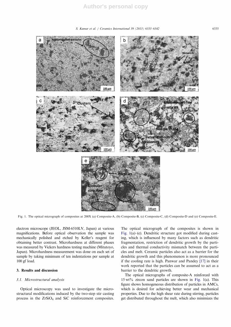
The optical micrograph of the composites is shown inFig. 1(a)–(e). Dendritic structure got modified during cast-ing, which is influenced by many factors such as dendriticfragmentation, restriction of dendritic growth by the parti-cles and thermal conductivity mismatch between the parti-cles and melt. Ceramic particles also act as a barrier for thedendritic growth and this phenomenon is more pronouncedif the cooling rate is high. Panwar and Pandey [17] in theirwork reported that the particles can be assumed to act as abarrier to the dendritic growth.The optical micrographs of composite-A reinforced with
15 wt% zircon sand particles are shown in Fig. 1(a). Thisfigure shows homogeneous distribution of particles in AMCs,which is desired for achieving better wear and mechanicalproperties. Due to the high shear rate during stirring, particlesget distributed throughout the melt, which also minimizes the
Fig. 1. The optical micrograph of composites at 200X (a) Composite-A, (b) Composite-B, (c) Composite-C, (d) Composite-D and (e) Composite-E.
S. Kumar et al. / Ceramics International 39 (2013) 6333–6342 6335
Author's personal copy
particles settling. However, fine particles are pushed at fasterrate during stirring action which gets agglomerated around thearea away from stirrer which is visible at certain places in themicrostructure. In the micrograph of the composite-A frag-mented dendrites in the matrix can also be seen, thoughlimited dendritic growth in the particle depleted region is alsovisible in this figure. During solidification fine size (20–32 mm)zircon sand particles are pushed or engulfed by advancingsolid–liquid interface creating sufficient space inside the matrix,which leads to growth of dendrite [11]. Dendrites fragmenta-tion can be attributed to the shearing of initial dendritic armsby the stirring action. The zircon sand particles provide site fornucleation of melt as temperature difference between particleand the melt is higher. It was also found that the perturbationin the solute field due to the presence of particles can changethe dendrite tip radius and the dendrite tip temperature. Allthese effects lead dendrite to cell formation. Also the length ofthe dendrite is reduced due to the presence of the particles inmatrix [18]. The optical micrographs of composite-B rein-forced with 3.75 wt% of zircon sand and 11.25 wt% siliconcarbide particles in the ratio of 1:3 are shown in Fig. 1(b). Thestructure exhibits uniform distribution of particles inside thematrix. However, the particles are observed to form networkstructure at certain places. Moreover, eutectic silicon networkis fine and the dimension of interdendritic region is compar-ably less than that of the particle diameter. Absence of voids atinterface indicates the good bonding between the matrix andthe reinforced particles, which helps in better load transferfrom the matrix to reinforcement materials.
The optical micrographs of composite-C containing7.5 wt% of zircon sand and 7.5 wt% silicon carbideparticles in the ratio of 1:1 is shown in Fig. 1(c). It depictsthe refinement of microstructure and eutectic silicon. Theeutectic silicon got refined to finer scale and nucleates nearparticles as colonies. Clustering of particles is observed atsome places and some of the clustered particles have chipout during grinding and polishing of the samples.
Micrograph of composite-D containing 11.25 wt% ofzircon sand and 3.75 wt% silicon carbide particles in theratio 3:1 is shown in Fig. 1(d). Finer to coarse distributionof eutectic silicon along with homogeneous distribution ofparticles can be seen. Eutectic silicon colonies aroundparticles are more pronounced in the micrograph. Eutecticsilicon is more refined and morphology has changed fromacicular to globular around the particles. Also in the matrixthe eutectic silicon having blunted morphology as comparedto long needle shape or acicular is seen. However, the fineparticles and silicon form a network structure because ofpushing interface from different nucleation sites. Moreover,the clustering of fine particles at some places is also observed.
Optical micrograph of composite-E containing 15 wt% ofsilicon carbide particles is shown in Fig. 1(e). Here eutecticsilicon is more refined and are of finer scale as comparedto other composites. Clustering is also observed at someplaces. The eutectic silicon colonies network is observed.The majority of eutectic silicon is acquiring globularmorphology and eutectic colonies are interconnected.
Overall analysis of structure indicates that microstruc-ture is refined whereas eutectic silicon are having bluntedand globular morphological features. This refinement maylead to better tribological and mechanical properties ofthe composite. The colonization of eutectic silicon in thevicinity of the particles enhances wear resistance ofmaterial. The reinforced particles are fairly distributed inthe alloy matrix. The good bonding between particles andalloy matrix is also revealed in the microstructural analy-sis. Moreover, porosity is at minimum level and notobserved in the optical examination, although clustering isseen at same places in the composite. Microstructure analysisshows that addition of SiC has a pronounced effect on themicrostructure refinement, particularly eutectic silicon. Thedegree of microstructure and eutectic silicon refinementincreases in accordance with the increase of SiC reinforcedparticle percentage. The most prominent feature observed inall composites is the absence of dendritic growth, whichis accounted for two-step stir casting processing of thecomposites.
3.2. Microhardness
The microhardness measurement at different phases ofcomposite has been carried out to know the effect ofreinforced particulates on the alloy matrix. It is observedthat the hardness of aluminum composites increases withincrease in SiC particle content as given in Table 4.Microhardness measurements have been carried out on
the embedded reinforced particles as well as in the vicinityof particles and matrix. Reinforced particles show highhardness, which decreases as we move away from particleto matrix. The high hardness at particle/matrix interfaceindicates good interfacial bonding between particle andalloy matrix. Composite-B shows high microhardnessvalue at particle, interface and matrix in comparison toother composites, which is achieved by good interfacialbonding and refinement of microstructure.
3.3. Wear characteristics
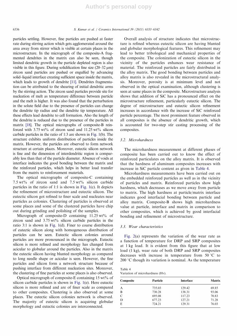
Fig. 2(a) represents the variation of the wear rate asa function of temperature for DRP and SRP compositesat 1 kg load. It is evident from this figure that at lowload (1 kg), wear rate of both DRP and SRP compositesdecreases with increase in temperature from 50 1C to200 1C though its variation is nominal. As the temperature
Table 4
Variation of microhardness (Hv).
Composite Particle Interface Matrix
A 735.03 129.42 69.85
B 730.28 138.31 93.06
C 695.08 117.23 70.83
D 677.23 127.21 71.28
E 724.21 129.31 76.03
S. Kumar et al. / Ceramics International 39 (2013) 6333–63426336

Author's personal copy
is increased, Al matrix expands and holds the particle moretightly. Under these conditions, reinforced particles offermore resistance to wear causing a decrease in wear rate.Here adhesive wear mechanism dominates up to 200 1C.However, at higher temperature, due to the formation ofoxide layers between the sample surface and countersurface of the steel disc wear rate of the compositesdecreases sharply. The decrease in wear rate at elevatedtemperature is because of the fact that at low load theasperities on the surface are elastically deformed. It isfurther noted that DRP composites offer lower wear ratein comparison to that of SRP composites. It is interestingto note that above 200 1C the wear rate of all compositesincreases gradually as temperature is increased. The com-posites show transition from mild to serve wear at above200 1C temperature. Martin et al. [19] have measured thewear rate for 2618 Al alloy reinforced with 15 vol% SiC inthe temperature range 20 1C to 200 1C where a transitionfrom mild to severe wear was observed. Zhang and Alpas[20] have suggested that the critical transition (from mild tosevere) of wear mode occurs at temperature correspondingto 0.4Tm where Tm is melting point of alloy (Tm¼650 1C,
melting temperature for LM13 alloy). At this critical tem-perature, thermally activated deformation process becomesactive which may lead to softening of the material adjacent tothe contact surfaces.The wear rate of all composites at high load (5 kg) with
variation in temperature from 50 1C to 300 1C is shown inFig. 2(b). It was observed that wear rate increases slightlyfrom 50 1C to 150 1C and then decreases at 200 1Ctemperatures for both DRP and SRP composites. At theinitial stage of sliding, the alloy matrix expands andbecome soft compared to a later stage. The tightenedparticles are removed under the influence of high load andgot detached exposing fresh matrix surface. However, thealloy gets strain hardened due to continuous sliding underan applied load after a certain sliding distance, whichfurther offers resistance to wear and less loss is observed inbetween 50 1C and 150 1C at higher load condition.Between 150 1C and 200 1C formation of oxide layer onthe surface of pin protects the surface causing a decrease inwear rate [19]. Above 200 1C the transition from mild tosevere wear occurs and matrix becomes more soft causingdetachment of the formed oxide layer by delaminationmechanism [21]. Increment in wear rate is because of theremoval of large wear particles by the process of plasticdeformation of the surface layer, nucleation of subsurfacecrack followed by crack propagation due to continuoussliding action. Again, it is interesting to note that withincrement in temperature from 250 1C to 300 1C, the wearrate of DRP and SRP composites gradually decreases. Athigher load and high temperature, the chip out debris stickat the edges (due to softening effect of matrix at highertemperature) get removed easily from the edges resulting adecrement in wear rate. In all the tests composite-B iscontinuously exhibiting better wear resistance at all tem-perature. Better microhardness of the interface can bedirectly correlated to the good bonding achieved by thereinforcement with the matrix. Composite-D also exhibitsbetter wear resistance as compared to composite-A inwhich only zircon sand particle is reinforced. However,composite-B also exhibits better wear resistance as com-pared to composite-E in which only silicon carbideparticles are reinforced. Composite-B having a combina-tion of 3.75% silicon carbide and 11.25% zircon sandparticles shows better wear resistance as compared to allcomposites at high load (5 kg) with an increase in tem-perature from 50 1C to 300 1C. All the composites showthe increment in wear rate with increase in temperaturefrom 200 1C to 250 1C followed by further decrease withincreasing temperature up to 300 1C at 5 kg load. Thisvariation in wear rate is because of removal of oxide layerdue to continuous sliding action, which results in directmetal-to-metal contact. Rajaram et al. [21] pointed outthat the formation of oxide films at high temperaturereduces the wear rate by avoiding direct metal-to-metalcontact. The oxide film may be removed due to continuoussliding actions, which results in direct metal-to-metalcontact, and exposing new surface to the environment.
50 100 150 200 250 300
1.0
1.5
2.0
2.5
3.0
3.5
Wea
r rat
e x
10-3
(mm
3/m
)
A B C D E
50 100 150 200 250 3004
6
8
10
12
14
16
18
20
22
24
Wea
r rat
e x
10-3
(mm
3/m
)
Temperature (°C)
Temperature (°C)
A B C D E
Fig. 2. Wear rate against the temperature of the composites with (a) 1 kg
load and (b) 5 kg.
S. Kumar et al. / Ceramics International 39 (2013) 6333–6342 6337
Author's personal copy
At elevated temperatures, the strain transfer phenomenonto the interfaces becomes less effective as the surroundingmatrix alloy begins to soften. At this stage the fracturing ofthe reinforced particles may mainly occur by crushing andgrinding action against each other and also the steelcounterface in the soft matrix alloy. As a result, majorcomponent of composite may get damaged at elevatedtemperatures under tensile strain conditions and may leadto formation and growth of void within the matrix alloy[22]. There is a decrement in wear rate at 300 1C for allcomposites, which is mainly due to the presence of steeldebris between the sliding surface. Wilson and Alpas [22]have observed similar behavior around 300 1C for Almatrix composite. They suggested that there is a possiblemild to severe wear transition occurring in the counterfacesteel itself, at or near a temperature of 300 1C. Once severewear and seizure effects arise in with the steel duringsliding contact, the steel debris generated by this processwould be transferred to the opposing wear surface of thecomposite specimen leading to negative or minimumcomposite wear rate.
After analyzing wear behavior of composites at lowloads (1 kg) and high load (5 kg) at different temperature,it is clear that dual reinforcement particle (DRP) mixed
in definite proportion is very much effective process forenhancing wear resistance. Silicon carbide particles arebetter for wear behavior as compared to zircon sandparticles as reinforcement in LM13 alloy. Composite-Bexhibits better wear behavior due to high microhardness ofthe interface between particle and matrix. Good interfacialbonding is necessary for better wear behavior as loadtransfer occurs through interface and also debonding ofreinforcement particles results in increase in wear rate.
3.4. Morphological analysis of worn surface and debris
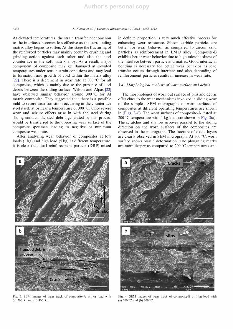
The morphologies of worn out surface of pins and debrisoffer clues to the wear mechanisms involved in sliding wearof the samples. SEM micrographs of worn surfaces ofcomposites at different operating temperatures are shownin (Figs. 3–6). The worn surfaces of composite-A tested at200 1C temperature with 1 kg load are shown in Fig. 3(a).The scratches and shallow grooves parallel to the slidingdirection on the worn surfaces of the composites areobserved in the micrograph. The fracture of oxide layersare clearly observed in SEM micrograph. At 300 1C, wornsurface shows plastic deformation. The ploughing marksare more deeper as compared to 200 1C temperatures and
Fig. 3. SEM images of wear track of composite-A at1 kg load with
(a) 200 1C and (b) 300 1C.
Fig. 4. SEM images of wear track of composite-B at 1 kg load with
(a) 200 1C and (b) 300 1C.
S. Kumar et al. / Ceramics International 39 (2013) 6333–63426338
Author's personal copy
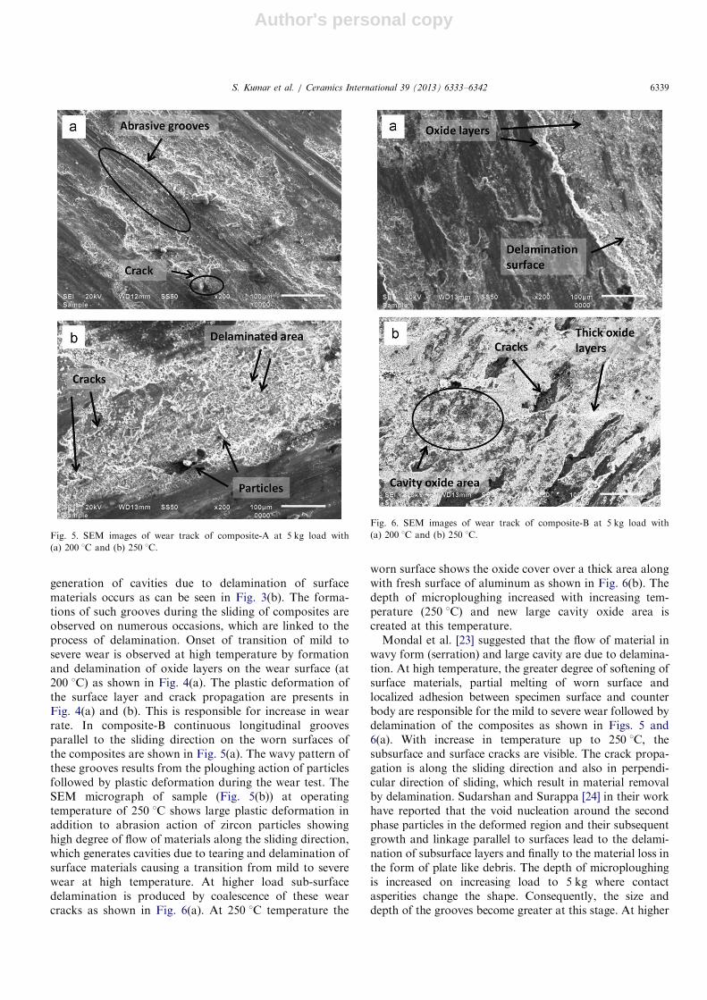
generation of cavities due to delamination of surfacematerials occurs as can be seen in Fig. 3(b). The forma-tions of such grooves during the sliding of composites areobserved on numerous occasions, which are linked to theprocess of delamination. Onset of transition of mild tosevere wear is observed at high temperature by formationand delamination of oxide layers on the wear surface (at200 1C) as shown in Fig. 4(a). The plastic deformation ofthe surface layer and crack propagation are presents inFig. 4(a) and (b). This is responsible for increase in wearrate. In composite-B continuous longitudinal groovesparallel to the sliding direction on the worn surfaces ofthe composites are shown in Fig. 5(a). The wavy pattern ofthese grooves results from the ploughing action of particlesfollowed by plastic deformation during the wear test. TheSEM micrograph of sample (Fig. 5(b)) at operatingtemperature of 250 1C shows large plastic deformation inaddition to abrasion action of zircon particles showinghigh degree of flow of materials along the sliding direction,which generates cavities due to tearing and delamination ofsurface materials causing a transition from mild to severewear at high temperature. At higher load sub-surfacedelamination is produced by coalescence of these wearcracks as shown in Fig. 6(a). At 250 1C temperature the
worn surface shows the oxide cover over a thick area alongwith fresh surface of aluminum as shown in Fig. 6(b). Thedepth of microploughing increased with increasing tem-perature (250 1C) and new large cavity oxide area iscreated at this temperature.Mondal et al. [23] suggested that the flow of material in
wavy form (serration) and large cavity are due to delamina-tion. At high temperature, the greater degree of softening ofsurface materials, partial melting of worn surface andlocalized adhesion between specimen surface and counterbody are responsible for the mild to severe wear followed bydelamination of the composites as shown in Figs. 5 and6(a). With increase in temperature up to 250 1C, thesubsurface and surface cracks are visible. The crack propa-gation is along the sliding direction and also in perpendi-cular direction of sliding, which result in material removalby delamination. Sudarshan and Surappa [24] in their workhave reported that the void nucleation around the secondphase particles in the deformed region and their subsequentgrowth and linkage parallel to surfaces lead to the delami-nation of subsurface layers and finally to the material loss inthe form of plate like debris. The depth of microploughingis increased on increasing load to 5 kg where contactasperities change the shape. Consequently, the size anddepth of the grooves become greater at this stage. At higher
Fig. 5. SEM images of wear track of composite-A at 5 kg load with
(a) 200 1C and (b) 250 1C.
Fig. 6. SEM images of wear track of composite-B at 5 kg load with
(a) 200 1C and (b) 250 1C.
S. Kumar et al. / Ceramics International 39 (2013) 6333–6342 6339
Author's personal copy
load the material removal is caused by micro cutting anddelamination, which is resulted from the microcracks.
4. Analysis of debris
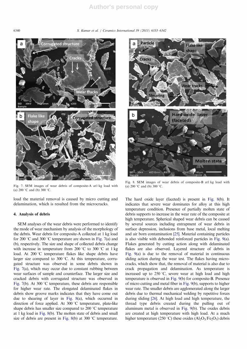
SEM analyses of the wear debris were performed to identifythe mode of wear mechanism by analysis of the morphology ofthe debris. Wear debris for composite-A collected at 1 kg loadfor 200 1C and 300 1C temperature are shown in Fig. 7(a) and(b), respectively. The size and shape of collected debris changewith increase in temperature from 200 1C to 300 1C at 1 kgload. At 200 1C temperature flakes like shape debris havelarger size compared to 300 1C. At this temperature, corru-gated structure was observed in some debris shown inFig. 7(a), which may occur due to constant rubbing betweenwear surfaces of sample and counterface. The larger size andcracked debris with corrugated structure was observed inFig. 7(b). At 300 1C temperature, these debris are responsiblefor higher wear rate. The elongated delaminated flakes indebris show groove marks indicates that they have come outdue to shearing of layer in Fig. 8(a), which occurred indirection of force applied. At 300 1C temperature, plate-likeshape debris has smaller size compared to 200 1C temperatureat 1 kg load in Fig. 8(b). The molten state of debris and smallsize of debris are present in Fig. 8(b) at 300 1C temperature.
The hard oxide layer (faceted) is present in Fig. 8(b). Itindicates that severe wear dominates for alloy at this hightemperature condition. Presence of partially molten state ofdebris supports to increase in the wear rate of the composite athigh temperature. Spherical shaped wear debris can be causedby several sources including entrapment of wear debris insurface depression, inclusions from base metal, local meltingand air born contamination [25]. Material containing particlesis also visible with debonded reinforced particles in Fig. 9(a).Flakes generated by cutting action along with delaminatedflakes are also observed. Layered structure of debris inFig. 9(a) is due to the removal of material in continuoussliding action during the wear test. The flakes having micro-cracks, which show that, the removal of material is also due tocrack propagation and delamination. As temperature isincreased up to 250 1C, severe wear at high load and hightemperature is observed in Fig. 9(b) for composite-B. Presenceof micro cutting and metal fiber in Fig. 9(b), supports to higherwear rate. The smaller debris are agglomerated along the largerdebris due to thermal mechanical welding by repetitive forcesduring sliding [26]. At high load and high temperature, thethread type debris created during the pulling out ofaluminum metal is observed in Fig. 9(b). The oxides debrisare created at high temperature with high load. At a muchhigher temperature (250 1C) these oxides (Al2O3/Fe2O3) debris
Fig. 7. SEM images of wear debris of composite-A at1 kg load with
(a) 200 1C and (b) 300 1C.
Fig. 8. SEM images of wear debris of composite-B at1 kg load with
(a) 200 1C and (b) 300 1C.
S. Kumar et al. / Ceramics International 39 (2013) 6333–63426340
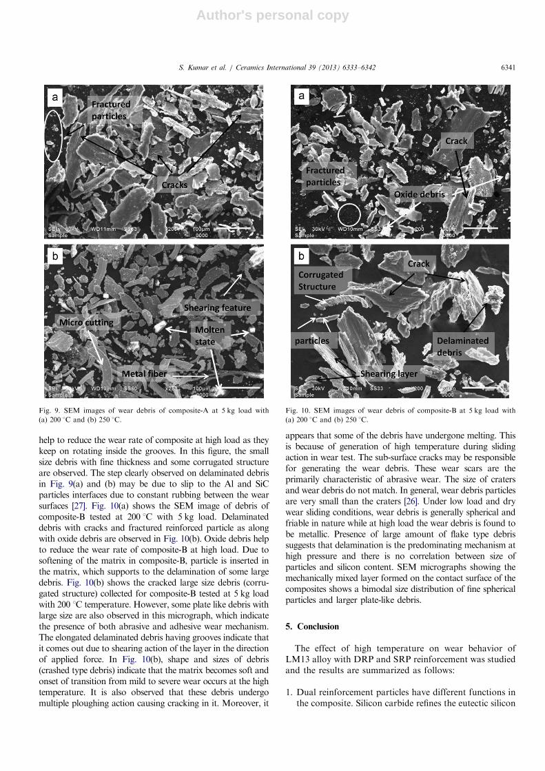
Author's personal copy
help to reduce the wear rate of composite at high load as theykeep on rotating inside the grooves. In this figure, the smallsize debris with fine thickness and some corrugated structureare observed. The step clearly observed on delaminated debrisin Fig. 9(a) and (b) may be due to slip to the Al and SiCparticles interfaces due to constant rubbing between the wearsurfaces [27]. Fig. 10(a) shows the SEM image of debris ofcomposite-B tested at 200 1C with 5 kg load. Delaminateddebris with cracks and fractured reinforced particle as alongwith oxide debris are observed in Fig. 10(b). Oxide debris helpto reduce the wear rate of composite-B at high load. Due tosoftening of the matrix in composite-B, particle is inserted inthe matrix, which supports to the delamination of some largedebris. Fig. 10(b) shows the cracked large size debris (corru-gated structure) collected for composite-B tested at 5 kg loadwith 200 1C temperature. However, some plate like debris withlarge size are also observed in this micrograph, which indicatethe presence of both abrasive and adhesive wear mechanism.The elongated delaminated debris having grooves indicate thatit comes out due to shearing action of the layer in the directionof applied force. In Fig. 10(b), shape and sizes of debris(crashed type debris) indicate that the matrix becomes soft andonset of transition from mild to severe wear occurs at the hightemperature. It is also observed that these debris undergomultiple ploughing action causing cracking in it. Moreover, it
appears that some of the debris have undergone melting. Thisis because of generation of high temperature during slidingaction in wear test. The sub-surface cracks may be responsiblefor generating the wear debris. These wear scars are theprimarily characteristic of abrasive wear. The size of cratersand wear debris do not match. In general, wear debris particlesare very small than the craters [26]. Under low load and drywear sliding conditions, wear debris is generally spherical andfriable in nature while at high load the wear debris is found tobe metallic. Presence of large amount of flake type debrissuggests that delamination is the predominating mechanism athigh pressure and there is no correlation between size ofparticles and silicon content. SEM micrographs showing themechanically mixed layer formed on the contact surface of thecomposites shows a bimodal size distribution of fine sphericalparticles and larger plate-like debris.
5. Conclusion
The effect of high temperature on wear behavior ofLM13 alloy with DRP and SRP reinforcement was studiedand the results are summarized as follows:
1. Dual reinforcement particles have different functions inthe composite. Silicon carbide refines the eutectic silicon
Fig. 9. SEM images of wear debris of composite-A at 5 kg load with
(a) 200 1C and (b) 250 1C.
Fig. 10. SEM images of wear debris of composite-B at 5 kg load with
(a) 200 1C and (b) 250 1C.
S. Kumar et al. / Ceramics International 39 (2013) 6333–6342 6341
Author's personal copy
whereas zircon sand provides good interfacial bonding.Zircon sand and silicon carbide particles also provideeffective nucleation site for eutectic silicon. The eutecticsilicon is having globular morphology in the vicinity ofparticles.
2. The combination of zircon sand and silicon carbide particlein a ratio of (1:3) reinforcement in the composite exhibitsbetter wear resistance as compared to other combinationsat all the temperature at low and high load both.
3. Study reveals that the dual reinforcement particleenhances the wear resistance as compared to singlereinforcement particle if mixed in a definite proportion.
4. Wear behavior of the composites is increased linearlywith increasing the operating temperature at high load.This effect is due to formation of the oxide filmand glazing layer on sliding components. These layersprevent the direct metal-to-metal contact of slidingsurfaces during sliding.
Acknowledgement
The authors are thankful to Armament Research Board(ARMREB), Defence Research and Development Organi-zation (DRDO), India for providing financial support underthe letter no. ARMREB/MAA/2008/105 for this study.
References
[1] S. Bajwa, W.M. Rainforth, W.E. Lee, Sliding wear behaviour of SiC/
Al2O3 nano composites, Wear 259 (2005) 553–561.
[2] S. Das, K. Das, S. Das, Abrasive wear behavior of Al–4.5 wt% Cu/
(zircon sandþsilicon carbide) hybrid composite, Journal of Compo-
site Materials 43 (2009) 2665–2672.
[3] K. Kaur, O.P. Pandey, Dry sliding wear behavior of zircon sand
reinforced Al–Si alloy, Tribology Letters 38 (2010) 377–387.
[4] Y.Q. Wang, A.M. Afsar, J.H. Jang, K.S. Han, J.I. Song, Room
temperature dry and lubricant wear behaviors of Al2O3f/SiCp/Al
hybrid metal matrix composites, Wear 268 (2010) 863–870.
[5] S. Suresha, B.K. Sridhara, Effect of addition of graphite particulates
on the wear behavior in aluminum–silicon carbide-graphite compo-
sites, Materials in Design 31 (2010) 1804–1812.
[6] H. Ahlatci, T. Kocer, E. Candan, H. Cimenoglu, Wear behaviour of
Al/(Al2O3pþSiCp) hybrid composites, Tribology International 39
(2006) 213–220.
[7] S. Das, K. Das, S. Das, Abrasive wear of zircon sand and alumina
reinforced Al–4.5 wt% Cu alloy matrix composites-A comparative
study, Composites Science and Technology 67 (2007) 746–751.
[8] K.R. Ahmad, S.B. Jamaludin, L.B. Hussain, Z.A. Ahmad, The
influence of alumina particle size on sintered density and hardness of
discontinuous reinforced aluminum metal matrix composite, Jurnal
Teknologi 42 (A) (2005) 49–57.
[9] N. Ozdemir, F. Yakuphanoglu, The effects of particle size and volume
fraction of Al2O3 on electronic thermal conductivity of a-Al2O3
particulate reinforced aluminum composites (Al/Al2O3-MMC), Inter-
national Journal of Advanced Manufacturing Technology 29 (2006)
226–229.
[10] Y. Wang, H.Y. Wang, K. Xiu, Hong-Ying Wang, Q.C. Jiang, Fabrica-
tion of TiB2 particulate reinforced magnesium matrix composites by two-
step processing method, Materials Letters 60 (2006) 1533–1537.
[11] W. Zhou, Z.M. Xu, Casting of SiC reinforced metal matrix composites,
Journal of Materials Processing Technology 63 (1997) 358–363.
[12] V. Sharma, S. Kumar, R.S. Panwar, O.P. Pandey, Microstructural
and wear behavior of dual reinforced particle (DRP) aluminum alloy
composite, Journal of Materials Science 47 (2012) 6633–6646.
[13] S. Kumar, V. Sharma, R.S. Panwar, O.P. Pandey, Wear behavior of
dual particle size (DPS) zircon sand reinforced aluminum alloy,
Tribology Letters 47 (2012) 231–251.
[14] J. Hashim, The production of cast metal matrix composite by a
modified stir casting method, Jurnal Teknologi 35A (2001) 9–20.
[15] S.K. Chaudhury, A.K. Singh, C.S. Sivaramakrishnan, S.C. Panigrahi,
Wear and friction behavior of spray formed and stir cast Al2Mg11TiO2
composites, Wear 258 (2005) 759–767.
[16] E.G. Okafor, V.S. Aigbodion, Effect of zircon silicate reinforcements
on the microstructure and properties of as cast Al–4.5Cu matrix
particulate composites synthesized via squeeze cast route, Tribology
in Industry 32 (2010) 31–37.
[17] R.S. Panwar, O.P. Pandey, Analysis of wear tracks and debris of stir
cast LM13/Zr composite at elevated temperatures, Materials Char-
acterization 75 (2013) 200–213.
[18] J. Hashim, L. Looney, M.S.J. Hashmi, Particle distribution in cast
metal matrix composites—Part 1, Journal of Materials Processing
Technology 123 (2002) 251–257.
[19] M.A. Martinez, A. Martin, J. Llorca, Wear of SiC-reinforced Al-matrix
composites in the temperature range 20–200 1C, Wear 193 (1996)
169–179.
[20] J. Zhang, A.T. Alpas, Wear Regimes and transition in Al2O3
particulate-reinforced alloys, Materials Science and Engineering A
161 (1993) 273–284.
[21] G. Rajaram, S. Kumaran, T. Srinivasa Rao, High temperature
tensile and wear behaviour of aluminum silicon alloy, Materials
Science and Engineering A 528 (2010) 247–253.
[22] S. Wilson, A.T. Alpas, Effect of temperature on the sliding wear
performance of Al alloys and Al matrix composites, Wear 196 (1996)
270–278.
[23] D.P. Mondal, S. Das, R.N. Rao, M. Singh, Effect of SiC addition
and running-in wear on the sliding wear behaviour of Al–Zn–Mg
aluminium alloy, Materials Science and Engineering A 402 (2005)
307–319.
[24] M.K. Surappa Sudarshan, Dry sliding wear of fly ash particle
reinforced A356 Al composites, Wear 265 (2008) 349–360.
[25] A.W.J. De Gee, A note on the relation between friction and wear,
Wear 65 (1981) 397–398.
[26] A.J. Clegg, A.A. Das, Wear of a hypereutectic aluminium–silicon
alloy, Wear 43 (1977) 367–373.
[27] S. Kumar, R.S. Panwar, O.P. Pandey, Wear behavior at high
temperature of Dual particle size (DPS) zircon sand reinforced
aluminum alloy composite, Metallurgical and Materials Transactions
A: Physical Metallurgy and Materials Science (2012) http://dx.doi.org/
10.1007/s11661-012-1504-y.
S. Kumar et al. / Ceramics International 39 (2013) 6333–63426342