Investigation on Tribological Behavior During Friction Drilling ...
14
200 Vol. 42, No. 2 (2020) 200-213, DOI: 10.24874/ti.655.02.19.03 Tribology in Industry www.tribology.rs Investigation on Tribological Behavior During Friction Drilling Process - A Review M. Alphonse a , V.K. Bupesh Raja b, *, M. Gupta c a Department of Mechanical Engineering, Sathyabama Institute of Science and Technology, Chennai, Tamil Nadu, India, b School of Mechanical Engineering, Sathyabama Institute of Science and Technology, Chennai, Tamil Nadu, India, c Department of Mechanical Engineering, National University of Singapore, Singapore. Keywords: Friction Drilling Tribology Parameters Optimization Techniques Characterization A B S T R A C T Friction drilling is a nontraditional hole making process getting tremendous attention recently. In this process, tool is penetrated into the work piece due to the softening caused by the heat, which is developed between tool and the work piece. Materials less than 5mm thickness can be used for friction drilling. Wide varieties of materials such as tool steel, high speed steel, tungsten carbide and H13 steel can be used either with conical profile as friction drilling tool. For improving tool life nano- coating can be applied. This review mainly focuses on various optimization techniques such as Taguchi method and design of experiments, which can be utilized in friction drilling. Surface roughness, conicity and tribological response are also addressed in this study. Various parameters like cutting feed and speed, which play prominent role during friction drilling process are suitably dealt with. © 2020 Published by Faculty of Engineering * Corresponding Author: V.K. Bupesh Raja E-mail: [email protected] Received: 20 February 2019 Revised: 7 September 2019 Accepted: 24 March 2020 1. INTRODUCTION Friction drilling is the futuristic way of producing hole and alternatively called as flow drilling, thermal drilling and friction stir drilling. Friction drilling method is unique process having potential for wide application in structural, automobile and aeronautical components like exhaust engine parts, pedals, handle of seats, frame, castings etc. Plate thickness less than 4mm is advisable for this method. Industry is selected in by owing to their needs. Friction drilling is not recommended to easily melting material and harder material like Corten Steel, which is used in railways and structural members, because this process works on heat, so heat produced is also high. Further research is focused how to make use of this method in those materials. Unlike traditional drilling, Friction Drilling (FD) is an unconventional hole-making method. FD is a clean and chipless hole making method. Bushing is formed in the material during FD process; bushing height is triple times of the thickness of the material thickness. For assembling the FD drilled components, the bush formation shall aid for alignment and easy fastening. In traditional drilling process the fastening and assembly needs additional components incurring REVIEW
-
Upload
khangminh22 -
Category
Documents
-
view
0 -
download
0
Transcript of Investigation on Tribological Behavior During Friction Drilling ...

200
Vol. 42, No. 2 (2020) 200-213, DOI: 10.24874/ti.655.02.19.03
Tribology in Industry
www.tribology.rs
Investigation on Tribological Behavior During Friction Drilling Process - A Review
M. Alphonsea, V.K. Bupesh Rajab,*, M. Guptac
a
Department of Mechanical Engineering, Sathyabama Institute of Science and Technology, Chennai, Tamil Nadu, India, bSchool of Mechanical Engineering, Sathyabama Institute of Science and Technology, Chennai, Tamil Nadu, India, cDepartment of Mechanical Engineering, National University of Singapore, Singapore.
Keywords:
Friction Drilling Tribology Parameters Optimization Techniques Characterization
A B S T R A C T
Friction drilling is a nontraditional hole making process getting tremendous attention recently. In this process, tool is penetrated into the work piece due to the softening caused by the heat, which is developed between tool and the work piece. Materials less than 5mm thickness can be used for friction drilling. Wide varieties of materials such as tool steel, high speed steel, tungsten carbide and H13 steel can be used either with conical profile as friction drilling tool. For improving tool life nano-coating can be applied. This review mainly focuses on various optimization techniques such as Taguchi method and design of experiments, which can be utilized in friction drilling. Surface roughness, conicity and tribological response are also addressed in this study. Various parameters like cutting feed and speed, which play prominent role during friction drilling process are suitably dealt with.
© 2020 Published by Faculty of Engineering
* Corresponding Author:
V.K. Bupesh Raja E-mail: [email protected]
Received: 20 February 2019 Revised: 7 September 2019 Accepted: 24 March 2020
1. INTRODUCTION
Friction drilling is the futuristic way of producing hole and alternatively called as flow drilling, thermal drilling and friction stir drilling. Friction drilling method is unique process having potential for wide application in structural, automobile and aeronautical components like exhaust engine parts, pedals, handle of seats, frame, castings etc. Plate thickness less than 4mm is advisable for this method. Industry is selected in by owing to their needs. Friction drilling is not recommended to easily melting material and harder material like
Corten Steel, which is used in railways and structural members, because this process works on heat, so heat produced is also high. Further research is focused how to make use of this method in those materials. Unlike traditional drilling, Friction Drilling (FD) is an unconventional hole-making method. FD is a clean and chipless hole making method. Bushing is formed in the material during FD process; bushing height is triple times of the thickness of the material thickness. For assembling the FD drilled components, the bush formation shall aid for alignment and easy fastening. In traditional drilling process the fastening and assembly needs additional components incurring
RE
VIE
W

M. Alphonse et al., Tribology in Industry Vol. 42, No. 2 (2020) 200-213
201
additional manufacturing time and material cost. Hence the friction drilling technique can be utilized in automobiles for joining sheet metals [1]. Traditionally, to learn about the optimal machining process parameters, fuzzy logic technique and Taguchi method are commonly used. Taguchi method is commonly used for optimizing friction contact area ratio (FCAR), friction angles (FA), feed rate (FR), surface roughness (SR), bushing length (BL) and spindle speed (SS) thus improving tool life [2]. Studies related to multiple performance characteristics targeting resultant axial force, radial force, hole diameter dimensional error, roundness error and Formation of Bushing was not controllable, Bush will be formed while tool forced downwards. Improper bushing is formed due to low temperatures which cause the softening of material and low ductility. Due to this thrust force will be higher. Length of bushing was also not controllable; normally two to three times of the work piece thickness will be the height of bushing formed. Work piece material, tool material, Spindle speed, tool dimension , feed rate these all determines the height of bushing formed [3,4]. Friction drilling was a five step hole making process, where tool is penetrated into the work material. Due to friction, heat is generated between the material and tool thus softening the material. At early stages of sliding the frictional coefficient varies with respective to the load condition. Thrust force will be more in first two stages, and then will be gradually decreasing. Feed rate, spindle speed plays a major role in friction drilling process. Torque and thrust force are to be optimizing for getting a better surface finish and good quality hole. To calculate the performance of HSS friction drilling tool on AA6351 work piece of thickness 1mm, Taguchi Method is applied. For axial force and thrust force mathematical model was developed. Tribological investigation was done on this paper. Cone angle of the tool was critical to study; influence of torque and thrust force was studied in this research [5]. Work piece below 4mm is advisable for friction drilling process. High temperature rised due to drilling may affect nearby parts also. This can be saved by applying coatings techniques, controlling work piece thickness, feed rate, tool dimension, spindle speed. Somasundram and Boopathy conducted comprehensive research on aluminum-silicon
carbide metal matrix composites. Effect of various parameters such as feed rate and spindle speed were considered. DOE and RSM methods were applied to find an optimal solution. It was observed that torque, thrust force was depending on parameters like tool feed rate and spindle speed [6].To determine the roundness error and microstructure changes while using a friction drilling tool was a major study. Three different variety of material was used for this study and found that wt.%, feed rate and spindle speed have to be controlled, if spindle speed goes high and feed rate used to be maintained medium, to produce good quality hole [7]. Roundness (inside hole) errors on dry friction-drilled holes were investigated. For improving the machining parameters, design matrix and ANOVA were, to determine the optimum solution. Three different composition of material was used for study and found; by increasing wt% results will be good [8]. For producing good quality holes the study of torque and thrust force is very essential. The torque and thrust force increases or decreases with respective to feed rate and spindle speed. With increase in feed rate and constant spindle speed the thrust force increases gradually, if feed rate is constant and higher spindle speed, thrust force decreases. Due to the impact of the thrust force, the surface near the drilled hole also gets affected due to surface adhesion dealing to poor surface finish. Surface roughness of drilled hole is affected by feed rate, thrust force and spindle speed [9]. In a friction drilling process, variations in the wall thickness were compared with AlSi10Mg and AZ31 profiles. Several investigation methods like Quasi Static, Cyclic, and Microscopic analysis were used to determine the load, and found that by increasing the thickness of the work piece, the load and temperature also got increased [10]. The investigators used aluminum and copper as work material and used HSS and tungsten carbide as friction drilling tool for using in industry application. Friction drilling was having more advantages than a conventional method, both materials had good quality hole, but tool wear, surface roughness were found to depends on basic parameters only [11]. In another study, AA2024 aluminum plate was used as base material and microstructure behavior was investigated for evaluating the microstructure modifications, caused because of temperature. Coated tool was having lesser tool wear and surface finish [12]. Focus of this

M. Alphonse et al., Tribology in Industry Vol. 42, No. 2 (2020) 200-213
202
investigation was on the effects of drilling parameters such as feed rate, friction angle, spindle speed, friction contact area ratio (FCAR) on work piece torque, surface temperature and thrust force. Investigators established that Friction Contact Area Ratio (FCAR) with 50 %, 75 % and 100 % can be used for the process as these help to improve productivity [13]. Friction drilling method was performed extensively on ST 12 steel. By comparing with ST 12 steel, aluminum had good quality hole, which can be used in automobile industry [14]. Numerical investigation of a stress, larger elastic strain, and work material deformation in friction drilling method was reported for an aluminum A7075-T6 plate. Numerical analysis revealed that at lowest rpm and highest feed rate bush formation was good [15]. In the friction drilling process thermal conductivity plays a vital role to where and hence frictional heat was investigated. The temperature rises with lower feed rate and spindle speed; the time for cutting a hole gets increases with these parameters. It was very crucial to find out best cutting feed and speed [16]. Tribology is the study of friction, wear and lubrication, It is very much essential to learn the tribological properties during friction drilling process, because in this process tool wear and surface roughness was main criteria to study. During drilling process, high heat is developed. Due to the heat, surface area near to hole, tool also gets affected. During friction drilling there is no additional lubricants added to the drill bit and hence it is a dry cutting process. Miller and Shih investigated the tool wear, 1100 holes was made by Tungsten carbide tool, and the tools tribological properties was investigated [17] [18]. Software DEFORM-3D was used for studying the finite element model. Both experimental and FEM simulation studies were compared for friction drilling process. Effective stress decreases and strain increases with increase in feed rate and spindle speed, the investigator concluded that with rise in strain bushing quality may get reduce [19]. Thermal camera was used for finding the temperature difference during drilling. Temperature rise with increase in thrust force and torque, so main focus was to decrease both to produce good quality hole [20]. Surface roughness (Ra) of a tungsten carbide tool was measured after machining process and porosity of work piece, micro hardness, and roundness error were
established as major criteria. Quality of hole can be increased with raising the spindle speed and lower feed rate. Temperature near to hole was high while comparing with nearby areas. This temperature difference may affect the hole quality too [21]. With the continuous machining process micro structural changes affected indentation hardness during the friction drilling of titanium, carbon steel, aluminum and alloy steel. Due to high temperature or high thrust force, micro structure of the work piece may get affected. The effect in hole is more because due to the above the work piece may melt, burn or scratch. Delamination like fibre pull out may occur. The bushing may not form in even [22]. Qu and Blau used carbide tools for friction drilling process and reported a new method to calculate shear stress and friction coefficient result. The investigators developed mathematical calculation for each stage of friction drilling process and compared with real experiment result. The aim is to find the shear stress and friction coefficient. Impact was very high in first stage, because at starting stage it required more stress for cutting [23]. Investigation on surface roughness and bushing shape was analyzed for a sheet of Al alloy, found that for both thrust force has to be controlled [24]. The investigators compared both analytical and experimental method. Ansys was used as the tool for finite element modeling (FEM). In the experimental method, results concluded with high temperature the work-material undergoes deformation during machining process, this is because of load, so it is necessary to prevent raising the load [25]. On a cast metal friction drilling process was done, with increase in temperature bushing height too increases. The investigator found in his study that temperature rises with decrease in torque and thrust force. All these are dependent on feed rate and spindle speed [26]. An infrared camera was used for analyzing tool and work piece behavior. Thermal images state the inner core shape of the material. The investigator observed that there is a difference in tool and work piece temperature, with respective to the basic parameters [27]. The investigator proved that by preheating the material up to 247° C the process time can be reduced from 1.8 s to 0.8 s. By comparing experimental study processing time it consumed 10 s to 15 s. By preheated material the investigator proved the processing time can change [28]. The PVD (Ti, Al) N coated drill bit

M. Alphonse et al., Tribology in Industry Vol. 42, No. 2 (2020) 200-213
203
was used for machining process. Difference in coating was also studied through this research. Coated tool was having higher tool life while comparing uncoated tool [29]. The tool tip may get wear; diameter of the hole may not get affected to an extent. To reduce tool wear, point angle can be varied. K. Chong et al. found that 55° produces better hole. Surface roughness of hole was also good while comparing with other point angles. If roughness is good, then obviously diameter of hole may not be more. In further research main concentration is to reduce tool wear [30]. Effect of machining parameters like thrust force and the temperature in hole zone was investigated during friction drilling process. Machining conditions such as spindle speed, friction cone angle and feed rate are used for examining the properties of washer and petal geometry. For the study, different frictional angle and tool was used. Cone angle of tool was to be main criteria while designing tool [31]. Friction drilling is a green method with many advantages. From the literature survey it was found that study of bushing plays a crucial role. Bushing height has two main purposes one for threading and other is for holding. Bushing height depends upon the material and basic parameters like feed rate and spindle speed. In the experimental study three different tool point angle and galvanized material were used for drilling [32]. Simulated annealing optimization approach was used for validating the results. The spindle speeds of 3600 rpm with tool angle of 37.5º were found to be the optimum parameters for producing a good bushing height of 5.92 mm. While comparing both experimental and predicted values there was only 0.02 mm difference. Microstructure was more affected during the second stage and third stage of the drilling process; this is due to the high temperature generated during the process. Initial stage of friction drilling has less impact [32]. Navasingh et al. used three different spindle speed, tool angle and work piece thickness [33]. The bushing height was investigated with respect to ANN algorithm added with genetic algorithm. It was found that maximum bushing height can be obtained with maximum spindle speed. The galvanized material yielded maximum bushing height of 5.7
mm [33]. Ozek et al. also investigated the bushing height with reference to spindle speed, feed rate and surface roughness. It was noticed for aluminum alloy that with spindle speed of 3600 rpm, feed rate of 75 mm/min the maximum bushing height can be realized with minimum surface roughness. With increasing feed rate the surface roughness was getting affected by tool-work piece interaction [24]. Lower feed rate provides more advantage in flange height exhibiting appropriate shear force [34]. The investigators studied the torque in drill bit with dynamic modeling and real-time torque control. They observed that the surface roughness and bushing height could be controlled by torque [35]. The impact of tribological properties in the tool wear is crucial. Tool wear affects the tolerances. Due to the impact of tool wear the surface of work piece also gets damaged. The impact on the surface of drilled hole is caused due to the extreme conditions of spindle speed, feed rate, tool wear. Due to the above conditions bushing height also varies. In order to have good surface finish the spindle speed has to be high and feed rate has to be low. Another important factor is tool cone angle, so it could be observed that choice of correct tool with proper dimension and above drilling parameters are crucial factors. For calculating the process parameters as axial power and torque, an analytical model was developed. Comparison was done between experimental and numerical analyses. 3D FEM was applied for analytical study [36]. Tungsten carbide drill bit was used for experiment, with uncoated and coated tool. Performance of both the tools was experimentally studied with varieties of feed rate and spindle speed. Surface temperature, tool wear and axial thrust force were studied. Coated tool shows less wear and good surface finish [37]. Friction Drilling and Form tapping were jointly investigated in the process. The optimal condition was frequency monitored in both the cases. In further research the investigator recommend to use form tapping tool instead of friction tool [38]. V. Geffen in older days found a piercing tool, to making a hole with the help of frictional heat. Tool in this kind was used for machining light material. For heavy material piercing material was not suitable. Bosh was formed depend upon material hardness. Cylindrical area of tool makes surface area smoother. It is most important to
M. Alphonse et al., Tribology in Industry Vol. 42, No. 2 (2020) 200-213
204
design piercing tool for work material either of hard or soft material [39]. V Geffen defines the following points for a piercing tool, hole quality and surface roughness can be made better by point angle and tapered section. Temperature increased with respective to rotating tool speed. Frictional heat which developed during the process makes changes in surface quality of tool and work piece [40]. Hole quality, bush formation was depending on tool size, plate size. Rajesh et al. found that maximum of 3 mm work piece was advisable for piercing. Rajesh et al. derived in his study how to form a boshed hole with a piercing drill [41]. In this research, A. Bustillo et al. found the importance for comparing results with experimental work and simulation. Copper was used as base material. A. Bustillo et al. analyzed the material flow rate in the material. For a thin sheet to find the bush formation and to compare the results, that was the primary agenda. The results revealed that thrust force which plays a major role in bush formation. So the further work to be focused on how to reduce thrust force, to get an good quality hole [42]. O Pereira et al. discussed the use of friction drilling process in medium and high pressure boilers [43]. Optimization process was used to find the best possible process parameters. In the study S.S Habib attempted both dry drilling and wet drilling. It was observed that friction drilling process is most effective method for hole making. For validating results life cycle assessment test was conducted. The results revealed that friction drilling technique is most effective method for hole making in a metal sheet. The studies also revealed that thrust force generated during friction drilling was very high when compared to other methods, due to high frictional force involved in the process. S. S Habib and A. Bustillo et al. also investigated the effect of machining on the environment. Life cycle assessment showed that friction drilling method system boundary is free from cutting heat and chips which are traditionally thrown into the environment. In the other methods environment will be affected. In the field of manufacturing, study of cutting parameters are very essential. To improve the life of material and tool the optimization techniques are used [42,44]. To that effect, RSM is a standard tool for optimization. It is very essential to optimize the basic parameters like feed rate and spindle speed. It was found that by increasing the spindle speed the bushing height
was increased gradually and in the study it was found that 1.6 mm thickness material gives an optimized result [45]. Maximum bushing height was obtained with spindle speed of 4000 rpm and feed of 70 mm/min [45]. The investigators developed a genetic algorithm for finding the best optimized material and parameters [46]. E. Kilickap et al. concentrated on surface roughness with respect to the input parameters of the friction drilling process. Experimental results were compared with genetic algorithm and RSM method. In the study it was found that the predicted value and actual values are quite close [46]. In an investigation RSM tool was used to find out optimized model [47]. It was found that the lower feed rate, spindle speed and higher point angle of tool reduces the burr height and surface roughness. E. Kilickap developed an ANN model for validating the input and output parameters. Delamination factors were studied with respect to the input parameters. In an investigation it was found that higher rpm produced better surface finish [47]. Predicted and actual results also were closer [48]. It is noted from the literature survey that feed rate has a major role in friction drilling method. Depending upon the feed rate the surface roughness of tool and material is defined. Delamination factors also depend on same criteria. When feed rate is maximum, finish of holes is poor. In the observation it was noted that time required for machining is becoming less with increased feed rate. So it is essential to learn more about feed rate in a friction drilling method. The investigators gave importance to numerical analysis [49]. They focused on temperature effect on aluminum alloy. Heat was more in first few stages [49,58]. Using Deform-3D software, numerical analysis was carried out on titanium sheet metal. The objective of the study was to study the stress-strain distribution and temperature generated [50]. It was found that for titanium sheet metal can with stand up to 797.66 ºC, strain near to hole wall is more and stress is higher about 1690 Mpa. Vijaya baskar et al used ANSYS software to discuss about the bushing length determined from numerical analysis, while varying the spindle speed [51]. Both experimental and numerical values for bushing were compared. Rajesh et al. did exhaustive study on experimental and numerical analysis [52]. Material transformation, temperature were compared in the study. While comparing simulated model it was observed

M. Alphonse et al., Tribology in Industry Vol. 42, No. 2 (2020) 200-213
205
bushing length to be more by about 0.04 mm. But the temperature generated from the experimental model was more [52]. N.R.J. Hynes et al. [53] in the numerical investigation used aluminum metal matrix. By using the numerical analysis, deformation analysis was possible [53]. Another important criterion in friction drilling is spindle speed. For a dual phase steel, surface roughness is very less at higher rpm, while if rpm is reduced the roughness automatically increases. Moreover, bushing height is observed to increase with an increase in spindle speed. It was observed from the research that by increasing spindle speed, roughness was less, bushing height was high and axial force was less. R Kumar et al. concluded that higher spindle speed is optimum for friction drilling [54]. 2. FUNDAMENTAL EXPERIMENTAL
METHODOLOGY Friction drilling is a 5 step process, in which the work piece is softened and tool is penetrated to create a hole. Heat is generated from friction between a work piece and highly rotating friction drill bit. It’s a clean chip less process. In final step, bosh and bushing is formed. Five step nontraditional way of making hole is shown in Fig. 1. The tool tip gets in contact with the work piece at stage 1.
Fig. 1. Steps involved in friction drilling [1].
In both the radial and axial directions the tool tip, like the web center in twist drill, indents into the work piece and supports the drill. The work piece is softened due to the frictional force. In step 2 the tool is extruded into the work piece. In Step 3 work material is pushed side wards and pierces through the work piece. In step 4 the tool tip penetrates into the work piece; in this step the tool further moves forward to work-material pushed aside. This forms the bushing using the cylindrical part of
the tool. When bosh and bushing tool retracts and leaves the hole, enough surface area is created for threading. Bush height is normally three times from original thickness of the plate.
Fig. 2. Experimental setup of friction drilling: overview and close up view. Figure 2 shows the experimental setup of the vertical milling machine, where close up image shows the material is loaded for machining. 3. TRIBOLOGICAL CHARACTERIZATION Friction drilling is a dry cutting process in which a tool is penetrated in to the work piece. Wear is main factor while considering this process. The tribological behavior of both tool and material plays an important role in this process. Tool life and material surface finish decides the improvement in production.
Fig. 3. Tool used for Friction Drilling [7].
Figure 3 shows a normal friction drill tool with 100 & FCAR indicating friction contact area ratio. It may be of two categories 50 % and 100 %. 50 % means 50 % will be in direct contact with the work material, whereas 100 % means full cylindrical portions will be in contact. According the literature survey it is proved that 100 b% FCAR tool gives better result.

M. Alphonse et al., Tribology in Industry Vol. 42, No. 2 (2020) 200-213
206
Fig. 4. View of burr and protrusions [22].
Parameters like spindle speed, feed etc for a friction drilling process plays a major role in wear. Figure 4 shows zoomed view after drilled hole. Parameters used were: 3600 rpm spindle speed, 50 mm/min: feed for a 1.62 mm thick plate. Al5052 steel material was used as work piece material. Burr and Protrusion were formed on the work piece during machining process [8]. Figure 5 shows the roundness errors while conducting friction drilling process. Error is normal in case of a drilling process. These errors are depending on various parameters like feed rate, spindle speed and material [7].
Fig. 5. Roundness Profile [8].
In this work, Al/SiC plate was used for machining process. All the 4 holes are having different parameter.
4. EXPERIMENTAL OUTCOMES AND ANALYSIS Table 1 shows the friction drilling parameters for the study conducted by Shankar and Kumar [8]. Spindle speed was varied from 2500 to 3000 rpm. Figure 6 shows the roundness error with each combination. Bottom left combination is good when compared to others. At 3000 rpm, 60 mm/min thickness of 4mm surface roughness is less. If rpm is less and feed rate is more, roughness is more. For a very less tool wear, higher rpm and lower feed rate is the best choice. Table1. Friction Drilling Parameters .
Friction Drilling Parameters
Position Spindle Speed (rpm)
Feed Rate (mm/min)
Wt (%)
Thickness (mm)
Top Left 3000 60 25 3
Top Right 2500 50 20 3.5
Bottom left 3000 60 15 4
Bottom right 3000 60 5 3

M. Alphonse et al., Tribology in Industry Vol. 42, No. 2 (2020) 200-213
207
Fig. 6. Effect of thrust force [9].
The effect of thrust force was investigated for 3 speeds (2500, 3000 & 3500 rpm) and 3 feed rates (80,100 & 120 mm/min). Distance of tool covered in horizontal axis, from initial contact first stage to last stage is illustrated in Fig. 1. Vertical axis represents the thrust force. The results are presented in Fig. 6. M Boopathi concluded that thrust force is maximum (2500N) for lower spindle speed (2500rpm) and maximum feed rate (120mm/min), whereas thrust force is minimum (1200N) for lower feed rate and (80mm/min higher spindle speed (35000 N). Figure 7 shows the optical image of the hole. The hole structure is complex with zones of different structural features. Three main areas in the hole are heat affected zone (HAZ), thermo-mechanically affected zone (TMAZ) and stir zone (SZ). As the SZ zone is in direct contact with the tool, it is more affected as it experienced significant friction, deformation
and heating. TMAZ zone also experienced high temperature and deformation but to a lesser extent as it was not in direct contact with the tool. For HAZ zone, only heat is transmitted between tool and material.
Fig. 7. Optical image of the hole cross section [12].
Figures 8 and 9 shows the optical images of SZ and TMAZ illustrating how the material is affected after the machining process. TMAZ image shows larger elongated grains in the deformed direction and in the case of SZ, due to the influence of high temperature and deformation the grain structure is recrystallized. SZ area is more affected because of high temperature.
Fig. 8. Optical image of TMAZ [12].

M. Alphonse et al., Tribology in Industry Vol. 42, No. 2 (2020) 200-213
208
Fig. 9. Optical image of SZ [12].
a)
b)
Fig. 10. (a) Bushing length of 5 and 4 mm at feed rate of 100 mm/min and 500 mm/min respectively; (b) Cross-sections of friction-drilled hole with surface roughness of 0.403 µm and 0.925 µm, feed rate of 100 mm/min and 500 mm/min respectively [14].
Figure 10 shows the bushing after friction drilling under various angles. It also shows the measured value of surface roughness. Spindle speed was kept constant at 6000 rpm, but feed rate was varied from 100 mm/min to 500 mm/min. Surface roughness value of 0.403 µm and 0.925 µm was realized. FCAR was 100 %. Studies revealed that higher spindle speed and lower feed rate maintains good surface finish. Roughness was worst at higher feed rate. Optical micrographs of friction drilling are shown in Fig. 11. Each figure shows the number
of holes drilled. CMM technique was used for finding tool wear. Figure 11a shows early stage after drilling 2 holes. In the tool adhesion of the work material could be seen. Fig. 11b was taken after drilling 2000 hole. In the conical region, a patch of wear is visible. Figs 11 c and d show conical region of drill bit after drilling 5000 and 11000 holes, respectively. It was noticed that tool wear increases with increasing the number of holes drilled, feed rate and spindle speed [14].
a) b)
b) d)
Fig. 11. Optical micrographs of friction drilling tool with work material adhered to tool (a) after drilling 2, (b) after drilling 2000 holes, (c) after drilling 5000 holes, (d) after drilling 11000 holes [17].
Wrought Magnesium Alloy AZ31 is used as base material, in Fig. 12 shows the temperature field in a friction drilling process. For the 5mm diameter tool, temperature reached up to 420 °C while for 5.4 mm diameter tool the temperature realized was 437 °C. In the bore of the tool, temperature was about 350 °C as there was more distance between bore wall and material.
a) b) c)
Fig. 12. (a) Cut sectional view of friction drilled hole with friction drill bit (b)Temperature gradient in Friction Drilling Tool of 420º C (c) Temperature gradient in Friction Drilling Tool of 437 º C [20].
M. Alphonse et al., Tribology in Industry Vol. 42, No. 2 (2020) 200-213
209
Fig. 13. Comparison of friction coefficient [25].
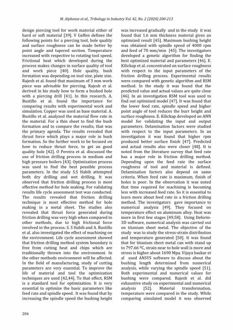
Fig. 14. SEM image of a friction drilling too after machining process [29].
Comparison of friction coefficient during drilling process in Aluminum A7075-T6 plate is shown in Fig. 13. Friction coefficients 0.5, 0.7, and 1.0 were determined for spindle speed of 3000rpm and
feed rate of 4.23 mm/s. It was observed that decrease in thrust force led to high coefficient of friction and that this may not change torque value. Coefficients of friction of 0.5, 0.7, and 1.0 observed with peak thrust forces of 600 N, 800 N and 1000 N respectively. The best match for modeling the coefficient of friction was about 0.7. Figure 14 shows the SEM image of a friction drilling tool after producing 15000 bushed holes. EDX analysis also carried out for testing the tool for distinguishing the different areas. 'A ' in microscopic image show very high Cr and Mn contents. 'B' contains W, Co, Ti and C similar to composition of work piece material. Very high Mn composition was observed in D area. Tool starts breaking was observed in D area. Holes Uncoated TiAlN Coated
10th
20th
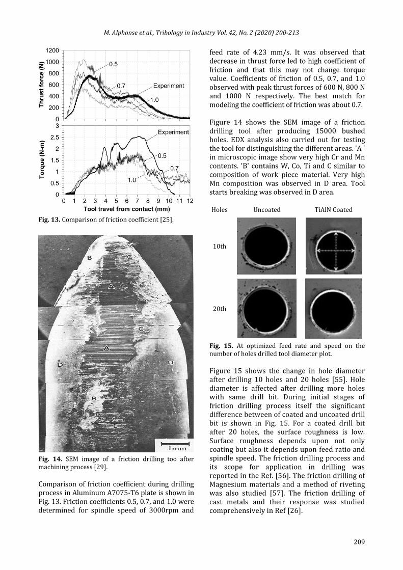
Fig. 15. At optimized feed rate and speed on the number of holes drilled tool diameter plot. Figure 15 shows the change in hole diameter after drilling 10 holes and 20 holes [55]. Hole diameter is affected after drilling more holes with same drill bit. During initial stages of friction drilling process itself the significant difference between of coated and uncoated drill bit is shown in Fig. 15. For a coated drill bit after 20 holes, the surface roughness is low. Surface roughness depends upon not only coating but also it depends upon feed ratio and spindle speed. The friction drilling process and its scope for application in drilling was reported in the Ref. [56]. The friction drilling of Magnesium materials and a method of riveting was also studied [57]. The friction drilling of cast metals and their response was studied comprehensively in Ref [26].

M. Alphonse et al., Tribology in Industry Vol. 42, No. 2 (2020) 200-213
210
5. CONCLUSION Present article briefly describes the upcoming and new friction drilling process. Choosing correct spindle feed rate and rotational speed values are essential in this process. Following are the main observations established by researchers worldwide:
At high feed rate and spindle speed high frictional heat is generated. More over when frictional heat increases thermal conductivity decreases. If thermal conductivity increases, frictional heat decreases leading to high wear of material and tool.
With increase or decrease in feed rate and spindle speed the surface temperature also increases or decreases.
With higher spindle speed, temperature of tool and work piece increases.
Minimal feed value of 50 mm/min increases the roundness error.
Proper bushing height is obtained with higher spindle speed. Whereas feed rate is negligible in case of a bushing height. More research is required to improve the quality of bushing height.
Tool conicity is found to affect the quality of bushing surface.
Torque and thrust force reduces with pre-heating and rise in spindle speed.
Frictional force and thermal conductivity during friction drilling affects the microstructure of the tool and work material. Magnitude of work hardening reduces due to the heat generated during the process.
Coated drill exhibits lesser wear when compared with uncoated drill bit with same input parameter
Bushing height got maximum when the input parameter feed rate is lower and spindle speed is higher.
REFERENCES
[1] M. Alphonse, V.K.B. Raja, K. Logesh, N.M. Nachippan, Evolution and Recent Trends in Friction Drilling Technique and the Application of Thermography, IOP Conference Series:
Materials Science and Engineering, vol. 197, 2017, doi: 10.1088/1757-899X/197/1/012058
[2] W.-L. Ku, C.-L. Hung, S.-M. Lee, H.-M. Chow, Optimization in thermal friction drilling for SUS 304 stainless steel, The International Journal of Advenced Manufacturing Technology, vol. 53, pp. 935–944, 2011, doi: 10.1007/s00170-010-2899-5
[3] S.A. El-Bahloul, H.E. El-Shourbagy, T.T. El-Midany, Optimization of Thermal Friction Drilling Process Based on Taguchi Method and Fuzzy Logic Technique, International Journal of Science and Engineering Applications, vol. 4, iss. 2, pp. 55-59, 2015, doi: 10.7753/IJSEA0402.1006
[4] K.-Y. Su, T. Welo, J. Wang, Improving Friction Drilling and Joining through Controlled Material Flow, Procedia Manufacturing, vol. 26, pp. 663–670, 2018, doi: 10.1016/j.promfg.2018.07.077
[5] P.V.G. Krishna, K. Kishore, V.V. Satyanarayana, Some Investigations in Friction Drilling Aa6351 Using High Speed Steel Tools, Journal of Engineering and Applied Sciences, vol. 5, no. 3, pp. 11-15, 2010.
[6] G. Somasundaram, S.R. Boopathy, Fabrication and friction drilling of aluminum silicon carbide metal matrix composite, in Frontiers in Automobile and Mechanical Engineering -2010, 25-27 Nov. 2010, Chennai, India, doi: 10.1109/FAME.2010.5714793
[7] G. Somasundaram, S.R. Boopathy, K. Palanikumar, Experimental investigation on roundness error in friction drilling and mechanical properties of Al/SiCp-MMC composites, Mécanique & Industries, vol. 12, no. 6, pp. 445-457, 2011, doi: 10.1051/meca/2011141
[8] G. Somasundaram, S.R. Boopathy, K. Palanikumar, Modeling and analysis of roundness error in friction drilling of aluminum silicon carbide metal matrix composite, Journal of Composite Materials, vol. 46, iss. 2, pp. 169–181, 2012, doi: 10.1177/0021998311410493
[9] M. Boopathi, S. Shankar, S. Manikandakumar, R. Ramesh, Experimental investigation of friction drilling on brass, aluminium and stainless steel, Procedia Engineering, vol. 64, pp. 1219–1226, 2013, doi: 10.1016/j.proeng.2013.09.201
[10] P. Wittke, F. Walther, Cyclic Deformation Behavior of Friction Drilled Internal Threads in AlSi10Mg and AZ31 Profiles, Procedia Structural Integrity, vol. 2, pp. 3264–3271, 2016, doi: 10.1016/j.prostr.2016.06.407
[11] A.K. Rai, P. Singh, V. Sachan, N. Bhaskar, Design, Fabrication and Testing of a Modified Single

M. Alphonse et al., Tribology in Industry Vol. 42, No. 2 (2020) 200-213
211
Slope Solar Still, International journal of Mechanical Engineering and Technology, vol. 4, iss. 4, pp. 8–14, 2013.
[12] A.A. Eliseev, S.V. Fortuna, E.A. Kolubaev, T.A. Kalashnikova, Microstructure modification of 2024 aluminum alloy produced by friction drilling, Materials Science and Engineering: A, vol. 691, pp. 121-125, 2017, doi: 10.1016/j.msea.2017.03.040
[13] T. Engbert, T. Heymann, D. Biermann, A. Zabel, Flow drilling and thread forming of continuously reinforced aluminium extrusionsg, Proceedings of the Institution of Mechanical Engineers, Part B: Journal of Engineering Manufacture, vol. 225, iss. 3, pp. 398–407, 2011, doi: 10.1243/2041297510394104
[14] M.T. Kaya, A. Aktas, B. Beylergil, H.K. Akyildiz, An Experimental Study on Friction Drilling of ST 12 steel, Transactions of the Canadian Society for Mechanical Engineering, vol. 38, no. 3, 319–329, 2014.
[15] A. Gopichand, V. Brahmam, D. Bhanuprakash, Numerical Simulation and Analysis of Friction Drilling Process for Alumina Alloy using Ansys, International Journal of Engineering Research & Technology, vol. 3, iss. 12, 602–607, 2014.
[16] C. Ozek, Z. Demir, Investigate the Friction Drilling of Aluminium Alloys According to the Thermal Conductivity, TEM Journal, vol. 2, no. 1, pp. 93-101, 2013.
[17] S.F. Miller, P.J. Blau, A.J. Shih, Tool wear in friction drilling, International Journal of Machine Tools and Manufacture, vol. 47, iss. 10, pp. 1636-1645, 2007, doi: 10.1016/j.ijmachtools.2006.10.009
[18] Z. Demir, C. Özek, Investigate the effect of pre-drilling in friction drilling of A7075-T651, Materials and Manufacturing Processes, vol. 29, iss. 5, pp. 593–599, 2014, doi: 10.1080/10426914.2014.892986
[19] B.P. Raju, M.K. Swamy, Finite Element Simulation of a Friction Drilling process using Deform-3D, International Journal of Engineering Research and Applications, vol. 2, iss. 6, pp. 716–721, 2012.
[20] D. Biermann, Y. Liu, Innovative flow drilling on magnesium wrought alloy AZ31, Procedia CIRP vol. 18, pp. 209–214, 2014, doi: 10.1016/j.procir.2014.06.133
[21] S.-M. Lee, H.-M. Chow, B.-H. Yan, Friction drilling of IN-713LC cast superalloy, Materials and Manufacturing Process, vol. 22, iss. 7-8, pp. 893–897, 2007, doi: 10.1080/10426910701451697
[22] S.F. Miller, A.J. Shih, P.J. Blau, Microstructural alterations associated with friction drilling of steel, aluminum, and titanium, Journal of Materials
Engineering and Performance, vol. 14, pp. 647–653, 2005, doi: 10.1361/105994905X64558
[23] J. Qu, P.J. Blau, A New Model to Calculate Friction Coefficients and Shear Stresses in Thermal Drilling, Journal of Manufacturing Science and Engineering, vol. 130, iss. 1, p. 4, 2008, doi: 10.1115/1.2815341
[24] C. Ozek, Z. Demir, Investigate the Surface Roughness and Bushing Shape in Friction Drilling Of A7075-T651 and St 37 Steel, TEM Journal, vol. 2, no. 2, pp. 170–180, 2013.
[25] S.F. Miller, A.J. Shih, Thermo-Mechanical Finite Element Modeling of the Friction Drilling Process, Journal of Manufacturing Science and Engineering, vol. 129, iss. 3, pp. 531–538, 2007, doi: 10.1115/1.2716719
[26] S.F. Miller, J. Tao, A.J. Shih, Friction drilling of cast metals, International Journal of Machine Tools and Manufacture, vol. 46, iss. 12-13, pp. 1526–1535, doi: 10.1016/j.ijmachtools.2005.09.003
[27] S.F. Miller, R. Li, H. Wang, A.J. Shih, Experimental and Numerical Analysis of the Friction Drilling Process, Journal of Manufacturing Science and Engineering, vol. 128, iss. 3, pp. 802-810, 2006, doi: 10.1115/1.2193554
[28] J.D. Skovron, R.R. Prasad, D. Ulutan, L. Mears, D. Detwiler, D. Paolini, B. Baeumler, L. Claus, Effect of Thermal Assistance on the Joint Quality of Al6063-T5A During Flow Drill Screwdriving, Journal of Manufacturing Science and Engineering, vol. 137, iss. 5, p. 8, 2015, doi: 10.1115/1.4031242
[29] M. Kerkhofs, M. Van Stappen, M. D’Olieslaeger, C. Quaeyhaegens, L.M. Stals, The performance of (Ti,Al)N-coated flowdrills, Surface and Coatings Technology, vol. 68-69, pp. 741–746, 1994, doi: 10.1016/0257-8972(94)90247-X
[30] K.Z. Chong, T.S. Shih, Optimizing Drilling Conditions for AZ61A Magnesium Alloy, Materials Transaction, vol. 43, iss. 8, pp. 2148-2156, 2002, doi: 10.2320/matertrans.43.2148
[31] L. Ozler, N. Dogru, An experimental investigation of hole geometry in friction drilling, Materials and Manufacturing Processes, vol. 28, iss. 4, pp. 470-475, 2013, doi: 10.1080/10426914.2012.746699
[32] N.R. Jesudoss, H.R. Kumar, Process optimization for maximizing bushing length in thermal drilling using integrated ANN ‑ SA approach, Journal of the Brazilian Society of Mechanical Sciences and Engineering, vol. 39, pp. 5097-5108, 2017, doi: 10.1007/s40430-017-0820-y
[33] N.R.J. Hynes, R. Kumar, J. Angela, J. Sujana, Optimum Bushing Length In Thermal Drilling Of Galvanized Steel Using Artificial Neural

M. Alphonse et al., Tribology in Industry Vol. 42, No. 2 (2020) 200-213
212
Network Coupled With Genetic Algorithm, Materials and Technology, vol. 51, no. 5, pp. 813–822, 2017, doi: 10.17222/mit.2016.290
[34] P.V. Shalamov, J.V. Kazantseva, Thermal Drilling with Force-Feed Tool, Procedia Engineering, vol. 206, pp. 985–990, 2017, doi: 10.1016/j.proeng.2017.10.582
[35] R.J. Furness, T.C. Tsao, J.S. Rankin, M.J. Muth, K.W. Manes, Torque control for a form tool drilling operation, IEEE Transactions on Control Systems Technology, vol. 7, no. 1, pp. 22–30, 1999, doi: 10.1109/87.736745
[36] M.B. Bilgin, K. Gök, A. Gök, Three-dimensional finite element model of friction drilling process in hot forming processes, Proceedings of the Institution of Mechanical Engineers, Part E: Journal of Process Mechanical Engineering, vol. 231, iss. 3, pp. 548–554, 2017, doi: 10.1177/0954408915614300
[37] S.M. Lee, H.M. Chow, F.Y. Huang, B.H. Yan, Friction drilling of austenitic stainless steel by uncoated and PVD AlCrN- and TiAlN-coated tungsten carbide tools, International Journal of Machine Tools and Manufacture, vol. 49, iss. 1, pp. 81–88, 2009, doi: 10.1016/j.ijmachtools.2008.07.012
[38] G. Urbikain, J.M. Perez, L.N. López de Lacalle, A. Andueza, Combination of friction drilling and form tapping processes on dissimilar materials for making nutless joints, Proceedings of the Institution of Mechanical Engineers, Part B: Journal of Engineering Manufacture, vol. 232, iss. 6, pp. 1007–1020, 2018, doi: 10.1177/0954405416661002
[39] V. Geffen, United States Patent 1191 1976.
[40] V. Geffen, Documents USP, Geffen JA Van, Larson PEA. United States Patent 1191 US . Patent 1979:2–6.
[41] N.R.J. Hynes, R. Kumar, Simulation on friction drilling process of Cu2C, Materialstoday: Proceedings, vol. 5, iss. 13, pp. 27161–27165, 2018, doi: 10.1016/j.matpr.2018.09.026
[42] A. Bustillo, G. Urbikain, J.M. Perez, O.M. Pereira, L.N.L. de Lacalle, Smart optimization of a friction-drilling process based on boosting ensembles, J Manuf Syst, pp. 1–14, 2018, doi: 10.1016/j.jmsy.2018.06.004
[43] O. Pereira, G. Urbikaín, A. Rodríguez, A. Calleja, I. Ayesta, Process performance and life cycle assessment of friction drilling on dual-phase steel, Journal of Cleaner Production, vol. 213, pp. 1147-1156, 2019, doi: 10.1016/j.jclepro.2018.12.250
[44] S.S. Habib, Study of the parameters in electrical discharge machining through response surface methodology approach, Applied Mathematical
Modelling, vol. 33, iss. 12, pp. 4397–4407,2009, doi: 10.1016/j.apm.2009.03.021
[45] A. Potdar, S. Sapkal, Optimization of Friction Drilling Process by Response Surface Methodology, Springer Singapore, vol. 949, pp. 351-359, 2020, doi: 10.1007/978-981-13-8196-6_31
[46] E. Kilickap, M. Huseyinoglu, A. Yardimeden, Optimization of drilling parameters on surface roughness in drilling of AISI 1045 using response surface methodology and genetic algorithm, The International Journal of Advanced Manufacturing Technology, vol. 52, pp. 79–88, 2011, doi: 10.1007/s00170-010-2710-7
[47] E. Kilickap, Modeling and optimization of burr height in drilling of Al-7075 using Taguchi method and response surface methodology, The International Journal of Advanced Manufacturing Technology, vol. 49, pp. 911–923, 2010, doi: 10.1007/s00170-009-2469-x
[48] S.R. Karnik, V.N. Gaitonde, J.C. Rubio, A.E. Correia, A.M. Abrão, J.P. Davim, Delamination analysis in high speed drilling of carbon fiber reinforced plastics (CFRP) using artificial neural network model, Materials & Design, vol. 29, iss. 9, pp. 1768–1776, 2008, doi: 10.1016/j.matdes.2008.03.014
[49] N.R.J. Hynes, M.M. Kumaran, N. Rakesh, C.K. Gurubaran, in Numerical Analysis in Friction Drilling Of AISI1020 Steel and AA 6061 T6 Alloy, Recent Advances in Environmental and Earth Sciences and Economics, Zakynthos Island, Greece, July 16-20, 2015, pp. 145–149.
[50] R. Kumar, N.R.J. Hynes, Numerical Analysis of Thermal Drilling Technique on Titanium sheet metal, AIP Conference Proceedings, vol. 1953, iss. 1, 2018, doi: 10.1063/1.5033158
[51] P. Vijayabaskar, N.R.J. Hynes, Simulation of Friction Stir Drilling Process, AIP Conference Proceedings, vol. 1953, iss. 1, 2018, doi: 10.1063/1.5033284
[52] R.K.N. Rajesh, J. Hynes, Finite-element simulation and validation of material flow in thermal drilling process, Journal of the Brazilian Society of Mechanical Sciences and Engineering, vol. 40, 2018, doi: 10.1007/s40430-018-1091-y
[53] N.R.J. Hynes, M.V. Maheshwaran, Numerical Analysis on Thermal Drilling of Aluminum Metal Matrix Composite, AIP Conference Proceedings, vol. 1728, iss. 1, 2016, doi: 10.1063/1.4946597
[54] R. Kumar, N.R.J. Hynes, Influence of rotational speed on mechanical features of thermally drilled holes in dual-phase steel, Proceedings of the Institution of Mechanical Engineers, Part B: Journal of Engineering Manufacture, vol. 233, iss. 5, pp. 1614-1625, doi: 10.1177/0954405418805601

M. Alphonse et al., Tribology in Industry Vol. 42, No. 2 (2020) 200-213
213
[55] N. Swain, P. Kumar, G. Srinivas, S. Ravishankar, H.C. Barshilia, Mechanical micro-drilling of Nimonic 80A superalloy using uncoated and TiAlN coated micro-drills, Materials and Manufacturing Processes, vol. 32, iss. 13, pp. 1737–1546, 2016, doi: 10.1080/10426914.2017.1279293
[56] V.K.B. Raja, R. Rajasekaran, A.J. Francis, An overview of non traditional drilling process,
International Journal of Applied Engineering Research, vol. 9, no. 23, pp. 23145-23153, 2014.
[57] G. Han, M. Wang, Z. Liu, P.-C. Wang, A New Joining Process for Magnesium Alloys: Rotation Friction Drilling Riveting, Journal of Manufacturing Science and Engineering, vol. 135, iss. 3, p. 9, doi: 10.1115/1.4023721