Tribological Components and Applications
45
Tribological Components and Applications 14.1 Introduction Common tribological components which are used in industrial applications include sliding- contact and rolling-contact bearings, seals, gears, cams and tappets, piston rings, electrical brushes, and cutting and forming tools. More recently, micro/nanoelectromechanical sys- tems (MEMS/NEMS), also called micro/nanodevices or micro/nanocomponents are being produced using micro/nanofabrication techniques (Bhushan, 2010). Some of the common in- dustrial applications include material processing, internal combustion engines for automotive applications, gas turbine engines for aerospace applications, railroads, and magnetic storage devices (Bhushan, 2001a, 2001b). For a component’s desired performance and life, its friction and wear need to be minimized, or optimized, for a given application. The relevant friction and wear mechanisms are dependent upon the device and the operating conditions. This chapter presents descriptions, relevant wear mechanisms, and typical materials for common tribological components, microcomponents, material processing and other industrial applications. 14.2 Common Tribological Components Tribological components that operate at low to moderate contact stresses (on the order of 5 MPa) include sliding-contact bearings, seals, piston rings and electrical brushes (Bhushan, 2001a, 2001b). The components that operate at high Hertzian stresses (on the order of 500 MPa) include rolling-contact bearings, gears, cams, and tappets (Bhushan, 2001a). 14.2.1 Sliding-Contact Bearings The machine elements that support a moving shaft against a stationary housing are called bearings. In general, we can classify bearings as either sliding-contact or rolling-contact
-
Upload
khangminh22 -
Category
Documents
-
view
1 -
download
0
Transcript of Tribological Components and Applications
Tribological Components and Applications
14.1 Introduction
Common tribological components which are used in industrial applications include sliding- contact and rolling-contact bearings, seals, gears, cams and tappets, piston rings, electrical brushes, and cutting and forming tools. More recently, micro/nanoelectromechanical sys- tems (MEMS/NEMS), also called micro/nanodevices or micro/nanocomponents are being produced using micro/nanofabrication techniques (Bhushan, 2010). Some of the common in- dustrial applications include material processing, internal combustion engines for automotive applications, gas turbine engines for aerospace applications, railroads, and magnetic storage devices (Bhushan, 2001a, 2001b). For a component’s desired performance and life, its friction and wear need to be minimized, or optimized, for a given application. The relevant friction and wear mechanisms are dependent upon the device and the operating conditions.
This chapter presents descriptions, relevant wear mechanisms, and typical materials for common tribological components, microcomponents, material processing and other industrial applications.
14.2 Common Tribological Components
Tribological components that operate at low to moderate contact stresses (on the order of 5 MPa) include sliding-contact bearings, seals, piston rings and electrical brushes (Bhushan, 2001a, 2001b). The components that operate at high Hertzian stresses (on the order of 500 MPa) include rolling-contact bearings, gears, cams, and tappets (Bhushan, 2001a).
14.2.1 Sliding-Contact Bearings
The machine elements that support a moving shaft against a stationary housing are called bearings. In general, we can classify bearings as either sliding-contact or rolling-contact

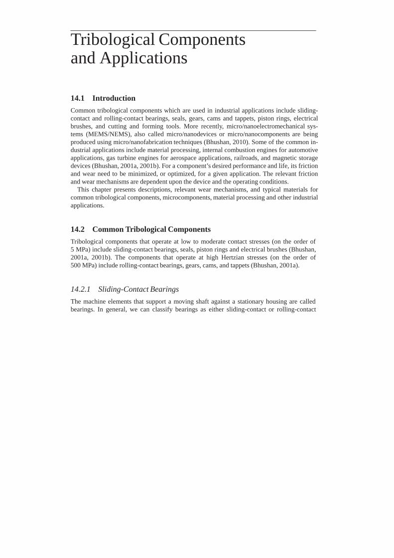
Figure 14.2.1 Schematic of a rotating shaft supported by a thrust and a journal bearing.
bearings. In sliding-contact bearings, also known as sliding or plain bearings or bushings, the load is transmitted between moving parts by sliding contact. The motion can be a planar motion (e.g., plane, curved, step, and composite sliders and pivoted-pad sliders) or a rotational motion (e.g., full and partial journal bearings, foil bearings, floating-ring bearings) (Bisson and Anderson, 1964; Neale, 1973; Booser, 1984; Fuller, 1984). (Also see Chapter 9 for examples.) Sliding bearings can be lubricated with a film of air, water, oil, grease, or the process fluid. Thrust and journal bearings are perhaps the most familiar and most widely used of all bearings types. Thrust bearings are used to support thrust (or axial) loads in a rotating machinery, Figure 14.2.1. These consist of multiple pads, either fixed or pivoted. Journal bearings are used to support radial (or normal) loads. These consist of a sleeve of bearing material wrapped partially or completely around a rotating shaft or journal, and are designed to support a radial load, Figure 14.2.1.
The bearings are generally lubricated with a liquid lubricant or grease. In self-acting bear- ings, lubrication is accomplished via hydrodynamic lubrication. Wear mechanisms are depen- dent upon the bearing materials and operating conditions. Sliding bearings most commonly fail by adhesive, abrasive, and/or chemical (or corrosive) wear mechanisms.
The selection of materials for sliding bearings is a multifunctional optimization problem. In general, the standard requirements are as follows: comformability, embeddability, compressive strength, fatigue strength, thermal conductivity, wear resistance, corrosive resistance, and cost. Bearing materials fall into two major categories: metals and nonmetals (Ku, 1970; Neale, 1973; Booser, 1984; Fuller, 1984; Glaeser, 1992; Bhushan and Gupta, 1997). Included in the metals are several types of soft metals – precious metals, tin- and lead-based alloys (babbitts), copper- based alloys (brasses and bronzes), aluminum-based alloys, cast iron, and porous metals. The nonmetals include wood, carbon-graphites, plastics, elastomers, ceramics, cermets, and several other proprietary materials. These materials can be used as a bulk material or as a lining on a bearing surface. In a lined bearing, the bearing material is bonded to a stronger backing
material such as steel. The thickness of the liner material usually ranges from 0.25 mm to as high as 10 mm. Many soft metals, carbon-graphites, plastics, and elastomers are used as one of the slider materials against a sliding member such as stainless steel under unlubricated conditions. In many bearing applications, hard and soft materials are used to coat bearing substrates by various deposition techniques.
14.2.2 Rolling-Contact Bearings
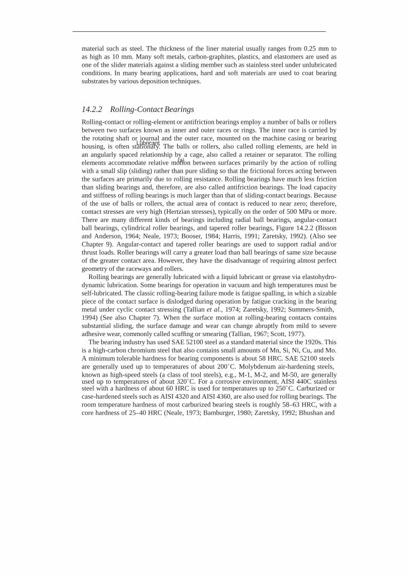
Rolling-contact or rolling-element or antifriction bearings employ a number of balls or rollers between two surfaces known as inner and outer races or rings. The inner race is carried by the rotating shaft or journal and the outer race, mounted on the machine casing or bearing housing, is often stationary. The balls or rollers, also called rolling elements, are held in an angularly spaced relationship by a cage, also called a retainer or separator. The rolling elements accommodate relative motion between surfaces primarily by the action of rolling with a small slip (sliding) rather than pure sliding so that the frictional forces acting between the surfaces are primarily due to rolling resistance. Rolling bearings have much less friction than sliding bearings and, therefore, are also called antifriction bearings. The load capacity and stiffness of rolling bearings is much larger than that of sliding-contact bearings. Because of the use of balls or rollers, the actual area of contact is reduced to near zero; therefore, contact stresses are very high (Hertzian stresses), typically on the order of 500 MPa or more. There are many different kinds of bearings including radial ball bearings, angular-contact ball bearings, cylindrical roller bearings, and tapered roller bearings, Figure 14.2.2 (Bisson and Anderson, 1964; Neale, 1973; Booser, 1984; Harris, 1991; Zaretsky, 1992). (Also see Chapter 9). Angular-contact and tapered roller bearings are used to support radial and/or thrust loads. Roller bearings will carry a greater load than ball bearings of same size because of the greater contact area. However, they have the disadvantage of requiring almost perfect geometry of the raceways and rollers.
Rolling bearings are generally lubricated with a liquid lubricant or grease via elastohydro- dynamic lubrication. Some bearings for operation in vacuum and high temperatures must be self-lubricated. The classic rolling-bearing failure mode is fatigue spalling, in which a sizable piece of the contact surface is dislodged during operation by fatigue cracking in the bearing metal under cyclic contact stressing (Tallian et al., 1974; Zaretsky, 1992; Summers-Smith, 1994) (See also Chapter 7). When the surface motion at rolling-bearing contacts contains substantial sliding, the surface damage and wear can change abruptly from mild to severe adhesive wear, commonly called scuffing or smearing (Tallian, 1967; Scott, 1977).
The bearing industry has used SAE 52100 steel as a standard material since the 1920s. This is a high-carbon chromium steel that also contains small amounts of Mn, Si, Ni, Cu, and Mo. A minimum tolerable hardness for bearing components is about 58 HRC. SAE 52100 steels are generally used up to temperatures of about 200◦C. Molybdenum air-hardening steels, known as high-speed steels (a class of tool steels), e.g., M-1, M-2, and M-50, are generally used up to temperatures of about 320◦C. For a corrosive environment, AISI 440C stainless steel with a hardness of about 60 HRC is used for temperatures up to 250◦C. Carburized or case-hardened steels such as AISI 4320 and AISI 4360, are also used for rolling bearings. The room temperature hardness of most carburized bearing steels is roughly 58–63 HRC, with a core hardness of 25–40 HRC (Neale, 1973; Bamburger, 1980; Zaretsky, 1992; Bhushan and

Figure 14.2.2 Schematics of (a) a radial ball bearing; (b) an angular-contact ball bearing; (c) a cylin- drical roller bearing; and (d) a tapered roller bearing.
Gupta, 1997). Some high-performance applications dictate the need for bearings that operate at high speeds and/or high temperatures (up to 1200◦C) with high precision. Since high
temperatures are beyond the range in which most ferrous materials are incapable of operating, more refractory materials and compounds are considered. Silicon nitride is the favorite ceramic material for high-performance applications. It has two to three times the hardness and one-third the dry friction coefficient of bearing steels, has good fracture toughness compared with other ceramic materials, and maintains its strength and oxidation resistance up to 1200◦C, which makes it a promising high temperature rolling-bearing material (Bhushan and Sibley, 1982). Si3 N4 has been used for bearing elements as well as for complete bearing configurations. Silicon nitride bearings are used in the aerospace/defense, tool spindle, chemical processing, nuclear, and automotive industries. Various hard and soft coatings and surface treatments have been developed for lightly loaded, long-life rolling-element bearings for applications in high vacuum and/or high temperatures, especially in applications with no external lubrication (Bhushan and Gupta, 1997).
Cages or retainers maintain the proper distance between rolling elements. In conventional rolling bearings, both metallic and nonmetallic retainers are used. Under normal temperatures, a large percentage of ball and roller bearings use stamped retainers of low-carbon steel or machined retainers of copper-based alloys such as iron-silicon bronze or a leaded brass. In applications where marginal lubrication exists during operation, silver-plated bronze or PTFE- based cage materials are used (Ku, 1970). For high-temperature and marginally lubricated
or unlubricated conditions, such as in aerospace applications, potential self-lubricated cage materials are phenolic, polyimide, graphite and composites, Ga-In-WS2 compact, Ta-Mo- MoS2 compact, and metals containing MoS2 -graphite (Bhushan and Sibley, 1982; Gardos and McConnell, 1982). Carbon fiber-reinforced polyimide composite with a solid-lubricant additive has exhibited low friction and wear when tested against an Ni-based alloy (Rene 41) at a normal stress of about 175 MPa and a temperature of 315◦C (Gardos and McConnell, 1982).
14.2.3 Seals
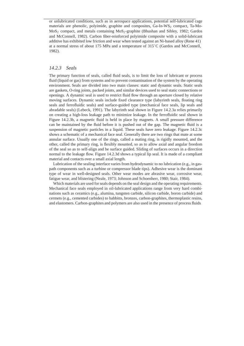
The primary function of seals, called fluid seals, is to limit the loss of lubricant or process fluid (liquid or gas) from systems and to prevent contamination of the system by the operating environment. Seals are divided into two main classes: static and dynamic seals. Static seals are gaskets, O-ring joints, packed joints, and similar devices used to seal static connections or openings. A dynamic seal is used to restrict fluid flow through an aperture closed by relative moving surfaces. Dynamic seals include fixed clearance type (labyrinth seals, floating ring seals and ferrofluidic seals) and surface-guided type (mechanical face seals, lip seals and abradable seals) (Lebeck, 1991). The labyrinth seal shown in Figure 14.2.3a relies primarily on creating a high-loss leakage path to minimize leakage. In the ferrofluidic seal shown in Figure 14.2.3b, a magnetic fluid is held in place by magnets. A small pressure difference can be maintained by the fluid before it is pushed out of the gap. The magnetic fluid is a suspension of magnetic particles in a liquid. These seals have zero leakage. Figure 14.2.3c shows a schematic of a mechanical face seal. Generally there are two rings that mate at some annular surface. Usually one of the rings, called a mating ring, is rigidly mounted, and the other, called the primary ring, is flexibly mounted, so as to allow axial and angular freedom of the seal so as to self-align and be surface guided. Sliding of surfaces occurs in a direction normal to the leakage flow. Figure 14.2.3d shows a typical lip seal. It is made of a compliant material and contacts over a small axial length.
Lubrication of the sealing interface varies from hydrodynamic to no lubrication (e.g., in gas- path components such as a turbine or compressor blade tips). Adhesive wear is the dominant type of wear in well-designed seals. Other wear modes are abrasive wear, corrosive wear, fatigue wear, and blistering (Neale, 1973; Johnson and Schoenherr, 1980; Stair, 1984).
Which materials are used for seals depends on the seal design and the operating requirements. Mechanical face seals employed in oil-lubricated applications range from very hard combi- nations such as ceramics (e.g., alumina, tungsten carbide, silicon carbide, boron carbide) and cermets (e.g., cemented carbides) to babbitts, bronzes, carbon-graphites, thermoplastic resins, and elastomers. Carbon-graphites and polymers are also used in the presence of process fluids

(a) (b)
(c) (d)
Figure 14.2.3 Schematics of (a) labyrinth seal, (b) ferrofluidic seal, (c) a mechanical face seal with outside pressurized, rotating primary ring and fixed mating ring, and (d) a lip seal on a cylindrical surface. Reproduced with permission from Lebeck, A.O. (1991), Principles and Design of Mechanical Face Seals, Wiley, New York. Copyright 1991. Wiley.
that are poor lubricants or under unlubricated conditions. A large number of mating materials have been used, such as Niresist iron, tool steel, hard-faced steel, nickel-copper-based materi- als (e.g., Monel), nickel-molybdenum alloys (e.g., Hastelloy B or Hastelloy C), Cobalt-based alloys (e.g., Stellite), tungsten carbide, boron carbide, alumina, or plasma-sprayed coatings of various ceramics. For example, many merchant ships employ asbestos-filled phenolic in oil- lubricated face-seal configurations as the stationary-face insert and the rotating mating shaft is made of Niresist iron or chrome-nickel steel. Carbon-graphites and plastics such as PTFE, polyimide, poly(amide-imide), or phenolic composites are used in water-lubricated face seals (Paxton, 1979; Stair, 1984; Bhushan and Gupta, 1997).
Lip seals are made of compliant materials-elastomers. The elastomers most com- monly used are butadiene-acrylonitrile (Buna N), polyacrylate, and vinylidene fluoride- hexafluoropropylene (Viton) at high temperatures (up to about 170◦C). Other lip-seal materials that are used for specialized applications include silicone, fluorosilicone, and perfluoroelas- tomer (Kalrez). The main prerequisites for the mating surfaces of lip seals are hardness and high abrasion resistance. The liner materials include chrome-nickel steels, case-hardened cast iron, and plasma-sprayed coatings of various ceramics, such as Cr2 O3 , Al2 O3 , or mixtures of oxides with other materials to achieve specific characteristics (Bhushan and Gupta, 1997).

Abradable (rub-tolerant) seals are used in the compressor and turbine sections of aircraft gas turbine engines (Meetham, 1981). Abradable seals are used at the rotor–stator interface to maintain the close tolerance without catastrophic failure. One of the sliding members is supposed to abrade against another if there is any interference. Abradable coatings are applied to compressor and turbine castings in some engines. In some cases, wear-resistant coatings are applied to the tip regions of rotating blades to minimize wear. Many of the commonly used abradable materials are sintered ceramics and plasma-sprayed coatings of Ni-Cr-bonded chrome carbide and tungsten carbide sliding against rub-tolerant materials such as felt metal and plasma-sprayed coatings of ceramics such as chrome oxide.
14.2.4 Gears
Gears are toothed wheels used for transmission of rotary motion from one shaft to another and a change in rotational speed (Dudley, 1964; Merritt, 1971; Shigley and Mischke, 1989). There are different types of gear including spur, helical, bevel and worm gears. Spur gears shown in Figure 14.2.4a are used to transmit rotary motion between parallel shafts and helical gears (Figure 14.2.4b) are used to transmit rotary motion between parallel and nonparallel shafts. The smaller of two mating gears is known as a pinion and the larger as a gear. To transmit motion at a constant angular-velocity ratio, an involute tooth profile is used. In the spur gears, the teeth are straight and parallel to the axis of rotation, whereas in helical gears, teeth are not parallel to the axis of rotation. The helix angle in helical gears is the same on each gear, but one gear must have a right hand helix and the other a left-hand helix. In spur gears, the line of contact is parallel to the axis of rotation; in helical gears the line is diagonal across the face of the tooth. The initial contact of spur-gear teeth is a line extending all the way across the face of the tooth, whereas the initial contact of helical-gear teeth is a point which changes into a line as the teeth come into more engagement. It is this gradual engagement of the teeth and the smooth transfer of load from one tooth to another which give helical gears the ability to transmit heavy loads at high speeds.
In the case of bevel gears, the rotational axes are not parallel to each other. Although bevel gears are usually made for a shaft angle of 90◦, they can be produced for almost any angle.
(a) (b) (c) (d)
Figure 14.2.4 Schematics of (a) pair of spur gears used to transmit rotary motion between parallel shafts; (b) pair of helical gears used to transmit motion between parallel shafts; (c) pair of straight bevel gears used to transmit motion between intersecting shafts; and (d) worm and worm gears used to transmit motion between nonparallel, non-intersecting shafts.
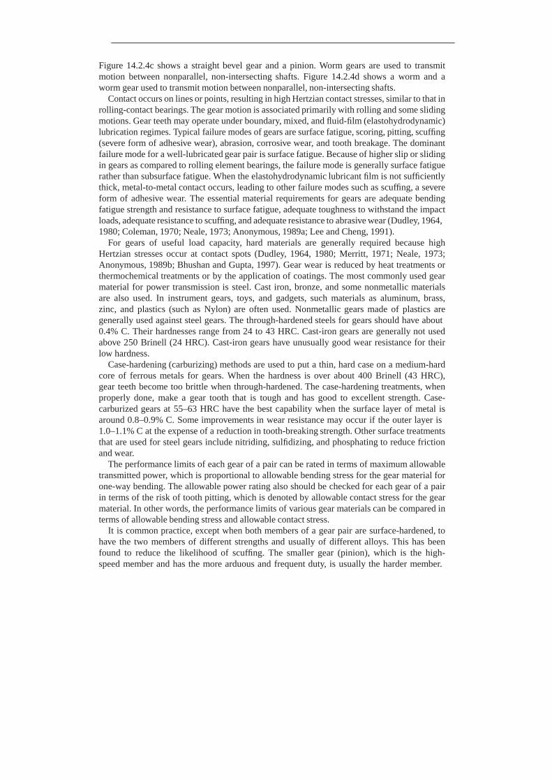
Figure 14.2.4c shows a straight bevel gear and a pinion. Worm gears are used to transmit motion between nonparallel, non-intersecting shafts. Figure 14.2.4d shows a worm and a worm gear used to transmit motion between nonparallel, non-intersecting shafts.
Contact occurs on lines or points, resulting in high Hertzian contact stresses, similar to that in rolling-contact bearings. The gear motion is associated primarily with rolling and some sliding motions. Gear teeth may operate under boundary, mixed, and fluid-film (elastohydrodynamic) lubrication regimes. Typical failure modes of gears are surface fatigue, scoring, pitting, scuffing (severe form of adhesive wear), abrasion, corrosive wear, and tooth breakage. The dominant failure mode for a well-lubricated gear pair is surface fatigue. Because of higher slip or sliding in gears as compared to rolling element bearings, the failure mode is generally surface fatigue rather than subsurface fatigue. When the elastohydrodynamic lubricant film is not sufficiently thick, metal-to-metal contact occurs, leading to other failure modes such as scuffing, a severe form of adhesive wear. The essential material requirements for gears are adequate bending fatigue strength and resistance to surface fatigue, adequate toughness to withstand the impact loads, adequate resistance to scuffing, and adequate resistance to abrasive wear (Dudley, 1964, 1980; Coleman, 1970; Neale, 1973; Anonymous, 1989a; Lee and Cheng, 1991).
For gears of useful load capacity, hard materials are generally required because high Hertzian stresses occur at contact spots (Dudley, 1964, 1980; Merritt, 1971; Neale, 1973; Anonymous, 1989b; Bhushan and Gupta, 1997). Gear wear is reduced by heat treatments or thermochemical treatments or by the application of coatings. The most commonly used gear material for power transmission is steel. Cast iron, bronze, and some nonmetallic materials are also used. In instrument gears, toys, and gadgets, such materials as aluminum, brass, zinc, and plastics (such as Nylon) are often used. Nonmetallic gears made of plastics are generally used against steel gears. The through-hardened steels for gears should have about 0.4% C. Their hardnesses range from 24 to 43 HRC. Cast-iron gears are generally not used above 250 Brinell (24 HRC). Cast-iron gears have unusually good wear resistance for their low hardness.
Case-hardening (carburizing) methods are used to put a thin, hard case on a medium-hard core of ferrous metals for gears. When the hardness is over about 400 Brinell (43 HRC), gear teeth become too brittle when through-hardened. The case-hardening treatments, when properly done, make a gear tooth that is tough and has good to excellent strength. Case- carburized gears at 55–63 HRC have the best capability when the surface layer of metal is around 0.8–0.9% C. Some improvements in wear resistance may occur if the outer layer is 1.0–1.1% C at the expense of a reduction in tooth-breaking strength. Other surface treatments that are used for steel gears include nitriding, sulfidizing, and phosphating to reduce friction and wear.
The performance limits of each gear of a pair can be rated in terms of maximum allowable transmitted power, which is proportional to allowable bending stress for the gear material for one-way bending. The allowable power rating also should be checked for each gear of a pair in terms of the risk of tooth pitting, which is denoted by allowable contact stress for the gear material. In other words, the performance limits of various gear materials can be compared in terms of allowable bending stress and allowable contact stress.
It is common practice, except when both members of a gear pair are surface-hardened, to have the two members of different strengths and usually of different alloys. This has been found to reduce the likelihood of scuffing. The smaller gear (pinion), which is the high- speed member and has the more arduous and frequent duty, is usually the harder member.
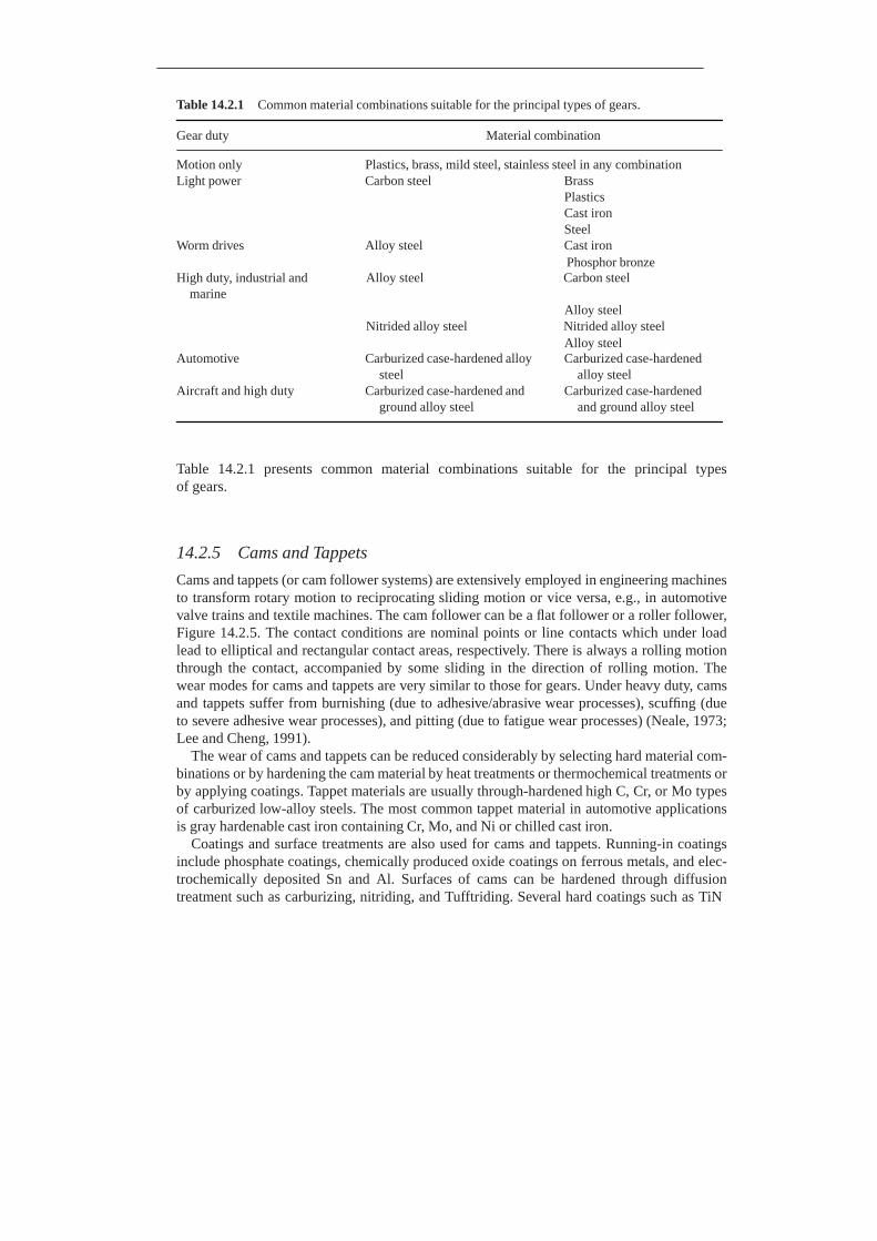
Table 14.2.1 Common material combinations suitable for the principal types of gears.
Gear duty Material combination
Motion only Plastics, brass, mild steel, stainless steel in any combination Light power Carbon steel Brass
Plastics Cast iron Steel
Worm drives Alloy steel Cast iron Phosphor bronze
High duty, industrial and marine
Alloy steel Carbon steel
Alloy steel Nitrided alloy steel Nitrided alloy steel
Alloy steel Automotive Carburized case-hardened alloy
steel Aircraft and high duty Carburized case-hardened and
ground alloy steel
Carburized case-hardened alloy steel
Carburized case-hardened and ground alloy steel
Table 14.2.1 presents common material combinations suitable for the principal types of gears.
14.2.5 Cams and Tappets
Cams and tappets (or cam follower systems) are extensively employed in engineering machines to transform rotary motion to reciprocating sliding motion or vice versa, e.g., in automotive valve trains and textile machines. The cam follower can be a flat follower or a roller follower, Figure 14.2.5. The contact conditions are nominal points or line contacts which under load lead to elliptical and rectangular contact areas, respectively. There is always a rolling motion through the contact, accompanied by some sliding in the direction of rolling motion. The wear modes for cams and tappets are very similar to those for gears. Under heavy duty, cams and tappets suffer from burnishing (due to adhesive/abrasive wear processes), scuffing (due to severe adhesive wear processes), and pitting (due to fatigue wear processes) (Neale, 1973; Lee and Cheng, 1991).
The wear of cams and tappets can be reduced considerably by selecting hard material com- binations or by hardening the cam material by heat treatments or thermochemical treatments or by applying coatings. Tappet materials are usually through-hardened high C, Cr, or Mo types of carburized low-alloy steels. The most common tappet material in automotive applications is gray hardenable cast iron containing Cr, Mo, and Ni or chilled cast iron.
Coatings and surface treatments are also used for cams and tappets. Running-in coatings include phosphate coatings, chemically produced oxide coatings on ferrous metals, and elec- trochemically deposited Sn and Al. Surfaces of cams can be hardened through diffusion treatment such as carburizing, nitriding, and Tufftriding. Several hard coatings such as TiN

Figure 14.2.5 Schematic of a cam and a translating roller follower (tappet).
and TiC, applied by PVD and CVD, also can be applied on cams and tappets to achieve low coefficients of friction and low wear.
14.2.6 Piston Rings
Piston rings are mechanical sealing devices used for sealing pistons, piston plungers, recipro- cating rods, etc., inside cylinders. In gasoline and diesel engines and lubricated reciprocating- type compressor pumps, the rings are generally split-type compression metal rings. When they are placed in the grooves of the piston and provided with a lubricant, a moving seal is formed between the piston and the cylinder bore. Piston rings are divided into two categories: compression rings and oil-control rings. Compression rings, generally two or more, are located near the top of the piston to block the downward flow of gases from the combustion chamber. Oil rings, generally one or more, are placed below the compression rings to prevent the passage of excessive lubricating oil into the combustion chamber yet provide adequate lubrication for the piston rings. In typical lubricated situations, the piston skirt is in direct contact with the cylinder and acts as a bearing member that supports its own weight and takes thrust loads. In unlubricated arrangements, it is necessary to keep these two surfaces separated because they are not frictionally compatible. This is usually accomplished with a rider ring that supports the piston, (Figure 14.2.6) (Neale, 1973).
An ideal piston-ring material must meet the following requirements: low friction and wear losses, superior scuffing resistance, tolerances for marginal lubrication and rapidly varying environments, good running-in wear behavior, long-term reliability and consistency of perfor- mance, long maintenance-free life, and low production cost.
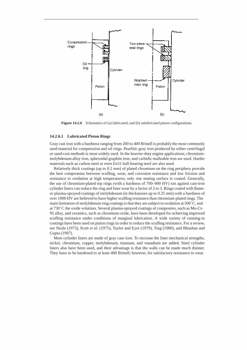
Figure 14.2.6 Schematics of (a) lubricated; and (b) unlubricated piston configurations.
14.2.6.1 Lubricated Piston Rings
Gray cast iron with a hardness ranging from 200 to 400 Brinell is probably the most commonly used material for compression and oil rings. Pearlitic gray iron produced by either centrifugal or sand-cast methods is most widely used. In the heavier-duty engine applications, chromium- molybdenum alloy iron, spheroidal graphite iron, and carbidic malleable iron are used. Harder materials such as carbon steel or even En31 ball-bearing steel are also used.
Relatively thick coatings (up to 0.2 mm) of plated chromium on the ring periphery provide the best compromise between scuffing, wear, and corrosion resistance and low friction and resistance to oxidation at high temperatures; only one mating surface is coated. Generally, the use of chromium-plated top rings (with a hardness of 700–900 HV) run against cast-iron cylinder liners can reduce the ring and liner wear by a factor of 2 to 3. Rings coated with flame- or plasma-sprayed coatings of molybdenum (in thicknesses up to 0.25 mm) with a hardness of over 1000 HV are believed to have higher scuffing resistance than chromium-plated rings. The main limitation of molybdenum ring coatings is that they are subject to oxidation at 500◦C, and at 730◦C the oxide volatizes. Several plasma-sprayed coatings of composites, such as Mo-Cr- Ni alloy, and ceramics, such as chromium oxide, have been developed for achieving improved scuffing resistance under conditions of marginal lubrication. A wide variety of running-in coatings have been used on piston rings in order to reduce the scuffing resistance. For a review, see Neale (1973), Scott et al. (1975), Taylor and Eyre (1979), Ting (1980), and Bhushan and Gupta (1997).
Most cylinder liners are made of gray case iron. To increase the liner mechanical strengths, nickel, chromium, copper, molybdenum, titanium, and vanadium are added. Steel cylinder liners also have been used, and their advantage is that the walls can be made much thinner. They have to be hardened to at least 400 Brinell; however, for satisfactory resistance to wear

and scuffing, they are hard-chromium plated. It should be noted that chromium-plated liners should not run against the chromium-plated piston rings, but rather against plain cast-iron rings or rings with other types of coatings. The sulfidizing and nitriding treatments also have been used in cylinder liners and are claimed to be comparable with chromium plating for scuffing resistance and as an aid in running-in. Aluminum cylinder liners with high silicon content have also been used, which are lightweight materials. Some engine test results show that the liner wear of aluminum liners is lower than that of conventional cast-iron liners (Taylor and Eyre, 1979; Ting, 1980).
14.2.6.2 Unlubricated Piston Rings
Materials used for unlubricated piston rings are almost without exception nonmetals. This is due to the tendency of metals to weld under dry sliding (Scott et al., 1975; Fuchsluger and Vandusen, 1980). Exceptions are metals impregnated with lubricants or coated with wear- resistant materials. In the nonmetal category, plastics, carbons, and ceramics are the materials most widely used. Among plastics, filled PTFE is used most commonly. Another family of plastics consists of filled polyimides. Polyimides, while not as chemically resistant or as low in friction as PTFE, have a high temperature limit (315–370◦C) and are more rigid. Some other rigid plastics that find use as piston rings are poly(amide-imides), polyphenylene sulfides, and aramids. For lower-temperature (below 150◦C), lightly loaded, low-speed applications, rings of Nylon, acetal, ultrahigh-molecular-weight polyethylene, etc., have found use.
Carbon is another commonly used ring material. It is the material most commonly used in the temperature range from 370 to 540◦C. Below 370◦C, carbon is limited by its reaction to varying degrees of humidity and its fragility. Ceramics have low wear rates, but virtually all ceramics are expensive to fabricate and are subject to thermal shock. Consequently, the use of ceramics for piston ring applications has been limited to ceramic coatings for metal rings.
The most commonly used mating liner materials for nonmetallic piston rings are cast irons and hardened steels. When other materials, such as the 300 and 400 series stainless steels, must be used, a chrome-plated or nitrided wear surface frequently provides the compatibility needed. When neither course of action is open, a solid-lubricant coating is frequently used. Carbon-graphite is reported to have a lower wear rate in combination with Nickel-resist or nitrided steel than with chrome plate.
14.2.7 Electrical Brushes
Machines that utilize electrical brushes can be broadly classified into two groups. In the first group, the machines require a commutator. In these machines, the brushes must be capable of transferring the load current to the external circuit as well as assisting the commutation function. Within this class of machines are DC motors and generators. In the second class of machines, brushes are used only to transmit electric power from a stationary source to a moving component by means of a slip ring, Figure 14.2.7. Examples of slip-ring applications are AC generators, motors, and special applications. Brush wear is believed to be due to adhesion and particle transfer, while fatigue has been identified in some circumstances. A further wear mechanism that can occur is fracture caused by mechanical impact between the brush and the slip ring.
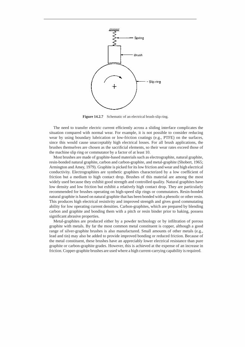
Figure 14.2.7 Schematic of an electrical brush-slip ring.
The need to transfer electric current efficiently across a sliding interface complicates the
situation compared with normal wear. For example, it is not possible to consider reducing wear by using boundary lubrication or low-friction coatings (e.g., PTFE) on the surfaces, since this would cause unacceptably high electrical losses. For all brush applications, the brushes themselves are chosen as the sacrificial elements, so their wear rates exceed those of the machine slip ring or commutator by a factor of at least 10.
Most brushes are made of graphite-based materials such as electrographite, natural graphite, resin-bonded natural graphite, carbon and carbon-graphite, and metal-graphite (Shobert, 1965; Armington and Amey, 1979). Graphite is picked for its low friction and wear and high electrical conductivity. Electrographites are synthetic graphites characterized by a low coefficient of friction but a medium to high contact drop. Brushes of this material are among the most widely used because they exhibit good strength and controlled quality. Natural graphites have low density and low friction but exhibit a relatively high contact drop. They are particularly recommended for brushes operating on high-speed slip rings or commutators. Resin-bonded natural graphite is based on natural graphite that has been bonded with a phenolic or other resin. This produces high electrical resistivity and improved strength and gives good commutating ability for low operating current densities. Carbon-graphites, which are prepared by blending carbon and graphite and bonding them with a pitch or resin binder prior to baking, possess significant abrasive properties.
Metal-graphites are produced either by a powder technology or by infiltration of porous graphite with metals. By far the most common metal constituent is copper, although a good range of silver-graphite brushes is also manufactured. Small amounts of other metals (e.g., lead and tin) may also be added to provide improved bonding or reduced friction. Because of the metal constituent, these brushes have an appreciably lower electrical resistance than pure graphite or carbon-graphite grades. However, this is achieved at the expense of an increase in friction. Copper-graphite brushes are used where a high current-carrying capability is required.
Copper alloys and steel are most commonly used in slip-ring commutators or counter sur- faces against which the brush is operated, although noble and rare metals are sometimes used for small-scale or special applications. Copper is chosen because of its good electrical and thermal properties. High-conductivity copper is most commonly used for commuta- tors, although silver-bearing copper (< 0.1% silver), chrome-copper (< 1% chrome), and zirconium-copper (0.25% zirconium) also may be used, especially where higher strength at el- evated temperatures is required. Common materials are bronze (copper-tin), phosphor bronze (copper-tin-phosphorus), gun metal (copper-tin-zinc), cupronickel (copper, 4% nickel), and Monel (nickel, 25–40% copper). Steel slip rings are used in applications demanding high sliding speeds, which make copper alloys unusable because of their lower mechanical strength and high wear.
Electroplating or other surface treatments can be used to provide an improved current transfer on a higher-strength substrate (e.g., copper on steel or high-strength aluminum) and will give a performance close to that observed for the bulk material of the surface coatings. Good commutating performance can be achieved by using a sintered-copper facing on steel commutator bars (Armington and Amey, 1979; McNab and Johnson, 1980).
14.3 MEMS/NEMS
Microelectromechanical systems (MEMS) refer to microscopic devices that have a character- istic length of less than 1 mm but more than 100 nm and combine electrical and mechanical components. Nanoelectromechanical systems (NEMS) refer to nanoscopic devices that have a characteristic length of less than 100 nm and combine electrical and mechanical components. In mesoscale devices, if the functional components are on micro- or nanoscale, they may be referred to as MEMS or NEMS, respectively (Bhushan, 2010). These are referred to as an intelligent miniaturized system comprising of sensing, processing, and/or actuating func- tions and combine electrical and mechanical components. The acronym MEMS originated in the USA. The term commonly used in Europe is microsystem technology (MST), and in Japan it is micromachines. Another term generally used is micro/nanodevices. MEMS/NEMS terms are also now used in a broad sense and include electrical, mechanical, fluidic, optical, and/or biological functions. MEMS/NEMS for optical applications are referred to as mi- cro/nanooptoelectromechanical systems (MOEMS/NOEMS). MEMS/NEMS for electronic applications are referred to as radio-frequency-MEMS/NEMS or RF-MEMS/RF-NEMS. MEMS/NEMS for biological applications are referred to as BioMEMS/BioNEMS.
To put the characteristic dimensions of MEMS/NEMS and BioNEMS into perspective, see Figure 14.3.1. NEMS and BioNEMS shown in the figure range in size from 2 to 300 nm, and the size of MEMS is 12,000 nm. For comparison, individual atoms are typically a fraction of a nanometer in diameter, deoxyribonucleic acid (DNA) molecules are about 2.5 nm wide, biological cells are in the range of thousands of nm in diameter, and human hair is about 75 μm in diameter. NEMS can be built with weight as low as 10−20 N with cross sections of about 10 nm, and a micromachined silicon structure can have a weight as low as 1 nN. For comparison, the weight of a drop of water is about 10 μN and the weight of an eyelash is about 100 nN.
Micro/nanofabrication techniques include top-down methods, in which one builds down from the large to the small, and the bottom-up methods, in which one builds up from the small

Figure 14.3.1 Characteristic dimensions of MEMS/NEMS and BioNEMS in perspective. Examples shown are of a single walled carbon nanotube (SWNT) chemical sensor (Chen et al., 2004), molecular dynamic simulations of carbon-nanotube based gears (Srivastava, 2004), quantum-dot transistor obtained from van der Wiel et al. (2003), and DMD obtained from www.dlp.com. For comparison, dimensions and weights of various biological objects found in nature are also presented.
to the large (Bhushan, 2010). Top-down methods include micro/nanomachining methods and methods based on lithography as well as nonlithographic miniaturization for mostly MEMS and few NEMS fabrication. In the bottom-up methods, also referred to as nanochemistry, the devices and systems are assembled from their elemental constituents for NEMS fabrication, much like the way nature uses proteins and other macromolecules to construct complex biological systems. The bottom-up approach has the potential to go far beyond the limits of top-down technology by producing nanoscale features through synthesis and subsequent assembly. Furthermore, the bottom-up approach offers the potential to produce structures with enhanced and/or completely new functions. It allows a combination of materials with distinct chemical composition, structure, and morphology.
Tribological issues are important in MEMS/NEMS and BioMEMS/BioNEMS requiring intended and/or unintended relative motion (Bhushan, 1998, 2010, 2011). In these devices, various forces associated with the device scale down with the size. When the length of the machine decreases from 1 mm to 1 μm, the surface area decreases by a factor of a million, and the volume decreases by a factor of a billion. As a result, surface forces such as adhesion, friction, meniscus forces, and viscous forces that are proportional to surface area, become a thousand times larger than the forces proportional to the volume, such as inertial and electromagnetic forces. In addition to the consequence of a large surface-to-volume ratios, the small tolerances that these devices are designed for, make physical contacts more likely, thereby making them particularly vulnerable to adhesion between adjacent components. Slight particulate or chemical contamination present at the interface can be detrimental. Further, the small start-up forces and the torques available to overcome retarding forces are small, and the increase in resistive forces such as adhesion and friction become a serious tribological concern that limits the durability and reliability of MEMS/NEMS (Bhushan, 1998, 2010, 2011). A large lateral force required to initiate relative motion between two surfaces, large static friction, is referred to as “stiction,” which has been studied extensively in the tribology of magnetic storage systems (Bhushan, 1996a, 1999, 2001a, 2003, 2011). The source of stiction is generally liquid mediated adhesion with the source of liquid being process fluid or capillary condensation of the water vapor from the environment. Adhesion, friction/stiction (static friction), wear, and surface contamination affect MEMS/NEMS and BioMEMS/BioNEMS performance and in some cases, can even prevent the devices from working.
Nanomechanical properties are scale dependent, therefore these should be measured at relevant scales.
The following are some examples of MEMS/NEMS and BioMEMs and a microfabrication process that experience tribological issues.
14.3.1 MEMS
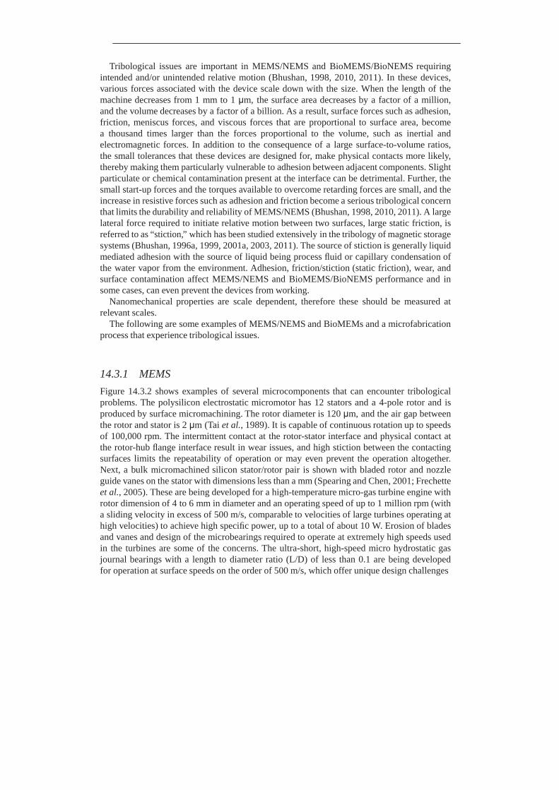
Figure 14.3.2 shows examples of several microcomponents that can encounter tribological problems. The polysilicon electrostatic micromotor has 12 stators and a 4-pole rotor and is produced by surface micromachining. The rotor diameter is 120 μm, and the air gap between the rotor and stator is 2 μm (Tai et al., 1989). It is capable of continuous rotation up to speeds of 100,000 rpm. The intermittent contact at the rotor-stator interface and physical contact at the rotor-hub flange interface result in wear issues, and high stiction between the contacting surfaces limits the repeatability of operation or may even prevent the operation altogether. Next, a bulk micromachined silicon stator/rotor pair is shown with bladed rotor and nozzle guide vanes on the stator with dimensions less than a mm (Spearing and Chen, 2001; Frechette et al., 2005). These are being developed for a high-temperature micro-gas turbine engine with rotor dimension of 4 to 6 mm in diameter and an operating speed of up to 1 million rpm (with a sliding velocity in excess of 500 m/s, comparable to velocities of large turbines operating at high velocities) to achieve high specific power, up to a total of about 10 W. Erosion of blades and vanes and design of the microbearings required to operate at extremely high speeds used in the turbines are some of the concerns. The ultra-short, high-speed micro hydrostatic gas journal bearings with a length to diameter ratio (L/D) of less than 0.1 are being developed for operation at surface speeds on the order of 500 m/s, which offer unique design challenges
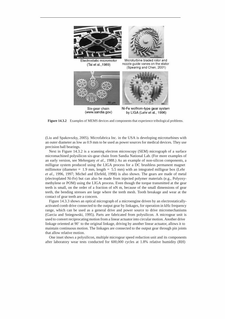
Figure 14.3.2 Examples of MEMS devices and components that experience tribological problems.
(Liu and Spakovszky, 2005). Microfabrica Inc. in the USA is developing microturbines with an outer diameter as low as 0.9 mm to be used as power sources for medical devices. They use precision ball bearings.
Next in Figure 14.3.2 is a scanning electron microscopy (SEM) micrograph of a surface micromachined polysilicon six-gear chain from Sandia National Lab. (For more examples of an early version, see Mehregany et al., 1988.) As an example of non-silicon components, a milligear system produced using the LIGA process for a DC brushless permanent magnet millimotor (diameter = 1.9 mm, length = 5.5 mm) with an integrated milligear box (Lehr et al., 1996, 1997; Michel and Ehrfeld, 1998) is also shown. The gears are made of metal (electroplated Ni-Fe) but can also be made from injected polymer materials (e.g., Polyoxy- methylene or POM) using the LIGA process. Even though the torque transmitted at the gear teeth is small, on the order of a fraction of nN m, because of the small dimensions of gear teeth, the bending stresses are large where the teeth mesh. Tooth breakage and wear at the contact of gear teeth are a concern.
Figure 14.3.3 shows an optical micrograph of a microengine driven by an electrostatically- activated comb drive connected to the output gear by linkages, for operation in kHz frequency range, which can be used as a general drive and power source to drive micromechanisms (Garcia and Sniegowski, 1995). Parts are fabricated from polysilicon. A microgear unit is used to convert reciprocating motion from a linear actuator into circular motion. Another drive linkage oriented at 90◦ to the original linkage, driving by another linear actuator, allows it to maintain continuous motion. The linkages are connected to the output gear through pin joints that allow relative motion.
One inset shows a polysilicon, multiple microgear speed reduction unit and its components after laboratory wear tests conducted for 600,000 cycles at 1.8% relative humidity (RH)
Figure 14.3.3 Optical micrograph of a microengine driven by an electrostatically-actuated comb drive (microengine) fabricated by Sandia Summit Technologies. Reproduced with permission from Garcia, E.J. and Sniegowski, J.J. (1995), “Surface Micromachined Microengine,” Sensors and Actuators A 48, 203–214. Copyright 1995. Elsevier. One inset shows a polysilicon microgear speed reduction unit after laboratory wear test for 600,000 cycles at 1.8% relative humidity (Tanner et al., 2000). The second inset shows a stuck comb drive (CSEM).
(Tanner et al., 2000). Wear of various components is clearly observed in the figure. Humidity was shown to be a strong factor in the wear of rubbing surfaces. In order to improve the wear characteristics of rubbing surfaces, vapor deposited self-assembled monolayers of fluorinated (dimethylamino) silane have been used (Hankins et al., 2003). The second inset shows a comb drive with a deformed frame, which results in some fingers coming in contact. The contacting fingers can result in stiction.
Commercially available MEMS devices also exhibit tribological problems. Figure 14.3.4 shows an integrated capacitive-type silicon accelerometer fabricated using surface microma- chining by Analog Devices, a couple of mm in dimension, which is used for the deployment of airbags in automobiles, and more recently for various other consumer electronics market (Core et al., 1993; Sulouff, 1998). The central suspended beam mass (about 0.7 μg) is supported on the four corners by spring structures. The central beam has interdigitated cantilevered elec- trode fingers (about 125 μm long and 3 μm thick) on all four sides that alternate with those of the stationary electrode fingers as shown, with about a 1.3 μm gap. Lateral motion of the central beam causes a change in the capacitance between these electrodes, which is used to measure the acceleration. Stiction between the adjacent electrodes as well as stiction of the beam structure with the underlying substrate, under isolated conditions, is detrimental to the operation of the sensor (Core et al., 1993; Sulouff, 1998). Wear during unintended contacts of these polysilicon fingers is also a problem. A molecularly thick diphenyl siloxane lubricant film, resistant to high temperatures and oxidation, is applied by a vapor deposition process on the electrodes to reduce stiction and wear (Martin and Zhao, 1997). As sensors are required to

Capacitive type silicon accelerometer for automotive sensory applications
(Sulouff, 1998)
Applied Pressure
Piezoresistive type pressure sensor
(Parsons, 2001)
Thermal inkjet printhead (Bayda and Groscup, 2001)
Figure 14.3.4 Examples of commercial MEMS that experience tribological problems.

sense low g accelerations, they need to be more compliant and stiction becomes even a bigger concern.
Figure 14.3.4 also shows a cross-sectional view of a typical piezoresistive type pressure sensor, which is used for various applications including manifold absolute pressure (MAP) and tire pressure measurements in automotive applications, and disposable blood pressure measurements. The sensing material is a diaphragm formed on a silicon substrate, which bends with applied pressure (Smith, 1997; Parsons, 2001). The deformation causes a change in the band structure of the piezoresistors that are placed on the diaphragm, leading to a change in the resistivity of the material. The MAP sensors are subjected to drastic conditions – extreme temperatures, vibrations, sensing fluid, and thermal shock. Fluid under extreme conditions could cause corrosive wear. Fluid cavitation could cause erosive wear. The protective gel encapsulent generally used can react with sensing fluid and result in swelling or dissolution of the gel. Silicon cannot deform plastically, therefore any pressure spikes leading to deformation past its elastic limit will result in fracture and crack propagation. Pressure spikes could also cause the diaphragm to delaminate from the support substrate. Finally, cyclic loading of the diaphragm during use can lead to fatigue and wear of the silicon diaphragm or its delamination.
The bottom schematic in Figure 14.3.4 shows a cross-sectional view of a thermal printhead chip (on the order of 10 to 50 cm3 in volume) used in inkjet printers (Baydo and Groscup, 2001). They comprise of a supply of ink and an array of elements with microscopic heating resistors on a substrate mated to a matching array of ink-injection orifices or nozzles (about 70 μm in diameter) (Aden et al., 1994; Le, 1998; Lee, 2003). In each element, a small chamber is heated by the resistor where a brief electrical impulse vaporizes part of the ink and creates a tiny bubble. The heaters operate at several kHz and are therefore capable of high-speed printing. As the bubble expands, some of the ink is pushed out of the nozzle onto the paper. When the bubble pops, a vacuum is created and this causes more ink from the cartridge to move into the printhead. Clogged ink ports are the major failure mode. There are various tribological concerns (Aden et al., 1994). The surface of the printhead where the ink is shot out towards the paper can get scratched and damaged as a result of countless trips back and forth across the pages, which are somewhat rough. As a result of repeated heating and cooling, the heated resistors expand and contract. Over time, these elements will experience fatigue and may eventually fail. Bubble formation in the ink reservoir can lead to cavitation erosion of the chamber, which occurs when bubbles formed in the fluid become unstable and implode against the surface of the solid and impose impact energy on that surface. Fluid flow through nozzles may cause erosion and ink particles may also cause abrasive wear. Corrosion of the ink reservoir surfaces can also occur as a result of exposure of ink at high temperatures as well as due to ink pH. The substrate of the chip consists of silicon with a thermal barrier layer followed by a thin film of resistive material and then conducting material. The conductor and resister layers are generally protected by an overcoat layer of a plasma- enhanced chemical vapor deposition (PECVD) α-SiC:H layer, 200–500 nm thick (Chang et al., 1991).
Figure 14.3.5 shows two digital micromirror devices (DMD) pixels used in digital light processing (DLP) technology for digital projection displays in computer projectors, high defi- nition television (HDTV) sets, and movie projectors (Hornbeck and Nelson, 1988; Hornbeck, 1999, 2001). The entire array (chip set) consists of a large number of oscillating aluminum alloy micromirrors as digital light switches which are fabricated on top of a complementary
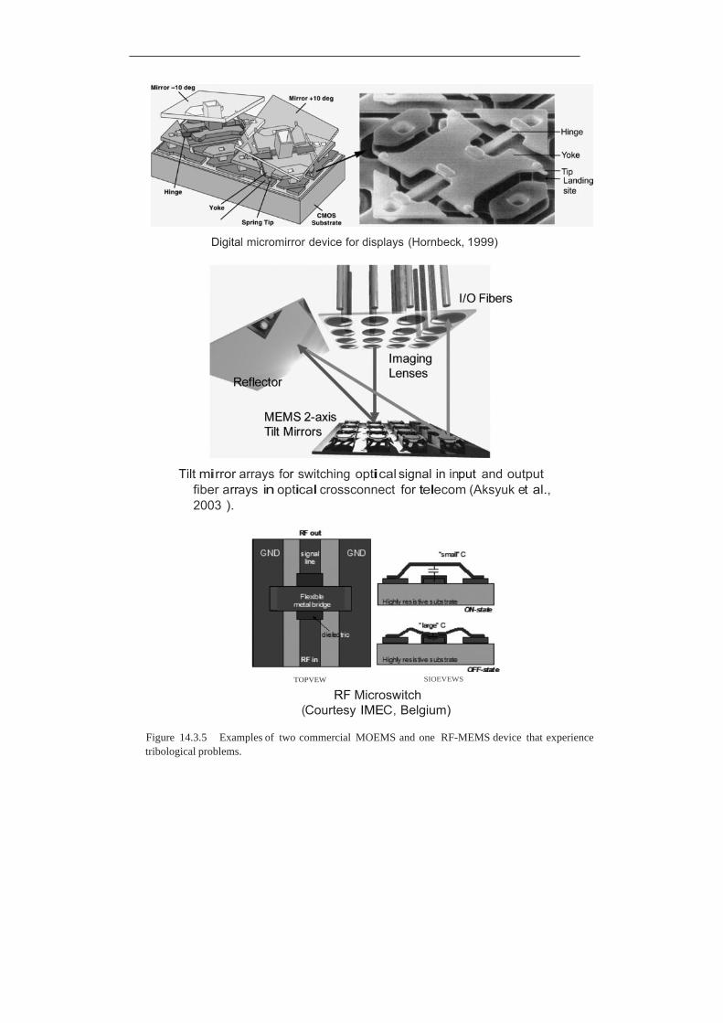
Digital micromirror device for displays (Hornbeck, 1999)
Tilt mirror arrays for switching optical signal in input and output fiber arrays in optical crossconnect for telecom (Aksyuk et al., 2003 ).
TOPVEW SIOEVEWS
RF Microswitch (Courtesy IMEC, Belgium)
Figure 14.3.5 Examples of two commercial MOEMS and one RF-MEMS device that experience tribological problems.
metal-oxide-semiconductor (CMOS) static random access memory integrated circuit. The surface micromachined array consists of half a million to more than two million of these independently controlled reflective micromirrors, each about 12 μm square and with 13 μm pitch which flip backward and forward at a frequency of on the order of 5000 to 7000 times a second as a result of electrostatic attraction between the micromirror structure and the under- lying electrodes. For binary operation, the micromirror/yoke structure mounted on torsional hinges is oscillated ± 10◦ (with respect to the plane on the chip set), and is limited by a mechanical stop. Contact between cantilevered spring tips at the end of the yoke (four present on each yoke) with the underlying stationary landing sites is required for true digital (binary) operation. Stiction and wear during contact between aluminum alloy spring tips and landing sites, hinge memory (metal creep at high operating temperatures), hinge fatigue, shock and vibration failure, and sensitivity to particles in the chip package and operating environment are some of the important issues affecting the reliable operation of a micromirror device (Henck, 1997; Douglass, 1998, 2003; Liu and Bhushan, 2004a, b). A vapor phase deposited self-assembled monolayer of the fatty acid perfluorodecanoic acid (PFDA) on surfaces of tip and landing sites is used to reduce stiction and wear (Hornbeck, 1997; Robbins and Jacobs, 2001). However, these films are susceptible to moisture, and to keep moisture out and create a background pressure of PFDA, a hermetic chip package is used. The spring tip is used in order to use the spring stored energy to pop up the tip during pull-off. A lifetime estimate of over one hundred thousand operating hours with no degradation in image quality is the norm. At a mirror modulation frequency of 7 kHz, each micromirror element needs to switch about 2.5 trillion cycles.
Figure 14.3.5 also shows a schematic of a 256 × 256-port large optical cross-connects, introduced in 2000 by Glimmerglass, Hayward, California, for optical telecommunication networks in order to be able to rapidly manipulate a larger number of optical signals (Aksyuk et al., 2003). This optical microswitch uses 256 or more movable mirrors on a chip for switching a light beam from an input fiber to a few output fibers. The mirrors are made of gold-coated polysilicon and are about 500 μm in diameter. The reliability concerns are the same as those just described for DMDs. To minimize stiction, the chipset is hermetically sealed in dry nitrogen (90% N2 , 10% He).
Figure 14.3.5 also shows a schematic of an electrostatically-actuated capacitive-type RF microswitch for switching of RF signals at microwave and low frequencies (DeWolf and van Spengen, 2002). It is a membrane type and consists of a flexible metal (Al) bridge that spans the RF transmission line in the center of a coplanar waveguide. When the bridge is up, the capacitance between the bridge and RF transmission line is small, and the RF signal passes without much loss. When a DC voltage is applied between the RF transmission line and the bridge, the latter is pulled down until it touches a dielectric isolation layer. The large capacitance thus created shorts the RF signal to the ground. The failure modes include creep in the metal bridge, fatigue of the bridge, charging and degradation of the dielectric insulator, and stiction of the bridge to the insulator (DeWolf and van Spengen, 2002; Suzuki, 2002). The stiction occurs due to capillary condensation of water vapor from the environment, van der Waals forces, and/or charging effects. If the restoring force in the bridge of the switch is not large enough to pull the bridge up again after the actuation voltage has been removed, the device fails due to stiction. Humidity-induced stiction can be avoided by hermetically sealing the microswitch. Some roughness of the surfaces reduces the probability of stiction. Selected actuation waveforms can be used to minimize charging effects.

14.3.2 NEMS
Probe-based data recording technologies have been explored for ultra-high areal density recording where the probe tip (with a radius of about 5 nm) is expected to be scanned at velocities up to 100 mm/s. Major techniques include – thermomechanical (Vettiger et al., 1999), phase change (Bhushan and Kwak, 2007), and ferroelectric recording (Bhushan and Kwak 2008; Kwak and Bhushan, 2008).
14.3.3 BioMEMS
An example of a wristwatch type biosensor based on microfluidics referred to as a lab-on-a-chip system is shown in Figure 14.3.6 (Tang and Lee, 2001; van der Berg, 2003). These systems are designed to either detect a single or a class of (bio)chemical(s), or for system-level analytical capabilities for a broad range of (bio)chemical species known as a micro total analysis system (μTas), and have the advantage of incorporating sample handling, separation, detection, and data analysis onto one platform. The chip relies on microfluidics and involves the manipulation
Figure 14.3.6 MEMS based biofluidic chip, commonly known as a lab-on-a-chip, that can be worn like a wristwatch.
of tiny amounts of fluids in microchannels using microvalves. The test fluid is injected into the chip generally using an external pump or syringe for analysis. Some chips have been designed with an integrated electrostatically-actuated diaphragm type micropump. The sample, which can have volume measured in nanoliters, flows through microfluidic channels via an electric potential and capillary action using microvalves (having various designs including membrane type) for various analyses. The fluid is preprocessed and then analyzed using a biosensor.
If the adhesion between the microchannel surface and the biofluid is high, the biomolecules will stick to the microchannel surface and restrict flow. In order to facilitate flow, microchannel surfaces with low bioadhesion are required. Fluid flow in polymer channels can produce triboelectric surface potential, which may affect the flow.
14.3.4 Microfabrication Processes
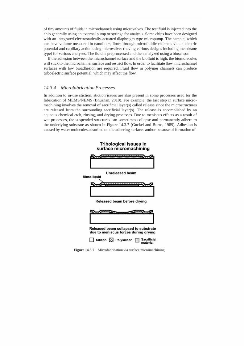
In addition to in-use stiction, stiction issues are also present in some processes used for the fabrication of MEMS/NEMS (Bhushan, 2010). For example, the last step in surface micro- machining involves the removal of sacrificial layer(s) called release since the microstructures are released from the surrounding sacrificial layer(s). The release is accomplished by an aqueous chemical etch, rinsing, and drying processes. Due to meniscus effects as a result of wet processes, the suspended structures can sometimes collapse and permanently adhere to the underlying substrate as shown in Figure 14.3.7 (Guckel and Burns, 1989). Adhesion is caused by water molecules adsorbed on the adhering surfaces and/or because of formation of
Figure 14.3.7 Microfabrication via surface micromachining.
adhesive bonds by silica residues that remain on the surfaces after the water has evaporated. This so-called release stiction is overcome by using dry release methods, such as CO2 critical point drying or sublimation drying (Mulhern et al., 1993). CO2 at high pressure is in a su- percritical state and becomes liquid. Liquid CO2 is used to remove wet etchant, and then it is converted back to gas phase.
14.4 Material Processing
The desired shape and accuracy of machine parts are obtained by the removal of material (material cutting) or by plastic deformation of material (metal forming) (Schey, 1977; Samuels, 1982; Booser, 1984; Anonymous, 1989c; Bhushan, 1996a, 2001a, Shaw, 1996, 1997). In material cutting, material is removed either by a cutting tool in the form of relatively large chips or by abrasives in the form of relatively small chips. The material-cutting processes that involve cutting tools include turning to produce cylindrical surfaces; milling to produce flat surfaces and surfaces of complex geometry; and drilling, boring, and reaming to produce round holes. The material-cutting processes that involve abrasives include grinding and free- abrasive and fixed-abrasive lapping or polishing. In all of these material-removal processes, the general removal mechanisms at the tip of the cutting edge are the same in all processes. The metal-forming processes include forging, rolling, drawing of wire, bar or tube, extrusion, and sheet-metal working. In most material processing, cutting fluids are used (Bastian, 1951; Braithwaite, 1967; Booser, 1984; Shaw, 1996, 1997). These cutting fluids also reduce friction at the cutting interface.
14.4.1 Cutting Tools
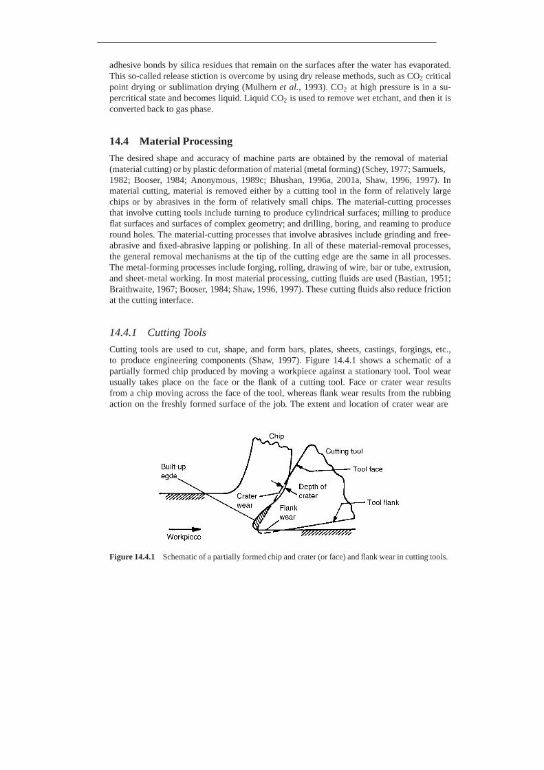
Cutting tools are used to cut, shape, and form bars, plates, sheets, castings, forgings, etc., to produce engineering components (Shaw, 1997). Figure 14.4.1 shows a schematic of a partially formed chip produced by moving a workpiece against a stationary tool. Tool wear usually takes place on the face or the flank of a cutting tool. Face or crater wear results from a chip moving across the face of the tool, whereas flank wear results from the rubbing action on the freshly formed surface of the job. The extent and location of crater wear are
Figure 14.4.1 Schematic of a partially formed chip and crater (or face) and flank wear in cutting tools.

considerably affected by the formation of a built-up edge composed of highly strained and hardened fragments of material (Tipnis, 1980; Anonymous, 1989c; Shaw, 1997). Tool wear occurs by adhesive, abrasive, chemical (by thermal diffusion), and electrochemical wear. In general, the life of a cutting tool is judged by one of the following criteria: (1) complete failure of the tool; (2) cutting time for material removal to a predetermined crater depth or flank-wear land width; and (3) loss of workpiece dimensional tolerance and degradation of surface finish. The most important properties of a cutting tool material are its hot hardness (i.e., resistance to softening under temperatures generated at the cutting edge of the tool), toughness, and chemical stability and reactivity. Other relevant properties are elastic modulus, rupture strength, compressive strength, and coefficient of thermal expansion. Cutting-tool life is a most important factor in the economics of production.
Tools can be made from anything from an elastomer to a diamond, but a few tool materials dominate. Of the different cutting-tool materials in use today, about 40% are high-speed steels (HSS) (a class of tool steel), about 10% are cemented carbides (cermets), about 30% are carbon, alloy, and stainless steels, 5% are ceramics including diamonds and cubic boron nitride, and the rest are other materials (cast alloys, cast irons, nonferrous metals, and elastomers) (Budinski, 1980; Shaw, 1997). According to some estimates, 60% of all carbide tools are coated grades.
A comparison of hot hardness (hardness as a function of temperature) for commonly used tool materials is presented in Figure 14.4.2. Carbon steels are confined to hand tools, light-duty
Figure 14.4.2 A comparison of hot hardness (Knoop hardness as a function of temperature) of high- speed steel, cemented tungsten carbide, alumina, cast Co-Cr-W alloy, cubic boron nitride, and diamond tool materials.
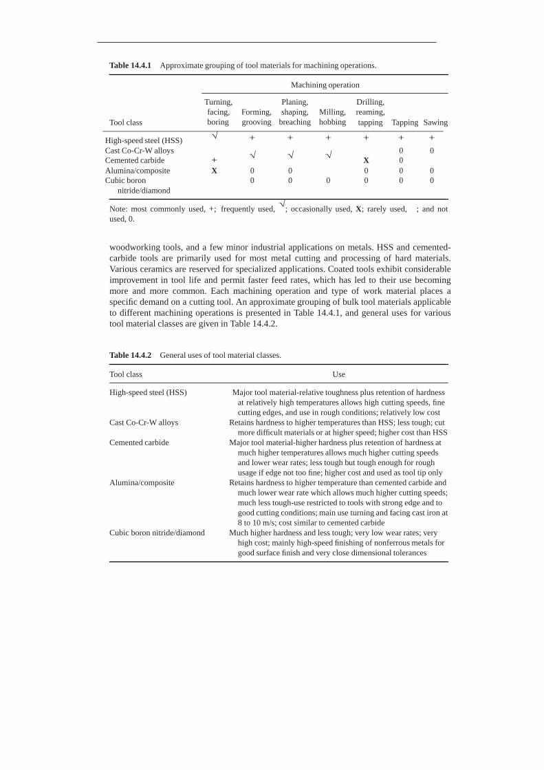
Table 14.4.1 Approximate grouping of tool materials for machining operations.
Machining operation
Tool class
Turning, facing, boring
Forming, grooving
Planing, shaping,
breaching
Milling, hobbing
Drilling, reaming, tapping Tapping Sawing
High-speed steel (HSS) √ + + + + + +
Cast Co-Cr-W alloys 0 0 Cemented carbide +
√ √ √ X 0
Alumina/composite X 0 0 0 0 0 Cubic boron 0 0 0 0 0 0
nitride/diamond
Note: most commonly used, +; frequently used, √
; occasionally used, X; rarely used, ; and not
used, 0.
woodworking tools, and a few minor industrial applications on metals. HSS and cemented- carbide tools are primarily used for most metal cutting and processing of hard materials. Various ceramics are reserved for specialized applications. Coated tools exhibit considerable improvement in tool life and permit faster feed rates, which has led to their use becoming more and more common. Each machining operation and type of work material places a specific demand on a cutting tool. An approximate grouping of bulk tool materials applicable to different machining operations is presented in Table 14.4.1, and general uses for various tool material classes are given in Table 14.4.2.
Table 14.4.2 General uses of tool material classes.
Tool class Use
High-speed steel (HSS) Major tool material-relative toughness plus retention of hardness at relatively high temperatures allows high cutting speeds, fine cutting edges, and use in rough conditions; relatively low cost
Cast Co-Cr-W alloys Retains hardness to higher temperatures than HSS; less tough; cut more difficult materials or at higher speed; higher cost than HSS
Cemented carbide Major tool material-higher hardness plus retention of hardness at much higher temperatures allows much higher cutting speeds and lower wear rates; less tough but tough enough for rough usage if edge not too fine; higher cost and used as tool tip only
Alumina/composite Retains hardness to higher temperature than cemented carbide and much lower wear rate which allows much higher cutting speeds; much less tough-use restricted to tools with strong edge and to good cutting conditions; main use turning and facing cast iron at 8 to 10 m/s; cost similar to cemented carbide
Cubic boron nitride/diamond Much higher hardness and less tough; very low wear rates; very high cost; mainly high-speed finishing of nonferrous metals for good surface finish and very close dimensional tolerances
Carbon and alloy steels usually contain less than 5% total alloy content. This, combined with lower quality-control standards in their manufacture, makes them lower in cost than high-speed tool steels. However, these steels simply cannot equal the hardening and wear characteristics of tool steels. Low-carbon steels (such as AISI 1010 and AISI 1020) can be hardened by cold working to less than 200 Brinell. Medium-carbon grades (such as AISI 1040 and AISI 1060) can be hardened to 500–600 Brinell by direct-hardening or flame-hardening techniques. Alloy steels can be carburized (such as AISI 4320 and AISI 4620) or direct-hardened (such as AISI 4130 and AISI 4140) to a hardness no more than about 58 HRC.
Nearly 90% of the HSS tools are M series (with molybdenum as the major alloying element); the remaining are T series (with tungsten as the major alloying element). Although T-HSS are somewhat superior in wear resistance, they are more difficult to grind. Cobalt-containing M-HSS can be heat-treated to a higher hardness, 900–940 HV (67–70 HRC) versus 800–860 HV (64–66 HRC) for the non-cobalt-containing series. When tools are used in a corrosive environment, it is often necessary to use stainless steels, such as in the food industry and the chemical process industry. Of the various stainless steels, Cr-Ni steels with a martensitic structure, such as 440C, are the most useful as tool materials. Type 440C is capable of being quench-hardened to 58–60 HRC, and its wear characteristics are similar to those of air-hardening cold-working tool steel such as A2.
Cast Co-Cr-W alloys often contain some molybdenum and boron. In addition, vanadium, tantalum, and columbium as alloying elements and manganese and silicon as deoxidizers are generally present. The hardness of cast alloys ranges from 650 to 800 HV. The cast alloys can withstand higher temperatures than HSS and hence provide properties that are in between those of HSS and sintered carbides.
Sintered or cemented carbide tool materials are made of finely divided carbide particles of tungsten, titanium, tantalum, niobium, and other refractory metals bonded with cobalt, nickel, nichrome, molybdenum, or even steel alloys and are produced by powder metallurgy processes. The most commonly used cemented carbide is tungsten carbide with about 6 wt % cobalt binder. The most important property of cemented carbides is their hardness. The carbide particles that make up the major portion of these composites are harder than any metal. For example, the hardness of tungsten carbide, which is the most commonly used carbide, is about 2000 HV.
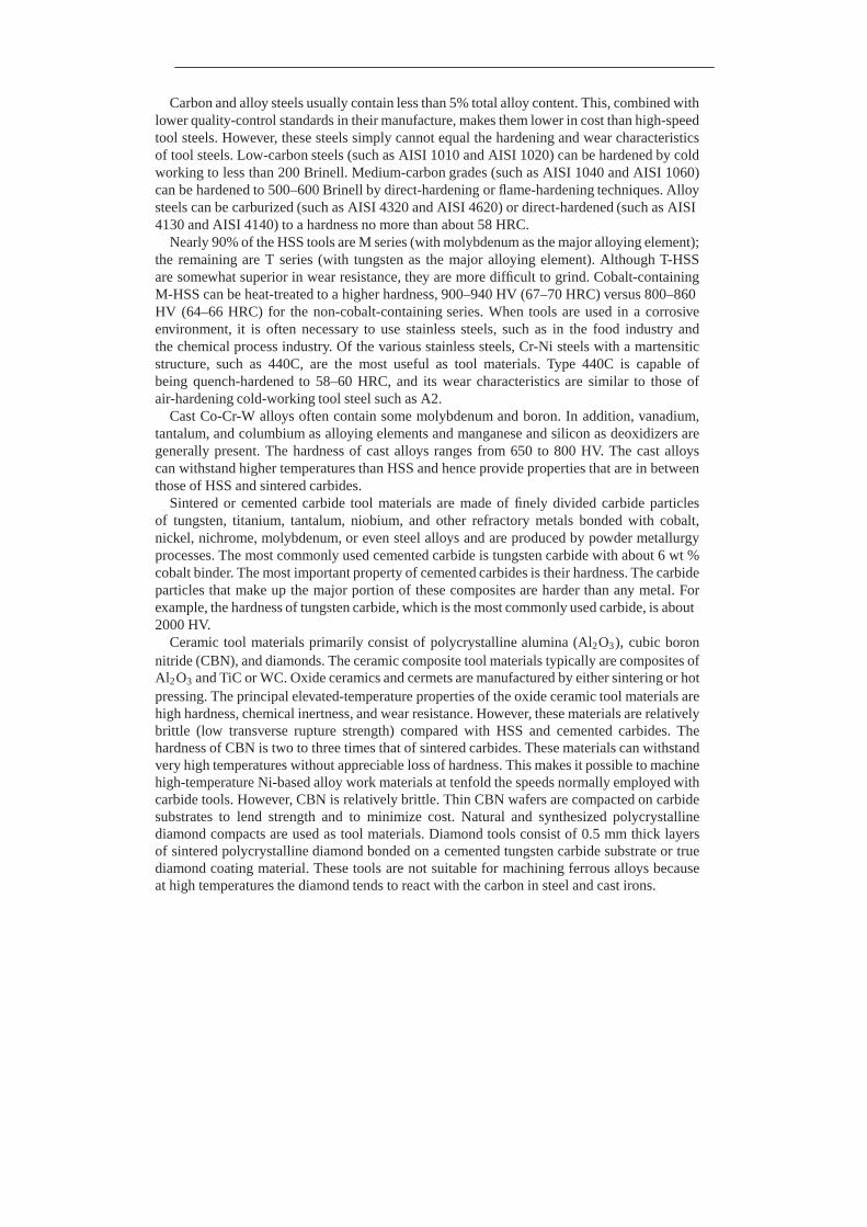
Ceramic tool materials primarily consist of polycrystalline alumina (Al2 O3 ), cubic boron nitride (CBN), and diamonds. The ceramic composite tool materials typically are composites of Al2 O3 and TiC or WC. Oxide ceramics and cermets are manufactured by either sintering or hot pressing. The principal elevated-temperature properties of the oxide ceramic tool materials are high hardness, chemical inertness, and wear resistance. However, these materials are relatively brittle (low transverse rupture strength) compared with HSS and cemented carbides. The hardness of CBN is two to three times that of sintered carbides. These materials can withstand very high temperatures without appreciable loss of hardness. This makes it possible to machine high-temperature Ni-based alloy work materials at tenfold the speeds normally employed with carbide tools. However, CBN is relatively brittle. Thin CBN wafers are compacted on carbide substrates to lend strength and to minimize cost. Natural and synthesized polycrystalline diamond compacts are used as tool materials. Diamond tools consist of 0.5 mm thick layers of sintered polycrystalline diamond bonded on a cemented tungsten carbide substrate or true diamond coating material. These tools are not suitable for machining ferrous alloys because at high temperatures the diamond tends to react with the carbon in steel and cast irons.

Coatings (typically 2–25 μm thick) of various ceramic materials, such as TiC, TiN, TiCx Ny , TiOx Ny , Al2 O3 , HfC, ZrC, TaC, HfN, and ZrN, on high-speed-steel and cemented-carbide substrates (usually WC-Co or WC-TiC-TaC-Co compacts), have been deposited successfully to increase tool life. The coatings have been deposited by various vapor-deposition techniques: activated reactive evaporation (ARE); ion plating; sputtering; and chemical vapor deposition (CVD). The use of CVD techniques for such coatings (e.g., TiC) on cemented tungsten carbide tools is well established. However, the CVD process is not suited to coat high- speed tools because of the high deposition temperature (1000–1200◦C) of the process, which results in metallurgical changes and distortion of the tool. The low deposition temperatures of evaporation, ion plating, and sputtering are particularly attractive. Various surface treatments such as carburizing and nitriding of some steel tools and ion implantation are also found to improve tool life considerably.
14.4.2 Grinding and Lapping
Grinding is a versatile process that is used to manufacture parts that require a good surface finish (on the order of 1 μm peak to valley) and dimensional accuracy. Grinding is performed with small, extremely hard abrasive particles (grits) usually bonded together in the form of a wheel in the presence of a cutting fluid (Shaw, 1996, 1997; Bhushan, 1996a). The wheel can be either vitrified or resin or metal bonded. The most frequently used abrasives are MgO, SiO2 , Al2 O3 , SiC, cubic boron nitride (CBN), and diamond. Figure 14.4.3a shows a surface grinding operation and an undeformed shape of chip.
Lapping (finishing or polishing) is a fine finishing process and is usually the last stage in the finishing of a component (Samuels, 1982; Bhushan, 1996a). It is used to produce surfaces of extremely good finish (5–100 nm peak to valley) and flatness. In the free abrasive lapping, the workpiece is usually mounted on a steel puck with adhesive and moved across the face of the lap under normal ambient pressure in the presence of abrasive powder slurry, Figure 14.4.3b. The lap is usually made of soft materials such as bonze, tin, copper, or cast iron. The abrasive is suspended in a liquid carrier (e.g., ethylene glycol or a lubricant such as olive oil). Some of the abrasive gets embedded into the lap. Common abrasives used in lapping are Cr2 O3 , Al2 O3 , SiC, and diamond of various grit sizes ranging from about 0.05 μm to several μm.
In fixed-abrasive lapping, a lapping tape (abrasive impregnated tape) is rubbed against the workpiece. The lapping tapes are flexible and conform well to the workpiece. Lapping tapes normally use Cr2 O3 , Al2 O3 , and SiC of various grit sizes ranging from about 1.5 μm to 14 μm held in an organic binder. The tape substrate is typically acetate or polyester film of about 25 μm in thickness with a total thickness of about 40-45 μm (Bhushan, 1996a).
14.4.3 Forming Processes
Schematics of basic forms of wire, bar, and tube drawing operation, extrusion, and shearing (punching, blanking, or slitting) are shown in Figure 14.4.4 (Schey, 1977; Booser, 1984). The performance of forming punches and dies is usually dictated by the amount of wear, which is influenced by the kind and size of workpiece, the sharpness of the die radii, die construction and finish, lubrication, and hardness of the die material.
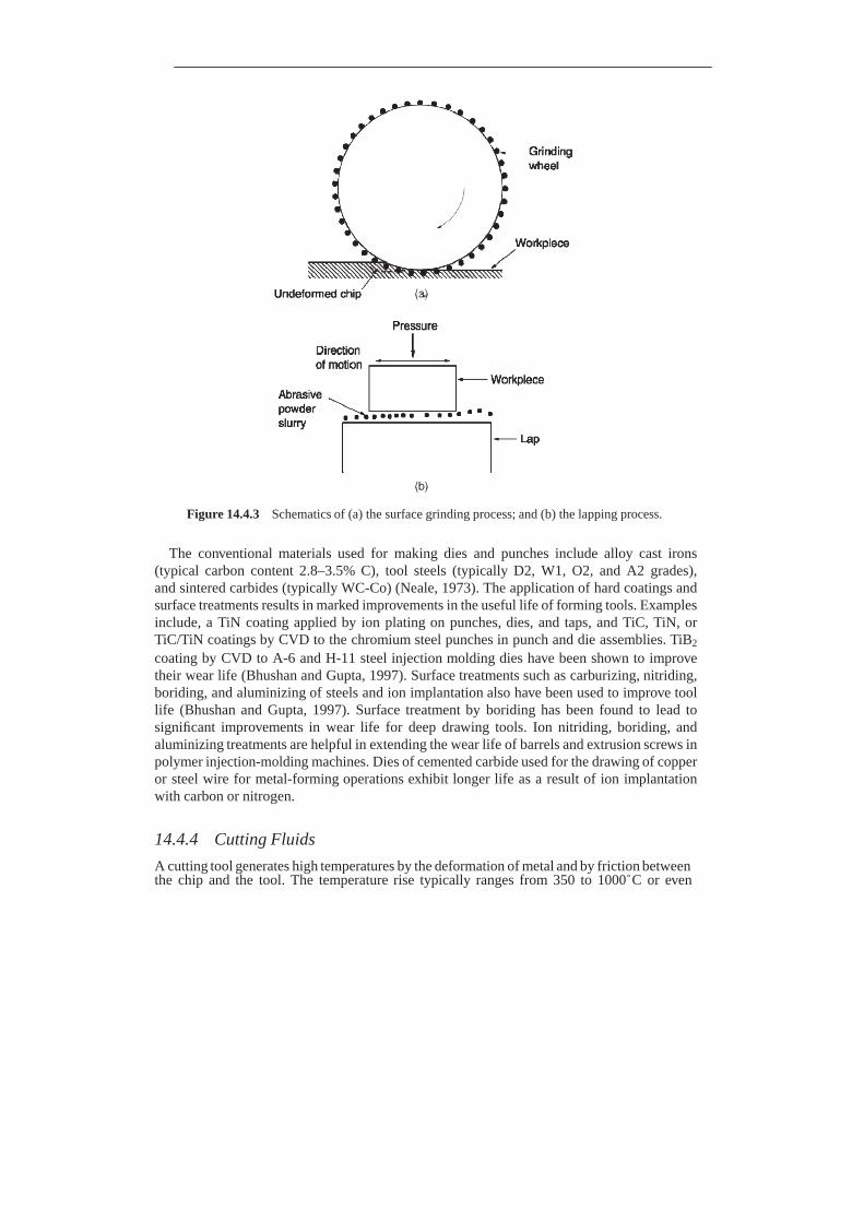
Figure 14.4.3 Schematics of (a) the surface grinding process; and (b) the lapping process.
The conventional materials used for making dies and punches include alloy cast irons
(typical carbon content 2.8–3.5% C), tool steels (typically D2, W1, O2, and A2 grades), and sintered carbides (typically WC-Co) (Neale, 1973). The application of hard coatings and surface treatments results in marked improvements in the useful life of forming tools. Examples include, a TiN coating applied by ion plating on punches, dies, and taps, and TiC, TiN, or TiC/TiN coatings by CVD to the chromium steel punches in punch and die assemblies. TiB2
coating by CVD to A-6 and H-11 steel injection molding dies have been shown to improve their wear life (Bhushan and Gupta, 1997). Surface treatments such as carburizing, nitriding, boriding, and aluminizing of steels and ion implantation also have been used to improve tool life (Bhushan and Gupta, 1997). Surface treatment by boriding has been found to lead to significant improvements in wear life for deep drawing tools. Ion nitriding, boriding, and aluminizing treatments are helpful in extending the wear life of barrels and extrusion screws in polymer injection-molding machines. Dies of cemented carbide used for the drawing of copper or steel wire for metal-forming operations exhibit longer life as a result of ion implantation with carbon or nitrogen.
14.4.4 Cutting Fluids
A cutting tool generates high temperatures by the deformation of metal and by friction between the chip and the tool. The temperature rise typically ranges from 350 to 1000◦C or even

Figure 14.4.4 Schematics of basic forms of: (a) tube drawing operation; (b) extrusion; and (c) punching of a metal sheet of billet through the die operation.
higher. The primary function of any cutting fluid is to dissipate the frictional heat away to keep the interface cool, especially in high-speed cutting operations, such as in turning (Bastian, 1951; Braithwaite, 1967; Booser, 1984; Shaw, 1996, 1997). The other function is to provide lubrication. For efficient cooling, the heat transfer properties of the cutting fluid should be good. Other considerations associated with the cutting fluid include lubricity, corrosion prevention, and health and safety hazards.
Cutting fluids contain mineral oils, fatty oils, or a combination of these, mixtures of mineral oil and emulsifiers (soluble oils) added to water or synthetic fluids (organic and inorganic salts dissolved in water).
14.5 Industrial Applications
Tribology is extremely important in numerous industrial applications requiring relative motion, for example, automobiles, aircrafts, railroads and magnetic storage devices (O’Connor et al., 1968; Neale, 1973; Peterson and Winer, 1980; Booser, 1983; Bhushan, 1996a, 2001a; Bhushan and Gupta, 1997). Since the 1980s, microdevices involving mechanical components have been produced using microfabrication technologies. The above applications are briefly described next.
14.5.1 Automotive Engines
Internal combustion (IC) engines are the almost exclusive choice for use in automobiles (Rogowski, 1953; Taylor, 1966, 1968; Crouse, 1970; Judge, 1972; Heywood, 1988; Anony- mous, 1997). In reciprocating IC engines, fuel is burned and its combustion power is converted from a linear reciprocation motion of the piston in its cylinder through a connecting rod to a rotating motion in the crankshaft. The crankshaft is connected to the drive shaft and a transmission which provides rotary motion at a desired speed to the rubber tires.
As just stated, in reciprocating IC engines, the piston moves back and forth in a cylinder and transmits power through a connecting rod and crank mechanism to the drive shaft. The cyclical piston motion produces a steady rotation in the crankshaft. The piston comes to rest at the top-center (TC) crank position and bottom-center (BC) crank position when the cylinder volume is a minimum or maximum, respectively. The majority of reciprocating engines operate on a four-stroke cycle, whereas some engines operate on a two-stroke cycle. In the four-stroke cycle, each cylinder requires four strokes of its piston, Figure 14.5.1, two revolutions of the crankshaft to complete the sequence of events which provide a power stroke (Rogowski, 1953). In the intake stroke, which starts with the piston at TC and ends with the piston at BC, fresh mixture is drawn into the cylinder by downward movement of the piston with the inlet valve open and the exhaust valve closed. In the compression stroke, with all valves closed, the piston reverses direction from the intake stroke and compresses the trapped mixture. In the power stroke or expansion stroke, as the piston approaches the top of its compression stroke, the air-fuel mixture burns and develops the high pressure which powers the piston downward. Piston rings provide a seal against the cylinder wall to minimize gas leakage. In the exhaust stroke, as the piston approaches the end of its downward stroke at BC, the exhaust valve opens. The piston reverses direction and starts to move up towards TC and exhaust gases are expelled through the exhaust system. After this, the cycle starts again. Two types of IC engines commonly used in automobiles include spark ignition (SI) gasoline (or petrol) and compression ignition (CI) diesel engines. In the case of the SI gasoline engine, air-fuel mixture is drawn into the intake stroke and the air-fuel mixture is ignited by the spark plug in the power stroke. The compression ratio is about 8:1. In the case of the CI diesel engine, electrical ignition is not used and the intake system delivers only air. Fuel is injected directly into the combustion chamber. The compression ratio is very high, about 20:1. Air compression alone generates heat large enough to ignite the fuel on injection.
Figure 14.5.2 shows a schematic of a four-stroke and four-cylinder SI engine used in passenger cars (Weertman and Dean, 1981). With most water-cooled engines, the cylinders are cast into a single block containing cooling passages, lubricant passages, and supporting
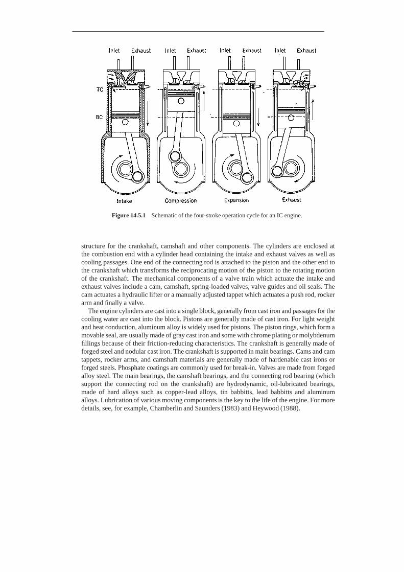
Figure 14.5.1 Schematic of the four-stroke operation cycle for an IC engine.
structure for the crankshaft, camshaft and other components. The cylinders are enclosed at the combustion end with a cylinder head containing the intake and exhaust valves as well as cooling passages. One end of the connecting rod is attached to the piston and the other end to the crankshaft which transforms the reciprocating motion of the piston to the rotating motion of the crankshaft. The mechanical components of a valve train which actuate the intake and exhaust valves include a cam, camshaft, spring-loaded valves, valve guides and oil seals. The cam actuates a hydraulic lifter or a manually adjusted tappet which actuates a push rod, rocker arm and finally a valve.
The engine cylinders are cast into a single block, generally from cast iron and passages for the cooling water are cast into the block. Pistons are generally made of cast iron. For light weight and heat conduction, aluminum alloy is widely used for pistons. The piston rings, which form a movable seal, are usually made of gray cast iron and some with chrome plating or molybdenum fillings because of their friction-reducing characteristics. The crankshaft is generally made of forged steel and nodular cast iron. The crankshaft is supported in main bearings. Cams and cam tappets, rocker arms, and camshaft materials are generally made of hardenable cast irons or forged steels. Phosphate coatings are commonly used for break-in. Valves are made from forged alloy steel. The main bearings, the camshaft bearings, and the connecting rod bearing (which support the connecting rod on the crankshaft) are hydrodynamic, oil-lubricated bearings, made of hard alloys such as copper-lead alloys, tin babbitts, lead babbitts and aluminum alloys. Lubrication of various moving components is the key to the life of the engine. For more details, see, for example, Chamberlin and Saunders (1983) and Heywood (1988).
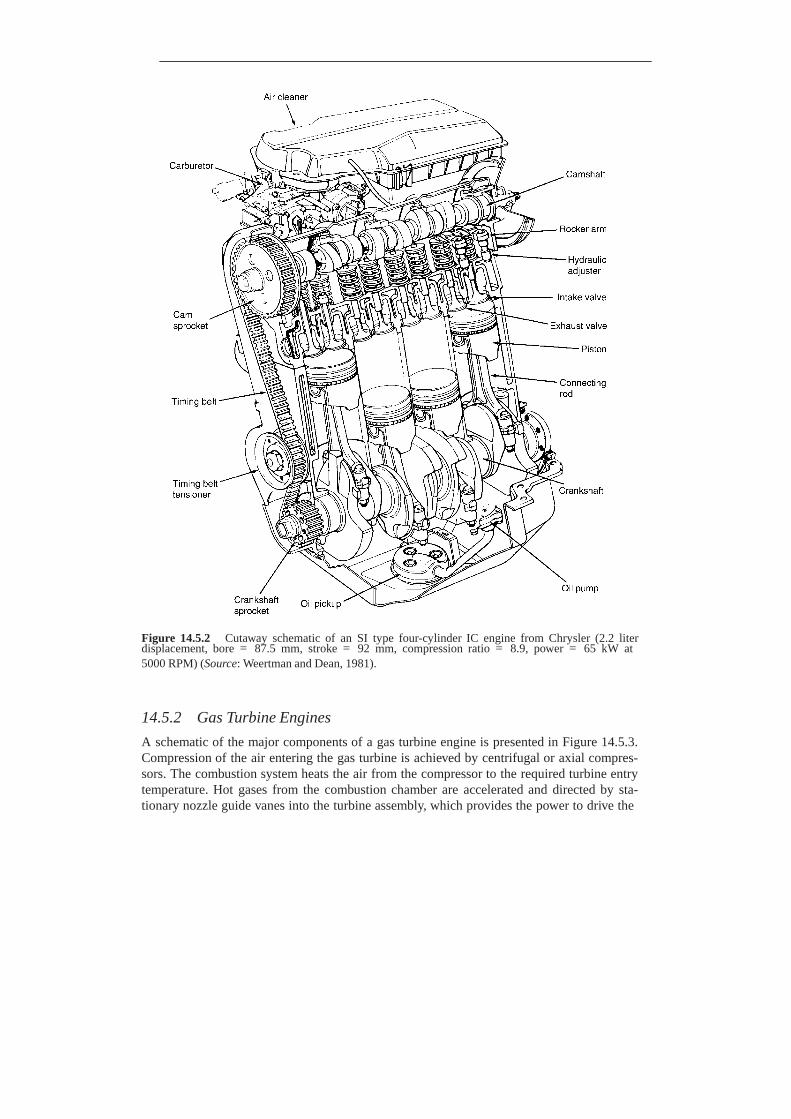
Figure 14.5.2 Cutaway schematic of an SI type four-cylinder IC engine from Chrysler (2.2 liter displacement, bore = 87.5 mm, stroke = 92 mm, compression ratio = 8.9, power = 65 kW at 5000 RPM) (Source: Weertman and Dean, 1981).
14.5.2 Gas Turbine Engines
A schematic of the major components of a gas turbine engine is presented in Figure 14.5.3. Compression of the air entering the gas turbine is achieved by centrifugal or axial compres- sors. The combustion system heats the air from the compressor to the required turbine entry temperature. Hot gases from the combustion chamber are accelerated and directed by sta- tionary nozzle guide vanes into the turbine assembly, which provides the power to drive the

Rolor blade
(a)
Swirl vanes
Flame tube
Combustion system mounting flange
(b) Corrugated joint
Intermediate pressure turbine
Turning blade shroud
shaft
Low pressure nozzle guide vane
Intermediate pressure nozzle guide vane
Figure 14.5.3 Schematic of gas turbine engine components: (a) a typical axial-flow compressor; (b) a typical combustion chamber; and (c) a typical turbine assembly (Source: Meetham, 1981).
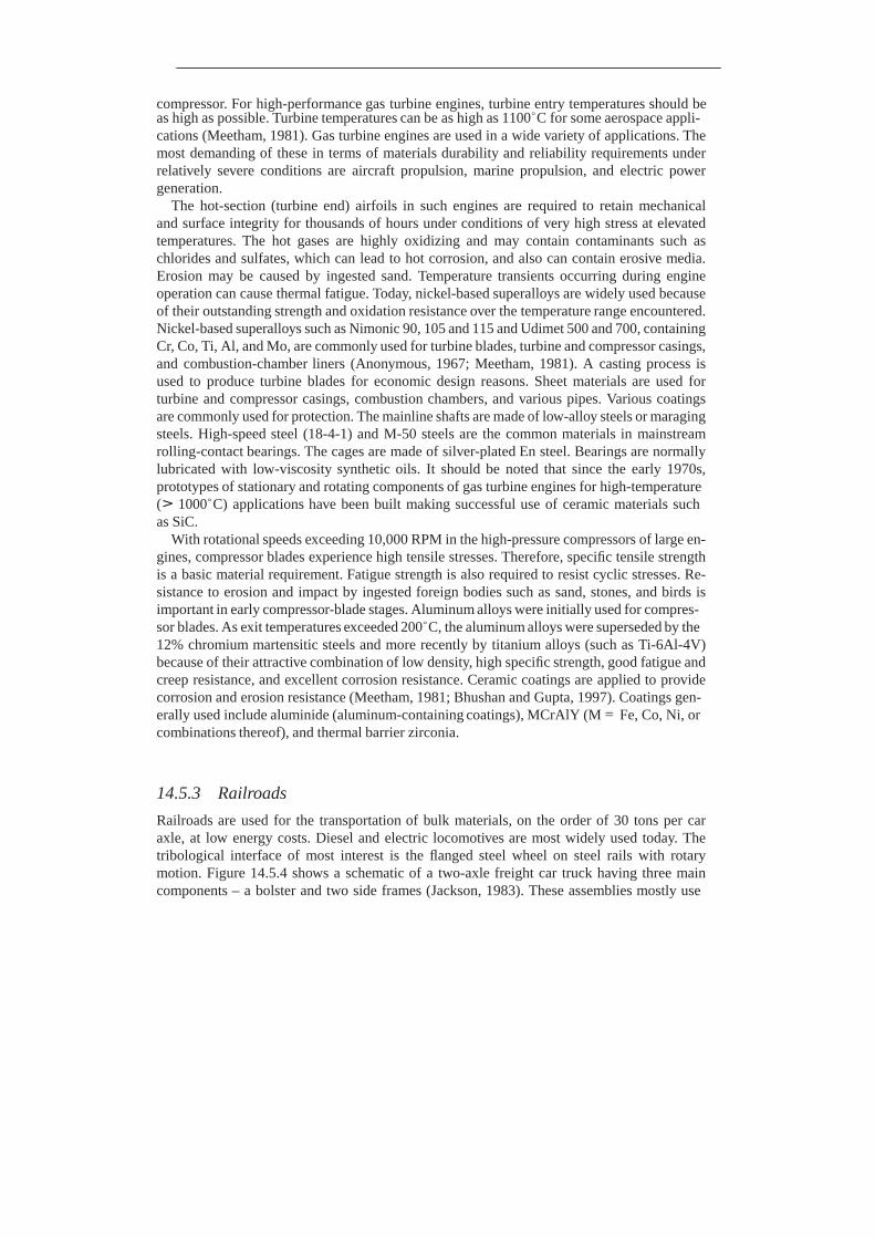
compressor. For high-performance gas turbine engines, turbine entry temperatures should be as high as possible. Turbine temperatures can be as high as 1100◦C for some aerospace appli- cations (Meetham, 1981). Gas turbine engines are used in a wide variety of applications. The most demanding of these in terms of materials durability and reliability requirements under relatively severe conditions are aircraft propulsion, marine propulsion, and electric power generation.
The hot-section (turbine end) airfoils in such engines are required to retain mechanical and surface integrity for thousands of hours under conditions of very high stress at elevated temperatures. The hot gases are highly oxidizing and may contain contaminants such as chlorides and sulfates, which can lead to hot corrosion, and also can contain erosive media. Erosion may be caused by ingested sand. Temperature transients occurring during engine operation can cause thermal fatigue. Today, nickel-based superalloys are widely used because of their outstanding strength and oxidation resistance over the temperature range encountered. Nickel-based superalloys such as Nimonic 90, 105 and 115 and Udimet 500 and 700, containing Cr, Co, Ti, Al, and Mo, are commonly used for turbine blades, turbine and compressor casings, and combustion-chamber liners (Anonymous, 1967; Meetham, 1981). A casting process is used to produce turbine blades for economic design reasons. Sheet materials are used for turbine and compressor casings, combustion chambers, and various pipes. Various coatings are commonly used for protection. The mainline shafts are made of low-alloy steels or maraging steels. High-speed steel (18-4-1) and M-50 steels are the common materials in mainstream rolling-contact bearings. The cages are made of silver-plated En steel. Bearings are normally lubricated with low-viscosity synthetic oils. It should be noted that since the early 1970s, prototypes of stationary and rotating components of gas turbine engines for high-temperature (> 1000◦C) applications have been built making successful use of ceramic materials such as SiC.
With rotational speeds exceeding 10,000 RPM in the high-pressure compressors of large en- gines, compressor blades experience high tensile stresses. Therefore, specific tensile strength is a basic material requirement. Fatigue strength is also required to resist cyclic stresses. Re- sistance to erosion and impact by ingested foreign bodies such as sand, stones, and birds is important in early compressor-blade stages. Aluminum alloys were initially used for compres- sor blades. As exit temperatures exceeded 200◦C, the aluminum alloys were superseded by the 12% chromium martensitic steels and more recently by titanium alloys (such as Ti-6Al-4V) because of their attractive combination of low density, high specific strength, good fatigue and creep resistance, and excellent corrosion resistance. Ceramic coatings are applied to provide corrosion and erosion resistance (Meetham, 1981; Bhushan and Gupta, 1997). Coatings gen- erally used include aluminide (aluminum-containing coatings), MCrAlY (M = Fe, Co, Ni, or combinations thereof), and thermal barrier zirconia.
14.5.3 Railroads
Railroads are used for the transportation of bulk materials, on the order of 30 tons per car axle, at low energy costs. Diesel and electric locomotives are most widely used today. The tribological interface of most interest is the flanged steel wheel on steel rails with rotary motion. Figure 14.5.4 shows a schematic of a two-axle freight car truck having three main components – a bolster and two side frames (Jackson, 1983). These assemblies mostly use
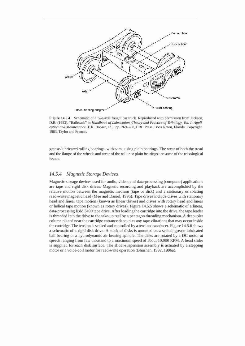
Figure 14.5.4 Schematic of a two-axle freight car truck. Reproduced with permission from Jackson, D.R. (1983), “Railroads” in Handbook of Lubrication :Theory and Practice of Tribology. Vol. I: Appli- cation and Maintenance (E.R. Booser, ed.), pp. 269–288, CRC Press, Boca Raton, Florida. Copyright 1983. Taylor and Francis.
grease-lubricated rolling bearings, with some using plain bearings. The wear of both the tread and the flange of the wheels and wear of the roller or plain bearings are some of the tribological issues.
14.5.4 Magnetic Storage Devices
Magnetic storage devices used for audio, video, and data-processing (computer) applications are tape and rigid disk drives. Magnetic recording and playback are accomplished by the relative motion between the magnetic medium (tape or disk) and a stationary or rotating read-write magnetic head (Mee and Daniel, 1996). Tape drives include drives with stationary head and linear tape motion (known as linear drives) and drives with rotary head and linear or helical tape motion (known as rotary drives). Figure 14.5.5 shows a schematic of a linear, data-processing IBM 3490 tape drive. After loading the cartridge into the drive, the tape leader is threaded into the drive to the take-up reel by a pentagon threading mechanism. A decoupler column placed near the cartridge entrance decouples any tape vibrations that may occur inside the cartridge. The tension is sensed and controlled by a tension transducer. Figure 14.5.6 shows a schematic of a rigid disk drive. A stack of disks is mounted on a sealed, grease-lubricated ball bearing or a hydrodynamic air bearing spindle. The disks are rotated by a DC motor at speeds ranging from few thousand to a maximum speed of about 10,000 RPM. A head slider is supplied for each disk surface. The slider-suspension assembly is actuated by a stepping motor or a voice-coil motor for read-write operation (Bhushan, 1992, 1996a).
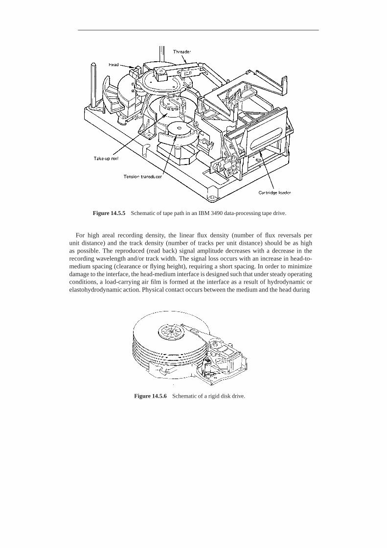
Figure 14.5.5 Schematic of tape path in an IBM 3490 data-processing tape drive.
For high areal recording density, the linear flux density (number of flux reversals per unit distance) and the track density (number of tracks per unit distance) should be as high as possible. The reproduced (read back) signal amplitude decreases with a decrease in the recording wavelength and/or track width. The signal loss occurs with an increase in head-to- medium spacing (clearance or flying height), requiring a short spacing. In order to minimize damage to the interface, the head-medium interface is designed such that under steady operating conditions, a load-carrying air film is formed at the interface as a result of hydrodynamic or elastohydrodynamic action. Physical contact occurs between the medium and the head during
Figure 14.5.6 Schematic of a rigid disk drive.
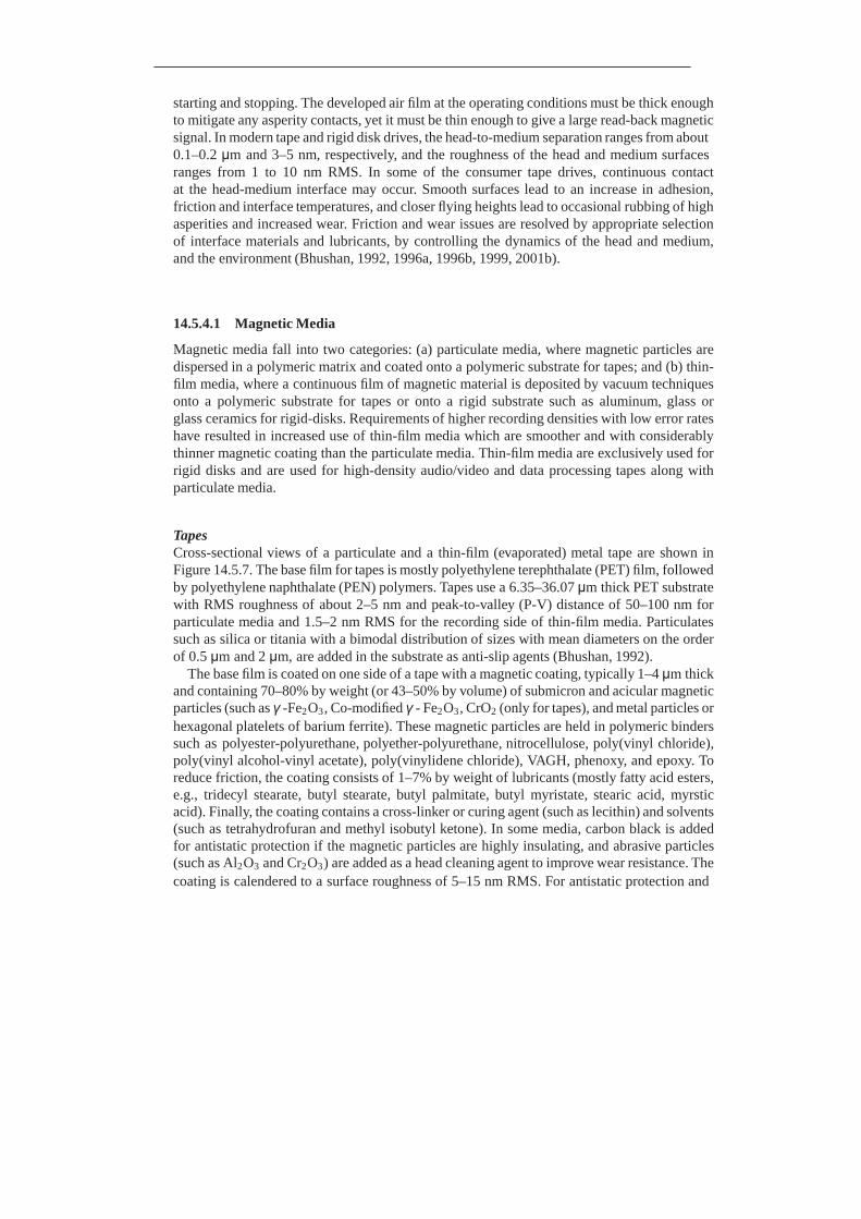
starting and stopping. The developed air film at the operating conditions must be thick enough to mitigate any asperity contacts, yet it must be thin enough to give a large read-back magnetic signal. In modern tape and rigid disk drives, the head-to-medium separation ranges from about 0.1–0.2 μm and 3–5 nm, respectively, and the roughness of the head and medium surfaces ranges from 1 to 10 nm RMS. In some of the consumer tape drives, continuous contact at the head-medium interface may occur. Smooth surfaces lead to an increase in adhesion, friction and interface temperatures, and closer flying heights lead to occasional rubbing of high asperities and increased wear. Friction and wear issues are resolved by appropriate selection of interface materials and lubricants, by controlling the dynamics of the head and medium, and the environment (Bhushan, 1992, 1996a, 1996b, 1999, 2001b).
14.5.4.1 Magnetic Media
Magnetic media fall into two categories: (a) particulate media, where magnetic particles are dispersed in a polymeric matrix and coated onto a polymeric substrate for tapes; and (b) thin- film media, where a continuous film of magnetic material is deposited by vacuum techniques onto a polymeric substrate for tapes or onto a rigid substrate such as aluminum, glass or glass ceramics for rigid-disks. Requirements of higher recording densities with low error rates have resulted in increased use of thin-film media which are smoother and with considerably thinner magnetic coating than the particulate media. Thin-film media are exclusively used for rigid disks and are used for high-density audio/video and data processing tapes along with particulate media.
Tapes Cross-sectional views of a particulate and a thin-film (evaporated) metal tape are shown in Figure 14.5.7. The base film for tapes is mostly polyethylene terephthalate (PET) film, followed by polyethylene naphthalate (PEN) polymers. Tapes use a 6.35–36.07 μm thick PET substrate with RMS roughness of about 2–5 nm and peak-to-valley (P-V) distance of 50–100 nm for particulate media and 1.5–2 nm RMS for the recording side of thin-film media. Particulates such as silica or titania with a bimodal distribution of sizes with mean diameters on the order of 0.5 μm and 2 μm, are added in the substrate as anti-slip agents (Bhushan, 1992).
The base film is coated on one side of a tape with a magnetic coating, typically 1–4 μm thick and containing 70–80% by weight (or 43–50% by volume) of submicron and acicular magnetic particles (such as γ -Fe2 O3 , Co-modified γ - Fe2 O3 , CrO2 (only for tapes), and metal particles or hexagonal platelets of barium ferrite). These magnetic particles are held in polymeric binders such as polyester-polyurethane, polyether-polyurethane, nitrocellulose, poly(vinyl chloride), poly(vinyl alcohol-vinyl acetate), poly(vinylidene chloride), VAGH, phenoxy, and epoxy. To reduce friction, the coating consists of 1–7% by weight of lubricants (mostly fatty acid esters, e.g., tridecyl stearate, butyl stearate, butyl palmitate, butyl myristate, stearic acid, myrstic acid). Finally, the coating contains a cross-linker or curing agent (such as lecithin) and solvents (such as tetrahydrofuran and methyl isobutyl ketone). In some media, carbon black is added for antistatic protection if the magnetic particles are highly insulating, and abrasive particles (such as Al2 O3 and Cr2 O3 ) are added as a head cleaning agent to improve wear resistance. The coating is calendered to a surface roughness of 5–15 nm RMS. For antistatic protection and
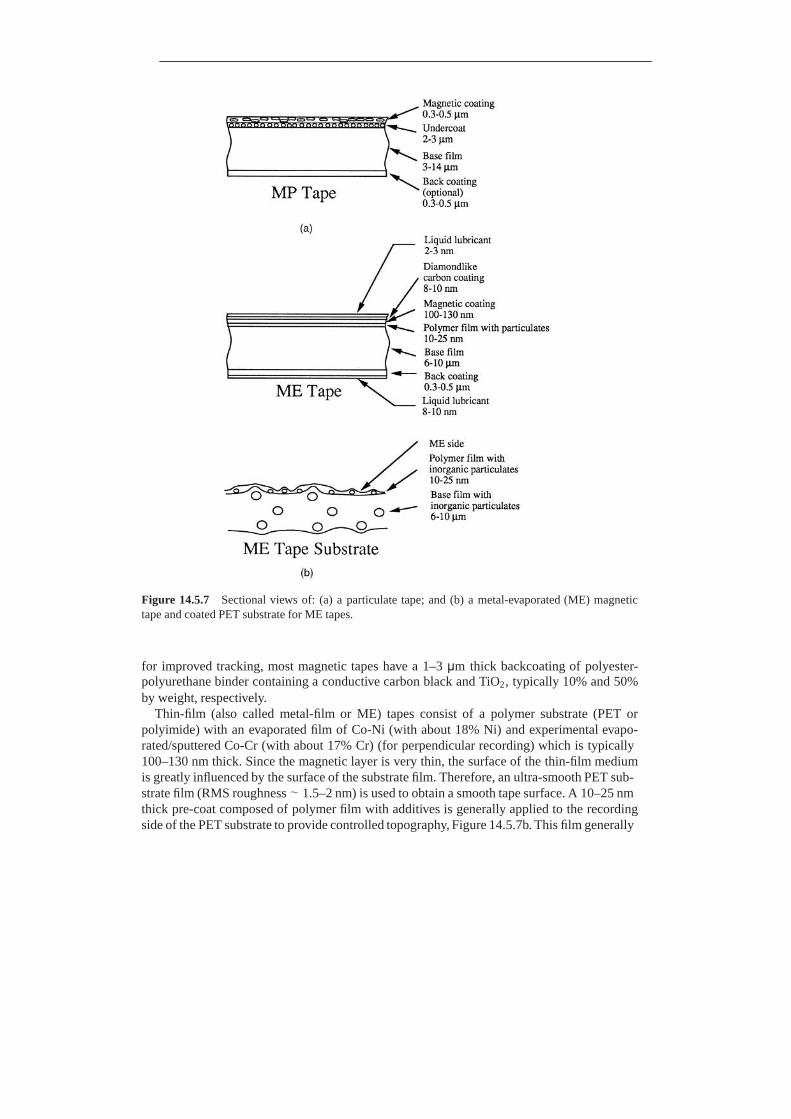
Figure 14.5.7 Sectional views of: (a) a particulate tape; and (b) a metal-evaporated (ME) magnetic tape and coated PET substrate for ME tapes.
for improved tracking, most magnetic tapes have a 1–3 μm thick backcoating of polyester- polyurethane binder containing a conductive carbon black and TiO2 , typically 10% and 50% by weight, respectively.
Thin-film (also called metal-film or ME) tapes consist of a polymer substrate (PET or polyimide) with an evaporated film of Co-Ni (with about 18% Ni) and experimental evapo- rated/sputtered Co-Cr (with about 17% Cr) (for perpendicular recording) which is typically 100–130 nm thick. Since the magnetic layer is very thin, the surface of the thin-film medium is greatly influenced by the surface of the substrate film. Therefore, an ultra-smooth PET sub- strate film (RMS roughness ∼ 1.5–2 nm) is used to obtain a smooth tape surface. A 10–25 nm thick pre-coat composed of polymer film with additives is generally applied to the recording side of the PET substrate to provide controlled topography, Figure 14.5.7b. This film generally

contains inorganic particulates (typically SiO2 with a particle size of 100–200 nm diameter and areal density of typically 10,000/mm2 ). The polymer pre-coat is applied to reduce the roughness (mostly P-V distance) in a controlled manner from that of the PET surface, and to provide good adhesion with the ME films. The particles are added to the pre-coat to control the real area of contact and consequently the friction. A continuous magnetic coating is deposited on the polymer film. The polymer film is wrapped on a chill roll during deposition, which keeps the film at a temperature of 0 to –20◦C. Co80 Ni20 material is deposited on the film by a reactive evaporation process in the presence of oxygen; oxygen increases the hardness and corrosion resistance of the ME film. The deposited film, with a mean composition of (Co80 Ni20 ) 80 O20 consists of very small Co and Co-Ni crystallites which are primarily inter- mixed with oxides of Co and Ni. Diamond-like carbon in about 8–10 nm thickness is used to protect against corrosion and wear. A topical liquid lubricant (typically perfluoropolyether with reactive polar ends) is then applied to the magnetic and back coatings by rolling. The topical lubricant enhances the durability of the magnetic coating, and also inhibits the highly reactive metal coating from reacting with ambient air and water vapor. A backcoating is also applied to balance stresses in the tape, and for anti-static protection.
Rigid Disks Figure 14.5.8 shows a sectional view of a thin-film rigid disk. The substrate for rigid disks is either non-heat-treatable aluminum-magnesium alloy AISI 5086 (95.4% Al, 4% Mg, 0.4% Mn, and 0.15% Cr) electroless plated with nickel-phosphorus (90–10 wt %) layer to improve its surface hardness to 600–800 kg/mm2 (Knoop) and smoothness, chemically strengthened glass, or glass-ceramic. To minimize static friction at the head–disk interface, the start-stop zone or the entire disk surface of substrates is textured. Disks are textured either by mechanical texturing techniques using either free or fixed abrasives in the circumferential or random orientation to a typical RMS roughness of 4–8 nm, or a laser texturing technique to create bumps on the disk surface. The finished substrate is coated with a magnetic film 25–75 nm thick. Some metal films require a Cr undercoat (10–50 nm thick) as a nucleation layer to improve magnetic properties, such as coercivity. Magnetic films used are metal films of cobalt-based alloys (e.g., Co-Pt-Cr, Co-Pt-Ni). These metallic magnetic films have weak durability and poor corrosion resistance. Protective overcoats with a liquid lubricant overlay are generally used to provide low friction, low wear, and corrosion resistance. The protective coating is typically sputtered diamond-like carbon (DLC). In most cases, a thin layer of perfluoropolyether lubricant with reactive polar ends is used. The trend is to use partially bonded lubricant film consisting of an unbonded or lubricant film. The unbonded top layer would heal any worn areas on the disk surface where the lubricant may have been removed, and the bonded underlayer provides lubricant persistence. Furthermore, the bonded layer does not contribute to meniscus effects in stiction.
Figure 14.5.8 Sectional view of a thin-film magnetic rigid disk.
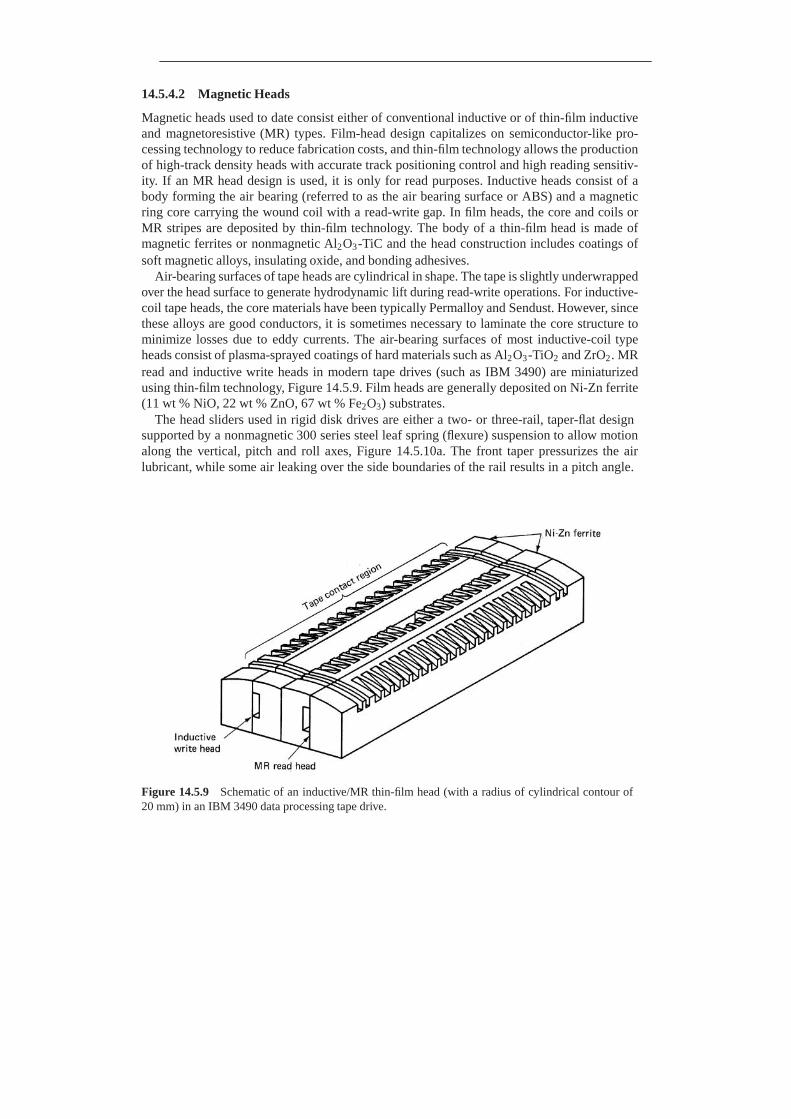
14.5.4.2 Magnetic Heads
Magnetic heads used to date consist either of conventional inductive or of thin-film inductive and magnetoresistive (MR) types. Film-head design capitalizes on semiconductor-like pro- cessing technology to reduce fabrication costs, and thin-film technology allows the production of high-track density heads with accurate track positioning control and high reading sensitiv- ity. If an MR head design is used, it is only for read purposes. Inductive heads consist of a body forming the air bearing (referred to as the air bearing surface or ABS) and a magnetic ring core carrying the wound coil with a read-write gap. In film heads, the core and coils or MR stripes are deposited by thin-film technology. The body of a thin-film head is made of magnetic ferrites or nonmagnetic Al2 O3 -TiC and the head construction includes coatings of soft magnetic alloys, insulating oxide, and bonding adhesives.
Air-bearing surfaces of tape heads are cylindrical in shape. The tape is slightly underwrapped over the head surface to generate hydrodynamic lift during read-write operations. For inductive- coil tape heads, the core materials have been typically Permalloy and Sendust. However, since these alloys are good conductors, it is sometimes necessary to laminate the core structure to minimize losses due to eddy currents. The air-bearing surfaces of most inductive-coil type heads consist of plasma-sprayed coatings of hard materials such as Al2 O3 -TiO2 and ZrO2 . MR read and inductive write heads in modern tape drives (such as IBM 3490) are miniaturized using thin-film technology, Figure 14.5.9. Film heads are generally deposited on Ni-Zn ferrite (11 wt % NiO, 22 wt % ZnO, 67 wt % Fe2 O3 ) substrates.
The head sliders used in rigid disk drives are either a two- or three-rail, taper-flat design supported by a nonmagnetic 300 series steel leaf spring (flexure) suspension to allow motion along the vertical, pitch and roll axes, Figure 14.5.10a. The front taper pressurizes the air lubricant, while some air leaking over the side boundaries of the rail results in a pitch angle.
Figure 14.5.9 Schematic of an inductive/MR thin-film head (with a radius of cylindrical contour of 20 mm) in an IBM 3490 data processing tape drive.

Figure 14.5.10 Schematics of: (a) an IBM 3370/3380/3390 type suspension-slider assembly; and (b) an IBM tri-rail thin-film nanoslider (direction of disk rotation is shown by an arrow).

Figure 14.5.11 Schematic of the head-rigid disk interface.
The inductive type or inductive/MR type thin-film read-write elements used in high-end disk drives (e.g., IBM 3390) are integrated in the Al2O3-TiC (70–30 wt %) slider at the trailing edge of the center rail in the three-rail design where the lowest flying height occurs, Figure 14.5.10b. The suspension supplies a vertical load typically ranging from 30 mN (3g) to 50 mN (5g) (apparent contact pressure ∼35 kPa), dependent upon the size of the slider, which is balanced by the hydrodynamic load when the disk is spinning. As the drives get smaller and flying height decreases, the size and mass of the sliders and their gram load decreases. Lower mass results in higher air-bearing frequency, which reduces dynamic impact. Smaller size and required lower gram load results in an improvement in stiction and start-stop and flyability lifetimes. The surface roughness of the air-bearing rails is typically 1.5–2 nm RMS. The stiffness of the suspension (∼25 mN/mm) is several orders of magnitude lower than that of the bearing (∼0.5 kN/mm), so that most dynamic variations are taken up by the suspension without degrading the air bearing.
Small disk drives also use inductive-coil type heads of one or two types: minimonolithic (mini-Winchester) and minicomposite. A minimonolithic head slider consists of a slider body and a core piece carrying the coil, both consisting of monolithic magnetic material (typically Mn-Zn ferrite). The taper-flat bearing area is provided by the outer rails of a tri-rail design. The center rail defines the width of the magnetic element in the trailing edge where a ferrite core is formed. A minimonolithic head slider consists of an Mn-Zn ferrite core and read-write gap, glass bonded into the air-bearing surface of a nonmagnetic, wear-resistant slider (typically calcium titanate).
A schematic representation of the head-disk interface is shown in Figure 14.5.11. Environ- ment, usage time, and contamination (external and wear debris) play a significant role in the reliability and usable lifetime of the interface.
14.6 Closure
A variety of tribological components are used to accommodate relative motion. Common components include sliding-contact and rolling-contact bearings, seals, gears, cams and cam

tappets, piston rings, electrical brushes, and cutting and forming tools. Tribological com- ponents also include various MEMS/NEMS devices. Some industrial applications include material processing, automotives, aerospace, railroads, and magnetic storage devices.