Optimal design of customised hip prosthesis using fiber reinforced polymer composites
10
This article appeared in a journal published by Elsevier. The attached copy is furnished to the author for internal non-commercial research and education use, including for instruction at the authors institution and sharing with colleagues. Other uses, including reproduction and distribution, or selling or licensing copies, or posting to personal, institutional or third party websites are prohibited. In most cases authors are permitted to post their version of the article (e.g. in Word or Tex form) to their personal website or institutional repository. Authors requiring further information regarding Elsevier’s archiving and manuscript policies are encouraged to visit: http://www.elsevier.com/copyright
-
Upload
independent -
Category
Documents
-
view
0 -
download
0
Transcript of Optimal design of customised hip prosthesis using fiber reinforced polymer composites
This article appeared in a journal published by Elsevier. The attachedcopy is furnished to the author for internal non-commercial researchand education use, including for instruction at the authors institution
and sharing with colleagues.
Other uses, including reproduction and distribution, or selling orlicensing copies, or posting to personal, institutional or third party
websites are prohibited.
In most cases authors are permitted to post their version of thearticle (e.g. in Word or Tex form) to their personal website orinstitutional repository. Authors requiring further information
regarding Elsevier’s archiving and manuscript policies areencouraged to visit:
http://www.elsevier.com/copyright

Author's personal copy
Optimal design of customised hip prosthesis using fiber reinforcedpolymer composites
I. Sridhar *, P.P. Adie, D.N. GhistaSchool of Mechanical and Aerospace Engineering, Nanyang Technological University, 50 Nanyang Avenue, Singapore 639798, Singapore
a r t i c l e i n f o
Article history:Received 25 October 2009Accepted 12 January 2010Available online 15 January 2010
Keywords:Hip prosthesisFiber-reinforced compositesOptimizationStiffness
a b s t r a c t
The need for new materials in orthopaedic surgery arises from the recognition of the stress-shielding effectof bone by high-modulus implants presently made of engineering alloys. A lower modulus implant mate-rial will result in the construction of a more biomechanically compatible prosthesis. In this respect, com-posite materials are gaining importance because they offer the potential for implants with tailor-madestiffness in contrast to metals. In the present study, the bending stiffness of composite prosthesis ismatched with that of bone in both the longitudinal and radial directions by choosing optimal carbon fiberreinforced polyether ether ketone (PEEK) matrix lay-up. A numerical optimization algorithm is developedto deduce the optimal composite femoral prosthesis lay-up that matches the stiffness properties of thefemoral bone in both the transverse and longitudinal directions. Effective bending moments and compres-sive forces acting on the hip joint are considered in the design of the optimal length and diameter of theprosthesis. The optimization algorithm was implemented, by using MATLAB(R)™ for designing the com-posite prosthesis to a patient’s specific requirement. Finally the efficiency of the composite stem is com-pared with that of metallic alloy stems in terms of stress shielding using a finite element program.
� 2010 Elsevier Ltd. All rights reserved.
1. Introduction
Osteo-arthritis affects joints between bones due to the growthof small lumps of bone on the contacting surfaces of the joints. Thisprevents the joints from sliding in the usual manner, causingexcruciating pain during movement. Replacing a natural joint withan artificial joint offers good potential to alleviate the problem. Inhip joint replacement operations, the head of the femur is sec-tioned-off, and the soft marrow is removed to create a hollow in-tra-medullar cavity through the centre of the femur shaft. Anartificial implant (mainly comprising of a long stem and a head)is then glued into the femoral cavity. The implant head fits intothe acetabular socket of the hip bone. The critical mechanical prop-erty requirements of the implant material include (but are not lim-ited to) high specific bending stiffness, high bending stiffnesscomparable to that of the surrounding cortical bone, biocompati-bility, corrosion resistance and high endurance limit. It is notewor-thy that the loads on a typical joint fluctuate approximately amillion times a year [1].
Recent statistics from Howmedica Osteonics reveal aseptic loos-ening as the main cause (76%) of hip joint revision surgery. Thestiffness mismatch between the implant and the surrounding boneis one of the main reasons for the loosening of implants, due to
stress shielding [2]. Most of the current metal hip prostheses(made of 316L stainless steels, cobalt – chromium alloys and a-btitanium alloys) have a modulus, which is an order of magnitudegreater than that of the surrounding cortical bone. The mismatchbetween the moduli causes the majority of the load to be carriedby the prosthesis. This results in the lack of an effective transferof load to the surrounding femoral bone. Such a phenomenon(termed as stress shielding) is known to cause resorption of the un-loaded bone by the human body, due to decreased bone tissuestrain level. In addition, metal implants may cause allergic reac-tions due to the release of metal ions in excessive amounts, as a re-sult of friction or enzymatic effects [3].
The need for new materials in orthopaedic surgery arises fromthe recognition of the stress-shielding effect of bone by high-mod-ulus implants, presently made of engineering alloys. A lower mod-ulus implant material would result in the construction of a morebiomechanically compatible prosthesis. In this respect, carbonand aramid fiber reinforced polymer matrix (such as polyetherether ketone – PEEK) composite materials are gaining importance,because they offer the potential for implants with tailor-made stiff-ness in contrast to metals. They possess superior biomechanicalproperties, such as better fatigue strength, chemical resistance,environmental stability, and resistance to sterilization by c-radia-tion and biocompatibility [4–6].
Simoes et al. [7] have designed a hip prosthesis using a stiff corecovered with a flexible composite material, wherein the variation
0261-3069/$ - see front matter � 2010 Elsevier Ltd. All rights reserved.doi:10.1016/j.matdes.2010.01.016
* Corresponding author. Fax: +65 67911859.E-mail address: [email protected] (I. Sridhar).
Materials and Design 31 (2010) 2767–2775
Contents lists available at ScienceDirect
Materials and Design
journal homepage: www.elsevier .com/locate /matdes

Author's personal copy
of the relative thickness of the two materials controls the struc-tural stiffness of the prosthesis. The proper use of composite mate-rial implants allows the designer to tailor the stiffness to suit thatof the bone, while maintaining the required mechanical strength.Wang et al. [8] have demonstrated the use of carbon fiber rein-forced polyether ether ketone (PEEK) composites (CFRP) as a viablebearing surface material for the acetabular cups to reduce wear atthe joint during hip arthoplasty. Li et al. [9] and Srinivasan et al.[10] have designed a fiber-reinforced composite prosthesis basedon individual lamina failure, while Liao [11] has developed a man-ufacturing technique to fabricate an artificial hip implant usingCFRP composite laminates. Also Liao and Sivashanker [12] haveanalysed the uniaxial compressive failure of these hip implants,noting that the compressive strength of continuous fiber compos-ites is about 40–60% less than their tensile strength due to fibermicrobuckling. Boss and Ganesh [13] have used a combination oftextile performing and pultrusion techniques to fabricate carbon fi-ber reinforced stiffness graded composite polymers for biomedicalapplications.
The manufacturing of femoral stem using polymeric matrixcomposites can be done using various fabrication methods basedon reinforcement phase geometry. The methods based on particu-late and short fiber reinforcement usually produce near isotropicproperties, and are hence ruled out for the stem design. On theother hand, continuous fiber-reinforced composites can be tailoredto produce orthotropic properties by controlling fiber volume frac-tion and individual ply orientations within the laminate. There areseveral methods available to produce femoral stem using continu-ous fiber-reinforced composites [10–12,14]. Initially, laminates areproduced by staking about 200–400 plies in an autoclave furnace.The actual number of plies depends up on the desired maximumanterior–posterior thickness or radius of the stem. The individualply orientations are obtained using carpet plot or Genetic Algo-rithms based optimization tools choosing modulus of modulimatch (between the laminate and bone) as an objective. Then,the prosthesis is cut from the middle portion of the laminate bymachining as shown in Fig. 1 [10,11]. The disadvantage of thismethod lies in its inherent inability to produce a stem with equallengths of fiber reinforcement. This will result in compromisedstrength of the femoral stem.
The implant can also be manufactured by using a curvedshape female mold and laying up the unidirectional plies intothe mold. The curvature of each ply or ply group is not constant,but varying with that of the curvature of the mold, as shown inFig. 1b [14]. The thickness of the prosthesis from the medial tothe lateral direction determines the number of the plies thathave to be used. Another technology to produce cylindricalstems is by means of filament winding and pultrusion. Thesemethods can produce a stem with equal length plies of fiberreinforcement; hence the strength of the stem is uncompro-mised. Fig. 2 illustrates one of the resulting ply produced by fil-ament winding.
Herein, initially the optimal dimensions of the hip joint stemare given in Section 3 based on competing failure modes of fe-mur-hip joint stem for the considered loading conditions [6]. Then,we present the design optimization of a long fiber-reinforced com-posite hip prosthesis for in-plane bending stiffness. The compositelaminate is considered as a homogeneous orthotropic solid sub-jected to uni-axial and bending loads, transmitted to the prosthesisstem by the loads applied to the implant head. The objective is tomatch the bending stiffness of the composite prosthesis stem withthat of the femur bone in both the longitudinal and transversedirections. For simplicity, we illustrate the composite lay-up se-quence optimization and the stress analysis of the stem insertedfemur, using a simplified geometry by considering the stem as acylindrical structure.
2. Methodology
2.1. Bone structure
The mechanical behavior of bone is typical of that of a cellularmaterial. Bone grows in response to stresses, and trabeculae devel-opment takes place along the principal stress trajectories in theloaded bone. Under stress-stimulated growth, the structuralanisotropy of cancellous bone depends on the ratio of the principalstresses. For example, in the femoral head, the principal stresses
b
CFRP prepreg sheets
Cured laminate
Machined prosthesis
x
y
z
autoclave
Machining
a
Fig. 1. Illustrations of the steps involved in the machining of a hip prosthesis fromlong fiber-reinforced composites using (a) the plate-cut technology [10,11] and (b)the bend-plate technology [14].
x
y
X (axial direction)
z, r (radial direction)
θ (hoop direction)
ϕ
Fig. 2. Cylindrical coordinate system for helically-wound cylindrical composite.
2768 I. Sridhar et al. / Materials and Design 31 (2010) 2767–2775

Author's personal copy
are roughly equal, and the bone grows with a material architectureakin to that of foams with almost equi-axial cells. The mechanicalproperties of bone vary linearly from the mid shaft to its extremi-ties along the length of the femur. In the current analysis, we haveconsidered the bone as a linear elastic and orthotropic material.
2.2. Mechanics of hip prosthesis
The hip is one of the largest weight-bearing joints in the humanbody. It consists of a ball portion (called the femoral head) locatedon the top of the femur, which fits into a rounded socket (the ace-tabulum) in the pelvis (or hipbone). Bands of tissue called liga-ments connect the ball portion to the socket, and providestability to the joint. The surfaces of the ball and socket possess asmooth durable layer of articular cartilage, which cushions theends of the bones enabling them to move with consummate ease.A thin, smooth tissue called the synovial-membrane covers all thearticulate surfaces of the hip joint. In a healthy hip, this membranegenerates sufficient amount of fluid, which lubricates the hip jointand eliminates the effects of undue friction. Thus the hip joint sur-faces function in harmony, allowing a person to move comfortably(without any pain) in the normal mode.
The single leg standing posture is often deemed an appropriatemodel for calculating the resultant joint loads [15–18]. The com-bined effect of body and muscle forces on the femoral head maybe treated as a distributed force acting at angles to the anteriorand medial planes of the prosthesis. This resultant force on theprosthesis head may be resolved into a force in the anterior–poster-ior plane and a force in the medial–lateral plane, which result inshear and compressive forces as well as bending and twisting mo-ments. These resulting moments and forces vary along the sectionof the prosthesis, resulting in different stress states in the structure.We can consider the prosthesis design to be primarily governed byforces in the medial–lateral plate. The resultant of all these forceson the prosthesis is an equivalent compressive force (F) and bend-ing moment (M) in the medial–lateral plane as illustrated in Fig. 3.
3. Review of hip joint stem design based on the guidelines ofHayes and Sneath [6,19]
In the design of a hip implant, factors such as the contour (orgeometry), material stiffness, and interfacial-bonding characteris-tics between the implant and bone are critical for the long servicelife of the femoral stem. Herein, we describe the design prescrip-tion for the optimal diameter and length of the prosthesis stemto be inserted into the enlarged intra-medullary canal, such thatthe bending moment in the stem does not cause splitting of theweakened bone.
For the purpose of design analysis, the prosthesis is idealised (asillustrated in Fig. 3) to have two components: the head (or the por-tion of it outside the medullary canal) and the inserted stem in-serted into the femur medullary canal. The loading on theprosthesis consists of (i) an axial force (F) applied to the stem,and (ii) bending moment (M) which causes bending of the prosthe-sis stem and the bone into which the stem is inserted, as well astensile circumferential (or hoop) stresses in the bone due to pres-sure exerted inside the medullar canal by the stem-in-bending.Based on this loading condition, the design of the stem is subjectedto the following competing failure modes:
� Bone cracking circumferentially when the tensile hoop stress,rB
ht , generated by the pressure exerted by the stem-in-bendingwithin the canal exceeds the failure stress rB
hf .� Bone cracking in bending, due to tensile bending stress rB
bt
exceeding the failure stress rBbf .
� Implant stem failure in bending, when the tensile bending stres-ses rI
bt exceed the failure stress rIbf .
3.1. Bone cracking circumferentially due to hoop stress, rBh (failure
stress rBh)
As illustrated in Fig. 3a, the applied bending moment M on theprosthesis in turn causes the stem to apply pressure p (or normalbending stresses) on the femur medullary canal surface of diame-ter d and length L. The variation of pressure p is shown in Fig. 3a,and its maximum value is
p ¼ 6M
dL2 ð1Þ
Equal and opposite normal pressure or stresses are exerted onthe prosthesis stem, causing it to bend. Assuming that the boneis a thick-walled cylinder, the maximum tensile hoop stress rB
ht
� �in the bone due to this internal pressure p obtained, using Lame’stheory for thick-cylinders [20] is given by the following design con-straint condition:
rBht ¼
6M
dL2
D2 þ d2
D2 � d2 6 rBhf ð2Þ
3.2. Bone cracking due to longitudinal bending stress rBbt , exceeding the
failure stress rBbt
The pressure p exerted within and along the bone medullary ca-nal by the stem, due to the bending moment (M) on the prosthesis
L
d
p
DM
26dL
M
26
dLM
p
L
p
p
p
P
σσ
4F/Π(D2-d2)
32MD/Π(D4-d4)
M
M
(a)
(b)
ii
i
iii
Bone cross-section
Prosthesis stem
Fig. 3. Illustration of typical stress patterns in the femur caused by the insertion ofthe prosthesis stem in the femoral canal. Note that the resultant forces (i.e. bendingmoment, M and axial force, F) will cause (i) radial pressure on the stem, (ii) hooptensile stresses in the annular bone, and (iii) longitudinal stresses in the femur.
I. Sridhar et al. / Materials and Design 31 (2010) 2767–2775 2769

Author's personal copy
head, causes longitudinal tensile stress rBbt
� �in the annular bone
on its cross-section of inner diameter d and outer diameter D, asshown in Fig. 3b. The maximum value of rB
bt and the correspondingdesign constraint condition are expressed as follows:
rBbt ¼
32MD
pðD4 � d4Þ6 rB
bf ð3Þ
The bone is also subjected to compressive stress equal to 4F/p(D2 � d2) due to the force F acting on the femoral head. This com-pressive stress will reduce the net tensile stress rB
bt by this amount.However, for ensuring safe prosthesis design, we will ignore thiscompressive stress.
3.3. Implant failure in bending, rIb (exceeding failure stress rI
b)
The implant stem is subjected to bending due to the pressuredistribution acting along its length (as illustrated in Fig. 3b-ii).The tensile stress, due to the bending moment (M) acting on it isresisted by its circular cross-section of diameter d and second mo-ment of area I = pd4/64. Hence, the tensile stress on the implantstem due to bending moment M is given by,
rIb ¼
32M
pd3 6 rIbf ð4Þ
By way of an example, let us consider that (i) the bone fails un-der a hoop tension of 1 MPa, and a tensile bending stress of 8 MPa,and (ii) that the implant material fails at a stress of 48 MPa. Then,the implant design is optimal if all the three competing failuremodes occur simultaneously, thereby giving us the following de-sign expression:
rBhf : rB
bf : rIbf ¼ 1 : 8 : 48 ð5Þ
Substituting for rBh and rB
b from Eqs. (2) and (3) into the aboveEq. (5), yields the following relationship:
rBhf
rBbf
¼ 6M
L2
ðD2 þ d2ÞðD2 � d2Þ
pðD4 � d4Þ32MD
¼ 18
or,
3pðD2 þ d2Þ2 ¼ 2DdL2 ð6Þ
Likewise, substituting for rBb and rI
b from Eqs. (3) and (4) intoEq. (5) the following relationship is obtained:
rBbf
rIbf
¼ Dd3
D4 � d4 ¼8
48
or,
d4 þ 6Dd3 � D4 ¼ 0 ð7Þ
By solving Eq. (7) for implant diameter d, in terms of femur diame-ter D is a known quantity (or variable), the values for implant lengthL can be found from Eq. (6).
By way of an example, consider a femur of 4 cm diameter (D).Solving Eq. (7), the value of implant diameter d is found to be2.14 cm. Then, using the geometrical relationship (6) and the com-puted value of implant diameter d (=2.14 cm), the value of the im-plant length L is found to be 15.27 cm.
3.4. Stress-shielding ratio and bone resorption potential
One of the main objectives of this study is to determine whetherthe implant will produce a similar magnitude of stress in the boneat the bone–implant interface as that of intact bone. That meansthe stresses produced in the bone by the implant are similar to
the natural stress state in the bone. This is expressed by thestress-shielding ratio, hi in the bone which is defined as [21]
hi ¼ri
rnið8Þ
where hi is the stress-shielding ratio at location i on bone, ri is theequivalent stress (Von Mises) at location i in the implanted bone,and rni is the effective stress at location i in the intact bone. Theobjective is to obtain hi as close to unity, i.e. the stress magnitudeat point i for the implanted bone needs to be similar to the naturalstress state of the intact bone. This implies that the implanted boneis closer to its natural physiological and mechanical state. Thestress-shielding ratio hi is then incorporated into an objective func-tion [21]
FðXÞ ¼XN
i�1
ðhi � 1Þ2 ð9Þ
where F(X) is the potential of bone resorption due to the prosthesisimplantation. Minimizing F(X) will lead to risk reduction of boneloss due to stress shielding.
3.5. Classical laminate plate theory (CLPT)
In the current design optimization algorithm, the compositematerial is assumed to be homogeneous and the effects of the con-stituent materials (i.e. fiber and matrix) are averaged as macro-scopic properties. The ply conventions are depicted in Fig. 4. Theconstitutive law, governing the deformation pattern of a compositematerial subjected to in-plane stress resultants (N, force per unitwidth) and bending moments (M) in terms of the compliance ma-trix is given by [22,23]:
fegfkg
� �¼½a� ½b�½b� ½d�
� � fNgfMg
� �ð10Þ
The elements of matrices [a], [b], and [d] essentially denotematerial properties (such as Young’s moduli, Poisson’s ratio andshear moduli in the material axes), thickness of lamina and theirrespective orientations (i.e., angle between geometric and materialaxes). The matrix [b] couples in-plane strains to applied bendingmoments and relates bending curvatures to applied in-plane nor-mal forces. The stress–strain relationship of a ply, with the fiberorientation / as shown in Fig. 2, is
z
h
h/2
-h/2
x
Line of
symmetry
Fig. 4. Illustration of a typical stacking sequence of a symmetrical laminate.
2770 I. Sridhar et al. / Materials and Design 31 (2010) 2767–2775

Author's personal copy
rX
rh
rr
rS
8>>><>>>:
9>>>=>>>;¼
Q XX Q Xh Q Xr Q XS
Q Xh Q hh Q hr Q hS
Q Xr Q hr Q rr Q rS
Q XS Q hS Q rS Q SS
26664
37775
eX
eh
er
eS
8>>><>>>:
9>>>=>>>;
ð11Þ
The transformations of the material orthotropic properties frommaterial axis to the cylindrical coordinates are given in the appen-dix. The moment {M}–curvature {j} relationship, of in terms ofbending compliance (i.e., inverse of flexural stiffness matrix), is gi-ven by:
jX
jh
jr
jS
8>>><>>>:
9>>>=>>>;¼
dXX dXh dXr dXS
dXh dhh dhr dhS
dXr dhr drr drS
dXS dhS drS dSS
26664
37775
MX
Mh
Mr
MS
8>>><>>>:
9>>>=>>>;
ð12Þ
For a circularly wound composite stem of radius, r, the flexuralmoduli can be calculated using the expression [23]: the axial mod-ulus, Ef
X ¼ 12=ðr3dXXÞ, the circumferential modulus, Efh ¼ 12=ðr3dhhÞ,
the radial modulus, Efr ¼ 12=ðr3drrÞ, and the in-plane shear modu-
lus, EfS ¼ 12=ðr3dSSÞ.
4. Optimization of composite femoral stem design usingMATLAB�
Using a stiff stem material for an artificial hip joint leads to re-duced curvature when subjected to an external bending moment.This reduced curvature in turn decreases the stress field on thebone when compared to its natural state, causing bone stressshielding, and finally loosening of stem. Hence, it is desirable tohave stem material properties close to that of the bone orthotropicproperties to avoid bone stress shielding. It is possible to tailor acarbon fiber reinforced polymeric composite stem by controllingthe fiber orientation of the fly sequence in the laminate. The opti-mal ply winding sequence of femoral stem to obtain orthotropicmoduli similar to that of a natural bone is achieved using a MAT-LAB� code by following the procedure outlined in flow-chartshown in Fig. 5. By way of an example, we illustrate the optimiza-tion methodology for biocompatible carbon fiber reinforced poly-ether ether ketone matrix (CF/PEEK) with 60% fiber volumefraction. Using the coordinate system shown in Fig. 2, the mechan-ical properties of the CF/PEEK used are as follows: Exx = 137 GPa,Eyy = 9.4 GPa, Ezz = 9.1 GPa, Gxy = 5.1 GPa, Gxz = 4.7 GPa, Gyx = 5.1 G-Pa, Gyz = 3.2 GPa, Gzx = 4.6 GPa, Gzy = 3.2 GPa, txy = 0.33, txz = 0.32,tyx = 0.04, tyz = 0.4, tzx = 0.04, tzy = 0.4. The orthotropic mechanicalproperties of femur are assumed to be: EX = 17.4 GPa, Eh = 9.6 GPa,Er = 10.1 GPa, GXh = 3.51 GPa, and tXh = 0.39.
The aim of the optimization program is to engineer an implantwith stiffness values as close as possible to those of femur, with thevalues of implant bending stiffness being of main interest due tothe natural loading condition of the femur to be by means of bend-ing. The principal stiffness in the three principal axes, namely EX,Eh, and Er are of main interest. The optimization algorithm usedin the MATLAB� program is illustrated in the flow chart in Fig. 5,as described below:
The winding angle optimization program using MATLAB� is ex-plained in the following steps:
1. The user inputs the following key parameters: femur diameter,desired winding angle steps, orthotropic properties of compos-ite lamina, and the allowable stiffness deviation for Ex, Eh, and Er
from the desired values.2. The algorithm then calculates the corresponding stem radius
and length (the stem is assumed to be a solid cylindrical rod)based on the three competing failure modes summarized inSection 3.
3. Based on the stem diameter, the number of windings (N) isdetermined, assuming standard winding thickness of0.125 mm. In order to increase the computation speed, thewinding is repeated few times for the same winding angle toreduce the total number of winding angle combinations neededto be analyzed. For example, 75 fiber windings are needed toobtain a stem radius of 9.375 mm. In order to increase the com-putation speed, the program determines 15x winding per cycle.Hence the optimization program will start from [�7515/�7515/
Input
Calculate implant dimensions of stem length and radius, using equations
in section 3.5
Determine total possible angle combinations,
N=(# of angle)# of plies
Calculate engineering constants using equations
Loop (1 to N): Calculate winding angle sequence &
moduli
Returns empty matrix and error msg. in MATLAB
Compare calculated moduli with bone modulus values
Greater than tolerance limit
Within the tolerance limit
Store all angle configurations, stiffness
Disp. selected 3 angle configurations, stiffness, ply
stress
End
For computational sake, limit N = 107 .N > 107
Yes Multiply (# of plies) by
real number starting from 2
No
Feed "new" (# of plies)
Fig. 5. Illustration of the flow chart outlining the steps involved in the computing ofthe optimal laminate sequence using MATLAB�.
Table 1Mechanical properties of femur and CF/PEEK stem.
EX (GPa) Eh (GPa) Er (GPa) GXh (GPa) tXh
Femur 17.400 9.600 10.100 3.510 0.39CF/PEEK 17.758 9.849 9.927 5.923 0.57
I. Sridhar et al. / Materials and Design 31 (2010) 2767–2775 2771

Author's personal copy
�7515/�7515/�7515]S to [7515/7515/7515/7515/7515]S inwinding angle steps specified by the user (e.g. 15�, 30�, 45�,etc.).
4. The next step is evaluation of the resulting moduli values foreach winding angle combination, with the material propertiesof CF/PEEK provided as input to the Matlab program. The result-ing moduli values are then compared with the specific femurorthotropic moduli values. The winding sequence is stored asan output, if the calculated moduli are within the allowed devi-ation from the femur moduli.
The optimization program calculates the implant dimensionsvalues from the loading and diameter of the bone. Then, it deter-mines the total number of possible winding angle configurationsbased on standard thickness of each winding layer of 0.125 mm.The same winding angle is repeated 15 times for ease of manufac-turing. The calculation of engineering constants is the next step fol-lowed by display of resulting winding angle configurations. Thesemoduli values are inputted as material properties in the stressanalysis using finite element method.
5. Stress analysis of optimized stem
Stress analysis using ABAQUS/CAE� commercial finite elementanalysis is carried out on optimized stem – femur assembly toinvestigate the stress-shielding of femur under static physiologicalloading condition. The purpose of the stress analysis is to comparevarious possible implant materials in term of their ability toproduce a similar stress magnitude with respect to the naturalstress magnitude of the bone, specifically in the bone at the
bone–implant interface. The stress-shielding ratio and the boneresorption potential are given by Eqs. (8) and (9), respectively.The stem is assumed to be bonded to the femur by biological fixa-tion meaning that the outermost surface of the stem forms a strongadhesion with the surrounding bone tissue. This was done usinginter-connected pores coated with biodegradable material on thestem surface to induce the formation of bone matrix inside thepores. This results in strong bone–stem attachment, and hence itcan be assumed that there are no relative motions between thebone and the stem at the bone–stem interface [24]: In the finiteelement analysis, this contact condition is achieved by tyingthe surface nodes between the bone and the stem.
stem
femur
encastred
load
Fig. 6. Boundary condition and load acting on the stem.
Fig. 7. Finite element mesh contour of stem under biological fixation.
0 0.2 0.4 0.6 0.8 11
2
3
4
5
6
7
8
normalised length
Von
-Mis
es S
tress
, (kP
a)
femurcarbon fiberTi6AL4V316L SSCo-Cr
Anterior(a)
0 0.2 0.4 0.6 0.8 12
2.5
3
3.5
4
4.5
5
5.5
6
normalised length
Von
-Mis
es S
tress
, (kP
a)
femurcarbon fiberTi6AL4V316L SSCo-Cr
Medial(b)
0 0.2 0.4 0.6 0.8 14
6
8
10
12
14
16
18
normalised length
Von
-Mis
es S
tress
, (kP
a)
femurcarbon fiberTi6AL4V316L SSCo-Cr
Posterior(c)
Fig. 8. Von Mises stress (kPa) contours on femur with various stem materials on (a)anterior side, (b) medial side, and (c) posterior region.
2772 I. Sridhar et al. / Materials and Design 31 (2010) 2767–2775

Author's personal copy
For modeling simplicity, the femur is considered as a hollow-bone of external diameter 4 cm and length 25 cm. The stem dimen-sions obtained from the optimization program are: 1.88 cm diam-eter and 15.67 cm length. Four different stem materials, namelyCF/PEEK, CoCr alloy, 316L stainless steel, and Ti6Al4 V are consid-ered. The femur and CF/PEEK stem were assumed to be linear elas-tic and orthotropic material, with their respective elastic constantsdescribed in Table 1.
The engineering alloys Co–Cr, Ti6Al4 V and 316L stainless steelare isotropic with linear elastic behavior. Their constitutive behav-ior is described by Hooke’s law with two material constantsYoung’s modulus and Poisson’s ratio. The Young’s moduli of CoCr,Ti6Al4 V and 316L SS are 240 GPa, 110 GPa, 210 GPa respectively,and their Poisson’s ratio are 0.37, 0.30 and 0.27 respectively.1
Only the maximum loads appearing for a dynamic gait cycle, re-ported by El’Sheikh et al. [25] are considered in the stress analysis.The maximum reaction forces acting on the stem are resolved inthree principal directions and they are Fx = 2.19 kN, Fy = �0.67 kNand Fz = �5.50 kN. Fig. 6 shows the boundary and loading condi-tions used for stress analysis in ABAQUS/CAE. Eight-noded solidlinear brick elements are used to discretize the geometry as shownin Fig. 7. Mesh sensitivity analysis was carried out before acceptingthe discretized mesh.
6. Results and discussion
The results from this study are summarized in the following se-quence. Initially, an optimal layer sequence of carbon fiber poly-mer (PEEK) composite winding sequence is obtained fromoptimization algorithm using MATLAB� for the stem design. Theresulting orthotropic moduli of the stem material are fed as mate-rial properties in the commercial finite element modeling (FEM)programme for stress analysis.
6.1. Optimal CFRP winding sequence
The optimization program for designing hip joint stem materialusing composite materials is described in Section 4. The material
used is high strength carbon fiber reinforced in polyether ether ke-tone (PEEK) matrix. The fiber volume fraction is set at 60%. Severalwinding angle increments were used to obtain optimum design ofthe stem, with increment of 5�, 10�, 15�, 30�, and 45�. It was foundthat only 15� angle increment gave closest stem moduli values tothat of femur. The optimal ply sequence is [�7515/6015/4515/3015/6015]S with the respective longitudinal, transverse, and radialmoduli values are 17.76 GPa, 9.85 GPa, and 9.93 GPa. The thicknessof each winding is 0.125 mm.
6.2. Numerical results
The composite properties, obtained for the optimal winding se-quence, are incorporated for the stem in the ABAQUS finite ele-ment programme. The performance of this CFRP stem iscompared with that of metallic stems in terms of stress shielding.
The resulting Von Mises stress contour plots for intact boneand implanted bone subjected to static loading from the finiteelement analysis are given in Fig. 8. At the bone–stem interfaceregion, the Von Mises stress magnitudes on the bone surfaceare compared for intact bone and artificial stem–bone. The VonMises stress magnitudes were taken at salient points in the ante-rior, medial, and posterior region of the bone–stem interface asshown in Fig. 8.
At all regions, as observed from Fig. 8, the Von Mises stress mag-nitude for CF/PEEK stem are very close to those of femur. It is alsoobserved, from the static loading analysis, that CF/PEEK stem
Fig. 9. Von Mises stress (in Pa) contour under biological fixation for: a. intact femur, in comparison with implant stem of: b. CF/PEEK; c. Ti6Al4 V; d. CoCr; e. 316L stainlesssteel.
1 Reference is Cambridge Engineering Selector (CES) 2008 supplied by GrantaDesign, Cambridge (UK).
Bone resorption potential
0123456
Anterior Medial Posterior
CF-PEEK CoCr Ti6Al4V 316L SS
CF/
PEE
K
CF/
PEE
K
CF/
PEE
K F(X
)
Fig. 10. Bone resorption potential for various stem materials taken at anterior,medial, and posterior region of the bone–stem interface under biological fixation.
I. Sridhar et al. / Materials and Design 31 (2010) 2767–2775 2773

Author's personal copy
produces similar Von Mises stress patterns as those of intact femur.Smooth distribution of Von Mises stress pattern without suddenincrease in stress magnitude characterizes the femur and CF/PEEKVon Mises stress contour. Contrary to CF/PEEK stem, high magni-tude Von Mises stresses were observed at the bone–stem interfacefor metallic stems, with the stem experiencing high stresses whilethe surrounding bone experienced lower stresses. This phenome-non is called stress-shielding, whereby the implant take most ofthe load while the bone is ‘‘shielded” from the load. Hence, thebone becames ‘‘inactive”, and this results in subsequent boneresorption.
It is also worth to be noted that high stress concentration re-gion at the metallic stems outer surface in the posterior to medialregion may lead to reduction of the fatigue life, as shown inFig. 9c–e. On the contrary, CF/PEEK stem distributes the load inan almost similar path as the intact bone, shown in Fig. 9b.Hence, the fatigue life of the stem can be preserved and the riskof bone resorption due to bone’s ‘‘inactivity” could be minimizedby using composite stems. The bone resorption potential F(X), gi-ven by Eq. (9) is plotted in Fig. 10, and it clearly shows that CFRPstem gives almost zero F(X) indicating negligible stress shielding.
These results demonstrate the effectiveness of this technique,and provide meaningful insights into the design of orthopedicimplants using long fiber-reinforced composites. The Matlab opti-mization code was interfaced with its Graphical User Interface(GUI) module shown in Fig. 11 for surgeon’s design customisa-tion. This can enable the surgeon to incorporate the following:(a) bone elastic constants (which can be estimated from the com-puter tomography (CT) scan of the bone), (b) composite laminaproperties in the material axis, (c) expected maximum loadingof the prosthesis based on the patient’s lifestyle, (d) bone out-er-diameter and (e) the angle to be varied in the constructionof the laminate before executing the programme. In the outputwindow, the surgeon obtains the fiber winding sequence of thestem is obtained, along with the optimum length and diameterof the prosthesis subjected to the competing failure modes de-scribed in Section 3. The developed front-end of the software
has another viewing window to provide the individual fiberwindings sequence to achieve the required stem wall thicknessand further the calculated maximum bending stresses in thestem under imposed loading conditions. Thereby the user canmake sure that the optimised fiber winding sequence is indeedsatisfies both the stiffness and strength constraints.
Although in the current theoretical study we have not carriedout any experimental work, it is interesting to note that recentlyCampbell et al. [26] have fabricated carbon fiber reinforced poly-amide cylindrical stems and studied their performance under com-pression – compression fatigue loading conditions. All the testsamples survived a fatigue life of 107 cycles and the relative stiff-ness as a function of cycles to failure increased due to cyclic hard-ening behavior. In a previous study on the usage of compliantcomposite stems, Vail et al. [27] noticed improved bone surfaceshear strain on the medial and lateral surfaces. They further sug-gest the usage of stems of variable cross-section composite stemsfor further enhancement in their performance.
7. Conclusions
This study has shown the potential of CF/PEEK composite to re-place the metallic stem, due to its ability to produce as a stem withstiffness properties close to those of bone, to result in reduction ofstress-shielding effect.
The optimization program using MATLAB� has provided effec-tive and fast means of designing femoral stem personalized to indi-vidual patient’s bone quality, geometry and loading. The userinterface is made as user friendly as possible to assist practitionersin using the program.
The finite element study has verified the significant reduction ofstress-shielding effect on the bone caused by the stiffness mis-match between the bone and the stem. Minimizing the stiffnessdifference between the bone and the stem will results in betterload distribution to the bone, hence reducing the potential boneloss at the bone–stem interface due to resorption.
Fig. 11. Result screenshot of the optimization program, using MATLAB�: illustrating the graphical user interface to customize the Hip prosthesis.
2774 I. Sridhar et al. / Materials and Design 31 (2010) 2767–2775
Author's personal copy
Appendix A
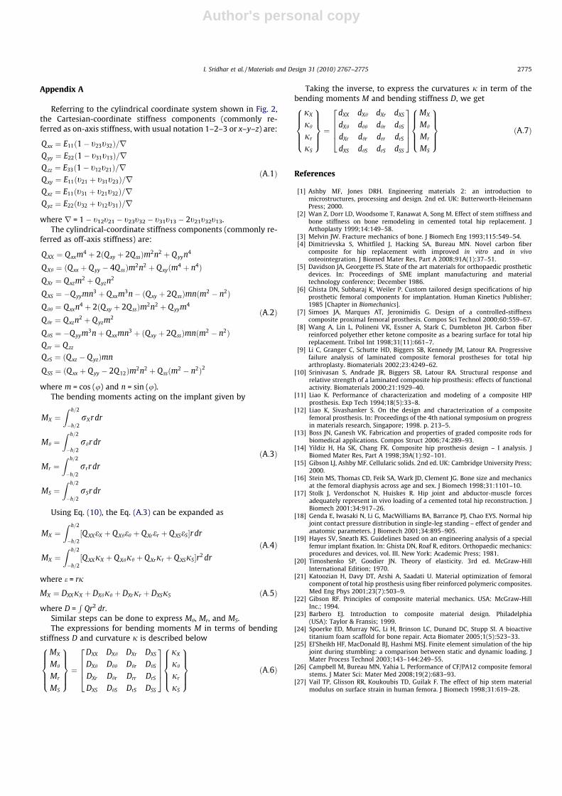
Referring to the cylindrical coordinate system shown in Fig. 2,the Cartesian-coordinate stiffness components (commonly re-ferred as on-axis stiffness, with usual notation 1–2–3 or x–y–z) are:
Qxx ¼ E11ð1� t23t32Þ=rQyy ¼ E22ð1� t31t13Þ=rQzz ¼ E33ð1� t12t21Þ=rQxy ¼ E11ðt21 þ t31t23Þ=rQxz ¼ E11ðt31 þ t21t32Þ=rQyz ¼ E22ðt32 þ t12t31Þ=r
ðA:1Þ
where r = 1 � t12t21 � t23t32 � t31t13 � 2t21t32t13.The cylindrical-coordinate stiffness components (commonly re-
ferred as off-axis stiffness) are:
QXX ¼ Q xxm4 þ 2ðQ xy þ 2QssÞm2n2 þ Q yyn4
QXh ¼ ðQ xx þ Q yy � 4Q ssÞm2n2 þ Q xyðm4 þ n4ÞQXr ¼ Qxzm2 þ Q yzn
2
QXS ¼ �Q yymn3 þ Q xxm3n� ðQxy þ 2Q ssÞmnðm2 � n2ÞQ hh ¼ Qxxn4 þ 2ðQxy þ 2Q ssÞm2n2 þ Q yym4
Q hr ¼ Qxzn2 þ Q yzm2
Q hS ¼ �Q yym3nþ Q xxmn3 þ ðQxy þ 2Q ssÞmnðm2 � n2ÞQrr ¼ Qzz
QrS ¼ ðQ xz � Q yzÞmn
QSS ¼ ðQ xx þ Q yy � 2Q12Þm2n2 þ Q ssðm2 � n2Þ2
ðA:2Þ
where m = cos (u) and n = sin (u).The bending moments acting on the implant given by
MX ¼Z h=2
�h=2rXr dr
Mh ¼Z h=2
�h=2rhr dr
Mr ¼Z h=2
�h=2rrr dr
MS ¼Z h=2
�h=2rSr dr
ðA:3Þ
Using Eq. (10), the Eq. (A.3) can be expanded as
MX ¼Z h=2
�h=2½Q XXeX þ Q Xheh þ QXrer þ Q XSeS�r dr
MX ¼Z h=2
�h=2½Q XXjX þ Q Xhjh þ Q Xrjr þ QXSjS�r2 dr
ðA:4Þ
where e = rj
MX ¼ DXXjX þ DXhjh þ DXrjr þ DXSjS ðA:5Þ
where D =R
Qr2 dr.Similar steps can be done to express Mh, Mr, and MS.The expressions for bending moments M in terms of bending
stiffness D and curvature j is described below
MX
Mh
Mr
MS
8>>><>>>:
9>>>=>>>;¼
DXX DXh DXr DXS
DXh Dhh Dhr DhS
DXr Dhr Drr DrS
DXS DhS DrS DSS
26664
37775
jX
jh
jr
jS
8>>><>>>:
9>>>=>>>;
ðA:6Þ
Taking the inverse, to express the curvatures j in term of thebending moments M and bending stiffness D, we get
jX
jh
jr
jS
8>>><>>>:
9>>>=>>>;¼
dXX dXh dXr dXS
dXh dhh dhr dhS
dXr dhr drr drS
dXS dhS drS dSS
26664
37775
MX
Mh
Mr
MS
8>>><>>>:
9>>>=>>>;
ðA:7Þ
References
[1] Ashby MF, Jones DRH. Engineering materials 2: an introduction tomicrostructures, processing and design. 2nd ed. UK: Butterworth-HeinemannPress; 2000.
[2] Wan Z, Dorr LD, Woodsome T, Ranawat A, Song M. Effect of stem stiffness andbone stiffness on bone remodeling in cemented total hip replacement. JArthoplasty 1999;14:149–58.
[3] Melvin JW. Fracture mechanics of bone. J Biomech Eng 1993;115:549–54.[4] Dimitrievska S, Whitfiled J, Hacking SA, Bureau MN. Novel carbon fiber
composite for hip replacement with improved in vitro and in vivoosteointegration. J Biomed Mater Res, Part A 2008;91A(1):37–51.
[5] Davidson JA, Georgette FS. State of the art materials for orthopaedic prostheticdevices. In: Proceedings of SME implant manufacturing and materialtechnology conference; December 1986.
[6] Ghista DN, Subbaraj K, Weiler P. Custom tailored design specifications of hipprosthetic femoral components for implantation. Human Kinetics Publisher;1985 [Chapter in Biomechanics].
[7] Simoes JA, Marques AT, Jeronimidis G. Design of a controlled-stiffnesscomposite proximal femoral prosthesis. Compos Sci Technol 2000;60:559–67.
[8] Wang A, Lin L, Polineni VK, Essner A, Stark C, Dumbleton JH. Carbon fiberreinforced polyether ether ketone composite as a bearing surface for total hipreplacement. Tribol Int 1998;31(11):661–7.
[9] Li C, Granger C, Schutte HD, Biggers SB, Kennedy JM, Latour RA. Progressivefailure analysis of laminated composite femoral prostheses for total hiparthroplasty. Biomaterials 2002;23:4249–62.
[10] Srinivasan S, Andrade JR, Biggers SB, Latour RA. Structural response andrelative strength of a laminated composite hip prosthesis: effects of functionalactivity. Biomaterials 2000;21:1929–40.
[11] Liao K. Performance of characterization and modeling of a composite HIPprosthesis. Exp Tech 1994;18(5):33–8.
[12] Liao K, Sivashanker S. On the design and characterization of a compositefemoral prosthesis. In: Proceedings of the 4th national symposium on progressin materials research, Singapore; 1998. p. 213–5.
[13] Boss JN, Ganesh VK. Fabrication and properties of graded composite rods forbiomedical applications. Compos Struct 2006;74:289–93.
[14] Yildiz H, Ha SK, Chang FK. Composite hip prosthesis design – I analysis. JBiomed Mater Res, Part A 1998;39A(1):92–101.
[15] Gibson LJ, Ashby MF. Cellularic solids. 2nd ed. UK: Cambridge University Press;2000.
[16] Stein MS, Thomas CD, Feik SA, Wark JD, Clement JG. Bone size and mechanicsat the femoral diaphysis across age and sex. J Biomech 1998;31:1101–10.
[17] Stolk J, Verdonschot N, Huiskes R. Hip joint and abductor-muscle forcesadequately represent in vivo loading of a cemented total hip reconstruction. JBiomech 2001;34:917–26.
[18] Genda E, Iwasaki N, Li G, MacWilliams BA, Barrance PJ, Chao EYS. Normal hipjoint contact pressure distribution in single-leg standing – effect of gender andanatomic parameters. J Biomech 2001;34:895–905.
[19] Hayes SV, Sneath RS. Guidelines based on an engineering analysis of a specialfemur implant fixation. In: Ghista DN, Roaf R, editors. Orthopaedic mechanics:procedures and devices, vol. III. New York: Academic Press; 1981.
[20] Timoshenko SP, Goodier JN. Theory of elasticity. 3rd ed. McGraw-HillInternational Edition; 1970.
[21] Katoozian H, Davy DT, Arshi A, Saadati U. Material optimization of femoralcomponent of total hip prosthesis using fiber reinforced polymeric composites.Med Eng Phys 2001;23(7):503–9.
[22] Gibson RF. Principles of composite material mechanics. USA: McGraw-HillInc.; 1994.
[23] Barbero EJ. Introduction to composite material design. Philadelphia(USA): Taylor & Fransis; 1999.
[24] Spoerke ED, Murray NG, Li H, Brinson LC, Dunand DC, Stupp SI. A bioactivetitanium foam scaffold for bone repair. Acta Biomater 2005;1(5):523–33.
[25] El’Sheikh HF, MacDonald BJ, Hashmi MSJ. Finite element simulation of the hipjoint during stumbling: a comparison between static and dynamic loading. JMater Process Technol 2003;143–144:249–55.
[26] Campbell M, Bureau MN, Yahia L. Performance of CF/PA12 composite femoralstems. J Mater Sci: Mater Med 2008;19(2):683–93.
[27] Vail TP, Glisson RR, Koukoubis TD, Guilak F. The effect of hip stem materialmodulus on surface strain in human femora. J Biomech 1998;31:619–28.
I. Sridhar et al. / Materials and Design 31 (2010) 2767–2775 2775