Hybrid Prosthesis, Tilted Implants, Angled Abutments and ...
Upload
khangminh22Category
view
0download
0
THE TRIBOLOGICAL BEHAVIOUR OF
THE DUAL MOBILITY HIP PROSTHESIS
IN RELATION TO IMPINGEMENT
Eko Saputra
UNIVERSITY OF TWENTE.
ISBN: 978-90-365-5226-4
The tribological behaviour of the dual mobility hip prosthesis in relation to
impingement
Eko Saputra
University of Twente

Composition of the graduation committee: Prof.dr.ir. H.F.J.M. Koopman University of Twente Chairman and secretary Prof.dr.ir. E. van der Heide University of Twente Supervisor Prof.dr. Jamari, M.Sc. University of Diponegoro Supervisor Dr.ir. R. Loendersloot University of Twente Prof.dr.ir. D.J. Schipper University of Twente Prof.dr.ir. A.P. Bayuseno University of Diponegoro Dr. P.K. Sharma University Medical Center Groningen THE TRIBOLOGICAL BEHAVIOUR OF THE DUAL MOBILITY HIP PROSTHESIS IN RELATION TO IMPINGEMENT Saputra, Eko Ph.D. Thesis, University of Twente, Enschede, The Netherlands, September 2021 ISBN: 978-90-365-5226-4 DOI: 10.3990/1.9789036552264 Keywords: contact stress; dual mobility; hip prosthesis; impingement; wear Printed by Gildeprint B.V., Enschede, The Netherlands Copyright © E. Saputra, Enschede, The Netherlands All rights reserved

The tribological behaviour of the dual mobility hip prosthesis in relation to
impingement
PROEFSCHRIFT
ter verkrijging van de graad van doctor aan de Universiteit Twente,
op gezag van de rector magnificus, Prof. dr. ir. A. Veldkamp,
volgens besluit van het College voor Promoties in het openbaar te verdedigen
op donderdag 8 september 2021 om 12.45 uur
door
Eko Saputra geboren op 9 augustus 1984
te Tegal, Indonesië

Dit proefschrift is goedgekeurd door: de promotoren: Prof.dr.ir. E. van der Heide
Prof.dr. Jamari, M.Sc.
v
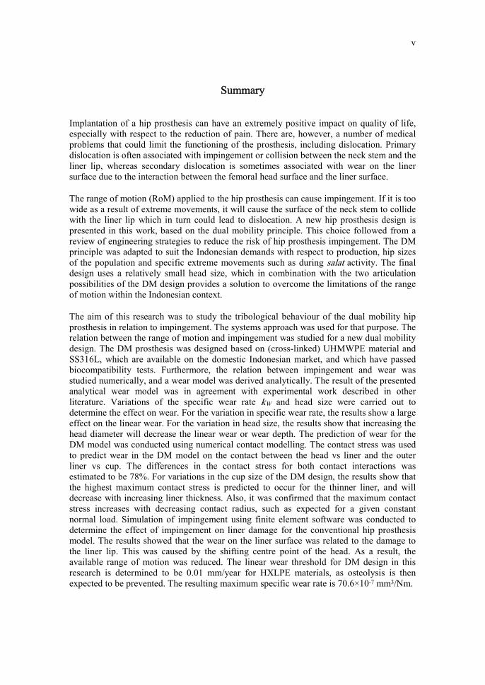
Summary Implantation of a hip prosthesis can have an extremely positive impact on quality of life, especially with respect to the reduction of pain. There are, however, a number of medical problems that could limit the functioning of the prosthesis, including dislocation. Primary dislocation is often associated with impingement or collision between the neck stem and the liner lip, whereas secondary dislocation is sometimes associated with wear on the liner surface due to the interaction between the femoral head surface and the liner surface.
The range of motion (RoM) applied to the hip prosthesis can cause impingement. If it is too wide as a result of extreme movements, it will cause the surface of the neck stem to collide with the liner lip which in turn could lead to dislocation. A new hip prosthesis design is presented in this work, based on the dual mobility principle. This choice followed from a review of engineering strategies to reduce the risk of hip prosthesis impingement. The DM principle was adapted to suit the Indonesian demands with respect to production, hip sizes of the population and specific extreme movements such as during salat activity. The final design uses a relatively small head size, which in combination with the two articulation possibilities of the DM design provides a solution to overcome the limitations of the range of motion within the Indonesian context.
The aim of this research was to study the tribological behaviour of the dual mobility hip prosthesis in relation to impingement. The systems approach was used for that purpose. The relation between the range of motion and impingement was studied for a new dual mobility design. The DM prosthesis was designed based on (cross-linked) UHMWPE material and SS316L, which are available on the domestic Indonesian market, and which have passed biocompatibility tests. Furthermore, the relation between impingement and wear was studied numerically, and a wear model was derived analytically. The result of the presented analytical wear model was in agreement with experimental work described in other literature. Variations of the specific wear rate kW and head size were carried out to determine the effect on wear. For the variation in specific wear rate, the results show a large effect on the linear wear. For the variation in head size, the results show that increasing the head diameter will decrease the linear wear or wear depth. The prediction of wear for the DM model was conducted using numerical contact modelling. The contact stress was used to predict wear in the DM model on the contact between the head vs liner and the outer liner vs cup. The differences in the contact stress for both contact interactions was estimated to be 78%. For variations in the cup size of the DM design, the results show that the highest maximum contact stress is predicted to occur for the thinner liner, and will decrease with increasing liner thickness. Also, it was confirmed that the maximum contact stress increases with decreasing contact radius, such as expected for a given constant normal load. Simulation of impingement using finite element software was conducted to determine the effect of impingement on liner damage for the conventional hip prosthesis model. The results showed that the wear on the liner surface was related to the damage to the liner lip. This was caused by the shifting centre point of the head. As a result, the available range of motion was reduced. The linear wear threshold for DM design in this research is determined to be 0.01 mm/year for HXLPE materials, as osteolysis is then expected to be prevented. The resulting maximum specific wear rate is 70.6×10⁻⁷ mm3/Nm.

vi
An experimental procedure to determine the specific wear rate in a pre-clinical setting for the hip prosthesis design was developed based on a pin-on-disk setup and was based on a newly developed hip simulator setup. Bovine serum was used to simulate lubricated conditions. The results showed that for non-cross-linked UHMWPE under dry conditions, the specific wear rate was above the threshold of 70.6×10⁻⁷ mm3/Nm, while for bovine serum lubricated conditions the wear rate was below the threshold. In addition, the specific wear rates for UHMWPE cross-linked materials with irradiation of 50-100 kGy and lubricated with bovine serum performed at a wear rate below the threshold of 70.6×10⁻⁷ mm3/Nm.
This thesis is divided into two parts. Part 1 reflects the overall research and Part 2 summarizes the scientific work in the form of a collection of research publications.
vii
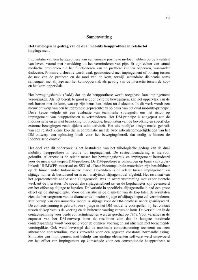
Samenvatting Het tribologische gedrag van de dual mobility heupprothese in relatie tot
impingement Implantatie van een heupprothese kan een enorme positieve invloed hebben op de kwaliteit van leven, vooral met betrekking tot het verminderen van pijn. Er zijn echter een aantal medische problemen die het functioneren van de prothese kunnen beperken, waaronder dislocatie. Primaire dislocatie wordt vaak geassocieerd met impingement of botsing tussen de nek van de prothese en de rand van de kom, terwijl secundaire dislocatie soms samengaat met slijtage aan het kom-oppervlak als gevolg van de interactie tussen de kop- en het kom-oppervlak.
Het bewegingsbereik (RoM) dat op de heupprothese wordt toegepast, kan impingement veroorzaken. Als het bereik te groot is door extreme bewegingen, kan het oppervlak van de nek botsen met de kom, wat op zijn beurt kan leiden tot dislocatie. In dit werk wordt een nieuw ontwerp van een heupprothese gepresenteerd op basis van het dual mobility-principe. Deze keuze volgde uit een evaluatie van technische strategieën om het risico op impingement van heupprothesen te verminderen. Het DM-principe is aangepast aan de Indonesische eisen met betrekking tot productie, heupmaten van de bevolking en specifieke extreme bewegingen zoals tijdens salat-activiteit. Het uiteindelijke design maakt gebruik van een relatief kleine kop die in combinatie met de twee articulatiemogelijkheden van het DM-ontwerp een oplossing biedt voor het bewegingsbereik dat nodig is binnen de Indonesische context.
Het doel van dit onderzoek is het bestuderen van het tribologische gedrag van de dual mobility heupprothese in relatie tot impingement. De systeembenadering is hiervoor gebruikt. Allereerst is de relatie tussen het bewegingsbereik en impingement bestudeerd voor de nieuw ontwerpen DM-prothese. De DM-prothese is ontworpen op basis van (cross-linked) UHMWPE-materiaal en SS316L. Deze biocompatibele materialen zijn beschikbaar op de binnenlandse Indonesische markt. Bovendien is de relatie tussen impingement en slijtage numeriek bestudeerd en is een analytisch slijtagemodel afgeleid. Het resultaat van het gepresenteerde analytische slijtagemodel was in overeenstemming met experimentele werk uit de literatuur. De specifieke slijtagesnelheid kW en de kopdiameter zijn gevarieerd om het effect op slijtage te bepalen. De variatie in specifieke slijtagesnelheid had een groot effect op de slijtagediepte. Voor de variatie in de diameter van de kop laten de resultaten zien dat het vergroten van de diameter de lineaire slijtage of slijtagediepte zal verminderen. Met behulp van een numeriek model is slijtage voor de DM-prothese nader geanalyseerd. De contactspanning is gebruikt om slijtage in het DM-model te voorspellen bij het contact tussen de kop versus de voering en de buitenste voering versus de kom. De verschillen in de contactspanning voor beide contactinteracties werden geschat op 78%. Voor variaties in de cupmaat van het DM-ontwerp laten de resultaten zien dat de hoogste maximale contactspanning wordt voorspeld voor de dunnere voering en zal afnemen met toenemende voeringdikte. Ook werd bevestigd dat de maximale contactspanning toeneemt met een afnemende contactradius, zoals verwacht voor een gegeven constante normaalbelasting. Simulatie van impingement met behulp van eindige elementen software werd uitgevoerd om het effect van impingement op komschade voor een conventionele heupprothese te

viii
bepalen. De resultaten tonen aan dat de slijtage op het voeringoppervlak verband hield met de schade aan de rand van de voerin wat veroorzaakt wordt door het verschuivende middelpunt van de kop. Als gevolg hiervan werd het beschikbare bewegingsbereik verkleind. De maximale slijtagediepte voor DM-ontwerp in dit onderzoek is bepaald op 0,01 mm/jaar voor HXLPE-materialen, omdat osteolyse dan naar verwachting zal worden voorkomen. De resulterende maximale specifieke slijtagesnelheid is 70,6×10⁻⁷ mm3/Nm.
Een experimentele procedure om de specifieke slijtagesnelheid te bepalen in een pre-klinische setting voor het ontwerp van de heupprothese is ontwikkeld in dit proefschrift op basis van een pin on disk setup en op basis van een nieuw ontwikkelde heupsimulatoropstelling. Runderserum werd gebruikt om gesmeerde omstandigheden te simuleren. Uit de resultaten bleek dat voor UHMWPE onder droge omstandigheden de specifieke slijtagesnelheid boven de drempel van 70,6×10⁻⁷ mm3/Nm lag, terwijl voor met runderserum gesmeerde omstandigheden de slijtagesnelheid onder de drempel lag. De specifieke slijtagepercentages voor cross-linked UHMWPE met stralingsdoses van 50-100 kGy in gesmeerde omstandigheden lagen onder de drempel van 70,6×10⁻⁷ mm3/Nm.
Dit proefschrift bestaat uit twee delen. Deel 1 weerspiegelt het totale onderzoek en deel 2 vat het wetenschappelijke werk samen in de vorm van een verzameling onderzoekspublicaties.
ix
Contents
Part I Summary v
Contents ix
Nomenclature xiii
Chapter 1 Introduction ........................................................................................................ 1
Chapter 2 Engineering strategies for the Indonesian market to reduce the risk of hip prosthesis impingement ...................................................................................... 9
2.1 Dislocation related to liner wear and impingement in total hip replacement: clinical evidence ................................................................... 9
2.2 Design choices affecting impingement and liner wear ............................ 11 2.3 Engineering strategy selection for the Indonesian market ...................... 22 2.4 Tribological systems approach ................................................................ 23 2.5 Conclusions.............................................................................................. 24 References ........................................................................................................ 25
Chapter 3 Hip prosthesis design with a special emphasis on preventing dislocation due to extreme movement .......................................................................................... 37
3.1 Introduction ............................................................................................. 37 3.2 Dual mobility design ................................................................................ 39 3.3 Demands with respect to the range of motion .......................................... 42 3.4 Materials selection ................................................................................... 45 3.5 Dual mobility design solution for the RoM ............................................. 46 3.6 Finite element model for calculation of local contact stresses at
impingement ............................................................................................ 48 3.7 Conclusions.............................................................................................. 50 References ........................................................................................................ 51
Chapter 4 Modelling impingement in relation to liner wear ............................................. 55
4.1 Introduction.............................................................................................. 55 4.2 Liner wear prediction for a single mobility system ................................. 55 4.3 Wear prediction of dual mobility model using numerical method ........... 63 4.4 Relation impingement and wear for a single mobility design .................. 70 4.5 Wear threshold of acetabular liner in dual mobility design ..................... 77 4.6 Conclusions.............................................................................................. 78 References ........................................................................................................ 78
x
Chapter 5 Experimental results on liner wear ................................................................... 83
5.1 Introduction.............................................................................................. 83 5.2 Experimental details ................................................................................ 85 5.3 Results ..................................................................................................... 91 5.4 Discussion ................................................................................................ 95 5.5 Conclusions.............................................................................................. 97 References ........................................................................................................ 97
Chapter 6 Conclusions .................................................................................................... 101
6.1 Conclusions ............................................................................................ 101 6.2 Future works ........................................................................................... 102 Part II Patent:
J. Jamari, E. Saputra, I.B. Anwar, et al., Indonesian Patent: S00201703018, 2019, Sendi panggul buatan bipolar untuk memudahkan gerakan salat pasien (Bipolar artificial hip joint for patient performing salat).
Papers:
Paper A: E. Saputra, I.B. Anwar, R. Ismail, J. Jamari, E. van der Heide, 2014, “Numerical simulation of artificial hip joint movement for western and japanese-style activities”, Jurnal Teknologi (Sciences & Engineering), Volume 66, Issue 3, pp. 53-58.
Paper B: J. Jamari, I.B. Anwar, E. Saputra, R. Ismail, E. van der Heide, 2017, “Range of
motion simulation of hip joint movement during salat activity”, The Journal of Arthroplasty, Volume 32, pp. 2898-2904.
Paper C: E. Saputra, I.B. Anwar, J. Jamari, E. van der Heide, 2019, “A wear formulation
of total hip prosthesis for salat activity”, International Review of Mechanical Engineering, Volume 13, No. 1, pp. 29-37.
Paper D: E. Saputra, I.B. Anwar, R. Ismail, J. Jamari, E. van der Heide, 2017, “Study the
effect of wear rate on impingement failure of an acetabular liner surface based on finite element analysis”, International Journal of Materials and Product Technology, Volume 55, Issue 4, pp. 340-353.
Paper not included in the thesis J. Jamari, E. Saputra, I.B. Anwar, E. van der Heide, 2019, “Study of an additional layer of cement mantle hip joints for reducing cracks”, Journal of Functional Biomaterials, Volume 10, Issue 3, pp. 1-8
xi
Conference contributions: A. E. Saputra, I.B. Anwar, J. Jamari, E. van der Heide, 2013, “Finite element analysis of
artificial hip joint movement during human activities”, Procedia Engineering, Volume 68, pp. 102-108, doi: https://doi.org/10.1016/j.proeng.2013.12.154
B. R. Ismail, E. Saputra, M. Tauviqirrahman, A.B. Legowo, I. Budiwan Anwar, J. Jamari, 2014, “Numerical study of salat movements for total hip replacement patient”, Applied Mechanics and Materials, Volume 493, pp. 426-431, doi: https://doi.org/10.4028/ www.scientific.net/AMM.493.426
C. J. Jamari, R. Ismail, E. Saputra, S. Sugiyanto, I.B. Anwar, 2014, “The effect of repeated impingement on UHMWPE material in artificial hip joint during salat activities”, Advanced Materials Research, Volume 896, pp. 272-275, doi: https://doi.org/10.4028/ www.scientific.net/AMR.896.272
D. E. Saputra, I.B. Anwar, J. Jamari, E. van der Heide, 2015, “A bipolar artificial hip joint design for contact impingement reduction”, Advanced Materials Research,Volume 1123, pp. 164-168, doi: https://doi.org/10.4028/www.scientific.net/AMR.1123.164
E. E. Saputra, I.B. Anwar, R. Ismail, J. Jamari, E. van der Heide, 2016, “Finite element analysis of the impingement on the acetabular liner rim due to wear of the acetabular liner surface”, AIP Conference Proceedings 1725, 020074, doi: https://doi.org/10.1063/ 1.4945528
F. E. Saputra, I.B. Anwar, R. Ismail, J. Jamari, E. van der Heide, 2016, “Finite element study of contact pressure distribution on inner and outer liner in the bipolar hip prosthesis”, AIP Conference Proceedings 1725, 020075, doi: https://doi.org/10.1063/ 1.4945529
G. J. Jamari, E. Saputra, I.B. Anwar, R. Ismail, E. van der Heide, 2017, “Finite element study of the effect of uhmwpe liner thickness on the contact area and stress distribution in a bipolar hip joint”, IOP Conf. Series: Materials Science and Engineering 202, 012095, doi: https://doi.org/10.1088/1757-899X/202/1/012095
H. E. Saputra, I.B. Anwar, R. Ismail, J. Jamari, E. van der Heide, 2017, “Study of unipolar and bipolar hip prostheses using finite element simulation: contact stress analysis”, Key Engineering Materials, Volume 739, pp. 96-102, doi: https://doi.org/10.4028/www. scientific.net/KEM.739.96

xii
xiii
Nomenclature This section presents the general nomenclature used in this thesis. Certain specialized terminology is defined locally. Roman symbol a perpendicular [mm] b base [mm] c hypotenuse [mm] �� centre of the head [mm] �� centre of the liner [mm] � diameter of disk [mm] �� diameter of head [mm] � gap between centre point of cup and centre point of head [mm] �� pin diameter [mm] � Young’s modulus [MPa] normal force [N] force in direction x [N] � force in direction y [N] � force in direction z [N] ℎ linear wear [mm] ℎ� height of cup [mm] ℎ� height of head [mm] ℎ� height of penetration [mm] �� specific wear rate [mm3/Nm] � sliding distance [mm] � mass loss [g] � the number of loading cycles [-] � pressure [MPa] �� mean contact pressure [MPa] � radius of contact [mm] �� radius of contact [mm] �� radius of contact [mm] �� radius of spherical articulating surface [mm] � wear track radius [mm] �� radius of cup [mm] �� radius of head [mm] �� radius of liner [mm] � wear volume [m3] �� volumetric cup [m3] �� volumetric head [m3] �� volumetric penetration [m3] v sliding velocity [m/s] x axis direction [-] y axis direction [-]
xiv
Greek symbol � Poisson’s ratio [-] � stress [MPa] � angle [°] angle [°] ! angle [°] λ film thickness/roughness [-] " coefficient of friction [-] # density [kg/m3] $ rotational velocity [rpm] Subscript and superscript x corresponding to horizontal x axis y corresponding to horizontal y axis z corresponding to vertical z axis Abbreviations 2D two dimensional 3D three dimensional AR axix reference AM axis mobile CoF coefficient of friction CPE conventional polyethylene CAD computer aided design DM dual mobility HXLPE highly cross-linked polyethylene RoM range of motion SM single mobility THA total hip arthroplasty THR total hip replacement UHMWPE ultra-high-molecular-weight-polyethylene VS virtual skeleton

Part I


1
Chapter 1
Introduction The human musculoskeletal system is essential for motion while at the same time giving form, support and stability to the body. This complex system includes bones, ligaments, tendons, muscles and joints. There are many types of joints inside the human body with static and dynamic behaviour related to the human extremities. This research focuses on a specific joint, namely the hip joint. The anatomy of the hip joint includes the spherical head of the femur or femoral head, the articular cartilage, the cup of the acetabulum, and the pelvis, see Figure 1.1. The interacting surfaces of the femur head and the acetabulum are covered with articular cartilage and are separated by a small cavity that contains synovial fluid.
Figure 1.1. Anatomy of the human hip joint [1]
People with severe hip pain, which limits everyday activities such as walking or bending, or people with hip dysplasia or with hip osteoarthritis could benefit from total hip replacement (THR) surgery [2, 3, 4, 5, 6]. THR is currently a proven medical procedure, both for young adults with severe fractures of the pelvis or femur and for senior people suffering from rheumatoid arthritis or osteoarthritis. It is a hip joint replacement procedure in patients with an artificial hip joint or hip prosthesis. The artificial hip joint consists characteristically of an acetabular cup made of engineering plastic, a ceramic material or a metal such as stainless steel, chrome-molybdenum (CrMo) alloys or titanium alloys (Ti-alloy), while the femoral head and stem are typically made of an CrMo or Ti-alloy, although ceramic heads exist as well [7]. The polymers and alloys are increasingly used for total hip prostheses and also for knee prostheses in orthopedic surgery [7, 8]. This is due mainly to a combination of mechanical and surface properties followed by improvements in biocompatibility and bioactivity (bioactive material) [7]. An overview of a frequently used prosthetic hip joint implant configuration is shown in Figure 1.2.
Pelvis
Femur
Acetabulum
Articular cartilage

2
Figure 1.2. Total hip replacement [9]
Implantation of a hip prosthesis can have an extremely positive impact on the quality of life, especially with respect to the reduction of pain. It can also restore hip functions, allowing patients to perform daily activities such as sitting on a chair, walking normally or quickly, using the stairs or for specific work-related activities. There are, however, a number of medical problems that could limit the functioning of the prosthesis during its useful life. These problems include loosening, osteolysis, infection, periprosthetic fracture, dislocation and instability [10]. One aspect of particular interest is the failure of hip prostheses due to dislocation [11].
THR dislocation can be defined as ‘the complete loss of articulation contact between two artificial joint components’ [12]. Failure due to dislocation occurs in natural joints as well and limits the mechanical functioning of the joint. Dislocation after THR occurs in around 2% to 15% of cases [10, 13, 14, 15, 16]. Figure 1.3 shows clearly the dislocation after THR.
Figure 1.3. Dislocation after THR [17]
There are two causes of dislocation that are of particular interest in this work, namely primary dislocation and secondary dislocation. Primary dislocation is often associated with impingement or collision between the neck stem and the liner lip, whereas secondary
Cup
Liner

3
dislocation is sometimes associated with wear on the liner surface due to the interaction between the femoral head surface and the liner surface [18, 19]. The range of motion (RoM) applied to the hip prosthesis can cause impingement. If it is too wide, it will cause the surface of the neck stem to collide with the liner lip. The impingement with a wider RoM can lead to dislocations, whereas normal impingement followed by repeated impingement can cause damage to the liner lip.
Figure 1.4. Number of THR procedures at Prof. Dr. R Soeharso Orthopaedic Hospital,
Solo, Indonesia 2008-2017 [17]
THR is a medical procedure that is frequently used in Indonesia. Figure 1.4 shows the number of THR procedures from 2008 to 2017 performed at Prof. Dr. R. Soeharso Orthopaedic Hospital, Solo, Indonesia [17] based on data from that hospital. It shows the gradual increase in THRs and indicates the step increase when the government improves health facilities for the community. This is reinforced by the life expectancy of Indonesian people, which reached 71.20 years in 2018 [20]. It is expected that economic growth will further increase the number of THRs in Indonesia, thus indicating the potential market.
Currently, hip prosthesis replacement is performed with imported products that are designed for the European and American market. Until now, Indonesia does not have any domestically designed and produced hip prosthesis products. Consequently, the specific needs of Indonesian patients are not being met. Several developments of an economic, medical and engineering nature are promoting the need to design a hip joint product for the Indonesian market and produce it in Indonesia too.
The economic reason is related to the current price of hip replacement products and to the Indonesian government programmes that stimulate Indonesian industry. In general, the price of imported products is relatively high in comparison with the price of domestically produced products. This is due to additional import costs, customs taxes and profits of foreign companies. By producing hip prosthesis products in Indonesia, the prices will likely
0
20
40
60
80
100
120
2007 2009 2011 2013 2015 2017 2019
Num
ber
of T
HA
pro
cedu
res
Year

4
be more affordable for the people of Indonesia. This is in line with the government programme "Increasing Use of Domestic Production (P3DN)" which is a governmental effort to encourage people to use domestic products more than imported products, as stated in the National Industrial Development Master Plan (RIPIN) for the period 2015-2035 [21].
The second reason is related to the dimensions of imported hip prosthesis products that do not necessarily match the average hip dimensions of Indonesians. Based on data from the company Corentec, the smallest diameter of the imported acetabular cup sold in Indonesia is around 44 mm [22] while the average femoral head diameter of Indonesians is around 42 mm [23]. The possible implant size is currently too limited to cover all THRs for Indonesians, as the producers of hip prosthesis generally use bone dimensions that are common in Europe and the United States. However, the dimensions of the pelvic bone differ greatly between westerners and Asians [24, 25]. Therefore, the dimensions of the currently used prostheses are generally too large to be used for THR in Indonesia and need to be adapted to the required size distribution of the Indonesian domestic market. Figure 1.5 displays data from Corentec about the hip prostheses utilized in the Indonesian market, showing that smaller sizes are most commonly used for Indonesian patients [22].
Figure 1.5. The commonly used acetabular cup size for Indonesian patients that underwent
THR during 2017. (The smallest is size number 44 mm and the largest is size number 62 mm) [22]
The third reason is of an engineering nature and is related to the RoM that is needed to be able to accommodate activities specific to Indonesian people. The required functionality in terms of the RoM of the THR is therefore highly specific for the Indonesian market. Usually, an orthopaedic doctor will recommend that the patient should keep performing common daily activities such as walking, sitting and using the stairs. At the same time, patients are advised not to perform extreme movements such as stretching the legs excessively and squatting excessively. One activity, however, that is both connected to the quality of life in Indonesia and excessive in terms of the RoM is related to the movement of
0
10
20
30
40
50
60
44 46 48 50 52 54 56 58 60 62
Num
ber
of p
atie
nts
(-)
Size of acetabular cup (mm)
5
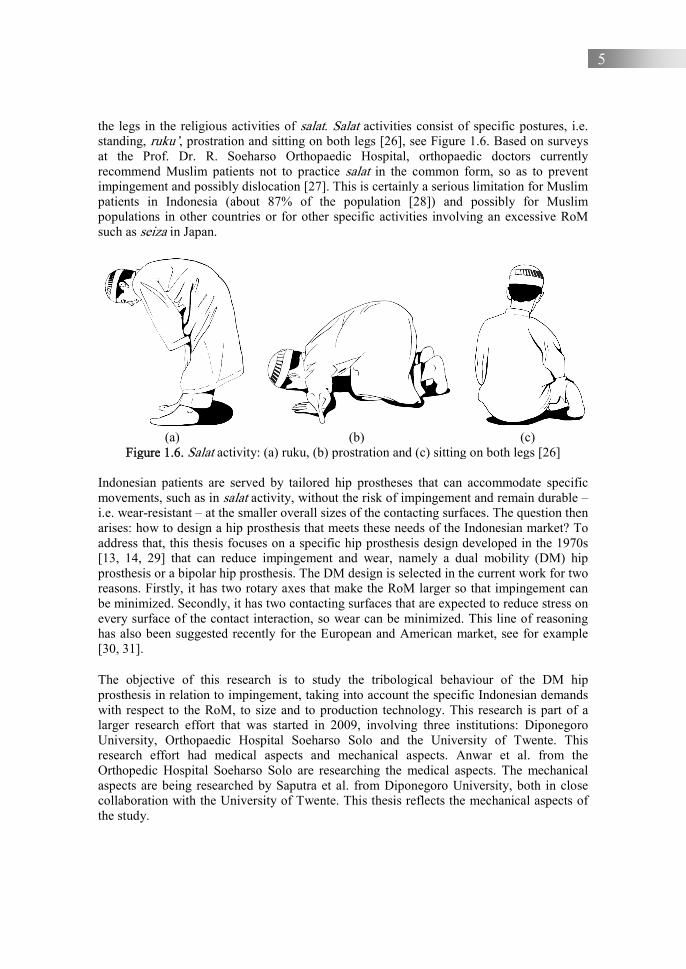
the legs in the religious activities of salat. Salat activities consist of specific postures, i.e. standing, ruku’, prostration and sitting on both legs [26], see Figure 1.6. Based on surveys at the Prof. Dr. R. Soeharso Orthopaedic Hospital, orthopaedic doctors currently recommend Muslim patients not to practice salat in the common form, so as to prevent impingement and possibly dislocation [27]. This is certainly a serious limitation for Muslim patients in Indonesia (about 87% of the population [28]) and possibly for Muslim populations in other countries or for other specific activities involving an excessive RoM such as seiza in Japan.
(a) (b) (c)
Figure 1.6. Salat activity: (a) ruku, (b) prostration and (c) sitting on both legs [26]
Indonesian patients are served by tailored hip prostheses that can accommodate specific movements, such as in salat activity, without the risk of impingement and remain durable – i.e. wear-resistant – at the smaller overall sizes of the contacting surfaces. The question then arises: how to design a hip prosthesis that meets these needs of the Indonesian market? To address that, this thesis focuses on a specific hip prosthesis design developed in the 1970s [13, 14, 29] that can reduce impingement and wear, namely a dual mobility (DM) hip prosthesis or a bipolar hip prosthesis. The DM design is selected in the current work for two reasons. Firstly, it has two rotary axes that make the RoM larger so that impingement can be minimized. Secondly, it has two contacting surfaces that are expected to reduce stress on every surface of the contact interaction, so wear can be minimized. This line of reasoning has also been suggested recently for the European and American market, see for example [30, 31].
The objective of this research is to study the tribological behaviour of the DM hip prosthesis in relation to impingement, taking into account the specific Indonesian demands with respect to the RoM, to size and to production technology. This research is part of a larger research effort that was started in 2009, involving three institutions: Diponegoro University, Orthopaedic Hospital Soeharso Solo and the University of Twente. This research effort had medical aspects and mechanical aspects. Anwar et al. from the Orthopedic Hospital Soeharso Solo are researching the medical aspects. The mechanical aspects are being researched by Saputra et al. from Diponegoro University, both in close collaboration with the University of Twente. This thesis reflects the mechanical aspects of the study.

6
The research method selected in this work is based on a combination of analytical and numerical work. The DM design was assessed using analytical methods and numerical methods with respect to impingement and wear performance. Impingement simulations are conducted using finite element software. A wear analysis is performed with the aim of understanding the governing mechanisms and of constructing a wear analytical model. In addition, experimental work was designed and executed to validate the wear performance with cross-linked polymer variations.
This thesis is divided into two parts. Part 1 reflects the overall research and Part 2 summarizes the scientific work in the form of a collection of research publications. Part 1 is structured as follows: (1) introduction, (2) engineering strategies for the Indonesian market to reduce the risk of hip prosthesis impingement, (3) hip prosthesis design with a special emphasis on preventing dislocation due to extreme movement, (4) modelling impingement in relation to liner wear, (5) experimental results on liner wear and (6) conclusion. Part 2 consists of several studies pertaining to Part 1 that are set out in the publication. In detail, paper A is a study of the simulation of the impingement process in hip prosthesis due to movement in general daily activities and movements in Japanese activities. Paper B is an investigation of the RoM in hip-induced movements of salat activity. Paper C is a study of the development of wear formulas for calculating wear on liners due to movement in salat activity. Paper D is a study of the effect of wear on liner on the process of impingement occurrence. Paper E is an investigation of the wear on liner due to walking and salat activity using analytical and experimental methods. Some conference proceedings relating to the research have been published and included as well. References
1. Anatomy and physiology instructor in bones of the pelvis and lower back, accessed 3 July 2018, <https://www.innerbody.com/image_ diagram/skel18.html>
2. Wilcock, G.K., 1978, “Benefits of total hip replacement to older patients and the community”, British Medical Journal, 2, pp. 37-39.
3. Phatama, K.Y., Pradana, A.S., Mustamsir, E., Hidayat, M., Sakti, S.W., Pandiangan, R.A.H., Muhammad, S.I., Putera, M.A., 2019, “Primary single stage total hip arthroplasty in a patient 40 years post traumatic hip dysplasia, a case report”, Trauma case reports, 23, 100223.
4. de Lima, F., Fernandes, D.A., Melo, G., et al., 2019, “Effects of total hip arthroplasty for primary hip osteoarthritis on postural balance: A systematic review”, Gait & Posture, 73, pp. 52-64.
5. Siopack, J.S., Jergesen, H.E., 1995, “Total hip arthroplasty”, The Western Journal of Medicine, 162, pp. 243-249.
6. Shaikh, H.S., O’Malley, M.J., 2019, “Arthroplasty for congenital hip deformity”, Operative Technique in Orthopaedics, 29(3), 100724.
7. Wilches, L.V., Uribe, J.A., Toro, A., 2008, “Wear of materials used for artificial joints in total hip replacement”, Wear, 265, pp. 143-149.
8. Brach Del Prever, E.M., Bistolfi, A., Bracco, P., Costa, L., 2009, “UHMWPE for arthroplasty: past or future?”, Journal of Orthopaedics and Traumatology, 10(1), pp. 1-8.
7
9. All about anterior hip replacement, accessed 16 May 2021, <https://www.arthritis-health.com/surgery/hip-surgery/all-about-anterior-hip-replacement>.
10. Khatod, M., Barber, T., Paxton, E., Namba, R., Fithian, D., 2006, “An analysis of the risk of hip dislocation with a contemporary total joint registry”, Clinical Orthopaedics and Related Research, 447, pp. 19-23.
11. Sikes, C.V., Lai, L.P., Schreiber, M., Mont, M.A., Jinnah, R.H., Seyler, T.M., 2008, “Instability after total hip arthroplasty treatment with large femoral heads vs constrained liners”, The Journal of Arthroplasty, 23(7), pp. 59-63.
12. Dargel, J., Oppermann, J., Brüggemann, G.P., Eysel, P., 2014, “Dislocation following total hip replacement”, Deutsches Ärzteblatt International, 111(51-52), pp. 884-890.
13. Grazioli, A., Ek, E.T., Rudiger, H.A., 2012, “Biomechanical concept and clinical outcome of dual-mobility cups”, International Orthopaedics, 36(12), pp. 2411-2418.
14. Langlais, F.L., Ropars, M., Gaucher, F., Musset, T., Chaix, O., 2008, “Dual mobility cemented cups have low dislocation rates in THA revisions”, Clinical Orthopaedics and Related Research, 466(2), pp. 389-395.
15. Asselineau, A., Da S.C., Beithoon, Z., Molina V., 2007, “Prevention of dislocation of total hip arthroplasty: the dual mobility cup”, Interactive Surgery, 2(3-4), pp. 160-164.
16. Philippot, R., Boyer, B., Farizon, F., 2013, “Intraprosthetic dislocation: a specific complication of the dual-mobility system”, Clinical Orthopaedics and Related Research, 471(3), pp. 965-970.
17. Anwar, I.B., 2017, “Number of total hip arthroplasty procedure at Prof. Dr. R Soeharso Orthopaedic Hospital”, Personal collection.
18. Cuckler, J.M., 2011, “The dislocated total hip: the dreaded 3 AM phone call”, Seminars in arthroplasty, 22, pp. 98-99.
19. Hummel, M.T., Malkani, A.L., Yakkanti, M.R., Baker, D.L., 2009, “Decreased dislocation after revision total hip arthroplasty using larger femoral head size and posterior capsular repair”, The Journal of Arthroplasty, 24(6), pp. 73-76.
20. “Human Development Index (HDI) 2018”. Jakarta, Indonesia: Statistics Indonesia. No. 32/04/Th. XXII, 15 April 2019
21. National Industrial Development Master Plan 2015-2035. Ministry of Industry public communication center, accessed 16 May 2021, <http://www.kemenperin.go.id/ ripin.pdf>.
22. Corentec Company, 2017, “The hip prosthesis in Indonesia market”, Internal data. 23. Ginting, I., 2014, “A practical and simple method for determining the magnitude of
preoperative X-ray magnification in hip hemiarthroplasty at the orthopedic hospital, Prof. Dr. R Soeharso Surakarta”, Thesis, Universitas Sebelas Maret.
24. Baharrudin, M.Y., Abdul Kadir, M.R., Zulkifly, A.H., Saat, A., Abdul, A.A., Hisyam Lee, M., 2011, “Morphology study of the proximal femur in Malay population”, International Journal of Morphology, 29(4), pp. 1321-1325.
25. Nelson, D.A., Beck, T.J., Wu, G., Lewis, C.E., Bassford, T., Cauley, J.A., LeBoff, M.S., Going, S.B., Chen, Z., “Ethnic differences in femur geometry in the women's health initiative observational study”, Osteoporosis International, 22(5), pp. 1377-88.
26. The basics of Muslim’s prayer, Darulmashari, 3rd Edition, accessed 16 May 2021, <http://www.aicp.org>.
27. Jamari, J., Anwar, I.B., Saputra, E., van der Heide E., 2017, “Range of motion simulation of hip joint movement during salat activity”, The Journal of Arthroplasty, 32(9), pp. 2898-2904.

8
28. "Population by Region and Religion Embraced", Inhabitant census 2010, Jakarta, Indonesia: Statictics Indonesia.
29. Prudhon, J.L., Ferreira, A., Verdier, R., 2013, “Dual mobility cup: dislocation rate and survivorship at ten years of follow-up”, International Orthopaedics, 37(12), pp. 2345-2350.
30. Terrier, A., Latypova, A., Guillemin, M., Parvex, V., Guyen, O., 2017, “Dual mobility cups provide biomechanical advantages in situations at risk for dislocation: a finite element analysis”, International Orthopaedics, 41, pp. 551-556.
31. Horriat, S., Haddad, F.S., 2018, “Dual mobility in hip arthroplasty”, Bone & Joint Research, 7(8), pp. 508-510.

9
Chapter 2
Engineering strategies for the Indonesian market to reduce the risk of hip prosthesis impingement 2.1. Dislocation related to liner wear and impingement in total hip
replacement: clinical evidence
Dislocation of the hip, meaning that the femoral head moves out of the acetabulum, is one of the major complications in total hip arthroplasty (THA), along with loosening and infection [1]. Dislocation is a serious problem, as it results in a sharp decrease in the functioning of the patient and may contribute to implant damage. The literature reveals that about 2% to 5% of the patients suffer dislocations after primary THR [2, 3, 4, 5] and about 15% to 30% after revision THR [6, 7]. The relative importance of dislocation as a complication in THA can also be seen from the causes of surgical revisions of the implant. The major cause in the U.S.A. for surgical revisions of the implant is postoperative instability after THR. Approximately 22.5% of revisions are due to dislocation [4]. Once dislocation occurs, there is a high chance of recurrence [1], which further increases the severity of the complication. The same holds for the risk of dislocations after a revision, which could even rise to 28% [1]. Dislocation may generally be associated with the patient's characteristic movements and load history [8, 9], suboptimal component position, the etiology of revision, or limb-length discrepancy [10, 11, 12, 13]. Furthermore, the surgical procedure used for THR and medical conditions like traumatic displacement of the hip or disorders that could cause increased muscle tension, such as Parkinson’s disease, might also affect dislocation recurrence [2, 3, 5, 14].
Figure 2.1. Damage to the liner due to wear and impingement [15]
In time, two engineering aspects control dislocation as well: impingement because of neck-cup contact during hip movements and wear of the liner [1, 16, 17]. An example of wear within the liner and the damage to the liner lip due to impingement for an acetabular cup is given in Figure 2.1.
Damage to the lip Wear within the liner
10
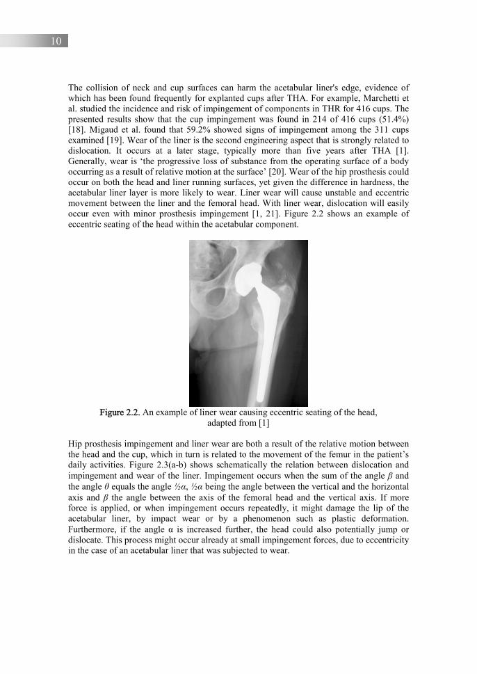
The collision of neck and cup surfaces can harm the acetabular liner's edge, evidence of which has been found frequently for explanted cups after THA. For example, Marchetti et al. studied the incidence and risk of impingement of components in THR for 416 cups. The presented results show that the cup impingement was found in 214 of 416 cups (51.4%) [18]. Migaud et al. found that 59.2% showed signs of impingement among the 311 cups examined [19]. Wear of the liner is the second engineering aspect that is strongly related to dislocation. It occurs at a later stage, typically more than five years after THA [1]. Generally, wear is ‘the progressive loss of substance from the operating surface of a body occurring as a result of relative motion at the surface’ [20]. Wear of the hip prosthesis could occur on both the head and liner running surfaces, yet given the difference in hardness, the acetabular liner layer is more likely to wear. Liner wear will cause unstable and eccentric movement between the liner and the femoral head. With liner wear, dislocation will easily occur even with minor prosthesis impingement [1, 21]. Figure 2.2 shows an example of eccentric seating of the head within the acetabular component.
Figure 2.2. An example of liner wear causing eccentric seating of the head,
adapted from [1]
Hip prosthesis impingement and liner wear are both a result of the relative motion between the head and the cup, which in turn is related to the movement of the femur in the patient’s daily activities. Figure 2.3(a-b) shows schematically the relation between dislocation and impingement and wear of the liner. Impingement occurs when the sum of the angle β and the angle θ equals the angle ½α, ½α being the angle between the vertical and the horizontal axis and β the angle between the axis of the femoral head and the vertical axis. If more force is applied, or when impingement occurs repeatedly, it might damage the lip of the acetabular liner, by impact wear or by a phenomenon such as plastic deformation. Furthermore, if the angle α is increased further, the head could also potentially jump or dislocate. This process might occur already at small impingement forces, due to eccentricity in the case of an acetabular liner that was subjected to wear.

11
(a) (b)
Figure 2.3. Illustration of (a) impingement and (b) wear in the liner hip prosthesis
2.2. Design choices affecting impingement and liner wear
Design parameters of a conventional or single mobility (SM) hip prosthesis include the diameter of the head, the diameter of the neck and the inner diameter of the liner. Together with material and surface selection, and the load and velocity distributions during movements of the body, these design parameters are related to the occurrence of impingement and to wear of the hip prosthesis. The relation to impingement is straightforward by the range of motion. The RoM will be affected by the head-to-neck ratio and by the cup orientation. The head-to-neck ratio is defined as the ratio of the diameter of the head and neck. The cup orientation includes the inclination, the angle between the cup axis and the sagittal plane, and anteversion, the angle between the cup axis projected onto the sagittal plane and the longitudinal axis [22]. Both inclination and anteversion are illustrated in Figure 2.4, with respect to the anterior pelvic plane.
(a) (b) (c)
Figure 2.4. Description of (a) definition of the anterior pelvic plane, (b) inclination of the cup and (c) anteversion of the cup, adapted from [23]
θ
½α β
r
Impingement
Liner
Rotation Head
Wear Liner
Rotation
F α

12
The relation to wear of the liner surface is by the normal load, the sliding distance and the contacting surfaces, i.e. the main building blocks of Archard’s wear law, see Section 2.2.1 for a detailed introduction. As such, wear will be influenced by the diameter of the head and the material combination, for a given loading cycle. The head diameter and liner material will influence the size of the contact area and, combined with the related sliding distance per rotation and the wear resistance of the selected surfaces, it will determine the amount of wear during the loading cycle. Furthermore, the load contributes to the contact stress at the liner surface and to the related frictional response.
In this chapter, the following three strategies are evaluated to optimize the RoM and the contacting surfaces in order to reduce impingement and wear. First, the application of a larger femoral head is considered to enlarge the RoM. The head diameter is a critical component of the hip prosthesis design. The risk of dislocation has been found to be lower when the diameter of the head is increased [17, 24]. To stabilize the THA, a large head diameter and acetabular cups with constrained liners can also be used [3, 25, 26]. Secondly, an optimized RoM might be found in the DM design [27, 28, 29]. Thirdly, wear can be reduced by applying a larger head diameter in combination with material modification of the liner, in particular by using cross-linked polyethylene [24]. The latter three routes will be discussed in the following sections.
2.2.1. Larger diameter head and/or a constrained liner A larger head size will increase the ratio between head and neck diameter, preventing impingement up to a greater critical rotation angle [17]. Consequently, hip dislocation can be also prevented theoretically with a larger RoM [30], see Figure 2.5. If the critical angle of rotation for a smaller head is �%and for a larger head is �&, from Figure 2.5 it is clear that �& is larger than �%. The theoretical equation that can be derived from Figure 2.5 for the critical angle is:
� = − 2! (2.1)
! = *+,-% .
/ (2.2)
The variable of α, β, θ in Eqs. (2.1) and (2.2) are respectively the angle of half cycle (180ᵒ), the angle between the axis of the femoral head and the vertical axis as the critical angle, and the angle between the axis of head and the axis of liner. Also, variables of b, a, and c are base, perpendicular and hypotenuse, where the opposite and hypotenuse are the neck radius and head radius. Equation (2.1) was compared with the work of McPherson [31], showing a deviation ± 3%. This may be caused by inset, i.e. the gap between the centre point of head and the liner or chamfer on the liner lip. The head diameters of THA are typically 22, 28, 32, 36 and 40 mm. The femoral head size is categorized by small, medium and large heads, the latter class consisting of head diameters from 36 mm onwards [17]. As such, the critical angle might increase from 114ᵒ for a 22 mm head to 145ᵒ for a 40 mm head, for a constant neck diameter of 12 mm. The effect of inclination and anteversion changes this; see paper A of part II of this thesis. Figure 2.6 shows the angle of impingement due to head diameter variation [32].

13
(a)
(b) (c)
Figure 2.5. The critical angle for a hip prosthesis indicating (a) the concept of the critical angle (b) for a smaller head and (c) for a larger head
Figure 2.6. The critical angle of impingement angle for different head sizes [32]
Head
Liner
β1
Head
Liner
β2
0
4
8
12
16
20
28 32 36 40
Ang
le o
f im
ping
emen
t (°)
Head diameter (mm)
14
Garbuz et al. show that the dislocation rate can be significantly reduced, up to 1.1% vs. 8.7% with a large head diameter of 36 to 40 mm, in comparison with a medium head diameter of 32 mm [24]. Furthermore, linear wear is reported to be reduced for larger head diameters [33]. In addition to reducing the risk of dislocation, a larger head is, however, often correlated with loosening and high volumetric wear of the acetabular cup when used against a cemented polyethylene cup [34, 35]. In other studies, osteolysis is reported [36, 37, 38]. An overview of the performance of several head diameters in terms of volumetric wear is shown in Table 2.1.
Table 2.1. Mean total volumetric wear for different head diameters [34, 39]
Head diameter Mean total volumetric wear (mm3) per year 26 88.431 ± 36.341 28 95.519 ± 21.719
36/40 159.64 ± 33.430
Table 2.1 shows that the volumetric wear increases with increasing head diameter. Schmalzried et al. [40] demonstrated that there is a volumetric wear increase of 6.3 mm3 per year for every millimetre increase in the diameter of the head. The reasons for the increase in wear volume due to increased head diameter that are given in the literature are related to the increased contact area, the velocity during movement and the reduced thickness of polyethylene [35, 39, 41]. The latter is because, as a consequence of increasing the head diameter, a reduced thickness of polyethylene could increase the contact stress on the surface of polyethylene [41, 42].
In this work, Archard’s wear law [43] is used to describe wear in the liner-head contact,
� = ��� (2.3)
where �, ��, and � are the wear volume in (mm3), the specific wear rate in (mm3/Nm), the normal force in (N) and the sliding distance in (m) respectively. Sometimes, linear wear is more important than volumetric wear. For that, Eq. (2.3) can be expressed as,
ℎ = �� − �� (2.4)
in which h in Eq. (2.4) is the linear wear, i.e. the reduction in distance between the centre of the head �� and the centre of the liner ��.
Alternatively, Eq. (2.3) can be rearranged, in which the specific wear rate is expressed as the quotient of the amount of volumetric wear and the normal force multiplied by the sliding distance.
�� = 01� (2.5)
The specific wear rate for ultra-high-molecular-weight-polyethilene (UHMWPE), measured by various hip simulators, ranges from 0.84 to 8.13×10⁻⁷ [44] to 2.5×10⁻⁶ [45] mm3/Nm. This corresponds to mild wear conditions where the specific wear rate is typically between 10-6 and 10-8 mm3/Nm. Also, it is estimated that the average linear wear rate in the total hip

15
prosthesis is 0.1 mm per year [45]. Hardness will affect the wear rate of a material in a specific tribological system.
Based on Eq. (2.3), if the �� and are constant, the volumetric wear will increase linearly with the sliding distance. Therefore, it is expected that a larger head will increase volumetric wear due to the greater sliding distance, as each cycle of rotations performed with a larger head radius �� will result in a greater sliding distance �. ∆� = ∆��� (2.6) Based on Eqs. (2.3) and (2.6), a sudden increase in volumetric wear in Table 2.1 when using a head diameter of 36/40 mm is possible. Furthermore, increasing contact stress might cause mechanical degradation of polyethylene, which includes fracture and delamination [41]. Therefore, great care is recommended when using a head with a large diameter for active young patients [34]. In addition, the risk of dislocation can be also reduced with a constrained liner, see Figure 2.7. Constrained liners might improve the stability of the THA and are therefore widely used by surgeons [46, 47]. In the case of a revision, the use of constrained implants decreases the average dislocation rate by around 10% and the average re-operation rate by 4% [48]. Other literature showed that the dislocation of constrained liner ranges between 4.5% and 29% [49, 50].
Figure 2.7. The constrained liner with locked ring, adapted from [50]
In general, constrained liners have a locked ring. Locked rings are used to lock the head and limit dislocation of the head, not by enlarging the RoM but by limiting the rotation of the head. Implant manufacturers have made a variety of implant products, which can be categorized by two types of constrained liners that are widely used, see Figure 2.8(a-b). The first is a SM model in which locking is conducted by a retaining finger to capture the head. The head cannot come out of the liner, Figure 2.8(a). The second is a tripolar model with locking ring to capture the bipolar outer femoral head, also preventing the head from coming out of the liner. The model in Figure 2.8(a) is similar to a SM model, except that the head implant is locked in the liner. This model causes the RoM angle to decrease so that the impingement starts earlier at lower angles. The constrained liner model in Figure 2.8(b)
Cup
Locked ring
Polyethylene liner
Head
16
tends to produce more polyethylene debris, due to two metal-to-plastic contact interactions. Increased debris will increase the risk of osteolysis.
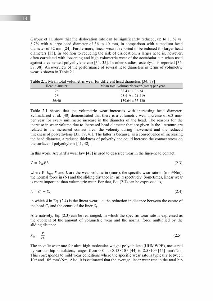
(a) (b)
Figure 2.8. Types of constrained liner (a) Zimmer constrained insert [50], and (b) Stryker constrained insert [51]
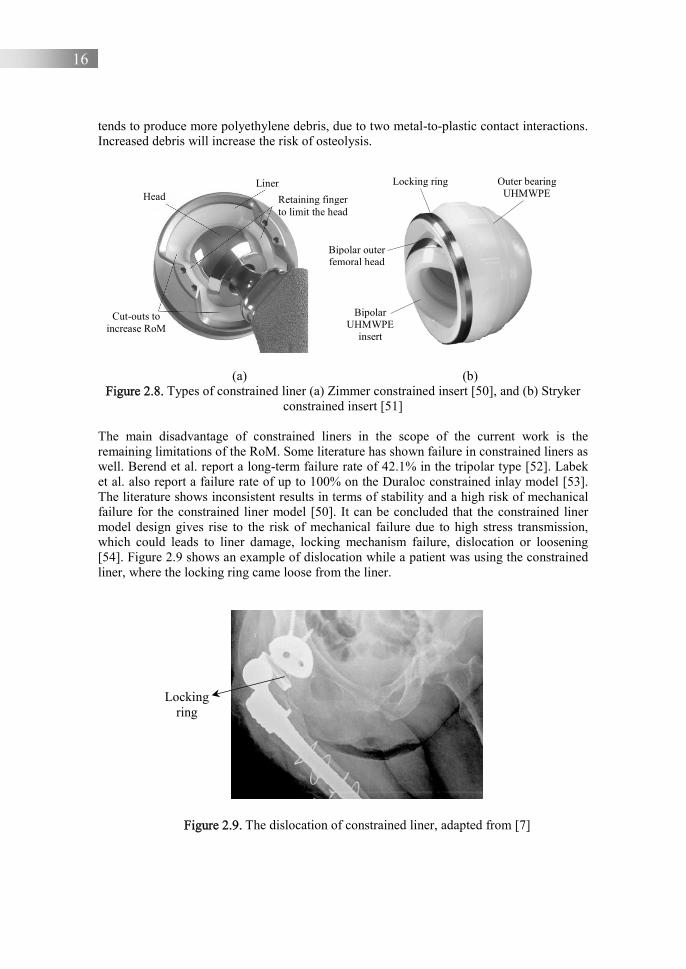
The main disadvantage of constrained liners in the scope of the current work is the remaining limitations of the RoM. Some literature has shown failure in constrained liners as well. Berend et al. report a long-term failure rate of 42.1% in the tripolar type [52]. Labek et al. also report a failure rate of up to 100% on the Duraloc constrained inlay model [53]. The literature shows inconsistent results in terms of stability and a high risk of mechanical failure for the constrained liner model [50]. It can be concluded that the constrained liner model design gives rise to the risk of mechanical failure due to high stress transmission, which could leads to liner damage, locking mechanism failure, dislocation or loosening [54]. Figure 2.9 shows an example of dislocation while a patient was using the constrained liner, where the locking ring came loose from the liner.
Figure 2.9. The dislocation of constrained liner, adapted from [7]
Head Liner
Retaining finger to limit the head
Cut-outs to increase RoM
Locking ring Outer bearing UHMWPE
Bipolar UHMWPE
insert
Bipolar outer femoral head
Locking ring
17
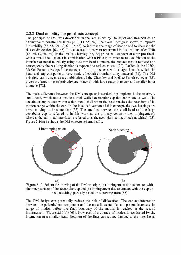
2.2.2. Dual mobility hip prosthesis concept The principle of DM was developed in the late 1970s by Bousquet and Rambert as an alternative to constrained liners [2, 3, 14, 55, 56]. The overall design is shown to improve hip stability [57, 58, 59, 60, 61, 62, 63], to increase the range of motion and to decrease the risk of dislocation [64, 65]. It is also used to prevent recurrent hip dislocations after THR [65, 66, 67, 68, 69]. In the 1960s, Charnley [56, 70] proposed a concept of a hip prosthesis with a small head (metal) in combination with a PE cup in order to reduce friction at the interface of metal to PE. By using a 22 mm head diameter, the contact area is reduced and consequently the resulting friction is expected to reduce as well [70]. Earlier, in the 1950s, McKee-Farrah developed the concept of a hip prosthesis with a lager head in which the head and cup components were made of cobalt-chromium alloy material [71]. The DM principle can be seen as a combination of the Charnley and McKee-Farrah concept [55], given the large liner of polyethylene material with large outer diameter and smaller inner diameter [72].
The main difference between the DM concept and standard hip implants is the relatively small head, which rotates inside a thick-walled acetabular cup that can rotate as well. The acetabular cup rotates within a thin metal shell when the head reaches the boundary of its motion range within the cup. In the idealised version of this concept, the two bearings are never moving at the same time [55]. The interface between the small head and the large acetabular cup is referred to in this work as the primary contact (liner impingement), whereas the cup-metal interface is referred to as the secondary contact (neck notching) [73]. Figure 2.10(a-b) shows the DM concept schematically.
(a) (b)
Figure 2.10. Schematic drawing of the DM principle, (a) impingement due to contact with the inner surface of the acetabular cup and (b) impingement due to contact with the cup or
neck notching, partially based on a drawing from [55]
The DM design can potentially reduce the risk of dislocation. The contact interaction between the polyethylene component and the metallic acetabular component increases the range of motion before the final boundary of the motion is reached at the second impingement (Figure 2.10(b)) [63]. Now part of the range of motion is conducted by the interaction of a smaller head. Rotation of the liner can reduce damage to the liner lip as
Liner impingement Neck notching

18
well. In the case of impingement between the neck and liner, the extra force is used for the rotation instead of for plastic deformation (Figure 2.10(a)).
The literature confirms that the DM design is likely to reduce the risk of dislocations. Simian et al. concluded it was useful to reduce the risk of dislocation following the THA revision for a wide variety of reasons and stated that the DM cups had not caused high stresses at the bone implant interface [74]. Pituckanotai et al. specifically recommend using DM and large head as hip prosthesis for safety in THA [75]. The DM concept has been demonstrated to reduce the dislocation rate following primary and revised THA [27, 51, 63, 76, 77, 78, 79]. The DM of hip prosthesis prevents instability with dislocation in THA ranges from 0% to 8.7% [11, 65, 80, 81, 82, 83, 84]. European studies have shown that the DM hip prosthesis could provide greater stability without compromising clinical outcomes and durability for implant fixation [11, 63, 65, 80, 81, 82, 83, 84, 85].
Figure 2.11. Relationship of film thickness/roughness, coefficient of friction
and specific wear rate, adapted from [89] Based on the literature, the contact interaction in the hip prosthesis is based on lubrication by synovial fluid [86, 87]. The contact situation in hip prosthesis can be in boundary lubrication, mixed lubrication and full-film lubrication [88], where the lubrication regime in hip prosthesis during activities is dependent on the kinematics and loading conditions [86].
0 1 2 3 4 5 6 7
0.1
0.2
0.3
0.4
10-10
10-8
10-6
10-4
Film thickness/roughness, λ
Coe
ffic
ient
of
fric
tion,
μ
Spec
ific
wea
r ra
te, k
W (m
m3 /
Nm
)
Bou
ndar
y lu
bric
atio
n
Mixed lubrication
Full-film lubrication
Hydrodynamic lubrication
CoC
MoP MoM

19
The lubrication regime will affect friction and wear. For example, the coefficient of friction (CoF) in each lubrication regime is different. The CoF in boundary lubrication, mixed lubrication and hydrodynamic lubrication are typically in the range of 0.18-0.38, 0.04-0.18 and 0.05-0.18 respectively [89].
Figure 2.11 shows the relation between film thickness/roughness λ, coefficient of friction μ and specific wear rate kW. The lubrication regime of the hip prosthesis can be determined by considering the film thickness/roughness. The lubrication regime can be classified based on the λ value, i.e. boundary lubrication (λ < 1), mixed lubrication (1 < λ < 3) and full-film lubrication (λ > 3) [90]. Based on the literature, a hip prosthesis of metal-on-plastic (MoP) has the λ value in range 0.1-1, where it is categorized as boundary lubrication. The interaction contact between asperities cannot be avoided because of the soft and rough surface of UHMWPE. Hip prosthesis of metal-on-metal (MoM) has the λ value in the range of 0.6-2.9, where it is categorized as mixed-lubrication, whereas the ceramic-on-ceramic (CoC) is categorized as full-film lubrication because it has the λ value in the range of 5.7-28.3 [91, 92, 93, 94, 95].
In addition, the lubrication regime of the hip prosthesis can also determined by considering the value of the specific wear rate. The specific wear rate for material combinations of metal-on-UHMWPE and metal-on-metal is around ~10-7 (mm3/Nm), whereas the value of specific wear rate for ceramic-on-ceramic is around ~10-8 (mm3/Nm) [96], see Table 2.2. Table 2.2. Specific wear rate and film thickness/roughness of material combination [91, 92,
93, 94, 95, 96,] Material combination Specific wear rate, kW (mm3/Nm) Film thickness/roughness, λ
Metal-on-UHMWPE (MoP) ~10-7 0.1-1 Metal-on-metal (MoM) ~10-7 0.6-2.9 Ceramic-on-ceramic (CoC) ~10-8 5.7-28.3
Based on Figure 2.10, there are two contact interactions of MoP in the DM hip prosthesis. First, the contact interaction between the head against liner (MoP) and second, the contact interaction between the liner against cup (MoP). Therefore, the lubrication regime for the general DM can be categorized as the boundary lubrication (refer to Table 2.2). It means that the potential for wear to occur in the general DM hip prosthesis is greater because there are two contact MoP interactions. This is supported by the results of volumetric wear rates for various hip prostheses tested in hip simulators, see Table 2.3.
Table 2.3. Volumetric wear rates for various hip prostheses tested in hip simulators [96] Material combination Volumetric wear (mm3/million cycles) Metal-on-UHMWPE 40 Metal-on-Cross-linked UHMWPE 5-10 Metal-on-metal 1.0 Ceramic-on-ceramic 0.1
In this research, the general design of DM is then modified to reduce wear on both contact pairs. Firstly, the head diameter is adjusted in line with the design of Charnley of 22-28 mm, as friction is expected to be lower. Secondly, the material used for liner is cross-linked
20
UHMWPE, therefore wear will be minimized for this material (refer to Table 2.3). Thirdly, with the addition of a metal cover on the outer liner surface the contact interaction will be MoM. This is performed to increase the value λ, therefore the position of the lubrication regime is expected to change to mixed lubrication. Mixed lubrication conditions might be the expected main operating regime given the moderate rotational velocities and relatively low contact pressures, see Stewart [92]. This means that the mild wear regime exists in the DM THA. In addition, friction has a limited relation to impingement and dislocation, contrary to wear, which is the focus of this work.
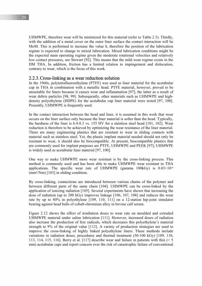
2.2.3. Cross-linking as a wear reduction solution In the 1960s, polytetrafluoroethylene (PTFE) was used as liner material for the acetabular cup in THA in combination with a metallic head. PTFE material, however, proved to be unsuitable for liners because it causes wear and inflammation [97], the latter as a result of wear debris particles [98, 99]. Subsequently, other materials such as UHMWPE and high-density polyethylene (HDPE) for the acetabular cup liner material were tested [97, 100]. Presently, UHMWPE is frequently used.
In the contact interaction between the head and liner, it is assumed in this work that wear occurs on the liner surface only because the liner material is softer than the head. Typically, the hardness of the liner is 6.4-8.3 vs. 155 HV for a stainless steel head [101, 102]. Wear reduction is therefore to be achieved by optimizing the wear resistance of the liner material. There are many engineering plastics that are resistant to wear in sliding contacts with material such as stainless steel. Yet, the plastic implant material needed should not only be resistant to wear, it should also be biocompatible. At present, biocompatible plastics that are commonly used for implant purposes are PTFE, UHMWPE and PEEK [97]; UHMWPE is widely used as acetabular liner material [97, 100].
One way to make UHMWPE more wear resistant is by the cross-linking process. This method is commonly used and has been able to make UHMWPE wear resistant in THA applications. The specific wear rate of UHMWPE (gamma 100kGy) is 0.03×10⁻⁶ (mm3/Nm) [103] in sliding condition.
By cross-linking, connections are introduced between various chains of the polymer and between different parts of the same chain [104]. UHMWPE can be cross-linked by the application of ionizing radiation [105]. Several experiments have shown that increasing the dose of radiation (up to 200 kGy) improves linkage [106, 107, 108] and reduces the wear rate by up to 80% in polyethylene [109, 110, 111] on a 12-station hip-joint simulator bearing against head balls of cobalt-chromium alloy in bovine calf serum.
Figure 2.12 shows the effect of irradiation doses to wear rate on moulded and extruded UHMWPE material under saline lubrication [111]. However, increased doses of radiation also increase the production of free radicals, which decreases this polyethylene’s material strength to 9% of the original value [112]. A variety of production strategies are used to improve the cross-linking of highly linked polyethylene liners. These methods include variations in radiation doses, procedures and thermal treatment (50-100 kGy) [109, 110, 113, 114, 115, 116]. Berry et al. [117] describe wear and failure in patients with thin (< 5 mm) acetabular cups and report concern over the risk of catastrophic failure of conventional

21
PE in previous generations of large femoral heads. These concerns have been widely addressed by the development of highly cross-linked PE [109, 118, 119, 120].
Figure 2.12. The effect of irradiation dose to wear rate of moulded and extruded UHMWPE
under saline lubrication [111] The wear resistance of polyethylene to the form of cross-path motion that exists in an acetabular cup can be increased by the cross-linking method [121, 122, 123], where the cross-path motion was determined in flexion/extension, lateral bending and axial rotation [100]. These motions are known as uni-directional motion and multi-directional motion where they can form a pattern on the cup surface during sliding motion. The trajectory of motion at the point of contact between the head and the cup can form a common quasi-elliptical or rectangular pattern during the gait cycle [124, 125, 126]. Based on observations of several patients with variations in walking patterns, a pattern of motion has been found that is more elongated and closed [126], an example of which can be seen in Figure 2.13 [45].
(a) (b) Figure 2.13. Motion pattern traced by the contact between the head and cup of hip
prosthesis, (a) elongated motion and (b) square motion, adapted from [45] Radiation cross-linking by high dose irradiation was performed to increase the wear resistance of the polymer in general [127]. Since UHMWPE wear is associated with increased plasticity [128], the wear can be reduced by decreasing plasticity through cross-
0
2
4
6
8
10
0 50 100 150
Spec
ific
wea
r ra
te, k
W, ×
10-7
(mm
3 /N
m)
Irradiation doses (kGy)
MoldedExtruded
A B
A B

22
linking [127]. Wang [129] stated that increasing radiation dose cross-linking on UHMWPE makes it possible to decrease the specific wear rate, see Figure 2.14.
Figure 2.14. Specific wear rate kW as a function of the radiation dose,
adopted from [129] 2.2.4. Current femoral head materials The head in hip prosthesis products is generally made of stainless steel, titanium alloys or Co-Cr-Mo alloys [97]. Specifically the Co-Cr-Mo alloys are known for corrosion resistance, toughness, wear resistance and hardness [97]. An important point with respect to the material head is the biocompatibility of the implant material, where the stainless steel, titanium alloys and Co-Cr-Mo alloys are biocompatibility materials [130].
Another implant material for the head of the most frequently used hip prosthesis is ceramic [131]. Alumina is used in THA because it has biocompatibility, chemical durability and high wear resistance [132, 133]. Zirconia ceramics, in addition to having advantages in high toughness and good mechanical properties, also have good crack resistance [134]. Meanwhile, zirconia toughened alumina is a combined material of zirconia and alumina where the composite material is able to increase toughness [135, 136, 137]. However, not all these materials will be used in this research. In this research, the implant material will be chosen by considering several aspects, as discussed in Section 2.3. 2.3. Engineering strategy selection for the Indonesian market
The two types of hip prosthesis designs presented in Section 2.2 are both able to reduce the risk of impingement and consequently the risk of dislocation. However, a large head has a disadvantage, which is the reported higher wear volume [31, 36] when combined with the polyethylene material. In addition, the consequence of a large head – reduction of the thickness of polyethylene liner material of the acetabular cup – causes a higher risk of
0
0.2
0.4
0.6
0.8
1
0 2.5 5 7.5 10 12.5 15 17.5
Spec
ific
wea
r ra
te,k
W, ×
10-6
(mm
3 /N
m)
Radiation dose (Mrads)
23
mechanical degradation including fracture and delamination [38]. The expected lifetime of the associated hip prostheses will therefore be shorter. Clearly, this might be solved by using improved PE liner surfaces. Yet, given the specific size distribution of the Indonesian people with respect to the hip dimensions, it is not feasible to search further in this direction. The prosthesis should actually be reduced in size instead of enlarged [138].
DM prostheses have the advantage of combining smaller product dimensions with a reduced risk of impingement. Secondly, they could have a benefit in terms of liner wear, given the smaller diameter head. Therefore, the DM design is adopted in this work. Nevertheless, concerns about wear in the case of young and active patients are a significant downside, especially as there is little literature in that area. Based on the literature review, no research has been found that discusses DM in relation to the Indonesian way of living and corresponding specific demands on the range of motion, such as for the salat movements.
The implant material selected and used in this study is stainless steel 316L for the head and cup, and cross-linked UHMWPE for the liner. The reason for this selection is that these are the most feasible in Indonesia from a production point of view. All the selected materials can be produced in Indonesia. Therefore, this research is expected to support the independence that the Indonesian government has outlined in the "National Research Master Plan 2017-2045" and the "National Research Priorities 2020-2024" on the need for health technology.
2.4. Tribological systems approach
The overall objective of the research is to study the tribological behaviour of the DM hip prosthesis in relation to impingement. The so-called systems approach is used for that purpose. In this thesis the structure of the contact situations in DM hip prosthesis operations is reduced to the interaction of the head surface and the liner/cup surface. Figure 2.15 shows a schematic diagram of the tribological system. The function of the systems in this study is to ensure the stability of the hip prosthesis for a large RoM and focuses on the associated impingement and wear of the running surfaces. The selected diameter of the head is important for that, as is the wear resistance of the selected materials. The relationship between the system and the remaining application can be reduced to the input, such as the range of motion, normal load or interfacial pressure, and output variables such as friction and wear. In this thesis, the main variable for the structure of the system is the material that is selected for the liner. The number of cycles and loads can be linked to the lifetime from the point of view of wear.
The performance of the DM design is assessed by analysing and evaluating the system's wear and impingement output characteristics. The model of a hip prosthesis is presented in more detail in Section 3.2. Impingement prediction is discussed in more detail in Sections 3.5, 4.1 and 4.3. Wear prediction is presented in Section 4.2. The relation between impingement and wear is discussed in Section 4.3.

24
Figure 2.15. Schematic drawing of the tribological system The systems approach is used to analyse the processes that influence impingement and wear in hip prosthesis applications. The DM hip prosthesis consists of two contact situations, namely the sliding contact on the inside of liner surface and the sliding contact on the outside of liner surface, see Figure 2.10. The two sliding interactions have their respective roles in impingement and wear. 2.5. Conclusions
Dislocation is a common failure in hip prosthesis, being related to impingement and liner wear. The collision of neck and cup surfaces can harm the acetabular liner's edge, evidence of which has been found frequently for explanted cups after THA. Liner wear will cause unstable and eccentric movement between the liner and the femoral head.
1. Head 2. Liner 3. Cup 4. Environment 5. Synovial fluid
Wear Characteristics
1
2
4
Volumetric wear Linear wear Range of Motion
Tribological system
Operating variables
3
5

25
The Dual Mobility principle can be used within the Indonesian context. This choice followed from a review of engineering strategies to reduce the risk of hip prosthesis impingement. The DM principle has the ability to allow patients to make extreme movements such as in salat. The overall objective of the research is to study the tribological behaviour of the DM hip prosthesis in relation to impingement. The systems approach can be used for that purpose. References 1. Pulido, L., Restrepo, C., Parvizi, J., 2007, “Late instability following total hip
arthroplasty”, Clinical Medical & Research, 5(2), pp. 139-142. 2. Grazioli, A., Ek, E.T., Rudiger, H.A., 2012, “Biomechanical concept and clinical
outcome of dual-mobility cups”, International Orthopaedics; 36(12), pp. 2411-2418. 3. Langlais, F.L., Ropars, M., Gaucher, F., Musset, T., Chaix, O., 2008, “Dual mobility
cemented cups have low dislocation rates in THA revisions”, Clinical Orthopaedics and Related Research, 466(2), pp. 389-395.
4. Prudhon, J.L., Ferreira, A., Verdier, R., 2013, “Dual mobility cup: dislocation rate and survivorship at ten years of follow-up”, International Orthopaedics; 37(12), pp. 2345-2350.
5. Asselineau, A., Da, S.C., Beithoon, Z., Molina, V., 2007, “Prevention of dislocation of total hip arthroplasty: the dual mobility cup”, Interactive Surgery, 2, pp. 160-164.
6. Su, E.P., Pellicci, P.M., 2004, “The role of constrained liners in total hip arthroplasty”, Clinical orthopaedics and related research, 420, pp. 122-129.
7. Sonohata, M., Waewsawangwong, W., Goodman, S.B., 2013, “Successful closed reduction of a dislocated constrained total hip arthroplasty”, Joint Implant Surgery & Research Foundation, 3(3), pp. 49-52.
8. Clifford, P.E., Mallon, W.J., 2005, “Sports after total joint replacement”, Clinics in Sports Medicine, 24(1), pp. 175-186.
9. Adrados, M., Myhre, L.A., Rubin, L.E., 2018, “Late total hip arthroplasty dislocation due to yoga”, Arthroplasty Today, 4(2), pp. 180-183.
10. Springer, B.D., Fehring, T.K., Griffin, W.L., et al., 2009, “Why revision total hip arthroplasty fails”, Clinical Orthopaedics and Related Research, 467(1), pp. 166-173.
11. Martino, I.D., Triantafyllopolous, G.K., Sculco, P.K., Sculco, T., 2014, “Dual mobility cups in total hip arthroplasty”, World Journal of Orthopedics, 5(3), pp. 180-187.
12. Alberton, G.M., High, W.A., Morrey, B.F., 2002, “Dislocation after revision total hip arthroplasty: An analysis of risk factors and treatment options”, The Journal of Bone and Joint Surgery. American volume, 84(10), pp. 1788-1792.
13. Kung, P.L., Ries, M.D., 2007, “Effect of femoral head size and abductors on dislocation after revision THA”, Clinical Orthopaedics and Related Research, 465, pp. 170-174.
14. Zahar, A., Rastogi, A., Kendoff, D., 2013, “Dislocation after total hip arthroplasty”, Current Reviews in Musculoskeletal Medicine, 6, pp. 350-356.

26
15. Saputra, E., Anwar, I.B., Ismail, R., Jamari, J., van der Heide, E., 2017, “Study the effect of wear rate on impingement failure of an acetabular liner surface based on finite element analysis”, International Journal of Materials and Product Technology, 55(4), pp. 340-353.
16. Brown, T.D., Elkins, J.M., Pedersen, D.R., Callaghan, J.J., 2014, “Impingement and dislocation in total hip arthroplasty: Mechanisms and consequences”, Iowa Orthopedic Journal,” 34, pp. 1-15.
17. Girard, J., 2015, “Femoral head diameter considerations for primary total hip arthroplasty”, Orthopaedics & Traumatology: surgery & research, 101, pp. 25-29.
18. Marchetti, E., Krantz, N., Berton, C., Bocquet, D., Fouilleron, N., Migaud, H., Girard, J., 2011, “Component impingement in total hip arthroplasty: Frequency and risk factors. A continuous retrieval analysis series of 416 cups”, Orthopaedics & Traumatology: surgery & research, 97, pp. 127-133.
19. Migaud, H., Marchetti, E., Bocquet, D., Krantz, N., Berton, C., Girard, J., 2012, “Rate and risk factors of prosthetic impingement after THA: Observation of 311 Cups Retrievals”, Orthopaedic Proceedings, 94-B (SUPP_XXXVII), pp. 340.
20. de Gee, A.W.J., Rowe, G.W. (ed.), 1969, “Glossary of terms and definitions in the field of friction, wear and lubrication-Tribology”, Technical report, International Research Group - Organisation for Economic Co-operation and Development.
21. Anwar, I.B., Ismail, R., 2015, “The effect of liner wear to impingement in the hip prosthesis”, Personal communication.
22. Reize, P., Geiger, E.V., Suckel, A., Rudert, M., Wulker, N., 2008, “Influence of surgical experience on accuracy of acetabular cup positioning in total hip arthroplasty”, The American Journal of Orthopedics, 37(7), pp. 360-363.
23. Kochman, A., Goral, A., Kozak, J., Marek, W., Morawska-Kochman, M., Synder, M., 2018, “Preoperative ultrasonographic assessment of the anterior pelvic plane for personalized total hip replacement”, Journal of Ultrasound in Medicine, 37, pp. 949-958.
24. Garbuz, D.S., Masri, B.A., Duncan, C.P., Greidanus, N., Bohm, E., Petrak, M., Valle, C., Gross, A., 2012, “The Franck Stinchfield Award. Dislocation in revision THA. Do large heads (36 and 40 mm) result in reduced dislocation rates in a randomized trial?”, Clinical Orthopaedics and Related Research, 470(2), pp. 351-356.
25. Berend, K.R., Lombardi, A.V., Jr., Welch M., Adams J.B., 2006, “A constrained device with increased range of motion prevents early dislocation”, Clinical Orthopaedics and Related Research, 447, pp. 70-75.
26. Khan, R.J., Fick, D., Alakeson, R., 2006, “A constrained acetabular component for recurrent dislocation”, The Journal of Bone and Joint Surgery. British volume, 88(7), pp. 870-876.
27. D’Apuzzo, M.R., Koch, C.N., Esposito, C.I., Elpers, M.E., Wright, T.M., Westrich, G.H., 2016, “Assessment of damage on a dual mobility acetabular system”, The Journal of Arthroplasty, 31, pp. 1828-1835.
27
28. Geringer, J., Boyer, B., Farizon, F., 2011, “Understanding the dual mobility concept for the total hip arthroplasty: investigations on a multiscale analysis-highlighting the role of arthrofibrosis”, Wear, 271, pp. 2379-2385.
29. Wegrzyn, J., Teba, E., Jacquel, A., Carret, J.P., Béjui-Hugues, J., Pibarot, V., 2015, “Can dual mobility cups prevent dislocation in all situations after revision total hip arthroplasty?”, The Journal of Arthroplasty, 30, pp. 631-640.
30. D’Lima, D.D., Urquhart, A.G., Buehler, K.O., Buehler, K., Walker, R., Colwell, C., 2000, “The effect of the orientation of the acetabular and femoral components on the range of motion of the hip at different head-neck ratios”, The Journal of Bone and Joint Surgery, 82, pp. 315-321.
31. McPherson, E.J., Clarke, I., Donaldson, T.K., 2012, “Lesson learned from retrieval analysis of a dislocating, large diameter mom revision tha: a case report”, Joint Implant Surgery & Research Foundation, Chagrin Falls, Ohio, USA.
32. Kluess, D., Martin, H., Mittelmeier, W., Schmitz, K.P., Bader, R., 2007, “Influence of femoral head size on impingement, dislocation and stress distribution in total hip replacement”, Medical Engineering & Physics, 29, pp. 465-471.
33. Cho, M.R., Choi, W.K., Kim, J.J., 2016, “Current concepts of using large femoral heads in total hip arthroplasty”, Hip & Pelvis, 28(3), pp. 134–141.
34. Cross, M.B., Nam, D., Mayman, D.J., 2012, “Ideal femoral size in total hip arthroplasty balances stability and volumetric wear”, Musculoskeletal Journal of Hospital for Special Surgery, 8, pp. 270-4.
35. Rathi, P., Pereira, G.C., Giordani, M., Di Cesare, P.E., 2013, “The pros and cons of using larger femoral heads in total hip arthroplasty”, American Journal of Orthopedics (Belle Mead, N.J.), 42, pp. 53-9.
36. Kabo, J.M., Gebhard, J.S., Loren, G., Amstutz, H.C., 1993, “In vivo wear of polyethylene acetabular components”, The Journal of Bone and Joint Surgery. British volume, 75(2), pp. 254-258.
37. Livermore, J., Ilstrup, D., Morrey, B., 1990, “Effect of femoral head size on wear of the polyethylene acetabular component”, The Journal of Bone and Joint Surgery. American volume, 72(4), pp. 518-528.
38. Ma, S.M., Kabo, J.M., Amstutz, H.C., 1983, “Frictional torque in surface and conventional hip replacement,” The Journal of Bone and Joint Surgery. American volume, 65(3), pp. 366-370.
39. Lachiewicz, P.F., Heckman, D.S., Soileau, E.S., Mangla, J., Martell, J.M., 2009, “Femoral head size and wear of highly cross-linked polyethilene at 5 to 8 years”, Clinical Orthopaedics and Related Research, 467(12), pp. 3290-3296.
40. Schmalzried, T.P., Callaghan, J.J., 1999, “Wear in total hip and knee replacements”, The Journal of Bone and Joint Surgery. American volume, 81(1), pp. 115-136.
41. Triclot, P., Gouin, F., 2011, “Update-“Big-head”: The solution to the problem of hip implant dislocation”, Orthopaedics & Traumatology: surgery & research, 97S, pp. S42-S48.
28
42. Shen, F.W., Lu, Z., McKellop, H.A., 2011, “Wear versus thickness and other features of 5-Mrad crosslinked UHMWPE acetabular liners”, Clinical Orthopaedics and Related Research, 469, pp. 395-404.
43. Kauzlarich, J.J., Williams, J.A., 2001, “Archard wear and component geometry”, Proceedings of the Institution of Mechanical Engineers, Part J: Journal of Engineering Tribology, 215(4), pp. 387-403.
44. Dowson, D., Jobbins, B., Seyed-Harraf, A., 1993, “An evaluation of the penetration of ceramic femoral heads into polyethylene acetabular cups”, Wear, 162-164, pp. 880-889.
45. Turrell, M., Wang, A., Bellare, A., 2003, “Quantification of the effect of cross-path motion on the wear rate of ultra-high molecular weight polyethylene”, Wear, 255, pp. 1034-1039.
46. Sonohata, M., Waesawangwong, W., Goodman, S.B., 2012, “Successful closed reduction of a dislocated constrained total hip arthroplasty: A case report and literature review”, The Open Orthopaedics Journal, 6, pp. 211-214.
47. Harman, M.K., Hodge, W.A., Banks, S.A., 2003, “Closed reduction of constrained total hip arthroplasty”, Clinical Orthopaedics and Related Research, 414, pp. 121-8.
48. Williams, J.T., Ragland, P.S., Clarke, S., 2007, “Constrained components for the unstable hip following total hip arthroplasty: a literature review”, International Orthopaedics, 31, pp. 273-277.
49. Anderson, M.J., Murray, W.R., Skinner, H.B., 1994, “Constrained acetabular components”, The Journal of Arthroplasty, 9, pp.17-23.
50. Zimmer epsilon durasul constrained insert, accessed 25 January 2020, <https://www.zimmerbiomet.com>.
51. Stryker trident constrained acetabular insert, accessed 25 January 2020, <https://www.strykermeded.com>.
52. Berend, K.R., Lombardi, A.V., Mallory, T.H., Adams, J.B., Russell, J.H., Groseth, K.L., 2005, “The long-term outcome of 755 consecutive constrained acetabular components in total hip arthroplasty examining the successes and failures”, The Journal of Arthroplasty, 20(suppl 3), pp. 93-102.
53. Labek, G., Brabec, E., Frischhut, S., Krismer, M., 2009, “High failure rate of the duraloc constrained inlay”, Acta Orthopaedica, 80, pp. 545-547
54. Guyen, O., 2016, “Constrained liners, dual mobility or large diameter heads to avoid dislocation in THA”, EFORT Open Reviews, 1, pp. 197-204.
55. Laura, A.D., Hothi, H., Battisti, C., Cerquiglini, A., Henckel, J., Skinner, J., Hart, A., 2017, “Wear of dual-mobility cups: a review article”, International Orthopaedics (SICOT), 41, pp. 625-633.
56. Toledo-Pereyra, L.H., 2004, “John Charnley - father of modern total hip replacement”, Journal of Investigative Surgery, 17(6), pp. 299-301.
57. Farizon, F., de Lavison, R., Azoulai, J.J., Bousquet, G., 1998, “Results with a cementless alumina-coated cup with dual mobility. A twelve-year follow-up study”, International Orthopaedics; 22(4), pp. 219-224.
29
58. Aubriot, J.H., Lesimple, P., Leclercq, S., 1993, “Study of Bousquet’s non-cemented acetabular implant in 100 hybrid total hip prostheses (Charnley type cemented femoral component). Average 5-year follow-up”, Acta Orthopaedica Belgica, 59(1), pp. 267-271.
59. Philippot, R., Adam, P., Farizon, F., Fessy, M.H., Bousquet, G., 2006, “Survival of cementless dual mobility sockets: ten-year follow-up”, Revue de Chirurgie Orthopédique et Réparatrice de lÁppareil Moteur, 92(4), pp. 326-331.
60. Lautridou, C., Lebel, B., Burdin, G., Vielpeau, C., 2008, “Survival of the cementless Bousquet dual mobility cup: Minimum 15-years follow-up of 437 total hip arthroplasties”, Revue de Chirurgie Orthopédique et Réparatrice de l’Appareil Moteur, 94, pp. 731-739.
61. Leclercq, S., Benoit, J.Y., de Rosa, J.P., Tallier, E., Leteurtre, C., Girardin, P.H., Evora, T.M., 2013, “Chromium-cobalt dual mobility socket: results at a minimum 10 years’ follow-up”, Orthopaedics & Traumatology: surgery & research, 99, pp. 923-928.
62. Vielpeau, C., Lebel, B., Ardouin, L., Burdin, G., Lautridou, C., 2011, “The dual mobility socket concept: experience with 668 cases”, International Orthopaedics, 35, pp. 225-230.
63. Combes, A., Migaud, H., Girard, J., Duhamel, A., Fessy, M.H., 2013, “Low rate of dislocation of dual-mobility cups in primary total hip arthroplasty,” Clinical Orthopaedics and Related Research, 471, pp. 3891-3900.
64. Klingenstein, G.G., Yeager, A.M., Lipman, J.D., Westrich, G., 2013, “Computerized range of motion analysis following dual mobility total hip arthroplasty, traditional total hip arthroplasty, and hip resurfacing”, The Journal of Arthroplasty, 28(7), pp. 1173-1176.
65. Hailer, N.P., Weiss, R.J., Stark, A., Kärrholm, J., 2012, “Dual-mobility cups for revision due to instability are associated with a low rate of re-revisions due to dislocation: 228 patients from the Swedish hip arthroplasty register”, Acta Orthopaedica, 83(6), pp. 566-571.
66. Leclercq, S., el Blidi, S., Aubriot, J.H., 1995, “Bousquet’s device in the treatment of recurrent dislocation of a total hip prosthesis. Apropos of 13 cases”, Revue de Chirurgie Orthopédique et Réparatrice de l’Appareil Moteur, 81, pp. 389-394.
67. Hamadouche, M., Biau, D.J., Huten, D., Musset, T., Gaucher, F., 2010, “The use of a cemented dual mobility socket to treat recurrent dislocation”, Clinical Orthopaedics and Related Research, 468, pp. 3248-3254.
68. Leiber-Wackenheim, F., Brunschweiler, B., Ehlinger, M., Gabrion, A., Mertl, P., 2011, “Treatment of recurrent THR dislocation using of a cement less dual-mobility cup: a 59 cases series with a mean 8 years’ follow-up”, Orthopaedics & Traumatology: surgery & research, 97, pp. 8-13.
69. Mertl, P., Combes, A., Leiber-Wackenheim, F., Fessy, M.H., Girard, J., Migaud, H., 2012, “Recurrence of dislocation following total hip arthroplasty revision using dual
30
mobility cups was rare in 180 hips followed over 7 years”, Musculoskeletal Journal of Hospital for Special Surgery, 8, pp. 251-6.
70. Jackson, J., 2011, “Father of the modern hip replacement: Professor Sir John Charnley (1911-82)”, Journal of Medical Biography, 19(4), pp. 151-156.
71. Jacobsson, S.A., Djerf, K., Wahlstrom, O., 1990, “A comparative study between McKee-Farrar and Charnley arthroplasty with long-term follow-up periods”, The Journal of Arthroplasty, 5(1), pp. 9-14.
72. Loving, L., Lee, R.K., Herrera, L., Essner, A.P., Nevelos, J.E., 2013, “Wear performance evaluation of a contemporary dual mobility hip bearing using multiple hip simulator testing conditions”, The Journal of Arthroplasty, 28, pp. 1041-1046.
73. Uddin, M.S., 2015, “Contact of dual mobility implants: effects of cup wear and inclination”, Computer Methods in Biomechanics and Biomedical Engineering, 18(15), pp. 1611-1621.
74. Simian, E., Chatellard, R., Druon, J., Berhouet, J., Rosset, P., 2015, “Dual mobility cup in revision total hip arthroplasty: Dislocation rate and survival after 5 years”, Orthopaedics & Traumatology: surgery & research, 101, pp. 577-581.
75. Pituckanotai, K., Arirachakaran, A., Tuchinda, H., Nualsalee, C.P.N., Setrkraising, K., Kongtharvonskul, J., 2018, “Risk of revision and dislocation in single, dual mobility and large femoral head total hip arthroplasty: systematic review and network
meta‑analysis”, European Journal of Orthopaedic Surgery and Traumatology, 28, pp. 445-455.
76. Boyer, B., Philippot, R., Geringer, J., Farizon, F., 2012, “Primary total hip arthroplasty with dual mobility socket to prevent dislocation: a 22-year follow-up of 240 hips”, International Orthopaedics, 36, pp. 511-518.
77. Ko, L.M., Hozack, W.J., 2016, “The dual mobility cup: what problems does it solve?”, Bone Joint Journal, 98-B, pp. 60-63.
78. Philippot, R., Camilleri, J.P., Boyer, B., Adam, P., Farizon, F., 2009, “The use of a dual-articulation acetabular cup system to prevent dislocation after primary total hip arthroplasty: analysis of 384 cases at a mean follow-up of 15 years”, International Orthopaedics, 33, pp. 927-932.
79. Caton, J.H., Prudhon, J.L., Ferreira, A., Aslanian, T., Verdier, R., 2014, “A comparative and retrospective study of three hundred and twenty primary Charnley type hip replacements with a minimum follow up of ten years to assess whether a dual mobility cup has a decreased dislocation risk”, International Orthopaedics, 38, pp. 1125-1129.
80. Philippot, R., Adam, P., Reckhaus, M., Delangel, F., Verdot, F., Curvale, G., Farizon, F., 2009, “Prevention of dislocation in total hip revision surgery using a dual mobility design”, Orthopaedics & Traumatology: surgery & research, 95(6), pp. 407-413.
81. Guyen, O., Pibarot, V., Vaz, G., Chevillotte, C., Bejui-Hugues, J., 2009, “Use of a dual mobility socket to manage total hip arthroplasty instability”, Clinical Orthopaedics and Related Research, 467(2), pp. 465-472.

31
82. Massin, P., Besnier, L., 2010, “Acetabular revision of total hip arthroplasty using a press-fit dual mobility cup”, Orthopaedics & Traumatology: surgery & research, 96(1), pp. 9-13.
83. Civinini, R., Carulli, C., Matassi, F., Nistri, L., Innocenti, M., 2012, “A dual-mobility cup reduces risk of dislocation in isolated acetabular revisions”, Clinical Orthopaedics and Related Research, 470(12), pp. 3542-3548.
84. Vasukutty, N.L., Middleton, R.G., Matthews, E.C., Young, P., Uzoigwe, C., Minhas, T., 2012, “The double-mobility acetabular component in revision total hip replacement. The United Kingdom experience”, The Journal of Bone and Joint Surgery. British volume, 94, pp. 603-608.
85. Massin, P., Orain, V., Philippot, R., Farizon, F., Fessy, M., 2012, “Fixation failures of dual mobility cups. A mid-term study of 2601 hip replacements”, Clinical Orthopaedics and Related Research, 470, pp. 19321940.
86. Sonntag, R., Reinders, J., Rieger, J.S., Heitzmann, D.W.W., Kretzer, J.P., 2013, “Hard-on-hard lubrication in the artificial hip under dynamic loading conditions”, Plos One, 8(8), pp. 1-8.
87. Jin, Z.M., Medley, J.B., Dowson, D., 2003, “Fluid film lubrication in artificial hip joints in part of volume: Tribological research and design for engineering systems”, Tribology Series, 41, pp. 237-256.
88. Williams, S., Jalali-Vahid, D., Brockett, C., et al., 2006, “Effect of swing phase load on metal-on-metal hip lubrication, friction and wear”, Journal of Biomechanics, 39(12), pp. 2274-2281.
89. Hutchings, I.M., 2017, “Tribology: friction and wear of engineering materials”, Edward Arnold, Great Britain, pp. 141.
90. Williams, S., Jalali-Vahid, D., Brockett, C., Jin, Z.M., Stone, M.H., et al., 2006, "Effect of swing phase load on metal-on-metal hip lubrication, friction and wear”, Journal of Biomech 39(12), pp. 2274–2281.
91. Di Puccio, F., Mattei, L., 2015, “Biotribology of artificial hip joints”, World Journal of Orthopedics, 6(1), pp. 77–94.
92. Stewart, T.D., 2020, “Tribology of artificial joints”, Orthopaedics and Trauma, 24(6), pp. 435-440.
93. Jalali-Vahid, D., Jagatia, M., Jin, Z.M., Dowson, D., 2001, “Prediction of lubricating film thickness in UHMWPE hip joint replacements,” Journal of Biomechanics, 34(2), pp. 261-266.
94. Jin, Z.M., Dowson, D., Fisher, J., 1997, “Analysis of fluid film lubrication in artificial hip joint replacements with surfaces of high elastic modulus”, Proceedings of the Institution of Mechanical Engineers, Part H: Journal of Engineering in Medicine, 211, pp. 247–256.
95. Sagbas, B., 2016 “Biotribology of artificial hip joints in advances in tribology”, Intechopen, pp. 111-141.
96. Jin, Z.M., Fisher, J., 2014, “Tribology of hip joint replacement”, European Surgical Orthopaedics and Traumatology, pp. 2365-2377.
32
97. Merola, M., Affatato, S., 2019, “Materials for hip prostheses: A Review of Wear and Loading Considerations”, Materials, 12(495), pp. 1-24.
98. Veruva, S.Y., Lanman, T.H., Isaza, J.E., Freeman, T.A., Kurtz, S.M., Steinbeck, M.J., 2017, “Periprosthetic UHMWPE wear debris induces inflammation, vascularization, and innervation after total disc replacement in the lumbar spine”, Clinical Orthopaedic and Related Research, 475(5), pp.1369-1381.
99. Kandahari, A.M., Yang, X., Laroche, K.A., Dighe, A.S., Pan, D., Cui, Q., 2016, “A review of UHMWPE wear-induced osteolysis: the role forearly detection of the immune response”, Bone Research, 4, 16014, pp.1-13.
100. Kurtz, S.M., 2009, UHMWPE biomaterials handbook: Ultra high molecular weight polyethylene in total joint replacement and medical devices. Amsterdam: Elsevier/Academic Press.
101. UHMW (Ultra-High-Molecular-Weight Polyethylene), accessed 24 April 2020, <https://dielectricmfg.com>.
102. AISI Type 316L Stainless Steel, annealed bar, accessed 24 April 2020, <http://asm.matweb.com>.
103. Menezes, P.L., Nosonovsky, M., Ingole, S.P., Kailas, S.V., Lovell, M.R., “Tribology for scientists and engineers: from basics to advanced concepts”, Springer, New York.
104. Miller-Keane, Marie O'Toole, 2003, “Encyclopedia and dictionary of medicine, nursing, and allied health”, Seventh Edition, Retrieved 12 October 2018.
105. Charlesby, A., 1952, “Cross-linking of polythene by pile radiation”, Proceedings of the Royal Society of London, 215(1121), pp. 187-214.
106. Oral, E., Beckos, C.G., Malhi, A.S., Muratoglu, O.K., 2008, “The effects of high dose irradiation on the crosslinking of vitamin e-blended ultrahigh molecular weight polyethylene”, Biomaterials, 29(26), pp. 3557-3560.
107. Ziaie, F., Anvari, F., Ghaffari, M., Borhani, M., 2005, “Dose rate effect on LDPE cross-linking induced by electron beam irradiation”, Nukleonika, 50(3), pp. 125-127.
108. Asano, T., Akagi, M., Clarke, L.C., Masuda, S., Ishii, T., Nakamura, T., 2007, “Dose Effects of Cross-Linking Polyethylene for Total Knee Arthroplasty on Wear Performance and Mechanical Properties”, Journal of Biomedical Materials Research part B: Applied biomaterials, 83(2), pp. 615-622.
109. McKellop, H., Shen, F., Lu, B., Campbell, P., Salovey, R., 1999, “Development of an extremely wear-resistant ultra high molecular weight polyethylene for total hip replacements”, Journal of Orthopaedic Research, 17, pp. 157-167.
110. Wang, A., Essner, A., Polineni, V.K., Stark, C., Dumbleton, J.H., 1998, “Lubrication and wear of ultra high molecular weight polyethilene in total joint replacements”, Tribology International, 31, pp. 17-33.
111. Xiong, L., Xiong, D., 2012, “The influence of irradiation dose on mechanical properties and wear resistance of molded and extruded ultra-high molecular weight polyethylene”, Journal of the Mechanical Behavior of Biomedical Materials, 9, pp. 73-82.
33
112. Kurtz, S.M., Villarraga, M.L., Herr, M.P., 2002, “Thermomechanical behavior of virgin and highly cross-linked ultra-high molecular weight polyethylene used in total joint replacements”, Biomaterials, 23, pp. 3681-3697.
113. Burroughs, B.R., Rubash, H.E., Harris, W.H., 2002, “Femoral head sizes larger than 32 mm against highly cross-linked polyethylene”, Clinical Orthopaedics and Related Research, 405(405), pp. 150-157.
114. Muratoglu, O.K., Bragdon, C.R., O‘Connor, D., Perinchief, R., Estok, D., Jasty, M., Harris, W., 2001, “Larger diameter femoral heads used in conjunction with a highly cross-linked ultra-high molecular weight polyethylene: a new concept”, The Journal of Arthroplasty, 16(8 suppl. 1), pp. 24-30.
115. Estok, D.M., Burroughs, B.R., Muratoglu, O.K., Harris, W.H., 2007, “Comparison of hip simulator wear of 2 different highly cross-linked ultra-high molecular weight polyethylene acetabular components using both 32- and 38-mm femoral heads”, The Journal of Arthroplasty, 22(4), pp. 581-589.
116. Muratoglu, O.K., Bragdon, C.R., O‘Connor, D.O., Jasty, M., Harris, W., Gul, M., McGarry, F., 1999, “Unified wear model for highly crosslinked ultra-high molecular weight polyethylenes (UHMWPE)”, Biomaterials, 20(16), pp. 1463-1470.
117. Berry, D.J., Barnes, C.L., Scott, R.D., Cabanela, M.E., Poss, R., 1994, “Catastrophic failure of the polyethylene liner of uncemented acetabular components”, The Journal of Bone and Joint Surgery. British volume, 76(4), pp. 575-578.
118. Baker, D.A., Bellare, A., Pruitt, L., 2003, “The effects of degree of cross-linking on the fatigue crack initiation and propagation resistance of orthopedic grade polyethylene”, Journal of Biomedical Materials Research, 66, pp. 146-154.
119. Baker, D.A., Hastings, R.S., Pruitt, L., 1999, “Study of fatigue resistance of chemical and radiation cross-linked medical grade ultrahigh molecular weight polyethylene”, Journal of Biomedical Materials Research, 46, pp. 573-581.
120. Muratoglu, O.K., Bragdon, C.R., O’Connor, D.O., Jasty, M., Harris, W., 2001, “A novel method of cross-linking ultra-high-molecular-weight polyethylene to improve wear, reduce oxidation, and retain mechanical properties: Recipient of the 1999 HAP Paul Award”, The Journal of Arthroplasty, 16, pp. 149-160.
121. Maxian, T.A., Brown, T.D., Pedersen, D.R., Callaghan, J.J., 1996, “Adaptive finite element modeling of long-term polyethylene wear in total hip arthroplasty”, Journal of Orthopaedic Research, 14, pp. 668-675.
122. Wang, A., Sokol, M., Stark, C., Dumbleton, J.H., 1996, “Distribution of frictional stresses at the articular surfaces of human hip joint during gait and its effect on wear of UHMWPE acetabular cups. In: Transactions of the Fifth World Biomaterials Congress”, pp. 874. Toronto: University of Toronto Press.
123. Wang, A., Polineni, V.K., Essner, A., Sokol, M., Sun, D.C., Stark, C., Dumbleton, J.H., 1997, “The significance of nonlinear motion in the wear screening of orthopaedic implant materials”, Journal of Testing and Evaluation, 25, pp. 239-245.

34
124. Ramamurti, B., Bragdon, C., O’Connor, D., Lowenstein, J., Jasty, M., Estok, D., Harris, W., 1996, “Loci of movement of selected points on the femoral head during normal gait”, The Journal of Arthroplasty, 11(7), pp.852-855.
125. Wang, A., Sun, D., Yau, S.-S., Edwards, B., Sokol, M., Essner, A., Polineni, V., Stark, C., Dumbelton, J., 1997, “Orientation softening in the deformation and wear of ultra-high polyethylene”, Wear, 203-204, pp.230-241.
126. Bennett, D., Orr, J., Baker, R., 2000, “Movement loci of selected points on the femoral head for individual total hip arthroplasty patients using three-dimensional computer simulation”, The Journal of Arthroplasty, 15(7), pp.909-915.
127. Oral, E., Muratoglu, O.K., 2007, “Cc Radiation cross-linking in ultra-high molecular weight polyethylene for orthopaedic applications”, Nuclear Instruments and Methods in Physics Research section B, 265(1), pp.18-22.
128. Edidin, A.A., Pruitt, L., Jewett, C.W., Crane, D.J., Roberts, D., Kurtz, S.M., 1999, “Plasticity-induced damage layer is a precursor to wear in radiation-cross-linked UHMWPE acetabular components for total hip replacement. Ultra-high-molecular-weight polyethylene”, The Journal of Arthroplasty, 14(5), pp. 616-627.
129. Wang, A., 2001, “A unified theory of wear for ultra-high molecular weight polyethylene in multidirectional sliding”, Wear, 248, pp.38-47.
130. Saini, M., Singh, Y., Arora, P., Arora, V., Jain, K., 2015, “Implant biomaterials: A comprehensive review,” World Journal of CliniCal Cases, 3(1), pp. 52-57
131. Hu, C.Y., Yoon, T.R., 2018, “Recent updates for biomaterials used in total hip arthroplasty”, Biomaterials research, 22(33), pp. 1-12.
132. Piconi, C., Maccauro, G., Muratori, F., Branch Del Prever E. 2003, “Alumina and zirconia ceramics in joint replacements”, Journal of Applied Biomaterials & Biomechanics, 1, pp. 19-32.
133. Hamadouche, M., Sedel, L., 2000, “Ceramics in orthopaedics”, The journal of Bone and Joint Surgery. British volume, 82, pp. 1095-1099.
134. De Aza, A.H., Chevalier, J., Fantozzi, G., Schehl, M., Torrecillas, R., 2002, “Crack growth resistance of alumina, zirconia and zirconia toughened alumina ceramics for joint prostheses”, Biomaterials, 23, pp. 937-945.
135. Affatato, S., Testoni, M., Cacciari, G.L., Toni, A, 1999, “Mixed oxides prosthetic ceramic ball heads. Part 2: effect of the ZrO2 fraction on the wear of ceramic on ceramic joints”, Biomaterials, 20, pp. 971-975.
136. Affatato, S., Goldoni, M., Testoni, M., Toni, A., 2001, “Mixed oxides prosthetic ceramic ball heads. Part 3: Effect of the ZrO2 fraction on the wear of ceramic on ceramic hip joint prostheses. A long-term in vitro wear study”, Biomaterials, 22, pp. 717-723.
137. Affatato, S., Torrecillas, R., Taddei, P., Rocchi, M., Fagnano, C., Ciapetti, G., Toni, A., 2006, “Advanced nanocomposite materials for orthopaedic applications. I. A long-term in vitro wear study of zirconia-toughened alumina”, Journal of Biomedical Materials Research Part B: Applied biomaterials, 78, pp. 76-82.

35
138. Anwar, I.B., “Design and implementation of a large range-of-motion hip prosthesis for the Indonesian people (working title)”, Dissertation to be defended at the University of Twente, in progress.

36

37
Chapter 3
Hip prosthesis design with a special emphasis on preventing dislocation due to extreme movement 3.1. Introduction
In Chapter 2, clinical evidence was reviewed with respect to dislocation in THR related to liner wear and to impingement. It shows that dislocation must be avoided to prevent damage of the hip prosthesis, which might initiate the need for a revision. The first cause of dislocation, impingement, finds its origin typically in a limited range of motion (RoM). If the maximum RoM that is available due to the design is smaller than the RoM that is required for the movement, impingement will occur. Secondly, dislocation occurs due to impingement that is related to wear of the liner surface. Wear of the liner surface increases the inset, i.e. the distance between the centre of the head and the liner, which will decrease the RoM available and might cause dislocation to occur easily [1, 2].
In this section, a design of a hip prosthesis is presented based on the engineering strategy that is described in Chapter 2, which limits the risk of impingement, with a special emphasis on preventing dislocation due to extreme movement such as occurring during salat activity (see Chapter 1). The research for the design consisted of medical and mechanical aspects. Iwan Budiwan Anwar, orthopaedic surgeon at the Soeharso hospital, Solo, Indonesia, covered the medical aspects. Anwar’s research included dislocation, the orthopaedic procedures, tribological aspects of the clinical work and the risk of inflammation, see [3]. The mechanical aspects included a mechanical review and an analysis of the tribological aspects of the design, both covered in this chapter. The presented work on the RoM in relation to the design was a joint effort. The design phases, indicating the time schedule and mentioning the patent and the current papers that accompany the design steps, are explained in Figure 3.1.
The four steps indicated in that figure were chosen for the DM design in this study. The first step was the selection of the implant material used in the hip DM design. The materials chosen were 316L stainless steel and UHMWPE, both of which can be obtained easily on the domestic Indonesian market. The second step was the acetabular cup and stem design. The acetabular cup has a screw on the top of the convex and a perforated plate on the side. Both of these were designed so that the acetabular cup is able to attach well to the acetabulum, the acetabular stem consisting of two main components, namely the stem head and the rod stem. In this design, the stem head and stem rod were made separately. Thus, the length of the rod stem could be varied according to the patient's needs. The third step was the DM design, which consisted of head, inner liner and outer liner design. The head and outer liner are made of AISI 316L, while the inner liner is made of UHMWPE. This design is expected to have a wider RoM than the SM designs with the same head diameter. It might also be able to protect the surface of the convex UHMWPE liner to minimize wear
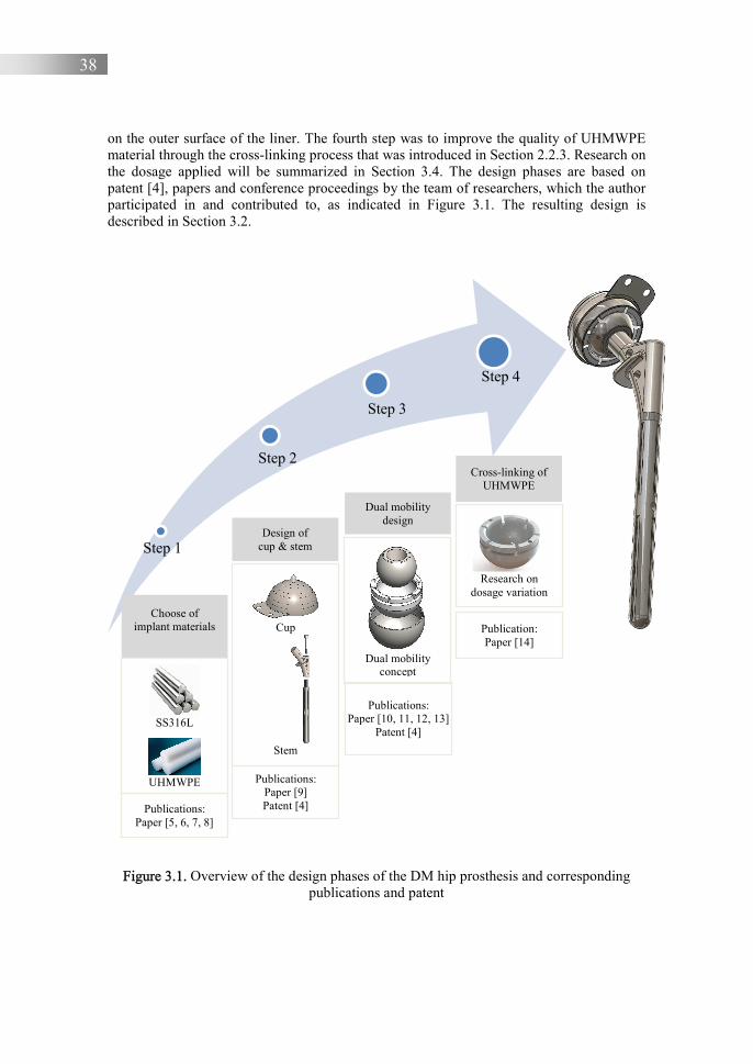
38
on the outer surface of the liner. The fourth step was to improve the quality of UHMWPE material through the cross-linking process that was introduced in Section 2.2.3. Research on the dosage applied will be summarized in Section 3.4. The design phases are based on patent [4], papers and conference proceedings by the team of researchers, which the author participated in and contributed to, as indicated in Figure 3.1. The resulting design is described in Section 3.2.
Figure 3.1. Overview of the design phases of the DM hip prosthesis and corresponding publications and patent
Step 1
Step 2
Step 3
Step 4
Publications: Paper [5, 6, 7, 8]
Publications: Paper [9] Patent [4]
Publications: Paper [10, 11, 12, 13]
Patent [4]
Publication: Paper [14]
Choose of implant materials
Design of cup & stem
Dual mobility design
Cross-linking of UHMWPE
SS316L
UHMWPE
Cup
Stem
Dual mobility
concept
Research on
dosage variation
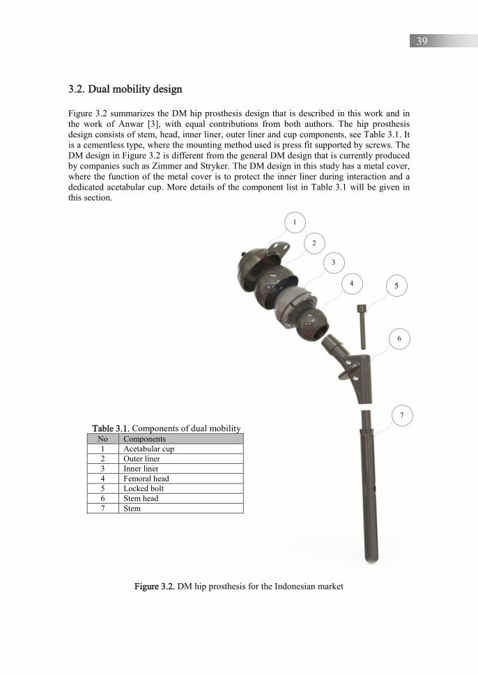
39
3.2. Dual mobility design
Figure 3.2 summarizes the DM hip prosthesis design that is described in this work and in the work of Anwar [3], with equal contributions from both authors. The hip prosthesis design consists of stem, head, inner liner, outer liner and cup components, see Table 3.1. It is a cementless type, where the mounting method used is press fit supported by screws. The DM design in Figure 3.2 is different from the general DM design that is currently produced by companies such as Zimmer and Stryker. The DM design in this study has a metal cover, where the function of the metal cover is to protect the inner liner during interaction and a dedicated acetabular cup. More details of the component list in Table 3.1 will be given in this section.
Figure 3.2. DM hip prosthesis for the Indonesian market
Table 3.1. Components of dual mobility No Components 1 Acetabular cup 2 Outer liner 3 Inner liner 4 Femoral head 5 Locked bolt 6 Stem head 7 Stem
1
2
3
4 5
6
7
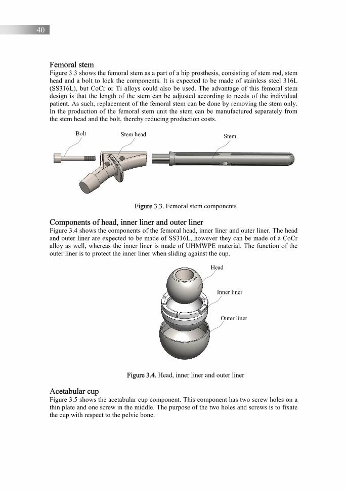
40
Femoral stem Figure 3.3 shows the femoral stem as a part of a hip prosthesis, consisting of stem rod, stem head and a bolt to lock the components. It is expected to be made of stainless steel 316L (SS316L), but CoCr or Ti alloys could also be used. The advantage of this femoral stem design is that the length of the stem can be adjusted according to needs of the individual patient. As such, replacement of the femoral stem can be done by removing the stem only. In the production of the femoral stem unit the stem can be manufactured separately from the stem head and the bolt, thereby reducing production costs.
Figure 3.3. Femoral stem components
Components of head, inner liner and outer liner Figure 3.4 shows the components of the femoral head, inner liner and outer liner. The head and outer liner are expected to be made of SS316L, however they can be made of a CoCr alloy as well, whereas the inner liner is made of UHMWPE material. The function of the outer liner is to protect the inner liner when sliding against the cup.
Figure 3.4. Head, inner liner and outer liner Acetabular cup Figure 3.5 shows the acetabular cup component. This component has two screw holes on a thin plate and one screw in the middle. The purpose of the two holes and screws is to fixate the cup with respect to the pelvic bone.
Bolt Stem head Stem
Head
Inner liner
Outer liner

41
Figure 3.5. Acetabular cup component
All component sizes can be varied within a certain range. The stem length can be varied according to the length of the femur, while the outer diameter of the cup can be varied according to the diameter of the acetabulum. The diameter of the outer liner can be adjusted according to the cup diameter change. The thickness of the cup and outer liner are fixed at 1.3 mm and 0.95 mm respectively. When the thickness of the inner liner is adjusted, the inner liner diameter changes accordingly. Possible variations in design sizes are in accordance with Table 3.2.
Table 3.2. Size variation of DM design
No Head size
[mm] Inner diameter of inner
liner [mm] Outer diameter of outer
liner [mm] Outer diameter of cup
[mm] 1 22 22.2 33.4 36 2 22 22.2 37.4 40 3 28 28.2 39.2 42 4 28 28.2 43.2 46 5 28 28.2 47.2 50 6 28 28.2 49.2 52 7 28 28.2 51.2 54 8 28 28.2 53.2 56
There are two movements in DM design, namely the movement of the head against the liner and liner against the cup. In theory, the two movements will not occur at the same time [15] as they are always independent of each other. The first movement occurs in the sliding contact of the head against the inner bearing; the outer bearing will then move only when the head has reached the range of motion available in the inner bearing [16]. The sliding velocities range from 0 to 60 mm/s [15], assuming a head diameter of 28 mm. Both of these movements experience sliding friction, but the exact levels are outside the scope of this work. The friction of the head (metal) sliding against the inner liner (engineering plastic) is, however, expected to be low [17]. In this study, the roughness of head and liner is set at Ra = 0.044 μm and Ra = 1.2 μm respectively, based on confocal microscopy measurements [18]. The effect of surface texture was not taken into account in this study.
The sliding contact between the head surface and inner liner surface will produce UHWPE wear debris. The wear rate of the liner is considered to be the most important aspect for this version of the DM design, given the relation to dislocation. In this research, a metal cover (outer liner) is selected to cover the PE liner, see Figure 3.6(a-b). The metal cover in this design aims to prevent PE wear on the convex surface of the PE liner. In general, a DM design has two sliding contact interactions: one between the metal head and the PE liner and one between the PE liner and the metal cup. Therefore, wear occurs on the concave
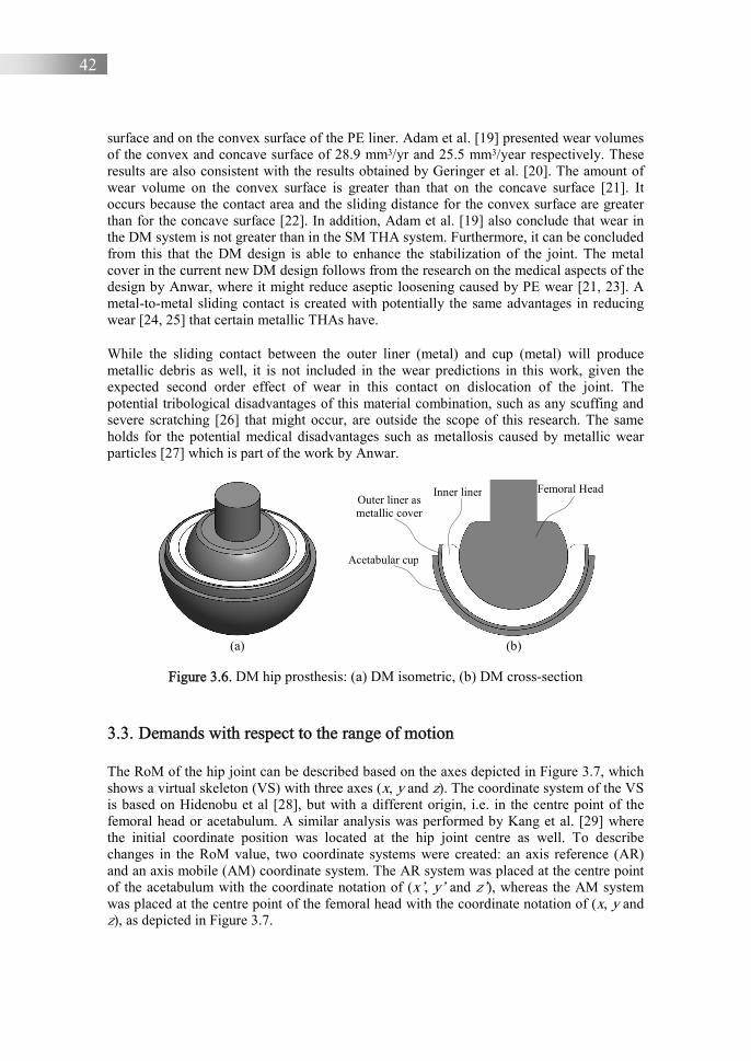
42
surface and on the convex surface of the PE liner. Adam et al. [19] presented wear volumes of the convex and concave surface of 28.9 mm3/yr and 25.5 mm3/year respectively. These results are also consistent with the results obtained by Geringer et al. [20]. The amount of wear volume on the convex surface is greater than that on the concave surface [21]. It occurs because the contact area and the sliding distance for the convex surface are greater than for the concave surface [22]. In addition, Adam et al. [19] also conclude that wear in the DM system is not greater than in the SM THA system. Furthermore, it can be concluded from this that the DM design is able to enhance the stabilization of the joint. The metal cover in the current new DM design follows from the research on the medical aspects of the design by Anwar, where it might reduce aseptic loosening caused by PE wear [21, 23]. A metal-to-metal sliding contact is created with potentially the same advantages in reducing wear [24, 25] that certain metallic THAs have.
While the sliding contact between the outer liner (metal) and cup (metal) will produce metallic debris as well, it is not included in the wear predictions in this work, given the expected second order effect of wear in this contact on dislocation of the joint. The potential tribological disadvantages of this material combination, such as any scuffing and severe scratching [26] that might occur, are outside the scope of this research. The same holds for the potential medical disadvantages such as metallosis caused by metallic wear particles [27] which is part of the work by Anwar.
(a) (b)
Figure 3.6. DM hip prosthesis: (a) DM isometric, (b) DM cross-section
3.3. Demands with respect to the range of motion
The RoM of the hip joint can be described based on the axes depicted in Figure 3.7, which shows a virtual skeleton (VS) with three axes (x, y and z). The coordinate system of the VS is based on Hidenobu et al [28], but with a different origin, i.e. in the centre point of the femoral head or acetabulum. A similar analysis was performed by Kang et al. [29] where the initial coordinate position was located at the hip joint centre as well. To describe changes in the RoM value, two coordinate systems were created: an axis reference (AR) and an axis mobile (AM) coordinate system. The AR system was placed at the centre point of the acetabulum with the coordinate notation of (x’, y’ and z’), whereas the AM system was placed at the centre point of the femoral head with the coordinate notation of (x, y and z), as depicted in Figure 3.7.
Inner liner
Acetabular cup
Outer liner as metallic cover
Femoral Head
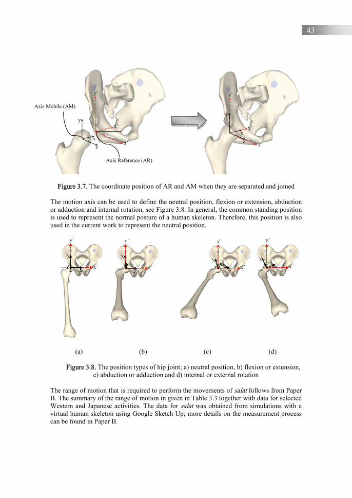
43
Figure 3.7. The coordinate position of AR and AM when they are separated and joined
The motion axis can be used to define the neutral position, flexion or extension, abduction or adduction and internal rotation, see Figure 3.8. In general, the common standing position is used to represent the normal posture of a human skeleton. Therefore, this position is also used in the current work to represent the neutral position.
(a) (b) (c) (d)
Figure 3.8. The position types of hip joint; a) neutral position, b) flexion or extension, c) abduction or adduction and d) internal or external rotation
The range of motion that is required to perform the movements of salat follows from Paper B. The summary of the range of motion in given in Table 3.3 together with data for selected Western and Japanese activities. The data for salat was obtained from simulations with a virtual human skeleton using Google Sketch Up; more details on the measurement process can be found in Paper B.
Axis Mobile (AM)
Axis Reference (AR)
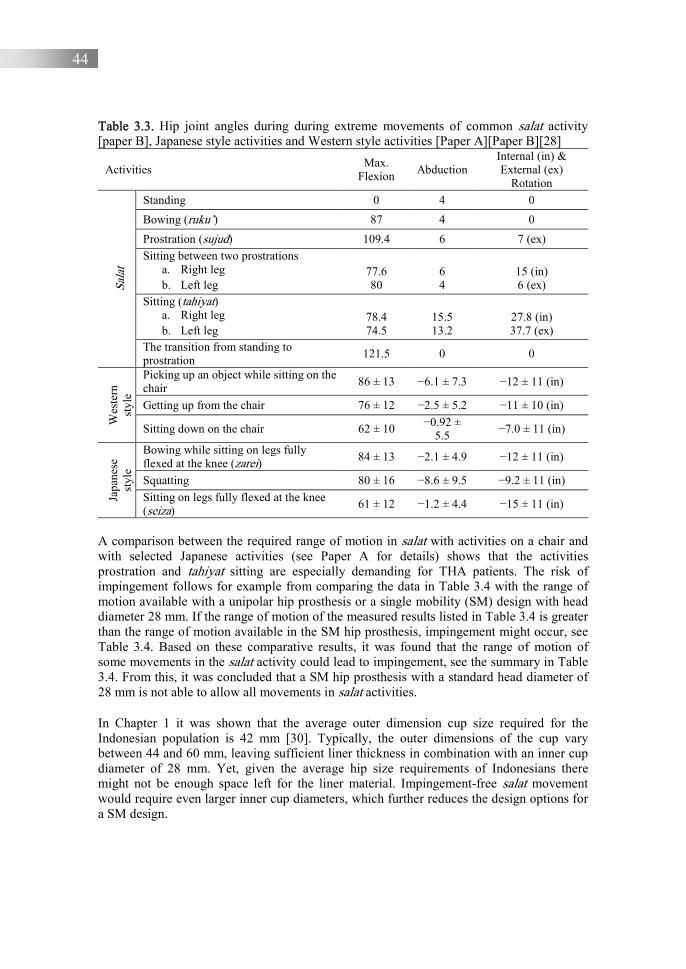
44
Table 3.3. Hip joint angles during during extreme movements of common salat activity [paper B], Japanese style activities and Western style activities [Paper A][Paper B][28]
Activities Max.
Flexion Abduction Internal (in) & External (ex)
Rotation
Sala
t
Standing 0 4 0
Bowing (ruku’) 87 4 0
Prostration (sujud) 109.4 6 7 (ex) Sitting between two prostrations
a. Right leg b. Left leg
77.6 80
6 4
15 (in) 6 (ex)
Sitting (tahiyat) a. Right leg b. Left leg
78.4 74.5
15.5 13.2
27.8 (in) 37.7 (ex)
The transition from standing to prostration
121.5 0 0
Wes
tern
st
yle
Picking up an object while sitting on the chair
86 ± 13 −6.1 ± 7.3 −12 ± 11 (in)
Getting up from the chair 76 ± 12 −2.5 ± 5.2 −11 ± 10 (in)
Sitting down on the chair 62 ± 10 −0.92 ± 5.5
−7.0 ± 11 (in)
Japa
nese
st
yle
Bowing while sitting on legs fully flexed at the knee (zarei) 84 ± 13 −2.1 ± 4.9 −12 ± 11 (in)
Squatting 80 ± 16 −8.6 ± 9.5 −9.2 ± 11 (in)
Sitting on legs fully flexed at the knee (seiza)
61 ± 12 −1.2 ± 4.4 −15 ± 11 (in)
A comparison between the required range of motion in salat with activities on a chair and with selected Japanese activities (see Paper A for details) shows that the activities prostration and tahiyat sitting are especially demanding for THA patients. The risk of impingement follows for example from comparing the data in Table 3.4 with the range of motion available with a unipolar hip prosthesis or a single mobility (SM) design with head diameter 28 mm. If the range of motion of the measured results listed in Table 3.4 is greater than the range of motion available in the SM hip prosthesis, impingement might occur, see Table 3.4. Based on these comparative results, it was found that the range of motion of some movements in the salat activity could lead to impingement, see the summary in Table 3.4. From this, it was concluded that a SM hip prosthesis with a standard head diameter of 28 mm is not able to allow all movements in salat activities.
In Chapter 1 it was shown that the average outer dimension cup size required for the Indonesian population is 42 mm [30]. Typically, the outer dimensions of the cup vary between 44 and 60 mm, leaving sufficient liner thickness in combination with an inner cup diameter of 28 mm. Yet, given the average hip size requirements of Indonesians there might not be enough space left for the liner material. Impingement-free salat movement would require even larger inner cup diameters, which further reduces the design options for a SM design.

45
Table 3.4. Summary of the occurring impingement in salat activities, see [paper B] Salat activities Impingement Note Standing x - Bowing (ruku’) x -
Prostration (sujud) √ Impingement in flexion (HR and 28 mm THA)
Sitting between two prostrations a. Right leg b. Left leg
x x
- -
Sitting (tahiyat) c. Right leg d. Left leg
x √
- Impingement in external rotation (HR, 28 mm THA and LDH-THA)
The transition from standing to prostration
√ Impingement in flexion (HR and 28 mm THA)
Note: HR= hip resurfacing; LDH-THA= large diameter head-total hip arthroplasty To further clarify, Figure 3.9(a-b) shows the femoral head of the hip and the femoral head of a hip prosthesis in more detail. Figure 3.9(a) depicts the size of the femoral head of the hip, while Figure 3.9(b) shows the femoral head (ball) of the hip prosthesis. Figure 3.9(a-b) shows that the diameter of the femoral head of the hip is equal to the cup diameter of the hip prosthesis, represented by diameter A, while the femoral head (ball) of the hip prosthesis has a diameter smaller than diameter A, represented by diameter B.
(a) (b)
Figure 3.9. (a) femoral head of hip bone, (b) femoral head of hip prosthesis [31]. Diameters A and B relate to thefemoral head of the hip bone
and the femoral head of the hip prosthesis respectively 3.4. Materials selection
The material used to make components of the acetabular cup, outer liner, femoral head, stem head and stem rod is stainless steel 316L (SS316L). This material is widely used for implant components and is considered a biocompatibility material [32]. This material is obtained from the domestic market in Indonesia; the composition is given in Table 3.5. Selected material properties such as Young’s modulus, Poisson’s ratio, and yield stress of SS316L are presented in Table 3.6. An UHMWPE material is used for the inner liner
Diameter A
Diameter B

46
component. This material was obtained from the Indonesian domestic market in the form of solid cylinders. Selected material properties are given in Table 3.6. Table 3.5. Composition of AISI 316L [33]
Composition wt.% Composition wt.% Fe 65.2 Al 0.0383 C 0.0136 Co 0.420 Si 0.421 Cu 0.645
Mn 1.90 Nb 0.312 P <0.0050 Ti 0.0775 S 0.0210 V 0.0910 Cr 14.5 W 0.0324 Mo 1.01 Pb 0.0983 Ni 14.7 - -
Table 3.6. Material Properties of SS316L and UHMWPE
Mechanical properties SS316L [34] UHMWPE [35] Young’s modulus, E (MPa) 200000 850-945 Poisson’s ratio, v (-) 0.3 0.4 Yield stress, σ (MPa) 205 20-23
To create the expected increase in wear resistance of the liner, a cross-linking process is adopted in this research. The cross-linking process was conducted at the Center for isotopes and Radiation application in BBPT-Serpong, Indonesia, which is part of the National Nuclear Energy Agency. Dosage variation was conducted with a dose of 50 kGy and a dose of 100 kGy. In this study, the effect of UHMWPE cross-linking on changes in surface roughness, hardness and colour was not conducted but was based on the literature. It should be noticed that UHMWPE cross-linking might decrease mechanical properties such as the toughness, modulus, ultimate tensile strength, yield strength and hardness of the polymer [36].
3.5. Dual mobility design solution for the RoM
The proposed DM design has two axes of rotation. With the same femoral head diameter, it can be seen from Figure 3.10 that a DM hip prosthesis design has a wider RoM than the SM hip prosthesis design, as ½α1 > ½α2. The dashed line shows the interaction contact between head and liner and between outer liner and cup.
Further, to assess the impingement preventing ability of this design, an impingement simulation was conducted. The geometry of the DM model was created using computer aided design (CAD) software. The diameter of the head, the neck stem and the inset of the liner are 28 mm, 14 mm and 2 mm respectively. The head diameter is fixed at 28 mm and the thickness of the liner is 7 mm, so the cup diameter can then be varied to meet the acetabulum diameter requirements. The gap between the femoral head and the acetabular liner cup is 24 µm.
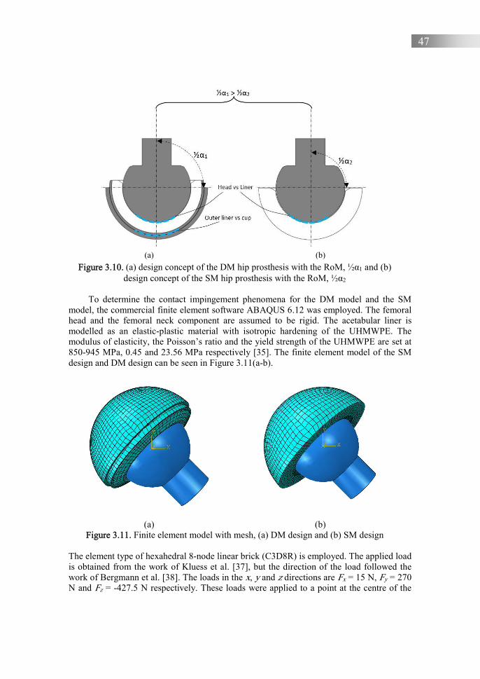
47
(a) (b)
Figure 3.10. (a) design concept of the DM hip prosthesis with the RoM, ½α1 and (b) design concept of the SM hip prosthesis with the RoM, ½α2
To determine the contact impingement phenomena for the DM model and the SM
model, the commercial finite element software ABAQUS 6.12 was employed. The femoral head and the femoral neck component are assumed to be rigid. The acetabular liner is modelled as an elastic-plastic material with isotropic hardening of the UHMWPE. The modulus of elasticity, the Poisson’s ratio and the yield strength of the UHMWPE are set at 850-945 MPa, 0.45 and 23.56 MPa respectively [35]. The finite element model of the SM design and DM design can be seen in Figure 3.11(a-b).
(a) (b) Figure 3.11. Finite element model with mesh, (a) DM design and (b) SM design
The element type of hexahedral 8-node linear brick (C3D8R) is employed. The applied load is obtained from the work of Kluess et al. [37], but the direction of the load followed the work of Bergmann et al. [38]. The loads in the x, y and z directions are Fx = 15 N, Fy = 270 N and Fz = -427.5 N respectively. These loads were applied to a point at the centre of the
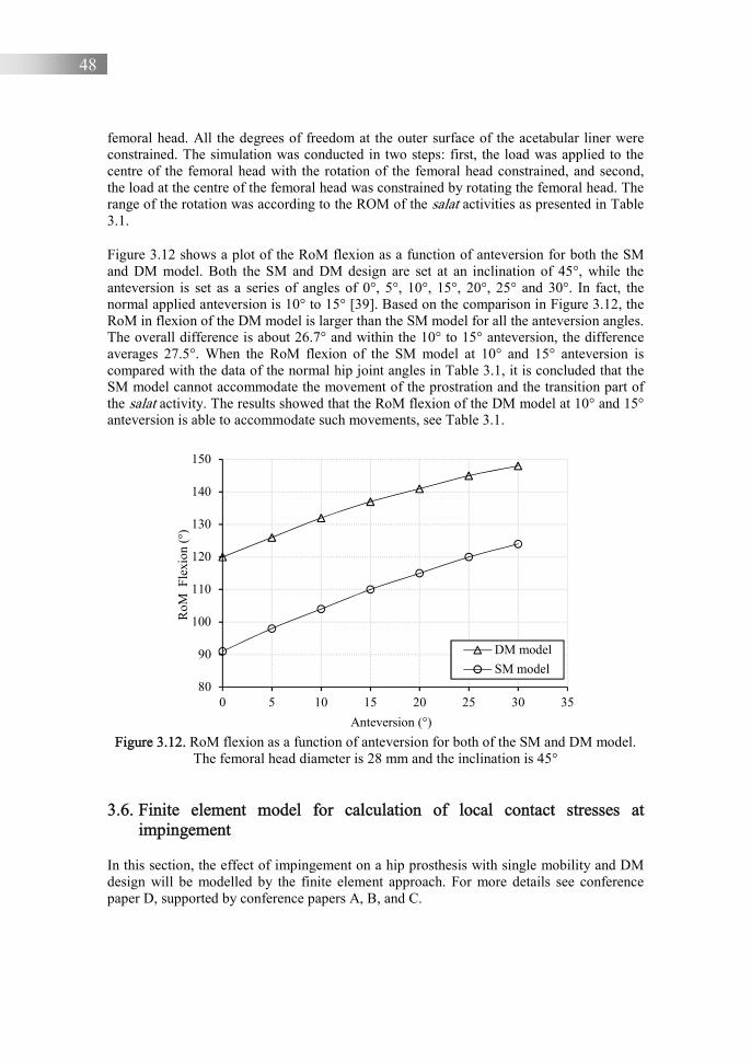
48
femoral head. All the degrees of freedom at the outer surface of the acetabular liner were constrained. The simulation was conducted in two steps: first, the load was applied to the centre of the femoral head with the rotation of the femoral head constrained, and second, the load at the centre of the femoral head was constrained by rotating the femoral head. The range of the rotation was according to the ROM of the salat activities as presented in Table 3.1.
Figure 3.12 shows a plot of the RoM flexion as a function of anteversion for both the SM and DM model. Both the SM and DM design are set at an inclination of 45°, while the anteversion is set as a series of angles of 0°, 5°, 10°, 15°, 20°, 25° and 30°. In fact, the normal applied anteversion is 10° to 15° [39]. Based on the comparison in Figure 3.12, the RoM in flexion of the DM model is larger than the SM model for all the anteversion angles. The overall difference is about 26.7° and within the 10° to 15° anteversion, the difference averages 27.5°. When the RoM flexion of the SM model at 10° and 15° anteversion is compared with the data of the normal hip joint angles in Table 3.1, it is concluded that the SM model cannot accommodate the movement of the prostration and the transition part of the salat activity. The results showed that the RoM flexion of the DM model at 10° and 15° anteversion is able to accommodate such movements, see Table 3.1.
Figure 3.12. RoM flexion as a function of anteversion for both of the SM and DM model.
The femoral head diameter is 28 mm and the inclination is 45° 3.6. Finite element model for calculation of local contact stresses at
impingement
In this section, the effect of impingement on a hip prosthesis with single mobility and DM design will be modelled by the finite element approach. For more details see conference paper D, supported by conference papers A, B, and C.
80
90
100
110
120
130
140
150
0 5 10 15 20 25 30 35
RoM
Fle
xion
(°)
Anteversion (°)
DM model
SM model

49
ABAQUS 6.12, a commercial finite element code, was employed in this work to model the stresses and strains that occur for a DM hip prosthesis as a function of the selected design parameters. The results are compared with a SM design also modelled in Abaqus. The femoral head and the femoral neck component are assumed to be rigid. The acetabular liner is modelled as an elastic-plastic material with isotropic hardening of the UHMWPE. The modulus of elasticity, the Poisson’s ratio and the yield strength of the UHMWPE are adopted from [35]. The element type used in the acetabular liner is an 8-node linear brick, reduced integration, as well as hourglass control (C3D8R), where the elements are around 6500 in number. This element type is recommended for modellingcontinuum solids. The continuum elements can be used for linear analysis and complex non-linear analyses involving contact, plasticity and large deformations. This also usually provides a solution of equivalent accuracy at less cost [40].
(a) (b)
(c) (d)
Figure 3.13. The 3D model of femoral head against acetabular liner including the applied load, constrained, mesh and rotation direction (a) SM design in isometric view, (b) SM design in front view, (c) DM design in isometric view and (d) DM design in front view
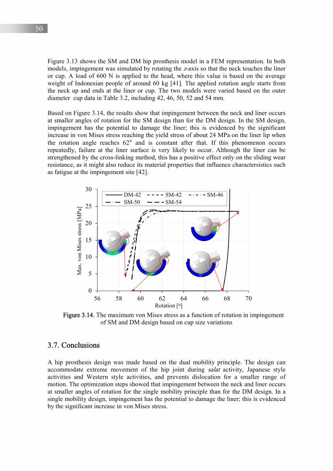
50
Figure 3.13 shows the SM and DM hip prosthesis model in a FEM representation. In both models, impingement was simulated by rotating the z-axis so that the neck touches the liner or cup. A load of 600 N is applied to the head, where this value is based on the average weight of Indonesian people of around 60 kg [41]. The applied rotation angle starts from the neck up and ends at the liner or cup. The two models were varied based on the outer diameter cup data in Table 3.2, including 42, 46, 50, 52 and 54 mm.
Based on Figure 3.14, the results show that impingement between the neck and liner occurs at smaller angles of rotation for the SM design than for the DM design. In the SM design, impingement has the potential to damage the liner; this is evidenced by the significant increase in von Mises stress reaching the yield stress of about 24 MPa on the liner lip when the rotation angle reaches 62° and is constant after that. If this phenomenon occurs repeatedly, failure at the liner surface is very likely to occur. Although the liner can be strengthened by the cross-linking method, this has a positive effect only on the sliding wear resistance, as it might also reduce its material properties that influence charactersistics such as fatigue at the impingement site [42].
Figure 3.14. The maximum von Mises stress as a function of rotation in impingement
of SM and DM design based on cup size variations
3.7. Conclusions
A hip prosthesis design was made based on the dual mobility principle. The design can accommodate extreme movement of the hip joint during salat activity, Japanese style activities and Western style activities, and prevents dislocation for a smaller range of motion. The optimization steps showed that impingement between the neck and liner occurs at smaller angles of rotation for the single mobility principle than for the DM design. In a single mobility design, impingement has the potential to damage the liner; this is evidenced by the significant increase in von Mises stress.
0
5
10
15
20
25
30
56 58 60 62 64 66 68 70
Max
. von
Mis
esst
ress
[MP
a]
Rotation [ᵒ]
DM-42 SM-42 SM-46SM-50 SM-54
51
The DM prosthesis was designed based on (cross-linked) UHMWPE material and SS316L, which are easily obtained on the domestic Indonesian market, and which have passed biocompatibility tests.
References
1. Pulido, L., Restrepo, C., Parvizi, J., 2007, “Late instability following total hip arthroplasty”, Clinical Medical & Research, 5(2), pp. 139-142.
2. Anwar, I.B., 2019, “The effect of head inset due to wear on the liner surface to range of motion”, Personal communication.
3. Anwar, I.B., Design and implementation of a large range-of-motion hip prosthesis for the Indonesian people (working title)”, Dissertation to be defended at the University of Twente, in progress.
4. Ismail, R., Jamari, J., Saputra, E., Anwar, I.B., 2019, “Sendi panggul buatan bipolar untuk memudahkan gerakan salat pasien (Bipolar artificial hip joint to patient Performing Salat)”, Patent ID: S00201703018.
5. Anwar, I.B., Santoso, A., Saputra, E., Ismail, R., Jamari, J., van der Heide, E., 2017, “Human bone marrow-derived mesenchymal cell reactions to 316L stainless steel: An in vitro study on cell viability and interleukin-6 expression”, Advanced Pharmaceutical Bulletin, 7(2), pp. 335-338.
6. Anwar, I.B., Saputra, E., Jamari, J., van der Heide, E., 2015, “Preliminary study on the biocompatibility of stainless steel 316L and UHMWPE material”, Advanced Materials Research, 1123, pp. 160-163.
7. Anwar, I.B., Santoso, A., Saputra, E., Ismail, R., Jamari, J., van der Heide, E., 2018, “Initial response of human bone marrow–derived stem cells after contact with ultrahigh-molecular-weight polyethylene (uhmwpe) material: an in vitro study on cell viability and interleukin-6 expression”, Journal of Pharmacy & Bioallied Sciences, 10 (1), pp. 43-47.
8. Anwar, I.B., Saputra, E., Ismail, R, Jamari, J., van der Heide, E., 2015, “Study on the biocompatibility and wear of stainless steel 316L and UHMWPE materials”, Proceedings of Malaysian International Tribology Conference, pp. 56-57
9. Anwar, I.B., Saputra, E., Ismail, R, Jamari, J., van der Heide, E., 2016, “Fixation strength analysis of cup to bone material using finite element simulation”, AIP conference proceedings, 1725 (1), 020006.
10. Saputra, E., Anwar, I.B., Jamari, J., van der Heide, E., 2015, “A bipolar artificial hip joint design for contact impingement reduction”, Advanced Materials Research, 1123, pp. 164-168.
11. Saputra, E., Anwar, I.B., Ismail, R., Jamari, J., van der Heide, E., 2017, “Study of unipolar and bipolar hip prostheses using finite element simulation: contact stress analysis”, Key Engineering Materials, 739, pp. 96-102.

52
12. Saputra, E, Anwar, I.B., Ismail, R, Jamari, J, van der Heide, E., 2016, “Finite element study of contact pressure distribution on inner and outer liner in the bipolar hip prosthesis”, AIP conference proceedings, 1725 (1), 020075.
13. Jamari, J., Saputra, E, Anwar, I.B., Ismail, R., van der Heide, E., 2017, “Finite element study of the effect of UHMWPE liner thickness on the contact area and stress distribution in a bipolar hip joint”, IOP conference series: materials science and engineering. 202 (1), 012095.
14. Al Hakim, R.A.N., Arrohman, S., Saputra, E., Anwar, I.B., Jamari, J., Ismail, R., 2018, “The contact simulation comparison of uhmwpe to the crosslink intensity effect”, E3S web of conferences, 73, 12014.
15. Fisher, J., Dowson, D., Hamdzah, H., et al., 1994, “The effect of sliding velocity on the friction and wear of UHMWPE for use in total artificial joints”, Wear, 175(1-2), pp. 219-225.
16. Ko, L.M., Hozack, W.J., 2016, “The dual mobility cup: what problems does it solve?”, The Bone & Joint Journal, 98-B(1 Suppl A), pp. 60-63.
17. JIS, AISI Standard Grade 316L bright surface stainless steel round rod, accessed 29 January 2020, <https://www.alibaba.com>.
18. Saputra, E., Khafidh, M., Anwar, I.B., Ismail, R., Jamari, J., 2016, “The measurement of liner and head surface under confocal microscopy”, Internal document.
19. Adam, P., Farizon, F., Fessy, M.-H., 2014, “Dual mobility retentive acetabular liners and wear: Surface analysis of 40 retrieved polyethylene implants”, Orthopaedics & Traumatology: surgery & research, 100, pp. 85-91.
20. Geringer, J., Boyer, B., Farizon F., 2011, “Understanding the dual mobility concept for total hip arthroplasty. Investigations on a multiscale analysis-highlighting the role of arthrofibrosis”, Wear, 271, pp. 2379-2385.
21. Horriat, S., Haddad, F.S., 2018, “Dual mobility in hip arthroplasty: what evidence do we need?”, Bone & Joint Research, 7, pp. 508-510.
22. Gao, Y., Chai, W., Wang, L., Wang, M., Jin, Z., 2015, “Effect of friction and clearance on kinematics and contact mechanics of dual mobility hip implant”, Proceedings of the Institution of Mechanical Engineers Part H: J engineering in medicine, 230(1), pp. 39-49.
23. Howard, J.L., Kremers, H.M., Loechler, Y.A., et al., 2011, “Comparative survival of uncemented acetabular components following primary total hip arthroplasty”, The Journal of Bone and Joint Surgery. American volume, 93, pp. 1597-1604.
24. Dowson, D., Hardaker, C., Flett, M., Isaac, G., 2004, “A hip joint simulator study of the performance of metal-on-metal joints: part II: design”, The Journal of Arthroplasty, 19, pp. 124-130.
25. Schmalzried, T.P., Peters, Z., Maurer, B., Bragdon, C., Harris, W., 1996, “Long duration metal-on-metal total hip replacement with low wear of the articulating surfaces”, The Journal of Arthroplasty, 11, pp. 322-331.
53
26. Burbano, M., Russell, R., Huo, M., et al., 2014, Surface characterization of retrieved metal-on-metal total hip implants from patients with adverse reaction to metal debris, Materials, 7, pp. 1866-1879.
27. Oliveira, C.A., Candelaria, I.S., Oliveira, P.B., et al., 2015, Metallosis: A diagnosis not only in patients with metal-on-metal prostheses, European Journal of Radiology Open, 2, pp. 3-6.
28. Sugano, N., Tsuda, K., Miki, H., Takao, M., Suzuki, N., Nakamuro, N., 2012, “Dynamic Measurements of Hip Movement in Deep Bending Activities After Total Hip Arthroplasty Using a 4-Dimensional Motion Analysis System”, The Journal of Arthroplasty, 27(8), pp. 1562-1568.
29. Kang, M.J., Sadri, H., Moccozet, L., Magnenat-Thalmann, N., Hoffmeyer, P., 2002, “Accurate simulation of hip joint range of motion”, Proceedings of Computer Animation 2002 (CA 2002), Geneva, 215e219.
30. Ginting, I., “Metode praktis dan sederhana dalam menentukan Besar magnifikasi Rontgen preoperative pada hip hemiarthroplasty di RS Orthopedic Prof. Dr. R soeharso Surakarta (A practical and simple method in determining the magnification of preoperative X-rays in hip hemiarthroplasty at Prof. Orthopedic Hospital. Dr. R. Soeharso Surakarta)”, Thesis, UNS-Pascasarjana Prodi, Dokter Spesialis I Ortopedi & Traumatology-S93009004-2014.
31. Hip joint replacement, accessed 16 May 2021, < https://www.trihealth.com/institutes-and-services/trihealth-orthopedic-and-sports-institute/services/joint-replacement-surgery/hip-joint-replacement>.
32. Anwar, I.B., Saputra, E., Jamari, J., van der Heide, E., 2015, “Preliminary study on the biocompatibility of stainless steel 316L and UHMWPE material”, Advanced Materials Research, 1123, pp. 160-163.
33. Saputra, E., Anwar, I.B., Ismail. R., Jamari, J., 2015, “Tensile testing of SS316L from domestic market”, Internal document.
34. Yildiz, F., Yetim, A.F., Alsaran, A., Celik, A., Kaymaz, I., 2011, “Fretting fatigue properties of plasma nitrided AISI 316L stainless steel: Experiments and finite element analysis”, Tribology International, 44, pp.1979-1986.
35. Eichmiller, F.C., Tesk, J.A., Croarkin, C.M., 2001, “Mechanical properties of ultra-high molecular weight polyethylene NIST Reference Material RM 8456”, in TransactionS of the Society for Biomaterials. 27th Annual Meeting, 22(6), pp. 472.
36. Muratoglu, O.K., Bragdon, C.R., O’Connor, D.O., et al., 1999, “Unified wear model for highly crosslinked ultra-high molecular weight polyethylenes (UHMWPE)”, Biomaterials, 20(16), pp. 1463-1470.
37. Kluess, D., Martin, H., Mittelmeier, W., Schmitz, K.P., Bader, R., 2007, “Influence of femoral head size on impingement, dislocation and stress distribution in total hip replacement”, Medical Engineering & Physics, 29, pp. 465-471.
38. Bergmann, G., Graichen, F., Rohlmann, A., 1993, “Hip joint loading during walking and running, measured in two patients”, The Journal of Biomechanics, 26, pp. 969-990.

54
39. Barrack, R.L., 2003, “Dislocation after total hip arthroplasty: implant design and orientation”, Journal of the American Academy of Orthopaedic Surgeons, 11, pp. 89-99.
40. ABAQUS (2012), ABAQUS Documentation, Dassault Systèmes, Providence, RI, USA.
41. Average sizes of men and women, accessed 19 September 2021, <https://www.worlddata.info/average-bodyheight.php>.
42. Kurtz, S.M., Villarraga, M.L., Herr, M.P., 2002, “Thermomechanical behavior of virgin and highly cross-linked ultra-high molecular weight polyethylene used in total joint replacements”, Biomaterials, 23, pp. 3681-3697.

55
Chapter 4
Modelling impingement in relation to liner wear 4.1. Introduction
This section presents a model to predict wear and damage to the lip of liners due to impingement. The prediction of wear of the liner of the SM prosthesis system is also presented in paper C. The prediction of liner wear in the dual mobility model is carried out using finite element simulations, partially based on conference papers D, F and H. Simulation of the contact stress is performed by using a finite element approach as well. The damage to the liner lip is derived from an impingement simulation, which is presented in conference papers B and C. Subsequently, the impingement simulation is extended by including wear on the inner surface of the liner to determine the effect of wear on the liner on impingement; this section refers to paper D.
4.2. Liner wear prediction for a single mobility system
4.2.1. Linear and volumetric wear equation Wear of the liner of a SM system is modelled in this thesis based on the following three assumptions 1) wear is due to sliding wear only, 2) sliding wear varies linearly with the sliding distance and normal force and 3) a specific wear rate can be constructed similar to Archard’s wear model [1]. The applied normal force F and the sliding distance of one cycle L are the main variables in this approach, see Eq. (2.3). The sliding length of a cycle depends on the specific dimensions of the prosthesis, as well as on the activity. Furthermore, the length characteristics can be derived from published test sequences with experimental facilities at other laboratories. An overview is given in Table 4.1.
Table 4.1. The summary of the sliding distance for hip simulators and gait, adapted from [2] Cases L [mm] HUT-3 [3] 1.71rs HUT-BRM [4] 2.46rs MMED-BRM [5] 2.46rs MTS-BRM [6] 2.46rs AMTI [7] 1.75rs Munich [8, 9] 1.67rs Leeds Mk I [10] 1.41rs ISO/DIS 14242-1 [11] 1.58rs Durham Mk II [12] 1.59rs Leeds Mk II [13] 1.57rs Pro-Sim [14] 1.65rs Walking gait cycle [15, 16] 1.65rs Note: rs is the radius of the spherical articulating surface in mm

56
Table 4.1 shows the value of the sliding distance per cycle in a wide range of hip simulators and for a walking gait cycle. Based on Table 4.1, it can be concluded that the sliding distance used for the ProSim hip simulator equals the estimated sliding distance of a walking gait cycle. As such, the results can be used to validate concepts in relation to the walking gait cycle.
The basis of the presented wear model is the contact area when the femoral head removes a wear height ℎ� from the liner by sliding, such as shown in Figure 4.1 (a-b). When the femoral head penetrates into the cup, a head height ℎ� is obtained. In addition, this penetration forms the contact radius �, where � = �� (contact radius of cup) = �� (contact radius of head).
ℎ� = ℎ� 4 ℎ� (4.1)
(a) (b)
�� �� r ℎ� ℎ� ℎ� d
= Radius of the cup = Radius of the head = Radius of the contact = Height of the cup = Height of penetration = Height of the head = Gap between the centre point of the cup and the centre point of the head
Figure 4.1. The femoral head – liner contact geometry used to calculate (a) linear wear and (b) volumetric wear
The variables �� and �� follow from a geometrical analysis in which ��& = 2��ℎ� − ℎ�& or ��& = 2��ℎ�, for ℎ�& << �� (4.2) and

57
��& = 2��ℎ� − ℎ�& or ��& = 2��ℎ�, for ℎ�& << �� (4.3) Substitute the expression ℎ� 4 ℎ� from Eq. (4.1) in the Eq. (4.3), this reads: ��& = 2��ℎ� 4 2��ℎ� (4.4) Combining Eqs. (4.2) and (4.4) to result ℎ�,
ℎ� = 56�758-56 (4.5a)
then substitute the Eq. (4.5a) to Eq. (4.1) to get ℎ�,
ℎ� = 58�758-56 (4.5b)
While van Beek [17] describes the half-contact area between two conforming surfaces,
ℎ� ≈ :6;&56 − :8;
&58 = :;& < %
56 − %58= = :;
& < %5∗= = :;
&5∗ or �& = 2�∗ℎ� (4.6)
where �∗ in Eq. (4.6) is the effective contact radius, �∗ = 565858-56
By dividing both the left-hand side and the right-hand side of Eq. (2.3) by the new nominal area of contact, one can derive the following relation for linear wear ℎ, �6� = ��� (4.7)
The differential form of Eq. (4.7) is given by ?�6?� = ��� (4.8)
where � is contact pressure or stress in N/mm2, therefore ℎ� is function of contact radius �,
� = 1@:; (4.9)
In order to simplify the calculation, the applied force “” is assumed constant as a function of time. The applied force is obtained from the peak force of 3000 N that occurs in the walking gait phase, where the ratio of peak force to body weight is about 4:1 [16, 18]. This value is also used as a standard for loading test in wear-testing machines according to ISO 14242-1 [19]. The application of a peak force to the hip prosthesis makes it possible to test the ultimate wear ability of the liner. In addition, the application of the average force can be selected to test the average wear resistance of the liner to a normal load.
Substitute the expression 1
@:; and 2�∗ℎ� from Eq. (4.9) and Eq. (4.6) respectively in for �
and �& in the Eq. (4.8), so that

58
?�6?� = ��
1@A& B6B8B8CB6�6D (4.10)
Integrating ℎ� with respect to �, thus:
E ℎ��ℎ� = ��1
&@ B6B8B8CB6E �� (4.11)
Multiplying by the amount of cycles � �6;& = ��
1F58-56G&@5658 �� (4.12)
Substitute the expression 58�7
58-56 from Eq. (4.5b) in for ℎ�& in the Eq. (4.12) and using the
sliding distance of walking gait cycle expression from Table 4.1, gives for ℎ�:
ℎ� = HIJ1F58-56GK%.MN56O@58K56 (4.13)
To make a clear differentiation between design parameter and operational condition, Eq. (4.13) is modified,
ℎ� = HAIJF58-56GK%.MN56@58K56 D F�G (4.14)
where Eq. (4.14) reflecting the design parameters ��, ��, �� and reflecting the operational conditions and �. To determine volumetric wear, the present linear wear model is further developed. Figure 4.1(b) does not show directly the volumetric wear. However, the volume can be formed by revolving the half area of cross-section wear that refers to the axis cup. In other words, the volume can be created by multiplying the area and height (linear wear). Based on Figure 4.1(b),
� = F�� − ��G 4 ℎ� (4.15) Using Pythagoras’ theorem, the following can be derived
P& 4 �& = ��& → �& = ��& − P& (4.16) FP − �G& 4 �& = ��& (4.17)
Substitute the expression ��& − P&from Eq. (4.16) in for �&in the Eq. (4.17)
FP − �G& 4 F��& − P&G = ��&
P& − 2P� 4 �& 4 ��& − P& = ��&

59
P = ?;-56; R58;&? (4.18)
If ℎ� = �� − P , then,
ℎ� = �� − <?;-56; R58;&? =
ℎ� = &?58-?;R56; -58;&? (4.19)
Substitute the Eq. (4.19) in for ℎ�in the Eq. (4.1), the equation of ℎ� is obtained,
ℎ� = &?58-?;R56; -58;&? 4 ℎ� (4.20)
Based on the volume of the spherical cap, if �� and �� are the volumetric wear of head and cup, the volumetric wear of penetration �� is an intersection of �� and ��.
�� = %S Tℎ�& F3�� − ℎ�G (4.21)
�� = %S Tℎ�&F3�� − ℎ�G (4.22)
�� = �� − �� (4.23) Based on Eq. (4.21) and Eq. (4.22), the volumetric wear �� can be calculated:
�� = A%S Tℎ�& F3�� − ℎ�GD − A%
S Tℎ�&F3�� − ℎ�GD (4.24)
Eq. (4.24) converts linear wear to volumetric wear. The principal aim of Eq. (4.23) is to calculate the wear volume based on the wear depth obtained from Eq. (4.13). The wear volume is obtained from the volume formed by ℎ� subtract by the volume created by ℎ� , see Figure 4.1(b) and Eq. (4.23) and Eq. (4.24) respectively. Further, Eq. (4.23) is reduced by Eq. (4.22) based on Eq. (4.23), so that the volumetric wear is described by Eq. (4.24).
Dowson et al. [18] present both volumetric wear and linear wear data from tests on a Charnley hip prosthesis, in which an alumina femoral head was slided reciprocating on the UHMWPE liner. Figure 4.2 shows a plot of the penetration (or linear wear) of their femoral heads number 1 and 2 into the liner, i.e. the extent of wear as a function of the number of loading cycles related to height. In addition, Figure 4.2 shows a wide range of plots of Dowson [18], Kauzlarich-Williams [20] and the wear model that is developed in this thesis. The dashed line curve is a plot of Eq. (4.12) for the walking case with �� equal to 4.49×10-
7 mm3/Nm. In Figure 4.2, the result of the present wear model is plotted as well showing good agreement with the experimental work of reference [18]. The average deviation of wear between the present model and the Kauzlarich-Williams model is about 2%. The current wear model formulation is more suited for design optimization than the Kauzlarich-Williams formulation of liner wear, as it includes the design parameters of the prosthesis and because it allows for easy adaptation of the operational conditions.
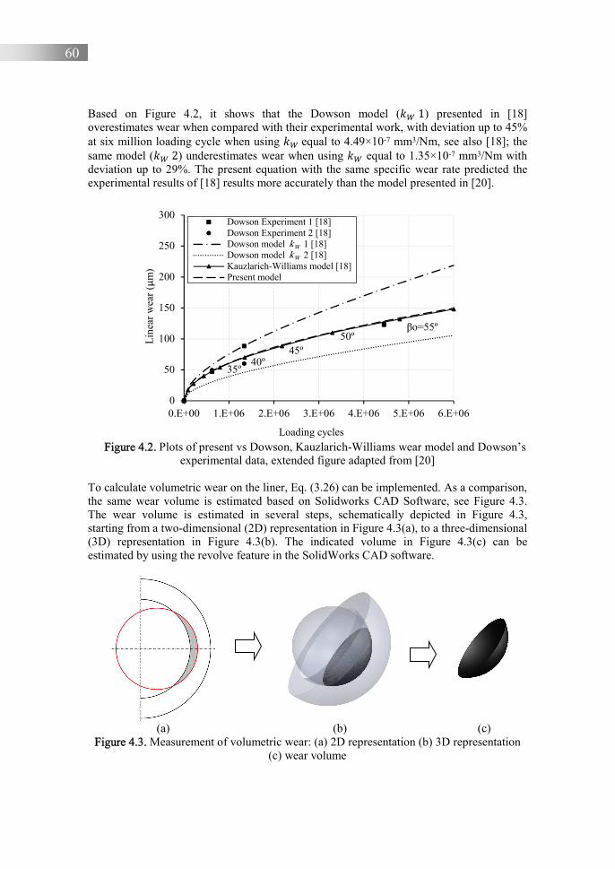
60
Based on Figure 4.2, it shows that the Dowson model (�� 1) presented in [18] overestimates wear when compared with their experimental work, with deviation up to 45% at six million loading cycle when using �� equal to 4.49×10⁻⁷ mm3/Nm, see also [18]; the same model (�� 2) underestimates wear when using �� equal to 1.35×10⁻⁷ mm3/Nm with deviation up to 29%. The present equation with the same specific wear rate predicted the experimental results of [18] results more accurately than the model presented in [20].
Figure 4.2. Plots of present vs Dowson, Kauzlarich-Williams wear model and Dowson’s
experimental data, extended figure adapted from [20] To calculate volumetric wear on the liner, Eq. (3.26) can be implemented. As a comparison, the same wear volume is estimated based on Solidworks CAD Software, see Figure 4.3. The wear volume is estimated in several steps, schematically depicted in Figure 4.3, starting from a two-dimensional (2D) representation in Figure 4.3(a), to a three-dimensional (3D) representation in Figure 4.3(b). The indicated volume in Figure 4.3(c) can be estimated by using the revolve feature in the SolidWorks CAD software.
(a) (b) (c) Figure 4.3. Measurement of volumetric wear: (a) 2D representation (b) 3D representation
(c) wear volume
35º40º
45º50º
βο=55º
0
50
100
150
200
250
300
0.E+00 1.E+06 2.E+06 3.E+06 4.E+06 5.E+06 6.E+06
Lin
ear
wea
r (μ
m)
Loading cycles
Dowson Experiment 1 [18]Dowson Experiment 2 [18]Dowson model kW 1 [18]Dowson model kW 2 [18]Kauzlarich-Williams model [18]Present model
kWkW

61
Figure 4.4 shows a plot of volumetric wear as a function of the number of loading cycles. The solid line is a plot of Eq. (4.24) for the walking case, while the cycle is a plot of volumetric wear by CAD software. Based on this comparison, it was decided to further use Eq. (4.24).
Figure 4.4. Analytical volumetric wear model vs the estimation using Solidworks
4.2.2. Variation of specific wear rate and head size to wear Based on Eqs. 2.3 and 4.12, one of variables affecting wear is the specific wear rate, ��, which is consistent with [21] The value of �� depends on the materials of the interacting surfaces, which can be seen from Table 2.2. Especially for metal-on-UHMWPE pairs, the �� value can also be influenced by the treatment of UHMWPE material such as the cross-linking process discussed in subsection 2.2.3. In addition, the wear volume is also influenced by the diameter of the head, where the diameter of the head will affect the contact area and contact pressure P.
This section will discuss the effect of variations in the value of �� and head diameter on the wear of the SM model using Eq. (4.12). A specific wear rate, �� equal to ~10-7 mm3/Nm for the metal-on-UHMWPE pair, was used according to Table 2.2, where the �� values for 316L stainless steel against UHMWPE were determined as 1.4, 1.6, and 2.9×10⁻⁷ mm3/Nm [22, 23, 24, 25]. Linear wear due to variations in �� was calculated using a head diameter of 28 mm. The effect of the head diameter was analysed using the head diameters given in Table 2.1, i.e. a diameter of 26, 28 and 36 mm. The applied load was set at 3000 N.
Figure 4.5 shows the wear depth as a function of the loading cycle for varying ��. As a comparison, the dashed line shows the linear wear when �� is equal to 4.49×10⁻⁷ mm3/Nm. The other lines show the results where �� is equal to 1.4, 1.6 and 2.9×10⁻⁷ mm3/Nm respectively. Based on Figure 4.5, it can be seen that the selected range of �� values has a large effect on the wear depth. This also sets the boundary conditions for the treatment of UHMWPE material by crosslinking. The greater the radiation dose in the cross-linking
0
10
20
30
40
50
0.E+00 1.E+06 2.E+06 3.E+06 4.E+06 5.E+06 6.E+06
Vol
umet
ric
wea
r (m
m3 )
Loading Cycles
Present model
Solidworks
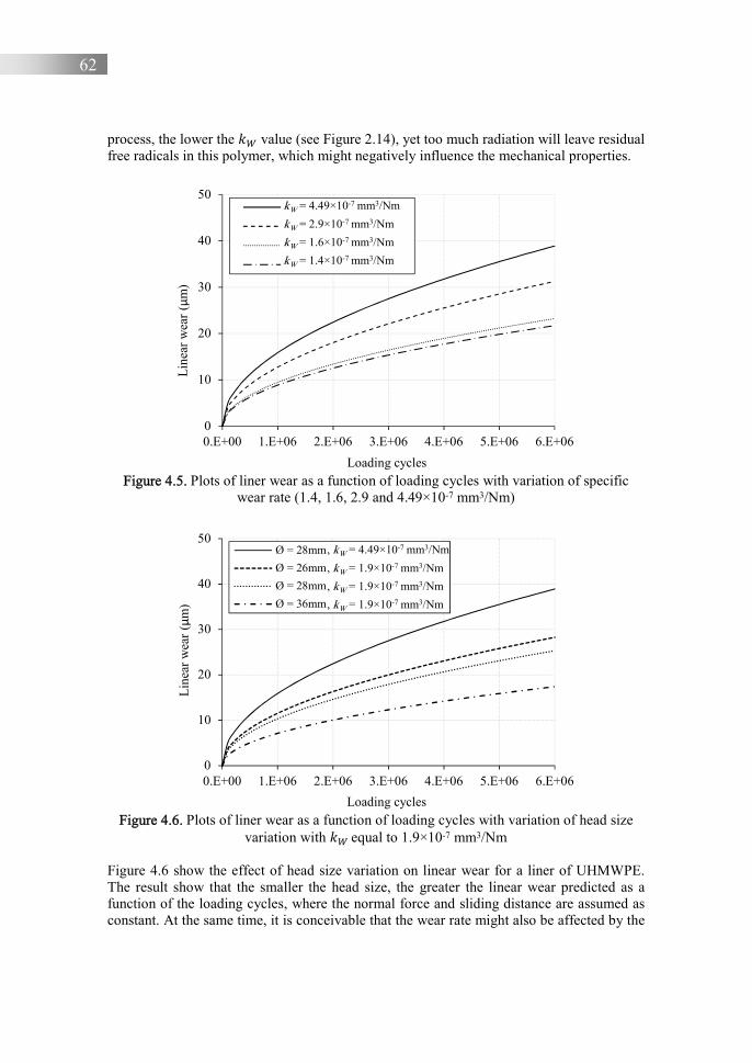
62
process, the lower the �� value (see Figure 2.14), yet too much radiation will leave residual free radicals in this polymer, which might negatively influence the mechanical properties.
Figure 4.5. Plots of liner wear as a function of loading cycles with variation of specific
wear rate (1.4, 1.6, 2.9 and 4.49×10⁻⁷ mm3/Nm)
Figure 4.6. Plots of liner wear as a function of loading cycles with variation of head size
variation with �� equal to 1.9×10⁻⁷ mm3/Nm
Figure 4.6 show the effect of head size variation on linear wear for a liner of UHMWPE. The result show that the smaller the head size, the greater the linear wear predicted as a function of the loading cycles, where the normal force and sliding distance are assumed as constant. At the same time, it is conceivable that the wear rate might also be affected by the
0
10
20
30
40
50
0.E+00 1.E+06 2.E+06 3.E+06 4.E+06 5.E+06 6.E+06
Lin
ear
wea
r (μ
m)
Loading cycles
kw0 = 4.49x10⁻⁷ hhhhhh
kW3 = 2.9x10⁻⁷
kW2 = 1.6x10⁻⁷
kW1 = 1.4x10⁻⁷
kW = 4.49×10⁻⁷ mm3/Nm
kW = 2.9×10⁻⁷ mm3/Nm
kW = 1.6×10⁻⁷ mm3/Nm
kW = 1.4×10⁻⁷ mm3/Nm
0
10
20
30
40
50
0.E+00 1.E+06 2.E+06 3.E+06 4.E+06 5.E+06 6.E+06
Lin
ear
wea
r (μ
m)
Loading cycles
Ø = 28mm , kW 4.49x10⁻⁷
Ø = 26mm , kW 0.5x10⁻⁷
Ø = 28mm , kW 0.5x10⁻⁷
Ø = 36mm , kW 0.5x10⁻⁷ hhhhhhhh
, kW = 4.49×10⁻⁷ mm3/Nm
, kW = 1.9×10⁻⁷ mm3/Nm
, kW = 1.9×10⁻⁷ mm3/Nm
, kW = 1.9×10⁻⁷ mm3/Nm

63
contact pressure. For that purpose, experimental work is conducted in Chapter 5 to validate the influence of the reduced contact area that occurs in the smaller head. 4.3. Wear prediction of dual mobility model using numerical method
4.3.1. Contact stress simulation Wear for the DM design is more complicated than for the SM model, due to its contact interaction. In the DM design, there are two contact interactions, namely head versus inner liner and outer liner versus cup, while the SM model has only one contact interaction, namely head versus liner.
One of the important parameters in the wear equation is the contact stress or contact pressure on the surface of contact interaction. The contact stress itself can be calculated using the contact theory. For the conformal contact, the Hertz [26, 27] and Bartel [28] contact theories can be used. These theories are widely used to predict the contact stress on the liner surface for the SM case. These theories have not yet been applied in the DM case, however. The contact stresses on the inner liner and cup surface of the DM model can be used to predict the initial wear on both surfaces of the inner liner and cup.
There are two materials selected for this research, i.e. UHMWPE and SS316L. The femoral head, outer liner and cup component are made of SS316L material, while the liner and inner liner are made of UHMWPE material. The material properties of UHMWPE and SS316L material can be seen in more detail from Table 3.6.
Figure 4.7 shows the geometrical modelling of the SM, DM and large head unipolar model respectively. The SM model that is selected for this simulation will be used to compare the contact stress of the liner with the inner liner of DM model. The large head unipolar model will be used to compare the contact stress between the cup of the large head unipolar model and the cup of DM model. The contact geometry for all models can be seen in Table 4.2. Simulations were conducted with the commercial finite element software ABAQUS.
(a) (b) (c)
Figure 4.7. (a) Geometry contact of the SM model, (b) DM design and (c) Large head unipolar model
Head
Liner
F
Cup Fixed
F
Head
Inner liner
Cup Outer liner
F
Large head
Cup

64
An axisymmetric contact model is assumed to simplify and minimize the simulation time. In these simulations, axisymmetric quadrilateral 4-node bilinear elements were used, with reduced integration and hourglass control (CAX4R). The average number of elements was approximately 5000. The load of 3000 N is applied at the centre point of the head for all simulations, where the applied load based on Bartel’s work [28] is applied for validation purposes. The outer cup surfaces for all models were fixed for all directions.
Comparison of the results of the contact stress maximum were conducted as validation. The implant materials were a rigid head, now cobalt-chrome so as to be consistent with the method outlined in [29], and a deforming cup from UHMWPE material. Figure 4.8(a) shows the contact stress maximum on the liner surface of the SM model as a function of load, calculated with the Hertzian theory, with the method of Bartel and with the current FE simulation respectively, similar to the work and method outlined in [29]. In the current simulation, the contact stress maximum was obtained at the centre point of contact on the liner surface; also see Figure 4.8(b).
Table 4.2. The geometry size of SM, DM and large head unipolar models in mm
Diameter SM model DM model
Large head unipolar model
Head Liner Cup Head Liner Outer liner Cup Head Cup Inner - 28.2 40.2 - 28.2 40.2 45.2 - 45.2 Outer 28 40.2 50 28 40.2 45 50 45 50
(a) (b) Figure 4.8. (a) The comparison of the contact stress maximum on the SM THA liner surface with a diameter of 28.2 mm in contact with an outer head diameter of 28 mm as a function of load calculated with Bartel’s theory, Hertzian theory and the present FE model, and (b) the
contour plot of contact stress on the liner for F = 3000 N, extended figure adapted from [30]
Based on this comparison, it can be seen that the contact stress maximum predicted with the current FE simulation shows a good agreement with the work of Bartel, confirming the work presented in [29]. The deviation of the contact stress maximum between the present
0
2
4
6
8
10
12
14
16
18
20
0 500 1000 1500 2000 2500 3000
Con
tact
str
ess
max
imum
(M
Pa)
Force (N)
Hertz theoryBartel theoryFE Present

65
FE simulation and Bartel theory is about 5.7%. This is contrary to the contact stress maximum estimated based on the Hertzian theory, which showed a deviation of about 67.7%. It verifies that Hertz theory underestimates contact stresses in the case of conformal contact with high load and larger deformations [26, 28], see also [29].
The contact stress analysis is then extended to the cases of the proposed DM design and to a large head design. The material pair used in this simulation is adopted from Table 3.6. The applied load used in this case is 3000 N. Figure 4.9(a) presents the comparison of contact stress on the liner surfaces. Based on these comparisons, it is found that the contact stress maximum on the liner surface of the DM model is higher than the SM model, i.e. 4.3% more at the selected load of 3000 N.
Figure 4.9(b) compares the contact stress on the cup surfaces of the large head design and the DM design as a function of load. Based on Figure 4.9(b), it shows that the trend progress of contact stress on the cup surface of DM is different from the trend of Figure 4.9(a). Initially, the contact stress on the cup surface of DM model increases until the load reaches about 500 N, then it reduces to a steady state level continuing to a load of 3000 N. The contact stress maximum difference on the cup surfaces between the large head unipolar and DM design is about 78%, which suggests that the cup surface of DM model is less susceptible to volumetric wear.
(a) (b)
Figure 4.9. Comparison as a function of load of the contact stress maximum on the liner surfaces for (a) a SM and DM design, and (b) for the cup surfaces of a large head unipolar
and DM design
Further, Figure 4.10(a) shows the contact stress distribution on the liner surfaces of SM and DM models as a function of the contact radius. Based on the result, the contact stress maximum on the liner surface of the DM design is about 4.3% higher than for a SM model at smaller contact radii. For larger radii, however, the contact stress of the two designs does not differ significantly. Figure 4.10(b) presents the contact stress distribution on the cup surfaces of a large head and of a DM design as a function of load. Based on Figure 4.10(b), the contact stress maximum on the cup surface of large head model is higher than the DM
0
2
4
6
8
10
12
14
16
18
20
0 500 1000 1500 2000 2500 3000
Con
tact
str
ess
max
imum
(M
Pa)
Force (N)
Liner of DM modelLiner of SM model
0
10
20
30
40
50
60
70
80
90
100
0 500 1000 1500 2000 2500 3000
Con
tact
str
ess
max
imum
(M
Pa)
Force (N)
Cup of DM modelCup of large head

66
model with deviation about 78 %. Part of this can be explained from the differences in the contact radii of both designs. Similar to [30], the differences can also partially be explained by the fact that the liner in a DM design consists of two materials.
(a) (b)
Figure 4.10. (a) The contact stress distribution on the liner of SM and DM model as a function of contact radius, and (b) the contact stress distribution on the cup of large head
unipolar and DM model as a function of contact radius A more detailed view of the stress situation for the liners can be seen from Figure 4.11(a-b), whereas the contour plot of contact stress for the cup of large head unipolar and DM design can be seen in Figure 4.12(a-b). This shows that the position of the contact stress maximum is at the centre point of contact interaction for both liner surfaces, while the contact stress maximum is shifted from the centre point of contact interaction for the DM cup surface.
(a) (b)
Figure 4.11. The contour plot of contact stress distribution on the surface of liner for (a) SM
model and (b) DM model
0
2
4
6
8
10
12
14
16
18
20
0 2 4 6 8 10 12
Con
tact
str
ess
(MP
a)
Contact radius (mm)
Liner of SM model
Liner of DM model
Contactradius
0
10
20
30
40
50
60
70
80
90
100
0 2 4 6 8 10C
onta
ct s
tres
s (M
Pa)
Contact radius (mm)
Cup of large head
Cup of DM model
Contactradius
Max. Max.
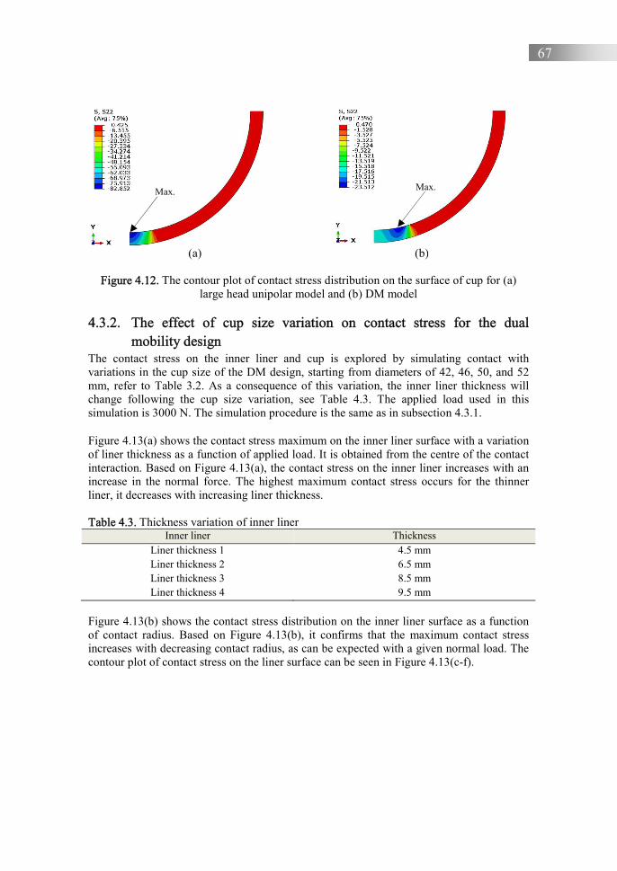
67
(a) (b)
Figure 4.12. The contour plot of contact stress distribution on the surface of cup for (a)
large head unipolar model and (b) DM model 4.3.2. The effect of cup size variation on contact stress for the dual
mobility design The contact stress on the inner liner and cup is explored by simulating contact with variations in the cup size of the DM design, starting from diameters of 42, 46, 50, and 52 mm, refer to Table 3.2. As a consequence of this variation, the inner liner thickness will change following the cup size variation, see Table 4.3. The applied load used in this simulation is 3000 N. The simulation procedure is the same as in subsection 4.3.1.
Figure 4.13(a) shows the contact stress maximum on the inner liner surface with a variation of liner thickness as a function of applied load. It is obtained from the centre of the contact interaction. Based on Figure 4.13(a), the contact stress on the inner liner increases with an increase in the normal force. The highest maximum contact stress occurs for the thinner liner, it decreases with increasing liner thickness.
Table 4.3. Thickness variation of inner liner
Inner liner Thickness Liner thickness 1 4.5 mm Liner thickness 2 6.5 mm Liner thickness 3 8.5 mm Liner thickness 4 9.5 mm
Figure 4.13(b) shows the contact stress distribution on the inner liner surface as a function of contact radius. Based on Figure 4.13(b), it confirms that the maximum contact stress increases with decreasing contact radius, as can be expected with a given normal load. The contour plot of contact stress on the liner surface can be seen in Figure 4.13(c-f).
Max. Max.

68
(a) (b)
(c) (d)
(e) (f)
Figure 4.13. (a-b) The contact stress maximum and the contact stress distribution on the inner liner as a function of applied load with the liner thickness variation, (c-f) the contour plot of contact stress on the inner liner of DM model with the inner liner
thickness 1, 2, 3 and 4 respectively
Figures 4.14(a-b) show the contact stress maximum and distribution on the cup surfaces. Figure 4.14(a) presents the contact stress maximum on inner side of the cup surface. The
0
5
10
15
20
25
0 500 1000 1500 2000 2500 3000
Con
tact
str
ess
max
imum
(M
Pa)
Force (N)
Liner thickness 1Liner thickness 2Liner thickness 3Liner thickness 4
0
5
10
15
20
25
0 2 4 6 8 10 12
Con
tact
str
ess
(MP
a)Contact radius (mm)
Liner thickness 1Liner thickness 2Liner thickness 3Liner thickness 4
Max.
Max.

69
location does not occur at the centre point of contact. Furthermore, at liner thickness 1 for example it decreases at the load range 100-200 N and increases again for the load range 200-3000 N. The highest contact stress occurs when the liner thickness is equal to 4.3 mm, while the lowest contact stress occurs when the liner thickness is equal to 9.5 mm. Figure 4.14(b) presents the contact stress distribution on the cup surface as a function of the contact radius. The location of the highest contact stress does not occur at the centre point of contact; however, it shifts to near the end of the contact area. Thus, the contact stress shows two peaks, one at the centre contact and one near the edge of the contact, see Figure 4.14(c-d). The highest contact radius occurs when the inner liner thickness is equal to 9.5 mm, while the lowest contact radius occurs when the inner liner thickness is equal to 4.5 mm.
(a) (b)
(c) (d)
Figure 4.14. (a-b) The contact stress distribution and the contact stress distribution on the cup surface as a function of contact radius for liner thickness variation, (c-f) the contour
plot of contact stress on the cup of DM model with the inner liner thickness of 1, 2, 3 and 4 respectively
0
2
4
6
8
10
12
14
16
18
20
0 500 1000 1500 2000 2500 3000
Con
tact
str
ess
max
imum
(M
Pa)
Force (N)
Liner thickness 1Liner thickness 2Liner thickness 3Liner thickness 4
0
2
4
6
8
10
12
14
16
18
20
0 2 4 6 8 10 12
Con
tact
str
ess
max
imum
(M
Pa)
Contact radius (mm)
Liner thickness 1Liner thickness 2Liner thickness 3Liner thickness 4
Max.

70
(e) (f)
Figure 4.14. (a-b) The contact stress distribution and the contact stress distribution on the cup surface as a function of contact radius for liner thickness variation, (c-f) the contour
plot of contact stress on the cup of DM model with the inner liner thickness of 1, 2, 3 and 4 respectively (continued)
The results of the maximum contact stress in Figures 4.13 and 4.14 can be used to determine the optimal head and cup diameter in the DM model. Based on Figure 4.13, it is concluded that the smaller the diameter of the head, the lower the maximum contact stress. Actually, referring to Eq. (4.9), contact stress will increase when contact radius decreases. However, in this case, the maximum contact stress decreases due to the increasing thickness of the inner liner, while the smallest size of the head diameter is limited by the 22 mm Charnley design. Also, Girard et al. classified the femoral heads as small, medium and large heads, where small heads having a diameter range of 22 to 28 mm [31]. Therefore, the optimal femoral head diameter is between 22-28 mm, while the cup diameter follows the patient's acetabulum diameter. 4.4. Relation impingement and wear for a single mobility design
This section presents the correlation of wear of the inside of the liner surface and damage on the liner lip due to impingement. The analysis included evaluation of the macrostructure of the damage based on visual investigation and computer simulation analysis. A commercial finite element method ABAQUS software package was used to simulate local impingement on the liner lip due to wear depth variations (wear rates) inside the liner surface. Here, the wear depth is based on the data of wear prediction of Figure 4.5. The von Mises stress and contact deformation on the liner lip or rim at impingement is presented as well. In addition, the initial impingement angle is also presented to show the correlation between the wear inside of the liner surface and the angle of impingement occurrence. For more detail, see paper D and conference paper E. The liner is placed between the cup (shell or cup) and the femoral head (ball) in an SM hip prosthesis. The hip prosthesis and location of the liner are similar to the configuration given in Figure 1.2. Based on the visual investigation of the liner revision, which is obtained from the orthopedic hospital Soeharso, two damaged areas on the liner were found, see Figure 2.1. The first one was on the liner lip and the second one was on the inside of the liner surface. The first damage might be a result of the repeated impingement between neck stem and liner lip [32]. The second
Max.

71
damaged area might be the result of wear that is caused by sliding of the femoral head and liner surfaces.
(a) (b) Figure 4.15. Dimension of (a) femoral head with neck stem and (b) acetabular liner with
chamfer
The simulation in this study is divided into two steps: the static contact of femoral head against the acetabular liner and the rotation of femoral head against the acetabular liner until impingement. In the simulation process, 3D models of femoral head and acetabular liner are created using CAD software. The cup is not involved in this simulation because it can be represented as a fixed constraint on the outer surface of the acetabular liner. Based on Figure 4.15, variable of �� (head radius) and �� (liner radius) are 14 mm and 14.2 mm, respectively. The diameter of the neck stem is 14.2 mm. The acetabular liner has inset 2 mm and chamfer angle 45o.
Wear can be created virtually, using the cut-revolve feature in CAD software. In this case, the shape of the worn area could be based on the wear depth from a calculation or experiment, yet in this case the shape is created assuming wear with the radius of the femoral head such as depicted in Figure 4.16. The wear data from Figure 4.5 is used for the simulation of the wear depth. This simulation does not focus on the wear prediction but aims only to investigate the correlation between the wear inside of the liner surface and the impingement progress on the liner lip.
In summary, the femoral head is assumed to be a rigid body, whereas the acetabular liner is assumed to be deformable and consisting of UHMWPE. The latter material model of UHMWPE is assumed to be an isotropic strain hardening elastic-plastic material model, with stress-strain curve data from Kurtz et al. [33]. For the simulation purpose, the stress-strain curve is discretized, where it is similar to used by McNie et al. and Faulkner et al. [34, 35]. This model assumes an elastic modulus of 850 MPa [18] and an initial yield stress of 20 MPa.
RH
RL
Ø 14
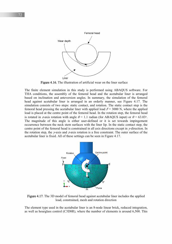
72
Figure 4.16. The illustration of artificial wear on the liner surface
The finite element simulation in this study is performed using ABAQUS software. For THA conditions, the assembly of the femoral head and the acetabular liner is arranged based on inclination and anteversion angles. In summary, the simulation of the femoral head against acetabular liner is arranged in an orderly manner, see Figure 4.17. The simulation consists of two steps: static contact, and rotation. The static contact step is the femoral head pressing the acetabular liner with applied load F = 3000 N, where the applied load is placed at the centre point of the femoral head. In the rotation step, the femoral head is rotated in z-axis rotation with angle = 1.1 radian (for ABAQUS input) or = 63.03o. The magnitude of this angle is either user-defined or it is set towards impingement occurrence between the neck stem surfaces with the liner lip. In the static contact step, the centre point of the femoral head is constrained in all axis directions except in y-direction. In the rotation step, the y-axis and z-axis rotation is a free constraint. The outer surface of the acetabular liner is fixed. All of these settings can be seen in Figure 4.17.
Figure 4.17. The 3D model of femoral head against acetabular liner includes the applied load, constrained, mesh and rotation direction
The element type used in the acetabular liner is an 8-node linear brick, reduced integration, as well as hourglass control (C3D8R), where the number of elements is around 6,500. This
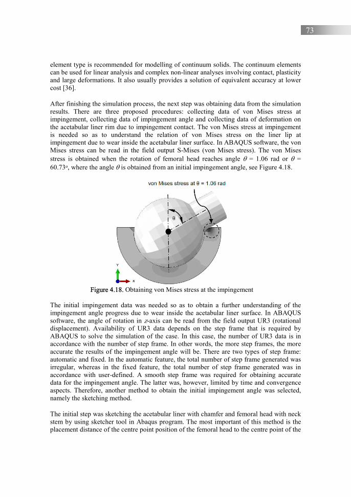
73
element type is recommended for modelling of continuum solids. The continuum elements can be used for linear analysis and complex non-linear analyses involving contact, plasticity and large deformations. It also usually provides a solution of equivalent accuracy at lower cost [36].
After finishing the simulation process, the next step was obtaining data from the simulation results. There are three proposed procedures: collecting data of von Mises stress at impingement, collecting data of impingement angle and collecting data of deformation on the acetabular liner rim due to impingement contact. The von Mises stress at impingement is needed so as to understand the relation of von Mises stress on the liner lip at impingement due to wear inside the acetabular liner surface. In ABAQUS software, the von Mises stress can be read in the field output S-Mises (von Mises stress). The von Mises stress is obtained when the rotation of femoral head reaches angle = 1.06 rad or = 60.73o, where the angle is obtained from an initial impingement angle, see Figure 4.18.
Figure 4.18. Obtaining von Mises stress at the impingement
The initial impingement data was needed so as to obtain a further understanding of the impingement angle progress due to wear inside the acetabular liner surface. In ABAQUS software, the angle of rotation in z-axis can be read from the field output UR3 (rotational displacement). Availability of UR3 data depends on the step frame that is required by ABAQUS to solve the simulation of the case. In this case, the number of UR3 data is in accordance with the number of step frame. In other words, the more step frames, the more accurate the results of the impingement angle will be. There are two types of step frame: automatic and fixed. In the automatic feature, the total number of step frame generated was irregular, whereas in the fixed feature, the total number of step frame generated was in accordance with user-defined. A smooth step frame was required for obtaining accurate data for the impingement angle. The latter was, however, limited by time and convergence aspects. Therefore, another method to obtain the initial impingement angle was selected, namely the sketching method.
The initial step was sketching the acetabular liner with chamfer and femoral head with neck stem by using sketcher tool in Abaqus program. The most important of this method is the placement distance of the centre point position of the femoral head to the centre point of the

74
acetabular liner. In this study, it is referred to as an offset of centre points. The magnitude of this offset is the sum of the difference of a radius between the femoral head and the acetabular liner, the wear depth, and the deformation contact due to static contact. The value of the contact deformation is obtained from the result of the simulation, as a function of the applied load. If only the wear effect on the initial impingement angle is considered, one can ignore the contact deformation. The initial impingement angle with and without the contact deformation will be presented as a comparison.
After the applied offset, the new centre point of the femoral head is found. Further, the new centre point as circle centre point ‘O’ is created. Then, the new circle radius is the length of the centre point ‘O’ to point ‘A’. By drawing a curved line from point A counterclockwise to neck line, so the new curved line cut the neckline and resulted in cut point B. By connecting the point of O, A, and B, the angle of AOB is formed. This angle is called the initial impingement angle, see Figure 4.19.
Figure 4.19. The procedure to obtain the initial impingement angle
In addition to the von Mises stress on the acetabular liner rim and the initial impingement angle of impingement contact due to wear inside the acetabular liner surface, the progress data of contact deformation on the impingement contact point is needed. The data of contact deformation is obtained on the acetabular liner rim, see Figure 4.20. The contact deformation is taken along with the impingement process until the rotation angle reaches = 1.1 radians. The contact deformation that is investigated on the acetabular liner rim is a deformation in the y-axis direction. In ABAQUS software, the displacement in y-axis can be read from the field output U2 (y-displacement). If this impingement occurs repeatedly, the liner is expected to damage the liner lip, see conference paper C.
Figure 4.21 shows the progress of the maximum von Mises stress on the acetabular liner rim at impingement, at the rotation of femoral head reach angle = 1 rad and at = 57.23o. Based on Figure 4.21, it is concluded that the von Mises maximum stress increases with increasing wear depth. Consequently, when the centre point of femoral head shifts due to the existence of wear inside the acetabular liner surface, it will cause the impingement to occur faster. The wear indicated by wear 1, 2 and 3 are the wear depth for a specific wear rate of 1.4, 1.6, 2.9×10⁻⁷ mm3/Nm respectively.
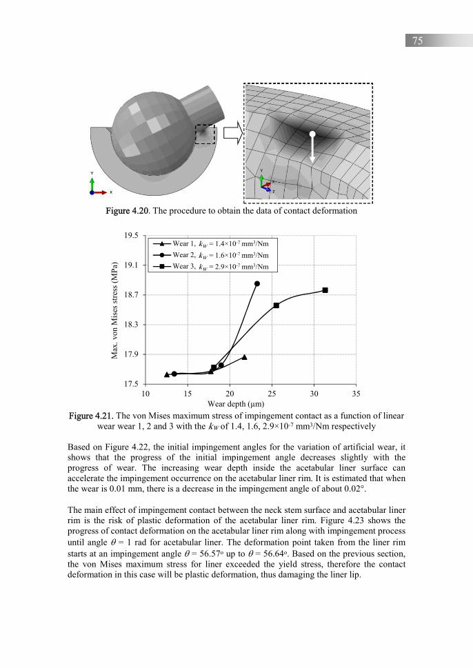
75
Figure 4.20. The procedure to obtain the data of contact deformation
Figure 4.21. The von Mises maximum stress of impingement contact as a function of linear
wear wear 1, 2 and 3 with the kW of 1.4, 1.6, 2.9×10⁻⁷ mm3/Nm respectively
Based on Figure 4.22, the initial impingement angles for the variation of artificial wear, it shows that the progress of the initial impingement angle decreases slightly with the progress of wear. The increasing wear depth inside the acetabular liner surface can accelerate the impingement occurrence on the acetabular liner rim. It is estimated that when the wear is 0.01 mm, there is a decrease in the impingement angle of about 0.02°.
The main effect of impingement contact between the neck stem surface and acetabular liner rim is the risk of plastic deformation of the acetabular liner rim. Figure 4.23 shows the progress of contact deformation on the acetabular liner rim along with impingement process until angle = 1 rad for acetabular liner. The deformation point taken from the liner rim starts at an impingement angle = 56.57o up to = 56.64o. Based on the previous section, the von Mises maximum stress for liner exceeded the yield stress, therefore the contact deformation in this case will be plastic deformation, thus damaging the liner lip.
17.5
17.9
18.3
18.7
19.1
19.5
10 15 20 25 30 35
Max
. von
Mis
es s
tres
s (M
Pa)
Wear depth (µm)
Wear 1, kw = 1.4×10⁻⁷ mm3/Nm
Wear 2, kw = 1.6×10⁻⁷ mm3/Nm
Wear 3, kw = 2.9×10⁻⁷ mm3/Nm
kW = 1.4×10⁻⁷ mm3/Nm
kW = 1.6×10⁻⁷ mm3/Nm
kW = 2.9×10⁻⁷ mm3/Nm
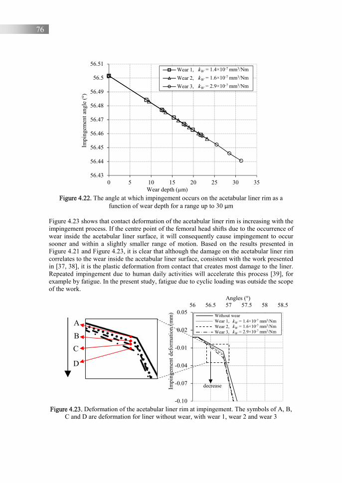
76
Figure 4.22. The angle at which impingement occurs on the acetabular liner rim as a
function of wear depth for a range up to 30 μm
Figure 4.23 shows that contact deformation of the acetabular liner rim is increasing with the impingement process. If the centre point of the femoral head shifts due to the occurrence of wear inside the acetabular liner surface, it will consequently cause impingement to occur sooner and within a slightly smaller range of motion. Based on the results presented in Figure 4.21 and Figure 4.23, it is clear that although the damage on the acetabular liner rim correlates to the wear inside the acetabular liner surface, consistent with the work presented in [37, 38], it is the plastic deformation from contact that creates most damage to the liner. Repeated impingement due to human daily activities will accelerate this process [39], for example by fatigue. In the present study, fatigue due to cyclic loading was outside the scope of the work.
Figure 4.23. Deformation of the acetabular liner rim at impingement. The symbols of A, B,
C and D are deformation for liner without wear, with wear 1, wear 2 and wear 3
56.43
56.44
56.45
56.46
56.47
56.48
56.49
56.5
56.51
0 5 10 15 20 25 30 35
Impi
ngem
ent a
ngle
(°)
Wear depth (µm)
Wear 1, kw = 1.4×10⁻⁷ mm3/Nm
Wear 2, kw = 1.6×10⁻⁷ mm3/Nm
Wear 3, kw = 2.9×10⁻⁷ mm3/Nm
kW = 1.4×10⁻⁷ mm3/Nm
kW = 1.6×10⁻⁷ mm3/Nm
kW = 2.9×10⁻⁷ mm3/Nm
-0.10
-0.07
-0.04
-0.01
0.02
0.0556 56.5 57 57.5 58 58.5
Impi
ngem
ent d
efor
mat
ion
(mm
)
Angles (°)
Without wearWear 1, kW = 1.4×10⁻⁷ mm3/NmWear 2,Wear 3,
decrease
kW = 1.4×10⁻⁷ mm3/NmkW = 1.6×10⁻⁷ mm3/NmkW = 2.9×10⁻⁷ mm3/Nm
A
B
C
D
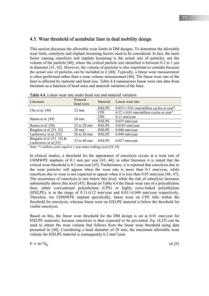
77
4.5. Wear threshold of acetabular liner in dual mobility design
This section discusses the allowable wear limits in DM designs. To determine the allowable wear limit, osteolysis and implant loosening factors need to be considered. In fact, the main factor causing osteolysis and implant loosening is the actual size of particles, not the volume of the particle [40], where the critical particle size identified is between 0.2 to 1 µm in diameter [41, 42]. However, the volume of particles is also important to consider because the actual size of particles can be included in it [40]. Typically, a linear wear measurement is often performed rather than a wear volume measurement [40]. The linear wear rate of the liner is affected by material and head size. Table 4.4 summarizes linear wear rate data from literature as a function of head sizes and material variation of the liner.
Table 4.4. Linear wear rate under head size and material variation
Literature Femoral head sizes
Material Linear wear rate
Cho et al. [48] 22 mm HXLPE 0.015 ± 0.01 mm/million cycles or year* CPE 0.12 ± 0.01 mm/million cycles or year*
Hanna et al. [49] 28 mm CPE 0.11 mm/year HXLPE 0.035 mm/year
Rames et al. [50] 22 to 28 mm HXLPE 0.0185 mm/year Bragdon et al. [51, 52] 28 mm HXLPE 0.048 mm/year Lachiewicz et al. [53] 26 to 28 mm HXLPE 0.048 mm/year Bragdon et al. [51, 52] & Lachiewicz et al [53] 32 to 40 mm HXLPE 0.027 mm/year
Note: * 1 million cycles equal to 1 year under walking cycle [54, 55]
In clinical studies, a threshold for the appearance of osteolysis occurs at a wear rate of UHMWPE implants of 0.1 mm per year [43, 44]; in other literature it is stated that the critical wear threshold is 0.3 mm/year [45]. Furthermore, it is reported that osteolysis due to the wear particles will appear when the wear rate is more than 0.1 mm/year, while osteolysis due to wear is not expected to appear when it is less than 0.05 mm/year [46, 47]. The occurrence of osteolysis is rare below this level, while the risk of osteolysis increases substantially above this level [47]. Based on Table 4.4 the linear wear rate of a polyethylene liner, either conventional polyethylene (CPE) or highly cross-linked polyethylene (HXLPE), is in the range of 0.11-0.12 mm/year and 0.011-0.048 mm/year respectively. Therefore, for UHMWPE implant specifically, linear wear on CPE falls within the threshold for osteolysis, whereas linear wear on HXLPE material is below the threshold for visible osteolysis.
Based on this, the linear wear threshold for the DM design is set at 0.01 mm/year for HXLPE materials, because osteolysis is then expected to be prevented. Eq. (4.25) can be used to obtain the wear volume that follows from the linear wear threshold using data presented in [40]. Considering a head diameter of 28 mm, the maximum allowable wear volume for HXLPE material is consequently 6.2 mm3/year.
� = T�&ℎ� (4.25)
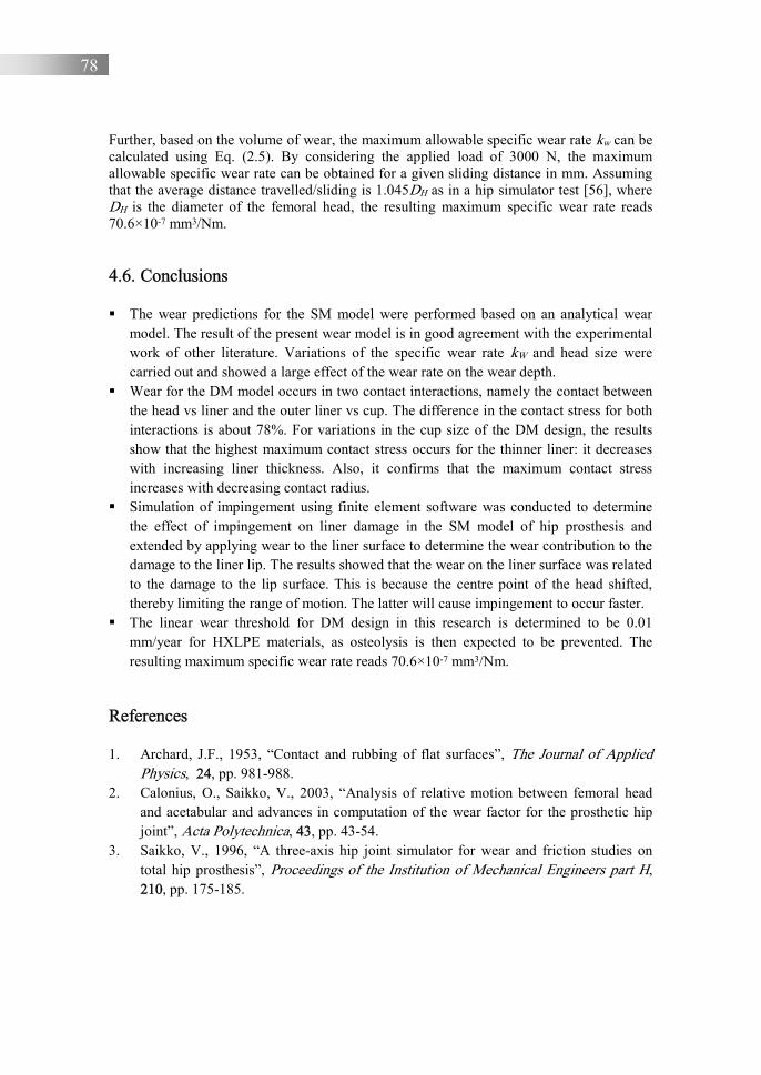
78
Further, based on the volume of wear, the maximum allowable specific wear rate kw can be calculated using Eq. (2.5). By considering the applied load of 3000 N, the maximum allowable specific wear rate can be obtained for a given sliding distance in mm. Assuming that the average distance travelled/sliding is 1.045DH as in a hip simulator test [56], where DH is the diameter of the femoral head, the resulting maximum specific wear rate reads 70.6×10⁻⁷ mm3/Nm.
4.6. Conclusions
The wear predictions for the SM model were performed based on an analytical wear model. The result of the present wear model is in good agreement with the experimental work of other literature. Variations of the specific wear rate kW and head size were carried out and showed a large effect of the wear rate on the wear depth.
Wear for the DM model occurs in two contact interactions, namely the contact between the head vs liner and the outer liner vs cup. The difference in the contact stress for both interactions is about 78%. For variations in the cup size of the DM design, the results show that the highest maximum contact stress occurs for the thinner liner: it decreases with increasing liner thickness. Also, it confirms that the maximum contact stress increases with decreasing contact radius.
Simulation of impingement using finite element software was conducted to determine the effect of impingement on liner damage in the SM model of hip prosthesis and extended by applying wear to the liner surface to determine the wear contribution to the damage to the liner lip. The results showed that the wear on the liner surface was related to the damage to the lip surface. This is because the centre point of the head shifted, thereby limiting the range of motion. The latter will cause impingement to occur faster.
The linear wear threshold for DM design in this research is determined to be 0.01 mm/year for HXLPE materials, as osteolysis is then expected to be prevented. The resulting maximum specific wear rate reads 70.6×10⁻⁷ mm3/Nm.
References 1. Archard, J.F., 1953, “Contact and rubbing of flat surfaces”, The Journal of Applied
Physics, 24, pp. 981-988. 2. Calonius, O., Saikko, V., 2003, “Analysis of relative motion between femoral head
and acetabular and advances in computation of the wear factor for the prosthetic hip joint”, Acta Polytechnica, 43, pp. 43-54.
3. Saikko, V., 1996, “A three-axis hip joint simulator for wear and friction studies on total hip prosthesis”, Proceedings of the Institution of Mechanical Engineers part H, 210, pp. 175-185.
79
4. Saikko, V., Ahlroos, T., 1999, “Type of motion and lubricant in wear simulation of polyethylene acetabular cup”, Proceedings of the Institution of Mechanical Engineers part H . 213, pp. 301-310.
5. Mckellop, H.A., Clarke, I.C., 1985, “Degradation and wear of ultra-high-molecular-weight polyethylene”, In: Corrosion and degradation of implant materials: second symposium, ASTM STP 859. (Eds. Fraker A.C, Griffin C.D.). Philadelphia: American Society for Testing and Materials. 351-368.
6. Wang, A., Polineni, V.K., Essner, A., et al., 1997, “The significance of nonlinear motion in the wear screening of orthopaedic implant materials”, Journal of Testing and Evaluation, 25, pp. 239-245.
7. Bragdon, C.R., O’connor, D.O., Lowenstein, A., 1997, “Biological reaction to debrid in relation to joint prosthesis”, Proceedings of the Institution of Mechanical Engineers part H, 211, pp. 187-197.
8. Ungethum, M., 1976, “Tribologisch-biomechanische untersuchungen fur den totalen gelenkersatz der menschlichen hufte”, Doctoral Dissertation. Rheinisch-Wesfalische Technische Hochschule Aachen.
9. Walther, A., 1997, “Investigations on the wear couple BIOLOX forte and earlier alumina materials”, In: Puhl W (ed) Performance of the wear couple BIOLOX Forte in hip arthroplasty, pp. 123-135.
10. Dowson, D., Jobbins, B., 1988, “Design and development of a versatile hip joint simulator and a pleminary assessment of wear and creep in Charnley total replacement hip joints”, Engineering in Medicine, 17, pp. 111-117.
11. ISO/DIS 14242-1 Draft International Standard. 2001. Implants for surgery-Wear of total hip joint prostheses-Part I: Loading and displacement parameters for wear-testing machines and corresponding environmental conditions for test.
12. Smith, S.L., Unsworth, A., 2001, “A five-station hip joint simulator”, Proceedings of the Institution of Mechanical Engineers part H, 215, pp. 61-64.
13. Barbour, P.S.M, Stone, M.H., Fisher, J., 1999, “A hip joint simulator study using simplified loading and motion cycles generating physiological wear paths and rates”, Proceedings of the Institution of Mechanical Engineers part H, 213, pp. 455-467.
14. Goldsmith, A.A.J., Dowson, D., 1999, “A multi-station hip joint simulator study of the performance of 22 mm diameter zirconia-ultra-high molecular polyethilene total replacement hip joints”, Proceedings of the Institution of Mechanical Engineers part H, 213, pp. 77-90.
15. Johnston, R.C., Smidt, G.L., 1969, “Measurement of hip-joint motion during walking-evaluation of an electrogoniometric method”, Journal of Bone and Joint Surgery, 51-A, pp. 1083-1094.
16. Paul, J.P., 1976, “Force actions transmitted by joints in the human body”, Proceedings of the Royal Society B, 192, pp. 163-172.
17. van Beek, A., 2012, “Advanced engineering design: lifetime performance and reliability”, Delft University of Technology. TU Delft.
80
18. Dowson, D., Jobbins, B., Seyed-Harraf, A., 1993, “An evaluation of the penetration of ceramic femoral heads into polythene acetabular cups”, Wear, 162-164, pp. 880-889.
19. International Standard (2014). Implant for surgery-Wear of total hip-joint prostheses, Part 1: Loading and displacement parameters for wear-testing machines and corresponding environmental conditions for test (ISO Standard No. 14242-1:2014). <https://www.iso.org/standard/63073.html>.
20. Kauzlarich, J.J., Williams, J.A., 2001, “Archard wear and component geometry”, Proceedings of the Institution of Mechanical Engineers, 215, pp. 387-403.
21. Mattei, L., Di Puccio, F., Ciulli, E., 2013, “A comparative study of wear laws for soft-on-hard hip implants using a mathematical wear model”, Tribology International, 63, pp. 66-77.
22. Lloyd, A.I.G., 1986, “The sliding wear of UHMWPE against steel”, thesis, Department of Materials Engineering, University of Cape Town.
23. Mustafaev, T.K., Dowson, D., Gillis, B.J., 1976, “The lubricated wear of high density polyethylene with mineral oil and stearic acid”, The wear of non-metallic materials, Proc. 3rd Leeds-Lyon Symposium on Tribology, Edited by D. Dowson, M. Godet and C.M. Taylor, MEP, London, pp. 65-71.
24. Dumbleton, J.H., Shen, C., 1976, “The wear behaviour of ultra-high molecular weight polyethylene”, Wear, 37, pp. 279-289.
25. Rostoker, W., Galante, J.O., 1976, “Some new studies on the wear behaviour of ultra-high molecular weight polyethylene”, Journal of Biomedical Materials Research, 10, pp. 303-310.
26. Hertz, H., 1882, “Uber die Beruhrung Fester Elastischer Korper (On the Contact of Elastic Solids)”, Journal für die reine und angewandte Mathematik, 92, pp. 156-171.
27. Johnson, K.L., 1985, “Contact Mechanics”, Cambridge University Press, Cambridge, UK.
28. Bartel, D.L., Burstein, A.H., Toda, M.D., Edwards, D.L., 1985, “The Effect of Conformity and Plastic Thickness on Contact Stresses in Metal-Backed Plastic Implants”, Journal of Biomechanical Engineering, 107, pp. 193-199.
29. Di Puccio, F., Mattei, L., 2015, “Biotribology of artificial hip joints”, World Journal of Orthopedics, 6(1), pp. 77-94.
30. Saputra, E., Anwar, I.B., Ismail, R., Jamari, J. van der Heide, E., 2016, “Finite element study of contact pressure distribution on inner and outer liner in the bipolar hip prosthesis”, AIP conference proceedings. 1725, p. 020075.
31. Girard J., 2015, “Femoral head diameter considerations for primary total hip arthroplasty”, Orthopaedics & Traumatology: surgery & research, 101, pp. 25-29.
32. Jamari, J., Ismail, R., Saputra, E., Sugiyanto, S., Anwar, I.B., 2014, “The effect of repeated impingement on UHMWPE material in artificial hip joint during salat activities”, Advanced Materials Research, 896, pp. 272-275.
33. Kurtz, S.M., 1999, “Advances in the Processing, Sterilization, and Crosslinking of Ultra High Molecular Weight Polyethelene for Total Joint Arthroplasty”, Exponent Failure Analysis Associates, USA.

81
34. McNie, C., Barton, D.C., Stone, M.H., Fisher, J., 1998, “Prediction of plastic strains in ultra-high molecular weight polyethylene due to microscopic asperity interactions during sliding wear”, Proceedings of the Institution of Mechanical Engineers part H, 212, pp. 49-56.
35. Faulkner, A., Arnell, R.D., 2000, “The development of a finite element model to simulate the sliding interaction between two, three-dimensional, elastoplastic, hemisperichal asperities”, Wear, 242, pp. 114-122.
36. ABAQUS (2012), ABAQUS Documentation, Dassault Systèmes, Providence, RI, USA.
37. Tanino, H., Harman, M.K., Banks, S.A., Hodge, W.A., 2007, “Association between dislocation, impingement, and articular geometry in retrieved acetabular polyethylene cups”, Journal of Orthopaedic Research, 25, pp. 1401-1407.
38. Scifert, C.F., Brown, T.D., Pedersen, D.R., Callaghan, J.J., 1998, “A finite element analysis of factors influencing total hip dislocation”, Clinical orthopaedics and related research, 355, pp. 152-162.
39. Jamari, J., Ismail, R., Saputra, E., Sugiyanto, S., Anwar, I.B., 2014, “The effect of repeated impingement on UHMWPE material in artificial hip joint during salat activities”, Advanced Materials Research, 896, pp. 272-275.
40. Shepherd, D.E.T., Dearn, K.D., 2012, “Wear processes in polymer implants in Durability and reliability of medical polymers”, Woodhead publishing series in biomaterials, pp. 143-163.
41. Ingham, E., Fisher, J., 2000, “Biological reactions to wear debris in total joint replacement”, Proceedings of the Institution of Mechanical Engineers part H, 214, pp. 21–37.
42. Galvin, A.L., Tipper, J.L., Ingham, E., Fisher, J., 2005, “Nanometer size wear debris generated from cross-linked and noncross-linked ultra-high molecular weight polyethylene in artificial joints”, Wear, 259, pp. 977-983.
43. Rey-Vinolas, S., Engel, E., Mateos-Timoneda, M.A., “Polymers for bone repair”, Bone Repair Biomaterials, pp. 179-197.
44. Langlois, J., Hamadouche, M., 2020, “Recent update on crosslinked polyethylene in total hip arthroplasty in special Issue: HIP and KNEE Replacement”, SICOT-J, 6(13), pp. 1-6.
45. Stilling, M., 2009, “Polyethylene wear analysis experimental and clinical studies in total hip replacement”, Acta Orthopaedica, 80, pp. 1-74.
46. Manley, M.T., Sutton, K., 2008, “Bearings of the future for total hip arthroplasty”, The Journal of Arthroplasty, 23, pp. 47-50e.1.
47. Dumbleton, J.H., Manley, M.T., Edidin, A.A., 2002, “A literature review of the association between wear rate and osteolysis in total hip arthroplasty”, The Journal of Arthroplasty, 17(5), pp. 649-661.
48. Cho, M.R., Choi, W.K., Kim, J.J., 2016, “Current concept of using large femoral heads in total hip arthroplasty”, Hip & Pelvis, 28(3), pp. 134-141.
82
49. Hanna, S.A., Somerville, L., McCalden, R.W., Naudie, D.D., MacDonald, S.J., 2016, “Highly cross-linked polyethylene decreases the rate of revision of total hip arthroplasty compared with conventional polyethylene at 13 years' follow-up”, Bone and Joint Journal, 98-B(1), pp. 28-32.
50. Rames, R.D., Stambough, J.B., Pashos, G.E., Maloney, W.J., Martell, J.M., Clohisy, J.C., 2019, “Fifteen-Year Results of Total Hip Arthroplasty With Cobalt-Chromium Femoral Heads on Highly Cross-Linked Polyethylene in Patients 50 Years and Less”, The Journal of Arthroplasty, 34(6), pp. 1143-1149.
51. Bragdon, C.R., Barrett, S., Martell, J.M., Greene, M.E., Malchau, H., Harris, W.H., 2006, “Steady-state penetration rates of electron beamirradiated, highly cross-linked polyethylene at an average 45-month follow-up”, The journal of arthroplasty, 21, pp. 935-943.
52. Bragdon, C.R., Kwon, Y.M., Geller, J.A., Greene, M.E., Freiberg, A.A., Harris, W.H., Malchau, H., 2007, “Minimum 6-year follow up of highly cross-linked polyethylene in THA”, Clinical Orthopaedics and Related Research, 465, pp. 122-127.
53. Lachiewicz, P.F., Heckman, D.S., Soileau, E.S., Mangla, J., Martell, J.M., 2009, “Femoral head size and wear of highly cross-linked polyethylene at 5 to 8 years”, Clinical Orthopaedics and Related Research, 467, pp. 3290-3296.
54. Seedhom, B.B., Wallbridge, N.C., 1985, “Walking activities and wear of prostheses”, Annals of the Rheumatic Diseases, 44, pp. 838-843.
55. Shepherd, D.E.T., Azangwe, G., 2007, “Synthetic versus tissue engineered implants for joint replacement”, Applied Bionics and Biomechanics, 4, pp. 179-185.
56. Wang, A., Sun, D.C., Yau, S.S, Edwards, B., Sokol, M., Essner, A., Polineni, V.K., Stark, C., Dumbleton, J.H., 1999, “Orientation softening in the deformation and wear of ultra-high molecular weight polyethylene”, Wear, 203-204, pp. 230-241.
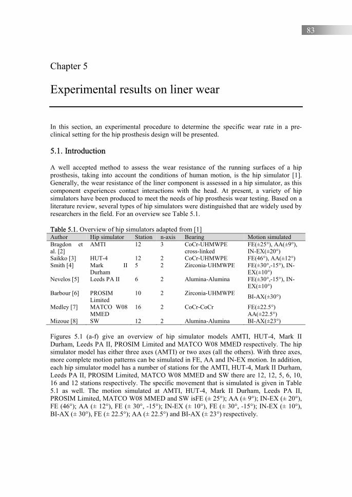
83
Chapter 5 Experimental results on liner wear In this section, an experimental procedure to determine the specific wear rate in a pre-clinical setting for the hip prosthesis design will be presented. 5.1. Introduction
A well accepted method to assess the wear resistance of the running surfaces of a hip prosthesis, taking into account the conditions of human motion, is the hip simulator [1]. Generally, the wear resistance of the liner component is assessed in a hip simulator, as this component experiences contact interactions with the head. At present, a variety of hip simulators have been produced to meet the needs of hip prosthesis wear testing. Based on a literature review, several types of hip simulators were distinguished that are widely used by researchers in the field. For an overview see Table 5.1. Table 5.1. Overview of hip simulators adapted from [1] Author Hip simulator Station n-axis Bearing Motion simulated Bragdon et al. [2]
AMTI 12 3 CoCr-UHMWPE cross-linked
FE(±25°), AA(±9°), IN-EX(±20°)
Saikko [3] HUT-4 12 2 CoCr-UHMWPE FE(46°), AA(±12°) Smith [4] Mark II
Durham 5 2 Zirconia-UHMWPE FE(±30°,-15°), IN-
EX(±10°) Nevelos [5] Leeds PA II 6 2 Alumina-Alumina FE(±30°,-15°), IN-
EX(±10°) Barbour [6] PROSIM
Limited 10 2 Zirconia-UHMWPE
BI-AX(±30°)
Medley [7] MATCO W08 MMED
16 2 CoCr-CoCr FE(±22.5°) AA(±22.5°)
Mizoue [8] SW 12 2 Alumina-Alumina BI-AX(±23°) Figures 5.1 (a-f) give an overview of hip simulator models AMTI, HUT-4, Mark II Durham, Leeds PA II, PROSIM Limited and MATCO W08 MMED respectively. The hip simulator model has either three axes (AMTI) or two axes (all the others). With three axes, more complete motion patterns can be simulated in FE, AA and IN-EX motion. In addition, each hip simulator model has a number of stations for the AMTI, HUT-4, Mark II Durham, Leeds PA II, PROSIM Limited, MATCO W08 MMED and SW there are 12, 12, 5, 6, 10, 16 and 12 stations respectively. The specific movement that is simulated is given in Table 5.1 as well. The motion simulated at AMTI, HUT-4, Mark II Durham, Leeds PA II, PROSIM Limited, MATCO W08 MMED and SW isFE (± 25°); AA (± 9°); IN-EX (± 20°), FE (46°); AA (± 12°), FE (± 30°, -15°); IN-EX (± 10°), FE (± 30°, -15°); IN-EX (± 10°), BI-AX (± 30°), FE (± 22.5°); AA (± 22.5°) and BI-AX (± 23°) respectively.
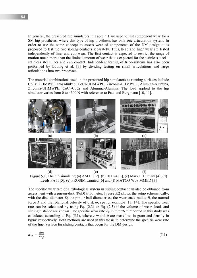
84
In general, the presented hip simulators in Table 5.1 are used to test component wear for a SM hip prosthesis, where this type of hip prosthesis has only one articulation system. In order to use the same concept to assess wear of components of the DM design, it is proposed to test the two sliding contacts separately. Thus, head and liner wear are tested independently of liner and cup wear. The first contact is expected to restrict the range of motion much more than the limited amount of wear that is expected for the stainless steel – stainless steel liner and cup contact. Independent testing of tribo-systems has also been performed by Loving et al. [9] by dividing testing on small articulations and large articulations into two processes.
The material combinations used in the presented hip simulators as running surfaces include CoCr, UHMWPE cross-linked, CoCr-UHMWPE, Zirconia-UHMWPE, Alumina-Alumina, Zirconia-UHMWPE, CoCr-CoCr and Alumina-Alumina. The load applied to the hip simulator varies from 0 to 4500 N with reference to Paul and Bergmann [10, 11].
(a) (b) (c)
(d) (e) (f)
Figure 5.1. The hip simulator; (a) AMTI [12], (b) HUT-4 [3], (c) Mark II Durham [4], (d) Leeds PA II [5], (e) PROSIM Limited [6] and (f) MATCO W08 MMED [7]
The specific wear rate of a tribological system in sliding contact can also be obtained from assessment with a pin-on-disk (PoD) tribometer. Figure 5.2 shows the setup schematically, with the disk diameter D, the pin or ball diameter dp, the wear track radius R, the normal force F and the rotational velocity of disk ω, see for example [13, 14]. The specific wear rate can be calculated by using Eq. (2.3) or Eq. (2.5) if the volume of wear, load, and sliding distance are known. The specific wear rate kw in mm3/Nm reported in this study was calculated according to Eq. (5.1), where ∆m and ρ are mass loss in gram and density in kg/m3 respectively. Both methods are used in this thesis to determine the specific wear rate of the liner surface for sliding contacts that occur for the DM design.
�X = ∆�1�Y (5.1)

85
Figure 5.2. Schematic of PoD wear test system adopted from [13, 14]
5.2. Experimental details
5.2.1. Pin-on-disk tribometer A PoD tribometer designed and constructed at the Laboratory for Engineering Design and Tribology, University of Diponegoro, see [15], is used to measure the specific wear rate of UHMWPE in sliding contact with SS316L. The components of the PoD tribometer can be seen in Figure 5.3 and Table 5.2. The applied load used in this research is 5 N in accordance with ASTM G99-17 [14] and is similar to other research [16, 17]. The rotational velocity ω of the disk is 50 rpm, resulting in a sliding velocity v of 0.1 m/s, while the mean contact pressure pm is 30 MPa. The experiment is performed for a maximum of 75,000 cycles, taking about 25 hours to complete.
Figure 5.3. The parts of PoD tribometer used in this research
Components A = Pin B = Disk C = Applied load D = Adjustment tool E = Frame F = Electric motor G = Display
C D
E
F
G
A B
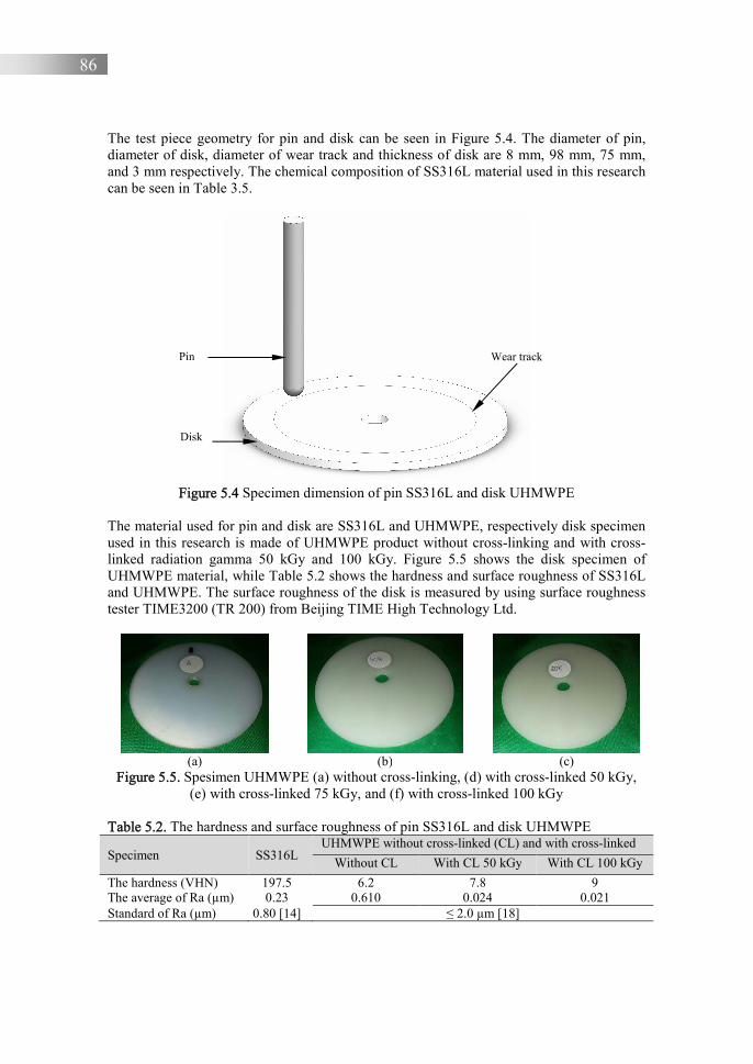
86
The test piece geometry for pin and disk can be seen in Figure 5.4. The diameter of pin, diameter of disk, diameter of wear track and thickness of disk are 8 mm, 98 mm, 75 mm, and 3 mm respectively. The chemical composition of SS316L material used in this research can be seen in Table 3.5.
Figure 5.4 Specimen dimension of pin SS316L and disk UHMWPE
The material used for pin and disk are SS316L and UHMWPE, respectively disk specimen used in this research is made of UHMWPE product without cross-linking and with cross-linked radiation gamma 50 kGy and 100 kGy. Figure 5.5 shows the disk specimen of UHMWPE material, while Table 5.2 shows the hardness and surface roughness of SS316L and UHMWPE. The surface roughness of the disk is measured by using surface roughness tester TIME3200 (TR 200) from Beijing TIME High Technology Ltd.
(a) (b) (c)
Figure 5.5. Spesimen UHMWPE (a) without cross-linking, (d) with cross-linked 50 kGy, (e) with cross-linked 75 kGy, and (f) with cross-linked 100 kGy
Table 5.2. The hardness and surface roughness of pin SS316L and disk UHMWPE
Specimen SS316L UHMWPE without cross-linked (CL) and with cross-linked
Without CL With CL 50 kGy With CL 100 kGy
The hardness (VHN) 197.5 6.2 7.8 9 The average of Ra (µm) 0.23 0.610 0.024 0.021 Standard of Ra (µm) 0.80 [14] ≤ 2.0 µm [18]
Wear track Pin
Disk
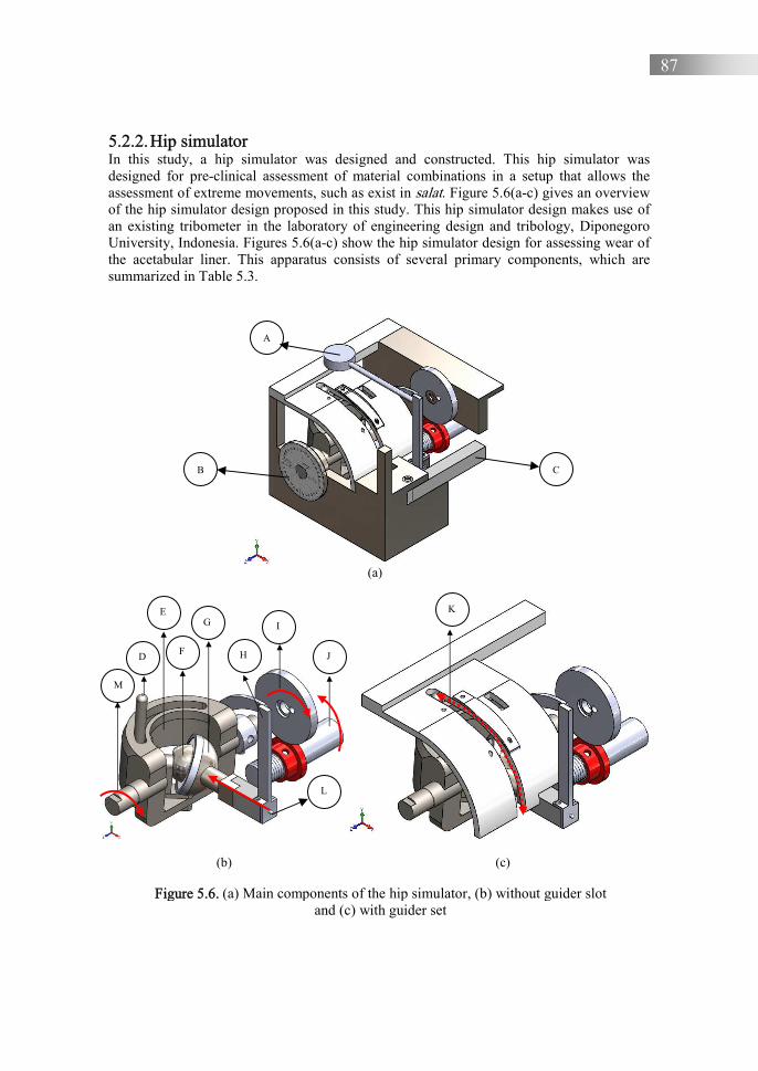
87
5.2.2. Hip simulator In this study, a hip simulator was designed and constructed. This hip simulator was designed for pre-clinical assessment of material combinations in a setup that allows the assessment of extreme movements, such as exist in salat. Figure 5.6(a-c) gives an overview of the hip simulator design proposed in this study. This hip simulator design makes use of an existing tribometer in the laboratory of engineering design and tribology, Diponegoro University, Indonesia. Figures 5.6(a-c) show the hip simulator design for assessing wear of the acetabular liner. This apparatus consists of several primary components, which are summarized in Table 5.3.
(a)
(b)
(c)
Figure 5.6. (a) Main components of the hip simulator, (b) without guider slot and (c) with guider set
K
D
E
F
G
H
I
J
L
A
B C
M
88
Table 5.3. Components of hip simulator Symbol Components Symbol Components
A Dial gauge indicator H Bar sensor to obtain penetration data B Cycle measurement (proximity sensor) I Driving gear C Cantilever bar J Driver shaft D Abduction-adduction bar K Guider set to guide abduction-adduction E Main frame for flexion-extension to
obtain gait cycles L Point contact of load
F Head ball or femoral head M Crank for flexion-extension G Cup support for liner
The femoral head is applied at the rotating axis of the hip simulator, see the indicated mainframe component E of the hip simulator in Figure 5.6(b). The acetabular liner is placed in the cup support liner, which is indicated by G in the same figure. The applied load is generated by pneumatic pressure. From the cantilever bar, the load is transferred to the indenter bar and then to the cup support liner through the point-of-load component. The applied load used in this experiment is 800 N, the upper limit of the current version of the simulator. Movement of this apparatus starts with the rotation of the electric motor at a given velocity, as illustrated by J in Figure 5.6(b). This rotation is set to one cycle per second then rotates gear I. The gear being driven continues to rotate the main frame through a crank M. The rotation of the mainframe starts the abduction-adduction bar movement along the guider slot D, where this slot will guide the abduction-adduction track that realizes the walking gait cycle. The number of cycles used in this experiment is 75,000, taking about 20 hours.
The height reduction in the experiment was obtained by reading the dial indicator located on the motion sensor rod. This dial indicator determines the penetration depth that occurs in contact with the acetabular liner. The dial indicator, a Mitutoyo series 543 with 0.001-mm accuracy, is mounted on the top lid of the chamber. Linear wear was measured in real time and its data is displayed on a monitor that is integrated with the dial indicator. Specifically, this measuring device is connected to an Arduino microcontroller, which forwards data to a computer so that the data can be retrieved directly, or in real time. Linear wear data was exported to a Microsoft Excel application. In addition, the mass of the acetabular liner before and after the wear test was measured by using VIBRA HTR-Analytical balances with 0.0001-g readability. The wear mass at the end of the test is used as data for calculating the specific wear rate, which is shown in the sub-section 5.3.2.2.
The whole apparatus is made of SS316L material. The chamber housing of the hip simulator is shown in Figure 5.7(a). Figure 5.7(b) shows the inside components of this apparatus. This apparatus is driven by an electric motor, the Lenze series D-4293 External made in Germany, which has a maximum torque 6.7 Nm. The rotation of the electric motor is connected to a gear pair, which produces two movements: flexion and abduction-adduction. The flexion movement is driven directly by the electric motor, whereas the abduction-adduction movement together with the flexion movement follow along the guider line. Obviously, in one rotation, this tool performs two flexion and two abduction movements. Every cycle is measured with inductive proximity sensor switch NPN NO (Normally Open) 4MM DC6-36V LJ12A3-4-Z/BX, where this sensor can detect objects
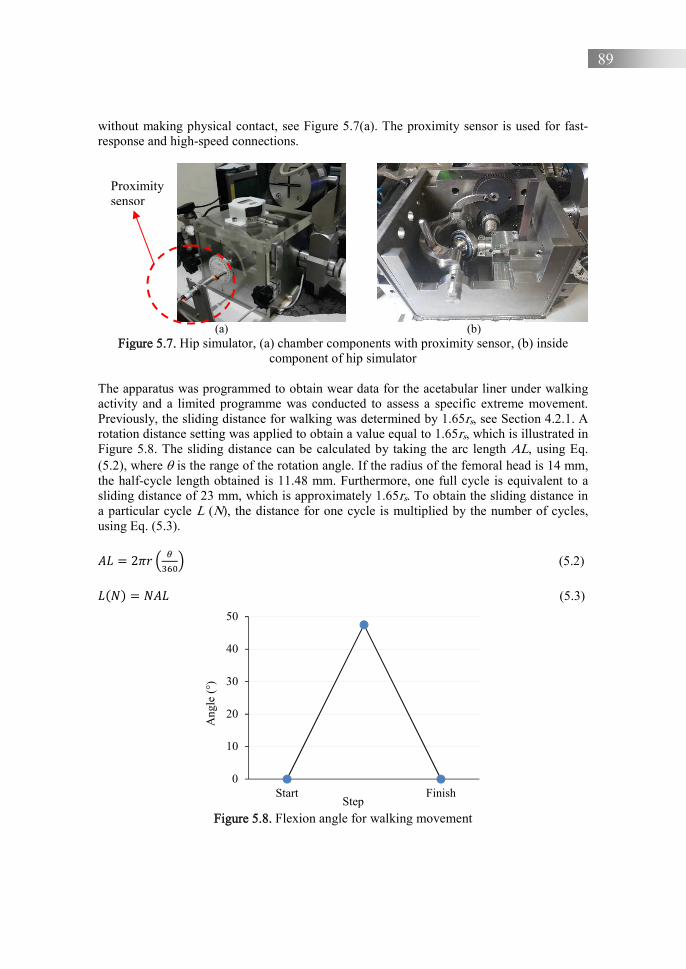
89
without making physical contact, see Figure 5.7(a). The proximity sensor is used for fast-response and high-speed connections.
(a) (b)
Figure 5.7. Hip simulator, (a) chamber components with proximity sensor, (b) inside component of hip simulator
The apparatus was programmed to obtain wear data for the acetabular liner under walking activity and a limited programme was conducted to assess a specific extreme movement. Previously, the sliding distance for walking was determined by 1.65rs, see Section 4.2.1. A rotation distance setting was applied to obtain a value equal to 1.65rs, which is illustrated in Figure 5.8. The sliding distance can be calculated by taking the arc length AL, using Eq. (5.2), where is the range of the rotation angle. If the radius of the femoral head is 14 mm, the half-cycle length obtained is 11.48 mm. Furthermore, one full cycle is equivalent to a sliding distance of 23 mm, which is approximately 1.65rs. To obtain the sliding distance in a particular cycle L (N), the distance for one cycle is multiplied by the number of cycles, using Eq. (5.3).
Z� = 2T� < [SM\= (5.2)
�F�G = �Z� (5.3)
Figure 5.8. Flexion angle for walking movement
0
10
20
30
40
50
Start Finish
Ang
le (
°)
Step
Proximity sensor

90
The femoral head of the prosthesis is made of SS316L, with a diameter of 28 mm. It is manufactured by a machining process and polished to obtain a smooth surface, see Table 5.4. The acetabular liner is made of UHMWPE material, with inner and outer diameters of 28.92 mm and 37 mm respectively. The acetabular liner is made using the compressive moulding process. The compressive moulding parameters were adopted from [19]. The surface roughness is measured on the inside surface of the liner using a Mark Surf PS1surface roughness tester, see Table 5.5. Figure 5.9(a) shows the liner position inside the cup, and Figure 5.9(b) shows the arrangement of the head and liner inside the hip simulator. Table 5.4. The surface roughness of femoral head and UHMWPE liner Components The average of Ra (μm) Standard for Ra (µm) [18] Femoral head 0.044 ≤ 0.05 UHMWPE liner 0.95 ≤ 2.00
(a) (b)
Figure 5.9. (a) Liner inside of cup and (b) positions of head and liner in the hip simulator 5.2.3. Bovine serum Bovine serum is made from cow blood as the main ingredient using a centrifuge machine [20]. Every 100 ml of cow blood processed produces about 30-40 ml of bovine serum. The cow blood sample must be given an anti-coagulant substance so that the cow blood does not clot. The anti-coagulant used is 3 gr Ethylenediaminetetraacetic Acid (EDTA) in powder form. The cow blood sample that has been mixed with EDTA is then taken to the laboratory for the sample centrifuge process. The centrifuge process is carried out to separate bovine serum from red blood cells. This process uses a Hettich Universal 320R centrifuge as shown in Figure 5.10(a). The procedure for placing a blood sample is shown in Figure 5.10(b). To produce bovine serum, the centrifuge machine runs at a speed of 5000 rpm at a temperature of 25oC and takes 10 minutes for each cycle. The resulting bovine serum is shown in Figure 5.10(c).
Bovine serum is stored in a freezer to prevent bacterial contamination, then thawed before it is used as a lubricant in the PoD test. The liquefaction process can be carried out at room temperature or immersed in water. Bovine serum only lasts about a week at room temperature. The bovine serum is applied by dropping it on the contact surface of UHMWPE during the testing process, 0.08 ml every 10 minutes. The contact point of the two materials was kept fully wetted with lubricant, see Figure 5.11(a) and Figure 5.11(b).

91
The lubrication used in the hip simulator is also bovine serum. The lubrication is carried out by dropping it on the contact surface of the femoral head and liner during the experimental process in this method, using an amount of 0.08 ml every 30 minutes.
(a) (b) (c)
Figure 5.10. (a) Centrifuge machine, (b) blood sample in the centrifuge machine, and (c) bovine serum
(a) (b)
Figure 5.11. (a) dropping bovine serum onto the disk and (b) lubricated sliding contact 5.3. Results
5.3.1. Coefficient of friction Figure 5.12 summarises the calculated CoF based on the PoD results for all specimens, i.e. non cross-linked, 50 kGy, 75 kGy and 100 kGy, under non lubricated (NL) and lubricated (L) conditions, Figure 5.12(a) and Figure 5.12(b) respectively.

92
(a) (b)
Figure 5.12. CoF for UHMWPE non cross-linked and cross-linked (50 and 100 kGy) under (a) non lubricated (NL) and (b) lubricated (L) condition
5.3.2. Specific wear rate 5.3.2.1. Pin-on-disk results Knowing the wear volume of the disk, the specific wear rate in the PoD experiment can be calculated using Eq. (2.5), where the wear volume was calculated by measuring the cross-sectional wear on the disk. The cross-sectional wear is obtained by measuring the wear track area using profilometry. In this study, the UHMWPE track wear profile was measured using the Mitutoyo SJ-210 surface roughness tool. Then the wear area was estimated using the peak analyzer feature in a graph and data analysis program such as in Figure 5.13 (a-b). The grey area in Figure 5.13 (b) is used to calculate the wear volume and then the specific wear rate. The adopted method is consistent with [21, 22, 23, 24].
Table 5.5 gives an overview of the cross-sectional wear and the volumetric wear measured after PoD testing and measured for the UHMWPE disk. The cross-sectional area was measured for all samples. The volumetric wear can then be calculated by multiplying the cross-sectional wear by the total sliding distance of the wear track. Based on Table 5.5, the highest and lowest cross-sectional wear measurements were 0.0066 mm2 and 0.0015 mm2 respectively. The highest volumetric wear was 1.546 mm3 while the lowest volumetric wear was 0.3591 mm3.
0.02
0.03
0.04
0.05
0.06
0.07
0.08
0.09
0.1
0 15000 30000 45000 60000 75000
Coe
ffic
ient
of
fric
tion,
µ (
-)
Cycles (-)
non cross-linked (NL)50 kGy (NL)100 kGy (NL)
0.02
0.03
0.04
0.05
0.06
0.07
0.08
0.09
0.1
0 15000 30000 45000 60000 75000
Coe
ffic
ient
of
fric
tion,
µ (
-)
Cycles (-)
non cross-linked (L)50 kGy (L)100 kGy (L)
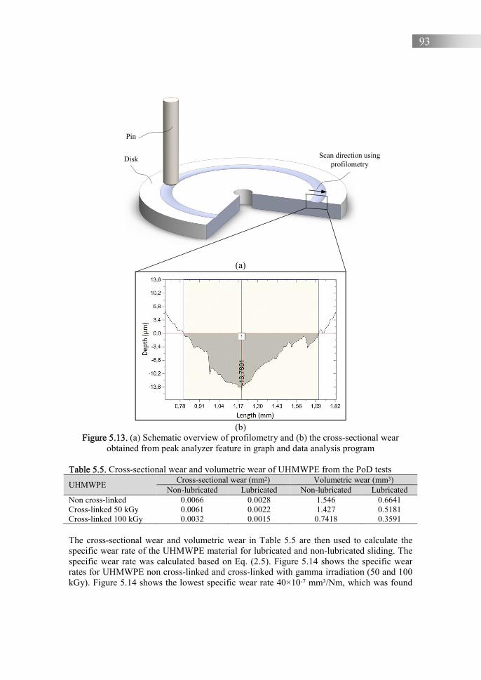
93
(a)
(b)
Figure 5.13. (a) Schematic overview of profilometry and (b) the cross-sectional wear obtained from peak analyzer feature in graph and data analysis program
Table 5.5. Cross-sectional wear and volumetric wear of UHMWPE from the PoD tests
UHMWPE Cross-sectional wear (mm2) Volumetric wear (mm3)
Non-lubricated Lubricated Non-lubricated Lubricated Non cross-linked 0.0066 0.0028 1.546 0.6641 Cross-linked 50 kGy 0.0061 0.0022 1.427 0.5181 Cross-linked 100 kGy 0.0032 0.0015 0.7418 0.3591 The cross-sectional wear and volumetric wear in Table 5.5 are then used to calculate the specific wear rate of the UHMWPE material for lubricated and non-lubricated sliding. The specific wear rate was calculated based on Eq. (2.5). Figure 5.14 shows the specific wear rates for UHMWPE non cross-linked and cross-linked with gamma irradiation (50 and 100 kGy). Figure 5.14 shows the lowest specific wear rate 40×10-7 mm3/Nm, which was found
Scan direction using profilometry
Pin
Disk

94
for the 100 kGy sample under lubricated conditions. The highest specific wear rate 178×10-
7 mm3/Nm occurred for the UHMWPE non cross-linked samples without lubrication.
Figure 5.14. Specific wear rate of UHMWPE in mm3/Nm based on PoD results,
F = 5 N, v = 0.1 m/s, pm = 30 MPa
5.3.2.2. Hip simulator results Table 5.6 show the wear mass and volumetric wear of the UHMWPE after the hip simulator tests, performed with and without bovine serum. Based on Table 5.6, the highest and lowest wear mass were 11.00 mg and 2.51 mg respectively. The highest volumetric wear was 11.64 mm3 while the lowest volumetric wear was 2.65 mm3. The wear mass and volumetric wear in Table 5.6 are then used to calculate the specific wear rate of the UHMWPE sliding surface using Eq. (5.1).
Table 5.6. Wear mass and volumetric wear of UHMWPE after the hip simulator test
UHMWPE Wear mass (mg) Volumetric wear (mm3)
Non-lubrication Lubrication Non-lubrication Lubrication Non cross-linked 11.00 3.85 11.64 4.07 Cross-linked 50 kGy 9.40 3.01 9.95 3.18 Cross-linked 100 kGy 8.35 2.51 8.84 2.65
Figure 5.15 shows the specific wear rates for UHMWPE non cross-linked and cross-linked with gamma irradiation (50 and 100 kGy). To make reading easier, the hip simulator is shortened to HipSim. Figure 5.15 shows the lowest specific wear rate 20×10-7 mm3/Nm, which occured for the 100 kGy sample with lubrication. While the highest specific wear rate 82×10-7 mm3/Nm occurred for the UHMWPE non cross-linked sample and dry sliding conditions.
0
20
40
60
80
100
120
140
160
180
200
non cross-linked 50 kGy 100 kGy
Spec
ific
wea
r ra
te k
W, ×
10-7
(mm
3 /N
m) PoD-dry sliding
PoD-lubricated (bovine serum)

95
Figure 5.15. Specific wear rate in mm3/Nm for the combination of SS316L vs UHMWPE performed by using hip simulator. Results are shown for UHMWPE non cross-linked, and
50 kGy & 100 kGy UHMWPE cross-linked. F = 800 N, v = 0.023 m/s, pm = 2 MPa 5.4. Discussion Figure 5.16 compares the specific wear rate of UHMWPE by using the PoD setup and by using the hip simulator without lubrication (UHMWPE non cross-linked, 50 kGy & 100 kGy). The absence of bovine serum can be seen from the wear rates, which are rather high for this material combination [25]. Cross-linking has a positive effect on the wear rate. The higher the doses, the lower the wear rate.
Figure 5.16 shows that the specific wear rate generated by the hip simulator is lower than the specific wear rate generated by PoD for dry sliding contact. The latter is likely related to the average contact pressure pm of the hip simulator when compared with PoD. The same qualitative relation between the PoD and hip simulator results was measured for lubricated conditions, see Figure 5.17. Clearly, wear was reduced by adding bovine serum by about a factor 2 for both methods. The results summarized in Figure 5.16 and 5.17 can be compared with the maximum wear rate that is allowed for the new design both for dry and for lubricated conditions. It shows that the UHMWPE liner material, cross-linked with irradiation 50-100 kGy performs at a wear rate below the threshold of 70.6×10⁻⁷ mm3/Nm for dry and for bovine serum lubricated conditions.
Sliding wear processes generally consist of a run-in regime followed by a steady state regime. Table 5.7 summarises the number of cycles of the PoD and hip simulator tests that are found to be representative of the run-in regime according to the reference. The specimens studied in these references are always a metal-on-plastic (MoP) combination and more specifically an UHMWPE material for dry or lubricated conditions. Based on these observations, the number of cycles for the run-in process of a PoD test is in the range of 0.001-2 million cycles, while for the hip simulator it is in the range of 0.05-2 million
0
20
40
60
80
100
120
140
160
180
200
non cross-linked 50 kGy 100 kGy
Spec
ific
wea
r ra
te k
W, ×
10-7
(mm
3 /N
m)
HipSim - dry Sliding
HipSim - lubricated (bovine serum)
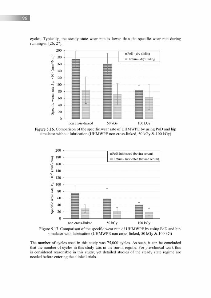
96
cycles. Typically, the steady state wear rate is lower than the specific wear rate during running-in [26, 27].
Figure 5.16. Comparison of the specific wear rate of UHMWPE by using PoD and hip
simulator without lubrication (UHMWPE non cross-linked, 50 kGy & 100 kGy)
Figure 5.17. Comparison of the specific wear rate of UHMWPE by using PoD and hip
simulator with lubrication (UHMWPE non cross-linked, 50 kGy & 100 kG) The number of cycles used in this study was 75,000 cycles. As such, it can be concluded that the number of cycles in this study was in the run-in regime. For pre-clinical work this is considered reasonable in this study, yet detailed studies of the steady state regime are needed before entering the clinical trials.
0
20
40
60
80
100
120
140
160
180
200
non cross-linked 50 kGy 100 kGy
Spec
ific
wea
ar r
ate
k W, ×
10-7
(mm
3 /N
m) PoD - dry sliding
HipSim - dry Sliding
0
20
40
60
80
100
120
140
160
180
200
non cross-linked 50 kGy 100 kGy
Spec
ific
wea
r ra
te k
W, ×
10-7
(mm
3 /N
m)
PoD-lubricated (bovine serum)
HipSim - lubricated (bovine serum)
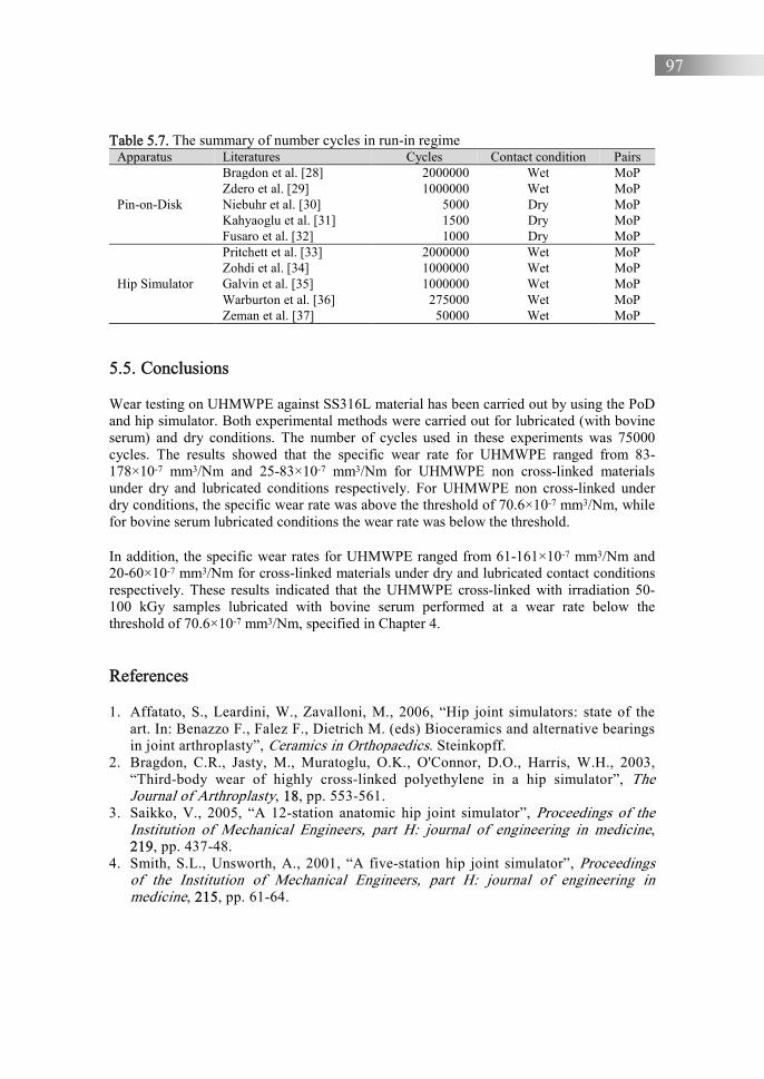
97
Table 5.7. The summary of number cycles in run-in regime Apparatus Literatures Cycles Contact condition Pairs
Pin-on-Disk
Bragdon et al. [28] 2000000 Wet MoP Zdero et al. [29] 1000000 Wet MoP Niebuhr et al. [30] 5000 Dry MoP Kahyaoglu et al. [31] 1500 Dry MoP Fusaro et al. [32] 1000 Dry MoP
Hip Simulator
Pritchett et al. [33] 2000000 Wet MoP Zohdi et al. [34] 1000000 Wet MoP Galvin et al. [35] 1000000 Wet MoP Warburton et al. [36] 275000 Wet MoP Zeman et al. [37] 50000 Wet MoP
5.5. Conclusions
Wear testing on UHMWPE against SS316L material has been carried out by using the PoD and hip simulator. Both experimental methods were carried out for lubricated (with bovine serum) and dry conditions. The number of cycles used in these experiments was 75000 cycles. The results showed that the specific wear rate for UHMWPE ranged from 83-178×10-7 mm3/Nm and 25-83×10-7 mm3/Nm for UHMWPE non cross-linked materials under dry and lubricated conditions respectively. For UHMWPE non cross-linked under dry conditions, the specific wear rate was above the threshold of 70.6×10⁻⁷ mm3/Nm, while for bovine serum lubricated conditions the wear rate was below the threshold.
In addition, the specific wear rates for UHMWPE ranged from 61-161×10-7 mm3/Nm and 20-60×10-7 mm3/Nm for cross-linked materials under dry and lubricated contact conditions respectively. These results indicated that the UHMWPE cross-linked with irradiation 50-100 kGy samples lubricated with bovine serum performed at a wear rate below the threshold of 70.6×10⁻⁷ mm3/Nm, specified in Chapter 4. References
1. Affatato, S., Leardini, W., Zavalloni, M., 2006, “Hip joint simulators: state of the art. In: Benazzo F., Falez F., Dietrich M. (eds) Bioceramics and alternative bearings in joint arthroplasty”, Ceramics in Orthopaedics. Steinkopff.
2. Bragdon, C.R., Jasty, M., Muratoglu, O.K., O'Connor, D.O., Harris, W.H., 2003, “Third-body wear of highly cross-linked polyethylene in a hip simulator”, The Journal of Arthroplasty, 18, pp. 553-561.
3. Saikko, V., 2005, “A 12-station anatomic hip joint simulator”, Proceedings of the Institution of Mechanical Engineers, part H: journal of engineering in medicine, 219, pp. 437-48.
4. Smith, S.L., Unsworth, A., 2001, “A five-station hip joint simulator”, Proceedings of the Institution of Mechanical Engineers, part H: journal of engineering in medicine, 215, pp. 61-64.
98
5. Nevelos, J.E., Ingham, E., Doyle, C., Nevelos, A.B., Fisher, J., 2001, “Wear of HIPed and non-HIPed alumina-alumina hip joints under standard and severe simulator testing conditions”, Biomaterials, 22, pp. 2191-2197.
6. Barbour, P.S., Stone, M.H., Fisher, J., 1999, “A hip joint simulator study using simplified loading and motion cycles generating physiological wear paths and rates”, Proceedings of the Institution of Mechanical Engineers, part H: journal of engineering in medicine, 213, pp. 455-467.
7. Medley, J.B., Krygier, J.J., Bobyn, J.D., Chan, F.W., Lippincott, A., Tanzer, M., 1997, “Kinematics of the MATCO hip simulator and issues related to wear testing of metal-metal implants”, Proceedings of the Institution of Mechanical Engineers, part H: journal of engineering in medicine, 211, pp. 89-99.
8. Mizoue, T., Yamamoto, K., Masaoka, T., Imakiire, A., Akagi, M., Clarke, I.C., 2003, “Validation of acetabular cup wear volume based on direct and two-dimensional measurements: hip simulator analysis”, Journal of Orthopaedic Science, 8, pp. 491-499.
9. Loving, L., Lee, R.K., Herrera, L., Essner, A.P., Nevelos, J.E., 2013, “Wear performance evaluation of a contemporary dual mobility hip bearing using multiple hip simulator testing conditions”, The journal of arthroplasty, 28, pp.1041-1046.
10. Paul, J.P., Mc Grouther, D.A., 1975, “Forces transmitted at the hip and knee joint of normal and disabled persons during a range of activities”, Acta Orthopaedica Belgica, 41(1), pp. 78-88.
11. Bergmann, G., Graichen, F., Rohlmann, A., 1993, “Hip joint loading during walking and running, measured in two patients”, Journal of Biomechanics, 26, pp. 969-990.
12. ADL Hip Simulator, description and specification, Amti.bz. ADL-Hip-12-Spec-101408.
13. Jia, B.B., Li, T.S., Liu, X.J., Cong, P.H., 2007, “Tribological behaviors of several polymer-polymer sliding combinations under dry friction and oil-lubricated conditions”, Wear, 262, pp. 1353-1359.
14. Standard test method for wear testing with a pin-on-disk apparatus, ASTM G99-17, 2017.
15. Wahyudi, M., 2018, “Analisis gesekan dan keausan material UHMWPE pada pengujian pin on disc dengan pelumas dan tanpa pelumas (Analysis of the friction and wear of UHMWPE material on the pin on disc test with lubricant and without lubricant)”, Master thesis, University of Diponegoro.
16. Odabas, D., 2008, “Effects of Load and Speed on Wear Rate of Abrasive Wear for 2014 Al Alloy”, IOP conference series: materials science and engineering, 295, 012008
17. Li, J., Wang, K., Li, Z., Tu, J.P., Jin, G., Su, J., Zhai, B., 2018, “Mechanical tests, wear simulation and wear particle analysis of carbon-based nanomultilayer coatings on Ti6Al4V alloys as hip prostheses”, Royal Society of Chemistry, 8, 6849-6857
18. Implants for surgery - partial and total hip joint prostheses, Part 2: Articulating surfaces made of metallic, ceramic and plastics materials, ISO 7206-2:2011, 2011.
19. Kurtz, S.M., 1999, “Advances in the processing, sterilization, and crosslinking of ultra high molecular weight polyethelene for total joint arthroplasty”, Biomaterials, 20(18), pp. 1659-1688.
99
20. Wei, Z., Batagov, A.O., Carter, D.R.F., Krichevsky, A.M., 2016, “Fetal Bovine Serum RNA Interferes with the Cell Culture derived Extracellular RNA”, Scientific Reports, 6, 31175.
21. Guezmil, M., Bensalah, W. dan Mezlini, S., 2016, “Tribological behavior of UHMWPE against TiAl6V4 and CoCr28Mo alloys under dry and lubricated conditions,” Journal of the Mechanical Behavior of Biomedical Materials, 63, pp. 375-385.
22. Sagbas, B., Durakbasa, M.N., 2014, “Surface texturing of vitamin E blended UHMWPE for reduction of wear”, Acta Physica Polonica A., 125(2), pp.481-483.
23. Ma, L., Rainforth, W.M., Sun, D., Wharton, J.A., Wood, R.J.K, 2009, “A ‘3-body’ abrasion wear study of bioceramics for total hip joint replacements”, Wear, 267(11), pp. 2122-2131.
24. Pylios, T., Shepherd, D.E., 2008, “Wear of medical grade silicone rubber against titanium and ultrahigh molecular weight polyethylene”, Journal of Biomedical Materials Research part B: applied biomaterials, 84(2), pp. 520-523.
25. Rodríguez Cañizo, R.G., García García, L.A., Torres, M.V., Merchán Cruz, E.A., Sandoval Pineda, J.M., 2010, “Experimental wear analysis of ultra-high-molecular-weight polyethylene and 316L stainless steel used in manufacturing coxofemoral prosthesis”, Revista Colombiana de Biotecnología, 12(2), pp. 67-85
26. Chen, Y., Li, Y., Koizumi, Y., Haider, H., Chiba, A., 2017, “Effects of carbon addition on wear mechanisms of CoCrMo metal-on-metal hip joint bearings”, Materials Science and Engineering C, 76, pp. 997-1004.
27. Yan, Y., Neville, A., Dowson, D., 2006, “Biotribocorrosion-an appraisal of the time dependence of wear and corrosion interactions: I. The role of corrosion”, Journal of Physics D: applied physics, 39, pp. 3200-3205.
28. Bragdon, C.R., O’Connor, D.O., Lowenstein, J.D., Jasty, M., Biggs, S.A., Harris, W.H., 2001, “A new pin-on-disk wear testing method for simulating wear of polyethylene on cobalt-chrome alloy in total hip arthroplasty”, The Journal of Arthroplasty, 16(5), pp. 658-665.
29. Zdero, R., Guenther, L.E., Gascoyne, T.C., 2017, “Chapter 19: Pin-on-disk wear testing of biomaterials used for total joint replacements”, Experimental Methods in Orthopaedic Biomechanics, pp. 299-311.
30. Niebuhr, D., 2007, “Friction and wear behavior of engineering materials in a simulated Martian (CO2) environment, a preliminary study”, Wear, 263, pp. 88-92.
31. Kahyaoglu, O.K., Unal, H., 2012, “Friction and wear behaviours of medical grade UHMWPE at dry and lubricated conditions”, International Journal of Physical Sciences, 7(16), pp. 2478-2485.
32. Fusaro, R.L. 1982, “Effect of sliding speed and contact stress on tribological properties of ultra-high-molecular-weight polyethilene”, NASA Technical Paper 2059, pp. 1-19.
33. Pritchett, J., 2016, “Very large diameter polymer acetabular liners show promising wear simulator results”, Journal of Long-Term Effects of Medical Implants, 26(4), pp.311-319.
34. Zohdi, H., Andreatta, B., Heuberger, R., 2017, “Particles and ions generated in total hip joint prostheses: In vitro wear test results of UHMWPE and XLPE acetabular components”, Tribology Letters, 65(92). Pp. 1-15.
35. Galvin, A.L., Jennings, L.M., Tipper, J.L., Ingham, E., Fisher, J., 2010, “Wear and creep of highly crosslinked polyethylene against cobalt chrome and ceramic femoral

100
heads”, Proceedings of the Institution of Mechanical Engineers Part H: J. engineering in medicine, 224, pp. 1175-1183.
36. Warburton, K.J., Everingham, J.B., Helms, J.L., Kazanovicz, A.J., Hollar, K.A., Brourman, J.D., Fox, S.M., Lujan, T.J., 2018, “Wear testing of a canine hip resurfacing implant that uses highly cross-linked polyethylene,” Journal of Orthopaedic Research, 36(4), pp. 1196-1205.
37. Zeman, J., Ranusa, M., Vrbka, M., Gallo, J., Krupka, I., Hartl, M., 2018, “UHMWPE acetabular cup creep deformation during the run-in phase of THA's life cycle”, Journal of the Mechanical Behavior of Biomedical Materials, 87, pp. 30-39.
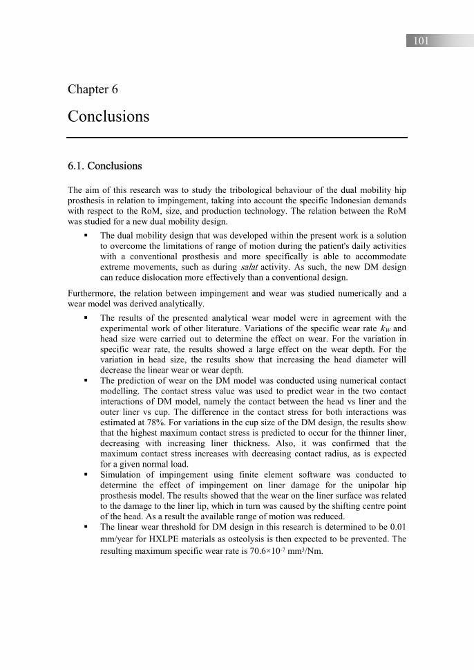
101
Chapter 6
Conclusions 6.1. Conclusions
The aim of this research was to study the tribological behaviour of the dual mobility hip prosthesis in relation to impingement, taking into account the specific Indonesian demands with respect to the RoM, size, and production technology. The relation between the RoM was studied for a new dual mobility design.
The dual mobility design that was developed within the present work is a solution to overcome the limitations of range of motion during the patient's daily activities with a conventional prosthesis and more specifically is able to accommodate extreme movements, such as during salat activity. As such, the new DM design can reduce dislocation more effectively than a conventional design.
Furthermore, the relation between impingement and wear was studied numerically and a wear model was derived analytically.
The results of the presented analytical wear model were in agreement with the experimental work of other literature. Variations of the specific wear rate kW and head size were carried out to determine the effect on wear. For the variation in specific wear rate, the results showed a large effect on the wear depth. For the variation in head size, the results show that increasing the head diameter will decrease the linear wear or wear depth.
The prediction of wear on the DM model was conducted using numerical contact modelling. The contact stress value was used to predict wear in the two contact interactions of DM model, namely the contact between the head vs liner and the outer liner vs cup. The difference in the contact stress for both interactions was estimated at 78%. For variations in the cup size of the DM design, the results show that the highest maximum contact stress is predicted to occur for the thinner liner, decreasing with increasing liner thickness. Also, it was confirmed that the maximum contact stress increases with decreasing contact radius, as is expected for a given normal load.
Simulation of impingement using finite element software was conducted to determine the effect of impingement on liner damage for the unipolar hip prosthesis model. The results showed that the wear on the liner surface was related to the damage to the liner lip, which in turn was caused by the shifting centre point of the head. As a result the available range of motion was reduced.
The linear wear threshold for DM design in this research is determined to be 0.01 mm/year for HXLPE materials as osteolysis is then expected to be prevented. The resulting maximum specific wear rate is 70.6×10⁻⁷ mm3/Nm.
102
An experimental procedure to determine the specific wear rate in a pre-clinical setting for the hip prosthesis design was developed based on a pin-on-disk setup and based on a newly developed hip simulator setup. Bovine serum was used to simulate lubricated conditions.
The results showed that for non cross-linked UHMWPE under dry conditions, the specific wear rate was above the threshold of 70.6×10⁻⁷ mm3/Nm, while for bovine serum lubricated conditions the wear rate was below the threshold. In addition, the specific wear rates for UHMWPE cross-linked materials with irradiation of 50-100 kGy and lubricated with bovine serum performed at a wear rate below the threshold of 70.6×10⁻⁷ mm3/Nm.
6.2. Future works
The present research was conducted in a pre-clinical setting. Apart from the medical aspects that need further research, such as the biocompatibility, the following aspects need further attention as well, before entering a clinical setting:
1. The metal-on metal contact. In this study, it was found that the proposed liner consisting of UHMWPE and metal materials can reduce contact stress or contact pressure, see Figure 4.9b. It is related to the contact radii, see Figure 4.10(b). Based on Eq. (4.7), decreasing contact stress can reduce wear. Therefore, these findings need to be studied further to reduce wear in the metal-on-metal contact of the DM-design. Furthermore, research is needed to verify the frictional aspects of this contact under conditions that are close to implanted conditions.
2. Based on Figure 4.14(b), there is increasing contact stress near the end of the contact area. The common form of contact stress distribution on the hip prosthesis is similar to that in Figure 4.10(a). This phenomenon can result in different wear forms. Therefore, these phenomena need to be studied further to obtain the wear form numerically or experimentally.
3. In this wear experiment, the number of cycles used only reaches the run-in regime, where it is caused by limiting the apparatus. For clinical trials, the number of wear test cycles on the liner needs to be continued up to the steady-state regime.
4. We chose a dual mobility design with a metal-to-metal contact surface which aims to minimize the wear rate. However, to reach the output of the study – the hip prosthesis design – researchers need to carry out several steps: (1) preclinical study (in vivo study, in vitro study) and (2) clinical trial (phase 0 – first in human trials, phase I – a small number of human subjects, phase II – a larger group of patients, phase III – randomized controlled multicentre trials, phase IV – post-marketing surveillance trials). As in preclinical study, the material should be tested in human cells to observe the reaction of the cell to the implant material. The material also needs to be tested in an animal model to assess the body tissue reaction to the implant material. The implant must be compatible with human tissue without causing an adverse reaction. Material biocompatibility was discussed further in Chapter 2. If the material has been proved biocompatible in a preclinical study, it can be further investigated in clinical trials or human experiments.

103
Part II

104

Patent
J. Jamari, E. Saputra, I.B. Anwar, et al., 2019 Sendi panggul buatan bipolar untuk memudahkan
gerakan salat pasien (Bipolar artificial hip joint for patient performing salat)
Indonesian Patent: S00201703018

P-1
P-2
Paper A
E. Saputra, I.B. Anwar, R. Ismail, J. Jamari, E. van der Heide, 2014 Numerical simulation of artificial hip joint movement for
Western and Japanese-style activities
Jurnal Teknologi (Sciences & Engineering), Volume 66, Issue 3, pp. 53-58, doi: https://doi.org/10.11113/jt.v66.2694

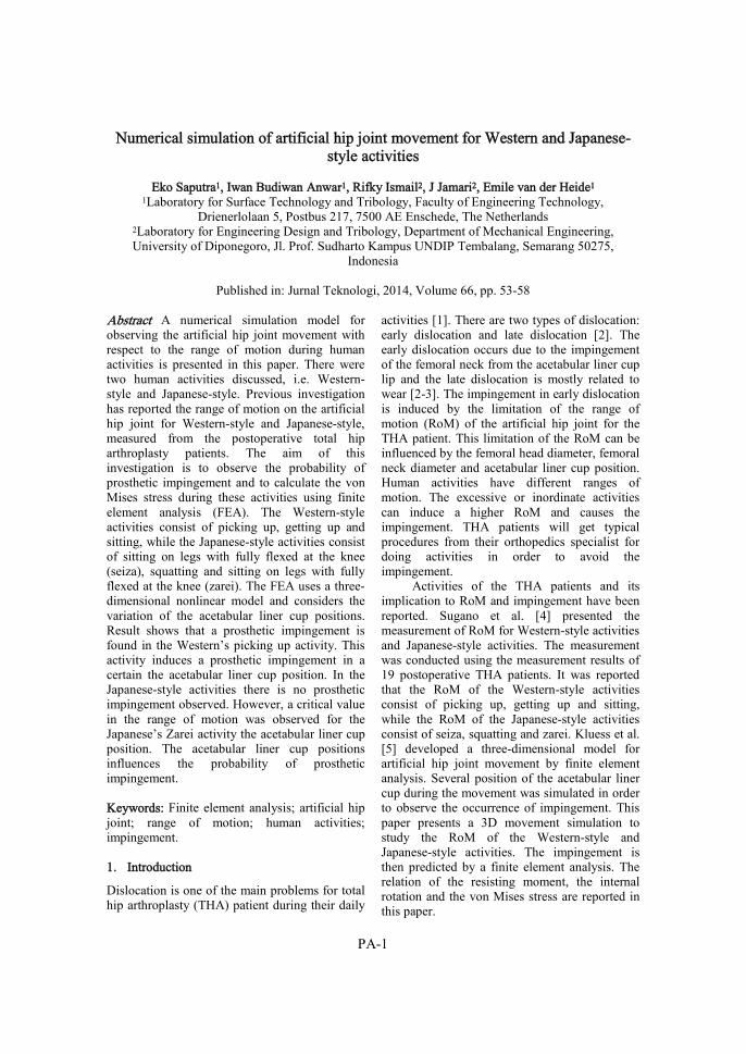
PA-1
Numerical simulation of artificial hip joint movement for Western and Japanese-style activities
Eko Saputra1, Iwan Budiwan Anwar1, Rifky Ismail2, J Jamari2, Emile van der Heide1
1Laboratory for Surface Technology and Tribology, Faculty of Engineering Technology, Drienerlolaan 5, Postbus 217, 7500 AE Enschede, The Netherlands
2Laboratory for Engineering Design and Tribology, Department of Mechanical Engineering, University of Diponegoro, Jl. Prof. Sudharto Kampus UNDIP Tembalang, Semarang 50275,
Indonesia
Published in: Jurnal Teknologi, 2014, Volume 66, pp. 53-58
Abstract A numerical simulation model for observing the artificial hip joint movement with respect to the range of motion during human activities is presented in this paper. There were two human activities discussed, i.e. Western-style and Japanese-style. Previous investigation has reported the range of motion on the artificial hip joint for Western-style and Japanese-style, measured from the postoperative total hip arthroplasty patients. The aim of this investigation is to observe the probability of prosthetic impingement and to calculate the von Mises stress during these activities using finite element analysis (FEA). The Western-style activities consist of picking up, getting up and sitting, while the Japanese-style activities consist of sitting on legs with fully flexed at the knee (seiza), squatting and sitting on legs with fully flexed at the knee (zarei). The FEA uses a three-dimensional nonlinear model and considers the variation of the acetabular liner cup positions. Result shows that a prosthetic impingement is found in the Western’s picking up activity. This activity induces a prosthetic impingement in a certain the acetabular liner cup position. In the Japanese-style activities there is no prosthetic impingement observed. However, a critical value in the range of motion was observed for the Japanese’s Zarei activity the acetabular liner cup position. The acetabular liner cup positions influences the probability of prosthetic impingement. Keywords: Finite element analysis; artificial hip joint; range of motion; human activities; impingement. 1. Introduction
Dislocation is one of the main problems for total hip arthroplasty (THA) patient during their daily
activities [1]. There are two types of dislocation: early dislocation and late dislocation [2]. The early dislocation occurs due to the impingement of the femoral neck from the acetabular liner cup lip and the late dislocation is mostly related to wear [2-3]. The impingement in early dislocation is induced by the limitation of the range of motion (RoM) of the artificial hip joint for the THA patient. This limitation of the RoM can be influenced by the femoral head diameter, femoral neck diameter and acetabular liner cup position. Human activities have different ranges of motion. The excessive or inordinate activities can induce a higher RoM and causes the impingement. THA patients will get typical procedures from their orthopedics specialist for doing activities in order to avoid the impingement.
Activities of the THA patients and its implication to RoM and impingement have been reported. Sugano et al. [4] presented the measurement of RoM for Western-style activities and Japanese-style activities. The measurement was conducted using the measurement results of 19 postoperative THA patients. It was reported that the RoM of the Western-style activities consist of picking up, getting up and sitting, while the RoM of the Japanese-style activities consist of seiza, squatting and zarei. Kluess et al. [5] developed a three-dimensional model for artificial hip joint movement by finite element analysis. Several position of the acetabular liner cup during the movement was simulated in order to observe the occurrence of impingement. This paper presents a 3D movement simulation to study the RoM of the Western-style and Japanese-style activities. The impingement is then predicted by a finite element analysis. The relation of the resisting moment, the internal rotation and the von Mises stress are reported in this paper.

PA-2
2. Material and Method 2.1. Material model
The finite element model of the contact system in the present study consists of femoral head, femoral neck and acetabular liner cup. The femoral head and the femoral neck component are assumed rigid. The acetabular liner cup component is modeled as an elastic-plastic material with isotropic hardening and assuming a visco-elastic-plastic material behavior of the ultra-high-molecular-weight polyethylene (UHMWPE). The modulus of elasticity, the Poisson’s ratio and the yield strength of the UHMWPE are set to 945 MPa, 0.45 and 23.56 MPa, respectively [6]. The plastic strain is calculated based on the work of Fregly et al. [7].
n
00
00 2
121
(1)
where the material parameter, n, is equal to 3.
2.2. Finite element method 2.2.1. Geometry
The geometrical modeling of the unipolar artificial hip joint follows the model of Kluess et
al. [5], as is depicted in Fig. 2(a). Diameter of the femoral head and the femoral neck are 28 mm and 14 mm, respectively. The thickness of the acetabular liner cup is 7 mm. A gap between the femoral head and the acetabular liner cup is 24 µm and it is modeled as a lubrication space.
Fig. 2(b) shows the finite element meshes for the acetabular liner cup. The commercial finite element software ABAQUS is employed. The element type of hexahedral eight nodes linear brick (C3D8R) is employed, while the number of the element is approximately 9000.
(a) (b) Figure 2: (a) Model of the femoral head and the acetabular liner cup and (b) the finite element meshes of the acetabular liner cup
Figure 1: The plastic strain curve
2.2.2. Boundary conditions
The value of the applied load of the present model is taken from the work of Kluess et al. [5], but the direction of the load follows the work of
Bergmann et al. [8]. The loads in the x, y and z directions are Fx = 15 N, Fy = 270 N and Fz = -427.5 N, respectively, and are applied on a point at the center of the femoral head, see Fig.3. All

PA-3
the degree of freedom at the outer surface of the acetabular liner cup is constrained. The simulation is conducted in two steps: firstly, the load is applied to the center of the femoral head with constraining the rotation of the femoral head is constrained and secondly, the load at the center of the femoral head is constrained with rotating the femoral head. The range of the internal rotation (IR) is according to the RoM of human activities. 2.2.3. Human activities
The simulations are performed for the Western-style and the Japanese-style activities. Here, the value of the RoM is taken based on the work of Sugano et al. [4]. The Western-style activities consist of picking up an object while sitting on the chair, getting up from the chair, and sitting down on the chair.The Japanese-style activities consist of bowing while sitting on legs with fully flexed at the knee (zarei), squatting, and sitting on legs with fully flexed at the knee (seiza). Figures for expressing all these activities can be
seen in Fig.4 [4]. Those activities give a certain value of the RoM in degree. Maximum flexion, adduction and internal rotation are the component items for the RoM value. Table 1 shows the value of RoM for the human general activities.
Figure 3: Boundary conditions on finite element model
(a) (b) (c)
(d) (e) (f)
Figure 4: (a) Picking up an object while sitting on the chair, (b) Getting up from the chair, (c) sitting down on the chair, (d) Bowing while sitting on legs fully flexed at the knee (zarei), (e) squatting, and
(f) sitting on legs fully flexed at the knee
Fy Fx Fz IR

PA-4
Table 1: Hip joint angle [°] during human activities, adapted from [4]
Motion, Degree Average ± Standard deviation
Maximum Flexion
Adduction Internal Rotation
Western-style activities on the chair Picking up an object while sitting on the chair Getting up from the chair Sitting down on the chair Japanese-style activities on the floor Bowing while sitting on legs fully flexed at the knee (zarei) Squatting Sitting on legs fully flexed at the knee (seiza)
86 ± 13 76 ± 12 62 ± 10 84 ± 13 80 ± 16 61 ± 12
−6.1 ± 7.3 −2.5 ± 5.2 −0.92 ± 5.5 −2.1 ± 4.9 −8.6 ± 9.5 −1.2 ± 4.4
−12 ± 11 −11 ± 10 −7.0 ± 11 −12 ± 11 −9.2 ± 11 −15 ± 11
2.2.4. Variation
The variation of the angle between inclination and anteversion of the acetabular liner cup is simulated in order to study the possibility of the impingement to occur between the femoral neck and the acetabular liner cup lip. The variations of inclination of the acetabular liner cup are 45o and 60o and the variation of anteversion of the acetabular liner cup are 15o and 30o. The angle of the femoral neck axis line and the femoral stem axis line is 135o. The simulation uses a femoral head diameter of 28 mm. The variations in the present study follow the work of Kluess et al. [5].
3. Results and discussions 3.1. Validation
In order to check the developed model simulation, a validation was conducted by comparing the results to the work of Kluess et al. [5]. The inclination and anteversion of the acetabular liner cup were fixed for 60o and 30o, respectively. Result of the validation is shown in Fig. 5. The average deviation between the present model and the Kluess et al. model is about 1.32 %. The developed model is in good agreement with literature with respect to the predicted resisting moment.
Figure 5: Comparison between the present model and the Kluess model [5] in predicting the resisting moment as a function of the angle of internal rotation.

PA-5
3.2. Western-style activities
Fig. 6(a) and 6(b) show the degree of impingement for the Western-style activities. In Fig. 6(a) the internal rotation for the picking-up, getting-up and sitting down activities is reported with considering four different position of the acetabular liner cup. The minimum requirements of the internal rotation for picking-up, getting-up and sitting down activities are 12, 11 and 7, respectively. The highest resisting moments for picking-up, getting-up and sitting down activities are 4.41 Nm, 3.88 Nm and 3.21 Nm as is depicted in Fig. 6(b).
The unipolar artificial hip joint does not induce an impingement for most of the Western-style activities. Yet, the picking up activity, for the acetabular liner cup inclination of 45 and anteversion of 15, could be critical as the impingement is predicted to occur at 8 of the internal rotation. Therefore, the THA patients are suspected not to be able to finish the picking up activity due to the fact that it needs at least 12 of internal rotation. Fig. 7 shows the von Mises stress analysis. Fig. 7(a,c) shows the stress
analysis for getting up activity, Fig. 7(b,d) shows the picking up activity, and Fig.7(e) shows the sitting down activity, where the combination degree of the acetabular liner cup inclination and the anteversion is 45-15. Two impingement positions can be found from the analysis based on this figure, namely impingement site and egress site.
Dislocation is predicted to occur for the patients who are trying to perform the picking up activity. The other combination positions of the acetabular liner cup for inclination and anteversion are also reported in a safe position, 45-30, 60-15 and 60-30. However, based on several testimonies of the orthopedic specialist, it is stated that the inclination and the anteversion of the acetabular liner cup combinations of 45-15 are mostly used. It is suggested that the unipolar artificial hip joint, proposed by Kluess et al. [5], need to be redesigned to accommodate the picking up activity with respect to the inclination and the anteversion of the acetabular liner cup combination of 45-15.
(a) (b)
Figure 6: (a) Comparison of the calculated value of internal rotation obtained from variations of the acetabular liner cup position in the Western-style activities and (b) plot of its resisting moment as a
function of its internal rotation angle.
0°
10°
20°
30°
40°
50°
60°
70°
Picking up Getting up Sitting down
Inte
rna
l Ro
tati
on
Western-Style
Required
45_15
45_30
60_15
60_30
0.00
1.00
2.00
3.00
4.00
5.00
0° 10° 20° 30° 40° 50° 60° 70° 80° 90°
Res
istin
g m
omen
t [N
m]
Angle of internal rotation
Incl=45, Antv=15, picking up
Incl=45, Antv=15, getting Up
Incl=45, Antv=15, Sitting down
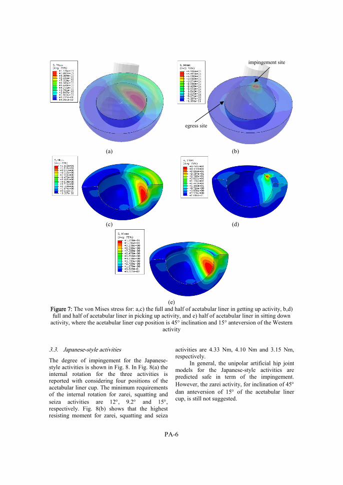
PA-6
(a) (b)
(c) (d)
(e)
Figure 7: The von Mises stress for: a,c) the full and half of acetabular liner in getting up activity, b,d) full and half of acetabular liner in picking up activity, and e) half of acetabular liner in sitting down
activity, where the acetabular liner cup position is 45° inclination and 15° anteversion of the Western activity
3.3. Japanese-style activities
The degree of impingement for the Japanese-style activities is shown in Fig. 8. In Fig. 8(a) the internal rotation for the three activities is reported with considering four positions of the acetabular liner cup. The minimum requirements of the internal rotation for zarei, squatting and seiza activities are 12, 9.2 and 15, respectively. Fig. 8(b) shows that the highest resisting moment for zarei, squatting and seiza
activities are 4.33 Nm, 4.10 Nm and 3.15 Nm, respectively.
In general, the unipolar artificial hip joint models for the Japanese-style activities are predicted safe in term of the impingement. However, the zarei activity, for inclination of 45 dan anteversion of 15 of the acetabular liner cup, is still not suggested.
egress site
impingement site
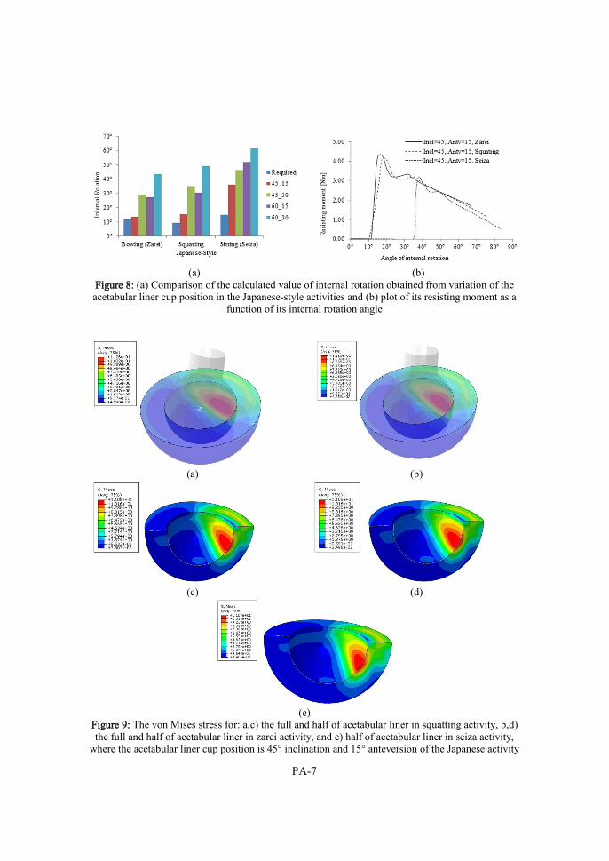
PA-7
(a) (b)
Figure 8: (a) Comparison of the calculated value of internal rotation obtained from variation of the acetabular liner cup position in the Japanese-style activities and (b) plot of its resisting moment as a
function of its internal rotation angle
(a) (b)
(c) (d)
(e)
Figure 9: The von Mises stress for: a,c) the full and half of acetabular liner in squatting activity, b,d) the full and half of acetabular liner in zarei activity, and e) half of acetabular liner in seiza activity,
where the acetabular liner cup position is 45° inclination and 15° anteversion of the Japanese activity

PA-8
This is because the impingement of the zarei activity is predicted to occur at 13.53 of internal rotation whiles the result shows that the required degree of the zarei activity is 12o. Moreover, the safe margin of the internal rotation is about 10 as was suggested by Sugano et al. [4]. Therefore, an evaluation is still needed for the unipolar artificial hip joint model proposed by Kluess et al. [5]. The model needs to be redesigned for accommodating the zarei activity in a more safe condition. The von Mises stress contours for the Japanese-style activities are shown in Fig. 9(a,c), 9(b,d) and 9(e) for squatting, zarei and seiza activities, respectively, with the combination of inclination and anteversion of the acetabular liner cup of 45-15.
4. Conclusion
This paper investigated the range of motion of the human activities of the Western-style and the Japanese-style using finite element analysis for THA patient. The unipolar artificial hip joint model was used in the simulation. Based on the results it can be stated that for the THA patients the Western-style and Japanese-style most activities can be performed safely. The impingement and dislocation are predicted to be occur at picking up activity in the Western-style activity for the inclination and anteversion combination of the acetabular liner cup of 45-15. The seiza activity in the Japanese-style activitiy is not recommended to be performed for the THA patients because of the safety margin of the internal rotation is less than 10. The impingement between the femoral neck and the acetabular liner cup lip during a contact situation can be predicted by the finite element simulation. It is demonstrated that the von Mises stress at the impingement position is higher than the yield strength of the material. References 1. Sikes, C.V., Lai, L.P., Schreiber, M., Mont,
M.A., Jinnah, R.H., Seyler, T.M., 2008, “Instability After Total Hip Arthroplasty Treatment with Large Femoral Heads vs Constrained Liners”, The Journal of Arthroplasty, Vol. 23, No.7, pp. 59-63.
2. Cuckler, J.M., 2011, “The Dislocated Total Hip: The Dreaded 3 AM Phone Call”, Seminars in Arthroplasty 22, pp. 98-99.
3. Hummel, M.T., Malkani, A.L., Yakkanti, M.R., Baker, D.L., 2009, “Decreased Dislocation After Revision Total Hip Arthroplasty Using Larger Femoral Head Size and Posterior Capsular Repair”, The Journal of Arthroplasty, Vol. 24, No. 6, pp. 73-76.
4. Sugano, N., Tsuda, K., Miki, H., Takao, M., Suzuki, N., Nakamuro, N., 2012, “Dynamic Measurements of Hip Movement in Deep Bending Activities After Total Hip Arthroplasty Using a 4-Dimensional Motion Analysis System”, The Journal of Arthroplasty, Vol. 27, No. 8, pp. 1562-1568.
5. Kluess, D., Martin, H., Mittelmeier, W., Schmitz, K.P., Bader, R., 2007, “Influence of Femoral Head Size on Impingement, Dislocation and Stress Distribution in Total Hip Replacement”, Medical Engineering & Physics 29, pp. 465-471.
6. Eichmiller, F.C., Tesk, J.A., Croarkin, C.M., 2001, “Mechanical Properties of Ultra High Molecular Weight Polyethylene NIST Reference Material RM 8456”, In: ‘Transactions of the Society for Biomaterials, 27th Annual Meeting’, p. 472.
7. Fregly, B.J., Bei, Y., Sylvester, M.E., 2003, “Experimental Evaluation of An Elastic Foundation Model to Predict Contact Pressures in Knee Replacements”, Journal of Biomechanics 36, pp. 1659-1668.
8. Bergmann, G., Graichen, F., Rohlmann, A., 1993, “Hip Joint Loading During Walking and Running, Measured in Two Patients”, Journal of Biomechanics 26, pp. 969- 990.

Paper B
J. Jamari, I.B. Anwar, E. Saputra, R. Ismail, E. van der Heide, 2017 Range of motion simulation of hip joint movement
during salat activity
The Journal of Arthroplasty, Volume 32, pp. 2898-2904, doi: https://doi.org/10.1016/j.arth.2017.03.056


PB-1
Range of motion simulation of hip joint movement during salat activity
J Jamari1, Iwan Budiwan Anwar2, Eko Saputra2, Emile van der Heide2
1Laboratory for Engineering Design and Tribology, Department of Mechanical Engineering, Diponegoro University, Jl. Prof. Soedharto SH, Tembalang, Semarang 50275, Indonesia
2Laboratory for Surface Technology and Tribology, Faculty of Engineering Technology, University of Twente Drienerloolaan 5, Postbox 217, 7500 AE, Enschede, The Netherlands
Published in: The Journal of Arthroplasty, Volume 32, pp. 2898-2904
Abstract Impingement of an artificial hip joint due to limited range of motion (RoM) during human activity is one of the main sources of hip joint failure. The aim of this paper is to simulate the RoMs of hip joints during salat, the practice of formal worship in Islam. Salat consists of several stages which can be represented with a cycle (raka’ah). Every raka’ah consists of standing, bowing (ruku’), straightening up (i’tidal), transition of standing towards prostrating, prostrating (sujud) and sitting. A virtual skeleton model was employed to analyze the motion during salat for the possibility of the impingement occurrence. The results of the simulation were presented in terms of maximum flexion, abduction and internal or external rotation. The results also showed that the prostration position is similar in RoM with the Japanese zarei position, and similar in RoM to picking up an object while sitting in a chair. Specific aspects of salat such as the difference in position of the two legs at the last sitting position create an extreme range of motion which in turn results in a high risk of impingement. Keywords: hip joint; range of motion; Salat; impingement 1. Introduction
Impingement of an artificial hip joint (AHJ) is a key source of failure in total hip replacement (THR). This impingement occurs at the contact between femoral neck and cup liner rim [1-3]. The impingement is also influenced by prosthetic design, component position, biomechanical factors, and patient variables [4]. It causes instability, can damage an acetabular liner, creates wear of the polyethylene surface of a polymer – metal AHJ and causes dislocations [4-7]. Fricka et al [8] showed that the numbers of dislocations after a THR were about 0.5%-10%, and after their revision, they can even reach the
levels of 10%-25%. A dislocation rate of 3.2% in a series of 10,500 patients has been reported by Woo and Morrey [9], while Khan et al [10] reported a rate of 2.1% in a series of 6774 patients. Morrey [11] concluded that the average rate of the long-term dislocation in the primary THA is about 2.25%.
There are 2 types of dislocations, that is, early dislocation and late dislocation [12]. The early dislocation is typically related to component malpositioning, impingement, and a lack of possibility to restore from the offset [12, 13], whereas a late dislocation is often associated with wear of the acetabular component which leads to instability as a function of time [12]. The early dislocation is often caused by extreme or excessive movements of the hip during human activities. Salat is an example of such human activities as it includes extreme movements of the hip joint. Salat, one of the 5 pillars of Islam is an essential aspect of the religious practice of Moslems [14-16]. Unfortunately, there is no clinical data available which suggest an incidence of early dislocation after THA in Salat.
In general, the RoM of a normal hip joint during human activity is represented by flexion-extension, abduction-adduction and internal-external rotation [17]. Recently, research on the RoM of the hip joint was conducted by Sugano et al [18] for specific Japanese activities such as zarei and seiza, further referred to as Japanese-style activities. The results were compared to activities such as sitting on a chair, further called general activities. Based on the literature review, there has been no study conducted on the RoM for salat activity.
The purpose of this study is to simulate the hip joint’s RoMs during salat activity and compare it with other activities, that is, with Japanese-style activity and with general activities. In addition, information on the risk of impingement of hip joint owing to salat activities

PB-2
can be seen by comparing the RoM data of normal hip and the RoM data of hip with THA.
2. Materials and Methods
Instead of using a human model, this study used a virtual skeleton (VS) model to mimic and analyze the normal condition of the human skeleton motion. This is because the geometries of the skeleton used are similar to those of the real adult human skeleton. The following dimensions of the skeleton were used: 1870 mm, 500 mm and 50 mm for the height of the VS, the maximum length of proximal femur and the diameter of the femoral head, respectively. These dimensions were taken from the measured skeleton model. The size of the geometry of the VS was neglected because the size would not affect the RoM value. Google SketchUp 8 was used to simulate the VS motion and the RoM of a normal hip joint during salat activity. To check the accuracy of Google SketchUp software, a comparison of the RoMs between the Google SketchUp and the real condition was performed for validation. Figure 1 shows the example of flexion position and Table 1 summarises the hip movements, which is adapted from the study by Luttgens and Hamilton [19]. It is shown in Table 1 that the zone of RoM of the hip flexion is about 100°-125°. The hip flexion obtained from the Google SketchUp is about 120°. This means that
the performed simulation is still in the range of the real hip flexion. It can be concluded that the RoM analysis from the Google SketchUp can be used to predict the real condition of the hip movement.
Figure 1: Flexion position [19]
All the sequences of salat in this research refer to a guide of salat from the Association of Islamic Charitable Projects [24]. Salat activities consist of standing, bowing (ruku’), straightening up (i’tidal), transition of standing towards prostration, prostration (sujud), sitting between the 2 prostrations and sitting (see Fig. 2-4). There are 2 types of the sitting: sitting between 2 prostrations (initial sitting) and the concluding
sitting (the last sitting). Sitting between the 2 prostrations is performed by sitting with the left foot tucked under the buttocks while the right foot is kept vertical as in prostration. The last sitting is performed by passing the left foot to the right leg and placing the buttocks on the floor, keeping the right foot in a position as that in prostration. Sitting in salat activities differs from sitting in the Japanese-style of seiza position, as in seiza the legs are fully flexed at the knee [18].
Table 1: Comparison of the hip activity range of motion (in degrees) from the references.
Motion Source
Magee DJ [20] Hamill & Knutzen [21] Solomon et al. [22] Dutton [23] Flexion 110-120 120-125 140 110-120 Extension 10-15 10-15 10 10-15 Abduction 30-50 45 45 30-50 Adduction 30 30 30 25-30 Internal rotation 30-40 50 40 30-40 External rotation 40-60 50 40 40-60

PB-3
The motion analysis of the VS refers to the principles as used by Hidenobu et al [25] where the initial coordinate position was on the front of the femur bone. However, this study used the initial coordinate position of the center point of the femoral head or acetabulum. Similar analysis was also performed by Kang et al [26] where the initial coordinate position was located at the center point of the femoral head, called the hip joint center. This position is further referred to as the present initial coordinate position. The present initial coordinate position is a more accurate measure of the RoM value than that of Hidenobu et al [25] because it is consistent with the centre position of the hip joint rotation. To find the changes of the RoM value, 2 axis coordinates were created, that is, an axis reference (AR) and an axis mobile (AM). The AR was placed at the center point of the acetabulum with the coordinate notation of (x’, y’, and z’), whereas the AM was placed at the center point of the femoral head with the coordinate notation of (x, y, and z), as depicted in Figure 5. In general, the common standing position is used to represent a normal posture of a human skeleton. Therefore, this position is also used to represent a neutral position and the origin center axis of the femoral head is also placed in this position.
Figure 2: Bowing (Ruku’) [24]
Figure 3: Prostration (Sujud) [24]
When the femoral head rotates, the AM
rotates with respect to the AR. The 3 axes of rotation represent 3 distinct points of view: viewing from the side position, which gives a measure for flexion and extension, viewing from above, which gives a measure of adduction and abduction, and viewing from the front position, which gives a measure of the internal and external rotation (see Fig. 6). Figure 7 shows an example of the movements in the flexion – extension plane. First, the VS is rotated to the correct point of view. Second, the femoral head is rotated to get the flexion. Third, the change of the angle is measured to get the RoM.
Figure 4: Sitting (Tahiyat) [24]
An investigation on whether impingement occurred as a result of flexion, adduction or abduction, internal or external rotation for the acetabular lip and the neck of the femoral head was also performed in this research. The risk of impingement due to salat activities follows from comparing the RoM of the normal hip to the RoM of the hip restricted by the dimensions of the THA.
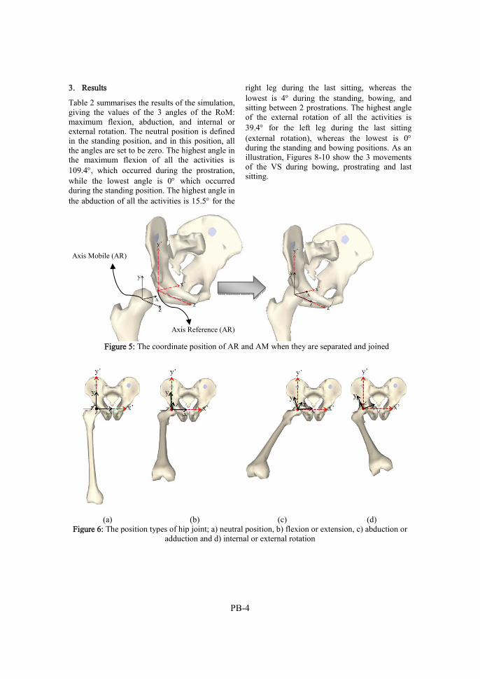
PB-4
3. Results
Table 2 summarises the results of the simulation, giving the values of the 3 angles of the RoM: maximum flexion, abduction, and internal or external rotation. The neutral position is defined in the standing position, and in this position, all the angles are set to be zero. The highest angle in the maximum flexion of all the activities is 109.4, which occurred during the prostration, while the lowest angle is 0 which occurred during the standing position. The highest angle in the abduction of all the activities is 15.5 for the
right leg during the last sitting, whereas the lowest is 4 during the standing, bowing, and sitting between 2 prostrations. The highest angle of the external rotation of all the activities is 39.4 for the left leg during the last sitting (external rotation), whereas the lowest is 0 during the standing and bowing positions. As an illustration, Figures 8-10 show the 3 movements of the VS during bowing, prostrating and last sitting.
Figure 5: The coordinate position of AR and AM when they are separated and joined
(a) (b) (c) (d)
Figure 6: The position types of hip joint; a) neutral position, b) flexion or extension, c) abduction or adduction and d) internal or external rotation
Axis Mobile (AR)
Axis Reference (AR)

PB-5
Table 2: Normal hip joint angles during Salat activity
Salat activities Max.
Flexion Abduction
Internal (in) & External (ex) Rotation
Standing 0 4 0 Bowing (ruku’) 87 4 0 Prostration (sujud) 109.4 6 7 (ex) Sitting between two prostration
c. Right leg d. Left leg
77.6 80
6 4
15 (in) 6 (ex)
Sitting (Tahiyat) e. Right leg f. Left leg
78.4 74.5
15.5 13.2
27.8 (in) 37.7 (ex)
Transition of standing towards prostration
121.5 0 0
(a) (b) (c)
Figure 7: Procedure of measuring the RoM: a) rotates the VS from the front to the left side, b) rotates the hip to flexion, and c) measure the angle by protactor tool to get the RoM
Next, the results were compared with the
data obtained from Sugano et al [18] for general activities based on the sitting position on a chair and Japanese-style activities based on the sitting on the floor, for a patient with THA. The general activities include picking up an object while sitting on a chair, getting up from the chair and sitting on the chair. The Japanese-style activities include bowing while sitting on 2 legs fully flexed at the knee (zarei), squatting and sitting on 2 legs fully flexed at the knee (seiza). The RoM values of the general activities are shown in Table 3, whereas RoM values of the Japanese-style activities are shown in Table 4. Both the general activities and the Japanese-style activities show the same range of the hip joint angles, that is, maximum flexion, adduction, and internal rotation. However, for the Japanese-style
activities and the general activities, there is no information of abduction and external rotation. For the present study there is no adduction reported. The results presented in Table 2 give information on the 2 joints, as the position of the legs when performing salat activities is not symmetrical.
Impingement on the acetabular liner is caused by a high RoM. An investigation on the effect of impingement on stresses and strains of the acetabular liner owing to the Japanese style activities and the general activities is initiated by [27] using a Finite Element Method approach. Results show that the impingement occurs in the picking up of the general activities, but it does not occur in that of the Japanese style activities. The risk of impingement owing to salat activities can be seen by comparing the hip with active

PB-6
RoM (see Table 1) to the hip with total hip arthroplasty (THA) (see Table 5). Table 1 gives results of the reference for hip activity RoM [20-23], whereas Table 5 gives an overview of the results of the different post operative arcs of hip motion measured in the three study groups, i.e. hip resurfacing (HR), 28- mm THA, and large diameter head total hip arthroplasty (LDH-THA) [17]. A summary of the risk of impingement due to salat activities is presented in Table 6
Figure 8: Bowing (virtual skeleton)
Figure 9: Prostration (virtual skeleton)
Figure 10: Sitting (virtual skeleton)
Table 3: Hip joint angle for Western-style activities in a chair [18]
Western-style activities on the chair Max. Flexion Adduction Internal rotation
Picking up an object while sitting on the chair
86 ± 13 (55-116)
−6.1 ± 7.3 (−25 to 4.6)
−12 ± 11 (−32 to 21)
Getting up from the chair 76 ± 12 (50-106)
−2.5 ± 5.2 (−16 to 11) −11 ± 10 (−29 to 20)
Sitting down on the chair 62 ± 10 (44-89) −0.92 ± 5.5 (−21 to 13)
−7.0 ± 11 (−27 to 17)
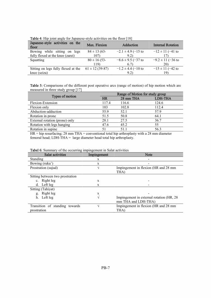
PB-7
Table 4: Hip joint angle for Japanese-style activities on the floor [18] Japanese-style activities on the floor
Max. Flexion Adduction Internal Rotation
Bowing while sitting on legs fully flexed at the knee (zarei)
84 ± 13 (63-107)
−2.1 ± 4.9 (−15 to 9.2)
−12 ± 11 (−41 to 17)
Squatting 80 ± 16 (53-119)
−8.6 ± 9.5 (−37 to 6.7)
−9.2 ± 11 (−36 to 20)
Sitting on legs fully flexed at the knee (seiza)
61 ± 12 (39-87) −1.2 ± 4.4 (−10 to 9.2)
−15 ± 11 (−42 to 19)
Table 5: Comparisons of the different post operative arcs (range of motion) of hip motion which are measured in three study group [17]
Types of motion Range of Motion for study group
HR 28 mm THA LDH-THA Flexion-Extension 117.4 116.6 124.6 Flexion only 103 102.8 112.4 Abduction-adduction 55.9 52.1 57.9 Rotation in prone 51.5 50.8 64.1 External rotation (prone) only 28.1 27.5 36.7 Rotation with legs hanging 47.6 45.2 55 Rotation in supine 51 51.1 56.3 HR = hip resurfacing; 28 mm THA = conventional total hip arthroplasty with a 28 mm diameter femoral head; LDH-THA = large diameter head total hip arthroplasty. Tabel 6: Summary of the occurring impingement in Salat activities
Salat activities Impingement Note Standing x - Bowing (ruku’) x - Prostration (sujud) √ Impingement in flexion (HR and 28 mm
THA) Sitting between two prostration
c. Right leg d. Left leg
x x
- -
Sitting (Tahiyat) g. Right leg h. Left leg
x √
-
Impingement in external rotation (HR, 28 mm THA and LDH-THA)
Transition of standing towards prostration
√ Impingement in flexion (HR and 28 mm THA)

PB-8
4. Discussion
Prior works [1-7] have reported that impingement plays an important factor influencing the failure of the THA patients. Impingement will lead to the occurrence of early dislocation. The early dislocation is often caused by extreme or excessive movements of the hip during human activities, such as salat. This impingement could be minimized by increasing the RoM of the AHJ [28]. Sugano et al [18] has studied the RoM of the hip joint for specific Japanese activities such as zarei and seiza, and the results were compared with those of the general activities such as sitting on a chair. To the best of our knowledge, there has been no study conducted on the RoM for salat activity. Therefore, this study was purposed to predict the RoMs of the hip joint during salat activity. For better understanding, this prediction was also compared with other activities such as Japanese-style activity and with other general activities. In addition, information on the risk of impingement of hip joint due to salat activities can be seen by comparing the RoM data of normal hip and the RoM data of hip with THA.
It was found that the RoM simulations of the normal hip joint during salat show values similar to other activities. Activities in salat are standing, bowing, straightening up, transition from standing towards prostration, prostration, sitting between the 2 prostrations, and sitting. The prostration position is similar to the zarei position and picking up an object while sitting on a chair, but it is different with respect to the position of the 2 legs during sitting. The impingement prediction on the acetabular liner due to salat activities is determined by comparing the active RoM of the normal hip joint and the RoM of the hip with THA. It is shown that the impingement due to salat activities will occur in the transition from standing towards prostration, transition and sitting. The most critical position is the final sitting activity. This position has the RoM values in the internal rotation for the right leg and in the external rotation for the left leg of about 27.8 and 37.7, respectively. These values are important to be considered, because if these conditions are implemented to a patient with THA, dislocation will occur. To overcome this problem, the femoral head size is usually increased. Kluess et al [28], for instance, has investigated the influence of the femoral head
size on impingement, dislocation and stress distribution in a THA. They showed that an increased head size could result in impingement-free RoM, as well as higher maximum resisting moments. There are several techniques to solve the risk of dislocations among patients with THA, for instance, by increasing the femoral head size, optimizing the cup position, or redesigning a conventional AHJ into a bipolar AHJ. Many researchers have applied these techniques. The study of Kluess et al [29] was based on the femoral head size; Bouchard et al [30] investigated the design factors influencing the performance of constrained acetabular liners by using the finite element method; and Pandit et al [31] investigated the bipolar femoral head arthroplasty in osteoarthritis. The dislocation of the AHJ is closely related to the impingement of the stem neck and the acetabular lip because of the excessive movement of the hip.
These results provide better evidence in designing an AHJ for salat. Based on these results, further development studies, such as positioning the acetabular cup and selecting the head diameter, can be easily conducted. However, some limitations are worth noting. In the present study, the geometrical dimensions were taken from the skeletal model. Future work should therefore take the dimension data from patients. Nevertheless, the model has been developed in this study so that any data can be added to the model later. Another important study for designing an AHJ for salat is wear. Wear is related to the late dislocation. Prediction of wear can be performed analytically or numerically. The Archard wear model is widely used for first-order wear prediction in an analytical way. The main variables of the Archard wear model are the specific wear rate, the normal load, and the sliding distance. The specific wear rate of a material pair is obtained from experimental measurements. For the hip movement, the applied load and the sliding distance can be obtained from the gait cycle. Unfortunately, research on the salat gait cycle is very limited in literature. Hashim et al [32], for instance, has studied the salat gait cycle in terms of the ground reaction force as a function time. They concluded that salat gait cycle is similar to the walking gait cycle, yet the load in the salat gait cycle is higher than that in the normal walking gait cycle. Based on this information, it can be assumed that the sliding distance of the

PB-9
salat gait cycle is similar to the sliding distance of a normal walking gait cycle. The sliding distance and the average maximum load of the salat gait cycle is 1.65 times the femoral head radius [33] and 7.6 times the body weight in the hip, respectively [34]. As for the calculation of wear, this information is important, and when combined with the specific wear rate, it could give a first approximation of the increased wear volume as a result of the salat activity.
5. Conclusions
The RoM simulations because of salat activity have been performed. The activities include standing, bowing, straightening up, transition from standing towards prostration, prostration, sitting between the two prostrations and sitting. The result of this research is the RoM values in each activity. The RoM values of the salat activities, the Japanese style activities and the general activities have been compared. The impingement prediction on the acetabular liner due to salat activities is determined by comparing the active RoM of the normal hip joint and the RoM of the hip with THA. It is shown that the impingement due to salat activities will occur in the transition of standing towards prostration, transition and sitting. Based on these findings future studies are recommended with respect to design an AHJ for salat. References
1. Ganz, R., Parvizi, J., Beck, M., Leunig, M., Notzli, H., Siebenrock K.A., 2003, “Femoroacetabular impingement: a cause for osteoarthritis of the hip”, Clin Orthop Relat Res., Vol. 417, pp.112-20.
2. Bartz R.L., Nobel P.C., Kadakia N.R., Tullos HS., 2000, “The effect of femoral component head size on posterior dislocation of the artificial hip joint”, J Bone Joint Surg Am. Vol. 82, pp. 1300-7.
3. Krushell, R,J., Burke, D.W., Harris, W.H., Range of motion in contemporary total hip arthroplasty. The impact of modular head-neck components. J Arthroplasty. 1991;6:97-101.
4. Malik, A., Maheshwari, A., Lawrence, D.D., Impingement with total hip replacement. J Bone Joint Surg Am. 2007;89:1832-42.
5. Marchetti, E., Krantz, N., Berton, C., Bocquet, D., Fouilleron, N., Migaud, H., et al., Component impingement in total hip arthroplasty: Frequency and risk factors. A continuous retrieval analysis series of 416 cup, Orthopaedics & Traumatology: Surgery & Research 2011;97:127.
6. Shon, W.Y., Baldini, T., Peterson, M.G., Wright, T.M., Salvati, E.A., Impingement in total hip arthroplasty: A study of retrieved acetabular components. J Arthroplasty 2005;20:427.
7. Sikes, C.V., Lai, L.P., Schreiber, M., Mont, M.A., Jinnah, R.H., Seyler, T.M., Instability after total hip arthroplasty treatment with large femoral heads vs constrained liners. J Arthroplasty 2008;23:59.
8. Fricka, K.B., Marshall, A., Paprosky, W.G., Constrained liners in revision total hip arthroplasty: An overuse syndrome: In the affirmative. J Arthroplasty 2006;21:121.
9. Woo, R.Y., Morrey, B.F., Dislocations after total hip arthroplasty. J Bone Joint Surg Am 1982;64:1295-1306.
10. Khan, M.A., Brakenbury, P.H., Reynolds, I.S., Dislocation following total hip replacement. J Bone Joint Surg Br 1981;63:214-218.
11. Morrey, B.F., Instability after total hip arthroplasty. Orthop Clin North Am 1992;23:237-248.
12. Cuckler, J.M., The dislocated total hip: The dreaded 3 AM phone call. Semin Arthro 2011;22:98.
13. Hummel, M.T., Malkani, A.L., Yakkanti, M.R., Baker, D.L., Decreased dislocation after revision total hip arthroplasty using larger femoral head size and posterior capsular repair. J Arthroplasty 2009; 24:73.
14. Rassool, G.H., The crescent and Islam: healing, nursing and the spiritual dimension. Some considerations towards an understanding of the Islamic perspectives on caring. J Adv Nurs. 2000;32:1476-84.
15. Ott, B.B., Al-Khadhuri,J., Al-Junaibi, S., Preventing ethical dilemmas: understanding Islamic health care practices. Pediatr Nurs. 2003;29:227-30.
16. Halligan, P., Caring for patients of Islamic denomination: critical care nurses’ experiences in Saudi Arabia. J Clin Nurs. 2006;15:1565-73.

PB-10
17. Lavigne, M., Ganapathi, M., Mottard, S., Girard, J., Vendittoli, P.A., Range of motion of large head total hip arthroplasty is greater than 28 mm total hip arthroplasty or hip resurfacing. Clin Biomech 2011;26:267.
18. Sugano, N., Tsuda, K., Miki, H., Takao, M., Suzuki, N., Nakamura, N., Dynamic measurements of hip movement in deep bending activities after total hip arthroplasty using a 4-dimensional motion analysis system. J Arthroplasty 2012; 27:1562.
19. Luttgens, K., Hamilton, N., Kinesiology: Scientific Basis of Human Motion, 9th Ed., Madison, WI: Brown & Benchmark 1997.
20. Magee, D.J., Orthopaedic physical assesment, 5th Edition. Missouri: Saunders-Elsevier Inc. 2008. ISBN: 978-0-7216-0571-5.
21. Hamill, J., Knutzen, K.M., Biomechanical basis of human movement: Biomechanic of the hip (3rd Ed.) Philadelphia: Lippincott Williams and Wilkins. 2009. ISBN: 978-1-4511-7730-5.
22. Solomon, L., Warwick, D., Nayagam, S., Apley’s system of orthopaedics and fracture: The Hip (9th Ed.) London: Hodder Arnold. 2010. ISBN: 978 0 340 942 086.
23. Dutton, M., Dutton’s Orthopaedic examination, evaluation and intervention, 3rd Edition. McGraw-Hill education. 2012. ISBN: 978-0-07-174404-1.
24. Association of Islamic Chartiable Projects in North American. The basics of Muslim’s prayer. Darulmashari 2008; 3rd Edition: 1429. http://www.aicp.org. Accessed: 5 April 2013.
25. Hidenobu, M., Kyo, T., Sugano, N., Anatomical hip range of motion after implantation during total hip arthroplasty with a large change in pelvic inclination. J Arthroplasty 2012;27:1641.
26. Kang, M.J., Sadri, H., Moccozet, L., Magnenat-Thalmann, N., Hoffmeyer, P., Accurate simulation of hip joint range of motion, Proceedings of Computer Animation 2002 (CA 2002), Geneva, 2002; 215-219.
27. Saputra, E., Anwar, I.B., Jamari, J., van der Heide E., Finite element analysis of artificial hip joint movement during human activities. Procedia Eng 2013;68:102-108.
28. Amstutz, H.C., Lodwig, R.M., Schurman, D.J., Hodgson, A.G., Range of motion studies for total hip replacements. A
comparative study with a new experimental apparatus. Clin Orthop Relat Res 1975:111:124.
29. Kluess, D., Martin, H., Mittelmeier, W., Schmitz, K.P., Bader, R., Influence of femoral head size on impingement, dislocation and distribution in total hip replacement. Medical Engineering & Physics 2007; 29:465.
30. Bouchard, S.M., Stewart, K.J., Pedersen, D.R., Callaghan, J.J., Brown, T.D., Design factors influencing performance of constrained acetabular liners: Finite element characterization, J Biomech 2006; 39:885.
31. Pandit, R., Ortho, D., Bipolar femoral head arthroplasty in osteoarthritis a prospective study with a minimum 5-year follow-up period. J Arthroplasty 1996;11:560.
32. Hashim, A.Y.B., Osman, N.A.A., Abas, W.A.B.W., Latif, L.A.. Analysis of Salat gait, Int J Open Problems Copt Math 2010:3:552.
33. Calonius, O., Saikko, V., Analysis of relative motion between femoral head and acetabular cup and advances in computation of the wear factor for the prosthetic hip joint, Acta Polytechnica 2003:43:43.
34. Paul, J.P., Force actions transmitted by joints in the human body. Proc R Soc Lond B 1976;192:163.
Paper C
E. Saputra, I.B. Anwar, J. Jamari, E. van der Heide, 2019 A wear formulation of total hip prosthesis
for salat activity
International Review of Mechanical Engineering, Volume 13, No. 1, pp. 29-37,
doi: https://doi.org/10.15866/ireme.v13i1.16340


PC-1
A wear formulation of total hip prosthesis for salat activity
E. Saputra1, I.B. Anwar1,2, J. Jamari3, E. van der Heide1 1Laboratory for Surface Technology and Tribology, Faculty of Engineering Technology, University
of Twente, Postbox 217, 7500 AE Enschede, The Netherlands 2Orthopaedic and Traumatology Department, Prof. dr. R. Soeharso Orthopaedic Hospital, Jl. A. Yani
Pabelan, Surakarta 57162, Indonesia 3Laboratory for Engineering Design and Tribology, Department of Mechanical Engineering,
Diponegoro University, Jl. Prof. Sudharto SH, Tembalang, Semarang 50275, Indonesia
Published in: International Review of Mechanical Engineering, Volume 13, No. 1, pp. 29-37.
Abstract The wear on the acetabular liner surface of total hip prosthesis due to human activity cannot be avoided. Salat is an obligation religious activity for Muslims performed five times daily, without exception for patients who used the total hip prosthesis. Salat consists of standing, bowing, prostrating and sitting on the leg motions. Many researchers have investigated the wear on the liner surface for daily activity but not for salat activity. This study has aimed to calculate wear on the acetabular liner surface due to salat activity. A new linear wear model has been proposed in order to estimate the linear wear or the wear depth on the acetabular liner surface. In addition, a volumetric wear model or volume loss on the acetabular liner surface has also been developed based on the new linear wear model. These wear model are used to calculate wear on the acetabular liner surface due to walking and salat activities. Results show that the linear wear due to salat activity is lower than walking activity, because of the intensity of salat activity is lower than walking. However, the combinations of both wear due to walking activity and salat activity need to be considered. Keywords: Gait Cycle, Linear Wear Model, Salat Activity, Total Hip Prosthesis, Volumetric Wear Notation d the distance of center point of head and
cup F force hC height of cup hH height of head hP penetration or linear wear KW the dimensional wear coefficient L sliding distance N number of revolution or loading cycle r contact radius rC contact radius of cup
rH contact radius of head rs the radius of the spherical articulating
surface R* the effective contact radius RC radius of cup RH radius of head V wear volume or volumetric wear VC volumetric wear of cup VH volumetric wear of head VP volumetric wear of penetration x distance of center point of the cup to the
boundary of contact radius π pi 1. Introduction
Islam is one of the major religions in the world. In 2010, Christianity was the world’s largest religion with 2.2 billion adherents, whereas Islam was the second one with 1.6 billion followers [1]. Islam has five pillars for the followers, i.e., the testimony of faith, salat (prayer), giving zakat (support of the needy), fasting during Ramadhan and the pilgrimage (Hajj) to Makkah [2]. Salat is a particular way to worship God among Muslims implemented with activity. Salat activity is performed five times daily or in seventeen cycles (rak^ahs) daily, where one cycle consists of standing, bowing (Ruku^), straightening up (I^tidal), prostrating (Sujud) and sitting on the legs. Based on the Holy Qur’an and hadith, it is an obligatory religious daily activity for Muslims, without exception for Muslim patients who use a hip prosthesis.
Total hip arthroplasty (THA) is one of the most successful orthopedic procedures for the diseased cartilage and bone of the hip joint that replaced surgically with implant materials. The THA involves surgical removal of the diseased femoral head and socket and replacing them with the hip prosthesis. It consists of acetabular cup,

PC-2
acetabular liner, femoral head, and stem. One of the main problems for the THA patient during their daily activities is dislocation [3]. The dislocations are divided into early dislocation and late dislocation [4]. The early dislocation occurs due to the impingement of the femoral neck to the rim of acetabular liner, and the late dislocation is mostly related to wear on the surface of acetabular liner [4]-[5].
The wear phenomenon on the surface liner of the total hip prosthesis due to daily activities cannot be avoided. Daily activities such as walking, fast walking, running, walking downstairs and upstairs produced load and sliding variations on the acetabular liner surface that cause wear. The applied load and the sliding in this situation are variables based on the wear model of Archard in relation to adhesive wear [6] as shown in Eq. (1). In this equation, V is the wear volume in mm3, KW is the dimensional wear coefficient in mm3/Nm, F is the applied load in N, L is the sliding distance in mm, and N is the number of sphere revolutions or the number of loading cycles.
FNW
KL
V (1)
The dimensional wear coefficient KW is obtained from experimental data, whereas load and sliding distances are derived from the gait cycle. Walking gait cycle is the most widely used data by researchers in order to predict wear on the acetabular liner surface of the total hip prosthesis. Paul et al. [7] have provided load data during the walking gait cycle, whereas Calonius et al. [8] have provided sliding distance data from the walking gait cycle and a hip simulator.
In order to obtain the linear wear on the acetabular liner surface, many researchers have performed experiments and they have proposed the wear calculation model analytically and numerically. Many researchers have investigated wear on the liner surface considering walking condition, although many kind of research have performed it using the hip simulator, they have tried to approximate walking condition. Dowson et al. [9] have presented both linear and volumetric wear data from tests on Charnley hip prosthesis with hip simulator under simulated walking condition and they have proposed the linear wear calculation model. Kauzlarich et al.
[10] have developed a wide range of the wear calculation model on the basis of local Archard wear in various conditions, such as spherical ended pin or pivot, crossed cylinders, journal bearing and spherical bearing. Specifically for spherical bearing, the formula has been validated, and it has showed a good agreement with Dowson’s experimental data. Wu et al. [11] have proposed computer algorithms in order to estimate the wear appearing in the total hip prosthesis by using finite element analysis based on the modified Archard wear law under walking condition. Stanfos et al. [12] have initiated the wear research in the total hip prosthesis by using the boundary element method. Liu et al. [13] have proposed the new formula to predict wear of polyethylene in the hip prosthesis, where it is based on wear volume being dependent on and proportional to the product of the sliding distance and contact area. Liu et al. [14] have continued the research using the formula by considering the effect of motion inputs on the wear prediction of artificial hip joints, wherein this study the full simulated walking cycle condition is based on a walking measurement. Alvarez-Vera et al. [15] have investigated the wear performance in the FIME II hip joint simulator under normal gaits, where the total hip prosthesis used a metal-metal Co-Cr alloy with different boron additions. Uddin et al. [16] have proposed the prediction of wear in hard-on-hard of the hip joint prosthesis using finite element method for walking gait cycle. Uddin et al. [17] have also shown the wear measurement of the conventional crosslinked polyethylene and highly crosslinked polyethylene cups using a coordinate measuring machine (CMM). They have continued their study by presenting a wear model in order to estimate the evolution of wear in hard-on-hard bearing components under the influence of the cup abduction angle, Shankar et al. [18]. Recently, Uddin et al. [19] have showed the evaluation of hip implant wear measurements by CMM technique with uncertainty analysis. Based on the previous literature, the wear study on the liner surface of the total hip prosthesis due to salat activity has been not performed. However, the wear prediction on the liner surface due to salat activities is needed to improve the ability of hip prosthesis for Muslim patients. Therefore, this research gives the contribution to science in the field of tribology specifically the wear prediction.
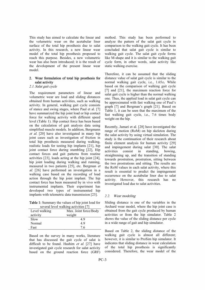
PC-3
This study has aimed to calculate the linear and the volumetric wear on the acetabular liner surface of the total hip prosthesis due to salat activity. In this research, a new linear wear model of the total hip prosthesis proposed to reach this purpose. Besides, a new volumetric wear has also been introduced; it is the result of the development of the present linear wear model. 2. Wear formulation of total hip prosthesis for
salat activity 2.1. Salat gait cycle
The requirement parameters of linear and volumetric wear are load and sliding distances obtained from human activities, such as walking activity. In general, walking gait cycle consists of stance and swing stages, where Paul et al. [7] have summarized the hip joint load or hip contact force for walking activity with different speed level (Table 1). Hip contact force has been based on the calculation of gait analysis data using simplified muscle models. In addition, Bergmann et al. [20] have also investigated in many hip joint cases such as investigation of friction in total hip prosthesis measured during walking, realistic loads for testing hip implants [21], hip joint contact force during stumbling [22], Hip contact forces and gait patterns from routine activities [23], loads acting at the hip joint [24], hip joint loading during walking and running, measured in two patients [25], etc. Bergman et al. [26] have performed an investigation in a walking case based on the recording of load action through the hip joint implant. The hip contact force has been measured by in vivo with instrumented implants. Their experiment has developed two types of instrumented hip implants with telemetric data transmission [23].
Table 1: Summary the values of hip joint load for several level walking activities [7]
Level walking activity
Max. Joint force/Body weight
Slow 4.9 Normal 4.9 Fast 7.6
Based on the survey in many works, literature that has discussed the gait cycle of salat is difficult to be found. Hashim et al. [27] have investigated gait cycle research for salat activity based on the ground reaction force (GRF)
method. This study has been performed to analyze the pattern of the salat gait cycle in comparison to the walking gait cycle. It has been concluded that salat gait cycle is similar to walking gait cycle. The salat gait cycle forms like M-shape and it is similar to the walking gait cycle form, in other words, salat activity like static walking exercise.
Therefore, it can be assumed that the sliding distance value of salat gait cycle is similar to the normal walking gait cycle, i.e., 1.65rs. While based on the comparison of walking gait cycle [7] and [21], the maximum reaction force for salat gait cycle is higher than the normal walking one. Thus, the applied load in salat gait cycle can be approximated with fast walking one of Paul’s graph [7] and Bergman’s graph [21]. Based on Table 1, it can be seen that the maximum of the fast walking gait cycle, i.e., 7.6 times body weight on the hip.
Recently, Jamari et al. [28] have investigated the range of motion (RoM) on hip skeleton during the salat activity by using virtual simulation. The study is the continuation of their research about finite element analysis for human activity [29] and impingement during salat [30]. The salat activities consist in standing, bowing, straightening up, and the transition of standing towards prostration, prostration, sitting between the two prostrations and sitting. The results are the RoM values in each salat activity, where this result is essential to predict the impingement occurrence on the acetabular liner due to salat activity. However, this research has no investigated load due to salat activities.
2.2. Wear modeling
Sliding distance is one of the variables in the Archard wear model, where the hip joint case is obtained from the gait cycle produced by human activities or from the hip simulator. Table 2 shows the value of the sliding distance per cycle in a wide range of gait and hip simulator. Based on Table 2, the sliding distance of the walking gait cycle is almost all different; however, it is similar to ProSim hip simulator. It indicates that sliding distance in wear calculation of the total hip prosthesis is significantly considered. Therefore, the wear model of the

PC-4
total hip prosthesis with a specific variable of sliding distance is needed. In this paper, the wear prediction model for the total hip prosthesis with specific variable of sliding distance costumized with a wide range of case is proposed. Table 2: The summary of the sliding distance for eleven simulators and gait[8] Cases L [mm] HUT-3 [31] 1.71rs HUT-BRM [32] 2.46rs MMED-BRM [33] 2.46rs MTS-BRM [34] 2.46rs AMTI [35] 1.75rs Munich [36]-[37] 1.67rs Leeds Mk I [38] 1.41rs ISO/DIS 14242-1 [39] 1.58rs Durham Mk II [40] 1.59rs Leeds Mk II [41] 1.57rs ProSim [42] 1.65rs Walking gait cycle [43]-[7] 1.65rs Note: rs is the radius of the spherical articulating surface in mm
Fig. 1. The geometry of a wearing spherical bearing for linear wear
The present linear wear model is a modification of the Archard one. The basic of the current wear model is the contact area when the
femoral head penetrates to the acetabular liner such as shown in Fig. 1. Based on Fig. 1, variables of RC, RH, r, hH, hC, and hP are defined as cup radius, head radius, contact radius, head height, cup height and height of penetrating, respectively.
When the femoral head penetrates to the acetabular cup, head height hH, is obtained,
written as Eq. (2). In addition, this penetration forms the contact radius r, where r = rC = rH.
Ph
Ch
Hh (2)
Based on Fig. 1, it can be simplified to be two triangles, therefore it can be solved with Pythagoras theorem to find variables rC and rH, next, it will get Eqs. (3)-(4).
22 2 CCCC hhRr
CCC hRr 22 , for 2Ch << CR (3)
22 2 HHHH hhRr
HHH hRr 22 , for 2Hh << HR (4)
RH rH
RH-hH
rC
Li
RC-hC
RC

PC-5
Eq. (2) is substituted to Eq. (4), and it obtained Eq. (5),
PHCHH hRhRr 222 (5)
Find hC by considering Eq. (3) and (5), and getting Eq. (6),
HC
PHC
RR
hRh
(6)
Substituting Eq. (6) to Eq. (2), to obtain Eq. (7),
HC
PCH
RR
hRh
(7)
While the half-contact area between two conforming surfaces is described by van Beek [44], see Eq. (8).
*
2
*
2222
2
1
2
11
222 R
r
R
r
RR
r
R
r
R
rh
CHC
C
H
HH
HhRr*2 2 (8)
Where *R is the effective contact radius,
HC
CH
RR
RRR
*
By dividing the left-hand sides and the right-hand side of Archard wear model in Eq. (1) by the real area of contact (Fig. 1), the relation for linear wear hH can be obtained,
PNKL
hW
H (9)
The differential form of Equation (9) is given by
PNKdL
dhW
H (10)
where P is contact pressure and quoted in N/mm2, as shown in Eq. (11):
2r
FP
(11)
Fig. 2. The applied force “F” curve with time or
gait phase
In order to simplify the calculation, the applied force “F” is constant for every time or gait phase, where the applied force is obtained from the peak force in the gait phase. Fig. 2 illustrates the applied force as a function of the time/gait phase.
Substituting for P using Eq. (11) and further substitution for the contact radius from Eq. (8) into Eq. (10), so that,
N
hRR
RR
FK
dL
dh
HHC
CH
WH
2
(12)
Time/gait phase
Forc
e
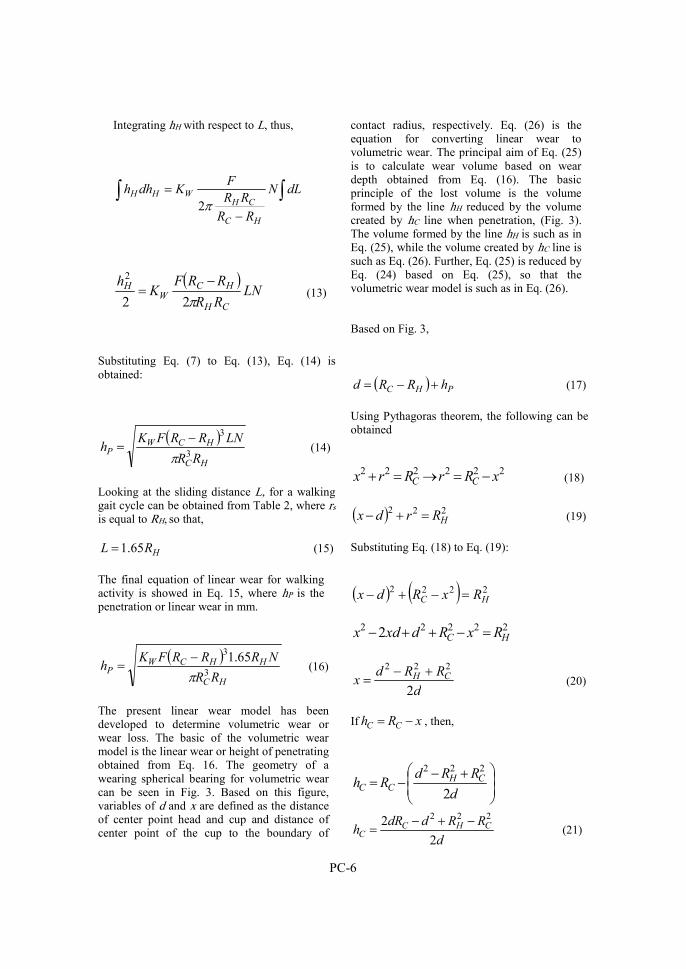
PC-6
Integrating hH with respect to L, thus,
dLN
RR
RR
FKdhh
HC
CHWHH
2
LN
RR
RRFK
h
CH
HCW
H
22
2 (13)
Substituting Eq. (7) to Eq. (13), Eq. (14) is obtained:
HC
HCWP
RR
LNRRFKh
3
3
(14)
Looking at the sliding distance L, for a walking gait cycle can be obtained from Table 2, where rs is equal to RH, so that,
HRL 65.1 (15)
The final equation of linear wear for walking activity is showed in Eq. 15, where hP is the penetration or linear wear in mm.
HC
HHCWP
RR
NRRRFKh
3
3 65.1
(16)
The present linear wear model has been developed to determine volumetric wear or wear loss. The basic of the volumetric wear model is the linear wear or height of penetrating obtained from Eq. 16. The geometry of a wearing spherical bearing for volumetric wear can be seen in Fig. 3. Based on this figure, variables of d and x are defined as the distance of center point head and cup and distance of center point of the cup to the boundary of
contact radius, respectively. Eq. (26) is the equation for converting linear wear to volumetric wear. The principal aim of Eq. (25) is to calculate wear volume based on wear depth obtained from Eq. (16). The basic principle of the lost volume is the volume formed by the line hH reduced by the volume created by hC line when penetration, (Fig. 3). The volume formed by the line hH is such as in Eq. (25), while the volume created by hC line is such as Eq. (26). Further, Eq. (25) is reduced by Eq. (24) based on Eq. (25), so that the volumetric wear model is such as in Eq. (26).
Based on Fig. 3,
PHC hRRd (17)
Using Pythagoras theorem, the following can be obtained
222222
xRrRrx CC (18)
222HRrdx (19)
Substituting Eq. (18) to Eq. (19):
2222HC RxRdx
22222 2 HC RxRdxdx
d
RRdx CH
2
222 (20)
If xRh CC , then,
d
RRdRh CH
CC 2
222
d
RRddRh CHC
C 2
2 222 (21)

PC-7
Fig. 3. A geometry of a wearing spherical
bearing for volumetric wear
Substituting Eq. (21) to Eq. (2), the equation of hH is obtained:
PCHC
H hd
RRddRh
2
2 222
(22) Based on the volume of the spherical cap, if VH (Eq. 23) and VC (Eq. 24) are the volumetric wear of head and cup, the volumetric wear of penetration VP (Eq. 26) is an intersection of VH and VC. Based on Eq. (21) and Eq. (22), the volumetric wear VP can be calculated:
HHHH hRhV 33
1 2 (23)
CCCC hRhV 33
1 2 (24)
CHP VVV (25)
CCCHHHP hRhhRhV 3
3
13
3
1 22 (26)
3. Results and discussion 3.1. Validation of wear modeling with other
model
Dowson et al. [9] have presented both the data of linear and volumetric wear from experiments on a Charnley hip prosthesis in which a ceramic femoral head has been reciprocated in ultra-high-molecular-weight polyethylene (UHMWPE) acetabular liner, (Table 3). Fig. 4 shows a plot of the penetration of their femoral heads number 1and 2, into the acetabular liner, i.e., the extent of linear wear as a function of the number of loading cycles. Besides, Fig. 4 shows a wide range of plot of Dowson, Kauzlarich and the present wear model. The dash line curve is a plot of Eq. (16) for walking case by using these values together with an amount of KW equal to 4.49 x 10⁻⁷ mm3/Nm. In Fig. 4, the result of the present wear model shows a good agreement with another wear model.
Table 3: Dimension of test prosthesis [9]
Components Materials Diameters (mm)
Acetabular liner (1) UHMWPE 32.5458 Acetabular liner (2) UHMWPE 32.5340 Femoral head (1) Alumina 31.98 Femoral head (2)
Alumina
31.94
To get the volumetric wear on the acetabular liner, Eq. (26) can be implemented. Solidworks is also used to measure volume loss based on the penetration data in Fig. 6. The measurement of wear volumetric is performed to be several steps. First step is creating sketch of wear volumetric refer to parameters obtained from Eq. (26), as illustration see Fig. 7a. Second step is creating part of wear volumetric based on sketch created in first step, see position of wear volumetric in Fig. 7b. Last step (Fig. 7c) is measuring wear volumetric using a measure feature that it is provided by solidworks CAD software. Figure 8 shows a plot of volumetric wear as a function of the number of loading cycles. The solid line is a plot of Eq. (26) for walking case, while the cycle is a plot of volumetric wear by
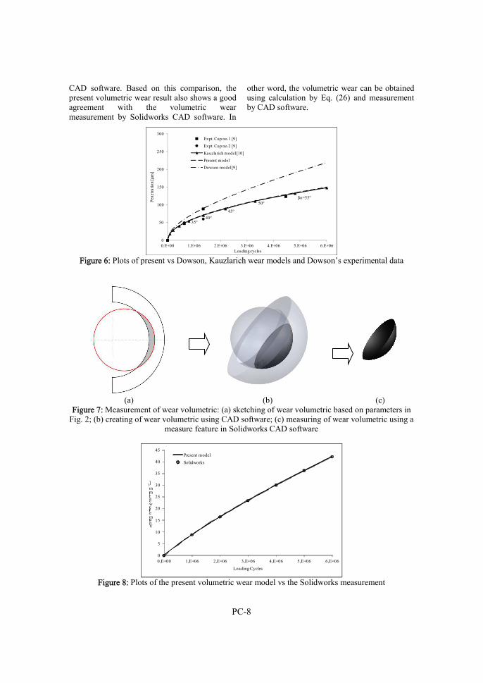
PC-8
CAD software. Based on this comparison, the present volumetric wear result also shows a good agreement with the volumetric wear measurement by Solidworks CAD software. In
other word, the volumetric wear can be obtained using calculation by Eq. (26) and measurement by CAD software.
35º40º
45º
50ºβο=55º
0
50
100
150
200
250
300
0.E+00 1.E+06 2.E+06 3.E+06 4.E+06 5.E+06 6.E+06
Pene
trat
ion
[μm
]
Loading cycles
Expt. Cup no.1 [9]
Expt. Cup no.2 [9]
Kauzlarich model [10]
Present model
Dowson model [9]
Figure 6: Plots of present vs Dowson, Kauzlarich wear models and Dowson’s experimental data
(a) (b) (c) Figure 7: Measurement of wear volumetric: (a) sketching of wear volumetric based on parameters in
Fig. 2; (b) creating of wear volumetric using CAD software; (c) measuring of wear volumetric using a measure feature in Solidworks CAD software
0
5
10
15
20
25
30
35
40
45
0,E+00 1,E+06 2,E+06 3,E+06 4,E+06 5,E+06 6,E+06
Volumetric wear [mm
3]
Loading Cycles
Present model
Solidworks
Figure 8: Plots of the present volumetric wear model vs the Solidworks measurement
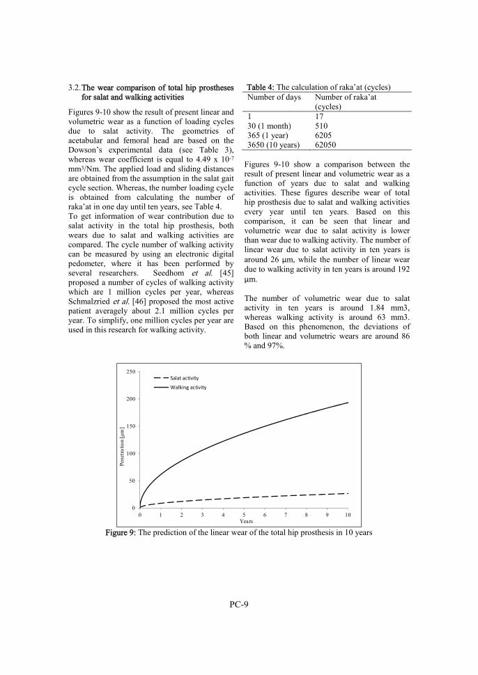
PC-9
3.2. The wear comparison of total hip prostheses for salat and walking activities
Figures 9-10 show the result of present linear and volumetric wear as a function of loading cycles due to salat activity. The geometries of acetabular and femoral head are based on the Dowson’s experimental data (see Table 3), whereas wear coefficient is equal to 4.49 x 10⁻⁷ mm3/Nm. The applied load and sliding distances are obtained from the assumption in the salat gait cycle section. Whereas, the number loading cycle is obtained from calculating the number of raka’at in one day until ten years, see Table 4. To get information of wear contribution due to salat activity in the total hip prosthesis, both wears due to salat and walking activities are compared. The cycle number of walking activity can be measured by using an electronic digital pedometer, where it has been performed by several researchers. Seedhom et al. [45] proposed a number of cycles of walking activity which are 1 million cycles per year, whereas Schmalzried et al. [46] proposed the most active patient averagely about 2.1 million cycles per year. To simplify, one million cycles per year are used in this research for walking activity.
Table 4: The calculation of raka’at (cycles) Number of days Number of raka’at
(cycles) 1 17 30 (1 month) 510 365 (1 year) 6205 3650 (10 years) 62050
Figures 9-10 show a comparison between the result of present linear and volumetric wear as a function of years due to salat and walking activities. These figures describe wear of total hip prosthesis due to salat and walking activities every year until ten years. Based on this comparison, it can be seen that linear and volumetric wear due to salat activity is lower than wear due to walking activity. The number of linear wear due to salat activity in ten years is around 26 μm, while the number of linear wear due to walking activity in ten years is around 192 μm. The number of volumetric wear due to salat activity in ten years is around 1.84 mm3, whereas walking activity is around 63 mm3. Based on this phenomenon, the deviations of both linear and volumetric wears are around 86 % and 97%.
0
50
100
150
200
250
0 1 2 3 4 5 6 7 8 9 10
Pene
trat
ion
[μm
]
Years
Salat activity
Walking activity
Figure 9: The prediction of the linear wear of the total hip prosthesis in 10 years
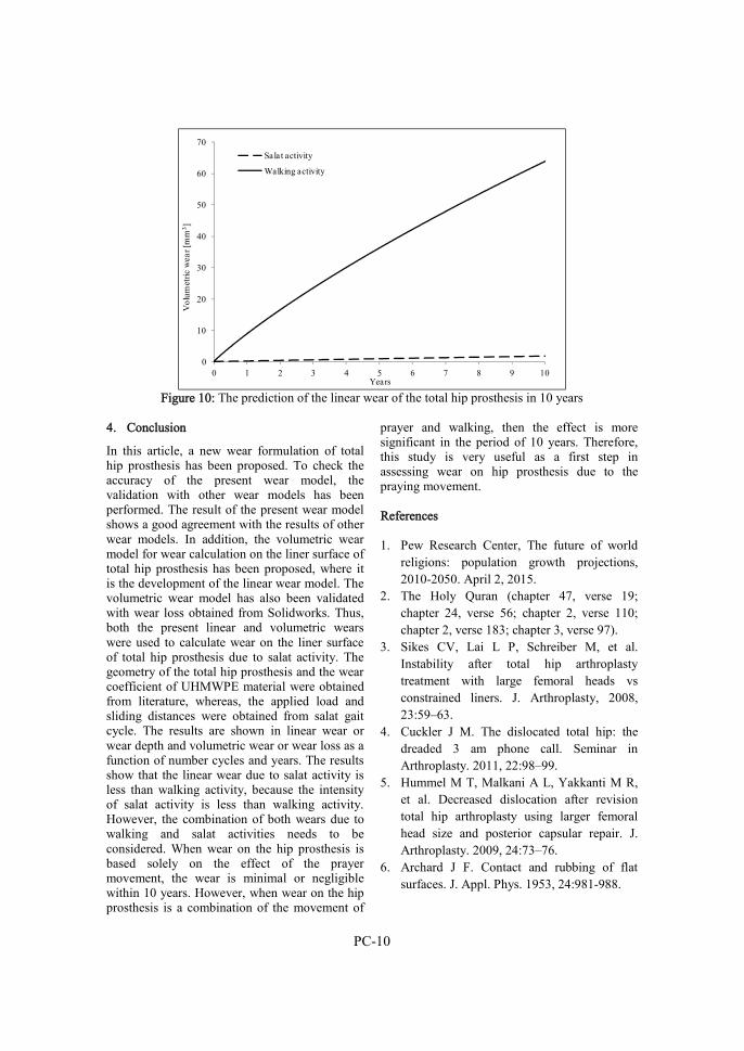
PC-10
0
10
20
30
40
50
60
70
0 1 2 3 4 5 6 7 8 9 10
Vol
umet
ric w
ear [
mm
3 ]
Years
Salat activity
Walking activity
Figure 10: The prediction of the linear wear of the total hip prosthesis in 10 years
4. Conclusion
In this article, a new wear formulation of total hip prosthesis has been proposed. To check the accuracy of the present wear model, the validation with other wear models has been performed. The result of the present wear model shows a good agreement with the results of other wear models. In addition, the volumetric wear model for wear calculation on the liner surface of total hip prosthesis has been proposed, where it is the development of the linear wear model. The volumetric wear model has also been validated with wear loss obtained from Solidworks. Thus, both the present linear and volumetric wears were used to calculate wear on the liner surface of total hip prosthesis due to salat activity. The geometry of the total hip prosthesis and the wear coefficient of UHMWPE material were obtained from literature, whereas, the applied load and sliding distances were obtained from salat gait cycle. The results are shown in linear wear or wear depth and volumetric wear or wear loss as a function of number cycles and years. The results show that the linear wear due to salat activity is less than walking activity, because the intensity of salat activity is less than walking activity. However, the combination of both wears due to walking and salat activities needs to be considered. When wear on the hip prosthesis is based solely on the effect of the prayer movement, the wear is minimal or negligible within 10 years. However, when wear on the hip prosthesis is a combination of the movement of
prayer and walking, then the effect is more significant in the period of 10 years. Therefore, this study is very useful as a first step in assessing wear on hip prosthesis due to the praying movement. References 1. Pew Research Center, The future of world
religions: population growth projections, 2010-2050. April 2, 2015.
2. The Holy Quran (chapter 47, verse 19; chapter 24, verse 56; chapter 2, verse 110; chapter 2, verse 183; chapter 3, verse 97).
3. Sikes CV, Lai L P, Schreiber M, et al. Instability after total hip arthroplasty treatment with large femoral heads vs constrained liners. J. Arthroplasty, 2008, 23:59–63.
4. Cuckler J M. The dislocated total hip: the dreaded 3 am phone call. Seminar in Arthroplasty. 2011, 22:98–99.
5. Hummel M T, Malkani A L, Yakkanti M R, et al. Decreased dislocation after revision total hip arthroplasty using larger femoral head size and posterior capsular repair. J. Arthroplasty. 2009, 24:73–76.
6. Archard J F. Contact and rubbing of flat surfaces. J. Appl. Phys. 1953, 24:981-988.
PC-11
7. Paul J P. Force actions transmitted by joints in the human body. Proc. R. Soc. Lond. B. 1976, 192:163-172.
8. Calonius O, Saikko V,. Analysis of relative motion between femoral head and acetabular and advances in computation of the wear factor for the prosthetic hip joint. Acta. Polytech. 2003, 43:43–54.
9. Dowson D, Jobbins B, Seyed-Harraf A. An evaluation of the penetration of ceramic femoral heads into polythene acetabular cups. Wear. 1993, 162-164:880–889.
10. Kauzlarich J J, Williams J A. Archard wear and component geometry. Proc. Instn. Mech. Engrs. 2001, 215:387-403.
11. Wu J S S, Hung J P, Shu C S, et al. The computer simulation of wear behavior appearing in total hip prosthesis. Comput. Meth. Prog. Bio. 2003, 70(1):81-91.
12. Sfantos G K, Aliabadi M H. Total hip arthroplasty wear simulation using the boundary element method. J. Biomech. 2007, 40:378-389.
13. Liu F, Galvin A, Jin Z, et al. A new formulation for the prediction of polyethylene wear in artificial hip joints. Proc. IMech. E. Part H. 2011, 225(1):16-24.
14. Liu F, Fisher J, Jin Z. Effect of motion inputs on the wear prediction of artificial hip joints. Tribol. Int. 2013, 63:105-114.
15. Alvarez-Vera M, Ortega-Saenz J A, Hernandez-Rodrigues M A L. A study of the wear performance in a hip simulator of a metal-metal Co-Cr alloy with different boron additions. Wear. 2013, 301:175-181.
16. Uddin M S, Zhang L C. Predicting the wear of hard-on-hard hip joint prostheses. Wear. 2013, 301:192-200.
17. Uddin M S. Wear Measurement and Assessment of Explanted Cross-Linked PE Acetabular Cups Using a CMM. Tribology Transactions. 2014, 57(5):767-777.
18. Shankar S, Gowthaman K, Uddin M S. Predicting long-term wear performance of hard-on-hard bearing couples: effect of cup
orientation. Med. Biol. Eng. Comput. 2015, 54 (10):1541-1552.
19. Uddin M S, Mak C Y E, Callary S A. Evaluating hip implant wear measurements by CMM technique. Wear. 2016, 364-365:293-200.
20. Damm P, Dymke J, Ackermann R, et al. Friction in total hip joint prosthesis measured in vivo during walking. PLoS ONE 2013. 2013, 8(11):1-8.
21. Bergmann G., Graichen F., Rohlmann A, et al. Realistic loads for testing hip implants. Biomed. Mater. Eng. 2010, 20:65-75.
22. Bergmann G, Graichen F, Rohlmann A. Hip joint contact forces during stumbling. Langenbeck. Arch. Surg. 2004, 389(1):53-9.
23. Bergmann G, Deuretzbacher G, Heller M, et al. Hip contact forces and gait patterns from routine activities . J. Biomech. 2001, 34:859-71.
24. Bergmann G, Graichen F, Rohlmann A. Loads acting at the hip joint in: Sedel, Cabanela (eds) Hip surgery – new materials and developments. M Dunitz, London. 1998,1-8.
25. Bergmann G, Graichen F, Rohlmann A. Hip Joint Loading Walking and Running, Measured in Two Patients. J. Biomechanics, 1993, 26(8):969-990.
26. Bergmann G, Graichen F, Rohlmann A, et al. Hip joint forces during load carrying. Clin. Orthop. Relat. R. 1997, 335:190-201.
27. Hashim A Y B., Osman N A A, Abas W A B W, et al. Analysis of shalat gait. Int. J. Open. Problems. Comp. Math. 2010, 3:552-562.
28. Jamari J, Anwar I B, Saputra E, et al. Range of motion simulation of hip joint movement during salat activity. J Arthroplasty. 2017, 32(9):2898-2904.
29. Saputra E, Anwar I B, Jamari J, et al. Finite element analysis of artificial hip joint movement during human activities. Proc. Eng. 2013, 68:102-108.
30. Jamari J, Ismail R, Saputra E, et al. The effect of repeated impingement on UHMWPE material in artificial hip joint
PC-12
during salat activities. Ad. Mat. Res. 2014, 896:272-275.
31. Saikko V. A three-axis hip joint simulator for wear and friction studies on total hip prosthesis. Proc. Inst. Mech. Engr. (H). 1996, 210:175-185.
32. Saikko V, Ahlroos T. Type of motion and lubricant in wear simulation of polyethylene acetabular cup. Proc. Inst. Mech. Engr. (H). 1999, 213:301-310.
33. Mckellop H A, Clarke I C. Degradation and wear of ultra-high-molecular-weight polyethylene. In: ”Corrosion and degradation of implant materials: second symposium, ASTM STP 859.” (Eds. Fraker A.C, Griffin C.D.). Philadelphia: American Society for Testing and Materials. 1985:351-368.
34. Wang A, Polineni V K, Essner A, et al. The significance of nonlinear motion in the wear screening of orthopaedic implant materials. J. Testing. Eval. 1997, 25:239-245.
35. Revell P A, Al-Saffar N, Kobayashi A. Biological reaction to debris in relation to joint prosthesis. Proc. Inst. Mech. Engr. (H). 1997, 211:187-197.
36. Ungethum M, 1976. Tribologisch-biomechanische untersuchungen fur den totalen gelenkersatz der menschlichen hufte. Doctoral Dissertation. Rheinisch-Wesfalische Technische Hochschule Aachen.
37. Walter A, 1997. Investigations on the wear couple biolox forte and earlier alumina materials. IN: ”Performance of the wear couple biolox forte in hip arthroplasty” (E. Puhl, W.). Stuttgart, Ferdinand Enke Verlag. 1997:123-135.
38. Dowson D, Jobbins B. Design and development of a versatile hip joint simulator and a pleminary assessment of wear and creep in Charnley total replacement hip joints. Eng in Med. 1988, 17:111-117.
39. ISO/DIS 14242-1 Draft International Standard. 2001. Implants for surgery-Wear of total hip joint prostheses-Part I: Loading and displacement parameters for wear-testing
machines and corresponding environmental conditions for test.
40. Smith S L, Unsworth A. A five-station hip joint simulator. Proc. Inst. Mech. Engr. (H). 2001, 215:61-64.
41. Barbour P S M, Stone M H, Fisher J. A hip joint simulator study using simplified loading and motion cycles generating physiological wear paths and rates. Proc. Inst. Mech. Engr. (H). 1999, 213:455-467.
42. Goldsmith A A J, Dowson D, 1999. A multi-station hip joint simulator study of the performance of 22 mm diameter zirconia-ultra-high molecular polyethilene total replacement hip joints. Proc. Inst. Mech. Engr. (H). 1999, 213:77-90.
43. Johnston R C, Smidt G L. Measurement of hip-joint motion during walking-evaluation of an electro goniometric method. J. Bone. Joint. Surg. 1969, 51-A:1083-1094.
44. van Beek A, 2012. Advanced engineering design: lifetime performance and reliability. Delft University of Technology. TU Delft.
45. Seedhom B B, Wallbridge N C. Walking activities and wear of prostheses. Ann. Rheum. Dis. 1985, 44:838-843.
46. Schmalzried T P, Szuszczewicz E S, Northfield M R, et al. Quantitative assessment of walking activity after total hip or knee replacement. J. Bone. Joint. Surg. Am. 1998, 80:4-9.
Paper D
E. Saputra, I.B. Anwar, R. Ismail, J. Jamari, E. van der Heide, 2017 Study the effect of wear rate on impingement failure of
an acetabular liner surface based on finite element analysis
International journal of materials and product technology,
Volume 55, Issue 4, pp. 340-353, doi: 10.1504/IJMPT.2017.087033


PD-1
Study the effect of wear rate on impingement failure of an acetabular liner surface based on finite element analysis
E. Saputra1, I.B. Anwar1, R. Ismail2, J. Jamari2, E. van der Heide1
1Laboratory for Surface Technology and Tribology, Faculty of Engineering Technology, University of Twente, Postbox 217, 7500 AE Enschede, The Netherlands
2Laboratory for Engineering Design and Tribology, Department of Mechanical Engineering, Diponegoro University, Jl. Prof. Sudharto SH, Tembalang, Semarang 50275, Indonesia
Published in: International journal of materials and product technology,
Volume 55, Issue 4, pp. 340-353
Abstract In this study, correlation of wear inside of an acetabular liner surface (ALS) and damage on an acetabular liner rim (ALR) due to impingement effect are investigated. The analysis included evaluation of the macrostructure of the damage based on visual investigation and computer simulation analysis. A commercial finite element method ABAQUS software package is used to simulate local impingement on the ALR due to wear depth variations (wear rates) inside the ALS. Here, the wear depth is based on the data of wear experiment from literature. The von Mises stress and contact deformation on the ALR at impingement is presented. In addition, the initial impingement angle is also presented to show the correlation between the wear inside of the ALS and the angle of impingement occurrence. The results show that the existence of wear inside of the ALS can increase the damage of the ALR due to impingement effect. Keywords: acetabular liner; finite element analysis; impingement; wear rate. 1. Introduction
Dislocation is one of the main problems of total hip arthroplasty patients during their daily activities [1]. Two types of dislocation can be distinguished to be an early dislocation and late dislocation [2]. In general, the early and late dislocations are mostly related to impingement between the neck stem against the acetabular liner rim and wear inside of the acetabular liner surface, respectively [2,3]. For the early dislocation, impingement is induced by the limitation of range of motion (RoM) of the total hip arthroplasty patient’s artificial hip joint. The excessive human activities can induce a higher range of motion and cause impingement. The activities of the total hip arthroplasty patients as well as its implication for the range of motion and impingement have been reported. According to this, Sugano et al. presented the measurement of the RoM for Western and Japanese style activities[4]. Recently, Saputra et al. [5,6] found that impingement and dislocation are predicted to be occurred in picking up activities for the combination of inclination and anteversion in the acetabular liner cup of 45and 15, respectively.
Additionally, after total hip revision is done, it is found that the wear in the late dislocation can increase the impingement as a part of early dislocation. It is indicated by the wear phenomenon inside the acetabular liner surface that is sometimes followed by damage on the acetabular liner rim. This can be examined from visual inspection of an orthopedic specialist. There is not many literature discuss the contribution of wear inside the acetabular liner surface to the damage on the acetabular liner rim. By finite element simulation, Scifert et al. modified the acetabular linear design (chamfer bevel angle, lip breadth, head center inset) to investigate the peak intrinsic moment developed to resist dislocation, and the ranges of motion before neck on lip impingement and before frank dislocation [7]. The result showed that in every millimeter of the increased head center inset, the peak moment resisting dislocation increases 5.8%. Tanino et al. found that the acetabular liner articular geometry, which is the depth of the articular surface, is relative to the acetabular liner rim [8]. It is also related to the prevalence of dislocation based on clinical data. This phenomenon is possible because the wear inside of the acetabular liner is shifted to the center point of the femoral head; consequently it will increase the head center inset. Based on the aforementioned literature, it can be noticed that the wear of the acetabular liner surface affecting the impingement cannot be avoided. Hence, the knowledge of the relation between the wear inside of the acetabular liner surface and the impingement on the acetabular liner rim is important. On the other hand, description of the impingement process due to existence wear inside of the acetabular liner surface and contribution of wear to the damage rate on the acetabular liner are still unclear.
In the work of Scifert et al., the increased of peak moment resisting was not due to wear inside of the acetabular liner surface but it was due to the modification of the head inset center [7]. Therefore, there was no correlation between the wear and the damage on the acetabular liner rim. Similar result was also found by Tanino et al. [8]. There is no explanation how the contributions of wear at the inside of the acetabular liner surface to the damage on the acetabular liner rim. Theoretically, the wear rate of the acetabular liner surface can be predicted. Hence, the impingement
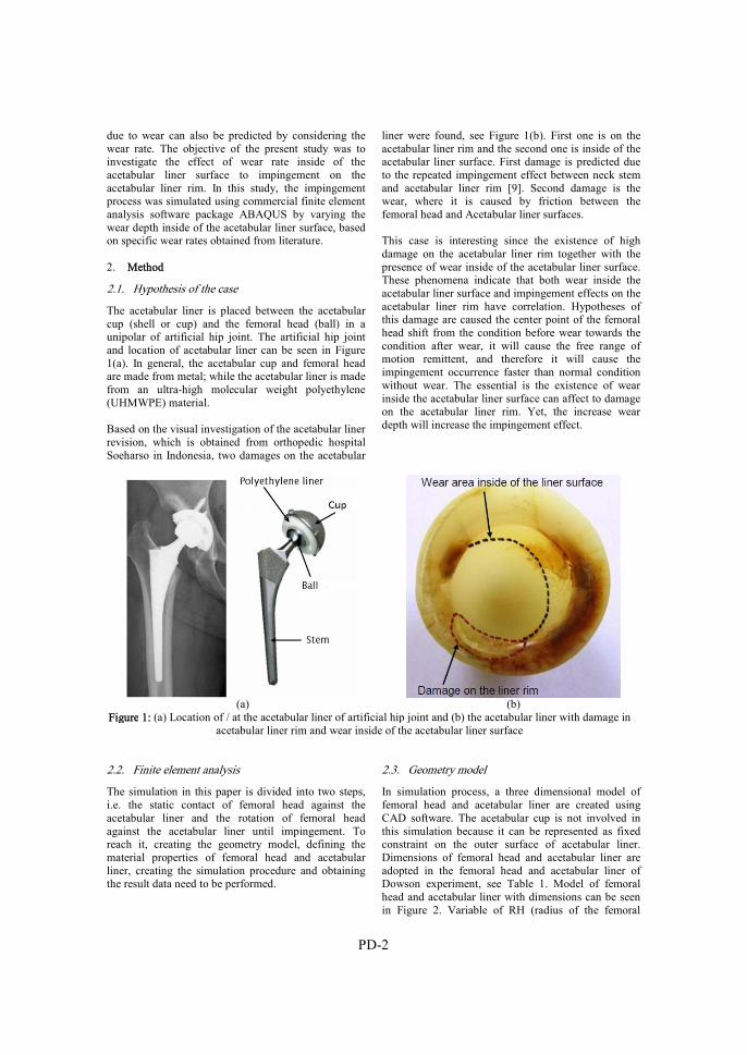
PD-2
due to wear can also be predicted by considering the wear rate. The objective of the present study was to investigate the effect of wear rate inside of the acetabular liner surface to impingement on the acetabular liner rim. In this study, the impingement process was simulated using commercial finite element analysis software package ABAQUS by varying the wear depth inside of the acetabular liner surface, based on specific wear rates obtained from literature.
2. Method
2.1. Hypothesis of the case
The acetabular liner is placed between the acetabular cup (shell or cup) and the femoral head (ball) in a unipolar of artificial hip joint. The artificial hip joint and location of acetabular liner can be seen in Figure 1(a). In general, the acetabular cup and femoral head are made from metal; while the acetabular liner is made from an ultra-high molecular weight polyethylene (UHMWPE) material.
Based on the visual investigation of the acetabular liner revision, which is obtained from orthopedic hospital Soeharso in Indonesia, two damages on the acetabular
liner were found, see Figure 1(b). First one is on the acetabular liner rim and the second one is inside of the acetabular liner surface. First damage is predicted due to the repeated impingement effect between neck stem and acetabular liner rim [9]. Second damage is the wear, where it is caused by friction between the femoral head and Acetabular liner surfaces.
This case is interesting since the existence of high damage on the acetabular liner rim together with the presence of wear inside of the acetabular liner surface. These phenomena indicate that both wear inside the acetabular liner surface and impingement effects on the acetabular liner rim have correlation. Hypotheses of this damage are caused the center point of the femoral head shift from the condition before wear towards the condition after wear, it will cause the free range of motion remittent, and therefore it will cause the impingement occurrence faster than normal condition without wear. The essential is the existence of wear inside the acetabular liner surface can affect to damage on the acetabular liner rim. Yet, the increase wear depth will increase the impingement effect.
(a) (b)
Figure 1: (a) Location of / at the acetabular liner of artificial hip joint and (b) the acetabular liner with damage in acetabular liner rim and wear inside of the acetabular liner surface
2.2. Finite element analysis
The simulation in this paper is divided into two steps, i.e. the static contact of femoral head against the acetabular liner and the rotation of femoral head against the acetabular liner until impingement. To reach it, creating the geometry model, defining the material properties of femoral head and acetabular liner, creating the simulation procedure and obtaining the result data need to be performed.
2.3. Geometry model
In simulation process, a three dimensional model of femoral head and acetabular liner are created using CAD software. The acetabular cup is not involved in this simulation because it can be represented as fixed constraint on the outer surface of acetabular liner. Dimensions of femoral head and acetabular liner are adopted in the femoral head and acetabular liner of Dowson experiment, see Table 1. Model of femoral head and acetabular liner with dimensions can be seen in Figure 2. Variable of RH (radius of the femoral

PD-3
head) and RL (radius of liner) are appropriated with diameters in Table 1. The diameter of neck stem is 14.2 mm. The acetabular liner has inset 2 mm and chamfer angle 45ᴼ.
Table 1: Dimension of acetabular liner and femoral head Components Diameter (mm) Acetabular liner 1 32.5458 Acetabular liner 2 32.5340 Femoral head 1 31.9800 Femoral head 2 31.9400 Neck stem 14.2
(a) (b)
Figure 2: Dimension of (a) femoral head with neck stem and (b) acetabular liner with chamfer
(a) (b) Figure 3: (a) The illustration of artificial wear inside of acetabular liner and (b) the wear depth of acetabular for
two acetabular liners as a function of loading cycles under normal walking condition [10] An artificial wear inside of the acetabular liner surface to provide the simulation requirement was created. With simple techniques, the artificial wear can be created using cut revolve feature in CAD software. The shape of artificial wear is based on the wear depth and the diameter of femoral head in Table 1. The shape of artificial wear is created with the assumption that the wear shape is appropriate with the radius of the femoral head, see Figure 3(a). The implementation of wear depth in here is using the wear depth data from Dowson’s experiment [10]. Dowson et al. investigated
the wear inside two acetabular liner surfaces using hip simulator apparatus [10]. Where, the dimensions of each femoral head and acetabular liner follow Table 1. Dowson et al. presented the progress of wear depth as a function of loading cycle under normal walking conditions [10], see Figure 3(b). In this work, wear is modelled as a geometrical cut inside of the acetabular liner surface without consider lubrication regime. Contact condition in this simulation is assumed as a dry contact. Furthermore, this
0
25
50
75
100
125
150
0.E400 1.E406 2.E406 3.E406 4.E406 5.E406
wear d
epth F
μmG
Loading cycles
Acetabular liner 1Acetabular liner 2

PD-4
simulation does not focus on the wear prediction but it is only to investigate the correlation between the wear inside of the acetabular liner surface with the impingement progress on the acetabular liner rim.
2.4. Material properties
In general, the femoral head and acetabular liner are made from metal or ceramic and an ultra-high molecular weight polyethylene (UHMWPE) material respectively. To simplify, the femoral head is assumed as rigid body because the femoral head is harder, whereas the acetabular liner is assumed as deformable. Material model of UHMWPE model is assumed as an isotropic strain hardening elastic-plastic material model, where it is developed by stress-strain curve data from tensile test. The data of true stress-strain curve from tensile test of UHMWPE material is obtained from Kurtz et al. [11], see Figure 4.
Figure 4: True stress vs true strain of UHMWPE material [11]
To finite element simulation requirement, the stress-strain curve is discretized where it is similar to that used by McNie et al. [12] and Faulkner and Arnell [13]. This model assumed an elastic modulus of 850 MPa [10] and an initial yield stress of 20 MPa.
2.5. Simulation procedure
The finite element simulation in this study is performed using Abaqus software version 6.12. In the real condition, the assembly of femoral head and acetabular liner is arranged based on inclination and anteversion angles. To simplify this, here, the simulation of the femoral head against acetabular liner is arranged in an ordered level, see Figure 5. The simulation consists of two steps, i.e. static contact and rotation steps. The static contact step is the femoral head pressing the acetabular liner with applied load F = 3000 N, where the applied load is placed in the center point of femoral head. This applied load adopts the vertical load from Dowson experiment. In the rotation step, the femoral
head is rotated in z-axis rotation with angle θ = 1.1 radian (for Abaqus input) or θ = 63.03o. The magnitude of this angle is a user-defined, or it is set towards impingement occurrence between the neck stem surfaces with the acetabular liner rim. In the static contact step, the center point of the femoral head is constrained in all axis directions except in y-direction. In the rotation step, the y and z axes rotation is free constraint. The outer surface of acetabular liner is fixed. All of these settings can be seen in Figure 5.
Figure 5: The 3D model of femoral head
against acetabular liner include the applied load, constrained, mesh and rotation direction
The element type that used in the acetabular liner is an 8-node linear brick, reduced integration, as well as hourglass control (C3D8R), where the numbers of elements are around 6,500 elements. This element type is recommended for modeling of continuum solids. The continuum elements can be used for linear analysis and complex non-linear analyses involving contact, plasticity and large deformations. It also usually provides a solution of equivalent accuracy at less cost [14]. The femoral head cannot be meshed due to the rigid body. The numbers of simulations are eight simulations with wear depth variation based on wear depth for two acetabular liners and femoral head, see figure 3 (b). 2.6. Post-processing
After finishing the simulation process, the next step is obtaining data from the simulation results. Several procedures to obtain data of the results are needed to be created. There are three proposed procedures, i.e. collecting data of von Mises stress at impingement, collecting data of impingement angle and collecting data of deformation on the acetabular liner rim due to impingement contact. 2.6.1. The von Mises stress at impingement
The data of von Mises maximum stress at impingement is needed to understand the relation of von Mises stress on the acetabular liner rim at impingement due to wear
020406080
100120140160180200
0 0.2 0.4 0.6 0.8 1 1.2 1.4 1.6
True St
ress, σ
FMPaG
True Strain, ε F-G

PD-5
inside the acetabular liner surface. In ABAQUS software, the von Mises stress can be read in the field output S-Mises (von Mises stress). The von Mises stress is obtained when the rotation of femoral head reaches angle θ = 1.06 radian or θ = 60.73o, where the angle θ is obtained from an initial impingement angle, see illustration in Figure 6. The initial impingement angle will be explained in the next chapter.
Figure 6: The illustration of obtaining von Mises stress
at impingement 2.6.2. Initial impingement angles
The data of initial impingement are needed to understand the relation of impingement angle progress due to wear inside the acetabular liner surface. In Abaqus software, the angle of rotation in z-axis can be read in the field output UR3 (rotational displacement). Availability of UR data depends on step frame that required by Abaqus to solve the simulation of case. In this case, the UR data are appropriate with step frame. In other words, the more step frame is resulted in the more accurate angle. There are two types of step frame, i.e. automatic and fixed type. In the automatic one, the step frame that resulted is irregular, whereas the fixed
one, the step frame that resulted is regularly appropriate with user-defined. To obtain the accurate data of initial impingement angle, the smooth step frame is required. As the consequence, it will take long time and require high convergence. Therefore, another method to obtain the initial impingement angle is required.
In this paper, the method that is used to take the initial impingement angle is sketching method. The initial step is conducted by sketching the acetabular liner with chamfer and femoral head with neck stem. The main concern of this method is the placement distance of the center point position of the femoral head to the center point of the acetabular liner. In this paper, it is called as offset of center points. The magnitude of this offset is the addition of the difference of a radius between the femoral head and the acetabular liner; wear depth and deformation contact due to static contact. The value of contact deformation is obtained from the result of simulation, where the value of this contact deformation depends on the applied load. If only consider the wear effect of the initial impingement angle, the contact deformation can be neglected. In fact, the contact deformation is always exist due to the human body weight. Therefore, in this paper, the initial impingement angle with and without the contact deformation will be presented as a comparison.
After the applied offset, the new center point of the femoral head is found. Further, the circle with the new center point as circle center point ‘O’ is created. The circle radius is the length of the center point ‘O’ to point chamfer ‘A’. The new circle will cut the neckline and resulted in cut point B. By connecting the point of O, A and B, the angle of AOB is formed. This angle is called as the initial impingement angle.
Figure 7: The procedure to obtain the initial impingement angle
2.6.3. Contact deformation on the acetabular liner
rim at impingement
In addition to the von Mises stress on the acetabular liner rim and the initial impingement angle of
impingement contact due to wear inside the acetabular liner surface, the progress data of contact deformation on the impingement contact point are needed. The data of contact deformation are obtained on the acetabular

PD-6
liner rim, see Figure 8. The contact deformation is taken along with the impingement process until the rotation angle reaches θ = 1.1 radian. The contact deformation that is investigated on the acetabular liner rim is a deformation in y-axis direction. In ABAQUS software, the displacement in y-axis can be read in the field output U2 (y-displacement). 3. Results and discussion
In the previous work (Saputra et al., 2013), the similar impingement simulation that consists of the load and rotation step had been performed, then it is used as a validation process. The different is only from the position of assembly between the head and the liner, where in this work does not applying the inclination and anteversion angles. 3.1. The maximum of von Mises stresses on the
acetabular liner rim
Figure 9 shows the progress of von Mises maximum stress on the acetabular liner rim at impingement or at the rotation of femoral head reach angle θ = 1.06 radian or θ = 60.73o. Based on Figure 9, the von Mises maximum stress increases along with the increasing wears depth. Logically, when the center point of femoral head shifts due to existence of wear inside of the acetabular liner surface, it will cause the impingement to occur faster. With the same angle of rotation for all wear variations, it will cause the stress in the impingement contact to increase. It is proven by the increasing of von Mises stress along with the wear variation. To show the position of von Mises maximum stress in the acetabular liner rim for each wear variation, as representation, the von Mises maximum stress on the acetabular liner rim number 1 is presented, see Figure 10.
Figure 8: The procedure to obtain the data of contact deformation
Figure 9: The von Mises maximum stress of impingement contact as a function of wear depth inside of
the acetabular liner surface
18
19
20
21
22
23
24
25
0 20 40 60 80 100 120 140
Max. v
on Mis
es stre
ss FMP
aG
Wear depth FµmG
Acetabular liner 1Acetabular liner 2
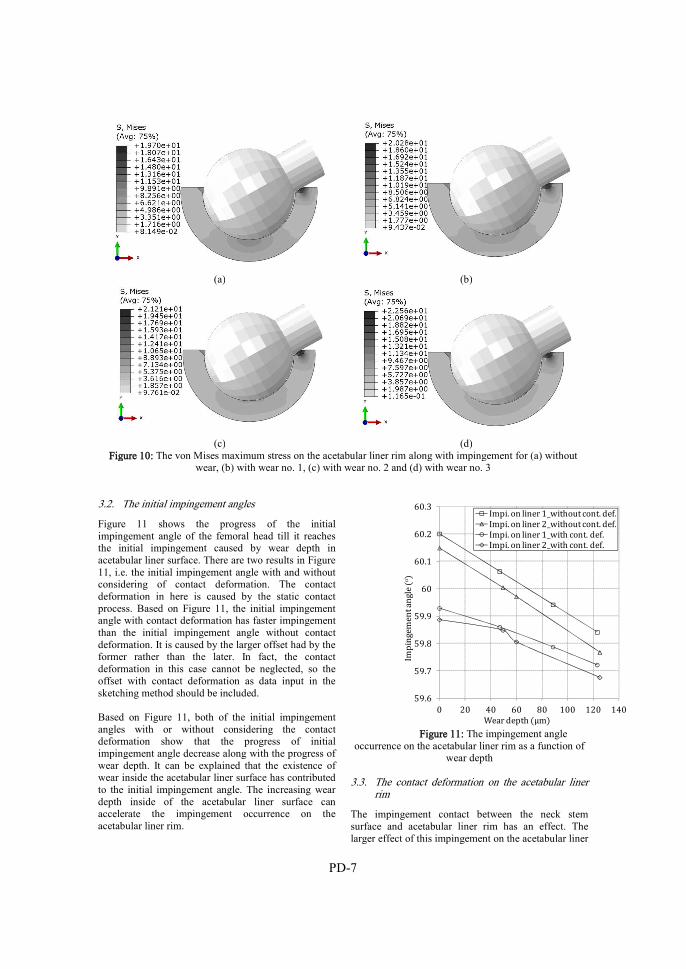
PD-7
(a) (b)
(c) (d)
Figure 10: The von Mises maximum stress on the acetabular liner rim along with impingement for (a) without wear, (b) with wear no. 1, (c) with wear no. 2 and (d) with wear no. 3
3.2. The initial impingement angles
Figure 11 shows the progress of the initial impingement angle of the femoral head till it reaches the initial impingement caused by wear depth in acetabular liner surface. There are two results in Figure 11, i.e. the initial impingement angle with and without considering of contact deformation. The contact deformation in here is caused by the static contact process. Based on Figure 11, the initial impingement angle with contact deformation has faster impingement than the initial impingement angle without contact deformation. It is caused by the larger offset had by the former rather than the later. In fact, the contact deformation in this case cannot be neglected, so the offset with contact deformation as data input in the sketching method should be included.
Based on Figure 11, both of the initial impingement angles with or without considering the contact deformation show that the progress of initial impingement angle decrease along with the progress of wear depth. It can be explained that the existence of wear inside the acetabular liner surface has contributed to the initial impingement angle. The increasing wear depth inside of the acetabular liner surface can accelerate the impingement occurrence on the acetabular liner rim.
Figure 11: The impingement angle
occurrence on the acetabular liner rim as a function of wear depth
3.3. The contact deformation on the acetabular liner
rim
The impingement contact between the neck stem surface and acetabular liner rim has an effect. The larger effect of this impingement on the acetabular liner
59.6
59.7
59.8
59.9
60
60.1
60.2
60.3
0 20 40 60 80 100 120 140
Impin
gement
angle
Fo G
Wear depth FµmG
Impi. on liner 1_without cont. def.Impi. on liner 2_without cont. def.Impi. on liner 1_with cont. def.Impi. on liner 2_with cont. def.
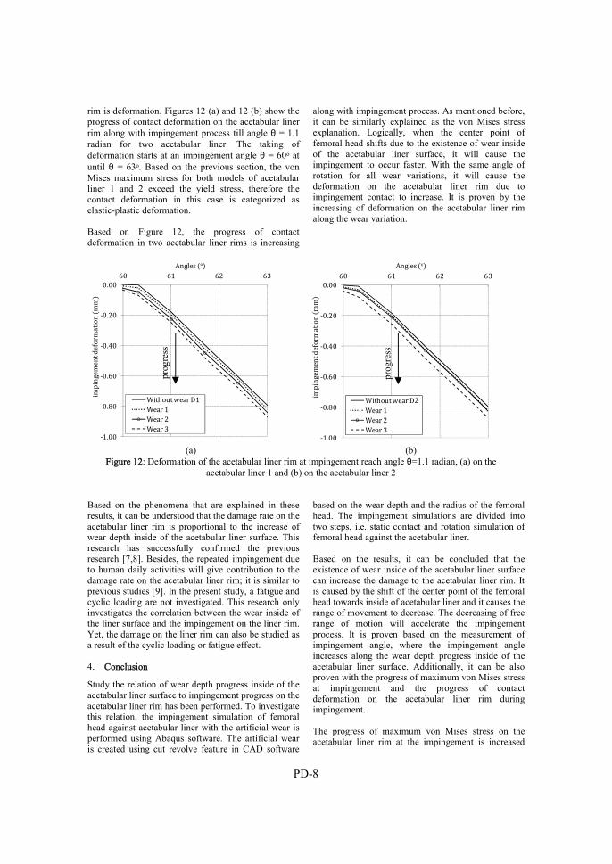
PD-8
rim is deformation. Figures 12 (a) and 12 (b) show the progress of contact deformation on the acetabular liner rim along with impingement process till angle θ = 1.1 radian for two acetabular liner. The taking of deformation starts at an impingement angle θ = 60o at until θ = 63o. Based on the previous section, the von Mises maximum stress for both models of acetabular liner 1 and 2 exceed the yield stress, therefore the contact deformation in this case is categorized as elastic-plastic deformation. Based on Figure 12, the progress of contact deformation in two acetabular liner rims is increasing
along with impingement process. As mentioned before, it can be similarly explained as the von Mises stress explanation. Logically, when the center point of femoral head shifts due to the existence of wear inside of the acetabular liner surface, it will cause the impingement to occur faster. With the same angle of rotation for all wear variations, it will cause the deformation on the acetabular liner rim due to impingement contact to increase. It is proven by the increasing of deformation on the acetabular liner rim along the wear variation.
(a) (b)
Figure 12: Deformation of the acetabular liner rim at impingement reach angle θ=1.1 radian, (a) on the acetabular liner 1 and (b) on the acetabular liner 2
Based on the phenomena that are explained in these results, it can be understood that the damage rate on the acetabular liner rim is proportional to the increase of wear depth inside of the acetabular liner surface. This research has successfully confirmed the previous research [7,8]. Besides, the repeated impingement due to human daily activities will give contribution to the damage rate on the acetabular liner rim; it is similar to previous studies [9]. In the present study, a fatigue and cyclic loading are not investigated. This research only investigates the correlation between the wear inside of the liner surface and the impingement on the liner rim. Yet, the damage on the liner rim can also be studied as a result of the cyclic loading or fatigue effect.
4. Conclusion
Study the relation of wear depth progress inside of the acetabular liner surface to impingement progress on the acetabular liner rim has been performed. To investigate this relation, the impingement simulation of femoral head against acetabular liner with the artificial wear is performed using Abaqus software. The artificial wear is created using cut revolve feature in CAD software
based on the wear depth and the radius of the femoral head. The impingement simulations are divided into two steps, i.e. static contact and rotation simulation of femoral head against the acetabular liner. Based on the results, it can be concluded that the existence of wear inside of the acetabular liner surface can increase the damage to the acetabular liner rim. It is caused by the shift of the center point of the femoral head towards inside of acetabular liner and it causes the range of movement to decrease. The decreasing of free range of motion will accelerate the impingement process. It is proven based on the measurement of impingement angle, where the impingement angle increases along the wear depth progress inside of the acetabular liner surface. Additionally, it can be also proven with the progress of maximum von Mises stress at impingement and the progress of contact deformation on the acetabular liner rim during impingement. The progress of maximum von Mises stress on the acetabular liner rim at the impingement is increased
-1.00
-0.80
-0.60
-0.40
-0.20
0.0060 61 62 63
imping
ement
defor
mation
FmmG
Angles FoG
Without wear D1Wear 1Wear 2Wear 3
-1.00
-0.80
-0.60
-0.40
-0.20
0.0060 61 62 63
imping
ement
defor
mation
FmmG
Angles FoG
Without wear D2Wear 1Wear 2Wear 3
prog
ress
prog
ress

PD-9
along with the progress of wear inside the acetabular liner surface. Yet, the contact deformation on the impingement between neck stem surface and the acetabular liner rim is increased along with impingement process. All results of this research confirm that the wear rate inside the acetabular liner surface will increase the damage on the acetabular liner rim due to the impingement contact. References
1. Sikes, C.V., Lai, L.P., Schreiber, M., Mont, M.A., Jinnah, R.H. and Seyler, T.M. (2008) ‘Instability after total hip arthroplasty treatment with large femoral heads vs constrained liners’, J. Arthrop., Vol. 23, No.7, pp. 59-63.
2. Cuckler, J.M. (2011) ‘The dislocated total hip: the dreaded 3 AM phone call’, Semin. Arthro., Vol. 22, pp. 98-99.
3. Hummel, M.T., Malkani, A.L., Yakkanti, M.R. and Baker D.L. (2009) ‘Decreased dislocation after revision total hip arthroplasty using larger femoral head size and posterior capsular repair’, J. Arthrop., Vol. 24, No. 6, pp. 73-76.
4. Sugano, N., Tsuda, K., Miki, H., Takao, M., Suzuki, N. and Nakamura, N. (2012) ‘Dynamic measurements of hip movement in deep bending activities after total hip arthroplasty using a 4-dimensional motion analysis system’, J. Arthrop., Vol. 27, No. 8, pp. 1562-1568.
5. Saputra, E., Anwar, I.B., Ismail, R., Jamari, J. and van der Heide, E. (2014) ‘Numerical simulation of artificial hip joint movement for Western and Japanese-style activities’, J Teknologi (Sci. & Eng.), Vol. 66, No. 3, pp. 53-58.
6. Saputra, E., Anwar, I.B., Jamari, J. and van der Heide, E. (2013) ‘Finite element analysis of
artificial hip joint movement during human activities’, Procedia Eng., No. 68, pp. 102-108.
7. Scifert, C.F., Brown, T.D., Pedersen, D.R. and Callaghan, J.J. (1998) ‘A finite element analysis of factors influencing total hip dislocation’, Clin. Orthop., Vol. 355, pp. 152-162.
8. Tanino, H., Harman, M.K., Banks, S.A. and Hodge, W.A. (2007) ‘Association between dislocation, impingement, and articular geometry in retrieved acetabular polyethylene cups’, J. Orthop. Res., Vol. 25, No. 11, pp. 1401-1407.
9. Jamari, J., Ismail, R., Saputra, E., Sugiyanto, S. and Anwar, I.B., (2014) ‘The effect of repeated impingement on UHMWPE material in artificial hip joint during salat activities’, Adv. Mat. Res., Vol. 896, pp. 272-275.
10. Dowson, D., Jobbins, B. and Seyed-Harraf A. (1993) ‘An evaluation of the penetration of ceramic femoral heads into polythene acetabular cups’, Wear, Vol. 162-164, pp. 880-889.
11. Kurtz, S.T., Pruitt, L., Jewett, C.W., Crawford, R.P., Crane, D.J. and Edidin, A.A. (1998) ‘The yielding, plastic flow, and fracture behavior of ultra-high molecular polyethylene used in total joint replacements’, Biomaterials, Vol. 19, pp. 1989-2003.
12. McNie, C., Barton, D.C., Stone, M.H. and Fisher, J. (1998) ‘Prediction of plastic strains in ultra-high molecular weight polyethylene due to microscopic asperity interactions during sliding wear’, Proc. Inst. Mech. Eng. H, No. 212, pp. 49-56.
13. Faulkner, A. and Arnell, R.D. (2000) ‘The development of a finite element model to simulate the sliding interaction between two, three-dimensional, elastoplastic, hemisperichal asperities’, Wear, Vol. 242, No. 242, pp. 114-122.
14. ABAQUS (2012) `ABAQUS Documentation', Dassault Systèmes, Providence, RI, USA.


Conference Paper A
E. Saputra, I.B. Anwar, J. Jamari, E. van der Heide, 2013
Finite element analysis of artificial hip joint movement during human activities
Procedia Engineering, Volume 68, pp. 102-108,
doi: https://doi.org/10.1016/j.proeng.2013.12.154


CPA-1
Finite element analysis of artificial hip joint movement during human activities
E. Saputra1, I.B. Anwar1, J. Jamari2, E. van der Heide1 1Laboratory for Surface Technology and Tribology, Faculty of Engineering Technology,
University of Twente, Postbox 217, 7500 AE Enschede, The Netherlands 2Laboratory for Engineering Design and Tribology, Department of Mechanical Engineering,
Diponegoro University, Jl. Prof. Sudharto SH, Tembalang, Semarang 50275, Indonesia
Accepted in: Procedia Engineering, Volume 68, pp. 102 – 108
Abstract The range of motion of artificial hip joint during human activities, measured from the postoperative total hip arthroplasty patients, has been reported previously. There were two human activities discussed, i.e. Western-style and Japanese-style. This paper analyzes the hip joint movement during human activities, based on the measured range of motion, using finite element simulation. The Western-style activities consist of picking up, getting up and sitting, while the Japanese-style activities consist of sitting on legs with fully flexed at the knee (seiza), squatting and sitting on legs with fully flexed at the knee (zarei). The aim of this study is to investigate the probability of prosthetic impingement to occur and to calculate the von Mises stress during the activities. A three-dimensional nonlinear finite element (FE) method is used in the simulation. The acetabular liner cup positions are varied. Results show that in the Western-style activities, the picking up activity induces prosthetic impingement in a certain the acetabular liner cup position, whereas in the Japanese-style activities there is no prosthetic impingement observed. However, the Japanese’s Zarei activity has a critical value in the range of motion. The von Mises stresses during the prosthetic impingement have been shown and the value is higher than the yield stress of the material. Keywords: Finite element analysis; artificial hip joint; range of motion; human activities; impingement Nomenclature F = force (N) Greek symbols Ɛ = strain (-) σ = stress (MPa) Subscripts r = resultant x = x-coordinate y = y-coordinate
z = z-coordinate Superscript n = material parameter 1. Introduction Dislocation is one of the main problems for total hip arthroplasty (THA) patient during their daily activities [1]. There are two types of dislocation: early dislocation and late dislocation [2]. The early dislocation occurs due to the impingement of the femoral neck from the acetabular liner cup lip and the late dislocation is mostly related to wear [2-3]. The impingement in early dislocation is induced by the limitation of the range of motion (RoM) of the artificial hip joint for the THA patient. This limitation of the RoM can be influenced by the femoral head diameter, femoral neck diameter and acetabular liner cup position. Human activities have different ranges of motion. The excessive or inordinate activities can induce a higher RoM and causes the impingement. THA patients will get typical procedures from their orthopedics specialist for doing activities in order to avoid the impingement. Activities of the THA patients and its implication to RoM and impingement have been reported. Sugano et al. [4] presented the measurement of RoM for Western-style activities and Japanese-style activities. The measurement was conducted using the measurement results of 19 postoperative THA patients. It was reported that the RoM of the Western-style activities consist of picking up, getting up and sitting, while the RoM of the Japanese-style activities consist of seiza, squatting and zarei. Kluess et al. [5] developed a three-dimensional model for artificial hip joint movement by finite element analysis. Several position of the acetabular liner cup during the movement was simulated in order to observe the occurrence of impingement. This paper presents a 3D movement simulation to study the RoM of the Western-style and Japanese-style activities. The

CPA-2
impingement is then predicted by a finite element analysis. The relation of the resisting moment, the internal rotation and the von Mises stress are reported in this paper. 2. Material and Method 2.1. Material model The finite element model of the contact system in the present study consists of femoral head, femoral neck and acetabular liner cup. The femoral head and the femoral neck component are assumed to be rigid. The acetabular liner cup component is modeled as an elastic-plastic material with isotropic hardening and assuming a visco-elastic-plastic material behavior of the ultra high molecular weight polyethylene (UHMWPE). The modulus of elasticity, the Poisson’s ratio and the yield strength of the UHMWPE are set to 945 MPa, 0.45 and 23.56 MPa, respectively [6]. The plastic strain is calculated based on the work of Fregly et al. [7]:
n
00
00 2
1
2
1
(1)
where the material parameter, n, is equal to 3.
4.1. Finite element method 4.1.1. Geometry
(a) (b)
Figure 1: a) Model of the femoral head and the acetabular liner cup and b) the finite
element meshes of the acetabular liner cup
The geometrical modeling of the unipolar artificial hip joint follows the model of Kluess et al. [5], as is depicted in Fig. 1(a). Diameter of the
femoral head and the femoral neck are 28 mm and 14 mm, respectively. The thickness of the acetabular liner cup is 7 mm. A gap between the femoral head and the acetabular liner cup is 24 µm and it is modeled as a lubrication space. Fig. 1(b) shows the finite element meshes for the acetabular liner cup. The commercial finite element software ABAQUS is employed. The element type of hexahedral 8 nodes linear brick (C3D8R) is employed, while the number of the element is approximately 9000.
4.1.2. Boundary conditions The value of the applied load of the present model is taken from the work of Kluess et al. [5], but the direction of the load follows the work of Bergmann et al. [8]. The loads in the x, y and z directions are Fx = 15 N, Fy = 270 N and Fz = -427.5 N, respectively, and are applied on a point at the center of the femoral head. All the degree of freedom at the outer surface of the acetabular liner cup is constrained. The simulation is conducted in two steps: firstly, the load is applied to the center of the femoral head with constraining the rotation of the femoral head is constrained and secondly, the load at the center of the femoral head is constrained with rotating the femoral head. The range of the rotation is according to the RoM of human activities.
4.1.3. Human activities The simulations are performed for the Western-style and the Japanese-style activities. Here, the value of the RoM is taken based on the work of Sugano et al. [4]. The Western-style activities consist of picking up an object while sitting on the chair, getting up from the chair, and sitting down on the chair. The Japanese-style activities consist of bowing while sitting on legs with fully flexed at the knee (zarei), squatting, and sitting on legs with fully flexed at the knee (seiza). Figures for expressing all these activities can be seen in (Fig.2) [4]. Those activities give a certain value of the RoM in degree. Maximum flexion, adduction and internal rotation are the component items for the RoM value. Table 1 shows the value of RoM for the human general activities.
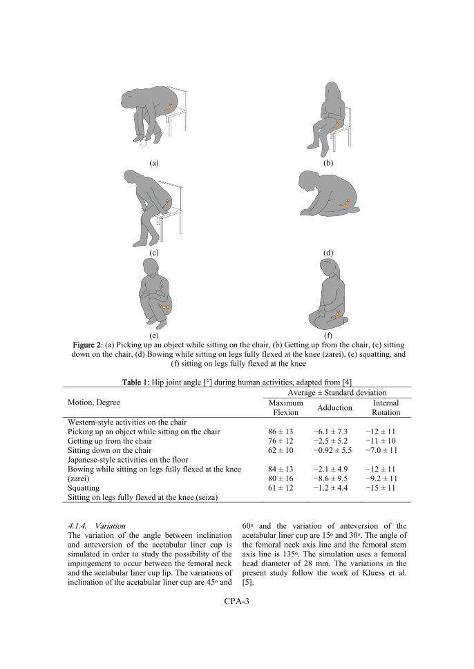
CPA-3
(a) (b)
(c) (d)
(e) (f)
Figure 2: (a) Picking up an object while sitting on the chair, (b) Getting up from the chair, (c) sitting down on the chair, (d) Bowing while sitting on legs fully flexed at the knee (zarei), (e) squatting, and
(f) sitting on legs fully flexed at the knee
Table 1: Hip joint angle [°] during human activities, adapted from [4]
Motion, Degree Average ± Standard deviation
Maximum Flexion
Adduction Internal Rotation
Western-style activities on the chair Picking up an object while sitting on the chair Getting up from the chair Sitting down on the chair Japanese-style activities on the floor Bowing while sitting on legs fully flexed at the knee (zarei) Squatting Sitting on legs fully flexed at the knee (seiza)
86 ± 13 76 ± 12 62 ± 10 84 ± 13 80 ± 16 61 ± 12
−6.1 ± 7.3 −2.5 ± 5.2 −0.92 ± 5.5 −2.1 ± 4.9 −8.6 ± 9.5 −1.2 ± 4.4
−12 ± 11 −11 ± 10 −7.0 ± 11 −12 ± 11 −9.2 ± 11 −15 ± 11
4.1.4. Variation The variation of the angle between inclination and anteversion of the acetabular liner cup is simulated in order to study the possibility of the impingement to occur between the femoral neck and the acetabular liner cup lip. The variations of inclination of the acetabular liner cup are 45o and
60o and the variation of anteversion of the acetabular liner cup are 15o and 30o. The angle of the femoral neck axis line and the femoral stem axis line is 135o. The simulation uses a femoral head diameter of 28 mm. The variations in the present study follow the work of Kluess et al. [5].

CPA-4
3. Results and discussions 4.1. Validation In order to check the developed model simulation, a validation was conducted by comparing the results to the work of Kluess et al. [5]. The inclination and anteversion of the acetabular liner cup were fixed for 60o and 30o, respectively. Result of the validation is shown in Fig. 3. The average deviation between the present model and the Kluess et al. model is about 1.32 %. The developed model is in good agreement with literature with respect to the predicted resisting moment.
Figure 3: Comparison between the present
model and the Kluess model [5] in predicting the resisting moment as a function of the angle of
internal rotation 4.2. Western-style activities Fig. 4(a) and 3(b) show the degree of impingement for the Western-style activities. In Fig. 4(a) the internal rotation for the picking-up, getting-up and sitting down activities is reported with considering four different position of the acetabular liner cup. The minimum requirements of the internal rotation for picking-up, getting-up and sitting down activities are 12, 11 and 7, respectively. The highest resisting moments for picking-up, getting-up and sitting down activities are 4.41 Nm, 3.88 Nm and 3.21 Nm as is depicted in Fig. 4(b). The unipolar artificial hip joint does not induce an impingement for most of the Western-style activities. Yet, the picking up activity, for the acetabular liner cup inclination of 45 and anteversion of 15, could be critical as the impingement is predicted to occur at 8 of the internal rotation. Therefore, the THA patients are suspected not to be able to finish the picking up activity due to the fact that it needs at least 12 of internal rotation. Fig. 4 shows the von Mises
stress analysis. Fig. 5(a) shows the stress analysis for getting up activity and Fig. 5(b) shows the picking up activity where the combination degree of the acetabular liner cup inclination and the anteversion is 45-15. Two impingement positions can be found from the analysis based on this figure, namely impingement site and egress site.
(a)
(b)
Figure 4: (a) Comparison of the calculated value of internal rotation obtained from variations of the acetabular liner cup position in the Western-
style activities and b) plot of its resisting moment as a function of its internal rotation
angle Dislocation is predicted to occur for the patients who are trying to perform the picking up activity. The other combination positions of the acetabular liner cup for inclination and anteversion are also reported in a safe position, 45-30, 60-15 and 60-30. However, based on several testimonies of the orthopedic specialist, it is stated that the inclination and the anteversion of the acetabular liner cup combinations of 45-15 are mostly used. It is suggested that the unipolar artificial hip joint, proposed by Kluess et al. [5], need to be redesigned to accommodate the picking up activity with respect to the inclination and the anteversion of the acetabular liner cup combination of 45-15.

CPA-5
(a)
(b)
Figure 5: The von Mises stress for: (a) getting up activity and (b) picking up activity where the
acetabular liner cup position is 45° inclination and 15° anteversion of the Western activity
4.3. Japanese-style activities The degree of impingement for the Japanese-style activities is shown in Fig. 6. In Fig. 6(a) the internal rotation for the three activities is reported with considering four positions of the acetabular liner cup. The minimum requirements of the internal rotation for zarei, squatting and seiza activities are 12, 9.2 and 15, respectively. Fig. 6(b) shows that the highest resisting moment for zarei, squatting and seiza activities are 4.33 Nm, 4.10 Nm and 3.15 Nm, respectively.
(a)
(b)
Figure 6: (a) Comparison of the calculated value of internal rotation obtained from variation of the
acetabular liner cup position in the Japanese-style activities and (b) plot of its resisting
moment as a function of its internal rotation angle
In general, the unipolar artificial hip joint models for the Japanese-style activities are predicted safe in term of the impingement. However, the zarei activity, for inclination of 45 dan anteversion of 15 of the acetabular liner cup, is still not suggested. This is because the impingement of the zarei activity is predicted to occur at 13.53 of internal rotation whiles the result shows that the required degree of the zarei activity is 12o. Moreover, the safe margin of the internal rotation is about 10 as was suggested by Sugano et al. [4]. Therefore, an evaluation is still needed for the unipolar artificial hip joint model proposed by Kluess et al. [5]. The model needs to be redesigned for accommodating the zarei activity in a more safe condition. The von Mises stress contours for the Japanese-style activities are shown in Fig. 7(a) and 7(b) for squatting and zarei activities, respectively, with the combination of inclination and anteversion of the acetabular liner cup of 45-15.
(a)
impingement site
egress site
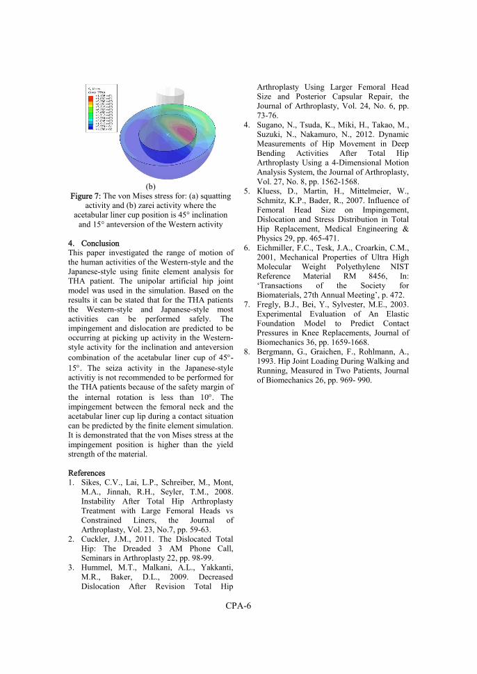
CPA-6
(b)
Figure 7: The von Mises stress for: (a) squatting activity and (b) zarei activity where the
acetabular liner cup position is 45° inclination and 15° anteversion of the Western activity
4. Conclusion This paper investigated the range of motion of the human activities of the Western-style and the Japanese-style using finite element analysis for THA patient. The unipolar artificial hip joint model was used in the simulation. Based on the results it can be stated that for the THA patients the Western-style and Japanese-style most activities can be performed safely. The impingement and dislocation are predicted to be occurring at picking up activity in the Western-style activity for the inclination and anteversion combination of the acetabular liner cup of 45-15. The seiza activity in the Japanese-style activitiy is not recommended to be performed for the THA patients because of the safety margin of the internal rotation is less than 10. The impingement between the femoral neck and the acetabular liner cup lip during a contact situation can be predicted by the finite element simulation. It is demonstrated that the von Mises stress at the impingement position is higher than the yield strength of the material. References 1. Sikes, C.V., Lai, L.P., Schreiber, M., Mont,
M.A., Jinnah, R.H., Seyler, T.M., 2008. Instability After Total Hip Arthroplasty Treatment with Large Femoral Heads vs Constrained Liners, the Journal of Arthroplasty, Vol. 23, No.7, pp. 59-63.
2. Cuckler, J.M., 2011. The Dislocated Total Hip: The Dreaded 3 AM Phone Call, Seminars in Arthroplasty 22, pp. 98-99.
3. Hummel, M.T., Malkani, A.L., Yakkanti, M.R., Baker, D.L., 2009. Decreased Dislocation After Revision Total Hip
Arthroplasty Using Larger Femoral Head Size and Posterior Capsular Repair, the Journal of Arthroplasty, Vol. 24, No. 6, pp. 73-76.
4. Sugano, N., Tsuda, K., Miki, H., Takao, M., Suzuki, N., Nakamuro, N., 2012. Dynamic Measurements of Hip Movement in Deep Bending Activities After Total Hip Arthroplasty Using a 4-Dimensional Motion Analysis System, the Journal of Arthroplasty, Vol. 27, No. 8, pp. 1562-1568.
5. Kluess, D., Martin, H., Mittelmeier, W., Schmitz, K.P., Bader, R., 2007. Influence of Femoral Head Size on Impingement, Dislocation and Stress Distribution in Total Hip Replacement, Medical Engineering & Physics 29, pp. 465-471.
6. Eichmiller, F.C., Tesk, J.A., Croarkin, C.M., 2001, Mechanical Properties of Ultra High Molecular Weight Polyethylene NIST Reference Material RM 8456, In: ‘Transactions of the Society for Biomaterials, 27th Annual Meeting’, p. 472.
7. Fregly, B.J., Bei, Y., Sylvester, M.E., 2003. Experimental Evaluation of An Elastic Foundation Model to Predict Contact Pressures in Knee Replacements, Journal of Biomechanics 36, pp. 1659-1668.
8. Bergmann, G., Graichen, F., Rohlmann, A., 1993. Hip Joint Loading During Walking and Running, Measured in Two Patients, Journal of Biomechanics 26, pp. 969- 990.
Conference Paper B
R. Ismail, E. Saputra, M. Tauviqirrahman, A.B. Legowo, I.
Budiwan Anwar, J. Jamari, 2014
Numerical study of salat movements for total hip replacement patient
Applied Mechanics and Materials, Volume 493, pp. 426-431,
doi: https://doi.org/10.4028/www.scientific.net/AMM.493.426

CPB-1
Numerical study of salat movements for total hip replacement patient
R. Ismail1, E. Saputra1, M. Tauviqirrahman1, I.B. Anwar2 and J Jamari1
1Laboratory for Engineering Design and Tribology, Department of Mechanical Engineering, University of Diponegoro, Central Java, Indonesia
2Soeharso Orthopaedic Hospital, Solo, Central Java, Indonesia
Published in: Applied Mechanics and Materials, Volume 493, pp. 426-431
Abstract Salat as a daily Muslim activitiy in praying contains several movements which are not suggested by orthopaedic doctor to be conducted by patient with total hip replacement (THR). Sujud and sitting are two movements in Salat which is recommended to be done above the chair for THR patients. There are lacks of scientific discussions about the consequences of the normal salat movement for Muslim THR patients. This paper observes the effect of these movements to the artificial hip joint in THR patient body. A three-dimensional finite element simulation is used to investigate the resisting moment, the contact pressure and the von Mises stress. An artificial hip joint model proposed by previous researcher is used in the simulations. The results show that sujud induces the impingement and plastic deformation whereas sitting is relatively safe to be conducted by THR patients. Some suggestions are also discussed with respect to the design of new artificial hip joint model which allows THR patients to conduct Salat in a normal way. The reduction of inset at the liner, the new profile at circumferential edge inner liner and the increase in the femoral head diameter can be considered as a guideline for new design of the artificial hip joint for Muslim. Keywords: Salat Movement, Artificial Hip Joint, Total Hip Replacement, Impingement
1. Introduction
Salat as a daily Muslim activity in praying consists of various movements. Several Salat movements are not suggested by orthopaedic doctor for total hip replacement (THR) patients, for instance, the movements which ask the patient knees touching the floor: sujud and sitting movement. Muslim patients with THR are advised to conduct these movements above the chair to avoid the dislocation and impingement of the artificial hip joint. Dislocation, a leading cause for clinical failure of THR [1], can be caused by the weakness of muscle of tissues around the joint, malposition of the implant components and also repeated impingements [1-2]. Impingement of the femoral neck on the acetabular liner can be induced by the excessive motion of the artificial hip joint. The repeated impingement causes excessive wear, reduces the initial dimension and/or material failure of implant components of polyethylene
liners [3]. The effect of dislocation and the repeated effect of impingement are unsafe for the THR patients. This leads to the investigation of the effect of Salat movement for the THR patients to observe the possibilities of the dislocation and/or impingement in more deeply. During interviews with some patients in Suharso Orthopaedic Hospital, Solo, some of Muslim patients with THR express their wish to accomplish Salat in a normal way. Based on population census data conducted by BPS Statistic Indonesia in 2010, Indonesia has the largest number of Muslim in the world. Indonesia’s Muslim population reached 207 million (87%) from the total population in Indonesia (237 million) [4]. Considering the large Muslim population in Indonesia, the aforementioned wish becomes important to be investigated. However, based on literature survey, a very few scientific discussions about the consequences of the normal Salat movement for Muslim THR patients are found. Therefore, to complement such a discussion, a novel finding focused on the observation of the effect of normal Salat movements on the artificial hip joint for THR patient body is discussed. A numerical analysis using finite element method is conducted to simulate several Salat movements and its impacts to impingements and dislocation for patients with THR.
2. Salat Movements
Various obligatory movements are required during Salat activities. The visualization of Salat movements, discussed in this research, is captured from the Association of Islamic Charitable Projects [5]. Salat covers several movements: (i) standing, (ii) bowing (ruku’), (iii) straightening up (i’tidal), (iv) prostration (sujud), (v) sitting between the two prostrations and (vi) the last sitting (tahiyah). This research will discuss two movements: sujud and sitting between the two prostrations whereas other movements are discussed in the future paper. The details of sujud (prostration) movement (lying face downward until touching the floor with the hands and legs position) are depicted schematically in Fig. 1. The artificial hip joint in the patient body is positioned with high degree of flexion (110°). The details of sitting between the two prostrations are showed schematically in Fig. 2. The artificial hip joint in patient body is
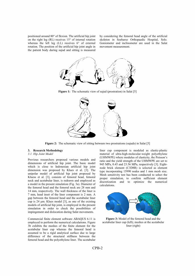
CPB-2
positioned around 80° of flexion. The artificial hip joint on the right leg (RL) receives 15° of internal rotation whereas the left leg (LL) receives 6° of external rotation. The position of the artificial hip joint angle in the patient body during sujud and sitting is measured
by considering the femoral head angle of the artificial skeleton in Soeharso Orthopaedic Hospital, Solo. Goniometer and inclinometer are used in the Salat movement measurement.
Figure 1: The schematic view of sujud (prostration) in Salat [5]
Figure 2: The schematic view of sitting between two prostrations (sujuds) in Salat [5]
3. Research Methodology
3.1. Hip Joint Model
Previous researchers proposed various models and dimensions of artificial hip joint. The basic model which is close to Indonesian artificial hip joint dimension was proposed by Klues et al. [3]. The unipolar model of artificial hip joint proposed by Kluess et al. [3], consists of femoral head, femoral neck and acetabular liner, is redrawn and employed as a model in the present simulation (Fig. 3a). Diameter of the femoral head and the femoral neck are 28 mm and 14 mm, respectively. The wall thickness of the liner is 7 mm, head inset of the liner component is 2 mm. A gap between the femoral head and the acetabular liner cup is 24 μm. Klues model [3], as one of the existing models of artificial hip joint, is employed in the present simulation in order to check the possibilities of impingement and dislocation during Salat movements. Commercial finite element software ABAQUS 6.11 is employed to perform the numerical calculations. Figure 3b exhibits the meshes of the finite element for the acetabular liner cup whereas the femoral head is assumed to be a rigid analytical surface due to large difference of the structural stiffness between the femoral head and the polyethylene liner. The acetabular
liner cup component is modeled as elastic-plastic material of ultra-high-molecular-weight polyethylene (UHMWPE) where modulus of elasticity, the Poisson’s ratio and the yield strength of the UHMWPE are set to 945 MPa, 0.45 and 23.56 MPa, respectively [3]. Eight-node brick element (C3D8R) is selected as element type incorporating 15990 nodes and 1 mm mesh size. Mesh sensitivity test has been conducted to select the proper simulation, to confirm sufficient element discretization and to optimize the numerical calculations.
Figure 3: Model of the femoral head and the
acetabular liner cup (left); meshes at the acetabular liner (right)

CPB-3
3.2. Boundary Condition and Simulation
The value of the applied load on the present model is taken from the work of Kluess et al. [3] whereas the direction of the load follows the work of Bergmann et al. [6]. The loads in the x, y and z -directions are Fx = 15 N, Fy = 270 N and Fz = -427.5 N, respectively, and applied on a point at the center of the femoral head. All the degree of freedoms at the outer surface of the liner cup is constrained. The simulation is conducted in two steps: firstly, the load is applied to the center of the femoral head with constraining the rotation of the femoral head and secondly, the load at the center of the femoral head is constrained with rotating the femoral head. The range of the rotation is based on the measured RoM of Salat activities. 3.3. Model validation
In order to check the present model, mesh development and simulations, a validation was conducted by comparing the present results with Kluess et al. result [3]. As shown in Fig. 4, the present model shows a good agreement with literature with respect to the predicted resisting moment. The average deviation of resisting moment between the present model and the Kluess et al. model is about 1.32 %.
Figure 4: Good agreement between the present model
and Klues et al. model [3]
4. Results and discussion
The results are presented for several parameters: resisting moment, contact pressure and contact stress using von Mises criterion for two Salat movements: sujud and sitting. Impingement as the early mode of dislocation is investigated for these movements. 4.1. Resisting Moment
The resisting moments as a reaction of the tangential stress and friction in the joint due to leg rotation and hip joint force for sujud and sitting movements are depicted in Figs. 5. The calculated resisting moments are compared with the requirement of flexion and rotation during Salat movements. Sujud requires 110° of flexion and 7° of external rotation of the hip joint
movements. Sitting requires 78° of flexion and 15° of internal rotation for RL (right leg) and 80° of flexion and 6° of external rotation for LL (left leg). Accomplishing sujud movement requires 110° of flexion. Based on Figs. 5a, the resisting moment starts to increase on 90° of flexion. This indicates that the impingement of femoral head on acetabular liner is present. The higher degree of impingement during sujud movement can be found if the external rotation is taken into account. The impingement is not found in sitting movement due to a free space of rotation and flexion in range of motion. Accomplishing sitting movement requires 15° of internal rotation (RL) and 6° of external rotation (LL). Based on Fig. 5b, the impingement will be occur at 20° of internal rotation of RL and does not occur for external rotation of LL. The requirement of flexion angle for sitting, around 80°, can be achieved before the increase of the resisting moment.
(a)
(b)
Figure 5. Resisting moments as a function of its internal rotation angle: (a) sujud and (b) sitting
Flexion in Sujud (110°)
LL external rotation
(6º)
RL internal rotation
(16º)
Impingement occurs

CPB-4
(a)
(b)
(c)
Figure 6: Contact pressure during Salat movements: (a) sujud, and (b) sitting-LL and (c) sitting-RL
4.2. Contact Pressure
In the present paper, the contact pressure is calculated with respect to the analysis of the area of articulating surfaces and the maximum value of the pressure (Fig. 6). During sujud movement, the articulating surface is discovered at the circumferential edge of the inner liner diameter and results in a maximum value of contact pressure of 38.22 MPa. During sitting movement, the articulating surface of LL and RL is discovered inside the liner with the small value of contact pressure. 4.3. Contact Stress
The contact stress is analyzed using von Mises criterion to predict the plastic deformation of the liner. The results of von Mises stress distribution for sujud and sitting movement have the similar location to the contact pressure. In sujud movement, the maximum von Mises stress reaches a value of 23.56 MP, i.e. the yield strength of UHMWPE material. It indicates that the plastic deformation takes place and the impingement occurs. The plastic deformation, located in circumferential edge of the inner liner, is caused by the inset of the liner 2 mm on the femoral head surface. In sitting movement, the lower von Mises stresses are
found in RL and LL indicating the absence of the plastic deformation and impingement. The discussion this sections is focused on the sujud movements due to the presence of impingement and plastic deformation. Investigation of resisting moment on sujud movements shows that initially, the femoral head rotates freely in the liner and is only impeded by the friction of the contacting surfaces. The resisting moment starts to increase suddenly due to repositioning of the rotation centre to the circumferential edge of the liner. The simulation result predicts that impingement occurs between the neck and the liner. Then, the resisting moment decreases progressively as the increase of the rotational movement and results in the smaller articulating contact area [3].
(a)
(b)
(c)
Figure 7. von Mises stress during Salat movements: (a) sujud, and (b) sitting-LL and (c) sitting-RL
Since repeated impingement can cause damage to the liner and induces dislocation [3]. A maximum range of motion until impingement should be a main consideration for new implant designs. In the present paper, the new design of artificial hip joint which
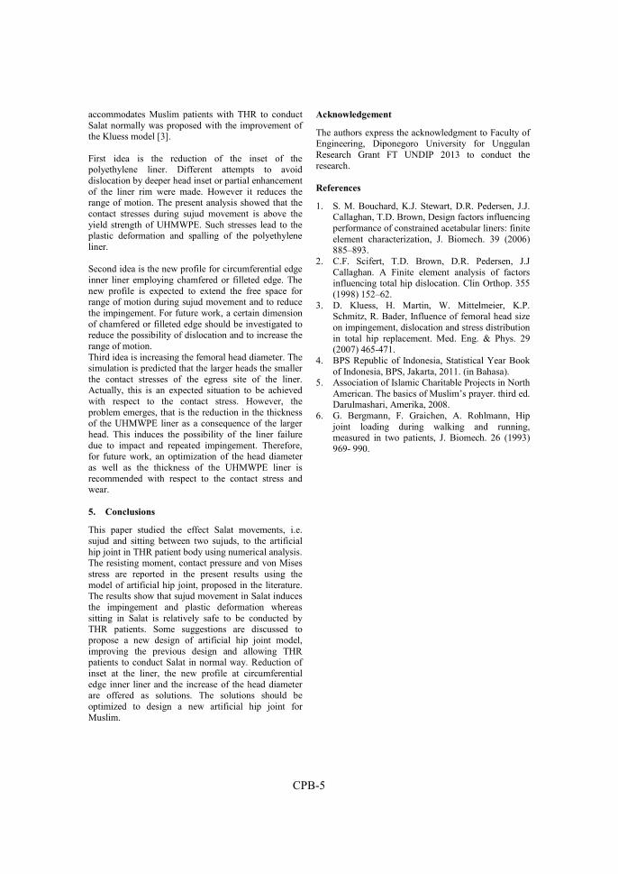
CPB-5
accommodates Muslim patients with THR to conduct Salat normally was proposed with the improvement of the Kluess model [3]. First idea is the reduction of the inset of the polyethylene liner. Different attempts to avoid dislocation by deeper head inset or partial enhancement of the liner rim were made. However it reduces the range of motion. The present analysis showed that the contact stresses during sujud movement is above the yield strength of UHMWPE. Such stresses lead to the plastic deformation and spalling of the polyethylene liner. Second idea is the new profile for circumferential edge inner liner employing chamfered or filleted edge. The new profile is expected to extend the free space for range of motion during sujud movement and to reduce the impingement. For future work, a certain dimension of chamfered or filleted edge should be investigated to reduce the possibility of dislocation and to increase the range of motion. Third idea is increasing the femoral head diameter. The simulation is predicted that the larger heads the smaller the contact stresses of the egress site of the liner. Actually, this is an expected situation to be achieved with respect to the contact stress. However, the problem emerges, that is the reduction in the thickness of the UHMWPE liner as a consequence of the larger head. This induces the possibility of the liner failure due to impact and repeated impingement. Therefore, for future work, an optimization of the head diameter as well as the thickness of the UHMWPE liner is recommended with respect to the contact stress and wear.
5. Conclusions
This paper studied the effect Salat movements, i.e. sujud and sitting between two sujuds, to the artificial hip joint in THR patient body using numerical analysis. The resisting moment, contact pressure and von Mises stress are reported in the present results using the model of artificial hip joint, proposed in the literature. The results show that sujud movement in Salat induces the impingement and plastic deformation whereas sitting in Salat is relatively safe to be conducted by THR patients. Some suggestions are discussed to propose a new design of artificial hip joint model, improving the previous design and allowing THR patients to conduct Salat in normal way. Reduction of inset at the liner, the new profile at circumferential edge inner liner and the increase of the head diameter are offered as solutions. The solutions should be optimized to design a new artificial hip joint for Muslim.
Acknowledgement
The authors express the acknowledgment to Faculty of Engineering, Diponegoro University for Unggulan Research Grant FT UNDIP 2013 to conduct the research.
References
1. S. M. Bouchard, K.J. Stewart, D.R. Pedersen, J.J. Callaghan, T.D. Brown, Design factors influencing performance of constrained acetabular liners: finite element characterization, J. Biomech. 39 (2006) 885–893.
2. C.F. Scifert, T.D. Brown, D.R. Pedersen, J.J Callaghan. A Finite element analysis of factors influencing total hip dislocation. Clin Orthop. 355 (1998) 152–62.
3. D. Kluess, H. Martin, W. Mittelmeier, K.P. Schmitz, R. Bader, Influence of femoral head size on impingement, dislocation and stress distribution in total hip replacement. Med. Eng. & Phys. 29 (2007) 465-471.
4. BPS Republic of Indonesia, Statistical Year Book of Indonesia, BPS, Jakarta, 2011. (in Bahasa).
5. Association of Islamic Charitable Projects in North American. The basics of Muslim’s prayer. third ed. Darulmashari, Amerika, 2008.
6. G. Bergmann, F. Graichen, A. Rohlmann, Hip joint loading during walking and running, measured in two patients, J. Biomech. 26 (1993) 969- 990.

CPB-6
Conference Paper C
J. Jamari, R. Ismail, E. Saputra, S. Sugiyanto, I.B. Anwar, 2014
The effect of repeated impingement on UHMWPE material in artificial hip joint during salat activities
Advanced Materials Research, Volume 896, pp. 272-275,
doi: https://doi.org/10.4028/www.scientific.net/AMR.896.272

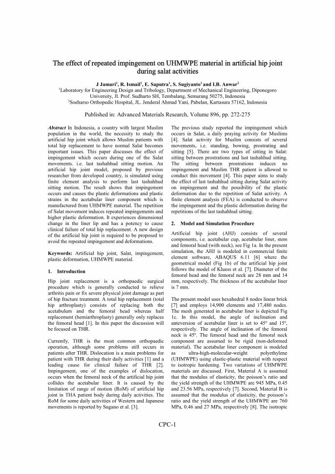
CPC-1
The effect of repeated impingement on UHMWPE material in artificial hip joint during salat activities
J Jamari1, R. Ismail1, E. Saputra1, S. Sugiyanto1 and I.B. Anwar2
1Laboratory for Engineering Design and Tribology, Department of Mechanical Engineering, Diponegoro University, Jl. Prof. Sudharto SH, Tembalang, Semarang 50275, Indonesia
2Soeharso Orthopedic Hospital, JL. Jenderal Ahmad Yani, Pabelan, Kartasura 57162, Indonesia
Published in: Advanced Materials Research, Volume 896, pp. 272-275
Abstract In Indonesia, a country with largest Muslim population in the world, the necessity to study the artificial hip joint which allows Muslim patients with total hip replacement to have normal Salat becomes important issues. This paper discusses the effect of impingement which occurs during one of the Salat movements. i.e. last tashahhud sitting motion. An artificial hip joint model, proposed by previous researcher from developed country, is simulated using finite element analysis to perform last tashahhud sitting motion. The result shows that impingement occurs and causes the plastic deformations and plastic strains in the acetabular liner component which is manufactured from UHMWPE material. The repetition of Salat movement induces repeated impingements and higher plastic deformation. It experiences dimensional change in the liner lip and has a potency to cause clinical failure of total hip replacement. A new design of the artificial hip joint is required to be proposed to avoid the repeated impingement and deformations. Keywords: Artificial hip joint, Salat, impingement, plastic deformation, UHMWPE material. 1. Introduction
Hip joint replacement is a orthopaedic surgical procedure which is generally conducted to relieve arthritis pain or fix severe physical joint damage as part of hip fracture treatment. A total hip replacement (total hip arthroplasty) consists of replacing both the acetabulum and the femoral head whereas half replacement (hemiarthroplasty) generally only replaces the femoral head [1]. In this paper the discussion will be focused on THR. Currently, THR is the most common orthopaedic operation, although some problems still occurs in patients after THR. Dislocation is a main problems for patient with THR during their daily activities [1] and a leading cause for clinical failure of THR [2]. Impingement, one of the examples of dislocation, occurs when the femoral neck of the artificial hip joint collides the acetabular liner. It is caused by the limitation of range of motion (RoM) of artificial hip joint in THA patient body during daily activities. The RoM for some daily activities of Western and Japanese movements is reported by Sugano et al. [3].
The previous study reported the impingement which occurs in Salat, a daily praying activity for Muslims [4]. Salat activity for Muslim consists of several movements, i.e. standing, bowing, prostrating and sitting [5]. There are two types of sitting in Salat: sitting between prostrations and last tashahhud sitting. The sitting between prostrations induces no impingement and Muslim THR patient is allowed to conduct this movement [4]. This paper aims to study the effect of last tashahhud sitting during Salat activity on impingement and the possibility of the plastic deformation due to the repetition of Salat activity. A finite element analysis (FEA) is conducted to observe the impingement and the plastic deformation during the repetitions of the last tashahhud sitting.
2. Model and Simulation Procedure
Artificial hip joint (AHJ) consists of several components, i.e. acetabular cup, acetabular liner, stem and femoral head (with neck), see Fig 1a. In the present simulation, the AHJ is modeled in commercial finite element software, ABAQUS 6.11 [6] where the geometrical model (Fig 1b) of the artificial hip joint follows the model of Kluess et al. [7]. Diameter of the femoral head and the femoral neck are 28 mm and 14 mm, respectively. The thickness of the acetabular liner is 7 mm. The present model uses hexahedral 8 nodes linear brick [7] and employs 14,900 elements and 17,480 nodes. The mesh generated in acetabular liner is depicted Fig 1c. In this model, the angle of inclination and anteversion of acetabular liner is set to 45º and 15º, respectively. The angle of inclination of the femoral neck is 45º. The femoral head and the femoral neck component are assumed to be rigid (non-deformed material). The acetabular liner component is modeled as ultra-high-molecular-weight polyethylene (UHMWPE) using elastic-plastic material with respect to isotropic hardening. Two variations of UHMWPE materials are discussed. First, Material A is assumed that the modulus of elasticity, the poisson’s ratio and the yield strength of the UHMWPE are 945 MPa, 0.45 and 23.56 MPa, respectively [7]. Second, Material B is assumed that the modulus of elasticity, the poisson’s ratio and the yield strength of the UHMWPE are 760 MPa, 0.46 and 27 MPa, respectively [8]. The isotropic
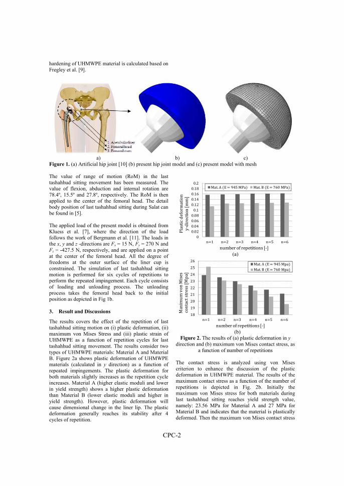
CPC-2
hardening of UHMWPE material is calculated based on Fregley et al. [9].
a) b) c)
Figure 1. (a) Artificial hip joint [10] (b) present hip joint model and (c) present model with mesh The value of range of motion (RoM) in the last tashahhud sitting movement has been measured. The value of flexion, abduction and internal rotation are 78.4º, 15.5º and 27.8º, respectively. The RoM is then applied to the center of the femoral head. The detail body position of last tashahhud sitting during Salat can be found in [5]. The applied load of the present model is obtained from Kluess et al. [7], where the direction of the load follows the work of Bergmann et al. [11]. The loads in the x, y and z -directions are Fx = 15 N, Fy = 270 N and Fz = -427.5 N, respectively, and are applied on a point at the center of the femoral head. All the degree of freedoms at the outer surface of the liner cup is constrained. The simulation of last tashahhud sitting motion is performed for six cycles of repetitions to perform the repeated impingement. Each cycle consists of loading and unloading process. The unloading process takes the femoral head back to the initial position as depicted in Fig 1b. 3. Result and Discussions
The results covers the effect of the repetition of last tashahhud sitting motion on (i) plastic deformation, (ii) maximum von Mises Stress and (iii) plastic strain of UHMWPE as a function of repetition cycles for last tashahhud sitting movement. The results consider two types of UHMWPE materials: Material A and Material B. Figure 2a shows plastic deformation of UHMWPE materials (calculated in y direction) as a function of repeated impingements. The plastic deformation for both materials slightly increases as the repetition cycle increases. Material A (higher elastic moduli and lower in yield strength) shows a higher plastic deformation than Material B (lower elastic moduli and higher in yield strength). However, plastic deformation will cause dimensional change in the liner lip. The plastic deformation generally reaches its stability after 4 cycles of repetition.
(a)
(b) Figure 2. The results of (a) plastic deformation in y
direction and (b) maximum von Mises contact stress, as a function of number of repetitions
The contact stress is analyzed using von Mises criterion to enhance the discussion of the plastic deformation in UHMWPE material. The results of the maximum contact stress as a function of the number of repetitions is depicted in Fig. 2b. Initially the maximum von Mises stress for both materials during last tashahhud sitting reaches yield strength value, namely: 23.56 MPa for Material A and 27 MPa for Material B and indicates that the material is plastically deformed. Then the maximum von Mises contact stress
00.020.040.060.08
0.10.120.140.160.18
0.2
n=1 n=2 n=3 n=4 n=5 n=6
Plastic
defor
mation
y-d
irectio
n [mm]
number of repetitions [-]
Mat. A FE = 945 MPaG Mat. B FE = 760 MPaG
181920212223242526
n=1 n=2 n=3 n=4 n=5 n=6
Maxim
um vo
n Mise
scon
tact st
ress [M
pa]
number of repetitions [-]
Mat. A FE = 945 MpaGMat. B FE = 760 MpaG

CPC-3
tends to decrease as the number of repetitions increases. The increase of plastic deformation as the increase of the number of repetitions induces the decrease of the maximum contact stress. The presence of plastic deformation causes plastic strain, as depicted in Figs 3 and 4, for Material A and B. The zoom view is presented to study the severity of the plastic strain occurred in both materials. The maximum value of the plastic strain of Material A is higher than Material B and also produces a larger plastic strain. Plastic strain and plastic deformations on the UHMWPE inner diameter creates some space for the femoral neck to extend the movement during last tashahhud sitting. This space reduces the degree of the impingement and decrease the maximum contact stress. Although the plastic strain and plastic deformation due to repeated impingement give advantage in reducing the contact stress, however, these phenomena should be avoided in AHJ system. It increases the presence of wear and the possibility of the clinical failure of THR for Muslim patients. A new design should be proposed to accommodate Muslim to have normal Salat movements including last tashahhud sitting. The contact stress is analyzed using von Mises criterion to enhance the discussion of the plastic deformation in UHMWPE material. The results of the maximum contact stress as a function of the number of repetitions is depicted in Fig. 2b. Initially the
maximum von Mises stress for both materials during last tashahhud sitting reaches yield strength value, namely: 23.56 MPa for Material A and 27 MPa for Material B and indicates that the material is plastically deformed. Then the maximum von Mises contact stress tends to decrease as the number of repetitions increases. The increase of plastic deformation as the increase of the number of repetitions induces the decrease of the maximum contact stress. The presence of plastic deformation causes plastic strain, as depicted in Figs 3 and 4, for Material A and B. The zoom view is presented to study the severity of the plastic strain occurred in both materials. The maximum value of the plastic strain of Material A is higher than Material B and also produces a larger plastic strain. Plastic strain and plastic deformations on the UHMWPE inner diameter creates some space for the femoral neck to extend the movement during last tashahhud sitting. This space reduces the degree of the impingement and decrease the maximum contact stress. Although the plastic strain and plastic deformation due to repeated impingement give advantage in reducing the contact stress, however, these phenomena should be avoided in AHJ system. It increases the presence of wear and the possibility of the clinical failure of THR for Muslim patients. A new design should be proposed to accommodate Muslim to have normal Salat movements including last tashahhud sitting.
(a) (b)
Figure 3. The result of equivalent plastic strain PEEQ for Material A: (a) normal view and (b) zoom view, after 6th cycle of repetitions
(a) b)
Figure 4. The result of equivalent plastic strain PEEQ for Material B: (a) normal view and (b) zoom view, after 6th cycle of repetitions

CPC-4
4. Conclusions
This paper studies the effect of repeated impingement on UHMWPE material in artificial hip joint during Salat activities, especially in last tashahhud sitting. Based on the finite element simulation, it was found that the last tashahhud sitting motion induces repeated impingements, plastic deformations and plastic strain in acetabular liner, which is manufactured from UHMWPE material. Material A with higher elastic moduli and lower in yield strength experiences higher plastic deformation and plastic strain than Material B (lower elastic moduli and higher in yield strength). However, the plastic deformation and plastic strain should be avoided in AHJ system. It increases the presence of wear and the possibility of the clinical failure of THR for Muslim patients. A new design should be proposed to accommodate Muslim to have normal Salat movements including last tashahhud sitting motion. Acknowledgements
The authors express the acknowledgment to Faculty of Engineering, Diponegoro University for Unggulan Research Grant with contract No. 545/SK/UN7.3.3/VI/2013 to conduct the researches. References
1. S.M. Bouchard, K.J. Stewart, D.R. Pedersen, J.J. Callaghan, T.D. Brown, Design factors influencing performance of constrained acetabular liners: finite element characterization, J. Biomech. 39 (2006) 885-893.
2. C.V. Sikes, L.P. Lai, M. Schreiber, M.A. Mont, R.H. Jinnah, T.M. Seyler, Instability after total hip arthroplasty treatment with large femoral heads vs constrained liners, J. Arthroplasty. Vol. 23, No.7, (2008) 59-63.
3. N. Sugano, K. Tsuda, H. Miki, M. Takao, N. Suzuki, N. Nakamuro, Dynamic measurements of hip movement in deep bending activities after total hip arthroplasty using a 4-dimensional motion analysis system, J. Arthroplasty. Vol. 27, No. 8, (2012) 1562-1568.
4. R. Ismail, E. Saputra, M. Tauviqirrahman, A.B. Legowo, I.B. Anwar, Jamari, Numerical study of salat movements for total hip replacement patient, Int. Conf. Mech. Eng. (ICOME), Mataram, Indonesia (2013).
5. Association of Islamic Chartiable Projects in North American. The Basics of Muslim’s Prayer, third ed., Darulmashari, 2008.
6. ABAQUS 6.11/Standard User’s Manual, Dassault Systèmes Simulia Corp., USA, 2011.
7. D. Kluess, H. Martin, W. Mittelmeier, K.P. Schmitz, R. Bader, Influence of femoral head size on impingement, dislocation and stress distribution in total hip replacement, Med. Eng. & Phys. 29, (2007) 465-471.
8. S.M. Kurtz, UHMWPE Biomaterials Handbook, second ed., Academic Press, Elsevier, 2nd ed., London, 2009.
9. B.J. Fregly, Y. Bei, M.E. Sylvester, Experimental evaluation of an elastic foundation model to predict contact pressures in knee replacements, J. Biomech. 36, (2003) 1659-1668.
10. Information on http://healthcare.utah.edu. 11. G. Bergmann, F. Graichen, A. Rohlmann, Hip
joint loading during walking and running, measured in two patients, J. Biomech. 26, (1993) 969- 990.
.
Conference Paper D
E. Saputra, I.B. Anwar, J. Jamari, E. van der Heide, 2015
A bipolar artificial hip joint design for contact impingement reduction
Advanced Materials Research, Volume 1123, pp. 164-168,
doi: https://doi.org/10.4028/www.scientific.net/AMR.1123.164

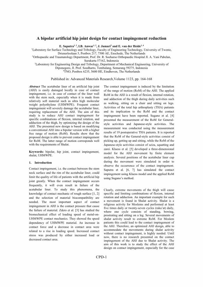
CPD-1
A bipolar artificial hip joint design for contact impingement reduction
E. Saputra1, 3, I.B. Anwar1, 2, J. Jamari3 and E. van der Heide1, 4 1Laboratory for Surface Technology and Tribology, Faculty of Engineering Technology, University of Twente,
Drienerloolaan 5, Postbox 217, 7500 AE, Enschede, The Netherlands 2Orthopaedic and Traumatology Department, Prof. Dr. R. Soeharso Orthopaedic Hospital Jl. A. Yani Pabelan,
Surakarta 57162, Indonesia 3Laboratory for Engineering Design and Tribology, Department of Mechanical Engineering, University of
Diponegoro, Jl. Prof. Soedharto, Tembalang, Semarang 59275, Indonesia 4TNO, Postbox 6235, 5600 HE, Eindhoven, The Netherlands
Published in: Advanced Materials Research,Volume 1123, pp. 164-168
Abstract The acetabular liner of an artificial hip joint (AHJ) is easily damaged locally in case of contact impingement, i.e. in case of contact of the liner wall with the stem neck, especially when it is made from relatively soft material such as ultra high molecular weight polyethylene (UHMWPE). Frequent contact impingement will severely damage the acetabular liner, requiring replacement of the AHJ. The aim of this study is to reduce AHJ contact impingement for specific combinations of flexion, internal rotation, and adduction of the thigh, by optimizing the design of the AHJ. The presented new design is based on modifying a conventional AHJ into a bipolar version with a higher free range of motion (RoM). Results show that the proposed design is able to prevent contact impingement for RoM. The latter range of motion corresponds well with the requirements of Shalat.
Keywords: bipolar, hip joint, contact impingement, shalat, UHMWPE.
1. Introduction
Contact impingement, i.e. the contact between the stem neck surface and the rim of the acetabular liner, could limit the quality of life of patients with the artificial hip joint greatly. When the contact impingement occurs frequently, it will even result in failure of the acetabular liner. To study this phenomena, the knowledge of contact mechanic of rough surface [1, 2] and the selection of material biocompatibility are needed. The most important aspect of contact impingement in AHJ is the contact pressure that cause the failure of material. Zdero et al. [3] has studied the biomechanical effect of loading speed of metal-on-UHMWPE contact mechanics. They showed the speed dependency of UHMWPE material. An increase in contact force and a decrease in contact area were related to a rise in loading speed. Increased contact stress was produced by either increased load or decreased contact area.
The contact impingement is induced by the limitation of the range of motion (RoM) of the AHJ. The applied RoM in the AHJ is a result of flexion, internal rotation, and adduction of the thigh during daily activities such as walking, sitting on a chair and sitting on legs. Activities of the total hip arthroplasty (THA) patients and its implication to the RoM and the contact impingement have been reported. Sugano et al. [4] presented the measurement of the RoM for General-style activities and Japanese-style activities. The measurement was conducted using the measurement results of 19 postoperative THA patients. It is reported that the RoM of the General-style activities consist of picking up, getting up and sitting, while the RoM of the Japanese-style activities consist of seiza, squatting and zarei. Kluess et al. [5] developed a three-dimensional model for the AHJ movement by finite element analysis. Several positions of the acetabular liner cup during the movement were simulated in order to observe the occurrence of the contact impingement. Saputra et al. [6, 7] has simulated the contact impingement using Kluess model and the applied RoM using Sugano’s method.
Clearly, extreme movements of the thigh will cause specific and limiting combinations of flexion, internal rotation and adduction. An important example for such a movement is found in Shalat activity. Shalat is a religious activity for Moslems and performed at least five times daily or twenty-seven cycles (raka’at) daily, where one cycle consists of standing, bowing, prostrating and sitting on a leg. Several movements of shalat activity result to extreme RoM. For Moslem patients this could lead to the contact impingement of the AHJ. Therefore, an optimized AHJ design, able to accommodate the movements during shalat activity without contact impingement, is highly needed. Until now, there is no research presented on the contact impingement of the AHJ due to Shalat activity. The aim of this work is to study the effect of the AHJ design on contact impingement, especially for the case

CPD-2
of Shalat. The contact impingement phenomena are studied with a finite element analysis for a conventional AHJ design and for the new proposed AHJ design. 2. Material and Method
A new bipolar design to reduce contact impingement on the acetabular liner was developed based on the conventional AHJ, see Fig. 1. The geometry of the bipolar design is optimized using CAD software. The geometries of the bipolar model are 28 mm, 14 mm and
2 mm for the femoral head diameter, the neck stem diameter and the inset of the acetabular liner, respectively. This design has two axis and inset so that the RoM of this model is larger than for the conventional solution. As a comparison, Fig. 1 shows a conventional design of the AHJ adopted from Kluess et al. [5]. The thickness of the acetabular liner cup is 7 mm. A gap between the femoral head and the acetabular liner cup is 24 µm and it is modeled as a lubrication space.
(a) (b)
(c) (d)
Figure 1: Bipolar model (BM) and conventional model (CM) of the AHJ: (a) BM isometric, (b) BM cross-section, (c) CM isometric and (d) CM cross-section. (Note: dark gray color is stainless steel 316L and light gray color is
UHMWPE material) To determine the contact impingement phenomena for both the bipolar and the conventional design, the commercial finite element software ABAQUS 6.11 was employed. Table 1 shows the results of the previous analysis [8] for Shalat activity [9]. The femoral head and the femoral neck component are assumed to be rigid. The acetabular liner cup component is modeled as an elastic-plastic material with isotropic hardening and assuming a viscoelastic-plastic material behavior of the ultra-high molecular weight polyethylene (UHMWPE). The modulus of elasticity, the Poisson’s ratio and the yield strength of the UHMWPE are set to be 945 MPa, 0.45 and 23.56 MPa, respectively [10]. The element type of hexahedral 8 nodes linear brick (C3D8R) is employed. The applied load is taken from the work of Kluess et al. [5], but the
direction of the load follows the work of Bergmann et al. [11]. The loads in the x, y and z directions are Fx = 15 N, Fy = 270 N and Fz = -427.5 N, respectively. These loads are applied to a point at the center of the femoral head. All the degree of freedom at the outer surface of the acetabular liner cup is constrained. The simulation is conducted in two steps: firstly, the load is applied to the center of the femoral head with constraining the rotation of the femoral head, and secondly, the load at the center of the femoral head is constrained with rotating the femoral head. The range of the rotation is according to the RoM of the Shalat activities as presented in Table 1.
Femoral head
Acetabular liner
Acetabular cup
Femoral head Acetabular liner
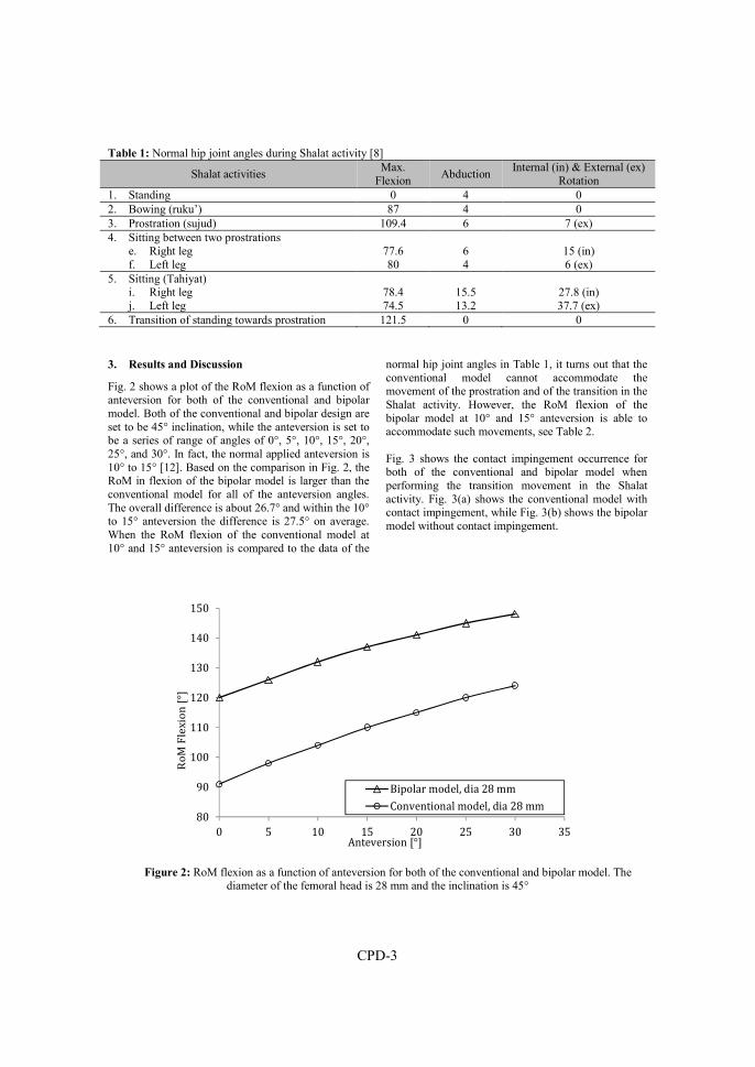
CPD-3
Table 1: Normal hip joint angles during Shalat activity [8]
Shalat activities Max.
Flexion Abduction
Internal (in) & External (ex) Rotation
1. Standing 0 4 0 2. Bowing (ruku’) 87 4 0 3. Prostration (sujud) 109.4 6 7 (ex) 4. Sitting between two prostrations
e. Right leg f. Left leg
77.6 80
6 4
15 (in) 6 (ex)
5. Sitting (Tahiyat) i. Right leg j. Left leg
78.4 74.5
15.5 13.2
27.8 (in) 37.7 (ex)
6. Transition of standing towards prostration 121.5 0 0
3. Results and Discussion
Fig. 2 shows a plot of the RoM flexion as a function of anteversion for both of the conventional and bipolar model. Both of the conventional and bipolar design are set to be 45° inclination, while the anteversion is set to be a series of range of angles of 0°, 5°, 10°, 15°, 20°, 25°, and 30°. In fact, the normal applied anteversion is 10° to 15° [12]. Based on the comparison in Fig. 2, the RoM in flexion of the bipolar model is larger than the conventional model for all of the anteversion angles. The overall difference is about 26.7° and within the 10° to 15° anteversion the difference is 27.5° on average. When the RoM flexion of the conventional model at 10° and 15° anteversion is compared to the data of the
normal hip joint angles in Table 1, it turns out that the conventional model cannot accommodate the movement of the prostration and of the transition in the Shalat activity. However, the RoM flexion of the bipolar model at 10° and 15° anteversion is able to accommodate such movements, see Table 2. Fig. 3 shows the contact impingement occurrence for both of the conventional and bipolar model when performing the transition movement in the Shalat activity. Fig. 3(a) shows the conventional model with contact impingement, while Fig. 3(b) shows the bipolar model without contact impingement.
80
90
100
110
120
130
140
150
0 5 10 15 20 25 30 35
Ro
M F
lex
ion
[°]
Anteversion [°]
Bipolar model, dia 28 mm
Conventional model, dia 28 mm
Figure 2: RoM flexion as a function of anteversion for both of the conventional and bipolar model. The diameter of the femoral head is 28 mm and the inclination is 45°

CPD-4
Table 2: Contact impingement of both of the conventional model and the bipolar model
Shalat activities Contact impingement
Conventional model Bipolar model 1. Standing x x 2. Bowing (ruku’) x x 3. Prostration (sujud) √ x 4. Sitting between two prostrations
g. Right leg h. Left leg
x x
x x
5. Sitting (Tahiyat) k. Right leg l. Left leg
x x
x x
6. Transition of standing towards prostration √ x
a) b)
Figure 3: Plot of the contact impingement occurrence: a) the conventional model with contact impingement and b)
the bipolar model without contact impingement
4. Conclusion
A new bipolar AHJ design was proposed, having two axis of movement for contact impingement reduction. The geometry of the bipolar model was optimized using CAD software. To evaluate whether the design is able to solve the contact impingement problems the commercial finite element analysis software ABAQUS 6.11 was used and the results were compared to the conventional AHJ design. The results show that the bipolar AHJ model is able to accommodate greater angles of flexion at 10° to 15° anteversion. This corresponds well with the requirements of Shalat.
References
1. J. Jamari, D.J. Schipper, Plastic deformation and contact area of an elastic-plastic contact of ellipsoid bodies after unloading, Tribol. Int. 40 (2007) 1311–1318.
2. J. Jamari, D.J. Schipper, Deterministic repeated contact of rough surfaces, Wear 264 (2008) 349–358.
3. R. Zdero, Z.S. Bagheri, M. Rezaey, E.H. Schemitsch, H. Bougherara, The biomechanical effect of loading speed on metal-on-UHMWPE contact mechanics, Open Biomed. Eng. J. 8 (2014) 28–34.
4. N. Sugano, K. Tsuda, H. Miki, M. Takao, N. Suzuki, N. Nakamuro, Dynamic measurements of hip movement in deep bending activities after total hip arthroplasty using a 4-dimensional motion analysis system, J. of Arthrop. 27 (2012) 1562-1568.
5. D. Kluess, H. Martin, W. Mittelmeier, K.P. Schmitz, R. Bader, Influence of femoral head size on impingement, dislocation and stress distribution in total hip replacement, Med. Eng. & Phys. 29 (2007) 465-471.
6. E. Saputra, I.B. Anwar, J. Jamari, E. van der Heide, Finite element analysis of artificial hip joint movement during human activities, Proc. Eng. 68 (2013) 102-108.
7. E. Saputra, I.B. Anwar, R. Ismail, J. Jamari, E. van der Heide, Numerical simulation of artificial hip
Impingement
CPD-5
joint movement for Western and Japanese-style activities, J. Teknol. (Sci. & Eng.) 66 (2014) 53-58.
8. I.B. Anwar, E. Saputra, J. Jamari, E. van der Heide, Range of motion simulation of hip joint movement during shalat activity, submitted to The J. of Arthrop. (2014).
9. Association of Islamic Chartiable Projects in North American. The Basics of Muslim’s Prayer, Darulmashari 3rd Edition, 2008. http://www.aicp.org.
10. F.C. Eichmiller, J.A. Tesk, C.M. Croarkin, Mechanical properties of ultra high molecular weight polyethylene NIST Reference Material RM 8456, in Trans. of the Soc. for Biomat. 27th Annual Meeting (2001) 472.
11. G. Bergmann, F. Graichen, A. Rohlmann, Hip joint loading during walking and running, measured in two patients, J. of Biomech. 26 (1993) 969- 990.
12. R.L. Barrack, Dislocation after total hip arthroplasty: implant design and orientation, J. Am. Acad. Orthop. Surg. 11 (2003) 89-99.

Conference Paper E
E. Saputra, I.B. Anwar, R. Ismail, J. Jamari, E. van der Heide, 2016
Finite element analysis of the impingement on the acetabular liner rim due to wear of
the acetabular liner surface
AIP Conference Proceedings 1725, 020074, doi: 10.1063/1.4945528

CPE-1
Finite element analysis of the impingement on acetabular liner rim due to
wear of acetabular liner surface
E. Saputra1,3, I.B. Anwar1,2, R. Ismail2, J. Jamari2, E. van der Heide1,4
1Laboratory for Surface Technology and Tribology, Faculty of Engineering Technology, University of Twente Drienerloolaan 5, Postbox 217, 7500 AE, Enschede, The Netherlands
2Orthopaedic and Traumatology Department, Prof. Dr. R. Soeharso Orthopaedic Hospital, Jl. A. Yani Pabelan, Surakarta 57162, Indonesia
3Laboratory for Engineering Design and Tribology, Department of Mechanical Engineering, University of Diponegoro, Jl. Prof. Soedharto, Tembalang, Semarang 59275, Indonesia
4TNO, Postbox 6235, 5600 HE Eindhoven, The Netherlands.
Published in: AIP Conference Proceedings 1725, 020074, doi: 10.1063/1.4945528 Abstract This paper studies the impingement on the rim of acetabular liner due to wear on the surface of acetabular liner using finite element simulation. A three dimensional contact model between a femoral head and an acetabular liner was developed. There are three steps in this simulation, i.e. creating the artificial wear on the surface of acetabular liner, applying the load at the femoral head, and rotating the femoral head from neutral position till the impingement occurrence. The artificial wear is created based on the data of wear depth which was obtained from literature. Results showed that the wear on the acetabular liner surface has affected the impingement occurrence, in which the impingement angle becomes narrow. In addition, the failure possibility of the acetabular liner rim becomes higher.
1. Introduction
The failure on the rim of acetabular liner (RAL) due to repeated impingement is an important factor in the artificial hip joint (AHJ). The impingement on the RAL is induced by the range of motion (RoM) limitation of the AHJ of the total hip prosthesis patient. The limitation of the RoM can be influenced by the human activities and the change of the geometry of AHJ components. The wear on the surface of acetabular liner (SAL) is one of the geometry change’s cause. The wear on the SAL can move the center point of the femoral head, so the angle of impingement will be shorter. Based on the visual investigation on the acetabular liner after surgical operation, the relation between the wear on the SAL with the failure on the RAL due to impingement is found. The impingement and wear are also categorized as the early dislocation and late dislocation respectively [1]. In general, the early and late dislocations are mostly related to the impingement between the neck stem with the acetabular liner rim and to wear of the acetabular liner surface, respectively [1-2]. Study of the impingement on the RAL in this paper is initiated by several previous studies related to hip dislocation due to human activities [3-5].
Based on clinical data, Tanino et al. [6] found that acetabular liner articular geometry, which the depth of the articular surface is relative to the polyethylene liner rim, is related to the prevalence of dislocation. Using finite element analysis, Scifert et al. [7] showed that in every millimeter of the increased head center inset, the peak moment resisting dislocation increases 5.8%. Based on literature review, there is no concern in the relation of the impingement effects on the rim of acetabular liner due to wear on the surface of acetabular liner. The objective of this paper is to study the impingement on the RAL due to wear on the SAL. Finally, as to show the function of wear depth, the results will be presented in the graph of impingement angles and von Mises stress.
2. Material and method
2.1. Material model
To obtain the data of impingement, the finite element analysis using computer simulation is performed. A three dimensional (3D) model of the acetabular liner and femoral head is created, where the diameter of femoral head and the inner diameter of acetabular liner are 31.98 mm and 32.5458 mm respectively [8]. In addition, the center point of the acetabular liner has inset 2 mm. The diameter of neck stem is 7.1 mm, where this value is obtained from the head-neck ratio of Charnley standard (2.25:1) [9]. The material of femoral head and acetabular liner are alumina (Al2O3) and ultra-high molecular weight polyethylene (UHMWPE) respectively. The femoral head is assumed as rigid, while the acetabular liner is deformable. The acetabular liner is modeled as an elastic-plastic material with isotropic hardening and assuming a visco-elastic-plastic material behavior of the ultra-high-molecular-weight polyethylene (UHMWPE). Where, the modulus of elasticity, the Poisson’s ratio and the yield strength of the UHMWPE are 830 MPa [8], 0.45 and 23.56 MPa [10],
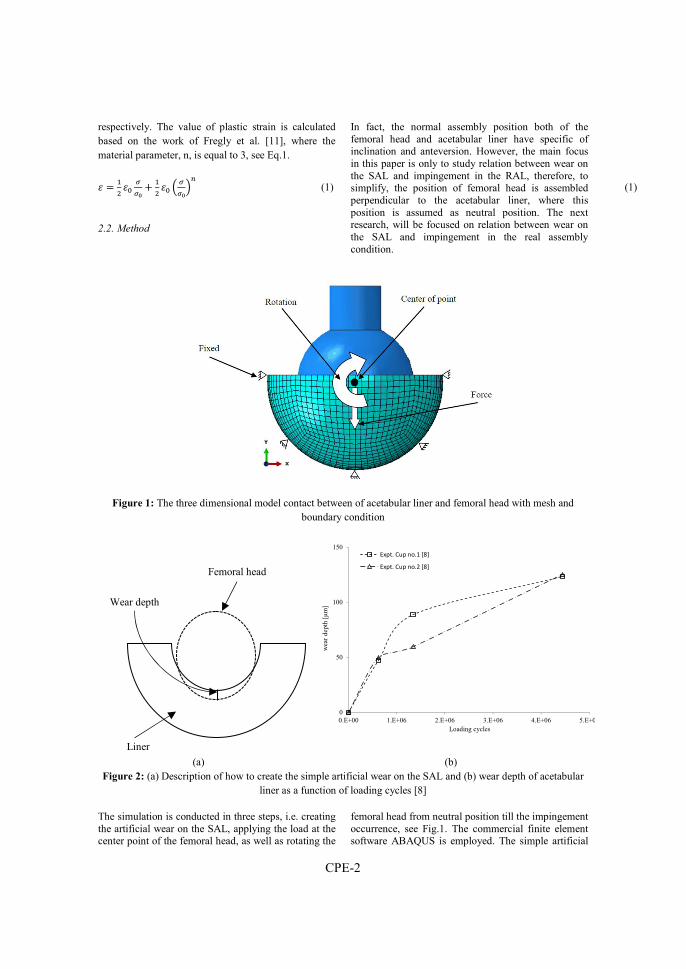
CPE-2
respectively. The value of plastic strain is calculated based on the work of Fregly et al. [11], where the material parameter, n, is equal to 3, see Eq.1.
� = %& �\
���
4 %& �\ < �
��=�
(1) (1)
2.2. Method
In fact, the normal assembly position both of the femoral head and acetabular liner have specific of inclination and anteversion. However, the main focus in this paper is only to study relation between wear on the SAL and impingement in the RAL, therefore, to simplify, the position of femoral head is assembled perpendicular to the acetabular liner, where this position is assumed as neutral position. The next research, will be focused on relation between wear on the SAL and impingement in the real assembly condition.
Figure 1: The three dimensional model contact between of acetabular liner and femoral head with mesh and boundary condition
(a) (b) Figure 2: (a) Description of how to create the simple artificial wear on the SAL and (b) wear depth of acetabular
liner as a function of loading cycles [8]
The simulation is conducted in three steps, i.e. creating the artificial wear on the SAL, applying the load at the center point of the femoral head, as well as rotating the
femoral head from neutral position till the impingement occurrence, see Fig.1. The commercial finite element software ABAQUS is employed. The simple artificial
0
50
100
150
0.E+00 1.E+06 2.E+06 3.E+06 4.E+06 5.E+06
wea
r de
pth
[μm
]
Loading cycles
Expt. Cup no.1 [8]
Expt. Cup no.2 [8]
Wear depth
Femoral head
Liner

CPE-3
wear on the SAL is created by cutting partly of the acetabular liner geometry using inserting of the femoral head, where the length of inserting based on the data of wear depth, see Fig.2b. The value of wear depth as a function of loading cycles is obtained from literature [8], see Fig. 2a. The value of the load and angle of rotation which applied at the center point of the femoral head are 3000 N in vertical direction [8] and 1 rad or 57.30° clockwise respectively. All the degree of freedom at the outer surface of acetabular liner is fixed. These steps are performed continuously until the last wear. The element type of hexahedral 8 nodes linear brick (C3D8R) is employed, while the number of element is approximately 7500.
3. Results and discussion
To show the effect of wear on the SAL to impingement on the RAL, the progress of impingement angle at initial impingement and maximum von Mises stress at impingement reach 57.30° are presented. Fig. 3a is the cross-section of acetabular liner at initial impingement occurrence to show the position of impingement angle, while Fig. 3b is the cross-section of acetabular liner at impingement reach 57.30°. Based on Fig. 3a-b, the position of the maximum von Mises stress at initial impingement and impingement reach 57.30° are on the SAL and the RAL respectively. However, the focus of maximum von Mises stress in this research is when the rotation of femoral head reach 57.30°.
(a) (b)
Figure 3: (a) The cross-section of acetabular liner when impingement occurrence as well as position of the impingement angle and (b) location of impingement
(a) (b)
Figure 4: (a) The initial impingement angle of femoral head as a function of the wear depth on the SAL and (b) The maximum von Mises stress of impingement contact as a function of wear depth on the SAL
55.6
55.7
55.8
55.9
56
56.1
56.2
0 20 40 60 80 100 120 140
Impin
gement
angle
[⁰]
Wear depth [µm]
Expt. Cup no.1 [8]Expt. Cup no.2 [8]
33
34
35
36
37
38
39
0 50 100 150
Max. v
on Mis
es str
ess [M
Pa]
Wear depth [µm]
Expt. Cup no.1 [8]Expt. Cup no.2 [8]
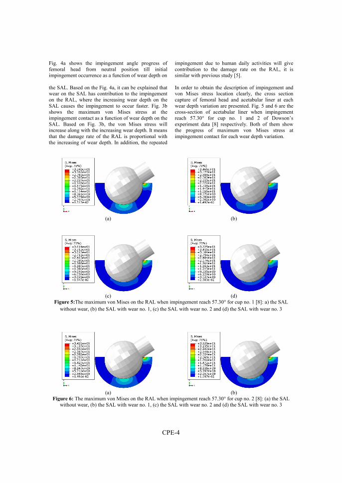
CPE-4
Fig. 4a shows the impingement angle progress of femoral head from neutral position till initial impingement occurrence as a function of wear depth on the SAL. Based on the Fig. 4a, it can be explained that wear on the SAL has contribution to the impingement on the RAL, where the increasing wear depth on the SAL causes the impingement to occur faster. Fig. 3b shows the maximum von Mises stress at the impingement contact as a function of wear depth on the SAL. Based on Fig. 3b, the von Mises stress will increase along with the increasing wear depth. It means that the damage rate of the RAL is proportional with the increasing of wear depth. In addition, the repeated
impingement due to human daily activities will give contribution to the damage rate on the RAL, it is similar with previous study [5]. In order to obtain the description of impingement and von Mises stress location clearly, the cross section capture of femoral head and acetabular liner at each wear depth variation are presented. Fig. 5 and 6 are the cross-section of acetabular liner when impingement reach 57.30° for cup no. 1 and 2 of Dowson’s experiment data [8] respectively. Both of them show the progress of maximum von Mises stress at impingement contact for each wear depth variation.
(a) (b)
(c) (d)
Figure 5:The maximum von Mises on the RAL when impingement reach 57.30° for cup no. 1 [8]: a) the SAL without wear, (b) the SAL with wear no. 1, (c) the SAL with wear no. 2 and (d) the SAL with wear no. 3
(a) (b)
Figure 6: The maximum von Mises on the RAL when impingement reach 57.30° for cup no. 2 [8]: (a) the SAL without wear, (b) the SAL with wear no. 1, (c) the SAL with wear no. 2 and (d) the SAL with wear no. 3
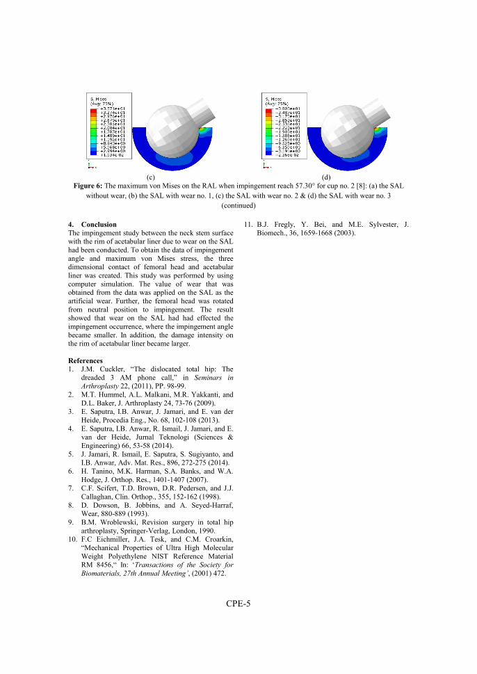
CPE-5
(c) (d)
Figure 6: The maximum von Mises on the RAL when impingement reach 57.30° for cup no. 2 [8]: (a) the SAL without wear, (b) the SAL with wear no. 1, (c) the SAL with wear no. 2 & (d) the SAL with wear no. 3
(continued)
4. Conclusion
The impingement study between the neck stem surface with the rim of acetabular liner due to wear on the SAL had been conducted. To obtain the data of impingement angle and maximum von Mises stress, the three dimensional contact of femoral head and acetabular liner was created. This study was performed by using computer simulation. The value of wear that was obtained from the data was applied on the SAL as the artificial wear. Further, the femoral head was rotated from neutral position to impingement. The result showed that wear on the SAL had had effected the impingement occurrence, where the impingement angle became smaller. In addition, the damage intensity on the rim of acetabular liner became larger. References
1. J.M. Cuckler, “The dislocated total hip: The dreaded 3 AM phone call,” in Seminars in Arthroplasty 22, (2011), PP. 98-99.
2. M.T. Hummel, A.L. Malkani, M.R. Yakkanti, and D.L. Baker, J. Arthroplasty 24, 73-76 (2009).
3. E. Saputra, I.B. Anwar, J. Jamari, and E. van der Heide, Procedia Eng., No. 68, 102-108 (2013).
4. E. Saputra, I.B. Anwar, R. Ismail, J. Jamari, and E. van der Heide, Jurnal Teknologi (Sciences & Engineering) 66, 53-58 (2014).
5. J. Jamari, R. Ismail, E. Saputra, S. Sugiyanto, and I.B. Anwar, Adv. Mat. Res., 896, 272-275 (2014).
6. H. Tanino, M.K. Harman, S.A. Banks, and W.A. Hodge, J. Orthop. Res., 1401-1407 (2007).
7. C.F. Scifert, T.D. Brown, D.R. Pedersen, and J.J. Callaghan, Clin. Orthop., 355, 152-162 (1998).
8. D. Dowson, B. Jobbins, and A. Seyed-Harraf, Wear, 880-889 (1993).
9. B.M. Wroblewski, Revision surgery in total hip arthroplasty, Springer-Verlag, London, 1990.
10. F.C Eichmiller, J.A. Tesk, and C.M. Croarkin, “Mechanical Properties of Ultra High Molecular Weight Polyethylene NIST Reference Material RM 8456,“ In: ‘Transactions of the Society for
Biomaterials, 27th Annual Meeting’, (2001) 472.
11. B.J. Fregly, Y. Bei, and M.E. Sylvester, J. Biomech., 36, 1659-1668 (2003).

Conference Paper F
E. Saputra, I.B. Anwar, R. Ismail, J. Jamari, E. van der Heide, 2016
Finite element study of contact pressure distribution on inner and outer liner in the bipolar hip prosthesis
AIP Conference Proceedings 1725, 020075,
doi: 10.1063/1.4945529


CPF-1
Finite element study of contact pressure distribution on inner and outer liner
in the bipolar hip prosthesis
E. Saputra1, 2, I.B. Anwar1, 3, R. Ismail2,, J. Jamari2, E. van der Heide1,4
1Laboratory for Surface Technology and Tribology, Faculty of Engineering Technology, University of Twente Drienerloolaan 5, Postbox 217, 7500 AE, Enschede, The Netherlands
2Laboratory for Engineering Design and Tribology, Department of Mechanical Engineering, University of Diponegoro, Jl. Prof. Soedharto, Tembalang, Semarang 59275, Indonesia
3Orthopaedic and Traumatology Department, Prof. Dr. R. Soeharso Orthopaedic Hospital, Jl. A. Yani Pabelan, Surakarta 57162, Indonesia
4TNO, Postbox 6235, 5600 HE Eindhoven, The Netherlands.
Published in: AIP Conference Proceedings 1725, 020075, doi: 10.1063/1.4945529 Abstract Wear in the hip prosthesis due to sliding contact as a product of human activity is a phenomenon which cannot be avoided. In general, there are two model of hip prostheses which are widely used in total hip replacement, i.e. unipolar and bipolar models. Wear in the bipolar model is more complex than the unipolar model due to its contact motion. The bipolar model has two contact mechanisms while the unipolar model has only one contact mechanism. It means that the bipolar model has two wear positions, i.e. wear on inner and outer liner surface. Fortunately, wear phenomena in the hip prosthesis can be predicted by analytical or numerical method. Wear on the inner and outer liner surface in the bipolar model itself can be early predicted by contact pressure distribution that is obtained from contact mechanic analysis. The contact pressure distribution itself is an essential variable in wear equations. This paper is aimed to study the difference of the contact pressure distribution on the inner and outer liner surface in the bipolar model. To obtain the contact pressure distribution at each surface, contact mechanic analysis on the inner and outer liner surface by analytical and numerical method were performed. Results showed that there was significant difference of the contact pressure distribution on the inner and outer liner surface in the bipolar model. Therefore, it is expected that there is significant wear difference on the inner and outer liner in the bipolar model.
1. Introduction
Early and late dislocation are phenomena for total hip arthroplasty (THA) patient during their daily activities [1]. The early dislocation is caused by impingement of femoral neck with acetabular liner rim/lip, while the late dislocation is mostly related to wear [2-3]. The impingement in the early dislocation is induced by the limitation of the range of motion (RoM) of hip prostheses for the THA patient. This limitation can be caused by the femoral head diameter, femoral neck diameter and acetabular liner position. In addition, the excessive or inordinate human activities can induce the higher RoM and cause the impingement. Researches of impingement caused by human daily activity using
finite element analysis have been performed [4-6]. Further, the researches have been developed into the more spesific Salat activity [7-8]. This research is continued to focus on late dislocation i.e. wear in hip prostheses. Wear on hip prostheses due to its motion and applied load as a product of human activities is a phenomenon which cannot be avoided. In general, the hip prostheses have two types based on the number of motion axis, i.e. unipolar or conventional and bipolar model. The unipolar model consists of the femoral head, liner, and cup component, while the bipolar model consists of the femoral head, inner and outer liner, and cup component. In this study, the use of the term liner component in the unipolar model is the same as the inner liner on the bipolar model, see Fig. 1. Wear in the bipolar model is more complex than the unipolar model due to its contact motion. The bipolar model has two contact mechanisms while the unipolar model has only one contact mechanism. It means that the bipolar model has two wear positions, i.e. wear on inner and outer liner surface. Fortunately, the wear phenomenon can be predicted by analytical or numerical method before it occurs. In general, wear on the surface of two interaction bodies can be calculated using the wear equation that is proposed by Archard [9], see Eq. 1.
�* = �
�
= �� (1) where the variable of V, s, k, F, H and KD are the volume of material removed, sliding distance, dimensionless wear coefficient, applied normal load, hardness and dimensional wear coefficient, respectively. In addition, Eq. 1 can be presented as linear wear by dividing both the left and right hand side by the nominal area of contact, see Eq. 2. �� = ��� (2) (2)
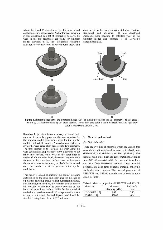
CPF-2
where the h and P variables are the linear wear and contact pressure, respectively. Archard’s wear equation is then developed by a lot of researchers to solve the wear in the hip prostheses especially for unipolar model. Dowson et al. [10] developed Archard’s Equation to calculate wear in the unipolar model and
compare it to his own experimental data. Further, Kauzlarich and Williams [11] also developed Archard’s wear equation to calculate wear in the unipolar model and compare it to Dowson’s experimental data.
(a) (b)
(c) (d)
Figure 1. Bipolar model (BM) and Unipolar model (UM) of the hip prostheses: (a) BM isometric, b) BM cross-section, c) UM isometric and d) UM cross-section. (Note: dark gray color is stainless steel 316L and light gray
color is UHMWPE material) [6]. Based on the previous literature survey, a considerable number of researchers proposed the wear equation for the unipolar model case, while wear for the bipolar model is subject of research. A possible approach is to divide the wear calculation process into two segments. The first segment is to calculate the wear using the wear equation for unipolar case. Here, it focuses on the inner liner surface, while wear on the outer liner is neglected. On the other hand, the second segment only focuses on the outer liner surface. How to determine the contact pressure accurately on both the inner and outer liner surface is still a question in the bipolar model case. This paper is aimed at studying the contact pressure distribution on the inner and outer liner for the case of bipolar model using analytical and numerical methods. For the analytical method, the Hertzian contact theory will be used to calculate the contact pressure on the inner and outer liner surface. While for the numerical method, the two dimensional 2-D axisymmetric contact to represent the unipolar and bipolar model will be simulated using finite element (FE) software.
2. Material and method
2.1. Material model
There are two kind of materials which are used in this research, i.e. ultra-high-molecular-weight polyethylene (UHMWPE) and stainless steel 316L (SS316L). The femoral head, outer liner and cup component are made from SS316L material, while the liner and inner liner are made from UHMWPE material. These material properties are considered as elastic material, following Archard’s wear equation. The material properties of UHMWPE and SS316L material can be seen in more detail in Table 1.
Table 1. Material properties of UHMWPE and SS316L Materials Modulus
elasticity [MPa] Poisson’s
ratio UHMWPE [12] 945 0.45 SS316L [13] 193000 0.3
Head Liner
Outer liner Cup
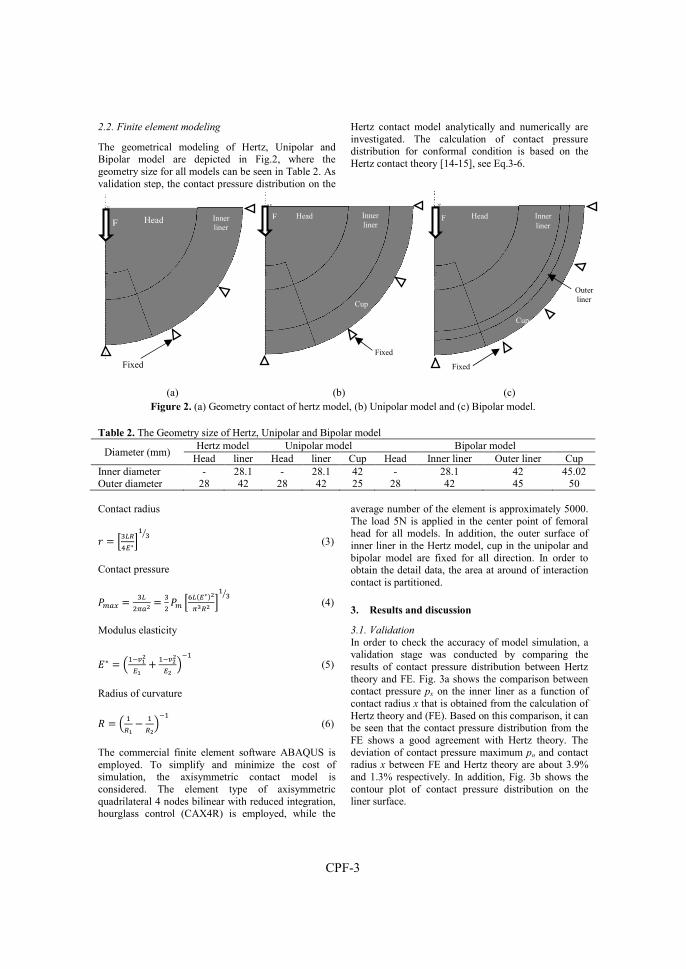
CPF-3
2.2. Finite element modeling
The geometrical modeling of Hertz, Unipolar and Bipolar model are depicted in Fig.2, where the geometry size for all models can be seen in Table 2. As validation step, the contact pressure distribution on the
Hertz contact model analytically and numerically are investigated. The calculation of contact pressure distribution for conformal condition is based on the Hertz contact theory [14-15], see Eq.3-6.
(a) (b) (c) Figure 2. (a) Geometry contact of hertz model, (b) Unipolar model and (c) Bipolar model.
Table 2. The Geometry size of Hertz, Unipolar and Bipolar model
Diameter (mm) Hertz model Unipolar model Bipolar model
Head liner Head liner Cup Head Inner liner Outer liner Cup Inner diameter - 28.1 - 28.1 42 - 28.1 42 45.02 Outer diameter 28 42 28 42 25 28 42 45 50 Contact radius
� = �S�5��∗�% S�
(3)
Contact pressure
��. = S�&@.; = S
& �� �M�F�∗G;@K5; �
% S� (4)
Modulus elasticity
�∗ = <%-��;��
4 %-�;;�;
=-% (5)
Radius of curvature
� = < %5�
− %5;
=-% (6)
The commercial finite element software ABAQUS is employed. To simplify and minimize the cost of simulation, the axisymmetric contact model is considered. The element type of axisymmetric quadrilateral 4 nodes bilinear with reduced integration, hourglass control (CAX4R) is employed, while the
average number of the element is approximately 5000. The load 5N is applied in the center point of femoral head for all models. In addition, the outer surface of inner liner in the Hertz model, cup in the unipolar and bipolar model are fixed for all direction. In order to obtain the detail data, the area at around of interaction contact is partitioned. 3. Results and discussion
3.1. Validation
In order to check the accuracy of model simulation, a validation stage was conducted by comparing the results of contact pressure distribution between Hertz theory and FE. Fig. 3a shows the comparison between contact pressure px on the inner liner as a function of contact radius x that is obtained from the calculation of Hertz theory and (FE). Based on this comparison, it can be seen that the contact pressure distribution from the FE shows a good agreement with Hertz theory. The deviation of contact pressure maximum po and contact radius x between FE and Hertz theory are about 3.9% and 1.3% respectively. In addition, Fig. 3b shows the contour plot of contact pressure distribution on the liner surface.
Fixed
F Head Inner liner
F
Fixed
Head Inner liner
Cup
F
Fixed
Head Inner liner
Outer liner
Cup
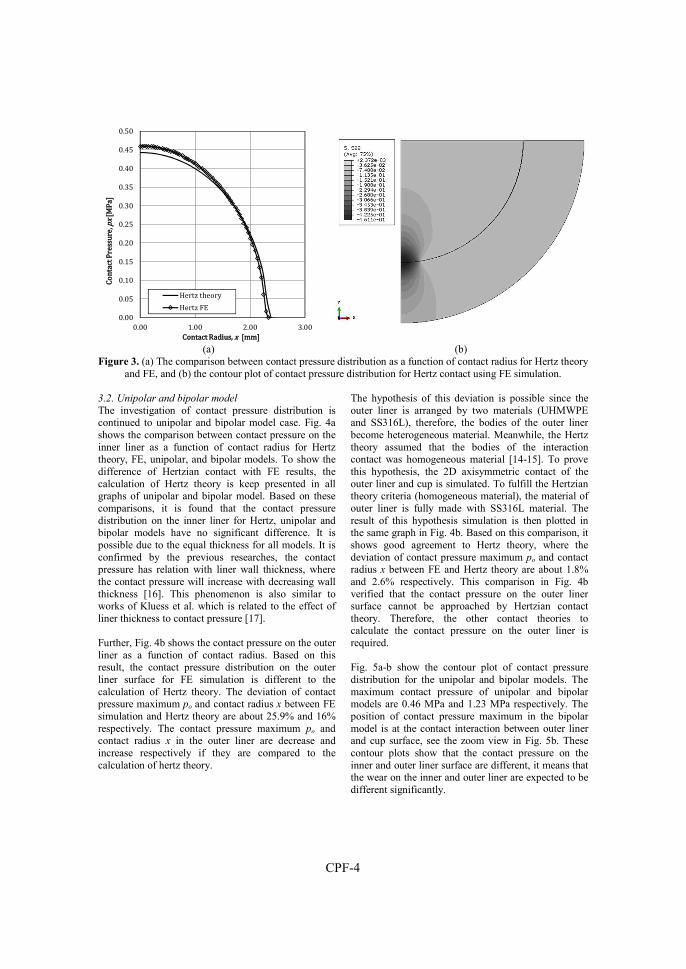
CPF-4
(a) (b) Figure 3. (a) The comparison between contact pressure distribution as a function of contact radius for Hertz theory
and FE, and (b) the contour plot of contact pressure distribution for Hertz contact using FE simulation. 3.2. Unipolar and bipolar model
The investigation of contact pressure distribution is continued to unipolar and bipolar model case. Fig. 4a shows the comparison between contact pressure on the inner liner as a function of contact radius for Hertz theory, FE, unipolar, and bipolar models. To show the difference of Hertzian contact with FE results, the calculation of Hertz theory is keep presented in all graphs of unipolar and bipolar model. Based on these comparisons, it is found that the contact pressure distribution on the inner liner for Hertz, unipolar and bipolar models have no significant difference. It is possible due to the equal thickness for all models. It is confirmed by the previous researches, the contact pressure has relation with liner wall thickness, where the contact pressure will increase with decreasing wall thickness [16]. This phenomenon is also similar to works of Kluess et al. which is related to the effect of liner thickness to contact pressure [17]. Further, Fig. 4b shows the contact pressure on the outer liner as a function of contact radius. Based on this result, the contact pressure distribution on the outer liner surface for FE simulation is different to the calculation of Hertz theory. The deviation of contact pressure maximum po and contact radius x between FE simulation and Hertz theory are about 25.9% and 16% respectively. The contact pressure maximum po and contact radius x in the outer liner are decrease and increase respectively if they are compared to the calculation of hertz theory.
The hypothesis of this deviation is possible since the outer liner is arranged by two materials (UHMWPE and SS316L), therefore, the bodies of the outer liner become heterogeneous material. Meanwhile, the Hertz theory assumed that the bodies of the interaction contact was homogeneous material [14-15]. To prove this hypothesis, the 2D axisymmetric contact of the outer liner and cup is simulated. To fulfill the Hertzian theory criteria (homogeneous material), the material of outer liner is fully made with SS316L material. The result of this hypothesis simulation is then plotted in the same graph in Fig. 4b. Based on this comparison, it shows good agreement to Hertz theory, where the deviation of contact pressure maximum po and contact radius x between FE and Hertz theory are about 1.8% and 2.6% respectively. This comparison in Fig. 4b verified that the contact pressure on the outer liner surface cannot be approached by Hertzian contact theory. Therefore, the other contact theories to calculate the contact pressure on the outer liner is required. Fig. 5a-b show the contour plot of contact pressure distribution for the unipolar and bipolar models. The maximum contact pressure of unipolar and bipolar models are 0.46 MPa and 1.23 MPa respectively. The position of contact pressure maximum in the bipolar model is at the contact interaction between outer liner and cup surface, see the zoom view in Fig. 5b. These contour plots show that the contact pressure on the inner and outer liner surface are different, it means that the wear on the inner and outer liner are expected to be different significantly.
0.000.050.100.150.200.250.300.350.400.450.50
0.00 1.00 2.00 3.00
Conta
ct Pres
sure, p
x [MPa]
Contact Radius, x [mm]
Hertz theoryHertz FE

CPF-5
(a) (b) Figure 4. (a) The comparison between contact pressure distribution as a function of contact radius on the inner
liner surface for Hertz, unipolar and bipolar condition, and (b) like previous graph but the data is obtained on the outer liner surface.
(a) (b)
Figure 5. (a) The contour plot of contact pressure distribution on the surface of inner acetabular liner for unipolar model and (b) the contour plot of contact pressure distribution on the surface of outer liner for bipolar model.
4. Conclusion
The study of contact pressure distribution on the inner and outer liner surfaces in the bipolar model has been performed. This research is aimed to predict the initial wear on the inner and outer acetabular liner by studying the distribution of contact pressure. Simulation is conducted using a commercial software ABAQUS. The simulation is started with hertz contact as validation stage. Further, simulation is continued on the model of unipolar and bipolar, where the unipolar simulation is performed as comparator. The results are presented in the graphs of contact pressure distribution as a function of contact radius at each contact interaction. In addition, the contour of contact pressure for all models are also presented. The results showed
that the distribution of contact pressure on the inner liner surface for the contact condition of Hertz, unipolar and bipolar have no significant difference. It occurred because all models used the same thickness. This phenomenon is similar to the previous works. However, the maximum and average of contact pressure distribution on the outer liner surface are higher than on the inner liner surface. Based on these results, it can be concluded that wear on the inner and liner surface is expected to be different. References
1. J.M. Cuckler, “The dislocated total hip: The dreaded 3 AM phone call,” in Seminars in
Arthroplasty 22, (2011), PP. 98-99.
0.000.050.100.150.200.250.300.350.400.450.50
0.00 1.00 2.00 3.00
Contac
t Press
ure, px
[MPa]
Contact Radius, x [mm]
Hertz theoryHertz FEUnipolar-inner linerBipolar-inner liner
0.000.200.400.600.801.001.201.401.601.80
0.00 0.50 1.00 1.50 2.00Con
tact Pr
essure
, px [M
Pa]
Contact Radius, x [mm]
Hertz theory-Outer linerHertz FE-Outer linerOuter liner

CPF-6
2. M.T. Hummel, A.L. Malkani, M.R. Yakkanti, and D.L. Baker, J. Arthroplasty 24, 73-76 (2009).
3. E. Saputra, I.B. Anwar, J. Jamari, and E. van der Heide, Procedia Eng., No. 68, 102-108 (2013).
4. E. Saputra, I.B. Anwar, R. Ismail, J. Jamari, and E. van der Heide, Jurnal Teknologi (Sciences & Engineering) 66, 53-58 (2014).
5. J. Jamari, R. Ismail, E. Saputra, S. Sugiyanto, and I.B. Anwar, Adv. Mat. Res., 896, 272-275 (2014).
6. H. Tanino, M.K. Harman, S.A. Banks, and W.A. Hodge, J. Orthop. Res., 1401-1407 (2007).
7. C.F. Scifert, T.D. Brown, D.R. Pedersen, and J.J. Callaghan, Clin. Orthop., 355, 152-162 (1998).
8. D. Dowson, B. Jobbins, and A. Seyed-Harraf, Wear, 880-889 (1993).
9. B.M. Wroblewski, Revision surgery in total hip arthroplasty, Springer-Verlag, London, 1990.
10. F.C Eichmiller, J.A. Tesk, and C.M. Croarkin, “Mechanical Properties of Ultra High Molecular Weight Polyethylene NIST Reference Material RM 8456,“ In: ‘Transactions of the Society for Biomaterials, 27th Annual Meeting’, (2001) 472.
11. B.J. Fregly, Y. Bei, and M.E. Sylvester, J. Biomech., 36, 1659-1668 (2003).

Conference Paper G
J. Jamari, E. Saputra, I.B. Anwar, R. Ismail, E. van der Heide, 2017
Finite element study of the Effect of UHMWPE liner thickness on the contact area and
stress distribution in a bipolar hip joint
IOP Conf. Series: Materials Science and Engineering 202, 012095, doi:10.1088/1757-899X/202/1/012095

CPG-1
Finite element study of the effect of UHMWPE liner thickness on contact area
and stress distribution in a bipolar hip joint
J. Jamari1, E. Saputra1,2, I.B. Anwar2, 3, R. Ismail1, E. van der Heide2 1 Laboratory for Engineering Design and Tribology, Department of Mechanical Engineering, University of
Diponegoro, Jl. Prof. Soedharto, Tembalang, Semarang 50275, Indonesia 2 Laboratory for Surface Technology and Tribology, Faculty of Engineering Technology, University of Twente,
Drienerloolaan 5, Postbox 217, 7500 AE, Enschede, The Netherlands 3 Orthopaedic and Traumatology Department, Prof. Dr. R. Soeharso Orthopaedic Hospital,
Jl. A. Yani Pabelan, Surakarta 57162, Indonesia
Published in: IOP Conf. Series: Materials Science and Engineering 202, 012095, doi:10.1088/1757-899X/202/1/012095
Abstract Contact area and stress distribution of the polyethylene liner (PE liner) have a major influence on the wear process. The main factor that affects the contact area and stress on the PE liner is thickness. The International Standards Organization (ISO) recommends a minimum PE liner thickness of 6 mm. However, the thickness of PE liner in a bipolar hip prosthesis has a limited range of motion compare to the unipolar one due to the addition of the outer liner component. Therefore, study the effect of PE liner thickness to the contact area and stress distribution in the bipolar model is interesting. This aim of this research is to study the effect of the PE liner thickness to the contact area and stress distribution on the surface of contact between head and PE liner and the contact between outer liner and cup in the bipolar model. This research was carried out by finite element analysis. Results show that the highest contact stress on the liner occurs at the lowest liner thickness. The highest contact radius on the liner surface occurs at the highest liner thickness. The bipolar model with the liner thickness of 4.5 mm in this research gives the lowest contact stress. Introduction
Islam is the largest religion in Indonesia based on the central bureau of statistics in Indonesia [1]. In Islam, its adherent is called as a Moslem. One of the religious activities for Moslem is Salat activity. Salat activity consists of standing, bowing (Ruku’), straightening up (I’tidal), transition of standing towards prostration, prostration (Sujud), sitting between the two prostrations, and sitting [2]. Salat is an obligatory activity for Moslem, not least for Moslem patients who use the hip prosthesis. In another word, Salat activity and the general activities will affect the motion of hip prosthesis [3-5]. One of the differences between the Salat activities with daily activities is the range of motion (RoM) in the hip prosthesis movement. Based on the RoM data of hip prosthesis from Soeharso Orthopaedic Hospital, Solo, some movement with a large angle of the range of motion was found. Effects of the value of the angle will accelerate the process of impingement which potential to dislocation. Therefore,
the design of hip prosthesis for Moslem patients must be tailored to accommodate the movement of prayer. Especially, for the Indonesian people, the dimensions of the hip prosthesis must also be adapted to the diameter of the average hip of Indonesian people. In general, there are two types of the hip prosthesis in total hip replacement, i.e. unipolar model, and bipolar model. The unipolar model consists of a cup, liner, head and stem, whereas the bipolar model consists of the cup, outer liner, inner liner, head, and stem. Calculation of the RoM of Salat for the unipolar and bipolar model had been performed [6]. Based on this study it was found that the bipolar model can accommodate Salat movement better than the unipolar model for the same head diameter. The consequence of using the bipolar model to PE liner is that the liner thickness becomes definite. By assuming the outer diameter of the cup and head of both models are the same, the liner thickness of the unipolar model is thicker than the bipolar model. Based on the International Organization for Standardization (ISO), the recommendation of liner thickness is equal to 6 mm [7]. This recommendation can be applied in the unipolar model; however, it is difficult to be applied in the bipolar model. This is due to the limitation of cup dimension and the addition of outer liner. In fact, the liner thickness will affect the contact stress distribution and contact area due to contact interaction between head and liner. The contact stress and contact area on the liner will affect to the wear of the liner surface.
There are several researchers investigated the effect of the liner thickness to the contact stress. In 1985, Bartel et al. [8] investigated the effect of conformity and plastic thickness on the contact stresses in Metal-Backed plastic implants. They found that the contact stresses on the liner are very sensitive to clearance with a minimum thickness of the 4-6 mm. Furthermore, in

CPG-2
1986 Bartel et al. [9] continued their research concerning the effect of conformity, thickness and material on stresses in the ultra high molecular weight polyethylene (UHMWPE) components for total hip replacement. Their result found that the liner thickness should be maximized to reduce contact stress that leads to surface damage. In 2010, Shen et al. [10] investigated wear versus the thickness and other features of 5-Mrad crosslinked UHMWPE liners. They found that the reducing the liner thickness from 6 mm to 3 mm increased the contact stress by 46%, however, the wear rate decreased by 19%. Recently, Jamari et al. [11] investigated the effect of the wall thickness on the wear of PE liner. Their results show that higher contact stresses will be achieved with decreasing the liner thickness. The general conclusion from literature related to the liner thickness is that the liner thickness less than 6 mm causes the high contact stress on the liner surface that will also increase the wear process. Unfortunately, most of the contact stress investigations were only considered for the unipolar model. Therefore, the investigation of the contact stress distribution and contact radius in the bipolar model is performed.
The objective of this research is to study the contact stress distribution and contact area on the liner surface due to the contact interaction. Moreover, the contact stress distribution on the cup surface due to interaction contact between outer liner and the cup is also studied. Finite element analysis is employed for calculating the contact area and stress distribution. Method
1.1. Material Model
In general, hip prostheses are made from metal and plastic materials. In this research, the femoral head, the outer liner, and the cup components are made from the SS316L material, while the liner and the inner liner are made from UHMWPE material. For validation process,
the cobalt chromium molybdenum (CoCrMo) is employed. These material properties are considered as elastic material, following Archard’s wear equation [12]. The material properties of UHMWPE, CoCrMo, and SS316L materials can be seen in Table 1.
Table 1: Material properties of UHMWPE and SS316L
Materials Modulus
elasticity [GPa] Poisson’s
ratio UHMWPE [13] 0.5-1 0.4 CoCrMo [13] 230 0.3 SS316L [14] 193 0.3
1.2. Geometrical Model
There are two models in this research, i.e. unipolar and bipolar models (see Figure 1a-d for more detail). The unipolar model is used for validation process, whereas the bipolar model is used for analyzing the contact stress distribution and contact area on the liner and cup surfaces (Figure 2). The dimension of the unipolar model is adopted from the model of Puccio and Mattei [13]. The dimension of the bipolar model is designed based on the femoral head dimension average of Indonesian people. Data from the Indonesian orthopedic hospital show that the average diameter of Indonesian femoral head is 42 mm. This data is then used as a parameter to determine the dimension of outer liner and inner liner of the bipolar model. The head diameter of the bipolar model is 28 mm. To investigate the effect of the inner liner thickness to the contact stress and contact area on the inner liner, the thickness of inner liner is varied. The variations of the inner liner thickness are 3 mm, 3.5 mm, 4 mm and 4.5 mm. Further, the dispute thickness of head and the inner liner is divided to be two thicknesses to get the thickness of outer liner and cup. Therefore, when the thickness of inner liner increases the thickness of cup decreases, see Table 2 for more detail. The clearances between of head-inner and outer liner-cup are 0.1 mm.
(a) (b) (c) (d) Figure 1: Unipolar model (UM) and bipolar model (BM) of the hip prostheses: (a) UM isometric view, b) UM
cross-section view, c) BM isometric view and d) BM cross-section view [6]. (Note: dark gray color is metal material and light gray color is plastic material)
Outer liner
Cup
Head Inner liner Head Liner
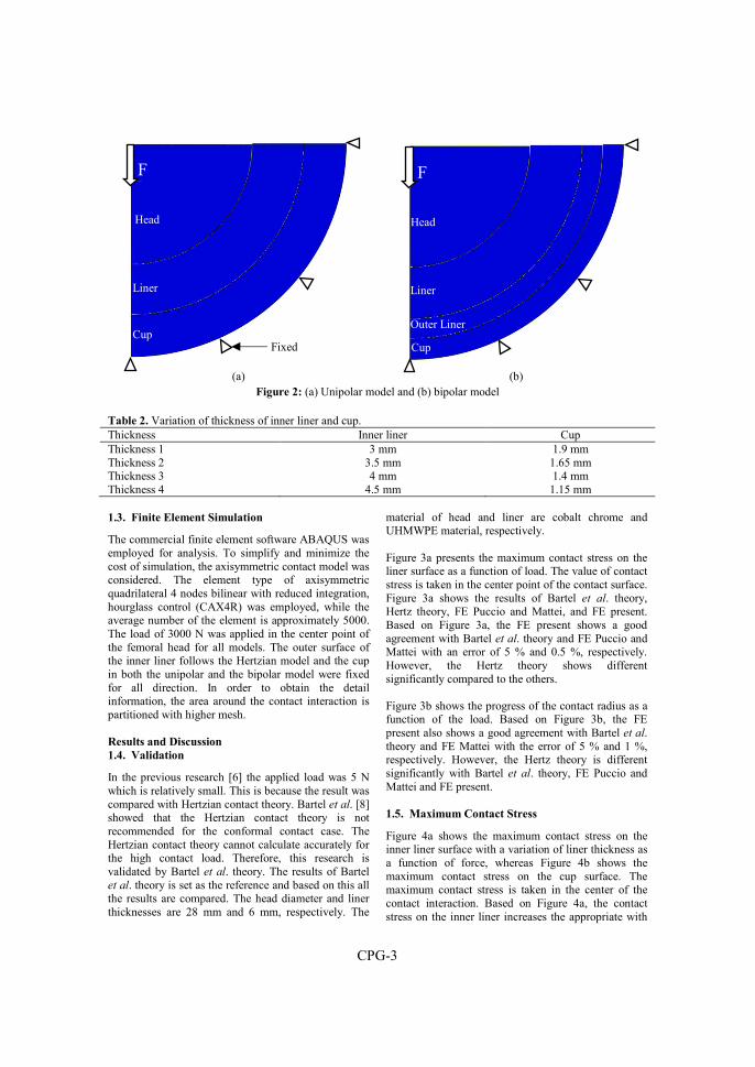
CPG-3
(a) (b)
Figure 2: (a) Unipolar model and (b) bipolar model Table 2. Variation of thickness of inner liner and cup. Thickness Inner liner Cup Thickness 1 3 mm 1.9 mm Thickness 2 3.5 mm 1.65 mm Thickness 3 4 mm 1.4 mm Thickness 4 4.5 mm 1.15 mm 1.3. Finite Element Simulation
The commercial finite element software ABAQUS was employed for analysis. To simplify and minimize the cost of simulation, the axisymmetric contact model was considered. The element type of axisymmetric quadrilateral 4 nodes bilinear with reduced integration, hourglass control (CAX4R) was employed, while the average number of the element is approximately 5000. The load of 3000 N was applied in the center point of the femoral head for all models. The outer surface of the inner liner follows the Hertzian model and the cup in both the unipolar and the bipolar model were fixed for all direction. In order to obtain the detail information, the area around the contact interaction is partitioned with higher mesh. Results and Discussion
1.4. Validation
In the previous research [6] the applied load was 5 N which is relatively small. This is because the result was compared with Hertzian contact theory. Bartel et al. [8] showed that the Hertzian contact theory is not recommended for the conformal contact case. The Hertzian contact theory cannot calculate accurately for the high contact load. Therefore, this research is validated by Bartel et al. theory. The results of Bartel et al. theory is set as the reference and based on this all the results are compared. The head diameter and liner thicknesses are 28 mm and 6 mm, respectively. The
material of head and liner are cobalt chrome and UHMWPE material, respectively. Figure 3a presents the maximum contact stress on the liner surface as a function of load. The value of contact stress is taken in the center point of the contact surface. Figure 3a shows the results of Bartel et al. theory, Hertz theory, FE Puccio and Mattei, and FE present. Based on Figure 3a, the FE present shows a good agreement with Bartel et al. theory and FE Puccio and Mattei with an error of 5 % and 0.5 %, respectively. However, the Hertz theory shows different significantly compared to the others. Figure 3b shows the progress of the contact radius as a function of the load. Based on Figure 3b, the FE present also shows a good agreement with Bartel et al. theory and FE Mattei with the error of 5 % and 1 %, respectively. However, the Hertz theory is different significantly with Bartel et al. theory, FE Puccio and Mattei and FE present. 1.5. Maximum Contact Stress
Figure 4a shows the maximum contact stress on the inner liner surface with a variation of liner thickness as a function of force, whereas Figure 4b shows the maximum contact stress on the cup surface. The maximum contact stress is taken in the center of the contact interaction. Based on Figure 4a, the contact stress on the inner liner increases the appropriate with
HeadHead
Liner
FF
Fixed Cup
F
Head
Liner
Cup
Outer Liner

CPG-4
increase the force. The highest contact stress occurs when the inner liner thickness is equal to 3 mm, while the lowest contact stress occurs when the inner liner is equal to 4.5 mm. Figure 4b shows the contact stress on the cup surfaces as a function of load. Based on figure 4b, the contact stress phenomena on the cup surface is different with the contact stress phenomena on the
inner liner surfaces. The increasing of the contact stress on the cup surface is fluctuation. As the example in the cup thickness equal 1.9 mm, the initial contact stress increase till 27 MPa at the force of 400 N, then the contact stress is fluctuation until at force of 3000 N. This phenomenon occurs at all of the cup thickness.
(a) (b)
Figure 3: (a) The comparison between contact pressure distribution as a function of contact radius for Hertz theory and FE, and (b) the contour plot of contact pressure distribution for Hertz contact using FE simulation
(a) (b)
Figure 4: (a) The comparison between contact pressure distribution as a function of contact radius on the inner liner surface for Hertz, unipolar and bipolar condition, and (b) like previous graph but the data is obtained on the
outer liner surface 1.6. Contact Stress Distribution and Contact
Radius
Figures 5a and 5b show the contact stress distribution and contact radius on the liner and cup surfaces as a
function of the contact radius. These values are taken at the force equal to 3000 N. Figure 5a presents the contact stress distribution on the liner surface. The contact stress maximum is getting started at the center point of contact then decrease to reach the last contact
0
5
10
15
20
0 1000 2000 3000
Co
nta
ct s
tre
ss m
axi
mu
m (
MP
a)
Force (N)
Bartel et al. theory
Hertz theory
FE Present
FE Puccio and Mattei
0
5
10
15
20
0 1000 2000 3000
con
tact
ra
diu
s (m
m)
Force (N)
Bartel et al. theory
Hertz theory
FE Present
FE Puccio and Mattei
0
5
10
15
20
25
30
0 1000 2000 3000
Co
nta
ct s
tre
ss m
axi
mu
m (
MP
a)
Force (N)
Liner thick. = 3 mmLiner thick. = 3.5 mmLiner thick. = 4 mmLiner thick. = 4.5 mm
0
5
10
15
20
25
30
0 1000 2000 3000
Co
nta
ct s
tre
ss m
axi
mu
m (
MP
a)
Force (N)
Cup thick. = 1.9 mmCup thick. = 1.65 mmCup thick. = 1.4 mmCup thick. = 1.15 mm
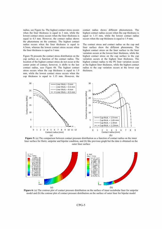
CPG-5
radius, see Figure 6a. The highest contact stress occurs when the liner thickness is equal to 3 mm, while the lowest contact stress occurs when the liner thickness is equal to 4.5 mm. However, the contact radius shows the phenomena on the contrary. The highest contact radius occurs when the liner thickness is equal to 4.5mm, whereas the lowest contact stress occurs when the liner thickness is equal to 3 mm. Figure 5b presents the contact stress distribution on the cup surface as a function of the contact radius. The location of the highest contact stress do not occur at the center point of contact, however, it shifts to the last contact radius, sees Figure 6b. The highest contact stress occurs when the cup thickness is equal to 1.9 mm, while the lowest contact stress occurs when the cup thickness is equal to 1.15 mm. However, the
contact radius shows different phenomenon. The highest contact radius occurs when the cup thickness is equal to 1.15 mm, while the lowest contact radius occurs when the cup thickness is equal to 1.9 mm. The contact stress and contact radius on the cup and liner surface show the different phenomena. The highest contact stress on the liner surface to the liner variation occurs at the lowest liner thickness, while the highest contact stress on the cup surface to the cup variation occurs at the highest liner thickness. The highest contact radius to the PE liner variation occurs at the highest liner thickness, while the highest contact radius to the cup variation occurs at the lower cup thickness.
(a) (b)
Figure 5: (a) The comparison between contact pressure distribution as a function of contact radius on the inner liner surface for Hertz, unipolar and bipolar condition, and (b) like previous graph but the data is obtained on the
outer liner surface
(a) (b)
Figure 6: (a) The contour plot of contact pressure distribution on the surface of inner acetabular liner for unipolar model and (b) the contour plot of contact pressure distribution on the surface of outer liner for bipolar model
0
5
10
15
20
25
30
0 1 2 3 4 5 6 7 8 9 10 11 12
Co
nta
ct s
tre
ss (
MP
a)
Contact radius (mm)
Liner thick. = 3 mm
Liner thick. = 3.5 mm
Liner thick. = 4 mm
Liner thick. = 4.5 mm
0
5
10
15
20
25
30
0 1 2 3 4 5 6 7 8 9
Co
nta
ct s
tre
ss m
axi
mu
m (
MP
a)
Contact radius (mm)
Cup thick. = 1.9 mm
Cup thick. = 1.65 mm
Cup thick. = 1.4mm
Cup thick. = 1.15mm
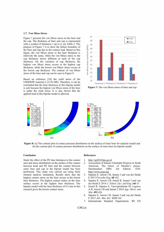
CPG-6
1.7. Von Mises Stress
Figure 7 presents the von Mises stress on the liner and the cup. The thickness of liner and cup is represented with a symbol of thickness 1 up to 4, see Table 2. The purpose of Figure 7 is to show the failure boundary of the liner and cup due to the contact load. Based on this figure, the von Mises stress to the liner thickness is relatively the same, while the von Mises stress to the cup thickness shows different at each of the cup thickness. On the variation of cup thickness, the highest von Mises stress occurs at the highest cup thickness, while the lowest von Mises stress occurs at the lowest cup thickness. The contour of von Mises stress of the liner and cup can be seen in Figure 8. Based on reference [18] the yield stress of the UHMWPE material is 23.56 MPa. Therefore, it can be concluded that the liner thickness in this bipolar model is safe because the highest von Mises stress of the liner is under the yield stress. It is also shown that the applied load in this bipolar model is allowed.
Figure 7: The von Mises stress of liner and cup
(a) (b)
Figure 8: (a) The contour plot of contact pressure distribution on the surface of inner liner for unipolar model and
(b) the contour plot of contact pressure distribution on the surface of outer liner for bipolar model
Conclusion
Study the effect of the PE liner thickness to the contact area and stress distribution on the surface of the contact between head and PE liner and the contact between outer liner and cup in the bipolar model has been performed. This study was carried out using finite element analysis simulation. Results show that the highest contact stress on the liner occurs at the lowest liner thickness. The highest contact radius on the liner surface occurs at the highest liner thickness. The bipolar model with the liner thickness of 4.5 mm in this research gives the lowest contact stress.
References
1. http://sp2010.bps.go.id 2. Association of Islamic Chartiable Projects in North
American. The basics of Muslim’s prayer. Darulmashari 2008; 3rd Edition: 1429. http://www.aicp.org
3. Saputra E, Anwar I B, Jamari J and van der Heide E 2013 Procedia Eng. 68 102
4. Saputra E, Anwar I B, Ismail R, Jamari J and van der Heide E 2014 J. Teknol. (Sci. and Eng.) 66 53
5. Ismail R, Saputra E, Tauviqirrahman M, Legowo A B, Anwar I B and Jamari J 2014 App. Mech. and
Mat. 493 426 6. Saputra E, Anwar I B, Jamari J and van der Heide
E 2015 Adv. Mat. Res. 1123 164 7. International Standard Organization. BS EN
10
11
12
13
14
15
16
17
18
19
20
21
Thickness 1 Thickness 2 Thickness 3 Thickness 4
von
Mis
es
stre
ss m
axi
mu
m [
MP
a]
Liner
Cup

CPG-7
12563: 1999. Non-Active Surgical Implant. Joint Replacement Implants. Specific Requirements for Hip Joint Replacement Implants.
8. Bartel D L, Burstein A H, Toda M D and Edwards D L 1985 J. Biomech. Eng. 107 193
9. Bartel D L, Bicknell V L and Wright T M 1986 The J. Bone and Joint Surg. 68-A 1041
10. Shen F W, Lu Z and McKellop H A 2010 Clin. Orthop. Relat. Res. 469 395
11. Jamari J, Hidayat A, Saputra E, Anwar I B, Ismail R and van der Heide E 2015 Adv. Mat. Res. 1123 196
12. Archard J F 1953 J. Appl. Phys. 24 981 13. Puccio F D and Mattei L 2015 World J. Orthop.
6(1) 77 14. Yildiz F, Yetim A F, Alsaran A, Celik A and
Kaymaz I 2011 Tribol. Int. 44 1979 15. Kluess D, Martin H, Mittelmeier W, Schmitz K P
and Bader R 2007 Med. Eng. & Phys. 29 465.


Conference Paper H
E. Saputra, I.B. Anwar, R. Ismail, J. Jamari, E. van der Heide, 2017
Study of unipolar and bipolar hip prostheses using finite element simulation: contact stress analysis
Key Engineering Materials, Volume 739, pp. 96-102,
doi: https://doi.org/10.4028/www.scientific.net/KEM.739.96


CPH-1
Study of unipolar and bipolar hip prostheses using finite element simulation: contact
stress analysis
E. Saputra1,3, I.B. Anwar1,2, R. Ismail3, J. Jamari3, E. van der Heide1
1Laboratory for Surface Technology and Tribology, Faculty of Engineering Technology, University of Twente, Drienerloolaan 5, Postbox 217, 7500 AE, Enschede, The Netherlands
2Orthopaedic and Traumatology Department, Prof. Dr. R. Soeharso Orthopaedic Hospital, Jl. A. Yani Pabelan, Surakarta 57162, Indonesia
3Laboratory for Engineering Design and Tribology, Department of Mechanical Engineering, University of Diponegoro, Jl. Prof. Soedharto SH, Tembalang, Semarang 50275, Indonesia
Published in: Key Engineering Materials, Volume 739, pp. 96-102
Abstract One of the phenomena which cannot be avoided in a hip prosthesis due to sliding contact as a product of human activity is a wear on the surface of contact interaction. The wear in a bipolar model of the hip prosthesis (the bipolar model) is more complicated than an unipolar model of the hip prosthesis (the unipolar model). There are two contact interactions in the bipolar model, while the unipolar model has only one contact interaction. Wear on the liner and cup surfaces of the bipolar model itself can be early estimated by investigation the contact stresses due to their contact interactions. The contact stress on the liner surface of the unipolar model can be estimated using an analytical method. However, the estimation of contact stress on the liner and cup surface of the bipolar model using analytical method still need to consider. The purpose of this paper is to study the contact stresses on the liner and cup surfaces of the bipolar model using the finite element simulation. There are three models of hip prostheses which are simulated in this research, i.e. the unipolar model, bipolar model and big head unipolar model. The results showed that the maximum contact stress on the liner surface of the bipolar model is higher than the unipolar model. The maximum contact stress on the cup surface of the bipolar model is lower than the big head unipolar model. Based on these results, it can be concluded that the contact stress on the liner and cup surfaces of the bipolar model cannot be estimated using the analytical method. Keywords: contact stress; unipolar; bipolar; hip prosthesis.
1. Introduction
Impingement and wear are phenomenon of the total hip arthroplasty patient due to their daily activities [1]. In general, impingement and wear are related to an early and late dislocation, respectively [2, 3]. The limitation of the range of motion (RoM) of the hip prosthesis which caused by the diameter of head, neck and the polyethylene (PE) liner position can induce the impingement occurrence. In the previous research, the impingements of hip prosthesis due to the human daily
activity using finite element simulation have been investigated [4-6]. Further, the specific investigations of impingement due to Salat activity (prayer) have been also developed [7, 8].
These researches were extended to wear on the liner surface of hip prostheses due to its motion and applied load as a product of human activities. Based on the number of motion axis, the hip prostheses are categorized to be unipolar or conventional and bipolar models. The unipolar model is arranged on the head, liner, and cup component, while the bipolar model is arranged of the head, inner and outer liner, and cup component. Here, the inner liner in the bipolar model is equal with the liner in the unipolar model. Wear in the bipolar model due to its contact interaction is more complicated than the unipolar model. In the bipolar model, there are two contact interactions i.e. head versus inner liner and outer liner versus cup, while the unipolar model has only one contact interaction i.e. head versus liner. It means that there are two wear positions in the bipolar model.
In fact, the wear on the liner surface can be early expected by the analytical method. In general, Archard’s wear equation [9] is widely used to predict wear on the surface of two interacting bodies. By several researchers, the Archard’s wear equation was then widely developed to solve the wear on the liner surface of the hip prostheses, especially for the unipolar model. Dowson et al. [10] used the Archard’s equation for calculating wear on the liner surface of the unipolar model and comparing it to his own experimental data. Kauzlarich and Williams [11] also developed the Archard’s wear equation to calculate wear in the unipolar model and compare it to Dowson’s experimental data. Based on the literature review, a lot of researchers developed the wear equation for the unipolar model case, while the wear equation for the bipolar model has not clear explanation yet.
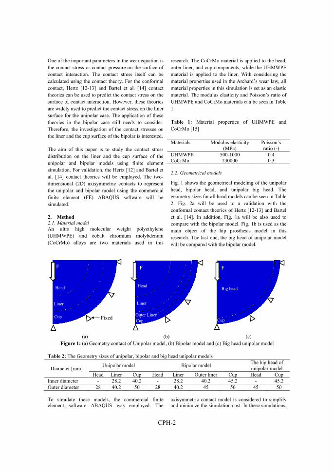
CPH-2
One of the important parameters in the wear equation is the contact stress or contact pressure on the surface of contact interaction. The contact stress itself can be calculated using the contact theory. For the conformal contact, Hertz [12-13] and Bartel et al. [14] contact theories can be used to predict the contact stress on the surface of contact interaction. However, these theories are widely used to predict the contact stress on the liner surface for the unipolar case. The application of these theories in the bipolar case still needs to consider. Therefore, the investigation of the contact stresses on the liner and the cup surface of the bipolar is interested.
The aim of this paper is to study the contact stress distribution on the liner and the cup surface of the unipolar and bipolar models using finite element simulation. For validation, the Hertz [12] and Bartel et al. [14] contact theories will be employed. The two-dimensional (2D) axisymmetric contacts to represent the unipolar and bipolar model using the commercial finite element (FE) ABAQUS software will be simulated.
2. Method
2.1. Material model
An ultra high molecular weight polyethylene (UHMWPE) and cobalt chromium molybdenum (CoCrMo) alloys are two materials used in this
research. The CoCrMo material is applied to the head, outer liner, and cup components, while the UHMWPE material is applied to the liner. With considering the material properties used in the Archard’s wear law, all material properties in this simulation is set as an elastic material. The modulus elasticity and Poisson’s ratio of UHMWPE and CoCrMo materials can be seen in Table 1.
Table 1: Material properties of UHMWPE and CoCrMo [15]
Materials Modulus elasticity (MPa)
Poisson’s ratio (-)
UHMWPE 500-1000 0.4 CoCrMo 230000 0.3
2.2. Geometrical models
Fig. 1 shows the geometrical modeling of the unipolar head, bipolar head, and unipolar big head. The geometry sizes for all head models can be seen in Table 2. Fig. 2a will be used to a validation with the conformal contact theories of Hertz [12-13] and Bartel et al. [14]. In addition, Fig. 1a will be also used to compare with the bipolar model. Fig. 1b is used as the main object of the hip prosthesis model in this research. The last one, the big head of unipolar model will be compared with the bipolar model.
(a) (b) (c) Figure 1: (a) Geometry contact of Unipolar model, (b) Bipolar model and (c) Big head unipolar model
Table 2: The Geometry sizes of unipolar, bipolar and big head unipolar models
Diameter [mm] Unipolar model Bipolar model
The big head of unipolar model
Head Liner Cup Head Liner Outer liner Cup Head Cup Inner diameter - 28.2 40.2 - 28.2 40.2 45.2 - 45.2 Outer diameter 28 40.2 50 28 40.2 45 50 45 50 To simulate these models, the commercial finite element software ABAQUS was employed. The
axisymmetric contact model is considered to simplify and minimize the simulation cost. In these simulations,
Head
Liner
F
Cup Fixed
F
Head
Liner
Cup Outer Liner
F
Big head
Cup
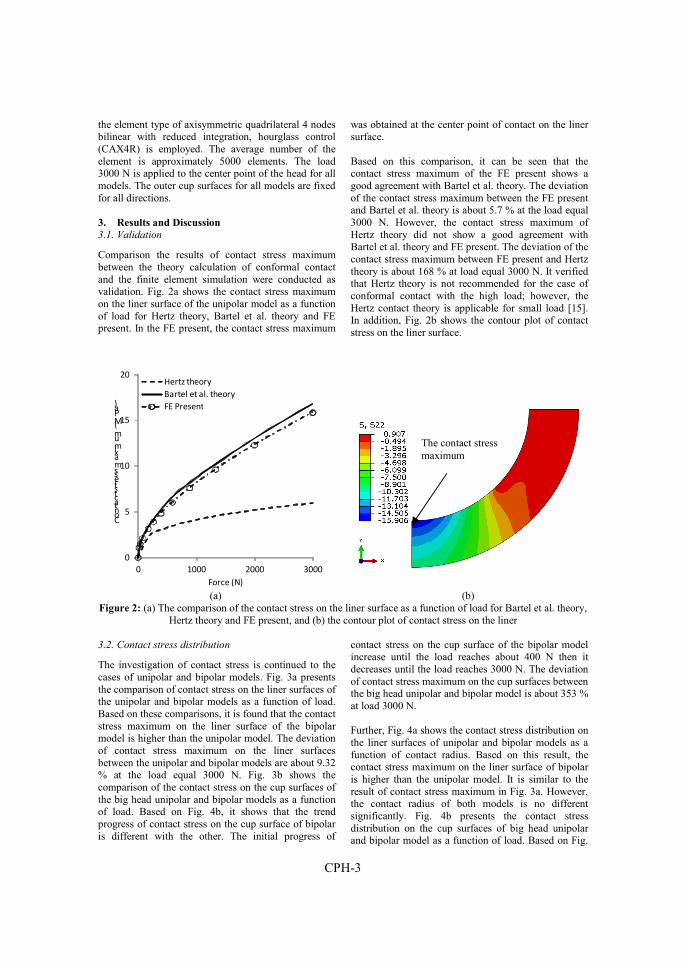
CPH-3
the element type of axisymmetric quadrilateral 4 nodes bilinear with reduced integration, hourglass control (CAX4R) is employed. The average number of the element is approximately 5000 elements. The load 3000 N is applied to the center point of the head for all models. The outer cup surfaces for all models are fixed for all directions.
3. Results and Discussion
3.1. Validation
Comparison the results of contact stress maximum between the theory calculation of conformal contact and the finite element simulation were conducted as validation. Fig. 2a shows the contact stress maximum on the liner surface of the unipolar model as a function of load for Hertz theory, Bartel et al. theory and FE present. In the FE present, the contact stress maximum
was obtained at the center point of contact on the liner surface. Based on this comparison, it can be seen that the contact stress maximum of the FE present shows a good agreement with Bartel et al. theory. The deviation of the contact stress maximum between the FE present and Bartel et al. theory is about 5.7 % at the load equal 3000 N. However, the contact stress maximum of Hertz theory did not show a good agreement with Bartel et al. theory and FE present. The deviation of the contact stress maximum between FE present and Hertz theory is about 168 % at load equal 3000 N. It verified that Hertz theory is not recommended for the case of conformal contact with the high load; however, the Hertz contact theory is applicable for small load [15]. In addition, Fig. 2b shows the contour plot of contact stress on the liner surface.
0
5
10
15
20
0 1000 2000 3000
Contact stress maximum (MPa)
Force (N)
Hertz theory
Bartel et al. theory
FE Present
(a) (b)
Figure 2: (a) The comparison of the contact stress on the liner surface as a function of load for Bartel et al. theory, Hertz theory and FE present, and (b) the contour plot of contact stress on the liner
3.2. Contact stress distribution
The investigation of contact stress is continued to the cases of unipolar and bipolar models. Fig. 3a presents the comparison of contact stress on the liner surfaces of the unipolar and bipolar models as a function of load. Based on these comparisons, it is found that the contact stress maximum on the liner surface of the bipolar model is higher than the unipolar model. The deviation of contact stress maximum on the liner surfaces between the unipolar and bipolar models are about 9.32 % at the load equal 3000 N. Fig. 3b shows the comparison of the contact stress on the cup surfaces of the big head unipolar and bipolar models as a function of load. Based on Fig. 4b, it shows that the trend progress of contact stress on the cup surface of bipolar is different with the other. The initial progress of
contact stress on the cup surface of the bipolar model increase until the load reaches about 400 N then it decreases until the load reaches 3000 N. The deviation of contact stress maximum on the cup surfaces between the big head unipolar and bipolar model is about 353 % at load 3000 N. Further, Fig. 4a shows the contact stress distribution on the liner surfaces of unipolar and bipolar models as a function of contact radius. Based on this result, the contact stress maximum on the liner surface of bipolar is higher than the unipolar model. It is similar to the result of contact stress maximum in Fig. 3a. However, the contact radius of both models is no different significantly. Fig. 4b presents the contact stress distribution on the cup surfaces of big head unipolar and bipolar model as a function of load. Based on Fig.
The contact stress maximum

CPH-4
4b, the contact stress maximum on the cup surface of the big head unipolar model is higher than the bipolar model. However, the contact radius of both models is different significantly. The contact radius of the bipolar model is higher than the big head of unipolar model.
The hypothesis of these deviations is same with the explanation in previous research [16]. It possible since the liner in the bipolar model is arranged by two materials (plastic and metal), therefore, the PE liner bodies become heterogeneous materials.
0
5
10
15
20
0 1000 2000 3000
Con
tact
str
ess
max
imum
(MPa
)
Force (N)
Liner of Bipolar
Liner of Unipolar
0
10
20
30
40
50
60
70
80
90
100
0 1000 2000 3000
Con
tact
str
ess
max
imum
(M
Pa)
Force (N)
Cup of Bipolar
Cup of big head unipolar
(a) (b)
Figure 3: (a) The comparison of the contact stress maximum on the liner surfaces of unipolar and bipolar models as a function of load, and (b) like previous graph but the data is obtained on the cup surfaces of bipolar and big
head unipolar
0
2
4
6
8
10
12
14
16
18
20
0 2 4 6 8 10 12 14
con
tact
str
ess
(M
Pa
)
Contact radius (mm)
Liner of unipolar
Liner of bipolar
0
10
20
30
40
50
60
70
80
90
100
0 2 4 6 8
con
tact
str
ess
(M
Pa
)
Contact radius (mm)
Cup of big head Unipolar
Cup of bipolar
(a) (b)
Figure 4: (a) The comparison of the contact stress distribution on the liner of unipolar and bipolar as a function of contact radius, and (b) like previous graph but the data is obtained on the cups of big head unipolar and bipolar
The contour plot of contact stress for the liner of unipolar and bipolar models can be seen in Fig. 5a-b, whereas the contour plot of contact stress for the cup of big head unipolar and bipolar models can be seen in Fig. 6a-b. Based on Fig. 5a-b, the contour plots of them show the same appearing. The position of contact stress
maximum is at the center point of contact interaction. However, it is different for the contact stress phenomena in Fig. 6a-b. The position of contact stress maximum in the cup of big head unipolar model is at the center point of contact interaction, whereas the

CPH-5
position of contact stress in the cup of bipolar model is shifted.
(a) (b)
Figure 5: The contour plot of contact stress distribution on the surface of liner for (a) unipolar model and (b) bipolar model
(a) (b)
Figure 6: The contour plot of contact stress distribution on the surface of cup for (a) unipolar model and (b) bipolar model
4. Conclusion
The FE analysis of the contact stress on the liner and cup surfaces of unipolar and bipolar models have been performed. The objective of this research is to study the contact stress distribution on the liner and cup surfaces of the unipolar and bipolar model. The FE simulation in this research was performed using a commercial FE software ABAQUS. The simulation was started with the unipolar contact model as verification stage. In this verification, the FE results were then validated with Hertz and Bartel et al. contact theories. Further, the FE simulation was expanded on the bipolar and big head unipolar models, where the
simulation of big head unipolar was achieved as a comparator. The results were presented in the contact stress maximum on the center point of contact as a function of the load at each contact interaction. Based on these result, the contact stress maximum on the liner surface of the bipolar model was higher than the unipolar model. While, the contact stress maximum on the cup surface of the bipolar model was lower than the big head unipolar model. Based on these results, it can be concluded that the contact stress on the liner and cup surfaces of the bipolar model cannot be estimated using analytical method (Hertz or Bartel et al. of contact theories).
The contact stress maximum
The contact stress maximum
CPH-6
References
1. C.V. Sikes, L.P. Lai, M. Schreiber, M.A. Mont, R.H. Jinnah and T.M. Seyler: J. Arthroplasty Vol. 23 (2008), pp. 59-63
2. J.M. Cuckler: Seminars in Arthroplasty 22 (2011), pp. 98-99
3. M.T. Hummel, A.L. Malkani, M.R. Yakkanti and D.L. Baker: J. Arthroplasty Vol. 24 (2009), pp. 73-76
4. E. Saputra, I.B. Anwar, J. Jamari and E.van der Heide: Procedia Eng. Vol. 68 (2013), pp. 102-108
5. E. Saputra, I.B. Anwar, R. Ismail, J. Jamari and E. van der Heide: Jurnal Teknologi (Sciences and Engineering) Vol. 66 (2014), pp. 53-58
6. E. Saputra, I.B. Anwar, J. Jamari and E. van der Heide: Adv. Mat. Res. Vol. 1123 (2015), pp. 164-168
7. R. Ismail, E. Saputra, M. Tauviqirrahman, A.B. Legowo, I.B. Anwar and J. Jamari: Appl. Mech. Mater. Vol. 493 (2014), pp. 426-431
8. J. Jamari, R. Ismail, E. Saputra, S. Sugiyanto and I.B. Anwar: Adv. Mat. Res. Vol. 896 (2014), pp. 272-275
9. J.F. Archard: J. Appl. Phys. Vol. 24 (1953), pp. 981-988
10. D. Dowson, B. Jobbins and A. Seyed-Harraf: Wear 162–164 (1993), pp. 880–889
11. J.J. Kauzlarich and J.A. Williams: Proc. Instn. Mech. Engrs. Vol. 215 (2001), pp. 387−403
12. H. Hertz: J. Reine und Angewandte Mathematik Vol. 92 (1882), pp. 156-171
13. K.L. Johnson: Contact Mechanics (Cambridge University Press, Cambridge, UK, 1985)
14. D.L. Bartel, A.H. Burstein, M.D. Toda, D.L. Edwards: J. Biomech. Eng. Vol. 107 (1985), pp. 193-199
15. F.D. Puccio, L. Mattei: World J. Orthop. Vol. 6 (2015), pp. 77-94
16. E. Saputra, I.B. Anwar, R. Ismail, J. Jamari and E. van der Heide: AIP Conf. Proc. Vol. 1725 (2016), p. 020075
Acknowledgements First and foremost, I would like to saying “Alhamdulillah”, praise is to Allah the lord of the worlds who has given me the opportunity, strength, and ability to complete this research. Also, completing this research is not easy without the help of others, therefore I would like to thank all those who have helped and supported this research.
I am enormously grateful to Prof. Emile van der Heide and Prof. Jamari, my daily supervisor. I would like to thank them for sharing their ideas and knowledge, their encouragement, their patience, and their generosity. They supported me throughout the whole process of my study, ranging from the correction of typing errors, valuable comments/suggestions and numerous other things which always helped me to more in the right direction. I might not have survived my study and would not have produced these scientific results without their help and support.
Next, I would like to thank the graduation committee members: H.F.J.M. Koopman, E. van der Heide, Jamari, R. Loendersloot, D.J. Schipper, A.P. Bayuseno and P.K. Sharma for reading the final thesis draft and subsequently giving me their valuable advice and suggestions to improve the quality of my thesis.
I am indebted to Pak Jamari, Pak Sugiyanto, Pak Rifky, Pak Tauviq, Pak Budi, Pak Muchamad, Pak Imam for introducing me to the Engineering Design and Tribology Group, University of Diponegoro which leads to the opportunity to carry out the PhD research project at University of Twente. I would also like to thank dr. Iwan as my PhD partner for the sharing in orthopaedic knowledge.
I would also like to thank Mbak Nur and Belinda for the help with many administrative matters. Not to forget, I also want to thank to Mas Yuris, Pak Towi, Mas Mujib and team of hip simulator and pin on disk for helping me to finish the manufacture of hip prototype, hip simulator and pin on disk apparatus.
And last, but certainly not least, I would like thank my lovely wife Nofa Pardani for her patience, her support, her understanding and her unfailing love. Closest to my heart are my friends and family in Indonesia. Especially my parents “Mama and Bapa“ for their never ending care and my brothers “mas Pendi and Aris” for the all the ispiring energy they provides me with.
Copyright © 2022 FDOKUMEN