
Health Is Above Wealth Diet and Health Nutrition and Health ...
Upload
khangminh22Category
view
3download
0
6, rue de la Redoute - CS 3783321078 DIJON Cedex - FRANCE
CONTACTS
+33 (0)3 80 78 42 30
+33 (0)3 80 78 42 10+33 (0)3 80 78 42 [email protected]
France Export
Fax : +33 (0)3 80 78 42 15
www.orthopaedics.proteor.com
PR
OST
HES
IS C
ATA
LOG
V7

2
MANUFACTURE AND LOGISTICS
Our manufacturing unit in Seurre (Burgundy) masters industrial know-how, such as machining of materials (steel, stainless steel, alloys, titanium, aluminium), use of composite materials (carbon fiber, glass fiber, …), silicone injection, machining of polyurethane foams, rectification of digital 3D forms, precision assembly, thermoforming of plastics, lining and saddlery.
An efficient logistics plateform with optimum stock levels ensures worldwide delivery of our products to all the professionals in the orthopedic field. Packaging design is studied to match the shipping methods, ensure a very safe transportation of the products and minimize waste and while preserving environment.
Thanks to ongoing investments in innovation, many medical and scientific partnerships, as well as cooperation with CPOs, PROTEOR’s expertise is recognized all over O&P fitting market.
• AFTER SALES SUPPORTOur after sales department carries out preventive control and maintenance of the products to keep them to the highest quality level all along their life cycle.
• TRAINING AND TECHNICAL ASSISTANCE PROTEOR’s experts ensure training for our products and manufacturing technologies of custom-made orthopedic devices.Our technical support can provide training sessions in our company or at the customer’s premises to meet patient’s needs.
MEETING YOUR NEEDSPROTEOR, an independent family-owned group
based in Burgundy since 1913, offers a complete range of over 4500 items for O&P professionals to
manufacture custom-made orthopedic devices.
6, rue de la Redoute - CS 3783321078 DIJON Cedex - FRANCE
CONTACTS
+33 (0)3 80 78 42 30
+33 (0)3 80 78 42 10+33 (0)3 80 78 42 [email protected]
France Export
Fax : +33 (0)3 80 78 42 15
www.orthopaedics.proteor.com

3

4
BUILDING THE FUTURE
PROTEOR’s development teams (R&D, design department)
are working on upcoming innovation.
ISO 9001ISO 13485
PROTEOR recently set up a common structure dedicated to the development of fitting solutions and components. Innovation is based on modern technologies such as additive manufacturing or connected objects. We aim to bring new solutions for lower limb prosthetic components, as well as new fitting concepts and applications going along with some products.
Thanks to tests and trial means at its disposal, PROTEOR can reproduce as accurately as possible the strains to which the products will be exposed when used by patients. All our products comply with regulatory (EC) and standard (ISO 10328) requirements.
• THE PRODUCTS shown in this catalogue are medical devices of class I manufactured or distributed by Proteor. All Proteor’s products comply with the 93/42/EEC directive. • QUALITY STANDARDS PROTEOR is certified by LNE G-MED to standards ISO 9001 and ISO 13485 in force.
5
6
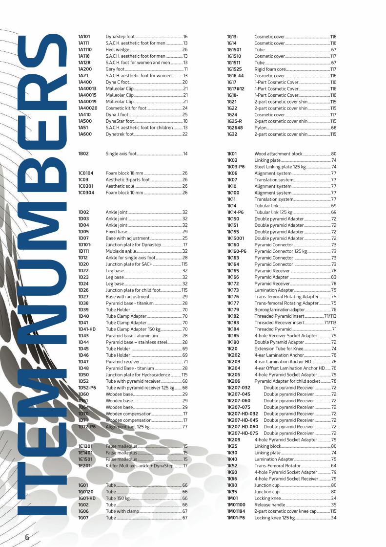
1A101 DynaStep foot............................................................... 161A111 S.A.C.H. aesthetic foot for men ...................... 131A1110 Heel wedge .....................................................................261A118 S.A.C.H. aesthetic foot for men ...................... 131A128 S.A.C.H. foot for women and men ................ 131A200 Gery foot ............................................................................. 111A21 S.A.C.H. aesthetic foot for women .............. 131A400 Dyna C foot .....................................................................201A40013 Malleolar Clip ................................................................211A40015 Malleolar Clip ................................................................211A40019 Malleolar Clip ................................................................211A40020 Cosmetic kit for foot ..............................................241A410 Dyna J foot ......................................................................251A500 DynaStar foot................................................................ 181A51 S.A.C.H. aesthetic foot for children ............. 131A600 Dynatrek foot ...............................................................22
1B02 Single axis foot ............................................................14
1C0104 Foam block 18 mm ..................................................261C03 Aesthetic 3-parts foot ..........................................261C0301 Aesthetic sole ..............................................................261C0304 Foam block 10 mm ..................................................26
1D02 Ankle joint .......................................................................321D03 Ankle joint .......................................................................321D04 Ankle joint .......................................................................321D05 Fixed base .......................................................................291D07 Base with adjustment ..........................................251D101- Junction plate for Dynastep ............................ 171D111 Multiaxis ankle ............................................................321D12 Ankle for single axis foot ..................................281D20 Junction plate for SACH .....................................1151D22 Leg base ............................................................................321D23 Leg base ............................................................................321D24 Leg base ............................................................................321D26 Junction plate for child foot ...........................1151D27 Base with adjustment ..........................................291D38 Pyramid base - titanium .....................................281D39 Tube Holder ..................................................................701D40 Tube Clamp Adapter ..............................................701D41 Tube Clamp Adapter ..............................................701D41-HD Tube Clamp Adapter 150 kg ............................701D43 Pyramid base - aluminium ...............................281D44 Pyramid base – stainless steel ...................281D45 Tube Holder ..................................................................691D46 Tube Holder ..................................................................691D47 Pyramid receiver ........................................................ 711D48 Pyramid Base - titanium ....................................281D50 Junction plate for Hydracadence ..............1151D52 Tube with pyramid receiver ............................681D52-P6 Tube with pyramid receiver 125 kg..........681D60 Wooden base ................................................................291D61 Wooden base ................................................................291D64 Wooden base ................................................................291D70 Wooden compensation......................................... 171D71 Wooden compensation......................................... 171D72-P6 Alignment tool 125 kg ..........................................77
1E1301 False malleolus ........................................................... 151E1401 False malleolus ........................................................... 151E1501 False malleolus ........................................................... 151E201- Kit for Multiaxis ankle + DynaStep ............ 17
1G01 Tube ......................................................................................661G0120 Tube ......................................................................................661G01-HD Tube 150 kg ....................................................................661G02 Tube ......................................................................................661G06 Tube with clamp ........................................................671G07 Tube ......................................................................................67
1G13- Cosmetic cover ...........................................................1161G14 Cosmetic cover ...........................................................1161G1501 Tube ......................................................................................671G1510 Cosmetic cover ...........................................................1171G1511 Tube ......................................................................................671G1525 Rigid foam core..........................................................1171G16-44 Cosmetic cover ...........................................................1161G17 1-Part Cosmetic Cover .........................................1161G17#12 1-Part Cosmetic Cover .........................................1161G18- 1-Part Cosmetic Cover .........................................1161G21 2-part cosmetic cover shin .............................1151G22 2-part cosmetic cover shin .............................1151G24 Cosmetic cover ...........................................................1171G25-R 2-part cosmetic cover shin .............................1151G2648 Pylon ....................................................................................681G32 2-part cosmetic cover shin .............................115
1K01 Wood attachment block .....................................801K03 Linking plate ................................................................. 741K03-P6 Steel Linking plate 125 kg ................................ 741K06 Alignment system ...................................................771K07 Translation system.................................................771K10 Alignment system ...................................................771K100 Alignment system ...................................................771K11 Translation system.................................................771K14 Tubular link ....................................................................691K14-P6 Tubular link 125 kg ..................................................691K150 Double pyramid Adapter ...................................721K151 Double pyramid Adapter ...................................721K155 Double pyramid Adapter ...................................721K15001 Double pyramid Adapter ...................................721K160 Pyramid Connector ................................................. 731K160-P6 Pyramid Connector 125 kg............................... 731K163 Pyramid Connector ............................................... 731K164 Pyramid Connector ............................................... 731K165 Pyramid Receiver ....................................................781K166 Pyramid Adapter .....................................................831K172 Pyramid Receiver .....................................................781K173 Lamination Adapter ................................................751K176 Trans-femoral Rotating Adapter ...............751K177 Trans-femoral Rotating Adapter ...............751K179 3-prong lamination adaptor ..................................761K182 Threaded Pyramid insert .........................71/1131K183 Threaded Receiver insert .........................71/1131K184 Threaded Pyramid .................................................... 711K185 4-hole Receiver Socket Adapter .................791K190 Double Pyramid Adapter ..................................721K20 Extension Tube for Knee.................................... 741K202 4-ear Lamination Anchor...................................761K203 4-ear Lamination Anchor HD .........................761K204 4-ear Offset Lamination Anchor HD .......761K205 4-hole Pyramid Socket Adapter .................791K206 Pyramid Adapter for child socket .............781K207-032 Double pyramid Receiver .....................721K207-045 Double pyramid Receiver .....................721K207-060 Double pyramid Receiver .....................721K207-075 Double pyramid Receiver .....................721K207-HD-032 Double pyramid Receiver .....................721K207-HD-045 Double pyramid Receiver .....................721K207-HD-060 Double pyramid Receiver .....................721K207-HD-075 Double pyramid Receiver .....................721K209 4-hole Pyramid Socket Adapter .................791K25 Linking block.................................................................801K30 Linking plate ................................................................. 741K40 Lamination Adapter ................................................751K52 Trans-Femoral Rotator .......................................641K60 4-hole Pyramid Socket Adapter .................791K66 4-hole Pyramid Socket Receiver ................791K90 Junction cup ...................................................................801K95 Junction cup ...................................................................801M01 Locking knee .................................................................341M01100 Release handle ...........................................................351M01194 2-part cosmetic cover knee cap .................1151M01-P6 Locking knee 125 kg ...............................................34IT
EM N
UM
BER
S
7
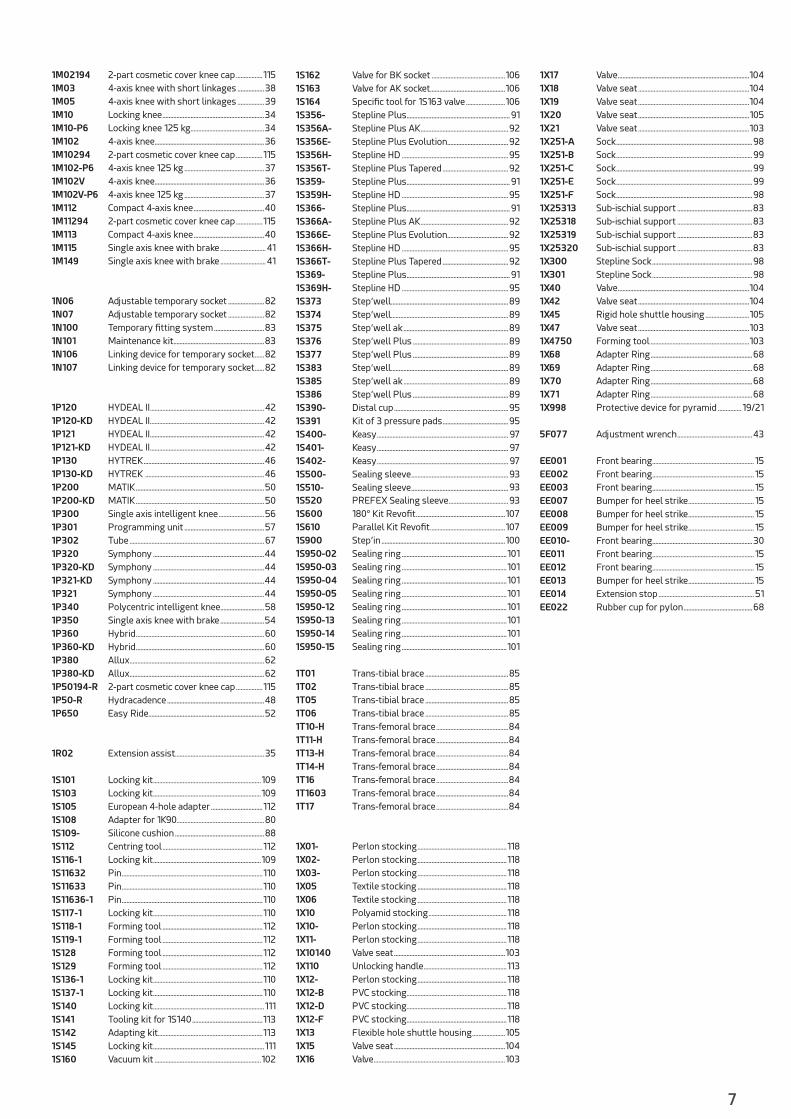
1M02194 2-part cosmetic cover knee cap .................1151M03 4-axis knee with short linkages .................381M05 4-axis knee with short linkages .................391M10 Locking knee .................................................................341M10-P6 Locking knee 125 kg ...............................................341M102 4-axis knee......................................................................361M10294 2-part cosmetic cover knee cap .................1151M102-P6 4-axis knee 125 kg ...................................................371M102V 4-axis knee......................................................................361M102V-P6 4-axis knee 125 kg ...................................................371M112 Compact 4-axis knee .............................................401M11294 2-part cosmetic cover knee cap .................1151M113 Compact 4-axis knee .............................................401M115 Single axis knee with brake .............................411M149 Single axis knee with brake .............................41
1N06 Adjustable temporary socket .......................821N07 Adjustable temporary socket .......................821N100 Temporary fitting system ................................831N101 Maintenance kit ..........................................................831N106 Linking device for temporary socket ......821N107 Linking device for temporary socket ......82
1P120 HYDEAL II .........................................................................421P120-KD HYDEAL II .........................................................................421P121 HYDEAL II .........................................................................421P121-KD HYDEAL II .........................................................................421P130 HYTREK .............................................................................461P130-KD HYTREK ............................................................................461P200 MATIK ..................................................................................501P200-KD MATIK ..................................................................................501P300 Single axis intelligent knee .............................561P301 Programming unit ...................................................571P302 Tube ......................................................................................671P320 Symphony .......................................................................441P320-KD Symphony .......................................................................441P321-KD Symphony .......................................................................441P321 Symphony .......................................................................441P340 Polycentric intelligent knee ............................581P350 Single axis knee with brake ............................541P360 Hybrid ..................................................................................601P360-KD Hybrid ..................................................................................601P380 Allux ......................................................................................621P380-KD Allux ......................................................................................621P50194-R 2-part cosmetic cover knee cap .................1151P50-R Hydracadence ..............................................................481P650 Easy Ride..........................................................................52
1R02 Extension assist.........................................................35
1S101 Locking kit .....................................................................1091S103 Locking kit .....................................................................1091S105 European 4-hole adapter .................................1121S108 Adapter for 1K90........................................................801S109- Silicone cushion .........................................................881S112 Centring tool ................................................................1121S116-1 Locking kit .....................................................................1091S11632 Pin ..........................................................................................1101S11633 Pin ..........................................................................................1101S11636-1 Pin ..........................................................................................1101S117-1 Locking kit ......................................................................1101S118-1 Forming tool ................................................................1121S119-1 Forming tool ................................................................1121S128 Forming tool ................................................................1121S129 Forming tool ................................................................1121S136-1 Locking kit ......................................................................1101S137-1 Locking kit ......................................................................1101S140 Locking kit .......................................................................1111S141 Tooling kit for 1S140 .............................................1131S142 Adapting kit...................................................................1131S145 Locking kit .......................................................................1111S160 Vacuum kit ....................................................................102
1S162 Valve for BK socket ...............................................1061S163 Valve for AK socket................................................1061S164 Specific tool for 1S163 valve .........................1061S356- Stepline Plus .................................................................. 911S356A- Stepline Plus AK ........................................................921S356E- Stepline Plus Evolution .......................................921S356H- Stepline HD ....................................................................951S356T- Stepline Plus Tapered ..........................................921S359- Stepline Plus .................................................................. 911S359H- Stepline HD ....................................................................951S366- Stepline Plus .................................................................. 911S366A- Stepline Plus AK ........................................................921S366E- Stepline Plus Evolution .......................................921S366H- Stepline HD ....................................................................951S366T- Stepline Plus Tapered ..........................................921S369- Stepline Plus .................................................................. 911S369H- Stepline HD ....................................................................951S373 Step’well ...........................................................................891S374 Step’well ...........................................................................891S375 Step’well ak ...................................................................891S376 Step’well Plus .............................................................891S377 Step’well Plus .............................................................891S383 Step’well ...........................................................................891S385 Step’well ak ...................................................................891S386 Step’well Plus .............................................................891S390- Distal cup .........................................................................951S391 Kit of 3 pressure pads ..........................................951S400- Keasy .................................................................................... 971S401- Keasy .................................................................................... 971S402- Keasy .................................................................................... 971S500- Sealing sleeve ..............................................................931S510- Sealing sleeve ..............................................................931S520 PREFEX Sealing sleeve ......................................931S600 180° Kit Revofit .........................................................1071S610 Parallel Kit Revofit ................................................1071S900 Step’in ...............................................................................1001S950-02 Sealing ring ...................................................................1011S950-03 Sealing ring ...................................................................1011S950-04 Sealing ring ...................................................................1011S950-05 Sealing ring ...................................................................1011S950-12 Sealing ring ...................................................................1011S950-13 Sealing ring ...................................................................1011S950-14 Sealing ring ...................................................................1011S950-15 Sealing ring ...................................................................101
1T01 Trans-tibial brace .....................................................851T02 Trans-tibial brace .....................................................851T05 Trans-tibial brace .....................................................851T06 Trans-tibial brace .....................................................851T10-H Trans-femoral brace ..............................................841T11-H Trans-femoral brace ..............................................841T13-H Trans-femoral brace ..............................................841T14-H Trans-femoral brace ..............................................841T16 Trans-femoral brace ..............................................841T1603 Trans-femoral brace ..............................................841T17 Trans-femoral brace ..............................................84
1X01- Perlon stocking .........................................................1181X02- Perlon stocking .........................................................1181X03- Perlon stocking .........................................................1181X05 Textile stocking .........................................................1181X06 Textile stocking .........................................................1181X10 Polyamid stocking ..................................................1181X10- Perlon stocking .........................................................1181X11- Perlon stocking .........................................................1181X10140 Valve seat .......................................................................1031X110 Unlocking handle .....................................................1131X12- Perlon stocking .........................................................1181X12-B PVC stocking................................................................1181X12-D PVC stocking................................................................1181X12-F PVC stocking................................................................1181X13 Flexible hole shuttle housing .....................1051X15 Valve seat .......................................................................1041X16 Valve ....................................................................................103
1X17 Valve ....................................................................................1041X18 Valve seat .......................................................................1041X19 Valve seat .......................................................................1041X20 Valve seat .......................................................................1051X21 Valve seat .......................................................................1031X251-A Sock .......................................................................................981X251-B Sock .......................................................................................991X251-C Sock .......................................................................................991X251-E Sock .......................................................................................991X251-F Sock .......................................................................................981X25313 Sub-ischial support ................................................831X25318 Sub-ischial support ................................................831X25319 Sub-ischial support ................................................831X25320 Sub-ischial support ................................................831X300 Stepline Sock ................................................................981X301 Stepline Sock ................................................................981X40 Valve ....................................................................................1041X42 Valve seat .......................................................................1041X45 Rigid hole shuttle housing ............................1051X47 Valve seat .......................................................................1031X4750 Forming tool ...............................................................1031X68 Adapter Ring .................................................................681X69 Adapter Ring .................................................................681X70 Adapter Ring .................................................................681X71 Adapter Ring .................................................................681X998 Protective device for pyramid ............... 19/21
5F077 Adjustment wrench ................................................43
EE001 Front bearing ................................................................. 15EE002 Front bearing ................................................................. 15EE003 Front bearing ................................................................. 15EE007 Bumper for heel strike .......................................... 15EE008 Bumper for heel strike .......................................... 15EE009 Bumper for heel strike .......................................... 15EE010- Front bearing ................................................................30EE011 Front bearing ................................................................. 15EE012 Front bearing ................................................................. 15EE013 Bumper for heel strike .......................................... 15EE014 Extension stop ............................................................. 51EE022 Rubber cup for pylon ............................................68
8
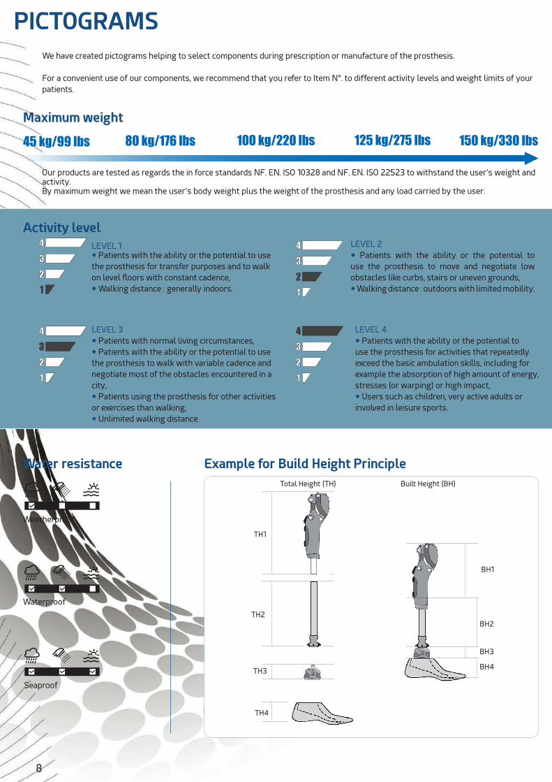
We have created pictograms helping to select components during prescription or manufacture of the prosthesis.
For a convenient use of our components, we recommend that you refer to Item N°. to different activity levels and weight limits of your patients.
1234
1234
1234
1234
PICTOGRAMS
45 kg/99 lbs 80 kg/176 lbs 100 kg/220 lbs 125 kg/275 lbs 150 kg/330 lbs
Water resistance
Activity level
Maximum weight
Our products are tested as regards the in force standards NF. EN. ISO 10328 and NF. EN. ISO 22523 to withstand the user’s weight and activity.By maximum weight we mean the user’s body weight plus the weight of the prosthesis and any load carried by the user.
LEVEL 4
• Patients with the ability or the potential to use the prosthesis for activities that repeatedly exceed the basic ambulation skills, including for example the absorption of high amount of energy, stresses (or warping) or high impact,
• Users such as children, very active adults or involved in leisure sports.
LEVEL 1• Patients with the ability or the potential to use the prosthesis for transfer purposes and to walk on level floors with constant cadence,
• Walking distance : generally indoors.
LEVEL 2
• Patients with the ability or the potential to use the prosthesis to move and negotiate low obstacles like curbs, stairs or uneven grounds,
• Walking distance : outdoors with limited mobility.
LEVEL 3
• Patients with normal living circumstances,
• Patients with the ability or the potential to use the prosthesis to walk with variable cadence and negotiate most of the obstacles encountered in a city,
• Patients using the prosthesis for other activities or exercises than walking,
• Unlimited walking distance.
Weatherproof
Waterproof
Seaproof
Example for Build Height Principle
TH2BH2
Built Height (BH)Total Height (TH)
TH3
BH3
TH4
BH4
TH1
BH1
CHA
PTE
RS
9
FOO
TA
NK
LEK
NEE
AD
AP
TER
SOCK
ETLI
NER
COSM
ETIC
CO
VER
CHAPTERS
This catalogue can be downloaded on our website :
www.orthopaedics.proteor.com
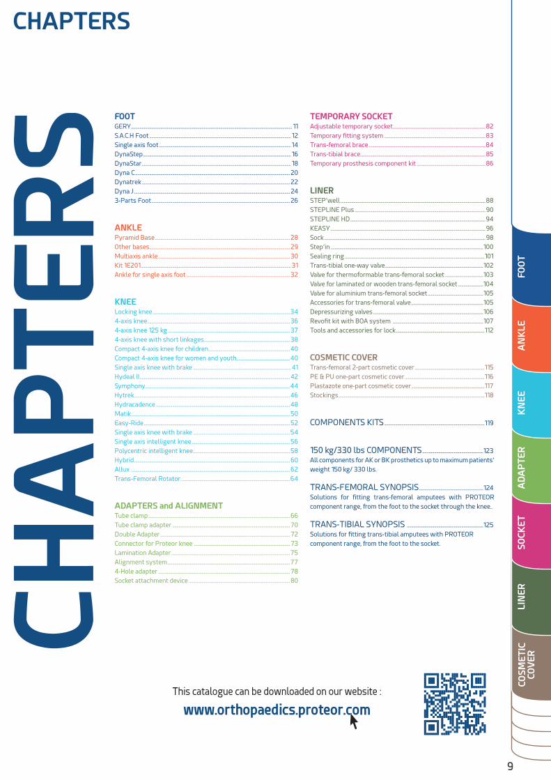
FOOTGERY .................................................................................................................................................... 11S.A.C.H Foot .................................................................................................................................. 12Single axis foot .........................................................................................................................14DynaStep ........................................................................................................................................ 16DynaStar ......................................................................................................................................... 18Dyna C ..............................................................................................................................................20Dynatrek ........................................................................................................................................22Dyna J ...............................................................................................................................................243-Parts Foot ...............................................................................................................................26
ANKLEPyramid Base ............................................................................................................................28Other bases .................................................................................................................................29Multiaxis ankle .........................................................................................................................30Kit 1E201 ..........................................................................................................................................31Ankle for single axis foot ...............................................................................................32
KNEELocking knee ..............................................................................................................................344-axis knee ...................................................................................................................................36 4-axis knee 125 kg ................................................................................................................374-axis knee with short linkages ...............................................................................38Compact 4-axis knee for children ...........................................................................40Compact 4-axis knee for women and youth .................................................40Single axis knee with brake ..........................................................................................41Hydeal II ..........................................................................................................................................42Symphony.....................................................................................................................................44Hytrek ...............................................................................................................................................46Hydracadence ...........................................................................................................................48Matik..................................................................................................................................................50Easy-Ride ......................................................................................................................................52Single axis knee with brake .........................................................................................54Single axis intelligent knee ..........................................................................................56Polycentric intelligent knee .........................................................................................58Hybrid ...............................................................................................................................................60Allux ..................................................................................................................................................62Trans-Femoral Rotator ....................................................................................................64
ADAPTERS and ALIGNMENTTube clamp ..................................................................................................................................66Tube clamp adapter ............................................................................................................70Double Adapter .......................................................................................................................72Connector for Proteor knee ........................................................................................73Lamination Adapter .............................................................................................................75Alignment system ................................................................................................................774-Hole adapter .........................................................................................................................78Socket attachment device .............................................................................................80
TEMPORARY SOCKETAdjustable temporary socket .....................................................................................82Temporary fitting system .............................................................................................83Trans-femoral brace ...........................................................................................................84Trans-tibial brace...................................................................................................................85Temporary prosthesis component kit ...............................................................86
LINERSTEP’well .....................................................................................................................................88STEPLINE Plus ........................................................................................................................90STEPLINE HD ............................................................................................................................94KEASY ..............................................................................................................................................96Sock ....................................................................................................................................................98Step’in ............................................................................................................................................100Sealing ring ................................................................................................................................101Trans-tibial one-way valve ..........................................................................................102Valve for thermoformable trans-femoral socket ...................................103Valve for laminated or wooden trans-femoral socket .......................104Valve for aluminium trans-femoral socket ...................................................105Accessories for trans-femoral valve ..................................................................105Depressurizing valves .....................................................................................................106Revofit kit with BOA system ...................................................................................107Tools and accessories for lock .................................................................................112
COSMETIC COVERTrans-femoral 2-part cosmetic cover ................................................................115PE & PU one-part cosmetic cover .........................................................................116Plastazote one-part cosmetic cover ...................................................................117Stockings ......................................................................................................................................118
COMPONENTS KITS ............................................................................................119
150 kg/330 lbs COMPONENTS ........................................................123All components for AK or BK prosthetics up to maximum patients’ weight 150 kg/ 330 lbs.
TRANS-FEMORAL SYNOPSIS ...........................................................124Solutions for fitting trans-femoral amputees with PROTEOR component range, from the foot to the socket through the knee..
TRANS-TIBIAL SYNOPSIS ......................................................................125Solutions for fitting trans-tibial amputees with PROTEOR component range, from the foot to the socket.
CHA
PTE
RS

10
FOOT
FOO
T

11
GER
Y
1234
150 kg/330 lbs
Item N°. Color Side Size (cm) Shell MaterialMax. Patient's
Weight.
1A200 (H) Caucasian -G / -D 22 to 29 EVA 150 kg
1A200 (B) Ebony -G / -D22 to 25
EVA100 kg
26 to 29 125 kg
• GERY foot is specially designed to increase patients’ independence with limited mobility (geriatric or artheritic).
• 30 % lighter than a SACH foot : its pyramid base is integrated in its EVA foot shell with closed cells.
• The flexibility of its EVA structure reduces strains on the residual limb and absorbs shocks caused by slightly uneven grounds.
• During walking or transfer the core of the GERY foot allows the patient to reach dorsiflexion very easily without having to raise the heel, which increases the leg segment angle and makes step completion easier.
• Easy to clean, resistant to water and damp heat.
Can be used as a bath prosthesis.
Example of item N° for a GERY foot, skin color, left side, size 26 : 1A200-G26H Foot weight, Adapter included, size 25 : 350 g
1A20
0
SACH GERY
Leg segment angle during walking
100 mm 82 mm
10 mm
MODÈLE DÉPOSÉ
PATENTED
BREVETÉ
Available in ebony color (up to 125kg)
GER
IATR
IC
12
S.A.C.H. FOOTSO
LID
AN
KLE
CU
SHIO
N H
EEL
1234
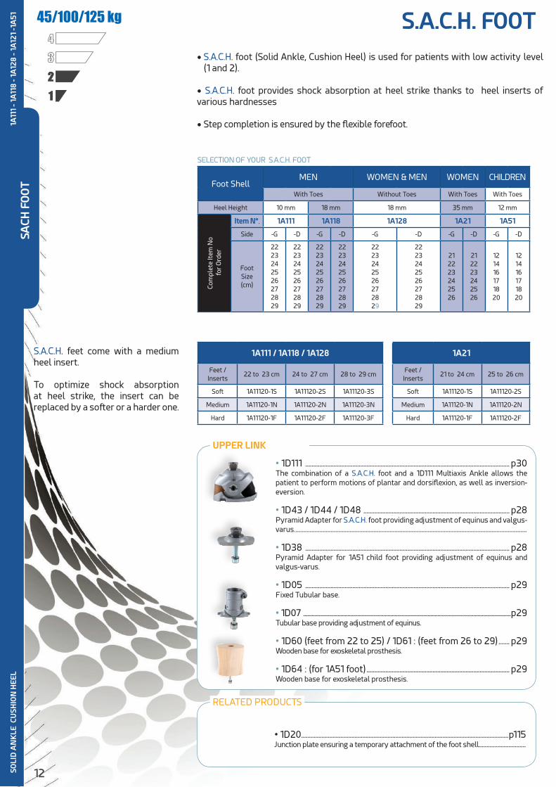
45/100/125 kg
Foot ShellMEN WOMEN & MEN WOMEN CHILDREN
With Toes Without Toes With Toes With Toes
Heel Height 10 mm 18 mm 18 mm 35 mm 12 mmCo
mpl
ete
Item
No
for
Ord
erItem N°. 1A111 1A118 1A128 1A21 1A51
Side -G -D -G -D -G -D -G -D -G -D
Foot Size (cm)
2223242526272829
2223242526272829
2223242526272829
2223242526272829
2223242526272829
2223242526272829
212223242526
212223242526
121416171820
121416171820
1A111 / 1A118 / 1A128
Feet /Inserts
22 to 23 cm 24 to 27 cm 28 to 29 cm
Soft 1A11120-1S 1A11120-2S 1A11120-3S
Medium 1A11120-1N 1A11120-2N 1A11120-3N
Hard 1A11120-1F 1A11120-2F 1A11120-3F
1A21
Feet /Inserts
21 to 24 cm 25 to 26 cm
Soft 1A11120-1S 1A11120-2S
Medium 1A11120-1N 1A11120-2N
Hard 1A11120-1F 1A11120-2F
• 1D111 .................................................................................................................................. p30The combination of a S.A.C.H. foot and a 1D111 Multiaxis Ankle allows the patient to perform motions of plantar and dorsiflexion, as well as inversion-eversion.
• 1D43 / 1D44 / 1D48 ............................................................................................. p28Pyramid Adapter for S.A.C.H. foot providing adjustment of equinus and valgus-varus. ........................................................................................................................................................................................
• 1D38 .................................................................................................................................. p28Pyramid Adapter for 1A51 child foot providing adjustment of equinus and valgus-varus.
• 1D05 .................................................................................................................................. p29Fixed Tubular base.
• 1D07 ......................................................................................................................................................p29Tubular base providing adjustment of equinus.
• 1D60 (feet from 22 to 25) / 1D61 : (feet from 26 to 29) ....... p29Wooden base for exoskeletal prosthesis.
• 1D64 : (for 1A51 foot) ........................................................................................... p29Wooden base for exoskeletal prosthesis.
• 1D20 ....................................................................................................................................p115Junction plate ensuring a temporary attachment of the foot shell ..............................
• S.A.C.H. foot (Solid Ankle, Cushion Heel) is used for patients with low activity level (1 and 2).
• S.A.C.H. foot provides shock absorption at heel strike thanks to heel inserts of various hardnesses
• Step completion is ensured by the flexible forefoot.
S.A.C.H. feet come with a medium heel insert.
To optimize shock absorption at heel strike, the insert can be replaced by a softer or a harder one.
SELECTION OF YOUR S.A.C.H. FOOT
1A11
1 - 1
A11
8 - 1
A12
8 - 1
A12
1 -1
A51
SACH
FO
OT
UPPER LINK
RELATED PRODUCTS

13
Item N°. Side Size (cm)Max. Patient’s
Weight
1A111 -G / -D 22 to 25 100 kg1A111 -G / -D 26 to 29 125 kg
Approximate weight for Size 25 : 390 g
1A111 - Aesthetic Foot for Men, Sandal-Toe Heel height : 10 mm
Item N°. Side Size (cm)Max. Patient’s
Weight
1A118 -G / -D 22 to 29 100 kgApproximate weight for Size 25 : 410 g
1A118 - Aesthetic Foot for Men, Sandal-ToeHeel height : 18 mm
Item N°. Side Size (cm)Max. Patient’s
Weight
1A128 -G / -D 22 to 29 100 kgApproximate weight for Size 25 : 455 g
1A128 - Foot for Men and Women, without toesHeel height : 18 mm
Item N°. Side Size (cm)Max. Patient’s
Weight
1A21 -G / -D 21 to 26 100 kgApproximate weight for Size 22 : 415 g
1A21 - Aesthetic Foot for Women Heel height : 35 mm
Item N°. Side Size (cm)Max. Patient’s
Weight
1A51 -G / -D12 / 14 / 1617 / 18 / 20 45 kg
Approximate weight for Size 14 : 130 g
1A51 - Aesthetic Foot for Children Heel height : 12 mm
SOLI
D A
NK
LE C
USH
ION
HEE
L1A
111
- 1A
118
- 1A
128
- 1A
121
-1A
51
SACH
FO
OT
14
MIX
TE
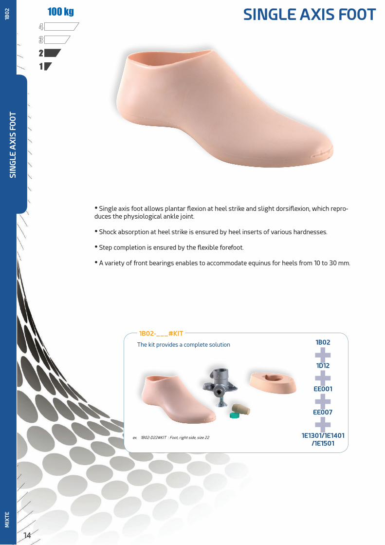
1234
100 kg
• Single axis foot allows plantar flexion at heel strike and slight dorsiflexion, which repro-duces the physiological ankle joint.
• Shock absorption at heel strike is ensured by heel inserts of various hardnesses.
• Step completion is ensured by the flexible forefoot.
• A variety of front bearings enables to accommodate equinus for heels from 10 to 30 mm.
1B02-___#KIT
The kit provides a complete solution 1B02
1D12
EE001
EE007
1E1301/1E1401/1E1501
++++
ex. 1B02-D22#KIT : Foot, right side, size 22
1B0
2SI
NG
LE A
XIS
FO
OT
SINGLE AXIS FOOT
15
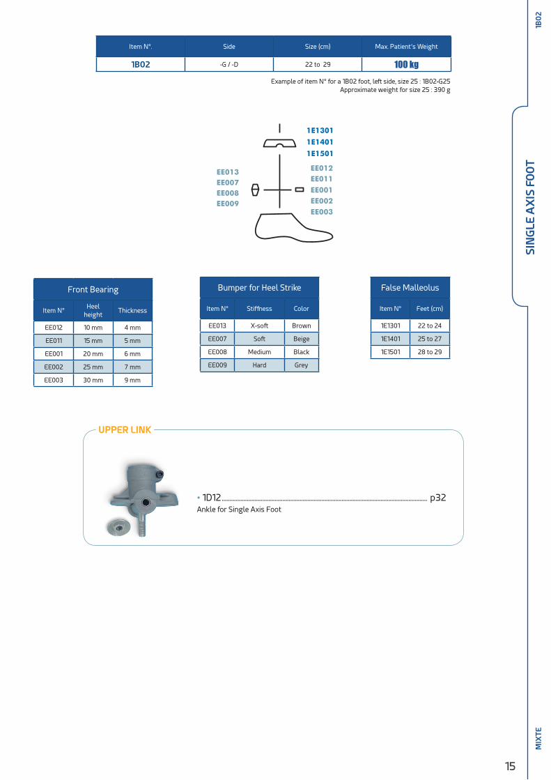
UPPER LINK
Front Bearing
Item N°Heel
heightThickness
EE012 10 mm 4 mm
EE011 15 mm 5 mm
EE001 20 mm 6 mm
EE002 25 mm 7 mm
EE003 30 mm 9 mm
False Malleolus
Item N° Feet (cm)
1E1301 22 to 24
1E1401 25 to 27
1E1501 28 to 29
Bumper for Heel Strike
Item N° Stiffness Color
EE013 X-soft Brown
EE007 Soft Beige
EE008 Medium Black
EE009 Hard Grey
Item N°. Side Size (cm) Max. Patient’s Weight
1B02 -G / -D 22 to 29 100 kg
MIX
TE
• 1D12 .................................................................................................................................... p32Ankle for Single Axis Foot
1D12
1E13011E14011E1501
EE001EE011EE012
EE002EE003
EE013EE007EE008EE009
1B02
Example of item N° for a 1B02 foot, left side, size 25 : 1B02-G25Approximate weight for size 25 : 390 g
1B0
2SI
NG
LE A
XIS
FO
OT
16
123480/100 kg
1A10
1EN
ERG
Y R
ETU
RN
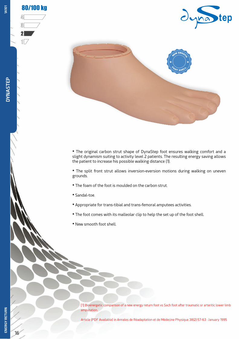
• The original carbon strut shape of DynaStep foot ensures walking comfort and a slight dynamism suiting to activity level 2 patients. The resulting energy saving allows the patient to increase his possible walking distance (1).
• The split front strut allows inversion-eversion motions during walking on uneven grounds.
• The foam of the foot is moulded on the carbon strut.
• Sandal-toe.
• Appropriate for trans-tibial and trans-femoral amputees activities.
• The foot comes with its malleolar clip to help the set up of the foot shell.
• New smooth foot shell.
[1] Bioenergetic comparison of a new energy return foot vs Sach foot after traumatic or arteritic lower limb
amputation.
Article (PDF Available) in Annales de Réadaptation et de Médecine Physique 38(2):57-63 · January 1995
DYN
AST
EP
17
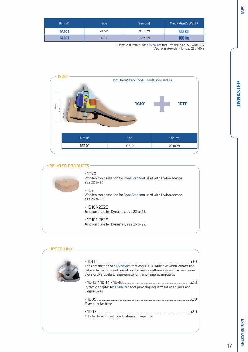
Item N°. Side Size (cm) Max. Patient’s Weight
1A101 -G / -D 22 to 25 80 kg1A101 -G / -D 26 to 29 100 kg
1A10
1EN
ERG
Y R
ETU
RN
Example of item N° for a DynaStep foot, left side, size 25 : 1A101-G25Approximate weight for size 25 : 440 g
Item N°. Side Size (cm)
1E201 -G / -D 22 to 29
1E201
1A101 1D111+Kit DynaStep Foot + Multiaxis Ankle
96 m
m
70 m
m
43
mm
UPPER LINK
• 1D70 Wooden compensation for DynaStep foot used with Hydracadence, size 22 to 25
• 1D71Wooden compensation for DynaStep foot used with Hydracadence, size 26 to 29
• 1D101-2225Junction plate for Dynastep, size 22 to 25.
• 1D101-2629Junction plate for Dynastep, size 26 to 29.
RELATED PRODUCTS
DYN
AST
EP
• 1D111 .................................................................................................................................. p30The combination of a DynaStep foot and a 1D111 Multiaxis Ankle allows the patient to perform motions of plantar and dorsiflexion, as well as inversion-eversion. Particularly appropriate for trans-femoral amputees
• 1D43 / 1D44 / 1D48 ............................................................................................. p28Pyramid adapter for DynaStep foot providing adjustment of equinus and valgus-varus.
• 1D05 .................................................................................................................................... p29Fixed tubular base.
• 1D07 .................................................................................................................................... p29Tubular base providing adjustment of equinus.

18
Item N°. Side Size (cm) Color
1A40020 -G / -D 22 to 29 Caucasian
1A40020B -G / -D 22 to 29 Ebony
1A40020 / 1A40020 B (brown foot shell) Replacement Cosmetic Kit includes a mal-leolar clip and a technical fiber sock
PU Link
• A flexible joint made of high performance PU provides the link between the heel keel
and the long strut of the DynaStar foot.
• Carbon composite upper strut, aluminium lower heel keel.
• The combination of the PU link and the carbon fiber strut absorbs foot rotation at heel
strike. The flexible shock absorption provides a rapid flat foot during walking.
• The PU link and the carbon composite strut split in the forefoot make inversion-ever-
sion easier.
• Lateral stability due to the large bearing surface at the fore-foot : width is close to a
sound foot.
• The split plantar keel provides inversion/eversion that accommodates uneven grounds
more easily.
• Delivered fitted in its foot shell with a protective sock and a malleolar clip.
1A50
0
MODÈLE DÉPOSÉ
PATENTED
BREVETÉ
Foot shell weight (Size 25) : 198g
DYN
AST
AR
ENER
GY
RET
UR
N
ADJUSTMENTS & TECHNICAL POINTS
• Heel adjustment range :from 0 to 20 mm
• Polyurethane link designed to withstand the highest strains.
• A rear flexion stop ensures foot protection and safety under extreme conditions of use
OVERALL DIMENSIONS
• Compact Ground-Pyramid height : 10,6 cm for size 25
125 kg
1234

19
Item N°. Modules Side Size (cm) TH* (mm) BH* (mm)
1A500 – ** 2 to 5 G / D 22 to 29 106 86
Module selection according to weight and activity
Activity / Weight 45 to 59 kg 60 to 79 kg 80 to 99 kg 100 to 125 kg
Moderate 2 2 3 4
Normal 2 3 4 5
High 3 4 5 -
Module available according to the foot size
Size (cm) / Module 2 3 4 5
22
23
24
25
26
27
28
29
** Example of item N° for a DynaStar foot, left side, size 25 : 1A500-3G25Foot weight for size 25 (foot shell not included) : 345 g
* TH and BH are measured with the foot shell (size 25)
1A40013 - Malleolar Clip - Size 22 to 251A40014 - Malleolar Clip - Size 26 to 271A40015 - Malleolar Clip - Size 28 to 29
1A50
0
1A40019 - Shoe-horn
1X998 - Protective Device for the Pyramid during trials
UPPER LINK
RELATED PRODUCTS
107
134
145
• 1K172 / 1K185 : 107 mm ..................................................... p78/79
• 1K202 / 1K203 : 134 mm .......................................................... p76
• 1K207-032 : 134 mm ................................................................... p72
• 1K207-045 : 147 mm.................................................................... p72
• 1K207-060 : 162 mm .................................................................... p72
• 1K207-075 : 177 mm. ................................................................... p72
• 1D40 / 1D41 / 1D45 / 1D46 : 142 mm................... p69/70D
YNA
STA
REN
ERG
Y R
ETU
RN
20
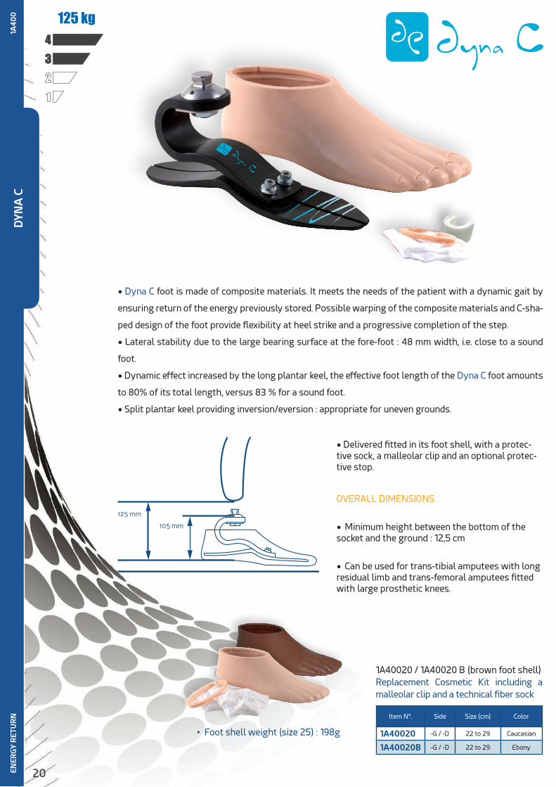
• Dyna C foot is made of composite materials. It meets the needs of the patient with a dynamic gait by
ensuring return of the energy previously stored. Possible warping of the composite materials and C-sha-
ped design of the foot provide flexibility at heel strike and a progressive completion of the step.
• Lateral stability due to the large bearing surface at the fore-foot : 48 mm width, i.e. close to a sound
foot.
• Dynamic effect increased by the long plantar keel, the effective foot length of the Dyna C foot amounts
to 80% of its total length, versus 83 % for a sound foot.
• Split plantar keel providing inversion/eversion : appropriate for uneven grounds.
1234
125 kg
• Delivered fitted in its foot shell, with a protec-tive sock, a malleolar clip and an optional protec-tive stop.
OVERALL DIMENSIONS
• Minimum height between the bottom of the socket and the ground : 12,5 cm
• Can be used for trans-tibial amputees with long residual limb and trans-femoral amputees fitted with large prosthetic knees.
1A4
00
• Foot shell weight (size 25) : 198g
DYN
A C
ENER
GY
RET
UR
N Item N°. Side Size (cm) Color
1A40020 -G / -D 22 to 29 Caucasian
1A40020B -G / -D 22 to 29 Ebony
1A40020 / 1A40020 B (brown foot shell)Replacement Cosmetic Kit including a malleolar clip and a technical fiber sock

21
RELATED PRODUCTS
Module selection according to weight and activity
Activity / Weight 50 to 60 kg 60 to 75 kg 75 to 90 kg 90 to 105 kg 105 to 125 kg
Moderate 1 1 2 3 4
Normal 1 2 3 4 5
High 2 3 4 5 -
1A4
00
Modules available according to the foot size
Size (cm) / Module 1 2 3 4 5
22
23
24
25
26
27
28
29
Example of item N° for a Dyna C foot, module 3, right side, size 25 : 1A400-3D25Approximative foot weight for size 25 (foot shell not included) : 420 g
* TH and BH are measured with the foot shell (size 25)
Item N°. Modules Side Size (cm) TH* (mm) BH* (mm)
1A400 – 1 to 5 G / D 22 to 29 120 105
UPPER LINK
• European 4-Hole Pattern 1K172 / 1K185 : 121 mm p78/79
• 4-ear Lamination Anchor & Double Adapter 1K202 or : • 1K203 with 1K207 .................................................................p72/76 • 1K207-032 : 150 mm. .....................................................................p72 • 1K207-045 : 163 mm......................................................................p72 • 1K207-060 : 178 mm. .....................................................................p72 • 1K207-075 : 193 mm. .....................................................................p72
• Tube Clamp Adapter191 mm. ...........................................p69/701D40 / 1D41 / 1D45 / 1D46 :
1A40013 - Malleolar Clip - Size 22 to 251A40014 - Malleolar Clip - Size 26 to 271A40015 - Malleolar Clip - Size 28 to 29
1A40019 - Shoe-horn
1X998 - Protective Device for the Pyramid during trials
DYN
A C
ENER
GY
RET
UR
N
22
DYN
ATR
EKEN
ERG
Y R
ETU
RN
1234
150 kg
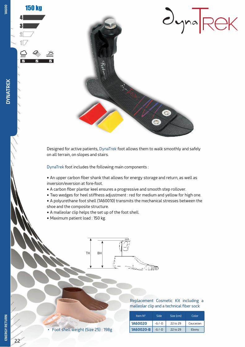
Designed for active patients, DynaTrek foot allows them to walk smoothly and safely on all terrain, on slopes and stairs.
DynaTrek foot includes the following main components :
• An upper carbon fiber shank that allows for energy storage and return, as well asinversion/eversion at fore-foot.
• A carbon fiber plantar keel ensures a progressive and smooth step rollover.
• Two wedges for heel stiffness adjustment : red for medium and yellow for high one.
• A polyurethane foot shell (1A60010) transmits the mechanical stresses between theshoe and the composite structure.
• A malleolar clip helps the set up of the foot shell.
• Maximum patient load : 150 kg.
1A60
0
• Foot shell weight (Size 25) : 198g
Item N°. Side Size (cm) Color
1A60020 -G / -D 22 to 29 Caucasian
1A60020-B -G / -D 22 to 29 Ebony
Replacement Cosmetic Kit including a malleolar clip and a technical fiber sock
TH BH

23
DYN
ATR
EKEN
ERG
Y R
ETU
RN
Item N°. Modules Side Size (cm) TH (mm) BH (mm)
1A600 - * 1 to 4 G / D 22 to 25 170 154
1A600 - * 1 to 6 G / D 26 to 30 180 164
Example of item N° for a DynaTrek foot, module 3, right side, size 25 : 1A600-3D25Approximative foot weight for size 25 (foot shell not included) : 400 g
Modules available according to the foot size
Size (cm) / Module 1 2 3 4 5 6
22
23
24
25
26
27
28
29
30
Module selection according to weight and activity
Activity / Weight 45 to 59 kg 60 to 74 kg 75 to 89 kg 90 to 104 kg 105 to 124 kg 125 to 150 kg
Normal 1 2 3 4 5 6
High 2 3 4 5 6 -
RELATED PRODUCTS
1A40013 - Malleolar Clip - Size 22 to 251A40014 - Malleolar Clip - Size 26 to 271A40015 - Malleolar Clip - Size 28 to 29
1A40019 - Shoe-horn
1X998 - Protective Device for the PyramidTo avoid spoiling the pyramid during trials
1A60
0
UPPER LINK
• European 4-Hole Pattern• 1K172 / 1K185 : 174/184 mm ..............................p78/79
• 4-ear Lamination Anchor & Double Adapter 1K202 or :• 1K203 with 1K207 .................................................................p72/76 • 1K207-032 : 206/216 mm ..........................................................p72 • 1K207-045 : 219/229 mm ..........................................................p72 • 1K207-060 : 234/244 mm. .......................................................p72 • 1K207-075 : 249/259 mm. ........................................................p72
• Tube Clamp adapter 191 mm. ..........................................p69/701D40 / 1D41 / 1D41HD / 1D45 / 1D46
Height according to the foot size 22-25 / 26-29

24
1234
100 kg
• Delivered in kit with a foot shell, a protective sock and a malleolar clip, adhesive, a bushing and screws.
• The foot can accurately suit the patients’ needs through optimization of height and alignment.
OVERALL DIMENSIONS
• Size between socket base and ground : 330 mm.
• Heel height adjustment : +5/+22 mm.
1A41
0
1A40020 / 1A40020 B (ebony foot shell)Replacement Cosmetic Kit including a mal-leolar clip and a technical fiber sock.
• Foot shell weight (Size 25) : 198g
Item N°. Side Size (cm)
1A40020 -G / -D 22 to 29
1A40020B -G / -D 22 to 29
DYN
A J
ENER
GY
RET
UR
N
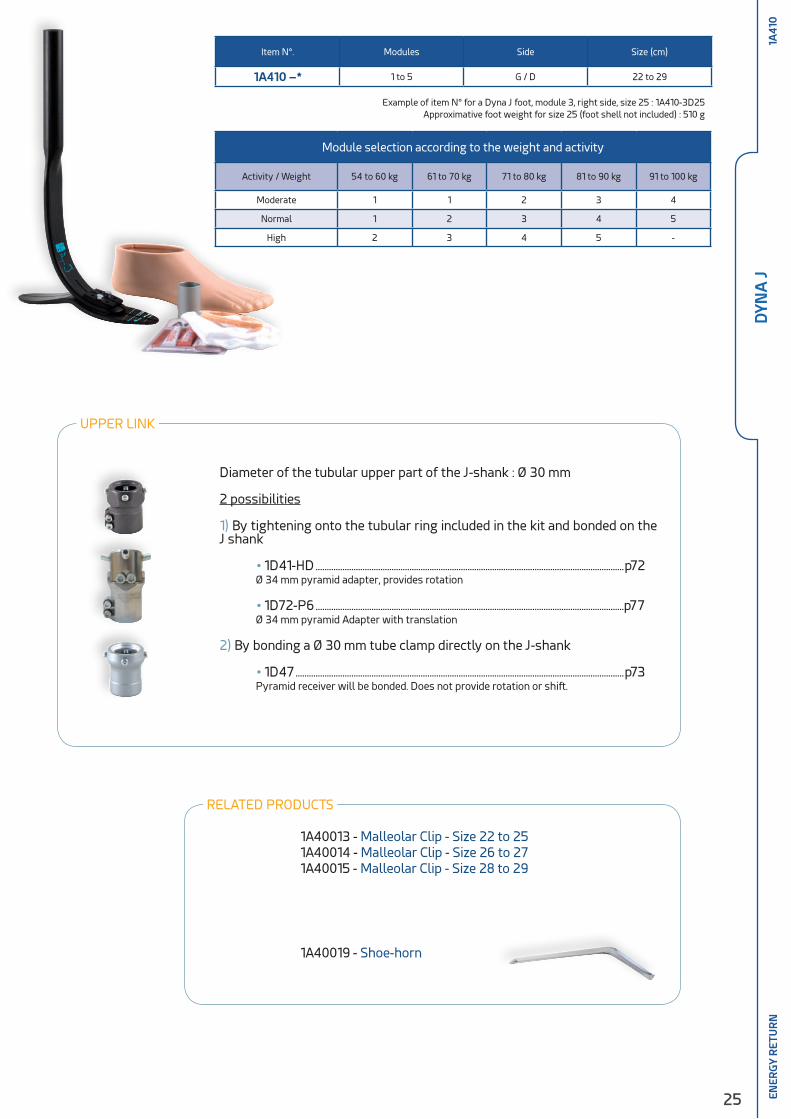
• Dyna J is an energy return foot specially designed for BK amputees with short stump.
• Carbon composite long blade coming in letter J shape.
• Thanks to its J shape and its upper adapters close to its distal part, Dyna J ensures an optimal distribution of the weight and reduces the strains in the socket.
• Lateral stability due to the large bearing surface at the fore-foot.
• Dynamic effect increased by the long plantar keel, the effective foot length of the
Dyna J foot amounts to 80% of its total length, versus 83 % for a sound foot.
• The split plantar keel provides inversion/eversion that accomodates uneven grounds.
25
RELATED PRODUCTS
Item N°. Modules Side Size (cm)
1A410 –* 1 to 5 G / D 22 to 29
Module selection according to the weight and activity
Activity / Weight 54 to 60 kg 61 to 70 kg 71 to 80 kg 81 to 90 kg 91 to 100 kg
Moderate 1 1 2 3 4
Normal 1 2 3 4 5
High 2 3 4 5 -
1A41
0
Example of item N° for a Dyna J foot, module 3, right side, size 25 : 1A410-3D25Approximative foot weight for size 25 (foot shell not included) : 510 g
UPPER LINK
Diameter of the tubular upper part of the J-shank : Ø 30 mm
2 possibilities
1) By tightening onto the tubular ring included in the kit and bonded on the J shank
• 1D41-HD ..........................................................................................................................................p72 Ø 34 mm pyramid adapter, provides rotation
• 1D72-P6 ..........................................................................................................................................p77 Ø 34 mm pyramid Adapter with translation
2) By bonding a Ø 30 mm tube clamp directly on the J-shank
• 1D47 ...................................................................................................................................................p73 Pyramid receiver will be bonded. Does not provide rotation or shift.
1A40013 - Malleolar Clip - Size 22 to 251A40014 - Malleolar Clip - Size 26 to 271A40015 - Malleolar Clip - Size 28 to 29
1A40019 - Shoe-horn
DYN
A J
ENER
GY
RET
UR
N
26
1234
1C0
3 3-PARTS FOOTEX
OSK
ELET
AL
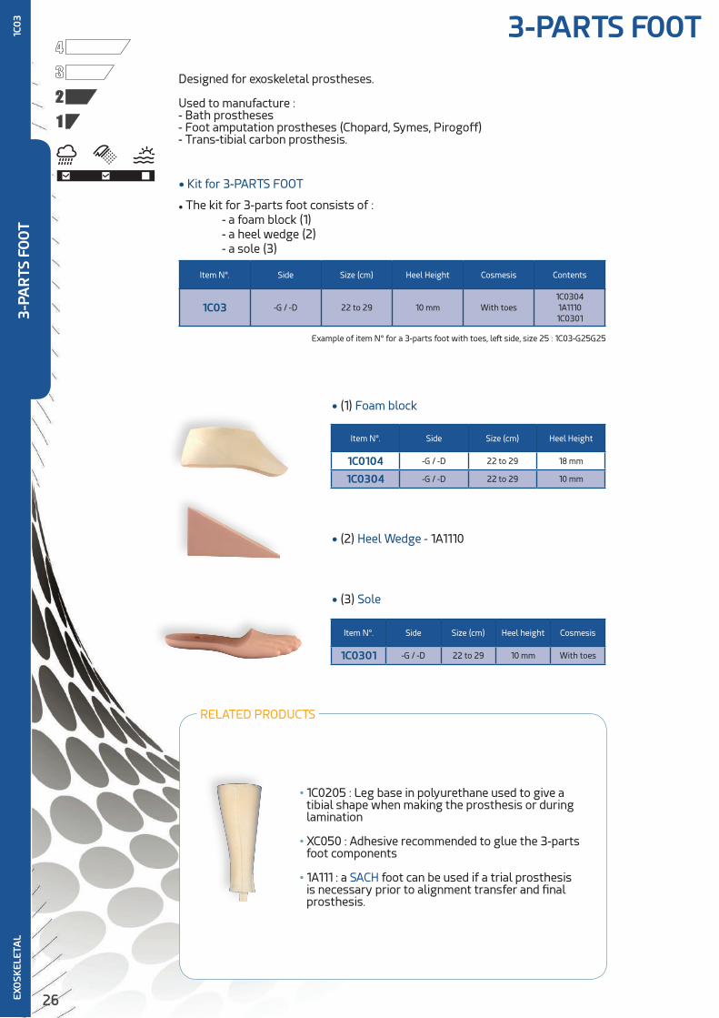
• (3) Sole
Item N°. Side Size (cm) Heel height Cosmesis
1C0301 -G / -D 22 to 29 10 mm With toes
RELATED PRODUCTS
• 1C0205 : Leg base in polyurethane used to give a tibial shape when making the prosthesis or during lamination
• XC050 : Adhesive recommended to glue the 3-parts foot components
• 1A111 : a SACH foot can be used if a trial prosthesis is necessary prior to alignment transfer and final prosthesis.
• (1) Foam block
Item N°. Side Size (cm) Heel Height
1C0104 -G / -D 22 to 29 18 mm
1C0304 -G / -D 22 to 29 10 mm
• (2) Heel Wedge - 1A1110
• The kit for 3-parts foot consists of : - a foam block (1) - a heel wedge (2) - a sole (3)
Item N°. Side Size (cm) Heel Height Cosmesis Contents
1C03 -G / -D 22 to 29 10 mm With toes1C03041A11101C0301
• Kit for 3-PARTS FOOT
Example of item N° for a 3-parts foot with toes, left side, size 25 : 1C03-G25G25
Designed for exoskeletal prostheses.
Used to manufacture :- Bath prostheses- Foot amputation prostheses (Chopard, Symes, Pirogoff)- Trans-tibial carbon prosthesis.
3-PA
RTS
FO
OT
27
ANKLE
AN
KLE
28
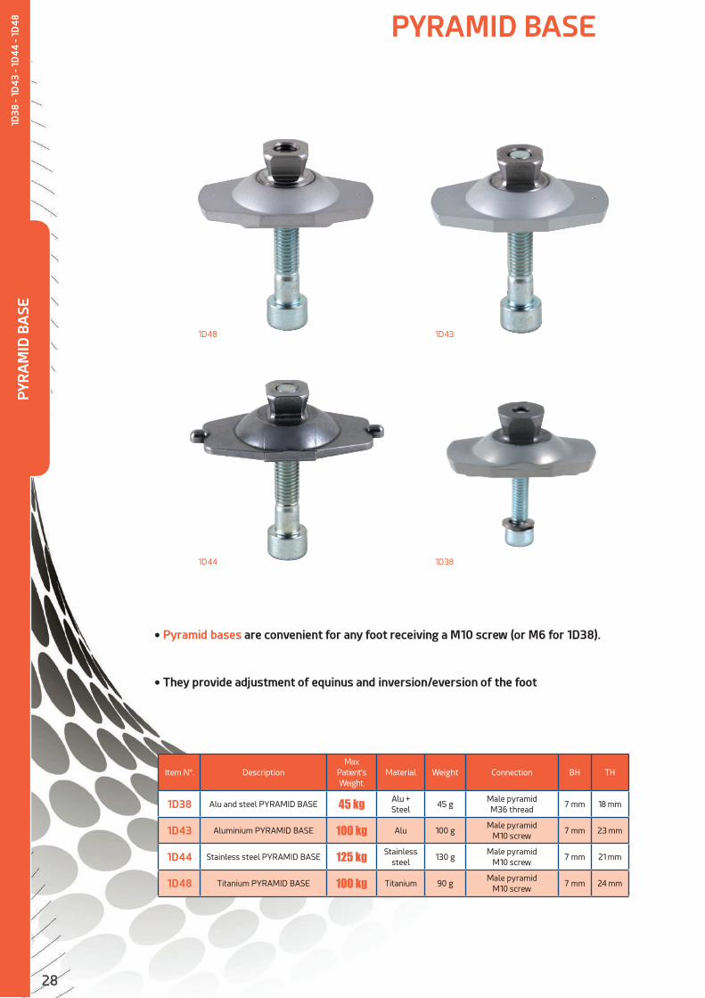
Item N°. DescriptionMax
Patient’s Weight.
Material Weight Connection BH TH
1D38 Alu and steel PYRAMID BASE 45 kg Alu + Steel
45 gMale pyramid M36 thread
7 mm 18 mm
1D43 Aluminium PYRAMID BASE 100 kg Alu 100 gMale pyramid
M10 screw7 mm 23 mm
1D44 Stainless steel PYRAMID BASE 125 kg Stainless steel
130 gMale pyramid
M10 screw7 mm 21 mm
1D48 Titanium PYRAMID BASE 100 kg Titanium 90 gMale pyramid
M10 screw7 mm 24 mm
PYRAMID BASE
• Pyramid bases are convenient for any foot receiving a M10 screw (or M6 for 1D38).
• They provide adjustment of equinus and inversion/eversion of the foot
1D48 1D43
1D44 1D38
PYR
AM
ID B
ASE
1D38
- 1D
43 -
1D4
4 -
1D4
8
29
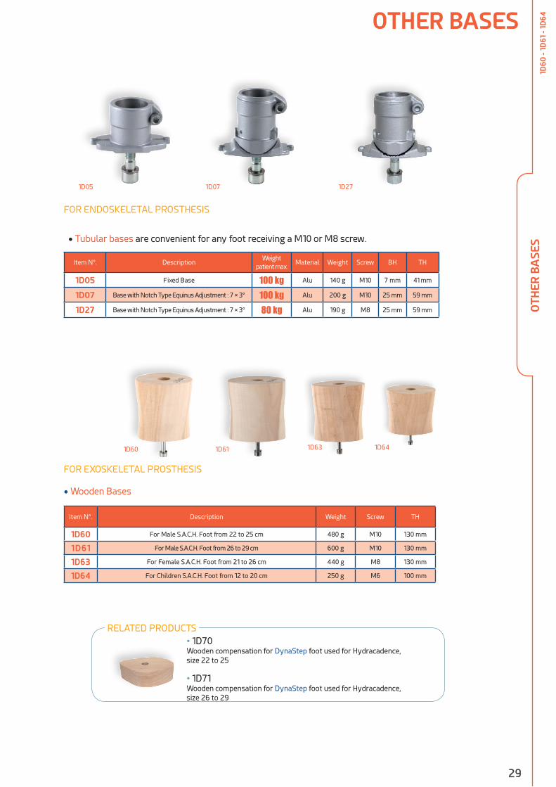
• Tubular bases are convenient for any foot receiving a M10 or M8 screw.
Item N°. DescriptionWeight
patient max.Material Weight Screw BH TH
1D05 Fixed Base 100 kg Alu 140 g M10 7 mm 41 mm
1D07 Base with Notch Type Equinus Adjustment : 7 × 3° 100 kg Alu 200 g M10 25 mm 59 mm
1D27 Base with Notch Type Equinus Adjustment : 7 × 3° 80 kg Alu 190 g M8 25 mm 59 mm
• Wooden Bases
Item N°. Description Weight Screw TH
1D60 For Male S.A.C.H. Foot from 22 to 25 cm 480 g M10 130 mm
1D61 For Male S.A.C.H. Foot from 26 to 29 cm 600 g M10 130 mm
1D63 For Female S.A.C.H. Foot from 21 to 26 cm 440 g M8 130 mm
1D64 For Children S.A.C.H. Foot from 12 to 20 cm 250 g M6 100 mm
1D05 1D07 1D27
1D60 1D61 1D641D63
OTHER BASES
FOR ENDOSKELETAL PROSTHESIS
FOR EXOSKELETAL PROSTHESIS
OTH
ER B
ASE
S1D
60 -
1D61
- 1D
64
• 1D70 Wooden compensation for DynaStep foot used for Hydracadence,size 22 to 25
• 1D71Wooden compensation for DynaStep foot used for Hydracadence, size 26 to 29
RELATED PRODUCTS

30
• The multiaxis ankle enables any S.A.C.H. or DynaStep foot receiving a M10 screw to perform motions of plantar and dorsiflexion, as well as inversion-eversion.
• This ankle helps flat foot achievement and is convenient for uneven grounds thanks to its numerous possible motions.
• It is recommended for both trans-femoral and trans-tibial amputees.
• A wide range of front and rear bearings allows to match the ankle to patients’ activity and weight.
Item N°.Max patient's
Weight Material Weight
UpperConnection
LowerConnection
TH BH
1D111 100 kg Alu 250 g Male pyramid M10 screw 65 mm 53 mm
Delivered fitted with EE010-1 and EE008 bearings
• Selection of Rear Bumper
Item N°. Hardness Thickness Color Material Weight
EE013 X-soft 50 mm Brown Elastomer 17 g
EE007 Soft 50 mm Beige Elastomer 20 g
EE008 Medium 50 mm Black Elastomer 20 g
EE009 Hard 50 mm Grey Elastomer 20 g
• Selection of Front Bearings
Item N°. Hardness Thickness Color Material Weight
EE010-1 Soft 20 mmHoney color
Elastomer 6 g
EE010-2 Medium 20 mm Blue Elastomer 6 g
EE010-3 Hard 20 mm Ivory Elastomer 6 g
MULTIAXIS ANKLE
• 1D11150 :
Adjustment Kit consisting of EE009 + EE010-2 + EE010-3
MU
LTIA
XIS
AN
KLE
1D11
1
31
MU
LTIA
XIS
AN
KLE
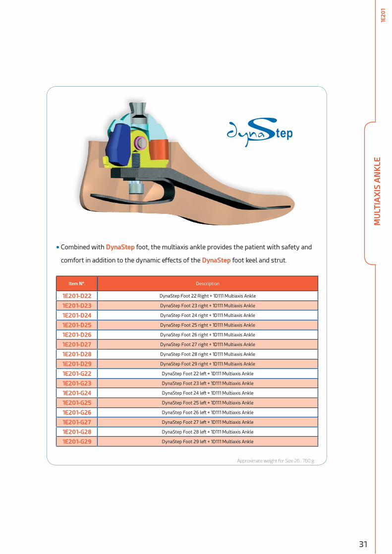
Approximate weight for Size 26 : 760 g
• Combined with DynaStep foot, the multiaxis ankle provides the patient with safety and
comfort in addition to the dynamic effects of the DynaStep foot keel and strut.
Item N°. Description
1E201-D22 DynaStep Foot 22 Right + 1D111 Multiaxis Ankle
1E201-D23 DynaStep Foot 23 right + 1D111 Multiaxis Ankle
1E201-D24 DynaStep Foot 24 right + 1D111 Multiaxis Ankle
1E201-D25 DynaStep Foot 25 right + 1D111 Multiaxis Ankle
1E201-D26 DynaStep Foot 26 right + 1D111 Multiaxis Ankle
1E201-D27 DynaStep Foot 27 right + 1D111 Multiaxis Ankle
1E201-D28 DynaStep Foot 28 right + 1D111 Multiaxis Ankle
1E201-D29 DynaStep Foot 29 right + 1D111 Multiaxis Ankle
1E201-G22 DynaStep Foot 22 left + 1D111 Multiaxis Ankle
1E201-G23 DynaStep Foot 23 left + 1D111 Multiaxis Ankle
1E201-G24 DynaStep Foot 24 left + 1D111 Multiaxis Ankle
1E201-G25 DynaStep Foot 25 left + 1D111 Multiaxis Ankle
1E201-G26 DynaStep Foot 26 left + 1D111 Multiaxis Ankle
1E201-G27 DynaStep Foot 27 left + 1D111 Multiaxis Ankle
1E201-G28 DynaStep Foot 28 left + 1D111 Multiaxis Ankle
1E201-G29 DynaStep Foot 29 left + 1D111 Multiaxis Ankle
1E20
1

32
ANKLE for SINGLE AXIS FOOT
• Ankle for 1B02 Single Axis Foot
Item N°.Max patient’s
WeightMaterial Weight
Upper connection
1D12 100 kg Alu 250 g Tube Ø 30 mm
• Selection of False Malleoli
Item N°. Description Material Weight
1E1301 For foot from 22 to 24 cm PU 25 g
1E1401 For foot from 25 to 27 cm PU 30 g
1E1501 For foot 28 to 29 cm PU 35 g
Item N°. DescriptionMax
patient’s Weight
Material Weight
1D02 For foot from 22 to 24 cm 100 kg Alu 250 g
1D03 For foot from 25 to 27 cm 100 kg Alu 260 g
1D04 For foot from 28 to 29 cm 100 kg Alu 270 g
1D22 For foot from 22 to 24 cm 100 kg Wood 580 g
1D23 For foot from 25 to 27 cm 100 kg Wood 590 g
1D24 For foot from 28 to 29 cm 100 kg Wood 600 g
• Selection of Rear Bumpers for 1B02 Foot
Item N°. Hardness Thickness Color Material Weight
EE013 X-soft 50 mm Brown Elastomer 17 g
EE007 Soft 50 mm Beige Elastomer 20 g
EE008 Medium 50 mm Black Elastomer 20 g
EE009 Hard 50 mm Gey Elastomer 20 g
• Selection of Front Bearings
Item N°. Thickness Description Material Weight
EE011 5 mm For 10 mm heel Elastomer 2 g
EE001 6 mm For 14 mm heel Elastomer 3 g
EE002 7 mm For 19 mm heel Elastomer 4 g
EE003 9 mm For 24 mm heel Elastomer 5 g
• 5F055 Key for Malleolar Nut
1E1301
1D23
FOR ENDOSKELETAL PROSTHESIS
FOR EXOSKELETAL PROSTHESIS
1D12
1E13011E14011E1501
EE001EE011
EE002EE003
EE013EE007EE008EE009
1B02
• Malleolar Joint and Leg Base
Join
tLe
g b
ase
1D02
AN
KLE
FO
R S
ING
LE A
XIS
FO
OT
1D12
RELATED PRODUCTS

33
• 5F055 Key for Malleolar Nut
KNEE
KN
EE
34
LOCKING KNEEM
ECH
AN
ICA
L
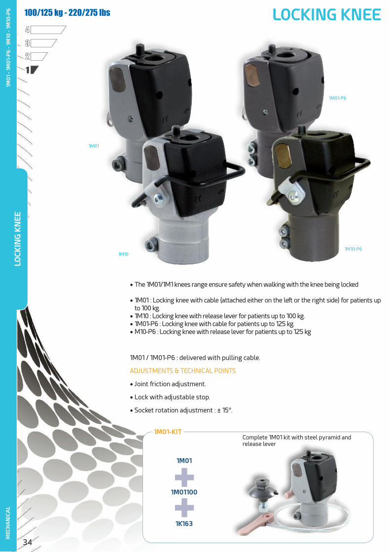
• The 1M01/1M1 knees range ensure safety when walking with the knee being locked
• 1M01 : Locking knee with cable (attached either on the left or the right side) for patients up to 100 kg.
• 1M10 : Locking knee with release lever for patients up to 100 kg.• 1M01-P6 : Locking knee with cable for patients up to 125 kg.• M10-P6 : Locking knee with release lever for patients up to 125 kg
1M01 / 1M01-P6 : delivered with pulling cable.
ADJUSTMENTS & TECHNICAL POINTS
• Joint friction adjustment.
• Lock with adjustable stop.
• Socket rotation adjustment : ± 15°.
1234
100/125 kg - 220/275 lbs
1M01-KIT
1M01
1M01100
1K163
++
Complete 1M01 kit with steel pyramid andrelease lever
1M01
1M01-P6
1M10-P61M10
LOCK
ING
KN
EE1M
01
- 1M
01-
P6
- 1M
10 -
1M10
-P6

35
MEC
HA
NIC
AL
Item N°.Max.
Patient’s Weight
Weight TH BH H Material FlexionProximalAdapter
Distal Adapter
1M01 100 kg 345 g 99 mm 58 mm 13 mmAlu + Steel
130 °1K160/1K1631K03/1K301K20/1K40
Tube Ø 30 mm
1M10 100 kg 355 g 99 mm 58 mm 13 mmAlu + Steel
130 °1K160/1K1631K03/1K301K20/1K40
Tube Ø 30 mm
1M01-P6 125 kg 375 g 102 mm 59 mm 14 mm
Alu + Steel
130 °1K160-P61K03-P6
1K40
Tube Ø 34 mm
1M10-P6 125 kg 375 g 102 mm 59 mm 14 mm
Alu + Steel
130 °1K160-P61K03-P6
1K40
Tube Ø 34 mm
TH
BH
H
Ø 30 mm
TH
BH
H
Ø 34 mm
• 1G13 .................................................................................................................................p1161-Part Cosmetic Cover
• 1G21 .................................................................................................................................p115Shin for 2-Part Cosmetic Cover
• 1M01194 ......................................................................................................................p115Knee Cap for 2-Part Cosmetic Cover
• 1M01100 Release Handle
• 1R02 Extension Assist convenient for 1M01 and 1M10 with a 30 mm Ø tube
• 1M1001 Replacement Manual Lever for 1M10 and 1M10-P6
• 1M0130Complete Replacement Cable
1M01 / 1M10 1M01-P6 / 1M10-P6
RELATED PRODUCTS
RECOMMENDED FEET
• 1A200 : Gery foot ....................................................................................................p11
• 1A101 : DynaStep foot .......................................................................................p16
• 1A111 : SACH foot ...................................................................................................p12
• 1B02 : Single axis foot ...................................................................................... p14
LOCK
ING
KN
EE1M
01
- 1M
01-
P6
- 1M
10 -
1M10
-P6
36
4-A
XIS
KN
EE4-AXIS KNEE
MEC
HA
NIC
AL
1234
100 kg / 220 lbs
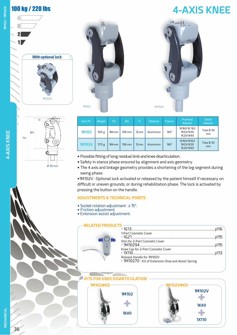
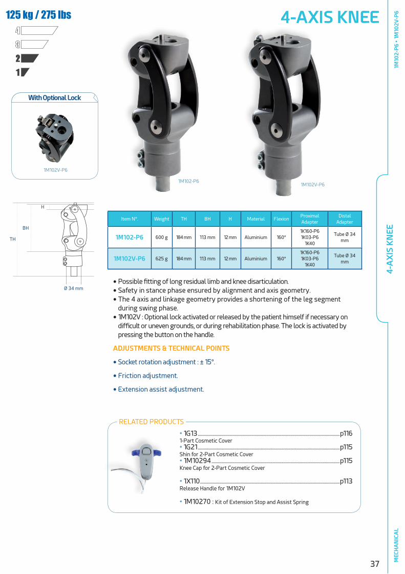
• Possible fitting of long residual limb and knee disarticulation.
• Safety in stance phase ensured by alignment and axis geometry.
• The 4 axis and linkage geometry provides a shortening of the leg segment during swing phase.
•1M102V : Optional lock activated or released by the patient himself if necessary on difficult or uneven grounds, or during rehabilitation phase. The lock is activated by pressing the button on the handle.
ADJUSTMENTS & TECHNICAL POINTS
• Socket rotation adjustment : ± 15°.• Friction adjustment.• Extension assist adjustment.
125 kg / 275 lbs
Item N°. Weight TH BH H Material FlexionProximal Adapter
Distal Adapter
1M102 565 g 184 mm 108 mm 12 mm Aluminium 160°1K160/1K 163
1K03/1K301K20/1K40
Tube Ø 30 mm
1M102V 575 g 184 mm 108 mm 12 mm Aluminium 160°1K160/1K1631K03/1K301K20/1K40
Tube Ø 30 mm
1M102 1M102V
TH
BH
H
Ø 30 mm
• 1G13 ............................................................................................................................p1161-Part Cosmetic Cover• 1G21 ............................................................................................................................p115Shin for 2-Part Cosmetic Cover• 1M10294 ................................................................................................................p115Knee Cap for 2-Part Cosmetic Cover• 1X110 ..........................................................................................................................p113Release Handle for 1M102V• 1M10270 : Kit of Extension Stop and Assist Spring
RELATED PRODUCTS
1M10
2 •
1M10
2V
KITS FOR KNEE DISARTICULATION
1M102
1K40
1M102V
1K40
1X110
+ ++
1M102V#KD1M102#KD
With optional lock
1M102V
37
4-A
XIS
KN
EEM
ECH
AN
ICA
L
4-AXIS KNEE
1234
125 kg / 275 lbs
Item N°. Weight TH BH H Material FlexionProximal Adapter
Distal Adapter
1M102-P6 600 g 184 mm 113 mm 12 mm Aluminium 160°1K160-P61K03-P6
1K40
Tube Ø 34 mm
1M102V-P6 625 g 184 mm 113 mm 12 mm Aluminium 160°1K160-P61K03-P6
1K40
Tube Ø 34 mm
TH
BH
H
Ø 34 mm
1M102-P61M102V-P6
RELATED PRODUCTS
• Possible fitting of long residual limb and knee disarticulation.
• Safety in stance phase ensured by alignment and axis geometry.
• The 4 axis and linkage geometry provides a shortening of the leg segment during swing phase.
• 1M102V : Optional lock activated or released by the patient himself if necessary on difficult or uneven grounds, or during rehabilitation phase. The lock is activated by pressing the button on the handle.
ADJUSTMENTS & TECHNICAL POINTS
• Socket rotation adjustment : ± 15°.
• Friction adjustment.
• Extension assist adjustment.1M
102-
P6
• 1M
102V
-P6
With Optional Lock
• 1G13 ............................................................................................................................p1161-Part Cosmetic Cover• 1G21 ............................................................................................................................p115Shin for 2-Part Cosmetic Cover• 1M10294 ................................................................................................................p115Knee Cap for 2-Part Cosmetic Cover
• 1X110 ..........................................................................................................................p113Release Handle for 1M102V
• 1M10270 : Kit of Extension Stop and Assist Spring
1M102V-P6

38
4-AXIS KNEE with SHORT LINKAGESM
ECH
AN
ICA
L
RE-
EDU
CATI
ON
1M0
3
1234
100 kg / 220 lbs
• This knee is particularly appropriate for rehabilitation thanks to the possibility of adjusting stability in two different positions reached by modifying the rear linkage geometry.
• Safety in stance phase ensured by alignment and axis geometry.
• The 4-axis and linkage geometry pro-vides a shortening of the leg segment during swing phase.
ADJUSTMENTS & TECHNICAL POINTS
• Socket rotation adjustment : ± 15°.
• Friction adjustment.
• Extension assist adjustment.
• 2 ranges of stability adjustment (reha-bilitation and normal).
Item N°. Weight TH BH H Material FlexionProximal Adapter
Distal Adapter
1M03 510 g 166 mm 85 mm 11 mm Aluminium 140°1K160/1K1631K03/1K301K20/1K40
Tube Ø 30 mm
TH
BH
H
Ø 30 mm
4-A
XIS
KN
EE W
ITH
SH
OR
T LI
NK
AG
ES
4-axis - 2 positions
RELATED PRODUCTS
• 1G13 ............................................................................................................................p1161-Part Cosmetic Cover• 1G21 ............................................................................................................................p115Shin for 2-Part Cosmetic Cover• 1M02194 ................................................................................................................p115Knee Cap for 2-Part Cosmetic Cover
• 1M10270 : Kit of Extension Stop and Assist Spring

39
1M0
54-AXIS KNEE with SHORT LINKAGES
MEC
HA
NIC
AL
1234
100 kg /220 lbs
• Appropriate for patients with short residual limbs.
• Safety in stance phase ensured by alignment and axis geometry.
• The 4-axis and linkage geometry pro-vides a shortening of the leg segment during swing phase.
ADJUSTMENTS & TECHNICAL POINTS
• Socket rotation adjustment : ± 15°..
• Friction adjustment.
• Extension assist adjustment
Item N°. Weight TH BH H Material FlexionProximal Adapter
Distal Adapter
1M05 460 g 166 mm 85 mm 11 mm Aluminium 140°1K160/1K1631K03/1K301K20/1K40
Tube Ø 30 mm
TH
BH
H
Ø 30 mm
RELATED PRODUCTS
4-A
XIS
KN
EE W
ITH
SH
OR
T LI
NK
AG
ES
4-axis
• 1G13 ............................................................................................................................p1161-Part Cosmetic Cover• 1G21 ............................................................................................................................p115Shin for 2-Part Cosmetic Cover• 1M02194 ................................................................................................................p115Knee Cap for 2-Part Cosmetic Cover

40
COMPACT 4-AXIS KNEEM
ECH
AN
ICA
L
1234
45/80 kg - 99/176 lbs
• 1M112 : Lightweight and compact knee designed for children up to 45 kg.
• 1M113 : Lightweight and compact knee designed for women and youth up to 80 kg.
• Safety in stance phase ensured by alignment and axis geometry.
• The 4-axis and linkage geometry provides a shortening of the leg segment during swing phase.
ADJUSTMENTS & TECHNICAL POINTS
• Socket rotation adjustment : ± 15°.
• Friction adjustment.
• Extension assist adjustment
Item N°.Max.
Patient’s Weight
Weight TH BH H Material FlexionProximal Adapter
Distal Adapter
1M112 45 kg 320 g 155 mm 75 mm 11 mm Aluminium 165°1K164
1K03/1K301K20/1K40
Tube Ø 22 mm
1M113 80 kg 340 g 155 mm 75 mm 11 mm Aluminium 165°1K160/1K1631K03/1K301K20/1K40
Tube Ø 30 mm
TH
BH
H
Ø 22 mmØ 30 mm
1M1121M113
COM
PACT
4-A
XIS
KN
EE1M
112
• 1M
113
RELATED PRODUCTS
• 1G13 ............................................................................................................................p1161-Part Cosmetic Cover• 1G22 or 1G32 ......................................................................................................p115Shin for 2-Part Cosmetic Cover designed for children or for 80 kg patients• 1M11294 .................................................................................................................p115Knee Cap for 2-Part Cosmetic Cover
• 1M11270 : Kit of Extension Stops

41
SINGLE AXIS KNEE WITH BRAKE
1234
100 kg / 220 lbs
• During stance phase, the ground reaction force closes a jaw locking the rota-tion axis.
• Delivered complete kit with its extension assist and cosmetic cover.
ADJUSTMENTS & TECHNICAL POINTS
• Brake adjustment according to patient’s weight and activity.
• Knee friction adjustment.
• Extension assist adjustment.
Item N°. Weight TH BH H Material FlexionProximal Adapter
Distal Adapter
1M115 540 g 75 mm 50 mm 22 mmSteel/
Stainless steel
150° Pyramid Pyramid
1M149 368 g 75 mm 50 mm 30 mm Titanium 150° Pyramid Pyramid
TH BH
H
1M115#KIT
1M115 1G01
+1D41
KIT KNEE 1M115
+SI
NG
LE A
XIS
KN
EE W
ITH
BR
AK
E1M
115
• 1M
149
MEC
HA
NIC
AL
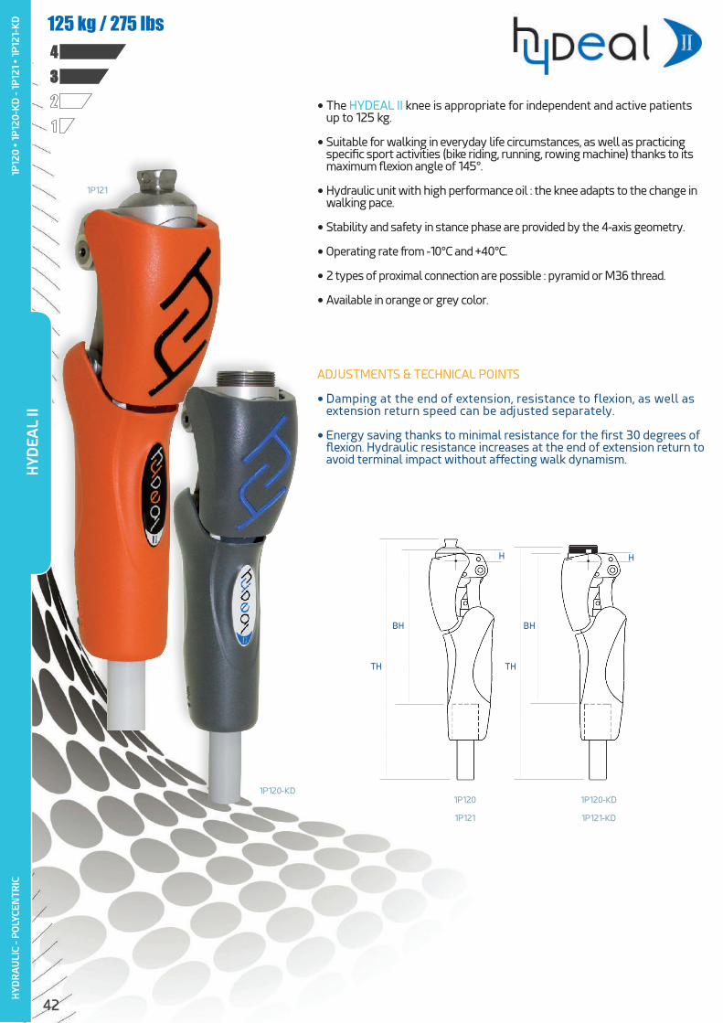
42
HYD
RA
ULI
C - P
OLY
CEN
TRIC
1234125 kg / 275 lbs
ADJUSTMENTS & TECHNICAL POINTS
• Damping at the end of extension, resistance to flexion, as well as extension return speed can be adjusted separately.
• Energy saving thanks to minimal resistance for the first 30 degrees of flexion. Hydraulic resistance increases at the end of extension return to avoid terminal impact without affecting walk dynamism.
• The HYDEAL II knee is appropriate for independent and active patients up to 125 kg.
• Suitable for walking in everyday life circumstances, as well as practicing specific sport activities (bike riding, running, rowing machine) thanks to its maximum flexion angle of 145°.
• Hydraulic unit with high performance oil : the knee adapts to the change in walking pace.
• Stability and safety in stance phase are provided by the 4-axis geometry.
• Operating rate from -10°C and +40°C.
• 2 types of proximal connection are possible : pyramid or M36 thread.
• Available in orange or grey color.
TH TH
BH BH
H H
1P120
1P121
1P120-KD
1P121-KD
1P121
1P120-KD
HYD
EAL
II1P
120
• 1
P12
0-K
D -
1P12
1 •
1P12
1-K
D

43
HYD
RA
ULI
C - P
OLY
CEN
TRIC
RELATED PRODUCTS
• 1G16-44 ........................................................................................................................p116 Polyurethan 1-Part Cosmetic Cover
• 1K179 ................................................................................................................................p76 3-Prong Lamination Adapter for Knee Disarticulation
• 1G01-HD ........................................................................................................................p66Aluminium tube Ø 34 mm
• 1P11067 : Short Extension Spring Cylinder Kit (TH shortening : 30 mm)
• 1D52-P6 .......................................................................................................................p68Ø 34 mm Aluminium Tube with Pyramid Receiver
• 1K52 .................................................................................................................................p64Trans-Femoral Rotator (≤100 Kg) (1P120 et 1P121)
• 1X71 ..................................................................................................................................p68 Adapter for Tube Ø 34 / Ø 30 (≤100 Kg)
• 5F077 : Adjustment Wrench
RECOMMENDED FEET
• 1A500 : DynaStar Foot .....................................................................................p18
• 1A400 : Dyna C Foot .........................................................................................p20
• 1A600 : DynaTrek Foot ...................................................................................p22
Includes adjustment wrench
5F077
Item N°. Weight TH BH H Material FlexionProximal Adapter
Distal Adapter
1P120 1050 g 318 mm 200 mm 14,5 mmAlu
Stainless steel145° Pyramid
Tube Ø34 mm
1P120-KD 1080 g 309 mm 197 mm 11 mmAlu
Stainless steel145° M36 thread
Tube Ø34 mm
1P121 1050 g 318 mm 200 mm 14,5 mmAlu/Stainless
steel145° Pyramid
Tube Ø34 mm
1P121-KD 1080 g 309 mm 197 mm 11 mmAlu/Stainless
steel145° M36 thread
Tube Ø34 mm
HYD
EAL
II1P
120
• 1
P12
0-K
D -
1P12
1 •
1P12
1-K
D
Separate adjustments of extension and flexion
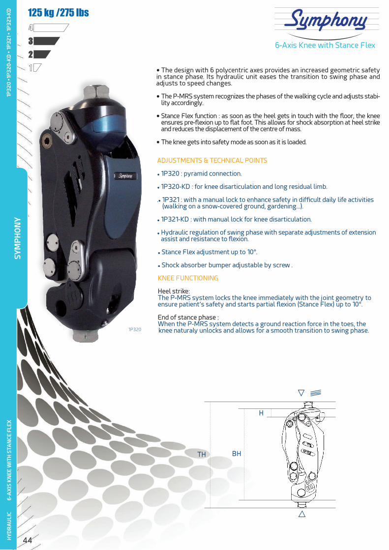
44
• The design with 6 polycentric axes provides an increased geometric safety in stance phase. Its hydraulic unit eases the transition to swing phase and adjusts to speed changes.
• The P-MRS system recognizes the phases of the walking cycle and adjusts stabi-lity accordingly.
• Stance Flex function : as soon as the heel gets in touch with the floor, the knee ensures pre-flexion up to flat foot. This allows for shock absorption at heel strike and reduces the displacement of the centre of mass.
• The knee gets into safety mode as soon as it is loaded.
6-Axis Knee with Stance Flex
6-A
XIS
KN
EE W
ITH
STA
NCE
FLE
XH
YDR
AU
LIC
ADJUSTMENTS & TECHNICAL POINTS
• 1P320 : pyramid connection.
• 1P320-KD : for knee disarticulation and long residual limb.
.• 1P321 : with a manual lock to enhance safety in difficult daily life activities (walking on a snow-covered ground, gardening…).
• 1P321-KD : with manual lock for knee disarticulation.
• Hydraulic regulation of swing phase with separate adjustments of extension assist and resistance to flexion.
• Stance Flex adjustment up to 10°.
• Shock absorber bumper adjustable by screw .
KNEE FUNCTIONING
Heel strike:The P-MRS system locks the knee immediately with the joint geometry to ensure patient’s safety and starts partial flexion (Stance Flex) up to 10°.
End of stance phase : When the P-MRS system detects a ground reaction force in the toes, the knee naturaly unlocks and allows for a smooth transition to swing phase.
TH BH
H
1234125 kg /275 lbs
1P320
SYM
PH
ON
Y1P
320
•1P
320
-KD
• 1
P32
1 •
1P32
1-K
D
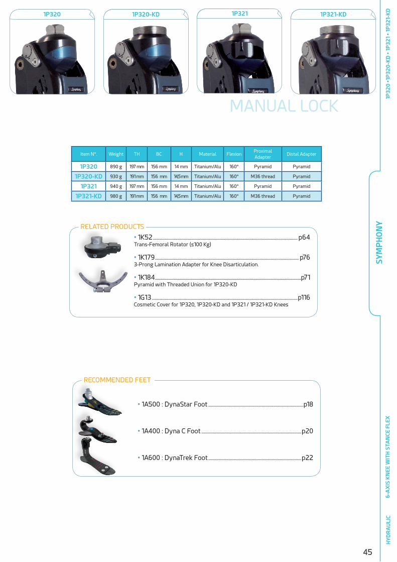
45
Item N°. Weight TH BC H Material FlexionProximal Adapter
Distal Adapter
1P320 890 g 197 mm 156 mm 14 mm Titanium/Alu 160° Pyramid Pyramid
1P320-KD 930 g 191 mm 156 mm 14,5 mm Titanium/Alu 160° M36 thread Pyramid
1P321 940 g 197 mm 156 mm 14 mm Titanium/Alu 160° Pyramid Pyramid
1P321-KD 980 g 191 mm 156 mm 14,5 mm Titanium/Alu 160° M36 thread Pyramid
• 1K52 ................................................................................................................................. p64Trans-Femoral Rotator (≤100 Kg)
• 1K179 ................................................................................................................................ p763-Prong Lamination Adapter for Knee Disarticulation.
• 1K184 ..................................................................................................................................p71Pyramid with Threaded Union for 1P320-KD
• 1G13 ..................................................................................................................................p116Cosmetic Cover for 1P320, 1P320-KD and 1P321 / 1P321-KD Knees
6-A
XIS
KN
EE W
ITH
STA
NCE
FLE
XH
YDR
AU
LIC
1P321-KD1P320-KD1P320 1P321
RELATED PRODUCTS
MANUAL LOCK
SYM
PH
ON
Y1P
320
•1P
320
-KD
• 1
P32
1 •
1P32
1-K
DRECOMMENDED FEET
• 1A500 : DynaStar Foot .....................................................................................p18
• 1A400 : Dyna C Foot .........................................................................................p20
• 1A600 : DynaTrek Foot ...................................................................................p22
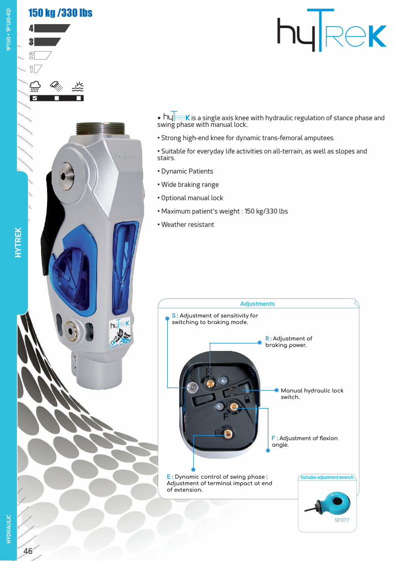
46
HYT
REK
1234150 kg /330 lbs
1P13
0 •
1P
130
-KD
HYD
RA
ULI
C
• is a single axis knee with hydraulic regulation of stance phase and swing phase with manual lock..
• Strong high-end knee for dynamic trans-femoral amputees.
• Suitable for everyday life activities on all-terrain, as well as slopes and stairs.
• Dynamic Patients
• Wide braking range
• Optional manual lock
• Maximum patient’s weight : 150 kg/330 lbs
• Weather resistant
Adjustments
Includes adjustment wrench
5F077
S : Adjustment of sensitivity for switching to braking mode.
R : Adjustment of braking power.
Manual hydraulic lock switch.
E : Dynamic control of swing phase : Adjustment of terminal impact at end of extension.
F : Adjustment of flexion angle.
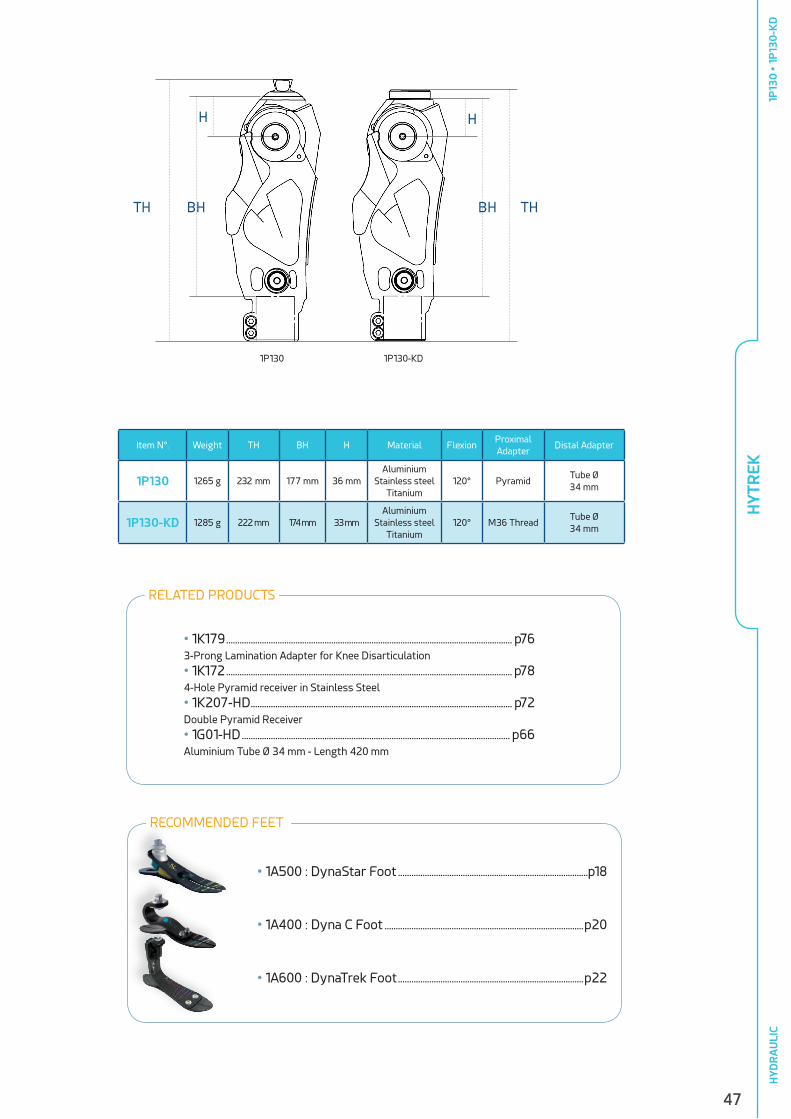
47
1P130 1P130-KD
HYT
REK
Item N°. Weight TH BH H Material FlexionProximal Adapter
Distal Adapter
1P130 1265 g 232 mm 177 mm 36 mmAluminium
Stainless steel Titanium
120° PyramidTube Ø34 mm
1P130-KD 1285 g 222 mm 174 mm 33 mmAluminium
Stainless steel Titanium
120° M36 ThreadTube Ø34 mm
TH BH
H H
THBH
• 1K179 ................................................................................................................................ p763-Prong Lamination Adapter for Knee Disarticulation
• 1K172 ................................................................................................................................ p78 4-Hole Pyramid receiver in Stainless Steel
• 1K207-HD ..................................................................................................................... p72Double Pyramid Receiver
• 1G01-HD ........................................................................................................................ p66Aluminium Tube Ø 34 mm - Length 420 mm
RELATED PRODUCTS
1P13
0 •
1P
130
-KD
HYD
RA
ULI
C
RECOMMENDED FEET
• 1A500 : DynaStar Foot .....................................................................................p18
• 1A400 : Dyna C Foot .........................................................................................p20
• 1A600 : DynaTrek Foot ...................................................................................p22

48
TH BH
H
HYDRACADENCEH
YDR
AU
LIC
1234100 kg / 220 lbs
ADJUSTMENTS & TECHNICAL POINTS• Heel height adjustment by the patient with a knob according to the type of shoes
he is wearing.
• Adjustment of the hydraulic unit according to walking pace.
• Socket rotation adjustment : ± 15°.
OVERALL DIMENSIONS• With a DynaStep foot 1A101 : 435 mm < knee-ground height < 570 mm
• With a SACH foot : 436 mm < knee-ground height < 563 mm
• Hydracadence is an hydraulic single axis knee with a functional coupling between the knee and the ankle joint during flexion and extension movements.
• At heel strike, the knee in extension simultaneously brings the ankle and therefore the foot into extension. Then flat foot is rapidly achieved to enhance safety on slopes and uneven grounds
• When knee flexion reaches 20° during swing phase, the foot is actively lifted up in dorsi-flexion, then lowered in the course of the walking cycle. This raise of the forefoot makes walking easier and reduces the risk of stumbling.
• Frame in carbon composite.
HYD
RA
CAD
ENCE
1P50
-R
Ankle Joint
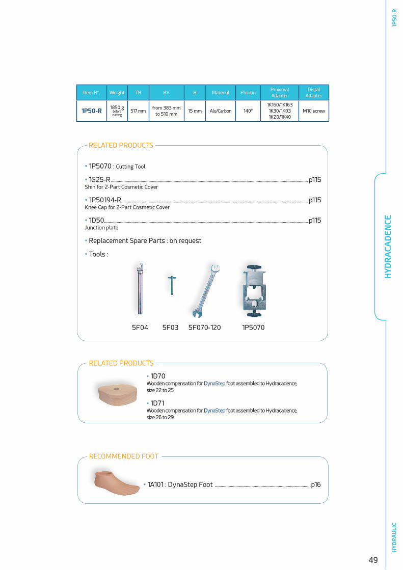
49
Item N°. Weight TH BH H Material FlexionProximal Adapter
Distal Adapter
1P50-R1850 g
before cutting
517 mmfrom 383 mm
to 510 mm15 mm Alu/Carbon 140°
1K160/1K1631K30/1K031K20/1K40
M10 screw
5F04 5F03 5F070-120 1P5070
• 1P5070 : Cutting Tool
• 1G25-R ............................................................................................................................................................................. p115Shin for 2-Part Cosmetic Cover
• 1P50194-R.................................................................................................................................................................... p115Knee Cap for 2-Part Cosmetic Cover
• 1D50 ................................................................................................................................................................................... p115Junction plate
• Replacement Spare Parts : on request
• Tools :
• 1A101 : DynaStep Foot ....................................................................................p16
RECOMMENDED FOOT
RELATED PRODUCTS
HYD
RA
CAD
ENCE
1P50
-RH
YDR
AU
LIC
• 1D70 Wooden compensation for DynaStep foot assembled to Hydracadence,size 22 to 25
• 1D71Wooden compensation for DynaStep foot assembled to Hydracadence,size 26 to 29
RELATED PRODUCTS
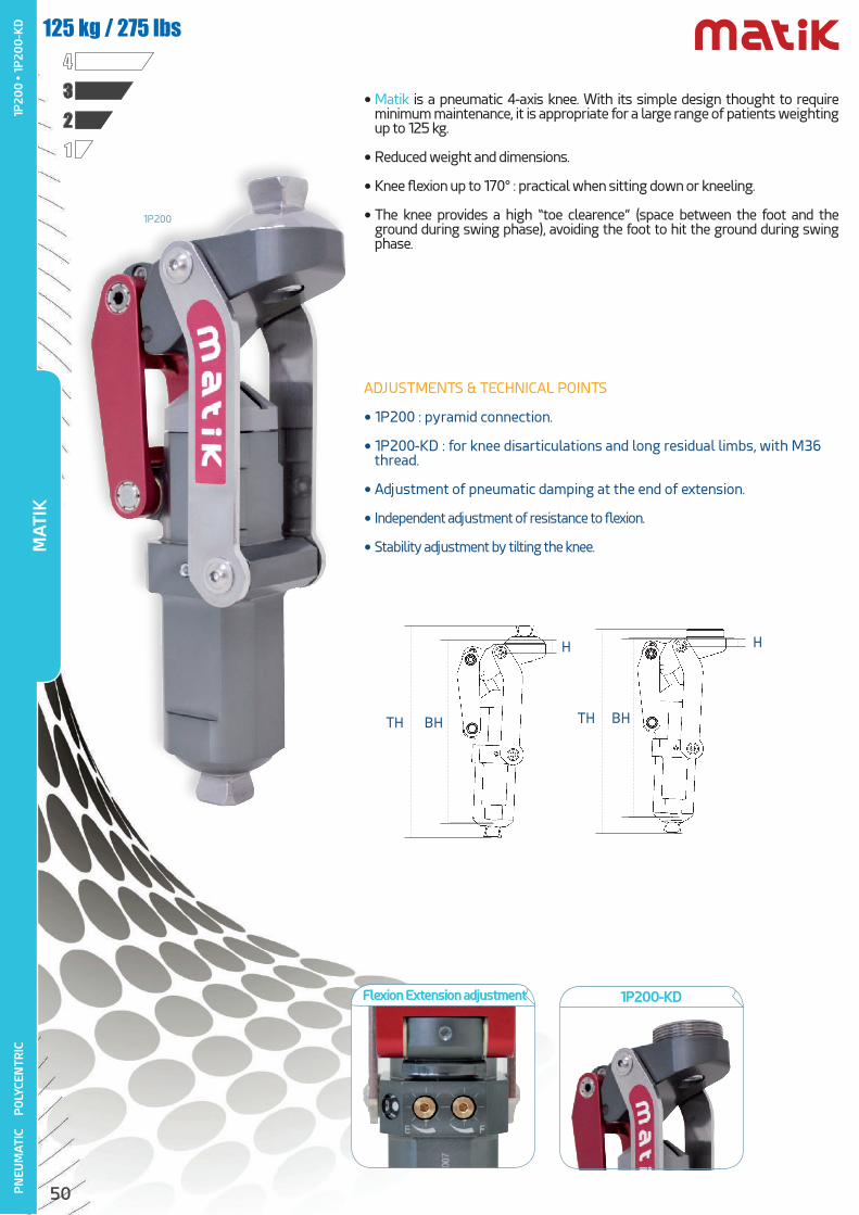
50PN
EUM
ATI
C
PO
LYCE
NTR
IC
ADJUSTMENTS & TECHNICAL POINTS
• 1P200 : pyramid connection.
• 1P200-KD : for knee disarticulations and long residual limbs, with M36 thread.
• Adjustment of pneumatic damping at the end of extension.
• Independent adjustment of resistance to flexion.
• Stability adjustment by tilting the knee.
• Matik is a pneumatic 4-axis knee. With its simple design thought to require minimum maintenance, it is appropriate for a large range of patients weighting up to 125 kg.
• Reduced weight and dimensions.
• Knee flexion up to 170° : practical when sitting down or kneeling.
• The knee provides a high “toe clearence” (space between the foot and the ground during swing phase), avoiding the foot to hit the ground during swing phase.
1234
125 kg / 275 lbs
TH BH
H
TH BH
H
1P200-KDFlexion Extension adjustment
1P200
MA
TIK
1P20
0 •
1P
200
-KD
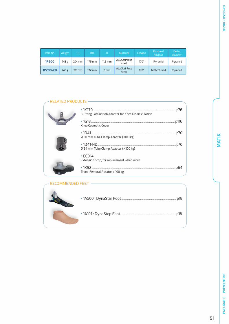
51
Item N°. Weight TH BH H Material FlexionProximal Adapter
Distal Adapter
1P200 743 g 204 mm 175 mm 11,5 mmAlu/Stainless
steel170° Pyramid Pyramid
1P200-KD 743 g 195 mm 172 mm 8 mmAlu/Stainless
steel170° M36 Thread Pyramid
• 1K179 ............................................................................................................................... p763-Prong Lamination Adapter for Knee Disarticulation
• 1G18 ..................................................................................................................................p116Knee Cosmetic Cover
• 1D41 ................................................................................................................................. p70Ø 30 mm Tube Clamp Adapter (≤100 kg)
• 1D41-HD ......................................................................................................................... p70Ø 34 mm Tube Clamp Adapter (> 100 kg)
• EE014Extension Stop, for replacement when worn
• 1K52 ................................................................................................................................. p64Trans-Femoral Rotator ≤ 100 kg
• 1A500 : DynaStar Foot .....................................................................................p18
• 1A101 : DynaStep Foot .......................................................................................p16
RECOMMENDED FEET
RELATED PRODUCTS
MA
TIK
1P20
0 •
1P
200
-KD
PN
EUM
ATI
C
PO
LYCE
NTR
IC
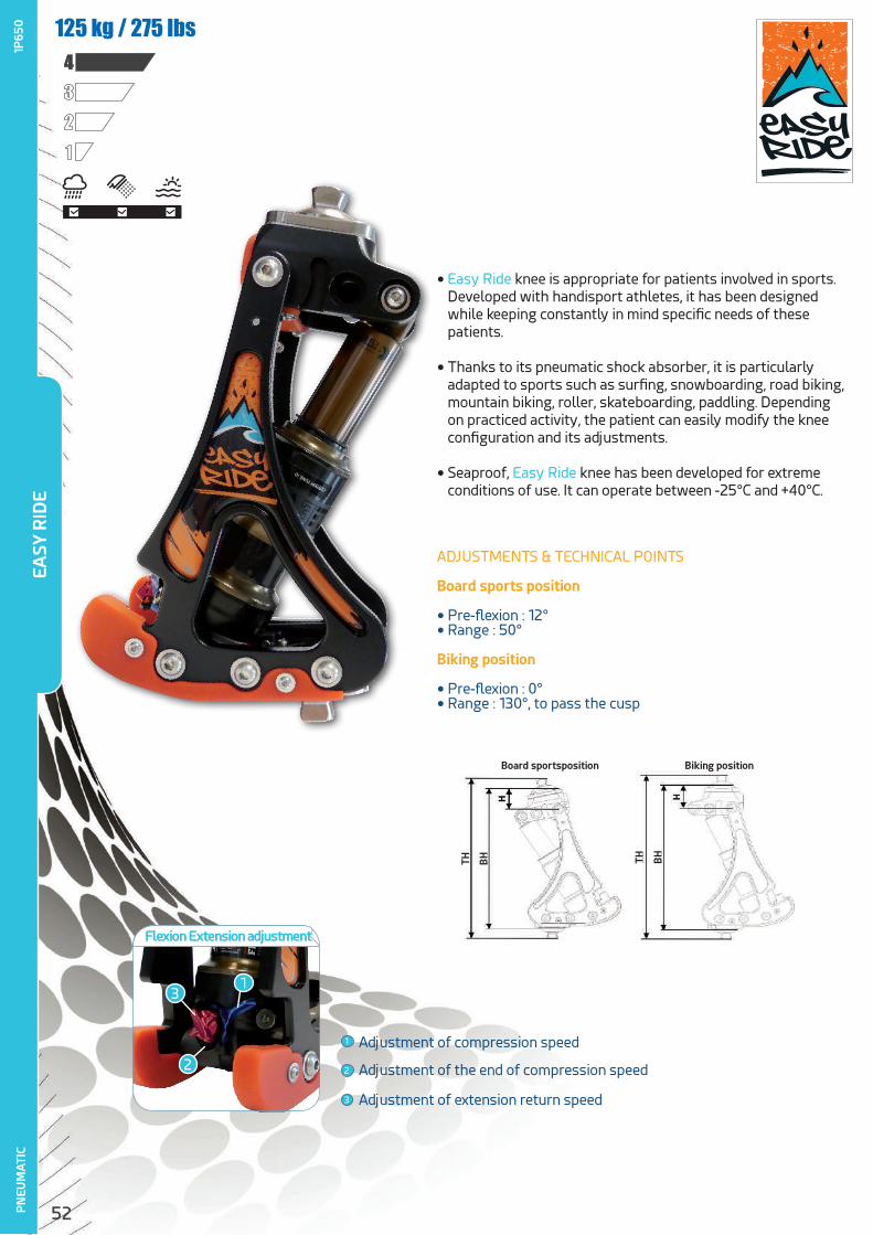
52PN
EUM
ATI
C
• Easy Ride knee is appropriate for patients involved in sports. Developed with handisport athletes, it has been designed while keeping constantly in mind specific needs of these patients.
• Thanks to its pneumatic shock absorber, it is particularly adapted to sports such as surfing, snowboarding, road biking, mountain biking, roller, skateboarding, paddling. Depending on practiced activity, the patient can easily modify the knee configuration and its adjustments.
• Seaproof, Easy Ride knee has been developed for extreme conditions of use. It can operate between -25°C and +40°C.
ADJUSTMENTS & TECHNICAL POINTS
Board sports position
• Pre-flexion : 12°• Range : 50°
Biking position
• Pre-flexion : 0°• Range : 130°, to pass the cusp
EASY
RID
E1P
650 125 kg / 275 lbs
1234
1
2
3
Adjustment of compression speed
Adjustment of the end of compression speed
Adjustment of extension return speed
Flexion Extension adjustment
1
2
3
Board sportsposition
TH THBH BH
Biking position
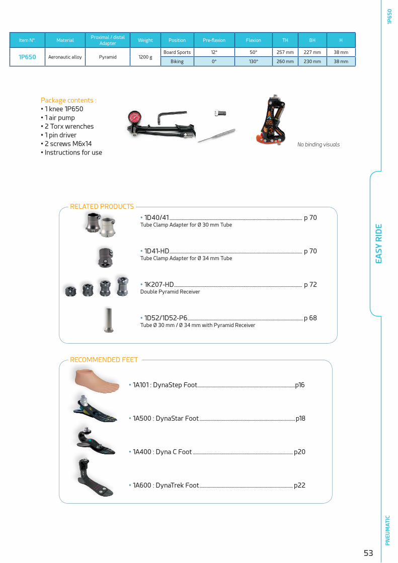
53
PN
EUM
ATI
C
Item N°. MaterialProximal / distal
AdapterWeight Position Pre-flexion Flexion TH BH H
1P650 Aeronautic alloy Pyramid 1200 gBoard Sports 12° 50° 257 mm 227 mm 38 mm
Biking 0° 130° 260 mm 230 mm 38 mm
EASY
RID
E1P
650
• 1D40/41 ...................................................................................................................... p 70Tube Clamp Adapter for Ø 30 mm Tube
• 1D41-HD ...................................................................................................................... p 70Tube Clamp Adapter for Ø 34 mm Tube
• 1K207-HD .................................................................................................................. p 72Double Pyramid Receiver
• 1D52/1D52-P6 .......................................................................................................p 68Tube Ø 30 mm / Ø 34 mm with Pyramid Receiver
RELATED PRODUCTS
Package contents :• 1 knee 1P650• 1 air pump• 2 Torx wrenches• 1 pin driver• 2 screws M6x14• Instructions for use
No binding visuals
• 1A101 : DynaStep Foot .......................................................................................p16
• 1A500 : DynaStar Foot .....................................................................................p18
• 1A400 : Dyna C Foot ......................................................................................... p20
• 1A600 : DynaTrek Foot ................................................................................... p22
RECOMMENDED FEET
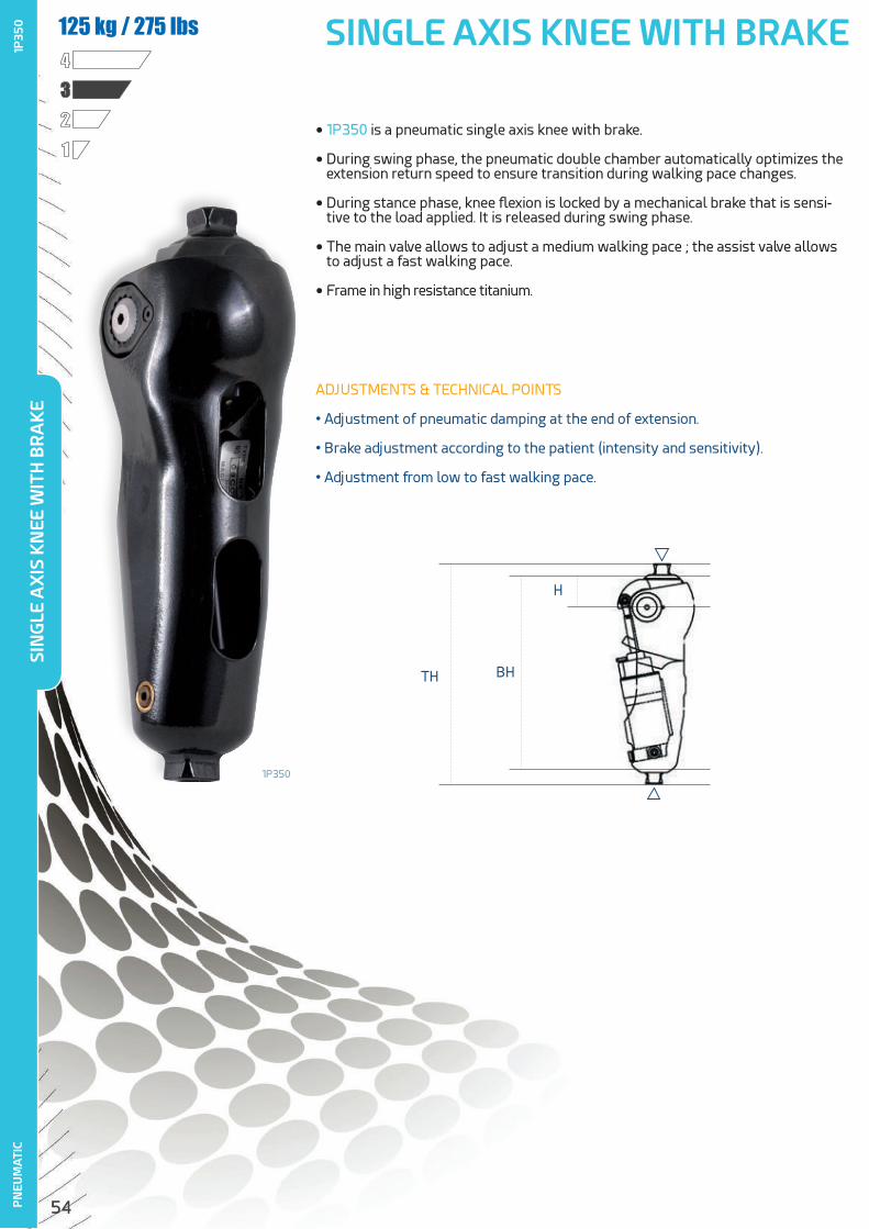
54
TH BH
H
SINGLE AXIS KNEE WITH BRAKEP
NEU
MA
TIC
1234125 kg / 275 lbs
ADJUSTMENTS & TECHNICAL POINTS
• Adjustment of pneumatic damping at the end of extension.
• Brake adjustment according to the patient (intensity and sensitivity).
• Adjustment from low to fast walking pace.
• 1P350 is a pneumatic single axis knee with brake.
• During swing phase, the pneumatic double chamber automatically optimizes the extension return speed to ensure transition during walking pace changes.
• During stance phase, knee flexion is locked by a mechanical brake that is sensi-tive to the load applied. It is released during swing phase.
• The main valve allows to adjust a medium walking pace ; the assist valve allows to adjust a fast walking pace.
• Frame in high resistance titanium.
1P350
SIN
GLE
AX
IS K
NEE
WIT
H B
RA
KE
1P35
0

55
Item N°. Weight TH BH H Material FlexionProximal Adapter
Distal Adapter
1P350 935 g220 mm
195 mm 32 mm Titanium 160° Pyramid Pyramid
• 1D41-HD ...........................................................................................................p70Tube Clamp Adapter for Ø 34 mm Tube
• 1K172 ..................................................................................................................p78Pyramid receiver in Stainless Steel
• 1K207-HD .......................................................................................................p72Double Pyramid Receiver from 32 to 75 mm
• 1G01-HD ..........................................................................................................p66Aluminium Tube Ø 34 mm
• 1P35020-HExtension Stops
• 1D52-P6 .........................................................................................................p68Tube Ø 34 mm with Pyramid Receiver
• 1A500 : DynaStar Foot .......................................................................p18
• 1A400 : Dyna C Foot ...........................................................................p20
• 1A600 : DynaTrek Foot .....................................................................p22
RECOMMENDED FEET
RELATED PRODUCTS
SIN
GLE
AX
IS K
NEE
WIT
H B
RA
KE
1P35
0P
NEU
MA
TIC
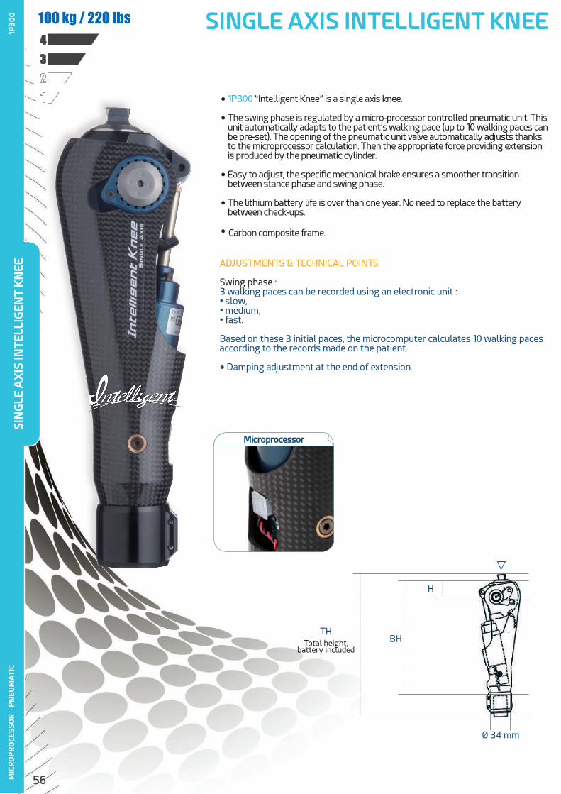
56
SINGLE AXIS INTELLIGENT KNEE
Total height, battery included
THBH
H
Ø 34 mm
• 1P300 “Intelligent Knee” is a single axis knee.
• The swing phase is regulated by a micro-processor controlled pneumatic unit. This unit automatically adapts to the patient’s walking pace (up to 10 walking paces can be pre-set). The opening of the pneumatic unit valve automatically adjusts thanks to the microprocessor calculation. Then the appropriate force providing extension is produced by the pneumatic cylinder.
• Easy to adjust, the specific mechanical brake ensures a smoother transition between stance phase and swing phase.
• The lithium battery life is over than one year. No need to replace the battery between check-ups.
• Carbon composite frame.
1234100 kg / 220 lbs
ADJUSTMENTS & TECHNICAL POINTS
Swing phase :3 walking paces can be recorded using an electronic unit :• slow,• medium,• fast.
Based on these 3 initial paces, the microcomputer calculates 10 walking paces according to the records made on the patient.
• Damping adjustment at the end of extension.
MIC
RO
PR
OCE
SSO
R
PN
EUM
ATI
CSI
NG
LE A
XIS
INTE
LLIG
ENT
KN
EE1P
300
Microprocessor

57
Item N°. Weight TH BH H Material FlexionProximal Adapter
Distal Adapter
1P300 1085 g309 mm
252 mm 37 mm Carbon 155° Pyramid Tube Ø 34 mm
• 1G01-HD ........................................................................................................................... p66Aluminium tube Ø 34 mm
• 1D41-HD ............................................................................................................................ p70Tube Clamp Adapter for Ø 34 mm tube
• 1P302 .................................................................................................................................p67Aluminium tube Ø 34 mm / Ø 30 mm
• 1D52-P6 .......................................................................................................................... p68Tube Ø 34 mm with Pyramid Receiver
• 1K52 ....................................................................................................................................p64Trans-Femoral Rotator
• 1P301 : Programming Unit
• 1P30010 : Lithium Battery Replacement
• 1P30020 : Extension Stops
• 1G16-44 : Cosmetic Cover................................................................................p116
MIC
RO
PR
OCE
SSO
R
PN
EUM
ATI
C
RELATED PRODUCTS
SIN
GLE
AX
IS IN
TELL
IGEN
T K
NEE
1P30
0
• 1A500 : DynaStar Foot .......................................................................p18
• 1A400 : Dyna C Foot ...........................................................................p20
• 1A600 : DynaTrek Foot .....................................................................p22
RECOMMENDED FEET
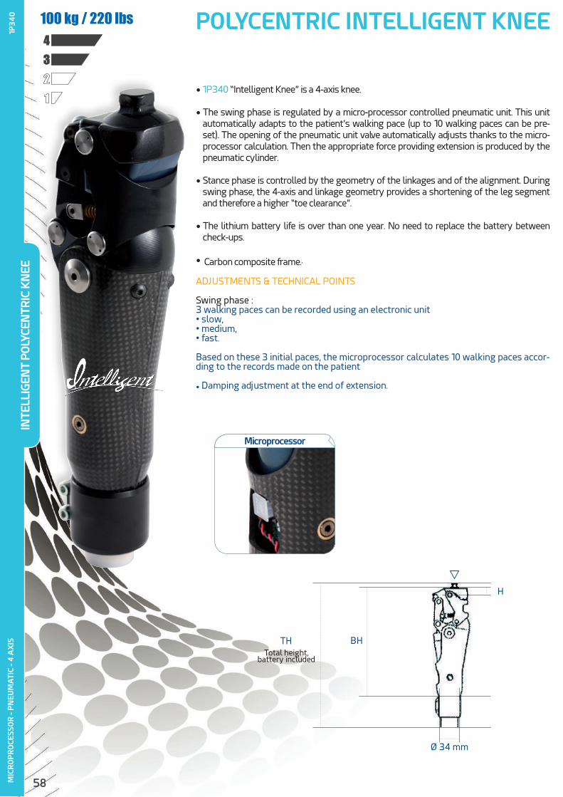
58
POLYCENTRIC INTELLIGENT KNEEM
ICR
OP
RO
CESS
OR
- P
NEU
MA
TIC
- 4 A
XIS
1234
100 kg / 220 lbs
Microprocessor
ADJUSTMENTS & TECHNICAL POINTS
Swing phase :3 walking paces can be recorded using an electronic unit • slow,• medium,• fast.
Based on these 3 initial paces, the microprocessor calculates 10 walking paces accor-ding to the records made on the patient
• Damping adjustment at the end of extension.
TH BH
H
Ø 34 mm
Total height, battery included
• 1P340 “Intelligent Knee” is a 4-axis knee.
• The swing phase is regulated by a micro-processor controlled pneumatic unit. This unit automatically adapts to the patient’s walking pace (up to 10 walking paces can be pre-set). The opening of the pneumatic unit valve automatically adjusts thanks to the micro-processor calculation. Then the appropriate force providing extension is produced by the pneumatic cylinder.
• Stance phase is controlled by the geometry of the linkages and of the alignment. During swing phase, the 4-axis and linkage geometry provides a shortening of the leg segment and therefore a higher “toe clearance”.
• The lithium battery life is over than one year. No need to replace the battery between check-ups.
• Carbon composite frame..
INTE
LLIG
ENT
PO
LYCE
NTR
IC K
NEE
1P34
0

59
Item N°. Weight TH BH H Material FlexionProximal Adapter
Distal Adapter
1P340 995 g293 mm
235 mm 13 mm Carbon 160° Pyramid Tube Ø 34 mm
MIC
RO
PR
OCE
SSO
R -
PN
EUM
ATI
C - 4
AX
IS
• 1G01-HD ........................................................................................................................... p66Aluminium tube Ø 34 mm
• 1D41-HD ............................................................................................................................ p70TubeClamp adapter for Ø 34 mm
• 1P302 ................................................................................................................................p67Aluminium tube Ø 34 mm / Ø 30 mm
• 1D52-P6 .......................................................................................................................... p68Tube Ø 34 mm with Pyramid Receiver
• 1K52 ....................................................................................................................................p64Trans-Femoral Rotator
• 1P301 : Programming unit
• 1P30010 : Lithium Battery Replacement
• 1P30020 : Extension Stops
• 1G16-44 : Cosmetic Cover ................................................................................p116
RELATED PRODUCTS
INTE
LLIG
ENT
PO
LYCE
NTR
IC K
NEE
1P34
0• 1A500 : DynaStar Foot .......................................................................p18
• 1A400 : Dyna C Foot ...........................................................................p20
• 1A600 : DynaTrek Foot .....................................................................p22
RECOMMENDED FEET
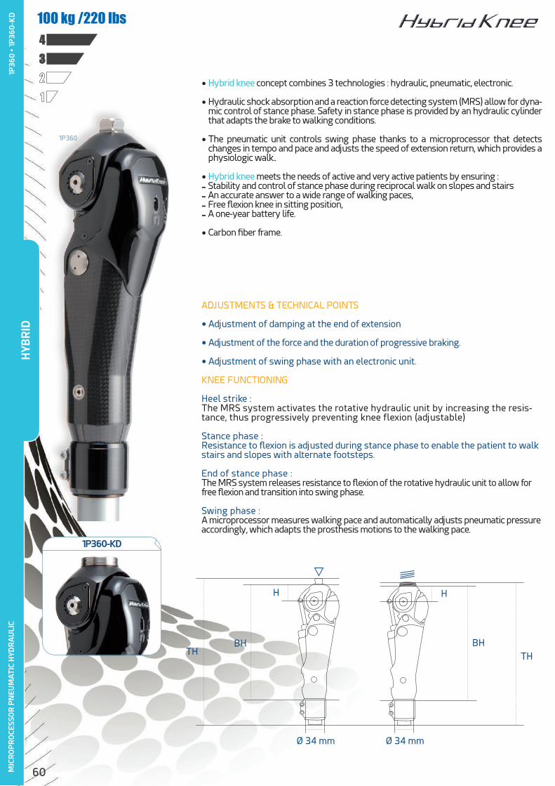
60
• Hybrid knee concept combines 3 technologies : hydraulic, pneumatic, electronic.
• Hydraulic shock absorption and a reaction force detecting system (MRS) allow for dyna-mic control of stance phase. Safety in stance phase is provided by an hydraulic cylinder that adapts the brake to walking conditions.
• The pneumatic unit controls swing phase thanks to a microprocessor that detects changes in tempo and pace and adjusts the speed of extension return, which provides a physiologic walk..
• Hybrid knee meets the needs of active and very active patients by ensuring :- Stability and control of stance phase during reciprocal walk on slopes and stairs- An accurate answer to a wide range of walking paces,- Free flexion knee in sitting position,- A one-year battery life.
• Carbon fiber frame.
ADJUSTMENTS & TECHNICAL POINTS
• Adjustment of damping at the end of extension
• Adjustment of the force and the duration of progressive braking.
• Adjustment of swing phase with an electronic unit.
KNEE FUNCTIONING
Heel strike : The MRS system activates the rotative hydraulic unit by increasing the resis-tance, thus progressively preventing knee flexion (adjustable)
Stance phase : Resistance to flexion is adjusted during stance phase to enable the patient to walk stairs and slopes with alternate footsteps.
End of stance phase : The MRS system releases resistance to flexion of the rotative hydraulic unit to allow for free flexion and transition into swing phase.
Swing phase : A microprocessor measures walking pace and automatically adjusts pneumatic pressure accordingly, which adapts the prosthesis motions to the walking pace.
MIC
RO
PR
OCE
SSO
R P
NEU
MA
TIC
HYD
RA
ULI
C
THBH
H H
BHTH
Ø 34 mm Ø 34 mm
1234100 kg /220 lbs
1P360
HYB
RID
1P36
0 •
1P
360
-KD
1P360-KD

61
Item N°. Weight TH BH H Material FlexionProximal Adapter
Distal Adapter
1P360 1375 g309 mm
252 mm 37 mm Carbon 140° Pyramid Tube Ø 34 mm
1P360-KD 1385 g303 mm
250 mm 35 mm Carbon 140° M36 thread Tube Ø 34 mm
MIC
RO
PR
OCE
SSO
R P
NEU
MA
TIC
HYD
RA
ULI
C
• 1K179 ................................................................................................................................... p763-Prong Lamination Adapter for Knee Disarticulation pour KD
• 1K184 ....................................................................................................................................p71Threaded Pyramid
• 1K52 .................................................................................................................................... p64Trans-Femoral Rotator
• 1G01-HD ........................................................................................................................... p66Aluminium tube Ø 34 mm
• 1D41-HD ............................................................................................................................ p70Tube Clamp Adapter for 34 mm Ø tube
• 1P302 .................................................................................................................................p67Aluminium Tube Ø 34 mm / Ø 30 mm
• 1D52-P6 .......................................................................................................................... p68Tube Ø 34 mm with Pyramid Receiver
• 1P301 : Programming Unit
• 1P30010 : Lithium Battery Replacement
• 1P36020 : Extension Stop
• 1G16-D44/1G16-G44 : Cosmetic Cover ................................................p116
1P301 1P360+
1P361 : KIT WITH HYBRID KNEE AND THE PROGRAMMING UNIT
RELATED PRODUCTS
• 1A500 : DynaStar Foot .......................................................................p18
• 1A400 : Dyna C Foot ...........................................................................p20
• 1A600 : DynaTrek Foot .....................................................................p22
RECOMMENDED FEET
HYB
RID
1P36
0 •
1P
360
-KD

62
• ALLUX is an hydraulic, polycentric knee with stance phase and swing phase controlled by a microprocessor.
• Its polycentric design provides stability thanks to axis geometry and a higher distance between the foot extremity and the ground during swing phase («toe clearance»).
• In case of stumbling, the electronic system takes over the control thanks to dedicated sen-sors that detect abnormal situations in real time. The microprocessor immediately increases the hydraulic resistance to prevent the knee from sudden buckling.
• Whatever the degree of knee flexion, the active braking function monitors each stage of the stance phase for managing slopes and stairs descent.
• Delivered with a lithium battery replacement.
ADJUSTMENTS & TECHNICAL POINTS
• Maximum flexion up to 155°.
• ALLUX is delivered with a software dongle allowing to set the knee via a wireless connection.
• A remote controller (supplied) allows the patient to select control mode among the 5 available :
- Normal
- Lock at a certain knee angle
- Selective flexion limit
- Lock at full extension
- Free motion with a certain resistance.
KNEE FUNCTIONING
ALLUX knee automatically locks at the desired angle if it stays in flexed position for a few moments
MIC
RO
PR
OCE
SSO
R
HYD
RA
ULI
C
PO
LYCE
NTR
IC
1234125 kg / 275 lbs
SUPPLIED WITH
TH
H
BH
ALL
UX
1P38
0 •
1P38
0-K
D
• 1P38010 : Remote Controller• 1P38011 : Adapter Cover• 1P38012 : Power-off Cover• 1P38013 : Replacement Battery• 1P38014 : Extension Cable for Replacement Battery• 1P38015 : Charger• 1P38016 : Power supply Adapter “Electrical Power / Charger”• 1P38017 : Power supply Adapter for Electrical Sockets• 1P38018 : Charging Cable for the Replacement Battery• 1P38019 : Bag for Replacement Battery

63
RECOMMENDED FEET
Item N°. Weight TH BH Material FlexionProximal Adapter
Distal Adapter
1P380 1450 g294 mm
267 mm Alu / Stainless steel 155° Pyramid Pyramid
1P380-KD 1460 g288 mm
265 mm Alu / Stainless steel 155° M36 thread Pyramid
MIC
RO
PR
OCE
SSO
R
HYD
RA
ULI
C
PO
LYCE
NTR
IC
• 1K179 .................................................................................................................................. p763-Prong Lamination Adapter for Knee Disarticulation
• 1K52 : ................................................................................................................................p64Trans-Femoral Rotator (≤100 kg)
RELATED PRODUCTS
• 1A400 : Dyna C Foot ............................................................................................ p20
• 1A600 : DynaTrek Foot ...................................................................................... p22
1P38010
1P38050
Must be ordered with the first knee
ALL
UX
1P38
0 •
1P
380
-KD
1P380-KD Includes remote controller USB Dongle
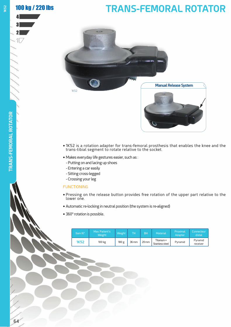
64
• 1K52 is a rotation adapter for trans-femoral prosthesis that enables the knee and the trans-tibial segment to rotate relative to the socket.
• Makes everyday life gestures easier, such as : - Putting on and lacing up shoes - Entering a car easily - Sitting cross-legged - Crossing your leg
FUNCTIONING
• Pressing on the release button provides free rotation of the upper part relative to the lower one.
• Automatic re-locking in neutral position (the system is re-aligned)
• 360° rotation is possible..
1K52 TRANS-FEMORAL ROTATOR
1234100 kg / 220 lbs
Item N°.Max. Patient’s
WeightWeight TH BH Material
Proximal Adapter
Connecteurdistal
1K52 100 kg 180 g 36 mm 20 mmTitanium +
Stainless steelPyramid
Pyramid receiver
1K52
TRA
NS-
FEM
OR
AL
RO
TATO
R
Manual Release System
65
AD
AP
TER
AN
D A
LIG
NM
ENT
ADAPTER AND ALIGNMENT

66
TUBE CLAMPOur tubular adapters are developed and manufactured according to ISO 10328 standards.
Each adapter bears the serial number to ensure a perfect traceability, as well as CE mark. Recommended tightening torque is also marked to ease the work of professionals during assembly.
• Aluminium Tube - 30 mm Ø - 420 mm length
Tube for trans-tibial or trans-femoral endoskeletal prosthesis.
Item N°.Max. Patient’s
WeightMaterial Weight TH Diameter
1G01 100 kg Aluminium 200 g 420 mm Ø 30 mm
• Aluminium tube Ø 34 mm - 420 mm length
Item N°.Max. Patient’s
WeightMaterial Weight TH Diameter
1G01-HD 150 kg Aluminium 235 g 420 mm Ø 34 mm
• Aluminium tube Ø 30 mm - 200 mm length
Tube for trans-tibial or trans-femoral endoskeletal prosthesis.
Item N°.Max. Patient’s
WeightMaterial Weight TH Diameter
1G0120 100 kg Aluminium 95 g 200 mm Ø 30 mm
1G0120#KIT (1G0120 + 1D41)
+
Aluminium tube Ø 30 mm - 200 mm length and tube clamp
Item N°.Max. Patient’s
WeightMaterial Weight TH Diameter
1G0120=kit 100 kg Aluminium 195 g 217 mm Ø 30 mm
• Aluminium tube Ø 25 mm - 350 mm length
Item N°.Max. Patient’s
WeightMaterial Weight TH Diameter
1G02 60 kg Aluminium 140 g 350 mm Ø 25 mm
TUB
E CL
AM
P1G
01
• 1G
012
0 •
1G
012
0#
KIT
• 1
G0
1-H
D •
1G
02
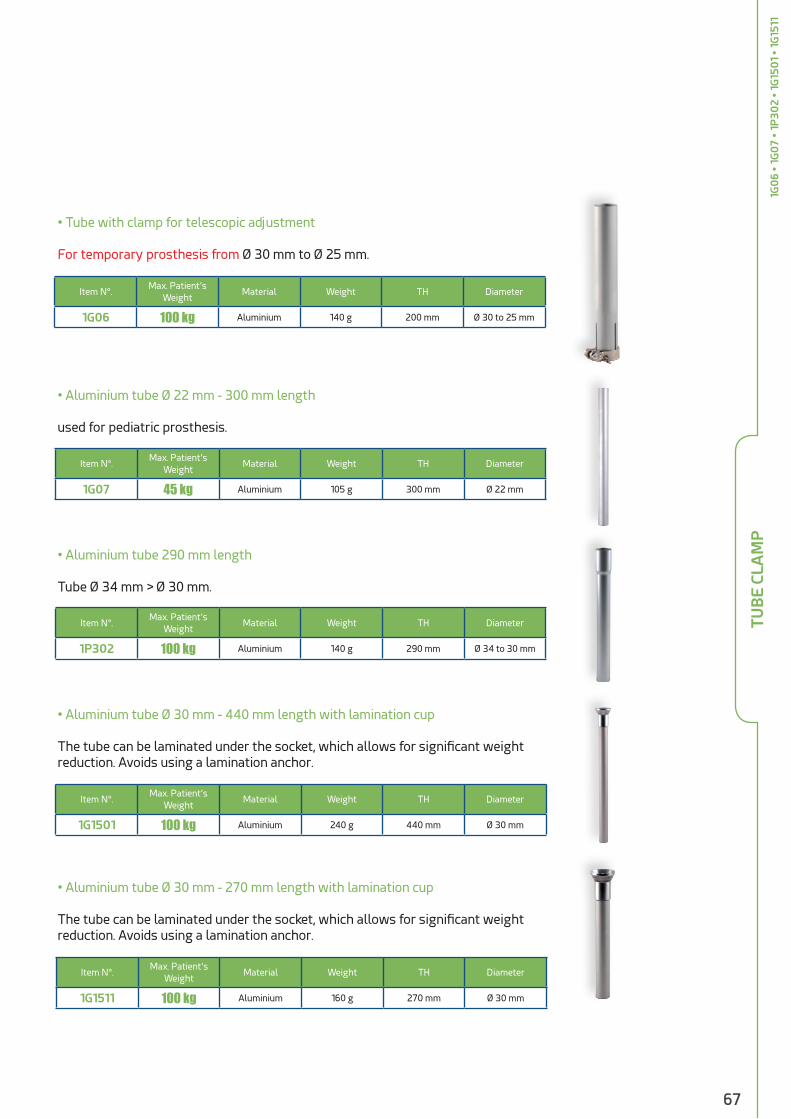
67
• Tube with clamp for telescopic adjustment
For temporary prosthesis from Ø 30 mm to Ø 25 mm.
• Aluminium tube Ø 22 mm - 300 mm length
used for pediatric prosthesis.
• Aluminium tube Ø 30 mm - 440 mm length with lamination cup
The tube can be laminated under the socket, which allows for significant weight reduction. Avoids using a lamination anchor.
• Aluminium tube Ø 30 mm - 270 mm length with lamination cup
The tube can be laminated under the socket, which allows for significant weight reduction. Avoids using a lamination anchor.
• Aluminium tube 290 mm length
Tube Ø 34 mm > Ø 30 mm.
Item N°.Max. Patient’s
WeightMaterial Weight TH Diameter
1G06 100 kg Aluminium 140 g 200 mm Ø 30 to 25 mm
Item N°.Max. Patient’s
WeightMaterial Weight TH Diameter
1G07 45 kg Aluminium 105 g 300 mm Ø 22 mm
Item N°.Max. Patient’s
WeightMaterial Weight TH Diameter
1G1501 100 kg Aluminium 240 g 440 mm Ø 30 mm
Item N°.Max. Patient’s
WeightMaterial Weight TH Diameter
1G1511 100 kg Aluminium 160 g 270 mm Ø 30 mm
Item N°.Max. Patient’s
WeightMaterial Weight TH Diameter
1P302 100 kg Aluminium 140 g 290 mm Ø 34 to 30 mm
1G0
6 •
1G0
7 •
1P
302
• 1G
150
1 •
1G15
11TU
BE
CLA
MP
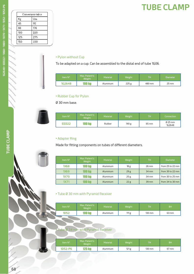
68
• Adapter Ring
Made for fitting components on tubes of different diameters.
Item N°.Max. Patient’s
WeightMaterial Weight TH Diameter
1X68 100 kg Aluminium 18 g 26 mm from 25 to 22 mm
1X69 100 kg Aluminium 29 g 34 mm from 30 to 22 mm
1X70 100 kg Aluminium 20 g 34 mm from 30 to 25 mm
1X71 100 kg Aluminium 22 g 39 mm from 34 to 30 mm
• Tube Ø 30 mm with Pyramid Receiver
Item N°.Max. Patient’s
WeightMaterial Weight TH BH
1D52 100 kg Aluminium 111 g 130 mm 63 mm
• Tube Ø 34 mm with Pyramid Receiver
Item N°.Max. Patient’s
WeightMaterial Weight TH BH
1D52-P6 125 kg Aluminium 121 g 130 mm 67 mm
• Pylon without Cup
To be adapted on a cup. Can be assembled to the distal end of tube 1G06.
Item N°.Max. Patient’s
WeightMaterial Weight TH Diameter
1G2648 100 kg Aluminium 225 g 480 mm 25 mm
• Rubber Cup for Pylon
Ø 30 mm base.
Item N°.Max. Patient’s
WeightMaterial Weight TH Connection
EE022 100 kg Rubber 140 g 65 mmØ 25 mm1G2648
TUB
E CL
AM
P1G
264
8 •
EE0
22 •
1X6
8 •
1X69
• 1
X70
• 1
X71
• 1
D52
• 1
D52
-P6 TUBE CLAMP

69
• Tube adapter
Ø 30 mm Aluminium Tube with Aluminium Pyramid Receiver.
Item N°.Max. Patient’s
WeightMaterial Weight TH BH
1D45 100 kg Aluminium 290 g 440 mm 440 mm
• Tube adapter
Ø 30 mm Aluminium Tube with Titanium Pyramid Receiver.
Item N°.Max. Patient’s
WeightMaterial Weight TH BH
1D46 100 kg Alu + Titanium 280 g 440 mm 440 mm
• Ø 30 mm Tubular Link
Link providing connection between a 30 mm Ø tube and a socket with a 4-hole plate.
Item N°.Max. Patient’s
WeightMaterial Weight TH BH
1K14 100 kg Aluminium 60 g 32 mm 32 mm
• Ø 34 mm Tubular LInk
Link providing connection between a 34 mm Ø tube and a socket with a 4-hole plate.
Item N°.Max. Patient’s
WeightMaterial Weight TH BH
1K14-P6 125 kg Aluminium 76 g 42 mm 42 mm
TUB
E CL
AM
P1D
45
• 1D
46
• 1K
14 •
1K1
4-P
6
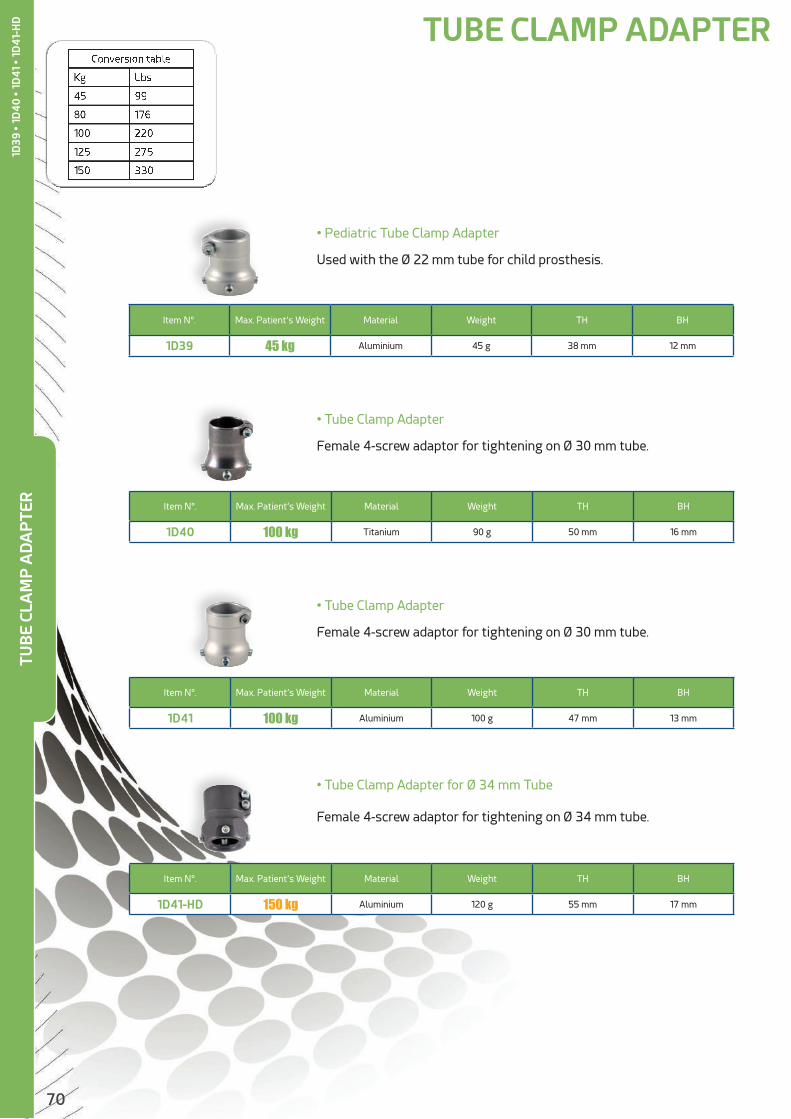
70
TUBE CLAMP ADAPTER
• Tube Clamp Adapter
Female 4-screw adaptor for tightening on Ø 30 mm tube.
Item N°. Max. Patient’s Weight Material Weight TH BH
1D41 100 kg Aluminium 100 g 47 mm 13 mm
• Tube Clamp Adapter for Ø 34 mm Tube
Female 4-screw adaptor for tightening on Ø 34 mm tube.
Item N°. Max. Patient’s Weight Material Weight TH BH
1D41-HD 150 kg Aluminium 120 g 55 mm 17 mm
• Pediatric Tube Clamp Adapter
Used with the Ø 22 mm tube for child prosthesis.
Item N°. Max. Patient’s Weight Material Weight TH BH
1D39 45 kg Aluminium 45 g 38 mm 12 mm
• Tube Clamp Adapter
Female 4-screw adaptor for tightening on Ø 30 mm tube.
Item N°. Max. Patient’s Weight Material Weight TH BH
1D40 100 kg Titanium 90 g 50 mm 16 mm
TUB
E CL
AM
P A
DA
PTE
R1D
39 •
1D
40
• 1
D41
• 1
D41
-HD

71
• Pyramid Receiver for Bonding
This adapter will be bonded with epoxy (supplied) on a 30 mm Ø tube.
Item N°. Max. Patient’s Weight Material Weight TH BH
1D47 100 kg Aluminium 85 g 52 mm 18 mm
• Threaded Pyramid insert M36 x 1,5 mm
Item N°. Max. Patient’s Weight Material Weight TH BH
1K182 125 kg Stainless steel 65 g 28 mm 6 mm
• Threaded Receiver insert M36 x 1,5 mm
Use with 1K179 or 1S145.
Item N°. Max. Patient’s Weight Material Weight TH BH
1K183 150 kg Stainless steel 75 g 23 mm 14 mm
• Threaded Pyramid
For screwing on1P200-KD, 1P320-KD, 1P321-KD, 1P360-KD, 1P130-KD, 1P180-KD.
Item N°. Max. Patient’s Weight Material Weight TH BH
1K184 125 kg Stainless steel 94 g 30 mm 15 mm
TUB
E CL
AM
P A
DA
PTE
R1D
47
• 1
K182
• 1
K183
• 1
K184

72
DOUBLE ADAPTER
• Double Pyramid Receiver
Avoid using a tube in tight spaces.
Item N°.Max. Patient’s
WeightMaterial Weight TH BH
1K207-032 100 kg Aluminium 85 g 32 mm 32 mm
1K207-045 100 kg Aluminium 100 g 45 mm 45 mm
1K207-060 100 kg Aluminium 115 g 60 mm 60 mm
1K207-075 100 kg Aluminium 130 g 75 mm 75 mm
• Double Pyramid Receiver
Avoid using a tube in tight spaces.
Item N°.Max. Patient’s
WeightMaterial Weight TH BH
1K207-HD-032 150 kg Aluminium 100 g 32 mm 32 mm
1K207-HD-045 150 kg Aluminium 130 g 45 mm 45 mm
1K207-HD-060 150 kg Aluminium 145 g 60 mm 60 mm
1K207-HD-075 150 kg Aluminium 160 g 75 mm 75 mm
• Double Pyramid Adapter
Item N°.Max. Patient’s
WeightMaterial Weight TH BH
1K190 150 kg Stainless steel 120 g 36 mm 7 mm
Double adapter including a pyramid receiver and a pyramid. It allows for individual height ad-justment of the prosthesis as its height can be shortened.
5C413 Cutting Tool : Recommended to cut the 1K151 and 1K150 Adapters to the desired height.
Item N°.Max. Patient’s
WeightMaterial Weight TH BH
1K151 100 kg Aluminium 141 to 201 g 44 to 89 mm 29 to 89 mm
Double adapter including two pyramid receivers. Can be adjusted in height by shortening, which allows the CPO to accurately adjust the prosthesis height. It can also provide rotation adjustment.1K15001 and 1K155 : Threaded tube alone (in aluminium or steel)
Item N°.Max. Patient’s
WeightMaterial Weight TH BH
1K150 (1) 100 kg Aluminium 109 to 170 g 40 to 100 mm 40 to 100 mm
1K15001 (2) 125 kg Aluminium 119 g 40 to 100 mm 40 to 100 mm
1K155 (2) 125 kg Steel 119 g 40 to 100 mm 40 to 100 mm
• Telescopic Double Pyramid Adapter
1
2
DO
UB
LE A
DA
PTE
R1K
207-
# •
1K20
7-H
D-#
• 1K
150
• 1K
150
01
• 1K1
55 •
1K15
1 • 1
K190
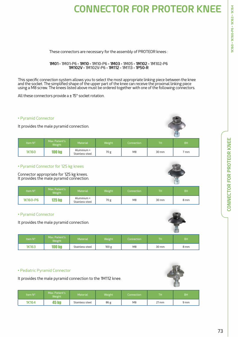
73
These connectors are necessary for the assembly of PROTEOR knees :
1M01 - 1M01-P6 - 1M10 - 1M10-P6 - 1M03 - 1M05 - 1M102 - 1M102-P61M102V - 1M102V-P6 - 1M112 - 1M113 - 1P50-R
This specific connection system allows you to select the most appropriate linking piece between the knee and the socket. The simplified shape of the upper part of the knee can receive the proximal linking piece using a M8 screw. The knees listed above must be ordered together with one of the following connectors.
All these connectors provide a ± 15° socket rotation.
CONNECTOR FOR PROTEOR KNEE
• Pyramid Connector
It provides the male pyramid connection.
Item N°.Max. Patient’s
WeightMaterial Weight Connection TH BH
1K160 100 kg Aluminium + Stainless steel
70 g M8 30 mm 7 mm
• Pyramid Connector for 125 kg knees
Connector appropriate for 125 kg knees.It provides the male pyramid connection.
Item N°.Max. Patient’s
WeightMaterial Weight Connection TH BH
1K160-P6 125 kg Aluminium + Stainless steel
70 g M8 30 mm 8 mm
• Pyramid Connector
It provides the male pyramid connection.
Item N°.Max. Patient’s
WeightMaterial Weight Connection TH BH
1K163 100 kg Stainless steel 100 g M8 30 mm 8 mm
• Pediatric Pyramid Connector
It provides the male pyramid connection to the 1M112 knee.
Item N°.Max. Patient’s
WeightMaterial Weight Connection TH BH
1K164 45 kg Stainless steel 86 g M8 21 mm 9 mm
CON
NEC
TOR
FO
R P
RO
TEO
R K
NEE
1K16
0 •
1K1
60-P
6 •
1K16
3 •
1K16
4
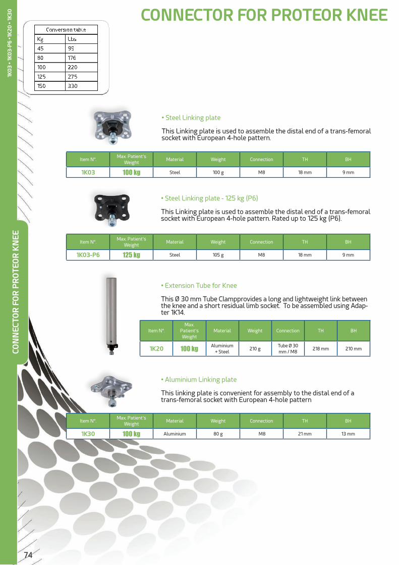
74
• Extension Tube for Knee
This Ø 30 mm Tube Clampprovides a long and lightweight link between the knee and a short residual limb socket. To be assembled using Adap-ter 1K14.
Item N°.Max.
Patient’s Weight
Material Weight Connection TH BH
1K20 100 kg Aluminium + Steel
210 gTube Ø 30 mm / M8
218 mm 210 mm
• Aluminium Linking plate
This linking plate is convenient for assembly to the distal end of a trans-femoral socket with European 4-hole pattern
Item N°.Max. Patient’s
WeightMaterial Weight Connection TH BH
1K30 100 kg Aluminium 80 g M8 21 mm 13 mm
• Steel Linking plate
This Linking plate is used to assemble the distal end of a trans-femoral socket with European 4-hole pattern.
Item N°.Max. Patient’s
WeightMaterial Weight Connection TH BH
1K03 100 kg Steel 100 g M8 18 mm 9 mm
• Steel Linking plate - 125 kg (P6)
This Linking plate is used to assemble the distal end of a trans-femoral socket with European 4-hole pattern. Rated up to 125 kg (P6).
Item N°.Max. Patient’s
WeightMaterial Weight Connection TH BH
1K03-P6 125 kg Steel 105 g M8 18 mm 9 mm
CONNECTOR FOR PROTEOR KNEECO
NN
ECTO
R F
OR
PR
OTE
OR
KN
EE1K
03
• 1K0
3-P
6 •1
K20
• 1K
30

75
• Lamination Adapter
Used for knee disarticulation or long residual limb.
Item N°.Max.
Patient’s Weight
Material Weight Connection TH BH
1K40 125 kg Steel 120 g M8 120 mm 6.5 mm
LAMINATION ADAPTER
• Trans-Femoral Rotating Adapter
3-prong anchor with rotating receiver.
Item N°.Max. Patient’s
WeightMaterial Weight TH BH
1K176 125 kg Aluminium + Stainless steel
205 g 68 mm 25 mm
• Trans-Femoral Rotating Adapter
3-prong anchor with rotating pyramid.
Item N°.Max. Patient’s
WeightMaterial Weight TH BH
1K177 100 kg Stainless steel 225 g 76 mm 17 mm
• Lamination Adapter
3-prong anchor with pyramid.
Item N°.Max. Patient’s
WeightMaterial Weight TH BH
1K173 125 kg Stainless steel 150 g 65 mm 12 mm
LAM
INA
TIO
N A
DA
PTE
R1K
40
• 1
K173
• 1
K176
• 1
K17
7
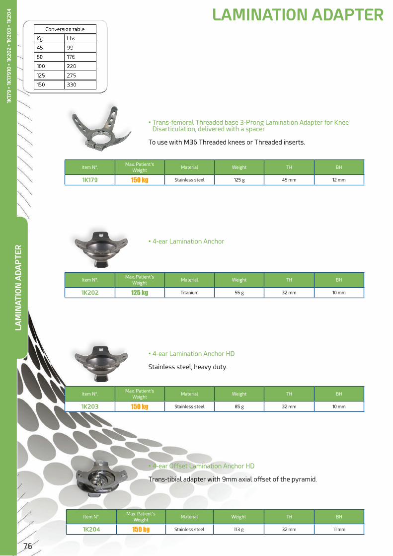
76
• 4-ear Lamination Anchor
Item N°.Max. Patient’s
WeightMaterial Weight TH BH
1K202 125 kg Titanium 55 g 32 mm 10 mm
• 4-ear Lamination Anchor HD
Stainless steel, heavy duty.
• 4-ear Offset Lamination Anchor HD
Trans-tibial adapter with 9mm axial offset of the pyramid.
Item N°.Max. Patient’s
WeightMaterial Weight TH BH
1K203 150 kg Stainless steel 85 g 32 mm 10 mm
Item N°.Max. Patient’s
WeightMaterial Weight TH BH
1K204 150 kg Stainless steel 113 g 32 mm 11 mm
• Trans-femoral Threaded base 3-Prong Lamination Adapter for Knee Disarticulation, delivered with a spacer
To use with M36 Threaded knees or Threaded inserts.
Item N°.Max. Patient’s
WeightMaterial Weight TH BH
1K179 150 kg Stainless steel 125 g 45 mm 12 mm
LAM
INA
TIO
N A
DA
PTE
RLAMINATION ADAPTER
1K17
9 • 1
K179
10 •
1K20
2 • 1
K20
3 • 1
K20
4

77
ALIGNMENT SYSTEM
• Alignment tool for Sagittal and Frontal Shift
Translation of ± 11 mm. For Ø 34 mm tube. Used for trial fitting of 1A410 Dyna J foot.
Item N°. Max. Patient’s Weight Material Weight TH BH
1D72-P6 125 kg Stainless steel 305 g 78 mm 38 mm
P.A.D. ALIGNMENT SYSTEM AND P.S.D. SHIFT SYSTEM
Rigid polyurethane blocks allows for very accurate tilt and shift adjustments of the socket during trial fitting.These blocks are bonded at the distal end of the endosqueletal laminated sockets. They are sanded down during finishing, then included in the final lamination. They can be screwed to European 4-hole pattern.Shift adjustment range : ± 25 mm. Tilt adjustment according to the models.
Item N°. Description Fitting TiltWeight
patient max.Weight TH Diameter
1K06 P.A.D. 360 Module Trans-Femoral ± 5° 100 kg 460 g 38 mm 132 mm
1K07 P.S.D. 1 Shift Module Trans-Femoral NO 100 kg 275 g 21 mm 132 mm
1K10 P.A.D. 250 Module Trans-Tibial ± 5° 100 kg 280 g 34 mm 108 mm
1K11 P.S.D. 2 Shift Module Trans-Tibial no 100 kg 190 g 21 mm 108 mm
1K06 1K07 1K10 1K11
T.A.C. ALIGNMENT SYSTEM
T.A.C. alignment system in steel and aluminium is incorporated during trial fitting.1K100 system ensures tilt and shift adjustments of trans-tibial prosthesis.
Shift adjustment range : ± 7.5 mm. Tilt adjustment range : ± 9 °
Item N°. DescriptionProximal
ConnectionDistal
ConnectionWeight
patient max.Weight TH BH
1K100 T.A.C. 100 Module
4-Hole M6(36 mm)
4-Hole M6(36 mm) 100 kg 250 g 36 mm 36 mm
ALI
GN
MEN
T SY
STEM
1D72
-P6
• 1K
06
• 1K
07
• 1
K10
• 1
K11
• 1K
100

78
• Stainless Steel Pyramid Receiver for Socket
This adapter features European 4-hole pattern and a pyramid receiver allowing for tilt adjustment of the socket.
Item N°. Max. Patient’s Weight Material Weight TH BH
1K172 125 kg Stainless steel 100 g 16 mm 16 mm
4-HOLE ADAPTER
• Pediatric Pyramid Socket Adapter
4-hole with M5 + 30 mm pattern.
• Adapter with 4-Hole M6 36 mm pattern for Adult Socket
Allowing tilt adjustment of the socket.
Item N°. Max. Patient’s Weight Material Weight TH BH
1K165 45 kg Aluminium 35 g 13 mm 13 mm
Item N°. Max. Patient’s Weight Material Weight TH BH
1K206 45 kg Aluminium + Stainless steel
45 g 18 mm 6 mm
Pyramid Adapter for Child Socket
Pyramid Receiver for Child Socket
4-H
OLE
AD
AP
TER
1K20
6 • 1
K165
• 1K
172

79
• 4-hole Receiver Socket Adapters
These titanium adapters feature European 4-hole pattern and a pyramid receiver allowing for tilt adjustment of the socket.1K66 also provides rotation adjustment.
Item N°.Max. Patient’s
WeightMaterial Weight TH BH Rotation
1K185 125 kg Titanium 64 g 17 mm 17 mm NO
1K66 125 kg Titanium 93 g 26 mm 26 mm YES
• 4-hole Pyramid Socket Adapters
These adapters feature European 4-hole pattern and a pyra-mid adapter allowing for tilt adjustment of the socket.1K60 also provides rotation adjustment.
Item N°.Max. Patient’s
WeightMaterial Weight TH BH Rotation
1K205 125 kg Stainless steel 80 g 22 mm 22 mm NO
1K60 125 kg Titanium 106 g 23 mm 23 mm YES
• 4-hole Pyramid Socket Adapter
This titanium Adapter features European 4-hole pattern and a py-ramid adapter allowing for tilt adjustment of the socket.
Item N°. Max. Patient’s Weight Material Weight TH BH
1K209 125 kg Titanium 46 g 22 mm 8 mm
1K185
1K205
1K66
1K60
4-H
OLE
AD
AP
TER
1K18
5 •
1K66
• 1
K20
5 •
1K60
• 1
K20
9
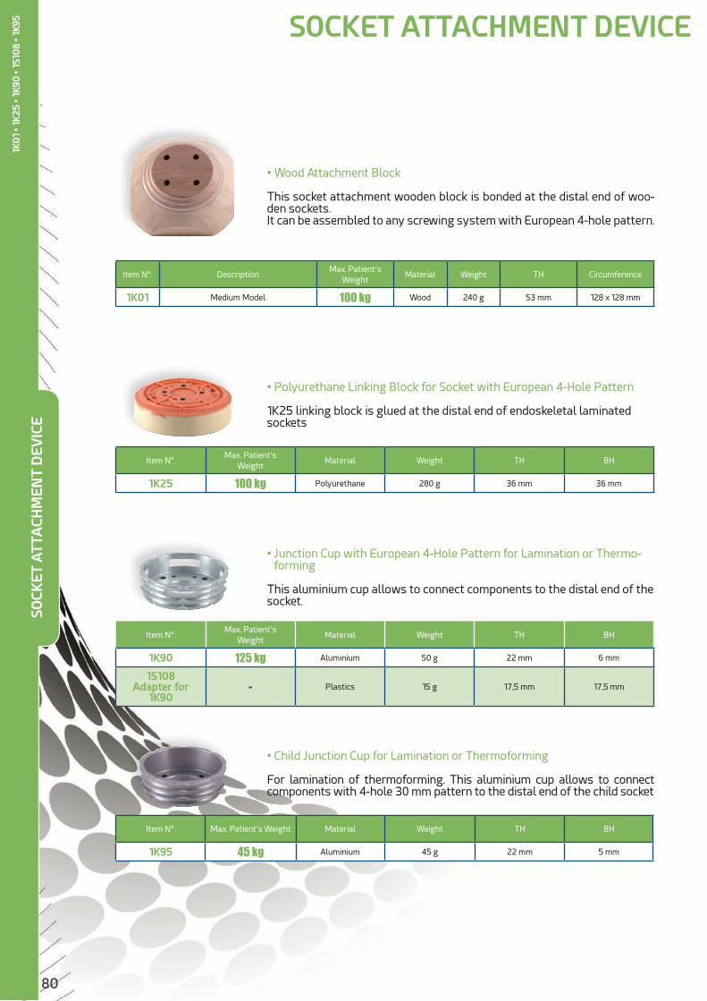
80
• Wood Attachment Block
This socket attachment wooden block is bonded at the distal end of woo-den sockets.It can be assembled to any screwing system with European 4-hole pattern.
Item N°. DescriptionMax. Patient’s
WeightMaterial Weight TH Circumference
1K01 Medium Model 100 kg Wood 240 g 53 mm 128 x 128 mm
• Polyurethane Linking Block for Socket with European 4-Hole Pattern
1K25 linking block is glued at the distal end of endoskeletal laminated sockets
Item N°.Max. Patient’s
WeightMaterial Weight TH BH
1K25 100 kg Polyurethane 280 g 36 mm 36 mm
• Junction Cup with European 4-Hole Pattern for Lamination or Thermo-forming
This aluminium cup allows to connect components to the distal end of the socket.
Item N°.Max. Patient’s
WeightMaterial Weight TH BH
1K90 125 kg Aluminium 50 g 22 mm 6 mm
1S108 Adapter for
1K90- Plastics 15 g 17,5 mm 17,5 mm
• Child Junction Cup for Lamination or Thermoforming
For lamination of thermoforming. This aluminium cup allows to connect components with 4-hole 30 mm pattern to the distal end of the child socket
Item N°. Max. Patient’s Weight Material Weight TH BH
1K95 45 kg Aluminium 45 g 22 mm 5 mm
SOCKET ATTACHMENT DEVICESO
CKET
ATT
ACH
MEN
T D
EVIC
E
1K0
1 • 1
K25
• 1K
90 •
1S10
8 • 1
K95

81
TEM
PO
RA
RY
SOCK
ETTEMPORARY SOCKET

82
RELATED PRODUCTS
• This socket with adjustable closing allows an easy fitting for patients with recent trans-femoral amputa-tion.
• A wide range of adult and child sizes.
• A suspension system is necessary (suspenders).
•We strongly recommend to protect the residual limb with jersey.
Item N°. Side Item N°. lineCircumference of residual
limb baseHeight
Perineum / Socket EndLower Connection Use
1N06 -G / -D 3438 34 to 38 cm
26,5 cm 1N106 Adult
1N06 -G / -D 3943 39 to 43 cm
1N06 -G / -D 4448 44 to 48 cm
1N06 -G / -D 4953 49 to 53 cm
1N06 -G / -D 5458 54 to 58 cm
1N06 -G / -D 5963 59 to 63 cm
1N07 -G / -D 3033 30 to 33 cm21,5 cm 1N107 Child
1N07 -G / -D 3438 34 to 38 cm
ADJUSTABLE TEMPORARY SOCKET
• 1N106 : Linking Device for Temporary Adult Prosthesis
• 1N107 : Linking Device for Temporary Child Prosthesis
• TJ001/2/3/4/5 : Cotton Tubular Jersey
• 1X170 : Suspenders for Temporary Prosthesis
AD
JUST
AB
LE T
EMP
OR
AR
Y SO
CKET
1N
06
• 1N
07
1N1061N107

83
Item N°. Lower Connection Upper Connection Material Weight TH
1N100
1K172 Adult Trans-Femoral Socket Alu / Stainless steel
400 g 290 mm1K165 Child Trans-Femoral Socket Alu / Stainless steel
1K205 Adult Trans-Tibial Socket Aluminium
1K166, 1K206 Child Trans-Femoral Socket Aluminium
• This temporary fitting system consists of 3 splints (1N101) and a multipurpose cup. It can be used rapidly to fit trans-tibial and trans-femoral adults and children with temporary or trial socket. It allows easy alignments. Cost efficient and practical : the cup can be re-used to manufacture the laminated or thermofor-med final socket.
• Sub-Ischial Supports
Item N°. Length x width Material
1X25319 400 x 53 mm
Steel1X25320 450 x 57 mm
1X25313 470 x 57 mm
1X25318 400 x 53 mm Duraluminium
1X25313/18/19
• These pre-cut materials allow rapid manufacture of sub ischial supports for duralu-minium sockets or walking devices.
1X25320
TEMPORARY FITTING SYSTEM
RELATED PRODUCTS
• 1N101 Maintenance Kit :
- 3 stainless steel splints, 2 mm thick, with screws TEM
PO
RA
RY
FITT
ING
SYS
TEM
1N10
0 •
1X
2531
8 •
1X25
319
• 1X
2532
0 •
1X
2531
3
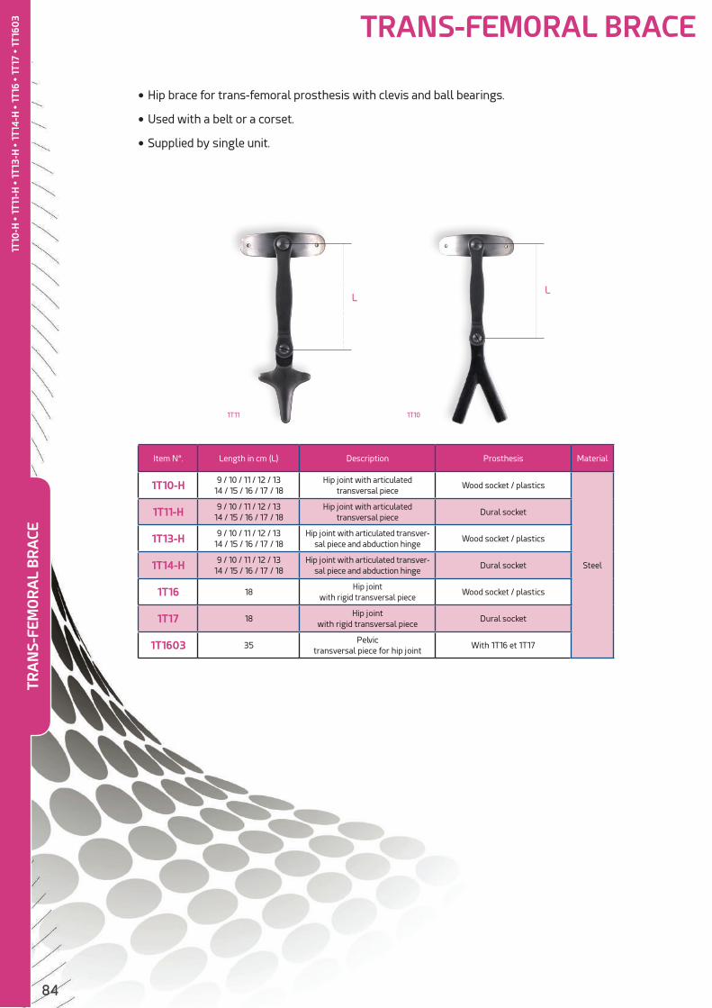
84
TRA
NS-
FEM
OR
AL
BR
ACE
• Hip brace for trans-femoral prosthesis with clevis and ball bearings.
• Used with a belt or a corset.
• Supplied by single unit.
Item N°. Length in cm (L) Description Prosthesis Material
1T10-H 9 / 10 / 11 / 12 / 1314 / 15 / 16 / 17 / 18
Hip joint with articulatedtransversal piece
Wood socket / plastics
Steel
1T11-H 9 / 10 / 11 / 12 / 1314 / 15 / 16 / 17 / 18
Hip joint with articulatedtransversal piece
Dural socket
1T13-H 9 / 10 / 11 / 12 / 13 14 / 15 / 16 / 17 / 18
Hip joint with articulated transver-sal piece and abduction hinge
Wood socket / plastics
1T14-H 9 / 10 / 11 / 12 / 1314 / 15 / 16 / 17 / 18
Hip joint with articulated transver-sal piece and abduction hinge
Dural socket
1T16 18Hip joint
with rigid transversal pieceWood socket / plastics
1T17 18Hip joint
with rigid transversal pieceDural socket
1T1603 35Pelvic
transversal piece for hip jointWith 1T16 et 1T17
TRANS-FEMORAL BRACE
1T101T11
LL
1T10
-H •
1T1
1-H
• 1
T13-
H •
1T1
4-H
• 1
T16
• 1T
17 •
1T1
603
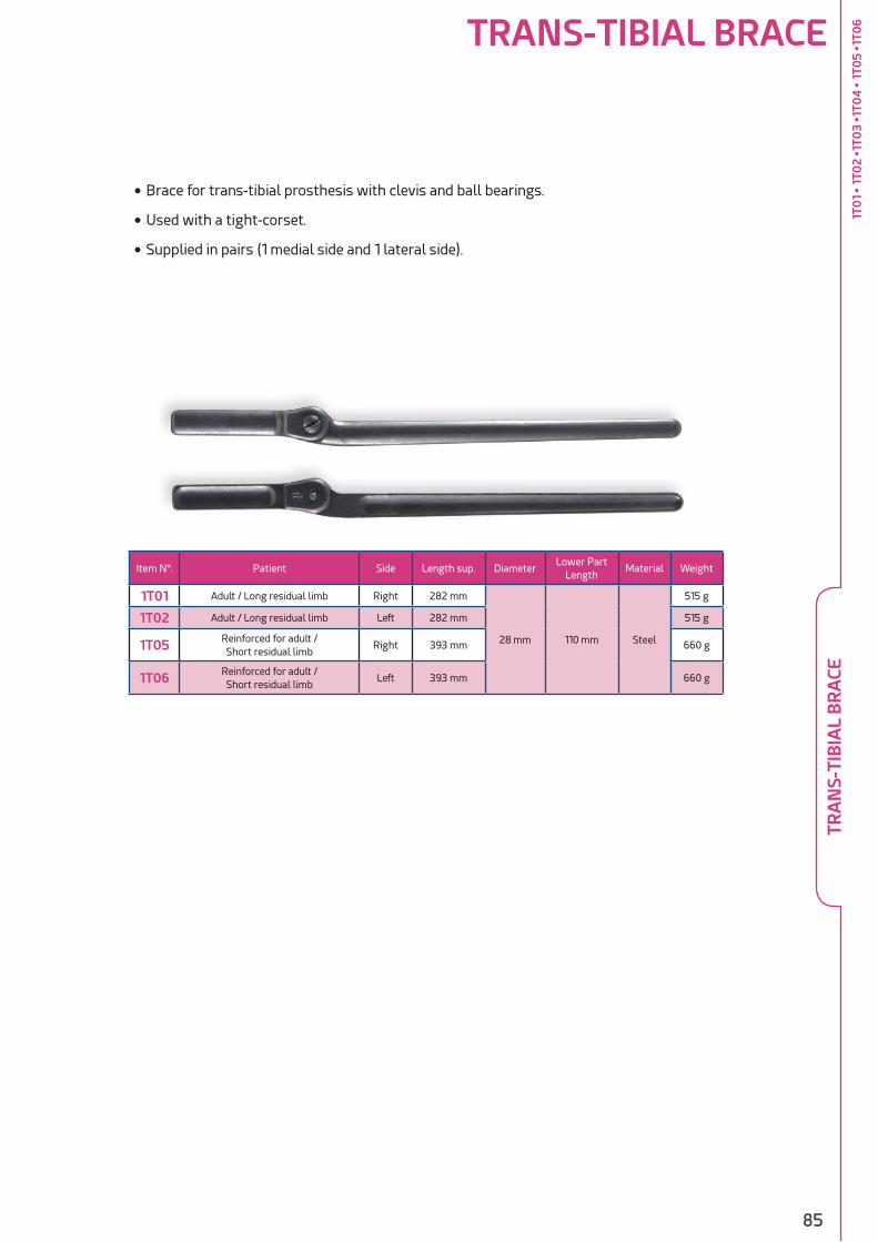
85
TRANS-TIBIAL BRACE
• Brace for trans-tibial prosthesis with clevis and ball bearings.
• Used with a tight-corset.
• Supplied in pairs (1 medial side and 1 lateral side).
Item N°. Patient Side Length sup. DiameterLower Part
LengthMaterial Weight
1T01 Adult / Long residual limb Right 282 mm
28 mm 110 mm Steel
515 g
1T02 Adult / Long residual limb Left 282 mm 515 g
1T05 Reinforced for adult /Short residual limb
Right 393 mm 660 g
1T06 Reinforced for adult /Short residual limb
Left 393 mm 660 g
TRA
NS-
TIB
IAL
BR
ACE
1T0
1 •
1T0
2 •1
T03
•1T0
4 •
1T0
5 •1
T06

86
TEM
PO
RA
RY
PR
OST
HES
IS C
OM
PO
MEN
T K
IT
Item N°. Kit Description Kit Content
1E100 KIT FOR TEMPORARY TRANS-FEMORAL ADULT PROSTHESIS 1K163 + 1M05 + 1G01 + 1D41 + 1D44 + 1N106
1E101 KIT FOR a TRANS-FEMORAL CHILD PROSTHESIS 1N107 + 1M112 + 1G07 + 1D39 + 1D38 + 1K164
1E104 KIT FOR STEEL TRANS-FEMORAL CHILD PROSTHESIS 1M112 + 1G07 + 1D39 + 1D38 + 1N100 + 1K165 + 1K164
1E110 KIT FOR TEMPORARY TRANS-TIBIAL ADULT PROSTHESIS 1N100 + 1G01 + 1D41 x2 + 1D44 + 1K205
1E111 KIT FOR TEMPORARY TRANS-TIBIAL CHILD PROSTHESIS 1N100 + 1G07 + 1D39x2 + 1D38 + XE028 + 1K166
1E116 KIT FOR TEMPORARY TRANS-FEMORAL ADULT PROSTHESIS – 1M10
1N106 + 1M10 + 1G01 + 1D41 + 1D44 + 1K163
1E135 KIT FOR TEMPORARY TRANS-FEMORAL ADULT PROSTHESIS – 1M10
1N100 + 1M10 + 1G01 + 1D41 + 1D44 + 1K163 + 1K172
1E136 KIT FOR TEMPORARY TRANS-FEMORAL ADULT PROSTHESIS – 1M102
1N100 + 1M102 + 1G01 + 1D41 + 1D44 + 1K163 + 1K172
TEMPORARY PROSTHESIS COMPONENT KIT
To ease CPOs' work, we have created the following kits of components for the manufacture of temporary prosthesis for adults or children.

87
LIN
ER
LINER

88
• The STEP’well range liners are made of silicone gel covered with a protective textile fabric.
• Silicone gel liners protect the residual limb of patients with very different activity levels.
• Biocompatible according to ISO 10993-1 standard, this silicone gel reduces the allergenic risks and also withstands chemical effects and ageing.
• The textile cover of the liners provides easier handling and donning of the prosthesis wit-hout limiting its elastic features. Designed to ensure a perfect fit of the residual limb pro-minences, liners are seamless to avoid all uncomfortable spot.
• Either with or without distal attachment, they are fitted with a flexible cup depending on the liner size.
• STEP’well and STEP’well Plus with distal attachment are available in 2 matrix lengths : - 10 cm : standard - 5 cm : for short residual limbs to prevent the matrix edge from being at the same level as the bend of the knee
• One year warranty
SILI
CON
E G
EL L
INER
3 models available, with and without distal attachment.
A wide range of sizes
• TRANS-TIBIAL :
- Locking liner with 10 or 5 cm matrix.
- STEP’well : 3 mm thickness
- STEP’well Plus : 3 mm thickness at the back 6 mm thickness in the front
- An inner position indicator in the front allows to roll the liner easily on the residual limb.
• TRANS-FEMORAL :
- STEP’well AK : 3 mm thickness Conical shape
Item N°. Material Diameter
1S109-80
Silicone
80 mm
1S109-100 100 mm
1S109-120 120 mm
• Silicone Cushion : it protects sensitive areas of the residual limb.
RELATED PRODUCTS
STEP
’WEL
L1S
373
• 1S3
74 •
1S38
3 • 1
S376
• 1S
377
• 1S3
86 •
1S37
5 • 1
S385

89
Item N°.Distal
AttachmentSize Profile Distal Thickness Matrix
1S373 YES 21/23/25/26/28/30/32/34/36/38/40/45
3 mm regular
9 mm 10 cm
1S374 YES 21/23/25/26/28/30/32/36/40/45 9 mm 5 cm
1S383 NO 21/23/25/26/28/30/32/34/36/38/40/45 13 mm NO
• STEP’well
Thanks to their tapered shape and their regular 3 mm thickness, STEP’well liners are appropriate for trans-tibial amputees expecting a good compres-sion with a thin liner.
Item N°.Distal
AttachmentSize Profile Distal Thickness Matrix
1S376 YES 21/23/25/26/28/30/32/34/36/38
3mm posterior 6mm anterior
10 mm 10 cm
1S377 YES 21/23/25/26/28/30/32/36 10 mm 5 cm
1S386 NO 21/23/25/26/28/30/32/34/36/38 14 mm NO
• STEP’well Plus
Thanks to their tapered shape and their increased thickness in the front, STEP’well Plus liners are appropriate for trans-tibial amputees whose bony prominences require increased care. The back re-mains thin not to hinder knee flexion.
A position indicator (red line) in the thick part (in the front of the liner) allows to position the liner cor-rectly.
Item N°.Distal
Attach-ment
Size (cm) ProfileDistal
ThicknessMatrix
1S375 YES S : from 30 to 35M : from 33 to 38L : from 36 to 43
3 mm regular
9 mm 10 cm
1S385 NO 13 mm NO
• STEP’well AK
Thanks to their conical shape and their regular 3 mm thic-kness, STEP’well AK liners are appropriate for trans-femo-ral amputees expecting a comfortable compression of an irregular or flaccid residual limb or an easy suspension on a short residual limb.
SILI
CON
E G
EL L
INER
S M L
43-58 cm 44-57 cm 54-73 cm
35-46 cm 38-50 cm 44-57 cm
30-35 cm 33-38 cm 36-43 cm0 cm4 cm
18 cm
40 cm
Comfort thanks to silicone gel
For patients with moderate or high activity level
Durability : one year warranty
STEP
’WEL
L1S
373
• 1S3
74 •
1S38
3 • 1
S376
• 1S
377
• 1S3
86 •
1S37
5 • 1
S385

90
• The STEPLINE PLUS liners are made of copolymer gel, a flexible material which fits the shape of sensitive residual limbs and provides a comfortable distribution of pres-sure.
• Recommended for healing residual limbs, residual limbs with multiple trauma and diabetic patients with arterial problems and a very sensitive skin.
• These very flexible liners can fit any residual limb shape. They can be thermoformed for the most particular shapes.
• Its original design, thicker in the front, protects bony areas while the thiner back helps knee flexion by limiting strains applied to the patella and folds behind the knee.
• The textile cover does not limit elastic features. The lateral flat seams do not lead to uncomfort in the distal part of the stump.
• Appropriate for patients with low or moderate activity level.
• Six months warranty
COP
OLY
MER
GEL
LIN
ER
Available with and without distal attachment.
Two designs are available :
• 6 mm in the front and 3 mm in the back1S356 and 1S366
• 9 mm in the front and 3 mm in the back to fit ultra sensitive trans-tibial residual limbs : 1S359 and 1S369
- Can be combined with sealing sleeve 1S500/510 and 1S520. - Thermoformable
STEP
LIN
E P
LUS
1S35
6-#
• 1S
359-
# •
1S36
6-#
• 1S
369-
#
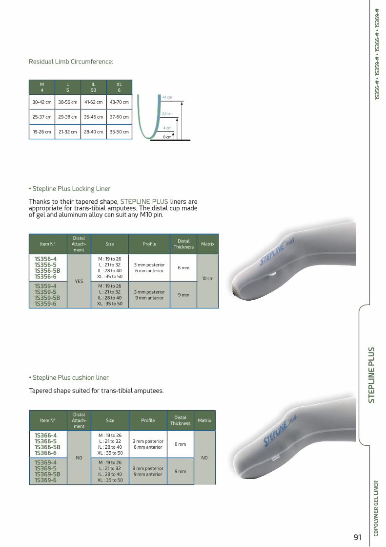
91
Item N°.Distal
Attach-ment
Size ProfileDistal
ThicknessMatrix
1S356-4 1S356-5 1S356-5B 1S356-6
YES
M : 19 to 26L : 21 to 32
IL : 28 to 40XL : 35 to 50
3 mm posterior6 mm anterior
6 mm
10 cm
1S359-4 1S359-5 1S359-5B 1S359-6
M : 19 to 26L : 21 to 32
IL : 28 to 40XL : 35 to 50
3 mm posterior9 mm anterior
9 mm
• Stepline Plus Locking Liner
Thanks to their tapered shape, STEPLINE PLUS liners are appropriate for trans-tibial amputees. The distal cup made of gel and aluminum alloy can suit any M10 pin.
• Stepline Plus cushion liner
Tapered shape suited for trans-tibial amputees.
Item N°.Distal
Attach-ment
Size ProfileDistal
ThicknessMatrix
1S366-4 1S366-5 1S366-5B 1S366-6
NO
M : 19 to 26L : 21 to 32
IL : 28 to 40XL : 35 to 50
3 mm posterior6 mm anterior
6 mm
NO 1S369-4 1S369-5 1S369-5B 1S369-6
M : 19 to 26L : 21 to 32
IL : 28 to 40XL : 35 to 50
3 mm posterior9 mm anterior
9 mm
COP
OLY
MER
GEL
LIN
ER
M4
L5
IL5B
XL6
30-42 cm 38-56 cm 41-62 cm 43-70 cm
25-37 cm 29-38 cm 35-46 cm 37-60 cm
19-26 cm 21-32 cm 28-40 cm 35-50 cm0 cm
4 cm
22 cm
41 cm
Residual Limb Circumference:
STEP
LIN
E P
LUS
1S35
6-#
• 1S
359-
# •
1S36
6-#
• 1S
369-
#

92
Item N°.Distal
AttachmentSize
Regular Thickness
Distal Thickness
Color
Item N°.Distal
AttachmentSize Profile
Distal Thickness
Color
Liners for specific fitting
• STEPLINE PLUS Tapered
To ensure comfort of conical and sensitive residual limbs, the STEPLINE PLUS Tapered liner has been designed with an in-creased 6 mm thickness in its distal part.
• STEPLINE PLUS Evolution
STEPLINE PLUS Evolution liner includes in its front part a flexible textile cover which allows liner stretching and mini-mizes discomfort during knee flexion.The resistant fabric of its back side reduces lengthening to minimize "pistoning" effect while enhancing stability.
• STEPLINE PLUS AK
This model of STEPLINE PLUS is appropriate for any type of trans-femoral residual limb.
Tape
red
Evol
utio
nak
gain
e pr
e�ex
Tape
red
Evol
utio
nak
gain
e pr
e�ex
Tape
red
Evol
utio
nak
gain
e pr
e�ex
1S356A-4 1S356A-5 1S356A-6 1S356A-7 1S356A-8
YESM : 20 to 32L : 21 to 33IL : 26 to 41
XL : 27 to 43XPL : 30 to 50
3 mm 5,2 mm Grey 1S366A-4 1S366A-5 1S366A-6 1S366A-7 1S366A-8
NO
1S356E-4 1S356E-5 1S356E-5B
YESM : 21 to 31L : 23 to 33IL : 27 to 38
2,9 mmposterior
6,5 mmanterior
8 mmSkin
color/Grey 1S366E-4
1S366E-5 1S366E-5B
NO
STEP
LIN
E P
LUS
COP
OLY
MER
GEL
LIN
ER
Item N°.Distal
AttachmentSize Profile
Distal Thickness
Color
1S356T-4 1S356T-5
1S356T-5BYES
M : 21 to 31L : 23 to 33IL : 27 to 38
3 mm posterior
6 mm anterior6 mm Skin color
1S366T-4 1S366T-5
1S366T-5BNO
1S35
6T-#
• 1S
366T
-# •
1S35
6E-#
• 1S
366E
-# •1
S356
A6#
• 1S
366A
-#

93
Sealing Sleeves
SEA
LIN
G S
LEEV
E IN
CO
PO
LYM
ER G
EL
Item N°. Material Length ProfileDistal
CircumferenceProximal
CircumferenceColor
1S500-M
Copolymer Gel 350 mm 3 mm regular
21 to 30 cm 29 to 43 cm
Skin color
1S500-L 28 to 42 cm 36 to 51 cm
1S500-LP 31 to 46 cm 39 to 55 cm
1S500-XL 34 to 50 cm 42 to 60 cm
1S500-XXL 36 to 55 cm 44 to 70 cm
1S510-M 21 to 30 cm 29 to 43 cm
Grey
1S510-L 28 to 42 cm 36 to 51 cm
1S510-LP 31 to 46 cm 39 to 55 cm
1S510-XL 34 to 50 cm 42 to 60 cm
1S510-XXL 36 to 55 cm 44 to 70 cm
Item N°. Material Length ProfileDistal
CircumferenceProximal
CircumferenceColor
1S520-S
Copolymer Gel 340 mm 3 mm regular
15 to 22 cm 23 to 34 cm
Skin color 1S520-M 21 to 30 cm 34 to 43 cm
1S520-L 28 to 42 cm 34 to 51 cm
1S520-XL 34 to 50 cm 42 to 60 cm
• PREFLEX Sealing Sleeve
Sealing sleeve with pre-flexed shape, designed to minimize discomfort during flexion.
• Sealing SleevesSkin color : very resistant thanks to its thick cover fabric.Grey : easy to use thanks to its great flexibility.
Tape
red
Evol
utio
nak
gain
e pr
e�ex
STEP
LIN
E P
LUS
1S50
0-#
• 1S
510
-# •
1S52
0-#
94
• STEPLINE HD liners are made of copolymer gel with an inner coating that en-sures Hygiene and Durability.
• An ultrathin velvety biocompatible coating has been applied on the gel area. It helps limiting embedded impurities that may appear on the part of the liner in contact with the skin when the patient is wearing it. Moreover, it can be cleaned more easily. Unpleasant smells are reduced and the patient’s everyday comfort is improved.
• The skin color external fabric is wear-resistant.
• The features of the copolymer gel are identical to those of the STEPLINE PLUS liners : distribution of pressure for patients having a particularly sensitive resi-dual limb (healing, with multiple trauma, diabetic patients with arterial disease, …)
• Design : thicker in the front to protect bony areas ; thiner in the back to help knee flexion.
• 6 months warranty.
• Available with and without distal attachment.
• Recommended for trans-tibial patients
WIT
H IN
NER
CO
ATI
NG
2 MODELS ARE AVAILABLE :
• 6 mm in the front and 3 mm in the back : 1S356H et 1S366H
• 9 mm in the front and 3 mm in the back to fit ultra sensitive trans-tibial residual limbs : 1S359H & 1S369H
- Liners Length: 410 mm
- Thermoformable
STEP
LIN
E H
D
1S35
6H-#
• 1S
359H
-# •
1S36
6H-#
• 1S
369H
-# 3
66A
-#

95
RELATED PRODUCTS
Item N°.Distal
Attach-ment
Size ProfileDistal
ThicknessMatrix
1S356H-4 1S356H-5 1S356H-5B 1S356H-6
YES
M : 21 to 31L : 23 to 33IL : 27 to 38XL : 29 to 42
3 mm posterior
6 mm anterior
6 mm
10 cm
1S359H-4 1S359H-5 1S359H-5B 1S359H-6
M : 21 to 31L : 23 to 33IL : 27 to 38XL : 29 to 42
3 mmposterior
9 mmanterior
9 mm
• Stepline HD Locking Liner
The distal cup made of gel and aluminum alloy can suit any M10 pin.
• Stepline HD without Distal Attachment
Item N°. Circumference / Diameter Liners STEPLINE PLUS / HD
1S390-1 16 cm / 5 cm Small residual limbs
1S390-2 23,5 cm / 7,5 cm STEPLINE PLUS / HD 4 -5
1S390-3 30 cm / 9,5 cm STEPLINE PLUS / HD 5B -6
• Distal cup : in transparent and very elastic copolymer gel.Perfectly appropriate for any STEPLINE PLUS / STEPLINE HD liners. Compensates volume for residual limbs with conical shape. Flexibility provides comfort in sensitive areas. Thickness in distal part : 3 mm. Height 14 cm.
Item N°.Distal
Attach-ment
Size ProfileDistal
ThicknessMatrix
1S366H-4 1S366H-5 1S366H-5B 1S366H-6
NO
M : 21 to 31L : 23 to 33IL : 27 to 38XL : 29 to 42
3 mm posterior
6 mm anterior
6 mm
NO
1S369H-4 1S369H-5 1S369H-5B 1S369H-6
M : 21 to 31L : 23 to 33IL : 27 to 38XL : 29 to 42
3 mm posterior
9 mmanterior
9 mm
• 1S391 : Kit of 3 Pressure Pads in Copolymer GelIncludes 3 pads of different sizes : 50 x 85 mm ; 75 x 105 mm ; 105 x 125 mm.Spreads and reduces pressure areas in the sensitive parts of the residual limb. Manages residual limb volume changes. Perfectly appropriate for any STEPLINE PLUS / STEPLINE HD liner.
M4
L5
IL5B
XL6
30-47 cm 37-60 cm 43-63 cm 46-68 cm
26-40 cm 31-45 cm 36-49 cm 40-55 cm
21-31 cm 23-33 cm 27-38 cm 29-42 cm0 cm
4 cm
22 cm
41 cm
Stump Circumference :
STEP
LIN
E H
D1S
356H
-# •
1S35
9H-#
• 1S
366H
-# •
1S36
9H-#
W
ITH
INN
ER C
OA
TIN
G
Diameter :
Circumference :

96
• KEASY has established itself over the years as the unique prefabricated cone al-lowing to manufacture rapidly quality finished thermoformed liners.
• Its regular thickness allows vacuum thermoforming to fit the residual limb proe-minences. We recommend 170 °C heating temperature for 1 min 15 to 3 minutes according to the KEASY dimensions.
• No welding, no gluing and seamless : it minimizes allergenic risks and avoids any feeling of discomfort.
• Finishing time is shorten with easy cutting out and sanding. Changes in residual limb volume can be compensated by gluing extra thicknesses on the outside of the KEASY.
• Closed cells structure : perspiration and cleaning products do not penetrate into the material and cleaning is easy.
• Liners manufactured with KEASY have a good durability. They withstand friction, crushing and stretching, providing durable comfort.
THER
MO
FOR
MA
BLE
CO
NE
8 MODELS
Extra distal thickness.
• Trans-tibial in 5 sizes : - 110 mm : long and thin residual limbs - 130 mm : small residual limbs (for children or forearm interface) - 160 & 180 mm : common residual limbs - 195 mm : sizeable residual limbs
• Trans-femoral in 2 sizes - 210 mm - 230 mm
Rigid interface between a gel liner and a socket
• Trans-tibial in one size : 170 mm
180
160
110
210
170
130
195
230
Thermoformable cone used to manufacture a custom-made soft liner
Average manufacturing time : 5 minutes
Hygienic : close cells structure, easy to clean
Cost efficient : can be re-heated and re-shaped several times
KEA
SY1S
40
2-11
0 •
1S4
00
-130
• 1S
40
0-1
60 •
1S4
00
-180
• 1S
40
0-1
95 •
1S4
00
-210
•1S4
00
-230
• 1S
40
1-17
0
PATENTED
PATENTE
D

97
Item N°. Use Length Ø Proximal ProfileDistal Thic-
knessPackaging
1S401-170 Trans-tibialShort & medium
420 mm 420 mm 3 mm 10 mmx 1
1S401-170#12 x 12
• Keasy Comfort
Liner appropriate for a rigid lami-nated or thermoformed socket for patients with low activity level or for first fitting.We recommend to wear a sock, a sleeve or a jersey as an interface between the skin and the KEASY liner..
• Keasy interface
This type of liner is used as an interface between a gel liner and a rigid socket. It enhances patients’ comfort with no need to increase gel thickness to keep the same level of prosthe-sis control. Cut longer than the prosthesis, it protects the gel liner against friction, al-lowing it to have a longer product life
Item N°. Use Length Ø Proximal Profile Distal Thickness Packaging
1S402-110 Trans-tibial, smallUpper limb
305 mm 110 mm 5 mm 8 mmx 1
1S402-110#12 x 12
1S400-130 Trans-tibial,Long & thin
500 mm 130 mm 6,5 mm 10 mmx 1
1S400-130#12 x12
1S400-160 Trans-tibialShort & medium
400 mm 160 mm 6,5 mm 10 mmx 1
1S400-160#16 x 16
1S400-180 Trans-tibialShort & medium
500 mm 180 mm 6,5 mm 15 mmx 1
1S400-180#12 x12
1S400-195 Trans-tibialXL
510 mm 195 mm 6,5 mm 10 mmx 1
1S400-195#9 x 9
1S400-210Trans-femoral 500 mm 210 mm 6,5 mm 10 mm
x 1
1S400-210#6 x 6
1S400-230 Trans-femoral XL
510 mm 230 mm 6,5 mm 10 mmx 1
1S400-230#6 x 6
THER
MO
FOR
MA
BLE
CO
NE
Distal Thickness
Ø Proximal
Profile
Length
Examples of thermoformed cones
170
110
160
180
210
130
195
230
KEA
SY1S
40
2-11
0 •
1S4
00
-130
• 1S
40
0-1
60 •
1S4
00
-180
• 1S
40
0-1
95 •
1S4
00
-210
•1S4
00
-230
• 1S
40
1-17
0
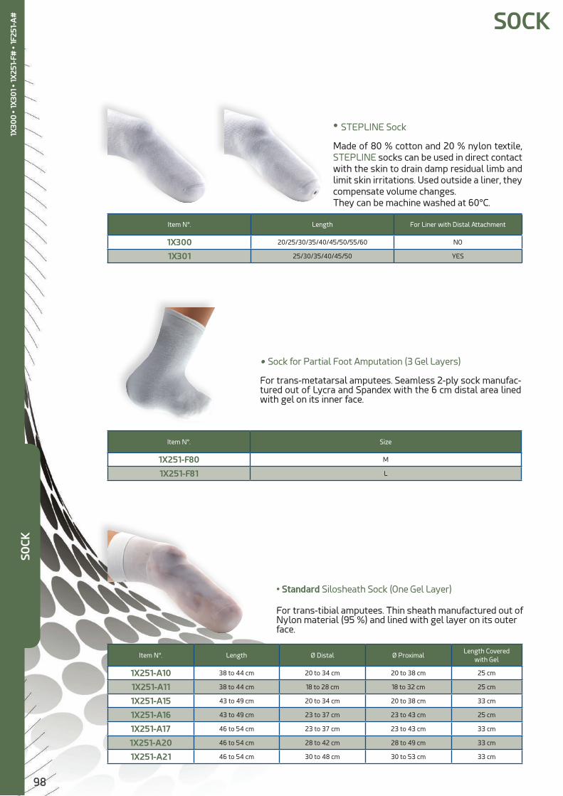
98
• STEPLINE Sock
Made of 80 % cotton and 20 % nylon textile, STEPLINE socks can be used in direct contact with the skin to drain damp residual limb and limit skin irritations. Used outside a liner, they compensate volume changes.They can be machine washed at 60°C.
Item N°. Length For Liner with Distal Attachment
1X300 20/25/30/35/40/45/50/55/60 NO
1X301 25/30/35/40/45/50 YES
• Sock for Partial Foot Amputation (3 Gel Layers)
For trans-metatarsal amputees. Seamless 2-ply sock manufac-tured out of Lycra and Spandex with the 6 cm distal area lined with gel on its inner face.
Item N°. Size
1X251-F80 M
1X251-F81 L
• Standard Silosheath Sock (One Gel Layer)
For trans-tibial amputees. Thin sheath manufactured out of Nylon material (95 %) and lined with gel layer on its outer face.
SOCK
Item N°. Length Ø Distal Ø ProximalLength Covered
with Gel
1X251-A10 38 to 44 cm 20 to 34 cm 20 to 38 cm 25 cm
1X251-A11 38 to 44 cm 18 to 28 cm 18 to 32 cm 25 cm
1X251-A15 43 to 49 cm 20 to 34 cm 20 to 38 cm 33 cm
1X251-A16 43 to 49 cm 23 to 37 cm 23 to 43 cm 25 cm
1X251-A17 46 to 54 cm 23 to 37 cm 23 to 43 cm 33 cm
1X251-A20 46 to 54 cm 28 to 42 cm 28 to 49 cm 33 cm
1X251-A21 46 to 54 cm 30 to 48 cm 30 to 53 cm 33 cm
SOCK
1X30
0 •
1X30
1 • 1
X25
1-F#
• 1F
251-
A#

99
• Triple Protection Silosheath Sock (3 Gel Layers)
For trans-tibial amputees. Thin sheath manufactured out of Nylon material (95 %) and lined with two gel layers on its
Item N°. Length Ø Distal Ø ProximalLength Covered
with Gel
1X251-B40 38 to 44 cm 20 to 34 cm 20 to 38 cm 25 cm
1X251-B41 38 to 44 cm 18 to 28 cm 18 to 32 cm 25 cm
1X251-B42 43 to 49 cm 20 to 34 cm 20 to 38 cm 33 cm
1X251-B43 43 to 49 cm 23 to 37 cm 23 to 43 cm 25 cm
1X251-B44 46 to 54 cm 23 to 37 cm 23 to 43 cm 33 cm
1X251-B45 46 to 54 cm 28 to 42 cm 28 to 49 cm 33 cm
1X251-B46 46 to 54 cm 30 to 48 cm 30 to 53 cm 33 cm
• Extra Silosheath Sock (2 Textile Layers + 3 Gel Layers)
For trans-tibial amputees. Two thin sheaths manufactured out of Nylon material (95 %) covering three layers of protective gel.
Item N°. Length Ø Distal Ø ProximalLength Covered
with Gel
1X251-C80 38 to 44 cm 20 to 34 cm 20 to 38 cm 25 cm
1X251-C81 38 to 44 cm 18 to 28 cm 18 to 32 cm 25 cm
1X251-C82 43 to 49 cm 20 to 34 cm 20 to 38 cm 33 cm
1X251-C83 43 to 49 cm 23 to 37 cm 23 to 43 cm 25 cm
1X251-C84 46 to 54 cm 23 to 37 cm 23 to 43 cm 33 cm
1X251-C85 46 to 54 cm 28 to 42 cm 28 to 49 cm 33 cm
1X251-C86 46 to 54 cm 30 to 48 cm 30 to 53 cm 33 cm
• Double Silosheath sock (2 gel layers)
For trans-tibial amputees. Two thin sheaths manufactured out of Nylon material (95 %) covering two layers of protective gel.
Item N°. Length Ø Distal Ø ProximalLength Covered
with Gel
1X251-E62 30 cm 23 to 30 cm 38 to 46 cm 25 cm
1X251-E65 30 cm 30 to 36 cm 46 to 56 cm 25 cm
1X251-E66 40 cm 30 to 36 cm 46 to 56 cm 25 cm
SOCK
1X25
1-B
# •
1X25
1-C#
• 1X
251-
E#

100
STEP-IND
EVIC
E TO
TU
RN
TH
E LI
NER
INSI
DE
OU
T
Step-in is a multi-purpose support designed to help easily turning inside out any kind of liners (copolymer gel, silicone gel, silicone...).
It facilitates putting on, drying and daily cleaning of the liner.
Height : 39 cm
Item N°. Packaging
1S900 Unit
1S900#5 Set of 5STEP
-IN
1S90
0
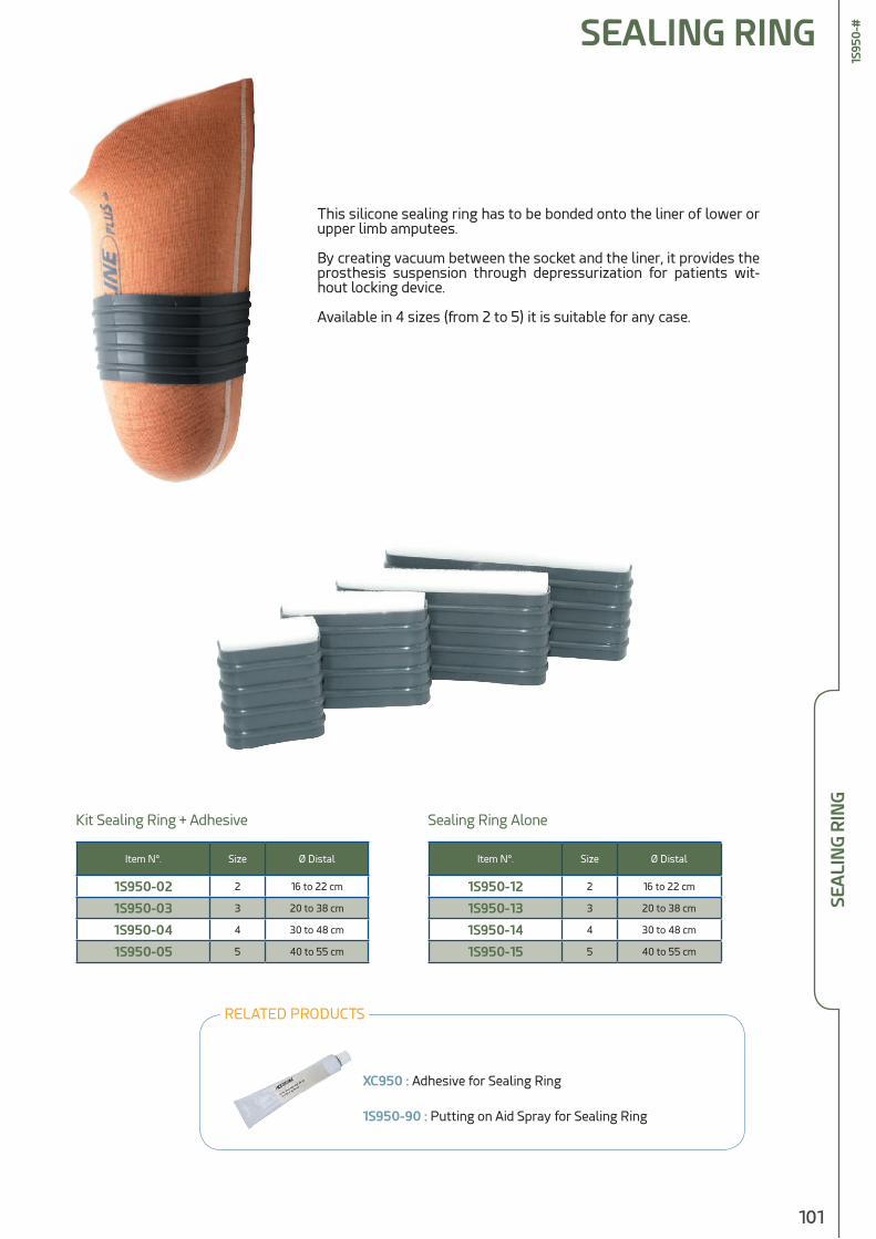
101
SEALING RING
SEA
LIN
G R
ING
1S95
0-#
This silicone sealing ring has to be bonded onto the liner of lower or upper limb amputees.
By creating vacuum between the socket and the liner, it provides the prosthesis suspension through depressurization for patients wit-hout locking device.
Available in 4 sizes (from 2 to 5) it is suitable for any case.
Item N°. Size Ø Distal
1S950-02 2 16 to 22 cm
1S950-03 3 20 to 38 cm
1S950-04 4 30 to 48 cm
1S950-05 5 40 to 55 cm
Item N°. Size Ø Distal
1S950-12 2 16 to 22 cm
1S950-13 3 20 to 38 cm
1S950-14 4 30 to 48 cm
1S950-15 5 40 to 55 cm
Kit Sealing Ring + Adhesive Sealing Ring Alone
RELATED PRODUCTS
XC950 : Adhesive for Sealing Ring
1S950-90 : Putting on Aid Spray for Sealing Ring
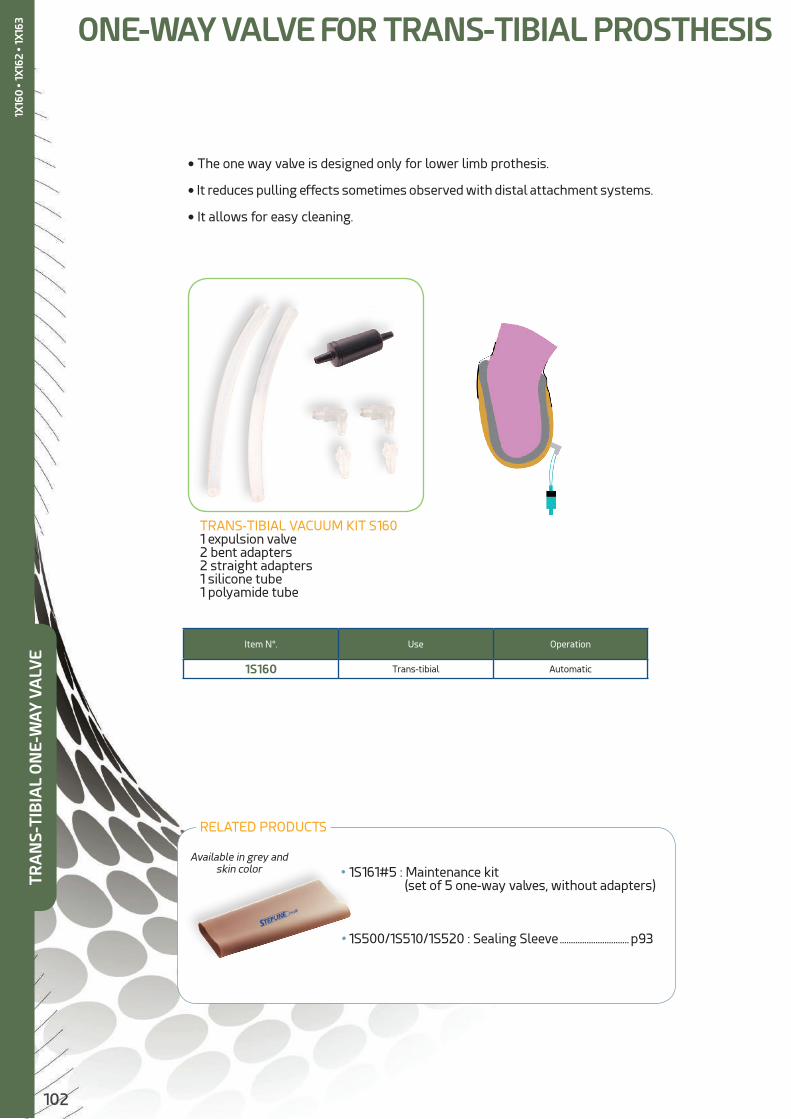
102
TRANS-TIBIAL VACUUM KIT S1601 expulsion valve2 bent adapters2 straight adapters1 silicone tube1 polyamide tube
Item N°. Use Operation
1S160 Trans-tibial Automatic
ONE-WAY VALVE FOR TRANS-TIBIAL PROSTHESIS
• The one way valve is designed only for lower limb prothesis.
• It reduces pulling effects sometimes observed with distal attachment systems.
• It allows for easy cleaning.
• 1S161#5 : Maintenance kit (set of 5 one-way valves, without adapters)
• 1S500/1S510/1S520 : Sealing Sleeve ............................... p93
Available in grey and skin color
TRA
NS-
TIB
IAL
ON
E-W
AY
VA
LVE
RELATED PRODUCTS
1X16
0 •
1X16
2 • 1
X163
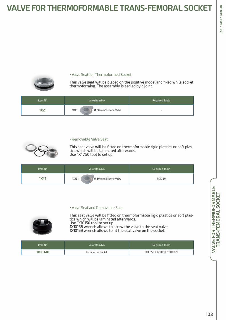
103
a
• Valve Seat and Removable Seat
This seat valve will be fitted on thermoformable rigid plastics or soft plas-tics which will be laminated afterwards.Use 1X10150 tool to set up.1X10158 wrench allows to screw the valve to the seat valve.1X10159 wrench allows to fit the seat valve on the socket.
Item N°. Valve Item No Required Tools
1X10140 Included in the kit 1X10150 / 1X10158 / 1X10159
• Valve Seat for Thermoformed Socket
This valve seat will be placed on the positive model and fixed while socket thermoforming. The assembly is sealed by a joint.
Item N°. Valve Item No Required Tools
1X21 1X16 : Ø 30 mm Silicone Valve -
• Removable Valve Seat
This seat valve will be fitted on thermoformable rigid plastics or soft plas-tics which will be laminated afterwards.Use 1X4750 tool to set up.
Item N°. Valve Item No Required Tools
1X47 1X16 : Ø 30 mm Silicone Valve 1X4750
VALVE FOR THERMOFORMABLE TRANS-FEMORAL SOCKET
VA
LVE
FOR
TH
ERM
OFO
RM
AB
LE
TRA
NS-
FEM
OR
AL
SOCK
ET1X
21 •
1X45
• 1X
1014
0
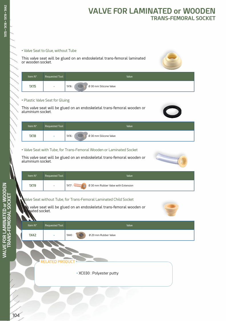
104
• Valve Seat with Tube, for Trans-Femoral Wooden or Laminated Socket
This valve seat will be glued on an endoskeletal trans-femoral wooden or aluminium socket.
• Valve Seat to Glue, without Tube
This valve seat will be glued on an endoskeletal trans-femoral laminated or wooden socket.
Item N°. Requested Tool Valve
1X15 - 1X16 : Ø 30 mm Silicone Valve
• Plastic Valve Seat for Gluing
This valve seat will be glued on an endoskeletal trans-femoral wooden or aluminium socket.
• Valve Seat without Tube, for Trans-Femoral Laminated Child Socket
This valve seat will be glued on an endoskeletal trans-femoral wooden or laminated socket.
VALVE FOR LAMINATED or WOODENTRANS-FEMORAL SOCKET
Item N°. Requested Tool Valve
1X18 - 1X16 : Ø 30 mm Silicone Valve
Item N°. Requested Tool Valve
1X19 - 1X17 : Ø 30 mm Rubber Valve with Extension
Item N°. Requested Tool Valve
1X42 - 1X40 : Ø 20 mm Rubber Valve
• XC030 : Polyester putty
RELATED PRODUCT
VALV
E FO
R L
AM
INAT
ED o
r W
OO
DEN
TRA
NS-
FEM
OR
AL
SOCK
ET1X
15 •
1X18
• 1X
19 •
1X42

105
• Aluminium Valve Seat for Welding
This valve seat will be welded on an aluminium socket.
• 1X45 Rigid Hole Shuttle Housing
To be glued on a wooden or laminated traditional socket.
• 1X13 Flexible Hole Shuttle Housing
To be fixed on the cosmetic cover and the stocking to allow an easier access to the valve.
VALVE FOR ALUMINIUM TRANS-FEMORAL SOCKET
ACCESSORIES FOR TRANS-FEMORAL VALVE
Item N°. Requested Tool Valve
1X20 - 1X16 : Ø 30 mm Silicone Valve
VA
LVE
FOR
ALU
MIN
IUM
TR
AN
S-FE
MO
RA
L SO
CKET
1X20
• 1X
45

106
Item N°. Description
1S162 Valve for BK Socket
Item N°. Description
1S163 Valve for AK Socket
Item N°. Description
1S164 Tool for 1S163 depressurizing Valve
DEPRESSURIZING VALVES
Depressurizing Valves for Trans-Tibial Socket
Allows a firm suspension of the prosthesis onto the residual limb, due to automatic air expulsion.Easy to use for the patients.
Specific ToolAllows to set up, remove and configurate (manually or automatically) trans-femoral valve 1S163.
1S16
2 • 1
S163
• 1S
164
DEP
RES
SUR
IZIN
G V
ALV
E
Depressurizing Valves for Trans-Femoral Socket
Allows a firm suspension of the prosthesis onto the residual limb, thanks to manual air expulsion or automatic one.The cap has a quick opening system (¼ turn), allowing to use a putting on aid for the prosthesis.Easy to use for the patient.A specific tool (1S164) can be used to set up the valve.

107
Revofit allows the amputee to adjust precisely the socket’s tightening, by rotating a simple dial.
Principle : a wire is inserted in a sheath which is laminated inside the socket. The concealed wiring is linked to a setting wheel that controls tightness.
With simple turn, the patient is able to tighten the socket for a better control over the prosthesis according to its activity.
It is also easy to loosen the socket in order to release the pressure off the residual limb and then get a better comfort while resting or sitting the handling can be done with a single hand, even through clothing.
The wired tightening system, combined with some panels cut out in the socket, allows to target the residual limb’s compression or expansion areas. It offers the possibility to support size variations and to relieve the most sensitive areas.
REVOFIT KIT WITH BOA SYSTEM
Item N°. Description Kit contents
1S600 180° Revofit KitBOA closing system with its specific
tool + Bayonet + 120 mm inlaid guide + 2 flexible cables + threader
Item N°. Description Kit Contents
1S610 Parallel Revofit KitBOA closing system with its specific
tool + Bayonet + 120 mm inlaid guide + 2 flexible cables + threader
Two set-ups are available, depending on the prosthetist’s and his patient’s choice.
• 1S600 : 180° Revofit Kit
The ends of the tightening wire come out from both sides of the adjustment dial.
• 1S610 : Parallel Revofit Kit
The ends of the tightening wire come out in parallel from one side of the adjust-ment dial.
REV
OFI
T K
IT W
ITH
BO
A S
YSTE
M1S
600
• 1S
610
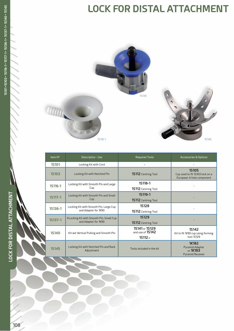
108
Item N°. Description - Use Required Tools Accessories & Options
1S101 Locking Kit with Cord - -
1S103 Locking Kit with Notched Pin 1S112 Centring Tool1S105
Cup used to fit 1S103 lock on a European 4-hole component
1S116-1 Locking Kit with Smooth Pin and Large Cup
1S118-1
1S112 Centring Tool-
1S117-1 Locking Kit with Smooth Pin and Small Cup
1S119-1
1S112 Centring Tool-
1S136-1 Locking Kit with Smooth Pin, Large Cup and Adapter for 1K90
1S128
1S112 Centring Tool-
1S137-1 KLocking Kit with Smooth Pin, Small Cup and Adapter for 1K90
1S129
1S112 Centring Tool-
1S140 Kit wit Vertical Pulling and Smooth Pin
1S141 or 1S129 and use of 1S142
1S112 v
1S142Kit to fit 1K90 cup using forming
tool 1S129
1S145 Locking Kit with Notched Pin and Rack Adjustment
Tools included in the kit
1K182Pyramid Adapter
or 1K183Pyramid Receiver
LOCK FOR DISTAL ATTACHMENT
1S116-1 1S145
1S140
LOCK
FO
R D
ISTA
L A
TTA
CHM
ENT
1S10
1 •1
S10
3 • 1
S116
-1 •
1S11
7-1
• 1S1
36-1
• 1S
137-
1 • 1
S14
0 •
1S14
5
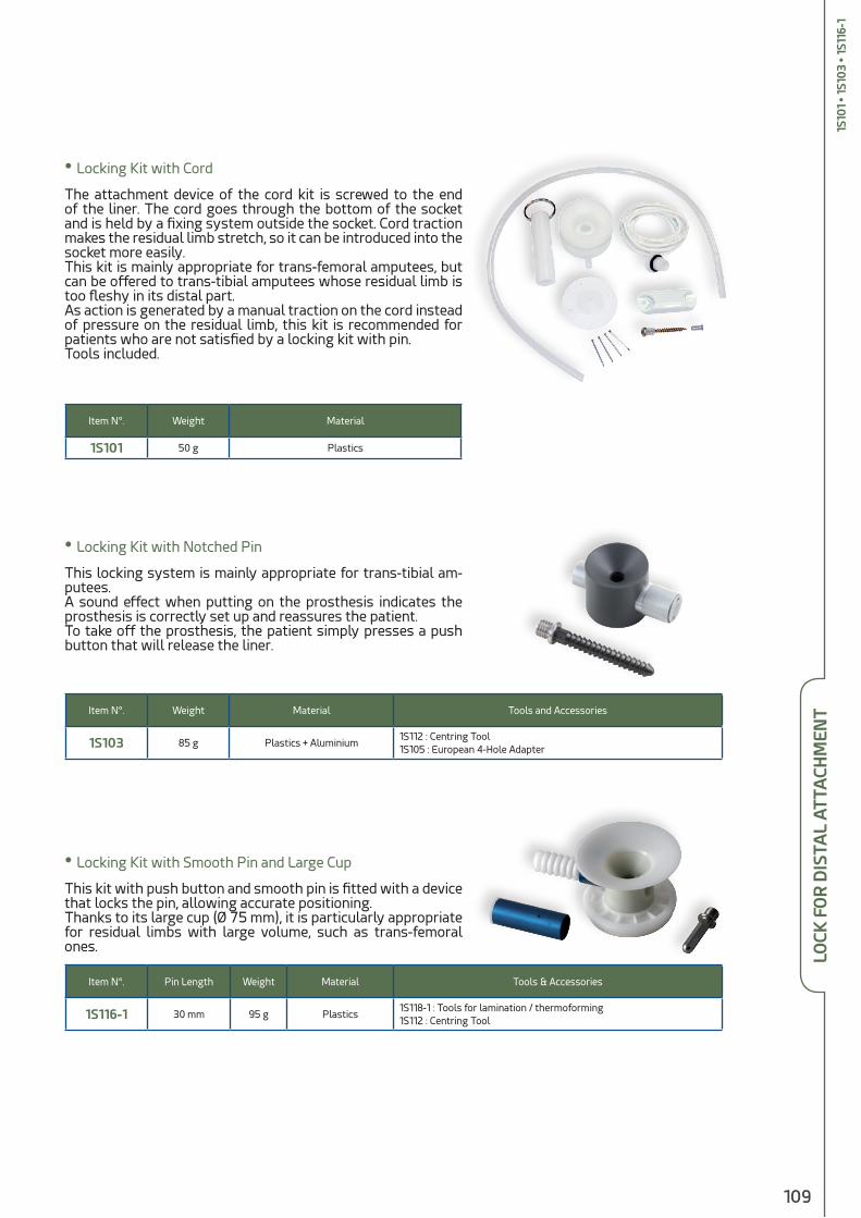
109
• Locking Kit with Cord
The attachment device of the cord kit is screwed to the end of the liner. The cord goes through the bottom of the socket and is held by a fixing system outside the socket. Cord traction makes the residual limb stretch, so it can be introduced into the socket more easily. This kit is mainly appropriate for trans-femoral amputees, but can be offered to trans-tibial amputees whose residual limb is too fleshy in its distal part.As action is generated by a manual traction on the cord instead of pressure on the residual limb, this kit is recommended for patients who are not satisfied by a locking kit with pin.Tools included.
Item N°. Weight Material
1S101 50 g Plastics
• Locking Kit with Notched Pin
This locking system is mainly appropriate for trans-tibial am-putees.A sound effect when putting on the prosthesis indicates the prosthesis is correctly set up and reassures the patient.To take off the prosthesis, the patient simply presses a push button that will release the liner.
Item N°. Weight Material Tools and Accessories
1S103 85 g Plastics + Aluminium1S112 : Centring Tool1S105 : European 4-Hole Adapter
• Locking Kit with Smooth Pin and Large Cup
This kit with push button and smooth pin is fitted with a device that locks the pin, allowing accurate positioning.Thanks to its large cup (Ø 75 mm), it is particularly appropriate for residual limbs with large volume, such as trans-femoral ones.
Item N°. Pin Length Weight Material Tools & Accessories
1S116-1 30 mm 95 g Plastics1S118-1 : Tools for lamination / thermoforming1S112 : Centring Tool
LOCK
FO
R D
ISTA
L AT
TACH
MEN
T1S
101
• 1S1
03
• 1S1
16-1
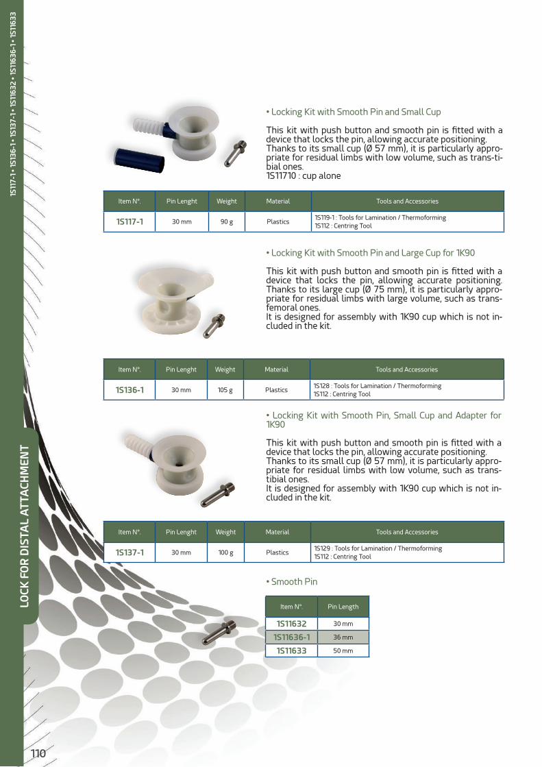
110
• Locking Kit with Smooth Pin and Small Cup
This kit with push button and smooth pin is fitted with a device that locks the pin, allowing accurate positioning.Thanks to its small cup (Ø 57 mm), it is particularly appro-priate for residual limbs with low volume, such as trans-ti-bial ones.1S11710 : cup alone
Item N°. Pin Lenght Weight Material Tools and Accessories
1S117-1 30 mm 90 g Plastics1S119-1 : Tools for Lamination / Thermoforming1S112 : Centring Tool
• Locking Kit with Smooth Pin and Large Cup for 1K90
This kit with push button and smooth pin is fitted with a device that locks the pin, allowing accurate positioning. Thanks to its large cup (Ø 75 mm), it is particularly appro-priate for residual limbs with large volume, such as trans-femoral ones.It is designed for assembly with 1K90 cup which is not in-cluded in the kit.
Item N°. Pin Lenght Weight Material Tools and Accessories
1S136-1 30 mm 105 g Plastics1S128 : Tools for Lamination / Thermoforming1S112 : Centring Tool
• Locking Kit with Smooth Pin, Small Cup and Adapter for 1K90
This kit with push button and smooth pin is fitted with a device that locks the pin, allowing accurate positioning.Thanks to its small cup (Ø 57 mm), it is particularly appro-priate for residual limbs with low volume, such as trans-tibial ones.It is designed for assembly with 1K90 cup which is not in-cluded in the kit.
• Smooth Pin
Item N°. Pin Lenght Weight Material Tools and Accessories
1S137-1 30 mm 100 g Plastics1S129 : Tools for Lamination / Thermoforming1S112 : Centring Tool
Item N°. Pin Length
1S11632 30 mm
1S11636-1 36 mm
1S11633 50 mm
LOCK
FO
R D
ISTA
L A
TTA
CHM
ENT
1S11
7-1
• 1S1
36-1
• 1S
137-
1 • 1
S116
32 •
1S11
636-
1 • 1
S116
33

111
• Locking Kit with Smooth Pin and Vertical Pulling
This locking kit with pin is operated by vertical tab pul-ling.
Control of unlocking can be displaced through a handle fitted on the side of the socket.
2 pins are supplied :a smooth pin that provides fine adjustment of the liner, and a smooth pin with notched end allowing the pa-tient to know if the pin is well engaged and providing accurate adjustment.
Ø 45 mm cup.
Item N°. Weight Material Tools and Accessories
1S140 85 g Plastics
1S141 : Tools for Lamination / Thermoforming1S129 : Tool for Lamination / Thermoforming, used with 1S1421S112 : Centring Tool1S142 : Adapting Kit for assembly with 1K90 cup1X110 : Handle for displaced control of unlocking
• Locking Kit with Notched Pin and Rack Adjustment
1S145 locking kit provides very fine adjustment thanks to its rack system which avoids any slack in the bottom of the socket.It comes with a lamination prong for the upper connec-tion and the tools needed for lamination.The lower connection is provided by screwing a threaded pyramid insert (1K182) or a threaded Receiver insert (1K183).
Item N°. Weight Material Tools and Accessories
1S145 125 g Aluminium + Stainless steel1K182 : Threaded Pyramid insert 1K183 : Threaded Receiver insert
LOCK
FO
R D
ISTA
L AT
TACH
MEN
T1S
140
• 1S
145

112
• European 4-Hole plate
This cup allows to fit any European 4-hole linking compo-nent (4 x M6, 36 mm) on a knee.Comes with its protective tools.
Item N°. Weight Material
1S105 75 g Aluminium
• Centring Tool
Fitted on the end of a positive model previously slightly levelled, the 1S112 tool allows to install a pin lock. It will be taken off (for re-use) when the positive model is broken down.Used for item No 1S103, 1S116-1, 1S117-1, 1S136-1, 1S137-1, 1S140
Item N°. Material
1S112 Plastics
• Forming Tool for 1S116-1
1S118-1 tool allows to keep enough space at the bottom of the socket to receive 1S116-1 locking kit with smooth pin.
Item N°. Description Material
1S118-1 Forming Tool for 1S116-1 Plastics
Item N°. Description Material
1S119-1 Forming Tool for 1S117-1 Plastics
Item N°. Description Material
1S128 Forming Tool for 1S136-1 Plastics
Item N°. Description Material
1S129 Forming Tool for 1S137-1or 1S140
Plastics
• Forming Tool for 1S117-1
1S119-1 tool allows to keep enough space at the bottom of the socket to re-ceive 1S117-1 locking kit with smooth pin.
• Forming Tool for 1S136-1
1S128 tool allows to keep enough space at the bottom of the socket to receive 1S136-1 locking kit with smooth pin and adapter.
• Forming Tool for 1S137-1 et 1S140
1S129 tool allows to keep enough space at the bottom of the socket to receive 1S137-1 locking kit with smooth pin and adapter, or 1S140 locking kit with 1S142 kit.
TOOLS AND ACCESSORIES FOR LOCKTO
OLS
AN
D A
CCES
SOR
IES
FOR
LO
CK1S
105
• 1S1
12 •
1S11
8-1
• 1S1
19-1
• 1
S128
• 1S
129
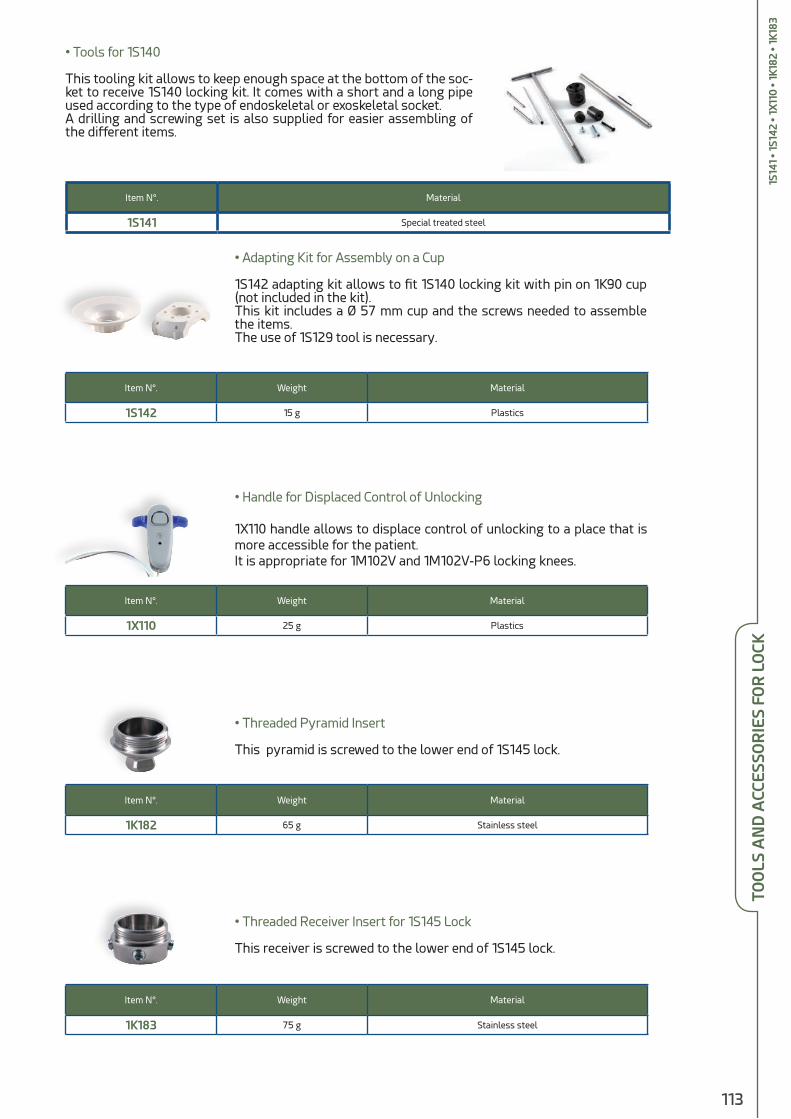
113
• Tools for 1S140
This tooling kit allows to keep enough space at the bottom of the soc-ket to receive 1S140 locking kit. It comes with a short and a long pipe used according to the type of endoskeletal or exoskeletal socket.A drilling and screwing set is also supplied for easier assembling of the different items.
Item N°. Material
1S141 Special treated steel
TOO
LS A
ND
ACC
ESSO
RIE
S FO
R L
OCK
• Threaded Pyramid Insert
This pyramid is screwed to the lower end of 1S145 lock.
Item N°. Weight Material
1K182 65 g Stainless steel
• Threaded Receiver Insert for 1S145 Lock
This receiver is screwed to the lower end of 1S145 lock.
Item N°. Weight Material
1K183 75 g Stainless steel
• Adapting Kit for Assembly on a Cup
1S142 adapting kit allows to fit 1S140 locking kit with pin on 1K90 cup (not included in the kit).This kit includes a Ø 57 mm cup and the screws needed to assemble the items.The use of 1S129 tool is necessary.
Item N°. Weight Material
1S142 15 g Plastics
• Handle for Displaced Control of Unlocking
1X110 handle allows to displace control of unlocking to a place that is more accessible for the patient.It is appropriate for 1M102V and 1M102V-P6 locking knees.
Item N°. Weight Material
1X110 25 g Plastics
1S14
1 • 1
S142
• 1X
110
• 1K
182
• 1K1
83

114
CO
SMET
IC C
OV
ER
COSMETIC COVER

115
• Does not modify the knee adjustments
• Lets clothing slip on the cosmetic cover without snagging it.
Shin Item N° Knee Cap Item No Knee
1G25-R 1P50194-R 1P50-R
1G22 1M11294 1M112
1G32 1M11294 1M113
1G21 1M02194 1M03 / 1M05
1G21 1M01194 1M01 / 1M10 / 1M01-P6 / 1M10-P6
1G21 1M10294 1M102 / 1M102V / 1M102-P6 / 1M102V-P6
Item N°. Foot
1D20 S.A.C.H.
1D26 Child
Item N°. Knee
1D50 Hydracadence
• Junction Plates
They ensure perfect and clean attachment of the cosmetic shin on the foot.
1D20
TRANS-FEMORAL 2-PART COSMETIC COVER
TRA
NS-
FEM
OR
AL
2-PA
RT
COSM
ETIC
CO
VER
1G25
-R •
1G22
• 1G
32 •
1G21
• 1P
5019
4-R
• 1M
1129
4 •
1M0
2194
• 1
M0
1194
• 1M
1029
4 •
1 D
20 •
1D26
• 1D
50
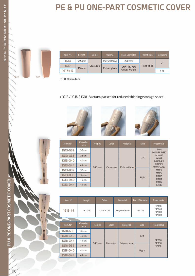
116
PE & PU ONE-PART COSMETIC COVER
Item N°. Length Color Material Max. Diameter Prosthesis Packaging
1G14 545 mm
Caucasian
Polyurethane 200 mm
Trans-tibialx 1
1G17480 mm Polyethylene
Shin : 147 mmAnkle : 100 mm1G17#12 x 12
Item N°.Circumfe-
renceHeight Color Material Side Prosthesis
1G13-G32 32 cm
900 mm Caucasian Polyurethane
Left
1M011M01-P6 1M10
1M10-P6 1M102
1M102-P6 1M102V
1M102V-P6 1M031M05 1M1121M1131M1151M149
1G13-G36 36 cm
1G13-G40 40 cm
1G13-G44 44 cm
1G13-D32 32 cm
Right1G13-D36 36 cm
1G13-D40 40 cm
1G13-D44 44 cm
Item N°.Circumfe-
renceHeight Color Material Side Prosthesis
1G18-G36 36 cm
900 mm Caucasian Polyurethane
Left
1P2001P3501P130
1G18-G40 40 cm
1G18-G44 44 cm
1G18-D36 36 cm
Right1G18-D40 40 cm
1G18-D44 44 cm
Item N°. Length Color Material Max. Diameter Prosthesis
1G16-44 90 cm Caucasian Polyurethane 44 cm
1P1201P3401P3001P360
• 1G13 / 1G16 / 1G18 : Vacuum packed for reduced shipping/storage space.
1G14 1G17For Ø 30 mm tube
PU
& P
E O
NE-
PAR
T CO
SMET
IC C
OV
ER1G
14 •
1G 1
7 • 1
G 1
7#12
• 1G
13-#
• 1G
16-4
4 •
1G18
-#

117
Item N°. Length Color Material Proximal Ø Distal Ø Thickness Prosthesis
1G1510 590 mmCaucasian Plastazote
170 mm 100 mm 26/28 mm Trans-Tibial
1G24 510 mm 190 mm 125 mm 26/28 mm Trans-Femorale
Item N°. Length Color Material Max. Diameter Prosthesis
1G1525 245 mm Beige Polyurethane 23,5 mm Trans-Tibial
• Both cosmetic covers are thermoformable at 100°.
1G1510 1G24
PLASTAZOTE ONE-PART COSMETIC COVER
• 1G1525 : Rigid Foam Core for 1G1510
PLA
STA
ZOTE
ON
E-PA
RT
COSM
ETIC
CO
VER
RELATED PRODUCTS
1G51
0 •
1G24
• 1G
1525
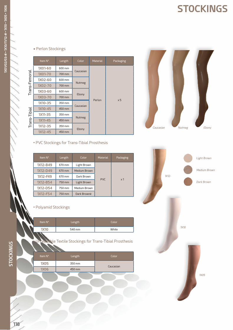
118
Item N°. Length Color Material Packaging
1X01-60 600 mmCaucasian
Perlon x 5
1X01-70 700 mm
1X02-60 600 mmNutmeg
1X02-70 700 mm
1X03-60 600 mmEbony
1X03-70 700 mm
1X10-35 350 mmCaucasian
1X10-45 450 mm
1X11-35 350 mmNutmeg
1X11-45 450 mm
1X12-35 350 mmEbony
1X12-45 450 mm
Item N°. Length Color Material Packaging
1X12-B49 670 mm Light Brown
PVC x 1
1X12-D49 670 mm Medium Brown
1X12-F49 670 mm Dark Brown
1X12-B54 750 mm Light Brown
1X12-D54 750 mm Medium Brown
1X12-F54 750 mm Dark Browné
Item N°. Length Color
1X10 540 mm White
Item N°. Length Color
1X05 350 mmCaucasian
1X06 450 mm
• Perlon Stockings
• PVC Stockings for Trans-Tibial Prosthesis
• Polyamid Stockings
• Unreadable Textile Stockings for Trans-Tibial Prosthesis
Light Brown
Caucasian Nutmeg Ebony
Medium Brown
Dark Brown
STOCKINGS
1X05
1X10
1X12-
STO
CKIN
GS
Tran
s-Fe
mor
alTr
ans-
Tib
ial
1X0
1/0
2/0
3-#
• 1X
10/1
1/12
-# •
1X10
• 1X
05
• 1X0
6
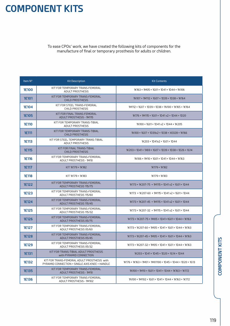
119
COM
PO
NEN
T K
ITS
COMPONENT KITS
To ease CPOs’ work, we have created the following kits of components for the manufacture of final or temporary prosthesis for adults or children.
Item N°. Kit Description Kit Contents
1E100 KIT FOR TEMPORARY TRANS-FEMORALADULT PROSTHESIS
1K163 + 1M05 + 1G01 + 1D41 + 1D44 + 1N106
1E101 KIT FOR TEMPORARY TRANS-FEMORALCHILD PROSTHESIS
1N107 + 1M112 + 1G07 + 1D39 + 1D38 + 1K164
1E104 KIT FOR STEEL TRANS-FEMORALCHILD PROSTHESIS
1M112 + 1G07 + 1D39 + 1D38 + 1N100 + 1K165 + 1K164
1E105 KIT FOR FINAL TRANS-FEMORALADULT PROSTHESIS - 1M115
1K176 + 1M115 + 1G01 + 1D41 x2 + 1D44 + 1D20
1E110 KIT FOR TEMPORARY TRANS-TIBIALADULT PROSTHESIS
1N100 + 1G01 + 1D41 x2 + 1D44 + 1K205
1E111 KIT FOR TEMPORARY TRANS-TIBIALCHILD PROSTHESIS
1N100 + 1G07 + 1D39x2 + 1D38 + XE028 + 1K166
1E113 KIT FOR STEEL TEMPORARY TRANS-TIBIALADULT PROSTHESIS
1K203 + 1D41x2 + 1G01 + 1D44
1E115 KIT FOR FINAL TRANS-TIBIALCHILD PROSTHESIS
1K203 + 1D41 + 1X69 + 1G07 + 1D39 + 1D38 + 1D26 + 1G14
1E116 KIT FOR TEMPORARY TRANS-FEMORALADULT PROSTHESIS - 1M10
1N106 + 1M10 + 1G01 + 1D41 + 1D44 + 1K163
1E117 KIT 1K179 + 1K182 1K179 + 1K182
1E118 KIT 1K179 + 1K183 1K179 + 1K183
1E122 KIT FOR TEMPORARY TRANS-FEMORALADULT PROSTHESIS 115/75
1K173 + 1K207-75 + 1M115 + 1D41 x2 + 1G01 + 1D44
1E123 KIT FOR TEMPORARY TRANS-FEMORALADULT PROSTHESIS 115/60
1K173 + 1K207-60 + 1M115 + 1D41 x2 + 1G01 + 1D44
1E124 KIT FOR TEMPORARY TRANS-FEMORALADULT PROSTHESIS 115/45
1K173 + 1K207-45 + 1M115 + 1D41 x2 + 1G01 + 1D44
1E125 KIT FOR TEMPORARY TRANS-FEMORALADULT PROSTHESIS 115/32
1K173 + 1K207-32 + 1M115 + 1D41 x2 + 1G01 + 1D44
1E126 KIT FOR TEMPORARY TRANS-FEMORALADULT PROSTHESIS 05/75
1K173 + 1K207-75 + 1M05 + 1D41 +1G01 + 1D44 + 1K163
1E127 KIT FOR TEMPORARY TRANS-FEMORALADULT PROSTHESIS 05/60
1K173 + 1K207-60 + 1M05 + 1D41 + 1G01 + 1D44 + 1K163
1E128 KIT FOR TEMPORARY TRANS-FEMORALADULT PROSTHESIS 05/45
1K173 + 1K207-45 + 1M05 + 1D41 + 1G01 + 1D44 + 1K163
1E129 KIT FOR TEMPORARY TRANS-FEMORALADULT PROSTHESIS 05/32
1K173 + 1K207-32 + 1M05 + 1D41 + 1G01 + 1D44 + 1K163
1E131 KIT FOR TRANS-TIBIAL ADULT PROSTHESISwith PYRAMID CONNECTION
1K203 + 1D41 + 1D45 + 1D20 + 1G14 + 1D44
1E132 KIT FOR TRANS-FEMORAL ADULT PROSTHESIS with PYRAMID CONNECTION + SINGLE AXIS KNEE + HANDLE
1K176 + 1K163 + 1M01 + 1M01100 + 1D45 + 1D44 + 1D20 + 1G13
1E135 KIT FOR TEMPORARY TRANS-FEMORALADULT PROSTHESIS - 1M10
1N100 + 1M10 + 1G01 + 1D41 + 1D44 + 1K163 + 1K172
1E136 KIT FOR TEMPORARY TRANS-FEMORALADULT PROSTHESIS - 1M102
1N100 + 1M102 + 1G01 + 1D41 + 1D44 + 1K163 + 1K172
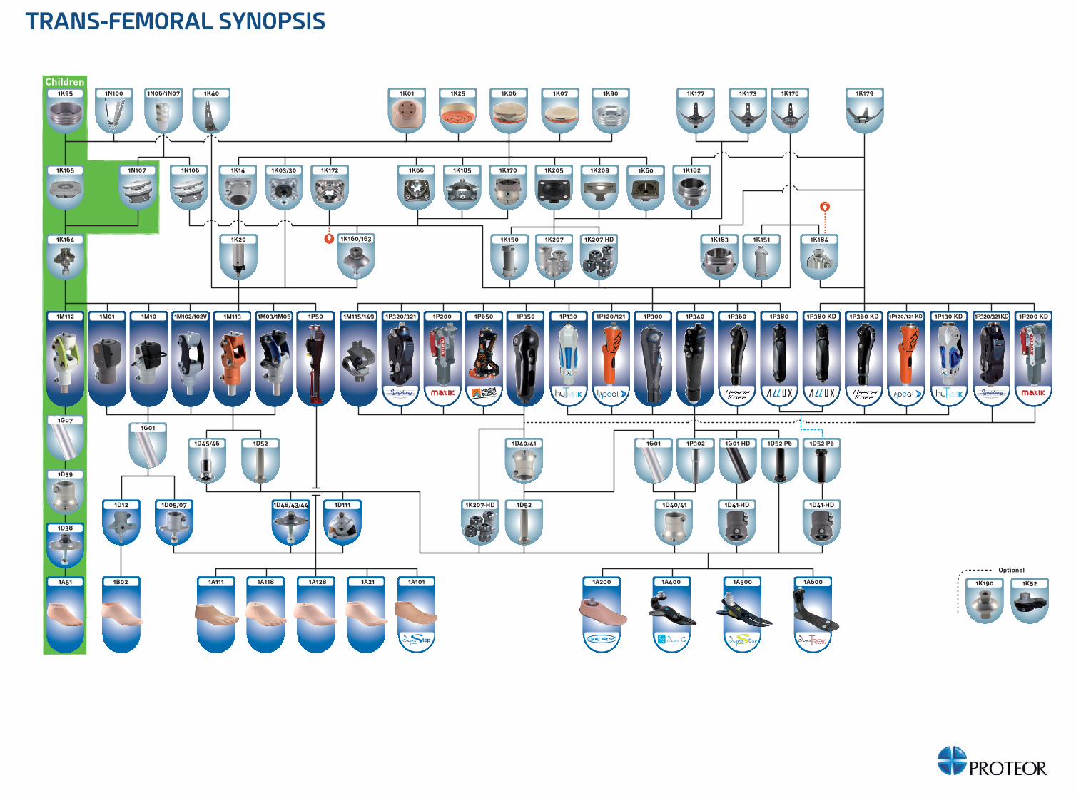
Children
1A51
1K164
1K165
1K95
1N107
1K901N100 1K01 1K25 1K06 1K07
1K1821K14
1K207
1N06/1N07 1K1731K40
1K172
1K183
1K179
1K205
1K177 1K176
1K03/30 1K170
1K160/163 1K151
1N106
1K1501K20 1K207-HD
1K185 1K209 1K601K66
1M112 1P3501M01 1M115/1491M10 1M102/102V 1M113 1M03/1M05 1P50 1P300 1P340 1P360 1P360-KD1P200 1P200-KD1P320/321-KD1P320/321 1P380 1P380-KD1P120/121
2
1P120/121-KD
2
1P130-KD1P1301P650
1K184
1A5001A4001A200
1D1111D05/07
1D38
1B02
1D41-HD 1D41-HD1D48/43/44
1K190
1D52
1G071G01
1G01-HD 1D52-P6 1D52-P6
1D40/41
1G01 1P3021D45/46
1D12
1D39
1A111
1K207-HD
1K52
1D40/41
1D52
1A118 1A128 1A21 1A101 1A600
Optional
TRANS-FEMORAL SYNOPSIS

TRANS-TIBIAL SYNOPSIS
Children
1D471D40/41
1D1111D48/43/44
1D52
1A101 1A200
1K205
1D41-HD
1A500 1A400
1K100 1K185 1K601K1721K66
1K182
1K14
1G01 1G01
1K166/206
1D39 1D40/41
1G07 1D45/46
1D39
1D05/071D121D38
1G1501/11
1K150
1A51 1B02
1K207
1A410
1X69
1K183
1K90 1K202/2031K95 1N100 1K01 1K25 1K10 1K11 1K179
1K190
1D72-P6
S.A.C.H.
1K209
1A600
TRANS-TIBIAL TRANS-FEMORAL
4-ear lamination anchor HD
1K203 • -
4-ear offset lamination anchor HD
1K204 • -
Trans-femoral threaded base 3-Prong Lamination Adapter for Knee Disarticulation, delivered
with a spacer
1K179 - •
Tube clamp adapter 1D41-HD • •
Threaded receiver insertM36 x 1,5 mm
1K183 • •
Double pyramid adapter 1K190 • •
Double pyramid receiver 1K207-HD • •
Single axis hydraulic knee Hytrek(Pyramid or M36 threaded)
1P1301P130-KD - •
Aluminium tubeØ 34mm - 420 mm length
1G01-HD • •
Dynatrek foot 1A600 • •
Gery foot 1A200 • •
150KG / 330 LBS COMPONENTS

TRANS-TIBIAL SYNOPSIS
Children
1D471D40/41
1D1111D48/43/44
1D52
1A101 1A200
1K205
1D41-HD
1A500 1A400
1K100 1K185 1K601K1721K66
1K182
1K14
1G01 1G01
1K166/206
1D39 1D40/41
1G07 1D45/46
1D39
1D05/071D121D38
1G1501/11
1K150
1A51 1B02
1K207
1A410
1X69
1K183
1K90 1K202/2031K95 1N100 1K01 1K25 1K10 1K11 1K179
1K190
1D72-P6
S.A.C.H.
1K209
1A600
TRANS-TIBIAL TRANS-FEMORAL
4-earlamination anchor HD
1K203 • -
4-ear offsetlamination anchor HD
1K204 • -
Trans-femoral threaded base 3-Prong Lamination Adapter forKnee Disarticulation, delivered
with a spacer
1K179 - •
Tube clamp adapter 1D41-HD • •
Threaded receiver insertM36 x 1,5 mm
1K183 • •
Double pyramid adapter 1K190 • •
Double pyramid receiver 1K207-HD • •
Single axis hydraulic knee Hytrek(Pyramid or M36 threaded)
1P1301P130-KD - •
Aluminium tubeØ 34mm - 420 mm length
1G01-HD • •
Dynatrek foot 1A600 • •
Gery foot 1A200 • •
150KG / 330 LBS COMPONENTS

6, rue de la Redoute - CS 3783321078 DIJON Cedex - FRANCE
CONTACTS
+33 (0)3 80 78 42 30
+33 (0)3 80 78 42 10+33 (0)3 80 78 42 [email protected]
France Export
Fax : +33 (0)3 80 78 42 15
www.orthopaedics.proteor.com
PR
OST
HES
IS C
ATA
LOG
V7
Copyright © 2022 FDOKUMEN