
DIFFERENT CONTROL STRATEGIES USED IN DIDACTIC PLANT PD-3 OF SMAR THROUGH OPC TECHNOLOGY
10
Procedings of COBEM 2007 Copyright c 2007 by ABCM 19th International Congress of Mechanical Engineering November 5-9, 2007, Brasília, DF DIFFERENT CONTROL STRATEGIES USED IN DIDACTIC PLANT PD-3 OF SMAR THROUGH OPC TECHNOLOGY Edgar J. Amaya Simeón, [email protected] Alberto José Álvares, [email protected] Victor Rafael R Celestino, [email protected] Carlos Frederico Maciel Silveira, [email protected] Universidade de Brasília, Departamento de Engenharia Mecânica e Mecatrônica, Grupo de Inovação em Automação Industrial (GIAI), CEP 70910-900, Brasília, DF, Brazil Abstract. In this work, three different control strategies, neural network, fuzzy logic and PID (Proportional Integral Derivative), were implemented in Matlab, acting on a Smar PD3 didactic plant by means of OPC (OLE - Object Linking and Embedding - for Process Control) technology. The PD3 plant employs Foundation Fieldbus protocol and configura- tion tools of Smar System 302. The PD3 process chosen for testing control strategies consists to control the temperature on the mix water tank , which has a constant flow input of constant temperature hot water and an input consisting of ambient temperature water controlled by a pneumatic valve. The PID control was developed using differences equation and adjusting the parameters using a Ziegler- Nichols method. The Neural Network, that has a structure (3-20-1) capable to learn the dynamic of the PID controller, was trained using the values saved in vectors from the response of the PID controller. The training was accomplished using a backpropagation method that is least Square Method (LMS). The LMS method, search the minimum valor of the function square error. The Fuzzy Logic Controller was developed using the toolbox of the Matlab, membership function was edited in the FIS editor. In addition to the controllers a supervisory was developed using GUI of Matlab, acting on PD3 plant independently of SCADA Process View (Smar System 302). Controllers obtained satisfactory results for the combinations of input variables values, the Neural Network and PID controller have similiar response actuation and the Fuzzy Logic Controller has a less accuracy response, in other words the results highlight differences in performance among control strategies. Keywords: Control Systems, Neural Networks, Fuzzy Logic, PID, Fieldbus Foundation. 1. INTRODUCTION In this work, the temperature control level in the mix water tank of Smar PD-3 didactic plant was executed, acting through different control strategies, implemented in Matlab. Plant access was achieved using OPC technology (OLE - Object Linking and Embedding - for Process Control). The plant allows the implementation of several control loops, by using industrial devices with sensing, actuating and control functions. These devices are directly managed through a Fieldbus Foundation protocol. PD3 Plant also includes a System 302 software suite. The objective of this work was to implement and compare three different control strategies, Neural Network, Fuzzy Logic and PID (Proportional Integral Derivative),to communicate with the Fieldbus Foundation Smar instruments located in the PD3 didactic plant, using the Matlab opc toolbox that use OPC technology (OLE - Object Linking and Embedding - for Process Control), also to develop the supervisory system in order to have the HMI(Human Machine Interface). The rest of this paper is organized as follows: Section 2 presents the description of the PD3 didactic plant; Section 3 presents the three different control strategies and desbribes the supervisory system; Section 4 describes the tests, results and discussions; and finally Section 5 concludes the paper. 2. SMAR PD3 DIDACTIC PLANT The Smar PD3 didactic plant aim is to demonstrate didactically the operation of several control loops, using the same equipment and configuration tools (System 302 software suite), developed for the application in industrial control. With a compact arrangement, this plant makes accessible to instructors and students all components in the loop, allowing not only the observation of its behavior, but also its manipulation (Smar, 2004). In the implementation of such loops, the same characteristics and situations found by instrumentation professionals are provided, with the resources of advanced technology available in the market. Besides the proposed control loops, others can be generated from the same physical structure assembled, without the need of any mechanical modification, but only by modifying the configuration of its devices through functional blocks (Smar, 2005). The plant applies Fieldbus Foundation technology, an industrial communication bus used to connect field devices such as sensors, actuators, indicators and controllers, which allow the control of temperature, flow and associated levels, helping in industrial instrumentation and control systems learning. The Smar PD3 didactic plant, presented in the Fig. 1, is monitored and operated by a station, constituted of a PC microcomputer and supervisory software, which executes equipment data acquisition and presents those by screen ani-
Transcript of DIFFERENT CONTROL STRATEGIES USED IN DIDACTIC PLANT PD-3 OF SMAR THROUGH OPC TECHNOLOGY
Procedings of COBEM 2007Copyright c© 2007 by ABCM
19th International Congress of Mechanical EngineeringNovember 5-9, 2007, Brasília, DF
DIFFERENT CONTROL STRATEGIES USED IN DIDACTIC PLANT PD-3OF SMAR THROUGH OPC TECHNOLOGY
Edgar J. Amaya Simeón, [email protected] José Álvares, [email protected] Rafael R Celestino, [email protected] Frederico Maciel Silveira, [email protected] de Brasília, Departamento de Engenharia Mecânica e Mecatrônica, Grupo de Inovação em Automação Industrial (GIAI),CEP 70910-900, Brasília, DF, Brazil
Abstract. In this work, three different control strategies, neural network, fuzzy logic and PID (Proportional IntegralDerivative), were implemented in Matlab, acting on a Smar PD3 didactic plant by means of OPC (OLE - Object Linkingand Embedding - for Process Control) technology. The PD3 plant employs Foundation Fieldbus protocol and configura-tion tools of Smar System 302. The PD3 process chosen for testing control strategies consists to control the temperatureon the mix water tank , which has a constant flow input of constant temperature hot water and an input consisting ofambient temperature water controlled by a pneumatic valve. The PID control was developed using differences equationand adjusting the parameters using a Ziegler- Nichols method. The Neural Network, that has a structure (3-20-1) capableto learn the dynamic of the PID controller, was trained using the values saved in vectors from the response of the PIDcontroller. The training was accomplished using a backpropagation method that is least Square Method (LMS). The LMSmethod, search the minimum valor of the function square error. The Fuzzy Logic Controller was developed using thetoolbox of the Matlab, membership function was edited in the FIS editor. In addition to the controllers a supervisorywas developed using GUI of Matlab, acting on PD3 plant independently of SCADA Process View (Smar System 302).Controllers obtained satisfactory results for the combinations of input variables values, the Neural Network and PIDcontroller have similiar response actuation and the Fuzzy Logic Controller has a less accuracy response, in other wordsthe results highlight differences in performance among control strategies.
Keywords: Control Systems, Neural Networks, Fuzzy Logic, PID, Fieldbus Foundation.
1. INTRODUCTION
In this work, the temperature control level in the mix water tank of Smar PD-3 didactic plant was executed, actingthrough different control strategies, implemented in Matlab. Plant access was achieved using OPC technology (OLE -Object Linking and Embedding - for Process Control). The plant allows the implementation of several control loops,by using industrial devices with sensing, actuating and control functions. These devices are directly managed through aFieldbus Foundation protocol. PD3 Plant also includes a System 302 software suite.
The objective of this work was to implement and compare three different control strategies, Neural Network, FuzzyLogic and PID (Proportional Integral Derivative),to communicate with the Fieldbus Foundation Smar instruments locatedin the PD3 didactic plant, using the Matlab opc toolbox that use OPC technology (OLE - Object Linking and Embedding- for Process Control), also to develop the supervisory system in order to have the HMI(Human Machine Interface).
The rest of this paper is organized as follows: Section 2 presents the description of the PD3 didactic plant; Section 3presents the three different control strategies and desbribes the supervisory system; Section 4 describes the tests, resultsand discussions; and finally Section 5 concludes the paper.
2. SMAR PD3 DIDACTIC PLANT
The Smar PD3 didactic plant aim is to demonstrate didactically the operation of several control loops, using the sameequipment and configuration tools (System 302 software suite), developed for the application in industrial control. Witha compact arrangement, this plant makes accessible to instructors and students all components in the loop, allowing notonly the observation of its behavior, but also its manipulation (Smar, 2004).
In the implementation of such loops, the same characteristics and situations found by instrumentation professionalsare provided, with the resources of advanced technology available in the market. Besides the proposed control loops,others can be generated from the same physical structure assembled, without the need of any mechanical modification,but only by modifying the configuration of its devices through functional blocks (Smar, 2005).
The plant applies Fieldbus Foundation technology, an industrial communication bus used to connect field devicessuch as sensors, actuators, indicators and controllers, which allow the control of temperature, flow and associated levels,helping in industrial instrumentation and control systems learning.
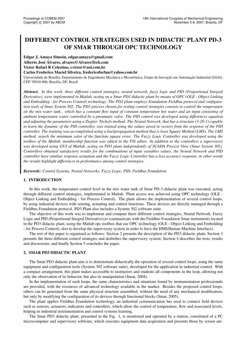
The Smar PD3 didactic plant, presented in the Fig. 1, is monitored and operated by a station, constituted of a PCmicrocomputer and supervisory software, which executes equipment data acquisition and presents those by screen ani-
Procedings of COBEM 2007Copyright c© 2007 by ABCM
19th International Congress of Mechanical EngineeringNovember 5-9, 2007, Brasília, DF
mations. It also allows actuating directly on registries, modifying equipment internal values and control loop operationalmodes.
Figure 1. SMAR PD3 Didactic Plant.
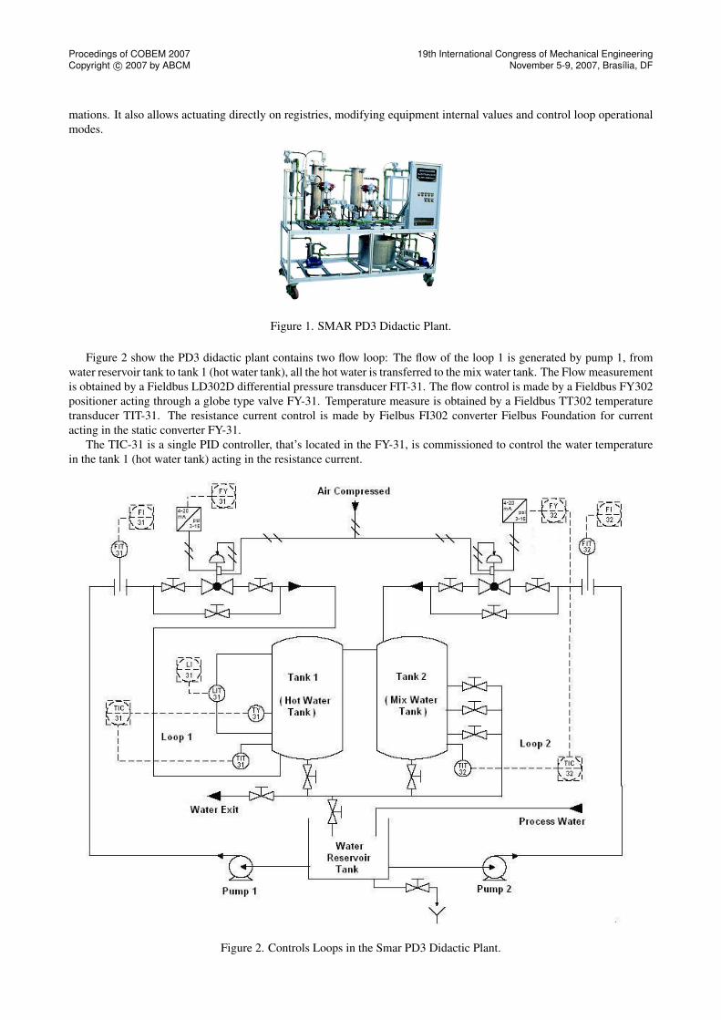
Figure 2 show the PD3 didactic plant contains two flow loop: The flow of the loop 1 is generated by pump 1, fromwater reservoir tank to tank 1 (hot water tank), all the hot water is transferred to the mix water tank. The Flow measurementis obtained by a Fieldbus LD302D differential pressure transducer FIT-31. The flow control is made by a Fieldbus FY302positioner acting through a globe type valve FY-31. Temperature measure is obtained by a Fieldbus TT302 temperaturetransducer TIT-31. The resistance current control is made by Fielbus FI302 converter Fielbus Foundation for currentacting in the static converter FY-31.
The TIC-31 is a single PID controller, that’s located in the FY-31, is commissioned to control the water temperaturein the tank 1 (hot water tank) acting in the resistance current.
Figure 2. Controls Loops in the Smar PD3 Didactic Plant.
Procedings of COBEM 2007Copyright c© 2007 by ABCM
19th International Congress of Mechanical EngineeringNovember 5-9, 2007, Brasília, DF
The flow of the loop 2 is generated by pump 2, from water reservoir tank to tank n 2 (mix water tank). Flow mea-surement is obtained by a Fieldbus LD302D differential pressure transducer FIT-32. Flow control is made by a FieldbusFY302 positioner acting through a globe type valve FY-32. Temperature measure is obtained by a Fieldbus TT302 tem-perature transducer TIT-32.
The TIC-32 can be any of the control strategies implemented in Matlab like Neural Network, Fuzzy Logic or PIDcontroller, that’s located in the micro computer, is commissioned to control the water temperature in the tank 2 (mix watertank) acting in the control valve that control the flow of cold water.
3. CONTROL STRATEGIES
3.1 Artificial Neural Networks (ANN)
The need to control systems and processes exist since remote times, while methodologies to enhance a ANN trainingare recent (Bakshi, 1993), (Qin, 1992), (Leonard, 1992). The analysis and design of neural controllers is not trivial, due tothe fact that ANN is not directly modeled by differential equations, what preclude the use of classical methods for analysisand design.
In general, it is difficult to obtain general analytical expressions due to the variety of network structures and activationfunctions which can be used. Most frequent modes to use neural networks in system control are: obtaining system inversemodel through learning, behavior mapping of a known controller in the network, adaptation characteristics learning orreference models. Thus, online training of neural networks, until recently, demanded a significant processing speed andrequired very efficient convergence methods, what also demands large computational processing. With technological ad-vances and creation of new optimization methods, online training became possible, create a neural networks applications,where a large number of practical applications became possible.
ANN are generic nonlinear approximators. Neither the structure nor the parameters are needed. If training data is richin information, if neurons number are sufficient, and if there is an adequate training algorithm, a plausible solution canbe expected. A global optimum solution is seldom needed for practical problems. When a large range of operations isexpected, it is more difficult for just one ANN to have a good performance in the entire range. In this article we proposean ANN trained for a defined operation range.
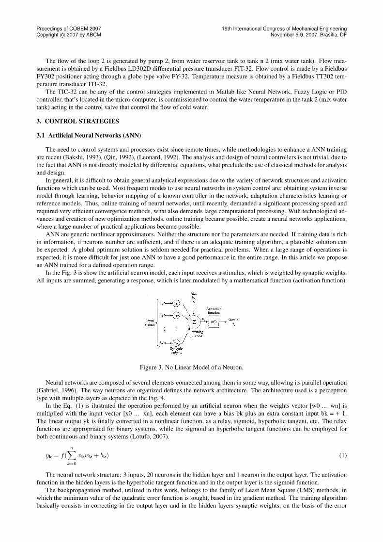
In the Fig. 3 is show the artificial neuron model, each input receives a stimulus, which is weighted by synaptic weights.All inputs are summed, generating a response, which is later modulated by a mathematical function (activation function).
Figure 3. No Linear Model of a Neuron.
Neural networks are composed of several elements connected among them in some way, allowing its parallel operation(Gabriel, 1996). The way neurons are organized defines the network architecture. The architecture used is a perceptrontype with multiple layers as depicted in the Fig. 4.
In the Eq. (1) is ilustrated the operation performed by an artificial neuron when the weights vector [w0 ... wn] ismultiplied with the input vector [x0 ... xn], each element can have a bias bk plus an extra constant input bk = + 1.The linear output yk is finally converted in a nonlinear function, as a relay, sigmoid, hyperbolic tangent, etc. The relayfunctions are appropriated for binary systems, while the sigmoid an hyperbolic tangent functions can be employed forboth continuous and binary systems (Lotufo, 2007).
yk = f(n∑
k=0
xkwk + bk) (1)
The neural network structure: 3 inputs, 20 neurons in the hidden layer and 1 neuron in the output layer. The activationfunction in the hidden layers is the hyperbolic tangent function and in the output layer is the sigmoid function.
The backpropagation method, utilized in this work, belongs to the family of Least Mean Square (LMS) methods, inwhich the minimum value of the quadratic error function is sought, based in the gradient method. The training algorithmbasically consists in correcting in the output layer and in the hidden layers synaptic weights, on the basis of the error
Procedings of COBEM 2007Copyright c© 2007 by ABCM
19th International Congress of Mechanical EngineeringNovember 5-9, 2007, Brasília, DF
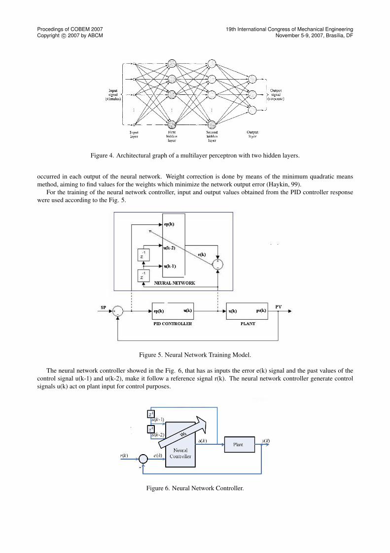
Figure 4. Architectural graph of a multilayer perceptron with two hidden layers.
occurred in each output of the neural network. Weight correction is done by means of the minimum quadratic meansmethod, aiming to find values for the weights which minimize the network output error (Haykin, 99).
For the training of the neural network controller, input and output values obtained from the PID controller responsewere used according to the Fig. 5.
Figure 5. Neural Network Training Model.
The neural network controller showed in the Fig. 6, that has as inputs the error e(k) signal and the past values of thecontrol signal u(k-1) and u(k-2), make it follow a reference signal r(k). The neural network controller generate controlsignals u(k) act on plant input for control purposes.
Figure 6. Neural Network Controller.

Procedings of COBEM 2007Copyright c© 2007 by ABCM
19th International Congress of Mechanical EngineeringNovember 5-9, 2007, Brasília, DF
3.2 PID (proportional integral derivative)
The utility of PID controllers is its general applicability to the majority of control systems. In particular, when plantmathematical model is unknown, PID is the most useful control method. Although in many applications, PID can’tprovide optimal control. PID control has the following inputs variables, SP (Set Point) and CV (Controlled Variable).The difference between SP value and CV value constitutes the error; this error is the input for PID controller, which willgenerate a control action seeking to error zero. After some actuating time, the SP value is attained.
Error processing happens in accordance with schematics presented in the Fig. 7. The e(t) term represents error as atime function, the control signal is the result of the sum of the proportional, integral and derivative terms, acting in theprocess to be controlled, finally, Output term represents Controlled variable.
Figure 7. PID controller basic schematics.
Control action over process is a result of summing individual actions of the three components. The first, on top of theFig. 7, has as individual error action multiplied by the constant Kp. The second, the of integral error multiplied by theconstant Ki. And the third, the multiplied of derivative error by the constant Kd. Considering Ki as Kp/Ti, Kd as Kp*Td.The transfer function of the PID controlled in the frequency domain is be expressed in the Eq. (2), the same transferfunction in the discret domain showed in the Eq. (3). In order to implement the PID controller in a program computer it’snecessary to represent in its discrete form showed in the Eq. (4).
U(s)E(s)
= Kp(1 +1
Tis+ Tds) (2)
With application of z transform:
U(z)E(z)
= (Kp +KpTz
Ti(z − 1)+
KpTd(z − 1)Tz
) (3)
Given that multiplication by z-1 represents a delay of one sampling interval (T), the following difference equation isobtained for PID controller in its digital form:
u(k) = (Kp +KpT
Ti+
KpTd
T)e(k) + KpTdTe(k − 1) +
Kpu(k − 1)Ti
(4)
Equation (4) applied in a recursive manner, was the core of the remote PID controller algorithm proposed in this work.The algorithm was implemented in Matlab in a remote client computer, which access to the PD3 didactic plant throughOPC protocol.
For the tuning of the PID controller, a Ziegler-Nichols method was used, where an experimental adjustment of PIDparameters was done. The method works in the following manner: A step function is placed as set point and PID isturned-on, with Tr equal to infinity and Ti equal to zero; Kp gain is adjusted until reaching marginal stability condition.This gain, de Kpc, is named critical gain. The resulting sinusoid period as marginal stable output is indicated by Ppc. Thefinal Kp value is set as 0.6 Kpc, Ti as 0.5 Ppc, and Td as 0.125 Ppc (Ogata, 2004). Using the algorithm above and applyinga small empirical adjustment on top of values found, the following parameters were used for the implementation: Kp =3.7; Ti = 9; Td = 1. For all tests and results obtained, it was used T = 2 s.
3.3 Fuzzy Logic Controller
Fuzzy set theory and fuzzy logic establish the rules of a non-linear mapping. The use of fuzzy sets provides a basisfor a systematic way for application of uncertain and indefinite models. Fuzzy control is based on a logical system calledfuzzy logic. It is much closer in spirit to human thinking and natural language than classical logical systems. Nowadays,fuzzy logic is used in almost all sectors of industry and science. One of them is plant control. According to many

Procedings of COBEM 2007Copyright c© 2007 by ABCM
19th International Congress of Mechanical EngineeringNovember 5-9, 2007, Brasília, DF
researchers, there are some reasons for the present popularity of fuzzy logic control. First of all, fuzzy logic can beeasily applied for most applications in industry. Besides, it can deal with intrinsic uncertainties by changing controllerparameters. Finally, it is appropriate for rapid applications. Therefore, a fuzzy logic system has been applied to industrialsystems as a controller. Human experts prepare linguistic descriptions as fuzzy rules. These rules are obtained based onexperiments of the processŠ step response, error signal and its time derivative (Cam, 2007).
Basically, fuzzy rules provide a convenient way for expressing control policy and domain knowledge. Furthermore,several linguistic variables might be involved in the antecedents (before then) and the conclusions (after then) of theserules. A fuzzy logic system mainly consists of three steps: fuzzification, fuzzy inference and defuzzification. In thefuzzification step, the real variables are translated into linguistic variables by using fuzzy set theory. In the fuzzy inferencestep, ’IfUThen’ rules that define the system behavior are evaluated. The defuzzification step translates the linguistic resultobtained from the fuzzy inference into a real value by using the rule base provided .
The fuzzy controller applied in this work is composed of a set of inferencing rules of a type such as If <expression>AND <expression> Then <result>, which define control actions as a function of the several value ranges, which plantinput variables can assume. 225 inference rules were implemented.
Using the Fuzzy Logic Toolbox (Jang and Gulley, 1999), the controller was implemented using FIS editor, a Matlabtoolbox. The controller was built based on Mamdani model and max-min composition was used for operations withfuzzy numbers: min operator for AND connector, max for OR connector, besides min operator for implying and max foraggregation. The centroid method was used for defuzzification.
The controller uses three input variables, which are extracted from plant output: water temperature in the hot watertank TIT-31, water temperature in the mix water tank TIT-32 and set point of the water temperature in the mix water tankTIT-32SP. The output is the open percent value of the control valve FY-32.
Input variables assume values: cold (C1), warm (W1, W2, W3), hot (H1, H2, H3), and very hot (VH1, VH2, VH3).The membership functions have the form presented in the Fig. 8.
Figure 8. Input Membership Functions.
Procedings of COBEM 2007Copyright c© 2007 by ABCM
19th International Congress of Mechanical EngineeringNovember 5-9, 2007, Brasília, DF
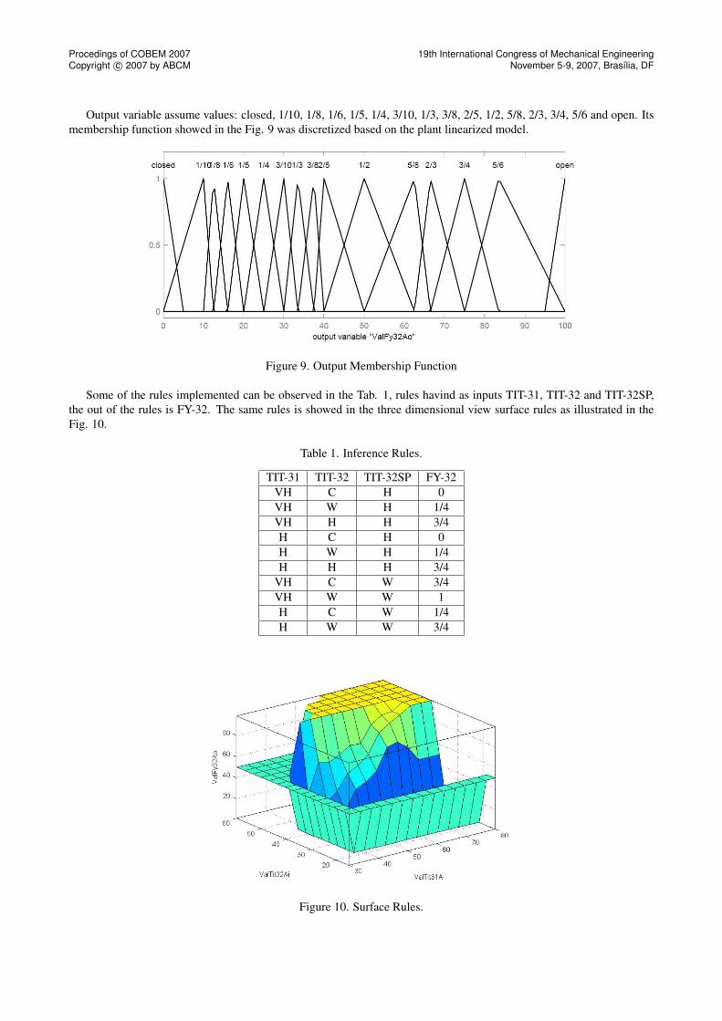
Output variable assume values: closed, 1/10, 1/8, 1/6, 1/5, 1/4, 3/10, 1/3, 3/8, 2/5, 1/2, 5/8, 2/3, 3/4, 5/6 and open. Itsmembership function showed in the Fig. 9 was discretized based on the plant linearized model.
Figure 9. Output Membership Function
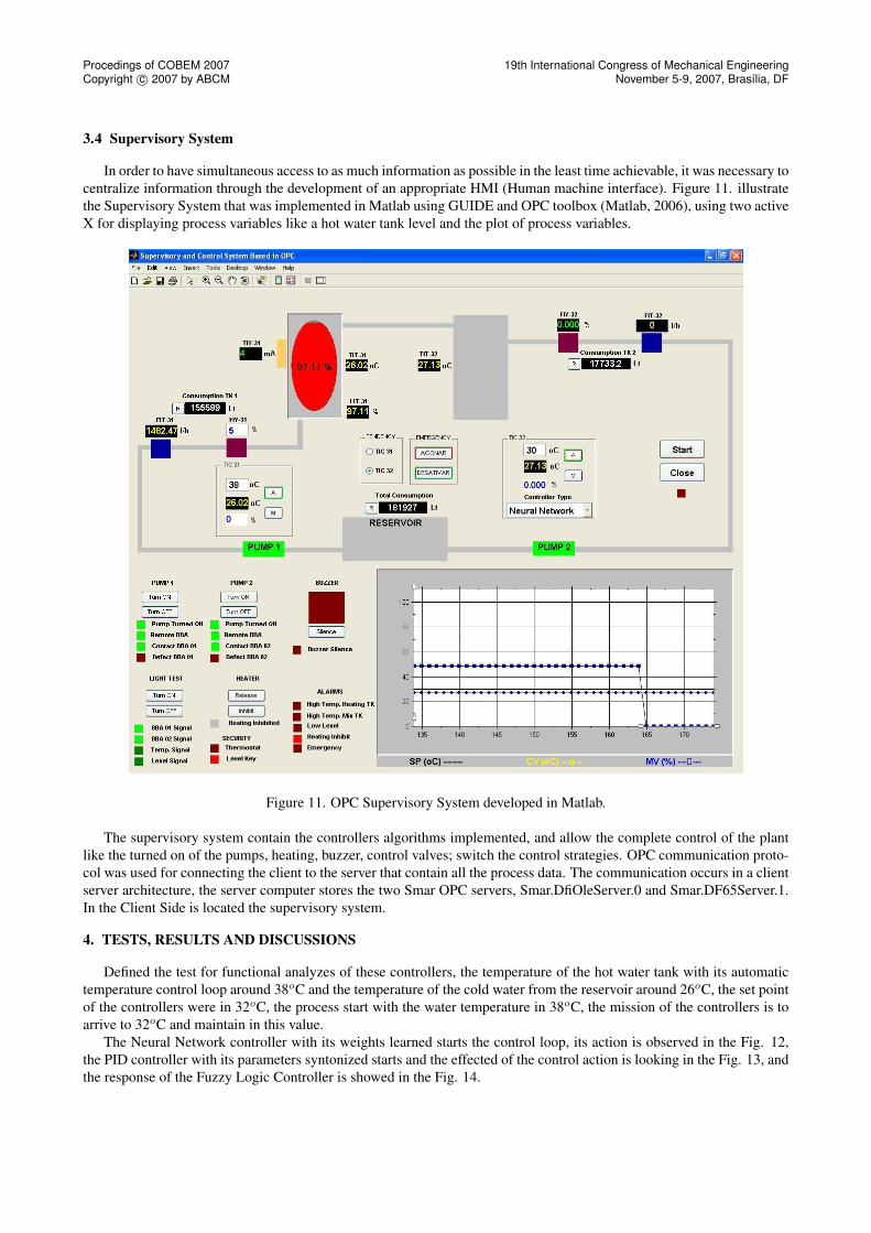
Some of the rules implemented can be observed in the Tab. 1, rules havind as inputs TIT-31, TIT-32 and TIT-32SP,the out of the rules is FY-32. The same rules is showed in the three dimensional view surface rules as illustrated in theFig. 10.
Table 1. Inference Rules.
TIT-31 TIT-32 TIT-32SP FY-32VH C H 0VH W H 1/4VH H H 3/4H C H 0H W H 1/4H H H 3/4
VH C W 3/4VH W W 1H C W 1/4H W W 3/4
Figure 10. Surface Rules.
Procedings of COBEM 2007Copyright c© 2007 by ABCM
19th International Congress of Mechanical EngineeringNovember 5-9, 2007, Brasília, DF
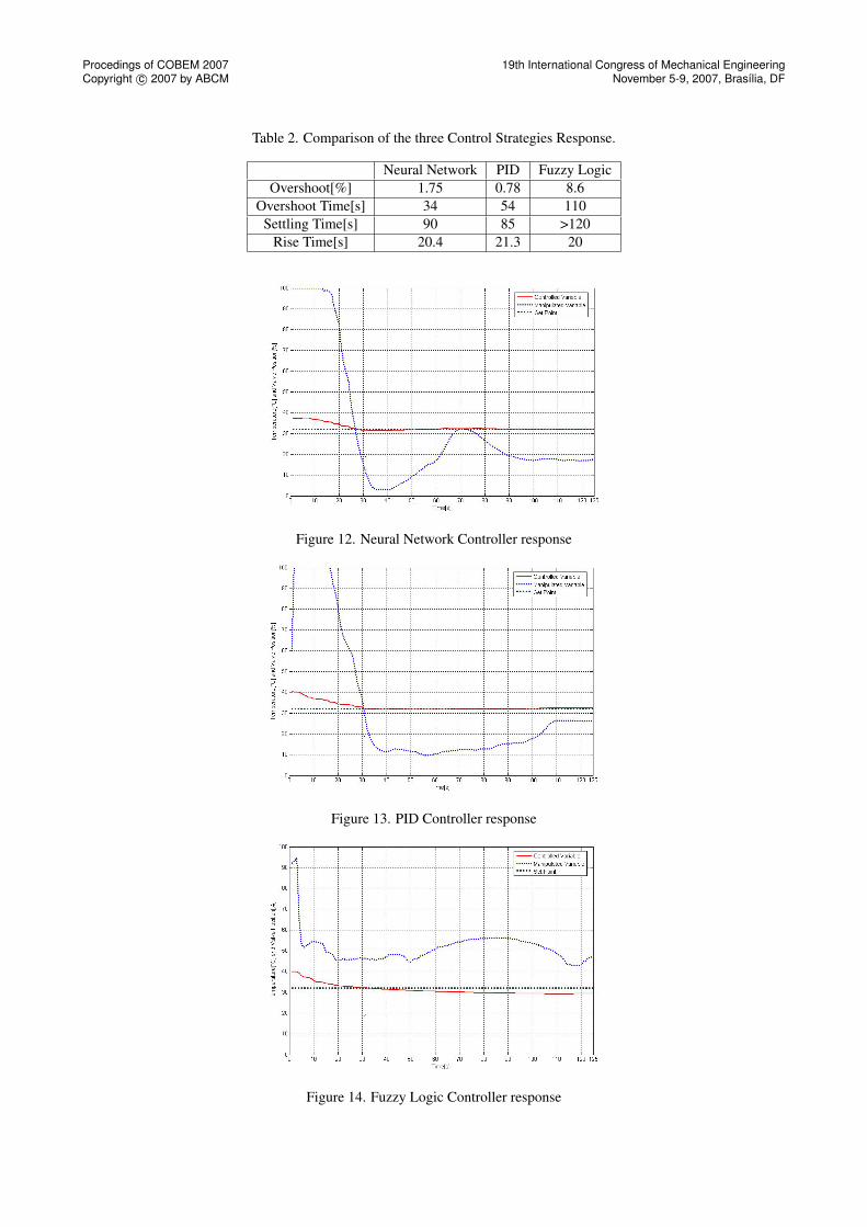
3.4 Supervisory System
In order to have simultaneous access to as much information as possible in the least time achievable, it was necessary tocentralize information through the development of an appropriate HMI (Human machine interface). Figure 11. illustratethe Supervisory System that was implemented in Matlab using GUIDE and OPC toolbox (Matlab, 2006), using two activeX for displaying process variables like a hot water tank level and the plot of process variables.
Figure 11. OPC Supervisory System developed in Matlab.
The supervisory system contain the controllers algorithms implemented, and allow the complete control of the plantlike the turned on of the pumps, heating, buzzer, control valves; switch the control strategies. OPC communication proto-col was used for connecting the client to the server that contain all the process data. The communication occurs in a clientserver architecture, the server computer stores the two Smar OPC servers, Smar.DfiOleServer.0 and Smar.DF65Server.1.In the Client Side is located the supervisory system.
4. TESTS, RESULTS AND DISCUSSIONS
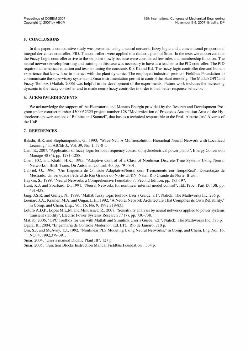
Defined the test for functional analyzes of these controllers, the temperature of the hot water tank with its automatictemperature control loop around 38oC and the temperature of the cold water from the reservoir around 26oC, the set pointof the controllers were in 32oC, the process start with the water temperature in 38oC, the mission of the controllers is toarrive to 32oC and maintain in this value.
The Neural Network controller with its weights learned starts the control loop, its action is observed in the Fig. 12,the PID controller with its parameters syntonized starts and the effected of the control action is looking in the Fig. 13, andthe response of the Fuzzy Logic Controller is showed in the Fig. 14.
Procedings of COBEM 2007Copyright c© 2007 by ABCM
19th International Congress of Mechanical EngineeringNovember 5-9, 2007, Brasília, DF
Table 2. Comparison of the three Control Strategies Response.
Neural Network PID Fuzzy LogicOvershoot[%] 1.75 0.78 8.6
Overshoot Time[s] 34 54 110Settling Time[s] 90 85 >120
Rise Time[s] 20.4 21.3 20
Figure 12. Neural Network Controller response
Figure 13. PID Controller response
Figure 14. Fuzzy Logic Controller response
Procedings of COBEM 2007Copyright c© 2007 by ABCM
19th International Congress of Mechanical EngineeringNovember 5-9, 2007, Brasília, DF
5. CONCLUSIONS
In this paper, a comparative study was presented using a neural network, fuzzy logic and a conventional proportionalintegral derivative controller, PID. The controllers were applied to a didactic plant of Smar. In the tests were observed thatthe Fuzzy Logic controller arrive to the set point slowly because were considered few rules and membership function. Theneural network envelop learning and training in this case was necessary to have as a teacher to the PID controller. The PIDrequire mathematical equation and tests to tuning the constants Kp, Ki and Kd. The fuzzy logic controller demand humanexperience that know how to interact with the plant dynamic. The employed industrial protocol Fieldbus Foundation tocommunicate the supervisory system and Smar instrumentation permit to control the plant remotely. The Matlab OPC andFuzzy Toolbox (Matlab, 2006) was helpful in the development of the experiments. Future work includes the increasingdynamic to the fuzzy controller and to made neuro fuzzy controller in order to had better response behavior.
6. ACKNOWLEDGEMENTS
We acknowledge the support of the Eletronorte and Manaus Energia provided by the Reserch and Development Pro-gram under contract number 4500052325 project number 128 "Modernization of Processes Automation Area of the Hy-droelectric power stations of Balbina and Samuel", that has as a technical responsible to the Prof. Alberto José Álvares ofthe UnB.
7. REFERENCES
Bakshi, B.R. and Stephanopoulos, G., 1993, "Wave-Net: A Multiresolution, Hierachial Neural Network with LocalizedLearning," in AIChE J., Vol. 39, No. 1, 57-8 1.
Cam, E., 2007, "Application of fuzzy logic for load frequency control of hydroelectrical power plants", Energy ConversionManage 48 (4), pp. 1281-1288.
Chen, F.C. and Khalil, H.K., 1995, "Adaptive Control of a Class of Nonlinear Discrete-Time Systems Using NeuralNetworks", IEEE Trans. On Automat. Control, 40, pp. 791-801.
Gabriel, O., 1996, "Um Esquema de Controle AdaptativoNeural com Treinamento em TempoReal", Dissertação deMestrado. Universidade Federal do Rio Grande do Norte-UFRN. Natal, Rio Grande do Norte. Brasil.
Haykin, S., 1999, "Neural Networks a Comprehensive Foundation", Second Edition, pp. 183-197.Hunt, K.J. and Sbarbaro, D., 1991, "Neural Networks for nonlinear internal model control", IEE Proc., Part D, 138, pp.
431-438.Jang, J.S.R. and Gulley, N., 1999, "Matlab fuzzy logic toolbox User’s Guide. v.1", Natick: The Mathworks Inc, 235 p.Leonard J.A., Kramer, M.A. and Ungar, L.H., 1992, "A Neural Network Architecture That Computes its Own Reliability,"
in Comp. and Chem. Eng., Vol. 16, No. 9, 1992,819-835.Lotufo A.D.P., Lopes M.L.M. and Minussia C.R., 2007, "Sensitivity analysis by neural networks applied to power systems
transient stability", Electric Power Systems Research 77 (7), pp. 730-738.Matlab, 2006, "OPC Toolbox for use with Matlab and Simulink User’s Guide. v.2.", Natick: The Mathworks Inc, 373 p.Ogata, K., 2004, "Engenharia de Controle Moderno". Ed. LTC, Rio de Janeiro, 710 p.Qin, S.J. and McAvoy, T.J., 1992, "Nonlinear PLS Modeling Using Neural Networks," in Comp. and Chem. Eng.,Vol. 16,
NO. 4, 1992,379-391.Smar, 2004, "User’s manual Didatic Plant III", 127 p.Smar, 2005, "Function Blocks Instruction Manual Fieldbus Foundation", 334 p.