CODESYS OPC Server V3 - Still haven't found what you are ...
37
© 3S-Smart Software Solutions GmbH CODESYS OPC Server V3 Installation and Usage Version: 16.0 Template: templ_tecdoc_en_V1.0.docx File name: CODESYS_OPC_Server_V3_User_Guide.docx
-
Upload
khangminh22 -
Category
Documents
-
view
2 -
download
0
Transcript of CODESYS OPC Server V3 - Still haven't found what you are ...

© 3S-Smart Software Solutions GmbH
CODESYS OPC Server V3 Installation and Usage
Version: 16.0 Template: templ_tecdoc_en_V1.0.docx File name: CODESYS_OPC_Server_V3_User_Guide.docx

© 3S-Smart Software Solutions GmbH
Tem
plat
e: t
empl
_tec
doc_
en_V
1.0.
docx
CONTENT Page
1 Overview on OPC 4 2 Overview on ODESYS OPC Server V3 5 2.1 CODESYS Gateway V3 5 2.2 Gateway V2.3 7 3 Installation of the CODESYS OPC Server V3 8 3.1 Installation and Registration 8 4 Usage of the CODESYS OPC Server V3 9 5 Configuration of the symbols in the programming system 10 5.1 V3 Interface 10 5.2 V2.3 Interface 12 6 CODESYS OPC Server Configuration by OPCConfig.exe 14 6.1 Call OPCConfig.exe 14 6.1.1 Default call 14 6.1.2 Open a particular INI file 14
6.2 Menu Commands and Configuration Dialogs 15 6.2.1 File 15 6.2.2 Edit 15 6.2.3 ? 16 6.2.4 Settings for OPC server 16 6.2.5 Settings for <PLC> 17 6.2.6 Settings for connection to <PLC> 18
6.3 Simulation Interface 21 6.3.1 SIMULATION3 21 6.3.2 SIMULATION 21
6.4 Special case „GATEWAY“ 22 6.5 Redundant Group 22 6.6 Configuration of OPCConfig with OPCConfig.ini 24 7 Configuration settings in OPCServer.ini 25 7.1 Configuration of the OPC server under section [Server] 25 7.2 Configuration of the communication to the controllers 26 7.3 Example of an INI file for the V3 interface 26 7.4 Example of an INI file for the V2.3 interface 27 7.5 Configuration of ‘Redundant Group’ 29 7.6 Information on the changed logfilter 31 7.7 Configuration of simulation 31 7.7.1 SIMULATION 31
7.8 Changing directory and name of INI and LOG file 31

© 3S-Smart Software Solutions GmbH
Tem
plat
e: t
empl
_tec
doc_
en_V
1.0.
docx
8 Connection to OPC servers on other computers with DCOMCNFG.EXE 33
9 Error Diagnosis 34 9.1 Means of error diagnosis 34 9.2 Brief checklist 34 9.3 Error cases 35 Change History 36

CODESYS Inspiring Automation Solutions 4/37 CODESYS OPC Server V3 Overview on OPC
© 3S-Smart Software Solutions GmbH
1 Overview on OPC
OPC1 is a standardized interface for access on process data. It is based on the Microsoft standard COM/DCOM2 and enlarged due to the requirements of data access in automation, where the interface is mainly used to read data from or write data to the controller. Typical OPC clients are visualizations, programs in purpose to register operating data, etc. Typical providers of OPC Servers are PLC systems and field bus interface cards.
The OPC Server is an executable program that is started automatically during the establishment of a connection between client and PLC. Hence, the OPC Server is able to inform the client about changed variable values or states.
The OPC Server provides all variables (referred to as Items in ) that are available on the PLC (Item Pool or Address Space). These items are managed within a Data Cache ensuring a fast access to their values. Also possible is a direct, not cached access on the items of the PLC.
Additionally alarm and event information of items can be considered to be another type of data. For this purpose items can be linked with digital- and limit alarms or events. For doing this it is highly recommended to use the AEConfiguration tool. The tool can be found in the program directory of CODESYS. However, in the OPC Server the items can be organized in so-called Groups ( Private and – only for V2.3 - Public).
The private groups can be composed in the client arbitrarily from particular items. Initially they do not effect the groupings in the OPC Server, but if necessary can in case of V2.3 be transformed to Public Groups. Working with Private Groups for example is useful in order to be able to activate or inactivate certain groups of variables with just one single command, depending on whether they should be accessible or not.
Grouped data should be read from the OPC Server consistently, i.e. all variables should be read at the same time. Regard however that this is not always possible in case of target systems with restricted communication buffers!
Due to the characteristics of DCOM it is possible to access a running on another computer. It is also allowed that more than one client accesses the data source at the same time. The applicability of different languages (C++, Visual Basic, Delphi, Java) is another benefit of employing COM.
1 OPC = OLE for Process Control; OLE = Object Linking and Embedding
For further information see www.opcfoundation.org and www.opc_europe.org 2 COM = Component Object Model (base for OLE); DCOM = Distributed Component Object Model

CODESYS Inspiring Automation Solutions 5/37 CODESYS OPC Server V3 Overview on ODESYS OPC Server V3
© 3S-Smart Software Solutions GmbH
2 Overview on ODESYS OPC Server V3
The CODESYS OPC Server V3 is based on the PLCHandler of 3S-Smart Software Solutions GmbH. This communication module permits a direct communication to all PLCs programmable with CODESYS.
Thereby, the OPC Server V3.x supports the following OPC specifications:
OPC Common Definitions and Interfaces Version 1.0 Data Access Custom Interface Standard Version 1.0 Data Access Custom Interface Standard Version 2.05A Data Access Custom Interface Standard Version 3.0 Data Access Automation Interface Standard Version 2.0 Alarms and Events Custom Interface Version 1.10
Furthermore hierarchical browsing (read of variables available on the PLC) for items is supported.
Communication between OPC Server and PLC can be carried out via one of the following interfaces:
Gateway V3 Gateway V2.3 ARTI ARTI3 SIMULATION3 SIMULATION
Which interface has to be chosen for the communication depends on the particular PLC and has to be configured in the INI file of the OPC Server (parameter: interface type). With help of the tool OPCConfig the INI file can be comfortably configured. See chap. 6 “CODESYS OPC Server Configuration by OPCConfig.exe”. The OPC Server is able to communicate with both, V3 as well as V2.3 PLCs, at the same time.
Furthermore a missing PLC can be simulated. Than a symbol file with all symbols in instead of the plc provides the OPC server the symbol pool (XML file or SDB file).
2.1 CODESYS Gateway V3
Basically a symbol/item list has to be generated in the programming system. There in Symbol Configuration, variables can be chosen for the symbol list. Depending on the settings in the target description file, the symbol list is transferred either implicitly within the application or as a separate child application. After this, the symbols can be browsed by the OPC server independent of the transfer method. Additionally a symbol file with extension XML is stored in the project path. If the developer of the visualization (OPC client) has not a PLC, this XML file can be used for simulation purposes.
The XML file is named according to the following syntax:
<Project name>.<Device name>.<Application name>.xml
The communication between the OPC server and a CODESYS V3 controller is always done via CODESYS Gateway V3. In contrast to Gateway Server V2.3, this server is not bound any longer to the Windows operating system and can be positioned at any desired position within the PLC network except embedded PLCs.

CODESYS Inspiring Automation Solutions 6/37 CODESYS OPC Server V3 Overview on ODESYS OPC Server V3
© 3S-Smart Software Solutions GmbH
See in the following picture a possible structure of a CODESYS V3 PLC network:
The application as well as the symbol information are filed on the PLC. Requests concerning the symbol information, the values and the status information are handled by the PLC itself.
A symbol list is generated basing on the variables defined in the Symbol Configuration. Usually the symbol list is implicitly transferred to the PLC with the download of the PLC application. This, however, can also be done in an explicit transfer with downloading a separate child application on the plc, which then can be handled separately.
In this case the syntax of the symbol application is:
<Application name>.__Symbols
If the Symbol configuration e.g. has been defined for application Application during downloading the application, also the symbol information gets loaded to the PLC as Application.__Symbols :
The symbol application must be regarded as „normal“ application, also concerning the maximum number of applications on a PLC.
Contemporaneously with the application download the symbol list will be exported in a symbol file (XML format) and stored in the project directory.
CODESYS Inspiring Automation Solutions 7/37 CODESYS OPC Server V3 Overview on ODESYS OPC Server V3
© 3S-Smart Software Solutions GmbH
The XML file is named according to the following syntax:
<Project name>.<Device name>.<Application name>.xml
If the developer of the visualization (OPC client) has not available a PLC, this symbol file can be used for simulation purposes.
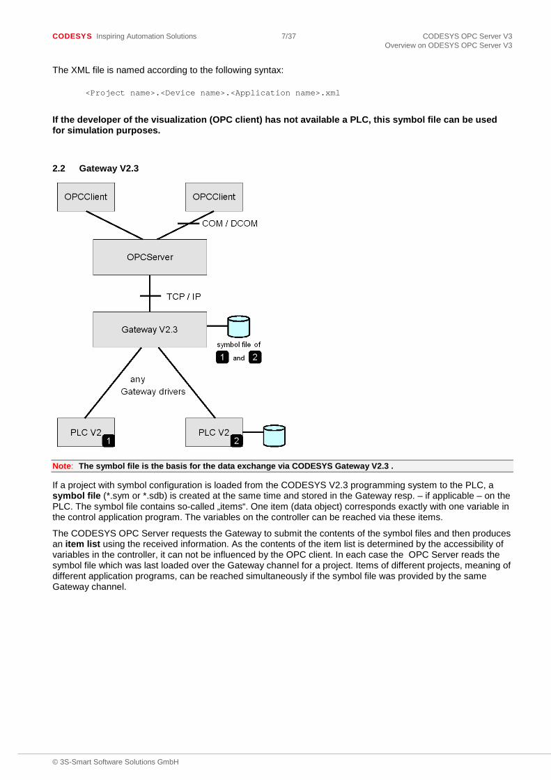
2.2 Gateway V2.3
Note: The symbol file is the basis for the data exchange via CODESYS Gateway V2.3 .
If a project with symbol configuration is loaded from the CODESYS V2.3 programming system to the PLC, a symbol file (*.sym or *.sdb) is created at the same time and stored in the Gateway resp. – if applicable – on the PLC. The symbol file contains so-called „items“. One item (data object) corresponds exactly with one variable in the control application program. The variables on the controller can be reached via these items.
The CODESYS OPC Server requests the Gateway to submit the contents of the symbol files and then produces an item list using the received information. As the contents of the item list is determined by the accessibility of variables in the controller, it can not be influenced by the OPC client. In each case the OPC Server reads the symbol file which was last loaded over the Gateway channel for a project. Items of different projects, meaning of different application programs, can be reached simultaneously if the symbol file was provided by the same Gateway channel.
CODESYS Inspiring Automation Solutions 8/37 CODESYS OPC Server V3 Installation of the CODESYS OPC Server V3
© 3S-Smart Software Solutions GmbH
3 Installation of the CODESYS OPC Server V3
OPC Server V3 is delivered in setup form. All files needed for the OPC communication get installed and the OPC Server will be registered automatically as COM server.
Note: For using the OPC Server V3 on a Windows Vista system, it is strongly recommended to run the OPC client in Windows XP SP2 compatibility mode and with extended administrator rights in order to get a continuous updating of the values.
3.1 Installation and Registration
Further on, there is the possibility to register resp. to uninstall the OPC Server manually either as COM server or as service.
1..Parallel installation and registration
With command WinCODESYSOPC /RegServer
the server is registered as COM server. Thereby as location path always the current position of WinCODESYSOPC.exe will be used. Thus the call only may be done from a local path.
2. Registration as service
With command WinCODESYSOPC /Service
WinCODESYSOPC.exe gets installed as system service. Started once, the service will stay “started” until the system gets terminated. The communication to the configured PLCs survives. Also here the service gets installed in the current position of WinCODESYSOPC.exe.
3. Uninstalling the
With command WinCODESYSOPC /UnRegServer
all entries of the OPC Server will be removed from the registry. The installed files will not be removed.
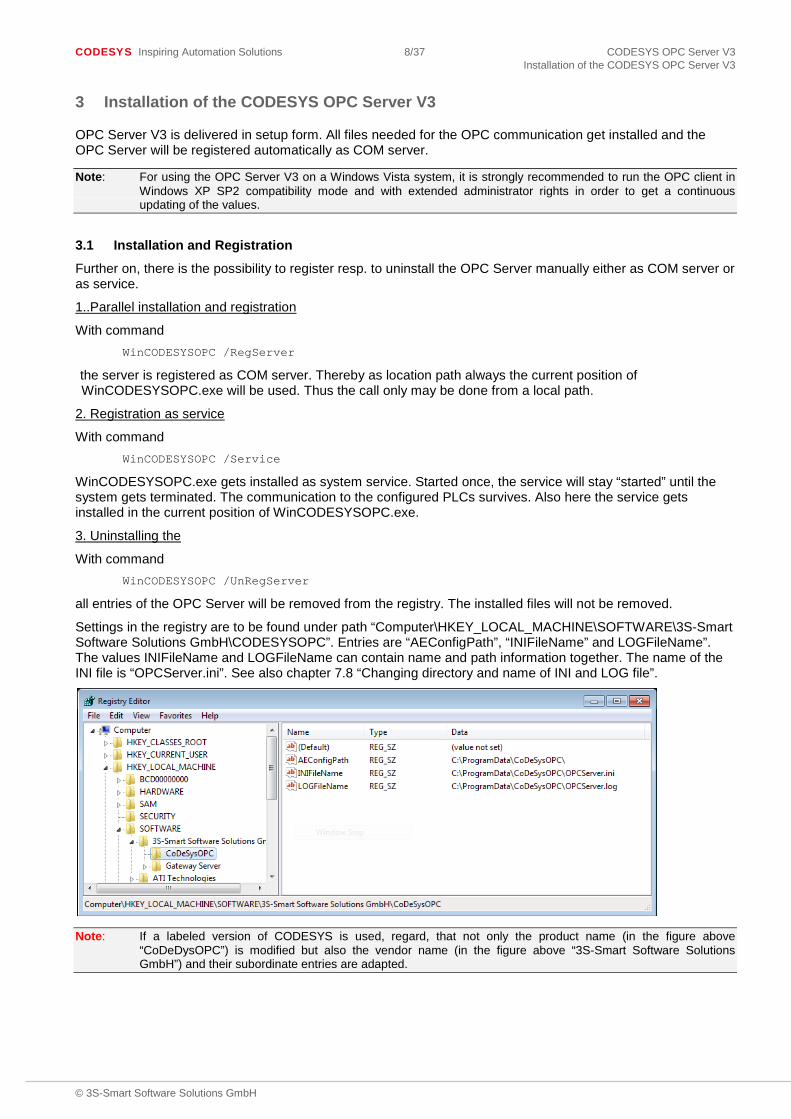
Settings in the registry are to be found under path “Computer\HKEY_LOCAL_MACHINE\SOFTWARE\3S-Smart Software Solutions GmbH\CODESYSOPC”. Entries are “AEConfigPath”, “INIFileName” and LOGFileName”. The values INIFileName and LOGFileName can contain name and path information together. The name of the INI file is “OPCServer.ini”. See also chapter 7.8 “Changing directory and name of INI and LOG file”.
Note: If a labeled version of CODESYS is used, regard, that not only the product name (in the figure above “CoDeDysOPC”) is modified but also the vendor name (in the figure above “3S-Smart Software Solutions GmbH”) and their subordinate entries are adapted.

CODESYS Inspiring Automation Solutions 9/37 CODESYS OPC Server V3 Usage of the CODESYS OPC Server V3
© 3S-Smart Software Solutions GmbH
4 Usage of the CODESYS OPC Server V3
To receive a communication from the PLC via OPC server to the OPC client, the following steps are necessary:
1. The application on the control contains symbols (Items) configured with symbol configuration. See chapter 5 “Configuration of the symbols in the programming system”.
2. The OPC server receives all necessary settings to establish the connections in “OPCServer.ini”. The name and path of the OPC server INI file is by default “OPCServer.ini” in the installation directory. How to change this default settings see chapter 7.8 “Changing directory and name of INI and LOG file” How to create the OPCServer.ini see chapter 6 “CODESYS OPC Server Configuration by OPCConfig.exe”.
3. After selection of server CODESYS.OPC.DA the desired OPC-Client can browse all configured symbols.
After the installation, the OPC Server should be offered for selection by the OPC client (e.g. visualization). The name of the OPC Server is CODESYS.OPC.DA.
The OPC Server will be started automatically by the operating system as soon as a client establishes a connection. The OPC Server then will terminate automatically as soon as all clients have closed their connections to the server.
There will be no OPC Server icon in the task bar, but it will be only handled in the Windows Task Manager as a process.
For each configured PLC the OPC Server V3 generates the status variables _CommState and _CommStateOK. _CommState can be interpreted from an OPC Client and the following states can be requested:
STATE_TERMINATE = -1 STATE_PLC_NOT_CONNECTED = 0 STATE_PLC_CONNECTED = 1 STATE_NO_SYMBOLS = 2 STATE_SYMBOLS_LOADED = 3 STATE_RUNNING = 4 STATE_DISCONNECT = 5 STATE_NO_CONFIGURATION = 6
_CommStateOK is a Boolean variable indicating in state TRUE a communication with the OPC server. The name of the plc can be taken from the prefix of the Boolean variable. If the variable is FALSE, currently no communication is possible. This happens for example during download.
In redundant groups the status variables are generated for each plc in the group. Then for differentiation the name of the status variables follows the syntax:
__CommStateOK<PLCName>
__CommState<PLCName>
Example:
OPCServer.ini: [RedGroup:0] Name=MyGroup NumPLCs=2 DefaultPLC=0 PLCName0=SPWinV3 PLCName1=SPWinV3R
Thus, there are the following status variables: __CommStateOKSPWinV3
__CommStateSPWinV3
__CommStateOKSPWinV3R
__CommStateSPWinV3R

CODESYS Inspiring Automation Solutions 10/37 CODESYS OPC Server V3 Configuration of the symbols in the programming system
© 3S-Smart Software Solutions GmbH
5 Configuration of the symbols in the programming system
5.1 V3 Interface
Step 1: Add Symbol Configuration
Select the Application object in the device tree and add object Symbol configuration (Project-> Add Object -> Symbol configuration). The symbol configuration editor appears:
Step 2: Configure symbols
The dialog shown above will be opened on a double-click on the symbol configuration object. In order to get the currently available item pool, first click on the Refresh button. Thereupon, in the left part of the editor window all variables available in the application will be displayed. These are only variables with read or write access. In order to add a variable or node currently selected in the left tree to the right window use the arrow button < > > between the two windows.
The access right for a selected item can be modified in the right window by clicking on the symbol in column Access Rights. Each mouse-click switches to the next one of the possible symbols and thus to the respective access right:
read+write (read and write access), write-only (only write access), read-only (only read access).
Note: In case of arrays and structures the aggregate variable as well as the particular components will be generated implicitly
If the symbol configuration will be modified in online mode, the modified application can be downloaded via button Download.

CODESYS Inspiring Automation Solutions 11/37 CODESYS OPC Server V3 Configuration of the symbols in the programming system
© 3S-Smart Software Solutions GmbH
Step 3: Login
Note: Instructions for configuring the plc by device description file regarding the behavior of the symbol configuration can be found in the document “CODESYSControlV3_Manual.pdf” Chapter “6.5.4.1 Symbol configuration”.
With commanding Login the application will be compiled and downloaded.
If the controller is configured in a way that it downloads the symbols within the task application (default way), the following happens:
The application with the implicit symbol information will be created and downloaded to the plc. The symbol file is stored next to the project file as well.
If the controller is configured that it downloads the symbols in its own application, the following happens:
The syntax of the symbol application is: <Application name>.__Symbols
The application and the child application will be created and downloaded to the PLC. The symbol file is stored next to the project file as well.
The symbol application has to be regarded as „normal“ application, also concerning the maximum number of applications on a PLC.

CODESYS Inspiring Automation Solutions 12/37 CODESYS OPC Server V3 Configuration of the symbols in the programming system
© 3S-Smart Software Solutions GmbH
5.2 V2.3 Interface
Step 1: Activate option Create symbol entries
In order to get the symbol file generated automatically at each compilation of the project, first option Dump symbol entries (Project -> Options -> Symbol configuration) must be activated.
Step 2: Configure symbol file
In dialog Set object attributes (Project -> Options -> Symbol configuration -> Configure symbol file…) in the project structure tree you can select those objects/variables, for which the symbol options should be set.
Multiple selection of objects is possible (<Shift> + <Ctrl>). If, like shown in the following picture, object OPC_variables is selected, the settings done for this object also will be applied to its child objects.
The following options are supported:
Export variables of object: The variables of the selected object(s) are issued in the symbol file. Export data entries: Entries giving access to the aggregate variable are generated for the
structures and arrays of the object. Precondition: export variables of object is activated. Export structure components: In case of structures for each component a separate symbol entry
is created. Precondition: Export variables of object is activated. Export array entries: In case of arrays for each element a separate symbol entry is created.
Precondition: Export variables of object is activated. Write access: The variables of the object may be changed by the OPC Server.
Note: This version of the OPC Server can only access items of basis data types. For this reason for each object the options ‘Export structure components’ and ‘Export array entries’ must be activated.
Note: It is recommended to export only those variables/objects for access by OPC, which are really needed.
CODESYS Inspiring Automation Solutions 13/37 CODESYS OPC Server V3 Configuration of the symbols in the programming system
© 3S-Smart Software Solutions GmbH
Step 3: Build
During compilation of the project the symbol file (*.sdb) is generated and stored in the project directory.
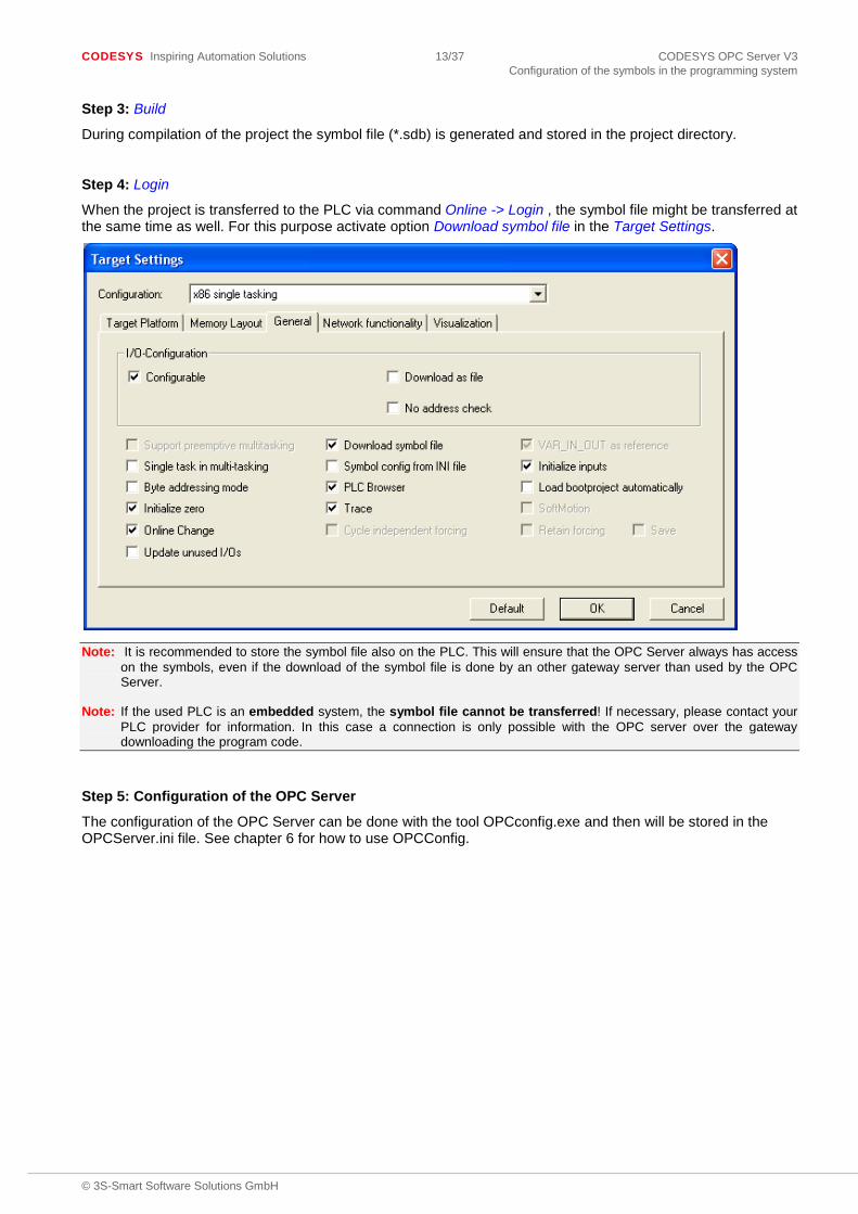
Step 4: Login
When the project is transferred to the PLC via command Online -> Login , the symbol file might be transferred at the same time as well. For this purpose activate option Download symbol file in the Target Settings.
Note: It is recommended to store the symbol file also on the PLC. This will ensure that the OPC Server always has access on the symbols, even if the download of the symbol file is done by an other gateway server than used by the OPC Server.
Note: If the used PLC is an embedded system, the symbol file cannot be transferred! If necessary, please contact your PLC provider for information. In this case a connection is only possible with the OPC server over the gateway downloading the program code.
Step 5: Configuration of the OPC Server
The configuration of the OPC Server can be done with the tool OPCconfig.exe and then will be stored in the OPCServer.ini file. See chapter 6 for how to use OPCConfig.

CODESYS Inspiring Automation Solutions 14/37 CODESYS OPC Server V3 CODESYS OPC Server Configuration by OPCConfig.exe
© 3S-Smart Software Solutions GmbH
6 CODESYS OPC Server Configuration by OPCConfig.exe
For the connection between OPC client and the controller(s)/PLC(s) there are parameters defined in the file “OPCServer.ini”.
Regard that the default path of the INI file depend on the used operating system. The file can be found in previous versions than windows vista in the installation directory of the OPC server (default „C:\Program Files\3S CODESYS\CODESYS OPC Server V3“). In all subsequent windows systems the file is put in „C:\ProgramData\CODESYSOPC“ by default.
Regard that the OPC server expects a file as it is defined in the Registry. That means by default the INI file name is “C:\ProgramData\CODESYSOPC\OPCServer.ini”. How to change this default settings see chapter 7.8 “Changing directory and name of INI and LOG file” Only this file is used from the CODESYS OPC server for establishing a connection. Files with other names are ignored.
Certainly “OPCServer.ini” can directly be edited. But it is much more comfortable to do the settings with the configuration tool OPCConfig be found in the installation directory (by default „C:\Program Files\3S CODESYS\CODESYS OPC Server V3“).
6.1 Call OPCConfig.exe
6.1.1 Default call
With calling OPCConfig.exe, the tool ‘OPCConfig’ opens with the registered INI file.
6.1.2 Open a particular INI file
OPCConfig can be called with a command line parameter to open a particular INI file as well. If the INI file isn’t stored in the same directory as OPCConfig.exe, call the tool with a full path in argument <file name>.
Syntax: “<path of OPCConfig>\OPCConfig.exe” /open <file name>
Example
Following command opens the file “MySpecialConf.ini”: “C:\Program Files\3S CODESYS\CODESYS OPC Server V3\OPCConfig.exe” /open MyOPCServer.ini
Note: The OPC server doesn’t use a particular file for establishing the connection if it is not registered and therefore is not the active INI file.
CODESYS Inspiring Automation Solutions 15/37 CODESYS OPC Server V3 CODESYS OPC Server Configuration by OPCConfig.exe
© 3S-Smart Software Solutions GmbH
6.2 Menu Commands and Configuration Dialogs
6.2.1 File
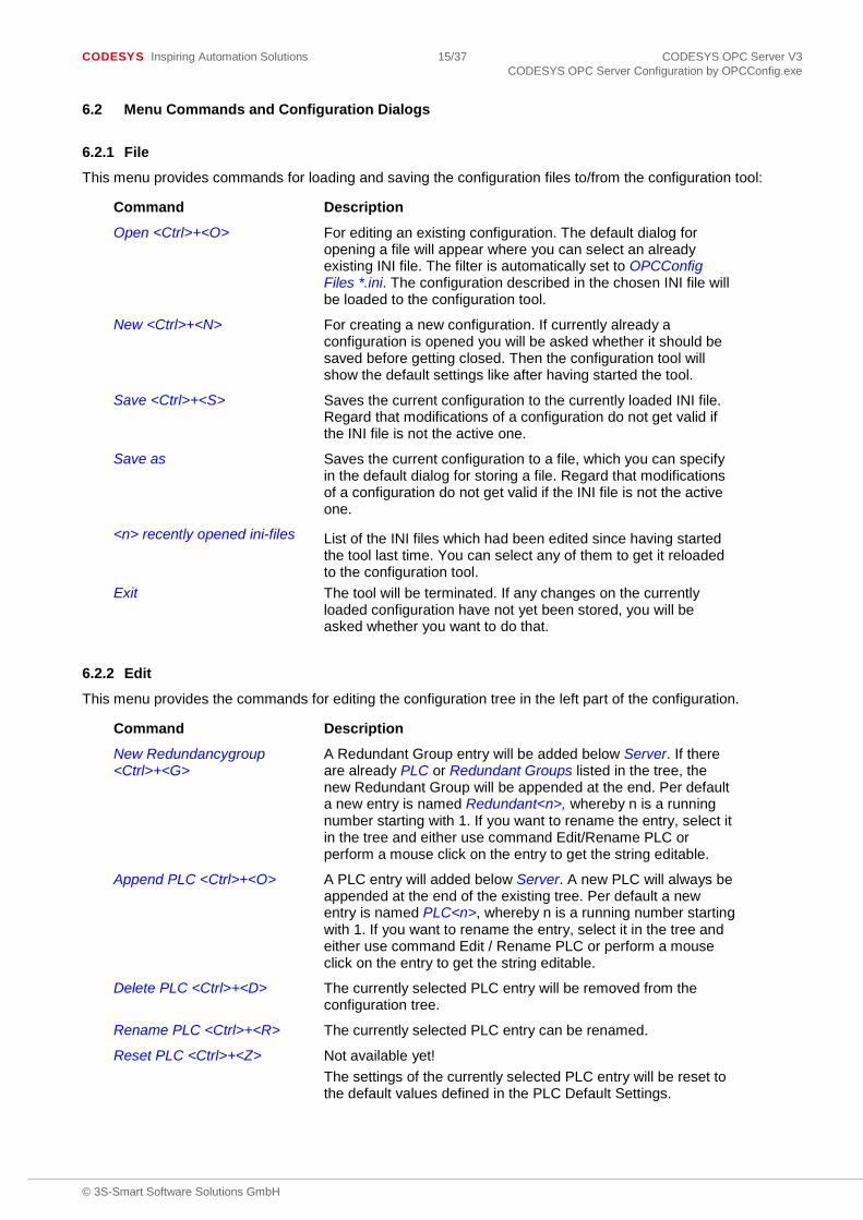
This menu provides commands for loading and saving the configuration files to/from the configuration tool:
Command Description
Open <Ctrl>+<O> For editing an existing configuration. The default dialog for opening a file will appear where you can select an already existing INI file. The filter is automatically set to OPCConfig Files *.ini. The configuration described in the chosen INI file will be loaded to the configuration tool.
New <Ctrl>+<N> For creating a new configuration. If currently already a configuration is opened you will be asked whether it should be saved before getting closed. Then the configuration tool will show the default settings like after having started the tool.
Save <Ctrl>+<S> Saves the current configuration to the currently loaded INI file. Regard that modifications of a configuration do not get valid if the INI file is not the active one.
Save as Saves the current configuration to a file, which you can specify in the default dialog for storing a file. Regard that modifications of a configuration do not get valid if the INI file is not the active one.
<n> recently opened ini-files List of the INI files which had been edited since having started the tool last time. You can select any of them to get it reloaded to the configuration tool.
Exit The tool will be terminated. If any changes on the currently loaded configuration have not yet been stored, you will be asked whether you want to do that.
6.2.2 Edit
This menu provides the commands for editing the configuration tree in the left part of the configuration.
Command Description
New Redundancygroup <Ctrl>+<G>
A Redundant Group entry will be added below Server. If there are already PLC or Redundant Groups listed in the tree, the new Redundant Group will be appended at the end. Per default a new entry is named Redundant<n>, whereby n is a running number starting with 1. If you want to rename the entry, select it in the tree and either use command Edit/Rename PLC or perform a mouse click on the entry to get the string editable.
Append PLC <Ctrl>+<O> A PLC entry will added below Server. A new PLC will always be appended at the end of the existing tree. Per default a new entry is named PLC<n>, whereby n is a running number starting with 1. If you want to rename the entry, select it in the tree and either use command Edit / Rename PLC or perform a mouse click on the entry to get the string editable.
Delete PLC <Ctrl>+<D> The currently selected PLC entry will be removed from the configuration tree.
Rename PLC <Ctrl>+<R> The currently selected PLC entry can be renamed.
Reset PLC <Ctrl>+<Z> Not available yet! The settings of the currently selected PLC entry will be reset to the default values defined in the PLC Default Settings.

CODESYS Inspiring Automation Solutions 16/37 CODESYS OPC Server V3 CODESYS OPC Server Configuration by OPCConfig.exe
© 3S-Smart Software Solutions GmbH
6.2.3 ?
This command opens a message box with information on version, copyright and vendor of the tool.
6.2.4 Settings for OPC server
This dialog is available when the root entry Server is selected in the configuration tree. It provides the following settings:
- Update Rate (ms): Default: 200 Basic update rate of the OPC-Server in milliseconds. This is the cycle time according to which all item data are read from the PLC. The data get written into the cash with which the client communicates with a separately defined update rate. Note: With the status information the server also provides a parameter Bandwidth Usage giving the ratio of the actual update rate to the configured update rate in percents.
- Sync Init : Default: not active If this option is activated, a synchronous connection is initialized.
- Writes produce data change calls: see chap. 7.1, Entry „ReadCyclesAfterWrite“:
- Use Colon as PLC-name separator: see chap. 7.1, Entry „UseColonAsPlcDivider“
- Suppress callbacks on add/remove: see chap. 7.1, Entry „GroupUpdateBehaviour“
Logging
- Enable Logging (Defaultevents): Default: not active If this option is activated, any actions as well as errors on the OPC server will be recorded in a LOG file. This file will be stored in the installation directory and will be named OPCServer.log. After a shutdown of the OPC Server the LOG file can be evaluated. The messages of several OPC sessions are lined up in one LOG file until it reaches the size of 1 MB. Then the current date will be added in the file name (OPCServer<date>.log, e.g. OPCServer12.10.2008.log) and the file will be saved. After that a new LOG file OPCServer.log will be created.
- Log Additional Events: Default: not active If this option is active, then additional events are written into the LOG file.
- Add Debug Events (slow): Default: not active If this option is active, then debug events are written into the LOG file.

CODESYS Inspiring Automation Solutions 17/37 CODESYS OPC Server V3 CODESYS OPC Server Configuration by OPCConfig.exe
© 3S-Smart Software Solutions GmbH
6.2.5 Settings for <PLC>
This dialog is available, if the <PLC> entry is selected in the configuration tree.
- Interface: Name of the interface used for the communication between programming system and PLC. The selection list per default contains the following interface types: ARTI, GATEWAY, SIMULATION for projects created with CODESYSV2.3; GATEWAY3, SIMULATION3 for V3 projects. Concerning the SIMULATION or SIMULATION3 interface please see chap. 6.1, “Simulation Interface”.
- Project name: Name of the currently concerned symbol file. It has to be used in case of simulation. If there is no path the file has to be found in the OPC server directory. In CODESYS V3 the symbol file name follows the syntax: <project name>.<device>.<application>.xml. In CODESYS V2.3 : <project name>.sdb.
Note: This entry is only used if interface SIMULATION or SIMULATION3 is contemporary used too
- Timeout (ms): Default: 10000 If within this period of time the OPC server does not receive any feedback on a sent service from the PLC, it will close down automatically.
- Number of Tries: Default: 3 Number of attempts the gateway communication driver will make to transfer a block correctly. As soon as the last attempt has failed, a communication error message will be created. (this entry is only relevant for drivers which support a communication via blocks, Level 2).
- Buffer Size (Byte): Default: 0 Size of the communication buffer on the target device; if the entry is “0” the device driver will be searched for this size information. If it does not provide any, it will be assumed that the buffer is unlimited.

CODESYS Inspiring Automation Solutions 18/37 CODESYS OPC Server V3 CODESYS OPC Server Configuration by OPCConfig.exe
© 3S-Smart Software Solutions GmbH
- Wait Time (s): Default: 10 Time in seconds the OPC server will wait until the controller is ready (important during the automatic start of the controller)
- Reconnect Time (s): Default: 15 Time interval, according to which the OPC server repeatedly tries to reconnect with the controller via the gateway.
- Active: Default: activated: Only if this option is activated, the PLC will be regarded by the OPC Server.
- Motorola Byteorder: Default: not activated The target system of the project does not use the Motorola byte order (this aspect is to be given special regard when working with 68K, 8051, Power PC !). This Entry has to coincide with the entry in the settings for connection of the PLC.
- No Login Service: Default: not activated This option must be activated for specific target systems which request the sending of a login service.
- Logging: Options for the logging of events in a LOG file, see chap. 6.2.4. Per default the logging of the default events is activated (Enable logging (Defaultevents): Information on setup and shutdown of the connection). For error analysis you can explicitly activate the logging of additional events (Log Additional Events) and debugging events (Add Debug Events (slow!)). Note that the latter two options will drastically increase the system load!
6.2.6 Settings for connection to <PLC>
This dialog will be available if entry Connection below a <PLC> is selected in the configuration tree.
Here the communication settings as defined for the application in the respective CODESYS V3 project must be entered. If no communication setting is defined the OPC-Server ends with STATE_TERMINATE. So have a closer look at the appropriate LOG file, where all sequences the OPC-Server had done are listed. There you can find the logged and unsuccessful attempts for starting communication.

CODESYS Inspiring Automation Solutions 19/37 CODESYS OPC Server V3 CODESYS OPC Server Configuration by OPCConfig.exe
© 3S-Smart Software Solutions GmbH
For creating a new communication resp. for modifying an existing one, use button Edit to open the dialog CODESYS address of PLC:
Enter the IP address and port for the gateway and for identifying the PLC specify either the name or address (PLC name (recommended) or address), or address and port of the Tcp/Ip blockdriver (Use Tcp/blockdriver); each the settings must correspond to those defined in Communication Settings tab of the Device Editor for the concerned CODESYS project. After closing the dialog with OK the settings will be displayed in the main dialog.
In a CODESYS V2.3 project the valid settings are performed in the dialog Communication Parameters. From all the channels shown in the tree structure the valid one can be selected for the plc.

CODESYS Inspiring Automation Solutions 20/37 CODESYS OPC Server V3 CODESYS OPC Server Configuration by OPCConfig.exe
© 3S-Smart Software Solutions GmbH
Extended configuration is possible via button Expert, in dialog Additional generic parameters:
These settings are described in the programming guide for the PLC Handler; if required, a value can be edited after a mouse-click in the „value“ column.

CODESYS Inspiring Automation Solutions 21/37 CODESYS OPC Server V3 CODESYS OPC Server Configuration by OPCConfig.exe
© 3S-Smart Software Solutions GmbH
6.3 Simulation Interface
If the PLC (device) configured in the CODESYS project is not available, the OPC Server allows to work in simulation mode. For this purpose only the symbol file, generated by the CODESYS project, is needed. The symbols exported to this file can be used in the OPC Server, however the values of the symbols will not be accessible in simulation mode.
For simulation with a V3 project, in the PLC settings configuration (see chap. 6.2.5) select interface type “SIMULATION3”, for simulation with a V2.3 project select “SIMULATION”.
6.3.1 SIMULATION3
In the OPC server INI file, a simulation access is configured by selecting the Interface SIMULATION3 and by setting the name of the symbol file in Project name. The symbol file is automatically generated by a build command of a CODESYS V3 project when a symbol configuration exists and is stored with the name extension XML next to the project file. If this file is stored in the OPC server directory, then only the project name has to be specified here. But it can also be copied to any location, then under Project name also the directory name has to be specified.
Dialog with configuration of a simulated access to the stock of symbols of SimulatedControlWinV3:
6.3.2 SIMULATION
In the OPC server INI file, a simulation access by Gateway V2.3 connection is configured by selecting the interface SIMULATION and by setting the name of the symbol file in Project name. The symbol file is automatically generated by a build command of a CODESYS V2.3 project when in Options -> symbol configuration the corresponding options are set. The symbol file is stored in the same directory as the project file and has the extension SDB. If the symbol file is stored in the OPC server directory, then the directory name has not to be specified. But it can also be copied to any location, then under Project name the directory name has to be specified.
Dialog with configuration of a simulated access to the stock of symbols of SimulatedPLCWinNT:

CODESYS Inspiring Automation Solutions 22/37 CODESYS OPC Server V3 CODESYS OPC Server Configuration by OPCConfig.exe
© 3S-Smart Software Solutions GmbH
6.4 Special case „GATEWAY“
In the CODESYS V2.3 environment, it is possible to establish a connection only to the Gateway V2.3 if the following conditions apply:
- Symbol file can not be stored on the PLC - PLC does not know the name of the currently running project - Symbol file is manually copied to the Gateway and not by a download or online change
Then the symbol information stored in the gateway are available for the OPC-Client..
Following settings has to be done in the OPC-Server.ini:
6.5 Redundant Group
A Redundant Group (also “redundancy group” ) serves to ensure that the OPC Server gets values of the desired variables (items) even if the communication with the primarily desired PLC is not working and is then taken over by a parallel-operated control. For this purpose the group defines two PLC connections providing the same set of items. Via a Master Variable it can be controlled from which of these PLCs primarily will be read.
The needed settings for the OPC server INI file are performed with the tool OPCConfig.exe as follows:

CODESYS Inspiring Automation Solutions 23/37 CODESYS OPC Server V3 CODESYS OPC Server Configuration by OPCConfig.exe
© 3S-Smart Software Solutions GmbH
Command Edit/New RedundancyGroup opens the following dialog for configuring a redundant group:
All PLCs currently configured are listed in the Available PLCs window. In order to add a PLC to the redundancy group, select it here and use the arrow button to add it in the PLCs in this group window. Regard that all PLCs added to the group must provide identical sets of variables. There, up to two controls can be selected.
Default PLC: Define the PLC from which the OPC Server should read the items, if the check of the Master Variable does not provide an unique one.
Select PLC in group to set Master Variable: Select a PLC in the ‘PLCs in this group’ window and enter an Boolean variable which is used in the application and which should be the “master variable” for this PLC. The OPC Server will check the master variable of each PLC in the group and will read the values from that PLC whose master variable is TRUE. If the master variables do not determine uniquely from which PLC the values should be read, they will be read from the default PLC. The values can only be written if at least one PLC sets the master variable.
The name of the master variable in CODESYS follows the following syntax: <Application>.<POU>.<variable>
The name of variables in CODESYS V2.3 contains no application name and global variables contain no POU name. So the structure looks like:
<POUname>.<variablename>
or .<NameGlobalVariable>
Note: The CODESYS OPC Server V3 does not work at all with no master variable. If the master variable of the redundant group is missing, this will be documented in the LOG file.
LifeCounter Variable (all PLCs in group): Via this variable each PLC can check, whether the OPC Server is still active. It must be defined for this purpose in all PLCs of the group and the life counter variable type must be DWORD.
The name of the LifeCounter Variable in CODESYS V3 follows the following syntax: Application>.<POU>.<variable>
The names of variables in CODESYS V2.3 contain no application name and global variables contain no POU name. So the structure looks like:
<POUname>.<variablename>
or .<NameGlobalVariable>

CODESYS Inspiring Automation Solutions 24/37 CODESYS OPC Server V3 CODESYS OPC Server Configuration by OPCConfig.exe
© 3S-Smart Software Solutions GmbH
6.6 Configuration of OPCConfig with OPCConfig.ini
For defining the behavior of the tool OPCConfig it is possible to place the INI file „OPCConfig.ini“ in the working directory of the tool. Under section [Config] you can register vendor and product name. Under section [PLCDefaults] you can register default settings for the connection to the contoller, which the tool will use, if a new controller is added. The INI-file is read every startup of OPCConfig.
Beispiel: [Config]
vendor=3S-Smart Software Solutions GmbH product=CODESYSOPCDA and CODESYSOPCAE inifilevalue=<name of the registryvalue, containing the OPServer-inifilepath> [PLCDefaults] interface=GATEWAY active=1 motorola=1 nologin=0 timeout=12 tries=5 buffersize=5000 reconnecttime=13 v3gatewayport=1217 v3gateway=localhost v3address=1234
Setting Description
[Config]
vendor=3S-Smart Software Solutions GmbH
Vendor
product=CODESYSOPCDA and CODESYSOPCAE
Product name
[PLCDefaults]
interface=GATEWAY Default interface
active=1 motorola=1 nologin=0 timeout=12 tries=5 buffersize=5000 reconnecttime=13 v3gatewayport=1217 Default settings for connection with CODESYS Gateway V3 .
The settings are used, if a PLC with CODESYS Gateway V3 interface is added.
v3gateway=localhost
v3address=0000
CODESYS Inspiring Automation Solutions 25/37 CODESYS OPC Server V3 Configuration settings in OPCServer.ini
© 3S-Smart Software Solutions GmbH
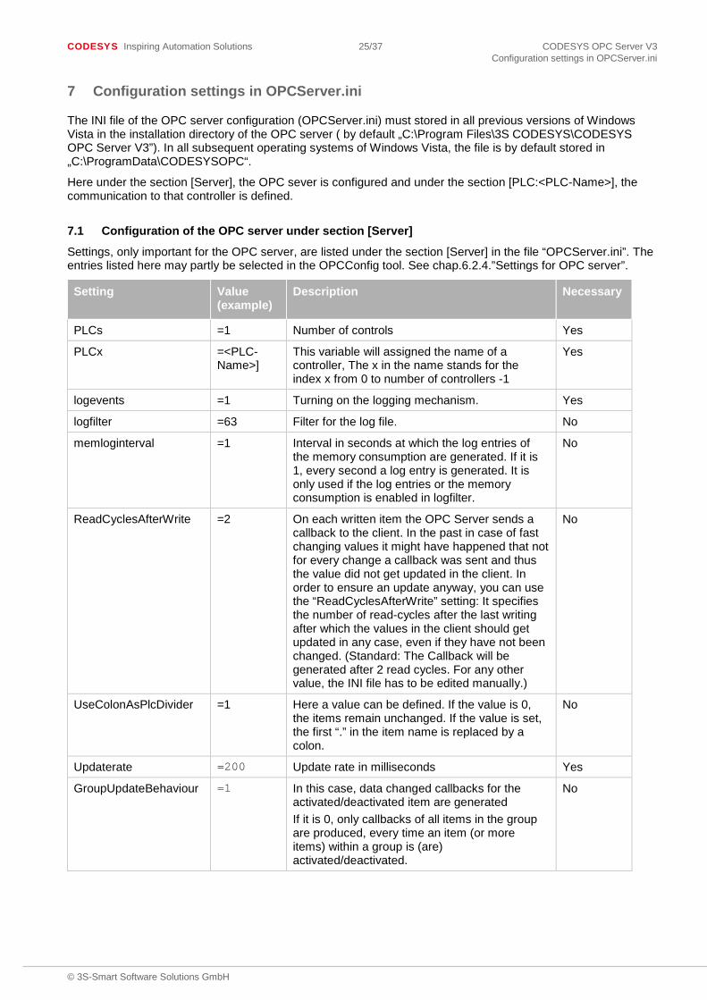
7 Configuration settings in OPCServer.ini
The INI file of the OPC server configuration (OPCServer.ini) must stored in all previous versions of Windows Vista in the installation directory of the OPC server ( by default „C:\Program Files\3S CODESYS\CODESYS OPC Server V3”). In all subsequent operating systems of Windows Vista, the file is by default stored in „C:\ProgramData\CODESYSOPC“.
Here under the section [Server], the OPC sever is configured and under the section [PLC:<PLC-Name>], the communication to that controller is defined.
7.1 Configuration of the OPC server under section [Server]
Settings, only important for the OPC server, are listed under the section [Server] in the file “OPCServer.ini”. The entries listed here may partly be selected in the OPCConfig tool. See chap.6.2.4.”Settings for OPC server”.
Setting Value (example)
Description Necessary
PLCs =1 Number of controls Yes
PLCx =<PLC-Name>]
This variable will assigned the name of a controller, The x in the name stands for the index x from 0 to number of controllers -1
Yes
logevents =1 Turning on the logging mechanism. Yes
logfilter =63 Filter for the log file. No
memloginterval =1 Interval in seconds at which the log entries of the memory consumption are generated. If it is 1, every second a log entry is generated. It is only used if the log entries or the memory consumption is enabled in logfilter.
No
ReadCyclesAfterWrite
=2 On each written item the OPC Server sends a callback to the client. In the past in case of fast changing values it might have happened that not for every change a callback was sent and thus the value did not get updated in the client. In order to ensure an update anyway, you can use the “ReadCyclesAfterWrite” setting: It specifies the number of read-cycles after the last writing after which the values in the client should get updated in any case, even if they have not been changed. (Standard: The Callback will be generated after 2 read cycles. For any other value, the INI file has to be edited manually.)
No
UseColonAsPlcDivider =1 Here a value can be defined. If the value is 0, the items remain unchanged. If the value is set, the first “.” in the item name is replaced by a colon.
No
Updaterate =200 Update rate in milliseconds Yes
GroupUpdateBehaviour =1 In this case, data changed callbacks for the activated/deactivated item are generated If it is 0, only callbacks of all items in the group are produced, every time an item (or more items) within a group is (are) activated/deactivated.
No

CODESYS Inspiring Automation Solutions 26/37 CODESYS OPC Server V3 Configuration settings in OPCServer.ini
© 3S-Smart Software Solutions GmbH
The following table lists the possible options for the logfilter. If multiple entries are to be activated, these add up and enter the result in ‘logfilter’.
Logfilter Description
15 (16#0000000F) Generate standard log entries.
32 (16#00000020) Generate additional log entries.
48 (16#00000030) Generate debug log entries.
512 (16#00000200) Generate log entries about the memory consumption. The entry will be created every “memloginterval” seconds.
7.2 Configuration of the communication to the controllers
Under the section [PLC:<PLC-Name>] the communication settings are done for the related controls. This information is passed to the underlying PLCHandler. All settings particular the special are described in detail in “PLCHandler Programming Guide”
At least partially the entries can be selected using the tool OPCConfig. See chap. 6.2.6 ,“Settings for connection to <PLC>”.
The most important entry here is the address of the controller. It depends on the interface type, which settings have to be set.
Example for interface type GATEWAY3:
gateway=Tcp/Ip CODESYS Gateway V3 settings
gatewayaddress=localhost IP Address
gatewayport=1217 Port
Device=TCP/IP CODESYS Control V3 settings
parameters=2 Parameter to set address and port
parameter0=Address
value0=050C Here insert CODESYS PLC address. It must be identical to the node address, as defined in the programming system.
parameter1=Port
value1=11740 Here insert the port address..
7.3 Example of an INI file for the V3 interface
INI File for V3.x Description
[Server] Settings for the OPC Server
PLCs=1 Connection to two PLCs is intended
PLC0=PLC1 Name of the first PLC: PLC1
logevents=1 Switch-On of the log-mechanism
Logfilter=15 Creation of default log entries.
ReadCyclesAfterWrite=2 Herewith after each write request of the client, after having written a value, for this value a callback will be caused. This is done in order to by all means pass the current value once more after “2” update cycles. This is needed for quickly changing values.

CODESYS Inspiring Automation Solutions 27/37 CODESYS OPC Server V3 Configuration settings in OPCServer.ini
© 3S-Smart Software Solutions GmbH
INI File for V3.x Description
UseColonAsPlcDivider=0 Here a value can be specified. If it is not zero, the first “.” (e.g. the one after the PLC-name) is superseded by a colon.
updaterate=200 To determine the configurable update rate
[PLC:PLC1] Settings for PLC1
interfacetype=GATEWAY3 Herewith via the GATEWAY a connection with the PLC will be established.
active=1 Active
timeout=2000 Timeout
tries=3 Number of trials
Project=OPC.Device.Application.xml Name and path of the generated symbol file. In case of simulation this file is concerned. If there is no path this file has to be in the OPC server directory
waittime=10 Waiting time
reconnecttime=5 Reconnect time
gateway=Tcp/Ip Settings for the connection to PLC_A ( Connection between client and local Gateway via TCP/IP ) gatewayaddress=localhost
gatewayport=1217
device=TCP/IP Parameter for the connection to the target device, where PLC1 is running (dialog Communication Parameters in the tool OPCConfig): The value to be entered under “value0” is the CODESYS node address and must be identical to the node address in the programming system.
parameters=1
parameter0=Address
value0=050C
7.4 Example of an INI file for the V2.3 interface
Thus, after each write request of the client after the writing of a value for this item, a callback is triggered by the client and after 2 cycles the current value must be updated again.
Setting Description
[Server] Settings for the OPC Server
PLCs=2 Connection to two PLCs is intended
PLC0=PLC_A Name of the first PLC: PLC_A
PLC1=PLC_B Name of the first PLC: PLC_B
logevents=1 Switch-On of the log-mechanism
Logfilter=16#ffffffcf Activation of all errors and info, no details
ReadCyclesAfterWrite=2 Please see chap. 7.1 for a description
UseColonAsPlcDivider Here a value can be specified. If it is not zero, the first “.” (e.g. the one after the PLC-name) is superseded by a colon.
Updaterate=200 To determine the configurable update rate.
[PLC:PLC_A] Settings for PLC_A

CODESYS Inspiring Automation Solutions 28/37 CODESYS OPC Server V3 Configuration settings in OPCServer.ini
© 3S-Smart Software Solutions GmbH
Setting Description
active=1 Active
interfacetype=GATEWAY Thus, a connection will be established via the GATEWAY with the PLC.
motorola=0 Motorola Byteorder
nologin=1 Login service
timeout=2000 Timeout
tries=3 Number of trials
waittime=10 Waiting time
reconnecttime=5 Reconnect time
buffersize=0 Buffer size: 0 means that the buffer size is got from the PLC
project=PC.sdb Name and path of the symbol file, which in case of simulation is concerned. If there is no path, the symbol file has to be in the OPC server directory.
gateway=Tcp/Ip Settings for the connection to PLC_A ( Connection client –local gateway via TCP/IP ) gatewayaddress=localhost
gatewayport=1210
device=Tcp/Ip Parameter for the connection to the target device, where PLC_A is running (Communication Parameters dialog) parameters=3
parameter0=Address
value0=127.0.2.1
parameter1=Port
value1=1200
parameter2=Motorola byteorder
value2=No
Parameter3=TargetID
Value3=0 Target ID of the PLC, which serves for routing in a „routing“ communication driver to with the OPC Server should connect.
Parameter4=SymbolFilePath Optional entry, via which the PLC Handler determines, where the recently loaded symbol file can be stored. First this file will be checked and according to the ProjectID it will be decided, whether the symbol file must be reloaded. See chap. 6.2.5, Expert Settings.
[PLC:PLC_B] By analogy to the section for PLC_A.

CODESYS Inspiring Automation Solutions 29/37 CODESYS OPC Server V3 Configuration settings in OPCServer.ini
© 3S-Smart Software Solutions GmbH
7.5 Configuration of ‘Redundant Group’
If you want to join controllers to redundant groups, do this comfortable up to two controllers with the configuration tool OPCConfig. If you want to extend the redundant group, you can do this with corresponding entries in OPCServer.ini for up to five controllers by editing the INI file manually.
At runtime, all controls operate in parallel and all of them are capable to send the values of the symbols to the client. In fact, they are read from the client, where the master variable is TRUE. If this is not clearly possible, it is read out from the default-PLC. If the controller, which is read from, fails, then the next best controller is used. This happens, when the quality of the symbols gets BAD. This is as long possible as controls are available with symbols in quality GOOD. With an increasing life counter it is controllable, whether the OPC server still operates.
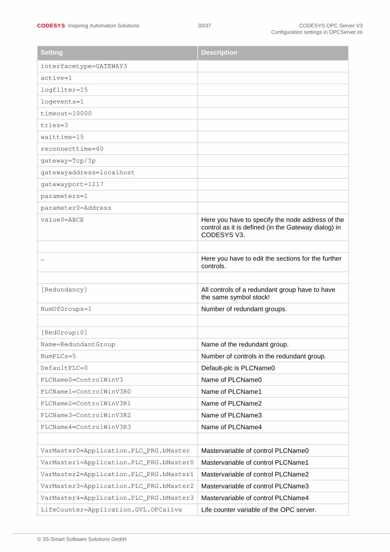
All controls have to be configured as described, by defining the number and the names of the controls in the section [server] and by defining the associated communication in the section [PLC:<PLCName>]. For redundant groups the section [Redundancy] is required with defining the number of the desired groups. Then for each group a section [RedGroup:x] is required. Here the group name, the number of controls, the default-plc, all control names, the master variables and the name of the live counter variable have to be defined. Up to five controls can be joined to a redundant group.
Example for configuration of a redundant group in a INI file
Setting Description
[Server]
PLCs=5
PLC0=ControlWinV3
PLC1=controlWinV3R0
PLC2=controlWinV3R1
PLC3=controlWinV3R2
PLC4=controlWinV3R3
[PLC:ControlWinV3] In this section the communication is defined.
interfacetype=GATEWAY3
active=1
logfilter=15
logevents=1
timeout=10000
tries=3
waittime=15
reconnecttime=60
gateway=Tcp/Ip
gatewayaddress=localhost
gatewayport=1217
parameters=1
parameter0=Address
value0=ABCD Here you have to specify the node address of the control as it is defined (in the Gateway dialog) in CODESYS V3.
[PLC:ControlWinV3R0] In this section the communication is defined.
CODESYS Inspiring Automation Solutions 30/37 CODESYS OPC Server V3 Configuration settings in OPCServer.ini
© 3S-Smart Software Solutions GmbH
Setting Description
interfacetype=GATEWAY3
active=1
logfilter=15
logevents=1
timeout=10000
tries=3
waittime=15
reconnecttime=60
gateway=Tcp/Ip
gatewayaddress=localhost
gatewayport=1217
parameters=1
parameter0=Address
value0=ABCE Here you have to specify the node address of the control as it is defined (in the Gateway dialog) in CODESYS V3.
… Here you have to edit the sections for the further controls.
[Redundancy] All controls of a redundant group have to have the same symbol stock!
NumOfGroups=1 Number of redundant groups.
[RedGroup:0]
Name=RedundantGroup Name of the redundant group.
NumPLCs=5 Number of controls in the redundant group.
DefaultPLC=0 Default-plc is PLCName0
PLCName0=ControlWinV3 Name of PLCName0
PLCName1=ControlWinV3R0 Name of PLCName1
PLCName2=ControlWinV3R1 Name of PLCName2
PLCName3=ControlWinV3R2 Name of PLCName3
PLCName4=ControlWinV3R3 Name of PLCName4
VarMaster0=Application.PLC_PRG.bMaster Mastervariable of control PLCName0
VarMaster1=Application.PLC_PRG.bMaster0 Mastervariable of control PLCName1
VarMaster2=Application.PLC_PRG.bMaster1 Mastervariable of control PLCName2
VarMaster3=Application.PLC_PRG.bMaster2 Mastervariable of control PLCName3
VarMaster4=Application.PLC_PRG.bMaster3 Mastervariable of control PLCName4
LifeCounter=Application.GVL.OPCalive Life counter variable of the OPC server.

CODESYS Inspiring Automation Solutions 31/37 CODESYS OPC Server V3 Configuration settings in OPCServer.ini
© 3S-Smart Software Solutions GmbH
7.6 Information on the changed logfilter
The values of the INI file setting ‘logfilter=’ created with a previous version of the OPC server than 3.4.0.0 have to be corrected for all subsequent versions.
Valid values before V3.4.0.0
Valid values from V3.4.0.0
Description
10 (16#0000000A) 15 (16#0000000F) Creation of default log entries
-47 (16#ffffffd1) 47 (16#0000002F) Creation or default log entries and additional entries
-1 (16#ffffffff) 63 (16#0000003F) Creation or default log entries, additional entries and debug entries
7.7 Configuration of simulation
If there is not a control with a running application, the resulting lack of connection form PLC to OPC server can be replaced by a static access to a file that contains all the symbol information. See chap. 6.3, ‘Simulation Interface’.
If it is a Gateway V3 connection, which is to be replaced, then under section [<PLCName>] the interface SIMULATION3 has to be set and in project the directory and the name of the symbol file has to be set. The directory need not to be set, if the file is stored in the same directory as OPCServer.ini.
Setting Description
[PLC:SimulatedControlWinV3]
interfacetype=SIMULATION3
project=OneSymbol.Device.Application.xml Name of the symbol file (with extension XML) and eventually the directory name.
These settings can be done with the tool OPCConfig.exe. See chap. 6.3.1 “SIMULATION3”.
7.7.1 SIMULATION
If it is a Gateway V2.3 connection, which is to be replaced, then under section [<PLCName>] the interface SIMULATION has to be set and in project the directory and the name of the V2.3 symbol file has to be set. In V2.3, the symbol file is stored in a different format and has the extension SDB. The directory need not to be set, if the file is stored in the same directory as OPCServer.ini.
Setting Description
[PLC:SimulatedPLCWinNT]
interfacetype=SIMULATION
project=MyV23Project.sdb Name of the symbol file (with extension SDB) and eventually the directory name.
These settings can be done with the tool OPCConfig.exe. See chap. 6.3.2 “SIMULATION”.
7.8 Changing directory and name of INI and LOG file
If there is a desire of special directories and names for the INI file and the LOG file, then the associated entries in the windows registry have to be changed. The database can be accessed with regedit.exe. The entries are found under [HKEY_LOCAL_MACHINE\SOFTWARE\3S-Smart Software Solutions GmbH\CODESYSOPC]. Under the name “INIFileName “ there are stored the directory and name of the configuration file of the OPC server and under the name „LOGFileName” the directory and name of the LOG file is stored. With the command New in the context menu of the “Registry Editor” the values can be changed.

CODESYS Inspiring Automation Solutions 32/37 CODESYS OPC Server V3 Configuration settings in OPCServer.ini
© 3S-Smart Software Solutions GmbH
In case the entry LOGFileName is invalid, an entry to the Windows Event logger is created.
Example of an error log in the Windows Event Viewer:

CODESYS Inspiring Automation Solutions 33/37 CODESYS OPC Server V3 Connection to OPC servers on other computers with DCOMCNFG.EXE
© 3S-Smart Software Solutions GmbH
8 Connection to OPC servers on other computers with DCOMCNFG.EXE
This setting is only to be done, if the OPC client cannot configure a remote connection to an OPC Server!
The following description relates on a Windows operating system in German!
With DCOMCNFG.EXE , which is founded in the system directory, you can configure an OPC server, which operates on a remote PC with connection. With double-click on DCOMCNFG.EXE the dialog Component Services opens. Under Console Root->Component Services ->Computers->My Computer->DCOM-Configuration there is a list of services. With selection of CODESYSOPCDA you can command Properties by the context menu and the dialog CODESYSOPCDA Properties opens. Select tab Location and there select the option Run appliation on the following computer. Here you can insert the desired remote PC.
Note: In order to make this connection work, there must be an OPC server running also on the local computer.
Windows 7 64Bit:
If the operating system Windows 7 64Bit is used, then the above procedure is not possible, because DCOMCNFG has not registered the component service CODESYSOPCDA . By calling ‘MMC comexp.msc / 32’ you can register the service and thus a remote connection to an OPC server can be established.

CODESYS Inspiring Automation Solutions 34/37 CODESYS OPC Server V3 Error Diagnosis
© 3S-Smart Software Solutions GmbH
9 Error Diagnosis
9.1 Means of error diagnosis
1. OPC Server LOG file
2. Second (test-)client for reproducing the error
3. V2.3 Interface: Gateway Inspector with trace and logging functions (for sophisticated communication errors)
9.2 Brief checklist
Basically check the following points:
1) PLC running? Gateway installed and running? Symbol in task bar in the right hand corner active?
2) Installation and Registration of the OPC Server OK? Takes place automatically by executing: WinCODESYSOPC /Install (installation + registration) resp. WinCODESYSOPC /RegServer (only registration).
3) Preparation of the project resp. settings in the CODESYS programming system OK? V3 Interface: - Symbols created? - Project saved? Built and download done? V2.3 Interface: - Project options: Dump symbol entries activated? - Communication parameters: selected Gateway channel OK? - Project saved, built, download done?
4) Check the connection and the server settings: OPCConfig.exe: - Connection: (Entry must correspond with the valid Gateway set up in the CODESYS communication parameters) If no communication setting is defined the OPC-Server ends with STATE_TERMINATE. - Usual server settings: Motorola byte order: no (Attention when using 68K, 8051, PowerPC, only concerns V2.3), set up public groups, synchronous initialization, notification on quality change, update rate 200ms, waiting time target system 60s, reconnect interval 5s, communication timeout 3s, buffer size: 0 or fitting for target system (only concerns V2.3)? - Save -> New Configuration becomes effective when new connection to the OPC Server is established
5) Check, whether there are symbol entries disposable: DiagnosticOPCClient.exe (this diagnostic client is not part of the installation but can be delivered on demand) Establish connection (Connect OPC Server), click on Private Groups in right hand side window with right mouse button, confirm dialog with OK, click on the group entry which appears now with right mouse button Add all items all generated symbol entries (variables) should appear.

CODESYS Inspiring Automation Solutions 35/37 CODESYS OPC Server V3 Error Diagnosis
© 3S-Smart Software Solutions GmbH
9.3 Error cases
Error case: No connection to the PLC (Status NO_CONFIG)
To be checked:
- Is the PLC running?
- Are the communication parameter in the OPC Server OK?
- Is the communication protocol for the PLC valid?
- Is the PLC available on the defined communication channel? (Might be tested with ping via TCP/IP.)
- Is the cable to the PLC OK?
- If a remote gateway is used, is it started?
Error case: OPC server is connected, but no/incorrect PLCs are listed
If a connection to the OPC server is established but the PLCs are not listed in the way they defined in the initialization file of the OPCserver, check if the INI-file is in the correct location and has the correct name as it is defined in the registry („OPCServer.ini“).
Error case: No symbols available (Status NO_CONFIG):
To be checked:
V3.x interface:
- Have symbols been exported? Check this in file <project name>.<device name>.<application name>.xml
V2.3 interface:
- Is option Dump symbol entries activated in the CODESYS programming system in Project->Options, and are variables selected fort his purpose? (Possibly check the SYM file.)
- Is a symbol file (*.sdb) available in the gateway files directory or on the PLC?
- Corresponds the Project-ID of the project in the programming system with that specified in the symbol file? (Possibly before the restart of the PLC a further download has been done without creating also a new boot project)
Error case: Items Quality „BAD“
Possible reasons:
- Communication error occurs with PLC while OPC Server is running.
- Communication error occurs during downloading a new program to the PLC.
- Group or item is inactive.
Note: • The OPC Server will automatically terminated as soon as all clients have closed their connection to
the server.
• The OPC Server is displayed as process in Windows Task Manager
CODESYS Inspiring Automation Solutions 36/37 CODESYS OPC Server V3 Change History
© 3S-Smart Software Solutions GmbH
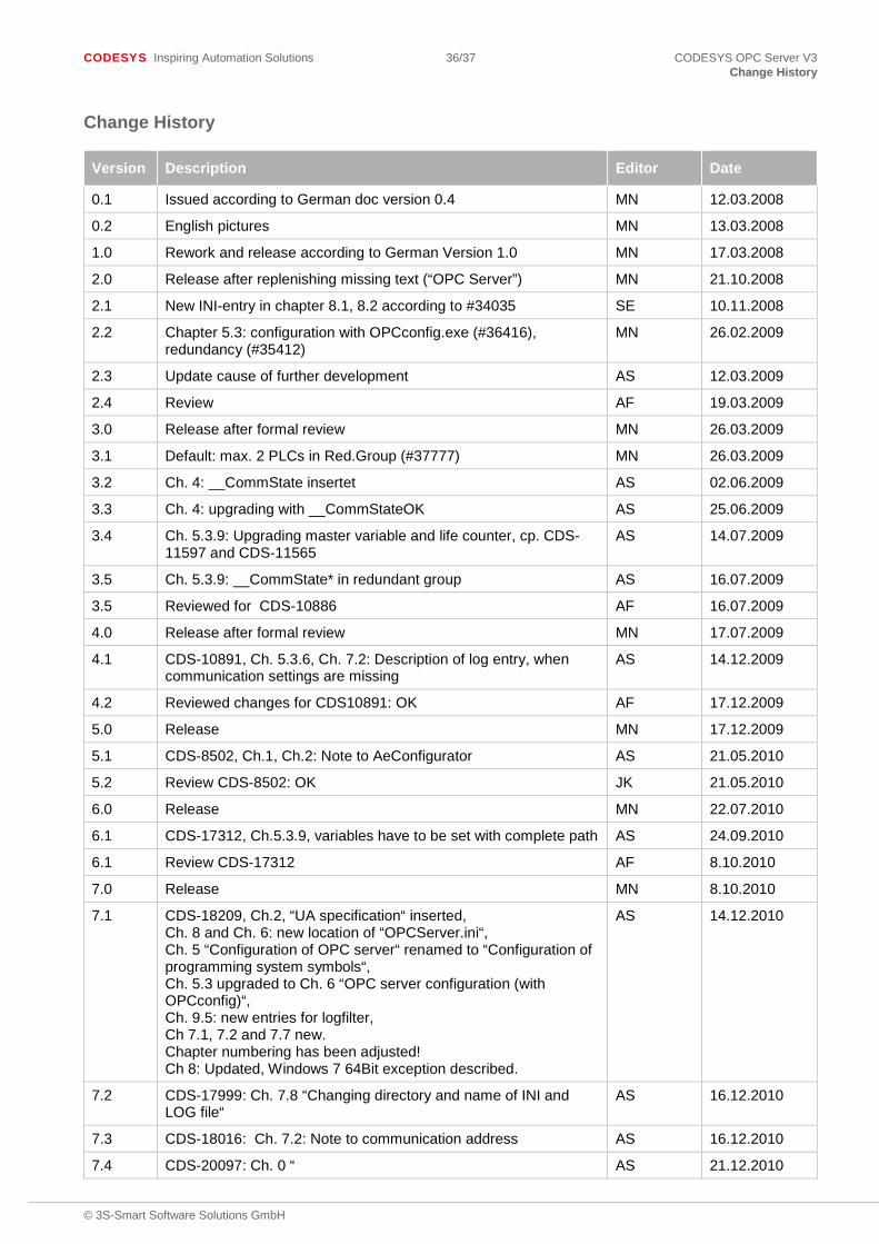
Change History
Version Description Editor Date
0.1 Issued according to German doc version 0.4 MN 12.03.2008
0.2 English pictures MN 13.03.2008
1.0 Rework and release according to German Version 1.0 MN 17.03.2008
2.0 Release after replenishing missing text (“OPC Server”) MN 21.10.2008
2.1 New INI-entry in chapter 8.1, 8.2 according to #34035 SE 10.11.2008
2.2 Chapter 5.3: configuration with OPCconfig.exe (#36416), redundancy (#35412)
MN 26.02.2009
2.3 Update cause of further development AS 12.03.2009
2.4 Review AF 19.03.2009
3.0 Release after formal review MN 26.03.2009
3.1 Default: max. 2 PLCs in Red.Group (#37777) MN 26.03.2009
3.2 Ch. 4: __CommState insertet AS 02.06.2009
3.3 Ch. 4: upgrading with __CommStateOK AS 25.06.2009
3.4 Ch. 5.3.9: Upgrading master variable and life counter, cp. CDS-11597 and CDS-11565
AS 14.07.2009
3.5 Ch. 5.3.9: __CommState* in redundant group AS 16.07.2009
3.5 Reviewed for CDS-10886 AF 16.07.2009
4.0 Release after formal review MN 17.07.2009
4.1 CDS-10891, Ch. 5.3.6, Ch. 7.2: Description of log entry, when communication settings are missing
AS 14.12.2009
4.2 Reviewed changes for CDS10891: OK AF 17.12.2009
5.0 Release MN 17.12.2009
5.1 CDS-8502, Ch.1, Ch.2: Note to AeConfigurator AS 21.05.2010
5.2 Review CDS-8502: OK JK 21.05.2010
6.0 Release MN 22.07.2010
6.1 CDS-17312, Ch.5.3.9, variables have to be set with complete path AS 24.09.2010
6.1 Review CDS-17312 AF 8.10.2010
7.0 Release MN 8.10.2010
7.1 CDS-18209, Ch.2, “UA specification“ inserted, Ch. 8 and Ch. 6: new location of “OPCServer.ini“, Ch. 5 “Configuration of OPC server“ renamed to “Configuration of programming system symbols“, Ch. 5.3 upgraded to Ch. 6 “OPC server configuration (with OPCconfig)“, Ch. 9.5: new entries for logfilter, Ch 7.1, 7.2 and 7.7 new. Chapter numbering has been adjusted! Ch 8: Updated, Windows 7 64Bit exception described.
AS 14.12.2010
7.2 CDS-17999: Ch. 7.8 “Changing directory and name of INI and LOG file“
AS 16.12.2010
7.3 CDS-18016: Ch. 7.2: Note to communication address AS 16.12.2010
7.4 CDS-20097: Ch. 0 “ AS 21.12.2010
CODESYS Inspiring Automation Solutions 37/37 CODESYS OPC Server V3 Change History
© 3S-Smart Software Solutions GmbH
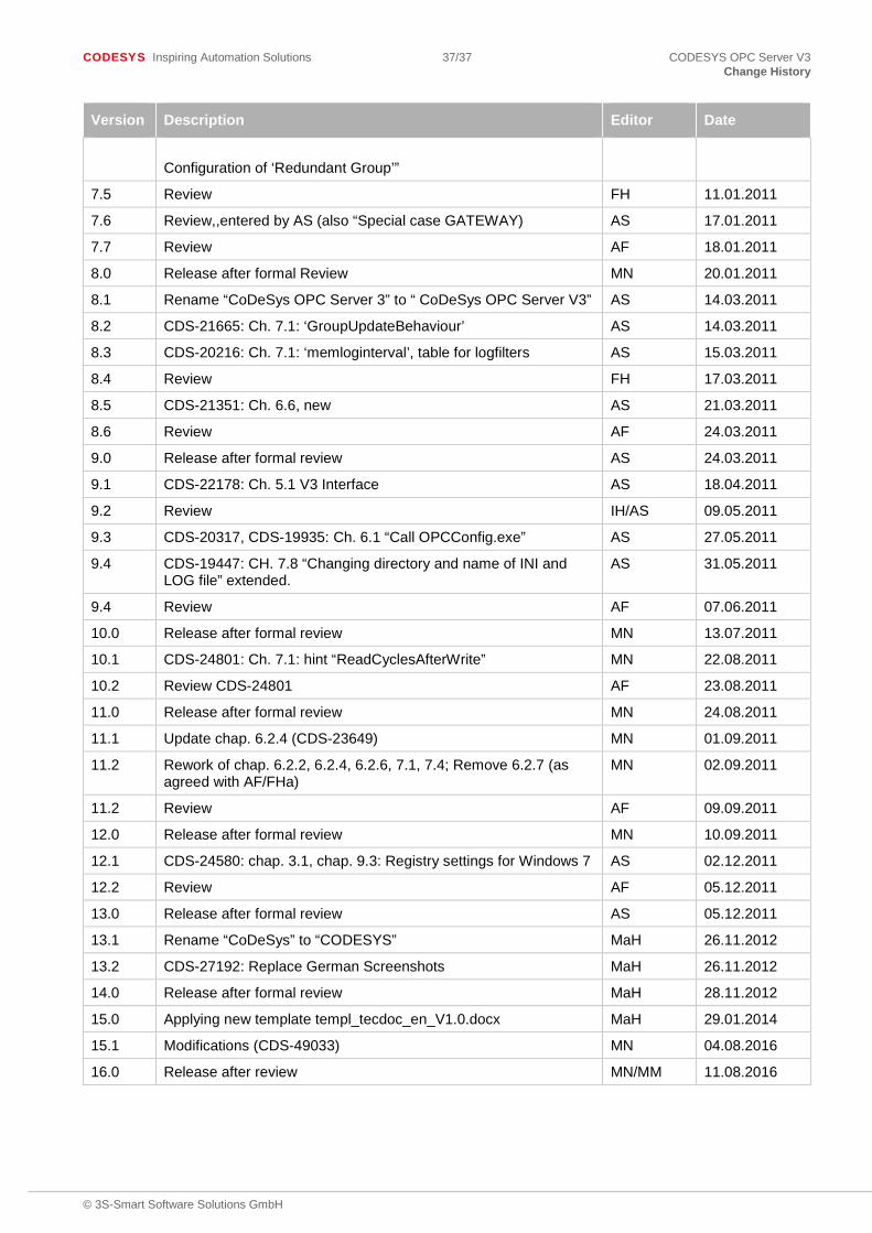
Version Description Editor Date
Configuration of ‘Redundant Group’”
7.5 Review FH 11.01.2011
7.6 Review,,entered by AS (also “Special case GATEWAY) AS 17.01.2011
7.7 Review AF 18.01.2011
8.0 Release after formal Review MN 20.01.2011
8.1 Rename “CoDeSys OPC Server 3” to “ CoDeSys OPC Server V3” AS 14.03.2011
8.2 CDS-21665: Ch. 7.1: ‘GroupUpdateBehaviour’ AS 14.03.2011
8.3 CDS-20216: Ch. 7.1: ‘memloginterval’, table for logfilters AS 15.03.2011
8.4 Review FH 17.03.2011
8.5 CDS-21351: Ch. 6.6, new AS 21.03.2011
8.6 Review AF 24.03.2011
9.0 Release after formal review AS 24.03.2011
9.1 CDS-22178: Ch. 5.1 V3 Interface AS 18.04.2011
9.2 Review IH/AS 09.05.2011
9.3 CDS-20317, CDS-19935: Ch. 6.1 “Call OPCConfig.exe” AS 27.05.2011
9.4 CDS-19447: CH. 7.8 “Changing directory and name of INI and LOG file” extended.
AS 31.05.2011
9.4 Review AF 07.06.2011
10.0 Release after formal review MN 13.07.2011
10.1 CDS-24801: Ch. 7.1: hint “ReadCyclesAfterWrite” MN 22.08.2011
10.2 Review CDS-24801 AF 23.08.2011
11.0 Release after formal review MN 24.08.2011
11.1 Update chap. 6.2.4 (CDS-23649) MN 01.09.2011
11.2 Rework of chap. 6.2.2, 6.2.4, 6.2.6, 7.1, 7.4; Remove 6.2.7 (as agreed with AF/FHa)
MN 02.09.2011
11.2 Review AF 09.09.2011
12.0 Release after formal review MN 10.09.2011
12.1 CDS-24580: chap. 3.1, chap. 9.3: Registry settings for Windows 7 AS 02.12.2011
12.2 Review AF 05.12.2011
13.0 Release after formal review AS 05.12.2011
13.1 Rename “CoDeSys” to “CODESYS” MaH 26.11.2012
13.2 CDS-27192: Replace German Screenshots MaH 26.11.2012
14.0 Release after formal review MaH 28.11.2012
15.0 Applying new template templ_tecdoc_en_V1.0.docx MaH 29.01.2014
15.1 Modifications (CDS-49033) MN 04.08.2016
16.0 Release after review MN/MM 11.08.2016