Control with UniOP JMobile and CoDeSys V2 - Autic System AS
44
Tech-note *Preliminary* Control with UniOP JMobile and CoDeSys V2 This manual contains detailed information on how to create a control system based on the UniOP platform running the JMobile HMI software. The control is based on the 3S CoDeSys V2 software PLC. Exor International S.p.A. ptn0404 Ver. 1.0
-
Upload
khangminh22 -
Category
Documents
-
view
1 -
download
0
Transcript of Control with UniOP JMobile and CoDeSys V2 - Autic System AS
Tech-note *Preliminary*
Control with UniOP JMobile
and CoDeSys V2
This manual contains detailed information on how to create a control system based on the
UniOP platform running the JMobile HMI software. The control is based on the 3S
CoDeSys V2 software PLC.
Exor International S.p.A. ptn0404 Ver. 1.0

Tech-note
ptn0404-0.docx - 7.08.2012 Control with UniOP JMobile and CoDeSys V2
2
Copyright 2012 Exor International S.p.A. – Verona, Italy Subject to change without notice The information contained in this document is provided for informational purposes only. While efforts were made to verify the accuracy of the information contained in this documentation, it is provided “as is” without warranty of any kind. Third-party brands and names are the property of their respective owners. www.uniop.com
Tech-note *Preliminary*
ptn0404-0.docx - 7.08.2012 Control with UniOP JMobile and CoDeSys V2
3
Contents
Overview ........................................................................................................................................ 4 Control Solutions with UniOP and CoDeSys V2 ............................................................... 4 System Configuration ........................................................................................................ 5 Compact Stand-alone Controller ....................................................................................... 5 Controller with Distributed I/O ........................................................................................... 5 Connectivity in HMI and Control Systems......................................................................... 5 Requirements and Limitations .......................................................................................... 6
Getting Started ............................................................................................................................... 7 HMI and PLC System Configurations ............................................................................... 7 CoDeSys V2 Runtime Licencing ....................................................................................... 7 Distributed I/O ................................................................................................................... 7 CAN Interface and PLIO03 I/O Module............................................................................. 8 Compact I/O Module ......................................................................................................... 8 Slots Numbers ................................................................................................................... 9 Installing the Option Modules ............................................................................................ 9 Option Module Diagnostic ............................................................................................... 10 Installing the CoDeSys V2 Programming System .......................................................... 10 Installing Target Support Packages ................................................................................ 10 Updating Old Target Support Packages ......................................................................... 12 Setting-up the Communication ........................................................................................ 12 Setting-up Communication in the CoDeSys V2 Programming Software ........................ 12
HMI Programming ........................................................................................................................ 14 Setting-up Communication with CoDeSys V2 Runtime .................................................. 14 Using CoDeSys V2 Symbols with JMobile ...................................................................... 14 Generate Symbol Files with CoDeSys V2 Programming Software ................................ 15 Importing a CoDeSys V2 Symbol File ............................................................................. 15 Tag Addressing ............................................................................................................... 16 PLC Input and PLC Output ............................................................................................. 17 Retentive Memory ........................................................................................................... 18 Communication Diagnostic ............................................................................................. 19
Using the CoDeSys V2 PLC ........................................................................................................ 20 Target Settings ................................................................................................................ 20 Memory Layout ............................................................................................................... 21 General 22 Setting the PLC Configuration ........................................................................................ 23 Configuring Distributed I/O .............................................................................................. 23 Settings for CAN Slaves.................................................................................................. 25 Configuring Integrated I/O ............................................................................................... 27 PLC Programming ........................................................................................................... 35 Programming I/O Elements ............................................................................................. 35 Programming the CANopen Interface ............................................................................. 36 PLC Project Upload ......................................................................................................... 43
Internal Controller Hardware ........................................................................................................ 44 The CAN Interface .......................................................................................................... 44 Timer resolution .............................................................................................................. 44
Tech-note *Preliminary*
ptn0404-0.docx - 7.08.2012 Control with UniOP JMobile and CoDeSys V2
4
Overview
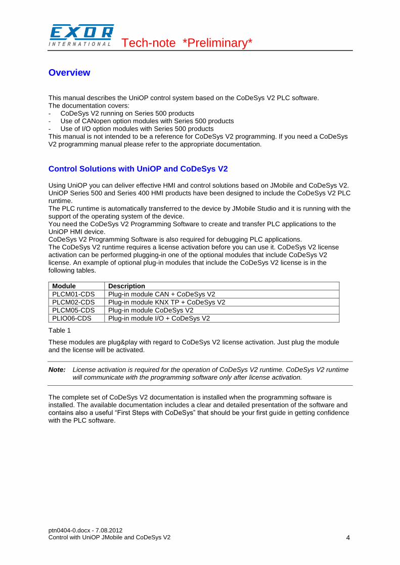
This manual describes the UniOP control system based on the CoDeSys V2 PLC software. The documentation covers: - CoDeSys V2 running on Series 500 products - Use of CANopen option modules with Series 500 products - Use of I/O option modules with Series 500 products This manual is not intended to be a reference for CoDeSys V2 programming. If you need a CoDeSys V2 programming manual please refer to the appropriate documentation.
Control Solutions with UniOP and CoDeSys V2
Using UniOP you can deliver effective HMI and control solutions based on JMobile and CoDeSys V2. UniOP Series 500 and Series 400 HMI products have been designed to include the CoDeSys V2 PLC runtime. The PLC runtime is automatically transferred to the device by JMobile Studio and it is running with the support of the operating system of the device. You need the CoDeSys V2 Programming Software to create and transfer PLC applications to the UniOP HMI device. CoDeSys V2 Programming Software is also required for debugging PLC applications. The CoDeSys V2 runtime requires a license activation before you can use it. CoDeSys V2 license activation can be performed plugging-in one of the optional modules that include CoDeSys V2 license. An example of optional plug-in modules that include the CoDeSys V2 license is in the following tables.
Module Description
PLCM01-CDS Plug-in module CAN + CoDeSys V2
PLCM02-CDS Plug-in module KNX TP + CoDeSys V2
PLCM05-CDS Plug-in module CoDeSys V2
PLIO06-CDS Plug-in module I/O + CoDeSys V2
Table 1
These modules are plug&play with regard to CoDeSys V2 license activation. Just plug the module and the license will be activated.
Note: License activation is required for the operation of CoDeSys V2 runtime. CoDeSys V2 runtime will communicate with the programming software only after license activation.
The complete set of CoDeSys V2 documentation is installed when the programming software is installed. The available documentation includes a clear and detailed presentation of the software and contains also a useful “First Steps with CoDeSys” that should be your first guide in getting confidence with the PLC software.
Tech-note *Preliminary*
ptn0404-0.docx - 7.08.2012 Control with UniOP JMobile and CoDeSys V2
5
System Configuration
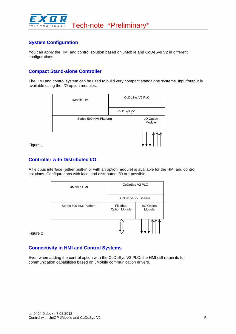
You can apply the HMI and control solution based on JMobile and CoDeSys V2 in different configurations.
Compact Stand-alone Controller
The HMI and control system can be used to build very compact standalone systems. Input/output is available using the I/O option modules. Figure 1
Controller with Distributed I/O
A fieldbus interface (either built-in or with an option module) is available for the HMI and control solutions. Configurations with local and distributed I/O are possible. Figure 2
Connectivity in HMI and Control Systems
Even when adding the control option with the CoDeSys V2 PLC, the HMI still retain its full communication capabilities based on JMobile communication drivers.
JMobile HMI CoDeSys V2 PLC
Series 500 HMI Platform I/O Option Module
CoDeSys V2 incense
JMobile HMI CoDeSys V2 PLC
Series 500 HMI Platform I/O Option Module
CoDeSys V2 License
Fieldbus Option Module

Tech-note *Preliminary*
ptn0404-0.docx - 7.08.2012 Control with UniOP JMobile and CoDeSys V2
6
Requirements and Limitations
The following firmware and software versions are required to work with the CoDeSys HMI and control systems:
Version
JMobile Studio and Runtime 1.80 SP1 or higher
Series 500 BSP UN30: 1.57 or higher UN31: 1.54 or higher
CoDeSys V2 2.3.2 or higher
Table 2
Note: Support for CoDeSys V3 is not part of this implementation.
Tech-note *Preliminary*
ptn0404-0.docx - 7.08.2012 Control with UniOP JMobile and CoDeSys V2
7
Getting Started
This chapter describes the basic steps to follow in order to get HMI and control solution running on Series 500 HMI products.
HMI and PLC System Configurations
The modularity of the Series 500 allows multiple system configurations that include bus interface and I/O option modules.
CoDeSys V2 Runtime Licencing
The CoDeSys V2 runtime requires a licence for running in the UniOP Series 500 products. CoDeSys V2 runtime licence is activated when certain option modules are plugged in the option slots of the HMI. If no licence has been activate, the CoDeSys V2 runtime will not operate; the CoDeSys V2 programming software will not be able to communicate with the runtime. Also, JMobile runtime will not be able to perform any communication with the CoDeSys V2 runtime. The list of option module that include CoDeSys V2 licence activation is the following: PLCM01-CDS PLCM02-CDS PLCM05-CDS PLIO06-CDS List of option modules including CODeSys V2 licence activation may change with time.
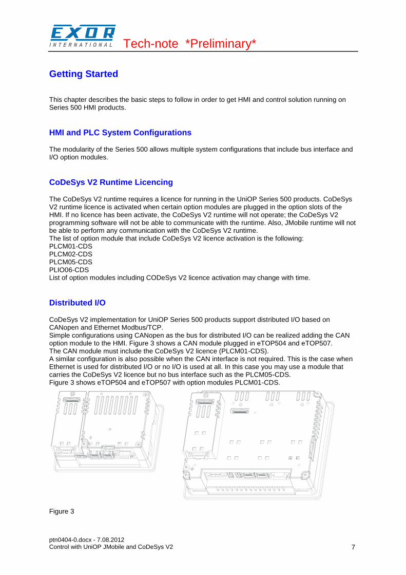
Distributed I/O
CoDeSys V2 implementation for UniOP Series 500 products support distributed I/O based on CANopen and Ethernet Modbus/TCP. Simple configurations using CANopen as the bus for distributed I/O can be realized adding the CAN option module to the HMI. Figure 3 shows a CAN module plugged in eTOP504 and eTOP507. The CAN module must include the CoDeSys V2 licence (PLCM01-CDS). A similar configuration is also possible when the CAN interface is not required. This is the case when Ethernet is used for distributed I/O or no I/O is used at all. In this case you may use a module that carries the CoDeSys V2 licence but no bus interface such as the PLCM05-CDS. Figure 3 shows eTOP504 and eTOP507 with option modules PLCM01-CDS.
Figure 3
Tech-note *Preliminary*
ptn0404-0.docx - 7.08.2012 Control with UniOP JMobile and CoDeSys V2
8
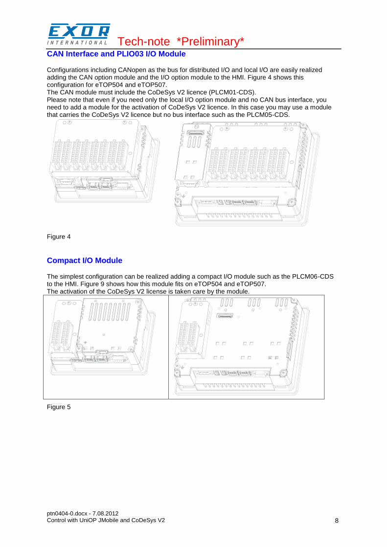
CAN Interface and PLIO03 I/O Module
Configurations including CANopen as the bus for distributed I/O and local I/O are easily realized adding the CAN option module and the I/O option module to the HMI. Figure 4 shows this configuration for eTOP504 and eTOP507. The CAN module must include the CoDeSys V2 licence (PLCM01-CDS). Please note that even if you need only the local I/O option module and no CAN bus interface, you need to add a module for the activation of CoDeSys V2 licence. In this case you may use a module that carries the CoDeSys V2 licence but no bus interface such as the PLCM05-CDS.
Figure 4
Compact I/O Module
The simplest configuration can be realized adding a compact I/O module such as the PLCM06-CDS to the HMI. Figure 9 shows how this module fits on eTOP504 and eTOP507. The activation of the CoDeSys V2 license is taken care by the module.
Figure 5
Tech-note *Preliminary*
ptn0404-0.docx - 7.08.2012 Control with UniOP JMobile and CoDeSys V2
9
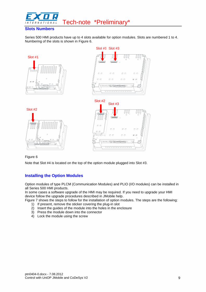
Slots Numbers
Series 500 HMI products have up to 4 slots available for option modules. Slots are numbered 1 to 4. Numbering of the slots is shown in Figure 6.
Figure 6
Note that Slot #4 is located on the top of the option module plugged into Slot #3.
Installing the Option Modules
Option modules of type PLCM (Communication Modules) and PLIO (I/O modules) can be installed in all Series 500 HMI products. In some cases a software upgrade of the HMI may be required. If you need to upgrade your HMI device follow the upgrade procedures described in JMobile help. Figure 7 shows the steps to follow for the installation of option modules. The steps are the following:
1) If present, remove the sticker covering the plug-in slot 2) Insert the guides of the module into the holes in the enclosure 3) Press the module down into the connector 4) Lock the module using the screw
Slot #1
Slot #1 Slot #3
Slot #2
Slot #2 Slot #3
Slot #1 Slot #3

Tech-note *Preliminary*
ptn0404-0.docx - 7.08.2012 Control with UniOP JMobile and CoDeSys V2
10
Figure 7
Note: Do not plug/remove option modules when the HMI device is powered.
Option Module Diagnostic
Diagnostic information on option modules, such as the CAN interface or the I/O module, is available in the Plugin List item of the System Settings. Once Plugin List has been selected in the System Settings menu, the screen will show what option modules have been recognized in the available slots.
Installing the CoDeSys V2 Programming System
The CoDeSys V2 programming software can be downloaded for free from the 3S web site at the following address: http://www.3s-software.com/index.shtml?en_download You need to register before you can access the download page. The registration will be promptly processed by 3S.
Installing Target Support Packages
A dedicated “Target Support Package (TSP)” is required to allow the standard CoDeSys V2.3 programming software to program control systems based on UniOP Series 500 or Series 400 products.
Tech-note *Preliminary*
ptn0404-0.docx - 7.08.2012 Control with UniOP JMobile and CoDeSys V2
11
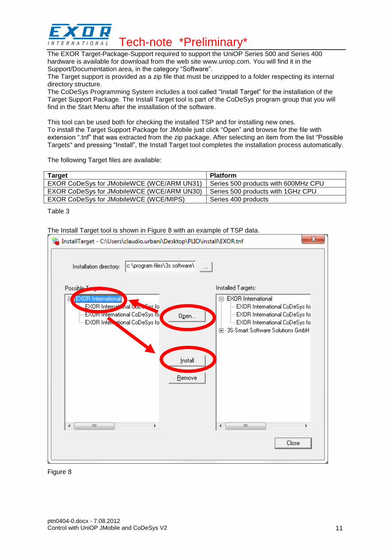
The EXOR Target-Package-Support required to support the UniOP Series 500 and Series 400 hardware is available for download from the web site www.uniop.com. You will find it in the Support/Documentation area, in the category “Software”. The Target support is provided as a zip file that must be unzipped to a folder respecting its internal directory structure. The CoDeSys Programming System includes a tool called “Install Target” for the installation of the Target Support Package. The Install Target tool is part of the CoDeSys program group that you will find in the Start Menu after the installation of the software. This tool can be used both for checking the installed TSP and for installing new ones. To install the Target Support Package for JMobile just click “Open” and browse for the file with extension “.tnf” that was extracted from the zip package. After selecting an item from the list “Possible Targets" and pressing “Install”, the Install Target tool completes the installation process automatically. The following Target files are available:
Target Platform
EXOR CoDeSys for JMobileWCE (WCE/ARM UN31) Series 500 products with 600MHz CPU
EXOR CoDeSys for JMobileWCE (WCE/ARM UN30) Series 500 products with 1GHz CPU
EXOR CoDeSys for JMobileWCE (WCE/MIPS) Series 400 products
Table 3
The Install Target tool is shown in Figure 8 with an example of TSP data.
Figure 8

Tech-note *Preliminary*
ptn0404-0.docx - 7.08.2012 Control with UniOP JMobile and CoDeSys V2
12
Updating Old Target Support Packages
When a new version of the “Target Support Package” is available, it can be installed replacing the older one. If Target Support Packages are already installed, you will be asked to confirm before overwriting. After the updated Target Support Package has been installed, the conversion of existing PLC projects may require some changes, depending on the level of compatibility of the new Target Support Package compared to the old one. Updates to the Target Support Package will come with proper instructions for the conversion of existing projects, if needed. To start the TSP update process, follow the same steps as for the first installation of the TSP. See Figure 8 for an example.
Setting-up the Communication
The HMI and control system is composed by two main subsystems, the JMobile HMI runtime and the CoDeSys V2 PLC runtime. Both subsystems will be programmed via Ethernet. The CoDeSys V2 runtime is part of JMobile runtime for HMI products Series 400 and Series 500. When the HMI is in Loader Mode there is no PLC runtime and communication with the programming software will not be possible. In order to have the PLC runtime loaded, you can download a HMI project using JMobile Studio or use the Update Runtime command in Manage Target. For further information on installing the runtime, please refer to JMobile Studio help.
Note the CoDeSys V2 PLC runtime must be activated with option modules such as PLCM01-CDS, PLCM05-CDS or others. If the runtime has not been activated, it will not respond to communication requests from the programming software.
Setting-up Communication in the CoDeSys V2 Programming Software
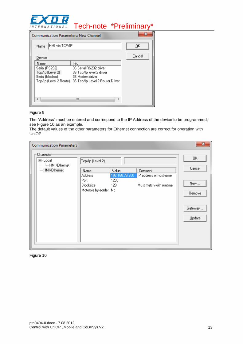
This chapter describes how to set-up the communication in order to connect the programming software to the PLC runtime. In the CoDeSys V2 programming software select “Online\Communication Parameters”. The first time this dialog is opened, the user will be requested to specify the channel for the connection to the PLC runtime. Connection channels can be created with the “New…” button. When creating a new channel, you have to define the type and all the relevant parameters in the dialog box shown in Figure 9. Communication is possible using Ethernet with level 2 driver, selecting the device “Tcp/Ip level 2”.
Tech-note *Preliminary*
ptn0404-0.docx - 7.08.2012 Control with UniOP JMobile and CoDeSys V2
13
Figure 9
The “Address” must be entered and correspond to the IP Address of the device to be programmed; see Figure 10 as an example. The default values of the other parameters for Ethernet connection are correct for operation with UniOP.
Figure 10
Tech-note *Preliminary*
ptn0404-0.docx - 7.08.2012 Control with UniOP JMobile and CoDeSys V2
14
HMI Programming
JMobile must be configured for operation with the internal PLC module in a way much similar to the operation with a normal PLC.
Setting-up Communication with CoDeSys V2 Runtime
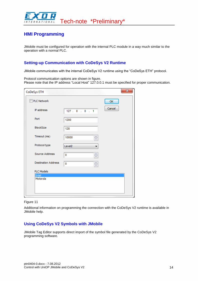
JMobile communicates with the internal CoDeSys V2 runtime using the “CoDeSys ETH” protocol. Protocol communication options are shown in figure. Please note that the IP address “Local Host” 127.0.0.1 must be specified for proper communication.
Figure 11
Additional information on programming the connection with the CoDeSys V2 runtime is available in JMobile help.
Using CoDeSys V2 Symbols with JMobile
JMobile Tag Editor supports direct import of the symbol file generated by the CoDeSys V2 programming software.

Tech-note *Preliminary*
ptn0404-0.docx - 7.08.2012 Control with UniOP JMobile and CoDeSys V2
15
Generate Symbol Files with CoDeSys V2 Programming Software
The CoDeSys V2 programming software saves a list of all the names used into the PLC program to a file with extension “.sym”. This file is stored in the application folder. To enable the generation of the “.sym” file you have to check the option “Dump symbol entries” in the “Symbol configuration” section of “Project/Options…” as shown in Figure 12. You may eventually have to check the “Configure symbol file” option to make sure that symbols are created for all variables in all POUs. Please refer to CoDeSys V2 documentation for additional information.
Figure 12
Importing a CoDeSys V2 Symbol File
Use the command “Import Tags” in JMobile Tag Editor to import the symbols generated by the programming software. To correctly import the “.sym” files generated by CoDeSys V2, you have to select the Import Type in the JMobile Tag Import dialog box, as shown in Figure 13.
Figure 13
CoDeSys V2 programming software generates a new version of the “.sym” file each time the PLC project is built. You need to import the symbol file again in JMobile Tag Editor only when new tags have been created or existing tags have been deleted. CoDeSys V2 Ethernet driver supports automatic symbol file (SDB) upload from the PLC; any change in the tag offset due to a new compilation of the PLC program does not require importing again the symbol file. Symbol file must be imported again only in case that tags have been renamed, changed data format change or new tags have been added.
Tech-note *Preliminary*
ptn0404-0.docx - 7.08.2012 Control with UniOP JMobile and CoDeSys V2
16
The automatic symbol file upload from the PLC requires that the symbol file has been downloaded to the runtime with the PLC program. To download symbols to the PLC runtime you have to check the option “Download Symbol File” in the General tab of the Target Settings as shown in Figure 21.
Note: New Tags can be ONLY created in the CoDeSys V2 programming software. The tag dictionary must not be changed from within JMobile.
Tag Addressing
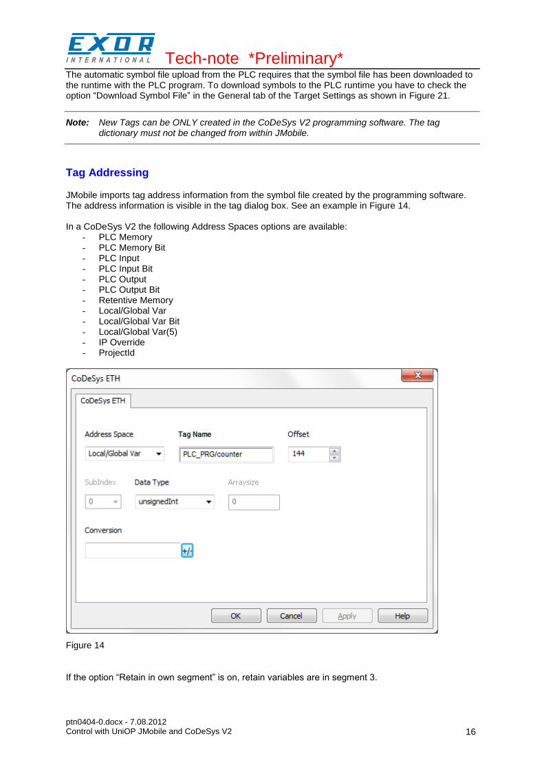
JMobile imports tag address information from the symbol file created by the programming software. The address information is visible in the tag dialog box. See an example in Figure 14. In a CoDeSys V2 the following Address Spaces options are available:
- PLC Memory - PLC Memory Bit - PLC Input - PLC Input Bit - PLC Output - PLC Output Bit - Retentive Memory - Local/Global Var - Local/Global Var Bit - Local/Global Var(5) - IP Override - ProjectId
Figure 14
If the option “Retain in own segment” is on, retain variables are in segment 3.
Tech-note *Preliminary*
ptn0404-0.docx - 7.08.2012 Control with UniOP JMobile and CoDeSys V2
17
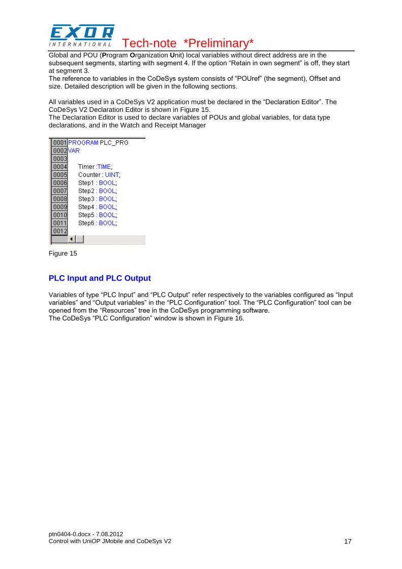
Global and POU (Program Organization Unit) local variables without direct address are in the subsequent segments, starting with segment 4. If the option “Retain in own segment” is off, they start at segment 3. The reference to variables in the CoDeSys system consists of “POUref” (the segment), Offset and size. Detailed description will be given in the following sections. All variables used in a CoDeSys V2 application must be declared in the “Declaration Editor”. The CoDeSys V2 Declaration Editor is shown in Figure 15. The Declaration Editor is used to declare variables of POUs and global variables, for data type declarations, and in the Watch and Receipt Manager
Figure 15
PLC Input and PLC Output
Variables of type “PLC Input” and “PLC Output” refer respectively to the variables configured as “Input variables” and “Output variables” in the “PLC Configuration” tool. The “PLC Configuration” tool can be opened from the “Resources” tree in the CoDeSys programming software. The CoDeSys “PLC Configuration” window is shown in Figure 16.

Tech-note *Preliminary*
ptn0404-0.docx - 7.08.2012 Control with UniOP JMobile and CoDeSys V2
18
Figure 16
Input and Output points can be addressed either using tags or pointing directly to them (direct addressing mode).
Retentive Memory
Variables of the Address Space “Retentive Memory” refer to CoDeSys V2 variables declared in the “Declaration Editor” in the section enclosed between the keywords VAR_RETAIN and END_VAR. These variables maintain their value when the controller is powered off and even after an uncontrolled shutdown of the controller. The content of retain variables is saved when the device is turned off and restored at the following power-up. There is a limit to the maximum number of retentive variables that can be defined. The current implementation supports a maximum of up to 8184 bytes. This value appears in the Target Settings dialog, as shown in Figure 17.

Tech-note *Preliminary*
ptn0404-0.docx - 7.08.2012 Control with UniOP JMobile and CoDeSys V2
19
Figure 17
At programming time it is responsibility of the programmer to ensure that the maximum amount of available memory will not be exceeded. When compiling the project, the CoDeSys V2 software will use the specific Target Settings information to check if the total amount of retentive variables has been exceeded. Retain settings cannot be changed by the user. The content of retentive memories will be lost in the following cases: - a new PLC program is downloaded to the PLC
Communication Diagnostic
JMobile reports communication diagnostic information also for the communication with the internal PLC runtime. To display communication diagnostic information use System Variables from the section “Communication”.
Tech-note *Preliminary*
ptn0404-0.docx - 7.08.2012 Control with UniOP JMobile and CoDeSys V2
20
Using the CoDeSys V2 PLC
The CoDeSys V2 runtime designed for Series 500 UniOP HMI is fully compatible with the CoDeSys V2 standard. The description of the CoDeSys V2 programming software is contained in the CoDeSys manual distributed with the package; please refer to this documentation for detailed information.
Target Settings
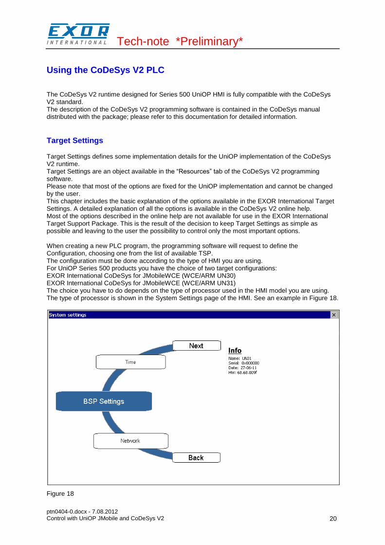
Target Settings defines some implementation details for the UniOP implementation of the CoDeSys V2 runtime. Target Settings are an object available in the “Resources” tab of the CoDeSys V2 programming software. Please note that most of the options are fixed for the UniOP implementation and cannot be changed by the user. This chapter includes the basic explanation of the options available in the EXOR International Target Settings. A detailed explanation of all the options is available in the CoDeSys V2 online help. Most of the options described in the online help are not available for use in the EXOR International Target Support Package. This is the result of the decision to keep Target Settings as simple as possible and leaving to the user the possibility to control only the most important options. When creating a new PLC program, the programming software will request to define the Configuration, choosing one from the list of available TSP. The configuration must be done according to the type of HMI you are using. For UniOP Series 500 products you have the choice of two target configurations: EXOR International CoDeSys for JMobileWCE (WCE/ARM UN30) EXOR International CoDeSys for JMobileWCE (WCE/ARM UN31) The choice you have to do depends on the type of processor used in the HMI model you are using. The type of processor is shown in the System Settings page of the HMI. See an example in Figure 18.
Figure 18
Tech-note *Preliminary*
ptn0404-0.docx - 7.08.2012 Control with UniOP JMobile and CoDeSys V2
21
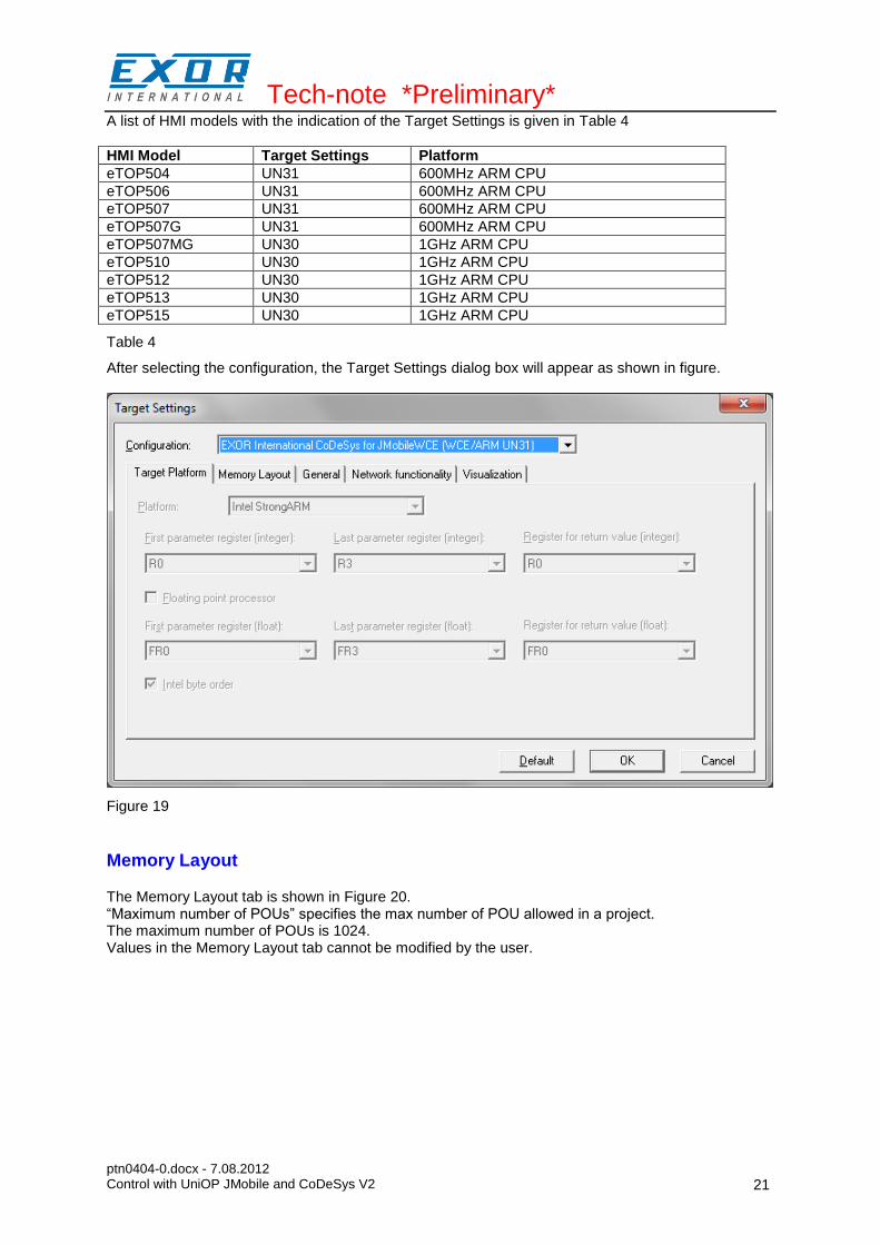
A list of HMI models with the indication of the Target Settings is given in Table 4
HMI Model Target Settings Platform
eTOP504 UN31 600MHz ARM CPU
eTOP506 UN31 600MHz ARM CPU
eTOP507 UN31 600MHz ARM CPU
eTOP507G UN31 600MHz ARM CPU
eTOP507MG UN30 1GHz ARM CPU
eTOP510 UN30 1GHz ARM CPU
eTOP512 UN30 1GHz ARM CPU
eTOP513 UN30 1GHz ARM CPU
eTOP515 UN30 1GHz ARM CPU
Table 4
After selecting the configuration, the Target Settings dialog box will appear as shown in figure.
Figure 19
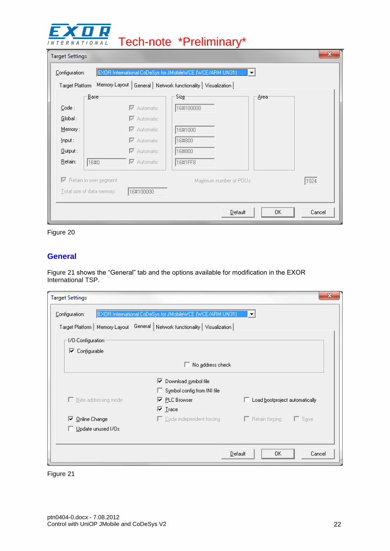
Memory Layout
The Memory Layout tab is shown in Figure 20. “Maximum number of POUs” specifies the max number of POU allowed in a project. The maximum number of POUs is 1024. Values in the Memory Layout tab cannot be modified by the user.
Tech-note *Preliminary*
ptn0404-0.docx - 7.08.2012 Control with UniOP JMobile and CoDeSys V2
22
Figure 20
General
Figure 21 shows the “General” tab and the options available for modification in the EXOR International TSP.
Figure 21

Tech-note *Preliminary*
ptn0404-0.docx - 7.08.2012 Control with UniOP JMobile and CoDeSys V2
23
Visualization is not supported. The corresponding tab in Target Settings does not contain any information.
Setting the PLC Configuration
The configuration of the CoDeSys V2 PLC runtime must be defined in the “PLC Configuration” object available in the “Resources” tab.
Note: To create a valid PLC Configuration, Target Settings must have been properly configured.
Configuring Distributed I/O
CoDeSys V2 implementation for UniOP Series 500 products support distributed I/O based on CANopen and Ethernet Modbus/TCP. Use the element “CanMaster” if you want to build a distributed I/O system based on CAN. Use the element “Ethernet I/O Slave” if you want to build a distributed I/O system based on Ethernet with the Modbus/TCP protocol.
CanMaster
This chapter contains detail information on the configuration of CANopen option modules available for Series 500 products. Series 500 HMI products do not include a CAN interface in their basic configuration. You must use one of the available CAN option modules to add a CAN interface to the device. Distributed I/O systems based on the CAN fieldbus interface must be configured using CoDeSys V2 PLC Configuration. To add a CANopen master interface you have to use the commands “Insert element”/”Append subelement” in the PLC Configuration. The list of available elements will appear right-clicking on the root of the configuration tree. Choose “CanMaster” to add an element with the CAN interface. A complete and detailed description on the configuration of CAN controllers and on the configuration of CAN slave devices is included in the CoDeSys User Manual in chapter “6.6 – PLC Configuration”. The parameters of the CAN interface are grouped in three tabs accessible on the right part of the PLC Configuration tool when the CanMaster element has been added to the configuration tree.
Base parameters
Figure 22 shows the “Base Parameters” tab.
Figure 22
Tech-note *Preliminary*
ptn0404-0.docx - 7.08.2012 Control with UniOP JMobile and CoDeSys V2
24
Module id CoDeSys internal identifier used to recognize the board; it is a read only parameter displayed just for user information
Node number CoDeSys internal identifier assigned by the programming software depending on the order of the board in the PLC Configuration layout; it is a read only parameter displayed just for user information
Diagnostic address Memory address for the storage of diagnostic information of the CAN master
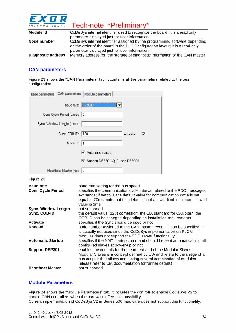
CAN parameters
Figure 23 shows the “CAN Parameters” tab; it contains all the parameters related to the bus configuration.
Figure 23
Baud rate baud rate setting for the bus speed Com. Cycle Period specifies the communication cycle interval related to the PDO messages
exchange; if set to 0, the default value for communication cycle is set equal to 20ms; note that this default is not a lower limit: minimum allowed value is 1ms
Sync. Window Length not supported Sync. COB-ID the default value (128) comesfrom the CiA standard for CANopen; the
COB-ID can be changed depending on installation requirements Activate specifies if the Sync should be used or not Node-Id node number assigned to the CAN master; even if it can be specified, it
is actually not used since the CoDeSys implementation on PLCM modules does not support the SDO server functionality
Automatic Startup specifies if the NMT startup command should be sent automatically to all configured slaves at power-up or not
Support DSP301… enables the controls for the heartbeat and of the Modular Slaves; Modular Slaves is a concept defined by CiA and refers to the usage of a bus coupler that allows connecting several combination of modules (please refer to CiA documentation for further details)
Heartbeat Master not supported
Module Parameters
Figure 24 shows the “Module Parameters” tab. It includes the controls to enable CoDeSys V2 to handle CAN controllers when the hardware offers this possibility. Current implementation of CoDeSys V2 in Series 500 hardware does not support this functionality.

Tech-note *Preliminary*
ptn0404-0.docx - 7.08.2012 Control with UniOP JMobile and CoDeSys V2
25
Figure 24
Settings for CAN Slaves
The configuration for the CAN slaves has a common part, which is independent of the EDS file. Figure 25 shows the “CAN Parameters” tab of a generic CAN Slave.
Figure 25
Node ID Node number of the slave device Write DCF Create all SDO’s specifies whenever the SDO messages for the slave configuration,
depending on the PDO mapping, should be created for all objects (option activated) or just for the modified objects (option not activated); in this latter case, please make sure the EDS file loaded in CoDeSys V2 is matching the hardware device features, otherwise some required SDO messages will be erroneously skipped
No initialization if activated the sequence of SDO messages required for the device initialization (PDO mapping) will not be created
Optional device if activated the current device is considered as optional into the bus; at start-up the CAN controller will check if it is present applying the following rules: - if the device is present since start-up and it correctly replies to the
CANopen mandatory object “Device Type” query (matching the .eds specification), then it is started; the master will continue with the next device;
- if the device is present since start-up and it does not reply as expected to the “Device type” query, it is not started; the master stops then, reporting a mismatching error in the CAN configuration; if the “Optional device” with not-matching “Device Type” is inserted in the bus after start-up, the master will skip it and continue to scan the other devices;
- if the device is not present since start-up, it is simply skipped; the master will continue with the next device.
Ethernet I/O Slave
This chapter contains information on the configuration of distributed I/O based on Ethernet with the use of the Modbus/TCP protocol. CoDeSys V2 runtime can use the built-in Ethernet interface of Series 500 products for the distributed I/O network. No additional hardware is required.
Tech-note *Preliminary*
ptn0404-0.docx - 7.08.2012 Control with UniOP JMobile and CoDeSys V2
26
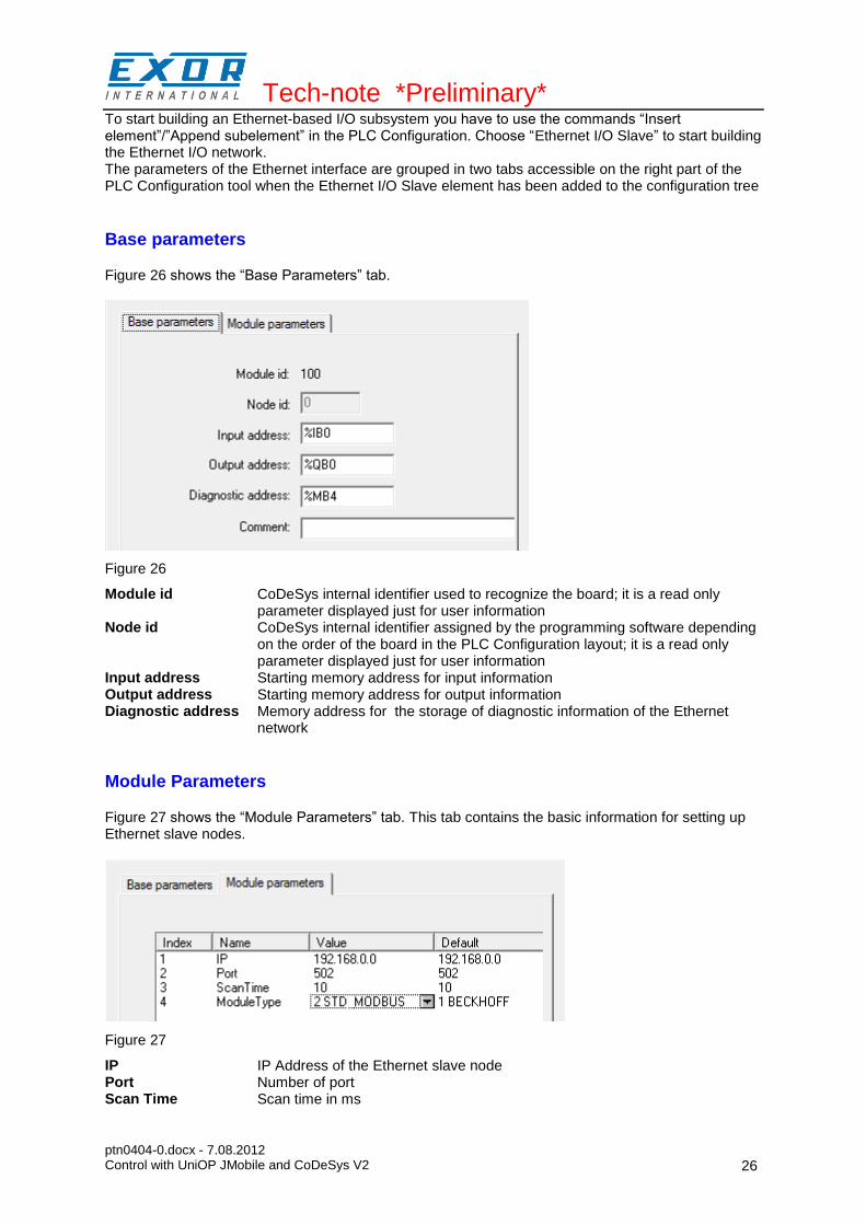
To start building an Ethernet-based I/O subsystem you have to use the commands “Insert element”/”Append subelement” in the PLC Configuration. Choose “Ethernet I/O Slave” to start building the Ethernet I/O network. The parameters of the Ethernet interface are grouped in two tabs accessible on the right part of the PLC Configuration tool when the Ethernet I/O Slave element has been added to the configuration tree
Base parameters
Figure 26 shows the “Base Parameters” tab.
Figure 26
Module id CoDeSys internal identifier used to recognize the board; it is a read only parameter displayed just for user information
Node id CoDeSys internal identifier assigned by the programming software depending on the order of the board in the PLC Configuration layout; it is a read only parameter displayed just for user information
Input address Starting memory address for input information Output address Starting memory address for output information Diagnostic address Memory address for the storage of diagnostic information of the Ethernet
network
Module Parameters
Figure 27 shows the “Module Parameters” tab. This tab contains the basic information for setting up Ethernet slave nodes.
Figure 27
IP IP Address of the Ethernet slave node Port Number of port Scan Time Scan time in ms

Tech-note *Preliminary*
ptn0404-0.docx - 7.08.2012 Control with UniOP JMobile and CoDeSys V2
27
Module Type Type of the slave node. The following types are supported: WAGO BECKHOFF STD_ MODBUS
After the information for the slave module has been defined, you have to configure the structure of the I/O points that will be used. You have to right-click on the element, choose “Append Sub-element” and choose one of the available options from the list. Figure 28 shows an example configuration including 8 digital inputs and 8 digital outputs.
Figure 28
Configuring Integrated I/O
Series 500 HMI products come with options that let you create control systems with integrated I/O. Integrated I/O systems based on option modules can be easily configured using CoDeSys V2 PLC Configuration. To add an I/O option module you have to use the commands “Insert element”/”Append subelement” in the PLC Configuration. The list of available elements will appear right-clicking on the root of the configuration tree. Choose one integrated I/O module from the list to add it to the current PLC configuration. The parameters of all integrated I/O modules are collected in single tab of the PLC Configuration tree.
Base parameters
Figure 29 shows the “Base Parameters” tab for integrated I/O modules.
Figure 29
Module id CoDeSys internal identifier used to recognize the board; it is a read only
Tech-note *Preliminary*
ptn0404-0.docx - 7.08.2012 Control with UniOP JMobile and CoDeSys V2
28
parameter displayed for user information Node id CoDeSys internal identifier assigned by the programming software depending
on the order of the board in the PLC Configuration layout; it is a read only parameter displayed for user information
Input address Starting address for input information Output address Starting address for output information Diagnostic address Memory address for the storage of diagnostic information of the I/O module
PLIO03
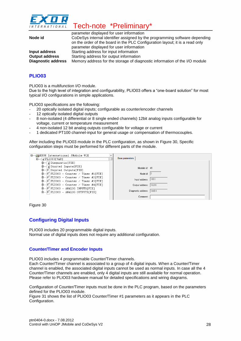
PLIO03 is a multifunction I/O module. Due to the high level of integration and configurability, PLIO03 offers a “one-board solution” for most typical I/O configurations in simple applications. PLIO03 specifications are the following: - 20 optically isolated digital inputs; configurable as counter/encoder channels - 12 optically isolated digital outputs - 8 non-isolated (4 differential or 8 single ended channels) 12bit analog inputs configurable for
voltage, current or temperature measurement - 4 non-isolated 12 bit analog outputs configurable for voltage or current - 1 dedicated PT100 channel-input for general usage or compensation of thermocouples. After including the PLIO03 module in the PLC configuration, as shown in Figure 30, Specific configuration steps must be performed for different parts of the module.
Figure 30
Configuring Digital Inputs
PLIO03 includes 20 programmable digital inputs. Normal use of digital inputs does not require any additional configuration.
Counter/Timer and Encoder Inputs
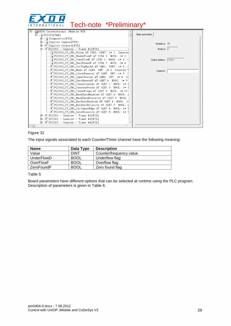
PLIO03 includes 4 programmable Counter/Timer channels. Each Counter/Timer channel is associated to a group of 4 digital inputs. When a Counter/Timer channel is enabled, the associated digital inputs cannot be used as normal inputs. In case all the 4 Counter/Timer channels are enabled, only 4 digital inputs are still available for normal operation. Please refer to PLIO03 hardware manual for detailed specifications and wiring diagrams. Configuration of Counter/Timer inputs must be done in the PLC program, based on the parameters defined for the PLIO03 module. Figure 31 shows the list of PLIO03 Counter/Timer #1 parameters as it appears in the PLC Configuration.
Tech-note *Preliminary*
ptn0404-0.docx - 7.08.2012 Control with UniOP JMobile and CoDeSys V2
29
Figure 31
The input signals associated to each Counter/Timer channel have the following meaning:
Name Data Type Description
Value DINT Counter/frequency value
UnderFlowD BOOL Underflow flag
OverFlowF BOOL Overflow flag
ZeroFoundF BOOL Zero found flag
Table 5
Board parameters have different options that can be selected at runtime using the PLC program. Description of parameters is given in Table 6.
Tech-note *Preliminary*
ptn0404-0.docx - 7.08.2012 Control with UniOP JMobile and CoDeSys V2
30
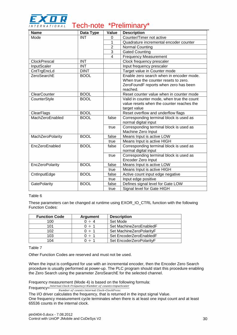
Name Data Type Value Description
Mode INT 0 Counter/Timer not active
1 Quadrature incremental encoder counter
2 Normal Counting
3 Gated Counting
4 Frequency Measurement
ClockPrescal INT Clock frequency prescaler
InputScaler INT Input frequency prescaler
CntTrgEncLd DINT Target value in Counter mode
ZeroSearchE BOOL Enable zero search when in encoder mode. When true the counter resets to zero. ZeroFoundF reports when zero has been reached.
ClearCounter BOOL Reset counter value when in counter mode
CounterStyle BOOL Valid in counter mode, when true the count value resets when the counter reaches the target value
ClearFlags BOOL Reset overflow and underflow flags
MachZeroEnabled BOOL false Corresponding terminal block is used as normal digital input
true Corresponding terminal block is used as Machine Zero Input
MachZeroPolarity BOOL false Means Input is active LOW
true Means Input is active HIGH
EncZeroEnabled BOOL false Corresponding terminal block is used as normal digital input
true Corresponding terminal block is used as Encoder Zero Input
EncZeroPolarity BOOL false Means Input is active LOW
true Means Input is active HIGH
CntInputEdge BOOL false Active count input edge negative
true Input edge positive
GatePolarity BOOL false Defines signal level for Gate LOW
true Signal level for Gate HIGH
Table 6
These parameters can be changed at runtime using EXOR_IO_CTRL function with the following Function Codes:
Function Code Argument Description
100 0 4 Set Mode
101 0 1 Set MachineZeroEnabledF
102 0 1 Set MachineZeroPolarityF
103 0 1 Set EncoderZeroEnabledF
104 0 1 Set EncoderZeroPolarityF
Table 7
Other Function Codes are reserved and must not be used. When the input is configured for use with an incremental encoder, then the Encoder Zero Search procedure is usually performed at power-up. The PLC program should start this procedure enabling the Zero Search using the parameter ZeroSearchE for the selected channel. Frequency measurement (Mode 4) is based on the following formula:
Frequency=
The I/O driver calculates the frequency, that is returned in the input signal Value. One frequency measurement cycle terminates when there is at least one input count and at least 65536 counts in the internal clock.

Tech-note *Preliminary*
ptn0404-0.docx - 7.08.2012 Control with UniOP JMobile and CoDeSys V2
31
As an example, to cover the frequency range 1Hz to 20KHz you have to set:
Range ClockPresc InputScaler
1Hz to 2Hz 0 1
2Hz to 20KHz 0 0
Configuring Digital Outputs
PLIO03 includes 12 digital outputs. Use of digital outputs does not require any additional configuration.
Configuring Analog Inputs
PLIO03 includes 4 differential programmable analog input channels. PLIO03 Analog Input channels have several parameters that must to be properly configured according to the operation mode requested for each channel. For each of the 4 channels it is required to specify the operating mode and the full-scale range. Each channel can be configured for single-ended voltage measurement resulting in having 8 voltage analog inputs. Figure 32 shows the configuration of the 4 Analog Inputs Couples. Note that 9 analog values are produced by the module.
Figure 32
All the four channels are independently programmable to execute six different types of measurements. The parameters Ch1Type, Ch2Type, Ch3Type and Ch4Type can be configured as show in Table 8.
Parameter value Measurement Mode Unit
0 Voltage Differential V
1 Voltage Single Ended V
2 Current A
3 Resistance 2 wires m
4 Resistance 3 wires m
5 Voltage Thermocouple V
Table 8
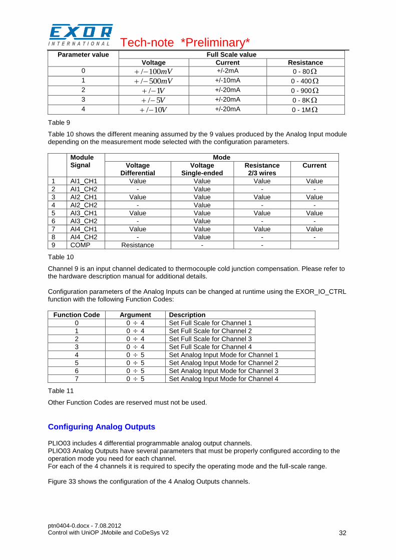
Full Scale can be selected for each Channel couple as shown in Table 9.
Tech-note *Preliminary*
ptn0404-0.docx - 7.08.2012 Control with UniOP JMobile and CoDeSys V2
32
Parameter value Full Scale value
Voltage Current Resistance
0 mV100/ +/-2mA 0 - 80
1 mV500/ +/-10mA 0 - 400
2 V1/ +/-20mA 0 - 900
3 V5/ +/-20mA 0 - 8K
4 V10/ +/-20mA 0 - 1M
Table 9
Table 10 shows the different meaning assumed by the 9 values produced by the Analog Input module depending on the measurement mode selected with the configuration parameters.
Module Signal
Mode
Voltage Differential
Voltage Single-ended
Resistance 2/3 wires
Current
1 AI1_CH1 Value Value Value Value
2 AI1_CH2 - Value - -
3 AI2_CH1 Value Value Value Value
4 AI2_CH2 - Value - -
5 AI3_CH1 Value Value Value Value
6 AI3_CH2 - Value - -
7 AI4_CH1 Value Value Value Value
8 AI4_CH2 - Value - -
9 COMP Resistance - -
Table 10
Channel 9 is an input channel dedicated to thermocouple cold junction compensation. Please refer to the hardware description manual for additional details. Configuration parameters of the Analog Inputs can be changed at runtime using the EXOR_IO_CTRL function with the following Function Codes:
Function Code Argument Description
0 0 4 Set Full Scale for Channel 1
1 0 4 Set Full Scale for Channel 2
2 0 4 Set Full Scale for Channel 3
3 0 4 Set Full Scale for Channel 4
4 0 5 Set Analog Input Mode for Channel 1
5 0 5 Set Analog Input Mode for Channel 2
6 0 5 Set Analog Input Mode for Channel 3
7 0 5 Set Analog Input Mode for Channel 4
Table 11
Other Function Codes are reserved must not be used.
Configuring Analog Outputs
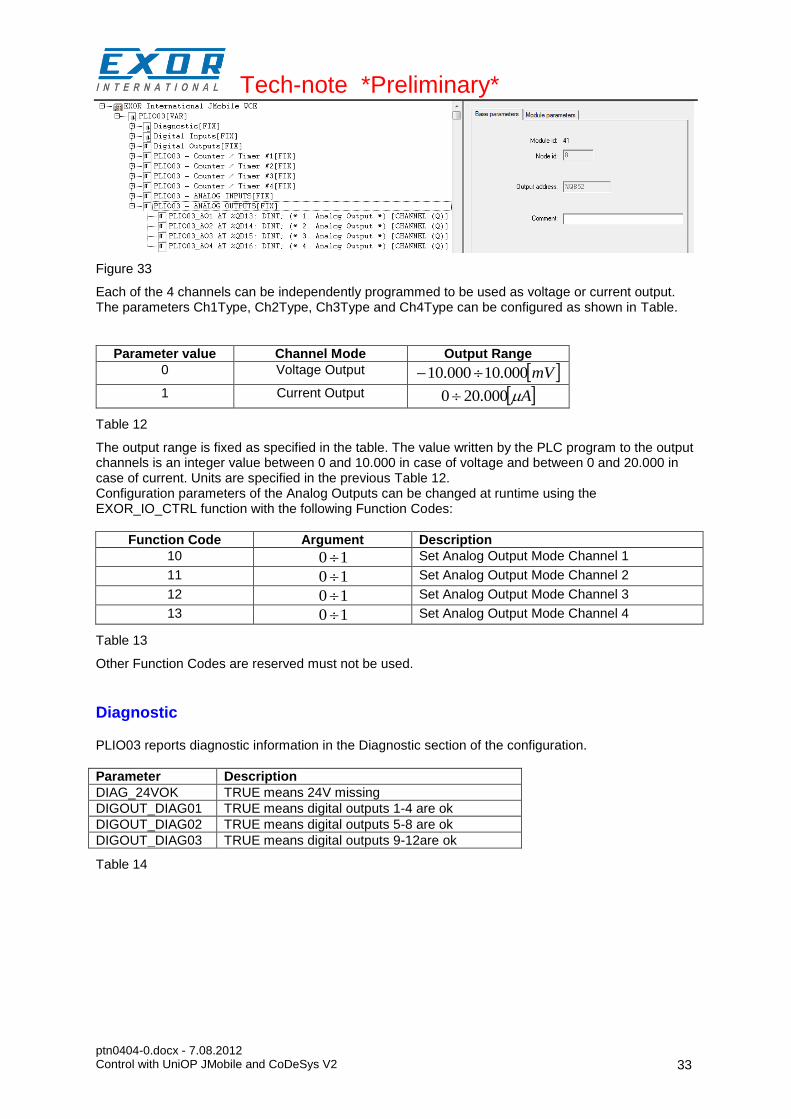
PLIO03 includes 4 differential programmable analog output channels. PLIO03 Analog Outputs have several parameters that must be properly configured according to the operation mode you need for each channel. For each of the 4 channels it is required to specify the operating mode and the full-scale range. Figure 33 shows the configuration of the 4 Analog Outputs channels.
Tech-note *Preliminary*
ptn0404-0.docx - 7.08.2012 Control with UniOP JMobile and CoDeSys V2
33
Figure 33
Each of the 4 channels can be independently programmed to be used as voltage or current output. The parameters Ch1Type, Ch2Type, Ch3Type and Ch4Type can be configured as shown in Table.
Parameter value Channel Mode Output Range
0 Voltage Output mV000.10000.10
1 Current Output A000.200
Table 12
The output range is fixed as specified in the table. The value written by the PLC program to the output channels is an integer value between 0 and 10.000 in case of voltage and between 0 and 20.000 in case of current. Units are specified in the previous Table 12. Configuration parameters of the Analog Outputs can be changed at runtime using the EXOR_IO_CTRL function with the following Function Codes:
Function Code Argument Description
10 10 Set Analog Output Mode Channel 1
11 10 Set Analog Output Mode Channel 2
12 10 Set Analog Output Mode Channel 3
13 10 Set Analog Output Mode Channel 4
Table 13
Other Function Codes are reserved must not be used.
Diagnostic
PLIO03 reports diagnostic information in the Diagnostic section of the configuration.
Parameter Description
DIAG_24VOK TRUE means 24V missing
DIGOUT_DIAG01 TRUE means digital outputs 1-4 are ok
DIGOUT_DIAG02 TRUE means digital outputs 5-8 are ok
DIGOUT_DIAG03 TRUE means digital outputs 9-12are ok
Table 14
Tech-note *Preliminary*
ptn0404-0.docx - 7.08.2012 Control with UniOP JMobile and CoDeSys V2
34
Figure 34
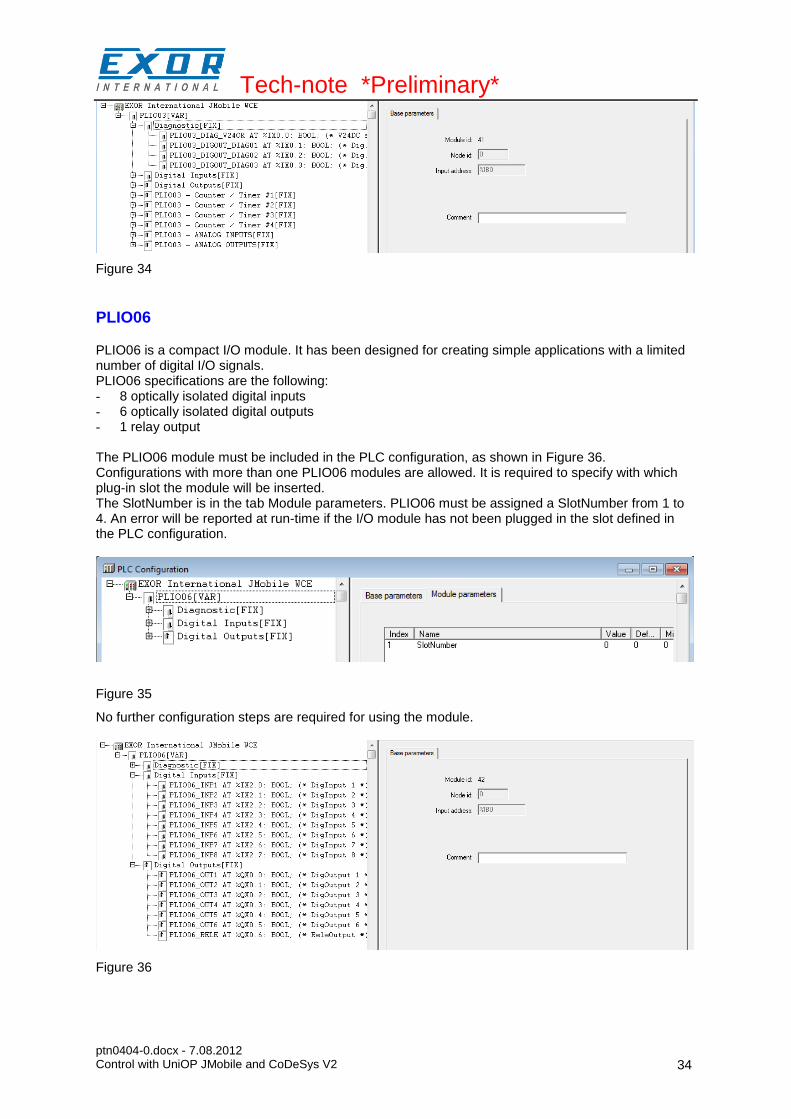
PLIO06
PLIO06 is a compact I/O module. It has been designed for creating simple applications with a limited number of digital I/O signals. PLIO06 specifications are the following: - 8 optically isolated digital inputs - 6 optically isolated digital outputs - 1 relay output The PLIO06 module must be included in the PLC configuration, as shown in Figure 36. Configurations with more than one PLIO06 modules are allowed. It is required to specify with which plug-in slot the module will be inserted. The SlotNumber is in the tab Module parameters. PLIO06 must be assigned a SlotNumber from 1 to 4. An error will be reported at run-time if the I/O module has not been plugged in the slot defined in the PLC configuration.
Figure 35
No further configuration steps are required for using the module.
Figure 36
Tech-note *Preliminary*
ptn0404-0.docx - 7.08.2012 Control with UniOP JMobile and CoDeSys V2
35
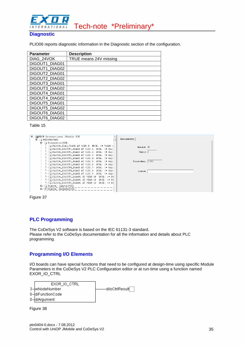
Diagnostic
PLIO06 reports diagnostic information in the Diagnostic section of the configuration.
Parameter Description
DIAG_24VOK TRUE means 24V missing
DIGOUT1_DIAG01
DIGOUT1_DIAG02
DIGOUT2_DIAG01
DIGOUT2_DIAG02
DIGOUT3_DIAG01
DIGOUT3_DIAG02
DIGOUT4_DIAG01
DIGOUT4_DIAG02
DIGOUT5_DIAG01
DIGOUT5_DIAG02
DIGOUT6_DIAG01
DIGOUT6_DIAG02
Table 15
Figure 37
PLC Programming
The CoDeSys V2 software is based on the IEC 61131-3 standard. Please refer to the CoDeSys documentation for all the information and details about PLC programming.
Programming I/O Elements
I/O boards can have special functions that need to be configured at design-time using specific Module Parameters in the CoDeSys V2 PLC Configuration editor or at run-time using a function named EXOR_IO_CTRL
Figure 38

Tech-note *Preliminary*
ptn0404-0.docx - 7.08.2012 Control with UniOP JMobile and CoDeSys V2
36
This function is included in the library “EXOR.lib”. The function has the following input parameters:
wNodeNumber Each board in the CoDeSys V2 PLC Configuration editor has a progressive Node Number starting from zero; this is assigned by CoDeSys and can be seen in the board “Base Parameters”. This parameter identifies the board to which the “diFunctionCode” and “diArgument” parameters will be passed.
diFunctionCode This parameter is passed to the specified board; it significance changes from board to board.
diArgument This parameter is passed to the specified board; its significance varies from board to board.
The function has the following output parameters:
diIoCtrlResult This is the return value; its significance varies from board to board and from FunctionCode to FunctionCode.
Programming the CANopen Interface
Connection to special CANopen devices may require direct access to some CAN commands. Function blocks are available for this purpose. This chapter describes the most important cases.
CAN Master Operate Functions (EXOR_CAN_IO_CTRL)
The function “EXOR_CAN_IO_CTRL” is available to control special features of the CAN master. This function can operate on CanMaster Module, on one of the connected CAN slaves or one of the Tx or Rx PDOs of the slaves, depending on the parameters.
Figure 39
This function can be found in the library “EXOR_CANopen.lib”. Input parameters are the following: wNodeNumber Each board in the CoDeSys PLC Configuration Editor has a progressive Node
Number starting from zero, this is assigned by CoDeSys and is visible in the board Base Parameters. This parameter identifies the board to which the “diFunctionCode” and “diArgument” parameters will be passed to. This must be the Node Number of a CanMaster board.
wSubNodeNumber This is the Node Number of the Sub Element, i.e. the CAN Slave Node appended to the CanMaster to which the IO_CTRL is directed to. If this value is set to 0xFFFF, then the IO_CTRL is directed to the CanMaster Module itself.
bTxPDO This parameter selects if the IO_CTRL is directed to a Tx or Rx PDO of the selected CAN Slave Node. If TRUE then TX PDO is selected. It is unused if parameter ucPDOnr is set to 0xFF.
ucPDOnr This parameter selects to which PDO the IO_CTRL is directed to. Zero is the first PDO defined for the selected CAN Slave Node. If this parameter is set to
Tech-note *Preliminary*
ptn0404-0.docx - 7.08.2012 Control with UniOP JMobile and CoDeSys V2
37
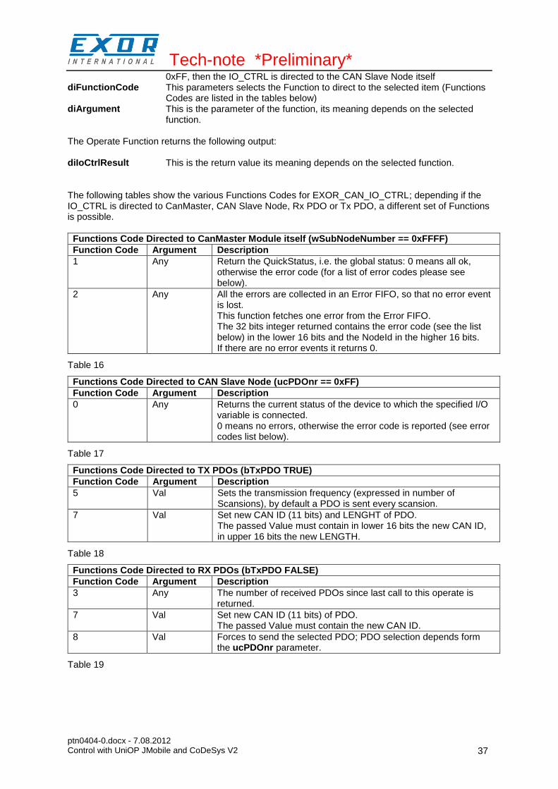
0xFF, then the IO_CTRL is directed to the CAN Slave Node itself diFunctionCode This parameters selects the Function to direct to the selected item (Functions
Codes are listed in the tables below) diArgument This is the parameter of the function, its meaning depends on the selected
function. The Operate Function returns the following output: diIoCtrlResult This is the return value its meaning depends on the selected function. The following tables show the various Functions Codes for EXOR_CAN_IO_CTRL; depending if the IO_CTRL is directed to CanMaster, CAN Slave Node, Rx PDO or Tx PDO, a different set of Functions is possible.
Functions Code Directed to CanMaster Module itself (wSubNodeNumber == 0xFFFF)
Function Code Argument Description
1 Any Return the QuickStatus, i.e. the global status: 0 means all ok, otherwise the error code (for a list of error codes please see below).
2 Any All the errors are collected in an Error FIFO, so that no error event is lost. This function fetches one error from the Error FIFO. The 32 bits integer returned contains the error code (see the list below) in the lower 16 bits and the NodeId in the higher 16 bits. If there are no error events it returns 0.
Table 16
Functions Code Directed to CAN Slave Node (ucPDOnr == 0xFF)
Function Code Argument Description
0 Any Returns the current status of the device to which the specified I/O variable is connected. 0 means no errors, otherwise the error code is reported (see error codes list below).
Table 17
Functions Code Directed to TX PDOs (bTxPDO TRUE)
Function Code Argument Description
5 Val Sets the transmission frequency (expressed in number of Scansions), by default a PDO is sent every scansion.
7 Val Set new CAN ID (11 bits) and LENGHT of PDO. The passed Value must contain in lower 16 bits the new CAN ID, in upper 16 bits the new LENGTH.
Table 18
Functions Code Directed to RX PDOs (bTxPDO FALSE)
Function Code Argument Description
3 Any The number of received PDOs since last call to this operate is returned.
7 Val Set new CAN ID (11 bits) of PDO. The passed Value must contain the new CAN ID.
8 Val Forces to send the selected PDO; PDO selection depends form the ucPDOnr parameter.
Table 19
Tech-note *Preliminary*
ptn0404-0.docx - 7.08.2012 Control with UniOP JMobile and CoDeSys V2
38
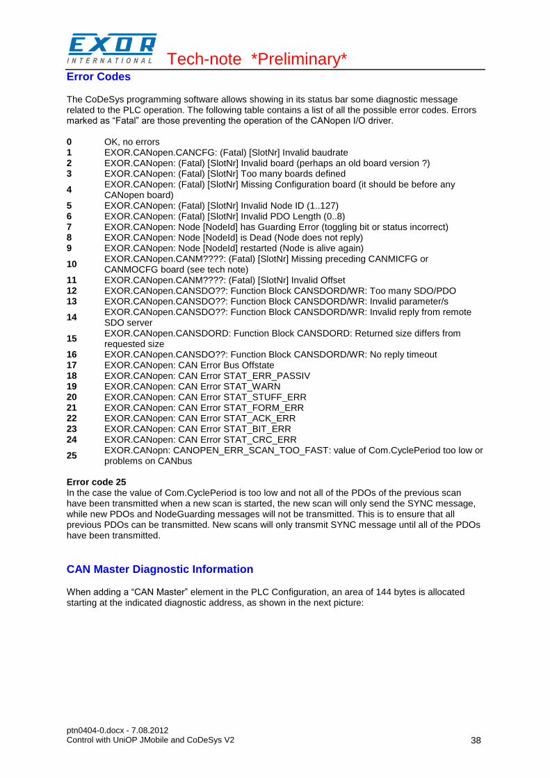
Error Codes
The CoDeSys programming software allows showing in its status bar some diagnostic message related to the PLC operation. The following table contains a list of all the possible error codes. Errors marked as “Fatal” are those preventing the operation of the CANopen I/O driver. 0 OK, no errors 1 EXOR.CANopen.CANCFG: (Fatal) [SlotNr] Invalid baudrate 2 EXOR.CANopen: (Fatal) [SlotNr] Invalid board (perhaps an old board version ?) 3 EXOR.CANopen: (Fatal) [SlotNr] Too many boards defined
4 EXOR.CANopen: (Fatal) [SlotNr] Missing Configuration board (it should be before any CANopen board)
5 EXOR.CANopen: (Fatal) [SlotNr] Invalid Node ID (1..127) 6 EXOR.CANopen: (Fatal) [SlotNr] Invalid PDO Length (0..8) 7 EXOR.CANopen: Node [NodeId] has Guarding Error (toggling bit or status incorrect) 8 EXOR.CANopen: Node [NodeId] is Dead (Node does not reply) 9 EXOR.CANopen: Node [NodeId] restarted (Node is alive again)
10 EXOR.CANopen.CANM????: (Fatal) [SlotNr] Missing preceding CANMICFG or CANMOCFG board (see tech note)
11 EXOR.CANopen.CANM????: (Fatal) [SlotNr] Invalid Offset 12 EXOR.CANopen.CANSDO??: Function Block CANSDORD/WR: Too many SDO/PDO 13 EXOR.CANopen.CANSDO??: Function Block CANSDORD/WR: Invalid parameter/s
14 EXOR.CANopen.CANSDO??: Function Block CANSDORD/WR: Invalid reply from remote SDO server
15 EXOR.CANopen.CANSDORD: Function Block CANSDORD: Returned size differs from requested size
16 EXOR.CANopen.CANSDO??: Function Block CANSDORD/WR: No reply timeout 17 EXOR.CANopen: CAN Error Bus Offstate 18 EXOR.CANopen: CAN Error STAT_ERR_PASSIV 19 EXOR.CANopen: CAN Error STAT_WARN 20 EXOR.CANopen: CAN Error STAT_STUFF_ERR 21 EXOR.CANopen: CAN Error STAT_FORM_ERR 22 EXOR.CANopen: CAN Error STAT_ACK_ERR 23 EXOR.CANopen: CAN Error STAT_BIT_ERR 24 EXOR.CANopen: CAN Error STAT_CRC_ERR
25 EXOR.CANopn: CANOPEN_ERR_SCAN_TOO_FAST: value of Com.CyclePeriod too low or problems on CANbus
Error code 25 In the case the value of Com.CyclePeriod is too low and not all of the PDOs of the previous scan have been transmitted when a new scan is started, the new scan will only send the SYNC message, while new PDOs and NodeGuarding messages will not be transmitted. This is to ensure that all previous PDOs can be transmitted. New scans will only transmit SYNC message until all of the PDOs have been transmitted.
CAN Master Diagnostic Information
When adding a “CAN Master” element in the PLC Configuration, an area of 144 bytes is allocated starting at the indicated diagnostic address, as shown in the next picture:
Tech-note *Preliminary*
ptn0404-0.docx - 7.08.2012 Control with UniOP JMobile and CoDeSys V2
39
Figure 40
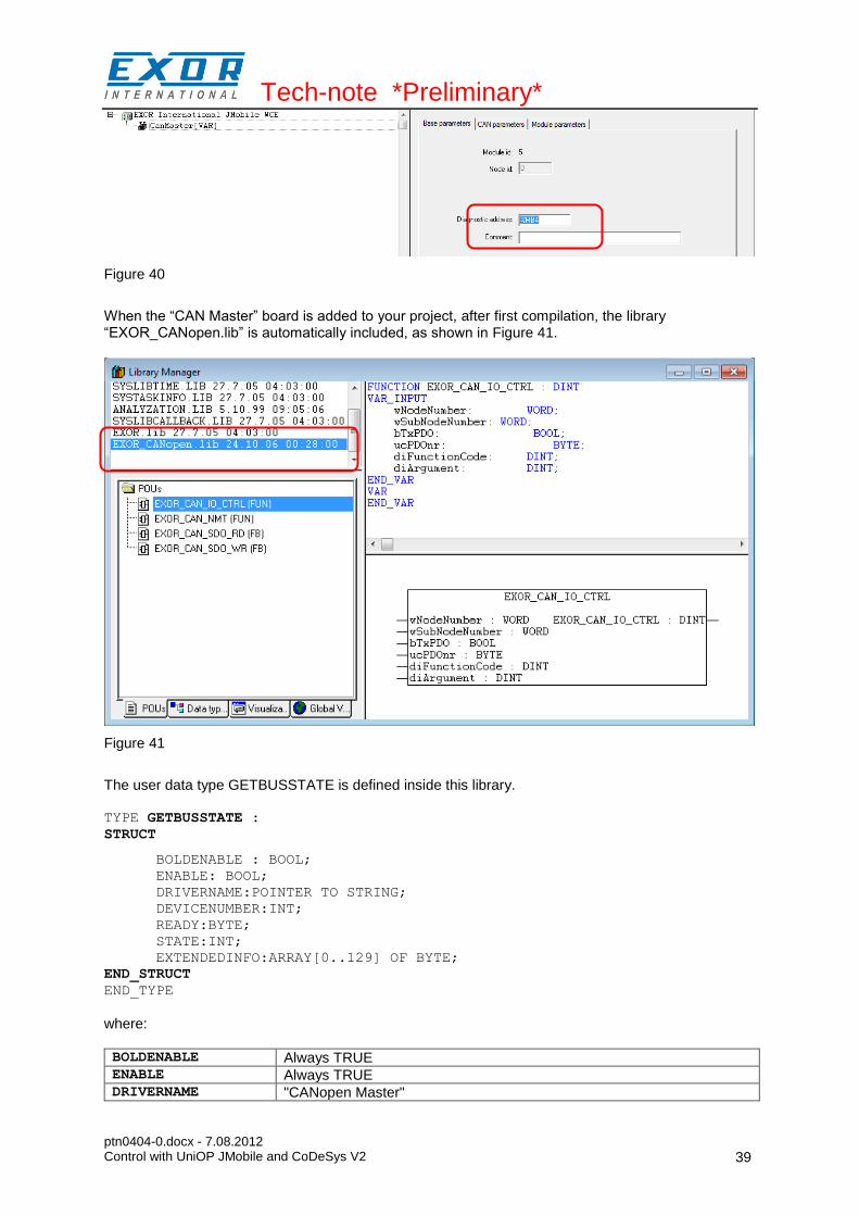
When the “CAN Master” board is added to your project, after first compilation, the library “EXOR_CANopen.lib” is automatically included, as shown in Figure 41.
Figure 41
The user data type GETBUSSTATE is defined inside this library. TYPE GETBUSSTATE :
STRUCT
BOLDENABLE : BOOL;
ENABLE: BOOL;
DRIVERNAME:POINTER TO STRING;
DEVICENUMBER:INT;
READY:BYTE;
STATE:INT;
EXTENDEDINFO:ARRAY[0..129] OF BYTE;
END_STRUCT
END_TYPE
where: BOLDENABLE Always TRUE ENABLE Always TRUE DRIVERNAME "CANopen Master"

Tech-note *Preliminary*
ptn0404-0.docx - 7.08.2012 Control with UniOP JMobile and CoDeSys V2
40
DEVICENUMBER CanPort choosen in the CANMaster configuration READY TRUE if running STATE Quick Status: 0 (zero) means OK, other values are error codes, see
“ERROR CODES” table EXTENDEDINFO Elements 0, 128 and 129 are not used.
Elements 1 to 127 reports the state of nodes 1 to 127. Meaning of the bits of each byte is: Bit 0: Bus module exists in PLC configuration. Bit 1: Bus module is available in bus system. Bit 2: Bus module reports error. Bit 3: Node is initialized and without errors (i.e. it's OFF during initialization and configuration).
Table 20
In the PLC program you can define a variable of type GETBUSSTATE and pointing to the “Diagnostic Address” of the “CAN Master” element, as shown in Figure 42.
Figure 42
This GETBUSSTATE user data type complies with the CoDeSys V2 standard method of obtaining diagnostic information from bus I/O, as explained in the CoDeSys V2 help.
Access to Remote Data Using SDO Protocol
The SDO protocol can be used to access any remote variable, defined according to the CANopen standard. The CANopen interface in UniOP works as SDO client and remote nodes are servers. While in PDO mode the transmission is normally cyclical and automatic, in SDO mode the data exchange is normally single-shot. Each session can normally transfer only one data item. This means that the SDO protocol is much slower than the PDO protocol. Two Function Blocks are available to configure communication via the SDO protocol. EXOR_CAN_SDO_RD read remote variables EXOR_CAN_SDO_WR write remote variables They are part of the library “EXOR_CANopen.lib”.
Tech-note *Preliminary*
ptn0404-0.docx - 7.08.2012 Control with UniOP JMobile and CoDeSys V2
41
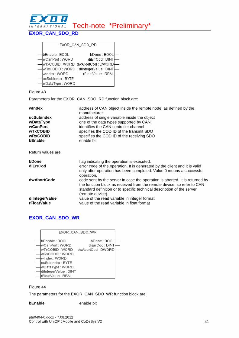
EXOR_CAN_SDO_RD
Figure 43
Parameters for the EXOR_CAN_SDO_RD function block are: wIndex address of CAN object inside the remote node, as defined by the
manufacturer ucSubindex address of single variable inside the object wDataType one of the data types supported by CAN. wCanPort identifies the CAN controller channel wTxCOBID specifies the COD ID of the transmit SDO wRxCOBID specifies the COD ID of the receiving SDO bEnable enable bit
Return values are: bDone flag indicating the operation is executed. diErrCod error code of the operation. It is generated by the client and it is valid
only after operation has been completed. Value 0 means a successful operation.
dwAbortCode code sent by the server in case the operation is aborted. It is returned by the function block as received from the remote device, so refer to CAN standard definition or to specific technical description of the server (remote device).
diIntegerValue value of the read variable in integer format rFloatValue value of the read variable in float format
EXOR_CAN_SDO_WR
Figure 44
The parameters for the EXOR_CAN_SDO_WR function block are: bEnable enable bit

Tech-note *Preliminary*
ptn0404-0.docx - 7.08.2012 Control with UniOP JMobile and CoDeSys V2
42
wCanPort identifies the CAN controller channel wTxCOBID specifies the COD ID of the transmit SDO wRxCOBID specifies the COD ID of the receiving SDO wIndex address of the CAN object inside the remote node, as defined by the
manufacturer ucSubindex address of single variable inside the object wDataType one of the data types supported by CAN. diIntegerValue is the value to be written in integer format rFloatValue is the value to be written in float format Return values are: bDone is a flag indicating the operation is executed. diErrCod error code of the operation. It is generated by the client and it is valid
only after operation is completed. Value 0 means a successful operation. dwAbortCode is the code sent by the server in case the operation is aborted. It is
reported as received, so refer to CAN standard definition or to specific technical description of the server.
The possible values for the abort code (see return value dwAbortCod) are shown in the table below. 0503 0000h Toggle bit not alternated. 0504 0000h SDO protocol timed out. 0504 0001h Client/server command specifier not valid or unknown. 0504 0002h Invalid block size (block mode only). 0504 0003h Invalid sequence number (block mode only). 0504 0004h CRC error (block mode only). 0504 0005h Out of memory. 0601 0000h Unsupported access to an object. 0601 0001h Attempt to read a write only object. 0601 0002h Attempt to write a read only object. 0602 0000h Object does not exist in the object dictionary. 0604 0041h Object cannot be mapped to the PDO. 0604 0042h The number and length of the objects to be mapped would exceed PDO length. 0604 0043h General parameter incompatibility reason. 0604 0047h General internal incompatibility in the device. 0606 0000h Access failed due to an hardware error. 0607 0010h Data type does not match, length of service parameter does not match 0607 0012h Data type does not match, length of service parameter too high 0607 0013h Data type does not match, length of service parameter too low 0609 0011h Sub-index does not exist. 0609 0030h Value range of parameter exceeded (only for write access). 0609 0031h Value of parameter written too high. 0609 0032h Value of parameter written too low. 0609 0036h Maximum value is less than minimum value. 0800 0000h general error 0800 0020h Data cannot be transferred or stored to the application. 0800 0021h Data cannot be transferred or stored to the application because of local control.
0800 0022h Data cannot be transferred or stored to the application because of the present device state.
0800 0023h Object dictionary dynamic generation fails or no object dictionary is present (e.g. object dictionary is generated from file and generation fails because of an file error).
Allowed values for data type (refer to input parameter wDataType ) are listed below. 0001 BOOLEAN 0002 INTEGER8 0003 INTEGER16 0004 INTEGER32
Tech-note *Preliminary*
ptn0404-0.docx - 7.08.2012 Control with UniOP JMobile and CoDeSys V2
43
0005 UNSIGNED8 0006 UNSIGNED16 0007 UNSIGNED32 0008 REAL32
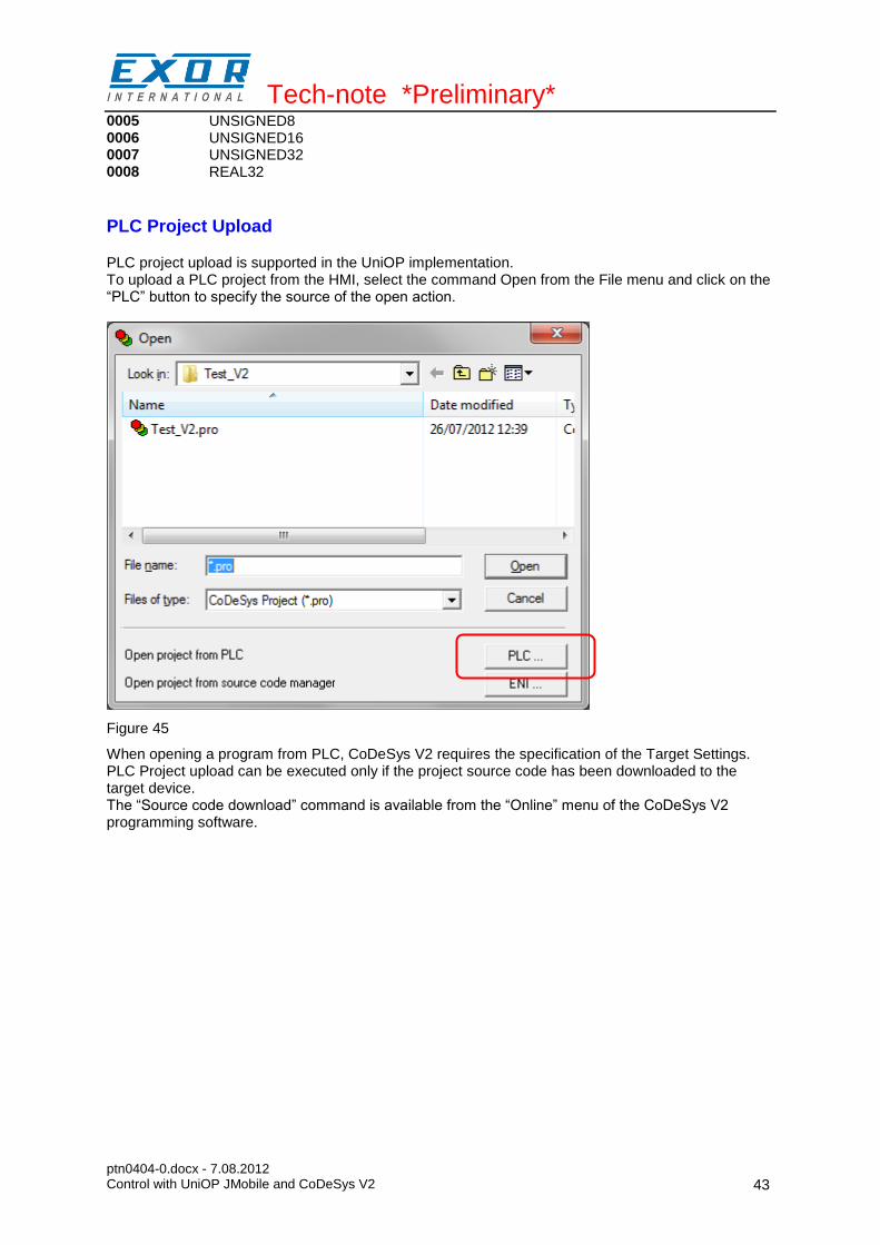
PLC Project Upload
PLC project upload is supported in the UniOP implementation. To upload a PLC project from the HMI, select the command Open from the File menu and click on the “PLC” button to specify the source of the open action.
Figure 45
When opening a program from PLC, CoDeSys V2 requires the specification of the Target Settings. PLC Project upload can be executed only if the project source code has been downloaded to the target device. The “Source code download” command is available from the “Online” menu of the CoDeSys V2 programming software.
Tech-note *Preliminary*
ptn0404-0.docx - 7.08.2012 Control with UniOP JMobile and CoDeSys V2
44
Internal Controller Hardware
This chapter describes some implementation-specific issues in the CoDeSys V2 runtime kernel developed for use with the Series 500 HMI products.
The CAN Interface
The PLCM01 CAN option module include a CAN bus interface implemented according to the CAN protocol specifications 2.0 A. This CAN controller supports only Standard frame format (2.0 A) with bit rates up to 1 Mbit/s. The following transfer functions have been implemented: - Transfer rate and timing - Message framing (Part A) - Arbitration accordingly to Part A specifications - Automatic retransmission in case of lost arbitration or error detection - Acknowledgement - Message validation - Error detection and error signaling - Global Identifier masking (for 11-bit and 29-bit long identifiers) - Interrupt or data polling driven software supported - Automatic transfer of data frame (prepared in SDRAM buffer) triggered by one bit setting - Automatic receive of data packets with the allowed frame identifier - 32 separated SDRAM memory buffers for data packets having the node corresponding ID - Fully implemented CAN error fault confinement - Automatic detection of Bus off state - Detection of the heavily disturbed CAN bus and warning Programming the parameter baudRateKbps at the value 0 enables the use of custom timing The resulting baud rate is calculated using the formula: Bit frequency = 8 MHz / (Prescaler * (1 + Tsetup + Thold)) Valid values for parameters are: Prescaler 1 to 64 Tsetup 1 to 8 Thold 1 to 4 Other two parameters can affect the behavior of the CAN controller: SyncJumpWidth: defines the number of time quanta (8 MHz / Prescaler) allowed to accept a SYNC pulse. Valid values are 1 to 4. SampleMode: defines the number of times the bit is sampled before is considered valid. Valid values are 0 (1 sample) and 1 (3 samples). It is currently not used in SCM03-C where the bus line is always sampled once.
Timer resolution
The resolution of CoDeSys V2 timers is 1 millisecond. When a timer value is defined it is internally translated to the corresponding number of milliseconds. The resolution of the internal Real Time Clock is 1 millisecond allowing the maximum resolution of timers. Note that the execution time of the PLC program may apparently affect the resolution of timers.