Fibrous-clay mineral formation and soil evolution in Aridisols of northeastern Patagonia, Argentina
C
SSa
b
c
a
ARR2A
KEENCC
1
mFtihvpsm(
lmwem
0d
Materials Science and Engineering B 176 (2011) 640–646
Contents lists available at ScienceDirect
Materials Science and Engineering B
journa l homepage: www.e lsev ier .com/ locate /mseb
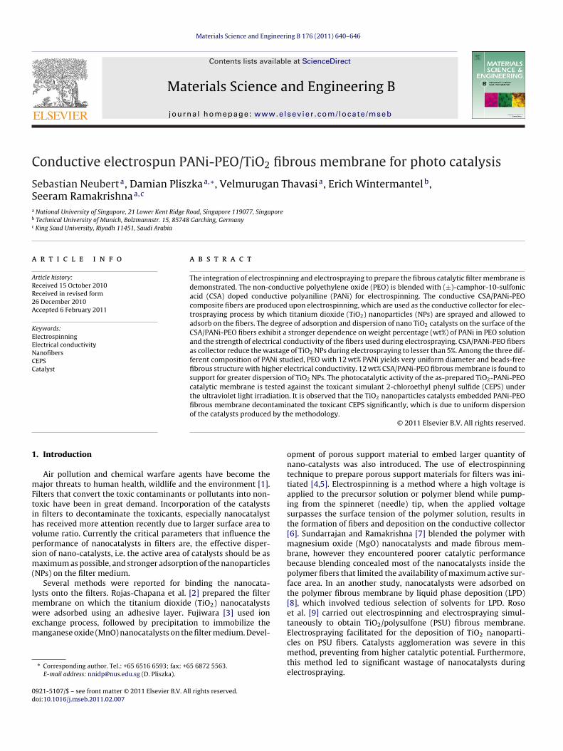
onductive electrospun PANi-PEO/TiO2 fibrous membrane for photo catalysis
ebastian Neuberta, Damian Pliszkaa,∗, Velmurugan Thavasia, Erich Wintermantelb,eeram Ramakrishnaa,c
National University of Singapore, 21 Lower Kent Ridge Road, Singapore 119077, SingaporeTechnical University of Munich, Bolzmannstr. 15, 85748 Garching, GermanyKing Saud University, Riyadh 11451, Saudi Arabia
r t i c l e i n f o
rticle history:eceived 15 October 2010eceived in revised form6 December 2010ccepted 6 February 2011
eywords:lectrospinninglectrical conductivityanofibers
a b s t r a c t
The integration of electrospinning and electrospraying to prepare the fibrous catalytic filter membrane isdemonstrated. The non-conductive polyethylene oxide (PEO) is blended with (±)-camphor-10-sulfonicacid (CSA) doped conductive polyaniline (PANi) for electrospinning. The conductive CSA/PANi-PEOcomposite fibers are produced upon electrospinning, which are used as the conductive collector for elec-trospraying process by which titanium dioxide (TiO2) nanoparticles (NPs) are sprayed and allowed toadsorb on the fibers. The degree of adsorption and dispersion of nano TiO2 catalysts on the surface of theCSA/PANi-PEO fibers exhibit a stronger dependence on weight percentage (wt%) of PANi in PEO solutionand the strength of electrical conductivity of the fibers used during electrospraying. CSA/PANi-PEO fibersas collector reduce the wastage of TiO2 NPs during electrospraying to lesser than 5%. Among the three dif-
EPSatalyst
ferent composition of PANi studied, PEO with 12 wt% PANi yields very uniform diameter and beads-freefibrous structure with higher electrical conductivity. 12 wt% CSA/PANi-PEO fibrous membrane is found tosupport for greater dispersion of TiO2 NPs. The photocatalytic activity of the as-prepared TiO2-PANi-PEOcatalytic membrane is tested against the toxicant simulant 2-chloroethyl phenyl sulfide (CEPS) underthe ultraviolet light irradiation. It is observed that the TiO2 nanoparticles catalysts embedded PANi-PEO
taminby th
fibrous membrane deconof the catalysts produced
. Introduction
Air pollution and chemical warfare agents have become theajor threats to human health, wildlife and the environment [1].
ilters that convert the toxic contaminants or pollutants into non-oxic have been in great demand. Incorporation of the catalystsn filters to decontaminate the toxicants, especially nanocatalystas received more attention recently due to larger surface area toolume ratio. Currently the critical parameters that influence theerformance of nanocatalysts in filters are, the effective disper-ion of nano-catalysts, i.e. the active area of catalysts should be asaximum as possible, and stronger adsorption of the nanoparticles
NPs) on the filter medium.Several methods were reported for binding the nanocata-
ysts onto the filters. Rojas-Chapana et al. [2] prepared the filter
embrane on which the titanium dioxide (TiO2) nanocatalystsere adsorbed using an adhesive layer. Fujiwara [3] used ionxchange process, followed by precipitation to immobilize theanganese oxide (MnO) nanocatalysts on the filter medium. Devel-
∗ Corresponding author. Tel.: +65 6516 6593; fax: +65 6872 5563.E-mail address: [email protected] (D. Pliszka).
921-5107/$ – see front matter © 2011 Elsevier B.V. All rights reserved.oi:10.1016/j.mseb.2011.02.007
ated the toxicant CEPS significantly, which is due to uniform dispersione methodology.
© 2011 Elsevier B.V. All rights reserved.
opment of porous support material to embed larger quantity ofnano-catalysts was also introduced. The use of electrospinningtechnique to prepare porous support materials for filters was ini-tiated [4,5]. Electrospinning is a method where a high voltage isapplied to the precursor solution or polymer blend while pump-ing from the spinneret (needle) tip, when the applied voltagesurpasses the surface tension of the polymer solution, results inthe formation of fibers and deposition on the conductive collector[6]. Sundarrajan and Ramakrishna [7] blended the polymer withmagnesium oxide (MgO) nanocatalysts and made fibrous mem-brane, however they encountered poorer catalytic performancebecause blending concealed most of the nanocatalysts inside thepolymer fibers that limited the availability of maximum active sur-face area. In an another study, nanocatalysts were adsorbed onthe polymer fibrous membrane by liquid phase deposition (LPD)[8], which involved tedious selection of solvents for LPD. Rosoet al. [9] carried out electrospinning and electrospraying simul-taneously to obtain TiO2/polysulfone (PSU) fibrous membrane.
Electrospraying facilitated for the deposition of TiO2 nanoparti-cles on PSU fibers. Catalysts agglomeration was severe in thismethod, preventing from higher catalytic potential. Furthermore,this method led to significant wastage of nanocatalysts duringelectrospraying.
S. Neubert et al. / Materials Science and Engineering B 176 (2011) 640–646 641
fmbtotmiedocfldiwba
tpinewcd(Ttsttppss
Table 1Composition of electrospun CSA/PANi-PEO solutions.
Solution A Solution B Solution C Solution D
PANi 0.05 g 0.10 g 0.15 g 0.20 gCSA 0.05 g 0.10 g 0.15 g 0.20 gChloroform 7.7 g 7.7 g 7.7 g 7.7 gPEO 0.85 g 0.80 g 0.79 g 0.80 g
Fig. 1. Structure of chemicals used in this study.
Among various methods, electrospinning is the promising toabricate catalytic fibrous membranes because of its potential for
aking larger surface area and porous fibrous filter that can alsoe as the supporting material for embedding nanocatalysts. Elec-rospraying can be an efficient method to deposit nanocatalystsnto the fibrous filter membrane. Currently, electrospraying leadso agglomeration of particles, poor deposition of nanoparticles and
ore materials wastage which restricts being employed for mak-ng efficient catalytic filter membranes. In both electrospinning andlectrospraying processes, the deposition of fibers and particles isone on a grounded conductive collector and therefore the amountf materials deposition depends on the conductive strength of theollector used. By employing the conductive fibers as the collectoror the electrospraying should enable the collection of nanocata-ysts directly on the fibers and also better dispersion over the fibersue to its 1 dimensional (1D) morphology. Conductive polymers are
n general not sufficiently electrospinnable due to lower moleculareight. Furthermore, the polymer used to make fibrous filter mem-
rane has to be strong enough to withstand whatever pressure ispplied against during application.
In this study polyethylene oxide (PEO) has been chosen for elec-rospinning to make catalytic fibrous membrane as it has been wellroven material in filter applications due to its higher mechan-
cal strength [10]. Electrospun PEO fibers nevertheless wouldot become a efficient collector for electrospraying in order tombed nanocatalysts because of its non-conducive nature. PEOas blended with (±)-camphor-10-sulfonic acid (�) (CSA) doped
onductive polymer polyaniline (PANi) in this study to impart con-uctivity to PEO, and electrospun into fibers. Titanium dioxideTiO2) was chosen as catalyst because of its catalytic property.he electrospun CSA/PANi-PEO fibers were used as the collectorhat enhanced the dispersion of TiO2 nanocatalysts during electro-praying and also reduced the TiO2 wastage effectively. In testinghe performance of catalyst for toxicants, simulants instead ofhe actual chemical agents are usually considered. 2-Chloroethylhenyl sulfide (CEPS) has similar in chemical composition and
hysical properties to the blister agent sulfur mustard but are con-iderably lesser toxic than the agent itself and hence was chosen astimulant in this study (Fig. 1) [11].PANi concentration 6.0% 12.0% 19.0% 25.0%
2. Experimental details
2.1. Materials
PEO (MW ca. 100,000), PANi (emeraldine base; MW ca. 65,000),CSA, poly(vinyl chloride) (PVC), N,N-dimethylformamide (DMF),methanol (ACS reagent, purity ≥ 99.8%), were purchased fromSigma–Aldrich, Germany and used without any further purifica-tion. Chloroform (Merck, Germany), tetrahydrofuran (THF) (Merck,Germany), diethyl ether (Fisher Scientific Ltd., UK), heptane (FisherScientific, UK) and 2-chlorothyl phenyl sulfide (CEPS) (purity 98%,Aldrich, USA) were used as received. TiO2 P25 nanopowder ofmean surface area 50 m2 kg−1 (Degussa, Germany) was used for thestudy. 3-Methacryloxypropyltrimethoxysilane (MEMO) (Degussa,Germany) was used in the TiO2 solution to prevent aggregation ofTiO2 NPs.
2.2. Membrane fabrication
All experiments were carried out at room temperature. Polyani-line (PANi) was first doped with the CSA to convert the insulatingnature of PANI into conducting state because the protons of CSAare added to –N sites while the number of electron in the chainare constant [11]. Conductive polymer CSA/PANi was then blendedinto PEO to introduce electrical conductivity to PEO. Various wt%of PEO blend solutions were prepared by mixing with the differ-ent concentration of polyaniline doped with CSA (Table 1). Theconcentration of doped PANi in the PEO matrix varied between11 wt% and 50 wt%, by varying the ratio of PANi to PEO. Polyani-line solution was prepared by dissolving the CSA in chloroform.Solution was filtered using Acrodisc, 0.2 �m Supor Membrane (UK)to remove any particulate matter. PEO was then slowly added tothe doped polyaniline solution and subsequently allowed to stirfor 24 h to obtain a homogeneous solution. As-prepared CSA/PANi-PEO solution was taken for electrospinning experiment. To preparethe CSA/PANi-PEO fibers, electrospinning was carried out by set-ting the distance between spinneret and aluminum foil collector at10 cm, solution flow rate at 0.8 ml/h, voltage at 13 kV, and humid-ity at 30–40% (Fig. 2a). For preparing PVC fibers, 0.3 g of PVC wasdissolved in the solution that contains 1.5 ml DMF and 1.5 ml THF,and stirred for 24 h. The resultant solution was electrospun intoPVC fibers after setting the spinneret and collector distance at10 cm, flow rate at 1 ml/h, at 10 kV and humidity of 70% (Fig. 2a).TiO2 nanoparticles (NPs) solution was prepared in methanol atconcentration 5 wt%, and sonicated using a high intensity ultra-sonic liquid processor (Sonics VCX 500, USA) at 30% intensity for1 h. 0.25 g of MEMO was added into the solution and sonicatedfor 3 min, and taken for electrospinning experiment. The electro-spinning parameters; distance between spinneret and PANi-PEOfibrous membrane collector of 8 cm, flow rate of 0.3 ml/h and
voltage at 10 kV were set. As-prepared conductive CSA/PANi-PEOfibrous membrane was laid on polyethylene (PE), and grounded(Fig. 2b).
642 S. Neubert et al. / Materials Science and Engineering B 176 (2011) 640–646
Fig. 2. Setup for (a) electrospinning, and (b) electrospraying.
2
msemNwcUmTtu
3
3
w
Fig. 3. Gold electrode with a 5 �m distance on silica substrate.
.3. Membrane characterization
Fibers morphology was examined by scanning electronicroscope (QUANTA 200F, The Netherlands). For conductive mea-
urements, the fibers were deposited on silica chip coated goldlectrode (Fig. 3). Electrical conductivity of PANi-PEO fibrousembrane was studied using potentiostat (Autolab PGSTAT30,etherlands). 100 mg of TiO2 NPs embedded PANi-PEO membraneas placed into 10 ml solution prepared with CEPS in heptane at
oncentration of 0.05‰ (v/v). The membrane was then exposed toV radiation for 10 min, and also 60 min. The absorbance decay waseasured at the wavelength of 220 ± 5 nm. The binding stability of
iO2 NPs onto the PANi-PEO fibers was also tested by sonicatinghe solution at 30% intensity level in diethyl ether medium usingltrasonic liquid processor.
. Results and discussion
.1. CSA doped PANi-PEO fibers
The morphology of CSA/PANi-PEO fibers obtained at differentt% was investigated under SEM. PEO blended with 6 wt% and
Fig. 4. PEO fibers with (a) 6% PANi concentration, (b) 12% P
Fig. 5. I–V curve of 6%, 12% and 19% (w/w) CSA/PANi-PEO fibrous membrane.
12 wt% CSA/PANi yielded uniform and defect-free fibers (Fig. 4aand b) whereas 19% CSA/PANi-PEO showed irregularities in thefibrous structure and beads (Fig. 4c). The average diametersfor 6 wt% and 12 wt% CSA/PANi-PEO fibers were 995 ± 184 nm,987 ± 179 nm, respectively, and the 19% CSA/PANi-PEO fibershad 997 ± 236 nm. SEM analysis concluded that fibers obtainedusing 6 wt% and 12 wt% PANi were free of defects while 19 wt%fibers morphology was affected by beads. When high-voltage
was applied between the spinneret tip and the grounded alu-minum collector, fibers were collected due to the conductivenature of collector. Electrical conductivity of the as-prepared6 wt%, 12 wt% and 19 wt% PANi-PEO fibrous membranes of samethickness (∼80 �m) was measured (Fig. 5). From the I–V mea-ANi concentration, and (c) 19% PANi concentration.

S. Neubert et al. / Materials Science and Engineering B 176 (2011) 640–646 643
F PANia
sPolPfisPPioapfite
3
arw
Fa
ig. 6. PANi-PEO fibers (a) 6% of PANi and aluminum foil as the collector, (b) 12% ofnd (d) 12% of PANi collected without aluminum foil.
urement, it was found that the 6 wt% PANi concentration inEO resulted in nA current range, which is about five ordersf magnitude smaller than that of 12 wt% and 19 wt%. A simi-ar conductivity trend upon varying the PANi concentration forEO fibers was also observed by Norris et al. [12]. For thebers with 12 wt% of PANi, the current was in mA range, asame as 19% PANi, despite the higher conductivity due to higherANi content. Increasing the PANi content above 12 wt% in theEO blend did not improve conductivity; furthermore, increasen PANi content led to significant decrease in the uniformityf fibers and beads formation. The 19 wt% PANi yielded beadsnd broken fibers (Fig. 4c), which dampened the current trans-ort in the fibers. I–V studies on 6%, 12% and 19 wt% PANi-PEObers suggested that the 12% PANi was the optimal composi-ion to prepare the composite fibers suitable as collector forlectrospraying.
.2. Effect of collectors on the adhesion of TiO2 nanoparticles
The as-prepared CSA/PANi-PEO fibers laid on the grounded withluminum foil underneath. Electrospraying of TiO2 NPs did notesult in uniform coating of TiO2 NPs over the fibers. TiO2 NPsere found to be agglomerated on the fibers and especially the
ig. 7. Grounded PVC fibers (a) without DMF/THF residual and without aluminum foil, (bnd without aluminum foil.
and aluminum foil as the collector, (c) 6% of PANi collected without aluminum foil,
agglomeration was significant at 12 wt% and 19 wt% PANi. Suchagglomeration could cause pores blockage, and larger pressuredrop when membrane used in filter applications. To improve theuniform deposition and reduce the agglomeration of TiO2 on thePANi-PEO fibers, the experimental setup was modified such thatthe electrospun fibers from electrospinning transferred on thepolyethylene sheet, and grounded the fibers directly. Since no othercharged surfaces, besides of conductive fibers, were present—allTiO2 NPs were deposited exclusively on the fibers. This arrange-ment established the electrospun conductive PANi-PEO fibers asthe collector for electrospraying process. The higher conductiveproperty of PANi-PEO facilitated the deposition of electrosprayedTiO2 NPs directly on the surface of the fibers, and also uniform dis-persion of TiO2 NPs (Fig. 6). As seen in SEM picture (Fig. 6c), 6%PANi-PEO fibers showed substantially lesser TiO2 NPs on the fibersthan that of 12% PANi-PEO (Fig. 6d).
TiO2 NPs were found as aggregates on the fibers when aluminumfoil was used as the collector. TiO2 nanoparticles in methanol
solution were charged by the applied voltage during electrospin-ning. Note that during electrospinning fibers were deposited whilealuminum foil was placed underneath. In the other case where con-ductive nanofibers deposited on the aluminum foil for collection ofTiO2 NPs, this particles collection over the fibers disturbed by the) with DMF/THF residuals and with aluminum foil, and (c) with DMF/THF residuals
644 S. Neubert et al. / Materials Science and Engineering B 176 (2011) 640–646
F ret tipa
fpfia
tam(pdft(PctNeawtfirdT
Fll
3.3. Catalytic performance of TiO -PANi-PEO fibrous membrane
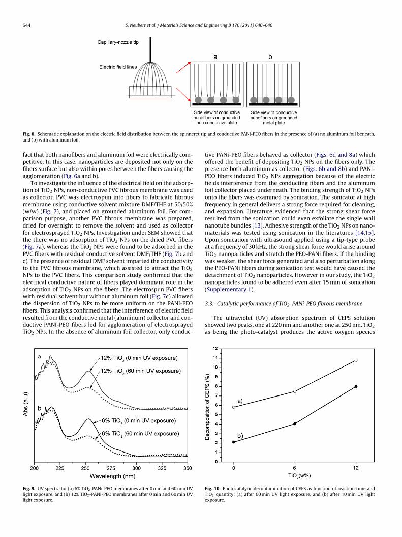
ig. 8. Schematic explanation on the electric field distribution between the spinnend (b) with aluminum foil.
act that both nanofibers and aluminum foil were electrically com-etitive. In this case, nanoparticles are deposited not only on thebers surface but also within pores between the fibers causing thegglomeration (Fig. 6a and b).
To investigate the influence of the electrical field on the adsorp-ion of TiO2 NPs, non-conductive PVC fibrous membrane was useds collector. PVC was electrospun into fibers to fabricate fibrousembrane using conductive solvent mixture DMF/THF at 50/50%
w/w) (Fig. 7), and placed on grounded aluminum foil. For com-arison purpose, another PVC fibrous membrane was prepared,ried for overnight to remove the solvent and used as collectoror electrosprayed TiO2 NPs. Investigation under SEM showed thathe there was no adsorption of TiO2 NPs on the dried PVC fibersFig. 7a), whereas the TiO2 NPs were found to be adsorbed in theVC fibers with residual conductive solvent DMF/THF (Fig. 7b and). The presence of residual DMF solvent imparted the conductivityo the PVC fibrous membrane, which assisted to attract the TiO2Ps to the PVC fibers. This comparison study confirmed that thelectrical conductive nature of fibers played dominant role in thedsorption of TiO2 NPs on the fibers. The electrospun PVC fibersith residual solvent but without aluminum foil (Fig. 7c) allowed
he dispersion of TiO NPs to be more uniform on the PANI-PEO
2bers. This analysis confirmed that the interference of electric fieldesulted from the conductive metal (aluminum) collector and con-uctive PANI-PEO fibers led for agglomeration of electrosprayediO2 NPs. In the absence of aluminum foil collector, only conduc-ig. 9. UV spectra for (a) 6% TiO2-PANi-PEO membranes after 0 min and 60 min UVight exposure, and (b) 12% TiO2-PANi-PEO membranes after 0 min and 60 min UVight exposure.
and conductive PANi-PEO fibers in the presence of (a) no aluminum foil beneath,
tive PANi-PEO fibers behaved as collector (Figs. 6d and 8a) whichoffered the benefit of depositing TiO2 NPs on the fibers only. Thepresence both aluminum as collector (Figs. 6b and 8b) and PANi-PEO fibers induced TiO2 NPs aggregation because of the electricfields interference from the conducting fibers and the aluminumfoil collector placed underneath. The binding strength of TiO2 NPsonto the fibers was examined by sonication. The sonicator at highfrequency in general delivers a strong force required for cleaning,and expansion. Literature evidenced that the strong shear forceresulted from the sonication could even exfoliate the single wallnanotube bundles [13]. Adhesive strength of the TiO2 NPs on nano-materials was tested using sonication in the literatures [14,15].Upon sonication with ultrasound applied using a tip-type probeat a frequency of 30 kHz, the strong shear force would arise aroundTiO2 nanoparticles and stretch the PEO-PANi fibers. If the bindingwas weaker, the shear force generated and also perturbation alongthe PEO-PANi fibers during sonication test would have caused thedetachment of TiO2 nanoparticles. However in our study, the TiO2nanoparticles found to be adhered even after 15 min of sonication(Supplementary 1).
2
The ultraviolet (UV) absorption spectrum of CEPS solutionshowed two peaks, one at 220 nm and another one at 250 nm. TiO2as being the photo-catalyst produces the active oxygen species
Fig. 10. Photocatalytic decontamination of CEPS as function of reaction time andTiO2 quantity; (a) after 60 min UV light exposure, and (b) after 10 min UV lightexposure.

S. Neubert et al. / Materials Science and Engineering B 176 (2011) 640–646 645
partic
utwTts3s
dccTih(vtpaac
tRtfitc
4
tIPd
Fig. 11. Photocatalytic action of TiO2 nano
nder UV irradiation. The photolytic decontamination of CEPS inhe presence of TiO2 NPs embedded PANi-PEO fibrous membraneas studied by measuring the CEPS absorbance decay at 220 nm.
he photo-catalytic decontamination of CEPS was correlated withhe decrease in the absorbance of CEPS at 220 nm and plotted ashown in Fig. 9. All the measurements were only carried out afterh. It is clear that the higher amount of TiO2 hydrolyzed the CEPS
ignificantly (Figs. 9 and 10).Fibrous membrane with 6 wt% TiO2 in CSA/PANi-PEO was intro-
uced into the CEPS solution and irradiated with UV light in alosed chamber for 10 min and 60 min. The experiment was alsoarried for the 12 wt% TiO2-PANi-PEO fibrous membrane and non-iO2 coated PANi-PEO membrane. The catalytic activity was alsonvestigated for 60 min UV exposure time. It was observed that theigher concentration of TiO2 NPs decreased the absorbance of CEPSFigs. 9 and 10). TiO2 produces the radical under irradiation of ultra-iolet light that could allow the hydrolysis of CEPS and resulted inhe formation of HEPS (Fig. 11). Upon irradiation, hydroxyl groupresent in Lewis acid Ti4+ of TiO2 due to intercalation or physicaldsorption of water molecules reacts with CEPS molecules formingnontoxic hydroxyl ethyl phenyl sulfide (HEPS) [16–18] and the
hlorine is displaced to form the elimination product.The greater dispersion and uniform coating of TiO2 NPs enabled
o reduce the CEPS by 11% with only 12 wt% of TiO2 NPs (Fig. 10).oso et al. [9] obtained 11% decontamination of CEPS but by usinghe higher quantity, i.e. about 32 wt% of TiO2 NPs adsorbed PEObers. It suggests that effective dispersion of the nanocatalysts onhe fibrous filter membrane is more important in improving theatalytic activity.
. Conclusions
The effective integration of electrospinning and electrosprayingo prepare the TiO2 catalytic fibrous membrane was demonstrated.t was shown in the study that the electrical conductive native of theANi-PEO fibrous membrane had a major influence on the uniformispersion of TiO2 NPs. By using a conductive CSA doped PANi-PEO
les towards CEPS under UV environment.
fibrous membrane as collector for electrosprayed TiO2 NPs, a highlyTiO2 uniform coating on the fibers surface was achieved. With 12%PANi concentrated PEO fibers, the TiO2 NPs were deposited on thefibers surface, without aggregating in the membrane pores. Thedeposition of TiO2 NPs by electrospraying was remarkably signif-icant in this study. Better catalytic performance of the resultantmembrane and stronger binding nature of TiO2 NPs to the PANi-PEO fibers promise that the method developed in this study couldbe potential for manufacturing the high performance catalytic filtermembranes.
Acknowledgements
We acknowledge the funding support from the A*STAR,Singapore, under the project ‘Fabrication of Novel Nanocompos-ite Filter Membranes for Understanding Basic Principles and TheirAdvanced Technology Applications’ (Grant No. R-398-000-041-305). S. Neubert thanks the ‘German Academic Foundation’ forsupport. We are indebted to Dr. Molamma P. Prabhakaran, Dr. S.Sundarrajan, Dr. A. Sreekumaran Nair, and K. Thirumal for theirhelp in the experimental part of our work.
Appendix A. Supplementary data
Supplementary data associated with this article can be found, inthe online version, at doi:10.1016/j.mseb.2011.02.007.
References
[1] N. Künzli, R. Kaiser, S. Medina, M. Studnicka, O. Chanel, P. Filliger, M. Herry,J.F. Horak, V. Puybonnieux-Texier, P. Quénel, J. Schneider, R. Seethaler, J.C.Vergnaud, H. Sommer, The Lancet 356 (2000) 795–801.
[2] J.A. Rojas-Chapana, H. Tributsch, D. Fink, A. Petrov, Journal of Porous Materials12 (2005) 215–224.
[3] K. Fujiwara, Nuclear Instruments & Methods in Physics Research Section B-Beam Interactions with Materials and Atoms 265 (2007) 150–155.
[4] R. Gopal, S. Kaur, Z.W. Ma, C. Chan, S. Ramakrishna, T. Matsuura, Journal ofMembrane Science 281 (2006) 581–586.
[5] S. Kaur, R. Gopal, W.J. Ng, S. Ramakrishna, T. Matsuura, MRS Bulletin 33 (2008)21–26.

6 and E
[
[
[
[
[
46 S. Neubert et al. / Materials Science
[6] V. Thavasi, G. Singh, S. Ramakrishna, Energy & Environmental Science 1 (2008)205–221.
[7] S. Sundarrajan, S. Ramakrishna, Journal of Materials Science 42 (2007)8400–8407.
[8] C. Drew, X. Liu, D. Ziegler, X.Y. Wang, F.F. Bruno, J. Whitten, L.A. Samuelson, J.
Kumar, Nano Letters 3 (2003) 143–147.[9] M. Roso, S. Sundarrajan, D. Pliszka, S. Ramakrishna, M. Modesti, Nanotechnol-ogy 19 (2008) 285707.
10] A. Patanaik, V. Jacobs, R.D. Anandjiwala, Journal of Membrane Science 352(2010) 136–142.
11] Y. Cao, P. Smith, A.J. Heeger, Synthetic Metals 48 (1992) 91–97.
[[
[[
ngineering B 176 (2011) 640–646
12] I.D. Norris, M.M. Shaker, F.K. Ko, A.G. MacDiarmid, Synthetic Metals 114 (2000)109–114.
13] A. Piermattei, S. Karthikeyan, R.P. Sijbesma, Nature Chemistry 1 (2009)133–137.
14] J.M.Y. Carrillo, E. Rapheal, A.V. Dobrynin, Langmuir 26 (2010) 12973–12979.
15] K.L. Johnson, Tribology International 31 (1998) 413–418.16] K. Hashimoto, H. Irie, A. Fujishima, Japanese Journal of Applied Physics Part1-Regular Papers Brief Communications & Review Papers 44 (2005) 8269–8285.17] G.W. Wagner, B.K. MacIver, Langmuir 14 (1998) 6930–6934.18] G.K. Prasad, Journal of Scientific & Industrial Research 68 (2009)
379–384.
Copyright © 2022 FDOKUMEN