Unsaturated Polyester Nanocomposites modified with fibrillated cellulose and PEO-b-PPO-b-PEO block...
7
Unsaturated Polyester Nanocomposites modified with fibrillated cellulose and PEO-b-PPO-b-PEO block copolymer Daniel H. Builes a,b , Jalel Labidi a , Arantxa Eceiza a , Iñaki Mondragon a , Agnieszka Tercjak a,⇑ a Group ‘Materials + Technologies’, Department of Chemical and Environmental Engineering, Polytechnic School, University of the Basque Country (UPV/EHU), Pza Europa 1, 20018 Donostia-San Sebastián, Spain b Department of Innovation, Andercol S.A., Medellín, Colombia article info Article history: Received 24 June 2013 Received in revised form 17 September 2013 Accepted 21 September 2013 Available online 4 October 2013 Keywords: A. Nanocomposites A. Fibres B. Curing B. Mechanical properties D. Atomic force microscopy (AFM) abstract PEO-b-PPO-b-PEO block copolymer (EPE20) was used as both nanostructuring agent for unsaturated polyester (UP) matrix and dispersing agent for sisal microfibrillated cellulose (MFC), which successfully reduced the brittles of the UP matrix increasing the toughness of designed materials and allowed to maintain the flexural modulus in the UP/EPE20/MFC. Sisal MFC, prepared by chemical and mechanical treatment using high pressure homogeneizer, was employed as reinforcement for nanaostructurated UP based thermosetting systems. UP system modified with both 1 wt.% MFC and 5 wt.% EPE20 led to design optically transparent nanostructured thermosetting materials with good mechanical properties. Ó 2013 Elsevier Ltd. All rights reserved. 1. Introduction Nowadays, unsaturated polyester (UP) resins are widely used in variety of engineering applications such as adhesives, surface coating, painting and composites materials for automotive and building sectors. The main drawback of this type of resin, simi- larly to the other thermosetting materials is brittles, which limits their application in the fabrication of materials with high impact and fracture strength [1–3]. Many approaches have been used to reduce the brittles of thermosetting materials based on UP such as additives, thermoplastics [4,5] especially block copolymers [2,6–8] or elastomers [9]. In the last few decades, one of the promising approaches to improve the mechanical properties of the UP is used cellulose as reinforcement [10–13]. In this re- search field, especially micro- or nanofibrillated cellulose (MFC) has been used as effective advanced fillers. In this case, the improvement of the mechanical properties depends strongly on the good adhesion between the reinforcement and polymeric matrix [11,14] leading to good dispersion of the reinforcement. This mainly depends on the reinforcement content, size and surface treatment. MFC have been first time isolated in 1983 by a mechanical disintegration process from wood cell [15,16]. This type of cellulosic material was widely used as reinforcement of the polymeric materials since this material is renewable and has low cost, low density, high toughness and modulus, and greatly expanded in surface area, obtained by a chemical and mechanical homogenization process [17,18]. As mentioned above good mechanical properties in composite materials, consist of polar cellulose fibres and non-polar polymeric matrix, are directly related to the interfacial properties and compatibility between them. To reach good interfacial adhesion and compatibility, cou- pling agents such as silane, maleated polypropylene and maleated polyethylene [10,19] have been used leading to outstanding improvement in mechanical properties. In our previous works [6,7] it have been shown the relationship between nanostructuring of UP-based thermosets and mechanical properties using the amphiphilic properties of poly(ethylene oxide-b-propylene oxide-b-ethylene oxide) block copolymer EPE20 as a nanostructuring agent at contents from 5 to 50 wt.%. This family of block copolymer has been also extensively studied in aqueous solutions due mainly to its possibility to generate hydrogen bonds. In the present work, EPE20 was used as coupling agent. Based on our knowledge, this is the first time when MFC has been incorporated in UP resins and when block copolymers are used not only as nanostructuring agent for the UP but also as dis- persion agent for sisal MFC. Consequently, in this work UP resin was modified with both EPE20 and sisal MFC to obtain nanostruc- tured termosetting systems with high optical transparency and good mechanical properties. 0266-3538/$ - see front matter Ó 2013 Elsevier Ltd. All rights reserved. http://dx.doi.org/10.1016/j.compscitech.2013.09.015 ⇑ Corresponding author. Tel.: +34 943017169; fax: +34 943017140. E-mail address: [email protected] (A. Tercjak). Composites Science and Technology 89 (2013) 120–126 Contents lists available at ScienceDirect Composites Science and Technology journal homepage: www.elsevier.com/locate/compscitech
Transcript of Unsaturated Polyester Nanocomposites modified with fibrillated cellulose and PEO-b-PPO-b-PEO block...

Composites Science and Technology 89 (2013) 120–126
Contents lists available at ScienceDirect
Composites Science and Technology
journal homepage: www.elsevier .com/ locate /compsci tech
Unsaturated Polyester Nanocomposites modified with fibrillatedcellulose and PEO-b-PPO-b-PEO block copolymer
0266-3538/$ - see front matter � 2013 Elsevier Ltd. All rights reserved.http://dx.doi.org/10.1016/j.compscitech.2013.09.015
⇑ Corresponding author. Tel.: +34 943017169; fax: +34 943017140.E-mail address: [email protected] (A. Tercjak).
Daniel H. Builes a,b, Jalel Labidi a, Arantxa Eceiza a, Iñaki Mondragon a, Agnieszka Tercjak a,⇑a Group ‘Materials + Technologies’, Department of Chemical and Environmental Engineering, Polytechnic School, University of the Basque Country (UPV/EHU),Pza Europa 1, 20018 Donostia-San Sebastián, Spainb Department of Innovation, Andercol S.A., Medellín, Colombia
a r t i c l e i n f o a b s t r a c t
Article history:Received 24 June 2013Received in revised form 17 September 2013Accepted 21 September 2013Available online 4 October 2013
Keywords:A. NanocompositesA. FibresB. CuringB. Mechanical propertiesD. Atomic force microscopy (AFM)
PEO-b-PPO-b-PEO block copolymer (EPE20) was used as both nanostructuring agent for unsaturatedpolyester (UP) matrix and dispersing agent for sisal microfibrillated cellulose (MFC), which successfullyreduced the brittles of the UP matrix increasing the toughness of designed materials and allowed tomaintain the flexural modulus in the UP/EPE20/MFC. Sisal MFC, prepared by chemical and mechanicaltreatment using high pressure homogeneizer, was employed as reinforcement for nanaostructuratedUP based thermosetting systems. UP system modified with both 1 wt.% MFC and 5 wt.% EPE20 led todesign optically transparent nanostructured thermosetting materials with good mechanical properties.
� 2013 Elsevier Ltd. All rights reserved.
1. Introduction
Nowadays, unsaturated polyester (UP) resins are widely usedin variety of engineering applications such as adhesives, surfacecoating, painting and composites materials for automotive andbuilding sectors. The main drawback of this type of resin, simi-larly to the other thermosetting materials is brittles, which limitstheir application in the fabrication of materials with high impactand fracture strength [1–3]. Many approaches have been used toreduce the brittles of thermosetting materials based on UP suchas additives, thermoplastics [4,5] especially block copolymers[2,6–8] or elastomers [9]. In the last few decades, one of thepromising approaches to improve the mechanical properties ofthe UP is used cellulose as reinforcement [10–13]. In this re-search field, especially micro- or nanofibrillated cellulose (MFC)has been used as effective advanced fillers. In this case, theimprovement of the mechanical properties depends strongly onthe good adhesion between the reinforcement and polymericmatrix [11,14] leading to good dispersion of the reinforcement.This mainly depends on the reinforcement content, size andsurface treatment.
MFC have been first time isolated in 1983 by a mechanicaldisintegration process from wood cell [15,16]. This type of
cellulosic material was widely used as reinforcement of thepolymeric materials since this material is renewable and has lowcost, low density, high toughness and modulus, and greatlyexpanded in surface area, obtained by a chemical and mechanicalhomogenization process [17,18]. As mentioned above goodmechanical properties in composite materials, consist of polarcellulose fibres and non-polar polymeric matrix, are directlyrelated to the interfacial properties and compatibility betweenthem. To reach good interfacial adhesion and compatibility, cou-pling agents such as silane, maleated polypropylene and maleatedpolyethylene [10,19] have been used leading to outstandingimprovement in mechanical properties.
In our previous works [6,7] it have been shown the relationshipbetween nanostructuring of UP-based thermosets and mechanicalproperties using the amphiphilic properties of poly(ethyleneoxide-b-propylene oxide-b-ethylene oxide) block copolymerEPE20 as a nanostructuring agent at contents from 5 to 50 wt.%.This family of block copolymer has been also extensively studiedin aqueous solutions due mainly to its possibility to generatehydrogen bonds. In the present work, EPE20 was used as couplingagent. Based on our knowledge, this is the first time when MFC hasbeen incorporated in UP resins and when block copolymers areused not only as nanostructuring agent for the UP but also as dis-persion agent for sisal MFC. Consequently, in this work UP resinwas modified with both EPE20 and sisal MFC to obtain nanostruc-tured termosetting systems with high optical transparency andgood mechanical properties.
D.H. Builes et al. / Composites Science and Technology 89 (2013) 120–126 121
2. Experimental section
2.1. Materials
Sisal (Agave Sisalana) fibres supplied by Celesa (Celulosa de Lev-ante, S.A.) were used for the preparation of the nanofibrils. Ethanol96% v/v PA-ACS, toluene HPLC, sodium hydroxide pellets PA-ACS-ISO and acetic acid glacial QP, were supplied by Panreac.
Linear PEO-b-PPO-b-PEO triblock copolymer with structureE20P69E20 (E = ethylene oxide and P = propylene oxide, the sub-scripts indicate the number of repeated units) named here asEPE20, with a number average molecular weight (Mn) of5750 g mol�1 was purchased from Sigma–Aldrich. A commercialortho-phthalic UP resin with trade name Cristalan 860 manufac-tured by Andercol S.A. was used as the thermosetting precursor.It contains a UP prepolymer with a number average molecularweight (Mn) of 1800 and polydispersity index of 3 as determinedby gel permeation chromatography (GPC), and made from phthalicand maleic anhydrides and propylene glycol, dissolved in styreneas crosslinking monomer with a C@C molar ratio between styreneand prepolymer of c.a. 1. Methyl ethyl ketone peroxide (MEKP)with the trade name Peroxan ME50L as polymerization initiator,and cobalt n-octoate in solvent mixture-6% (OCo) as acceleratorpromoter were supplied by Hegardt S.L.
2.2. Microfibrils Isolation
A chemical–mechanical treatment was used to achieve micro-fibrils. First, the original sisal fibres were reduced in a Heavy-Duty Cutting Mill Retsch SM 2000 with a 2–4 mm sieve. Theseshort fibres were submitted to a solvent extraction processaccording to TAPPI T204 standard [20]. After this step, the fibreswere treated in a 7.5 wt.% aqueous solution of sodium hydroxideduring 90 min in reflux. The obtained pulp was washed repeatedtimes with 10 wt.% acetic acid solution and distillate water untilit was neutralized. This chemical treatment was carried out inorder to remove impurities from the surface of the fibres andto swell them and remove excessive amount of lignin, therebymaking mechanical treatments easier. After chemical treatments,a fibrillation process was carried out using the homogenizationtechnology. The pulp was dispersed in water at concentrationof c.a. 0.1 wt.% and stirred continuously before being pumpedthrough a Panda 2 K Niro Soavi homogenizer. In order to gethigher fibrillation effect, the pressure was varied during pump-ing passes. The process started with 10 passes at 100 bar, then30 passes at 600 bar and finally 80 passes at 1000–1300 bar[21–23]. The aqueous suspension of fibrils obtained fromhomogenizer was dried at 60 �C until powder was obtained. Thispowder was washed several times with a solution of ethanol/toluene in a relation of 2:1 v/v and dried at room temperatureunder vacuum.
2.3. Blending protocol
UP resin was pre-accelerated mixing it with 0.3 phr OCo, i.e.,0.3 g OCo per 100 g of UP resin. UP/EPE20 nonreactive mixtureswere prepared mixing UP resin with an adequate EPE20 contentby stirring with a magnetic mixer until a homogeneous liquidwas obtained. The reacting mixtures were prepared adding 1.5phr MEKP, i.e., 1.5 g MEKP per 100 g UP resin. A mould with twoflat glasses separated by a U-shaped PTFE sheet was used. In thefirst cycle, the mixtures were pre-cured at 25 �C during 24 h in aforced convection oven, followed by 12 h at 35 �C, 3 h at 85 �Cand 1 h at 170 �C.
2.4. Characterization techniques
Optical microscopy (OM) micrographs of the sisal cellulose fi-bres during homogenization process and investigated thermoset-ting systems were carried out using a Nikon Eclipse E600W withthe software analySIS docu FIVE.
Morphology of the thermosetting mixtures was analyzed usingatomic force microscopy (AFM) using a scanning probe microscope(SPM) (NanoScope IIIa Multimode from Digital Instruments, VeecoInstruments, Inc) in tapping mode (TM-AFM). One beam cantilever(125 lm) with silicon probe (curvature nominal radius of 5–10 nm) was used. Samples were cut using an ultramicrotome LeicaUltracut R with a diamond blade.
The dynamic light scattering (DLS) measurements were per-formed in a Brookhaven BI-200SM goniometer with a 9000AT cor-relator. A light beam from a He–Ne laser (Mini L-30, wavelengthk = 637 nm, 10 mW) directed to a pot with a glass vat with a refrac-tive index matching liquid surrounding the scattering cell andthermostated at 25 �C was used. The scattered light intensity wasmeasured at 90� with respect to the incident beam. Size distribu-tions of MFC in two different aqueous dispersions were analyzedafter filtration using a 0.20 lm filter (Millipore). The first disper-sion was 0.018 wt.% of MFC in water. The second one was com-posed of 0.018 wt.% of MFC and 0.09 wt.% of EPE20. Prior to themeasurements, the samples were kept for 48 h at room tempera-ture, which led to a considerable reduction of dust.
In order to study the mechanical properties of investigatedsystems, three-point bending and fracture toughness tests wereperformed following ASTM D 790 10 and ASTM D 5045-99 stan-dards, respectively, in a universal testing machine MTS modelInsight 10 provided with a 250 N load cell. Rectangular samplesof 12.7 � 1.0 � 40 mm3 using a length span of 16 mm were testedat a crosshead rate of 0.4 mm min�1 for flexural tests. Flexuralmodulus was determined from the slope of the load–displacementcurve. The fracture toughness was evaluated in terms of the criticalstress-intensity factor, KIc. An approximate estimation of KIc valueswas obtained from a three-point bending test performed on singleedge notched specimens (SENB). Rectangular samples of6 � 1.5 � 30 mm3, with 2.7 mm V-shaped notches and micro-cracked were tested at a crosshead rate of 10 mm min�1 and lengthspan of 23 mm. At least five measurements were carried out permixture.
3. Results and discussion
3.1. Microfibrillated cellulose characterization
Fig. 1 shows optical micrographs of fibrillation process of the si-sal cellulose during mechanical homogenization process. As can beobserved, the cellulose fibres became smaller and higher fibrilla-tion degree can be reached during the homogenization process(compare Fig. 1a with d). Finally, the typical millimeter sized fibresobserved clearly after 10 passess disappeared and only MFC can bedetected after 100 passess. The optical micrographs of the sisal cel-lulose fibres after 100 passes taken in higher magnification (insetof Fig. 1d) indicated lack of millimeter sized fiber and confirmedthat the employed process effectively reduced the size of the fibresbeing promising to obtain even fibrillation of the cellulose at thenanometric scale.
The decrease of sedimentation observed in the aqueous MFCdispersion during each step of the homogenization process indi-cates that MFC became smaller forming a stable colloidal suspen-sion [24]. Fig. 2 shows the visual appearance of the sisal cellulosefibres suspensions in water during microfibrillation process.Homogeneity of the suspensions increased with increasing of the

a 500 µµm b 500 µm
c 500 µm d
5 µm
500 µm
Fig. 1. Optical micrographs of cellulose fibres during mechanical homogenization process after (a) 10 passes, (b) 40 passes, (c) 60 passes and (d) 100 passes.
Fig. 2. Visual appearance of aqueous suspensions of 0.04 wt.% sisal cellulose fibresduring homogenization process after (a) 10 passes, (b) 40 passes, (c) 60 passes, (d)100 passes and (e) 120 passes.
Fig. 3. AFM image (1 lm � 1 lm) of fibrillated sisal fibres. The inset corresponds to5 lm � 5 lm AFM image.
122 D.H. Builes et al. / Composites Science and Technology 89 (2013) 120–126
passes in homogenizer. After 40 passes sisal cellulose fibrils startedto form suspension in water however were still not well dispersed.On the contrary, after 100 passes, stable and homogeneous colloi-dal suspension was achieved without visual difference if comparewith the highest number of passes. It is worth to note that fibressuspension increased the viscosity and simultaneously a gel-likeaspect could be easily detected. These results are in good agree-ment with results obtained using optical microscopy and werestrongly related with continuous decrease of the cellulose fibressize, which due to chemical–mechanical homogenization processbecome micro- and even nanosized cellulose fibres.
In order to confirm the micro- and nanometric size of the fibresafter chemical–mechanical treatment AFM measurement wasperformed. A representative AFM phase image of the sisal cellulosefibres after 120 passes in the homogenizer (spin-coated on the sil-icon wafer surface) is shown in Fig. 3. AFM results indicated thatfibres were broken down to smaller fibres during homogenizationprocess forming a network of fibrils. A detailed observationallowed to distinguish fibres with a diameter of c.a. 160 nm (indi-cated by the arrow pointing to the right) were fibrillated in fibrilswith diameter of c.a. 10 nm (indicated by the arrow pointing
upward). Furthermore, AFM analysis confirmed fibrillation afterthe homogenization process since individual microfibrils could beclearly distinguished on the surface of fibres; each fiber consistedof 5–10 nm diameter microfibrils kept together by electrostaticforces [25]. The fibrillated structure of the fibres confirmed theeffectiveness of using a high pressure homogenizer. This resultedin individual micrometer long fibrils (longer than 5 lm, see the in-set of Fig. 3) with diameter, at least in part, at nanometer scale (c.a.10 nm). Here, it should be pointed out that individual microfibrilsof fibrillated cellulose had a thickness smaller than width, whichoccasionally led the fibrils to twist over their axis mostly in thedirection of their smaller thickness [25].
Fig. 4 shows the dynamic light scattering size distribution of anaqueous solution of 0.09 wt.% of EPE20, a water dispersion of0.018 wt.% of MFC and a dispersion of 0.018 wt.% of MFC in anaqueous solution of 0.09 wt.% of EPE20. As expected, the dispersionof MFC in water exhibited higher size distribution than MFC

100 101 102 103 104
0
50
100
MFC in water solution of EPE20 MFC in water Aqueous solution of EPE20
Hydrodynamic diameter (nm)
Inte
nsity
(%
)
Fig. 4. Size distributions for aqueous solution of (-�-) 0.09 wt.% EPE20, (—)0.018 wt.% MFC dispersion in water and (-) 0.018 wt.% MFC dispersion in aqueoussolution of 0.09 wt.% EPE20.
D.H. Builes et al. / Composites Science and Technology 89 (2013) 120–126 123
dispersed in an aqueous solution of EPE20. This can be explainedtaking into account the ability of the fibrils to form dense networksheld together by strong hydrogen interfibrillar bonds. This abilityof MFC provoked their tendency to agglomerate in water forminga characteristic gel-like structure [24]. On the other hand, the addi-tion of MFC into EPE20 solution allowed to break the agglomera-tion of fibres. Consequently, better dispersion of MFC, by meansof a decrease of the particles diameter from c.a. 4 to 1 lm, canbe reached. To compare the order of magnitude between MFCparticles and EPE20 micelles, the size dispersion of an aqueoussolution of EPE20 was also included in Fig. 4, proving that EPE20acts as an effective surfactant for MFC due to the cellulose-PEOhydrogen bonds interactions [26–28].
3.2. Unsaturated Polyester Nanocomposites
MFC achieved after chemical and mechanical treatments wasused to modify thermosetting system based on UP. First of all itshould be pointed out these results refer to the bulk behavior ofdesigned systems since the cured systems were prepared in aparallelepipedic mould of 1 ± 0.1 mm thickness. Additionally, asreported in our previous works [6,7], UP matrix can be nanostruc-tured with EPE20 block copolymer, which nanodomains were com-posed by self-assembled micelles formed in the non-reactiveEPE20/UP mixture. These micelles were driven by the immiscibilityof the PPO central block with the UP resin and stabilized by the PEOlateral blocks. Thus, the nanodomains in the cured mixture werecomposed mainly by a core of PPO surrounded by PEO partiallymixed with crosslinked UP-rich network. Thus, in this investiga-tion EPE20 block copolymer was used not only as nanostructuringagent of UP but also as dispersing agent for the cellulose.
To prove the effectiveness of the dispersion of the MFC in UPmatrix after addition of EPE20 block copolymer, other mixture of
b200 µmaFig. 5. Optical micrographs of (a) 5%EPE20/UP, (b) 1%MFC/UP and (c) 1%MFC/5%EPE20/sheet.
UP modified only with MFC was prepared. The optical micrographsof UP, 1%MFC/UP and 1%MFC/5%EPE20/UP cured systems areshown in Fig. 5. Digital images of transparency of investigated sys-tems are shown in top inset of each optical micrographs in Fig. 5.Due to the 5%EPE20/UP mixture exhibited the best performancein mechanical properties and optical transparency [7] comparedwith other EPE20 content, this content was also fixed at 5 wt.% inthe MFC/EPE20/UP system. Under the same preparation conditions,addition of 1 wt.% MFC to the UP without EPE20 block copolymerlead to clearly visible agglomeration of the MFC in the UP matrix.As can be seen, the 1%MFC/UP cured system did not lose opticaltransparency of the UP matrix, however, agglomeration of theMFC can be clearly detected (Fig. 5b). On the contrary, 1%MFC/5%EPE20/UP cured system led to fabrication of highly transparentthermosetting system without agglomeration of the MFC on themacroscopic level (Fig. 5c).
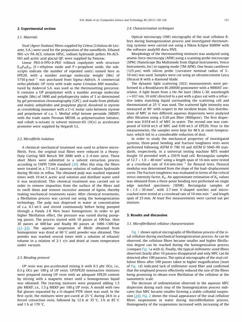
To confirm dispersion of the sisal microfibrillated cellulose andthe nanostructuration of the UP matrix in the investigated thermo-setting system modified with both 1 wt.% MFC and 5 wt.% EPE20,final morphology of the 1%MFC/5%EPE20/UP cured mixture wasstudied using AFM (Fig. 6). To comparison, in Fig. 6 AFM phaseimages of neat UP and 5%EPE20/UP cured systems are also shown.Under the same preparation condition, neat UP resin showedtypical spherical morphology [6,7] related to the heterogeneouscuring process of thermosetting system based on UP. Simulta-neously, addition of 5 wt.% EPE20 block copolymer lead to micro-phase separation of EPE20 from the UP-rich matrix. In this case,spherical domains of EPE20 block copolymer with the diameteraround 9–12 nm can be clearly distinguished simultaneously withmuch smaller microphase separation of heterogeneous UP matrixwith diameter of segregated domains around 4–7 nm. AFM phaseimage of 1%MFC/5%EPE20/UP cured mixture indicated good disper-sion of the MFC without losing the nanostructuration of the UP ma-trix. This phenomenon seems to be related to the adsorption abilityof MFC. This property of MFC could provoke the location of a part ofEPE20 on the surface of the fibrils acting as a dispersing agent in-stead of as a nanostructuring agent (see the EPE20 phase separa-tion next to MFC pointed by the arrows in Fig. 6c). Thus, EPE20tended to avoid the strong fibril–fibril hydrogen bonding betweenAOH groups on the surface of the fibrils and replace them by inter-molecular interactions between fibrils and PEO-blocks leading tonew hydrogen bonding [27,29]. Consequently, more space be-tween fibrils, due to steric effects, can be generated allowing loca-tions of UP oligomers (or water molecules in the case of aqueoussolutions) into twists and turns of MFC. This effect is shown sche-matically in Fig. 7. Here it should be pointed out that the interac-tions between UP or EPE20 and MFC depend strongly on thetopographical nature of MFC [30]. As was reported by Serranoet al. [31], this final topography of MFC is crucial for the adsorptionability of the MFC. The adsoprtion of EPE20 on the MFC surface im-proves the wettability allowing the coadsorption of UP resin[32,33], viz., the EPE20 that remained on the surface of MFC canretain St owing to the St-PPO compatibility [7]. Due to the last,UP oligomers can be located also onto MFC, thereby improving
200 µm200 µm cUP cured systems. The inset of each image corresponds to a digital image of 1 mm
a
b
cFig. 6. AFM images (0.75 lm � 0.75 lm) of (a) neat UP, (b) 5%EPE20/UP and (c)1%MFC/5%EPE20/UP cured systems. The inset in each image corresponds to5 lm � 5 lm AFM phase image.
OH
HO
Imput of styrene to PPO block and UP
oligomers (or water)
PPOPEO PEO
Fibriles with fibrile-fibrile hydrogen bonding
Fibriles with fibrile-EPE20hydrogen bonding
EPE20 micelle
Fig. 7. Schematic description of the dispersion/adsorption phenomena of MFC/UPresin (or water) after mixed with EPE20 block copolymer.
0.3
0.4
0.5
0.6
0.7
0.8
2
3
4
Neat UP 5%EPE20/
UP
1%MFC/5%EPE20/
UP
KIc
(M
Pa m
0.5 )
E (
GPa
)
E
KIc
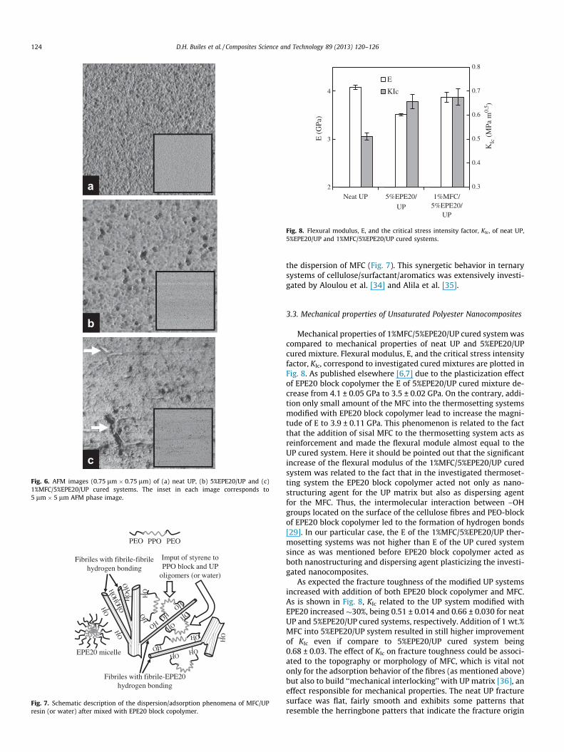
Fig. 8. Flexural modulus, E, and the critical stress intensity factor, KIc, of neat UP,5%EPE20/UP and 1%MFC/5%EPE20/UP cured systems.
124 D.H. Builes et al. / Composites Science and Technology 89 (2013) 120–126
the dispersion of MFC (Fig. 7). This synergetic behavior in ternarysystems of cellulose/surfactant/aromatics was extensively investi-gated by Aloulou et al. [34] and Alila et al. [35].
3.3. Mechanical properties of Unsaturated Polyester Nanocomposites
Mechanical properties of 1%MFC/5%EPE20/UP cured system wascompared to mechanical properties of neat UP and 5%EPE20/UPcured mixture. Flexural modulus, E, and the critical stress intensityfactor, KIc, correspond to investigated cured mixtures are plotted inFig. 8. As published elsewhere [6,7] due to the plasticization effectof EPE20 block copolymer the E of 5%EPE20/UP cured mixture de-crease from 4.1 ± 0.05 GPa to 3.5 ± 0.02 GPa. On the contrary, addi-tion only small amount of the MFC into the thermosetting systemsmodified with EPE20 block copolymer lead to increase the magni-tude of E to 3.9 ± 0.11 GPa. This phenomenon is related to the factthat the addition of sisal MFC to the thermosetting system acts asreinforcement and made the flexural module almost equal to theUP cured system. Here it should be pointed out that the significantincrease of the flexural modulus of the 1%MFC/5%EPE20/UP curedsystem was related to the fact that in the investigated thermoset-ting system the EPE20 block copolymer acted not only as nano-structuring agent for the UP matrix but also as dispersing agentfor the MFC. Thus, the intermolecular interaction between –OHgroups located on the surface of the cellulose fibres and PEO-blockof EPE20 block copolymer led to the formation of hydrogen bonds[29]. In our particular case, the E of the 1%MFC/5%EPE20/UP ther-mosetting systems was not higher than E of the UP cured systemsince as was mentioned before EPE20 block copolymer acted asboth nanostructuring and dispersing agent plasticizing the investi-gated nanocomposites.
As expected the fracture toughness of the modified UP systemsincreased with addition of both EPE20 block copolymer and MFC.As is shown in Fig. 8, KIc related to the UP system modified withEPE20 increased �30%, being 0.51 ± 0.014 and 0.66 ± 0.030 for neatUP and 5%EPE20/UP cured systems, respectively. Addition of 1 wt.%MFC into 5%EPE20/UP system resulted in still higher improvementof KIc even if compare to 5%EPE20/UP cured system being0.68 ± 0.03. The effect of KIc on fracture toughness could be associ-ated to the topography or morphology of MFC, which is vital notonly for the adsorption behavior of the fibres (as mentioned above)but also to build ‘‘mechanical interlocking’’ with UP matrix [36], aneffect responsible for mechanical properties. The neat UP fracturesurface was flat, fairly smooth and exhibits some patterns thatresemble the herringbone patters that indicate the fracture origin

50 µma b c
Fig. 9. Optical micrographs of fracture surface of tested samples of (a) neat UP, (b) 5%EPE20/UP and (c) 1%MFC/5%EPE20/UP cured systems. The arrows pointing upwardsindicate the tip of initial crack marks. The arrows pointing downwards indicate the tip of the machined notch. The inset at the right top shows an scheme of the fracturesurface of a tested sample.
D.H. Builes et al. / Composites Science and Technology 89 (2013) 120–126 125
and direction of rapid fracture progression, which are clear evi-dences for brittle rupture (Fig. 9a). For the 5%EPE20/UP system, lessflat (with deformations) and rougher fracture surface was depictedunder favorable lighting (Fig. 9b), indicating that fracture behaviorwas more ductile, agreeing with the KIc improvement. Further-more, a considerable change in the appearance of fracture surfacewas noted for 1%MFC/5%EPE20/UP system (Fig. 9c). This fracturesurface resembles the appearance of the fracture surfaces reportedby Abdelmouleh et al. [10] for a UP/fibres systems confirming thechanges in the fracture mechanism if compared with the fracturemechanism of neat UP or 5%EPE20/UP cured system.
4. Conclusions
Cellulose fibrils with diameters below 100 nm and length in themicrometer range were successfully isolated from sisal cellulosefibres using chemical and mechanical treatments. The good disper-sion of the obtained MFC in water or UP matrix was achieved usingEPE20 block copolymer as surfactant. Additionally, as confirmed byatomic force microscopy, good dispersion of the MFC was achievedin the UP cured system modified with EPE20 block copolymer,which played double-role, nanostructuring agent for UP matrixand dispersing agent for MFC in the UP matrix. This synergeticeffect of the ternary system improved the fracture toughness witha low decrease of UP flexural modulus by means of the modifica-tion with 1 wt.% of MFC and 5 wt.% of EPE20. Finally, a novelprotocol to fabricate UP-based cellulose nanocomposites has beenreached. This protocol can be used as practical way to control thenanostructuration of a UP matrix considering an appropriatereinforcement/transparency balance.
Acknowledgments
D.H.B. is gratefully acknowledged to Andercol S.A. and Group‘Materials + Technologies’ of the University of the Basque Countryfor their support. A.T. acknowledges MICINN for Ramón y Cajalprogram (RYC-2010-05592). Financial support from Basque Coun-try Government in the frame of ETORTEK NANOIKER (IE11-304),SAIOTEK2012 (S-PE12UN106) and GRUPOS CONSOLIDADOS(IT776-13) is gratefully acknowledged. The authors wish to alsothank the Spanish Ministry of Economy and Competitiveness forthe project MAT2012-31675 and TRAYSRENEW. Moreover, we
are grateful to the Macrobehavior-Mesostructure-NanotechnologySGIker unit of the UPV/EHU.
References
[1] Pascault JP, Sautereau H, Verdu J, Williams RJJ. Thermosetting polymers. NewYork: Marcel Dekker; 2002.
[2] Serrano E, Gerard P, Lortie F, Pascault JP, Portinha D. Nanostructuration ofunsaturated polyester by all-acrylic block copolymers, 1. Use of high-molecular-weight block copolymers. Macromol Mater Eng 2008;293:820–7.
[3] Redline EM, Francis LF, Bates FS. Radical-cured block copolymer-modifiedthermosets. J Polym Sci Part B: Polym Phys 2011;49:540–50.
[4] Bakar M, Djaider F. Effect of plasticizers content on the mechanical propertiesof unsaturated polyester resin. J Thermoplast Compos Mater2007;2007(20):53–64.
[5] Suspene L, Yang YS, Pascault JP. In: Riew K, Kinloch AJ, editors. Toughenedplastics 1. Science and engineering. Washington (USA): American ChemicalSociety; 1993.
[6] Builes DH, Tercjak A, Mondragon I. Nanostructured unsaturated polyestermodified with poly[(ethylene oxide)-b-(propylene oxide)-b-(ethylene oxide)]triblock copolymers. Polymer 2012;53:3669–76.
[7] Builes DH, Hernández H, Mondragon I, Tercjak A. Relationship betweenmorphology of nanostructured unsaturated polyesters modified with PEO-b-PPO-b-PEO triblock copolymer and their optical and mechanical properties. JPhys Chem C 2013;117:3563–71.
[8] Messori M, Toselli M, Polati F, Tonelli C. Unsaturated polyester resins modifiedwith poly(e-caprolactone)-perfluoropolyethers block copolymers. Polymer2001;42:9877–85.
[9] Cherian AB, Thachil ET. Blends of unsaturated polyester resin with functionalelastomers. J Elast Plast 2003;35:367–80.
[10] Abdelmouleh M, Boufi S, Belgacem MN, Dufresne A, Gandini A. Modification ofcellulose fibres with functionalized silanes: effect of the fiber treatment on themechanical performances of cellulose–thermoset composites. J Appl Polym Sci2005;98:974–84.
[11] Al-Turaif HA. Relationship between tensile properties and film formationkinetics of epoxy resin reinforced with nanofibrillated cellulose. Prog Org Coat2013;76:477–81.
[12] Hu L, Wan Y, He F, Luo HL, Liang H, Li X, et al. Effect of coupling treatment onmechanical properties of bacterial cellulose nanofibre-reinforced UPRecocomposites. Mater Lett 2009;63:1952–4.
[13] Gao Ch, Yizao W, He F, Liang H, Luo H. Mechanical, moisture absorption, andphotodegradation behaviors of bacterial cellulose nanofiber-reinforcedunsaturated polyester composites. Adv Polym Technol 2011;30:249–56.
[14] Liao H, Wu H, Wu M, Zhan X, Liu H. Aligned electrospun cellulose fibersreinforced epoxy resin composite films with high visible light transmittance.Cellulose 2012;19:111–9.
[15] Herrick FW, Casebier RL, Hamilton JK, Sandberg KR. Microfibrillated cellulose:morphology and accessibility. J Appl Polym Sci Polym Symp 1983;37:797–813.
[16] Turbak AF, Snyder FW, Sandberg KR. Microfibrillated cellulose, a new celluloseproduct: properties, uses, and commercial potential. J Appl Polym Sci PolymSymp 1983;37:815–27.
[17] Kaushik A, Singh M. Isolation and characterization of cellulose nanofibrils fromwheat straw using steam explosion coupled with high shear homogenization.Carbohydr Res 2011;346:76–85.
126 D.H. Builes et al. / Composites Science and Technology 89 (2013) 120–126
[18] Seydibeyoglu MO, Oksman K. Novel nanocomposites based on polyurethaneand micro fibrillated cellulose. Compos Sci Technol 2008;68:908–14.
[19] Acha BA, Reboredo MM, Marcovich NE. Creep and dynamic mechanicalbehavior of PP-jute composites: effect of the interfacial adhesion. CompositesPart A 2007;38:150716.
[20] Technical Association of the Pulp and Paper Industry. T204 cm-97. In: TAPPITest Methods, TAPPI, Norcross.
[21] Zimmermann T, Bordeanu N, Strub E. Properties of nanofibrillated cellulosefrom different raw materials and its reinforcement potential. Carbohydr Polym2010;79:1086–93.
[22] Kaushik A, Singh M. Isolation and characterization of cellulose nanofibrils fromwheat straw using steam explosion coupled with high shear homogenization.Carbohydr Res 2011;346:76–85.
[23] Lee SY, Chun SJ, Kang IA, Park JY. Preparation of cellulose nanofibrils by high-pressure homogenizer and cellulose-based composite films. J Ind Eng Chem2009;15:50–5.
[24] Alila S, Besbes I, Vilar MR, Mutjéc P, Boufi S. Non-woody plants as rawmaterials for production of microfibrillated cellulose (MFC): a comparativestudy. Ind Crop Prod 2013;41:250–9.
[25] Olsson RT, Kraemer R, Lopez-Rubio A, Torres-Giner S, Ocio MJ, Lagaron JM.Extraction of microfibrils from bacterial cellulose networks for electrospinningof anisotropic biohybrid fiber yarns. Macromolecules 2010;43:4201–9.
[26] Samir MASA, Alloin F, Sanchez JY, Dufresne A. Cellulose nanocrystalsreinforced poly(oxyethylene). Polymer 2004;45:4149–57.
[27] Zhuang X, Yanga X, Shi J, Cheng B, Guan K, Kang W. Solution blowing ofsubmicron-scale cellulose fibers. Carbohydr Polym 2012;90:982–7.
[28] Samir MASA, Alloin F, Sanchez JY, Kissi NE, Dufresne A. Preparation of cellulosewhiskers reinforced nanocomposites from an organic medium suspension.Macromolecules 2004;37:1386–93.
[29] Tercjak A, Gutiererez J, Mondragon G, Mondragon I. Cellulose nanocrystals andAu nanoparticles well-dispersed in a poly(styrene-b-ethylene oxide) blockcopolymer matrix. J Phys Chem C 2011;115:22180–5.
[30] Kim JK, Mai YW. Engineered interfaces in fiber reinforcedcomposites. Amsterdam: Elsevier Science; 1998.
[31] Serrano L, Urruzola I, Nemeth D, Belafi-Bako K, Labidi J. Modified cellulosemicrofibrils as benzene adsorbent. Desalination 2011;270:143–50.
[32] Grundke K. Wetting, spreading and penetration. In: Holmberg K, editor.Handbook of applied surface and colloid chemistry. Chichester: John Wiley &Sons; 2001.
[33] Semal S, Blake TD, Geskin V, de Ruijter MJ, Castelein G, De Coninck J. Influenceof surface roughness on wetting dynamics. Langmuir 1999;15:8765–70.
[34] Aloulou F, Boufi S, Labidi J. Modified cellulose fibres for adsorption of organiccompound in aqueous solution. Sep Purif Technol 2006;52:332–4.
[35] Alila S, Aloulou F, Beneventi D, Boufi S. Self-aggregation of cationic surfactantsonto oxidized cellulose fibers and coadsorption of organic compounds.Langmuir 2007;23:3723–31.
[36] Bénard Q, Fois M, Grisel M, Laurens P. Laser surface treatment of compositematerials to enhance adhesion properties. In: Possart W, editor. Adhesion-current research and application. Weinheim: Wiley-VCH Verlag GmbH & Co.KGaA; 2005.