
The complete, efficient, solar water pumping solution ... - Lorentz
Upload
khangminh22Category
view
9download
0
B-i
APPENDIX B
PUMPING UNITS
B - 1. Types and Styles of Mechanical Pumping Units.1. Development of the Walking Beam Mechanical Pumping Unit.2. Styles of Pumping Units.3. Conventional Units.4. The Air-Balanced Pumping Unit.5. Mark Unitorque Units.6. Low Profile Units.7. Other Styles of Pumping Units.
B - 2. Selecting and Setting Up Pumping Units.1. Selecting the Correct Pumping Unit Base.2. Height of the Base.3. Preparing the Base.4. Centering the Horse Head Bridle Carrier Bar over the Hole.5. Leveling the Pumping Unit.6. Safety Grounding.7. Selecting Guard Rails and Belt Guards.
B - 3. Changing Pumping Unit Adjustments.1. Designing the Pumping Unit to Do the Job.2. Changing the Counterweight Position to Balance the Rod Load.3. Beam-Balanced Pumping Units.4. Changing Stroke Length.5. Lowering And Raising Rods.
B - 4. Belts And Sheaves.1. Introduction to Belts and Sheaves.2. V-Belts, Sizes, Widths, and Depths.3. Types of Belts Based on Load Performance.4. Number of Belts Required to Start and Pull Loads.5. Lengths of Belts in Inches.6. Belt Life.7. Styles of Sheaves.8. Number of Grooves.9. The Keyway.10. Math Calculations.

B-ii

B-1
The Lease Pumper’s Handbook
Appendix BPumping Units
Section 1
TYPES AND STYLES OF MECHANICAL PUMPING UNITS
B1-1. Development of the Walking BeamMechanical Pumping Unit.
Mechanical pumping units have undergonemany advances since the early years whenone central roundhouse station pumpedmany wells. During the mid-1920’s, LufkinIndustries, Inc. made their first pumpingunit. This wood beam unit began capturingpart of the market that had been supplied bymanufacturers of the round wooden wheel,the roundhouse model, and several otherstyles of units. The single counterweightgearbox with one pitman arm was firstmarketed in 1925 and was very efficient.The pump jack and workover mast wereremoved from the pumping unit shown inFigure 1 in the late 1980’s, though the unitwas still pumping every day. It has pumpedseveral hundred thousand barrels of oil.
Figure 1. Lufkin pumping unit from theearly 1920s.
A gear-driven pump jack powered by a flatbelt was developed by Alamo Duplex. Tomove the pumping unit out of gear, the beltwas shifted over to an idler gear. Thesebecame more popular for water wells thanoil wells, because of their limited size. Theunit pictured in Figure 2 was removed fromservice in the 1970’s. Note that thewellhead and stuffing box were designed aspart of the unit base.
Figure 2. The Alamo Duplex GearedPumping Unit with flat belts.

B-2
Figure 3. The 1926 Lufkin Crank-Balanced Pumping Unit is still in service
today with only slight modification.
The next pumping unit that Lufkin offeredbegan manufacture on July 15, 1926,although it was 1931 before the designbecame popular. This unit with twin cranksand counterweights proved to be an idealdesign (Figure 3). It was well balanced andeven served as the stepping stone fordevelopment of the Mark series. After morethan seventy years of service, thismechanical beam-balanced model, with onlyminor changes, is still available for purchasetoday.
B1-2. Styles of Pumping Units.
There are four basic styles of beam-balanced pumping units:
· Conventional units.· The Mark series units.· Air-balanced units.· Low-profile units.
These styles are so common that three orfour of them may be represented on a singlelease.
B1-3. Conventional Units.
Conventional units are characterized by aSamson post in the middle of the walkingbeam. However, there are four majorvariations in conventional unit design.These include:
· Beam-balanced.· Crank-balanced.· Reverse Mark.· Slant-hole.
Beam-balanced. This pumping unit gets itsname from the fact that weights are added tothe tail of the walking beam behind the tailbearing or equalizer bearing to counterbalance the weight of the sucker rod string.Many manufacturers have sold variations ofthis design over the years, such as the smallunit shown in Figure 4.
Figure 4. A small beam-balancedpumping unit.
It may be necessary to lift the cover of thegearbox to know the correct direction ofrotation for this unit while it is in operationand to determine how to maintain it. Somewill have herringbone gears that permit themto rotate in either direction. Others are chaindriven, and some of these get lubricationonly when they are rotated in the correct

B-3
direction. Some operate with 50 weightmotor oil in the gearbox, others require 90weight gear oil, and some even require 120weight oil for long life and properperformance. Holes are drilled in the flangeof the walking beam to permit changing thestroke length. These units are generally usedfor shallow wells.
The standard beam-balanced pumping unitwith counterweight balance and two pitmanarms has been the workhorse of the industrysince Lufkin put it on the market in 1926.Used primarily for medium to deep wells, itis still manufactured by several companies.
Crank-balanced. This unit has alreadybeen pictured in (Figure 3). The crank-balanced unit was the workhorse of theindustry for more than fifty years withoutmuch competition. This unit is still populartoday and continues to be sold.
Figure 5. The Reverse Mark pumpingunit.
(courtesy of Lufkin Industries, Inc.)
Reverse Mark model. A newer style ofconventional unit being manufactured is theReverse Mark unit. At a distance, it isdifficult to distinguish it from the standard
unit. However, note the differences in thepumping geometry apparent in Figure 5.These include the location of the saddlebearing in relation to the walking beamcenter and the off-center pitman arm pinhole. The improved performance of theReverse Mark series results in a reduction intorque and power requirements. It canoperate with a smaller reducer and primemover.
Slant-hole model. To meet special needs,the slant-hole unit (Figure 6) was developed.These units can operate and pump wells at adeviation angle of 45 degrees. Slant-holepumping units have a horse head that ismuch longer below the walking beam than aconventional head. As the unit makes arevolution, this longer head and othermodifications cause the bridle to sweepforward with each stroke to provide thecorrect angle of 45 degrees.
Figure 6. A slant-hole unit.(courtesy of Lufkin Industries, Inc.)
B1-4. The Air-Balanced Pumping Unit.
The air-balanced unit has enjoyed a halfcentury of service in the oil fields. Althoughit is not as common as the conventional and

B-4
the mark series, in some areas it is extremelypopular. Compressed air in a cylinder underthe front of the walking beam is utilized tooffset the weight of the column of rods andfluid in the well, eliminating the need forcounterweights.
The air-balanced unit (Figure 7) isextremely desirable for deep, heavypumping loads where the counterweight loadneeded to install a conventional unit wouldbe prohibitive and a long stroke is desired.Another of the advantages of the air-balanced pumping unit is the accuratefinger-tip control of the balance of thepumping load. This balance operatesautomatically.
The air-balanced unit has an aircompressor mounted behind the gearbox forair makeup. To balance this unit the leasepumper merely disengages the clutch andobserves where the walking beam stops. Ifit is horizontal, the unit is balanced. Byturning a dial, the unit can be re-balanced ina few minutes. This is the only unit thatoffers this simple balancing feature for amassive pumping unit.
Figure 7. An air-balanced pumping unit.
Figure 8. The Mark II UnitorquePumping Unit.
(courtesy of Lufkin Industries, Inc.)
B1-5. Mark Unitorque Units.
The introduction of the Mark seriespumping unit (Figure 8) by Lufkin Industriesmore than thirty years ago changed thetrends in the pumping unit industry. Thisdramatically improved unit and its uniquegeometry revolutionized the design ofmechanical pumping units everywhere. TheMark pumping unit design greatly improvedpumping geometry and the efficiency of thepumping unit.
The Mark unit is lighter in weight,resulting in lowered materials andtransportation costs. The unit requires justtwo lighter weight pads and is able to pumpa deeper well. The dynamics of the unit alsoresulted in lowering horsepowerrequirements, lower lifting costs, lower peakloads, and longer rod life. For medium todeep wells, the Mark series is used in a largeshare of pumping unit installations.
B1-6. Low Profile Units.
Pumping units are located almosteverywhere. This includes on farms and

B-5
ranches, in cities, on golf courses, inorchards, and elsewhere. Some specialapplication pumping units have beendesigned to reduce their intrusion on thevista and to prevent interference with otheroperations. For example, at one timepumping units in irrigated crop land wereplaced in holes to avoid interfering withsprinkler systems. With low profile units(Figure 9), giant sprinkling systems canoperate and travel right over the pumpingunit while watering crops. This installationmay require the well to be completed with alowered wellhead also to reduce the profileby lowering the base as much as possible.The low profile unit continues to beimproved and fills a definite need in theindustry.
Figure 9. A low-profile pumping unit.(courtesy of Lufkin Industries, Inc.)
B1-7. Other Styles of Pumping Units.
Many other styles of mechanical pumpingunits are available on the market, such asstyles where the rods rotate. The sizes of theAPI recognized pumping units vary from thevery small to the very large.

B-6
The Lease Pumper’s Handbook
Appendix BPumping Units
Section 2
SELECTING AND SETTING UP PUMPING UNITS
B2-1. Selecting the Correct Pumping UnitBase.
When selecting a pumping unit, regardlessof whether it is new or used, the firstconsideration is to choose an appropriatebase. The base will generally be a metalskid or a pre-formed concrete structure.Bases are designed to meet many differentconditions (Figure 1). For example, the typeof prime mover is a critical factor. Multiple-cylinder engines require a different skiddesign than single-cylinder engines. If theprime mover is to be an electric motor, anelevated skid, built closer to the gearboxreduces the belt length and size of the beltguard. The shorter belt also gives muchbetter service, lasts longer, and costs less.
A different concrete pad will be requiredfor the shorter pumping units with elevatedmotors. If the pumping unit is to be set onthe ground, with either compacted rock orsills, the steel base must be almost threetimes as wide as a pumping unit that is to bebolted down on a pre-formed concrete base.
Once a pumping unit is on the location andready to install it, there are several importantfactors that must be considered, such as typeof pumping unit skid base, selection of agood base for the crushed rock pad, andother factors. This section addresses manyof these basic considerations.
Figure 1. There are many styles of metalbases for different installation needs.
(courtesy of Lufkin Industries, Inc.)
B2-2. Height of the Base.
The pumping unit base must be highenough to allow sufficient distance for thenecessary fittings between the horse headand the wellhead on the pump downstroke.To determine how high the base must be, thedistance from the bottom of the pumpingunit carrier bar on the downstroke to the topof the wellhead must be determined. With

B-7
the riser nipple, the pumping tee, and thestuffing box installed, the height of wellheadabove the ground must be measured. Manyproblems with base height result when thesefactors are not considered so that the surfacepipe with the wellhead is set too high. Thiscan cause the pumping unit to have to beplaced on a high mound of crushed rock,pipe framed pumping unit stand, or concretebase. Occasionally, more than one basemust be stacked on top of each other to solvethis problem (Figure 2).
Figure 2. A pumping unit set on twoconcrete bases to allow for the height of
the wellhead.
The depth of the well should also beconsidered. Shallow wells should have alower wellhead than deep ones because theunits are so small and low.
After determining the distance from thetop of the stuffing box to the bottom of thecarrier bar, 12 inches is subtracted to allowfor the installation of a polished rod linerand possibly a rod lubricator, whileproviding room for a polished rod clamp.The remaining distance is the from the topof the polished rod liner to the bottom of thecarrier bar on the downstroke.
B2-3. Preparing the Base.
There are three main factors to considerwhen installing a base for a pumping unit.These factors are :
· Earth stability and preparation.· The type of skid on the pumping unit.· Preparation of the base to receive the
pumping unit.
Earth stability and preparation.Regardless of the style of base used, thepumping unit needs to be set on a firm bedof gravel. Once the height of the base hasbeen determined, the area is covered withgravel or crushed rock and leveled. Somelease pumpers bury a straight 2x4 board inthe center of the gravel for the full length ofthe base. This gives a satisfactory supportfor the level as the crew works the gravel toa flat surface. The level must also be turnedacross the pad to check side-to-side levelingto prevent the pumping unit from leaning toone side. After the gravel bed is level andthe board removed, the space that the boardoccupied can be filled in with gravel byhand.
Type of skid base on the pumping unit.The style of pumping unit as well as thestyle of steel skid are important in decidingwhat pad and base design is used. Generally,pumping units with wide bases are placed oncrushed rock pads with boards laid upon thepad. The boards extend beyond the width ofthe pumping unit skid base. In this way, theweight of the pumping unit is distributedover the length of the boards and, thus,spread over the crushed rock pad. When theboards are laid upon the rock pad, they arefirst leveled and stabilized—that is,sufficient rock is placed under and aroundthe boards to keep them from shifting.

B-8
Pumping units that have narrow skids aregenerally placed on concrete bases—eitherpre-formed structures or poured-in-placeconcrete. This approach can also be used forunits with wide skids. Pre-formed concretebases are installed using techniques similarto the use of boards. In other words, theconcrete blocks are placed on the crushedrock pad, leveled, and stabilized.
If the concrete is laid at the site, a smooth,level pad of concrete is poured (Figure 3).Often the pumping unit is bolted to theconcrete base by means of bolts embeddedin the concrete. The correct placement ofthe bolts can be made easier through the useof frames that help locate the bolt positionsso that they line up with the holes in the skidof the pumping unit (Figure 4).
A pumping unit that uses a multiple-cylinder engine prime mover will usually beset on a full concrete base that may even beell-shaped to allow for the engine.
Preparing the base to receive thepumping unit. Before installing the base onthe crushed rock pad, the pumping unitshould be on hand and ready to install.Occasionally the steel base of the pumpingunit must be modified before it can bemounted on the selected base. For example,mounting holes may be required to fit thebolts on the pre-formed concrete base.
Other factors that may need to beconsidered include the orientation of thepumping unit on the pad. For example, whatis the best and safest way to get electricity toan electric motor prime mover? If an engineis used as a prime mover, the direction of thewinter and summer wind should beconsidered so that the radiator of the enginecan be positioned to take advantage ofcooling in the summer and warming in thewinter.
Figure 3. Laying out the concrete pad fora pumping unit.
(courtesy of Lufkin Industries, Inc.)
Figure 4. A frame can be used to assist inthe placing anchor bolts in the correctlocations for the pumping unit skid.
(courtesy of Lufkin Industries, Inc.)

B-9
B2-4. Centering the Horse Head BridleCarrier Bar over the Hole.
Another item that should be carefullychecked when installing the pumping unit isthat the carrier bar is perfectly centered overthe hole. When the rods hang perfectlycentered in the stuffing box under load, thechances of a stuffing box leak are lessenedand the need to buy packing is reduced. Thisalso prevents polished rod and/or liner wearand metal-to-metal galling, scoring, andwear. Damaging the polished rod or linerdue to unnecessary side wear or damage isexpensive to repair and costly in packingreplacement due to short working life. On ashallow well with a well-centered polishedrod, a set of packing can last for severalyears and will not need to be tightened asoften.
B2-5. Leveling the Pumping Unit.
Occasionally a pumping unit must beremoved and the base re-leveled because ofcontinuing problems with stuffing box leaks.Often this is caused by the pumping unitsettling unevenly because of an unstablepad. The amount that the pumping unit isleaning can be easily determined byremoving the packing from the stuffing boxto check the centering of the polished rod inthe stuffing box with the horse head at thetop, at the center, and at the bottom of thestroke. This is a check that the lease pumpercan easily make when a stuffing box beginsto leak excessively. Occasionally a tiltedpumping unit can be leveled by insertingshims between the pumping unit and thebase. Otherwise, the base must be re-leveledto support the pumping unit evenly.
B2-6. Safety Grounding.
When a pumping unit has an electricmotor as a prime mover, one of the possibledangers is electrical shock from a short. Agrounding system should be installed on allelectrically driven pumping units forpersonal protection. The system is made upof bare copper ground wires that connectappropriate areas of the wellhead, such asthe electric motor, the control box, and thepumping unit. A clamp was formerlyattached to one of the 2-inch casing nippleson the wellhead beside the casing valve.However, tests have shown that having theground cable attached to the wellhead cancause galvanic corrosion that leads to tubing,casing, and rod corrosion. The acceptedpractice today utilizes a ground rod driveninto the earth near the control panel.
The best method of preventing anelectrical shock in the event of a short is toperiodically check the electrical system to besure the grounding system is intact.Generally, there are no problemsmaintaining the integrity of this system,except for the line that is attached to thewellhead, which is where the electricity issupposed to go in event of a problem. Whenthe well is worked on, the ground line maybe removed and not reattached at the end ofthe job. It can also be broken off just fromworkers walking on it at the wellhead. Thelease pumper should check this clamp aminimum of every six months on every well.
B2-7. Selecting Guard Rails and BeltGuards.
Protective guards should be installedaround all moving equipment. Thesedevices not only protect workers around theunit, but they protect cows, horses, sheep,and wild animals from injury. Guard rails(Figure 5) should be selected to meet

B-10
particular needs. To do so, adjustments mayhave to be made beyond the manufacturer’srails. These are designed primarily toprotect people. Sheep fencing or othersuitable protection may also be addedaccording to need.
Figure 5. One style of guard rails.(courtesy of Lufkin Industries, Inc.)
Counterweights on the Mark series pumpmove upward toward the wellhead and anappropriate guard should always be placedbetween the front of the pumping unit andthe wellhead.
Occasionally it is desirable to put guardrails only around the counterweightmovement area. For some pumping units,this is a satisfactory arrangement.
Belt Guards. Belt guards (Figure 6) offer alarge margin of safety when working arounda pumping unit. When making andinstalling a belt guard, care must beexercised in the construction to be sure thatit agrees with available belt lengths.
Figure 6. Belt guards installed on a largepumping unit.
(courtesy of Lufkin Industries, Inc.)

B-11
The Lease Pumper’s Handbook
Appendix BPumping Units
Section 3
CHANGING PUMPING UNIT ADJUSTMENTS
There are many reasons for makingchanges in the design and adjustments of themechanical pumping unit. Most of thesechanges in adjustments seek to achieve amore efficiently operating pumping unit, tochange downhole pump action, to stimulateoil production, or to solve specific problems.Some of the common adjustments are:
· Changing the counterweight balance.· Changing stroke length.· Lowering and raising the rod string to
stimulate gas locked or failing pumps.· Changing the number of strokes per
minute.· Making changes such as belt length,
motor size, dynamometer controls, etc.
Figure 1. Because of a need to pump alarge volume of water, this pumping unitis much larger than would normally be
required.
Most of these changes are not typicallyperformed by the lease pumper. Somerequire a crew and special equipment. Jobdescriptions vary, however, from lease tolease and with different lease operators. Thelease pumper’s duties also depend on thedepth of the wells, pumping unit size, anddaily work load. The purpose of this sectionis to give an overview of such procedures.
B3-1. Designing the Pumping Unit to Dothe Job.
Regardless of the cause—natural waterdrive, water flood, etc.—the well may haveto pump high volumes of water along withthe oil. In Figure 1, an over-sized pumpingunit has been installed on a shallow well tosupport production of the desired daily oiland water volume. The counterweights havebeen removed to achieve near balance of therod load. This installation achieves thedesired pumping goals, but it is not assatisfactory as a correctly designed pumpingunit. The gearbox is oversized and may beoperating at a higher RPM than isrecommended by the manufacturer, whichcould lead to oil foaming and lubricationproblems.
Pumping unit manufacturers will assembleand sell a long stroke unit with a reducedsize gearbox designed to meet special needs.The requirement for custom-designedpumping units increased with the growing

B-12
use of enhanced recovery. When pulling apumping unit from storage to place it backinto service, it may be necessary to check themanufacturer’s production record tounderstand the design and capability of apumping unit. As an illustration, LufkinIndustries, Inc. has a record of every unitthat they have ever manufactured.
B3-2. Changing the CounterweightPosition to Balance the Rod Load.
Counterweights are moved in or out on thecrank as needed to balance the pumping load(Figure 2). The counterweights of the unitare adjusted along the crank arm to balancethe weight of the rod string. The heavier therod string, the farther out on the arm theweights must be. When moving theseweights, it may be necessary to refer to themanufacturer’s operation manual or hire anexperienced service person to place thepitman arm in the correct position toperform this procedure, based on the powerrequired to move them. There are severaltechniques used for balancing many oldermodels.
Pumping unit weights are manufactured inseveral sizes to meet balancing needs. Thin,auxiliary weights can be added to thecounterweight when it is not heavy enough.
When balancing counterweight loads onunits that have electrical power, an ammetershould be used to monitor amperage on theupstroke and downstroke.
It has been customary through the years tobalance the rod load with a slightly “rodheavy” attitude. This means that each timethe unit stops pumping, the unit will stop onthe downstroke and the polished rod in thehole. This has a tendency to keep the rodfree of dirt and extends the life of the rodand packing.
The lease pumper should always checkwith the manufacturer’s representative whenmaking dramatic changes.
Figure 2. To balance some pumpingunits, the counterweights are
repositioned.(courtesy of Lufkin Industries, Inc.)
When weights are repositioned or removedfrom a pumping unit, the balance of the unitcan suddenly shift with the weight of the rodstring being applied to the end of thewalking beam. This can cause a sudden and
B-13
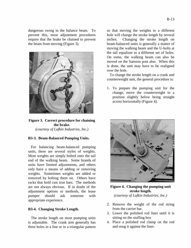
dangerous swing in the balance beam. Toprevent this, most adjustment proceduresrequire that the brake be chained to preventthe beam from moving (Figure 3).
Figure 3. Correct procedure for chainingthe brake.
(courtesy of Lufkin Industries, Inc.)
B3-3. Beam-Balanced Pumping Units.
For balancing beam-balanced pumpingunits, there are several styles of weights.Most weights are simply bolted onto the tailend of the walking beam. Some brands ofunits have limited adjustments, and othersonly have a means of adding or removingweights. Sometimes weights are added orremoved by bolting them on. Others haveracks that hold cast iron bars. The methodsare not always obvious. If in doubt of theadjustment options or methods, the leasepumper should ask someone withappropriate experience.
B3-4. Changing Stroke Length.
The stroke length on most pumping unitsis adjustable. The crank arm generally hasthree holes in a line or in a triangular pattern
so that moving the weights to a differenthole will change the stroke length by severalinches. Changing the stroke length onbeam-balanced units is generally a matter ofmoving the walking beam and the U-bolts atthe tail equalizer to a different set of holes.On some, the walking beam can also bemoved on the Samson post also. When thisis done, the unit may have to be realignedover the hole.
To change the stroke length on a crank andcounterweight unit, the general procedure is:
1. To prepare the pumping unit for thechange, move the counterweight to aposition slightly below being straightacross horizontally (Figure 4).
Figure 4. Changing the pumping unitstroke length.
(courtesy of Lufkin Industries, Inc.)
2. Remove the weight of the rod stringfrom the carrier bar.
3. Lower the polished rod liner until it issitting on the stuffing box
4. Place a polished rod clamp on the rodand snug it against the liner.

B-14
5. After tightening the rod clamp, engagethe prime mover to move the walkingbeam until the rod weight has beenremoved from carrier bar
6. Set the brake and chain the brake of thepumping unit so that it cannot move.
7. Clean and oil the new holes, removingall rust and paint.
8. Change the pins to the new holes.9. Tighten and key the nuts.10. Grease the previously used holes to
prevent rust.11. Mark the nut so that position changes
can be detected.
B3-5. Lowering and Raising Rods.
(NOTE: The following is intended as aguide only and should not be construed asspecific instructions. There are certaindangers associated with performing theseduties. These processes are to be performedby a competent, knowledgeable technicianwith experience in pumping unit operations.All tools and equipment should be designedspecifically for use in performing thesetasks. The use of faulty or improper tools ora lack of specific knowledge in performingthese tasks could lead to serious injury ordeath. The person or persons attempting toperform these tasks are doing so at their ownrisk. This guide is only a suggestion and isnot to be construed as specific instructionsas different types of units require differentprocesses in performing these tasks.)
There are several reasons that rods mayhave to be lowered or raised. Differentwells have different problems, but pumpsmay have to be lowered to break a gas lockor to tap a pump to stimulate trash removalfrom under the balls and seats. If the pumphas available space, occasionally pumpaction can be restored by raising the rods orraising and then lowering them. It may bepossible to unseat the pump then re-seat it.
When rods are lowered to tap bottom, onthe downstroke the pump is completelyclosed together and the top traveling part ofthe clutch strikes the standing clutch half.This sends a shock through the pump toloosen the trash under the seats and allowthe pump to begin pumping again.
Pump repair companies may not agree thattapping wells is necessary, but manyproduction companies perform this functionas a matter of practice before pulling anywell. Some shallow- and medium-depthwells must tap at all times; otherwise, theywill not continue to pump for more than afew days or hours at a time. If properlyadjusted, many shallow wells can tap forseveral years, and the pump shows nodamage when pulled. Occasionally, the rodsmust be raised before lowering them torestore pump action. The procedure is:
1. Stop the unit with the head down and setthe brake.
2. Loosen the polished rod liner packingnut and set screw.
3. Lower the liner until it is resting on topof the stuffing box.
4. Place a clamp on the polished rod sittingon top of the liner and tighten it.
5. Loosen the clamp on top of the carrierbar, raise it several inches, and re-tighten.
WARNING: Never grab the polishedrod between the carrier bar and theclamp. If the clamp slips, everything inbetween will be crushed.
6. Let the brake off slowly to allow the rodweight to be placed back on the carrierbar clamp.
7. Remove the lower clamp from thepolished rod, raise the liner, retighten thepacking, and tighten the set screw.
8. Turn on the unit.

B-15
This will lower the rods, and the unitshould be tapping bottom lightly. If thepump does not tap, the lease pumper mustrepeat the process until it does tap.
The procedure to raise rods includes thefollowing steps:
1. Stop the pumping unit with the crank atabout the 10 to 11 o’clock position orabout 15 degrees before top dead centerand set the brake.
2. Lower the polished rod liner byloosening the packing nut, backing offthe set screw, and lowering the rod linerdown to the stuffing box.
3. Tighten the polished rod clamp with itsitting on the polished rod liner.
4. Loosen the brake.5. Turn on the pumping unit.6. As the head comes down with the
weights at the 12 o’clock position, turnthe power off and set the brake.
WARNING: Several inches of rod willbe exposed. Never grab this area. If theupper clamp slips, everything in betweenwill be crushed.
7. Loosen the upper clamp, allow it to dropback down on the carrier bar, then re-tighten.
8. Remove the clamp above the polishedrod liner.
9. Let the brake off and turn the unit untilthe horse head is down. Set the brake.
10. Lift the polished rod liner a few inches.11. Tighten the packing nut and the set
screw.
The lease pumper must never get in ahurry when lowering or raising rods.Experience teaches much of what needs tobe known. By looking in the lease recordsbook, the lease pumper will know the lengthof the pumping unit stroke and the strokeaction available in the pump. This willassist greatly in deciding the correct action.Without adequate records, the lease pumperwill just have to rely on judgment.

B-16
The Lease Pumper’s Handbook
Appendix BPumping Units
Section 4
BELTS AND SHEAVES
B4-1. Introduction to Belts and Sheaves.
A good understanding of belts and sheavesis important in obtaining satisfactoryperformance from a wide range of belt-driven equipment, especially pumping units.Poor operation practices lead to unnecessarydown time, loss of production, a decreases inincome, and increases in lifting costs perbarrel of oil
Belt manufacturers want their customers toobtain satisfactory results from using theirproduct and publish free or low-costbooklets to assist in belt and sheaveselection and maintenance. As anillustration, the Gates Rubber Companypublishes two booklets that can be obtainedthrough local Gates distributors:
· The Pumper’s Friend. (A Guide for V-Belts and Sheaves). 12 pages
· Gates Industrial Drive Products &Preventive Maintenance Guide. 78pages.
B4-2. V-Belt Sizes, Widths, and Depths.
Industrial V-belts (Figure 1) are availablein two styles: super and high power. Thesecome in the following sizes with widths anddepths in inches:
Super HC V-Belt Sizes.
Size Width Depth3V & 3VX 3/8 21/645V & 5VX 5/8 35/648V 1 7/8
Hi-Power II V-Belt Sizes.
A ½ 5/16B 21/32 13/32C 7/8 17/32D 1¼ ¾E 1½ 29/32
Figure 1. Cross-section of a high-powerV-belt.
(courtesy of Gates Rubber Company)
B-17
B4-3. Types of Belts Based on LoadPerformance.
V-belts may be purchased in two or morequalities. The primary governing factor indeciding which quality to buy depends uponthe load performance and type of service thatis required. A standard style belt will havethe rubber on the sides exposed to theatmosphere, while the more expensive styleswill be fully encased in a tough, cloth, flexweave cover. For all-weather outdoorapplications such as pumping unit belts, thefully cased belt is tough, shock resistant, andlong lasting.
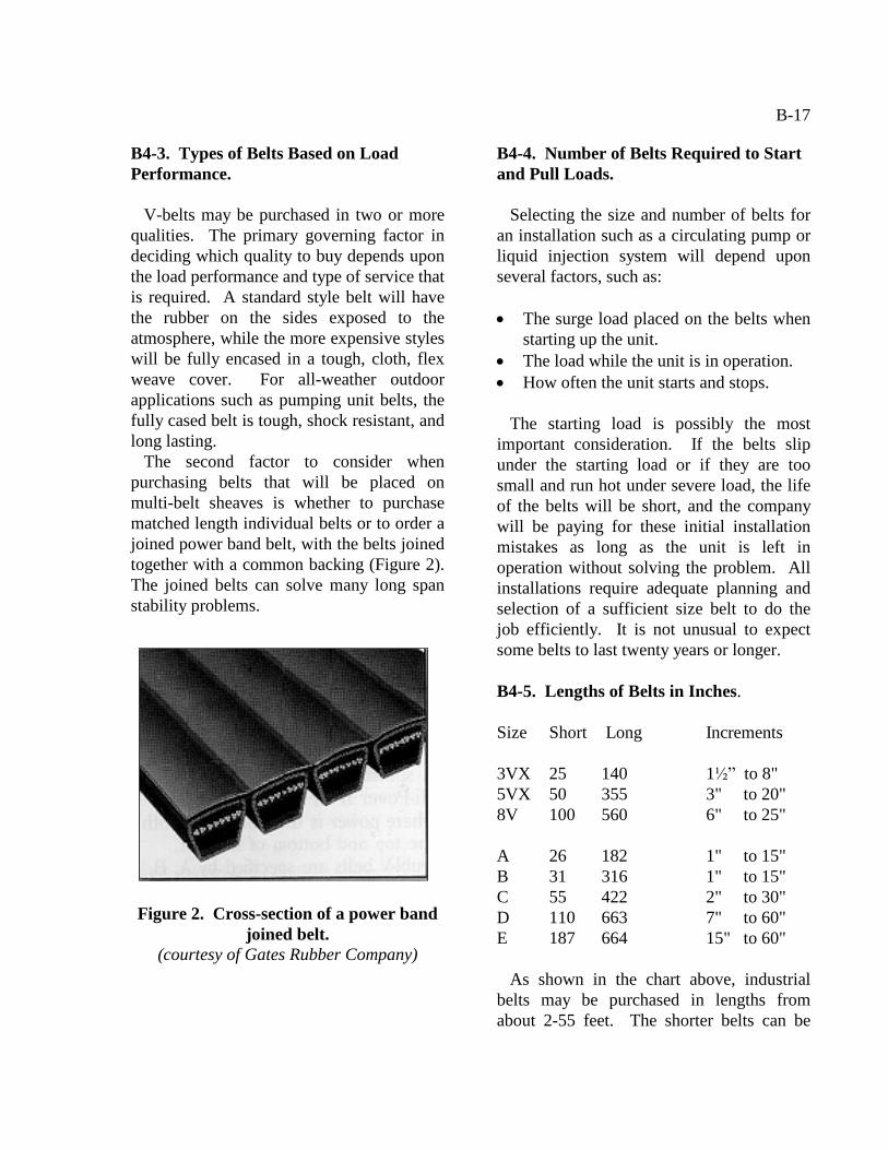
The second factor to consider whenpurchasing belts that will be placed onmulti-belt sheaves is whether to purchasematched length individual belts or to order ajoined power band belt, with the belts joinedtogether with a common backing (Figure 2).The joined belts can solve many long spanstability problems.
Figure 2. Cross-section of a power bandjoined belt.
(courtesy of Gates Rubber Company)
B4-4. Number of Belts Required to Startand Pull Loads.
Selecting the size and number of belts foran installation such as a circulating pump orliquid injection system will depend uponseveral factors, such as:
· The surge load placed on the belts whenstarting up the unit.
· The load while the unit is in operation.· How often the unit starts and stops.
The starting load is possibly the mostimportant consideration. If the belts slipunder the starting load or if they are toosmall and run hot under severe load, the lifeof the belts will be short, and the companywill be paying for these initial installationmistakes as long as the unit is left inoperation without solving the problem. Allinstallations require adequate planning andselection of a sufficient size belt to do thejob efficiently. It is not unusual to expectsome belts to last twenty years or longer.
B4-5. Lengths of Belts in Inches.
Size Short Long Increments
3VX 25 140 1½” to 8"5VX 50 355 3" to 20"8V 100 560 6" to 25"
A 26 182 1" to 15"B 31 316 1" to 15"C 55 422 2" to 30"D 110 663 7" to 60"E 187 664 15" to 60"
As shown in the chart above, industrialbelts may be purchased in lengths fromabout 2-55 feet. The shorter belts can be

B-18
purchased in incremental lengths of 1 inchor less and, in the heavier belts, up to 60inches between lengths.
As each size of belt gets longer, additionaladjustment space must be provided. Sincethe side movement of the skid rails thatsupport the prime mover provides for theselection of two or more belt lengths, smallmotors may be moved only a few inches toprovide for belt replacement and correcttension, but the larger ones must haveseveral feet of adjustment capabilities.
B4-6. Belt Life.
Belt life is governed by correct sheavesizes, speeds, balance of units, eliminationof slippage with correct belt tension, correctbelt selection, proper alignment, and othercontrollable factors. If an installationrequires belt replacement too often,something is wrong in the design and shouldbe corrected.
Each time a belt runs over a sheave, itmust be flexed in and out under load. Thefaster the belt travels, the more times itflexes per minute, and the more heat that isgenerated. This can dramatically shorten thelife of the belt. When planning high-speed orheavy-load installations, the manufacturer’sbelt engineering experts should be contactedto assist with planning the design of theinstallation. Idler pulleys will occasionallysolve these problems.
B4-7. Styles of Sheaves.
There are two basic types of sheaves.Smaller sheaves, one inch or less indiameter, are usually one piece and bored tosize to fit the shaft. Variable pitch sheavesthat permit changing the speed of theequipment by adjusting the pitch are usually
small sheaves. The larger sheaves used onpumping units and equipment with driveshafts over 1 inch in diameter typically useheavy-duty tapered split bushings and hubs.Two common styles of two-piece sheavesare the QD sheave (Figure 3) and the taper-lock sheaves (Figure 4). Of these two, theQD style is very popular in the oilfield.
Figure 3. A QD sheave(courtesy of Gates Rubber Company)
Figure 4. A taper-lock sheave.(courtesy of Gates Rubber Company)

B-19
B4-8. Number of Grooves.
Smaller sheaves seldom use more than twoor three belts, but the C, D, and E sizes mayhave up to ten or even twelve grooves. It iscommon for there to be grooves withoutbelts so that more can be added if required.
Sheave diameter and belt flexing. Whenusing a small belt, the sheave may also besmall. Each belt has a limit as to how muchbend it can be subjected to without severelyweakening the belt and reducing itsproductive life. The speed at which sheavesrun is largely determined by the number offeet per minute of belt travel. A maximumspeed of 6,500 feet per minute seems to betypical. The minimum acceptable andlargest diameters available for QD sheavesare as follows:
Belt Diameter Largest Grooves3V 2.20 33.5' 1 to 105V 4.40 50 1 to 128V 12.50 71 1 to 12
A/B 3.75 38.35 1 to 10C 5.40 50.40 1 to 12D 12.6 58.6 1 to 10
B4-9. The Keyway.
Inserting a key in a square keyway in thesheave locks the sheave with a keyway inthe shaft and keeps the sheave from slipping.The sheave may also be held in place by aset screw, if needed. Keys will be of anappropriate size according to the diameter ofthe sheave. The larger the sheave, the largerthe key and keyway. The end of the key willbe slightly tapered to allow it to enter easily.
If the two key slots are of different sizes,combination keys are available to allow theuse of sheaves on shafts that have a differentsize keyway. These combination keys arecapable of performing satisfactorily withoutdanger of failure caused by size.
B4-10. Math Calculations.
The lease pumper is often required tocalculate various factors when installing andmaintaining belts. These include:
· Calculating belt length, full formula· Calculating belt length, short formula· Changing sheave size to change
revolutions per minute (RPM)· Changing pumping unit strokes per
minute (SPM)
Such calculations are reviewed inAppendix F, Mathematics.

B-20
Copyright © 2022 FDOKUMEN