A BE-SOI MEMS for Inertial Measurement in Geophysical Applications
8
This article has been accepted for inclusion in a future issue of this journal. Content is final as presented, with the exception of pagination. IEEE TRANSACTIONS ON INSTRUMENTATION AND MEASUREMENT 1 A BE-SOI MEMS for Inertial Measurement in Geophysical Applications Bruno Andò, Salvatore Baglio, Gaetano L’Episcopo, Vincenzo Marletta, Nicolò Savalli, and Carlo Trigona Abstract—In this paper, an inertial transducer developed in bulk and etch silicon-on-insulator microelectromechanical-system technology is presented. The device is suitable for low-frequency observation and could represent an interesting solution to im- plement low-cost monitoring systems for applications requiring a large number of monitoring sites and disposable devices. In particular, the sensor design and the technology adopted are presented here along with models describing the device operation. In addition, an experimental sensor prototype is proposed, and experimental results confirming the suitability of the proposed architecture and its consistence with the predicted behavior are discussed. Index Terms—Bulk and etch silicon-on-insulator (BE-SOI), in- ertial sensor, low cost, microelectromechanical system (MEMS), seismic measurements, volcanic monitoring. I. I NTRODUCTION I T IS established that microelectromechanical system (MEMS) devices are now becoming ubiquitous. They have registered an unprecedented growth in the market and can cater for a large spectrum of applications ranging from environmental monitoring and security to automation, mobile communication, and healthcare, and lately, they have penetrated the sector of game consoles. Although MEMS devices have become popular because they can be produced using the traditional technologies used for integrated circuits, many dedicated technologies have been developed to enhance the device performance and to enable the development of new structures to produce large numbers of low-cost devices. The characteristics of the MEMS make it suitable for wireless sensor networks. In the related work, the utility of MEMS devices for geophysical sensing, replacing traditional geophones, have been investigated [1]–[3]. The dynamics of volcanic systems are governed by com- plex coupled phenomena. Understanding these phenomena is a prerequisite for the following: 1) a more robust definition of volcanic alert levels, allowing more efficient and effective volcano monitoring; and 2) a better knowledge of the physical and chemical processes of mass transfer, which is essential for volcanic hazard evaluation [4]. Manuscript received June 19, 2010; revised December 31, 2010; accepted January 3, 2011. The Associate Editor coordinating the review process for this paper was Thomas Lipe. The authors are with the Dipartimento di Ingegneria Elettrica, Elettron- ica e dei Sistemi, University of Catania, 95125 Catania, Italy (e-mail: [email protected]). Digital Object Identifier 10.1109/TIM.2011.2108077 Among the available techniques, seismic, ground deforma- tion, and gas monitoring have been more extensively utilized at active volcanic sites [5]–[7]. Devices utilizing inertial systems (seismometers) are utilized to study the seismicity driven by volcanic processes. Other devices, which are also exploiting inertial systems (spring gravimeters), are employed to study the changes of the gravity field associated with the magma/gas dynamics in the shallower part of a volcano’s plumbing system [8], [9]. Volcanic tremor and long period seismicity are typical seis- mic signatures accompanying eruptive processes [5]. Volcanic tremor is the persistent ground vibration often observed at many volcanoes. Coupled seismic/gravity studies are limited by issues related to the available instrumentation. In particular, the high cost of spring gravimeters prevents the development of extended arrays of continuously running devices since only a few single institutions can afford the related costs. Furthermore, the harsh conditions often encountered on the summit zone of active volcanoes (limited accessibility, presence of corrosive gases, high daily and seasonal temperature changes, lack of mains electricity, etc.) often pose severe constraints on the use of relatively heavy, sensitive, and delicate instruments, requiring a large amount of power to function [10]. The above shortcomings could be overcome by a “smart dust” approach adopting inertial sensors that are cheaper and lighter and that have lower resource consumption than the existing ones at the expense of poor performance, particularly in terms of sensitivity. The possibility of realizing a network of such low-cost devices within the area to be monitored will produce a large amount of information with a high spatial resolution, which could be useful in implementing an early warning system. The information collected by the network could be used to build qualitative knowledge of the seismic ac- tivity in the monitored area, which can successively be refined by having conventional monitoring stations accomplishing fine measurements in specific sites of interest (highlighted by the early warning system). In this paper, an inertial transducer developed at the Diparti- mento di Ingegneria Elettrica, Elettronica e dei Sistemi labora- tories by a bulk and etch silicon-on-insulator (BE-SOI) MEMS technology is presented [12]–[15]. The device represents an interesting solution for the implementation of low-cost systems for the monitoring of the seismic activity in volcanic areas. As compared with traditional solutions, the sensing architecture proposed is suited for the implementation of cheap and efficient devices at the expense of sensitivity. This approach allows for the realization of low-cost distributed networks of monitoring 0018-9456/$26.00 © 2011 IEEE lirmm-00580557, version 1 - 28 Mar 2011 Author manuscript, published in "IEEE Transactions on Instrumentation & Measurement PP, 99 (2011) 1-8"
-
Upload
independent -
Category
Documents
-
view
0 -
download
0
Transcript of A BE-SOI MEMS for Inertial Measurement in Geophysical Applications
This article has been accepted for inclusion in a future issue of this journal. Content is final as presented, with the exception of pagination.
IEEE TRANSACTIONS ON INSTRUMENTATION AND MEASUREMENT 1
A BE-SOI MEMS for Inertial Measurement inGeophysical Applications
Bruno Andò, Salvatore Baglio, Gaetano L’Episcopo, Vincenzo Marletta, Nicolò Savalli, and Carlo Trigona
Abstract—In this paper, an inertial transducer developed inbulk and etch silicon-on-insulator microelectromechanical-systemtechnology is presented. The device is suitable for low-frequencyobservation and could represent an interesting solution to im-plement low-cost monitoring systems for applications requiringa large number of monitoring sites and disposable devices. Inparticular, the sensor design and the technology adopted arepresented here along with models describing the device operation.In addition, an experimental sensor prototype is proposed, andexperimental results confirming the suitability of the proposedarchitecture and its consistence with the predicted behavior arediscussed.
Index Terms—Bulk and etch silicon-on-insulator (BE-SOI), in-ertial sensor, low cost, microelectromechanical system (MEMS),seismic measurements, volcanic monitoring.
I. INTRODUCTION
I T IS established that microelectromechanical system(MEMS) devices are now becoming ubiquitous. They have
registered an unprecedented growth in the market and can caterfor a large spectrum of applications ranging from environmentalmonitoring and security to automation, mobile communication,and healthcare, and lately, they have penetrated the sector ofgame consoles. Although MEMS devices have become popularbecause they can be produced using the traditional technologiesused for integrated circuits, many dedicated technologies havebeen developed to enhance the device performance and toenable the development of new structures to produce largenumbers of low-cost devices.
The characteristics of the MEMS make it suitable forwireless sensor networks. In the related work, the utility ofMEMS devices for geophysical sensing, replacing traditionalgeophones, have been investigated [1]–[3].
The dynamics of volcanic systems are governed by com-plex coupled phenomena. Understanding these phenomena isa prerequisite for the following: 1) a more robust definitionof volcanic alert levels, allowing more efficient and effectivevolcano monitoring; and 2) a better knowledge of the physicaland chemical processes of mass transfer, which is essential forvolcanic hazard evaluation [4].
Manuscript received June 19, 2010; revised December 31, 2010; acceptedJanuary 3, 2011. The Associate Editor coordinating the review process for thispaper was Thomas Lipe.
The authors are with the Dipartimento di Ingegneria Elettrica, Elettron-ica e dei Sistemi, University of Catania, 95125 Catania, Italy (e-mail:[email protected]).
Digital Object Identifier 10.1109/TIM.2011.2108077
Among the available techniques, seismic, ground deforma-tion, and gas monitoring have been more extensively utilized atactive volcanic sites [5]–[7].
Devices utilizing inertial systems (seismometers) are utilizedto study the seismicity driven by volcanic processes. Otherdevices, which are also exploiting inertial systems (springgravimeters), are employed to study the changes of the gravityfield associated with the magma/gas dynamics in the shallowerpart of a volcano’s plumbing system [8], [9].
Volcanic tremor and long period seismicity are typical seis-mic signatures accompanying eruptive processes [5]. Volcanictremor is the persistent ground vibration often observed at manyvolcanoes.
Coupled seismic/gravity studies are limited by issues relatedto the available instrumentation. In particular, the high costof spring gravimeters prevents the development of extendedarrays of continuously running devices since only a few singleinstitutions can afford the related costs. Furthermore, the harshconditions often encountered on the summit zone of activevolcanoes (limited accessibility, presence of corrosive gases,high daily and seasonal temperature changes, lack of mainselectricity, etc.) often pose severe constraints on the use ofrelatively heavy, sensitive, and delicate instruments, requiringa large amount of power to function [10].
The above shortcomings could be overcome by a “smartdust” approach adopting inertial sensors that are cheaper andlighter and that have lower resource consumption than theexisting ones at the expense of poor performance, particularlyin terms of sensitivity. The possibility of realizing a networkof such low-cost devices within the area to be monitored willproduce a large amount of information with a high spatialresolution, which could be useful in implementing an earlywarning system. The information collected by the networkcould be used to build qualitative knowledge of the seismic ac-tivity in the monitored area, which can successively be refinedby having conventional monitoring stations accomplishing finemeasurements in specific sites of interest (highlighted by theearly warning system).
In this paper, an inertial transducer developed at the Diparti-mento di Ingegneria Elettrica, Elettronica e dei Sistemi labora-tories by a bulk and etch silicon-on-insulator (BE-SOI) MEMStechnology is presented [12]–[15]. The device represents aninteresting solution for the implementation of low-cost systemsfor the monitoring of the seismic activity in volcanic areas. Ascompared with traditional solutions, the sensing architectureproposed is suited for the implementation of cheap and efficientdevices at the expense of sensitivity. This approach allows forthe realization of low-cost distributed networks of monitoring
0018-9456/$26.00 © 2011 IEEE
lirm
m-0
0580
557,
ver
sion
1 -
28 M
ar 2
011
Author manuscript, published in "IEEE Transactions on Instrumentation & Measurement PP, 99 (2011) 1-8"
This article has been accepted for inclusion in a future issue of this journal. Content is final as presented, with the exception of pagination.
2 IEEE TRANSACTIONS ON INSTRUMENTATION AND MEASUREMENT
Fig. 1. Layout of the MEMS device. The device has a crab-leg structure withdimensions La = 618 μm, Lb = 2200 μm, and Lp1 = Lp2 = 3000 μm.
nodes that implement an early warning system on a largearea with a spatial resolution that is unattainable by standardmonitoring systems.
II. BE-SOI MEMS INERTIAL SENSOR
A. Architecture and FEM Simulations
The investigated device, shown in Fig. 1, has been designedto enhance its sensitivity. Essentially, the device is a suspendedsquare-shaped mass supported by four crab-leg beams. To copewith the above requirements, a proof mass with a size of3000 μm by 3000 μm has been designed, while the crab-leg beams have the following dimensions: b = 183 μm,La = 618 μm, and Lb = 2200 μm for the thigh and the shinsegments, respectively. A large mass and the crab-leg beamshave been adopted to enhance the device sensitivity.
The device was designed in the MEMS Pro environment, andthe resulting layout is shown in Fig. 1. Four polysilicon (poly-Si) strain gauges SGi (i = 1, . . . , 4) have been integrated intothe beams to measure the structural deformation due to externalforces, thus implementing a resistive-readout strategy.
Finite-element method (FEM) simulations have been per-formed by the CoventorWare suite to investigate the devicebehavior. By modeling the device response to an imposedstimulus, a resonance frequency, ωFEM
n close to 190 Hz, anda spring stiffness kFEM = 14.39 N/m have been estimated. Ifrequired, this value can be modified during the design phase bymodifying the central mass dimensions or the spring properties.
Since the target of this explorative phase is the investigationof the applicability of this MEMS architecture in the afore-mentioned context, constraints on the frequency response arenot strictly addressed. Moreover, it must be considered thatthis device must be operated in the resonant mode. From anoperative point of view, this will require the need to force thedevice into its resonant regime and to extract the information onthe detected quantities by demodulating the output signal andtaking the frequency response of the device into account. The
Fig. 2. Real view of the device. (a) The packaged device and (b) a SEM imageof the suspended mass.
information about an external stimulus (velocity) is containedin the harmonics around the resonant frequency.
An interesting behavior is observed when the device operatesin a real situation and is driven in its resonant mode by naturalvibrating sources coming from the monitored environment. Inparticular, this operating mode could be exploited in monitoringsites offering continuously vibrating sources, which could bethe case of some seismic areas. This scenario will be furtherexplored in Section IV.
B. Real Device
A photograph of the packaged device and a scanning electronmicroscope (SEM) image of the die with the suspended massare shown in Fig. 2, where the arrow shows the direction of thesensing axes.
The investigated micromachined device has been realizedby using a BE-SOI process, which is available at the CentroNacional de Microelectronica, Barcelona, Spain.
The steps of the technology can be summarized as follows:
• thermal growth of oxide (Diff) on both sides, thickness of0.1 μm, at T = 1100 ◦C;
• deposition of polysilicon (Poly) on both sides, thicknessof 0.48 μm, and reactive-ion etching (RIE) to removepolysilicon on the front side;
• deposition of the oxide between polysilicon and metal(Cont), thickness of 0.73 μm, and RIE of oxides;
• deposition of Al/Cu alloy (Metal) on the front side,thickness of 0.7 μm, and RIE to remove metal on thefront side;
• a 0.5-μm-thick layer of SiO2 (Pad) is deposited on thefront side by using a plasma-enhanced chemical vapordeposition technique. Poly-Si and SiO2 on the backsideare removed, and a 1-μm layer of metal (Al/Cu) on thebackside is deposited. The photolithography of SiO2 onthe front side is performed, and the 15-μm-thick layer ofsilicon is removed through a deep RIE;
• RIE of metal, the thickness to be removed is 1 μm, andan etching procedure of the Silicon on the backside, thethickness to be removed is 450 μm;
• removing metal from the backside and RIE of buried SiO2
from the backside, the thickness to be removed is 2 μm.
The need to have a large mass to enhance the device sensitiv-ity required the choice of this technology, with its seven delicateprocessing steps, over other processes.
lirm
m-0
0580
557,
ver
sion
1 -
28 M
ar 2
011

This article has been accepted for inclusion in a future issue of this journal. Content is final as presented, with the exception of pagination.
ANDÒ et al.: BE-SOI MEMS FOR INERTIAL MEASUREMENT IN GEOPHYSICAL APPLICATIONS 3
Fig. 3. Wheatstone bridge used to convert the resistance variation in aproportional output voltage signal. The device values are as follows: R1 =R4 = 2.2 kΩ; R2 = 680 Ω; R3 = 1 kΩ; SGi = 1.2 kΩ (i = 1, . . . , 4); andVcc = 8 V. Pti (i = 1, . . . , 4) values have been used to balance electronics;switches Ji (i = 1, . . . , 4) have been used to choose the bridge configurationduring the development phase. A current value of Icc ≈ 1.7 mA has beenexperimentally estimated.
The proof mass is made of silicon, buried oxide, crystalsilicon, and oxides (Diff, Cont, and Pad). Accounting for thegeometry and the processing technology, the mass is estimatedto be 10.1 mg. The crab-leg springs are composed of 15 μm ofcrystal silicon, Diff, Cont and Pad, while 450 μm of silicon andthe 2-μm oxide have been removed.
As previously stated, the device uses a resistive-readoutstrategy. The imposed stimulus xi results in displacement xo
of the MEMS structure with respect to the ground and varyingresistance ΔR of the integrated strain gauges. The experimen-tally estimated resistance of the strain gauges is around 1.2 kΩ.A direct-current-voltage-driven Wheatstone bridge in the con-figuration shown in Fig. 3 is used to convert the change inresistance to a proportional voltage signal Vout. The chosenbridge configuration allows for the optimization of the systemsensitivity.
Switches Ji (i = 1, . . . , 4) in Fig. 3 have been used to opti-mize the bridge configuration and for the sake of convenienceduring the development phase. The bridge has been driven byan 8 V supply that supplies to a current of about Icc = 1.7 mAonce the values of the devices reported in Fig. 3 are taken intoaccount.
C. Modeling of the Device
A complete model of the device is described in [15]. Thispaper will focus on the device behavior when forced by a
velocity term. During the experimental test (see Section IV), thedevice response will be compared to a reference seismometerinstalled in the same station.
By considering the readout strategy described inSection II-B, the following assumptions can be made.
1) A linear relationship between ΔR and Vout can be as-sumed due to the small expected values of ΔR.
2) Due to the very small stimulus applied to the device, alinear relationship between the mass displacement xo andterm ΔR can been supposed.
The above assumptions have been supported by experimentalresults presented in Section III.
On the basis of these considerations and assuming thatthe mechanical behavior of the device can be described bya second-order model (in terms of x0 and xi), the expectedfrequency responses in terms of the system output signal Vout
is given by the following expression:
Vout
xi=
sGx
s2
ω2n
+ 2ξsωn
+ 1(1)
where Vout is the output signal of the conditioning electronicsprocessing the information coming from the strain gauge in thebridge arms, xi is the imposed velocity stimulus, Gx is thesystem gain (including the electronics gains and the proportion-ality factor between xo and ΔR), ξ is the system damping, andωn/2π is the system natural frequency.
D. Spring Modeling
The device has been modeled by using Castigliano’s theoremand considering the strain energy contribution given by thedisplacement of the structure along the x axis (see Fig. 2) [16].The model of the elastic constant has been obtained by usingthe heterogeneous beam theory that is in accordance with thedifferent stacked materials offered by the technology. For thisreason, the device has been studied in a homogeneous domain[16], taking an equivalent shape of the spring into account,having a Young modulus En and moment of inertia In, i.e.,
kestm =
αEmaxIn
l3=
αEmaxb∑[
Ei
En
t3i12 + ti
Ei
En(hi − hn)2
]l3
(2)
where α is a constant value correlated to the springs; Emax isthe maximum Young modulus of the stack materials; l is theequivalent length of the spring given by a contribution of La
and Lb, as shown in Fig. 1; b is the width of the beam (183 μm);hn is the neutral axis position assumed in the homogeneousdomain; and Ei, ti, and hi represent the Young modulus, thethickness, and the neutral axis position for the ith element,respectively (i = 1, . . . , 4). The spring constant kest
m estimatedthrough the heterogeneous beam theory corresponds to about17.01 N/m. Assuming an equivalent mass m = 10.1 mg leadsto a natural frequency of ωest
n =√
kestn /m = 200 Hz. This
frequency assures a good compromise between the need for alarge mass that leads to an enhanced sensitivity and a resonantfrequency far enough from the frequency range of the expectedstimuli.
lirm
m-0
0580
557,
ver
sion
1 -
28 M
ar 2
011
This article has been accepted for inclusion in a future issue of this journal. Content is final as presented, with the exception of pagination.
4 IEEE TRANSACTIONS ON INSTRUMENTATION AND MEASUREMENT
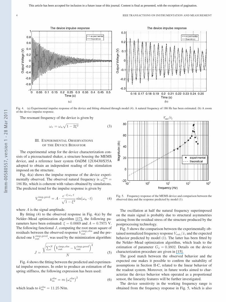
Fig. 4. (a) Experimental impulse response of the device and fitting obtained through model (4). A natural frequency of 186 Hz has been estimated. (b) A zoomof the device impulse response.
The resonant frequency of the device is given by
ωr = ωn
√1 − 2ξ2 (3)
III. EXPERIMENTAL OBSERVATIONS
OF THE DEVICE BEHAVIOR
The experimental setup for the device characterization con-sists of a piezoactuated shaker, a structure housing the MEMSdevice, and a reference laser system OADM 12U6430/S35Aadopted to obtain an independent reading of the stimulationimposed on the structure.
Fig. 4(a) shows the impulse response of the device experi-mentally observed. The observed natural frequency is ωobs
n =186 Hz, which is coherent with values obtained by simulations.The predicted trend for the impulse response is given by
V imp,predout = A · e−ξ·ωn·t√
1 − ξ2sin(ωn · t) (4)
where A is the signal amplitude.By fitting (4) to the observed response in Fig. 4(a) by the
Nelder–Mead optimization algorithm [17], the following pa-rameters have been estimated: ξ = 0.0069 and A = 0.7975 V.The following functional J , computing the root mean square ofresiduals between the observed response V imp,obs
out and the pre-dicted one V imp,pred
out , was used by the minimization algorithm:
J =
√∑Ni
(V imp,obs
out − V imp,predout
)2
N(5)
Fig. 4 shows the fitting between the predicted and experimen-tal impulse responses. In order to produce an estimation of thespring stiffness, the following expression has been used:
kobsm = m
(ωobs
n
)2(6)
which leads to kobsm = 11.25 N/m.
Fig. 5. Frequency response of the MEMS device and comparison between theobserved data and the response predicted by model (1).
The oscillation at half the natural frequency superimposedon the main signal is probably due to structural asymmetriesarising from the residual stress of the structure produced by thepostprocessing technology.
Fig. 5 shows the comparison between the experimentally ob-tained normalized frequency response Vout/xi and the expectedbehavior predicted by model (1). The latter has been fitted bythe Nelder–Mead optimization algorithm, which leads to theestimation of parameter Gx = 0.3802. Details on the devicecharacterization procedure are given in [15].
The good match between the observed behavior and theexpected one makes it possible to confirm the suitability ofassumptions in Section II-C, related to the linear behavior ofthe readout system. Moreover, in future works aimed to char-acterize the device behavior when operated as a proportionalsensor, the linearity features will be further investigated.
The device sensitivity in the working frequency range isobtained from the frequency response in Fig. 5, which is also
lirm
m-0
0580
557,
ver
sion
1 -
28 M
ar 2
011
This article has been accepted for inclusion in a future issue of this journal. Content is final as presented, with the exception of pagination.
ANDÒ et al.: BE-SOI MEMS FOR INERTIAL MEASUREMENT IN GEOPHYSICAL APPLICATIONS 5
TABLE ISENSITIVITY VALUES AROUND THE RESONANT FREQUENCY. Δf STATES
FOR THE STIMULUS FREQUENCY. HENCE, IT REPRESENTS THE INTERVAL
BETWEEN THE RESONANT FREQUENCY AND THE FREQUENCIES AT
WHICH THE SENSITIVITY HAS BEEN ESTIMATED
required to estimate the actual stimulus (velocity) in the realscenario, as described in Section IV. It must be borne inmind that the device must be operated in the resonant mode,and as mentioned above, an external stimulus (velocity) willproduce harmonics around the resonant frequency. The devicesensitivity for some typical frequencies around the resonantmode are reported in Table I.
Table I also gives the device resolution, which has beenestimated as the ratio between the observed noise power of thedevice response Vout in case of a null stimulus and the devicesensitivity at some typical frequency.
This analysis leads to a noise-floor estimation of 1.0 ×10⁻³ V/
√Hz at 186 Hz.
Taking into account the resonant behavior of the device, itcan be affirmed that the bandwidth of the MEMS device islimited by its natural frequency.
IV. TEST IN A REAL SCENARIO
In collaboration with the researchers of the Istituto Nazionaledi Geofisica e Vulcanologia (INGV), Sezione di Catania, thedevice was tested in the field to observe the device behaviorin a real scenario. In particular, in June 2009, the device wasinstalled on the summit zone of Stromboli, where a seismicnetwork, managed by the INGV, has been continuously operat-ing. The seismic network is composed of 13 digital stations thatare equipped with Guralp CMG 40T broadband sensors (0.02–60 s) [18].
The latter is an ultralightweight seismometer consistingof three sensors in a sealed case, which can measure thenorth/south, east/west, and vertical components of the groundmotion simultaneously, with sensitivity of 2 × 400 V/m · s−1
nominal (differential). Its dimensions are 154 mm in diameterand 207 mm in height [18].
On the basis of the aforementioned features, the Guralpseismometer has been adopted as the reference instrument forthe experiment involving the MEMS device.
As already discussed in Section I, the device developed mustoperate like an event detector, and the aim of the experiment isto assess its features in this working mode. It must be consid-ered that this low-cost device would be suitable for the imple-mentation of sensor networks implementing an early warningsystem. In this view, the MEMS device is required to providequalitative information on the ongoing seismic phenomenonrather than a quantitative estimation of its intensity. The latter
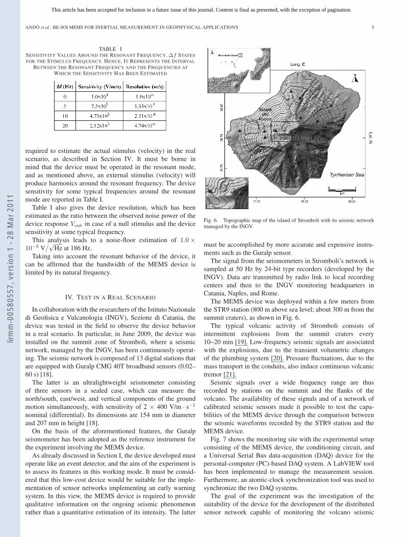
Fig. 6. Topographic map of the island of Stromboli with its seismic networkmanaged by the INGV.
must be accomplished by more accurate and expensive instru-ments such as the Guralp sensor.
The signal from the seismometers in Stromboli’s network issampled at 50 Hz by 24-bit type recorders (developed by theINGV). Data are transmitted by radio link to local recordingcenters and then to the INGV monitoring headquarters inCatania, Naples, and Rome.
The MEMS device was deployed within a few meters fromthe STR9 station (800 m above sea level; about 300 m from thesummit craters), as shown in Fig. 6.
The typical volcanic activity of Stromboli consists ofintermittent explosions from the summit craters every10–20 min [19]. Low-frequency seismic signals are associatedwith the explosions, due to the transient volumetric changesof the plumbing system [20]. Pressure fluctuations, due to themass transport in the conduits, also induce continuous volcanictremor [21].
Seismic signals over a wide frequency range are thusrecorded by stations on the summit and the flanks of thevolcano. The availability of these signals and of a network ofcalibrated seismic sensors made it possible to test the capa-bilities of the MEMS device through the comparison betweenthe seismic waveforms recorded by the STR9 station and theMEMS device.
Fig. 7 shows the monitoring site with the experimental setupconsisting of the MEMS device, the conditioning circuit, anda Universal Serial Bus data-acquisition (DAQ) device for thepersonal-computer (PC)-based DAQ system. A LabVIEW toolhas been implemented to manage the measurement session.Furthermore, an atomic-clock synchronization tool was used tosynchronize the two DAQ systems.
The goal of the experiment was the investigation of thesuitability of the device for the development of the distributedsensor network capable of monitoring the volcano seismic
lirm
m-0
0580
557,
ver
sion
1 -
28 M
ar 2
011
This article has been accepted for inclusion in a future issue of this journal. Content is final as presented, with the exception of pagination.
6 IEEE TRANSACTIONS ON INSTRUMENTATION AND MEASUREMENT
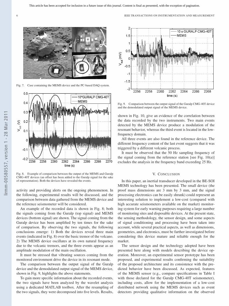
Fig. 7. Case containing the MEMS device and the PC-based DAQ system.
Fig. 8. Example of comparison between the output of the MEMS and GuralpCMG-40T devices (an offset has been added to the Guralp signal for the sakeof representation). Both the devices have revealed the events.
activity and providing alerts on the ongoing phenomenon. Inthe following, experimental results will be discussed, and thecomparison between data gathered from the MEMS device andthe reference seismometer will be considered.
An example of the recorded data is shown in Fig. 8; boththe signals coming from the Guralp (top signal) and MEMSdevices (bottom signal) are shown. The signal coming from theGuralp device has been amplified by ten times for the sakeof comparison. By observing the two signals, the followingconclusions emerge: 1) Both the devices reveal three mainevents (indicated in Fig. 8) over the basic tremor of the volcano.2) The MEMS device oscillates at its own natural frequencydue to the volcanic tremors, and the three events appear as anamplitude modulation of the main oscillation.
It must be stressed that vibrating sources coming from themonitored environment drive the device in its resonant mode.
The comparison between the output signal of the Guralpdevice and the demodulated output signal of the MEMS device,shown in Fig. 9, highlights the above statements.
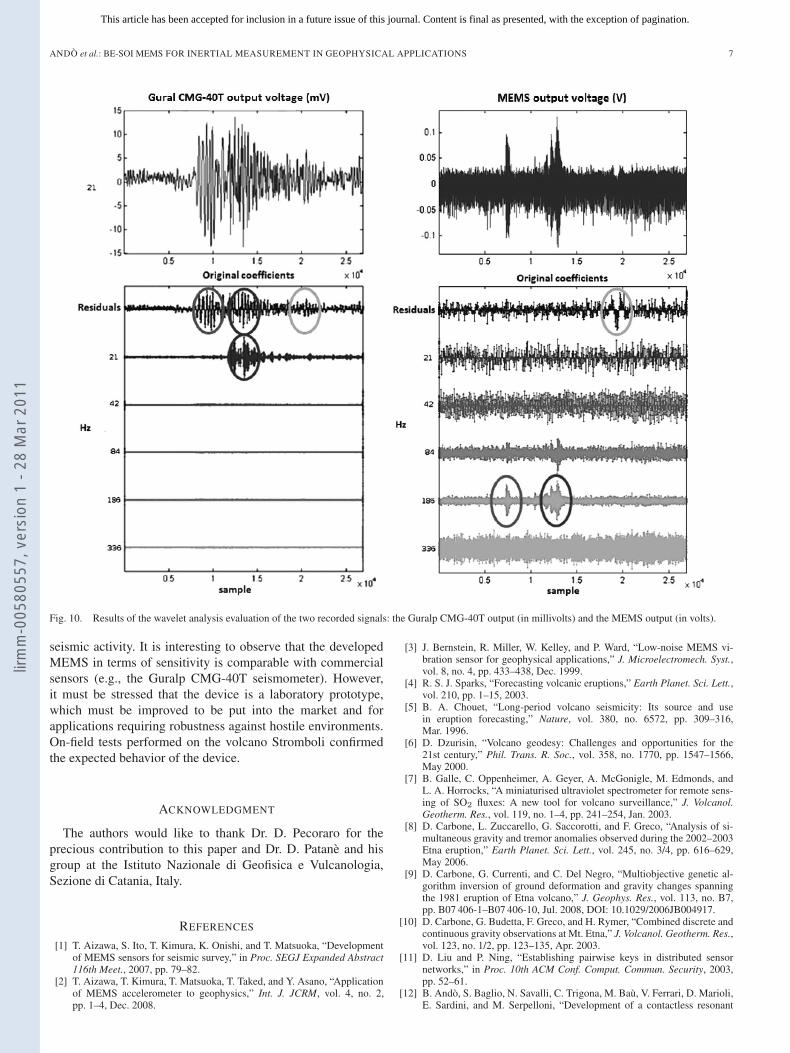
To gain more specific information about the recorded events,the two signals have been analyzed by the wavelet analysisusing a dedicated MATLAB toolbox. After the resampling ofthe two signals, they were decomposed into five levels. Results,
Fig. 9. Comparison between the output signal of the Guralp CMG-40T deviceand the demodulated output signal of the MEMS device.
shown in Fig. 10, give an evidence of the correlation betweenthe data recorded by the two instruments. Two main eventsdetected by the MEMS device produce a modulation of theresonant behavior, whereas the third event is located in the low-frequency domain.
All three events are also found in the reference device. Thedifferent frequency content of the last event suggests that it wastriggered by a different volcanic process.
It must be observed that the 50 Hz sampling frequency ofthe signal coming from the reference station [see Fig. 10(a)]excludes the analysis in the frequency band exceeding 25 Hz.
V. CONCLUSION
In this paper, an inertial transducer developed in the BE-SOIMEMS technology has been presented. The small device (theproof mass dimensions are 3 mm by 3 mm, and the signalprocessing electronics can be easily shrunk) could represent aninteresting solution to implement a low-cost (compared withhigh accurate seismometers available on the market) monitor-ing system for early warning purposes requiring a large numberof monitoring sites and disposable devices. At the present state,the sensing methodology, the sensor design, and some aspectsof signal conditioning and processing have been taken intoaccount, while several practical aspects, as well as dimensions,geometries, and electronics, must be further investigated beforeconsidering this device mature and reliable enough for themarket.
The sensor design and the technology adopted have beenpresented here along with models describing the device op-eration. Moreover, an experimental sensor prototype has beenproposed, and experimental results confirming the suitabilityof the proposed architecture and its consistence with the pre-dicted behavior have been discussed. As expected, featuresof the MEMS sensor (e.g., compare specifications in Table Iwith those declared for the Guralp CMG-40T seismometer),including costs, allow for the implementation of a low-costdistributed network using the MEMS devices such as eventdetectors providing qualitative information on the observed
lirm
m-0
0580
557,
ver
sion
1 -
28 M
ar 2
011
This article has been accepted for inclusion in a future issue of this journal. Content is final as presented, with the exception of pagination.
ANDÒ et al.: BE-SOI MEMS FOR INERTIAL MEASUREMENT IN GEOPHYSICAL APPLICATIONS 7
Fig. 10. Results of the wavelet analysis evaluation of the two recorded signals: the Guralp CMG-40T output (in millivolts) and the MEMS output (in volts).
seismic activity. It is interesting to observe that the developedMEMS in terms of sensitivity is comparable with commercialsensors (e.g., the Guralp CMG-40T seismometer). However,it must be stressed that the device is a laboratory prototype,which must be improved to be put into the market and forapplications requiring robustness against hostile environments.On-field tests performed on the volcano Stromboli confirmedthe expected behavior of the device.
ACKNOWLEDGMENT
The authors would like to thank Dr. D. Pecoraro for theprecious contribution to this paper and Dr. D. Patanè and hisgroup at the Istituto Nazionale di Geofisica e Vulcanologia,Sezione di Catania, Italy.
REFERENCES
[1] T. Aizawa, S. Ito, T. Kimura, K. Onishi, and T. Matsuoka, “Developmentof MEMS sensors for seismic survey,” in Proc. SEGJ Expanded Abstract116th Meet., 2007, pp. 79–82.
[2] T. Aizawa, T. Kimura, T. Matsuoka, T. Taked, and Y. Asano, “Applicationof MEMS accelerometer to geophysics,” Int. J. JCRM, vol. 4, no. 2,pp. 1–4, Dec. 2008.
[3] J. Bernstein, R. Miller, W. Kelley, and P. Ward, “Low-noise MEMS vi-bration sensor for geophysical applications,” J. Microelectromech. Syst.,vol. 8, no. 4, pp. 433–438, Dec. 1999.
[4] R. S. J. Sparks, “Forecasting volcanic eruptions,” Earth Planet. Sci. Lett.,vol. 210, pp. 1–15, 2003.
[5] B. A. Chouet, “Long-period volcano seismicity: Its source and usein eruption forecasting,” Nature, vol. 380, no. 6572, pp. 309–316,Mar. 1996.
[6] D. Dzurisin, “Volcano geodesy: Challenges and opportunities for the21st century,” Phil. Trans. R. Soc., vol. 358, no. 1770, pp. 1547–1566,May 2000.
[7] B. Galle, C. Oppenheimer, A. Geyer, A. McGonigle, M. Edmonds, andL. A. Horrocks, “A miniaturised ultraviolet spectrometer for remote sens-ing of SO2 fluxes: A new tool for volcano surveillance,” J. Volcanol.Geotherm. Res., vol. 119, no. 1–4, pp. 241–254, Jan. 2003.
[8] D. Carbone, L. Zuccarello, G. Saccorotti, and F. Greco, “Analysis of si-multaneous gravity and tremor anomalies observed during the 2002–2003Etna eruption,” Earth Planet. Sci. Lett., vol. 245, no. 3/4, pp. 616–629,May 2006.
[9] D. Carbone, G. Currenti, and C. Del Negro, “Multiobjective genetic al-gorithm inversion of ground deformation and gravity changes spanningthe 1981 eruption of Etna volcano,” J. Geophys. Res., vol. 113, no. B7,pp. B07 406-1–B07 406-10, Jul. 2008, DOI: 10.1029/2006JB004917.
[10] D. Carbone, G. Budetta, F. Greco, and H. Rymer, “Combined discrete andcontinuous gravity observations at Mt. Etna,” J. Volcanol. Geotherm. Res.,vol. 123, no. 1/2, pp. 123–135, Apr. 2003.
[11] D. Liu and P. Ning, “Establishing pairwise keys in distributed sensornetworks,” in Proc. 10th ACM Conf. Comput. Commun. Security, 2003,pp. 52–61.
[12] B. Andò, S. Baglio, N. Savalli, C. Trigona, M. Baù, V. Ferrari, D. Marioli,E. Sardini, and M. Serpelloni, “Development of a contactless resonant
lirm
m-0
0580
557,
ver
sion
1 -
28 M
ar 2
011
This article has been accepted for inclusion in a future issue of this journal. Content is final as presented, with the exception of pagination.
8 IEEE TRANSACTIONS ON INSTRUMENTATION AND MEASUREMENT
MEMS force sensor in SOI technology,” in Proc. Eurosensors XXII, 2008,pp. 421–424.
[13] B. Andò, S. Baglio, N. Savalli, C. Trigona, D. Marioli, E. Sardini, andM. Serpelloni, “Hybrid telemetric MEMS for high temperature mea-surements into harsh industrial environments,” in IEEE I2MTC, 2009,pp. 1423–1428.
[14] B. Andò, S. Baglio, A. Beninato, and V. Marletta, “An integrated differ-ential inductive sensor implementing bio-immunoassay,” in Proc. IEEEBiosens., 2009.
[15] B. Andò, S. Baglio, V. Marletta, N. Savalli, C. Trigona, D. Carbone,D. Patanè, S. Rapisarda, and L. Zuccarello, “A BE-SOI MEMS for in-ertial measurement in geophysical applications,” in Proc. IEEE I2MTC,pp. 1326–1330.
[16] G. K. Fedder, “Simulations of Microelectromechanical Systems,” Ph.D.dissertation, Dept. Elect. Eng. Comput. Sci., Univ. California at Berkeley,Berkeley, CA, 1994.
[17] J. C. Lagarias, J. A. Reeds, M. H. Wright, and P. E. Wright, “Convergenceproperties of the Nelder–Mead simplex method in low dimensions,” SIAMJ. Optim., vol. 9, no. 1, pp. 112–147, 1998.
[18] [Online]. Available: www.guralp com/products/40T.[19] S. Calvari, L. Spampinato, L. Lodato, A. J. L. Harris, M. R. Patrick,
J. Dehn, M. R. Burton, and D. Andronico, “Chronology and complex vol-canic processes during the 2002–2003 flank eruption at Stromboli volcano(Italy) reconstructed from direct observations and surveys with a hand-held thermal camera,” J. Geophys. Res., vol. 110, no. B2, p. B02 201-1,Feb. 2005, DOI: 10.1029/2004JB003129.
[20] B. A. Chouet, P. Dawson, T. Ohminato, M. Martini, G. Saccorotti,F. Giudicepietro, G. De Luca, G. Milana, and R. Scarpa, “Sourcemechanisms of explosions at Stromboli Volcano, Italy, determined frommoment-tensor inversions of very-long-period data,” J. Geophys. Res.,vol. 108, no. B1, p. 2019, Jan. 2003, DOI: 10.1029/2002JB001919.
[21] B. A. Chouet, G. Saccorotti, M. Martini, P. Dawson, G. De Luca,G. Milana, and E. R. Scarpa, “Source and path effects in the wavefieldsof tremor and explosions at Stromboli volcano, Italy,” J. Geophys. Res.,vol. 102, no. B7, pp. 15 129–15 150, 1997.
Bruno Andò received the M.S. degree in electronicengineering and the Ph.D. degree in electrical en-gineering from the Università di Catania, Catania,Italy, in 1994 and 1999, respectively.
From 1999 to 2001, he was a Researcher with theElectrical and Electronic Measurement Group, Di-partimento Elettrico Elettronico e Sistemistico, nowthe Dipartimento di Ingegneria Elettrica, Elettronicae dei Sistemi, University of Catania, where he hasbeen an Assistant Professor since 2002. He holdsseveral national and international scientific collabo-
rations. He teaches courses in “measurement theory,” “electronic instrumenta-tions,” and “sensors and transducers.” During his activity, he has coauthoredmore than 200 scientific papers, presented in international conferences andpublished in international journals and books. His main research interests aresensor design and optimization, microelectromechanical system and nanosys-tem, multisensors architecture for Ambient Assisted Living, new materials forsensors, nonlinear techniques for signal processing with particular interest instochastic resonance and dithering applications, and distributed measurementsystems for environmental monitoring.
Salvatore Baglio received the “Laurea” and Ph.D.degrees from the University of Catania, Catania,Italy, in 1990 and 1994, respectively.
He was a Lecturer of automatic control theorywith the University of Messina, Messina, Italy, and ofelectronic measurement systems with the Universityof Catania. Since 1996, he has been with the Di-partimento di Ingegneria Elettrica, Elettronica e deiSistemi, University of Catania, where he is currentlyan Associate Professor of electronic instrumenta-tions and measurements. He is a coauthor of several
scientific publications, including papers that were published in internationaljournals or presented at international conferences, and chapters in books. Heis also the holder of several U.S. patents. His research interests are mainlyfocused on measurement methodologies, smart sensors, microsensors, andmicrosystems.
Gaetano L’Episcopo was born in Catania in 1983.He received the B.S. degree in electronics engineer-ing and the M.S. degree in automation and complexsystem control engineering in 2006 and 2010, re-spectively, from the University of Catania, Catania,Italy, where he is currently working toward the Ph.D.degree in the Dipartimento di Ingegneria Elettrica,Elettronica e dei Sistemi.
His research interests includemicroelectromechanical-system devices forsensors and actuators, microgenerators for energy
harvesting, and nanotechnology.
Vincenzo Marletta received the M.S. degree in 2007from the University of Catania, Catania, Italy, wherehe is currently working toward the Ph.D. degree inthe Dipartimento di Ingegneria Elettrica, Elettronicae dei Sistemi.
His main research interests include sensor de-sign and characterization, including ferroelectric andmultiferroics electric-field sensors, aids for visuallyimpaired people, soft computing methodologies forinstrumentation and measuring systems, smart sen-sors, exploitation of nonlinear dynamics in sensors,
microsensors, and microsystems in standard and dedicated technologies.
Nicolò Savalli received the M.S. and Ph.D. degreesfrom the University of Catania, Catania, Italy, in1999 and in 2003, respectively.
Since 2003, he has been a Lecturer of applied elec-tronic measurements and electrical measurementswith the Dipartimento di Ingegneria Elettrica, Elet-tronica e dei Sistemi, University of Catania, wherehe is also currently a Research Associate. He hascoauthored more than 70 scientific publications, in-cluding international journals, international confer-ences, and national conferences. His main research
interests include soft computing methodologies for instrumentation and mea-suring systems, smart sensors, material characterization, device applications ofnonlinear dynamics, microsensors and microsystems in standard and dedicatedtechnologies, photonic band-gap materials, and optical filters.
Carlo Trigona was born in Siracusa, Italy, in De-cember 18, 1981. He received the M.S. degree inautomation engineering and control of complex sys-tem and the Ph.D. degree in electronic, automation,and control of complex system from the Universityof Catania, Catania, Italy, in 2006 and 2009, respec-tively.
He is currently with the Dipartimento di Ingegne-ria Elettrica, Elettronica e dei Sistemi, University ofCatania. He has authored several scientific papers.His research interests include microsystems and mi-
crosensors, fluxgate magnetometers, and analog and digital electronic circuitdesigns.
lirm
m-0
0580
557,
ver
sion
1 -
28 M
ar 2
011