Towards an Embedded Visuo-Inertial Smart Sensor
15
Towards an embedded Visuo-Inertial Smart Sensor P. Chalimbaud, F. Marmoiton, F. Berry Dream Sensor Team (DST) LASMEA - UMR CNRS 6602 University Blaise Pascal of Clermont-Ferrand 63177 Aubi` ere - Cedex, France chalimba, berry, [email protected] Abstract. In neurological system of primates, changes in posture are detected by the central nervous system through a vestibular process. This process, located in inner ear, coordinates several system outputs to main- tain stable balance, visual gaze, and autonomic control in response to changes in posture. Consequently the vestibular data is merged to other sensing data like touch, vision,.... The visuo-inertial merging is crucial for several tasks like navigation, depth estimation, stabilization. This pa- per proposes a ”primate-inspired” sensing hardware, based on a CMOS imaging and an artificial vestibular system. The whole sensor can be considered like a smart embedded sensor where one of the most original aspect of this approach is the use of a System On Chip implemented in a FPGA to manage the whole system. The sensing device is designed around a 4 Millions pixels CMOS imager and the artificial vestibular set is composed by 3 linear accelerometers and 3 gyroscopes. With its structure, the system proposes a high degree of versatility and allows the implementation of parallel image and inertial processing algorithms. In order to illustrate the proposed approach, we consider a depth estimation with Kalman filtering implementation. Keywords : CMOS imager, visuo-inertial sensor, depth estimation, Kalman Filter, smart sensor SeeMOS 1 Introduction In a biological system, the sensing mechanisms are gradually integrated with the actuating mechanisms in order to achieve a mature performing system. Among these sensing mechanisms, the fusion of visual and inertial data has many high- potential applications in navigation, eye stabilization, equilibrium,... In humans, the visuo-inertial perception is performed by the eyes, the inner ears and the cognitive system merge these informations in order to solve a given task. In an artificial approach, the perception of visuo/inertial data in one whole dedicated system remains a real challenge! Many previous works propose the use of a classical CCD camera with a custom inertial set or gyro sensor like [13],
-
Upload
independent -
Category
Documents
-
view
1 -
download
0
Transcript of Towards an Embedded Visuo-Inertial Smart Sensor

Towards an embedded Visuo-Inertial SmartSensor
P. Chalimbaud, F. Marmoiton, F. Berry
Dream Sensor Team (DST)LASMEA - UMR CNRS 6602
University Blaise Pascal of Clermont-Ferrand63177 Aubiere - Cedex, France
chalimba, berry, [email protected]
Abstract. In neurological system of primates, changes in posture aredetected by the central nervous system through a vestibular process. Thisprocess, located in inner ear, coordinates several system outputs to main-tain stable balance, visual gaze, and autonomic control in response tochanges in posture. Consequently the vestibular data is merged to othersensing data like touch, vision,.... The visuo-inertial merging is crucialfor several tasks like navigation, depth estimation, stabilization. This pa-per proposes a ”primate-inspired” sensing hardware, based on a CMOSimaging and an artificial vestibular system. The whole sensor can beconsidered like a smart embedded sensor where one of the most originalaspect of this approach is the use of a System On Chip implemented ina FPGA to manage the whole system. The sensing device is designedaround a 4 Millions pixels CMOS imager and the artificial vestibularset is composed by 3 linear accelerometers and 3 gyroscopes. With itsstructure, the system proposes a high degree of versatility and allows theimplementation of parallel image and inertial processing algorithms. Inorder to illustrate the proposed approach, we consider a depth estimationwith Kalman filtering implementation.
Keywords : CMOS imager, visuo-inertial sensor, depth estimation, KalmanFilter, smart sensor SeeMOS
1 Introduction
In a biological system, the sensing mechanisms are gradually integrated with theactuating mechanisms in order to achieve a mature performing system. Amongthese sensing mechanisms, the fusion of visual and inertial data has many high-potential applications in navigation, eye stabilization, equilibrium,... In humans,the visuo-inertial perception is performed by the eyes, the inner ears and thecognitive system merge these informations in order to solve a given task.
In an artificial approach, the perception of visuo/inertial data in one wholededicated system remains a real challenge! Many previous works propose theuse of a classical CCD camera with a custom inertial set or gyro sensor like [13],

[9], [15], stereo visuo-inertial system [12] or consider only a moving camera on astraight train track with approximate constant velocity [14] to perform a robuststructure from motion estimation. Through this paper, we propose a customizedsmart sensor based on a CMOS imager, three linear accelerometers and three gy-roscopes. The main originality is the system management by a System-On-Chipintegrated in a FPGA. Our approach allows to perform the most of early per-ception process in the processing unit (FPGA) and just sends the main sensingfeatures to the host computer so as to reduce a classical communication bottle-neck. Another advantage of this method is the possibility of real-time feedbackon the sensors. It allows to actively tune the different parameters in order tooptimize the perception similar to the primate perception, where for example instrong light the pupil contracts and becomes small, but still allows light to becast over a large part of the retina.
In this work, we focus on the description of our embedded sensor dedicatedto visuo-inertial perception which can be seen like a reactive architecture. In-deed traditional visuo/inertial sensors are composed of a camera on which theinertial sensors are fixed. The combination of these two sensor modalities is thecomplementary characteristic of camera and inertial sensors. On one hand, theinertial sensors can measure very high velocities and accelerations and on theother hand, the cameras can track features very accurately at low velocities.In our case, the inertial sensors are directly aligned and integrated closed tothe imager. The use of CMOS imaging technology allows to increase the imageframe rate by selecting only a window of interest(WOI) in the image and con-sequently allows to obtain a high speed synchronous visuo/inertial date rate.For this reason, the system presented in this paper can be considered, aboveall, as a research platform for smart visuo/inertial sensor. In the next section, alarge overview of the hybrid smart sensor is proposed. Secondly, an applicationfor depth estimation is presented and afterwards some results are shown whichprove the relevance of our approach.
2 Hardware Description
The goal of artificial vision research is to exploit images or image sequencesgenerated by sensors, in order to effectively translate an environment. Fromthis translation, different processes can be used to identify or inspect an object,control robots, etc. In this next development stage, the problem is to interpretan environment, so as to identify the set of objects present in a scene. The firstway to treat the vision problem is to carry out passive vision approaches which isthe classical way to analyze images. In contrast, another approach exists knownas ”active vision” which is a result of an attempt to simulate the human visualsystem. Dealing with human vision, head motions, eye jerk and movements, theway the eyes adapt to lighting variations, and specially the vestibular system inthe inner ear which gives inertial information essential which are fundamentalin the perception process.
Based on this concept, our approach consists of integrating the control of theimager and the inertial sensor in the perception loop, especially in the early per-ception processes. By integration of early processing and a combination of visualand inertial mechanisms, close to the imager, a reactive sensor can be designed.With such a smart sensor, it is possible to perform basic processing and selec-
Fig. 1. Overview of the camera and synoptic of the assembly
tion of relevant features close to the imager. The inertial data may be seen ascomplementary information (stabilization,...) or by opposition for a real data fu-

sion (depth estimation,...). Of course, vision tasks are numerous and varied, andthe choice of a versatile architecture based on a reprogrammable chip becomesnatural[7]. For example, FPGAs have already been used to accelerate real-timepoint tracking [2], stereo-vision computing [16], color-based object detection [3],and video and image compression [4]. In our case, the notion of SOPC (SystemOn Programmable Chip) describes the whole system.
Moreover, most vision applications are often focused on several small imageareas and consequently acquisition of the whole image is not always necessary.From this observation, it is evident that one of the main goals of an efficient visionsensor is to select Windows Of Interest (WOI) in the image and concentrateprocessing resources on these. Then, the notion of local study is predominantand the choice of the imaging technology becomes crucial.
2.1 Global Hardware Architecture
The global processing system is composed of System On Programmable Chip(SOPC) by which an entire system of components is put on a single chip (FPGA).An overview of the embedded vision system is proposed in the figure 1.
This modular architecture is composed of three modules :• Sensing device board : CCD and CMOS are the two most common
imaging technologies used today in industrial digital cameras. A particularity ofCMOS imagers is to adopt a digital memory style readout, using row decodersand column amplifiers. Random access of pixel values is possible and allowsto select readout of windows of interest.. In this way and in contrast to CCDimagers, it is possible to obtain a high speed imaging capability by addressingonly a small region in the image.
This board is composed of a CMOS imager (LUPA 4000) manufactured byCypress. This 4 mega-pixel CMOS active pixel sensor features synchronous shut-ter and a maximum frame-rate of 15fps at full resolution. The readout speed canbe boosted by means of sub sampling and windowed Region Of Interest (ROI)readout. Dynamic high range scenes can be captured using the double and mul-tiple slope functionality. The dynamic optical range can be up to 67 dB in singleslope operation and up to 90 dB in multiple slope operation.
The inertial set is composed of two 2D linear accelerometers ADXL311 de-signed by Analog Devices and three gyrometers ENC03−M designed by Murata.These sensors are souldered onto the imager PCB and aligned with the imagingdevice. A single 8-input analog to digital converter allows to convert measure-ments of different axes . It is also important to mention here that a temperaturesensor is included in this board to regulate the inertial sensors derivations.
• Main board :This is the core of the system (Fig. 3) designed around a Stratix EP1S60
manufactured by Altera. The need for strong parallelization was what led us toconnect 5×2MBytes SRAM asynchronous memory blocks. Each 2MB memoryhas private data and address buses. Consequently, in the FPGA, 5 processes(using 2MB each) can address all the memory at the same time and an SDRAM

Fig. 2. Overview of sensing boards assembly and synoptic diagram
module socket provides an extension of the memory to 64 MBytes (Figure 2).This choice for Stratix is argued below.
Firstly, Stratix is optimized to maximize the performance benefits of SOPCintegration based on a NIOS embedded Processor. A NIOS processor is a user-configurable soft core processor, allowing many implementations and optimiza-tion options. The NIOS CPU is a pipelined general-purpose RISC microproces-sor. It supports both 32-bits and 16-bits architectural variants and both 16 and32-bits variants use 16-bits instructions.
Secondly, Stratix integrates DSP Blocks. These embedded DSP Blocks havebeen optimized to implement several DSP functions with maximum perfor-mance and minimum logic resource utilization. Furthermore, these embeddedDSP Blocks can be used to create DSP algorithms and complex math routinesin high-performance hardware DSP Blocks and access them as regular softwareroutines or implement them as custom instructions to the NIOS CPU.
Lastly, the Stratix device incorporates a configurable internal memory calledTriMatrix memory. The TriMatrix memory is composed of three sizes of embed-ded RAM blocks. The Stratix EP1S60 TriMatrix memory includes 574 M512blocks (32×18 bits), 292 M4K blocks (128×36 bits), and 6 M-RAM blocks(4K×144bits).
• Communication board : This last board is connected to the main boardand manages all communications with the host computer. The communicationbus is actually high-speed USB2.0 and the Cameralink is in study.

Fig. 3. Global synoptic of the hybrid sensor.
2.2 Architectural Design
The goal of the proposed design is to create a flexible interface between thesensing device board (fig. 2) and a host computer in exploiting the advantagesof the SOPC described above. The design is based on a master entity whichsynchronizes and defines the control parameters of a set of modules. This setof modules acts on various points of the acquisition chain. The master entity issynthesized by a NIOS soft core processor (Module M0). The role of master entity(easily defined by the software) is to synchronize the whole sensor. It ensures anefficient interfacing between several control modules ( Module Px) and externaldevices. An internal RAM (Module R0) is used to store the instructions sequencewhich defines master behavior. The role of the NIOS is twofold : first, it controlsthe slave device described by the synoptic scheme in figure 2. Secondly, the NIOSmanages communication flows with the host computer (Module H0). Two NIOSperipherals are dedicated to communication management. The host computersends requests in order to indicate to the master entity the relevant behaviorto adopt. While the master entity may be busy dealing with other tasks, themodule ( Module P4) stores host computer requests. Then, when the masteris released, it consults the stack of requests. The second peripheral, dedicatedto communication, drives image data toward the host computer and acquisitionwindow parameters toward the master entity.
One the most important part of the design is the module P3. This module isthe core of the embedded processing. The different data flows (corrected windowsof interest and inertial measurements) can be treated by parallel computing(Process 1,...). In our case, only the image processing consisting of a featuredetection (thresholding and barycentre detection) have been implemented.

Fig. 4. Block diagram of implemented architecture in the FPGA
3 Depth estimation
In this section, we propose an implementation of a depth estimator on our plat-form. The application works on a combination of inertial and visual data to re-cover the depth of a simple scene. Traditionally, the vision reconstruction fromnon-calibrated image sequences allows to reconstruct 3D scene with a scale fac-tor [11]. However, these kinds of reconstructions are expensive computationallyand in most cases, are not compatible with ”real time constraints”. The useof inertial and visual data emerges as a new way to handle this question [17].Indeed, as it is explained below, successive camera positions are computed withthe inertial sensors’ information while visual features can be measured in theimages. Under the assumption that the observed features are static, a standardstereovision method [8] can be applied to recover 3D information. In the nextparagraph, the use of visual and inertial data is discussed and a 3D recoveringalgorithm with Kalman filter is proposed.

3.1 Visual features
Assuming that a camera performs an exact perspective projection, the imageformation process can be expressed as a projective mapping from P3 7→ P2,where Pn is a n-dimensional projective space1.
If we consider a 3D point M ∈ P3, its relation with m ∈ P2 (projection ofimage on plane M) is given by the well-known relation:
m = PM (1)
where M =
XYZ1
, P =
αu 0 u0 00 αv v0 00 0 1 0
, m =
UVλ
=
xy1
where x = Uλ and y = V
λ are the coordinates of the detected feature and λ isa scale factor, (u0, v0) is the center of the image plane and αv, αv considers thedifference of focal length along the x and y axis.
Between times 1 and i, the camera can be considered as a stereovision system(Fig. 5) where the point M is projected in both frames R1 and Ri.
Fig. 5. Configuration of the vision system.
At first, let us express the homogenous transformation matrice Ti at t = isuch as
Ti =
qT1i q14i
qT2i q24i
qT3i q34i
0 1
(2)
where qTji (j = 1, 2, 3) are (3x1) vectors and qj4i is the translation between R1
and Ri. These vectors represent the rotation and the translation of the transfor-mation respectively and can be obtained by the inertial sensors. This is discussed1 The affine space Rn can be embedded isomorphically in Pn by a standard injection

in the next section. So, at t = i, the projection of one point in the 2D imageplane is expressed by :
mi = P.TiM (3)
The development of this relation gives:
xi.λ = (αuqT1i + u0q
T3i)M + αuq14i + u0q34i
yi.λ = (αvqT2i + v0q
T3i)M + αvq24i + v0q34i
λ = qT3iM + q34i
and the substitution of λ results in the following equations :{
(αuqT1i + u0q
T3i − qT
3iui)M = q34i − αuq14i − u0q34i
(αvqT2i + v0q
T3i − qT
3ivi)M = q34i − αvq24i − v0q34i(4)
which can be rewritten as:AiM = bi (5)
where Ai is a (2x3) matrix involving the matrix P and Ri of the ith positionof camera and the coordinates of pixel mi. When we consider n positions fromi = 1 to i = n, eq. 5 can be written as:
A.M = b
where A is a (2n× 3) matrix obtained by stacking the n matrices Ai, and bis a (2n) vector obtained by stacking the n vectors bi.
A solution to estimate the 3D position of M can be obtained by applyingleast squares methods and is (when rank(A)=3):
M = (AT A)−1AT b
For every i, images and inertial data are synchronously grabbed by the sensorand processed by SOC board. On every 40ms, an image and the whole inertialmeasurements can be processed by the FPGA and the host computer.
3.2 Inertial features
As it is explained above, the inertial features are measured by 3 accelerometersand 3 gyrometers and the estimation of Ti can be done by a rough integration[6]of the inertial data such as:
Ti =
qT1i q14i
qT2i q24i
qT3i q34i
0 1
with the translation terms
qx
qy
qz
=
q14i
q24i
q34i
=
q140
q240
q340
+
∆T 2
2
i−1∑
k=0
[(2.(i− k)− 1)γk] ∆T

and the rotation matrix
qT1i
qT2i
qT3i
= expAS(θi)
with AS(θi) =0 −θzi θyi
θzi 0 −θxi−θyi θxi 0
and θi =
θxi
θyi
θzi
=
∑ik=1 ωk∆T and ∆T is
the period between two measurements. These relations come from the Rodrigues’Rotation Formula and the interested readers can refer for more details in [5].
This approach is natural but implies a drift in the attitude computation thataccumulates with elapsed time due to the intrinsic noise of the sensors. In orderto reduce the noise influence the inertial data, Kalman filter[10] [1] is used onthe following state vector Xi:
Xi =
qx
qy
qz
T
,
qx
qy
qz
T
,
γx
γy
γz
T
,
γx
γy
γz
T
,
θxi
θyi
θzi
T
,
ωx
ωy
ωz
T
,
ωx
ωy
ωz
T
We can write the discretized state equation with sampling period ∆T by:
Xi+1 = F.Xi + v(i)
where F is the discretized state transition matrix of the system. The size ofmatrix F is 21× 21, so to simplify, we only give F for one axis such as:
F =
1 ∆T ∆T 2
2∆T 3
6 0 0 00 1 ∆T ∆T 2
2 0 0 00 0 1 ∆T 0 0 00 0 0 1 0 0 00 0 0 0 1 ∆T ∆T 2
20 0 0 0 0 1 ∆T0 0 0 0 0 0 1
= eA∆T
and v(i) is the discrete-time process noise represented by (21 × 21) covariancematrix Qi such as
Qi = E[v(i)vT (i)]
with v(i) =∫ ∆T
0eA(∆T−τ).D.v(i.∆T + τ).dτ . D is a combination vector and
v(i) is the spread of the mean terms. In this case, considering only one axis, thecovariance of the process noise is (for x axis):
Qix =
1360 ∆T 10σ2
γx172 ∆T 6σ2
γx130 ∆T 5σ2
γx124 ∆T 4σ2
γx0 0 0
172 ∆T 6σ2
γx120 ∆T 5σ2
γx18 ∆T 4σ2
γx16 ∆T 3σ2
γx0 0 0
130 ∆T 5σ2
γx18 ∆T 4σ2
γx13 ∆T 3σ2
γx12 ∆T 2σ2
γx0 0 0
124 ∆T 4σ2
γx16 ∆T 3σ2
γx12 ∆T 2σ2
γx∆Tσ2
γx0 0 0
0 0 0 0 120 ∆T 5σ2
ωx18 ∆T 4σ2
ωx16 ∆T 3σ2
ωx0 0 0 0 1
8 ∆T 4σ2ωx
13 ∆T 3σ2
ωx12 ∆T 2σ2
ωx0 0 0 0 1
6 ∆T 3σ2ωx
12 ∆T 2σ2
ωx∆Tσ2
ωx
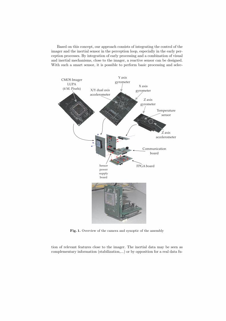
The observation process is
Yi = H.Xi + W (i)
where W (i) is the noise of the measurement system and is represented by acovariance matrix Mk and the observation matrix H is given by:
H =
(0)6×6
1 0 0 0 0 00 1 0 0 0 00 0 1 0 0 0
(0)6×6
0 0 0 1 0 00 0 0 0 1 00 0 0 0 0 1
(0)3×6
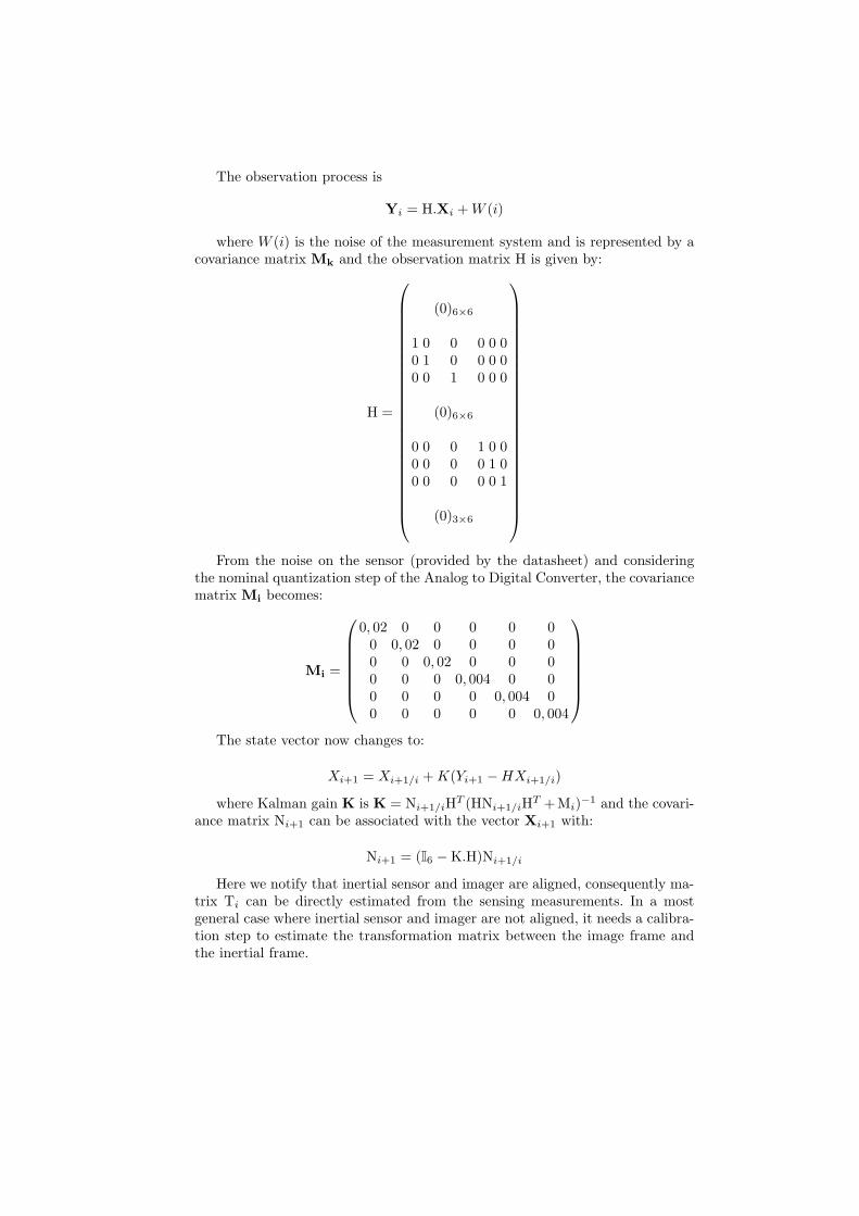
From the noise on the sensor (provided by the datasheet) and consideringthe nominal quantization step of the Analog to Digital Converter, the covariancematrix Mi becomes:
Mi =
0, 02 0 0 0 0 00 0, 02 0 0 0 00 0 0, 02 0 0 00 0 0 0, 004 0 00 0 0 0 0, 004 00 0 0 0 0 0, 004
The state vector now changes to:
Xi+1 = Xi+1/i + K(Yi+1 −HXi+1/i)
where Kalman gain K is K = Ni+1/iHT (HNi+1/iHT +Mi)−1 and the covari-ance matrix Ni+1 can be associated with the vector Xi+1 with:
Ni+1 = (I6 −K.H)Ni+1/i
Here we notify that inertial sensor and imager are aligned, consequently ma-trix Ti can be directly estimated from the sensing measurements. In a mostgeneral case where inertial sensor and imager are not aligned, it needs a calibra-tion step to estimate the transformation matrix between the image frame andthe inertial frame.

3.3 Results
In this section, we present first results for a position estimation. Firstly, we pro-pose a simulated result obtained with Matlab. Secondly, real results are proposedto validate our approach.
Simulation In this simulation, the initial position of M (in the camera frame)is M = (0.5, 0.5, 5)T and the coordinates of m are synthesized in the images withan accuracy of 1 pixel.
The figure 6 presents the depth estimation for a combination of accelerationand a rotation. The camera motion is parameterized by γ = (0.2, 0.3, 0.5)T .
Fig. 6. Z estimation with a movement of translation with drift
On this figure, a drift on inertial informations ((0.03, 0.03, 0.03)T ms−2) isinjected and an offset estimation appears.
On figure 7, a rotation velocity of ω = (0.3, 0.2, 0.1)T is added to the cameramovement with a drift ((0.02, 0.02, 0.02)T rads−1 and zero mean white noise(σNoise Accel =0.01m.s−2 and σNoise Rot = 0.005Rad.s−1).
After 150 iterations, the system does not converge due to the drift.

Fig. 7. Z estimation with a combination of translation and rotation with drift
Experimental results In this experimentation, a camera motion along the x-axis is carried out. For the visual data, we only consider a point projected by alaser tracker on a white plane. This point is detected in the image by thresholdingand the depth estimation consists in the estimation of the distance between thecamera and the plane. The distance is fixed to 1.4 m and the focal length of thecamera is 6mm.
0 10 20 30 40 50 60 70 80 90 100−0.5
0
0.5
1
1.5
2Comp. Z
Fig. 8. Z estimation with movement along the x-axis
The figure 8 shows a depth estimation of the point M. After convergence, theresults are as following:
– With Kalman Filter (Blue curve):• Estimated depth after t=1.12s is 1.394 m• Estimated depth after t= 4s is 1.243 m
– Without Kalman Filter (Red curve):• Estimated depth after t=1.12s is 1.237 m• Estimated depth after t= 4s is 0.881 m
Except the Kalman filter, a drift is measured after several second and impliesa normal biased depth estimation. However, the reconstruction accuracy showsthe validity of the sensor.
4 Conclusion
This paper have explored the building of sensor dedicated to visuo-inertial mea-surements. Its main originality consists in using CMOS imager, FPGA architec-ture and inertial sensor in order to make a versatile smart system. The proposedembedded system attempts to define a global coordination between inertial data,low-level processing and visual tasks. The approach, based on FPGA Technologyand CMOS imager, reduces the classical bottleneck between sensor and process-ing unit. Indeed visual and inertial sensing are two sensory modalities that canbe explored to give robust solutions on image segmentation and recovery of3D structure from images, increasing the capabilities of autonomous robots andenlarging the application potential of vision systems.
In this paper, after the presentation of the sensor, a method for depth re-covering is proposed and applied to the sensor data.Assuming that the observedfeatures are static for that we have used standard stereovision method. A Kalmanfilter is used on inertial data to consider the noise and allows an efficient filter-ing of the raw measurements. We have also developed a DSP board in order toimprove the computation capabilities of our system. With this device, our em-bedded system will evolve into a heterogeneous architecture and new researchinto co-design between the FPGA and the DSP will be necessary.
Acknowledgement
This work has been granted by Murata for the gyroscopes integration. Specially,the authors would like to thank Professor Jeannot Gallice.
References
1. Yaakov Bar-Shalom and Xiao-Rong Li. Estimation with Applications to Trackingand Navigation. John Wiley & Sons, Inc., New York, NY, USA, 2001.
2. A. Benedetti and P. Perona. Real-time 2-d feature detection on a reconfigurablecomputer. In CVPR ’98: Proceedings of the IEEE Computer Society Conferenceon Computer Vision and Pattern Recognition, page 586, Washington, DC, USA,1998. IEEE Computer Society.
3. D. Benitez and J. Cabrera. Reactive computer vision system with reconfigurablearchitecture. In ICVS ’99: Proceedings of the First International Conference onComputer Vision Systems, pages 348–360, London, UK, 1999.

4. W. Bohm, J. Hammes, B. Draper, M. Chawathe, C. Ross, R. Rinker, and W. Naj-jar. Mapping a single assignment programming language to reconfigurable systems.J. Supercomput., 21(2):117–130, 2002.
5. R. W. Brockett. Robotic manipulators and the product of exponentials formula.In In Mathematical Theory of Networks and Systems, pages 120–127, Beer Sheva,June 1983. Proceedings of the International Symposium Held at the Ben GurionUniversity of the Negev.
6. P. Chalimbaud, F. Berry, F. Marmoiton, and S. Alizon. Design of a hybrid visuo-inertial smart sensor. In ICRA05 Workshop on Integration of Vision and InertialSensors (InerVis2005), Barcelona, Spain, 2005.
7. A. DeHon. The density advantage of configurable computing. Computer, 33(4):41–49, 2000.
8. O. Faugeras. Three-Dimensional Computer Vision, a Geometric Viewpoint. MITPress, 1993.
9. A. Huster and S. M. Rock. Relative position estimation for manipulation tasks byfusing vision and inertial measurements. In In Proceedings of the Oceans 2001 Con-ference, volume 2, pages 1025–1031, Honolulu, USA, November 2001. MTS/IEEE.
10. R. E. Kalman. A new approach to linear filtering and prediction problems. Trans-actions of the ASMEJournal of Basic Engineering,, pages 35–45, 1960.
11. M. Lhuillier and L. Quan. Quasi-dense reconstruction from image sequence. InProceedings of the 7th European Conference on Computer Vision, volume 2, Copen-hagen, Denmark, May 2002.
12. Jorge Lobo and Jorge Dias. Inertial sensed ego-motion for 3d vision. Journal ofRobotic Systems, 21(1):3–12, 2004.
13. T. Mukai and N. Ohnishi. The recovery of object shape and camera motion usinga sensing system with a video camera and a gyro sensor. In In Seventh IEEEInternational Conference on Computer Vision (ICCV 1999), pages 411–417, Corfu,Greece, September 1999.
14. G. Qian, R. Chellappa, and Q. Zhang. Robust structure from motion estimationusing inertial data. Journal of the Optical Society of America A, 18(12):2982–2997,December 2001.
15. D. Strelow and S. Singh. Optimal motion estimation from visual and inertialmeasurements. In In Proceedings Workshop on Integration of Vision and InertialSensors (INERVIS 2003), Coimbra, Portugal, June 2003.
16. J. Woodfill and B. Von Herzen. Real-time stereo vision on the parts reconfigurablecomputer. In FCCM ’97: Proceedings of the 5th IEEE Symposium on FPGA-Based Custom Computing Machines, page 201, Washington, DC, USA, 1997. IEEEComputer Society.
17. Suya You and Ulrich Neumann. Fusion of vision and gyro tracking for robustaugmented reality registration. In VR ’01: Proceedings of the Virtual Reality 2001Conference (VR’01), page 71. IEEE Computer Society, 2001.