19760006052.pdf - NASA Technical Reports
343
NASYd TE:i;iN ICAL MEMORANDUM NASA TM X-71838 (NASk-T??-X-71R?P) 'XI'l4?j/CE?;TPUF r- 1 - TC-2, K76-13140 HELICS P FIIGH'I E?TE EEFCFT (KASA) 343 F HC e~c,i,- CCCI 22c TITANICENTAUR D-1T TC-2, HELlOS A FLIGHT DATA RE PORT Lewis Research Center Cleveland, Ohio September 197 5
-
Upload
khangminh22 -
Category
Documents
-
view
0 -
download
0
Transcript of 19760006052.pdf - NASA Technical Reports

NASYd T E : i ; i N I C A L M E M O R A N D U M
NASA TM X-71838
( N A S k - T ? ? - X - 7 1 R ? P ) ' X I ' l 4 ? j / C E ? ; T P U F r - 1 - TC-2, K76-13140 H E L I C S P FI IGH' I E ? T E E E F C F T ( K A S A ) 3 4 3 F HC e ~ c , i , - C C C I 2 2 c
TITANICENTAUR D-1T
TC-2, HELlOS A
FLIGHT DATA RE PORT
Lewis Research Center
Cleveland, Ohio
September 197 5
TC-2 FL ICHT DATA REPORT
HELIOS A
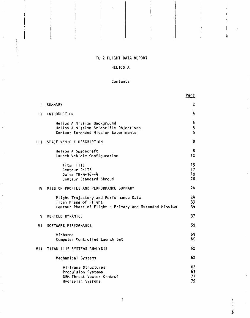
Con ten ts
I SUMMARY
I I INTRODUCTION
Hel ios A M i 5s ion Background Nel ios A Mission S c i e n t i f i c Object ives Centaur Extended Mission Experiments
I I I SPACE VEHICLE D E S C R l PTlON
He1 ios A Spacecraft Launch Vehic le Conf igurat ion
T i t an I l l € Centaur D-ITR Delta TE-M-364-4 Centaur Standard Shroud
I V M I SS l ON PROF l LE AND PERFORMANCE SUMMARY
F l i g h t T ra jec to ry and Performance Data T i tan Phase of F l i gh t Centaur Phase o f F l i gh t - Primary and Extended Mission
V VEHICLE D Y N A M I C S
V I SOFTWARE PERYORMANCE
A i r borne Cornputel r on t r o l l ed Launch Set
V I I TITAN l l l E SYSTEhS ANALYSIS
Mechanical Systems
Air f rame St ructures Propulsion Systems SRM Thrust Vector C-mtrol H y d r a ~ ~ l ;c Systems
Page
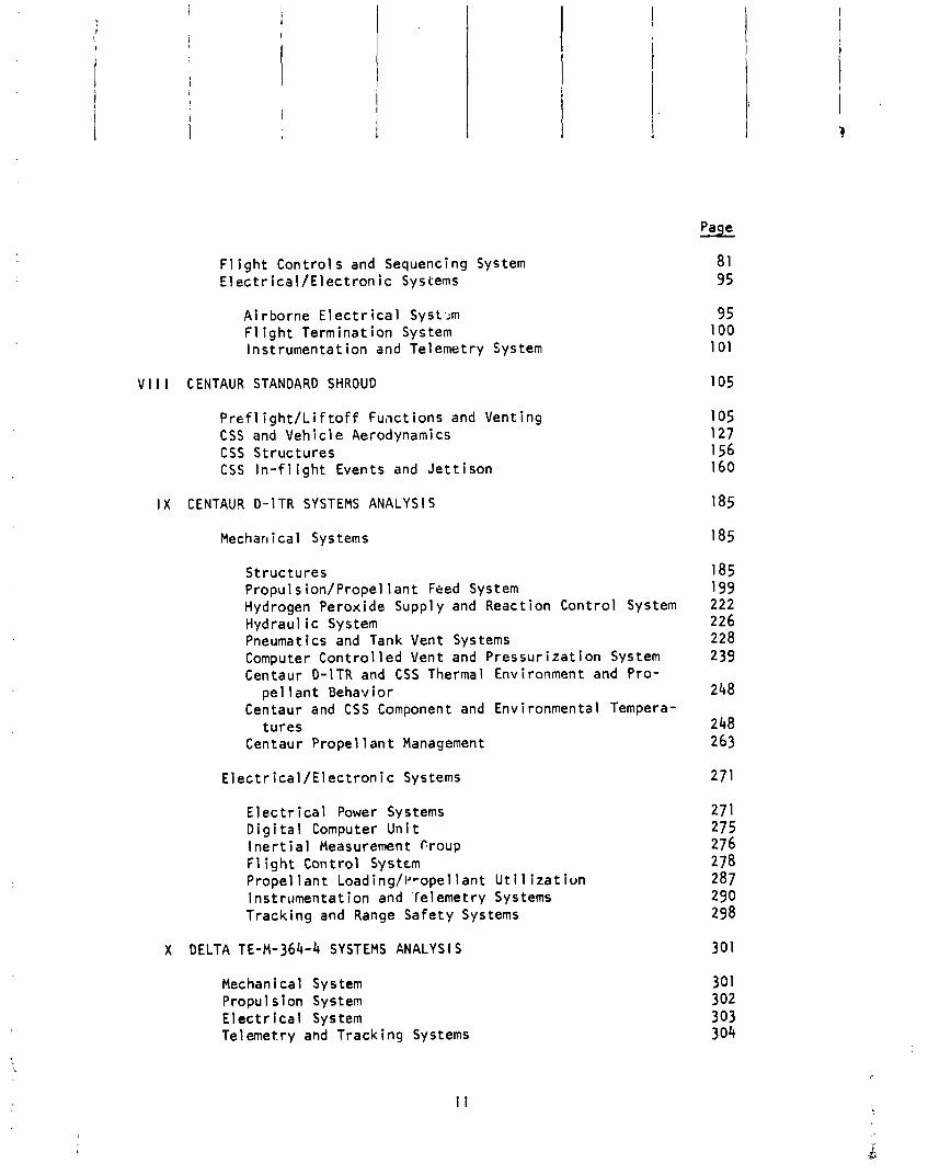
F l i g h t Cont ro ls and Sequencing System E l e c t r i c a l / E l e c t r o n i c Systems
Airborne E l e c t r i c a l Syst.m F l i g h t Terminat ion System lnstrumentat ion and Telemetry System
V l l l CENTAUR STANDARD SHROUD 105
P r e f l i g h U L i f t o f f Functions and Venting CSS and Vehic le Aerodynamics CSS St ructures CSS I n - f 1 i gh t Events and Je t t i son
I X CENTAUR D-ITR SYSTEMS ANALYSIS 185
Mechan i ca 1 Sys tems 185
St ructures Propul s ion/Propel 1 ant Feed System Hydrogen Peroxide Suppl y and React ion Control System Hydraul i c System Pneuma t i cs and Tank Vent Sys tems Computer Con t ro l led Vent and Pressur i za t ion System Centaur D-ITR and CSS Thermal Environment and Pro-
pe l l a n t Behavior Centaur and CSS Component and Environmental Tempera-
tures Centaur Prope l lan t Management
E l e c t r i c a l / E l e c t r o n i c Systems 271
E l e c t r i c a l Power Systems 27 1 D i g i t a l Computer U n i t 275 I n e r t i a l Measurement Croup 276 F l i g h t Control System 278 Propel lant Load ing /~ rope l l an t U t i l i z a t i u n 287 Instrumentat ion and Telemetry Systems 290 Tracking and Range Safety Systems 298
X DELTA ~ E - ~ - 3 6 4 - 4 SYSTEMS ANALYS l S 301
Mechanical System Propul s ion System E l e c t r i c a l System Telemetry and Tracking Systems
XI FACILITIES AND AGE
Complex 41 F a c i l i t i e s F lu id Systems Operat ions Pneumatic Ground Systems Env i ronmen ta 1 Control Systems El e c t r i ca 1 Ground Systems Del ta Stage Support Systems Hel ios A Spacecraft Support Systems
i i i
Page

I SUMMARY
I SUMMARY
by K. A. Adams
T i t adcen tau r TC-2 was launched from the Eastern Test Range, Complex 41, a t 0 2 : l l EST on Tuesday, December 10, 1974. Th is was the f i r s t opera- t i o n a l f l i g h t o f the newest NASA unmanned launch veh ic le . The spacecraft was the Hel ios A, the f i r s t o f the two so la r probes designed and b u i l t by the Federal Republic o f Germany.
The pr imary mission ob jec t i ve , t o p lace the Hel ios spacecraft on a h e l i o - c e n t r i c o r b i t i n the e c l i p t i c plane w i t h a pe r i he l i on d is tance o f 0.31 AU, was successfu l ly accompl ished.
A f te r successful i n j e c t i o n o f the Hel ios spacecraft , a ser ies o f exper i - ments was performed w i t h the Centaur stage t o demonstrate i t s operat ional capabi l i t ies. These experiments included a one-hour zero "g" coast per iod and subsequent engine burn t o demonstrate the c a p a b i l i t y t o f l y long coast p lanetary missions such as MJS177 ano a three-hour zero "g" coast and sub- sequent engine burn t o demonstrate the capab i 1 i t y t o perform geosynchronous missions. A l l ob jec t i ves o f t h i s Centaur extended mission experiment phase were successful 1 y met.


I I l NTRODUCT l ON
by K. A. Adams
He1 i os A M i ss ion Backqround
I n June 1969 the Federal Republ i c o f Germany and the United States o f America agreed on the j o i n t cooperat ive Hel ios so la r probe p ro jec t . This basic agree- ment provided f o r the design, development, t e s t and launch o f two f l i g h t space- c r a f t t o w i t h i n 0.3 AU o f the sun. Germany was assigned t h e r e s p o n s i b i l i t y f o r p rov id ing the two spacecraft , seven s c i e n t i f i c experiments on each space-
* c r a f t , and c o n t r o l l i n g the spacecraft throughout the mission. The United States was assigned the task o f p rov id ing th ree s c i e n t i f i c experiments on each space- c r a f t , two T i t a n I I IE/Centaur/Del ta ( ~ ~ - ~ - 3 6 4 - 4 ) launch vehic les and t r ack ing and data recept ion from the NASA Deep Space Network (DSN) . Major cont ractua l
I e f f o r t on the program began i n 1970. I n March of 1971 the German Government I (BMBW) proposed an add i t i ona l experiment, Ce les t i a l Mechanics, fo r the He1 ios
mission. Late i n the program, a Faraday Rotat;on experiment was a l so approved.
Th is j o i n t p r o j e c t i s expected t o prov ide new understanding o f fundamental so la r processes and Sun/Earth re la t ionsh ips by ob ta in ing in format ion and measurements on the so la r wind, magnetic and e l e c t r i c f i e l d s , cosmic rays, cosmic dust and so la r d isc . It w i l l a l so t e s t the theory o f general r e l a t i v i t y . The NASA Lewi s Research Center (LeRc) has prime r e j ~ o n s i b i 1 i t y for the launch veh ic le . The NASA Goddard-Space F l i g h t Center ( C Y ~ L - through i t s He1 ios P ro jec t i s re - 1 sponsible f o r the a c t i v i t i e s o f the United States agencies which a re invo lved i n Hel ios and f o r p rov i s i on o f the United States sponsored experiments. The Gesel l s c h a f t f u r We1 traumforschung ( G ~ w ) o f the Federal Republ i c o f Germany i s responsible f o r the technica l d i r e c t i o n c f the prime spacecraft con t rac to r , Messerschmidt-Boel kow-Blohm GmBH (MBB-~ t t ob runn ) , for the German experiments , and f o r a l l o ther German organizat ions which con t r i bu te t o the Hel ios p ro jec t .
The T i tan l l l E and Centaur D-ITR, f i t t e d w i t h a sp in - s tab i l i zed s o l i d p rope l l an t TE-M-364-4 e el t a ) stage, i s designed t o launch the He1 ios A ucmanned spacecraft i n t o a h e l i o c e n t r i c o r b l t , i n the e c l i p t i c plane, w i t h a p e r i h e l i o n o f approx i - mately 0.31 AU and an aphel lon o f approximately 1.0 AU. This was the f i r s t o f two planned Hel ios spacecraft. The launch o f Hel ios A was from the AFETR Launch Complex 41, Cape Canaveral, F lo r ida , u t i l i z i n g a park ing o r b i t ascent mode. The launch o f Hel ios B i s planned f o r l a t e 1975.
F l i gh t t lme o f the He1 ios A primary mission i s approximately 120 days, extending through the f i r s t so la r occu l t a t i on . The t o t a l mission l i f e t ime, however, i s expected t o exceed 18 months w i t h pr imar f i n t e r e s t i n the reg ion o f the o r b i t between pe r i he l ion and so la r occu l t a t i on .
A f t e r the spacecraft was placed i n t o i t s des i red h e l i o c e n t r i c t r a j e c t o r y , the Centaur veh ic le continued i n t o an experfmental f l i g h t phase. During t h i s post Hel los experiment phase developmental data was obtained r e l a t i v e t o the Centaur's capability f o r extended per iods of zero-9 coast and m u l t i p l e engine s t a r t s .
Helios A Mission S c i e n t i f i c Objectives - The p r inc ipa l ob jec t ive o f the Hellos A mission i s the explorat ion of i n t e r - planetary space i n the prox imi ty o f the Sun by:
- Measuring the magnetic f i e l d , the density, temperature, ve loc i t y and d i rec t i on o f the solar wind.
- Studying d i scon t i nu i t i es and shock phenomena i n the in terp lanetary medium magnetically, e l e c t r i c a l l y , and by observing the behavior of the solar wind pa r t i c l es .
- Studying rad io waves and the e lect ron plasma o s c i l l a t i o n s i n t h e i r natura l s tate.
- Measuring the propagation and spat ia l gradient o f so lar and g a l a t i c cosmic rays.
- Studying the spat ia l gradient and dynamics o f the in terp lanetary dust and chemical composition o f dust grains.
- X-ray monitoring the solar d isc by means o f a Geiger-Muller counter.
- Testing the theory o f General R e l a t i v i t y w i th respect t o both o r b i t a l and signal propagat ion e f fec ts . i -- .-
Helios A successful ly accomplished i t s mission object ives on March I S , 1975, i
when i t s a t i s f i e d the agreed s c i e n t i f i c measurement c r i t e r i a dur ing i t s p e r l - he l ion passage (0.309 AU). A l l instruments were working and good s c i e n t i f i c data was received from each o f the 10 ac t i ve experiments. Data has a lso been received from the two passive experiments ( ~ e l e s t i a l Mechanics and Faraday ~ o t a t ion), bc t t h e i r period o f maximum in te res t i s j u s t before f i r s t so la r occul t a t i o n (mid-Apri 1). A l l spacecraft systems operated nominal l y w i t h tem- peratures general ly f a l l i n g w i t h i n a few degrees centigrade of predic t ions (except f o r the German Magnetometer Experiment 2) . Prel iminary ind ica t ions are tha t Helios B would be assigned a minimum per ihe l ion o f about 0.29 AU.
Centaur Extended Mission Experiments
Following i n jec t i on o f the Helios i n t o i t s required t ra jec to ry , the Centaur vehic le was designed t o perform developmental experlments. These Centaur experiments include:
- One-hour zero-g coast capab i l i t y .
- Main engine i g n i t l o n tes t fo l low ing one-hour zero-g coast.
- Three-hour zero-g coast w i th thermal maneuvers.

1 --
- Boost pump operation experiment w i t h i g n i t o r s on.
- Zero-g boost pump dead head operat Ion.
Extensive special instrumentation was i ns ta l l ed on Centaur t o provide engineering data which w i l l be used t o assess i t s c a p a b i l i t y t o meet the requirements o f fu tu re NASA, in te rna t iona l and commercial programs.
During the Centaur extended mission, a l l experiment object ives were suc- cess fu l l y met. A de ta i led analys is o f t h i s mission phase w i l l be pub- 1 lshed by LeRC I n a separate engineering repor t .
I I I SPACE VEHICLE DESCRl PT ION
I I I SPACE VEHICLE DESCRl P'Ti ON
Hel ios A Spacccraf t
by K. A. Adams
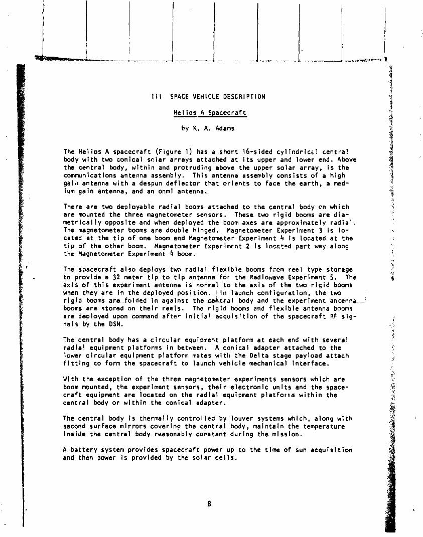
The Hel los A spacecraft (Figure 1) has a short 16-sided cy l i n d r i c t l centra! body w i t h two conical sc iar arrays attached a t i t s upper and lower end. Above the centra l body, w i t n i n and prot ruding above the upper solar array, i s the communicat ions entenna assembly. This antenna assevbly consis ts o f a h igh g a i i ~ antenna w i t h a despun def lec tor tha t o r i en ts t o face the earth, a med- ium gain antenna, and an onmi antenna.
There are two deployable rad ia l tooms attached t o the cent ra l body en which are mounted the three magnetometer sensors. These two r i g i d booms are d ia - metr ica l l y opposite and when deployed the boom axes are approximately rad ia l . The magnetometer booms are double hinged. Magnetometer Experiment 3 i s l o - cated a t the t i p o f one boom and Magnetometer Experiment 4 i s located a t the t i p o f the other boom. Magnetometer Experiment 2 I s l o c a t ~ d pa r t way along the Magnetometer Experiment 4 boom.
The spacecraft a lso deploys twn rad ia l f l e x i b l e booms f rm reel type storage to provide a 32 meter t i p t o t i p antenna for the Radiowave Experiment 5. The ax is o f t h i s experiment antenna i s normal t o the ax i s o f the two r i g i d booms when they are I n the deployed pos i t i on I n launch cont igurat ion, the two 1 r i g i d booms a r a f o l d e d i n aqainst the L r a l body and the experiment a n t e n n c l booms are stored on t h e i r reels . The r i g i d booms and f l e x i b l e antenna booms are deployed upon comnand a f te r i n i t i a l acquisition of the spacecraft RF s ig - nals by the DSN.
The centra l body has a c i r c u l a r equipment platform a t each end w i t h several rad ia l equipment platforms i n between. A conical adapter attached t o the lower c i r c u l a r equipment p lat form mates w i th the Delta stage payload a t tach f i t t i n g t o form the spacecraft to launch vehic le mechanical in ter face.
With the e x c e p t i o ~ o f the three magnetometer experiments sensors which are boom mounted, the experiment sensors, t h e i r e lec t ron ic u n i t s and the space- c r a f t equipment are located on the rad ia l equipment p l a t f o ~ n ~ s w i t h i n the centra l body o r w i th in the conical adapter.
The centra l body i s thermally cont ro l led by louver systems which, along w i t h second surface mi r ro rs coverino the centra l body, maintain the temperature ins ide the cent ra l body reasonably copstant dur ing the mission.
A ba t te ry system provides spacecraft power up t o the t ime o f sun acqu is i t i on and then power i s provided by the solar c e l l s .

Figure 1 Spacecraft Launch Conf1gura.tion
9
The spacecraf t a t t i t u d e con t ro l i s performed by sun sensors and a co l d n i troben gas j e t system. Coarse and f i n e sensbrs i n the sun sensor as- sembly w i l l be used t o complete the i n i t i a l a c q u i s i t i o n sequence by o r i - en ta t i on of the spacecraf t sp in axes t o a p o s i t i o n perpendicular t o the spacecraft - sun 1 ine. Antenna sigr.al s t reng th measurvents a re used t o b r i ng the sp in axes o f the spacec la f t perpendicular t o the e c l i p t i c plane. The f i n a l sp in ra te , 60 + 1 RPM. wi I 1 be ac!-,ieved by the gas j e t system, implemented by the grounT command based on t e l emetered sp in r a t e infot.ma- ti on.
A l i s t i n g o f the Hel ios R s c i e n t i f i c experiments and the p r i n c i p a l i n v e s t i - gators i s presented i n Table 1 .
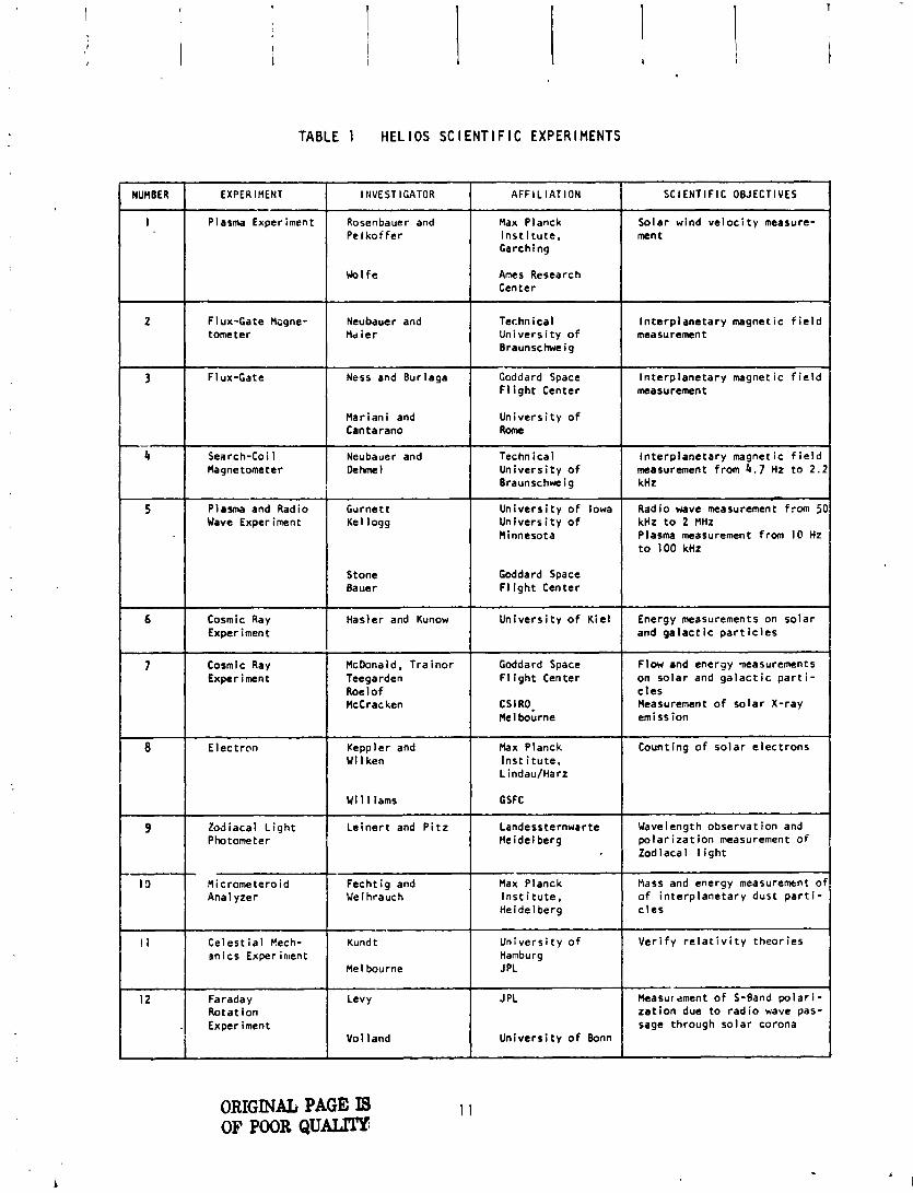
I E N T l F l C EXPERIMENTS TABLE 1 HEL I O S SC
NUMBER - --
Plasma Experiment - -
Rosenbauer and Pe lko f fe r
-
Max Planck I n s t i t u t e , Garching
Ames Research Center
Technical Un ive rs i t y o f Braunschweig
Flux-Gate Hsgne- torneter
l n te rp lane ta ry magnetic f i e l d measurement
Neubauer and Md i e r
Flux-Gate
Mariani and Cantarano
Ness and Burlaga I
Un ive rs i t y o f I Goddard Space F l i g h t Center
I n te rp lane ta ry magnetic f i e l d measurement
Search-Coi 1 Magnetometer
Stone Ba ue r
Plasma and Radio Wave Experiment
Goddard Space F l i g h t Center
Neubauer and Dchmel
Gurnett Kel logg
Technical Un ive rs i t y o f Braunschweig
Cosmic Ray Experiment
Cosmic Ray McDonald, Tra i n o r Exper i men t Teegarden
Roe l o f McCrac ken
In te rp lane ta ry magnetic f i e l d measurement from 4.7 Hz t o 2 . : kHz
Un ive rs i t y o f Iowa Un ive rs i t y o f Minnesota
Hasler and Kunow Un ive rs i t y o f K i e l
Goddard Space Flow and energy measurements F l i g h t Center on so la r and g a l a c t i c p a r t i -
CSIRO. Measurement o f so la r X-ray Me1 bourne emission
Radio wave measurement from 51 kHz t o 2 MHz Plasma measurement from I@ Hz t o 100 kHz
Energy measurements on so la r and g a l a c t i c p a r t i c l e s
Max Planck I n s t i t u t e , Lindau/Harz
E lec t ron Counting o f so la r e lec t rons Iceppler and W i l ken
W i 11 iams
Landessternwarte Wavelength observat ion and Heidel berg p o l a r i z a t i o n measurement o f
Zodiacal l i g h t
Zodiacal L i g h t Photometer
Le ine r t and P i t z
- Max Planck I n s t i t u t e , Heidelberg
1 Un ive rs i t y o f
Mass and energy measurement o o f i n te rp lane ta ry dust p a r t i - c l e s
Micrometeroid Anal yzer
V e r i f y r e l a t i v i t y t heo r ies
Fecht ig and Wei hrauch
Hamburg 1 IPL
C e l e s t i a l Eech- m i c s Experiment
Kund t
Me1 bourne
ORIGINAL PAGE LS OF POOR Q U m
Faraday Rota t ion Exper iment
Levy
Vol land
J PL
Un ive rs i t y o f Bonn
- Heasur anent o f S-Band po la r i - z r t l o n due to r a d i o wave pas- sage through so lar corona

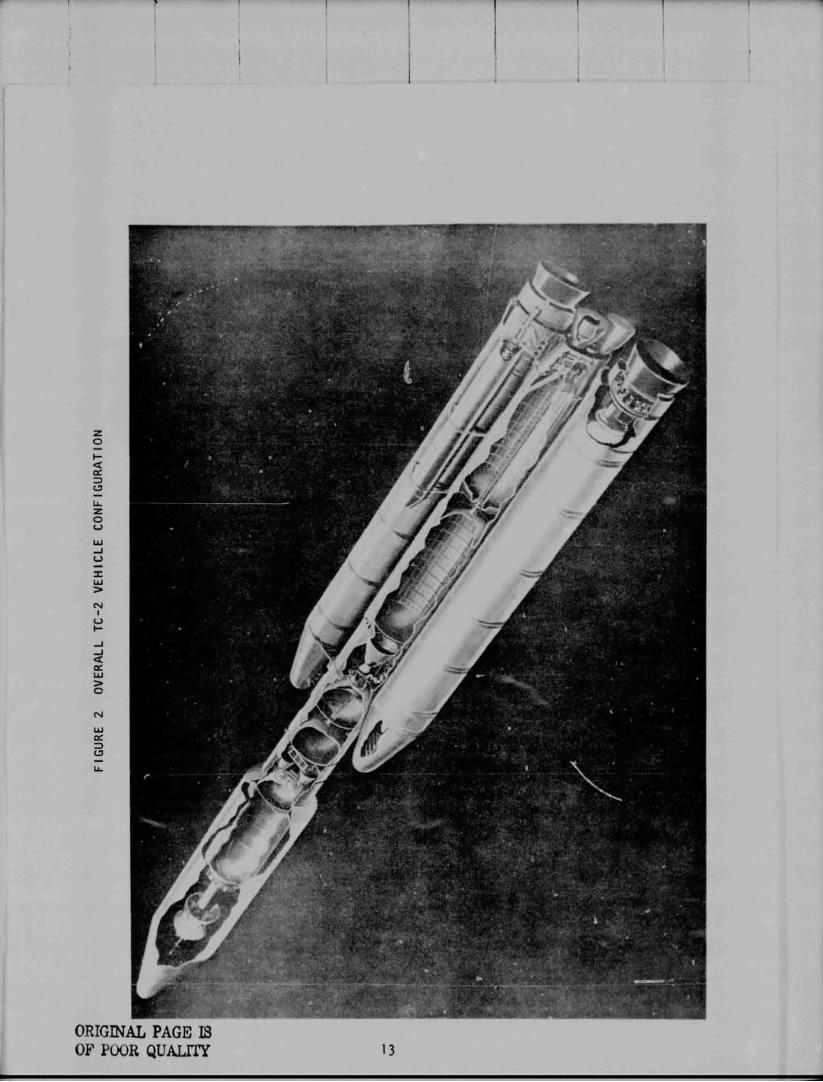
Launch Vehic le Conf igurat ion
The launch veh ic le fo r He1 i os A was the f i v e stage T i tan I I I E/Centaur D-lTR/ Del t a TE-M-364-4 con f igu ra t ion . Th is was the f i r s t opera t iona l f 1 i g h t o f t h i s combination o f stages.
The o v e r a l l veh i c l e con f i gu ra t i on i s shown i n F igure 2. The T i t a n veh i c l e cons is ts o f a two-stage l i q u i d propuls ion core veh i c l e manufactdred by the Mar t in Mar ie t ta Corporat ion and two s o l i d rocket motors (zero stage) manu- fac tured by United Technology Center. The T i t a n veh i c l e i n t eg ra to r i s Mar t in Mar ie t ta . The t h i r d stage i s the Centaur D-1TR manufactured by General Dy- namics Convair D iv is ion. For the He1 ios A mission the De l ta TE-M-364-4 sol i d rocket stage, manufactured by McDonnell Douglas and managed by Goddard Space F l i g h t Center, was in tegrated i n t o the con f igu ra t ion t o p rov ide add i t i ona l v e l o c i t y f o r t h i s h igh energy mission.
The payload f a i r i n g f o r t h i s con f i gu ra t i on i s the newly developed Centaur Standard Shroud (csS) manufactured by Lockheed Miss i 1 es and Space Company, Inc. Figure 3 shows the Centaur/CSS/Helios A spacecraf t general arrangement fcr t h i s mission.
The fo l low ing sect ions o f the r epo r t g i ve a summary d e s c r i p t i o n o f the veh i - c l e stage con f igu ra t ions . De ta i led subs stem descr ip t ions can be found i n I" the F l i g h t Da taAepor t f o r T i tan1Centau.r -Y-1 Proof F l i g h t (NASA TM X-71692),1 Only con f igu ra t ion d i f ferences from TC-I wi 1 l be addressed i n t h i s %por t .

Fig
ure
3
CE
NT
AU
R H
EL
IOS
GE
NE
RA
L A
RR
AN
GE
ME
B
CE
NT
AU
R/T
ITA
N
DE
LT
A
INT
ER
STA
GE
AD
AP
TE
R
SPIN
TA
BL
E,
HE
LIO
S
CE
NT
AU
R D-IT
TE
-M-3
64-4
M
OT
OR
AN
D
VE
HIC
LE
P
AY
LO
AD
AT
TA
CH
FITTING
EN
VIR
ON
ME
NT
AL
S
EL
D
T i t a n l l l E
by J. L. C o l l i n s
The T i t a d c e n t a u r booster, designated T i tan I I I E , was developed from the f a m i l y o f T i t a n I I I vehic les i n use by the A i r Force s ince 1964. The T i t a n l l l E I s a modi f ied vers ion o f the T i t a n 1110. Mod i f i ca t i ons were made t o the T i t a n t o accept s teer ing commands and d i sc re tes from the Centaur i ne r - t i a l guidance system instead o f a r a d i o guidance system. I n add i t i on , a r e - dundant programmer system was added. The T i t a n l I l E cons i s t s o f two sol i d rocket motors designated Stage 0 and the T i t a n I I 1 core veh i c l e Stages I and I I.
The two Sol i d Rocket Motors (SRM'S) prov ide a t h rus t o f 2.4 m i l 1 ion pounds a t l i f t o f f . These motors, b u i l t by Uni ted Technology Center, use p rope l l an t s which are b a s i c a l l y aluminum and amnonium perch lo ra te i n a syn the t i c rubber b inder . F l i g h t con t ro l du r ing the Stage 0 phase o f f l i g h t i s provided by a Thrust Vector Control (TVC) system i n response t o commands from the T i t an f l i g h t con t ro l computer. Ni t rogen t e t r o x i d e i n j ec ted i n t o t he SRM nozz le through TVC valves d e f l e c t s the t h r u s t vector t o prov ide con t ro l . Pressur ized tanks at tached t o each sol i d rocket motor supply the t h rus t vec to r c o n t r o l f l u i d . E l e c t r i c a l systems on each SRM p rov ide power f o r the TVC system.
T i t a n core Stages I and I I are b u i l t by the Ma r t i n Ma r i e t t a Corporat ion. The Stages I and I I p rope l l an t tanks a re copst ructed o f welded aluminum panels and domes w h i k i n t e r c o n n e c t ing s k i r t s - b s e convent ional a l um inum sheet and s t r i n g e r cons t ruc t ion . The Stage I I forward s k i r t provides the a t t a c h p o i n t f o r the Centaur stage and a l s o houses a t r uss s t r uc tu re suppor t ing most o f the T i t a n l l l E e l ec t r on i cs . A thermal b a r r i e r was added t o i s o l a t e t he T i t a n l l l E e l e c t r o n i c s compartment from the Centaur engine compaitment.
Stages I and I I a re qoth powered by l i q u i d rocket engines made by the Aero je t L i q u i d Rocket Company. Propel lants fo r both stages a re n i t r ogen t e t r o x i d e and a 50/50 combination o f hydrazine and unsymmetrical d imethylhydrazine. The Stage I engine cons is ts o f dual t h rus t chambers and turbopumps producing 520,000 pounds t h r u s t a t a l t i t u d e . Independent g imba l l i ng o f the two t h r u s t chambers, us ing a convent ional hyd rau l i c system, provides c o n t r o l i n p i t c h , yaw, and r o l l du r ing Stage I f l i g h t .
The Stage I I engine i s a s i ng l e t h r u s t chamber and turbopump producing 100,000 pounds t h r u s t a t a l t i t u d e . The t h r u s t chamber gimbals f o r f l i g h t con t ro l I n p i t c h and yaw and the turbopump exhaust duct r o ta tes t o prov ide r o l l con t ro l du r ing Stage I1 f l i g h t .
The Stage I o x i d i z e r autogenous p ressu r i za t i on system cons is ted o f one super- heater t o lower I n - f l i g h t tank pressure l eve l s from those experienced du r i ng TC-I which had two superheaters. Th is p ressu r i za t i on system prov ides tank u l l a g e pressure dur ing Stage I burn t ime.
The T i t a n f l i g h t con t ro l computer prov ides p i t c h , yaw and r o l l commands t o the so l i d rocke t motor 's t h r u s t vector c o n t r o l system and the Stages I and II hydrau l i c actuators . The f l i g h t c o n t r o l computer receives a t t i t u d e s i g - na l s from the three-ax is reference system which conta ins th ree displacement gyros.
Vehic le a t t i t u d e ra tes i n p i t c h and yaw a re provided by the r a t e gyro sys- tem located i n Stage 1 . In add i t i on , the f l i g h t c o n t r o l computer generates preprogrammed p i t c h and yaw s igna ls , provides s igna l cond i t i on ing , f i l t e r i n g and ga in changes, and con t ro l s the dump o f excess t h r u s t vector con t ro l f l u i d . A r o l l a x i s c o n t r o l change was added t o prov ide a v a r i a b l e f l i g h t azimuth c a p a b i l i t y f o r p lanetary launches. The Centaur computer provides s tee r i ng programs f o r Stage 0 wind load re1 i e f and guidance s tee r i ng f o r T i tan Stages I and l i . A f l i g h t programmer prov ides t im ing f o r f l i g h t c o n t r o l programs, ga in changes and o ther d i s c r e t e events. A s tag ing t imer provides acceleration-dependent d isc re tes f o r Stage I i g n i t i o n and timed d i sc re tes f o r o ther events keyed t o s tag ing events. The f l i g h t programmer and s tag ing t imer , opera t ing i n con- j unc t i on w i t h a r e l ay package and enable-disable c i r c u i t s , comprise the e l e c t r i - ca l sequencing system. On T i t an l l l E a second programmer, r e l ay packages and o ther c i r c u i t s were added t o prov ide redundancy. Also, c a p a b i l i t y f o r t rans - m i t t i n g backup commands was added t o the T i t an systems f o r s tag ing of t h e Centaur Standard Shroud and t he Centaur.
The standard T i t a n uses three b a t t e r i e s : ; one f o r f l i g h t con t ro l and sequencing4 one f o r te1emetr.r and ins t rumentat ion, d . m n e f o r ordnance. On T i tan l l l E add d i t i o n a l separate redundant Range Safety Command system b a t t e r i e s were added t o s a t i s f y Range requirements.
The T i t an te lemetry system i s an S-band frequency, pulse code modulat ion/ f re- quency modulation (PCM/FM) system cons i s t i ng o f one con t ro l conver ter and re - mote mu1 t i p lexer un i t s . The PCM format i s reprogrammable.
For t h i s T i t a n veh ic le , the f o l l ow ing measurements were added beyond the stan- dard T i t a n l l l E instrumentat ion: s i x accelerometers on t he Stage I engines, a Stage I o x i d i z e r pump i n l e t pressure, two narrow band chamber pressure %as- urements on the two Stage I engines and an o r i f i c e and ven tu r i pressure meas- urement i n the Stage I autogenous system.
Many o f the mod i f i ca t ions t o the T i t a n f o r Titan/Cet?taur were made t o incor - porate redundancy and r e l i a b i l i t y improvements. I n a d d i t i o n t o those m o d i f i - ca t ions p rev i ouc l y mentioned, a f ou r t h r e t r o r o c k e t was added t o Stage II i n order t o ensure proper T i t a d c e n t a u r separat ion i f one motor does no t f i r e . A l l redundancy mod i f i ca t ions t o T i t a n l l l E u t i l i z e d T i t a n f l i g h t proven com- ponents.
Centaur 0-ITR
by R. C. Kalo
The Centaur tank i s a p ressure -s tab i l i zed s t r u c t u r e made from s t a i n l e s s s tee l (0.014 inches t h i c k i n c y l i n d r i c a l sec t ion ) . A double-wal led, vacuum-insulated in termediate bu l khead separates the 1 i q u i d oxygen tank from the 1 i q u i d hydrogen tank.
The e n t i r e c y l i n d r i c a l sec t ion o f the Centaur LH2 tank i s covered by a r a d i a t i o n sh ie ld . Th is sh i e l d cons is ts o f th ree separate layers o f an aluminized Mylar-dacron net sandwich. The forward tank bulkhead and tank access door a re insu la ted w i t h a m u l t i l a y e r aluminized Mylar. The a f t bulkhead i s covered w i t h a membrane which i s i n contact w i t h the tank bu lk- head and a r i g i d r a d i a t i o n sh i e l d sucported on brackets. The membrane i s a layer o f dacron-reinforced aluminized Mylar. The r a d i a t i o n s h i e l d i s -lade o f laminated ny lon f a b r i c w i t h aluminized Mylar on i t s inner sur face and whi te po l yv i ny l f l o u r i d e on i t s ou te r surface.
The forward equipment module, an aluminum con ica l s t ruc tu re , a t taches t o the tank by a shor t c y l i n d r i c a l s tub adapter. Attached t o the forward r i n g o f the equipment module i s an adapter which forms the mounting s t r u c t u r e f o r the Del ta (Fourth) Stage.
Two modes o f tank p ressur i za t ion a re use . Before p rope l l an t tanking, a he1 ium system maintains pressure. W i t h -! rope1 l a n t s i n the tank, pressure -- i s maintained by p rope l l an t b o i l o f f . Dur ing f l i g h t , the a i rborne he l ium
i system provides supplementary pressure when requi red. This system a l s o pro- v ides pressure f o r the Hz02 and engine con t ro l s system.
Primary t h r u s t i s provided by two P r a t t & Whitney RLiOA3-3 engines, which develop 15,000 pounds t o t a l t h r u s t each. The engines a re fed by hydrogen peroxide fue led boost pumps. Engine g imba l l i ng i s provided by a separate hydraul i c system on each eng!ne.
Jur ing coast f l i g h t , a t t i t u d e con t ro l i s provided by four H202 engine c l u s t e r , , iani fo ld assemblies mounted on the tank a f t bulkhead on the per iphera l cen- t e r o f each quadrant. Each assembly cons is ts o f two 6 - l b l a t e r a l t h r u s t en- gines manifolded together.
A r e t r o t h r u s t system cons i s t i ng o f two d i a m e t r i c a l l y oppos i te nozzles mounted on the tank a f t bulkhead and canted 45' from the v e h i c l e l ong i t ud i na l center - l i n e prov ides the t h rus t for separat ing the Centaur f rom the De l t a stage. Actuat ion o f two p a r a l l e l mounted pyrotechnic valves vent res idua l he l ium from the storage b o t t l e through t he two r e t r o t h r u s t nozzles.
A p rope l l an t u t i l i z a t i o n system c o n t r o l s t b ? engine mix tu re r a t i o t o ensure t h a t both p rope l l an t tanks w i l l be evy t i ed s imultaneously. Quan t l t y meas- urement probes a re mounted w i t h i n the f ue l and o x i d i z e r tanks.
The Centaur D- i s an advanced ory. From the (SCU) . Eng ine d i g i t a I -to-ana
IT as t r i on i cs system's Teledyne D i g i t a l Computer Un i t (DCU) , high speed computer w i t h a 16,384 word random access mem-
DCU d l scretes are provided t o the Sequence Control Uni t commands go t o the Servo-Inverter Uni t (SIU) through s i x
l og (D/A) channels.
The Honeywell I n e r t i a l Reference Uni t (IRu) contains a four-gimbal, a l l - a t t i t u d e stable platform. Three gyros s t a b i l i z e t h i s platform, on which a:e mounted three pulse-balanced accelerometers. A prism and window a l low for op t i ca l azimuth alignment. Resolvers on the p la t fo rm gimbals transform vector components from i n e r t i a l t o veh ic le coordinates. A c r ys ta l o s c i l l a - to r , which i s the primary t iming reference, i s a lso contained i n the IRU.
The System Electronic Uni t (SEU) provides cond i t ioned power and sequencing f o r the IRU. Communication from the IRU t o the DCU i s through three analog- t o - d i g i t a l channels ( f o r a t t i t u d e and ra te signals) and three incremental v e l o c i t y channels. The SEU and I R U combination forms the I n e r t i a l Measuring Group (I MG) . The Centaur D-ITR system a lso provides guidance f o r Ti tan, w i t h the s t a b i l i - zat ion funct ion performed by the T i tan.
The centra l contro l system i s housed i n The centra l contro l the Centaur D-ITR.
l e r f o r the Centaur pulse code modulation PCM telemetry the DCU. System capacity i s 267,000 b i t s per second.
l e r services two Teledyne remote-multiplexer u n i t s on
L --. The C-Band tra%ng system provides t rack ing o f the vehic le dur ing
I f l i g h t . The airborne transponder returns an ampl i f ied radio-frequency s ig - nal when i t detects a t rack ing radar 's in terrogat ion.
The Centaur uses a basic d-c power system, provided by ba t te r i es and d i s t r i b - uted v i a harnessing. The servo-inverter provides a-c power, 26 and 115 v o l t s , s ing le phase, 400 Hz.
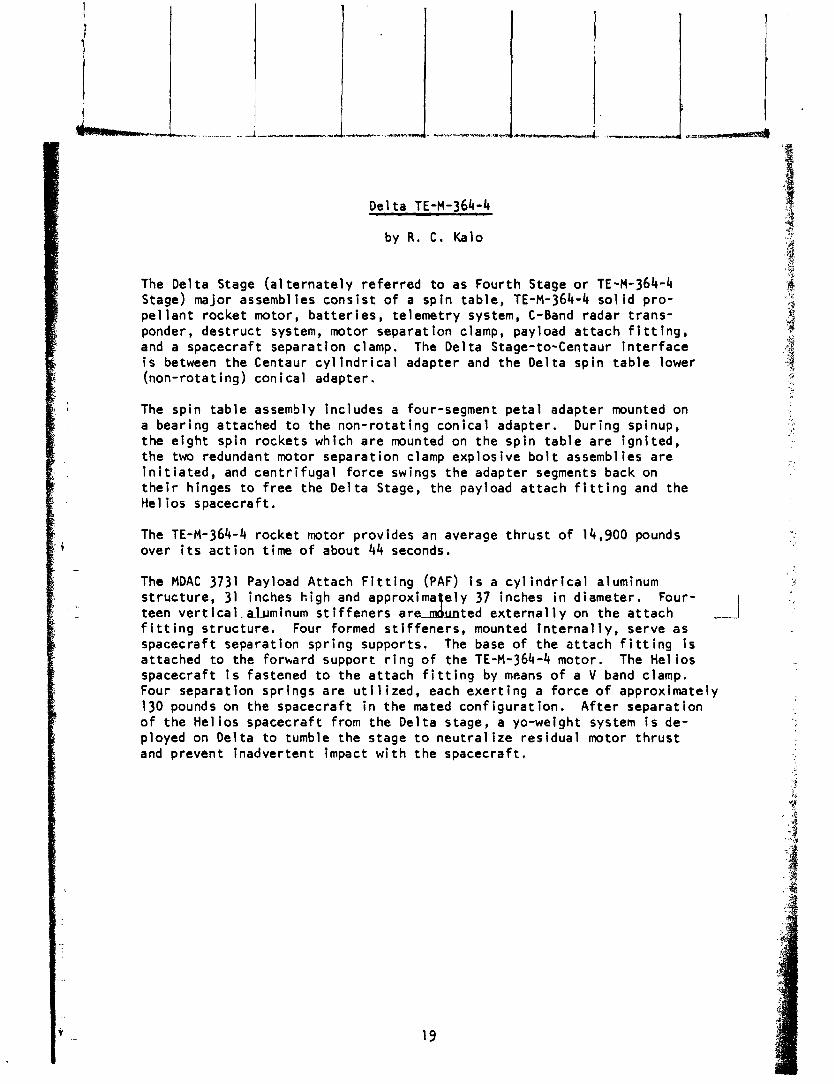
D t l t a TE-M-364-4
The Del ta Stage (a1 t e rna te l y r e fe r red t o as Four th Stage o r TE-M-364-4 Stage) major assemblies cons i s t o f a sp in tab le , TE-M-364-4 s o l i d p ro - pe l l a n t rocket motor, b a t t e r i e s , te lemetry system, C-Band radar t rans - ponder, des t ruc t system, motor separat ion clamp, payload a t t a c h f i t t i n g , and a spacecraf t separat ion clamp. The Del t a Stage-to-Centaur i n t e r f a c e i s between the Centaur c y l i n d r i c a l adapter and the De l ta sp in t a b l e lower (non-rotat ing) con ica l adapter.
The sp in t ab l e assembly includes a four-segment pe ta l adapter mounted on a bear ing at tached t o the non- ro ta t ing con ica l adapter. Dur ing spinup, the e i g h t sp in rockets which a re mounted on the sp in t a b l e a re i gn i t ed , the two redundant motor separat ion clamp exp los ive b o l t assemblies a re i n i t i a t e d , and c e n t r i f u g a l f o r ce swings t h e adapter segments back on t h e i r hinges t o f ree the De l ta Stage, the payload a t t a c h f i t t i n g and the He1 ios spacecraf t .
The TE-M-364-4 rocke t motor prov ides an average t h r u s t o f 14,900 pounds over i t s ac t i on t ime o f about 44 seconds.
The MDAC 3731 Payload At tach F i t t i n g (PAF) i s a c y l i n d r i c a l aluminum s t ruc tu re , 31 inches h igh and approxima e l y 37 inches i n diameter. Four- teen vertical..aluminum s t i f f e n e r s a r d unted e x t e r n a l l y on the a t t a c h - f i t t i n g s t r uc tu re . Four formed s t i f f e n e r s , mounted I n t e r n a l l y , serve as
I spacecraf t separat ion sp r ing supports. The base o f the a t t a c h f i t t i n g i s at tached t o the forbard support r i n g o f the TE-M-364-4 motor. The He1 ios spacecraft i s fastened t o the a t t ach f i t t i n g by means o f a V band clamp. Four separat ion spr ings a re u t i l i z e d , each exe r t i ng a f o r c e o f approximately 130 pounds on t he spacecraf t i n the mated con f igu ra t ion . A f t e r separat ion o f the He l los spacecraf t from the De l ta stage, a yo-weight system i s de- ployed on Del ta t o tumble the stage t o n e u t r a l i z e res idua l motor t h r u s t and prevent inadver tent impact w i t h the spacecraf t .

Centaur Standard Shroud - by T. P. C a h i l l
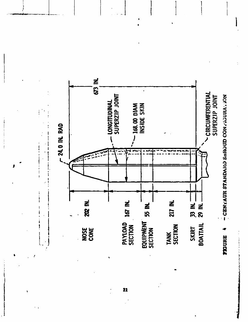
The Centaur Standard Shroud i s a j e t t i s o n a b l e f a i r i n g designed t o pro- t e c t the Centaur veh i c l e and i t s payloads f o r a v a r i e t y o f space missions. The Centaur Standard Shroud, as shown i n F igure 4, cons i s t s o f th ree major segments: a payload sect ion, a tank sect ion, and a b o a t t a i l sec t ion . The 14-foot diameter o f the shroud was selected t o accommodate V ik ing space- c r a f t requirements. The separat ion j o i n t s sevcr the shroud i n t o c lamshel l halves.
The shroud basic s t r u c t u r e i s a r i n g s t i f fened alumlnum and magnesium s h e l l . The c y l i n d r i c a l sect ions a re constructed of two l i g h t gage alumlnum sheets. The ou te r sheet i s l o n g i t u d i n a l l y corrugated f o r s t i f f ness . The sheets a re jo ined by spot welding through an epoxy adhe i v e bond. Sheet sp l ices, r i n g attachments, and f i e l d j o i n t s employ convent ional r i v e t and bo l ted const ruc- t i o n . The b i -con ic nose i s a semi-monocoque magnesium-thorium s i n g l e s k i n she l l . The nose dome i s s t a i n l ess s t ee l . The b o a t t a i l sec t ion accomplishes the t r a n s i t i o n from the 14-foot shroud diameter t o the 10- foot Centaur i n t e r - stage adapter. The b o a t t a i l i s constructed o f a r i n g s t i f f e n e d aluminum sheet con ica l s h e l l having ex te rna l r i v e t e d hat sec t ion s t i f f e n e r s .
The Centaur Standard Shroud modular concept permi ts i n s t a l l a t ion o f t h e tank sect ion around the Centaur independent /of the payload sect ion. The payload 1 sec t ion i s i n s t a l l e d around the s p a c e d a f t i n a spec ia l c lean room, a f t e r I
which the encapsulated spacecraf t i s t ransported t o the launch pad f o r i n - s t a l l a t i o n on the Centaur.
The lower sec t ion o f the shroud provides i n s u l a t i o n f o r the Centaur l i q u i d hydrogen tank dur ing p rope l l an t tank ing and prelaunch ground ho ld operat ions. Th is sec t ion has seals a t each 2nd which c lose o f f the volume between the Centaur tanks and the shroud. A he1 i um purge i s requi red t o prevent forma- t i o n o f i c e i n t h i s volume.
The shroud i s separated from the T i t a d c e n t a u r dur ing T i t a n Stage I1 f l i g h t . J e t t i s o n i s accomplished when an e l e c t r i c a l command from the Centaur i n i t i - ates t he Super-zip separat ion system detonat ion. Redundant dual exp los ive cords a re conf ined i n a f l a t t ened s tee l tube which l i e s between two notched p l a tes around the circumference o f the shroud near the base and up t he s ides o f the shroud t o the nose dome. The pressure produced by the exp los ive co rd detonat ion expands the f l a t t ened tubes, breaking t he two notched p l a tes and separat ing the shroud i n t o two halves.
To ensure r e l i a b i l i t y , two completely redundant e l e c t r i c a l and exp los ive systems a re used. I f the f i r s t system should f a i l t o func t ion , the second i s au tomat i ca l l y ac t i va ted as a backup w i t h i n one-half second.
The T i tan pyrotechnic ba t te ry supplies the e l e c t r i c a l power t o I n i t i a t e the Centaur Standard Shroud e l e c t r i c pyrotechnic detonators. Primary and backup j e t t i s o n d iscre te signals are sent t o the T i tan squib f i r i n g c i r c u i t r y by the Centaur Sequence Control Unl t (SCU) . A t e r t i a r y j e t - t i son signal, f o r add i t iona l redundancy, i s derived from the T i tan staging timer.
Four base-mounted, co i l - sp r i ng thrusters force each o f the two severed shroud sections t o p i vo t about hinge points a t the base o f the shroud. After r o t a t i n g approximately 60 degrees, each shroud ha1 f separates from i t s hinges and c m t inues t o fa1 1 back and away from the launch vehicle.
Two add i t iona l sets o f springs are i ns ta l l ed l a t e r a l l y across the Centaur Standard Shroud s p l i t l ines; one set o f two springs i n the upper nose cone t o ass is t i n overcoming nose dome rubbing f r i c t i o n and one set o f two springs a t the top o f the tank sect ion t o provide add i t iona l impulse during Centaur/Shroud j e t t i son disconnect breakaway.
NOSE
CO
NE
PAY L
OAD
SECT
ION
EQUI
PIV~
ENT
SECT
ION
202
IN.
A
167
IN.
v 55
IN.
TANK
S E
CTlO
N
SKIR
T BO
ATTA
IL
r 2
40 IN
. RA
D I
673
IN.
,- - LO
NGllU
OlNA
L SU
PERZ
IP J
OIN
T
'"
168.
00 D
lAM
IN
SIDE
SKI
N .
I V M I S S ION PROF1 LE AND PERFORRANCE SUMMARY

I V M I SS ION PROF1 LE AND PERFORMANCE SUMMARY
F l i g h t T ra j ec to r y and Perfocmance Data
by R. P. Kuiv inen
Stage 0 i g n i t i o n f o r the TC-2 launch veh i c l e occurred a t 0711:01.057 GMT (021 1 :01.057 EST) on Tuesday, December 10, 1974, w i t h l i f t o f f occu r r i ng approximately 0.3 seconds l a t e r . The ADDJUST-des igned T i tan Stage 0 s teer ing programs f o r aerodynamic load r e l i e f were based on a Windsonde ba l loon which was r - leased 2.5 hours p r i o r t o the expected launch t ime.
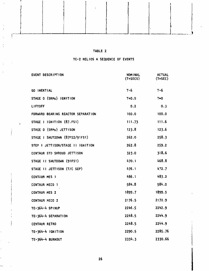
The f l i g h t sequence of events i s contained i n Table 2. The He l los A por- t i o n o f the miss ion extended from Stage 0 i g r i t ion through the TE-364-4 burn and spacecraf t separation. The Centaar extended mission commenced a f t e r the separat ion o f t he TE-364-4/Hel i o s A from the Centlaur.
The Stage 0 phase o f f l i g h t was nea r l y nominal. The i g n i t i o n o f t he Stage I engines (87FsI) occurred a t 111.6 seconds i n t o the f l i g h t which was about 0.1 seconds e a r l i e r than pred ic ted. 12.0 seconds a f t e r i g n i t i o n , a t 124.6 second: i n t o the f l i g h t , the s o l i d rocket motors (SRM's) were j e t t i soned . The comparison of the actua l t r a j e c t o r y w i t h the p r e f l i g h t p red ic ted t r a - j e c t o r y showed the veh i c l e was extremely c lose t o the p red ic ted p o s i t i o n and v e l o c i t y a t SRM j e t t i s c - . I
I - -- - - The d u r a t i ~ ~ i o f Stage I p o r t i o n o f f l i g h t was 3.7 seconds shor ter than pre- dicted. The Stage I/Stage I I s tag ing sequence commenced a t 258.3 seconds w i t h Stage I shutdown (87F~2 ) and has completed w i t h separat ion occur r ing a t 259.6 seconds. The Stage I I i g n i t i o n s igna l ( 91F~1 ) was sent s imul tan- eously w i t h the Stage I I shutdown s ignal ( 8 7 ~ ~ 2 ' . The veh i c l e was approx i - mately 3000 f ee t h igher i n a l t i t u d e and 80 feet /sec lower i n v e l o c i t y than pred ic ted a t the t ime o f Stage I shutdawn.
During t he T i t a n Stage I I p o r t i o n o f f l i g h t the Centaur Sequence Contro l U n i t (sCU) commanded j e t t i s o n o f the Centaur Standard Shroud a t 318.6 sec- onds i n t o f 1 i gh t . Thi s event i s commanded by the Centaur SCU 60 seconds a f t e r the Centaur f l i g h t computer senses T i t a n Stage I shutdown.
The duratic.1 o f the T i t a n Stage I I p c r t i o n o f f l i g h t was 2.4 seconds longer than predicsed, w i t h Stage I I shutdown occur r ing a t 468.8 seconds i n t o the f l i g h t . The Centaur DCU commanded Stage ! I separat ion 3.9 seconds a f t e r sensing the shutdown decel l e r a t ion.
The veh i c l e was 528 f t low i n a l t i t u d e and 60 f t / sec low i n v e l o c i t y a t T i t a d c e n t a u r separation. These d ispers ions were w e l l w i t h i n the expected tolerances.
Centaur main engine s t a r t (MES-1) f o r f i r s t burn occurred a t 483.2 seconds i n t o f l igh t . The Centaur f i r s t burn terminated upon successful i n s e r t i o n i n t o the park ing o r b i t a t 584.0 secords i n t o f l i g h t . Table 3 shows t h a t a h i g h l y accurate parking o r b i t was achieved.
The Centaur coasted i n park ing o r b i t for 21.93 minutes i n a p rope l l an t set - t l e d mode. The Centaur second burn o f 273.4 seconds occurred a t t he end o f the coast w i t h main engine s t a r t (MES-2) a t 1899.5 seconds i n t o the f l i g h t w i t h the guidance system commanding MECO-2 a t 2172.9 seconds.
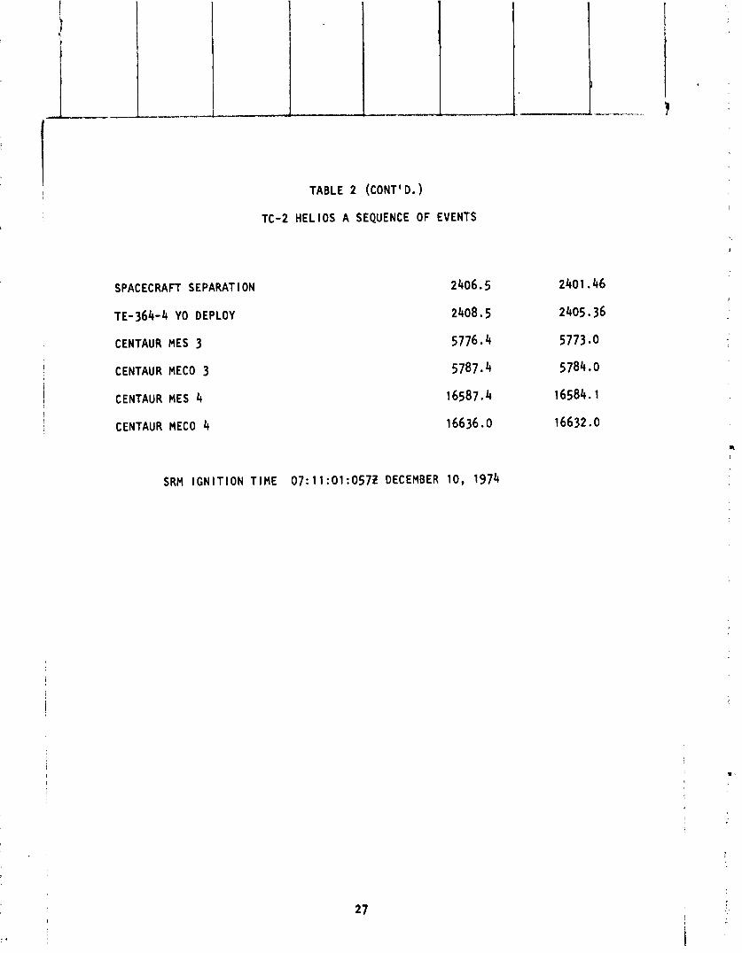
Seventy seconds a f t e r MECO-2, the TE-M-364-4 and spacecraft were spun up. Separation occurred two seconds l a t e r . The second burn o r b i t s 1 data i s shown i n Table 3 a t TE-M-364-4 separat ion from the Centaur. The o r b i t a l data ind ica tes a very accurate o r b i t was achieved by the Centaur second burn.
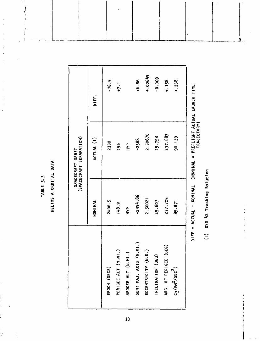
The TE-M-364-4 burn completed the He1 ios p o r t i o n o f fl igb. p l ac i ng the space- c r a f t i n t o i t s f i n a l h e l i o c e n t r i c o r b i t . The burn appeared t o be about one second longer than expected. The o r b i t a l elemento a t spacecraft separat ion, which occurred a t 2401.46 seconds, a re presented i n Table 3. A s l i g h t l y higher ve loc i t y , approximately 30 f t /sec, was achieved by the TE-M-364-4. The free- f a l l t r a j e c t o r y s imulat ion of the o r b i t a l elements t o p e r i h e l i o n passage, which i s presented i n Table 4, shows t h a t a very accurate He1 i os A he1 i o c e n t r i c o r b i t was obtained.
The Centaur, a f t e r the TE-M-364-4 was sep rated, performed two add i t i ona l f i r - i n g s o f t h e m a i ~ s n g i n e s todemonstrate .- -- t e c a p a b i l i t y - 6 t o c o a s t a t I e a s t o n e I - .. hour i n a zero-g mode and f i r e the engines as we l l as a longer zero-g coast which represented a t y p i c a l geosynchronous mission sequence. Several propel - l a n t management experiments were performed i n t h i s Centaur extended mission.
The Centaur was a1 igned along the rad ius vector such t ha t the resu l t an t o r b i t a f t e r the t h i r d and four th burns would be a h i gh l y e l l i p t i c a l geocentr ic o r b i t .
A f t e r the one-hour zero-g coast, the Centaur t h i r d burn occurred a t 5773 sec- onds i n t o the f l i g h t f o r a dura t ion o f 11 seconds. The Centaur then coasted f o r three hours i n the zero-g mode performing thermal naneuvers. A t 16584.1 seconds i n t o the f l i g h t the Centaur f o u r t h and f i n a l engine f i r i n g occurred. The dura t ion o f t h i s burn was 47.9 seconds which was about 0.7 seconds shor ter than expected. The o r b i t a l elements f o r the extended mission a re tabulated i n Table 5. The o r t i b accuracy i s considered sa t i s f ac to r y s ince the t h i r d and f ou r t h burns were no t guided. The t h i r d burn was terminated on a f i x e d burn t ime and the f o u r t h burn, on an acce le ra t ion l eve l based upon a prede- termined res idua l p rope l lan t weight. The i n c l i n a t i o n was 1.95 degrees greater than predicted, which ind icated an out -o f -p lane t h rus t component. The i n c l i - na t i on d ispers ion was invest igated and was considered not t o be unexpected f o r the a u t o p i l o t software con f i gu ra t i on t h a t was f lown. The i nves t i ga t i on a l so revealed changes i n some o f the o ther o r b i t a l parameters dur ing t he coast phases. The o r b i t a l elements were computed from telemetered accelerometer data and i t was concluded t h a t these changes could be due t o accelerometer b ias e r ro rs . Because o f insufficient t rack ing o f the Centaur C-band dur ing t he extended mission, con f i rmat ion o f these changes i n o r b i t a l parameters was no t possi ble.
2 5
EVENT DESCR l PT l ON
TABLE 2
TC-2 HELIOS A SEQUENCE OF EVENTS
GO INERTIAL
STAGE 0 (SRMS) IGNITION
L l FTOFF
FORWARD BEAR l NG REACTOR SEPARAT l ON
STAGE I IGNITION ( 8 7 . ~ S 1 ) I
STAGE 0 (SRMS) JETT l SON
STAGE I SHUTDOWN (87FS2/91 FS1)
STEP I JETTISON/STAGE II IGNITION
CENTAUR STD SHROUD JETTISON
STAGE I I SHUTDOWN ( 9 1 ~ ~ 1 )
STAGE I I JETTISON (TIC SEP)
CENTAUR MES 1
CENTAUR MECO 1
CENTAUR MES 2
CENTAUR MECO 2
TE-364-4 SP l NUP
TE-364-4 SEPARATION
CENTAUR RETRO
TE-364-4 l GN l T l ON
TE- 364-4 BURNOUT
NOM l NAL (T+SECS)
ACTUAL (T+SEC)
SPACECRAFT SEPARAT l ON
TE-364-4 YO DEPLOY
CENTAUR MES 3 !
CENTAUR MECO 3
i 1 CENTAUR MES 4 I I ! CENTAUR MECO 4
TABLE 2 (CONT' D. )
TC-2 H E L I O S A SEQUENCE OF EVENTS
SRM I G N I T I O N T I M E 0 7 : 1 1 : 0 1 : 0 5 7 Z DECEMBER 1 0 , 1 9 7 4

TAB
LE
3.1
HE
L l O
S A
OR
B I'
iL
DA
TA
EPO
CH
(S
EC
S)
PE
RIG
EE
ALT
(N
.MI
.)
APO
GEE
ALT
(N
.MI
.)
SE
MI
MA
J.
AX
IS
(N.M
I.)
EC
CE
NT
RIC
ITY
(N
.D.)
I NC
L I N
AT I 0
3
(DEG
)
ARG
. O
F P
ER
IGE
E
(DE
G)
c3 (K
M2
/s~
c2)
NOM
l N
AL
PA
RK
ING
Od
BIT
(M
ECO
1
+ D
EC
AY
)
AC
TUA
L D
IFF
.
DIF
F =
AC
TUA
L - N
OM
INA
L {N
OM
INA
L =
P
RE
FLI
GH
T A
CTU
AL
LAU
NC
H
T l M
E TR
AJEC
TOR
Y)
(1)
De
riv
ed
Orb
it f
rom
Gu
ida
nce
Da
ta
(2)
Tra
ck
ing
Da
ta f
rom
BD
A,
ANT
&
ASC

EPO
CH
(S
EC
S)
PE
RIG
EE
ALT
(N
.MI.)
APO
GEE
A
LT
(N. M
I. )
SE
MI
MA
J.
AX
IS
(N.M
I.)
EC
CE
NT
RIC
ITY
(N
.D.)
l NC
L l N
AT l ON
(D
EG
)
ARG
. O
F P
ER
IGE
E
(DE
G
2 2
C,(K
Pl /S
EC
)
TAB
LE
3.2
HE
LIO
S A
OR
BIT
AL
DAT
A
CEN
TAU
R
2ND
BU
RN
(TE
-36
4-4
SE
PAR
AT I O
N)
NOM
l N
AL
22
48
.5
10
2.6
1
HYP
-22
91
3.0
7
1.1
54
78
29
.80
8
23
1 .3
91
9.3
93
AC
TUA
L (1
)
22
07
.7
10
3.9
7
HYP
-22
85
7.1
6
1.1
52
21
29
.82
0
23
1.4
35
9.4
16
DIF
F.
Dl F
F =
AC
TUA
L - N
OM
INA
L (N
OM
INA
L =
PR
EFL
l G
HT
AC
TUA
L LA
UN
CH
TIM
E
TR
AJE
CT
OR
Y)
(1)
De
riv
ed
Orb
it f
rom
Gu
ida
nce
Da
ta
EPO
CH
(S
EC
S)
PE
RIG
EE
ALT
(N
.MI.
)
APO
GEE
A
LT
(N.
M I.
) S
EM
I M
AJ.
A
XIS
(N
.MI.)
EC
CE
NTR
ICIT
Y
(N.D
.)
l NC
L l N
AT l O
N (D
EG)
ARG
. O
F PE
R1 G
EE
(DEG
)
c3 (K
M2:
s~c2
)
TAB
LE
3.3
HE
LIO
S A
O
RB
ITA
L D
ATA
SPAC
ECR
AFT
OR
BIT
(S
PA
CE
CR
AFT
SE
PA
RA
TIO
N)
NOM
l N
AL
AC
TUA
L (1
) D
IFF
.
Dl F
F - AC
TUA
L -
NO
MIN
AL
(NO
MIN
AL
= P
RE
FLIG
HT
AC
TUA
L LA
UN
CH
TIM
E
TRA
JEC
TOR
Y)
(1)
DSS
42
Tra
ck
ing
So
luti
on


EPO
CH
(SE
CS
)
PE
RIG
EE
ALT
(N
.MI.
)
APO
GEE
A
LT
(N .M
I . ) SE
MI.
MA
J. A
XIS
(N
.MI.)
EC
CE
NTR
ICIT
Y
(N.D
.)
INC
LIN
A:
!ON
!D
EG)
ARC
. O
F PE
R1 G
EE
(DE
G)
c3 (K
M2/
sEc2
)
TAB
LE
5
CEN
TAU
R
EXTE
ND
ED h
lSS
ION
OR
BIT
AL
DAT
A
CEN
TAU
R
3RD
BURN
(M
ECO
3
)
NOM I N
AL
57
87
.9
20
0.3
5
HYP
- 34
75
9.6
9
1.1
04
84
2
29
.81
4
23
0.4
51
6.1
92
AC
TUA
L (1
)
57
87
.8
20
8.3
5
HYP
- 34
64
9.7
6
1.1
05
40
6
29
.91
8
23
0.6
04
6.2
1 1
DlF
F
CEM
TAUR
4TH
BU
RN
(MEC
O 4)
NOM l N
AL
AC
TUA
L !I
) D
lFF
Dl F
F =
AC
TUA
L - N
OM
l NAL
(N
OM
INA
L =
PR
EFLI
GH
T A
CTU
AL
LAU
NC
H
TIM
E
TRA
JEC
TOR
Y)
(1)
Gu
ida
nce
De
riv
ed
Orb
it S
olu
tio
n

T i tan Phase o f F l i qh t
by J. L. Co l l i ns
The Stage 0 (Sol i d Rocket Motors) propulsion performance was very close t o the p r e f l i gh t predicted parameters. This s i t u a t i o n resul ted i n a nominal t ra jec to ry being flown during the Stage 0 burn.
The Stage I had a normal engine s t a r t t rzns ien t , a normal e x i t c losure j e t - t i son and normal ox id izer deplet ion shutdown charac ter is t i c . Propulsion parameters were very close t o the p r e f l i g h t predicted values which yielded a nominal t ra jec to ry during Stage I burn. A f 12 ps i suct ion pressure os- c i l l a t i o n a t 16 Hz was noted a t about 140 seconds i n t o the Stage I burn.
The Stage I I had a normal engine s t a r t t rans ien t and a fue l leading simul- taneous deplet ion shutdown. Propulsion parameters indicated a nominal steady s ta te f l i g h t except f o r a chamber pressure spike o f 250 psi noted dur ing shut- down.
Overall, the T i tan E-2 performed i t s pa r t o f the ove ra l l mission i n a s a t i s - fac tory manner and a t the end o f Stage I I burn the vehic le was nominal a t 528 f t . low i n a l t i t u d e and 60.0/ft/sec low i n ve loc i ty . These dispersions were w i th in the expected f l i g h t tolerance.
From the T i tan po in t o f view there were s veral f i r s t s which are l i s t e d below: - - 4 --- -
1. F i r s t f l i g h t o f the -021 accelerometers I
2. F i r s t f l i g h t of POGO instrumentation - Stage I 3. F i r s t f 1 igh t w i t h conformal coated Fl igh t Control System Components
Centaur Phase o f F l i g h t - Primary and Extended Mission
by R. C . Kalo
Centaur (TC-2) successful l y placed the He1 ios spacecraft i n t o a h igh l y ac- curate he l iocent r ic o r b i t w i t h the required a t t i t u d e alignment. Following separation o f the TE-M-364-4/Hel ios payload, the Centaur vehi c l e proceeded i n t o a 4 1/2-hour experiment phase which successful l y accompl ished a1 l ob- j e c t ives.
Performance of the Centaur was completely sa t is fac tory . The Hel ios mission was performed using a two-burn, se t t led parking o r b i t ascent mode. The post Helios experiment phase consisted of a one-hour zero-G coast, a t h i r d burn (f ixed durat ion o f 11 seconds), a 3-hour zero-G coast w i th r o l l ax i s thermal maneuvers, and a fou r th burn ( cu to f f based on vehic le weight) fol lowed by a boost pump experiment and a H202 deplet ion tes t . A l l Helios mission objec- t ives, T i t adcen tau r operat ional capab i l i t y object ives, and the Centaur ex- periment phase object ives were sa t is f ied . These object ives are l i s t e d as f o l lows:
He1 ios Mission Pecul iar
1. The launch vehic le in jec ted the Helios spacecraft i n t o the cen t r i c o r b i t .
2. Centaur a l iQacd the TE-M-364-4 s tage A QK spacecraft i n j e c t
1 requ i red he 1 i o-
ion burn. A 3. Centaur generated the TE-M-364-4 stage sp inup and separation commands.
4. Centaur executed a re t ro th rus t maneuver '01 lowing separation o f the TE- M-364-4.
5 . Vibra t ion data on the TE-M-364-4 payload adapter was obtained.
6. Centaur Standard Shroud (CSS) payload cav i t y pressure and temperature data was obtained.
7. Total impulse o f the TE-M-364-4 was ve r i f i ed .
T i tan/Cent&ur Operat ional Capabi 1 i t y
1. D-ITR Centaur operat ional 2-burn mission c a p a b i l i t y was demonstrated.
2. D-lTR Centaur v ib ra t i on loads data were obtained.
3. Thermal performance o f the D-ITR Centaur insu la t ion system (2-burn miss ion) was demonstrated.
4. Performance o f the computer contro l 1 ed vent and pressur izat ion sys tem was demonstrated .

5. CSS ascent vent ing and contro l o f cav i t y d i f f e r e n t i a l pressures was demon- strated.
Extended Mission Experiment Phase
1. Data was obtained t o ev l lua te propel lant behavior, heat t r r n t r r r , and pro- pel lan t tank ternperature/pressure h i s to ry during a one-hour zero-G coast o f the type requi red f o r the 1977 Mariner Jupi ter/Saturn mission.
2. The D-ITR Centaur hardware arid software capabi l i t y f o r performing mul t l p l e main engine s t a r t s was demonstrated.
3. Data was obtained t o evaluate propel lant behavior, heat t ransfer and propel- l an t tank temperature/pressure h i s to ry during a long zero-G coast which u t i l i z e s r o l l maneuvers f o r thermal cont ro l .
4. Data was obtained t o evaluate boost pump operat ion i n a "dead-head" and en- gine chi l ldown mode i n a low-G environment.

V VEHICLE DYNAMICS
I
V VEHICLE DYNAMICS
by J. C. Estes and T. F. Gerus
Dynamic loads a re imposed upon the veh i c l e from several sources. 'hey a re wind loads, acoust ic f i e l d s , and loads due t o system dynamic response from engines c t a r t l n g and stopping. Evaluat ion o f t he f l i g h t wind loads a r e as fo l lows:
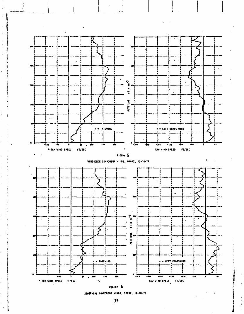
The ADDJUST system designed f 1 i g h t s t ee r i ng programs PIAXOO*TC02 f o r the wind prof l l e measured by a Windsonde bal loon released a t 04412, December 10, 1974. The p i t c h arld yaw components o f t h i s wind are shown i n F igure 5 . Dur- ing prelaunch v e r i f i c a t i o n o f the f l i g h t s t ee r i ng programs, peak respmse t o the 04412 wind was ca lcu la ted t o be 78% o f the weakest s t r u c t u r a l a l l owab le ( a t 5434 f ee t ) and 79% of the a l lowable TVC steer ing usage ( a t 60000 f e r t ) . I t should be noted t h a t these percentages inc lude a combination o f nominal wind responses w i t h allowance: fo r such unmeasured and/or non-nominal quan t i - t i c s as gusts, bu f f e t i ng , t r a j e c t o r y d ispers ions, and two-hour wind changes.
A post-launch wlnd sounding was made w i t h a Jirnsphere ba l loon released a t 97252, December 10, 1974. The p i t c h and yaw components o f t h i s wind a re shown i n F igure 6. The 07252 sounding i s the best a v a i l a b l e measurement o f the f l i g h t winds, al though i t reached c r i t i c a l a l t i t u d e about 45 minutes a f t e r launch. Peak ca lcu la ted responses f o r t h i s sounding were 85% o f the weakest s t r u c t u r a l a l lowable ( a t 15371 f+e t ) and 99.6% o f the a1 lowable TVC steer i nq usage-.(at 56622 f e e t ) . These .p t rcen tagss i nc l ude the same a l low- -. I
ances f o r extreme cond i t i ons dessr ibed above f o r the prelaunch v e r i f i c a t i o n s . As may be seen i n the d iscuss ions o f measured TVC s teer ing usage (Sect ion V i I ) , T i t an f l i g h t con t ro l s ( S c t i o n V I I ) , and shroud bending moments (Sect ion V I I I ) . a l l the measured f l i q h t wind responses were w e l l below the a l lowable.
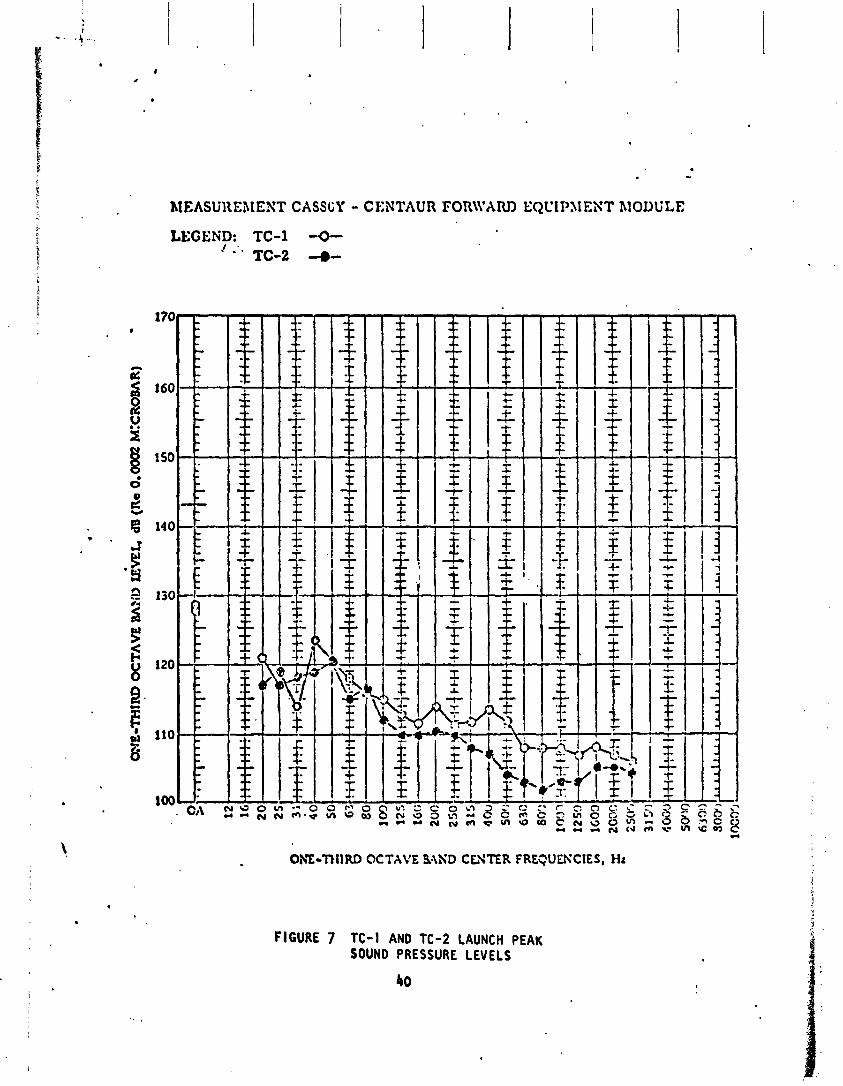
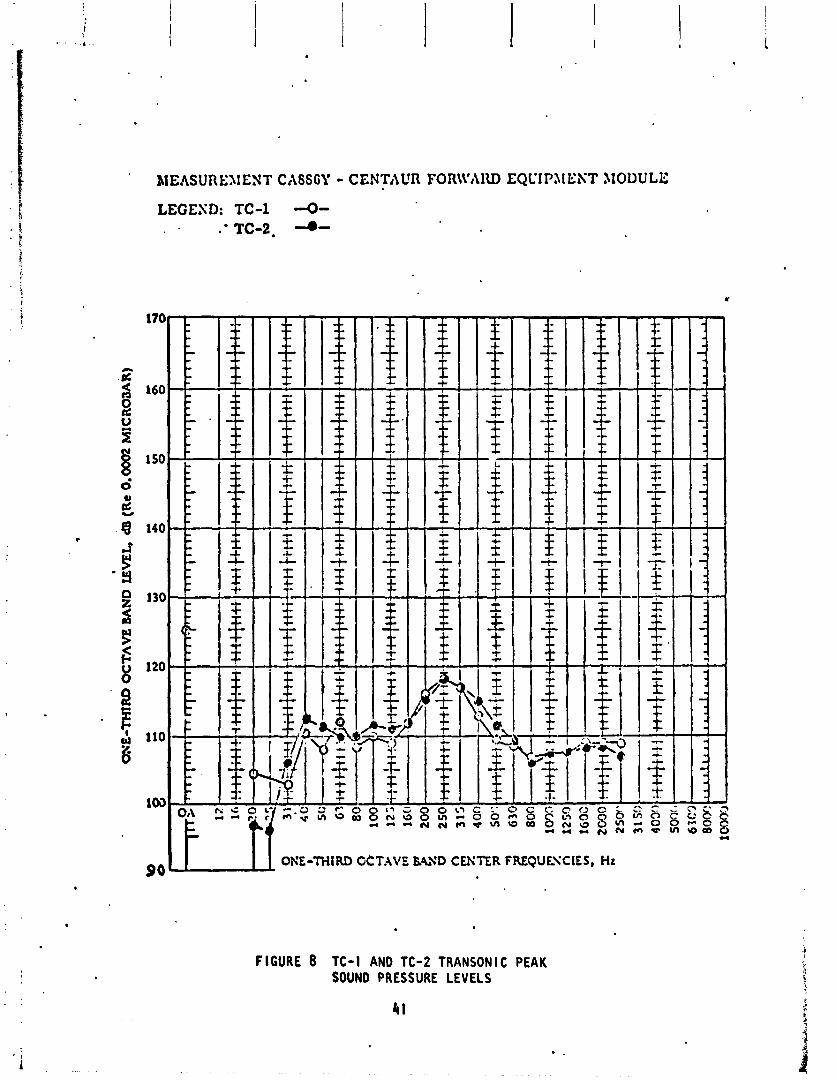
Tlte acoust ic l eve l s measured above the Centaur equipment module a re shown i n Figures 7 and 8. The data i s shown f o r both launch and t ransonic and i s com- pared w i t h TC-I . The acoust ic leve l d l f ferences between TC-I and TC-2 through- out the spectrum dre we l l w i t h i n expected dev ia t ions .
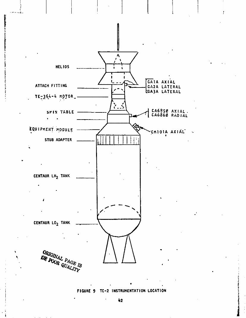
The measurements t h a t a re most s e n s i t i v e t o dynamic response from engin&, s t a r t i n g and stopping a re those a t the payload in te r face . The accelerometer loca t ions r e l a t i v e t o the p r e f l i g h t dynamic model coordinates a re shown i n F igure 9. Rlthough CA 850 and CA 866 measured s i m i l a r response t o a l l t r an - s ients , the ~ l s c u s s i o n f o l l ow ing w i l l compare p red i c t i ons t o f l i g h t measure- ments on G A I A , GA2A and GA3A.
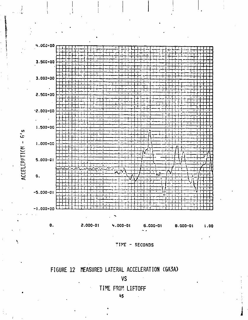
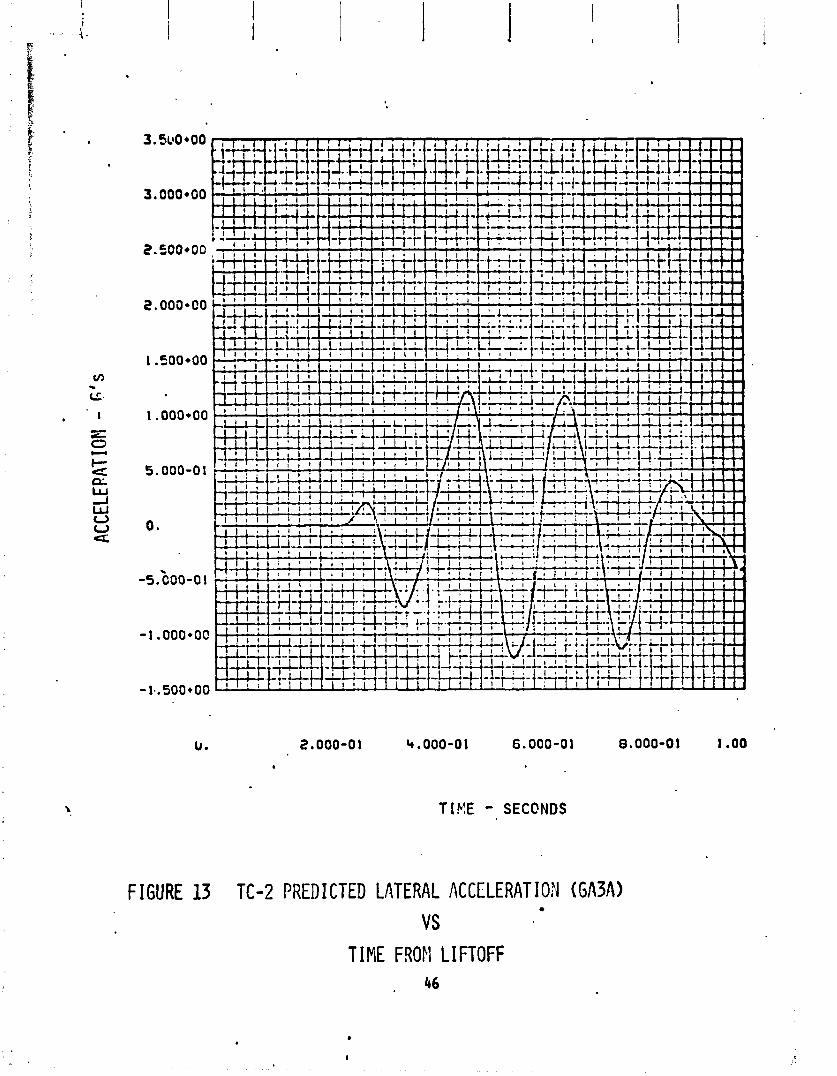
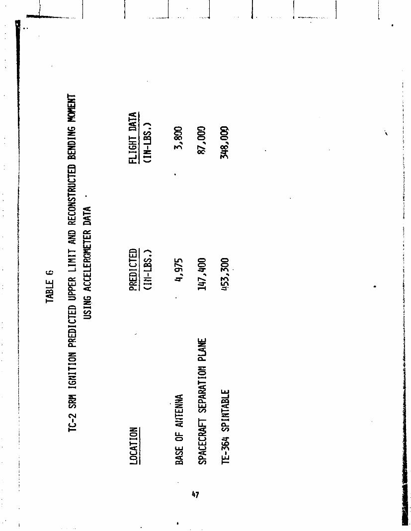
The highest l a t e r a l response measured i n f l i g h t was a t SRM i g n i t i o n . The measured response and the upper l i m i t p red ic ted response a re shown i n Figures 10, 11, 12 and 13. The comparison between the moments r e s u l t i n g from the dy- namic responses a t th ree most c r i t i c a l s t a t i o n s a re shown i n Table 6. I t must be noted t h a t the moment computations have accuracy l i m i t a t i o n s s ince r o t s t i o n a l degrees o f freedom were no t measured. As can be seen i n the tab le , the moments r e s u l t i n g from the measured responses cce we l l w i t h l n the upper l i m i t p red ic ted va 1 ues.
37
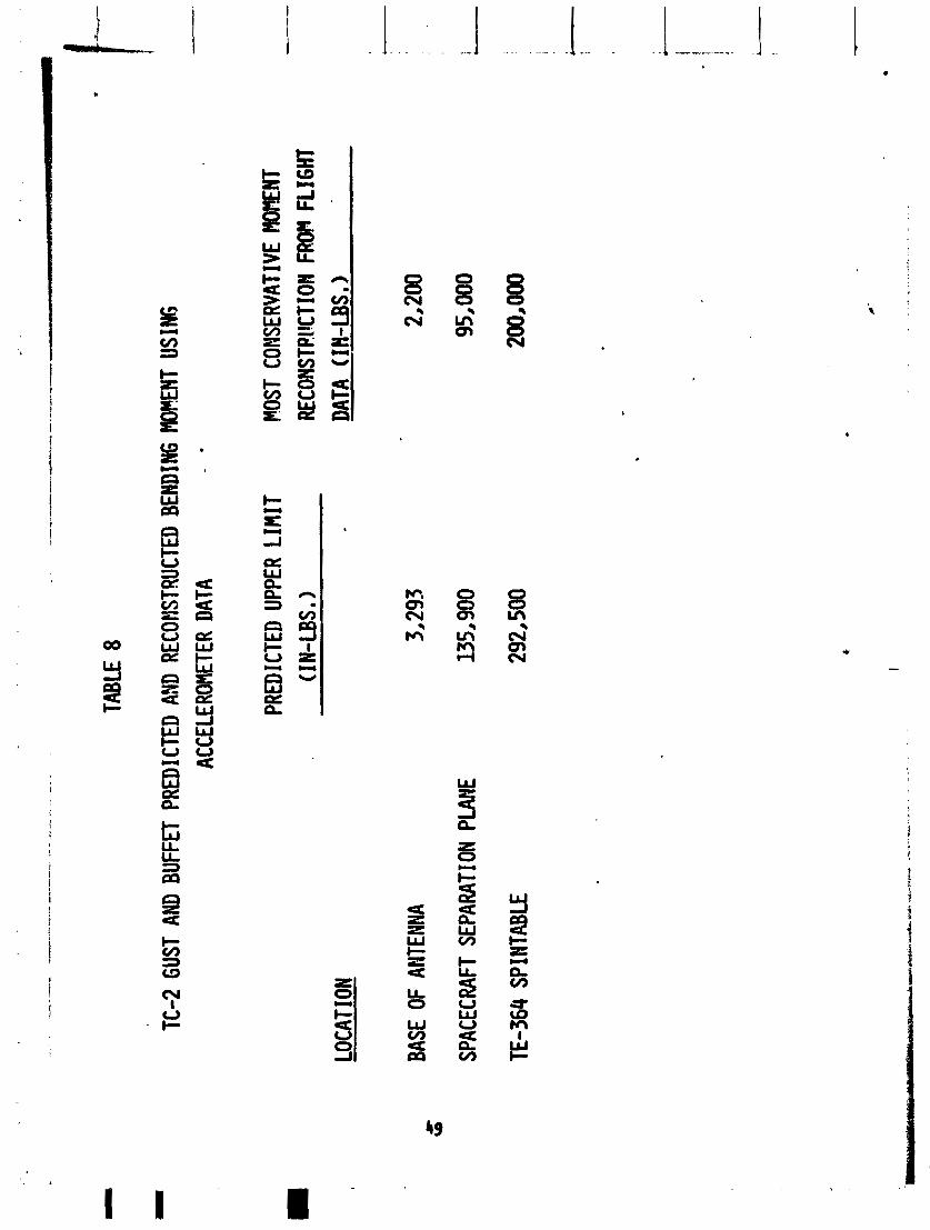
A tabu la t ion o f the accelerometer response due t o gust and b u f f e t i s shown I n Table 7. The maximum predic ted response i s a l so shown. A comparison of bending moments due t o pred ic ted and measured responses a t the three most c r i t i c a l s t a t i ons i s shown i n Table 8. As the t ab le ind icates, the moments which can be reconstructed most conservat ive ly are we l l w i t h i n the upper l i m i t p red ic ted values. As i n the above launch t rans ien t , r o t a t i o ~ ~ l degrees o f freedom were no t measured.
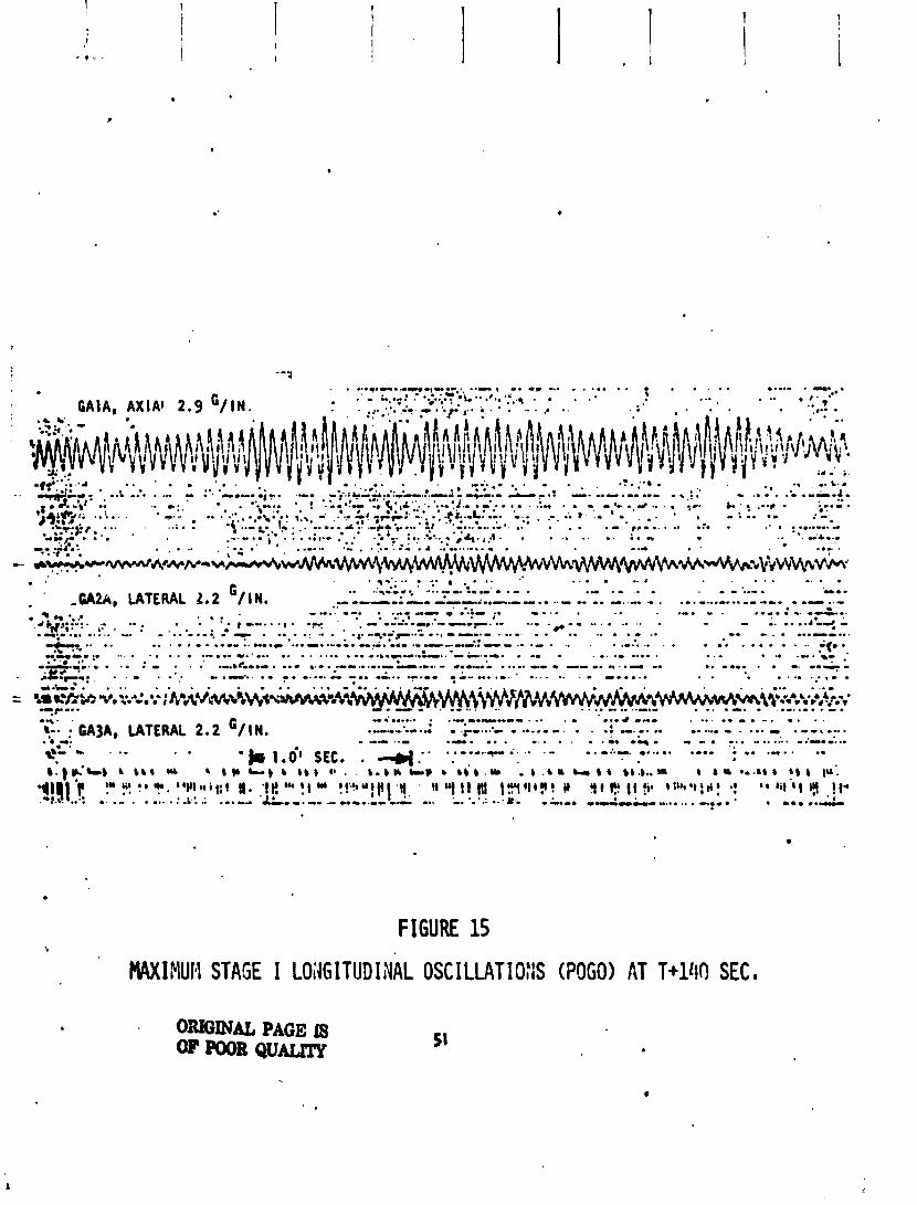
Longitudinal response due t o POGO occurred dur ing Stage I f l i g h t on TC-2. A s imp l i f i ed comparison o f the response l eve l and dura t ion measured a t the Stage I gimbal i s shown i n Figure 14 f o r the TC-1 and TC-2. The actua l TC-2 response leve ls measured a t the payload i n t e r f a c e a re shown on Figure 15. The response l eve l s measured on TC-2 were not a problem because they were far helow the maximum predic ted values f o r the o ther c r i t i c a l condi t ions.
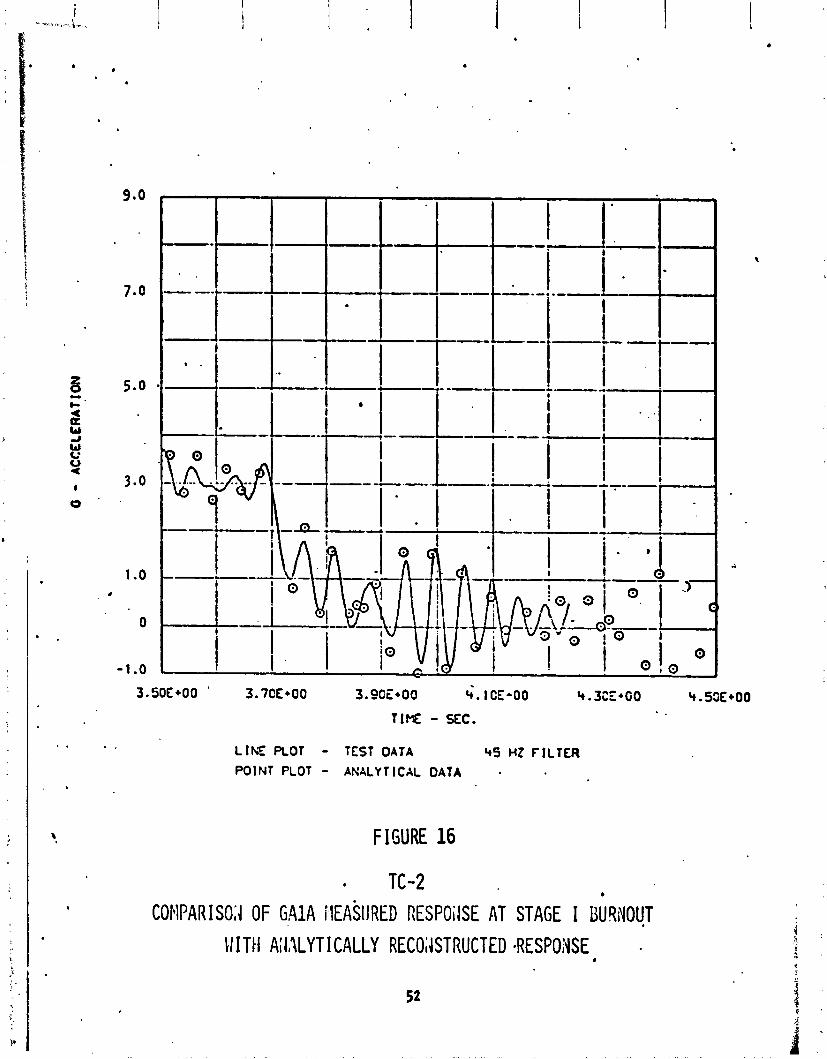
A comparison between measured acce le ra t ion and acce le ra t ion reconstructed using TC-2 chamber pressure a t Stage I burnout a re shown i n Figures 16, 17 and 18. Evaluat ion o f t h i s data ind icates t ha t measured l ong i t ud ina l re - sponse (Figure 16) agrees reasonably w i t h t h a t reconstructed us ing chamber pressure. A1 though l a t e r a l response ( ~ i g u r e s 17 and 18) does not agree as wel l , both pred ic ted and ,;easured a re very small. Therefore, the p rev ious ly pred ic ted dispersed values f o r loads a t Stage I shutdown are a l so considered va l id.
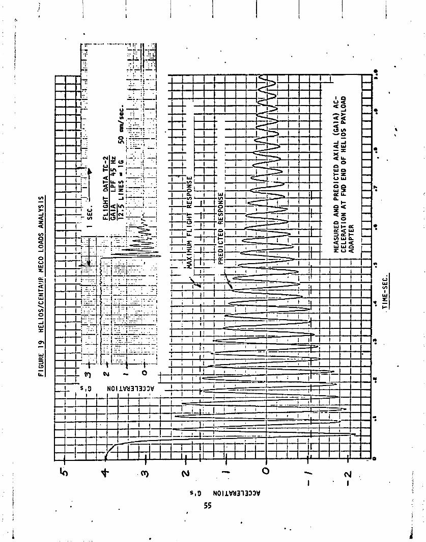
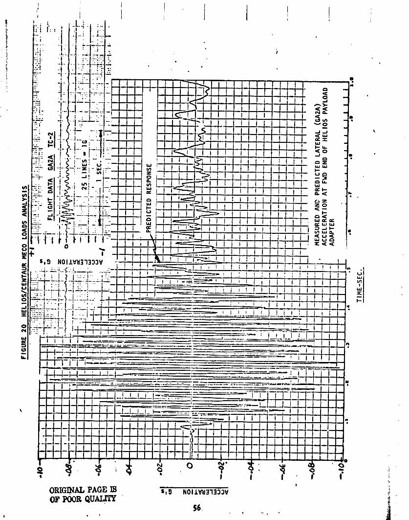
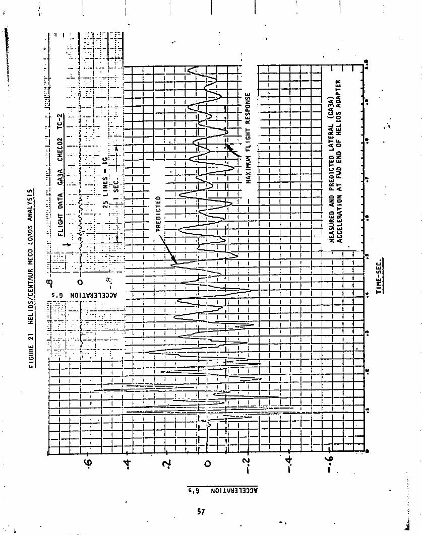
A comparison betweep predic ted and measured acce le ra t ion response a t MECO i s shown i n Figures 19, 20 and 21. Longitudilnal response measured (Figure 19) 1 I s higher than pcadicted because the p r e d i c t i o n was made e a r l y i n the program --_I when the most dispersed predic ted propel l a n t l eve l a t MECO was lower than the actua l p rope l lan t leve l a t TC-2 MECO. As i n Stage I shutdown, l a t e r a l re - sponse p red ic t ions (Figures 20 and 21) d i d no t accurate ly match measured values but -bo th pred ic ted and actua l measured values a re low.
PITCH WIND SPEED n / s c c a YAW WIND SPEED FT/SEC
FIGURE 5 WINDSONDE COMPONENT V I W S . 04512. 12-10-74
PITCH WIND SPEED nlsrc . . YAY Y I ~ D SPEED rvsrc
~ I G U R E 6 JIHSPMERE COIPONENT WINDS. 07252, 12-16-75
Oh%-'TlIlRD OCTAVE 5 W D CWTER FREQUEh'CIf S, Hr
FIGURE 7 TC-l AND TC-2 LAUNCH PEAK SOUND PRESSURE LEVELS
bIEhSURE>IEST CASSGY - CENTAUR FORtl'rlllD EQL'IP3tEKT NODULE
LEGESD: TC-1 4- . ' TC-2 4-
FIGURE 8 T C - I AND TC-2 TRANSONIC PEAK SOUND PRESSURE LEVELS
HEL I O S
ATTACH F l TT l NG
T E y 3 5 3 - 4 H c ? O R - . .
S P I N T A B L E *
STUB ADAPTER
CENTAUR LH2 TANK
CENTAUR LO2 TANK -
----- C A 6 5 ; e A X I A L . C A 6 8 6 0 R A D I A L
F I G U R E 9 TC-2 INSTRUMENTATION LOCATION
42

4.000-0 I - 6 s 000-0 1
T IME - SECONDS
FIGURE 10 TC-2 MEASURED LATERAL ACCFLFRATION
T I !1E FROY L I FTOFF
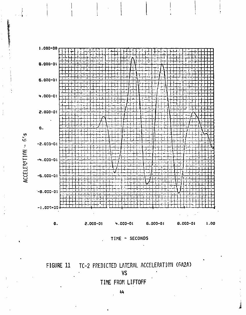
FIGURE 11
TIME - SECONDS
TC-2 PREDICTED MTERAL ACCELERAT IOFJ (FA2A)
TIME FROM LIFTOFF 44
< C L
. (I' J Lu
TIPE - SECONDS
FIGURE 12 MEASURED LATERAL ACCELERATION (GA3A)
TIME FRO:; LIFTOFF
TIEE - SECONDS
FIGURE 13 TC-2 PREDICTED LATERAL ACCCLERAT ION (GA3A) VS
TIME FROM LIFTOFF 46
TABL
E 6
TC-2
S
I IG
IlITI
ON
PRED
ICTE
D UP
PER
LIM
IT A
ND R
ECON
STRU
CTED
BEN
DING
FOM
EKT
USIN
G AC
CELE
ROME
TER
DATA
-
LOCA
TION
, ?R
ED I C
TED
BASE
OF
AHTE
NWA
FLIG
HT D
ATA
(IN
-US
I
TE-3
64
SP I N
TABL
E
t
Y
SPAC
ECRA
FT S
EPAR
ATIO
N PL
ANE
147 , 400

TABL
E 7
TC-2
GU
ST A
HD B
UFFE
T CO
MPAR
ISON
NAX
LATE
RAL
RESP
OiISE
OCC
URRE
D KE
AR T
+43
SEC,
MN =
1.0
2,
ON W
A,
AIJD
GA3
4 MS AL
SO
dEAR
MAX
IMUM
,
a GA
3A M
AY B
E SL
IGHT
LY H
IGHE
R AT
T+
40,
MN =
' 0.9
3.
0
USIH
G 20
HZ L
OW
PASS
FILT
ER,
PEAK
AMP
L. AR
E: FL
IGHT
RES
ULTS
ACCE
L FE
E.
ACCE
L HZ
G
O-PK
64lA
PlAX
.38
(AXI
AL)
19
0.30
e
m
3 XR
fIS =
0.
35
GA2A
MA
X 0.
60
4.8
0.4
3 XR
TS
=
0.58
GA3A
MA
X 0.
33
4.7
0.3
3 XR
MS =
0,
40
MODE
NO
.
54
RSS
25
26
50
51
RSS
25
26
50
51
RSS
BUFF
ET P
REDI
CTIO
N GU
ST
PRED
ICTI
ON
- --
FR
EQ .
G O-
PK
G O-
PK
(ALR
EADY
RE
DUCE
D : BY
0.3
5 FA
CTOR
)
18.4
.4
9 AL
L =
0.
56
..5
.75
4.8
.52
.
15.8
0.
1 15
.8
0.23
AL
L =
1.11
4.6
. b4 4.
8 .7
0
15.8
.2
3 15
.8
.08
ALL
=
1.19
. .
, .
. .
./
.
I .
.
_. .
_ __--..-
,-..---..-.
.-- - .-
1. -. - ̂
. .
-=--
- TA
BLE
8
I
TC-2
GU
ST A
ND B
UFFE
T PR
EDIC
TED
AND
RECO
NSTR
UCTE
D BE
NDIN
G PW
ENT
USIN
6 AC
CELE
ROME
TER
DATA
BASE
OF
ANTE
NNA
SPAC
ECRA
FT S
EPAR
ATI O
N PL
AlE
TE-3
64 S
PINTABLE
PRED
ICTE
D UP
PER
LIR
IT
MOST
CON
SERV
ATIVE
!%PE
NT
RECO
NSTP
lKTIO
N FR
Or(
FLIG
Hl
DATA
(IN
-LBS
,)

'?
FIGURE 15
MAXIMUP1 STAGE I LOX ITUD I NAL OSC I LLATIOX (POGO) AT T+1110 SEC ,
3. 9GE.00 4\. 1 0E400
T I N - SEC.
L f NC PLOT - TEST DATA 45 HZ FILTER POINT PLOT - ANALYTICAL OATA
FIGURE 16
CONPARISOA OF GAlA MEAS~IRED RESPOilSE AT STAGE I BU!WOUT
Cl I Ttl AlLlLYT I CALLY RECOJSTRUCTED *RESPONSE

- L I ~ E ROT - TEST OATA ' ~ ~ ~ H Z F I L T E R ' . P O I N T R O T - A N A L Y T I C A L D A T A a
' FIGURE 17
a CORP,IRISO;I . OF GA2A ?~EASU~'~ED RESPO~JSE AT STAGE I, BUI(I.IOI!T

3.50t*00 3.70E*00 3.90E+00 4.10E+00 4.30E*00
TIK -SEC.
LINE R O T - TEST OATA , 45 HZ FILTER POINT R O T - ANALYTICAL OAfA
FIGURE 18
COMPARIS0:I OF GA3k MEASURED RESPOiiSE AT STAGE 1 BUR?IOUT WITH AiJALYT ICALLY RECOXTRUCTED R E S P O X E .
ORIGQUL PAGE I8 OF POOR Q u m
V I SOFTWARE PERFORMANCE
V I SOFTWARE PERFORMANCE
Airborne
by J. L. Feagan
A l l a va i l ab le DCU f l i g h t te lemetry data was thoroughly reviewed t o v e r i f y t h a t the f l i g h t software performed as designed. The data reviewed included analog p l o t s o f the DCU inputs (A/D1s) and outputs (D/A1s), and d i g i t a l l i s t - ings o f the SCU swi tch commands and the software i n te rna l sequencing. The d i g i t a l data was a lso used t o v e r i f y the proper operat ion o f each module of the f l i g h t program as we l l as the t r ans fe r o f data between the var ious mod- ules. The d e t a i l s o f the software performance a re elaborated upon i n the descr ip t ions o f the var ious f l i g h t systems; e.g., PU, f l i g h t con t ro l , gu id- ance, CCVAPS and t r a j ec to r y .
Computer Control 1 ed Launch Set (CCLS)
by A. L. Gordan
During the TC-2 launch countdown, the performance o f the CCLS was normal. No hardware o r software problems were encountered. A l l CCLS countdown procedure tasks were performed w i th in the a1 lowable time marks. This in- cluded the receiv ing and loading of the DCU w i th ADDJUST P/Y data coef- f i c i e n t s v i a the ADDJUST transmission l i n k s from GDC, San Diego.

V I I T I T A N l l l E SYSTEMS ANALYSIS
ITAN l l l E SYSTEMS ANALYSIS
Mec han i ca 1 Systems
A i r f rame St ructures
by R. W. York
The T i t a n E2 veh i c l e a i r f rame con f i gu ra t i on remained unchanged from t t t e E l Proof F l i g h t con f igu ra t ion . Response o f the v e h i c l e a i r f rame t o steady- s t a t e loads and t r ans ien t events was nominal w i t h peaks a t expected leve ls . The magnitude o f the l ong i t ud i na l o s c i l l a t i o n observed dur ing the l a t t e r p o r t i o n o f Stage I f l i g h t d i d no t adversely a f f e c t the T i t an s t r uc tu re . Pressure measurements i n T i t a n compartment 2A ind ica ted t h a t the compart- ment pressure and thermal b a r r i e r pressure d i f f e r e n t i a l t ime h i s t o r i e s were i n agreement w i t h the design data (Figures 48 and 49.2, Sect ion V I 11).
P rope l lan t tank u l l age pressures measured dur ing f l i g h t i nd i ca te l i m i t l e v e l s requi red f o r s t r u c t u r a l s t a b i l i t y were maintained dur ing a l l phases o f f l i g h t . The prelaunch lockup pressure f o r the Stage I o x i d i z e r tank was i n t e n t i o n a l l y 10 p s i h igher than t ha t f lown on E l Proof F l i gh t . The add i t i ona l tank pressure was requi red t o mainta in adequate s t r u c t u r a l mar- g i n dur ing f l i g h t i n the absence o f one u l l a g e gas superheater. F l i g h t u l l a g e pressure data f o r the Stage I o x i d i z e r tank ind ica tes good co r re l a - t i o n w i t h predi-cted l eve l s ( ~ i ~ u r e 25),. .
I
SRM separat ion and Stage I/Stage l l separat ion occurred w i t h i n p red ic ted three-sigma event t imes. F l i gh t data ind ica tes T i t an ordnance f o r these events performed as expected.
The T i t an veh i c l e maintained s t r u c t u r a l i n t e g r i t y throughout a l l phases o f booster ascent f l i gh t . Data from f l i g h t i ns t rumer~ ta t ion agreed we1 1 w i t h p red ic ted f l i g h t values.
Propuls ion Systems
by R. J. Salmi and R. J. Schroeder
Table 9 summarizes the b a l l i s t i c performance o f the E-2 SRMs. A l l o f the performance parameters were normal and we l l w i t h i n the spec i f i ed l i m i t s except fo r the maximum va lue o f the forward end chamber pressure (PC which was 5 t o 6 percent low. The low PC was expected and has been a c h a r a c t e r i s t i c o f t he SRMs produced on c e r t a i n con t rac ts , and there i s con- s i de ra t i on t o change the s p e c i f i c a t i o n . On the PC vs. t ime curves o f Figures 22 and 23, PC shows up as a sp ike a t 0.5 seconds and i t s ac tua l value has a n e g l i g i b l e e f f e c t on the o v e r a l l performance. The head end PC t r an - s i en t s a re shown i n Figure 24. They were smooth normal bu i ldups as expected and we l l w i t h i n the i n t e r f ace spec i f i ca t i ons . The s p e c i f i c impulse was w e l l w i t h i n 1 i m i t s but s l i g h t l y lower (about 0.5 and 0.7 percent) than experienced on E - I . The main d i f f e rence i n the p rope l l an t mix between E-1 and E-2 i s t h a t E-2 i s made w i t h UTC PBAN and E-1 was made w i t h ASR PBAN.
The Xeb Act ion Time (wAT) f o r E-2 was w i t h i n the 106.9 seconds c lass, being s l i g h t l y on the f a s t s ide whereas E - 1 was o f the slow burning 109.0 WAT c lass. The t h r u s t d i f f e r e n t i a l s dur ing i g n i t i o n and t a i l o f f were we l i w i t h i n the spec- i f i c a t i o n 1 i m i t s . During i g n i t i o n , the t h r u s r d i f f e r e n t i a l was 26,200 'bs. (168,000 a l lowable) and 55,700 lbs . du r ing ! t a i l o f f (290,000 a! lowable). I
1 . - --- - 1 Stage I and Staqe I I Prope l lan t Feed System
The T i t an p rope l l an t feed sys tem on Stage I and Stage II wete the same con- f i g u r a t i o n used on TC-1.
The T i tan Stage I and Stage I I propel l a n t tanks w r e loaded w i t h propel l a n t s based on an average expected i n - f l i g h t propel l a n t b u l k temperature o f 65OF. Stage I p rope l l an t tanks were loaded t o prov ide a 2 sigma p r o b a b i l i t y o f having an o x i d i z e r dep le t i on shutdown. Th is was done t o minimize the r i s k o f encoun- t e r i n g h i gh stage I I ac tua to r loads dur ing the Stage II engine s t a r t t r ans i en t . A comparison o f the actua l loaded p rope l l an t weights f o r each tank w i t h the expected loaded weights i s shown i n Table 10. Loaded p rope l l an t weights were w i t h i n the a l lowable to lerance o f - + 0.4 percent f o r ?ne o x i d i z e r and - + 0.3 percent f o r the f ue l .
Stage I and Stage I1 prope l lan t tanks were i n i t i a l l y pressur ized w i t h n i t r ogen gas w i t h i n the requ i red prelaunch l i m i t s on F - l day. Tank pressures were s a t i s - f a c t o r i l y malntalned. Table 1 1 compares the recorded te lemetry tank pressures a t l i f t o f f w i t h the requi red prelaunch l i m i t s .

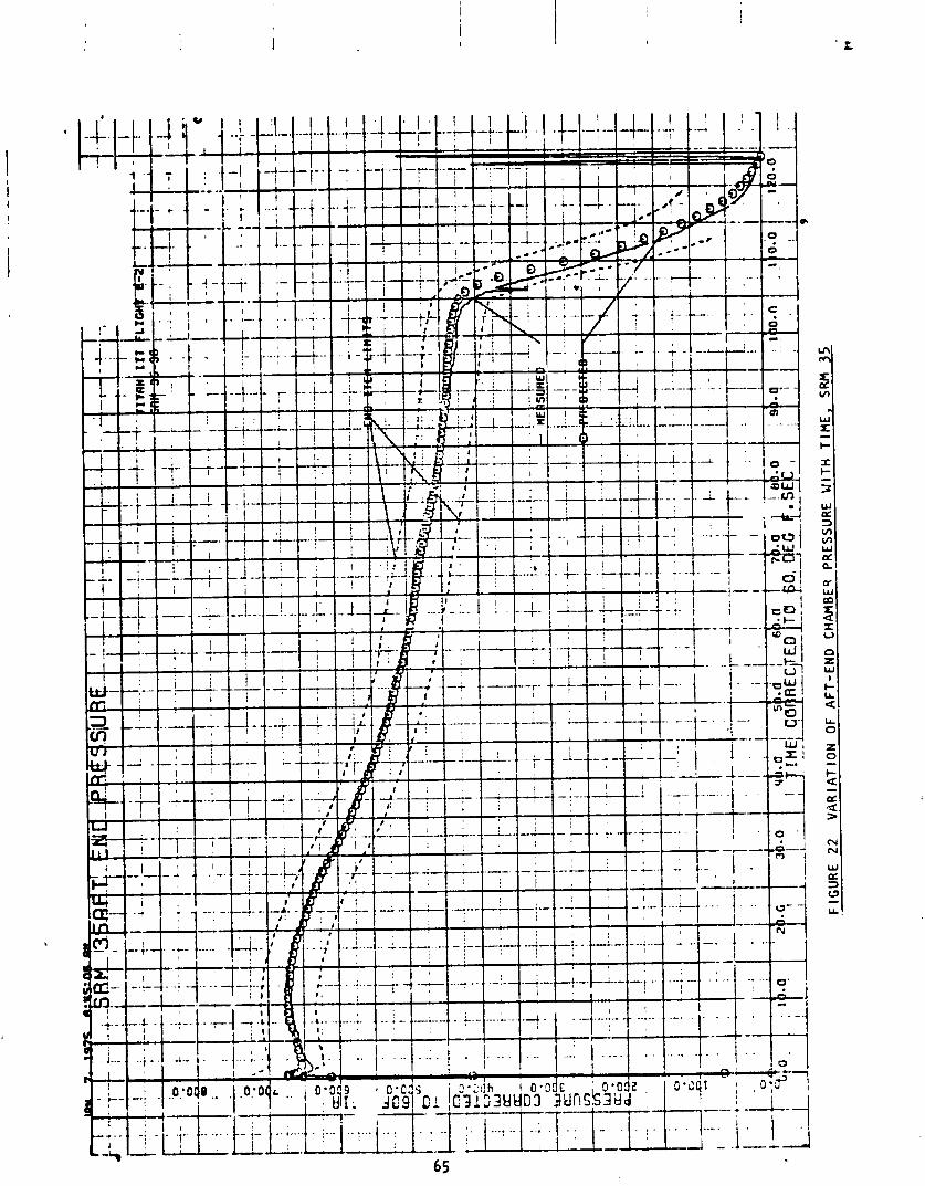

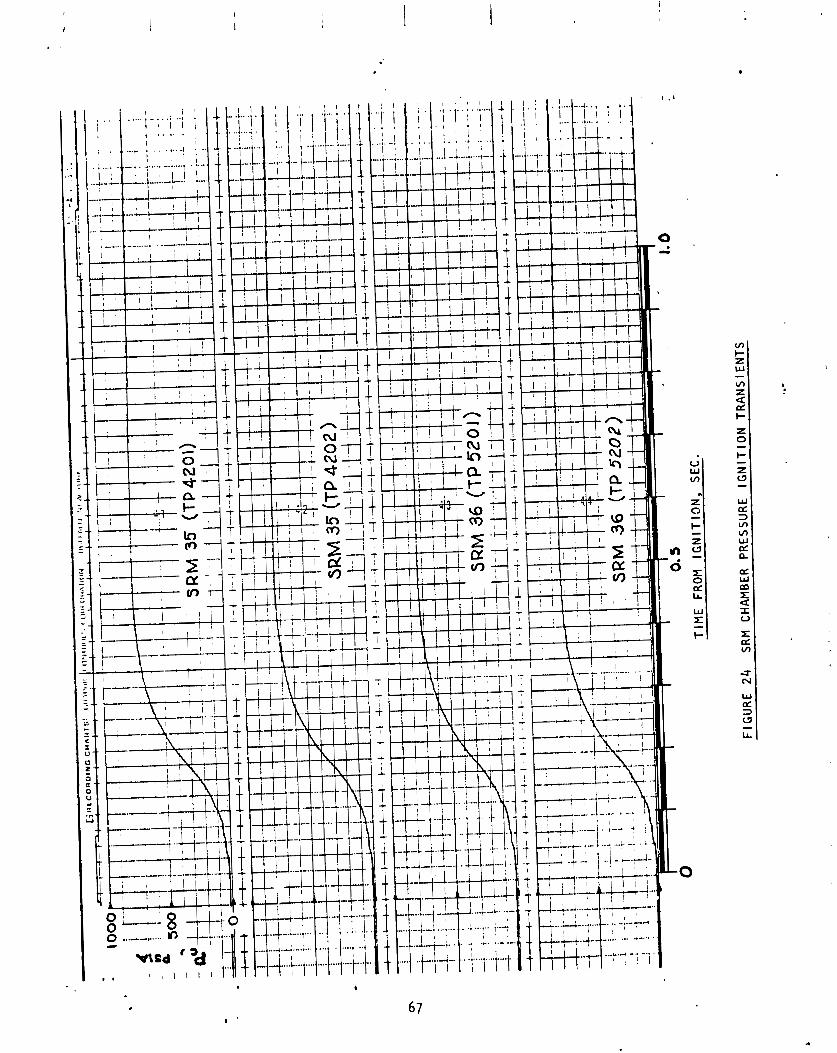
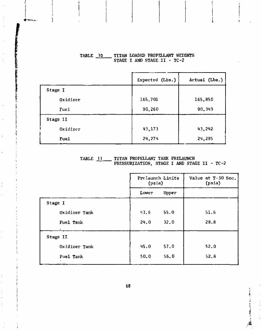
TABLE 10 TITAN LOADED PROPELLANT WEIGHTS STAGE I AND STAGE I1 - TC-2
TABLE 1 1 TITAN PROPELLANT TANK PRELAUNCH PRESSURIZATION, STAGE I AND STAGE I1 - TC-2
Stage I
Oxidizer Tank
Fuel Tank
Stage I1
Oxidizer Tank
Fuel Tank C
I Prelaunch Limits (psis)
Lower Upper
43.6 55.0
24.0 32.0
45.0 57.0
50.0 56.0
1
Value a t T-30 Sec. ( p s i 4
51.6
28.8
52.0
52.8
The autogenous p ressur i za t ion systems on Stage I and Stage I I suppl ied adequate p ressur i za t ion gases t o the p rope l l an t tanks dur ing engine op- e ra t ion . Table 12 compares the expected average t m k pressures dur ing engine opera t ion w i t h the ac tua l f l i g h t values. Since the Stage I o x i - d i z e r autogenous p ressu r i za t i on system was modif ied f o r TC-2 (see Stage I Engine), a comparison o f the expected and ac tua l Stage I o x i d i z e r tank pressure dur ing Stage I engine opera t ion was made ( ~ i g u r e 25) . The ox- i d i z 2 r tank pressure dur ing the Stage I engine opera t ion was 0.8 t o 2.0 p s i h igher than expected and w i t h i n the 3 sigma l i m i t o f prev ious T i t a n I I I f l i gh t s t ha t used the s i n g l e superheater con f igu ra t ion .
Stage I Engine
The Stage I engine con f i gu ra t i on was the same as TC-1 w i t h the f o l l o w i n g changes incorporated as a r e s u l t o f l ong i t ud i na l o s c i l 1 a t ; m s encountered on TC-1 dur ing Stage I operat ion. The o x i d i z e r autogenous p ressu r i za t i on system was changed from a dual superheater con f igu ra t ion t o a s i n g l e super- heater con f igu ra t ion . Accelerometers were mounted on the o x i d i z e r pump housing, the gimbal b lock and the o x i d i z e r discharge l i n e o f each engine subassembly. Two pressure measurements were added on the o x i d i z e r autoyen- ous p ressur i t a t i on 1 ines. An o x i d i z e r suc t ion pressure measurement was added t o the o x i d i z e r feed l i n e on engine subassembiy t w o .
F l i g h t performance o f t he T i t a n Stage I engine was s a t i s f a c t o r y . Engine s t a r t s igna l (87FS1) occurred a t T + l l l . 6 seconds when the accelerometer i n the T i t a n f l i g h t programmer sensed a rqduct ion i n acce le ra t i on t o 1.5 g ' s i dur ing the t a i l a f f per iod o f the Stage O..goLid rocket motors. _ _ . _ ,
Separation o f the t h r u s t chamber e x i t closures was sat i s f a c t o r y as ind ica ted by the normal engine s t a r t t r ans i en t . The t ime d i f f e r e n t i a l between sub- assembly one i g n i t i o n and subassembly two i g n i t i o n was 0.02 seconds. E igh ty percent ra ted t h r u s t l e ve l f o r each subassembly was reached w i t h a 0.01 sec- ond t ime d i f f e r e n t i a l . There was no t h rus t overshoot produced :I-I e i t h e r subassembly. Stage I engine s t a r t t r ans i en t data i s shown i n T i . 13 .
Engine performance dur ing the steady-state per iod was s a t i s f a c t o r y . Average engine t h rus t was 1.93 percent h igher than expected, averdye s p e c i f i c i npu lse was 0.50 seconds lower than expected, and average engine mix tu re r a t i o was 1.17 percent higher than expected. The corresponding 3 sigma d ispers ion about the expected vclues were + 3.27 percent on t h rus t , + 2.3 seconds on s p e c i f i c impulse and + 2.17 perzent on mix tu re r a t i o . ~ r ; ; b e l l a n t outage was 2,308 pounds o f fEel . Th is was 1,014 pounds g rea te r than the expected mean outage but 868 pounds less than the expected maximum outage. Stage I engine steady-state performance data i s shown i n Table 14.
Performance o f autogenous p ressu r i za t i on system dur ing engine operat ion was s 3 t i s f a c t o r y . (See Stage I and Stage I I Prope l lan t Feed System).
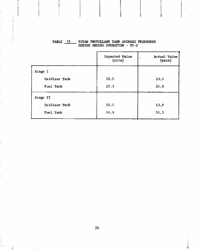
TABLE 12 TITAN PROPELLANT TANK AVERAGE PRESSURES DURING ENGINE OPERATION - TC-2
A
, Expected Value (psia)
22.5
27.3
50.5
54.4
' Stage I
Oxidizer Tank
Fuel Tank
Stage I1
Oxidizer Tank
Fuel Tank
. Actual Value ( p s i 4
23.5
25.8
53.8
55.3
&
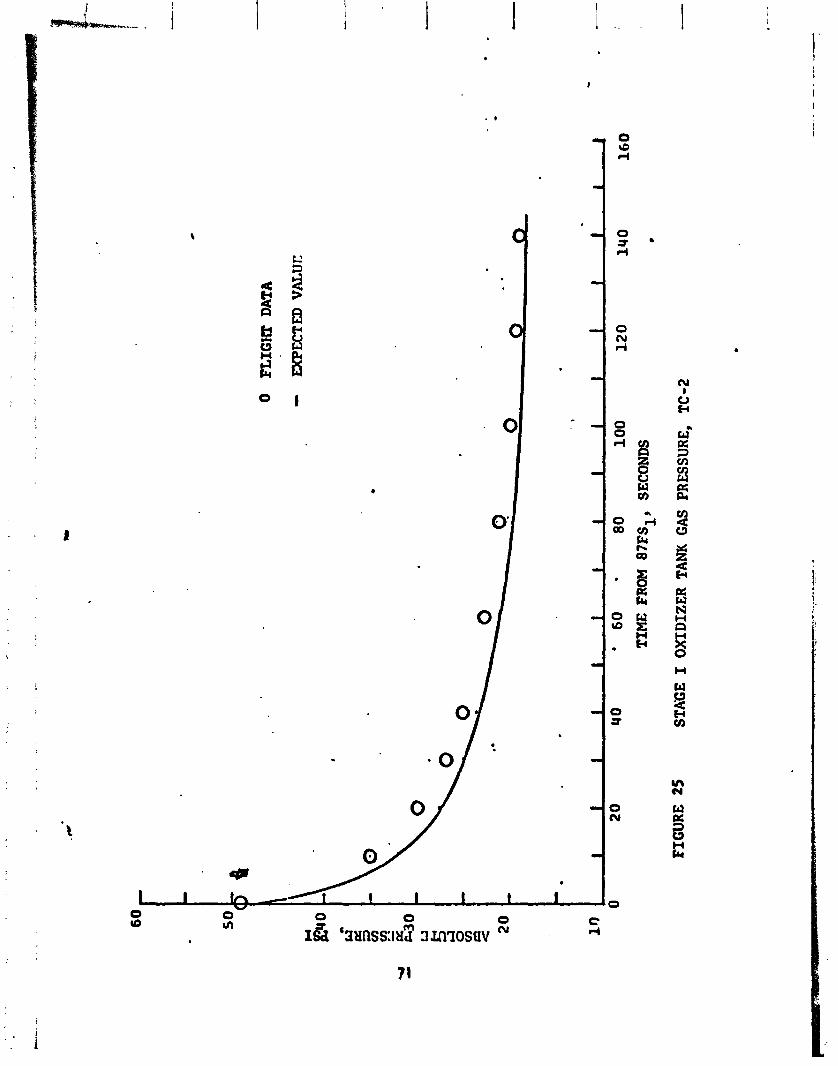
0 FL
IGH
X D
ATA
I)
MPE
CT
ED
VALUT:
FIG
UR
E 25
TIM
E FR
OM 87FS1,
SEC
ON
DS
STA
GE
I OXIDIZER T
ANK
GAS
PRESSURE,
TC-2
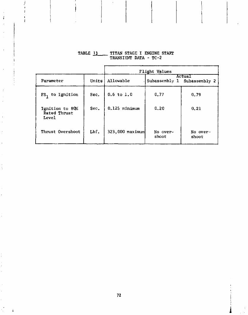
Parameter
TABLE 13 TITAN STAGE I ENGINE START TRANSIENT DATA - TC-2
FS1 t o I g n i t i o n
Ign i t ion t o 88A Rated Thrust Level
Thrust Overshoot
Units
Sec.
Sec.
Lbf.
F l i g h t Values I Actual
Allowable .I Subassmbly 1 Subassembly 2
1 -- - - -
0.79
0.21
No over- shoot
0.6 t o 1 . 0
0.125 minimum
323,000 maximum
0.77
0.20
No over- shoot
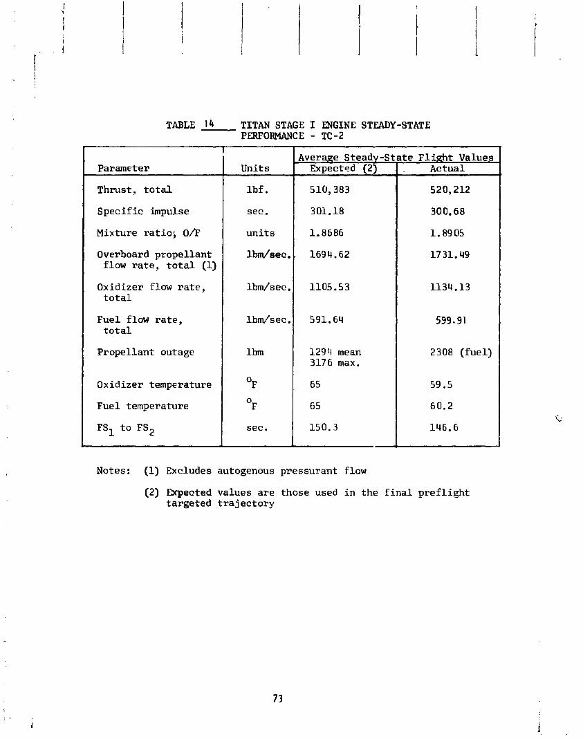
Parameter
TABLE 14 TITAN STAGE I ENGINE STEADY-STATE PERFORMANCE - TC-2
Thrust , t o t a l
Spec i f i c impulse
Mixture r a t i o ; O h
Overboard propel lant flow r a t e , t o t a l (1)
Oxidizer flow r a t e , t o t a l
Fue l flow r a t e , t o t a l
Propel lant outage
Oxidizer temperature
Fuel temperature
Units -
lb f . sec . u n i t s
l b d s e c .
lbm/sec ,
l b d s e c ,
lbm
0 F 0
F
sec.
Average Steady -St Expected (2)
1294 mean 3176 max.
6 5
6 5
150.3
, t e F l i g h t Values Actual
520,212
300.68
1.8905
17 31.49
1134.13
599.91
2308 ( fue l )
59.5
60.2
146.6
Notes: (1) Excludes autogenous pressurant flow
(2) Expected values a r e those used i n t h e f i n a l p r e f l i g h t targeted t r a j e c t o r y

Stage I engine shutdown occurred a t T+258.3 seconds when the t h r u s t chamber pressure switches sensed a reduct ion i n chamber pressure and issued t he en- g ine shutdown s igna l (87FS2). Engine shutdown was the r e s u l t o f o x i d i z e r exhaustion as planned. The shutdown t r ans ien t was normal f o r an o x i d i z e r exhaustion mode. An 80 p s i t h r u s t chamber pressure spike occurred on engine subassembly one a t 87FS2 + 0.55 seconds. Th is pressure sp ike i s considered normal s ince s i m i l a r spikes have been observed on three prev ious T i tan ' : I fl igh ts . Stage I engine opera t ing t ime (FSI t o FS2) was 3.7 seconds shor,:r than expected as a r e s u l t o f the increased p rope l l an t f l ow ra te .
Stage I I Engine
The Stage I I engine con f i gu ra t i on was the same as TC-I.
F l i g h t performance o f the T i t a n Stage I I engine was sa t i s f ac to r y . Engine s t a r t s igna l (91FS1) occurred a t T+258.3 seconds (simultaneous w i t h Stage I engine shutdoun s igna l , 8 7 F ~ 2 ) . The Stage I I engine s t a r t t r a n s i e n t was normal as shown i n Table I S .
Engine steady-state performance was sat i s fac to ry . Average engine t h r u s t was 0.56 percent lower than expected, average s p e c i f i c impul se was 0.57 seconds higher than expected a ~ d average engine mix tu re r a t i o was 0.68 percent lower than expected. The corresponding 3 sigma d ispers ions about the expected values were + 3.80 percent on t h rus t , + 3.5 seconds on s p e c i f i c impulse and + 2.66 perceFt on mix tu re r a t i o . steaTY-state engine performance data i s - shown i n Table 16. I
.. -. -- .
The engine autogenous pressur i za t i on sys tem performed sat i s fac to r y (see Stage I and Stage I I Propel l an t Feed system) . Stage I I engine shutdown (91F~2 ) occurred a t T+468.8 seconds when t he sensed veh i c l e acce le ra t ion dropped t o 1.0 g ' s . Engine shutdown was the r e s u l t o f f u e l exhaustion fo l lowed by o x i d i z e r exhaustion dur ing the shutdown t r ans ien t . The shutdown t r ans ien t was normal . Stage I I engine opera t ing t ime (FSI t o FS2) was 2.3 seconds longer than ex- pec ted .
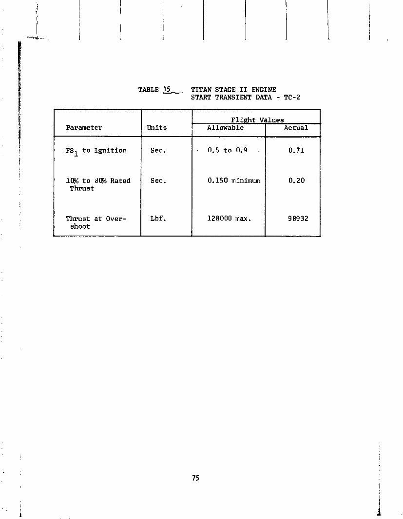
TABLE 15 TITAN STAGE I1 ENGINE START TRANSIENT DATA - TC-2
Parameter
1 10% t o Rated I Sec.
Units
FS1 t o Ignition Sec.
Thrust
Thrust at Over- shoot
0.5 t o 0.9 t
0.150 minimum
Flight Values
Lbf. 128000 max .
Allowable Actual
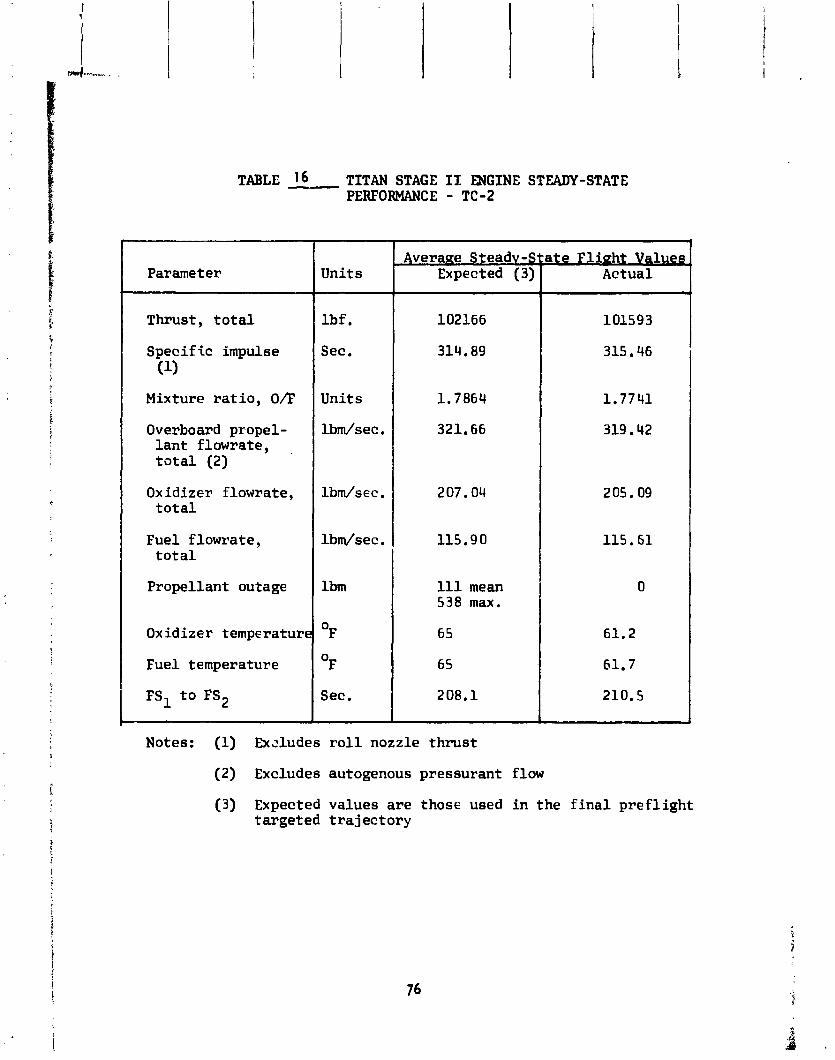
TABLE 16 TITANSTAGEILENGINESTEADY-STATE PERFORMANCE - TC-2
Parameter
Thrust, t o t a l
Spec i f i c impulse (1)
Mixture r a t i o , OD
Overboard propel- l a n t f l m r a t e , t o t a l (2)
Oxidizer f lowrate, t o t a l
Fuel f lowra te , t o t a l
Propel lant outage
Oxidizer temperature
Fuel temperature
Uni ts
l b f .
See.
Uni ts
l b d s e c .
l b d s e c . l b d s e c .
lbm
0 F 0 F
Sec.
Average Steadv-State F l i n h t Valueg Expected (3) 1 Actual
102166
314.89
1.7864
321.66
207.04
115.90
111 mean 538 max.
6 5
65
208.1
Notes: (1) Exdudes r o l l nozzle t h r u s t
(2) Excludes autogenous pressurant flow
(3) Expected values a r e those used i n t he f i n a l p r e f l i g h t t a rge ted t r a j e c t o r y
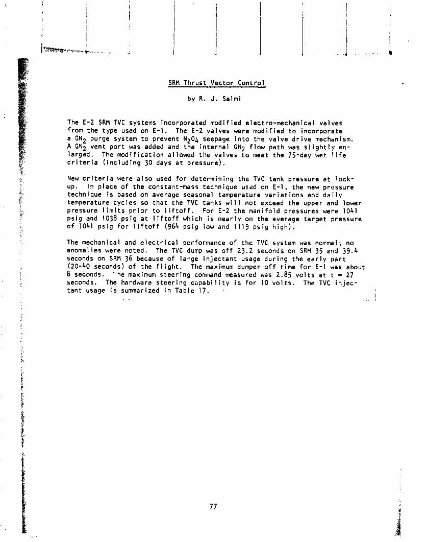
SRM Thrust Vector Control
by R. J. Salmi
The E-2 SRM TVC systems incorporated modi f ied electro-mechanical valves from the type used on E-1. The E-2 valves were modif ied t o incorporate a GN2 purge system t o prevent N204 seepage i n t o the va lve d r i v e mechanism. A GN2 vent po r t was added and the i n t e rna l GN2 f low path was s l i g h t l y en- larged. The mod i f i ca t i on al lowed the valves t o meet the 75-day wet l i f e c r i t e r i a ( i nc l ud ing 30 days a t pressure).
New c r i t e r i a were a l s o used fo r determining the TVC tank pressure a t l ock - up. I n place o f the constant-mass technique used on E - 1 , the new pressure technique i s based on average seasonal tzmperature v a r i a t i o n s and d a i l y temperature cyc les so t h a t the TVC tanks w i l l no t exceed the upper and lower pressure l i m i t s p r i o r t o l i f t o f f . For E-2 the mani fo ld pressures were 1041 ps i g and 1038 p s i g a t 1 i f t o f f which i s near l y on the average t a rge t pressure o f 1041 ps i g f o r l i f t o f f (964 ps i g low and 1119 ps i g h i gh ) .
The mechanical and e l e c t r i c a l performance o f the TVC system was normal; no anomalies were noted. The TVC dump was o f f 23.2 seconds on SRM 35 znd 39.4 seconds on SRM 36 because o f l a rge i n j e c t a n t usage dur ing the e a r l y p a r t (20-40 seconds) o f the f l i g h t . The maximum dumper o f f t ime f o r E-1 was about 8 seconds. - 9e maximum s teer ing command measured was 2.85 v o l t s a t t = 27 seconds. The hardware s teer ing capabi 1 i t y i s f o r 10 v o l t s . The TVC i n j e c - t an t usage i s summarized i n Table 17. t !
. - . . ! . -. I

TAB
LE
17
INJE
CT
AN
T F
LU
ID U
SAG
E
b
NITROGEN T
ET
HO
XID
E LOADED
8,4
15
w
QD
T
OT
AL
EX
PE
ND
ED
LB
6
,63
7
TO
TA
L D
UM
PE
D LB
3,4
16
TO
TA
L T
VC
ST
EE
RIN
G L
B
3,2
21
MANIFOLD P
RE
SS
UR
E A
T IGNITION
1,0
38
MA
NIF
OL
D P
RE
SS
UR
E A
T S
EP
AR
AT
ION
57
1
SRM
36

Hydraul ic Systems
Per formf ice o f the hydrau l i c systems ?n Stage I and Stage I I was normal. The e l e c t r i c motor d r i ven pump i n each stage suppl ied normal h y d r a u l : ~ pressure f o r the f l i g h t con t ro l system t e s t s performed dur ing countdown. Hydrau l ic pressures suppl ied by the t u rb i ne d r i ven pump on each stase dur ing engine operat ion were normal, except t h a t the S t a ~ e I pressure i n d i c a t i o n was s l i g h t l y low due t o i n s t r u m f i t a t i o n e r r o r . Hydrau l ic r ese rvo i r l e ve l s were w i t h i n l i m i t s throughout the countdown and f l i g h t . Stage I and Stage I I hydra31 i c system performance d a t a are presented i n Table 18.
During f l i g h t , te lemetry data i , !d i ca ted the Stage I hydra l r l ic pressure t o be 110 ps i below the lower l i m i t . Analysis o f the data ind ica tes t h a t the pressure was r~ormal , and t h a t the re was an e r r o r i n the .:st rumen ta- t i o n o r te lemetry equipment.
A t T+0.345 seconds, the DRS tape ind ica ted a "NO-W" cond i t i on on the St.ge I I accumulator-reservoir precharge pressure. The GO s igna l was maintained, however. Analys is ind ica ted t h a t the precharge pressure was indeed lower than average due t o the low ambient te;npara:ure (58OF) c r~ launch day. The pressure had been set a t 1785 ps ia a t 71°F, and had dropped t o approximately 1740 ps i a on launch day. Th is cond i t i on , t o - gether w i t h a h i g h s e t t i n g on the pressut-e sw i tch and the v i b r a t i o n caused by the Stage 0 i g n i t i3n apparent ly caused the temporary "NO-GO" i nd i ca t i on . I t i s rs t imated t h a t a f u r t he r temperature drop o f 20" ts 25'F would be reqlr i red t o e f f e c t the !oss o f the "GO" s i gna l .
The s t r l r c t u ra l loads t ransmi t ted i n t o the Stage I hydraul i c actuators dur ing the Stage I engine s t a r t t r ans i eq t were normal. A maximum load o f 12,450 pounds corrpress ion was appl i ed t o s~. i~~)ssembl y 1 yaw i ro l 1 ac tua to r 3 - 1 . The a l lowable load f o r Stage I actuators i s 50,COO pounds. The Ztage I I engine s t a r t t r ans i en t produced a maximum load of 9,750 pounds corcpres- s ion on the Stage i l yaw ac tua to r 2-2. Th is i s the h ighest load ing y e t ob- served f o r the 2-2 act t !ator, and the ;econd h ighest load observed f o r Stage I I . I t i s a l so the hIghest load ever observed f o r a Stage I o x i d i z e r de- p l e ~ . o n shutdown. The Stagc l l ac tua to rs have a demonstrated load caoac i ty o f 18,000 pounds. Table 19 shows the maximum ac tua to r loads encountered on TC-2 dur ing the engine s t a r t t r ans i en t s . Alst2 shown f o r com?ari:on a re the TC-I loads and the I.,aximum a r d m;n;murn loads f o r a l l T i t an veh ic les .

TABLE 18
Ti t an Hydraulic System; F l i g h t Data - TC-2
Hydrad i c Supply Pressure
Max. a t Pump S t a r t Average Steady S t a t e
Reservoir Level
P r i o r t o Pump S t a r t A t Max. hunp S t a r t Press. Average Steady S t a t e Shutdown Minus 5 Sec.
p s i p s i
% % % %
4500 Max. (1)
29 00-3000
(1) Proof pressure limit. (2) Out of tolerar;=e - see t e x t .
TABLE
T i t an Hydraulic Actuaror Maximum Loads During Engine S t a r t Trans ien t s
1
Units ?tape I Actuators - Stage I1 Actuators Lbf . ~ubas&mblv One ~uba&ernb'ly Two Subassembly Three
r i t c , Yaw-Holl Yaw-Holl P i t c h P i t c h Yaw Vehicle 2-1 3-1 4 -1 1-2 2-2
TC-2 +12,450 +9540 +5670 +975011) -1:,980 -4980 - 510 -79 00 -p t
Ti t an (2) Family
+ I nd i ca t e s compression load. - I nd i ca t e s t ens ion load. (1) Highest compression load y e t observed. (2) Stage I da ta is from TIIID only.

F l i g h t Cont ro ls and Sequencing System
by E. S . J e r i s and T. W. Porada
The f l i g h t con t ro l system maintained veh i c l e s t a b i i i t y throughout powered f l i g h t . A l l open loop p i t c h r a t e s and preprogrammed events were issued as planned. No system o r component anomalies occurred. Duqp programming o f TVC i n j e c t a n t f l u i d was sa t i s f ac to r y . The dump command was zero f o r 39.4 seconds due t o the long du ra t i on o f ADDJUST s teer ing commands from Centaur. Dump command was a t zero f o r on1 y 8 seconds on E-1 . A f t e r SRM j e t t i s m , the veh i c l e experienced an 11 deg/sec r o l l r a t e . Th is r o l l r a t e i s t he h ighest recorded on T l l l veh ic les . Peak r a t e on previous T l l l veh ic les was 8 deg/sec, and on E-1, t he peak r a t e was 5 deg/sec. P r i o r t o the SRM j e t t i s o n event, the Stage I engines corrected f o r an apparent r o l l torque. The Stage I engines assumed a d i f f e r e n t i a l gimbal angle o f approximately .53 degrees t o counteract the r o l l torque. The cause o f the r o l l torque i s not we l l understood. Probable causes have been i d e n t i f i e d , but could not be proven conc lus ive ly . Among the poss ib le causes are: (1) asymmetric shutdown behavior o f the SRMs causing t h r u s t d ispers ion, (2) SRM plume behavior dur ing the shutdown causing impingement torques, (3) quest ionable aerodynamic c o e f f i c i e n t s , and (4) unknown angles o f a t t a c k (wind data no t a v a i l a b l e over 60,000 f ee t a ' t i tude) adding un- cc. t a i n t y i n aerodynamic forces.
Comnand vo l tage t o each SRM quadrant and the dynamic and s t a t i c s tab i 1 i t y 1 i m i t s are shown i n Figures 26 and 27. The s tab i 1 i t y 1 i m i t s represent the TI l l E-2 s ide fo rce cons t ra i n t i n terms o f TVC system quadrant vo l tage. This cons t ra i n t i s used i n con junc t ion w i t h launch day wind syn the t i c veh i - c l e s imul3t ions as a go/no-go c r i t e r i o n w i t h respect t o veh i c l e s t a b i l i t y and con t ro l au tho r i t y . S imulat ion responses s a t i s f y i n g the c o n s t r a i n t as- sures a 3 sigma p r o b a b i l i t y o f acceptable con t ro l a u t h o r i t y and veh i c l e s t a b i l i t y . Maximum command dur ing Stage 0 f l i g h t was 2.85 v o l t s which i s 28.5 percent o f the con t ro l system capabi 1 i t y and 47.5 percent o f the l y - namic s t a b i e : r y l i m i t . The peak command occurred a t T+27 seconds and was due t o Centaur ADDJUST p i t c h up wind load re1 i e f s teer ing .
For Stage I and I I , the con t ro l system l i m i t i s the maximum gimbal angle associated w i t h the ac tua to r stop. Actual gimbal angle used f o r Stages I and I I versus f l i g h t t ime i s p l o t t e d i n Figures 28 through 33. During Stage I f l i g h t , the peak gimbal angle requi red f o r con t ro l was 1.06 de- grees which i s 25.7 percent o f the maximwn gimbal angle. The peak angle was requ i red a t SRM j e t t i s o n . During Stage 1 1 , 7 .6 degrees o r 22.4 per- cent of peak gimbal angle was the maximum gimbal angle requi red a t CSS j e t t i s o n .
The con t ro l system respons? t o veh i c l e dynamics was evaluated f o r each s i g n i f i c a n t f l i g h t event. The ampl i tude, frequency and dura t ion o f veh i - c l e t rans ien ts , 3rld the con t ro l system command c a p a b i l i t y requi red i s shown i n Table 20.
Both f l i g h t programmers and the staging t imer issued a l l preprogrammed d iscre tes a t the proper times. The Centaur sent four d iscre tes t o the T i t a n a t the proper t i r e s . The complete sequence o f events w i th actual and nominal times from SRM i g n i t i o n i s shown i n Table 21.
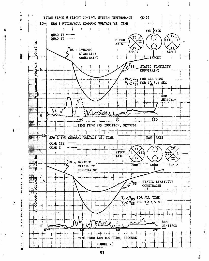
I , * i I TITAN STACE 0 FLlCIIT CONTRQI. SYSTEW PERFORMANCE (8-2) I
1
. . . . SRH I P I T C H /ROLL COWAND VOLTAGE V S . TIHE ; . . , '
i i i i i 1 i 1 . 1
.......... -.. ...-.-. ........ SECONDS .* --. - .... ; .... ...
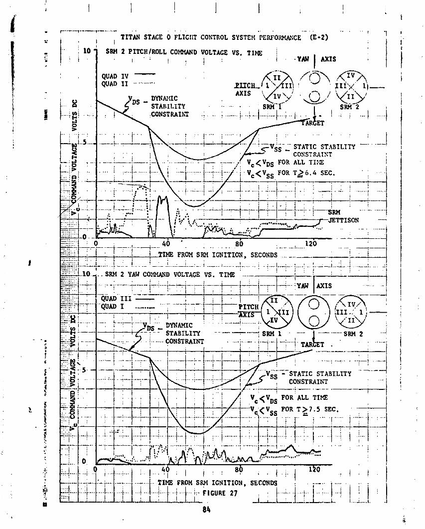
SRH 2 PITCH/ROLL COMMAND VOLTAGE VS. TIM3 i .
PITCH
DYNANIC A X I S
STABILITY . . . . . . . . .CONSTRAf hi .; . .. ; ...... . j. ..i -.
o YAW A X I S I
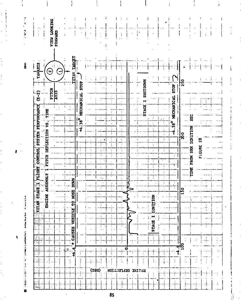
- ................ , . . . . . . I ... : .. I... : ...I ..-.!.... I...; .... 1.. :. I
!
I)'
::
4; I?
U

, . . . . .---. ...... ...- : , : . . I-..: .... 1 .... ;-..I .... i.. I !
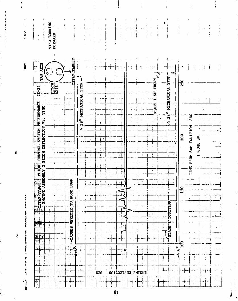
j... I ...!... I I '-. :.---
I,: j .... ...... ---.- /:I ( ..........
ENGINE .. - ..-... .... ...
.... i
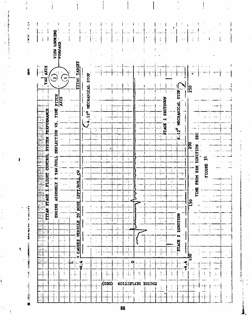
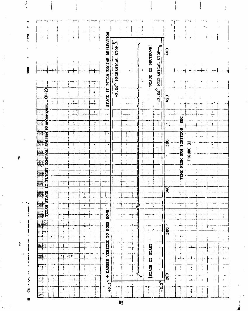
. : i d -:--g N . - . --- I d " ,
. ! I
' . , . . . ! . f , i . . . i...... ......_. : _ - . I . . . .
, , i : . I . - + . I , .---- .-

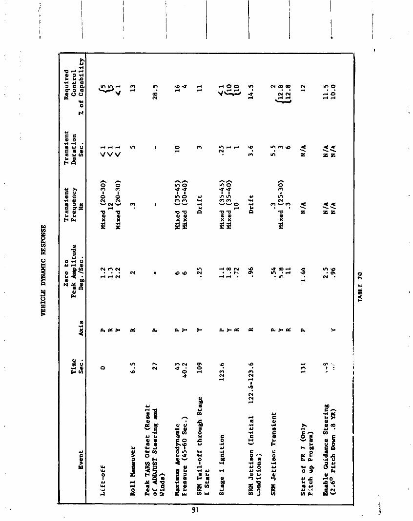
VEH
ICLE
D
YN
AM
IC
RES
PON
SE
Zer
o t
o
Tra
nsi
en
t T
ran
sie
nt
Req
uir
ed
Tim
e P
eak
Am
pli
tud
e F
req
uen
cy
Du
rati
on
C
on
tro
l E
ven
t S
ec .
Ax is
D
eg . /S
ec .
Hz
Sec
. ib
of
Ca
pa
bil
ity
Lif
t-o
ff
0
Ro
ll M
aneu
ver
6.5
Pea
k T
ARS
O
ffse
t (R
esu
lt
of ADDJUST
Ste
eri
ng
and
2
7 W
inds
)
lbci
anrm
Ae
tod
yn
amic
4
3
F re
sau
re
(45-
60
Sec
. ) 4
0.2
SRM
T
ail
-off
th
rou
gh
Sta
ge
10
9
I S
tart
Sta
ge
I Ig
nit
ion
SRW
Je
ttis
on
(In
itia
l L
on
dit
ion
r)
SRM
J
ett
iso
n T
ran
sie
nt
Sta
rt o
f PR
7
(Onl
y P
itc
h u
p P
mg
ram
)
1.2
M
ixed
(2
0-30
) 1
.3
12
2.
2 M
ixed
(2
0-30
)
2 .3
Mix
ed
(35-
45)
Mix
ed
(30-
40)
.25
Dri
ft
123.
6 P
1.1
M
ixed
(3
5-4
5)
Y 1.8
Mix
ed
(35
-40
) R
.72
10
122.
6-12
3.6
R .9
6 D
rift
.54
.3
5 -8
Mix
ed
(25
-30
) 11
.3
En
able
Gu
idan
ce S
tee
rin
g
i -3
(2
.6O
P
itc
h D
own
.8 Y
R)
..:
Y
- * .. .
.. -.-
TAB
LE 2
0
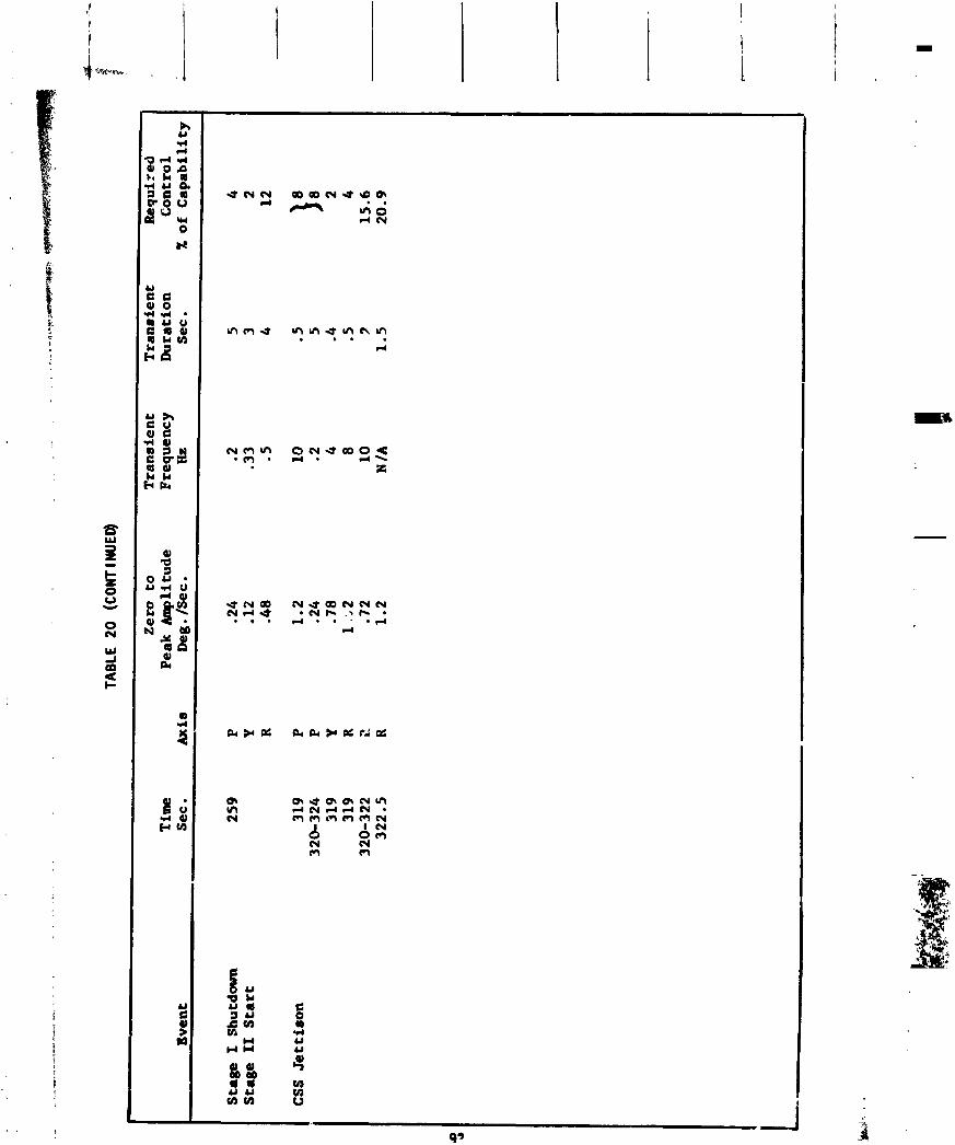
TAB
LE 2
0 (C
ON
TIN
UED
)
Zero
to
Tra
ne i
en
t T
ran
sien
t R
equ
ired
T
ime
Pea
k A
mp
litu
de
Fre
qu
ency
D
ura
tion
C
on
trol
Eve
nt
Sec .
&is
Deg
. kc
.
Hz
Sec .
X o
f C
ap
ab
ilit
y
Sta
ge
I Shutd
own
Sta
ge I1 S
tart
CSS
Je
ttis
on

. . . . . ~ ' . ' . . . . . . . . . . . . . . . . . o o o o o o o ~ o o o o d o o o o o o o o o u u o u u o o c + + + + + + + + + + + + I 1 I 1 1 + + + + + 1 I + 1 1 I + +
8 o u u r c a a F-ac d d r l m m P ?
o o o q o o o . . . d B 8 . . . . . . O O m O N O ~ O C . 0 dNNmahP-- O 1 0
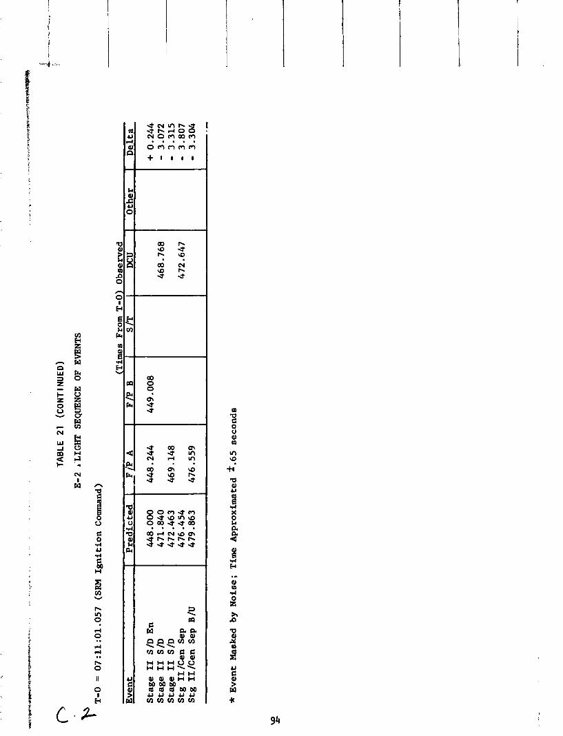
r',
TAB
LE 2
1 (C
ON
TIN
UE
D)
E-2
r'
LIG
HT
SEQ
UEN
CE
OF
EVEN
TS
' T-0 =
07
:11
:01
.05
7
(SR
M
Ign
itio
n C
omm
and)
Ev
ent
Sta
ge
I1
S/D
E
n
Sta
ge
I1
S/D
S
tag
e I
1 S
ID
Stg
I1 /C
en
Sep
S
tg I
I/C
en
Sep
B/U
Pr
ed
icte
d
(Tim
es F
rom
T-0
) O
bse
rved
F
/P
A
-
1 F
/P
B I
S /T
I DCU
I O
ther
1
I
* E
ven
t M
aske
d b
y N
ois
e;
Tim
e A
pp
roxi
mat
ed f
.65
se
con
ds
De
lta
E l e c t r i c a l / E l e c t r o n i c Systems
Ai rborne E l e c t r i c a l System
by B. L. Beaton
So l i d Rocke~ Motor E l e c t r i c a l Svstem
The sol i d rocket motor (SRM) e l e c t r i c a l system performance was s a t i s f a c t o r y w i t h no s i g n i f i c a n t anomalies. A l l power requirements o f the SRM e l e c t r i c a l system were s a t i s f i e d . One minor anomaly occurred a t SRM i g n i t i o n when a bridgewi r e apparent ly shorted t o s t r u c t u r e a f t e r i n i t i a t i o n and simul taneous shor t ing occurred i n the i g n i t o r safe and arm device. TC-1 experienced the same cond i t ion.
The SRM e l e c t r i c a l system was i d e n t i c a l t o t h a t f lown on TC-1.
The SRM e l e c t r i c a l system suppl ied the requirements o t the dependent systems a t normal vo l tage leve ls . The SRM e l e c t r i c a l system performance i s summar- ized i n Table 22.
The anomaly a t SRM i g n i t i o n was apparent ly caused by a shor t from an SRM i g n i t e r br idgewire p o s i t i v e t o s t r u c t u r e and simultaneous shor t ing from the t r ans ien t r e t u r n t o readiness r e t u r n w i t h i n the i g n i t e r safe and arm device. As a r e s u l t , the T i t a n core t r ans fe r c d r a n t shunt ind icated 10.4 amps f o r I approximately 355 ms. The cur ren t dropped t o zero sirnul taneous w i t h the re- moval o f the cu r ren t path when the SRM umbil i c a l s were ejected. The anomaly had no adverse e f f e c t on any a i rborne system.
T i t an Core E l e c t r i c a l System
The core e l e c t r i c a l system performance was sa t i s f ac to r y w i t h no anomalies. A l l power requirements o f the core e l e c t r i c a l system were s a t i s f i e d . A l l vo l tage and cu r ren t measurements ind ica ted expected values. Some br idgewire shor t in9 ( a f t e r i n i t i a t i o n ) was observed a t every ordnance event.
The T i t an electrical system was i d e n t i c a l t o t h a t f lown on TC-1.
The T i t a n core e i e c t r i c a l system suppl ied the requirements o f the dependent systems a t normal vo l taqe and cur ren t l eve l s . The T i t a n core e l e c t r i c a l sys- tem performance i s summarized i n Table 23.
The 800 Hz squarcwave output o f the s t a t i c i n v e r t e r was 38.15 v o ~ t s dur ing the e n t i r e f l i g h t .
The TPS bus vo l tGga was 30.3 vo l t s d-c a t TPS bus enable and rose t o 31.4 v o l t s d-c a t T i t a d c e n t a u r staging. Th is cond i t i on i s normal due t o increas ing
a:
ba t t e r y tempera:!cre s ince the ba t t e r y i n t e r n a l heater and the TPS bus a re en- abled concurrent ly .

4
The TPS bus vo l tage and pyrotechnic f i r i n g cu r ren ts dur ing ordnance e v ~ n t s a re summarized i n Table 24.
The t rans fe r cu r ren t ind icated 10.4 amps a t T-0 as previous1 y discussed under SRM e l e c t r i c a l system performance. The t r a n s f e r cu r ren t ind ica ted t ha t dur ing shor t per iods o f h igh cu r ren t demand on the APS bus, the I P S b a t t e r y provided load sharing. Th is occurred a t TPS enab: -, Stage I en- g ine s t a r t and Stage 1 / 1 1 separat ion.

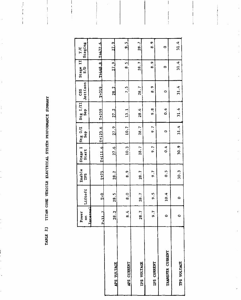
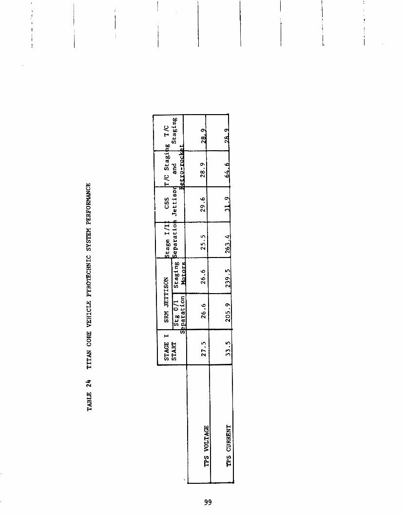
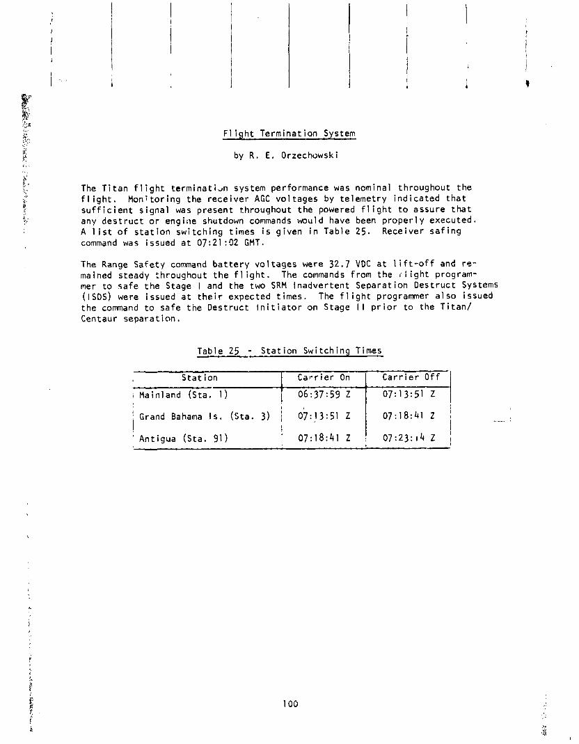
F l i g h t Terminat ion System
by R . E. Orzechowski
The T i t a n f 1 i g h t t e rm ina t i an system performance was nominal throughout t h e f l i g h t . M o n i t o r i n g the r e c e i v e r AGC vo l tages by te lemet ry i n d i c a t e d t h a t s u f f i c i e n t s igna l was present throughout t h e powered f l i g h t t o assure t h a t any d e s t r u c t o r engirle shutdown commands would have been p r o p e r l y executed. A l i s t o f s t a t i o n sw i t ch ing t imes i s g i ven i n Table 25. Receiver s a f i n g command was issued a t 07:21:02 GMT.
The Range Safe ty command b a t t e r y vo l tages were 32.7 VDC a t l i f t - o f f and r e - mained steady throughout t h e f 1 i g h t . The commands f rom the i l i g h t program- mer t o sa fe t h e Stage I and the two SRM Inadver ten t Separat ion Des t ruc t Systems (ISDS) were issued a t t h e i r expected t imes. The f l i g h t programmer a l s o issued the command t o sa fe t h e Des t ruc t I n i t i a t o r on Stage I I p r i o r t o the T i t a n / Centaur separa t ion .
Table 25 - S t a t i o n Swi tch ing Times
, S t a t ion 1 C a r r i e r On 1 C a r r i e r O f f ] i Mainland (Sta. 1 ) [ 06:37:59 Z i 07:13:51 Z I ' Grand Bahama I s . (Sta. 3) 07:13:51 Z
I ' 07:18:41 Z 1 i I I I ' An t igua (Sta. 91) 07:18:41 Z 1 07:23:14 Z 1
l ns t rumen ta t i on and Telemetry System
by R. E . Orzechowski
A t o t a l o f 207 measurements were te lemetered by the T i t a n Remote Mu1 t i p l e x e d lns t rumen ta t i on System (RMIS). A summary o f t h e types o f measurements versus t h e systems i n which they were moni tored i s g i ven i n Table 2 6 . P r e l i m i n a r y rev iew o f t he f l i g h t da ta I n d i c a t e s t h a t a l l measurements y i e l d e d s a t i s f a c t o r y data .
Adequate te lemet ry coverage o f t h e T i t a n v e h i c l e was prov ided from l i f t - o f f t o beyond T i t a d c e n t a u r separa t ion . A summary o f t he p r e d i c t e d data coverage versus ac tua l data coverage o f t h e T i t a n te lemet ry l i n k i s g i ven i n Table 27.
There was a data dropout o f 1 . 5 =econds d u r a t i o n a t 07:13:04.8 GMT. T h i s dropout was expected and i s due t o plume a t t e n u a t i o n a t the t ime o f Stage 0 separa t ion .
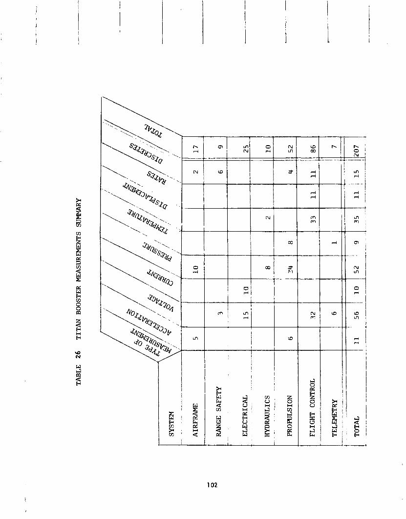
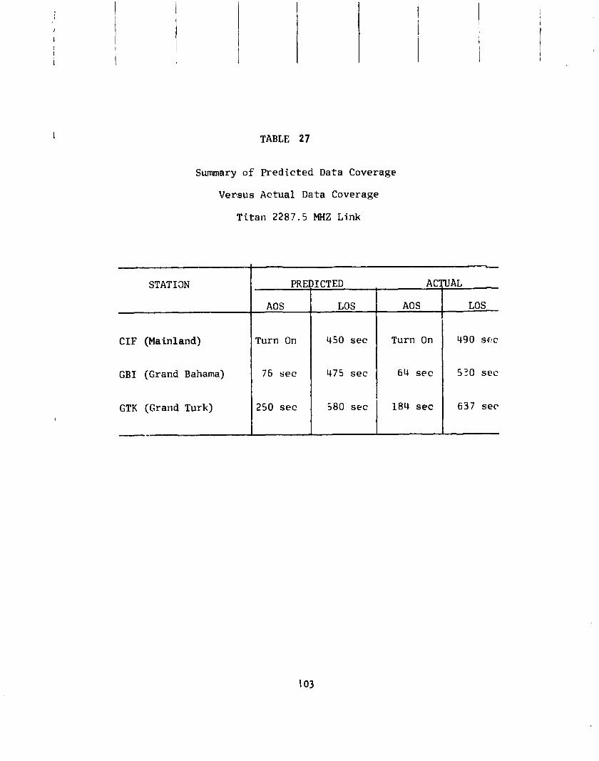
TABLE 27
Summary o f Predicted Data Coverage
Versus Actual Data Coverage
Ti tan 2287.5 MHZ Link
---
STATI3N PREDICTED ACTUAL
AOS LOS AOS LOS
CIF (Mainland)
GBI (Grand Baharna)
GTK (Grand Turk)
--
Turn On
76 sec
250 sec
450 sec
475 s e c
580 sec
Turn On
64 sec
184 sec
490 s e c
530 sec
6 3 7 s e c
V l l l CENTAUa STANDARD SHROUD
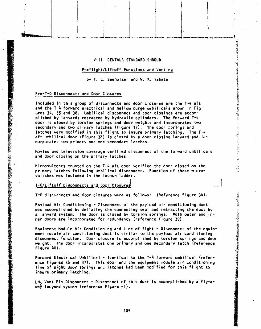
V l l l CENTAUR STANDARD SHROUD
P r e f l i g h t / L i f t o f f Functions and Venting
by T. L. Seeholzer and W. K. Tabata
Pre-T-0 D i sconnects and Door Closures
Included i n t h i s group of disconnects and door c losures a re the T-4 a f t and the T-4 forward e l e c t r i c a l and he1 ium purge umbil i c a l s shown i n F ig - ures 34, 35 and 36. Umbi 1 i c a l disconnect and door c l os i ngs a re accom- p l {shed by lanyards re t rac ted by hydraul i c c y l inders. The forward T-4 door i s c losed by t o r s i on spr ings and door weighis and incorporates two secondary and two primary la tches (F igure 37). The door sp r ings and la tches were modi f ied i n t h i s f l i g h t t o insure pr imary l a t ch i ng . The T-4 a f t umbil i c a l door (Figure 38) i s c losed by a door c l os i ng lanyard and 111-
corporates two pr imary and one secondary 1 atches.
Movies and t e l e v i s i o n coverage v e r i f i e d disconnect o f the forward umb i l i ca l s and door c l os i ng on the pr imary la tches.
Microswitches mounted on the T-4 a f t door v e r i f i e d the door c losed on the pr imary la tches fo l low ing umb i l i ca l disconnect. Funct ion o f these micro- switches was include0 i n the launch ladder .
I T-O/Lif t o f f Di scsnnects and Door Closuc.4u -.
T-0 d i sccnnects and daor c losures were as f o l lows : ( ~ e f e r e n c e F igure 34).
Payload A i r Condi t ion ing - ?isconnect o f the payload a i r condi:ioning duct was accomplished by d e f l a t i n g the connecting seal and r e t r a c t i n g the duct by a lanyard system. The door i s closed by t o r s i on spr ings. Poth ou te r and i n - ner doors a re Incorporated f o r redundancy (reference F igure 39).
Equipment Module A i r Condi t ion ing and L ine o f S ight - Disconnect o f the equip- ment module a i r cond i t i on ing duct i s s i m i l a r t o the payload a i r cond i t i on i ng d i sconnect funct ion. Door c losure i s accompl i shed by t o r s ion spr i ngs and door weight. The door incorparates one p r i m r y and one secondary l a t c h (reference F lgure 40).
Forward E l e c t r i c a l Umbi l ica l - I den t i ca l t o the T-4 forward umb i l i ca l ( r e f e r - ence Figures 36 and 37). Th is door and the equipment module a i r cond i t i on i ng 1 ine o f s tgh t door spr ings any la tches had been modi f ied f o r t h i s f l i g h t t o insure pr imaty la tch ing .
LH2 Vent F i n Disconnect - D i scowac t o f t h i s duct i s accomplished by a f l y - a - way l a~ rya rd system (reference F lgure 41 ) .
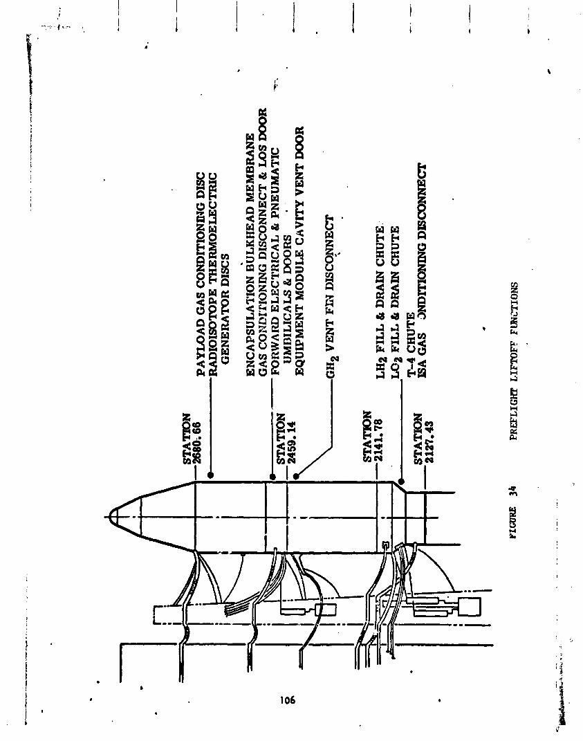
L- -
STA
TlO
ON
-2
680;
66
PA
YL
OA
D G
AS
CO
ND
ITIO
NIN
G DISC
-RA
DIO
ISO
TOPE
T
HE
RM
OE
LE
CT
RIC
G
EN
ER
AT
OR
DIS
CS
-
. E
NC
AP
SUL
AT
ION
BULK
HEAD
MEM
BR
AN
E
GA
S C
ON
L?I
'llO
NIN
G D
ISC
ON
NE
CT
& LOS DOOR
--
STA
TIO
N
FU
RW
AR
D ELECTRICAL &
PN
EU
MA
TIC
-.
UM
DIL
ICA
LS
& D
OO
RS
* -
EQ
UIP
ME
NT
MO
DU
LE
CAVITY V
EN
T DOOR
-GH
~ VENT FC? D
ISC
qNN
EC
T
.
STA
TIO
N
-214
1.78
L
H2 FILL 6
DRAIN C
HU
TE
: W
2 FILL 6
DRAIN C
HU
TE
T
-4 CHUTE
ISA
GA
S
;IN
DIT
ION
ING
DY
SCO
NN
ECT
FIG
UR
E
34
PREF
LIG
HT LIFTOFF
FUN
CTI
ON
S
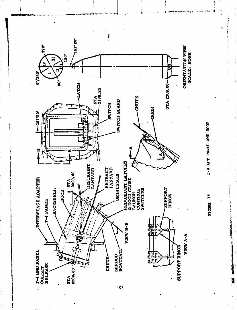
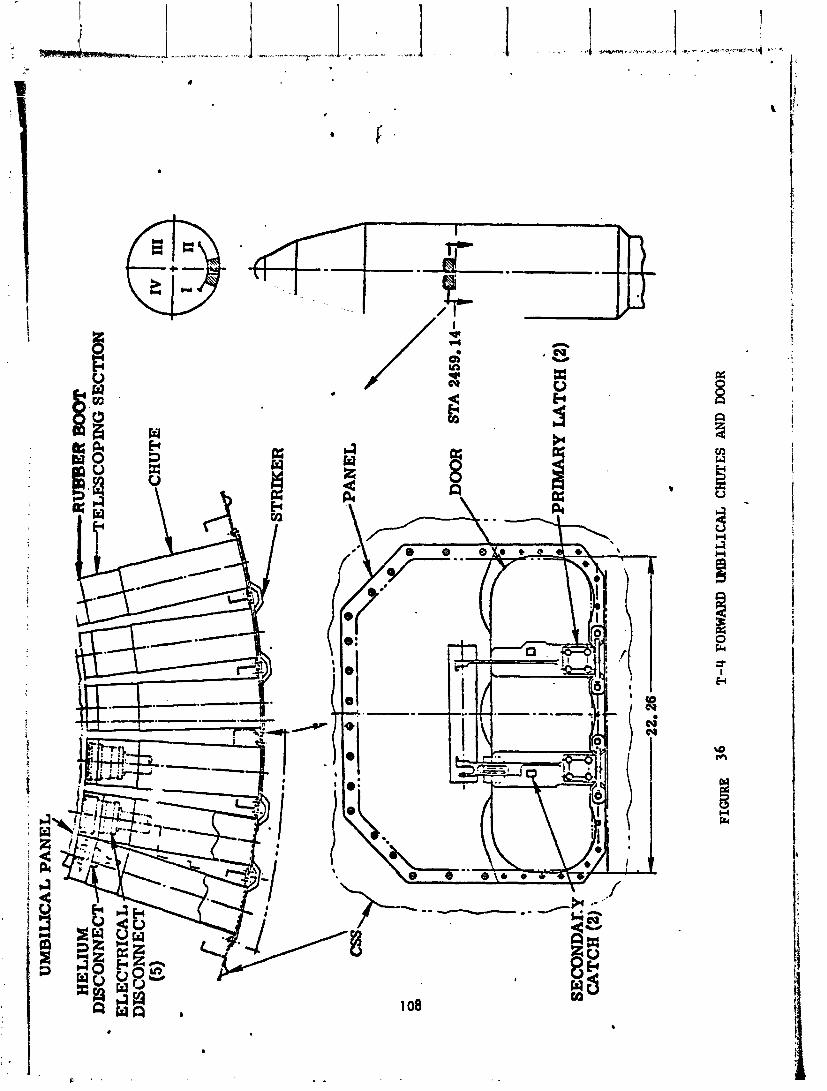
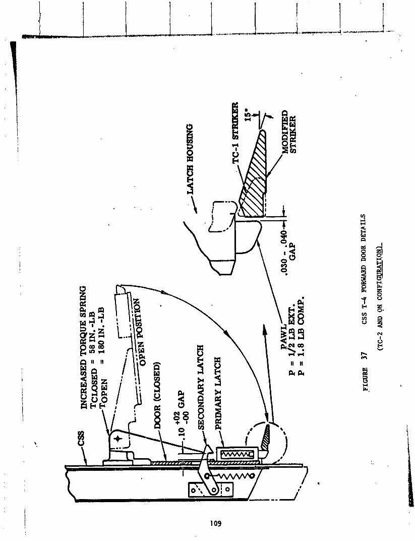
INC
RE
ASE
D T
OR
QU
E S
PR
ING
T
CL
OSE
D =
58 IN. -LB
I =
180IN. -LB
GA
P
HO
USI
NG
I ! I L
#
PA
WL
P
= 1/2 LB EXT.
GA
P
FIG
UR
E
37
CSS
T-4 FORWARD
DOO
R D
ET
AIL
S
(TC
-2 AND
QN
CO
NFIG
URAT
IO*
TC
-I S
T-
'MO
DIF
IED
ST
RIK
ER

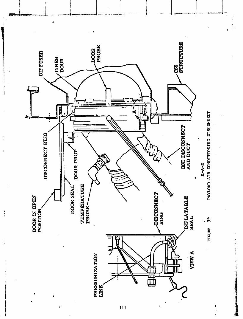
DOOR I
N O
PE
N
DIS
CO
NN
EC
T R
iiJG
PR
ESS
UR
IZA
TIO
N
AND D
UC
T *
11-A
-3
FIG
UR
E 39
PAYI
LOAD
AIR
CO
ND
ITIO
NIN
G D
ISC
ON
NE
CT
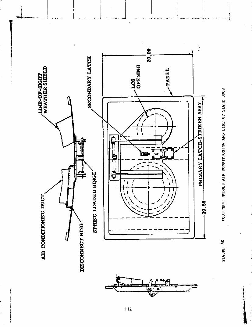
AIR
CO
ND
ITIO
NIN
G D
UC
T \
DIS
CO
NN
EC
T R
lNG
/
/ SE
CO
ND
AR
Y LATCH
SPR
ING
LOADED H
ISJG
E
FIGURE 40
EQ
UIP
ME
NT
MO
DU
LE A
IR
CO
ND
ITIO
NIN
G A
ND
LIN
E O
F SI
GH
T D
OO
R
.-
"
.' I..
, . . .
.
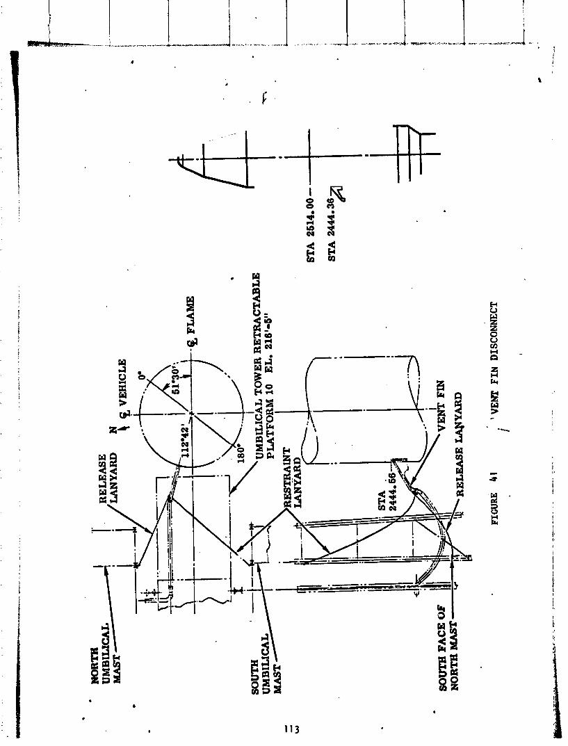
'VE
NT
FIN DISCONNECT
i
LH and LO2 F i l l and Dra in Valve Disconnects and Doors - Disconnect o f the f va ve i s accomplished by a lanyard system which disconnects the va lve by f r a c t u r i n g f r ang ib l e bo l t s . Doors a re c losed by lanyards and incorpora te two pr imary and one secondary la tches (reference Figures 42 a ~ d 43).
.1. l n te rs tage Adapter A i r Condi t ion ing - Disconnect and door c l o s i n g a re s i m i l a r .$
4 t o t he payload a i r cond i t i on ing ( re ference F igure 39).
“t Q .$$
A l l f unc t ions o f the T-0 disconnects and doors were v e r i f i e d by movie and Y
t e l e v i s i o n camera data. For the T-4, T-0 and Equipment Module A i r Condl- :J
t i o n i n g L i ne o f Sight doors, a re ference l i n e was pa in ted on the pr imary .%. 2 -:
l a t c h housing and a do t was pa in ted on the pawl r e t a i n i n g p i n t o a s s i s t i n determining pr imary door 1 a tch ing (F igure 37). Movies cover ing these doors v e r i f i e d pr imary l a t ch i ng .
Centaur Standard Shroud Ascent Vent System
The Centaur Standard Shroud Ascent and Vent System con t ro l s the ven:i ng o f seven separate compartments. The vent ing r a tes a re c o n t r o l l e d t o minimize veh i c l e and spacecraf t s t r u c t u r a l d i f f e r e n t i a l pressures dur ing ascent through the atmosphere. The seven vented compartments, the contained gas media and volumes, the vent areas and the number o f vents f o r the TC-2 v e h i c l e a re shown i n F igure 44. The TC-2 and TC-1 Proof F l i g h t CSS Ascent Vent Systems were i d e n t i c a l except f o r how one compartment, Compartment 4A, was vented.
Compartment 1 , the Hel ios A spacecraf t , had an i n t e rna l volume o f 66 cub ic 1 f ee t o f n i t r o g e h w h i c h was vented into-.tJie-CSS payload compartment. The - He1 i os A spacecraf t presented no vent ing problem.
Compartment 2, the payload compartment, and Compartment 3, the Centaur e l ec - t r o n i c s compartment, were e s s e n t i a l l y one compartment. The Environmental Sh ie ld which separated the two compartments provided l i b e r a l communication between compartments. Compartment 2/3 had a combined volume o f 3787 cubic f e e t o f n i t r ogen gas.
Compartmer t 4A, t he Centaur equi pment module compartment, was bounded by t he Centaur Equipment Module, the Centaur Stub Adapter and the top o f the C e n t a r LH2 tank. Th is 78 cubic fee t compartment was purged w i t h he1 ium on the ground. The heliurn purge was requi red t o prevent cryo-pumping o f condensable gases i n - t o t he LH2 tank. During t he launch countdown ladder j u s t p r i o r t o l i f t o f f , a spring-loaded door i n the Equipment Module was opened by a pyrotechnic p i n pu l - l e r p rov id ing 9.5 square inches o f vent area i n t o Compartment 3 through a f i b e r - g las duct.
I n f l i g h t , the n i t r ogen gas i n CLmpartments 1 and 2/3 and the he l ium gas i n Compartment 4A were vented through 125 square inches o f vent area d i s t r i b u t e d ,4
. . I n 11 rectangular vents d i s t r i b u t e d around the circumference o f the CSS. $ ;-&

I
GLASS MAT
FIL
LE
D
90'
FIB
ER
GL
ASS
310-
SEC
ON
DA
RY
07
0-P
RIM
A R
Y
VIEW A
VIEW B
DOOR SPRINGS (
2)
DOOR I
NST
AL
LE
D
LA
NY
AR
D B
RE
AK
WIR
E
\ I
DOOR
.
AT
TA
CH
CL
IP '
CH
UT
E D
OO
R
FOR
TH
ET
HE
R
RIM
AH
Y L
AT
CH
(2)
TE
TH
ER
LANYARD
' . .
FIG
UR
E 42
AND LOX
FIL
L AND
DR
AIN
VA
LVE
CH
UTE
AN
D DO
OR
8
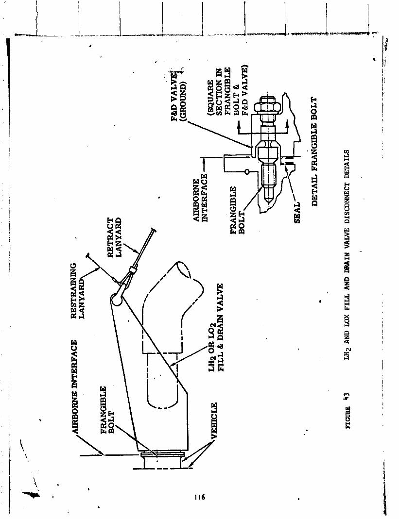
DE
TA
IL F
RA
NG
IBL
E BOLT
FIGURE
43
LH
2 AN
D MX F
ILL
AND DRAIN VALVE
DIS
CO
NN
ECT
DE
TA
ILS
I
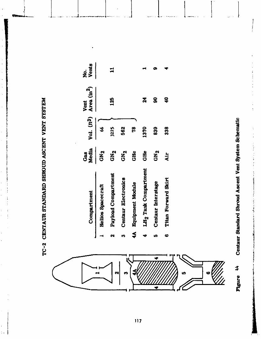
TC
-2
CE
NT
AU
R S
TA
NIZ
4RD
SH
RO
UD
ASC
EN
T V
EN
T S
YST
EM
Gas
V
ent
No.
C
ompa
rtm
ent
Med
ia
Vol
. (f
@)
Are
a (i
n2)
V
ents
*
Hel
ios
Sp
acec
raft
G
N2
Pay
load
Com
part
men
t G
N2
125
11
Cen
taur
Ele
ctro
nic
s G
N2
562
Equ
ipm
ent
Mod
ule
GH
e 32" 7
8 1
LEI2 Tank
Com
part
men
t G
He
1370
24
1
Cen
taur
In
ters
tage
G
N2
839
90
9
Tit
an F
orw
ard
Skirt
Af r
33
8 40
4
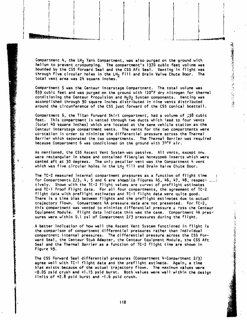
X Compartment 4, the LH2 Tank Compartment, was a l s o purged on the ground w i t h .X
,-" helium t o prevent cryopumping. The compartment's 1370 cubic feet vol l~me was f bounded by the CSS Forward Seal and the CSS A f t Seal. Venting I n fl i g h t was 3 through f i v e c i r c u l a r holes i n the LH2 F i l l and Drain Valve Chute Door. The i.& ,? .. 8 t o t a l vent area was 24 square inches. s ,.I. ,*
.* Compartment 5 was the Centaur ln te rs tage Compartment. The t o t a l v o l u m was , I_ ..!.
839 cubic f ee t and was purged on the ground w i t h 120°F d ry n i t r ogen f o r thermal ..,'&
cond i t ion ing the Centaur Propulsion and H202 System components. Venting was . L. we . .' , accomplished through 90 square inches d i s t r i b u t e d i n n ine vents d i s t r i b u t e d ; . ,? .. . around the circumference o f the CSS j u s t forward o f the CSS con ica l b o a t t a i l . :a'"
Compartment 6, the T i t an Forward S k i r t compartment, had a volume o f 338 cubic feet . This compartment i s vented through two ducts which lead t o four vents ( t o t a l 40 square inches) which a re located a t the same veh i c l e s t a t i o n as the Centaur ln te rs tage compartment vents. The vents f o r the two compartments were co-s ta t ion i n order t o minimize the d i f f e r e n t i a l pressure across the Thermal Ba r r i e r which separated the tw compartments. The Thermal Ba r r i e r was requi red because Compartment 6 was condi t ioned on the ground w i t h 7P°F a i r .
As mentioned, the CSS Ascent Vent System was passive. A l l vents, except one, were rectangular i n shape and contained f i be rg las honeycomb i nse r t s which were canted a f t a t 30 degrees. The on1 y pecul i a r vent was the Compartment 4 vent which was f i v e c i r c u l a r holes i n the LH2 F i l l and Dra in Valve Chute Door.
The TC-2 measured i n te rna l f o r Compartments..2L3, 4 , 5 t i v e l y. Shown w i t h the TC and TC-l Proof F l i g h t data f l i g h t data w i t h preflight
f I compartment p re sures as a funct ion o f f l i g h t t ime and 6 are sham .in Figures 45, 46, 47, 48, respec- ---.I
-2 f l i g h t values a re curves o f p r e f l i g h t estimates . For a l l fou r compartments, the agreement o f TC-2 est imates and TC-I f 1 i g h t data were q u i t e good.
There i s a t lme b ias between f l i g h t s and the p r e f l i g h t est imates due t o actua l t r a j e c t o r y f lown. Compartment 4A pressure data are not presented. For TC-2, t h i s compartment was vented t o minimize d i f f e r e n t i a l pressure a ross the Centaur Equipment Module. F l i g h t data i nd i ca te t h i s was the case. Compartment i!A pres- sures were w i t h i n 0.1 ps i o f Compartment 2/3 pressures dur ing the f l i g h t .
A be t t e r i n d i c a t i o n o f how we l l the Ascent Vent System funct ioned i n f l i g h t i s the comparison of compartment d l f f e r e n t i a l pressures ra the r than i nd i v i dua l compartment i n te rna l pressures. The d i f f e r e n t i a l pressure across the CSS For- ward Seal, the Centaur Stub Adapter, the Centaur Equipment Module, the C S S A f t Seal and the Thermal Ba r r i e r as a func t ion o f TC-2 f l i g h t t ime a re shown i n F igure 49.
The C S S Forward Seal d i f f e r e n t i a l pressures (Compartment 4-Compartment 2/3) agree we l l w i t h TC-l f l i g h t data and the p r e f l i g h t est imate. Again, a t ime b ias e x i s t s because o f the actua l t r a j e c t o r y flown. The maximum values were -0.05 ps id crush and +1.15 ps id burs t . Both values were w e l l w l t h i n the design l i m i t s o f +2.8 ps id burs t and -1.6 p s i d crush.
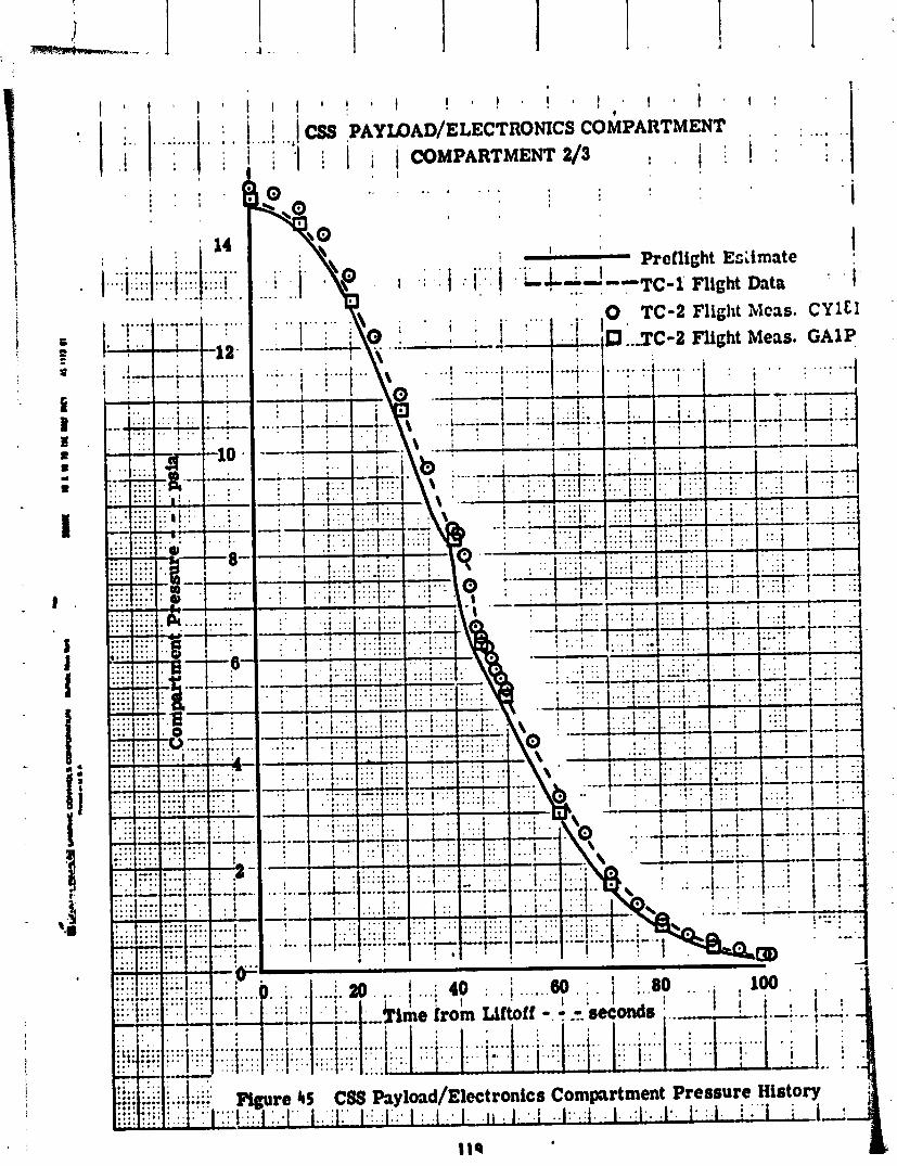
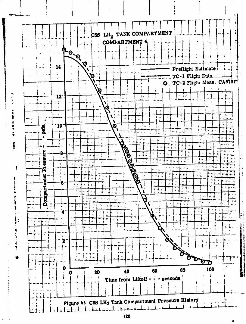
. ,
I 1 . 1 !

20 40 60 80 Time from Liftoff - 7 - seconds : - . . . .
Centaur Intorstage Compartment Pressure . . 1 ' ! ' .'l',"" ..,"' " '." , " " " .
1 ' ' " ' ' I ' . '
121
History ' , "
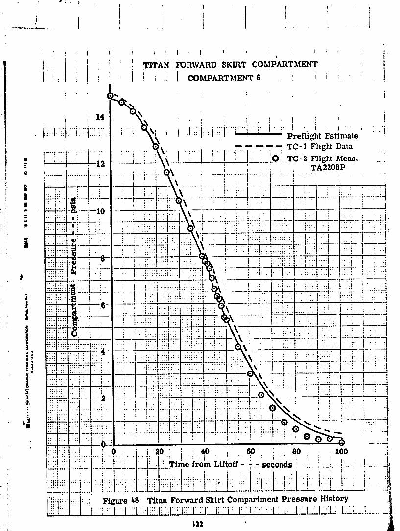
: 1 : TITAN FORWARD SKIRT COMPARTMENT 1 i I 1 COMPARTMENT 6 i
, . j 1 ,

Preflight Estimate i
o m - - m - TC-1 Flight Data I
. . . a
I
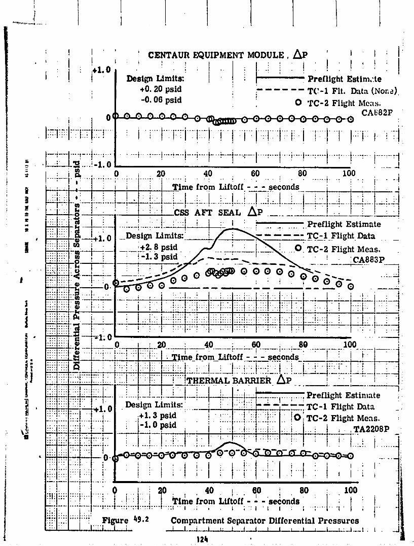
The Centaur Stub Adapter d i f f e r e n t i a l pressures (compartment 4A-Compartment 4) were i den t i ca l t o the Forward Seal data; i .e., no d i f f e r e n t i a l pressure ac ro is the Centaur Equipment Module, so burs t pressures across the Forward Seal were crush pressures across the Stub Adapter. F l i g h t data were w e l l w i t h i n the design 1 i m i t s o f +1.6 ps id bu rs t and -2.8 ps id crush and agreed wel l w i t h the p r e f l i g h t estimate. TC-1 d i d no t have a comparable Stub Adapter d i f f e ren t i a l pressure because Compartment 4A was vented d i f f e r e n t l y . On TC-1 w i t h the payload mounted on e t r uss adapter d l r e c t l y t o the Stub Adapter, Com- partment 4~ was vented d i r e c t l y i n t o Compartment 4 i n order t o minimize crush pressure loadins on the Stub Adapter. On l i - 2 w i t h the Hel ios A spacecraft mounted t o the Centaur Equipment Module, Compartment 4A was vented i n t o Corn-rt- ment 3 I n n rder t o minimize crush pressure loading on the Equipment Module. This i s a C;S Ascent Vent System mission p e c u l i a r i t y .
The d i f f e ren t i a l pressure across the Equipment Module (Compartment 4A-Compartment 2/3) was e s s e n t i a l l y zero dur ing f l i g h t . Again, there was no compar;ble measure- ment on TC-1 due t o how Compartment 4A was vented.
The CSS A f t Seal d i f f e r e n t i a l pressures (Compartment 4-Compartment 5) were less than the p r e f l i g h t est imate and less than the TC-1 values. Maximum crush was -0.05 ps id and the maximum burs t was 0.35 ps id . Both values were w e l l w i t h i n the design l irni ts o f +2.8 ps id bu rs t and - 1.3 ps id crush.
2. The spacecraft compartment maximum pressure decay r a t e dur agreed we l l w i t h the p re f 1 i gh t est imate and TC-1 f l i g h t data.
The maximum Thermal Ba r r i e r d i f f e r e n t i a l pressures (Compartment 5-Compartment 6) were -0.05 p s i d crush and +0.1 ps id burs t ; we l l w i t h i n the design l i m i t s o f +1.3 - . id bu rs t and -1.0 ps id crush.
- - L - Another i nd i ca t i on o f the performance o f the CSS Ascent Vent System i s the d i f -
i f e r e n t i a l pressures across por t ions o f the CSS, the Centaur ln te rs tage Adapter, and the T i tan Forward S k i r t compartments. These data a re presented i n the re - po r t sect ion e n t i t l e d , CSS and Vehicle Aerodynamics.
The CSS Ascent Vent System a l so had a cons t ra i n t t o minimize the maximum r a t e o f pressure decay i n the spacecraft compartment dur ing the t ransonic p o r t i o n o f f l i gh t . An expanded t ime p l o t o f the spacecraft compartment (Compartment 2/3) i n t e rna l pressures dur ing the t ransonic i s shown i n F igure 50. As ind ica ted i n F igure 50, the maximum pressure decay r a t e was approximately -.75 psi/second. Th is value compares we l l w i t h the p r e f l i g h t est imate o f 0.89 psi/second and the TC-1 f l i g h t value o f 0.75 psi/second. The t ime b ias due t o actua l t r a j e c t o r y f lown i s again apparent i n F igure 50.
The TC-2 Centaur Standard Shroud Ascent Vent System performed s a t i s f a c t o r i l y and as designed.
1. Compartment pressure t ime h i s t o r i e s and compartment d i f feren+ i a l pressures agreed we l l w i t h p r e f l i g h t est imates and w i t h TC-I f l i g h t data.
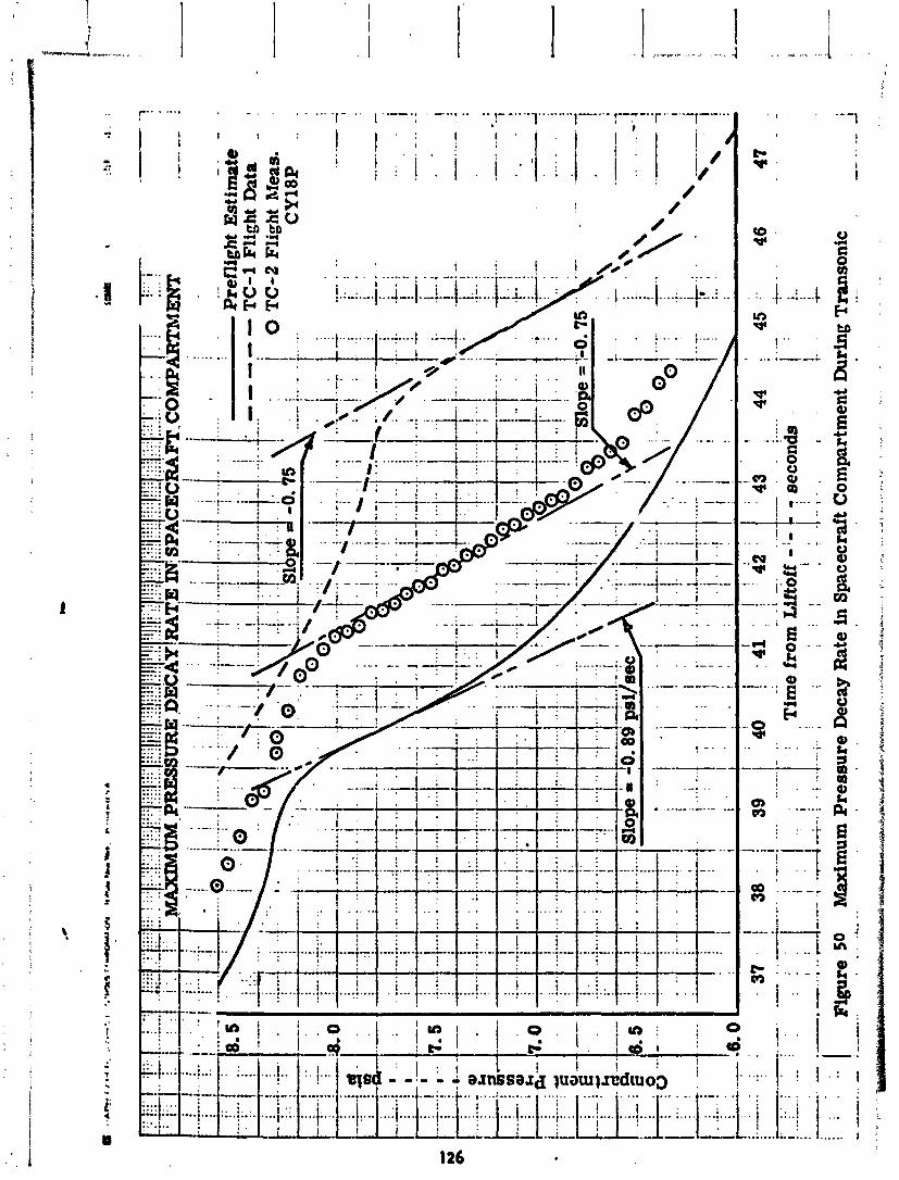
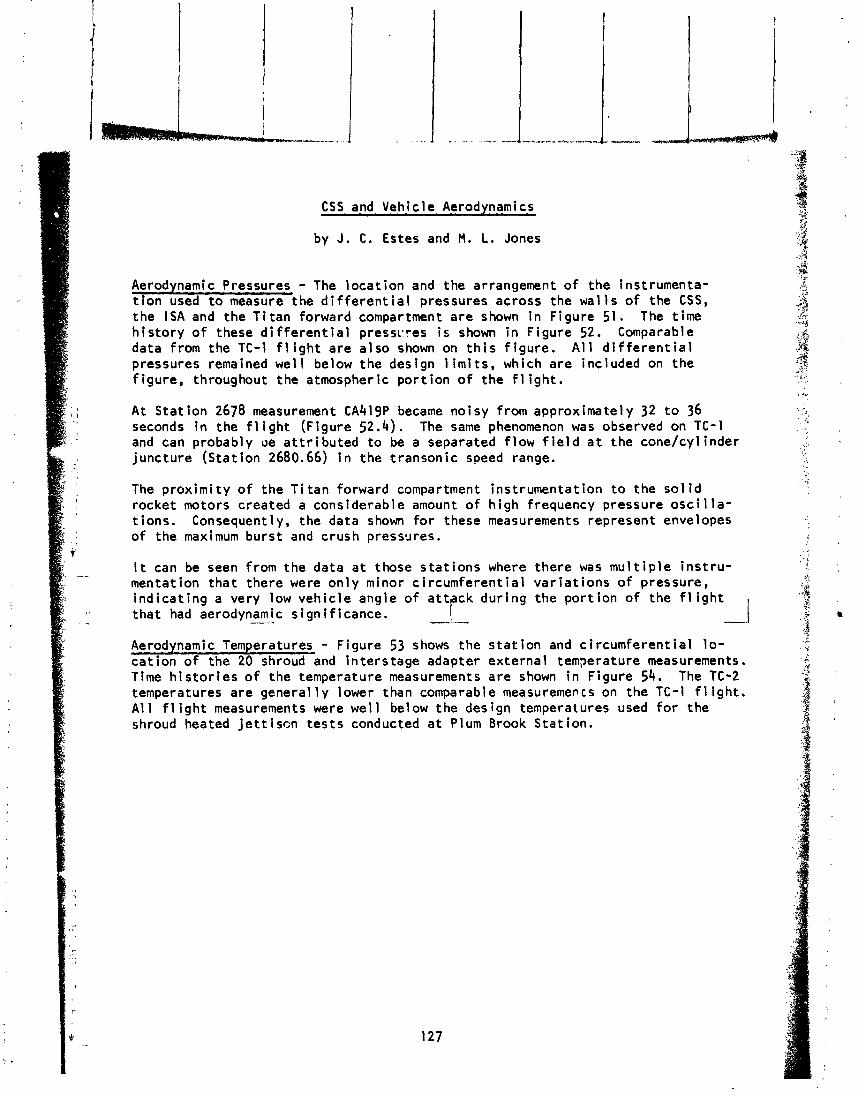
CSS and Vehicle Aerodynamics
by J. C. Estes and M. L. Jones
Aerodynamic Pressures - The loca t ion and the arrangement o f the instrumenta- t i o n used t o measure the d i f f e r e n t i a l pressures across the wal ls of the CSS, the I S A and the T i tan forward compartment are shown i n Figure 51. The time h i s to ry o f these d i f f e r e n t i a l presscres i s shown i n Figure 52. Comparable data from the TC-1 f l i g h t are a lso shown on t h i s f igure . A l l d i f f e r e n t i a l pressures remained wel l below the design l i m i t s , which are included on the f igure, throughout the atmospheric p o r t ion o f the f 1 i gh t . A t Stat ion 2678 measurement CA419P became noisy from approximately 32 t o 36 seconds i n the f 1 i ght (Figure 52.4). The same phenomenon was observed on TC-1 and can probably oe a t t r i bu ted t o be a separated f low f i e l d a t the cone/cylinder juncture (Stat ion 2680.66) i n the transonic speed range.
The prox imi ty o f the T i tan forward compartment instrumentation t o the s o l i d rocket motors created a considerable amount o f h igh frequency pressure o s c i l l a - t ions. Consequently, the data shown f o r these measurements represent envelopes o f the maximum burst and crush preswres.
It can be seen from the data a t those s ta t ions where there was mu1 t i p l e i ns t ru - mentation tha t there were on ly minor c i rcumferent ia l var ia t ions o f pressure, ind ica t ing a very low vehic le angle of a t t ck dur ing the por t ion o f the f l i g h t tha t had aerodynamic --- s igni f icance. I -.
?
Aerodynamic Temperatures - Figure 53 shows the s t a t i o n and c i rcumferent ia l l o - cat ion of the 20 shroud and in terstage adapter external temperature measurements. Time h i s t o r i e s o f the temperature measurements are shown i n Figure 54. The TC-2 temperatures are general 1 y lower than comparable measurements on the TC-1 f l ight . A l l f l i g h t measurements were wel l below the design temperatures used f o r the shroud heated j e t t i s c n tes ts conducted a t Plum Brook Stat ion.
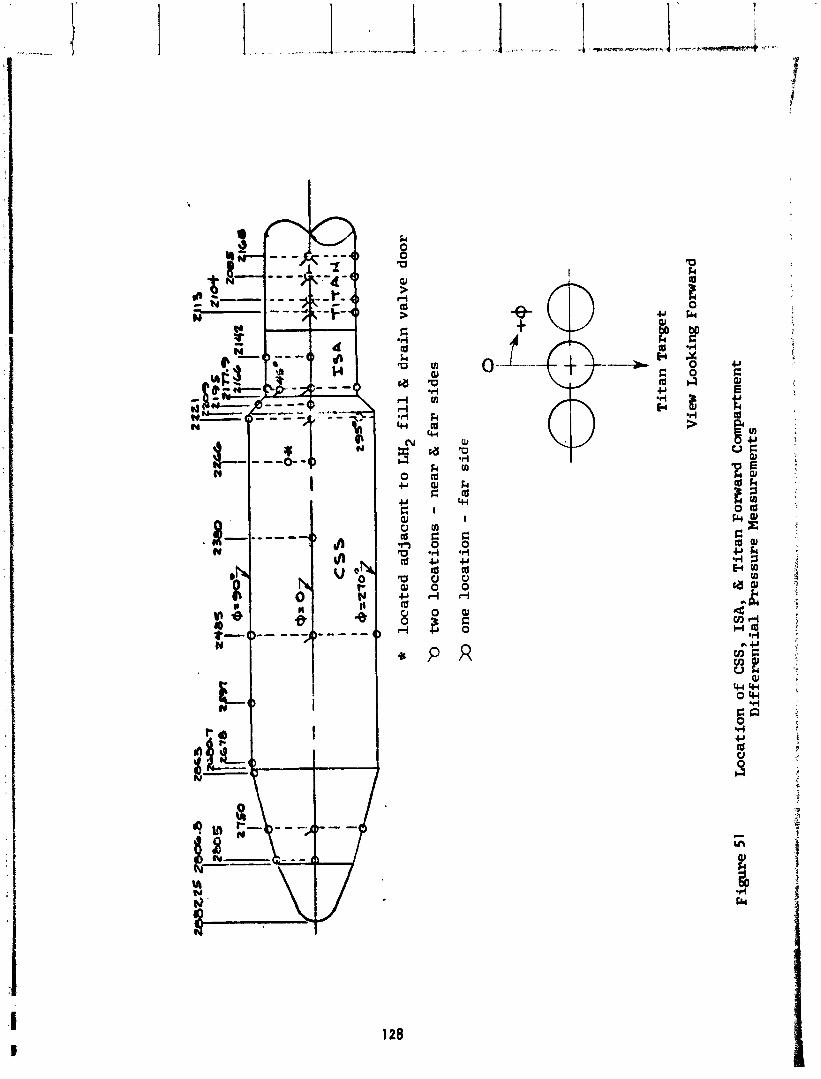
k m
rcl
I
E 0 'rl CI a U 0 rl
Q1 E 0
R
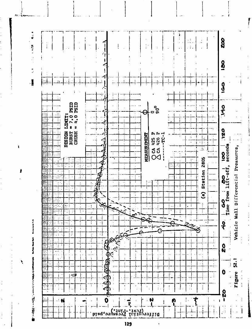
. . . .... :::: 1:. . . . : ! ! : i . . . . . . ,- . . . I . . I . . . : ' I . ; . . . . . . . . . I " ' i ..... ;"+ -"". -..a. ". .... . . . .-* .;.- -.. ,.-
! i C '! i.4
.... ....
' I i
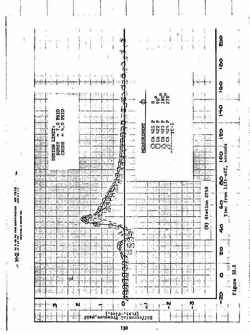
DE
SIG
N L
IMIT
: BURST
7.0
P
SID
C
RU
SH
= 4.0
PSI
D
MEA
SURE
MEN
T I
Fig
ure
52
.2
-. -.
-20
0
1
. .
. .
ZO
i4
0,
60
:
80
,1
00
! I2
0
j 1-
; 1
60
1-
w
I -..
I :.
..
c-: : -
z:,:l
-:.
Time from li
ft-o
ff,
seconds -
'
... .
...
L.-
A
* -
....
....
I
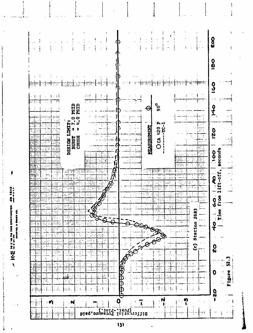
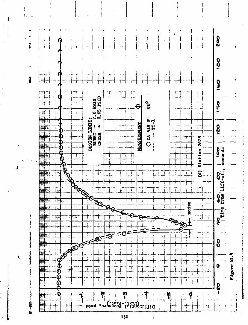

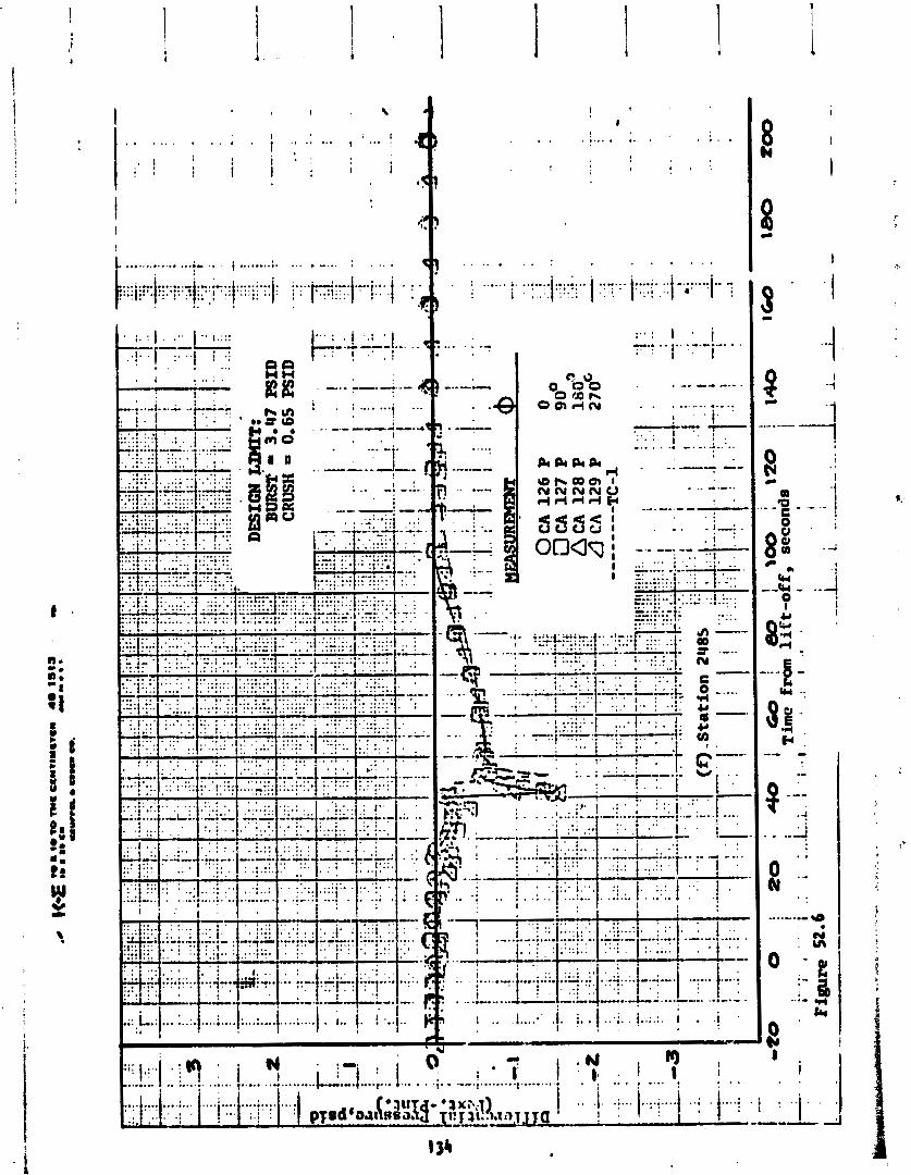
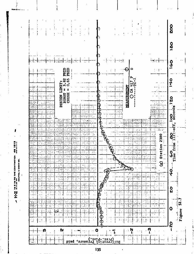
r :
1 . -
(:
#
f - .- \
r 1
. . . . .
. -
- .
-
-
.. ,
I 0 .:
;!
.. 0 , -k
. . . . . .i . ; N . I ( ) t ... i I; I i i I. .... ..I ....$ .,--...... .... ...... -. ................ . ,
l.... ... ......:..................... :. .. i . ' - 8 . I : -- .---I *
. . ......... :.!.-.:.:.I ; . ; : : !
. A_.- 0 . . . , . 1 I . .
.: : ) : ..---- ! A':":
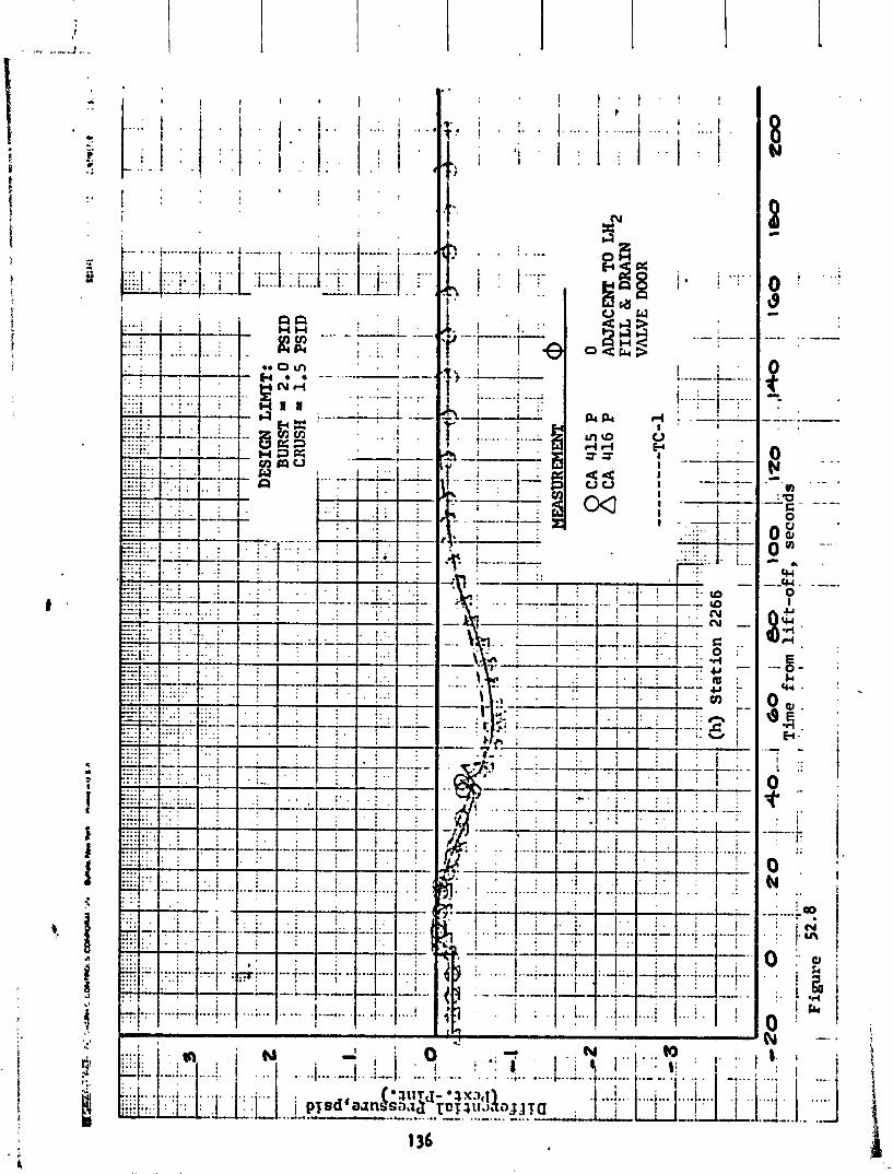
1 ' !.* .--. + .... i .... ;--I .--;... . . . . &Pi 7 :---
xi U , .
C;' 33 . .
I --: 5 4 - --,- 1-- . . I i .
-.ad.
" :+ .... . . .
...., . . . . *:. ' L...

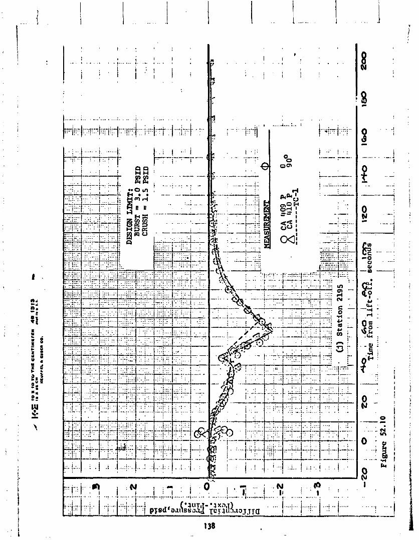
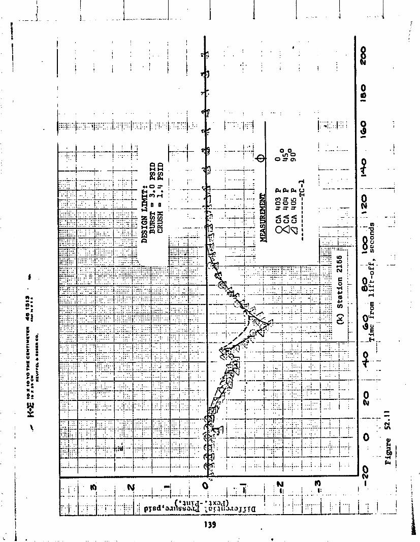
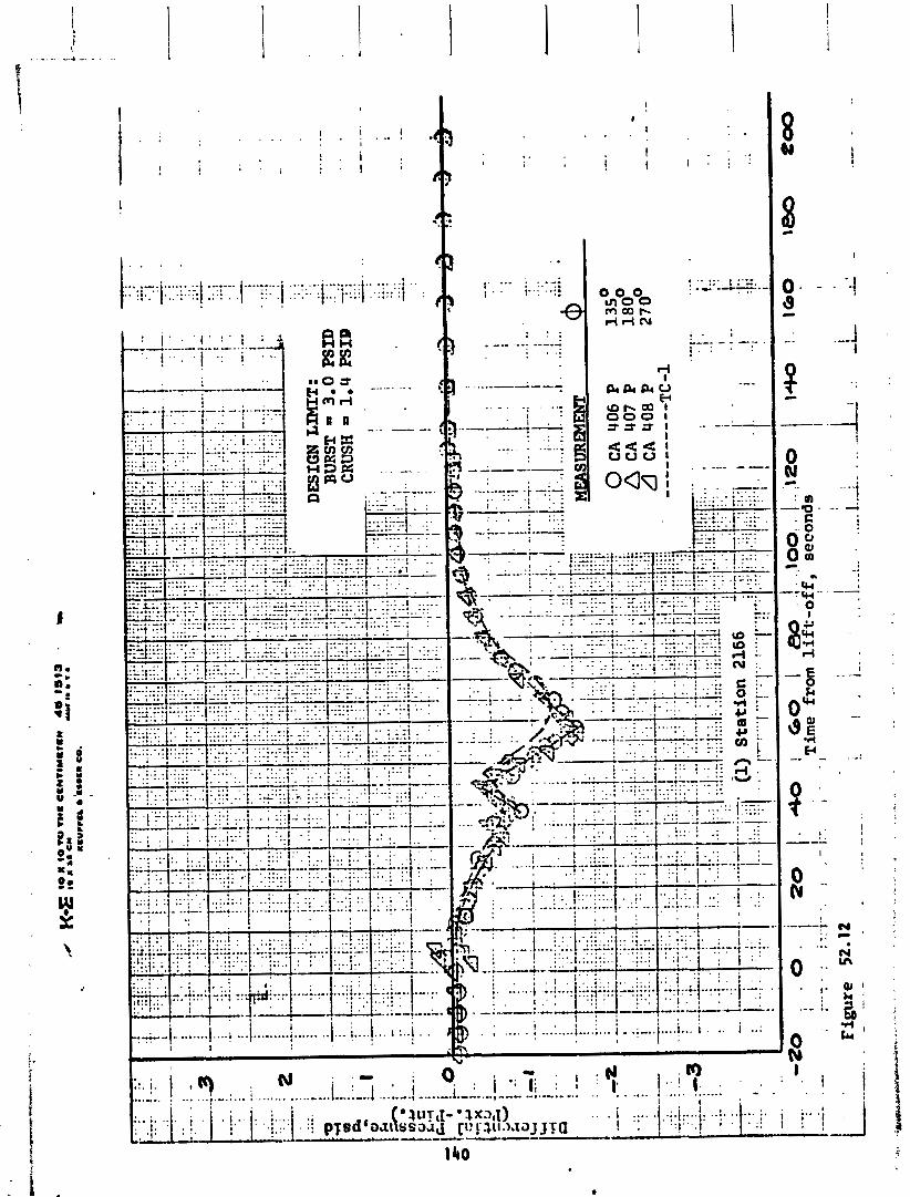
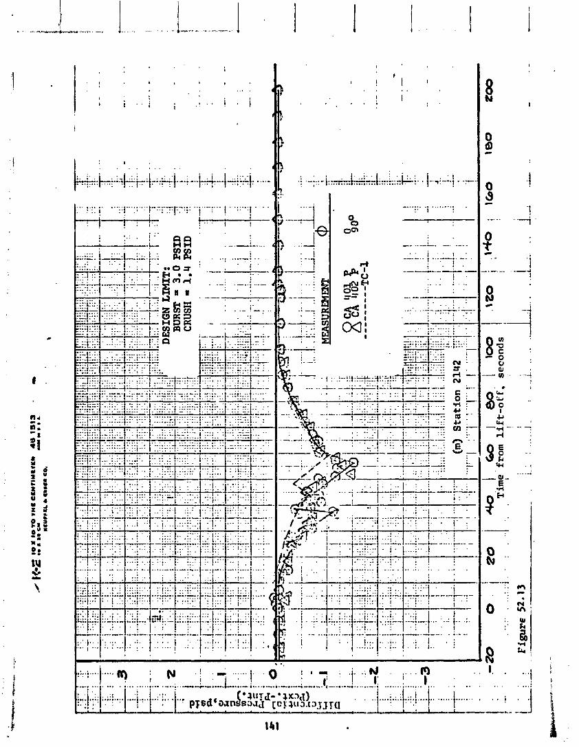
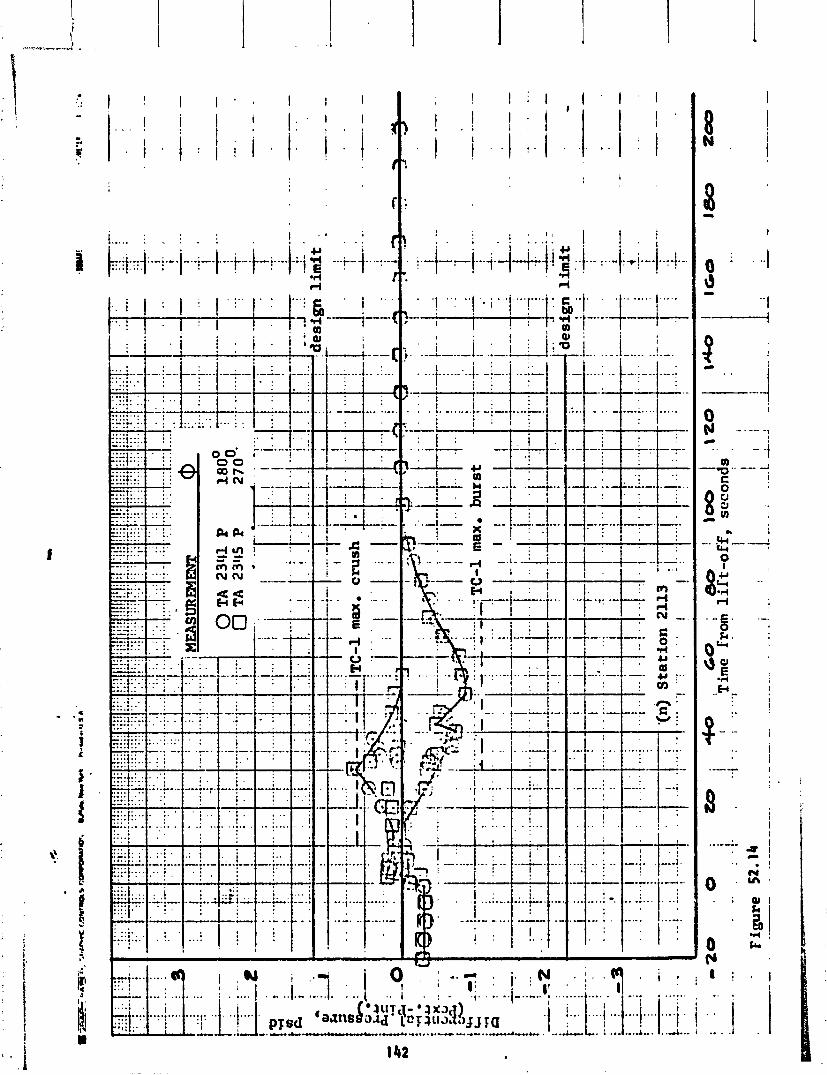
W
O I , 1 -., i : N I! - i . , i 1 1 . i .. 1 .. , . : - .,. . .. ..I -..-.- ' ...*-..- .... . .. . $ 311?~1- *3xac aid p ~ ~ d ? ~ J J T Q .i i . . 1.. . . 1::i . . 1 -.- ........ U .... .. ....- .a)..&. ..'& I . ... .... A". ..-J..- 1 .. - .I
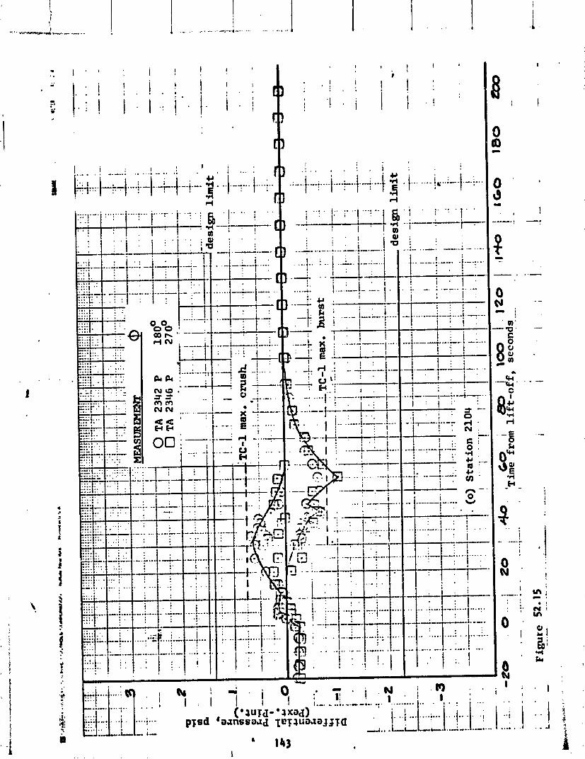
. I . ! ,


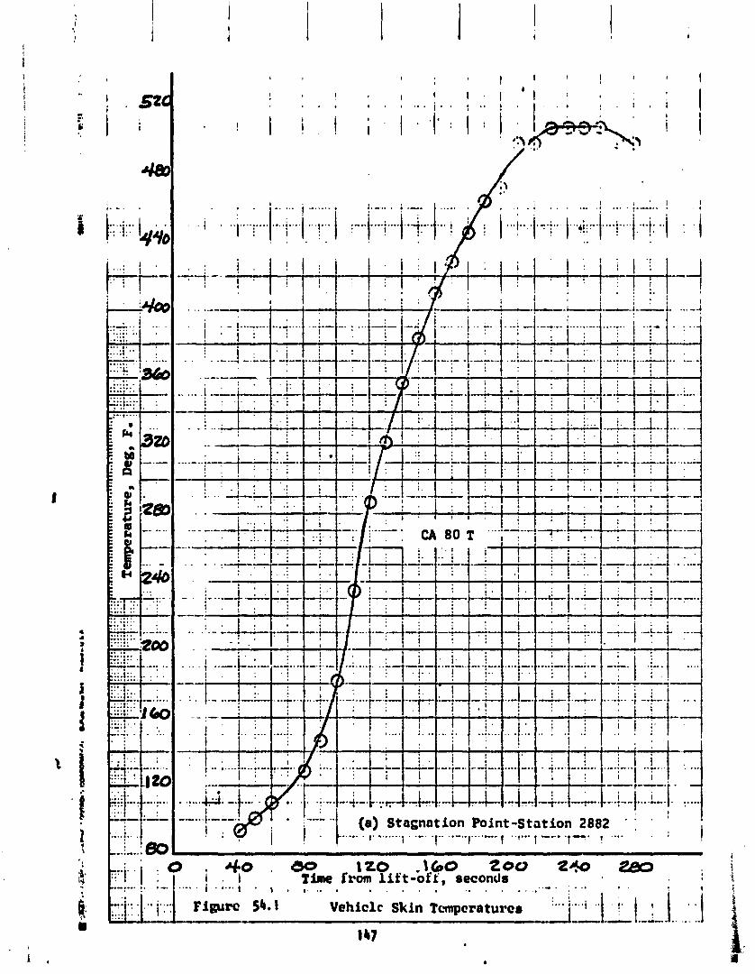
r d
2
. .
- - # . . .. -
> - .
- - 3
-
b
- .
I
- - 2
- -
3
- ,
D - 1 2 0 ,160 200 Z W
T h e from l i f t -off, seconds . . . . ..... . . . . . . . . . . . . . . . t - L . 8 . 9 . . ..- . . , I .... Vehiclc Skin Tcvnpcraturcs :...;
.....
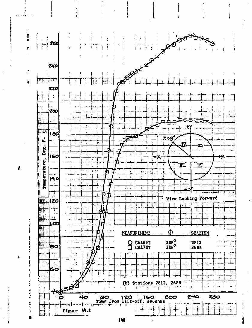

00 1 2 0 Time from liit ..;. --.?.. I ,


I - - (f) Station 2029 , I ' .. , . . . . I ' I ' m 1 ' ' I - ' I ' I
>
. . .
>
- . . I ... :. ..I . . . : I,&,
;::;. j ,
..... - ..... .......
....... jliiii c4q:
. . . . . 1: . ; (I: . . . . . . . . *..~ . ' . . . . .... ::..I: , --- ........ . . . . ., . . . .... .... . . . . ..20 , ..... . .. - ....... . a
-- .... . . . . . . . . -;..I. 0 a ..... ... . : : . , i. . . :.::I.: - - . + t . . . .
i
. 0 40 PO I- 1 6 0 Zoo 240 280 a
Time from l i f t -off , scconds ; ~i ---.-.. ....,... +... .... . I I , 1 ..i . -.b--;I . i I , I . . - . . . . ' I f 5 . i . . . . . . . . . ' Figure 54.6 ' , 4
! ----.- . . * . -. 1 52
. .
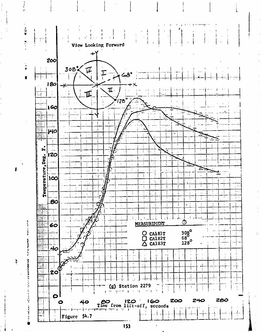
. . ,. .. . . . , .-...-.. 1 - .' '
i I . 1
' 1 ; / I I 0 . I . . . . . ! . . 1 . :
I . i I I I . I . i t
! i View Looking Forward I
i '
1 2 0 - 160 zoo 2- - -of E, seconds , , . , . . ... ; . . ... . . .
i i . .... L.;,.. 1 . ; I . 1 . . i . .i..] I
-.- . .&.. _ - - , ..-L.. ...*- -. "A..
I53 a
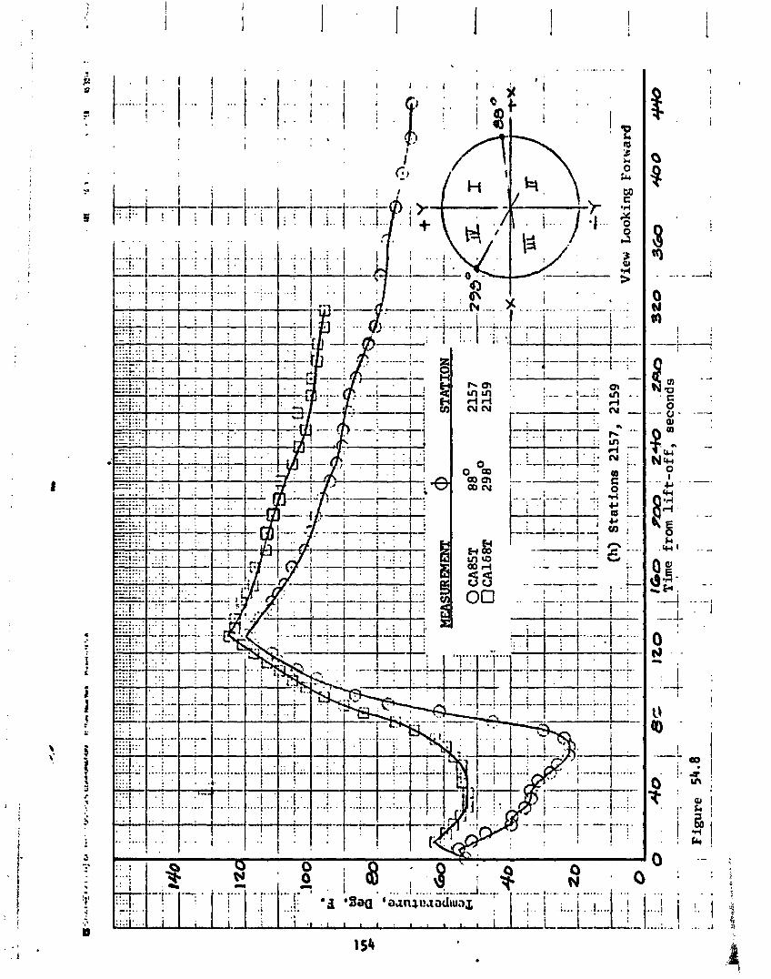
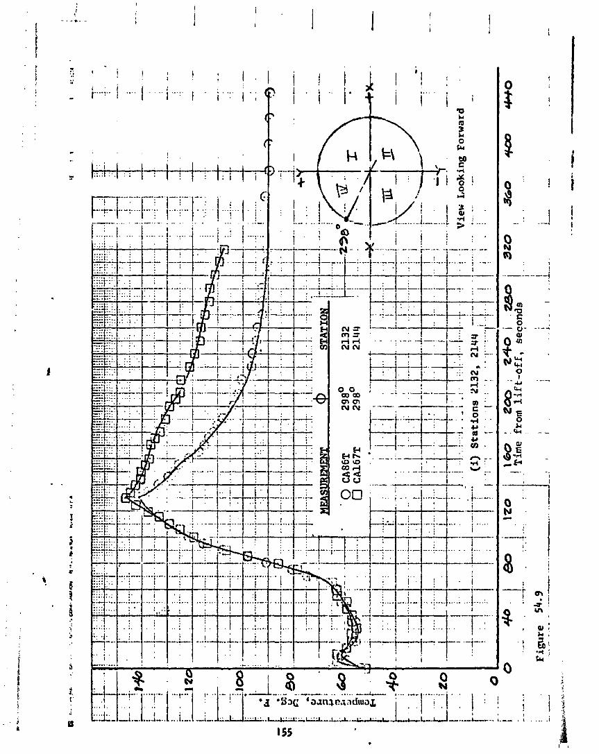
CSS St ructures
by C. W. Eastwood
The f l i g h t loads, both a x i a l an+ bending moments, on the shroud were c a l - cu la ted from s t r u c t u r a l s t r a i n s t h a t were sensed by s t r a i n measurements composed o f s t r a i n gage arrays. Near the a f t end of the shroud, four a r - rays were located a t S ta t i on 2294 and spaced 90 degrees apar t a t azimuths 24O, 1 I b0 , 204" and 294' as shown i n F igure 55. Each a r ray cons is ted o f four u n i a x i a l gages mounted on the e x t e r i o r s k i n co r ruga t ions and connected e l e c t r i c a l l y as shown i n Figure 56. The s t r a i n measurements were i n s t a l l e d on the shroud p r i o r t o bu i ldup on the veh i c l e and were zeroed a f t e r e rec t i on on the launch pad. Consequently, t he t a r e weight o f the shroud (50,000 I bs) forward o f the s t r a i n gages was nu1 led-out. Although the value i s smal l com- pared t o t he fl igh t maximum load, the data presented has been corrected t o inc lude the shroud t a r e weight.
The maximum combined loads on the shroud a t Stat ion 2294 occurred a t T + 38.3 seconds. The equiva lent a x i a l load a t t h a t t ime was 229,500 pounds on the compression s ide and 160,500 pounds tens ion load on the oppos i te s ide. O f t h i s equiva lent a x i a l load, 34,500 pounds were d i r e c t a x i a l load and 195,000
6 pounds were from a bending moment o f 8.19 x 10 inch-pounds. The d i r e c t a x i a l load was composed o f 25,500 pounds o f aerodynamic loading and 9,000 pounds o f i n e r t i a load ing from the veh i c l e acce le ra t i on o f 1.8 g. The loads experienced by the CSS dur ing TC-2 f l i gh t are l i s t ed iin Table 28. Loads f o r TC-I f l i g h t I and loads appl i d - l o the t e s t C S S a l s o a d - i n c l uded i n the t ab le f o r compari - --I son. Maximum equiva lent a x i a l loads on t he CSS f o r TC-2 f l i g h t , a l though higher than f o r TC-I f l i g h t , were less than 47 percent o f the t e s t maximum values.
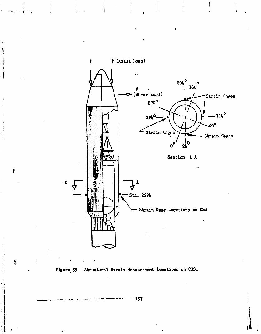
Y P (~xial Load)
(shear Load)
Section A A
\-- Strain Gage Locations on W
Figure, 55 Structural Strain Meaaurement Locations on CSS.
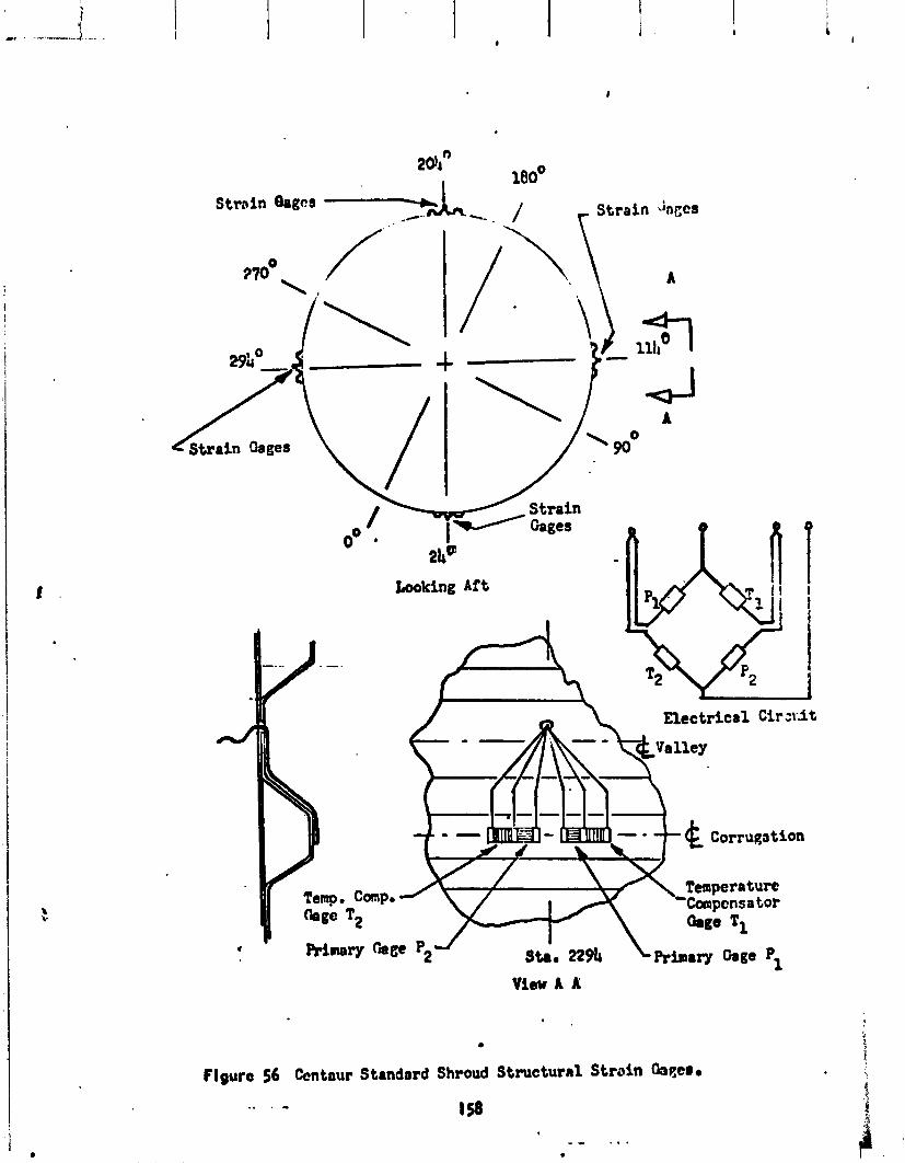
Strnin b g c s - Strain k c s
View A A
Figure 56 Centaur Standard Shroud Structural Strain
.. . - 1s
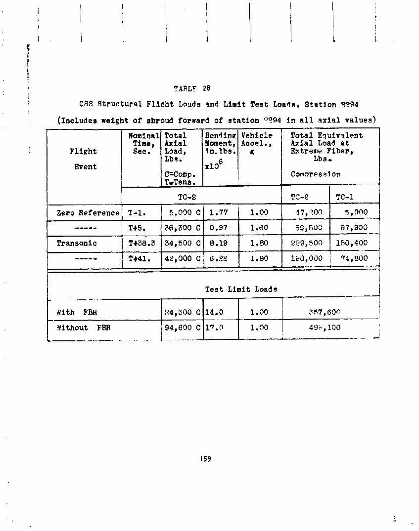
TABLE 28
CSS S t r u c t u r a l F l i g h t Loads nnd L i m i t Teat Loada, Station 5?94
( ~ n c l u d e s weight of shroud forward of station ??94 I n a l l axial values)
Nominal Total Time, Axial
F l ight Sec. Load, Lbs.
Event C=Comp . T~Tens .
I
kendlnll Vehicle Moment, Accel., .In.lbs.
1
Zero Reference T-1. 1.00
----- T+5 a 1.60
Transonic T+38.3 34,500 C 8.19 1.80
.._-- TM1. 142,000 C / 6.22 1.80
Total Equivalent Axial Load a t Extreme Fiber,
Lbs
Test L i m i t Loads
I 1.00 357,600 i 1-00 499,100
1 I
I
I
14.0 .-
17.0
-.
Nith FBR
;?fi thout FBR . . , , . , , - +,-. . - ..... .-. - .--...
24,300 C
94,600 C --- d
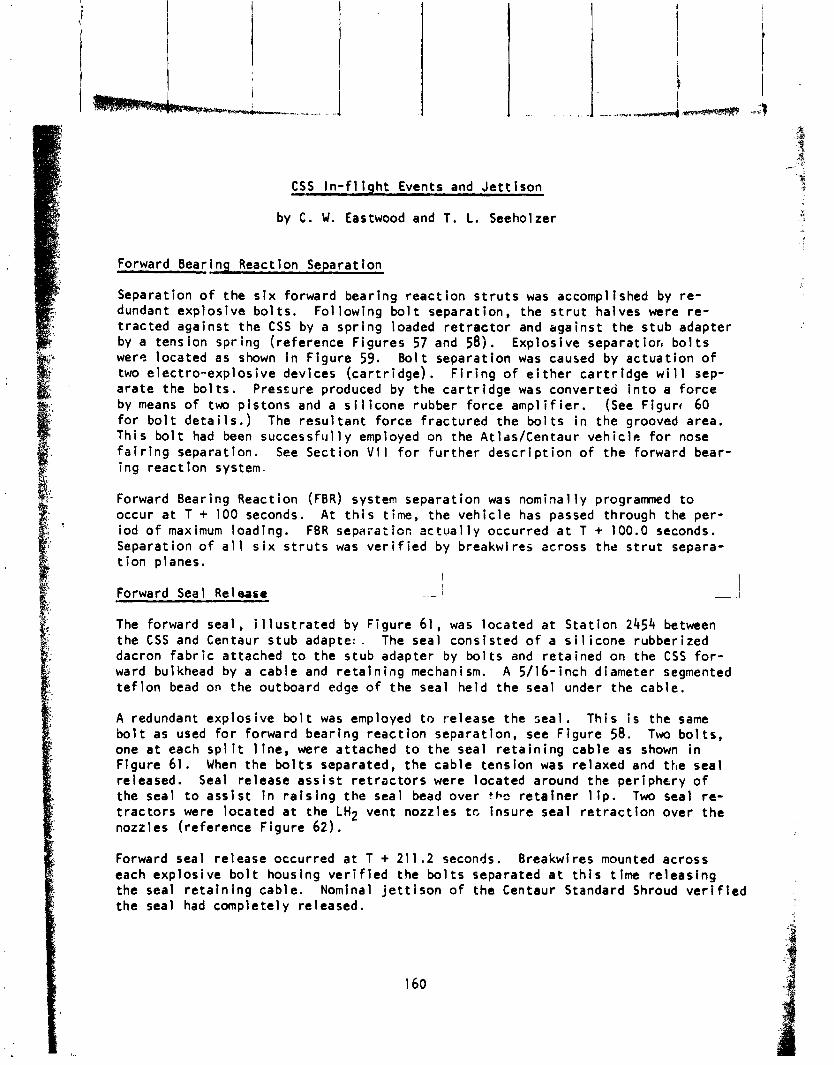
Forward Bear
CSS I n - f l i g h t Events and J e t t i s o n - by C . W. Eastwood and T. L. Seeholzer
i nq React ion Separat ion
Separation o f the s i x forward bear ing reac t i on s t r u t s was accomplished by r e - dundant exp los ive b o l t s . Fo l lowing b o l t separat ion, the s t r u t halves were re - t r ac ted against the CSS by a sp r ing loaded r e t r a c t o r and against the s tub adapter by a tension spr ing ( re ference Figures 57 and 58;. Explosive separatior, b o l t s were located as shown i n F igure 59. B o l t separat ion was caused by ac tua t ion o f two e lec t ro -exp los ive devices ( ca r t r i dge ) . F i r i n g o f e i t h e r c a r t r i d g e w i l l sep- a ra te the bo l t s . Pressure produced by the c a r t r i d g e was converted i n t o a fo rce by means o f two p is tons and a s i l i c o n e rubber fo rce amp1 i f i e r . (See Figure, 60 f o r b o l t d e t a i l s . ) The r e s u l t a n t fo rce f rac tu red the b o l t s i n the grooved area. Th is b o l t had been s u c c e s s f ~ ~ l l y employed on the At lss/Centaur veh i c l e f o r nose f a i r i n g separat ion. See Sect ion V I I f o r f u r t h e r d e s c r i p t i o n o f the forward bear- i ng reac t ion system.
Forward Bearing Reaction (FBR) system separat ion was nominal l y prograrmed t o occur a t T + 100 seconds. A t t h i s time, the veh i c l e has passed through the per- iod o f maximum loading. FBR sepai-at lac ac tua l l y occurred a t T + 100.0 seconds. Separation o f a l l s i x s t r u t s was v e r i f i e d by breakwires across the s t r u t separa- t i o n planes.
! Forward Seal Release I
I - I
The forward seal , i 1 l u s t ra ted by Figure 61 , was located a t S ta t i on 2454 between the CSS and Centaur stub adap te l . The seal cons is ted o f a s i l i c o n e rubber ized dacron f a b r i c at tached t o the s tub adapter by b o l t s and re ta ined on the C S S f o r - ward bulkhead by a cab le and r e t a i n i n g mechanism. A 5/16-inch diameter segmented t e f l o n bead on the outboard edge o f the seal he ld the seal under the cab le .
A redundant exp los ive b o l t was employed t o release the seal . Th is i s the same b o l t as used f o r forward bear ing reac t i on separat ion, see F igure 58. Two b o l t s , one a t each s p l i t l i n e , were at tached t o the seal r e t a i n i n g cable as shown i n Figure 61. When the b o l t s separated, the cab le tens ion was relaxed and the seal released. Seal re lease a s s i s t r e t r a c t o r s were located around the per iphery o f the seal t o a s s i s t i n r a i s i n g the seal bead over t k r e t a l n e r l i p . Two seal r e - t r a c t o r s were located a t the LH2 vent nozzles t c insure seal r e t r a c t i o n over t he nozzles (reference F igure 62).
Forward seal re lease occurred a t T + 211.2 seconds. Breakwires mounted across each exp los ive b o l t housing v e r i f i e d the b o l t s separated a t t h i s t ime re leas ing the seal r e t a i n i n g cable. Nominal j e t t i s o n o f the Centaur Standard Shroud v e r i f i e d the seal had complete1 y released.
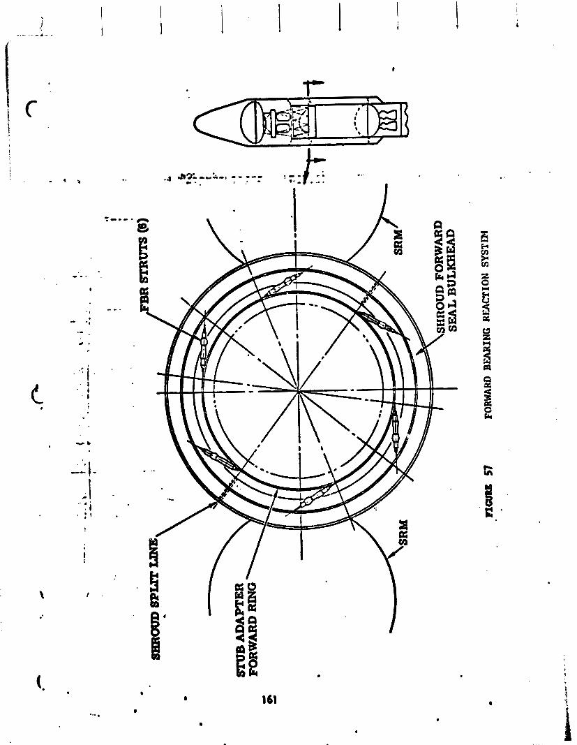
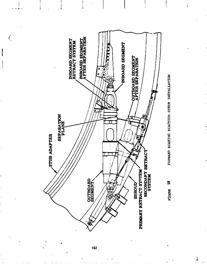
STU
B A
DA
PT
ER
SEP
AR
AT
ION
PLANE
INB
OA
RD
SEGMENT
BE
TR
AC
T S
YST
EM
SHR
OU
D
PRIMARY RETRACT m
TE
M
SECONDARY RETRACT
SYST
EM
FT
C~
E 5
8 FORWARD BEARING REACTION STRUT INSTALLATION

r2
8.
00
N
oh
ST
RU
T LENGTH
c
STRUT
SEP
AR
AT
ION
PLANE
\ 10"
RE
F
-C
SEP
AR
AT
ION
BO
LT
B
OL
TC
AT
CH
ER
SE
PA
RA
TIO
N F
ITT
ING
RE
TR
AC
T C
AB
LE
AT
TA
CH
HO
LE
' PLANE
FIGURE
59
FORW
ARD
BE
AR
ING
REA
CTI
ON
STRVT
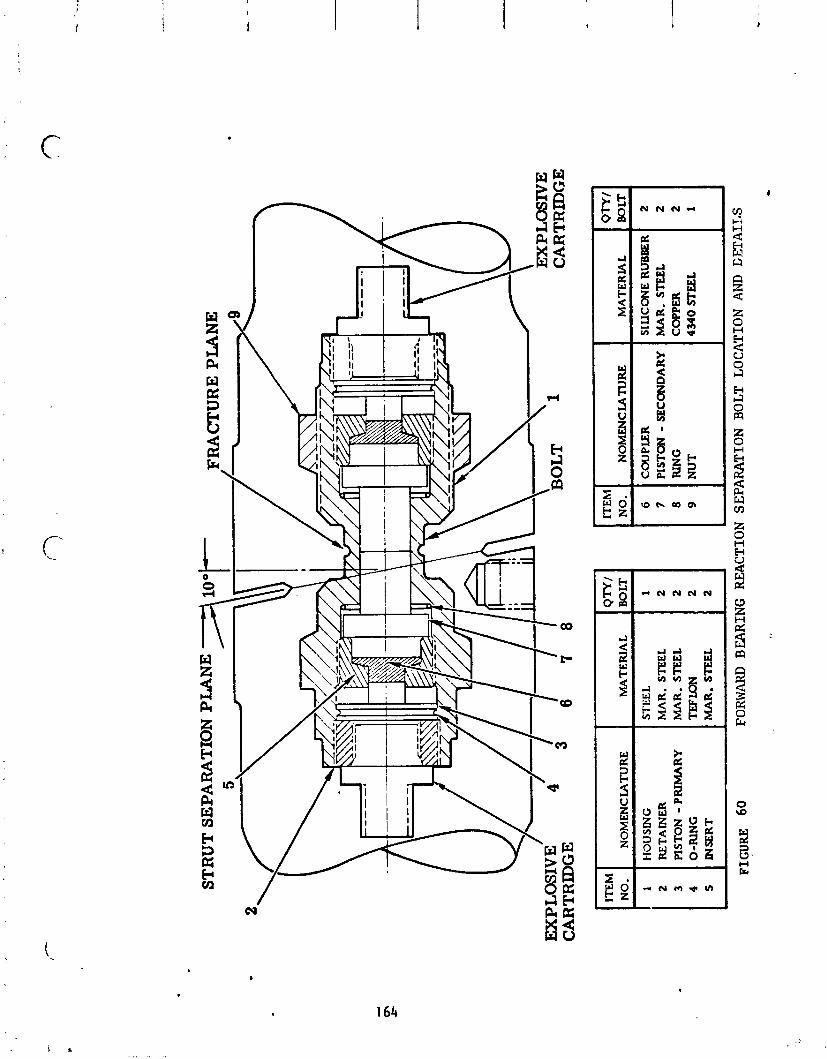
7
MA
TE
RIA
L
SIL
ICO
NE
RU
BB
ER
1 2
FIG
UR
E
60
FORWARD B
EA
RIN
G
RE
AC
TIO
N S
EPA
RA
TIO
N B
OL
T LOC
ITE
hl
NO
.
6 7 8 9
Qn
l
BO
LT
1 2 2 2 2 I
TIO
N A
ND
GJX
AIT
S
NO
ME
NC
IAT
UR
E
CO
UPL
ER
P
IST
ON
- SE
CO
ND
AR
Y
RIN
G
NU
T
h4A
TE
RIA
L
STE
EL
M
AR
. ST
EE
L
MA
R. STEEL
TE
F IDN
MA
R.
STE
EL
ITE
M
NO
.
1 2 3 4 5
MA
R.
STE
EL
C
OPP
ER
43
40 S
EE
L
NO
ME
NC
WT
UR
E
HOUSING
RE
TA
INE
R
PISTON -
PR
IMA
RY
O
-RIN
G
INSE
RT
2 2 1
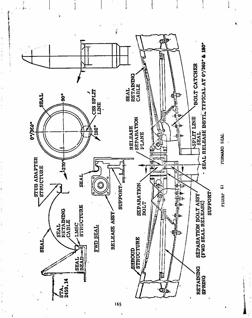
RE
TA
ININ
G
SEP
AR
AT
ION
RE
TA
ININ
G
S~P
AR
AT
ION
BOLT A
SSY
(FWD S
EA
L R
EL
EA
SE)
SPR
ING
FIGURF
6 1
FORW
ARD
SEA
L
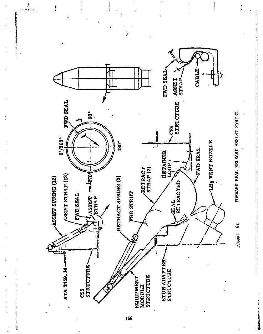
FIGURE
62
FORW
ARD SEAL R
EL
EA
SE A
SSIS
T S
YST
EM
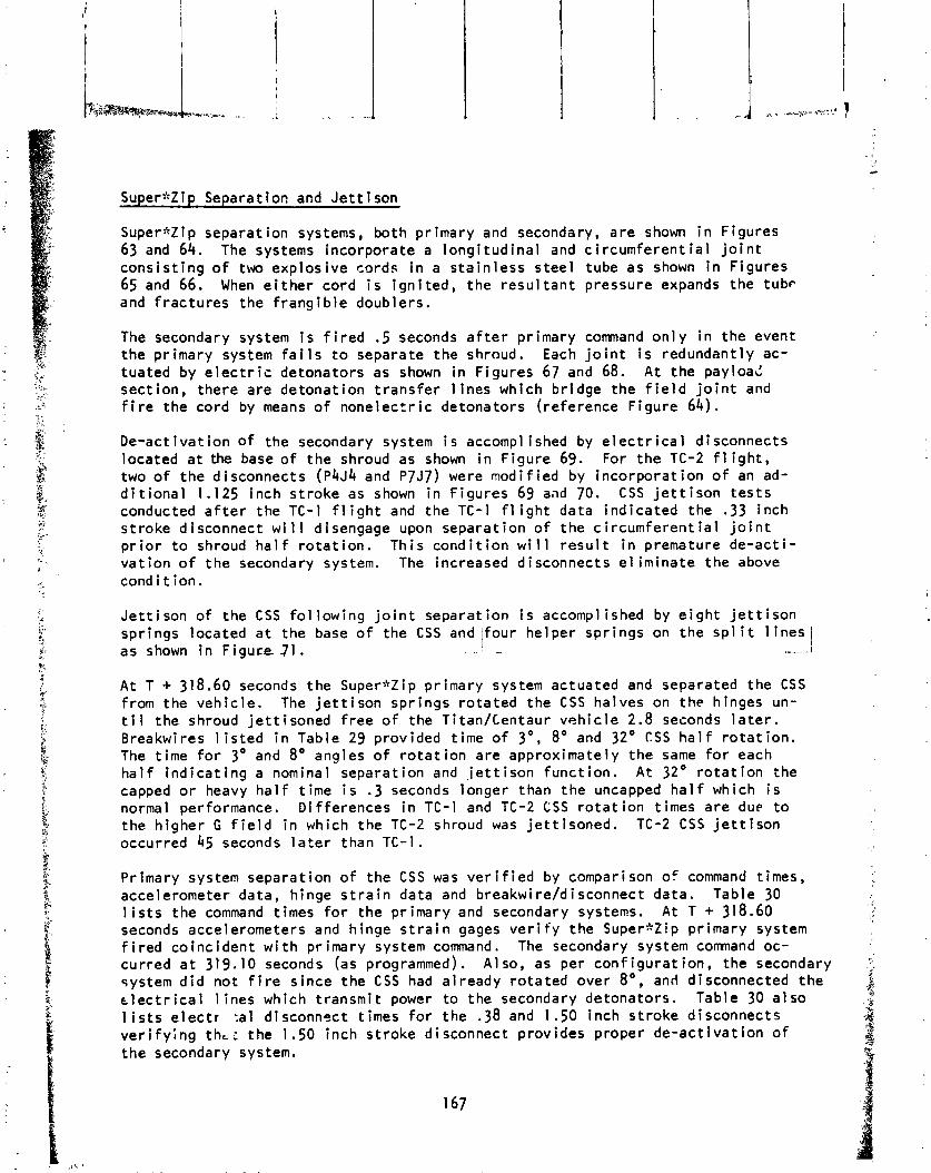
Superazip Separation and J e t t i s o n
Super*Zip separat ion systems, both pr imary and secondary, a re shown i n Figures 63 and 64. The systems incorporate a l ong i t ud i na l and c i r cumfe ren t i a l j o i n t cons i s t i ng o f two exp los ive cords i n a s t a i n l ess s tee l tube as shown i n Figures 65 and 66. When e i t h e r cord i s Ign i ted , the r e s u l t a n t pressure expands the tubp and f rac tu res the f rang ib le doublers.
The secondary system i s f i r e d .5 seconds a f t e r pr imary command o n l y i n the event the pr imary system f a i l s t o separate the shroud. Each j o i n t i s redundant ly ac- tuated by e l e c t r i c detonators as shown i n Figures 67 and 68. A t the payload sect ion, there a re detonat ion t r ans fe r 1 ines which b r idge the f i e l d j o i n t and f i r e the cord by means o f nonelecrr i c detonators (reference Figure 64).
De-act i v a t i on o f the secondary system i s accompl ished by e l e c t r i c a l d i sconnects located a t the base o f the shroud as shown i n F igure 69. For the TC-2 f l igh t , two o f the disconnects ( P 4 ~ 4 and P7J7) were modi f ied by incorpora t ion o f an ad- d i t i o n a l 1.125 inch s t roke as shown i n Figures 69 aad 70. CSS j e t t i s o n t e s t s conducted a f t e r the TC-1 f l i g h t and the TC-1 f l i g h t data ind ica ted the .33 inch s t roke disconnect wi I 1 disengage upon separat ion o f the c i r cumfe ren t i a l j o i n t p r i o r t o shroud h a l f r o t a t i o n . Th is cond i t i on wi 11 r e s u l t i n premature de-ac t i - va t i on o f t he secondary system. The increased disconnects e l im ina te the above cond i t i on .
Je t t i son o f the C S S f o l l ow ing j o i n t separat ion i s accomplished by e i g h t j e t t i s o n spr ings located a t the base o f the CSS and / fou r he lper spr ings on t he s p l i t l i n e s 1 as shown i n F i gu re 71. I
. . --- --- ,-.-I
A t T + 318.60 seconds the Supernzip pr imary system actuated and separated the CSS from the veh ic le . The j e t t i s o n spr ings r o ta ted the CSS halves on t he hinges un- t i l the shroud j e t t i soned f r e e o f the T i t a d c e n t a u r veh i c l e 2.8 seconds l a t e r . Breakwires l i s t e d i n Table 29 provided t ime o f 3", 8" and 32" CSS h a l f r o t a t i o n . The t ime f o r 3" and 8" angles o f r o t a t i o n are approximately the same f o r each h a l f i n d i c a t i n g a nominal separat ion and j e t t i s o n func t ion . A t 32" r o t a t i o n the capped o r heavy h a l f t ime i s .3 seconds longer than the uncapped ha1 f which i s normal performance. Di f ferences i n TC-1 and TC-2 C S S r o t a t i o n times a re due t o the h igher G f i e l d i n which the TC-2 shroud was j e t t i soned . TC-2 C S S j e t t i s o n occurred 45 seconds l a t e r than TC-I.
Primary system separat ion o f the C S S was v e r i f i e d by comparison of command times, accelerometer data, hinge s t r a i n data and breakwire/disconnect data. Table 30 l i s t s the command times f o r the pr imary and secondary systems. A t T + 318.60 seconds accelerometers and hinge s t r a i n gages v e r i f y the Super*Zip pr imary system f i r e d co inc iden t w i t h pr imary system command. The secondary system command oc- cur red a t 31 9.10 seconds (as programmed). A 1 so, as per conf i gu ra t ion, the secondary system d i d not f i r e s ince the CSS had a l ready ro ta ted over 8" , and disconnected t he t l e c t r i c a l l ines which t ransmi t power t o the secondary detonators. Table 30 a l s o l i s t s e l e c t r :al d isconnsct t imes f o r the .38 and 1.50 inch s t roke disconnects v e r i f y i n g thL i the 1 . S O inch s t roke disconnect provides proper de-ac t l va t ion o f the secondary system.
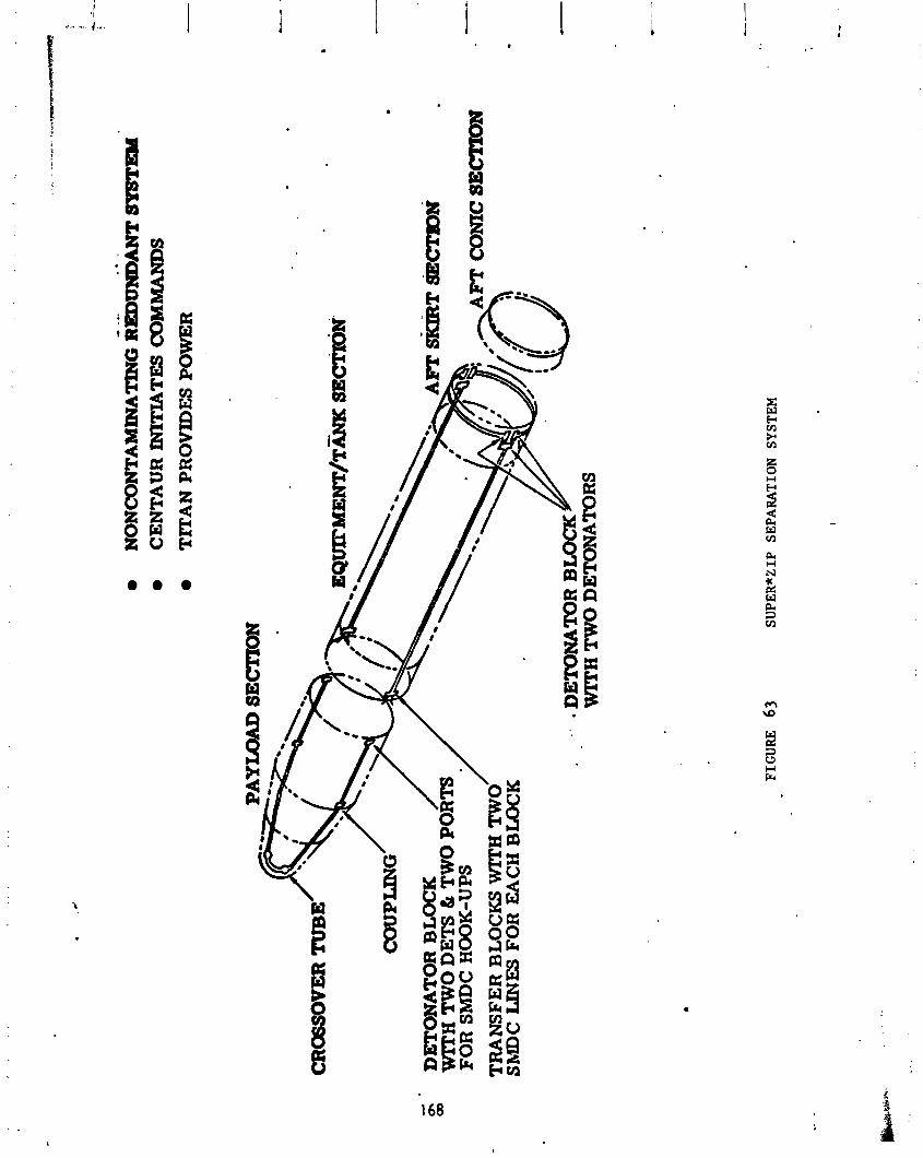
CE
NT
AU
R INITIATES COMMANDS
TlT
AN
PR
OV
IDE
S POWER
-
CR
OG
SOV
ER TUBE
DE
TO
NA
TO
R BLOCK
WIT
H TWO D
ET
S &
TW
O P
FOR SMDC H
OO
K-U
PS
TR
AN
SFE
R B
LO
CK
S W
ITH
TW
ShlD
C L
INE
S
WITH T
WO
DE
TO
NA
TO
RS
FIGU
RE 63
SUPER*ZIP
SEPARATION SYST
EM
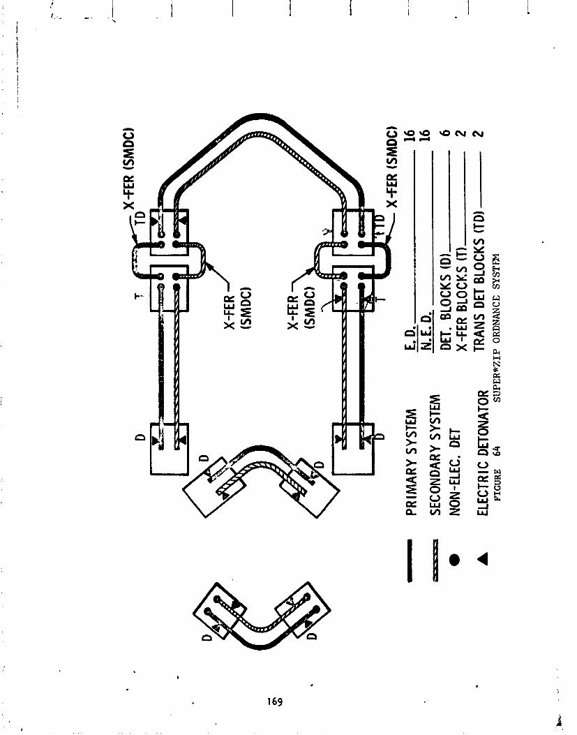
r -D
X-FE
R (S
MDC
)
- PRIM
AR
Y SY
STEM
E.
D. 16
- SEC
ONDA
RY S
YSTE
M
N. E
. D.
16
NON-
ELEC
. DE
T DE
T. BL
OCKS
(Dl
6 X
-FER
BLO
CKS
(TI
2 EL
ECTR
I C D
ETON
ATOR
TR
ANS
DET
BLOC
KS (T
D)
2 FI
GU
RE
64
SUPE
R*Z
IP
OR
DN
AN
CE
SYST
EM
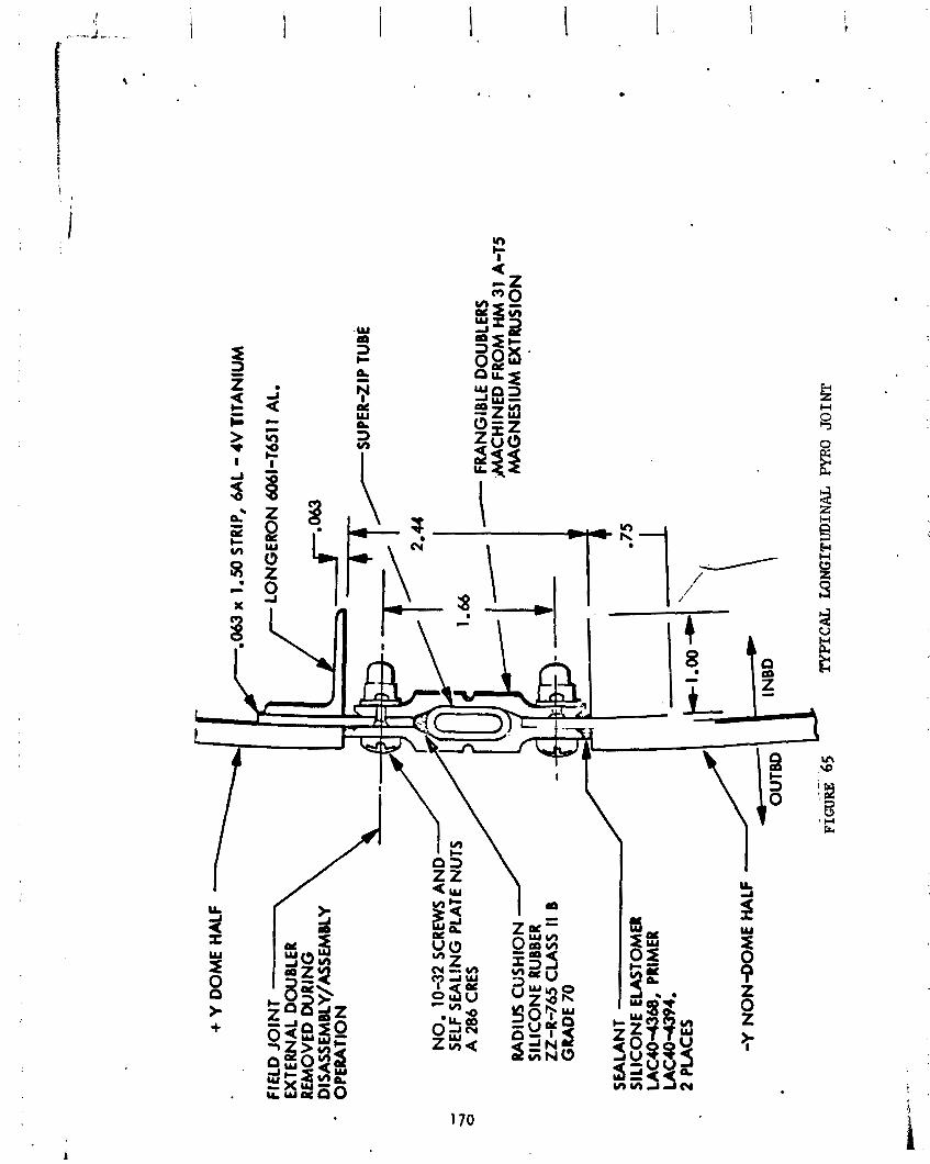
+ Y
DO
ME
HA
LF
,063
x 1
.50
STR
IP,
6AL - 4V
TIT
AN
IUM
FI E
L0 J
OIN
T
LO
NG
ER
ON
606
1-T6
511
AL.
EX
TER
NA
L D
OU
BLE
R
RE
MO
VE
D W
RIN
G
Dl S
ASS
EMB
LY/A
SSEM
BlY
O
PE
RA
TIO
N
NO
. 10
-32
SCRE
WS
AN
D
SELF
SE
ALI
NG
PLA
TE N
U
A 2
86 C
RES
- FRANG
IBLE
DO
UB
LER
S M
AC
HIN
ED
FR
OM
HM
31
A-1
5 R
AD
IUS
CU
SH
ION
M
AG
NE
SIU
M E
XTR
US
ION
S
ILIC
ON
E R
UBBE
R 22
-1-7
65
CLA
SS I1
B
GR
AD
E 70
-Y
NO
N-D
OM
E HAL
F
Ffm
-6' 6
5 u
TYPICAL UlNGITUDINAL PYRO 30 I NT

FWD
SUPE
R-ZI
P TU
BE
3116
DIA
707
5-T6
AL
LOCK
BOLT
S W
ITH
6061
-T6
COLL
ARS
0.14
5
1
1 I
I
1
I
I I
I I
1
,
FRAN
G I B
LE D
OUB
LERS
70
75 -T
6 AL
UM.
24.0
0 M
AX L
ENGT
H *
TYPICAL CIRCUMFERENTIAL PYRO JOINT
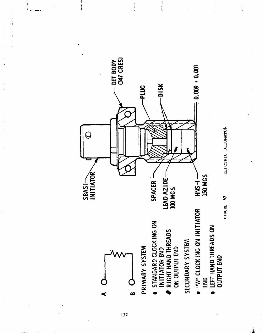
A B 3
'PR
IMA
RY
SY
STL
!
e ST
ANDA
RD C
LOCK
lNG
ON
INIT
IATO
R E
ND
RIG
HT H
AND
THRE
ADS
ON
OUTP
UT E
ND
SECO
NDAR
Y SY
STEM
a "W
" CL
OCK
ING
ON
INIT
IATO
R
HN
S-I
END
150
MG
S e
LEFT
HAN
D TH
READ
S O
N OU
TPUT
END
FI
GU
RE
67
E
LE
CT
RIC
D
ETO
NA
TOR
.38
IN.
STR
OK
E
I I
POW
ER
TO
ONE HALF
PO
WbR
TO I
DN
GIT
UD
INA
L
ClR
CU
MF
ER
EN
TU
L m
&
ON
E H
AL
F
SUP
EIM
ZIP
CIRCUMFESENTUL
SUPER* ZIP
SEC
TIO
N A
-A
FIG
UR
E
69
SUPE
R*Z
IP
SP
ST
M E
LE
CT
RIC
AL
DIS
CO
NN
EC
TS
TC
-2 AND ON W
NF
IGU
RA
TI)
N
RE
TR
AC
TIO
N
SPR
ING
RIGID
ASS
EM
BL
Y
IN THROUGH
aOTH T
UB
ES
&
INN
ER
TU
BE
I \
EL
EC
TR
ICA
L
CO
NN
EC
TO
R
.38"
EN
GA
GE
ME
NT
8 X
NC
OR
FOR
AT
E 1.125 IN*
STR
-
IN B
RA
CK
ET
ASS
Yo
8 A
DD
ED
SP
RlN
G TO E
NSL
XE
1.12
5 IN
. M
OT
ION
OF BRACKET
PR
IOR
TO -38 IN* DISCONNECT T
RA
VE
L.
. *
-
8 RIGTRACTION S
PR
ING
RE
hlO
VZ
D
TO
EL
IMW
TE
SL
DE
UIA
D.
SUPER*ZIP
SYSI
SSM
ELECTRICAL DISCONNECT MODIFICATIONS
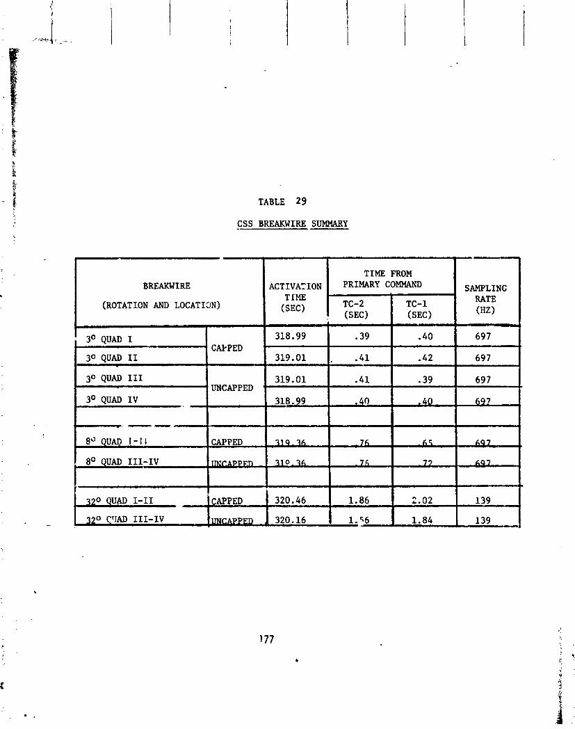
TABLE 29
CSS BREAKWIRE SUMMARY
BREAKWIRE
(ROTATION AND LOCATI3N)
I TIME FROM ACTIVATION PRIMARY SAMPLING
RATE (HZ)
( 3 O QUAD I - CAPPED
1 30 QUAD I1 1 30 QUAD I11
' UNCAPPED
8" QUA0 1 - 1 I CAPPED
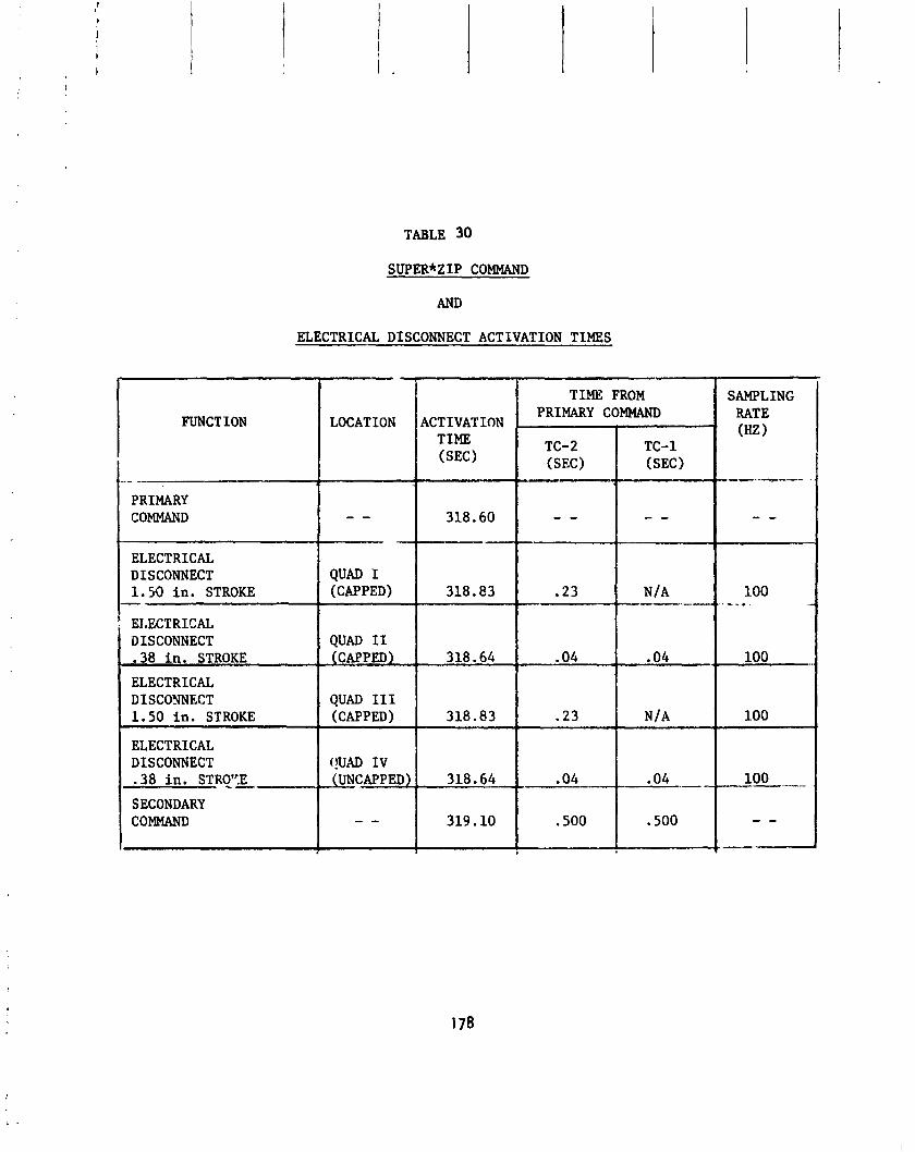
TABLE 30
SUPER*ZIP COMMAND
AND
ELECTRICAL DISCONNECT ACTIVATION TIMES
FUNCTION
PRIMARY COMMAND
ELECTRICAL DISCONNECT 1. X) in. STROKE - EIXCTRICAL DISCONNECT .38 in. STROKE - ELECTRICAL DISCONNECT 1.50 in. STROKE
ELECTRICAL DISCONNECT .38 in. S T R T L
SECONDARY COMMAND
-
LOCATION
- - --
QUAD I (CAPPED)
QUAD I1 (CAPPED)
QUAD I11 (CAPPED)
r!um IV JUNCAF'PED)
- -
TIME FROM
ACTIVATION PRIMARY COMMAND
TIME (SEC) (SEC
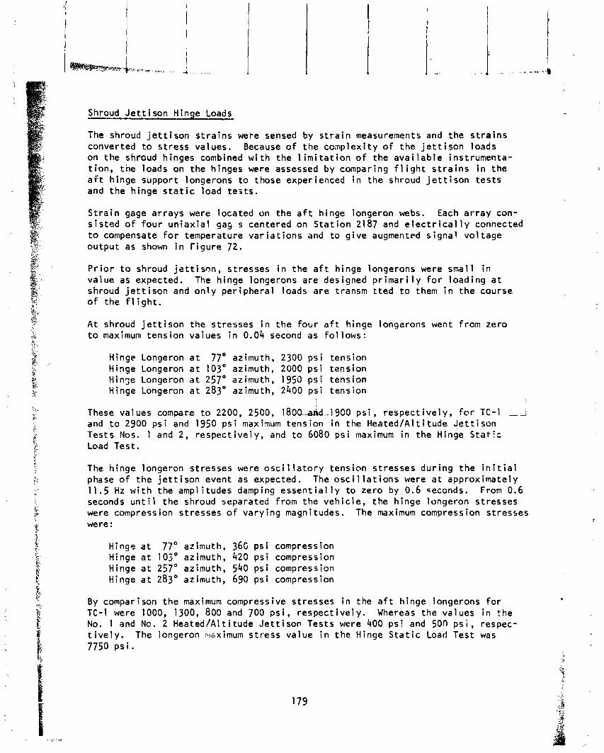
The shroud j e t t i s o n s t r a i n s were sensed by s t r a i n measurements and the s t r a i n s converted t o s t ress values. Because o f t he conp lex i t y o f the j e t t i s o n loads on the shroud hinges combined w i t h the l i m i t a t i o n o f the a v a i l a b l e instrumenta- t i on , tne loads on the hinges were assessed by comparing f l i g h t s t r a i n s i n the a f t hinge support longerons t o those experienced i n the shroud j e t t i s o n t e s t s and t he hinge s t a t i c load tes ts .
I
S t r a i n gage a r rays were located on the a f t hinge s i s t e d o f four u n i a x i a l gas s centered on S ta t i on t o compensate f o r temperature v a r i a t i o n s and t o g output as shown i n r i g u r e 72.
I I
longeron webs. Each a r ray con- 2187 and e l e c t r i c a l l y connected
i v e augmented s igna l vo l tage
i ! ew. \*,.*, . ,.; , . 1 .. , . ,, .
Shroud J e t t i s o n Hinge Loads
P r i o r t o shroud j e t t i s o n , stresses i n the a f t hinge longerons were smal l i n value as expected. The hinge longerons a re designed p r i m a r i l y f o r load ing a t shroud j e t t i s o n and on l y per iphera l loads a re transm t t e d t o them i n t h e course of the f l i g h t .
A t shroud j e t t i s o n the stresses i n t he f ob r a f t hinge l o n ~ e r o n s went from zero t o maximum tens ion values i n 0.04 second as fo l lows :
Hinge Longeron a t 77' azimuth, 2300 p s i tension Hinge Longeron a t 103' azimuth? 2000 p s i tens ion Hin7e Longeron a t 257' azimuth, 1950 p s i tens ion Hinge Longeron a t 283' azimuth, 2400 ps i tens ion
I I These values compare t o 2200, 2500, 1800.-add-1900 ps i , respec t i ve ly , f o r TC-I --i and t o 2900 p s i and 1950 p s i maxinum tens ion i n the Heated/Al t i tude J e t t i s o n Tests Nos. 1 and 2, respec t i ve ly , and t o 6080 p s i maximum i n the Hinge Stat!: Load Test.
The hinge longeron stresses were o s c i l l a t o r y tens ion s t resses dur ing t he i n i t i a l phase o f t he j e t t i s o n event as expected. The o s c i l l a t i o n s were a t approximately 11.5 Hz w i t h the amplitudes damping e s s e n t i a l l y t o zero by 0.6 ceconds. From 0.6 seconds u n t i l t he shroud separated from the veh ic le , the hinge longeron s t resses were compression stresses o f va ry ing magnitudes. The maximum compression stresses were:
Hinge a t 77' azimuth, 36G p s i compression Hinge a t 10 jO azimuth, 420 p s i compression Hinge a t 257' azimuth, 540 p s i compression Hinge a t 283' azimuth, 690 ps i compression
By comparison t he maximum compressive s t resses i n the a f t h inge longerons f o r TC-I were 1000, 1300, 800 and 700 p s i , respec t i ve ly . Whereas the values i n the No. 1 and Nc. 2 HeatedIAl t i tude J e t t i s o n Tests were 400 p s l and 500 p s i , respec- t i v e l y . The longeron m~ximum s t r ess va lue i n the Hinge S t a t i c Load Test was 7750 PS i .
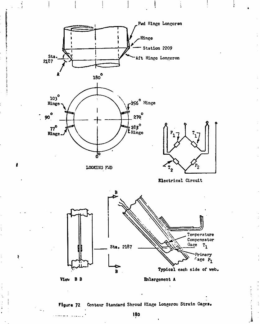
Vier B B
E l e c t r i c a l Circuit
B . Typical each s i d e of web.
blargement A
Flgure 72 Centaur Standard Shroud !lingo Lonecrow Strain Gaces~
-.-.-.-.- ._ .__. . 180 e

Shroud j e t t i s o n loads as evidenced by a f t h inge longeron s t r a i n s s t a r t ed a t T + 318.7 seconds and the l a s t i nd i ca t i on o f lo r~geron s t r a i n s which was as- sociated w i t h completed j e t t i s o n o f t he shroud from the vehicle was at T + 321.5 seconds. The du ra t i on o f shroud j e t t i s o n was 2.8 seconds and compares t o 2.8 seconds fo r TC-1 shroud j e t t i s o n and 2.7 seconds f o r t he Heated/Al t i t ude J e t t i s o n Tests.
The stresses i n the a f t h inge longerons dur ing shroud j e t t i s o n were o f low value and compared we l l t o the Heated/Al t i tude J e t t i s o n Tests data and were consider- ab ly less than h a l f o f the value o f the stresses i n the Hinge S t a t i c Load Test as shown i n Table 31. Data t races o f the f l i g h t shroud j e t t i s o n In each a f t hinge longeron versus t ime a re compared i n F igure 73 t o curves from TC-1 shroud j e t t i s o n . As shown, t he t races are s i m i l a r both i n magnitude and i n s t ress f l u c - t ua t i on .

T Tension C Compression TC-2 FLIGHT DATA
Hinee Location ,
I 319 3 19.5 320 320.5 Sec
Time, Seconds
TC-1 FLIGHT DATA
275 Time, Seconds
FIGURE 73 AFT HINGE LONCERON STRESSES AT STATION 2187~URlNG SHROUD JETTISON
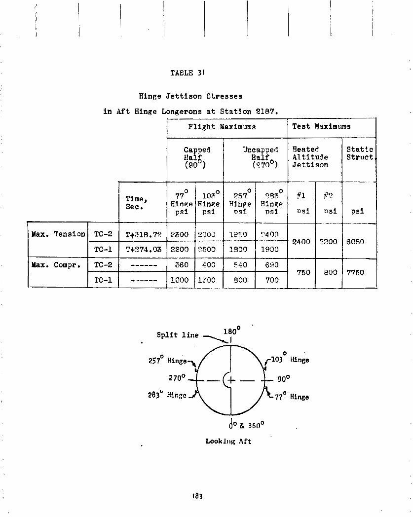
TABLE 31
Hinge Jettison Stresses
i n A f t Hinge Longerons at Station 2187.
Capped I Uncapaed Halg Hslf (90 ) (270 )
I 77O 103' o o Time, ?57 353 Sec. Hinee Hinpe Hinge Hinge
psi p s i PSI psi
Max. Tension TC-2 T+z,18.7%! 2300 2003 1 ---. .. --.,--.
-_____ 360 400 S40
TC-1 T+274.03 2200 8500 1900
Max. Compr. TC-2 690
TC-1 ------ 1000 IT00 800 700 - -- - ..--- --
- Test Maximums "1 Heated Static Altitude Struct, Jettison
S p l i t l i n e 180' ' . 1 1
IX CENTAUR 0-ITR SYSTEMS A N A L Y S I S

I X CENTAUR D-1TR SYSTEMS ANALYSIS
Mechanical Systems
S t r u c t u r e s
by R. T. B a r r e t t , C . W. Eastwood, R. C . Edwards, T. L. Seeholzer and J . 0 . VanVleet
8, .p +
I E . rr The ISA s a t i s f a c t o r i l y t r a n s f e r r e d a l l Centaur and CSS load ings o n t o the ,.,, T i t a n S k i r t s t r u c t u r e . The ISA forward r i n g was comple te ly severed a t T i t a n /
Centaur s t a g i n g and t h e v e h i c l e s separated a t a constant a c c e l e r a t i o n . . , 1..
;? P The u l lage pressures i n t h e Centaur prope l l a n t compartments were w i t h i n p re - : .: sc r i bed l i m i t s . S u f f i c i e n t p ressure was main ta ined t o prevent b u c k l i n g and ::, maximum pressures d i d n o t exceed b u r s t 1 i m i t s o f t h e tank s t r u c t u r e . , ..
The s t r u c t u r a l components l oca ted on t h e fo rward p o r t i o n o f t h e Centaur tank s a t i s f a c t o r i l y supported t h e payload and e l e c t r o n i c pac!.?oes. The s t u b adapter s t r u c t u r e s a f e l y w i ths tood t h e t a n g e n t i a l l oad ing 06 the s i x FBR s t r u t s .
i
The Forward Bear ing Reactor s t r u t s successfu l 1 y t r a n s f e r r e d fl i g h t loads from Y. t h z CSS t o t h e Centaur s t u b adapter . The magnitude o f these loads was w e l l w i t h - $" i n t h e demonstrated c a p a b i l i t y . F ?' l n t e r s t a q e Adapter . . ..
The i n t e r s t a g e adapter ( I SA) p rov ides a phys i ca l connect i on between t h e T i t an fo rward s k i r t ( a t S t a t i o n 2127.43) and t h e Centaur ( a t S t a t i o n 2240.79). I n a d d i t i o n , i t p rov ides a support r i n g f o r t he Centaur Standard Shroud a t S t a t i o n 2180.48 as shohn i n F igu re 74.
A separa t i on m o n i t o r i n g dev ice ( y o y o ) was mounted between the I S A and t h e Centaur a f t bulkhead ( ~ l ~ u r e 75 ) . T h i s yo-yo was instrumented and p l o t t e d d u r i q g f l i g h t f o r a t o c a l o f 15 f e e t a f t e r separa t i on t o v e r i f y t h a t separa t i on was sa t : s - f a c t o r y .
The f l i g h t loads, b o t h a x i a l and bending moments, on the forward s e c t i o n o f t h e i n t e r s t a g e adapter (ISA) were c a l c u l a t e d f rom s t r u c t u r a l s t r a i n s t h a t were sensed by s t r a i n measurements composed o f s t r a i n gage a r r a y s . On t h e s e c t i o n o f t he I S A fo rward o f t h e shroud/lSA i n t e r f a c e , f o u r s t r a i n gage a r r a y s were l oca ted a t Sta- t l o n 2208 and spaced 90 degrees a p a r t a t azimuths 24'. l l b O , 204' and 294' as shown i n F i g u r e 76. Each a r r a y cons is ted o f f o u r u n i a x i a l gages mounted on t h e s t r i n g e r s and z l e c t r i c a l l y connected as shown i n F igu re 77.
P r i o r t o p r o p e l l a n t t ank ing o f t h e v e h i c l e , t h e s t r a i n measurements were zeroed. T h i s method o f re fe rence r e q u i r e d t h e a d d i t i o n o f t h e weight ( i n a 1 -g f i e l d ) o f t h e d r y Centaur, t h e fo rward adapters and equipment, and t h e He l ios-A spacecra f t , t o t a l 1 i n g 8,400 pourds, t o a1 1 a x i a l loads on t h e forward ISA. A1 so, a c a l i b r a - t i o n f a c t o r o f 0.79 was a p p l i e d t o t h e i n d i c a t e d bending moments on the ISA. The
c a l i b r a t i o n f a c t o r wqs determined f rom the i m i t Load S t a t i c S t r u c t u r a l Tests
( re ference 1 ) .

'B0
06
T PUMP C
UT
OU
T-
m
TIT
A N
SK
IRT
VENT
SYST
EM
L% VENT D
UC
T-
MAINTE N
A NC E -
AC
CE
SS D
OO
R
AF
T R
ING
l NTE
RS
TAG
E A
DA
PT
ER
SYST
EM
AC
CE
SS
STR
ING
ER
S @
'6'
SPA
CIN
G
GA
S C
ON
DIT
IOM
NG
I
DIS
TR
IBU
TIO
N S
YST
EM
CSS
IN
TE
RF
AC
E F
UN
G
STA
. 21
80.4
8
1 T
ITA
N S
KIR
T LOAD
j-T
RA
NS
FE
R
FITTINGS
ME
LN
M
CH
ILL
DO
WN
-E
M
MA
INT
EN
AN
CE
A
CC
ESS
DO
OR
!
STR
ING
ER
S @
I
5'
SPA
CIN
G
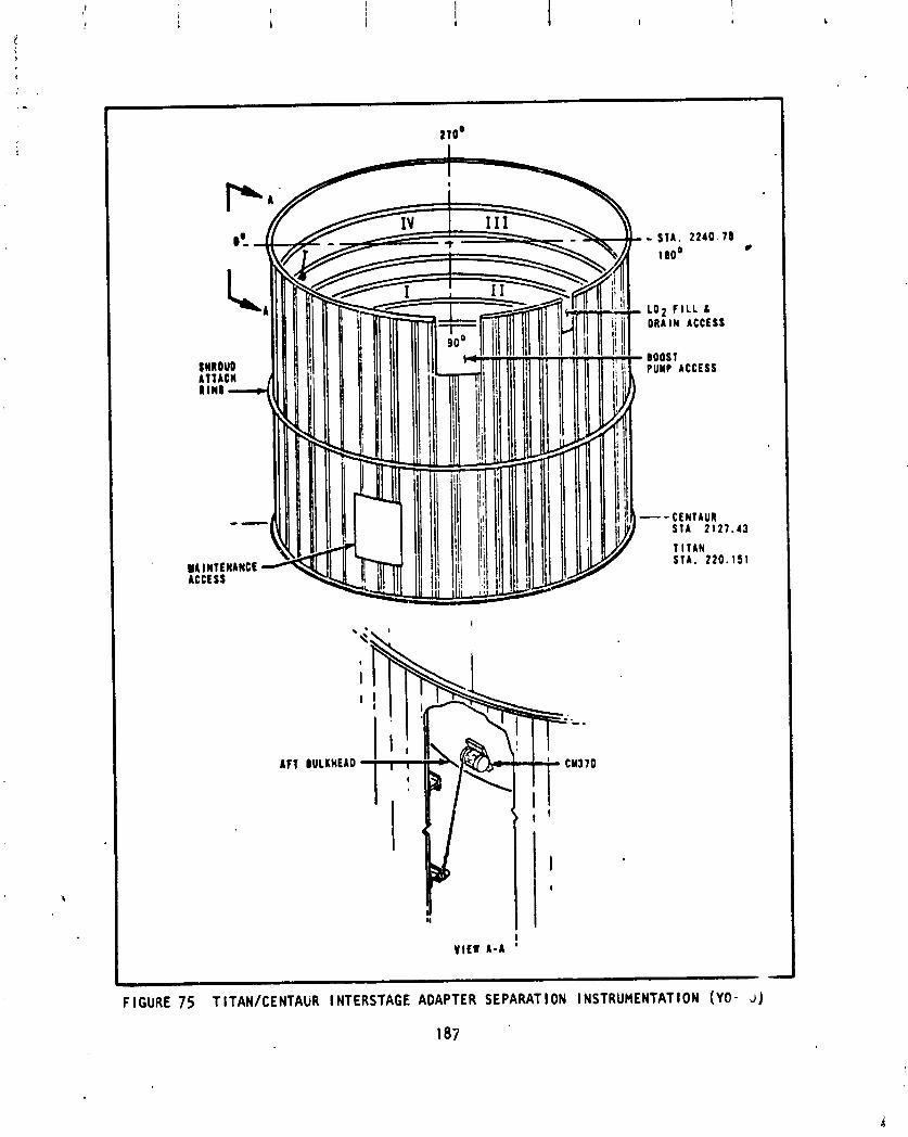
VIEW A-A !
LO2 F I L L L DRAIN ACCESS
-- Cf NTAUR STA 2121 .43
T ITAN ETA. 2 2 0 . 1 5 1
F l GURE 75 T ITAN/CENTAUR l NTERSTAGE ADAPTER SEPARAT l ON l NSTRUHENTAT l ON (YO - J)
187

v -(Shear .
Load )
Section A A
~ l ~ u r e " 7 6 S tructurnl Strain Measurement b e i t ion8 on ISA.
. .
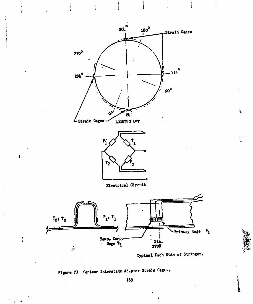
I
"Strain Oaaea
Blecrtricnl Circuit
The , -yo separa t ion t r a c e was v e r y smooth ( ~ i g u r e 78) , i n d i ~ a t i r ~ g a n l rma l separa t ion . Since t h e 1 ' 4 i s 9.5 f e e t long and t h e t o t a l yo-yo t r a v e l i s 15 f e e t , t h e I S A c lea red t h e Centaur.
The maximum combined loads on the I S A a t S t a t ion 22C3 were a t T + 257 sec- onds a t maximum a c c e l e r a t i o n d u r i n g Stage I bu rn . The e q u i v a l e n t a x i a l load a t t h a t t ime \ a s 128,500 pounds on the cor. ,;rec-,ion s i d e and 126,300 pounds compression on the oppos i te s ide . O f t h i s equ iva len t a x i a l load, 127,400 po~.mds were d i r e c t a x i a l l ocd and 1 , i 0 0 pounds were from a bending moment o f
6 0.03 x 10 inch-pounds.
4 x l o 6 inch- $2.200 pounds
lead was 100,200 on the o p p o s i t o
The maximum bending rnonlent on the I S A a t S:ation 2208 was 1 . pounds a t T + 38.3 seconds. A,: L .r t ime t'.e a x i a i load b1as compression a t S t a t i o n 2208 or, the I S A . The e q u i v a l e n t a x i a pounds on the compressive s ' '5 and 24,20C pounds ccmpress i on s ide .
Equ iva lent a x i a l loads, d i r e c t a x i a l loads and bending moment a t t he vc-r lous event t i n e s d u r i n g the TC-2 f l i g ' r t a re l i s t e d I n Table 32. Loads ; .ppl ied t o t h e t e s t I S A w i t h the FdR system i n s t a l l e d and t h e equivalent a x i a l loads f o r TC-1 f l i g h t a r e i ~ c l u d e d i n t h e t a b l e f o r comp3r ism. As shohr~, the f l i ~ ' . maximum e q d i v j ' s n t a x i a l load For TC-2 was 80 percent o f t he TC-1 load and 58 percent o f the t e s t load. The f l i g b t maximum bending moment was less than 26 percent o f the t e a t va lue maximum. The a x i a l load a t Stage I maximum ac- c e l e r a t i o n was 60 percent g r e a t e r than the t e s t a x i a l load, however, as pre- v i o u s l y s ta ted , t h e combined load was o n l y approx imate ly 58 p2rcent o f t h e t e s t va lue.
Using the bending moments from t h e I S A ac Sta t ;on 2108 and from the shroud a t S t a t i o n 1294 and c o r r e l a t i n g thd values w i t h t h e q u a l i f i c a t i o n t e s t values, a bending moment value f o r f l i g h t on the ISA/Ti t an S k i r t i n t e r f a c e a t S t a t i o n 2127 can be approximate w i t h i n ? I perct :nt . A t T + 38.3 seconds o f f l !gh t6 g t h e va lue was '2.2 x 10 i nch -po~~nds compaf,ed t o a t e s t valr le o f 22.9 x 10 inch-pwnds. The equ iva len t a x i a l load a t S t a t i o n 2127 a t T + 38.3 seconds c a l c u l a t e d by combining the c o r r e l a t e d bending momerit and t9e a x i a l load was 503,400 pounds compression compared t o a t e s i v a l u e o f 869,600 pounds and 310,000 pounes tens i o n compar. I t o a t e s t va lue o f 658,400 pounds. I n percent o f t e s t va lues, the e q u i v a l e n t a x i a l loaJs t S t a t i o n 2127 f o r TC-2 and TC-1 f l i g h t s were as f o l lows:
S t a t i o n LdL7 Percent o f F l i g h t Equ iva len t Test Equ iva lent Ax ia l Load Type Axia 1 Load
Compress Ion 57.8% 44.1% Tens ion 47.1% 29.8%

TABLE 32
ISA St ruc tura l F l ight Loads and L i m i t Test Loads, Stat ion 2808.
( ~ n c l u d e s weight of Centaur, Propallants, Adapters, Equipment,
and Helios A lpacecraf t forward of Sta. 2808 i n a l l a x i a l values)
Flight
Event
Zero Reference
---a*
Transonic
--we--
S R M Max Accel
SRM J e t t i r o n
Stage I Max Accel
Prior t o CSS J e t t .
Stage 11 M a x Accel - . -.- ". -
Nominal
Time,
Sec .
Total Axial Bend. Load, Mom , Lbs
in.lb. I Compress,
x10 6
Vehicle
Accel . , g
Total Equivalent Axial Load a t Extreme Fiber,
Lbs
Compression
Test L i m i t Loads
With FBH u n t i l T-100 79,000 4.33 1.00 223,400 t
Although TC-2 f 1 TC-1 loads were
ght loads were greater than TC-1 values, both TC-2 and ess than 58 percent o f the t e s t ve r i f i ed design loads.
Centaur Tank
The propel lant tank forms the primary Centaur vehic le s t ruc ture (Figure 79). The tank locat ions and c r i t e r i a which determine the maximum a1 lowable and minimum required tank pressures during vcr ious phases o f f l i g h t are de- scribed i n Figure 80. These maximum a l lowable and minimum requi re tank pres- sure 1 i m i t s are compared t o actual TC-2 propel l a n t tank pressures i n Figure 81. During the f l ight , the combined u l lage and hydrostat ic pressure o f the l i q u i d hydrogen tank was always less than 29.2 psia and the l i q u i d hydrogen tank u l lage pressure was always greater than the minimum required pressure. The oxygen tank pressure was always greater than the combined hydrogen u l - lage and hydrostat ic pressures. The d i f f e r e n t i a l pressure between the pro- pe l l an t compartments d i d not exceed 23.0 ps i a t any time dur ing f l i g h t . The l i q u i d oxygen tank pressure was always less than the maximum al lowable pressure.
Stub Adapter
The stub adapter i s a ten- foot diameter skin-and-stringer cy l inder high, which attaches t o the Centaur tank and provides a mounting p forward equipment and payloads.
The adapter was not instrumented f o r s t r a i monitor ing - no d i r e c t f o r the adapter ir_avai lab le. The desig & Lowable crush pressure module i s 2.9 psid; measured f l i gh t pressures ranged from zero ps id ps id crush.
25 inches at form f o r
load data f o r t h e A
t o 1.2
Equipment Module
The Centaur equipment module i s a conical sk in -s t r inger s t ruc ture of 10-foot diameter base and f i ve - foo t diameter top, 30 inches high, which attaches t o the top o f the stub adapter. I t s funct ion, f o r TC-2 was t o provide a mounting surface f o r the avionics packages, t o ac t as a thermal insu la t ing cap f o r the Centaur tank, and t o serve as a payload mounting platform. A spring-loaded door i n the module opened a t l i f t o f f , as scheduled, so tha t there was no burst o r crush pressure on the module during f l i g h t . Module pressure j u s t p r i v t o f l i g h t was 0.18 ps id burst . There was no s t r a i n gage data f o r the equipment module.
Mission Pecul i a r Adapter
The He1 ios Mission Pecul i a r Adapter i s a conical aluminum skin-str inger-frame s t ruc ture j o in ing the a f t end o f the Delta spin-table assembly t o the forward end o f the Centaur Equipment Module.

cRr#w tW
O.1
8 1
I L
\QV
IO O
XY
GE
N ,
,O
,O
IS
,T
WZ
EF
:-
O~
~
TA
NK
W
AR
D
.- -
.
. .
MA
XIM
UM
A
LL
OW
AB
LE
LI
eU
lD
HY
DR
OG
EN
TA
NK
P
KE
SS
UtC
f L
I Q
UID
HY
DR
O G
EM
TIM
E
FR
OM
LIF
T-
OF
F,
SE
CO
ND
S
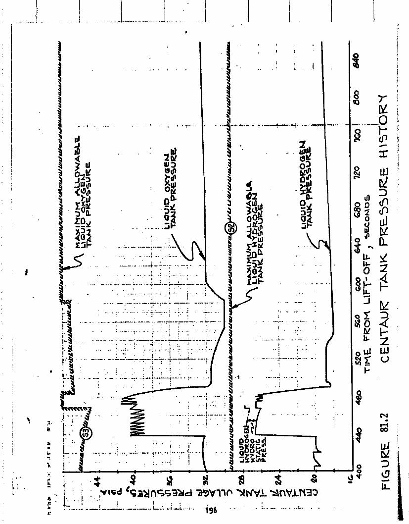

i"'
An environmental s h i e l d i s a t tached t o t he adapter forward r ing . The outer edges o f the s h i e l d a re supported from the equipment module a f t r i n g by 12 t ubu la r s t r u t s . The s h i e l d a l s o serves as a work p la t fo rm f o r access t o t he payload. The s h i e l d cons is ts o f e i g h t segments, each made from a sandwich panel o f balsa wood core w i t h aluminum sheets.
There was no s t r a i n gage o r pressure data f o r the Mission Pecu l ia r Adapter.
References
1. C. Eastwood: Centaur Standard Shroud (CSS) S t a t i c L i m i t Load S t ruc tu ra l Tests. NASA TMX-71727, Apr i 1 1975.
RLlO Engine System
Propuls ion/Propel lant Feed System
by K. W . Baud and W. K . Tabata
Ground P r e c h i l l - L i q u i d hel ium p r e c h i l l o f the engine f u e l pumps on t he ground was sa t i s f ac to r y . L i s t e d i n Table 33 a re t he C - 1 and C-2 engine fue l pump housing temperatures a t l i f t o f f , Each fue l pump housing has a dual element temperature probe, so t h e p r imary measurements, CP122T and CP123T, as w e l l as the backup measurements, ~ ~ l l 8 T and C P l l T , a r e 1 i s ted . A1 1 fou r measurements i nd i ca te both f u e l pumps were we1 1 below t h e 100°~ maximum a t l i f t o f f . A lso l i s t e d i n Table 33 a re the C - 1 and C-2 engine o x i d i z e r pump housing temperatures ( s i ngle-element probes) and t he C - 1 and C-2 engine t h r u s t chamber temperature measurements. A l l these temperatures were as expected and w i t h i n the experience of the TC-1 Proof F l i g h t and previous A t las/Centaur launches.
P res ta r t - The C-1 and C-2 engine f ue l and o x i d i z e r pump housing tempera- tu res and the t h r u s t chamber temperatures a t the beginning of the f i r s t - b u r n and the second-burn p r e s t a r t s a re l i s t e d i n Table 33. For both p res ta r ts , a l l temperatures were as expected and w i t h i n the range of prev ious Centaur f l i g h t s .
The f i r s t burn and second burn had programmed p r e s t a r t du ra t i on o f 8 sec- onds and 17 seconds, respec t i ve ly . The pump housing temperatures I nd i ca te proper cooldown t r ans ien t s du r i ng t h e p r e s t a r t per iods.
S t a r t - The f i r s t - b u r n t r ans ien t s f o r the C-1 and C-2 engines a re shown i n - Figure 82 f o r the t ime pe r i od o f main engine s t a r t (MES) p l us 1.0 seconds t o p lus 1.7 seconds.
F igure 82a shows the C - 1 and C - 2 engine chamber pressures. The t ime t o acce lerate t o 90 percent o f steady-state t h r u s t f o r both engines and t he d i f f e r e n t i a l acce le ra t ion t ime between t he two engines a r e w i t h i n previous f l i g h t experience. I g n i t i o n on both engines (not shown i n F igure 82a) oc- curred a t approximately 0.2 seconds a f t e r s t a r t s igna l as expected.
The s t a r t t rans ien ts o f the o x i d i z e r pump speed, t he f u e l ven tu r i upstream pressure, the ox i d i ze r pump discharge pressure, and the f u e l pump discharge pressure shown i n Figures 82b through 82e a r e a1 1 normal.
The second-burn s t a r t t r ans i en t s a re shown i n F igure 83. A1 1 t r ans ien t s a re norns l and as expected. The d i f f e r e n t i a l acce le ra t i on t ime t o 90 percent t h r u s t ( ~ i g u r e 83a) between the C - 1 and C-2 engines i s approxi - mately 0.3 seconds. Th i s i s l a r g e r than norma I , but no t ou ts ide o f pre- v ious f l i g h t experience. A t l a s k e n t a u r f l i g h t AC-32 had a d i f f e r e n t i a l acce le ra t ion t ime on the second burn o f approximately 0.27 seconds. The la rger d i f f e r e n t i a l times would be expected, s ince acceptance t e s t o f the
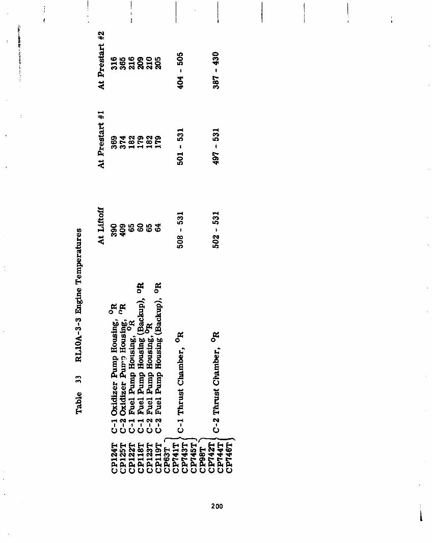
Tab
le
33
RL
10A
-3-3
E
bgin
e T
emp
erat
ure
s
At
Lif
toff
CP
l24
T
C -1
Oxi
dize
r P
ump
Hou
sing
, OR
390
CP
125T
C
-2 O
xidi
zer
Pu
rr?
Hou
sing
, "R
409
CP
l22
T
C-1
Fue
l P
ump
Hou
sing
, OR
65
CP
118T
C
-1 F
uel
Pum
p H
ousi
ng (
Bac
kup)
, O
R
60
CP
123T
C
-2 Fuel
Pum
p ~
ou
sin
g, OR
65
C
P11
QT
C
-2 F
uel
Pum
p H
ousi
ng (
Bac
kup)
, O
R 64
C
P6
3T
7
CP7
41T
} C
-1 T
hru
st C
ham
ber,
O
R
CP
743T
cp
74
m}
C-2
Thrust
Cha
mbe
r,
OR
C
P74
4T
At
Pre
star
t #1
At
Pre
star
t #2
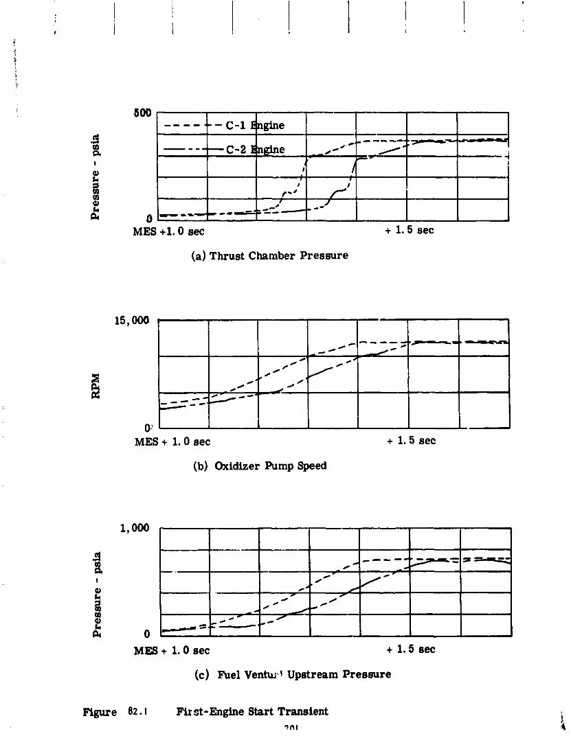
MES +l. 0 sec + 1.5 sec
(a) Thrust Chamber Pressure
(b) Oxidizer Pump Speed
MES + 1.0 sec + 1.5 sec
(c) Fuel Ventwk+ Upstream Pressure
Fir st - Ehgine Start Transient 7fll
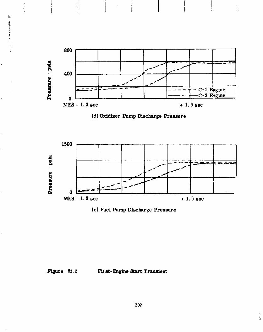
MES + 1.0 sec + 1.5 sec
(d) Oxidizer Pump Discharge Pressure
MES + 1.0 sec + 1.5 sec
(e) Fuel Pump Discharge Pressure
Fb et - Engine Start Transient
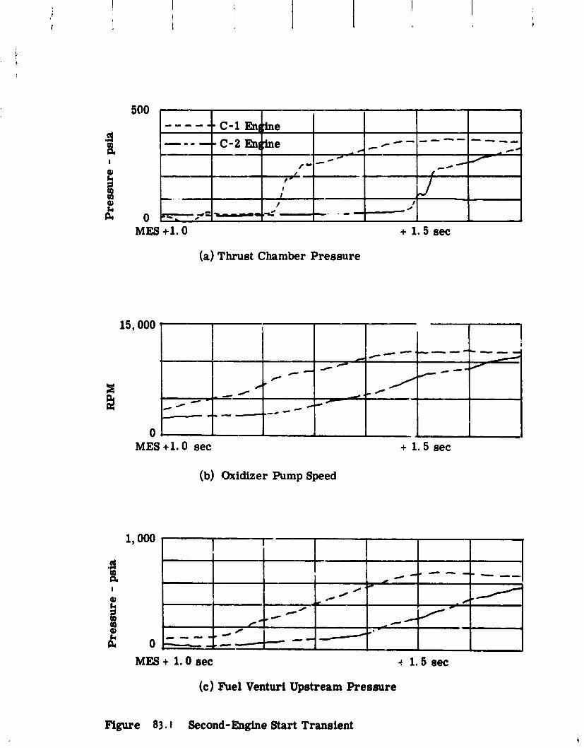
(a) Thrust Chamber Pressure
MES + 1.0 sec
(b) Oxidizer Pump Speed
+ 1.5 sec
MES + 1.0 sec + I. 5 sec
(c) Fuel Venturi Upstream Pressure
Mgure 83.1 Second- Engine Start Transient
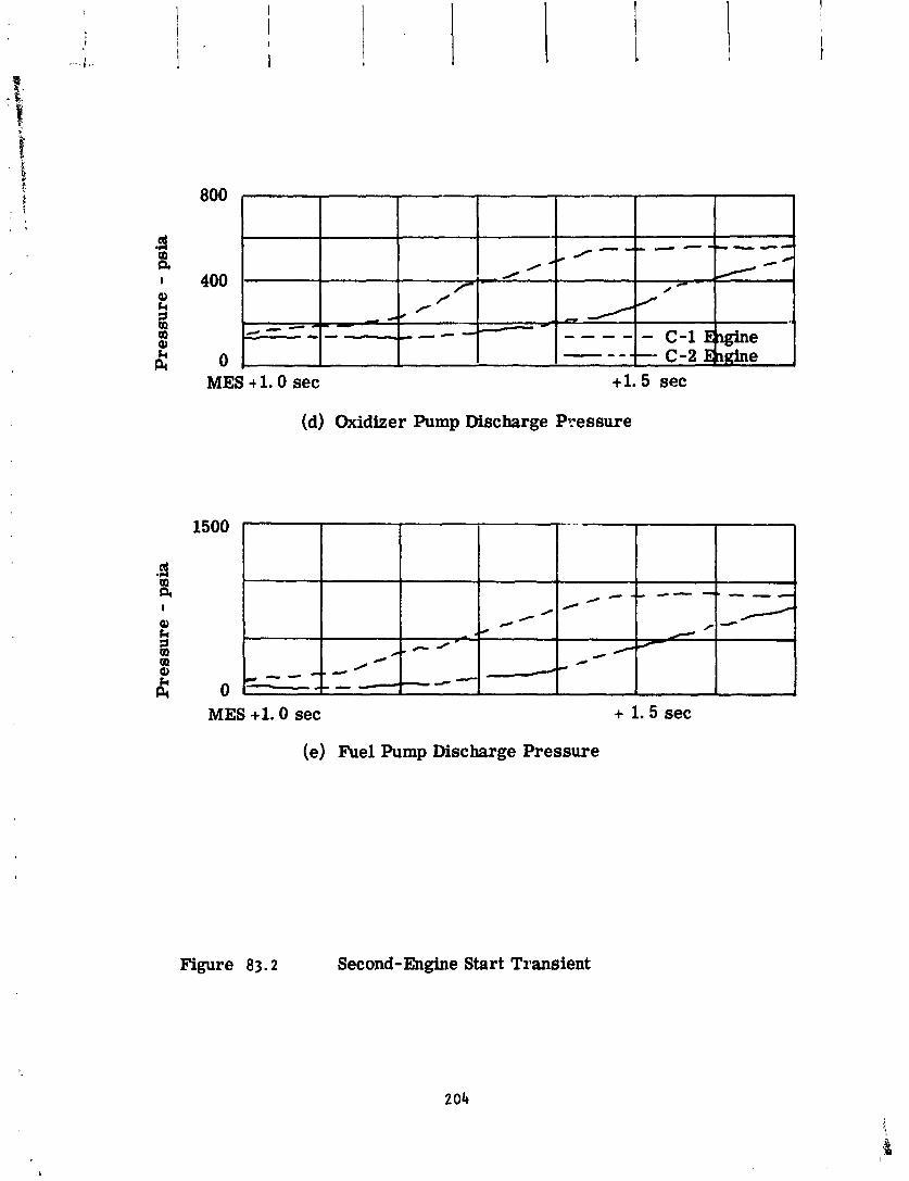
MES + 1.0 sec +l. 5 sec
(d) Oxidizer Pump Discharge Pressure
Figure 83.2
(e) Fuel Pump Discharge Pressure
Second-Engine Start Transient
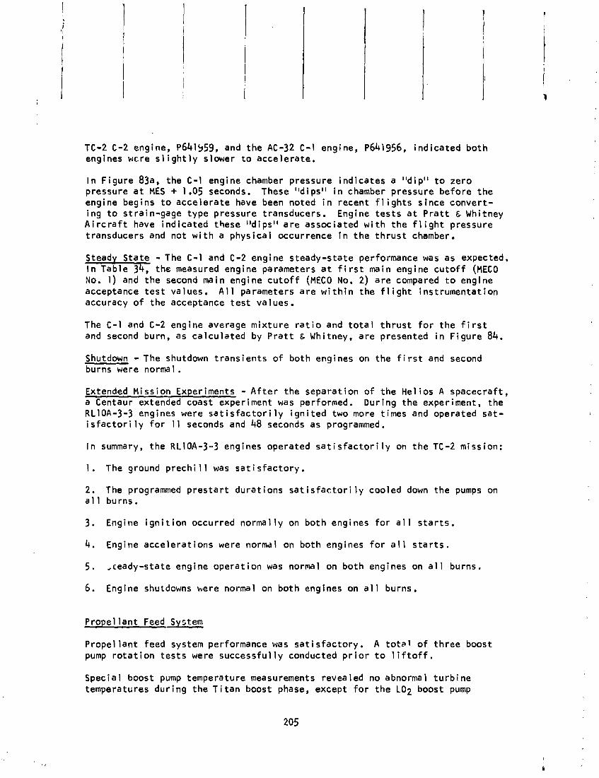
TC-2 C-2 engine, ~641459, and the AC-32 C-1 engine, ~641956, ind ica ted bo th engines wcre s l i g h t l y slower t o acce lerate .
I n F igure 83a, the C-1 engine chamber pressure ind ica tes a "dip" t o zero pressure a t MES + 1.05 seconds. These "dips" i n chamber pressure before the engine begins t o acce le ra te have been noted i n recent f l i g h t s s ince conver t - ing t o strain-gage type pressure transducers. Engine t e s t s a t P r a t t & Whitney A i r c r a f t have ind ica ted these "dips" a re associated w i t h the f l i g h t pressure transducers and not w i t h a phys ica l occurrence i n t h e t h r u s t chamber.
- The C-1 and C-2 engine steady-state performance was as expected. the measured engine parameters a t f i r s t main engine c u t o f f (MECO
No. 1 ) and the second main engine c u t o f f (MECO No. 2) a re compared t o engine acceptance t e s t values. A l l parameters a re w i t h i n the f l i g h t ins t rumentat ion accuracy o f the acceptance t e s t values.
The C - 1 and C-2 engine average mix tu re r a t i o and t o t a l t h r u s t f o r t he f i r s t and second burn, as ca lcu la ted by P r a t t & Whitney, a re presented i n F igure 84.
Shutdown - The shutdown t r ans ien t s o f both engines on the f i r s t and second burns were normal.
Extended Mission Experiments - A f t e r the separat ion o f t he Hel ios A spacecraf t , a Centaur extended coast experiment was performed. Dur ing the experiment, the RL10A-3-3 engines were s a t i s f a c t o r i l y i g n i t e d two more times and operated sa t - i s f a c t o r i l y f o r 11 seconds and 48 seconds as programmed.
I n summary, the RL10A-3-3 engines operated s a t i s f a c t o r i l y on t h e TC-2 mission:
1 . The ground prechi 11 was sa t i s factory . 2 . The programmed p r e s t a r t du ra t ions sat i s f a c t o r i l y cooled down the pumps on a1 1 burns.
3. Engine i g n i t i o n occurred normal ly on both engines f o r a l l s t a r t s .
4. Engine acce le ra t ions were normal on both engines f o r a l l s t a r t s .
5 . ,ceady-state engine opera t ion was normal on both engines on a l l burns.
6. Engine shutdowns were normal on both engines on a l l burns.
P rope l lan t Feed System
Propel l a n t feed system performance was sa t i s f ac to r y . A t o t a l o f th ree boost pump r o t a t i o n t e s t s were success fu l l y conducted p r i o r t o l i f t o f f .
Special boost pump temperature measurements revealed no abnormal t u r b i n e temperatures dur ing the T i t a n boost phase, except f o r the LO2 boost pump
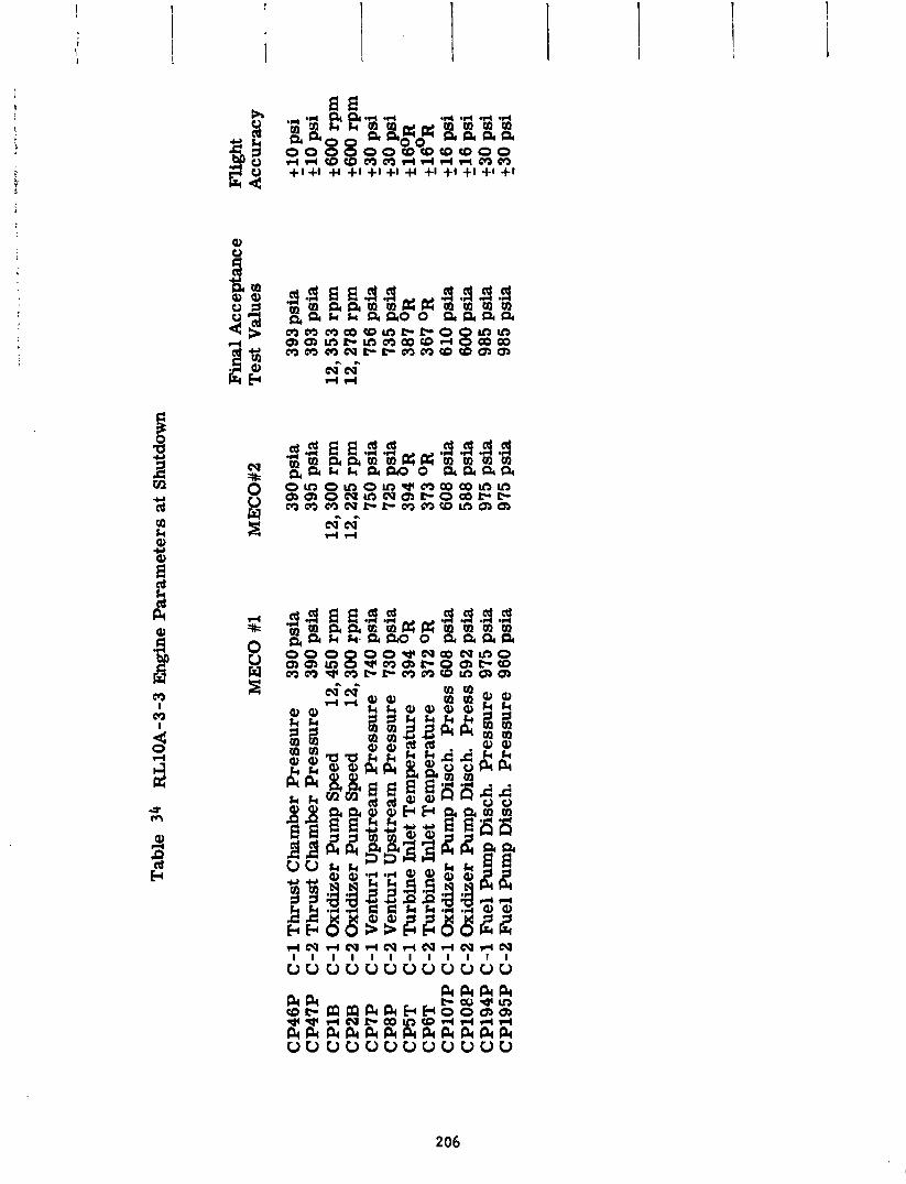
Tab
le
34
KZ
llOA
-3-3
E
ngin
e P
aram
eter
s at
Shu
tdow
n
Fin
al A
ccep
tanc
e M
EC
O #
1 M
EC
O#2
T
est
Val
ues
CP
46
P
C-1
Th
rust
Cha
mbe
r P
ress
ure
39
0 p
sia
CP
47
P
C-2
Th
rust
Cha
mbe
r P
ress
ure
39
0 p
sia
CP
lB
C-1
Oxi
dize
r P
ump
Spe
ed
12,4
50 r
pm
C
P2B
C
-2 O
xidi
zer
Pum
p S
peed
12
,300
rp
m
CP
7P
C
-1 V
entu
ri U
pstr
eam
Pre
ssu
re
740
psi
a C
P8
P
C-2
Ven
turi
Up
stre
am P
ress
ure
73
0 si
a 8
CP
5T
C-1
Tu
rbin
eIn
letT
emp
erat
ure
39
4 R
C
P6T
C
-2 T
urb
ine
Inle
t T
emp
erat
ure
37
2 OR
C
PlO
7P C
-1 O
xidi
zer
Pum
p D
isch
. P
ress
608
psi
a C
P10
8P C
-2 O
xidi
zer
Pum
p D
isch
. P
ress
592
psi
a C
P19
4P C -1
F'u
el P
ump
Dis
ch.
Pre
ssu
re
975
psi
a C
P19
5P C
-2 F
'uel
Pum
p D
isch
. P
ress
ure
96
0 p
sia
390
psi
a 39
5 p
sia
12,3
00 r
prn
12,2
25 r
prn
750
psi
a 72
5 si
a g
394
R
373
OR
60
8 p
sia
588
psi
a 97
5 p
sia
975
psi
a
393
psi
a 39
3 p
sia
12
,35
3 rp
rn
12,2
78 r
prn
756
psi
a 73
5 p
sia
387
OR
36
7 O
R
610
psi
a 60
0 p
sia
985
psi
a 98
5 ps
ia
Fli
ght
Acc
urac
y --
+30
psi
+
_30 p
si
il6
psi
-
216
psi
23
0 p
si
+30
psi
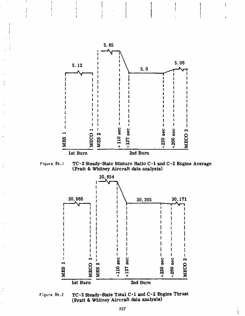
E 1st Burn 2nd Burn
F i g u r e 8 4 . 1 TC-2Steady-StateMixtureRatioC-landC-2EngineAverage (Pratt & Whitney Aircraft data analysis)
1st Burn 2nd Burn
Figure 84 .2 TC-2 Steady-State Total C-1 and C-2 Engine Thrust (Pratt & Whitney Aircraft data analysis)
sha f t housing temperature. Th i s measurement ind ica ted t he LO2 boost pump sh?Ft housing was approximately 4 5 ' ~ co lder than the corresponding measure- m d 2 1 ~ c on AC-32.
; ( #>s t pump opera t ion dur ing each burn was normal. A p o t e n t i a l overspeed c. n d i t i o n was noted and has been f u l l y invest igated. The r e s u l t s ind ica ted n o problem f o r f u t u r e missions.
The con f i gu ra t i on o f the p rope l l an t feed system was i d e n t i c a l t o the TC-1 con f i gu ra t i on w i t h the fo l low ing exceptions:
1 . Minor changes were made t o t he boost pump seal c a v i t y purge t ub ing t o en l b l e dewpoint checks t o be made.
2. Airborne components were added t o p rov ide t he c a p a b i l i t y t o r o t a t e the boost pumps us ing gaseous n i t r ogen from a ground supply dur ing t he count- d m n . 3. Special ins t rumentat ion was added t o monitor the temperature and v i b r a - t i o n environment o f the boost pumps dur ing the T i t a n boost phase.
The changes made t o incorporate the boost pump r o t a t i o n system cons is ted o f adding a se l f - sea l i ng disconnect on the a f t T-4 second panel, and rou t i ng tub ing from the disconnect t o the LO2 and LH2 boost pump tu rb i ne i n l e t pres- sure sense l i n e s as shown i n F igure 85. Two check valves were i n s t a l l e d i n se r ies i n t he branch legs t o each t u rb i ne t o prevent overboard leakage and cross f l ow between t he two tu rb ines dur ing normal boost pump operat ion. The t u r b i n e i n l e t Cressure sensing l i n e s were rerouted t o an e x i s t i n g la rger diameter pot, on the t u r b i n e nozz le box t o reduce t he l i n e pressure drop dur ing t he boost pump r o t a t i o n t e s t s .
Locat ions of t he spec ia l temperature and v i b r a t i o n measurements added f o r TC-2 a re as shown i n Figures 86 and 87 f o r the LH2 boost pump, and i n F i g - ures 88 and 89 f o r the LO2 boost pump.
A t o t a l o f th ree boost pump r o t a t i o n t e s t s were conducted p r i o r t o launch. The i i r s t two ,sts were conducted dur ing t h e countdown of the aborted launch and the t h : r d du r i ng t he countdown o f the ac tua l launch. Boost pump pe r f o r - msnce d6' . ubtained dur ing t h e th ree r o t a t i o n t e s t s a re summarized i n Table 35. Included f o r comparison a re the data from two r o t a t i o n t e s t s conducted dur ing the TC-2 Terminal Countdown Demonstration (TCD) t e s t conducted Octo- bc r '2, 1974, and t he data from the A t l a s K e n t a u r veh ic les AC-32 and AC-33. The performance was considered normal f o r a l l th ree r o t a t i o n t e s t s .
Boost pump performance dur ing both Centaur burns was s a t i s f x t o r y . A sum- mary o f t he performance data i s presented i n Tab1 e 36.
A pc'.cn i a l boost pump overspeed cond i t i on was noted dur ing the f i r s t 15- seco-d t ime per iod a f t e r each MECO. Dur ing these t ime per iods, res idua l
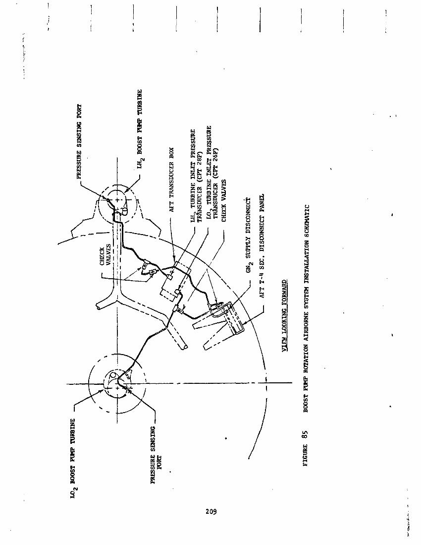
BOO
ST PllPlP
TU
RB
INE
PR
ESS
UR
E S
mS
ING
PORT
LH2
BOO
ST PZMP TURBINE
PRE
SSU
RE
SE
NSI
NG
AFT T
RA
NSD
UC
ER BOX
\, LH TURBINE INLET P
RE
SSU
RE
T
~N
SD
UC
ER
(CPT
28
P)
IX1
TU
RB
INE
INL
E!C
PRE
SSU
RE
T
&SD
UC
ER
(C
PT
26
~)
CH
ECK
VALVES
L-
GN
~
SUPP
LY
DISC
ONNE
CT
AFT
T-4 S
EC
. D
ISC
ON
NEC
T PA
NEL
VIEW
LOO
KIN
G FORWARD
FIG
UR
E
85
BOO
ST P
IMP ROTATION A
IRBO
RN
E Sm
TE
M I
NST
AU
AT
ION
SC
HPl
AT
IC
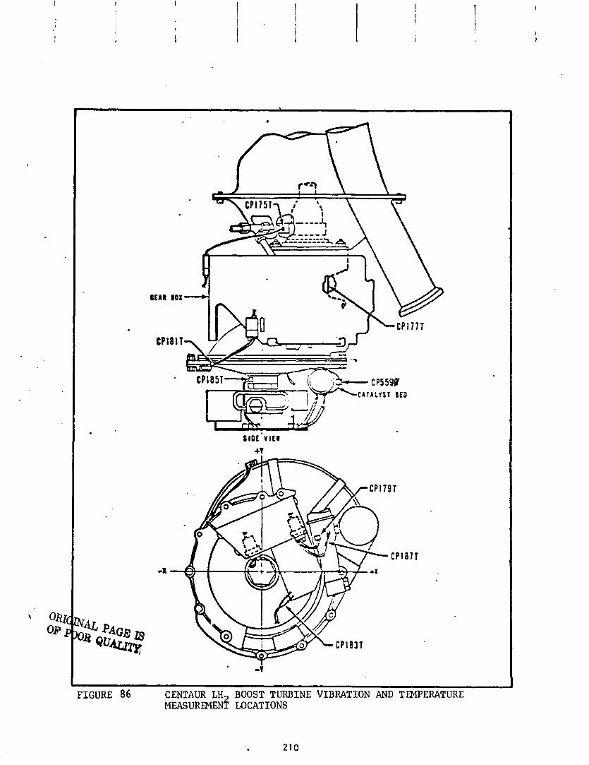
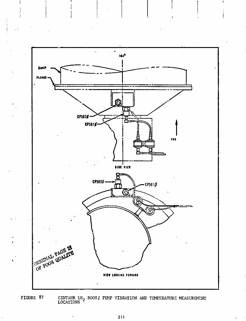
t FWD
F I G U R E 87 CENTAUR LH2 B O O S l F'UMP VIBRATION AND T W E R A T U R E MEASUREMENT LOCATIONS
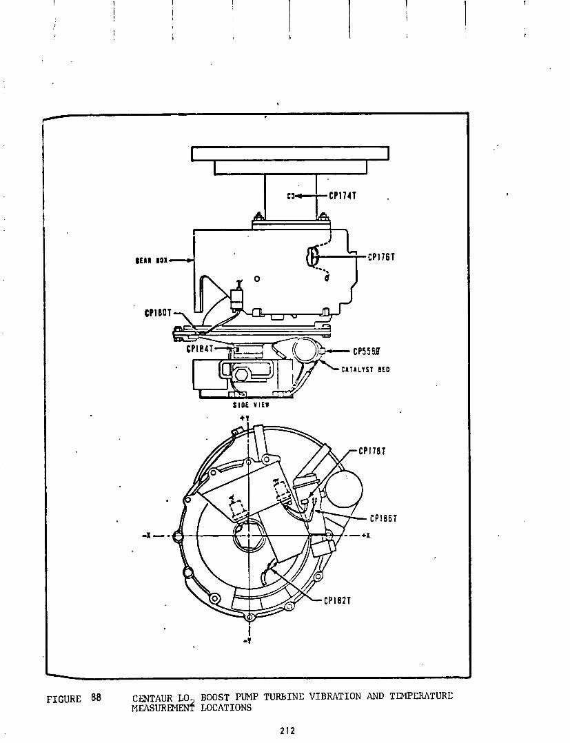
QEAR
CP
BOX 4
F I G U R E 88 CENTAUR LO ROOST PUMP T U R B I N E V I B R A T I O N AND TDIPCRATURE MEASUREMEN$ LOCATIONS
2 1 2
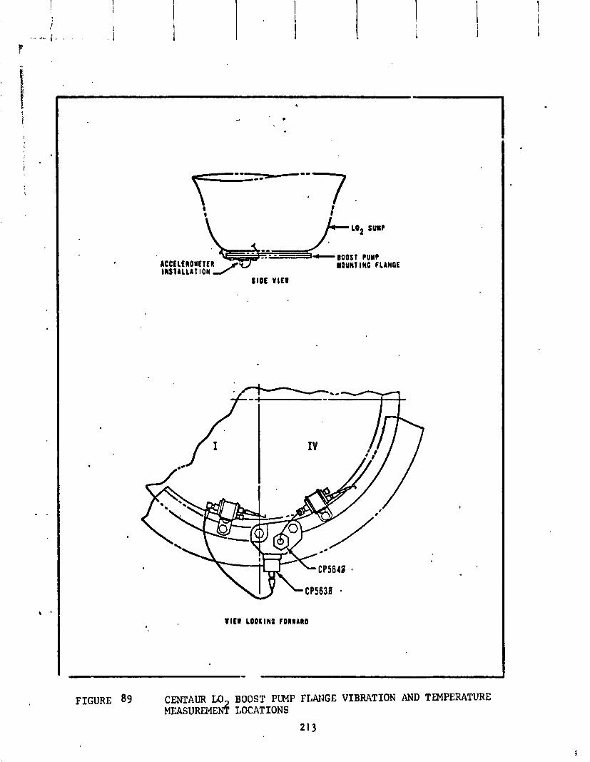
LO* SUMP - BOOST PUMP ACCtl lROutTf R l l S l L L L L l l O N f MOUNI lNG f LLNQE
SIDE VIEW
FIGURE 89 CENTAUR LO BOOST PUMP FLANGE VIBRATION AND TEMPERATURE MEASUREME& LOCATIONS
21 3
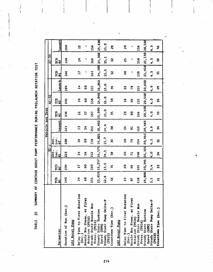
TAB
LE
35
SUM
MAR
Y O
F C
ENTA
UR
B
OO
ST P
UM
P PE
RFO
RM
AN
CE
DU
RIN
G P
REL
AU
NC
H
RO
TATI
ON
TE
ST
Par
amet
er
Du
rati
on
of
Run
(S
ec . )
LO2
Bo
ost
PL
rmv
Del
ay
Tim
e to
Fir
st
Ro
tati
on
(S
ec .)
No
zzle
B
ox Press.
at
Fir
st
Ro
tati
on
(P
SIA
) S
tea
dy
Sta
te N
ozz
le
Box
P
ress
. (P
SIA
) S
tea
dy
Sta
te T
urb
ine
Sp
eed
(RFW)
Ste
ad
y S
tate
Pum
p D
elt
a-P
(P
SID
) C
oa
std
m T
ime
(Sec
.)
LH2
Bo
ost
Pump
Del
ay T
ime
to F
irs
t R
ota
tio
n
(Se
c . )
No
zzle
Box
P
ress
. a
t F
irs
t R
ota
tio
n
(PS
IA)
Ste
ad
y S
tat€
No
zzle
Box
P
ress
. (P
SIA
) S
tea
dy
Sta
te T
urb
ine
S
pee
d (RPM)
Ste
ad
y S
tate
Am
p D
elt
a-P
(P
SID
) C
oae
tdow
n T
im (
Sec
.)
Ve
hic
le a
nd
Te
st
- -
TCD
L
1
40
14
6 0
15
5
15,6
51
12
.6
32
23
87
15
8
19,8
04
3.5
31
- TC
D
#2
2 04
17
6 0
16
0
16
,25
0
13
.5
35
2 0
69
16
1
20,3
45
3.4 33
Lnc
. L
223
14
5 4
15
2
16
,57
14
.5
3 8
20
71
14 8
20,3
21
4.0 34
- A
bt .
Lnc .
#2
2 08
16
6 0
15
8
16
,82
5
15
.7
3 6
2 0
70
15
4
20
,45
0
4.3
31
Lau
nch
223
1.3
54
155
16, &
GO
14.4
38
2 4
81
15 2
!O,
460
3.9 34
- TC
D
#1
2 36
11
57
15
7
.5,9
00
15
.0
3 5
23
9 0
15
6
20
, 5O
I
4.0
33
TCD
#2
2 45
14
60
15
6
15
,99
0
15
.0
30
19
59
15
5
20
,50
0
4.0
35
Lau
nch
19 4
14
60
'
155
l6,a
SO
15.0
36
2 2
78
15 5
20
,60
0
u. 0
29
TCD
#
1 -
16
6
17
- 1
63
14,3
01
15
.1
32
2 0
- 1
59
21,4
54
4.3
31
TCD
#2
16
0
14
- 1
62
14
,30
0
15
.1
32
25 -
15
8
21
,13
0
4.3
32
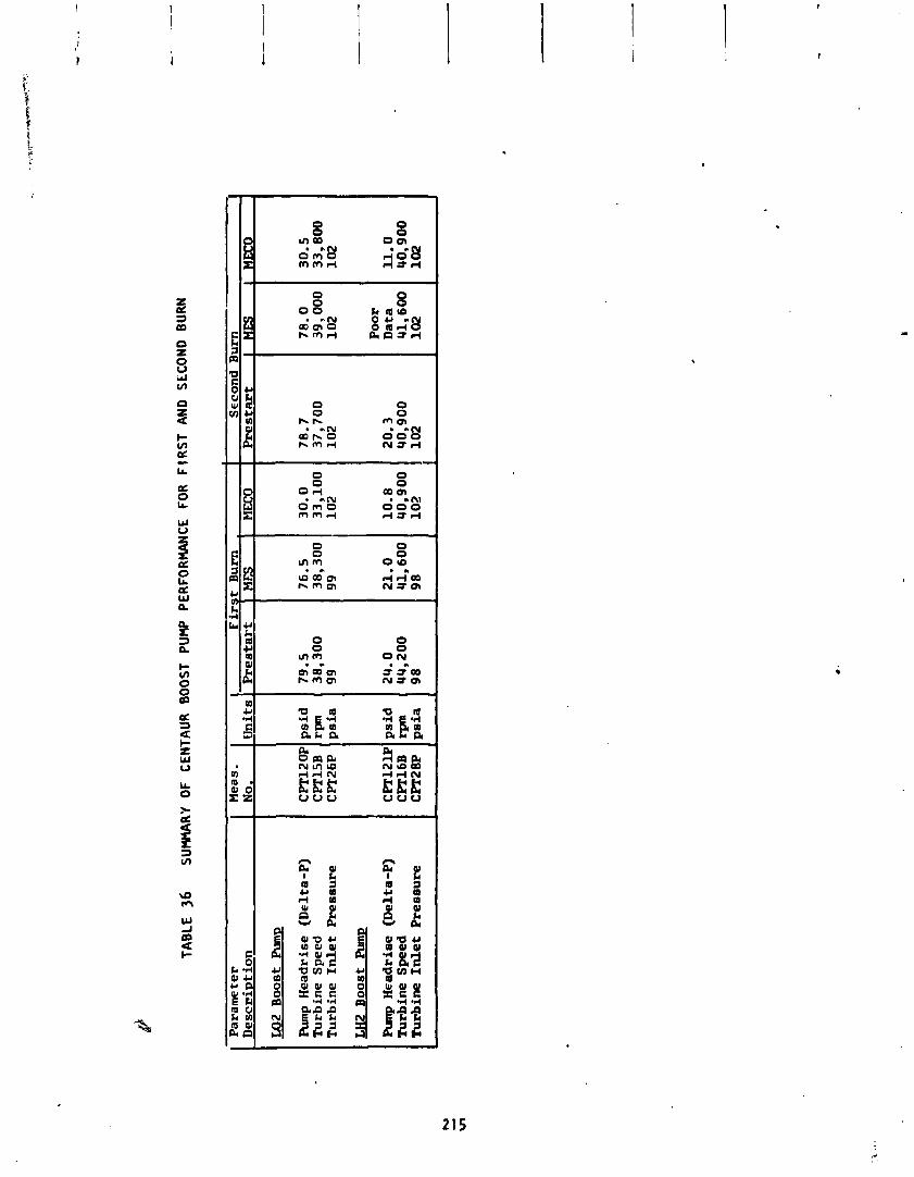
TAB
LE
36
SU
WR
Y O
F C
ENTA
UR
B
OO
ST P
UM
P PE
RFO
RM
AN
CE
FOR
F
IRS
T A
ND
SE
CO
ND
BU
RN
De
sc
ri~
t ion
M2
Bo
ost
Pum
p
Run
p H
ea
dri
se
(Del
ta-P
) T
urb
ine
Sp
eed
T
urb
ine
In
let
Pre
ssu
re
LH2
Bo
ost
Pu
tnu
Rmp H
ea
dri
se
(Del
ta-P
) T
urb
ine
Sp
eed
T
urb
ine
In
let
Pre
ssu
re
Me
as
.
CP
Tl2
OP
psi
d
CPT
15B
rp
n
CPT
26P
psi
a
CP
T12
1P p
sid
C
PT16
B
rpn
C
PT28
P 1 psia
Fir
Pre
eta
rf
79
.5
38
,30
0
99
24.0
4
4,2
00
9
8
MEC
O
30
.0
33
,10
0
10
2
10
.8
40
,90
0
10
2
78
.0
39
,00
0
10
2
Po
or
Dat
a 4
1,6
00
102
MEC
O
30.5
3
3,8
00
102
11
.0
90
,90
0
10
2
hydrogen peroxide ( ~ ~ 0 2 ) was purged from the boost pump supply l ines. The res idua ls f lowed through the c a t a l y s t bed o f each t u r b i n e where i t decomposed, thereby supply ing energy t o the t u r b i n e wheel. Concurrent w i t h the purg ing ac t ion , t he boost pumps were on ly p a r t i a l l y pumping (which i s normal) due e i t h e r t o MECO disturbances d i sp l ac i ng l i q u i d from the pump i n l e t , o r due t o p a r t i a l c a v i t a t i o n . The a p p l i c a t i o n o f p a r t i a l power t o t h e tu rb ines which were on l y p a r t i a l l y loaded resu l t ed i n acce le ra t i on o f the boost pumps.
A complete i nves t i ga t i on o f t he p o t e n t i a l overspeed cond i t i on was conducted. The i nves t i ga t i on determined t ha t t h e l i m i t e d quan t i t y o f res idua l peroxide was no t s u f f i c i e n t t o produce damaging t u rb i ne speeds even under worst case cond i t i ons o f no pumping ac t i on f o r the e n t i r e 15 seconds o f purging. Thus, no c o r r e c t i v e a c t i o n was required.
A summary o f the p rope l l an t feed system temperature data i s presented i n Ta- b le 37 f o r times o f s i g n i f i c a n t events. There were no abnormal o r unexpected temperatures noted w i t h one except ion. The temperature measurement located on t he LO2 boost pump sha f t housing ( ~ P 1 7 4 ~ ) ind ica ted temperatures a f t e r 1 i f t o f f t h a t were approximately 4S°F co lder than the corresponding measure- n x c t on AC-32. A p l o t o f t he temperature data from t h i s measurement i s pre- sented i n F igure 90. P lo t s o f the temperature data from a l l o ther spec ia l boost pump measurements a re presented i n Figures 91 and 92 f o r t he 222 and LH2 boost pumps, respect i ve 1 y . I t should be noted t h a t the temperature o f the LO2 boost pump sha f t housing ( c P I ~ ~ T ) , as shown i n F igure 90, was very s e n s i t i v e t o t he surrounding en- v i ronrnent. The temperature decreased r a p i d l y dur ing the b o o ~ t phase due t o convect ive coo l i ng produced by p ropu ls ion compartment vent ing. The temper- a tu re then showed a s i g n i f i c a n t increase du r i ng the 80-second t ime per iod o f t h r u s t e r f i r i n g s p r i o r t o the f i r s t boost pump s t a r t , and again dur ing the t ime per iod from f i r s t boost pump s t a r t u n t i l T i t a d c e n t a u r separat ion. The r e l a t i v e l y large d i f fe rences between the AC-32 and TC-2 data might, therefore, be w i t h i n the normal veh ic le - to -veh ic le d ispers ions. The l i m i t e d amount o f f l i g h t data p r o h i b i t e d an accurate assessment o f whether the data was abnormal. A l l o ther t u rb i ne temperatures were near ambient, so the low LO2 pump sha f t housing temperature was not considered a problem.
The LO and LH2 supply duct metal sur face temperatures a t second boost pump s t a r t ?see Table 37) were w i t h i n the p r e f 1 i g h t p red ic ted ranges. The LO2 duct average metal temperature was p red ic ted t o be w i t h i n the range from - 2 8 5 0 ~ t o - 2 ~ 2 ~ ~ ; the TC-2 f l i gh t va lue was -26S°F. The LH2 duct average metal temperature was p red ic ted t o be w i t h i n the range from -35b°F t o - 2 7 ~ ~ ~ ; the TC-2 fl i g h t va lue was -307OF.
I n summary, performance o f the p rope l l an t feed system i n support o f t he He l ios miss ion was s a t i s f a c t o r y . Boost pump performance du r i ng the prelaunch ro ta - t i o n t e s t s and dur ing f i r s t and second burn was s a t i s f a c t o r y . Special temper- a tu re ins t rumentat ion on the boost pumps revealed no abnormal temperatures, except the LO2 boost pump sha f t housing temperature was approximately 4S°F

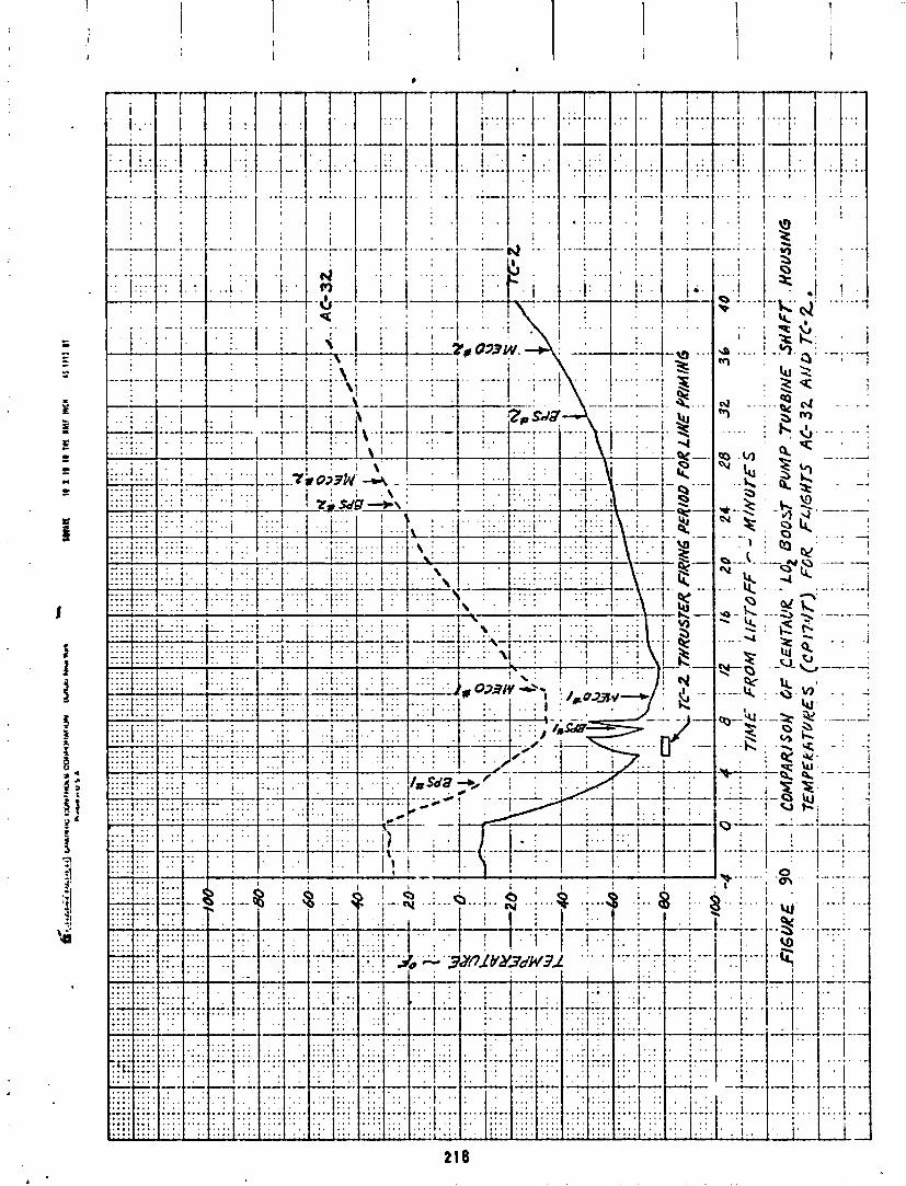
' I i I ; ; p j , ! I n( ;:4-m 1 ' ! ', - . ; . : 1' / - . : -- & - - -. - - - -. I iq I . ,
. ,. i. , , . .; . . . . i . ! !----
--?, 033 W . --+ I : 1 . .

i ..
I..
I
'. T
Uk

.-.-..,.- -.-- r--r- -- i---r- * I ' i
. 1 1 . . :. '
colder than on AC-32. The 1 imited quant i ty o f f 1 igh t data proh iL i ted an ac- curate assessment o f the abnormality o f t h i s data. The low temperature had no e f f e c t on boost pump operation and was not considered a problem.
A po ten t ia l boost pump overspeed condi t ion was noted during the f i : . t 15 sec- onds a f t e r each MECO. A complete inves t iga t ion indicated tha t the po tent ia l overspeed condi t ion was not a problem f o r f u tu re Centaur f l i g h t s .
The LO2 and LH2 supply duct metal temperatures a t the end o f the 24 minute se t t l ed coast were w i t h i n the range o f p r e f l i g h t predicted values.
Hydrogen Peroxide Supply and React ion Cont ro l System
by K , W. Baud
The hydrogen peroxide supply and reac t ion con t ro l system performed s a t i s f a c - t o r i l y i n support of t he Hel ios mission. A l l system component and hydrogen peroxide bu l k temperatures were maintained w i t h i n acceptable 1 i m i t s . Pro- grammed t h r u s t e r f i r i n g s dur ing the boost phase and s e t t l i n g sequences oc- cur red i n t he proper sequence and f o r the proper dura t ion . L a t e r a l d i r ec ted t h rus te r s responded t o t he f l i g h t con t ro l system commands and maintained proper veh i c l e a l t i t u d e c o n t r o l .
The con f igu ra t ions o f the hydrogen peroxide supply and reac t i on c o n t r o l sys- tems were i d e n t i c a l t o the con f i gu ra t i on p rev ious ly f lown on TC-I.
The hydrogen peroxide ( ~ ~ 0 ~ ) supply and reac t ion c o n t r o l system (RCS) per- formed sa t i s f a c t o r i l y from 1 i f t o f f through spacecraf t separat ion. The RCS was i n a c t i v e dur ing the t ime pe r i od from l i f t o f f t o f i r s t main engine c u t o f f (MECO No. 1) except f o r programmed f i r i n g o f f ou r RCS engines be fo re boost pump s t a r t and warming f i r i n g s o f t he e i gh t l a t e r a l engines j u s t p r i o r t o MECO No. 1. The performance o f t he RCS : s on ly b r i e f l y discussed i n t h i s sect ion. A de ta i l ed d iscuss ion o f t he RCS performance i n regard t o on-o f f duty cyc les and con t ro l o f t he v e h i c l e i s presented i n t he f l i g h t c o n t r o l system ana lys is .
The S2A, Y I , Y2, and S ~ B t h rus te r s were f i r e d ( i n t h a t order) f o r 20 seconds each dur ing the T i t a n boost phase t o remove any la rge accumulations o f gas i n the H202 b o t t l e s . The f i r i n g s were accomplished i n r ap id succession w i t h no w a i t i n g i n t e r v a l , Temperature measurements located on t h e t h r u s t chamber bodies confirmed proper f i r i n g o f t he S2A, Y1, and 528 t h rus te r s . A temper- a t u r e measurement was no t i n s t a l l e d on the Y2 t h rus te r , however, proper f i r i n g was evidenced by the response o f o t he r temperatl lre measurements i ns i de the T i t a d c e n t a u r in te rs tage adapter.
A l l e i g h t l a t e r a l t h rus te r s were s imultaneously f i r e d f o r 10 seconds com- mencing approximately 20 seconds p r i o r t o each MECO. Purpose o f the f i r i n g s has t o warm these t h rus te r s p r i o r t o en te r i ng a long coast. Temperature measurerxnts located on t h e t h r u s t chamber bodies o f f ou r o f the t h rus te r s (P3, P4, Y 1 , and ~ 3 ) v e r i f i e d the warming f i r i n g was p roper l y performed,
A t MECO No. 1, a l l f ou r a x i a l s e t t l i n g t h rus te r s (S2A, S2B, s ~ A , and S ~ B ) were f i r e d i n a continuous on mode f o r 250 seconds which prov ided 24 pounds- t h r u s t f o r i n i t i a l p rope l l an t s e t t l ing, Dur ing t h e t ime per iod between MECO No. 1 p lus 250 seconds and MES No. 2 minus 120 seconds, the p rope l l an t se t - t l i n g t h r u s t was reduced t o 12 pounds-thrust . S2A and S4A were used f o r the f i r s t h a l f o f t he 12 pound-thrust mode; S2B and S ~ B were used f o r the l a s t h a l f . A t MES No. 2 minus 120 seconds, a l l f ou r a x i a l t h r u s t e r s were again turned on and remained on u n t i l MES No. 2 p lus 5 seconds. Proper sequencing and opera t ion of the four a x i a l t h rus te r s were v e r i f i e d by the temperature measurement on each.
P i t ch , yaw, and r o l l c o n t r o l were prov ided by the e i g h t l a t e r a l t h rus te r s dur ing the f i r s t coast and between MECO No. 2 and spacecraf t separat ion. Proper veh i c l e a t t i t u d e con t ro l was provided. See the f l i g h t c o n t r o l sys- tem ana lys is f o r a d e t a i l e d discussion.
A summary o f t he H202 supply and RCS systems temperature data recorded a t t imes o f s i g n i f i c a n t events i s presented i n Table 38. A l l temperature data were w i t h i n acceptable l im i t s . The lowest temperature recorded (25OF) was a t the C P T ~ I ~ T loca t i on dur ing the T i t a n boost phase. Th i s measurement was located on an unheated sec t ion o f t h e LO2 boost pump H202 supply l i n e . The l i n e contained no H202 a t t h i s t ime and, being unheated, was q u i t e s e n s i t i v e t o the convect ive coo l i ng produced by ven t ing o f t he p ropu ls ion compartment. The corresponding temperature on the TC-I f l i g h t was 20°~.
Three o f the tervperature measurements located on the H202 l i n e s t o t he boost pumps ( c P I ~ ~ T , C P T ~ ~ ~ T , and ~ ~ 8 3 3 ~ ) revealed temperatures i n excess o f the normal 1 4 0 ~ ~ upper l i m i t f o r t he Hz02 system. Two o f these measurements ( C P T ~ ~ ~ T and ~ ~ 8 3 3 ~ ) were on unheated l i n e s very near the h r t face o f t he LH2 t u rb i ne r o t o r housing. High temperatures a t these locat ions, p a r t i c u - l a r l y dur ing the coast phase when t h e l i n e s a re empty, were expected and present no problem.
The h igh temperature ind ica ted a t t h e CP159T l oca t i on was po t expected, but does not present a problem. The h i gh temperature was p r i m a r i l y caused by impingement o f t he S4A and S ~ B a x i a l t h r u s t e r exhaust on t h i s sec t ion o f emp- t y l ine dur ing the 4s engine on mode before second boost pump s t a r t . The l ine r a p i d l y cooled w i t h the resumption o f Hz02 f low a f t e r second boost pump s t a r t .
I n summary, the Hz02 supply and RCS systems :erformed s a t i s f a c t o r i l y i n sup- p o r t o f the Hel ios mission. A l l programmed t h r u s t e r f i r i n g s were accomplished i n the proper sequence and f o r the proper dura t ion . Vehic le a t t i t u d e c o n t r o l was p roper l y maintained. The minimum temperature (2S0F) occurred dur ing the boost phase on the unheated p o r t i o n o f the LO2 boost pump supply l i n e and was expected . A l l o the r temperatures were w i t h i n the design range o f 4 0 ' ~ t o 1200F w i t h the except ion o f th ree measurements. Two o f these measurements were on an un- heated l i n e near the hot LH2 t u r b i n e and were expected t o be above 120°F. The t h i r d measurement was on an empty supply l i n e t o the LH2 t u rb i ne which received impingement h e a t i ~ i g from the a x i a l t h rus te r s i n quadrant 4. The temperatures experienced posed no problem s ince the l i nes were empty.

TAB
LE
38
SUM
MAR
Y O
F H
-0,
AN
D
RC
S
TEM
PE
RA
TUR
E
DA
TA
Par
amet
er
De
scri
uti
on
3202
Bu
lk
RCS
Bo
ttle
b
oo
st
Pum
p B
ott
le
pr
us
ter
Cha
mbe
r S
urf
ac
e
4202
Lin
es
to
Th
rust
ers
Y20
2 L
ine
s to
Bo
ost
Pumps
&ad
1 L
H2
(fit
tin
g)
Iuad
2
LH2
Zua
d 3
LH2
&ad
4 LH
iH
0ri
fig
e I
nle
t .o
? O
rifi
ce
In
let
Bet
wee
n F
eed
Val
ves
A
2 I
nle
t (N
ear
Tee
)
Mea
s.
No.
CP9
3T
C
P65
9T
CP
148T
C
PlV
9T
CP
375T
C
P37
6T
CP
691T
C
P69
3T
CP
836T
C
P82
7T
CPT
150T
C
PT15
1T
CP
T15
2T
CP
153T
C
P15U
T
CPT
155T
CP1
5GT
C
P15
7T
CP
15 8T
C
P15
9T
CP
T36
1T
CPT
714T
C
P83
1T
CP
833T

TAB
LE
38
SUM
MAR
Y O
F H
202
AND
RC
S TE
MPE
RA
TUR
E D
ATA
(C
ON
TIN
UE
D)
Parameter
Meas.
Description
No.
I I Ot
her
- -
BPN #2 Body
I Bottle Manifold Line
HZ02 Vent Line
CP
834T
C
P7 5
6T
CP
832T
Hydraul i c System
Centaur hydraul i c system performance was sa t i s f ac to r y . The hydraul i c r ec i rcu- l a t i o n pumps responded p roper l y when commanded on p r i o r t o main engine s t a r t (MES 1, MES 2, MES 3, MES 4) and throughout t h e boost pump spinup t e s t and the blowdown maneuver. I n add i t i on , t he C-2 r e c i r c u l a t i o n pump was switched on four t imes au tomat i ca l l y by the low temperature thermostat i n t he C-2 hydrau- l i c manifold. Main system operat ion was normal throughout the four main en- g ine f i r i n g s . S ta r tup and shutdown t rans ien ts , as we!l as opera t ing pressures, were norma 1 . The hydrau l i c system on t he TC-2 v e h i c l e incorporated a d d i t i o n a l temperature ins t rumentat ion (power pack, r e c i r c u l a t i o n motor housing and ac tua to r body temperatures) f o r the purpose o f mon i to r ing the e f f e c t s o f long coast per iod, zero-G operat ion and o r b i t a l maneuvers on system components. Th i s data w i l l be ?resented i n d e t a i l i n a l a t e r r epo r t . However, a l l temperature data ob- ta ined f o r the f i r s t two mair, engine f i r i n g s a re presented, together w i t h pressure data, i n Table 39.
No system anoma 1 i es were noted.

TAB
LE
39
CEt
iTA
UR
H
YD
RA
ULI
C
SY
STE
M T
C-2
F
LIG
HT
PER
FOR
MA
NC
E
Hy
dra
uli
c S
yst
em Press.
I P
i--a
me
t~r
-
C1
En
gin
e C
2 E
ng
ine
Mea
s.
No.
Tem
per
atu
res
I C
1 p
ower
p
ack
CL
hy
d.
ma
nif
old
' C
1 r
ec
irc
. m
oto
r h
sg.
C1
yaw
a
ctu
ato
r body
-
Un
its
ps i
a
psi
a
0
0 F
0 F $
"F
CH
T2T
CH
TST
CH
9T
CH
33T
C2
pow
er
pac
k
C2
hyd.
m
anif
old
C
2 re
cir
c.
mo
tor
hag
. C
2 p
itc
h a
ctu
ato
r body
Re
cir
c .
ON
12
5
13
0
58
65
5
7
A0
5 7
45
55
67
CH
T4T
CI0
16T
C
IUO
T
CH
36T
MEC
O #
1
11
30
1
12
2
7 0
1
13
5 1
9
3
6 4
6 5
4 3
84
Rec
irc
. O
N
--
12
6
13
2
8 0
75
7
3
87
77
7 0
9 7
8
4
2nd
Bur
l
MEC
O
#2
11
20
1
11
5
13
9
17
0
76
14
0
13
0
15
9
87
13
5
Blowd
Rec
irc .
ON
12
3
12
8
87
9
9
85
8
1
66
39
7 8
6
8
m
tec
irc
O
FF -
12
0
12
8
87
89
' 8 3
8
0
61
45
64
65
Pneumatics and Tank Vent Systems
by M. L. Jones
The Centaur pneumatic system, which i s shown schemat ica l ly i n F igure 93 the same as t h a t on TC-1 except i n the f o l l ow ing areas:
1. Hydrogen tank p ressu r i za t i on - The diameter o f the f l ow meter ing o r associated w i t h the number two p r e s s u r i t a t l o n va lve was changed from 0. inches t o 0.0995 incnes.
, was
i f i c e 157
2. Helium re t r o - t h rus t - Th i s system was added t o TC-2 i n order t o prov ide the requi red separat ion d is tance between the Centaur and t he spacecraf t i m - mediately a f t e r spacecraf t separat ion and before f i r i n g the spacecraf t rocket motor. The system cons is ts o f two normal ly c losed pyrotechnic valves, mounted i n p a r a l l e l , and two forward canted nozzles. The system i s ac t i va ted by open- ing the pyrotechnic valves a l l ow ing the remainder o f the hel ium i n t he smal ler (4650 cu. in . ) b o t t l e t o blow down through the two nozzles app ly ing a reverse t h r u s t t o the Centaur.
3. Helium storage - Th i s p o r t i o n o f t he system was changed by adding two check valves i n se r ies between the two hel ium b o t t l e s and an add i t i ona l hel ium charge so lenoid valve. The check valves were added t o i s o l a t e the l a rge r (7365 cu. in.) he1 ium b o t t l e from the re t r o - t h rus t system. The charge va lve was add- ed t o permi t charg ing the l a rge r b o t t l e independently o f the smal ler b o t t l e i n order t o leak t e s t the check valves.
4. Oxygen tank vent system - The vent nozzle a1 ignment angle was changed f rom 40-48' w i t h the v e r t i c a l t o 150.
Propel l a n t Tank Pressur i za t ion and Ven t ing - A t ime h i s t o r y o f t he propel l a n t tank u l lage pressures i s shown i n F igure 94. P r i o r t o T-27.8 seconds, the pr imary hydrogen vent valve, which has a s p e c i f i c a t i o n opera t ing range from 19.0 t o 21.5 psia, regu la ted the tank pressure. A t T-27.8 seconds, t he p r i - mary hydrogen bent va lve was commanded t o the locked mode and t he tank pres- sure was al lowed t c r i s e i n order t o s a t i s f y t he tank s t r u c t u r a l s t reng th requirements dur ing 1 i f t o f f and dur ing the subsonic p o r t ion o f t he f l i gh t . A minimum requirement o f 23.1 ps ia a t l i f t o f f had been es tab l i shed before the f l i g h t . A maximum l i m i t o f 24.9 ps i a had a l s o been es tab l i shed i n order t o preclude t he p o s s i b i l i t y o f ven t ing hydrogen gas overboard before 8 sec- onds i n t o the f l i g h t .
From the t ime o f vent va lve lockup u n t i l T-8 seconds, the tank Fressure was moni to red by the computer cor , t ro l l ed vent and pressur i t a t ion system (ccvAP!;) , which ca l cu l a ted the pressure r i s e r a t e and p red ic ted the tank pressure a t l i f t o f f . I f the CCVAPS p r e d i c t i o n had not f a l l e n w i t h i n the es tab l i shed l im i ts , an automatic launch abor t would have been i n i t i a t e d . A t T-8 seconds
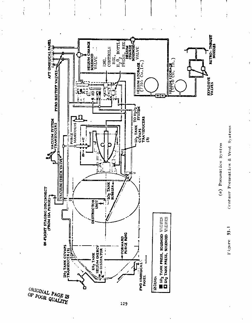
I ID2 TANK PRESS. SOUP1Om
VA
LV
ES
. W
2 TANK PRESS. WtPIOID
VA
LV
ES
&
(a)
Pn
eurn
at ics
Sy
ste
m
Cc
nta
ur
Pn
eun
at i
cs
&
Ve
nt
S>
,ste
rns
I
VA
LVE
S
W~
O-
T
HM
IST
NOLLlU
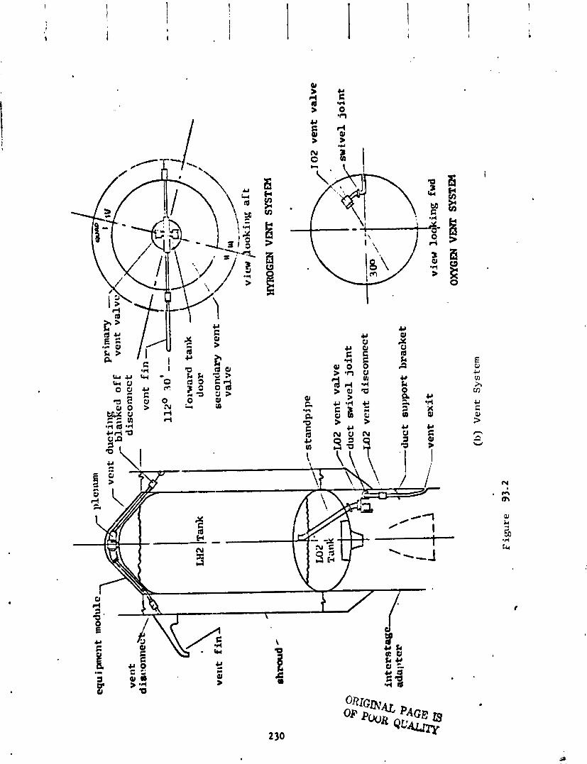


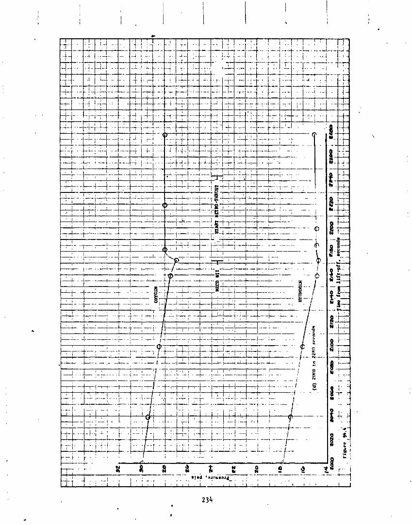

t h e CCVAPS pred ic ted presLIJre a t l i f t o f f was 23.75 ps i a . The ac tua l l i f t o f f pressure was 23.78 ps ia . A t T-8 seconds the CCVAPS was deact ivated u n t i l t he s t a r t o f tank p ressur i za t ion f o r the f i r s t main engine s t a r t sequence.
A f t e r 1 i f t o ; f the tank pressure cont inued t o r i s e , but a t a decreasing ra te , u n t i l i t reached 24.7 ps i a a t approximately T+25 seconds. A f t e r reaching the peak value, t he pressure g radua l l y decreased t o 24.15 ps ia and remained re l a - t i v e l y constant u n t i l T+gO seconds, when the pr imary vent va lve was commanded t o t he re1 i e f mode. The decreasing r a t e o f pressure r i s e and t h e eventual de- crease i n pressure can be at:: i buted t o a combination o f fac to rs : decreased convect ive heat inpu t t o t h e tank from the he l ium purge gas as i t vented over- board dur ing atmosphere ascent, suppressed b o i l i n g o f t he l i q u i d hydrogen as t he v e h i c l e acce le ra t i on increased; and t he increas ing of the u l l a g e volume by v i r t u e o f the tank changing shape as pressure increased. Dur ing t h e pe r i od when t he pr imary vent va lve was i n t he locked mode, the secondary vent valve, which has a s p e c i f i c a t i o n opera t ing range from 24.8 t o 26.8 ps ia , was i n the r e l i e f mode i n order t o p r o t e c t aga inst overp ressur i za t ion o f t h e tank.
A t T+90 seconds the primary hydrogen vent va lve was commanded t o t he r e l i e f mode, and t he hydrogen tank vented down t o the c o n t r o l range o f t he vent va lve. The va lve then began t o cyc l e between i t s opera t ing l i m i t s and cont inued t o cyc l e u n t i l commanded t o t h e locked mode f o r the s t a r t o f tank p ressu r i za t i on f o r f i r s t main engine s t a r t .
The drop o f approximateiy one ps l a i n the opera t ing l i m i t s o f the vent va lve f iom T+gO t o T+188 seconds and the onset o f r e l a t i v e l y h igh frequency cyc l ing can be a t t r i b u t e d t o t he d im in ish ing back pressure on the va lve o u t l e t . These a re c h a r a c t e r i s t i c phenomena o f the vent valves and have been observed on o ther Centaur f l i gh t s and dur ing acceptance t e s t i n g o f the valves. A f t e r T+ 320 seconds, when the Centaur Standard Shroud was j e t t i soned , t h e upper l i m i t o f the va lve opera t ing range remained e s s e n t i a l l y the same, but the lower l i m i t dropped approximately 0.3 ps ia . When the shroud was j e t t i soned , the cap on the second l e g o f t he vent system was a l s o je t t i soned , opening t h a t l eg f o r vent ing. The dynamic e f f e c t o f the response t ime o f the va lve by the greater f l ow capac i ty o f the system caused t he pressure t o decrease t o a lower l eve l before the vent va lve cou ld c lose.
The ' ~ l l a g e pressure i n the oxygen tank was 31 ps i a a t l i f t o f f . The vent va lve, which has a s p e c i f i c a t i o n opera t ing range from 29.0 t o 32.0 ps ia , was i n the r e l i e f mode. Immediately a f t e r l i f t o f f , the vent va lve began t o c y c l e between i t s opera t ing l i m i t s and cont inued t o c y c l e u n t i l t he beginning o f tank p ressu r i za t i on f o r f i r s t main engine s t a r t . A t T+25 seconds the lower l i m i t decreased about 0.5 p s i . La te r i n the f l i g h t du r ing atmospheric ascent, the reseat pressure decreased an add i t i ona l 0.5 p s i . These same opera t ing c h a r a c t e r i s t i c s were observed on TC-I and can be a t t r i b u t e d , i n pa r t , t o the d im in ish ing back pressure on the vent system as the veh i c l e ascented through the atmosphere.
Several t imes dur ing the boost phase o f f l i g h t , the u l l age pressure rose above 32 ps ia , the upper s p e c i f i c a t i o n l i m i t of the vent va lve. T ! i is a l s o
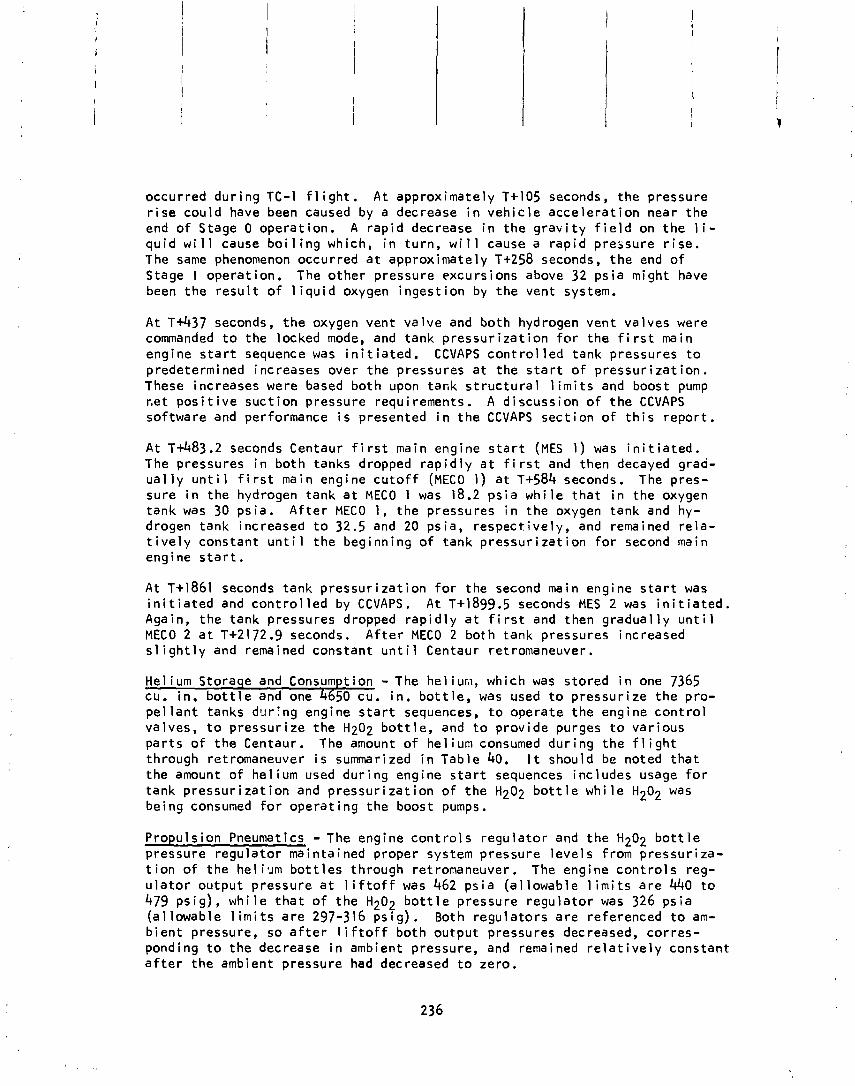
occurred dur ing TC-I f l i g h t . A t approximately T+105 seconds, the pressure r i s e cou ld have been caused by a decrease i n veh i c l e acce le ra t i on near the end o f Stage 0 operat ion. A r ap i d decrease i n t he g r a v i t y f i e l d on t he l i - qu id w i l l cause b o i l i n g which, i n tu rn , w i l l cause a r ap id pressure r i s e . The same phenomenon occurred a t approximately T+258 seconds, t he end o f Stage I operat ion. The o ther pressure excursions above 32 ps ia might have been t he r e s u l t o f l i q u i d oxygen inges t ion by the vent system.
A t T+437 seconds, t he oxygen vent va lve and both hydrogen vent valves were commanded t o the locked mode, and tank p ressu r i za t i on f o r the f i r s t main engine s t a r t sequence was i n i t i a t e d . CCVAPS c o n t r o l l ed tank pressures t o predetermined increases over the pressures a t the s t a r t o f p ressur i za t ion . These increases were based both upon tank s t r u c t u r a l l i m i t s and boost pump r.et p o s i t i v e suc t ion pressure requirements. A d iscuss ion o f t he CCVAPS software and performance i s presented i n t he CCVAPS sect ion o f t h i s repor t .
A t ~+483 .2 seconds Centaur f i r s t main engine s t a r t (MES 1 ) was i n i t i a t e d . The pressures i n both tanks dropped r a p i d l y a t f i r s t and then decayed graa- u a l l y u n t i l f i r s t main engine c u t o f f (MECO 1) a t T+584 seconds. The pres- sure i n the hydrogen tank a t MECO 1 was 18.2 ps i a wh i l e t h a t i n the oxygen tank was 30 ps ia . A f t e r MECO I, the pressures i n the oxygen tank and hy- drogen tank increased t o 32.5 and 20 ps ia , respec t i ve ly , and remained r e l a - t i v e l y constant u n t i l t he beginning o f tank p ressu r i za t i on f o r second main engine s t a r t .
A t T+1861 seconds tank p ressu r i za t i on f o r the second main engine s t a r t was i n i t i a t e d and c o n t r o l l e d by CCVAPS. A t T+1899.5 seconds MES 2 was i n i t i a t e d . Again, the tank pressures dropped r a p i d l y a t f i r s t and then g radua l l y u n t i l MECO 2 a t T+2172.9 seconds. A f t e r MECO 2 both tank pressures increased s l i g h t l y and remained constant u n t i l Centaur retromaneuver.
Hel ium Storage and Consumption - The he1 iun, which was s tored i n one 7365 cu. in . b o t t l e and one 4650 cu. i n . b o t t l e , was used t o p ressur i ze t he pro- pe l l a n t tanks dgr ing engine s t a r t sequences, t o operate the eng i ne c o n t r o l valves, t o p ressur i ze the Hz02 b o t t l e , and t o prov ide purges t o var ious pa r t s o f t he Centaur. The amount o f he l ium consumed dur ing t he f l i g h t through retromaneuver i s summarized i n Table 40. I t should be noted t ha t the amount o f hel ium used dur ing engine s t a r t sequences includes usage f o r tank p ressu r i za t i on and p ressu r i za t i on o f t he Hz02 b o t t l e w h i l e H202 was being consumed f o r opera t ing the boost pumps.
Propuls ion Pneumatics - The engine c o n t r o l s regu la to r and t he H202 b o t t l e pressure regu la to r maintained proper system pressure leve ls from pressur iza- t i o n o f the h e l i . ~ m b o t t l e s through retromaneuver. The engine c o n t r o l s reg- u l a t o r output pressure a t l i f t o f f was 462 ps i a (a1 lowable 1 i m i t s a re 440 t o 479 ps is ) , wh i l e t h a t o f the H20? b o t t l e pressure r egu la to r was 326 ps ia (a l lowable l i m i t s a re 297-316 p s ~ g ) . Both regu la to rs a re referenced t o am- b i e n t pressure, so a f t e r l i f t o f f both output pressures decreased, co r res - ponding t o the decrease i n ambient pressure, and remained r e l a t i v e l y constant a f t e r the ambient pressure had decreased t o zero.
He1 i um Retro-Thrust - A t ~+2244.9 seconds, the two norma 1 l y c losed pyrotechnic valves i n t he he l ium re t r o - t h rus t system were f i r e d , a l l ow ing the remainder o f the he l ium i n the smal ler b o t t l e to .d ischarge through two forward canted noz- z les . The discharge o f t he he l ium through t he nozzles created a reverse t h r u s t on the Centaur, p rov id ing a separat ion d is tance between t he Centaur and the spacecraf t . The pressure i n t he smal ler b o t t l e went from 2780 t o 0 ps ia . The pressure i n the la rge b o t t l e remained c m s t a n t , i n d i c a t i n g t h a t t he check va lves d i d no t leak.
Helium Purqe - Throughout t he launch countdown, the ground system suppl ied a h e l i u a gas purge t o the forward and a f t ends o f t he veh ic le . The gas was used t o purge the hydrogen tanklshroud annulus, t he des t ruc t package, and several p ropu ls ion system components. The purge was requi red t o mainta in enough pres- sure d i f f e r e n t i a l across the shroud a f t e r cryogenic tank ing t o prevent ground winds in f low. For t he launch day wind cond i t i ons o f approximately 10 MPH, a minimum d i f f e r e n t i a l pressure o f 0.045 ps i d was required. A t t he beginning o f hydrogen tank ing the pressure dropped momentari ly t o 0.065 p s i d but then re- covered t o 0.171 p s i d and remained e s s e n t i a l l y constant u n t i l hydrogen vent va lve lockup. The pressure then began t o r i s e unt i 1 i t reached a value o f 0.225 p s i d a t 1 i f t o f f .
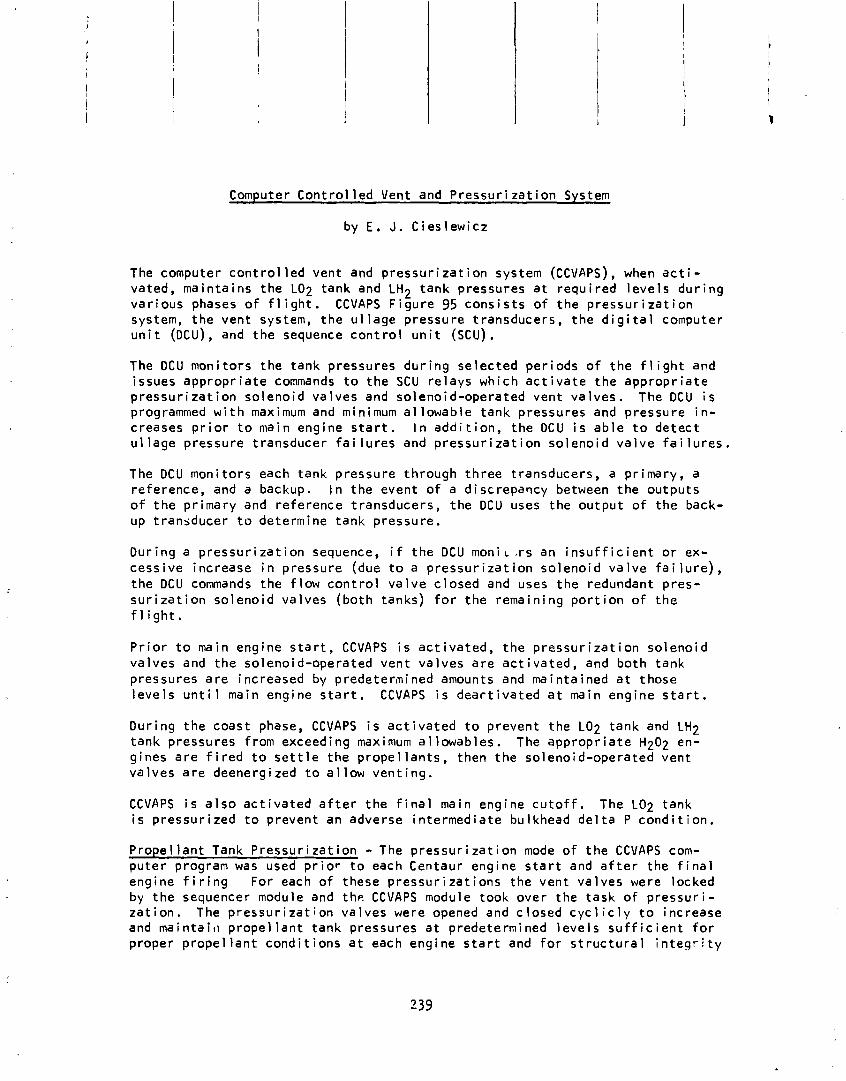
Computer C o n t r o l l e d Vent and P r e s s u r i z a t i o n System
by E. J. C ies lew icz
The computer c o n t r o l l e d vent and p r e s s u r i z a t i o n system (CCVAPS), when a c t i - vated, ma in ta ins t h e LO2 tank and LH2 tank pressures a t r e q u i r e d l e v e l s d u r i n g v a r i o u s phases o f f l i g h t . CCVAPS F i g u r e 95 c o n s i s t s o f t h e p r e s s u r i z a t i o n system, t h e vent system, t h e u l l a g e pressure t ransducers , t h e d i g i t a l computer u n i t (DCU) , and the sequence c o n t r o l u n i t (SCU) . The DCU mon i to rs t h e tank pressures d u r i n g se lec ted pe r iods o f t h e f l i g h t and issues a p p r o p r i a t e commands t o t h e SCU r e l a y s wh ich a c t i v a t e the a p p r o p r i a t e p r e s s u r i z a t i o n so leno id va l ves and so leno id-opera ted vent va l ves . The DCU i s programmed w i t h maximum and m i nirnum a l lowable tank pressures and pressure i n - creases p r i o r t o main engine s t a r t . I n a d d i t i o n , t h e DCU i s a b l e t o d e t e c t u l lage pressure t ransducer f a i l u r e s and p r e s s u r i z a t i o n so leno id v a l v e f a i l u r e s .
The DCU mon i to rs each tank pressure th rough t h r e e t ransducers, a pr imary , a re ference, and a backup. I n t h e event o f a d i s c r e p a m y between t h e ou tpu ts o f t h e p r imary and re fe rence t ransducers , t h e DCU uses t h e ou tpu t o f t h e back- up t ransducer t o determine tank pressure .
Dur ing a p r e s s u r i z a t i o n sequence, i f t h e DCU m o n i ~ . r s an i n s u f f i c i e n t o r ex- cess i ve increase i n pressure (due t o a p r e s s u r i z a t i o n so leno id v a l v e f a i l u r e ) , t h e DCU commands the f l o w c o n t r o l v a l v e c losed and uses t h e redundant pres- s u r i z a t i o n so leno id va lves (bo th tanks) f o r t h e remain ing p o r t i o n o f t h e f l i g h t .
P r i o r t o main engine s t a r t , CCVAPS i s a c t i v a t e d , t h e p r e s s u r i z a t i o n so leno id va l ves and t h e so leno id-opera ted vent va l ves a r e a c t i v a t e d , and bo th tank pressures a r e increased by p rede te rn ined amounts and mai n t a ined a t those l e v e l s u n t i l main engine s t a r t . CCVAPS i s deac t i va ted a t main eng ine s t a r t .
Du r ing t h e coast phase, CCVAPS i s a c t i v a t e d t o prevent t h e LO2 tank and LH2 tank pressures from exceeding maximum a1 lowables. The a p p r o p r i a t e Hz02 en- g ines a r e f i r e d t o s e t t l e t h e p r o p e l l a n t s , then t h e so leno id-opera ted vent va l ves a r e deenergized t o a l l o w v e n t i n g .
CCVAPS i s a l s o a c t i v a t e d a f t e r t h e f i n a l main engine c u t o f f . The LO2 tank i s p ressu r i zed t o prevent an adverse i n te rmed ia te bulkhead d e l t a P c o n d i t i o n .
P r o p e l l a n t Tank P r e s s u r i z a t i o n - The p r e s s u r i z a t i o n mode o f t h e CCVAPS com- p u t e r program was used p r i o r t o each Centaur engine s t a r t and a f t e r the f i n a l engine f i r i n g For each o f these p r e s s u r i z a t i o n s the vent va l ves were locked by the sequencer module and t h e CCVAPS module took over the task o f p r e s s u r i - z a t i o n . The p r e s s u r i z a t i o n va l ves were opened and c losed c y c l i c l y t o increase and mai n ta i11 prope l l a n t tank pressures a t predetermi ned l e v e l s s u f f i c i e n t f o r p roper p r o p e l l a n t c o n d i t i o n s a t each engine s t a r t and f o r s t r u c t u r a l i n t e g r i t y

LH
2 T
AK
K
LO
2 ST
AN
DP
IPE
/ LO
^ VE
NT
VA
LV
E
L%
T
AN
K P
RE
SS
UR
E
CO
NT
RO
L V
AL
VE
----------
FI'
TW
95
CO
MR!
TI.'R
C
Oif
I'3O
LLiD
VE
NT A
N9
WE
SSll?
T7A
TIO
N S
YST
EM
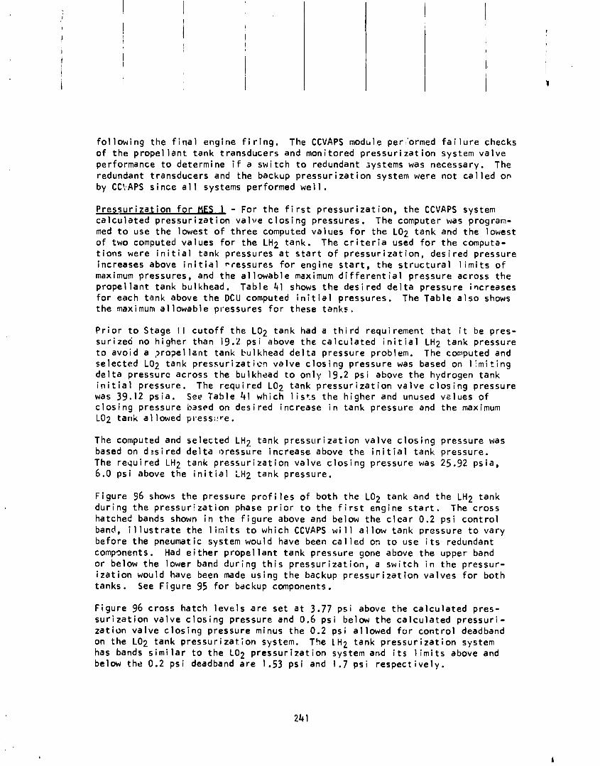
f o l l o w i n g t h e f i n a l engine f i r i n g . The CCVAPS modble perrormed f a i l u r e checks o f t h e p r o p e l l a n t tank t ransducers and moni tored p r e s s u r i z a t i o n system v a l v e performance t o determine i f a s w i t c h t o redundant systems was necessary. The redundant t ransducers and the backup p r e s s u r i z a t i o n system were n o t c a l l e d OP
by CC'iAPS s ince a l l systems performed w e l l .
P r e s s u r i z a t i o n f o r MES - For t h e f i r s t p r e s s u r i z a t i o n , t h e CCVAPS system c a l c u l a t e d p r e s s u r i z a t i o n v a l v e c 10s i ng pressures. The computer was program- med t o use t h e lowest o f t h r e e computed va lues f o r t h e LO2 tank and the lowest o f two computed va lues f o r t h e LH2 tank. The c r i t e r i a used f o r t h e computa- t i o n s were i n i t i a l tank pressures a t s t a r t o f p r e s s u r i z a t i o n , d e s i r e d pressure increases above i n i t i a l pressures f o r engine s t a r t , t h e s t r u c t u r a l l i m i t s o f maximum pressures, and t h e a l l o w a b l e maximum d i f f e r e n t i a l p ressure across t h e p r o p e l l a n t tank bulkhead. Tab le 41 shows t h e des i red d e l t a pressure increases f o r each tank above t h e D C U computed i n i t i a l p ressures . The Tab le a l s o shows t h e maximum a1 lowable pressures f o r these tanks .
P r i o r t o Stage I I c u t o f f t h e LO2 tank had a t h i r d requ i rement t h a t i t be pres- su r i zed no h ighe r than 19.2 p s i above t h e c a l c u l a t e d i n i t i a l LH2 tank pressure t o a v o i d a ,>rope l lan t tank bulkhead d e l t a pressure problem. The cowputed and se lec ted LO2 tank p r e s s u r i z a t i c n v a l v e c l o s i n g pressure was based on l l m i t i n g d e l t a pressure across the bulkhead t o o n l y 19.2 p s i above t h e hydrogen tank i n i t i a l pressure. The r e q u i r e d LO2 tank p r e s s u r i z a t i o n v a l v e c l o s i n g pressure was 39.12 p s i a . See Tab le 41 which l i s t s t h e h ighe r and unused va lues o f c l o s i n g pressure based on d e s i r e d increase i n tank pressure and t h e maximum LO2 tank a1 lowed pressi ! re.
The computed and se lec ted LH? tank p r e s s u r i z a t i o n v a l v e c l o s i n g pressure was based on d 2s i red d e l t a oressure increase above the i n i t i a l tank pressure. The r e q u i r e d LH2 tank p r e s s u r i z a t i o n v a l v e c l o s i n g pressure was 25.92 ps ia , 6.0 p s i above t h e i n i t i a l LH2 tank pressure.
F igu re 56 shows t h e pressure p r o f i l e s o f b o t h t h e LO2 tank and t h e LH2 tank d u r i n g t h e p r e s s u r i z a t i o n phase p r i o r t o t h e f i r s t engine s t a r t . The c ross hatched bands shown i n t h e f i g u r e above and below t h e c l e a r 0.2 p s i c o n t r o l band, i l l u s t r a t e t h e l i m i t s t o which CCVAPS w i l l a l l o w tank pressure t o va ry be fo re t h e pneumat i c system would have been ca l l e d on t o use i t s redundant compments. Had e i t h e r p r o p e l l a n t tank pressure gone above the upper band o r below t h e lower band d u r i n g t h i s p r e s s u r i z a t i o n , a s w i t c h i n t h e pressur - i z a t i o n would have been made u s i n g t h e backup p r e s s u r i z a t i o n va l ves f o r b o t h tanks. See F i g u r e 95 f o r backup components.
F i g u r e 96 c ross ha tch l e v e l s a r e se t a t 3.77 p s i above t h e c a l c u l a t e d pres- s u r i z a t i o n v a l v e c l o s i n g pressure and 0.6 p s i below t h e c a l c u l a t e d p r e s s u r i - z a t i o n v a l v e c l o s i n g pressure minus the 0.2 p s i a l l owed f o r c o n t r o l deadband on t h e LO2 tank p r e s s u r i z a t i o n system. The LH2 tank p r e s s u r i z a t i o n system has bands s i m i l a r t o t h e LO2 p r e s s u r i z a t i o n system and i t s 1 i m i t s above and below t h e 0.2 p s i deadband a r e 1.53 p s i and 1.7 p s i r e s p e c t i v e l y .
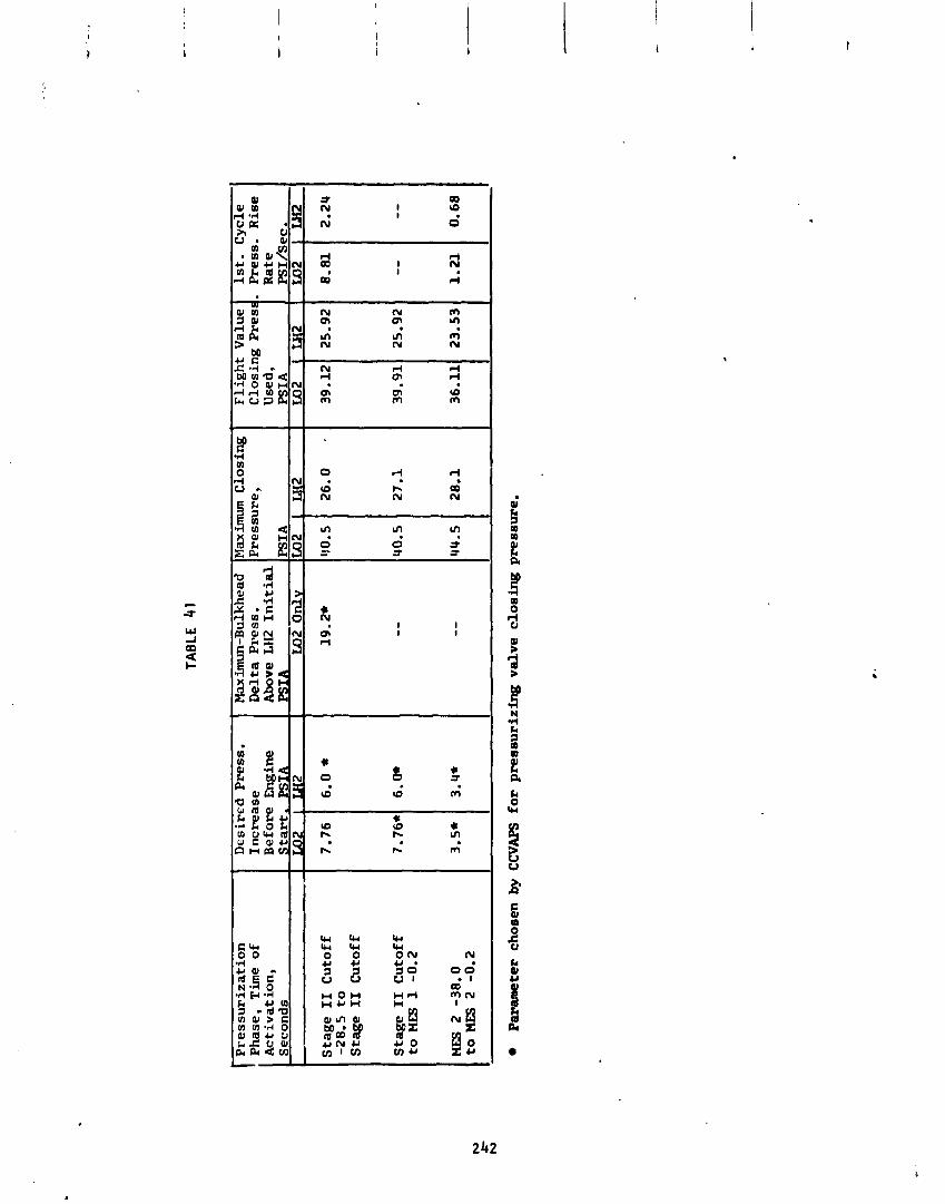
Pre
ss
uri
za
tio
n
Ph
ase,
T
ime
of
Ac
tiv
ati
on
, S
eco
nd
s
Sta
ge
I1 C
uto
ff
-28
.5
to
Sta
ge
I1
Cu
toff
Sta
ge
11 C
uto
ff
to M
B 1
-0.2
MES
2
-38
.0
to
PIE
S 2
-0.2
De
sire
d P
ress
. In
cre
ase
B
efo
re
En
gin
e S
tart
. P
SIA
I
TAB
LE
41
Max im
un
-Bu
lkh
ead
Maximum
Clo
sin
g
De
lta
PI-
ess.
P
ress
ure
,
Pa
ram
ete
r ch
ose
n b
y C
CV
APS
fo
r p
ress
uri
zin
g v
alv
e c
los
ing
pre
ssu
re.
Abo
ve LH2
In
itia
l P
SIA
L
o2 O
nlv
19.2*
Fli
gh
t V
alu
e C
losi
ng
Pre
sr
Use
d.
PS
IA
LO2
40
.5
1st.
C
ycl
e P
ress
. R
ise
R
ate
P
SIA
Lo2 -
8.81
- -
1.2
1

XME FROM MES 1 - &COWS
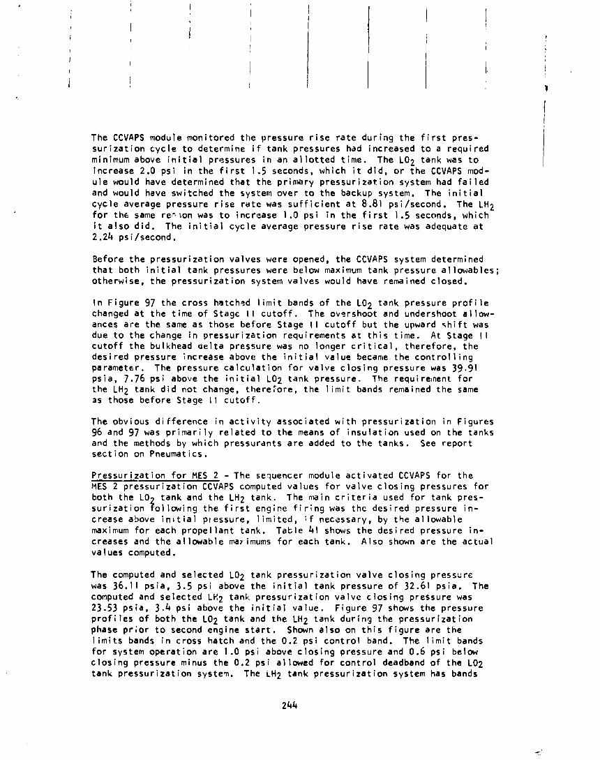
The CCVAPS module moni to red t h e pressure r i s e r a t e d u r i n g t h e f i r s t p res - s u r i z a t i o n c y c l e t o determine i f tank pressures had increased t o a r e q u i r e d minimum above i n i t i a l pressures i n an a l l o t t e d t ime . The LO2 tank was t o increase 2.0 p s i i n the f i r s t 1.5 seconds, which i t d i d , o r t h e CCVAPS mod- u l e would have determined t h a t t h e p r imary p r e s s u r i z a t i o n system had f a i l e d and would have swi tched t h e system over t o t h e backup system. The i n i t i a l c y c l e average pressure r i s e r a t e was s u f f i c i e n t a t 8.81 psi/second. The LH2 f o r t he same res7;on was t o increase I .O p s i i n t h e f i r s t 1.5 seconds, which i t a l s o d i d . The i n i t i a l c y c l e average pressure r i s e r a t e was adequate a t 2.24 ps i /second.
Before t h e p r e s s u r i z a t i o n va l ves were opened, t h e CCVAPS system determined t h a t b o t h i n i t i a l tank pressures were below maximum tank pressure a l l owab les ; o therwise, t h e p r e s s u r i z a t i o n system va lves would have remained c losed.
I n F i g u r e 97 t h e c ross hatchcd l i m i t bands o f t h e LO2 tank pressure p r o f i l e changed a t t h e t ime o f Stage I I c u t o f f . The overshoot and undershoot a l l o w - ances a r e the same as those be fo re Stage I I c u t o f f b u t t h e upward q h i f t was due t o t h e change i n p r e s s u r i z a t i o n requirements s t t h i s t ime. A t Stage I I c u t o f f t h e bulkhead d e l t a pressure was no longer c r i t i c a l , t he re fo re , t h e des i red pressgre increase above t h e i n i t i a l va lue became t h e c o n t r o l l i n g parameter. The pressure c a l c u l a t i o n f o r v a l v e c l o s i n g pressure was 39.91 ps ia , 7.76 p s i above the i n i t i a l LO2 tank pressure . The requ i re:nent f o r t he LH2 tank d i d n o t change, therecore , t h e 1 i m i t bands remained t h e same 3s those be fo re Stage I I c u t o f f .
The obvious d i f f e r e n c e i n a c t i v i t y assoc ia ted w i t h p r e s s u r i z a t i o n i n F igu res 96 and 97 was p r i m a r i l y r e l a t e d t o t h e means o f i n s u l a t i o n used on the tanks and the methods by which pressurants a r e added t o t h e tanks . See r e p o r t s e c t i o n on Pneumatics.
P r e s s u r i z a t i o n f o r MES 2 - The sequencer module a c t i v a t e d CCVAPS f o r t h e MES 2 p r e s s u r i z a t i o n CCVAPS computed va lues f o r v a l v e c l o s i n g pressures f o r bo th t h e LO tank and t h e LH2 tank . The nlain c r i t e r i a used fo; tank pres- f s u r i z a t i o n o l l o w i n g t h e f i r s t engine f i r i n g was t h e d e s i r e d pressure i n - crease above i n ~ t i a l pressure, l i m i t e d , i f necessary, by t h e a l l o w a b l e maximum f o r each prope l l a n t tank . T a t l e 41 shows t h e des i red pressure i n - creases and t h e a l l o w a b l e marimums f o r each tank. A l s o shown a r e t h e a c t u a l va lues computed.
The computed and se lec ted LO2 tank p r e s s u r i z a t i o n v a l v e c l o s i n g pressure was 36.1 1 ps ia , 3.5 p s i above the i n i t i a l tank pressure o f 32.61 ps ia . The computed and se lec ted LC2 tank p r e s s u r i z a t i o n v a l v e c l o s i n g pressure was 23.53 p s i a , 3.4 p s i above t h e i n i t i a l va lue . F i g u r e 97 shows t h e pressure p r o f i l e s o f bo th t h e LO2 tank and t h e LH2 tank d u r i n g the p r e s s u r i z a t i o n phase p r i o r t o second engine s t a r t . Shown a l s o on t h i s f i g u r e a r e t h e l i m i t s bands i n c ross ha tch and t h e 0.2 p s i c o n t r o l band. The l i m i t bands fo r system o p e r a t i o n a r e 1.0 p s i above c l o s i n g pressure and 0.6 p s i below c l o s i n g pressure minus the 0.2 p s i a l l owed f o r c o n t r o l deadband o f t h e LO2 tank p r e s s u r i z a t i o n sys tev . The iH2 tank p r e s s u r i z a t i o n system has bands
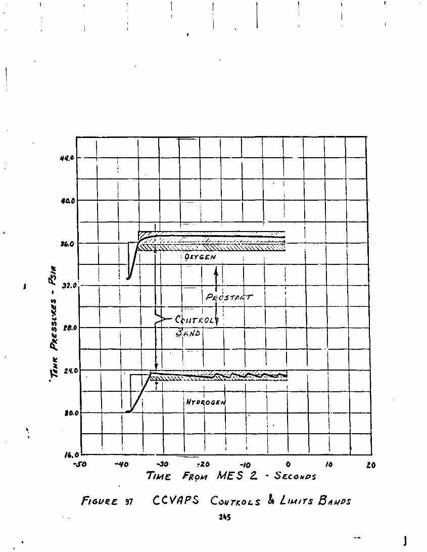
s i m i l a r t o the LO2 p ressur i za t ion system bnd i t s l i m i t s above and below the 0.2 ps i deadband a re 0.36 ps i and 0.3 ps i , resoec t i ve ly .
Pressure r i s e ra tes o f the p rope l l an t tanks were monitored by CCVAPS t o assure t ha t the LO2 tank rose 2.0 ps i i n the a l l o t t e d 2.0 seconds. The ac tua l r i s e r a t e on the f i r s t p ressur i za t ion c y c l e was s u f f i c i e n t a t 1.21 psi/second. The LH2 tank was t o r i s e 0.35 ps i i n the same a l l o t t e d 2.0 second per iod. Actual r i s e r a t e f o r t he LH2 tank was adequate a t 0.68 psi/second.
Propel iant Tank Vent ing - The vent ing mode o f the CCVAPS computer program was enabled a t the t imes l i s t e d i n Table 42. A lso shown i n the Table a re the oressure leve ls used by CCVAPS t o t r i g g e r the s t a r t o f a ven t ing sequence. Tank pressurss throughout f l igh+ were not h igh er~ough t o t r i g g e r a ven t ing rout ine. Pressures were always below the values l i s t e d i n Table 42.
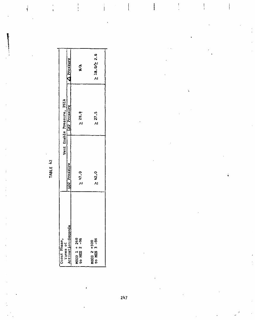
MECO 1 +
26
0
to MES
2 -96
MECO
2
+3
00
to M
ES
3 -96
A Pressure
N/A
TAB
LE 4
2
I Coast
Ph
ase
, Tunes of
Ac
tiv
at ion-Seconds
Vent
En
able
Pressure, PSIA
LO2 Pressure
1 LH2 ?ressure
I
-L
Centaur D-ITR and CSS Thermal Env i ronments and Propel l a n t Behavior
by R . F . Lacovic
Centaur and C S S Component and Environmental Temperatures
The Centaur v e h i c l e was ex tens ive ly instrumented i n order t o assess t he com- ponent thermal con t ro l and environment o f t he D-1T Centaur con f igu ra t ion . Th i s con f i gu ra t i on contained the f o l l o w i n g new o r rev ised thermal c o n t r o l ;lardware.
1. LH2 tank s idewal l r a d i a t i o n sh i e l d i ng
2. T i tan ium stub adapter.
3 . P rope l lan t feed system r a d i a t i o n sh i e ld ing .
4. Hz02 system r a d i a t i o n sh ie ld ing , heaters, and impingement sh i c l ds .
5 . Prelaunch purging and gas cond i t i on ing .
6. Pneumatic and vent system coat ings and sh ie l d i ng .
7. E l ec t r on i c packages coat ings and sh ie ld ings .
Most o f these con f i gu ra t i on changes were incorporated i n order t o make t he Centaur thermal performance s u i t a b l e f o r long space coast missions. Con- sequently, as expected the Centaur thermal performance dur ing the He l ios p o r t i o n o f the TC-2 mission was s a t i s f a c t o r y and w e l l w i t h i n prev ious D-1A Centaur f l i ght experience.
The Centaur component and environmental temperatures from l i f t o f f through spacecraf t separat ion a re l i s t e d herein. These temperatures a re compared w i t h TC-1 f l i g h t temperature l i s t i n g s t o i nd i ca te the r e p e a t a b i l i t y o f the D-1T thermal con t ro l performance du r i ng the boost phass. The loca t ions o f the sensors used i n the f o l lowing 1 i s t i n g s a re shown i n Figures 98 and 99.
Packaqe Temperatures - The e l e c t r o n i c and mechanical package temperatures a re l i s t e d i n Table 43. The temperatures a t l i f t o f f were a l l s a t i s f a c t o r i l y maintained by prelaunch cond i t i on i ng t o w e l l w i t h i n the 5 0 ' ~ - 9 0 ° ~ prelaunch l i m i t s . Dur ing the 22 minute park ing o r b i t coast the forward packages (which received sun1 i gh t ) warmed s l i g h t l y , and the a f t packages (which received no sun1 i gh t ) cooled s l i g h t l y . A l l o f the package temperatures were we1 l w i t h i n t h e i r opera t ing l i m i t s through spacecraf t separat ion. Three o f the package temperatures (CT61 IT, CT622, and C K ~ O T ) d i d show a more rap id warming trend, but these temperatures were s t i l l we1 1 below the 160 '~ opera t ing l i m i t .

ORIGIN&, PAGE t9
OF
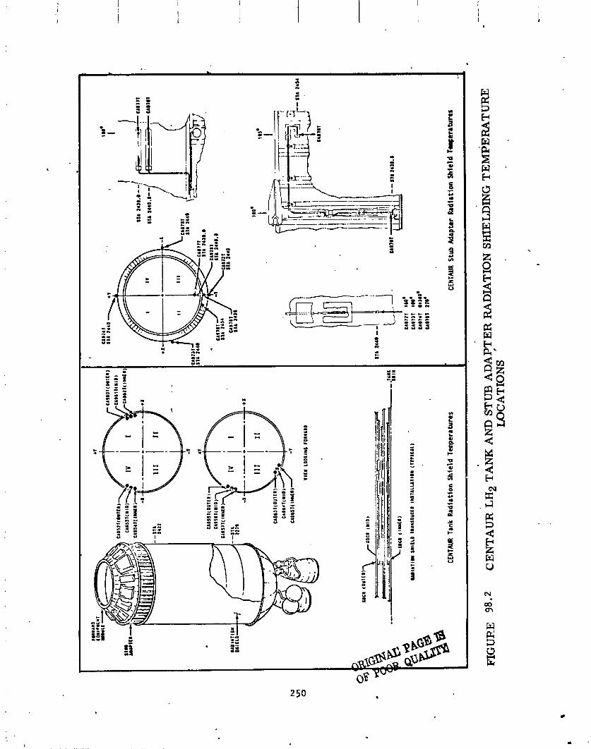
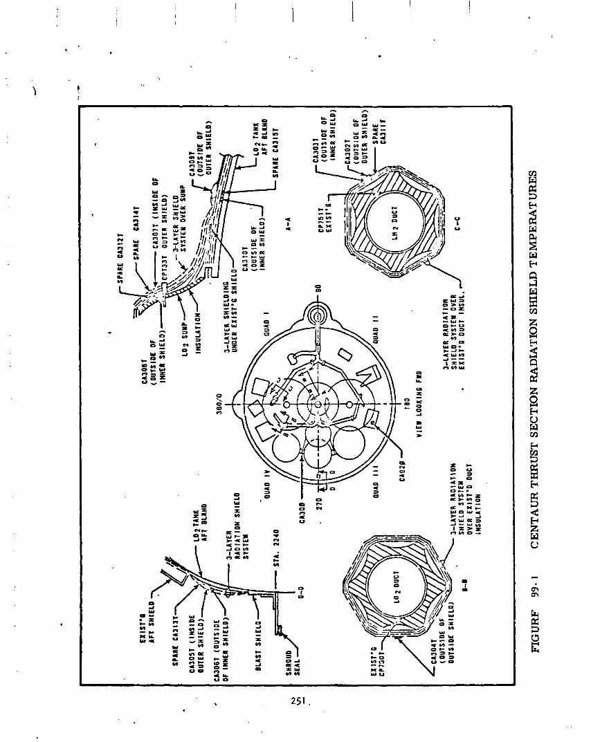
EX
IST
'I
AFT
S
NlE
LO 3
SPAR
E C
A31
3T
CA3
OST
(I
NS
IDE
O
UTER
S
HIE
LD)-
LO
AF
T 2 T
BLKH
D
AN
I r
CA3
O9T
IN
SU
LATI
ON
\$.>--
- (O
UTS
IDE
O
F
5.
-
OU
TER
SH
IELD
) C
A3D
6I
(OU
TSIO
E
3801
'0
DF
INN
ER S
HIE
LD)
3-LA
YER
S
HIE
LOIH
G
UNO
ER E
XIS
T*G
SH
IELD
CA
310T
BLA
ST
SH
IELD
STA.
2
24
0
SHRO
UD
A-A
SE
AL
CA
300
CP
75 1
T f
CA
303T
-.
..--
. (O
UTS
IDE
O
F
(OU
TSID
E
OF
LL
O
TANK
IN
NER
SH
IELD
) A
FI
OLK
HD
SPAR
E C
A31
5T
Lx
's
'-'l
/ IN
NER
SH
IELD
)
\\
u
QUA
D I I I
PUAD
I I
CA
92U
18
0
VIE
W
LOO
KIN
G F
WD
&LAY
ER
RA
DIA
TIO
N
3-LA
YER
R
AO
IAT
IOII
S
HIE
LD S
YSTE
M O
VER
mm
S
HIE
LD S
YSTE
M
. E
XIS
T'G
DU
CT
INS
UL.
ID--
OVE
R E
XIS
T'D
DU
CT
INS
ULA
TIO
N
FIG
UR
F 99- 1
CE
NT
AU
R T
HR
UST
SE
CT
ION
RA
DIA
'I'I
ON
SH
IEL
D T
EM
PE
RA
TU
RE
S
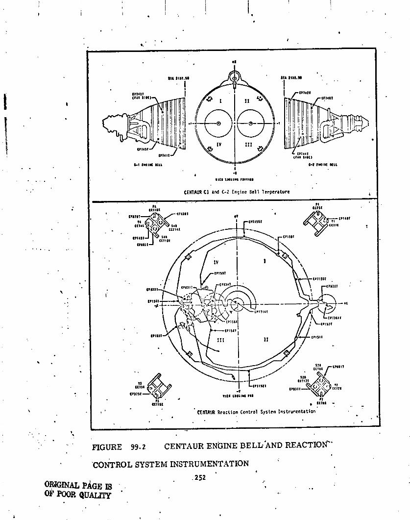
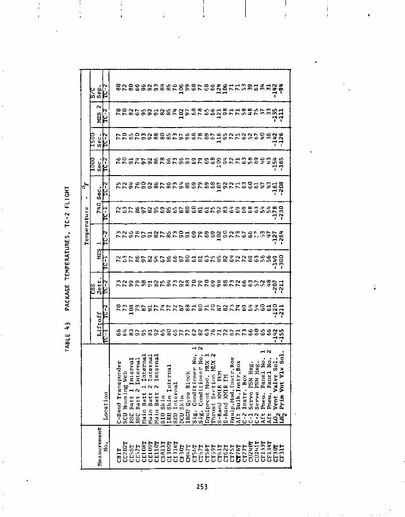
TAB
LE
43
PAC
KA
GE
TEM
PE
RA
TUR
ES
, T
C-2
F
LIG
HT
I T
em
pe
ratu
re
- "F
I C
SS
I I
S7C
Sep
. Tc-2
8 0
72
8
0
6 6
9 6
9 2
9 3
84
8
5 7
6
10
6
99
6
8
7 7 6 8
6 6
12
4
lo6
7
1
71
5 3
39
6
1
34
3
1
,14
2
-94.
Lii
In
T
Mea
sure
men
t N
o.
CB
lT
CC
202T
C
E56
T
C E
5 7T
C
E10
8T
CE
109T
C
Ell
OT
CS
8ll
T
CI 3
00T
C
I 31
6T
CK 3
0T
CML4
7T
CT
56T
C
T57
T
CT
SRT
C
T39
T
CT
GlT
C
T62
T
CT
75T
C
T7
6T
CT
77T
C
1J2
4 0T
C
U2U
lT
CF
133T
C
F13
4T
CF
30T
C
F 31
T
Lo
ca
t io
n
C-B
and
Tra
nsp
on
de
r SC
U
Ho
usi
ng
Web
RSC
B
att
1 I
nte
rna
l R
SC
Ba
tt 2
In
tern
al
blai
n B
att
1 I
nte
rna
l bl
ain
Ba
tt 2
In
tern
al
Mai
n B
att
2
Inte
rna
l S
IU S
kin
IR
U S
kin
In
tern
al
SEU
In
tern
al
DCU
Sk
in
IRG
U G
yro
Blo
ck
S
ig.
Co
nd
itio
ne
r N
o.
1
Sig
. C
on
dit
ion
er
No.
2
Eq
uip
men
t Pl
od.
EfllX
1
Th
rust
Sc-
c7ti
on
EKJX
2
S-B
and
XM
IR PCM
S-B
and
XElI
R FE
I E
qu
ip.E
lod
.In
str.
Bo
x
Aft
Bu
lk. I
ns
tr .B
ox
C-2
In
str
. B
ox
C-1
S
erv
o PSN H
sg.
C-2
Servo PSN
Hsg
. A
ft P
neu
. P
an
el
No.
1
Af
t P
neu
. P
an
el
No.
2
M2
Ve
nt
Va
lve
So
l.
LH2
Pri
m V
nt
Vlv
So
l.

S t r u c t u r a l Temperatures - The var ious Centaur s t r u c t u r a l temperatures a re 1 i s t e d i n Table 44. The equipment module temperatures remained near ly con- s t an t once the temperatures had s t a b i l i z e d a t the end o f the ascent vent ing. The temperatures o f the new t i t an i um stub adapter a t var ious times through- out the f l i g h t a re shown i n F igure 100. These temperature p r o f i l e s compared w e l l w i t h the prelaunch p red i c t i ons , i n d i c a t i n g t h a t the p red ic ted heat t r a n s f e r r a t e t o the LH2 tank forward r i n g had been obtained. The tempera- t u r e o f the ins ide surfaces o f the payload area o f the Centaur Standard Shroud a re shown i n F igure 101. As shown i n t h i s f i gu re , the temperatures were f a r below the 1 3 5 ~ ~ l i m i t , even w i t h the 50 second increase i n t ime t o shroud j e t t i s o n .
Propuls ion System and Hz02 System Temperatures - The Centaur RLIO, propel - l a n t feed, and Hz02 system temperatures a re l i s t e d i n Tables 45 and 46. A l l o f the temperatures were s a t i s f a c t o r y . The p rope l l an t feed system tempera- tu res were c lose t o t he nominal expected f o r the r a d i a t i o n sh ie lded con f i g - u r a t i o n . The engine b e l l and pump temperatures were c lose t o the maximum pred ic ted leve ls as a r e s u l t o f Hz02 engine exhaust impingement and s o l a r heat ing. The Hz02 system temperatures were a1 l between 8 7 O ~ and 100 '~ ex- cept f o r a few l oca l i zed hot spots t h a t received H202 engine exhaust i m - pingement (such as ~ ~ 1 5 9 ~ ) o r heat soakback from the boost pump tu rb i ne (such as ~P361T) . The heaters and r a d i a t i o n s h i e l d boots maintained good thermal con t ro l o f t he l i nes . The impingement heat ing e f f e c t s dur ing the continuous 80 second Hz02 engine f i r i n g pr imary sequence dur ing boost was acceptable and about the same as f o r TC-1. The C - l LH? pump housing showed the most marked e f f e c t s o f the impiigement heat ing and i s shown i n F igure 102.
Radia t ion Shie ld Temperatures - The Centaur LH2 tank s idewal l , forward bu lk - head, sump, feed1 ines, and LO2 tank a f t bulkhead r a d i a t i o n s h i e l d system temperatures a re 1 i s t e d i n Tables 47 and 48. The thermal performance o f these systems was as expected. The temperatures a t l i f t o f f were c lose t o previous TC-1 f l i g h t and TCD t e s t experiences. Dur ing the boost, the rap id ven t ing r e s u l t s i n a decrease i n s h i e l d temperatures. A f t e r CSS j e t t i s o n , the s h i e l d temperatures begin t o increase t o achieve e q u i l i b r i u m w i t h t h e i r space environment r e s u l t i n g i n la rge temperature grad ients through the sh ie ld ing . These temperature increases, which cont inued through spacecraf t separat ion, a re i n good agreement w i t h ca lo r imete r t e s t i n g o f the she i l d i ng which showed t h a t over one hour i s requ i red f o r the sh ie l d i ng t o reach a steady s t a t e temperature grad ient .
The LO2 tank a f t bulkhead d i d not con ta in the th ree layer r a d i a t i o n sh i e l d - ing as i t d i d f o r TC-I ( the schedul ing f o r the TC-2 recon f i gu ra t i on d i d not ~3rrnit i t ) . T t l i s aecojrtts f o r t he la rge d i f f e r e n c e s between TC-1 and TC-2 temperatures i n t h i s area.
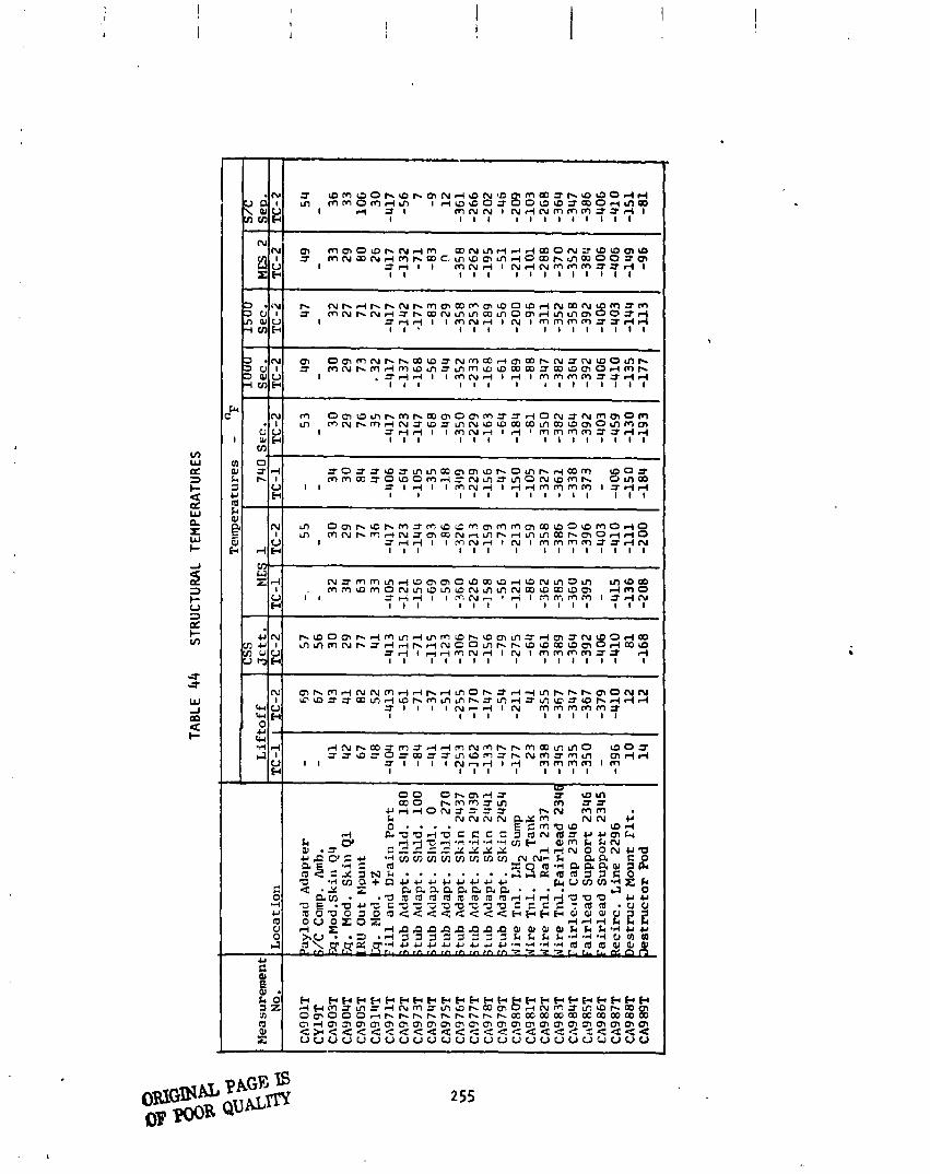
4 d ~ b m 3 m 3 d d m ~ m h h m C 0 ~ 7 m O -03
I ~ z ~ z O t r n = t m a m = f b N m 3 m m m d d
3 I I I I ~ 7 7 I 7 m m m m I m I I I I I I

. . . . . . . .
. . . . . . - . . ' ... - ---- * F; . - - . --- - . .------ - .----. .-.-.- --- I:, . . - . ---. pr- --+- - ----- - -- -
. * .--Cf---. --.. - - --- -. ..*--.-. --.* .
. . ...... --- ........... ---. . . . . . _ ... ....... .--. . , . .-c- . - b - a
I " t t " 6 . ' - ' - '
- 4 . .... c.. . , , , ...........
; . . i . .-....
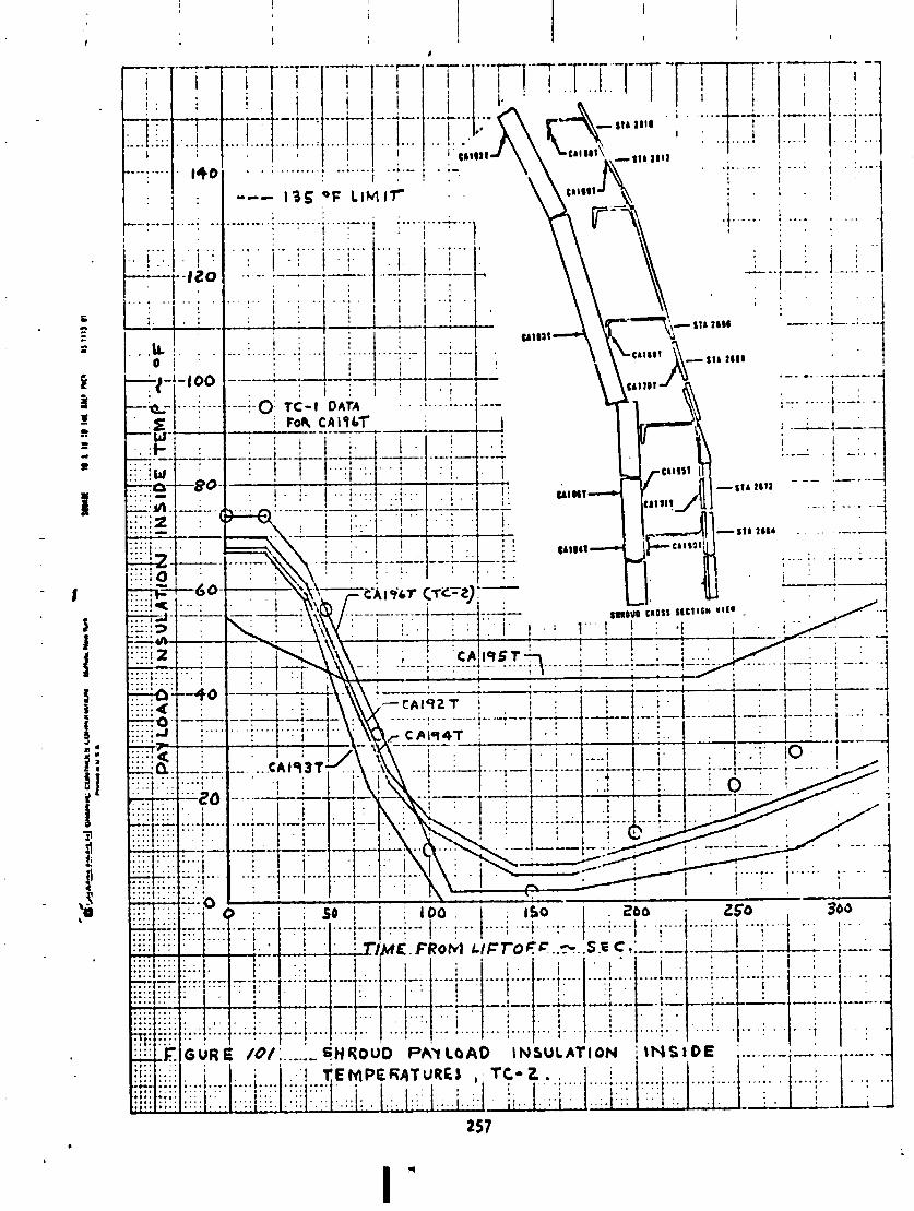

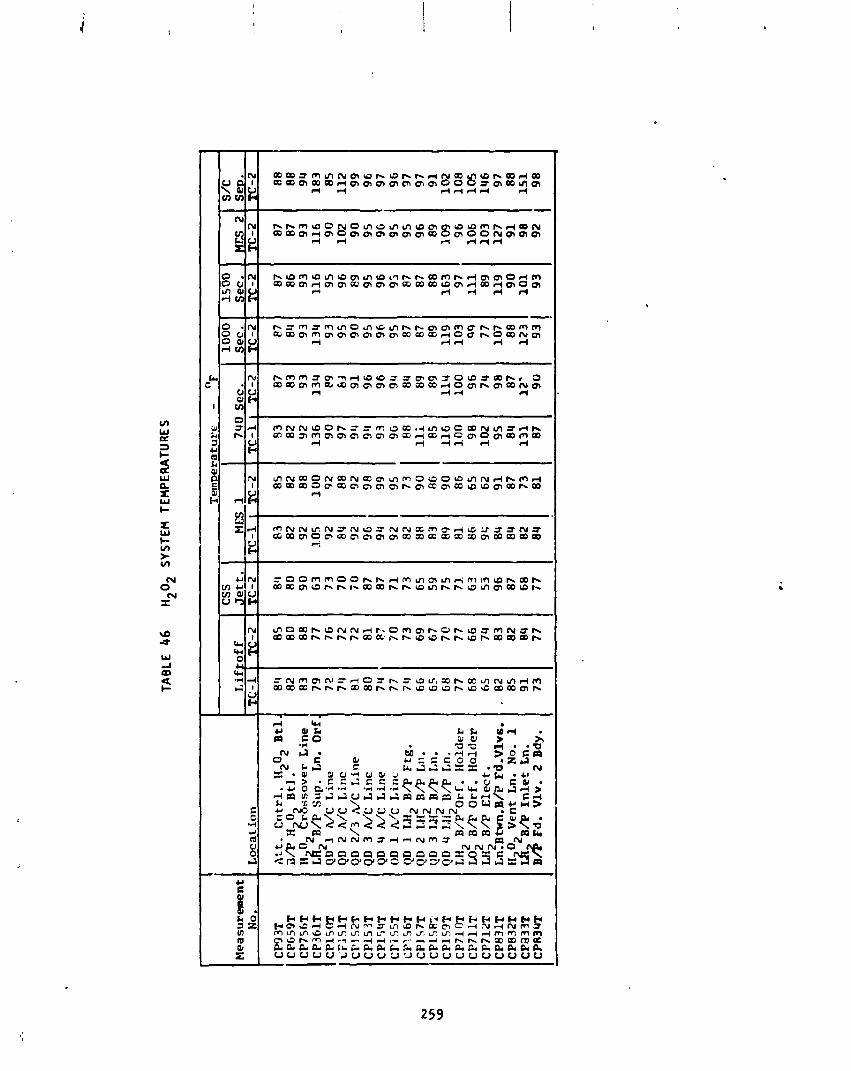
TAB
LE 4
6 H
202
SYST
EM T
EMPE
RA
TUR
ES
Mea
sure
men
t N
o.
CP9
3T
C
P65
9T
CP
756T
C
P36
1T
CP
l5O
r iF
l51
T
CF152T
CP
15 31
T C
PI 5
UT
Cl'i
55T
CPl56T
CP
157T
C
P.1
587
CP
159T
C
P7l
OT
C
P71
1T
CP
712T
C
P83
1T
CP
832T
cp
a 3 3T
C
P83
4T
t I
css
Att
. C
ntr
l.
N2o
2 Bt
l 3/
P
H
o2 B
tl.
H
O2
Zro
sso
ve
r Line
LR~ B/P
su
p.
~n
.
Orf
Q
D I
A&
Line
QD
2 A
/C
Lin
e
QD
2/3
,Z/C Line
QD 3
n/C
L
ine
Q
D
4 A,&
L
ine
OD
1 h
/C L
inc
QD
1
Llf
2 B
/P F
tg.
QD
2 LH
2 B
/P L
n.
QD
3 LH
2 B
/P L
n.
QD
4 LJ
iZ B
/P L
n.
LH2 B/P
Orf
. H
old
er
M2
B/F
Orf
. It
old
er
LH2
B/P
Ele
ct.
Ln.Btun.B/P
Fd.Vlv6.
H 0
Ven
t L
n.
No.
1
~4 'B/P
I
nle
t ~n.
B/$
Fd
. V
lv.
2 Bdy.
Lo
ca
t io
n
Se
c.
Se
c.
TC
-2
TC
-2
Lif
toff
T
C-1
I
TC
-2
I
- -
Je
tt.
TC
-2

'
L ' i . . . 2 :
. . u ) '

o m m w a m w a ~ a ~ m N N ~ 3 0 z r m m = m m f m ~ m a z - I
rum 1 1 I 1 I I I I I
." a m d b m z r z t o m d a w ~ z m d s m 3 m m I O ~ z z r m h d w m d Y ~ Z I N d N P m d m N I NON
zt+ I 1 1 . 1 1 I 1 I l l
d ~ ~ ~ ~ u ~ ~ r n r n m m , m m r - b b m ~ N N N N N N N ~ - ~ - ~ - ~ - ~ f f f m r U 3 - 3 3 3 r N N N N N N N N N N 3 N N N N N N N N N N N N NNNN
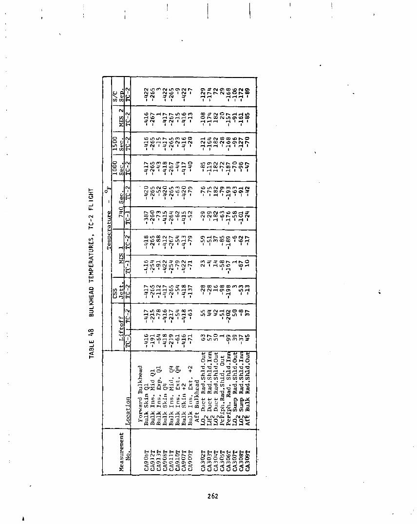
Measurement
No.
TAB
LE 4
8 B
ULK
HEA
D T
EM
PE
RA
TUR
ES
, T
C-2
F
LIG
HT
CSS
Jett.
TC -2
-417
-265
-112
-417
-265
-5 4
-418
-137
-28
-28
16
-98
-19 8 3
-5 3
-13 -
Locat ion
Forward Bulkhead
Bulk Skin Q1
Bulk Ins. Mid Q1
Bulk Ins. Exp. Ql
Bulk Skin 44
Bulk Ins. Mid. 44
Bulk Ins.
Ex
t. 44
Bulk Skin +2
Bulk 111s. Ext. +2
Aft Bulkhead
LO2 Duct Rad.Shld.Out
LH2 Duct Rad.Shld.Inn
LO2 Duct Rad.Shld.Out
Periph.Rad. Shld. Out
Periph. Rad. Shld.1~
LO2 Sump Rad.Shld.Out
LO Sump Rad.Shld.Inn
~f
z
Bulk Rad .Shld.Out
Tempe
1000
Sec.
TC-2
-417
-265
-43
-418
-267
-44
-417
-40
- 85
-119
182
-7 2
-187
-7 0
-96
- 47
Liftoff
15 00
Sec.
TC -2
-416
-265
-15
-417
-265
-23
-416
-2 0
-121
-164
182
-2 8
-168
-96
-127
-7 0
7
TC-1
-416
-191
-64
-418
-219
-61
-416
-71
63
57
50
1
-99 39
-37
45
MES 2
TC-2
-416
-267
1
-417
-267
-15
-416
-13
-108
-174
182
2 0
-157
-9 1
-161
-85
-
TC-2
-417
-215
-78
-416
-217
-54
-418
-63
55
4 4
4 2
-51
-202
5 0 -8
37

Centaur Prope l lan t Manaqement
by R . F . Lacovic
Boost Phase Prope l lan t Behavior - The LO2 ven t ing t h a t occurred d ~ r i n g the TC-1 boost was aqain observed dur inq the TC-2 boost. There were i nd i ca t i ons o f 1 iqu i d vent i ng from T+45 t o ~+75-seconds, when the LO2 tank vent va lve operat ion r e f l e c t s t he decreasing ambient pressure, and from T+285 t o T+300 seconds, when t h e hyd ros ta t i c head i s l o s t a t Stage I shutdown. I t appears t h a t s i m i l a r LO2 ven t ing w i l l cont inue t o occur as long as t he present TC tank ing leve ls , sequencing, and acce le ra t ions a re maintained.
I t i s probable t h a t l i q u i d hydrogen ven t ing a l s o occurred. The LH2 tank 1 i q u i d h a p o r sensor CM241~ located a t t he top o f t h e tank went wet a t SRM j e t t i s o n , as a r e s u l t o f t h e decrease i n veh i c l e acce le ra t ion . Since the LH2 pr imary vent va lve i s f l ow ing f u l l a t t h i s t ime, i t i s l i k e l y t h a t some LH2 was vented. CM241X ind ica ted wet f o r on ly 2 seconds, e compared w i t h 30 seconds a t SRM j e t t i s o n dur ing the TC-I f l i g h t .
Se t t led Coast Propel l a n t Behavior - The TC-2 f l i ght provided the f i r s t demonstration and v e r i f i c a t i o n of t he s e t t l e d coast p rope l l an t management techniques f o r the D-1T Centaur con f igu ra t ion . The new hardware and se- quenc ing associated w i t h these techniques a re summari zed i n Table 49. The r e s u l t i n g p rope l l an t management d i f fe rences , as compared w i t h t he D-1A Centaur con f igu ra t ion , a re a l s o presented i n t h i s tab le . All o f these d i f fe rences were requi red as a r e s u l t o f t he increased propel l a n t load ing and the reduced acce le ra t ion l e v e l s associated w i t h D-IT Centaur.
The new, o r revised, f l i g h t hardware cons is ted o f :
1. An LH2 tank hel ium energy d i s s i p a t o r t o reduce the impact o f the pres- surant on the l i q u i d surface.
2. A per fo ra ted tube i n the LO2 tank t o i n j e c t hel ium press; . beneath the l i q u i d surface t o reduce he l ium consumption.
3 . A r e v i s i o n o f the LH2 boost pump v o l u t e bleed t o r e d i r e c t the f low away from the l i q u i d surface.
4. A r e l o c a t i o n o f the LH2 tank s losh b a f f l e t o i t s most forward l oca t i on t o prov ide p rope l l an t damping.
5. The incorpora t ion o f LH2 tank s idewal l r a d i a t i o n sh i e l d i ng i n o rder t o e l iminate the need f o r LH2 tank ven t ing throughout the coast .
The behavior o f the p rope l lan ts throughout the coast was as fo l lows . A t MECO 1 t he l i q u i d l eve l i n the LH2 tank was about 10 inches above the f o r - ward s losh b a f f l e . A t t h i s l c ? t i o n , the b a f f l e provided on ly 40 percent
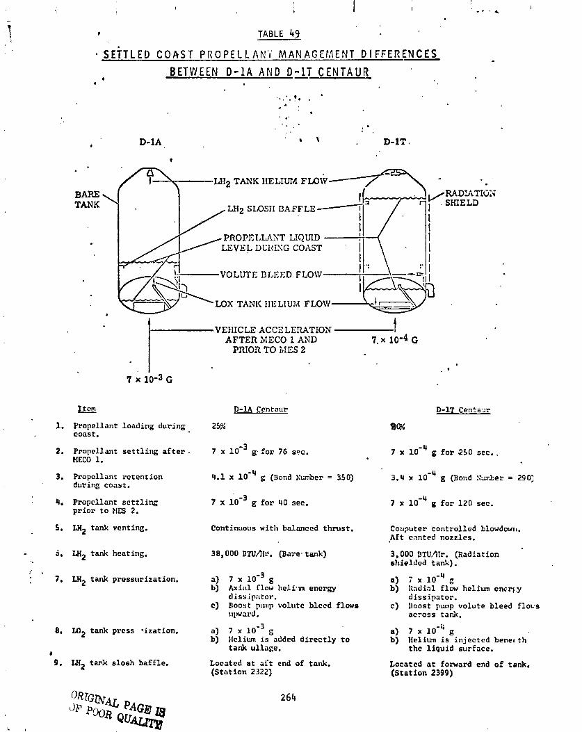
TABLE 49
S E ~ T L E D C O A S T P R O P E L L A F ! ' i MANAGErJENT D I F F E R E N C E S B E T W E E N D - 1 A A N D DAT C E N T A U R *
0
LH2 TANK HELIUM FLOW
LH2 SLOSII BAFFLE-
PROPELLANT LIQUID LEVEL DL'RISG COAST
LOX TANK HELIUM FLOW
I, VEHICLE ACCE LE!UTION
AFTER MECO 1 ASD f
7. x 10-4 G PRIOR TO hIES 2
0
7 x 10⁻³ G
BARE TANK
1-
1. Propcllant loading during coast.
D- lA Centaur
25%
7 x loe3 g. f o r 76 sec. 7 x 10" g f o r 250 sec.. 2. Propellant s e t t l i n g a f t e r . EIECO 1.
4.1 x 10'~ g (Bond Kunber = 350) 3.4 x 10'' g (Bond ::u&er = 290) 3. Propcllant r e t en t ion during coast.
4. h o p e l l a n t s e t t l i n g p r i o r t o MCS 2.
7 x 10'~ g f o r 40 sec. 7 x 10" g f o r 120 sec.
S. LH2 tank venting. Continuous w i t h b d m c c d t h rus t . Coaputer control led blowdow~. Aft canted nozzles.
3,000 DTU/IIr. (Radiation shie lded tank).
6 , % tank heating, 38,000 Dl'U/IIi6. (Bare tank)
:' L - 7. LHZ tank pressur izat ion. 01 7 b) A x i d flow hc1i:un energy
d i s s ipa to r . c) noost p ~ p volute bleed flows
llpwal~d.
a) i x 1 0 ' " g b) Radial flow heliurn cnc r ly
d i s s ipa to r . c) Doost punp volute bleed flo!:s
ac ross tank.
8. LO2 tank press *ization. a) 7 x 1 0 ' ~ g b) 1Ielium is added d i r e c t l y t o
tank ullage.
a) 7 x 1 0 ' ~ g b) Helium i s in jected benei t h
t h e l i q u i d surface. a 9. LH2 t a ~ k s losh baffle. Located a t a f t end of tank.
(Sta t ion 2322) Located a t fomard end o f tank. (Sta t ion 2399)
o f i t s optimum e f fec t i veness i n damping LH2 s losh ( f o r a l i q u i d leve l 3 inches above the b a f f l e , the e f fec t i veness i s 100 percent ) . The LH2 behavior a t MECO 1 i s i nd ica ted i n F igure 103. A t 12 seconds a f t e r MECO 1 a large splash o f LH2 had t rave led t o t he top o f the tank as ind ica ted by the a c t i v a t i o n s o f the fou r uppermost 1 iquid/vapor sensors. The splash was a l s o ind ica ted by the three f o r - ward bulkhead s k i n temperatures (CA906T, CAg071, and CA908T a t S t a t i o n 2472) which decreased t o LH2 temperature a t s i x seconds a f t e r MECO 1. A t MECO 1 + 30 seconds the LH2 began t o fa1 1 away from the top o f the tank as ind icated by the d ry ing of ~ ~ 2 4 1 ~ . A t MECO 1 + 34 seconds the LH2 began t o fa1 1 away from the top o f the tank as ind ica ted by the d r y i ng o f CM241X. A t MECO 1 + 34 seconds ~ ~ 2 4 2 X ( loca ted 12 inches below ~ ~ 2 4 1 ~ ) went wet unt i 1 MECO 1 + 46 seconds, thus i n d i c a t i n g the passage o f the descending LH2. An ex t r apo la t i on o f t h i s LH2 descent r a t e ind ica tes t h a t i t would take about 20 a d d i t i o n a l seconds f o r the descending LH2 t o reach the l i q u i d sur face a t S t a t i o n 2418.
A f t e r t h i s i n i t i a l splash o f LH2, the re was no f u r t h e r i n d i c a t i o n o f LH2 mo- t i o n through MES 2. However, s ince the nearest l i qu id /vapor sensors t o t h e 1 i qu i d surface were 8 inches away, i t i s poss ib le f o r small LH2 sur face mo- t i o n s t o occur w i thou t being detected.
The p rope l l an t management techniques se lected fo r D-1T Centaur s e t t l e d coast per iods have been v e r i f i e d . The 250 seconds o f 45 engine f i r i n g a f t e r MECO was more than s u f f i c i e n t t o con t ro l the p rope l l an t motion a t MECO, even w i t h t he non-optimum s losh b a f f l e loca t ion . The t r a n s i t i o n t o the 2s engine f i r : n g p rope l l an t r e ten t i on mode a t MECO 1 + 250 seconds occurred w i t h no i nd i ca t i ons o f propel l a n t motion. There were a l s o ,-00 i nd i ca t i ons o f propel l a n t d i s t u r - bances dur ing the 120 second 4s engine f i r i n g per iod p r i o r t o MES 2, which included the LH2 tank vent and p ressu r i za t i on per iod and the boost pump dead- head per iod.
Se t t l ed Coast Prope l lan t Tank Pressures - The LO2 tank and LH2 tank pressure h i s t o r i e s throuqhout the s e t t l e d coast per iod a re shown i n F iqure 104. Both the LO2 and tank pressures increased sharp ly f o r 20 seconds f o l l o w i n g MECO 1 (1.3 p s i d LO2 tank, 0.5 ps i d LH2 tank). Th i s sharp pressure increase i s a t t r i b u t e d p a r t l y t o the release o f energy a t MECO 1 as a r e s u l t o f the head loss, and p a r t l y t o the a d d i t i o n o f energy r e s u l t i n g from the r e c i r c u l a - t i o n and vo lu te bleed f lows dur ing the post-MECO boost pump sp in down. These energies probably con t r ibu ted t o the post-MECO p rope l l an t splashing. Once the tank pressures s t a b i l i z e d , the pressures then increased s low ly as a r e s u l t o f the inc iden t space heat ing. The LO2 tank pressure increased 0.5 p s i d dur- i ng the coast from MECO 1 + 20 t o MECO 1 + 450 seconds, and zero ps i d from
MECO 1 + 450 seconds t o MES 2. Th is pressure r i s e was as expected, s ince the p rope l l an t load ing was la rge enough t o absorb a l l o f the space heat ing i n t o the l iqu id . The LH2 tank pressure increased on ly 1.2 ps i d from MECO 1 + 20 seconds t o MES 2. The new LH2 tank s idewal l r a d i a t i o n sh i e l d i ng reduced the pressure r i s e r a t e by more than an order o f magnitude i n comparison w i t h the D-1A Centaur LH2 tank pressure r i s e ra te . As a r e s u l t o f the small pressure iw rease , no LH2 tank ven t ing was requi red a t any t ime from MECO 1 t o the s t a r t o f tank p ressu r i za t i on .
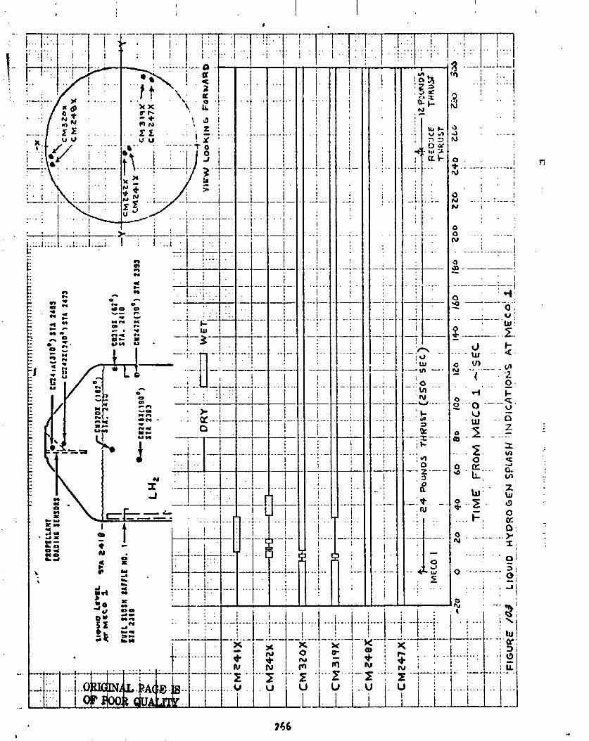
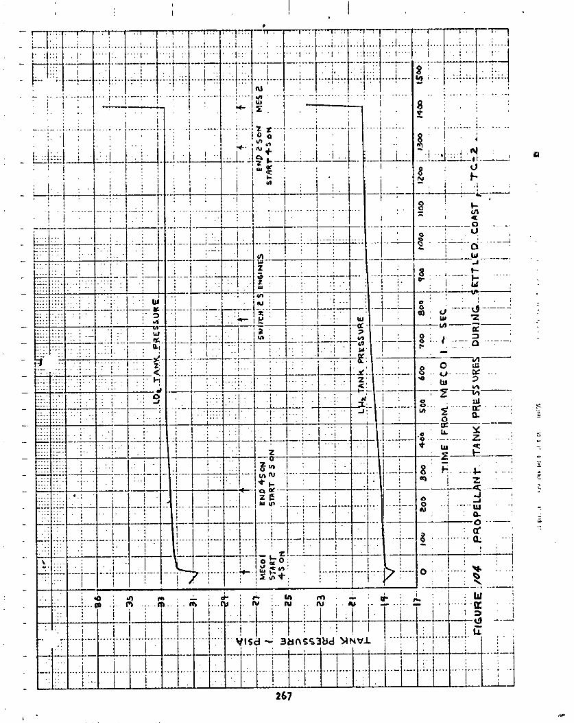

Tank Pressur i t a t ion a t MES 2 - Many o f the p rope l l an t management hardware changes f o r 0-1T Centaur were incorporated i n order t o reduce the hel ium con- sumption dur ing pre-MES 2 p ressur i za t ion . The p rox im i ty o f the 1 i q u i d surface and the low veh i c l e acce le ra t ion a t t h i s t ime can r e s u l t i n l i q u i d sp lash ing dur ing p ressur i t a t ion t h a t g r e a t l y increases the he1 i um consumed. The new LH2 tank hel ium energy d i ss i pa to r was designed t o reduce sp lash ing by adding the he l ium t o the tank a t low v e l o c i t i e s i n a r a d i a l d i r e c t i o n . The new per fo ra ted tube (bubbler) used f o r p ressu r i z i ng the LO2 tank, by i n j e c t ~ n g hel ium beneath the l i q u i d surface, g rea t l y reduces hel ium consumption by vapor i z ing oxygen.
The LO2 tank and LH2 tank pressure h i s t o r i e s dur ing pre-MES 2 p ressu r i za t i on a re shown i n F igure 105. (The p rope l l an t sa tu ra t i on pressures a re a l s o shown i n F igure 105 t o g ive an i n d i c a t i o n o f the boost pump NPSH.) The quan t i t y o f he1 ium requi red t o achieve the 4 p s i d increase i n the LO2 tank was 0.14 pounds. Th i s quan t i t y compares t o a p red ic ted quan t i t y o f 0.68 pounds i f the e x i s t i n g D-1A Centaur mode o f p ressu r i za t i on through the LO2 tank standpipe had been used. The LO2 tank bubbler performed as expected, r e s u l t i n g i n a rap id and s tab le LO2 tank p ressur i za t ion r e q u i r i n g on ly small quan t i t i e s o f pressurant. The quan t i t y o f hel ium requi red t o achieve the 3.5 p s i d increase i n the LH2 tank was 0.76 pounds. Th i s compares t o a nominal p r e f l i g h t p red ic ted quan t i t y o f 0.81 pounds assuming t h a t no LH2 sp lash ing occurred dur ing the pressur iza- t i o n . The new hel ium energy d i s s i p a t o r appd re~ i t l y worked a; expected.
Post-MECO 2 L i qu id Hydroqen Behavior - A t MECO 2 the l i q u i d l eve l i n the LH2 tank was about one inch below the a f t s losh b a f f l e . The LH2 motion a f t e r MECO 2 i s ind ica ted i n F igure 106 which shows the l i qu id /vapor sensor a c t i - v a t i o n t imes. For 72 seconds a f t e r MECO 2 the Centaur was i n a zero g coast mode. Dur ing t h i s t ime p a r t o f t he LH2 moved t o the top o f the tank. As a r e s u l t o f MECO disturbances, the re lease o f s tored energy from the head loss, and the vo lu te bleed and r e c i r c u l a t i o n f lows dur ing the post-MECO boost pump sp in down, sensor C~241X a t the top o f the tank went wet a t MECO 2 + 63 sec- onds. A t MECO 2 + 72 seconds the he l ium r e t r o t h r u s t was ac t i va ted which provided a t h r u s t i n the a f t d i r e c t i o n ranging from 300 pounds t o 10 pounds over a 10 second per iod . Th i s t h rus t moved the bu lk o f the LH2 forward thus we t t i ng the fo r . la rd sensors and leavir lg the a f t sensors d ry , except fo r a f i l l e t o f l i q u i d around the a f t s losh b a f f l e . Th i s l i qu id /vapor con f igu ra - t i o n remained throughout :he f o l l o w i n g zero g coast .
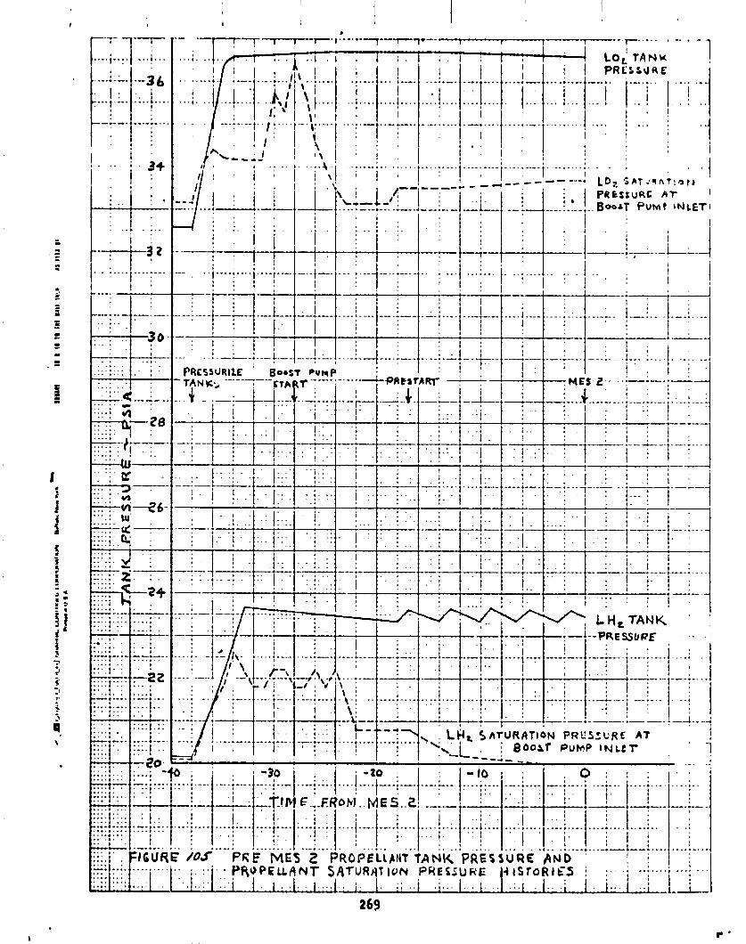
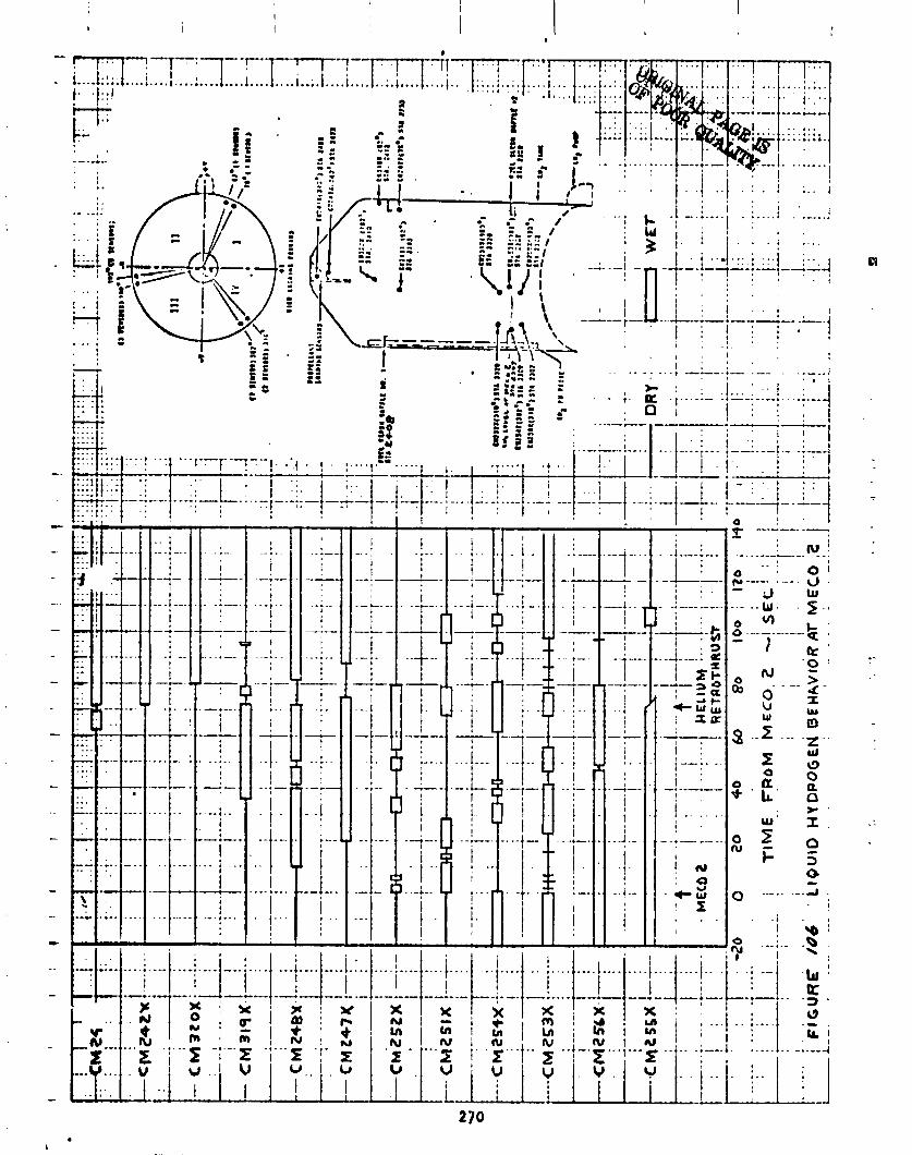
id-
E l e c t r i c a l / E l e c t r o n i c Svstems
E l e c t r i c a l Power Systems
by J. B. Nechvatal
The e l e c t r i c a l system cons is ts o f a power changeover sw i tch ( i n t e g r a l p a r t o f the Sequence Contro l u n i t ) , th ree main b a t t e r i e s ( in terconnected by a diode assembly), two independent range sa fe ty command ( veh i c l e des t ruc t ) b s t t e r ies, and a s i ng le 400 Hz i nve r t e r ( the i nve r t e r i s an i n t e g r a l p a r t o f the Servo l nver te r u n i t ) . The perfornance o f the Centaur e l e c t r i c a l system was s a t i s f a c t o r y and no un- expected system cu r ren t demands were noted dur ing the programmed f l i g h t per iod. T rans fe r o f the e l e c t r i c a l load from ex te rna l power t o t he i n t e rna l b a t t e r i e s was accomplished a t minus 111.2 seconds by the changeover swi tch and normal t r ans fe r c h a r a c t e r i s t i c s were observed.
The th ree Centaur busses were suppl ied by separate 150 ampere-hour ba t t e r i es , interconnected by a diode assembly. The diode assembly permi t ted Bus P r : . L ba t t e r y t o supply Bus No. 1 and Bus No. 3 power dur ing surge loads and a t poss ib le de le t i on o f capac i t y o f Bus No. 1 and/or Bus No. 3 ba t t e r y dur ing a long/extendtd f l i g h t sequence. (Bus No. 2 ba t t e r y has the lowest programmed power d ra in . )
A t 1 i f t o f f , the three (3) main b a t t e r y bus vo l tbges were 28.5, 29.0, and 28.7 v o l t s f o r Bus No. 1, No. 2 and No. 3 b a t t e r i e s respec t i ve ly . Ba t te ry data a re shown i n Table 50.
Bus No. 1 ba t t e r y vo l tage was r e l a t i v e l y constant throughout t he f l i g h t , re- f l e c t i n g on ly t he Bus No. 2 ba t t e r y v a r i a t i o n s . Bus No. 2 ba t t e r y vo l tage r e f l e c t e d the e f f e c t s o f the Bus No. 3 f l i g h t cu r ren t demands, bu t remained f a i r l y constant dur ing the programmed f l i g h t . Bus No. 3 ba t t e r y vo l tage re- sponded normal ly t o l eve l changes r e s u l t i n g from the a p p l i c a t i o n and removal o f electro-mechanical loads per the programmed f l i g h t sequence. A ION o f 27.5 v o l t s was observed dur ing Main Engine S t a r t Sequence No. 1 (a ~ e r i o d o f maxi mum load) . The t o t a l Centaur cu r ren t (as measured y CETIC) was 45.0 amperes a t 1 i f t o f f . Peak cur ren ts were recorded dur ing the Main Engine S t a r t Sequences, w i t h a maximum peak a t Main Engine S t a r t No. 1 . The per ioas 3f maximum and minimum cur ren t leve ls r e l a t i v e t o Mark Events a re shown i n Table 51. The f l i g h t cu r ren t p r o f i l e was cons is ten t w i t h values recorded dur ing p r e f l i g h t t e s t s and no anorna l i 2s were observed.
Bat tery cu r ren t values w i t h respect t o f l i g k t programmed events a re shown i n Table 51.
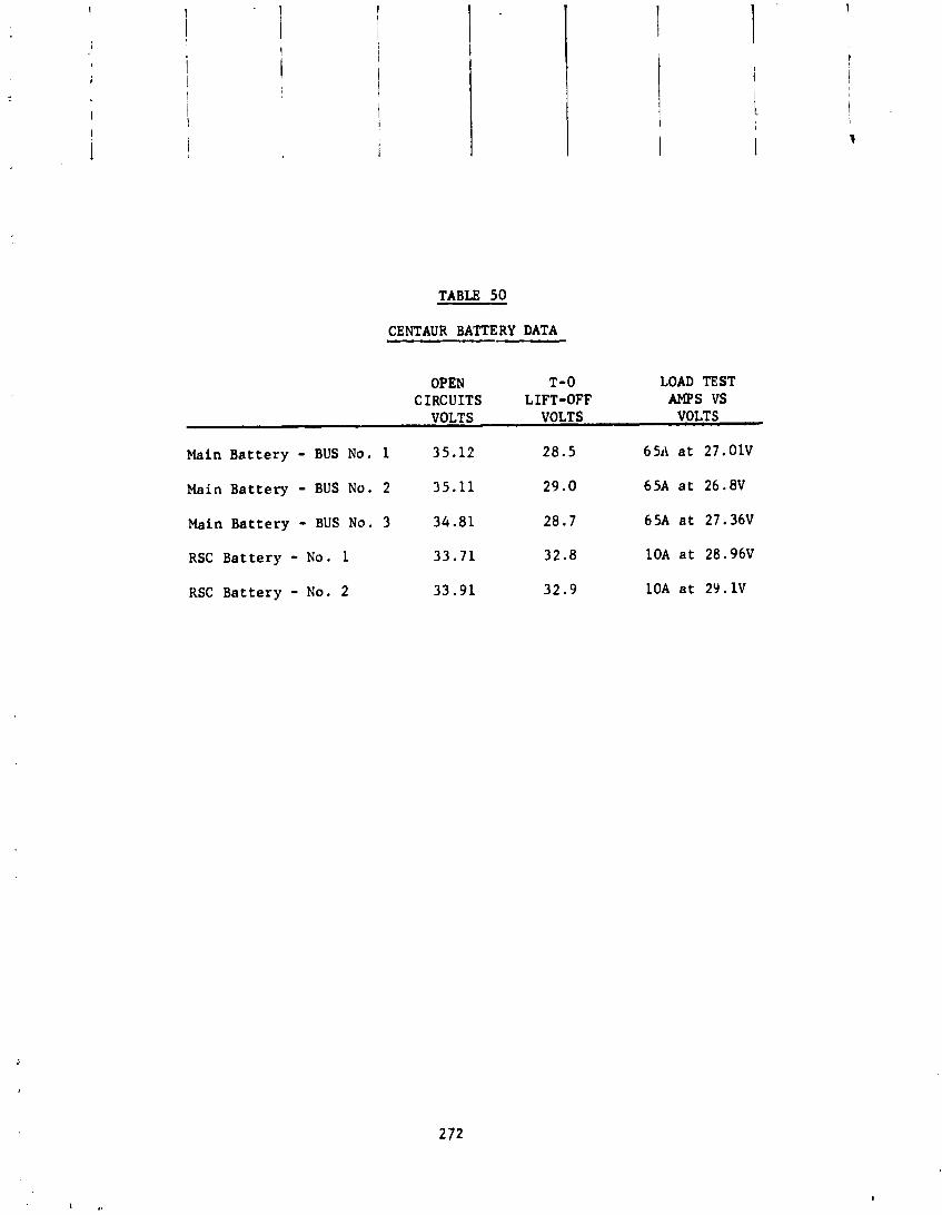
TABU 50
CENTAUR BATTERY DATA
OPEN T-0 LOAD TEST CIRCUITS LIFT-OFF AMPS VS
VOLTS VOLTS VOLTS
Main Battery - BUS No. 1 35.12 28.5 6511 a t 27.OlV
Main Battery - BUS NO. 2 35.11 29.0 65A a t 26.8V
Main Battery - BUS No. 3 34.81 28.7 65A a t 27.36V
RSC Battery - No. 1 33.71 32.8 1OA a t 28.96V
RSC Battery - No. 2 33.91 32.9 10A a t 29.1V
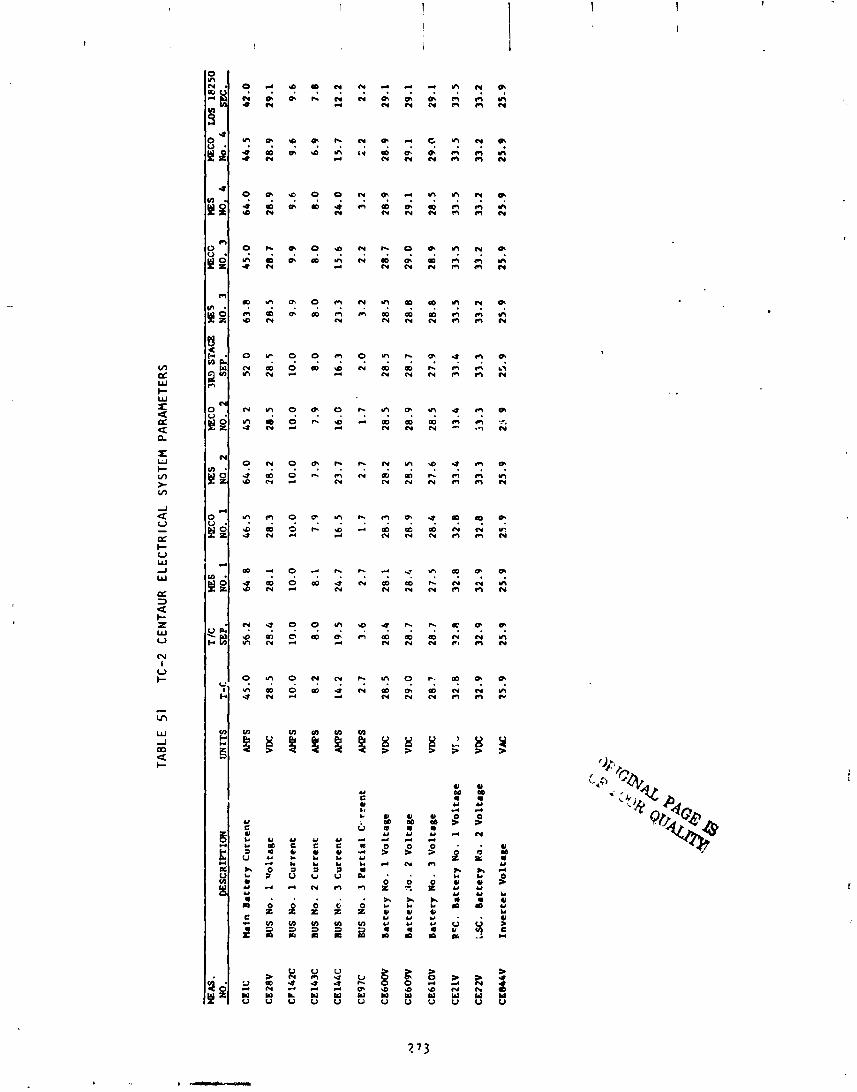
TAB
LE
51
TC-2
C
ENTA
UR
E
LEC
TRIC
AL
SY
STE
M P
AR
AM
ETER
S
WA
S.
WES
H
eco
?E
S
WC
O
3- ST
AC
2 mS
mXG
WES
W
ECO
U)S
18
25
0
NO
. DESCRIPTION
IJtU
TS
14
=IC.
N
O.1
N
O.l
N
0.2
N
O.?
s
.
NO
.3
NO
.)
NO
.*
4
I&.
SE P
bi
n B
att
ery
Cu
rre
nt
BUS
No.
1 v
olt
ag
e
BUS
No.
1 C
urr
en
t
BUS
No.
2
Cu
rre
nt
BUS
Na.
3
Cu
rre
nt
BUS
No.
3 P
art
ial
C-r
ren
t
Ba
tte
ry N
o.
1 V
olt
ag
e
Ba
tte
ry 3
0.
2 V
olt
ag
e
Ba
tte
ry N
o.
3 V
olt
ase
RC
C.
Ba
tte
ry N
o.
1 V
olt
ag
e
;SC
. B
att
ery
NO
. 2
Vo
lta
ge
Inv
ert
er
Vo
lta
ge

The i nd i v i dua l bus cur rents exh ib i t ed normal p r o f i l e s . Bus No. 1 remained steady between 9.6 t o 10.0 amperes, r e f l e c t i n g on ly the expected v a r i a t i o n s due t o the DCU duty cyc l e and rea l t ime i n t e r r u p t s .
Bu: No. 2 cu r ren t was r e l a t i v e l y constant, w i t h the except ion o f the p~ . iod i o f P J c o n t r o l . Var ia t ions o f 6.9 t o 8.2 were noted dur ing t h i s t ime i n t e r v a l , , which was nominal and as expected. Uus No. 3 cur ren t exh ib i t ed changes through- I out the f 1 i gh t i n response t o veh i c l e demands. The maximum cur ren t observed was 36.5 amperes a t Main Engire f i r s t s t a r t sequence.
Two i nd i v i dua l e l ec t r on i c package cur ren ts (IMG and SCU) were monitored v i a te lemetry . The I M G (inertial i4easutsement Group) cu r ren t exh ib i t ed normal low leve l osc i 1 l a t i o n s f o l lowing p l a t f o rm s t a b i 1 i z a t i o n (prelaunch f unc t i on ) . The load cur ren t va r ied bet Jeen 6.1 and 6.5 amperes. The 5CU (Sequence Cor- t r o l u n i t ) cu r ren t a l s o e x b , ~ b i t e d normal output w i t h a steady s t a t e load o f 0.18 amperes, and a s t robe cur ren t o f 0.88 amperes. The I M G and SCU are sup- p l i e d by the Bus No. 1 ba t t e r y and a re p a r t o f t he t o t a l Bus No. 1 load.
Performance o f ti?+: two range ?a fe t y command b a t t e r i e s was s a t i s f a c t o r y . The vol tages a t 1 i f t o f f were 32.8 v o l t s f o r range sa fe ty command no. 1 and 32.9 v o l t s f o r range ;af\.ty command no. 2. Voltages remained steady throughout the f l i g h t u n t i l Main Erlgint: Cu to f f No. !, when the range sa fe ty command re- ce i Oers a re turned o f f and the des t ruc t syst-ln i s deact iv :ted.
Vehic le A C Gower wac suppl i ed by the Servc l nver te r Un i t . The vo l tage output o f the i nve r t e r rema i ned steady a t 25.9 v o l t s AC throughout the programmed f l i g h t .
D i g i t a l Computer Uni t
by R . S . Palmer
A l l DCU inputs and outputs were analyzed. The DCU performed s a t i s f a c t o r i l y as evidence by proper funct ioning o f f l i g h t events and operat ion o f associated systems. The data ind ica t ing DCU performance a r c presented w i t h the f l ight performance analyses o f the associated systems.
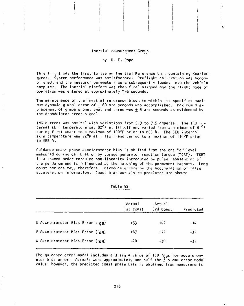
I n e r t i a l Measurement Group
by D . E. Pope
T h i s f l i g h t was the f i r s t t o Ase an l n e r t i a l Reference gyros. System performance was sa t i s f a c t o r y . P r e f l i g h t p l i shed , and t h e measurc.' parameters were subsequent ly computer. The i n e r t i a l p l a t f o r m was then f i n a l a l i g n e d opera t i o n was entered a t a ~ p r o x i m a t e l y T-6 seconds.
The maintenance o f t h e i n e r t i a l re fe rence b lock t o w i t h
n i t c o n t a i n i n g K e a r f o t t c a l i b r a t i o n was accom- oaded i n t o t h e v e h i c l e and t h e f l i g h t mode o f
n i t s s p e c i f i e d maxi- mum dynamic gimbal e r r o r o f + 60 a r c seconds was accompl ished. Maximum d i s - placement o f gimbals one, two, and t h r e e was 2 5 a r c seconds as evidenced by the demodulator e r r o r s i g n a l .
I M G c u r r e n t was nominal w i t h v a r i a t i o n s f rom 5.9 t o 7.5 amperes. The IRU i n - t e r n a l s k i n temperature was 82OF a t l i f t l ~ f f and v a r i e d f rom a minimum o f 8 1 ' ~ d u r i n g f i r s t coast t o a maximum o f 1 0 0 ~ ~ p r i o r t o MES 4. The SEU i n t e r n 3 1 s k i n temperature was 7 2 ' ~ a t l i f t o f f and v a r i e d t o a maximum o f 114O~ p r i o r t o MES 4.
Guidance coast phase accelerometer b i a s i s s h i f t e d from the one I1g" l e v e l measured d u r i n g c a l i b r a t i o n by to rque genera tor r e a c t i o n to rque (TGRT) . TGRT i s a second o rde r t o r q u i n g n o n - l i n e a r i t y in t roduced by p u l s e reba lanc ing o f t h e pendulum and i s in f luenced by t h e matching o f t h e permanent magnets. Long coast pe r iods may, t h e r e f o r e , i n t roduce e r r o r s by t h e accumula t ion o f f a l s e a c c e l e r a t i o n i n fo rma t ion . Coast b i a s a c t u a l s t o p r e d i c t e d a r e shown:
Tab le 52
Actua l Ac tua l 1 s t Coast 3 rd Coast P red ic ted
U Accelerometer Bias E r r o r ( q g ) +5 3 +42 t i 4
V Accelerometer Bias E r r o r ( k g ) +67 +72 +3 2
W Accelerometer B ias F r r o r ( y g ) -20 -30 -32
The guidanca e r r o r mor'sl inc ludes a 3 sigma va lue o f 150 U g s f o r accelerom- e t e r b i a s e r r o r . Ac:rla's were approx imate ly one-ha l f t he 3 sigma e r r o r model va lue; however, t h e p r e d i c t e d coast phase b i a s i s ob ta ined f rom measurements
a t t h e component l e v e l . These p r e d i c t e d values a r e shown i n Tab le 52 and w i t h the except ion o f t h e W accelerometer, a r e one-ha l f t o o n e - t h i r d o f t he ac tua l values. The p r e d i c t i o n technique w i l l be r e f i n e d as more f l i g h t da ta becomes a v a i l a b l e and be fo re p r e d i c t e d values a r e used i n the e r r o r model .
F l i qh t Cont ro l System
by R . A . Edkin and T. W. Porada
F l i ght Control Commands
The D i g i t a l Computer Un i t ( N U ) and the Sequence Contro l Un i t (SCU) performed s a t i s f a c t o r i l y i n i ssu ing the f l i g h t c o n t r o l system commands t o o ther veh i c l e systems. The SCU receives i t s inpu t from the DCU and converts t h i s input i n t o swi tch commands usable by o ther veh i c l e systems.
Table 53 l i s t s the SCU sw i tch ing sequence anti f l i g h t events. The column headed "Sequence" shows t he t ime o f t he event from the s t a r t o f each phase o f f 1 i g h t . The column headed "Planned Time" shows t he t i n e a f t e r l i f t o f f f o r each event based upon p r e f l i g h t ac tua l launch t ime t r a j e c t o r y w i t h launch day winds. The "Actual Time" column shows the t ime a f t e r l i f t o f f t h a t each command was issued by the SCU dur ing f 1 i g h t . Other funct ions programmed by the DCU sof tware a re shown i n the t ab le t o he lp i n c l a r i f y i n g t he f l i g h t sequence.
Control Dynamics
The dynamic behavior o f the veh i c l e ind ica ted t h a t a normal environment was experienced. Vehic le dynamic response was evaluated i n terms o f amp1 i tude, frequency, and du ra t i on o f r a t e gyro, a t t i t u d e e r r o r , d i g i t a l l y der ived r a t e (DDR) o f a t t i t u d e e r r o r , engine gimbal angles and coast phase c o n t r o l engine f i r i n g data. These data ind ica ted t ha t the c o n t r o l system d i d not impose any severe loading o r v i b r a t i o n env i ronment on the veh ic le . The veh i c l e respond- ed normal ly t o a l l commands and t r ans ien t disturbances cnd showed a bounded l i m i t c y c l e cond i t i on throughout f l i g h t . Centaur ins t rumentat ion r a t e gyro data a re shown tdbula ted i n Table 54 a t major f l i g h t events.
A t t he T i tan/Cer i c lu r separat ion (~+472.7 seconds) event, res idua l ra tes be- f o r e and a f t e r separat ion a re shown below:
Before Separation A f t e r Separat ion Requ i rement
Residual rate, deg./sec. 0.27 0.21 2 .O
No evidence o f bumping o r in te r fe rence was ev ident from ra te gyro o r acce le r - ometer data. The Centaur engines were observed t o be a t t h e i r nu1 1 pos i t i ons a t the t ime o f separat ion. A summary o f :he maximum ra tes and engine gimbal angles i s shown below f o r the i g n i t i o n and shutdown t r ans ien t s . Included a l s o a re those engine gimbal angles requi red f o r t he maximum s tee r i ng commands ob- served .
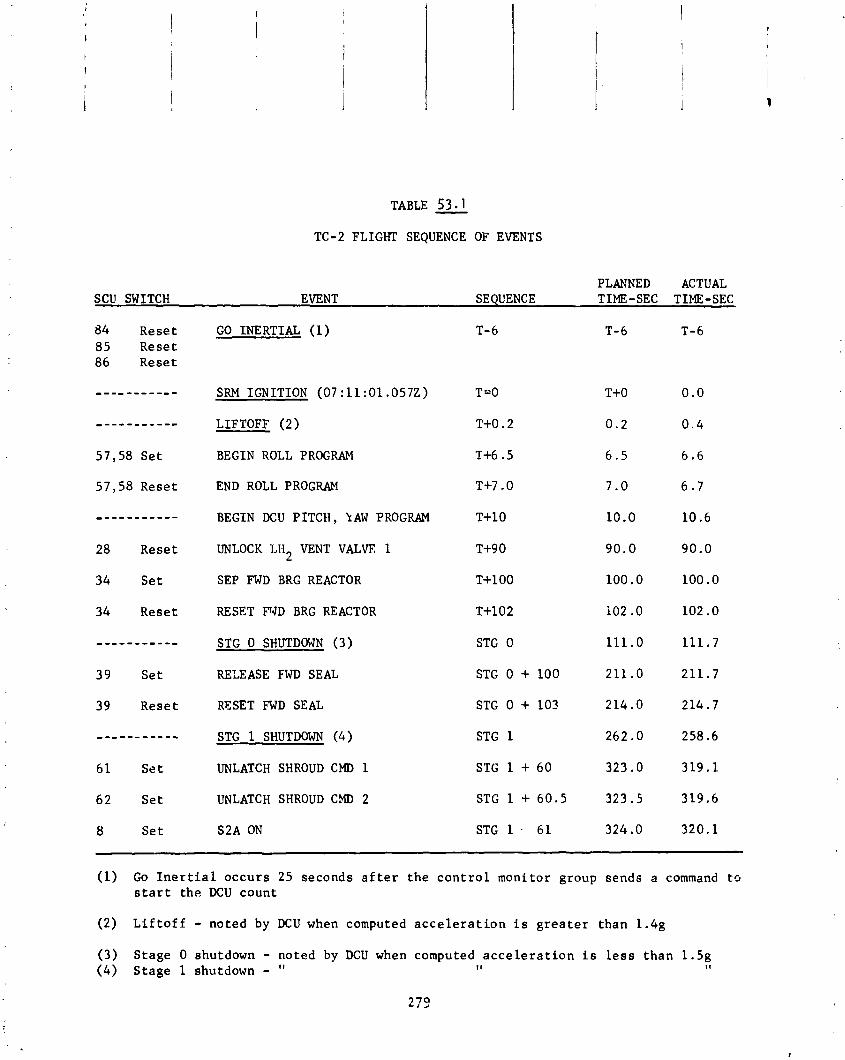
TABLE 53.1 TC-2 FLIGHT SEQUENCE OF EVENTS
PLANNED ACTUAL SCU SWITCH EVENT SEQUENCE TIME-SEC TIME-SEC
84 Reset GO INERTIAL (1) 85 Reset 86 Reset
_ _ _ _ _ _ _ _ _ _ - SRM IGNITION (07 : 11 :01 .0572) T=O T+O 0.0
----------- LIFTOFF (2) T+0.2 0 .2 0 . 4
57,58 Se t BEGIN ROLL PROGRAM T+6.5 6 . 5 6.6
57,58 Reset END ROLL PROGRAM T+7.0 7.0 6 . 7
----------- BEGIN DCU PITCH, 1AW PROGRAM T+10 10.0 10.6
28 Reset UNLOCK LH2 VENT VALVE 1
34 Se t SEP FWD BRG REACTOR
34 Reset RESET FVD BRG REACTOR T+102 102 .O 102.0
----------- STG 0 SHUTDOWN (3) STG 0 111.0 111.7
39 Set RELEASE FWD SEAL STG 0 + 100 211 . O 211.7
39 Reset RESET FWD SEAL STG 0 + 103 214.0 214.7
61 Se t UNLATCH SHROUD CMD 1 STG 1 + 60 323 . O 319.1
62 Se t UNLATCH SHROUD CMD 2 STG 1 + 60.5 323.5 319.6
8 Set S2A ON STG 1 . 61 324 .O 320.1
(1) Go I n e r t i a l occurs 25 seconds a f t e r the c o n t r o l monitor group sends a command t o s t a r t the DCU count
(2) L i f t o f f - noted by DCU when computed a c c e l e r a t i o n i s g r e a t e r than 1.4g
(3) Stage 0 shutdown - noted by DCU when computed a c c e l e r a t i o n i s l e s s than 1.5g ( 4 ) Stage 1 shutdown - I'
I 1 11

TABLE 5 3 . 2
TC-2 FLIGHT SEQUENCE OF EVENTS
PLANNED ACTUAL SCU SWITCH EVENT SEQUENCE TIME-SEC TIME-SEC
6 1 Rese t RESET SHROUD CMD 1 62 Rese t RESET SHROUD CMD 2
STG 1 + 61.5 323.5 320.6
8 Reset S2A OFF 1 S e t Y 1 ON
STG 1 + 8 1 343.0 340.1
1 Rese t Y l OFF 2 S e t Y2 ON
STG 1 + 101 363 .O 360.1
2 Rese t Y2 OFF 12 S e t S2B ON
STG 1 + 121 383.0 380.1
12 Reset S2B OFF STG 1 + 141 403.0 400.1
24 S e t 28 S e t 31 S e t
LOCK LO2 VENT VALVE LOCK LH2 VENT VALVE 1 LOCK LH2 VENT VALVE 2
STG 2 - 30.5 439.6 435 .1 I 1 11 II
27 S e t 29 S e t 32 S e t
OPEN CONTROL VALVE PRESS LO TANK PRESS L H ~ TANK
STG 2 - 28.56 441.54 437.0 II I t 11
I 1 I 1 1 1
23 Set 18 S e t
PRIMARY -BOOST PUMPS ON B/U-BOOST PUMPS ON
----------- STG 2 SHUTDOWN (5) 65 S e t STG 2 s /D B/U STG 2
17 S e t C 1 C I R C PUMP ON 21 S e t C2 C I R C PUMP ON
STG 2 + 0 .1 470.2 458.9
6 3 S e t T /C SEPARATIOE (6) 6 4 S e t
SEP 475.6 472.7
19 S e t OPEN PRESTART VALVES SEP + 2 . 5 478.1 475.2
27 Rese t CLOSE CONTROL VALVE SEP + 10.22 485.82 482.9
(5) Stage I1 shutdown - 2oted by DCU when observed a c c e l e r a t i o n i s l e s s t han I g
(6) TIC s e p a r a t i o n - commanded by DCU when computed a c c e l e r a t i o n i s l e s s t han 0.01g

TABLE 5 3 . 3 - TC-2 FLIGHT SEQUENCE OF EVEKTS
PLANNED ACTUAL SCU SWITCH EVENT SEQUENCE TIME-SEC TIME-SEC
MEs 1 ( 7 ) IGNITERS ON
---------- 22 S e t 20 S e t
MES 1 486.1 OPEN START VALVES
22 Reset IGNITERS OFF MES 1 + 4 490.1
MES 1 + 12 498.1 17 Rese t 21 Reset
C1 C I R C PUMP OFF C2 C I R C PUMP OFF
1-4 S e t YAW ENGINES ON MECO 1-20 564.8
5 ,6 S e t 15,16 S e t PITCH ENGINES OK MECO 1-20 564.8
1-4 Rese t YAW ENGINES OFF MECO 1-10 574.8
5,6 Rese t 15,16 Rese t
PITCH ENGINES OFF MECO 1-10 574.8
MECO 1 (8) PRIMARY-BOOST PUMPS OFF B/U-BOOST PUMPS OFF CLOSE START VLAVES CLOSE PRESTART VALVES
----------- 23 Reset 18 Rese t 20 Rese t 19 Reset
MECO 1 II
II
I 1
8 S e t 10 S e t 12 S e t 14 S e t
SETTLING ENGINES ON !I
MECO 1 + 0 . 1 584.9 !I II
I t I t
11 I 1
6 8 9 7 2 Rese t 76,8O
RESET PU SWITCHES MECO 1 + 1 585.8
REDUCE TO 2s ENGINES ON S2B, S4B OFF
--. . ------- 12,14 Rese t MECO 1 + 250 834.8
CHANGE S ENGINE PAIRS S2A, S4A OFF SZB, S4B ON
HALFhAY THROUGH 2 S
ON MODE
----------- 8 1 Reset 12,14 S e t
(7) MES 1 - commanded by che DCU 10 .5 seconds a f t e r T/C s e p a r a t i o n
(8) MECO 1 - commanded by t h e DCU based on guidance computed time
28 1
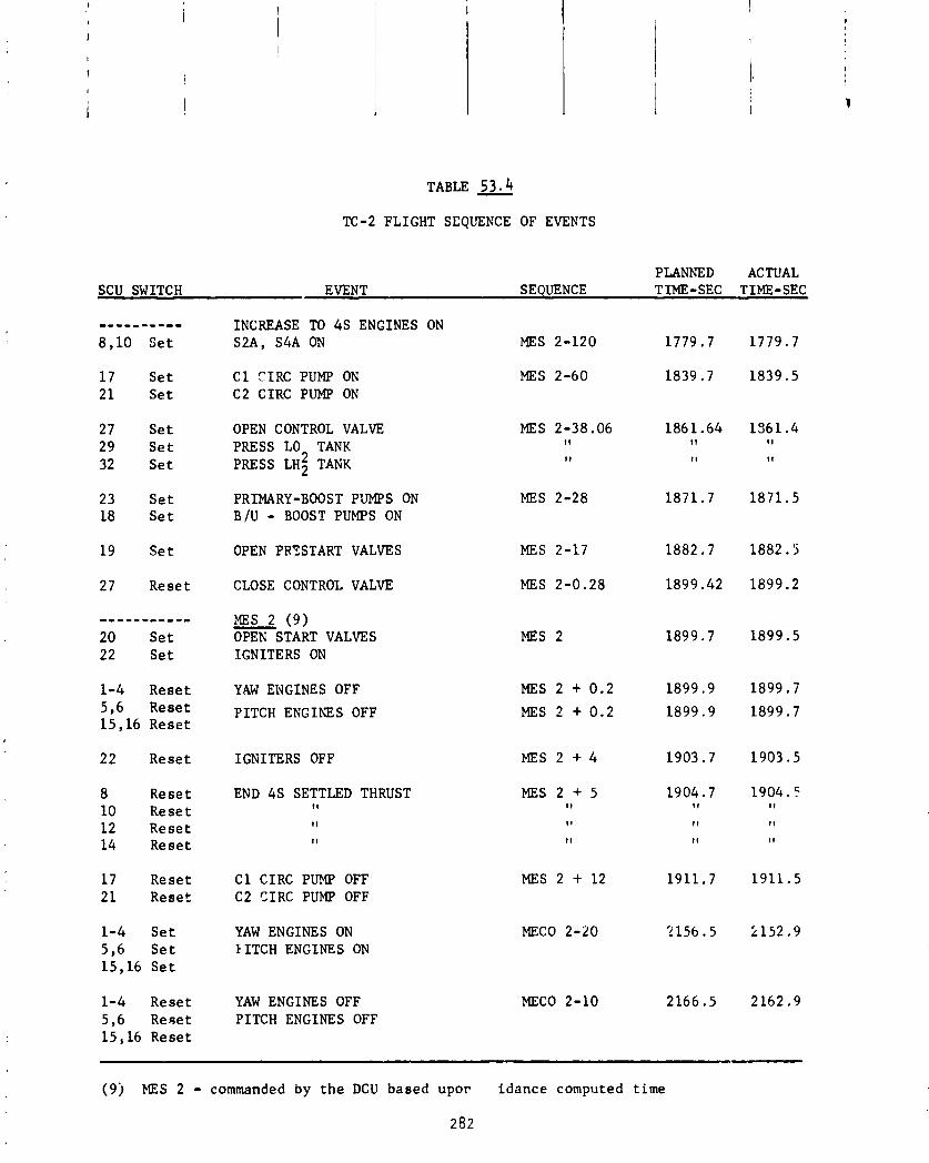
TABLE 53.4 TC-2 FLIGHT SEQUENCE OF EVENTS
PLANNED ACTUAL SCU SWITCH EVENT SEQUENCE TIME-SEC TIME-SEC
INCREASE TO 4 s ENGINES ON S2A, S4A ON
---------- 8 , 1 0 S e t MES 2-120
MES 2-60 1 7 S e t 2 1 S e t
C 1 CIRC PUMP ON C2 CIRC PUMP ON
27 S e t 29 S e t 32 S e t
OPEN CONTROL VALVE PRESS LO TANK PRESS LH; TANK
PRIMARY-BOOST P'JMPS ON B / U - BOOST PUMPS ON
MES 2-38.06 11
II
MES 2-28 23 S e t 18 S e t
19 S e t OPEN PRYSTART VALVES MES 2-17
MES 2-0.28 CLOSE CONTROL VALVE 27 R e s e t
MES 2 ( 9 ) - OPEN START VALVES IGNITERS ON
----------- 20 S e t 22 S e t
MES 2
1-4 R e s e t 5 ,6 R e s e t 1 5 , 1 6 R e s e t
YAW ENGINES OFF
PITCH ENGINES OFF
MES 2 + 0 .2
MES 2 + 0 . 2
IGNITERS OFF 22 R e s e t
8 R e s e t 1 0 R e s e t 1 2 R e s e t 1 4 R e s e t
END 4 s SETTLED THRUST I 1
1 7 R e s e t 2 1 R e s e t
C 1 CIRC PUMP OFF C2 CIRC PUMP OFF
MES 2 + 12
MECO 2-20 1-4 S e t 5 , 6 S e t 15 ,16 S e t
YAW ENGINES ON IITCH ENGINES ON
1-4 R e s e t 5 , 6 R e ~ e t 1 5 , 1 6 R e s e t
YAW ENGINES OFF PITCH ENGINES OFF
MECO 2-10
( 9 j MES 2 - commanded by t h e DCU b a s e d u p o r i d a n c e computed t i m e
282

TABLE 53.5 TC-2 FLIGHT SEQUENCE OF EVENTS
PLANNED ACTUAL SCU SWITCH EVENT SEQUENCE TIME-SEC TIME-SEC
---------- MECO 2 (10) - 23 Rese t PRIMARY-BOOST PUMPS OFF MECO 2 2176.5 2172.9 19 Rese t CLOSE PRESTART VALVES I I I I I I
20 Rese t CLOSE START VALVES I t I 1 I I
18 Rese t R /U-BOOST PUMPS OFF I I 1 1 I t
68,72 Rese t RESET PU SWITCHES 76,80 Rese t
MECO 2 + 1 2177.5 2173.9
95 Rcse t ENABLE TE364 IGNI'I ION MECO 2 + 6 0 2236.5 2232.9
73,74 S e t FIRE SPIN ROCKETS MECO 2 + 70 2246.5 2242.9
73,74 Rese t FIRE SPIN ROCKETS (RESET) MECO 2 + 70.8 2247.3 2243.7
35 S e t FIRE WIRE CUTTERS MECO 2 + 71 2247.5 2243.9
69,70 S e t SEP TE364 /FIRE RETROS MECO 2 ;- 72 2245.5 2244.9
69 ,70 Rese t SEP ~ E 3 6 4 /FIRE RETROS (RESET) MECO 2 + 77 2253.5 2249.9
35 Rese t FIRE WIRE CUTTERS (RESET) M E C O 2 + 7 7 . 1 2253.6 2250.0
----------- TE364 IGNITION 2290.5 2285.8
----------- BURNOUT 2234.3 2330.7
----------- HELIOS SPACECRAFT SEPARATION 2406.5 2401.5
(10) MECC 2 - commanded by t h e DCU based upon guidancc computed time
283

Table 54
Event - MES 1
1 s t Burn S teer ing
MECO 1
MES 2
2nd Burn S teer ing
MECO 2
F i r e Spin Rockets
Centaur Ro ta t iona l Rates and Engine Gimbal Angles Dur ing Powered F l i g h t -
Time
483.2
492.2
584.0
1899.5
N 0
Data
2172.9
2242.9
Ax is - P i t c h Yaw Rol l
P i t c h Yaw Rol l
P i t c h yaw R o l l
P i t c h Yaw Rol l
P i t c h Yaw R o l l
P i t c h Yaw R o l l
P i t c h Yaw Rol l
Gimbal Angle/ Rate Deq/Sec. Ax is - Contro l Capab i l i t v
-1.5 P i t c h +I .3/+3 .O -0.1 Yaw/Rol 1 -.5/+3 .o -1.4
P i t c h +1.4/23 .O yaw/Roll -2 .0/23 .O
N 0
Data
P i t c h ~ a w / R o l l
P i t c h Yaw/Rol l
A l i m i t c y c l e o f approximately 0.7 degrees peak-to-peak a t 3.5 Hz was observed dur ing the f i r s t burn. Th i s i s normal operat ion. Dur ing the second burn, data were noisy and sporadic; a s i m i l a r l i m i t cyc le , however, was d i sce rn i b l e .
The Centaur f i r s t coast showed the f o l lowing duty cycles. Th i s i s def ined as the r a t i o o f d is turbance torque t o c o n t r o l t o r q w quoted i n percentage.

Tab le 55 A t t i t u d e Con t ro l System Average Duty Cyc le
Mode A x i s Duty Cyc le '/
S e t t l i n g 45 ON
Re ten t ion 2SA ON
Re ten t ion 2'8 ON
P i t c h Yaw Rol l
P i t c h Yaw Rol l
P i t c h yaw R o l l
Fo l l ow ing t?ECO 2, t he Centaur a l i g n e d t h e spacec ra f t t o t h e des i red p o i n t i n g v e c t o r and a t T+2242.9 seconds s p i n rocke ts were commanded t o f i r e . T h i s event achieved a s p i n r a t e f o r t h e spacec ra f t o f approx imate ly 90 rpm. The s p i n r a t e h i s t o r y o f t h e t a b l e i s shown i n F i g u r e 107. I t was observed t h a t t h e s q i n decay was approx imate ly t w i c e as f a s t as those observed on Pioneer f l i g h t s . An impuls ive c lockw ise r o l l d i s tu rbance r e s u l t i n g i n a r o l l r a t e o f 0.4 degrees/second a t t h e s p i n up event was observed on Centaur. T h i s has been observed on Pioneer f l i g h t s and i s assoc ia ted w i t h b reak ing t h e r e s t r a i n - i n g l i n e which keeps the s p i n t a b l e from r o t a t i n g d u r i n g the ascent . I t was, however, lower i n magnitude as shown below.
Tab le 56
V e h i c l e Rol l Rate Due t o Breaki ng Rope Degrees/Second
P i oneer AC -27 P i oneer AC-30 Hel i o s TC -2
A l a r g e p r o p e l l a n t r e s i d u a l on TC-2 i s t h c r,,ajor d i f f e r e n c e fr: + h e 7 ; r f l i g h t s . T h i s d i f f e r e n c e i s under f u r t h e r study t o d e t e r m i ~ e i f + ' :,cd reduct i o n i n r o l l r a t e can be accounted f o r by t h e l a r g e p r ~ p c l : c l e .
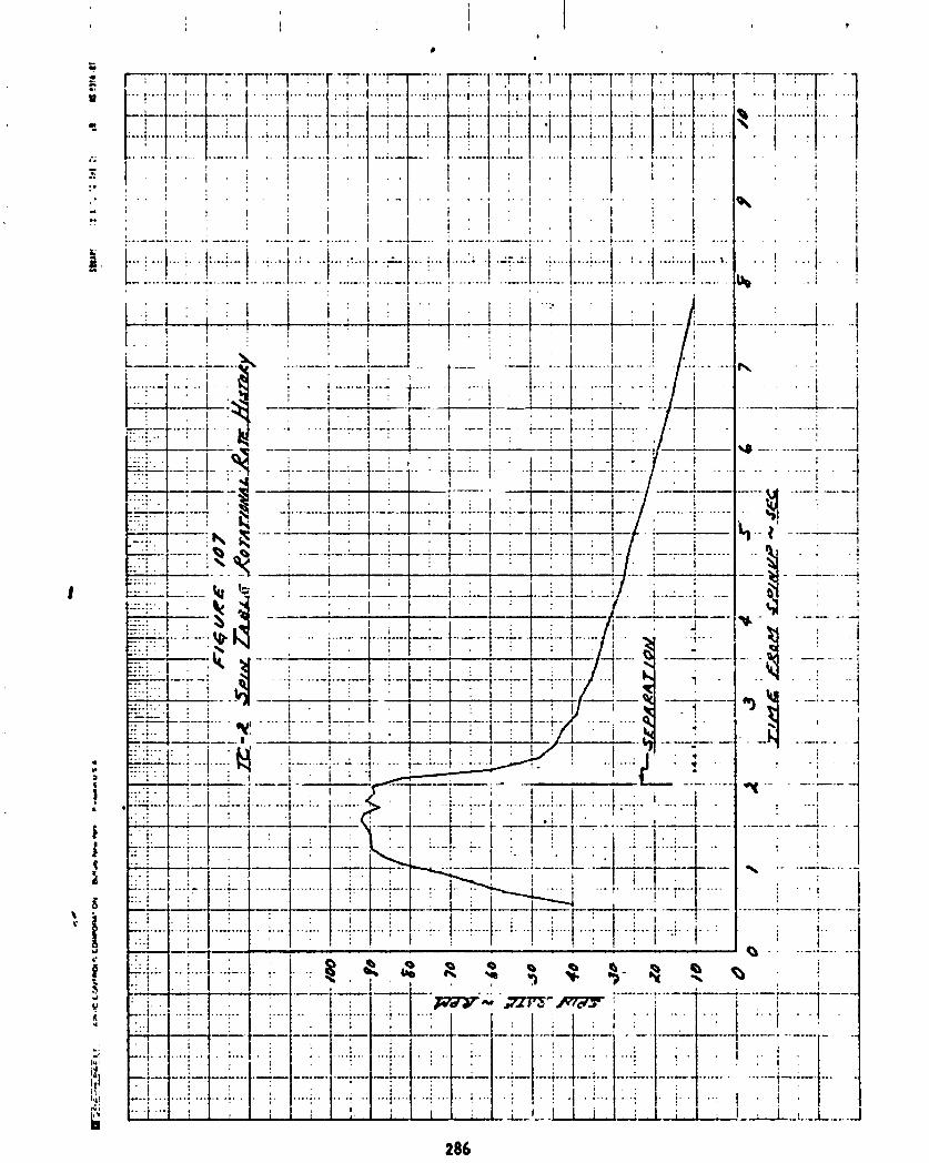
. . .... .... .... .... . . . . I .... ...
........ .... .... ....... .... ........ ........ .... .
" ""- .... " . . . . . .."" . . . . . . 1
. . . . . . . .
i , I I
9 . , i I ! !
! I : .-.---; .-... .; ---... . . . . . . . t . --.I... i . . I:.-'.-.\ . . . . ... ..... . . . . ..-..--*..---..---- .- ...-- -.-,... . . - !
, . p ! : i ; ; ...
! I . . i ! I . t
Propel lant Loading/Propel lant U t i l i z a t i o n
by K. Semenchuk
Prope l lan t L-vel I nd i ca t i ng Systev (PLIS'
The p r o p e l l m t l eve l i n d i c 3 t i n g system (PLIS) cons is ts o f a LH2 probe, LO2 probe, and LO2 o v e r f i l l sensor. LH2 and LO2 probes con ta in th ree hot w i r e sensors. The LO, o v e r f i l l sensor conta ins one hot w i r e sensor. Each sensor has tw redundant sensing ele4nents.
The PLlS i s used t o i nd i ca te the tank ing o f the p rope l l an t s :G the des leve ls . Each sensor give. :In i nd i ca t i on tha t a c e r t a i n l eve l has been reached by the l iqu i d propb r l a n t by chang inq i t s opera t ing chnrac te r i s Th is change i s detected by :he CSE vh ich gives a "wet" o r "dry" l iqh t ca t i on on the Blockhouse Aur i l i a r y Fuel Tanking Panel.
The LO2 and LH2 probe sensors operate a t 95 percent, 99.? percent, and percent l e v e l s i n t h e i r respec t i ve tanks. The LO3 over f i l l sensor i s 1 a t approxima' %I y I. 75 l nches above the 100.2 perccnt sensor.
The Centaur l e v t i i n d i c a t i n q system operated s a t i s f a c t o r i l y du r ing the
red
I C S .
n d i -
100.2 oa a ted
count- down. A t i i f t o f f , both tanks LO^ and LH2) were a t 100.7 percen t - leve ls .
Propel lant U t l l i z a t i o n .'.em (Pu)
A p rope l l an t u t i l i z a t i o n (Pu) system c ~ n s i s t c o f LH2 and LO2 sensors, e l e c t r i - ca l harneches, a servo p o s i t loner mounted on each engine mix tu re r a t i o con t ro l valve, and e l ec t r on i cs c i r c u i t r y housed h i t h i n the Servo I nve r t e r Un i t [SIU). The SIU p ro r ides e r r o r de tec t i cn and va lve servo pos t t i one r f iedback e x c i t a - t ion.
The s i g n ~ l generated by t h i s c i r c u i t r y i s processed by the D i g i t a l Computer Un i t (DCU) f o r c rea t i on of va lve p o s i t i o n commands. The DCU operates switches i n the Sequence Control Un! (SCU) t o d r i v e the engine valves t o the requi red p o s i t ion.
The PLI system (1; reduces res idua l mass o f one p rope l l an t a t dep le t ion o f the o ther p rope l l an t and (2) redc.,~ e r r o r s caused by d ispers ion due t o tanking, !of l o f f , p r o p ! l a n t uncer ta in t ies , and e i g i n c performance un ...? r t a i r l t i t s .
The PU system con t ro l s m ix tu re r a t i o as a continuous func t ion o f the mass r a t i o o f p rope l lan ts i n the tanks.
No PU con t ro l s occurred dur ing f i r s t and t h i r d burns as expected. During f ~ r s t burn, the p rope l lan ts stayed above the top o f the probes; and the t h i r d burn was too shor t (1 1 secs) f o r PU con t ro l . The propel Ian: a t i l i t a t i o n sys- t en was operated closed loop dur ing second and f o u r t h burns.
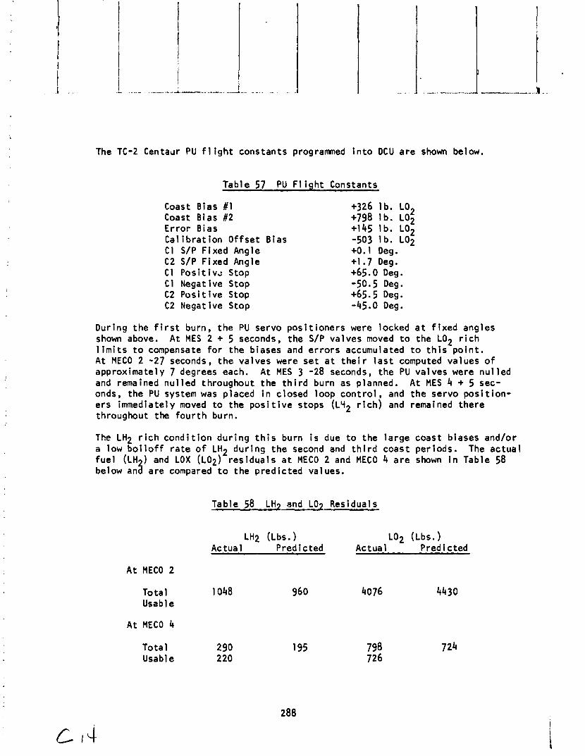
The TC-2 C e n t a ~ r PU f l i g h t constants programed i n t o DCU a re shown below.
Table 57 PU F l i gh t Constants
Coast Bias #1 Coast Bias #2 Er ro r Bias Cal i b r a t ion Of fse t Bias C I S/P Fixed Angle C2 S/P Fixed Angle C1 P o s i t i v t Stop C1 Negative Stop C2 Pos i t i ve Stop C2 Negative Stop
+326 I b. LO^ +798 1 b. LO2 +I45 Ib . LO2 -503 l b . LO2 +0.1 Deg. +1.7 Deg. +65.0 Deg. -50.5 Deg. +65.5 Deg. -45.0 Deg.
During the f i r s t burn, the PU servo pos i t ioners were locked a t f i x e d angles shown above. At MES 2 + 5 seconds, the S/P valves moved t o the LO2 r i c h l i m i t s t o compensate f o r the biases and e r ro r s accumulated t o t h i s po in t . A t MECO 2 -27 seconds, the valves were se t a t t h e i r l a s t computed values o f approximately 7 degrees each. A t MES 3 -28 seconds, the PU valves were nu1 led and remained nu1 led throughout the t h i r d burn as planned. A t MES 4 + 5 sec- onds, the PU system was placed i n closed loop con t ro l , and the servo pos i t i on - e rs immediate1 y moved t o the p o s i t i v e stops (LLI2 r i c h ) and remained there throughout the f o u r t h burn.
The LH2 r i c h cond i t i on dur ing t h i s burn i s due t o the la rge coast biases and/or a low b o i l o f f r a t e o f LH2 dur ing the second and t h i r d coast per iods. The ac tua l f u e l (LH ) and LOX ( ~ 0 ~ ) res idua ls a t MECO 2 and MECO 4 a re shown i n Table 58 a below an are compared t o the pred ic ted values.
Table 58 LH7 and LO7 Residuals
LH2 ( ~ b s . ) LO2 ( ~ b s . ) Actual Predicted Actual Predicted
A t MECO 2
Total 1048 960 4076 4430 Usable
A t MECO 4
Tota l 290 Usable 220
A t the end o f the mission, the residual fuel was enough t o sustain 13.5 I seconds o f burn time. i
i During the t h i r d coast period, the heaters on the servo posi t ioners were cycled on-of f three times as commanded by the DCU. The temperatures o f the servo posi t ioners were 62OF and 5g°F f o r C 1 and C2, respect ive ly a t 1 i f t o f f . The lowest temperature recorded was +26OF and the highest never exceeded +62OF f o r the e n t l r e f l i g h t .
Instrumentation and Telemetry Systems
by J. M. Bul loch and T. J. H i l l
Instrumentation - A t o t a l o f 569 measurements were instrumented, 523 PCM measurements, 23 twenty-four b i t DCU words v i a the PCM system, and 23 analog measurements.
The fo l low ing measurements f a i l e d t o provide v a l i d data during the f l i g h t :
CP5640 (LO Boost Pump Flange Longitudinal V i brat ion) f a i l e d t o provide any - vibra t ion aata during the f l ight . The data leve l was constant a t the 50 per- cent ( Information Bandwidth amp1 i f i e r b ias l eve l ) . Sat ls factory operat ion o f the measurement was observed during prelaunch systems tests. The exact cause o f the anoma l y i s unknown.
CA289T (Tank Skin 2426/90) indicated o f f scale h igh unt i l 47 seconds i n t o the - f l i g h t . The measurement had f a i l e d previously during TCD and was not repaired due t o i naccess ib i l i t y o f the transducer under the shroud. The most probable cause o f the anomaly I s a bad connection a t the sp l i ce j o i n t o f the transducer leads t o the harness wires. An improved technique f o r i n s t a l 1 ing these spl ices has been developed e f f e c t i v e TC-5, AC-40 and on.
CP187~ (LH2 Boost Pump Decomposer chamber) was attenuated throughout the f 1 i ght . Addit ional l y , negative steps o f 4 percent IBW were noted a t c i r c pump s t a r t and i g n i t o r f i r i n g . Simi lar charac ter is t i cs were noted during the FED and TCD. In- ves t iga t ion a f t e r the TCD indicated a short c i r c u i t i n the thermocouple between the reference junct ion and RMU. Because o f the large number of measurements u t i l i z i n g t h i s RMU connector, i t was decided not t o troubleshoot o r attempt t o f i x the measurement because o f possible damage t o the other measurements.
The fo l lowing measurements exhib i ted data anomalies during the f l i g h t :
(LoZ Boost Pump Flange, Latera l ) , C~5600 ( L H ~ Boost Pump Flange, Lateral , o or ward Equipment Module ~ c o u s t i c ) x a1 1 cases, recovery was w i t k , two seconds. The v ib ra t i on and acoust ic data i s recoverable during the
t ransient period. This type o f bias s h i f t and recovery i s t yp i ca l o f a momentary open i n the coaxial cable/connector c i r c u i t s between the accelerometer, '.TI1 ca l - i b ra t i on connectors and charge ampl i f iers .
CA6850 (payload Adapter Longi tud ina l ) exhib i ted a +3 percent IBW s h i f t a t For- - ward Bearing Reactor separation. CA6860 (payload Adapter ~ a d i a l ) exhi b i red a (-) 5 percent IBW s h i f t a t the same time. Both measurements remained sh i f ted fo r the remainder o f the acqu is i t i on period. The most probable cause i s trans- ducer s e n s i t i v i t y t o ambient pressure changes. Testing i n the lab has indicdted these transducers (27-01922) can d r i f t o r e x h i b i t s h i f t s due t o abrupt shocks
when the pressure changes from ambient t o a vacuum. This discrepancy w i 11 be el iminated by modifying the transducer e lec t ron ics on TC-5 and up and AC-37 and up. CF6T (LO2 tank u l lage temperature) remained o f f scale h igh through- out the Cape Canaveral acqu is i t ion period except between 145 and 154 seconds. Data during t h i s period showed three separate leve ls and i s considered inva l id . Downrange data from Hawai i indicates the measurement was prov id ing val i d data p r i o r t o the t h i r d burn up t o MES 3. The measurement had f a i l e d during TCD and was not replaced due t o transducer inaccessi b i 1 i ty. Invest i ga t ion a f te r the TCD indicated an e l e c t r i c a l open c i r c u i t w i t h i n the LO2 tank. Data i n d i - cates the anomaly was a t the sensor. No fu r the r inves t iga t ion i s planned. It i s believed t h i s discrepancy may have been brought about by the unusually ex- tensive hand1 ing of the LO standpipe when measurement CF23T was added f o r the extended mission. CPT33T ?LO2 Boost Pump I n l e t ~ e m ~ e r a t u r e ) ~ exhi b i ted p o s i t i v e and negat i ve noise spikes (up t o band edge i n amp1 i tude) throughout the f 1 i gh t . No data was l os t due t o these t r ~ n s i e n t s . The spik ing was caused by in te rac t ion i n the common leg temperature br idge due t o the i n te rm i t t en t nature o f the CF6T transducer (see 3 above). This i s a known operat ing cha rac te r i s t i c o f these common leg c i r c u i t s .
The fo l low ing measurements a l l exhib i ted data charac ter is t i cs which are a t t r i b - uted t o a f a u l t y spl i ce between the transducer and harness:
CAl86T (Superzi p Outer 2688/-2) exhib i ted an anomalous 1 S°F p o s i t i v e excurs ion - between 23 and 26 se-.onds. CA176T (Shroud Skin Stat ion 2551/128) exhib i ted an anomalous 50°F pos i t i ve d r i f t between 75 and 86 seconds, re tu rn ing abrupt ly t o the expected leve l a t 86 seconds. CA969T ( L H ~ Sump Radiation Shield Outer Sta- t i o n 2235) stepped o f f scale h igh a t s e c o n d s (T/c separation). Data p r i o r t o t h i s t ime appeared va l id . An improved technique f o r i n s t a l l i n g these sp l i ces has been developed e f fec t i ve TC-5 and on and AC-40 and on.
The fol lowing measurements a l l exhib i ted data cha rac te r i s t i cs which may be a t t r i b - uted to the transducer becoming unbonded from the a t tach st ructure, resu l t i ng i n poor t herma 1 contact :
CA288T (Tank Skin Stat ion 2426/0), CA290T (Tank Skin Stat ion 2370/0), and - CA293T (Tanksk in Stat ion 2334/0) a l l exhib i ted e r r a t i c outputs (between 10 and 30 per- cent IBW) from p r i o r t o 1 i f t o f f t o approximately T + 180 seconds. Data a f t e r 180 seconds appears val id.
CA29iT (Tank Skin Stat ion 2370/90), CA292T (Tank Skin Stat ion 2370/180), and CA294T (Tank Skin Stat ion 2334/90) a l l indicated an unexpected warming trend begtnni ng a t 472 seconds (Ti tadcentaur separation).
CP744T (C2 Fngine Be1 1 Stat ion 507 Inboard) indicated a drop i n temperature t o -112°F a t MES 1 when a drop t o -30S°F was expected. The measurement indicated the expected ambient output p r i o r t o MES 1. A thorough analys is o f the data from these tank sk in temperature measurements has not been completed and so i t i s not yet known how much o f the data i s ac tua l l y questionable. U n t i l the
anomalies are defined, the cause o f the (possible) anomalies cannot be deter- mined.
CA894P ( I SA hmbien t Pressure) exhib i ted several negat ive t ransients during the - f i r s t 15 seconds o f f l i g h t . A s im i l a r anomaly was noted on TC-1 and on two ambient pressure measurements on AC-31. These t ransients are a t t r i b u t e d t o in- te rmi t ten t l i f t o f f o f the wiper arm i n the transducer. No s i g n i f i c a n t data was l os t .
The Conrac transducer used i n conjunct ion w i t h t h l s measurement i s no longer being procured and i s being phased out by a Servonics transducer.
CP195P (C2 Pump LH2 Discharge) d i d not read less than approximately 15 ps ia a t times when the transducer was a c t u a l l y sensing lower pressure. Since the meas- urement performed normally a t a l l pressures above approximately 15 psia, the transducer was apparent1 y a t faul t. I t appears tha t some obstruct ion prevented the transducer wiper arm from t rave l i ng below the I S psia po in t ( the point a t which i t rested i n a one-atmosphere pressure environment). The transducer had been ca l ib ra ted over i t s f u l l range p r i o r t o i n s t a l l a t i o n and functioned prop- e r l y a t low pressures a t tha t time. The cause o f an obstruct ion tha t could have developed since tha t time i s a matter f o r pure speculation. No fur ther i nves t i - gat ion i s planned because t h i s i s the f i r s t time t h i s problem has been reported w i t h tha t type transducer and no data loss occurred i n the area o f i n te res t f o r tha t measurement.
Unexplained 37 Hz o s c i l l a t i o n buildups and occasional sp ik ing were observed on measurement - CM42R (IRGU P i t ch Rate Low Output) a f t e r T + 51 minutes dur ing the f l i g h t . S imi lar osci l la t i ons and some spik ing were a lso observed on t h l s meas- urement dur ing prelaunch operations. Maximum amp1 i tudes o f the osci l la t i ons and spi kes d i d not exceed 15 percent IBW p-p (0.21 deg/sec p-p) and were general - l y less tha t 10 percent IBW p-p. The o s c i l l a t i o n s were no t apparent on the r a t e gyro output monitor ( c M ~ ~ R ) . A pos t - f l i gh t analys is o f the anomaly could not define any ra te gyro package problem tha t could cause the observed phenomena ( re f . PR#AG05262Cp). The 37 Hz osci 1 l a t i o n mode i s be1 ieved t o be the r e s u l t of a l ias ing a higher frequency osci l l a t i o n mode (probably 800 HZ) w i t h the PCM measurement sampl ing r a t e (279 sampl es/sec) . The f i r s t launch attempt o f t h i s veh ic le on December 8, 1974, was aborted due t o red1 ine measurement - CPT62T (C-2 LH2 Pump l n l e t Temperature) J r i f t ing o f f - scale-high a t approximately T-30 minutes. Subsequent inves t iga t ion revealed a f a u l t y transducer. Fa i lu re analysis indicated the cause was due t o the i m - proper use of glue t o cement the i n t e r f a c i a l seal i n the connector when the seal i s supposed t o be press-f i t I n t o the connector. Some o f the glue inadvertent1 y got onto the connector pins resu l t i ng i n i n te rm i t t en t operat ion a t cryogenic temperatures, To prevent a fu tu re occurrence, survey 2-75 has been i n i t i a t e d t o v e r i f y tha t the i n t e r f a c i a l seal has not been glued i n t o any connectors f o r a l l ex i s t i ng 55-01259 stock.

Telemetry Systems
The performance o f the Centaur FM/FM, PCM L ink 1, PCM L ink 2, and the TE- M-364-4 stage telemetry was sa t is fac tory . A t o t a l o f 582 measurements were instrumented, 546 on PCM, 23 on the Centaur FM/FM, and 13 on '.he TE- M-364-4 stage FM/FM.
Signal strengths indicate sa t i s fac to ry performance o f the airborne RF system. This was the f i r s t Centaur vehic le t o u t i l i z e a redundant PCM t ransmit ter . !
f
The same PCM b i t stream from the DCU was used t o modulate d i f f e r e n t FM trans- ! m i t t e r s on 2202.5 and 2215.5 MHz. The dual RF l i n k was t o assure data re - i
covery i n the post-Hellos phase o f Centaur f l i g h t . Two Hi-gain antennas were a lso i ns ta l led on the Centaur for the same purpose. A t T + 4173 (MECO 2 + 2000 sec.) a l l three Centaur RF sources were switched from the omni antennas t
t o the Hi-gain antennas. RF signal strengths rose approximately 30 db a t t h i s time, ind ica t ing sat is factory performance o f the H i -gain system and RF switches.
Ground Stat ion coverage and p a r t i c i p a t i n g s ta t ions are shown i n Figure 108. Two stat ions reported problems dur ing the f l i g h t . A R I A 2 was unable t o deploy i t s antenna and was unable t o provide any coverage. As a r e s u l t , there i s a gap i n the data ava i lab le from T + 1130 t o AOS a t ACN a t T + 1246.
The USNS Vanguard reported that i t switched t o a backup 30-foot antenna t o sup- po r t the f 1 i gh t and tha t due t o a l a t e turn ing maneuver the sh ip 's superstruc- tu re i n te r fe r red w i t h the signal received by t h i s antenna. Vanguard d i d have in te rmi t ten t data coverage from T + 1869 seconds to Johannesburg AOS a t T + 1916.
The expected occulat ion of the signal received a t CIF a t l i f t o f f d i d occur i n the f i r s t second o f f 1 ight. Coverage was provided a t Complex 36 and Hangar J f o r t h i s period.
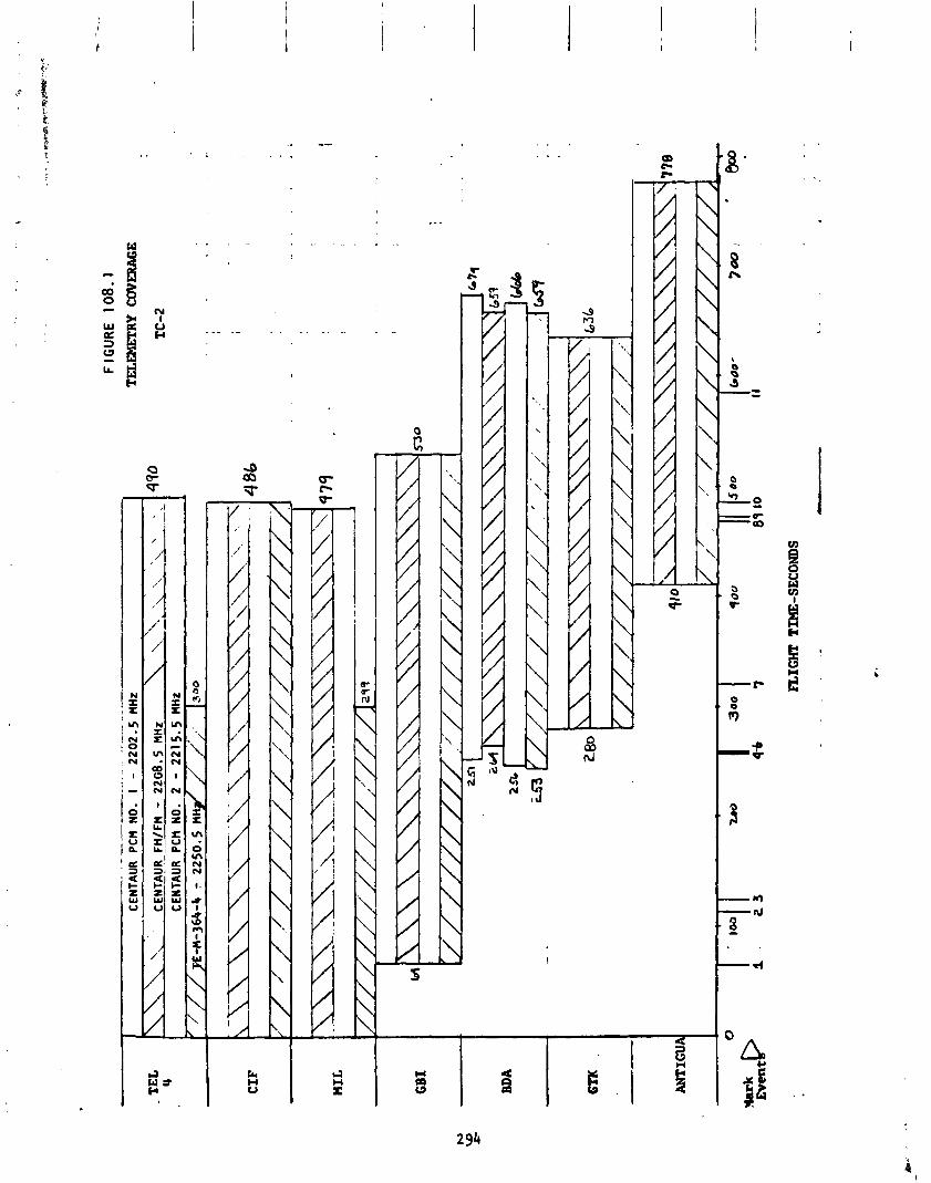
- .--A
-
..
1 C
ENTA
UR
PC
H N
O.
I - 2
20
2.5
MH
z I
- 22
08
.5
MH
z C
ENTA
UR
P
Ctl
NO
. 2
- 221
5.5
MHz
FIG
UR
E
10
8.1
TELE
MET
RY
CO
VERA
GE
TC
-2
GBI
530
ANTIGU -1
FLIGHT TIME-SECONDS
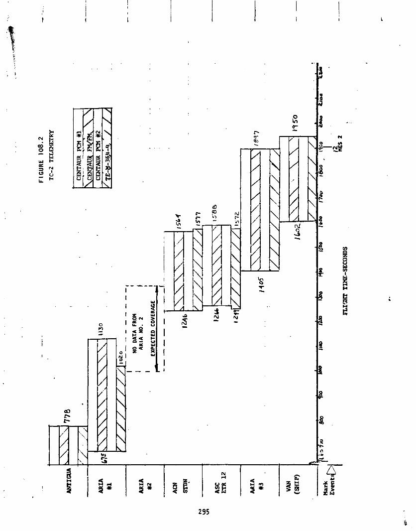
FIGU
RE 108.2
TC
-2
TELE
MET
RY
Cm
TA
UR
PC
M
#I.
1
1 C
ENTA
UR
P(E
I #2
I
ARIA
#l
I
NO
DA
TA
FRO
M
I I
AR
IA N
O.
2 1
I I
EXPE
CTE
D C
OVE
RA
GE
I --
I
AR
IA
#2
ASC
ETR 12
AR
IA
#3
Har
k ~
ve
n tc
FL1m
TIME-SECONDS
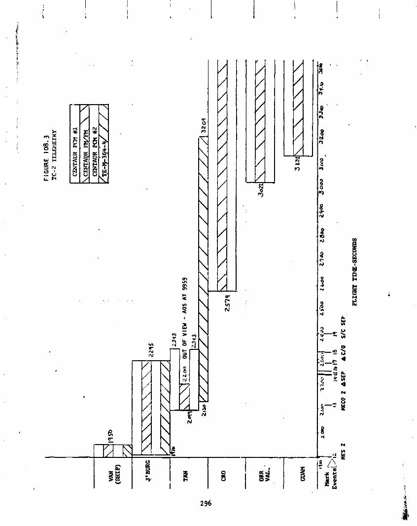
J'BURG
TAN
ORR
VA
L.
GUA
M
2200
OUT
O
F V
IEW
- AO
S AT
99
59
Za19
FIG
UR
E
108.
3 T
C-2
T
EL
EbE
rUY
CEN
TAU
R PCM #1
t
\CEP
AU
R
FY/FM- \
CMTAUR PCM #
2
MES
2
MEC
@ 2
A
SE
P
bC
/O
S/C
SEP
FL
Im
TPE-SECONDS

FIG
UR
E
108.
4 i
. .-
*-.
TC-2 TELEMETRY C
OV
ERA
GE
CE
NrA
UR
PC
M
#1
-. -
CX$J
Tt(U
R w
q \
L
CEN
TAU
R PCM
#2
1
TAN
-
ORR
VA
L.
HAWAII
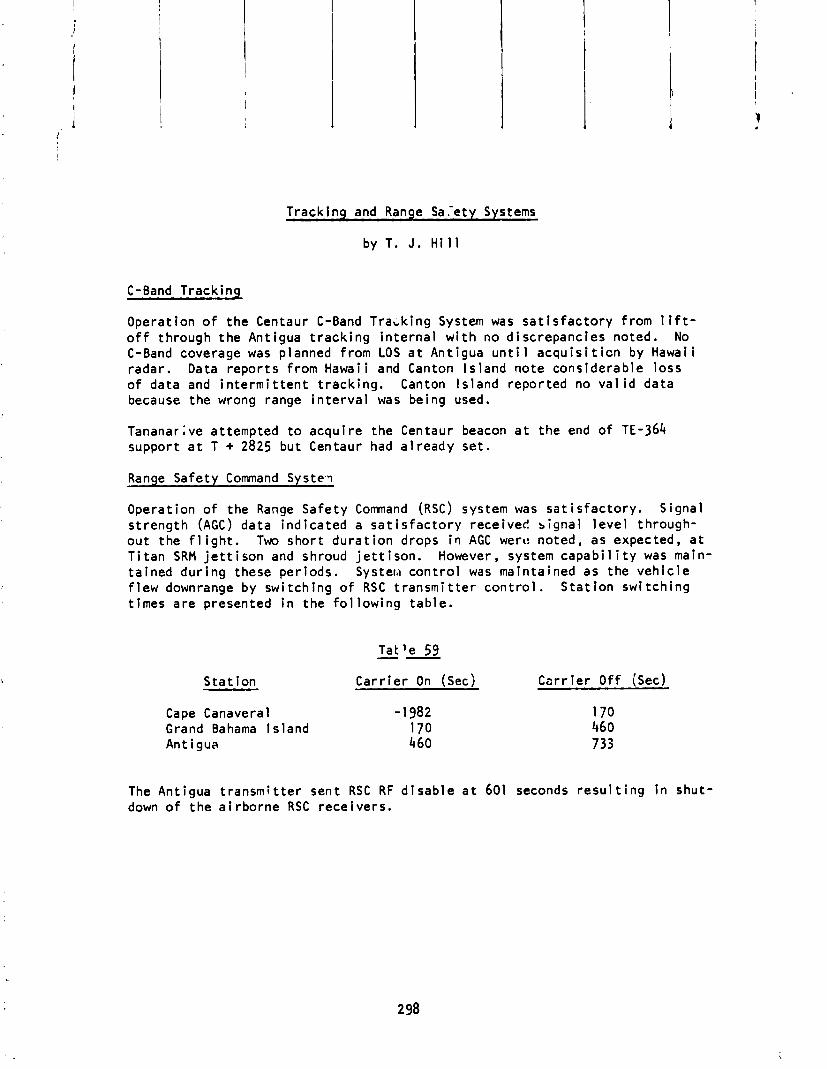
Tracking and Range Sa .-ety Systems
by T. J. H i l l
C-Band Tracking
Operation o f the Centaur C-Band Tracking System was s a t i s f a c t o r y from l i f t - o f f through the Antigua t r ack i ng i n t e rna l w i t h no discrepancies noted. No C-Band coverage was planned from LOS a t Antigua u n t i 1 acqu is i t i c n by Hawai i radar. Data repor ts from Hawai i and Canton l s l and note considerable loss o f data and i n t e r m i t t e n t t rack ing . Canton l s land reported no v a l i d data because the wrong range i n t e r v a l was being used.
Tananar ;ve attempted t o acqui re the Centaur beacon a t the end o f TE-364 support a t T + 2825 but Centaur had a l ready set .
Ranqe Safety Command Syste.1
Operat ion o f the Range Safety Command (RSC) system was sa t i s f ac to r y . Signal s t reng th (AGC) data ind ica ted a sa t i s f a c t o r y received s ignal l e ve l through- ou t the f l i g h t . Two shor t du ra t i on drops i~ AGC werc noted, as expected, a t T i t an SRM j e t t i s o n and shroud j e t t i s o n . However, system c a p a b i l i t y was main- ta ined dur ing these per iods. Systew con t ro l was rnaintalned as the veh i c l e f l e w downrange by swi tch ing o f RSC t r ansm i t t e r con t ro l . S ta t i on swi tch ing t imes a re presented i n the f o l l ow ing tab le .
S ta t ion Ca r r i e r On ( ~ e c ) Ca r r i e r O f f (Sec)
Cape Canaveral - 1982 Grand Bahama Is land 170 Antigua 460
The Antigua t r ansm i t t e r sent RSC RF d i sab le a t 601 seconds r e s u l t i n g i n shut- down o f the a i rborne RSC rece ivers .
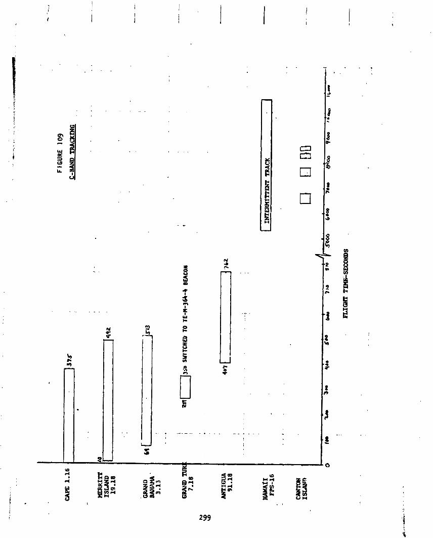
X DELTA T E - M - 3 6 4 - 4 SYSTEMS ANALYS l S
X DELTA TE-M-364-4 SYSTEMS ANALYSIS
Mechanical System
by R. C . Edwards
Dur ing t he TC-2 f l i g h t , t he Del ta s t r uc tu re performed s a t i s f a c t o r i l y . The p3yload a t t a c h f i t t i n g , TE-364-4 motor, and sp in t ab l e s a f e l y wi thstood the s t r u c t u r a l loadings imposed dur ing the booster and TE-364 t h r u s t per iod o f f 1 i g h t .
The mechanical events occurred on t ime and no anomalies were noted. The ten- s ion chord tha t secures the sp in t a b l e i n place funct ioned s a t i ~ f a c t o r i l y . The sp in rockets were f i r e d on time, breaking the tens ion chord. A sp in r a t e o f 92.5 RPM was imparted t o the TE-364-4 motor and spacecraf t . The r o t o r a t - tach ing clamp was severed on t ime a ~ d was j e t t i s o n e d due t o i t s own stored energy. Fol lowing clamp band separat ion, the fou r sp in t ab l e pe ta l s ro ta ted about hinges a t t h e i r base t o f r e e the TE-364-4 motor from the sp in tab le . The w i re c u t t e r device severed the w i r i n g harness between the sp in t ab l e and the t imer mounted on the payload a t t ach f i t t i n g . The payload clamp band and the "yo" weight were released on schedule and w i thou t any discrepancies noted.
A maximum a x i a l acce le ra t ion o f 13.6 g ' s occurred a t TE-364-4 burnout. The maximum pressure decrease i n the payload compartment was 0.66 p s i per second.
A more de ta i l ed and extens ive r epo r t on the performance o f the De l ta Stage w i l l be publ ished by the McDonnell Douglas Ast ronaut ics Company i n Ju l y !975.

Propuls ion System
The performance o f the TE-M-364-4 sol i d propel l a n t motor was norma I. The i g n i t i o n de lay was 44.0 seconds. The a c t i o n t ime o f the motor was 43.6 seconds. The a c t i o n t ime i s def ined as t he t ime i n t e r ~ a l from when the chamber pressure reaches 300 ps i a on the ascending p o r t i o n o f the chamber pressure t ime h i s t o r y curve t o when i t reaches 100 ps i a on the descending po r t i on o f the curve. Combust ion wai smooth and s tab le . The maximum cham- ber pressure was 610 psia.

E l e c t r i c a l System
by C . H. A r t h
The telemetry ba t t e r y was s a t i s f a c t o r i l y above the red1 i ne value (26.0 VDC) a t l i f t o f f reading 29.3 V D C . The f l i g h t h i s t o r y o f the telemetry ba t t e r y vo l tage and cur ren t ind icated normal performance, The ordnance ba t t e r y sat- i s f i e d the r e d l i n e value o f 11.0 VDC reading 11.06 V D C a t l i f t o f f and per- formed normal 1 y.
Telemetry and Tracking Systems
by T. J. H i l l
Three radar s t a t i ons (BDA, VAN and TAN) o f the Space Tracking and Data Ac- qui s i t ion Network repor ted t h a t the TE-M-364-4 stage beacon was respond ing w i t h a "weak and lob ing" s igna l . Lobing i s def ined as received s igna l s t reng th v a r i a t i o n s i n the transponders pu lse re tu rns . The STDN No. 502.3 Network Operations Plan (NOP) f o r C-Band Systems spec i f i es le f t -hand c i r - c u l a r p o l a r i z a t i o n f o r Del ta antennas. STDN s ta t i ons would normal ly con- f i g u r e t h e i r s t a t i ons f o r l i n e a r v e r t i c a l p o l a r i z a t i o n . Bermuda (BDA, Vanguard (VAN) , and Tananar i v e (TAN) used 1 inear v e r t i c a l p o l a r i z a t i o n , apparent ly causing the TE-M-364-4 s igna l t o appear weak and lob ing. Sta- t i ons con f i gu ra t i ng t o c i r c u l a r p o l a r i z a t i o n (Grand Turk, Ascension-STDN and Ascension-ETP) repor ted nominal s igna l s t rengths. The problem appears t o be a r e s u l t o f c ross -po la r i za t ion between the TE-M-364-4 and the three STDN s ta t i ons r epo r t i ng d i f f i c u l t y .
S ta t ion coverage data i s included i n Sect ion I X i n the d iscuss ion o f the Centaur C-Band t rack ing .
XI FACILITIES AND AGE

X I FACILITIES AND AGE
Complex 41 Faci 1 i t ies
b j M. Crnobrnja
Mod i f i ca t ions Since TC-1
The launch o f TC-1 Proof F l i g h t r esu l t ed i n considerable damage t o Trans- po r t e r No. 2 due t o a post-launch f i r e . The damage was assessed by a Launch Damaae Committee and the f o l l o w i n g ac t ions were implemented i n re - sponse t o the recommendations made by the Launch Damage Committee:
1. Close a l l openings i n the t r anspo r t e r base and masts t o prevent e n t r y o f d i r e c t f lame and debr is .
2. I n s t a l l heat r e s i s t a n t boots over the SRM umb i l i ca l cables.
3. Incorporate bulkheads i n the t ranspor te r booms.
4. Provide quick-opening la tches f o r access doors a t the base o f the t rans- po r t e r masts.
5. E l iminate t he F i r e x system f o r the water deluge system.
6. I n i t i a t e a prelaunch c loseout inspect ion o f areas a t the base o f the masts.
7. Revjse the post- launch inspec t ion team procedures.
8. Operate the DTS and DRS systems u n t i l the launch complex i s secure a f t e r launch.
9. Add a C02 i n e r t i o n system f o r the base o f the t ranspor te r masts and booms.
10. Add a new water deluge system t o the base o f the t ranspor te r masts.
1 1 . Modi fy the LOX vent l i n e t o r e t u r n LOX t o grade ra the r than dump overboard from Level 9 o f t he Urnbi 1 i c a l Tower.
Faci 1 i t y and S i t e Operation
A i l f a c i l i t y systems requi red f o r the TC-2 veh i c l e performed s a t i s f a c t o r i l y . Launch damage was minimal and t y p i c a l , i f not c leaner, than o ther T i t an launches.
F l u i d Systems Operations
by M. Crnobrnja
T i t a n F rope l lan t Loading
T i t an veh i c l e p rope l l an t load ing was i n i t i a t e d on F-3 day and completed on F-2 day. Table 60 provides q u a n t i t i e s and temperatures o f propel l a n t s loaded on the T i t an stages.
The p rope l l an t loading system was i d e n t i c a l t o TC-1 except f o r the sutomat ic temperature compensators which have been deleted. System operat ion was sat - i sfactory .
Centaur Prope l lan t Loadina
Centaur propel l a n t s were tanked dur ing launch countdown. Sign i f i can t sys- tem operat ion event t imes a re prov ided i n Table 61. The system opera t ion was s a t i s f ac to r y f o r launch countdown tanking, detanking dur ing scrub and re tank ing f o r launch.
The Centaur load ing system was i d e n t i c a l t o TC-1 except f o r the r e rou t i ng o f the LOX vent l i n e from Level 9 t o grade.
L i q u i d He1 ium System
L iqu id hel ium f l ow f o r ch i l l down o f Centaur veh i c l e turbopumps was i n i t i a t e d dur ing countdown. Table 61 provides system operat ion event times. System operat ion was sa t i s f ac to r y .
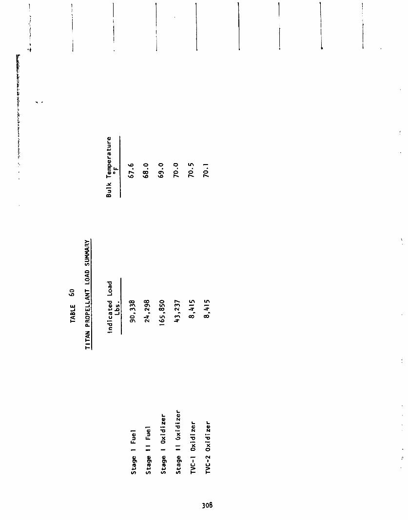

TABLE 61
S t a r t LO2 Chilldown
S t a r t LO2 Tanking
S t a r t LH2 C h i l l d w n
S t a r t LH2 Tanking
LO2 a t F l i g h t Level
LH2 a t F l i g h t Level
S t a r t LHe Chi1 ldown
Secure LH Tanking 2
.I Secure LO2 Tanking
Secure LHe Ch i 1 1 down
CENTAUR SYSTEM EVENTS
Actual Time M1n:Sec
Pneuma t i c Ground Systems
by A. C. Hahn
The pneumatic systems inc lude t h e pr imary helium, emergency helium, purge he1 ium, and rou t i ne n i t rogen systems. The three he1 ium systems a re pecu- l i a r t o Centaur. The r o u t i n e n i t r ogen storage suppl ies both the T i t a n and the Centaur n i t r ogen systems. Figures 110 through 114 prov ide informat ion on system operat ions.
System operat ion was s a t i s f a c t o r y and w i t hou t anomalies dur ing launch count- down.
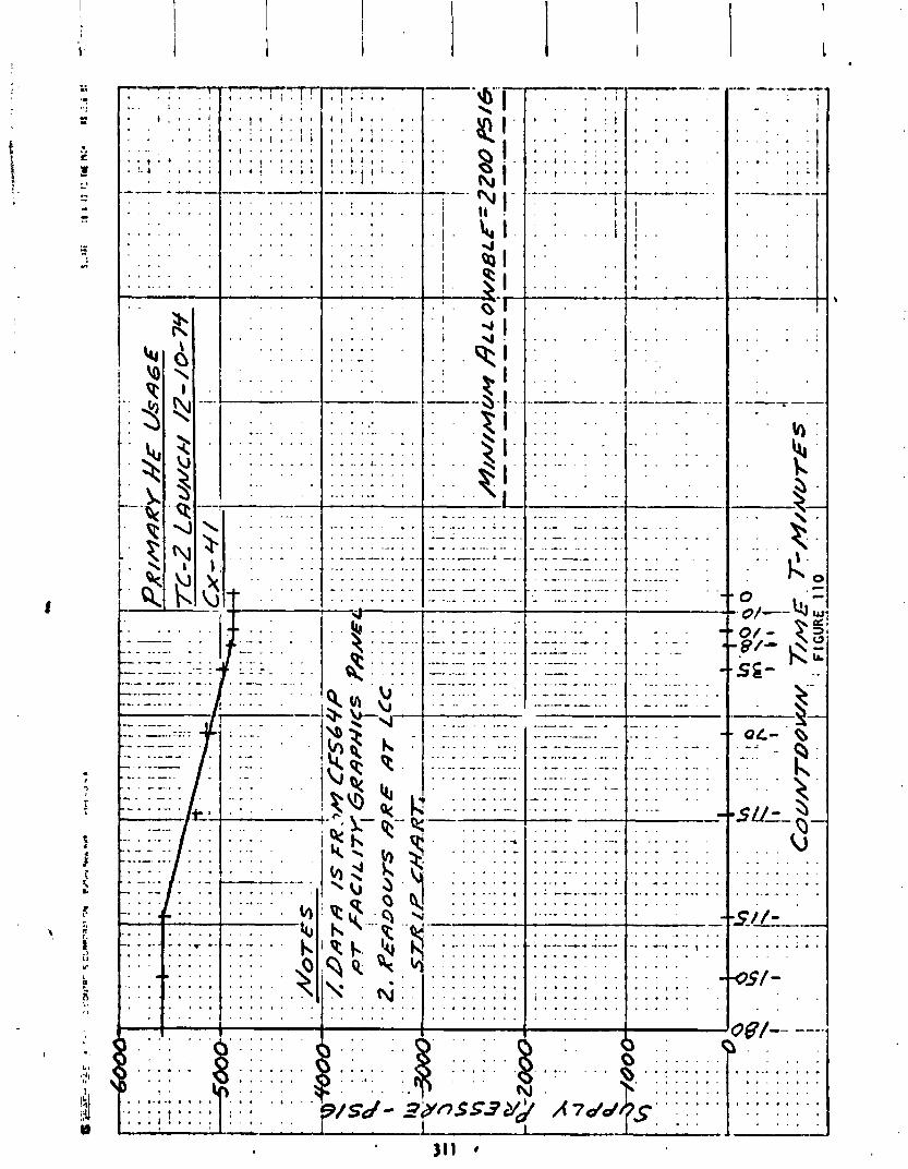
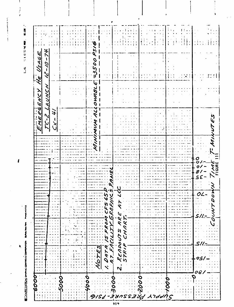
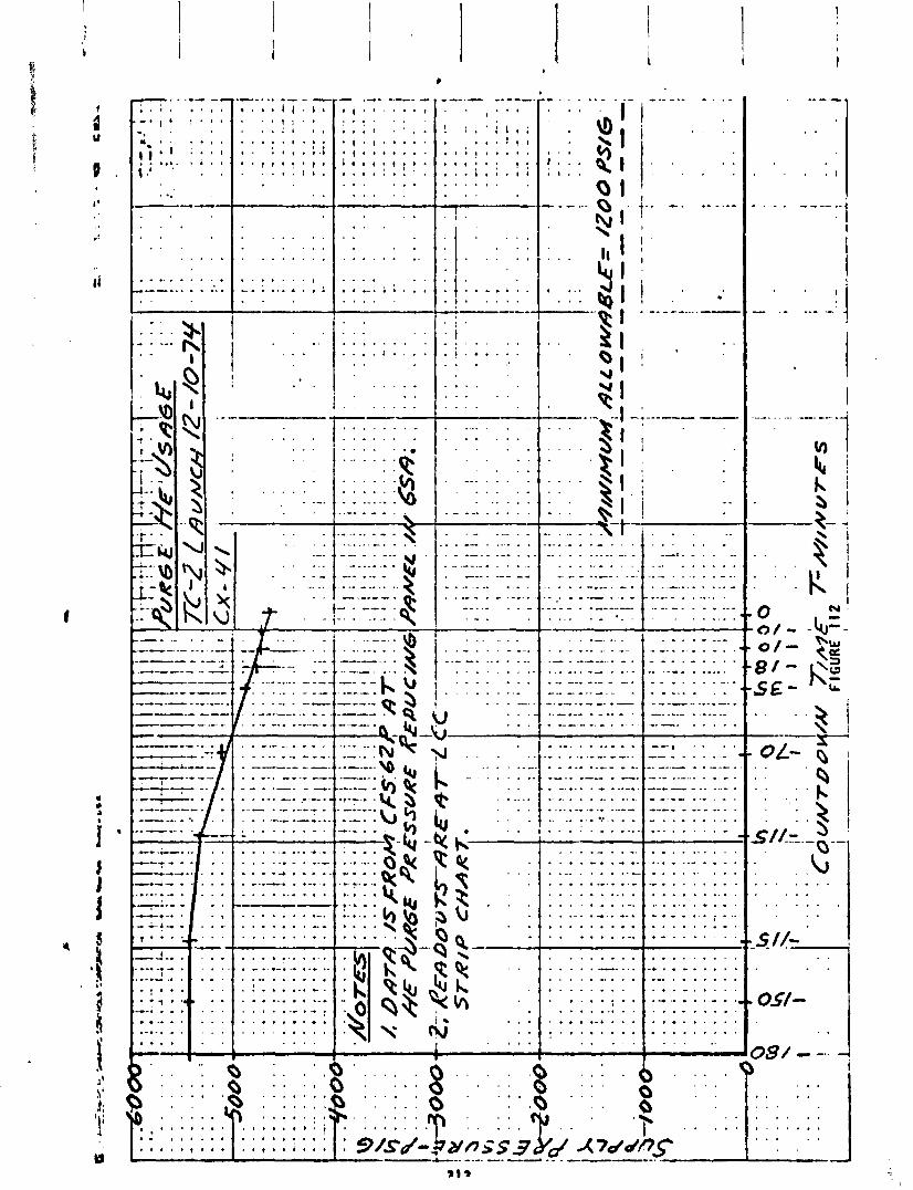
.. . . . ,.-
. 9 .
, . 0 -1- . 4 . . .
t . . . 8 1 . . 2 I
.-..a .. -- *. - r . a I i i . 4 , . . , t i . . . . . : , . . . . . . . . . . . , . : 1 , . ; . i . . , , * ! . , * . . I . l i .
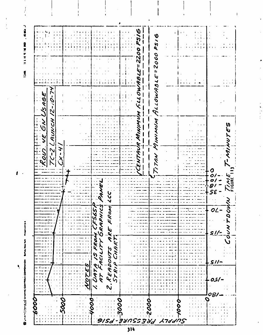
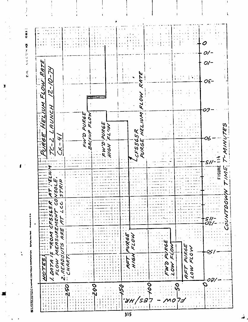
Environmental Control Systems
by A. C . Hahn
T i t a n A i r Condi t ion ing System Operation
The core a i r cond i t i on ing system suppl ies condi t ioned a i r t o compartment 2A and t o the s t a r t ca r t r idges . System operat ion was s a t i s f a c t o r y anomalies dur ing launch countdown.
Centaur Environmental Control System
The Centaur Environmental Control Systern prov ides condi t ioned a i
and w i thou t
r o r gaseous n i t r ogen t o the payload, Centaur equipment module, and i n t e r s tage adapter compartment. System operat ion was switched from a i r t o GN2 e a r l y i n the one hour ho ld p r i o r t o the s t a r t o f Centaur p rope l l an t ;oading. Figures 115 through 125 and Table 62 prov ide in fo rmat ion on the Gi42 p c r t i o n o f the system.
System operat down.
Right a f t e r 1 the umbi 1 i c a l
i on was s a t i s f a c t o r y and w i thou t anomalies dur ing launch count-
i f t o f f the ground h a l f o f the payload disconnect separated from duct. Movies and measurements o f the s t a r t o f payload duct
pressure decay show t h a t the ground h a l f separated from the a i rborne h a l f o f the disconnect p roper l y . The most l i k e l y cause o f the separat ion o f t he ground h a l f from the umb i l i ca l duct i s severe bu f f e t i ng . The umb i l i ca l duct i s sup- por ted from the Nor th Mast. Vehic le d r i f t toward the North Mas: caused the severe bu f f e t i ng .
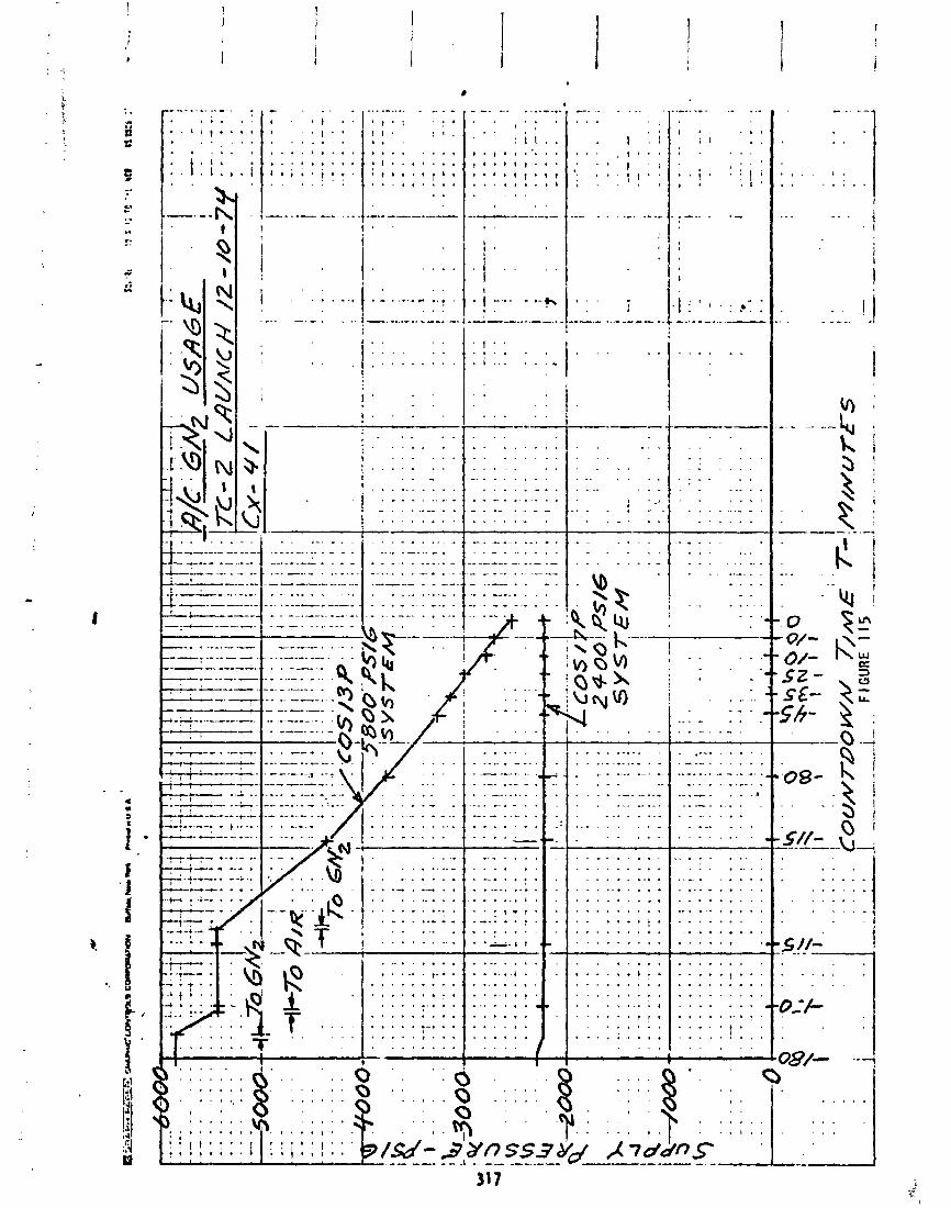
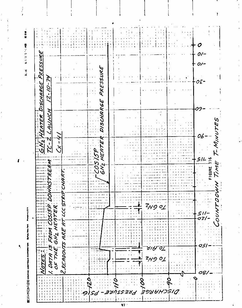


. . . . , . . . . I t ; , , : . i . . . , . , ,
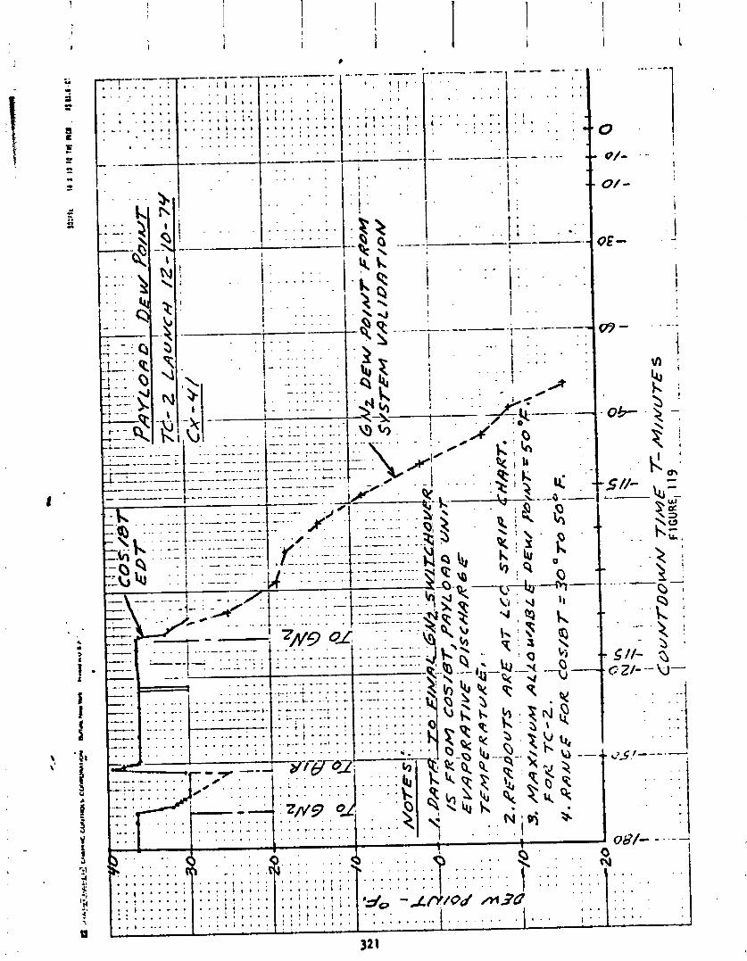
._- - - .-- ' , I ! ! '
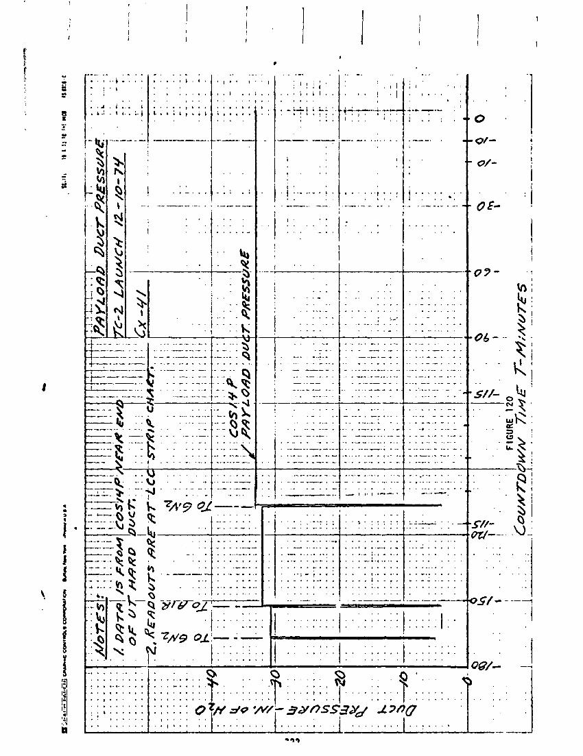

" ' I . '
: . . , : . I . . . .
, : ; , . . . . . . . . . . . . . . . . , > . . . . . . . . I . . . . . A t . . .
I . . . . . . . . . I . . . . . . . . .
. i . . . . . . . .
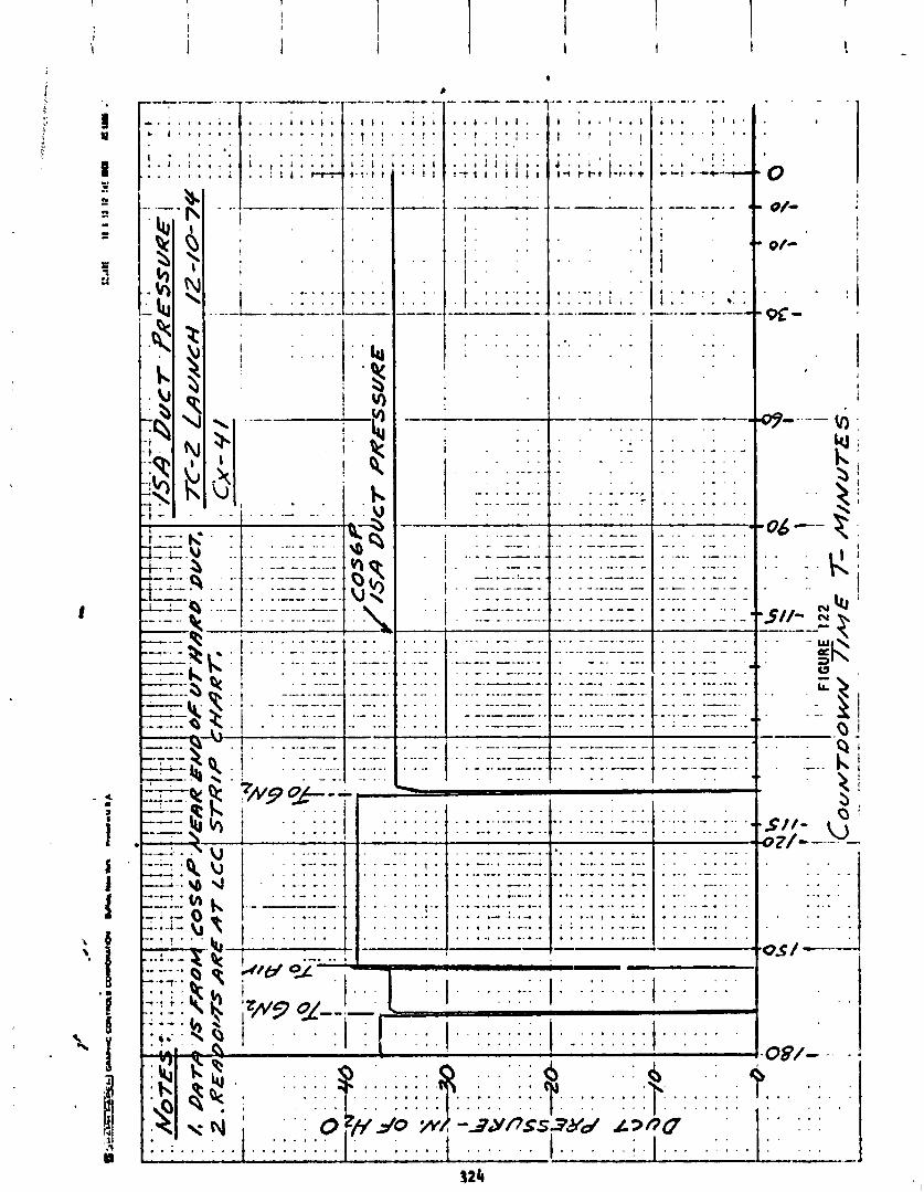
1 .
1 . . . . . . . . . . . . . . . . . . . 1 . 1 . . . . . . . . . . . . i : . I ; : : . : : .:: ---a- ---I- ---. ---- . - ---- ----'-a
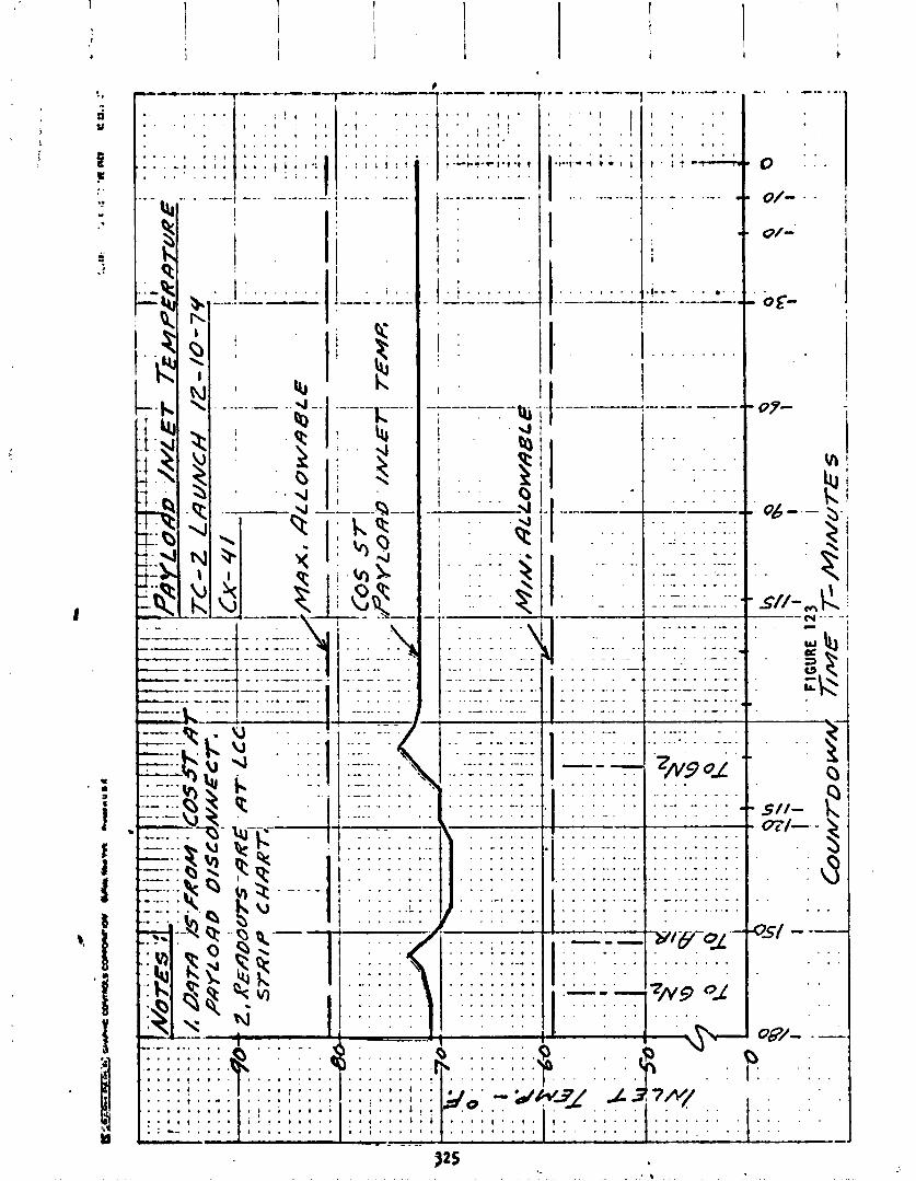

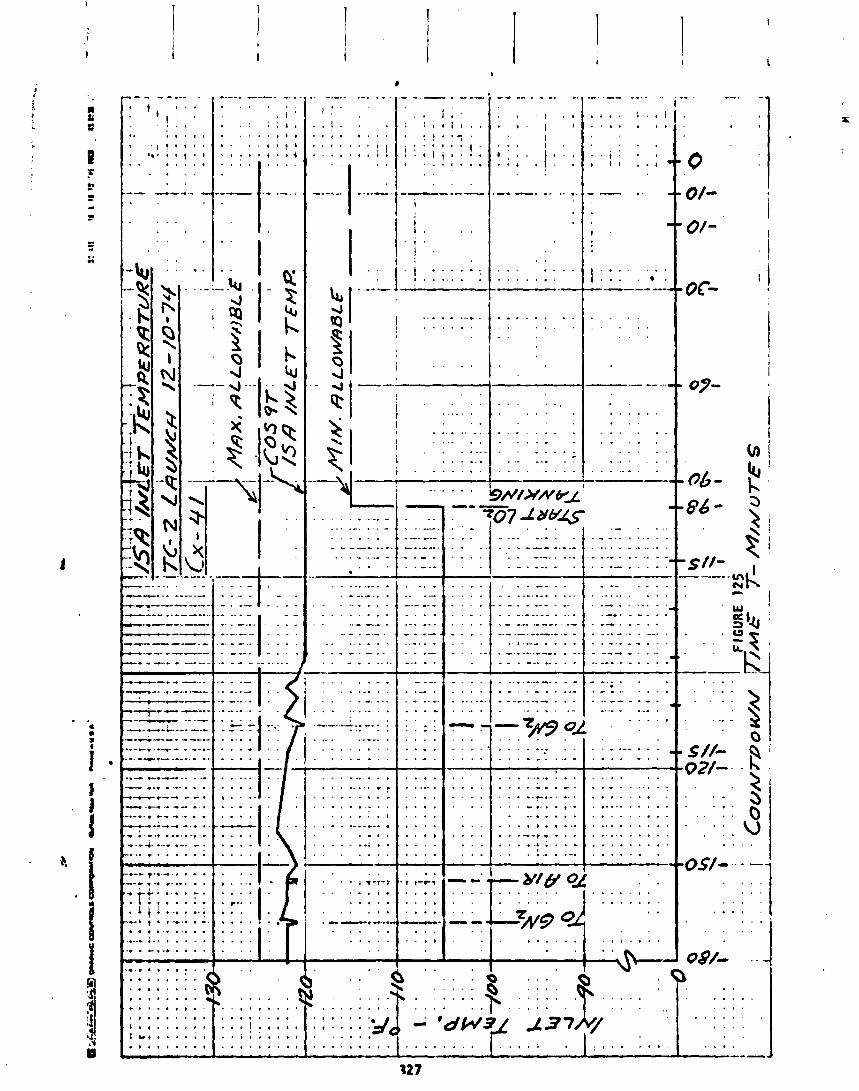

COMPARTMENT
pay l oad
CEM
TABLE 62
A/C G N l FLOWS - TC-2 LAUNCH - DECEMBER 10, 1974
COMPLEX 41
GN2 FLOW, LB/MIN REQU I RED ACTUAL MEASUREMENT --
COS24R recd a t LCC panel meter
COS22R read a t LCC panel meter
COS23R read a t LCC panel m L e r
Data i s f rom f l o w c o n t r o l assemblies downstream o f t h e A/C u n i t s

E l e c t r i c a l Ground Systems
by J. Nestor and H. E. Timmons
T i t an E l e c t r i c a l - The T i t an e l e c t r i c a l ground systems con f igu ra t ion was e s s e n t i a l l y the same f o r the launch o f TC-2 as i t was f o r TC-I. The launch countdown i s i n i t i a - ted and monitored from the Launch Control Console (LCC) i n the Launch Con- t r o l Center. The actua l processing o f c r i t i c a l readiness and ho ld func t ions i s performed by the Control Monitor Group (CMG), a t ime-based automatic countdown c o n t r o l l e r . The CMG works i n con junct ion w i t h per iphera l equipment such as the Vehicle Checkout Set (VECOS), Tracking and F l i g h t Safety Monitor Group (TFsMG) , and F l i ght Safety Checkout Control Mon i t o r Group (FSCCMG) . Thz data received dur ing the countdown i s t ransmi t ted t o var ious record ing devices over hard1 ine transmiss ion systems, both from the veh i c l e and from the ground PCM system. Capab i l i t y a l so e x i s t s t o s t r i p data out o f the open locp RF te lemetry s igna l .
The f l i g h t o f TC-2 was the f i r s t usage o f a newly b u i l t van/transporter se t b u t l t s p e c i f i c a l l y f o r NASA programs. The v a d t r a n s p o r t e r set used on TC-1 was one which was obtained from the A i r Force, except f o r the Centaur Mobi le Transfer Rosm (MTR), which was new-bui l d by NASA. The t ranspor te r s t r u c t u r e and the MTR f o r TC-2 were e s s e n t i a l l y copies o f the TC-1 equipment. However, the T i t an van incorporated both T i t a n launch con t ro l and ground instrumenta- t i o n equipment i n t o a s i n g l e van (Figure 126). Prev ious ly , t h i s equipment was segregated i n t o two separate vans. The ground ins t rumentat ion equipment was new s ta te -o f - the -a r t design incorpora t ing a h igher s igna l l e ve l f o r be t - t e r noise r e j ec t i on . The launch con t ro l equipment was a l l b u i l t t o the o r - i g i n a l T i t an designs, w i t h some o f the components being obtained from a program of refurbishment o f pro to type equipment which had been p rev ious ly stored a t the con t rac to r ' s p lan t i n Denver. The t ranspor te r cab l i ng was a l s o a new design which s imp l i f i ed the o v e r a l l system w i r i n g and reduced the amount of cab l i ng requ i red.
A few modi f icat ions were made t o the ground systems a f t e r TC-I. The more major cnanges included the add i t i on o f C02 and water deluge systems on the t ranspor ter f o r f i r e prevent ion, add i t i on o f cu r ren t shunts i n the ground power suppl i es t o provide added data f o r t roubleshoot ing, and the a d d i t i o n o f a backup generator a t the V I B t o provide power i n the event o f a main AC power outage.
One major change i n the data system involved the f i r s t usage of the Data Re- cording and Quick-Look Set (DRQLS) i n the V I B . DRQLS replaced the remoLe Data Recording Set ( ~ 3 s ) p rev ious ly used i n the V I B t o eva luate launch con t ro l event data. DRQLS provides a magnetic tape record ing of the data as we1 l as rea l time p r i n t o u t o f each event change tlme-tagged t o a r eso lu t i on o f 3 m i l - l iseconds.
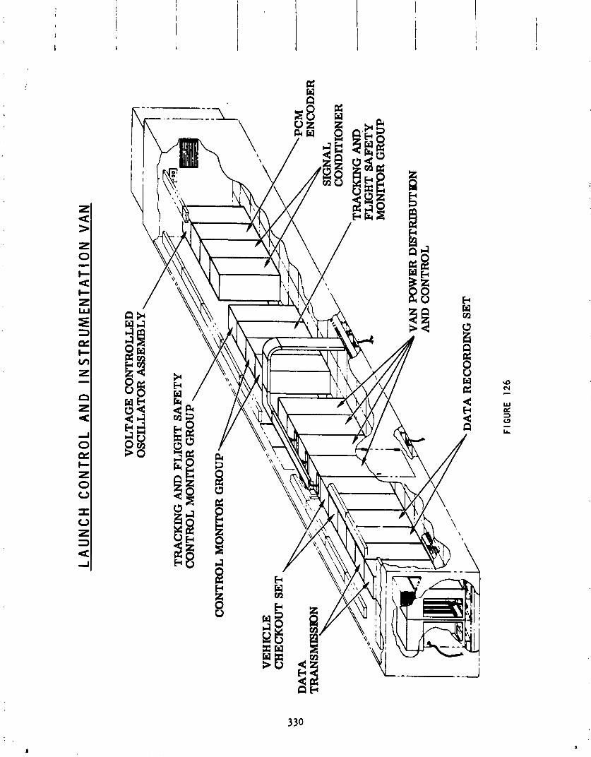
LA
UN
CH
CO
NTR
OL
AN
D
INS
TR
UM
EN
TA
TIO
N V
AN
FIGU
RE
126
The launch of TC-2 was o r i g i n a l l y scheduled t o take place two days e a r l i e r than i t a c t u a l l y d id . Th is attempt was scrubbed due t o the f a i l u r e o f the Centaur LH2 boost pump i n l e t temperature transducer.
During the aborted at tempt several minor problems occurred i n the ground systems. These problems had no impact on the launch attempt nor the ac- t ua l launch two days l a t e r . The problems included f i v e i n d i c a t i n g lamps on var ious items o f checkout equipment which were burned out dur ing t he launch preps and no ise on one channel o f data taken dur ing the Automatic Vehic le V e r i f i c a t i o n . An amp1 i f i e r f a i l e d i n the s t r i p cha r t recorder r e - cord ing LOX F i l l and Dra in Valve temperature a t T-120 minutes. The ampl i - f i e r was replaced and re tes ted dur ing the one hour b u i l t - i n ho ld and per- formed p roper l y t he rea f t e r . When CMG "B" power was appl ied f rom the Launch Control Console (LcC) a t T-90 minutes, the i n d i c a t o r on the LCC panel f a i l e d t o l i g h t . A check of the data showed t h a t power was on and t h a t t h i s , too, was a burned ou t l i gh tbu lb . The CMG count was then s t a r t e d and a l l events proceeded normal ly u n t i l the ho ld and abor t f o r the boost pump transducer f a i l u r e a t T-10 minutes.
The countdown and launch o f Titan/Centaur -2 was accomplished w i t h no major launch con t ro l o r ground ins t rumentat ion systems problems. Table 63 pro- v ides a l i s t o f minor anomalies discussed i n the f o l l ow ing paragraphs. The count picked up a t T-625 minutes a t 2:36 p.m., EST (19:36 GMT), on December 9, 1974.
P r i o r t o the s t a r t o f the countdown the Programmable PCM Decommutator i n the VIB used t o decommutate T i tan t e l e a e t r y da% dropped ou t o f synchronizat ion. This decomnutator i s used t o s t r i p va r ious measurements ou t o f the te lemetry data stream f o r d i sp l ay and eva luat ion. Loss o f synchron izat ion r e s u l t s i n d isp lay readings which a re no t represen ta t i ve o f the ac tua l data.
This problem o f "decom dropout" hsd been present on a random bas is s ince the Terminal Countdown Demonstrat i on (TCD) on October 22, 1974. Trouble- shoot ing had been unable t o i s o l a t e the cause o f the problem. I n order t o c l ea r the problem once i t had occurred, the mylar tape con ta in ing the addres- s ing i ns t r uc t i ons must be read i n t o the memory o f the decomnutator by use o f a tape reader. The t ime t o c l ea r the problem i s approximately 3 minutes. As o f the launch date, the problem never had occurred more than two o r three times i n any one day, therefore, t he re was no launch cons t ra i n t assigned.
During the launch countdown the problem recurred one t ime, a t approximately T-500 minutes. The memory was re1 oaded and synchron i z a t ion reacqui red. The problem d i d no t recur any more through the remainder o f the launch countdown a c t i v i t i e s . Had the problem increased i n scope such t h a t re loading the mem- o r y could not so lve i t , a backup p l an us ing a secondary data system had been agreed t o by t he concerned organizat ions.

TAB
LE
63
- T
ITA
N L
AUN
CH
C
ON
TRO
L AN
D
GRO
UND
INS
TRU
ME
NTA
TIO
N
ANO
MAL
IES
TIM
E -
P r i o
r to
Countd
ow
n
T-3
00
m
in.
T +
0.34
5 se
c.
T +
0.42
7 se
c.
W
T +
0.45
0 se
c.
W
hl
PRO
BLEM
C
AUSE
Tit
an
air
bo
rne
PC
M d
eco
mm
uta
tor
los
t s
yn
ch
ron
iza
tio
n
Cau
se unkn
ow
n
Tit
an
la
nd
lin
e m
ea
sure
me
nt
7703
-+N 04 injectant pres- Transducer or ground
sure
;dro
pp
ed
ap
pro
xi m
a te
l y
5% i n
va
f ue
sig
na
l c
on
dit
ion
er
"Sta
ge
II
Hy
dra
uli
c A
ccu
mu
lato
r P
rech
arg
e P
res
su
re N
o-G
o"
Ai r
bo
rne
pre
ss
ure
in
dic
ati
on
cam
e on -
rem
ain
ed
un
til
2C
IE u
mb
ilic
al
dis
- s
wit
ch
an
om
aly
co
nn
ect
"VEC
OS
CST
P
ower
E
na
ble
'' s
ign
al
pu
lse
d o
ff a
nd
b
ack
on
Cau
se un
know
n 3
mil
lis
ec
on
ds
la
ter
Tit
an
um
bil
ica
l d
isc
on
ne
ct
sequence
n
ot
as
pre
dic
ted
1 a
nya
rd
ov
er 1
oad
A t approximately T-300 minutes, T i t a n measurement 7703 dropped i n value approximately 4-5 percent. Th is i s a measurement o f the N204 i n j e c t a n t pressure i n the Thrust Vector Control (TVC) tanks on the Sol i d Rocket Motors (sRM) which i s t ransmi t ted over the land1 ine ins t rumentat ion sys- tem. Th is i s a s i g n i f i c a n t measurement i n t h a t i t i s d isp layed on the Pad Safety O f f i c e r ' s (PSO) console i n the Launch Control Center. I t i s one o f the measurements he uses t o make a "go/no-go" determinat ion on the s ta tus o f the launch veh ic le . There a re two o ther measurements on the a i r - borne te lemetry system which essen t ia l 1 y dupl i ca te the suspect measurement. Both o f these measurements were steady and agreed i n value w i t h each o ther w i t h i n 0.5 percent. I t was, therefore, determined t h a t the problem was conf ined t o t he ins t rumentat ion system only , e i t h e r i n the transducer o r the ground s igna l cond i t i on i ng system. Verbal assurance was g iven t o the PSO by the UTC engineer ing team t h a t the pressure was proper based on t h e i r moni tor ing o f the te lemetry data. Based on t h i s assurance and a p e r i o d i c update over the communicatio::~ system, the PSO al lowed the launch t o con- t i nue .
The o n l y o ther ground systems problems occurred a f t e r SRM i g n i t i o n . A t 7: 1 1 :01.363, 0.306 seconds a f t e r SRM i g n i t i o n but 0.066 seconds before i n d i c a t i o n o f veh i c l e movement, the Stage I I Hydrau l ic Accummulator Pre- charge Pressure No-Go i n d i c a t i o n came m as ind ica ted by Data Recording Set (DRS) channel 028 going high. Normally t h i s would i nd i ca te a drop i n the precharge pressure below the lower a l lowab le l i m i t . However, the go i n d i c a t i o n from the same pressure sw i tch d i d no t go o f f , i n d i c a t i n g a problem i n the switch i t s e l f r a t he r than an ac tua l pressure decay. Both ind ica t ions went o f f as expected when the T i t a n 2ClE umb i l i ca l disconnected a t 7: 1 1 :01.588. The Stage I I Hydraul i c Accummul a t o r Precharge Pressure Go s igna l i s a core readiness monitor; i . e . , i s a p r e r e q u i s i t e t o en te r i ng the termina l countdown. Once the termina l countdown begins a t T-32 seconds, the pressure i s no longer included i n the launch ladder. The NO-GO p a i t o f the swi tch provides an i n d i c a t i o n o n l y and i s no t invo lved i n t he launch sequence.
A t 7:11:01.444, again a f t e r i g n i t i o n but p r i o r t o l i f t o f f , a s igna l which goes from the Control Monitor Group (CMG) t o the Vehic le Checkout Set (vECOS) pul sed o f f and back on 3 m i l l i seconds l a t e r . The s igna l , ' IVECOS CST Power Enabled," i s used t o t u rn VECOS power on when a t e s t i s t o i n - c lude a p lus count demoqstration. I t i s no t used a t a l l dur ing a launch. The pu lse probably occurred as the r e s u l t of the v i b r a t i o n caused by the SRM i g n l t i o n sound wave. The s igna l i s a patched s igna l us ing patch cords i n a proqram board. Since i t was not s i g n i f i c a n t t o the launch and s ince the patchboard must be removed and repatched p r i o r t o the next usage, no at tempt w i l l be made t o i s o l a t e the exact problem,
The disconnect sequence o f the T i t a n umb i l i ca l s was no t per p lan. The Stage I e l e c t r i c a l umbi 1 i c a l ( ICIE), which was t o be the f i r s t core umbil i c a l ou t , a c t u a l l y came ou t a f t e r one o f the upper Stage I I e l e c t r i c a l umb i l i ca l s , 2AlE. No det r imenta l e f f e c t s o f t h i s sequence were noted, the o n l y concern being t h a t the sequence had not p rev ious ly been tested. The umbi 1 i c a l re- lease sequence on TC-I had a l so been d i f f e r e n t than the des i red sequence.
As a r e s u l t o f the eva lua t ion o f the TC-1 sequence, i t was decided t o modify the lanyard r i g g i n g associated w i t h a l l the T i t an umb i l i ca l s i n an attempt t o achieve t he des i red sequence f o r TC-2. The lanyards f o r the two So l i d Rocket Motor umbil ic. ls, LBlE and RBlE, were shortened by one inch each wh i l e the core umbi 1 i c a l lanyards were each lengthened by va r ious amounts (1ClE - 1/4 inch; 2A1E - 3/8 inch; 2A2E - 1/2 inch; 2C1E - 3 /4 inch) . I n add i t i on , an adjustment was made i n the J-bar p o s i t i o n f o r LBlE and RBlE which lowered i t 1/2 inch. Normally, these adjustments would have resu l t ed i n the proper sequence. However, on the TC-2 launch, the J-bar t o which the lC lE umb i l i ca l was at tached became overloaded causing i t t o deform. Th is deformat ion caused the umb i l i ca l t o release s l i g h t l y l a t e r than pred ic ted. The load i n the lC lE lanyard was estimated t o be about 250 pounds based on the 318 inch permanent deformation which remained a t the J-bar a f t e r launch. The a l lowab le load l i m i t s fo r the s t a t i c p u l l fo rce on t h i s umb i l i ca l a re 70 t o 230 pounds. The dynamics o f the launch may have added t o the s t a t i c forces normal ly encountered dur ing t e s t i n g which would account f o r the deformat ion and r e s u l t a n t l a t e um- b i l i c a l disconnect. Post-launch review has shown t h a t t h i s sequence i s accept- ab le and no change w i l l be made t o the umb i l i ca l lanyards f o r on-going vehic les . Table 64 shows the T i taa umbi 1 i c a l sequence.
Centaur E l e c t r i c a l
A1 1 systems performed s a t i s f a c t o r i 1 y throughc~! i countdown and launch operat ions. No problems nor any s i g n i f i c a n t discrepancies were observed. The second MTR, i n con junct ion w i t h Van Set No. 4, was used f o r the f i r s t t ime i n support o f a launch, and i s scheduled t o be used next t o support a c t i v i t i e s f o r the V i k i ng A (TC-4) l amch .
Some important mod i f i ca t ions t o Complex 41 were implemented a f t e r the launch of TC-1 t o prov ide f o r improved operat ions and t o accommodate TC-2 conf igura- t i o n changes. One o f the more s i g n i f i c a n t design improvements, r e s u l t i n g i n lower opera t ing costs, was the incorpora t ion o f "Local Control" c a p a b i l i t y i n the AGE Bu i ld ing and MTR. The veh i c l e power and pneumatic systems were modif ied t o permi t , a t the cognizant engineer 's op t ion , the performance o f checkout and v a l i d a t i o n procedures a t the complex w i thou t the support from the VIB t h a t had p rev ious ly been necessary. Th is change permi ts more expedi t ious per fo rmarm o f t e s t s i nvo l v i ng these two systems, a t the same t ime f rees the VIB f o r o ther tasks t h a t could be performed concurrent 1 y.
The comp!ex was a l so modif ied from TC-1 con f i gu ra t i on t o p rov ide f o r performance of thc boost pump r o t a t i o n t e s t s as described i n Sect ion I X o f t h i s r epo r t . The p ropu ls ion and a t t i t u d e con t ro l system was madi f ied t o prov ide f o r GSE con t ro l t o operate and monitor the sp in t e s t s from e i t h e r the AGE Bu i l d i ng o r the V I E . The change i n TC-2 mission requirements from two burn t o f ou r burn mandated the use o f two a i rborne he1 ium b o t t l e s as i n TC-1. Th is change, as descr ibed i n Section I X o f t h i s repor t , had the added requirement t ha t the two b o t t l e s be capable o f being i n d i v i d u a l l y charged o r discharged. The pneumatic con t ro l system was modi f ied t o prov ide t h i s c a p a b i l i t y from e i t h e r the complex o r the VIB, as we l l as p rov id ing the added ins t rumentat ion t o permi t continuous mon- i t o r i n g o f b o t t l e temperatures and pressures v i a land l ines .
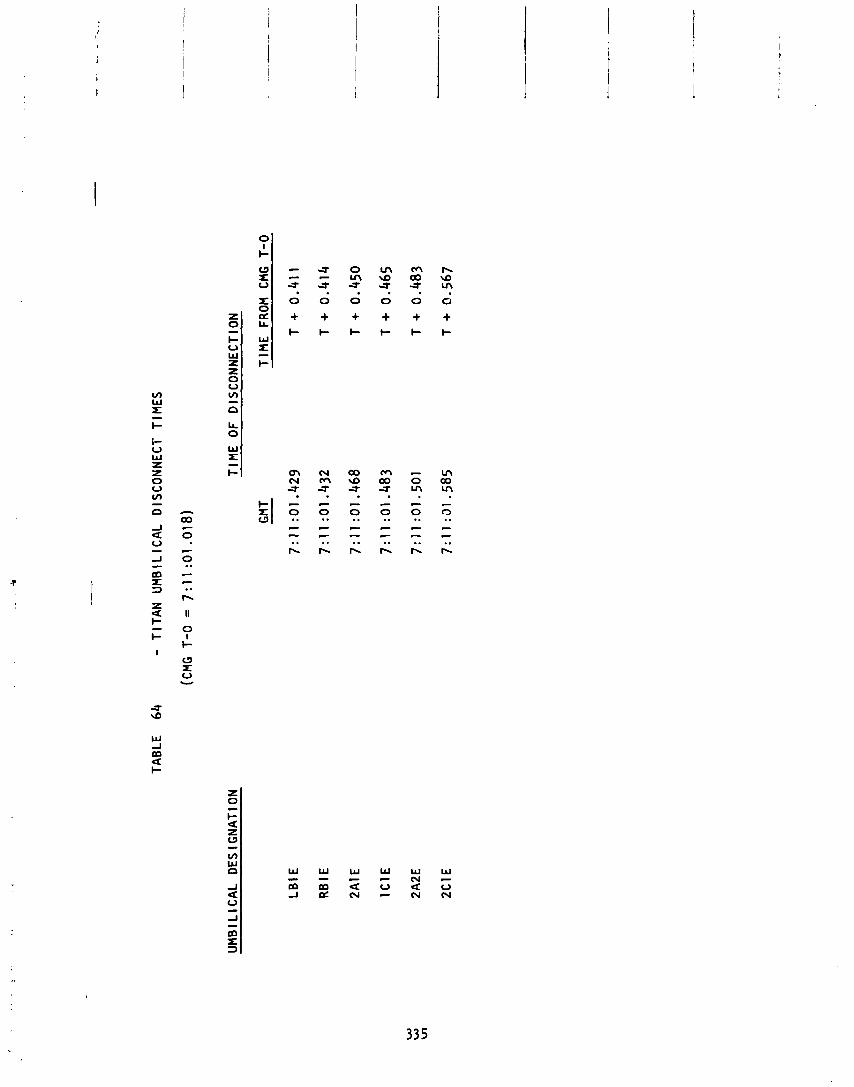
W W W W W W - - c c N - m m a u a o J c Z N - N N
Centaur U m b i l i c a l s
The Centaur u m b i l i c a l s performed s a t i s f a c t o r i l y w i t h one except ion . The shroud c a v i t y pressure probe u m b i l i c a l d i d n o t separa te as planned. T h i s u m b i l i c a l c o n s i s t s o f a v i n y l tube whictr s l i p s over a 1/4- inch tube which p ro t rudes through t h e shroud about two inches. The tube i s l oca ted near t h e LH2 f i l l and d r a i n va l ve . Between the su r face o f t h e shroud and the end o f t h e tube i s a c o i l o f w i r e ( tube s t r i p p e r ) t o which a r e t r a c t l a n - yard i s at tached. The r e t r a c t l anya rd i s ac tua ted w i t h t h e LH2 f i l l and d r a i n v a l v e lanyard. Post- launch examinat ion o f t h e pressure probe u m b i l i - c a l revea led t h a t t h e tube s t r i p p e r was n o t a t tached t o t h e lanyard and the vin.yl tube had f r a c t u r e d w i t h v e r y jagged edges, which seems unusual f o r v i n y l tub ing. GDC has performed some spec ia l t e s t s t o determine t h e cause o f t h e u m b i l i c a l f a i l u r e . The r e s u l t s o f t 5 e t e s t i n g a r e presented i n GDC r e p o r t 671-6-75-1 0 t i t l e d "Shroud C a v i t y Pressure Probe Umbi 1 i c a l . I' GDC w i 1 1 ma in ta in t h e e x i s t i n g c o n f i g u r a t i o n o f t he Shroud C a v i t y Pressure Probe U m b i l i c a l Re t rac t System 2xcept t h a t t hey w i l l r ep lace t h e present tube s t r i p p e r w i t h one made from l a r g e r d iameter w i r e . The GDC s t a t i c t e s t s showed the s t r i p p e r made f rom t h e l a r g e r d iameter w i r e t o have an u l t i m a t e s t r e n g t h o f 143 l b s . a t -100°F as compared t o 61 l b s . a t -100°F f o r t he s t r i p p e r used on TC-2.
The Centaur umbi 1 i c a l d isconnect sequence i s shown I n 'fable 65.
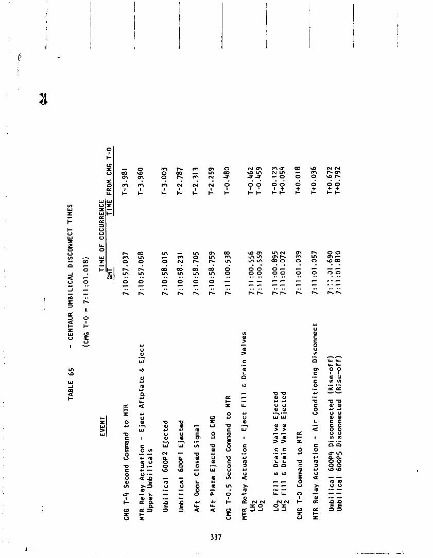
TAB
LE
65
- C
ENTA
UR
U
MB
ILIC
AL
DIS
CO
NN
EC
T TI
ME
S
EVEN
T T
lME
OF
C
CC
UR
REN
CE
GMT -
TlM
E
FRO
H
CMG
T-0
CMG
T-4
S
eco
nd C
om
nd
to
MTR
MTR
R
ela
y A
ctu
ati
on
- E
jec
t A
ftp
late
&
Eje
ct
Upper
Um
bil
ica
ls
Um
bi 1
i ca
1 6
00P
2 E
jec
ted
Um
bi 1
ica
l 6
00
~
1 E
jec
ted
Aft
Door
Clo
sed
Sig
na
l
W
w
Aft
Pla
te E
jec
ted
to
CM
G
*
CMG
T-0
.5
Seco
nd C
om
nd
to
MTR
MTR
R
ela
y A
ctu
ati
on
-
Eje
ct
Fil
l &
D
rain
Va
lve
s
LH2
LO2
LO2
Fil
l &
D
rain
Va
lve
E
jec
ted
LH
2 F
ill
&
Dra
in V
alv
e
Eje
cte
d
CMG
T-0
C
omna
nd
to M
TR
MTR
R
ela
y A
ctu
ati
on
- A
ir C
on
dit
ion
ing
Dis
co
nn
ect
Umb i 1
i ca
1 60
0P4
D i s
con
ne
c te
d
(~
i
se
-of f )
Um
b i l i ca
l 6
00P
5 D
isco
nn
ecte
d
(R i se
-of f)
Del ta Stage Support Systems
by A. Lieberman
A l l AG! and f a c i l i t y i ~ s t a l l a t i o n s i n support o f the t h i r d stage De l ta veh i c l e and i t s associated GSE operated s a t i s f a c t o r i l y du r ing prelaunch and launch operat ions.
The f i r s t - t i m e use o f the Del ta t h i r d stage on the ITL requi red modi f ica- t i o n s t o the ITL t o prov ide checkout and launch c a p a b i l i t y . Del ta GSE f o r monitor and con t ro l o f Del ta func t ions were located i n the Launch Control Center No. 1 i n the V I B , I n Equipment Room No. 2 o f the AGE Bu i l d i ng and on Level 11 o f the MST. In terconnect ing cab l i ng was provided between the VIB De l ta GSE, PSOC, DTS and Land1 ine PCM systems, the AGE Bu i l d i ng De l ta GSE, spacecraft umb i l i ca l , MST and MTR.
The Del S&A arm Level 1 panel. and rnon
t a safe and arm and recorder c o n t r o l panel i n the LCC provided remote ing and moni tor ing a s wel l as remote con t ro l o f the Del ta recorder on 1 o f the MST. The PSOC provided an arm permission s ignal t o the t i A The d e l t a TLM and ins i rurnentat ion con t ro l panel i n the LCC c o n t r o l l e d
i tot-ed Del ta stage power.
The GSFC power supply rack i n the AGE Bu i l d i ng provided ground power f o r the S&A c i r c u i t s , l o ca l monitor and con t ro l o f var ious Del ta stage func t ions and l oca l con t ro l of the Del ta recorder on the MST. Space and f a c i l i t y power were provided t o miscellaneous Delta GSE an L-vel 1 1 o f the MST f o r Del ta checkout. The recorder monitored the De l ta pyrotechnic system dur ing prelaunch opera- t i ons . I n add i t i on , the i n s t a l l a t i o n provided simultaneous t r a n s m i t t a l o f these s igna ls v i a the MTH t o Complex 36 and the CIF.
The Del ta por tab le ground s t a t i o n located i n the LCC was cabled t o an e x i s t i n g V I B r ece i v i ng antenna t o permi t ground checkout o f the R T systems w i t h the veh i c l e a t the pad.
H e l i o s A Spacecraft Support Systems
by A. Lieberman
A l l AGE and f a c i l i t y i n s t a l l a t i o n s i n support o f t h e H e l i o s spacecra f t and i t s p e c u l i a r GSE opera ted s a t i s f a c t o r i l y d u r i n g prelaunch and launch opera t icns.
The support o f the He l i os payload on the ITL r e q u i r e d m o d i f i c a t i o n s t o t h e ITL t o p rov ide checkout and launch c a p a b i l i t y . H e l i o s GSE f o r mon i to r and c o n t r o l o f t he spacec ra f t d u r i n g prelaunch and launch o p e r a t i o n s were l o - ca ted i n the AGE B u i l d i n g and on Level 12 o f t h e MST. In te rconnec t ing c a b l i n g was prov ided between t h e AGE B u i l d i n g H e l i o s GSE and Level 12 o f t h e MST, t h e spacecra f t u m b i l i c a l cab le and the Range i n t e r f a c e t o Hangar AO. Ground power and adapter cab les t o mate w i t h German type connectors were a l s o provided.
Ground checkout o f the H e l i c s RF systems was accomplished u s i n g a system o f r e r a d i a t i n g antennas on Level 12 o f the MST coupled t o a C S S antenna.