Analysis of Two-Phase Flow Instabilities in Multi-Channel Natural ...

ARTICLE IN PRESS
JOURNAL OFSOUND ANDVIBRATION
0022-460X/$ - s
doi:10.1016/j.js
�CorrespondE-mail addr
nordmann@mi
Journal of Sound and Vibration 317 (2008) 273–293
www.elsevier.com/locate/jsvi
Whirl and whip instabilities in rotor-bearing system consideringa nonlinear force model
Helio Fiori de Castroa, Katia Lucchesi Cavalcaa,�, Rainer Nordmannb
aDepartment of Mechanical Design—Unicamp, Postal Box 6122, 13083-970 Campinas, SP, BrazilbDepartment of Mechatronics in Mechanical Engineering, TU-Darmstadt, Petersenstrasse. 30, D-64287 Darmstadt, Germany
Received 17 April 2007; received in revised form 25 February 2008; accepted 27 February 2008
Handling Editor: P. Davies
Available online 8 April 2008
Abstract
Linear models and synchronous response are generally adequate to describe and analyze rotors supported by
hydrodynamic bearings. Hence, stiffness and damping coefficients can provide a good model for a wide range of situations.
However, in some cases, this approach does not suffice to describe the dynamic behavior of the rotor-bearing system.
Moreover, unstable motion occurs due to precessional orbits in the rotor-bearing system. This instability is called ‘‘oil
whirl’’ or ‘‘oil whip’’. The oil whirl phenomenon occurs when the journal bearings are lightly loaded and the shaft is
whirling at a frequency close to one-half of rotor angular speed. When the angular speed of the rotor reaches
approximately twice the natural frequency (first critical speed), the oil whip phenomenon occurs and remains even if the
rotor angular speed increases. Its frequency and vibration mode correspond to the first critical speed. The main purpose of
this paper is to validate a complete nonlinear solution to simulate the fluid-induced instability during run-up and run-
down. A flexible rotor with a central disk under unbalanced excitation is modeled. A nonlinear hydrodynamic model is
considered for short bearing and laminar flow. The effects of unbalance, journal-bearing parameters and rotor
arrangement (vertical or horizontal) on the instability threshold are verified. The model simulations are compared with
measurements at a real vertical power plant and a horizontal test rig.
r 2008 Elsevier Ltd. All rights reserved.
1. Introduction
Studies of the characteristics of rotor-bearing systems are necessary in the design of rotating systems andtheir industrial applications, and for the diagnosis of system malfunctions. Mathematical models have beendeveloped to represent real machines with considerable confidence. Research has also focused on determiningbetter models of rotating machinery, such as turbogenerators and multistage pumps, which are horizontalrotating machines with high load capacity. Childs et al. [1] proposed a nonlinear hydrodynamic force model,based on journal bearing impedance descriptions, which can be used to analyze stability but not to simulate
ee front matter r 2008 Elsevier Ltd. All rights reserved.
v.2008.02.047
ing author.
esses: [email protected] (H.F. de Castro), [email protected] (K.L. Cavalca),
m.tu-darmstadt.de (R. Nordmann).
ARTICLE IN PRESS
Nomenclature
C bearing radial clearance[C] damping matrix of the systemD bearing diametere unbalanced mass eccentricityE Young’s modulusF auxiliary hydrodynamic force function{Fh} nonlinear hydrodynamic forces{Fu} unbalanced forcesG auxiliary hydrodynamic force function[G] gyroscopic matrix of the systemh dimensionless oil film thicknessH oil film thicknessJz polar moment of inertia[K] stiffness matrix of the systemL bearing lengthLe shaft element lengthm unbalanced mass[M] mass matrix of the systemp dimensionless oil pressure distributionP oil pressure distribution{q} generalized coordinates.Q dimensionless unbalanced magnitude
R bearing radiusTz rotor torqueV auxiliary hydrodynamic force function{W} rotor weightx radial dimensionless displacement of the
journal in the bearingX radial displacement of the journal in the
bearingy radial dimensionless displacement of the
journal in the bearingY radial displacement of the journal in the
bearingz axial dimensionless displacement of the
rotorZ axial displacement of the rotorZ coordinate referencea auxiliary hydrodynamic force functionb proportional damping coefficient related
to stiffnessm dynamic viscosity of oiln cylindrical coordinate of the bearingr mass densityj rotation angle of the rotor
H.F. de Castro et al. / Journal of Sound and Vibration 317 (2008) 273–293274
fluid-induced instability. Capone [2,3] developed numerical simulations to study cylindrical hydrodynamicbearings, obtaining the orbits of the shaft in the bearings based on a nonlinear hydrodynamic force model.
Other researchers have investigated the speed-dependent behavior of bearing characteristics. Tiwari et al. [4]developed an identification algorithm for the characterization of bearing dynamics using unbalanced responsemeasurements for multidegree-of-freedom flexible rotor-bearing systems. Sinha et al. [5] proposed anidentification method to estimate the static load on the fluid bearings of a flexible machine from rundowndata. This is an important practical problem, because static load strongly influences the bearing’s dynamiccharacteristics.
Linear journal-bearing models are normally used to simulate rotor-bearing systems. However, linear modelsare not ideal to represent real rotating systems in certain situations. In such cases, nonlinear models should beemployed to better represent real systems [6–9].
The interaction between the rotating system and the oil film in a hydrodynamic bearing causes unstabledynamic behavior [10], which is characterized by a subsynchronous forward precessional vibration. Thesedynamic behaviors are called oil whirl and oil whip [7,11–14].
These instabilities are a kind of self-exciting vibration of a rotor-bearing system. The oil whirl is asubsynchronous precessional movement that vibrates at a frequency close to half of the rotation speed. Whenthe rotation speed reaches twice the first natural frequency, the self-excited vibration frequency remainsconstant and close to the first resonance frequency. This new behavior is the oil whip instability. Oil whipinstability, in particular, can be severely harmful to the rotor-bearing system. The journal’s amplitude islimited by the journal bearing clearance, but the shaft vibration amplitude may become very high, since itvibrates at the natural frequency [11]. The two fluid-induced instability effects can be associated to the bearingstiffness and the shaft stiffness. If the journal is close to the bearing center, the bearing stiffness is much lowerthan the shaft stiffness. In that case, the system stiffness is controlled by the bearing stiffness and the fluid-induced instability occurs due to oil whirl [15,16]. On the other hand, when the journal is too close to the

ARTICLE IN PRESSH.F. de Castro et al. / Journal of Sound and Vibration 317 (2008) 273–293 275
bearing wall, the bearing stiffness is much higher than the shaft stiffness. In that case, the system stiffness issimilar to the shaft stiffness and the instability vibration is caused by the oil whip, which is related to thebending mode of the rotor system [7].
To reduce the effects of this particular dynamic behavior, some authors have been studying control methodsto reduce oil instability [17].
Jing et al. [18,19] considered the nonlinear model proposed by Capone [2,3] to analyze the nonlineardynamic behavior of bearings, taking into account the oil whip phenomenon, although the angularacceleration was not considered as it is in the present work.
Owing to the nonlinearities of rotating systems supported by lubricated bearings, some researchersapplied nonlinear techniques to study the dynamic behavior of these systems [20–23]. These techniques wereused to identify fluid-induced instabilities demonstrated by experimental results of horizontal and verticalrotors [24].
Castro et al. [7] introduced angular acceleration in the equation of motion and analyzed fluid-inducedinstability (oil whirl and oil whip). They found that Capone’s model is able to model the rotor’s dynamicbehavior under fluid-induced instabilities in transient motion, thus allowing for stability analyses according toRefs. [11–14].
To continue the study started by Castro et al. [7], an analysis is made taking into account the dynamicbehavior of a rotating system under the oil whirl and oil whip phenomenon, considering the influence ofunbalance, rotor arrangement (vertical or horizontal rotor) and bearing parameters (L/D ratio, bearingclearance and oil viscosity) on the instability threshold. In addition, the simulated results are compared withmeasurements taken at a real vertical power plant and in a horizontal test rig.
2. Mathematical model
A mathematical model of a rotating system can be divided into two parts: the finite element model of theshaft and concentrated mass of the disk, and the nonlinear hydrodynamic supporting forces of the cylindricaljournal bearing [2,3], which is obtained by solving the Reynolds equation for short bearings. A short journalbearing scheme and the cylindrical coordinate reference system are shown in Fig. 1.
Eq. (1) describes the pressure distribution P inside the cylindrical journal bearing, based on the solution ofthe Reynolds equation for the laminar flow condition:
qqu
h3 qp
qW
� �þ
R
L
� �2 qqz
h3 qp
qz
� �¼
qh
qWþ 2
dh
dt, (1)
Fig. 1. Short journal-bearing scheme and coordinate reference system.

ARTICLE IN PRESSH.F. de Castro et al. / Journal of Sound and Vibration 317 (2008) 273–293276
where the dimensionless parameters are
h ¼H
C¼ 1� x cosðWÞ � y sinðWÞ; z ¼
Z
L; x ¼
X
C; y ¼
Y
C; t ¼ _jt; p ¼
P
p0
and p0 ¼ 6m _jR
C
� �2
.
The solution of Eq. (1) considers the axial gradient (qp/qz) due to axial losses of lubricating fluid in a shortjournal bearing, neglecting the pressure gradient in the angular direction (qp/qW). The bearing parameters areradial clearance C, bearing length L, bearing radius R and oil viscosity m. The dimensionless oil film thicknessh, dimensionless time t, rotor angular speed _j, and dimensionless journal displacement in horizontal x,vertical y and axial z directions are also considered.
The fluid is considered incompressible and the viscosity is assumed to be constant across the fluid. HalfSommerfeld solution is applied and the cavitation effect is neglected, considering null pressure for negativevalues of pressure distribution. Thus, the complete theoretical solution of the differential equation under thesehypotheses is given by
pðW; zÞ ¼1
2
L
D
� �2ðx� 2 _yÞ sinðWÞ � ðyþ 2 _xÞ cosðWÞ
ð1� x cosðWÞ � y sinðWÞÞ3
� �ð4z2 � 1Þ. (2)
In order to determine the hydrodynamic force Fh generated by the distribution of the oil film pressure onthe shaft, the differential contact area (dA ¼ R dWLdz) is considered in the integration, resulting in Eq. (3):
fFhg ¼
F hx
Fhy
( )¼ � mo
R2
C2
� �L2
D2
� �ðRLÞ
½ðx� 2 _yÞ2 þ ðyþ 2 _xÞ2�1=2
ð1� x2 � y2Þ
3xV ðx; y; aÞ � sinðaÞGðx; y; aÞ � 2 cosðaÞF ðx; y; aÞ
3yV ðx; y; aÞ � cosðaÞGðx; y; aÞ � 2 sinðaÞF ðx; y; aÞ
( ), (3)
where the functions V, G, F and a are, respectively, given in Eqs. (4)–(7):
V ðx; y; aÞ ¼2þ ðy cosðaÞ � x sinðaÞÞGðx; y; aÞ
ð1� x2 � y2Þ, (4)
Gðx; y; aÞ ¼Z aþp
a
duð1� x cosðuÞ � y sinðuÞÞ
¼pffiffiffiffiffiffiffiffiffiffiffiffiffiffiffiffiffiffiffiffiffiffiffiffi
1� x2 � y2p �
2ffiffiffiffiffiffiffiffiffiffiffiffiffiffiffiffiffiffiffiffiffiffiffiffi1� x2 � y2
p tan�1y cosðaÞ � x sinðaÞffiffiffiffiffiffiffiffiffiffiffiffiffiffiffiffiffiffiffiffiffiffiffiffi
1� x2 � y2p
!, (5)
F ðx; y; aÞ ¼ðx cosðaÞ þ y sinðaÞÞð1� x2 � y2Þ
, (6)
a ¼ tan�1yþ 2 _x
x� 2 _y
� ��
p2sign
yþ 2 _x
x� 2 _y
� ��
p2signðyþ 2 _xÞ. (7)
The horizontal rotor scheme is shown in Figs. 2a and b and its finite element model is illustrated in Fig. 2c.The differential equation of motion is given by Eq. (8), which takes into account the hydrodynamic force {Fh}given in Eq. (3), the unbalanced forces {Fu}, the rotor weight {W} and the generalized coordinates of theflexible rotor {q}T ¼ {x1, y1, y, x3, y3, y x6, y6, y, x9, y9, y x11, y11}, which consider all the degrees offreedom of the rotating system, including the journal displacement in each bearing. If a vertical rotor isassumed, the rotor weight is not considered:
½M�f €qg þ ½C�½ _q� þ ½K �fqg ¼ fF ug þ fFhg � fW g. (8)
In order to determine the mass [M] and stiffness [K] matrices, a finite element method is used, consideringthe shaft and the concentrated mass of the rotor [25,26].
The shaft damping matrix [C] contains a first part proportional to the stiffness matrix and a second partwith the gyroscopic effects (½C� ¼ b½K � þ _j½G�). The gyroscopic matrix [G] is also obtained by a finite elementmethod.

ARTICLE IN PRESS
Fig. 2. Horizontal rotor: (a) physical model; (b) physical model—cross-section; (c) finite element model.
Table 1
Material properties for simulation
Material property Value
Young’s modulus, E 2.067� 1011 Pa
Density, r 7800 kg/m3
Proportional coefficient related to stiffness, b 25� 10�5
H.F. de Castro et al. / Journal of Sound and Vibration 317 (2008) 273–293 277
The system excitation force is due to the unbalanced mass m and its eccentricity e, expressed in Eq. (9):
fFug ¼ me€j sin jþ _j2 cos j
€j sin jþ j _j2 cos j
( ). (9)
To consider the angular acceleration €j of the rotating system, Eq. (10) correlates the drive-motor inputtorque TZ with the rotation of the system [27], where Jz is the polar moment of inertia. This equation isobtained by Lagrange’s equation and considers the coupling between torsional and lateral vibrations:
Jz €jffi Tz þmeðsin j €x� cos j €yþ _j _x cos jþ _j _y sin jÞ. (10)
However, this coupling is considerably weak and can be neglected, as indicated by Childs [14]. Eq. (10) istherefore reduced to Eq. (11):
Jz €jffi Tz. (11)
The solution of the equation of motion is obtained using numerical methods. The Newmark integrationmethod was chosen here because it is a robust algorithm to solve nonlinear equations in the time domain.
3. Simulation results
3.1. Simulation data
Considering a constant angular acceleration, the length of the four elements between the bearings isLe ¼ 0.1450m, the shaft diameter is 0.012m and the centered disk diameter and length are 0.095 and 0.043m,respectively. Simulations were done varying the unbalance and the journal-bearing parameters, as well as therotor position (horizontal or vertical). Table 1 lists the material properties considered in the model. A low

ARTICLE IN PRESSH.F. de Castro et al. / Journal of Sound and Vibration 317 (2008) 273–293278
proportional structural damping coefficient b was assumed in order to highlight the effects studied in thiswork. In all the simulations, the system’s dynamic rundown rather than runup behavior is analyzed, since thelatter may be associated with other phenomena such as the inertial effect of the oil whip.
The dynamic behavior of a rotor supported by journal bearings is important in the design stage. Inpredictive maintenance, one can also use the prediction of the dynamic behavior to diagnose failure. Thecomplete model of the system consists of a linear finite element model for the rotor and a nonlinear model forthe bearings. Before beginning the numerical simulations of the system parameters, the congruence of theresults of the theoretical model and the experimental test rig is ascertained. The influence of design variablessuch as unbalance and bearing parameters can be then simulated. The influence of a vertical or horizontalrotor was also taken into account.
3.2. Horizontal and vertical rotor
First a comparison is made between the horizontal and vertical rotor. Table 2 presents the properties of theunbalanced moment (me) and the journal bearing. Fig. 3 shows the displacement of the rotor in the bearing forthe horizontal and vertical case in the x and y directions. Waterfall plots must be drawn with the rotor underacceleration in order to observe the dynamic behavior in the frequency domain. This type of diagram
Table 2
Parameters for the comparison of horizontal and vertical behavior
Unbalance moment me 2� 10�5 kgm
Bearing clearance, C 90mmBearing diameter, D 0.031m
Bearing length, L 0.010m
Oil viscosity, m 0.04Pa s
Fig. 3. (a) Displacement x—horizontal rotor, (b) displacement y—horizontal rotor, (c) displacement x—vertical rotor; (d) displacement
y—vertical rotor.

ARTICLE IN PRESSH.F. de Castro et al. / Journal of Sound and Vibration 317 (2008) 273–293 279
correlates the rotating speed, signal magnitude and frequency spectrum, indicating if the precessionalvibration is dominated by a synchronous or asynchronous vibration or even by a combination of them.Considering the displacements in the bearing, waterfall plots are generated for each case, as shown in Fig. 4afor a horizontal rotor and in Fig. 4b for a vertical rotor.
The resonance frequency of the rotor is close to 22Hz, as illustrated in Fig. 3, which indicates thatprecessional vibration increases in both cases when the rotation speed approaches 22Hz. Fig. 4 shows asimilar result because both cases (horizontal and vertical) present a 1.0� increase in vibration amplitude at afrequency of 22Hz.
In the vertical rotor, the shaft vibrates around the geometric center of the bearing. However, at lowrotational speeds, this equilibrium point in the horizontal rotor is not in the bearing’s geometric center, asindicated in Figs. 3a and b. The amplitude at zero Hz in the waterfall plot of the horizontal rotor (Fig. 4a)represents the equilibrium position of the shaft. This position is far from the bearing center at lower rotationspeeds, but close to the center in the oil whip region (above 45Hz).
To link the waterfall diagrams (Fig. 4) to the dynamic behavior of the rotor-bearing system, some rotationspeed intervals are analyzed. In the horizontal rotor, the first region occurs before the resonance frequency,below 20Hz. The displacements shift towards the center of the bearing center as the rotation speed increases,as illustrated in Figs. 3a and b. The second region occurs between 20 and 25Hz, when the synchronousvibration assumes higher values and the rotor crosses over the resonance. The vibration in the third regionlocated above the resonance (between 25 and 45Hz) is of lower amplitude and the oil whirl precessionalvibration is not evident here. One of the reasons for this behavior is the influence of the system’s weight, whichleads to a position of equilibrium and, hence, to stable motion. The fourth region, characterized by the highestvibration amplitude caused by the oil whip, occurs above 45Hz. Here, the shaft equilibrium position is at thebearing’s geometric center.
The vertical rotor displacements generally occur around the center of the bearing, as indicated in Figs. 3cand d. Similarly to the horizontal case, four regions are also visible here: the region before the resonancefrequency at 20Hz, the resonance region between 20 and 25Hz, the oil whirl region from 30 to 45Hz, andthe fourth region, above 45Hz, which suffers the oil whip effect and where amplitudes increase significantly(Fig. 4b).
Fig. 4. Waterfall diagrams for me ¼ 2� 10�5 kgm: (a) horizontal rotor; (b) vertical rotor.

ARTICLE IN PRESSH.F. de Castro et al. / Journal of Sound and Vibration 317 (2008) 273–293280
The synchronous vibration decreases above resonance in the vertical rotor, at which point thesubsynchronous vibration enters into action. From 30 to 45Hz (Fig. 4b), the vibration frequency is closeto one half of rotation speed, which is characterized by oil whirl. Above 45Hz (or twice the resonancefrequency), the vibration frequency remains constant and equal to the resonance frequency (22Hz). This is oilwhip behavior. In the horizontal rotor, oil whirl is not noticeable in the same frequency range. Instead, oilwhip appears at close to double the first resonance frequency (45Hz) because the system’s dynamic behavior isstable up to this frequency due to the rotor weight effect (Fig. 4a).
The main reason for the distinct behaviors of these two assemblies (horizontal and vertical) is the journal’sposition in the bearing. Because the journal usually closer to the bearing center in the vertical rotor, the oilwhirl effect is more evident in the vertical assembly. In contrast, in the horizontal rotor, the journal vibratesaround the journal’s position of equilibrium in the bearing (shaft locus), which is not as close to the center ofthe bearing as in the vertical rotor (see Figs. 3a and b).
3.3. Unbalance influence
The influence of unbalance was investigated in the vertical rotor because the instability is more evident inthis assembly. The journal-bearing parameters listed in Table 2 were taken into account in the numericalsimulations.
Fig. 5 illustrates the progression of the deflection in the journal bearing as the rotation speed increases.Different unbalanced moments are considered for each curve. The analysis is aided by waterfall plots for someconditions to better illustrate this progression. The waterfall plot in Fig. 4b represents the lowest unbalancedmoment (me ¼ 2� 10�5 kgm), while the waterfall plots in Figs. 6a and b show moments of greater unbalanceof 5 and 7.5� 10�5 kgm, respectively.
The subsynchronous motion (0.5� ) lasts longer for lower unbalanced moments, due to the weak forwardsynchronous vibration at 1.0� . When the moment of unbalance increases, the amplitude of the synchronousvibration increases and dominates the precessional motion of the rotor. When the rotation speed exceeds thefirst resonance frequency at 22Hz, the precession becomes subsynchronous. Because the unbalance is higher,the beginning of subsynchronous movement shifts to higher rotational speeds, occurring even closer to doublethe first resonance frequency where the rotor vibrates in its natural frequency, which does not change in thefrequency domain. This effect is called oil whip instability.
To analyze how unbalance affects the nonlinear behavior of the rotor-bearing system, bifurcation diagramswere drawn for 32 and 35Hz. These two rotation speeds were chosen because instability begins in this range offrequencies and the amplitude increases significantly, as indicated in Fig. 5. Figs. 7a and b, respectively, depict
Fig. 5. Nonstationary deflection of the rotor considering several unbalanced values (solid line—me ¼ 2� 10�5 kgm; dotted line—
me ¼ 5.0� 10�5 kgm; dashed line—me ¼ 7.5� 10�5 kgm).

ARTICLE IN PRESS
Fig. 6. Waterfall diagrams: (a) me ¼ 5.0� 10�5 kgm; (b) me ¼ 7.5� 10�5 kgm.
Fig. 7. (a) Bifurcation diagram for unbalance influence: (a) horizontal displacement at 32Hz; (b) vertical displacement at 32Hz;
(c) horizontal displacement at 35Hz; (d) vertical displacement at 35Hz (C ¼ 90 mm, L/D ¼ 0.5 and m ¼ 0.04Pa s).
H.F. de Castro et al. / Journal of Sound and Vibration 317 (2008) 273–293 281
bifurcation diagrams of horizontal and vertical displacement at 32Hz, while Figs. 7c and d show thesedisplacements at 35Hz.
At 32Hz, the unbalance threshold of instability is 1.5� 10�4 kgm. A period-doubling bifurcation isencountered above this threshold, which means that there is a transition from a synchronous whirl to a

ARTICLE IN PRESSH.F. de Castro et al. / Journal of Sound and Vibration 317 (2008) 273–293282
subsynchronous whirl at approximately half the rotating speed, indicating oil whirl instability [23]. Fig. 8shows the rotor orbit and Poincare sections. In the orbit where the unbalance is 1.0� 10�4 kgm, the whirl issubsynchronous due to the period-doubling motion described by the Poincare sections. The transition fromperiod doubling to period motion is clearly visible when the unbalance is 1.5� 10�4 kgm. At an unbalance ofmore than 1.5� 10�4 kgm, the whirl is synchronous (period motion).
When the rotation speed is 35Hz, the unbalanced threshold of instability occurs at 3� 10�4 kgm, indicatingthat when the unbalance is higher, the beginning of subsynchronous movement shifts to higher rotationalspeeds.
It is therefore clear that the amount of unbalance significantly affects the dynamic behavior of the rotor interms of fluid-induced instabilities. The findings reported here are congruent with the experimental results ofMuszynska [11], who demonstrates that higher unbalances produce a wider range of rotations with stablesynchronous vibrations, i.e., the subsynchronous vibration is imperceptible.
3.4. Journal-bearing parameters
Other parameters are checked due to their significant influence on the dynamic behavior of the system withrespect to hydrodynamic bearings: radial clearance, viscosity of the lubricating oil and L/D ratio (length-to-diameter ratio of the bearing). These parameters are related to the Ocvirk or nondimensional Sommerfeldnumbers [14].
However, an analysis of the system’s response to the changes in these parameters would not suffice tounderstand the dynamic behavior of the system, because of the nonlinearities inherent to the rotor-bearingsystem. Bifurcation diagrams, orbits and Poincare sections were therefore drawn to illustrate the influence ofradial clearance C (Figs. 9 and 10), lubricant viscosity m (Figs. 11 and 12) and L/D ratio (Figs. 13 and 14).
Increased radial clearance leads to a period-doubling motion, as indicated in Figs. 9 and 10. The transitionfrom a synchronous to a subsynchronous whirl begins when the radial clearance is 80 mm. At a radial clearanceof 90 mm, the influence of the half-speed frequency is much higher and at 100 mm the motion is practicallyperiod doubling. The same effect is indicated by the viscosity and L/D ratio. Fig. 11 shows the bifurcation
Fig. 8. Orbit and Poincare sections at 32Hz for unbalance of 1� 10�4, 1.5� 10�4, 2� 10�4 and 5� 10�4 kgm.

ARTICLE IN PRESS
Fig. 9. Bifurcation diagram for influence of radial clearance: (a) horizontal displacement; (b) vertical displacement (me ¼ 1.5� 10�4 kgm,
L/D ¼ 0.5 and m ¼ 0.04Pa s).
Fig. 10. Orbit and Poincare sections at 32Hz for radial clearance of 80, 90, 95 and 100mm.
H.F. de Castro et al. / Journal of Sound and Vibration 317 (2008) 273–293 283

ARTICLE IN PRESS
Fig. 11. Bifurcation diagram for influence of viscosity: (a) horizontal displacement; (b) vertical displacement (C ¼ 90 mm, L/D ¼ 0.5,
me ¼ 1.5� 10�4 kgm).
Fig. 12. Orbit and Poincare sections at 32Hz for viscosity of 0.010, 0.025, 0.040 and 0.055Pa s.
H.F. de Castro et al. / Journal of Sound and Vibration 317 (2008) 273–293284

ARTICLE IN PRESS
Fig. 13. Bifurcation diagram for L/D ratio: (a) horizontal displacement; (b) vertical displacement (C ¼ 90 mm, m ¼ 0.04 Pa s,
me ¼ 1.5� 10�4 kgm).
Fig. 14. Orbit and Poincare sections at 32Hz for L/D ratio of 0.5, 0.54, 0.58 and 0.625.
H.F. de Castro et al. / Journal of Sound and Vibration 317 (2008) 273–293 285

ARTICLE IN PRESSH.F. de Castro et al. / Journal of Sound and Vibration 317 (2008) 273–293286
diagram and Fig. 12 shows the orbits and Poincare sections for the variation in viscosity. The motion issynchronous if the viscosity is 0.01 Pa s, but period-doubling motion starts if the viscosity changes to 0.015,indicating the beginning of oil whirl instability. Figs. 13 and 14 show these diagrams for the increase in L/D
ratio. At a ratio of 0.5, the unstable motion is at the threshold of instability, showing the transition fromsynchronous to subsynchronous motion. Another effect that can be observed when the viscosity and L/D ratioincrease is the decrease in displacement amplitude, see Figs. 11 and 13. A comparison with Eq. (3) reveals thatthe higher the viscosity or L/D ratio the higher the hydrodynamic supporting forces. Thus, the stiffness anddamping effect are also greater, reducing the amplitude of the displacement.
Therefore, increasing these bearing parameters leads to instable motion, which cannot be deter-mined considering only their relation given by Ocvirk or nondimensional Sommerfeld numbers. Thereduction in displacement amplitude due to higher viscosity and L/D ratio is also congruous with thesenumbers.
Fig. 15. Schematic of real power plant rotor.

ARTICLE IN PRESS
Fig. 16. Unbalance effect of oil-whirl instability in a real turbine ( Q ¼ 1.5; Q ¼ 6.3; Q ¼ 15).
H.F. de Castro et al. / Journal of Sound and Vibration 317 (2008) 273–293 287
4. Comparative analysis with a real vertical power plant
The main purpose of the comparative analysis presented here is to illustrate the similarity of the simulatedresults with measurements taken in a real power plant whose dynamic characteristics closely resemble those ofthe simulated rotor (Fig. 15). To this end, the behavior of the hydrodynamic cylindrical bearing assembled inthe power plant rotor is compared with the computational simulations obtained by the vertical rotor modelproposed here. The upper hydrodynamic short bearing is assembled under the main rotor, with a radialclearance of 80 mm. The natural frequency of the rotor is 60Hz (3600 rev/min), with oil-whip instability at120Hz (7200 rev/min).
Fig. 16 shows the influence of the dimensionless unbalance Q (applied unbalance/residual unbalance) on theturbine stability (oil whirl). It is interesting to note the similarity to the simulated results depicted in Fig. 5,except for the effect of the greater flexibility in the simulated rotor, which is revealed by the amplitude peaks atthe natural frequency of the rotor (22Hz). However, one can clearly see that the same unbalance effect occursin both systems (real turbine and above 35Hz for simulated rotor): when the mass unbalance increases, the oilwhirl is delayed in the frequency domain with lower vibration amplitudes. Therefore, the nonlinearhydrodynamic-bearing model applied here yields very satisfactory results, providing robustness to itsapplication in critical situations, when rotor vibration causes the bearings to work with very thin oil filmviscosity.
5. Comparative analysis with a horizontal test rig
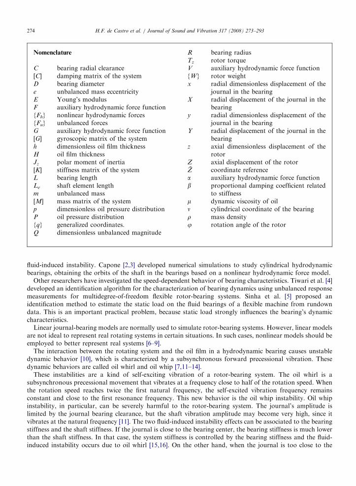
The experimental setup consisted of two hydrodynamic bearings and a lumped mass assembled in the centerof the shaft (Fig. 17), like the Laval rotor used in the simulation tests. The shaft of the physical system wasmade of steel with a 12mm diameter. The distance between the bearings was 600mm. The concentrated massconsisted of a disk with an external diameter of 94.7mm, a length of 47.0mm and a mass of 2.34 kg. A pair ofcylindrical hydrodynamic bearings was used to support the shaft, which was made of in bronze, with a radialclearance of 90 mm and L/D ratio of 0.64. The bearings were lubricated with AWS 32 oil, whose operatingtemperature was close to 25 1C. The nominal frequency of the electric motor lay in the range of 1–60Hz. Therotor support structure can be considered rigid in these operational frequencies.
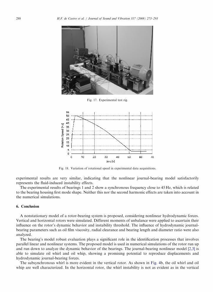
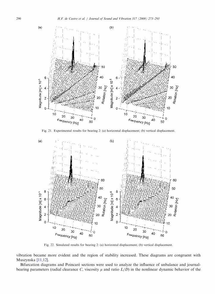
The unbalance time response was recorded at the concentrated mass of the rotor. In order to obtain thecurves in the horizontal and vertical directions, the orbit of the rotor mass was monitored by two magneticproximity sensors. To monitor the displacement of the shaft inside the bearings, two magnetic proximitysensors were immersed in the oil film. The measurements were taken within the range of the nominal rotationspeed of the electric motor. Fig. 18 shows the variation of the rotation speed over time in a range of 3–50Hz.A fast runup is carried out first, followed by a slower rundown. The experimental responses (horizontal andvertical directions) are compared with the simulation results. Figs. 19 and 20 show, respectively, theexperimental measurements and the simulation results for bearing 1. Figs. 21 and 22 show these results forbearing 2, while Figs. 23 and 24 depict the results for the concentrated mass. In each case, the simulated and
ARTICLE IN PRESS
Fig. 17. Experimental test rig.
Fig. 18. Variation of rotational speed in experimental data acquisitions.
H.F. de Castro et al. / Journal of Sound and Vibration 317 (2008) 273–293288
experimental results are very similar, indicating that the nonlinear journal-bearing model satisfactorilyrepresents the fluid-induced instability effects.
The experimental results of bearings 1 and 2 show a synchronous frequency close to 45Hz, which is relatedto the bearing housing first mode shape. Neither this nor the second harmonic effects are taken into account inthe numerical simulations.
6. Conclusion
A nonstationary model of a rotor-bearing system is proposed, considering nonlinear hydrodynamic forces.Vertical and horizontal rotors were simulated. Different moments of unbalance were applied to ascertain theirinfluence on the rotor’s dynamic behavior and instability threshold. The influence of hydrodynamic journal-bearing parameters such as oil film viscosity, radial clearance and bearing length and diameter ratio were alsoanalyzed.
The bearing’s model robust evaluation plays a significant role in the identification processes that involvesparallel linear and nonlinear systems. The proposed model is used in numerical simulations of the rotor run upand run down to analyze the dynamic behavior of the bearings. The journal-bearing nonlinear model [2,3] isable to simulate oil whirl and oil whip, showing a promising potential to reproduce displacements andhydrodynamic journal-bearing forces.
The subsynchronous whirl is more evident in the vertical rotor. As shown in Fig. 4b, the oil whirl and oilwhip are well characterized. In the horizontal rotor, the whirl instability is not as evident as in the vertical

ARTICLE IN PRESS
Fig. 19. Experimental results for bearing 1: (a) horizontal displacement; (b) vertical displacement.
Fig. 20. Simulated results for bearing 1: (a) horizontal displacement; (b) vertical displacement.
H.F. de Castro et al. / Journal of Sound and Vibration 317 (2008) 273–293 289
rotor, but the whip instability clearly appears at close to double the natural frequency (Fig. 4a). The influenceof unbalance was studied in vertical rotors because they highlight the whirl effect. Increasing the moment ofunbalance increases the threshold of instability. At the lowest moment of unbalance, synchronous precessionalvibration was hardly perceptible in the waterfall plot. As the unbalance moment increased, this kind of
ARTICLE IN PRESS
Fig. 21. Experimental results for bearing 2: (a) horizontal displacement; (b) vertical displacement.
Fig. 22. Simulated results for bearing 2: (a) horizontal displacement; (b) vertical displacement.
H.F. de Castro et al. / Journal of Sound and Vibration 317 (2008) 273–293290
vibration became more evident and the region of stability increased. These diagrams are congruent withMuszynska [11,12].
Bifurcation diagrams and Poincare sections were used to analyze the influence of unbalance and journal-bearing parameters (radial clearance C, viscosity m and ratio L/D) in the nonlinear dynamic behavior of the

ARTICLE IN PRESS
Fig. 23. Experimental results for concentrated mass: (a) horizontal displacement; (b) vertical displacement.
Fig. 24. Simulated results for concentrated mass: (a) horizontal displacement; (b) vertical displacement.
H.F. de Castro et al. / Journal of Sound and Vibration 317 (2008) 273–293 291
system’s response. The decrease of unbalance and increase of all bearing parameters caused a shift from aperiod motion, characterized by synchronous vibration due to unbalance excitation, to a period-doublingmotion, which is characteristic of the half-speed frequency vibration and indicates oil whirl. The orbits and

ARTICLE IN PRESSH.F. de Castro et al. / Journal of Sound and Vibration 317 (2008) 273–293292
Poincare sections show the transition from synchronous to subsynchronous vibration at the threshold ofinstability.
A comparison was made with a real case study involving a vertical power plant and a horizontal test rig. Inthe comparison with the vertical power plant, the effect of the unbalance on the oil whirl instability was quitesimilar to the simulations. Experimental measurements of the test rig were carried out at both bearings and theconcentrated mass, showing satisfactory results. This comparison confirmed that the nonlinear hydrodynamicjournal bearing model offers a viable solution for rotor-bearing system simulations when considering fluid-induced instabilities.
Acknowledgments
The authors gratefully acknowledge the Brazilian and German research funding agencies CAPES/DAADPROBRAL program, CNPq and FAPESP for their support of this work.
References
[1] D. Childs, H. Moes, H. Leeuwen, Journal bearing impedance descriptions for rotordynamic applications, Journal of Lubrification
Technology (1977) 198–214.
[2] G. Capone, Orbital motions of rigid symmetric rotor supported on journal bearings, La Meccanica Italiana 199 (1986) 37–46.
[3] G. Capone, Analytical description of fluid-dynamic force field in cylindrical journal bearing, L’Energia Elettrica 3 (1991) 105–110 (in
Italian).
[4] J.K. Tiwari, A.W. Lees, M.I. Friswell, Identification of speed-dependent bearings parameters, Journal of Sound and Vibration 254
(2002) 967–986.
[5] J.K. Sinha, A.W. Lees, M.I. Friswell, Estimating the static load on the fluid bearings of a flexible machine from run-down data,
Mechanical System and Signal Processing 18 (2004) 1349–1368.
[6] H. Diken, Non-linear vibration analysis and subharmonic whirl frequencies of the Jeffcott rotor model, Journal of Sound and
Vibration 243 (2001) 117–125.
[7] H.F. Castro, K.L. Cavalca, R. Nordmann, Rotor-bearing system instabilities considering a non-linear hydrodynamic model, Seventh
IFToMM-Conference on Rotor Dynamics, Vienna, September 2006, pp. 1–10.
[8] K.L. Cavalca, F.G. Dedini, Experimental analysis of tilting-pad journal bearing influence in a vertical rotating system, IFToMM-
International Conference on Rotor Dynamics, Darmstadt, September 1998, pp. 571–582.
[9] E.P. Okabe, K.L. Cavalca, Rotordynamic analysis if system with a non-linear model of tilting pad bearings, Seventh IFToMM-
Conference on Rotor Dynamics, Vienna, September 2006, pp. 1–10.
[10] Robert Gasch, Rainer Nordmann, Herbert Pfutzner Rotordynamik, Springer, Berlin, 2002.
[11] A. Muszynska, Whirl and whip—rotor bearing stability problems, Journal of Sound and Vibration 110 (3) (1986) 443–462.
[12] A. Muszynska, Stability of whirl and whip in rotor bearing system, Journal of Sound and Vibration 127 (1) (1988) 49–64.
[13] S. Crandall, From whirl to whip in rotordynamics, Transactions of IFToMM Third International Conference on Rotordynamics, Lyon,
September 1990, pp. 19–26.
[14] Dara Childs, Turbomachinery Rotordynamics, Wiley-Intersciences, New York, 1993.
[15] A. Muszynska, D.E. Bently, Fluid-generated instabilities of rotors, Bently Nevada Corporation ORBIT 10 (1) (1989) 6–14.
[16] D.E. Bently, The death of whirl and whip, Bently Nevada Corporation ORBIT, Fourth Quarter, 2001, pp. 42–46.
[17] B.-H. Rho, K.-W. Kim, A study of the dynamic characteristic of synchronous controlled hydrodynamic journal bearing, Tribology
International 35 (2002) 339–345.
[18] J. Jing, G. Meng, Y. Sun, S. Xia, On the non-linear dynamic of a rotor-bearing system, Journal of Sound and Vibration 274 (2004)
1031–1044.
[19] J. Jing, G. Meng, Y. Sun, S. Xia, On the whipping of a rotor-bearing system by a continuum model, Applied Mathematical Modelling
29 (2004) 461–475.
[20] G. Adiletta, A.R. Guido, C. Rossi, Nonlinear dynamics of a rigid unbalanced rotor in journal bearings—part I: theoretical analysis,
Nonlinear Dynamics 14 (1997) 57–87.
[21] G. Adiletta, A.R. Guido, C. Rossi, Nonlinear dynamics of a rigid unbalanced rotor in journal bearings—part II: experimental
analysis, Nonlinear Dynamics 14 (1997) 157–189.
[22] J.K. Wang, M.M. Khonsari, Bifurcation analysis of a flexible rotor supported by two fluid-film journal bearing, Journal of Tribology
128 (2006) 594–603.
[23] Q. Ding, A.Y.T. Leung, Numerical and experimental investigation on flexible multi bearing rotor dynamics, Journal of Vibration and
Acoustics 127 (2005) 408–415.
[24] M.A.C. Michalski, Y.M.B. Moreno, R.O. Rocha, M. Zindeluk, Identifying oil instability phenomena in rotors using nonlinear
techniques analysis, Proceedings of XII International Symposium on Dynamic Problems of Mechanics, Ilhabela, Brazil, 2007, pp.1–10.

ARTICLE IN PRESSH.F. de Castro et al. / Journal of Sound and Vibration 317 (2008) 273–293 293
[25] R.L. Ruhl, J.F. Booker, A finite element model for distributed parameter turborotor systems, Journal of Engineering for Industry 94
(1972) 128–132.
[26] H.D. Nelson, J.M. McVaugh, Dynamics of rotor-bearing systems using finite elements, Journal of Engineering for Industry 98 (1976)
593–600.
[27] K.L. Cavalca, Non-linear analysis of a Laval Rotor passing through the resonance under a Coulomb dry-friction action, Machine
Vibration 2 (2) (1993) 71–79.
Copyright © 2022 FDOKUMEN