Curvature and rotation-induced instabilities in channel flow
27
J. Fluid Me&. (1990), VOZ. 210, pp. 537-663 Printed in Great BritaQ 537 Curvature= and rotation-induced instabilities in channel flow By 0. JOHN E. MATSSON AND P. HENRIK ALFREDSSON Department of Gas Dynamics, Royal Institute of Technology, S-100 44 Stockholm, Sweden (Received 28 January 1989 and in revised form 28 June 1989) In a curved channel streamwise vortices, often called Dean vortices, may develop above a critical Reynolds number owing to centrifugal effects. Similar vortices can occur in a rotating plane channel due to Coriolis effects if the axis of rotation is normal to the mean flow velocity and parallel to the walls. In this paper the flow in a curved rotating channel is considered. It is shown from linear stability theory that there is a region for which centrifugal effects and Coriolis effects almost cancel each other, which increases the critical Reynolds number substantially. The flow visualization experiments carried out show that a complete cancellation of Dean vortices can be obtained for low Reynolds number. The rotation rate for which this occurs is in close agreement with predictions from linear stability theory. For curved channel flow a secondary instability of travelling wave type is found at a Reynolds number about three times higher than the critical one for the primary instability. It is shown that rotation can completely cancel the secondary instability. 1. Introduction The mechanisms behind hydrodynamic instability differ between various flows. For instance, in a laminar fluid flow along a flat plate or in a plane channel, so-called Tollmien-Schlichting waves may be amplified above a certain critical Reynolds number. This type of instability mechanism is often used to predict transition on airfoils through engineering approximations such as the en method. However, in a number of other flow situations a completely different instability may arisc in the form of stationary roll cells. This mechanism may be of importance in flows with density variations, or in flows with streamline curvature or system rotation, all of which have important technical applications. The latter two effects may influence the boundary-layer flow on, for instance, rotating turbine blades, which had already been recognized as a problem of significance by Prandtl in 1944 (see Oswatitsch & Wieghardt 1987, p. 17). For a fluid layer between two plates, heated from below, an instability may develop which is caused by the unstable density stratification. The parameter determining whether or not the instability will develop is the Rayleigh number. Centrifugal instability, i.e. an imbalance between the centrifugal force acting on fluid elements and the pressure, may arise in several flow fields as for example in cylindrical Couette flow, flow along a concave wall or flow in a curved channel. For instance, curved channel flow is governed by the so-called Dean number defined as Re yt, where Re (the Reynolds number) = U,, d/v and y = d/R (d is the channel width, R its radius of curvature at the channel centreline and d < R, and U, is the bulk flow
-
Upload
oralroberts -
Category
Documents
-
view
2 -
download
0
Transcript of Curvature and rotation-induced instabilities in channel flow
J . Fluid Me&. (1990), VOZ. 210, p p . 537-663
Printed in Great BritaQ 537
Curvature= and rotation-induced instabilities in channel flow
By 0. JOHN E. MATSSON AND P. HENRIK ALFREDSSON Department of Gas Dynamics, Royal Institute of Technology, S-100 44 Stockholm, Sweden
(Received 28 January 1989 and in revised form 28 June 1989)
In a curved channel streamwise vortices, often called Dean vortices, may develop above a critical Reynolds number owing to centrifugal effects. Similar vortices can occur in a rotating plane channel due to Coriolis effects if the axis of rotation is normal to the mean flow velocity and parallel to the walls. In this paper the flow in a curved rotating channel is considered. It is shown from linear stability theory that there is a region for which centrifugal effects and Coriolis effects almost cancel each other, which increases the critical Reynolds number substantially. The flow visualization experiments carried out show that a complete cancellation of Dean vortices can be obtained for low Reynolds number. The rotation rate for which this occurs is in close agreement with predictions from linear stability theory. For curved channel flow a secondary instability of travelling wave type is found at a Reynolds number about three times higher than the critical one for the primary instability. It is shown that rotation can completely cancel the secondary instability.
1. Introduction The mechanisms behind hydrodynamic instability differ between various flows.
For instance, in a laminar fluid flow along a flat plate or in a plane channel, so-called Tollmien-Schlichting waves may be amplified above a certain critical Reynolds number. This type of instability mechanism is often used to predict transition on airfoils through engineering approximations such as the en method. However, in a number of other flow situations a completely different instability may arisc in the form of stationary roll cells. This mechanism may be of importance in flows with density variations, or in flows with streamline curvature or system rotation, all of which have important technical applications. The latter two effects may influence the boundary-layer flow on, for instance, rotating turbine blades, which had already been recognized as a problem of significance by Prandtl in 1944 (see Oswatitsch & Wieghardt 1987, p. 17).
For a fluid layer between two plates, heated from below, an instability may develop which is caused by the unstable density stratification. The parameter determining whether or not the instability will develop is the Rayleigh number. Centrifugal instability, i.e. an imbalance between the centrifugal force acting on fluid elements and the pressure, may arise in several flow fields as for example in cylindrical Couette flow, flow along a concave wall or flow in a curved channel. For instance, curved channel flow is governed by the so-called Dean number defined as Re yt, where Re (the Reynolds number) = U,, d / v and y = d / R (d is the channel width, R its radius of curvature at the channel centreline and d < R, and U, is the bulk flow

538 0. J . E . Matsson and P. H . Alfredsson
velocity). The critical Dean number is given in Drazin & Reid (1981) as 35.92 (calculated by Gibson & Cook 1974). This flow has recently been studied both using a numerical simulation by FinIay, Keller & Ferziger (1988) and exporimentally by Ligrani & Niver (1988).
A slightly more complicated problem, which has been studied to some extent, is the so-called Taylor-Dean problem, where the flow is driven by an azimuthal pressure gradient between two concentric cylinders at the same time as the inner cylinder is rotating. Some experiments on this flow were carried out by Brewster, Grosberg & Nissan (1959) and the linear stability problem was investigated by Hughes & Reid (1964). In this case it is possible to modify the basic velocity profile as compared to either Taylor-Couette flow or Dean flow and for certain parameter values the linear stability problem becomes quite different from what is usually encountered. In that case the neutral stability curve for stationary streamwise vortices consists of two loops, and the critical Taylor number is determined by one of these loops, depending on a characteristic parameter. An interesting point is that at the parameter value for which the critical Taylor number is the same for the two loops, the corresponding wavenumbers differ by a factor of about 1.5. Hence, by changing the characteristic parameter value slightly, the most unstable wavenumber for stationary vortices changes by a factor of two. However, Raney & Chang (1971) showed that the two loops are interconnected by an oscillatory mode, i.e. the flow undergoes a Hopf bifurcation and that for certain parameter values this mode determines the critical Taylor number.
For the above cases the instability is set up by an imbalance between a body force, due to buoyancy or centrifugal effects, and the pressure. Also Coriolis forces may affect the flow in a similar way. Hart (1971), Lezius & Johnston (1976) and most recently Alfredsson & Persson (1989) studied plane channel flow subjected to system rotation. In the latter study flow visualization of the roll cells were made at low Re. For rotating channel flow two parameters are needed to characterize the stability of the flow, namely the Reynolds number and the rotation number (Ro = Bd/U, , where $2 is the system angular velocity). The instability mechanism may qualitatively be understood as follows. The Coriolis acceleration of a fluid particle in a rotating system is
This acceleration gives rise to a force in the opposite direction, which in a rotating channel is normal to the walls as the basic flow is unidirectional and parallel to the walls. The forcc is directed towards the leading side of the channel. In this case the basic flow has the standard parabolic profile, giving the largest force in the centre of the channel, thereby giving an unstable ‘stratification’ of the Coriolis force on the leading side and a stable one on the trailing side. However, for large rotation rates the flow becomes stabilized by the rotation. A simplified analysis of the regions of stabilization and destabilization is given by Tritton & Davies (1985) through a ‘displaced particle ’ argument. The linear stability theory gives the lowest critical Re to be about 89, which occurs at an Ro of 0.5. This is almost two orders of magnitude smaller than the Re ( = 7696) for which TollmienSchlichting waves become unstable.
In the present study the combined effect of centrifugal and Coriolis forces on the flow is studied, in terms of the flow in a curved channel subjected to rotation around an axis parallel to the walls and normal to the flow. Depending on the direction of rotation the Coriolis effect either counteracts or enhances the centrifugal instability. For certain values of the rotation number the flow becomes stabilized by the
Qcor = 2 8 x u.
Curvature- and rotation-induced instabilities in channel flow 539
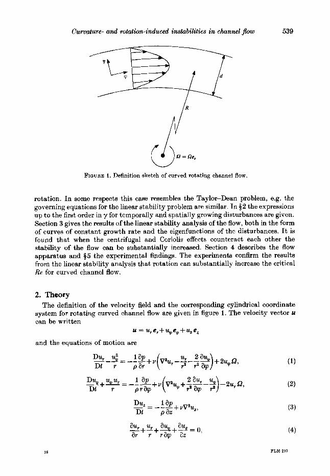
FIGURE 1. Definition sketch of curved rotating channel flow.
rotation. In some respects this case resembles the Taylor-Dean problem, e.g. the governing equations for the linear stability problem are similar. In $ 2 the expressions up to the first order in y for temporally and spatially growing disturbances are given. Section 3 gives the results of the linear stability analysis of the flow, both in the form of curves of constant growth rate and the eigenfunctions of the disturbances. It is found that when the centrifugal and Coriolis effects counteract each other the stability of the flow can be substantially increased. Section 4 describes the flow apparatus and 55 the experimental findings. The experiments confirm the results from the linear Stability analysis that rotation can substantially increase the critical Re for curved channel flow.
2. Theory The definition of the velocity field and the corresponding cylindrical coordinate
system for rotating curved channel flow are given in figure 1. The velocity vector u can be written
u = u,e,+u,e,+u,e,
and the equations of motion are
18

540 0. J . E . Matsson and P. H . Alfredsson
where
and
~a a a u a a - = -+u * v = -+uU,-+++uz- Dt at at ar r@ 82
The boundary conditions are
u,(r) = uP(r) = u,(r) = 0 a t r = R f 9 ,
which together with (4) gives
8% - ( r ) = 0 a t r = R+%. ar
For the mean flow it is assumed that u, = u, = 0 and that up = U(r), which for ( 1 ) gives
i.e. the radial pressure gradient is set up by the centrifugal force and the Coriolis force. The mean velocity profile can be given exactly (see e.g. Finlay et al. 1988); however, for small y it is more illustrative to give it as a perturbation series in y . If r = R( 1 + y k ) , where 7 is a dimensionless coordinate with 7 = - 1 a t the inner wall and 9 = 1 at the outer wall, the velocity distribution is
u = $( 1-72) (1 -+yy) + O(y2).
The mean velocity field is hence a slightly modified parabolic profile and to the first- order the correction term is antisymmetric with respect to the channel centreline. The maximum velocity is now found a t 7 M -b, i.e. i t is slightly shifted towards the inner wall.
2.1. Neutrally stable disturbances The experiments indicate an instability in the form of streamwise vortices and the neutrally stable linear disturbances are assumed to have the form
u: = R(r ) eiflzld, u' = Q,(r) eWd, P
u: = Z(r ) eiflzld, p ' lp = P(r) eiflzld,
where p is the non-dimensional spanwise wavenumber. By assuming that the ratio of channel width to radius of curvature is small, i.e. y << 1, we can expand (1)-(4) and neglect terms of order y2 and higher. This gives the following coupled equations describing the disturbances :
(6)
(7)
(D2 -P2)'R + 2yD(D2 - p 2 ) R - 2,PRe(y% +Ro) Q, = O(y2) ,
(D' -P') @ + yD@ -Re(%' + 7% + 2Ro) R = O(y2) ,
where D = d/dq and % is the non-dimensional undisturbed mean velocity % = U/U,. Equation (7 ) is a direct consequence of (2), whereas (6) is obtained by eliminating the pressure between (1) and (3) and using (4) to eliminate u,. For Ro = 0, i.e. no rotation, these equations are similar to those given in Drazin & Reid (1981, p. 110) and the common terms are underlined; however, some more terms of order y are kept in

Curvature- and rotation-induced instabilities in channel Jlow 541
(6) and (7) in addition to the rotation terms. Note that the rotation number involves a sign depending on the sense of rotation. The boundary conditions are
R(7) = DR(7) = @(7) = 0 at 7 = - 1 , l . (8) Equations (6) and (7 ) with the boundary conditions (8) constitute an eigenvalue
problem for /3 with y , Re and Ro as parameters. In the lowcst-order approximation for curved channel flow y and Re combine into one non-dimensional number, namely the Dean number (De =Bey:). However, if all terms of order y are kept (in the disturbance equations and in the mean velocity profile) the stability is no longer only dependent on the Dean number, but is a slowly varying function of y .
2.2 . Spatially and temporally developing disturbances Usually, temporal growth rates are considered when studying growing disturbances. However, the experimental observations show that there exist stationary roll cells in the flow which instead could be considered as a spatially growing disturbance. To take both temporally and spatially growing disturbances into account the disturbance can be taken to be of the type
exp (iPzld + stUb/d + mg?/y),
where s and m are real non-dimensional growth rates, i.e. the disturbances can grow exponentially in time and/or in the downstream direction (note that q / y is equal to the streamwise length along the channel centreline). This leads to the following system of equations with the same boundary conditions as for the neutral stable case :
(D2 -/32)2R - 2P2Re(%y +Ro) @+ 2yD(D2 -P2)R
= sRe(D2 -p” + yD)R + m{Re [9(D2 -p”) -9”- 2RoDIR - 2y/P@} + O(m2, ms, r2), (D2 - p”) @-Re (9’+ y 9 + 2Ro) R + yD@
I 1 = sRe@+m Re42@+-[D3+2yD2-P2D-3y/32]R +O(m2,s2 ,ms ,y2) . i P2
2.3. Hopf bifurcation For certain parameter combinations it is possible to obtain a time-dependent solution of the form
exp [i (pz/dkwtU,/d) +s tU , , ld+q /y] ,
i.e. a travelling wave in the positive or negative z-direction. In this case the corresponding eigenfunctions are complex. This is often referred to as a Hopf bifurcation and occurs when the Coriolis mode and the centrifugal mode interact strongly. Similar behaviour has been shown to exist for Taylor-Dean flow by Raney & Chang (1971), and also two-layer Rayleigh-Bdnard convection where viscous and temperature modes may interact and give rise to disturbances of travelling wave type (Rasena, Busse & Rehberg 1989). Another example is the flow of a three-layer inviacid, stably stratified fluid with different but constant velocities within the three layers, for which an instability can occur owing to wave interaction between the two interfaces (Craik 1985).
18-2

542 0. J . E . Matsson and P . H . Alfredsson
-- 8 0
h
v 0 0 - --
E! 0 0 s

Curvature- and rotation-induced instabilities in channel flow 543
ps
v ._.
FIG
UR
E 2.
Neu
tral
sta
bil
ity
curv
es f
or c
urve
d ch
anne
l fl
ow a
t va
riou
s n
egat
ive
rota
tion
nu
mb
ers.
(a) Ro
= 0
, (b
) -0
.02,
(c
) -0
.021
5,
(d)
-0.0
24
, (e
) -0.
025,
(f)
-0.0
28, (9
) -0.
0284
, (h
) -0.
032,
(i)
-0.0
328,
(j)
-0.0
35, (k
) -0.
04,
(I) -
0.5
. T
he lo
cus f
or th
e H
opf b
ifu
rcat
ion
is s
how
n b
y th
e sy
mbo
l in
(f-
i).

544 0. J . E . Matsson and P . H . Alfredsson
3. Numerical results The eigenvalue problem derived in $2 was solved with a shooting method using a
fourth-order Runge-Kutta method. The calculations were made with double precision and with orthogonalization of the solution vectors to decrease the numerical errors.
3.1. Neutral disturbances 3.1.1. Cu.rvcd chanmel $ow
Figure 2 ( a ) shows the neutral curves for the four lowest modes, numbered I, 11, I11 and IV, for the non-rotating case a t y = 0.025. The critical wavenumber for the different modes increases approximately as the mode number times the lowest critical wavenumber. Equations (6) and (7) contain terms of order y , usually not taken into account, and for y = 0.025 the critical Dean number is 36.27 and Pcrit = 3.96, compared to the values given by Drazin & Reid (1981) of 35.92 and 3.95, respectively. Decreasing y gives values that decrease linearly towards 35.92.
3.1.2. Curved channel Jlow with rotation I n figure 2 ( b l ) neutral stability curves are shown for the curved channel a t various
negative rotation numbers for y = 0.025. There is a complex interaction between various modes as the rotation number is changed, which is quite different from what is found in the canonical cases such as curved channel or Taylor-Couette flow but is probably similar to what happens in Taylor-Dean flow. The interaction takes the form of several cut-and-connect processes between the neutral curves of various modes. In figure 2 one should bear in mind that a neutral curve does not necessarily contain the same mode along its full length, but can consist of a t least two different modes.
In the interval of Ro between 0 and -0.02 the first cut-and-connect takes place between mode I1 and mode 111 as can be seen in figure 2(b) (Ro = -0.02), where the two resulting curves are called loops in the following. Mode I still determines the critical Re; however, the critical Re has now increased by about 70% as compared to Ro = 0. For Ro = -0.0215 the lower loop has disappeared (figure 2c), whereas the upper loop has grown and the disturbance associated with that loop has become less stable. Decreasing Ro to -0.024 leads to further growth of the upper loop, but also leads to a cut-and-connect process between mode I and this loop. In figure 2 ( e ) where Ro = -0.025 the cut-and-connect process is completed. At this Ro a cut-and-connect has also taken place between higher modes.
Figure 3 (a , b) shows a blow-up of the cut-and-connect process for Ro = -0.024 and -0.025. The transfer of modes between one loop to another will be further discussed later in this section. However, it is for the cut-and-connect processes that the Hopf- bifurcation type of disturbance occurs. At Ro = -0.025 the Hopf bifurcation curve is indicated with symbols between the two loops.
Up to Ro = -0.024 the critical Reynolds number increases and is determined by mode I. At Ro = -0.025 the newly created lower loop determines the critical Re, which at this Ro is 535 with a critical p of 3.8. I n figure 2 ( f ) (Ro = -0.028) the locus for the most unstable Hopf-bifurcation mode is also plotted. Neutral disturbances associated with the upper loop are, at Ro = -0.028, still much more stable than those associated with the lower loop. However, at Ro slightly larger than -0.0284 the upper and lower loops have the same critical Re which is 1245, although a t this Ro

Curvature- and rotation-induced instabilities in channel $ow 545
19.0 -
p 18.9 -
18.8
(4
7
15.5 -! 2050 2100 2
Re
FIGURE 3. Blow-up of cut-and-connect process. (a) Ro = -0.024, (6) -0.025. Locus for the Hopf bifurcation is shown by the symbol in (6).
the critical Re is given by the Hopf-bifurcation branch as shown in figure 2(g). Increasing the rotation rate further gives a smaller critical Re, as the upper loop moves towards lower Re, and the flow hence becomes less stable (figure 2 h-2) and the critical Re is no longer determined by the Hopf-bifurcation. However, as Ro is further lowered this loop starts to deform drastically and unfold over a short range of Ro (figure Zh-j), and at Ro = -0.035 (figure 2j) it has a shape similar to that of plane rotating channel flow. The development of the neutral curves is quite complicated and the reader is referred to the figures to see the process. For decreasing Ro the flow becomes more and more rotation dominated and for Ro = -0.5 the critical Re is 89.7, which should be compared with that from a plane channel of 88.6, obtained by e.g. Alfredsson & Persson (1989). Also the higher modes take part in a similar unfolding process and at large values of Ro the neutral curves for the higher modes are similar to those of non-rotating curved channel flow (cf. figure 2a) .
For positive Ro nothing spectacular happecs but there is a smooth transformation from the curvature-dominated to the rotation-dominated flow. The critical Reynolds number (figure 4a) and the corresponding wavenumbers (figure 4 b ) have been

546 0. J . E. Matsson and P. H . Alfredsson
3000
2000
Re
1000
a - 3 -2 - 1 0 1 2 3
-3 - 2 - 1 0 1 2 3 Ro
FIGURE 4. Critical Reynolds number (a) and the corresponding wavenumber ( b ) a t various rotation numbers for the two loops corresponding to the stationary disturbances.
obtained from the neutral stability diagrams. For high absolute values of Ro the flow becomes stable, as also found by Alfredsson & Persson (1989) for rotating plane channel flow. The high peak around Ro = -0.028 corresponds to the near cancellation of the Coriolis and centrifugal effects as is evident from the neutral stability curves in figure 2.
Figure 5 shows a blow-up of the peak region in figure 4. Also included are the critical values for the Hopf bifurcation. The solid line indicates the critical Re in figure 5 ( a ) , and in figure 5 ( b ) it shows the corresponding p. It is interesting to note that close to Ro = -0.028 the wavenumber of the lower loop decreases drastically, and a t this point the solution for the most unstable mode first ' bifurcates ' to the time-dependent solution which has a larger spanwise wavenumber. If Ro is decreased further the most unstable solution again bifurcates, this time to the upper loop, giving an even higher wavenumber. Decreasing Ro further, the most unstable wavenumber decreases rapidly and for large negative Ro it approaches the value obtained for a plane rotating channel flow a t the same Ro.
The eigenfunctions of the radial velocity disturbance for the most unstable

Curvature- and rotation-induced instabilities in channel f i w 547
2000
Re lo00
0
I //i
# /
I
17
//I 1 / / I I / / ; , Hopf bifurcation
-0.04 -0.03 - 0.02
2c
P 1(
f //
N /+ /// ./IHopf bifurcation
' I
Upper loop
I I Lower loop
0 -0.04 -0.03 -0.02
RO
FIGURE 5. The critical Reynolds number (a) and corresponding wavenumber ( b ) in the region where the most unstable mode type change.
stationary mode and the corresponding stream function in the (7, 2)-plane are shown in figure 6, The maximum values of both the eigenfunctions and the stream functions are normalized to one. Note that the left-hand side of the figures corresponds to the concave channel wall and that they are drawn so that the actual geometry of the vortices are shown. The results shown in figure 6 ( a ) for Ro = 0 are in excellent agreement with the calculations of Reid (1958). In this case the vortex is located a t

548 0. J . E . Matsson and P. H . Alfredsson
FIGURE 6 ( a d ) . For caption see facing page
the outer side, i.e. the concave side, of the channel where the curvature effects make the flow unstable. For Ro = -0.028 the eigenfunction is similar; however, the maximum has moved towards the centre of the channel. For Ro = - 0.0284, there are two equally unstable stationary disturbances corresponding to the two loops. For the lower loop the stream function seems to become somewhat distorted. At this stage a secondary vortex appears at the outer side of the channel. For the upper loop (figure 6 d ) the strongest vortex appears at the inner channel wall, although two secondary vortices do also appear. As the rotation effects start to dominate, the secondary vortices become lcss intense and at Ro = -0.033 no secondary vortices

Curvature- and rotation-induced instabilities in channel $ow
(4 (f 1
A
549
FIGURE 6. Eigenfunctions of the radial velocity disturbance and the corresponding stream function in the (z,~,z)-plane for the most unstable mode at various rotation numbers. (a) Ro = 0, (b ) -0.028, (c) -0.0284 (lower loop), (d) -0.0284 (upper loop), (e) -0.031, (f) -0.032, (8) -0.033, (h) -0.04.
appear in the flow. At Ro = -0.04 the flow structure is qualitatively very close to that with only curvature effects, but with the vortex located a t the opposite side.
The cut-and-connect process between different neutral curves raises several interesting questions, one being what modes the new loops consist of. This may be found by investigating the eigenfunctions along the neutral curves. I n the following a mode which has the maximum of the eigenfunction close to the inner wall is dcnoted Coriolis dominated, whereas the opposite is true for a centrifugally dominated mode. In some cases neither picture holds, the eigenfunction is then largest at the centre part of the channel or has two maxima, one close to each wall. For R o up to -0.02 the most unstable mode shown in figure 2 ( a , b ) is centrifugally dominated. After the cut-and-connect process between R o = - 0.024 and - 0.025 the mode determining the critical R e a t the lower loop is centrifugally dominated whereas the part of that loop which originates from the cut-and-connect process is
550 0. J . E. Matsson and P. H . Alfredsson
18
17 1
15
1800 1900 2000 2100 2200 2300 Re
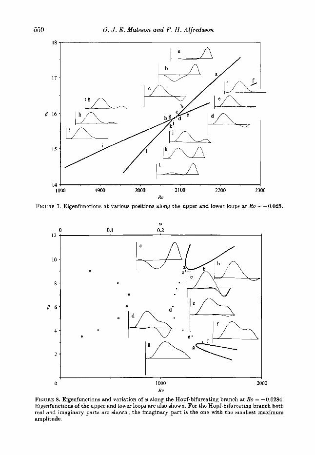
FIGURE 7 . Eigenfunctions a t various positions along the upper and lower loops a t Ro = -0.025.
12
10
8
4
2
0 1000 Re
2000
FIGURE 8. Eigenfunctions and variation of w along the Hopf-bifurcating branch at Ro = -0.0284. Eigenfunctions of the upper and lower loops are also shown. For the Hopf-bifurcating branch both real and imaginary parts are shown; the imaginary part is the one with the smallest maximum amplitude.

j
1
10
s = 0.05 0.03
0.01
0
P
1
(4
0.1
Curvature- and rotation-induced instabilities in channel ,flow 55 1
I
0.1 J I00 1000 10
Re I00
FIGURE 9. Curves of constant growth rate a t Ro = 0: (a) temporal growth; ( b ) spatial growth. x , data from Finlay et al. (1988).
Coriolis dominated. For the upper loop these modes have switched as can be seen in figure 7. Also, before the cut-and-connect process the modes change along the neutral curves and change identity between the two curves where they come close together.
At Ro = -0.0284 (figure 2g) the lower loop still contains centrifugally dominated disturbances ; however, this loop moves towards high Re and disappears when Ro is decreased further. From this Ro and up to large negative Ro the most unstable mode is Coriolis dominated; however, higher modes seem still to be influenced by centrifugal effects.
Figure 8 shows the real and imaginary parts of the eigenfunctions for the Hopf bifurcation a t Ro = -0.0284. Close to the neutral curves of the stationary disturbance it is seen that the real part of the eigenfunction is close to that a t the neutral curves whereas the imaginary part is small. Also shown is the variation of w along the Hopf-bifurcation branch.

552 0. J . E. Matsson and P. H . Alfredsson
100
10
B
1
0.1 100 103 1 0 4
i 0 0.01 0.02
0.1 4 10' 103
Re 10'
FIGURE 10. Curves of constant growth rate a t Ro = -0,0275: (a) temporal growth; ( b ) spatial growth. , Hopf-bifurcation branch.
3.2. Growing disturbances Results concerning disturbances growing either in time or in the streamwise direction will be presented in the following. As shown in $2.2 it is possible to reduce the equations governing both temporally and spatially growing disturbances to a coupled system of ordinary differential equations if the disturbance is assumed to grow exponentially in time or in the azimuthal direction. For curved channel flow without rotation some direct comparisons can be made to the linear stability results

Curvature- and rotation-induced instabilities in channel flow 553
of Finlay et al. (1988), whereas for the spatially developing case the present linear results can be compared to their results from a weakly nonlinear analysis.
Figure 9 ( a ) shows curves of constant growth rate for curved channel flow (i.e. Ro = 0 ) , which shows that the higher the Re the higher the growth rate. The curves obtained are in excellent agreement with those of Finlay et al. (1988) as shown by figure 9 (a) where their results for s = 0.05 are plotted together with our results. The spatially growing disturbances are shown in figure 9 (b ) . Note that the typical growth rates obtained are fairly high, e.g. m = 0.1 means a doubling in amplitude every seven channel heights.
The spatially growing disturbance may be compared to the weakly nonlinear analysis of Finlay et al. (1988). In their figure 22 they show how the amplitude of the disturbances increases along the channel, where the temporal evolution has been transformed to a spatial development, assuming a propagation velocity equal to the mean velocity. For instance, one of their cases was ,9 = 5 and Re = 2.7ReCrit, which gave a growth rate of about 0.13 (estimated from their figure 22). A similar value can be extrapolated from figure 9(b) .
For the cases in figure 9 the neutral curves for the stationary disturbances determine the unstable region ; however, when the Hopf bifurcation occurs this is not so. For instance a t Ro = -0.0275 (figure 10a) the two loops together with the Hopf- bifurcation branch determine the unstable region. It is also interesting to note that curves of positive temporal growth rate intersect the neutral curve, and in this case the envelope to all curves with positive growth rate gives the unstable region for stationary disturbances. At the intersection point in the parameter space the system evidently has two eigenvalues corresponding to two different modes, Coriolis and centrifugally dominated, respectively. Two such regions are found, one corresponding to the lower loop and one to the upper loop. The same type of result is obtained for spatially growing disturbances as seen in figure 10(b).
4. Experimental apparatus and procedure The experiments were carried out in a curved water channel mounted on a rotating
table. The water supply system was stationary and the water was fed through a rotating annular coupling to and from the channel. A throttle valve, mounted after the pump, was used for controlling the flow rate, whereas a valve downstream the channel outlet regulated the pressure level in the channel. The rotating table was driven, via a belt drive, by a stepper motor with a gear box for precise speed control. The speed of rotation was determined by measuring the time of a suitable number of revolutions of the channel. The maximum speed was about 20 r.p.m.
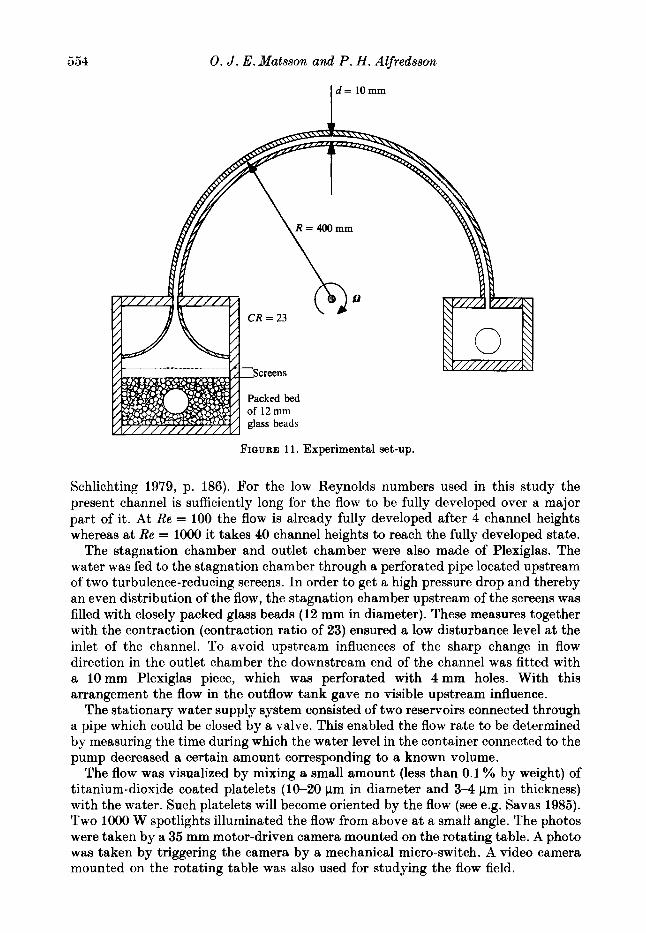
Figure 11 shows a sketch of the channel. The curved channel section covered 180' and the radius of curvature was 400 mm at the centreline of the channel, giving a total channel length of 1250mm. Its width was 10mm and its height 280mm, ensuring that the sidewalls had little effect on the flow in the central parts of the channel. In terms of channel heights the length is 125. The channel was made of Plexiglas. Two 3 mm plates were used for the channel walls. Top and bottom were c u t from a semicircular plate of 10 mm Plexiglas. In order to clean the channel of trace particles stuck to the walls, magnetically manoeuvred brushes were installed inside the channel. When not in use they were parked at the downstream end of the channel.
The basic laminar flow in a curved channel has to the first order the standard parabolic profile and the fully developed state is reached when x/d 2 0.04Re (see e.g.
554 0. J . E . Matsson and P. H . Alfredsson
I d = 10mm
Packed bed of 12 mm glass beads
FIQIJRE 11 . Experimental set-up.
Schlichting 1979, p. 186). For the low Reynolds numbers used in this study the present channel is sufficiently long for the flow to be fully developed over a major part of it. At Re = 100 the flow is already fully developed after 4 channel heights whereas a t Re = 1000 it takes 40 channel heights to reach the fully developed state.
The stagnation chamber and outlet chamber were also made of Plexiglas. The water was fed to the stagnation chamber through a perforated pipe located upstream of two turbulence-reducing screens. I n order to get a high pressure drop and thereby an even distribution of the flow, the stagnation chamber upstream of the screens was filled with closely packed glass beads (12 mm in diameter). These measures together with the contraction (contraction ratio of 23) ensured a low disturbance level at the inlet of the channel. To avoid upstream influences of the sharp change in flow direction in the outlet chamber the downstream end of the channel was fitted with a 10mm Plexiglas piece, which was perforated with 4 m m holes. With this arrangement the flow in the outflow tank gave no visible upstream influence.
The stationary water supply system consisted of two reservoirs connected through a pipe which could be closed by a valve. This enabled the flow rate to be determined by measuring the time during which the water level in the container connected to the pump decreased a certain amount corresponding to a known volume.
The flow was visualized by mixing a small amount (less than 0.1 % by weight) of titanium-dioxide coated platelets (10-20 pm in diameter and 3 4 pm in thickness) with the water. Such platelets will become oriented by the flow (see e.g. Savas 1985). Two 1000 W spotlights illuminated the flow from above a t a small angle. The photos were taken by a 35 mm motor-driven camera mounted on the rotating table. A photo was taken by triggering the camera by a mechanical micro-switch. A video camera mounted on the rotating table was also used for studying the flow field.

Curvature- and rotation-induced instabilities in channel flow 555
FIGURE 12. Curved channel flow without rotation, Re = 960, y = 0.025.

556 0. J . E . Matsson and P. H . A4fredsson
t 2000
FIGURE 14(a-e). For caption Bee facing page.
Curvature- and rotution-induced instabilities in channel flow 557
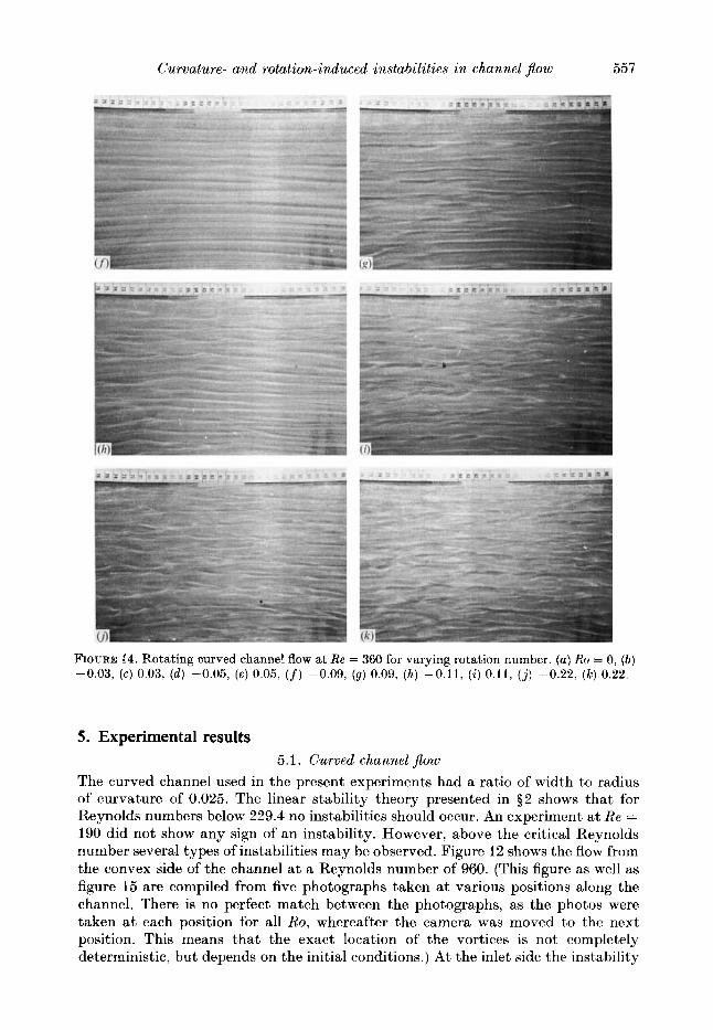
FIGURE 14. Rotating curved channel flow at Re = 360 for varying rotation number. (a) Ro = 0, (b) -0.03, (c) 0.03, ( d ) -0.05, (e) 0.05, ( f ) -0.09, (9 ) 0.09, (h) -0.11, ( i ) 0.11, (j) -0.22, (k) 0.22.
5. Experimental results 5.1. Curved channel flow
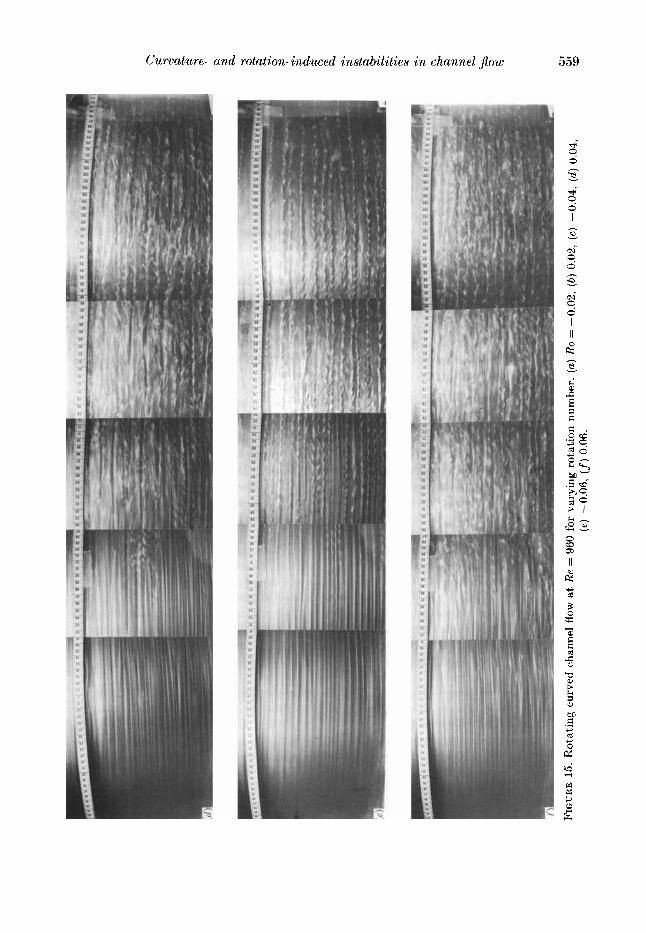
The curved channel used in the present experiments had a ratio of width to radius of curvature of 0.025. The linear stability theory presented in $ 2 shows that for Reynolds numbers below 229.4 no instabilities should occur. An experiment a t Re = 190 did not show any sign of an instability. However, above the critical Reynolds number several types of instabilities may be observed. Figure 12 shows the flow from the convex side of the channel at a Reynolds number of 960. (This figure as well as figure 15 are compiled from five photographs taken a t various positions along the channel. There is no perfect match between the photographs, as the photos were taken a t each position for all Ro, whereafter the camera was moved to the next position. This means that the exact location of the vortices is not completely deterministic, but depends on the initial conditions.) At the inlet side the instability

558 0. J . E . Matsson and P . H . Alfredsson
m 8 c 0
e, .- Y
d
Curvature- and rotation-induced instabilities in channel ,flow 559
d
I z

560 0. J . E. Matsson and P. H . Alfredsson
showed up first as a streaky structure typical of the existence of streamwise vortices. The higher the Reynolds number the closer to the inlet a clear streaky structure appeared. For Re below 700 the streaky structure was observed over the whole length of the channel. Above 700 the originally streaky structure became twisted in the downstream part of the channel (see figure 12). These twists were travelling downstream and interpreted as a secondary instability, of the same type as earlier observed in a rotating plane channel flow by Alfredsson & Persson (1989). At Re = 960 the twists were first observed a t about 70 channel heights, i.e. after about goo, and travelled downstream with about 80 %I of the bulk velocity. The higher the Reynolds number the more upstream the twists first appear. At even higher Re a more chaotic motion develops, starting in the downstream part of the channel, which moves upstream as the Reynolds number increases. At Re = 1100 the twists extend all the way to the outlet ; however, at Re = 1500 the twists appear in the region 40-80 channel widths from the inlet. Further downstream the flow visualization shows a very chaotic picture. At Re = 1850 twists appear very close to the inlet directly followed by a highly disturbed flow. Figure 13 is an attempt to describe where the different flow regimes occurred when the Reynolds number was varied. The boundaries between the different flow regimes are not distinct, but the qualitative agreement with a similar figure in Ligrani & Niver (1988) obtained from another type of flow visualization is good.
5.2. Curved channel flow with rotation
At Re = 360 typical longitudinal vortices occurred over the whole channel a t Ro = 0 (figure 14a, note that in figure 14 the flow direction is from right to left. and the channel is viewed from the concave side). The typical wavelength observed in the figure is 15 mm, but with large individual variations. Detailed observations of the flow of particles for this case show that the dark regions correspond to the borders of a pair of counter-rotating vortices. This means that the corresponding wavenumber is equal to 4.2, which is close to the most unstable wavcnumber according to the linear stability analysis.
A t Ro = -0.03 the vortices almost completely disappeared as a result of the Coriolis force counteracting the centrifugal force. This is in accordance with the results from the linear stability analysis (figures 4 and 5) which showed that for the present value of the y the flow became stabilized around this value of Ro, e.g. a t Ho = -0.0284 the critical Reynolds number is 1245 which should be compared to the critical Reynolds number without rotation which is 229. However, the disappearance of the vortices occurred only in a small interval of Ro; by Ro = -0.05 the vortices had started to reappear (figure 14d) and a t Ro = -0.09 clear straight streaks were again observed (figure 14f).
At Ro = -0.1 1 (figure 14h) the streaky structure undergoes an undulating motion. Some of the streaks seem to merge with their neighbours. However, most streaks are fairly long and for this case they can be clearly distinguished and identified a t least over the extent of the photograph. At Ro = -0.22 (figure 14j) the streaks seem to become more unstable, sometimes they divide and sometimes they end abruptly.
When rotating the channel in the other direction the streaks have started to undulate by Ro = 0.03 (figure 14c), and the undulation increases with increasing Ro. The flow structure a t Ro = 0.05 (figure 14e) is similar to that seen for Ro = -0.11 (figure 14h). This is what might be expected because these two rotation numbers are a t an equal distance from the rotation number corresponding to the maximum stability point. A t higher Ro (figure 14g, i , k) the structure of the streaks is similar to

Gurvature- and rotation-induced instabilities in channel ,flow 56 1
that obtained for negative rotation rates, i.e. a t higher absolute values of Ro the instability is rotation dominated.
Figure 12 showed the flow without rotation a t a Reynolds number ofRe = 960. For this non-rotating casc the vortices appear close to the inlet and the twists a,re seen around x/d = 70. Figure 15(a-f) shows the same Reynolds number but with three different rotational speeds in both directions. At Ro = -0.02 (figure 15a) it is clearly shown that the twists have completely disappeared. At Ro = 0.02, the twists are instead more pronounced and appear closer to the channel inlet. At Ro = -0.04 the twists appear again, now around x/d = 80. For Ro = 0.04 the twists are not observed, instead the flow is strongly influenced by a large-scale irregular disturbance. At Ro =-0.06 the twists start a t around x/d = 60 and appear throughout the rest of the channel. For Ro = 0.06 the flow is again subjected to large- scale disturbances starting at around x/d = 50.
6. Discussion The present study shows flow visualization of rotating curved channel flow which
a t one limit, i.e. without rotation can be compared with the numerical simulation of Finlay et al. (1988) and the experiments of Ligrani & Niver (1988). In the present study the same ratio of channel width to curvature ratio as in these earlier studies was chosen, namely 1 : 40. The different flow regimes determined by Ligrani & Niver compare well with our observations as shown in figure 13. With the present flow visualization technique the different flow structures occurring in the flow are easily distinguished and it was possible to observe two types of secondary instability a t high Re, namely a regular twisting motion and an irregular undulating or wavy motion. I n Taylor-Couette flow, see e.g. Coles (1965), a secondary instability in the form of an undulating motion of the basic vortices is observed and is then very regular. It is not clear if the observed waves are the same type of disturbance. A twisting motion has been observed in the rotating channel flow of Alfredsson & Persson (1989) and also in the numerical simulation of the same flow by Yang & Kim (1988). In Taylor-Couette flow, Andereck, Liu & Swinney (1986) found an instability which they named ‘twisted Taylor vortices ’. This instability resembles the one found here. Also, the Taylor vortices a t the ends of the annular column in a Taylor-Couette flow arc sometimes twisted and similar to the twisted vortices observed here. In the numerical simulation of Finlay et al. (1988) two types of secondary instability wcre also observed.
In some respects the curved rotating channel flow resembles the Taylor-Dean problem studied by Hughes & Reid (1964) especially the form of the neutral stability curves for stationary disturbances, which in both cases divide themselves into two loops. We also find that these loops are interconnected through a Hopf-bifurcation branch. The same is true also for the Taylor-Dean problem as shown by Raney & Chang (1971). In the Taylor-Dean problem this behaviour is explained by the velocity profile shape, which has two separate regions where centrifugal instability may occur, and these instabilities may hence interact.
The division into two loops gives rise to a bifurcation type of behaviour when the rotation number changes for the present flow configuration, in that the most unstable mode switches from one stationary mode to a time-dependent mode and then to the other stationary mode as the rotation number is varied.
562 0. J . E.Matsson and P . H . Alfredsson
7. Summary ( i ) The expressions up to first order in y for the mean velocity profile as well as the
eigenvalue problem determining both temporally and spatially growing disturbances are given for rotating curved channel flow.
(ii) The linear stability analysis of the flow shows that when the centrifugal and Coriolis cffccts counteract each other the stability of the flow can be substantially enhanced as compared to curved channel flow without rotation.
(iii) For certain parameter combinations, where the centrifugal and Coriolis effects closely cancel, the linear stability analysis shows that three different disturbances may be obtained, each of them determining the instability within a certain parameter range. The most unstable wavenumber changes stepwise when the most unstable disturbance switches from one mode to the next.
(iv) The experiments show that an almost complete cancellation of the vortices a t an Re 50% higher than the critical Re can be obtained close to the most stabilizing Ro as determined from the linear stability analysis.
(v) At higher RP the non-rotating channel shows clear secondary instabilities in the downstream part of the channel. If the rotation direction was so that the Coriolis effect and the curvature effect counteracted, i t was possible to completely cancel the secondary instability. Also, here the cancellation was most effective at an Ro close to the most stabilizing Ro with respect to the primary linear disturbance.
Thanks are due to Peter Rogberg who took part during the early stages of this work. This work has been financed by STU, the Swedish Board for Technical Development, under the program for energy related industrial fluid mechanics.
R E F E R E N C E S
ALFREDSSON, P. H. & PERSSON, H. 1989 Instabilities in channel flow with system rotation.
ANDERECK, C. I)., LUI, S. S. & SWINNEY, H. L. 1986 Flow regimes in a circular Couette system
BREWSTER, D. P., GROSBERG, P. & XISSAN, A. H. 1959 The stability of viscous flow between
COLES, I). 1965 Transition in circular Couette flow. J . F h i d Mech. 21, 385. CRATK. A. D. D. 1985 Wave Interactions and Fluid Flows. Cambridge University Press. DRAZIN; P. G. & REID. W. H. 1981 Hydrodynamic Stability. Cambridge University Press. FINLAY, W. H.: KELLER, J . B. & FERZIGER, J. H.
J . Fluid Mech. 202, 543.
with independently rotating cylinders. J . F h i d Mech. 164, 155.
horizontal concentric cylinders. Proe. R. SOC. Lond. A251, 76.
1988 Instability and transition in curved channel flow. J . Fluid Mech. 194, 417.
GIBSON, R. D. & COOK, A. E. 1974 The stability of curved channel flow. &. J . Mech. AppE. Muths 27, 149.
HART. t J . E. 1971 Instability and secondary motion in a rotating channel flow. J . Fluid Mech. 45, 341.
HUGHES, T H. & REIT), W. H. 1964 The effect of a transverse pressure gradient on the stability of Couette flow. Z . Angew. Math. Phys. 15, 573.
LEZIUS. D. K. & JOHNSTON, J. P. 1976 The structure and stability of turbulent boundary layers in rotating channel flow. J . Fluid Mech. 77, 153.
LIGRANI, P. M. & EIVER, R. D. 1988 Flow visualization of Dean vortices in a curved channel with 40 to 1 aspect ratio. Phys. Fluids 31, 3605.
OSWATITSCH, K. & WIEGHARDT, K. 1987 Ludwig Prandtl and his Kaiser-Wilhelm-Institut. Ann. Rev. Fluid Meeh. 19, 1.
Curvature- and rotation-induced instabilities in channel flow 563
RANEY, D. C. & CHANC, T. S. 1971 Oscillatory modes of instability for flow between rotating cylinders with a transverse pressure gradient. 2. Angew. Math. Phys. 22, 680.
RASENA, S., BUSSE, F. H. & REHBERC, I. 1989 A theoretical and experimental study of double- layer convection. J . Fluid Mech. 199, 519.
REID, W. H. 1958 On the stability of viscous flow in a curved channel. Proc. R . Lond. ~Yoc. A244, 186.
SAVAS, 0. 1985 On flow visualization using reflective flakes. J . Fluid Mech. 152, 235. SCHLICHTING, H. 1979 Boundary Layer Theory, 7th edn. McGraw-Hill. TRITTON, I). J. & DAVIES, P. A. 1985 Instabilities in geophysical fluid dynamics. In Hydrodynamic
Instabilities and the Transition to Turbulence. Topics in Applied Physics, vol. 45, 2nd edn. Springer.
YANG, K. & KIM, J . 1988 Transition in plane Poiseuille flow with system rotation. Bull. Am. Phys. Soc. 33, 2284.