Decoupling force and position control in constrained motion with friction
Upload
independentCategory
view
4download
0
IADC/SPE 128767
Decoupling Stick-slip and Whirl to Achieve Breakthrough in Drilling Performance Sean Xianping Wu, Luis Paez, Uyen Partin and Mukul Agnihotri, Smith Technologies Copyright 2010, IADC/SPE Drilling Conference and Exhibition This paper was prepared for presentation at the 2010 IADC/SPE Drilling Conference and Exhibition held in New Orleans, Louisiana, USA, 2–4 February 2010. This paper was selected for presentation by an IADC/SPE program committee following review of information contained in an abstract submitted by the author(s). Contents of the paper have not been reviewed by the International Association of Drilling Contractors or the Society of Petroleum Engineers and are subject to correction by the author(s). The material does not necessarily reflect any position of the International Association of Drilling Contractors or the Society of Petroleum Engineers, its officers, or members. Electronic reproduction, distribution, or storage of any part of this paper without the written consent of the International Association of Drilling Contractors or the Society of Petroleum Engineers is prohibited. Permission to reproduce in print is restricted to an abstract of not more than 300 words; illustrations may not be copied. The abstract must contain conspicuous acknowledgment of IADC/SPE copyright.
Abstract Stick-slip and whirl are the devastating vibrations that significantly limit drilling performance. They not only cause equipment failures, but also increase non-productive time driving up field development costs. Although the industry has achieved tremendous improvements in fighting against these dysfunctions, the root causes of stick-slip and whirl are still not fully understood.
Stick-slip is characterized by the fluctuation of rotary speed of the bottom hole assembly (BHA) while whirl is known as the severe lateral vibration that may occur at bit and/or BHA. A driller’s dilemma emerges when increasing weight-on-bit (WOB) induces stick-slip whereas increasing revolutions /minute (RPM) induces whirl. Keeping both WOB and RPM low reduces vibration levels but it negatively affects ROP. As a result, the drilling operation either suffers low ROP or experiences higher ROP but with severe vibrations. The latter can cause damage to the bit and rotary steerable system (RSS), motor (PDM), measurement while drilling/logging while drilling (MWD/LWD) leading to a lack of steerability and poor borehole quality.
New research strongly suggests the above dilemma is related to the drillstring’s tendency to couple stick-slip and whirl. This coupling is induced by improper bit selection and unfavorable bit-BHA interactions. For a given bit and rock, the critical values of WOB and RPM triggering stick-slip and whirl can be predetermined assuming other drilling conditions are known and fixed. Plotted in a rectangular coordinate with abscissa of RPM and ordinate of WOB, these critical values represent the boundaries of stable drilling parameters. The other important boundaries include:
• Maximum torque limited by rig capability • Minimum ROP specified by operators • Maximum WOB limited by drillstring buckling and directional control
These boundaries together define a closed domain in the space of WOB and RPM. This domain is called the “optimum zone” in this paper. The drilling parameters in the optimum zone theoretically guarantee BHA/bit stability. The scope of the optimum zone depends on the bit and the mechanical properties of the rock to be drilled. The drillstring dynamics, however, reduce the optimum zone significantly by creating bit-BHA interactions. In an extreme case, these interactions can push the boundaries of stick-slip and whirl to cross, completely eliminating the optimum zone. In this situation, any attempt to mitigate vibrations by varying drilling parameters will most likely fail. To solve this challenge, an advanced drillstring model was developed and applied to quantify the following effects on the optimum zone:
• Mechanical rock properties • Bit design including cutter, body and gauge profile • BHA design and its interaction with bit
The ability to obtain superior stability and ROP simultaneously depends on two key factors: (1) maximizing the optimum zone through bit optimization, and (2) minimizing bit-BHA interactions by BHA optimization. The objective of both is to decouple potential stick-slip and whirl. The authors will present several case studies to illustrate the concept of optimum zone and its effectiveness on decoupling stick-slip and whirl to increase overall drilling performance.
2 IADC/SPE 128767
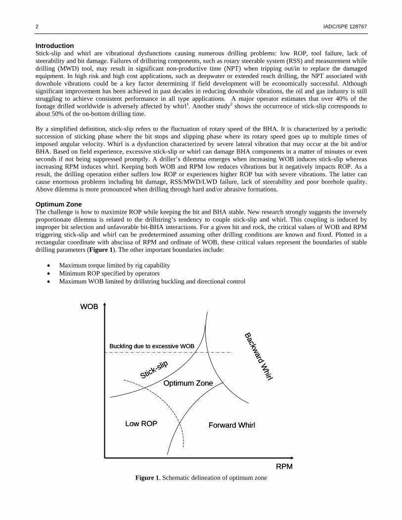
Introduction Stick-slip and whirl are vibrational dysfunctions causing numerous drilling problems: low ROP, tool failure, lack of steerability and bit damage. Failures of drillstring components, such as rotary steerable system (RSS) and measurement while drilling (MWD) tool, may result in significant non-productive time (NPT) when tripping out/in to replace the damaged equipment. In high risk and high cost applications, such as deepwater or extended reach drilling, the NPT associated with downhole vibrations could be a key factor determining if field development will be economically successful. Although significant improvement has been achieved in past decades in reducing downhole vibrations, the oil and gas industry is still struggling to achieve consistent performance in all type applications. A major operator estimates that over 40% of the footage drilled worldwide is adversely affected by whirl1. Another study2 shows the occurrence of stick-slip corresponds to about 50% of the on-bottom drilling time. By a simplified definition, stick-slip refers to the fluctuation of rotary speed of the BHA. It is characterized by a periodic succession of sticking phase where the bit stops and slipping phase where its rotary speed goes up to multiple times of imposed angular velocity. Whirl is a dysfunction characterized by severe lateral vibration that may occur at the bit and/or BHA. Based on field experience, excessive stick-slip or whirl can damage BHA components in a matter of minutes or even seconds if not being suppressed promptly. A driller’s dilemma emerges when increasing WOB induces stick-slip whereas increasing RPM induces whirl. Keeping both WOB and RPM low reduces vibrations but it negatively impacts ROP. As a result, the drilling operation either suffers low ROP or experiences higher ROP but with severe vibrations. The latter can cause enormous problems including bit damage, RSS/MWD/LWD failure, lack of steerability and poor borehole quality. Above dilemma is more pronounced when drilling through hard and/or abrasive formations. Optimum Zone The challenge is how to maximize ROP while keeping the bit and BHA stable. New research strongly suggests the inversely proportionate dilemma is related to the drillstring’s tendency to couple stick-slip and whirl. This coupling is induced by improper bit selection and unfavorable bit-BHA interactions. For a given bit and rock, the critical values of WOB and RPM triggering stick-slip and whirl can be predetermined assuming other drilling conditions are known and fixed. Plotted in a rectangular coordinate with abscissa of RPM and ordinate of WOB, these critical values represent the boundaries of stable drilling parameters (Figure 1). The other important boundaries include:
• Maximum torque limited by rig capability • Minimum ROP specified by operators • Maximum WOB limited by drillstring buckling and directional control
Low ROP Forward Whirl
Backward Whirl
Buckling due to excessive WOB
Stick-slip
Optimum Zone
RPM
WOB
Low ROP Forward Whirl
Backward Whirl
Buckling due to excessive WOB
Stick-slip
Optimum Zone
RPM
WOB
Figure 1. Schematic delineation of optimum zone

IADC/SPE 128767 3
These boundaries together define a closed domain in the space of WOB and RPM. The authors have labeled this domain the optimum zone. The drilling parameters in the optimum zone theoretically guarantee stability. The scope of the optimum zone depends on the bit and the mechanical properties of the rock to be drilled. The drillstring dynamics, however, reduce the optimum zone significantly by creating bit-BHA interactions. In an extreme case, these interactions can push the boundaries of stick-slip and whirl to cross, completely eliminating the optimum zone (Figure 2). In this situation, any attempt to mitigate vibrations by varying drilling parameters will most likely fail.
Figure 2. Annihilation of optimum zone due to strong coupling of stick-slip and whirl
Low ROP Forward WhirlBackward W
hirl
Buckling due to excessive WOB
Stick-slip
RPM
WOB
Low ROP Forward WhirlBackward W
hirl
Buckling due to excessive WOB
Stick-slip
RPM
WOB
Advanced Drillstring Dynamics Model If the effects of the bit and BHA on drillstring dynamics can be quantified, the optimum zone concept is a powerful tool for increasing the efficiency of the entire drilling system. The potential hazards of using an improper bit or BHA component can be easily identified by evaluating the size and position of the optimum zone. In addition, the feasible combination of WOB and RPM can be estimated by knowing the boundaries of the optimum zone. The challenging part, however, is to be able to predict the magnitude of vibration/slick-slip accurately. To solve this challenge, engineers apply an advanced drillstring dynamics model which incorporates the following critical information:
• Mechanical rock properties • Bit/reamer design including cutter, body and gauge profile • Physical characteristics of BHA components • Formation characteristics (heterogeneous, anisotropy and interbedding) • Well trajectory and borehole geometry
This comprehensive 4-D finite element model accurately predicts the drilling system’s performance from bit to surface and simulates the transient response of the entire system in time domain. This model can be applied to any drillstring configuration to provide details of the BHA including RSS, PDM, PDC/roller cone bits, stabilizers, reamers, MWD/LWD and other downhole tools. The outputs from this model include acceleration, velocity, forces, bending moment and displacement at any node along the drillstring. To precisely quantify the forces between cutting structure and rock, the formation samples were analyzed at the service provider’s Houston, Texas-based drilling laboratory.3-6 Under controlled pressures, a series of indentation and scrape tests (Figure 3) were conducted to replicate the dynamics between the cutting structure and the actual rock sample. The laboratory results quantified actual cutting structure forces in scientific terms of magnitude and orientation as a function of the rock failure mechanism and quantified rock removal rates. The analysis allowed the accurate transition into a virtual environment where engineers determined the bit/reamer’s characteristics in confined mode. Engineers are able to quantify the magnitude of the downhole vibrations and cutting forces, which in turn predicts directional tendency and instantaneous ROP. Using these quantitative results and 3D visualization, the optimum drilling system was identified, which would provide the best balance between ROP, stability and steerability.

4 IADC/SPE 128767
Combined Force Displacement0015659(Chisel);LU;2000 psi
0
5000
10000
15000
20000
25000
0 0.05 0.1 0.15 0.2 0.25 0.3 0.35 0.4 0.45
Depth of Penetration, in
Pene
tratio
n Fo
rce,
lbf
Figure 3 – Indentation test with the combined force displacement chart
Unlike a critical speed analysis which assumes the magnitude and frequency of excitation forces, the dynamic modeling technology is based on a transient model that utilizes laboratory-derived rock mechanics and a realistic drilling environment. It minimizes the uncertainty of the contact forces between bit and rock/formation in order to maximize the reliability of the results. The instantaneous impact loads at the bit or BHA can be captured and their transient effects on the entire drillstring are accurately modeled. The values of the measurement data (real-time or memory type) are better realized by comparing to modeling results in order to pinpoint the underlying causes of observed damaging vibrations. Decoupling Stick-Slip and Whirl Using the advanced drillstring dynamics model, it is possible to theoretically predict the potential occurrence of stick-slip or whirl given the details of bit, BHA, wellbore and lithology. More importantly, the optimum zone of the given drilling system can be delineated in the space of WOB and RPM. As a result, stick-slip and whirl could be theoretically decoupled by maximizing the optimum zone. The advantages of applying the optimum zone concept to solve difficult challenges of coupled vibrations can be summarized as follows:
1. The coupling of stick-slip and whirl can be easily visualized and better understood by drilling engineers in a concise graph with respect to WOB and RPM
2. The effects of any change in the followings on the drillstring’s dynamics can be quantified and subsequently become more predictable
• Bit and BHA • WOB and RPM • Formation properties, well trajectory and borehole geometry
3. The comparison of various solutions is straightforward because the drilling system yielding maximum optimum zone is most likely to achieve stable drilling without sacrificing ROP
4. The shape and position of optimum zone in the space of WOB and RPM provides important guide data for drillers to fine tune the operating parameters
In the next section, we apply two field case studies to introduce the optimization process. Two key components of this optimization: (1) the concept of optimum zone, and (2) the advanced drillstring dynamics model. Please note the threshold values of stick-slip and whir used for delineating optimum zone are usually specified by customers. In addition, the optimization’s primarily focus is on bit design and BHA configuration. Other factors such as hole cleaning and borehole quality are not addressed in the scope of this paper. Case Study - 1: Under-Reaming While Drilling, South America While drilling in a high-profile field in South America, the operator was experiencing excessive BHA/PDC bit vibration. The drilling dysfunction was causing unacceptably low penetration rates (ROP) while reducing tool life of expensive downhole equipment ultimately driving up field development costs. The problems were most noticeable when utilizing an expandable reamer in a rotary steerable BHA to drill a 10-5/8” pilot hole reamed open to 12-1/4 inches. Specific issues while holding angle in the tangent section included excessive torque induced stick-slip as well as high axial and lateral vibration. The service provider was asked to optimize the BHA design including PDC bit selection. The engineers applied the proprietary dynamics modeling tool to first replicate the drilling vibrations experienced in field, and then optimize bit/BHA using the optimum zone concept. The stratigraphic sequence in the problematic 12-1/4” x 10-5/8” hole section consists of the following Tertiary formations:

IADC/SPE 128767 5
1. Formation A - uniform sequence of hard fine to very fine, friable quartz sandstone (11,000 psi UCS) 2. Formation B – soft calcareous shale and clay (5,000 psi UCS) 3. Formation C – mainly hard layers of limestone (14,000 psi UCS).
The first step in the optimization process was to determine what PDC bit can deliver the required ROP while remaining dynamically stable. A set of PDC bits (Figure 4) were quantitatively evaluated in the advanced dynamics model by taking into account the design details in bit profile, blade/cutter count, back rake angle and gauge length.
GPL: 3”
8 Blades/ 13mm (63)
GPL: 2.5”
6 Blades/ 16mm (52)
GPL: 3”
8 Blades/ 13mm (63)
GPL: 2.5”
6 Blades/ 16mm (52)
Bit 3 Bit 4Bit 3 Bit 4
GPL: 3”
7 Blades/ 16mm (54)
GPL: 3”
7 Blades/ 16mm (54)
Bit 1Bit 1
GPL: 3”
8 Blades/ 13mm (63)
GPL: 2.5”
6 Blades/ 16mm (52)
GPL: 3”
8 Blades/ 13mm (63)
GPL: 2.5”
6 Blades/ 16mm (52)
Bit 3 Bit 4Bit 3 Bit 4
GPL: 3”
7 Blades/ 16mm (54)
GPL: 3”
7 Blades/ 16mm (54)
Bit 1Bit 1
Figure 4 - Three 10-5/8” test bits were run in the simulation
In order to achieve the overall stability of the entire drillstring, it is imperative to understand the interaction between the BHA and bit. An improper BHA configuration can exaggerate the vibrations at the bit and ultimately trigger the coupling of stick-slip and whirl. Under-reaming while drilling is one of the most challenging operations as it tends to generate severe torsional and lateral vibrations, particularly when the bit and under-reamer are drilling rocks with varying hardness. Based on field expertise and modeling results, the worst scenario takes place at the transition from hard to soft formation shown as scenario-2 in (Figure 5). In this situation, the bit tends to drill faster than reamer and the weight is hung on the reamer. Consequently, weight-on-reamer (WOR) is higher than the weight-on-bit (WOB). This situation has been observed in the field and laboratory to be a triggering mechanism for damaging vibrations.

6 IADC/SPE 128767
Formaci ón
Blanda
Formaci ón Dura
ón Blanda
MD
BROCA
REAMER
BROCA
REAMER
BROCA
REAMER
BROCA
REAMER
Formation Vivian
Formation
Chonta Superior
Chonta Inferior
MD
BIT
REAMER
BIT
REAMER
BIT
REAMER
BIT
REAMER
Formation
4
1
3
211 kpsi UCMPS
5 kpsi UCMPS
14 kpsi UCMPS
Figure 5 – Four critical transitional drilling scenarios, 12-1/4” x 10-5/8” hole section To meet the challenges, engineers recommended an innovative expandable reaming technology which has a proven record in overcoming difficult drilling environments worldwide.7-9 The concentric reamer’s (Figure 6) one-piece cutter block and extension mechanism design give the tool built-in toughness and superior reliability. The tongue and groove actuation system traverses each of the three PDC cutter-laden blocks and opens them to a pre-selected diameter. The blocks are then locked in place by the tool’s hydraulic system. The single piece body design increases the tool’s torque and load carrying capacity ensuring it can efficiently handle the heavy weight of the RSS BHA below.
Figure 6 – Concentric reamer with innovative stabilizer pad to ensure proper hole gauge As important as the reamer’s design, the correct positioning of the reamer in BHA is critical to determining the dynamics of the drillstring. Multiple BHA configurations were evaluated and compared in the advanced dynamics model by varying the position of reamer in BHA. The two best BHA configurations are plotted in (Figure 7).
IADC/SPE 128767 7
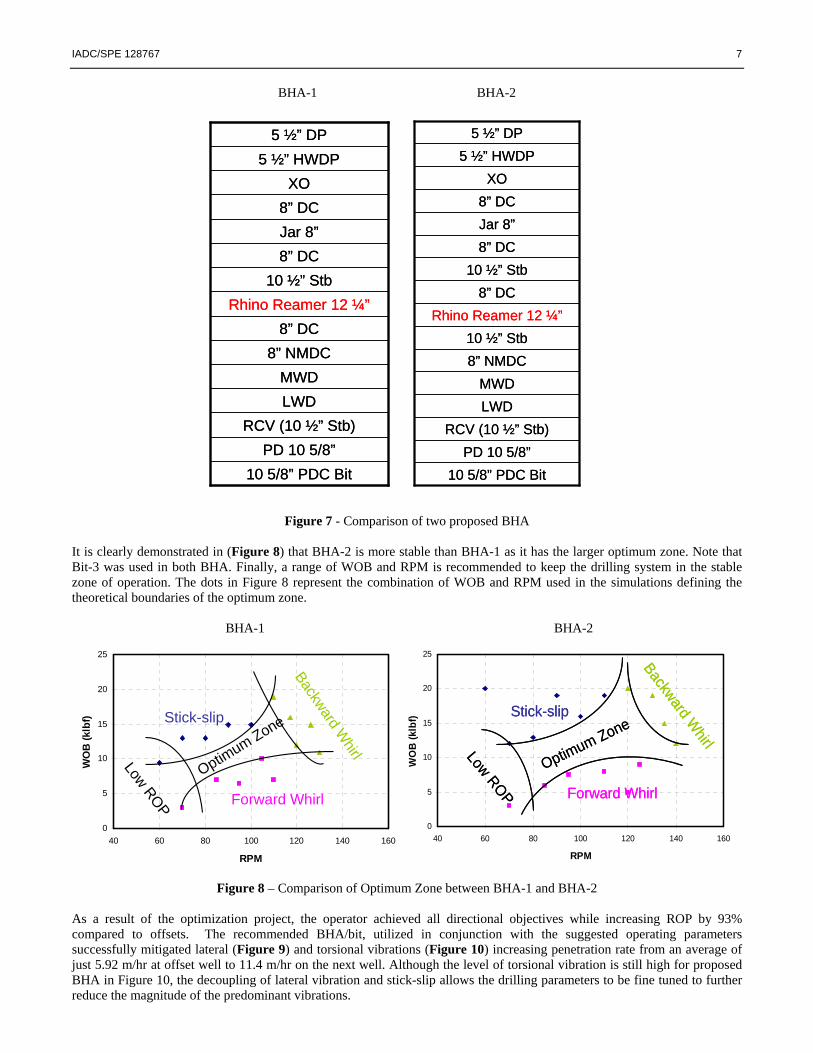
BHA-1 BHA-2
Figure 7 - Comparison of two proposed BHA
It is clearly demonstrated in (Figure 8) that BHA-2 is more stable than BHA-1 as it has the larger optimum zone. Note that Bit-3 was used in both BHA. Finally, a range of WOB and RPM is recommended to keep the drilling system in the stable zone of operation. The dots in Figure 8 represent the combination of WOB and RPM used in the simulations defining the theoretical boundaries of the optimum zone. BHA-1 BHA-2
Figure 8 – Comparison of Optimum Zone between BHA-1 and BHA-2
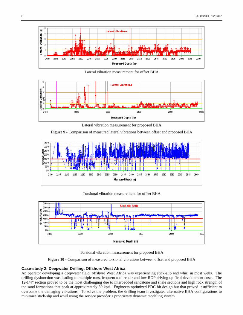
As a result of the optimization project, the operator achieved all directional objectives while increasing ROP by 93% compared to offsets. The recommended BHA/bit, utilized in conjunction with the suggested operating parameters successfully mitigated lateral (Figure 9) and torsional vibrations (Figure 10) increasing penetration rate from an average of just 5.92 m/hr at offset well to 11.4 m/hr on the next well. Although the level of torsional vibration is still high for proposed BHA in Figure 10, the decoupling of lateral vibration and stick-slip allows the drilling parameters to be fine tuned to further reduce the magnitude of the predominant vibrations.
10 5/8” PDC Bit PD 10 5/8”
RCV (10 ½” Stb)LWDMWD
8” NMDC8” DC
10 ½” Stb8” DCJar 8”8” DC
XO5 ½” HWDP
5 ½” DP
Rhino Reamer 12 ¼”
10 5/8” PDC Bit PD 10 5/8”
RCV (10 ½” Stb)LWDMWD
8” NMDC8” DC
Rhino Reamer 12 ¼”10 ½” Stb
8” DCJar 8”8” DC
XO5 ½” HWDP
5 ½” DP
10 5/8” PDC Bit PD 10 5/8”
RCV (10 ½” Stb)LWDMWD
8” NMDC10 ½” Stb
8” DC10 ½” Stb
8” DCJar 8”8” DC
XO5 ½” HWDP
5 ½” DP
Rhino Reamer 12 ¼”
10 5/8” PDC Bit PD 10 5/8”
RCV (10 ½” Stb)LWDMWD
8” NMDC10 ½” Stb
8” DC10 ½” Stb
8” DCJar 8”8” DC
XO5 ½” HWDP
5 ½” DP
Rhino Reamer 12 ¼”
0
5
10
15
20
25
40 60 80 100 120 140 160
RPM
WO
B (k
lbf) Stick-slip
Forward Whirl
Backward WhirlLow ROP
Optimum Zone
0
5
10
15
20
25
40 60 80 100 120 140 160
RPM
WO
B (k
lbf) Stick-slip
Forward Whirl
Backward WhirlLow ROP
Optimum Zone
0
5
10
15
20
25
40 60 80 100 120 140 160
RPM
WO
B (k
lbf) Stick-slip
Forward Whirl
Backward WhirlLow ROP
Optimum Zone
0
5
10
15
20
25
40 60 80 100 120 140 160
RPM
WO
B (k
lbf) Stick-slip
Forward Whirl
Backward WhirlLow ROP
Optimum ZoneStick-slip
Forward Whirl
Backward WhirlLow ROP
Optimum Zone
8 IADC/SPE 128767
Lateral vibration measurement for offset BHA
Lateral vibration measurement for proposed BHA
Figure 9 - Comparison of measured lateral vibrations between offset and proposed BHA
Torsional vibration measurement for offset BHA
Torsional vibration measurement for proposed BHA
Figure 10 - Comparison of measured torsional vibrations between offset and proposed BHA Case-study 2: Deepwater Drilling, Offshore West Africa An operator developing a deepwater field, offshore West Africa was experiencing stick-slip and whirl in most wells. The drilling dysfunction was leading to multiple runs, frequent tool repair and low ROP driving up field development costs. The 12-1/4” section proved to be the most challenging due to interbedded sandstone and shale sections and high rock strength of the sand formations that peak at approximately 30 kpsi. Engineers optimized PDC bit design but that proved insufficient to overcome the damaging vibrations. To solve the problem, the drilling team investigated alternative BHA configurations to minimize stick-slip and whirl using the service provider’s proprietary dynamic modeling system.

IADC/SPE 128767 9
An analysis of sonic and gamma-ray logs (Figure 11) showed an abrupt transition of unconfined compressive strength (UCS) from 3 ksi in shale to 15 ksi in sandstone with peaks at 30 ksi. Severe lateral vibration was encountered when entering the hard sandstone and the RPM was immediately reduced from 160 to just 60 in order to mitigate vibrations. However, when the operator lowered RPM, stick-slip levels increased unexpectedly demonstrating the complex challenges of potential coupled stick-slip and whirl.
60 RPM in sandstoneYields higher Stick_RT, but
lower VIBLAT_RT
160 RPM in shaleYields lower Stick_RT, but
higher VIBLAT_RT
Figure 11 - The mode of primary vibration varied when drilling through the transition from soft shale to hard sandstone in offset well To provide effective solutions, the first step of the optimization process was to replicate the drilling dynamics using the offset field data. A virtual drilling system was composed in the model incorporating the details of the bit, BHA, rock strength, formation properties, well trajectory, borehole geometry and operating parameters. Figure 12 illustrates the vibrations of the offset drilling system in a virtual drilling environment. The model clearly shows that higher RPM triggers severe lateral vibrations and that lower RPM induces severe torsional vibrations.

10 IADC/SPE 128767
Stick Slip
Rev
s/m
in
Bit Lateral Vibration
- 160 RPM - 60 RPM
G
Figure 12 - Simulations reproducing the transition of vibration mode when altering RPM at offset well shown in Figure 11 A number of new BHA configurations were evaluated in the advanced dynamics model. Although many BHA configurations were tested, most were not recommended because the improvement was only marginal in the model. Eventually, a new BHA with a motor on top of a rotary steerable system (RSS) was proposed and shown to deliver outstanding performance. The offset BHA and proposed BHA are illustrated in Figure 13. BHA 1
8" Collar (2 joints)
Jar
8" Collar (9 joints)
12 1/4” Roller Roller Reamer
8" NM Collar
8" NM Collar
MWD
12 1/8” Stabilizer
MWD
12 1/8” Stabilizer
MWD
Flex Collar
12 1/8” Stabilizer
Push The Bit RSS
12 1/4" PDC Bit
8" Collar (2 joints)
Jar
8" Collar (9 joints)
12 1/4” Roller Roller Reamer
8" NM Collar
8" NM Collar
MWD
12 1/8” Stabilizer
MWD
12 1/8” Stabilizer
MWD
Flex Collar
12 1/8” Stabilizer
Push The Bit RSS
12 1/4" PDC Bit
BHA 2
MWD
12 1/8” Stabilizer
MWD
12 1/8” Stabilizer
MWD
8" NM Collar
8" NM Collar
12 ¼” Roller Roller Reamer
8" Collar (9 joints)
Jar
8" Collar (2 joints)
Motor
Flex Collar
12 1/8” Stabilizer
Push The Bit RSS
12 1/4" PDC Bit
MWD
12 1/8” Stabilizer
MWD
12 1/8” Stabilizer
MWD
8" NM Collar
8" NM Collar
12 ¼” Roller Roller Reamer
8" Collar (9 joints)
Jar
8" Collar (2 joints)
Motor
Flex Collar
12 1/8” Stabilizer
Push The Bit RSS
12 1/4" PDC Bit
Figure 13 - Comparison of offset BHA (BHA-1) with proposed BHA (BHA-2)

IADC/SPE 128767 11
The idea of adding a mud motor comes from the following consideration: (1) the motor can effectively decouple the vibration between the bit and BHA, and (2) the additional torque delivered to the bit by the motor could help to overcome the reactive torque at bit/rock interface. Under the same operating conditions, the proposed BHA is shown to have substantially less lateral and torsional vibrations (Figure 14). As a graphical explanation, a comparison of the optimum zone is plotted in Figure 15 where the optimum zone is significantly enlarged by adding the downhole motor.
Bit Lateral Vibration
Stick Slip
- BHA 2- BHA 1
Rev
s/m
inG
Figure 14 - Comparison of lateral and torsional vibrations between offset BHA and proposed BHA under the same operating parameters BHA-1 BHA-2
0
5
10
15
20
25
30
35
0 20 40 60 80 10
Figure 15 – Comparison of Optimum Zone between BHA-1 and BHA-2
0
Surface RPM
WO
B (k
lbf)
Stick-slip
Forward Whirl
Backward W
hirl
Optimum ZoneLow ROP
0
5
10
15
20
25
30
35
0 20 40 60 80
Surface RPM
WO
B (k
lbf)
100
Stick-slip
Forward Whirl
Backward W
hirl
Optimum Zone
0
5
10
15
20
25
30
35
0 20 40 60 80
Surface RPM
WO
B (k
lbf)
100
Stick-slip
Forward Whirl
Backward W
hirl
0
5
10
15
20
25
30
35
0 20 40 60 80
Surface RPM
WO
B (k
lbf)
100
0
5
10
15
20
25
30
35
0 20 40 60 80 10
Surface RPM
WO
B (k
lbf)
0
Stick-slip
Forward Whirl
Backward Whirl
Optimum ZoneLow ROP
0
5
10
15
20
25
30
35
0 20 40 60 80 10
Surface RPM
WO
B (k
lbf)
0
Stick-slip
Forward Whirl
Backward Whirl
Optimum Zone
0
5
10
15
20
25
30
35
0 20 40 60 80 10
Surface RPM
WO
B (k
lbf)
0
Stick-slip
Forward Whirl
Backward Whirl
Optimum ZoneLow ROP
Stick-slip
Forward Whirl
Backward W
hirl
Optimum ZoneLow ROP

12 IADC/SPE 128767
The next well drilled in the same field using the proposed BHA has achieved 100% increase in ROP and 100% reduction in lateral and torsional vibrations (Figure 16).
Figure 16 – Comparison of measured vibration severity between BHA-1 and BHA-2
Conclusions A new method has been developed to solve the challenge of decoupling stick-slip and whirl. The critical aspect in this method, the optimum zone concept, was introduced in detail and demonstrated to improve the optimization process leading to a performance step-change. The ability to obtain superior stability and ROP simultaneously depends on two key factors: (1) maximizing the optimum zone through bit optimization, and (2) minimizing bit-BHA interactions with BHA optimization. The objective of both is to decouple the potential stick-slip and whirl. The enabling technology of this new method is an advanced drillstring dynamics model. It replicates the dynamic response from the bit to the surface in a virtual drilling environment by taking into account the critical information of bit, BHA and wellbore. Its accuracy is supported by the laboratory-derived rock mechanics and demonstrated by the numerous successful applications worldwide. By combining the advanced modeling technology with the new optimization method, the drilling engineer can identify the potential devastating vibrations in advance and quantify the effects of changes in bit/BHA. This capability will greatly help drilling industry to mitigate the damages induced by stick-slip or whirl, and ultimately achieve a breakthrough in the specific drilling application. Acknowledgements The authors would like to thank management at Smith International for permission to publish the data and present the conclusions. Also, special thanks to Craig Fleming, Smith International for his technical writing and editorial contributions.

IADC/SPE 128767 13
Reference Papers 1. Bailey, J.R., Biediger, E.A.O., Gupta, V., Ertas, D., Elks, W.C., Dupriest, F.E., 2008, “Drilling Vibrations Modeling
and Field Validation”, paper IADC/SPE 112650 presented at IADC/SPE Drilling Conference, Orlando, Florida, March 4-6.
2. Henneusse, H., 1992, “Surface detection of vibrations and drilling optimization: Field experiences”, presented at
IADC/SPE Drilling Conference, New Orleans, Louisiana, pp 409-423. 3. Gillick, S., Hamilton, A., Singh, A., van der Pouw K., 2004, “Rock Mechanics Lab Testing and Computerized
Simulation of Bit Dynamics Improves Drilling Performance in Horizontal Chalk Reservoirs” paper SPE 87101 presented at the IADC/SPE Drilling Conference, Dallas, Texas, Mar 2-4,.
4. Aslaksen, H., Annand, M., Duncan, R., Fjaere, A., Paez, L., Tran, U., 2007, “Integrated FEA Modeling Offers
System Approach to Drillstring Optimization”, paper IADC/SPE 99018 presented at the IADC/SPE Drilling Conference, Miami, Florida, Feb 21–23.
5. Frenzel, M., 2007, “Dynamic Simulations Provide Development Drilling Improvements”, paper OTC 19066
presented at the Offshore Technology Conference, Houston, Texas, Apr 30 - May 3.
6. Frenzel, M., Kull, B., 2008, “Dynamic Balancing of Bit/Reamer Cutters Improves Drilling Performance”, World Oil, pp 67-72, March 2008.
7. Algu, D.R, Denham, W., Nelson, G., Tang, W., Compton, M.T., Courville, D.F., Fitzmorris, D.L., 2008,
“Maximizing Hole Enlargement While Drilling (HEWD) Performance with State-of-the-art BHA Dynamic Analysis Program and Operation Road Map”, paper SPE 115607 presented at the SPE Annual Technical Conference and Exhibition, Denver, Colorado, Sep 21-24.
8. Courville, D.F., Childers, R.D., Miller, G.C.: ‘‘Wellbore Enlargement for a Deepwater Casing Program: Case Study and Developments’’ IADC/SPE paper 87153 presented at the IADC/SPE Drilling Conference, Dallas, Texas, 2 - 4 March 2004.
9. Miller, G.C., Childers, R.D.: ‘‘Innovative Concentric Reamer Enhances Deepwater Drilling Operations’’ SPE paper
84247 presented at the SPE Annual Technical Conference and Exhibition, Denver, Colorado, 5 - 8 October 2003.
Copyright © 2022 FDOKUMEN