Welded Guide Tube for Advanced Nuclear Fuel (II) - OSTI.GOV
116
KAERI/TR-2180/2002 JHcfeSSS Spot Welded Guide TubeSI S3 S3S S3KII) An Evaluation of Welding Performance of the Spot- Welded Guide Tube for Advanced Nuclear Fuel (II)
-
Upload
khangminh22 -
Category
Documents
-
view
0 -
download
0
Transcript of Welded Guide Tube for Advanced Nuclear Fuel (II) - OSTI.GOV

KAERI/TR-2180/2002
JHcfeSSS Spot Welded Guide TubeSI S3
S3S S3KII)
An Evaluation of Welding Performance of the Spot-
Welded Guide Tube for Advanced Nuclear Fuel (II)

DISCLAIMER
Portions of this document may be illegible in electronic image products. Images are produced from the best available original document.

*\] # n
e M.2.4# 2001 44 Spot Welded-Guide Tube4 -§-^444 44” 44444 4# 7]#s.j7A^s. ailMqcK
2002. 5. 14
4 4 4 : 4 4 -&
44^44 • ttfl• "1 # 4
4 4 J:
4 4 4
44444 : 4 4 %
i

ol= n
I. 4] 4 :
Spot Welded-Guide Tubes] -g-^ *§7} (II)
II. 4=-a] 34
7M^<as. (PLUS?)41 3-§"t -H]4]3. (SRA
ZIRLO guide thimble^ sleeveS] ^-g-^ (SW ZLO S), RXA Zircaloy-4 tube#
sleeveS] (SW Zry S) 34 SRA Zircaloy-4 guide thimble^ RXA
Zircaloy-4 grids] TIG -§-^ (TW Zry G)4 ^-g-^ (SW Zry G))S] f2] 7]^4
7] Til a] ¥■§: ^7>3r>^4. o] <5^ #3Hir PWR lW ^z}-^ ^4]^]
7)]^ys 7flS.S] -g-^ tiJ-^4) 4# -g-^ Li^i: ^7Hn>
-§-^ £#5>7] 7]^x>5.s. -a-g-^Tl] #-§-£]2]2]- 7]rfl^4.
III. ^f7B^S] 4]-§- 34
1. *§7} 4)3.
7>. Spot—welded Zirlo sleeve for PLUS 7 design (SW ZLO S)
t-K TIG-welded Zircaloy-4 grid for KSNP design (TW Zry G)
4. Spot—welded Zircaloy-4 grid for KSNP design (SW Zry G)
s]\ Spot-welded Zircaloy-4 cladding for 17X17 design (SW Zry S)
2. 3? ifl-g- 34
7>. f2] 7]^
- : Static autoclave
ii

- #4 54 : 360°C/LiOH (70 4 700 ppm LiOH)
- #4 7} 4 : 180°4 (in 70 ppm LiOH), 6# (in 700 ppm LiOH)
4. 7}$}^ Aj4
- 44 44 : 4470t-r: 4 #7}
- 44 3:5 : ASTM E 8M-00a
iv. <a^7M #4
#%##4-0- 7i)M^a (PLUS7)4 4-§-# 444 Zirlo 4-§-4
71)5. (SW ZLO S)S) #44"5 (1800 kgf)# TIG #4# CE 4 4M (KSNP)
TW Zry GS] #44"5 (1400 kgf) 44 ### 445 44^4. 360°C 70 ppm
LiOH -0-444 isog #4 #444 # 4-S-4 (sw zlo S) -B-4#si
4r#4S] 8.1 pm454 £7flS] 6.8 pm 54 4 20% 45 #44 44#
445 4#4$}44, 44# #4#4 #47>44 #445 4444 -0-4 #4
444 <>11# 3.4 4% 444 $># 4P.5. 44kf4.
444 454 4444 tig 44454 44454 444 7>^44
44 ##4$14. 444 444 7fls4 4444 44 44457}- 4=7} 444
444 martensite 544 44444, TIG 44454 4444 44457}
44455 547] 4}44 4 54 ar ^4 °H4 Widmannstatten 544
4447} 4455 44##.
44# 444 7}} 544 45 SW Zry G 4#4 4 4471}4 grid
4A<M 44445 444-7} 444 SW ZLO S 4#44 QA/QC7} 4 444
44 &# 445 4444. SW Zry S 4#4 4# -0-44-5 (500 kgf)# SW
ZLO S 4# (1800 kgf)54 4-f 4# 4i: 444^^4, 44# 4-0-4 7}}54
4-T- 4-0-4 4447-} #4# 455 ##£}# cracks] #44 7}44# 445
111

3.434. S3 360°C 700 ppm LiOH 94 444 °1 45.2] 4444 49
444S—4, sleeveS} 43 3444 4# crevice corrosion4 3#45&4%
v. 49;M 334 39 ^ 3434
334-2-5. SW ZLO S 434 -§-3 3343- 43- 333S5.4, 360°C
70 4 700 ppm LiOH 33444 33 1803 4 633 33 Ms 4-3
3344 33433. 44 334 SW Zry G 439 -§-34 43 QA/QC?} 3
43-433 ^3-2-4, SW Zry S 439 LiOH 4-444 4344 h4 3^35.&
39 -§-3 33 7fl3 4-3 39-7} 3S# 43.S 3334.
IV

SUMMARYI. Subject of the Project:
An evaluation of welding performance on the spot-welded guide tube foradvanced nuclear fuel (II)
II. The Objective and Importance of the ProjectIn order to identify the welding performance of welded materials for
the advanced nuclear fuel designed for the Korean Standard Nuclear Power Plant (PLUS?), the corrosion behavior and mechanical properties of the spot- welded SRA Zirlo thimble/sleeve (SW ZLO S), of the spot-welded RXA Zircaloy-4 tube/sleeve (SW Zry S), and of the spot— and TIG—welded RXA Zircaloy-4 thimble/grid (TW Zry G and SW Zry G) were evaluated. The results would be useful to evaluate the welding performance with the welding method, and to acquire the available data in relation to the corrosion properties of the welded materials in PWR primary coolant condition.
III. Scope and Contents of the Projects1. Application Materials
- Spot-welded Zirlo sleeve for PLUS? design (SW ZLO S)- TIG-welded Zircaloy—4 grid for KSNP design (TW Zry G)- Spot-welded Zircaloy-4 grid for KNSP design (SW Zry G)- Spot-welded Zircaloy—4 cladding for 17X17design (SW Zry S)
2. Scope and Contents• Corrosion test
- Equipment: Static autoclave- Condition: 360°C/70 and 700 ppm LiOH- Duration: 180 days in 70 ppm LiOH and 6 days in 700 ppm LiOH
• Mechanical test— Equipment: Tensile tester— Condition: ASTM E 8M—00a
IV. Results of the ProjectsThe spot-welded Zirlo material (1,800 kgf) showed higher welding
strength than the TIG-welded Zircaloy-4 one (1,400 kgf). After corrosion
in 70 ppm LiOH solution at 360°C for 180 days, the oxide thickness formed in welded zone of SW ZLO S appeared to be about 8.1 pm while that in matrix about 6.8 pm. This means that the corrosion of welded zone was accelerated about 20% than the matrix. However, it was observed that the accelerated corrosion of welded zone little affects its welding performance in aspects of welding strength.
Meanwhile, it was observed that the welded zone of spot—welded material showed more accelerated corrosion rate than that of TIG—welded one. It is probably attributed to the difference in microstructure with the welding method in both samples: the spot—welded material is mainly composed of martensite structure while the TIG-welded one reveal the Widmannstatten structure in relatively wide area as a result of slow cooling rate.
Although the same welding methods were applied, the properties of QA/QC significantly depended on the grid morphologies. The welding strength of SW Zry S (500 kgf) showed a significant lower value than that of SW ZLO S (1800 kgf). It would be attributed to the formation of crack in the near of welding zone during the spot—welding probably due to the localized stress. In addition, this material showed the poor corrosion resistance in 700 ppm LiOH solution at 360°C, showing the severe crevice corrosion between the sleeve and inner tube.
V. Proposal for ApplicationsThe SW ZLO S material showed relatively superior welding
performance, and their welding performance maintained even after corrosion in 70 ppm LiOH at 360*0 for 180 days and 700 ppm LiOH at 360*0 for 6 days. Meanwhile, the SW Zry G material revealed poor QA/QC properties, and SW Zry S material showed an accelerated corrosion rate in LiOH solution. It is thus considered that further research in terms of welding method is required to improve the corrosion resistance.
VI

CONTENT1. Introduction................................................................................................ 1
2. Experimental Procedure........................................................................... 2
A. Specimen................................................................................................ 2
B. Test Method........................................................................................... 2
(1) Tensile Test.............................................................................. 2
(2) Corrosion Test (360°C, 700 ppm LiOH)............................... 3
(3) Hydrogen Charging................................................................... 3
(4) Observation of Welding Zone.................................................. 4
(5) TEM observation....................................................................... 4
3. Results and Discussion................................................................................ 5
A. Tensile Test.......................................................................................... 5
B. Metallurgical Examination................................................................... 6
(1) Weld Nugget Size................................................................... 6
(2) Surface Contamination............................................................ 7
(3) Microstructure of Welding Zone............................................ 9
(4) TEM Observation...................................................................... 11
(5) Oxide Thickness....................................................................... 13
(6) Observation of Corroded—surface...................................... 17
(7) Observation of Hydride........................................................... 18
vii
4. Conclusions 19

^ 4
1. 4 e............................................................................................................. i
2. 2
7K 4^4#4 2
4. 4# ..................................................................................... 2
(1) 4#4-£ 44.................................................................... 2
(2) 4444 (360°C, 700 ppm LiOH)............................................... 3
(3) #444................................................... 3
(4) 44&4 ^ 444 4#................................................................ 4
(5) TEM ##...................................................................................... 4
3. 4444........................................................................................................... 5
7>. 4#4\E 44............................................................................................ 5
4\ Metallurgical Examination................................................................... 6
(1) Weld Nugget Size........................................................................... 5
(2) 44# X### 94 X### 44................................................... 7
(3) 44# 44 2:4##..................................................................... 9
(4) TEM ##........................................................................................ 11
(5) 44 #4............................................................................. 13
(6) 444# 3.###.............................................................................. 17
(7) #dz## ##......................................................................................18
4. 1 #....................................................................................................................19
viii

& 4
Table 1. The sampling of TEM specimens............................................................. 21Table 2. Maximum loads at failure of as-built specimen, corroded in 360 °C 700
ppm LiOH for 6 days and 70 ppm UOH for 180 days............................ 22Table 3. Distribution of weld nugget size............................................................... 23Table 4. Summaries of TEM analysis at the weld, HAZ and base regions...........25Table 5. Oxide thickness measured by SEM...........................................................26Table 6. Hydrogen concentration of the specimen hydrided in 400°C Ar+H2 gas
for min and corroded in 360°C 70 ppm LiOH aqueous solution for 180 days............................................................................................................ 27
IX
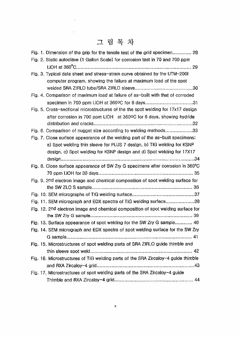
Fig.Fig.
Fig.
Fig.
Fig.
Fig.Fig.
Fig.
Fig.
Fig.Fig.
Fig.
Fig.Fig.
Fig.
Fig.
Fig.
3- H
1. Dimension of the grip for the tensile test of the grid specimen.............. 282. Static autoclave (1 Gallon Scale) for corrosion test in 70 and 700 ppm
UOH at 360°C..............................................................................................293. Typical data sheet and stress-strain curve obtained by the UTM-200f
computer program, showing the failure at maximum load of the spot welded SRA ZIRLO tube/SRA ZIRLO sleeve............................................. 30
4. Comparison of maximum load at failure of as-built with that of corroded
specimen in 700 ppm UOH at 360°C for 6 days...................................... 315. Cross-sectional microstructures of the the spot welding for 17x17 design
after corrosion in 700 ppm UOH at 360OC for 6 days, showing hydride distribution and cracks............................................................................... 32
6. Comparison of nugget size according to welding methods..................... 337. Close surface appearance of the welding part of the as-built specimens;
a) Spot welding thin sleeve for PLUS 7 design, b) TIG welding for KSNP design, c) Spot welding for KSNP design and d) Spot welding for 17X17 design............................................................................................................. 34
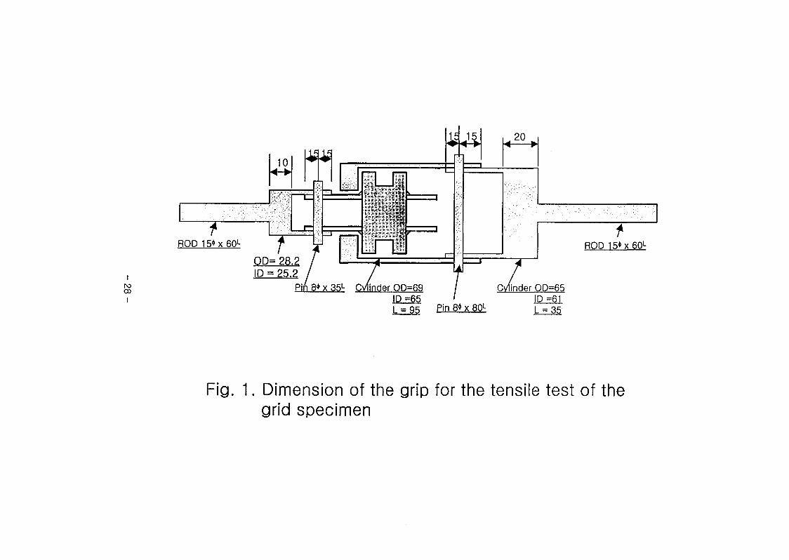
8. Close surface appearance of SW Zry G specimens after corrosion in 360°C70 ppm UOH for 30 days.............................................................................. 35
9. 2nd electron image and chemical composition of spot welding surface forthe SW ZLO S sample................................................................................... 36
10. SEM micrographs of TIG welding surface................................................3711. SEM micrograph and EDX spectra of TIG welding surface.......................38
12. 2nd electron image and chemical composition of spot welding surface forthe SW Zry G sample.................................................................................... 39
13. Surface appearance of spot welding for the SW Zry G sample............. 4014. SEM micrograph and EDX spectra of spot welding surface for the SW Zry
G sample......................................................................................................4115. Microstructures of spot welding parts of SRA ZIRLO guide thimble and
thin sleeve spot weld.....................................................................................4216. Microstructures of TIG welding parts of the SRA Zircaloy-4 guide thimble
and RXA Zircaloy-4 grid................................................................................4317. Microstructures of spot welding parts of the SRA Zircaloy-4 guide
Thimble and RXA Zircaloy-4 grid................................................................. 44
X

Fig. 18. Microstructures of spot welding parts of the RXA Zircaloy-4 tube and RXAZircaloy-4 sleeve spot welding for 17x17 design....................................45
Fig. 19. IBM micrograph at the weld of the spot-welded ZIRLO guide tube...... 46Fig. 20. TEM analysis at the weld of the spot-welded ZIRLO guide tube............ 47Fig. 21. TEM analysis at the weld of the spot-welded ZIRLO sleeve................... 48Fig. 22. TEM analysis at the base of the spot-welded ZIRLO sleeve................... 49Fig. 23. TEM analysis at the base of the spot-welded ZIRLO sleeve................... 50Fig. 24. TEM analysis at the base of the spot-welded ZIRLO sleeve................... 51Fig. 25. TEM micrograph at the base of the spot-welded ZIRLO guide tube...... 52Fig. 26. TEM analysis at the base of the spot-welded ZIRLO guide tube..........53Fig. 27. TEM analysis at the base of the spot-welded ZIRLO guide tube..........54Fig. 28. TEM analysis at the base of the spot-welded ZIRLO guide tube..........55Fig. 29. TEM micrograph at the weld of the spot-welded Zircaloy-4 guide
tube.............................................................................................................56Fig. 30. TEM analysis at the weld of the spot-welded Zircaloy-4 guide tube. .. 57 Fig. 31. TEM micrograph at the base of the spot-welded Zircaloy-4 guide
tube.............................................................................................................. 58Fig. 32. TEM analysis at the base of the spot-welded Zircaloy-4 guide
tube.............................................................................................................. 59Fig. 33. TEM analysis at the base of the spot-welded Zircaloy-4 guide
tube.............................................................................................................. 60Fig. 34. TEM micrograph at the weld of the TIG-welded Zircaloy-4 guide
tube.............................................................................................................. 61Fig. 35. TEM micrograph at the HAZ of the TIG-welded Zircaloy-4 guide
tube.............................................................................................................. 62Fig. 36. TEM micrograph at the base of the TIG-welded Zircaloy-4 guide
tube................................................................................... 63Fig. 37. Oxide morphologies of the SW ZLO S specimen Corroded in 360°C, 700
ppm LiOH aqueous solution for 6 days.....................................................64Fig. 38. Oxide morphologies of the TW Zry G specimen Corroded in 360°C 700
ppm LiOH aqueous solution for 6 days.....................................................65Fig. 39. Oxide morphologies of the SW Zry G specimen Corroded in 360°C 700
ppm LiOH aqueous solution for 6 days.....................................................66Fig. 40. Oxide morphologies of the SW Zry S specimen Corroded in 360°C 700
ppm LiOH aqueous solution for 6 days, (a) Oxide layer on the weldment, (b) Oxide layer on the outer surface of sleeved 0,000X), (c) Left side of
XI

the welded crevice(300X), (d) Right side of the welded crevice(270X),(e) Cross-section of the spot weldment(25X)........................................... 67
Fig. 41. Oxide morphologies of the SW ZLO S specimen Corroded in 360°C, 70ppm LiOH aqueous solution for 180 days...................................................68
Fig. 42. Oxide morphologies of the TW Zry G specimen Corroded in 360°C, 70ppm LiOH aqueous solution for 180 days...................................................69
Fig. 43. Oxide morphologies of the SW Zry G specimen Corroded in 360°C, 70ppm LiOH aqueous solution for 180 days................................................. 70
Fig. 44. Oxide morphologies of the SW Zry S specimen Corroded in 360°C, 70ppm LiOH aqueous solution for 180 days................................................. 71
Fig. 45. Surface appearance of tensile test specimens after corrosion in 360°C,
700 ppm LiOH for 6 days............................................................................. 72Fig. 46. Close surface appearance of the welding parts after corrosion in 700
ppm LiOH at 360°C for 6 days.....................................................................73Fig. 47. Surface appearance of all test specimens after corrosion in 70 ppm LiOH
at 360°C for 30 days.................................................................................... 74Fig. 48. Surface appearance of SW ZLO S specimens after corrosion in 70 ppm
LiOH at 360°C for 30 days............................................................................75Fig. 49. Close surface appearance of SW ZLO S specimens after corrosion in 70
ppm LiOH at 360°C for 30 days....................................................................76Fig. 50. Surface appearance of TW Zry G specimens after corrosion in 70 ppm
LiOH at 360°C for 30 days...........................................................................77Fig. 51. Close surface appearance of TW Zry G specimens after corrosion in 70
ppm LiOH at 360°C for 30 days....................................................................78Fig. 52. Surface appearance of SW Zry G specimens after corrosion in 70 ppm
LiOH at 360°C for 30 days...........................................................................79Fig. 53. Close surface appearance of SW Zry G specimens after corrosion in 70
ppm LiOH at 360°C for 30 days................................................................... 80Fig. 54. Surface appearance of SW Zry S specimens after corrosion in 70 ppm
LiOH at 360°C for 30 days................................................ ........................... 81Fig. 55. Close surface aAppearance of SW Zry S specimens after corrosion in 70
ppm LiOH at 360°C for 30 days....................................................................82Fig. 56. Surface appearance of All Test specimens after corrosion in 70 ppm LiOH
at 360°C for 180 days................................................................................... 83Fig. 57. Surface appearance of SW ZLO S specimens after corrosion in 70 ppm
LiOH at 360°C for 180 days
Xll
84

Fig. 58. Close surface appearance of SW ZLO S specimens after corrosion in 70ppm LiOH at 360°C for 180 days................................................................ 85
Fig. 59. Surface appearance of TW Zry G specimens after corrosion in 70 ppmLiOH at 360°C for 180 days..........................................................................86
Fig. 60. Close surface appearance of TW Zry G specimens after corrosion in 70ppm LiOH at 360°C for 180 days................................................................ 87
Fig. 61. Surface appearance of SW Zry G specimens after corrosion in 70 ppmLiOH at 360°C for 180 days......................................................................... 88
Fig. 62. Close surface appearance of SW Zry G specimens after corrosion in 70ppm LiOH at 360°C for 180 days.................................................................89
Fig. 63. Surface appearance of SW Zry S specimens after corrosion in 70 ppmLiOH at 360°C for 180 days.......................................................................... 90
Fig. 64. Close surface appearance of SW Zry S specimens after corrosion in 70ppm LiOH at 360°C for 180 days.................................................................91
Fig. 65. Hydride morphology of SW ZLO S specimen hydrided in 400°C Ar+H2 for30 min....................................................... 92
Fig. 66. Hydride morphology of TW Zry G specimen hydrided in 400°C Ar+H2 for
30 min...... ...................................................................................................... 93Fig. 67. Hydride morphology of SW Zry G specimen hydrided in 400°C Ar+H2 for
30 min.............................................................................................................94Fig. 68. Hydride morphology of SW Zry S specimen hydrided in 400°C Ar+H2 for
30 min............................................................................................................. 95Fig. 69. Hydride morphology of SW ZLO S specimen corroded in 360°C, 70 ppm
LiOH for 180 days.........................................................................................96Fig. 70. Hydride morphology of SW Zry S specimen corroded in 360°C, 70 ppm
LiOH for 180 days.........................................................................................96
Xlll


1. AH
34!* PLUS7# *# 333 SRA ZIRLO Guide
Thimble# SRA ZIRLO Sleeve## # *#4 43 334* 37j-#S,
34"&e33* 435. #34(KSNP) 4"334 4# SRA Zircaloy-4 Tube#
RXA Zircaloy-4 Sleeve 3# 3 *34 4# 334* 371-37] #3#
333S43, *4*4 S3 44s#*4 37]-43* t43OT. S3 *3
33 3 4# 3#54 S344 -§-34-44 4-4#44 43 data base
#S# #4 SRA Zircaloy—4 Guide Thimble# RXA Z Zircaloy—4 Grid##
TIG -§-3 3 3 -§-34 43 334s 47}#$4.
47}333 47>3 434 43 333s 44 43# 44s# *44455
3¥4 3435S5#, as-built 43# 360°C 70 3 700 ppm LiOH ^4444
63 3 1803 #443 4334 43 4-4433: *439#. 333s
444344 3 33 33 3 433# -§-34 #*4 34#3 #4 333
443 4 #e 3333# #s34 45* 33334 43 3344 37)39#.
4 4s# 44 4 OM 3 SEM #3* 433 3# 3*# 333 &3 ##,
333# N 3 Cu S3 34, -§-33 3 S4 tem ## 33 4=434
37)39#. S3 *5 #3 433 OM * #-3 hydride ### *S 33*
*439*4 # -§-3334 ## ##a## *3** 33 *439#.
4# #4 as-built 43, 360°C 70 9* 700 ppm LiOH **#44 *443
43, s#s *S#3 434 43 333s 43 3 44s# 4444* *4
PLUS 7# *3334 43 334* *3 37)39#.
1

2. iys^s
7>. 4 "9 4 44 ##
49444 ### 4#4 44 4 #444.
1) SW ZLO S : Spot Welding Thin Sleeve for PLUS 7 Design
( SRA ZIRLO Tube / SRA ZIRLO Sleeve)
2) TW Zry G : TIG Welding for KSNP Design
( SRA Zircaloy-4 Tube / RXA Zircaloy-4 Grid)
3) SW Zry G : Spot Welding for KSNP Design
( SRA Zircaloy-4 Tube / RXA Zircaloy-4 Grid)
3) SW Zry S : Spot Welding for 17X17 Design
(RXA Zircaloy-4 Tube / RXA Zircaloy—4 Sleeve)
4. 4919-^
1) 44#S 49
#9494 4# 49444 4#4 44 4## 4944
444 4 440)1 49 4949# #9494. Sleeve 44# Mandrel#
#444 #9# #9492, Grid 44# Fig. 14 9# 4# grip# 41444
#9494. #3 94# 44444 #4 4 DTU-900MLCD10T # 4~§-49#9
44 4# lOton #9 #4 0.2% 44 #4 7}#99#4, Stress-Strain Curve
4 4 44#4 44 ## 4#4 #m44 UTM-200F4 444 4#±&
44444.
2

2) #44#
# 4 ^4 ^4 4# #4A]-yFig. 2# ## static autoclave#
##44 ASTMG2-81 #44 44 360°C(18.9 MPa )# 700 ppm LiOH 4 70
ppm LiOH ##4 £##44 44484. 700 ppm LiOH ##4 ###44#
6## #44^# #&44 8# #4444 4# #4444 44# # ti.%44
44484. 70 ppm LiOH ##4 #444# #444# 180## #M #4
70# #44# #4 #4.
3) #54# 4 #544 #44# ‘
4 444 4# #548# 400=044 #44#%, Ar 7}^# h2
7>5# #4444 #4## %# furnace4 ^4 30# #8 #44# # M#
44484. 44 44 #5 44# #444 444 #4# 44# 444 #4
4#4 4# 444# 484.
© ###44 10 # ##  44
® ##44 10 # #8  44
® CCl4 #444 10 # #8  44
© Dry gun53. 4# #2
°1#- #"°1 #44 44# 7>4ji inert Gas Fusion Thermal Conductivity
Determination (IGFTCD) 344 4#€ 4=^4 44# #4484.
#4 7] 7]# 444 LECO 4 4# RH 404 Hydrogen determinator#
4-#48#4 844# 48# carrier gas #4444 #444# 344
5.444 8# #5# Ar gas# 44 ^t7]^LS 4#44 4 # ## gas#
thermal conductivity 444 #44 5-44 ###4 8# #5# 4#°1
#4 #4.
3

4) 44I&4 ^ 4#
4 5444 #4 A14 ^ 4-4# #W 44# 1200444
444 44(grinding) 1- #W # HF 10% + HN03 45% + H20 45%4
##4# 4 #44 swab ##55 etching# # 44444 ^ SEM# 4 #44
2.44 44&4 ^ 444# 4#4^4.
5) TEM 4#
#4#4 #44 47}# #4 44 444 (TEM)# 4-9-#
442:4# 444^4. TEM 4## Plus 7 445 4M4 W=# ZIRLO
sleeved 4 (spot) #44 ZIRLO 444 (guide tube) 44, KSNP 445
4 M# 444441 4-#4# Zircaloy-4 44444 4 5 (tig) #444
4 (spot) #44 Zircaloy-4 4^4 44# 4#44 #*8444. 4 #44
44# #44# 4 44 3 mm4JE4 #444 ll #44 7fl#]#cd 44#
#4#4 7143:44 42.444. 2.44 42 #44 44# #4#4 #4
444 #44 444 #^##(HAZ)£ 4444 443:44 42444. Table
HI# TEM4#4 °1#4 444 #4#4 4 44^1)4 #4# 4444 44$4.
44 4# #42.5. 7fl#)4 44# 44455 60 pm #4144 44455
444 #44 3mm 44# 4# # ethanol (90 %)4 perchloric acid(10 %)4
#4#4°114 44 45°C°114 12V4 44# 7)41*1 twin-jet polishing#
#444 #4444. #44 44# EDS7} #44 Jeol 4(47}4#4 200
keV)4 44444 (JEM—2000FXII) # 4 #44 44-4- 4##4 54 ^
4 4 #5# #44534.
4

3. 413 44
7>. 944"3 4^
#4444 4# 4^9444 4#4 _&94# 44 4## 4447]
444 4 444 44 9944# 94494. Fig. 3# 4 -§-44 SRA ZIRLO
Tube/SRA ZIRLO Sleeve 444 44 4444 44# UTM-200F Hfilfl
4444 #49 data sheet 4 stress-strain curve# 9#9 39°14. 444
f7%4 444 44 -§-444 4944 44 4# SM 944493
4#33 4444 94. 44- 44 9433 9-4 494 444## Table 24
994^3, 4# Fig. 44 jh|£S 44444.
#44 37] £] 444 Spot Welding Thin Sleeve for PLUS 7 Design
44CSW ZLO S 44), TIG Welding for the KSNP Design 44(TW Zry G
44) 4 Spot Welding for the KSNP Design(SW Zry G44) 4 444444
43 #434# 4 #44 #4937} 94^4. 4 SW ZLO S 444 494
444#°] TW Zry G 44 34 25% 4# # 9# 93 M4. 3E]3 SW
ZLO S 444 SW Zry G44# #44 4#444 44# 4 point #443
#4# 8 point #447] 4#4 94-7} #4 # #443# 444 44 94#
grids] 92:4 sleeve 44 4471] #444 444 4944, #44 44
QA/QC7> 4 494 44 99## 4 9 44. £4 4# 37>4 444 94
49 #4494 44# 44344 44 ^414 37]] 44-7} 433 34
LiOH 9#444 4]7>4 44 39 #494 4444 444 &# 433
4444.
Spot Welding for 17X17 Design 44 (SW Zry S 44)# 70 ppm LiOH
94444 1804 9444 444 #449# as-built 444 #4934-
#44$ 4. 34 4 700 ppm LIOH #444 9444 444 49 #4437}
5
35%4# 4d:4^4. 4 SW Zry S 4#^ 70 ppm LiOH 444
#444# ## ###4 ##44 700 ppm 4 #4 LiOH ##444# 4#
44%-# 4 4 44.
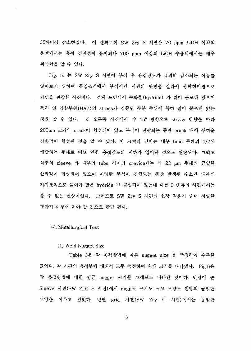
Fig. 5. # SW Zry S 4^34 f A) f. -g-#?^} #-## 4##
#45.7] 444 ##s#44 #44# 444 44# #44 #444# °.s.
44# ### A}^lo]4. 44 &444 #4# (hydride) 7> 40] ^-5.4] 0)0.4
#4 4 4W4(HAZ)4 stress?} ### ## f44 #4 #4 #&4 4#
4# # # $14. S A}^144 4 45° ##.03. stress #%=# 44
200pm a?M crack4 #444 #31 f44 #^4# ## crack 44 #4#
#444 #44 4# 4 # $14. 4 h@)4 #4# 4# tube #44 1/24
444# #45. 4s. 4# ###S4 447} 44# 4^.5. ###4. zl4il
4-T-4 sleeve 4 4#4 tube #44 crevice4# 4 23 pm #44 544
#444 %#44 $1^.4 444 444 #44# #4 1M# ##7} q^-4
7]4^4#5. #47} ## hydride 7} 4444 $1#4 4# 3 ##4 4%44#
# t $1# 4#4$14. ne]£S SW Zry S 4%4 4# ##a] #cj ##4
#7}7> 4^-4 40) # #4 €4.
4. Metallurgical Test
(1) Weld Nugget Size
Table 3# 4 ## ## °il 4# nugget size # ##44 ##4
&44. 4 4 #4 ###4 Lflsflzi 5.^ &^e}4 44 a## 44#4. Fig.6#
4 ##444 4# W nugget 3.7]% rz.5flM 44\3 444. ##4 #
Sleeve #^(SW ZLO S #4)4# nugget 37]3 33 £<#£ #%4 #4#
5.4# 4#ul $1$14. ## grid 4#(SW Zry G #^)o1]a^ #<y#
6

5 #5 4 #3 nugget 3.7}S. #3 3 #4 4 37} #35 ###454. 34
45 ^] 4"# RXA Zircaloy—4 tube 2} RXA Zircaloy—4 sleeve 44 ( SW Zry S
4#) 4 3 ###b 454 444 ^ 4433 444 44 3#33 3 37] 5
# ## 454. Grid 4 4] #2] tube #2] TIG #544# #5 #4 grid 2]
##7} #44 nugget 2] 344 44=4$] 3 3 37] 5 ###454.
(2) Mb 344# 5 3435 44-
Fig.7 # 4 7>x] as-built 444 -g-##4 4% #54-4-4# *0^
544. a)b SW ZLO S 442] 3444 nugget 3#4 4444 444
##7} ##4534 45b #54 4 #54 4 5## 34=4 4443 44. b)
b TIG Welding for KSNP Design 2] 3444 4#2] grid 7> M4 #5]
#44 4544 444 44 #444 34# #3554. c) b Spot Welding
for KSNP Design 442] #5 #4 4 a) 2] ^#4 4444 37]7} 43
445# 4r3 $14. 343 d) b Spot Welding for 17X17 Design 442] c)4
#44 54# 43 534 4 5"53.3 #44 4454 3#44 44^. 3]
#544 454 444 4 4433b 444 ##4 54# 44 4b
4#33b 444 ##4 5#44 #47] 4#44. 44 4# 4 7>4 #544
#44 c) 444 QA/QC 7} 7># 4#4 433 4444. Fig. 8 # 4 4##
34 #7] 444 70 ppm LiOH #444 30 4 #444 # 4# #5#
544544. A^44 a) 5 b) b 4 a# #344 #54 5# 34
#34b4 #5# #44-47} 345.54 #4# 4## 4443 #4. 344
a) 5 d) b #5# 7}#4eH 4€# ##7]7} 5544 #44 3 ##44#4
7}# #44 #544 444 #4#4 544 4# 4 # #4.
7

Fig. 9 xr SW ZLO S 4# 4 #4^-4 X#4 SEM element
mapping iti 5L# 4-g- #4 #4# 54 ^31 #4. #4  A -##4
4##4 #4# 5.4# ZIRLO 4## Zr. Nb, Sn # Fe 7> f* ##31 #54
47141 -§-#4  #444 O ^#4 4#4 #55 4#44. 4-^4
mapping A>*ofl 4-e}-# «}£}. #4 #4# 4 4 4-*o} 4 C 4-#)#
# #4#4 A^°J4: 54^31 #4. C ^-#441# i.0wt%4 Cu ##
-2.44 4#4#54, D 4 % 44- #4## #54 5##5 4444. n44
#54 5.44 #4# 4 444.
Fig. 10 4 TIG 4^441 4% SEM A^oicf. (a) 41 444 444 4
0.5mm 44 1mm #54 # grain 4 4## 4 4-2, 44 &441 44
4#44 4#4#4. (b)4 44 44f# 2000 «lls. 4## A>*ioi4, ^oi7>
10 ~ 30 pm 44 3 ~ 4 pm 4 #4# grain #4 # #"#55 #44711 4 #4
*11 #4 4aL#4. (c)4 4##41 4# 314# a}*|ou-ii, Fig. 11 4 EDX
spectrum 4 #4 444584. &#°fl #4## 4##4 ^s. #5 (77.3%) 4-
#5(21.9%) #31 ##### Zr 4 5:4(0.8%) e44#4. ^ ^4 44
-§-### 5###4 7)4 Zr4#5.5. 4#44 ##4.
Fig. 12 # SW Zry G 4^4 4 -§-4 ##- f4  SEM A}#, element
mapping 4 5# 4# #4 #444. A>4 4 #e 5#### 4
#4### # 4 ##31, 4445.5. #54 5#5 4#4#4. Fig. 13 #
#44# 4 #44 4# &## SEM # 4-§-44 4## 4*1014.. a)#
4tifl^(ioo tiii)s. #4#4 1/4 ## 4# 444, * ###4 ### 454
5# ##ir -8-44-31 #54- 7>#x>4 e4# #a>7> 4#5 5# 4 #5 ##=4
4# 44=55 #44 44t11 ##44## 4# # 4 #4-. b)# ##f#
5tiH#(2000 tiii)5. 4# A>*ojtii] ^ Moll #44 ###4 ##44 4#4
8

« EDX * 41# pig. 14 4 443 #4. 44*3 4^4!!
423 423 44 43.1 4 40 At% #4. #44133! Zr o] 8%, Cu 7}
3.9% #4. 4 o] 443 4 Mtf *# 441:4 -8-711:4 ^##34
3###3 4444. 4# Cu 41! 4 -§-44 4141 ##4 Cu ##423
4144 -§"§*4 12. a "143. 4444. 4 Cu 3 344- c)3 spectrum 44
444 $144 4-144 &! 33 141441 2.6% 443#4. 14 1434
4441 Cu 414 4134 41 113 4434 4-34 444 3% 443
441 13# 43 444. 4 113313 443# Cu 341 4 atomic%
4444 41443 411 4 1 44. N 411 44 141441 #434
#434 #43 41444 3.3 at% 4444 #4344.
413 1414 4# 3# SEM 1# #4 SW ZLO S 44441
#1433 #413 Cu 344 41343 SW Zry G 4#441 434 #1
13 Cu 344 41344. 43- #4 14# 41#443 1# 43, 41 4#
4 4 1443 324 44 Cu 3 3427} 424 4444. ## TIG
!#44! Cu4 N3 34# #4# 1 444.
(3) 1#1 243 OM 1#
Fig. 15 1 ZIRLO Guide Thimble 4 ZIRLO Thin Sleeve 43
#1# 133 4424# 4444#33 ### 4444. (a) 4 (c) 1313
SRA ZIRLO sleeve, 413 SRA ZIRLO tube 4 weld 7} #41 443 4433
243 7}#244 weld 3 2443 447} 1^44 444 #4. 41 144
4## 1^4-7] nfl!4 weld 313 43! ## #4 #3 weld 7}Aj]2
##433 7}#3#47} til34 #4 ^#34 41# 433 4444. 2#
27113 7}#344 #7H# HAZ 2 ### 1 #4. HAZ #3 #4341 (d) #
9

(h)44 34# 7^22l% #<y% 24# # # $14. (b) # (f) #4# ##4
442423 44% 4%4 Martensite 2423 44-%%. 4#4# #4:4% 3.
4#3 #4 7}%# % #% 444 #^%4 4#4 4#%
4#%3%# -§-4^7} #4 ^4%7] 4^4 3:44 44% %%4 Martensite
3:44 S44# 423 %%%%. (g) 4 (e) # 2-44 #4 #4 444
%4%:t-(HAZ)4 4-44%.
Fig.16# SRA Zircaloy-4 Guide Thimble 4 RXA Zircaloy-4 grid 4%
TIG #4 f%4 443:4# 4%%442-S. %%% 4444. (a) # grid 4
RXA(%%444) 34# 4-4-43 $12:4 (b)# RXA 4 344 HAZ 4444
4444. (c), (d), (e) ^ (f)# #4#4 34%%# %%% 444%. #4#4
#%23 44# 34% 34# 343 4#4 4-44-43 4## 344 4414
43 4# #4# #423 ### #4 # ^4 #27} 244 4#44.
(g)# SRA 34% guide thimble % HAZ 4 44# 4# #423 #%%%
4 4 #4 % %%# %3 %## % # 4%. (i)# grid 44 4# guide
thimble 4 % %%#%# 4-443 %#4 %#4 grid 3% % 4%#%7> ##
4# % # %%. (h) 4 (]')# guide thimble 4 SRA 34# %%43 %%.
Fig.17 # SRA Zircaloy-4 Guide Thimble 4 RXA Zircaloy-4 grid 44
4 #4#44 44134# 4%%4423 4# 4-4#4%. (a) 4 (b) #
4#4 #44 grid 44 TIG #4244- 441 #4%4 4#441 44# %%#
%%%7l 4%4 4# #44%. (a) 44# 4%4% TIG #4 34# 4443
%24 (b)# grid #44 %# % 4%#4 44 44 4#4 4 4#4%
#234 431 ##44# 4#4 344- TIG #44 4% 34% 344 #7fl%
2## 343 %%. (e) ^ (f)# #4#4 4#4 grid 3%3 4#4 guide
thimble 4 %%# 4423 4 #44 #44 #4 44## #4#4=4 3%%.
10

3# (h) g (i) b -§-^- ### ##o]#. (i) b ##4 SRA 3:2)0]
S)3# (h) b ##4 -H)32)o] ### ## ^ 0_5.nl- ##7]-
5b # f Si#. 4 5b 5^-# 2.7]) ## ^#0] 5-oa^Til o]=.o] x]x) gg##
b b Si#.
Fig.18b RXA Zircaloy—4 Tube# RXA Zircaloy-4 sleeve ## 5
-§-###°] o]#)3#b ### 0)^33 #b #5#o]#. (a), (e), (f) g (i) b
2.7fl# RXA 3:2)# 3#^3L $)3#, (b), (d), (g) g (h) b 2.7))# b#b#
54#b ##\S #-#°]#. (c)b Wb# ### ##431 Sib 4 %lAJ"5)
0)7)1# Martensite 3## 9*31 $i3# g #f &#°)] 7}##### W
f 4 ##27} ## 32)0) n]7)]sfl #31$)#. #b crevice ##4 H#€
3##b # # Si 3# -§-### 37)) 7>o]o)] hydride 7} ###$)#.
(4) -g-#4 32)2) TEM ##
Fig. 19b 5 -§-#€ ZIRLO SHb# # n)A)]32)i: 3# #3
gbM] ^#0) g## martensite f3# ##431 S1S12 Lathe Ml0)]# ## #
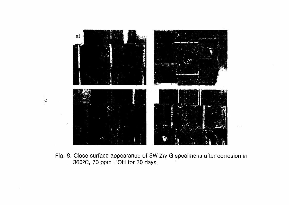
^-433 o}# Wo] ##5)0] %##. Fig. 20# Fig. 19# ### #£4#
Wbbg 50,000 43 #4#4 ### 543, SADP (selected area
diffraction pattern)0)]# ###$! a #"4# 3-g- ##45 a’#33 #$]£]#2
ZIRLO ##°)1# ###33 #7># Nb, Fe°)] ## ###4# 4 2## 5#
#### gg#.
Fig.21# # b54 #--§-# ZIRLO sleeve# 7]#32]# ##4b 533
-3-^0]## o]7)]32)# ##43 S1S134 gf 444#b 7># #°)] 2g€
5# 7} go] ###0=13# ## #54 ###4 ###$)#. O] ZIRLO sleeve0)]
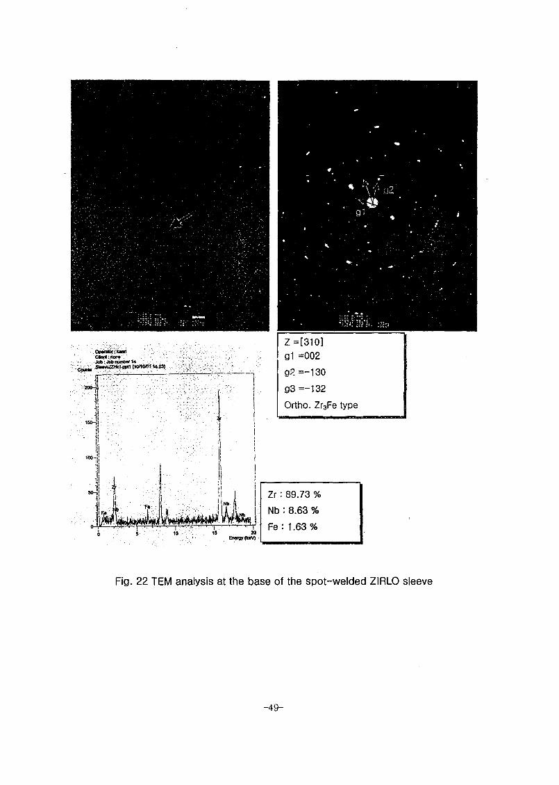
4# ### ## ### Fig. 224# 244 ##4S)#. ZIRLO sleeve4#
11

4### 4## 4### orthorhombic (Zr,Nb)3Fe #2#2# #4 4##4#
hep Zr(Fe0.6Nb0.4)2 4M4 tetragonal (Zr,Nb)2Fe 42:# 4442 ##4.
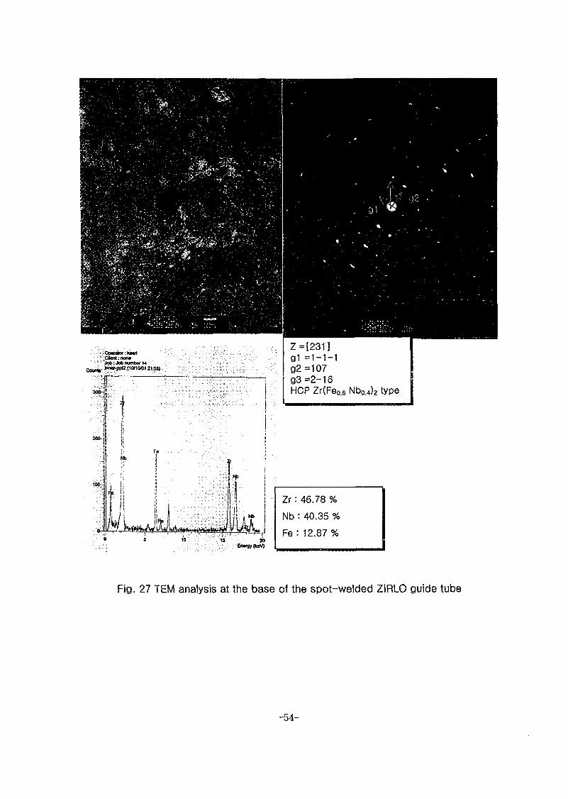
Fig.25# 4 #4# ZIRLO #44# 7)424# 4442 ##4 ZIRLO
sleeved 4^1 #4°1M #4)24# 4*3 ##4. Fig.26-2844 # 4
##°1 4 #4# ZIRLO #4444 «## 4##2 ZIRLO sleeve# ###
###3 ^Efl7> ####4. #, ZIRLO #4 #44 ##£]# 44# ####
orthorhombic (Zr,Nb)3Fe #2 #2# ## 4##4# hep Zr(Fe0.6Nb0.4)2
^44 tetragonal (Zr,Nb)2Fe #4# 4"#/%#.
Fig.29# 4 #4# zircaloy—4 #44# #4# 44 4## 442## 54
4# #25. Fig.19# ZIRLO #44# 4 #44# 44244 4# ###
#42## 4#42 ##4. 4 #44 Zircaloy-4# #44# martensite
42# 4442 ##24 #4 4 #425 2#4 #4# 4###4. Fig.30#
4*444# 442# images ## lathe 4 444 4*4# ##4# #2 ### # 4
##2 SADP44 #424# a’4-25 ####2 #### 4##4 ###.
Fig.31# Zircaloy—4 #44# 4424# 5442 ##4 4)44#
#4°)14 #4444 44)24°) 4###2 #4 #444# 444°) 44#2
##4. °1 Zircaloy-4 #4)44)4 4### 4### Zircaloy-4 #44)
44425 4### hep C14 Laves phase (ZrCr2) # 4###4. Fig.32#
334 Zircaloy-4 #4444 4### 4##4 44*4 #4# 44# 444)2
#4.
Fig.34# #2 #44 Zircaloy-4 #4444 #4f# #42## 444#
425 4 #44 4## ti)24# lathe# #4 4-54 42 #7>#2 442
2-3 #4# Widmannstatten 2## 4442 #4. #3 #4#44 lathe #4
4°1# #7># #3 #4°) 4 #44 #4°) #4 # 44 #24 #7) 4#4
12

##4343 #4# 4. 4 #454 E]ZL #454145 4###
e## ### 5 ^%4. 344 Fig. 3541 44# ###5(HAZ)414#
4##4 #4)# ###711 ### # $1^3# #4115 ## 3#
# # %%4. Fig.36# E]zt #4# Zircaloy-4 ###3] 7] 4 54^ 2# 5#
435 #4°1## #4124# 44# 3 $1^4. 343 E]zl #4# Zircaloy—
43] ###=f 4 44414 ### 4### hep Zr(Fe,Cr)2 ##4 4###
##4%4.
Table 441# 41414 4## ##5 4 4441 ## TEM ## 44# 4=44
44#4. 444-414# 4### 44 ### # &5S4. 4 #4# 4#414#
## 5 ##35. ## #"44 3## martensite #3# 4443 5$$34 43
#4414# #4 5 #4437} til 54 344 #*401 ##44 #&4. 43
#4# 44414# #4 5 5# 41 ##%=#7} ##35 ### 454 3.7}s.
##4^34 ##### #4 444# 44152# 44#4. 4#441 4#4
ZIRLO sleeve 4 #### 5# #4444 44124# 44#3 ##3#
### 4### orthorhombic (Zr,Nb)3Fe7> ### 4 #3# hep
Zr(Feo.6Nbo.4)2 ##4 tetragonal (Zr.Nb)2Fe 4#5 #5 ##4#4. 4 #441
4## Zircaloy-4 #### ##435 5# #444 #44# #4124#
44#3 M3 43 #441 4## Zircaloy-4 #### #44# #4124#
44#3 M3#, ### 2# 4### hep Zr(Fe,Cr)2 ##^4.
(6) #44 ## #4
(7» 700ppm LiOH #4#4 #44# 4#4 ##4 5#
Fig.37 # 360°C 700 ppm LiOH ## #414 6 # ##
#44^# ### # ZIRLO Guide Thimble # ZIRLO Thin Sleeve #4 Spot
13

Welding 44 543] 33^ ##4# 4# SEM #4#^14. (a)# 5*1) S^S]
#4431 4# SEM #4431 #*fl7> 4 l.l pm 44 (b)# #4# 5431
334 #44431 #3l7> 4 1.7 pm 4 $14. W# 4#4 Sleeve 4 3l#4
Guide Thimble 44 crevice 41 # 5.4 °ll 334 ##4431 4#4 ##4 54
44 #4t154,#317} 4 1.6 pm 44. 545 4445444 #44
4444 71)44 44 44441 444 #444 ##5 #44 $1## 4 # 44.
22li (d) 4 (e)# 44 4 5## crevice 4 #41 44 SEM 4444.
4 4444 il#4 #44 444 444 444 444 #4 44 ###4
4444 444 44 5### 544 444 4## 44 4444
$154 4 44-4 4 444 5414-4 71144 33# 4#4 444 4#55. 55
44 5444 44 ^444 $14.
Fig.38 # 360°C 700 ppm LiOH #3 #44 6 4 #4 f#43# #3#
# Zircaloy—4 Guide Thimble 4 Zircaloy—4 Grid #31 TIG ### 445431
3Aj4 #44# 4# SEM 4#44. 444 531 5#4 334 #4-4# 4 1.5
pm 4454 #3#4 #44# 454 4# 444 1.3 pm 3544. #4#
4# #4# #3# 544 #4-4 4## 4# 454# 4# 3345 $1# #4
TIG #3#44 37114# 4 3 pm 4 #45 #4s#4 #4 $l$i#31 44#
Fig. 10 4 (b)3l 44# 44 #4 4^11# grain 4 #4 2 ~ 3 pm 4##
#444 4711 grain 4 4711444 #3|7> 4=# 3# #55 4444. Crevice
4444 #44 #315 e 444 4454 Guide Thimble 31#4 #444
1.1pm 44 4# ## 4 # $14.
Fig.39 # 360°C 700 ppm LiOH #3 #44 6 4 #4 #443# 43#
# Zircaloy-4 Guide Thimble 4 Zircaloy—4 Grid 44 spot welding 54
#4-4# 4# SEM #444. 4#4#4 4# 544 #4-4 #31# 1.2 pm
14

5.5 ^sv 44 tl£°^ 4# 5:44 7)44* 444)#
55.5 overetching °fl 7)ol# 5°14. Grid 4 guide thimble a}o] o) 4#
crevice 4# #54 4444 0)3=14 *)X] go). M°1 434 Jfxio]
4S34# #2> a a) 44 #44 4M #4# #-& # 444.
Fig.40 4 360°C 700 ppm LiOH #4 #44 6 4 #4 #445# #*S4
# Zircaloy—4 Cladding 4 Zircaloy-4 Sleeve 42] spot welding 54 4-44#
4# SEM a>^144. a>^1 (a) ^ (b)4)4 I4x°] 4 #5 #4 5.4 M2]
4r#4 #4# 7)2) 4a>4^M 1.3pm 0)0^4. 35)4 2]#5] sleeve 2)- t]]#2]
cladding Aj-o]0)] crevice a)-o)4 5.40)]# 20 ~ 30 pm 2) #4=8- 4
^444 $194. 45=8: Fig.5 2) #4 A>44£ 444#4 42)- 44 crevice
^#44 4# 44 4-g. #4 4aS^ ^7> #44)& 5 #4 4 #4 hydride 7>
S4€ 5# 4 4 $14. Mai (c)4A) # 4 $1x4 €# crevice #4# 44
30 pm 54 200pm 55.2] inner crevice 7} $1#4| 4^4# #4#4 4 4
$1# 54 4 4s $14. M inner crevice -M2] 54 M4 4^4 45
444 5.44 sleeve 5 inner tube 445L5 4AS€ M5 544. 44 (d)4
a)4 54 44 crevice 4A)# o) 342) 544 200pm S.4 41# cladding
#42) 1/2 4 4$14. Mai sleeve 2)- 4)#£] tube a>o)4 -§-^o] 4^4
4#444 #55#2) 54£ 250pm 4444 4$14.
44 5=8- -§-5 54-°)4 #54 1H4 a4#=8r 44)55.5 454 4ai
#515 ## sleeve 5 4# tube 4 #54 #54 ^4^5. 4# 445.5
4444 44 5# M444 spot welding # #4)54 €■ 55.5. A}m44.
(4) 70ppm LiOH #*M4 #444 45s] 44-4 #4
15
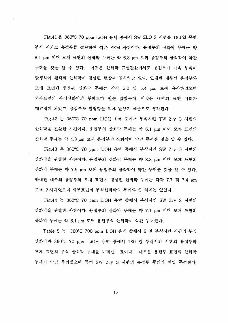
Fig.41 # 360°C 70 ppm LiOH M #41# SW ZLO S ### 180 4 ##
44 ##2 ##4# 4# SEM a>^1o]4. #44 444 4
8.1 pm #4 2-4 MS] ### #7ll# 4 6.8 pm 24 ##44 #44# 4#
4## 4# 4 4 34. #4# #44 24####2 ##47f 7># f^o]
#444 #44 #44# 44# #44 #442 #4. 444 444 ##44-
27fl 24# <g#4 444- 444 44 5.0 4 5.4 pm 24 #4432#
44244 444444 4424 #4 4444, °1## 444 24 447}
#2#41 4#2, -§-#42 #44# #t1] ##71 4422 #444.
Fig.42 4 360°C 70 ppm LiOH ## #4# 444# TW Zry G #44
4444 4## 4#°14. -§-#44 444 4414 4 6.1 pm 44 27fl 244
444 4*114 4 4.3 pm 24 -§-#44 #444 44 44# 4# 4 4 #4.
Fig.43 # 360°C 70 ppm LiOH ## #44 444# SW Zry G 4#4
#44# ### ##44. -§-#44 #44 4*114 4 8.3 pm 44 24 244
#44 4*114 4 7.9 pm 24 -§-#44 #444 4# 444 4# 4 4 #4.
4# 4 #44 -§-#44 27fl 2#4 4## #44 4414 44 7.7 4 7.4 pm
24 ##-432# 44244 44#444 4*114 4 444 334.
Fig.44 4 360°C 70 ppm LiOH 44 #41# 4### SW Zry S #44
#44# 4## ##44. ##44 #44 4*114 4 7.1 pm 44 27fl 2#4
#44 4*114 4 6.1 pm 24 ##44 #444 4# 4*134.
Table 5 4 360°C 700 ppm LiOH ## ### 6 4 444# #■#4 44
#444 360°C 70 ppm LiOH ## #41# 180 4 44## #44 ##44-
2711 2#4 44 #44 4*11# 44# 2# 4. 444 ##4 2# 4 #44
4*414 4# 44324 ## sw Zry S #44 ##4 4*114 #4 4434
16

44! #44 !#4#3H 141 333 7M1-3 ##4^1 ##
€ 24 #3#! ##34.
(6) 1334 244#
Fig. 45! 360°C 700 ppm LiOH 13343 6 # 1334! 42#
1 3! 44341 3# 34#3 4444. 4# 343 4 -g-4^-o)l rfi#
4444! Fig.46 °fl 443144. a) ! SW ZLOS343 141 24431 414
7}#A}4 134 4 2 H3 white oxide 7> ##344. o] /£# -g-#af 14 a}
7}# #14 ai# Jfo]3>| 134 7>^> 33ft Jf 33.JL ####. b) ! TW Zry
G 3 #3 3 5.444 #3 AT-^w-o] -g-^afL)- 5>H1 2.1 %# #S}44
^§334 44. c) ! SW Zry G 343 141431 a) 43 #4 white oxide!
^#33 ##4. 3LB]JL d) ! SW Zry S 343 141431 #23 #2#
#31# 13 #2 $14.
Fig. 47 fsi Fig. 55 444 3*4! 360°C 70 ppm LiOH 13443 30 4
Tn^l of #2# 1 4! 441-44. Fig. 47 1 360°C 70 ppm LiOH
14444 133## 2.1 4411 41 4444 141 4442 441 44
44(44)4 Metallurgical test 1 44 441(44)44. Fig.48 1 SW ZLO S
4414 241! 4444. Fig.49 1 414143 144 44431, 700 ppm
LiOH 1443 1444442 4444 141 44433 white oxide 7>
4134131, 44! Fig. 15 31 4444! 444 414 133 234 4411
Martensite 22 3434514 4144. Fig.50 ^ 51 ! TW Zry G 3#2]
243-4 4 1414 311 144 4444. 14444 Fig.51 4 44! 444
grid 3 tube 1! grid 3- grid 43 TIG 14137} 21 4=2# ##4!
#3 #2 44 Fig.52 4 53 ! SW Zry G 343 2444 4 14131 31#
17

eg 4 4-3M4. eg44$i Fig.53 4 444 ggg spot welding 4 #
447} ^ng4 #4 #°]]4 white oxide 7} ##5] g4. 24 grid 4 grid
44 tig #g 3 gg=#44 gg-4- 4#4 gg white oxide 4 g# 444
7Hr#44 &go] $14. Fig.54 55 r SW Zry S 444 &4 44 ^
#g#4 4# eg44o]4. 4 4-444 24 #4 4444 444 4 444
44# 444 7>g g^3i M-& 4444 4=51# 444 242 $14-.
Fig. 56 #4 Fig. 64 444 44# 360°C 70 ppm LiOH #4444 180#
#444# 45.4 # 4# #4#°]4. 30 4 #4#4 2#4 4 447} 34
#44 45.4 $4.
(7) #4 4-g 44 4 #4 444 hydride 4#
Fig. 65 # 400°C 4 Ar 4 H2 #4 7}2 #4444 30 # #4
#4* 444 SW ZLO S 444 hydride * 444-7]4*fl, 50 wfl 4 200 44
4#5. 4# 44 444 4444. 2-44 hydride # 4##°] 4444 4#
4422 gi# 4324, #g#e ggg4# 44- g#44 3## #g# #
$14. #g# 4 2-44 #4 44# #gg 44 44 980 ppm 4 1,182
ppm 2.5.4 #g#4 #24#4 ot 17% 42. 4# 4# 444#4.
Fig.66 e #44 4422 #2# 444 TW Zry G 444 hydride * 4#
4444. Hydride 4 44# SW ZLO S 444 #4432.4 #244
#4 44 4 2 442 #7>44 #g#4 2.^4 #2 44# 44 1,954 ppm 4
1,981 ppm 434.
Fig.67 # #44 4422 #2# 444 SW Zry G 444 hydride # 4#
4444. Hydride 4 #4# SW ZLO S 444 #2 #44324 244
18

x}o}7} 44, O] x>o]^ ZIRLO 4 Zircaloy-4 4 #44 7)%l#
344 ^444.
Fig.68 4* SW Zry S 444 hydride It 4# 7)-^lo) 4. Hydride 4 42.E
'#7}$ 3 7>xl Al^s.iq- EL*} 4E 34^ 544 2.711 Si #2 #%=-&
£ 14 44 2,947 ppm 93 2,371 ppm 554 4# 4454 4-44 E
4ir 4$34. 43E 544 massive hydride # 7)17)4-4 Qjl E44-$7)
*DE55 44^4.
Fig.69 3 70 E SW ZLO S 93 SW Zry S 4## 360°C 70 ppm LiOH
4M44 180 4 #444 # 4E 44 444 4444 t4 #444- #4
444534. Table 6 4 400°C 44 #3:4444 4^4 70 ppm LiOH
#-§-444 180 4 4444 444 -§-44 4 2414 #3E£* 4444 444
£5-44. SW ZLO 4^4 360°C 70 ppm LiOH 4444 180 4 #444 #
444 #3#£E -§-3#7> 42.5 ppm 45 57}) 7> 38.6 ppm 554 -§-4#7}
44 7}# #40) #7g4 444 44444.
4. ##
Spot Welding Thin Sleeve for PLUS 7 Design (SW ZLO S) 4%, TIG
Welding for KSNP Design(TW Zry G) 4#, Spot Welding for KSNP
Design (SW ZRY G) 54 5 Spot Welding for 17X17 Design (SW Zry S) 4# E
4 7>4 -S-4 4U 4 71)5444 4# -§-442 #344 93 Metallurgical
test 44 4-§-4 4E 4-B-& 4&4.
19

(1) 7H^<as. PLUS 7 4 l-g-44 W SW ZLO S 414 #112^
7le KSNP 4 A}-g- ^o] TIG #1 41 (TW Zry G) 414 #11224 4
30% 11 422 44#4. 360°C 70 ppm LiOH -g-444 180 1 ^ 360°C
700 ppm LiOH -&444 6 1 #441 414 #1#4 #44 4=1 7}# 5} 431
#1#4 #14 2.44 44 4=1 #7}#^24 #4 442 #1127}
14 1244 ##222 #1 1114 #15|# ^22 1414. 2# #1#
214 ##422 Cu Si 214 n l#H24 #1 1114^ 1## 44
## 422 4414.
(2) CE 1 4#44 4 #1# 4## SW Zry G 414 50. #1124
4441 7i# KSNP 4 4-g- #01 tig #1 4% (TW Zry G) 414
#11224 1412 4444 42 #42 e 447} 4424 4-44-4 Cu si
2427} 5ir el 444 #1# QA/QC 7} 1 4 = 444 ## 522
44422 #1114 444 12442 4S44.
(3) RXA Zircaloy—4 tube 4- sleeve # 4 #1# SW Zry S 41#
41427} SW ZLO S 414 1/3 1244. 700 ppm LIOH -g-444 #4
44 414 4# #1 #4 111 422 #44# #1# #4 si a4 4-444
1# 444 141:24 444 #112# as-built 414 44 35% 12
1241222 2#24 LiOH #444 -g-lSi H14 #444 &# 422
1114.
20

Table 1 The sampling of TEM specimens
Specimens TEM Examination
Spot welding thin sleeve for PLUS7 (ZIRLO GT/ZIRLO Sleeve)
Weld, Sleeve, Guide Tube
Spot welding for KSNP (Zry-4 GT/Zry-4 Grid)
Weld, Guide Tube
TIG welding for KSNP (Zry-4 GT/Zry-4 Grid)
Weld, HAZ, Guide Tube
- 21 -

Table 2 Maximum loads at failure of as-built specimen, corroded in 360°C 700 ppm Li OH for 6 days and 70 ppm LiOH for 1 SOdays
As-builtCorroded
in 700 ppm Li
Corroded in 70
ppm Li
Spot welding thin sleeve for PLUS 7 design(ZIRLO Guide
Tube/ZILRO Sleeve)1,752 1,787 1,814
TIG welding for the KSNP design (Zry-4 Guide
Tube/Zry-4 Grid)1,358 1,361 1,307
Spot welding for the KSNP design (Zry-4 Guide
Tube/Zry-4 Grid)1,809 1,643 1,873
Spot welding for the 17X17 design (Zry-4 Tube/Zry-4 Grid) 511 329 560
- 22 -

23-
Table 3. Distribution of wled nugget size
WeldingMethod No
Current WeldingForce(Bar)
Test No. of Weld
Weld Nugget Size (mm) Ave.SD
1st(KA) 2 nd (KA) KA(50%) Pt-1 Pt-2 Pt-3 Pt-4 Pt-5 Pt-6 Pt-7 P.t-8 PI-9 Pt-10 mm
ZirloTube / Zirlo Sleeve Spot
Welding
1 4.0(47) 7.5(57) 37.5/37.9 93/93 AB Tensile 4 4,5 4,7 46 4.7 4.6 0.082 93/99 4 4,5 4,6 44 4.5 4.5 0.073 99/92 " 4 4,4 46 43 4.4 4.4 0.114 99/98 700 Tensile 4 4,5 4,6 43 4.4 4.5 0.115 98/96 4 4,6 4,6 46 4.5 4.6 0.056 98/99 ■ 4 4,2 4,5 4,5 4,3 4.4 0.137 92/92 70 Tensile 4 4,6 4,6 46 4,5 4.6 0.048 98/97 N 4 4,5 4,5 45 4.7 4.6 0.099 97/99 " 4 4,5 4.4 46 4,5 .,--J 4.5 0.0710 98/91 Hv Tensile 4 4,6 4,5 45 4,3 4.5 0.1111 99/98 4 4,6 4,1 4.4 4.4 r,--" 4.4 0.1812 98/93 " 4 4,6 4,3 44 4,4 r,-~; 4.4 0.1113 .4.0(47) 7.5(57) 37.3/38 91/97 AB Met. 4 4,5 4,4 44 4.4 r,--; 4.4 0.0414 92/98 4 4,3 4,2 4,5 4.6 4.4 0.16-15 98/96 700 Met. 4 4,6 4,5 4,6 4.3 4.5 0,1116 92/98 " 4 4,5 45 46 4.4 4.5 0.0417 92/97 70 Met. 4 4,4 4,7 4 5 4.5 4.5 0.1118 96/98 4 4,7 4,6 4,6 4,5 4.6 0,07.19 97/97 Hv Met. 4 4,6 4.5 4,6 4,5 4.5 0.0420 97/96 4 4,6 4 5 4 6 4.5 4.5 0.04
No. of Weld Point 80 Average 4.5 0.07
Zir-4 tube AZir-4
Grid TIG Welding
1 4.0(47) 7.5(57) 37.3/38 97/92 AB Tensile 8 4 3,9 37 4.7 4 4 4,2 4,2 r,-"z 4.1 0.282 99/98 8 5 4 45 4,3 4,5 5,7 32 4 4.4 0.693 95/98 8 4 4 4,5 3,8 4.4 4,3 4.3 5,8 5 4.6 0.564 96/97 700Tensile 8 4,5 4.4 3 9 3,2 4 5.1 4,5 4,6 4.3 0.535 91/99 70 Tensile 8 37 4.6 3 6 4,2 3,6 5 5 3,2 4.1 0.656 97/91 8 3,8 5,1 38 16 3,6 3.6 3,3 5.3 ..-4.0 0.707 92/97 Hv Tensile 8 4,5 5,4 3,9 4.4 3.4 4.4 4.8 3,3 r,-"' 4.3 0.668 92/98 89 98/92 AB Met. 4 4,5 4,1 46 4.5 4.4 0.1910 91/98 4 4,5 5,2 3,8 5 r,-"" 4.6 0.5411 95/92 700 Met. 4 38 3.9 4 5.8 r,-"J 4.4 0.8312 99/95 4 3,9 3,9 5.9 4.4 r^-"' 4.5 0.8213 97/96 70 Met. 4 4,4 3,8 3,5 3,9 r,-"J .. 3.9 0.32.14 97/93 ■ 4 4,3 3,8 4,4 4 r,--" 4.1 0.24-15 98/97 Hv Met. 4 36 4,1 4 5,4 4.3 0.6816 99/92 ■ 4 3,6 3,2 46 4,1 r,-"' 3.9 0.5317 98/93 4 4,4 3,7 4,7 3,3 r,-"' 4.0 0,5518 98/93 4 4,2 4,2 4,3 4,6 r--"J ....4.3 0.16
No. of Weld Point 104 Average 4.2 0.23

24-
(Continued)WeldingMethod No
Current . WeldingForce(Bar)
B: :/:iTesf%::# No. of Weld
Weld Nugget Size (mm)SD
1st(KA) 2 nd (KA) KA(50%) Pii-S St-E: Pt-3 Pt-4 Pt-5 Pt-6 Pt-7 Pt-8 Pt-98;Pf-S
10, •mm
Zir-4 tube / Zir-4
Grid (Spot
Welding)
1 4.0(47) 7.5(57) 37.7/37.9 97/97 AB Tensile 8 3,1 2,9 3,4 3,5 3,5 4,1 3,8 3,4 r,--J 3.5 0.352 98/97 8 3,2 3,1 3,6 3,2 3,2 3,9 3,5 3,4 r,-"J 3.4 0.253 92/92 " 10 3,5 3,5 3 3,4 3.3 3,8 3.5 3,4 3,3 3 3.4 0.234 92/97 700 Tensile 8 3,6 4 3,3 3,8 3.6 3.6 3,1 3,6 3.6 0.265 96/92 70 Tensile 8 3 3,4 3,p 3,5 3,5 3,5 2,9 2,8 r,--; 3.2 0.276 98/96 8 3,6 3 3.5 3,8 3,8 3.4 2.6 3.6 r,--; 3.4 0.367 96/92 Hv Tensile 8 3 3.4 3,7 3,7 3,7 3,5 3.4 3,5 3.5 0.228 99/92 8 3,3 3,7 3,9 2,9 3,5 3,3 3,6 3,6 3.5 0.299 92/92 AB Met. 4 3,5 3,7 3.4 3,8 /■ 3.6 0.1610 92/92 “ 4 3,6 3,8 4 3,8 3.8 0.1911 92/96 700 Met. 4 3,6 3,3 3,9 3,9 3.7 0.2512 99/92 4 3,4 3,7 3,5 3,5 3.5 0.1113 98/93 70 Met. 4 3 3,6 3,3 3,6 3.4 0.2314 92/97 4 3,4 3,6 3,5 2,8 3.3 0.2915 92/93 Hv Met. 4 3,7 3,4 3,6 2,9 3.4 0.2916 96/93 4 3,7 3,6 2,9 3,1 3.3 0.3317 99/97 4 3,7 3,9 3,6 4.1 r,--J 3.8 0.1918 99/92 4 3,7 3,7 4 3,2 3.7 0.29
No. of Weld Point 106 Average 3.5 0.17
Zir-4 tube / Zir-4 Sleeve (17X17) (Spot
Welding)
1 3.4(44) 65(53) 65.4 / 53 AB Tensile 2 3,9 3,8 3.9 0.052 /49 23 /50 " 2 4,4 3.9 r,--; 4.2 0.254 /54 700 Tensile 2 4,1 4,2 r,-"J 4.2 0.055 /50 2 4,6 4.5 4.6 0.056 /55 " 2 4,2 4,3 13. 0.057 /50 70 Tensile 2 4,6 4,2 s'' s'' s'" 4.4 0.208 /55 2 4,6 4,6
rr,-"J 4.6 0.059 /54 " 2 4,1 4,5
r,--J r,-"J 4.3 0.2010 /52 Hv Tensile 2 4,7 4,1
r,--" 4.4 0.3011 /49 2 4,5 4,4 4,5 0.0512 182 " 2 4,3 4.4 r,-"' 4.4 0.0513 3.4(44) 65(53) 63.9 /49 AB Met. 2 4,2 4,2 r,--' r,--; 12. 0.00
14 182 2 4,1 3,9r.-"; 12. .........QJO.
15 183 700 Met. 2 4,2 4,4 r,--; r,-"J r,-"J 4.3 0.1016 182 2 3,6 4,1 4.0 0.1517 146 70 Met.-------(V I'll ------ 2 4,6 4,4 4.5 0.0518 155 2 4,5 4,4 4.5 0.0519 /5^ Hv Met. 0 4,1 4,5 13. 0.2020 J 50 2 4,3 4,1 12. 0.10
No. of Weld Point 40 Average 4.3 0.20

Table 4. Summaries of TEM analysis at the weld, HAZ and base regions
Specimens TEM Analysis
Spot welding thin sleeve for Plus 7 (ZIRLO GT/ZIRLO Sleeve)
• Weld: martensite(a’) structure, quenched twins, no precipitates
• Sleeve base: stress-relief structure, 3-type precipitates (ortho. Zr3Pe, hep Zr(Fe06 Nb04)2, tetra Zr2Fe)
• Guide tube: stress-relief structure, 3-type precipitates (ortho. Zr3Fe, hep Zr(Fe06 Nb04)2, tetra Zr2Fe)
Spot welding for KSNP (Zry-4 GT/ Zry-4 Grid)
• Weld: martensite(a’) structure, quenched twins, no precipitates
• Guide tube: stress-relief structure (or, partially recrystallized structure), 1 -type precipitates (hep Zr(Fe,Cr)2)
Tig welding for KSNP (Zry-4 GT/Zry-4 Grid)
• Weld: Widmannstatten structure, no twins, no precipitates
• HAZ: fully recrystallized a structure, 1-type precipitates (hep Zr(Fe,Cr)2)
• Guide tube: stress-relief structure, 1-type precipitates (hep Zr(Fe,Cr)2)
- 25 -

Table 5. Oxide thickness measured by SEM.
Corroded in 360°C 700 ppm UOH for 6
days
Corroded in 360°C 70 ppm UOH for
180 days
Weld BaseMetal Weld Base
Metal
SW ZLO S 1.7 1.1 8.1 6.8
TW Zry G 1.3 1.5 6.1 4.3
SW Zry G 1.2 1.2 8.3 7.9
SW Zry S 1.3 1.3 7.1 6.1
— 26 —

Table 6. Hydrogen concentration of the specimen hydrided in 400°C Ar + H2 gas for 30 min and corroded in 360°C 70 ppm LiOH aqueous solution for 180 days
Condition Hydrided in 400°C Ar + H2
gas
Corroded in 360°C 70 ppm LiOH for 180
days
Specimen \ Weld BaseMeta! Weld Base
Metal
SW ZLO S 980 1,182 42.5 38.6
TW Zry G 1,954 1,981 21.8 21.4
SW Zry G 886 1,648 27.8 24.6
SW Zry S 2,947 2,371 240 320
- 27 -
ROD 15»x 60L
0D= 28.2ID = 25.2
Cylinder QD=69 Cylinder OD=65ID =65 ID =61
Pin 8* x 80LL = 95 L = 35
Fig. 1. Dimension of the grip for the tensile test of the grid specimen

8
Fig. 2. Static autoclaved gallon scale) for corrosion test in 70 ppm and 700 ppm UOH at 360°C

Prepared Approved
< Test Report >Checked
File Path C\894iaS(etite)\700 pom\zi>ssl-x>c.Cod2*9 B THsetassa-a *ih Material zlo apot ileeve (TOOppa)
Client Name KAERI Ueape liweallgatlon »f. Mechanical ProperTeat Sp*c. 3311-07 Teap./Huald 26 Celclua praoe/EnvIrooaentTeat Date 200.10.11 BeenIt* Acoapted/BeleetedOperator NHLEE(«t2tS) . Beeark 1-3. 1-6 .;. ..
Hum. Sect.A Max Load I Strength Yields. 1 Elono. Moduli* Spaed 1 1 Speed 21 ' 76.4C 1796:98 233.31 0.00 2.11 ‘ ' o.oc 0.23 2.602 75.* 1775.58 290.7S O.Od " 2.15 o.oc * 0.23 2.50
Aver. • 75.4C 1787.2N • 232.31 . o.oa . 2.1f o.oc 0:29 2.50Unit m* : kef Load N/aa* kof Lead ‘ N/ae? aa/elit. 1 aa/aln
0.00 /1800.00 kgtload veraus Stroke- 0.00 M.00 m METAL : PIPE TENSILE1600.0(
1440.CX
1060.XX
/7
360.00
0.00
1
0.00 0.40 0.00 1.20 1.60 2.00 2.40 2.80 3.20 3.60 4.00
Fig. 3. Typical data sheet and stress-strain curve showing the failure at maximum load of the spot welded SRA ZIRLO tube/SRA ZIRLO sleeve.
- 30 -

2500
2000-
XM As-Builttmmt Corroded in 700 ppm Li for 6 days ■■i Corroded in 70 ppm Li for 180 days
S3"5LLm
T3roo
2
co
1500-
1000-
500-
SWZLOS TWZry G SWZryG SWZryS
Fig. 4. Comparison of maximum load at failure of as-built with that of corroded specimen in 700 ppm LiOH at 360°C for 6 days and of corroded in 70 ppm LiOH at 360°C for 180 days
* SW ZLO S : Spot Welding Thin Sleeve for PLUS 7Design
* TW Zry G : TIG Welding for KSNP Design* SW Zry G : Spot Welding for KSNP Design* SW Zry S : Spot Welding for 17X17 Design
- 31 -

Fig. 5. Cross-sectional microstructures of the the spotwelding for 17x17 design after corrosion in 700 ppm LiOH at 360°C for 6 days, showing hydride distribution and cracks

SWZOLS TWZryG SWZryG SWZryS*
Fig. 6. Comparison of nugget size according to welding methods
* SW ZLO S : Spot welding thin sleeve forPLUS 7 design
* TW Zry G : TIG welding for KSNP design* SW Zry G : Spot welding for KSNP design* SW Zry S : Spot welding for 17X17 design
- 33-

Fig. 7. Close surface appearance of the welding part of the as-built specimens; a) Spot welding thin sleeve for PLUS 7 design, b) TIG welding for KSNP design, c) Spot welding for KSNP design and d) Spot welding for 17X17 design
— 34—
35-
Fig. 8. Close surface appearance of SW Zry G specimens after corrosion in 360°C, 70 ppm LiOH for 30 days.

36-
i
. :;' : r-F
- '+ ■
+ . ' \
I WW ............."I EKclroo l**g« 1
(Concentration: Wt%)
Element Surface A B c D
0 13.3 7.6 34.3 20.4 -
Fe 1.4 0.3 25.4 3.4 -
Zr 82.8 88.6 40.3 69.2 24.6Nb 1.7 2.4 — 5.6 —
Sn 1.0 1.1 — 0.5 -
c - - — - 75.5Cu - - - 1.0 -
Fig. 9 2nd electron image and chemical composition of spot welding surface for the SW ZLO S sample.

37-
(a) Low Magnification Surface(200X)
Fig. 10. SEM micrographs of TIG welding surface

38-
Atomic % C: 77.3% 0: 21.9% Zr: 0.8%
” 4 ■ ’-'' 6 * lb 12 14 to is 20
Atomic % Zr: 100%
Fig. 11. SEM micrograph and EDX spectra of TIG welding surface

39-
I
»......... ;uw---------- 1
(Concentration: Wt%)
Element A B C D E
0 17.8 18.4 20.6 11.1 10.6Fe 2.7 - 0.5 - -
Zr 44.0 69.8 55.9 76.7 89.4N - 3.7 1.2 - -
Sn 0.7 - 0.4 - —
Cu 34.8 8.1 21.4 - -
Oxygen Kieljt Copper Kai
Nitrogen KetlZ lintel
Fig. 12.2nd electron image and chemical composition of spot welding surface for the SW Zry G sample.

Center of the Spot Weld
(a) Low magnification(IOOX) (b) High magnification(2000X)
Fig. 13. Surface appearance of spot welding for the SW Zry G sample

Fig. 14. SEM micrograph and EDX spectra of spot welding surface for the SW Zry G sample

42-
Fig. 15. Microstructures of spot welding parts of SRA ZIRLO guidethimble and thin sleeve spot weld

43-
Fig. 16. Microstructures of TIG welding parts of the SRAZircaloy-4 guide thimble and RXA Zircaloy-4 grid

Fig. 17 Microstructures of spot welding parts of the SRA Zircaloy-4 guide thimble and RXA Zircaloy-4 grid spot weld

Fig. 18 Microstructures of spot welding parts of the RXA Zircaloy-4 tube and RXA Zircaloy-4 sleeve spot weld for 17x17 design

-46-
Operator :kaeri ' • ■ .Cient: none .Job: Job number 14 ..... v.
Ceunts EpotVWdedtZMkiK1C/1(yD1 *7:00)
i
d L
20Energy (keV)
■
WM
■|H
Z =[11-23]g1 =01-1-1g2 =1-100g3 =10-1-1HOP a’ Zr type
Zr:100 %
Fig. 20 TEM analysis at the weld of the spot-welded ZIRLO guide tube
—47—

Fig. 21 TEM micrograph at the base of the spot-welded ZIRLO the ZIRLO sleeve
-48-
Z =[310] g1 =002
g2 =-130
g3 =-132
Ortho. Zr3Fe type
Operator: kaerl ,CBenl:noreJob: Job number 14 .StoM«(ZinoHvt1 (1CVKV0116.03)
Zr : 89.73 %
Nb : 8.63 %
Fe : 1.63 %20
Energy (keV)
Fig. 22 TEM analysis at the base of the spot-welded ZIRLO sleeve
-49-

: Operator: kaeriCSent: none .Job: Job number 14
Court, Slew-ppQ (10/1001 10.10)
Z =[04-43] g1 =2-1-10 g2 =-1-124 g3 =1-214HCP Zr(Fe0.6 NboA type
Zr: 45.80 %
Nb : 44.31%
Fe 9.89 %
Fig. 23 TEM analysis at the base of the spot-welded ZIRLO sleeve
-50-

Operator: low! ... C#eot:none Job: Job number 14
Couriti Sieeve-ppO (1CV1Q/D110:24)
20Energy (keV)
Z =[120] g1 =2-1-1 g2 =002 g3 =2-11 Tetra Zr2Fe type
Zr: 45.39 %
Nb : 44.28 %
Fe : 10.33 %
Fig. 24 TEM analysis at the base of the spot-welded ZIRLO sleeve
-51-

Fig. 25 TEM micrograph at the base of the ZIRLO guide tube
-52-

Operator: kaeri - C»ent:none 'Job: Job number 14 kmer-optl (lOfttMOl 21:43)
:40CH|j
ioo4:
Z =[121] g1 =1-23 g2 =-101 g3 =0-24 Ortho. Zr3Fe type
Zr : 44.23 %
Nb : 46.02 %
Fe : 9.75 %
Fig. 26 TEM analysis at the base of the spot-welded ZIRLO guide tube
-53-
Op«rator:kMri Client: non*Jod : Job number 14
Couni|^.lnfMr-ppt2.(10n(M>12159)
Z =[231] g1 =1-1-1 82=107 83 =2-16HOP Zr(Fe0.6 Nb0.4)2 type
Zr : 46.78 %
Nb : 40.35 %
Fe : 12.87 %
Fig. 27 TEM analysis at the base of the spot-welded ZIRLO guide tube
-54-

Operator :)oerf Client: none Job: Job number 14 ImreMVO (10/1001 22.-04)
30H| J
-.fit i-
1i i
Z =[135]g1 =21-192=1-21g3 =3-10Tetra Zr2Fe type
200-1
ill
o
Pi '
1 ii
5 to 15 20Energy (keV)
i
Zr : 37.72 %
Nb : 45.50 %
Fe : 16.78 %
Fig. 28 TEM analysis at the base of the spot-welded ZIRLO guide tube
-55-

Fig. 29 TEM micrograph at the weld of the spot-welded Zircaloy-4 guide tube
~56~

■Z =[0001]
g1 =2-1-10 g2 =0-110 g3 =2-200 HCP a’ Zr
Fig. 30 TEM analysis at the weld of the spot-welded Zircaloy-4 guide tube
-57-

Fig. 31 TEM micrograph at the base of the spot-welded Zircaloy-4 guide tube
-58-

Operator ;k»«1 Clfont :none
. Job: Job number 14 . ■■Counlt Baee(Z4H>pt1 <13/19/011326)
Z =[01-10] g1 =0002 g2 =-2110 g3 =-2112HCP Zr(Fe,Cr)2 type
Zr : 79.28 %
Fe : 12.32 %
Cr: 8.39 %
Fig. 32 TEM analysis at the base of the spot-welded Zircaloy-4 guide tube
•59-

Operator :kaeriCBent:noneJob: Job number 14
Z =[01-12] g1 =20-2-1 g2 =0-222 g3 =2-201 HCP Zr(Fe,Cr)2 type
Zr 87.75 %
Fe 7.91 %
Cr 4.34 %
Fig. 33 TEM analysis at the base of the spot-welded Zircaloy-4 guide tube
-60-

Fig. 34 TEM micrograph at the weld of the tig-welded Zircaloy-4 guide tube
-61
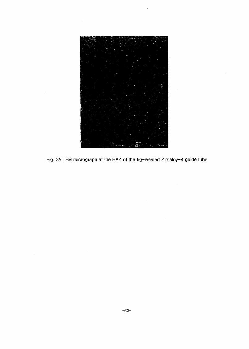
Fig. 35 TEM micrograph at the HAZ of the tig-welded Zircaloy-4 guide tube
-62-

Fig. 36 TEM micrograph at the base of the tig-welded Zircaloy-4 guide tube
-63-

Fig.37. Oxide morphologies of the SW ZLO S specimen corroded in 360°C 700 ppm LiOH aqueous solution for 6 days

Fig. 38. Oxide morphologies of the SW Zry G specimen corroded in 360°C 700 ppm LiOH aqueous solution for 6 days

Fig. 39. Oxide morphologies of the SW Zry G specimen corroded in 360°C 700 ppm UOH aqueous solution for 6 days

67-
(c) (d)Fig. 40. Oxide morphologies of the SW Zry S specimen corroded in 360°C
700 ppm LiOH aqueous solution for 6 days.(a) Oxide layer on theWeldment, (b) Oxide layer on the outer surface of sleeved0,000X),(c) Left side of the welded crevice(300X), (d) Right side of thewelded crevice(270X), (e) Cross-section of the spot weldment(25X)

Oxide of BM Surface Oxide of Weld Surface(a) 6.8 |xm (b) 8.1 urn (c) Crevice
Oxide of Inner Weld Surface Oxide of Inner BMSurface5.0 nm 5.4 urn
Fig.41. Oxide morphologies of the SW ZLO S specimen Corroded in360°C70 ppm LiOH aqueous solution for 180 days

Oxide of BM Surface4.3 nm
Oxide of Outer Weld Surface6.1 urn (b)
Crevice Oxide of Inner Weld Surface 5.6 nm
Fig. 42. Oxide morphologies of the TW Zry G specimen Corroded in360°C70 ppm LiOH aqueous solution for 180 days

Oxide of Outer Weld Surface
Oxide of Inner Weld Surface 7.7 pm
Oxide of BM Surface7.9 pm
Oxide of Inner BM Surface 7.4 pm
Fig. 43. Oxide morphologies of the SVV Zry G specimen Corroded in360°C70 ppm LiOH aqueous solution for 180 days

I-vl
I
Oxide of Outer Weld Surface 7.1 u.m
Oxide of Inner Weld Surface 7.7 nm
Oxide of BM Surface6A
Crevice
Fig. 44. Oxide morphologies of the SW Zry S specimen Corroded in360°C70 ppm LiOH aqueous solution for 180 days

72-
Fig. 45. Surface appearance of tensile test specimens after corrosion in 700 ppm LiOH at 360°C for 6 days

73-
Fig. 46. Close surface appearance of the welding parts after corrosion in 700ppm LiOH at 360°C for 6 days

74-
Fig. 47. Surface appearance of all test specimens after corrosion in 70 ppmUOH at 360°C for 30 days

Fig. 48. Surface appearance of SW ZLO S specimens after corrosion in 70 ppm LiOH at 360°C for 30 days
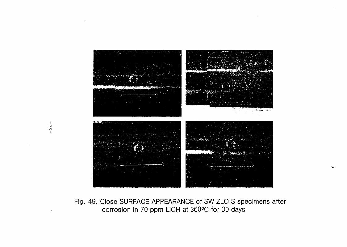
Fig. 49. Close SURFACE APPEARANCE of SW ZLO S specimens after corrosion in 70 ppm LiOH at 360°C for 30 days

Fig. 50. Surface appearance of TW Zry G specimens after corrosion in 70 ppm LiOH at 360°C for 30 days

Fig. 51. Close surface appearance of TW Zry G specimens after corrosion in 70 ppm LiOH at 360°C for 30 days

Fig. 52. Surface appearance of SW Zry G specimens after corrosion in 70 ppm UOH at 360°C for 30 days
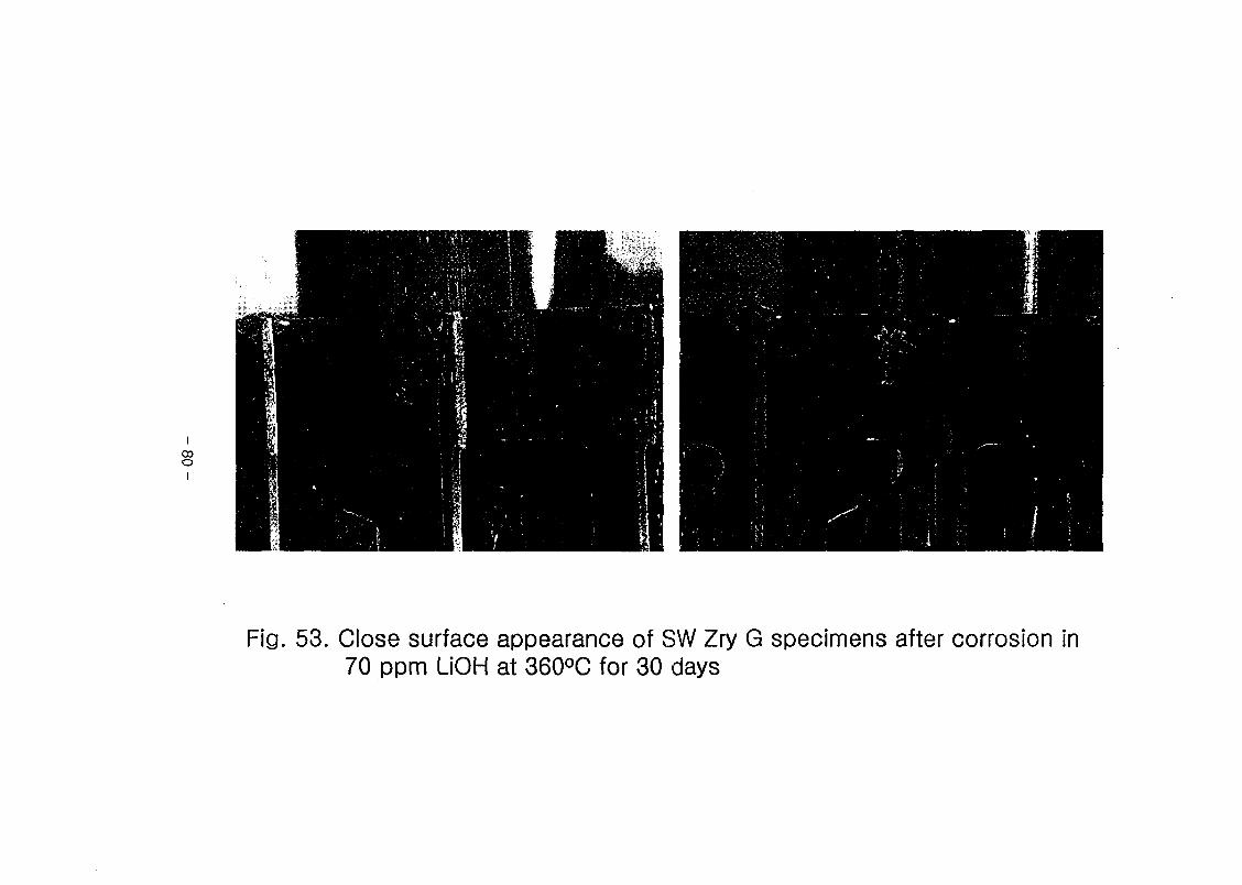
Fig. 53. Close surface appearance of SW Zry G specimens after corrosion in 70 ppm LiOH at 360°C for 30 days

81-
Fig. 54. Surface appearance of SW Zry S specimens after corrosion in 70 ppmLiOH at 360°C for 30 days

82-
Fig. 55. Close surface appearance of SW Zry S specimens after corrosion in70 ppm LiOH at 360°C for 30 days

ICOCO
I
Fig. 56. Surface appearance of all test specimens after corrosion in 70 ppmLiOH at 360°C for 180 days

84-
Fig. 57. Surface appearance of SW ZLO S specimens after corrosion in 70ppm LiOH at 360°C for 180 days

Fig. 58. Close surface appearance of SW ZLO S specimens after corrosion in 70 ppm UOH at 360°C for 180 days

Fig. 59. Surface appearance of TW Zry G specimens after corrosion in 70 ppm LiOH at 360°C for 180 days

Fig. 60. Close surface appearance of TW Zry G specimens after corrosion in 70 ppm LiOH at 360°C for 180 days

Fig. 61. Surface appearance of SW Zry G specimens after corrosion in 70 ppmLiOH at 360°C for 180 days

Fig. 62. Close surface appearance of SW Zry G specimens after corrosion in 70 ppm LiOH at 360°C for 180 days

-06
Fig. 63. Surface appearance of SW Zry S specimens after corrosion in 70 ppmLiOH at 360°C for 180 days

91-
Fig. 64. Close surface appearance of SW Zry S specimens after corrosion in70 ppm LiOH at 360°C for 180 days

Fig. 65 Hydride morphology and hydrogen concentration of the SW ZLO S specimen hydrided in 400°C Ar+H2 gas for 30 min.

93-
Fig. 66 Hydride morphology and hydrogen concentration ofthe TW Zry G specimen hydrided in 400°C Ar+H2 gasfor 30 min.

94-
Fig. 67 Hydride morphology and hydrogen concentration of the SW Zry G specimen hydrided in 400°C Ar+H2 gas for 30 min.

95-
Fig. 68. Hydride morphology and hydrogen concentration of theSW Zry S specimen hydrided in 400°C Ar+H2 gas for30 min.

a) Base Metal : 38.6 ppm b) Weldment: 42.5 ppm
Fig. 69 Hydride morphology and hydrogen concentration of the SW ZLO S specimen corroded in 360°C 70ppm LiOH aqueous solution for 180 days.

Fig. 70 Hydride morphology and hydrogen concentration of the SW Zry S specimen corroded in 360°C 70ppm LiOH aqueous solution for 180 days.


4 4 4 5 4 4
3*8 7l 45314 43: 33713SJL335: aesjz*i45 INIS 3*11 S3.
K AERI/TR-2180/2002
*11# / 34 71PM3& Spot Welded Guide Tube3 -§-33 37X11)
43434 3 344 (AR,tr #aj 43 3*14) ##§: / t-Iss#*!## ^35-343 71)3
4 3 4^344 343, 433:, 334, 4## / 33s.33-4 *H#
# 4- *1 413 #37)4 #34*1-4435 20024
4 °1 4 97 p. 5 a 4#( 0 x a#( ) H 7) A4
4443^7H( O ), 43 4( X #33
433#4% 7)1343:
&# (15-20#iflai)
3 JiLJZ*MH# S] (PLUS?), RXA Zir Zircaloy-4 Guide 1 4§-441 4# #4 (PLUS?) 41 4§-# TIG §-4# CE 4 5# 33# 455 3443 4 ZIRLO 7)1 34# 455 #: 414 #43# 444
RA ZIRLO Guide Thimble# Sleeve## 4 #4 caloy—4 Tube# Sleeve 43 4 #4 5#IL SRA rhimble# RXA Zircaloy-4 Grid 43 TIG -44 9)
444# 47M-5S3-. ##&e#4# 7HM45 4144 Zirlo 4-§-4 *H&# #445 (1800 kgf)#4 #31 (KSNP) TW Zry G3 #445 (1400 kgf) #3-^4. 360°C 70 ppm LiOH #^4M 1804 #4 §-43-3 43-33 3-4# 5*m# 3 20% 45 34 Dr# $5#-, 43# -§-43-3 3-34^4 §-445 44 4)3 ht)1 44# 434 3# 455 4333.
441343^(1034413)
7l)4S94S, 4§-4, tig-§-4, §-4 444, 33, zirlo,
4*11 S3, ##4, §-43 S4S4

BIBLIOGRAPHIC INFORMATION SHEET
Performing Org.
Report No.Sponsoring Org.
Report No.Stamdard Report No. INIS Subject Code
KAERI/TR-2180/2002
Title / Subtitle An Evaluation of weldability of the spot-welded guide
tube for advanced nuclear fuel
Project Manager and Department (or Main Author)
Sang Yoon Park, Development of New Cladding Materials
Researcher and
DepartmentJ. H. Back, M. H. Lee, B. K. Choi, Y. H. Jeong,
(Development of New Cladding Materials)
PublicationPlace
PublisherPublication
Date2002
Page 97 p. 111. & Tab. Yes( O ), No ( ) Size A4
Note
Classified Open( O ), Restricted( ), ___ Class Document
Report Type
Sponsoring Org. Contract No.
Abstract (15-20 Lines)
This report sum Zirlo thimble/sl Zircaloy-4 tube Zircaloy-4 guide and spot—weldin ZIRLO materials the TIG welded ppm LiOH solut ZIRLO shows th< matrix. However welded zone litt welding strength.
marizes the weldabilities of the spot—welded SRA eeve(PLUS7) and of the spot—welded RXA /sleeve. The welding performance of the SRA
thimble and RXA Zircaloy-4 grid welded by TIG— g methods were also evaluated. The spot-welded
(1,800 kgf) showed higher welding strength than Zircaloy-4 ones (1,400 kgf). After corrosion in 70 ion at 360°C for 180 days, the welded zone of s accelerated corrosion rate of about 20% than the
it was observed that the accelerated corrosion of le affects its welding performance in aspects of
Subject Keywords
(About 10 words)Advanced Nuclear Fuel, Spot Welding, TIG Welding, Weldability,
Corrosion, ZIRLO, Microstructure, Oxide Layer, Cu Contamination


![3} tj- 7] - OSTI.GOV](https://static.fdokumen.com/doc/165x107/631c4c86b8a98572c10cd705/3-tj-7-ostigov.jpg)