V4.5 Software Quick Start Guide | Soundcraft
18
V4.5 Software Quick Start Guide
-
Upload
khangminh22 -
Category
Documents
-
view
0 -
download
0
Transcript of V4.5 Software Quick Start Guide | Soundcraft

V4.5 Software Quick Start
Guide
Vi V4.5 Quickstart Guide.doc Page 2
Contents
Introduction to V4.5 & VM2 ........................................................................ 3
VM2 Concepts ........................................................................................... 4
Setting up a VM2 Network ......................................................................... 5
Identifying the HiQnet Network connector on Vi consoles ........................ 6
Detailed Console Operation of VM2 .......................................................... 7
Using the Fader Calibration feature on Vi2/4/6 ....................................... 18
Vi V4.5 Quickstart Guide.doc Page 3
INTRODUCTION TO V4.5 & VM2
The V4.5 software release adds important new functionality to the Vi family, primarily in the form of a unique new patented feature called VM2, which allows the status information for AKG wireless microphones to be displayed directly within the channel strip that they are connected to. This feature makes further use of Harman’s HiQnet network control protocol and brings many benefits including streamlining of the workflow and increase in speed of problem diagnosis. The V4.5 release also brings the operating software for all of the Vi consoles together into a single version, which means that any type of Vi console can be updated from now onwards using a single update file, downloadable from the Soundcraft website. Bug fixes and improvements can now be implemented more quickly as only one version of the code has to be maintained. Although it has taken a significant amount of time to implement the V4.5 release, this will pay dividends in the future, and code development will be significantly faster. Soundcraft is fully committed to on-going support and development of the Vi platform!
In this guide:
• VM2 Concepts
• Setting up a VM2 Network
• Detailed Console operation of VM2
• Troubleshooting the VM2 setup
• Other V4.5 Features

Vi V4.5 Quickstart Guide.doc Page 4
VM2 CONCEPTS
VM2 stands for ‘Vistonics Microphone Monitoring’. It takes advantage of Harman’s HiQnet control network to allow a level of integration between a HiQnet-enabled AKG Wireless Microphone system, and a Soundcraft Vi Series console. What is HiQnetTM? HiQnet is a network communications protocol developed by Harman which enables various professional audio products within the Harman Pro-audio range to communicate with each other and provides remote control and monitoring of Harman devices such as power amplifiers, powered speakers, DSP processors and microphones. Ethernet is normally used as the transport method for HiQnet control, as it provides a robust and standardised method of connecting multiple devices in a network configuration. A Windows application called System Architect provides a master control and monitoring program that allows all equipment on the HiQnet network to be controlled from a single user interface. How is HiQnet used on the Vi-series? Since V3.0 software, the Vi-series has included only a limited HiQnet functionality which allows error messages generated by other Harman devices to be displayed in the console’s message log – for example thermal overload messages generated by Crown amplifiers. In addition the consoles were able to transmit a Venue Preset recall - the HiQnet equivalent of a MIDI Program Change – to all other devices in the network. Version 4.5 now adds significantly to this existing HiQnet functionality with the ability to monitor wireless microphone status within the console GUI. In the future, HiQnet will be used to provide remote control of console parameters. How does VM2 work? In our Microphone Monitoring setup, the AKG wireless receivers are connected to an AKG device called Hub4000Q, which receives data cables from up to 8 wireless receiver units and provides a single HiQnet Ethernet connection through which the monitoring information for the 8 microphones can be accessed by other devices. In the simplest configuration, one Hub4000Q can be connected directly to the HiQnet port of a Vi Series console, and the monitoring functionality will be provided on the console. Typically however other devices will be required to share the HiQnet data from the microphones, and in this case an Ethernet switch (not shown in the diagram below) will be used to allow other Harman devices and/or a wired or wireless computer running Harman’s System Architect software to be connected into the network.

Vi V4.5 Quickstart Guide.doc Page 5
Soundcraft Vi6 FOH Console
Network switch
AKG Hub4000Q
Soundcraft Vi1 Monitor console
AKG DMS or WMS receivers
Ethernet Network connections
AKG data link connections
(Audio connections not shown)
SETTING UP A VM2 NETWORK
In the following setup information, a basic understanding of computer network configuration is assumed. Basic Network Topology The example illustrated shows a typical setup with a front-of-house and Monitor console and a rack of AKG wireless receivers. If only one console is being used, and there is no other HiQnet-connected equipment, the Hub4000Q can be directly connected to the console without using a switch, but in most cases it is better to use one. A computer running System Architect software may also be connected to the switch, and if a wireless router is included in the network, the AKG wireless iPhone app may be used for additional monitoring of the microphone data.
Vi V4.5 Quickstart Guide.doc Page 6
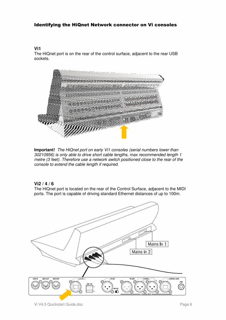
Identifying the HiQnet Network connector on Vi consoles
Vi1 The HiQnet port is on the rear of the control surface, adjacent to the rear USB sockets. Important! The HiQnet port on early Vi1 consoles (serial numbers lower than 30210956) is only able to drive short cable lengths, max recommended length 1 metre (3 feet). Therefore use a network switch positioned close to the rear of the console to extend the cable length if required.
Vi2 / 4 / 6 The HiQnet port is located on the rear of the Control Surface, adjacent to the MIDI ports. The port is capable of driving standard Ethernet distances of up to 100m.
Vi V4.5 Quickstart Guide.doc Page 7
DETAILED CONSOLE OPERATION OF VM2
Setting up and using VM2 monitoring on a Vi Series console falls into four simple steps:
• Connect up the HiQnet network as described in the previous section and check that the IP address configuration is correct on all devices.
• Connect up the audio connections from the AKG Receivers to the console (either to Stagebox or local inputs as appropriate).
• Associate each AKG receiver with a console connector using the mapping table in the Vi’s HiQnet Setup page
• The microphone monitoring information will now automatically be displayed on any channel strip which uses an AKG-mapped physical input connector as its patched source.
The following pages describe in more detail how to carry out the second two steps. Note: Screenshots shown are for Vi2/4/6. Vi1 will have same controls but layout will differ).
Vi V4.5 Quickstart Guide.doc Page 8
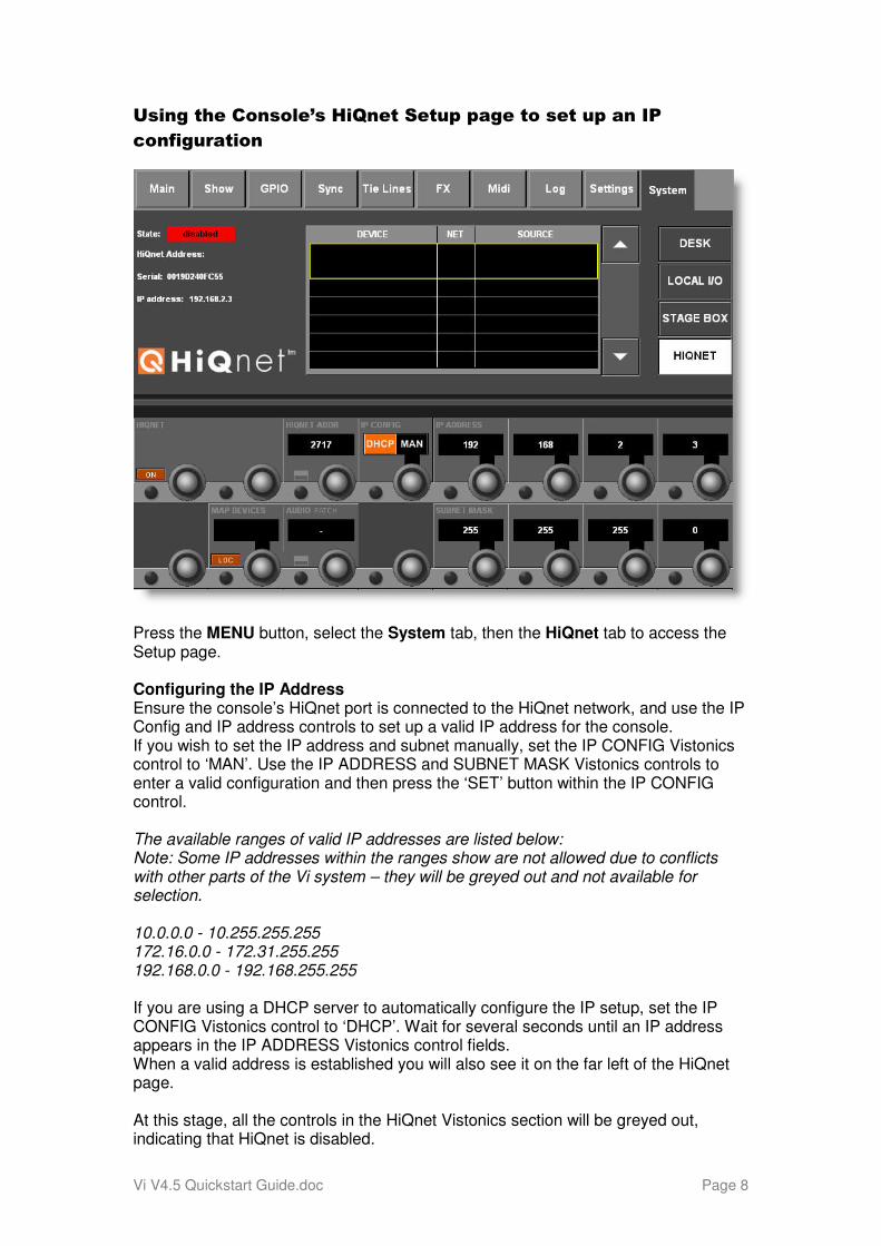
Using the Console’s HiQnet Setup page to set up an IP
configuration
Press the MENU button, select the System tab, then the HiQnet tab to access the Setup page. Configuring the IP Address Ensure the console’s HiQnet port is connected to the HiQnet network, and use the IP Config and IP address controls to set up a valid IP address for the console. If you wish to set the IP address and subnet manually, set the IP CONFIG Vistonics control to ‘MAN’. Use the IP ADDRESS and SUBNET MASK Vistonics controls to enter a valid configuration and then press the ‘SET’ button within the IP CONFIG control. The available ranges of valid IP addresses are listed below: Note: Some IP addresses within the ranges show are not allowed due to conflicts with other parts of the Vi system – they will be greyed out and not available for selection. 10.0.0.0 - 10.255.255.255 172.16.0.0 - 172.31.255.255 192.168.0.0 - 192.168.255.255 If you are using a DHCP server to automatically configure the IP setup, set the IP CONFIG Vistonics control to ‘DHCP’. Wait for several seconds until an IP address appears in the IP ADDRESS Vistonics control fields. When a valid address is established you will also see it on the far left of the HiQnet page. At this stage, all the controls in the HiQnet Vistonics section will be greyed out, indicating that HiQnet is disabled.
Vi V4.5 Quickstart Guide.doc Page 9
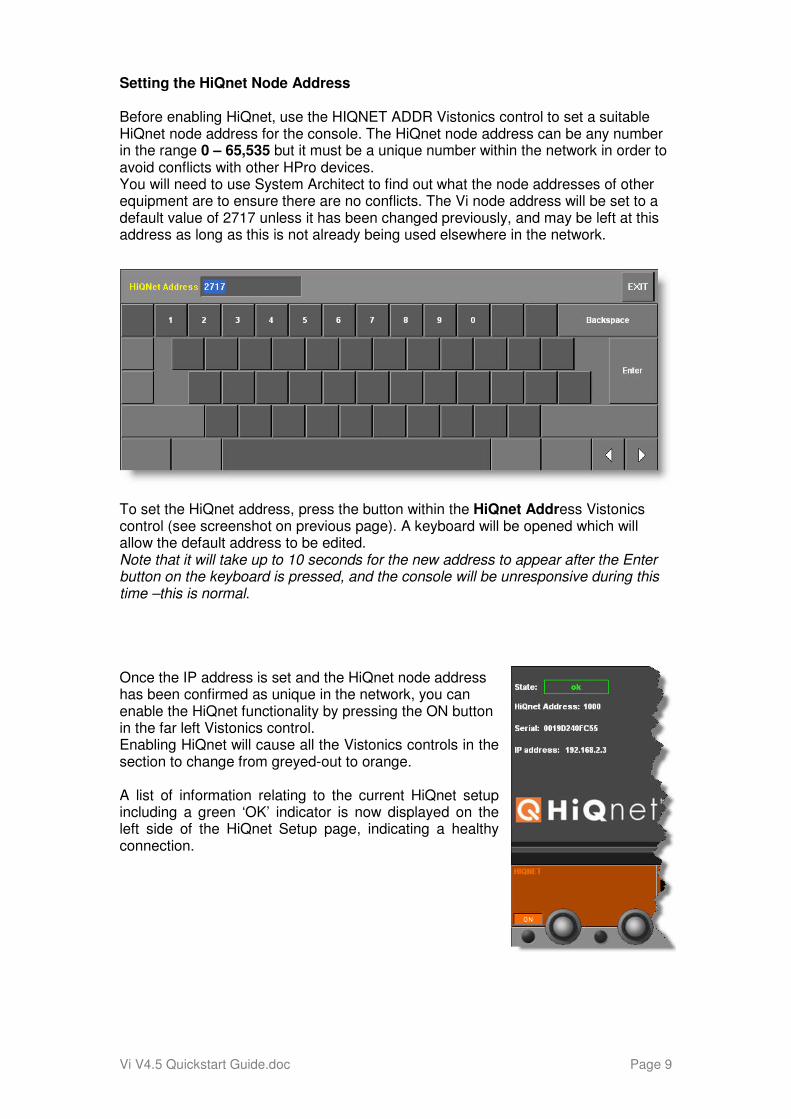
Setting the HiQnet Node Address Before enabling HiQnet, use the HIQNET ADDR Vistonics control to set a suitable HiQnet node address for the console. The HiQnet node address can be any number in the range 0 – 65,535 but it must be a unique number within the network in order to avoid conflicts with other HPro devices. You will need to use System Architect to find out what the node addresses of other equipment are to ensure there are no conflicts. The Vi node address will be set to a default value of 2717 unless it has been changed previously, and may be left at this address as long as this is not already being used elsewhere in the network.
To set the HiQnet address, press the button within the HiQnet Address Vistonics control (see screenshot on previous page). A keyboard will be opened which will allow the default address to be edited. Note that it will take up to 10 seconds for the new address to appear after the Enter button on the keyboard is pressed, and the console will be unresponsive during this time –this is normal. Once the IP address is set and the HiQnet node address has been confirmed as unique in the network, you can enable the HiQnet functionality by pressing the ON button in the far left Vistonics control. Enabling HiQnet will cause all the Vistonics controls in the section to change from greyed-out to orange. A list of information relating to the current HiQnet setup including a green ‘OK’ indicator is now displayed on the left side of the HiQnet Setup page, indicating a healthy connection.
Vi V4.5 Quickstart Guide.doc Page 10
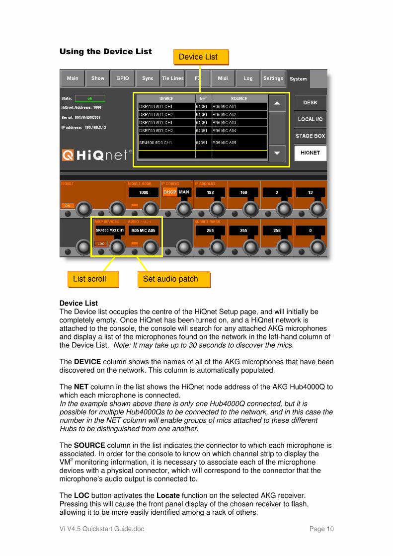
List scroll
Device List
Set audio patch
Using the Device List
Device List The Device list occupies the centre of the HiQnet Setup page, and will initially be completely empty. Once HiQnet has been turned on, and a HiQnet network is attached to the console, the console will search for any attached AKG microphones and display a list of the microphones found on the network in the left-hand column of the Device List. Note: It may take up to 30 seconds to discover the mics. The DEVICE column shows the names of all of the AKG microphones that have been discovered on the network. This column is automatically populated. The NET column in the list shows the HiQnet node address of the AKG Hub4000Q to which each microphone is connected. In the example shown above there is only one Hub4000Q connected, but it is possible for multiple Hub4000Qs to be connected to the network, and in this case the number in the NET column will enable groups of mics attached to these different Hubs to be distinguished from one another. The SOURCE column in the list indicates the connector to which each microphone is associated. In order for the console to know on which channel strip to display the VM2 monitoring information, it is necessary to associate each of the microphone devices with a physical connector, which will correspond to the connector that the microphone’s audio output is connected to. The LOC button activates the Locate function on the selected AKG receiver. Pressing this will cause the front panel display of the chosen receiver to flash, allowing it to be more easily identified among a rack of others.
Vi V4.5 Quickstart Guide.doc Page 11
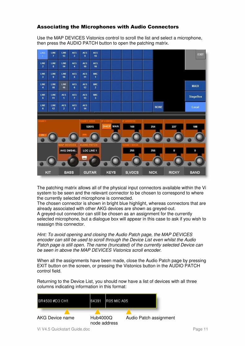
Associating the Microphones with Audio Connectors Use the MAP DEVICES Vistonics control to scroll the list and select a microphone, then press the AUDIO PATCH button to open the patching matrix.
The patching matrix allows all of the physical input connectors available within the Vi system to be seen and the relevant connector to be chosen to correspond to where the currently selected microphone is connected. The chosen connector is shown in bright blue highlight, whereas connectors that are already associated with other AKG devices are shown as greyed-out. A greyed-out connector can still be chosen as an assignment for the currently selected microphone, but a dialogue box will appear in this case to ask if you wish to reassign this connector. Hint: To avoid opening and closing the Audio Patch page, the MAP DEVICES encoder can still be used to scroll through the Device List even whilst the Audio Patch page is still open. The name (truncated) of the currently selected Device can be seen in above the MAP DEVICES Vistonics scroll encoder. When all the assignments have been made, close the Audio Patch page by pressing EXIT button on the screen, or pressing the Vistonics button in the AUDIO PATCH control field. Returning to the Device List, you should now have a list of devices with all three columns indicating information in this format:
AKG Device name Hub4000Q Audio Patch assignment node address
Vi V4.5 Quickstart Guide.doc Page 12
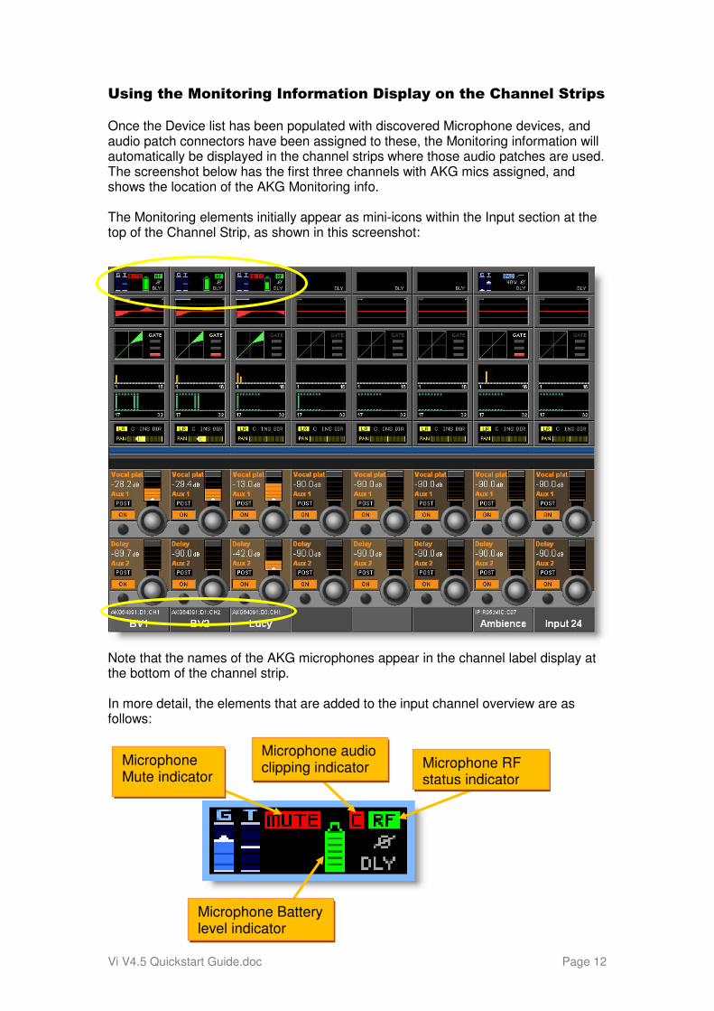
Microphone Mute indicator
Microphone audio clipping indicator Microphone RF
status indicator
Microphone Battery level indicator
Using the Monitoring Information Display on the Channel Strips Once the Device list has been populated with discovered Microphone devices, and audio patch connectors have been assigned to these, the Monitoring information will automatically be displayed in the channel strips where those audio patches are used. The screenshot below has the first three channels with AKG mics assigned, and shows the location of the AKG Monitoring info. The Monitoring elements initially appear as mini-icons within the Input section at the top of the Channel Strip, as shown in this screenshot: Note that the names of the AKG microphones appear in the channel label display at the bottom of the channel strip. In more detail, the elements that are added to the input channel overview are as follows:
Vi V4.5 Quickstart Guide.doc Page 13
The displayed Microphone monitoring elements shown on previous page provide the following functions: Microphone Mute status indicator Shows red ‘MUTE’ icon if the AKG mic is switched to muted state. When unmuted, this indicator icon disappears. Microphone Audio clipping indicator A red ‘C’ is displayed momentarily if the audio within the wireless mic audio path reaches full scale. Microphone RF status indicator A red or green ‘RF’ icon is displayed to indicate the health of the AKG RF level. A green RF indicator is displayed when the signal strength at the receiver is strong enough to enable audio transmission. A red RF indicator is displayed when the signal strength is too low for audio transmission. Note: If the microphone transmitter is switched off, the RF indicator will also change to red, as the system is unable to tell the reason for the lack of RF. The actual value in dB of the RF signal strength is displayed in the Vistonics detailed monitoring information display (see next page). Microphone Battery level indicator A red or green battery level icon indicates the health of the battery within the AKG wireless transmitter. The interior of the battery icon contains 7 segments showing varying battery level. The colour coding of the battery icon is as follows:
Green Segments 3-7 35-100% remaining Amber Segment 2 25% remaining Red Segments 0-1 1 hour remaining
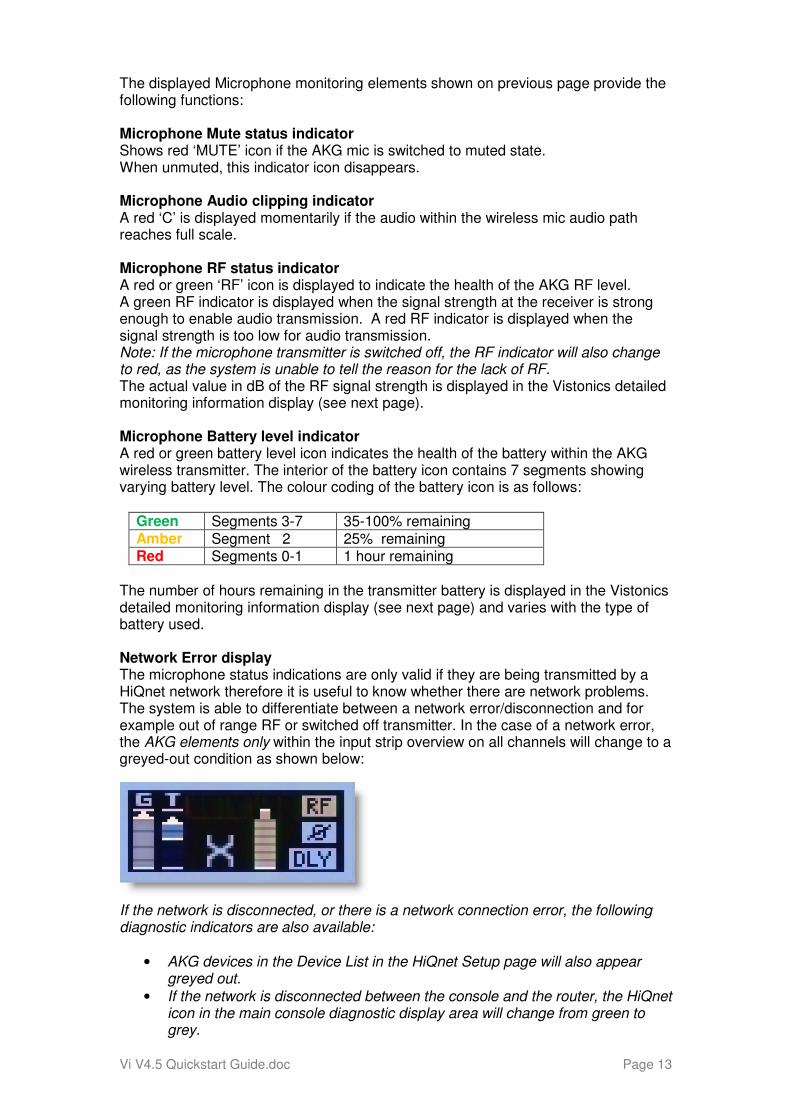
The number of hours remaining in the transmitter battery is displayed in the Vistonics detailed monitoring information display (see next page) and varies with the type of battery used. Network Error display The microphone status indications are only valid if they are being transmitted by a HiQnet network therefore it is useful to know whether there are network problems. The system is able to differentiate between a network error/disconnection and for example out of range RF or switched off transmitter. In the case of a network error, the AKG elements only within the input strip overview on all channels will change to a greyed-out condition as shown below:
If the network is disconnected, or there is a network connection error, the following diagnostic indicators are also available:
• AKG devices in the Device List in the HiQnet Setup page will also appear greyed out.
• If the network is disconnected between the console and the router, the HiQnet icon in the main console diagnostic display area will change from green to grey.
Vi V4.5 Quickstart Guide.doc Page 14
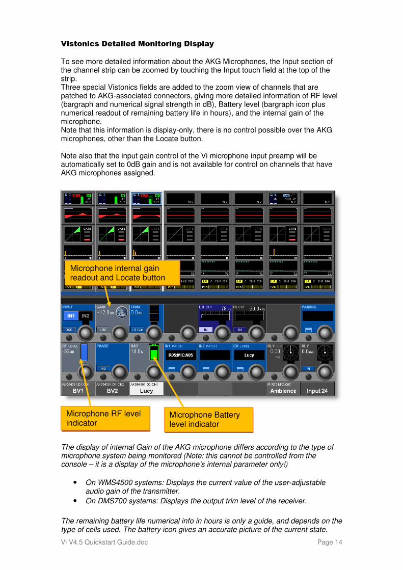
Microphone RF level indicator
Microphone Battery level indicator
Microphone internal gain readout and Locate button
Vistonics Detailed Monitoring Display
To see more detailed information about the AKG Microphones, the Input section of the channel strip can be zoomed by touching the Input touch field at the top of the strip. Three special Vistonics fields are added to the zoom view of channels that are patched to AKG-associated connectors, giving more detailed information of RF level (bargraph and numerical signal strength in dB), Battery level (bargraph icon plus numerical readout of remaining battery life in hours), and the internal gain of the microphone. Note that this information is display-only, there is no control possible over the AKG microphones, other than the Locate button. Note also that the input gain control of the Vi microphone input preamp will be automatically set to 0dB gain and is not available for control on channels that have AKG microphones assigned.
The display of internal Gain of the AKG microphone differs according to the type of microphone system being monitored (Note: this cannot be controlled from the console – it is a display of the microphone’s internal parameter only!)
• On WMS4500 systems: Displays the current value of the user-adjustable audio gain of the transmitter.
• On DMS700 systems: Displays the output trim level of the receiver.
The remaining battery life numerical info in hours is only a guide, and depends on the type of cells used. The battery icon gives an accurate picture of the current state.
Vi V4.5 Quickstart Guide.doc Page 15
TROUBLESHOOTING A VM2 SETUP Problem HiQnet cannot be switched ON in the Menu-System-HiQnet page because there is no IP address. Solution 1. Check the cable connection to the HiQnet port on the console – if there is no valid Ethernet connection, it will not be possible to switch on the HiQnet functionality. 2. Assuming cable connection is OK, if DHCP mode is selected on the console, check that the router that is being used has a DHCP server capability and that this is enabled in the router setup. 3. It is possible to connect the console directly to the Hub4000 without a router, with the console set to DHCP mode. In this case there will be a considerable delay (up to 60 secs) before an IP address is allocated, as this has to be negotiated between the console and the Hub. 4. If using a manually set address, the console’s IP address must have the same subnet mask as the Hub4000Q, so System Architect must be used to discover what that is. Once the address is known, set the console to a different address but with the same subnet mask. Problem No AKG receivers are detected by the console – the list on the HiQnet page is empty Solution 1.Check that all AKG receivers are connected to the Hub4000Q, the Hub4000Q front panel LEDs show connection status of the attached receivers, and there is a network connection between the Hub4000Q and the console (via a network switch if necessary) 2. Check that the IP Config of the console and the Hub4000Q match – if using a router with DHCP server and you do not want to use a manually set IP address, make sure the console is set to ‘DHCP’ mode in the Menu-System-HiQnet page. Problem The AKG receivers are listed in the Device list on the HiQnet page are greyed out. Solution This indicates that there is a network connection has previously existed correctly but there is now a connection error – either the Hub4000Q has been disconnected or switched off, or there is another connection problem between the Hub and desk or router and desk. Check all network connections.
Vi V4.5 Quickstart Guide.doc Page 16
Other Additional Features and bug fixes with Version 4.5
The V4.5 software release is the first software release for Vi in which the same update file can be used for all four models of Vi console – Vi1, 2, 4 & 6. This will enable us to deliver updates more efficiently in the future, as work to add features or fix bugs will only have to be done in one branch of software, rather than having to work on multiple ones.
In addition to the VM2 functionality described earlier, the following new features have been added:
Feature
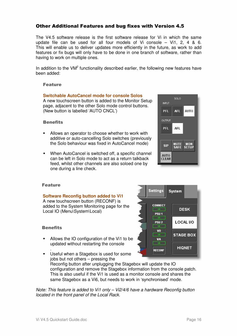
Switchable AutoCancel mode for console Solos A new touchscreen button is added to the Monitor Setup page, adjacent to the other Solo mode control buttons. (New button is labelled ‘AUTO CNCL’)
Benefits
� Allows an operator to choose whether to work with additive or auto-cancelling Solo switches (previously the Solo behaviour was fixed in AutoCancel mode)
� When AutoCancel is switched off, a specific channel can be left in Solo mode to act as a return talkback feed, whilst other channels are also soloed one by one during a line check.
Feature
Software Reconfig button added to Vi1 A new touchscreen button (RECONF) is added to the System Monitoring page for the Local IO (Menu\System\Local)
Benefits
� Allows the IO configuration of the Vi1 to be updated without restarting the console .
� Useful when a Stagebox is used for some jobs but not others – pressing the Reconfig button after unplugging the Stagebox will update the IO configuration and remove the Stagebox information from the console patch. This is also useful if the Vi1 is used as a monitor console and shares the
same Stagebox as a Vi6, but needs to work in ‘synchronised’ mode.
Note: This feature is added to Vi1 only – Vi2/4/6 have a hardware Reconfig button located in the front panel of the Local Rack.
Vi V4.5 Quickstart Guide.doc Page 17
Feature
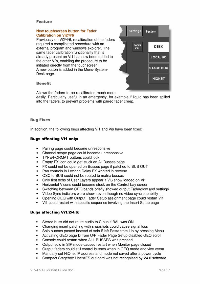
New touchscreen button for Fader Calibration on Vi2/4/6 Previously on Vi2/4/6, recalibration of the faders required a complicated procedure with an external program and windows explorer. The same fader calibration functionality that is already present on Vi1 has now been added to the other Vi’s, enabling the procedure to be initiated directly from the touchscreen. A new button is added in the Menu-System-Desk page.
Benefit
Allows the faders to be recalibrated much more easily. Particularly useful in an emergency, for example if liquid has been spilled into the faders, to prevent problems with paired fader creep.
Bug Fixes
In addition, the following bugs affecting Vi1 and Vi6 have been fixed:
Bugs affecting Vi1 only:
• Pairing page could become unresponsive
• Channel scope page could become unresponsive
• TYPE/FORMAT buttons could lock
• Empty FX icon could get stuck on All Busses page
• FX could not be opened on Busses page if patched to BUS OUT
• Pan controls in Lexicon Delay FX worked in reverse
• OSC to BUS could not be routed to matrix busses
• Only first 8chs of User Layers appear if Vi6 show loaded on Vi1
• Horizontal Vicons could become stuck on the Control bay screen
• Switching between GEQ bands briefly showed output Faderglow and settings
• Video Sync indictors were shown even though no video sync capability
• Opening GEQ with Output Fader Setup assignment page could restart Vi1
• Vi1 could restart with specific sequence involving the Insert Setup page
Bugs affecting Vi1/2/4/6:
• Stereo buss did not route audio to C bus if BAL was ON
• Changing insert patching with snapshots could cause signal loss
• Solo buttons pasted instead of solo if left Paste from Lib by pressing Menu
• Activating GEQ page D from O/P Fader Page Setup disabled GEQ scroll
• Console could restart when ALL BUSSES was pressed
• Output solo in SIP mode caused restart when Monitor page closed
• Output faders could still control busses when in GEQ mode and vice versa
• Manually set HiQnet IP address and mode not saved after a power cycle
• Compact Stagebox Line/AES out card was not recognised by V4.0 software
Vi V4.5 Quickstart Guide.doc Page 18
Using the Fader Calibration feature on Vi2/4/6
The Fader Calibration facility has been available on Vi1 since that product started shipping, but on the other Vi consoles it has only been possible up to now via a specialist procedure and additional software. From V4.5 onwards the Vi2/4/6 now also benefit from the ability to recalibrate faders directly from the System-Desk menu.
The procedure for performing the calibration on Vi2.4.6 is slightly different from the fully automatic one of Vi1, and it requires some manual intervention. Therefore detailed instructions are provided below.
When is recalibration needed?
Under normal conditions, the faders of Vi2/4/6 will never need to be recalibrated. There is no requirement to do this on a routine basis. The only times this will be necessary will be either after the fader PCB has been replaced due to a fault, or liquid has been splashed into the faders, in which case it will be obvious that something is wrong with the behaviour of the faders.
The sign that faders need to be recalibrated will be either that paired channels or busses exhibit a ‘creeping’ effect where the faders move slowly by themselves up or down, or that the faders do not return to the same positions after changing layers (this can also be confirmed by watching the numerical values of the Bus Master faders which are displayed in the Control Bay (or upper Vistonics row on Vi1), whilst changing output fader pages.
Instructions for Recalibrating the faders
1. Navigate to MENU-System-Desk and press the FADER CAL button on the right hand side of the touchscreen. Answer YES to the warning dialogue box (you will lose control of audio for the duration of the process).
2. Follow the instructions that are now displayed in the Short Chanel Label displays – initially the faders will all move to the bottom of travel and the instruction will say “Set all faders to minus infinity”. Although the faders may appear to already be at minus infinity, carefully move each fader knob so the cursor line is aligned with the minus infinity mark on the fader scale.
3. When all faders have been set in this way (do not forget the Master and Monitor faders in the Control Bay!), you will see a message in the Short Label displays saying “Press Any Key to Continue” - press any of the ON buttons on each Bay to start the lower end calibration process. The display will indicate ‘Find Minimum Value’ whilst this is happening,
4. When this has finished, the faders will all move to the top, and the message will be displayed “Set All Faders to +10”. Repeat the procedure of carefully aligning the fader knob cursor with the +10 mark on the scale, and when you see the message ‘Press Any Key to Continue”, press an ON button in each bay to start the upper calibration. The displays will indicate ‘Find Maximum value’ whilst this is happening.
5. When all bays have finished, the faders will return to their previous positions and the calibration procedure is complete. The calibration will be permanently stored the next time the console power is shut down.