Université d'Ottawa University of Ottawa
115
Université d'Ottawa University of Ottawa
-
Upload
khangminh22 -
Category
Documents
-
view
5 -
download
0
Transcript of Université d'Ottawa University of Ottawa

Université d'Ottawa University of Ottawa


Development of a WindowsTM 3-D Sound System using Binaural Technology
BY Adel Senki, B. A. Sc.
A thesis submitted to the Faculty of Graduate and Postdoctoral Studies in partial fulfillment of the requirements for the degree of Master of Science in
Systems Science.
Faculty of Administration University of Ottawa
June 30,2ûûû
O 2000, Adel Senki, Ottawa, Canada
The author has granted a wn- exclusive licence dowing the Natiod Library of Canada to repfoduce, Ioan, distri'bute or seii copies of this thesis in microform, paper or electronic formats.
The author retains ownership of the copyright in this thesis. Neither the thesis nor substantial extracts fiom it may be printed or otherwise reproduced without the author's permission.
L'auteur a accordé une licence non exciusive permettant B la Bibliothèque nationale du Canada de reprodiiire, prêter, distribuer ou vendre des copies de ceette thèse sous h fome de microfiche/nIm, de reproduction sur papier ou sur format électronique.
L'auteur conserve la propriété du droit d'auteur qui protège cette thèse. Ni fa thèse ni des extraits substantiels de celle-ci ne doivent être imprimés ou autrement reproduits sans son autorisation.

Abstract
It is anticipated that 3-D sound will becorne a major component in virtual reality
envimnments. In this thesis, we investigate the development of a Windows 3-D sound
system using binaural technology. This work should evennially be integrated in complex
vittual environment software. The 3-D sound effects are achieved by applying a filter pair
representing audio cues from a specific point in space to the left and nght channels of
headphones. As a first step, an offline 3-D audio file generation system is developed, and
effects such as sound reflections in a virtual rectangular room are added to this system.
The real-time implementation is considered next. The fiat approach tested for the real-
time irnplementation uses the time domain convolution of a sound source signal witb
head-related transfer functions, but the computational Ioad of this approach is such that it
cannot run in ml-time at audio sampling rates. As an alternative, a second approach with
a Fast Fourier Transform overlap and Save technique is used to reduce the computational
load, and a real-time implementation at audio freqwncies is therefore successfuIly
ac hieved.

Acknowledgements
1 would like to express my sincere gratitude to my supervisor, Dr. Martin Bouchard.
Thank you for giving me the oppoctunity to participate in a 3-D sound reproduction
system research project. 1 really enjoyed working under your guidance, leadership and
supervision.
Many thanks to Dr. Tet Yeap and Dr. Jean-Michel Thizy Director of the Systems Science
pmgram, and to Dr. Bouchard for procuring me with more than adequate research
facilities.
Special thanks to Dr. Yeap for an arrangement with Dr. Martin Bouchard to be my
official supervisor, until Dr. Martin Bouchard got accepted in the Faculty of Graduate
and Postdoctoral S tudies.
1 would also like to thank my wife, Amel El-hadi for providing me with full support and
love throughout my studies. Many thanks to some of my working colleagues, especially
Mr. Yu Feng and Mt. Mustafa Elarbi. Thank you al1 for your comments. help, and
exchange of knowledge and friendliness throughout the course of my studies. It was
really appreciated.
iii

Table of contents
Abstract i i
Acknowledciements iii Table of contents iv
List of Acronvms vi
List of Tables vii List of Ficrures vi ii
Cha~ter 1 Introduction 1
1.1 Motivation 1
13 Obiectives and research m e t h o d d ~ 2
13 Thesis Outline 5
1.4 Research Contributions 6
Cha~ter 2 A brief ovewiew of sound s~atialization thearv 7 2.1 Acoustics and ~svchoacoustics 7
2.2 A sirnoie examde of sound localization 8
2 3 Phvsical Variables in Acousücs 10
2.4 Cues of Psvchoacoustics 11
2.4.1 Coordinate Svstem 14
2.4.2 Horizontal Identification and Azimuth Cues 16
2.43 Vertical Identification and Elevation Cues 20
2.4.4 Front -Back Identification 22
2.4.5 Cues found and not round in Head-related T r a d e r Functions 22
2.5 Measurement of the Head-relateci TracMer Functions 24
2.6 Svnthesis of 3-D Sounds usinn HRTFs 28
2.7 Crosstalk and HRTF ada~taüon 30
2.8 Probletnatic of Head~hone Plavback with HRTF ~enerated sounds 32
2.9 Cha~ te r summarv 34
Cha~tei 3 Im~lementation of an Offline Binaural Audio Svstem 35 3.1 3-D Audio Svstern Generatinn Sound Files 35
3.2 Eauations and aleorithms used for the 3-D Sound- 3 6
33 Main structure of the offliw 3-D sound svstem 42

3.4 WAVE F i k 44
3.4.1 WAVE File Structure 45
3.4.2 Format Chu& 46
3.43 Data Chunk 47
3.4.4 WAVE file readin~ and wriüng 48
3.5 Listeniop tests usinn Commct and Diffuse MIT HRIR sets 51
3.6 cha~ter summarv 52
Cha~ter 4 Real-time lmnlementation 53
4.1 Plavine sound in r d - t h e in a Windowsm environment 53
4.2 Svstem architecture 54
4 3 First mal-time im~lementation: convolution in the time domain 59
4.4 Second mal-üme im~lementation: im~rovement of the ~erformance usiw freauencv domain convolution 60
4.5 Listenine tests for the rd-time 3-D sound a~plication 65
4.6 Cbamter summarv 66
Cha~ter 5 Conclusion and Future Woik 67 5.1 Conclusion 67
5.2 Future Works 6%
References 69 Aomndix A A *recidme.Mu fi- 73
Aomndix B C++ source code for the 3-0 sound andication I to be
Aomndix C C++ source code for a simde aodication (to be comdkd as an executable) callinci the 3-D sound DLL a~nlication 103

List of Acronyms
HRTF
HRIR
m
ID
DLL
A/D
DIA
FFI'
DSP
PCM
API
Head-related Transfer Functions.
Head-related Impulse Response
Interaurd Tirne Differences.
Interaura1 Intensit y Di fferences.
D ynarnicall y Linked Li brary.
Analog to Digital.
Digital to Analog.
Fast Fourier Transfom.
Digital Signal Processing.
Pulse-Code Modulation.
Application Rograrnming Interface

List of Tables
Table 2.1: Number ot azimuthal measurements and arimuth increment at
each elevation in the MIT HRIR database. 26
Table 3.1. WAVE File Format. 46
Table 4.1. Comoutational cost mi outnut samnle for time domain and frea.
d o m m linear 63
vii

List of Figures
Fiaure 2.1 : Concentric waves in a lake. 9
Fiaure 2.2: R i ~ ~ l e s of waves on a non-ftat surface. 9
Fiaure 2.3: Loudsneaker emittina sound that travels throuah the air at
about 340 meters per second. 10
Fiaure 2.4: Sine wave. 11
Fiaure 2.5: Human ear structure. 12
Fioure 2.6: Free-field scoustic transmission ~athwav into the ear- 14
Figure 2.7: 3-0 Planes (X. Y, 21. 15
Fiaure 2.8: 3-0 Soherical Coordinates. 16
Fiaure 2.9: lnteraural Time Differences OTDs). 18
Fiaure 2.1 0: lord Ravleiah's sim~fified model. 19
Fiaure 2.1 1 : Interaural lntensitv Differences (IIDs). 19
Fiaure 2.12:Freauencv resoonses for two different directions of arrival. - 21
Fiaure 2.13: Tvpical sound field with a source, an environment, and a
listener. 24
Fiaure 2.1 4: Measurement of HRTFs. 25
Fiaure 2.15:Anechoic Chamber at MIT Media Lab. 26
Fiaure 2.16: M I R Measurements. 28
Ficiure 2.17: Binaural svnthesis usina HRTFs. 29
viii

Fiaum 2.18: Direct and crosstalk transmission mths from loudswakers to
the ears of a listener. 31
Fiaure 2.19: lâeal ~lavback of HRTF aenerated 3-0 sound. 33
Fieure 2-20: Plavback of HRTF aenenitd 3-D sound via head~hones. 33
Ficiure 3.1 : 3-0 Audio svstem. 43
Fiaure 3.2: WAVE File Structure. 45
naure 3.3: Flowchart of WAVE file reading wirt A. 49
Ficiure 3.4: Flowchart of WAVE file readina. mrt B. 50
Fiaure 4.1. Intertask communication scheme for the svstem. 55
Fiaure 4.2 State Diaaram of the Main Proaram thread. 56
Fiaure 4.3. State Diaaram of the WinPlaver thread. 58
Fiaure 4.4. Alianment of i n ~ u t and out~ut sianals in the overlao and Save
techniuue. 62
Chapter 1 Introduction
1.1 Motivation
In 3-D sound reproduction (or 3 D audio), signal processing techniques are used to
artificially reproduce sounds that are perceived by human listeners as if they were
"natural" sounds, aithough the sounds are actually reproduced via headphones or
loudspeakers. To feel that the sound is "naturai", listeners must have an appropnate
perception of the location of the source (distance, azimuth, and elevation) and also a
perception of the environment amund them (open or closed room, small or large m m ,
etc.) [1,2].
Binaural technology [3) is a particular technique for generating 3-D audio, where the
transfer functions between a sound source and a human listener (called the head-related
transfer functions, or HRTFs) are used to filter mono sound sources. Binaural hearing
works on the basis that since we only have two ears, any sound we cm hear can be
reproduced by a pair of loudspeakers or by headphones. When sound waves arrive ai the
head, they are modified acoustically in a directionally dependent manner by diffractive
effects around the head and by interaction with the outer ears. This is characterized by the
HRTFs. Filtering a mono sound source with these HRTFs and playing back the resulting
signals in headphones, the result is sounds that are perceived as originating from the
source position specified by the HRTFs. When loudspeakers are used with binaural
techniques instead of headphones, the resulting techniques are called transaural technique

141. There are also geomevic approaches such as ambisonics and ambiophonics [5,6] to
reproduce 3-D sound in a m m , but those approaches usually require many loudspeakers,
while the binaural or transaural techniques require only two loudspeakers for one listener.
nie drawback of binaural or transaural techniques, however, is that they typically have a
high cornputational load.
There are many applications of binaural3-D auàio. There is of course the reproduction of
sounds as they would be perceived in a known environment. For example, a listener hem
sounds as they would be perceived in a great concert hall, although the listener may in
fact be in a small office, with poor acoustical characteristics. There is also the artistic
creation of sounds that are not common in mal-life. It is anticipated that there will be a
huge growth in the development of vinuai reality environments (the most important
application in the short term is for the entertainment industry, in particular for video
games), and 3-D sound will be a significant component in such environments. This is the
main motivation of this work.
1.2 Objectives and research methodology
The first objective of this thesis is to review and describe the basic sound spatialization
theory required to understand how it is possible to modify mono sound recordings using
binaural technology so that 3-D sounds cm be perceived by a listener. The second
objective of this thesis is to implement a real-time 3-D sound system based on head-
related transfer functions (HRTFs), to be used in a Windows TM software environment.

The sound system will work in rd-time, and it will use a standard PC audio board. The
second objective will answer questions such as:
1s an average PC using Windows 98 (an operating system not particularly known
for its rd-time capabilities) sufficient to produce 3-D sounds in real-time using
binaural technology?
1s a time domain approach (i.e. basic convolution) appropriate to implement the
HRTF filtering?
In surnmary, the research methodology to be followed will be:
1. Review the souad spatialization theory
There are many aspects to the sound spatialization theory. It is important to identify
which aspects (i.e. which cues) of sound spatialization can be reproduced in a real-time 3-
D sound system based on binaural technology and head-related transfer functions. Only
when this is clearly understood cm a designer really know what he can expect in terms of
3-D effects performance from the 3-D sound software to be developed. This is why
Chapter 2 is a very important chapter of this thesis.
2. Develop an omine 3-D sound system
This step requires finding the time-domain equations needed to compute the left and right
channel 3-D sound signals €rom an input mono sound source, using the head-related
transfer functions. It was chosen to decouple the programming of the 3-D sound
algorithms (i.e. this step in the methodology) and the programming of the nal-time

acquisition and rendering (i.e. the next steps). This is because botb of these tasks are
challenging, and implementing hem simultaneously in parallei seemed like an ambitious
(or dangerous) approach. Therefore a version of the 3-D sound system was developed for
an offline system that reacis an input mono sound file and writes a stereo 3-D sound file,
to be heard via headphones. This version does not have any real-time constraint, and the
focus can therefore be put on the programming and debugging of the 3-D sound
algorithm.
3. Develop a ml-time version of the 3-D sound system
This step requires to modify the 3-D sound system from the previous step in order to
write in real-time stereo output samples to a soundboard (again to be played via
headphones). This requires using multi-thread programming combined with the use of
Windowsm multimedia libraries. Note that in our implementation the input source is still
a file, and not a microphone or a packet Stream received from a computer network.
4. Improvement of the performance of the ml-time system
From a computational point of view, it is possible to improve the performance of the real-
time system. The net practical result will be to increase the maximum sampling rate of
the audio sound signals to be reproduced by the system. This is critical since the HRTFs
functions that are used in this thesis were sarnpled at audio frequencies. This step
involves the use of frequency domain convolution techniques, in order to reduce the
computational load of the 3-D sound algorithm. More specifically, an overlap and Save
fast Fourier transform (FFT) technique will be implemented. This will add to the

programming complexity of the program, but it will result in a more efficient
implementation of the 3-D sound system.
The rest of the thesis is structured according to the following outline: Chapter 2 presents
an qualitative overview of the theory of sound spatialization. Important topics are
discussed such as: physical variables, psychophysical variables, coordinate systems,
azimuth cues, interaural time differences o s ) , interaural intensity differences (IIDs),
elevation range cues, propagation effects and reflections.
Chapter 3 explains how an offline 3-D sound system that uses HRTFs and generates 3-D
audio output files was first developed. In that part of the project it was possible to include
environmental effects such as reflections and distance cues, because there were no red-
time constraints.
Chapter 4 discusses the design of the real time 3-D sound system. The HETF filtenng
was first implemented in the time domain using basic linear convolutions, and the
performance of the system was evaluated. Chapter 4 then describes how the performance
of the real time 3-D sound system can be improved using frequency domain methods to
perform linear convolutions. The thesis concludes with Chapter 5, which sumrnarizes the
main results of this thesis and provides suggestions for future research activities.

1.4 Research Contributions
The main contributions of this thesis are:
To briefly quaiitatively summarize the theory of sound spatialization required
understanding the concept of producing 3-D sounds using binaural technology.
The development of ml-tirne Windows software for 3-D audio rendering using
binaural technology. An off-line version (i.e. file based) of the software was also
developed, and it was possible in this case to add some environmental effects such as
reflections and distance cues.

Chapter 2 A brief overview of sound spatialization theory
This chapter reviews some basic aspects of sound and sound spatialization. It is very
important that a programmer be aware of these aspects, in order to know which aspects
(i.e. which cues) of sound spatialization can be reproduced in a real-time 3-D sound
system based on binaural technology and head-related transfer functions. For example, it
will be explained in this chapter that HRTFs can provide the cues for the position of a
sound source, but unless they are combined with some other audio processing, HRTFs do
not provide information about the acoustical environment (dimension of space, type of
walls, presence of objects, etc.).
2.1 Acoustics and psychoacoustics
Sound spatialization is related to both acoustics and psychoacoustics. Psychoacoustics is
a discipline that studies the relation between sounds (acoustics) and Our perception
(psycho). It is usually considered to be within the field of psychology. Acoustics is
known as the science of sound. Or, in technical ternis "... the generation, transmission and
reception of energy in the form of vibration waves in matter." [7]. A huge number of
scientific problems and disciplines fit into this definition, e.g. noise control, vibration and
structural acoustics, electro-acoustics, rmm acoustics, building acoustics, musical
acoustics, psychoacoustics, etc.

Acoustics is by its very nature a very inter-disciplinary field, drawing people from widely
differing backgrounds. A person who works as an 'acoustician' rnight be a physicist
studying acoustic wave propagation, a mechanical engineer trying to control noise and
vibration. an elecincal engineer designing a new electroacoustic transducer. a civil
engineer designing the acoustic properties of a building, an experimental psychologist
studying psychoacoustics, a physician doing research in audiology, a computer
programmer designing the sound effects for the newest computer game, etc.
2.2 A simple example of sound l d z a t i o n
Sound originates from a disturbance of the air by any object 181. For example, two han&
clapping cause a disturbance of the air around the hands, and the han& are the source of
the sound. The local region of air has increased energy caused by the motion of the air
molecules. This energy spteads ciutwards in sound waves. For example, if a stone is
dropped in the rniddle of a lake, this creates concentnc waves. The waves travel out from
the center as shown in Figure 2.1. An observer at any point on the lake would notice that
the fint wave to pass would be the largest in amplitude. Each subsequent wave would be
a little smaller, until the lake is again calm. Note that an observer lwking from the sky
could not detennine h m which direction the stone came in the lake. This is the same
effect as sound waves hitting a flat surface 191.
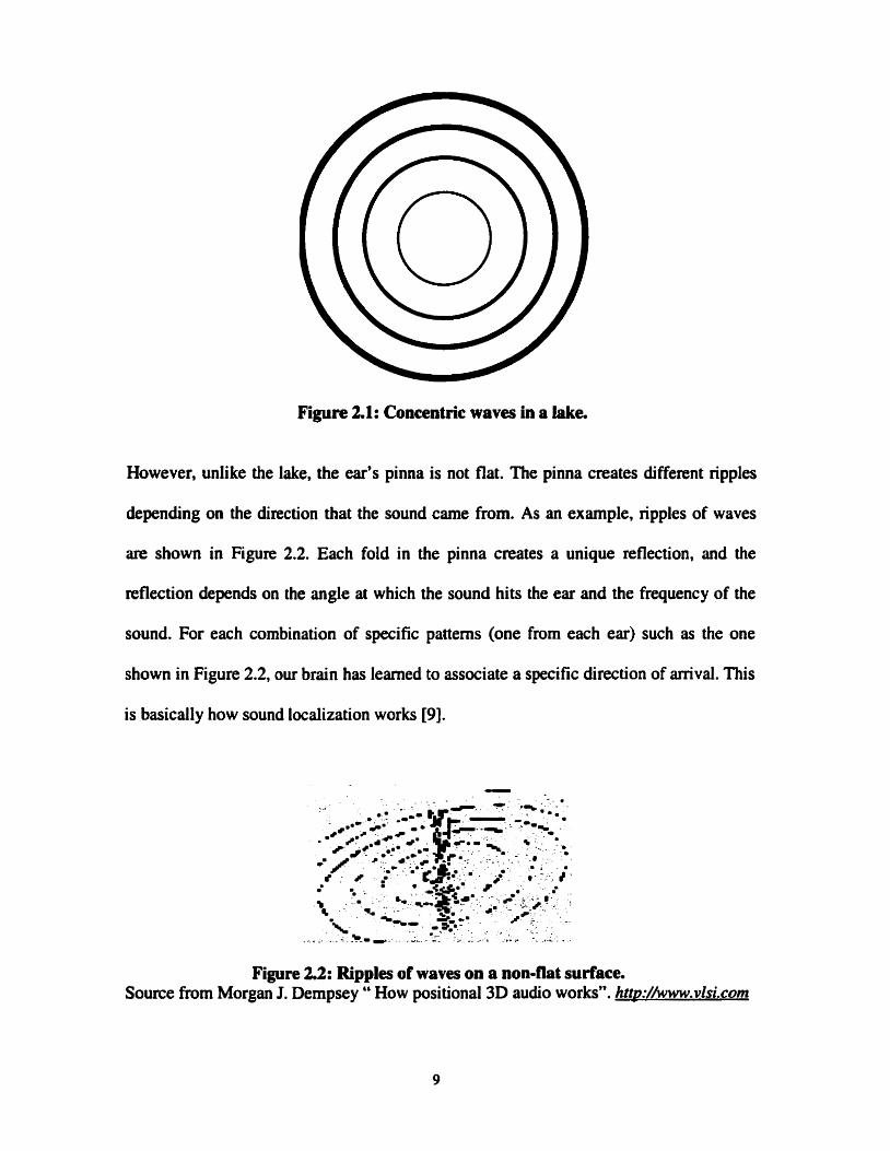
Figure 2.1: Concentric waves in a lake.
However, unlike the lake, the eu's pinna is not flat. The pinna creates different ripples
depending on the direction that the sound came from. As an exarnple, npples of waves
are shown in Figure 2.2. Each fold in the pinna creates a unique reflection, and the
reflection depends on the angle at which the sound hits the ear and the frequency of the
sound. For each combination of specific patterns (one from each ex) such as the one
shown in Figure 2.2, our brain has leamed to associate a specific direction of anival. This
is basically how sound localization works [9].
Figure 2.2: Ripples of waves on a non-flat sunace. Source h m Morgan J. Dempsey " How positional 3D audio works". httv:/~ww.vlsi.com

2.3 Physicai Variables in Acoustics
Some fundamental variables in acoustics are energy, speed of propagation and frequency.
Figure 2.3 shows a case where the source of acoustic energy is a loudspeaker. Sound
travels through the air at about 340 meters per second, and the cone of the loudspeaker
vibrates in the air causing disturbances depending on the electrical signals reaching the
loudspeaker from a sound system. Effectively, the loudspeaker converts elecüical energy
into sound energy, which travels through the air as waves radiating from the loudspeaker
r 101.
Figure 23: Loudspeaker emitting sound that travels through the air at about 340 meters per second.
Figure 2.4 shows the variations in air pressure over time, for a pure sine tone - the sound
produced by a pulsating sinusoicial source. Two main physical measurements describe
this wave: the amplitude and the period. The frequency of vibrations is equal to the
inverse of the period. The frequency simply mesures the number of waves that travel by
each unit of time. it is usually measured in hertz, 1 hertz (Hz) is 1 cycle per second. The
range of human hehng is approximately from 20 Hz to 20,000 Hz [10,11].

Pressure
f
Figure 2.4: Sine wave.
2.4 Cues of Psychoacoustics
When waves reach one of our ears, they cause the eardrum to vibrate and to transmit the
vibrations to the inner ear via the ossicles (Figure 2.5). In the inner ear a remarkable
organ called the cochlea converts these vibrations into neural (nervous) energy, for
interpretation by the higher levels of the auditory system. In the early nineteenth century,
scientists started to attempt to measure the response of subjects to sounds with controlled
physical characteristics. They determined that the perceptual attributes of loudness. pitch,
shqness, tonality, and roughness were strongly related to the physical variables of
amplitude and hquency [9,11,12].

Figure 2.5: Human ear stmcture. Source from htt~://w ww . o n l i n e . a n u . e d u . a u / r T A / A C A T / d r I
We as humans extract a lot of information that can be retrieved from sound, and to show
exactly how it is done we need to look at how sounds are perceived in the real world. To
do so it is useful to break the acoustics of the real world into three major components
[1,13]:
The first component is the sound source, which is an object in the real world that
emits sound waves such as human speech, car noise, bird songs, closing of doors
and so on. Sound waves get created through a variety of mechanical processes.
Once created, the waves usually get radiated in a certain direction. For example, a
mouth radiates more sound energy in the direction where the face is pointing than
to the side of the face.
The second component is the acoustic environment. Once a sound wave has been
emitted, it travels through an environment where several things can happen to it.
The air absorbs it. The amount of absorption depends on factors like wind and air
humidity. The sound can directly travel to a listener (direct path), bounce off of an
object twice before it reaches the listener (second order reflection path) and so on.
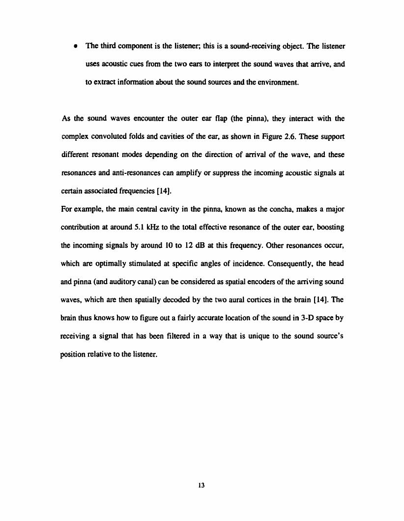
The third component is the listener. this is a sound-receiving object. The listener
uses acoustic cues from the two ears to interpret the sound waves that arrive, and
to extract information about the sound sources and the environment.
As the sound waves encounter the outer ear flap (the pinna), they interact with the
complex convoluted folds and cavities of the ear, as shown in Figure 2.6. These support
different resonant modes depending on the direction of amival of the wave, and these
resonances and anti-resonances can arnplify or suppress the incoming acoustic signals at
certain associated frequencies [14].
For example, the main centrai cavity in the pinna, known as the concha, makes a major
contribution at around 5.1 kHz to the total effective resonance of the outer ear, boosting
the incorning signals by around 10 to 12 dB at this frequency. Other resonances occur,
which are optimally stimulated at specific angles of incidence. Consequently, the head
and pinna (and auditory canal) cm be considered as spatial encoders of the aniving sound
waves, which are then spatially decoded by the two aura1 cortices in the brain [14]. The
brain thus knows how to figure out a fairly accurate location of the sound in 3-D space by
receiving a signal that has been filtered in a way that is unique to the sound source's
position relative to the listener.
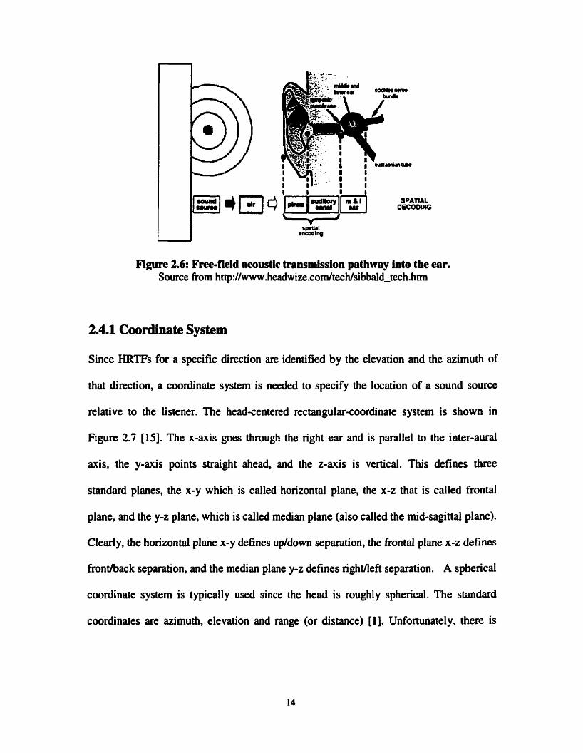
Figure 2.6: Free-field acoustic transmission pathway into the ear. Source from http://www.headwize.comltech/sibbald_tech.htm
2.4.1 Coordinate System
Since HRTFs for a specific direction are identified by the elevation and the azimuth of
that direction, a coordinate system is needed to specify the location of a sound source
relative to the lisiener. n i e head-centered rectangular-coordinate system is shown in
Figure 2.7 [15]. The x-axis goes through the right ear and is parallel to the inter-aural
axis, the y-axis points straight ahead, and the z-axis is vertical. This defines three
standard planes, the x-y which is called horizontal plane, the x-z that is called frontal
plane, and the y-z plane, which is called median plane (also called the mid-sagittal plane).
Clearly, the horizontal plane x-y defines up/down separation, the frontal plane x-z defines
frontlback separation, and the median plane y-z defines rightneft separation. A spherical
coordinate system is typically used since the head is roughly spherical. The standard
coordinates are azimuth, elevation and range (or distance) [Il. Unfortunately, there is

more than one way to define these coordinates, and different people define hem in
di fferent ways.
Figure 2*7: 3-D Planes O(, Y, 2). Source from 1996-1997 Richard O. Duda htt~://www- enm.sisu.edu/-kna~~/HCIROD3D/3D ~svch/coord.htm
The vertical-polar coordinate system (shown below on left of Figure 2.8) is the most
popular. It measures the azimuth 8 as the angle from the median plane to a vertical plane
containhg the source and the z-ais, and then measures the elevation as the angle up
from the horizontal plane. With this choice, surfaces of constant azimuth are planes
through the z-ais, and surfaces of constant elevation are cones concenvic about the z-
axis [16,17].
An important alternative is the interaural-polar coordinate system, shown below on
Figure 2.8 at the right. This measures the elevation @ as the angle from the horizontal
plane to a plane defined by the source and the x-mis, which is the interaural mis; the
azimuth 8 is then measured as the angle over from the median plane. With this choice.
surfaces of constant elevation are planes through the interaural axis, and surfaces of

constant azimuth are cones concentric with the interaurai axis. The vertical-polar system
is definitely more convenient for describing sources that are confined to the horizontal
plane, since one merely has to specify the azimuth as an angle between -180" and +L80°.
With the interad-polar systern, the azimuth is always between -90" and +9û0; and the
fmntlback distinction must be specified by the elevation, which is 0" for sources in the
front horizontal plane, and 180" (or -180") for sources in the back [17,18].
Figure 2.8: 3-D Spherid Coordinates. Source from 1996-1997 Richard O. Duda h tt~://ww w-enm.si su.edu/-kna~~/HCIROD3DlD ~ s v c hlcoord. htm
2.4.2 Horizontai Identification and Azirnuth Cues
One of the pioneers in spatial hearing research was John Stnitt, who is better known as
Lord Rayleigh. About 100 years ago, he developed his socalled Duplex Theory.
According to this theory, there are two primary cues for azimuth: Interaural Time
Diffennces (ITDs) and Interaural Intensity Differences (IIDs) [l, 191.
The first cue the brain uses to locate sounds is the time difference between the sound
reaching one ear and then the other ear. Figure 2.9 shows how the ear that receives sound

first is always closer to the source [13.16,18]. If there is a long time delay before the
sound reaches the more distant ear, then the brain infers that the sound cornes at a great
angle from this more distant ear to the sound source. It is also worth noting that if we use
an interamal-polar coordinate system and hold the azimuth constant. then we obtain a
constant value for the lTD. Thus, there is a simple one-to-one comspondence between
the ïïD and the cone of constant azimuth, which is sometimes called the "cone of
confusion" [16]. This is not the case for the vertical-polar system. where a given ITD may
correspond to different azimuths. Finally, note that the ITD alone only constrains the
source to be somewhere on the cone of confusion. In particular, it is not sufficient for
determining whether the source is in front or in back. ITD cues are thus inherently
ambiguous. For pure tones, only head movements can resolve this ambiguity. But for
complex sounds tbe effects of the pinna can resolve the ambiguity.
To distinguish a time delay between the ears, the brain must be able to discem and
identify differences between the sounds as it reaches the two ears. Human heads are
about seven inches wide at the ears. Sound travels in air at about c=340 m/s and humans
hear sounds between f = 20 and 20,000 Hz in frequency, with wavelength h being
directly related to frequency according to:
f=c/?L

' . . . .
interaurd time differena ( I ï û )
Fipre 2.9: IntemurPl Time Differences (ITDs). Source from
As shown in Figure 2.10, Lord Rayleigh had a simple explanation for the JTD [15,19].
Sound travels at a speed c of about 340 mls. Consider a sound wave from a distant source
that stnkes a spherical head of radius "a" from a direction specified by the azimuth angle
"9". Clearly, the sound arrives at the right ear before the left, since it has to travel the
extra distance a 0 +a sin0 to reach the left ear. Dividing that by the speed of sound, we
obtain the following simple and accurate formula for the interaurd time difference:
Thus, the ITD is zero when the source is directly ahead (0 = O), and is a maximum of
ko (n/2+1) when the source is off to one side (0 = 4 2 or d 2 ) . This represents a C
difference of arriva1 time of about 0.7 ms for a typical size human head.

I / Sound Sour-
Figure 2.10: Lord Rayleigh's simplified model. Source from 96-97 Richard O. Duda htt~://www-enm.sisu.edu/-kna~~/~C~~OD3D/D ~svch/azimuth .htm
Figure 2.1 1 shows that a second cue for detemiining horizontal direction is the sound
intensity. Since the head creates an audio shadow, then the sound waves that corne from
one side of the head are attenuated after passing through the head to reach the far ear.
in teraural intensity difference (1ID)
Figure 2.11: Intemural Intensity Differences (IIDs). Source from (http://www- engr.sj su.edu/-knapp/HCIROD3D/3D_psych/)

Lord Rayleigh had observed that the incident sound waves are diffracted by the head. He
actually solved the wave equation to show how a plane wave is diffracted by a rigid
sphere. His solution showed that in addition to the time difference there was also a
significant difference between the signal levels at the two ears: the Interaurd Intensity
Differences (IIDs). These JIDs are highly frequency dependent, since the diffraction by
the head varies with freqwncy. At low frequencies, where the wavelength of the sound
is long relative to the head diameter, there is hardly any difference in sound pressure at
the two ean. However, at high frequencies, where the wavelength is short, there may well
be a 20-dB or greater difference, which is called the head-shadow effect, where the far
ear is in the sound shadow of the head. Just like ITDs, IiDs cannot generally help to
distinguish whether the sound is above or below the horizontal plane of the ears, and they
can not generally help to distinguish between front and back [16,17].
2.43 Vertical Identification and Elevation Cues
The pnmary cues for azimuth are binaural (we need two ears to extract them), but the
primary cues for elevation are often said to be monaural (we can extract them with only
one ear) 1201. It stems from the fact that our outer ear or pinna acts like an acoustic
antenna. Its resonant cavities amplify some frequencies, and its geometry leads to
interference effects that attenuate other frequencies. Moreover, its frequency response is
directionally dependent. For any given angIe of elevation, some frequencies will be
enhanced, while others will be greatly reduced. The brain uses the high frequency part of
the sound spectrum to locate the vertical position of a sound source.

Figure 2.12 shows measured frequency responses for two different sound directions of
arrival [21]. In each case we see that there are two paths from the source to the ear canal,
one is the direct path and the other is a longer path following a reflection from the pinna
or concha. At moderately low frequencies, the pinna essentially collects additional sound
energy, and the signals from the two paths anive in phase. However, at high frequencies,
the delayed signal can be out of phase with the direct signal, and destructive interference
occurs. The greatest destructive interference occurs when the difference in path length d
is half a wavelength.
f = c / 2 d (2.3)
Figure 2.12:Frequency responses for two dif'ferent directions of arrival. Source from " http://wwwengr.sjsu.edu/-knapp/lE.ICIROD3D/3D~psyc~elev.htm"
In the right side of Figure 2.12, we see that a "pinna notch" occurs around 10 kHz. With
typical values for d, the notch frequency is usually in the 6-kHz to 1 6 - W range. Since
the pinna is a more effective reflector for sounds coming from the front than for sounds
coming frorn above [21,22,23], the resulting notch is much more pronounced for sources
in front than for sources above.
2.4.4 Front-Back Identification
The shape of our heads, pinna, and Our slightly forward facing ears also work as an audio
frequency filter useful for front to back identification. Frequencies between 250 and 500
H i and above 4000 Hz are relatively less intense when the source is behind us. On the
other hand, frequencies ktween 800 and 1800 Hz are relatively less intense when the
source is in front of us. Our memory of common sounds assists the brain in its frequency
evaluations [IO]. Unconsciously, we have learned the frequency spectrum content of
common sounds. When we hear a sound, we compare it to the frequency spectrum of a
reference sound in our memory. But sometimes the front or back location is still unclear.
Without thinking, people then tum their heads to aiign one ear toward the sound source
so that the sound intensity is highest in one ear [24].
2.45 Cues found and not found in Head-related Transfer Functions
We have discussed in the previous sections basic cues, which together form much of the
basics of psychoacoustics locaiization. First there are the Interaurd Time Differences
(ITDs). Secondly there are the Interaurd Intensity Differences (IIDs). Third there is the
outer eu's response, which attenuates the spectrum of an incorning sound depending on
its directions. A fourth cue can also be mentioned here: shoulder echoes. This cue can
also be used for vertical identification, and it cm actually be combined with the outer
ear's response. Since the HRTFs are by definition the transfer functions between a sound
source and the sounds received either at the entrance of the two ear canals or at the two
eardrums, these four cues are thus embedded in each individuai's HRTFs [25]. The

software system that will be developed in this thesis will be based on HRTF filtering, and
therefore the effect of these four cues will be included in the system.
However, there are some audio cues that are not included in the HRTFs. Some cues that
are not included in HRTFs are range (distance) cues and reflections (reverberation).
Range cues will be discussed first. When it cornes to localizing a source, in general we
are best at estimating azimuth, next best at estimating elevation, and worst at estimating
range or distance. in a similar fashion, the cues for azimuth are quite well understood, the
cues for elevation are less well understood, and the cues for range are least well
understood. Some of the range cues are [15,17,19]: loudness, ratio of direct to ~verberant
sound, Doppler motion effect, motion parallax, and excess interaural intensity difference.
These cues will not be discussed in this thesis, because they will not be implemented in
the 3-D audio systems to be developed.
Sound reflections are another very important effect in an acoustical environment. To a
certain extent we are able to hear the difference in time of arrival and location between
the direct path, the first order, and the n-th order reflections as shown in Figure 2.13 [13].
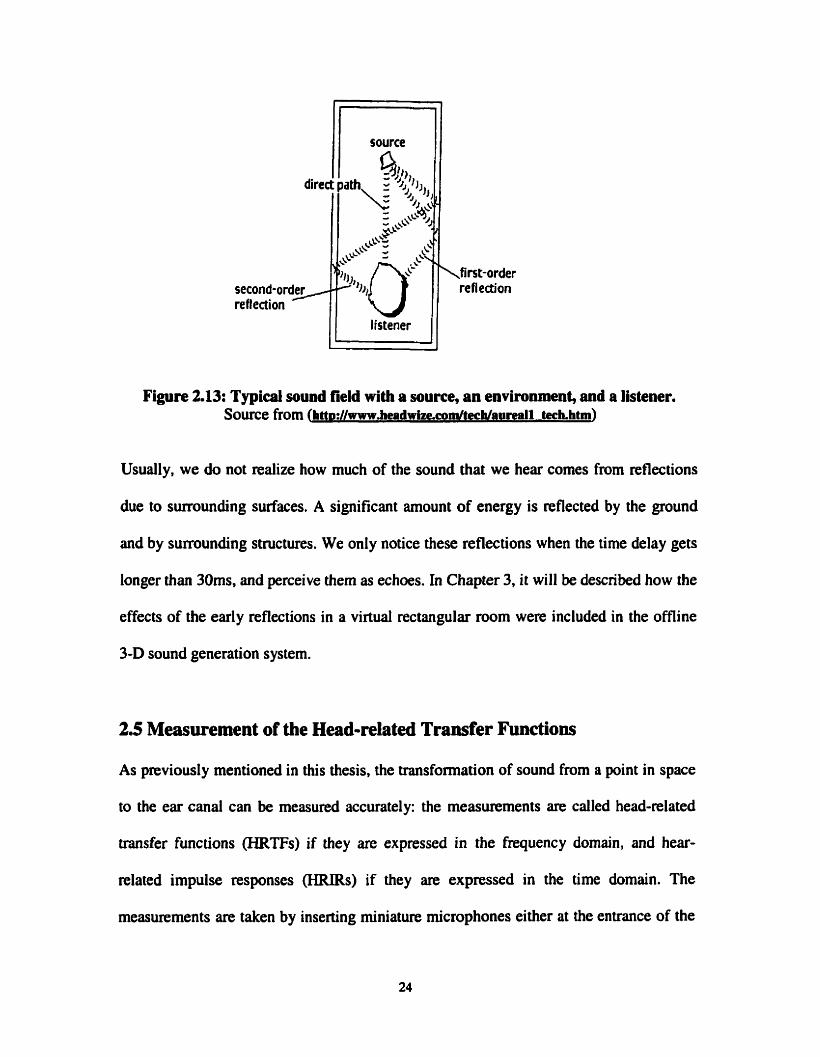
Figure 2.13: Typicai sound field with a source, an environment, and a Mener. Source from (htt~://www.headPirlze.~m/techla~reall tech.htm)
Usually, we do not realize how much of the sound that we hear cornes from reflections
due to surrounding surfaces. A significant amount of energy is reflected by the ground
and by surrounding structures. We only notice these reflections when the time delay gets
longer than 30ms, and perceive them as echoes. In Chapter 3, it will be described how the
effects of the early reflections in a virtual rectangular room were included in the offline
3-D sound generation system.
2.5 Measurement of the Head-related Transfer Functions
As previously mentioned in this thesis, the transformation of sound from a point in space
to the ear canal can bc measured accurately: the measurements are called head-related
transfer functions (HRTFs) if they are expressed in the frequency domain, and hear-
related impulse responses (HRIRs) if they are expressed in the time domain. The
measurements are taken by inserting miniature microphones either at the entrance of the

e a . canal or at the eardnrm of a human subject or a manikin [25,26]. A measurement
signal is played by a loudspeaker and the microphone signals are recorded. A computer
can then be used to derive a pair of HRTFs or HRIRs (for the left and right ears)
correspondhg to each specific sound source location, using correlation techniques. This
process is shown in Figure 2.14. The measurement procedure is repeated for many
locations of the sound source relative to the head, resulting in a database of hundreds of
HRTFs that descnbe the sound transfomation characteristics of a particular head.
dummy head wWi
Figure 2.14: Meanirement of HRTFs. Source from "http:/lww w .headwize.com/tech/gardner-tech. htm"
The WRlRs used in this thesis were measured from a KnowIes Electronic Manikin for
Acoustic Research (KEMAR). The measurements were made by a tearn at MIT, in MIT'S
anechoic chamber shown in Figure 2.15. The KEMAR is an anthropomorphic manikin
whose dimensions wen designed to equal those of a median human. The pinnas used
wen molded from human pinna. To descnbe the M ï ï measurements, the vertical-polar
coordinates system will be used. This cwrdinate system will be used in the rest of the
thesis. The sphencal space around the KEMAR was sampled at elevation from 4 0
degrees to +90 degrees (directly over head). At each elevation a full 360 degrees of

azimuth was sampled in equal shed increments. Table 2.1 shows the nurnber of sarnples
and azimuth increments at each elevation. A total of 7 10 locations were sampled [24].
Figure 2.15:Anechoic Chamber at MIT Media Lab. Source from u h n p : / / ~ ~ ~ .isvr.co.uk/faciliti/lg,anech.htm"
Table 2.1: Number of azimuthal measurements and azimuth increment at each elevation in the MIT H . database (vertical-polar coordinates). Source from
ftp://sound.media.rnit.cdulpub/Data/KEMAR/hrtfdoc.txt
Elevation (degrces)
-40
Number of AZIMUTHAL, Measuremen ts
56
Azimuth Incremen t (degrees)
6.43

Measurements at MIT were made using a Macintosh Quadra cornputer equipped with an
Audio Media II DSP card. Figure 2.16 shows al1 the components that were originally
included in the original HRlR impulse responses measured by the MIT researchers. The
recording system is consisting of 16-bit stereo DIA and A/D converters that operate at a
44.1 lrHz sarnpling rate, with anti-aliasing filters. One of the audio output channels was
sent to an amplifier, which drove a Realistic Optimus Pro 7 speaker. The KEMAR,
Knowles Electronics model DB-4004, was equipped with model DB-061 left pinna,
model DB-065 right pinna (we only used the measurements from the "small" left pinna in
this thesis), Etyrnotic ER41 microphones and Etyrnotic ER-Il preamplifiers. The
outputs of the microphone preamplifiers were connected to the stereo inputs of the Audio
Media card [24].
Ideally, HRIRs should only contain the propagation delay in the anechoic room and the
PINNA component of Figure 2.16 (which includes the pinna, the shoulders and the head
shadow effects). In particular, the effect of the ear canai should in general not be included
in the HRIRs, since there will be a physical ear canal in any playback system using
HRIRs. Including the ear canai in the HRIRs could thus lead to situations where the
effect of the ear canal appears twice in the sounds that reach the eardrums, and this may
cause distortion and a decrease of the locaiization performance of the HRIRs.
As it can be seen fkom Figure 2.16, the original measured HRIRs contain more elements
than the ideal HRIRs. In an attempt to remove the effect of the undesired elements from
the measured HRIRs, the MIT tearn has also produced a set of HRIRs called "diffuse".

They did so by averaging the HRIRs over ail spatial positions, hoping that this would
only leave the undesirable spatially-independent components in Figure 2.16, and then
they removed these components by filtering the original measurements with the inverse
response of those spatially-independent components, producing the "diffuse" set of
HRIRs. In this thesis, we will expriment with both the original HRIR measurements
(called "compact") and the "diffuse" set of HRIRs, just to see if one performs better than
the other with our setup.
Speaker 9 PINNG (pinna, shoulders, head
shadow)
1 PROPAGATION 1
Figure 2.16: HRIR Measurements.
Microphone
2.6 Synthesis of 3-D Sounds using HRTFs
The process of filtering a mono sound source with lefi and nght HRTF filters is cailed
binaurai synthesis, and this is further illustrated in Figure 2.17:

Figure 2.17: Binaural synthesis using HRTFs. Source from "http://www .headwize.com/tech/gardner-tech.htm9'
Binaural synthesis works well when the listener's own HRTFs are used to spthesize the
locaiization cues [16,20,23,24]. However, measuring HRTFs is a complicated procedure,
so 3-D audio systems typically use only a few sets of HRTFs previously measured from a
few particular human or manikin subjects.
Localization performance generally suffers when a listener listens to directional cues
synthesized from HRTFs measured from a different head [25], called non-individualized
HRTFs. This is because human heads are al1 of different sizes and shapes, and there is
also a great variation in the sizes and shapes of individual pinna. This means that every
individual has a different set of directional cues. The greatest differences are in the
amplitude and phase transformations at high frequencies caused by the pinna. It is thus
clear that we become accustorned to localizing with Our own ears, and thus Our
localization abilities will be diminished when listening through another person's eus. Our
uniqueness as individuals is the source of the greatest limitation of binaural 3-D sound
technolog y.

The use of non-individualized HRTFs produces mainly two particular kinds of
localization emrs in 3-D audio systems: fronthack confusions and elevation errors [24].
Fronthack confusion occurs when the iistener perceives the sound to be in the front when
it should be in the back, and vice-versa. When 3-D audio is reproduced over frontal
loudspeakers, back to front confusions tend to be common, which simply means that
some listeners may not be able to perceive sounds as king in the rear. In practice, this
means that when panning a sound from the front, around to the side, and to the rear, the
result will be perceived as a sound panning to the side and then back to the front.
Elevation errors are dso common with 3-D audio systems. In practice, when a sound is
moved from directly to the right to directly overhead, this may be perceived as though the
sound is moving from the nght to directly in front. This is a typical manifestation of
elevation emrs, commonly observed when using loudspeakers. Elevation performance is
much better when using headphones than when using loudspeakers because the high
frequency cues are more faithfully reproduced, but still the use of non-individualized
HRTFs will cause some elevation e m [23,24,25].
2.7 Crosstalk and HRTF adaptation
When nproducing localization cues to a listener using HRTFs, it is important that the left
and nght audio channels remain separated, that is, the left ear signal should go to the
listener's left ear only, and the right ear signal should go to the listener's right ear only.
This is easy to achieve when the listener is using headphones. When using loudspeakers,
however, there is significant "crosstaik" between each speaker and the opposite ear of the
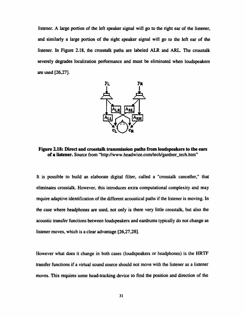
listener. A large portion of the left speaker signal will go to the right ear of the listener.
and similady a large portion of the right speaker signal will go to the left ear of the
listener. In Figure 2.18, the crosstalk paths are labeled ALR and ARL. The crosstalk
severely degrades localization performance and must be eliminated when loudspeakers
are used 126,271.
Figure 2.18: Direct and crosstalk transmission paths from loudspeakers to the ears of a listener. Source from "http:/I www.headwize.com/techlgardner~tech.htm~'
It is possible to build an elaborate digital filter. called a "crosstalk canceller," that
elirninates crosstalk. However, this introduces extra computational complexity and may
require adaptive identification of the different acoustical paths if the listener is moving. In
the case where headphones are used, not only is there very little crosstalk, but also the
acoustic transfer functions between loudspeaken and eardrums typically do not change as
listener moves, which is a clear advantage [26,27,28].
However what does it change in both cases (loudspeakers or headphones) is the HRTF
transfer functions if a virtual sound source should not move with the listener as a listener
rnoves. This requires some head-tracking device to find the position and direction of the
listener, then the elevation and azimuth of the virtud sound source location must be
computed using the listener as the origin, and finally the appropriate HRTFs must be
selected and used to filter the mono input sound source signal.
In the application developed for this thesis, it is supposed that the listener is not moving,
since it is expected that in a desktop virtuai environment the user will be in front of a
monitor and looking at the monitor. Sound sources however may be moving around the
listener. This simplification obviously eliminates the need for head-tracking devices.
Also, because it is not realistic to perform adaptive identification and compensation of
acoustic paths in real-time on a standard PC with limited computational power, this thesis
will only consider the problem of rendering 3-D sounds through headphones, where the
arnount of crosstalk is minimal.
2.8 Problematic of Headphone Playback with HRTF generated sounds
Some problems of headphone playback with HRTF generated 3-D sounds will be
addressed in this section. Ideally, the rendering of 3-D sounds generated via HRTFs or
HRIRs would be as in Figure 2.19, and individualized HRTFs would be used. As it has
been mentioned before in this thesis, using individualized HRTFs is not a realistic goal at
this point, because HRTFs require an extensive set of measurements. The ideal system of
Figure 2.19 also supposes that the HRTFs do not already include the ear canai effect, and
of course that the HRTFs do not include any component from the converters,
loudspeakers, microphones, amplifiers and filten that were used dunng the
measurements of the HRTFs.
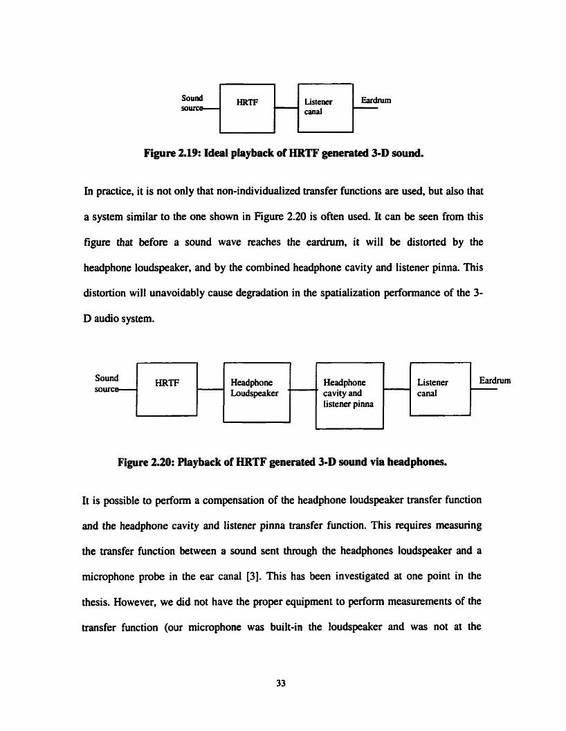
Listener :E~:I-~I*? Figure 2.19: Ideal playback of HRTF generated 3-D sound.
In practice, it is not only that non-individualized transfer functions are used, but also that
a system similar to the one shown in Figure 2.20 is often used. It can be seen from this
figure that before a sound wave reaches the eardrum, it will be distorted by the
headphone loudspeaker, and by the combined headphone cavity and listener pinna. This
distortion will unavoidably cause degradation in the spatialization performance of the 3-
D audio system.
Headphone Headphone Loudspeaker cavity and
listener pinna
Listener canal
Figure 2.20: Playback of HRTF generated 3-D sound via headphones.
It is possible to perform a compensation of the headphone loudspeaker transfer function
and the headphone cavity and listener pinna transfer function. This requires measuring
the transfer function between a sound sent through the headphones loudspeaker and a
microphone probe in the e u canal [3]. This has been investigated at one point in the
thesis. However, we did not have the proper equipment to perfonn measurements of the
transfer function (our microphone was built-in the loudspeaker and was not at the
entrance of the car canal or at the emdnun), and the results were not conclusive (Le. no
improvement during the preliminary listening tests using the compensation). Since this
was certainly not one of the main objectives of this thesis, this aspect was not
investigated further.
2.9 Chapter summary
in this chapter some fundamental aspects of sound localization theory were introduced.
The knowledge of those aspects is cntical in order to design properly a 3-D sound
system. Psychoacoustics cues were discussed, and it was mentioned which cues were
found in HRTFs and which cues were not found in HRTFs. It was also mentioned and
explained why this thesis deals only with binaurai rendering using headphones, for
listeners who do not move in a virtuai space. Some problems related to generating 3-D
sounds using HRTFs were also discussed.

Chapter 3 lmplementation of an Offline Binaural Audio
System
3.1 3-D Audio System C e n e h g Sound Fies
Now that the psychoacoustic cues found in the HRTFs have been reviewed in the
previous chapter, the design of the 3-D sound system can now be explained. It has been
stated that a goal of the thesis is to develop a system using headphones for listeners who
do not move in a vimial space. It was decided to first develop an offline (i.e. file based,
not real-time) version of the 3-D sound system. This version reads an input mono sound
file, and wntes a stereo 3-D sound file to be heard via headphones. The motivation for
this offline version is that the programming of the sound spatialization algorithm and the
real-time programming are both challenging tasks, and it is better to de-couple these two
tasks to allow better or easier debugging and performance evaluation. Therefore, the real-
time prograniming aspects are delayed until Chapter 4. Since the offline version
developed in this chapter does not have any real-time constraints, it will be possible to
introduce environmental effects such as propagation loss and reflections to the HRTF
filtering of the 3-D sound software.
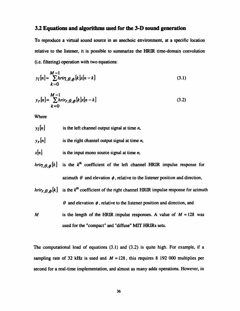
3.2 Equations and algorithms used for the 3-D sound generation
To reproduce a virtual sound source in an anechoic environment, at a specific location
relative to the listener, it is possible to surnmarize the HRIR time-domain convolution
(Le. filtering) operation with two equations:
Y I [nl is the left channel output signal at time n,
Y r [n] is the right channel output signal at time n,
hl is the input mono source signal at time n,
hn'r1,0,# k] is the kh coefficient of the left channel HRIR impulse response for
azimuth 0 and elevation # , relative to the listener position and direction,
hrirr,e,# [k] is the kh coefficient of the right channel HRIR impulse response for azirnuth
0 and elevation ) , relative to the listener position and direction, and
is the length of the HRIR impulse responses. A value of M = 128 was
used for the "compact" and "diffuse" MIT HRIRs sets.
The computational load of equations (3.1) and (3.2) is quite high. For example, if a
sarnpling rate of 32 kHz is used and M = 128, this requires 8 192 000 multiplies per
second for a mal-time implementation, and almost as many adds operations. However, in

the offline version developed in this chapter, then are no real-time constraints, and
computing (3.1) and (3.2) is therefore not a problem. Including additionai audio cues is
also possible. It was chosen to add the effect of propagation loss, propagation delay and
the effect of the early reflections in a virtual rectangular room (the choice of a virtual
rectangular room is justified later in this section).
To implement the effect of propagation loss, an inverse squared distance law was
assumed, and the resulting equation is:
Sound Intensity = Sound Intensiq ,,f ( Dist
(3.3).
w here
Sound Intensily is the sound intensity at a specified distance Dist
Sound Intensiiyref is the reference sound intensity at a specified reference distance
Distref .
To compute the propagation delay (in sarnples), the following equation is used:
Dist x Fs ~ e l w = [ j where
Fs is the sampling rate of the input and output sound files,
v s is the velocity of sound (340 meterdsecond was used), and

is the "floor" or "integer" function.
To compute the early reflections, we used the method of the "mirror sources". The idea
behind this method is that the response of a sound source in a room with wall rcfîections
cm be described equivalently by the response of a sound source in an anechoic room,
with additional sources in anechoic-mimred rooms used to produce the same waves as
the reflected waves in the original m m . Each source in the mirrored rooms must of
course have the appropriate gain and delay. This technique is fairly simple when
rectangular rooms are considered, and therefore in our application a viriual rectangular
room was chosen. The position of the sound sources in the mirrored rooms were
cornputed with the following equation [29]:
zm = n Z z , + (nz mod2)zr + (-1)"z x
Where
is the x position of the sound source in the mirrored m m ,
is the x position of the original sound source,
is the size of the original room in the x dimension,
is the order of room reflections in the x dimension used to compute a specific
mimred sound source,
is the y position of the sound source in the mimored room,
Ys is the y position of the original sound source,
Yr is the size of the original room in the y dimension,
ny is the number of room reflections in the y dimension used to compute a specific
mirrored sound source,
zm is the z position of the sound source in the mirrored rmm,
zs is the z position of the original sound source,
zr is the size of the original room in the 2 dimension, and
nz is the number of rmzn reflections in the dimension used to compute a specific
mirrored sound source, and
mod is the modulus mathematical operator.
The maximum values of nx , n y and nZ (Le. the maximum order of room reflections in
each of the different dimensions) was specified by the user as a common value
N,, y,z (= n, = n y = nz ). The distance between a sound source in a mirrored room and
the listener was simply computed by:
where:
XL is the x position of the listener,
y1 is the y position of the listener, and
zl is the z position of the listener.

The propagation delay between each sound source in a mimred room and the listener
was computed using equation (3.4). A constant frequency independent absorption
coefficient a was assumed for the reflections on the virtual walls. The value of a was
set by the user (0 5 a 11.0). With this absorption coefficient, equation (3.3) for sound
propagation loss becomes:
A L
Sound Intensiv = Sound Zntensity ref (""1 an
where n is the total number of refiections for a specific sound source in a mirrored m m
(i.e. the total number of walls that need to be crossed to reach a sound source in a
mirrored room).
With the knowledge of the sound intensity and propagation delay for each sound source
in a rnimred rwm (and for the original source), and with the knowledge of the HRIRs
associated with the direction of each sound source relative to the listener, it is then
possible to compute "equivalent" or "non-anechoic" HRIRs that will include the effects
of the early reflections [24,25]. This is done with the following equations:
N-1 hnr - eq, [ml = sn hrir,,, [m - Delay, ]
w here
Sn is the sound intensity associated with the nh mimred sound source,
D e b n is the propagation delay associated with the n'b mimred sound source,

h , is the rn& coefficient of the lefk HRIR associated with the n' mirrored
sound source,
kirr,, [m] is the m" coefficient of the right HRIR associated with the n' mimred
sound source,
hrir -eql [ml is the m" coefficient of the "equivalent" left HRIR for the original sound
source and the early reflections in the virtual rectangular room,
hrir- eq, [ml is the ni" coefficient of the "equivalent" right HRIR for the original sound
source and the early reflections in the virtual rectangular room, and
is the total number of mirrored sources. This is the prduct of the number
of room reflections in the x, y, and z dimensions.
The maximum length M' of the resulting "equivalent" HRIR is much higher than the
length M of the original anechoic HRIR:
w here
Nx,y ,~ is the maximum numbe; of room reflections in the x, y, and z dimensions
(sarne number is assumed for each dimension).
Equation (3.12) first cornputes the maximum delay (in samples) that can occur between a
sound source at the extreme corner of the furthest mirrored room and the listener, and it
adds the original HRIR length M to this delay. To see how much larger M' is compared
to M , a room of 6 by 6 by 4 meters and a sarnpling rate of 32 kHz with only 10 room
reflections in each dimension will have a resulting maximum length of M0=5425
coefficients, instead of the original M = 128 coefficients. M' is called the maximum
length because a designer may choose to truncate it to less coefficients than its total
length. The high value of M' compared to M is the reason why early reflections were
not implemented in the red-time 3-D sound system to be introduced in Chapter 4.
Removing the M and Fs ternis in (3.12) will produce an estimate of the length of the
early reverberation produced by the mimored room method. Keeping the same room
dimensions and the same number of room reflections as the previous example, we get
165 ms of early reverberation. In our application no effort was made to add the effect of
the late reverberation field, which usually requires some form of approximation due to
the computational complexity of the pmblem [Il .
3.3 Main structure of the offline 3-D sound system
The main structure of the offline 3-D sound software that was developed is shown in
Figure 3.1. Basicdly, an input mono sound file is read and the convolution of this signal
with the "equivalent" HRIRs is computed. The resulting 3-D sound signals are then
written in a stereo output sound file. Whenever the position of the sound source is
moving, new equivalent HRIRs are computed by the application.

Convolution input wave file with HTRFs in time Open and write output
source) (stereo 3D sound)
Given parameters: room dimensions, sound source position, iistener position, number of room reflections, absorption coefficient
left & right HRTF, the time delay and early reflection.
Figure 3.1: 3-D Audio system.
Since the 3-D application developed in this thesis should eventually be integrated in a
virtuai environment application, it was chosen to develop the 3-D sound processing
module as an independent DLL module that could be called by any Windowsm
application. To test the DLL module, a simple executable (.EXE) program was
developed where the following parameters were transmitted to the 3-D sound DLL: the
path of the HRIRs to be used, the name of the sound source file to be filtered, the
listener's position (x,y,z), the listener's head orientation (x,y only), the sound source
position (x,y,z), the time duration of the sound source, the wall reflectivity coefficient,
and the maximum number of room reflections in each dimension (sarne number for al1
dimensions). Note that it is assumed that the listener is looking in the (x,y) plane, but this
does not mean at al1 that sound sources have to be located in that plane. For the room
dimensions, the listener position and the sound source positions, the distances are in
meters, while seconds are used as the unit for the time duration of the sound sources.
Source code for the offiine 3-D sound software version of Chapter 3 is not included in
this thesis, since the most significant application developed in the thesis is the real-time

3-D sound generator of Chapter 4, and the source code for this application is incluckd in
the Appendix.
3.4 WAVE Files
A significant challenge in the offline 3-D sound application that was developed was the
programming of the algorithms for the generation of the 3-D sound, and this has been
described in section 3.2. Another challenge for the development of the offline 3-D sound
system was to properly read and write WAVE sound files, and this section will provide
details on this format and how we implemented the reading and writing of the sound files.
The "WAVE" File Format is a standardized file fonnat for storing digital awlio
(wavefom) data. It supports a variety of bit resolutions, sample rates, and audio
channels. This fonnat is very popular in PC platforms, and is widely used in professional
programs that process digital audio waveforms. The overall structure of the file is based
on the interchange file format (IFF). Microsoft has defined a general file format called
RIFF (Resource Interchange File Format). RIFF files are organized as a collection of
nested 4'chunks". Tags within the RIFF files identify the contents. The most common type
of RIFF files are "WAVE files (31,321, and this is the format that was used for the off-
line 3-D audio generator descri bed in this c hapter.

3.4.1 WAVE File Stmcture
A WAVE file is a parricular kind of RIFF file, and every RIFF file must begins wilh the
characters REF. in a WAVE file, there is a required Format ("fint ") chunk that contains
important parameters describing the wavefonn, such as its sampling rate. The Data
chunk, which contains the actual waveform data, is also required. Al1 other chunks are
optional. Figure 3.2 shows a graphical overview of an example, minimal WAVE file. It
consists of the RIFF header, the file size, the WAVE header, and the two required
chunks: a Format and a Data Chunk [33].
W A V E FMT CWNK DATA CHUNK I I LENGTH BYTE
Fipre 3.2: WAVE File Structure.
Most WAVE files have the same basic structure, and most prograrns treat WAVE files as
having a fixed header with the format shown in Table 3.1:
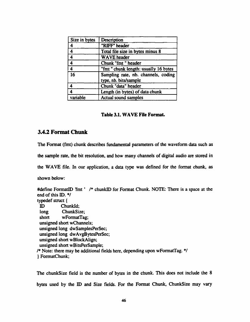
1 Size in bvtes 1 Descri~tion 1
-- - 1 variable rActual sound samples -
Table 3.1. WAVE File Format.
- --
4 4 4 4 4 16
4 4
3.4.2 Format Cbunk
- - -
"RIFF" heaâer Total file size in bytes minus 8 WAVE header Chunk "fmt " header "fmt " chunk length: usually 16 bytes Sarnpling rate. nb. channels, coding type, nb. bitdsample Chunk "&taw header LRneth (in bvtes) of data chunk
The Format (fmt) chunk describes fundamental parameters of the wavefom data such as
the sarnple rate. the bit resolution, and how many channels of digital audio are stored in
the WAVE file. In our application, a data type was defined for the format chunk, as
shown below:
#define Format0 Tmt ' 1* chunkID for Format Chunk. NOTE: There is a space at the end of this ID. */ typedef stmct ( ID Chun kId; long ChunkSize; short wFormatTag; unsigned short wlhannels; unsigned long dwSamplesPerSec; unsigned long dwAvgBytesPerSec; unsigned short wBlockAlign; unsigned short wBitsPerSample;
l* Note: there may be additional fields here, depending upon wFormatTag. */ } FormatChunk;
The chunksize field is the number of bytes in the chunk. This does not include the 8
bytes used by the ID and Size fields. For the Format Chunk, ChunkSize may Vary

according to what "format" of WAVE file is specified. The wFormatTag indicates
whether compression is used when storing the data. If compression is used wFormatTag
is equal to 1. Furthemore, compressed formats must have a Fact chunk that contains an
unsigned long indicating the size (in sample points) of the waveform after it has been
decompressed [33].
In this thesis then is no compression used, we set wFormatTag = O, then there are no
furtfier fields. The wchannels field contains the number of audio channels for the sound.
A value of 1 means rnonophonic sound, we set 2 for stereo sound. The dwSamplesPerSec
field is the sample rate at which the sound is to be played back in sample frarnes per
second (Hertz). The standard rates are 11025, 22050, 32000 and 44100 Hi. The
dwAvgBytesPerSec field indicates how many bytes are played every second.
The wBlockAlign is the size of a sample frame, in terms of bytes. A sarnple frame for a
16-bit mono wave is 2 bytes. A sample frarne for a 16-bit stereo wave is 4 bytes, etc. The
wBitsPerSample field indicates the bit resolution of a sample point, a 16-bit waveform
would have wBitsPerSample = 16. Only one Format Chunk is required in every WAVE
file.
3.43 Data Chunk
The Data (data) chunk contains the actual sample frames, al1 channels of waveform data
[33]. Below is the C++ code that was used for the data declaration structure of the data
chunk:
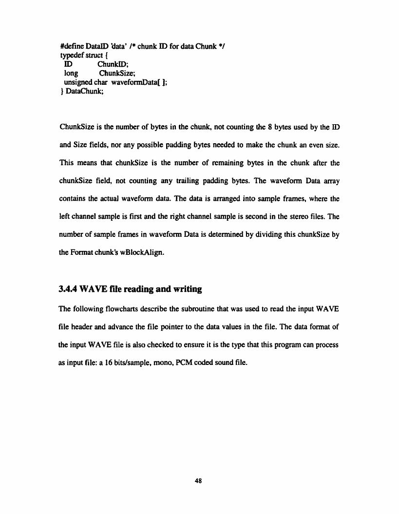
#define DataID 'data' /* chunk ID for data Chunk */ typedef stnict { ID Chunlüû; long ChunkSize; unsigned char wavefomData[];
} DataChunk;
ChunkSize is the number of bytes in the chunk, not counting the 8 bytes used by the ID
and Size fields, nor any possible padding bytes needed to make the chunk an even size.
This means that chunksize is the number of remaining bytes in the chunk after the
chunksize field, not counting any trailing padding bytes. The waveform Data anay
contains the actual waveform data. The data is arranged into sample frarnes, where the
left channel sample is first and the right channel sample is second in the stereo files. The
number of sample frames in waveform Data is determined by dividing this chunksize by
the Format chunk's wBlockAlign.
3.4.4 WAVE fde reading and writing
The following flowcharts describe the subroutine that was used to read the input WAVE
file header and advance the file pointer to the data values in the file. The data format of
the input WAVE file is also checked to ensure it is the type that this program can process
as input file: a 16 bitslsample, mono, PCM coded sound file.

Chunkld = k t 4 bytes of input file
ChunkSize = next 4 bytes of input file (size in bytes I
of the rest of the file) File is not RiFF file
1
Chunkid = next 4 bytes of input file
* TEST: IS CHUNK~D = "WAVE" ?
File is not WAVE file
EXIT
Chunkid = next 4 bytes of input file
TEST: IS CHUNKID = "FM' " ?
goto 1 f l Figure 3.3: Fiowchart of WAVE file reading, part A.

- Read "fmt * chunk size (4 bytes) - Read coding type (2 bytes) - Read nb. channels ( 2 bytes) - Read sarnpling rate (4 bytes) - Read nb. of bytesfsec (4 bytes) - Read nb. bytesisample (total of al1 channels, 2 bytes) - Read nb. bitslsample (2 bytes)
TEST: is coding type=PCM and nb. channels=l (mono) and nb. bitslsampte 4 6
Error :input file is not a 16 bit mono PCM file
EXIT
1
TEST: IS C H U N I ~ D = "DATA" ?
-- -
Chunkid = next 4 bytes of input file
I ChunkSize = next 4 bytes of input file (= size in bytes of the "DATA" chunk) 1
4
Read data values (interleaved left-right-left- right- ... if stereo)
I *
Figure 3.4: Flowchart of WAVE file reading, part B.

The information that was read from the input sound file (coding type, number of
bits/sarnple, sarnple rate, etc.) is also used to create the header for the output sound file.
The only fields that are changed are the fields related to the number of channels, which
goes h m one (mono) in the input source file to two (stereo) in the output 3-D sound file.
3.5 Listening tests using Compact and Diffuse MIT HRIR sets
Informal listening tests were performed to vaiidate the software that was developed and
to roughly evaluate the spatialization performance of the HRTF sets that were used. As
mentioned previously in the thesis, two distinct sets of HRTFs were used: the "compact"
set and the "diffuse" set from MIT'S KEMAR measurements. It should be noted that the
scftware that was developed could be used with just any set of HRTF, but those two sets
were the only ones we had available. Since Our program was not HRTF dependent, the
spatiaiization performance was not of critical importance: it would be very easy to
replace the HRTFs that we used if another set of HRTFs should provide a better
performance. The listening tests were done by the candidate and his supervisor. They
were performed using various lowtost open-type headphones, and occasionally with
closed-type headphones. It was found that the type of headphones did not have a
significant impact in Our experiments, so it was decided to use low-cost open-type
headphones, since they are cornmonly found with multimedia desktop cornputers. The
tests did not involve a detailed listening procedure, because this was clearly not a main
objective of this thesis. Such detailed procedures would involve the cornparison of the
sound position perceived by several listeners with the azimuth and elevation of the
HRIRs, for several directions and for anechoiclnon-anechoic listening environments.
The testing procedure was simply to play a 3-D sound that goes through a circular path in
a virtual rmm, and to venfy that when headphones are used with the developed 3-D
sound system, the vimial sound source seem to follow the specified path. We found no
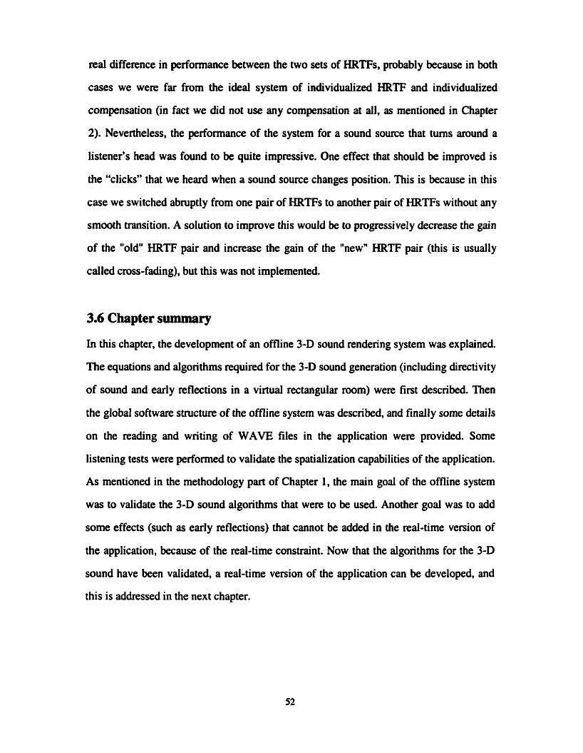
real diffennce in performance between the two sets of HRTFs, probabl y because in both
cases we were far from the ideal system of individualized HRTF and individualized
compensation (in fact we did not use any compensation at dl. as mentioned in Chapter
2). Nevertheless, the performance of the system for a sound source that turns around a
listener's head was found to be quite impressive. One effect that should be improved is
the "clicks" that we heard when a sound source changes position. This is because in this
case we switched abniptly from one pair of HRTFs to another pair of HRTFs without any
smooth transition. A solution to improve this would be to progressively decrease the gain
of the "old" HRTF pair and increase the gain of the "new" HRTF pair (this is usually
called cross-fading). but this was not implemented.
3.6 Chapter summary
In this chapter, the development of an offline 3-D sound rendering system was explained.
The equations and algorithms required for the 3-D sound generation (including directivity
of sound and early refiections in a vixtuai rectangular m m ) were first described. Then
the global software structure of the offline system was described, and finally some details
on the reading and writing of WAVE files in the application were provided. Sorne
listening tests were performed to validate the spatialization capabilities of the application.
As mentioned in the methodology part of Chapter 1, the main goal of the offline system
was to validate the 3-D sound algorithms that were to be used. Another goal was to add
some effects (such as early reflections) that cannot be added in the real-time version of
the application, because of the mal-time constraint. Now that the algorithms for the 3-D
sound have been validated a real-time version of the application can be developed. and
this is addressed in the next chapter.
Chapter 4 Real-time lmplementation
4.1 Playing sound in mal-time in a Windowsm environment
In this chapter, the developrnent of a Windows TM application to play 3-D sound on a PC
in real time is explained, using double buffering to maintain a continuous flow of sound
data. The only requirements for the developed application are a cornputer running
WindowsTM (Windows 95 and Windows 98 were tested) and a 16 bits sound board.
Windowsm support different types of multimedia &ta, for example MIDI, waveform
audio and video format. Wavefonn audio data is the type of interest in this thesis. For the
double bufiering, we basically set up two buffers and the system reads data using one
buffer at a time. While one is king played, the other one is getting filled with 3-D sound.
Intemally, Windowsm keeps a linked list of the two buffers. Whenever one of these
buffers becomes empty, it switches to the next buffer and calls a callback function to
refill the buffer that has been emptied. The system then creates a new thread for
managing the sound playback. Since a callback function is called only when the buffer is
empty, the fiat buffer needs to be output before the main loop stuts.
Audio playback is perfonned using a waveform audio output device (virtual device) or
simply, a waveOut device. This device is available from the Win32 Multimedia API
Reference. The Microsoft Multimedia API (Application Programming Interface) offea
multimedia audio services through multimedia audio functions to control different types
of wavefom audio devices. These services allow the programmer to:

Allocate, prepare and manage audio data blocks.
Open and close audio device drivers.
Query audio devices (for their capabilities) and hancile emors with multimedia a
functions.
Real time programming needs some kind of parallel processing to be computationall y
feasible. Windowsm 95/98 is a single processor operating system and thus can only
support parailelism through interleaving of processes and threads. Our application resides
entirely on one PC and therefore we need the transfer of audio buffers to be executed as
fast as possible to avoid interruption in audio playing. We used a shared-data mode1 to
perform inter-tas k communication. A shared-data mode1 favors multi-threaded
programming over multi-process programming, since tasks cornrnunicate using global
variables residing in memory shared by al1 the tasks. It also prevents copying large
arnount of data relentlessly.
4.2 System architecture
Figure 4.1 shows the inter-task communication scheme in the single process prograrn that
was developed, containing two threads, which are called Main thread and WinPlayer
thread.
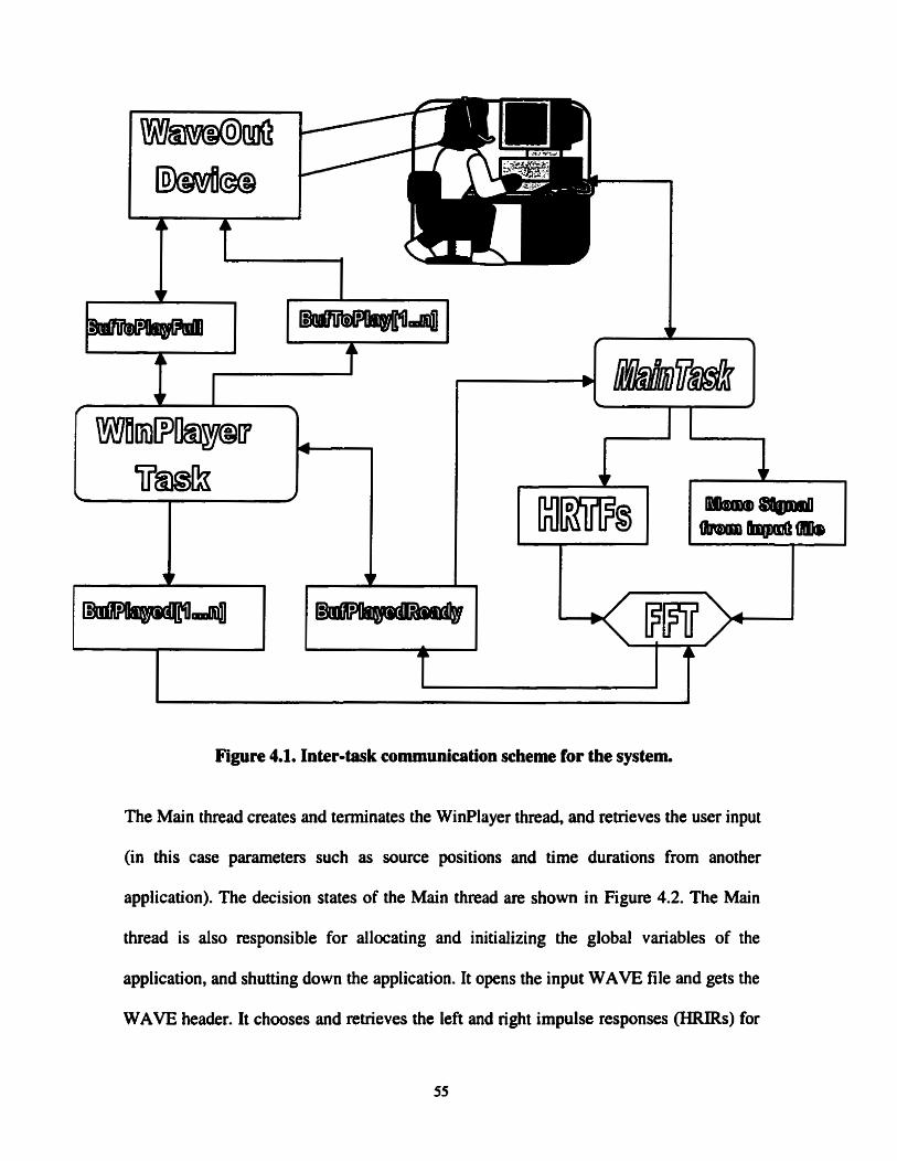
Figure 4.1. Inter-task communication scheme for the systea
The Main thread creates and terminates the WinPlayer thread, and retrieves the user input
(in this case parameters such as source positions and time durations from another
application). The decision States of the Main thread are s h o w in Figure 4.2. The Main
thread is also responsible for allocating and initializing the global variables of the
application, and shutting down the application. It opens the input WAVE file and gets the
WAVE header. It chooses and retrieves the left and right impulse responses (HRIRs) for

a given location. Finally, it filters the input wave file with the HRIRs, to produce 3-D
sound samples.
Al: a: as: m :
Figure 4.2. State Diagram of the Main Program t h d .
The WinPlayer thread creates two buffers: one for playing an audio wave and another one
for being refilled with data. Whenever the WaveOut device (see Figure 4.1) finishes
playing a buffer, it requests a new one h m the WinPlayer task, and irnmediately plays

the other buffer previously generated by the WinPlayer task. This technique is known as
double buHering. The decision states of the WinPlayer task are shown in Figure 4.3. The
WinPlayer task is responsible for generating audio samples to the BufïoPlay buffer (see
Figure 4.1) when the WaveOut device has finished to play a buffer (then BufïoPlayFull
is set to be FALSE). The WinPlayer task uses a "pauseci" variable to resurne playback
after the buffer is refilled, in case where the program is unable to provide data quickly
enough.
It is the WinPlayer task that selects an audio device. Windows supports any number of
audio devices, and selecting the right one can be tricky [32]. One way to find out the
capabilities of the device is to request the device capabilities (using the
waveOutGetDevCaps function of the Win32 Multimedia AH). The other way is by
calling the MinMaxChannels and MinMaxSamplingRate functions to determine the range
of parameters acceptable to audio objects. Figure 4.3 shows that when the
BufPlayedReady flag becomes FALSE, the WinPlayer task fills the next buffer to be
played into BufPlayed and sets the BufPlayedReady flag to TRUE, to notify the Main
task that a new buffer is ready to be played.

Figure 4 3 State Diagram of the WinPlayer thread.
4 3 First rd-tirne implementation: convolution in the time domain
With the d - t i m e structure described in the previous section, it was now possible to
integrate the 3 0 sound algorithm described by the time domain convolution equations
(3.1) and (3.2). Note that equations (3.4)-(3.11) for the computation of the early
retlections were dropped in the ml-time version, because of the length of the
"equivalent" HRIRs in this case, as explained by equation (3.12) and by an example in
Section 3.2. Most of the ha HRIRs sets were sarnpled at 44.1 kHz, except a
"diffuse32k set which was transformed from 44.1 kHz to 32 kH2. Since the
cornputaiional load of operating in real-time at 32 kHz is obviously lower than operating
at 44.1 kHz, it was chosen to use this HRIR set for the real-time implementation. Let's
recall that in the offline version of Chapter 3 we had found very littie difference (if any)
in our listening tests with the "compact" and "diffuse" HRIR sets, so a similar
performance cari be expected by using "diffuse32k".
Even with the simplification of using only equations (3.1) and (3.2), the time domain
convolution with the HRIRs produced some discontinuities in the output sound at 3 2 m .
because the application was not always capable of filling an output sound buffer while
another buffer was played. This is clearly unacceptable for a real-time 3-D sound
application. The maximum sampling rate that could be achieved without discontinuities
with this time domain convolution method was 16kHi. Note that this is of course PC
dependent, and a PentiumTM 200 MHz PC with a standard PCI 16 bits sound card was
used for those measurements.

To obtain an HRIR set that could work at 16 kHz, it is possible to down-sarnple (Le. low-
pass filter and decimate) [3 11 the HRIRs, but this would obviously reduce the bandwidth
of the hrquency response of the HRIRs to less than 8 kHz, which may eliminate some
important cues in frequencies higher than 8 W. As an alternative, it was decided to try
to modify equations (3.1) and (3.2) in order to get exactly the sarne output sarnples but
with a reduced complexity. This is desct-ibed in the next section.
4.4 Second real-time implementation: improvement of the performance
using frequency domain convolution
If the HRlRs and the input wave file signal are transformed into the frequency domain
using the Fast Fourier Transform (FET), they can simply be multiplied together and the
result inversely transformed (with an IFFT) to obtain the same spatialized time domain
output sounâs of equations (3.1) and (3.2). Even with the additional computations
involved in performing the FFîs on both the HRIR and the input wave signal and
performing the inverse FFï of their product, the total computationd load can be greatly
reduced compared to the time domain convolution method. Due to some properties of the
FFï, however, there are some slight complications when using the FFI' for the linear
convolution of two signals. The FFî method assumes that the signais are al1 periodic
with the pend king the length of the FFI' size. Thus multiplication operations of the
FFT of signals are analogous to circular convolution operations on their time domain
counterparts [34].
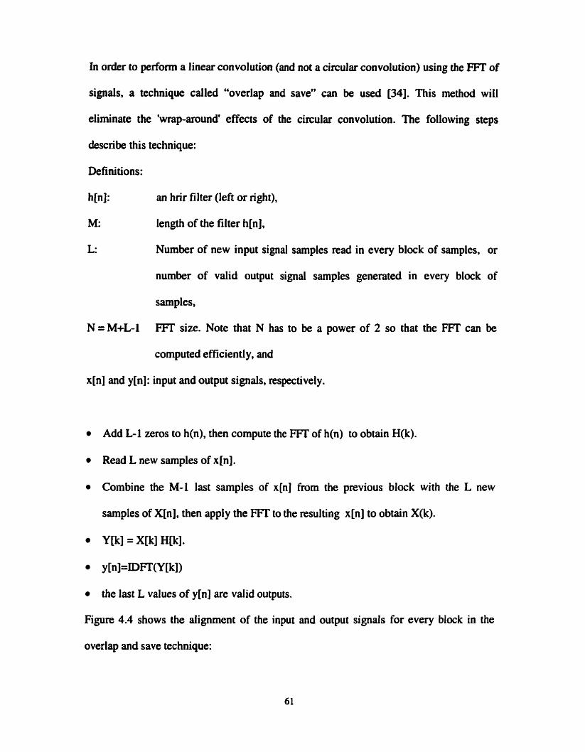
In order to perfomi a linear convolution (and not a circular convolution) using the FiT of
sipals, a technique called "overlap and save" can be used [34]. This method will
eliminate the 'wrap-around' effects of the circular convolution. The following steps
&scribe this technique:
Definitions:
h[n]: an hrir filter (left or nght),
M: length of the filter h[n],
L: Number of new input signal samples read in every block of sarnples, or
number of valid output signal samples generated in every block of
samples,
N=M+L-1 ET size. Note that N has to be a power of 2 so that the FFI' can be
computed efficiently, and
x[n] and y[n]: input and output signals, respectively.
Add L-1 zeros to h(n), then compute the FFî of h(n) to obtain H(k).
Read L new samples of x[n].
Combine the M-1 last samples of x[n] from the previous block with the L new
samples of X[n], then apply the FFI' to the resulting x[n] to obtain XR).
YB] = X[k] H[k].
y [nl=DFW[kl)
the last L values of y[n] are valid outputs.
Figure 4.4 shows the alignment of the input and output signals for every block in the
overlap and Save technique:

INPUT SIGNAL :
- L i L - L i
OUTPUT SIGNAL :
Figure 4.4. Alignment of input and output signals in the overlap and save technique.

In the frequency domain, using FFT with the overlap-save technique, the computational
cost per output sample is reduced. The number of real multiplies required per output
sample is 2 x M for the time domain linear convolution and 4 x 2 x N10g22N fmthe L
frequency domain linear convolution using overlap and Save. The factor 2 is because two
channels are computed, and the factor 4 for the frequency domain technique is because
any complex multiply requires 4 real multiplies. To illustrate this further, Table 4.1
compares for different values of M and L the number of real multiplies per output sample
required with the two methods.
M L N=L+M- 1 Multiplies/sarnple for Multiplies/sample for Time domain Linear. Freq. Domain Linear
1 Convolution Convolution using overlitp and Save
L
32 225 256 64 82.7 128 129 256 256 145. 1 32 993 1024 64 90.9 128 897 1024 256 100.7
Table 4.1. Compuîaüonal cost per output sample for time domain and freq. domain linear convolution techniques.
From Table 4.1, a few conclusions cm be found. First of dl, for low values of M (such as
32) the time domain linear convolution method requires less computations and should
therefore be used. For higher values of M (such as 128 and 512) the frequency domain
linear convolution method using overlap and Save technique requires less computations
and should be used. For a given value of M, the= is an optimum value of N (not too low,
not too high) for which the number of multiplies is rninimized. From Table 4.1, the
optimum for M=128 appears to be near N=l 024. In our application. the HRIRs also had
a length M of 128 sarnples, but a higher value than 1 024 was chosen for N. This is
because of the addi tiooal constraint that some overhead is introduced in the rd-time
application every time a switch occurs in the double buffering process. N=16 384 was
selected instead, and therefore the data block size L was 16 257 sarnples.
With the overlap and Save frequency domain technique using M=128, L-16 257 and
N=16 384, the maximum sampling rate frequency that could be achieved to play 3-D
sound audio sarnples in an unintempted fashion was 32kHz, without any discontinuity in
the output sound. This is twice as high as the maximum sampling rate that was achieved
with the time domain convolution technique, as reported in the previous section. As for
the numerical results obtain with the two techniques (when there is no discontinuity in the
output), it is a weli known fact that they both produce the sarne result since they are both
computing a linear convolution, and this was verified at the debugging stage of the
projec t.
It should be noted that the frequency domain technique would also be directly applicable
for the implementation of a 3-D sound system with reverberation, as the one described in
Section 3.2. The only difference would be that the equivalent HRIRs as computed by
quations (3.10) and (3.11) would be used instead of the anechoic HRIRs. The reduction

of computational complexity would be even greater than for anechoic HRiRs, since the
equivaient HRIRs typically have a much greater length, and the frequency domain
technique is particularly well suited for filters with long lengths, as shown by table 4.1.
The complete source code for the mal-time 3 D sound rendering system using the
freqwncy domain technique for the linear convolution is provided in the Appendices.
First, a "nadrne" text file describing the different source code files is shown in Appendix
A. Appendix B lists al1 the C++ source code for the real-time 3-D application, to be
compiled as a DLL. Appendix C shows the C t t source code of a simple application (to
be compiled as an executable) that calls the 3-D audio DLL for a specific listener
p s i tion, listener direction and sound source p s i tion.
With a real-time application now running with no discontinuity at 32 kHz, it was then
possible to use properly the "diffuse32kn ha HRIR set, and it was possible to perform
some listening tests to validate the performance of the system, as explained in the next
section.
4.5 Listening tests for the real-tirne 3-D sound application
As expected, the listening tests perfonned with the real-time implementation of the 3-D
sound soha re produced the same subjective results as those reported in section 3.5 for
the offline 3-D audio system (for the special case where no reflections were included in
the offline system). This cornes as no surprise since the "diffuse32" and "diffuse" ha
HRIR sets are basically the same up to a bandwidth of 16 kHz. Once again for a sound
source moving around the listemr's head, the listening nsults were quite redistic, at least
for the candidate and his supervisor. As explained in Section 3.5, no detailed subjective
listening tests were performed, because this was obviously not a main objective of the
project, and it is possible ai any time to replace a set of HRlR by another one if ii
performs better.
4.6 Chapter summary
In this chapter, details of the real-time implementation of a 3-D sound generation system
using binaural technology were presented. The first two sections provided details of the
multi-ha& approach that was used. The next sections described the time domain and
frequency domain techniques that were used to perform the HRIR filtering of a mono
sound source, and the performance of each technique was experimentally measured with
the maximum sampüng rate that was achieved with each technique. Finally, it was
verified that the subjective listening performance of the real-time 3-D sound system was
the same as the offline 3-D sound system described in Chapter 3, for the particular case
where no reflections were used.
Chapter 5 Conclusion and Future Work
5.1 Conclusion
In this thesis, we used the technique of binaural 3-D audio to develop a real-time
implementation of 3-D sound software. The theory of sound spatialization was first
reviewed so that it would be clear which 3-D effects could be reproduced by the system.
Then an intermediate offline version was developed, so that the algonthms could be
tested without the rd-time constraint. In the offline version it was also possible to add
some effects such as early reflections in a virtual rectangular room. Once the offline
system perfonned satisfactory it was possible to adapt it to a real-time implementation
(but without the early reflections). The initial real-time implementation used tirne-domain
convolutions to perform the HRIR filtering. It was found however that an improvement
using frequency domain linear convolution with an overlap and Save technique was
required, in order to achieve a sampling rate sufficiently high so that the application
could be directly used with a ha HRIR set.
As mentioned in this thesis, the conditions of the binaural system that we used were far
from the ideal individualized HRIRs and individualized compensation (in fact there was
no compensation at dl) . Nevertheless, the spatialization performance of the 3-D sound
system appeared to be good in some prelirninary listening tests accomplished by the
candidate and his supervisor. In any case, the developed software could easily be adapted
to use other sets of HRIRs, individualized or not, including compensation or not.


References
[l] Begault, D. R. (1994). "3-D Sound for Virtual Reaiity and Multimedia Applications".
Acadernic Press, Cambridge, MA.
[2] Kendall, G. S. (1995). "3-D sound primer: directional hearing and stereo reproduction",
Computer Music Journal. v 19 n 4. p 23-46.
[3] Moller, H. (1992). "Fundamentals of binaural technology.", Applied Acoustics. v 36 n 3-
4 p 171-218.
[4] Bauck, J., and Cooper, D. H. (1996). "Generaiized transaural stereo and applications",
Journal of the Audio Engineering Socieiy. v 44 n 9 p 683-705.
[SI Malharn, D. G. and Myatt, A. (1995). "3-D sound spatialization using ambisonic
techniques", Computer Music Journal. v 19 n 4. p 58-70.
[6] McEwan, J A . (1994). "Real-time 3-D: the sound of the times". GEC Review. v 9 n 2
1994. p 67-80.
[7] Gardner, W. G. (1997). "Head Tracked 3-D Audio Using Loudspeakers", Proc. IEEE
Workshop on Applications of Signal Rocessing to Audio and Acoustics, New Paitz, NY.
[8] Berg, R. E. and Stork D. G. (1982). "The Physics of Sound". Prentice-Hall,
Englewood Cliffs, NJ.
[9] Dempsey, MJ. (1997). "How Positional 3-D Audio Works"; VIS1 Technology.inc. White
Puper htt~://www.vlsi.com .
[IO] Sibbaid, A. (1994). "An introduction to sound and hearing. ".
"http:/h~sensauraco.u~wse/rech%2OPuge~evpcûû5.pdf ". [Il] Rigden, 1. S.(1985). "Physics and the Sound of Music" J. Wiley 2nd ed.
[12] Sibbald, A. (1995). "An introduction to Digital Earii technology". White Paper
http:/rivMv.sensaumco.u~~e/Tech%2OPage/DevpcOO3.pdf
[I3] htt~://www.headwize.com/techlaureal1 tech-htrn "3-D Audio Rimer " Aureal Corporation.
[14] Sibbald, A. (1996). "Vinual audio for headphones". Heaùwize Technicd Papers
(http://www. headwize.com/tecWsibbald~tech. hm)
[15] Wightman ,F L and Kistier D. 1. (1989). "Headphone simulation of free-field listening.
2: Psychophysical validation." Acoust. Soc. Am., 85, (2), pp. 868-878.
[16] Blauert, J. (1997). 'Spatial Hearing" 2". MIT Press, Cambridge, MA.
[17] Sibbald, A. (1994). "Virtual Eara technology".
lurp:/~.sensaura.co.u~~e/Tech%2OPag~evpcOl I.pdf.
[18] Handel, S. (1989). "A recommended introductory textbook on the psychology of
hearing; includes non-mathematical chapters on the physics of sound production,
propagation and diffraction, plus a lucid chapier on auditory neurophysiology".
Listening (MIT Press, Cambridge, MA).
[19] Duda, R. 0. (1996). "3-D Audio for HCI," in Proc. Twenty-Seventh Annual Asilomar
Conference on Signuls, Systems and Cornputen (Asilomar, CA).
[20] Brown, C. P. (1996). "Modeling the Elevation Characteristics of the Head-Related
Impulse Response," Technical Report No. 13, NSF Orant No. IRI-9402246, Dept. of
Elec. Engr., San Jose State Univ., San Jose, CA.
12 11 Han, H. L. (1994). "Measuhg a dummy head in search of pinna cues", J. Audio
Eng. Soc., Vol. 42, No. 112, pp. 15-37
[22] Raghunath Rao, K. and Jezekiel Ben-Arie (1996). "Optimal Head Related Transfer
Functions for Hearing and Monaural Localization in Elevation: A Signal Processing

Design Perspective", IEEE Tram. On Biomed Eng. Vol. 43, No. 1 1, Nov. pp. 1093
-1 104.
[23] Duda, R. 0. (1993). "Modeling head related transfer functions," in Pruc. Twenty-
Seventh Annual Asilomar conference on Signais, Systems and Cornputers.
Asilomar, CA.
1241 Gardner, W.G., and Martin, K.D.(1995). "HRTF measurements of a KEMAR , J.
Audio Eng. Soc., 43(3), pp. 3907-3908.
(251 Wenzel, E. M., Amda, M. Kistler, D. J. and Wightman, F. L. (1993). "Localization
using nonindividualized head-related transfer hinc tions", J. Acoust. Soc. Am., 94(1), pp.
11 1-123.
[26] Gardner, W .G. (1 998). '3-D Audio and Acoustic Envimment Modeling", Kluwer
Academic, Norwell, MA.
[27] Gardner, W. G. (1995). 'Transaural3-D audiott, M.I.T. Media La6 Perceptual
Compu ting Section. http://sound.media. mit.eddpupers. html.
[28] Sibbald, A.(1996) "Transaural acoustic crosstalk cancellation".
" http://kww. sensuura. CO. uWwse/Tech%2OPage/DevpdX)9.pdf~.
[29] Zudock, T. (1996) "Virtual audio through ray tracing", Dr DobbS Journal - Sofhvare
Tools for the Professional Programmer, v.2 1, n. 12, p.34, 12p.
1301 Hamrnershoi, D and Sandvad, 1. (1994). "Binaural aurdization. Simulating free field
conditions by headphones". Proc. AES, 96th Convention, Amsterdam.
[31] Gilkey, R. H., and Anderson, T. R. Ed (1997). Binaural and Spatial Hearing in Red and
Virtual Environrnents, Lawrence Erlbaum Associates, Mahwah, NJ.
[32] Kientzle, T. (1998). "A Programmer's Guide to Sound". Academic Press. Cambridge,
MA.

[33] hZt~://kww. univ-bon 1. fi/-id~~roovit;/a~foar(v~~e/k,ave.~df "wave file format
definition" Groovit.
[34] Proakis, J. D. and Manolakis, D. G. (1992). 'Digital Signai Rocessing". Principfes,
Algorithms, and Applications ", 2nd Ed. Macmillan, NY.
1351 Jorg, K. 'Direct Sound @irectX 5.0);' h~p:/h.ews64.com/nrcdirectsound.hm>l
[36] Henry A. S., and Michael F . D (1999) 'The Java 3D API and Vinual Reality," ZEEE
Cornputer Graphies and Applications, MayIJune, 1999

Appendix A "readme.txt" file
Readme file for real time 3-D audio system application
Wrinen By: Adel Senki (1646856)
Date: Jan 15,2000
It is a single-pmcess program that contain two threads:
User Interface thread:
- def.h II general application header file.
- PWCPP II main application file.
WinPlayer thread:
- auài0.h II header file for base class audioAbstract
- audi0.h II C++ file for audioh
- audiosource. h II header file for class D ynarnic AudioSource.
- audiosource.cpp Il C++ file for AudioSource.h
- winp1ayer.h Il header file for class WinPlayer, which is derived from the
Il DynarnicAudioSource class
- winplayer.cpp II C++ file for winp1ayer.h
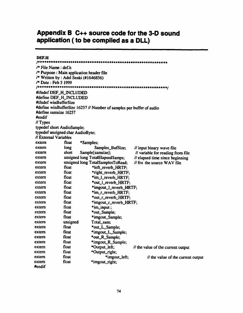
Appendix B C++ source code for the 3-0 sound application ( to be compiled as a DLL)
DEF.H /************************************************************ /* File Name : def.h /* Purpose : Main application header file /* Wntten by : Adel Senki (#1646856) /* Date : Feb 5 1999 /************************************************************/ #ifndef DEF-H-INCLUDED Mefine DEF-H-INCLUDED #ihdef winBufferSize #define winBufferSize 16257 // Number of samples per buffer of audio Mefine samsize 16257 #endif // Types typedef short Audiosample; typedef unsigned char AudioByte; // External Variables extern float *Samples; extem long Samples-BufSize; extem short Sarnple [samsize] ; extern unsigned long TotalElapsedSamps; extem unsiped long TotalSarnplesToRead; extem floa t *left,rever b-HRTF*; extem float *right,rever b-HRTF; extem float * im,l,re~erb~HRTF, extem floa t *ou t-l,re~erb~HRTF*. extem extern extem extern extem extem extem extem extem extem extem extern extem extern extern extem #endif
floa t float floa t floa t float float floa t unsigned float float fl oat float float fioat fioat float
// input binary wave file // variable for reading from file // elapsed tirne since begi~ing // fro the source WAV file
*irngout,l~everb-HRTF* * im-r-rever b'im,r,reverb_HRTF;HRTF; *ou tSout,r,reverb_HRTF;r-reverb-HRTF; *imgout-r-reverb-HRTF; *im-input ; *ou t-Sarnple; *imgout-Smple; Total-sam; *~ut~L~Sample; *imgout-L-Sample; *out-R-Sample; *irngout,R-Sample; *Output-left; // the value of the current output +Output-right;
*imgout,left; // the value of the current output *imgout-right;

/* Purpose : Main program file. The main program is responsible for ahcating and initializing the global /* variables of the application, managing al1 threads and shutting down the application. /* Written by : Adel Senki (1 646856) /******************************************************************************/
#INCLUDE "DEEH" #inchde " fourier. h" // Header files for playing audio #inchde "audio.hW #indude "winp1ayr.h" #inchde "audiosource.h" // System header files #inchde estd1ib.b #inchde 4ostream.b #inchde avind0ws.b #inchde <stdio.b #indude <conio. h> #indude etd1ib.b #inchde <math.h> // rnacro defined constants #de fine Vs 334.0 #define PI 3.14159265359 #define REFDIST 1 .O #define HRTF-LEN 128 extem FLLE *InFileflin; // input binary wave fiIe // structure for a point in 3 dimensionai space stmct point ( float X; float Y;
float 2; ); // structure for a point paired with a time duration struct position ( stnict point Coord;
float Time; ); // func t ion prototypes void CdcImpResp(float *, float *,struct point, struct point, int, struct point, char *, char *); long OpenWaveFile( FILE *, PCMWAVEFORMAT *); void InputRiffId(char *,FILE *); void AddWaveHeader( FILE *, PCMWAVEFORMAT); If structure used to pass information between threads typedef struct tagThreadInfo ( long samplingRate;
int channds; ) ThreadInfo;
// Thread handles HANDLE ghPlayTbread; D WORD d wPlayThreadID; D WORD WINAPI PlayThread(LPV0iD 1 pParm) ; extern "C" char ,export pl;iysound(char *hrtff path-char *hrtf-sub-path, char *InFileName,struct point Listener-orientation, struct point Listener,struct position CurrentSource) ( PCMWAVEFORMAT WaveHeader; // structure to hold wave header vals
float Fs; int i ; // the sampling Frequency

// open input WAVE file if ((InFileBin=fopen(InFileName,"rbn))=MJLL)
{ MessageBox(NULL,"Unable to open input wave file!", "ERROR", MB,OK~,[CONEXCLAMATION);
exit(-1) ; } Toial-sam=Samplcs-BufSiz* samsize- 1 ;
// Get WAVE header, use input header info to set Fs OpenWaveFile(InFileBin,&WaveHeader); Fs = WaveHeader. wf.nSamplesPerSec;
Il Get îhe source positions and durations TotalSarnplesToRead +=(CurrentSource.Time)*Fs; Samples-B ufSize= HRTF-LEN; if((Samp1es =(float *) mlIoc(sizeof(float)*Total,sam))=NULL)
( MessageBox(NULL,"Etror: Unable to allocate memoryl ","messagew, Ms-OKIMB-ICONEXCLAMATION);
exit(-1); } if((im-input =(float *) mailoc(sizeof(float)*T~taI~sam))=WLL)
MessageBox(NULL,"Emr: Unable to allocate memory2","message", MB-OKIMB-ICONEXCLAMATION);
exit(-1); } if((out-Sample =(float *) malloc(sizeof(float)*T~taI~sam))=NULL)
{ MessageBox(NULcL,"Error: Unable to allocate memory3","message", MB-OKIMB-ICONEXCLAMATION);
exit(-1); } if((imgout-Sample =(float *) malloç(sizeof(float)*Total-sam))=NULL) { MessageBox(NULL,"Error: Unable to allocate memory4","message",
MB-OKIMB-ICONEXCLAMATION); exit(4); }
if((1eft-reverb-HRTF =(float *) malloc(sizeof(float)*Total-sam))=NULL) { MessageBox(NUU,"Error: Unable to allocate memory5 ","messagew,
MB-OKIMB-ICONEXCLAMATION); exit(-1); )
if((right-reverb-HRTF =(float *) malloc(sizeof(float)YTotal~sam))=NULL) { MessageBox(NüLL, "Error: Unable to allocate memory6" ,"message",
MB-OKIMB-ICONEXCLAMATION); exit(-1); }
i f((im-1-reverb-HRTF =( float *) rnalloc(sizeo f( float) *To ta1-sam))=NULL) { MessageBox(NULL,"Error: Unable to allocate memory7" ."message",
MB-OKIMB-ICONEXCLAMATION); exit(4); }
if((out-l-revetb-HRTF =( float *) rnalloc(sizeo f( floût) Total-sam))=NULL) { MessageBox(NUU,"Error: Unable to allocate memory","message",
MB-OKIMB-ICONEXCLAMATION); exit(-1); }
if((imgout,l,reverb-WRTF =(fi oat *) malloc(sizeof(float)To tal-sam))=NULL) { MessageBox(NULL,"Error: Unable to allocate memory8","message",
MB-OK(~,ICOMXCLAMATION); exit(-1); }
if((im-r-reverb-HRTF =(float *) malloc(sizeof(float)*Total,sm))=NULL) { MessageBox(NUU,"Error: Unable to allocate memory9","message",
MB-OKIMs-ICONEXCLAMATION); exit(-1); }
if((out-r-reverb-HRTF =(fîoat *) rnalloc(~izeof(float)*Tota1~sam))==NULL) { MessageBox(NULL,"Emr: Unable to allocate mcmory","message",
MB-OKIMs-ICONEXCLAMATION); exit(-1); }

if((imgout-r-reverb-HRTF =(float *) malloc(sizeof(float)*Total~sam))=NULL) ( MessageBox(NüLL,"Emr: Unable to ailocate nemoryn,"message",
Ms-OKIMB-ICONEXCLAMATION); exit(-1); )
i f((imgout-L-Samplc =(float *) mdloc(sizeof(float)*To tal-sam))=NULL) ( MessageBox(NULL,"Error: Unable to allocate memory" ,"messagew,
MB-OKIMB-ICONEXCLAMATION); exit(-1); 1
if((out-L-Sarnple =(float *) malIoç(sizeof(float)YTotal,srirn))=NULL,) ( MessageBox(NüLL,"Emr: Unable to allocate memory","rnessage",
Ms-OKIMs-ICONEXCLAMATION); exit(-1); }
if((0utput-left =(float *) mailoc(sizeof(float)*Total,sam))=NULL) ( MessageBox(NITLL,"Enor: Unable to ailocate memory","message",
MB,OKIMB,ICONEXCLAMATION); exit(-1); }
if((imgout,left =(float *) malloc(sizeof(float)*Total~sam))=NITLL) { Mess;igeBox(NULL,"E~or: Unable to allocate memory","message",
MB,OK~MB,ICONEXCLAMATION); exit(-1); }
if((irngout-R-Sarnpte =(float *) mailoc(sizeof(float)*T~taI~sam))=NULL) { MessageBox(NULL,"Error: Unable to allocate rnemory","message",
MB-OKIMB-ICONEXCLAMATION); exit(-1); }
if((out-R-Sample =(float *) malloc(sizeof(float)~otal,sam))=NULL) { MessageBox(NULL, "Error: Una ble to ailocate rnemory "," message",
Ms-OKIMB-ICONEXCLAMATION); exit(-1); }
i f((0utput-right =( florit *) malloc(sizeof( float) *Total-sam))=NULL) ( MessageBox(NULL,"Error: Unable to allocate rnemory","message",
MB-OKIMB-ICONEXCLAMATION); exit(-1); }
i f((imgout-right =(float *) malIoc(sizeo f( float) *Totaltalsam))=NüLL) ( MessageBox(NULL,"Error: Unable to allocate memory"."message",
MB-OKIMB-ICONEXCLGMATION) ; exit(-1); }
for (i=0,idotal,sam;i++) Samples[i]=û.O;
im,input[i]=û.O; out,SampIe[i)=0.0; imgout-Sample[i]=O.O; im-1-reverb-HRTF[i]=O.O; im-rf reverb-HRTF[i]=û.O; out-l-reverb,mTF[i]a.O; irngout-1-reverb-HRTF[i]d.O; irngout,l_Sample[i]d.O; imgout-r-reverb-HRTF[i]=O.Q imgout-L-Sample[i]=O.O; out-L-Sample[i]=û.O; Output-left[i]=û.O; imgout-left[i]=O.O; imgout,R,Sample[i]=O.O; out,R,Sample[i]=O.O; Output-right[i]=û.O; imgout-right[i]=O.O;
1

11 calculate the response for the fmt position C a l c I m p R e s p ( 1 e f t f t t c v e r b b H R T F ~ g h t t r e v e ~ ) , Listener, Samples-B ufSize~istencr,orientati~n,hrtf-path,hrtf~sub-path); ~~float(Total,sam,O,left,feverbrbHRTF,im~l~~veh~~~,out~I~~verb~~~,imgoutrbl~reverb~~~ * fftfftfloatfl~taltalsam,O~&ttftverbrbHRTF,im~r~feverb~HRTF,~~ttrtftverbbHRTF~img~uttr~reverbbHRT FI;
ThreadInfo threadlnfo; threadInfo.~amplingRate=22050; threadInfoshannels=2; //Play // Create rhread for playing */ g_hPlayTluead = CreateThread(NULL, NUU, PlayThead, (LPVOiD)&threadInfo,
O, &dwPlayThreadID) ; if (ghPlayThread = NULL) {
cerr cc "prp.cpp: Error! creating play thread."; cerr << "GetLastEmrO: " << GetLastError() <c ".\nW;
1 if (!SetThreadPriority(&hPlayThread, THREADJMORITY-HIGHEST cen cc "ppcpp: Emr! setting play thread priority.\nW; cerr << "GetLastError(): " e< GetLastError() << ".\nW;
1 Sleep(S00 /* ms */); // Resume suspend play and record threads while ( ResumeThread(ghPlayThread) = 1 ) {
Sleep(5 /* ms *O; cen <c "Waiting for play thread to be suspended.\n";
1 cerr <c "Resumed play thread.\n"; while (1)
{ { Sleep(5 /* ms */);
I l fclose(1nFiIeB in); free(Samples) ; free(irn-input); free(out-Sample); free(imgout,Sample); free(1efi-reverb-HRTF); free(right-reverb-HRTF) ; free(i m-l-reverb-HRTF) ; free(out-1-reverb-mTF); free(imgout,l,reverb-HRTF) ; free( i m-r-reverb-HRTF) ; free(out-r-reverb-HRTF); free( i mgou t-r-reverb-HRTF) ; free(imgout-L-Sample); free(out-L-Sample); free(0utput-left); free(imgout,left); free(imgout-R-Sample) ; free(Output,right); free(imgout-right); free(out,R-Sample); return (O); 1

DWORD WïNAPI PlayThread(LPV0iD IpParm) ( Threadinfo * p'ïhreacünfo = (ThteadInfo *) IpPann;
cerr e "suspending play thread.\nM; SuspedThread(s,hflayThread); cerr « "prpcpp: Start piaying.\n"; player.Play(); cerr ce "prpcpp: Finished playing audio source.\n"; murn (O);
1
CalcImpResp This subroutine calculates the time delays (in samples) and atîenuations for the early reflections in the room. .......................................................................... void CalcimpResp(float *left,reverb,HRTF,float *right,reverb-HRTF, stnict point Source,struct point Listener, int SampIes-BufSize,
stmct point Listener-orientation, char *hrtf.ath. char *hrtf-sub-path) (
float Dist; Il distance mvelled by sound ray struct point MinSource; Il mirrored source x,y,z coords
float Gain; int i,I;
short int int-temp; float theta, phi, r, azimuth, elevation; float float-temp; float elevation,values[ 14]={ -40,-30,-20,- 10,0,1020,30,40,50,60,70,80,90} ; long azimuth-nb-of,values[l4]= (56,6O,72,72,72,72,72,6056,45,36,24,l2,1} ; float **azimuth-values,pointers; float azimuth-~alues-m40~elev[56]={0,6,13,1926,32,39,45,5 158, M,71,77,84,90,96,103,104,1 16,122,129,135,141,148,154,161,167,174,180,186, 193,199,206,2 12,219,22523 1,238,244,25 1 ,257,264,270,276,283,289,296,302,309,3 15,
32 l,328,334,34 1,347,354); float azimuth~values,m30,elev[~={0,6,12,18,24,30,36,42,48,54,60,66,72,78,84, 90,96,102,108,1 14,120,126,132,138,144,150,156,162,168,174,180,186,192, 198,204, 2 10,2 16,222,228,234340246,252,258,264,270276,282,288,294,
300,306,3 12,3 18,324,330,336,342,348,354}; float azimuth~values,m20,elev[72]=(0,5,10, 15,SO,S5,30,35,40,45,5O>S,6O,65,70, 75,80,85,90,95,100,105,1 IOJ 15*l2O,l25,l3O,l3S*l4O,l45, l5O9lS5,l6O,l65,l7O, 175,180,185,190,195 ,îûO,îOS,2 10,2 15,22O~25J3O235,24O,245 ,ZO,S5S,26O9265, 270,275,280,285,29û,î95,300,305,3 10,3 15,320,325,330,335,340,345,350,355) ; float azimuth,vdues,mlO,elev[72]=(0,5,10, 15~0,25,30,35,40,45~0~5,60,65,70, 75,80,85,90,95,100,10S,l 10,l lS,l2O,l25,l3O,l35,l~,l45,l5O*lSS,l~,l6S,l7O, l7S,l8O,l85,19O, l9~~ûû2O52 10,2 ,275,280,285,290,295,300,305,3 10,3 15,320,325,330,335,340,345,350,355); fioat mimuth-values,O,elev[72]= (05, 10,15,20,25,30,35,40,45,50~5,60,65,70, 75,80,85,90,95,100.105,1 10,l 15,120,125,130,135,140,145,150,155,160,165, 170,175, l8O,l8S,lW, l9SP2Oo,2O5 2 102 15,220,225 ,23O,23S24OJ45,25O,2S5,260,26S,27O275, 28Ol285,29û,295,300,305,3 10,3 L5,320,325,330,335,340,345,350,355 } ; float azimuth,values,lO~elev[72]=(05,10,15,20,25,30,35,40,45~0$5,60,65,70, 75,80,85,90,95,1Oo,105,110,1 lS,l2O,l25,l3O,l35,l4O1l45,l5OIlSS,l60,l6S,l7O,l75, lSO,185,19û, l9S,2oO,2O5JlO2l5,22Ot225,î3O~35~4O~45,2SO,255,2~,265,27O,
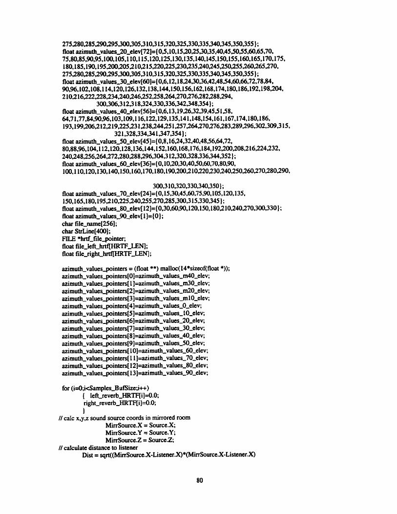
275280,2852W,295,3003053 10,3 15,320,325,330,335,340,345,350,355 } ; float azirnuth-values,20,eltv[72]= {O J, 10, lSJO~,3O,35,4O,4SJO~5,60,65,7O, 75,&0,85,90,95,100,105,110,115,120,125,130,135,1rU),145,150,155,~60,165,170,175, l8O,l85,lW,l9~,îûû2OO52 102 l5J2O225,î3O~35S4O~45~O,2SS26026S27O, 275280,î85JW,295,300,305,3 10,3 15,320,325,330,335,340,345,350,355) ; float azimuth,values,30,elev[60]=(0,6, 12, 1 8,24,30,36,42,48>4,60,M,72,78,W, 90,%,102,108,114,120,126,132,138,144,150,156,162,168,174,180,186,192,198~04, 2 10.2 l6,222228,234JN246252,2582W,270276282288,294,
300,306,3 12.3 18,324,330,336,342,348,354) ; float azimuth-~alues,40,elev[56]={0,6,13,1926,32,39,45,S L $8, a4,71,77,s4,90,96,103,109,1 16,122,129,135,141,148,154,161,167,174,180,186, 193,199,206,2 12,219,22523 1238,244,25 1,257264270276283z89,296,302,309,3 15,
32 1,328,334,M 1,347,354) ; float azimuth-values-50,elev[45]={0,8,I6,24,32~2, 80,88,%,104,112,120,128,136,144,152,160,168,176.184,192,200,208,216224~32, 240248,256,264,272,280288~96,3OQ,3 12,320,328,336,344,352) ; float azimuth-values,60,elev[36]= (0,10,20,30,4050,60,70,80,90, 100,110,120,130,140,150,160, 170,180,190,200,2 10220230,240,250,260,270,28090,
30,3 10,320,330,340,350} ; float azirnuth-values,70,elev[24]= (0,15,30,45,60,75,90,105,120,135, 150,165,180,195~10,225240~5,270,285,300,3 15,330,345); float azimuth-values,8O~elev[12]=(OI3O,60,90, 120, lS01180,2 lO*î4O,27O,3OO,33O } ; float azimuth-values,90,elev[l]=(O} ; char file,name[256] ; char StrLine[400]; FLE * hrtf'filepinter; fioat file-left-hrtfIHRTF-LENI; float file-right-mTF-LENI ;
azimuth-va azimuth-va azimuth-va azimuth-va azimuth-va azimuth-va azimuth-va azimuth-va azirnuth-va azimuth-va azimuth-va azimuth-va azi muth-va azimuth-va azimuth-va
lues-pointers lues-pointers luespinters lues-pointers lues-pointers lues-inters luespinten lues-pointers lues-pointen Iues-pointen lues-pointers iues-pointers lues-pointers lues-pointers lues-pointers
= (float **) malloc(l4*sizeof(float *)); :Oj=azimuth-values-m40-elev; : l]=azimuth-~alues~m30,elev; :2]=azimuth-~alues-~O,elev; ~3]=azimuth,values~m 10,elev; ~4]=azimuth,vaiues~0,elev; :5j=azimuth-~dues,lO,clev; :6]=azimuth~vaIues,20,elev; :7]=azimuth_values_30,elev; ~8~=azimuth~vdues,4O,clcv; :9]=azimuth-values-50,elev; lO]=sizimuth,values_60_elev;
: 1 l]=azimuth-values-70-elev; :12]=azimuth,values,80,elev; : 13]=azirnuth-values,9O_elev;
for (i=O,icSamples,B uf' ize;i++) { left-reverb-HRTFEijd.0; right-reverb-HRTF[i]=0.0; 1
// calc x,y,z sound source coords in mirrored room Miowce.X = S0urce.X; MirrS0urce.Y = Source.Y; MirrSource.2 = Source.2;
// calculate distance to listcner Dist = sqrt((MirrSourct.X-Listener.X)*(MirrSource.X-Listener.X)

+(MirrSource.Y-Listener.Y) *(MirrSource.Y-Listener.Y)+~SowceZ-Listener.Z)*~imSource.Z- Listener.2));
if(DistcREFD1ST) Dist=REm)IST;
Gain=(REFDIST/Dist) *(REm)IST/Dis t);
// compute cartesian coord relative to Iistener MirrSource.X = MirrSourceX - Listener.X; MirrS0urce.Y = Mird3ource.Y - Listener-Y; MirrSource.2 = MirrSowce.Z - Listener.2;
// compute cartesian coord relative to listener and listener orientation II theta is angle from (1,O) vector to listener orientation vector
f l o a t - t e m p = s q r t ( ( L i s t e n e r - o r i e n t a t i o n . X * l +(Listener,orientation.Y *listener-0rientath.Y));
if(float-temp!=0.0) // orientation nulle ! choisit theta=û theta= acos(Listener~orientation.X/floatttemp);
else theta= 0.0;
ifcistener-orientation.Y < 0) theta=-theta; // because theta computation is always between O and pi
/! compute the rotation float-temp=(cos(-theta)*MirrSource.X)+(-sin(-theta) *MirrSowce.Y); MirrSource.Y=(sin(-theta)*MirrSource.X)+( cos(-theta)*MhSource.Y); MinSource. X=float-temp;
// compute polar coord reiative to listener and listener orientation r=sqrt((MirrSource.X*MirrSource.X)+(MirrSource.Y *MirrSource.Y)
+(MirrSource.Z*MirrSource.Z)); if(r!=O.O) Ilcheck distance nulle, si oui phi4 choisi
phi=acos(MirrSource.Z/r); else
phi=0.0; if(MirrSource.X!=û.O) // check rizimuth nul, theta=+-PU2
theta=atan(MirrSource.Y/MirrSource.X); else
{ if(MirrSource.Y>=û.O) theta=PK?;
else theta=-Pm;
1 if(MirrSource.X<O)
theta=theta+PI;I/because theta computation is always between 90 and -90 elevation=((Pv2)-phi)/PI* 1 80.0; azimuth=(-theta)/PI* 180.0; if (azimuthd)
azimuth=azimuth+360.0;
//select appropriate HRTFs, read file II find proper elevation
float-temp= 1000.0; for(l=û;l< M;l++) { if(fabs(elevation~vaiues[l]-elevation)<fabs(float,temp-elevation))
{ float-ternp=elevation,values[l] ; int-temp=(short int)l;

II find proper azimuth value float,teniP=;o.O;
for(l*l<azimuth_nb-of- values[int~emp];l++) (if(fabs(azimuth,values~~inters[int-temp ][Il-azimuth)dabs(float-ternp-azimuth))
float~kmp=azimuth_vdues_poin~fs[iat,temp][1]; 1 if(fabs(360.0-azimuth)<fabs(float,tempazimuth))
float-tempr0.0; azimuth=float,tcmp;
// read hrtf tiom file i f(azimuth<= 180.0)
( if(strcmp("diffuse32 k",hrtf,sub_path)=O) spfintf(file,name,1'%s\\%s\klev%d\W%de%O3da.res11, hrtf-paîh,hrtf,sub-path,(int)elevation,(int)elevation, (int)azimuth);
e k sprintf(file,name,"%s\\%s\\elev%d\\H%de%O3da.dat", hrtf-path,hrtf~sub~ath,(int)elevation,(int)elevation, (int)azimuth);
if ((hrtf,frle_pointe~fopen(file-nme,"rbW))=NULL) ( sprintf(StrLine,"Unable to open hrtf file : %sl',file,name);
MessageBox(NüLL,StrLine,'*message", MB-OKIMB- CONE EXCLAMATION);
exit(-1); 1
for(l=û;l<HRTFTFLEN;I++) { fread(&int,temp,sizeof(short int), l ,hrtf- file-pointer);
int-temp=((int-temp»8)&Ox00FF)~(intItem~~8); file-left-hrtfll] =((float)int,temp)/32768.0; fread(&int-temp,sizeof(short int), 1 ,hrtf-file-pointer);
int,temp=((int~temp>>8)&0x00FF)~(intIt~mpc~8); file~ight~hrtfT1]=((float)int,temp)/32768.0;
if(feof(hrtf-fileminter) !=O) while(I<HRTFTFLEN)
{ file-left-hrtfll]=O.O; file-right,hrtf[l]=û.O;
l u ; 1
break; 1
1 fclose(hrtf-filesinter);
1 else ( azimuth=360.0-azimuth;
if(strcmp("diffuse32k,hrtf~sub~ath)==O) sprintf(fi1e-name,"%s\\%s\\elev%d\W9s" , hrtf-path,hrtf,sub-path,(int)elevation,(int)elevation, (int)azimuth);
else sprintf(file,name,"%s\\%s\klev%d\~H9bde%O3da.dat", hrtf-path,hrtf,sub-path,(int)elevation,(int)elevation, (int)azimuth);
if ((hrtf,filepinter=fopen(file,nani~,"rb"))=NULL) { sprintf(StrLine,"Unable to open hrtf file : %sl*,file-name);

MessageBox(NULL,SttLine,"message", MB-OKW-ICONEXCL AMATION) ;
exit(4); 1
for(l=û;leHRTF-LEN;I++) { fread(&int,temp,sizeof(short int), l,M-filegointer);
int,temp=((int,temp>>8)&OxOO~l(int-&mp<<8); file-right-~I]=((float)int,temp)/32768.0; fiead(&int-temp,sizeof(short int),l,hrtf-filepinter);
int~emp=((int-temp»8)&OxûûFF)~(int~tern~<<8); file-left-hrtnl] =((float)int-temp)l32768.0;
if(feof(hrtf-filegointer) !=O) { while(l<HRTF-EN)
{ file-right-hrtr[l]=û.û; file,ieftfthrtfll]=O.O;
I++; 1
break; 1
1 fclose(hrtf-filesinter);
1
//contribution to hrtf-eq left and right for(l=O,I<HRTE:-LEN;I++)
( lef~reverb-HRTF[i]+=(file,lefi-hrtfIl] *Gain); ~@t,re~erb,HRTF[l]+=(fiIe~~ght-~l ]*Gain);
1
This subroutine is responsible for reading in the WAVE file header from the input file and advancing the file pointer to the data chunk in the WAVE file. The data format of the input WAVE file is also checked to ensure it is a type that this program can proçess (16 bit mono KM). ***********************************************************************/ long OpenWaveFile( FlLE *InFiteBin, PCMWAVEFORMAT *WaveHeader) {
char ChunkId[S] ; long ChunkSize; InputRiffid( Chunkld, InFileBin); if (strcmp(ChunkId,"RIFF")!=O) { MessageBox(NULL,"Error: File is not a RIFF file","message", MB-OKIMB-ICONEXCLAMATION);
exit(- 1); 1 fread(&ChunkSize,sizeof(ChunkSize), 1,InFileBin); InputRiffId( ChunkId, InFileBin); if (strcmp(ChunkId," WAVE)!=O) ( MessageBox(NULt,"Error: File is not a WAVE fiIe","message", MB-OKIMB-ICONEXCLAMATION);

exit(- 1); 1 InputRiffid( ChunkId. InFileBin); if (strcmp(ChunkId,"fmt ")!=O) {
MessageBox(NüLL,"Emr: Unable to find fmt chunk."message", MB~OK~~ICONEXCLAMATION);
exit(-1);
fread(&ChunkSize,sizeof(ChunkSize), 1,InFileBin); hd(WaveHeader,sizeof( *WaveHeader), 1 JnFileB in); InputRiffId( Chunkid, InFileBin); if ( ((* WaveHeader). wf. w FormatTag != 1) 1
((*WaveHeader).wf.nChannels != 1) 1 ((*WaveHeader).wB itsPerSample != 16)
1 { MessageBox(NUU,"Error: Input file must be a 16 bit mono PCM file".
MB-OKIMB-ICONEXCL AM ATION); exit(- 1);
1 if (strcmp(ChunkId,"dat;i")!=O)
{ MessageBox(NULL,"Error: Unable to find data chunk, "message", MB-OKIMBJCONEXCLGMATIOW;
exit(- 1); 1
fiead(&ChunkSize,sizeof(ChunkS ize), 1 JnFileBin); return(ChunkSize);
1
This subroutine copies the riff chunk id into a character array. ***********************************************************************/ void Inpu&Riffid( char * Chunkid, FILE * InFileBin) { int i;
for ( i d ; i<4; i++) fread((ChunkId+i),sizeo f(c har), 1 JnFileB in);
*(ChunkId+4) = IO'; )
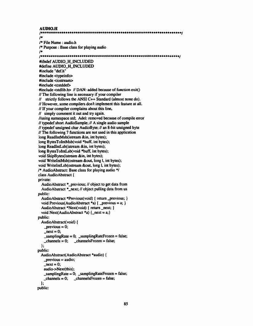
AUDI0.H /*********************************************************************/ /* /* File Name : audi0.h /* Purpose : Base class for playing audio I* ...................................................................... #ifndef AUDIO-H-NCLUDED #define AüDIO-H-INCLUDED #inchde "def.hW #inchde aypeinfo> #inclde <iostream> #include <cstddet) #inchde estd1ib.b // DAN: added because of function exit() // The following line is necessary if your compiler // strictly follows the ANS1 C++ Standard (almost none do). // However, some compilers dont implement this feature at all. // If your compiler cornplains about this line, // simply comment it out and try again. //using namespace std; Adel: removed because of compile error // typedef short AudioSample; // A single audio sample // typedef unsigned char AudioByte; // an 8-bit unsigned byte // The following 7 functions are not used in this application long ReadIntMsb(istream &in, int bytes); long B ytesToIntMsb(void *buK int bytes); long ReadIntLsb(istream &in, int bytes); long BytesToIntLsb(void *buff, int bytes); void SkipBytes(istream &in, int bytes); void WriteIntMsb(ostream &out, long 1, int bytes); void WriteIntLs b(ostream &out, long 1, int bytes); /* AudioAbstract: Base class for playing audio */ class AudioAbstract ( private:
AudioAbstract *-previous; // object to get data from AudioAbstract *,next; // object pulling data from us
public: AudioAbstract *Previous(void) ( return jrevious; } void Previous(AudioAbstr;ict *a) [ grevious = a; ) AudioAbstract *Next(void) ( r e m ,next; ) void Next(Audi0Abstract *a) {,next = a;)
public: Audio Abs trac t(void) (
jrevious = O; ,next = 0; -samplingRate = O; -samplingRateFrozen = false; ,channels = O; -channelsFrozen = false;
1; public: AudioAbstract(AudioAbstract *audio) {
jrevious = audio; ,next = 0; audio->Next(this); ,samplingRate = O; ,samplingRateFrozen = false; -channels = O; ,channelsFrozen = false;
}; public:
virtual -AudioAbsfract(void) ( } ; public: // Retums number of samples actually read, O on error. // This should always retum the full request unless there is // an e m r or end-of-data. virtual size-t GetSamples(AudioSamp1e *, size-t) = 0;
public: virtual s k t ReadBytes(AudioByte * buff, size-t length) (
return Previouso->ReadBytes(buff,length); 1;
private: long -samplingRate; bool ,samplingRateFrozen;
public: virtual long SamplingRate(void) (
cerr << "audi0.h: SamplingRate(void)\n"; if ( !,sarnplingRateFrozen) // Not fiozen?
cerr cc "audi0.h: Nego tiate!3amplingRateO\n"; NegotiateSamplingRateO; // Go figure i t out
r e m ,samplingRate; // Return it 1; virnial void SamplingRate(1ong s) ( // Set the sampling rate
cerr c< "audi0.h: SamplingRate(long s) with s = " « s « "\n"; if (-sarnplingRateFrozen) (
cerr << "Cant change sampling rate.\nn; exit(1);
1 ,sampiingRate = s;
1; public:
virtual void NegotiateSamplingRate(void); public:
virtual void MinMaxSamplingRate(1ong *min, long *max, long *prefer); virtual void SetSamplingRateRecursive(long s);
pnvate: long ,channels; bool ,channelsFrozen;
public: virtual int Channels(void) (
if ( !,channelsFrozen) Nego tiateChannels0; return ,channels;
1; virtual void Channels(int ch) (
if (-channelsFrozen) ( cerr <c "Cant change number of channels.\nW; exit(1);
1 -channels = ch;
1; virtual void NegotiateChannels(void); virtual void MinMaxChannels(int *min, int *ma, int *preferred) ; virtual void SetChannelsRecursive(int s);
1; #endif

/* Copyright 1997 Tim Kientzle. Al1 rights reserved.
Redistribution and use in source and binary forms, with or without modification, are permitted provided that the following conditions are met:
1. Redistributions of source code mut reâain the above copyright notice, this list of conditions and the following disclaimer. 2. Redistributions in binary form must reproduce the above copyright notice. this list of conditions and the following disclaimer in the documentation andfor other materials provided with the distribution. 3. Ail advertising materials mentioning features or use of this software must display the following acknowledgement: This product includes software developed by Tim Kientzle and published in "The Programmer's Guide to Sound." 4. Neither the names of Tirn Kientzle nor Addison-Wesley may be used to endorse or promote products derived from this software without specific prior written permission.
THIS SOFTWARE IS PROVIDED "AS 1s" AND ANY EXPRESS OR IMPLIED WARRANTES, INCLUDING, BUT NOT LIMITED TO, THE IMPLED WARRANTES OF MERCHANTABLITY AND FITNESS FOR A PARTICULAR PURPOSE ARE DISCLAIMED. IN NO EVENT SHALL TIM KIENTZLE OR ADDISON-WESLEY BE LIABLE FOR ANY DIRECT, INDIRECT, INCIDENTAL, SPECIAL, EXEMPLARY, OR CONSEQUENTIAL DAMAGES (INCLUDING, BUT NOT LfMlTED TO. PROCUREMENT OF SUBSTlTülE GOODS OR SERVICES; LOSS OF USE, DATA, OR PROFITS; OR BUSINESS INTERRUPTION) HOWEVER CAUSED AND ON ANY THEORY OF LIABILITY, TKHETHER iN CONTRACT, STRICT LiABILiTY, OR TORT (ZNCLUDING NEGLIGENCE OR OTHERWISE) ARISING IN ANY WAY OUT OF THE USE OF THIS SOFTWARE, EVEN IF ADVISED OF THE POSSIBILITY OF SUCH DAMAGE. */ /*********************************************************************/ /* /* FILE NAME : AUDIO-CPP /* /* Purpose : Definitions for AudioAbstract class. Complements audi0.h /* /* Comments added by : Adel Senki (1646856) /* /* Date : Dec 15, 1999 /* /********************************************************************/ #inchde "audio.hW
void Audio Abstract ::NegotiateSamplingRate(void) { if (Next()) // Are we the leftmost? NextO->NegotiateSamplingRate(); Il No, keep goin
else ( // Yes, we are long min = 8000, max = 44100, preferred = 44100, MinMaxSamplingRate(&min,&max,&preferred); // Get prefemed values if (min > rnax) ( Il Check for rediculous answers
cerr cc "Couldnt negotiate sampling rate.liW ; exit(1);
1 SetSamplingRateRecursive(prefened); // Set them everywhere

void AudioAbstract::MinMaxSamplingRate(long *min, long *max, long *preferred) {
if (PreviousO) ReviousO->MinMaxSamplingRate(minpmax,prefed); if CsamptingRate) *prefened = ,samplingRate; if (*prefened < *min) *preferred = *min; if (vrefened > *max) *preferred = *mm;
1
void AudioAbstract::SetSamplingRateRccusive(Iong s) ( if (PreviousO) // Set towards the right first PreviousO->SetSamplingRateRtcwsive(s);
SamplingRate(s); Il Set it -sarnplingRateFrozen = tnie; // Yes, we've negotiated
1 void AudioAbstract::NegotiateChannels(void) (
if (NextO) Nextu->NegotiateChannelsO;
else ( int min=l, max=2, preferred=l ; // Some reasonable default MinMaxChannels(&min,&max,&preferred); if (min > max) (
cerr ce "Couldni negotiate sampling rate.\nW ; exit(1);
1 SetChannelsRecursive(preferred);
1 1
void AudioAbstract::MinMaxChanneis(int *min, int * m a , int *preferred) { if (Previouso) Previous()->MinMaxChannels(min,max,preferred); if Cchannels) *preferred = -channels; if (*preferred < *min) *preferred = *min; if (*preferreâ > *max) *preferred = *mm;
1
void AudioAbstract::SetChannelsRecmive(int ch) { if (Previouso) PreviousO->SetChannelsRecursive(ch); Channels(ch); ,channelsFrozen = true;
1
long ReadIntMsb(istrearn &in, int size) ( if (size <= O) return O; long I = ReadIntMsb(in,size-1) 8; I + static-cast<long>(in.getO) & 255; return 1;
1
long BytesToIntMsb(void *vBuff, int size) ( unsigneci char *buff = reinterpet-castansigned char *>(vBuff); if (size <= O) return O; long I = BytesToIntMsb(buff,size-1) cc 8; 1 static-cast<long>(buff[size-11) & 255; retum 1;
1

long RcadInîLsb(istrcam &in, int size) { if (sue <= 0) retum 0; long 1 = static,cast<long>(in.get()) & 255; 1 ReadlntLsb(in,size- 1)«8; r e m 1;
1
long BytesToIntLsb(void *vBuff, int size) { unsignai char *buff = reinterprtt-cast<unsigneâ char *>(vBuf?); if (size <= 0) retun 0; long I = static-cat<long>(*buff) & 255; 1 BytesTolncLsb(buff+l ,size- 1)«8; return 1;
1
void SkipBytes(istream &in, int size) ( while (size- > 0)
in.get0 ; 1 void WriteIntMsb(ostream &out, long 1, int size) (
if (size <= 0) return; WriteIntMsb(out, b 8 , size-1); // Write MS Bytes 11 Adel: changed following line h m out.put(l&2!55) out.put(static,cast<chan(I8i255)); Il Write LS Byte
1
void WriteIntLsb(ostream &out, long 1, int size) { if (size <= 0) retwn; Il Adel: changed following iine h m out.put(lBt255) ou~put(static,cast<char>(lBt255)); // Write LS Byte WriteIntLsb(out, 1»8, size-1); // Write rest }

/******************************************************************************/ /* File Name : audiosourcc.h /* hirpose : Dedaration of DynamicAudioSource class for generating audio /* samplcs. This class is a derived class of the AudioAbstract class /* fiom audi0.h /* Written by : Adel Senki (1646856) /* Date : May 25,1999 /******************************************************************************/ #ifndef AUDIOSOüRCECEHHINCLüDED # D m AUDIOSOURCECEHHTNCLUDED #inchde "audio.hW #inchde eiostream. h> #inchde <stdlib.h> #ihdef S AMPLE 16-D-D Mefine SAMPLE 16-DEFINED typedef short Sample 16; #endif // Derive- class of AudioAbstract class class DynamicAudioSource: public AudioAbsîract { protected:
long GenWaveOutSamples(Samplel6 * p h t , long destSize); bool ,endOfSource; // me -> last data read from source
private: int j,i,int,temp;
// Total number of audio samples kept for processing //volatile unsigned long -samplesKept; size-t GetSmples(AudioSample * buffer, size-t numSamples) (
cerr << "audiosource.h: Error! Not supposed to cal1 GetSamples() here.\nU; exit(1); r e m (O);
1; // ReadBytes: not used (ignore) size-t ReadBytes(Audioi3yte buffer, size-t numsamples) {
cerr « "audiosource.h: Error! Not supposed to cal1 ReadBytes() here.\nn; exit(1); r e m (O);
1; public: DynamicAudioSource(long samplingRate) : AudioAbstract() (
,endOfSource = false;
-DynamicAudioSource() { } ; virtual void Play() = 0;
1; kndif

/******************************************************************************/ /* /* File Name : audiosource.cpp /* /* Purpose : Definitions for DynanicAudioSource class. Complements /* audiosourceh /* To change the type of audio samples to be generate (Le., /* sinusoidal samples or white noise samples), sirnply comment out the /* GenWaveOutSamples functions (need two functions in each case; one /* for Sample16 and one for Sample8) that you do not want to use and /* comment in the GenWaveOutSamples functions to be used. Currently, /* the functions for generating sinusoidd samples are in effect /* (cornmented out.) /* /* Written by : Adel Senki (1646856) /* /* Date : May 25,1999 /* /******************************************************************************/
unsigned long TotalElap~edSarnp~; unsigneû long TotaiSamplesToRead=û; FILE *InFileBin;
// elapsed time since beginning
float float float float float float float float float float float long short float float float float float unsigned float float float float
*leftnvnb-~F&l'~; *im-1-reverb-HRTF; *out-l-reverb-HRTF, *imgout-1-reverb-HRTF-, *right-reverb-HRTF; * im-r-reverb-HRTF*, *outrreverb-WRTF, *img~ut,r~reverb~HRTF; *im-input ; *out-Sample; *imgout-Sample;
Samples-BufSize; Sample[samsize]; *Samples; *out-L-Sample; *imgout,L,Sample; *out-Ft-Sample; *imgout-R-Sample;
Total-sam; *Output,left; // the value of the current output *Output-right; *imgout-left; // the value of the current output
*imgout,right;
// variable for reading from file
long DynarnicAudioSource::GenWaveOutSarnples(SampleI6 * p k t , long destSize) (
// over lap for (long i=0; i<(Samples-ButSize-1); i++)
( out~L~Sample[i]~ut~LLSampIe[(Totdtatsam-Samp1esesBufSize-l)] ; out~-Samp~e[i]=out,R,Sample[(To~-samSamples,BufSize- l)];
Total-sam++; } II read input fiead(Bt(Smple[Samples,BufSize]),sizeof(long),destSizeJnFile~in);
for (long i d ; i<Sampfes,BufSize; i++) Samples[i]=(float)Sample[i] ;
for (long id; i4ïoiol-sarn; i++) (Output-left[i]=(out,Sample[i] *~ut~l~reverb~HRTF[i~)-
(imgout-Sample[i] *imgout-1-reverb-HRTF[i]); Output-right[i]=(out-Sample[i3 *out-r-reverb-HRTF[i])-
(imgout-Sample[i J *imgout,r,reverb-HRTF[i]); imgout~left[i]=(imgout,Sample[i]*imgou~l,reverb,HRTF[i 1)-
(imgout-Sampfe[i] *out-1-reverb-HRTF[i]); imgout,right[i]=(imgout,Sample[i] *imgout-r-reverb-HRTF[i j)-
(imgout-Sample[i] *out-r-reverb-HRTF[i]); 1
fft-float(Total-sam, 1 ,Output,left,imgout-left ,out-L-Sample,imgout-L-Sample); fft-float(Total-sam, 1 ,Output-righ t,imgout-right ,out~R~Sample,imgout_R,Sample); for (long i=Samples-BufSize; kdesfiize; i++) {
pDest[2*i] = static-cast <Sample 16>(out-L,Sample[2*i] ); pDest[2*i+i ] = static-cast <SmpleI6>(out-R-Sample[2*i+l]);
1 Tot;ilElapsedSampse=destSize; return destSize;
1

/*+****************************************************************************/ /* File Name : winp1ayr.h /* Purpose : Definitions of class WinPlayer for playing audio. This class is a /* derived class h m the DynamicAudioSource class, which in turn is /* derived fiom the AudioAbstract class. /* Comments added by : Adel Senki (#1646856) /* Date : January 5,2000 /******************************************************************************/ //* Player class for playing audio using Win32 MAPIs # ~ E F WIN-PLAYER-H-INCLUDED #define WIN-PLAYERYERHHiNCLUDED #include "def.hW #inchde "audio.hU #inchde "audiosource. hW #inchde <windows.h> #include unmsystem.h> extern AudioSample * pBufPlayed; extem bool DSPReady-PlayedBufferSaved; extern bool DSPReady; // Derived class of D ynamic AudioSource class 11 (and hence of AudioAbstract class a h ) class WinPlayer : public DynamicAudioSource ( private:
unsigned long ,buffer,ID, unsigned long ,samplesGenerated; HWAVEOUT device; // Windows audio device to open volatile bool // mie -> device is paused int ,sarnpleWidth; // width of data to output int SelectDevice(void); // Open a suitable Waveûut device /* Callback function called by WaveOut device when it finishes playing a buffer */ // Allow the callback to see our members friend void CALLB ACK WaveOutCallbac k(HWAVE0UT h wo, UINT uMsg,
DWORD dwlnstance, DWORD dwParam1, DWORD dwParam2); // The callback function defined above is just a wrapper that // invokes this method void NextBuff(WAVEHDR *);
public: WinPlayer(1ong samplingRate.int channels)://. float fSource) : DynamicAudioSource(samplingRate) (//, fSource) { this->SamplingRate(sarnplingRate);
// this->channels(channels); ~ b u f f e r ~ ~ ;
,samplesûenerated = 0; -device = 0; j aused = m e ; ,sampleWidth = 0;
1; -WinPlayer() ( ); void Play(); // Actually play audio
1; #endif

/* Copyright 1997 Tim Kientzle. AI1 rights rcsemed.
Redistribution and use in source and binary fonns, with or without modification, are permitteci provided that the following conditions aremet:
1. Redistributions of source code must tetain the above copyright notice, this list of conditions and the foliowing disclaimer. 2. Redistributions in binary fom must reproduce the above copyright notice, this Iist of conditions and the following disclaimer in the documentation andior other materials provided with the distribution. 3. Al1 advertising materials mentioning features or use of this software must display the following acknowledgernent: This product includes software developed by Tirn Kientzle and published in "The Programmer's Guide to Sound." 4. Neither the names of Tirn Kientzle no; Addison-Wesley may be used to endorse or promote products derived fiom this software without specific prior written permission.
THIS SOFiWARE IS PROVIDED "AS 1s" AND ANY EXPRESS OR lMPLiED WARRANTES, INCLUDING, BUT NOT LIMITED TO, THE IMPLIED WARRANTES OF MERCHANTABILITY AND FlTNESS FOR A PARTICULAR PURPOSE ARE DfSCLAiMED. IN NO EVENT SHALL, TIM KIENTZLE OR ADDISON-WESLEY BE LIABLE FOR ANY DIRECT, INDIRECT, INCIDENTAL, SPECIAL, EXEMPLARY, OR CONSEQUENTIAL DAMAGES (INCLUDING, BUT NOT LIMITED TO, PROCUREMENT OF SUBSTITUTE GOODS OR SERVICES; LOSS OF USE, DATA, OR PROFITS; OR BUSINESS INTERRUPTION) HOWEVER CAUSED AND ON ANY THEORY OF LIABILITY, WHETHER IN CONTRACI', STRICT LIABILITY, OR TORT (INCLUDING NEGLIGENCE OR OTHERWISE) ARISING IN ANY WAY OUT OF THE USE OF THIS SOFWARE, EVEN IF ADVISED OF THE POSSiBILITY OF SUCH DAMAGE. */ ................................................................................ /* /* File Name : winplayrxpp /* /* Purp~se : Definitions for WinPlayr class. Complements winp1ayr.h /* /* Comments added by : Adel Senki (#1646856) /* /* Date : January 5,1999 /* /******************************************************************************/ #inchde <windows.h> #include <mmsystem.b #inchde <iostream> #inchde " winp1ayr.h"
void WinPlayer::Play(void) ( if (SelectDevice()) return; II Open a suitable device waveOutPause~device); // Don\ start playing yet ,pausecl = true;
// InitializeQueue(l28*1024L); // Allocate 128k queue
W AVEHDR waveHdt[2] ; for (int i=û; id; i u ) { waveHdr[i].dwBufferLength // Size in bytes
= winBufferSize * ,sarnpleW idihl8;

waveHdr[i].dwFlags = 0; waveH&[i].dwloops = 0; waveH&[i].lpData
= reinterptct,cast<LPSTRi new BYTE[wavtH&[i].dwBufferLength * Channels()]);
waveOutRepareHeade~devi~e,&waveH&[i],sizeof(waveH&[i 1)); NextBuff(&waveHdr[i]); Il Fil1 and write buffer to output
1 // Wait until finished and both buffers becorne fiee
wave~ut~estart~device); 11 Start playing mw
/*WHDR-DOiUE Set by the device driver to indicate that it is finished with the buffer and is returning it to the application. */
while(!,endOfSource Il source done?? (1 ((waveHdr[O] .d wFiags & WHDR-DONE) = O) // buffers finished? II ((waveHdr[ l].dwFlags & WHDR-DONE) = 0)) (
Sleep(S0 l* ms */); II Loop about 20 times a second 1 MMRESULT err = waveOutClose~device); while (en = WAVERRVERRSTILLPLAYiNG) { 11 If it's still playing ...
SIeep(250); II Wait for a bit ... err = waveOutClose~device); II try again ... II DAN: added err =
1;
for(int i l=0; il&; il++) ( waveOutUnprepareHeader~device,&waveHdr[i 1 ] ,sizeof(waveHdr[i 11)); delete a waveHdr[i l].lpD;ita;
1 1 11 CallBack void CALLBACK WaveOutCaliback(HWAVE0UT hwo, UINT uMsg, DWORD dwlnstance, DWORD dwParam 1, DWORD dwParani2) { WinPlayer *me = reinterpret-cast<WinPlayer *>(dwInstance); switc h(uMsg) { case WOM,DONE: // Done with this buffer
{ WAVENDR +pWaveHdr = reinterpret-cast<WAVEHDR *>(dwParaml); l* dwParam1: address of a WAVEHDR structure identifying the buffer in
which to put the data */ me->NextBuff(pWaveHdr); break;
1 default:
break; 1
1 void WinPlayer::NextBuff(WAVEHDR IpWaveHdr) {
long samples~ead = O; sivitch(-sarnplewidth) {
case 16: sarnplesRead = GenWaveOutSamples(
reinterprct-cast<Sample 16 *>(pWaveHdr->lpData),

winBufferSize); break;
case 8: // samplesRead = GenWaveOutSamples( // reinterpret-cast<Sample8 *ipWaveHdr-ApData). // winB uffersize) ;
break* 1 if (sampIesRead != 0) ( // 1 got data, so write it
// Keep current output buffer if processingDone pWaveHdr->dwBufferLength = amplesRead * ,sampleWidth 1 8; waveOutWrite(-device, pWaveHdr, sizeof(*pWaveHdr));
1 else if (!-endofSource) { // Whoops! Source couldnt keep up
waveOutPause(-device); // pause the output qaused = me; cerr « "Sound output paused due to lack of data.\nn; /* Write some zeros to keep this block in Windows'queue.
The buffer passed back to the application must be written back to the system otherwise that buffer is effectively dead (no longer in Window 's queue)
*/ memset(pWaveHdr-->lpData,O,winBufferSize); pWaveHdr->dwBufferLength = 256; waveOutWrite~device,pWaveHdr,sizeof(*pWaveHdr));
1 else { // No data, everything's done.
// Mark buffer as finished but dont write it pWaveHdr+dwFlags WHDR-DONE;
1 1 // These are the primary formats supported by Windows static stnict {
DWORD format; // Constant UINT rate; // break down for this constant UINT channels; WINT width; winFormats[J = { {WAVE-FORMAT,1S16,11025,2,16}, {WAVE-FORMAT,lSO8,11025,2,8), {WAVE~FORMAT,lM16.11025,1,16), { WAVE-FORMAT,lM08,11025,1,8}, { WAVE_FORMAT,2S l6,22OSO,2, L 6 ) , { WAVE-FORMATT2S08, 22050,2,8 ) , ( WAVE-FORMAT-2Ml6,22050.1.16 ), { WAVE,FORMATT2M08, 22050.1.8 } . {WAVEVEFORMAT_4S16, 44100,2,16}, {WAVEVEFORMATT4S08, 44100, 2.8). {WAVETFORMAT,4Mf6. 44100,1,16), {WAVETFORMAT,4M08,44 100,1,8 1, { o.o*o*o 1
1; 11 II Negotiate the sound format and open a suitable output device int WinPlayer::SelectDevice(void) {

II Get everyonc else's idea of format int channelsMin = 2, channelsMax = 2, channe1sPreferred = 2; long rateMin = 8000, rateMax = 44100, ratePreferred = 22050;
MinMaxChanneIs(&channelsMin,&channelsMax,&c hannelsfreferred); if (channelsMin > channelsMax) (
cerr « "Couldnt negotiate channels.\nW; exit(1);
1
MinMaxSamplingRate(BtrateMin,&rateMax,&ratePrefe~d); if (rateMin > rateMax) {
cem « "Couldn t negotiate rate.\nW; exit(1);
1
// First, try for an exact match sta tic const int NO-MATCH= 100000; UINT matchingDevice = NO-MATCH; WAVEFORMATEX waveFomt; waveFormat. wForrnatTag = WAVEVEFORMATTPCM; waveFormat.nChannels = channelsPreferred; waveFofmat.nSamp1esPerSec = ratekeferred; waveFormat . WB itsPerSample = 8 * sizeof(Samp1e 16); waveFormat.nBlockAlign = waveForrnat.nChannels
* waveFormat. wBitsPerSample 1 8; waveFomt.nAvgBylesPerSec = waveFormat.nB IockAlign
* waveFormat.nSarnplesPerSec; waveFormat.cbSize = 0; MMRESULT err = waveOutOpen(O,WAVE~MAPPER,$waveFormat,
O,O,WAvE,FORMATTQUERY); if (en = 0) (
matchingDevice = WAVE-MAPPER; channelsMax = channelsMin = channelsPreferred; rateMax = rateMin = ratekeferred; -sampleWidtb = 16;
1 e k { cerr « "WinPlay: Custorn format failed, "; cerr cc "trying standard formats.\nW;
1
// Get count of available devices UINT numkvs = waveOutGetNurnDevs(); if (numDevs = 0) (
cerr « "No sound output devices found!?\n"; exit(1);
1 // Check each available device for (UINT i=0; (icnumDevs) && (mtchingDevice = NO-MATCH); i++) {
// What formats does this device support? WAVEOUTCAPS waveOutCaps; MMRESULT err =
waveOutGetDevCaps(i,&waveOutCaps,sizeof(waveOutCaps)); if (en != MMSYSERR-NOERROR) {
cerr « "Couldnt get capabilities of device " « i « "W'; continue;

1 11 Check each standard format for(UINT jd; winFonnatsu].format != O; j+t) (
if ((winFormatsu ].format & waveOutCaps.dwFonnats) // supported? &&(ratchlin <= winFormats~).rate) 11 Rate ok? &&(rateMax >= winFonnatslj].rate) &&(channelsMin <= winFormats[j) .channels) 11 channels ok? &&(channelsMax >= winFormats~].channels)) (
11 Set up my parameters rnatchingûevice = i; rateMin = rateMax = ratepreferred = winFormats[j].rate; channelspreferred = winForrnatslj].channels; channeIsMin = chamelsMax = channelsPrefeneû; -sampleWidth = winFormatsu].width;
// Set up WAVEFORMATEX structure accordingly waveFormat.wFormatTag = WAVE-FORMAT-KM; waveFormat.nChannels = winFomatslj].channeIs; waveFonnat.nSamplesPerSec = w i n F o k t s ~ J .rate; waveFormat. WB itsPerSample = winFonnatslj] . width; waveFormat.nBlockAlign = waveFormat. wBitsPerSampIe / 8
* waveFormat.nChannels; waveFomt.nAvgBytesPerSec = waveFormat.nBlockAlign
waveFormat.nSamp1esPerSec; waveFormat.cMize = 0;
1 1
1 if (matchingDevice = NO-MATCH) (
cerr « "Cm1 handle this sound format.\n"; cerr « "Rate: " « rateMin << "-" « rateMax "\n"; cerr cc "ChanneIs: " « channelsMin « "-" « channelshliuc << "hW;
11 If we found a match, set everything SetChannelsRecursive(channelsPreferred); SetSamplingRateRecwsive(ratePre ferred) ;
// Open the rnatching device MMRESULT en2 = waveOutOpen(&~device,matc hingDevice,
&waveFormat, reinterpret,castd)WORD>(WaveOutCallback), reinterpret,c;ist<DWORD>(this),CUBACKKFUNCTION);
if (err2) { cerr << "Couldn\ open WAVE output device.\nW; exit(1);
1

f0urierf.c - Don Cross gdcross @ intersw.com http://www.intersrv.coml-dcrosslfft.htm1 Contains definitions for doing Fourier transforms and inverse Fourier transforms. This module performs operations on arrays of ïloat'. Revision hist6ry:
1998 September 19 [Don Cross J Updated coding standards. Improved efficiency of trig calculations.
*/
#inchde cmath.h> #inclde cf0urier.b #inchde cddcmath. h> #define CHECKPOINTER(p) CheckPointer(p,#p) static void CheckPointer ( void *p, char *name ) (
if(p=NULL) {
fprintf ( stderr, "Error in fft-float(): %s = NULL\nW, narne ); exit( 1);
1 1 void fft-float (
unsigned NumSamples, int InverseTransform, float *ReaIIn, float *ImagIn, float *RealOut, float *Imagout )
unsigned NumBits; /* Number of bits needed to store indices */ unsigned i, j, k, n; unsigned BlockSize, B IockEnd; double angle-numerator = 2.0 * DDC-PI; double tr, ti; /* temp real, temp imaginary */ if ( !IsPowerOfï wo(NumSarnples) ) {
fprintf ( stderr, "Error in fi(): NumSamples=%u is not power of twoh". NumSamples );
exit(1); 1 if ( InverseTransform )
angle-numerator = -angle-numerator; CHJXKPONïER ( Realfn ); CHECKPOINTER ( ReaiOut ); CHECKPOINTER ( imagout ); NumBits = NumberûfBitsNded ( NurnSarnples );
Il ** Do sirnultancous data copy and bit-reversal ordering into outpu ts... for ( i=O; i < NumSamples; i++ )

( j = ReverseBi& ( i. NumBits ); RealOut u] = RealIn[i] ; ImagOutu] = (ImagIn == NULL) ? 0.0 : imagin[i];
1 //** Do the itself. ..
B IockEnd = 1 ; for ( BlockSize = 2; BlockSize <= NumSamples; BlockSize < = 1 ) (
double deltataangle = angle-numerator I (double)BlockSize; double sm2 = sin ( -2 * delta-angle ); double sml = sin ( -delta,angIt ); double cm2 = cos ( -2 delta-angle ); double cm1 = cos ( -delta_angle ); double w = 2 * cm1 ; double ar[3], ai[3]; double temp; for ( i=û; i < NumSamples; i += BIockSize ) {
ar[2] = c d ; art11 = cml; U[2] = sm2; ai[l] = sml; for ( j=i, n < BlockEnd; j++, n* ) {
ar[O] = w*ar[l] - ar[2]; ar[2] = ar[l]; ar[l] = ar[O]; ai[O] = w*ai[L] - ai[2]; ai[2] = ai[l]; ai[l] = ai[O]; k = j + BlockEnd; tr = ar[O]*RealOut[k] - ai[O]*IrnagOut(k]; ti = ar[O]*ImagOut[k] + ail01 *ReaIOut[k]; RealOut[k] = ReaIOutlj] - tr; ImagOut[k] = ImagOutlj] - ti; RealOutlj] += tr; ImagOutu] += ti;
1 1 BlockEnd = BlockSize;
1 // ** Need to nonnalize if inverse transfo m...
if ( InverseTransforrn ) {
double denom = (double)NumSamples; for ( id; i < NumSamples; i++ ) (
RealOut[i] /= denom; ImagOut[i] /= denom;
1 1
1 /*- end of file f0urierf.c ---*/
/* fftmisc.c - Helper routines for Fast Fourier Transform implementation. Contains comrnon code for fft-floato and fft,double(). See also: f0urierf.c. fourierd.~, and ..\includeUOurier.h
#inchde 4ourier.b MefineTRüE 1 #define FALSE O #define BITS-PER-WORD (sizeof(unsigned) * 8) int IsPowerOfTwo ( unsigned x )
i f ( x c 2 ) return FALSE;
if ( x & (x-1) ) // Thatiks to byang' for this cute trick! return F U E ;
return TRUE; 1 unsigned NumberûtBitsNeeded ( unsigned PowerOff wo ) [ unsigneû i;
if ( PowerOQTwo c 2 ) { fpr ina
stderr, "»> Error in fftmisc.c: argument %d to NurnberOtBitsNeeded is too small,\nW, Powerofr wo );
exit(1); 1 for ( i d ; ; i++ ) {
if ( PowerOfïwo & (1 i) ) retum i;
1 1 unsignd ReverseBits ( unsigned index, unsigned NurnBits )
unsigned i, rev; for ( i=rev=O; i < NumBits; i++ ) (
rev = (rev « 1) ( (index & 1); index >>= 1 ;
1 return rev;
1 double Index-CO-frequency ( unsigned NumSamples, unsigned Index ) {
if ( Index >= NurnSamples ) retum 0.0;
else if ( Index <= NumSampled2 ) return (doub1e)Index I (doub1e)NumSamples;
return -(double)(NumSamples-Index) / (doub1e)NumSarnples; 1 /*-- end of file fftmisc.c--*/
/* ddch - Don cross, ûctober 1992. Generic ddclib stuff.
#ifndef DDC-DIX-H Mefine DDC-DDC-H // If you add something to DDCRET. please add the appropriate string If to the function DDCRET-String() in the file 'sourceùidcret.cpp*. enum DDCRET {
DDC-SUCCESS, 11 The operation succeded DIX-FAiLURE, // The operation failed for unspeci fied reasons DDC,OWTUTOFFMEMORY, // Operation failed due to running out of memory DIX-FILE-ERROR, // Operation encountered file y0 error D D C - W A L D - C a , II Operation was cailed with invaiid parameters DDC-USER-ABORT, // ûpention was aborted by the user ~~~~~~~~FiLE //File format does not match
1; const char *DDCRET-String ( DDCRET ); // See source\ddcret.cpp #define TRUE I #define FALSE O typedef int dBOOLEAN; typedef unsigned char BYTE; typedef unsigned char W 8 ; typedef signed char DITS; typedef unsigned short int UINT 16; typedef signed short int INT16; typedef unsigned long int üINT32; typedef signed long int INT32;
#ifdef BOEtLANDC- #if sizeof(U1NT 16) != 2 #enor Need to fix UINT 16 and INT 16
#endif #if sizeof(UINT32) != 4 #enor Need to fix üiNT32 and DIT32
#endif #endif #endif /* DIX-DDC-H */ /*- end of file ddc.h ---*/

Appendix C C++ source code for a simple application (to be compiled as an executable) calling the 3-D sound DLL application
#include <windows.h> #inchde cstdi0.b struct point { float X;
float Y; float 2; };
If structure for a point paired with a time duration struct position ( struct point Coord;
float Time; ); int WINMI WinMain(WSTANCE hCurInstance, HINSTANCE hPrevInstance, LPSTR IpCmdLine, int nCmdShow)
( char function-output; stnrct position CurrentSource; // current source in positions Iist
II stnict point Room; II coords for the room size stnict point Lis tener; // coords of the Iistener
sûuct point Listener-orientation; // orientation of the listener in a 2-D plane Il int ClosedPath=l; char InFileName[128]="noise44pl k20sec.wavW; char hrtfhrtfpath[256]="c:\\user\\mithrtfhrtf'; char hrtf-su b_pa th[64]="compac t '' ; char ( *playsound,ptr)(char *,char *,char *,struct point,struct point,struct position); HINSTANCE hLib; hLib = LoadLibrary("fft_dll.dll"); if(hLib==NULL) ( MessageBox(NULL, "LoadLibrary not successfull ! ","ERROR", MB-OKIMB,ICONEXCLAMATION);
return(- 1); 1
playsound-ptr = (char ( *)(char *,chu *,char *,struct point,struct point,struct position)) GetProcAddress(hLib, "~laysound"); if(playsound-pû==NüLL)
( MessageBox(NULL, "GetProcAddress not successfull ! ! ! ! ! ", "ERROR", MB-OKJMB-ICONEXCLAMATION);
return(- 1); 1 //Room.X=Q.O;Room.Y=4.0;Rmm.2=4.0; Listener.X=2.O;Listener.Y=2.O;Listener.Z=2.0; Listener,orientation.X=l .O;Listener-orientation.Y=O.O; CurrentSource.Coord.X=O.O; CurrentSource.Coord.Y= 1 .O; CurrentSource.Coord.Z=4.0; CurrentSource.Time=40.0; function,output=playsound_ptr(hrtfhrtfpath,hrtff sub,pat,InFileName, Listener,orientation,Listener,CurrentSource);
FreeLibrary(hLib);