Maintenance Manual Ottawa T2 4x2 - Eagle Mark 4
262
-
Upload
khangminh22 -
Category
Documents
-
view
3 -
download
0
Transcript of Maintenance Manual Ottawa T2 4x2 - Eagle Mark 4

Maintenance Manual Ottawa T2 4x2
A. Foreword ........................................................................................................................... 1About this manual ................................................................................................... 1Additional Information ............................................................................................. 1
B. Safety ................................................................................................................................ 3Hazardous Condition Signs .................................................................................... 3Do’s and Dont’s ...................................................................................................... 4
C. Preventive Maintenance .................................................................................................. 5Lubrication Points .............................................................................................................. 5
Lubrication Points .............................................................................................. 5Inspections ........................................................................................................................ 6
Every Day .......................................................................................................... 6Every 250 Hours of Operation ........................................................................... 6Every 500 Hours of Operation ........................................................................... 6Every 1,000 Hours of Operation ........................................................................ 6Every 2,000 Hours of Operation ........................................................................ 6
Checklists .......................................................................................................................... 7Daily Inspection Checklist ................................................................................. 7Preventive Maintenance Forms ....................................................................... 10
Preventive Maintenance Technique ................................................................................ 12General ........................................................................................................... 12
Fuel, Filters, Fluids and Lubricants ............................................................................. 12Maintenance ............................................................................................... 12
Cab Interior ................................................................................................................. 13Maintenance ............................................................................................... 13Seat Belt System ........................................................................................ 14
Cab Down — Exterior ................................................................................................. 15Maintenance ............................................................................................... 15
Cab Up ........................................................................................................................ 16Maintenance ............................................................................................... 16
Under Vehicle ............................................................................................................. 18Maintenance ............................................................................................... 18
Chassis ....................................................................................................................... 19Maintenance ............................................................................................... 19
Lubrication .................................................................................................................. 20Maintenance ............................................................................................... 20
Test Drive ................................................................................................................... 21Maintenance ............................................................................................... 21
0. Machine Complete .......................................................................................................... 23The Ottawa T2 Terminal Tractor ..................................................................................... 23
Description ...................................................................................................... 23Diesel Fuel Requirements ............................................................................................... 24
Precautions ..................................................................................................... 24Emergency Starting ......................................................................................................... 26
Precautions ..................................................................................................... 26Jump Starting Instructions ............................................................................... 26
Vehicle Towing ................................................................................................................ 28Precautions ..................................................................................................... 28Front End Towing (Front Wheels Off the Ground) .......................................... 28Front End Towing (All Wheels On the Ground) ............................................... 29Rear End Towing ............................................................................................ 29
Vehicle Modifications ...................................................................................................... 30Approval .......................................................................................................... 30
Vehicle Identification ....................................................................................................... 31Identification Plate ........................................................................................... 31Certification Label ........................................................................................... 31
Maintenance Manual Ottawa T2 4x2
Vehicle Serial Number ..................................................................................... 32Engine Serial Number ..................................................................................... 32
Component Location ....................................................................................................... 33Chassis/Cab, Left Side ............................................................................................... 33
Ottawa T2, Left Side (4x2 HHD chassis shown) ........................................ 33Chassis/Cab, Right Side ............................................................................................. 34
Ottawa T2, Right Side (4x2 HHD chassis shown) ...................................... 34Chassis/Cab, Front/Rear ............................................................................................ 35
Ottawa T2, Front/Rear (4x2 HHD chassis shown) ..................................... 35Chassis, Plan View ..................................................................................................... 36
Ottawa T2 Plan View (4x2 HHD chassis shown) ....................................... 36Electrical Instruments ...................................................................................................... 37
Guide to Troubleshooting ................................................................................ 37Basic Gauge Cluster Diagnostic Procedure .................................................... 37
Engine .................................................................................................................................. 39Description ............................................................................................................ 39
Controls and Instruments ................................................................................................ 40Fuel Gauge ................................................................................................................. 40
Diagnosis .................................................................................................... 40 Fuel System ................................................................................................................... 41
Fuel Tank .................................................................................................................... 41Description ................................................................................................. 41
Sensor, Fuel Level ...................................................................................................... 41Description ................................................................................................. 41
Pipes and Hoses ......................................................................................................... 41Description ................................................................................................. 41
Diesel Exhaust Fluid (DEF) ............................................................................................. 42DEF Tank and Pump .................................................................................................. 42
Description ................................................................................................. 42Sensor, Low DEF Level .............................................................................................. 42
Description ................................................................................................. 42DEF Hose Lines .......................................................................................................... 42
Description ................................................................................................. 42Start/Stop ........................................................................................................................ 43
Diagnosis (Starting and Charging Diagnosis) ................................................. 43Transmission ...................................................................................................................... 45
Description ............................................................................................................ 45Driveline/Axle ...................................................................................................................... 47
Description ............................................................................................................ 47Brakes .................................................................................................................................. 49
Controls and Instruments ................................................................................................ 49Foot Pedal (Treadle Valve) ......................................................................................... 49
Description ................................................................................................. 49Air Control Valves ....................................................................................................... 49
Description ................................................................................................. 49Brake System .................................................................................................................. 50
Description ...................................................................................................... 50Air Compressor and Governor .................................................................................... 51
Description ................................................................................................. 51Air Reservoir ............................................................................................................... 51
Description ................................................................................................. 51Stop Light Switch ........................................................................................................ 51
Description ................................................................................................. 51Brakes ......................................................................................................................... 52
Description ................................................................................................. 52

Maintenance Manual Ottawa T2 4x2
Trailer Brake Air Lines ................................................................................................ 53Description ................................................................................................. 53
Anti-lock Brake System (Optional) .............................................................................. 53Description ................................................................................................. 53
Automatic Traction Control (Optional) ........................................................................ 54Description ................................................................................................. 54
Manually Releasing Tractor Spring Brakes (Caging) .................................................. 54Description ................................................................................................. 54
Diagnosis (Mechanical) ................................................................................................... 56Brakes ............................................................................................................. 56
Steering ............................................................................................................................... 59Steering System .............................................................................................................. 59
Description (Power Steering Components) ..................................................... 59Description (Optional Hydrostatic Steering Components) ............................... 59
Diagnosis (Power Steering) ............................................................................................ 60Power Steering ................................................................................................ 60Hydraulic Pump with Priority Valve Test – Power Steering Testing ................ 60Tools Needed .................................................................................................. 61
Diagnosis (Hydrostatic Steering) ..................................................................................... 63Hydrostatic Steering ........................................................................................ 63
Suspension ......................................................................................................................... 65Description (Vehicle Suspension) ........................................................................ 65
Front Springs ................................................................................................................... 66Repair (Springs Removal) ............................................................................... 66Repair (Springs Installation) ............................................................................ 66
Load Handling ..................................................................................................................... 67Lift and Lower .................................................................................................................. 67
Description (Boom Components) .................................................................... 67Hydraulic Pump .......................................................................................................... 67
Description ................................................................................................. 67Control Valve .............................................................................................................. 67
Description ................................................................................................. 67Boom Lift Cylinders ..................................................................................................... 68
Description ................................................................................................. 68Diagnosis (Boom) ............................................................................................................ 69
Diagnosis ........................................................................................................ 69Hydraulic Pump with Priority Valve Tests – Boom .......................................... 70
Control System ................................................................................................................... 73Introduction - General Information ........................................................................ 73
Frame, Body, Cab and Accessories .................................................................................. 75Controls and Instruments ................................................................................................ 75
Description ...................................................................................................... 77Low Air Warning ......................................................................................................... 81
Diagnosis ................................................................................................... 81 Hourmeter .................................................................................................................. 81
Diagnosis ................................................................................................... 81Speedometer .............................................................................................................. 82
Diagnosis ................................................................................................... 82Voltmeter .................................................................................................................... 83
Diagnosis ................................................................................................... 83Seating ............................................................................................................................ 84
Description ...................................................................................................... 84Heating, Ventilation and Air Conditioning ........................................................................ 85
Description ...................................................................................................... 85Wiping and Cleaning of Windows ................................................................................... 86
Maintenance Manual Ottawa T2 4x2
Windshield Wipers ...................................................................................................... 86Description ................................................................................................. 86Diagnosis .................................................................................................... 86
Windshield Washer ..................................................................................................... 87Description ................................................................................................. 87Diagnosis .................................................................................................... 87
Lighting System ............................................................................................................... 88Description ...................................................................................................... 88
Headlights ................................................................................................................... 88Diagnosis .................................................................................................... 88
Clearance, Marker and Tail Lights .............................................................................. 89Diagnosis .................................................................................................... 89
Brake Lights ................................................................................................................ 90Diagnosis .................................................................................................... 90
Backup Light ............................................................................................................... 91Diagnosis .................................................................................................... 91
Turn Signal .................................................................................................................. 92Diagnosis .................................................................................................... 92
Beacon Light ............................................................................................................... 93Diagnosis .................................................................................................... 93
Dome Light .................................................................................................................. 93Diagnosis .................................................................................................... 93
Daytime Running Lights .............................................................................................. 94Diagnosis .................................................................................................... 94
Trailer Auxiliary Power ................................................................................................ 94Diagnosis .................................................................................................... 94
Transmission Shifter/Fifth-Wheel Control and Panel Lighting .................................... 95Diagnosis .................................................................................................... 95
Signal System ................................................................................................................. 96Horn ............................................................................................................................ 96
Diagnosis .................................................................................................... 96 Emergency Flasher .................................................................................................... 96
Diagnosis .................................................................................................... 96Backup Alarm .............................................................................................................. 97
Diagnosis .................................................................................................... 97Maintenance and Communication ................................................................................... 98
Radio ........................................................................................................................... 98Description ................................................................................................. 98Diagnosis .................................................................................................... 98
Glass/Window/Mirrors ..................................................................................................... 99Description ...................................................................................................... 99
Rear-View Mirror ......................................................................................................... 99Description ................................................................................................. 99
Construction and Suspension of Cab/Deck ................................................................... 100 Cab Frame ............................................................................................................... 100
Description ............................................................................................... 100Door .......................................................................................................................... 101
Description ............................................................................................... 101Repair (Rear Door Adjustment) ................................................................ 101
Roof and Door Mouldings ......................................................................................... 102Description ............................................................................................... 102
Cab Tilting ................................................................................................................ 102Description ............................................................................................... 102Cab Tilt (Hydraulic) Components ............................................................. 104Diagnosis (Cab Tilt) .................................................................................. 105

Maintenance Manual Ottawa T2 4x2
Cab Tilt Pump and Motor .......................................................................................... 106Diagnosis (Cab Tilt Pump) ....................................................................... 106Repair (Pump and Motor Removal) ......................................................... 106Repair (Pump and Motor Installation) ...................................................... 107Repair [Relief Pressure Adjustment] ........................................................ 107
Cab Tilt Cylinder ....................................................................................................... 109Repair (Cylinder Removal) ....................................................................... 109Repair (Cylinder Installation) .................................................................... 110
Cab Pivot Bushing .................................................................................................... 111Repair (Pivot Bushing Removal) .............................................................. 111Repair (Pivot Bushing Installation) ........................................................... 113
Cab Mounting and Suspension ................................................................................ 113Description ............................................................................................... 113Diagnosis (Cab Air Suspension) .............................................................. 114
Air Ride Suspension (Three-Point) ........................................................................... 114Repair (Cab Suspension Assembly Removal) ......................................... 114Repair (Cab Suspension Assembly Installation) ...................................... 115Repair (Air Ride Level Adjustment) .......................................................... 116
Leveling Valve .......................................................................................................... 116Repair (Valve Operation Check) .............................................................. 116
Shock Absorbers ...................................................................................................... 117Repair (Shock Removal) .......................................................................... 117Repair (Shock Installation) ....................................................................... 118
Cab Latch Bar Plate .................................................................................................. 118Repair (Latch Bar Plate Adjustment) ........................................................ 118
Chassis ......................................................................................................................... 119Description .................................................................................................... 119Diagnosis (Chassis) ...................................................................................... 120Repair (Frame Damage Analysis) ................................................................. 123Repair (Making Reinforcements, General Information) ................................. 123Repair (Making Reinforcements, Attachment) .............................................. 124Repair (Cracks in Steel Rails or Cross Members) ......................................... 124
Bodywork ...................................................................................................................... 126Footstep .................................................................................................................... 126
Description ............................................................................................... 126Accessories and Options .............................................................................................. 127
Accessory Relay ....................................................................................................... 127Diagnosis ................................................................................................. 127
Heater/Air Conditioning (Optional) ............................................................................ 127Diagnosis ................................................................................................. 127
Mirrors (Heated/Motorized) ....................................................................................... 128Diagnosis ................................................................................................. 128
Common Hydraulics ......................................................................................................... 131System Description ............................................................................................ 131
Tanks and Accumulators .............................................................................................. 131Reservoir .................................................................................................................. 131
Description ............................................................................................... 131Temperature Control, Cleaning and Hydraulic Oil ........................................................ 132
Return Filter .............................................................................................................. 132Description ............................................................................................... 132
Common Electric .............................................................................................................. 133Controls and Instruments .............................................................................................. 133
Description (Wiring Harness) ........................................................................ 133Safety ............................................................................................................................ 134
Fuses, Relays and Circuit Breakers ......................................................................... 134Description ............................................................................................... 134

Maintenance Manual Ottawa T2 4x2
Common Pneumatics ....................................................................................................... 137 Air System and Brakes ................................................................................................. 137
Description .................................................................................................... 137Diagnosis .................................................................................................................. 137
Brakes — Air System ............................................................................... 137Valves ............................................................................................................................ 142
Tractor Protection Valves .............................................................................. 142Proportioning Relay (Bobtail) Valve (Optional) .............................................. 142Quick Release Valves ................................................................................... 142Anti-Compounding Valve (Optional) .............................................................. 142Double (Two-Way) Check Valves ................................................................. 142
Air Dryer ........................................................................................................................ 143Description .................................................................................................... 143Diagnosis ....................................................................................................... 143
D. Error Codes .................................................................................................................. 145Description .................................................................................................... 145
E. Schematics ................................................................................................................... 147Air System Circuits ........................................................................................................ 147
Air Brakes ................................................................................................................ 147Components ............................................................................................. 147
Air Brake System with Split Brakes ............................................................... 147On-Highway Air System ................................................................................ 148On-Highway Air System Circuit ..................................................................... 150Off-Highway Air System ................................................................................ 152Off-Highway Air System Circuit ..................................................................... 154
Cab Seating ............................................................................................................. 156Air Lines — Driver's Seat ......................................................................... 156
Cab Suspension ....................................................................................................... 156Air Lines — Cab Suspension ................................................................... 156
Fifth-Wheel Coupling ............................................................................................... 157Air Lines — Fifth-Wheel Latch .................................................................. 1575th Wheel Interlock Option Circuit ............................................................ 159
Tractor/Trailer Park Brake ........................................................................................ 160Air Lines — Tractor/Trailer Park Brake Option ......................................... 160Tractor/Trailer Park Brake Valve Option Circuit ....................................... 161
Quick Trailer Air/R14 Valve ...................................................................................... 162Air Lines — Quick Trailer Air/R14 Valve Option ....................................... 162Quick Trailer Air/R14 Valve Option Circuit ............................................... 163
Trailer Hand Brake ................................................................................................... 163Air Lines — Trailer Hand Brake Option .................................................... 163Trailer Hand Brake Option Circuit ............................................................ 164Trailer Hose Connection Coiled Air Lines Circuit ..................................... 164Trailer Hose Connection Glad Hands Both Ends Coiled Air Lines Circuit 165Trailer Hose Connection Straight Rubber Air Lines Circuit ....................... 165
Air Horn ..................................................................................................................... 166Air Lines — Air Horn Option ..................................................................... 166Air Horn Option Circuit ............................................................................. 166
Inter Axle Lock .......................................................................................................... 167Air Lines — Inter Axle Option ................................................................... 167Inter Axle Lock Option Circuit ................................................................... 167
Grease Jockey Lube Pump ....................................................................................... 168Air Lines — Grease Jockey Lube Pump Option ....................................... 168Grease Jockey Lube Pump Option Circuit ............................................... 168
Differential Axle Lock ............................................................................................... 169Air Lines — Differential Axle Lock Option ................................................ 169
Maintenance Manual Ottawa T2 4x2
Differential Axle Lock Option Circuit ......................................................... 169 Additional 7.35 cu. in. Air Reservoir ......................................................................... 170
Air Lines — Additional 7.35 cu. in. Air Reservoir Option .......................... 170Additional 7.35 cu. in. Air Reservoir Option ............................................. 170
Air Dryer ................................................................................................................... 171Air Lines — Air Dryer Option .................................................................... 171Air Dryer Option ....................................................................................... 172
ABS Brakes ............................................................................................................. 173Air Lines — ABS Brakes Option – On-Highway Only .............................. 173ABS Brake Option Circuit ......................................................................... 174
Traction Control ....................................................................................................... 175Air Lines — Traction Control Option for ABS Brakes – On-Highway Only 175Traction Control Option for Use With ABS Brake Option Circuit .............. 176
3rd Air Tank .............................................................................................................. 177Air Lines — 3rd Air Tank Option – Off-Highway Only .............................. 1773rd Air Tank Option Circuit ....................................................................... 177
Hydraulic System Circuits ............................................................................................. 178Hydraulic Systems ......................................................................................... 178
Cab Tilt .................................................................................................................... 178Hydraulic Lines — Cab Tilt ....................................................................... 178
Fifth-Wheel Boom .................................................................................................... 179Hydraulic Lines — Fifth-Wheel Boom ...................................................... 179
Power Steering ........................................................................................................ 180Hydraulic Lines — Power Steering .......................................................... 180
Optional Hydrostatic Steering .................................................................................. 181Hydraulic Lines — Hydrostatic Steering ................................................... 181
Electrical System Circuits .............................................................................................. 182 Starting and Charging .............................................................................................. 182
Starting and Charging Circuit ................................................................... 182 Cab Accessory Components ................................................................................... 183
Wire Color Codes ..................................................................................... 183Anti-lock Braking System (ABS) ............................................................... 183Heater and Air Conditioning ..................................................................... 184Horn ......................................................................................................... 185Mirrors ...................................................................................................... 186Radio (Optional) ....................................................................................... 188Radio Circuit — Hot Wire ......................................................................... 189Windshield Washer (Optional) ................................................................. 190Windshield Wiper ..................................................................................... 191Cab Power Board ..................................................................................... 192Cab Interior Engine Wiring ....................................................................... 193
Cab Instrumentation ................................................................................................ 195Air Pressure Gauge Lighting .................................................................... 195Engine Hourmeter .................................................................................... 196Fuel Gauge .............................................................................................. 197Low Air Warning Alarm ............................................................................ 200Speedometer ............................................................................................ 201Voltmeter .................................................................................................. 202Gauge Cluster Wiring ............................................................................... 203
Chassis Circuits ....................................................................................................... 209Chassis Power Board ............................................................................... 209Air Dryer (Optional) .................................................................................. 210Cab Tilt Pump .......................................................................................... 211Cab Exterior/Front Chassis Wiring ........................................................... 212Chassis Wiring ......................................................................................... 215

Maintenance Manual Ottawa T2 4x2
Air System Tank Pressure Senders ......................................................... 218Battery Power Distribution ........................................................................ 219Cab Tilt System Control Wiring ................................................................ 221
Lighting Circuits (Cab and Chassis) ......................................................................... 224Backup Light and Alarm ........................................................................... 224Beacon/Strobe Light (Optional) ................................................................ 225Clearance Lights (Optional) ...................................................................... 226Daytime Running Lights (Optional) .......................................................... 227Dome Light ............................................................................................... 228Fifth-Wheel Control .................................................................................. 228Flood Light ................................................................................................ 229Headlights ................................................................................................ 230Marker Lights ............................................................................................ 230Panel Lighting ........................................................................................... 230Strobe Light .............................................................................................. 230Tail Lights ................................................................................................. 231Trailer Auxiliary Power ............................................................................. 231Transmission Shifter, Fifth-Wheel Control and Panel Lighting ................. 232Turn Signal, Tail, Brake Lights and Emergency Flasher .......................... 233Upper Cab Harness .................................................................................. 235Headlight/Dimmer Switch Wiring .............................................................. 236Auxiliary Lighting and Air Horn ................................................................. 238Tail Light/Backup Light Wiring .................................................................. 239
Engine Controls ........................................................................................................ 241Throttle Pedal (TPS) Wiring ..................................................................... 241Engine Wiring ........................................................................................... 242
Exhaust ..................................................................................................................... 245Aftertreatment Wiring ............................................................................... 245
F. Technical Data .............................................................................................................. 247Standard Vehicle Data .................................................................................................. 247
Ottawa T2 Series Terminal Tractor ............................................................... 247Hydraulic System .......................................................................................................... 249
Ottawa T2 Series 4x2 .................................................................................... 249Fluids, Lubricants and Sealants .................................................................................... 250
Ottawa T2 Series 4x2 .................................................................................... 250Fastener Torque Values ................................................................................................ 251
Ottawa T2 Series 4x2 .................................................................................... 251G. Appendix ....................................................................................................................... 253

– A. Foreword 1
Maintenance Manual Ottawa T2 4x2
mm mm mm mm mm mm
A. Forewordpage –
About this manualThis service manual covers the Ottawa T2 4x2 and 6x4 termi-nal (yard) tractors produced by Kalmar Solutions LLC, Kalmar Terminal Tractors. You will find here descriptions of the fea-tures, location and operation of the components. Diagnostic and repair procedures are included along with schematic dia-grams of the electric, pneumatic and hydraulic circuits. There is a table of specifications and a schedule for preventive mainte-nance.
Basic information, diagnostic and repair procedures are provid-ed for the uniquely Ottawa T2 features and components. De-signed to provide the owners and operators of Ottawa T2 4x2 and 6x4 terminal tractors with the information necessary to ser-vice and maintain their vehicles properly, this manual presents the information in seven sections.
For the major components, such as engine, transmission and axles, follow the service instructions and guidelines provided by the component manufacturer. This applies also to lesser com-ponents, such as the steering gear, ABS controllers and other system components, that are produced by quality manufactur-ers and supplied to Kalmar for production of Ottawa T2 vehi-cles.
It is our hope that this manual will help you to realize maximum utility, efficiency, reliability and durability from your Ottawa T2 tractor.
For more in-depth information on individual components, ser-vice and/or maintenance manuals are available on the internet. Below is a list of websites where component manuals can be found.
Additional Information• Cummins Engine - www.cummins.com
• Allison Transmission - www.allisontransmisson.com
• Meritor Axle - www.meritor.com
• Sisu Axle - www.sisuaxles.com
• Bendix Brake System - www.bendix.com
• Haldex Slack Adjusters - www.hbsna.com
• Holland 5th Wheels - www.safholland.com
• Fontaine Armor 5th Wheels - www.fontainecouplingsolutions.com
• Sheppard Steering Systems - www.rhsheppard.com
2 – A. Foreword
Maintenance Manual Ottawa T2 4x2
• TRW Steering Components - www.trw.com
• Chelsea PTO - www.chelseaproduct.com
• Parker Hydraulic pump - www.parker.com
• Cab Tilt Pump - www.bucherhydraulics.com
• Denso Starter - www.densoheavyduty.com
• Remy Alternator - www.delcoremy.com
• Bostrom Seat - www.bostromseating.com
• Link Cab Suspension - www.linkmfg.com
• Ottawa Kalmar - www.ottawatrucksna.com

– B. Safety 3
Maintenance Manual Ottawa T2 4x2
mm mm mm mm mm mm
B. Safetypage –
Hazardous Condition SignsThe following signs accompanied by an explanation are used to advise the reader of the degree of hazard associated with the procedure being described.
NOTEInformation that is important without being safety related.
Note is used to facilitate the work process, operation/handling or to increase understanding of the information.
DANGER
A situation that may result in serious personal injury, possibly death, if the instruction is not followed.
WARNING
A situation that may result in serious personal injury if the instruction is not followed.
CAUTION
A situation that may result in damage to the product if the instruction is not followed.

4 – B. Safety
Maintenance Manual Ottawa T2 4x2
page –
Do’s and Dont’s
• Do use care when removing the radiator filler cap. When the engine is hot, rotate the cap to the first detent, allow the pressure to dissipate and then remove it.
• Do stay clear when lowering the cab.
• Do set the parking brake when parking the vehicle.
• Don't apply full throttle while the engine is cold.
• Don't allow sparks or flames near a charging battery.
• Don’t allow sparks or flames nearby when inspecting fuel, fuel tank or filler-neck strainer.
• Don’t operate a vehicle in an enclosed area without ade-quate ventilation.
• Don’t operate the vehicle with inspection plates, cover plate or engine access doors removed or open.
• Don’t weld or flame cut frame rails or drill holes in rail flanges.
• Don’t modify the vehicle or its equipment without the advice and written consent of the Engineering department at Kalmar.
• Don’t push start the vehicle.
• Don’t stand or work under a raised cab unless the safety prop on the tilt cylinder is locked.
• Don’t jump start the vehicle using welding equipment.
• Don’t operate the vehicle with air pressure below 70 PSI.
• Don’t shift the transmission from neutral to drive or reverse at engine speeds above idle.
WARNING
Always disconnect the batteries before welding on or near the vehicle. Improper welding procedures may damage the alternator or batteries. Failure to heed this warning may result in serious personal injury or property damage.
0.1 Lubrication Points – C. Preventive Maintenance 5
Maintenance Manual Ottawa T2 4x2
mm mm mm mm mm mm
C. Preventive Maintenance
0.1 Lubrication Pointspage –
Lubrication Points
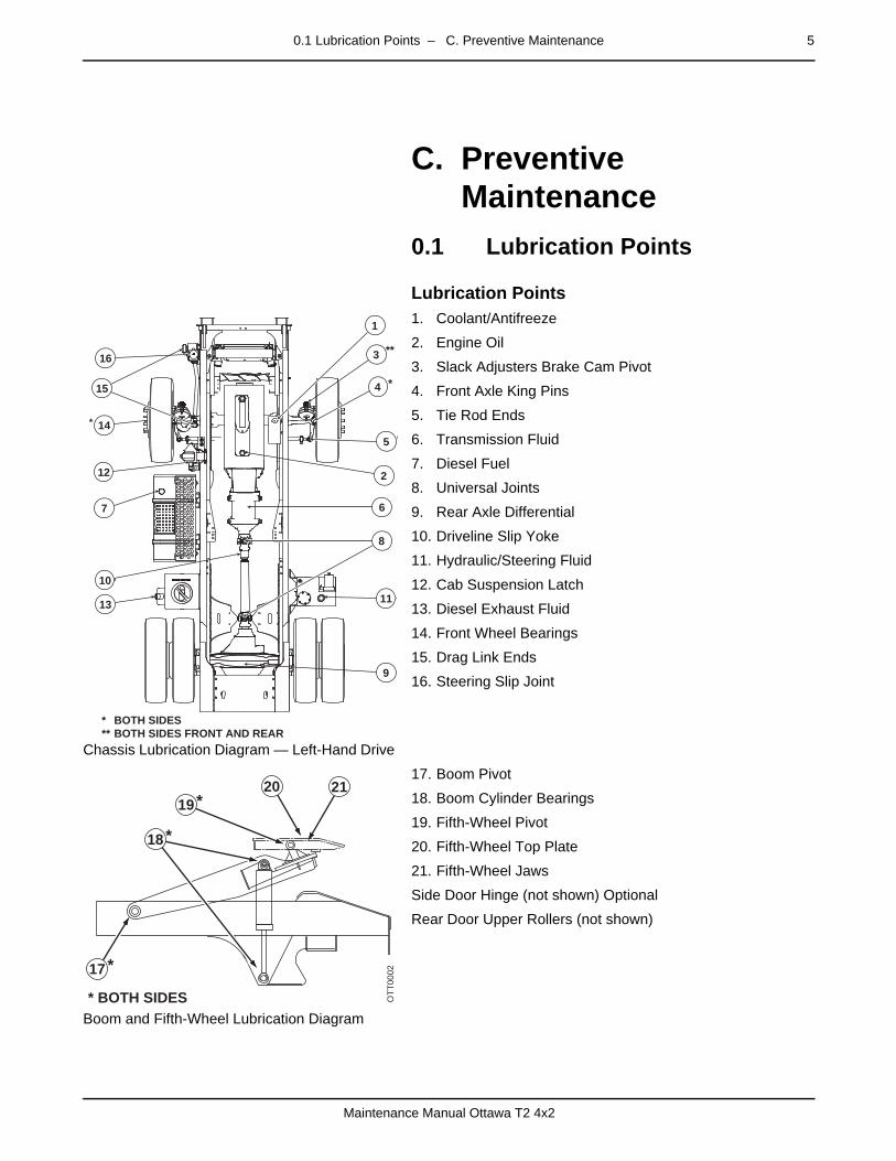
Chassis Lubrication Diagram — Left-Hand Drive
1. Coolant/Antifreeze
2. Engine Oil
3. Slack Adjusters Brake Cam Pivot
4. Front Axle King Pins
5. Tie Rod Ends
6. Transmission Fluid
7. Diesel Fuel
8. Universal Joints
9. Rear Axle Differential
10. Driveline Slip Yoke
11. Hydraulic/Steering Fluid
12. Cab Suspension Latch
13. Diesel Exhaust Fluid
14. Front Wheel Bearings
15. Drag Link Ends
16. Steering Slip Joint
Boom and Fifth-Wheel Lubrication Diagram
17. Boom Pivot
18. Boom Cylinder Bearings
19. Fifth-Wheel Pivot
20. Fifth-Wheel Top Plate
21. Fifth-Wheel Jaws
Side Door Hinge (not shown) Optional
Rear Door Upper Rollers (not shown)
2
3
4
5
67
8
9
* BOTH SIDES** BOTH SIDES FRONT AND REAR
1011
12
13
14
15
16
*
*
**
*
1
17
* BOTH SIDES
*
OTT
0002
18 *
20 2119 *
6 0.2 Inspections – C. Preventive Maintenance
Maintenance Manual Ottawa T2 4x2
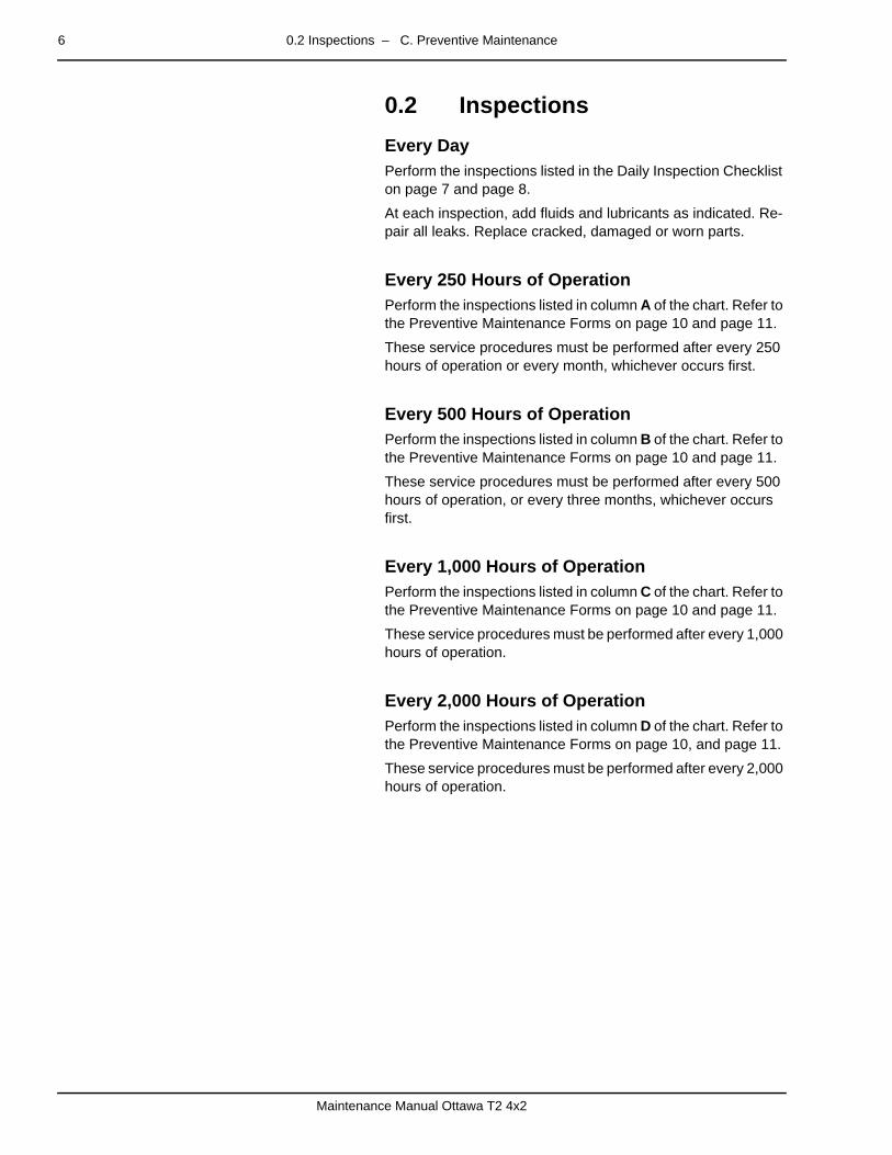
0.2 Inspectionspage – Every Day
Perform the inspections listed in the Daily Inspection Checklist on page 7 and page 8.
At each inspection, add fluids and lubricants as indicated. Re-pair all leaks. Replace cracked, damaged or worn parts.
page –
Every 250 Hours of OperationPerform the inspections listed in column A of the chart. Refer to the Preventive Maintenance Forms on page 10 and page 11.
These service procedures must be performed after every 250 hours of operation or every month, whichever occurs first.
page –
Every 500 Hours of OperationPerform the inspections listed in column B of the chart. Refer to the Preventive Maintenance Forms on page 10 and page 11.
These service procedures must be performed after every 500 hours of operation, or every three months, whichever occurs first.
page –
Every 1,000 Hours of OperationPerform the inspections listed in column C of the chart. Refer to the Preventive Maintenance Forms on page 10 and page 11.
These service procedures must be performed after every 1,000 hours of operation.
page –
Every 2,000 Hours of OperationPerform the inspections listed in column D of the chart. Refer to the Preventive Maintenance Forms on page 10, and page 11.
These service procedures must be performed after every 2,000 hours of operation.
0.3 Checklists – C. Preventive Maintenance 7
Maintenance Manual Ottawa T2 4x2
0.3 Checklistspage –
page –
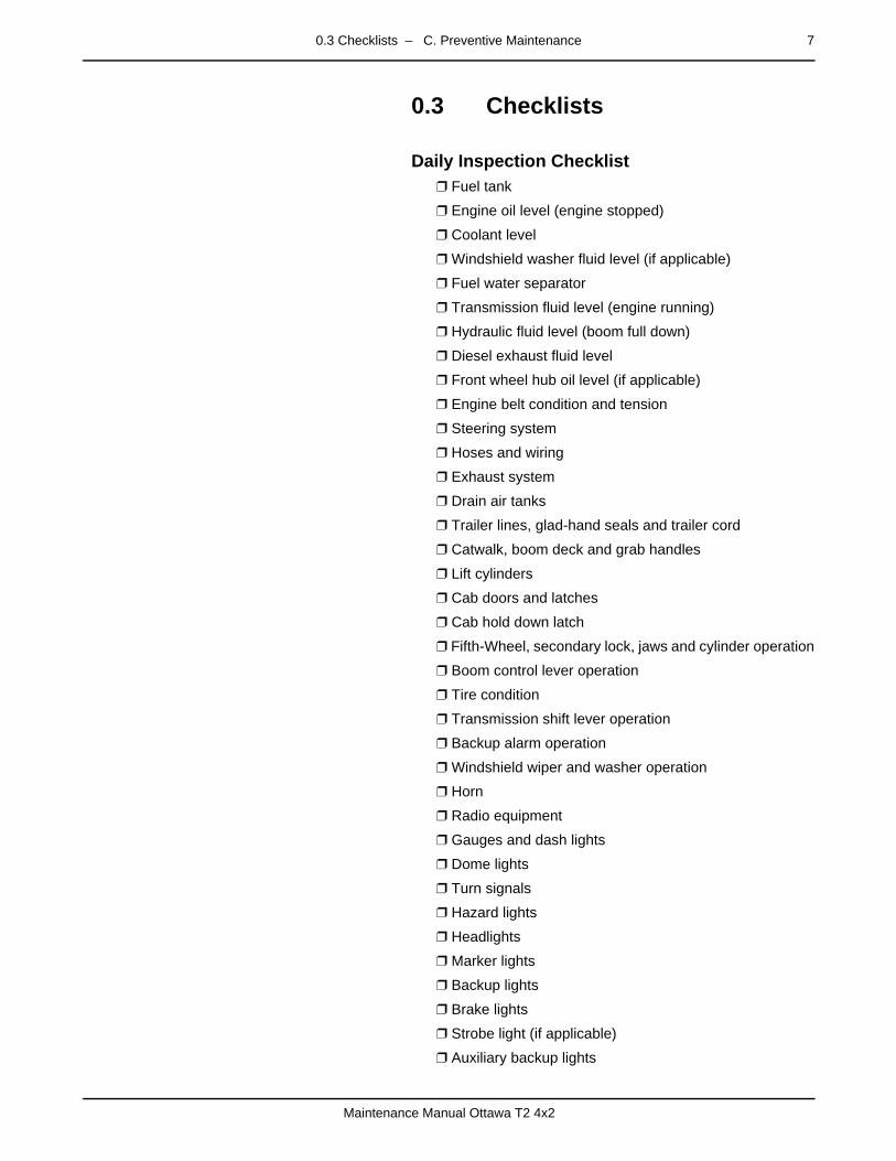
Daily Inspection Checklist❒ Fuel tank
❒ Engine oil level (engine stopped)
❒ Coolant level
❒ Windshield washer fluid level (if applicable)
❒ Fuel water separator
❒ Transmission fluid level (engine running)
❒ Hydraulic fluid level (boom full down)
❒ Diesel exhaust fluid level
❒ Front wheel hub oil level (if applicable)
❒ Engine belt condition and tension
❒ Steering system
❒ Hoses and wiring
❒ Exhaust system
❒ Drain air tanks
❒ Trailer lines, glad-hand seals and trailer cord
❒ Catwalk, boom deck and grab handles
❒ Lift cylinders
❒ Cab doors and latches
❒ Cab hold down latch
❒ Fifth-Wheel, secondary lock, jaws and cylinder operation
❒ Boom control lever operation
❒ Tire condition
❒ Transmission shift lever operation
❒ Backup alarm operation
❒ Windshield wiper and washer operation
❒ Horn
❒ Radio equipment
❒ Gauges and dash lights
❒ Dome lights
❒ Turn signals
❒ Hazard lights
❒ Headlights
❒ Marker lights
❒ Backup lights
❒ Brake lights
❒ Strobe light (if applicable)
❒ Auxiliary backup lights

8 0.3 Checklists – C. Preventive Maintenance
Maintenance Manual Ottawa T2 4x2
❒ Clean the cab interior.
❒ Clean the windows.
❒ Clean and adjust the mirrors.

0.3 Checklists – C. Preventive Maintenance 9
Maintenance Manual Ottawa T2 4x2
Daily Inspection Form
DAILY INSPECTION FORM
TRUCK # ________________ DRIVER NAME __________________________________________ DATE _____________
PERFORM THE FOLLOWING COMPLETE COMPLETE COMPLETE
LEVEL LIO KNAT CILUARDYH KCEHC LEVEL TNALOOC ENIGNE KCEHC LEVEL LEUF KCEHCCHECK ENGINE OIL LEVEL DRAIN WATER FROM AIR TANKS CHECK AIR INTAKE DUCTS CHECK TRANSMISSION FLUID LEVEL
CHECK THE FOLLOWING ITEMS AND INDICATE IF “OK” OR “REPAIR NEEDED”. CIRCLE LOCATON ON DRAWINGS IF NECESSARY. DESCRIBE PROBLEMS IN REMARKS AREA AT BOTTOM OF PAGE.
OK REPAIRNEEDED OK REPAIR
NEEDED OK REPAIR NEEDED
STHGIL PUKCAB GNIREETS SMROFTALP / SELDNAH / SPETS STHGIL EKARB ELTTORHT RETRATS
)S(THGIL DOOLF NOITAREPO MOOB TRATS LARTUEN5 MRALA PUKCAB TH WHEEL RELEASE STROBE LIGHT
HCTAL / NOISNEPSUS BAC SEKARB ECIVRES RETSORFED / RETAEH SKAEL DIULF EKARB KRAP SRORRIM
SREDNEF / SPALF DUM )S(NROH SROOD SERIT SENIL RIA RELIART SWODNIW
EGAMAD DROC THGIL RELIART SREPIW STHGIL DAEH TAES STHGIL LANGIS TLEB TAES
REMARKS:
10 0.3 Checklists – C. Preventive Maintenance
Maintenance Manual Ottawa T2 4x2
page –
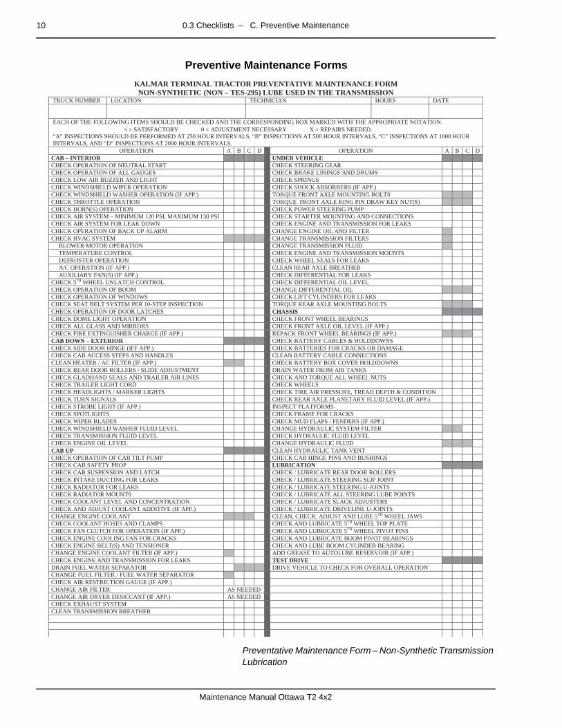
Preventive Maintenance Forms
Preventative Maintenance Form – Non-Synthetic Transmission Lubrication
KALMAR TERMINAL TRACTOR PREVENTATIVE MAINTENANCE FORMNON-SYNTHETIC (NON – TES-295) LUBE USED IN THE TRANSMISSION
TRUCK NUMBER LOCATION TECHNICIAN HOURS DATE
EACH OF THE FOLLOWING ITEMS SHOULD BE CHECKED AND THE CORRESPONDING BOX MARKED WITH THE APPROPRIATE NOTATION. √ = SATISFACTORY 0 = ADJUSTMENT NECESSARY Χ = REPAIRS NEEDED.“A” INSPECTIONS SHOULD BE PERFORMED AT 250 HOUR INTERVALS, “B” INSPECTIONS AT 500 HOUR INTERVALS, “C” INSPECTIONS AT 1000 HOUR INTERVALS, AND “D” INSPECTIONS AT 2000 HOUR INTERVALS.
OPERATION A B C D OPERATION A B C DCAB – INTERIOR UNDER VEHICLECHECK OPERATION OF NEUTRAL START CHECK STEERING GEARCHECK OPERATION OF ALL GAUGES CHECK BRAKE LININGS AND DRUMSCHECK LOW AIR BUZZER AND LIGHT CHECK SPRINGSCHECK WINDSHIELD WIPER OPERATION CHECK SHOCK ABSORBERS (IF APP.)CHECK WINDSHIELD WASHER OPERATION (IF APP.) TORQUE FRONT AXLE MOUNTING BOLTSCHECK THROTTLE OPERATION TORQUE FRONT AXLE KING PIN DRAW KEY NUT(S)CHECK HORN(S) OPERATION CHECK POWER STEERING PUMPCHECK AIR SYSTEM – MINIMUM 120 PSI, MAXIMUM 130 PSI CHECK STARTER MOUNTING AND CONNECTIONSCHECK AIR SYSTEM FOR LEAK DOWN CHECK ENGINE AND TRANSMISSION FOR LEAKSCHECK OPERATION OF BACK UP ALARM CHANGE ENGINE OIL AND FILTERCHECK HVAC SYSTEM CHANGE TRANSMISSION FILTERS BLOWER MOTOR OPERATION CHANGE TRANSMISSION FLUID TEMPERATURE CONTROL CHECK ENGINE AND TRANSMISSION MOUNTS DEFROSTER OPERATION CHECK WHEEL SEALS FOR LEAKS A/C OPERATION (IF APP.) CLEAN REAR AXLE BREATHER AUXILIARY FAN(S) (IF APP.) CHECK DIFFERENTIAL FOR LEAKSCHECK 5TH WHEEL UNLATCH CONTROL CHECK DIFFERENTIAL OIL LEVELCHECK OPERATION OF BOOM CHANGE DIFFERENTIAL OILCHECK OPERATION OF WINDOWS CHECK LIFT CYLINDERS FOR LEAKSCHECK SEAT BELT SYSTEM PER 10-STEP INSPECTION TORQUE REAR AXLE MOUNTING BOLTSCHECK OPERATION OF DOOR LATCHES CHASSISCHECK DOME LIGHT OPERATION CHECK FRONT WHEEL BEARINGSCHECK ALL GLASS AND MIRRORS CHECK FRONT AXLE OIL LEVEL (IF APP.)CHECK FIRE EXTINGUISHER CHARGE (IF APP.) REPACK FRONT WHEEL BEARINGS (IF APP.)CAB DOWN – EXTERIOR CHECK BATTERY CABLES & HOLDDOWNSCHECK SIDE DOOR HINGE (IFF APP.) CHECK BATTERIES FOR CRACKS OR DAMAGECHECK CAB ACCESS STEPS AND HANDLES CLEAN BATTERY CABLE CONNECTIONSCLEAN HEATER / AC FILTER (IF APP.) CHECK BATTERY BOX COVER HOLDDOWNSCHECK REAR DOOR ROLLERS / SLIDE ADJUSTMENT DRAIN WATER FROM AIR TANKSCHECK GLADHAND SEALS AND TRAILER AIR LINES CHECK AND TORQUE ALL WHEEL NUTSCHECK TRAILER LIGHT CORD CHECK WHEELSCHECK HEADLIGHTS / MARKER LIGHTS CHECK TIRE AIR PRESSURE, TREAD DEPTH & CONDITIONCHECK TURN SIGNALS CHECK REAR AXLE PLANETARY FLUID LEVEL (IF APP.)CHECK STROBE LIGHT (IF APP.) INSPECT PLATFORMSCHECK SPOTLIGHTS CHECK FRAME FOR CRACKSCHECK WIPER BLADES CHECK MUD FLAPS / FENDERS (IF APP.)CHECK WINDSHIELD WASHER FLUID LEVEL CHANGE HYDRAULIC SYSTEM FILTERCHECK TRANSMISSION FLUID LEVEL CHECK HYDRAULIC FLUID LEVELCHECK ENGINE OIL LEVEL CHANGE HYDRAULIC FLUIDCAB UP CLEAN HYDRAULIC TANK VENTCHECK OPERATION OF CAB TILT PUMP CHECK CAB HINGE PINS AND BUSHINGSCHECK CAB SAFETY PROP LUBRICATIONCHECK CAB SUSPENSION AND LATCH CHECK / LUBRICATE REAR DOOR ROLLERSCHECK INTAKE DUCTING FOR LEAKS CHECK / LUBRICATE STEERING SLIP JOINTCHECK RADIATOR FOR LEAKS CHECK / LUBRICATE STEERING U-JOINTSCHECK RADIATOR MOUNTS CHECK / LUBRICATE ALL STEERING LUBE POINTSCHECK COOLANT LEVEL AND CONCENTRATION CHECK / LUBRICATE SLACK ADJUSTERSCHECK AND ADJUST COOLANT ADDITIVE (IF APP.) CHECK / LUBRICATE DRIVELINE U-JOINTSCHANGE ENGINE COOLANT CLEAN, CHECK, ADJUST AND LUBE 5TH WHEEL JAWSCHECK COOLANT HOSES AND CLAMPS CHECK AND LUBRICATE 5TH WHEEL TOP PLATECHECK FAN CLUTCH FOR OPERATION (IF APP.) CHECK AND LUBRICATE 5TH WHEEL PIVOT PINSCHECK ENGINE COOLING FAN FOR CRACKS CHECK AND LUBRICATE BOOM PIVOT BEARINGSCHECK ENGINE BELT(S) AND TENSIONER CHECK AND LUBE BOOM CYLINDER BEARINGCHANGE ENGINE COOLANT FILTER (IF APP.) ADD GREASE TO AUTOLUBE RESERVOIR (IF APP.)CHECK ENGINE AND TRANSMISSION FOR LEAKS TEST DRIVEDRAIN FUEL WATER SEPARATOR DRIVE VEHICLE TO CHECK FOR OVERALL OPERATIONCHANGE FUEL FILTER / FUEL WATER SEPARATORCHECK AIR RESTRICTION GAUGE (IF APP.)CHANGE AIR FILTER AS NEEDEDCHANGE AIR DRYER DESICCANT (IF APP.) AS NEEDEDCHECK EXHAUST SYSTEMCLEAN TRANSMISSION BREATHER

0.3 Checklists – C. Preventive Maintenance 11
Maintenance Manual Ottawa T2 4x2
Preventative Maintenance Form – Synthetic Transmission Lubrication with High Capacity Filters
KALMAR TERMINAL TRACTOR PREVENTATIVE MAINTENANCE FORMSYNTHETIC (TES-295) LUBE AND ALLISON HIGH-CAPACITY FILTERS USED IN THE TRANSMISSION
TRUCK NUMBER LOCATION TECHNICIAN HOURS DATE
EACH OF THE FOLLOWING ITEMS SHOULD BE CHECKED AND THE CORRESPONDING BOX MARKED WITH THE APPROPRIATE NOTATION. √ = SATISFACTORY 0 = ADJUSTMENT NECESSARY Χ = REPAIRS NEEDED.“A” INSPECTIONS SHOULD BE PERFORMED AT 250 HOUR INTERVALS, “B” INSPECTIONS AT 500 HOUR INTERVALS, “C” INSPECTIONS AT 1000 HOURINTERVALS, AND “D” INSPECTIONS AT 2000 HOUR INTERVALS.
OPERATION A B C D OPERATION A B C DCAB – INTERIOR UNDER VEHICLECHECK OPERATION OF NEUTRAL START CHECK STEERING GEARCHECK OPERATION OF ALL GAUGES CHECK BRAKE LININGS AND DRUMSCHECK LOW AIR BUZZER AND LIGHT CHECK SPRINGSCHECK WINDSHIELD WIPER OPERATION CHECK SHOCK ABSORBERS (IF APP.)CHECK WINDSHIELD WASHER OPERATION (IF APP.) TORQUE FRONT AXLE MOUNTING BOLTSCHECK THROTTLE OPERATION TORQUE FRONT AXLE KING PIN DRAW KEY NUT(S)CHECK HORN(S) OPERATION CHECK POWER STEERING PUMPCHECK AIR SYSTEM – MINIMUM 120 PSI, MAXIMUM 130 PSI CHECK STARTER MOUNTING AND CONNECTIONSCHECK AIR SYSTEM FOR LEAK DOWN CHECK ENGINE AND TRANSMISSION FOR LEAKSCHECK OPERATION OF BACK UP ALARM CHANGE ENGINE OIL AND FILTERCHECK HVAC SYSTEM CHANGE TRANSMISSION FILTERS 3000 HOURS BLOWER MOTOR OPERATION CHANGE TRANSMISSION FLUID 6000 HOURS TEMPERATURE CONTROL CHECK ENGINE AND TRANSMISSION MOUNTS DEFROSTER OPERATION CHECK WHEEL SEALS FOR LEAKS A/C OPERATION (IF APP.) CLEAN REAR AXLE BREATHER AUXILIARY FAN(S) (IF APP.) CHECK DIFFERENTIAL FOR LEAKSCHECK 5TH WHEEL UNLATCH CONTROL CHECK DIFFERENTIAL OIL LEVELCHECK OPERATION OF BOOM CHANGE DIFFERENTIAL OILCHECK OPERATION OF WINDOWS CHECK LIFT CYLINDERS FOR LEAKSCHECK SEAT BELT SYSTEM PER 10-STEP INSPECTION TORQUE REAR AXLE MOUNTING BOLTSCHECK OPERATION OF DOOR LATCHES CHASSISCHECK DOME LIGHT OPERATION CHECK FRONT WHEEL BEARINGSCHECK ALL GLASS AND MIRRORS CHECK FRONT AXLE OIL LEVEL (IF APP.)CHECK FIRE EXTINGUISHER CHARGE (IF APP.) REPACK FRONT WHEEL BEARINGS (IF APP.)CAB DOWN – EXTERIOR CHECK BATTERY CABLES & HOLDDOWNSCHECK SIDE DOOR HINGE (IFF APP.) CHECK BATTERIES FOR CRACKS OR DAMAGECHECK CAB ACCESS STEPS AND HANDLES CLEAN BATTERY CABLE CONNECTIONSCLEAN HEATER / AC FILTER (IF APP.) CHECK BATTERY BOX COVER HOLDDOWNSCHECK REAR DOOR ROLLERS / SLIDE ADJUSTMENT DRAIN WATER FROM AIR TANKSCHECK GLADHAND SEALS AND TRAILER AIR LINES CHECK AND TORQUE ALL WHEEL NUTSCHECK TRAILER LIGHT CORD CHECK WHEELSCHECK HEADLIGHTS / MARKER LIGHTS CHECK TIRE AIR PRESSURE, TREAD DEPTH & CONDITIONCHECK TURN SIGNALS CHECK REAR AXLE PLANETARY FLUID LEVEL (IF APP.)CHECK STROBE LIGHT (IF APP.) INSPECT PLATFORMSCHECK SPOTLIGHTS CHECK FRAME FOR CRACKSCHECK WIPER BLADES CHECK MUD FLAPS / FENDERS (IF APP.)CHECK WINDSHIELD WASHER FLUID LEVEL CHANGE HYDRAULIC SYSTEM FILTERCHECK TRANSMISSION FLUID LEVEL CHECK HYDRAULIC FLUID LEVELCHECK ENGINE OIL LEVEL CHANGE HYDRAULIC FLUIDCAB UP CLEAN HYDRAULIC TANK VENTCHECK OPERATION OF CAB TILT PUMP CHECK CAB HINGE PINS AND BUSHINGSCHECK CAB SAFETY PROP LUBRICATIONCHECK CAB SUSPENSION AND LATCH CHECK / LUBRICATE REAR DOOR ROLLERSCHECK INTAKE DUCTING FOR LEAKS CHECK / LUBRICATE STEERING SLIP JOINTCHECK RADIATOR FOR LEAKS CHECK / LUBRICATE STEERING U-JOINTSCHECK RADIATOR MOUNTS CHECK / LUBRICATE ALL STEERING LUBE POINTSCHECK COOLANT LEVEL AND CONCENTRATION CHECK / LUBRICATE SLACK ADJUSTERSCHECK AND ADJUST COOLANT ADDITIVE (IF APP.) CHECK / LUBRICATE DRIVELINE U-JOINTSCHANGE ENGINE COOLANT CLEAN, CHECK, ADJUST AND LUBE 5TH WHEEL JAWSCHECK COOLANT HOSES AND CLAMPS CHECK AND LUBRICATE 5TH WHEEL TOP PLATECHECK FAN CLUTCH FOR OPERATION (IF APP.) CHECK AND LUBRICATE 5TH WHEEL PIVOT PINSCHECK ENGINE COOLING FAN FOR CRACKS CHECK AND LUBRICATE BOOM PIVOT BEARINGSCHECK ENGINE BELT(S) AND TENSIONER CHECK AND LUBE BOOM CYLINDER BEARINGCHANGE ENGINE COOLANT FILTER (IF APP.) ADD GREASE TO AUTOLUBE RESERVOIR (IF APP.)CHECK ENGINE AND TRANSMISSION FOR LEAKS TEST DRIVEDRAIN FUEL WATER SEPARATOR DRIVE VEHICLE TO CHECK FOR OVERALL OPERATIONCHANGE FUEL FILTER / FUEL WATER SEPARATORCHECK AIR RESTRICTION GAUGE (IF APP.)CHANGE AIR FILTER AS NEEDEDCHANGE AIR DRYER DESICCANT (IF APP.) AS NEEDEDCHECK EXHAUST SYSTEMCLEAN TRANSMISSION BREATHER
12 0.4 Preventive Maintenance Technique – C. Preventive Maintenance
Maintenance Manual Ottawa T2 4x2
0.4 Preventive Maintenance Technique
page –
GeneralThe following is more detailed information for preventive main-tenance. See the Lubrication Points page 5 provided in this manual. Refer to the Preventive Maintenance Forms on page 10 for additional scheduling. The hourly time limits described in this manual are absolute maximums. Harsh vehicle usage may dictate shorter intervals. Inspect frequently to discover where changes may be necessary.
0.4.1 Fuel, Filters, Fluids and Lubricantspage –
Maintenance
The engine, transmission and axle manufacturers provide maintenance information and specify fluids and lubricants to be used in their products. Comply with the original equipment manufacturer’s specifications in order to maintain warranty coverage.
Follow the periodic checklists as indicated. Fill reservoirs as necessary using specified fluids. When adding, use the same fluid as is in the reservoir. If the fluid is unknown, drain and re-place it according to specification.
Use only the fuel, coolant, coolant additives, diesel exhaust flu-id and lubricants specified by the engine manufacturer.
Follow the engine manufacturer’s specification for the coolant and water ratio or maintain engine coolant freeze protection at approximately 34F (37C). Determine the reason for lost flu-id. Repair as necessary.
The Kalmar Parts Catalog is customized to the vehicle. Refer to this catalog for filter part numbers.
Kalmar recommends API Grade 1 grease, any high-quality lith-ium-based grease, or a base oil with a Timken 40 minimum rat-ing for use in axles. Install the same lubricant as originally installed in the axles.
Do not use lithium grease on front axles equipped with “WET” wheel seals. The front hubs must be inspected after every 250 hours of operation.
Power steering, the boom lift and the cab tilt mechanism all use hydraulic fluid stored in a single tank mounted on the rail. A ve-hicle being operated in a severe application may require short-er intervals between changes. The system filter is on the hydraulic tank.

0.4 Preventive Maintenance Technique – C. Preventive Maintenance 13
Maintenance Manual Ottawa T2 4x2
0.4.2 Cab Interiorpage –
Maintenance Check Operation of Neutral Start — Move the gear selec-
tor to any position other than "N" and attempt to start the engine. The engine should not crank with the selector in any position other than "N".
Check Operation of All Gauges — With the engine run-ning verify that all gauges are functional.
Check Low Air Buzzer and Light — Apply and release the brake pedal until air pressure drops below 90 psi. At that point, the low air buzzer and dash warning light should come on.
Check Windshield Wiper Operation — Turn on the wind-shield wiper and confirm full and smooth travel of the wiper arm. Listen for any noises that might indicate a worn wiper motor.
Check Windshield Washer Operation (if applicable) — Depress the washer button and confirm the flow and pat-tern of the washer fluid.
Check Throttle Operation — Depress and release the foot throttle and check for binding and ease of operation.
Check Horn(s) Operation — Sound electric and air horns (if applicable) to confirm proper operation.
Check Air System. Minimum 120 PSI (8.27 bar), Maxi-mum 130 PSI (8.96 bar) — Start the engine and run at fast idle. Maximum system pressure should be limited to a min-imum of 120 P.S.I. (8.27 bar) and a maximum of 130 P.S.I. (8.96 bar).
Check Air System for Leak Down — Disconnect the glad hands from any trailer. Run engine at fast idle and allow air pressure to stabilize at 120 PSI for at least one minute. Shut off engine the and observe dash gauge(s) for two min-utes. The drop in pressure should not exceed 2 PSI (0.137 bar) over the two-minute period.
Check Operation of Back Up Alarm — With engine run-ning, move the gear selector to reverse and listen for back up alarm.
Check HVAC System —
• Blower Motor Operation
With the key on, ensure that the blower motor oper-ates at each position of the blower speed switch.
• Temperature Control
Confirm proper operation of the temperature con-trol switch.

14 0.4 Preventive Maintenance Technique – C. Preventive Maintenance
Maintenance Manual Ottawa T2 4x2
• Defroster Operation
With the engine running and the defroster control turned on, confirm air flow from the defroster vents.
• Air Conditioner Operation
With the engine running and the air conditioner con-trol turned on, confirm cooled air flow from the vents.
• Auxiliary Fan(s) (if applicable)
With the key on, turn on the auxiliary fans and con-firm operation.
Check 5th Wheel Unlatch Control — With system air pressure above 100 PSI confirm that the 5th wheel jaws un-latch when the dash control is activated.
Check Operation of Boom — With the engine running at fast idle activate the boom control and ensure full extension and retraction.
Check Operation of Windows — Confirm that all regulat-ed and sliding windows open and close fully.
Check Seat Belt Operation — Ensure that the seatbelt latch fastens and unfastens properly.
Check Rear and Side Door Latch Operation — Operate the side door latch from inside and outside the cab to en-sure proper operation.
Check Dome Light Operation — With key on, turn on cab dome light and confirm operation.
Check all Glass and Mirrors — Inspect all glass and mir-rors for cracks and breaks
Check Fire Extinguisher Charge (if applicable) — If the vehicle is equipped with a fire extinguisher confirm that it is properly charged.
page –
Seat Belt System
Inspect the seat belt system every 20,000 miles (32,187 km) or more often if exposed to severe environmental conditions or vocation. Check the following: Inspect belt on entire system for cuts, fraying, extreme or
unusual wear. Most common areas of belt wear include the buckle/latch area, the shoulder loop area and any place where the belt makes contact with vehicle or seat. Replace the entire belt system if necessary.
Inspect buckle for proper operation by inserting latch and listening for an audible click. Verify the buckle is not dam-aged, cracked or broken. Replace the entire belt system.
Inspect buckle cable (optional component) black coating on buckle cable must not be damaged. Internal cable wires must not be exposed, frayed or broken. Replace the entire system.
0.4 Preventive Maintenance Technique – C. Preventive Maintenance 15
Maintenance Manual Ottawa T2 4x2
Inspect latch for proper operation by inserting into buckle. Latch must insert smoothly and you must hear an audible click. Verify proper latching by tugging on belt. Latch must not be worn, deformed or corroded. Replace the entire belt system.
Inspect shoulder loop web guide (optional component) Seat belt must move freely through shoulder loop. Shoulder loop must also pivot freely and be free of obstructions. If necessary, adjust shoulder loop hardware and/or remove obstruction.
Inspect seat belt height adjuster (optional component) for damage. Mover adjuster up and down. It must move freely and lock at the different height positions. Replace the entire belt system if necessary.
Inspect retractor operation. When pulled and released slowly, seat belt must spool out and retract without locking. Replace the entire belt system if necessary.
Inspect mounting hardware on both sides of seat. Hard-ware should be tight. Hardware must not be missing, rust-ed, corroded or damaged. If necessary, replace defective or missing hardware with authorized parts and/or tighten hardware.
Inspect tethers for cuts, fraying, extreme or unusual wear. Tethers must also be inspected for proper attachment and/or adjustment. If necessary, replace defective tethers. Tighten and/or properly adjust tethers according to vehicle manufacturer’s specifications.
Inspect Komfort Latch® (optional component) for func-tion and ability to clamp on web. Replace the entire system if necessary.
0.4.3 Cab Down — Exteriorpage –
Maintenance Check Side Door Hinge (if applicable) — Inspect the door
hinge for wear and damage.
Check Cab Access Steps and Handles — Inspect all steps and grab handles for proper mounting and the ab-sence of cracks.
Clean Heater/AC Filter — Remove the HVAC filter and vacuum or blow clean with low-pressure air.
Check Rear Door Roller/Slide Adjustment — Inspect rear door rollers and slide for wear or damage.
Check Gladhand Seals and Trailer Air Lines — Inspect seals for tears and wear. Check air lines for kinks or cracks.
16 0.4 Preventive Maintenance Technique – C. Preventive Maintenance
Maintenance Manual Ottawa T2 4x2
Check Trailer Light Cord (if applicable) — Inspect light cord for cuts and abrasions. As the lights of the truck are checked confirm that a trailer connected with the light cord also has lights. This can be done either with a trailer con-nected or with a "test box".
Check Headlights/Marker Lights — Start engine, turn on light switches and confirm lights are illuminated.
Check Turn Signals — With key on, activate the turn sig-nal switch and the flasher to confirm that the turn signals are working.
Check Strobe Light (if applicable) — With the key on, turn on the strobe light to confirm its operation.
Check Spotlights — With the key on, turn on the spot-light(s) to confirm its operation.
Check Wiper Blades — Inspect wiper blades for tears or excessive wear.
Check Windshield Washer Fluid Level — Raise the hood and fill washer bottle as necessary.
Check Transmission Fluid Level — With the engine run-ning, use the transmission dipstick to check the fluid level per the guidelines in the Transmission Operator's Manual.
0.4.4 Cab Uppage –
Maintenance Check Operation of Cab Tilt Pump — Pull safety prop re-
lease cable and activate cab tilt switch. The cab should rise.
Check Cab Safety Prop — Inspect the cab safety prop that encloses the cab lift cylinder. It should drop freely into place to support the cab when it is in the raised position. The lower cab cylinder pin and bracket should be inspected for signs of fatigue.
Check Cab Suspension and Latch — Inspect the linkag-es of the suspension system for excessive wear and proper alignment. Inspect the air bag for leaks or signs of abrasion. Inspect the lock jaw for excessive wear and proper opera-tion.
Check Engine Intake Ducting for Leaks — Inspect all en-gine clean air tubes and hoses for leaks. All clamps should be checked for proper torque and all joints should be prop-erly aligned.
Check Radiator for Leaks — Inspect radiator core and tanks for signs of coolant leaks.
Check Radiator Mounts — Inspect radiator mounts for wear or excessive looseness.
0.4 Preventive Maintenance Technique – C. Preventive Maintenance 17
Maintenance Manual Ottawa T2 4x2
Check Coolant Level and Concentration — Check cool-ing system level. Coolant should be visible in radiator sight glass. It is not necessary for the coolant to be at the top of the sight glass. Test and maintain the proper antifreeze lev-el of concentration as outlined in the appropriate engine op-erator's manual.
Change Engine Coolant — Flush the cooling system and replace with clean coolant of the appropriate concentration.
Check Coolant Hoses and Clamps — Inspect all hoses for abrasion, cracks, holes and routing. Check all clamps for proper torque.
Check Fan Clutch for Operation (if applicable) — Run en-gine to confirm that the fan clutch engages at the proper temperature.
Check Engine Cooling Fan for Cracks — Shut the en-gine off if running. Inspect fan blades for signs of cracking.
Check Engine Belts and Tensioner — Inspect belt(s) for cracking and wear. Belt tensioner should be checked for proper operation.
Check Engine and Transmission for Leaks — Perform a visual inspection of the engine and transmission looking for any fluid leaks visible from above.
Drain Fuel Water Separator — Open the drain valve on the fuel/water separator and allow water to drain from the filter.
Change Fuel Water Separator — Replace the fuel filter following the instructions in the engine operator’s manual.
Check Air Restriction Gauge (if applicable) — Record reading on gauge, reset, start engine, run to high idle and shut off engine. If reading remains on zero, the gauge may be defective or the intake piping has a leak. The cause must be investigated and the gauge replaced and/or the piping repaired.
If the initial gauge reading indicates that the filter should be changed, do so at this time. See the next item on the PM form.
Change Air Filter — The air filter should be changed as needed. If the truck is equipped with a restriction gauge, re-place the filter when the gauge indicates it is appropriate.
Change Air Dryer Desiccant (if applicable) — The desic-cant should be changed as needed. Change as soon as water is evident when system air tanks are drained.
Check Exhaust System — Visually inspect all of the ex-haust system components for leaks and/or damage.
Clean Transmission Breather — Confirm that the breath-er, located on top of the transmission, is clean and the pas-sage is open. Do not spray directly with high pressure or cleaning solvents.
18 0.4 Preventive Maintenance Technique – C. Preventive Maintenance
Maintenance Manual Ottawa T2 4x2
0.4.5 Under Vehiclepage –
Maintenance Check Steering Gear — Inspect steering gear for fluid
leaks and excessive play. Inspect the steering linkage for wear or looseness.
Check Brake Linings and Drums — Visually check lin-ings and drums for wear and cracks. If the lining is 0.25" thick or less in any location the shoes should be replaced or relined.
Check Leaf Springs — Inspect leaf springs for cracking or excessive deflection. Inspect spring pins for wear.
Check Shock Absorbers (if applicable) — Inspect shock absorbers for leaks.
Torque Front Axle Mounting Bolts — Re-torque front axle mounting bolts to 210 ft. lbs. (285 Nm).
Torque Front Axle Kingpin Draw Key Nuts — Re-torque the steer axle kingpin draw key nut(s).
Check Hydraulic Pump — Inspect the hydraulic pump for leaks.
Check Starter Mounting and Connections — Confirm that starter mounting bolts are tight. Inspect electrical con-nections for good contact at starter terminals.
Check Engine and Transmission for Leaks — Perform a visual inspection of the engine and transmission looking for any fluid leaks visible from below.
Change Engine Oil and Filter — Drain and replace engine oil. Use oil meeting, at least, the minimum specifications provided in the engine operator's manual. Replace the oil filter.
Change Transmission Filters — Notice — This DOES NOT include the pan screen. The screen should only be re-placed during overhaul.
Change Transmission Fluid — Drain and replace trans-mission fluid. Use fluid meeting, at least, the minimum specifications provided in the transmission operator's man-ual.
Check Engine and Transmission Mounts — Re-torque engine and transmission mounts. Inspect isolator material and replace if deteriorated.
Check Wheel Seals for Leaks — Inspect front and rear hubs for signs of oil leaks. Replace if leaking.
Clean Rear Axle Breather — Ensure that the rear axle vent turns freely.
Check Differential for Leaks — Inspect rear axle housing for signs of leaks. Repair as necessary.
0.4 Preventive Maintenance Technique – C. Preventive Maintenance 19
Maintenance Manual Ottawa T2 4x2
Check Differential Oil Level — Check the differential oil level per the component manufacturer's instructions.
Change Differential Oil — Drain and replace differential oil. Use oil meeting, at least, the minimum specifications of the component manufacturer.
Check Lift Cylinders for Leaks — Inspect cylinders for signs of leaking. Repair as necessary.
Torque Rear Axle Mounting Bolts — Re-torque rear axle mounting bolts. Nut at 400 ft. lbs. (542 Nm), Bolt at 600 ft. lbs. (813 Nm).
0.4.6 Chassispage –
Maintenance Check Front Wheel Bearings — Raise and support the
front axle. Check for excessive play in wheel bearing.
Check Front Axle Oil Level (if applicable) — Check oil lev-el in front axle hubcaps. Fill to proper level as necessary.
Repack Front Wheel Bearings (if applicable) — Remove front hubs and repack the bearings using grease meeting, at least, the minimum specifications of the component man-ufacturer.
Check Battery Cables and Holddowns — Inspect battery cables for signs of abrasion or breaking. Repair and reroute as needed. Ensure that batteries are properly secured.
Check Batteries for Cracks or Acid Damage — Inspect batteries for signs of damage. Replace as necessary.
Clean Battery Cable Connections — Remove cable ter-minals from batteries, clean connections, reattach cable terminals.
Check Battery Box Cover Holddowns — Check bolts or rubber latches to ensure that the battery box cover is se-cured.
Drain Water from Air Tanks — With air system charged, open each manual drain until all moisture is removed from system.
Check and Torque All Wheel Nuts — Inspect all wheel nuts for signs of wear or damage. Re-torque all nuts to 450-500 ft. lbs. (610-678 Nm).
Check Wheels — Inspect all wheels for signs of damage including oversized holes and cracks.
Check Tire Air Pressure, Tread Depth and Condition — Inspect tires for damage and wear. Adjust to the proper air pressure.
Check Rear Axle Planetary Fluid Level (if applicable) — Check and adjust the lubricant level in the planetary hous-ings per the component manufacturer’s instructions.
20 0.4 Preventive Maintenance Technique – C. Preventive Maintenance
Maintenance Manual Ottawa T2 4x2
Inspect Platforms — Inspect the platforms for proper mounting and the absence of cracks and trip points.
Check Frame for Cracks — Inspect frame rails and cross-members for cracks and bending.
Check Mud Flaps/Fenders (if applicable) — If equipped with mud flaps and/or fender, inspect these items for proper mounting and damage.
Change Hydraulic System Filter — Remove and replace the hydraulic filter.
Check Hydraulic Fluid Level — Start engine, raise and lower the boom two to three times to ensure that system components are filled. Lower boom to full down position, shut off engine and check fluid level on tank gauge. Fill as necessary.
Change Hydraulic Fluid — Drain hydraulic tank and refill with Dexron III automatic transmission fluid.
Clean Hydraulic Tank Vent — Remove any dirt collecting around vent and ensure that vent is clear.
Check Cab Hinge Pins and Bushings — Inspect pins and bushings for wear or damage.
0.4.7 Lubricationpage –
Maintenance Check/Lubricate Rear Door Rollers — Inspect upper roll-
ers. Replace if binding or damaged. Lubricate.
Check/Lubricate Steering Slip Joint — Inspect slip joint for wear or damage. Lubricate with lithium grease.
Check/Lubricate Steering U-Joints — Inspect U-joints for wear or damage. Lubricate with lithium grease.
Check/Lubricate All Steering Lube Points — Inspect king pins, tie rod ends and drag link ends for wear or dam-age. Lubricate with lithium grease.
Check/Lubricate Slack Adjusters — Inspect brake slack adjusters for wear or damage. Measure the brake actuator stroke. If this measurement exceeds the component manu-facturer's recommendation check brake lining and adjuster to determine which is the cause of the excessive stroke and repair as necessary.
Check/Lubricate Driveline U-Joints — Inspect driveline and U-joints for wear or damage. Lubricate with lithium grease.
Clean, Check Adjust and Lube 5th Wheel Jaws — Re-move dirt and excessive grease from the 5th wheel jaws. Using a 5th wheel jaw gauge measure the free play. If free play exceeds 1/8" (3.175 mm) determine the cause of the excessive play and either repair or replace the jaws per the component manufacturer's recommendation.

0.4 Preventive Maintenance Technique – C. Preventive Maintenance 21
Maintenance Manual Ottawa T2 4x2
Check/Lubricate 5th Wheel Top Plate — Clean and in-spect the 5th wheel top plate for cracks or other damage. Apply lithium grease to the surface of the top plate.
Check/Lubricate 5th Wheel Pivot Pins — Inspect 5th wheel pivot pins for wear or damage. Lubricate with lithium grease.
Check/Lubricate Boom Pivot Bearings — Inspect boom pivot bearings for wear or damage. Lubricate with lithium grease.
Check/Lubricate Upper Cylinder Bearings — Inspect upper boom cylinder bearings for wear or damage. Lubri-cate with lithium grease.
Add Grease to Autolube Reservoir — If the vehicle is equipped with an automatic lubrication system inspect all lubrication points for sufficient grease. Fill the system's res-ervoir with the proper type and quantity of grease per the component manufacturer's recommendation.
0.4.8 Test Drivepage –
Maintenance Drive Vehicle to Check Overall Operation — Start and
drive vehicle. Test the operation of all systems and compo-nents.
22 0.4 Preventive Maintenance Technique – C. Preventive Maintenance
Maintenance Manual Ottawa T2 4x2

0.1 The Ottawa T2 Terminal Tractor – 0. Machine Complete 23
Maintenance Manual Ottawa T2 4x2
mm mm mm mm mm mm
0. Machine Complete
0.1 The Ottawa T2 Terminal Tractor
page –
DescriptionThe Ottawa T2 terminal tractor by Kalmar is designed to suit the operator and the tasks. Ottawa T2 tractors are pur-pose-built vehicles, designed to move trailers in the most effi-cient manner. Controls are conveniently arranged around the operator's seat. The operator can get into the cab from the slid-ing rear door or optional side door. The sliding feature and latching in open and closed position means that the rear door is never in the way. Full-length grab-handles, large windows and easy access to all operator controls are some of the fea-tures of the efficiently designed cab.
The trailer air lines and electrical connections are easily acces-sible through the rear door. Perforated decking allows the op-erator to move from cab to trailer comfortably and easily. A hydraulically powered boom under the fifth wheel raises a trail-er high enough to allow it to be moved without raising and low-ering its landing gear. These features along with in-cab fifth-wheel release and automatic relatch means that the oper-ator is not required to climb up and down from the cab for every trailer move.
The Ottawa T2 also features automatic transmissions, hydrau-lic cab tilt for easy maintenance access, a short turning radius and matched drive train components with durable axles that simplify maintenance even further. Ottawa T2 tractors are en-gineered for longevity and easy operation.
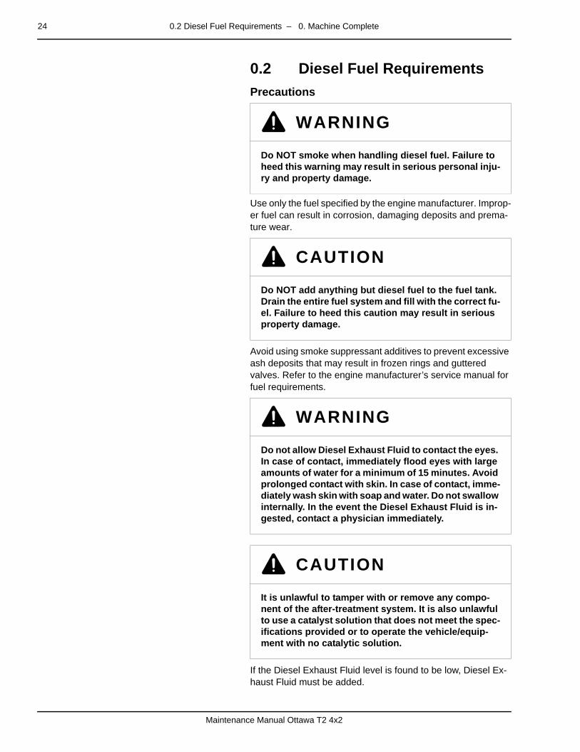
24 0.2 Diesel Fuel Requirements – 0. Machine Complete
Maintenance Manual Ottawa T2 4x2
0.2 Diesel Fuel Requirementspage –
Precautions
Use only the fuel specified by the engine manufacturer. Improp-er fuel can result in corrosion, damaging deposits and prema-ture wear.
Avoid using smoke suppressant additives to prevent excessive ash deposits that may result in frozen rings and guttered valves. Refer to the engine manufacturer’s service manual for fuel requirements.
If the Diesel Exhaust Fluid level is found to be low, Diesel Ex-haust Fluid must be added.
WARNING
Do NOT smoke when handling diesel fuel. Failure to heed this warning may result in serious personal inju-ry and property damage.
CAUTION
Do NOT add anything but diesel fuel to the fuel tank. Drain the entire fuel system and fill with the correct fu-el. Failure to heed this caution may result in serious property damage.
WARNING
Do not allow Diesel Exhaust Fluid to contact the eyes. In case of contact, immediately flood eyes with large amounts of water for a minimum of 15 minutes. Avoid prolonged contact with skin. In case of contact, imme-diately wash skin with soap and water. Do not swallow internally. In the event the Diesel Exhaust Fluid is in-gested, contact a physician immediately.
CAUTION
It is unlawful to tamper with or remove any compo-nent of the after-treatment system. It is also unlawful to use a catalyst solution that does not meet the spec-ifications provided or to operate the vehicle/equip-ment with no catalytic solution.

0.2 Diesel Fuel Requirements – 0. Machine Complete 25
Maintenance Manual Ottawa T2 4x2
The following are other common names used for DEF:
• Urea• AUS 32 (Aqueous Urea Solution 32)• AdBlue • NOx Reduction Agent• Catalyst Solution
Regardless of what the Diesel Exhaust Fluid is called, the Die-sel Exhaust Fluid must meet the engine manufacturer's speci-fication. See your engine operator's manual.
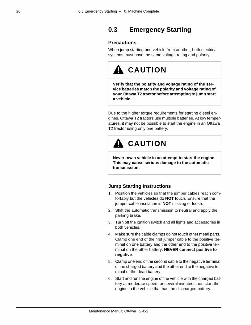
26 0.3 Emergency Starting – 0. Machine Complete
Maintenance Manual Ottawa T2 4x2
0.3 Emergency Startingpage –
PrecautionsWhen jump starting one vehicle from another, both electrical systems must have the same voltage rating and polarity.
Due to the higher torque requirements for starting diesel en-gines, Ottawa T2 tractors use multiple batteries. At low temper-atures, it may not be possible to start the engine in an Ottawa T2 tractor using only one battery.
–
Jump Starting Instructions1. Position the vehicles so that the jumper cables reach com-
fortably but the vehicles do NOT touch. Ensure that the jumper cable insulation is NOT missing or loose.
2. Shift the automatic transmission to neutral and apply the parking brake.
3. Turn off the ignition switch and all lights and accessories in both vehicles.
4. Make sure the cable clamps do not touch other metal parts. Clamp one end of the first jumper cable to the positive ter-minal on one battery and the other end to the positive ter-minal on the other battery. NEVER connect positive to negative.
5. Clamp one end of the second cable to the negative terminal of the charged battery and the other end to the negative ter-minal of the dead battery.
6. Start and run the engine of the vehicle with the charged bat-tery at moderate speed for several minutes, then start the engine in the vehicle that has the discharged battery.
CAUTION
Verify that the polarity and voltage rating of the ser-vice batteries match the polarity and voltage rating of your Ottawa T2 tractor before attempting to jump start a vehicle.
CAUTION
Never tow a vehicle in an attempt to start the engine. This may cause serious damage to the automatic transmission.
0.3 Emergency Starting – 0. Machine Complete 27
Maintenance Manual Ottawa T2 4x2
7. Remove the jumper cables by reversing the above installa-tion sequence exactly. While removing each clamp be sure that it does not touch any other metal while connected to the other battery.
WARNING
Batteries produce explosive gases, contain corrosive acid and generate levels of electrical current high enough to cause burns.
To reduce the risk of personal injury when working near a battery:
• WEAR SAFETY GLASSES and avoid leaning over a battery whenever possible.
• Do NOT expose a battery to open flames or sparks.
• Ensure that batteries with fill caps are properly filled with fluid.
• Do NOT allow battery acid to contact eyes or skin. Flush any contacted area thoroughly with water immediately and seek medical attention.
Failure to heed this warning may result in serious per-sonal injury and property damage.

28 0.4 Vehicle Towing – 0. Machine Complete
Maintenance Manual Ottawa T2 4x2
0.4 Vehicle Towingpage –
PrecautionsUse proper equipment to prevent damage to vehicles during towing. Conform to applicable state and local laws for towing vehicles. Vehicles should not be towed at speeds in excess of 55 mph (89 km/h). Connect towing equipment to main structur-al parts of the vehicle. See Operator’s Manual for more detailed instructions.
–
Front End Towing (Front Wheels Off the Ground)To relocate a disabled vehicle by front end towing with front wheels raised off the ground, follow these steps.
1. Block the rear wheels of the disabled vehicle.
2. Release the parking brake as outlined in the brake section of this manual.
See Caging the brakes in the Operator’s Manual or the sec-tion on caging the brakes in this manual if there is no air pressure in the system.
3. Disconnect the propeller shaft at the axle. Secure the pro-peller shaft to the frame or cross member.
4. Remove the axle shafts if there is damage or suspected damage to the axle(s).
5. Cover the hub openings to prevent loss of lubricant or entry of dirt or foreign objects.
CAUTION
Do NOT connect towing equipment to the bumper. Use tow hooks or tow eyes built into the frame. Use only towing equipment designed for the purpose. Fol-low the instructions of the wrecker manufacturer. Use safety chains. Failure to heed this caution may result in serious property damage.
Secure all loose and protruding parts of the vehicles prior to towing.
Do NOT stand or work under an elevated vehicle with-out adequate safety stands.
Do NOT attempt towing operations that will jeopardize the safety of other motorists, bystanders or the tow-ing or towed vehicles.
0.4 Vehicle Towing – 0. Machine Complete 29
Maintenance Manual Ottawa T2 4x2
When the vehicle has arrived at its destination, ensure it is safely positioned.
1. Block the rear wheels.
2. Install the axle shafts.
3. Remove the covers from the hub openings.
4. Align the universal joints and connect the propeller shaft.
5. Apply the parking brake before disconnecting the towing vehicle.
6. Check and fill rear axles with oil as needed.
–
Front End Towing (All Wheels On the Ground)The vehicle may be towed with all wheels on the ground provid-ed the steering system is operating normally. Remember that the steering will not have power assist and the vehicle will not have brakes. A tow bar must be used between the towing and the disabled vehicle.
To relocate a disabled vehicle by towing with all wheels on the ground, follow the procedure described above for towing with front wheels off the ground.
–
Rear End TowingWhen towing the vehicle with rear wheels raised, secure the steering wheel to maintain straight ahead position. Ensure that the front axle load is not more than the gross axle weight rating as indicated on the vehicle identification plate.

30 0.5 Vehicle Modifications – 0. Machine Complete
Maintenance Manual Ottawa T2 4x2
0.5 Vehicle Modificationspage –
ApprovalDo not modify your Ottawa T2 tractor without approval in writing from Kalmar Solutions LLC, Kalmar Terminal Tractors. Unau-thorized modifications may void the vehicle warranty.
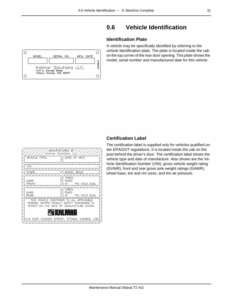
0.6 Vehicle Identification – 0. Machine Complete 31
Maintenance Manual Ottawa T2 4x2
0.6 Vehicle Identificationpage –
Identification PlateA vehicle may be specifically identified by referring to the vehicle identification plate. The plate is located inside the cab on the top corner of the rear door opening. This plate shows the model, serial number and manufactured date for this vehicle.
–
Certification LabelThe certification label is supplied only for vehicles qualified un-der EPA/DOT regulations. It is located inside the cab on the post behind the driver’s door. The certification label shows the vehicle type and date of manufacture. Also shown are the Ve-hicle Identification Number (VIN), gross vehicle weight rating (GVWR), front and rear gross axle weight ratings (GAWR), wheel base, tire and rim sizes, and tire air pressure.
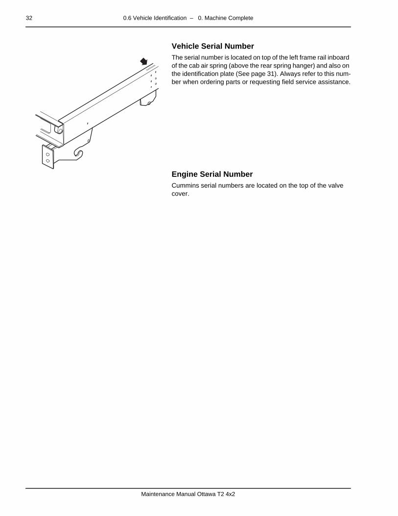
32 0.6 Vehicle Identification – 0. Machine Complete
Maintenance Manual Ottawa T2 4x2
–
Vehicle Serial NumberThe serial number is located on top of the left frame rail inboard of the cab air spring (above the rear spring hanger) and also on the identification plate (See page 31). Always refer to this num-ber when ordering parts or requesting field service assistance.
–
Engine Serial NumberCummins serial numbers are located on the top of the valve cover.
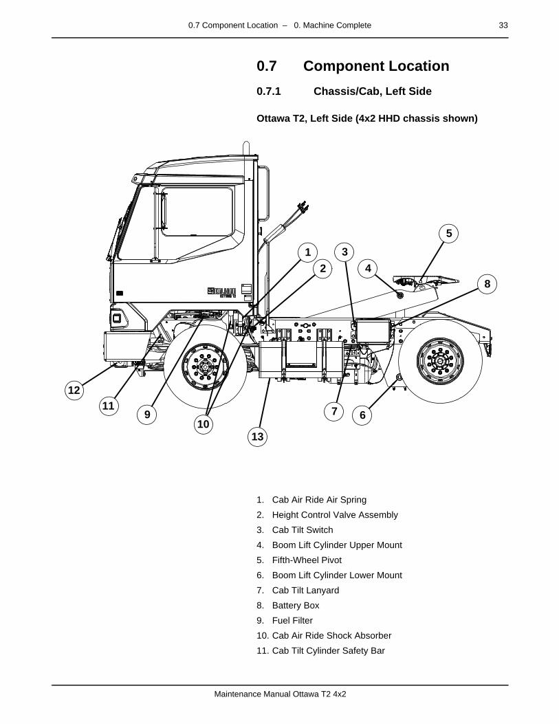
0.7 Component Location – 0. Machine Complete 33
Maintenance Manual Ottawa T2 4x2
0.7 Component Location
0.7.1 Chassis/Cab, Left Sidepage –
Ottawa T2, Left Side (4x2 HHD chassis shown)
1. Cab Air Ride Air Spring
2. Height Control Valve Assembly
3. Cab Tilt Switch
4. Boom Lift Cylinder Upper Mount
5. Fifth-Wheel Pivot
6. Boom Lift Cylinder Lower Mount
7. Cab Tilt Lanyard
8. Battery Box
9. Fuel Filter
10. Cab Air Ride Shock Absorber
11. Cab Tilt Cylinder Safety Bar
12
34
5
67
8
910
1112
13
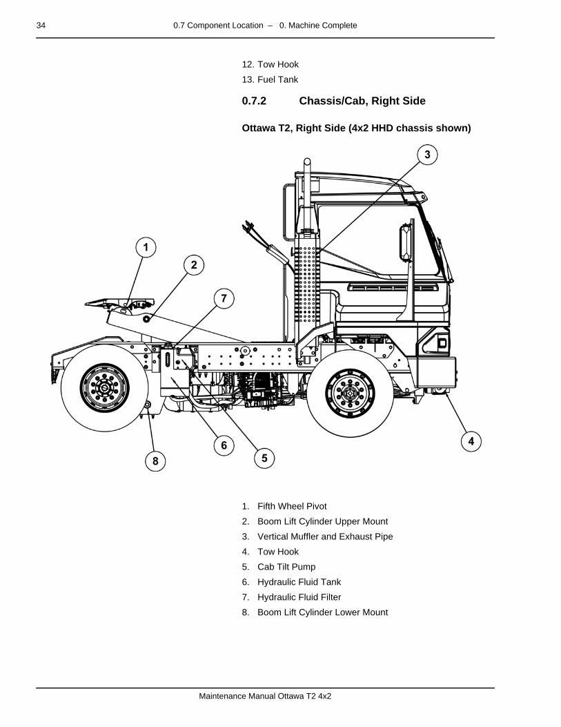
34 0.7 Component Location – 0. Machine Complete
Maintenance Manual Ottawa T2 4x2
12. Tow Hook
13. Fuel Tank
0.7.2 Chassis/Cab, Right Sidepage –
Ottawa T2, Right Side (4x2 HHD chassis shown)
1. Fifth Wheel Pivot
2. Boom Lift Cylinder Upper Mount
3. Vertical Muffler and Exhaust Pipe
4. Tow Hook
5. Cab Tilt Pump
6. Hydraulic Fluid Tank
7. Hydraulic Fluid Filter
8. Boom Lift Cylinder Lower Mount

0.7 Component Location – 0. Machine Complete 35
Maintenance Manual Ottawa T2 4x2
0.7.3 Chassis/Cab, Front/Rearpage –
Ottawa T2, Front/Rear (4x2 HHD chassis shown)
1. Front Panel (Removable)
2. Rear Door
3. Glad Hands (Air Brake)
4. Trailer Electrical Connector (7-pin)
5. Air Brake Chambers
6. Fifth-Wheel
7. Front Leaf Springs
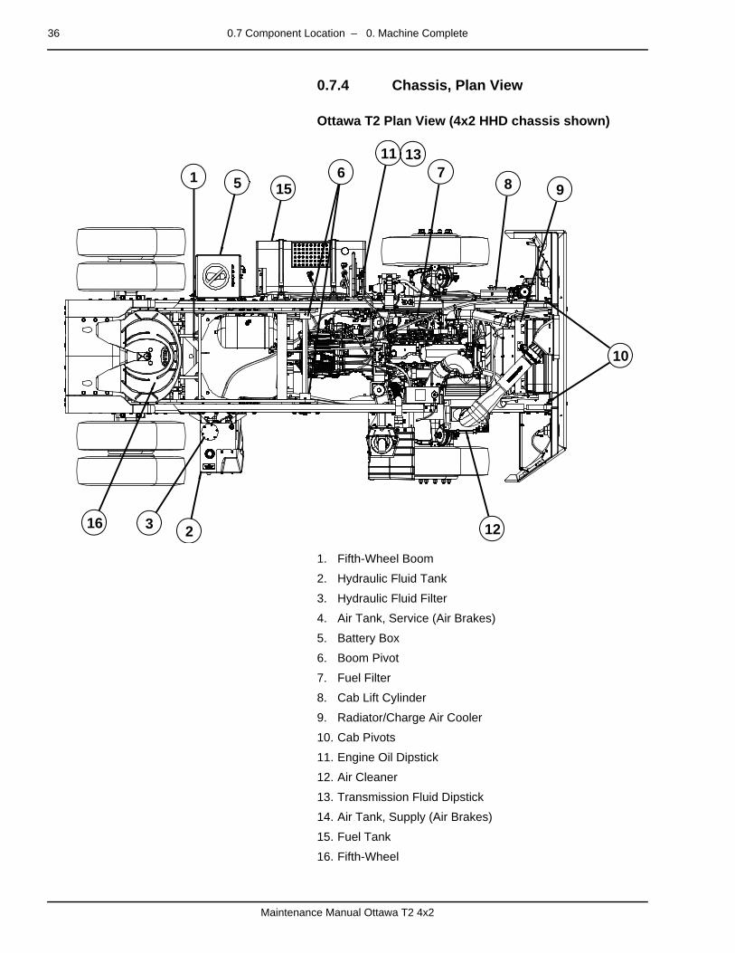
36 0.7 Component Location – 0. Machine Complete
Maintenance Manual Ottawa T2 4x2
0.7.4 Chassis, Plan Viewpage –
Ottawa T2 Plan View (4x2 HHD chassis shown)
1. Fifth-Wheel Boom
2. Hydraulic Fluid Tank
3. Hydraulic Fluid Filter
4. Air Tank, Service (Air Brakes)
5. Battery Box
6. Boom Pivot
7. Fuel Filter
8. Cab Lift Cylinder
9. Radiator/Charge Air Cooler
10. Cab Pivots
11. Engine Oil Dipstick
12. Air Cleaner
13. Transmission Fluid Dipstick
14. Air Tank, Supply (Air Brakes)
15. Fuel Tank
16. Fifth-Wheel
1
23
56 7
8 9
10
11
12
13
15
16
0.8 Electrical Instruments – 0. Machine Complete 37
Maintenance Manual Ottawa T2 4x2
0.8 Electrical Instrumentspage –
Guide to TroubleshootingThis guide is provided for diagnosis of problems in Kalmar elec-trical instruments. The sequence presented is intended to min-imize duplication. Follow the sequence as described to prevent misdiagnosis. This guide presumes that senders and gauges are properly matched and wired and that the correct voltage is applied.
page –
Basic Gauge Cluster Diagnostic ProcedureSchematics and diagrams of the electrical circuitry appear in Section E, Schematics.
The following steps describe the general path to follow when troubleshooting electrical faults that show up on the instrument panel.
1. On replacement parts, check the part numbers of the gauge and sender to ensure they are matched, and match the voltage in the vehicle (12 VDC or 24 VDC).
2. Inspect the wiring between the gauge cluster and sender. Wiring should be intact and tightly connected. Tighten and replace wiring as required.
3. If the gauge cluster still does not work, ensure that the steel housing of the sender is properly seated.
Grounded Sender Test — Attach the sender wire from the gauge to an established chassis ground. Momentarily apply power. The pointer should move to the far right of the scale. Remove power. If the gauge fails this test, replace the gauge and retest.
4. If the pointer jumps rapidly, overshoots or oscillates around the rest position, the sender connection contact is intermit-tent. Trace the sender wiring and verify that the connec-tions are secure. If connections are tight and in good condition, replace the gauge cluster.
WARNING
Ensure that the gauge cluster and senders are matched and properly wired in circuits with correct voltage. Failure to heed this warning could result in personal injury and property damage.

38 0.8 Electrical Instruments – 0. Machine Complete
Maintenance Manual Ottawa T2 4x2
– 1 Engine 39
Maintenance Manual Ottawa T2 4x2
mm mm mm mm mm mm
1 Enginepage –
DescriptionThe Ottawa T2 yard tractor is designed to utilize the benefits of a diesel engine of the type customarily found in fire engines, dump trucks and refuse haulers. Engine options are provided for OFF-HIGHWAY and DOT/EPA certified applications with a choice of power ratings available from several engine manufac-turers.
For service and maintenance information, consult the manuals included with your vehicle, contact the Kalmar dealer or the manufacturer of the component installed in your vehicle.

40 1.1 Controls and Instruments – 1 Engine
Maintenance Manual Ottawa T2 4x2
1.1 Controls and Instruments
1.1.7 Fuel Gaugepage –
Diagnosis
Fuel Gauge Components
• Cab Accessory Circuit Breaker
• Gauge Cluster
• Fuel Level Sending Unit
• Headlight Switch
• Ignition Switch
• Panel Dimmer Switch (Optional)
Fuel Gauge Circuit Diagnosis
Observation Cause Action
Zero reading Circuit breaker open Reset. Repair short as needed. Re-place circuit breaker as needed.
Open circuit, loose connection Test. Repair as needed.
Defective gauge cluster Test. Replace as needed.
Defective alternator Test. Replace as needed.
Inaccurate gauge Defective gauge cluster Test. Replace as needed.
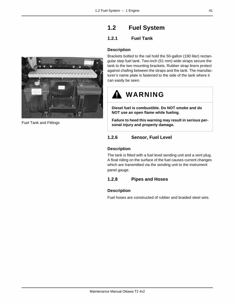
1.2 Fuel System – 1 Engine 41
Maintenance Manual Ottawa T2 4x2
1.2 Fuel System
1.2.1 Fuel Tankpage –
Description
Fuel Tank and Fittings
Brackets bolted to the rail hold the 50-gallon (190 liter) rectan-gular step fuel tank. Two-inch (51 mm) wide straps secure the tank to the two mounting brackets. Rubber strap liners protect against chafing between the straps and the tank. The manufac-turer’s name plate is fastened to the side of the tank where it can easily be seen.
1.2.6 Sensor, Fuel Levelpage –
Description
The tank is fitted with a fuel level sending unit and a vent plug. A float riding on the surface of the fuel causes current changes which are transmitted via the sending unit to the instrument panel gauge.
1.2.8 Pipes and Hosespage –
Description
Fuel hoses are constructed of rubber and braided steel wire.
WARNING
Diesel fuel is combustible. Do NOT smoke and do NOT use an open flame while fueling.
Failure to heed this warning may result in serious per-sonal injury and property damage.

42 1.3 Diesel Exhaust Fluid (DEF) – 1 Engine
Maintenance Manual Ottawa T2 4x2
1.3 Diesel Exhaust Fluid (DEF)
1.3.1 DEF Tank and Pumppage –
Description
DEF tank
The DEF tank is locate on the left side of the tractor at the rear of the fuel tank. It is a 5-gallon size tank constructed of cross-link polyethylene (XLPE). The tank is mounted with a bracket to the frame rail. The blue fill cap signifies its use as DEF ONLY.
1.3.6 Sensor, Low DEF Levelpage –
Description
A level sensor and level focus tube is integrated into a multi-function head unit on the DEF tank. The level sensor uses an ultrasonic transducer to sense the fluid level. The instrument panel will illuminate the Low DEF warning lamp when fluid level falls below the preset amount.
1.3.8 DEF Hose Lines page –
Description
The DEF system coolant lines between the DEF multifunction head unit and coolant system are reinforced synthetic rubber secured with worm-gear clamps.
The DEF suction and return lines are electrically heated to pre-vent fluid freezing. Both lines are connected to the dosing pump unit with 5/16" straight fittings. The DEF suction (throttle) line (1000 mm long) connects to the multifunction head unit with a 3/8" 90-degree fitting. The DEF return (pressure) line (1750 mm long) connects to the multifunction head unit with a 5/16" 90-degree fitting.
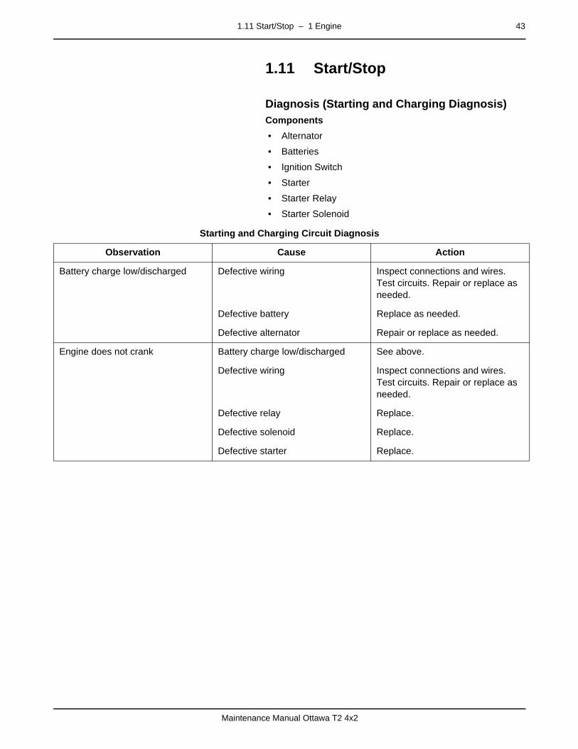
1.11 Start/Stop – 1 Engine 43
Maintenance Manual Ottawa T2 4x2
1.11 Start/Stoppage –
Diagnosis (Starting and Charging Diagnosis)Components
• Alternator
• Batteries
• Ignition Switch
• Starter
• Starter Relay
• Starter Solenoid
Starting and Charging Circuit Diagnosis
Observation Cause Action
Battery charge low/discharged Defective wiring Inspect connections and wires. Test circuits. Repair or replace as needed.
Defective battery Replace as needed.
Defective alternator Repair or replace as needed.
Engine does not crank Battery charge low/discharged See above.
Defective wiring Inspect connections and wires. Test circuits. Repair or replace as needed.
Defective relay Replace.
Defective solenoid Replace.
Defective starter Replace.

44 1.11 Start/Stop – 1 Engine
Maintenance Manual Ottawa T2 4x2
– 2 Transmission 45
Maintenance Manual Ottawa T2 4x2
mm mm mm mm mm mm
2 Transmissionpage –
DescriptionThe standard transmission is an automatic Allison, RDS series.
For service and maintenance information, consult the manuals included with your vehicle, contact the Kalmar dealer or the manufacturer of the component installed in your vehicle.

46 – 2 Transmission
Maintenance Manual Ottawa T2 4x2
– 3 Driveline/Axle 47
Maintenance Manual Ottawa T2 4x2
mm mm mm mm mm mm
3 Driveline/Axlepage –
DescriptionAn Ottawa T2 tractor will be equipped with one of several man-ufacturer’s rear axles. Special features, such as a locking or a “No-Spin” differential, are optional. Contact your Kalmar dealer if you do not know whether your vehicle contains these fea-tures.
For service and maintenance information, consult the manuals included with your vehicle, contact the Kalmar dealer or the manufacturer of the component installed in your vehicle.

48 – 3 Driveline/Axle
Maintenance Manual Ottawa T2 4x2
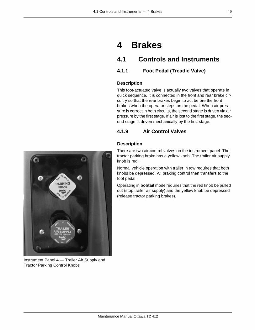
4.1 Controls and Instruments – 4 Brakes 49
Maintenance Manual Ottawa T2 4x2
mm mm mm mm mm mm
4 Brakes
4.1 Controls and Instruments
4.1.1 Foot Pedal (Treadle Valve)page –
Description
This foot-actuated valve is actually two valves that operate in quick sequence. It is connected in the front and rear brake cir-cuitry so that the rear brakes begin to act before the front brakes when the operator steps on the pedal. When air pres-sure is correct in both circuits, the second stage is driven via air pressure by the first stage. If air is lost to the first stage, the sec-ond stage is driven mechanically by the first stage.
4.1.9 Air Control Valvespage –
Description
Instrument Panel 4 — Trailer Air Supply and Tractor Parking Control Knobs
There are two air control valves on the instrument panel. The tractor parking brake has a yellow knob. The trailer air supply knob is red.
Normal vehicle operation with trailer in tow requires that both knobs be depressed. All braking control then transfers to the foot pedal.
Operating in bobtail mode requires that the red knob be pulled out (stop trailer air supply) and the yellow knob be depressed (release tractor parking brakes).

50 4.3 Brake System – 4 Brakes
Maintenance Manual Ottawa T2 4x2
4.3 Brake Systempage –
DescriptionMajor components of the air brake system include the following items.
• Air Compressor and Governor
• Air Control Valves
• Air Dryer (Optional)
• Air Reservoirs (Air Storage)
• Brake Chambers and Parking Brakes
• Double (Two-Way) Check Valves
• Foot Pedal (Treadle Valve)
• Foundation (Wheel) Brakes
• Proportioning (Bobtail) Valve (Optional)
• Quick Release Valves
• Slack Adjusters
• Stop Light Switch
• Tractor Protection Valves
• Trailer Brake Air Lines
Within the system are two separate air distribution circuits. These operate the rear (primary) and front (secondary) founda-tion brakes. Air flow within the two circuits is controlled through a series of valves which supply or release air to the chambers in response to the driver’s command. The parking brakes are spring-actuated, but compressed air is required to release them.
A buzzer and an indicator light warn of low pressure in the sys-tem when pressure falls below 70 psi. The air pressure gauge reflects the actual system pressure.
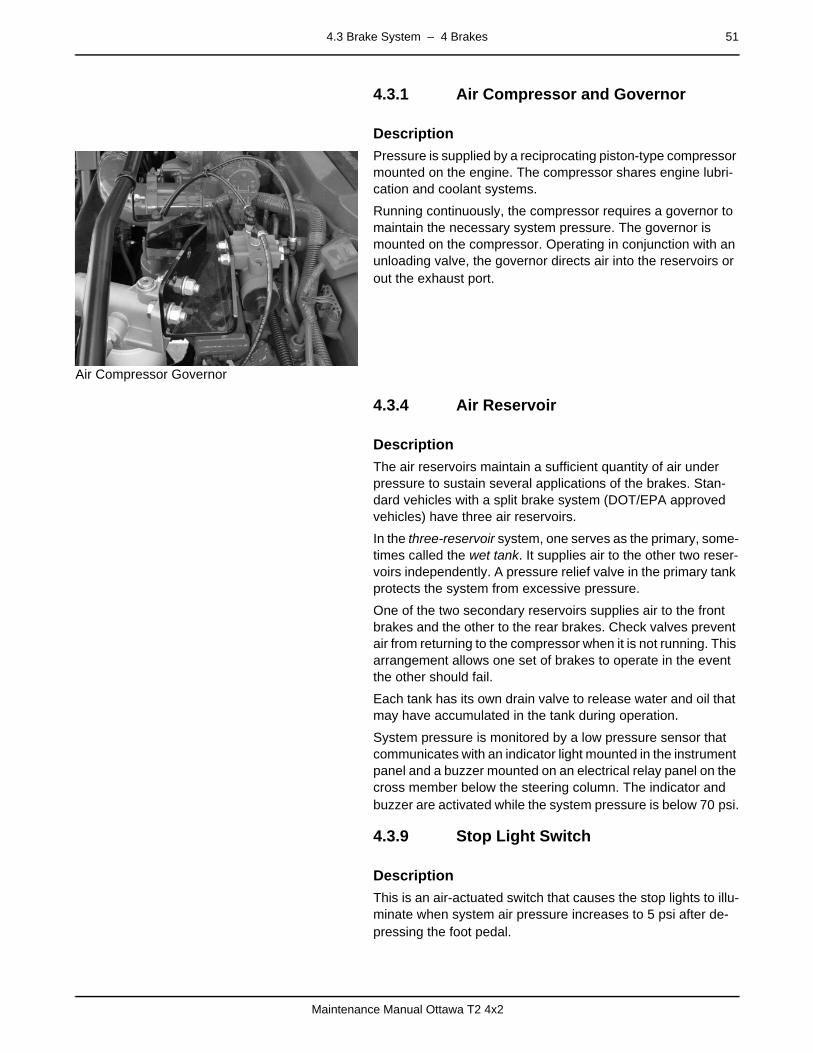
4.3 Brake System – 4 Brakes 51
Maintenance Manual Ottawa T2 4x2
4.3.1 Air Compressor and Governorpage –
Description
Air Compressor Governor
Pressure is supplied by a reciprocating piston-type compressor mounted on the engine. The compressor shares engine lubri-cation and coolant systems.
Running continuously, the compressor requires a governor to maintain the necessary system pressure. The governor is mounted on the compressor. Operating in conjunction with an unloading valve, the governor directs air into the reservoirs or out the exhaust port.
4.3.4 Air Reservoirpage –
Description
The air reservoirs maintain a sufficient quantity of air under pressure to sustain several applications of the brakes. Stan-dard vehicles with a split brake system (DOT/EPA approved vehicles) have three air reservoirs.
In the three-reservoir system, one serves as the primary, some-times called the wet tank. It supplies air to the other two reser-voirs independently. A pressure relief valve in the primary tank protects the system from excessive pressure.
One of the two secondary reservoirs supplies air to the front brakes and the other to the rear brakes. Check valves prevent air from returning to the compressor when it is not running. This arrangement allows one set of brakes to operate in the event the other should fail.
Each tank has its own drain valve to release water and oil that may have accumulated in the tank during operation.
System pressure is monitored by a low pressure sensor that communicates with an indicator light mounted in the instrument panel and a buzzer mounted on an electrical relay panel on the cross member below the steering column. The indicator and buzzer are activated while the system pressure is below 70 psi.
4.3.9 Stop Light Switchpage –
Description
This is an air-actuated switch that causes the stop lights to illu-minate when system air pressure increases to 5 psi after de-pressing the foot pedal.

52 4.3 Brake System – 4 Brakes
Maintenance Manual Ottawa T2 4x2
4.3.10 Brakespage –
Description
Brake Chambers and Parking Brakes — In the front are two single chamber units at the wheel ends. These operate the foundation brakes described below.
In the rear are two dual chamber units at the wheel ends. These operate both the foundation brakes and the parking brakes. When there are dual rear axles, brake chambers are typically mounted on the forward axle, but are sometimes supplied on both axles.
The brake chamber is designed to move the shoes against the drums using air pressure. Air pressure is released into the chamber by the foot pedal. Push rods change the air pressure into mechanical action to rotate the brake cam shafts. The push rods in the brake chambers provide a 2.25-2.50-inch (57-64 mm) range of stroke length.
The second chamber in the dual chamber unit uses the air pressure to keep a powerful spring compressed. This spring, attached to the push rod, provides the parking brake action.
When system air pressure falls below 43 PSI, the springs acti-vate the push rods and apply the foundation brakes. When sys-tem air pressure rises above the set point, it overcomes the spring pressure and releases the brakes.
For service, the springs can be released manually if the engine cannot be started, or if air pressure cannot be restored to the system.
Slack Adjuster Diagram
Slack Adjusters — Slack adjusters change the distance the brake shoes have to travel to contact the drum. During each ap-plication of the brakes, automatic adjusters detect the rotation of the brake cam shaft. They retain the setting at the point where the lining contacts the drum. This setting changes as the drum and linings wear.
Foundation (Wheel) Brakes — The foundation brakes consist of brake drums on the wheels and shoes lined with friction ma-terial attached to the axles. Actuated via cams rotated by push rods in the brake chambers, the shoes are pressed against the drums. Air pressure controlled by the foot pedal supplies the force necessary to stop the wheels from rotating.
OTT
0012
BRAKE CHAMBERPUSHROD
S-CAMBRAKESHOES
BRAKE DRUM
SLACKADJUSTER
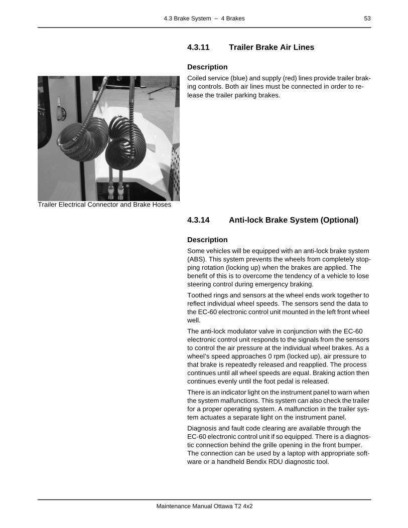
4.3 Brake System – 4 Brakes 53
Maintenance Manual Ottawa T2 4x2
4.3.11 Trailer Brake Air Linespage –
Description
Trailer Electrical Connector and Brake Hoses
Coiled service (blue) and supply (red) lines provide trailer brak-ing controls. Both air lines must be connected in order to re-lease the trailer parking brakes.
4.3.14 Anti-lock Brake System (Optional)page –
Description
Some vehicles will be equipped with an anti-lock brake system (ABS). This system prevents the wheels from completely stop-ping rotation (locking up) when the brakes are applied. The benefit of this is to overcome the tendency of a vehicle to lose steering control during emergency braking.
Toothed rings and sensors at the wheel ends work together to reflect individual wheel speeds. The sensors send the data to the EC-60 electronic control unit mounted in the left front wheel well.
The anti-lock modulator valve in conjunction with the EC-60 electronic control unit responds to the signals from the sensors to control the air pressure at the individual wheel brakes. As a wheel’s speed approaches 0 rpm (locked up), air pressure to that brake is repeatedly released and reapplied. The process continues until all wheel speeds are equal. Braking action then continues evenly until the foot pedal is released.
There is an indicator light on the instrument panel to warn when the system malfunctions. This system can also check the trailer for a proper operating system. A malfunction in the trailer sys-tem actuates a separate light on the instrument panel.
Diagnosis and fault code clearing are available through the EC-60 electronic control unit if so equipped. There is a diagnos-tic connection behind the grille opening in the front bumper. The connection can be used by a laptop with appropriate soft-ware or a handheld Bendix RDU diagnostic tool.

54 4.3 Brake System – 4 Brakes
Maintenance Manual Ottawa T2 4x2
4.3.15 Automatic Traction Control (Optional)
page –
Description
Some vehicles that are equipped with ABS may also be equipped with full-time automatic traction control (ATC). The ATC indicator lamp blinks when ATC is working.
ATC uses the ABS wheel sensors. It compares front wheel speed to rear wheel speed and left rear wheel speed to right rear wheel speed. When a set ratio is exceeded, ATC applies the rear brakes to the appropriate wheel end.
ATC operates only at speeds less than 25-30 miles per hour (40-48 kilometers per hour). At higher speeds, vehicle reaction to a sudden application of the brakes on one side may cause loss of driver control.
4.3.16 Manually Releasing Tractor Spring Brakes (Caging)
page –
Description
When air pressure in the system drops below approximately 43 psi, the spring parking brakes will apply automatically. To re-lease the spring brakes, the air pressure must be returned to 70 psi. If the system cannot be recharged and the vehicle must be moved, the spring parking brakes can be released manually (caged).
To release the spring brakes, the actual spring in the brake canisters must be mechanically compressed. A release stud, or spring caging tool, must be used to manually compress the brake chamber.
DANGER
Never manually release (cage) the spring brakes be-fore the wheels are properly blocked. If the wheels are not properly blocked before releasing the spring brakes, the vehicle may move unexpectedly. This could result in serious injury or death.
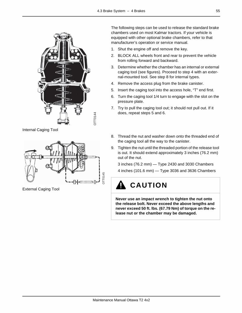
4.3 Brake System – 4 Brakes 55
Maintenance Manual Ottawa T2 4x2
Internal Caging Tool
The following steps can be used to release the standard brake chambers used on most Kalmar tractors. If your vehicle is equipped with other optional brake chambers, refer to that manufacturer’s operation or service manual.
1. Shut the engine off and remove the key.
2. BLOCK ALL wheels front and rear to prevent the vehicle from rolling forward and backward.
3. Determine whether the chamber has an internal or external caging tool (see figures). Proceed to step 4 with an exter-nal-mounted tool. See step 8 for internal types.
4. Remove the access plug from the brake canister.
5. Insert the caging tool into the access hole, “T” end first.
6. Turn the caging tool 1/4 turn to engage with the slot on the pressure plate.
7. Try to pull the caging tool out; it should not pull out. If it does, repeat steps 5 and 6.
External Caging Tool
8. Thread the nut and washer down onto the threaded end of the caging tool all the way to the canister.
9. Tighten the nut until the threaded portion of the release tool is out. It should extend approximately 3 inches (76.2 mm) out of the nut.
3 inches (76.2 mm) — Type 2430 and 3030 Chambers
4 inches (101.6 mm) — Type 3036 and 3636 Chambers
OTT
0144
OTT
0145
CAUTION
Never use an impact wrench to tighten the nut onto the release bolt. Never exceed the above lengths and never exceed 50 ft. lbs. (67.79 Nm) of torque on the re-lease nut or the chamber may be damaged.
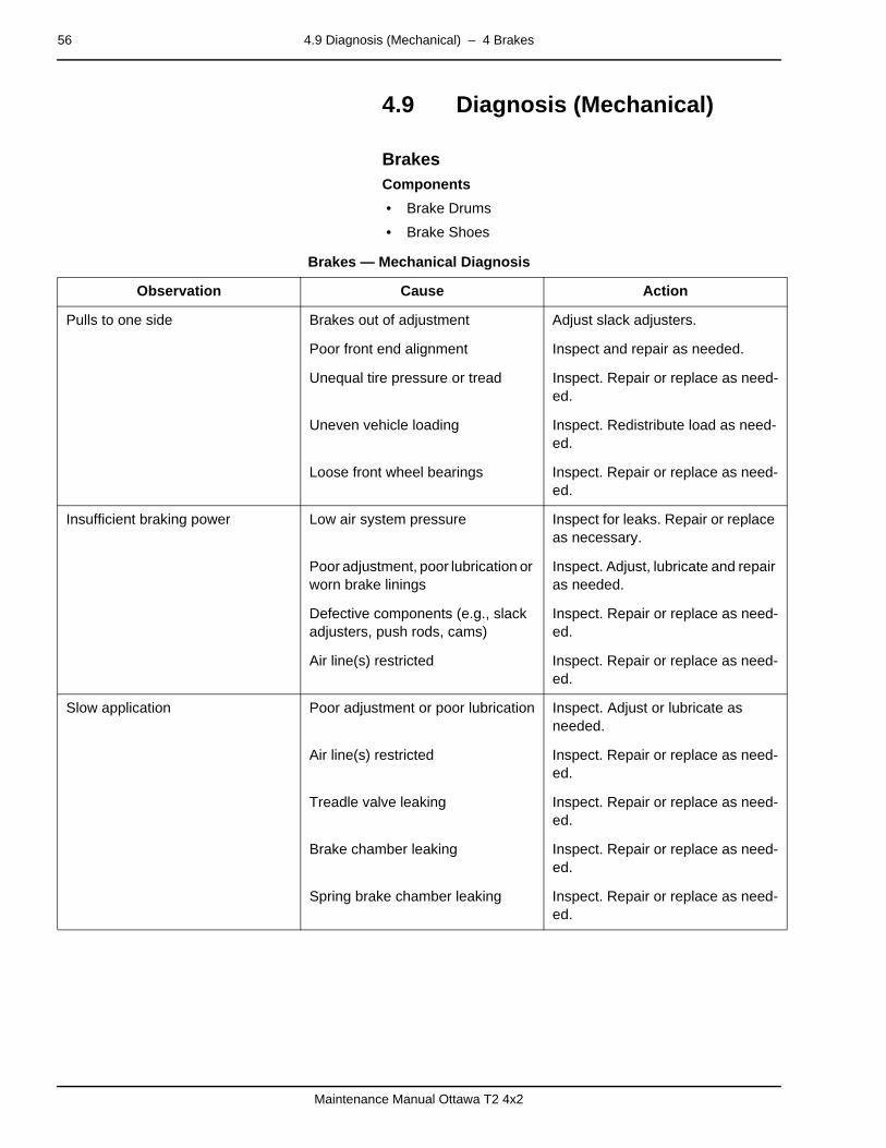
56 4.9 Diagnosis (Mechanical) – 4 Brakes
Maintenance Manual Ottawa T2 4x2
4.9 Diagnosis (Mechanical)page –
BrakesComponents
• Brake Drums
• Brake Shoes
Brakes — Mechanical Diagnosis
Observation Cause Action
Pulls to one side Brakes out of adjustment Adjust slack adjusters.
Poor front end alignment Inspect and repair as needed.
Unequal tire pressure or tread Inspect. Repair or replace as need-ed.
Uneven vehicle loading Inspect. Redistribute load as need-ed.
Loose front wheel bearings Inspect. Repair or replace as need-ed.
Insufficient braking power Low air system pressure Inspect for leaks. Repair or replace as necessary.
Poor adjustment, poor lubrication or worn brake linings
Inspect. Adjust, lubricate and repair as needed.
Defective components (e.g., slack adjusters, push rods, cams)
Inspect. Repair or replace as need-ed.
Air line(s) restricted Inspect. Repair or replace as need-ed.
Slow application Poor adjustment or poor lubrication Inspect. Adjust or lubricate as needed.
Air line(s) restricted Inspect. Repair or replace as need-ed.
Treadle valve leaking Inspect. Repair or replace as need-ed.
Brake chamber leaking Inspect. Repair or replace as need-ed.
Spring brake chamber leaking Inspect. Repair or replace as need-ed.
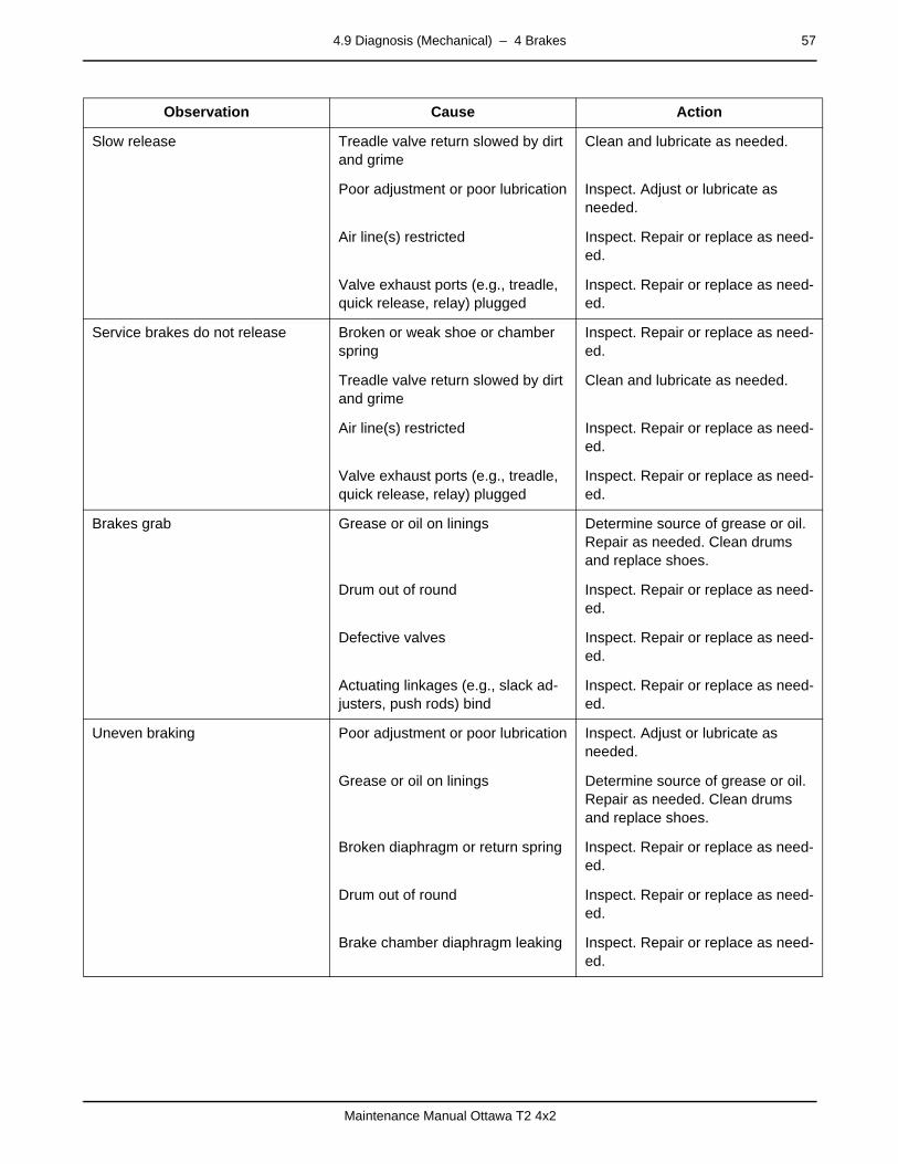
4.9 Diagnosis (Mechanical) – 4 Brakes 57
Maintenance Manual Ottawa T2 4x2
Slow release Treadle valve return slowed by dirt and grime
Clean and lubricate as needed.
Poor adjustment or poor lubrication Inspect. Adjust or lubricate as needed.
Air line(s) restricted Inspect. Repair or replace as need-ed.
Valve exhaust ports (e.g., treadle, quick release, relay) plugged
Inspect. Repair or replace as need-ed.
Service brakes do not release Broken or weak shoe or chamber spring
Inspect. Repair or replace as need-ed.
Treadle valve return slowed by dirt and grime
Clean and lubricate as needed.
Air line(s) restricted Inspect. Repair or replace as need-ed.
Valve exhaust ports (e.g., treadle, quick release, relay) plugged
Inspect. Repair or replace as need-ed.
Brakes grab Grease or oil on linings Determine source of grease or oil. Repair as needed. Clean drums and replace shoes.
Drum out of round Inspect. Repair or replace as need-ed.
Defective valves Inspect. Repair or replace as need-ed.
Actuating linkages (e.g., slack ad-justers, push rods) bind
Inspect. Repair or replace as need-ed.
Uneven braking Poor adjustment or poor lubrication Inspect. Adjust or lubricate as needed.
Grease or oil on linings Determine source of grease or oil. Repair as needed. Clean drums and replace shoes.
Broken diaphragm or return spring Inspect. Repair or replace as need-ed.
Drum out of round Inspect. Repair or replace as need-ed.
Brake chamber diaphragm leaking Inspect. Repair or replace as need-ed.
Observation Cause Action
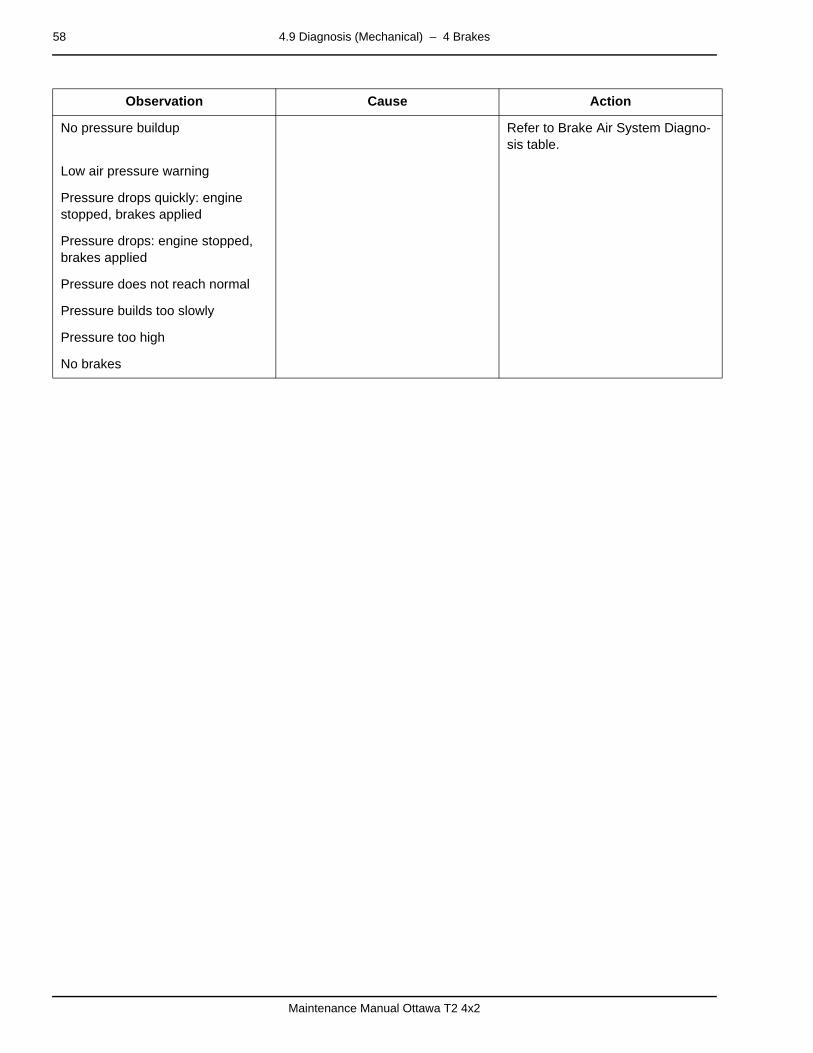
58 4.9 Diagnosis (Mechanical) – 4 Brakes
Maintenance Manual Ottawa T2 4x2
No pressure buildup Refer to Brake Air System Diagno-sis table.
Low air pressure warning
Pressure drops quickly: engine stopped, brakes applied
Pressure drops: engine stopped, brakes applied
Pressure does not reach normal
Pressure builds too slowly
Pressure too high
No brakes
Observation Cause Action
5.2 Steering System – 5 Steering 59
Maintenance Manual Ottawa T2 4x2
mm mm mm mm mm mm
5 Steering5.2 Steering System
page –
Description (Power Steering Components)The standard power steering system uses an integral power steering gear and the transmission-mounted hydraulic pump. The system operates on fluid drawn from the common reservoir shared with the boom and cab tilt systems.
Integral Power Steering Gear — When the steering wheel is turned, force is transmitted from the steering wheel to the steer-ing gear input shaft. A torsion bar pinned at one end to the input shaft and at the other end to the worm shaft, turns with the input shaft and exerts a rotational force on the worm shaft. In re-sponse to this rotational force, the worm shaft, acting through the recirculating ball mechanism, moves the rack piston axially through the gear-housing cylinder bore.
The rack piston’s axial movement is resisted by its engagement to the sector shaft, which is connected by linkage to the steered wheels. Because of this resistance, the input shaft actuates the control valve and twists the torsion bar. Pressurized fluid direct-ed by the control valve, assists in moving the rack piston axially through the cylinder bore. The rack piston then turns the sector shaft to steer the vehicle.
page –
Description (Optional Hydrostatic Steering Components)Hydrostatic steering consists of an orbital control valve, a hy-draulic pump (either engine mounted or mounted via a PTO on the transmission), steering cylinders, a reservoir and fluid lines. The orbital control valve has a steering wheel attached; the steering cylinders are attached to the front axle and connected to the steered wheels.
The orbital control valve is made up of two sections: the control valve section and the metering section. The control valve sec-tion directs fluid to and from the metering section and the steer-ing cylinders, and regulates the pressure to the steering cylinders. The control valve section is made up of a mechani-cally actuated spool valve and pressure chambers to provide circuit isolation. The metering section controls the amount of fluid to the steering cylinders while maintaining the relationship between the steering wheel and the steered wheels. This sec-tion can also act as a manual pump providing manual steering in the event of an inoperable hydraulic pump. The metering section consists of a rotor that orbits within a fixed stator to force oil through the section, and a commutator to channel the fluid to the valve section.
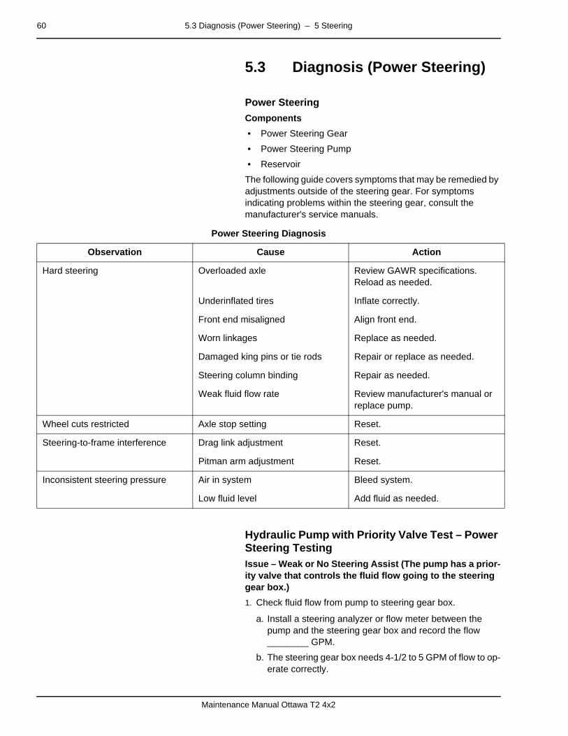
60 5.3 Diagnosis (Power Steering) – 5 Steering
Maintenance Manual Ottawa T2 4x2
5.3 Diagnosis (Power Steering)page –
Power Steering
Components
• Power Steering Gear
• Power Steering Pump
• Reservoir
The following guide covers symptoms that may be remedied by adjustments outside of the steering gear. For symptoms indicating problems within the steering gear, consult the manufacturer's service manuals.
Power Steering Diagnosis
–
Hydraulic Pump with Priority Valve Test – Power Steering TestingIssue – Weak or No Steering Assist (The pump has a prior-ity valve that controls the fluid flow going to the steering gear box.)
1. Check fluid flow from pump to steering gear box.
a. Install a steering analyzer or flow meter between the pump and the steering gear box and record the flow ________ GPM.
b. The steering gear box needs 4-1/2 to 5 GPM of flow to op-erate correctly.
Observation Cause Action
Hard steering Overloaded axle Review GAWR specifications. Reload as needed.
Underinflated tires Inflate correctly.
Front end misaligned Align front end.
Worn linkages Replace as needed.
Damaged king pins or tie rods Repair or replace as needed.
Steering column binding Repair as needed.
Weak fluid flow rate Review manufacturer's manual or replace pump.
Wheel cuts restricted Axle stop setting Reset.
Steering-to-frame interference Drag link adjustment Reset.
Pitman arm adjustment Reset.
Inconsistent steering pressure Air in system Bleed system.
Low fluid level Add fluid as needed.

5.3 Diagnosis (Power Steering) – 5 Steering 61
Maintenance Manual Ottawa T2 4x2
c. Close the flow valve on the steering analyzer and record the pressure _________ psi. The pressure needs to be 2100 to 2200 psi at pump relief.
d. If pump pressure is less than 2100 psi, the pressure relief on the pump needs to be adjusted. (Contact a Kalmar Field Service Representative for more information on set-ting the pump pressure relief.)
e. When turning the steering to the left, there should be 1700 to 1900 psi before poppet relief. When turning to the right, there should be 1600 to 1800 psi before poppet relief.
f. If the pump is not producing 4-1/2 to 5 GPM of flow and 2100 to 2200 psi and the steering is not operating correct-ly, the steering gear relief spring plungers may be set in-correctly in the steering gear box. (See Kalmar service bulletin # SB09TI0017.)
g. If the pump is not producing 4-1/2 to 5 GPM of flow at idle, the priority valve may be sticking due to contamination. To clean the priority valve, follow the instructions in the next step.
2. To clean the priority valve, follow these instructions.
a. Remove priority spool plug and the priority valve spring will be exposed and can be removed.
b. After the spring is removed, place your hand over the spool bore in the valve body and turn the valve body over. The priority flow orifice will drop out in your hand.
c. With the spool bore side of valve body down, tap the body lightly against a block of wood. This should cause the pri-ority spool to slide out of the spool bore.
d. Clean the spool bore and spool with clean solvent and dry with shop air or wipe dry with clean, lint-free shop towel.
e. Replace the priority flow orifice in the spring bore of the priority valve spool.
f. Replace the priority flow spring in the valve spool and with solid end of valve spool entering first, slide the valve spool with orifice and spring into the valve spool bore.
g. Install the plug and tighten.
h. Test pump. If there is no change in pump performance, replace the pump.
Note: Applies to systems using a single pump for steering and 5th wheel boom hydraulics.
–
Tools Needed• Steering analyzer
• 3000 psi pressure gauge
• 1/2" drive ratchet
• 1/2” drive 1-1/16" deep well socket
• 1/2” drive extension 3"
62 5.3 Diagnosis (Power Steering) – 5 Steering
Maintenance Manual Ottawa T2 4x2
• 1/2” end wrench
• Allen wrench 5/16”
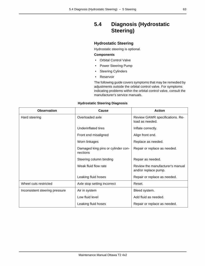
5.4 Diagnosis (Hydrostatic Steering) – 5 Steering 63
Maintenance Manual Ottawa T2 4x2
5.4 Diagnosis (Hydrostatic Steering)
page –
Hydrostatic SteeringHydrostatic steering is optional.
Components
• Orbital Control Valve
• Power Steering Pump
• Steering Cylinders
• Reservoir
The following guide covers symptoms that may be remedied by adjustments outside the orbital control valve. For symptoms indicating problems within the orbital control valve, consult the manufacturer's service manuals.
Hydrostatic Steering Diagnosis
Observation Cause Action
Hard steering Overloaded axle Review GAWR specifications. Re-load as needed.
Underinflated tires Inflate correctly.
Front end misaligned Align front end.
Worn linkages Replace as needed.
Damaged king pins or cylinder con-nections
Repair or replace as needed.
Steering column binding Repair as needed.
Weak fluid flow rate Review the manufacturer's manual and/or replace pump.
Leaking fluid hoses Repair or replace as needed.
Wheel cuts restricted Axle stop setting incorrect Reset.
Inconsistent steering pressure Air in system Bleed system.
Low fluid level Add fluid as needed.
Leaking fluid hoses Repair or replace as needed.
64 5.4 Diagnosis (Hydrostatic Steering) – 5 Steering
Maintenance Manual Ottawa T2 4x2

– 6 Suspension 65
Maintenance Manual Ottawa T2 4x2
mm mm mm mm mm mm
6 Suspensionpage –
Description (Vehicle Suspension)
Leaf Spring Suspension
The front suspension consists of parabolic leaf springs. There are 3 steel leaves on each side. Rubber blocks mounted on each axle reduce the shock of bottoming out.
Front Spring Anchor and Tow Hook
The front spring anchors and tow hooks are parts of special components welded to the front ends of the rails. Another weld-ment provides attachment for the rear spring hanger on each side.
Rear Spring Slipper
Spring slippers retain the rear leaf springs at the rear mounting brackets.
The standard vehicle is equipped with a rear axle (or axles) at-tached directly to the frame rails without any suspension sys-tem. Axle housings are rigidly attached to the frame, captured by means of weldments mounted inside and outside of each rail.
RUBBERBLOCK
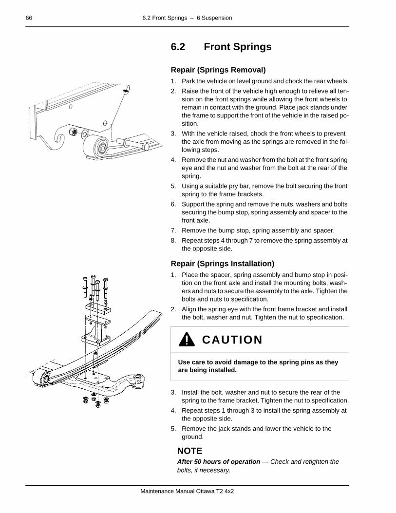
66 6.2 Front Springs – 6 Suspension
Maintenance Manual Ottawa T2 4x2
6.2 Front Springspage –
Repair (Springs Removal)1. Park the vehicle on level ground and chock the rear wheels.
2. Raise the front of the vehicle high enough to relieve all ten-sion on the front springs while allowing the front wheels to remain in contact with the ground. Place jack stands under the frame to support the front of the vehicle in the raised po-sition.
3. With the vehicle raised, chock the front wheels to prevent the axle from moving as the springs are removed in the fol-lowing steps.
4. Remove the nut and washer from the bolt at the front spring eye and the nut and washer from the bolt at the rear of the spring.
5. Using a suitable pry bar, remove the bolt securing the front spring to the frame brackets.
6. Support the spring and remove the nuts, washers and bolts securing the bump stop, spring assembly and spacer to the front axle.
7. Remove the bump stop, spring assembly and spacer.
8. Repeat steps 4 through 7 to remove the spring assembly at the opposite side.
– Repair (Springs Installation)1. Place the spacer, spring assembly and bump stop in posi-
tion on the front axle and install the mounting bolts, wash-ers and nuts to secure the assembly to the axle. Tighten the bolts and nuts to specification.
2. Align the spring eye with the front frame bracket and install the bolt, washer and nut. Tighten the nut to specification.
3. Install the bolt, washer and nut to secure the rear of the spring to the frame bracket. Tighten the nut to specification.
4. Repeat steps 1 through 3 to install the spring assembly at the opposite side.
5. Remove the jack stands and lower the vehicle to the ground.
NOTEAfter 50 hours of operation — Check and retighten the bolts, if necessary.
CAUTION
Use care to avoid damage to the spring pins as they are being installed.
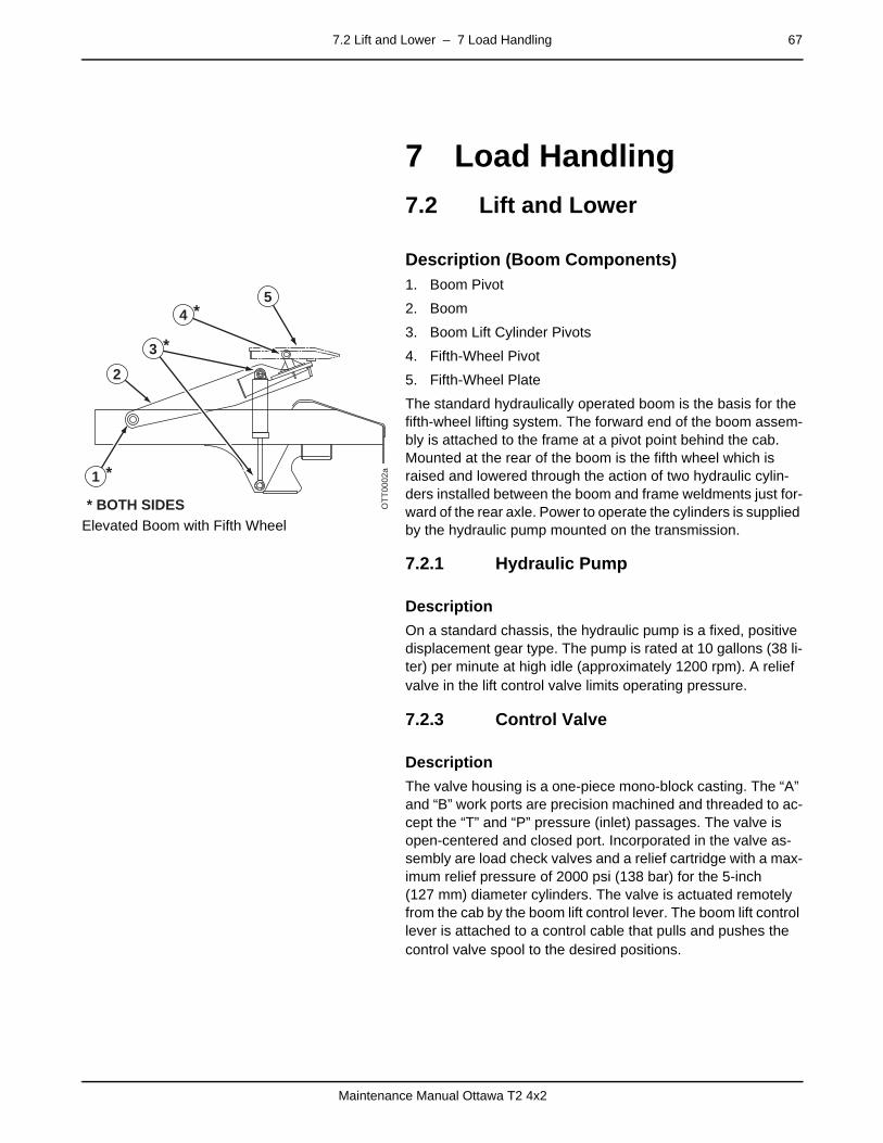
7.2 Lift and Lower – 7 Load Handling 67
Maintenance Manual Ottawa T2 4x2
mm mm mm mm mm mm
7 Load Handling
7.2 Lift and Lowerpage –
Description (Boom Components)
Elevated Boom with Fifth Wheel
1. Boom Pivot
2. Boom
3. Boom Lift Cylinder Pivots
4. Fifth-Wheel Pivot
5. Fifth-Wheel Plate
The standard hydraulically operated boom is the basis for the fifth-wheel lifting system. The forward end of the boom assem-bly is attached to the frame at a pivot point behind the cab. Mounted at the rear of the boom is the fifth wheel which is raised and lowered through the action of two hydraulic cylin-ders installed between the boom and frame weldments just for-ward of the rear axle. Power to operate the cylinders is supplied by the hydraulic pump mounted on the transmission.
7.2.1 Hydraulic Pumppage –
Description
On a standard chassis, the hydraulic pump is a fixed, positive displacement gear type. The pump is rated at 10 gallons (38 li-ter) per minute at high idle (approximately 1200 rpm). A relief valve in the lift control valve limits operating pressure.
7.2.3 Control Valvepage –
Description
The valve housing is a one-piece mono-block casting. The “A” and “B” work ports are precision machined and threaded to ac-cept the “T” and “P” pressure (inlet) passages. The valve is open-centered and closed port. Incorporated in the valve as-sembly are load check valves and a relief cartridge with a max-imum relief pressure of 2000 psi (138 bar) for the 5-inch (127 mm) diameter cylinders. The valve is actuated remotely from the cab by the boom lift control lever. The boom lift control lever is attached to a control cable that pulls and pushes the control valve spool to the desired positions.
1
* BOTH SIDES
*
OTT
0002
a
3 *
5
2
4 *

68 7.2 Lift and Lower – 7 Load Handling
Maintenance Manual Ottawa T2 4x2
7.2.1 Boom Lift Cylinderspage –
Description
The standard configuration utilizes two 4-inch (100 mm) diam-eter lift cylinders with a capacity of 48,500 pounds (22,000 kg) and a lifting height of 17.7 inches (450 mm). The cylinders are double acting in that they are hydraulically powered up and down. Restrictor fittings are threaded into the base end work ports to better control downward (lowering) speed.
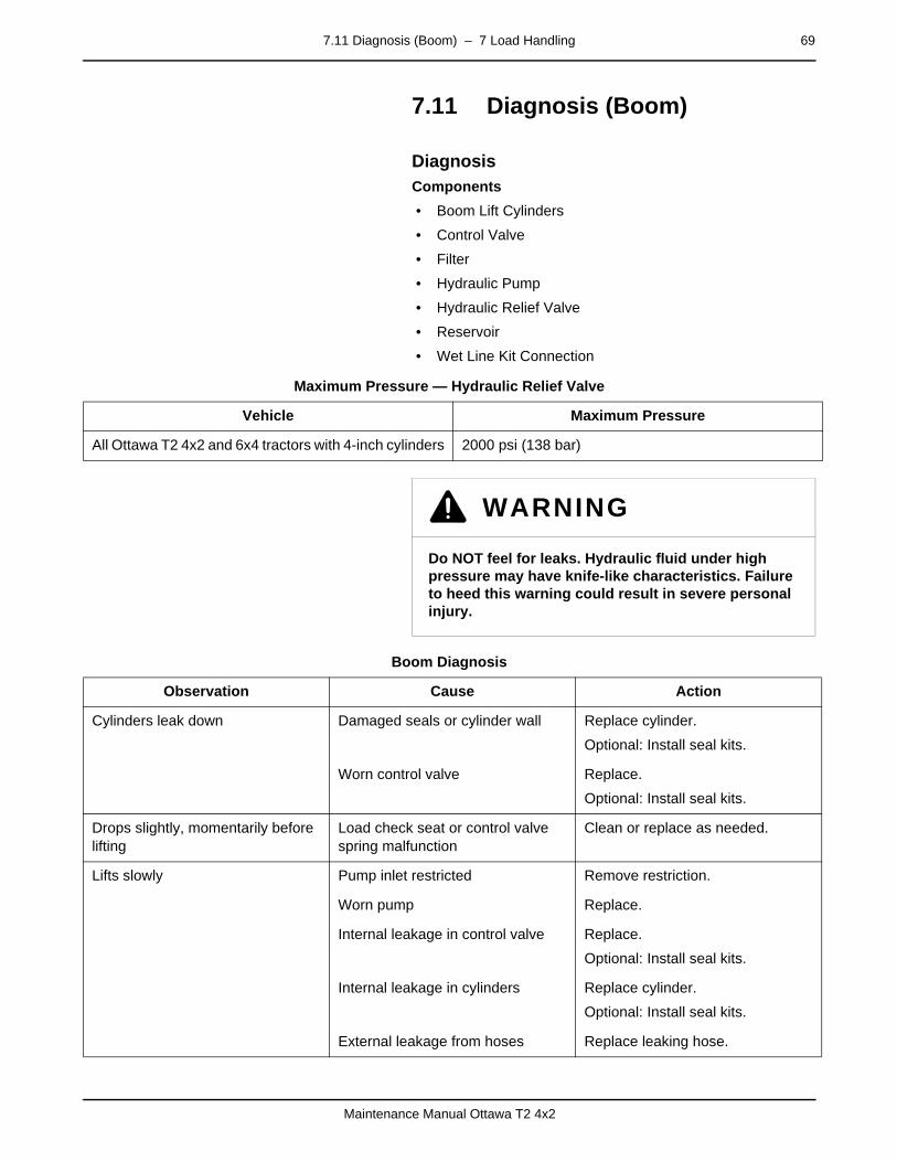
7.11 Diagnosis (Boom) – 7 Load Handling 69
Maintenance Manual Ottawa T2 4x2
7.11 Diagnosis (Boom)page –
DiagnosisComponents
• Boom Lift Cylinders
• Control Valve
• Filter
• Hydraulic Pump
• Hydraulic Relief Valve
• Reservoir
• Wet Line Kit Connection
Maximum Pressure — Hydraulic Relief Valve
Boom Diagnosis
Vehicle Maximum Pressure
All Ottawa T2 4x2 and 6x4 tractors with 4-inch cylinders 2000 psi (138 bar)
WARNING
Do NOT feel for leaks. Hydraulic fluid under high pressure may have knife-like characteristics. Failure to heed this warning could result in severe personal injury.
Observation Cause Action
Cylinders leak down Damaged seals or cylinder wall Replace cylinder.
Optional: Install seal kits.
Worn control valve Replace.
Optional: Install seal kits.
Drops slightly, momentarily before lifting
Load check seat or control valve spring malfunction
Clean or replace as needed.
Lifts slowly Pump inlet restricted Remove restriction.
Worn pump Replace.
Internal leakage in control valve Replace.
Optional: Install seal kits.
Internal leakage in cylinders Replace cylinder.
Optional: Install seal kits.
External leakage from hoses Replace leaking hose.
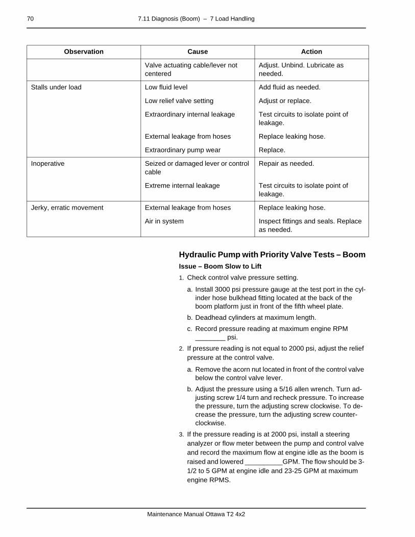
70 7.11 Diagnosis (Boom) – 7 Load Handling
Maintenance Manual Ottawa T2 4x2
–
Hydraulic Pump with Priority Valve Tests – BoomIssue – Boom Slow to Lift
1. Check control valve pressure setting.
a. Install 3000 psi pressure gauge at the test port in the cyl-inder hose bulkhead fitting located at the back of the boom platform just in front of the fifth wheel plate.
b. Deadhead cylinders at maximum length.
c. Record pressure reading at maximum engine RPM ________ psi.
2. If pressure reading is not equal to 2000 psi, adjust the relief pressure at the control valve.
a. Remove the acorn nut located in front of the control valve below the control valve lever.
b. Adjust the pressure using a 5/16 allen wrench. Turn ad-justing screw 1/4 turn and recheck pressure. To increase the pressure, turn the adjusting screw clockwise. To de-crease the pressure, turn the adjusting screw counter-clockwise.
3. If the pressure reading is at 2000 psi, install a steering analyzer or flow meter between the pump and control valve and record the maximum flow at engine idle as the boom is raised and lowered __________GPM. The flow should be 3- 1/2 to 5 GPM at engine idle and 23-25 GPM at maximum engine RPMS.
Valve actuating cable/lever not centered
Adjust. Unbind. Lubricate as needed.
Stalls under load Low fluid level Add fluid as needed.
Low relief valve setting Adjust or replace.
Extraordinary internal leakage Test circuits to isolate point of leakage.
External leakage from hoses Replace leaking hose.
Extraordinary pump wear Replace.
Inoperative Seized or damaged lever or control cable
Repair as needed.
Extreme internal leakage Test circuits to isolate point of leakage.
Jerky, erratic movement External leakage from hoses Replace leaking hose.
Air in system Inspect fittings and seals. Replace as needed.
Observation Cause Action

7.11 Diagnosis (Boom) – 7 Load Handling 71
Maintenance Manual Ottawa T2 4x2
–
Issue – Boom Not Lifting
1. Check that the fifth wheel control valve cable is operating freely.
2. Check for full movement of control valve lever.
3. Install a flow meter or steering analyzer between the pump and the control valve and record flow _______ GPM. A maximum engine RPM there should be 23-25 GPM of flow. If you are unable to get the required GPM of flow, replace the pump. If replacing the pump, check the splines on the pump shaft and the splines inside the PTO for wear.

72 7.11 Diagnosis (Boom) – 7 Load Handling
Maintenance Manual Ottawa T2 4x2

– 8 Control System 73
Maintenance Manual Ottawa T2 4x2
mm mm mm mm mm mm
8 Control Systempage –
Introduction - General InformationNot available.

74 – 8 Control System
Maintenance Manual Ottawa T2 4x2

9.1 Controls and Instruments – 9 Frame, Body, Cab and Accessories 75
Maintenance Manual Ottawa T2 4x2
mm mm mm mm mm mm
9 Frame, Body, Cab and Accessories
9.1 Controls and Instrumentspage –
4
30 32
31
33
1 2 3
5 6 7 9 1011
128
22
25
27
13
14
14 21 29
23
24 28
26
1817
1615
2019

76 9.1 Controls and Instruments – 9 Frame, Body, Cab and Accessories
Maintenance Manual Ottawa T2 4x2
S=Standard A=Assigned options U=Unassigned options
POS Name Standard DOT/EPA Tractor
Off-Highway Tractor
1 Air Diffuser S S
2 Radio A A
3 Main Gauge Panel S S
4 Headlight Switch S S
5 Dimmer Switch S A
6 Air Diffuser S S
7 Rear Wiper Switch A A
8 Front Wiper Switch S S
9 Ignition Switch S S
10 Push Button Start A A
11 Air Diffuser S S
12 Dome Light S S
13 Air Horn A A
14 Option Switches U U
15 Heater Control S S
16 Heater Control S S
17 Heater Control S S
18 Heater Control S S
19 Front Floodlight S S
20 Rear Floodlight S S
21 Trailer Air Supply S S
22 Parking Brake Control S S
23 Transmission Shifter S S
24 5th Wheel Control S S
25 5th Wheel Latch Control S S
26 Power Outlet A A
27 Option Switches U U
28 Air Restriction Indicator A A
29 Power Studs A A
30 Start Regen Switch S S
31 Idle Increase/Decrease Switch S S
32 Diagnostic Switch S S
33 On-Board Diagnostic Plug Port S S
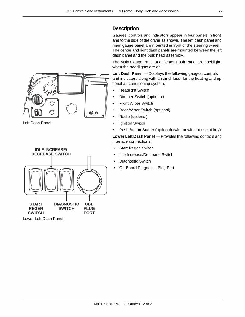
9.1 Controls and Instruments – 9 Frame, Body, Cab and Accessories 77
Maintenance Manual Ottawa T2 4x2
Description
Left Dash Panel
Gauges, controls and indicators appear in four panels in front and to the side of the driver as shown. The left dash panel and main gauge panel are mounted in front of the steering wheel. The center and right dash panels are mounted between the left dash panel and the bulk head assembly.
The Main Gauge Panel and Center Dash Panel are backlight when the headlights are on.
Left Dash Panel — Displays the following gauges, controls and indicators along with an air diffuser for the heating and op-tional air conditioning system.
• Headlight Switch
• Dimmer Switch (optional)
• Front Wiper Switch
• Rear Wiper Switch (optional)
• Radio (optional)
• Ignition Switch
• Push Button Starter (optional) (with or without use of key)
Lower Left Dash Panel — Provides the following controls and interface connections.
Lower Left Dash Panel
• Start Regen Switch
• Idle Increase/Decrease Switch
• Diagnostic Switch
• On-Board Diagnostic Plug Port
STARTREGENSWITCH
DIAGNOSTICSWITCH
OBDPLUGPORT
IDLE INCREASE/DECREASE SWITCH

78 9.1 Controls and Instruments – 9 Frame, Body, Cab and Accessories
Maintenance Manual Ottawa T2 4x2
Main Gauge Panel
Main Gauge Panel — Displays the following gauges and indi-cator lights.
• Gauges
1. DEF Gauge, DOT Tractors OnlyVolt Meter, Off-Highway Only
2. Speedometer
3. Fuel Gauge
4. Rear Brake Air Pressure Gauge
5. Odometer and Hour Meter
6. Front Brake Air Pressure Gauge
Indicators
• Indicator Lights – The indicator lights are arranged in three sections along the top of the main gauge panel.
Left Side Indicator Lights
– Left Turn Signal
– Charger
– Water-in-fuel
– ATC
– Trailer ABS
– Tractor ABS
Center Section Indicator Lights
– Low DEF Level
– High Beam
– Brake Air
– Low Fuel
– Malfunction Indicator Lamp (MIL)
– Check Engine
– Stop Engine
– Check Transmission
Right Side Indicator Lights
– Wait to Start
– Seat Belt
– Right Turn Signal
– High Exhaust System Temperature. DOT/EPA Tractors only.
– DPF (Diesel Particulate Filter) Regen needed. DOT/EPA Tractors only.
– Service
1 2 3
6 5 4
LEFT CENTER RIGHT
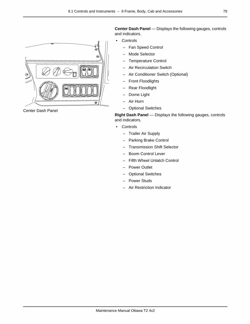
9.1 Controls and Instruments – 9 Frame, Body, Cab and Accessories 79
Maintenance Manual Ottawa T2 4x2
Center Dash Panel — Displays the following gauges, controls and indicators.
Center Dash Panel
• Controls
– Fan Speed Control
– Mode Selector
– Temperature Control
– Air Recirculation Switch
– Air Conditioner Switch (Optional)
– Front Floodlights
– Rear Floodlight
– Dome Light
– Air Horn
– Optional Switches
Right Dash Panel — Displays the following gauges, controls and indicators.
• Controls
– Trailer Air Supply
– Parking Brake Control
– Transmission Shift Selector
– Boom Control Lever
– Fifth Wheel Unlatch Control
– Power Outlet
– Optional Switches
– Power Studs
– Air Restriction Indicator

80 9.1 Controls and Instruments – 9 Frame, Body, Cab and Accessories
Maintenance Manual Ottawa T2 4x2
Driver Controlled Differential Lock
Driver Controlled Differential Lock
If equipped, the Driver Controlled Differential Lock control rock-er switch is located on the right dash panel.
Turn Signal, High Beam and Emergency Flasher Control
A multifunction switch is also provided on the stalk on the left side of the steering wheel.

9.1 Controls and Instruments – 9 Frame, Body, Cab and Accessories 81
Maintenance Manual Ottawa T2 4x2
9.1.36 Low Air Warningpage –
Diagnosis
The vehicle will be equipped with one of two air braking sys-tems. Vehicles that travel on the roads are made to comply with the regulations in Federal Motor Vehicle Safety Standard (FMVSS) 121. Vehicles that do not travel on the roads have an equally reliable braking system.
An anti-lock braking system option may also be found on the vehicle.
Components
• Gauge Cluster
• Headlight Switch
• Low Air Buzzer
• Low Air Pressure Switch (Indicator)
• Panel Dimmer Switch (Optional)
Low Air Warning Circuit Diagnosis
9.1.38 Hourmeterpage –
Diagnosis
Components
• Cab Accessory Fuse
• Gauge Cluster
• Ignition Switch
Hourmeter Circuit Diagnosis
Observation Cause Action
Inoperative light and buzzer Circuit breaker open Reset. Replace as needed.
Short circuit Test. Repair as needed.
Switch grounded Test. Repair as needed.
Defective air switch Test. Repair as needed
Defective assembly Replace.
Inoperative buzzer, light OK Open circuit Test. Repair as needed.
Defective buzzer Replace.
Inoperative light, buzzer OK Open circuit Test. Repair as needed.
Observation Cause Action
Inoperative Circuit breaker open Reset. Repair short as needed. Re-place circuit breaker as needed.

82 9.1 Controls and Instruments – 9 Frame, Body, Cab and Accessories
Maintenance Manual Ottawa T2 4x2
9.1.39 Speedometerpage –
Diagnosis
The speedometer may include an optional connection to the pulse generator.
Components
• Cab Accessory Circuit Breaker
• Gauge Cluster
• Headlight Switch
• Ignition Switch
• Panel Dimmer Switch (Optional)
Electronic Speedometer Circuit Diagnosis
Defective wiring Inspect connections and wires. Test circuits. Repair or replace as needed.
Mislocated wiring Inspect routing. Relocate wires or isolate terminals as needed.
Intermittent Defective wiring Inspect wires for kinks and breaks. Repair or replace as needed.
Mislocated wiring Inspect routing. Relocate wires or isolate terminals as needed.
Runs unevenly, or fast or slow Defective gauge cluster Replace.
Observation Cause Action
Observation Cause Action
Panel lamp does not light Circuit breaker open Reset. Repair short as needed. Re-place circuit breaker as needed.
Defective wiring Inspect connections and wires. Test circuits. Repair or replace as needed.
Inaccurate Defective wiring Inspect connections and wires. Test circuits.
No reading Circuit breaker open Reset. Repair short as needed. Re-place circuit breaker as needed.
Mislocated wiring Inspect routing. Relocate wires or isolate terminals as needed.
Defective wiring Inspect connections and wires. Test circuits. Repair or replace as needed.
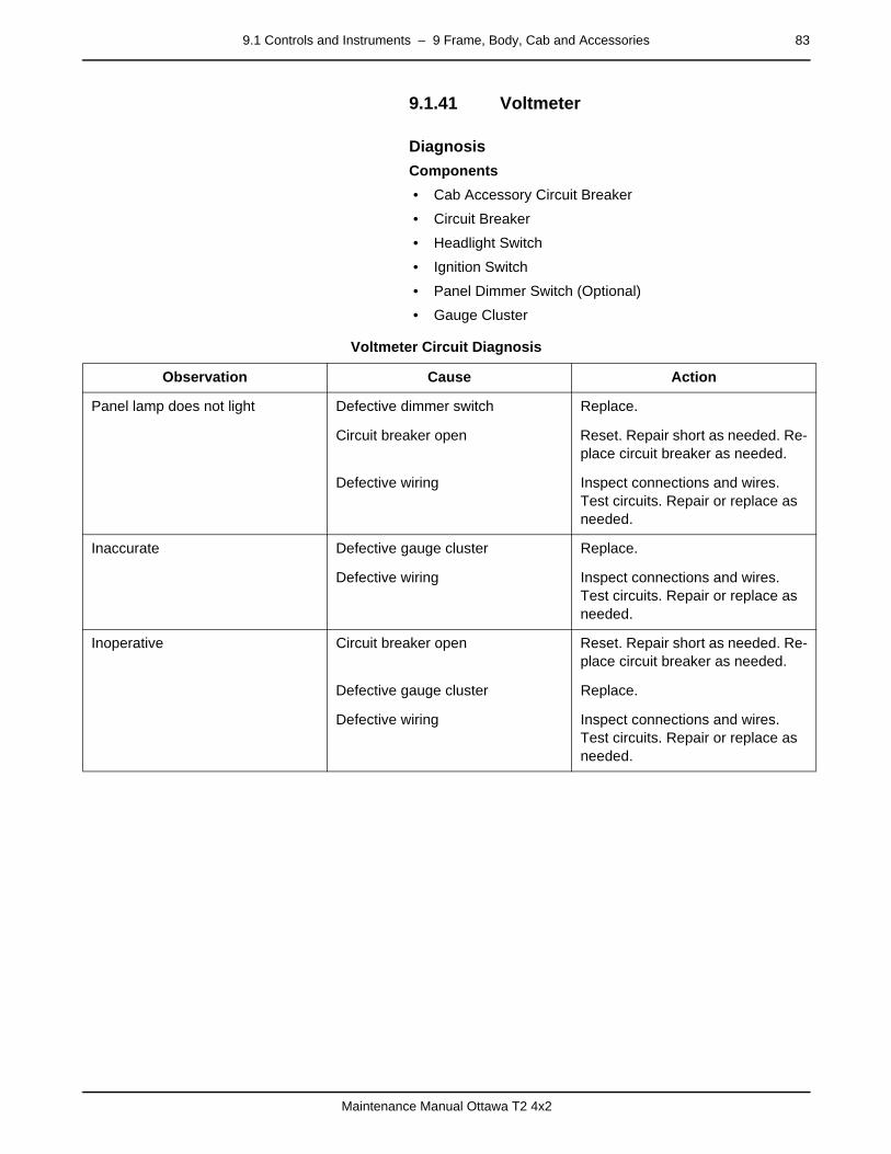
9.1 Controls and Instruments – 9 Frame, Body, Cab and Accessories 83
Maintenance Manual Ottawa T2 4x2
9.1.41 Voltmeterpage –
Diagnosis
Components
• Cab Accessory Circuit Breaker
• Circuit Breaker
• Headlight Switch
• Ignition Switch
• Panel Dimmer Switch (Optional)
• Gauge Cluster
Voltmeter Circuit Diagnosis
Observation Cause Action
Panel lamp does not light Defective dimmer switch Replace.
Circuit breaker open Reset. Repair short as needed. Re-place circuit breaker as needed.
Defective wiring Inspect connections and wires. Test circuits. Repair or replace as needed.
Inaccurate Defective gauge cluster Replace.
Defective wiring Inspect connections and wires. Test circuits. Repair or replace as needed.
Inoperative Circuit breaker open Reset. Repair short as needed. Re-place circuit breaker as needed.
Defective gauge cluster Replace.
Defective wiring Inspect connections and wires. Test circuits. Repair or replace as needed.
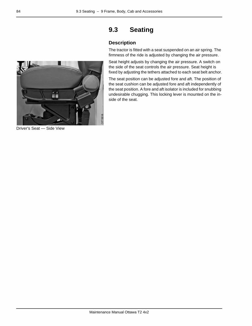
84 9.3 Seating – 9 Frame, Body, Cab and Accessories
Maintenance Manual Ottawa T2 4x2
9.3 Seatingpage –
DescriptionThe tractor is fitted with a seat suspended on an air spring. The firmness of the ride is adjusted by changing the air pressure.
Driver's Seat — Side View
Seat height adjusts by changing the air pressure. A switch on the side of the seat controls the air pressure. Seat height is fixed by adjusting the tethers attached to each seat belt anchor.
The seat position can be adjusted fore and aft. The position of the seat cushion can be adjusted fore and aft independently of the seat position. A fore and aft isolator is included for snubbing undesirable chugging. This locking lever is mounted on the in-side of the seat.
9.4 Heating, Ventilation and Air Conditioning – 9 Frame, Body, Cab and Accessories 85
Maintenance Manual Ottawa T2 4x2
9.4 Heating, Ventilation and Air Conditioning
page –
DescriptionA heater is standard equipment. Air conditioning is optional.
Air diffusion is provided through ducts in the instrument panel near the side window and underneath the instrument panel near the center of the cab. Air flow can also be directed to the windshield and side windows. Instrument panel controls give the driver several air handling options including fan speed and cab air temperature.
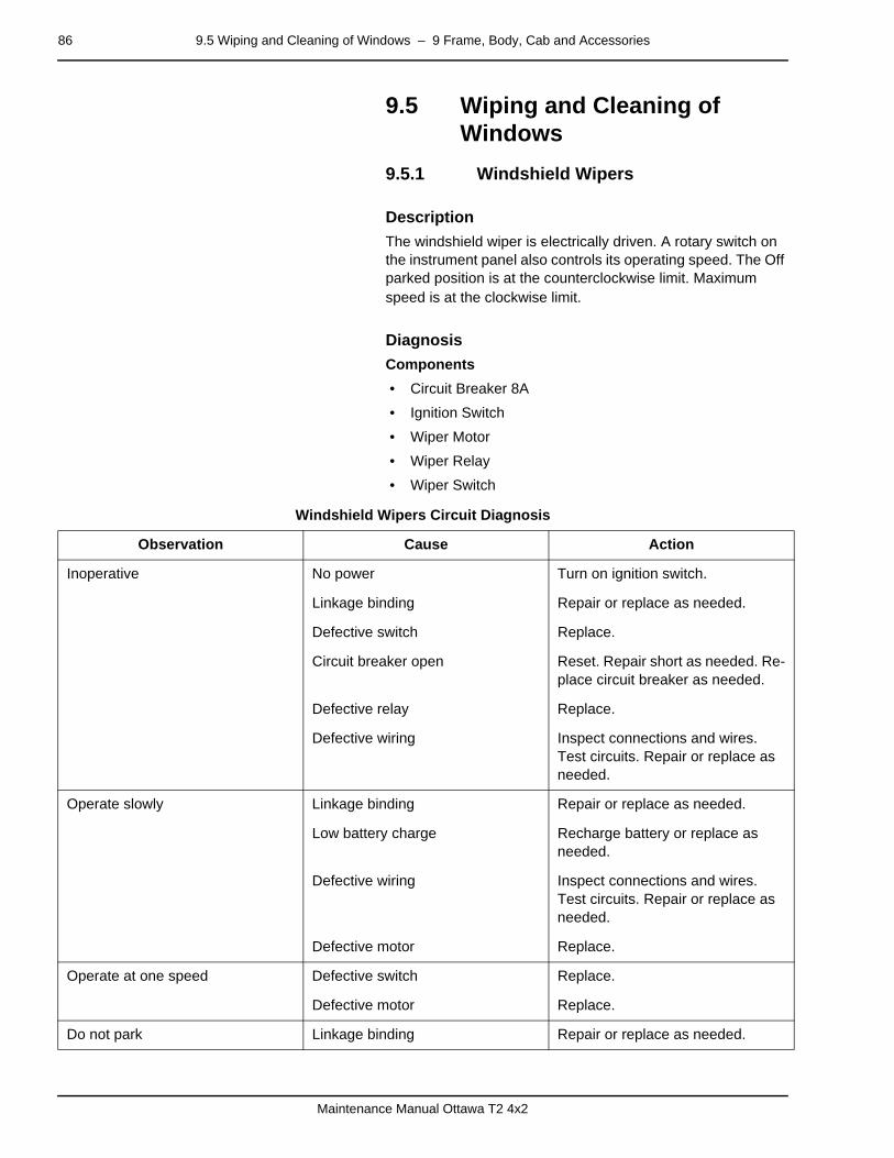
86 9.5 Wiping and Cleaning of Windows – 9 Frame, Body, Cab and Accessories
Maintenance Manual Ottawa T2 4x2
9.5 Wiping and Cleaning of Windows
9.5.1 Windshield Wiperspage –
Description
The windshield wiper is electrically driven. A rotary switch on the instrument panel also controls its operating speed. The Off parked position is at the counterclockwise limit. Maximum speed is at the clockwise limit.
page –
Diagnosis
Components
• Circuit Breaker 8A
• Ignition Switch
• Wiper Motor
• Wiper Relay
• Wiper Switch
Windshield Wipers Circuit Diagnosis
Observation Cause Action
Inoperative No power Turn on ignition switch.
Linkage binding Repair or replace as needed.
Defective switch Replace.
Circuit breaker open Reset. Repair short as needed. Re-place circuit breaker as needed.
Defective relay Replace.
Defective wiring Inspect connections and wires. Test circuits. Repair or replace as needed.
Operate slowly Linkage binding Repair or replace as needed.
Low battery charge Recharge battery or replace as needed.
Defective wiring Inspect connections and wires. Test circuits. Repair or replace as needed.
Defective motor Replace.
Operate at one speed Defective switch Replace.
Defective motor Replace.
Do not park Linkage binding Repair or replace as needed.
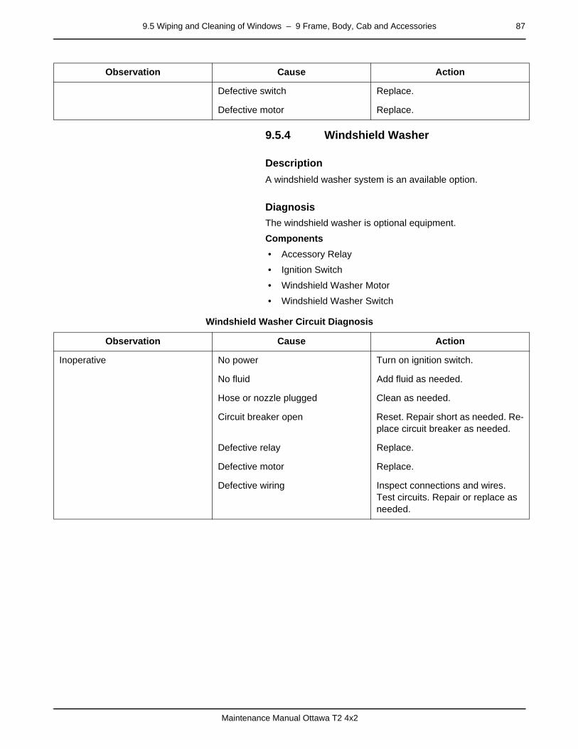
9.5 Wiping and Cleaning of Windows – 9 Frame, Body, Cab and Accessories 87
Maintenance Manual Ottawa T2 4x2
9.5.4 Windshield Washerpage –
Description
A windshield washer system is an available option.
page –
Diagnosis
The windshield washer is optional equipment.
Components
• Accessory Relay
• Ignition Switch
• Windshield Washer Motor
• Windshield Washer Switch
Windshield Washer Circuit Diagnosis
Defective switch Replace.
Defective motor Replace.
Observation Cause Action
Observation Cause Action
Inoperative No power Turn on ignition switch.
No fluid Add fluid as needed.
Hose or nozzle plugged Clean as needed.
Circuit breaker open Reset. Repair short as needed. Re-place circuit breaker as needed.
Defective relay Replace.
Defective motor Replace.
Defective wiring Inspect connections and wires. Test circuits. Repair or replace as needed.
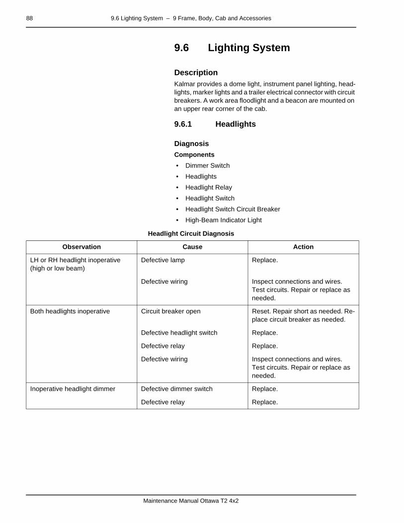
88 9.6 Lighting System – 9 Frame, Body, Cab and Accessories
Maintenance Manual Ottawa T2 4x2
9.6 Lighting Systempage –
DescriptionKalmar provides a dome light, instrument panel lighting, head-lights, marker lights and a trailer electrical connector with circuit breakers. A work area floodlight and a beacon are mounted on an upper rear corner of the cab.
9.6.1 Headlightspage –
Diagnosis
Components
• Dimmer Switch
• Headlights
• Headlight Relay
• Headlight Switch
• Headlight Switch Circuit Breaker
• High-Beam Indicator Light
Headlight Circuit Diagnosis
Observation Cause Action
LH or RH headlight inoperative (high or low beam)
Defective lamp Replace.
Defective wiring Inspect connections and wires. Test circuits. Repair or replace as needed.
Both headlights inoperative Circuit breaker open Reset. Repair short as needed. Re-place circuit breaker as needed.
Defective headlight switch Replace.
Defective relay Replace.
Defective wiring Inspect connections and wires. Test circuits. Repair or replace as needed.
Inoperative headlight dimmer Defective dimmer switch Replace.
Defective relay Replace.
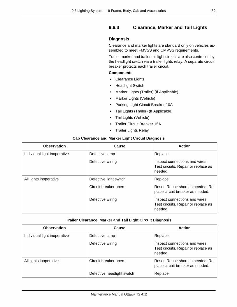
9.6 Lighting System – 9 Frame, Body, Cab and Accessories 89
Maintenance Manual Ottawa T2 4x2
9.6.3 Clearance, Marker and Tail Lightspage –
Diagnosis
Clearance and marker lights are standard only on vehicles as-sembled to meet FMVSS and CMVSS requirements.
Trailer marker and trailer tail light circuits are also controlled by the headlight switch via a trailer lights relay. A separate circuit breaker protects each trailer circuit.
Components
• Clearance Lights
• Headlight Switch
• Marker Lights (Trailer) (If Applicable)
• Marker Lights (Vehicle)
• Parking Light Circuit Breaker 10A
• Tail Lights (Trailer) (If Applicable)
• Tail Lights (Vehicle)
• Trailer Circuit Breaker 15A
• Trailer Lights Relay
Cab Clearance and Marker Light Circuit Diagnosis
Trailer Clearance, Marker and Tail Light Circuit Diagnosis
Observation Cause Action
Individual light inoperative Defective lamp Replace.
Defective wiring Inspect connections and wires. Test circuits. Repair or replace as needed.
All lights inoperative Defective light switch Replace.
Circuit breaker open Reset. Repair short as needed. Re-place circuit breaker as needed.
Defective wiring Inspect connections and wires. Test circuits. Repair or replace as needed.
Observation Cause Action
Individual light inoperative Defective lamp Replace.
Defective wiring Inspect connections and wires. Test circuits. Repair or replace as needed.
All lights inoperative Circuit breaker open Reset. Repair short as needed. Re-place circuit breaker as needed.
Defective headlight switch Replace.
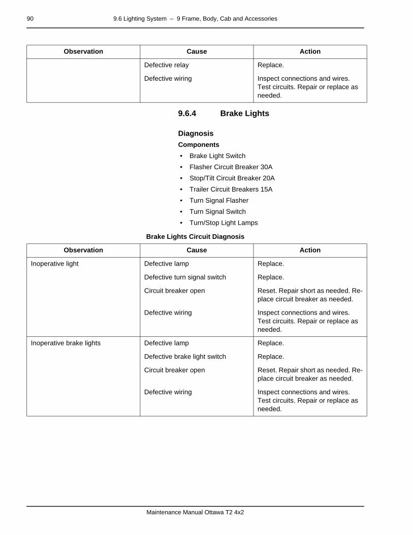
90 9.6 Lighting System – 9 Frame, Body, Cab and Accessories
Maintenance Manual Ottawa T2 4x2
9.6.4 Brake Lightspage –
Diagnosis
Components
• Brake Light Switch
• Flasher Circuit Breaker 30A
• Stop/Tilt Circuit Breaker 20A
• Trailer Circuit Breakers 15A
• Turn Signal Flasher
• Turn Signal Switch
• Turn/Stop Light Lamps
Brake Lights Circuit Diagnosis
Defective relay Replace.
Defective wiring Inspect connections and wires. Test circuits. Repair or replace as needed.
Observation Cause Action
Observation Cause Action
Inoperative light Defective lamp Replace.
Defective turn signal switch Replace.
Circuit breaker open Reset. Repair short as needed. Re-place circuit breaker as needed.
Defective wiring Inspect connections and wires. Test circuits. Repair or replace as needed.
Inoperative brake lights Defective lamp Replace.
Defective brake light switch Replace.
Circuit breaker open Reset. Repair short as needed. Re-place circuit breaker as needed.
Defective wiring Inspect connections and wires. Test circuits. Repair or replace as needed.

9.6 Lighting System – 9 Frame, Body, Cab and Accessories 91
Maintenance Manual Ottawa T2 4x2
9.6.5 Backup Lightpage –
Diagnosis
This circuit may contain an optional circuit breaker between the accessories relay and the flood light switch/backup flood relay.
Components
• Accessory Relay
• Backup Alarm
• Backup Light (rear of frame)
• Backup Relay
• Cab Flood Light Switch
• Circuit Breaker 15A
• Ignition Switch
Backup Light Circuit Diagnosis
Flood Light Circuit Diagnosis
Observation Cause Action
Inoperative backup light Defective lamp Replace.
Circuit breaker open Reset. Repair short as needed. Re-place circuit breaker as needed.
Defective backup relay Replace.
Defective wiring Inspect connections and wires. Test circuits. Repair or replace as needed.
Observation Cause Action
Inoperative Defective lamp Replace.
Defective light switch Replace.
Circuit breaker open Reset. Repair short as needed. Re-place circuit breaker as needed.
Defective relay Replace.
Defective wiring Inspect connections and wires. Test circuits. Repair or replace as needed.
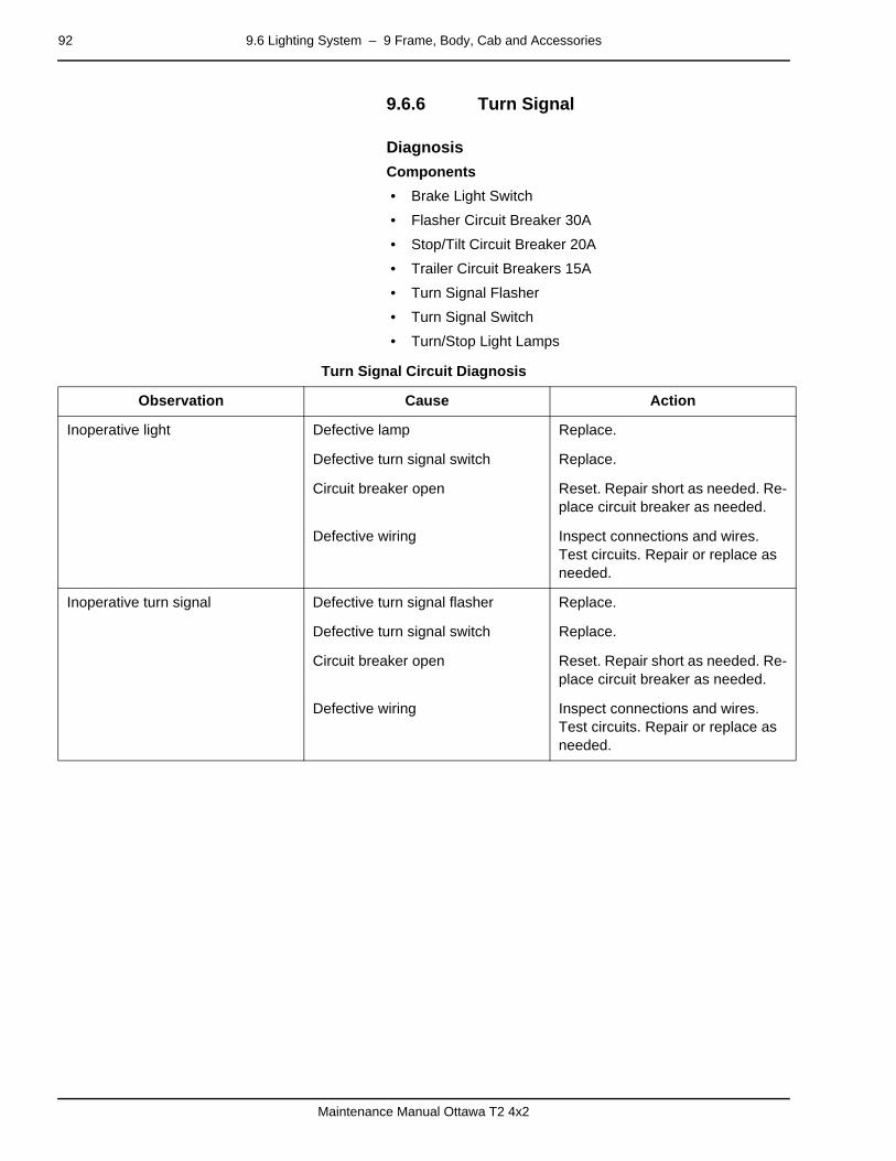
92 9.6 Lighting System – 9 Frame, Body, Cab and Accessories
Maintenance Manual Ottawa T2 4x2
9.6.6 Turn Signalpage –
Diagnosis
Components
• Brake Light Switch
• Flasher Circuit Breaker 30A
• Stop/Tilt Circuit Breaker 20A
• Trailer Circuit Breakers 15A
• Turn Signal Flasher
• Turn Signal Switch
• Turn/Stop Light Lamps
Turn Signal Circuit Diagnosis
Observation Cause Action
Inoperative light Defective lamp Replace.
Defective turn signal switch Replace.
Circuit breaker open Reset. Repair short as needed. Re-place circuit breaker as needed.
Defective wiring Inspect connections and wires. Test circuits. Repair or replace as needed.
Inoperative turn signal Defective turn signal flasher Replace.
Defective turn signal switch Replace.
Circuit breaker open Reset. Repair short as needed. Re-place circuit breaker as needed.
Defective wiring Inspect connections and wires. Test circuits. Repair or replace as needed.

9.6 Lighting System – 9 Frame, Body, Cab and Accessories 93
Maintenance Manual Ottawa T2 4x2
9.6.8 Beacon Lightpage –
Diagnosis
This circuit may contain an optional circuit breaker between the accessories relay and the beacon light switch.
Components
• Accessory Relay
• Beacon Light
• Beacon Light Switch
• Ignition Switch
Beacon Light Circuit Diagnosis
9.6.11 Dome Lightpage –
Diagnosis
Components
• Cab Accessory Circuit Breaker
• Dome Light
Dome Light Circuit Diagnosis
Observation Cause Action
Inoperative Defective beacon lamp Replace.
Defective switch Replace.
Circuit breaker open Reset. Repair short as needed. Re-place circuit breaker as needed.
Defective wiring Inspect connections and wires. Test circuits. Repair or replace as needed.
Observation Cause Action
Inoperative Defective lamp Replace.
Defective dome light switch Replace.
Circuit breaker open Reset. Repair short as needed. Re-place circuit breaker as needed.
Defective wiring Inspect connections and wires. Test circuits. Repair or replace as needed.
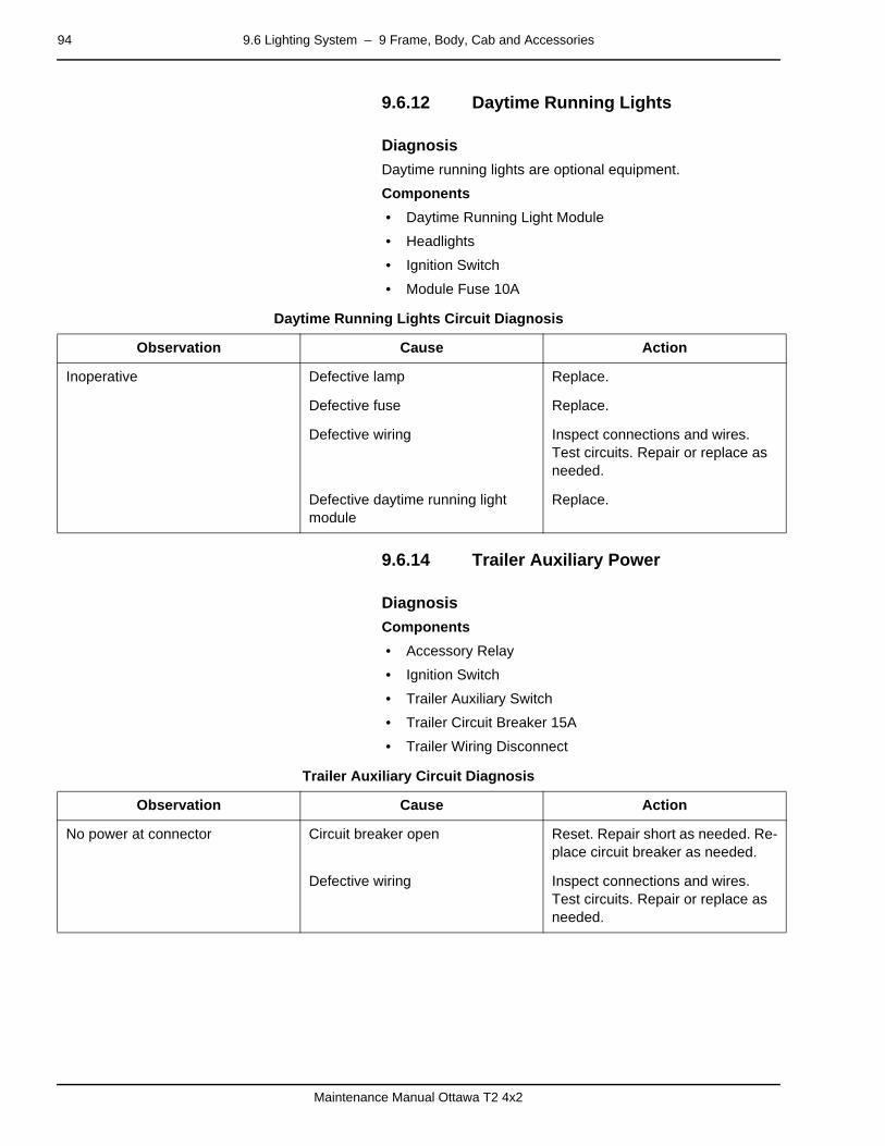
94 9.6 Lighting System – 9 Frame, Body, Cab and Accessories
Maintenance Manual Ottawa T2 4x2
9.6.12 Daytime Running Lightspage –
Diagnosis
Daytime running lights are optional equipment.
Components
• Daytime Running Light Module
• Headlights
• Ignition Switch
• Module Fuse 10A
Daytime Running Lights Circuit Diagnosis
9.6.14 Trailer Auxiliary Powerpage –
Diagnosis
Components
• Accessory Relay
• Ignition Switch
• Trailer Auxiliary Switch
• Trailer Circuit Breaker 15A
• Trailer Wiring Disconnect
Trailer Auxiliary Circuit Diagnosis
Observation Cause Action
Inoperative Defective lamp Replace.
Defective fuse Replace.
Defective wiring Inspect connections and wires. Test circuits. Repair or replace as needed.
Defective daytime running light module
Replace.
Observation Cause Action
No power at connector Circuit breaker open Reset. Repair short as needed. Re-place circuit breaker as needed.
Defective wiring Inspect connections and wires. Test circuits. Repair or replace as needed.

9.6 Lighting System – 9 Frame, Body, Cab and Accessories 95
Maintenance Manual Ottawa T2 4x2
9.6.15 Transmission Shifter/Fifth-Wheel Control and Panel Lighting
page –
Diagnosis
Components
• Electroluminescent Lamps
• Incandescent Lamps
• Headlight Switch
• Parking Light Circuit Breaker 10A
• Panel Dimmer Switch
Electroluminescence
Electroluminescent (EL) lamps consist of two wafer-thin pan-els, one transparent and one opaque, that produce light when energized electrically. The panels are separated by an ex-tremely narrow space. If a lamp is pinched so that the two pan-els come in contact, a short is created.
EL lamps require an inverter to change direct current to high cy-cle alternating current and increase the voltage. A shorted EL lamp will cause the inverter to shut down. To isolate the defec-tive lamp, disconnect one lead to each lamp and reconnect one at a time. A good lamp lights when connected.
Transmission Shifter/Fifth-Wheel Control and Panel Lighting Circuit Diagnosis
Observation Cause Action
Inoperative light Defective lamp Replace.
Defective dimmer switch Replace.
Circuit breaker open Reset. Repair short as needed. Re-place circuit breaker as needed.
Defective wiring (or inverter) Inspect connections and wires. Test circuits. Repair or replace as needed.
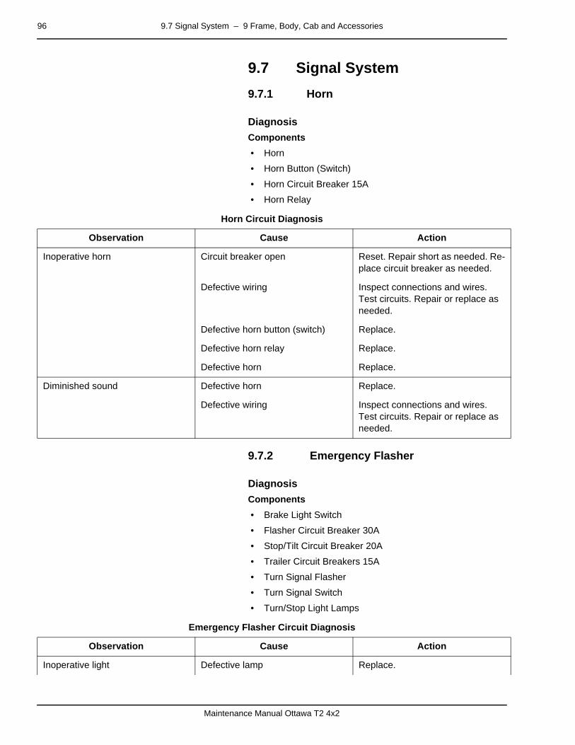
96 9.7 Signal System – 9 Frame, Body, Cab and Accessories
Maintenance Manual Ottawa T2 4x2
9.7 Signal System
9.7.1 Hornpage –
Diagnosis
Components
• Horn
• Horn Button (Switch)
• Horn Circuit Breaker 15A
• Horn Relay
Horn Circuit Diagnosis
9.7.2 Emergency Flasherpage –
Diagnosis
Components
• Brake Light Switch
• Flasher Circuit Breaker 30A
• Stop/Tilt Circuit Breaker 20A
• Trailer Circuit Breakers 15A
• Turn Signal Flasher
• Turn Signal Switch
• Turn/Stop Light Lamps
Emergency Flasher Circuit Diagnosis
Observation Cause Action
Inoperative horn Circuit breaker open Reset. Repair short as needed. Re-place circuit breaker as needed.
Defective wiring Inspect connections and wires. Test circuits. Repair or replace as needed.
Defective horn button (switch) Replace.
Defective horn relay Replace.
Defective horn Replace.
Diminished sound Defective horn Replace.
Defective wiring Inspect connections and wires. Test circuits. Repair or replace as needed.
Observation Cause Action
Inoperative light Defective lamp Replace.
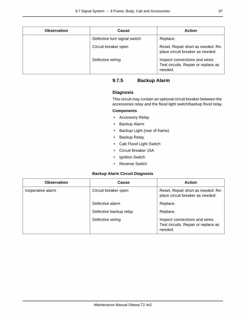
9.7 Signal System – 9 Frame, Body, Cab and Accessories 97
Maintenance Manual Ottawa T2 4x2
9.7.5 Backup Alarmpage –
Diagnosis
This circuit may contain an optional circuit breaker between the accessories relay and the flood light switch/backup flood relay.
Components
• Accessory Relay
• Backup Alarm
• Backup Light (rear of frame)
• Backup Relay
• Cab Flood Light Switch
• Circuit Breaker 15A
• Ignition Switch
• Reverse Switch
Backup Alarm Circuit Diagnosis
Defective turn signal switch Replace.
Circuit breaker open Reset. Repair short as needed. Re-place circuit breaker as needed.
Defective wiring Inspect connections and wires. Test circuits. Repair or replace as needed.
Observation Cause Action
Observation Cause Action
Inoperative alarm Circuit breaker open Reset. Repair short as needed. Re-place circuit breaker as needed.
Defective alarm Replace.
Defective backup relay Replace.
Defective wiring Inspect connections and wires. Test circuits. Repair or replace as needed.

98 9.8 Maintenance and Communication – 9 Frame, Body, Cab and Accessories
Maintenance Manual Ottawa T2 4x2
9.8 Maintenance and Communication
9.8.1 Radiopage –
Description
A radio is an available option.
page –
Diagnosis
Components
• Accessory Relay
• Radio
• Radio Circuit Breaker 15A
• Speakers
Radio Circuit Diagnosis
Observation Cause Action
Inoperative radio Circuit breaker open Reset. Repair short as needed. Re-place circuit breaker as needed.
Defective relay Replace.
Defective speakers Repair or replace.
Defective radio Replace.
Defective wiring Inspect connections and wires. Test circuits. Repair or replace as needed.
Poor performance Defective antenna Repair or replace.
Defective speakers Repair or replace.
Defective radio Replace.
Defective wiring Inspect connections and wires. Test circuits. Repair or replace as needed.

9.9 Glass/Window/Mirrors – 9 Frame, Body, Cab and Accessories 99
Maintenance Manual Ottawa T2 4x2
9.9 Glass/Window/Mirrorspage –
DescriptionWindows and Ventilation — The window in the side panel moves up and down via a regulator handle on the door. A fixed window ahead of the side panel window permits a full view on that side. A solid window on the opposite wall allows an unob-structed view in that direction.
9.9.5 Rear-View Mirrorpage –
Description
Mirrors — Heated and heated/motorized outside rear view mir-rors are optional equipment.
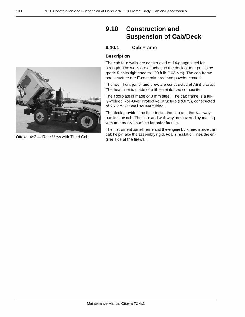
100 9.10 Construction and Suspension of Cab/Deck – 9 Frame, Body, Cab and Accessories
Maintenance Manual Ottawa T2 4x2
9.10 Construction and Suspension of Cab/Deck
9.10.1 Cab Framepage –
Description
Ottawa 4x2 — Rear View with Tilted Cab
The cab four walls are constructed of 14-gauge steel for strength. The walls are attached to the deck at four points by grade 5 bolts tightened to 120 ft lb (163 Nm). The cab frame and structure are E-coat primered and powder coated.
The roof, front panel and brow are constructed of ABS plastic. The headliner is made of a fiber-reinforced composite.
The floorplate is made of 3 mm steel. The cab frame is a ful-ly-welded Roll-Over Protective Structure (ROPS), constructed of 2 x 2 x 1/4" wall square tubing.
The deck provides the floor inside the cab and the walkway outside the cab. The floor and walkway are covered by matting with an abrasive surface for safer footing.
The instrument panel frame and the engine bulkhead inside the cab help make the assembly rigid. Foam insulation lines the en-gine side of the firewall.
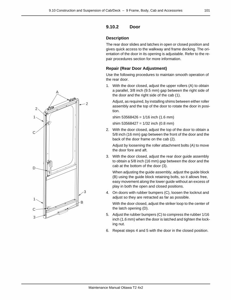
9.10 Construction and Suspension of Cab/Deck – 9 Frame, Body, Cab and Accessories 101
Maintenance Manual Ottawa T2 4x2
9.10.2 Doorpage –
Description
The rear door slides and latches in open or closed position and gives quick access to the walkway and frame decking. The ori-entation of the door in its opening is adjustable. Refer to the re-pair procedures section for more information.
page –
Repair (Rear Door Adjustment)
Use the following procedures to maintain smooth operation of the rear door.
1. With the door closed, adjust the upper rollers (A) to obtain a parallel, 3/8 inch (9.5 mm) gap between the right side of the door and the right side of the cab (1).
Adjust, as required, by installing shims between either roller assembly and the top of the door to rotate the door in posi-tion.
shim 53568426 = 1/16 inch (1.6 mm)
shim 53568427 = 1/32 inch (0.8 mm)
2. With the door closed, adjust the top of the door to obtain a 5/8 inch (16 mm) gap between the front of the door and the back of the door frame on the cab (2).
Adjust by loosening the roller attachment bolts (A) to move the door fore and aft.
3. With the door closed, adjust the rear door guide assembly to obtain a 5/8 inch (16 mm) gap between the door and the cab at the bottom of the door (3).
When adjusting the guide assembly, adjust the guide block (B) using the guide block retaining bolts, so it allows free, easy movement along the lower guide without an excess of play in both the open and closed positions.
4. On doors with rubber bumpers (C), loosen the locknut and adjust so they are retracted as far as possible.
With the door closed, adjust the striker loop to the center of the latch opening (D).
5. Adjust the rubber bumpers (C) to compress the rubber 1/16 inch (1.6 mm) when the door is latched and tighten the lock-ing nut.
6. Repeat steps 4 and 5 with the door in the closed position.
22
A
1
1
3
3
B
C
C
D
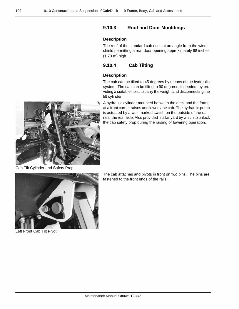
102 9.10 Construction and Suspension of Cab/Deck – 9 Frame, Body, Cab and Accessories
Maintenance Manual Ottawa T2 4x2
9.10.3 Roof and Door Mouldingspage –
Description
The roof of the standard cab rises at an angle from the wind-shield permitting a rear door opening approximately 68 inches (1.73 m) high.
9.10.4 Cab Tiltingpage –
Description
The cab can be tilted to 45 degrees by means of the hydraulic system. The cab can be tilted to 90 degrees, if needed, by pro-viding a suitable hoist to carry the weight and disconnecting the lift cylinder.
Cab Tilt Cylinder and Safety Prop
A hydraulic cylinder mounted between the deck and the frame at a front corner raises and lowers the cab. The hydraulic pump is actuated by a well-marked switch on the outside of the rail near the rear axle. Also provided is a lanyard by which to unlock the cab safety prop during the raising or lowering operation.
Left Front Cab Tilt Pivot
The cab attaches and pivots in front on two pins. The pins are fastened to the front ends of the rails.

9.10 Construction and Suspension of Cab/Deck – 9 Frame, Body, Cab and Accessories 103
Maintenance Manual Ottawa T2 4x2
Electric Pump Motor — Cab Tilt System
The cab tilt system electric pump motor is mounted on the hydraulic tank. It serves only the cab’s tilting system on the tractor.
Cab Tilt Control Switch and LanyardA — Cab Tilt Control SwitchB — Safety Prop Release Cable
The cab tilt control switch and lanyard are located on the rail between the hydraulic fluid tank and the rear wheel. Tilt action stops when the switch is released or when the cab reaches full up or full down position.
Cab Suspension Latching Bar
After the cab reaches the full down position, the latching mechanism makes a loud sound. The latching bar alignment can be adjusted. Refer to the repair procedures section for more information.
A
B
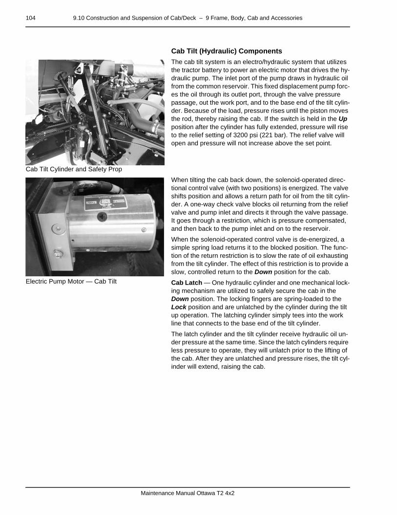
104 9.10 Construction and Suspension of Cab/Deck – 9 Frame, Body, Cab and Accessories
Maintenance Manual Ottawa T2 4x2
page –
Cab Tilt (Hydraulic) Components
Cab Tilt Cylinder and Safety Prop
The cab tilt system is an electro/hydraulic system that utilizes the tractor battery to power an electric motor that drives the hy-draulic pump. The inlet port of the pump draws in hydraulic oil from the common reservoir. This fixed displacement pump forc-es the oil through its outlet port, through the valve pressure passage, out the work port, and to the base end of the tilt cylin-der. Because of the load, pressure rises until the piston moves the rod, thereby raising the cab. If the switch is held in the Up position after the cylinder has fully extended, pressure will rise to the relief setting of 3200 psi (221 bar). The relief valve will open and pressure will not increase above the set point.
Electric Pump Motor — Cab Tilt
When tilting the cab back down, the solenoid-operated direc-tional control valve (with two positions) is energized. The valve shifts position and allows a return path for oil from the tilt cylin-der. A one-way check valve blocks oil returning from the relief valve and pump inlet and directs it through the valve passage. It goes through a restriction, which is pressure compensated, and then back to the pump inlet and on to the reservoir.
When the solenoid-operated control valve is de-energized, a simple spring load returns it to the blocked position. The func-tion of the return restriction is to slow the rate of oil exhausting from the tilt cylinder. The effect of this restriction is to provide a slow, controlled return to the Down position for the cab.
Cab Latch — One hydraulic cylinder and one mechanical lock-ing mechanism are utilized to safely secure the cab in the Down position. The locking fingers are spring-loaded to the Lock position and are unlatched by the cylinder during the tilt up operation. The latching cylinder simply tees into the work line that connects to the base end of the tilt cylinder.
The latch cylinder and the tilt cylinder receive hydraulic oil un-der pressure at the same time. Since the latch cylinders require less pressure to operate, they will unlatch prior to the lifting of the cab. After they are unlatched and pressure rises, the tilt cyl-inder will extend, raising the cab.

9.10 Construction and Suspension of Cab/Deck – 9 Frame, Body, Cab and Accessories 105
Maintenance Manual Ottawa T2 4x2
Cab Tilt Control Switch and LanyardA — Cab Tilt Control SwitchB — Safety Prop Release Cable
Cab Tilt Safety Prop — An additional mechanical safety de-vice is used to ensure that the cab cannot be inadvertently low-ered. The cab safety prop is similar to a hood prop in function; but instead of holding the hood (or cab in this case), it acts as a solid arm locking the hydraulic tilt cylinder in the extended (cab-tilted) position. It is cable-operated from the tilt operation station where the control switch is located.
page –
Diagnosis (Cab Tilt)
Components
• Stop/Tilt Circuit Breaker 20A
• Tilt Pump Control Switch
• Tilt Pump Motor
• Tilt Solenoid
Cab Tilt Diagnosis
A
B
DANGER
Do NOT work under the raised cab before ensuring that the cab safety prop is locked in position. Failure to heed this danger could result in severe personal in-jury or death.
Observation Cause Action
Inoperative pump Electrical See Electrical section.
Motor runs — cab does not tilt Low fluid Add fluid as needed.
Line leakage Locate and repair.

106 9.10 Construction and Suspension of Cab/Deck – 9 Frame, Body, Cab and Accessories
Maintenance Manual Ottawa T2 4x2
9.10.6 Cab Tilt Pump and Motorpage –
Diagnosis (Cab Tilt Pump)
Components
• Stop/Tilt Circuit Breaker 20A
• Tilt Pump Control Switch
• Tilt Pump Motor
• Tilt Pump Solenoid
Cab Tilt Pump Circuit Diagnosis
page –
Repair (Pump and Motor Removal)
The cab tilt pump and motor are located on the hydraulic tank.
Observation Cause Action
Inoperative motor Circuit breaker open Reset. Repair short as needed. Re-place circuit breaker as needed.
Defective tilt pump control switch Replace.
Defective tilt pump solenoid Replace.
Defective wiring Inspect connections and wires. Test circuits. Repair or replace as needed.
Raised cab does not return Circuit breaker open Reset. Repair short as needed. Re-place circuit breaker as needed.
Defective tilt pump control switch Replace.
Defective tilt pump valve Replace.
Motor operates — cab does not rise Refer to Hydraulic section.
WARNING
The hydraulic fluid in the system is under pressure. Care should be taken whenever the system is opened. Loosen fittings slightly and allow pressure to bleed off before removing hoses. Safety glasses must be worn when working on the hydraulic system.
Failure to heed this warning may result in serious per-sonal injury or property damage.
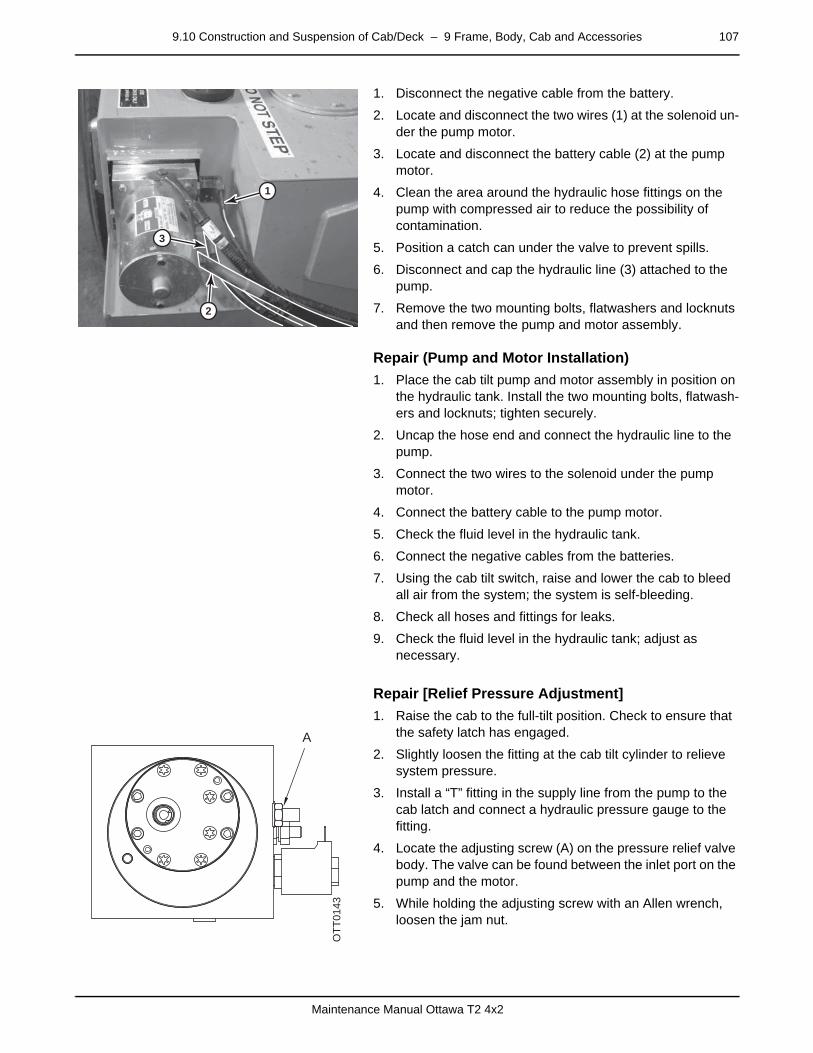
9.10 Construction and Suspension of Cab/Deck – 9 Frame, Body, Cab and Accessories 107
Maintenance Manual Ottawa T2 4x2
1. Disconnect the negative cable from the battery.
2. Locate and disconnect the two wires (1) at the solenoid un-der the pump motor.
3. Locate and disconnect the battery cable (2) at the pump motor.
4. Clean the area around the hydraulic hose fittings on the pump with compressed air to reduce the possibility of contamination.
5. Position a catch can under the valve to prevent spills.
6. Disconnect and cap the hydraulic line (3) attached to the pump.
7. Remove the two mounting bolts, flatwashers and locknuts and then remove the pump and motor assembly.
–
Repair (Pump and Motor Installation)
1. Place the cab tilt pump and motor assembly in position on the hydraulic tank. Install the two mounting bolts, flatwash-ers and locknuts; tighten securely.
2. Uncap the hose end and connect the hydraulic line to the pump.
3. Connect the two wires to the solenoid under the pump motor.
4. Connect the battery cable to the pump motor.
5. Check the fluid level in the hydraulic tank.
6. Connect the negative cables from the batteries.
7. Using the cab tilt switch, raise and lower the cab to bleed all air from the system; the system is self-bleeding.
8. Check all hoses and fittings for leaks.
9. Check the fluid level in the hydraulic tank; adjust as necessary.
–
Repair [Relief Pressure Adjustment]
1. Raise the cab to the full-tilt position. Check to ensure that the safety latch has engaged.
2. Slightly loosen the fitting at the cab tilt cylinder to relieve system pressure.
3. Install a “T” fitting in the supply line from the pump to the cab latch and connect a hydraulic pressure gauge to the fitting.
4. Locate the adjusting screw (A) on the pressure relief valve body. The valve can be found between the inlet port on the pump and the motor.
5. While holding the adjusting screw with an Allen wrench, loosen the jam nut.
2
3
1
A
OTT
0143

108 9.10 Construction and Suspension of Cab/Deck – 9 Frame, Body, Cab and Accessories
Maintenance Manual Ottawa T2 4x2
6. With the cab raised all the way up, hold the tilt control switch in the “UP” position. Note the reading on the hydrau-lic pressure gauge.
7. Turn the adjusting screw in or out as required to reach the specified relief pressure. For settings see Hydraulic System in the Technical Data section.
8. Using an Allen wrench, hold the adjusting screw in place and tighten the jam nut securely.
9. Disconnect the hydraulic gauge and remove the “T” fitting from the supply line; reconnect the supply line.
10. Check the supply line hose and fittings for leaks.
11. Lower the cab.
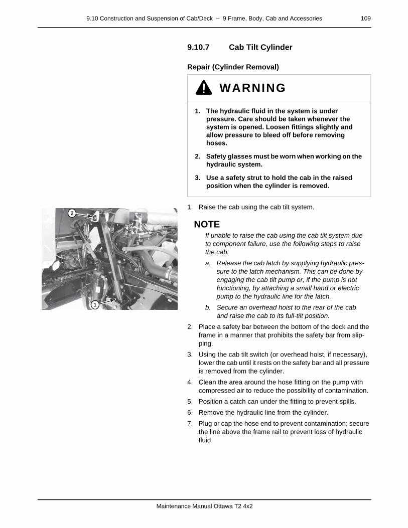
9.10 Construction and Suspension of Cab/Deck – 9 Frame, Body, Cab and Accessories 109
Maintenance Manual Ottawa T2 4x2
9.10.7 Cab Tilt Cylinderpage –
Repair (Cylinder Removal)
1. Raise the cab using the cab tilt system.
NOTEIf unable to raise the cab using the cab tilt system due to component failure, use the following steps to raise the cab.
a. Release the cab latch by supplying hydraulic pres-sure to the latch mechanism. This can be done by engaging the cab tilt pump or, if the pump is not functioning, by attaching a small hand or electric pump to the hydraulic line for the latch.
b. Secure an overhead hoist to the rear of the cab and raise the cab to its full-tilt position.
2. Place a safety bar between the bottom of the deck and the frame in a manner that prohibits the safety bar from slip-ping.
3. Using the cab tilt switch (or overhead hoist, if necessary), lower the cab until it rests on the safety bar and all pressure is removed from the cylinder.
4. Clean the area around the hose fitting on the pump with compressed air to reduce the possibility of contamination.
5. Position a catch can under the fitting to prevent spills.
6. Remove the hydraulic line from the cylinder.
7. Plug or cap the hose end to prevent contamination; secure the line above the frame rail to prevent loss of hydraulic fluid.
WARNING
1. The hydraulic fluid in the system is under pressure. Care should be taken whenever the system is opened. Loosen fittings slightly and allow pressure to bleed off before removing hoses.
2. Safety glasses must be worn when working on the hydraulic system.
3. Use a safety strut to hold the cab in the raised position when the cylinder is removed.
2
1
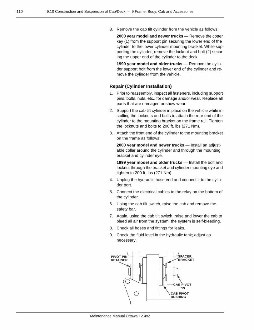
110 9.10 Construction and Suspension of Cab/Deck – 9 Frame, Body, Cab and Accessories
Maintenance Manual Ottawa T2 4x2
8. Remove the cab tilt cylinder from the vehicle as follows:
2000 year model and newer trucks — Remove the cotter key (1) from the support pin securing the lower end of the cylinder to the lower cylinder mounting bracket. While sup-porting the cylinder, remove the locknut and bolt (2) secur-ing the upper end of the cylinder to the deck.
1999 year model and older trucks — Remove the cylin-der support bolt from the lower end of the cylinder and re-move the cylinder from the vehicle.
–
Repair (Cylinder Installation)
1. Prior to reassembly, inspect all fasteners, including support pins, bolts, nuts, etc., for damage and/or wear. Replace all parts that are damaged or show wear.
2. Support the cab tilt cylinder in place on the vehicle while in-stalling the locknuts and bolts to attach the rear end of the cylinder to the mounting bracket on the frame rail. Tighten the locknuts and bolts to 200 ft. lbs (271 Nm).
3. Attach the front end of the cylinder to the mounting bracket on the frame as follows:
2000 year model and newer trucks — Install an adjust-able collar around the cylinder and through the mounting bracket and cylinder eye.
1999 year model and older trucks — Install the bolt and locknut through the bracket and cylinder mounting eye and tighten to 200 ft. lbs (271 Nm).
4. Unplug the hydraulic hose end and connect it to the cylin-der port.
5. Connect the electrical cables to the relay on the bottom of the cylinder.
6. Using the cab tilt switch, raise the cab and remove the safety bar.
7. Again, using the cab tilt switch, raise and lower the cab to bleed all air from the system; the system is self-bleeding.
8. Check all hoses and fittings for leaks.
9. Check the fluid level in the hydraulic tank; adjust as necessary.
CAB PIVOTPIN
SPACERBRACKET
PIVOT PINRETAINER
CAB PIVOTBUSHING

9.10 Construction and Suspension of Cab/Deck – 9 Frame, Body, Cab and Accessories 111
Maintenance Manual Ottawa T2 4x2
9.10.8 Cab Pivot Bushingpage –
Repair (Pivot Bushing Removal)
WARNING
Make sure all safety devices are in place while the cab is in the raised position.
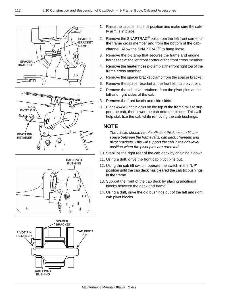
112 9.10 Construction and Suspension of Cab/Deck – 9 Frame, Body, Cab and Accessories
Maintenance Manual Ottawa T2 4x2
1. Raise the cab to the full-tilt position and make sure the safe-ty arm is in place.
2. Remove the SNAPTRAC® bolts from the left front corner of the frame cross member and from the bottom of the cab-
channel. Allow the SNAPTRAC® to hang loose.
3. Remove the p-clamp that secures the frame and engine harnesses at the left front corner of the front cross member.
4. Remove the heater hose p-clamp at the front right top of the frame cross member.
5. Remove the spacer bracket clamp from the spacer bracket.
6. Remove the spacer bracket at the front left cab pivot pin.
7. Remove the cab pivot retainers from the pivot pins at the left and right sides of the cab.
8. Remove the front fascia and side skirts.
9. Place 4x4x6-inch blocks on the top of the frame rails to sup-port the cab, then lower the cab onto the blocks. This will help stabilize the cab while removing the cab bushings.
NOTEThe blocks should be of sufficient thickness to fill the space between the frame rails, cab deck channels and pivot brackets. This will support the cab in the ride level position when the pivot pins are removed.
10. Stabilize the right rear of the cab deck by chaining it down.
11. Using a drift, drive the front cab pivot pins out.
12. Using the cab tilt switch, operate the switch in the “UP” position until the cab deck has cleared the cab tilt bushings in the frame.
13. Support the front of the cab deck by placing additional blocks between the deck and frame.
14. Using a drift, drive the old bushings out of the left and right cab pivot blocks.
–
SPACERBRACKET
SPACERBRACKETCAMP
PIVOT PINRETAINER
CABPIVOT PIN
CAB PIVOTBUSHING
CAB PIVOTPIN
SPACERBRACKET
PIVOT PINRETAINER
CAB PIVOTBUSHING
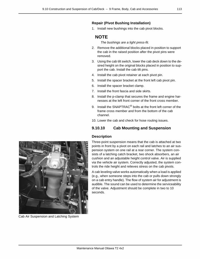
9.10 Construction and Suspension of Cab/Deck – 9 Frame, Body, Cab and Accessories 113
Maintenance Manual Ottawa T2 4x2
Repair (Pivot Bushing Installation)
1. Install new bushings into the cab pivot blocks.
NOTEThe bushings are a light press-fit.
2. Remove the additional blocks placed in position to support the cab in the raised position after the pivot pins were removed.
3. Using the cab tilt switch, lower the cab deck down to the de-sired height on the original blocks placed in position to sup-port the cab. Install the cab tilt pins.
4. Install the cab pivot retainer at each pivot pin.
5. Install the spacer bracket at the front left cab pivot pin.
6. Install the spacer bracket clamp.
7. Install the front fascia and side skirts.
8. Install the p-clamp that secures the frame and engine har-nesses at the left front corner of the front cross member.
9. Install the SNAPTRAC® bolts at the front left corner of the frame cross member and from the bottom of the cab channel.
10. Lower the cab and check for hose routing issues.
9.10.10 Cab Mounting and Suspensionpage –
Description
Cab Air Suspension and Latching System
Three-point suspension means that the cab is attached at two points in front by a pivot on each rail and latches to an air sus-pension system on one rail at a rear corner. The system con-sists of a latching catch bracket, two shock absorbers, an air cushion and an adjustable height control valve. Air is supplied via the vehicle air system. Correctly adjusted, the system con-trols the ride height and relieves stress on the cab pivots.
A cab leveling valve works automatically when a load is applied (e.g., when someone steps into the cab or pulls down strongly on a cab entry handle). The flow of system air for adjustment is audible. The sound can be used to determine the serviceability of the valve. Adjustment should be complete in two to 10 seconds.
page –

114 9.10 Construction and Suspension of Cab/Deck – 9 Frame, Body, Cab and Accessories
Maintenance Manual Ottawa T2 4x2
Diagnosis (Cab Air Suspension)
Components
• Cab Leveling Valve
• Cab Shock Absorbers
Cab Leveling Valve and Shock Absorber Diagnosis
9.10.11 Air Ride Suspension (Three-Point)page –
Repair (Cab Suspension Assembly Removal)
1. Park the vehicle on firm level ground.
2. Raise and support the cab.
3. After the cab is raised and supported, briefly press the cab “tilt” switch to the “DOWN” position. This will evacuate extra fluid from the cylinder.
4. Disconnect and cap the hydraulic lines (1) connected to the latch at the top of the suspension assembly.
5. Disconnect the air line (2) from the leveling valve on the suspension assembly.
6. Remove the four mounting bolts (3, 4) securing the suspen-sion assembly to the frame rail (driver's side).
Observation Cause Action
Cab leveling too fast or too slow Clogged leveling valve Inspect. Replace as needed.
Uncontrolled cab bounce No air in airbag Turn on air ride air valve.
Shock absorbers worn Inspect. Replace as needed.
Worn out cab pivot bushings Replace cab pivot bushings.D
SC
24452
1
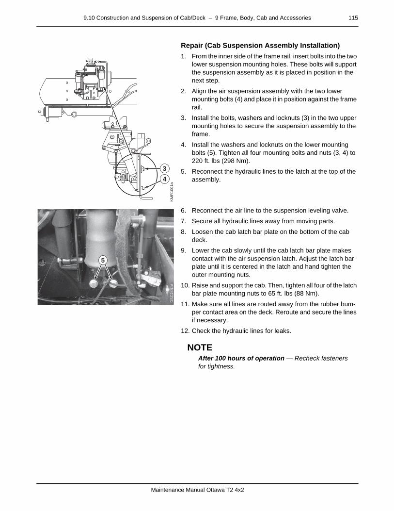
9.10 Construction and Suspension of Cab/Deck – 9 Frame, Body, Cab and Accessories 115
Maintenance Manual Ottawa T2 4x2
– Repair (Cab Suspension Assembly Installation)
1. From the inner side of the frame rail, insert bolts into the two lower suspension mounting holes. These bolts will support the suspension assembly as it is placed in position in the next step.
2. Align the air suspension assembly with the two lower mounting bolts (4) and place it in position against the frame rail.
3. Install the bolts, washers and locknuts (3) in the two upper mounting holes to secure the suspension assembly to the frame.
4. Install the washers and locknuts on the lower mounting bolts (5). Tighten all four mounting bolts and nuts (3, 4) to 220 ft. lbs (298 Nm).
5. Reconnect the hydraulic lines to the latch at the top of the assembly.
6. Reconnect the air line to the suspension leveling valve.
7. Secure all hydraulic lines away from moving parts.
8. Loosen the cab latch bar plate on the bottom of the cab deck.
9. Lower the cab slowly until the cab latch bar plate makes contact with the air suspension latch. Adjust the latch bar plate until it is centered in the latch and hand tighten the outer mounting nuts.
10. Raise and support the cab. Then, tighten all four of the latch bar plate mounting nuts to 65 ft. lbs (88 Nm).
11. Make sure all lines are routed away from the rubber bum-per contact area on the deck. Reroute and secure the lines if necessary.
12. Check the hydraulic lines for leaks.
NOTEAfter 100 hours of operation — Recheck fasteners for tightness.
–
KM
R10
01a
34
DS
C24
41a
5

116 9.10 Construction and Suspension of Cab/Deck – 9 Frame, Body, Cab and Accessories
Maintenance Manual Ottawa T2 4x2
Repair (Air Ride Level Adjustment)
1. Park the vehicle on firm level ground.
2. Start and run the engine until the air system has a minimum of 100 psi of air pressure.
3. Shut the engine down.
4. Turn on (open) the air supply to the cab suspension by turn-ing the “T-handle” valve on the bottom of the deck counter-clockwise.
5. Remove the plastic clip (2) in the center of the plastic linkage rod connected to the control arm on the suspension assembly.
6. Use tape to mark the linkage rod's current position (3).
7. Adjust the linkage rod length as required to set proper ride height. Disengage the serrated lower end (4) of the rod from the serrated portion of its upper sleeve (1):
To raise ride level — Decrease the rod (4) length by plac-ing the rod deeper into the upper sleeve (1).
To lower ride level — Increase the rod length by reducing the insertion of the rod in the sleeve.
NOTEOne inch (25.4 mm) of clearance is required between the stop bumpers on the air suspension assembly and the channel at the bottom of the cab deck for proper ride height.
9.10.12 Leveling Valvepage –
Repair (Valve Operation Check)
Check for proper operation of the leveling valve as follows:
1. While holding the cab entry handle in the “DOWN” position, count the time in seconds it takes for the air spring to raise the ride height.
2. If the noted time is:
Within 2–10 seconds — Valve is OK.
Under 2 seconds — Valve is damaged or filter is clogged.
Over 10 seconds — Valve is damaged or filter is clogged.
3. Replace the valve if the valve is damaged or the filter is clogged.
DS
C24
43
1
2
3
4
DS
C24
33

9.10 Construction and Suspension of Cab/Deck – 9 Frame, Body, Cab and Accessories 117
Maintenance Manual Ottawa T2 4x2
9.10.13 Shock Absorberspage –
Repair (Shock Removal)
Replacement of the shock absorber is necessary if the cab ride becomes too bouncy under normal operating conditions.
1. Raise the cab and lock it in the full-tilt position.
2. Remove the nuts (1) from the 7/16-inch mounting bolts se-curing the shock absorber in the top and bottom mounting brackets at one side of the suspension assembly.
3. Remove the bolts and remove the shock absorber from the assembly.
4. Repeat the procedure to remove the second shock absorb-er at the opposite side of the assembly.
–
DS
C24
41b
1
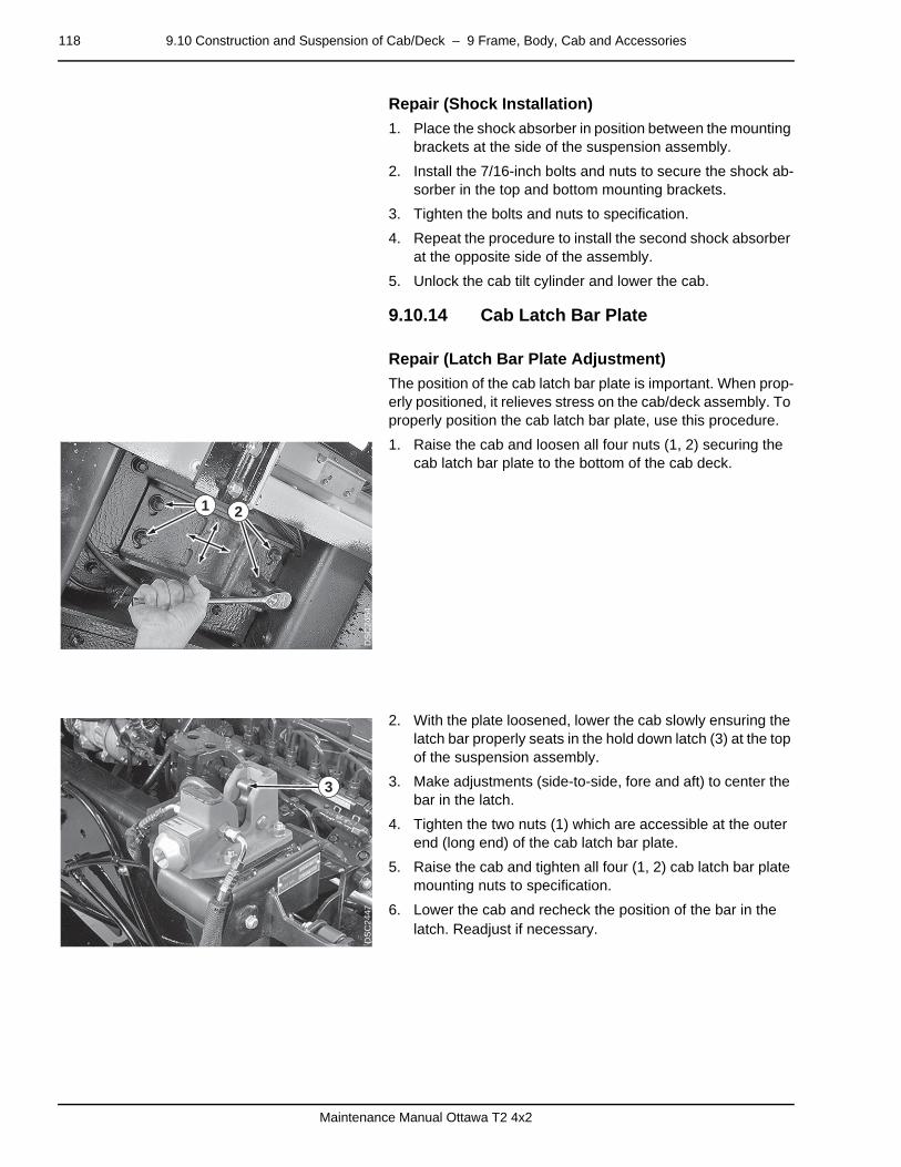
118 9.10 Construction and Suspension of Cab/Deck – 9 Frame, Body, Cab and Accessories
Maintenance Manual Ottawa T2 4x2
Repair (Shock Installation)
1. Place the shock absorber in position between the mounting brackets at the side of the suspension assembly.
2. Install the 7/16-inch bolts and nuts to secure the shock ab-sorber in the top and bottom mounting brackets.
3. Tighten the bolts and nuts to specification.
4. Repeat the procedure to install the second shock absorber at the opposite side of the assembly.
5. Unlock the cab tilt cylinder and lower the cab.
9.10.14 Cab Latch Bar Platepage –
Repair (Latch Bar Plate Adjustment)
The position of the cab latch bar plate is important. When prop-erly positioned, it relieves stress on the cab/deck assembly. To properly position the cab latch bar plate, use this procedure.
1. Raise the cab and loosen all four nuts (1, 2) securing the cab latch bar plate to the bottom of the cab deck.
2. With the plate loosened, lower the cab slowly ensuring the latch bar properly seats in the hold down latch (3) at the top of the suspension assembly.
3. Make adjustments (side-to-side, fore and aft) to center the bar in the latch.
4. Tighten the two nuts (1) which are accessible at the outer end (long end) of the cab latch bar plate.
5. Raise the cab and tighten all four (1, 2) cab latch bar plate mounting nuts to specification.
6. Lower the cab and recheck the position of the bar in the latch. Readjust if necessary.
DS
C24
54
1 2
DS
C24
47
3

9.12 Chassis – 9 Frame, Body, Cab and Accessories 119
Maintenance Manual Ottawa T2 4x2
9.12 Chassispage –
Description
Frame Construction
1
2
3
4
5
6
7
8 9 10
1. Front Crossmember Weldment
2. Front Spring Hanger and Bumper Mount Weldment with Two Hook (2)
3. Main Rail(2)
4. Fifth-Wheel Boom Pivot
5. Inverted-L Channel Rail Reinforcement (2 when equipped)
6. Boom Cylinder Lower Support/Axle Mounting Bracket (2)
7. Skid Ramp/Rear Crossmember Mounting Bracket(2)
8. Skid Ramp Weldment
9. Rear Tie Bar Angle
10. Rear Crossmember Weldment
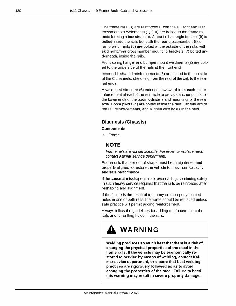
120 9.12 Chassis – 9 Frame, Body, Cab and Accessories
Maintenance Manual Ottawa T2 4x2
The frame rails (3) are reinforced C channels. Front and rear crossmember weldments (1) (10) are bolted to the frame rail ends forming a box structure. A rear tie bar angle bracket (9) is bolted inside the rails beneath the rear crossmember. Skid ramp weldments (8) are bolted at the outside of the rails, with skid ramp/rear crossmember mounting brackets (7) bolted un-derneath, inside the rails.
Front spring hanger and bumper mount weldments (2) are bolt-ed to the underside of the rails at the front end.
Inverted L-shaped reinforcements (5) are bolted to the outside of the C channels, stretching from the rear of the cab to the rear rail ends.
A weldment structure (6) extends downward from each rail re-inforcement ahead of the rear axle to provide anchor points for the lower ends of the boom cylinders and mounting for the rear axle. Boom pivots (4) are bolted inside the rails just forward of the rail reinforcements, and aligned with holes in the rails.
page –
Diagnosis (Chassis)Components
• Frame
NOTEFrame rails are not serviceable. For repair or replacement, contact Kalmar service department.
Frame rails that are out of shape must be straightened and properly aligned to restore the vehicle to maximum capacity and safe performance.
If the cause of misshapen rails is overloading, continuing safely in such heavy service requires that the rails be reinforced after reshaping and alignment.
If the failure is the result of too many or improperly located holes in one or both rails, the frame should be replaced unless safe practice will permit adding reinforcement.
Always follow the guidelines for adding reinforcement to the rails and for drilling holes in the rails.
WARNING
Welding produces so much heat that there is a risk of changing the physical properties of the steel in the frame rails. If the vehicle may be economically re-stored to service by means of welding, contact Kal-mar sevice department, or ensure that best welding practices are rigorously followed so as to avoid changing the properties of the steel. Failure to heed this warning may result in severe property damage.

9.12 Chassis – 9 Frame, Body, Cab and Accessories 121
Maintenance Manual Ottawa T2 4x2
Frame Diagnosis
WARNING
Do NOT cut the rails or holes in the rails using a weld-ing torch. Do NOT drill holes in top or bottom rail flanges. Failure to heed this warning may result in se-vere property damage.
Observation Cause Action
Cracked rails Loose bolts Install larger bolts. Refer to instructions for repairing cracked rails elsewhere in this manual. Reinforce rail.
Overloading Refer to instructions for repairing cracked rails elsewhere in this manual. Reinforce rail.
Sagging rails Overloading Straighten, reinforce and align the rails, or replace the frame as needed.
Uneven loading
Holes in rail flange
Too many rail web holes
Rail web holes too close together
Four or more rail web holes aligned vertically
Welds on flange
No filler blocks
Rail web holes cut with torch Straighten, reinforce and align the rails, or replace the frame as needed.
Notches anywhere in rails
Vehicle fire
Vehicle collision
Equipment added beyond vehicle capacity
Buckled rails Fifth wheel raised to maximum while maneuvering a loaded trailer
Straighten, reinforce and align the rails, or replace the frame as needed.
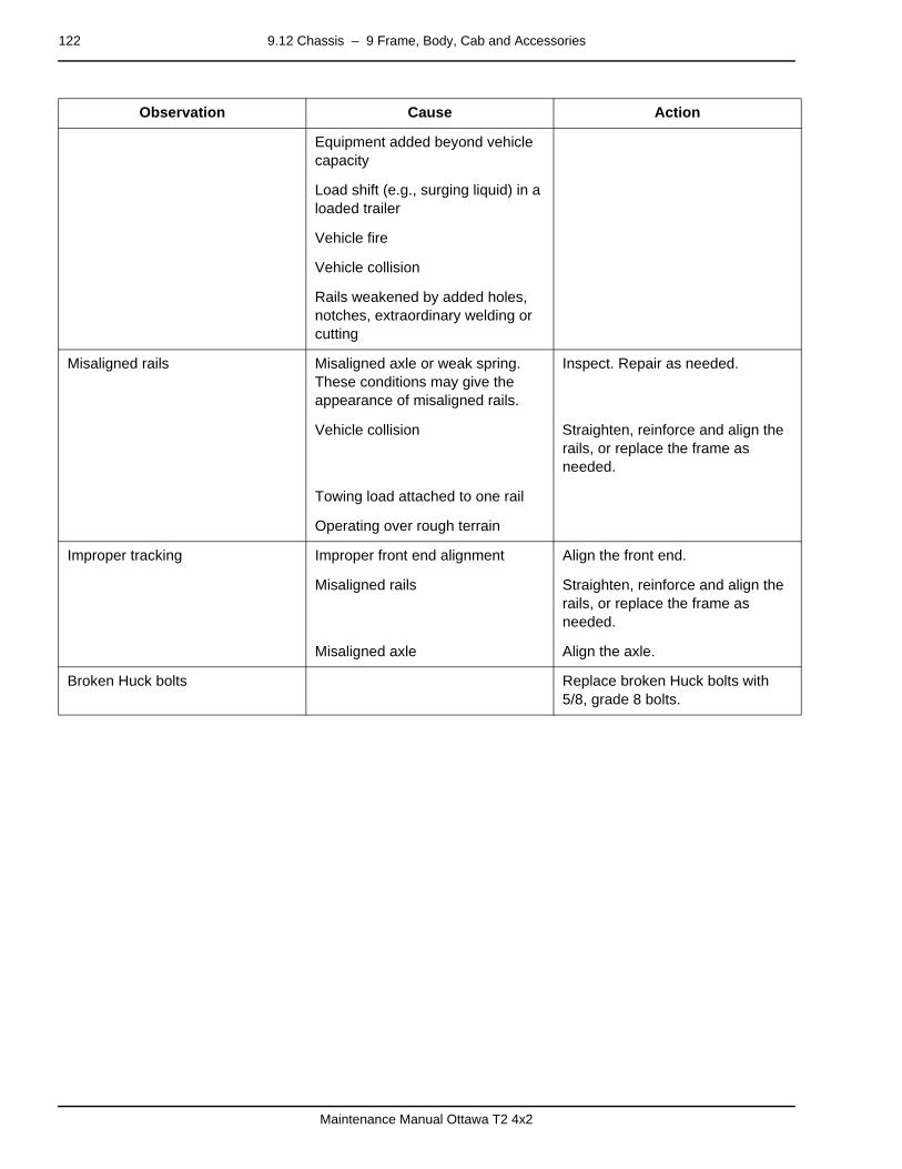
122 9.12 Chassis – 9 Frame, Body, Cab and Accessories
Maintenance Manual Ottawa T2 4x2
page –
Equipment added beyond vehicle capacity
Load shift (e.g., surging liquid) in a loaded trailer
Vehicle fire
Vehicle collision
Rails weakened by added holes, notches, extraordinary welding or cutting
Misaligned rails Misaligned axle or weak spring. These conditions may give the appearance of misaligned rails.
Inspect. Repair as needed.
Vehicle collision Straighten, reinforce and align the rails, or replace the frame as needed.
Towing load attached to one rail
Operating over rough terrain
Improper tracking Improper front end alignment Align the front end.
Misaligned rails Straighten, reinforce and align the rails, or replace the frame as needed.
Misaligned axle Align the axle.
Broken Huck bolts Replace broken Huck bolts with 5/8, grade 8 bolts.
Observation Cause Action

9.12 Chassis – 9 Frame, Body, Cab and Accessories 123
Maintenance Manual Ottawa T2 4x2
Repair (Frame Damage Analysis)This section is not intended to cover the causes of all possible frame problems; however, it should be of valuable assistance in preparing complete, concise reports. The purpose of this in-formation is to emphasize the fact that frame damage doesn’t just happen, there is always a cause or reason. An example of this would be a vehicle involved in a collision. The reason for damage in this case is apparent; however, other damages can be encountered where the reasons are not so apparent.
Three types of frame damage can be classified as follows:
1. Collision
2. Excessive bending moment
3. Localized stress concentration
Damage caused by collision should be repaired using proper methods and reinforcement. Excessive bending moment dam-age is caused by overloading, improper weight distribution or misapplication of the vehicle. Excessive bending moment dam-age will occur at different areas on various types of vehicles. The effects of excessive bending moment will vary by type of vehicle.
page –
Repair (Making Reinforcements, General Information)
In general, when making reinforcements of any type, observe the following practices.
1. Contact the Kalmar Engineering Department for design ap-proval.
2. Taper reinforcement plates to avoid abrupt changes in sec-tion modulus. Angles at the edge of a reinforcement plate should be less than 45 degrees.
3. When reinforcement plates are shaped by use of a cutting torch, all cracks, nicks and burrs must be removed from the edges by grinding. Burrs must also be removed from the edges of holes.
CAUTION
When welding on a Kalmar truck:
1. Always disconnect the wiring at the battery termi-nals and ECUs.
2. The ground for the welder should always be at-tached as close as possible to the work area.
3. Failure to adhere to these cautions can result in permanent damage to the electrical system.

124 9.12 Chassis – 9 Frame, Body, Cab and Accessories
Maintenance Manual Ottawa T2 4x2
4. Make reinforcements long enough so that they can be ta-pered and still extend beyond the critical area.
page –
Repair (Making Reinforcements, Attachment)Reinforcements must be attached with grade 8 bolts, locknuts and hardened washers on both ends of the bolt. This provides a good torque surface to maintain tight bolts. Avoid attaching reinforcements by welding. (In some cases, welding may be ac-ceptable. Such cases include the plug weld used on strap or web reinforcements.) Bolt holes that are enlarged or irregularly worn may be reamed to accept the next larger bolt diameter. For critical areas, body-fit bolts require reaming the hole to a nonstandard size to effect an interference fit for the bolt. When-ever possible, use existing frame holes rather than drill new ones.
In general, when attaching reinforcements to the frame, use bolts and observe the following:
1. Use existing holes, if possible.
2. Do not drill holes in the frame flange.
3. Holes should be made as close to the neutral axis (halfway between the flanges) as possible.
4. Bolt holes should be no larger than those already existing in the frame.
5. No more than three holes should be on a vertical line of the web.
6. Holes should be at least 3/4 inch (19.0 mm) apart.
7. Holes in a reinforcement plate should be at least two times the material thickness from the edge of the plate.
page –
Repair (Cracks in Steel Rails or Cross Members)Type of Cracks
The straight crack and the sunburst crack are the two common types. The straight crack will normally start from the edge of a flange. It will progress across the flange and through the web section of a rail. Ultimately, it will continue through the other flange. This type of crack may result from high concentrations of stress in small areas of the frame, excessive bending mo-ment and torsion loading. Sunburst cracks will radiate out from a hole in the web section of a rail or cross member. They are caused by high loads being applied at a mounting bracket or cross member, which is not securely or properly attached to the rail. If cracks occur to both the rail and reinforcement of a steel frame, they must be repaired separately. The flanges must re-act independently to prevent localized stress concentrations. Use a copper spacer between the flanges of cracked base rail flanges and reinforcement flanges. Cross member mounting flange cracks may be repaired in the same manner as side rail cracks. However, the weld bead should be built up to provide a

9.12 Chassis – 9 Frame, Body, Cab and Accessories 125
Maintenance Manual Ottawa T2 4x2
good smooth radius. If extensive damage is incurred to a cross member, the cross member should be replaced. It may be nec-essary to align the frame and level the rails before repairing the frame.
The following procedure should be used to repair cracks in a rail, reinforcement or cross member.
1. Remove any equipment that will interfere with access to the crack.
2. Locate the extreme end of the crack and drill a 1/2-inch (12.7 mm) hole.
3. V-grind the entire length of the crack from the starting point to the hole at the extreme end. The angle of the “V” will de-pend on the welding process used.
4. The bottom of the crack should be opened up 1/16 inch (1.6 mm) to allow good penetration of the weld. (A hacksaw blade may be used for this.)
5. Weld with the proper electrode and proper welding tech-niques.
6. Grind the weld smooth on both the inside and outside of the rail or cross member. Be extremely careful to eliminate weld buildup or notches on the edge of the flange.
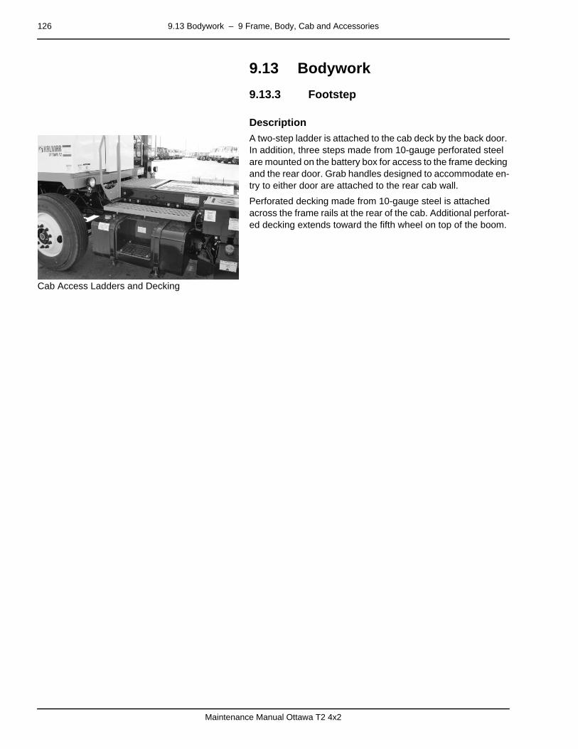
126 9.13 Bodywork – 9 Frame, Body, Cab and Accessories
Maintenance Manual Ottawa T2 4x2
9.13 Bodywork
9.13.3 Footsteppage –
Description
Cab Access Ladders and Decking
A two-step ladder is attached to the cab deck by the back door. In addition, three steps made from 10-gauge perforated steel are mounted on the battery box for access to the frame decking and the rear door. Grab handles designed to accommodate en-try to either door are attached to the rear cab wall.
Perforated decking made from 10-gauge steel is attached across the frame rails at the rear of the cab. Additional perforat-ed decking extends toward the fifth wheel on top of the boom.

9.16 Accessories and Options – 9 Frame, Body, Cab and Accessories 127
Maintenance Manual Ottawa T2 4x2
9.16 Accessories and Options
9.16.1 Accessory Relaypage –
Diagnosis
Components
• Accessory Circuit Breakers
• Accessory Relay
• Ignition Switch
Accessory Relay Circuit Diagnosis
9.16.2 Heater/Air Conditioning (Optional)page –
Diagnosis
Components
• AC On/Off Switch
• Blower Motor
• Cold Control
• Heater/AC Relay
• Heater Resistor Block
• Heater Switch
• Ignition Switch
Heater/Air Conditioning Circuit Diagnosis
Observation Cause Action
One accessory inoperative Circuit breaker open Reset. Repair short as needed. Re-place circuit breaker as needed.
All accessories inoperative Defective relay Replace.
Defective wiring Inspect connections and wires. Test circuits. Repair or replace as needed.
Observation Cause Action
Inoperative blower Circuit breaker open Reset. Repair short as needed. Re-place circuit breaker as needed.
Defective resistor Replace.
Defective heater switch Replace.
Defective heater/AC relay Replace.
Defective wiring Inspect connections and wires. Test circuits. Repair or replace as needed.
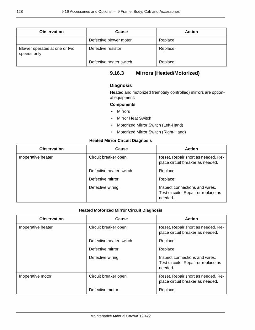
128 9.16 Accessories and Options – 9 Frame, Body, Cab and Accessories
Maintenance Manual Ottawa T2 4x2
9.16.3 Mirrors (Heated/Motorized)page –
Diagnosis
Heated and motorized (remotely controlled) mirrors are option-al equipment.
Components
• Mirrors
• Mirror Heat Switch
• Motorized Mirror Switch (Left-Hand)
• Motorized Mirror Switch (Right-Hand)
Heated Mirror Circuit Diagnosis
Heated Motorized Mirror Circuit Diagnosis
Defective blower motor Replace.
Blower operates at one or two speeds only
Defective resistor Replace.
Defective heater switch Replace.
Observation Cause Action
Observation Cause Action
Inoperative heater Circuit breaker open Reset. Repair short as needed. Re-place circuit breaker as needed.
Defective heater switch Replace.
Defective mirror Replace.
Defective wiring Inspect connections and wires. Test circuits. Repair or replace as needed.
Observation Cause Action
Inoperative heater Circuit breaker open Reset. Repair short as needed. Re-place circuit breaker as needed.
Defective heater switch Replace.
Defective mirror Replace.
Defective wiring Inspect connections and wires. Test circuits. Repair or replace as needed.
Inoperative motor Circuit breaker open Reset. Repair short as needed. Re-place circuit breaker as needed.
Defective motor Replace.

9.16 Accessories and Options – 9 Frame, Body, Cab and Accessories 129
Maintenance Manual Ottawa T2 4x2
Inoperative motor Defective wiring Inspect connections and wires. Test circuits. Repair or replace as needed.
Observation Cause Action
130 9.16 Accessories and Options – 9 Frame, Body, Cab and Accessories
Maintenance Manual Ottawa T2 4x2

10.3 Tanks and Accumulators – 10 Common Hydraulics 131
Maintenance Manual Ottawa T2 4x2
mm mm mm mm mm mm
10 Common Hydraulicspage –
System Description
The hydraulic system of the current production Ottawa tractors is composed of three subsystems. They are the boom (hoist), cab tilt and power steering. The common link among these three subsystems is the shared reservoir, return filter and hy-draulic fluid. With the exception of these items, all subsystems operate independently. The three subsystems have their own control valves and output actuators (cylinders).
The power steering is an open-centered circuit; that is, hydrau-lic oil flows continuously through the center of the control valve even while the steering wheel is not moving.
Power steering and the boom systems use the same hydraulic pump. The pump is equipped with a priority valve that directs the first four gallons per minute of flow to the steering circuit.
10.3 Tanks and Accumulators
10.3.1 Reservoirpage –
Description
The standard hydraulic reservoir has a 20-gallon capacity. It is fitted with a level sight gauge and a breather.
WARNING
The hydraulic fluid in the system is under pressure. Care should be taken whenever the system is opened. Loosen fittings slightly and allow pressure to bleed off before removing hoses. Safety glasses must be worn when working on the hydraulic system.
Failure to heed this warning may result in serious per-sonal injury or property damage.

132 10.6 Temperature Control, Cleaning and Hydraulic Oil – 10 Common Hydraulics
Maintenance Manual Ottawa T2 4x2
10.6 Temperature Control, Cleaning and Hydraulic Oil
10.6.8 Return Filterpage –
Description
The return filter is located in the hydraulic tank, where it is con-tinuously filtering fluid that is used in all three subsystems: boom, cab tilt and power steering.
11.1 Controls and Instruments – 11 Common Electric 133
Maintenance Manual Ottawa T2 4x2
mm mm mm mm mm mm
11 Common Electric
11.1 Controls and Instrumentspage –
Description (Wiring Harness)The wiring harness can accommodate several items of optional equipment. Contact your dealer for information about any equipment installed after the vehicle left the factory.
134 11.2 Safety – 11 Common Electric
Maintenance Manual Ottawa T2 4x2
11.2 Safety
11.2.2 Fuses, Relays and Circuit Breakerspage –
Description
Fuses, Relays and Circuit Breakers — The Kalmar tractor is equipped with two power boards. One power board is located in the cab under the center panel of the dash. The second pow-er board is located in the chassis over the transmission on the left side. See following figures for fuse, breaker and relay loca-tions.
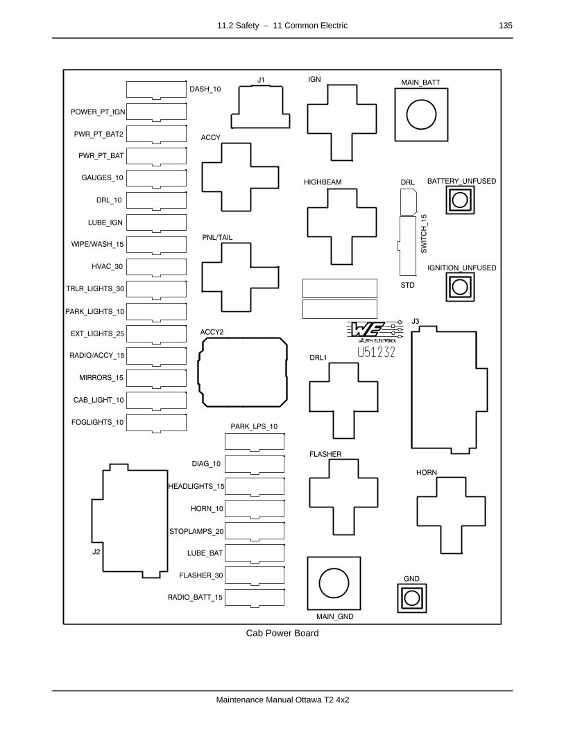
11.2 Safety – 11 Common Electric 135
Maintenance Manual Ottawa T2 4x2
Cab Power Board
DASH_10
PWR_PT_BAT2
POWER_PT_IGN
PWR_PT_BAT
GAUGES_10
DRL_10
LUBE_IGN
WIPE/WASH_15
HVAC_30
TRLR_LIGHTS_30
PARK_LIGHTS_10
EXT_LIGHTS_25
RADIO/ACCY_15
MIRRORS_15
FOGLIGHTS_10
CAB_LIGHT_10
PARK_LPS_10
DIAG_10
HEADLIGHTS_15
HORN_10
STOPLAMPS_20
LUBE_BAT
FLASHER_30
RADIO_BATT_15
J2
J1
ACCY
IGN
HIGHBEAM
MAIN_BATT
DRL BATTERY_UNFUSED
IGNITION_UNFUSED
SWITCH_15
STD
DRL1
J3
FLASHER
HORN
MAIN_GND
GND
PNL/TAIL
ACCY2

136 11.2 Safety – 11 Common Electric
Maintenance Manual Ottawa T2 4x2
Chassis Power Board

12.1 Air System and Brakes – 12 Common Pneumatics 137
Maintenance Manual Ottawa T2 4x2
mm mm mm mm mm mm
12 Common Pneumatics
12.1 Air System and Brakespage –
DescriptionThe main function of the vehicle air system is to provide com-pressed air to operate the brakes. Compressed air also oper-ates the cab suspension, driver’s seat suspension and posture features, fifth-wheel unlatching, trailer brakes and optional in-teraxle lockout.
12.1.1 Diagnosispage –
Brakes — Air System
A DOT/EPA system includes three reservoirs: primary, front and rear.
Components
• Air Compressor
• Air Control Valve
• Air Dryer (Optional)
• Antilock Modulator Valve (Optional)
• Automatic Slack Adjusters
• Bobtail Proportioning Relay Valve (Optional)
• Brake Valve (treadle)
• Check Valve
• Double Check Valve
• Front Brake Chambers
• Governor
• Low Pressure Indicator
• Pressure Protection Valve
• Pressure Relief Valve
• Quick Release Valve
• Rear Brake Chambers
DANGER
Only trained air brake technician must be allowed to service the air brakes. Failure to heed this danger could result in severe personal injury or death.

138 12.1 Air System and Brakes – 12 Common Pneumatics
Maintenance Manual Ottawa T2 4x2
• Reservoirs (DOT/EPA: primary, front and rear)
• Stoplight Switch
• Tractor Protection Valve
Brakes — Air System Diagnosis
Observation Cause Action
Frequent air dryer purging (cycling) Excessive system leakage Inspect system connections and valves. Repair or replace as need-ed.
Defective internal check valve Test. Replace as needed.
Defective governor Test. Adjust or replace as needed.
Purge valve leaks Test. Replace as needed.
Compressor unloader leaks Slight leakage permitted. Uncover inlet cavity and inspect piston. Repair or replace unloader as needed.
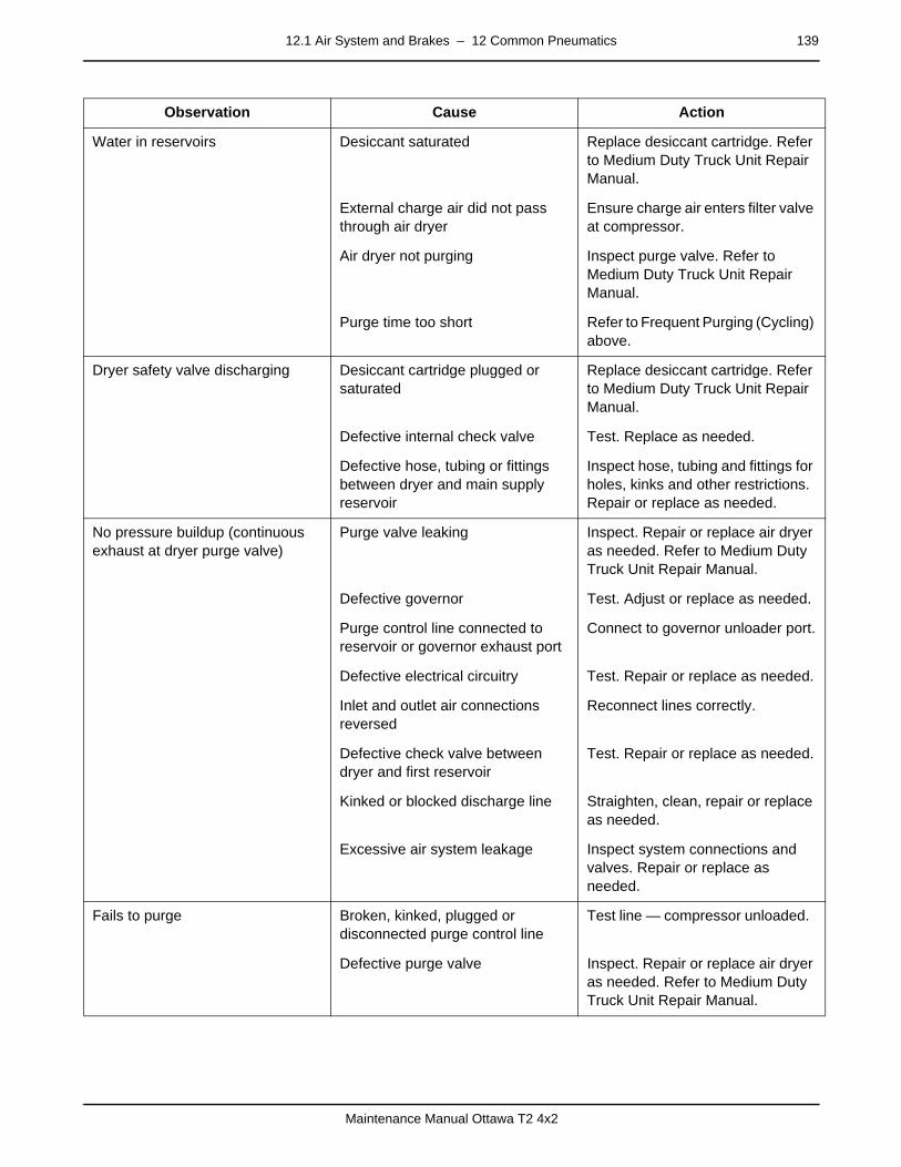
12.1 Air System and Brakes – 12 Common Pneumatics 139
Maintenance Manual Ottawa T2 4x2
Water in reservoirs Desiccant saturated Replace desiccant cartridge. Refer to Medium Duty Truck Unit Repair Manual.
External charge air did not pass through air dryer
Ensure charge air enters filter valve at compressor.
Air dryer not purging Inspect purge valve. Refer to Medium Duty Truck Unit Repair Manual.
Purge time too short Refer to Frequent Purging (Cycling) above.
Dryer safety valve discharging Desiccant cartridge plugged or saturated
Replace desiccant cartridge. Refer to Medium Duty Truck Unit Repair Manual.
Defective internal check valve Test. Replace as needed.
Defective hose, tubing or fittings between dryer and main supply reservoir
Inspect hose, tubing and fittings for holes, kinks and other restrictions. Repair or replace as needed.
No pressure buildup (continuous exhaust at dryer purge valve)
Purge valve leaking Inspect. Repair or replace air dryer as needed. Refer to Medium Duty Truck Unit Repair Manual.
Defective governor Test. Adjust or replace as needed.
Purge control line connected to reservoir or governor exhaust port
Connect to governor unloader port.
Defective electrical circuitry Test. Repair or replace as needed.
Inlet and outlet air connections reversed
Reconnect lines correctly.
Defective check valve between dryer and first reservoir
Test. Repair or replace as needed.
Kinked or blocked discharge line Straighten, clean, repair or replace as needed.
Excessive air system leakage Inspect system connections and valves. Repair or replace as needed.
Fails to purge Broken, kinked, plugged or disconnected purge control line
Test line — compressor unloaded.
Defective purge valve Inspect. Repair or replace air dryer as needed. Refer to Medium Duty Truck Unit Repair Manual.
Observation Cause Action
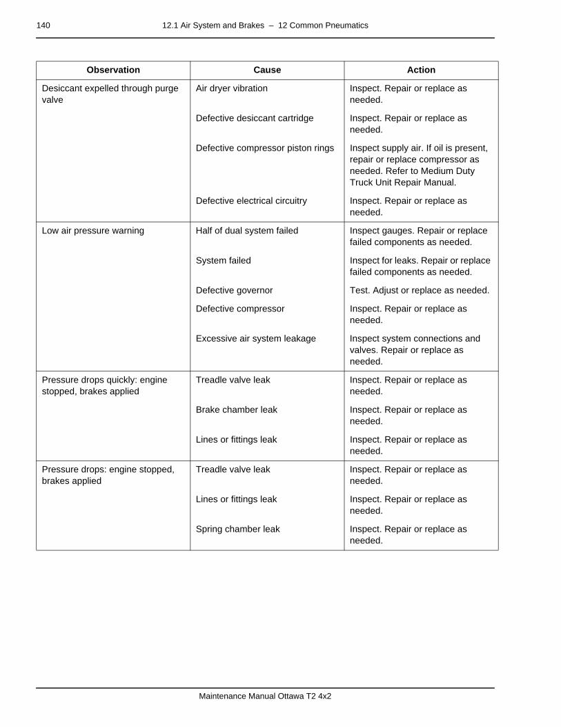
140 12.1 Air System and Brakes – 12 Common Pneumatics
Maintenance Manual Ottawa T2 4x2
Desiccant expelled through purge valve
Air dryer vibration Inspect. Repair or replace as needed.
Defective desiccant cartridge Inspect. Repair or replace as needed.
Defective compressor piston rings Inspect supply air. If oil is present, repair or replace compressor as needed. Refer to Medium Duty Truck Unit Repair Manual.
Defective electrical circuitry Inspect. Repair or replace as needed.
Low air pressure warning Half of dual system failed Inspect gauges. Repair or replace failed components as needed.
System failed Inspect for leaks. Repair or replace failed components as needed.
Defective governor Test. Adjust or replace as needed.
Defective compressor Inspect. Repair or replace as needed.
Excessive air system leakage Inspect system connections and valves. Repair or replace as needed.
Pressure drops quickly: engine stopped, brakes applied
Treadle valve leak Inspect. Repair or replace as needed.
Brake chamber leak Inspect. Repair or replace as needed.
Lines or fittings leak Inspect. Repair or replace as needed.
Pressure drops: engine stopped, brakes applied
Treadle valve leak Inspect. Repair or replace as needed.
Lines or fittings leak Inspect. Repair or replace as needed.
Spring chamber leak Inspect. Repair or replace as needed.
Observation Cause Action
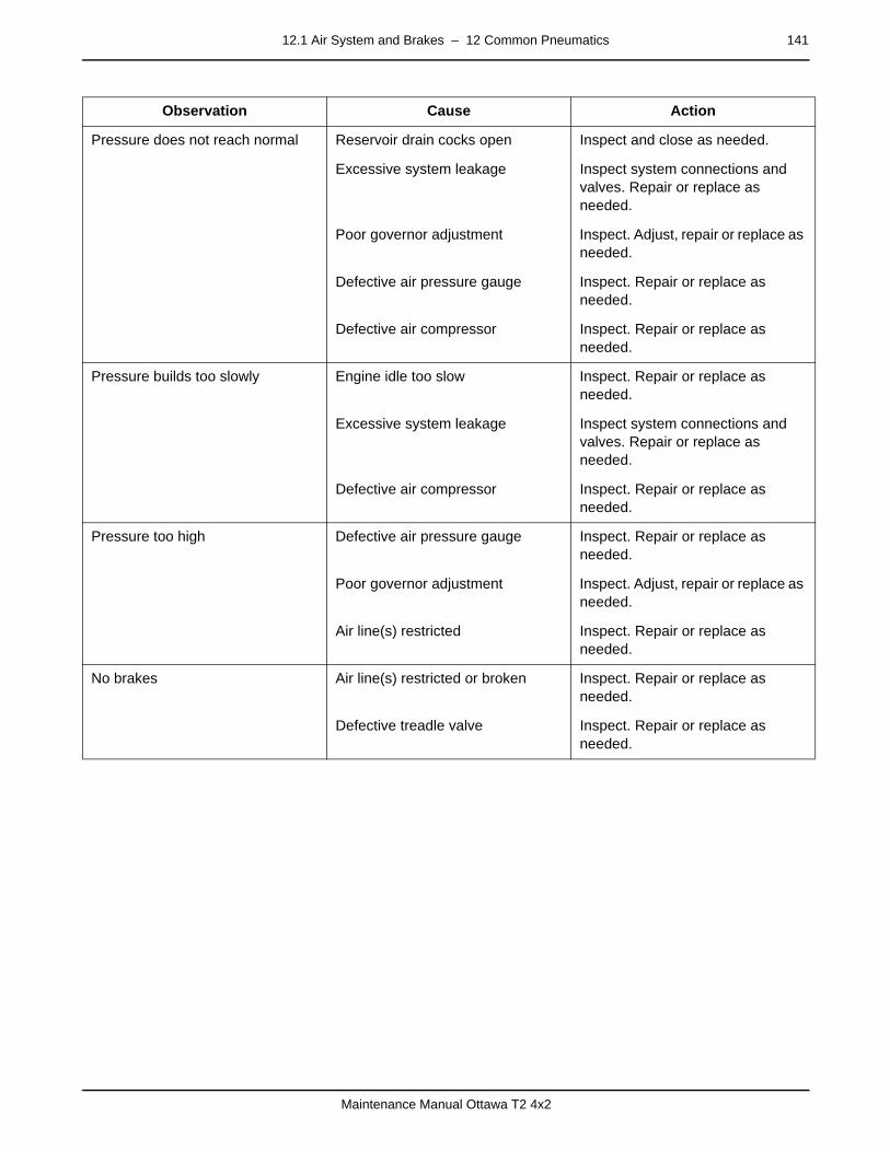
12.1 Air System and Brakes – 12 Common Pneumatics 141
Maintenance Manual Ottawa T2 4x2
Pressure does not reach normal Reservoir drain cocks open Inspect and close as needed.
Excessive system leakage Inspect system connections and valves. Repair or replace as needed.
Poor governor adjustment Inspect. Adjust, repair or replace as needed.
Defective air pressure gauge Inspect. Repair or replace as needed.
Defective air compressor Inspect. Repair or replace as needed.
Pressure builds too slowly Engine idle too slow Inspect. Repair or replace as needed.
Excessive system leakage Inspect system connections and valves. Repair or replace as needed.
Defective air compressor Inspect. Repair or replace as needed.
Pressure too high Defective air pressure gauge Inspect. Repair or replace as needed.
Poor governor adjustment Inspect. Adjust, repair or replace as needed.
Air line(s) restricted Inspect. Repair or replace as needed.
No brakes Air line(s) restricted or broken Inspect. Repair or replace as needed.
Defective treadle valve Inspect. Repair or replace as needed.
Observation Cause Action
142 12.4 Valves – 12 Common Pneumatics
Maintenance Manual Ottawa T2 4x2
12.4 Valvespage –
Tractor Protection ValvesLocated in the circuitry between the tractor and the trailer, a special valve responds to the trailer air supply knob, or to a bro-ken trailer air line, by cutting off the air supply to the trailer sys-tem.
page –
Proportioning Relay (Bobtail) Valve (Optional)Available as an option, this valve is designed to detect if a trail-er is connected to the brake air system. When a trailer is not present, the valve causes the front brakes to do a larger per-centage of the work than when a trailer is present.
Connected downstream of the primary reservoir, system air en-ters its supply port. If no trailer is present, pistons in the valve are repositioned so that, when the pedal is applied, a larger percentage of air goes to the front brakes causing them to as-sume a greater part of the work of stopping the tractor.
If a trailer is present and the trailer supply valve is opened, a portion of the trailer supply air enters the proportioning valve through its control port. The valve restores its internal pistons to their original positions. Air passes normally through the valve to the rear and trailer brakes.
page –
Quick Release ValvesEach brake chamber connects to its own quick release valve nearby. This valve responds to the release of the foot pedal. The purpose of this valve is to dump the air out of the spring chambers much more quickly than would be possible if the air had to travel back through the supply lines.
page –
Anti-Compounding Valve (Optional)Also available is an anti-compounding valve that prevents the service brakes from adding to (compounding) the effort exerted by the parking brakes. It protects against brake cracking and damage to the linings.
page –
Double (Two-Way) Check ValvesThese are used to sense pressure from front and rear, or sup-ply and service, and allow the dominant pressure to actuate the trailer brakes, the stop light switch and release the parking brakes. A two-way quick release valve combines the two func-tions in a single housing.
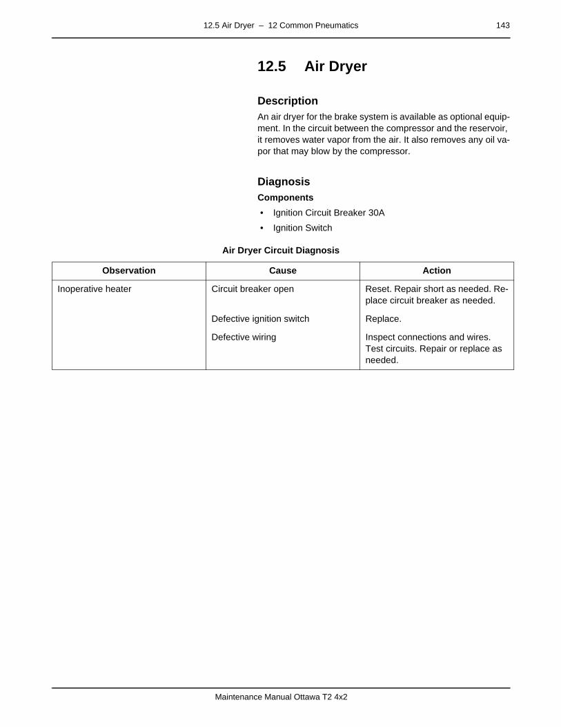
12.5 Air Dryer – 12 Common Pneumatics 143
Maintenance Manual Ottawa T2 4x2
12.5 Air Dryerpage –
DescriptionAn air dryer for the brake system is available as optional equip-ment. In the circuit between the compressor and the reservoir, it removes water vapor from the air. It also removes any oil va-por that may blow by the compressor.
page –
DiagnosisComponents
• Ignition Circuit Breaker 30A
• Ignition Switch
Air Dryer Circuit Diagnosis
Observation Cause Action
Inoperative heater Circuit breaker open Reset. Repair short as needed. Re-place circuit breaker as needed.
Defective ignition switch Replace.
Defective wiring Inspect connections and wires. Test circuits. Repair or replace as needed.

144 12.5 Air Dryer – 12 Common Pneumatics
Maintenance Manual Ottawa T2 4x2
– D. Error Codes 145
Maintenance Manual Ottawa T2 4x2
mm mm mm mm mm mm
D. Error Codes
page
– DescriptionThis section is not applicable for this vehicle.
NOTEError codes for the engine and transmission can be found in the Engine and Transmission manufacturer's manuals.

146 – D. Error Codes
Maintenance Manual Ottawa T2 4x2

0.1 Air System Circuits – E. Schematics 147
Maintenance Manual Ottawa T2 4x2
mm mm mm mm mm mm
E. Schematics0.1 Air System Circuits
0.1.1 Air Brakespage – Components
• ABS Electronic Control Unit
• ABS Modulator Valve
• Air Compressor
• Air Dryer (Optional)
• Air Pressure Governor
• Air Reservoirs (Storage Tanks)
• Brake Chambers
• Check Valves
• Foot Pedal (Treadle) Valve
• Interaxle Lockout (6x4 only, ABS)
• Pressure Relief Valves
• Proportioning Relay Valve
• Quick Release Valves
• Slack Adjusters
• Stoplight Switch
• Tractor Parking Brake Control Valve
• Tractor Protection Valves
• Trailer Air Supply Control Valve
• Two-Way Check and Quick Release Valves
Vehicles intended for road use conform to Federal Motor Vehi-cle Safety Standard (FMVSS) 121.
This standard specifies test requirements for air brake systems. Semi-trailer tractors must be equipped with an anti-lock brake system (ABS) and meet stopping distance requirements under normal and emergency conditions. ABS is optional on tractors that do not use the roads.
Vehicles intended for road use also conform to applicable Canadian Motor Vehicle Safety Standards (CMVSS).
page – Air Brake System with Split BrakesThe Ottawa ABS has three air reservoirs (storage tanks); pri-mary, front and rear. The primary acts as the supply tank to both front and rear service tanks. The instrument panel dis-plays a pressure gauge for each service tank.
–
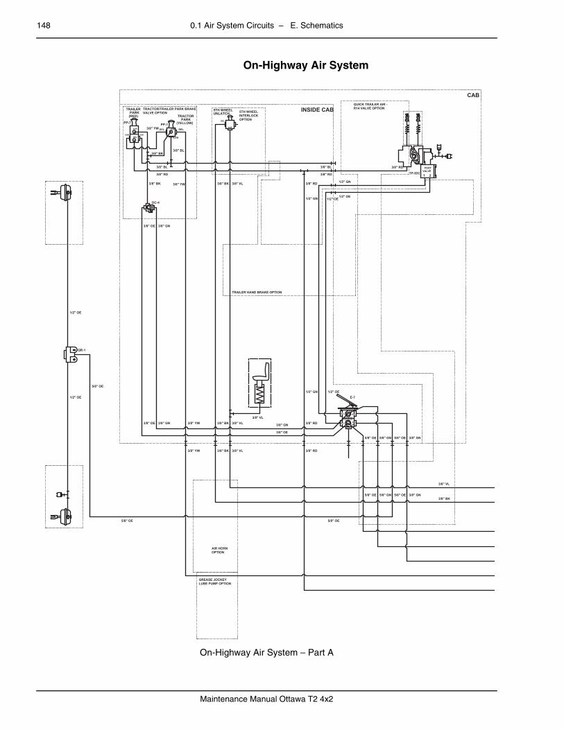
148 0.1 Air System Circuits – E. Schematics
Maintenance Manual Ottawa T2 4x2
On-Highway Air System
On-Highway Air System – Part A
CAB
INSIDE CAB
E-7
TP-3DC
PP-1PP-7
QR-1
DC-4
QUICK TRAILER AIR -R14 VALVE OPTION
5TH WHEELINTERLOCKOPTION
TRACTOR/TRAILER PARK BRAKEVALVE OPTION
TRAILER HAND BRAKE OPTION
AIR HORNOPTION
GREASE JOCKEYLUBE PUMP OPTION
3/8" BK
3/8" VL
5/8" OE 5/8" GN 5/8" OE 3/8" GN
1/2" OE1/2" GN
3/8" GN
3/8" OE
3/8" RD3/8" VL3/8" BK3/8" YW3/8" GN3/8" OE
3/8" YW 3/8" BK 3/8" VL 3/8" RD
5/8" OE 5/8" GN 5/8" OE 3/8" GN
5/8" OE5/8" OE
5/8" OE
1/2" OE
1/2" OE
3/8" OE 3/8" GN
3/8" BK 3/8" YW 3/8" BK 3/8" VL 3/8" RD
1/2" OE1/2" GN
3/8" RD
3/8" BL
1/2" GN
1/2" OE
3/8" RD
3/8" YW
3/8" BK
3/8" BL
3/8" RD
3/8" BL
3/8" VLFRONT BRAKESREAR BRAKES
DEL
DEL
SUPDEL
DELSUP
EXH
VALVEFOOT
1 2
TRACTORPARK
(YELLOW)
DELSUPDEL
EXH
TRAILERPARK
(RED)
DELCON
SUP
EXH
SUP
DEL
5TH WHEELUNLATCH
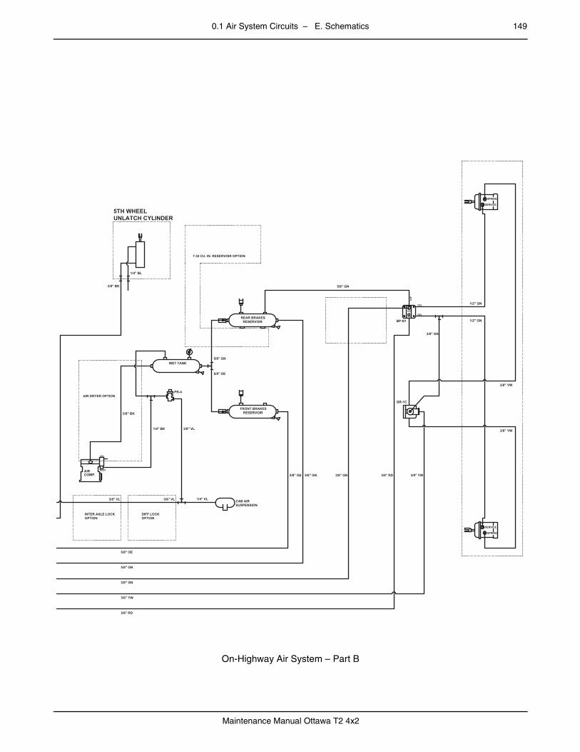
0.1 Air System Circuits – E. Schematics 149
Maintenance Manual Ottawa T2 4x2
–
On-Highway Air System – Part B
REAR BRAKESRESERVOIR
FRONT BRAKESRESERVOIR
WET TANK
CAB AIRSUSPENSION
QR-1C
BP-R1
PR-4AIR DRYER OPTION
7.35 CU. IN. RESERVOIR OPTION
DIFF LOCKOPTION
INTER AXLE LOCKOPTION
1/2" GN
1/2" GN
3/8" YW
3/8" YW
3/8" GN
5/8" GN
3/8" YW3/8" RD3/8" GN5/8" GN5/8" OE
5/8" OE
5/8" GN
5/8" BK
1/4" BK 3/8" VL
1/4" VL3/8" VL3/8" VL
5/8" OE
5/8" GN
3/8" GN
3/8" YW
3/8" RD
3/8" BK
1/4" BL
5TH WHEELUNLATCH CYLINDER
SER
SUP
CONDEL
DEL
AIRCOMP.
RESV
UNL
SPRING
SERVICE
SPRING
SERVICE
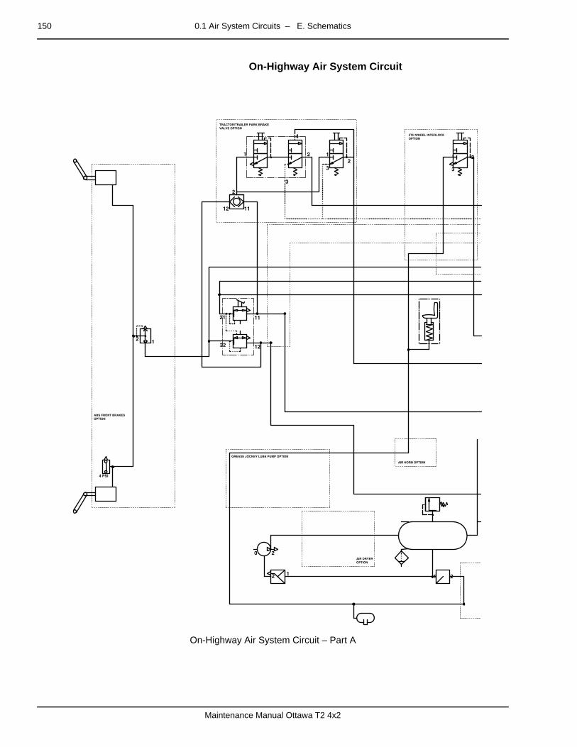
150 0.1 Air System Circuits – E. Schematics
Maintenance Manual Ottawa T2 4x2
– On-Highway Air System Circuit
On-Highway Air System Circuit – Part A
TRACTOR/TRAILER PARK BRAKEVALVE OPTION
ABS FRONT BRAKESOPTION
5TH WHEEL INTERLOCKOPTION
GREASE JOCKEY LUBE PUMP OPTION
AIR HORN OPTION
AIR DRYEROPTION
1 2
20
12
12
11
2
12
1 2
3
4
12
3
1 2
3
22
21 11
12
4 PSI
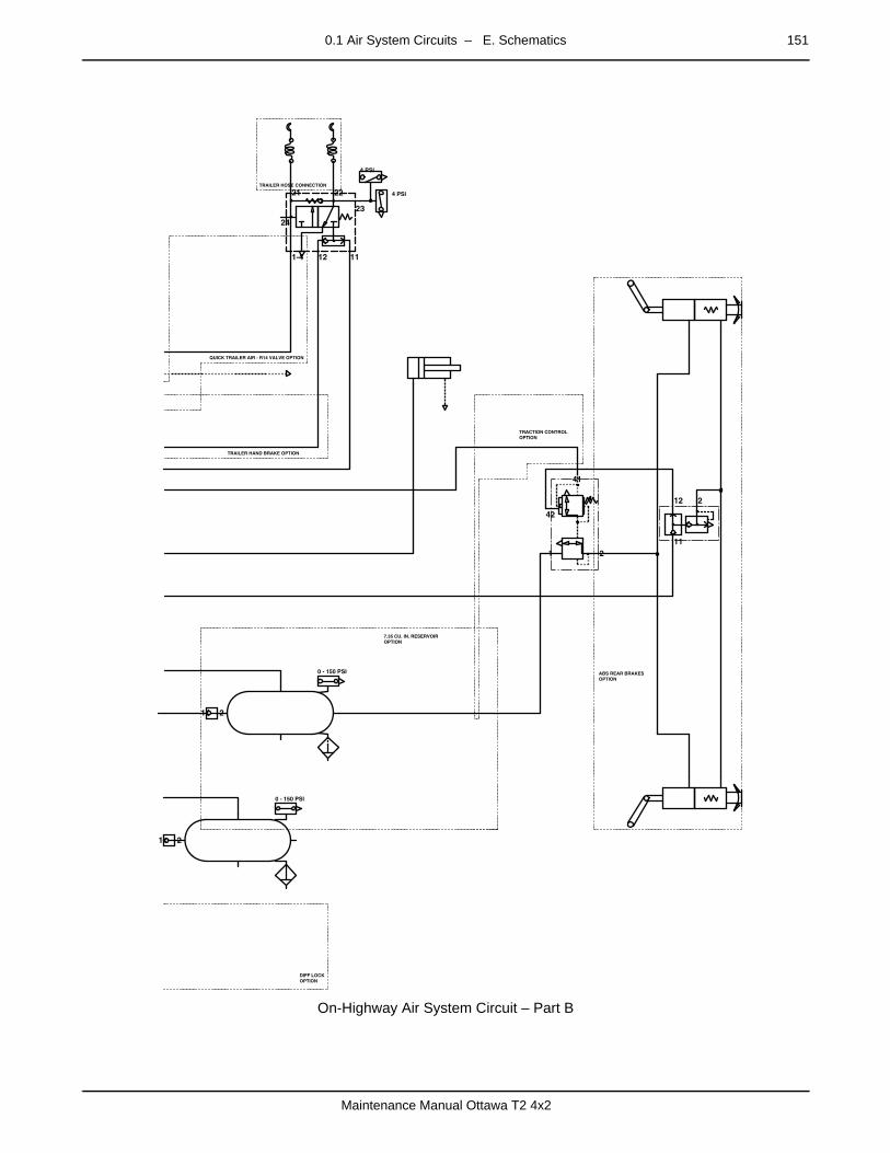
0.1 Air System Circuits – E. Schematics 151
Maintenance Manual Ottawa T2 4x2
On-Highway Air System Circuit – Part B
–
QUICK TRAILER AIR - R14 VALVE OPTION
TRAILER HAND BRAKE OPTION
TRACTION CONTROLOPTION
ABS REAR BRAKESOPTION
7.35 CU. IN. RESERVOIROPTION
TRAILER HOSE CONNECTION
DIFF LOCKOPTION
42
41
1 2
1 2
1 2
0 - 150 PSI
0 - 150 PSI
11
212
23
1112
24
1-4
21 22
4 PSI
4 PSI

152 0.1 Air System Circuits – E. Schematics
Maintenance Manual Ottawa T2 4x2
Off-Highway Air System
Off-Highway Air System – Part A
CAB
INSIDE CAB
TP-3DC
E-7
QR-1
PP-1PP-7
DC-4
QUICK TRAILER AIR -R14 VALVE OPTION
5TH WHEELINTERLOCKOPTION
TRACTOR/TRAILER PARK BRAKEVALVE OPTION
TRAILER HAND BRAKE OPTION
AIR HORNOPTION
GREASE JOCKEYLUBE PUMP OPTION
3/8" VL
3/8" BK5/8" GN5/8" OE5/8" GN5/8" OE
5/8" OE 5/8" GN 5/8" OE 5/8" GN
5/8" OE
1/2" OE1/2" GN
3/8" GN
3/8" OE
3/8" VL3/8" VL3/8" BK
3/8" BK 3/8" VL
3/8" YW3/8" GN3/8" OE
3/8" YW
5/8" OE
1/2" OE
1/2" OE
5/8" OE
3/8" RD3/8" BL
3/8" RD
1/2" GN
1/2" OE
1/2" OE
1/2" GN
3/8" YW
3/8" BL3/8" BK
3/8" BL
3/8" RD
3/8" BK
3/8" OE 3/8" GN
3/8" YW
3/8" BK 3/8" VL
FRONT BRAKESREAR BRAKES
DEL
DEL
SUPDEL
DELSUP
EXH
VALVEFOOT
1 2
SUP
DEL
5TH WHEELUNLATCH
TRACTORPARK
(YELLOW)
DELSUPDEL
EXH
TRAILERPARK
(RED)
DELCON
SUP
EXH

0.1 Air System Circuits – E. Schematics 153
Maintenance Manual Ottawa T2 4x2
–
Off-Highway Air System – Part B
QR-1SERVICE BRAKES
QR-1SPRING BRAKES
REAR BRAKESRESERVOIR
FRONT BRAKESRESERVOIR
CAB AIRSUSPENSION
DIFF LOCKOPTION
3RD AIR TANKOPTION
AIR DRYER OPTION
7.35 CU. IN. RESERVOIR OPTION
INTER AXLE LOCKOPTION
5/8" OE 5/8" GN 5/8" GN 3/8" YW
1/2" GN
1/2" GN
3/8" YW
3/8" YW
5/8" GN
5/8" OE
1/4" VL3/8" VL3/8" VL
5/8" BK
1/4" BK
3/8" VL
3/8" VL
1/4" BL
3/8" BK
5/8" OE
5/8" GN
5/8" GN
3/8" YW
5TH WHEELUNLATCH CYLINDER
AIRCOMP.
RESV
UNL
SPRING
SERVICE
SPRING
SERVICE

154 0.1 Air System Circuits – E. Schematics
Maintenance Manual Ottawa T2 4x2
– Off-Highway Air System Circuit
Off-Highway Air System Circuit – Part A
5TH WHEEL INTERLOCKOPTION
TRACTOR/TRAILER PARK BRAKEVALVE OPTION
GREASE JOCKEY LUBE PUMP OPTION
3RD AIR TANKOPTION
AIR HORN OPTION
AIR DRYEROPTION
22
21 11
12
1 2
3
12
3
1 2
3
4
20
11
2
12
12
12
4 PSI

0.1 Air System Circuits – E. Schematics 155
Maintenance Manual Ottawa T2 4x2
Off-Highway Air System Circuit – Part B
TRAILER HOSE CONNECTION
QUICK TRAILER AIR - R14 VALVE OPTION
TRAILER HAND BRAKE OPTION
7.35 CU. IN. RESERVOIROPTION
DIFF LOCKOPTION
12
4 PSI
23
1112
24
1-4
21 22
1 2
1 2
0 - 150 PSI
0 - 150 PSI
12
4 PSI
156 0.1 Air System Circuits – E. Schematics
Maintenance Manual Ottawa T2 4x2
0.1.2 Cab Seatingpage – Air Lines — Driver's Seat
Components
• Air Control Valve
• Air Reservoir
• Air Spring
The adjustable driver's seat cushion rides on an air bag. A lock-ing mechanism allows the driver to stop fore and aft chugging if desired. Seating comfort controls are mounted on each side below and in back of the seat cushion.
Refer to the main air system schematics in 0.1.1 Air Brakes for driver’s seat air lines.
0.1.3 Cab Suspensionpage – Air Lines — Cab Suspension
Components
• Air Spring
• Height Control Valve
• Latch
• Shock Absorbers
Ride level is adjustable and automatically maintained. Two shock absorbers react with the air spring to maintain a soft, smooth ride. A rubber bumper prevents the cab from striking the rails.
Refer to the main air system schematics in 0.1.1 Air Brakes for cab suspension air lines.

0.1 Air System Circuits – E. Schematics 157
Maintenance Manual Ottawa T2 4x2
0.1.4 Fifth-Wheel Couplingpage – Air Lines — Fifth-Wheel Latch
Air Lines — Fifth-Wheel Latch
Components
• Air Control Valve
• Air Cylinder
• Air Reservoir
Pressing the control valve button on the instrument panel opens the latch. The button is spring-loaded and normally closed. Once opened, the latch remains open until closed by a trailer king pin.
OTT0049
BRAKETREADLE
DELIVERYSUPPLY
TO BRAKESYSTEM
3/8 YW
3/8 YW
3/8 BK
3/8 BK
5TH WHEELAND BOOM
TO TRACTORPARK (YELLOW)
TO TRACTORPARK (RED)
PLUG
PLUGS
MANIFOLD,8 PORT
TO BRAKETANK
AIR LINES FIFTHWHEEL
5TH WHEELUNLATCH
5TH WHEELUNLATCH
3/8
YW
TO SERVICERESERVOIR
PLUGS
NEAR SIDE
FARSIDE
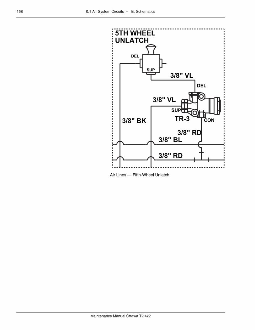
158 0.1 Air System Circuits – E. Schematics
Maintenance Manual Ottawa T2 4x2
Air Lines — Fifth-Wheel Unlatch
TR-33/8" BK
3/8" VL
3/8" VL
3/8" BL3/8" RD
3/8" RD
SUP
DEL
5TH WHEELUNLATCH
SUP
DEL
CON
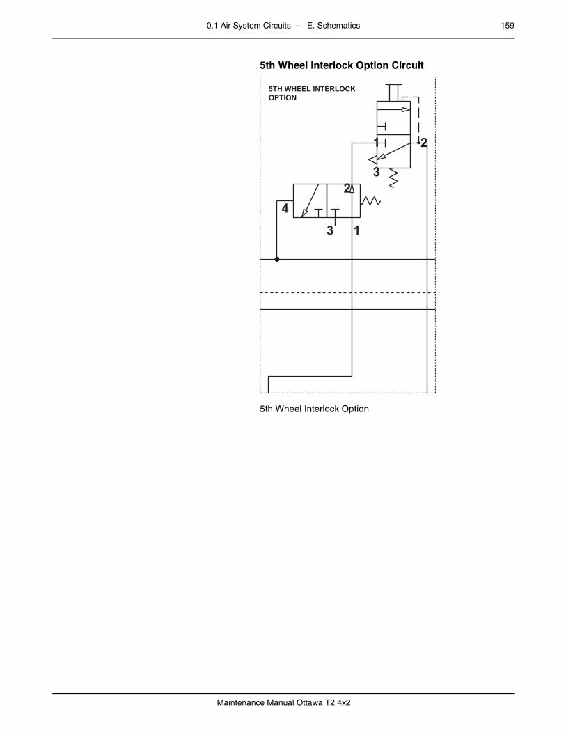
0.1 Air System Circuits – E. Schematics 159
Maintenance Manual Ottawa T2 4x2
– 5th Wheel Interlock Option Circuit
5th Wheel Interlock Option
5TH WHEEL INTERLOCKOPTION
1 2
3
3
2
14

160 0.1 Air System Circuits – E. Schematics
Maintenance Manual Ottawa T2 4x2
0.1.5 Tractor/Trailer Park Brakepage – Air Lines — Tractor/Trailer Park Brake Option
Air Lines — Tractor/Trailer Park Brake Option
3/8" BL
3/8" RD
3/8" YW
3/8" GN3/8" OE
TRAILERPARK
(RED)
DEL SUPEXH SUP DEL
TRACTORPARK
(YELLOW)
MV-3
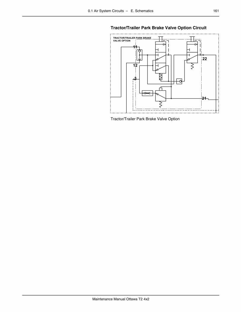
0.1 Air System Circuits – E. Schematics 161
Maintenance Manual Ottawa T2 4x2
– Tractor/Trailer Park Brake Valve Option Circuit
Tractor/Trailer Park Brake Valve Option
TRACTOR/TRAILER PARK BRAKEVALVE OPTION
12
11
3
21
22

162 0.1 Air System Circuits – E. Schematics
Maintenance Manual Ottawa T2 4x2
0.1.6 Quick Trailer Air/R14 Valvepage – Air Lines — Quick Trailer Air/R14 Valve Option
Air Lines — Quick Trailer Air/R14 Valve Option
TP-3DC
DC-4
QUICK TRAILER AIR -R14 VALVE OPTION
5/8" OE
5/8" GN
3/8" RD
3/8" RD
5/8" RD
5/8" OE
5/8" GN
5/8" GN
5/8" OE
VALVEFOOT
1 2
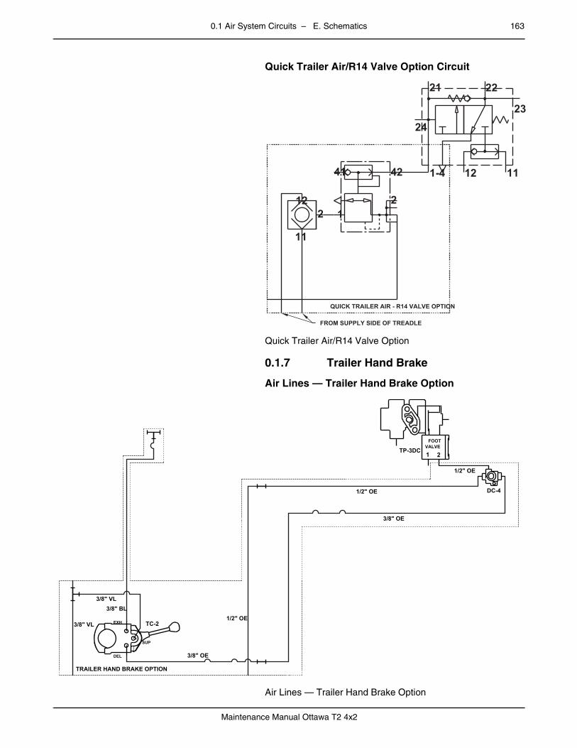
0.1 Air System Circuits – E. Schematics 163
Maintenance Manual Ottawa T2 4x2
– Quick Trailer Air/R14 Valve Option Circuit
Quick Trailer Air/R14 Valve Option
0.1.7 Trailer Hand Brakepage – Air Lines — Trailer Hand Brake Option
Air Lines — Trailer Hand Brake Option
QUICK TRAILER AIR - R14 VALVE OPTION
FROM SUPPLY SIDE OF TREADLE
11
212
41 42
12
23
1112
24
1-4
21 22
TP-3DC
DC-4
TC-2
TRAILER HAND BRAKE OPTION
1/2" OE
1/2" OE
3/8" OE
1/2" OE
3/8" OE
3/8" BL3/8" VL
3/8" VL
VALVEFOOT
1 2
SUP
DEL
EXH
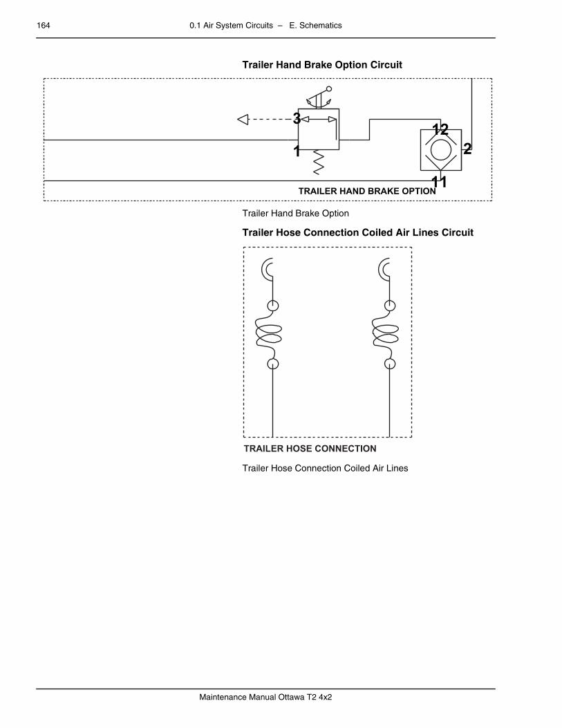
164 0.1 Air System Circuits – E. Schematics
Maintenance Manual Ottawa T2 4x2
– Trailer Hand Brake Option Circuit
Trailer Hand Brake Option
– Trailer Hose Connection Coiled Air Lines Circuit
Trailer Hose Connection Coiled Air Lines
TRAILER HAND BRAKE OPTION
3
1
11
212
TRAILER HOSE CONNECTION
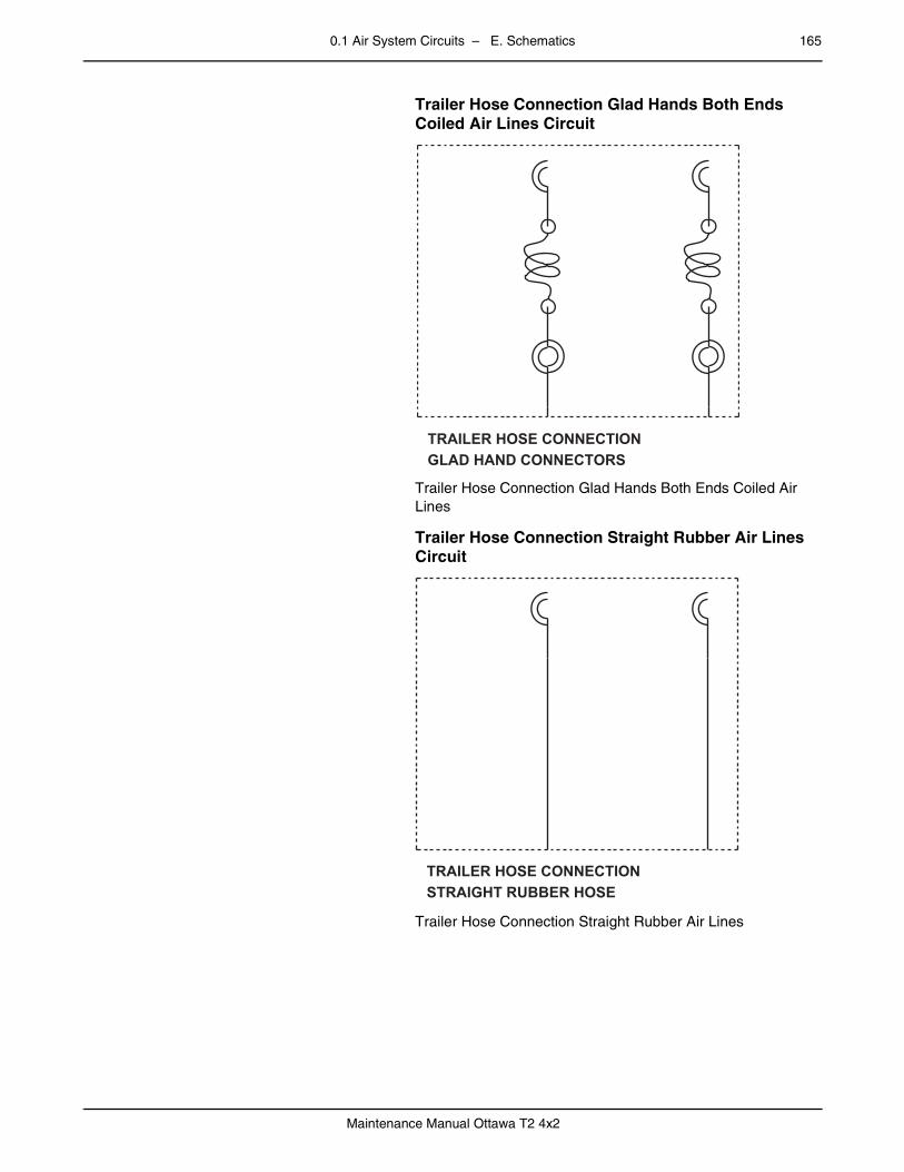
0.1 Air System Circuits – E. Schematics 165
Maintenance Manual Ottawa T2 4x2
– Trailer Hose Connection Glad Hands Both Ends Coiled Air Lines Circuit
Trailer Hose Connection Glad Hands Both Ends Coiled Air Lines
– Trailer Hose Connection Straight Rubber Air Lines Circuit
Trailer Hose Connection Straight Rubber Air Lines
TRAILER HOSE CONNECTIONGLAD HAND CONNECTORS
TRAILER HOSE CONNECTIONSTRAIGHT RUBBER HOSE

166 0.1 Air System Circuits – E. Schematics
Maintenance Manual Ottawa T2 4x2
0.1.8 Air Hornpage – Air Lines — Air Horn Option
Air Lines — Air Horn Option
– Air Horn Option Circuit
Air Horn Option
AIR HORNOPTION
3/8" VL
AIR HORN OPTION

0.1 Air System Circuits – E. Schematics 167
Maintenance Manual Ottawa T2 4x2
0.1.9 Inter Axle Lockpage – Air Lines — Inter Axle Option
Air Lines — Inter Axle Option
– Inter Axle Lock Option Circuit
Inter Axle Lock Option
INTER AXLE LOCKOPTION
3/8" VL
3/8" VL
INTER AXLE LOCKOPTION
32
1
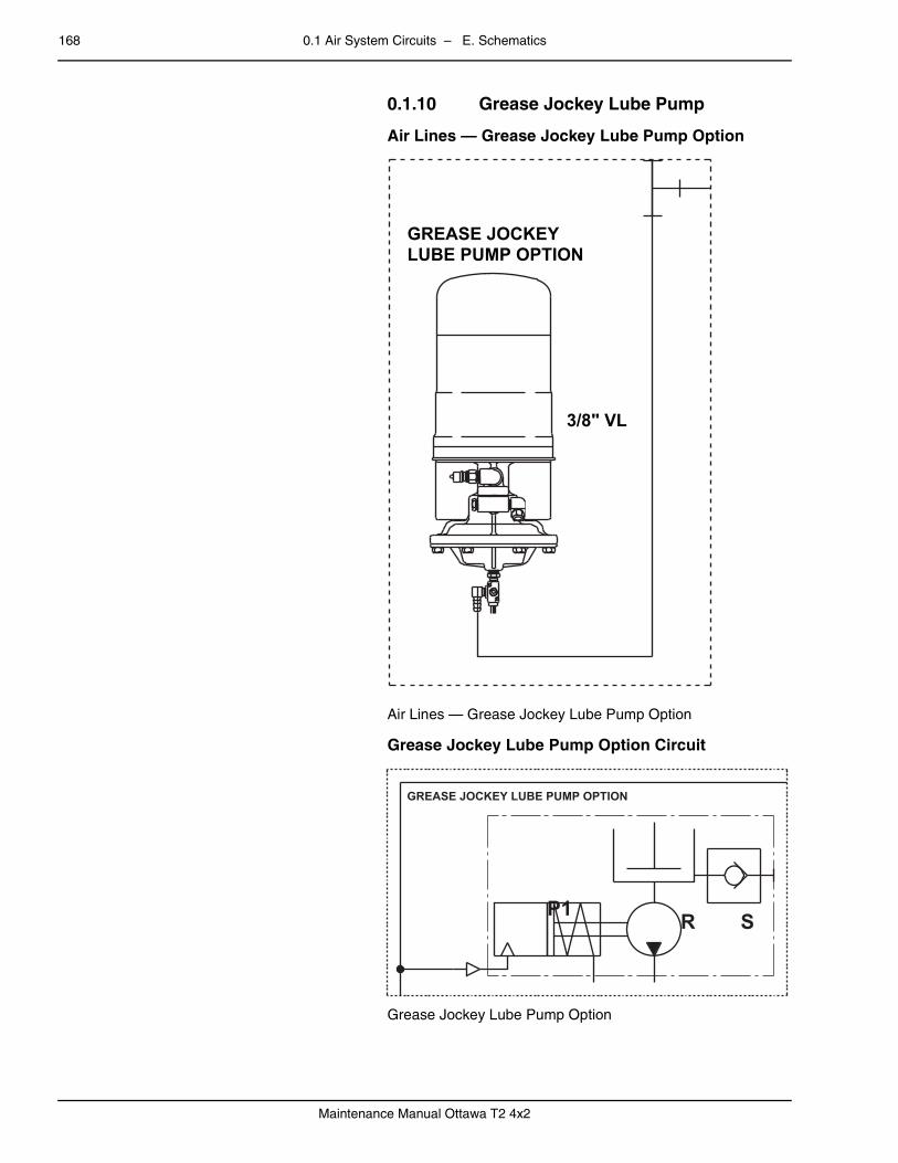
168 0.1 Air System Circuits – E. Schematics
Maintenance Manual Ottawa T2 4x2
0.1.10 Grease Jockey Lube Pumppage – Air Lines — Grease Jockey Lube Pump Option
Air Lines — Grease Jockey Lube Pump Option
– Grease Jockey Lube Pump Option Circuit
Grease Jockey Lube Pump Option
GREASE JOCKEYLUBE PUMP OPTION
3/8" VL
GREASE JOCKEY LUBE PUMP OPTION
P1 SR

0.1 Air System Circuits – E. Schematics 169
Maintenance Manual Ottawa T2 4x2
0.1.11 Differential Axle Lockpage – Air Lines — Differential Axle Lock Option
Air Lines — Differential Axle Lock Option
– Differential Axle Lock Option Circuit
Differential Axle Lock Option
DIFF LOCK
3/8" VL
3/8" VL
DIFFERENTIAL AXLE LOCKOPTION
32
1

170 0.1 Air System Circuits – E. Schematics
Maintenance Manual Ottawa T2 4x2
0.1.12 Additional 7.35 cu. in. Air Reservoirpage – Air Lines — Additional 7.35 cu. in. Air Reservoir
Option
Air Lines — Additional 7.35 cu. in. Air Reservoir Option
– Additional 7.35 cu. in. Air Reservoir Option
Additional 7.35 cu. in. Air Reservoir Option
7.35 CU. IN. RESERVOIR OPTION
5/8" VL 1/2" VL
1/2" VL5/8" VL
7.35 cu.ft.
7.35 CU. IN. RESERVOIROPTION
1 2
0 - 150 PSI
1
2
1
2
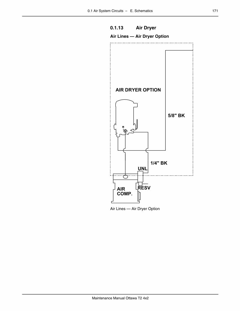
0.1 Air System Circuits – E. Schematics 171
Maintenance Manual Ottawa T2 4x2
0.1.13 Air Dryerpage – Air Lines — Air Dryer Option
Air Lines — Air Dryer Option
AIR DRYER OPTION
5/8" BK
1/4" BK
AIRCOMP.
RESV
UNL

172 0.1 Air System Circuits – E. Schematics
Maintenance Manual Ottawa T2 4x2
– Air Dryer Option
Air Dryer Option
AIR DRYEROPTION
2
34
1

0.1 Air System Circuits – E. Schematics 173
Maintenance Manual Ottawa T2 4x2
0.1.14 ABS Brakespage – Air Lines — ABS Brakes Option – On-Highway Only
Air Lines — ABS Brakes Option – On-Highway Only
ABS FRONTBRAKES
ABS FRONTBRAKES
ABS REARBRAKES
ABS REARBRAKES
TRACTION CONTROL OPTION 1/2" GN
1/2" GN
3/8" YW
3/8" YW
1/2" GN
1/2" GN
1/2" OE
1/2" OE
SPRING
SERVICE
SPRING
SERVICE
1
2
12
1
2
12

174 0.1 Air System Circuits – E. Schematics
Maintenance Manual Ottawa T2 4x2
– ABS Brake Option Circuit
ABS Brake Option
TRACTION CONTROLOPTION
ABS REAR BRAKESOPTION
TRACTION CONTROLOPTION
ABS FRONT BRAKESOPTION
42
41
1 211
212
R+
C-
H+
1
2
3
R+
C-
H+1
2
3
12
R+
C-
H+
1
2
3
R+
C-
H+ 1
2
34 PSI
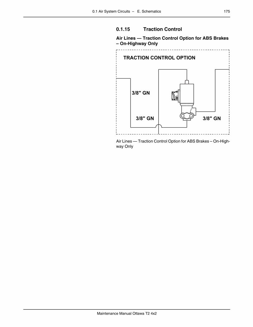
0.1 Air System Circuits – E. Schematics 175
Maintenance Manual Ottawa T2 4x2
0.1.15 Traction Controlpage – Air Lines — Traction Control Option for ABS Brakes
– On-Highway Only
Air Lines — Traction Control Option for ABS Brakes – On-High-way Only
TRACTION CONTROL OPTION
3/8" GN
3/8" GN
3/8" GN
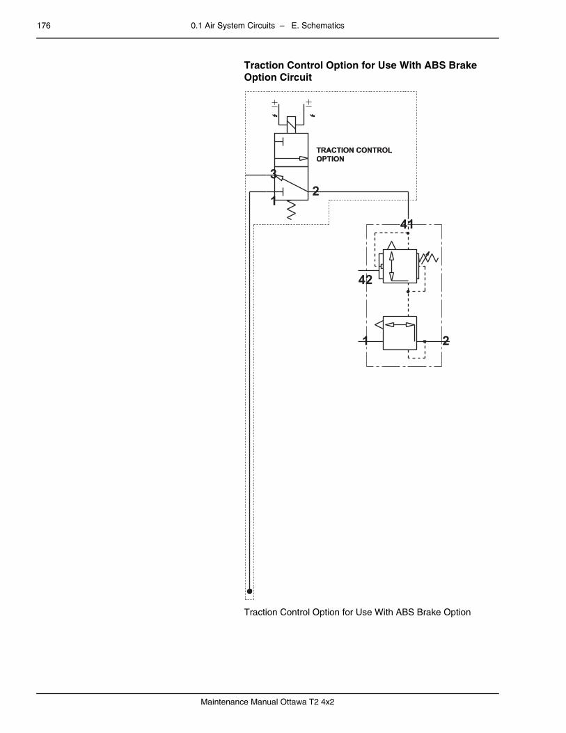
176 0.1 Air System Circuits – E. Schematics
Maintenance Manual Ottawa T2 4x2
– Traction Control Option for Use With ABS Brake Option Circuit
Traction Control Option for Use With ABS Brake Option
TRACTION CONTROLOPTIONTRACTION CONTROLOPTION
42
41
1 2
32
1

0.1 Air System Circuits – E. Schematics 177
Maintenance Manual Ottawa T2 4x2
0.1.16 3rd Air Tankpage – Air Lines — 3rd Air Tank Option – Off-Highway Only
Air Lines — 3rd Air Tank Option
– 3rd Air Tank Option Circuit
3rd Air Tank Option
WET TANK
3RD AIR TANKOPTION
5/8" BK
3/8" VL
5/8" BK
3RD AIR TANKOPTION
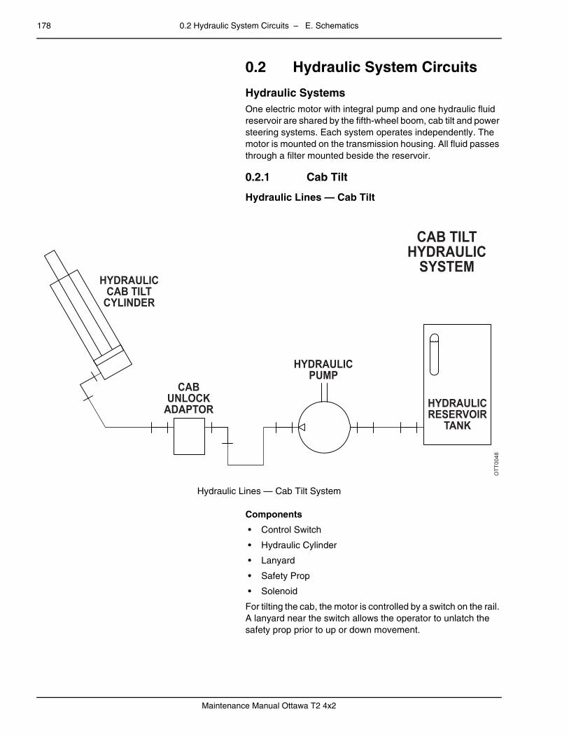
178 0.2 Hydraulic System Circuits – E. Schematics
Maintenance Manual Ottawa T2 4x2
0.2 Hydraulic System Circuitspage – Hydraulic Systems
One electric motor with integral pump and one hydraulic fluid reservoir are shared by the fifth-wheel boom, cab tilt and power steering systems. Each system operates independently. The motor is mounted on the transmission housing. All fluid passes through a filter mounted beside the reservoir.
0.2.1 Cab Tiltpage – Hydraulic Lines — Cab Tilt
Hydraulic Lines — Cab Tilt System
Components
• Control Switch
• Hydraulic Cylinder
• Lanyard
• Safety Prop
• Solenoid
For tilting the cab, the motor is controlled by a switch on the rail. A lanyard near the switch allows the operator to unlatch the safety prop prior to up or down movement.
OTT0048
HYDRAULICCAB TILT
CYLINDER
CABUNLOCK
ADAPTOR
HYDRAULICPUMP
HYDRAULICRESERVOIR
TANK
CAB TILTHYDRAULIC
SYSTEM

0.2 Hydraulic System Circuits – E. Schematics 179
Maintenance Manual Ottawa T2 4x2
0.2.2 Fifth-Wheel Boompage – Hydraulic Lines — Fifth-Wheel Boom
Hydraulic Lines — Fifth-Wheel Boom
Components
• Boom
• Control Valve
• Hydraulic Cylinders
• Hydraulic Relief Valve
Although engine speed controls the speed of the double-acting cylinders, restrictors slow the downward motion.
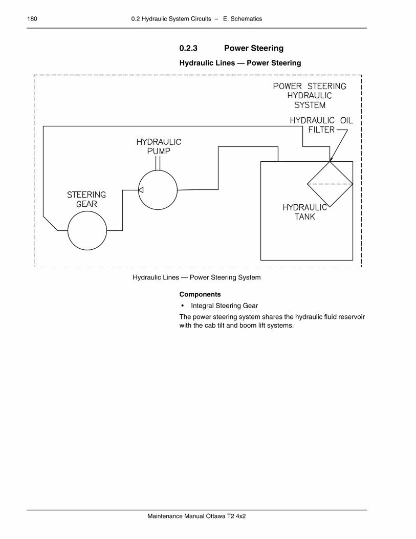
180 0.2 Hydraulic System Circuits – E. Schematics
Maintenance Manual Ottawa T2 4x2
0.2.3 Power Steeringpage – Hydraulic Lines — Power Steering
Hydraulic Lines — Power Steering System
Components
• Integral Steering Gear
The power steering system shares the hydraulic fluid reservoir with the cab tilt and boom lift systems.

0.2 Hydraulic System Circuits – E. Schematics 181
Maintenance Manual Ottawa T2 4x2
0.2.4 Optional Hydrostatic Steeringpage – Hydraulic Lines — Hydrostatic Steering
Hydraulic Lines — Hydrostatic Steering System
Components
• Orbital Control Valve
• Power Steering Pump
• Reservoir
• Steering Cylinders
The hydrostatic steering system shares the hydraulic fluid res-ervoir with the cab tilt and boom lift systems.

182 0.3 Electrical System Circuits – E. Schematics
Maintenance Manual Ottawa T2 4x2
0.3 Electrical System Circuits
0.3.1 Starting and Chargingpage – Starting and Charging Circuit
Starting and Charging Circuit
Components
• Alternator
• Batteries
• Circuit Breaker — Ignition Switch (Cab Accessory Fuse Panel)
• Fuse — Gauge (Cab Accessory Fuse Panel)
• Ignition Relay
• Ignition Switch
• Neutral Start Relay
• Start Cutout #1 Relay
• Start Cutout #2 Relay
• Start Solenoid
• Starter Motor with Solenoid

0.3 Electrical System Circuits – E. Schematics 183
Maintenance Manual Ottawa T2 4x2
0.3.2 Cab Accessory Componentspage – Wire Color Codes
BE = Blue
BK = Black
BN = Brown
GN = Green
OE = Orange
PE = Purple
PK = Pink
RD = Red
TN = Tan
WE = White
YW = Yellow
–
Anti-lock Braking System (ABS)
For information on the anti-lock braking system, refer to the vendor's service manual.

184 0.3 Electrical System Circuits – E. Schematics
Maintenance Manual Ottawa T2 4x2
– Heater and Air Conditioning
Heating and Air Conditioning Circuits
Components
• Accessory Relay #1
• Air Conditioner Switch
• Cab Fan (Optional)
• Cold Control (AC Optional)
• Fan Switch
• Fuse — HVAC (Cab Accessory Fuse Panel)
• HVAC Fan Motor
• Ignition Switch
Air conditioning is optional equipment.
OPTIONALCAB FAN
HC1000 RD/WE
HC1000 RD/WE
GD2
001
WE
GD2
001
WE
GD2001 WE
NEGATIVEPASS-THRU
STUD
CAB ACCFUSE HVAC
AC1000 BN BA2001 RD POSITIVEPASS-THRU
STUD
IGNITION SWITCHCONNECTORHVAC
ACC #1
85
A
A S I
B
C D B
86
30R2
8787A
30 A 3
B A C D F E E L H D J K F G M A B C
HC10
00 R
D/W
EHC
1000
RD/
WE
HC10
00 R
D/W
E
HC10
00 R
D/W
EHC
1000
RD/
WE
AC20
00 B
N
HC20
01 Y
W/R
D
HC2001 YW/RD HTR-
LOW
GY
HC1000 RD/WE HC10
00
FAN SWOFF
CHM
L
HTR-
MED
BK
HTR-
HI O
E
HTR-
LOW
GY
HTR-
MED
BK
HTR-
HI O
E
HC2001 YW/RD
HC2001 YW/RD HC2001 YW/RDHC2002 YW/BK HC2003 YW/BK
HC2003 YW/BK
HC20
01 Y
W/R
DHC
2003
YW
/BK
HC20
03HC
2002
A/C LOW PRESSURESWITCH & COLD
CONTROL CONNECTOR
ELECTRONIC ENGINEBULKHEAD CONNECTOR
HC20
01 Y
W/R
DFC
2000
BK
HC10
00 R
D/W
E
HC2001FC2000
AIR CONDITIONERSWITCH CONNECTOR
CAB CONTROLPANEL CONNECTOR
A/C LOW PRESSURESWITCH & COLD
CONTROL CONNECTOR
HEATER/AIR CONDITIONINGCIRCUIT
OTT0036
COLDCONTROL
FANMOTOR
NEGATIVEPASS-THRU
STUD
OPTIONALA/C
COMPRESSOR OPTIONALA/C HIGH
PRESSURE
A/C HIGHPRESSURE
SWITCH
A/C LOWPRESSURE
SWITCH
BK
HEATER & A/C
HC2001 YW/RD
A/CSWITCH
AB
A B
A
1112218
1965
1726162815251413229
1074321
292018232724
B
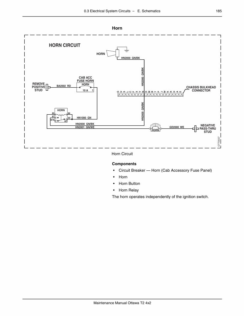
0.3 Electrical System Circuits – E. Schematics 185
Maintenance Manual Ottawa T2 4x2
– Horn
Horn Circuit
Components
• Circuit Breaker — Horn (Cab Accessory Fuse Panel)
• Horn
• Horn Button
• Horn Relay
The horn operates independently of the ignition switch.
–
OTT0037
REMOVEPOSITIVE
STUD
CAB ACCFUSE HORN
CHASSIS BULKHEADCONNECTOR
NEGATIVEPASS-THRU
STUD
HORN
HORN CIRCUIT
BA2002 RD
HN1000 GN
HN2000 GN/BK
HN2000 GN/BK
HN
2000
GN
/BK
HN
2000
GN
/BK
HN2001 GN/WE GD2000 WE
HORN
HORN
HORN86
G U S L C F X V N D M B T P J W K R H A E
8587
87AR7
30
10 A 1
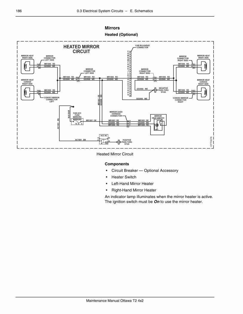
186 0.3 Electrical System Circuits – E. Schematics
Maintenance Manual Ottawa T2 4x2
Mirrors
Heated (Optional)
Heated Mirror Circuit
Components
• Circuit Breaker — Optional Accessory
• Heater Switch
• Left-Hand Mirror Heater
• Right-Hand Mirror Heater
An indicator lamp illuminates when the mirror heater is active. The ignition switch must be On to use the mirror heater.
OTT0078
POSITIVEPASS-THRU
STUD
MIRROR DASHHARNESS
CONNECTORCAB ACC
FUSEMIRRORSMIRRORS
ACC #285 86
30PR2
87
MR1000 RDNEGATIVE
PASS-THRUSTUD
HEATED MIRRORCIRCUIT
CAB BULKHEADCONNECTOR
GD2000 WE
AC10
01
BN
AC1001 BN
MR1001 OE MR1001 OE
MR1000 RDGD2000 WE
MR1
001
OE
GD2
000
WE
MR1001 OEAB
AB
AB
C MR1000 RDGD2000 WE
BUS
BAR
MR1000 RDGD2000 WE
MR1000 RDGD2000 WE
MR1000 RDGD2000 WE
MR1000 RDGD2000 WE
MR1000 RDGD2000 WE
MR1000 RDGD2000 WE
MR1000 RDGD2000 WE
AB
MR1000 RDGD2000 WE
GD2000 WE
GD2000 WE
AB
AB
AB
MIRRORCONNECTORRIGHT SIDE
MIRRORCONNECTORRIGHT SIDE
MIRROR HEATRIGHT SIDE
MIRROR HEATCONVEX
RIGHT SIDE
CONVEX MIRRORCONNECTOR
RIGHT
MIRRORCONNECTOR
LEFT SIDE
MIRRORCONNECTOR
LEFT SIDE
CONVEX MIRRORCONNECTOR
LEFT
MIRROR HEATRIGHT SIDE
MIRROR HEATCONVEX
RIGHT SIDE
SPAUVD
HX
TKLJEBRFWNMGC
MIRRORHEAT SWITCH
4
5
1
15 A 4
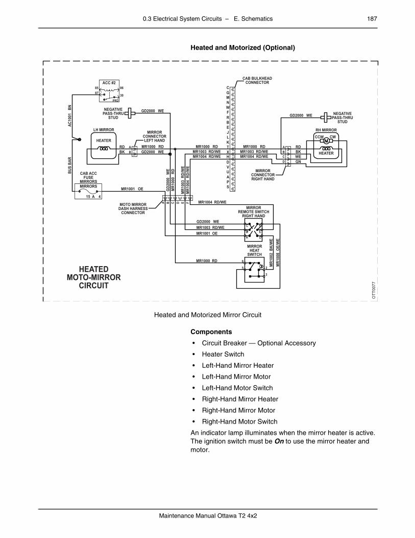
0.3 Electrical System Circuits – E. Schematics 187
Maintenance Manual Ottawa T2 4x2
Heated and Motorized (Optional)
Heated and Motorized Mirror Circuit
Components
• Circuit Breaker — Optional Accessory
• Heater Switch
• Left-Hand Mirror Heater
• Left-Hand Mirror Motor
• Left-Hand Motor Switch
• Right-Hand Mirror Heater
• Right-Hand Mirror Motor
• Right-Hand Motor Switch
An indicator lamp illuminates when the mirror heater is active. The ignition switch must be On to use the mirror heater and motor.
OTT0077
NEGATIVEPASS-THRU
STUD
LH MIRROR
CAB ACCFUSE
MIRRORSMIRRORS MR1001 OE
MR1000 RD
MR1
000
RD
MR1000 RD
MR1
003
RD/
WE
MR1
004
RD/
WE
MR1003 RD/WE
MR1003 RD/WE
MR1
008
OE/
WE
MR1
002
BK/
WE
MR1001 OE
MR1000 RD
MR1004 RD/WE
MR1000 RD
GD2000 WE
RH MIRROR
NEGATIVEPASS-THRU
STUD
HEATEDMOTO-MIRROR
CIRCUIT
HEATER
CCW CW
RDABCD
BKWEGN
CAB BULKHEADCONNECTOR
MR1003 RD/WEMR1004 RD/WE
MR1004 RD/WE
RDBK B
A B C D E F
AGD2000 WE
GD2000 WE
GD2
000
WE
GD2000 WE
MIRRORREMOTE SWITCH
RIGHT HAND
MIRRORCONNECTORRIGHT HAND
MIRRORCONNECTORLEFT HAND
SPAUVDHXTKLJEBRFWNMGC
MIRRORHEAT
SWITCH6
5 2
3
MOTO MIRRORDASH HARNESS
CONNECTOR
15 A 4
AC10
01
BNBU
S BA
R
ACC #285 86
30PR2
87
HEATER
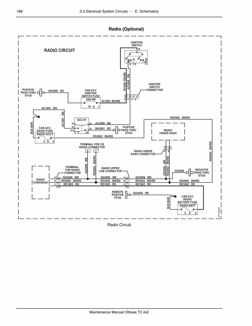
188 0.3 Electrical System Circuits – E. Schematics
Maintenance Manual Ottawa T2 4x2
– Radio (Optional)
Radio Circuit
OT
T00
40
POSITIVEPASS-THRU
STUD
POSITIVEPASS-THRU
STUD
BA2000 RD
RADIO CIRCUIT
IG1000 RD/WE
IG10
00 R
D/W
E
CAB ACCIGNITION
SWITCH FUSE
IGNITIONSWITCH
IGNITIONSWITCH
CONNECTOR
10 A 1
IGN SW
B
S IA
ACC #18587
86A C D B
30R2
87A
AC1001 BN
AC2000 BNAC
2000
BN
BA2001 RD
RD2002 BN/RD
RD20
02
BN/R
D
RD2002 BN/RDRD1003 RD
GD2
006
WE
GD2006 WERD2002 BN/RDRD1003 RD
GD2006 WERD2002 BN/RDRD1003 RD
RD2002 BN/RD
RD2002 BN/RD
RD20
02
BN/R
D
RD1003 RD
BA2004 RDCAB ACC
RADIOBATTERY FUSE
RADIO BATT
5 A 2
GD2006 WE
GD2006 NEGATIVEPASS-THRU
STUDRD20
02
BN/R
DG
D200
6 W
E
ABC
AB
A B
C
TERMINAL FOR CBRADIO CONNECTOR
RADIO UPPERCAB CONNECTOR
REMOTEPOSITIVE
STUD
RADIO UNDERDASH CONNECTOR
RADIOUNDER DASH
TERMINAL FOR RADIO
CONNECTOR
RADIOOVERHEAD
CAB ACCRADIO FUSERADIO ACCY
5 A 3
AC10
01
BN
BUS
BAR
BUS
BAR
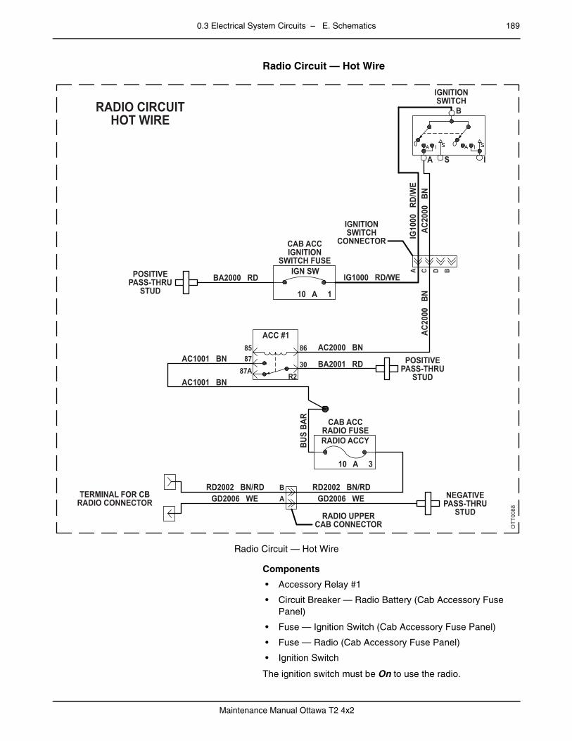
0.3 Electrical System Circuits – E. Schematics 189
Maintenance Manual Ottawa T2 4x2
– Radio Circuit — Hot Wire
Radio Circuit — Hot Wire
Components
• Accessory Relay #1
• Circuit Breaker — Radio Battery (Cab Accessory Fuse Panel)
• Fuse — Ignition Switch (Cab Accessory Fuse Panel)
• Fuse — Radio (Cab Accessory Fuse Panel)
• Ignition Switch
The ignition switch must be On to use the radio.
OTT0088
IGNITIONSWITCH
IGNITIONSWITCH
CONNECTOR
RADIO CIRCUITHOT WIRE
CAB ACCIGNITION
SWITCH FUSEIGN SW
10 A 1
IG10
00
RD/W
E
IG1000 RD/WE
AC20
00
BNAC
2000
BN
AC2000 BNAC1001 BN
AC1001 BN
ACC #1
BA2001 RD
BA2000 RDPOSITIVEPASS-THRU
STUD
GD2006 WERD2002 BN/RD
GD2006 WERD2002 BN/RD
TERMINAL FOR CBRADIO CONNECTOR
B
30R2
868587
87A
A
POSITIVEPASS-THRU
STUD
CAB ACCRADIO FUSE
BUS
BAR
NEGATIVEPASS-THRU
STUDRADIO UPPERCAB CONNECTOR
RADIO ACCY
10 A 3
A C D B
B
ISA

190 0.3 Electrical System Circuits – E. Schematics
Maintenance Manual Ottawa T2 4x2
– Windshield Washer (Optional)
Windshield Washer Circuit
Components
• Accessory Relay #1
• Circuit Breaker — Wiper/Washer (Cab Accessory Fuse Panel)
• Windshield Washer Motor
• Windshield Wiper Switch
The ignition switch must be On to use the windshield washer.
OTT0041
WINDSHIELDWIPER SW
WIPER SWITCHCONNECTOR
CHASSISBULKHEAD
CONNECTOR
OPTIONALWINDSHIELD
WASHER
WASHERCONNECTOR
TRANSMISSIONCASE
GROUND
CAB ACC FUSEWIPER/WASHER
POSITIVEPASS-THRU
STUD
WINDSHIELDWASHERCIRCUIT
WW
1000
PE
/RD
WW
2003
GN
WW
1000
PE
/RD
WW
2003
GN
WW2003 GN
WW
2003
GN
GD
1001
W
E
GD1001 WEWW
2003
GD
1001
WW2003 GN
G A
C B A E D F
BA B
USLCFXVND
P
L
HW
B
MBTPJWKRHAE
15 A
WIPER/WASH
ACC #18685
8787A
R230
AC1000 BN
BA2001 RD
BU
S B
AR
4
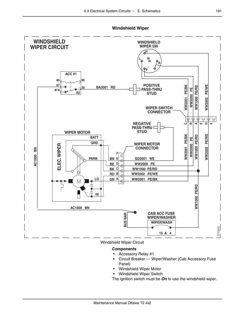
0.3 Electrical System Circuits – E. Schematics 191
Maintenance Manual Ottawa T2 4x2
– Windshield Wiper
Windshield Wiper Circuit
Components• Accessory Relay #1• Circuit Breaker — Wiper/Washer (Cab Accessory Fuse
Panel)• Windshield Wiper Motor• Windshield Wiper SwitchThe ignition switch must be On to use the windshield wiper.
OTT0042
CAB ACC FUSEWIPER/WASHER
WIPER MOTORCONNECTOR
WIPER SWITCHCONNECTOR
NEGATIVEPASS-THRU
STUDWIPER MOTOR
ELE
C. W
IPE
R
POSITIVEPASS-THRU
STUD
WINDSHIELDWIPER CIRCUIT
WW
1000
PE
/RD
WW
1000
PE
/RD
WW1000 PE/RD
WW
2001
P
E/B
K
WW2001 PE/BK
WW
2002
P
E/W
E
WW2002 PE/WE
WW
2000
P
EW
W10
00 P
E/R
D
WW
2001
P
E/B
K
WW
2002
P
E/W
E
WW
2000
P
E
WW2000 PEGD2001 WE
BK
GNRD
BEBN
BATT
GRD
PARK
LO
HI
BA2001 RD
WINDSHIELDWIPER SW
P
F
E
D
C
B
A
C B A E D F
L
H
WB
15 A
WIPER/WASH
ACC #1
8685
87
87AR2
30
AC1000 BN
AC
1000
B
N
BU
S B
AR
4

192 0.3 Electrical System Circuits – E. Schematics
Maintenance Manual Ottawa T2 4x2
– Cab Power Board
Cab Power Board Wiring
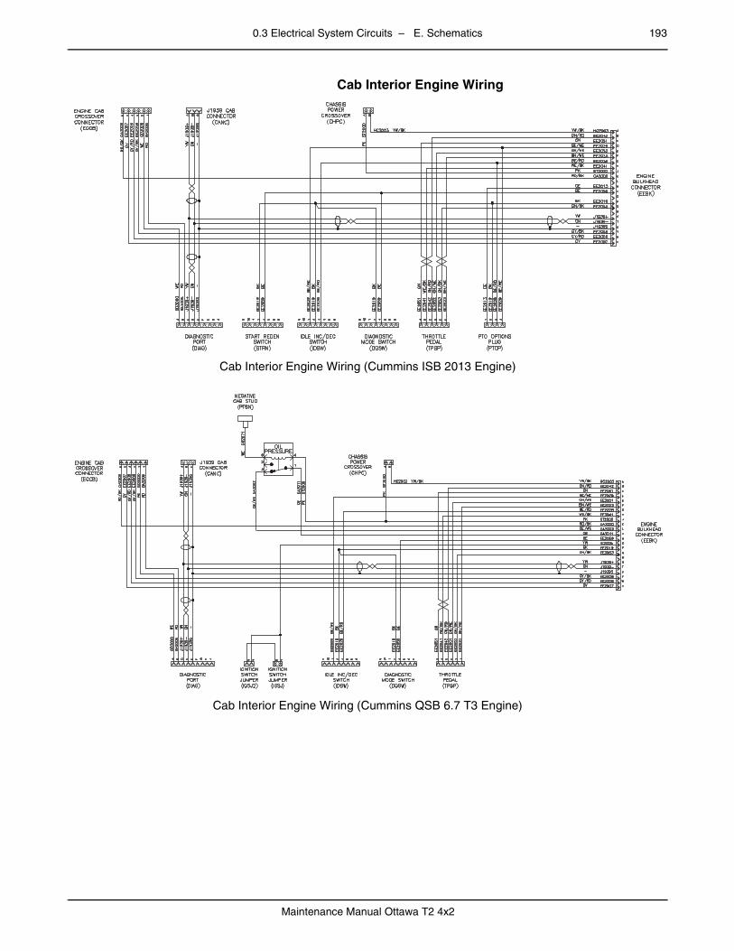
0.3 Electrical System Circuits – E. Schematics 193
Maintenance Manual Ottawa T2 4x2
– Cab Interior Engine Wiring
Cab Interior Engine Wiring (Cummins ISB 2013 Engine)
–
Cab Interior Engine Wiring (Cummins QSB 6.7 T3 Engine)
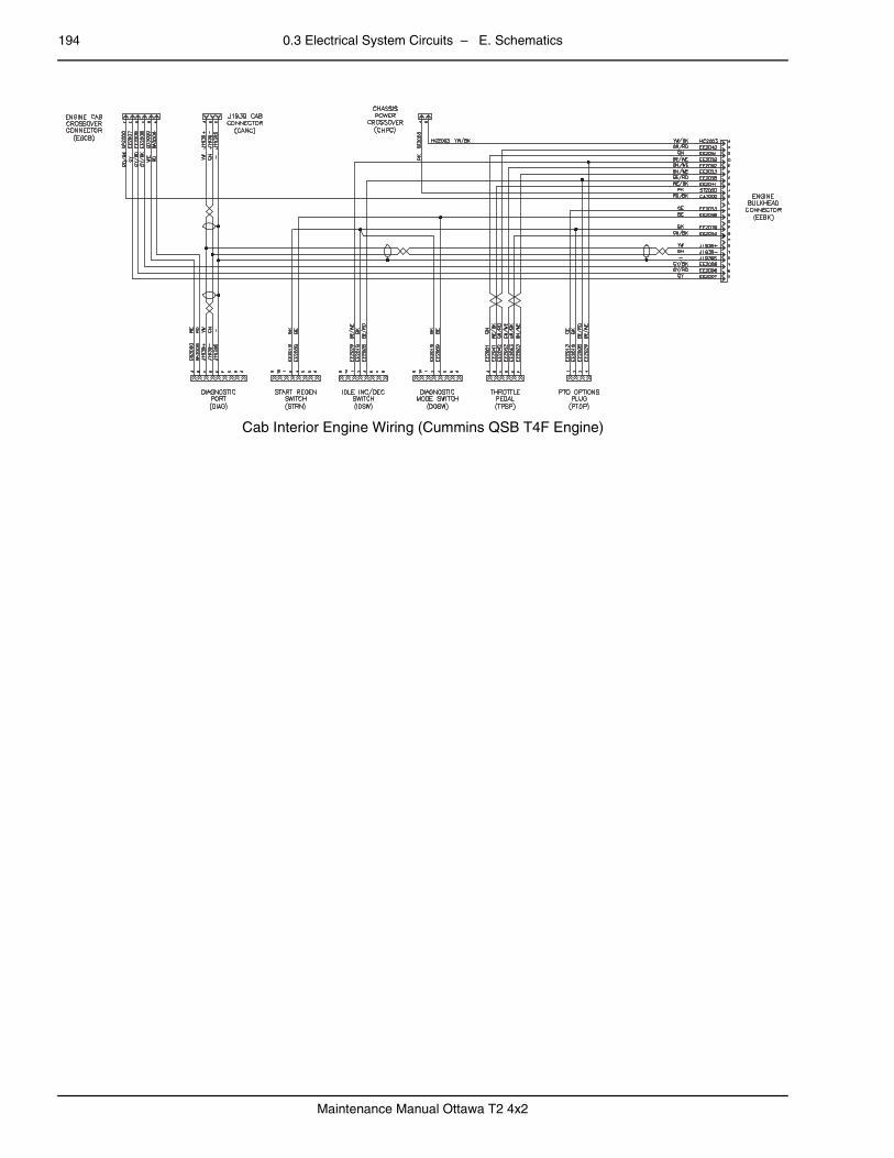
194 0.3 Electrical System Circuits – E. Schematics
Maintenance Manual Ottawa T2 4x2
–
Cab Interior Engine Wiring (Cummins QSB T4F Engine)

0.3 Electrical System Circuits – E. Schematics 195
Maintenance Manual Ottawa T2 4x2
0.3.3 Cab Instrumentationpage – Air Pressure Gauge Lighting
Air Pressure Gauge Lighting Circuit
Components
• Gauge
• Gauge (Second Service Tank)
• Gauge Lamp
• Gauge Lamp (Second Service Tank)
• Headlight Switch
• Panel Dimmer Switch (Optional)
Vehicles equipped with ABS have two service tanks and a pressure gauge for each one.
OTT0073
CAB BULKHEADCONNECTOR
NEGATIVEPASS–THRU
STUD
BRAKE CONTROLSPANEL CONNECTOR
GD2002 WE
PL2002
CFEAHBCDGJKLM
GMNWFRBEJLKTHXDVUAPS
PL2002 BE/RD
PL20
02
PL20
02
ENGINE GAUGE &WARNING PANEL
CONNECTOR
PL2002
AIRPRESS
OPT AIRPRESS
GD2002ACB
L G L G
S1HEADLAMP
SWITCH
S1HEADLAMP
SWITCH
S9PANEL LTS
DIMMER
STANDARDWITH OPTIONALDIMMER SWITCH
AIR GAUGELIGHTING CIRCUIT
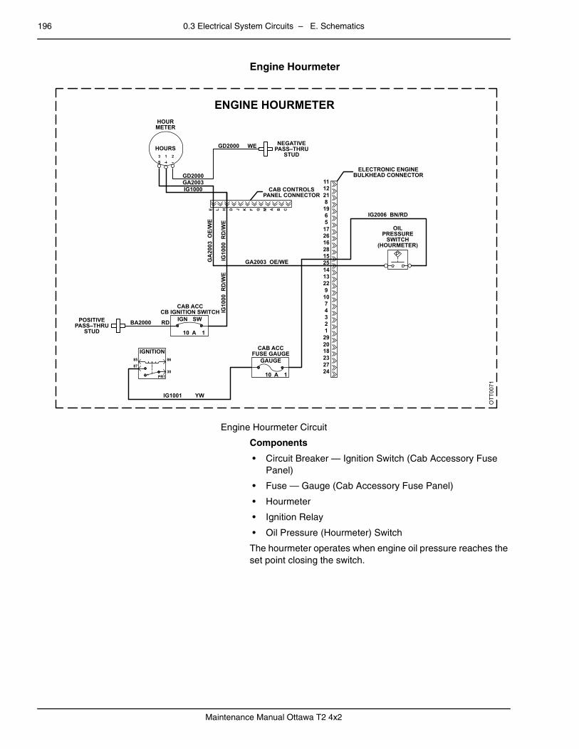
196 0.3 Electrical System Circuits – E. Schematics
Maintenance Manual Ottawa T2 4x2
– Engine Hourmeter
Engine Hourmeter Circuit
Components
• Circuit Breaker — Ignition Switch (Cab Accessory Fuse Panel)
• Fuse — Gauge (Cab Accessory Fuse Panel)
• Hourmeter
• Ignition Relay
• Oil Pressure (Hourmeter) Switch
The hourmeter operates when engine oil pressure reaches the set point closing the switch.
HOURMETER
HOURS
GD2000
GD2000 WE NEGATIVEPASS–THRU
STUD
ENGINE HOURMETER
CAB CONTROLSPANEL CONNECTOR
1112218
1965
1726162815251413229
1074321
292018232724
ELECTRONIC ENGINEBULKHEAD CONNECTOR
IG2006 BN/RD
OILPRESSURE
SWITCH(HOURMETER)
IG1000GA2003
GA2003 OE/WE
CAB ACCCB IGNITION SWITCH
BA2000
IG1001 YW
CAB ACCFUSE GAUGE
GAUGE
RD IGN SW
10
868587
30PR1
A 1
10 A 1
IGNITION
POSITIVEPASS–THRU
STUD
GA
2003
OE/
WE
IG10
00 R
D/W
EIG
1000
RD
/WE
3S
1 2
E L H D J K F G M A B C
OTT0071

0.3 Electrical System Circuits – E. Schematics 197
Maintenance Manual Ottawa T2 4x2
– Fuel Gauge
Fuel Gauge Circuit (Cummins ISB 6.7 2013 Engine)

198 0.3 Electrical System Circuits – E. Schematics
Maintenance Manual Ottawa T2 4x2
Components
• Fuse — Gauge (Cab Accessory Fuse Panel)
• Gauge
• Gauge Lamp
• Headlight Switch
• Ignition Relay
• Panel Dimmer Switch (Optional)
• Sender (Fuel Level — Variable Resistance)The fuel level gauge displays quarter tank intervals.
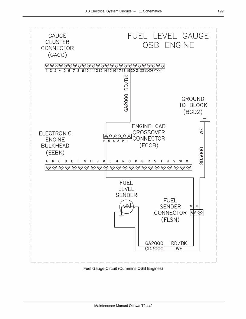
0.3 Electrical System Circuits – E. Schematics 199
Maintenance Manual Ottawa T2 4x2
Fuel Gauge Circuit (Cummins QSB Engines)
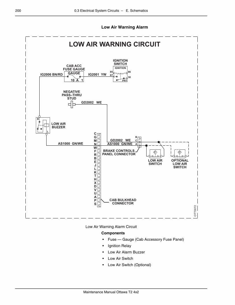
200 0.3 Electrical System Circuits – E. Schematics
Maintenance Manual Ottawa T2 4x2
– Low Air Warning Alarm
Low Air Warning Alarm Circuit
Components
• Fuse — Gauge (Cab Accessory Fuse Panel)
• Ignition Relay
• Low Air Alarm Buzzer
• Low Air Switch
• Low Air Switch (Optional)
OTT0072
CAB ACCFUSE GAUGE
IGNITIONSWITCH
LOW AIR WARNING CIRCUIT
IGNITION86
30
8587
PR1
GAUGE
10 A 1IG2006 BN/RD IG2001 YW
GD2002 WE
GD2002 WEBCAAS1000 GN/WE AS1000 GN/WE
BRAKE CONTROLSPANEL CONNECTOR
LOW AIRSWITCH
OPTIONALLOW AIRSWITCH
CAB BULKHEADCONNECTOR
CGMNWFRBEJLKTHXDVUAPS
LOW AIRBUZZER
B
L
NEGATIVEPASS–THRU
STUD

0.3 Electrical System Circuits – E. Schematics 201
Maintenance Manual Ottawa T2 4x2
– Speedometer
Speedometer Circuit
Components
• Fuse — Gauge (Cab Accessory Fuse Panel)
• Gauge (Speedometer)
• Gauge Lamp
• Headlight Switch
• Ignition Relay
• Panel Dimmer Switch (Optional)
Some tractor speedometers may also display the total distance traveled.
The speedometer is affected by DIP switch settings, tire size, gear ratios and the source of pulse generation.
OTT0056
WITH OPTIONALDIMMERSWITCH STANDARD
S9PANEL LTS
DIMMER
GEN-4 ECUCONNECTOR
GEN-4 3000TRANSMISSION
ECU (TCM)
29655
246450134
45327246184130699
701063432
2362421
6121227917573
7353143834257
288
494868266
27
6667
471244563558751654767711557874713652335131153719395940602080
S1HEADLAMP
SWITCH
PL20
02
PL20
02
PL2002 BE/RD
PL20
02 B
E/RD
TR-125 TN
TR-1
25
TN
IG20
06 B
N/RD
GD2
000
WE
IG2006 BN/RD
IG1001 YW
IG20
06CAB ACCFUSE GAUGE
GAUGE
IGNITION85 86
30PR1
87
10 A 1
ENGINE GAUGE ANDWARNING PANEL
CONNECTOR
SPEEDOMETERCIRCUIT
GD2000 WE
TR-1
25
TN
IG20
06 B
N/RD
GD2
000
WE
F L M H E J G C D K A B
F E A H B C D G J K L M
TR-125 TN – VEHICLE SPEED-SPEEDO
PL20
02
S1HEADLAMP
SWITCH
DSO
MD TRANS VHARNESS CABCONNECTOR
NEGATIVEPASS-THRU
STUD
SGIL
SPEEDOMETER
GA1
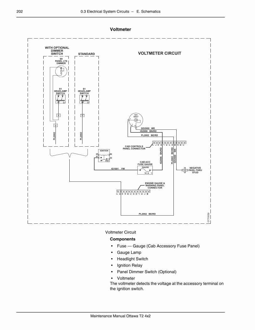
202 0.3 Electrical System Circuits – E. Schematics
Maintenance Manual Ottawa T2 4x2
– Voltmeter
Voltmeter Circuit
Components
• Fuse — Gauge (Cab Accessory Fuse Panel)
• Gauge Lamp
• Headlight Switch
• Ignition Relay
• Panel Dimmer Switch (Optional)
• VoltmeterThe voltmeter detects the voltage at the accessory terminal on the ignition switch.
OTT0059
WITH OPTIONALDIMMERSWITCH STANDARD
S9PANEL LTS
DIMMER
S1HEADLAMP
SWITCH
S1HEADLAMP
SWITCH
PL20
02
PL20
02
PL20
02
BE/
RD
GD
2000
W
E
PL2002 BE/RD
IG20
06
BN
/RD
IG2006 BN/RDGD2000 WE
PL2002 BE/RD
CAB ACCFUSE GAUGE
NEGATIVEPASS–THRU
STUDIG1001 YW
CAB CONTROLSPANEL CONNECTOR
ENGINE GAUGE &WARNING PANEL
CONNECTOR
IGNITION
86
30PR1
8587
GAUGE
10 A 1
F E A H B C D G J K L M
F L H D J K F G M A B C
VOLTMETER CIRCUIT
VOLTGA5
L
IG

0.3 Electrical System Circuits – E. Schematics 203
Maintenance Manual Ottawa T2 4x2
– Gauge Cluster Wiring
Gauge Cluster Wiring (Cummins ISB 2013 Engine) – Part A
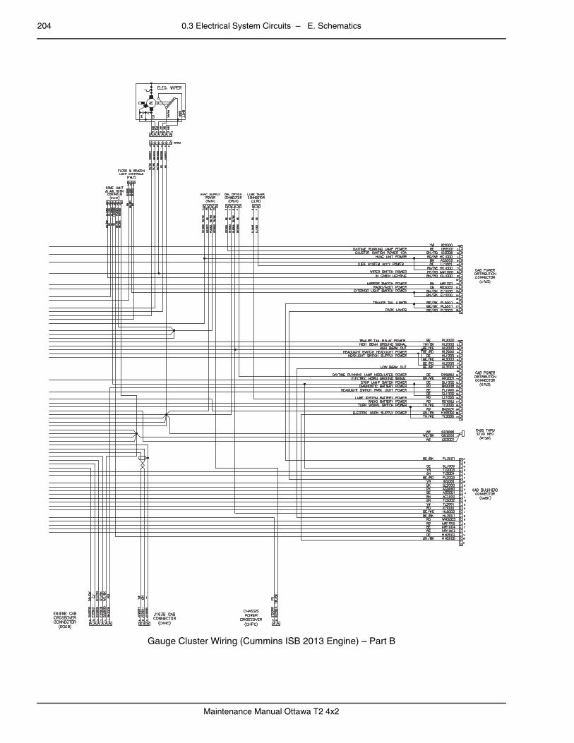
204 0.3 Electrical System Circuits – E. Schematics
Maintenance Manual Ottawa T2 4x2
Gauge Cluster Wiring (Cummins ISB 2013 Engine) – Part B

0.3 Electrical System Circuits – E. Schematics 205
Maintenance Manual Ottawa T2 4x2
–
Gauge Cluster Wiring (Cummins QSB 6.7 T3 Engine) – Part A

206 0.3 Electrical System Circuits – E. Schematics
Maintenance Manual Ottawa T2 4x2
Gauge Cluster Wiring (Cummins QSB 6.7 T3 Engine) – Part B

0.3 Electrical System Circuits – E. Schematics 207
Maintenance Manual Ottawa T2 4x2
–
Gauge Cluster Wiring (Cummins QSB T4F Engine) – Part A
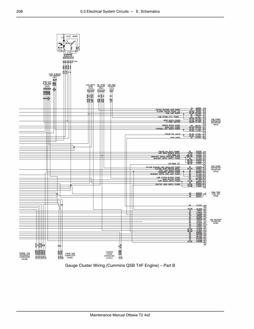
208 0.3 Electrical System Circuits – E. Schematics
Maintenance Manual Ottawa T2 4x2
Gauge Cluster Wiring (Cummins QSB T4F Engine) – Part B

0.3 Electrical System Circuits – E. Schematics 209
Maintenance Manual Ottawa T2 4x2
0.3.4 Chassis Circuitspage – Chassis Power Board
Chassis Power Board Wiring
67
10
3
1
5
2
4
89
161514
1211
13
INPUT IGNITION SIGNAL
INPUT REVERSE SIGNAL
OUTPUT REVERSE SIGNAL
BACKUP ALARM
CHASSIS BACKUP LIGHTS
ECM IGN
DEF SENDER IGN
ABS MODULE IGN
TRANSMISSION ECU IGN
INPUT ACCESSORY SIGNAL
AUX POWER FROM AUX RELAY
5TH WHEEL INDICATION POWER
OPTIONAL USER INPUT, SWITCH 1 POSITION B / AUX RELAY COIL GND
OPTIONAL USER INPUT, SWITCH 4 POSITION B / FAN CLUTCH RELAY COIL PWR
FAN CLUTCH RELAY AIR CONDITIONING CLUTCH PWR
FAN CLUTCH
OPTIONAL USER INPUT, SWITCH 3 POSITION B / FAN CLUTCH RELAY COIL GND
AIR DRYER HEATER POWER
AIR SUSPENSION DUMP VALVE
FUEL HEATER
OUTPUT SIGNAL START RELAY
INPUT SIGNAL ECU ANTI RESTART
INPUT SIGNAL KEYSWITCH CRANK POWER
INPUT SIGNAL TRANSMISSION NEUTRAL
AUX RELAY 2 OUTPUT POWER
AUX RELAY 2 COIL PWR
CAB TILT
TRANSMISSION ECU BATTERY
ECM1 BATTERY
AFTERTREATMENT EXHAUST POWER
OUTPUT KEYSWITCH BATTERY POST
DEF LINE HEATER COMMAND
LINE HEATER 1
LINE HEATER 2
LINE HEATER 3
DEF PUMP HEATER COMMAND
DEF PUMP HEATER SUPPLY
ECM2 BATTERY
ABS MODULE BATTERY
SPARE BATTERY
5
2
6
21
20
19
1
22
3
20
13
18
7
8
10
18
21
17
19
11
12
15
16
17
AUX RELAY 2 OUTPUT POWER 4
ECM1 BATTERY 9
ABS MODULE BATTERY 14
J1
J2
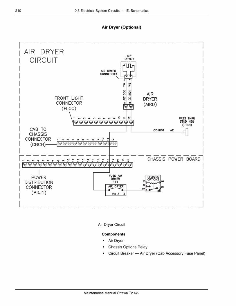
210 0.3 Electrical System Circuits – E. Schematics
Maintenance Manual Ottawa T2 4x2
– Air Dryer (Optional)
Air Dryer Circuit
Components
• Air Dryer
• Chassis Options Relay
• Circuit Breaker — Air Dryer (Cab Accessory Fuse Panel)

0.3 Electrical System Circuits – E. Schematics 211
Maintenance Manual Ottawa T2 4x2
– Cab Tilt Pump
Cab Tilt Pump Circuit
Components
• Batteries
• Fuse — Tilt (Cab Accessory Fuse Panel)
• Ignition Relay
• Starter with Solenoid
• Tilt Pump Control Switch
• Tilt Pump Motor (Up)
• Tilt Solenoid (Down)
• Tilt Solenoid to Pump
OTT0035
RD (BATTERY-TO-STARTER) RD
RD
BATTERIES
TILT PUMP CIRCUIT
RD (BATTERY-TO-START SOL.)
STARTERW/SOLENOID
MID-FRAMECROSSMEMBER
CONNECTOR
GD
1001
W
E
GD
1001
W
E
TRANSMISSIONCASE
GROUND
RD (TILT SOL.-TO-TILT PUMP)
BK
GD
1001
W
EG
D10
01
WE
TT20
00
BK
TILT
SOL.
-DN
- TILT
MO
TOR
-UP-
RD
TT20
01
GN
TT2001 GN
CHASSIS BULKHEADCONNECTOR
BA2000 RDCAB ACCFUSE TILT
BU
S B
AR
IGNITION
TILT
5
G U S L C F X V N D M B T P J W K R H A E
A 2
85 863087
PR1
TT1000 RD/BK
TT10
00
RD
/BK
TT10
00
RD
/BK
TILT SWITCHHARNESS CONNECTOR
TILT PUMPCONTROL SWITCH
A T
T100
0 R
D/B
K
C T
T200
0 B
K
B T
T200
1 G
N
TT2001 GNTT1000 RD/BK
TT2000 BK

212 0.3 Electrical System Circuits – E. Schematics
Maintenance Manual Ottawa T2 4x2
– Cab Exterior/Front Chassis Wiring
Cab Exterior/Front Chassis Wiring (Cummins ISB 2013 Engine)

0.3 Electrical System Circuits – E. Schematics 213
Maintenance Manual Ottawa T2 4x2
–
Cab Exterior/Front Chassis Wiring (Cummins QSB 6.7 T3 Engine)

214 0.3 Electrical System Circuits – E. Schematics
Maintenance Manual Ottawa T2 4x2
–
Cab Exterior/Front Chassis Wiring (Cummins QSB T4F Engine)

0.3 Electrical System Circuits – E. Schematics 215
Maintenance Manual Ottawa T2 4x2
– Chassis Wiring
Chassis Wiring (Cummins ISB 2013 Engine)

216 0.3 Electrical System Circuits – E. Schematics
Maintenance Manual Ottawa T2 4x2
–
Chassis Wiring (Cummins QSB 6.7 T3 Engine)
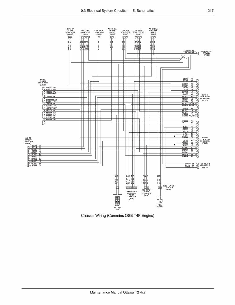
0.3 Electrical System Circuits – E. Schematics 217
Maintenance Manual Ottawa T2 4x2
–
Chassis Wiring (Cummins QSB T4F Engine)
–

218 0.3 Electrical System Circuits – E. Schematics
Maintenance Manual Ottawa T2 4x2
Air System Tank Pressure Senders
Air System Tank Pressure Senders (Cummins ISB 2013 Engine)
–
Air System Tank Pressure Senders (Cummins QSB 6.7 T3 Engine)
–
Air System Tank Pressure Senders (Cummins QSB T4F Engine)
–
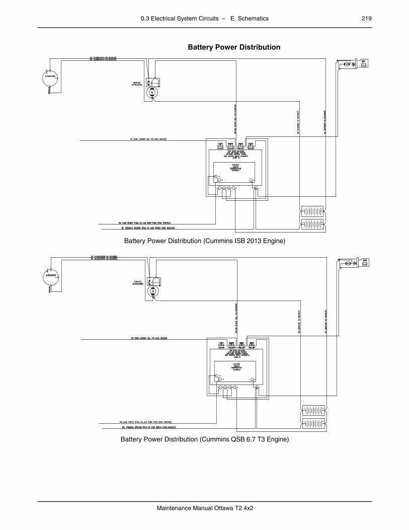
0.3 Electrical System Circuits – E. Schematics 219
Maintenance Manual Ottawa T2 4x2
Battery Power Distribution
Battery Power Distribution (Cummins ISB 2013 Engine)
–
Battery Power Distribution (Cummins QSB 6.7 T3 Engine)

220 0.3 Electrical System Circuits – E. Schematics
Maintenance Manual Ottawa T2 4x2
–
Battery Power Distribution (Cummins QSB T4F Engine)
–
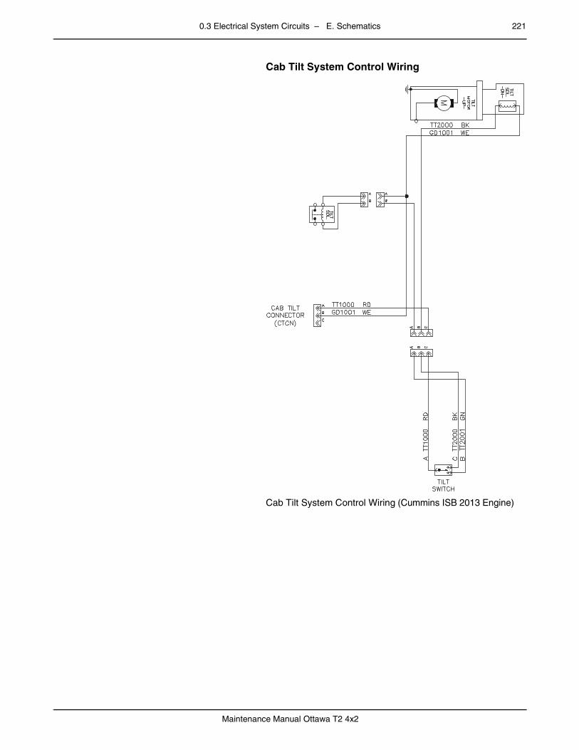
0.3 Electrical System Circuits – E. Schematics 221
Maintenance Manual Ottawa T2 4x2
Cab Tilt System Control Wiring
Cab Tilt System Control Wiring (Cummins ISB 2013 Engine)
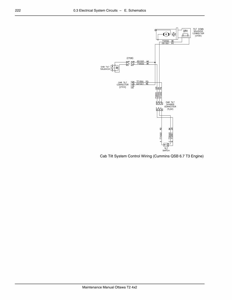
222 0.3 Electrical System Circuits – E. Schematics
Maintenance Manual Ottawa T2 4x2
–
Cab Tilt System Control Wiring (Cummins QSB 6.7 T3 Engine)
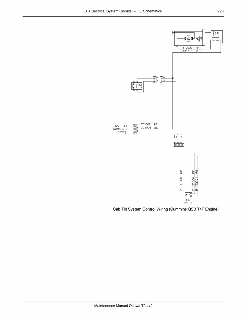
0.3 Electrical System Circuits – E. Schematics 223
Maintenance Manual Ottawa T2 4x2
–
Cab Tilt System Control Wiring (Cummins QSB T4F Engine)

224 0.3 Electrical System Circuits – E. Schematics
Maintenance Manual Ottawa T2 4x2
0.3.5 Lighting Circuits (Cab and Chassis)page – Backup Light and Alarm
Backup Light and Alarm Circuit
Components
• Backup Alarm
• Backup Lamp
• Circuit Breaker — Reverse (Cab Accessory Fuse Panel)
• Ignition Relay
• Reverse Relay
• Transmission Case Ground
The backup lamp illuminates and the alarm sounds when the transmission is shifted to reverse.

0.3 Electrical System Circuits – E. Schematics 225
Maintenance Manual Ottawa T2 4x2
– Beacon/Strobe Light (Optional)
Beacon/Strobe Light Circuit
Components
• Accessory Relay #2
• Beacon Light Switch (Optional)
• Beacon/Strobe Lamp
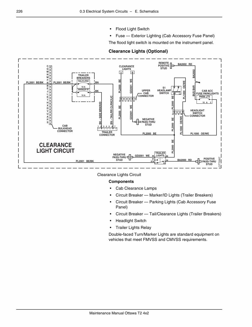
226 0.3 Electrical System Circuits – E. Schematics
Maintenance Manual Ottawa T2 4x2
• Flood Light Switch
• Fuse — Exterior Lighting (Cab Accessory Fuse Panel)
The flood light switch is mounted on the instrument panel.
– Clearance Lights (Optional)
Clearance Lights Circuit
Components
• Cab Clearance Lamps
• Circuit Breaker — Marker/ID Lights (Trailer Breakers)
• Circuit Breaker — Parking Lights (Cab Accessory Fuse Panel)
• Circuit Breaker — Tail/Clearance Lights (Trailer Breakers)
• Headlight Switch
• Trailer Lights Relay
Double-faced Turn/Marker Lights are standard equipment on vehicles that meet FMVSS and CMVSS requirements.
OTT0067
NEGATIVEPASS-THRU
STUD POSITIVEPASS-THRU
STUD
NEGATIVEPASS-THRU
STUD
UPPERCAB
CONNECTOR
CLEARANCELIGHTS
REMOTEPOSITIVE
STUD
S1HEADLAMP
SWITCH
PL2001 BE/BK
GD2001 WE
BA2000 RD
PL1000 OE/WE
HEADLIGHTSWITCH
CONNECTOR
CAB ACCFUSE PARKLIGHTS
PL1
000
OE
/WE
PL1
000
OE
/WE
BU
S B
AR
BA
2002
BA2002 RD
PL2000 BE
PL2
000
BE
PL2
000
BE
PL2
000
BE
PL2
000
BE
GD
2001
W
E
PL2
000
BE
GD
2001
W
E
CLEARANCELIGHT CIRCUIT
PL2001 BE/BK
CGMNWFRBEJLKTHXDVUAPS
PL2001 BE/BK BN
BK
BK
– S
IDE
MR
KR
/ID
BN
– T
AIL
/RR
CLR
NC
/LIC
TRAILERBREAKERS
TAIL/CLRNC
MARKER ID10 A
10 A
1 2 3 4 5 6 7
EFDCAB
D C A B
CABBULKHEAD
CONNECTOR TRAILERCONNECTOR
86
30
8587
87AR1
TRAILERLIGHTS
10 A 3
PARK LTS
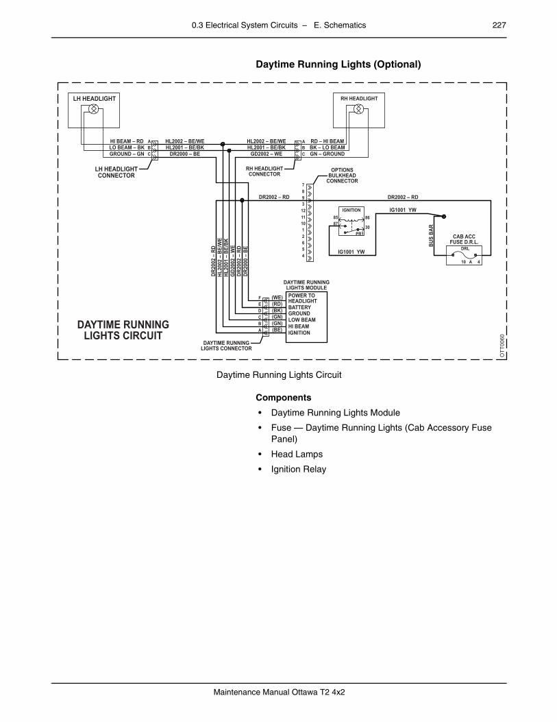
0.3 Electrical System Circuits – E. Schematics 227
Maintenance Manual Ottawa T2 4x2
– Daytime Running Lights (Optional)
Daytime Running Lights Circuit
Components
• Daytime Running Lights Module
• Fuse — Daytime Running Lights (Cab Accessory Fuse Panel)
• Head Lamps
• Ignition Relay
OTT0060
LH HEADLIGHT
LH HEADLIGHTCONNECTOR
DAYTIME RUNNINGLIGHTS CIRCUIT
HI BEAM – RDLO BEAM – BKGROUND – GN
HL2002 – BE/WEABC
HL2001 – BE/BKDR2000 – BE
DR20
00 –
BE
DR20
02 –
RD
DR20
02 –
RD
RD – HI BEAM
RH HEADLIGHT
BK – LO BEAMGN – GROUND
HL2002 – BE/WE
RH HEADLIGHTCONNECTOR
OPTIONSBULKHEAD
CONNECTOR
IG1001 YW
IG1001 YW
CAB ACCFUSE D.R.L.BU
S BA
R
DR2002 – RD
A
7893
12 IGNITION8587
30
86
DRL
10 A 4
PR1
111012654
BC
HL2001 – BE/BKGD2002 – WE
HL20
02 –
BE/
WE
HL20
01 –
BE/
BKG
D200
2 –
WE
DR2002 – RD
(WE)
DAYTIME RUNNINGLIGHTS MODULEPOWER TOHEADLIGHTBATTERYGROUNDLOW BEAMHI BEAMIGNITION
DAYTIME RUNNINGLIGHTS CONNECTOR
FEDCBA
(RD)(BK)(GN)(GN)(BE)

228 0.3 Electrical System Circuits – E. Schematics
Maintenance Manual Ottawa T2 4x2
– Dome Light
Dome Light Circuit
Components
• Accessory Relay #2
• Dome Lamp with Switch
• Fuse — Cab Lighting (Cab Accessory Fuse Panel)
The lamp On/Off switch is on the dome light fixture.
–
Fifth-Wheel Control
Refer to Transmission Shifter.
OTT0061
GD2001 WE
UPPER CABCONNECTOR
NEGATIVEPASS-THRU
STUD
DOMELIGHT
DOME LIGHTCIRCUIT
CL1000 BN/RD
GD2
001
WE
CL10
00
BN/R
D
ACC #285 86
30PR2
87
GD2
001
WE
GD2001 WE
CAB ACC FUSELIGHTING
CAB LIGHTING
10 A 1
B A C D F E
CL10
00
BN/R
D
AC10
01
BN

0.3 Electrical System Circuits – E. Schematics 229
Maintenance Manual Ottawa T2 4x2
– Flood Light
Flood Light Circuit
Components
• Accessory Relay #2
• Flood Light
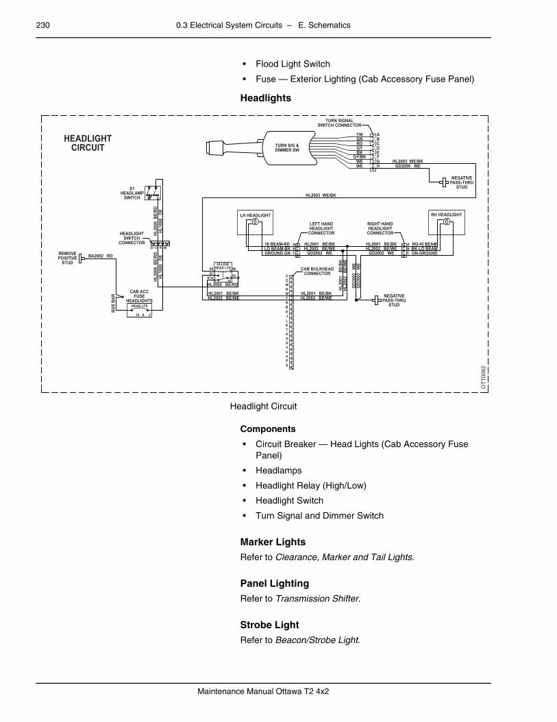
230 0.3 Electrical System Circuits – E. Schematics
Maintenance Manual Ottawa T2 4x2
• Flood Light Switch
• Fuse — Exterior Lighting (Cab Accessory Fuse Panel)
– Headlights
Headlight Circuit
Components
• Circuit Breaker — Head Lights (Cab Accessory Fuse Panel)
• Headlamps
• Headlight Relay (High/Low)
• Headlight Switch
• Turn Signal and Dimmer Switch
–
Marker Lights
Refer to Clearance, Marker and Tail Lights.
–
Panel Lighting
Refer to Transmission Shifter.
–
Strobe Light
Refer to Beacon/Strobe Light.
OTT0062
REMOVEPOSITIVE
STUD
HEADLIGHTSWITCH
CONNECTOR
S1HEADLAMP
SWITCH
CAB ACCFUSE
HEADLIGHTS
BA2002 RD
HL20
00 B
E/RD
HL10
00
OE
HL2002 BE/WEHL2001 BE/BK
HL2002 BE/WE
HL20
02
BE/W
E
HL2002 BE/WEGD2002 WE
GD2
002
WE
GD2
002
WE
HL2001 BE/BK
HL20
01
BE/B
K
HL2001 BE/BKHL2002 BE/WE
GD2002 WE
GD2000 WEHL2003 WE/BK
HL2003 WE/BK
TURN SIGNALSWITCH CONNECTOR
TURN SIG &DIMMER SW
HEADLIGHTCIRCUIT
ABCDEFGH
YWGNRDGYBK
GY/BKWEWE
HL2001 BE/BK
LEFT HANDHEADLIGHT
CONNECTOR
RIGHT HANDHEADLIGHT
CONNECTOR
NEGATIVEPASS-THRU
STUD
NEGATIVEPASS-THRU
STUD
CAB BULKHEADCONNECTOR
HL2000 BE/RD
LH HEADLIGHT
GROUND-GNLO BEAM-BKHI BEAM-RD
HL20
00 B
E/RD
HL10
00
OE
HEAD LTS
HI-LOWHEAD LTS 86
30
A
CGMNWFRBEJLKTHXDVUAPS
BC GN-GROUND
BK-LO BEAMRD-HI BEAM
RH HEADLIGHT
ABC
R4
8587
87A
15 A 2
C A BD
BUS
BAR
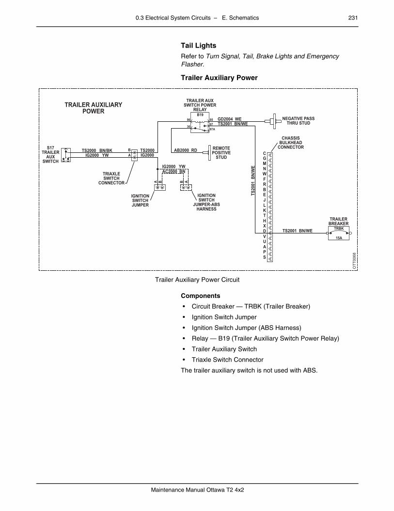
0.3 Electrical System Circuits – E. Schematics 231
Maintenance Manual Ottawa T2 4x2
– Tail Lights
Refer to Turn Signal, Tail, Brake Lights and Emergency Flasher.
– Trailer Auxiliary Power
Trailer Auxiliary Power Circuit
Components
• Circuit Breaker — TRBK (Trailer Breaker)
• Ignition Switch Jumper
• Ignition Switch Jumper (ABS Harness)
• Relay — B19 (Trailer Auxiliary Switch Power Relay)
• Trailer Auxiliary Switch
• Triaxle Switch Connector
The trailer auxiliary switch is not used with ABS.
OTT0068
S17TRAILER
AUXSWITCH
TS2000 BN/BK
TRIAXLESWITCH
CONNECTOR
TRAILER AUXILIARYPOWER
IGNITIONSWITCHJUMPER
IG2000 YWTS2000
GD2004 WETS2001 BN/WE
TS2001 BN/WE
TRAILERBREAKER
TRBK
15A
TS20
01 B
N/W
E
REMOTEPOSITIVE
STUD
CHASSISBULKHEAD
CONNECTOR
NEGATIVE PASSTHRU STUD
CGMNWFRBEJLKTHXDVUAPS
IGNITIONSWITCH
JUMPER-ABSHARNESS
IG2000
IG2000 YWAC2000 BN
AB2000 RD
B1986 85
8787A
30
TRAILER AUXSWITCH POWER
RELAY
AB
A AB B
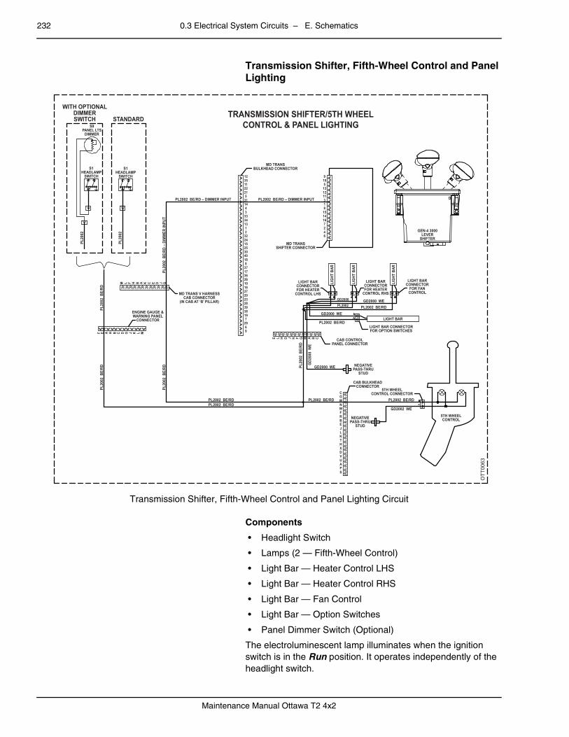
232 0.3 Electrical System Circuits – E. Schematics
Maintenance Manual Ottawa T2 4x2
– Transmission Shifter, Fifth-Wheel Control and Panel Lighting
Transmission Shifter, Fifth-Wheel Control and Panel Lighting Circuit
Components
• Headlight Switch
• Lamps (2 — Fifth-Wheel Control)
• Light Bar — Heater Control LHS
• Light Bar — Heater Control RHS
• Light Bar — Fan Control
• Light Bar — Option Switches
• Panel Dimmer Switch (Optional)
The electroluminescent lamp illuminates when the ignition switch is in the Run position. It operates independently of the headlight switch.
OTT0063
S9PANEL LTS
DIMMER
S1HEADLAMP
SWITCH
PL20
02
PL20
02
PL20
02 B
E/RD
PL20
02 B
E/RD
F E A H B C D G J K L M
E L H D J K F G M A B C
M L F H B A K C E D J GPL
2002
BE/
RD PL20
02 B
E/RD
PL2002 BE/RD
PL2002 BE/RD
PL2002 BE/RDPL2002GD2000
PL2002 BE/RD PL2002 BE/RD
GD2002 WE
GD2000 WE
GD2000 WE
GD2
000
WE
GD2000 WE
PL2002 BE/RD
PL20
02 B
E/RD
– D
IMM
ER IN
PUT
PL2002 BE/RD – DIMMER INPUT PL2002 BE/RD – DIMMER INPUT
MD TRANSBULKHEAD CONNECTOR
TRANSMISSION SHIFTER/5TH WHEELCONTROL & PANEL LIGHTING
MD TRANSSHIFTER CONNECTOR
LIGHT BARCONNECTORFOR HEATER
CONTROL LHS
LIGHT BARCONNECTORFOR HEATER
CONTROL RHS
LIGHT BARCONNECTOR
FOR FANCONTROL
GEN-4 3000LEVER
SHIFTER
LIGHT BAR CONNECTORFOR OPTION SWITCHES
CAB CONTROLPANEL CONNECTOR
NEGATIVEPASS-THRU
STUD
CAB BULKHEADCONNECTOR
5TH WHEELCONTROL CONNECTOR
5TH WHEELCONTROLNEGATIVE
PASS-THRUSTUD
LIG
HT B
AR
LIG
HT B
AR
LIG
HT B
AR
LIGHT BARENGINE GAUGE &WARNING PANEL
CONNECTOR
MD TRANS V HARNESSCAB CONNECTOR
(IN CAB AT ‘B’ PILLAR)
C
96
297
193839282320271610263617378
1840302515243221
13343334
14315
2122113512
64271614158131112135109
GMNWFRBEJLKTHXDVUAPS
S1HEADLAMP
SWITCH
STANDARD
WITH OPTIONALDIMMERSWITCH
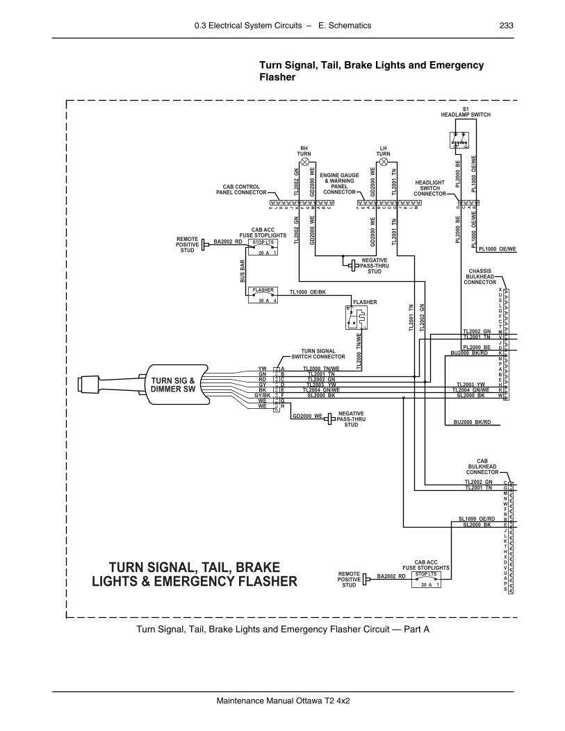
0.3 Electrical System Circuits – E. Schematics 233
Maintenance Manual Ottawa T2 4x2
– Turn Signal, Tail, Brake Lights and Emergency Flasher
Turn Signal, Tail, Brake Lights and Emergency Flasher Circuit — Part A
TURN SIG &DIMMER SW
TURN SIGNALSWITCH CONNECTOR
ABCDEF
TL2000 TN/WE
TL1000 OE/BK
BA2002 RDREMOTEPOSITIVE
STUD
CAB ACCFUSE STOPLIGHTS
CAB CONTROLPANEL CONNECTOR
RHTURN
LHTURN
ENGINE GAUGE& WARNING
PANELCONNECTOR
BUS
BAR
TL20
02 G
N
GD2
000
WE
TL20
02 G
N
TL20
01 T
N
GD2
000
WE
GD2
000
WE
TL20
01 T
N
TL20
01 T
N
TL20
02 G
N
GD2
000
WE
FLASHER
30 A 4
REMOTEPOSITIVE
STUDBA2002 RD
SL2000 BKSL1000 OE/RD
SL2000 BKTL2004 GN/WE
TL2003 YW
BU2000 BK/RD
BU2000 BK/RD
PL2000 BE
TL2001 TNTL2002 GN
PL1000 OE/WE
HEADLIGHTSWITCH
CONNECTOR
S1HEADLAMP SWITCH
PL10
00 O
E/W
E
PL20
00 B
E
PL10
00 O
E/W
E
PL20
00 B
E
TL2001 TNTL2002 GN
CABBULKHEAD
CONNECTOR
CHASSISBULKHEAD
CONNECTOR
CAB ACCFUSE STOPLIGHTS
STOP LTS
SPAUVDXHTKLJEBRFWNMGC
WRHEBAPNKDJVMTCFGLSUX
20 A 1
STOP LTS
20 A 1
E L H D J K F G M A B C F E A H B C D G J K L M D C A B
FLASHER
NEGATIVEPASS-THRU
STUD
TL20
00 T
N/W
E
TL2001 TNTL2002 GNTL2003 YW
TL2004 GN/WESL2000 BK
GD2000 WE NEGATIVEPASS-THRU
STUD
GH
YWGNRDGYBK
GY/BKWEWE
B
L
TURN SIGNAL, TAIL, BRAKELIGHTS & EMERGENCY FLASHER

234 0.3 Electrical System Circuits – E. Schematics
Maintenance Manual Ottawa T2 4x2
Turn Signal, Tail, Brake Lights and Emergency Flasher Circuit — Part B
OTT0064
SL2000 BKSL2000 BK RD
YW –
LH
TURN
RD –
STO
PG
N –
RH T
URN
SL2000 BK
TL2001 TN
TL2001 TN
TL2002 GN
TL2002 GN
BU1000 BK
BU2000 BK/RD
BU2000 BK/RD
BU2000 BK/RD
BU2000 BK/RD
BU20
00 B
K/RD
PL1000 OE/WE
GD1001 WE
GD1001 WE
GD1001 WE
GD1001 WE
GD1001 WE
GD1001 WE
TRANSMISSIONCASE
GROUND
(NOT USED WHENSTOP/TURN/TAIL
LIGHT IS COMBINED)
STOPLIGHTCONNECTOR
TAIL LIGHTSCONNECTOR
GD1001 WE
GD1
001
WE
GD1
001
WE
PL2000 BE
PL2000 BE
TL2001 TN
BA2002 RD
BA20
02BU
S BA
R
REMOTEPOSITIVE
STUD
CAB ACCFUSE PARKLIGHTS
RH FRONTTURN/PARK
PL2000 BE
PL2000 BE
PL20
00 B
E
TL2001 TN
TL20
01 T
N
TL2002 GN
TL2002 GN
PL20
00 B
EPL
2000
BE
TL20
02 G
N
PL20
00 B
ETL
2002
GN
TL20
02 G
N
LH FRONTTURN/PARK
SL2000 BKTL2004 GN/WE
TL2003 YW
SL2000 BK
SL2000 BK
RH REARSTOP/TURN/TAIL
LH REARSTOP/TURN/TAIL
BACK-UPLIGHT
TL2004 GN/WE TL2004 GN/WE
TL2004 GN/WE
GD1
001
WE
PL20
00 B
ETL
2004
GN/
WE
TL2003 YW TL2003 YWPL2000 BE
PL2000 BE
TL2003 YW
SL20
00 B
K
TL20
04 G
N/W
ETL
2003
YW
SL1000 OE/RD
SL1000 OE/RD
REVERSE85
ABECD
8687 30
R587AIG1001 YW
IGNITION85 8687 30
PR187A
CAB ACCFUSE STOPLIGHTS
STOP LIGHTSWITCH
TRAILERCONNECTOR
STOP LTS
15 A
YWLH TURN
10 A
GN
CIRCUITBREAKERS
RH TURN
10 A
CAB ACCFUSE REVERSE
REVERSE
7.5 A 2
1 2 3 4 5 6 7
PARK LTS
10 A 3
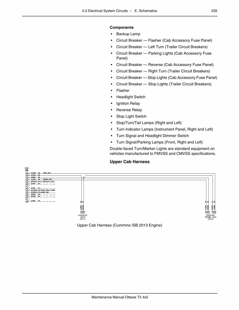
0.3 Electrical System Circuits – E. Schematics 235
Maintenance Manual Ottawa T2 4x2
Components
• Backup Lamp
• Circuit Breaker — Flasher (Cab Accessory Fuse Panel)
• Circuit Breaker — Left Turn (Trailer Circuit Breakers)
• Circuit Breaker — Parking Lights (Cab Accessory Fuse Panel)
• Circuit Breaker — Reverse (Cab Accessory Fuse Panel)
• Circuit Breaker — Right Turn (Trailer Circuit Breakers)
• Circuit Breaker — Stop Lights (Cab Accessory Fuse Panel)
• Circuit Breaker — Stop Lights (Trailer Circuit Breakers)
• Flasher
• Headlight Switch
• Ignition Relay
• Reverse Relay
• Stop Light Switch
• Stop/Turn/Tail Lamps (Right and Left)
• Turn Indicator Lamps (Instrument Panel, Right and Left)
• Turn Signal and Headlight Dimmer Switch
• Turn Signal/Parking Lamps (Front, Right and Left)
Double-faced Turn/Marker Lights are standard equipment on vehicles manufactured to FMVSS and CMVSS specifications.
– Upper Cab Harness
Upper Cab Harness (Cummins ISB 2013 Engine)

236 0.3 Electrical System Circuits – E. Schematics
Maintenance Manual Ottawa T2 4x2
–
Upper Cab Harness (Cummins QSB 6.7 T3 Engine)
–
Upper Cab Harness (Cummins QSB T4F Engine)
– Headlight/Dimmer Switch Wiring
Headlight/Dimmer Switch Wiring (Cummins ISB 2013 Engine)
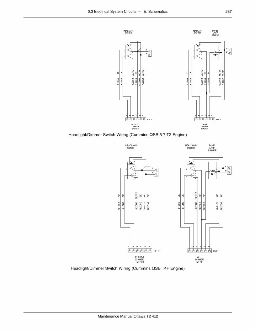
0.3 Electrical System Circuits – E. Schematics 237
Maintenance Manual Ottawa T2 4x2
–
Headlight/Dimmer Switch Wiring (Cummins QSB 6.7 T3 Engine)
–
Headlight/Dimmer Switch Wiring (Cummins QSB T4F Engine)

238 0.3 Electrical System Circuits – E. Schematics
Maintenance Manual Ottawa T2 4x2
– Auxiliary Lighting and Air Horn
Auxiliary Lighting and Air Horn (Cummins ISB 2013 Engine)
–
Auxiliary Lighting and Air Horn (Cummins QSB 6.7 T3 Engine)

0.3 Electrical System Circuits – E. Schematics 239
Maintenance Manual Ottawa T2 4x2
–
Auxiliary Lighting and Air Horn (Cummins QSB T4F Engine)
– Tail Light/Backup Light Wiring
Tail Light/Backup Light Wiring (Cummins ISB 2013 Engine)
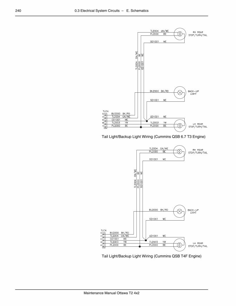
240 0.3 Electrical System Circuits – E. Schematics
Maintenance Manual Ottawa T2 4x2
–
Tail Light/Backup Light Wiring (Cummins QSB 6.7 T3 Engine)
–
Tail Light/Backup Light Wiring (Cummins QSB T4F Engine)
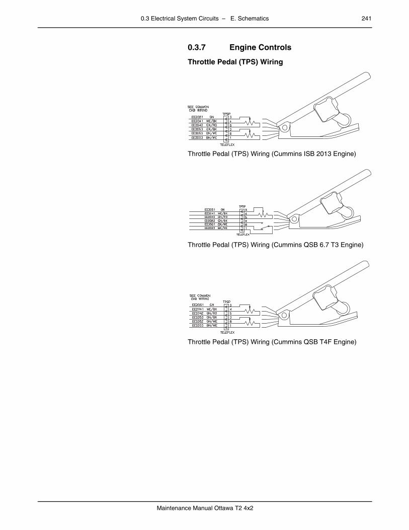
0.3 Electrical System Circuits – E. Schematics 241
Maintenance Manual Ottawa T2 4x2
0.3.7 Engine Controlspage – Throttle Pedal (TPS) Wiring
Throttle Pedal (TPS) Wiring (Cummins ISB 2013 Engine)
–
Throttle Pedal (TPS) Wiring (Cummins QSB 6.7 T3 Engine)
–
Throttle Pedal (TPS) Wiring (Cummins QSB T4F Engine)
–
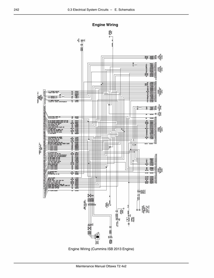
242 0.3 Electrical System Circuits – E. Schematics
Maintenance Manual Ottawa T2 4x2
Engine Wiring
Engine Wiring (Cummins ISB 2013 Engine)

0.3 Electrical System Circuits – E. Schematics 243
Maintenance Manual Ottawa T2 4x2
–
Engine Wiring (Cummins QSB 6.7 T3 Engine)
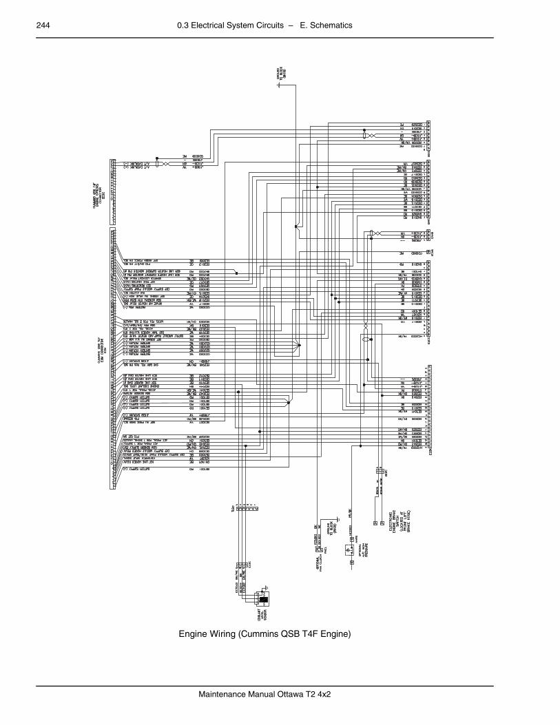
244 0.3 Electrical System Circuits – E. Schematics
Maintenance Manual Ottawa T2 4x2
–
Engine Wiring (Cummins QSB T4F Engine)

0.3 Electrical System Circuits – E. Schematics 245
Maintenance Manual Ottawa T2 4x2
0.3.8 Exhaustpage – Aftertreatment Wiring
Aftertreatment Wiring (Cummins ISB 2013 Engine)
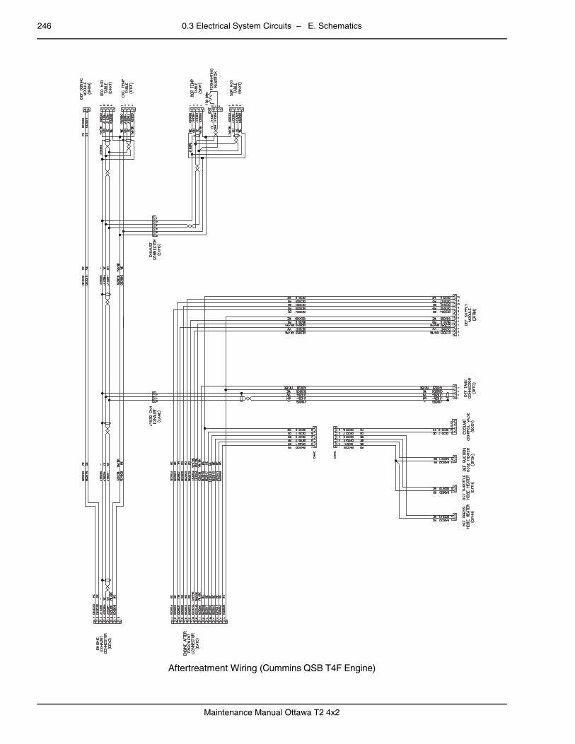
246 0.3 Electrical System Circuits – E. Schematics
Maintenance Manual Ottawa T2 4x2
–
Aftertreatment Wiring (Cummins QSB T4F Engine)
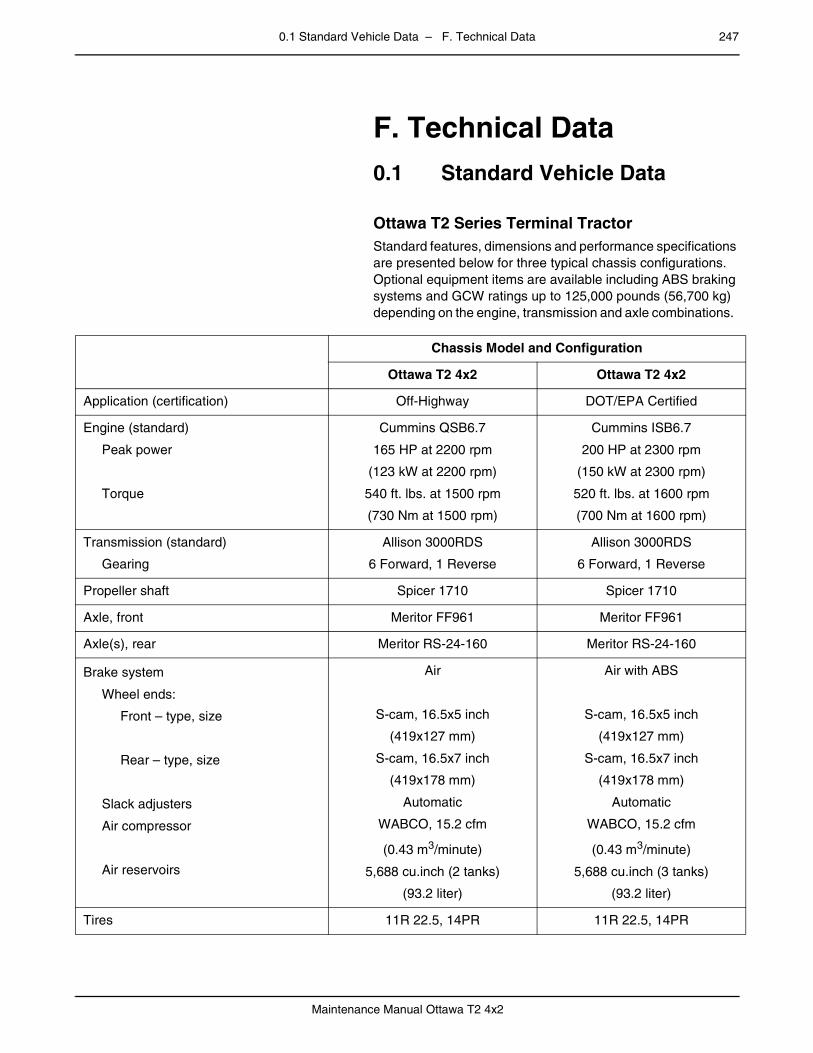
0.1 Standard Vehicle Data – F. Technical Data 247
Maintenance Manual Ottawa T2 4x2
mm mm mm mm mm mm
F. Technical Data0.1 Standard Vehicle Data
page –
Ottawa T2 Series Terminal TractorStandard features, dimensions and performance specifications are presented below for three typical chassis configurations. Optional equipment items are available including ABS braking systems and GCW ratings up to 125,000 pounds (56,700 kg) depending on the engine, transmission and axle combinations.
Chassis Model and Configuration
Ottawa T2 4x2 Ottawa T2 4x2
Application (certification) Off-Highway DOT/EPA Certified
Engine (standard)
Peak power
Torque
Cummins QSB6.7
165 HP at 2200 rpm
(123 kW at 2200 rpm)
540 ft. lbs. at 1500 rpm
(730 Nm at 1500 rpm)
Cummins ISB6.7
200 HP at 2300 rpm
(150 kW at 2300 rpm)
520 ft. lbs. at 1600 rpm
(700 Nm at 1600 rpm)
Transmission (standard)
Gearing
Allison 3000RDS
6 Forward, 1 Reverse
Allison 3000RDS
6 Forward, 1 Reverse
Propeller shaft Spicer 1710 Spicer 1710
Axle, front Meritor FF961 Meritor FF961
Axle(s), rear Meritor RS-24-160 Meritor RS-24-160
Brake system
Wheel ends:
Front – type, size
Rear – type, size
Slack adjusters
Air compressor
Air reservoirs
Air
S-cam, 16.5x5 inch
(419x127 mm)
S-cam, 16.5x7 inch
(419x178 mm)
Automatic
WABCO, 15.2 cfm
(0.43 m3/minute)
5,688 cu.inch (2 tanks)
(93.2 liter)
Air with ABS
S-cam, 16.5x5 inch
(419x127 mm)
S-cam, 16.5x7 inch
(419x178 mm)
Automatic
WABCO, 15.2 cfm
(0.43 m3/minute)
5,688 cu.inch (3 tanks)
(93.2 liter)
Tires 11R 22.5, 14PR 11R 22.5, 14PR

248 0.1 Standard Vehicle Data – F. Technical Data
Maintenance Manual Ottawa T2 4x2
GAWR
Front
Rear
12,000 lbs. (5,443 kg)
30,000 lbs. (13,608 kg)
12,000 lbs. (5,443 kg)
30,000 lbs. (13,608 kg)
GCWR 81,000 lbs. (43,545 kg) 81,000 lbs. (36,287 kg)
Wheelbase 116 inch (2,794 mm) 116 inch (2,794 mm)
Length overall 191 inch (4,851 mm) 191 inch (4,851 mm)
Width overall 97 inch (2,464 mm) 97 inch (2,464 mm)
Fifth-wheel boom lift capacity 50,000 lbs. (27,216 kg) 50,000 lbs. (27,216 kg)
Fifth wheel FW 3500 FW 3500
Chassis weight 14,500 lbs. (6,577 kg) 14,500 lbs. (6,577 kg)
Chassis Model and Configuration
Ottawa T2 4x2 Ottawa T2 4x2
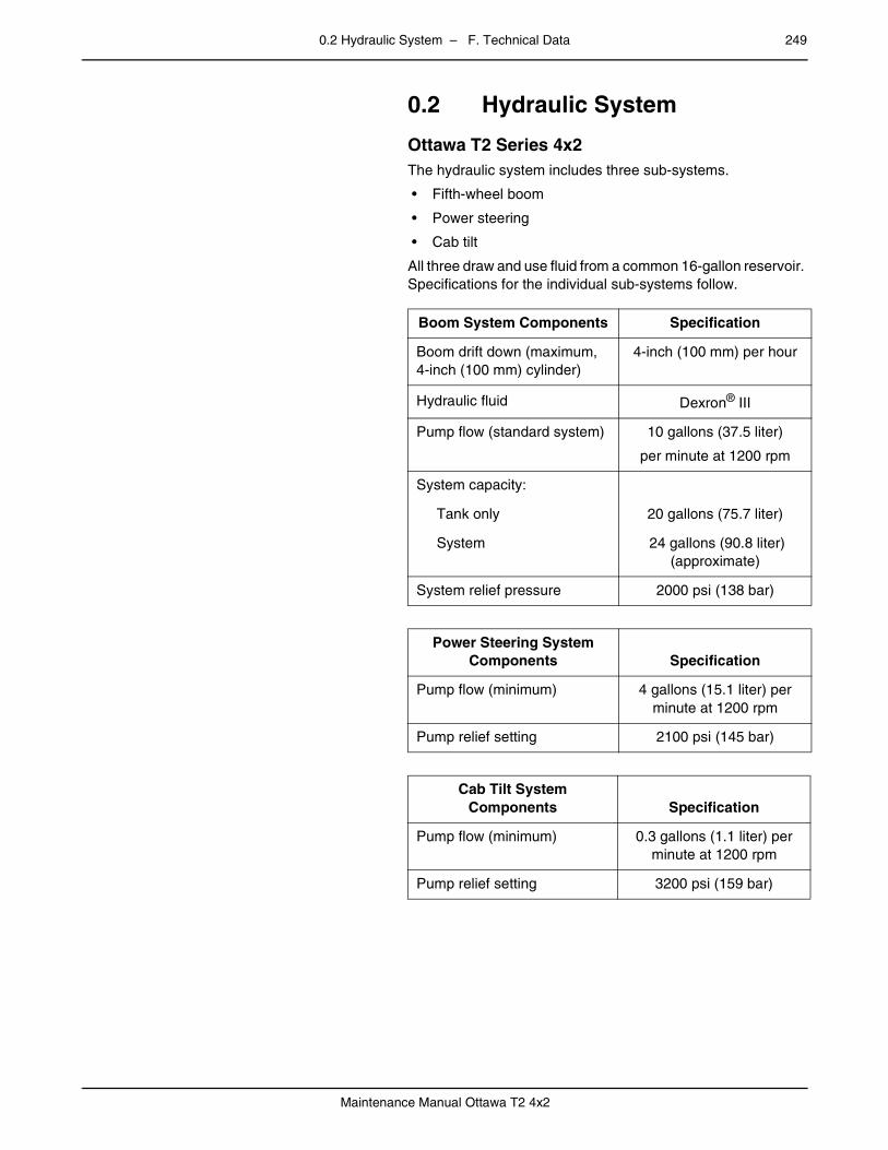
0.2 Hydraulic System – F. Technical Data 249
Maintenance Manual Ottawa T2 4x2
0.2 Hydraulic Systempage – Ottawa T2 Series 4x2
The hydraulic system includes three sub-systems.
• Fifth-wheel boom
• Power steering
• Cab tilt
All three draw and use fluid from a common 16-gallon reservoir. Specifications for the individual sub-systems follow.
Boom System Components Specification
Boom drift down (maximum, 4-inch (100 mm) cylinder)
4-inch (100 mm) per hour
Hydraulic fluid Dexron® III
Pump flow (standard system) 10 gallons (37.5 liter)
per minute at 1200 rpm
System capacity:
Tank only 20 gallons (75.7 liter)
System 24 gallons (90.8 liter) (approximate)
System relief pressure 2000 psi (138 bar)
Power Steering System Components Specification
Pump flow (minimum) 4 gallons (15.1 liter) per minute at 1200 rpm
Pump relief setting 2100 psi (145 bar)
Cab Tilt System Components Specification
Pump flow (minimum) 0.3 gallons (1.1 liter) per minute at 1200 rpm
Pump relief setting 3200 psi (159 bar)
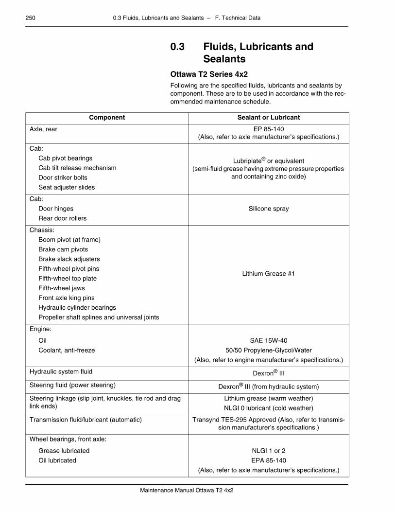
250 0.3 Fluids, Lubricants and Sealants – F. Technical Data
Maintenance Manual Ottawa T2 4x2
0.3 Fluids, Lubricants and Sealants
page –
Ottawa T2 Series 4x2Following are the specified fluids, lubricants and sealants by component. These are to be used in accordance with the rec-ommended maintenance schedule.
Component Sealant or Lubricant
Axle, rear EP 85-140(Also, refer to axle manufacturer’s specifications.)
Cab:
Cab pivot bearings
Cab tilt release mechanism
Door striker bolts
Seat adjuster slides
Lubriplate® or equivalent(semi-fluid grease having extreme pressure properties
and containing zinc oxide)
Cab:
Door hinges
Rear door rollers
Silicone spray
Chassis:
Boom pivot (at frame)
Brake cam pivots
Brake slack adjusters
Fifth-wheel pivot pins
Fifth-wheel top plate
Fifth-wheel jaws
Front axle king pins
Hydraulic cylinder bearings
Propeller shaft splines and universal joints
Lithium Grease #1
Engine:
Oil
Coolant, anti-freeze
SAE 15W-40
50/50 Propylene-Glycol/Water
(Also, refer to engine manufacturer’s specifications.)
Hydraulic system fluid Dexron® III
Steering fluid (power steering) Dexron® III (from hydraulic system)
Steering linkage (slip joint, knuckles, tie rod and drag link ends)
Lithium grease (warm weather)
NLGI 0 lubricant (cold weather)
Transmission fluid/lubricant (automatic) Transynd TES-295 Approved (Also, refer to transmis-sion manufacturer’s specifications.)
Wheel bearings, front axle:
Grease lubricated
Oil lubricated
NLGI 1 or 2
EPA 85-140
(Also, refer to axle manufacturer’s specifications.)

0.4 Fastener Torque Values – F. Technical Data 251
Maintenance Manual Ottawa T2 4x2
0.4 Fastener Torque Valuespage –
Ottawa T2 Series 4x2Following are the specified torque values required for sched-uled maintenance operations and typical repair and/or adjust-ment procedures covered in this manual.
Component Specified Torque Value
Axle mounting:
Front axle clamp plate bolts
Rear axle clamp plate bolts:
Bolt head
Nut
Rear axle torque link bolts
210 ft. lbs.
600 ft. lbs.
400 ft. lbs.
380 ft. lbs.
285 Nm
813 Nm
542 Nm
515 Nm
Cab latch mounting bolts 65 ft. lbs. 88 Nm
Cab latch bar plate mounting bolts 65 ft. lbs. 88 Nm
Cab pivot pin retainer screws 35 ft. lbs. 47 Nm
Cab rear door roller capscrews 75 in. lbs. 8.5 Nm
Cab suspension:
Assembly mounting bolts
Shock absorber mounting bolts
220 ft. lbs.
100 ft. lbs.
298 Nm
136 Nm
Cab tilt cylinder mounting bolts 200 ft. lbs. 271 Nm
Cab tilt pump mounting bolts 77 in. lbs. 8.7 Nm
Cab tilt pump relief valve adjusting screw jam nut 80 in. lbs. 9 Nm
Boom cylinder mounting:
Upper mount bolts
Lower mount bolts
Lower mount cross-bar locknuts
55 ft. lbs.
55 ft. lbs.
600 ft. lbs.
75 Nm
75 Nm
813 Nm
Boom pivot cross-bar bolts 380 ft. lbs. 515 Nm
Boom pump mounting bolts 55 ft. lbs. 75 Nm
Boom pump relief valve adjusting screw jam nut 15 ft. lbs. 20 Nm
Steering gear mounting bolts 350 ft. lbs. 475 Nm
Wheel lug nuts 450-500 ft. lbs. 610-678 Nm
252 0.4 Fastener Torque Values – F. Technical Data
Maintenance Manual Ottawa T2 4x2

– G. Appendix 253
Maintenance Manual Ottawa T2 4x2
mm mm mm mm mm mm
G. Appendixpage –
DescriptionThis section is not applicable for this vehicle.