Ultrafast Electronic Processes at Nanoscale Organic-Inorganic ...
180
Ultrafast Electronic Processes at Nanoscale Organic-Inorganic Semiconductor Interfaces Patrick Wallace Parkinson Brasenose College University of Oxford A thesis submitted for the degree of Doctor of Philosophy Michaelmas 2008
-
Upload
khangminh22 -
Category
Documents
-
view
1 -
download
0
Transcript of Ultrafast Electronic Processes at Nanoscale Organic-Inorganic ...

Ultrafast Electronic Processes atNanoscale Organic-Inorganic
Semiconductor Interfaces
Patrick Wallace Parkinson
Brasenose College
University of Oxford
A thesis submitted for the degree of
Doctor of Philosophy
Michaelmas 2008

2

List of published papers:
• Dimensionality-dependent energy transfer in polymer-intercalated SnS2 nanocom-posites, P Parkinson, E Aharon, MH Chang, C Dosche, GL Frey, A Kohlerand LM Herz, Physical Review B, 75, 165206 (2007)
• Transient terahertz conductivity of GaAs nanowires, P Parkinson, J Lloyd-Hughes, Q Gao, HH Tan, C Jagadish, MB Johnston and LM Herz, Nano Letters,7, 2162-2165 (2007)
• Conductivity of nanoporous InP membranes investigated using terahertz spec-troscopy, SKE Merchant, J Lloyd-Hughes, L Sirbu, IM Tiginyanu, P Parkin-son, LM Herz, and MB Johnston, Nanotechnology, 19, 395704 (2008)
• Efficient generation of charges via below-gap photoexcitation of polymer-fullereneblend films investigated by terahertz spectroscopy, P Parkinson, J Lloyd-Hughes,MB Johnston, and LM Herz, Physical Review B, 78, 115321 (2008)

ii
Figure 1: Photograph of the PLUC system used in this thesis.
Figure 2: Photograph of the Amplifier OPTP system used in this thesis.

Abstract: Ultrafast Electronic Processes at NanoscaleOrganic-Inorganic Semiconductor Interfaces
Patrick Wallace Parkinson, Brasenose College, submitted for the degree of DPhil inMichaelmas term 2008
This thesis is concerned with the influence of nanoscale boundaries and interfacesupon the electronic processes that occur within both organic and inorganic semicon-ductors. Photoluminescent polymers, highly conducting polymers and nanoscale in-organic semiconductors have been investigated using state-of-the-art ultrafast opticaltechniques, to provide information on the sub-picosecond photoexcitation dynamicsin these systems.
The influence of dimensionality on the excitation transfer dynamics in a conju-gated polymer blend is studied. Using time-resolved photoluminescence spectroscopy,the transfer transients both for a three-dimensional blend film, and for quasi-two-dimensional monolayers formed through intercalation of the polymer blend betweenthe crystal planes of a SnS2 matrix have been measured. A comparison of the exper-imental data with a simple, dimensionality-dependent model is presented, based onpoint dipole electronic coupling between electronic transition moments. Within thisapproximation, the energy transfer dynamics are found to adopt a three-dimensionalcharacter in the solid film, and a two-dimensional nature in the monolayers presentin the SnS2-polymer nanocomposite.
The time-resolved conductivity of isolated GaAs nanowires has been investigatedby optical-pump terahertz-probe time-domain spectroscopy. The electronic responseexhibits a pronounced surface plasmon mode that forms within 300 fs, before decayingwithin 10 ps as a result of charge trapping at the nanowire surface. The mobility hasbeen extracted using the Drude model for a plasmon and is found to be remarkablyhigh, being roughly one third of that typical for bulk GaAs at room-temperature andindicating the high quality and low bulk defect density in the nanowires studied.
Finally, the time-resolved conductivity dynamics of photoexcited polymer-fullerenebulk heterojunction blends for two model polymers, P3HT and MDMO-PPV, blendedwith PCBM are presented. The observed terahertz-frequency conductivity is charac-teristic of dispersive charge transport for photoexcitation both at the π−π∗ absorptionpeak (560 nm for P3HT), and significantly below it (800 nm). The photoconductivityat 800 nm is unexpectedly high, which is attributed to the presence of a charge trans-fer complex. In addition, the excitation-fluence dependence of the photoconductivityis studied over more than four orders of magnitude. The time-averaged photoconduc-tivity of the P3HT:PCBM blend is over 20 times larger than that of P3HT, indicatingthat long-lived positive polarons are responsible for the high photovoltaic efficiencyof polymer:fullerene blends. At early times (∼ ps) the linear dependence of photo-conductivity upon fluence indicates that interfacial charge transfer dominates as anexciton decay pathway, generating charges with mobility of at least ∼0.1cm2V−1s−1.At later times, a sub-linear relationship shows that carrier-carrier recombination ef-fects influence the conductivity on a longer timescale (> 1µs).

Acknowledgements
I would like to acknowledge the help and support of many people formaking the work presented in this thesis possible, and importantly, en-joyable. Primarily, I would like to thank my supervisor Dr. Laura Herzfor continual help, advice and encouragement over the last three years.For help and support, particularly with the more involved aspects of tera-hertz spectroscopy I am indebted to Dr. Michael Johnston of the TerahertzPhotonics group at the Clarendon Laboratory, University of Oxford. Ad-ditionally, I would like to thank my group members and office-mates oldand new : Enrique Castro-Camus, James Lloyd-Hughes, Suzannah Mer-chant, Ming-Hua Chang, Xinlong Xu, Stefan Schmid, Amy Stevens, PritiTiwana, and Carl Headley. For their support, chats, tea and general goodhumour, I am very grateful.
Much of the work presented in this thesis has been made possible by col-laborations with colleagues from around the world. In particular: Thesamples studied in Chapter 4 were provided by Prof. Gitti Frey of theDepartment of Materials Engineering, Technion Institute of Technology,Haifa, Israel and additional spectroscopy and sample preparation was per-formed by Dr. Carsten Dosche and Prof. Anna Kohler from the ChemicalPhysics Department, University of Potsdam, Germany; The samples andthe electron microscopy in Chapter 5 were provided by Dr. Michael Gaoand Prof. Chennupati Jagadish of Electronic Materials Engineering De-partment of the Australian National University, Canberra, Australia.
I owe a huge amount of gratitude to my parents, sister, and friends inNottingham for support, entertainment and happy distractions over thelast few years, particularly when I have been getting restless in Oxford!This work is dedicated to Daniel and Matt, for a lifetime of friendship andhappiness and who are sorely missed.
Lastly but certainly not least – thank you to Tasha, for being supporting,loving, caring and always smiling!
Contents
1 Introduction 11.1 Ultrafast timescales . . . . . . . . . . . . . . . . . . . . . . . . . . . . 31.2 Overview of this thesis . . . . . . . . . . . . . . . . . . . . . . . . . . 4
2 Electronic processes in organic semiconductors 72.1 Introduction to conjugated polymers . . . . . . . . . . . . . . . . . . 7
2.1.1 Electronic structure of carbon . . . . . . . . . . . . . . . . . . 82.1.2 Single particle excitations . . . . . . . . . . . . . . . . . . . . 112.1.3 Excitons . . . . . . . . . . . . . . . . . . . . . . . . . . . . . . 13
2.2 Conjugated polymer spectra . . . . . . . . . . . . . . . . . . . . . . . 162.2.1 Stokes shift . . . . . . . . . . . . . . . . . . . . . . . . . . . . 19
2.3 Exciton dynamics . . . . . . . . . . . . . . . . . . . . . . . . . . . . . 222.3.1 Fundamentals of exciton dynamics . . . . . . . . . . . . . . . 222.3.2 Exciton migration mechanisms . . . . . . . . . . . . . . . . . . 252.3.3 Exciton Traps . . . . . . . . . . . . . . . . . . . . . . . . . . . 28
2.4 Polaron dynamics . . . . . . . . . . . . . . . . . . . . . . . . . . . . . 332.4.1 DC mobility . . . . . . . . . . . . . . . . . . . . . . . . . . . . 362.4.2 AC mobility . . . . . . . . . . . . . . . . . . . . . . . . . . . . 382.4.3 Polaron trapping . . . . . . . . . . . . . . . . . . . . . . . . . 39
2.5 Inorganic Semiconductors . . . . . . . . . . . . . . . . . . . . . . . . 412.5.1 Band transport . . . . . . . . . . . . . . . . . . . . . . . . . . 42
3 Experimental Methods 473.1 Steady-state techniques . . . . . . . . . . . . . . . . . . . . . . . . . . 483.2 Time-resolved spectroscopy . . . . . . . . . . . . . . . . . . . . . . . 49
3.2.1 Optical pump-probe spectroscopy . . . . . . . . . . . . . . . . 503.2.2 Ultrashort amplified laser pulses . . . . . . . . . . . . . . . . . 503.2.3 Non-linear optics . . . . . . . . . . . . . . . . . . . . . . . . . 53
3.3 Experimental details . . . . . . . . . . . . . . . . . . . . . . . . . . . 573.3.1 Photoluminescence up-conversion . . . . . . . . . . . . . . . . 573.3.2 Optical-pump terahertz-probe spectroscopy . . . . . . . . . . . 633.3.3 Extracting the complex conductivity of a sample . . . . . . . . 753.3.4 Interpretation of the photoconductivity . . . . . . . . . . . . . 80
v

vi CONTENTS
4 Energy dynamics in Polymer-intercalated SnS2 nanocomposites 834.1 Background : White-light emitting OLEDs . . . . . . . . . . . . . . . 834.2 Experimental details . . . . . . . . . . . . . . . . . . . . . . . . . . . 854.3 Results from time-resolved photoluminescence spectroscopy . . . . . . 874.4 Discussion of dimensionality-dependent energy transfer . . . . . . . . 924.5 Summary . . . . . . . . . . . . . . . . . . . . . . . . . . . . . . . . . 97
5 Transient terahertz photoconductivity of GaAs nanowires 1005.1 Background . . . . . . . . . . . . . . . . . . . . . . . . . . . . . . . . 1015.2 Sample characteristics . . . . . . . . . . . . . . . . . . . . . . . . . . 1035.3 Discussion . . . . . . . . . . . . . . . . . . . . . . . . . . . . . . . . . 107
5.3.1 Pump fluence dependence of conductivity . . . . . . . . . . . . 1095.4 Surface Passivation . . . . . . . . . . . . . . . . . . . . . . . . . . . . 112
5.4.1 Etch and passivation protocol . . . . . . . . . . . . . . . . . . 1125.4.2 Carrier lifetime . . . . . . . . . . . . . . . . . . . . . . . . . . 1135.4.3 Stability of surface passivation . . . . . . . . . . . . . . . . . . 115
5.5 Summary . . . . . . . . . . . . . . . . . . . . . . . . . . . . . . . . . 116
6 Sub-gap OPTP studies of Polymer:Fullerene blends 1196.1 Background: Organic photovoltaics . . . . . . . . . . . . . . . . . . . 1206.2 Sample preparation . . . . . . . . . . . . . . . . . . . . . . . . . . . . 1226.3 Experimental Results . . . . . . . . . . . . . . . . . . . . . . . . . . . 1266.4 Discussion . . . . . . . . . . . . . . . . . . . . . . . . . . . . . . . . . 134
6.4.1 Carrier generation and recombination . . . . . . . . . . . . . . 1356.4.2 Dependence of charge carrier conductivity on excitation fluence 138
6.5 Conclusions . . . . . . . . . . . . . . . . . . . . . . . . . . . . . . . . 145
7 Conclusion 1477.1 Future work . . . . . . . . . . . . . . . . . . . . . . . . . . . . . . . . 150
A Pump-probe analysis for thin non-uniform media 151

Chapter 1
Introduction
Technological development in the 21st century has revolved around computing, high-
speed communication, and a host of electronic devices that are used in every-day life.
Since the development of semiconductor transistors in 1947 [1], efforts to improve op-
toelectronic and semiconductor device technology have focused upon increased speed
and efficiency and reduction in cost of inorganic semiconductors, primarily silicon.
However, a promising class of semiconductors known as conjugated molecular mate-
rials has also undergone 40 years of intensive research, originating with the discovery
of electroluminescence in a molecular crystal – anthracene – in 1962 [2]. The earli-
est studies of conjugated molecular materials established that the mechanism behind
electroluminescence was recombination of electron-hole pairs in a radiative process [3].
This provided evidence for the existence of a band-gap within these materials, allow-
ing comparison with inorganic semiconductors studied in the well understood field
of solid state physics [4]. More recently, the possibility of controlling the band-gap
of organic semiconductors has allowed the use of a variety of conjugated polymers
in many applications, including highly sensitive chemical sensors [5], field-effect tran-
sistors (OFETs) [6], solar cells (OPVs) [7] and high efficiency organic light-emitting
diodes (OLEDs) [8, 9]. There are many advantages of using conjugated polymer semi-
1

2
Device layer
[Macroscopic]
Aggregates/morphology
[Mesoscopic]
Chemical structure
[Microscopic]
~0
.5n
m~200nm
1nm
Domain structure
[Mesoscopic]
Figure 1.1: Schematic giving an example of the levels of structure within a solid-statepolymeric device, such as an OLED. The dimensions given are approximate, and takenfrom X-ray diffraction measurements [10]. Electronic processes and coupling at every levelinfluence the macroscopic properties of the final device.
conductors for optoelectronic devices in comparison with their inorganic counterparts,
in particular, the chemical tunability of the semiconductor band-gap, and their solu-
tion processibility, which enables cheap and relatively simple roll-to-roll production
of large area optoelectronics.
Although there is now a wide-scale commercialisation of organic optoelectronics
– particularly in the field of OLEDs – the underlying physical processes are not well
understood. This is due to the complex interplay of a host of physical processes: the
interaction of the electronic and vibrational states; the electronic interactions between
and within semiconducting regions; polymer aggregation; blended polymer phase seg-
regation; and the macroscopic incorporation of these materials into devices, as shown
in Figure 1.1. Systematic studies of these properties have been impeded by two major

1. Introduction 3
10-18 sec
1 Attosecond
10-15 sec
1 Femtosecond
10-12 sec
1 Picosecond
10-9 sec
1 Nanosecond
10-6 sec
1 Microsecond
Nuclear recoil
time
Atomic electron
transfer time
Molecular
Relaxation time
Fastest transistor
switch time
Typical CPU
calculation time
OUR EXPERIMENTAL MEASUREMENT TIMES [0.1 - 1500ps]
Figure 1.2: Schematic illustration of the timescales of electronic and nuclear motion inthe solid-state, as well as more common markers. Also marked is the experimental timeresolution of the techniques presented in this thesis.
obstacles. Firstly, the electronic processes tend to occur deep within the polymer bulk
while the behaviour at the surface or at interfaces can be radically different, meaning
experimental techniques requiring electrical contact to the material are inappropriate
for determining the intrinsic properties. Secondly, the strong coupling between the
electronic and vibrational states lead to processes which occur on ultrafast timescales,
requiring experiments with an equally fast response time. The work presented in this
thesis focuses on new techniques that are able to investigate electronic processes on
the femtosecond (1×10⁻¹⁵ s) to nanosecond (1×10⁻⁹ s) timescale, using a non-contact
approach.
1.1 Ultrafast timescales
The timescales over which electronic processes in organic semiconductors occur are
controlled by the interactions with the polymer environment. In ‘soft’ polymeric sys-
tems at room temperature, the polymer lattice is able to vibrate or rotate relatively
freely, which leads to quasi-particle hopping, trapping and recombination on ultrafast
timescales. While these timescales are common in solid-state physics, they remain far
outside of the realm of the everyday events on the human scale. On these timescales,
light itself is only able to move a matter of centimetres, and great care must be taken
in the designing and operation of experiments that work on these scales. Accordingly,
in the time-resolved experiments discussed in this thesis, ultrashort pulses (∼50 fs,
4 1.2. Overview of this thesis
equal to 1.5µm in length in air at the speed of light) rather than electronic devices
are used as our stopwatch, and in the now common optical pump-probe experiments
these pulses can be used to initiate and to measure electronic dynamics in a sam-
ple. Figure 1.2 provides a schematic view of the timescales of atomic and molecular
processes, and the capabilities of the techniques presented in this thesis.
1.2 Overview of this thesis
The overarching theme of the work reported herein is the effect of nanoscale interfaces
upon the electronic properties of semiconductors. As described in Chapter 2, a partic-
ular kind of interface known as a bulk heterojunction is of particular interest, where
high ratio of extracted charges to incident photons is required. Chapter 2 contains a
review of the literature regarding organic semiconductors and the electronic processes
that occur in them. In particular, the nature and behaviour of photoexcitations are
described, and the evolution of the resultant electronic state is examined. The basic
theories developed in this chapter are required to explain the physics of all of the
nanoscale systems reported in the remainder of this thesis.
Chapter 3 describes the experimental setups used to investigate nanoscale inter-
faces, and the analytical tools required to interpret the data. For the work pre-
sented in this thesis, two time-resolved systems were used: Photoluminescence up-
conversion spectroscopy (PLUCS) is used to determine the luminescence properties
of a sample as a function of time, while optical-pump terahertz-probe time-domain-
spectroscopy (OPTP-TDS) is used to investigate the dynamical conductivity of pho-
toinjected species in semiconductors. These tools form the experimental basis for the
work presented, and represent the cutting edge of non-contact ultrafast spectroscopy.
The interaction of the terahertz pulse with a photoexcited system is explored, and
the interpretation of the spectroscopic information in order to model the electronic

1. Introduction 5
processes within the sample is discussed.
In Chapter 4, the application of nanoscale interfaces to optimise a white-light
OLED is presented. White-light emission has proven to be a particular challenge for
scientists working in the field of OLEDs. The traditional approach revolves around
the blending of polymers with different emission wavelengths to achieve full visible-
spectrum emission. While the band-gap tunability of organic semiconductors would
appear to be perfectly suited to this approach, the energy transfer from sites of higher
energy to those of lower energy is so rapid that emission occurs from the lowest energy
sites only. In the approach reported in Reference [11], the intercalation of red (MEH-
PPV), green (F8BT) and blue (F8) emitting polymers into a SnS2 nanocomposite has
resulted in stable while light emission. The physical mechanism for the reduction in
energy transfer rate is explored using the PLUCS experiment. The results presented in
Chapter 4 reveal that the inhibition of energy transfer is related to the dimensionality
of the energy transfer, and may be predicted using existing theory.
The impact of reducing the physical size of an inorganic semiconductor is investi-
gated in Chapter 5, in which the electronic processes that occur within photoexcited
Gallium Arsenide (GaAs) nanowires are compared with their bulk counterpart. In
this experiment, the nanowires have a typical size of 7µm in length by 50 nm in diam-
eter, and are photoexcited by an ultrafast above band-gap pulse. These dimensions
are an order of magnitude larger than those necessary to observe one-dimensional
quantum confinement. However, bulk-like electronic behaviour was not observed; an
unexpected conductivity transient was seen, and was attributed to the presence of a
quasi-particle known as a localised surface plasmon. The energy of the absorption
band of the surface plasmon provides a direct handle on the carrier density within
the nanowires, permitting extraction of the carrier mobility and scattering rate with
relatively few assumptions. The primary findings include the ultrashort carrier life-
time in the nanoscale material (possibly due to a large surface trap density) and a

6 1.2. Overview of this thesis
large carrier mobility of around 1/3 of that seen in bulk GaAs. The impact of sur-
face trap states upon the carrier dynamics is explored in more detail, by treating the
surface using a surface passivation technique. A decrease in trap density is observed
(as expected for a surface-trap dominated system), however no significant increase is
seen in the carrier lifetime. An optimised surface passivation protocol is likely to be
able to allow the trap density and hence the carrier trapping rate to be controlled
through an all-chemical process.
Chapter 6 returns to organic semiconductors to address the microscopic influence
of a bulk heterojunction upon exciton dissociation and mobility. Two state-of-the-art
polymer:fullerene blends (used for photovoltaics) are investigated using time-resolved
conductivity measurements. By comparing both above- and below-gap optical excita-
tion, a surprisingly high value of conductivity is found for the latter. The mechanism
behind interfacial exciton dissociation is addressed, and our results confirm the ex-
istence of a sub-gap charge transfer state. This is an intermediate state between
the mobile exciton and the fully charge-separated state, with a distinctive sub-gap
absorption feature. Additionally, by varying the incident pump-powers by over four
orders of magnitude we are able to observe the effect of bimolecular charge annihi-
lation, and find that this two-particle form of charge recombination is the primary
mechanism for charge loss in these systems.
Finally, Chapter 7 provides a conclusion of the work in this thesis, along with an
outlook and future experiments that could extend the experimental findings reported
here.

Chapter 2
Electronic processes in organic
semiconductors
2.1 Introduction to conjugated polymers
The exciting applications under investigation in conjugated polymer research stem
from their semiconducting nature, in turn arising from the interactions between de-
localised π-electrons and polymer periodicity. The origin of the delocalisation lies
in the nature of the electronic structure of covalently bonded carbon atoms. In
this chapter, the fundamental origin of this semiconducting nature will be described,
and the creation, transport and annihilation processes of the primary photoexcita-
tion species will be addressed. Huckel molecular orbital theory will be introduced
to simplify the quantum mechanical description of conjugated hydrocarbons. The
Born-Oppenheimer approximation will be used to simplify the picture of electronic
processes in organic semiconductors, and the theory of Su, Schreiffer and Heeger
(SSH) will be covered to describe an early quantum mechanical approach towards
describing the photoexcited species. The topic of bulk heterojunctions will be intro-
duced, and various mechanisms behind exciton dissociation will be discussed in the
7

8 2.1. Introduction to conjugated polymers
C
Figure 2.1: The electronic structure of carbon is shown in this schematic, along withthe resultant sp3 hybridisation upon incorporation into an Ethene molecule. Hybridisationleads to three σ orbitals forming the strong covalent bonds that provide structure (shownin yellow), and one delocalised π electron per carbon centre (shown in red).
context of improving photovoltaic device performance. Finally, energy transport and
trapping mechanisms will be introduced for both charged and uncharged excitations
in polymeric semiconductors.
2.1.1 Electronic structure of carbon
Carbon (C612) has the electronic structure 1s22s22p2. When two or more carbon atoms
bond, there is a possibility of single, double or triple covalent bonds forming between
adjacent carbon atoms. In double or triple bonds, quantum mechanics predicts hy-
bridisation of these electronic states, mixing the valence s and p states into 3 or 2
sp2 (σ) bonds and 1 or 2 π bonds, respectively (see Figure 2.1) [12]. The π bond
(arising from the Pz electron state) is the delocalised state, and its existence implies
that the hydrocarbon is conjugated (as opposed to saturated) [13]. The conjugation
length is the effective extent of delocalisation of the π electrons within the molecule,
and is determined primarily by chemical structure, but also conformational struc-
ture, the presence of aromatic side groups (also known as pendant groups) or electron
traps (i.e. oxygen [14]), the surrounding chemical environment (particularly polymer
aggregation [15]) and boundary defects.

2. Electronic processes in organic semiconductors 9
C
C
C
C
C
C
C
C
C
C
C
C
CC
C
H
H
H
H
H
H
H
H
H
H
H
H
H
H
H
n
Figure 2.2: Chemical structure of trans-polyacetylene.
2.1.1.1 Extended polymers
Huckel molecular orbital theory (HMO) was developed from 1931 to 1937 by E.
Huckel [16, 17], and presents a mathematical method to treat the properties of hy-
drocarbons with more than one π electron. By treating the combined wavefunction of
all π electrons in a polymer as being molecular orbitals (as opposed to atomic orbitals)
perturbed by the atomic cores, it can be shown that the quantum mechanical picture
is very similar to that of a one-dimensional crystalline lattice. HMO is the equivalent
of the tight-binding model used in the field of inorganic semiconductors [18]. Huckel
theory is best applied to “alternant” hydrocarbons – those with alternating single
and double bonds (for example trans-polyacetylene, Figure 2.2), providing one free π
electron for each carbon core.
For the purposes of studying the electronic processes within these materials, we
can neglect the electronic interactions of the σ electrons. The π electrons are the least
strongly bound electrons, and therefore most easily excited. However, the σ electrons
do play an indirect role as mediators of conformational and vibrational structure1.
For a solid-state physics perspective, given one electron per atom, it would appear
that an extended conjugated molecule would have a metallic conductivity – indicated
by a half filled Brillouin zone, as shown in Figure 2.3a. However, it is found that
alternant polymers are unstable with respect to dimerisation leading to an effective
doubling of the real-space extent of the unit cell. In reciprocal k-space, this has the
1In the presence of certain side groups, however, the σ → π∗ transition can be promoted to anenergetically favourable transition.

10 2.1. Introduction to conjugated polymers
−1 −0.5 0 0.5 1−π/a < k < π/a
Ene
rgy
(arb
uni
ts)
−1 −0.5 0 0.5 1−π/a < k < π/a
b)a)
Band GapChemical potential
Band Gap
Figure 2.3: Brillouin-zone diagram of a) normal and b) dimerised conjugated polymer.Note the creation of a new gap at the original chemical potential due to dimerisation,resulting in semiconducting behaviour.
effect of producing an energy gap at k = ±π/2a (where a is the traditional real-space
unit-cell size), corresponding to a gap at the chemical potential of the material (Figure
2.3b). By considering the similarity of this dimerisation to the Peierls effect within
inorganic crystals, it can be shown that a periodic modulation of the crystal structure
results (Figure 2.4) [4]. This reduces the electronic energy, in turn ensuring the
stability of the dimerised state. The overall effect of this process turns the substance
into an insulator, or – depending on the size of the band gap – a semiconductor. The
terminology used in the field refers to the lower, valence level as the π bonding state,
whilst the upper conduction band is known as the π∗ anti-bonding state, with the
ground state energy-gap termed Eπ−π∗ .
The success of HMO at describing the hydrocarbon-based conjugated polymers is
based around the fact that it – similar to the tight binding model – is a symmetry
rooted theory [12, 20]. As a centrosymmetric structure, the carbon backbone lends a
defined axis to these polymers, allowing for traditional group-theory symmetry to be
applied to our conjugated systems. With this basic theory, the fundamental excited
states of the polymer can now be investigated.

2. Electronic processes in organic semiconductors 11
Figure 2.4: A schematic of band gap formation by localisation of double bonds in trans-polyacetylene. The physical effect of dimerisation is shown at the top of the figure, whilethe effect upon electronic states is shown below. The lowering of the ground state energymakes the dimerised state energetically favourable. Taken from Reference [19].
2.1.2 Single particle excitations
The polymer depicted in Figure 2.4, trans-polyacetylene, has been quantum mechan-
ically modelled using a tight-binding Hamiltonian by Su, Schreiffer and Heeger in
1979 [21, 22]. The fundamental charge carrier in the system was shown to be a soliton
rather than a band excitation (as would be expected in room temperature inorganic
semiconductors). A soliton can be understood to resemble a moving domain wall be-
tween two conjugated segments, and – as a quasi-particle – has an associated charge,
mass, spin and energy. The effective mass of a soliton on trans-polyacetylene is esti-
mated to be approximately m∗s ≈ 6me leading to a relatively mobile carrier, with an
energy in the middle of the band-gap [21]. Solitons may be unoccupied states, or may
be occupied by an electron or hole leading to an electronic charge of (0,+e,−e) and a
spin of (1/2,0,0) respectively. All of these states have an energy in the middle of the
band-gap, however, a further solution to the quantum mechanical model was shown
to exist by Campbell and co-workers [23]. This newly discovered state corresponded
to a polaron, the quasiparticle representing the interaction of a charge carrier and a
phonon. This state turns out to be more general than the soliton state, as it does

12 2.1. Introduction to conjugated polymers
Figure 2.5: A comparison of the “gap parameter” and electron density (solid line anddashed line) for a) a soliton and b) a polaron, as a function of the on-chain position. Theschematic to the right shows the positioning of the states within the band-gap, in variousstates : a) positive, neutral and negatively charged solitons and b) positive and negativelycharged polarons. In the caption, Q represents the quasi-particle charge, and S representsthe spin. Taken from Reference [24].
not require a degenerate ground-state polymer. The energy of the polaron does not
lie at the centre of the gap, but is composed of two localised one-electron eigenstates
with energies that lie in the band-gap at ε = ±hω0, where ω0 is related to the phonon
energy [24]. Figure 2.5 schematically depicts the difference between the two types of
quasi-particles, soliton and polaron. The study of solitons or polarons is of particular
importance in the field of doped organic semiconductors and where long-lived charge
states exists, and (in the case of polarons) sub-gap optical absorption states can be
seen using standard spectroscopic techniques. In the work presented in this thesis,
only polarons will be considered.
Polarons in organic semiconductors are usually associated with mono-polar injec-
tion, either through doping [25] or electrical injection [26, 27]. As will be explained
in the next section, photoexcitation rarely leads to efficient charge generation and
excitons are the typical photoexcited species. Photogeneration rates for polarons in
pristine polymeric semiconductors lie in the region of 10−3 to 0.1 polarons per inci-

2. Electronic processes in organic semiconductors 13
dent photon [28]. Sections 2.3.3.1 and 6.4 have more detail on the mechanisms behind
charge generation in organic semiconductors.
2.1.3 Excitons
In the majority of undoped organic semiconductors at room temperature there are
very few free carriers in either the conduction or the valence bands. The absorption
of a photon by a π electron in the valence level will result in its promotion into
the conduction band, and the creation of a hole in the valence band. The lack of
intrinsic free carriers leads to a low-level of electronic screening, and allows for the
interaction of the electron and hole to form a hydrogenic system known as an exciton.
Excitons in general can be separated into two species – Wannier-Mott excitons with
a large radius of orbit and low energies; and Frenkel excitons with small radii and
larger binding energies. In conjugated polymers, the excitons created are local to the
molecule, indicating Frenkel-type excitons. Polarisation studies by Raucher et al. have
shown that the primary photoexcitation modes in conjugated polymers are indeed
excitons, rather than free carriers [29]. In the case of poly(para-phenylenevinylene)
(PPV), Chandross et al. have shown the primary photoexcited species to be excitons,
requiring the inclusion of explicit Coulombic interactions to describe the electronic
state of the conjugated system [30, 31]. For this reason, we can describe these neutral
excitations as a fundamental energy carrier in most conjugated polymers, and their
movement as the fundamental pathway for energy migration.
The definition of exciton binding energy (Eg) in organic semiconductors is more
complicated than that of their inorganic counterpart, due to the strong coupling
between the polymer backbone geometry and the excitonic state. A good working
definition can be found in Reference [32], in which Bredas et al. suggest that the
binding energy is the difference in energy between creating the excitonic state, and
the creation of two oppositely charged, spatially separated and geometrically-relaxed

14 2.1. Introduction to conjugated polymers
polarons. Theoretical predictions and experimental measurements of the binding
energy of excitons have widely varied in the literature. Chandross et al. have shown
Eg of 0.9 eV in MEH-PPV, however energies from 0.4 eV [33] to 1.1 eV [34] have been
suggested in similar polymeric systems. Typically a distribution of exciton binding
energies will exist in a polymeric system. This is because of the distribution of
conjugated segments, each with specific electronic properties. It is often useful to
introduce the concept of ‘spectroscopic units’ – a synonym for conjugated segments –
to describe a portion of a polymer chain with a single unbroken conjugated segment
and associated energy levels and electronic dipole moment. Breaks in the conjugation
may arise from bond dislocations, physical breaks, twists or the presence of electron
donating or accepting dopants. By comparing the spectrum of PPV polymer to PV
oligomers, Woo et al. estimated the typical spectroscopic unit length to be between
10 and 17 phenyl rings [35].
2.1.3.1 Exciton creation-photoexcitation
Excitons can be created in any of the ways available to excited electronic states. In
many experimental scenarios, direct optical excitation is used2. As a photon is a
spin-1 particle, it can only excite an exciton into a spin singlet state, unless higher
order, multi-photon excitation occurs. However, if, due to the specific symmetry of
the polymer, the triplet state lies at a lower energy than the singlet state, the exciton
can non-radiatively decay into a triplet state via a vibrational transition involving
spin-orbit coupling (known as an intersystem crossing, and to be discussed later).
Until this point we have assumed that the polymer backbone does not react to the
creation of an exciton, except as a static background field. However, as the creation
of a mobile exciton leads to removal of a π-conjugated electron from the backbone,
2For spectroscopic measurements, photoexcitation is typically used, whilst for device measure-ments, electrical injection of charges is more common. An exception is charge-modulation spec-troscopy, where the differential absorption spectrum is measured with and without injected charges.In the current thesis, only photoexcitation is used.

2. Electronic processes in organic semiconductors 15
n=0
n=1n=2
n=3Upper electronic
manifold
Lower energy
state n=0
n=1
n=2
En
erg
y
Distance r
Figure 2.6: Molecular potential energy curves, with Franck-Condon transitions indicatedby vertical arrows. The transition denoted with a wavy line is a non-radiative transitionbetween a higher vibrational state of the upper electronic state, and the ground vibrationalstate. The difference in energy between the excitation transition and the emission transitionis the Stokes shift. Adapted from Reference [36].
creating a saturated bond, we would expect a dynamical change in the conformation of
the polymer. This, in turn results in a time-varying potential in which the exciton may
respond. This could lead to an extremely complicated picture, in which the electronic
response is strongly coupled to the polymer backbone relaxation, and vice versa. The
solution to this is expressed in the Franck-Condon principle (as depicted in Figure
2.6), which states that during an electronic transition, the electronic state changes
so fast that the conformational change can be neglected. This leads to the Born-
Oppenheimer approximation, that the change in distance between nuclei is negligible
over the time period of the electronic transition [36], or more formally, that the true
molecular wavefunction of a conjugated polymer may be adequately separated into
Φ = φelectronicφnuclear on the timescale of an electronic transition, where φelectronic and
φnuclear are the wavefunctions of the electronic state and the nuclear conformational
state, respectively [20]. The interaction is not negligible at later times however, and
the Born-Oppenheimer approximation cannot be used for the long-term analysis of
the spatial migration and energy evolution of the exciton.

16 2.2. Conjugated polymer spectra
Figure 2.7: The optical absorption, photoluminescence (PL) and electroluminescence (EL)of a typical conjugated polymer (PPV, poly(phenylene vinylene)) are shown. Note the shiftin energy between the peak absorption and peak emission, and the strong structure visiblein the luminescence. Taken from Reference [37].
2.2 Conjugated polymer spectra
Both the emission and absorption spectra of conjugated polymers arise due to the
distribution of energy levels in the ensemble of spectroscopic units; these are in turn
a result of the interaction of the carbon molecular spectra, with perturbations due to
the extended delocalisation of the π-electrons, the Peierls effect, on-chain vibrational
modes, and excitonic processes to name but a few. The most important factor deter-
mining the shape of the absorption spectrum is that of the band-gap formed by the
Peierls effect. A typical absorption spectrum is shown in Figure 2.7. We can begin to
understand and even predict the shape of the absorption and emission spectrum by
considering the processes involved linking the electronic and vibrational energy levels
in the polymer.
Conjugated polymers are only able to absorb above band-gap radiation, with the
minimum energy required being the difference between the highest energy vibrational
level in the lower band (known as the HOMO, highest occupied molecular orbital)
and the vibrational ground state of the conduction band level (the LUMO, or lowest

2. Electronic processes in organic semiconductors 17
unoccupied molecular orbital). Because of the strong coupling between the polymer
backbone and the electronic state, electronic transitions are typically accompanied by
vibrational motion, forming what is termed a vibronic transition. As stated above,
while these are strongly associated, within the Born-Oppenheimer approximation, the
energy of a molecule can be separated into
Et = Ee + Ev + Er (2.1)
referring to the electronic, vibrational and rotational components of the energy - we
may consider there to be no direct coupling. These are given in order of relative
magnitude, with typical energies of the electronic transitions being in the visible
region (∼ 2 eV), vibrational transition in the near infra-red (< 1 eV to as low as
1 meV) [38], and rotational energies in the far infra-red (∼meV) [36].
Following the procedure in Reference [39], the rate of emission or absorption may
be given by Fermi’s Golden rule,
Wif =2π
h|Mif | g(hω) (2.2)
where g(hω) is the density of states at a specific photon energy, and Mif is the matrix
element of the transition, given by,
Mif = 〈ψfinal|V (r)|ψinitial〉 . (2.3)
For electromagnetic photon-mediated transitions, V (r) is given by the electric dipole
moment interaction. The potential representing the interaction of a photon with an
electric dipole is given by,
V (r) = er.E, (2.4)
where E is the electric field and r is the effective dipole vector. Note that the form

18 2.2. Conjugated polymer spectra
of Equations 2.3 and 2.4 requires the parity of the wavefunction to change during the
transition. We can describe the total molecular wavefunction as
φ = ψj(r,Q)χjm(Q)ψs, (2.5)
where the first term represents the electronic component – j denotes the electronic
state – as a function of r and Q, the electronic and nuclear (configurational) co-
ordinates of the system. The second term represents the vibrational component,
where m is the vibrational state within the jth electronic state. The final term, ψspin,
represents the spin state of the system. The Franck-Condon principle implies that
the electronic dipole moment in Equation 2.4 interacts only with the electronic state;
in this case, the rate can be separated and expressed as
Wif ∝∣∣⟨ψei |V (r)|ψef
⟩∣∣2 ∣∣< χvi |χvf >∣∣2 ∣∣< ψsi |ψsf >
∣∣2 (2.6)
where the first term arises from the electronic wavefunction overlap under the ef-
fect of the dipole moment operator, the second term represents the vibrational state
overlap, and the third term occurs due to the spin projection of the electron. It
is important to note that as a consequence of the Franck-Condon principle and the
negligible momentum of a photon, direct transitions from the ground state are often
to a vibrationally excited state of the upper state (see Figure 2.6). This equation is
valid both for photon absorption and photon emission.
If any term in Equation 2.6 is zero, then the transition becomes forbidden. One
such situation occurs when a singlet exciton non-radiatively decays to a triplet state
(intersystem crossing). Decay to the ground state would then be a spin-forbidden
transition, and is prevented by the Pauli exclusion principle3. As there is threefold
3The processes in which triplet-excitons may radiatively decay is known as phosphorescence,however, this typically occurs at a much lower rate than the fluorescent decay of singlet states.

2. Electronic processes in organic semiconductors 19
degeneracy in the triplet system, if it is energetically favourable to allow full mixing
between spin states and the lifetime of the excitons τex is significantly longer than the
intersystem crossing time τisc, up to 75% of the initially photogenerated excitons will
result in triplets.
2.2.1 Stokes shift
Once an excited state has been formed, a variety of processes are available. Ne-
glecting intrachain and interchain energy migration (to be discussed in a later sec-
tion), we consider the excited state to remain localised. As a consequence of the
Franck-Condon principle, at some point following the electronic transition, the poly-
mer backbone will begin to relax before emitting a photon. A four stage processes
occurs, as demonstrated in Figure 2.8. In the special case near nuclear equilibrium,
the molecular potentials can be assumed to be parabolic and the potential minima
will be separated by a configurational coordinate ∆Q which represents the change
in the polymer backbone geometry between the ground (m = 0) and excited state.
Under this approximation, the term∣∣< χvi |χvf >
∣∣2 – known as the Franck-Condon
factor f – can be calculated analytically and expressed as
f0,f =Sm
m!e−S, (2.7)
where m is the vibrational mode number. S is known as the Huang-Rhys factor and
is equal to [36]
S =1
2
k(∆Q)2
hω. (2.8)
In Equation 2.8, k is the force constant of the vibrational motion and hω is the
phonon energy. The Huang-Rhys factor is related to the number of phonons that
are emitted during the configurational relaxation, therefore Shω is approximately the
energy difference between the unexcited ground state and exited ground state energy,

20 2.2. Conjugated polymer spectra
abso
rpti
on
emissio
n
relaxation
q1 q2
Figure 2.8: Schematic representation of the processes that occur during vibronic transi-tions, where q1 and q2 are the equilibrium separations of the nuclei in the ground and excitedstates. The first step is absorption of a photon, resulting in a change in the bond-lengthsin the material. Secondly, and over a slower timescale, the bonds relax to their excitedequilibrium position. At a later time, a photon is re-emitted, returning the system to theground electronic state. Finally, the bonds relax back. Adapted from Reference [13].
known as the ‘Stokes shift’, as demonstrated schematically in Figures 2.8 and 2.9 [40].
As the emission of a phonon is a fast processes in comparison with the lifetime of the
excited electronic state of the system, both emission and absorption of photons tend to
occur from the lowest excited vibrational state. This is known as Kasha’s rule4. The
most common phonon modes that couple to the electronic state are carbon-carbon
stretching and ring breathing, both with energies in the region of 0.2 eV, which give
rise to the characteristic shape of the absorption and emission spectra in conjugated
polymers. Also shown in Figure 2.9 is the possibility of spectral overlap between
emission and absorption. This becomes important in allowing exciton migration, as
described in the next section.
4”The emitting level of a given multiplicity is the lowest excited level of that multiplicity” [41].This rule is not strict however, and has been found to have exceptions.

2. Electronic processes in organic semiconductors 21
Figure 2.9: Simplified potential energy curves demonstrating how a mirror-image rela-tionship can arise between absorption and emission bands. Taken from Reference [42].
2.2.1.1 Broadening
In reality, when considering the bulk properties of conjugated polymers a variety of
real-world processes act to change the absorption and emission spectrum. Broadening
of a spectrum can be attributed to four main causes: inhomogeneity in the exciton
energy due to the distribution in polymer conjugation length, a variation in polymer
local chemical environment, torsional vibration leading to closely spaced replica (typ-
ically separated by tens of meV) and finally due to lifetime-limiting effects, such as
intermolecular collisions (in solution). The absorption spectrum tends to be broader
than photoluminescence spectrum, as while all spectroscopic units take part in the
absorption process, the down-hill exciton dynamics within a bulk polymer lead to
preferential emission from spectroscopic units in a low-energy subset of states.

22 2.3. Exciton dynamics
2.3 Exciton dynamics
The lifetime of excitons within conjugated polymer systems can be long compared
to the timescale of vibrational effects, and are typically in the tens to hundreds
of picoseconds regime [43]. In this time, the excitons are able to migrate between
spectroscopic units upon the same molecule (often termed energy migration) and
those in separate molecules (termed energy transfer) via a variety of processes.
The mechanism underlying either migration or transfer depends on the physical
size of the jump and the energetic reward for the process. The longest range mecha-
nism is photon emission and re-absorption, with no limit on the distance of the jump
(it is the only mechanism that occurs when the donor and acceptor spectroscopic
units[44] are 100A). However, an overlap between the fluorescence spectrum and
the absorption spectrum is essential. The next most distant process is accounted
for by a resonant or Forster transfer. This also requires a spectral overlap between
the donor emission spectrum and acceptor absorption spectrum5. The mechanism
is a coherent dipole-dipole interaction, and will be the main method we consider for
intermolecular transfer. Finally, as the exciton may initially be considered to have
the same size as that of the spectroscopic units, intramolecular migration may occur
when the wavefunction of the exciton extends into a neighbouring conjugation re-
gion – simply put, quantum mechanical tunnelling. The relative importance of these
mechanisms has been modelled by Beljonne et al. [45].
2.3.1 Fundamentals of exciton dynamics
Excitons are understood to migrate along a polymer backbone through inter-atomic
coupling. This takes the form of a random walk, as modelled in Reference [45]. The
extended delocalisation of the π electrons acts as a sea through which excitons may
5In the case where the donor and acceptor spectroscopic units are of the same chemical species,this overlap will be determined by the Stokes shift, as described in Section 2.2.1.

2. Electronic processes in organic semiconductors 23
permeate. Following the extensive model presented by Bassler et al. we may consider
the polymer as a network of sites with positional and energetic disorder [46, 47]. The
energetic disorder is simulated by a variation in the density of states.
The excitons tend to migrate from spectroscopic units of higher energy to those
of lower energy. This effect has been experimentally observed in time-resolved fluo-
rescence spectroscopy; the time-resolved spectra of the excitons exhibits a red-shift
with increasing time (Figure 2.10) [48, 49]. It has also been observed by Muller et al.,
using site-selective single molecule spectroscopy [50]. The lowest energy state (where
the excitons will tend to end up) will be the section of backbone with the longest
conjugation length. However, not all emission occurs from the low energy sites –
emission often occurs before the excitation reaches this section, and it is possible that
energy will become stuck in a non-radiative trap. For instance, in isolation and in a
pure sample, the overall intensity of emission drops exponentially with time, reflect-
ing the decay in exciton population. However, in blended host-guest systems [51], or
systems with specific exciton dissociation sites [52], the exciton lifetime will follow a
more complex model; Chapters 4 and 6 have more details on this topic.
In addition to spectral overlap, an important parameter may be the physical
separation of conjugated regions. For instance, if trans-polyacetylene were to undergo
a conformational change to cis-polyacetylene, conjugation regions become separated
and wavefunction tunnelling migration becomes less effective than other mechanisms.
It has been suggested that intrachain migration can be promoted by enforcing a rigidly
linear conformation of the polymer backbone, and experimental evidence seems to
support this theory [43, 49, 54]. The case of intramolecular and intermolecular energy
transfer are treated separately below; in all but the most pathological cases such as
single molecule spectroscopy [55], or extreme dilution in a matrix [56], both types of
transport will be present. In a bulk solid, a suitable energy offset between polymer
chains [51] or the appearance of mesoscopic ordering may even lead to the promotion

24 2.3. Exciton dynamics
ħνħν
Energy
Time
Figure 2.10: The downhill energy dynamics are depicted; the upper pane schematicallyshows the time evolution of the exciton energy with an initially high energy exciton mi-grating to lower energy sites before emitting a lower energy photon, while the lower showstypical fluorescence data taken by Kersting et al. [53] showing the resulting redshift overthe first two picoseconds.

2. Electronic processes in organic semiconductors 25
of interchain energy transfer over intrachain.
2.3.2 Exciton migration mechanisms
In the trivial re-absorption case described above, the donor exciton recombines emit-
ting a photon, which is absorbed by a remote acceptor. This processes has the net
effect of appearing to extend the exciton lifetime, typically from τ to somewhere on
the order of 2τ [36]. It must be taken into account when considering time resolved
spectroscopy, as the higher energy photons are more readily reabsorbed (due to en-
hanced spectral overlap with the absorption spectrum), leading to a lifetime extension
at higher energies; it may be avoided by preparing thin solid samples with a low op-
tical density. A standard photoluminescence experiment will normally be arranged
such that re-absorption has a negligible effect on the measurements.
2.3.2.1 Forster transfer
Forster transfer is described by a coherent quantum mechanical model. For allowed
singlet transitions, this is the primary mechanism of energy transfer. The theory was
first developed by J. and F. Perrin [57, 58], but extended by Forster in 1948 [59, 60]. It
is a non-radiative, Coulomb-mediated interaction; for a two molecule system (A andD
denote the acceptor and donor, respectively) the process is given by D∗+A→ D+A∗
where the excited states are marked with ∗. In this case, the wavefunction of the
excitation is described by the linear superposition,
ψTOT(t) = C1(t)ψ∗A(t)ψD(t) + C2(t)ψA(t)ψ∗D(t). (2.9)
The coefficients are constructed such that |C1(t)|2 and |C2(t)|2 describe the probability
of the excitation occurring on the donor or acceptor.
The rate of transfer was modelled by Perrin [58] as being proportional to the

26 2.3. Exciton dynamics
electromagnetic interaction between the electric field due to the exciton and the dipole
moment of the acceptor,
KD→A ∝ ED.pA ∝ [3(r.pA)(r.pD)− pA.pD]1
R3(2.10)
where p is the dipole moment, E is the electric field vector, and R is the mean
separation between donor and acceptor molecules. This is valid in the ‘strong cou-
pling regime’, where the intermolecular electronic interaction is stronger than the
vibrational coupling. It was found that this R−3 dependence was not representa-
tive; in 1948, Forster recognised that this was only valid if the donor and acceptor
wavefunctions remained coherent throughout the transfer [59, 60]. Due to the rapid
relaxation of vibronic transitions, the acceptor quickly dephases as it non-radiatively
decays to the ground vibrational state during the transfer. Forster’s addition to the
understanding of this interaction led to the concept of the ‘very-weak-coupling’ limit
transfer rate,
KD→A =1
τD
1
R6
(3
4π
∫c4
ω4n40
FD(ω)σA(ω) dω
)(2.11)
where FD(ω) is the fluorescence emission spectrum of the donor, and σA(ω) is the
acceptor absorption cross section. By collecting the terms constant over the polymer,
the transfer rate can be expressed in terms of a critical distance R0,
KD→A =1
τ
(R0
R
)6
(2.12)
which was found to fit the data more accurately.
2.3.2.2 Excitonic tunnelling and exchange
It is also possible – in highly aggregated materials – for excitons to tunnel between
polymer strands as neutral excitations via intermolecular orbital overlap (IOO). As

2. Electronic processes in organic semiconductors 27
only singlet (emissive) excitons may be transferred through the Forster and trivial
re-absorption interactions, IOO is the only mechanism available to triplet states. In
polymer ensembles with a high level of mesoscopic ordering, this can lead to the delo-
calisation of the exciton in two-dimensions, creating what are known as “intermolecu-
lar exciton states” [61, 62]. In addition, electron exchange (Dexters mechanism) is one
example of a non-radiative energy transfer mechanism, and has a rate exponentially
proportional to the donor-acceptor separation. Combining these coupling regimes
requires modelling coherent, incoherent, and classical approaches [36]. Kenkre and
Knox developed an approach based up generalised master equations [63, 64] able to
model both the strong and very-weak coupling regimes.
2.3.2.3 Excitation transfer in an ensemble
Equation 2.12 describes the interchain Forster transfer rate between a single donor-
acceptor pair. In reality, the pair is unlikely to exist in isolation; an ensemble must be
considered, requiring a spatial average of this rate over the extent of the bulk polymer.
For the three-dimensional case we may follow the derivation in Reference [65] and
write the time dependent density of excitations as
ρ(t) = exp
(− t
τD− βt
)(2.13)
where τD is the characteristic lifetime of the excited donor state, and
β =√πcAc0
1√τD. (2.14)
Here, cA represents the concentration of acceptors in the ensemble, and c0 is a critical
concentration. This model has been extensively investigated for a variety of molecular
and supra-molecular substances [51, 66–69]. The effect of dimensionality on donor-
acceptor excitation transfer is investigated in more detail in Chapter 4.

28 2.3. Exciton dynamics
2.3.3 Exciton Traps
After the excitation of an exciton in a molecule, energy transfer occurs until the ex-
citon decays – radiatively or non-radiatively – or is trapped. Traps arise due to sub-
stituting aromatic groups on the polymer with heavy atoms, or electron withdrawing
groups. Heavy atoms have a large spin-orbit coupling effect, which promotes the inter-
system crossing [36]. This converts radiative singlets states into non-radiative triplet
states. Electron withdrawing groups (for instance carbonyl or nitro compounds) re-
move electrons from the π band. This can cause a break in conjugation, and also
present a de-excitation pathway through intersystem crossing. In addition, many
nitroaromatics undergo photodegredation, causing unpredictable behaviour upon il-
lumination. Whilst in organic-light emitting diode applications exciton trapping or
dissociation may be seen as a problem, in the field of organic photovoltaics exciton
dissociation is encouraged. In this thesis, the topic of extrinsic exciton trapping is
not discussed – however, exciton dissociation plays an important part in much of the
work presented.
2.3.3.1 Exciton dissociation
Exciton dissociation in organic semiconductors appears to have many possible causes,
some of which are addressed in Chapter 6. These can usefully be divided into intrinsic
and extrinsic effects, where the latter refers to dissociation at interfaces, defects or
device-contacts. Intrinsic dissociation refers to on-chain effects that occur within the
bulk of a homogeneous material. Many such effects have been suggested; some of the
most referred to include:
• Onsager model. Onsager theory [70] suggests that the exciton dissociation
rate is related to the initial separation of the electron and hole. This model
has been widely applied, and has been shown to hold for materials such as
amorphous selenium [71] as well as polymers like PPV-amine chains [72] and

2. Electronic processes in organic semiconductors 29
PPV [73]. Both increasing the temperature or an applying an electric-field as-
sist electron-hole separation by increasing the intra-pair distance. Kohler et al.
showed that excitations far above the band-gap have a larger electron-hole sep-
aration in MEH-PPV, and used INDO and SCI quantum chemical calculations
to model the excitonic wavefunction [74]. This is in agreement with the Onsager
model, and may provide a quantum mechanical extension to this theory.
• Hot exciton dissociation. If excitons are created with photons of energy far
above the polymer band-gap, they are called “hot excitons”. The interpretation
of Arkhipov et al. is that the excess energy above that required for generation
of a ground state singlet is rapidly transferred into the thermal modes of the
polymer chain, which can then provide a suitable quantity of energy to permit
exciton dissociation [75, 76]. This was shown for the cases of PPV-amine and
MeLPPP, by using an external electric field to provide energy to fully dissociate
the on-chain excitons, after using excitation at various energies. In this case,
the background or bath temperature of the system is relatively unimportant in
comparison with the localised heating due to above-gap excitation.
• Disorder-assisted dissociation. While hot exciton dissociation has been
observed and modelled extensively, there is considerable evidence for charge
generation in certain systems where photoconduction starts at the band-gap. In
a work by Albrech et al. the energetic impetus for exciton dissociation has been
attributed to the disorder present in the density of states [77]. It is suggested
that at early times, the excitations are at the top of the density of states, and
may migrate freely; a electron-hole separation sufficient for dissociation may be
achieved via this migration.
• Mesoscopic structure. In pure polymers with a high level of regioregularity,
self-organised aggregates are known to form; of particular interest for this work

30 2.3. Exciton dynamics
is the case of poly(3-hexylthiophene) (P3HT), which forms two-dimensional
lamellae structure. Many features have been attributed to this structure, for
example the appearance of intermolecular emissive states [61, 62], enhanced
charge mobility [78] and rapid exciton dissociation [79].
• Two-photon assisted dissociation. Silva et al. reported efficient exciton
dissociation using an intense excitation pulse, for which two-photon effects be-
come significant [80]. Ultrafast exciton dissociation with 10% efficiency was
presented, compatible with resonant sequential excitation. This term is used to
refer both to two-photon absorption, and sequential excitation of a photoexcited
state.
Due to the large binding energy of excitons in organic semiconductors, the photon
to polaron branching ratio remains low under typical (i.e. solar) conditions. With
the exception of mesoscopic-ordering-assisted or two-photon assisted separation, it
remains difficult to construct high-efficiency organic photovoltaics. For this reason,
extrinsic dissociation sites must be used to enhance the dissociation efficiency.
2.3.3.2 Extrinsic dissociation – bulk heterojunctions
Although the concept of bi-layer heterojunctions are common from the field of inor-
ganic semiconductors, they are typically used to affect the electronic bands of the ma-
terial at the interface. In polymeric semiconductors, however, they may form specific
sites that encourage exciton dissociation [81]. The inherently short exciton diffusion
distance in most polymers require the interface to lie with 5-10 nm of the exciton cre-
ation site for it to affect the exciton dynamics [52, 82]. In general, for a bi-layer system
this limits the impact of heterojunction interfaces to a small volume fraction of the
material. In 1992, Sariciftci et al. presented the first polymer-fullerene heterojunc-
tions [83]; this was followed in 1995 by the development of the bulk (interpenetrating)
heterojunction for photovoltaic applications by Halls [84] and Heeger [85]. Rapidly

2. Electronic processes in organic semiconductors 31
the application of these techniques to photodiodes and photovoltaic devices became
commonplace. A bulk heterojunction (BHJ) is the liquid-phase blending of two dif-
ferent (primarily organic) semiconductors. After deposition and drying of the blend,
a composite is formed in which the two components are fully interdispersed. This in
turn ensures that a large fraction of the bulk volume lies within a few nanometers of
an interface.
The underlying principle of bulk heterojunction photovoltaics is shown in Fig-
ure 2.11. The first step, exciton generation, is relatively well understood, while the
second step may be described by the exciton diffusion mechanisms stated earlier
in this chapter. However, the mechanism behind charge separation at BHJ inter-
faces is not so well understood – it is known that the rate of dissociation depends
on the energy levels of the two materials being optimised for separation of the exci-
ton. Several experimental approaches have been made to understand this dissociation
mechanism. Morteani and co-workers presented a model based upon exciplex forma-
tion at polymer heterojunctions, and used electric-field dependent photoluminescence
spectroscopy to indicate that an interfacial exciplex is a general feature in type II het-
erojunctions [86]6. More recently, Hwang et al. used ultrafast transient absorption
to investigate the exciton dissociation process; a two-step process was observed, with
ultrafast exciton transfer into an intermediate charge-transfer (CT) state, followed
by charge transfer of the electron to the fullerene and the hole to the polymer [81].
The intermediate CT state is conceptually similar to the exciton being stretched at
the interface, reducing the binding energy sufficiently to permit thermal dissociation.
The inclusion of an intermediate step is also suggested by Goris et al., in which an
extremely sensitive absorption technique was used, and a sub-gap absorption band
was attributed to the intermediate CT state [87]. Later work by Benson-Smith et al.
observed sub-gap photoluminescence from this state, and observed the appearance of
6Type II heterojunctions are those where both the HOMO and LUMO levels of one componentare offset in the same direction with respect to the other component, as shown in Figure 2.11.

32 2.3. Exciton dynamics
S
S
~10nm
1) Absorption
2) Migration
3) Dissociation
ħω
P3HT PCBM
ħω
(1)
(2)(3)
LUMO : -3.7eV
HOMO : -6.1eV
LUMO : -3.3eV
HOMO : -5.2eV
Figure 2.11: The proposed mechanism of operation for bulk heterojunction assisted ex-citon dissociation. Two of the most common materials are shown on the left: the polymerand hole transporter P3HT, and the electron acceptor PCBM. The primary stages in chargegeneration are schematically depicted on the right. Below, a band-level diagram shows theenergetic landscape within which heterojunction dissociation may occur. The HOMO andLUMO levels given are taken from Reference [44].

2. Electronic processes in organic semiconductors 33
CT states in several other polymer blends, with the sole requirement being a suitable
energy level offset with respect to PCBM (Figure 2.12) [88]. In Chapter 6, further
experimental evidence for such a sub-gap state will be presented.
The primary advantage of this system in terms of exciton dissociation is that it is
scalable to any given thickness. However for an efficient solar cell, a continuous and
high-mobility percolation pathway from the interface to the contacts is also required
for both electrons and holes. As of 2007, the highest efficiency polymer BHJ solar
cells are capable of 6% efficiency using a single polymer-fullerene blend [89]. In the
case of very thick BHJ films, photovoltaic device performance is no longer limited
by photon absorption or exciton dissociation, but by charge separation and trans-
port to the contacts. After the exciton has dissociated, it is known that the electron
and hole will follow independent paths through the two interpenetrating materials.
To give the most direct percolation path to each contact and ideal morphology for
separation, blend ratios of up to 50% have been used [52, 90]. This high ratio is
primarily required due to phase segregation in the deposited composite, and a great
deal of research has concentrated on optimising the processing conditions to maximise
the photon absorption, exciton dissociation, and charge extraction [87, 91, 92]. In
this thesis, we report on the most common BHJ composite for solution processable
photovoltaics – regioregular poly(3-hexylthiophene) (P3HT) with [6,6]-phenyl-C61 bu-
tyric acid methyl ester (PCBM) – and will therefore concentrate upon these in the
remainder of this section and in Chapter 6.
2.4 Polaron dynamics
The dynamical motion of polarons differs substantially from that of excitons, due
primarily to the non-zero electronic charge. This eliminates both the photon medi-
ated transfer and the Forster mechanism as described for excitons. In bulk, room-

34 2.4. Polaron dynamics
Figure 2.12: Schematic of the energy levels in a polymer-fullerene blend. a) With asuitable energy level offset, energy transfer (ET) occurs to the PCBM, before rapidly chargeseparating (CS) into an energetically favourable charge-transfer complex (CTC) state. b)Where charge separation is not energetically favoured, radiative decay (RD) is promoted.Taken from Reference [88].

2. Electronic processes in organic semiconductors 35
temperature inorganic semiconductors, carrier motion can be seen as a delocalised
plane wave with a large mean free path between interactions (known as ‘band trans-
port’), whereas in disordered materials with high levels of traps and defects, a model
based upon thermally-activated or variable-range hopping is appropriate (known in
the organic semiconductor field as ‘molecular transport’) [4, 36]. Grozema and Siebbe-
les have recently published a review on the mechanisms of charge transport in organic
materials documenting a wide range of processes and resultant mobilities [93]. The
carrier mobility µ (which may be a function of frequency, time after charge creation,
temperature, shape of the density of states, etc.) is our primary macroscopic han-
dle on the microscopic origin of charge dynamics. The carrier drift velocity vd (the
net movement, in addition to the random walk of carriers) may be defined using the
relationship with current density j, by
j(t) = eNvd(t) (2.15)
where N is the carrier density. The carrier mobility under an applied electric field
E(t) = E0 cos(ωt) may now be defined using the working of Grozema et al. in Refer-
ence [93]7, where
vd(t) = µ1E0 cos(ωt) + µ2E0 sin(ωt). (2.16)
In Equation 2.16, µ1 and µ2 represent the real (in-phase) and imaginary (out-of-phase)
components of the carrier mobility. The microscopic origin of charge transport may
now be addressed for the two cases – DC (where ω = 0), leaving an entirely real,
‘resistive’ response, and AC (where ω > 0), for which both ‘resistive’ and ‘inductive’
response is possible.
7This equation holds only in the local limit that the polaron extent is less than the wavelengthof the incident electromagnetic field, allowing the wavevector k to be set to zero.

36 2.4. Polaron dynamics
2.4.1 DC mobility
For a significant sub-set of organic semiconductors devices (i.e. photovoltaics, light-
emitting diodes and switch-type field-effect transistors), the mobility under DC fields
is of primary importance. For single-crystal conjugated molecules, band-like transport
with trapping has been observed due to high levels of ordering and purity [36, 94].
In the case of rubrene, a DC mobility as high as 15 cm2/Vs has been observed [95].
However, for most polymeric semiconductors significantly lower mobilities are seen.
A notable example is that of P3HT, which has a particularly high charge carrier
mobility; values ranging from 10−5 cm2/Vs [96] to 0.1 cm2/Vs [78, 97] have been re-
ported. Sirringhaus et al. attributed such a large variation in mobility to the strong
dependence on intermolecular ordering; in effect, the progression from variable-range
hopping transport in disordered materials to a delocalised polaron (band-like) trans-
port at high levels of local order. This explanation was corroborated by Kline et al.,
who reported a 4 order of magnitude increase in mobility dependent upon increas-
ing chain length [98], which was attributed to the effect of chain length upon chain
packing and local structure.
The microscopic origin of this mobility is hinted at by this dependence upon lo-
cal packing and regioregularity [78, 100]. However, the details of whether polarons
hop primarily along the plane of the semiconductor chain [101] or perpendicular to
a molecular plane (along the π-stacking direction [102]) appears to depend strongly
upon the material in question. DC measurements are often inappropriate for mea-
suring the intrinsic on-chain mobility of polymers, as the complications of electrical
contacts and the inevitable mixing of intramolecular and intermolecular transport
make the analysis of the microscopic behaviour difficult to perform. However, there
is still interesting physics that may be accessed by performing bulk mobility mea-
surements. In particular, the mechanism of transport has been extensively studied;
where hopping-type transport is commonly observed, dispersive transport is often

2. Electronic processes in organic semiconductors 37
Figure 2.13: Schematic of dispersive energy transport. The charge density of an initiallyGaussian-shaped packet is shown as a a function of time (top to bottom). Taken fromReference [99].
indicated [99, 103]. Dispersive transport is characterised by the lack of a ‘mean’
transport time – the time-dependent distribution of charges for an initially Gaussian
shaped packet of charge traversing a polymer slab is shown in Figure 2.13, indicating
the absence of a characteristic transport time.
A simple model that is often used to describe thermally activated polaron hopping
is known as Miller-Abrahams type dynamics [104]. In this, the rate of energy transfer
from site i to site j is related to the difference in energy between the states,
Wij = W0f(rij)
1, Ei > Ej
exp
(−∆EijkT
), Ei Ej
(2.17)
where Ei, Ej, and ∆Eij are the energy levels of the initial and final states, and
the energy difference between the states, respectively. The term f(rij) is a function
dependent upon the spatial separation of the initial and final sites, where the exact
form is related to the mechanism of hopping. Following the model of Scheidler et al.

38 2.4. Polaron dynamics
for phonon-assisted tunnelling, this function may be written analytically as [105]
fPAT(rij) = exp
(−2rijα
), (2.18)
where α is the localisation length. Alternative formulations are available; the review
in Reference [93] describes some of the possible processes.
2.4.2 AC mobility
The AC mobility of a polymer is of particular interest for high-speed switching appli-
cations, but also because it can provide a handle on the intrinsic on-chain carrier mo-
bility of a polymer [106]. Conceptually, at high frequencies carrier move less distance
in each cycle, and an increasingly local probe of mobility is obtained with increasing
frequency. This has been used as an explanation for the almost universally observed
increasing mobility with frequency, and has permitted the extrapolation of carrier mo-
bilities as high as 600 cm2/Vs for an isolated ‘infinitely long’ chain of PPP [106]. This
is confirmed to some extent by conductivity measurements on CdSe nanoparticles,
where there is a qualitative change in the mobility between the strong-confinement
(particle is smaller than probe effective wavelength) and weak-confinement regime
(particle is larger than probe effective wavelength) [107]. However, the precise effect
of this confinement in organic semiconductors, and the frequency-dependent mobility
that results is still an open question.
Measurements of the AC mobility in polymeric semiconductors are typically in
the range of 10−2 − 102 cm2/Vs, as determined by transient microwave conductivity
(ν ∼ 30 × 109 Hz)[79, 108–111] or terahertz conductivity (ν ∼ 1 × 10¹² Hz)[112–
114] measurements. Terahertz frequency measurements will be primarily addressed
in this thesis. As shown in Figure 2.14, a typical terahertz-frequency conductiv-
ity signature of a photoexcited organic semiconductor is a monotonically increasing

2. Electronic processes in organic semiconductors 39
0.5 1 1.5 2 2.5 3 3.5−0.1
−0.05
0
0.05
0.1
Frequency ν (THz)
|∆σ|
(S
/cm
)
Figure 2.14: A typical terahertz frequency conductivity spectrum is shown for P3HTexcited at 560 nm; the real part is shown with blue squares and line, and the imaginarycomponent is green diamonds and line. Note that this is the photoconductivity of the excitedparticles only, and does not include a contribution from the equilibrium conductivity of thepolymer.
real and decreasing imaginary component. Nemec et al. assign this to the sum of a
frequency-independent free carrier term, together with a frequency-dependent Debye
relaxation term [115]. Grozema et al. presented a model based upon torsional disorder
that reveals an increasing mobility with frequency, up into the terahertz regime [116].
Hendry et al. use a more qualitative model, suggesting that free carriers would be
expected to contribute to both the real and imaginary components, whilst excitons
have a terahertz-frequency polarisation response, modelled by the Clausius-Mosotti
equation, and provide an imaginary component only [117]. Further discussion of
conductivity modelling is given in Section 3.3.4.
2.4.3 Polaron trapping
Polaron trapping is of significant interest to device scientists, and a firm knowledge
of the charge trapping mechanisms is required for optimisation of organic field effect
transistor performance [6]. Organic transistors are known to degrade over a relatively
short time period, which has been attributed to carrier trapping [118–121]. The

40 2.4. Polaron dynamics
Figure 2.15: A schematic depicting the physical and energetic effect of a polaron on apolymer backbone, represented by a black circle in the upper diagram. By placing a polaronon the chain, the surrounding bonds change nature, leading to a geometrical relaxation and‘pulling’ of the polaron energy level into the band-gap. Taken from Reference [6].
trapped charges may reduce the density of states. Three types of trapping will be
addressed here:
Self-trapping. Due to the strong interaction between the charge and the polymer-
backbone, polarons have a tendency to self-trap as shown in Figure 2.15. This means
that the polymer backbone will reorganise around the charge in such a way as to
minimise the energy of the system – in turn this reduces the number of lower-energy
states available (through Miller-Abrahams type transfer), and reduces the mobility
of the charge. To determine whether it is energetically favourable for a charge to
self-localise, the energy cost of localising the wavepacket (arising from the uncertainty
principle) must be weighed against the energy gain from local lattice polarisation [36].
Shallow traps. When OFET devices are operated, the reduction in device current
can be attributed to two, seemingly separate effects. Shallow traps (also known as
reversible traps) represent the class of traps with a small trapping energy. In this
case, carriers tend to be thermally de-trapped at room temperature in a short period
of time. These traps may be related to self-trapping, particularly in portions of the
bulk polymer in which self-trapping is favourable [120].

2. Electronic processes in organic semiconductors 41
Deep traps. Deep, or irreversible traps are those with a large binding energy,
suggested by Salleo et al. to arise from disordered areas of polymer film. In order to
de-trap carriers in these states, Salleo and co-workers suggested using above-band-gap
radiation [120]. However more recent studies have shown that de-trapping is unlikely
in this case, as the illumination simply injects ‘fresh’ charges due to dissociation of
the photoexcited excitons [118].
In addition, trapping at interfaces, extrinsic chemical impurities [121] or through
bipolarons [120] is known to occur under suitable conditions. In this thesis, there is
little evidence for polaron trapping over the 1 ns timescales available. Reference [121]
provides a good review of polaron trapping in state of the art OFETs.
2.5 Inorganic Semiconductors
Until this point, the electronic processes in organic semiconductors have been ex-
clusively addressed. However, another larger class of semiconductors is inorganic
in nature. A key inorganic semiconducting material is Gallium Arsenide, and the
electronic dynamics in nanowires of this material are investigated in Chapter 5. Inor-
ganic semiconductors have been experimentally and theoretically studied for over fifty
years; many textbooks contain good introductions to this field such as Smith [122],
Kittel [39] and Singleton [4]. These references provide a theoretical background ap-
plicable to bulk semiconducting materials.
The number of applications of nanostructured inorganic semiconductors is rapidly
growing, particularly in the field of optoelectronics and nano-electronics. Quantum
confinement occurs on the nanometre scale, and the behaviour of quantum objects
such as zero-dimensional quantum dots, or two-dimensional quantum wells are well
studied. However, non-quantum confined (or intermediate regime) nanostructured
materials are less well investigated, and are becoming increasingly important as the

42 2.5. Inorganic Semiconductors
length scales involved in semiconductor devices reach the nanometre scale. Recently
non-quantum confined nanowires have been used for field-effect transistors [123],
lasers [124], single-photon sensors [125] and in dye-sensitised solar cells [126]. A good
review of synthesis, microscopy and material characteristics of nanowires is given in
Reference [127]. The large surface-area to volume ratio leads to many novel effects,
both useful and unwanted. In this section, some of the theoretical areas specific to
nanostructured inorganic semiconducting materials are presented, and the differences
between inorganic and organic semiconductor electronic structure and dynamics are
highlighted.
2.5.1 Band transport
As described in Section 2.4, charge transport in disordered organic semiconductors is
typically described using a hopping or molecular model. In contrast, carrier transport
in inorganic semiconductors (and some crystalline molecular semiconductors) is best
described using band transport. In this case, a charge in the (idealised) material in a
conduction-band state moves with a constant velocity under an applied electric field.
The velocity and hence mobility can then be described simply using
m∗dv
dt= −eε, (2.19)
where ε is the applied electric field, v is the charge velocity, and m∗ is the effective
mass [39, 122]. A schematic showing the difference between hopping transport and
band transport is shown in Figure 2.16. From this description, it is clear that non-
dispersive transport is expected for band transport, differing from the organic semi-
conductor case. In reality, crystals are not ideal, and charge can scatter (randomising
their momentum) as a result of many different processes. In particular, impurity scat-
tering, thermal scattering (electron-phonon), and boundary scattering may occur and

2. Electronic processes in organic semiconductors 43
En
erg
y
Distance Distance
En
erg
y
a) Hopping transport b) Band transport with band-bending
(I) (II)
Figure 2.16: Schematic of a) hopping transport and b) band transport under a staticelectric field (towards positive distance), showing the influence of the energy levels uponthe transport mechanism. Also shown for band transport is two possible surface effects,depicting either a (I) positive or (II) negative surface potential.
the bulk conductivity can be readily described using the Drude model [128]. Also the
effect of the geometry, size and chemical bonding at the surface of the materials has a
significant effect upon the electronic structure and the performance of devices based
upon the semiconductor, for instance increased carrier trapping and the appearance
of new quasi-particles.
2.5.1.1 Surface traps
The theory of recombination of conduction band charges at bulk traps was developed
by Shockley and Read in 1957 [129]. Additionally, non-radiative trapping centres can
arise at the surface of inorganic semiconductors due to the atomic arrangement of
ions at the surface, in turn depending on the chemical origin of the surface atoms.
The relationship between the chemical nature of the surface covalent bonds and the
electronic structure is beyond the scope of this thesis; Reference [130] covers some of
the issues involved. The impact of surface chemistry upon devices based on inorganic
semiconductors can be related to a quantity known as the surface recombination
velocity. Following the workings of Reference [122], the flow of carriers towards a
surface can be written as 14vtn per unit area (where vt is the average thermal velocity
and n is the carrier density per unit area). The flow away from the surface may then

44 2.5. Inorganic Semiconductors
be written as 14rvtn+ S where r is the probability that the carrier is reflected and S
is the rate of emission from the surface into the bulk. At equilibrium, these must be
equal, and both values of n are equal to n0, such that
S =1
4(1− r)n0. (2.20)
However, when the system is perturbed from equilibrium (such that n 6= n0) the
surface trapping rate is given by
Strap =1
4(1− r)vt(n− n0) (2.21)
Strap = s∆n (2.22)
where s has the units of velocity, and is known as the surface recombination veloc-
ity. For micro or nanostructured electronics, the surface effects become increasingly
important and may even result in the complete quenching of photoluminescence in
favour of non-radiative trapping [131]. To reduce the surface recombination velocity
a technique known as surface passivation is often used. For instance, Yablonovitch
et al. [132] reported that a chemical treatment with inorganic sulfides provides a
favourable electronic surface for Gallium Arsenide. This technique was shown to
strongly extend the carrier lifetime in an inductive transient conductivity experi-
ment, and more recently an increase in lifetime has been observed using terahertz
time-domain spectroscopy [133].
2.5.1.2 Surface plasmons
The conduction-band carriers in inorganic semiconductors may be represented by a
nearly-free cloud of charges, which may oscillate about their equilibrium positions
with a characteristic quantised energy. This interpretation was expounded by Pines
and Bohm in 1952 [134], and is known as the plasmon model. In this case, the

2. Electronic processes in organic semiconductors 45
Plasmon component
Drude component
Combined
0 1 2 3 4 5Frequency (THz)
σ (A
rb u
nits
)
Figure 2.17: The real and imaginary components of a conductivity spectrum are shownfor a material with both Drude-like and plasmonic responses (upper and lower frame, re-spectively). Note that the frequency of the peak response in the plasmonic case can be usedto extract directly the carrier density within the material.
harmonic oscillation frequency of the bulk plasma is given by
ωp = (Ne2/εom∗)1/2, (2.23)
where N is the carrier density and m∗ is the carrier effective mass. In 1957, Ritchie
proposed a model to explain the occurrence of characteristic plasmonic absorption
at energies less than hωp, that only appeared for thin metallic films [135]. For the
smallest sized metallic objects, this sub-plasmonic absorption cross-section became
significant. This absorption was later termed a surface plasmon oscillation; a good
review of the field is given by Pitarke [136]. In essence, while plasmons are quantised
collective plasma oscillations in the bulk of the material, an interface (or surface) has
the effect of reducing the plasmon energy due to the change in dielectric function [39].
One of the most striking points is that coupling into or out of surface plasmon modes
is typically forbidden, however it becomes directly accessible to electromagnetic ex-
citation when the material dimensions are significantly smaller than the wavelength
corresponding to the surface plasmon frequency. The terahertz-frequency spectrum

46 2.5. Inorganic Semiconductors
for a material with both a Drude-like and plasmonic response is shown in Figure 2.17.
This is similar to the case of the Gallium Arsenide nanowires discussed in Chapter 5.

Chapter 3
Experimental Methods
The experimental studies in Chapters 4, 5 and 6 rely on a variety of spectroscopic tech-
niques. These can be broadly divided into steady-state and time-resolved techniques.
In this chapter, a brief section will be dedicated to steady-state techniques; however,
these are well established methods and often use commercially available tools. A
more in-depth explanation will be devoted to the time-resolved techniques of photo-
luminescence up-conversion spectroscopy (PLUCS) and optical-pump terahertz-probe
time-domain spectroscopy (OPTP-TDS). These are optically-gated techniques that
rely on non-linear optical effects, and ultrafast laser pulses. While these two time-
resolved methods used in this thesis are modern but well-established, the experimental
details and data analysis can be challenging and will be fully explained within. Sec-
ondly, the important topics of non-linear optics and the pump-probe technique will
be covered. The experimental layout and data analysis techniques associated with
PLUCS and OPTP-TDS will be described, and finally the analysis and interpretation
of the OPTP-TDS experiment will be covered.
47

48 3.1. Steady-state techniques
3.1 Steady-state techniques
The mainstay of optical spectroscopy of semiconductors is in accurate absorption
and luminescence measurements from the near infrared to ultraviolet (hν =0.5-5 eV,
ν =4000-40,000 cm−1, ν = 120−1200×1012 Hz, λ =2500-250 nm). This energy range
contains the band-gap of many commonly used inorganic semiconductors (i.e. bulk
Gallium Arsenide with a band-gap of Eg = 1.424 eV), and the primary absorption
of almost all organic semiconductors. For example, the most commonly used poly-
meric organic semiconductors all have absorption peaks in the visible wavelengths:
F8 at Eg=3.17 eV, F8BT at Eg=2.75 eV, and MDMO-PPV at Eg=2.43 eV (all data
taken from American Dye Source). As discussed in Section 2.2.1, the peak absorp-
tion and emission wavelengths in polymeric semiconductors are typically separated
in energy by the Stokes shift, related to the confirmation relaxation of the polymer
chain after photoexcitation, and simple steady-state measurements remain a powerful
spectroscopic technique [61].
All of the steady-state absorption data presented in this thesis were measured
using a Perkin-Elmer Lambda 9 UV/VIS/NIR spectrophotometer. This is a dual
beam instrument, capable of detection of optical densities as high as 6. When using
thin film samples, it is important to use an appropriate aperture in both the reference
and sample beams to avoid artifacts that arise from spatial beam ‘wander’. As the
beam size and our typical sample size are similar, the ‘wander’ can be a significant
source of error, which can directly lead on to error in the quantum efficiency of
emission or charge carrier generation.
The steady-state emission spectra were measured using the same experimental ar-
rangement as the photoluminescence up-conversion, and will be described in the next
section. Using our experimental setup, a typical absorption and emission spectrum
is shown in Figure 3.1.

3. Experimental Methods 49
400 500 600 700 800 9000
0.2
0.4
0.6
0.8
1
Abs
orpt
ion
(nor
mal
ised
)
Wavelength (nm)400 500 600 700 800 900
0
0.2
0.4
0.6
0.8
1
Phot
olum
ines
cenc
e (n
orm
alis
ed)
Figure 3.1: A typical, normalised steady-state absorption and photoluminescence curve(blue and green lines, respectively). The sample was P3HT embedded in a ultra-highmolecular weight polyethylene matrix, and the photoluminescence curve was measured afterexcitation at 450 nm. The figure shows the high signal to noise ratio obtainable using steady-state experiments, with relative ease.
3.2 Time-resolved spectroscopy
The field of time-resolved spectroscopy covers any spectroscopic measurement that
is made as a function of time after a perturbation to the equilibrium state of a sys-
tem, typically by exciting the system with a short optical pulse (although electric
excitation and systems based upon pulsed electron sources may also be used). Com-
mon electronic techniques include time-correlated single photon counting (TCSPC)
and time-resolved microwave conductivity [109, 137]. In these, high speed electron-
ics are used to measure the sample photoluminescence or conductivity as a function
of time, respectively. These techniques have the advantage of using electronic de-
lay techniques to provide time resolution, which are easy to implement. However,
the fundamental limit for resolution is set by the speed of the electronics within the
detection device, and the ultimate resolution is set by the clock rate of the data acqui-

50 3.2. Time-resolved spectroscopy
sition circuit. Currently, typical transistor switching times lie in the tens to hundreds
of nanoseconds regime [138], whilst specialist high-speed transistors have switching
times reaching down into the hundreds of picoseconds regime [139]. This means that
the ultimate resolution of electronic devices is limited to orders of magnitude longer
than the femtoseconds to tens of picosecond range which are characteristic of energy
dynamics in organic semiconductors1. To overcome this limitation, it is necessary to
move from electronically-gated measurements to optically-gated techniques.
3.2.1 Optical pump-probe spectroscopy
Pump-probe spectroscopy is a class of time-resolved experiments that encompasses
both PLUCS and OPTP-TDS, where both the excitation and the detection of spec-
troscopic properties are performed using synchronous short laser pulses, and the evo-
lution of the system can be mapped out by changing the optical delay between these
two events. This technique allows us to reach timescales limited by a) the duration
of the laser pulse, b) the accuracy of the optical delay line and c) the nature of the
non-linear interactions used to measure the properties, as described below. In prac-
tise, while the pulse duration sets an ultimate minimum temporal resolution of an
experiment, it is the finite thickness of non-linear crystal with the associated phase-
matching and dispersion effects that leads to coarsening of the temporal resolution.
The method of creating the ultrashort laser pulses is described in the next section.
3.2.2 Ultrashort amplified laser pulses
The generation of ultrashort (sub-picosecond, < 10−12 seconds) laser pulses has opened
up the field of ultrafast physics. Typically the technique of mode-locking is used, and
the advent of commercially available all solid-state lasers producing pulses as short as
1Certain specialist electronic devices such as streak cameras, or multi-channel plates also have atime resolution in the one picosecond regime.

3. Experimental Methods 51
Figure 3.2: The experimental configuration of the pulse stretcher used in the Spitfire CPAregenerative amplifier. The incident ‘seed’ pulse is temporally stretched by the applicationof a linear chirp, with the shorter wavelength (bluer) section of the pulse being delayed withrespect to the longer wavelength (redder) section. This is achieved with a pair of reflectivediffraction gratings. Taken from Reference [142].
6 fs have led to their becoming a common sight in modern physics laboratories [140].
To take advantage of non-linear effects, both a high pulse energy and an ultrashort
pulse duration are required, to reach the peak electric fields necessary. The primary
limitation in the production of these pulses is that non-linear effects in a laser gain
medium must be avoided, as self-focusing can lead to intensities above the damage
threshold of the gain medium. To this end, chirp-pulse amplification (CPA) regener-
ative amplifiers are becoming increasingly used; a good description of this technique
is given in Reference [141], however, a basic outline will be given here.
The amount of energy that may be extracted from a laser material is limited by
non-linear effects and the damage threshold of the material. These problems increase
with increasing pulse energy, or decreasing pulse duration, but may be avoided by
using CPA. The optical layout of a typical CPA amplifier is shown in Figure 3.3. The
basic technique is straightforward: an ultrafast pulse (< 1 ps) from a laser oscillator is
taken, and a linear chirp is applied using a grating based stretcher. Figure 3.2 shows
the experimental arrangement for the stretcher; the compressor is similar but reversed.

52 3.2. Time-resolved spectroscopy
Figure 3.3: The layout of the Spitfire CPA regenerative amplifier. The ‘seed’ pulse isprepared in the upper part of the figure by temporal stretching and setting of the polarisationstate. Secondly, the pulse is amplified in the lower section (labelled REGENERATIVEAMPLIFIER). The Pockels cells used to select an input pulse and to control the number ofpulse round-trips before coupling the pulse out are shown. Finally, the compressor is shownjust prior to the beam output, at the top right. Taken from Reference [142].
Typically, the stretched pulse may be extended up to a nanosecond in duration. This
‘seed’ pulse is then amplified using a regenerative amplification technique. In this,
the gain medium is initially pumped using a high-energy (∼ 7 mJ) nanosecond Q-
switched pulse before the seed is coupled into the amplifier cavity via a Pockels cell
and a thin-film polariser. After a set number of round-trips of the cavity (typically
∼7), the pulse has built to a maximum in power and the population inversion in the
gain medium is exhausted, and the amplified pulse can be coupled out of the cavity
using a second Pockels cell. The compressor is then used to re-compress the pulse to
its Fourier transform limit. The method significantly reduces the peak power of the
pulse during amplification, so any non-linear interaction within the gain medium is
avoided. The spectrum of the seed pulse and the resultant amplified pulse are shown
in Figure 3.4, revealing a reduction in bandwidth upon amplification. This in turn
marginally increases the pulse duration, and arises due to the amplification process.

3. Experimental Methods 53
740 760 780 800 820 840 8600
0.2
0.4
0.6
0.8
1
Wavelength (nm)
Inte
nsit
y (N
orm
alis
ed)
Tsunami SpectrumSpitfire Spectrum
Figure 3.4: The normalised spectrum of laser emission from the Tsunami Ti:Sapphireoscillator and the Spitfire CPA regenerative amplifier are shown (blue dashed line andgreen solid line, respectively). The broad bandwidth of the ‘seed’ pulse and the spectralnarrowing caused by the amplification processes can be seen.
3.2.3 Non-linear optics
Both the up-conversion technique and terahertz time-domain spectroscopy rely on
second-order non-linear processes exhibited by certain crystalline materials. Non-
linear optics is of particular importance for high power laser pulses, as we enter a
regime in which the polarisation P of a crystalline material no longer varies linearly
with the applied electric field, E [13]. In linear optics, we can write
P = ε0χE, (3.1)
where χ is the electric susceptibility. If we treat only the case where the polarisation
is parallel with the electric field (P = Px,E = Ex), we can now consider higher order
terms in P such that
Pnonlinear = P1 + P2 + P3... = ε0(χ1Ex + χ2E
2x + χ3E
3x...), (3.2)

54 3.2. Time-resolved spectroscopy
where E is the magnitude of the electric field. The different order susceptibilities give
rise to the full range of non-linear effects. The most important term for the effects used
in PLUCS and OPTP-TDS is the second order non-linear susceptibility, which leads to
phenomenon such as frequency mixing (and frequency doubling), optical rectification
and the Pockels effect. This non-linear effect does not occur in all materials – in fact,
the second order non-linear effect is only observed in non-centrosymmetric media,
since inversion symmetry would imply that the polarisation P would be unchanged
following an inversion transformation, and therefore χ2 = 0. In addition, the second
order effect is often very small and for these reasons much care must be taken to
choose a suitable crystal for a particular task. For arbitrary wavelength generation,
an optical parametric amplifier is used – this relies on both the second-order and
third-order non-linear coefficient. Good materials for third-order non-linearities are
centrosymmetric (hence χ2 = 0, meaning the third-order non-linearities dominate),
and must have a high damage threshold – sapphire and water are often used [143].
Reference [144] has a good general review of applied non-linear optics for ultrafast
pulses; only a brief outline of the basic principles will be given here.
Considering just the second order effects (and using the simplifying assumption
that the tensor χ may be expressed as a scalar χ2 in this case), if two plane waves
of the form Ei(t) = E(i)0 cos(ωit) are incident upon a medium, then the nonlinear
polarisation will be
P2(t) = ε0χ2 (E1 × E2) (3.3)
P2(t) = ε0χ2
(1
2E
(1)0 E
(2)0 [cos ((ω1 + ω2)t) + cos ((ω1 − ω2)t)]
). (3.4)
Equation 3.4 shows that the second-order non-linearity forms two waves with fre-
quencies ωs = ω1 + ω2 and ωd = ω1 − ω2, where the subscripts s and d represent
sum-frequency and difference-frequency generation, respectively. The resultant re-

3. Experimental Methods 55
emitted electric field is given by the second derivative of the polarisation with respect
to time, and for the simple cosine case given here, is of the same form as Equation 3.4.
The frequency of the re-emitted radiation follow from the requirement of conservation
of energy. A second requirement is conservation of photon momentum, ks = k1 + k2.
This is somewhat more difficult to achieve, as the photon momentum is dependant
upon the refractive index of the non-linear medium, which may be a vary as a re-
sult of optical frequency, polarisation or spatial direction of propagation: in general,
ki = ωin(ω)ui, (where ui represents a unit vector in the direction of propagation).
Using this, we may state what is known as the “phase-matching condition”, which is
equivalent to a requirement upon the refractive indices of the material for each wave
frequency and polarisation. Conceptually, we may imagine the non-linear process
occurring at each point throughout the crystal along the z-axis – if the speed of the
fundamental pulse and the non-linear polarisation induced pulse are not equal, at a
point z + ∆z the new generated non-linear product will soon be out of phase with
that generated at z, and will interferometrically cancel. If the speeds are equal, an
efficient non-linear process is possible. Each non-linear phenomenon utilised in this
thesis can now be studied; those for the PLUCS experiment are presented here.
Second-harmonic generation. As shown in Figure 3.1, organic semiconductors
have wide but well defined absorption bands, typically in the visible or near-ultraviolet
spectrum. For the production of useful excitation wavelengths from the Ti:Sapphire
laser fundamental (770 nm-950 nm), second harmonic generation must be used. In
this case, the two wavelengths shown in Equation 3.4 are equal and the directions of
propagation are co-linear : ω1 = ω2, ωs = 2ω1 and us = u1 + u2. In order to achieve
phase-matching throughout the crystal, it is necessary to orient the crystal so that
the fundamental wave is polarised perpendicular to the crystal optic axis such that
it propagates with a constant refractive index no, whilst the second-harmonic waves

56 3.2. Time-resolved spectroscopy
are have polarisation components both parallel and perpendicular to the optic axis,
and have a refractive index n(θ) that varies with the angle between optic axis and
propagation direction (such that no ≤ n(θ) ≤ ne). Following this scheme, a direction
may be found where phase matching is satisfied (i.e. no(ω) = n(2ω, θ)).
Sum-frequency generation. In the up-conversion process, photons from the sam-
ple photoluminescence are ‘added’ (mixed) to those from the gate pulse : ω1 = ωlaser,
ω2 = ωpl, and ωs = ωlaser + ωpl, which typically lies in the ultraviolet spectral region.
Only photoluminescence photons that are temporally overlapped with the gate pulse
inside the non-linear material undergo this processes, providing an all-optical method
of temporal selection, known as gating. In addition, Equation 3.4 shows that the
intensity of the up-converted light (typically on the order of hundreds of photons per
second) is proportional to E(pl)0 (t) and E
(laser)0 where t is the delay between the gate
pulse and the start of the photoluminescence; as the laser intensity is fixed, the signal
is then simply proportional to the photoluminescence as a function of time. The phase
matching conditions mean that only a small wavelength range of photoluminescence
photons are able to interact at a given crystal angle, providing a mechanism to be
spectrally selective. The crystal most often used for the two photon-addition tech-
niques is β-BaB2O2 – also known as BBO – due to its large value of χ2 = 1.78 pmV−1,
and small absorbance down to 200 nm [145].
In these procedures, the thickness of the crystal plays an important part – the
thicker the crystal, the larger the conversion efficiency, however, temporal broadening
due to dispersion and tightening requirement on phase-matching condition mean a
compromise must be struck, and crystals of between 0.1 mm and 2 mm are typically
used.

3. Experimental Methods 57
3.3 Experimental details
In this section, the experimental setups used will be described in detail. In this thesis,
three time-resolved experiments were carried out : photoluminescence up-conversion
known as “PLUCS” (used in Chapters 4), amplified optical-pump terahertz-probe
spectroscopy known as “Amplifier OPTP-TDS” (used in Chapters 5 and 6), and
low fluence oscillator based optical-pump terahertz-probe spectroscopy, known as
“Oscillator OPTP-TDS” (used in Chapter 6).
3.3.1 Photoluminescence up-conversion
Photoluminescence up-conversion spectroscopy is the name given to the class of op-
tical spectroscopy techniques, for which the photoluminescence lifetime is measured
using optical gating in a non-linear crystal. The basic principle relies on a single laser
pulse being split into two; the first is used to excite the sample, and the second is
used to gate the resultant photoluminescence. An optical delay line between these
two pulses provides the time resolution, and the combination of the phase-matching
conditions in the crystal and a spectrometer provide spectral discrimination. The
large initial laser pulse energy coupled with the extremely small up-converted pho-
ton number mean care must be taken to filter out the laser and fundamental pho-
toluminescence, to provide a reasonable signal to noise ratio. Figure 3.5 shows
the “PLUCS” system. A Spectra-Physics Millenia VIs frequency-doubled Nd:YAG
laser is used to pump a Tsunami Ti:Sapphire laser with 4 W of light at 532 nm.
The Tsunami oscillator provides pulses of ∼ 75 fs duration, with a tunable centre
wavelength in the range 695 nm-1060 nm and with approximately 11 nJ of energy per
pulse (at 800 nm). The pulse initially passes through a periscope to set a correct
beam height of 6” (152.4 mm). A combination of a half-wave plate (HWP1) and a
polarising cube beam splitter (BS1) allows the output power to be divided between

58 3.3. Experimental details
Spec 1.
Stage 1.
Stage 2.
Millenia VIs Tsunami
Upconversion box Spec 2.
LN2 cooled CCD
M-IR
M-IRM-IR
M-IR
M-IR
M-IR
M-UV
M-UV
M-UV
M-UVM-UV
OAP1
OAP2
GT GTHWP1 HWP1
HWP2
GT2
GT2XTAL1
L1L2
L3
F1
Sample
Spec 2.Xtal 2
L4
L5 L6
LN2 cooled CCD
Stage 3
F2
Figure 3.5: The experimental set-up for time-resolved and steady-state photoluminescencespectroscopy – the ‘PLUCS’ system – is shown. The upper panel depicts the optical pathson the bench, while the lower panel is a close-up view of the up-conversion crystal box. Thepurpose of the components is given in the text.

3. Experimental Methods 59
Part Description
Millenia VIs Spectra-Physics, Frequency-doubled Nd:YAG 4 W
Tsunami
Spectra-Physics Ti:Sapphire laser oscillatorPulse duration : 75 fsCentre wavelength : 695 nm-1060 nmTypical pulse energy : 11 nJ/pulseRepetition rate: 80 MHz
M-IR Vis-IR mirrors, Thor Labs part 5103M-UV Vis-UV mirrors, Thor Labs part 5108HWP1 Newport polymeric half-wave plate (IR)HWP2 Newport polymeric half-wave plate (UV)BS1, BS2 Cube beam-splitterGT1 B-Halle Glan Thompson polarising prism and beam
dumpStage 2 Newport ICS200PP 200 mm stageStage 3 Newport UE4 1PP rotation stageMotion Con-troller (notshown)
Newport ESP300
L1 Uncoated Comar lens 50DQ16L2 Uncoated Comar lens 40PS25L3 Comar lens 250PU25L4 Comar lens 125DQ25L5,L6 Comar lens 100PU50F1 Schott filter: blue-pass BG39F2 Schott filter: UV-pass UG1 or UG11OAP1 Off-axis parabolic mirror, 30 off-axisOAP2 Off-axis parabolic mirror, 30 off-axisXtal1 0.5 mm × 5 mm × 5 mm BBO φ = 35 θ = 0
Xtal2 0.3 mm × 5 mm × 5 mm BBO φ = 35 θ = 0
Spec1 Ocean Optics USB2000
Spec2Jobin Yvon TRIAX 190 Triple-axisGratings : 1) 1200 lines/mm 2) 300 lines/mm)
CCD Jobin Yvon Symphony 1024x256-OPEN-3LS CCDVacuum Pump(not shown)
Pfeiffer TSH071
Table 3.1: Parts list for the PLUCS system.

60 3.3. Experimental details
two paths, known as the ‘excitation’ path and the ‘gate’ path. Following the gate
path, the beam passes through another half-wave plate (HWP1) and polarising cube
beamsplitter (BS2) combination, to rotate the pulse polarisation back to its original
state. A small amount of light passes straight through the cube, which is fed into an
Ocean Optics USB2000 mini-spectrometer which can be used as a laser diagnostic.
The majority of the beam traverses a fixed delay stage 1, and down to a computer
controlled variable delay stage 2 (Newport ICS200PP with 200 mm of travel=1.3 ns
of delay). From here, it is directed into the up-conversion box.
The second pulse (excitation pulse) is focused through lens L1 onto a second-
harmonic generating BBO crystal Xtal1, mounted in a manual rotation and transla-
tion stage for accurate alignment and ease of phase matching. The frequency doubled
component is collimated using a second lens (L2), and then directed through a Glan
Thompson polarising prism with attached beam dump. As the frequency doubled
component is generated with the opposite polarisation with respect to the incident
light, this has the effect of removing the fundamental beam. Any remaining fun-
damental beam is removed by a transmissive filter, F1. The beam is then directed
through another half-wave plate (HWP2) and Glan Thompson pair (GT1), which
allow the polarisation state and transmitted power of the pulse to be set accurately
before being focused via L3 onto the sample. Thin film samples are held inside a
purpose built vacuum chamber, which can be evacuated to a pressure of 10−7 mbar.
The photoluminescence is collected and collimated using an off-axis parabolic mirror
(OAP1). Parabolic mirrors are used for two reasons; firstly, using reflective focus-
ing optics as opposed to refractive optics avoids temporal dispersion of the emitted
photoluminescence, and secondly parabolic mirrors are used to eliminate all spherical
and chromatic aberration. A second parabolic mirror is used to focus the photolumi-
nescence onto the up-conversion crystal inside the box.
The core of the up-conversion system is shown at the bottom of Figure 3.5. The

3. Experimental Methods 61
gate beam and the photoluminescence are directed onto a BBO crystal at a semi-angle
of 6, known as the “mixing angle”. The crystal Xtal2 is mounted in a mechanical
rotation stage, to enable the phase-matching conditions to be satisfied for a given
wavelength. The up-converted light is collected by lens L5, and directed through an
aperture to remove the gate and photoluminescence light. Lens L6 refocuses the up-
converted photons onto the entrance slit of the spectrometer, through a Schott UG11
or UG1 UV band-pass filter used to spectrally clean the signal. The filter chosen
depended upon the up-conversion wavelength, which was in turn set by the gate
and photoluminescence wavelengths. The aperture and spectral filter are essential to
permit the weak up-converted signal to be detected. After the monochromator, the
photons were detected using a liquid Nitrogen cooled CCD with integration times of
around one second.
3.3.1.1 Steady-state photoluminescence
To measure the steady-state photoluminescence of a sample (as shown in Figure 3.1),
the experiment must be adapted. The gate beam is blocked, and the up-conversion
crystal (Xtal2) is replaced by a further Glan Thompson polarising prism. This allows
the polarisation state of the photoluminescence to be measured. The aperture and
filter F2 must be removed or changed and the location of the final lens (L6) may need
to be moved to optimise the signal. Because of the much larger signal in the steady
state mode, care must be taken not to overload the CCD.
3.3.1.2 PLUCS calibration
To obtain reliable results, it is essential that the up-conversion system is calibrated.
The two components that require calibration are the crystal angle at Xtal2 and the
spectral response of the system as a whole. In both cases, a white-light source is
placed at the sample position, and used to substitute the sample photoluminescence

62 3.3. Experimental details
4 6 8 10 12 140
5000
10000
Crystal Angle (°)
Inte
nsity
(A
rb u
nits
)
1.7 1.8 1.9 2 2.1 2.2 2.3 2.4 2.5468
101214
Energy (eV)
Cry
stal
Ang
le (° )
θ = A + BE + CE2 + DE3
A=20.4807 B=8.1324 C=−9.2873 D=1.3956
Figure 3.6: The data used to calibrate the crystal phase matching angle (at 900 nm).The upper pane shows the signal versus crystal angle for photoluminescence wavelengthsof 500, 550, 600, 650 and 700 nm. The lower figure shows the peak signal angle againstphotoluminescence wavelength, and a polynomial fit to the data points.
with emission of a known spectrum; it is essential to use a filter (GG400 Schott) after
the lamp, to remove any UV components of the white-light that may lie in the same
wavelength range as the weak up-converted signal. To calibrate the crystal angle,
the monochromator is set to a specific wavelength λu. The ‘gate’ wavelength is fixed
at λg, so a single photoluminescence wavelength λpl = [1/λu − 1/λg]−1 is measured.
The crystal angle is then swept to obtain a maximum signal, indicating good phase-
matching. Figure 3.6 shows the results of this procedure for a ‘gate’ wavelength of
900 nm. The polynomial fit to the peak signal angle against photoluminescence energy
is used by the software to set the crystal angle automatically. As can be seen, the up-
converted signal intensity varies dramatically with photoluminescence wavelength.
This indicates the importance of determining the spectral response of the system.
The spectral calibration relies on both this fit, and the accurate knowledge of the
spectrum of the white light source used. Using a calibrated tungsten filament lamp,
a full spectrum is taken in steps, by upconverting each wavelength and setting the

3. Experimental Methods 63
crystal angle and spectrometer correctly. By comparing the intensity of the spectrum
observed Iob(λ) with the known emission spectrum of the lamp Ilamp(λ), the response
of the system at each wavelength can be calculated as R = Iob(λ)/Ilamp(λ).
3.3.2 Optical-pump terahertz-probe spectroscopy
The principle behind OPTP-TDS is typical of pump-probe experiments – simply, an
excitation pulse is focused onto a sample and after a variable delay, the excitation
state of the system is probed using a single cycle of terahertz radiation (λ = 250µm,
hν = 4.2 meV, ν ≈ 30 cm−1, ν = 1 × 10¹² Hz). This single cycle can be measured in
the time-domain, using the technique of electro-optic sampling (as described at the
end of this section). This provides the full complex spectrum of the terahertz probe,
in contrast to typical optical experiments where only the intensity is retrieved. Before
the experimental details are presented, the concepts behind time-domain spectroscopy
must be briefly described.
3.3.2.1 Time-domain spectroscopy
In conventional optical spectroscopy, the intensity of electromagnetic radiation is
measured, as a function of frequency. This is given by the Poynting vector, defined
as S = E ×H, where E is the electric field vector and H is the magnetic field vec-
tor. Given the ratio between the frequencies involved in optical/infrared spectroscopy
(1015 Hz) and the highest possible speed of electronic measurement (∼ 109 Hz), the
time-averaged Poynting vector is typically measured. For a plane wave propagating
along the z axis of the form E(t, z) = E0ei(kz−ωt), the time averaged intensity is pro-
portional to |E0|2. A full treatment is given in several basic electromagnetism texts,
such as Lorrain [146] or Jackson [147]. This would mean that traditional spectroscopy
(reliant upon on a measurement of the intensity as a function of frequency) is inca-
pable of measuring the complex refractive index of a material, due to the loss of phase

64 3.3. Experimental details
information. This problem may be avoided due to the analyticity of the refractive in-
dex under certain conditions; the useful technique of Kramers-Kronig analysis stems
from the non-local relationship between the electric displacement vector D and the
electric field E [147]. This analysis allows the full complex dielectric function of a ma-
terial to be retrieved from intensity-based measurements. However, either the real or
the imaginary part of the refractive index must be known over a large spectral range,
which is not always practicable. Time-domain spectroscopy allows the measurement
of the electric field as a function of time, and therefore the simple extraction of the
complex refractive index without recourse to Kramers-Kronig analysis. Terahertz
time-domain spectroscopy is such a technique, in which the linear electro-optic effect
is used to measure the probe electric field directly, as a function of time. In this case,
both the phase and amplitude information are available for a given pulse, providing
(in theory) the full complex refractive index of a material over the spectral range of
the probe. The analysis required to interpret the time-domain signal is presented in
a later section.
3.3.2.2 Experimental layout
The Amplifier OPTP-TDS system used is shown in Figure 3.7. This setup was used
for the data taken in Chapters 5 and 6. The general system will be described here,
while specific relevant details will be provided in the individual chapters. An ultrafast
laser pulse from the Spitfire Amplifier is split into two at a beam-splitter BS1, with
50% being used to pump a TOPAS optical parametric amplifier. The second half
passes a fixed delay stage (Stage1) to compensate for the path length inside the
TOPAS. At BS2, 0.2% of the pulse is split off to be used as the ‘gate’ pulse. The
remainder of the pulse traverses a mechanically controlled delay stage (Stage3), and
is directed onto an optical chopper, with a frequency f1 set and phase locked to half
the repetition rate of the laser (500 Hz). This means that one out of every two pulses

3. Experimental Methods 65
Em
po
we
r
Spitfire PRO
Millenia PROTsunami
TO
PAS
OPA
Computer control
Lock-in Amplifier 2
Lock-in Amplifier 1
Motion controllerto Lock-in
M-DC
M-DC
M-DC
M-DC
M-IR-F
M-IR-CVI
M-IR-CVI
M-IR-F
M-IR-CO
M-IR-CVI/BS3
M-IR-F M-IR-F
M-IR
M-IR
M-IR
BS1
BS2
CurveM1
CurveM2
ND-Wheel
Stage 5
Chopper1Chopper2
L1
Pol QWP
WP
L2OAP1
OAP2
OAP3
EM-IR
Xtal1
Xtal2
L3 L4
Sample
F1
F2
Vacuum Box
M-IR-F
M-IR-F
M-IR-CO
M-IR-CO
M-IR-F
M-IR-F M-IR-CVI
Stage 1
Stage 2
Stage 3
Stage 4
M-DC
M-DC
M-DC
M-IR-CVI
M-IR-CVI
Figure 3.7: The experimental set-up for optical-pump terahertz-probe spectroscopy usingthe amplifier system. The parts labelled are described in Table 3.2 and 3.3, and the beam-path is described in the text. Note that the entire terahertz beam path is inside the vacuumbox at the top right of the figure.

66 3.3. Experimental details
Part Description
Millenia PRO Spectra-Physics frequency-doubled Nd:YAG 3.8 W CW
Tsunami
Spectra-Physics Ti:Sapphire OscillatorPulse duration : 35 fsCentre wavelength : 800 nmPulse energy : 12 nJRepetition rate : 80 MHz
EmpowerSpectra-Physics Q-Switched Nd:YAGCW power : 7 WRepetition rate : 1 kHz
Spitfire
Spectra-Physics regenerative Ti:Sapphire AmplifierPulse duration : 50 fsCentre wavelength : 805 nmPulse energy : 1 mJRepetition rate : 1 kHz
TOPASLight-conversion Optical Parametric AmplifierOutput wavelength : 240 nm - 20,000 nm(Requires changing crystal set)
Lock-in Ampli-fiers
Stanford Research Systems SR830
Motion-Controller
Newport XPS
Table 3.2: Equipment list for the OPTP setup.

3. Experimental Methods 67
Part Description
M-DC Mirror : Single stack dichroic, Altechna (Lt.)M-IR-F Mirror : Femtosource OA22M-IR-CVI Mirror : CVI PS-PM-1037-CM-IR-CO Mirror : Comar 25MX06M-IR-NF Mirror : New Focus 5103EM-IR Elliptical Mirror : Comar 40MD00BS1 Dielectric 50% beam-splitterBS2 Femtolasers OA043 0.2% beam-splitterBS3 Femtolasers OA135 50% beam-splitterStage1, Stage2 Manual translation stageStage3 Newport M-ILS200PP stepperStage4 Newport M-ILS200CCHA DC motorStage5 Newport PR50CC rotation stageChopper1+2 Signal Recovery 650/651ND-wheel Thor labs NDC100C-2 variable ND filter wheelL1 Comar 160PS25 lensL2 Comar 125DQ25 lensL3 Lens, f=100 mmL4 Comar 60PI25 lensOAP1,2 JanosTech off-axis parabolic, 90, f=154 mmOAP3 JanosTech off-axis parabolic, 90, f=72 mmXtal1 IngCrys 2 mm×25 mm φ, ZnTe <110>Xtal2 IngCrys 1 mm×5 mm×5 mm, ZnTe <110>Pol Newport Polarcore polariserQWP Newport polymeric quarter-wave plateWP Wollaston prismF1 Cellulose Nitrate IR filter, 1µm pore sizeF2 Teflon Visible filter, 13 mm thick
Table 3.3: Optics list for the OPTP setup.

68 3.3. Experimental details
are allowed to pass, and are guided onto the Zinc Telluride optical rectification crystal
(Xtal1). The choice of chopping rate is important for obtaining a good signal to noise
ratio. A frequency of half the Amplifier repetition rate is the highest frequency that
preserves two pulses in every on-off cycle.
During the on-cycle, a strong single cycle of terahertz radiation is produced in
the ZnTe crystal, and emerges co-linearly with the incident infrared pulse. A thin
sheet of Cellulose Nitrate (F1) is used to scatter the remaining optical pulse, but
is transparent at terahertz frequencies. The terahertz pulse is focused using a gold-
plated off-axis parabolic mirror (OAP1) onto the sample, before being collimated
using a second parabolic mirror (OAP2). A third parabolic mirror (OAP3) is used
to focus the terahertz pulse onto a second Zinc Telluride crystal (Xtal2), where the
terahertz electric field is sampled using electro-optic sampling and the gate pulse.
Before arriving at the detection crystal, the gate pulse is directed through a polarising
filter; electro-optic sampling relies on encoding the electric field of the terahertz pulse
onto the polarisation state of the gate, and an initially clean polarisation state is
required for a good signal to noise ratio. A lens (L3) is used to focus the gate pulse
through a small hole in the centre of the final parabolic mirror (OAP3), forming a
spot of approximately 3 mm diameter at the detection crystal.
The optical pump wavelength emerging from the TOPAS optical parametric am-
plifier may be set2 in the range 240 nm - 20000 nm. For wavelengths shorter than
450 nm, silver mirrors are no longer useful, and the mirrors in the rest of the path
must be changed to those of a UV-enhanced aluminium type. After emerging from
the TOPAS, two mirrors (M-IR) are used to ensure no spatial or angular walk-off has
occurred within the TOPAS system. The second mechanical stage (Stage4) is used
as the pump delay stage. The beam passes through a reflective ND0-ND2 variable
neutral density filter in a computer controlled rotation stage. Using this, the power
2A crystal set must be changed to reach wavelengths longer than 2000 nm.

3. Experimental Methods 69
may be scanned, or a constant power can be achieved over a varying wavelength
range. The second optical chopper (Chopper2) is set to f2 – a frequency significantly
below that of Chopper1 – and care is taken to avoid multiples or integer factors of
f1. A lens (L1) is used to focus the beam onto a hole in the centre of OAP1, and
the pump is directed onto the sample position. Care must be taken to ensure a
good spatial overlap between the optical pump and the terahertz probe pulses due to
the near-diffraction limited spot size of the terahertz probe. Spectral artifacts may
arise if this is not the case, as the lower-frequency components of the terahertz probe
have a larger spot size than the high-frequency components [148]. The pump-beam
is typically around 2 mm in diameter. The whole terahertz beam path is enclosed in
a vacuum box, and for a typical experiment the internal pressure will be less than
1 × 10⁻³ mbar; Water vapour has many terahertz frequency absorption lines which
degrade the signal to noise ratio, and oxygen must be removed from samples prone to
photo-oxidation or other photodegredation routes. The effect of water vapour can be
seen in Figure 3.8, both delaying and attenuating the terahertz signal. The “ringing”
after the main pulse is indicative of terahertz spectral absorption.
The optical delay between the optical pump and terahertz probe allows the evolu-
tion of the photoexcitation to be probed as a function of time t′, over a delay of up to
1250 ps after excitation. The terahertz pulse is sampled by varying the delay between
the gate pulse and the terahertz generating optical pulse, denoted by t, and the opti-
cal delay scheme is depicted in Figure 3.9. In the arrangement shown in Figure 3.7,
the terahertz delay is independent of the pump delay, meaning the instantaneous
terahertz conductivity of a sample is measurable without the transformations often
required in the literature [149].
The two primary modes of operation of a optical-pump terahertz-probe experiment
are referred to as fixed-gate and fixed-pump mode. For the fixed-gate mode, the photo-
induced change in peak terahertz transmission is measured as a function of pump-

70 3.3. Experimental details
−4 −2 0 2 4 6−400
−200
0
200
400
600
Ele
ctric
fiel
d (V
/cm
)
Delay t (ps)
0 1 2 3 4 5
10−4
10−3
10−2
Spe
ctra
l int
ensi
ty
Frequency (THz)
0.57ps delay
Figure 3.8: A typical terahertz probe trace taken in vacuum (blue solid line) and air (reddashed line) is shown in the top panel, in units of electric field strength. The absolutevalues of the Fourier Transform of the time-domain data are given in the lower panel; theabsorption bands due to water vapour are visible between 1 and 2 THz. The increasedrefractive index is indicated by the 0.57 ps phase delay in the upper pane. The noise floor ismarked by a vertical line at 2.5 THz, limited by phase-matching in the thick ZnTe emitter.Note the two orders of magnitude between the signal max and the noise floor, giving adynamic range of 100.

3. Experimental Methods 71
Figure 3.9: A schematic showing the delay scheme in a typical OPTP-TDS experiment.In the experiment described in Figure 3.7, the Gate pulse is fixed, and the terahertz andoptical pump pulses are delayed from this by ∆t and ∆t + ∆t′ respectively. By fixing∆t = 0 and varying ∆t′,a fixed-gate experiment is conducted. Alternatively, fixing ∆t′ = τand scanning ∆t provides the fixed-pump configuration.
probe delay. The resulting curves are measures of the frequency-averaged transient
conductivity as a function of time after excitation and may yield information on free
carrier lifetimes and the evolution of the charge mobility. Additional information can
be extracted through operating the experiment in fixed-pump mode – here, the photo-
induced change in terahertz time-domain electric field is measured at a fixed pump-
delay. From this measurement, the real and imaginary parts of the photoconductivity
spectrum across the terahertz range can be determined for a set time after excitation
of the sample. A combination of the two modes can be powerful in resolving the full
time-resolved electronic dynamics of a sample. Having commented upon the linear
optical aspects of the OPTP-TDS experiment, it is useful to briefly explore some
of the less common techniques used – primarily, optical rectification, electro-optic
sampling, and double lock-in detection.
Optical rectification. To produce terahertz frequency radiation, one powerful
method is optical rectification [150]. In a similar manner to second harmonic genera-
tion, a single high power ultrafast pulse is incident upon a non-linear crystal, however
in this case the difference frequency signal is required [151]. A Gaussian pulse with

72 3.3. Experimental details
duration τ and centre frequency ωc will have a electric-field
E(t) = e−t2/√
2 ln 2τ2
cos(ωct). (3.5)
If this propagates through a material with a non-zero χ2, a polarisation equal to
P2 = e−2t2/√
2 ln 2τ2
cos2(ωct) = e−2t2/√
2 ln 2τ2
[1 + cos(2ωct)
2
], (3.6)
is produced, where the first term is the DC or rectification term, and the second term
is the second harmonic of the fundamental frequency ωc. The emitted electric field
is proportional to the second derivative of the polarisation, ETHz ∝ P ′′, leading to
an emitted pulse that resembles that shown in Figure 3.8. The second harmonic is
typically not seen, because it would require a different phase matching condition. An
appropriate choice of non-linear crystal allows this pulse to be phase-matched with
the generating optical pulse, and a resultant high terahertz generation efficiency,
with the upper frequency limited by the phase-matching conditions, and ultimately
the duration of the incident pulse3.
Electro-optic effect. We turn to electro-optic detection and the Pockels effect in
order to detect the terahertz radiation [144, 152, 153]. This case is slightly different
from the non-linear effects set out previously, and uses the interaction of an ultrashort
laser pulse ‘gate’ with the terahertz pulse to encode the terahertz electric field onto
the polarisation state of the gate as shown in Figure 3.10. Because the ultrafast pulse
has a duration on the order of 50 fs while the terahertz fields used in this study have
a period of around 1 ps, the terahertz field appears quasi-static on the timescale of
the gate pulse. For terahertz applications, Zinc Telluride or Gallium Phosphide of a
< 110 > cut are most frequently used [154].
3In other words : “the spectral bandwidth of the radiation should be the same as that of the opticalpulse if the dispersion effect can be ignored” – from Reference [150].

3. Experimental Methods 73
Figure 3.10 schematically depicts the electro-optic sampling process used in our
system; the basic concept follows that of Valdmantis et al. [155]. The terahertz electric
field is first encoded onto the polarisation state of the gate, secondly a quarter-wave
plate (QWP) is used to afford a π/4 bias to the probe beam, which allows the system
to be operated in the linear regime. The Wollaston prism (WP) is used to separate
the elliptical probe into horizontal and vertical components, and a pair of biased
p-i-n photodiodes are used to detect the relative intensity of the two components.
In normal operation, the differential output from the biased photodiodes is set to
zero without the terahertz pulse present by rotating the quarter-wave plate. This
means that the change in polarisation is related directly the voltage detected across
the photodiodes V and the maximum voltage swing Vmax by ∆φ = V/Vmax. In this
regime, the electric-field of the terahertz pulse at the crystal can be directly calculated,
as the phase-retardation induced in the electro-optic crystal is given by
∆φ =2π
λgate
dn3gater41ETHz, (3.7)
where λgate and ngate are the wavelength of the gate and refractive index at the gate
wavelength respectively, d is the crystal thickness and r41 is the electro-optic coefficient
of the crystal. A complete treatment requires calibration of the frequency-response of
each crystal used, however, this is less important for pump-probe spectroscopy where
only the relative change in terahertz field is of interest. Techniques for calibration are
given in Chapter 2 of Reference [156] and in Reference [157].
Double lock-in detection. A pair of lock-in amplifiers are used for signal recovery
in OPTP-TDS. The first is referenced to Chopper1 at 500 Hz (half the amplifier
repetition rate), while the second is referenced to the pump Chopper2 at a lower rate
(typically 42 Hz). The output from the first lock-in is proportional to the terahertz
signal ETHz, via Equation 3.7. The output from the second lock-in is proportional to

74 3.3. Experimental details
Ele
ctro
-op
tic
sam
plin
g in
<1
10
> Z
nTe
Po
lym
eri
c Q
ua
rte
r-w
ave
pla
te
t=tmax
t=t0
Gate
Gate
THz pulse
THz pulse
Wo
llast
on
Pri
sm
Elliptical polarisation
Circular polarisation
THz field encoded
onto gate polarisation
Figure 3.10: A schematic showing the electro-optic sampling procedure used in the experi-ment. Initially, the delay between the terahertz pulse and the gate is set, and the temporallyoverlapped electric field of the terahertz is encoded onto the polarisation state of the gate.The quarter-wave plate balances the two linear polarisation components, before the Wollas-ton prism is used to separate the components. The relative intensity of each state is givenat the right, and provides the differential signal that can be detected using photodiodes.The depolarisation of the ‘gate’ pulse is exaggerated, typically rotations smaller than 10%are expected.
the pump-induced change in terahertz transmission, ∆E = Eon−Eoff . The interplay
between the time-constant of each lock-in (τ1 and τ2), the chopper frequencies (f1 and
f2) and the delay between acquiring each point tsettle is important, and must fulfil the
requirements:
τ1 1/f1
f2 1/τ1
τ2 1/f2
tsettle τ2
If the above conditions are satisfied, the signal is a true representation of the pump-
induced change in transmission. The interpretation of the raw data ETHz and ∆E as
a function of t and t′ is addressed in the next section.

3. Experimental Methods 75
3.3.3 Extracting the complex conductivity of a sample
This section introduces the method of obtaining the complex conductivity of a pho-
toexcited sample from the experimental data. After the time-domain electric field
and photo-induced change in electric field have been obtained, it is useful to move
into the frequency domain, as this is where spectroscopic information of interest lies.
For a time domain electric field in vacuum of the form E(t) = E0e−iωt, the frequency-
domain counterpart is given by
Ev(ω) = E0(ω)eiωd/c, (3.8)
where c is the speed of light, d is the distance travelled and E0(ω) is the spectral
amplitude of the field.
3.3.3.1 Equilibrium refractive index
When a sample is placed in the terahertz beam, the complex refractive index n alters
the detected field. It has the effect of introducing reflections at each interface (which
may give rise to the Fabry-Perot effect), as well as adding phase delay and attenuating
the pulse, each of which may have a frequency dependence. A typical geometry is
shown in Figure 3.11, where the path before and after the sample are taken to be
vacuum (nv = 1). For this arrangement, the detected pulse may be described by
Es(ω) = tvstsvFPvsv(ω)Eo(ω)ei(ωd/c)n, (3.9)
where the subscripts v and s refer to the vacuum and sample respectively, and tij is
the Fresnel transmission coefficient at the interface of regions i and j, defined by
tij =4ninj
(ni + nj)2. (3.10)

76 3.3. Experimental details
The term FP relates to the Fabry-Perot effect, as shown in Figure 3.11, and has the
effect of creating ‘echoes’ of the pulse in the time domain, and an interference type
effect in the frequency domain. The Fabry-Perot effect may be neglected in certain
situations; when the film is thick (> 1 mm) the echoes may be removed by temporal
windowing of the pulse, and where it is very thin (< 10µm) the reflections lie so closely
overlapped in time, the effect is eliminated [158]. A comparison of Equations 3.8 and
3.9 shows that the complex refractive index may be obtained by dividing the two
quantities. The complex transmission coefficient of a sample may be defined as
T (ω) =Es(ω)
Ev(ω)= tvstsvFPvsv(ω)ei(ωd/c)(n−1). (3.11)
Unfortunately, the presence of the complex refractive index in the Fresnel transmission
components, the Fabry-Perot term and the exponential mean that in general, Equa-
tion 3.11 cannot be solved in an analytical form. Numerical procedures for obtaining
it have be been outlined by Duvillaret [159]. In the situation that the Fabry-Perot
term is neglected (as suggested above), then by assuming the Fresnel transmission
terms are independent of frequency (tvs(ω) = tvs(ω = 0)) an analytic solution for n
as a function of T (ω) may be obtained.
3.3.3.2 Complex conductivity
For OPTP-TDS, the conductivity of the photoexcited sample is required, and the
treatment differs from the equilibrium case. The three measured frequency domain
electric fields are Ev(ω),Es(ω) and E∗s (ω), where the final is that measured for the
photoexcited material and ∆E(ω) = E∗s − Es. To obtain the photoconductivity of the
sample, the relationship between the complex refractive index and the conductivity
must be explored. Starting from Maxwell’s Equations and a definition of conductiv-
ity as J = σE, the electromagnetic equation describing the arrangement shown in

3. Experimental Methods 77
x
z
Ein(z,t)
Z=0 L
n1=nvacuum n2=nvacuum
Eout(z,t)
n3=nsample
Figure 3.11: The geometry and definitions used for calculating the complex conductivity.The pulse moves along the z axis, with z = 0 defined at the sample surface. The pulseshown in blue represents the vacuum or reference signal, while the red pulse represents thesignal in the presence of the sample. For simplicity, all media except the sample are takento be vacuum. Note the reflections inside the sample which give rise to the Fabry-Peroteffect.
Figure 3.11 is given by
c2∇2E = ε0σdE
dt+ εr
d2E
dt2+∇ρε0εr
. (3.12)
In an insulating sample, or one where the charge density ρ does not vary with spatial
position z, the final term can be set to zero, as ∇ρ = 0. In this case, using the
time-domain plane field ansatz of the form E(t, z) = E0ei(kz−ωt), the wavevector k
becomes
k2 =iε0σω
c2+εrω
2
c2. (3.13)
Using the dispersion relationship given by k/ω = n/c, and the definition n =√εr,
the complex refractive index may be finally related to the conductivity by
n2 = ε∞ +iε0σ
ω(3.14)
where ε∞ is the high-frequency dielectric constant of the material.

78 3.3. Experimental details
3.3.3.3 Non-equilibrium conductivity in thin films
In the OPTP-TDS case, the complex conductivity σ(ω, t) becomes a function of time
after photoexcitation. A combination of the treatments in Section 3.3.3.1 and 3.3.3.2
are required; in doing this, the method of Lui [160] will be followed. For the geometry
in Figure 3.11 and the case of an optically thin film with a small photo-induced change
in terahertz transmission (∆E < 10−3E) – satisfied for almost all measurements upon
organic semiconductors – the following relationship is found:
∆σ(ω) =(n1 + n2)
LZ0
(1
1 + ∆E(ω)E(ω)
− 1
), (3.15)
where Z0 is the impedance of free space. In this thesis, it should be noted that both
∆T/T and ∆E/E will be used to represent the photoinduced change in terahertz
transmitted field. A rigorous study of the relationship between photoconductivity
and differential terahertz transmission has recently been reported by Kuzel et al.[161],
which found the same equation for the specific case of a very thin film and very small
∆E/E. This includes the films studied in Chapter 6, due to the large penetration
depth at the wavelengths used. It must be noted that at early times, and particularly
where the photoconductivity changes significantly within the terahertz pulse duration
a more careful analysis must be used as reported in References [158, 161, 162].
Equation 3.15 is valid for both fixed-gate and fixed-pump modes, and was used
for the study presented in Chapter 64. A typical reference semiconductor is semi-
insulating Gallium Arsenide (SI-GaAs), chosen for high carrier mobility ( µ = 9400 cm2/Vs
at 300K) and a band-gap conveniently close to the fundamental output of the Spitfire
laser (Eg = 1.424 eV, and Eλ = 1.55 eV, respectively) [163]. Figure 3.12 shows the
results of a fixed-gate experiment using a bulk SI-GaAs sample. The sensitivity of the
experiment (and particularly the double lock-in signal recovery technique) is demon-
4For the nanowire study in Chapter 5, an alternative equation was used, as shown and discussedin Appendix A.

3. Experimental Methods 79
−20 0 20 40 600
0.5
1
Pump−probe delay (ps)
∆ T
/ T
−20 0 20 40 60−5
0
5
10
15x 10−4
Pump−probe delay (ps)
∆ T
/ T
10−4
10−2
100
102
10−4
10−3
10−2
10−1
100
Incident Fluence (J/cm2)
∆ T
/ T
(at
t =
10p
s)
Figure 3.12: An example of an OPTP-TDS experiment on SI-GaAs taken using the systemdescribed in Section 3.3.2. Figures a) and b) show the results of a fixed-gate scan at a) high(100 J/cm2) and b) low (780µJ/cm2) pump fluence. The non-zero signal at negative timeis from a small pre-pulse at -96 ps – however, due to trap saturation at higher fluence itappears relatively large. Figure c) shows the peak ∆T/T over a pump fluence varying by 6orders of magnitude. The colours are representative of the fluence range, whilst squares andtriangles represent single lock-in and double lock-in measurements, respectively. The dashedline is a guide to the eye representing a sub-linear power-law curve where ∆T/T ∝ F 0.95.
strated with conductivity detected over four orders of magnitude, with optical-pump
fluence varied by six orders of magnitude. Whilst the interpretation of fixed-gate ex-
periments as shown in Figure 3.12 are fairly intuitive, the analysis and interpretation
of the fixed-pump mode can be complicated by the presence of quasi-particles other
than free carriers, and will be discussed below.

80 3.3. Experimental details
3.3.4 Interpretation of the photoconductivity
One of the fundamental strengths of OPTP-TDS is that the energy range of the
terahertz probe is significantly below the band-gap of typical semiconductors, meaning
it can act as a true probe of the photoexcited state of the system. Many quasi-particles
do, however, exhibit terahertz frequency absorption, either through a Drude-type
absorption (i.e. free-charge carriers), or quantised absorption bands (i.e. excitons,
plasmons, polarons, polaritons, charge density waves [164]). The most common will
be described here, and the specific case of localised surface plasmons is discussed in
more detail in Chapter 5.
Free charge carriers. The Drude model starts from the idea of a gas of electrons
– known as a plasma – which are free to move within a sample. No collisions exist
apart from scattering by ionic cores, the carriers are treated as non-interacting, and
scattering events randomise the momentum of a charge carrier at a rate equal to τ−1
where τ is known as the scattering time [4]. Even with these stringent approxima-
tions, this model has been frequently and successfully used to describe the terahertz
conductivity of inorganic and molecular semiconductors [94, 107, 149]. By solving
the differential equation for a damped forced oscillator, the conductivity is given by
σ(ω) =Ne2τ
m∗ (1− iωτ), (3.16)
where N is the carrier density, m∗ is the carrier effective mass, and e is the fundamen-
tal electric charge. The tell-tale signs of a Drude-like response are a positive maximum
in the real part of the conductivity at ω = 0, and a minimum in the imaginary part
at ω = τ−1 [13].
Plasmons and surface plasmons. In a Drude-type treatment, the carrier cloud
is treated as a free plasma with damping due to the ionic cores. The carriers are

3. Experimental Methods 81
able to oscillate around their equilibrium position, and the harmonic oscillation fre-
quency of the bulk plasma is given by ωp = (Ne2/ε0m∗)1/2 (known as the plasma
frequency). Quantised plasma oscillations are known as plasmons, and plasmonic
absorption can be observed directly in doped semiconductors using Raman scatter-
ing or using terahertz spectroscopy [165]. In addition, surface collective oscillations
have been observed in thin metallic films, known as surface plasmons [136]. In gen-
eral, coupling electromagnetic radiation into or out of surface plasmons is forbidden,
however, in the case that the radiation possesses a significantly longer wavelength
than the structure or by use of evanescent wave coupling in a prism arrangement,
direct observation is possible [166]. As the frequency and hence energy of the plas-
monic absorption is directly related to the carrier density (and sample geometry in
the case of surface plasmons), observation of a plasmonic feature can allow accurate
determination of the carrier density in a sample.
Semi-free charge carriers. The Drude model does not model the electronic prop-
erties of nanoscale materials – or organic semiconductors –accurately. For this reason,
a variety of models have been proposed. In particular, several adaptations of the
Drude model have been reported with varying levels of popularity, such as those de-
scribed by Smith [167, 168], the Cole-Davidson [169] or Cole-Cole model [170]. Each
model adds free parameters to the basic Drude model, and care must be taken to
fully account for any quasiparticle absorption bands before using these models [158].
This topic will be briefly addressed in Chapter 5.
Excitons. As described in the previous chapter, excitons are Coulombically bound
electron-hole pairs, and are the primary photogenerated species in pristine conjugated
polymers. In inorganic semiconductors, the binding tends to be weak leading to
relatively large electron-hole separations. In this case, it is common to model the
energy states of the free exciton as a hydrogenic system, permitting the use of the
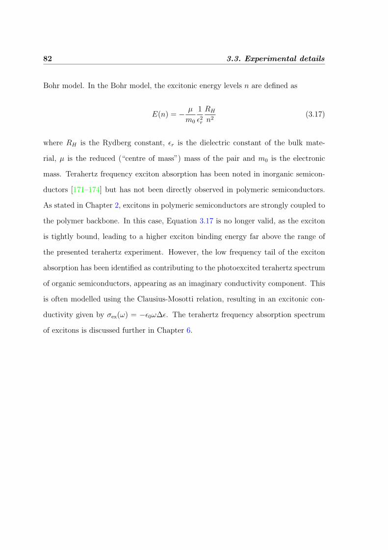
82 3.3. Experimental details
Bohr model. In the Bohr model, the excitonic energy levels n are defined as
E(n) = − µ
m0
1
ε2r
RH
n2(3.17)
where RH is the Rydberg constant, εr is the dielectric constant of the bulk mate-
rial, µ is the reduced (“centre of mass”) mass of the pair and m0 is the electronic
mass. Terahertz frequency exciton absorption has been noted in inorganic semicon-
ductors [171–174] but has not been directly observed in polymeric semiconductors.
As stated in Chapter 2, excitons in polymeric semiconductors are strongly coupled to
the polymer backbone. In this case, Equation 3.17 is no longer valid, as the exciton
is tightly bound, leading to a higher exciton binding energy far above the range of
the presented terahertz experiment. However, the low frequency tail of the exciton
absorption has been identified as contributing to the photoexcited terahertz spectrum
of organic semiconductors, appearing as an imaginary conductivity component. This
is often modelled using the Clausius-Mosotti relation, resulting in an excitonic con-
ductivity given by σex(ω) = −ε0ω∆ε. The terahertz frequency absorption spectrum
of excitons is discussed further in Chapter 6.

Chapter 4
Energy dynamics in
Polymer-intercalated SnS2
nanocomposites
4.1 Background : White-light emitting OLEDs
In this chapter, experimental results of photoluminescence from polymer blends are
presented, and the influence of the dimensionality upon energy transfer is discussed.
In Chapter 1, the huge potential for incorporating organic semiconductors into tradi-
tional optoelectronic applications was introduced. In particular, the field of OLEDs
is well developed, and high efficiency organic light-emitting diodes have been demon-
strated in the literature [8, 9]. One of the advantages of organic semiconductors
over inorganics is the wide tunability of the band-gap through simple changes in the
chemical structure. This has led to a rapid expansion in the applications of full-colour
light-emitting displays incorporating organic materials and fuelled work towards sta-
ble white-light-emitting diodes for solid-state lighting [175]. One promising approach
has been the blending of various conjugated polymers, each with a different emission
83

84 4.1. Background : White-light emitting OLEDs
wavelength [176, 177]. A disadvantage of this method is that ultrafast energy trans-
fer from the high-energy to the low-energy band-gap component of the blend rapidly
quenches the photoluminescence from the blue end of the spectrum. This strong in-
teraction between the components makes such materials extremely sensitive to doping
levels and film morphology, both of which may in turn be influenced by processing
conditions and change over time. An alternative approach suggested by Aharon et
al. [11, 178] is based on the confinement of the polymer blend in the interlayer galleries
of an inorganic semiconducting material that is largely transparent over the visible
spectrum. The formation of quasi-two-dimensional polymer monolayers within this
nanocomposite should inhibit energy transfer between the polymer blend components
allowing stable tuning of the apparent emission colour though changes in the blend
composition, in a process depicted in Figure 4.1. The dimensionality of these systems
plays an important role here, with one-dimensional transfer of excitations along the
chain typically being much slower than that within a three-dimensional polymeric
solid [45, 179–181]. Using this approach, stable white-light emission has recently
been demonstrated for a nanocomposite containing a blend of three polymers emit-
ting in the blue, green and red regions of the visible spectrum [11]. The inorganic
interlayers may have the additional functions of aiding charge carrier injection [11]
and protecting the polymer against degradation through encapsulation. In addition,
the nanocomposites are produced using supramolecular self-assembly of the compo-
nents in solution. This technique coupled with the following results confirm one of
the strongest advantages of organic semiconductors – that of solution processability,
whist retaining morphological control of the final material on the nanoscale.
In this chapter, a study of how the energy transfer dynamics in a conjugated
polymer solid are altered when moving from a three-dimensional (3D) film to a quasi-
two-dimensional (2D) monolayer are studied. This is achieved by intercalation of
optoelectronically active polymers into a SnS2 matrix. Through measuring the de-

4. Energy dynamics in Polymer-intercalated SnS2 nanocomposites 85
a) Normal (unrestricted)
transfer
RED EMISSION
b) Restricted
transfer
WHITE EMISSION P
L e
mis
sio
n e
ner
gy
2.80eV
2.45eV
2.15eV
2.80eV
2.45eV
2.15eV
N
S
x
N
F8BT
x
F8
O
O
x
MEH-PPV
Figure 4.1: The schematic diagram illustrates energy transfer from an initially excitedlarge band-gap (blue emitting) polymer known as the donor, to smaller band-gap (greenand red emitting) polymers known as the acceptor. This can be an extremely fast process;without sufficient care, the smallest band-gap polymer can act as an effective photolumines-cence quenching site for the larger band-gap polymers. By restricting the energy transferbetween polymer chains, emission from all three chromophores can be realised, generatingquasi-white light. On the right, the chemical structure of the three polymers in the blendare given.
cay of the blue-light-emitting polymer component (the “donor”) both in the presence
and the absence of the green- and red-light-emitting polymers (the “acceptor”) the
excitation transfer rate from the donor to the acceptor is experimentally assessed.
Comparison of this data with a simple model that extends Forster’s theory [59] for
resonant dipole-dipole electronic coupling to systems of different dimensionality indi-
cates that polymer-intercalation into an inorganic matrix indeed results in excitation
transfer characteristic for a truly two-dimensional polymeric solid.
4.2 Experimental details
Polymer blend monolayer (2D) samples were fabricated by intercalation of polymer
into SnS2 as described in Reference [11]1. This procedure is based on the exfoliation-
adsorption technique shown in Figure 4.2, in which an inorganic host material (SnS2 in
this case) is delaminated in solution into single sheets that then restack in the presence
1The samples were prepared and supplied by Dr. E. Aharon and Prof. G. Frey of the Technion-Israel Institute of Technology, Israel.

86 4.2. Experimental details
Figure 4.2: The schematic diagram illustrates the processes of exfoliation-intercalation,and the type of layered composite formed when the polymer blend is intercalated betweenlayers of inorganic SnS2 crystal. Taken from the Supporting Information to Reference [11].
of the conjugated polymer. After polymer incorporation, the mixture was repeatedly
washed in organic solvents to remove excess polymer not enclosed in the inorganic
matrix. The resulting material was re-dispersed in xylene and deposited on silica sub-
strates through drop-casting. Wide-angle X-ray diffraction measurements on these
nanocomposites showed a peak corresponding to the 0.58 nm c-axis spacing of SnS2
crystals and an additional peak at a 2θ corresponding to 1.04 nm indicating a crys-
tal interlayer expansion of 0.46 nm through incorporation of the polymer [11]. This
expansion is of similar magnitude to that reported for related polymer-intercalated
materials [182]. It is caused by the tendency of conjugated polymers to adopt a planar
conformation in layered compounds [11] indicating that a single monolayer of poly-
mer forms between SnS2 layers. Three types of nanocomposites were prepared: one
incorporated a blend of blue-light-emitting F82, green-light-emitting F8BT and red-
light-emitting MEH-PPV at a weight ratio of 30:60:10, respectively. Figure 4.1 shows
the chemical structures of the polymers used. A reference composite incorporated only
F8 to allow the examination of the donor luminescence in the absence of the acceptors
and another composite incorporated only MEH-PPV to allow the examination of the
acceptor luminescence in the absence of the donor. In addition, 100 nm-thick (3D)
polymer films were prepared by spin-casting either the F8:F8BT:MEH-PPV blend
2F8 is often referred to as ‘PFO’ in the literature.

4. Energy dynamics in Polymer-intercalated SnS2 nanocomposites 87
or just F8 from solution in xylene onto silica substrates. The molecular weights of
the polymers used were 74000 g/mol and 16000 g/mol for F8 and F8BT (both pur-
chased from American Dye Source) and 50000 g/mol for MEH-PPV (purchased from
Aldrich.)
To investigate the energy-transfer dynamics in these materials, time-resolved pho-
toluminescence up-conversion spectroscopy (PLUCS) was used, as described in Sec-
tion 3.3.1. The excitation energy was set to either 2.88 eV to excite MEH-PPV, or
3.1 eV to excite F8 preferentially. The excitation beam was focused onto a spot size
of 200µm at powers below 1 mW (< 0.4 mJ/pulse/m−2) adjusted to ensure that no
sample degradation occurred during the measurement. All experiments were carried
out with the sample held under vacuum (< 10−4 mbar) and were fully reproducible.
The temporal resolution of the system was approximately 300 fs as determined from
the measured width of the excitation pulse. In this geometry the system detects the
photoluminescence with polarisation parallel to the gate beam, and the excitation
beam was chosen to have a polarisation parallel to this. The time-integrated PL
spectra were measured using an Edinburgh instruments FLS920 spectrometer3.
4.3 Results from time-resolved photoluminescence
spectroscopy
Figure 4.3 shows the time-integrated photoluminescence spectra of F8 and the blend
for (a) the 3D thin film, and (b) the 2D monolayers included in the nanocompos-
ites. For all spectra shown, the samples were excited at an energy of 3.1 eV, creating
excitons mainly on the F8 donor. The F8 thin film and the corresponding nanocom-
posite show an emission peak at 2.82 eV and a progression at 2.67 eV, mediated by
3The time-integrated spectra were kindly measured by Dr. C. Dosche and Professor A. Kohlerof the University of Potsdam, Germany.

88 4.3. Results from time-resolved photoluminescence spectroscopy
0.0
0.2
0.4
0.6
0.8
1.0
1.8 2.0 2.2 2.4 2.6 2.8 3.00.0
0.2
0.4
0.6
0.8
1.0
(b)
Inte
nsity
(nor
mal
ized
)
Energy (eV)
(a)
Figure 4.3: Time-integrated photoluminescence spectra for neat F8 (dashed line, red)and for the F8:F8BT:MEH-PPV blend (solid line, black) for the case of (a) thin-film (3D)samples and (b) SnS2 nanocomposites intercalated with 2D polymer monolayers.

4. Energy dynamics in Polymer-intercalated SnS2 nanocomposites 89
C-C stretch vibrations. However, with addition of the F8BT:MEH-PPV acceptor
the thin-film luminescence becomes dominated by MEH-PPV, whose emission peaks
may be observed at 2.15 eV, 1.96 eV and 1.8 eV, due to vibronic coupling. The almost
complete quenching of both F8 and F8BT luminescence in the blend film indicates
an efficient energy transfer to the polymer with lowest band-gap. The nanocomposite
incorporating the blend, on the other hand, shows contributions to the emission from
all three polymers suggesting that the energy transfer efficiency in the 2D layers of the
nanocomposites is significantly reduced. As a result, the emission from the nanocom-
posite seems white to the eye, in contrast to the red appearance of the emission from
the thin film.
In order to obtain information about the rate (and therefore mechanism) of ex-
citon migration from donor to acceptor, time-resolved photoluminescence measure-
ments were carried out to determine the exciton population on F8 and MEH-PPV.
Figure 4.4 shows the decay of the F8 (donor) emission (at 2.67 eV) for neat F8 and
for F8:F8BT:MEH-PPV blends, both for a thin film (a) and a SnS2 nanocompos-
ite (b) sample. The decay of the PL from the F8 donor in both the thin film and
the nanocomposite becomes more rapid with addition of the F8BT:MEH-PPV ac-
ceptor, confirming that energy transfer occurs from donor to acceptor. The relative
change in this decay rate is considerably more rapid in the thin film samples than
the nanocomposite, suggesting that the nature of the transfer mechanism is strongly
modified when moving from a 3D film to a 2D monolayer. For comparison, Figure
4.5 displays the time-resolved photoluminescence from MEH-PPV (at 2.16 eV) both
for neat MEH-PPV intercalated in SnS2 and for the F8:F8BT:MEH-PPV blend in-
tercalated in SnS2. The neat MEH-PPV incorporated in SnS2 nanocomposite was
directly excited at 2.81 eV and the PL decay is representative of the exciton lifetime
on MEH-PPV in the composite. For the F8:F8BT:MEH-PPV blend intercalated in
SnS2, excitation at 3.1 eV predominantly created excitons on F8. Here, a delayed

90 4.3. Results from time-resolved photoluminescence spectroscopy
0 10 20 30 400.01
0.1
1
0.01
0.1
1
(b) 2D layerPL in
tens
ity (n
orm
alis
ed)
Time delay (ps)
(a) 3D film
Figure 4.4: Time-resolved photoluminescence decay measured at 2.67 eV. Both the PLfrom neat F8 (circles, red) and the PL from F8 in the polymer blend (squares, black) areshown for (a) a 3D thin film and (b) 2D layers incorporated a SnS2 nanocomposite. Thedecay of the F8 emission can be seen to accelerate slightly upon intercalation as F8 alsocouples weakly to the SnS2 matrix, which features an absorption onset in the UV region [11].

4. Energy dynamics in Polymer-intercalated SnS2 nanocomposites 91
Blend nanocomposite
Neat nanocomposite
Figure 4.5: Time-resolved photoluminescence decay measured at 2.16eV. Both the PLfrom neat MEH-PPV intercalated into SnS2 nanocomposite (triangles, green) and the PLfrom MEH-PPV in the polymer blend in SnS2 nanocomposite (circles, red) are shown. Anexcitation energy of 3.1 eV was used for the polymer-blend-SnS2, whilst an excitation energyof 2.8 eV was used for the neat MEH-PPV-SnS2 composite.
rise in the MEH-PPV emission can be observed with an increase in the apparent PL
lifetime, in accordance with energy transfer from the donor. However, the dynamics
of the MEH-PPV emission in the blend are complex, with the exciton density on
the polymer being fed not only by excitation transfer from F8 and F8BT, but also
through direct excitation by the laser pulse that is difficult to quantify accurately. For
the remainder of this chapter I will therefore focus on the somewhat more tractable
analysis of the donor emission from the materials.

92 4.4. Discussion of dimensionality-dependent energy transfer
4.4 Discussion of dimensionality-dependent energy
transfer
Theoretical discussion of energy transfer in π-conjugated donor-acceptor systems gen-
erally relies on electric dipole coupling between the emitting transition moment of
the donor and the absorptive transition moment of the acceptor [183]. The simplest
approximation here is based on interactions between point dipoles, and has been re-
peatedly applied to conjugated polymeric systems [184–188]. For this case, and as
introduced in Section 2.3.2.1, the rate of transfer k was calculated by Forster[59] to
be inversely proportional to the sixth power of the acceptor-donor separation r,
k(r) =1
τ
(R0
r
)6
(4.1)
where τ is the excitation lifetime for the donor in the absence of the acceptor, and
R0 is the Forster radius characteristic for the system. However, for an ensemble
of randomly distributed chromophores, a range of acceptor-donor distances will be
present in the material, requiring an ensemble average to be determined that will also
depend on the dimensionality of the system. To analyse the temporal evolution of
the excitation within this approximation, the procedure outlined by Baumann and
Fayer [185] is followed and applied to the case of a single type of donor. Firstly,
by considering only the de-excitation path for the donor that results from energy
transfer, the probability of an excitation remaining on the donor molecule is defined
as
E(t, r) = e−k(r)t. (4.2)
Re-transfer of excitation from acceptor to donor chromophore can be ruled out as a
result of the negligible spectral overlap of donor absorption with acceptor photolu-
minescence for these materials. In addition, the relatively small overlap between the

4. Energy dynamics in Polymer-intercalated SnS2 nanocomposites 93
donor absorption and its own emission that is typical of conjugated materials with
torsional degrees of freedom [189, 190] allows exciton migration within the donor to
be neglected at the high acceptor concentration employed here. This permits the
simplification of the full treatment by Baumann [185] and Blumen [191] as outlined
in the following. Assuming a random ordering of donors and acceptors, the configu-
rational average of the probability of finding an initially excited donor still excited at
time t is
G(t) =N∏i=1
(1− p) + pE(t, ri), (4.3)
where p is the probability that a site contains an acceptor and the product extends
over N molecular sites. By expanding the logarithm of Equation 4.3, the following is
obtained:
lnG(t) = −∞∑h=1
ph
h
N∑i=1
[1− E(t, ri)]h . (4.4)
The summation over individual sites may then be replaced with an integration over
all space, if a continuous spatial distribution is assumed:
lnG(t) = −ρφ(p,∆)
∫ ∞0
(1− e−k(r)t
)u(r)dr . (4.5)
Here, ρ is a number density of acceptors, φ(p,∆) is a scaling factor related to the
proportion of acceptors p and the number of spatial dimensions of the material ∆, and
u(r)dr is the probability of finding an acceptor molecule within the distance [r, r+dr]
from the donor, multiplied with the dimension-specific volume element. At this point,
the effect of dimensionality of the system enters, with the two-dimensional and three-
dimensional random acceptor distributions given given through u2d(r) = 2πr and
u3d(r) = 4πr2, respectively. By using as substitutions
µ =t
τR6
0 and y =µ
r6(4.6)

94 4.4. Discussion of dimensionality-dependent energy transfer
G(t) may be simplified for the two- and three-dimensional case as
lnG2D(t) = −2πρφ(p,∆)µ1/3
∫ ∞0
(1− e−y)y−4/3dy (4.7)
lnG3D(t) = −4πρφ(p,∆)µ1/2
∫ ∞0
(1− e−y)y−3/2dy . (4.8)
The integral is independent of t and reduces to a gamma function [192]. The time-
dependence of the excitation transfer from the donor, G(t), is solely determined by
µ, which in turn is influenced by the number of spatial dimensions. The expected
time-dependent PL decay of the donor as a result of energy transfer may be expressed
as
G(t) = G0e−(t/t0)α , (4.9)
where the t0 is a system specific time constant related to R0, φ, the acceptor concentra-
tion, and the donor’s excited state lifetime. The dependence of t0 on φ and therefore
the dimensionality complicates the analysis, and prohibits a meaningful value of R0
from being obtained. The exponent α depends on the number of dimensions in which
energy transfer can occur through α = ∆/6, so α = 1/3 and α = 1/2 should be
expected for a two-dimensional and a three-dimensional system, respectively4.
The experimental data displayed in Figure 4.4 is influenced by de-excitation of
the donor through all available mechanisms, while Equation 4.9 is based on energy
transfer as the only pathway. To extract information on just the energy transfer rate
from the data, the decay of exciton population f in the materials containing only the
donor polymer is considered to be described by the following rate equation:
d
dtf = −
(1
τ+ r(t)
)f(t), (4.10)
where τ is the natural exciton lifetime and r(t) is a time-dependent decay rate associ-
4For one-dimensional transfer, α ≈ 0.17 would be expected, significantly outside the range oferrors on the measured values of α.

4. Energy dynamics in Polymer-intercalated SnS2 nanocomposites 95
ated with processes such as exciton diffusion to non-radiative traps within the donor
system. In the presence of the F8BT:MEH-PPV acceptor, the exciton population on
the F8 donor g experiences additional losses,
d
dtg = −
(1
τ+ r(t)
)g(t)−K(t)g(t), (4.11)
where K(t) represents the time-dependent energy transfer rate from donor to acceptor
ensemble. It can be shown [187] that within the point-dipole model described above,
the ratio I(t) = f(t)/g(t) is directly related to K(t), and follows the time-dependence
of G(t) given in Equation 4.9.
Figure 4.6 displays the experimental data for I(t) obtained by division of the F8
emission from the blend by that from the materials containing F8 as the only poly-
mer, both for the case of the 3D polymer film and the 2D monolayer. Superimposed
on the data are the best fits based on stretched exponentials [193] as given by Equa-
tion 4.9 with α, G0 and t0 as free parameters. For monolayers enclosed in the SnS2
nanocomposites a value of α = 0.31± 0.04, while the thin film yields α = 0.47± 0.07,
close to the values of 0.33 and 0.5 to be expected for the case of two-dimensional and
three-dimensional transfer, respectively.
The excellent agreement between this simple model and the experimental data
seems surprising at first, given the complexity of the system. First, one might raise
the question of whether electronic coupling between adjacent polymer monolayers in
the nanocomposites also has to be considered. X-ray diffraction from the compos-
ites [11] points to the existence of extended SnS2 crystalline domains, indicating that
only a fraction of the adjacent crystal sheets incorporate polymer upon restacking in
solution. As a result, the polymer monolayers are sufficiently isolated in the crystal to
be considered as non-interacting two-dimensional systems. Another possible compli-
cation is that phase segregation between the components of the polymer blend might

96 4.4. Discussion of dimensionality-dependent energy transfer
lead to a non-random local distribution both in the solid film and the nanocomposites.
However, photoluminescence microscopy experiments with 200 nm resolution have in-
dicated uniform distribution of all components [11]. In addition, no residual donor
luminescence is observed at long times after excitation, or in the time-integrated spec-
tra, pointing towards a complete transfer of excitation and therefore the absence of
large homogeneous donor domains. The two indicators taken together suggest that
phase segregation, if present, may only exist over distances that are comparable with
the energy transfer range. Whilst the analysis presented above is strictly valid for a
two component system and this sample has three, the effect of having two acceptors
for the F8 donor to transfer energy to only alters the effective lifetime t0 in equation
4.9 and thus has no effect on the extracted dimensionality.
Finally, the validity of the point-dipole approximation used in this derivation
needs to be examined with care. Quantum chemical calculations predict that an ini-
tially created exciton on a conjugated polymer chain is delocalised over a few repeat
units [45, 179]. Subsequent lattice relaxation over a typical nuclear vibration period
will lead to a localisation of the exciton with a resulting wavefunction extent of the
order of one nanometre. Energy transfer over similar length scales is then expected
to deviate from calculations using the simple point-dipole approximation. To over-
come these limitations, alternative models have been based on line-dipole [194] or
distributed monopole [45, 179] approaches. The latter predicts an increase of transfer
rate between two conjugated oligomers in head-to-tail geometry and a decrease for
a cofacial arrangement in comparison with the simpler point-dipole approximation.
The two counteracting effects make it hard to assess qualitatively the overall effect on
a solid comprising an ensemble of conjugated oligomers, while a quantitative picture
would require demanding computational simulations on generated random morpholo-
gies that take proper account of the physical space occupied by the donor and acceptor
molecules. For the systems investigated here, deviations from the point-dipole ap-

4. Energy dynamics in Polymer-intercalated SnS2 nanocomposites 97
0 10 20 30 40 500.0
0.2
0.4
0.6
0.8
1.0
PL in
tens
ity R
atio
(Ble
nd /
Nea
t F8)
Time delay (ps)
Figure 4.6: Excitation transfer transients, defined as the ratio between the photolumines-cence intensity of F8 without acceptor and that with acceptor, shown both for a 3D solidfilm (squares) and 2D monolayers incorporated in SnS2 composites (triangles). The solidlines are numerical fits to the data using the model described in the text.
proximation are most likely to be observed for the 3D solid films, for which chains may
pack cofacially at distances as short as 3 - 8 A [195]. For the SnS2 nanocomposites the
arrangement of a 2D polymer monolayer inhibits such co-facial arrangements leading
to a significant increase in the smallest distances over which excitation transfer may
occur. As a result, the point-dipole approximation is expected to hold for the case of
a 2D polymer monolayer incorporated in this type of nanocomposite.
4.5 Summary
In this chapter, the dependence of dimensionality on the energy transfer in conjugated
polymer blends has been examined. For the three-dimensional blend film, excitation

98 4.5. Summary
transfer from the donor is almost completed within the first few picoseconds. In-
tercalation of quasi-two-dimensional polymer monolayers into an inorganic matrix
results in slower excitation transfer, which occurs over the timescale of a few tens of
picoseconds. For both systems, the transfer dynamics can be described by a stretched
exponential with a dimensionality-dependent exponent. A simple model was outlined
that is based on excitation transfer through electronic coupling between transition
moments considered to be point-dipoles, and takes account of the system dimension-
ality. Comparison with the experimental data indicates that within these approxima-
tions, energy transfer occurs in three dimensions for the solid film, but only in two
dimensions when the polymer is incorporated as a monolayer in the SnS2 nanocom-
posites, as schematically shown in Figure 4.7. The resulting decrease of the overall
rate at which energy is transferred to the lowest-energy component means that emis-
sion is clearly observed from all components of the polymer blend incorporated in the
nanocomposites. Achieving this task through a reduction in system dimensionality
is preferable to strong dilution of the material (e.g. with inert, randomly distributed
nanoparticles) since the former method should maintain a sufficient percolation path
for charges and excitons within the conjugated material. White electroluminescence
has recently been demonstrated for devices based on these nanocomposites [11], mak-
ing such polymer intercalation in an inorganic matrix a promising approach towards
achieving stable colour-tuning of light emitters.

4. Energy dynamics in Polymer-intercalated SnS2 nanocomposites 99
3D transfer
Quasi-2D transfer
Figure 4.7: The proposed difference between three dimensional and quasi-two dimensionalenergy transfer is shown schematically, depicting the confinement of the polymer strandswithin the galleries of the SnS2 matrix.
Chapter 5
Transient terahertz
photoconductivity of Gallium
Arsenide nanowires
In this chapter, the ultrafast carrier dynamics in nanostructured inorganic semicon-
ductors are reported. Whilst in the previous chapter, the nanoscale structure was
provided by self-assembly in solution, to obtain high purity inorganic nanostructures
it is often preferable to use a growth technique such as metal-organic chemical vapour
deposition (MOCVD). Gallium Arsenide nanowires provide an excellent model system
for assessing the change in electronic dynamics upon moving from bulk to nanostruc-
tured material. In particular, the effect of a dramatic increase in surface area-to-
volume ratio represents a step towards the situation required for bulk heterojunction
based optoelectronics (see Section 2.3.3.2). The dominant carrier trapping mecha-
nism was shown to be surface recombination; surface passivation of the nanowires
was carried out to change the surface trap density, and a qualitative agreement be-
tween experiment and theory is shown. In order to investigate the ultrafast electronic
dynamics, the technique of optical-pump terahertz-probe spectroscopy is used, as
100

5. Transient terahertz photoconductivity of GaAs nanowires 101
described in Section 3.3.2.
5.1 Background
An understanding of the dynamics of charge carriers in semiconductor nanostructures
is critical to the use of these materials in electronic and opto-electronic devices. In par-
ticular, semiconductor nanowires show promise as single photon detectors [125, 196],
electrically-driven lasers [124], nanoscale transistors [197] and in dye-sensitised so-
lar cells [126]. In this chapter, the conductivity of photoexcited GaAs nanowires on
sub-picosecond to nanosecond timescales using terahertz spectroscopy is presented.
Specifically, the transient photoconductivity of GaAs nanowires is studied using the
time-resolved terahertz method introduced in Section 3.3.2. To summarise the fun-
damental experimental procedure of using THz-TDS to analyse carrier dynamics in
semiconductors, excited species may be photoinjected into the sample using a pulse
from a femtosecond laser, and the complex conductivity can be tracked using a de-
layed single-cycle pulse of terahertz radiation [198]. The broad bandwidth of ter-
ahertz pulses allows the characterisation of the complex conductivity of a sample
across a frequency range comparable to typical plasma frequencies and momentum
scattering rates in inorganic semiconductors. Recent studies of nanomaterials using
THz-TDS have examined silicon micro- and nano-crystals [165, 199, 200], InP and
CdSe nanoparticles [107, 167] and nanostructured ZnO [201]. The most beneficial as-
pect of the THz-TDS approach is that it is non-contact and therefore avoids artifacts
that may arise in purely electrical measurements from difficulties in making Ohmic
contacts to a nano-sized material. THz-TDS also has a range of advantages over other
ultrafast techniques: for example, time-resolved photoluminescence measurements of
carrier lifetimes in GaAs nanowires are hindered by a large defect density that reduces
the photoluminescence efficiency [131].

102 5.1. Background
Figure 5.1: Scanning electron micrographs of GaAs nanowires on a quartz substrate. Thescale bar (white) represents a) 30µm and b) 2µm; the images were taken at 90 and 45 tothe surface respectively. The random orientation of the nanowires is caused by the lack ofsymmetry of the substrate.

5. Transient terahertz photoconductivity of GaAs nanowires 103
~7µm
50nm
Projection of Nanowires
i)
ii)
iii)
Dir
ect
ion
of
pro
pa
ga
tio
n
of
TH
z p
rob
e p
uls
e
Typical Nanowire geometry
Figure 5.2: This schematic shows the typical geometry of a GaAs nanowires grown ona quartz substrate. The right hand side indicates the three orthogonal orientations of thenanowires with respect to the polarisation of the terahertz electric field T . The geometricalfactor f in the surface plasmon frequency is given by i) f = 1/3 ii) f = 0 for T parallel tothe axis of the nanowire, and iii) f = 1/2.
5.2 Sample characteristics
In this chapter the experimental samples are GaAs nanowires grown from a gold col-
loid seed on a z-cut quartz substrate [202]1. The scanning electron micrograph (SEM)
image of the sample (Figure 5.1) shows an isotropic array of nanowires with gold
nanoparticles visible on the tips. An average areal density of ∼ 3 nanowires µm−2,
wire length of 5−10µm and areal fill fraction of 10±2% was determined from multiple
SEM images, with wire diameters of 50-100 nm. A typical nanowire is shown in the
schematic in Figure 5.2. The dynamics of photoexcited electrons was measured by
time-resolved THz-TDS, using a setup described in an earlier chapter (Section 3.3.2).
Figure 5.3 shows the pump-induced change in the peak of the terahertz electric field
pulse transmitted through the sample (∆T/T ) as a function of time t after excita-
tion. Over the first 5 ps, at an excitation-pulse fluence of 1.3 mJcm−2 (squares), the
nanowires exhibit a non-exponential decay in conductivity, which is proportional to
the ∆T/T . In comparison, bulk GaAs has a mono-exponential carrier lifetime of
1The samples and micrograph images in this experiment were prepared by Dr. M Gao and Prof.C Jagadish at the Australian National University, Australia.

104 5.2. Sample characteristics
−1 0 1 2 3 4 50
2
4
6
8
10
Pump−probe delay t (ps)
∆ T
/ T
(×
10−
4)
Figure 5.3: Pump-induced change in peak transmitted terahertz electric field (∆T/T )for different pump-probe delays t, for GaAs nanowires excited at 800 nm with an incidentpump fluence of 44µJcm−2 (red crosses) and 1.3 mJcm−2 (blue squares). Solid lines indicateexponential fits, used to extract conductivity decay times shown in Figure 5.8g). The dashedblack line is for bulk GaAs at 1.3 mJcm−2 but reduced in scale by a factor of 75. A weaklaser pre-pulse is responsible for the non-zero ∆T/T at t < 0.
∼3.5 ns at the same pump fluence, as Figure 5.4 indicates. The substantially shorter
conductivity dynamic for GaAs nanowires is a consequence of carrier trapping at
surface defects, and underlines their potential for use in ultra-fast nano-scale opto-
electronic devices. The shape of the decay in ∆T/T alters with the pump fluence,
tending to a faster, mono-exponential conductivity decay at lower pump fluence, as
illustrated for 44µJcm−2 in Figure 5.3 (circles). This effect results from surface trap
saturation, as discussed in more detail below.
By fixing the pump-probe delay t and recording the change in terahertz transmis-

5. Transient terahertz photoconductivity of GaAs nanowires 105
0 250 500 750 1000
10−4
10−3
Pump-probe delay t (ps)
∆ T
/ T
÷75
Figure 5.4: ∆T/T up to t = 1 ns for the nanowires (squares) and bulk GaAs (blackline, ÷75) at the higher (1.3 mJcm−2) pump fluence. In both cases ∆T/T exhibits a slowexponential decay with τ > 1 ns at long delay times.
sion, the frequency-dependence of the photoinduced conductivity ∆σ(ω, t) of GaAs
nanowires was determined, providing a time-resolved monitor of quasiparticle dynam-
ics in the material. An expression derived from standard thin-film optics was used
to obtain ∆σ(ω, t) from ∆T (ω, t)/T (ω, t), as explained in Appendix A. Figure 5.5
shows the extracted complex conductivity, at several early pump delay times after
the photoinjection of carriers. Here, the real part of ∆σ(ω, t) may be thought of as
the resistive response of the nanowires, with the imaginary part being associated with
an additional capacitive or inductive response. During the first 200 fs after excitation
the real part of the conductivity is positive and has no discernible frequency depen-
dence (Figure 5.5a). This indicates the presence of photogenerated free carriers with
a large scattering rate. However, over the next 300 fs a peak appears in the real part
of the conductivity (Figure 5.5a), accompanied by a corresponding zero crossing in
the imaginary part (Figure 5.5b). The frequency of this feature decreases with delay
time t, and it is therefore attributed to a carrier-density dependent mode such as a
localised surface plasmon (LSP) [203], rather than an excitonic transition [171, 204].
At later times t > 2 ps, this resonance has shifted below the frequency resolution of
the system, returning to a free-carrier type response at the longest delay accessible
using the current experimental setup (1 ns – not shown).

106 5.2. Sample characteristics
10
15
20
−10
0
10
10
15
20
−10
0
10
10
15
20
Rea
l[ ∆
σ(ω
,t)
] (Ω
−1cm
−1)
−10
0
10
Imag
[ ∆
σ(ω
,t)
] (Ω
−1cm
−1)
10
15
20
−10
0
10
0.5 1 1.5
10
15
20
Frequency ω/2π (THz)0.5 1 1.5
−10
0
10
Frequency ω/2π (THz)
t = 50fs
350fs
500fs
650fs
1.2ps
Figure 5.5: Time-resolved conductivity of photoexcited electrons, and the carrier densityand scattering rate extracted from the plasmon model described in the text. The a) realand b) imaginary components of the conductivity are given at a series of pump-probe delaytimes, for an incident pump pulse fluence of 1.3 mJcm−2. The circles are the raw data andthe lines are fits including both plasmon and plasma responses. The parameters extractedfrom these fits are shown in Figure 5.6.

5. Transient terahertz photoconductivity of GaAs nanowires 107
0.1 0.2 0.3 0.4 0.5 0.6 0.70
5
10
15
Pump−probe delay t (ps)
N (1
016cm
−3)
0.1 0.2 0.3 0.4 0.5 0.6 0.70
2
4
Pump−probe delay t (ps)Scat
terin
g ra
te (1
013
s−1)
Figure 5.6: Figure a) gives the total carrier density Nplasmon + Nplasma (squares), withan exponential fit (green line) with time constant 270 fs drawn as a guide to the eye. Thefilled area is the carrier density Nplasmon contributing to the plasmonic response. Figureb) shows the scattering rate (squares), with an exponential decay (solid line) with timeconstant 178 fs.
5.3 Discussion
Numerous models of features in ∆σ(ω, t) have been proposed, including: localised
surface plasmon (LSP) modes [165], transitions between excitonic states [171] and the
Drude-Smith model, which introduces a further parameter cn related to incomplete
randomisation of carrier momentum upon scattering [168]. While the Drude-Smith
model can produce comparable shapes of the frequency-dependent conductivity to
the surface plasmon model (when c1 ∼ −1, cn>1 = 0), it would require a time-
varying backscattering parameter to model the data, which has no obvious physical
origin. By utilising the surface plasmon approach to model the conductivity, a sound
physical basis for the observed conductivity is provided. Terahertz radiation can
couple into the (normally forbidden) plasmon mode due to the narrow width (50 nm)
of the nanowires, and the interaction between the modes on adjacent sides of the
same nanowire [203]. The emergence of collective modes such as LSPs is expected

108 5.3. Discussion
to occur for nanoparticles, where the carrier dynamics are dominated by surface
effects [165, 205].
LSP modes are coherent oscillations of the electron-hole plasma, modified from the
bulk plasma frequency by the interaction with the plasma/dielectric surface interface.
The relationship between the carrier density N and the plasmon frequency ωpl is
given by ω2pl = (fNe2) /ε0ε∞m
∗. Here, m∗ is the effective electron mass, ε∞ the
high-frequency dielectric response of the nanowires, and f is a factor dependent upon
the surface geometry and the surrounding dielectric medium [136]. For a terahertz
electric field T polarised perpendicular to the axis of a cylindrical nanowire in vacuum,
f = 1/2 or f = 1/3 (see the schematic in Figure 5.2), while for T parallel to the
nanowire’s axis, f = 0, and the only conductivity response is due to the bulk plasma
mode. The complex conductivity of a free-electron plasma with a plasmon resonance
is given within the Drude framework by [165]
σ(ω) =iNe2ω
m∗(ω2 − ω2
pl + iωγ) , (5.1)
where ωpl is the plasmon frequency (determined by the relationship given above) and
γ is the momentum scattering rate. For an ensemble of nanowires oriented at random
angles a contribution to the photoinduced conductivity will be dominated by two
different modes: a plasmon at ωpl and the bulk plasma at ωpl = 0. In order to model
the measured ∆σ(ω, t) these two contributions to the conductivity of the form given
in Equation 5.1, one with a carrier density Nbulk and f = 0 for the bulk mode and
another with carrier density Nplasmon and f = 1/2 (as the f = 1/3 mode presents
negligible surface area) are added together. The scattering rate γ is assumed to be
the same for both modes. Excellent fits to the measured data are obtained over the
full range of pump-probe delays t, as indicated by the solid lines in Figure 5.5. The
carrier densities and scattering rates extracted are shown as a function of pump-probe
delay in Figure 5.6a) and b) respectively. While the carrier density in the bulk-like

5. Transient terahertz photoconductivity of GaAs nanowires 109
mode is observed to form rapidly, that in the plasmon mode has only built up after
300 fs. In bulk GaAs, the free-electron plasma response develops over a timescale
comparable with the inverse of the plasma frequency [206]. The plasmon frequency
is lower than that of the plasma, consistent with the observed longer formation time
for the nanowires. In Figure 5.6b) the scattering rate can be seen to decrease initially
with t, before remaining roughly constant at 1013 s−1 for t > 400 fs. From the ex-
tracted scattering rates it is possible to determine the charge carrier mobility µ in the
long-time limit within the Drude model (µ = em∗−1γ−1) to be 2600 cm2V−1s−1. Re-
markably, this value is only a factor of three lower than typical electron mobilities in
bulk GaAs at room temperature(∼8000 cm2V−1s−1) [163], high-lighting the prospect
of implementation of these structures in fast nanoscale electronics and optoelectronics.
5.3.1 Pump fluence dependence of conductivity
The observed drop in the carrier density with time is indicative of the ultrafast trap-
ping or decay of the surface carrier population. An experiment using a fixed pump-
probe delay (t = 550 fs) and a range of incident pump fluences F was carried out
to allow comparison between plasmon frequencies ωpl deduced from experiment with
those anticipated assuming linearity between the pump fluence and photoexcited car-
rier density. The plasma frequencies extracted from fits to the conductivity spectra
(Figure 5.8a-e) using the previously discussed model are plotted in Figure 5.8f) as a
function of pump fluence. While the plasmon frequency increases with pump fluence,
it does not scale according to ωpl ∝√F ∝
√N . This suggests that the photoexcited
carrier density in the first 550 fs is non-linear with respect to fluence. Such behaviour
may be expected, due to either band-filling or ultrafast trapping and trap-state filling
within the first 550 fs and the subsequent effect upon carrier numbers that are able
to take part in the collective surface mode.
Since surface trapping strongly affects the carrier lifetime, it is essential to obtain

110 5.3. Discussion
0 1 2 3 4 5
10−4
10−3
Pump−probe delay (ps)
∆ T
/ T
Figure 5.7: The pump-induced change in terahertz transmission is shown for a rangeof incident pump fluences (from a low of 0.05 mJcm−2 to a high of 1.1 mJcm−2). A singlemono-exponential fit is shown (solid lines) between 0.8 and 1.8 ps, providing a good fit overthis time range.
an estimate of the surface trap density in order to calculate the carrier density at which
saturation has an effect. To investigate this behaviour, mono-exponential curves were
fitted to a range of pump-probe scans over the time window t = 0.8 − 1.8 ps (see
Figure 5.7) with the resulting decay times shown in Figure 5.8g). A clear dependence
of the carrier relaxation time on pump fluence can be seen, with a doubling in the
trapping time τ when the incident pump fluence is increased 30-fold. As the mobility
remains constant over the examined time interval, this change is primarily due to
saturation of the surface traps by the large photoinduced carrier population, leading
to a reduction in available trap states with increasing pump fluence. For a more
quantitative analysis, these data were fitted with the numerical solution of a rate
equation for carrier trapping [200] that included a finite number of available traps
and yielded a trap density of Ntraps = 2 × 1017 cm−3 and a trapping cross-section of
6 × 10⁻¹⁴ cm2 (solid line in Figure 5.8g). The extracted trap density is comparable
to the initial photoinjected carrier density, explaining the distinct change in carrier
lifetime with pump-fluence as the carrier density passes this mark.

5. Transient terahertz photoconductivity of GaAs nanowires 111
0
20
0
20
0
20
Rea
l [ ∆
σ(ω
,E)
] (Ω
−1cm
−1 )
0
20
0.5 1 1.50
20
Frequency ω/2π (THz)
a)
b)
c)
d)
e)
0 0.5 1 1.50
0.5
1
1.5
2
√ Pump Fluence (√mJcm−2)
Plas
mon
fre
quen
cy (
TH
z)
10.8
1
1.2
1.4
1.6
1.8
Pump Fluence (mJcm−2)
Dec
ay ti
me
(ps)
f)
g)
Figure 5.8: Pump-fluence dependence of terahertz conductivity at a pump-probe delayt=550 fs. Real part of photoinduced conductivity after excitation with various pump ener-gies: a) 2 mJcm−2, b) 1.1 mJcm−2, c) 0.79 mJcm−2, d) 0.57 mJcm−2 and e) 0.42 mJcm−2,where points are raw data, and solid lines are from the model described in the text. Figuref) shows the extracted plasmon frequency ωpl as a function of pump fluence F (circles) incomparison with a prediction from ωpl ∝
√F ∝
√N . Figure g) gives the lifetime of the
conductivity as a function of incident pump fluence extracted from exponential fits to aseries of pump-probe delay scans. The rate equation model described in the text (solid line)accurately reproduces the fluence-dependence of the carrier lifetime.

112 5.4. Surface Passivation
5.4 Surface Passivation
The surface trap states in inorganic semiconductors are well studied, and the be-
haviour of devices based upon GaAs has been improved by chemical treatments that
remove the surface layer and passivate the interface, such as bipolar transistors [207]
and photoconductive antennas [133]. Passivation is understood to prevent surface
atoms forming defect states within the band gap, which in turn reduces the surface
recombination rate; an in depth investigation of the mechanism behind the electronic
effect of surface passivation is beyond the scope of this work – an interested reader
can find more information in good reviews of this area [130, 208]. Assuming the car-
rier velocity and trap scattering cross-section remain unchanged, surface passivation
can be understood to change only the surface trap density and surface recombina-
tion velocity. Terahertz measurements of carrier lifetime in bulk GaAs have shown
as large as a 17% reduction in surface trap density by etching and passivation with
Ammonium Sulfate [133], however, to date there have been no similar measurements
for nanostructured GaAs. In this section, the effect of surface passivation upon the
physical structure, and the carrier lifetime (and hence trap density) of the nanowires
are investigated.
5.4.1 Etch and passivation protocol
The purpose of etching before the passivation step is to remove the surface oxide
layer. Ammonium Sulfate ((NH4)2S) is also weakly acidic, and will etch the surface
layers of GaAs, albeit at a slow rate. Three samples were prepared from nanowires
grown during a single run – a reference unpassivated sample, nanowires passivated
in a 2 vol% aqueous solution of Ammonium Sulfate (for 10 minutes), and a sample
etched in a 4 vol% solution of Hydrochloric Acid (HCl) in distilled water (for ∼2
seconds) before the passivation step. After passivation or etching, the sample was

5. Transient terahertz photoconductivity of GaAs nanowires 113
washed immediately in distilled water before being dried in a steady nitrogen gas
flow. The optical-pump terahertz-probe spectroscopy of the samples were measured
under vacuum, however, the samples were stored in air between measurements to
investigate the effect of de-passivation.
High-resolution SEM images of the three samples are shown in Figure 5.92. Little
difference can be seen between the reference and passivated samples, however, a
large change in sample morphology occurs during the etching process. Even at the
low etchant concentration and exposure times given above, it appears that etching
removes the nanowires from the surface of the sample. As will be shown, this has
little effect upon the terahertz photoconductivity of the sample, indicating that the
nanowires remain on the substrate but now lie in the plane of the substrate (as can
be seen faintly in Figure 5.9c). This may have the effect of leading to a stronger
interaction with the terahertz probe, due to the elimination of the “type i” nanowires
depicted in Figure 5.2. For this reason, the carrier lifetime rather than the peak
photoconductivity value is used as an indication of trap density for the remainder of
this section. More research is currently being undertaken to optimise the etching and
passivation protocol.
5.4.2 Carrier lifetime
The time-resolved photoconductivity of the reference and the passivated sample are
shown in Figure 5.10. The effect of passivation has been reported to lead to both a
large increase in peak photoconductivity and an extension in carrier lifetime [133],
and both effects are observed in this system. However, here the effects appear small,
with only a marginal increase in lifetime or peak signal observed. This may well
be a result of bypassing the etching step, and a large proportion of the surface is
likely to remain oxidised. To allow comparison to the data shown in Figure 5.8g), a
2The SEM images were prepared by Dr. M Gao of the Australian National University, Canberra.

114 5.4. Surface Passivation
Figure 5.9: A series of high-resolution SEM images of the a) reference nanowires beforetreatment, b) passivated nanowires, before etching and c) etched and passivated nanowires.The scale bar represents 1µm, and the micrographs were taken at 45 to the sample normal.Many fewer nanowires are visible after etching than in the unetched cases. However, severalfaint nanowire shapes are visible in the background showing it is possible that the nanowireswere weakened by the etching process leading to mechanical instability, and may remain onthe quartz substrate.

5. Transient terahertz photoconductivity of GaAs nanowires 115
pump-fluence dependence experiment was carried out over a large range. Figure 5.11
shows the extracted mono-exponential decay constant as measured between 1.6 and
6 ps after photoexcitation. The dashed lines are a fit to a simplification of the model
for carrier lifetime shown in Reference [200] and used earlier, where
τtrap =τtrap0
1−N/Ntrap
. (5.2)
Here, τtrap0 is the carrier lifetime at negligible photoinjected carrier density, such that
the traps act independently of fluence, N is the photoexcitation density and Ntrap
is the trap density. This equation is valid in the carrier density regime below trap
saturation – since the lifetime in bulk GaAs is of the order of 3 ns and the maximum
carrier lifetime seen here is 12 ps, this restriction is satisfied. While this is a rather
crude model (it does not take variation in the surface recombination velocity into
account, which is known to change upon passivation), it does qualitatively reproduce
the carrier lifetime in Figure 5.11, providing values of Ntrap of between 8× 10¹⁸ and
11 × 1018 cm−3. These values are significantly larger than those seen in the earlier
experiments; this may be accounted for by the use of a more simple model, or variation
between sample growth runs or in storage conditions. Regardless, a trend towards
lower surface trap density is observed upon surface passivation, and a 28% increase
in carrier lifetime is seen in the etched and passivation case.
5.4.3 Stability of surface passivation
Sulphur passivation of GaAs is known to be partially unstable in oxygen, as previously
noted in References [133] and [132]. In order to test the effect of de-passivation in
the nanowires sample, an additional sample was prepared by passivating (without
the etching step). The carrier lifetime was measured (at fixed incident fluence of
56 mJcm−2) over several days. The sample was stored in air between measurements, to

116 5.5. Summary
0
0.1
0.2
0
1
2
∆ T
/ T
−1 0 1 2 3 4 5 6 7
0
5
10
Pump−probe delay (ps)
Low: 2.1µJ/cm−2
Mid: 28µJ/cm−2
High: 330µJ/cm−2
Figure 5.10: The time-resolved photoconductivity of pre- and post-treatment nanowires isshown (red crosses and blue circles, respectively) for three different photoexcitation fluences.The passivated sample has a consistently higher peak conductivity, and slower carrier decayfor all fluences shown.
allow oxidation and de-passivation. Figure 5.12 shows the results of this experiment;
an initial rise in carrier lifetime is seen due to the passivation process (as expected),
followed by a return towards the unpassivated value over the next 17 days. The
de-passivation timescale is similar to that previously seen in the literature.
5.5 Summary
In summary, the work reported in this chapter involves measuring the transient ter-
ahertz conductivity of GaAs nanowires on sub-picosecond to nanosecond timescales
using a non-contact optical probe based on time-domain spectroscopy. The observed
conductivity dynamics differ strongly from those for bulk GaAs, displaying ultra-short
(∼1 ps) lifetimes that depend critically on the trap density at the nanowire surface.
These results open the possibility for implementation of these nanowires in ultra-fast
switching devices, whose properties can be optimised through a multitude of mecha-
nisms such as overcoating the nanowires with a higher band-gap material [131, 209]

5. Transient terahertz photoconductivity of GaAs nanowires 117
101
102
2
4
6
8
10
12
Dec
ay c
onst
ant (
ps)
Incident Fluence (µJ cm−2)
Untreated GaAs nanowires10mins passivationHCl + Passivation
9.92e+18 cm−3
8e+18 cm−3
1.12e+19 cm−3
Figure 5.11: A monoexponential decay constant was fitted to the time-resolved photoin-duced conductivity measurements for all three samples. The solid lines are a fit as describedin the text, and the labels give the calculated surface trap density for the three samples.

118 5.5. Summary
Unpassivated 0 1 2 3 4 5 6 7 8 9 10 11 12 13 14 15 16 17 18
1.4
1.6
1.8
2C
arri
er d
ecay
con
stan
t (ps
)
Days in airPassivated
Figure 5.12: The monoexponential decay constant is shown for a second sample, beforeand after treatment and after several hours stored in air. A slow return toward the unpassi-vated state is seen, however, after 168 hours the carrier lifetime remains around 10% longerthan in the unpassivated case. The error bars represented the uncertainty in the value ofthe carrier decay constant.
or chemical passivation of surface defects [133]. A preliminary study of the effects
of surface passivation was carried out, and whilst a qualitative decrease in surface
trap density was noted for passivated samples, optimisation of the passivation pro-
tocol is required before a in-depth study is possible. The electron mobility for the
nanowires at room temperature was extracted from the data by modelling of the
plasmon resonance that forms within the first 300 fs after excitation. The resulting
value of 2600 cm2V−1s−1 is only a factor of three lower than that typical for bulk
GaAs, demonstrating that high-quality epitaxial growth can generate nanowires with
excellent electronic properties.

Chapter 6
Sub-gap optical-pump
terahertz-probe studies of
Polymer:Fullerene blends
In this chapter, the time-resolved photoconductivity of polymer-fullerene bulk hetero-
junctions is investigated. As stated in Section 2.3.3.2, photovoltaic cells incorporating
a large-area heterojunction formed between an organic polymer and an electron accep-
tor have shown solar to electric power conversion efficiencies of up to 4–6%, and repre-
sent a promising technology for future power generation [89, 92]. It is known that the
interface not only provides an energetically favourable exciton dissociation site, but
also allows excitation states to exist that do not occur in either bulk component [88].
Some of the highest photovoltaic charge generation efficiencies measured have been
produced by blending organic semiconductors such as P3HT [poly(3-hexylthiophene)]
or a PPV [poly(phenylenevinylene)] derivative with PCBM (a methanofullerene), and
this chapter investigates the terahertz-frequency photoconductivity in these systems.
By measuring the photoconductivity for both above- and below-gap excitation, a
surprisingly high charge generation efficiency is noted for sub-gap excitation [210].
119

120 6.1. Background: Organic photovoltaics
The advantages of the non-contact terahertz measurements are again noted, allowing
simple measurements to be made of nanoscale properties.
6.1 Background: Organic photovoltaics
Polymer-fullerene blends have attracted considerable interest because they are very
easy to process from solution, making roll-to-roll production of flexible photovoltaics
a possibility [83–85, 91, 100, 211]. The primary characteristics required of high effi-
ciency photovoltaics include: an absorption spectrum that provides a good overlap
with the solar spectrum, and a balance between DC voltage and harvesting light,
fast electron transfer from charge donor to acceptor, a high photon to charge car-
rier branching efficiency, and high carrier mobility. It is well known that many
factors influence the efficiency of these devices, for example, chain arrangement in
the solid [212], polymer regio-regularity [100], the ratio of polymer to charge accep-
tor [112], and post-process thermal annealing [78, 91]. Therefore, for the optimisation
of photovoltaic device efficiencies a detailed knowledge of the mechanisms of charge
generation and subsequent motion through the material is essential.
A number of studies have attempted to identify the microscopic origin and cause
of charge generation and charge carrier mobility in organic semiconductors [106,
110, 111, 113, 117, 157, 213–219]. Relatively large carrier mobilities have been
proposed, however, there has been disagreement in the literature caused partly by
differences between the experimental methods used to investigate carrier dynam-
ics. Measurements carried out on photovoltaic devices, whilst revealing the real-
world behaviour of the materials, suffer from difficulties in interpretation arising from
the presence of an interface between the electrodes and the polymer [220]. Non-
contact measurements, including transient absorption [215, 219], photoluminescence
up-conversion [86, 214, 221], time-resolved microwave-conductivity [106, 110, 111,

6. Sub-gap OPTP studies of Polymer:Fullerene blends 121
213, 218] and terahertz time-domain-spectroscopy [112–115, 117, 157, 216, 217] have
also been used to great effect. A range of values for high-frequency electron and
hole mobility from 10−5 cm2V−1s−1 to over 600 cm2V−1s−1 have been proposed for
a variety of conjugated polymers; such a large degree of variation suggests that re-
sults are very sensitive to both experimental technique and the models used in the
analysis [96, 106].
In this chapter, two time-resolved optical-pump terahertz-probe (OPTP) spec-
trometers have been used to observe the fluence and wavelength dependence of charge
generation and carrier mobility in neat and PCBM-blended organic polymer films,
as described in Section 3.3.2. Using this approach the complex photoconductivity of
two state-of-the-art organic photovoltaic materials was measured, thin films of either
P3HT or poly[2-methoxy-5-(3,7-dimethyloctyloxy)-1,4-phenylenevinylene] (MDMO-
PPV) blended with PCBM. This study examines the dependence of the photoinduced
conductivity on time after excitation, frequency of the driving terahertz radiation, and
excitation fluence and wavelength. In later sections, attention is paid to the implica-
tions of these results for photogeneration efficiencies, carrier mobilities and lifetimes
and find qualitatively similar results for both polymers investigated.
The OPTP measurements of organic semiconductors reported to date have em-
ployed pulsed laser amplifier systems, resulting in high excitation fluences of up to
6 mJ cm−2. This approach produces carrier densities in the region of 1021 cm−3, how-
ever, second-order effects such as bimolecular excitonic or charge annihilation have
been shown to occur at carrier densities as low as 1016 cm−3 [111]. In addition, this
process inevitably leads to excitation fluences that are many orders of magnitude
above those typically encountered under natural conditions such as sunlight. Conclu-
sions drawn from such experiments may therefore have limited applicability to mate-
rial performance in a typical device structure. This has been circumvented by utilising
a low-fluence, high-repetition rate system, which allows observation of the photoin-

122 6.1. Background: Organic photovoltaics
duced conductivity changes for excitation fluences as low as 24 nJ cm−2 with a good
signal-to-noise ratio. In combination with the results derived from an amplifier-based
OPTP system, this allows an examination of the photoinduced terahertz conductivity
for excitation fluences ranging over more than four orders of magnitude.
A further difficulty encountered with OPTP measurements has been the use of
polymer films that are thick in comparison with the absorption depth at optical pump
wavelengths, to maximise the absorbed photon fluence and the resulting signal-to-
noise ratio [112, 216]. However, this practise leads to an exponential distribution of
carriers in the direction of terahertz propagation, which complicates the data anal-
ysis and extraction of the photoconductivity [117, 162]. In the experimental study
reported here, I have taken a different approach by exciting with photons of low
energy, i.e. significantly below the peak of the π − π∗ transition of both polymers.
Under these conditions a uniformly distributed density of photoexcitations is created,
whose spectral and temporal OPTP response is remarkably similar to that of charges
generated using excitation near the absorption peak. The observation of a low-energy
feature in absorption and photoluminescence measurements has recently led to the
suggestion that such low-energy photons may create a weakly bound polaron pair
formed between the highest occupied molecular orbital (HOMO) of the polymer and
the lowest unoccupied molecular orbital (LUMO) of the PCBM [87]. The measure-
ments presented here reveal a surprisingly high photoconductivity upon excitation of
this low-energy feature, suggesting that the polaron pair may offer an efficient direct
route to photoexcitation of charges in the polymer blends, in agreement with recent
conclusions by Benson-Smith et al. [88].

6. Sub-gap OPTP studies of Polymer:Fullerene blends 123
6.2 Sample preparation
P3HT (Mw=28000 g/mol, >95% regio-regularity), MDMO-PPV (Mw=718000 g/mol)
and PCBM were purchased from American Dye Source and used without further pu-
rification. The chemical structures of all components can be found at the top of
Figure 6.1. Each material was separately dissolved in dichlorobenzene at a concen-
tration of 15 gl−1 and polymer-fullerene blends were derived by mixing the relevant
solutions at a 1:1 ratio by volume. To produce films, the solutions were spun-cast or
drop-cast onto z-cut quartz substrates for optical density measurements or terahertz
measurements, respectively. Thick (d ∼10µm) drop-cast samples were required for
the terahertz measurements to ensure sufficiently high photoinduced conductivity for
the case when the absorption coefficent and the photon to charge branching ratio was
small (e.g. for the neat unblended samples). All samples were dried and annealed
at 100 C for 3 hours. Materials were handled and samples were prepared in an in-
ert (N2) atmosphere. Thin-film transmission measurements were performed using a
spectrophotometer (Perkin-Elmer Lambda 9), and the film thickness was measured
using a step-profilometer (Veeko DekTak 7).
Optical-pump terahertz-probe measurements were taken using two different ter-
ahertz spectrometers. The high-fluence spectrometer used a regenerative amplifier
(800 nm centre wavelength, 1kHz repetition rate, 50 fs pulse duration, 1 mJ pulse en-
ergy). The terahertz probe was generated through optical rectification in a 2mm-thick
ZnTe crystal, and detected using electro-optic sampling in a 1mm-thick ZnTe crys-
tal. Photoexcitation of the sample was carried out either using up to 500µJ/pulse of
the 800 nm fundamental, or the output from a TOPAS optical parametric amplifier,
providing around 30µJ/pulse at 560 nm. To measure the low-fluence photoconduc-
tivity, a Ti:Sapphire laser oscillator (800 nm centre wavelength, 80 MHz repetition
rate, 100 fs pulse duration, 12 nJ pulse energy) was used both to photoexcite the
sample and to generate and measure the terahertz probe. The terahertz probe was

124 6.2. Sample preparation
System λ Rep. Rate Power Energy/pulse(nm) Hz (period) min/max (W/cm2) min/max (µJ/cm2)
Amplifier 800 1000Hz (1 ms) 0.065/0.425 65/425560 1000Hz (1 ms) 0.075 210
Oscillator 800 80MHz (12.5 ns) 1.9/51.2 0.024/0.642
Table 6.1: A summary of the OPTP spectrometer systems used in this study. In par-ticular, note the short inter-pulse period with the oscillator system. The sharp increasein incident power using the oscillator system arose from a tighter focus of both pump andprobe beams made possible by a four focusing mirror arrangement, as opposed to the threemirror arrangement in the amplifier system (see Section 3.3.2 for more details).
generated in a biased photoconductive switch, and measured using electro-optic sam-
pling in a 2mm-thick ZnTe crystal – full details of this set-up are provided in Refer-
ence [133]. All measurements were made under vacuum (< 10−3 mbar) to minimise
photo-oxidisation; no sample degradation was seen during these experiments. A sum-
mary of the photoexcitation sources used is given in Table 6.1.
To recap upon Section 3.3.2, in an optical-pump terahertz-probe experiment the
photoinduced change in the transmitted terahertz electric field amplitude, ∆T/T , is
measured also as a function of pump-probe delay. The following relatively simple
calculation derived from thin-film optics allows reconstruction of the photoinduced
change in sample conductivity ∆σ from this change in transmission ∆T/T , only
requiring knowledge of the excited sample thickness d and the substrate refractive
index n:[160]
∆σ =1 + n
Z0d
(1
1 + ∆T/T− 1
), (6.1)
where Z0 is the impedance of free space. For excitation at 800 nm, a uniform dis-
tribution along the sample depth is created and d represents the film thickness. For
excitation at 560 nm, a uniformly excited block, as thick as the penetration depth d,
was assumed to exist upon an unexcited P3HT substrate of refractive index n=3.23
in the THz region [222, 223]. For ease of examination, the experimental results
shown throughout this chapter were converted from the measured ∆T/T to pho-

6. Sub-gap OPTP studies of Polymer:Fullerene blends 125
toinduced conductivity units. Both of the principal modes of operation of a optical-
pump terahertz-probe experiment were employed for the measurements; in the fol-
lowing these are referred to as fixed-gate and fixed-pump mode. For the fixed-gate
mode, the photoinduced change in peak terahertz transmission, which is related to
the frequency-averaged photoinduced conductivity of the sample, is measured as a
function of pump-probe delay. The resulting data are measures of the transient con-
ductivity as a function of time after excitation and may yield information on free
carrier lifetimes and the evolution of the charge mobility. Additional information
can be extracted through operating the experiment in fixed-pump mode – here, the
photoinduced change in terahertz time-domain electric field is measured at a fixed
pump-delay. From this measurement, the real and imaginary parts of the photocon-
ductivity spectrum across the terahertz range can be determined for a set time after
excitation of the sample.
Figure 6.1 shows the thin-film absorbance spectra for neat and PCBM-blended
P3HT and MDMO-PPV. For both polymers, the addition of PCBM introduces a
characteristic absorption at 340 nm. In the present chapter, I will distinguish be-
tween photoexcitation with energy above and below the polymer absorption on-set
as above-gap and below-gap, respectively. Knowledge of the absorption depth coupled
with the incident optical-pump fluence and sample thickness permits calculation of
the initial photoexcitation density. However, at the low-energy tail of the displayed
spectra the measured non-zero absorbance is most likely dominated by the effect of
scattering from the film, rather than electronic transitions in the material. Recent
results using this technique have demonstrated the existence of a sub-gap absorption
feature near 800 nm for P3HT:PCBM blends [87]. In order to obtain a correct mea-
sure of the photoinduced excitation density for the study presented here, the thin-film
absorbance measurements shown in Figure 6.1 were used for above-gap excitation,
while for below-gap excitation the absorbance was derived from the Photothermal

126 6.3. Experimental Results
PCBM MDMO-PPV P3HT
C H3
C H3
C H3
C H3
MeO
n
O
S
S
a)
b)
3.5 3 2.5 2 1.5
0
2
4
6
8
10
Energy (eV)
400 500 600 700 8000
2
4
6
Wavelength (nm)
Abso
rpti
on c
oef
fici
ent
(×10
4)
(cm
-1)
Figure 6.1: Absorption spectra for thin films of a) neat P3HT (black line) and theP3HT:PCBM blend (red line) and b) MDMO-PPV (blue line) and the MDMO-PPV:PCBMblend (green line). Vertical lines mark the centre wavelengths of the excitation used in theexperiments – 560 nm and 800 nm. The chemical structures of the materials used are dis-played at the top of the figure.
Deflection spectroscopy measurements of Reference [87]. The reported absorption
coefficient at 800 nm was 10 cm−1 for P3HT, 200 cm−1 for P3HT:PCBM, 2 cm−1 for
MDMO-PPV and 180 cm−1 for MDMO:PCBM [87].
6.3 Experimental Results
Figure 6.2 shows the time-resolved conductivity of both P3HT and P3HT:PCBM
blends after photoexcitation at 800 nm, extracted using the fixed-gate method. These
curves were obtained by using the high-fluence, low repetition rate system. Both
samples show a sharp rise in photoinduced conductivity immediately after excitation,

6. Sub-gap OPTP studies of Polymer:Fullerene blends 127
starting from a value near zero. These curves demonstrate that for both samples, the
lifetime of photoexcitations in the material is significantly shorter than the inter-pulse
separation (1 ms), and that at these photon fluences photoconductivity arises within
the temporal resolution of the system (∼300 fs).
The initial amplitude of the photoinduced conductivity is surprisingly similar for
both materials given that one might expect the presence of the electron acceptor
PCBM to enhance the generation of charges in the polymer considerably. Compara-
ble observations have been made by other groups using high excitation fluences but
exciting nearer the peak of the polymer absorption spectrum. Ai et al. [112] found
initial photoinduced THz-conductivities that were within an order of magnitude for
a range of P3HT:PCBM films with PCBM content varying between 0 and 80% by
weight, while Hendry et al. [162] observed the initial photoconductivity of a PPV
derivative blended with 50% PCBM to be approximately six times larger than that
for the neat film. More recently Cunningham et al. [113] observed very little change
in peak photoconductivity upon the addition of PCBM. However, it is the subse-
quent evolution of the photoconductivity that reveals the difference between the neat
polymer and the bulk heterojunction blend. As shown in Figure 6.3, in P3HT the
conductivity decreases rapidly over the first few picoseconds, and subsequently decays
according to the power law ∆σ ∝ t−β with β = 0.31± 0.03. This kind of power law
decay is a signature of the dispersive transport of charges in disordered media [99],
as discussed further in Section 2.4. In contrast, the conductivity dynamic in the
P3HT:PCBM blend is significantly slower, with a lifetime substantially longer than
the ∼ 1 ns range in the current experiment.
The photoinduced conductivity for the P3HT:PCBM film under photoexcitation
at the π − π∗ absorption peak (560 nm) is shown in the inset to Figure 6.2. The
dynamics are qualitatively identical to those seen when 800 nm excitation is used,
suggesting that the same species is photoexcited under both excitation conditions.

128 6.3. Experimental Results
0 5 10
0
1
2
3
4
5
6
7
8x 10⁻³
Pump−probe delay t (ps)
∆ σ
(S/c
m)
200 400 600 800 1000
0 5 100
0.05
t (ps)
∆ σ
(S/c
m)
P3HT:PCBM
P3HT
Figure 6.2: Photoinduced change in conductivity for thin films of neat P3HT (blue circles)and P3HT:PCBM (red diamonds) as a function of time after excitation with an 800 nmoptical pulse at a fluence of 425µJ cm−2. The inset shows the photoinduced change inconductivity of the blend after excitation with an 560 nm optical pulse at a fluence of210µJ cm−2. Lines shown are a guide to the eye.

6. Sub-gap OPTP studies of Polymer:Fullerene blends 129
100
101
102
103
10−4
Pump−probe delay τ (ps)
Pho
toco
nduc
tivity
∆σ (
S/c
m)
Figure 6.3: Photoinduced change in conductivity for thin films of neat P3HT (as inFigure 6.2) shown on a double logarithmic scale. The line is a fit using a model based uponthe sum of a single exponential and a dispersive (t−β) component.
To garner further information about the photoexcited species created in both case,
a fixed-pump measurement was taken at 1.2 ns delay after excitation, at which time
the system has entered a quasi-equilibrium state. Figure 6.4a shows the terahertz-
frequency spectra of the photoinduced conductivity for the P3HT:PCBM film after
excitation at 800 nm and 560 nm. The spectral signature of the conductivity response
is almost identical for both excitation wavelengths, again indicating that the same
type of species is generated for above-gap and below-gap excitation, at high fluences.
For inorganic semiconductors [149] and heavily doped polymers [224, 225] the
Drude model of free carriers has been found to model the terahertz conductivity
accurately. The observed monotonic increase in the real and imaginary parts of the
conductivity in Figure 6.4a is in clear disagreement with the Drude model, which pre-
dicts a maximum in the real part of the conductivity at ω = 0 and a positive imaginary
component peaked at the inverse scattering time of the carriers. Similar conductivity
spectra have been recently reported for polymer:fullerene blends using high excita-
tion fluences near the peak of the polymer absorption spectrum [112, 115, 117, 216].
The microscopic origin for the terahertz photoconductivity spectra of semiconduct-
ing polymers is currently a well-debated issue in the literature. It has been suggested

130 6.3. Experimental Results
0.5 1 1.5 2
−1.5
−1
−0.5
0
0.5
1
1.5
∆σ (
S/m
)
0.5 1 1.5 2−0.25
−0.2
−0.15
−0.1
−0.05
0
0.05
0.1
0.15
0.2
Frequency (THz)
a) b)
Figure 6.4: Photoinduced conductivity spectra across in the terahertz region for theP3HT:PCBM film (a) taken on the high-fluence amplifier system at 1.2 ns after excitationwith 800 nm-photons of fluence 425µJ cm−2 (blue and green lines) and after excitationwith 560 nm-photons of fluence 210µJ cm−2 (grey dashed lines, divided by 10 to allowcomparison); (b) taken on the low-fluence oscillator system after excitation with 800 nm-photons of fluence 0.64µJ cm−2 for a nominal delay time of 10 ps.
that such terahertz frequency response may arise from a charge conductivity limited
by torsional disorder along the polymer backbone,[116] or from the back-scattering
of charges from the ends of conjugated segments, leading to a maximum in the con-
ductivity at non-zero frequency [112] as described in the Drude-Smith model [168].
Additionally, the terahertz-frequency conductivity of polarons in polymer blends has
been modelled as a Debye relaxation process [115]. In order to distinguish between
these competing models, THz-TDS experiments are required at frequencies higher
than 2.5 THz (the maximum frequency accessible in this study, and also in those
presented in References [112–114]).
Figure 6.5 shows the photoinduced conductivity for P3HT and P3HT:PCBM films

6. Sub-gap OPTP studies of Polymer:Fullerene blends 131
as a function of time after excitation at 800 nm, measured with the laser oscillator
system at an excitation fluence roughly three orders of magnitude below that used to
acquire the data shown in Figure 6.2. In order to obtain a sufficiently high signal-to-
noise ratio at such low fluences using current techniques it is inevitable that higher
pulse repetition rates be used. As a result, no increase in photoconductivity is now
seen at t = 0 ps, suggesting that the predominant species present on time-averaging
has a lifetime that exceeds the inter-pulse separation of the laser oscillator (12.5 ns)
by a significant amount. For example, if it is assumed for simplicity that only one
species was present which decayed exponentially, then its lifetime would need to ex-
ceed ∼100 ns for a rise near zero delay to be unresolvable due to signal fluctuations.
The long-lived nature of the species strongly suggests that the low-fluence measure-
ments predominantly probe free charges in the material. This conclusion is supported
by the fact that a significant increase (×24) in the time-averaged conductivity can
be observed when PCBM is added to P3HT. P3HT:PCBM photovoltaic devices are
known to exhibit good external quantum efficiency [89], and it is therefore to be ex-
pected that the primary time-averaged photoexcited species in these materials are free
charge carriers. In order to determine the terahertz signature of free charges in the
polymer, the photoinduced conductivity spectrum was taken for the P3HT:PCBM
film, as shown in Figure 6.4b. Comparison with the data taken on the high-fluence
system unambiguously confirms that for all three types of measurement, i.e. at 1 ns
after excitation below-gap or above-gap with high fluence, and on time-average after
excitation below-gap with low-fluence, the predominant species causing a change in
terahertz transmission for P3HT:PCBM films are free charges. Section 6.4 contains
further discussion on the possible charge generation mechanisms for polymers and
polymer:fullerene blends photoexcited above and below the π − π∗ absorption edge.
Both high- and low-fluence OPTP systems were used to assess the fluence-dependence
of the photoinduced conductivity, which may provide information about charge-carrier

132 6.3. Experimental Results
0 5 10 150
1
2
3
4
5
6
7
8x 10⁻⁴
|∆σ|
(S
/cm
)
Pump−probe delay t (ps)
P3HT:PCBM blend : 71×10−5 Scm−1
Pristine P3HT : 3×10⁻⁵ Scm−1
Figure 6.5: Photoinduced change in conductivity for neat P3HT and P3HT:PCBM blendfilms as a function of time after excitation at 800 nm using the low-fluence (0.64µJ cm−2),high-repetition rate system. No rise in photoconductivity can be observed at zero delay(corresponding to the arrival of the excitation pulse), indicating that the photoconductivitylifetime is significantly longer than the laser inter-pulse period (∆t = 12.5 ns).
generation and carrier-carrier scattering mechanisms, and about the trap density in
the material [111, 166]. Such measurements are particularly useful to attempt to re-
late the photovoltaic efficiency measured in a high-fluence laboratory setting to a real
world (air mass 1.5) environment. Figure 6.6 shows the spectrally and temporally av-
eraged photoconductivity as a function of excitation fluence f for P3HT:PCBM and
MDMO-PPV:PCBM blends photoexcited at 800 nm. From the double-logarithmic
representation it can be seen that the fluence-dependence of the conductivity follows
a power law of the form |∆σ| = AfB. Best fits to the data are shown as lines in
the graph and yield an approximate dependence of the photoconductivity upon the
square-root of the fluence for P3HT:PCBM and MDMO-PPV:PCBM within the low
fluence regime (B = 0.48 ± 0.01 and B = 0.49 ± 0.01 respectively), and a linear
dependence (B = 0.98± 0.02) for P3HT:PCBM at high fluences. However, while the
two polymers investigated show a similar fluence-dependence of the photoconduc-
tivity, its overall value is larger for P3HT than for MDMO-PPV by approximately

6. Sub-gap OPTP studies of Polymer:Fullerene blends 133
an order of magnitude. The implications of the fluence-dependence of the terahertz
photoconductivity for the blend films on the mechanisms of charge carrier generation
and recombination are examined in detail in the Discussion section below.
6.4 Discussion
In this section I aim to place the present and previous results from OPTP spectroscopy
of polymeric semiconductors in the context of reported charge generation and trans-
port mechanisms in these materials. The absorption of a photon by a π-conjugated
polymer begins a chain of events that may result in charge generation. In neat poly-
mer films, Coulombically bound electron-hole pairs (excitons) are the primary species
created at low photoexcitation densities, with a photon-to-charge ratio φ of typically
less than 1% [110]. In P3HT:PCBM blend films φ may be as large as 65%, facilitating
the use of this blend in high-efficiency organic photovoltaic devices [92]. Once cre-
ated, excitons may migrate either along a polymer chain by hopping to neighbouring
conjugated segments, between chains, or into a charge-separated state. Alternatively,
excitons may decay via a radiative or non-radiative process. A charge-separated state
is one in which the (still-bound) electron and hole become separated between two con-
jugated segments, or over an interface [86, 221]. In these states, it is possible that an
energy-mismatch between segments or components may help to overcome the exciton
binding energy [36, 226, 227]. In the case of a P3HT:PCBM blend, charge separa-
tion has been proposed to occur predominantly at the bulk interface between the
polymer and the fullerene, generating an electron on the PCBM and the hole on the
polymer [83]. Using the above- and below-gap excitation dynamics and spectral con-
ductivity “fingerprint” presented above, more detail can be presented regarding the
charge generation and recombination mechanisms in these polymer-fullerene blends.
Subsequently, an estimate of the lower bounds to the mobility µ and bimolecular

134 6.4. Discussion
10−2
10−1
100
10−4
10−3
|∆σ|
(S
/cm
)
101
102
103
F (µJ/cm2)
P3HT:PCBM
MDMO−PPV:PCBM
P3HT:PCBM
Figure 6.6: Fluence-dependence of the photoinduced change in conductivity at 800 nmfor MDMO-PPV:PCBM (blue diamonds) and P3HT:PCBM (red squares) measured withthe low-fluence system, and for P3HT:PCBM measured with the high-fluence system (blacktriangles). For the low-fluence regime the data points are the average of photoconductivitytransients measured in the nominal delay range of -2–20 ps (as shown e.g. in Figure 6.5),while for the high-fluence regime the average was taken over the long-term delay scansbetween 0.08–1.2 ns (as displayed in the right panel of Figure 6.2). Both methods yieldthe spectrally averaged value of the terahertz photoconductivity for the times at which thespectrum carries a charge-carrier signature. The low-fluence data represent a time-averagedphotoconductivity value, while the high-fluence data corresponds to the charge yield beforerecombination. The lines shown are power-law fits yielding approximately square root andlinear dependencies for low fluence and high fluence experiments, respectively, as describedin the text.

6. Sub-gap OPTP studies of Polymer:Fullerene blends 135
annihilation constant γ of charge carriers is presented, by calculating the products
φµ and φγ from the measured fluence-dependencies of the photoconductivity.
6.4.1 Carrier generation and recombination
The origin of the induced conductivity for photoexcitation at energies significantly
below the peak of the π − π∗ absorption needs further consideration. Below, the dis-
cussion of the possible carrier generation mechanisms is divided into those applicable
at low and high photon fluence, and the changes that occur on blending neat P3HT
with PCBM are considered.
Charge generation routes that are intrinsic to neat conjugated polymer solids have
been discussed in much detail in the literature [72, 75, 80, 228–230]. For the below-
gap excitation of P3HT films, as carried out in the present study, it is possible that
electronic states are excited in the low energy tail of the distribution, corresponding
to very long conjugated polymer segments. The small yet finite absorbance of the
samples at 800 nm suggests that this is feasible, in particular given the large thickness
of the films. However, such states would have the minimum energy required for
the generation of an exciton in the material, while a number of theoretical models
indicate that an excess energy may be required for an exciton to dissociate into
charges. Such excess energy may, for example, lead to a larger initial separation
between electron and hole [74], which according to the Onsager model [70] will lead
to a higher charge separation probability. Excess vibrational energy associated with
the polymer backbone has also been postulated to enhance the on-chain dissociation
probability [75]. In addition, the energetic mismatch between adjacent sites in the
inhomogeneously broadened density of states present in the films may be utilised to
overcome the barrier to charge separation of the exciton [72, 228, 229].
However, a number of studies on polythiophene films have demonstrated that these
materials do not comply with such models and instead show charge generation effi-

136 6.4. Discussion
ciencies that are essentially independent of the energy of the exciting photons across
the lowest electronic transition band [79, 118, 219]. This effect has been attributed
to either the presence of an ordered lamellar structure in regio-regular P3HT [79] or
the availability of special “dissociation sites” comprising chain kinks, twists or aggre-
gates [219, 231]. The former study proposed an intrinsic charge separation efficiency
of 2% while the latter two concluded it to be as high as 13–20% within the low-
est absorption band. According to these studies, direct intrinsic photogeneration of
charges should be expected to occur to a significant extent for the P3HT films under
investigation here.
Intrinsic charge generation cannot, however, be the only mechanism in operation
as the addition of PCBM to P3HT is found to increase the initial photoconductiv-
ity, even though the density of P3HT spectroscopic units is reduced (Figure 6.2).
Therefore, extrinsic mechanisms for charge generation in P3HT introduced through
the addition of the electron acceptor PCBM also need to be considered. For the
case of polymer-fullerene blends, a specific charge transfer state has recently been
identified as an extrinsic, below-gap route to charge photogeneration. This directly
accessible state with less than ∼1.5 eV excitation energy was found to be present in
P3HT:PCBM and MDMO-PPV:PCBM blends, and absent in neat P3HT, MDMO-
PPV or PCBM films [87]. Similar effects have also been noted in polyfluorene-fullerene
blends [88, 227]. It was subsequently suggested that the relevant features in the ab-
sorption correspond to a weakly-bound polaron pair, as they occur concomitantly
with efficient charge photogeneration [87, 88]. The final product of exciting these
sub-gap features would thus be a charge separated state such as a free polaron,
with an electron transferring to the PCBM and the hole remaining on the poly-
mer chain [83, 226]. Using ultrafast transient absorption, Hwang et al. have recently
shown that for P3HT:PCBM blends, a charge-transfer state exists operating as an
intermediate state between the photoexcitation of an exciton and free polaron conduc-

6. Sub-gap OPTP studies of Polymer:Fullerene blends 137
tivity [81]. Such a state was not observed in neat P3HT films. The high photoinduced
terahertz conductivity measured for below-gap excitation of these blends across all
excitation fluences strongly suggests that such direct excitation of a sub-gap charge
transfer state is a principal mechanism contributing to charge generation here.
Ultrafast (<100 fs) charge generation in conjugated polymeric films at high exci-
tation fluences has been reported on a number of occasions,[73, 80, 82, 232–235] with
the mechanisms remaining the subject of much controversy. For example, it has been
suggested that a two-step, two-photon absorption to specific higher-lying even-parity
states in poly-phenylenevinylene may lead to subsequent efficient relaxation of the
exciton into a charge-separated state [73]. At high excitation densities, such states
may be accessed by sequential two-photon absorption within the duration of the exci-
tation pulse, leading to a super-linear dependence of the charge generation efficiency
on excitation fluence. For example, Silva et al. have used photoinduced absorption
measurements to show that the only route to photogeneration of polarons in thin films
of a polyindenofluorene derivative is via such two-step excitation processes [80, 235].
Alternatively, Muller et al. have postulated that these two-step photon absorption
processes in neat polymer films generate a fraction of bound polaron pairs as a first
step, whose subsequent re-excitation by a second photon pulse leads to their dissoci-
ation into free charges [234]. Interestingly, a subsequent study by the same authors
showed that for efficient polymer:PCBM photovoltaic blend films, such initial bound
polaron pairs are absent, and therefore the arrival of a second pulse is unable to gen-
erate further free charges [82]. Both of the postulated mechanisms for direct, two-step
charge photogeneration will thus lead to a super-linear increase in the charge gen-
eration efficiency for neat polymer films with photon fluence. However, for efficient
donor-acceptor blends, a linear fluence-dependence of the photon-to-charge conver-
sion efficiency may occur if extrinsic mechanisms at the heterojunction become the
dominant pathway to charge generation.

138 6.4. Discussion
In addition to the fluence-dependence of the initial generation of charges the
subsequent recombination of charges has also to be considered. Here, bimolecular
charge carrier recombination dynamics may lead to a sub-linear dependence of the
time-dependent charge population with excitation fluence. Previous studies of mi-
crowave conductivity on P3HT:PCBM films noted an onset of bimolecular charge
carrier recombination at an incident photon fluence of around 5×1012 cm−2, but did
not report any evidence of two photon effects for fluences up to 1015 cm−2 [111]. In
a similar study, Dicker et al. used time-resolved microwave conductivity measure-
ments on thin films of P3HT to demonstrate that the photoconductivity increases
sub-linearly over the range 1013 cm−2 to 4×1015 cm−2, attributing this to secondary
processes (e.g. bimolecular charge recombination) [79]. An OPTP measurement taken
on P3HT:PCBM blend films using a 500 nm optical pump in the range 2.5×1014 cm−2
to 2×1015 cm−2 also shows an initial sub-linear fluence dependence of photoconduc-
tivity with excitation power (over the time range 1 < t < 75 ps), in agreement with
bimolecular charge generation occurring already within the duration of the excitation
pulse [112].
The incident fluence used in the experiments reported here ranged from 9×1010 cm−2
to 1.7×1015 cm−2 per pulse at 800 nm, therefore, all of the excitation processes dis-
cussed above are likely to contribute to some extent. In order to make a qualitative
statement on their relative importance, the fluence-dependence of the terahertz pho-
toconductivity signal has been measured over more than four orders of magnitude,
which is now discuss in more detail.
6.4.2 Dependence of charge carrier conductivity on excita-
tion fluence
An ultimate goal of the spectroscopic analysis of organic photovoltaic materials is to
understand both the charge generation method and to find an appropriate model for

6. Sub-gap OPTP studies of Polymer:Fullerene blends 139
carrier mobility. However, without independent knowledge of the photon-to-charge
branching ratio φ and in absence of a universally accepted model for high-frequency
charge mobility µ, one can only compare the product of these two quantities. In
the following the differences in fluence-dependence of the photoconductivity observed
for the two fluence regimes are examined, and use this information to assess charge
mobility and recombination in the material.
Figure 6.6 illustrates a marked contrast between the low and high fluence pho-
toconductivity data measured for P3HT:PCBM films. As stated in Section 6.3, the
data can be well modelled for both fluence regimes using a power-law function, with
the low-fluence regimes displaying a square-root, and the high-fluence regime a linear
dependence of photoconductivity upon incident fluence. However, for a meaningful
comparison of the data sets taken within the two regimes one has to consider that
the high-fluence photoconductivity is measured over the first nanosecond after exci-
tation whereas the low-fluence data is essentially an average over the whole charge
lifetime. For the high-fluence regime, the photoconductivity displayed in Figure 6.6
is an average over 0.08–1 ns after excitation, for which a constant value is observed in
the conductivity dynamics (see Figure 6.2). These data thus represent the conduc-
tivity state of the material after the initial charge-generation processes have occurred
within the first few picoseconds, but before any significant charge-carrier decay has
occurred. The low-fluence data, on the other hand, is strongly influenced by “wrap-
around” effects: the lack of any step-wise increase in the photoconductivity at t = 0
(see Figure 6.5) demonstrates that a significant photoexcited charge-population re-
mains after 12.5 ns, the inter-pulse period of the laser. A meaningful comparison
with the high-fluence data is only possible if the evolution of the conductivity signal
beyond 1 ns after excitation is known as the low-fluence data must then be corrected
for the build-up of carriers from previous excitation pulses.
In general, the photoconductivity of the blend is given by ∆σ = Nqµ, where N

140 6.4. Discussion
is the carrier density, q is the electronic charge and µ is the effective carrier mobility
for the conductive polaron species. For the high-fluence data, the linearity of the
photoconductivity power-dependence suggests that extrinsic charge generation at the
P3HT:PCBM heterojunction is the primary mechanism for initial photon-to-charge
conversion even at fluences as high as 500µJcm−2. An initial (picosecond) value of
φµ may then be extracted from the high-fluence measurements of the initial photo-
conductivity ∆σ0 using:
φµ =∆σ0
q nphoton0
(6.2)
where nphoton0 =
(1− e−αd
)I0/d is the initially generated average photon density de-
rived from the absorption coefficient α, the sample thickness d, and the number of
photons I0 incident per unit area. Using this approach, a value of φµ=0.11cm2V−1s−1
is determined for excitation at 800 nm by performing a linear fit to the fluence-
dependence of the conductivity shown in the right side of Figure 6.6.
To interpret the low-fluence conductivity data, it has to be taken into account that
the carrier density is built up by successive pulses creating the “wrap-around” effect
mentioned in the previous paragraph. The sub-linear fluence-dependence observed
could be caused by non-linear effects in the charge generation and/or recombination
processes. However, the linear fluence dependence of the photoconductivity in the
high-fluence regime suggests that the latter is the case. Following the treatment
outlined by Dicker et al. in Reference [79], the rate of change of carrier density taking
into account a bimolecular decay route, can be written as
dN
dt=φnphoton
0
∆t− γN2 (6.3)
where γ is the bimolecular charge annihilation constant. Since the inter-pulse sep-
aration ∆t=12.5 ns is significantly shorter than the charge lifetime for the present
case, the steady-state charge density N∞ leading to the observed photoconductivity

6. Sub-gap OPTP studies of Polymer:Fullerene blends 141
is given by
N∞ =
√φnphoton
0 /(∆t γ). (6.4)
Since it is observed that there is a dependence of photoconductivity on the square-
route of excitation fluence, such bimolecular charge annihilation effects appear to
be the predominant mechanism for the photoconductivity decay over the lifetime
of the charge species, both in P3HT:PCBM and MDMO-PPV:PCBM blend films.
The product φγ of the photon-to-charge branching ratio and the bimolecular charge
annihilation constant may then be written as:
φγ =nphoton
0
∆t
(q φµ
∆σ
)2
. (6.5)
A square-root fit to the low-fluence photoconductivity data for P3HT:PCBM blends
(Figure 6.6, left) provides a value of φγ=1.94×10⁻¹¹ cm3s−1 using the high-fluence
value of φµ=0.11 cm2V−1s−1.
Using Equation 6.4 and these calculated values, it is possible to calculate the
steady-state carrier density in the low-fluence case, as shown in Figure 6.7. Since the
photon-to-charge branching ratio must be smaller than one, the above considerations
provide lower limits to the charge mobility and bimolecular charge annihilation con-
stant of 0.11 cm2V−1s−1 and 1.94×10⁻¹¹ cm3s−1, respectively, for photoexcitation of
P3HT:PCBM blends at 800 nm. However, as previous studies have suggested a high
initial photon-to-charge conversion ratio for such blend systems [112, 236] these val-
ues are likely to be of the same order of magnitude as the actual charge mobility and
bimolecular annihilation constant. As previously reported [112], the early time con-
ductivity dynamic (< 1 ns) often differs significantly from the later time dynamic as
the competition between the possible decay routes varies; i.e. between charge recom-
bination at an interface and polaron-polaron annihilation. In the presented case, the
high-fluence data provides an early time measurement in which exciton-dissociation

142 6.4. Discussion
1015
1016
1017
10180
0.05
0.1
0.15
0.2
N/φ (cm−3)
φµ (
cm2 /V
s)
Figure 6.7: Using Equation 6.2 (Equation 6.4), the value of φµ can be calculated foreach instantaneous (steady-state) carrier density for the high-fluence (low-fluence) system,respectively.
φµ (cm2V−1s−1)λ (nm) Fluence regime P3HT P3HT:PCBM
800 H 0.073 0.11L N/A 0.11 1
560 H N/A 0.072
Table 6.2: Summary table for φµ. Fluence regime refers to either H (high-fluence, low-repetition rate) or L (low-fluence, high-repetition rate).
at a P3HT:PCBM interface dominates, while the low-fluence data represents a time-
averaged measurement over the lifetime of the photoexcited species for which polaron-
polaron annihilation is the primary decay route [79].
To compare these values with those recorded under above-gap photoexcitation,
the product φµ was extracted from the photoconductivity data shown in the insert
of Figure 6.2 as measured for excitation at 560 nm with a fluence of 210µJcm−2. A
value of φµ560nm = 0.072 cm2V−1s−1 is obtained at 5 ps after excitation, somewhat
1The value of φµ was fixed at the high fluence value, to be able to extract γ from the experimentaldata.

6. Sub-gap OPTP studies of Polymer:Fullerene blends 143
smaller than the value at 800 nm of φµ800nm = 0.11 cm2V−1s−1. If similar carrier
mobilities for the charge-separated state produced after the photoexcitation of exci-
tons at 560 nm and the photo-product at 800 nm were assumed this would imply that
the charge generation efficiency is surprisingly high when the charge transfer state
is excited resonantly. For actual photovoltaic devices incorporating thin (d≈100 nm)
films this charge transfer state may however still not provide a major route towards
photocurrent generation as the associated sub-gap absorption appears to be relatively
weak [87].
The lower limit of 1.94×10⁻¹¹ cm3s−1 found for the charge annihilation rate is sig-
nificantly lower than values for γ found previously for neat polymer films: For both
neat P3HT [79] and poly(phenylene vinylene) [220] a value of γ has been determined
to be ∼ 1×10⁻⁸ cm3s−1. For P3HT it was suggested that the value correlates with
the charge carrier density for which there appear to be a significantly high number
of lamellae with two carriers present, leading to efficient charge annihilation within a
lamellae [79]. The value determined for the blend is approximately 2–3 orders of mag-
nitude smaller than those seen for neat polymer films, which should be expected since
it is the interface surface forming the heterojunction between P3HT and PCBM that
will influence the probability of an encounter between oppositely charged polarons in
the blend thus lowering the probability of bimolecular charge recombination. This
contrast between the charge recombination in neat and blend films is self-evident from
the conductivity dynamics for the two materials displayed in Figure 6.2.
The values of φµ reported here is approximately an order of magnitude larger
than those observed using the time-resolved microwave conductivity technique with
a similar excitation fluence [111, 237]. This observation is in accordance with the fre-
quency spectrum of the conductivity displayed in Figure 6.4, from which a significant
conductivity drop towards microwave frequency should be expected. The mobility
and quantum efficiency values reported by both Ai et al. and Cunningham et al. us-

144 6.4. Discussion
ing OPTP are significantly larger than those presented here [112, 113]. This is likely
to be a result of the use of Drude-Smith modelling in these studies, as the presence
of a strong back-scattering parameter requires that a larger carrier mobility must be
used to explain a given conductivity.
Finally, the product φµ for neat P3HT films photoexcited at 800 nm at very high
fluences (425µJcm−2) was determined to be φµ = 0.073 cm2V−1s−1. This value is
only slightly below that determined for the P3HT:PCBM blend films, and therefore
surprisingly high given that the addition of PCBM is expected to increase significantly
the quantum efficiency of charge generation. If the photon-to-charge branching ratio
were indeed significantly lower for the neat film than for the blend, a strong reduction
of charge mobility would be required upon blending to achieve the observed values
of φµ. The addition of PCBM should decrease the mobility of carriers in P3HT
to some extent [238], since the polymer:fullerene heterojunction is most effective
where the micro-crystalline phases in the blend are around 5-10 nm in size [52, 82].
However, recent investigations of P3HT:PCBM blend films indicate that that self-
organisation of P3HT into ordered domains is still effective even in the presence of 50
wt% PCBM [202]. Any decreases in mobility with blending are thus likely to be small,
suggesting that φ for the neat P3HT film cannot be much lower than that for the
blend, at the high photon fluences used for excitation here. It is therefore likely that
in the high-fluence regime, additional non-linear mechanisms of charge generation, as
discussed in detail the previous section, are in operation for neat P3HT. However,
the linear increase of the initial photoconductivity with excitation fluence observed
for P3HT:PCBM films suggests that for these a direct photogeneration of charges at
the heterojunction is the predominant mechanism, in agreement with the interpre-
tation by Muller et al. [82] of transient absorption and photocurrent enhancement
measurements conducted on PCBM:MDMO-PPV blend films.

6. Sub-gap OPTP studies of Polymer:Fullerene blends 145
6.5 Conclusions
In this chapter, the terahertz-frequency photoconductivity of two model polymer-
fullerene blends has been presented, varying the incident fluence over four orders of
magnitude. It is observed that a qualitatively similar time dynamic and terahertz-
frequency conductivity spectrum arise upon photoexcitation at energies resonant with
the peak of the π − π∗ absorption and well below it. The values of φµ (summarised
in Table 6.2), the quantum efficiency for charge generation multiplied by the carrier
mobility, are comparable at these two photoexcitation energies, suggesting that the
direct excitation of an intermediate charge-transfer complex is an efficient route to free
charge generation. The time-averaged terahertz photoconductivity, obtained using a
terahertz spectrometer based on a laser oscillator, reveal that the photoconductivity
is enhanced by a factor of over 20 upon blending P3HT with PCBM. Finally, the
fluence dependence of the photoconductivity demonstrate that different mechanisms
for charge relaxation occur over different timescales; at early times (< 1 ns) the lin-
ear dependence of photoconductivity upon fluence indicates that interfacial charge
transfer dominates as an exciton decay pathway, generating charges with mobility of
at least ∼0.1cm2V−1s−1. At later times, a sub-linear relationship shows that carrier-
carrier recombination effects influence the conductivity on a longer timescale (> 1µs).
Analysis of the time-averaged photoconductivity data suggests that the bimolecular
charge annihilation constant for these blends is approximately 2–3 orders of mag-
nitude smaller than that typical for neat polymer films, in accordance with a more
stable charge-separated state for the blend system.

Chapter 7
Conclusion
In this thesis, the electronic processes that occur in reduced dimensionality semi-
conductor blends, nanoscale inorganic semiconductors and bulk heterojunctions of
organic semiconductors have been presented, which were investigated using ultrafast
spectroscopic measurements. The unifying feature of these topics lies in the strongly
non-bulk behaviour of these nanoscale materials, however each system varies in the
nature of their specific response due to spatial confinement. Both organic and inor-
ganic semiconductors have been examined, and while each is inherently different on
the microscopic level (for example, showing considerably different processes follow-
ing the absorption of a photon), the applicability of the ultrafast photoconductivity
measurements to both permits generalisation of concepts across the semiconductor
field. In this chapter, the key results are briefly reviewed, and suggestions for future
extension of the work are given.
In Chapter 4, three common luminescence polymers were blended to permit white-
light emission. The energy transfer mechanism responsible for the downhill exci-
ton migration was shown to be well modelled by Forster incoherent dipole coupling.
Forster transfer has an explicit dependence upon the separation of donor and accep-
tor molecules – when a spatial ensemble is taken over a polymer ensemble, the energy
146

7. Conclusion 147
transfer rate becomes dependent upon the dimensionality of the system. By dividing
the photoluminescence decay transient of the donor molecule (F8) both without and
with the guest molecules present, the component of the decay due to energy transfer
was isolated. By performing this analysis for a thin-film sample (three-dimensional)
and a sample in which the blend is intercalated into the interplane galleries of an
inorganic semiconductor matrix (quasi-two dimensional), the theoretical predictions
from Forster theory could be compared with experimental data. A strong agreement
between the theory and experiment was taken as evidence that the dimensionality-
dependent Forster model was appropriate for this system. In addition, the results
suggested that the approximations of the theory (particularly the point-dipole ap-
proximation) were sound in this system. The restriction of energy transfer using
dimensionality reduction is preferable to using strong dilution of the guest molecule,
as a percolation path through the material is maintained.
In Chapter 5, the ultrafast photoconductivity of a nanoscale inorganic semiconduc-
tor was presented. Performing electrical conductivity measurements upon nanoscale
inorganic materials present many of the same challenges as their organic semicon-
ductor counterparts – primarily the difficulty creating electrical contacts and issues
associated with ultrashort carrier lifetimes. Gallium Arsenide nanowires were stud-
ied, and the carrier lifetime was found to be several orders of magnitude shorter
than that in bulk Gallium Arsenide, and strongly non-exponential. Using optical-
pump terahertz-probe spectroscopy, the complex conductivity was obtained over the
terahertz spectrum. By applying modelling based upon a morphological ensemble of
nanowires, two types of nanowires were identified. The nanowires with their long axis
aligned along the terahertz probe electric field produced a Drude-type response, asso-
ciated with free carriers. However, those aligned perpendicular to the terahertz probe
exhibited a surface plasmonic response, associated with direct excitation of normally
forbidden surface electronic modes. The surface plasmon mode provided a reliable

148
handle upon the carrier density, and the emergence of the surface plasmon mode was
shown to occur within the first 300 fs after excitation. The carrier mobility extracted
using this technique was only 1/3 of that observed for bulk Gallium Arsenide, sug-
gesting a pure and defect-free growth. In order to understand the effect of surface
trap states, a surface passivation technique was applied. While the carrier lifetime
was seen to improve, no significant decrease in surface trap states was noted. This
was attributed to a non-optimal passivation protocol, however, the sample was seen
to remain passivated over several days in air indicating the promise of this technique
in reducing surface trap density.
In Chapter 6, the electronic processes in neat and fullerene blended polymers fol-
lowing photon absorption were studied. The photoconductivity of P3HT, P3HT:PCBM
and MDMO-PPV:PCBM was examined using terahertz spectroscopy after sub-gap
and above-gap excitation. The effect of adding PCBM was shown to be an increase
in photoconductivity and a large increase in carrier lifetime, suggesting that once
the exciton is separated over the heterojunction interface it remains stable for many
hundreds of nanoseconds, with a lifetime ultimately controlled by bimolecular recom-
bination. By comparing the photoconductivity observed with sub-gap and above-gap
excitation, a clear sub-gap route to charge generation was found. As the sub-gap
excitation has insufficient energy to create a free exciton on the polymer, a directly
accessible interfacial charge-transfer state was hypothesised. This was in agreement
with recent work by Goris et al. and others, in which the sub-gap state was seen
as an essential intermediate state for exciton dissociation with a distinct sub-gap
photoluminescence [81, 87, 88].

7. Conclusion 149
7.1 Future work
As suggested in the previous section, the surface of nanostructured Gallium Arsenide
appears to have a strong effect upon the electronic dynamics. It would be of great
interest to combine the techniques of Chapter 5 and 6 in order to use the nanowires
together with an organic semiconductor to make a bulk heterojunction interface. The
advantages of this approach lie in the proven high mobility of the Gallium Arsenide
nanowires, providing a clear path for the electrons to the contacts of a photovoltaic
device. In addition, the polymer will provide a high photon absorption, spectrally
matched with solar emission.
An alternative experiment would be to combine the methods of PLUCS and
OPTP-TDS to study aggregates and isolated chains of an organic semiconductor.
By comparing the excitonic lifetime with the polaronic lifetime, a full picture of en-
ergy dynamics in organic semiconductors could be approached. In particular, both
PLUCS and OPTP-TDS are polarisation-sensitive techniques – by aligning the poly-
mer backbone, the excitonic electronic dipole moment of absorption and emission
might be compared with the conductivity anisotropy. In combination with isolated
polymer chains, the effect of reducing or eliminating intermolecular energy trans-
fer can be seen for both excitons and polarons, providing unprecedented nanoscale,
ultrafast information of energy dynamics in polymeric semiconductors.

Appendix A
Pump-probe analysis for thin
non-uniform media
The conductivity of photoexcited Gallium Arsenide nanowires is presented in Chap-
ter 5. In the case of non-uniform media, the analysis in Chapter 3 is no longer valid
and the thin-film approach cannot be taken directly. Several techniques for treating
such non-uniform cases have been presented, typically relying on an effective medium
theory (EMT), such as the Bruggeman EMT [201] or the Maxwell-Garnett EMT [239].
EMT approaches typically rely on treating a sample as an interpenetrating matrix
of two materials, each with an independent dielectric function. Both the Bruggeman
and the Maxwell-Garnet approaches have been shown to work well within specific
limits and approximations; Reference [240] provides a review of the principles and
applications of generalised effective medium theory. However, these theories are not
appropriate for the nanowires as presented. They do not have an effective thickness,
and in some places the sample has no nanowires present. For this reason, an alter-
native method of extracting the photoexcited conductivity must be used, which is
presented here.
Figure A.1 shows an scanning electron micrograph (SEM) of a typical section of
150

A. Pump-probe analysis for thin non-uniform media 151
Original SEM image at 4000xmagnification
Discriminated imageNanowire fill factor : 0.51
Figure A.1: The effective fill factor of nanowires is shown here. On the left is a standard4000× magnification SEM image of a section of the nanowires. By discriminating the imagebased on grey-level, the right panel is produced, showing a 51% fill factor.
the nanowires sample. Using a discrimination algorithm, this image can be cleaned,
and the effective areal fill factor of nanowires is obtained as fs = 0.51. Following the
working presented in Reference [166] and [241], the measured terahertz electric field
with and without the optical pump is defined as
Eon = fsEs∗ + (1− fs)Er∗ , (A.1)
Eoff = fsEs + (1− fs)Er, (A.2)
where Es and Er are the terahertz transmission through the sample and substrate,
and the substrate only, and the ∗ indicates a photoexcited state. Assuming that the
pump beam does not change the complex refractive index of the ‘reference’ material,

152
the electric fields may now be written as
Er = einrωδ/cEi (A.3)
Es = tvstsveinsωδ/cFPvsvEi (A.4)
Es∗ = tvs∗ts∗veins∗ωδ/cFPvs∗vEi (A.5)
where tij and FP are defined as the Fresnel transmission function and term corre-
sponding to the Fabry-Perot effect, as in Section 3.3.3. In addition, one may assume
that the reference material is vacuum, as in all but the vertically aligned case the
terahertz probe will progress from vacuum to sample to vacuum. Experimentally
∆E(τ, ω)/E(τ, ω) is determined, and coupled with Equations A.1 and A.2 the follow-
ing relationship can be written:
∆E
E=Eon − Eoff
Eoff
=fs (Es∗ − Es)
fsEs + (1− fs)Er
, (A.6)
from which a simple rearrangement provides
∆E
E=
fs
(Es∗Es− 1)
fs + (1− fs)Er
Es
. (A.7)
The ratio Es/Er given by Equations A.3 and A.4, and is approximately constant for
semi-insulating GaAs over the low terahertz range (well below the 8.0 THz optical-
phonon mode), and equal to Es/Er = 0.67. To analytically determine the other ratio,
Es∗/Es, the thin-film limit is required, where we are able to make the approximation
nωδ
c 1→ einωδ/c = 1 + i(nωδ/c). (A.8)
In this case, rearrangement of the Fabry-Perot terms in Equations A.4 and A.5,
explicit manipulation of the Fresnel transmission coefficients and use of the thin-film

A. Pump-probe analysis for thin non-uniform media 153
approximation allow the ratio Es∗/Es to be written as
Es∗
Es
=2− iωδ
c(1 + n2
s )
2− iωδc
(1 + n2s∗). (A.9)
The following general relations can now be substituted into Equation A.9,
ns∗ = ε2s∗ (A.10)
εs∗ = εs +iσ
ωε0(A.11)
where ε0 is the permittivity of free space. A final substitution back into Equation A.7
allows the conductivity σ to be related to the experimental data, with a final expres-
sion:
σ =
([2− iωδ
c− A
(2− iωδ
c(1 + εs)
)]c
iωδ− εrms
)ωε0i
(A.12)
A =
[1
fs
∆E
E
(fs + (1− fs)
Er
Es
)+ 1
]−1
(A.13)
This equation was used to retrieve the photoconductivity of GaAs nanowires, as shown
in Chapter 5.

Bibliography
[1] J Bardeen and W H Brattain. Physical principles involved in transistor action.Phys. Rev., 75:1208–1225, 1949.
[2] M Pope, P Magnante, and H P Kallmann. Electroluminescence in organiccrystals. J. Chem. Phys., 38:2042, 1963.
[3] W Helfrich and W G Schneider. Transients of volume-controlled current and ofrecombination radiation in anthracene. J. Chem. Phys., 44:2902, 1966.
[4] John Singleton. Band Theory and Electronic Properties of Solids. Oxford Mas-ter Series in Condensed Matter Physics. Oxford University Press, first edition,2001.
[5] L H Chen, D W McBranch, H L Wang, R Helgeson, F Wudl, and D G Whitten.Highly sensitive biological and chemical sensors based on reversible fluorescencequenching in a conjugated polymer. Proc. Natl. Acad. Sci. U. S. A., 96:12287–12292, 1999.
[6] G Horowitz. Organic field-effect transistors. Adv. Mater., 10:365–377, 1998.
[7] P Peumans, A Yakimov, and S R Forrest. Small molecular weight organicthin-film photodetectors and solar cells. J. Appl. Phys., 93:3693, 2003.
[8] R H Friend, R W Gymer, A B Holmes, J H Burroughes, R N Marks, C Taliani,D D C Bradley, JL Bredas, M Logdlund, and W R Salaneck. Electrolumines-cence in conjugated polymers. Nature, 397:121–128, 1999.
[9] Y Yang, E Westerweele, C Zhang, P Smith, and A J Heeger. Enhanced per-formance of polymer light-emitting-diodes using high-surface-area polyanilinenetwork electrodes. J. Appl. Phys., 77:694–698, 1995.
[10] T J Prosa, M J Winokur, J Moulton, P Smith, and A J Heeger. X-ray structuralstudies of poly(3-alkylthiophenes) - an example of an inverse comb. Macro-molecules, 25:4364–4372, 1992.
[11] E Aharon, M Kalina, and G L Frey. Inhibition of energy transfer between con-jugated polymer chains in host/guest nanocomposites generates white photo-and electroluminescence. J. Am. Chem. Soc., 128:15968–15969, 2006.
154

BIBLIOGRAPHY 155
[12] Peter Atkins and R Friedman. Molecular quantum mechanics. Oxford UniversityPress, third edition, 1997.
[13] Mark Fox. Optical Properties of Solids. Oxford Master Series in CondensedMatter Physics. Oxford University Press, first edition, 2001.
[14] M Yan, L J Rothberg, F Papadimitrakopoulos, M E Galvin, and T M Miller.Defect quenching of conjugated polymer luminescence. Phys. Rev. Lett., 73:744–747, 1994.
[15] R Jakubiak, C J Collison, W C Wan, L J Rothberg, and B R Hsieh. Aggregationquenching of luminescence in electroluminescent conjugated polymers. J. Phys.Chem. A, 103:2394, 1999.
[16] E Huckel. Quantum-theoretical contributions to the benzene problem. i. theelectron configuration of benzene and related compounds. Zeitscrift fur Physik,70:204, 1931.
[17] E Huckel. Quantum theoretical contributions to the problem of aromatic andnon-saturated compounds. Zeitscrift fur Physik, 76:658, 1932.
[18] Frank Pilar. Elementary quantum chemistry. McGraw-Hill, second edition,2001.
[19] van Mullekom, J A J M Vekemans, E E Havinga, and E W Meijer. Develop-ments in the chemistry and band gap engineering of donor-acceptor substitutedconjugated polymers. Mater. Sci. Eng. R-Rep., 32:1–40, 2001.
[20] Ira Levine. Quantum Chemistry. Prentice Hall, fifth edition, 2000.
[21] W P Su, J R Schrieffer, and A J Heeger. Solitons in polyacetylene. Phys. Rev.Lett., 42:1698–1701, 1979.
[22] A J Heeger, S Kivelson, J R Schrieffer, and W P Su. Solitons in conductingpolymers. Rev. Mod. Phys., 60:781–850, 1988.
[23] D K Campbell and A R Bishop. Solitons in polyacetylene and relativistic-field-theory models. Phys. Rev. B, 24:4859–4862, 1981.
[24] K Fesser, A R Bishop, and D K Campbell. Optical-absorption from polaronsin a model of polyacetylene. Phys. Rev. B, 27:4804–4825, 1983.
[25] C K Chiang, C R Fincher, Y W Park, A J Heeger, H Shirakawa, E J Louis, S CGau, and A G MacDiarmid. Electrical-conductivity in doped polyacetylene.Phys. Rev. Lett., 39:1098, 1977.
[26] M C J M Vissenberg and M Matters. Theory of the field-effect mobility inamorphous organic transistors. Phys. Rev. B, 57:12964, 1998.

156 BIBLIOGRAPHY
[27] C Tanase, E J Meijer, P W M Blom, and D M de Leeuw. Local charge carriermobility in disordered organic field-effect transistors. Org. Electron., 4:33–37,2003.
[28] C X Sheng, M Tong, S Singh, and Z V Vardeny. Experimental determination ofthe charge/neutral branching ratio eta in the photoexcitation of pi-conjugatedpolymers by broadband ultrafast spectroscopy. Phys. Rev. B, 75:085206, 2007.
[29] U Rauscher, H Bassler, D D C Bradley, and M Hennecke. Exciton versusband description of the absorption and luminescence spectra in poly(para-phenylenevinylene). Phys. Rev. B, 42:9830–9836, 1990.
[30] M Chandross, S Mazumdar, S Jeglinski, X Wei, Z V Vardeny, E W Kwock,and T M Miller. Excitons in poly(para-phenylenevinylene). Phys. Rev. B, 50:14702–14705, 1994.
[31] M Chandross, F Guo, and S Mazumdar. Excitons and biexcitons in poly(para-phenylenevinylene). Synth. Met., 69:625–628, 1995.
[32] JL Bredas, J Cornil, and A J Heeger. The exciton binding energy in luminescentconjugated polymers. Adv. Mater., 8:447, 1996.
[33] P G Dacosta and E M Conwell. Excitons and the band-gap in poly(phenylenevinylene). Phys. Rev. B, 48:1993–1996, 1993.
[34] J M Leng, S Jeglinski, X Wei, R E Benner, Z V Vardeny, F Guo, and S Mazum-dar. Optical probes of excited-states in poly(p-phenylenevinylene). Phys. Rev.Lett., 72:156–159, 1994.
[35] H S Woo, O Lhost, S C Graham, D D C Bradley, R H Friend, C Quattroc-chi, JL Bredas, R Schenk, and K. Mullen. Optical-spectra and excitations inphenylene vinylene oligomers. Synth. Met., 59:13–28, 1993.
[36] Charles Swenberg Martin Pope. Electronic Processes in Organic Crystals andPolymers. Monographs on the Physics and Chemistry of Materials. OxfordScience Publications, second edition, 1999.
[37] D. R. Baigent, R. H. Friend, A. B. Holmes, and S. C. Moratti. Electronicprocesses associated with electroluminescence in conjugated polymers, volume 81of Springer proceedings in physics, page 231. Springer, Tokyo, 1996.
[38] M B Johnston, L M Herz, A L T Khan, A. Kohler, A G Davies, and E HLinfield. Low-energy vibrational modes in phenylene oligomers studied by thztime-domain spectroscopy. Chem. Phys. Lett., 377:256–262, 2003.
[39] Charles Kittel. Introduction to Solid State Physics. Wiley, seventh edition,1995.

BIBLIOGRAPHY 157
[40] R F Mahrt and H Bassler. Light and heavy excitonic polarons in conjugatedpolymers. Synth. Met., 45:107, 1991.
[41] Michael Kasha. Characterization of electronic transitions in complex molecules.Discussions of the Faraday Society, 9:14–19, 1950.
[42] A. Kearwell and F. Wilkinson. Chemistry of electronically excited states oforganic molecules, volume 1 of Transfer and Storage of Energy by Molecules,pages 94–161. Wiley Interscience, London, 1969.
[43] M H Chang, M J Frampton, H L Anderson, and L M Herz. Photoexcitationdynamics in thin films of insulated molecular wires. Appl. Phys. Lett., 89:232110, 2006.
[44] J Y Kim, S H Kim, H H Lee, K Lee, W L Ma, X Gong, and A J Heeger. Newarchitecture for high-efficiency polymer photovoltaic cells using solution-basedtitanium oxide as an optical spacer. Adv. Mater., 18:572, 2006.
[45] D Beljonne, G Pourtois, C Silva, E Hennebicq, L M Herz, R H Friend, G DScholes, S Setayesh, K. Mullen, and JL Bredas. Interchain vs. intrachain energytransfer in acceptor-capped conjugated polymers. Proc. Natl. Acad. Sci. U. S.A., 99:10982–10987, 2002.
[46] B Movaghar, M Grunewald, B Ries, H Bassler, and D Wurtz. Diffusion andrelaxation of energy in disordered organic and inorganic materials. Phys. Rev.B, 33:5545–5554, 1986.
[47] T Q Nguyen, I B Martini, J Liu, and B J Schwartz. Controlling interchaininteractions in conjugated polymers: the effects of chain morphology on exciton-exciton annihilation and aggregation in meh-ppv films. J. Phys. Chem. B, 104:237, 2000.
[48] Bernard Valeur. Molecular fluorescence : principles and applications. Wiley-VCH, first edition, 2002.
[49] M H Chang, M J Frampton, H L Anderson, and L M Herz. Intermolecularinteraction effects on the ultrafast depolarization of the optical emission fromconjugated polymers. Phys. Rev. Lett., 98:027402, 2007.
[50] JG Muller, U Lemmer, G Raschke, M Anni, U Scherf, J M Lupton, andJ Feldmann. Linewidth-limited energy transfer in single conjugated polymermolecules. Phys. Rev. Lett., 91:267403, 2003.
[51] P Parkinson, E Aharon, M H Chang, C Dosche, G L Frey, A. Kohler, and L MHerz. Dimensionality-dependent energy transfer in polymer-intercalated SnS2
nanocomposites. Phys. Rev. B, 75:165206, 2007.

158 BIBLIOGRAPHY
[52] M Theander, A Yartsev, D Zigmantas, Villy Sundstrom, W Mammo,M R Andersson, and Olle Inganas. Photoluminescence quenching at apolythiophene/C60 heterojunction. Phys. Rev. B, 61:12957, 2000.
[53] R Kersting, U Lemmer, R F Mahrt, K Leo, H Kurz, H Bassler, and EO Gobel.Femtosecond energy relaxation in pi-conjugated polymers. Phys. Rev. Lett., 70:3820–3823, 1993.
[54] E E Nesterov, Z G Zhu, and T M Swager. Conjugation enhancement of in-tramolecular exciton migration in poly(p-phenylene ethynylene)s. J. Am. Chem.Soc., 127:10083–10088, 2005.
[55] R E Palacios and P F Barbara. Single molecule spectroscopy of poly 3-octyl-thiophene (P3OT). J. Fluoresc., 17:749, 2007.
[56] K Kanemoto, T Sudo, I Akai, H Hashimoto, T Karasawa, Y Aso, and T Otsubo.Intrachain photoluminescence properties of conjugated polymers as revealed bylong oligothiophenes and polythiophenes diluted in an inactive solid matrix.Phys. Rev. B, 73:235203, 2006.
[57] F. Perrin. Theorie de la fluorescence polarise (influence de la viscosite). Compt.Rend., 180:581, 1925.
[58] F. Perrin. Polarisation de la lumiere de fluorescence. vie moyenne des moleculesdans l’etat excite. J. Phys. Radium., 7:390–401, 1926.
[59] T. Forster. Zwischemolekular Energiewanderung und Fluoreszenz. Annalen derPhysik, 2:55, 1948.
[60] T. Forster. 10th spiers memorial lecture. transfer mechanisms of electronicexcitation. Discuss. Faraday Soc., 27:7–17, 1959.
[61] J Clark, C Silva, R H Friend, and F C Spano. Role of intermolecular couplingin the photophysics of disordered organic semiconductors: aggregate emissionin regioregular polythiophene. Phys. Rev. Lett., 98:206406, 2007.
[62] F C Spano. Modeling disorder in polymer aggregates: the optical spectroscopyof regioregular poly(3-hexylthiophene) thin films. J. Chem. Phys., 122:234701,2005.
[63] V M Kenkre and R S Knox. Generalized-master-equation theory of excitationtransfer. Phys. Rev. B, 9:5279–5290, 1974.
[64] V M Kenkre and R S Knox. Theory of fast and slow excitation transfer rates.Phys. Rev. Lett., 33:803–806, 1974.
[65] R C Powell and Z G Soos. Singlet exciton energy-transfer in organic solids. J.Lumines., 11:1, 1975.

BIBLIOGRAPHY 159
[66] L M Herz, C Daniel, C Silva, F J M Hoeben, A P H J Schenning, E W Meijer,R H Friend, and R T Phillips. Exciton dynamics in supramolecular assembliesof p-phenylenevinylene oligomers. Synth. Met., 139:839–842, 2003.
[67] Laura Maria Herz. Aggreagation effects in conjugated polymer films studiedby time-resolved photoluminescence spectroscopy. PhD thesis, Cambridge, Nov2001.
[68] C F Wang, J D White, T L Lim, J H Hsu, S C Yang, W S Fann, K Y Peng, andS A Chen. Illumination of exciton migration in rodlike luminescent conjugatedpolymers by single-molecule spectroscopy. Phys. Rev. B, 67:035202, 2003.
[69] M H Chang, F J M Hoeben, P Jonkheijm, A P H J Schenning, E W Meijer,C Silva, and L M Herz. Influence of mesoscopic ordering on the photoexcitationtransfer dynamics in supramolecular assemblies of oligo-p-phenylenevinylene.Chem. Phys. Lett., 418:196–201, 2006.
[70] L. Onsager. Initial recombination of ions. Phys. Rev., 54:554, 1938.
[71] D M Pai and R C Enck. Onsager mechanism of photogeneration in amorphousselenium. Phys. Rev. B, 11:5163, 1975.
[72] S Barth and H Bassler. Intrinsic photoconduction in PPV-type conjugatedpolymers. Phys. Rev. Lett., 79:4445, 1997.
[73] S V Frolov, Z Bao, M Wohlgenannt, and Z V Vardeny. Ultrafast spectroscopyof even-parity states in pi-conjugated polymers. Phys. Rev. Lett., 85:2196, 2000.
[74] A. Kohler, D Beljonne, Z Shuai, JL Bredas, A B Holmes, A Kraus, K. Mullen,and R H Friend. Charge separation in localized and delocalized electronic statesin polymeric semiconductors. Nature, 392:903, 1998.
[75] V I Arkhipov, E V Emelianova, and H Bassler. Hot exciton dissociation in aconjugated polymer. Phys. Rev. Lett., 82:1321, 1999.
[76] V I Arkhipov, E V Emelianova, S Barth, and H Bassler. Ultrafast on-chaindissociation of hot excitons in conjugated polymers. Phys. Rev. B, 61:8207–8214, 2000.
[77] U Albrecht and H Bassler. Yield of geminate pair dissociation in an energeticallyrandom hopping system. Chem. Phys. Lett., 235:389, 1995.
[78] H Sirringhaus, P J Brown, R H Friend, M M Nielsen, K Bechgaard, B M WLangeveld-Voss, A J H Spiering, R A J Janssen, E W Meijer, and P Herwig.Two-dimensional charge transport in self-organized, high-mobility conjugatedpolymers. Nature, 401:685–688, 1999.
[79] G Dicker, L D A Siebbeles, and J M Warman. Electrodeless time-resolvedmicrowave conductivity study of charge-carrier photogeneration in regioregularpoly(3-hexylthiophene) thin films. Phys. Rev. B, 70:045203, 2004.

160 BIBLIOGRAPHY
[80] C Silva, A S Dhoot, D M Russell, M A Stevens, A C Arias, J D MacKenzie,N C Greenham, R H Friend, S Setayesh, and K. Mullen. Efficient excitondissociation via two-step photoexcitation in polymeric semiconductors. Phys.Rev. B, 6412:125211, 2001.
[81] I W Hwang, D Moses, and A J Heeger. Photoinduced carrier generation inP3HT/PCBM bulk heterojunction materials. J. Phys. Chem. C, 112:4350, 2008.
[82] JG Muller, J M Lupton, J Feldmann, U Lemmer, M C Scharber, N S Sariciftci,C J Brabec, and U Scherf. Ultrafast dynamics of charge carrier photogenerationand geminate recombination in conjugated polymer : fullerene solar cells. Phys.Rev. B, 72:195208, 2005.
[83] N S Sariciftci, L Smilowitz, A J Heeger, and F Wudl. Photoinduced electron-transfer from a conducting polymer to buckminsterfullerene. Science, 258:1474,1992.
[84] J J M Halls, C A Walsh, N C Greenham, E A Marseglia, R H Friend, S CMoratti, and A B Holmes. Efficient photodiodes from interpenetrating polymernetworks. Nature, 376:498–500, 1995.
[85] G Yu, J Gao, J C Hummelen, F Wudl, and A J Heeger. Polymer photovoltaiccells - enhanced efficiencies via a network of internal donor-acceptor heterojunc-tions. Science, 270:1789–1791, 1995.
[86] A C Morteani, P Sreearunothai, L M Herz, R H Friend, and C Silva. Excitonregeneration at polymeric semiconductor heterojunctions. Phys. Rev. Lett., 92:247402, 2004.
[87] L Goris, A Poruba, L Hod’akova, M Vanecek, K Haenen, M Nesladek, P Wag-ner, D Vanderzande, and J V Manca. Observation of the subgap optical ab-sorption in polymer-fullerene blend solar cells. Appl. Phys. Lett., 88:052113,2006.
[88] J J Benson-Smith, L Goris, K Vandewal, K Haenen, J V Manca, D Vanderzande,D D C Bradley, and J Nelson. Formation of a ground-state charge-transfer com-plex in polyfluorene [6,6]-phenyl-c61 butyric acid methyl ester (PCBM) blendfilms and its role in the function of polymer/PCBM solar cells. Adv. Funct.Mater., 17:451–457, 2007.
[89] K Kim, J Liu, M A G Namboothiry, and D L Carroll. Roles of donor andacceptor nanodomains in 6annealed polymer photovoltaics. Appl. Phys. Lett.,90:163511, 2007.
[90] M Dante, J Peet, and T Q Nguyen. Nanoscale charge transport and internalstructure of bulk heterojunction conjugated polymer/fullerene solar cells byscanning probe microscopy. J. Phys. Chem. C, 112:7241–7249, 2008.

BIBLIOGRAPHY 161
[91] Y Kim, S A Choulis, J Nelson, D D C Bradley, S Cook, and J R Durrant.Device annealing effect in organic solar cells with blends of regioregular poly(3-hexylthiophene) and soluble fullerene. Appl. Phys. Lett., 86:063502, 2005.
[92] G Li, V Shrotriya, J S Huang, Y Yao, T Moriarty, K Emery, and Y Yang. High-efficiency solution processable polymer photovoltaic cells by self-organization ofpolymer blends. Nat. Mater., 4:864–868, 2005.
[93] F C Grozema and L D A Siebbeles. Mechanism of charge transport in self-organizing organic materials. Int. Rev. Phys. Chem., 27:87–138, 2008.
[94] O Ostroverkhova, D G Cooke, S Shcherbyna, R F Egerton, F A Hegmann, R RTykwinski, and J E Anthony. Bandlike transport in pentacene and functional-ized pentacene thin films revealed by subpicosecond transient photoconductivitymeasurements. Phys. Rev. B, 71:035204, 2005.
[95] V C Sundar, J Zaumseil, V Podzorov, E Menard, R L Willett, T Someya, M EGershenson, and J A Rogers. Elastomeric transistor stamps: reversible probingof charge transport in organic crystals. Science, 303:1644–1646, 2004.
[96] C Tanase, E J Meijer, and P W M Blom. Unification of the hole transportin polymeric field-effect transistors and light-emitting diodes. Phys. Rev. Lett.,91:216601, 2003.
[97] H Sirringhaus, N Tessler, and R H Friend. Integrated optoelectronic devicesbased on conjugated polymers. Science, 280:1741, 1998.
[98] R J Kline, M D McGehee, E N Kadnikova, J S Liu, and J M J Frechet. Con-trolling the field-effect mobility of regioregular polythiophene by changing themolecular weight. Adv. Mater., 15:1519, 2003.
[99] H Scher and E W Montroll. Anomalous transit-time dispersion in amorphoussolids. Phys. Rev. B, 12:2455, 1975.
[100] Y Kim, S Cook, S M Tuladhar, S A Choulis, J Nelson, J R Durrant, D D CBradley, M Giles, I McCulloch, C S Ha, and M Ree. A strong regioregularityeffect in self-organizing conjugated polymer films and high-efficiency polythio-phene: fullerene solar cells. Nat. Mater., 5:197–203, 2006.
[101] K R Amundson, B J Sapjeta, A J Lovinger, and Z N Bao. An in-planeanisotropic organic semiconductor based upon poly(3-hexyl thiophene). ThinSolid Films, 414:143, 2002.
[102] J Kirkpatrick, V Marcon, J Nelson, K Kremer, and D Andrienko. Chargemobility of discotic mesophases: A multiscale quantum and classical study.Phys. Rev. Lett., 98:227402, 2007.

162 BIBLIOGRAPHY
[103] P M Borsenberger, R Richert, and H Bassler. Dispersive and nondispersivecharge transport in a molecularly doped polymer with superimposed energeticand positional disorder. Phys. Rev. B, 47:4289–4295, 1993.
[104] A Miller and E Abrahams. Impurity conduction at low concentrations. Phys.Rev., 120:745–755, 1960.
[105] M Scheidler, U Lemmer, R Kersting, S Karg, W Riess, B Cleve, R F Mahrt,H Kurz, H Bassler, EO Gobel, and P Thomas. Monte carlo study of picosecondexciton relaxation and dissociation in poly(phenylenevinylene). Phys. Rev. B,54:5536–5544, 1996.
[106] P Prins, F C Grozema, J M Schins, S Patil, U Scherf, and L D A Siebbeles. Highintrachain hole mobility on molecular wires of ladder-type poly(p-phenylenes).Phys. Rev. Lett., 96:146601, 2006.
[107] M C Beard, G M Turner, and C A Schmuttenmaer. Size-dependent photocon-ductivity in cdse nanoparticles as measured by time-resolved terahertz spec-troscopy. Nano Lett., 2:983–987, 2002.
[108] G Dicker, T J Savenije, B H Huisman, and J M Warman. Photoconductiv-ity enhancement of poly(3-hexylthiophene) by increasing inter- and intra-chainorder. Synth. Met., 137:863–864, 2003.
[109] R J O M Hoofman, L D A Siebbeles, and J M Warman. Highly mo-bile electrons and holes on isolated chains of the semiconducting polymerpoly(phenylenevinylene). Nature, 392:54–56, 1998.
[110] P Prins, F C Grozema, J M Schins, T J Savenije, S Patil, U Scherf, and L D ASiebbeles. Effect of intermolecular disorder on the intrachain charge transportin ladder-type poly(p-phenylenes). Phys. Rev. B, 73:045204, 2006.
[111] T J Savenije, J E Kroeze, X N Yang, and J Loos. The formation of crystallinep3ht fibrils upon annealing of a PCBM:P3HT bulk heterojunction. Thin SolidFilms, 511:2, 2006.
[112] X Ai, M C Beard, K P Knutsen, S E Shaheen, G Rumbles, and R J Elling-son. Photoinduced charge carrier generation in a poly(3-hexylthiophene) andmethanofullerene bulk heterojunction investigated by time-resolved terahertzspectroscopy. J. Phys. Chem. B, 110:25462–25471, 2006.
[113] P D Cunningham and L M Hayden. Carrier dynamics resulting from above andbelow gap excitation of P3HT and P3HT/P3HT investigated by optical-pumpterahertz-probe spectroscopy. J. Phys. Chem. C, 112:7928, 2008.
[114] O Esenturk, J S Melinger, and E J Heilweil. Terahertz mobility measurementson poly-3-hexylthiophene films: device comparison, molecular weight, and filmprocessing effects. J. Appl. Phys., 103:023102, 2008.

BIBLIOGRAPHY 163
[115] H Nemec, H K Nienhuys, F Zhang, Olle Inganas, A Yartsev, and Villy Sund-strom. Charge carrier dynamics in alternating polyfluorene copolymer: fullereneblends probed by terahertz spectroscopy. J. Phys. Chem. C, 112:6558, 2008.
[116] F C Grozema, Y A Berlin, M A Ratner, and L D A Siebbeles. Intramolecularcharge transport along isolated chains of conjugated polymers: effect of torsionaldisorder and polymerization defects. J. Phys. Chem. B, 106:7791, 2002.
[117] E Hendry, J M Schins, L P Candeias, L D A Siebbeles, and M Bonn. Efficiencyof exciton and charge carrier photogeneration in a semiconducting polymer.Phys. Rev. Lett., 92:196601, 2004.
[118] J Lloyd-Hughes, T Richards, H Sirringhaus, M B Johnston, and L M Herz.Exciton dissociation in polymer field-effect transistors studied using terahertzspectroscopy. Phys. Rev. B, 77:125203, 2008.
[119] J Lloyd-Hughes, T Richards, H Sirringhaus, E Castro-Camus, L M Herz, andM B Johnston. Charge trapping in polymer transistors probed by terahertzspectroscopy and scanning probe potentiometry. Appl. Phys. Lett., 89:112101,2006.
[120] A Salleo, F Endicott, and R A Street. Reversible and irreversible trapping atroom temperature in poly(thiophene) thin-film transistors. Appl. Phys. Lett.,86:263505, 2005.
[121] L Burgi, T Richards, M Chiesa, R H Friend, and H Sirringhaus. A microscopicview of charge transport in polymer transistors. Synth. Met., 146:297–309, 2004.
[122] R.A Smith. Semiconductors. Cambridge University Press, first edition, 1959.
[123] Y Li, F Qian, J Xiang, and C M Lieber. Nanowire electronic and optoelectronicdevices. Mater. Today, 9:18, 2006.
[124] X F Duan, Y Huang, R Agarwal, and C M Lieber. Single-nanowire electricallydriven lasers. Nature, 421:241, 2003.
[125] A Fujiwara, K Yamazaki, and Y Takahashi. Detection of single charges andtheir generation-recombination dynamics in si nanowires at room temperature.Appl. Phys. Lett., 80:4567, 2002.
[126] M Law, L E Greene, J C Johnson, R Saykally, and P D Yang. Nanowire dye-sensitized solar cells. Nat. Mater., 4:455–459, 2005.
[127] M Law, J Goldberger, and P D Yang. Semiconductor nanowires and nanotubes.Ann. Rev. Mater. Res., 34:83, 2004.
[128] P Drude. Zur elektronentheorie der metalle. Annalen der Physik, 306:566–613,1900.

164 BIBLIOGRAPHY
[129] W Shockley and W T Read. Statistics of the recombinations of holes andelectrons. Phys. Rev., 87:835–842, 1952.
[130] M V Lebedev. Surface modification of III-V semiconductors: chemical processesand electronic properties. Prog. Surf. Sci., 70:153–186, 2002.
[131] L V Titova, T B Hoang, H E Jackson, L M Smith, J M Yarrison-Rice, Y Kim,H J Joyce, H H Tan, and C Jagadish. Temperature dependence of photolumi-nescence from single core-shell GaAs-AlGaAs nanowires. Appl. Phys. Lett., 89:173126, 2006.
[132] E Yablonovitch, C J Sandroff, R Bhat, and T Gmitter. Nearly ideal electronic-properties of sulfide coated GaAs-surfaces. Appl. Phys. Lett., 51:439–441, 1987.
[133] J Lloyd-Hughes, S K E Merchant, L Fu, H H Tan, C Jagadish, E Castro-Camus,and M B Johnston. Influence of surface passivation on ultrafast carrier dynamicsand terahertz radiation generation in GaAs. Appl. Phys. Lett., 89:232102, 2006.
[134] D Pines and D Bohm. A collective description of electron interactions: Ii.collective vs individual particle aspects of the interactions. Phys. Rev., 85:338–353, 1952.
[135] R H Ritchie. Plasma losses by fast electrons in thin films. Phys. Rev., 1:874–881,1957.
[136] J M Pitarke, V M Silkin, E V Chulkov, and P M Echenique. Theory of surfaceplasmons and surface-plasmon polaritons. Rep. Prog. Phys., 70:1–87, 2007.
[137] P P Infelta, M P D Haas, and J M Warman. Study of transient conductivity ofpulse irradiated dielectric liquids on a nanosecond timescale using microwaves.Radiat. Phys. Chem., 10:353–365, 1977.
[138] Paul Horowitz and Winfield Hill. The Art of Electronics. Cambridge UniversityPress, first edition, 1980.
[139] S N Vainshtein, V S Yuferev, and J I Kostamovaara. Analyses of the picosec-ond range transient in a high-power switch based on a bipolar gaas transistorstructure. IEEE Trans. Electron Devices, 52:2760–2768, 2005.
[140] J D Simon. Ultrashort light pulses. Rev. Sci. Instrum., 60:3597–3624, 1989.
[141] J Squier, F Salin, G Mourou, and D Harter. 100-fs pulse generation and am-plification in Ti:Al2O3. Opt. Lett., 16:324–326, 1991.
[142] Spectra-Physics. Spitfire pro manual, March 2005.
[143] Robert R. Alfano. The Supercontinuum Laser Source. Springer, second edition,2006.

BIBLIOGRAPHY 165
[144] Claude Rulliere, editor. Femtosecond Laser Pulses : Principles and Experi-ments. Springer-Verlag, first edition, 1998.
[145] D N Nikogosyan. Beta barium borate (BBO). Appl. Phys. A-Mater. Sci. Pro-cess., 52:359, 1991.
[146] Paul Lorrain, Dale Corson, and Francois Lorrain. Electromagnetic Fields andWaves. W.H. Freeman, third edition, 1988.
[147] John Jackson. Classical electrodynamics. Wiley, third edition, 1999.
[148] G L Dakovski, B Kubera, S Lan, and J Shan. Finite pump-beam-size effectsin optical pump-terahertz probe spectroscopy. J. Opt. Soc. Am. B-Opt. Phys.,23:139–141, 2006.
[149] M C Beard, G M Turner, and C A Schmuttenmaer. Transient photoconductivityin GaAs as measured by time-resolved terahertz spectroscopy. Phys. Rev. B,62:15764–15777, 2000.
[150] L Xu, X C Zhang, and D H Auston. Terahertz beam generation by femtosecondoptical pulses in electrooptic materials. Appl. Phys. Lett., 61:1784, 1992.
[151] A Rice, Y Jin, X F Ma, X C Zhang, D Bliss, J Larkin, and M Alexander.Terahertz optical rectification from ¡110¿ zincblende crystals. Appl. Phys. Lett.,64:1324, 1994.
[152] Q Wu, M Litz, and X C Zhang. Broadband detection capability of znte electro-optic field detectors. Appl. Phys. Lett., 68:2924–2926, 1996.
[153] C Winnewisser, P U Jepsen, M Schall, V Schyja, and H Helm. Electro-opticdetection of THz radiation in LiTaO3, LiNbO3, and ZnTe. Appl. Phys. Lett.,70:3069, 1997.
[154] J Shan, A Nahata, and T F Heinz. Terahertz time-domain spectroscopy basedon nonlinear optics. J. Nonlinear Opt. Phys. Mater., 11:31–48, 2002.
[155] J A Valdmanis, G A Mourou, and C W Gabel. Subpicosecond electrical sam-pling. IEEE J. Quantum Electron., 19:664–667, 1983.
[156] Kiyomi Sakai, editor. Terahertz Optoelectronics. Topics in Applied Physics.Springer, first edition, 2005.
[157] E Hendry, M Koeberg, J M Schins, H K Nienhuys, Villy Sundstrom, L D ASiebbeles, and A Bonn. Interchain effects in the ultrafast photophysics of asemiconducting polymer: THz time-domain spectroscopy of thin films and iso-lated chains in solution. Phys. Rev. B, 71:125201, 2005.
[158] H K Nienhuys and Villy Sundstrom. Intrinsic complications in the analysis ofoptical-pump, terahertz probe experiments. Phys. Rev. B, 71:235110, 2005.

166 BIBLIOGRAPHY
[159] L Duvillaret, F Garet, and J L Coutaz. A reliable method for extraction ofmaterial parameters in terahertztime-domain spectroscopy. IEEE J. Sel. Top.Quantum Electron., 2:739–746, 1996.
[160] K P H Lui and F A Hegmann. Ultrafast carrier relaxation in radiation-damagedsilicon on sapphire studied by optical-pump–terahertz-probe experiments. Appl.Phys. Lett., 78:3478–3480, 2001.
[161] P Kuzel, F Kadlec, and H Nemec. Propagation of terahertz pulses in photoex-cited media: Analytical theory for layered systems. J. Chem. Phys., 127:11,2007.
[162] Euan Hendry. Charge Dynamics in Novel Semiconductors. PhD thesis, Univer-siteit van Amsterdam, 2005.
[163] Otfried Madelung, editor. Semiconductors, basic data. Springer, second edition,1996.
[164] J Lloyd-Hughes, D Prabhakaran, A T Boothroyd, and M B Johnston.Low-energy collective dynamics of charge stripes in the doped nickelateLa2−xSrxNiO4+δ observed with optical conductivity measurements. Phys. Rev.B, 77:195114, 2008.
[165] H K Nienhuys and Villy Sundstrom. Influence of plasmons on terahertz con-ductivity measurements. Appl. Phys. Lett., 87:012101, 2005.
[166] P Parkinson, J Lloyd-Hughes, Q Gao, H H Tan, C Jagadish, M B Johnston,and L M Herz. Transient terahertz conductivity of GaAs nanowires. Nano Lett.,7:2162–2165, 2007.
[167] M C Beard, G M Turner, J E Murphy, O I Micic, M C Hanna, A J Nozik,and C A Schmuttenmaer. Electronic coupling in inp nanoparticle arrays. NanoLett., 3:1695–1699, 2003.
[168] N V Smith. Classical generalization of the drude formula for the optical con-ductivity. Phys. Rev. B, 64:155106, 2001.
[169] D W Davidson and R H Cole. Dielectric relaxation in glycerol, propylene glycol,and n-propanol. J. Chem. Phys., 19:1484–1490, 1951.
[170] K S Cole and R H Cole. Dispersion and absorption in dielectrics i. alternatingcurrent characteristics. J. Chem. Phys., 9:341–351, 1941.
[171] R A Kaindl, M A Carnahan, D Hagele, R Lovenich, and D S Chemla. Ultrafastterahertz probes of transient conducting and insulating phases in an electron-hole gas. Nature, 423:734–738, 2003.
[172] R H M Groeneveld and D Grischkowsky. Picosecond time-resolved far-infraredexperiments on carriers and excitons in GaAs-AlGaAs multiple-quantum wells.J. Opt. Soc. Am. B-Opt. Phys., 11:2502, 1994.

BIBLIOGRAPHY 167
[173] J Cerne, J Kono, M S Sherwin, M Sundaram, A C Gossard, and G E W Bauer.Terahertz dynamics of excitons in gaas/algaas quantum wells. Phys. Rev. Lett.,77:1131, 1996.
[174] J Lloyd-Hughes, H E Beere, D A Ritchie, and M B Johnston. Terahertz magne-toconductivity of excitons and electrons in quantum cascade structures. Phys.Rev. B, 77:125322, 2008.
[175] J S Huang, G Li, E Wu, Q F Xu, and Y Yang. Achieving high-efficiency polymerwhite-light-emitting devices. Adv. Mater., 18:114–117, 2006.
[176] N Ananthakrishnan, G Padmanaban, S Ramakrishnan, and J R Reynolds. Tun-ing polymer light-emitting device emission colors in ternary blends composedof conjugated and nonconjugated polymers. Macromolecules, 38:7660, 2005.
[177] T W Lee, O O Park, H N Cho, J M Hong, C Y Kim, and Y C Kim. Whiteemission from a ternary polymer blend by incomplete cascade energy transfer.Synth. Met., 122:437–441, 2001.
[178] E Aharon, A Albo, M Kalina, and G L Frey. Stable blue emission from apolyfluorene/layered-compound guest/host nanocomposite. Adv. Funct. Mater.,16:980–986, 2006.
[179] E Hennebicq, G Pourtois, G D Scholes, L M Herz, D M Russell, C Silva,S Setayesh, A C Grimsdale, K. Mullen, JL Bredas, and D Beljonne. Excitonmigration in rigid-rod conjugated polymers: an improved forster model. J. Am.Chem. Soc., 127:4744, 2005.
[180] T Q Nguyen, J J Wu, V Doan, B J Schwartz, and S H Tolbert. Control ofenergy transfer in oriented conjugated polymer-mesoporous silica composites.Science, 288:652–656, 2000.
[181] T Q Nguyen, J Wu, S H Tolbert, and B J Schwartz. Control of energy transportin conjugated polymers using an ordered mesoporous silica matrix. Adv. Mater.,13:609, 2001.
[182] M G Kanatzidis, R Bissessur, D C Degroot, J L Schindler, and C R Kan-newurf. New intercalation compounds of conjugated polymers - encapsulationof polyaniline in mos2. Chem. Mat., 5:595–596, 1993.
[183] G D Scholes. Long-range resonance energy transfer in molecular systems. Annu.Rev. Phys. Chem., 54:57–87, 2003.
[184] P Anfinrud, R L Crackel, and W S Struve. Excitation transport and trapping ina two-dimensional disordered system - cresyl violet on quartz. J. Phys. Chem.,88:5873–5882, 1984.

168 BIBLIOGRAPHY
[185] J Baumann and M D Fayer. Excitation transfer in disordered two-dimensionaland anisotropic 3-dimensional systems - effects of spatial geometry on time-resolved observables. J. Chem. Phys., 85:4087–4107, 1986.
[186] A Dogariu, R Gupta, A J Heeger, and H Wang. Time-resolved forster energytransfer in polymer blends. Synth. Met., 100:95–100, 1999.
[187] L M Herz, C Silva, A C Grimsdale, K. Mullen, and R T Phillips. Time-dependent energy transfer rates in a conjugated polymer guest-host system.Phys. Rev. B, 70:165207, 2004.
[188] P K Wolber and B S Hudson. Analytic solution to the forster energy-transferproblem in 2 dimensions. Biophys. J., 28:197–210, 1979.
[189] S Karabunarliev, M Baumgarten, E R Bittner, and K. Mullen. Rigorous franck-condon absorption and emission spectra of conjugated oligomers from quantumchemistry. J. Chem. Phys., 113:11372, 2000.
[190] S Karabunarliev, E R Bittner, and M Baumgarten. Franck-condon spectra andelectron-libration coupling in para-polyphenyls. J. Chem. Phys., 114:5863–5870,2001.
[191] A Blumen and J Manz. Concentration and time-dependence of the energy-transfer to randomly distributed acceptors. J. Chem. Phys., 71:4694–4702,1979.
[192] Michael Hobson Kenneth Riley and Stephen Bence. Mathematical methods forphysics and engineering. Cambridge University Press, third edition, 2006.
[193] G Duportail, F Merola, and P Lianos. Fluorescence energy-transfer in lipidvesicles - a time-resolved analysis using stretched exponentials. J. Photochem.Photobiol. A-Chem., 89:135–140, 1995.
[194] M M L Grage, Y Zaushitsyn, A Yartsev, M Chachisvilis, Villy Sundstrom, andT Pullerits. Ultrafast excitation transfer and trapping in a thin polymer film.Phys. Rev. B, 67:205207, 2003.
[195] J Cornil, X Crispin, R Silbey, and JL Bredas. Influence of interchain interactionson the absorption and luminescence of conjugated oligomers and polymers: Aquantum-chemical characterization. J. Am. Chem. Soc., 120:1289–1299, 1998.
[196] B S Robinson, A J Kerman, E A Dauler, R O Barron, D O Caplan, M L Stevens,J J Carney, S A Hamilton, J K W Yang, and K K Berggren. 781 Mbit/s photon-counting optical communications using a superconducting nanowire detector.Opt. Lett., 31:444, 2006.
[197] Y Cui, Z H Zhong, D L Wang, W U Wang, and C M Lieber. High performancesilicon nanowire field effect transistors. Nano Lett., 3:149, 2003.

BIBLIOGRAPHY 169
[198] C A Schmuttenmaer. Exploring dynamics in the far-infrared with terahertzspectroscopy. Chem. Rev., 104:1759–1779, 2004.
[199] D G Cooke, A N MacDonald, A Hryciw, J Wang, Q Li, A Meldrum, and F AHegmann. Transient terahertz conductivity in photoexcited silicon nanocrystalfilms. Phys. Rev. B, 73:193311, 2006.
[200] P U Jepsen, W Schairer, I H Libon, U Lemmer, N E Hecker, M Birkholz, K Lips,and M Schall. Ultrafast carrier trapping in microcrystalline silicon observed inoptical pump-terahertz probe measurements. Appl. Phys. Lett., 79:1291, 2001.
[201] J B Baxter and C A Schmuttenmaer. Conductivity of ZnO nanowires, nanopar-ticles, and thin films using time-resolved terahertz spectroscopy. J. Phys. Chem.B, 110:25229, 2006.
[202] Y Kim, H J Joyce, O Gao, H H Tan, C Jagadish, M Paladugu, J Zou, and A ASuvorova. Influence of nanowire density on the shape and optical properties ofternary InGaAs nanowires. Nano Lett., 6:599, 2006.
[203] A V Zayats and I I Smolyaninov. Near-field photonics: surface plasmon po-laritons and localized surface plasmons. J. Opt. A-Pure Appl. Opt., 5:S16–S50,2003.
[204] X L Wang and V Voliotis. Epitaxial growth and optical properties of semicon-ductor quantum wires. J. Appl. Phys., 99:121301, 2006.
[205] G W Bryant and W Jaskolski. Surface effects on capped and uncappednanocrystals. J. Phys. Chem. B, 109:19650–19656, 2005.
[206] R Huber, F Tauser, A Brodschelm, M Bichler, G Abstreiter, and A Leiten-storfer. How many-particle interactions develop after ultrafast excitation of anelectron-hole plasma. Nature, 414:286–289, 2001.
[207] C J Sandroff, R N Nottenburg, J C Bischoff, and R Bhat. Dramatic enhance-ment in the gain of a GaAs/AlGaAs heterostructure bipolar-transistor by sur-face chemical passivation. Appl. Phys. Lett., 51:33–35, 1987.
[208] V N Bessolov and M V Lebedev. Chalcogenide passivation of III-V semicon-ductor surfaces. Semiconductors, 32:1141–1156, 1998.
[209] T B Hoang, L V Titova, J M Yarrison-Rice, H E Jackson, A O Govorov,Y Kim, H J Joyce, H H Tan, C Jagadish, and L M Smith. Resonant excitationand imaging of nonequilibrium exciton spins in single core-shell GaAs-AlGaAsnanowires. Nano Lett., 7:588–595, 2007.
[210] P Parkinson, J Lloyd-Hughes, M B Johnston, and L M Herz. Efficient genera-tion of charges via below-gap photoexcitation of polymer-fullerene blend filmsinvestigated by terahertz spectroscopy. Phys. Rev. B, 78:115321, 2008.

170 BIBLIOGRAPHY
[211] C J Brabec, F Padinger, N S Sariciftci, and J C Hummelen. Photovoltaicproperties of conjugated polymer/methanofullerene composites embedded in apolystyrene matrix. J. Appl. Phys., 85:6866, 1999.
[212] L M Herz, C Silva, R T Phillips, S Setayesh, and K. Mullen. Exciton migrationto chain aggregates in conjugated polymers: influence of side-chain substitution.Chem. Phys. Lett., 347:318, 2001.
[213] G Dicker, J M Warman, and L D A Siebbeles. The disperse charge-carrierkinetics in regioregular poly(3-hexylthiophene). J. Phys. Chem. B, 108:17818,2004.
[214] P J Brown, D S Thomas, A. Kohler, J S Wilson, J S Kim, C M Ramsdale, H Sir-ringhaus, and R H Friend. Effect of interchain interactions on the absorptionand emission of poly(3-hexylthiophene). Phys. Rev. B, 67:064203, 2003.
[215] V Gulbinas, Y Zaushitsyn, H Bassler, A Yartsev, and Villy Sundstrom. Dynam-ics of charge pair generation in ladder-type poly(para-phenylene) at differentexcitation photon energies. Phys. Rev. B, 70:035215, 2004.
[216] E Hendry, M Koeberg, J M Schins, L D A Siebbeles, and M Bonn. Free carrierphotogeneration in polythiophene versus poly(phenylene vinylene) studied withthz spectroscopy. Chem. Phys. Lett., 432:441, 2006.
[217] M Koeberg, E Hendry, J M Schins, C F J Flipse, K Reimann, M Woerner,T Elsaesser, and M Bonn. Simultaneous ultrafast probing of intramolecularvibrations and photoinduced charge carriers in rubrene using broadband time-domain THz spectroscopy. Phys. Rev. B, 75:195216, 2007.
[218] P Prins, F C Grozema, and L D A Siebbeles. Efficient charge transport alongphenylene-vinylene molecular wires. J. Phys. Chem. B, 110:14659, 2006.
[219] Y Zaushitsyn, V Gulbinas, D Zigmantas, F Zhang, Olle Inganas, Villy Sund-strom, and A Yartsev. Ultrafast light-induced charge pair formation dynamicsin poly[3-(2’-methoxy-5’ octylphenyl)thiophene]. Phys. Rev. B, 70:075202, 2004.
[220] C Soci, D Moses, Q H Xu, and A J Heeger. Charge-carrier relaxation dynamicsin highly ordered poly(p-phenylene vinylene): Effects of carrier bimolecularrecombination and trapping. Phys. Rev. B, 72:245204, 2005.
[221] P Sreearunothai, A C Morteani, I Avilov, J Cornil, D Beljonne, R H Friend, R TPhillips, C Silva, and L M Herz. Influence of copolymer interface orientationon the optical emission of polymeric semiconductor heterojunctions. Phys. Rev.Lett., 96:117403, 2006.
[222] T I Jeon, D Grischkowsky, A K Mukherjee, and R Menon. Electrical and op-tical characterization of conducting poly-3-methylthiophene film by THz time-domain spectroscopy. Appl. Phys. Lett., 79:4142–4144, 2001.

BIBLIOGRAPHY 171
[223] T I Jeon, D Grischkowsky, A K Mukherjee, and R Menon. Electrical and op-tical characterization of conducting poly-3-methylthiophene film by THz time-domain spectroscopy (vol 79, pg 4142, 2001). Appl. Phys. Lett., 81:2902, 2002.
[224] T I Jeon, D Grischkowsky, A K Mukherjee, and R Menon. Electrical charac-terization of conducting polypyrrole by thz time-domain spectroscopy. Appl.Phys. Lett., 77:2452, 2000.
[225] T I Jeon, D Grischkowsky, A K Mukherjee, and R Menon. Electrical and opti-cal characterization of conducting polymers by thz time-domain spectroscopy.Synth. Met., 135:451, 2003.
[226] I W Hwang, C Soci, D Moses, Z G Zhu, D Waller, R Gaudiana, C J Brabec,and A J Heeger. Ultrafast electron transfer and decay dynamics in a small bandgap bulk heterojunction material. Adv. Mater., 19:2307, 2007.
[227] M A Loi, S Toffanin, M Muccini, M Forster, U Scherf, and M Scharber. Chargetransfer excitons in bulk heterojunctions of a polyfluorene copolymer and afullerene derivative. Adv. Funct. Mater., 17:2111, 2007.
[228] S Barth, H Bassler, H Rost, and H H Horhold. Extrinsic and intrinsic dcphotoconductivity in a conjugated polymer. Phys. Rev. B, 56:3844, 1997.
[229] S Barth, H Bassler, U Scherf, and K. Mullen. Photoconduction in thin films ofa ladder-type poly-para-phenylene. Chem. Phys. Lett., 288:147, 1998.
[230] M Wohlgenannt, W Graupner, G Leising, and Z V Vardeny. Photogenerationaction spectroscopy of neutral and charged excitations in films of a ladder-typepoly(para-phenylene). Phys. Rev. Lett., 82:3344–3347, 1999.
[231] A Ruseckas, M Theander, M R Andersson, M Svensson, M Prato, Olle Inganas,and Villy Sundstrom. Ultrafast photogeneration of inter-chain charge pairs inpolythiophene films. Chem. Phys. Lett., 322:136–142, 2000.
[232] C Gadermaier, G Cerullo, G Sansone, G Leising, U Scherf, and G Lanzani.Time-resolved charge carrier generation from higher lying excited states in con-jugated polymers. Phys. Rev. Lett., 89:117402, 2002.
[233] W Graupner, G Cerullo, G Lanzani, M Nisoli, E J W List, and G Leising.Direct observation of ultrafast field-induced charge generation in ladder-typepoly(para-phenylene). Phys. Rev. Lett., 81:3259–3262, 1998.
[234] JG Muller, U Lemmer, J Feldmann, and U Scherf. Precursor states for chargecarrier generation in conjugated polymers probed by ultrafast spectroscopy.Phys. Rev. Lett., 88:147401, 2002.
[235] X P Zhang, Y J Xia, R H Friend, and C Silva. Sequential absorption processesin two-photon-excitation transient absorption spectroscopy in a semiconductorpolymer. Phys. Rev. B, 73:245201, 2006.

172 BIBLIOGRAPHY
[236] S E Shaheen, C J Brabec, N S Sariciftci, F Padinger, T Fromherz, and J CHummelen. 2.5% efficient organic plastic solar cells. Appl. Phys. Lett., 78:841–843, 2001.
[237] J Piris, N Kopidakis, D C Olson, S E Shaheen, D S Ginley, and G Rumbles.The locus of free charge-carrier generation in solution-cast Zn1−xMgxo/poly(3-hexylthiophene) bilayers for photovoltaic applications. Adv. Funct. Mater., 17:3849, 2007.
[238] M Caironi, T Agostinelli, D Natali, M Sampietro, R Cugola, M Catellani,and S Luzzati. External quantum efficiency versus charge carriers mobility inpolythiophene/methanofullerene based planar photodetectors. J. Appl. Phys.,102:024503, 2007.
[239] E Hendry, M Koeberg, B O’Regan, and M Bonn. Local field effects on electrontransport in nanostructured TiO2 revealed by terahertz spectroscopy. NanoLett., 6:755, 2006.
[240] Tuck C. Choy. Effective medium theory : principles and applications. Interna-tional series of monographs on physics. Oxford : Clarendon Press, 1999.
[241] J. Lloyd-Hughes. Private communication, 2008.