
Ultrafast Dynamics for Electron Photodetachment from ... - arXiv

Ultrafast, cross-correlated harmonic imagingthrough scattering media
Amos Kuditcher, Brian G. Hoover, Markus P. Hehlen, Emmett N. Leith,Stephen C. Rand, and Marian P. Shih
A simple upconversion scheme utilizing 40-fs pulses is shown to permit high-contrast imaging of objectsobscured by a highly scattering medium when no ballistic component is evident in the scattered light andimaging is performed with any portion of the scattered light pulse. We present a time-gated, inherentlylow-pass spatially filtered imaging method that minimizes signal-averaging requirements and greatlyfacilitates imaging under severe scattering ~turbid! conditions. © 2001 Optical Society of America
OCIS codes: 320.7110, 320.2250, 290.7050, 070.0070.
6 7 8
tedpmfjnrpctsat
1. Introduction
There is a great need for simple techniques that per-mit imaging through tissue and other highly scatter-ing media with light as alternatives to the use ofdamaging ionizing radiation or the use of expensivecomputational techniques that are heavily reliant onhigh-speed data processing, such as magnetic reso-nance imaging. Visible and infrared light of coursescatter more than x rays in most materials, but manyimaginative ways of extracting image informationfrom the small amount of light transmitted throughnearly opaque scattering media have been devised inrecent years. A significant limitation to existing op-tical technologies for such imaging, however, is thecontrast limitation that is due to the presence in thedetector region of scattered light at the same fre-quency as the incident beams, but with scrambledwave-vector content. This problem is common to allthe time-gated imaging techniques, such as thosebased on time-domain holography,1–3 optical coher-ence tomography,4 four-wave mixing,5 Raman scat-
When this research was performed, A. Kuditcher, B. G. Hoover,M. P. Hehlen, E. N. Leith, and S. C. Rand were with the Depart-ment of Electrical Engineering, University of Michigan, Ann Ar-bor, Michigan 48109-2122. A. Kuditcher is now with CelesteOptics, Incorporated, P.O. Box 1779, Allen, Texas 75002-2518.His e-mail address is [email protected]. M. P.Hehlen is now with the Gemfire Corporation, 2471 E. BayshoreRoad, Palo Alto, California 94303. M. P. Shih is with the Depart-ment of Physics, Saginaw Valley State University, University Cen-ter, Michigan 48710-0001.
Received 24 August 2000.0003-6935y01y010045-07$15.00y0© 2001 Optical Society of America
tering, Kerr shutters, and parametric conversion,as well as to approaches suitable for use withcontinuous-wave sources,9,10 and it is the chief limi-tation to speed and contrast in most, if not all, ofthem. For example, in holographic time-gating,nonimage-bearing light contributes an intense back-ground in the detection plane which reduces the at-tainable contrast. A harmonic confocal techniquehas been described in which this problem is greatlyalleviated when the image-bearing signal is shifted toa frequency different from that of the background.8However, to date this approach has succeeded in im-aging only one point at a time in the weak scatteringor ballistic limit, rendering practical real-time imag-ery difficult.
We have extended the harmonic approach by in-troducing parallelism into the imaging process,eliminating the need for scanning ~without incur-ring a penalty in data processing!, and using ex-remely short pulses to show that imaging isffective even when scattering is so severe that un-eviated forward-scattered light ~the ballistic com-onent! disappears. In the present research weade use of an enlarged, collimated beam at the
undamental frequency to illuminate the entire ob-ect obscured behind the scattering medium. Sig-al light is generated at the sum frequency of aeference beam and the scattered ~object! beam byarametric upconversion in a noncollinear, cross-orrelation geometry that permits us to capture en-ire images at once. The image-bearing signal iseparated from the scattered fundamental light bysimple spatial stop, thereby eliminating most of
he undesired background intensity.
1 January 2001 y Vol. 40, No. 1 y APPLIED OPTICS 45
twTcdvf
taorfis
et
B
4
2. Experiment
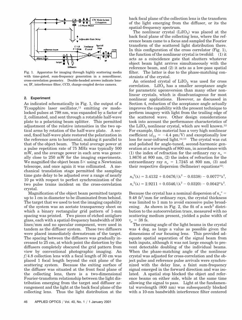
As indicated schematically in Fig. 1, the output of aTi:sapphire laser oscillator,11 emitting cw mode-locked pulses at 798 nm, was expanded by a factor of2, collimated, and sent through a rotatable half-waveplate to a polarizing beam splitter. This permittedadjustment of the relative intensities in the two op-tical arms by rotation of the half-wave plate. A sec-ond, fixed half-wave plate restored the polarization inthe reference arm to horizontal, making it parallel tothat of the object beam. The total average power ata pulse repetition rate of 75 MHz was typically 500mW, and the average power in each arm was gener-ally close to 250 mW for the imaging experiments.We magnified the object beam 53 using a Newtoniantelescope, and once again it was collimated. A me-chanical translation stage permitted the samplingtime gate delay to be adjusted over a range of nearly10 ps with respect to perfect synchronization of thetwo pulse trains incident on the cross-correlationcrystal.
Magnification of the object beam permitted targetsup to 1 cm in diameter to be illuminated from behind.The target that we used to test the imaging capabilityof the system was an acetate transparency sheet onwhich a binary rectangular grid pattern of 1-mmspacing was printed. Two pieces of etched antiglareglass, each with a spatial-frequency bandwidth of 300linesymm and no specular component, were used inandem as the diffuser system. These two diffusersere placed immediately downstream of the target.he spacing between the diffusers was gradually in-reased to 25 cm, at which point the distortion by theiffusers completely obscured the grid pattern fromiew by conventional photographic imaging. Any4.8 collection lens with a focal length of 30 cm was
placed 1 focal length beyond the exit plane of thescattering system. Because the exiting surface ofthe diffuser was situated at the front focal plane ofthe collecting lens, there is a two-dimensionalFourier-transform relationship between the light dis-tribution emerging from the target and diffuser ar-rangement and the light at the back focal plane of thecollecting lens. Thus the light distribution at the
Fig. 1. Apparatus for imaging through highly scattering mediawith time-gated, sum-frequency generation in a noncollinear,cross-correlation geometry. Double-headed arrows indicate lens-es; IF, interference filter; CCD, charge-coupled device camera.
6 APPLIED OPTICS y Vol. 40, No. 1 y 1 January 2001
back focal plane of the collection lens is the transformof the light emerging from the diffuser, or its thespatial-frequency spectrum.
The nonlinear crystal ~LiIO3! was placed at theback focal plane of the collecting lens, where the ref-erence beam came to a focus and sampled the Fouriertransform of the scattered light distribution there.In this configuration of the cross correlator ~Fig. 1!,he function of the nonlinear crystal is twofold: ~1! itcts as a coincidence gate that shutters whateverbject beam light arrives simultaneously with theeference beam, and ~2! it acts as a low-pass spatiallter. The latter is due to the phase-matching con-traints of the crystal.An oriented crystal of LiIO3 was used for cross
correlation. LiIO3 has a smaller acceptance anglefor parametric upconversion than many other non-linear crystals, which is disadvantageous for mostnonlinear applications. However, as discussed inSection 4, reduction of the acceptance angle actuallyimproves the capability with the present technique toperform imagery with light from the trailing edge ofthe scattered wave. Other design considerationstook into account the performance characteristics ofthe LiIO3 nonlinear crystal, which are well known.12
For example, this material has a very high nonlinearcoefficient ~d31 5 24.4 pmyV! and exceptionally lowloss for near-infrared light.12,13 The crystal was cutand polished for angle-tuned, second-harmonic gen-eration at a wavelength of 800 nm, in accordance with~1! the index of refraction for the ordinary ray no 51.8676 at 800 nm, ~2! the index of refraction for thextraordinary ray ne 5 1.7245 at 800 nm, ~3! andheir respective dispersion ~Sellmeier! equations12:
n02~l! 5 3.4132 1 0.0476y~l2 2 0.0338! 2 0.0077*l2,
ne2~l! 5 2.9211 1 0.0346y~l2 2 0.0320! 2 0.0042*l2.
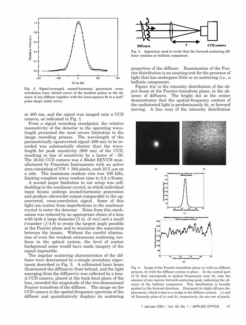
ecause the crystal has a nominal dispersion of no0 59.48 fs2ymm for ordinary rays, the crystal thicknesswas limited to 1 mm to avoid excessive pulse broad-ening. As shown in Fig. 2, the fit of a sech2 distri-bution to the autocorrelation trace, measured with noscattering medium present, yielded a pulse width oftp 5 38 fs.
The crossing angle of the light beams in the crystalwas 4 deg, as large a value as possible given thedimensions of our focusing lens. This provided ad-equate spatial separation of the signal beam fromboth inputs, although it was not large enough to pre-vent detectable doubling of the individual beams.When the phase-matching angle of the nonlinearcrystal was adjusted for cross-correlation and the ob-ject pulse and reference pulse arrivals were synchro-nized with the delay line, a faint sum-frequencysignal emerged in the forward direction and was iso-lated. A spatial stop blocked the object and refer-ence beams on either side, while at the same timeallowing the signal to pass. Light at the fundamen-tal wavelength ~800 nm! was subsequently blockedwith a 10-nm bandwidth interference filter centered
s
poaspp
at 400 nm, and the signal was imaged onto a CCDcamera, as indicated in Fig. 1.
From a signal recording standpoint, the relativeinsensitivity of the detector to the operating wave-length presented the most severe limitation to theimage recording process. The wavelength of theparametrically upconverted signal ~400 nm! to be re-corded was substantially shorter than the wave-length for peak sensitivity ~650 nm! of the CCD,resulting in loss of sensitivity by a factor of ;50.The 16-bit CCD camera was a Model EEV576 man-ufactured by Princeton Instruments with an activearea consisting of 576 3 384 pixels, each 23.5 mm ona side. The maximum readout rate was 100 kHz,limiting complete array readout time to 2.2 syframe.
A second major limitation in our setup was self-doubling in the nonlinear crystal, in which individualinput beams undergo second-harmonic generationand produce ultraviolet output comparable to the up-converted, cross-correlation signal. Some of thislight can scatter from imperfections in the nonlinearcrystal to enter the detector. Noise from this mech-anism was reduced by an appropriate choice of a lenswith both a large diameter @3 in. ~8 cm!# and a smallf-number ~ fy4.8! to create the largest angle possibleat the Fourier plane and to maximize the separationbetween the beams. Without the careful elimina-tion of even the weakest extraneous scattering sur-faces in the optical system, the level of scatterbackground noise would have made imagery of thesignal impossible.
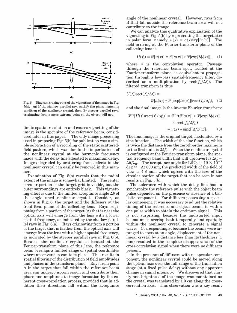
The angular scattering characteristics of the dif-fuser were determined by a simple secondary exper-iment described in Fig. 3. A collimated laser beamilluminated the diffuser~s! from behind, and the lightemerging from the diffuser~s! was collected by a lens.A CCD camera, placed at the back focal plane of thelens, recorded the magnitude of the two-dimensionalFourier transform of the diffuser. The image on theCCD camera is the spatial-frequency spectrum of thediffuser and quantitatively displays its scattering
Fig. 2. Signal-averaged, second-harmonic generation cross-correlation trace ~dotted curve! of the incident pulses in the ab-ence of any diffuser together with the least-squares fit to a sech2
pulse shape ~solid curve!.
properties of the diffuser. Examination of the Fou-rier distribution is an exacting test for the presence oflight that has undergone little or no scattering ~i.e., aballistic component!.
Figure 4~a! is the intensity distribution of the ob-ject beam at the Fourier-transform plane, in the ab-sence of diffusers. The bright dot at the centerdemonstrates that the spatial-frequency content ofthe undistorted light is predominantly dc, or forwardmoving. A line scan of the intensity distribution
Fig. 3. Apparatus used to verify that the forward-scattering dif-fuser contains no ballistic component.
Fig. 4. Image of the Fourier-transform plane ~a! with no diffuserresent, ~b! with the diffuser system in place. In the central partf ~b! that corresponds to spatial frequencies near dc, note thebsence of any narrow forward-scattering peak, indicating the ab-ence of the ballistic component. This distribution is broadlyeaked in the forward direction. Disregard its slight off-axis dis-lacement, which is due to a wedge in the diffuser system. ~c! and
~d! Intensity plots of ~a! and ~b!, respectively, for one row of pixels.
1 January 2001 y Vol. 40, No. 1 y APPLIED OPTICS 47

pWnFbat
ctthspc4TclHotegn
4
along one row of pixels @Fig. 4~c!# reveals the sharplyeaked distribution of spatial frequencies directly.hen a diffuser with a specular ~or ballistic! compo-
ent is placed in the optical system in Fig. 3, itsourier-transform plane ~not shown! would reveal aright, central specular component superimposed onuniform halo of higher spatial frequencies of scat-
ered light.More strongly scattering diffusers with no specular
omponent at all show only a smooth, broad distribu-ion of spatial frequencies. Figure 4~b! shows thathe diffuser, used for imaging in the present research,as no specular ~or ballistic! component. The brightpot signaling the presence of ballistic light is notresent. Instead, only a uniform smear of low-ontrast speckle is visible. The intensity plot, Fig.~d!, of one row of pixels of this pattern bears this out.he data in Figs. 4~b! and 4~d! clearly indicate that noentral peak with the angular spread of the ballisticight was present in the scattered light distribution.ence the imaging results reported in Section 3 were
btained under much more severe scattering condi-ions than in previous experiments where the pres-nce of a ballistic component permitted temporalating alone to select the best image-bearing compo-ent of the scattered light.7Our method is effective for both diffusers with an
observable ballistic ~i.e., specular! component and dif-fusers without. When a ballistic component ispresent, the reference beam can be synchronized withthe ballistic light which yields a sharp high-resolution image, without data processing, as quicklyas the array can be read out. In this case, our ap-proach extends previous ultrafast time-gated imag-ing techniques1–10 only by introducing parallelismand inherently high contrast. Yet remarkably, aswe show in Section 3, with a combination of temporalgating and spatial filtering, imaging can still be per-formed successfully when no ballistic component ispresent as well.
The experimental results reported in this paper arefor images formed through diffusers that have nospecular component. For such severe scatterers, theabundance of forward-traveling light disappears, andthe utility of time gating as an ultrafast shutter rap-idly diminishes when applied in isolation. Thenlight emerging from the scattering medium generallycontains enough randomized wave-vector bandwidthper unit time that image information is highly dis-torted at all delays. Nevertheless, as shown exper-imentally here, and as we explain in Sections 3 and 4,use of very short pulses in combination with phase-matched frequency conversion techniques can facili-tate effective imaging in this regime. Signals fromtime slices anywhere within the scattered objectpulse provide satisfactory imaging when angular se-lectivity is combined with time gating in the detectionscheme. Even at the low average power levels at-tainable from cw mode-locked oscillators, this methodis successful without electronic processing of the im-age.
8 APPLIED OPTICS y Vol. 40, No. 1 y 1 January 2001
3. Results
In Fig. 5~a! the rectangular grid pattern fabricatedfor use as a resolution target is reproduced. This is,in fact, what a photograph of the target would looklike in the absence of the diffuser system. The sep-aration and thickness of all lines on the target are 1mm. When hidden behind the two nonspecular dif-fusers, as described in Section 2, the target is com-pletely invisible to conventional photographicrecording and simply yields a uniform, featurelessspeckle pattern. Thus, without the benefit of ourtechnique, the target was entirely hidden by the dif-fusers, and its photograph therefore is not included inthis paper. The principal result of the ultrafastcross-correlated harmonic imaging technique isshown in Fig. 5~b! where the 1-mm grid is visible.The good fidelity of its details demonstrates that ourtechnique has overcome the severe scattering condi-tions that were imposed by our choice of diffuser.This demonstrates that our approach to imagingworks and that imaging through severe diffusers ispossible.
Features as small as 1 mm are well resolved by thistechnique. In practice it was found that imagingtarget features that are smaller than those of thisgrid pattern resulted in degraded imagery. The spa-tial resolution in our experiment was limited by thefinite pulse width of our timing gate. Light from twopoints situated a distance d apart at the exit surfaceof the first diffuser can combine, scatter in the samedirection, and pass through the gate together if d ,(CDtp)1y2 ; 1.68 mm. A second factor that potentially
Fig. 5. ~a! Resolution target, consisting of 1-mm squares andlines, to be imaged. The diffuser completely obscures this target.~b! Image recorded with the sum-frequency optical system in Fig.1. ~The uncorrelated background field was subtracted out.!
ecoitsfnosloeaBFbwsaAaphd
aBc
v
splltoibwwrlmcp
ptscitc
limits spatial resolution and causes vignetting of theimage is the spot size of the reference beam, consid-ered later in this paper. The only image processingused in preparing Fig. 5~b! for publication was a sim-ple subtraction of a recording of the static scattered-field pattern, which was due to the imperfections ofthe nonlinear crystal at the harmonic frequencymade with the delay line adjusted to maximum delay.Images degraded by scattering from defects in thenonlinear crystal can easily be removed in this man-ner.
Examination of Fig. 5~b! reveals that the radialxtent of the image is somewhat limited. The centerircular portion of the target grid is visible, but theuter surroundings are entirely black. This vignett-ng effect is due to the limited acceptance angle Du ofhe angle-tuned nonlinear crystal. Consider, ashown in Fig. 6, the target and the diffusers at theront focal plane of the collecting lens. Rays origi-ating from a portion of the target ~A! that is near theptical axis will emerge from the lens with a lowerpatial frequency, as indicated by the shallow paral-el rays in Fig. 6~a!. Rays originating from a portionf the target that is farther from the optical axis willmerge from the lens with a higher spatial frequency,s indicated by the steeper parallel rays in Fig. 6~b!.ecause the nonlinear crystal is located at theourier-transform plane of this lens, the referenceeam overlaps a limited range of spatial coordinateshere upconversion can take place. This results in
patial filtering of the distribution of field amplitudesnd phases in the transform plane. Rays from point
in the target that fall within the reference beamrea can undergo upconversion and contribute theirhase and amplitude to image formation by the co-erent cross-correlation process, provided that in ad-ition their directions fall within the acceptance
Fig. 6. Diagram tracing rays of the vignetting of the image in Fig.5~b!. ~a! If the shallow parallel rays satisfy the phase-matchingcondition of the nonlinear crystal, then ~b! steeper parallel rays,originating from a more extreme point on the object, will not.
ngle of the nonlinear crystal. However, rays fromthat fall outside the reference beam area will not
ontribute to the image.We can analyze this qualitative explanation of the
ignetting in Fig. 5~b! by representing the target u~x!in polar form, namely, u~x! 5 a~x!exp@if~x!#. Thefield arriving at the Fourier-transform plane of thecollecting lens is
U~ fx! ; ^@u~x!# 5 ^@a~x!# p ^$exp@if~x!#%, (1)
where p is the convolution operator. Passagethrough the reference beam spot, located at theFourier-transform plane, is equivalent to propaga-tion through a low-pass spatial-frequency filter, de-scribed as a multiplication by rect~ fxyDfs!. Thefiltered transform is thus
U~ fx!rect~ fxyDfs! 5
^@a~x!# p ^$exp@if~x!#%rect~ fxyDfs!, (2)
and the final image is the inverse Fourier transform:
^21@U~ fx!rect~ fxyDfs!# 5 ^21(^@a~x!# p ^$exp@if~x!#%
3 rect~ fxyDfs!)
5 u~x! p sinc@~Dfs!~x!#. (3)
The final image is the original target, modulated by asinc function. The width of the sinc function, whichis twice the distance from the zeroth-order maximumto the first null, is 2Dfs. When the nonlinear crystalis configured at the Fourier-transform plane, the spa-tial frequency bandwidth that will upconvert is Dfs 5Duyl0. The acceptance angle for LiIO3 is 19 3 1023
deg.12 At 800 nm, the predicted width of the field ofview is 4.8 mm, which agrees with the size of thecircular portion of the target that can be seen in ourresults in Fig. 5~b!.
The tolerance with which the delay line had toynchronize the reference pulse with the object beamulse depended on the presence or absence of a bal-istic component. For diffusers possessing a specu-ar component, it was necessary to adjust the relativeiming of the reference and object beams to withinne pulse width to obtain the optimum signal. Thiss not surprising, because the undistorted inputeams must overlap both temporally and spatiallyithin the nonlinear crystal to generate a signalave. Correspondingly, because the beams were ar-
anged to cross at an angle, displacement of the non-inear crystal by a distance less than its thickness ~1
m! resulted in the complete disappearance of theross-correlation signal when there were no diffusersresent.In the presence of diffusers with no specular com-
onent, the nonlinear crystal could be moved alonghe optical axis over the full range of the translationtage ~at a fixed pulse delay! without any apparenthange in signal intensity. We discovered that clar-ty and brightness of the image was maintained ashe crystal was translated by 1.0 cm along the cross-orrelation axis. This observation was a key result
1 January 2001 y Vol. 40, No. 1 y APPLIED OPTICS 49

tiimaiptiroctco
lgits
vfsrbtusTstearstievc
pitiitpamsd
pbcpau
5
of the present research and demonstrated two things.First, because cross correlation occurred at positionsseparated by 1 cm, the reference beam necessarilyintercepted off-axis portions of the scattered wavefront within the thin LiIO3 crystal that were delayedby more than 30 ps. Pulse stretching was therebyconfirmed to be substantial under the experimentalconditions depicted in Fig. 4~b!, amounting to at leastthis time interval. Second, the fact that imageswere observed over a range of positions of the non-linear crystal clearly indicated that, with the detec-tion technique used here, late-arriving light can bejust as useful for image formation as early-arrivinglight, provided that an appropriate combination ofselective procedures is used for detection.
The data for the image in Fig. 5~b! were acquired inan accumulation time of 20 s. This acquisition timecorresponded to that needed to saturate the mostbrightly illuminated pixel at the power levels used inthe experiment. At equivalent power levels, goodbut less intense images ~only 1000 counts in thebrightest pixel! could be obtained in approximately40 ms. At higher input powers, the recording timefor unsaturated images was correspondingly reduced.In view of this it is clear that, with this approach,dynamic imagery with frame times of less than 40 mscan be readily achieved with available oscillator pow-ers without resorting to data processing of any kind.
4. Discussion
Temporal gating is known to be ineffective on its ownin forming images of objects obscured by scatteringmedia when late-arriving light is used. This is be-cause late-arriving light consists of many sets of scat-tered rays that follow different vectorial routes inthree dimensions through the medium. However,as our results show, and as we discuss below, use ofvectorial constraints can overcome this problem byproviding the additional selectivity necessary to iso-late individual trajectories.
Our results show that ultrafast harmonic imagingworks well under nonspecular scattering conditions,when no ballistic component is evident in light trans-mitted by the medium. Also, late-arriving light canproduce good images. Hence when time gating isused at any point within a stretched, scattered imagepulse in combination with directionally selective ~vec-orial! detection, we have shown that high-qualitymages can be formed. Sets of rays that follow sim-lar, but not identical, vectorial routes through the
edium develop only a small spread in constant rel-tive phase. Such rays are capable not only of form-ng images, but of generating phase-matchedarametric output. The upconverted image qualityherefore depends on the degree to which the spreadn phases can be restricted in the detection process,egardless of how complex their trajectories may ber what total temporal delay the ray trajectory in-urs. In previous time-gated imaging experiments,he detection methods did not to our knowledge in-orporate the vectorial selectivity necessary to dem-nstrate the results shown here.
0 APPLIED OPTICS y Vol. 40, No. 1 y 1 January 2001
A combination of fast temporal gating and angu-arly selective detection is functionally equivalent toated off-axis, confocal spatial filtering with a van-shingly small pinhole. Such a spatial-filteringransformation results in perfect imaging in thetrong scattering limit.10 Ultrashort time gating by
itself minimizes the spread in delay times for sam-pled light, but makes no distinction, for example,between on-axis multiply scattered light and off-axislight with the same delay. Hence time-gated, late-arriving light from a highly scattering medium con-sists of a superposition of incoherent componentsunsuitable for imaging. For off-axis light originat-ing from the passage through a small fixed number ofscattering vertices, however, a relatively well-definedfamily of trajectories symmetric about the propaga-tion axis can be defined when we specify both thedelay and the projection of the initial ~or final! waveector on the propagation axis. Furthermore, if theamily of off-axis trajectories is then restricted to es-entially a single path, the phase distribution is nar-ow enough that high-quality upconversion imagingecomes possible. In this paper we have experimen-ally implemented detection of this type by efficientlypconverting only time-gated light with wave vectorsatisfying a crossed-beam, phase-matching condition.his approach limits the contributing rays to thoseharing a common plane of origin ~perpendicular tohe axis! and an initial scattered wave vector, to anxtent determined jointly by the temporal gate widthnd the crystal acceptance angle. By sampling aestricted set of scattering trajectories, ones notcrambled and distorted by other contributions of al-ogether different phase, we can achieve high-qualitymagery. Spatial resolution is determined by refer-nce beam pulse width and spot size, and the field ofiew is limited by the acceptance angle of the crossorrelator.
The observation in this research that late-arrivingortions of the scattered light can be used for imagingmmediately raises the question of what limitationshere may be in the use of shorter and shorter pulsesn combination with more and more angular selectiv-ty in imaging through severe scatterers. For arbi-rarily small upconversion acceptance angles andulse widths, it might be concluded at first that ourbility to image through scattering media with a har-onic cross-correlation technique is unlimited. Not
urprisingly, this premise is incorrect, as we nowiscuss.There are several limitations that can be antici-
ated. As pulses are shortened, their frequencyandwidth increases. Only a limited bandwidth canontribute to image formation, however, becausehase matching in the nonlinear crystal can bechieved only over a limited range, say Dv. Hencese of pulse widths shorter than t 5 ~Dv!21 reduces
the signal level without improving temporal resolu-tion. However small the acceptance angle Du maybe, it is finite, and the range of phase-matchable wavevectors incident on the crystal Dk is therefore limited

by angular dispersion over Du. This means thatpulses shorter than
t 5 ~cDk!21 5 Fck0S]n]uDDuG21
cannot be entirely phase matched in angle-tunedcrystals. Because the angular spread Du determinesa spatial-frequency bandwidth of Df 5 Duyl0, there isa minimum acceptable gate width
t 5 FcS]n]uD2pDfG21
for any desired spatial resolution. This point wasrecently confirmed in spatial-filtering experiments.14
In our optical system configuration ~Fig. 1! inwhich the nonlinear crystal is located at the Fourier-transform plane, one of the two factors limiting theresolution of our imaging process is the area overwhich upconversion occurs. The bandwidth of whatis effectively a low-pass spatial filter is determined bythe spot size of the reference beam at the point ofcross correlation because only those spatial frequen-cies that overlap with the reference beam can upcon-vert into the imaged signal. Thus, for a laserconstrained to a fixed amount of power, there is atrade-off between resolution and conversion effi-ciency. On the other hand, nonlinear crystals of thistype are usually not placed at the Fourier-transformplane, and alternative optical systems that differfrom Fig. 1 in this manner would face different im-aging limitations. For example, the finite size of thenonlinear crystal limits the spatial frequencies con-tributing to image formation. Even if all scatteredlight were arranged to impinge on the crystal inputface within the acceptance angle, the wave-vectorbandwidth would undergo vignetting in the Fourier-transform plane, owing to the crystal aperture.
Finally, as the severity of scattering increases,the average number of scattering events increases.The diversity of scattering paths corresponding to aparticular gate time and width therefore increasesnonlinearly as the transport mean free path l*, orthe distance a between the scatterers shortens.Under these circumstances, linear changes in gatewidth or upconversion area ~acceptance angle forplacement away from the transform plane! shouldbecome progressively less effective in selectingunique trajectories from the multitude of scatteredrays with sufficient phase definition to achievephase matching and form high-quality images. Inthe correlated scattering regime the net phase willcease to be well defined on arbitrarily complex tra-jectories when either a, the interparticle separa-tion, or l* become less than l. In this extremescattering limit, we can expect image quality todecline beyond our ability to restore it with shorterpulses or better cross-correlator characteristics atpredictable values of the transport mean free path,interparticle separation, and sample thickness.
This research was supported in part by the Re-search Corporation, by U.S. Army Research Officegrant DAAH-04-96-0254, and by the U.S. Air ForceOffice of Scientific Research under grant F49620-98-1-0189. M. P. Hehlen is indebted to the Swiss Na-tional Science Foundation for financial support.
References1. K. G. Spears, J. Serafin, N. H. Abramson, X. Zhu, and H.
Bjelkhagen, “Chronocoherent imaging for medicine,” IEEETrans. Biomed. Eng. 36, 1210–1214 ~1989!.
2. Y. Chen, Y. Chen, D. Dilworth, E. Leith, J. Lopez, and J.Valdmanis, “Two-dimensional imaging through diffusing me-dia using 150-fs gated electronic holography techniques,” Opt.Lett. 16, 487–489 ~1991!.
3. E. Leith, C. Chen, H. Chen, Y. Chen, D. Dilworth, J. Lopez, J.Rudd, P.-C. Sun, J. Valdmanis, and G. Vossler, “Imagingthrough scattering media with holography,” J. Opt. Soc. Am. A9, 1148–1153 ~1992!.
4. D. Huang, E. A. Swanson, C. P. Lin, J. S. Schuman, W. G.Stinson, W. Chang, M. R. Hee, T. Flotte, K. Gregory, C. A.Puliafito, and J. G. Fujimoto, “Optical coherence tomography,”Science 254, 1178–1181 ~1991!; M. R. Hee, J. A. Izzat, J. M.Jacobson, J. G. Fujimoto, and E. A. Swanson, “Femtosecondtransillumination optical coherence tomography,” Opt. Lett.18, 950–952 ~1993!.
5. M. A. O’Leary, D. A. Boas, B. Chance, and A. G. Yodh, “Ex-perimental images of heterogeneous turbid media byfrequency-domain diffusing-photon tomography,” Opt. Lett.20, 426–428 ~1995!.
6. J. Reintjes, M. Bashkansky, M. Duncan, R. Mahon, L. L. Tank-erskley, J. A. Moon, C. L. Adler, and J. M. S. Prewitt, “Time-gated imaging with nonlinear optical Raman interactions,”Opt. Photon. News 4, 28–32 ~1993!.
7. L. Wang, P. P. Ho, C. Liu, G. Zhang, and R. R. Alfano, “Ballistic2-D imaging through scattering walls using an ultrafast opti-cal Kerr gate,” Science 253, 769–771 ~1991!; L. Wang, P. P. Ho,X. Liang, H. Dai, and R. R. Alfano, “Kerr–Fourier imaging ofhidden objects in thick turbid media,” Opt. Lett. 18, 241–243~1993!.
8. K. M. Yoo, Q. Xing, and R. R. Alfano, “Imaging objects hiddenin highly scattering media using femtosecond second-harmonic-generation cross-correlation time gating,” Opt. Lett.16, 1068–1070 ~1991!.
9. H. Chen, Y. Chen, D. Dilworth, E. Leith, J. Lopez, M. Shih,P.-C. Sun, E. Arons, and K. Clay, “Comparison of various ho-lographic techniques for imaging through biological tissue,” inHolographic Imaging and Materials, T. H. Jeong, ed., Proc.SPIE 2043, 272–277 ~1993!.
10. E. Arons and D. Dilworth, “Analysis of Fourier synthesis ho-lography for imaging through scattering materials,” Appl. Opt.34, 1841–1847 ~1995!.
11. C.-P. Huang, H. C. Kapteyn, J. W. McIntosh, and M. M. Mur-nane, “Generation of transform-limited 32-fs pulses from aself-mode-locked Ti:sapphire laser,” Opt. Lett. 17, 139–141~1992!.
12. V. G. Dmitriev, G. G. Gurzadyan, and D. N. Nikogosyan,Handbook of Nonlinear Optical Crystals, 2nd ed., Optical Sci-ence Series ~Springer-Verlag, Berlin, 1995!, Vol. 64, pp. 103–106.
13. Specifications can be obtained at supplier’s URL: http:yyge-ology.uiggm.nsc.ruyuiggmymonokrysyproduktyiodat_e.htm.
14. E. N. Leith, B. G. Hoover, S. M. Grannell, K. D. Mills, H. S.Chen, and D. S. Dilworth, “Realization of time gating by use ofspatial filtering,” Appl. Opt. 38, 1370–1376 ~1999!.
1 January 2001 y Vol. 40, No. 1 y APPLIED OPTICS 51
Copyright © 2022 FDOKUMEN