Second/Third Harmonic Generation Microscopy
20
Chapter 3 Second/Third Harmonic Generation Microscopy Shakil Rehman, Naveen K. Balla, Elijah Y. Y. Seng, and Colin J. R. Sheppard 3.1 Introduction When the energy density at the focal spot of a microscope is sufficiently large, nonlinear optical effects such as, harmonic generation, sum-frequency generation, coherent Raman scattering, parametric oscillations, and multi-photon fluorescence can be observed. These optical phenomena can be used in a nonlinear optical microscope to study the biological material. Nonlinear optical microscopy may be divided into incoherent and coherent modes. Incoherent nonlinear microscopy is characterized by the optical signal (like fluorescence) with a random phase, whose power is proportional to the concentration of radiating molecules. The principle of nonlinear fluorescence microscopes is based on the simultaneous absorption of two S. Rehman (*) Division of Bioengineering, National University of Singapore, 9 Engineering Drive, Singapore 117576, Singapore and Singapore Eye Research Institute, 11, Third Hospital Avenue, #05-00, Singapore 168751, Singapore e-mail: [email protected] N.K. Balla Division of Bioengineering, National University of Singapore, 9 Engineering Drive, Singapore 117576, Singapore and Computation and Systems Biology, Singapore-MIT Alliance, National University of Singapore, Singapore 117576, Singapore E.Y.Y. Seng Division of Bioengineering, National University of Singapore, 9 Engineering Drive, Singapore 117576, Singapore C.J.R. Sheppard Division of Bioengineering, National University of Singapore, 9 Engineering Drive, Singapore 117576, Singapore and Department of Diagnostic Radiology, National University of Singapore, 5 Lower Kent Ridge Road, Singapore 119074, Singapore A. Diaspro (ed.), Optical Fluorescence Microscopy, DOI 10.1007/978-3-642-15175-0_3, # Springer-Verlag Berlin Heidelberg 2011 55
Transcript of Second/Third Harmonic Generation Microscopy

Chapter 3
Second/Third Harmonic Generation Microscopy
Shakil Rehman, Naveen K. Balla, Elijah Y. Y. Seng, and Colin J. R. Sheppard
3.1 Introduction
When the energy density at the focal spot of a microscope is sufficiently large,
nonlinear optical effects such as, harmonic generation, sum-frequency generation,
coherent Raman scattering, parametric oscillations, and multi-photon fluorescence
can be observed. These optical phenomena can be used in a nonlinear optical
microscope to study the biological material. Nonlinear optical microscopy may
be divided into incoherent and coherent modes. Incoherent nonlinear microscopy is
characterized by the optical signal (like fluorescence) with a random phase, whose
power is proportional to the concentration of radiating molecules. The principle of
nonlinear fluorescence microscopes is based on the simultaneous absorption of two
S. Rehman (*)
Division of Bioengineering, National University of Singapore, 9 Engineering Drive, Singapore
117576, Singapore
and
Singapore Eye Research Institute, 11, Third Hospital Avenue, #05-00, Singapore 168751,
Singapore
e-mail: [email protected]
N.K. Balla
Division of Bioengineering, National University of Singapore, 9 Engineering Drive, Singapore
117576, Singapore
and
Computation and Systems Biology, Singapore-MIT Alliance, National University of Singapore,
Singapore 117576, Singapore
E.Y.Y. Seng
Division of Bioengineering, National University of Singapore, 9 Engineering Drive, Singapore
117576, Singapore
C.J.R. Sheppard
Division of Bioengineering, National University of Singapore, 9 Engineering Drive, Singapore
117576, Singapore
and
Department of Diagnostic Radiology, National University of Singapore, 5 Lower Kent Ridge
Road, Singapore 119074, Singapore
A. Diaspro (ed.), Optical Fluorescence Microscopy,DOI 10.1007/978-3-642-15175-0_3, # Springer-Verlag Berlin Heidelberg 2011
55

or more photons, as in, two-photon excited fluorescence microscopy (Denk et al.
1990) and three-photon excitation fluorescence microscopy (Maiti et al. 1997;
Schrader et al. 1997). The coherent mode of nonlinear microscopy is characterized
by the optical signal whose phase is determined by factors like phase of excitation
field and the geometrical distribution of radiating molecules. Some of the coherent
nonlinear microscopic techniques are second harmonic generation (SHG) micro-
scopy (Campagnola et al. 1999; Gannaway and Sheppard 1978; Gauderon et al.
1998; Sheppard and Kompfner 1978), coherent anti-Stokes Raman scattering
(CARS) microscopy (Duncan et al. 1982), and third harmonic generation (THG)
microscopy (Barad et al. 1997; M€uller et al. 1998; Squier et al. 1998; Yelin and
Silberberg 1999). All of these nonlinear microscope modalities have benefited from
the fact that it is easier than ever before to generate ultrashort laser pulses at specific
wavelengths.
SHG is a nonlinear optical process which can take place in a microscope using
ultrashort laser pulses in the near-infrared range. The amplitude of SHG is propor-
tional to the square of the incident light intensity. In 1978, Sheppard first proposed
the idea that two-photon excited fluorescence (2PEF) and SHG can be used for
nonlinear microscopy. Later, in 1990, Denk et al. used ultrashort pulse lasers to
demonstrate the 2PEF microscopy that involves near-simultaneous absorption of
two photons to excite a fluorophore, followed by an incoherent emission of fluores-
cence. The nonlinear process of SHG takes place through an interaction between
the electric field and its spatial derivative. Emission by this process is highly
anisotropic, coherent, and phase-coupled to the excitation and is therefore subject
to phase-matching effects between the electric fields associated with the process.
In SHG, two photons are converted into a single photon at twice the excitation
energy emitted coherently. SHG takes place in systems lacking a center of symme-
try. In biological materials, cellular membranes possess such asymmetrically
distributed molecular structure. Supramolecular structures within cells and tissues
that can produce SHG signals are collagen and actin filaments. Being a nonlinear
process, SHG signal is maximum at the focus of the microscope, resulting in the
intrinsic three-dimensional sectioning without the use of a confocal aperture that
greatly reduces out-of-focus plane photobleaching and phototoxicity. Near-infrared
wavelength excitation allows excellent depth penetration in biological material;
therefore, this method is well-suited for studying intact tissue samples. Information
about the organization of chromophores, including dyes and structural proteins, at
the molecular level can be extracted from SHG imaging data in several ways. SHG
signals have well-defined polarizations, and hence SHG polarization anisotropy can
also be used to determine the absolute orientation and degree of organization of
proteins in tissues.
THG is a nonlinear optical process which has been intensely studied since the
early days of nonlinear optics (Bloembergen 1965; Shen 1984). This process has
been applied in imaging of lipids in cells and tissues (Debarre et al. 2006),
subcellular structure in neurons (Yelin and Silberberg 1999), cell nuclei (Yu et al.
2008), and simultaneous SHG, THG, and 2PEF imaging of live biomaterials (Chu
et al. 2001). All materials have some third-order nonlinearity depending on the
56 S. Rehman et al.

material property, symmetry, and the incident light. At the focus of microscope
objective lens, when a discontinuity or inhomogeneity is encountered, like an
interface between two media, the symmetry along the optical axis is broken and a
third harmonic signal can be obtained. High optical sectioning can be achieved
because of the nonlinear process of THG taking place only at the focal plane. Being
the property of all materials, third harmonic signal can be used for noninvasive
microscopy, particularly in biological materials without the need of fluorescence
labeling.
3.2 Nonlinear Optics Background
Nonlinear optical phenomena occur when the response of a material to the applied
optical field depends nonlinearly on the strength of the field. The applied field may
cause changes in the distribution or motion of the internal electric charges such as
electrons, ions, or nuclei within a molecular system, resulting in a field-induced
electric dipole moment which, in turn, acts as a new source to emit a secondary
wave. This is the fundamental process of optically field-induced polarization in a
molecular system and re-emission of a secondary electromagnetic wave.
The induced polarization in a medium depends on the strength of the applied
field and can be written as
PðtÞ ¼ e0wð1ÞEðtÞ ; (3.1)
where is e0 is the permittivity of free space, w(1) the linear susceptibility of the
medium, E is the incident field, and P is the induced polarization. The electric
susceptibility w indicates the ability of the electric dipoles in a dielectric to align
themselves with the electric field. A general expression for the induced polarization
can be written in a power series expansion in the magnitude of the electric field as
PðtÞ ¼ e0wð1ÞEðtÞ þ e0wð2ÞE2ðtÞ þ e0wð3ÞE3ðtÞ þ � � � : (3.2)
w(2) and w(3) are the second-order and third-order nonlinear susceptibilities,
respectively. For materials with inversion symmetry, all the even-order nonlinear
susceptibility coefficients are equal to zero. In general, P and E are vector quan-
tities, therefore, nth-order susceptibility w(n) becomes a (n þ 1) rank tensor. First
term in (3.2) represents the linear polarization and it can be shown that the linear
susceptibility wð1Þ ¼ n2 � 1, where n is the refractive index. Second term in (3.2) is
referred to as second-order nonlinear polarization Pð2ÞðtÞ ¼ e0wð2ÞE2ðtÞ and
Pð3ÞðtÞ ¼ e0wð3ÞE3ðtÞ as third-order nonlinear polarization and so on. Each of
these polarization terms gives rise to a different physical phenomenon. For example,
second-order polarization is used to produce SHG and sum/difference frequency
generation, and third-order polarization is responsible for THG, Raman scattering,
3 Second/Third Harmonic Generation Microscopy 57

Brillouin scattering, self-focusing, and optical phase conjugation. Furthermore,
second-order nonlinear optical interactions can only occur in noncentrosymmetric
crystals, that is, in crystals having no inversion symmetry, while third-order non-
linear phenomena can occur in any medium regardless of whether it possesses
inversion symmetry or not.
Consider that an electric field applied to a medium is of the form
EðtÞ ¼ E0 þ Eo cosðotÞ ; (3.3)
where E0 is the dc field and Eo is the amplitude of the field at frequency o.Substituting this value in (3.2) and solving for various polarizations, we get
cross-terms that represent the nonlinear phenomena. For example, the second-
order polarization can be written as
Pð2ÞðtÞ ¼ e0wð2ÞE2ðtÞ ¼ e0wð2Þ E20 þ
E2o
2þ E2
o cosð2otÞ2
þ 2E0Eo cosðotÞ� �
: (3.4)
The four terms of (3.4) represent wð2Þ based nonlinear optical processes and are
explained as follows.
e0wð2ÞE20: DC hyper-polarizability.
e0wð2ÞE2o 2= : DC optical rectification. Applied field produces a static voltage in
the medium that is proportional to the applied field.
e0wð2ÞE2o cosðotÞ 2= : Polarization generated at frequency 2o that can be used to
obtain a signal at twice the frequency of the input field and is responsible for SHG.
e0wð2Þ2E0Eo cosðotÞ: Linear electro-optic effect (Pockels effect) represents the
modification of the refractive index because of an applied DC electric field and can
be used for optical switching and for phase modulation of light.
By substituting (3.3) in third-order polarization term of (3.2), we get
Pð3ÞðtÞ ¼ e0wð3ÞE3ðtÞ¼ e0wð3Þ E0 þ Eo cosðotÞ½ �3:
(3.5)
Cross-terms obtained from this equation provide wð3Þ based optical processes,
some of which are explained as follows:
e0wð3ÞE20Eo cosðotÞ: Quadratic electro-optic effect also known as the Kerr effect.
This occurs in isotropic media such as gases and liquids as well as solids and is not
as widely used as the Pockels effect because of quadratic dependence with the
applied field.
e0wð3ÞE20E
2o cosð2otÞ: DC-induced SHG. Because of symmetry reasons SHG is
not possible in isotropic materials. In this case, applied electric field breaks the
symmetry, making SHG possible.
e0wð3ÞE3o cosð3otÞ: THG at three times the frequency of the applied field. THG is
allowed in all materials including isotropic ones.
58 S. Rehman et al.

e0wð3ÞE2o cosðotÞ: Optical (AC) Kerr effect. Third-order susceptibility permits a
term at frequency o caused by the applied field at the same frequency. This term
gives rise to self-focusing and self-phase modulation.
Here, we would like to give the readers a feel for how these nonlinearities arise,
through the example of an anharmonic oscillator suggested by Bloembergen
(1965). The approximate motion of a bound electron in a dielectric medium can
be expressed with the equation of motion of an anharmonic oscillator as
d2x
dt2þ g
dx
dtþ o2
0xþ ax2 ¼ F ; (3.6)
where F is the external force acting on the electron, x is the displacement from
its mean position, oo is the natural frequency of the electron, g is the damping
parameter, and ax2 is the nonlinear term with a being a nonlinear coefficient. Let
us assume an incident electromagnetic wave consisting of two oscillating elec-
tric fields of amplitude E1 and E2 and frequencies o1 and o2, of the form
E1e�io1t þ E2e
�io2t þ c.c, where c.c refers to the complex conjugate terms. The
external force F would then be �eE/m where e and m are the charge and mass of an
electron. According to the perturbation theory, we can write the solution of (3.3) as
x ¼ lxð1Þ þ l2xð2Þ þ l3xð3Þ þ � � � : (3.7)
For the above equation to hold for any value of l, the differential equation shouldbe satisfied for each power of l. So we get a series of equations as follows.
First order in l: d2xð1Þ=dt2 þ gdxð1Þ=dtþ o20x
ð1Þ ¼ �eE=mSecond order in l: d2xð2Þ=dt2 þ gdxð2Þ=dtþ o2
0xð2Þ ¼ �a½xð2Þ�2
Third order in l: d2xð3Þ=dt2 þ gdxð3Þ=dtþ o20x
ð3Þ ¼ �axð1Þxð2Þ and so on.
Solving for xð1Þ we get, xð1Þ ¼ eE1 m=ð Þ o21 � o2
0
� ��� �eio1t þ eE2 m=ð Þ=½
o21 � o2
0
� ��eio2t þ c.c:
To solve for the second-order term, let us substitute the value of xð1Þ in the
differential equation for xð2Þ and get
xð2Þ ¼e2
m2 E21
o21 � o2
0
� �2 ð2o1Þ2 � o20
h i ei2o1t þe2
m2 E22
o22 � o2
0
� �2 ð2o2Þ2 � o20
h i ei2o2t
þe2
m2 E21E
22
o21 � o2
0
� �2 o22 � o2
0
� �2 ðo1 þ o2Þ2 � o20
h i eiðo1þo2Þt
þe2
m2 E21E
22
o21 � o2
0
� �2 o22 � o2
0
� �2 ðo1 � o2Þ2 � o20
h i eiðo1�o2Þt þ c.c: (3.8)
Here, we have omitted the DC electric field as it is not relevant in this example.
The expression for xð2Þ contains two harmonic terms, a sum frequency term
3 Second/Third Harmonic Generation Microscopy 59

ðo1 þ o2Þ and a difference frequency term ðo1 � o2Þ which explain the second-
order optical phenomena as defined by (3.2). In a similar fashion, we can derive
the third-order harmonics by solving for xð3Þ. The second-order polarization, due toa single electron of charge e, is given by exð2Þ. If the number density of electrons
in the given dielectric is Ne, the bulk second-order polarization will be
Pð2Þ ¼ Neexð2Þ. As we already know the form of second-order polarization from
(3.2), Pð2ÞðtÞ ¼ e0wð2ÞE2ðtÞ. Therefore, we can get an expression for second-order
nonlinear susceptibility as
wð2Þ ¼ Neexð2Þ
enE2: (3.9)
This derivation is given in scalar form for simplicity. In a similar fashion, one
can solve for third-order nonlinear susceptibility for this problem.
3.3 Second Harmonic Generation
SHG is a three-wave mixing process based on second-order polarization as shown
in Fig. 3.1a. In this picture, two photons of frequency o are converted into one
photon of twice the frequency at 2o. The energy levels represented by solid lines
are atomic or molecular levels and dotted lines represent the virtual states. These
virtual energy states are combined states of the molecular system and the photons of
the incident radiation. This property of nonlinear harmonic generation via virtual
states leaves no residual energy in the medium and the emitted photon has exactly
same amount of energy as that of the absorbed photons. The conservation of energy
in such a nonlinear process provides the noninvasive property of imaging in the
microscopic applications of biological material.
Fig. 3.1 Energy level description of SHG (a) and THG (b) processes
60 S. Rehman et al.

Because of symmetry reasons, elements of the second-order susceptibility
cancel out in an isotropic homogeneous medium; hence, second-order nonlinear
optical effect can occur in a noncentrosymmetric crystalline structure only. The
first experiment carried out to demonstrate optical SHG was performed in 1961
(Franken et al. 1961). Some other physical nonlinear processes based on w 2ð Þ arelinear electro-optic effect (Pockel’s effect), optical rectification, and DC polariz-
ability. The second order-induced polarization can be written as (He and Liu 1999)
Pið2Þð2oÞ ¼ e0
Xjk
wð2Þijk ðo; oÞEjðoÞEkðoÞ ; (3.10)
where E(o) is the incident wave at frequency o and the induced polarization is at
2o that produces a new radiation at double the frequency. Here, wð2Þijk is a third-rank
tensor responsible for the SHG; for centrosymmetric materials, wð2Þijk vanishes
because of inversion symmetry. The indices ijk are summed over linear polarization
directions of x, y, and z. The induced polarization Pð2Þx ð2oÞ produces an electro-
magnetic field Exð2oÞ at twice the frequency of the input field. If we assume the
incident electric field of the form Ei sinðotÞ, then the resulting polarization becomes
Pð2Þi ð2oÞ ¼ e0
Xjk
wð2Þijk ðo; oÞEjðoÞEkðoÞsin2ðotÞ ; (3.11)
¼ 1
2e0Xjk
wð2Þijk ðo; oÞEjðoÞEkðoÞ½1� cosð2otÞ� : (3.12)
The first term in (3.9) gives rise to a DC polarization within the material and the
second term with cosð2otÞ corresponds to a polarization wave that oscillates at
twice the fundamental frequency o and that acts as a source for the second
harmonic output field. Because of symmetry selection rules, the elements of the
nonlinear susceptibility tensor wð2Þjk vanish for materials with inversion symmetry.
This symmetry rule also applies equally well for all even powers of nonlinear
susceptibilities given by (3.2). Therefore, second harmonic effect is not observed
for an isotropic and centrosymmetric material. For effective nonlinear harmonic
generation effect, the specimen must be relatively transparent to the wavelength of
fundamental illumination light and the generated higher harmonics.
Conversion efficiency in SHG relates to spatiotemporal overlap of waves at
fundamental and second harmonic frequencies, as well as to their group and phase
velocity matching. For effective energy transfer from the fundamental wave to the
second harmonic waves, both the energy and momentum conservation must be
satisfied. Energy conservation states that �ho0 þ �ho0 ¼ �h2o0, where �h ¼ h=2p,with h being Planck’s constant. This may as well be written as o0 þ o0 ¼ 2o0.
Similarly, the momentum conservation should be satisfied through the momentum
relation given by �hk0 þ �hk0 ¼ �h2k0, or k0 þ k0 ¼ 2k0 for collinear upconversion.
These two conservation requirements lead to phase-matching requirement for the
refractive index of the nonlinear medium at the two frequencies as nð2o0Þ ¼ nðo0Þ.
3 Second/Third Harmonic Generation Microscopy 61

For isotropic or cubic materials, this condition is not satisfied, as nð2o0Þ>nðo0Þ ina normal dispersion. This condition is satisfied only for an anomalous dispersion or
in a birefringent crystal. This can be done by selecting a special direction with in a
crystal so that the dispersion effect of the refractive index can be compensated by
the birefringence effect. Two methods are used for collinear phase matching by
selecting polarizations of the two waves. In type I phase matching,
noðo0Þ þ noðo0Þ ¼ 2neð2o0Þ, where the incident fundamental wave consists of
ordinary polarization while the second harmonic wave contains an extraordinary
polarization component. The superscripts of refractive indices, no and ne representthe ordinary and extraordinary wave components. In type II phase matching,
noðo0Þ þ neðo0Þ ¼ 2neð2o0Þ, where the fundamental wave consists of two polar-
izations (one ordinary and the other extraordinary polarization) while the second
harmonic wave contains extraordinary polarization component.
The above statements are true for a negative uniaxial crystal and roles of
ordinary and extraordinary waves are reversed for a positive uniaxial crystal.
3.3.1 SHG Microscopy
The first application of SHG in optical microscopy was imaging the structure of
nonlinearities in a crystal of ZnSe, in which, a large area of the specimen was
illuminated by a laser and a second harmonic signal was imaged in an optical
microscope (Hellwarth and Christensen 1974). The scanning mode of a SHG
microscope was implemented by (Gannaway and Sheppard 1978).The first
biological application of SHG microscopy was imaging a rat-tail tendon (Freund
and Deutsch 1986). The development of femtosecond mode-locked lasers provided
stable sources of high-intensity excitation required for the efficient generation of
nonlinear responses. Now SHG microscopy is used in a variety of biological
applications. Optical microscopy with SHG is widely used for contrast generation
in collagen (Campagnola et al. 2002; Chu et al. 2007; Freund et al. 1986; Lin et al.
2005), myocytes (Barzda et al. 2005; Campagnola et al. 2002), plants, and chloro-
plasts (Cox et al. 2005; Mizutani et al. 2000; Prent et al. 2005).
SHG microscopy is based on the noncentrosymmetric organization of micro-
structures in a sample, and the SHG signal can be generated as a result of a broken
symmetry at an interface or because of a noncentrosymmetric arrangement within
bulk structures. At an interface, biological membranes can produce detectable SHG
signal as in the case of a lipid bilayer (Moreaux et al. 2000). Molecular structures
having a symmetric distribution of chirality in the membrane do not give rise to
SHG signal; only an ordered asymmetric distribution of chiral molecules in the
membranes is responsible for SHG (Campagnola et al. 1999). SHG can also be
produced in biogenic crystal structures, for example, in calcite or starch granules
(Mizutani et al. 2000) and biophotonic crystalline and semi-crystalline structures in
living cells (Chu et al. 2002).
62 S. Rehman et al.

The phase-matching conditions in nonlinear crystals are usually obtained by
angle or temperature tuning (Boyd 2003). The SHG signal from biogenic crystals is
generated in a similar way as in nonlinear crystals. The difference between macro-
scopic and microscopic measurements of SHG is that in microscopic experiments
the fundamental light is tightly focused with a high Numerical Aperture (NA)
objective lens providing a cone of light with a wide range for incident angles
satisfying the phase-matching conditions for some of the rays.
3.3.2 Applications
SHG has been applied to diverse microscopic modalities such as, recording holo-
grams using second harmonic signals scattered from nanocrystals and an indepen-
dently generated second harmonic reference beam (Pu et al. 2008). By far, the most
studied biological structure by SHG microscopy is collagen. Figure 3.2 shows the
collagen structure in the cross-section of sclera of a 42 postnatal-days-old rabbit’s
eye. The images show the forward and backward scattered SHG signal.
Collagen and myosin fibrils of muscles are known to give a good second
harmonic signal. Here, we show the effectiveness of SHG microscopy in a
2-month-old zebra fish. The whole fish was mounted on a microscope well slide
using 0.5% low-melting agarose. The image was formed by an overlapping second
harmonic image over the transmission image as shown in Fig. 3.3. The second
harmonic signal from the skin is due to the collagen layer within the skin. The
second harmonic signal from within the fish body is due to muscles. A higher zoom
into one of these regions (inset) Fig. 3.3b, exposes the fibrillose structure of myosin
in the muscles. The image was obtained with an objective �40, 0.6 NA and using
Ti–sapphire laser at a wavelength of 822 nm.
Fig. 3.2 Backward (a) and forward (b) scattered SHG signal from the surface cuts of sclera, with
NA 0.75 objective, scale bar is 50 mm
3 Second/Third Harmonic Generation Microscopy 63

3.3.3 Polarization Dependence of SHG
In SHG microscopy, it is often advantageous to place an analyzer before the
detector so as to obtain images that reflect the polarization state of the SHG signal.
For focusing with low Numerical Aperture objectives (<NA 0.5 for a dry objec-
tive), we may use a paraxial approximation to the electric field at the focus. A
linearly polarized beam focused with a low NA objective will thus give an electric
field that is linearly polarized at the focus.
Taking collagen as an example, we can express the induced SHG polarization as
being related to the input polarization as
P2ox
P2oy
P2oz
24
35 ¼
0 0 0 0 d15 0
0 0 0 d24 0 0
d31 d31 d33 0 0 0
24
35
ExEx
EyEy
EzEz
2EyEz
2ExEz
2EyEy
26666664
37777775; (3.13)
where the 3� 6 matrix represents the wð2Þ tensor of collagen (Fukada and Yasuda
1964; Roth and Freund 1979), dij represents the tensor coefficients, and z is parallelto the long axis of the collagen fibril. Typical values of d33 d31= range from 0.8 to
2.4, with the lower values being found primarily in young rats and the higher values
in adult rats (Roth and Freund 1979; Williams et al. 2005).
Figure 3.4 shows the schematic representation of a possible setup for imaging
collagen (e.g., rat-tail tendon). It may be seen that for a linearly polarized beam at
an angle a to the long axis (z - axis), the induced SHG polarization is
P2oz ¼ d33E
2cos2aþ d31E2sin2a ; (3.14)
P2ox ¼ d15E
2 sin 2a: (3.15)
Fig. 3.3 SHG image of a zebra fish (a) transmission image (b) SHG image, inset shows the
enlarged view of an area identifying actin filaments
64 S. Rehman et al.
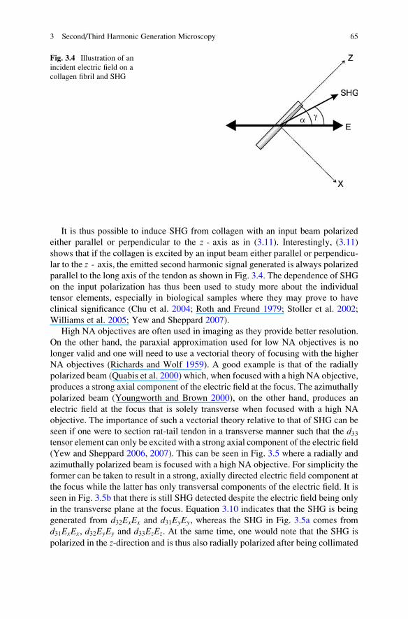
It is thus possible to induce SHG from collagen with an input beam polarized
either parallel or perpendicular to the z - axis as in (3.11). Interestingly, (3.11)
shows that if the collagen is excited by an input beam either parallel or perpendicu-
lar to the z - axis, the emitted second harmonic signal generated is always polarized
parallel to the long axis of the tendon as shown in Fig. 3.4. The dependence of SHG
on the input polarization has thus been used to study more about the individual
tensor elements, especially in biological samples where they may prove to have
clinical significance (Chu et al. 2004; Roth and Freund 1979; Stoller et al. 2002;
Williams et al. 2005; Yew and Sheppard 2007).
High NA objectives are often used in imaging as they provide better resolution.
On the other hand, the paraxial approximation used for low NA objectives is no
longer valid and one will need to use a vectorial theory of focusing with the higher
NA objectives (Richards and Wolf 1959). A good example is that of the radially
polarized beam (Quabis et al. 2000) which, when focused with a high NA objective,
produces a strong axial component of the electric field at the focus. The azimuthally
polarized beam (Youngworth and Brown 2000), on the other hand, produces an
electric field at the focus that is solely transverse when focused with a high NA
objective. The importance of such a vectorial theory relative to that of SHG can be
seen if one were to section rat-tail tendon in a transverse manner such that the d33tensor element can only be excited with a strong axial component of the electric field
(Yew and Sheppard 2006, 2007). This can be seen in Fig. 3.5 where a radially and
azimuthally polarized beam is focused with a high NA objective. For simplicity the
former can be taken to result in a strong, axially directed electric field component at
the focus while the latter has only transversal components of the electric field. It is
seen in Fig. 3.5b that there is still SHG detected despite the electric field being only
in the transverse plane at the focus. Equation 3.10 indicates that the SHG is being
generated from d32ExEx and d31EyEy, whereas the SHG in Fig. 3.5a comes from
d31ExEx, d32EyEy and d33EzEz. At the same time, one would note that the SHG is
polarized in the z-direction and is thus also radially polarized after being collimated
Fig. 3.4 Illustration of an
incident electric field on a
collagen fibril and SHG
3 Second/Third Harmonic Generation Microscopy 65

(Yew and Sheppard 2006, 2007). This further emphasizes the need for combining a
full vectorial theory of focusing with the tensor properties of SHG. The effect of
focussing a radially polarized beam at high NA are shown in Fig. 3.6.
Fig. 3.5 SHG images of rat-tail tendon for a fundamental beam polarized vertically (a)–(c). SHG
images without analyzer (d), and with an analyzer: (e) and (f) indicated by double-headed arrows,
oriented vertically for image (b), and horizontally for image (c). Collagen fibrils excited by an
excitation beam polarized either parallel or perpendicular to the long axis emit SHG polarized
parallel to the long axis of the fibrils
Fig. 3.6 SHG images of transversely sectioned rat-tail tendon. The long axis of the tendon is into
the paper. The effect of focusing a radially polarized beam with a high NA objective is seen in
(a) where the d33 tensor element is preferentially excited through the strong axial component at
the focus. In (b) the converse is true when focusing an azimuthally polarized beam with a high NA
objective, as this results in only transversal electric field components at the focus
66 S. Rehman et al.
3.4 Third Harmonic Generation
THG is a four-wave mixing process based on third-order nonlinear polarization
as shown in Fig. 3.1b. Unlike the second-order processes, the third-order process
is possible in all media, with or without inversion symmetry. The amplitude of
nonlinear susceptibility w 3ð Þ � w 2ð Þ , resulting in the magnitude of THG being
much smaller than that of SHG. THG was first reported in 1962 in a centrosymmet-
ric calcite crystal (Terhune et al. 1962). Other physical optical processes based
on third-order susceptibility wð3Þ are the Kerr effect, DC-induced SHG, and AC Kerr
effect.
The third-order induced polarization can be written as
Pið3Þð3oÞ ¼ e0
Xjkl
wð3Þijklðo; o; oÞEjðoÞEkðoÞElðoÞ : (3.16)
where E(o) is the incident wave at frequency o and wð3Þ is a fourth-rank tensor andindices ijkl are summed over linear polarization directions of x, y, and z. Theinduced polarization is at 3o that produces a new radiation at three times the
frequency of the incident wave. Cubic nonlinearities are responsible optical pro-
cesses like self-focusing and self-defocusing of optical beams, and also give rise to
interesting effects, such as, optical bistability, phase conjugation, and optical spatial
and temporal solitons. The presence of a cubic nonlinearity along with the quadratic
nonlinearity can produce additional interactions that can be written as
o0 þ o0 � o0 ! o0; o0 þ 2o0 � 2o0 ! o0
2o0 þ o0 � o0 ! 2o0; 2o0 þ 2o0 � 2o0 ! 2o0 :(3.17)
These relations hold for a fundamental optical frequency o0 under plane wave
approximation. Although the fundamental and second harmonic profiles remain
approximately Gaussian at low conversion efficiencies, their profiles may be
different from Gaussian because of the depletion of the fundamental signal.
The phase-matching condition for THG can be written as 3k1 � k3 ¼ 0. Here, k3and k1 are the wave vectors of the third harmonic field and the fundamental field,
respectively. This phase-matching condition can also be written in terms of refrac-
tive index n as ½nðoÞ � nð3oÞ� ¼ 0. In general, the refractive index of a medium is
always a function of frequency (the dispersion effect), making nðoÞ 6¼ nð3oÞ andonly in some special cases nðoÞ ¼ nð3oÞ. With a focused excitation beam, THG
from a homogenous bulk medium is canceled when the phase-matching condition is
satisfied. This interesting phenomenon has been explained on the basis of Gouy
phase shift, across the focus of the excitation beam (Cheng and Xie 2002). Along its
propagation direction, a Gaussian beam acquires a phase shift which differs from
that for a plane wave with the same optical frequency. This difference is called the
3 Second/Third Harmonic Generation Microscopy 67

Gouy phase shift and is given by ’ðzÞ ¼ � arctanðz=zRÞ, where zR is the Rayleigh
range. This gives a phase shift of p within the Rayleigh range for a Gaussian beam.
As THG is a coherent process, the emitted optical field from all the molecules is
added in contrast with the addition of intensities as in the case of an incoherent
process such as fluorescence. When the phases of the interacting optical fields are
properly matched, a condition termed as phase-matching, the total signal intensity
is proportional to the square of the number of scattering molecules (Boyd 2003).
When phase-matching is not right, the generated signal is significantly low in
magnitude. As the condition of phase-matching is dependent on the relative geom-
etry of the illuminating beam, the signal, and the medium, signals generated by a
coherent process are typically small (Cheng and Xie 2002).
Third harmonic signals can be effectively generated from an interface or from
an object with a size comparable to the FWHM (Full Width at Half Maximum) of
the axial excitation intensity profile. The signal from a bulk medium is canceled by
a wave-vector mismatch associated with the Gouy phase shift of the focused
excitation field. This permits THG imaging of small features with a high signal-
to-background ratio. The THG radiation from a small object or an interface
perpendicular to the optical axis exhibits a sharp radiation pattern along the optical
axis in the forward direction. For an interface parallel to the optical axis, the role of
the Gouy phase shift is to deflect the phase-matching direction, that is, the THG
radiation maximum direction, off the optical axis.
The method of THG microscopy in most samples is on the basis of a peculiarity
of the phase-matching conditions. The third harmonic signal vanishes completely
from most bulk samples, and is generated only when the illuminating beam is
focused at a small inclusion or an interface between two materials. A signal is
generated even when the two materials are index matched, as the THG process
relies on the nonlinear susceptibility rather than on the index of refraction.
As third harmonic signal is produced by a tightly focused laser beam at an
interface, it can be used to image biological and nonbiological specimens. The
production of the THG signal is restricted to the condition of breaking the axial
Fig. 3.7 THG signal shown
by arrows, from a plane
(dotted line) at the focus ofthe excitation laser beam. The
focal plane is at an interface
inside the object
68 S. Rehman et al.

focal symmetry by a change in material properties. The localized production of
third harmonic light at such boundaries provides inherent optical sectioning. There-
fore, it is possible to obtain three-dimensional images of microscopic objects by
detecting THG signal from different planes perpendicular to the axis of laser beam
propagation. This principle of THG is schematically shown in Fig. 3.7. The axial
symmetry is broken by some interface or change in refractive index owing to the
Gouy phase shift.
3.4.1 THG Microscopy
Third harmonic light is produced by a laser beam tightly focused at an interface. It is
possible to image both biological and non-biological specimens with inherent optical
sectioning of THG microscopy. Third harmonic light in a material is produced given
that the axial focal symmetry can be broken by a change in the material properties
like interfaces and boundaries because of refractive index or nonlinear susceptibility
changes. This localized production of third harmonic light at material interfaces
provides the inherent optical sectioning desired in a three-dimensional imaging at
higher axial resolution. It is possible to produce three-dimensional images by THG
from different planes perpendicular to the axis of beam propagation. Compared to
other modes of single or multi-photon laser fluorescence microscopy, no exogenous
fluorophores are needed in THG microscopy.
It was demonstrated by Tsang that under tight focusing conditions THG can be
generated through an interface within the focal volume of the excitation beam
(Tsang 1995). Later, it was shown that whenever there is either a change in refractive
index or third-order nonlinear susceptibility, third harmonic light is produced, and as
a result of this interface effect, third harmonic imaging is possible and can be
applied to study transparent samples having low contrast (Barad et al. 1997).
Volumetric imaging has also been done in both biological and non-biological
Fig. 3.8 Schematic layout of
a typical nonlinear optical
laser scanning microscope
3 Second/Third Harmonic Generation Microscopy 69

specimens demonstrating the dynamical imaging properties of THG in live samples
(M€uller et al. 1998; Squier et al. 1998).A typical nonlinear microscope system is shown in Fig. 3.8, where a standard
optical microscope can be modified into a THG microscope. The laser source is
usually a high power laser with femtosecond pulses. The laser beam is coupled
through one of the microscope ports and is focused into the sample by the micro-
scope objective. The focal point is scanned in the xy plane using two optical
scanners, and along the z-axis using the motorized stage of the microscope. The
third harmonic light is collected by the condenser and detected by a photomultiplier
tube (PMT) after filtering out the fundamental wavelength using a band-pass
interference filter. The signal from the PMT is amplified, digitized and coupled
into a computer, which synchronizes the scanning process and the data collection.
3.4.2 Applications
THG near the focal point of a tightly focused laser beam can be used to probe small
structures of transparent samples at the interfaces and inhomogeneities. Because of
the coherent nature of third harmonic process, the axial resolution of THG micros-
copy is, however, equal to the confocal parameter of the fundamental beam (Barad
et al. 1997). The signal level in THG microscopy can be optimized by the influence
of sample structure and beam focusing (Debarre et al. 2005), where they controlled
the signal level by modifying the Rayleigh range of the excitation beam and
applied this method for the contrast modulation in THG images of Drosophila
embryos. Besides structural and beam shape dependence, the THG is also sensitive
to the local differences in the refractive index, third-order susceptibility, and
dispersion. This aspect of THG was used to image lipids that are present in
many biological cells and tissues (Debarre et al. 2006). In this study, a multimodal
technique for microscopy was used to image lipid bodies, fluorescent compounds
in tissues and extra-cellular matrix by combining two-photon fluorescence, SHG,
and THG microscopy. Another multimodal nonlinear microscopic technique based
on a femtosecond Cr:Forsterite laser was used to simultaneously generate SHG,
THG, two-photon, and three-photon fluorescence images. Multi-photon excited
fluorescence (MPEF) provides functional information of molecules, while SHG
and THG can be used to image organized biological subcellular structures and
interfaces. THG and SHG involve only the virtual state without energy deposition;
therefore, they cause no photodamage or bleaching in the biological specimens
(Chu et al. 2001).
THG microscopy is shown to be particularly suitable for imaging biogenic
crystals and polarization sensitive imaging of crystalline structure in biological
samples (Oron et al. 2003, 2004). THG has been used for the characterization of
saline solutions and structural changes in collagen (Shcheslavskiy et al. 2004). It is
shown that THG epidetection is generally possible when the sample structure is
embedded in a scattering, non-absorbing tissue with thickness greater than the
reduced scattering mean free path (Debarre et al. 2007).
70 S. Rehman et al.

Recently, a multimodal microscopic technique was implemented by a combina-
tion of THG, SHG, and MPEF image contrast methods on the same microscope
(Gualda et al. 2008). In this study, specific cellular and anatomical features of the
nematode Caenorhabditis elegans were imaged with laser pulses at 1,028 nm from
a Ti:sapphire laser to excite the biological samples and the emitted THG signal was
detected in the near-UV at 343 nm.
3.5 Laser Sources for SHG and THG Microscopy
First laser used in nonlinear microscopy of a biological tissue, was a Q-switched
ruby laser at 694 nm, to study the collagen structure but resulted in strong absorp-
tion of the SHG signal at 347 nm (Fine and Hansen 1971). Later, a Q-switched
Nd–YAG laser at 1,064 nm and nanosecond pulses was used to observe connective
tissues (Freund et al. 1986). More recently, femtosecond pulse laser beams are
being used for SHG and THG microscopy because of their high peak intensities.
The most common and current industrial standard excitation source for non-
linear microscopy is the femtosecond pulse Ti:sapphire laser. With average power
of several watts, around 80MHz repetition rate, its wavelength range is only limited
by the bandwidth of the Ti:sapphire gain medium to between approximately 690
and 1,070 nm. This wavelength range is sometimes called therapeutic window, as it
can penetrate deep into the biological tissue without causing significant photo-
damage, and is not absorbed by water which may otherwise result in heating.
For THG microscopy, a Ti:saphire laser seems to be ideal but strong absorption
of the signal generated in the UV region limits its application to thin biological
specimens. To avoid UV absorption of the generated THG signal in thick biological
samples, THG microscopy is done with wavelengths longer than 1,200 nm.
Cr:Forsterite laser at excitation wavelength of 1,230 nm and repetition rate of
110 MHz is widely used for THG microscopy (Chu et al. 2001, MC Chan et al.
2008). Other lasers used for THG microscopy include optical parametric oscillator
(OPO) working at a wavelength of 1,500 nm and repetition rate of ~80 MHz,
synchronously pumped by a femtosecond Ti:sapphire laser (Canioni et al. 2001;
Yelin and Silberberg 1999); an optical parametric amplifier (OPA) at 1,200 nm and
250 kHz repetition rate pumped by a Ti:sapphire laser (M€uller et al. 1998; Squieret al. 1998); a fiber laser at 1,560 nm with a repetition rate of 50 MHz (Millard et al.
1999); and some new laser sources being used for nonlinear microscopy are Yb:
glass, Nd:glass, Cr:LiSAF, and fiber lasers.
3.6 Conclusion
The lateral resolution in SHG/THG microscopy remains close to the diffraction
limit of the imaging optics. In general, the interaction volume in the specimen decreases
with an increasing order of the nonlinearity of the process. For multi-photon absorption
3 Second/Third Harmonic Generation Microscopy 71

processes, this effect is counterbalanced by a relative increase in the excitation
wavelength. Hence, the real advantage of such a technique lies not in the improved
resolution but in the noninvasive and in vivo imaging without any sample staining.
SHG/THG microscopy because of its noninvasive nature is suitable for in vivo
imaging of live specimens without any preparation. The intensity of the SHG signal
depends on square of the incident light intensity, while the intensity of THG signal
depends on the third power of the incident light intensity. This nonlinear depen-
dence on the intensity leads to localized excitation and is ideal for intrinsic optical
sectioning in scanning laser microscopy. SHG microscopy is suitable for imaging
stacked membranes and arranged proteins with organized structures. The THG
microscopy is applicable to imaging cellular or subcellular interfaces. The main
advantage of THG/SHG microscopy is due to the virtual nature of higher harmonic
generation, in which, no saturation or bleaching results in the generated signal.
Continuous viewing without compromising the sample viability can be achieved
because of this property of nonlinear process, in which no energy is released. SHG/
THG microscopy can be applied to live specimen without compromising its
viability, while high resolution morphological, structural, functional, and cellular
information of biomedical specimens can be obtained. With the flexibility of
combining with fluorescence based microscopes, SHG/THG microscopy is likely
to become a major imaging modality in biomedical fields. Also, given the status of
laser development, it is to be expected that nonlinear optical microscopic techni-
ques such as SHG/THG will be utilized for high resolution microscopy in a variety
of applications.
References
Barad Y, Eisenberg H, Horowitz M et al (1997) Nonlinear scanning laser microscopy by third-
harmonic generation. Appl Phys Lett 70(8):922–924
Barzda V, Greenhalgh C, Aus der Au J et al (2005) Visualization of mitochondria in cardiomyo-
cytes by simultaneous harmonic generation and fluorescence microscopy. Opt Express
13:8263–8276
Bloembergen N (1965) Nonlinear optics, 4th edn. Benjamen, New York
Boyd RW (2003) Nonlinear optics. Academic, San Diego
Campagnola PJ, Wei M-D, Lewis A et al (1999) High-resolution nonlinear optical imaging of live
cells by second harmonic generation. Biophys J 77(6):3341–3349
Campagnola PJ, Millard AC, Terasaki M et al (2002) Three-dimensional high-resolution second-
harmonic generation imaging of endogenous structural proteins in biological tissues. Biophys J
82(1):493–508
Canioni L, Rivet S, Sarger L et al (2001) Imaging of Ca2þ intracellular dynamics with a third-
harmonic generation microscope. Opt Lett 26(8):515–517
Chan MC, Chu SW, Tseng CH et al (2008) Cr:Forsterite-laser-based fiber-optic nonlinear endo-
scope with higher efficiencies. Microsc Res Tech 71:559–563
Cheng J-X, Xie XS (2002) Green’s function formulation for third-harmonic generation micro-
scopy. J Opt Soc Am B 19(7):1604–1610
Chu S-W, Chen I-H, Liu T-M et al (2001) Multimodal nonlinear spectral microscopy based on a
femtosecond Cr:forsterite laser. Opt Lett 26:1909–1911
72 S. Rehman et al.

Chu S-W, Chen I-H, Liu T-M et al (2002) Nonlinear bio-photonic crystal effects revealed with
multimodal nonlinear microscopy. J Microsc 208(3):190–200
Chu S-W, Chen S-Y, Chern G-W et al (2004) Studies of w(2)/w(3) tensors in submicron-scaled bio-
tissues by polarization harmonics optical microscopy. Biophys J 86(6):3914–3922
Chu S-W, Tai S-P, Chan M-C et al (2007) Thickness dependence of optical second harmonic
generation in collagen fibrils. Opt Express 15(19):12005–12010
Cox G, Moreno N, Feijo J (2005) Second-harmonic imaging of plant polysaccharides. J Biomed
Opt 10:0240131–0240136
Debarre D, Supatto W, Pena A-M et al (2006) Imaging lipid bodies in cells and tissues using third-
harmonic generation microscopy. Nat Meth 3(1):47–53
Debarre D, Supatto W, Beaurepaire E (2005) Structure sensitivity in third-harmonic generation
microscopy. Opt Lett 30:2134–2136
Debarre D, Suppato W, Pena A-M et al (2006) Imaging in lipid bodies in cells and tissues using
third-harmonic generation microscopy. Nat Meth 3(1):47–53
Debarre D, Olivier N, Beaurepaire E (2007) Signal epidetection in third-harmonic generation
microscopy of turbid media. Opt Express 15(15):8913–8924
Denk W, Strickler JH, Webb WW (1990) Two-photon laser scanning fluorescence microscopy.
Science 248:73–76
Duncan MD, Reintjes J, Manuccia TJ (1982) Scanning coherent anti-Stokes Raman microscope.
Opt Lett 7(8):350
Fine S, Hansen WP (1971) Optical second harmonic generation in biological systems. Appl Opt
10:2350–2353
Franken PA, Hill AE, Peters CW et al (1961) Generation of optical harmonics. Phys Rev Lett
7:118
Freund I, Deutsch M (1986) Second-harmonic microscopy of biological tissue. Opt Lett 11:94–96
Freund I, Deutsch M, Sprecher A (1986) Connective tissue polarity: optical second-harmonic
microscopy, crossed-beam summation, and small-angle scattering in rat-tail tendon. Biophys J
50:693–712
Fukada E, Yasuda I (1964) Piezoelectric effects in collagen. Jpn J Appl Phys 3:117–121
Gannaway JN, Sheppard CJR (1978) Second-harmonic imaging in the scanning optical micro-
scope. Opt Quant Electron 10:435–439
Gauderon R, Lukins PB, Sheppard CJR (1998) Three-dimensional second-harmonic generation
imaging with femtosecond laser pulses. Opt Lett 23(15):1209–1211
Gualda EJ, Filippidis G, Voglis G et al (2008) In vivo imaging of cellular structures in Caenor-habditis elegans by combined TPEF, SHG and THG microscopy. J Microsc 229(1):141–150
He G-S, Liu SH (1999) Physics of nonlinear optics. World Scientific, Singapore
Hellwarth R, Christensen P (1974) Nonlinear optical microscopic examination of structure in
polycrystalline ZnSe. Opt Commun 12(3):318–322
Lin SJ, Hsiao CY, Sun Y et al (2005) Monitoring the thermally induced structural transitions of
collagen by use of second-harmonic generation microscopy. Opt Lett 30:622–624
Maiti S, Shear JB, Williams RM et al (1997) Measuring serotonin distribution in live cells with
three-photon excitation. Science 275:530–532
Millard AC, Wiseman PW, Fittinghoff DN et al (1999) Third-harmonic generation microscopy by
use of a compact femtosecond fiber laser source. Appl Opt 38:7393–7397
Mizutani G, Sonoda Y, Sano H et al (2000) Detection of starch granules in a living plant by optical
second harmonic microscopy. J Lumin 87–89:824–826
Moreaux L, Sandre O, Blanchard-Desce M et al (2000) Membrane imaging by simultaneous
second-harmonic generation and two-photon microscopy. Opt Lett 25:320–322
M€uller M, Squier J, Wilson KR et al (1998) 3D-microscopy of transparent objects using third-
harmonic generation. J Microsc 191:266–274
Oron D, Tal E, Silberberg Y (2003) Depth-resolved multiphoton polarization microscopy by third-
harmonic generation. Opt Lett 28(23):2315–2317
3 Second/Third Harmonic Generation Microscopy 73
Oron D, Yelin D, Tal E et al (2004) Depth-resolved structural imaging by third-harmonic
generation microscopy. J Struct Biol 147(1):3–11
Prent N, Cisek R, Greenhalgh C et al (2005) Application of nonlinear microscopy for studying the
structure and dynamics in biological systems. Proc SPIE 5971:5971061–5971068
Pu Y, Centurion M, Psaltis D (2008) Harmonic holography: a new holographic principle. Appl Opt
47:A103–A110
Quabis S, Dorn R, Eberler M et al (2000) Focusing light to a tighter spot. Opt Commun 179:1–7
Richards B, Wolf E (1959) Electromagnetic diffraction in optical systems. II Structure of the
image field in an aplanatic system. Proceedings of the Royal Society of London Series A
253(1274):358–379
Roth S, Freund I (1979) Second harmonic generation in collagen. J Chem Phys 70:1637–1643
Schrader M, Bahlmann K, Hell SW (1997) Three-photon-excitation microscopy: theory, experi-
ment and applications. Optik 104:116–124
Shcheslavskiy V, Petrov GI, Saltiel S et al (2004) Quantitative characterization of aqueous
solutions probed by the third-harmonic generation microscopy. J Struct Biol 147(1):42–49
Shen YR (1984) The principles of nonlinear optics. Wiley, New York
Sheppard CJR, Kompfner R (1978) Resonant scanning optical microscope. Appl Opt 17(18):
2879–2882
Squier JA, Muller M, Brakenhoff GJ et al (1998) Third harmonic generation microscopy. Opt
Express 3:315–324
Stoller P, Kim BM, Rubenchik AM et al (2002) Polarization-dependent optical second-harmonic
imaging of a rat-tail tendon. J Biomed Opt 7:205–214
Terhune RW,Maker PD, Savage CM (1962) Optical harmonic generation in calcite. Phys Rev Lett
8(10):404–406
Tsang TYF (1995) Optical third-harmonic generation at interfaces. Physical Review A 52:
4116–4125
Williams RM, Zipfel WR, Webb WW (2005) Interpreting second harmonic generation images of
collagen in fibrils. Biophys J 88:1377–1386
Yelin D, Silberberg Y (1999) Laser scanning third-harmonic-generation microscopy in biology.
Opt Express 5(8):169–175
Yew EYS, Sheppard CJR (2006) Effects of axial field components on second harmonic generation
microscopy. Opt Express 14:1167–1173
Yew EYS, Sheppard CJR (2007) Second-harmonic generation polarization microscopy with
tightly focused linearly and radially and azimuthally polarized beams. Opt Commun 275(2):
453–457
Youngworth K, Brown T (2000) Focusing of high numerical aperture cylindrical-vector beams.
Opt Express 7:77–87
Yu C-H, Tai S-P, Kung C-T et al (2008) Molecular third-harmonic-generation microscopy through
resonance enhancement with absorbing dye. Opt Lett 33:387–389
74 S. Rehman et al.