
Transient stability enhancement via hybrid technical approach
6
Transient Stability Enhancement via Hybrid Technical Approach Mostafa Eidiani 1* , Mohammad Ebrahimean Baydokhty 2 , Mahdi Ghamat 2 , Hossein Zeynal 3 , Hashem Mortazavi 4 1 Bojnourd Branch, Islamic Azad University, Bojnourd, Iran 2 Gonabad Branch, Islamic Azad University, Gonabad, Iran 3 Centre of Electrical Energy Systems(CEES), Universiti Teknologi Malaysia (UTM), Johor, Malaysia 4 Khorasan Regional Electric Company(KREC), Mashhad, Iran *E-mail: [email protected] Abstract— In this paper, improving in transient stability is made through a development of new approach. Since the maximum use of existing capacities along with the increased powers transferred through the transition lines make transient stability studies even more important. Generator tripping is one of the most effective methods that remedy to stability in case of severe faults. In this method, a number of units of a certain unit are disconnected as a way of making the system works steadily. The braking resistor is less efficient than generator tripping for transient stability. In the proposed method, system stability against severe turbulence is tackled with minimum tripping of generator units. At this proposal, the intensity of fault will be valuably lessen by applying braking resistor, and then, for the purpose of improving transient stability, the kinetic energy is reduced by removing certain unit at the right time. The approach has been tested on 9- bus with 3-generator system to demonstrate promising effects. Keywords-transient stability; Generator tripping; Braking resistor; Energy function I. INTRODUCTION Each dynamic system designed or constructed should operate in stable conditions. Under these circumstances, the system must satisfactorily continue to work and stay stable at all times even during the occurrence of faults with a good safety margin. Assuming the system to be in one of its stable modes, if the system eventually returns to its equilibrium condition after a disturbance, we say the system is stable. If it converges to another equilibrium condition close to the former equilibrium condition, we also call the system stable, and we call the system instable if the variables of the system diverge from the equilibrium point over time. In short, the stability of power systems consists of tendency of the power system to create recovery forces equal or bigger than disturbance forces applying thereto in order to maintain equilibrium condition of the system. Transient stability studies involves large and sudden disturbance such as the occurrence of a fault, the sudden disconnection of a line, and sudden entry and exit of charges. Transient stability studies the occurrence of a major disruption is essential. The relay setting system studies are required after a major disturbance. These studies are useful for determining the nature of the required relay setting system, specifying the fault removal critical time, determining the voltage levels of system and specifying intersystem power transfer capability. Different methods capacitors are used to improve transient stability such as controlling the generator's excitation, removal of the generator, fast valving, braking resistor, eliminating time, removal of charge and series [1], [2]. The above-mentioned methods try to do one or more of the followings: a) To reduce the impact of turbulence by minimizing intensity of fault and the period thereof. b) To increase synchronizer forces of recovery. c) To reduce the acceleration torque through control of input d) To decrease the acceleration torque by applying artificial load. II. GENERATOR TRIPPING On account of convenience and fastness [5], this control method is one of the most effective methods of improving transient stability [6]. In sense of generator tripping, we shed a number of high speed generators so that synchronism difference is eliminated and systems returns to stable condition. In this section, we study how generator tripping affects improvement of transient stability. Based on Atay’s energy function [7], [8]: Vൌ 1 2 ୬ ୧ୀଵ M ୧ θ ሶ ୧ ଶ െ P ୫୧ ୬ ୧ୀଵ ሺθ ୧ െ θ ୧ୱ ሻ නP ୧ ౩ dθ ୧ ୬ ୧ୀଵ ሺ1ሻ In which: ܯ୧ : Inertia constant of generator i : Mechanical input power of generators A23 2011 IEEE Student Conference on Research and Development (SCOReD) 978-1-4673-0102-2/11/$26.00 ©2011 IEEE 414
Transcript of Transient stability enhancement via hybrid technical approach

Transient Stability Enhancement via Hybrid Technical Approach
Mostafa Eidiani1*, Mohammad Ebrahimean Baydokhty2, Mahdi Ghamat2, Hossein Zeynal3, Hashem Mortazavi4
1 Bojnourd Branch, Islamic Azad University, Bojnourd, Iran 2 Gonabad Branch, Islamic Azad University, Gonabad, Iran
3 Centre of Electrical Energy Systems(CEES), Universiti Teknologi Malaysia (UTM), Johor, Malaysia 4 Khorasan Regional Electric Company(KREC), Mashhad, Iran
*E-mail: [email protected]
Abstract— In this paper, improving in transient stability is made through a development of new approach. Since the maximum use of existing capacities along with the increased powers transferred through the transition lines make transient stability studies even more important. Generator tripping is one of the most effective methods that remedy to stability in case of severe faults. In this method, a number of units of a certain unit are disconnected as a way of making the system works steadily. The braking resistor is less efficient than generator tripping for transient stability. In the proposed method, system stability against severe turbulence is tackled with minimum tripping of generator units. At this proposal, the intensity of fault will be valuably lessen by applying braking resistor, and then, for the purpose of improving transient stability, the kinetic energy is reduced by removing certain unit at the right time. The approach has been tested on 9-bus with 3-generator system to demonstrate promising effects.
Keywords-transient stability; Generator tripping; Braking resistor; Energy function
I. INTRODUCTION Each dynamic system designed or constructed should operate in stable conditions. Under these circumstances, the system must satisfactorily continue to work and stay stable at all times even during the occurrence of faults with a good safety margin. Assuming the system to be in one of its stable modes, if the system eventually returns to its equilibrium condition after a disturbance, we say the system is stable. If it converges to another equilibrium condition close to the former equilibrium condition, we also call the system stable, and we call the system instable if the variables of the system diverge from the equilibrium point over time. In short, the stability of power systems consists of tendency of the power system to create recovery forces equal or bigger than disturbance forces applying thereto in order to maintain equilibrium condition of the system. Transient stability studies involves large and sudden disturbance such as the occurrence of a fault, the sudden disconnection of a line, and sudden entry and exit of charges. Transient stability studies the occurrence of a major disruption is essential. The relay setting system studies are required after a major disturbance. These studies are useful for determining
the nature of the required relay setting system, specifying the fault removal critical time, determining the voltage levels of system and specifying intersystem power transfer capability. Different methods capacitors are used to improve transient stability such as controlling the generator's excitation, removal of the generator, fast valving, braking resistor, eliminating time, removal of charge and series [1], [2]. The above-mentioned methods try to do one or more of the followings:
a) To reduce the impact of turbulence by minimizing intensity of fault and the period thereof. b) To increase synchronizer forces of recovery. c) To reduce the acceleration torque through control of input d) To decrease the acceleration torque by applying artificial load.
II. GENERATOR TRIPPING On account of convenience and fastness [5], this control
method is one of the most effective methods of improving transient stability [6]. In sense of generator tripping, we shed a number of high speed generators so that synchronism difference is eliminated and systems returns to stable condition.
In this section, we study how generator tripping affects improvement of transient stability. Based on Atay’s energy function [7], [8]: V 12 M θ P θ θ
P dθ 1
In which: : Inertia constant of generator i : Mechanical input power of generators
A23 2011 IEEE Student Conference on Research and Development (SCOReD)
978-1-4673-0102-2/11/$26.00 ©2011 IEEE 414

: Electrical power output of generator : Vertex : Generator's angle to vertex θ : The angle at the stable equilibrium point . . : The angle at the instable equilibrium point u. e. p M 2 δ ∑ M δ /M 3
∑ 4 5 The first, second and third terms in energy equation (1) represent the rotor's kinetic energy, rotor's potential energy, and the energy stored in the system, respectively. Potential energy at instable equilibrium point is equal to: V P θ θ P dθه θ
θ
(6) If then system is stable & if then system is instable. Considering that the fault period is short, variations of angle are small in equation (1). If terms 2 and 3 of equation ( 1) versus term 1 can be neglected, therefore: V VK ∑ M θ ∑ M δ δ (7)
δ P PMT dt 8 If we assume T to be small, remains almost constant, therefore:
δP P . TM 9
We obtain the following relation by substituting equation (9) in equation (7): V T ∑ P PM ∑ P PM (10)
If we assume T to be the fault removal time ( ), the relation above gives the kinetic energy during the fault removal time. In case the system is instable, we should reduce its kinetic energy. To this end, we use generator tripping. In this method, after determining the proper production unit, we should shed a number of generators to reduce the kinetic energy aiming to achieve sustainability. If we choose production unit i for reducing the kinetic energy, after tripping a number of generators of unit I, relation (7) is transformed as follows: VK′ 12 M′δ
12 M δ
T ∑ P P .MM ∑ P P MMM (11) M 12
δ ∑ M δM 13
Comparison of relations (10) and (11) brings us to the conclusion that K , in other words, removal of the generator has reduced the kinetic energy and thus has contributed to system stability.
The abbreviation “i.e.” means “that is”, and the abbreviation “e.g.” means “for example”.
An excellent style manual for science writers is [7].
III. ALLOCATE PROPER TRIPPING TIME Generator tripping is happening at the risk of abrupt
changes in mechanical and electrical loading, hit the generator, turbine and power supply systems. Although thermal control units withstand such a blow, there is also the possibility that the controls schemes malfunctioned. So, removing the generator should be smartly committed [10]. Hence, the time to take the generator out affects on transient stability, the amount of production loss [7] and even the generator protection. According to the mentioned cases, the importance of the time was realized in generators removal. We assume and to denote the fault time, and the critical time, respectively. The two of the followings occur in faulty system: a) t t In this case, the system is stable and generator tripping may not contribute to stability, it may even undermine stability. If the aim is to improve transient stability, it would be better to use other methods. b) t t If the fault's type, severity, and location and system's topology, etc. are such that the critical time (t ) errors is shorter than fault removal time (which is prescheduled and fixed), the system will be instable in the period from critical time through the time when the appropriate action is taken. The generator must be kept untripped in the interval [ , ] which can economically sound. Therefore, generator tripping should take place when it is necessary and convincing, because the system may recover stability and it actually dose not require generator tripping after when the protection system started to operate, for example, after occurrence of short circuit in one of transition lines or switching on of one of the line's keys on the time t . Therefore, the generator tripping is managed in the interval [ , ]. Considering that the kinetic energy increases continuously over time, so that generator tripping should be done immediately at this interval, thereby stabilization could occur with the minimum power loss. However, it is recommended if the tripping can be conducted a short while after fault clear, because instant variations of transient energy of the system are very high during the fault period, so we should be idle for a short while before the generator tripping until these variations decrease. By this, the over expected excessive power loss could be prevented.
A23 2011 IEEE Student Conference on Research and Development (SCOReD)
415

IV. POINT GENERATOR TRIPPING AMOUNT
Considering the economic leverages involved in the control method of generator tripping, we should calculate the minimum number of generator tripping required to meet transient stability. In reference [6], assuming that production unit i consists of n generators, we trip of production in the first stage of production, and if the system remains instable, the production removal should be topped up. In reference [9] assuming that unit I, as the most instable unit to trip, the smallest generator of the unit in the first stage has to be run off, and if the system remains instable, this process proceeds up. For the reasons stated in this section, we cannot use these two methods. It is recommended that the following method, which is based on Athay energy function, has been used. Equations (10) and (11) give the kinetic energy of the system at fault time, and after tripping of generators of unit i, respectively. VK is equal to the total kinetic energy of generator units required to be shed in unit j to recover the instability. If α denotes the percentage of remaining generators of power plant unit j, the kinetic energy of the generator tripping from the unit j is equal to: VK 12 1 α M θ
12 1 α M δ δ T P P .M,,M P P M,,/MM,, (17 )
Where: ,, 1 α M 18 M,, 1 α M ∑ M 19
Finally: K ∑ (20)
Therefore: VK VK V 21 In above relation, α is unknown. After obtaining α, β 100α, which is the percentage of production, the loss of unit j will be specified. Therefore, having calculated β, the amount of generator tripping becomes discrete and it is equal to , m
should be selected in a way that is bigger than or equal to and is the minimum.
V. BRAKING RESISTOR
Brake resistor is a resistor with the ability to absorb high amount of energy in a short period of time; when disturbance occurs, this resistor arrives onto the system like an artificial electrical charge with high speed and increases consumed power. This accelerating energy is created as a result of disturbance which must be talked by the control systems. According to the standard of equal levels, the mechanical accelerator level must be lower than the level of brake, which results in improved system stability.
For modeling the brake resistor in the system, the system is studied without resistance influence; so its admittance matrix will be as follows [11]: IG0 YGG YGKYGK YKK EGVK 22
In which: G: Voltage behind the transient reactance of straight shaft of i th generator | | : voltage of kth bus with no generator attached From relation (22) we have : 23 24 In which: G : Matrix of reduced reactance with elimination of all nodes except for the generator's internal nodes. ith element of jth column of matrix G regardless of conductance is as follows: 25 For the system with n machine, real output power of i th generator is as follows: P Re E I Re E Y E
E G ∑ E E B sin δ δ
P b sinδ 26
Figure 1. Effect of brake resistor on transient stability
A23 2011 IEEE Student Conference on Research and Development (SCOReD)
416
Conductivity of braking resistor that is connected in parallel to bus is equal to G t P|V | , In which: t : power absorbed by the resistor | |: Size of voltage of the bus bar on which the brake resistor is installed. After connecting the braking resistor, the kth element of admittance matrix changes from to G , therefore, relation (24) is rewritten as follows: 27 28 29 30 Since admittance of a bus is equal to thévenin of kth bus, and assuming B , we have: 1 31
According to equation (31), we have: 1 1 11 11 32
Since T 1, we can write: 11 1 33 Therefore, the equation (31) will be cast as: 1 34 Assuming G ، G ، G to denote quantities of the network in the absence of braking resistor, based on relation (34) relations, relations (27) to (29) can be simplified as follows: ∆ 35 IG IG ∆YGEG jXT G 36 VK VK YKKYKGEG jXT G 37 In which: ∆YG YGKYKKYKG 38 Equations (35) to (37) give the effect of braking resistor on variables of bus bar. According to relation (36), current of generator i is as follows: ∆ 39 In which: ∆I ∆Y E 40 Therefore, the generators' output power after applying the braking resistor is: P ∆P XT G t (41) It is observed that applying the braking resistor results in reduced output power of generators, in other words, it contributes to transient stability by reducing output power of generators.
Figure. 3. Respective bus voltage angle of generators before control
action
Figure 4.Respective bus voltage angle of generators after application of
brake resistor
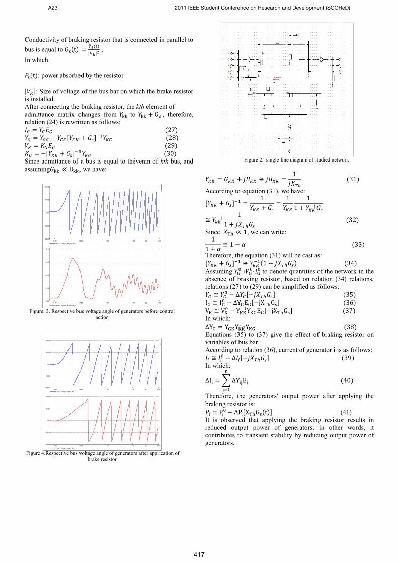
Figure 2. single-line diagram of studied network
2.001.501.000.500.00 [s]
200.00
100.00
0.00
-100.00
-200.00
Bus 2: Voltage, Angle in deg
2.001.501.000.500.00 [s]
80.00
60.00
40.00
20.00
0.00
Bus 3: Voltage, Angle in deg
DIgSILENT
2.001.501.000.500.00 [s]
200.00
100.00
0.00
-100.00
-200.00
Bus 2: Voltage, Angle in deg
2.001.501.000.500.00 [s]
200.00
100.00
0.00
-100.00
-200.00
Bus 3: Voltage, Angle in deg
DIgSILENT
A23 2011 IEEE Student Conference on Research and Development (SCOReD)
417

VI. PROPOSED HYBRID METHODOLOGY
Since, in generator tripping method, company bears losses due to the wastage of its production on the one hand, and should compensate the damages on the inflicted customer due to power out. And, braking resistor method has limitations in severe disturbances. Considering that the resistance bank is fixed in its place, this method is less effective in case of faults far away from bank's location. Another sense, if the resistance bank stays connected for a long time, instability will be likely to occur in the back swing mode [10].
TABLE I. CONSTANT VALUES OF GENERATORS
(P.U)
H (s) No. Gen.
No
0.15 4.775 1 1 1.15 5 0.354 5 2
0.69 3 0.583 3 3
According to relation (10), the kinetic energy of generator is directly proportional to generator's output power ( ). On the other hand, after applying the brake resistor, generator's output power decreases according to relation (41).
VII. SIMULATION RESULTS AND DISCUSSION
Studies were conducted on 9-bus, 3-genrator unit and 6-line system. Simulations were conducted using DIgSILENT software. We consider unit 1 as slack with voltage of 1.040 . Powers of units 2 and 3 are 163 and 85 MW, respectively. In simulations, we assume the fault to be three-phase error, bus 7, and the occurrence time to be 0.02 and fault removal time to be 0.25 seconds.
VIII. CONCLUSION
Considering limitations of resistance bank, resistor braking may be ineffective in improving stability in the event of a serious fault. Generator tripping must be practiced to improve transient stability due to serious faults. In this case, we should trip more than one generator unit to recover stability. To minimize the number of generator units to be tripped out, using the combined method is recommended.
ACKNOWLEDGEMENT
Authors acknowledge the financial supports provided by Khorasan Regional Electric Company (KREC), Mashhad, Iran.
REFERENCES [1] C.W. Taylor, Power System Voltage Stability, New York:
McGraw Hill, 1994 [2] P.Kundur, ”Effective Use of Power System Stabilizers for
Enhancement of Power System Stability,”in proc.1999 IEEE PES Power Engineering Society Summer Meeting,pp.96-103.
[3] J.Machowski,Power System Daynamic and Stability,NewYork:Wilery 1997
[4] G.Karady and J.Gu”A Hybrid method for Generator Tripping”IEEE Trans,Vol17,pp.1102-1107,Nowember 2002.
[5] T.Athay,R.Podmore and S. Virmani,”A Practical Method for Direct Analysis of Transient Stability”,IEEE Trans.,Vol.PAS98,pp.573-584
[6] T.Athay,V.R.Sherket,R.Podmore,S.Virmani,C.Puech,”Transient Energy Stability Analysis”,System Engineering for Power,Emergency Operating State Control-Section IV,U.S. Dept.of Energy,Publication No.CONF-790904-P1.
Figure 5.Respective bus voltage angle of generators after trip of one
generator
Figure 6.Respective bus voltage angle of generators after trip of three
generators
Figure 7. Respective bus voltage angle of generators after application of
combined method
2.001.501.000.500.00 [s]
200.00
100.00
0.00
-100.00
-200.00
Bus 2: Voltage, Angle in deg
2.001.501.000.500.00 [s]
80.00
60.00
40.00
20.00
0.00
-20.00
Bus 3: Voltage, Angle in deg
DIgSILENT
2.001.501.000.500.00 [s]
200.00
100.00
0.00
-100.00
-200.00
Bus 2: Voltage, Angle in deg
2.001.501.000.500.00 [s]
80.00
60.00
40.00
20.00
0.00
-20.00
Bus 3: Voltage, Angle in deg
DIgSILENT
2.001.501.000.500.00 [s]
150.00
100.00
50.00
0.00
-50.00
-100.00
Bus 2: Voltage, Angle in deg
2.001.501.000.500.00 [s]
90.00
60.00
30.00
0.00
-30.00
-60.00
-90.00
Bus 3: Voltage, Angle in deg
DIgSILENT
A23 2011 IEEE Student Conference on Research and Development (SCOReD)
418

[7] G.Karady,M.Kattamesk’’Improving Transient Stability Using Generator Tripping Based on Tracking Rotor-Angle’’IEEE2002
[8] P. Kundur, Power System Stability and Control. New York: McGrawHill, 1994
[9] M. Agha Mohammadi and M.B. Soltani, “Improvement Transient Stability Using Breaking Resistance”, 22th Psc-ir.com, 2007.
[10] M. Eidiani and M.H.M. Shanechi, “FAD-ATC, A New Method for Computing Dynamic ATC”, International Journal of Electrical Power & Energy System,vol. 28, n. 2, pp. 109-118, Feb. 2006.
[11] M. Eidiani, “A Reliable and efficient method for assessing voltage stability in transmission and distribution networks”, International International Journal of Electrical Power and Energy Systems, vol.33, n.3, pp. 453-456, March 2011.
[12] H.Zeynal, A.K.Zadeh, K. M. Nor, M. Eidiani, “Locational Marginal Price (LMP) Assessment Using Hybrid Active and Reactive Cost Minimization”, International Review of Electrical Engineering (I.R.E.E.),vol.5, n.5, pp.2413-2418, October 2010
A23 2011 IEEE Student Conference on Research and Development (SCOReD)
419