Literature Review on Transient Stability
7
IJSRSET141117 | Received: 12 Dec 2014 | Accepted: 20 Dec 2014 | January-February 2015 [(1)1: 45-51] Article Type: Technical Note 45 Literature Review on Transient Stability Sarma Sunilkumar M 1 , Ami T Patel 2 , Tandel Smitkumar S 3 Mahatma Gandhi Institute of Technical Education & Research Centre Navsari, Gujarat , India ABSTRACT Power system stability is defined as the ability of power system to recover its initial steady state after any deviation of the power system during its operation. Present time power systems are being operated nearer to their stability limits due to economic and environmental reasons. Maintaining a stable and secure operation of a power system is therefore a very important and challenging issue. Transient stability has been given much attention by power system researchers and planners in recent years, and is being regarded as one of the major sources of power system insecurity. FACTS devices, transmission line design, AVR(automatic voltage regulators),load shedding, bundled conductors ,fast switching devices, high speed excitation system play an important role in improving the transient stability, increasing transmission capacity and damping low frequency oscillations. In this paper also factors affecting transient stability and how we can improve the transient stability are discussed. Keywords: Angle Stability, Voltage Stability, Frequency Stability, Factors Affecting Transient Stability, Transient Stability Improvement Methods I. INTRODUCTION Power system stability has been recognized as an important problem for secure system operation since the 1920s.Many major blackouts caused by power system instability have illustrated the importance of this phenomenon. transient instability has been the dominant stability problem on most systems, and has been the focus of much of the industry’s attention concerning system stability. As power systems have evolved through continuing growth in interconnections, use of new technologies and controls, and the increased operation in highly stressed conditions, different forms of system instability have emerged. For example, voltage stability, frequency stability and inter area oscillations have become greater concerns than in the past. This has created a need to review the definition and classification of power system stability. A clear understanding of different types of instability and how they are interrelated is essential for the satisfactory design and operation of power systems. As well, consistent use of terminology is required for developing system design and operating criteria, standard analytical tools, and study procedures. II. DEFINITION OF POWER SYSTEM STABILITY A. Proposed Definition "Power system stability is the ability of an electric power system, for a given initial operating condition, to regain a state of operating equilibrium after being subjected to a physical disturbance, with most system variables bounded so that practically the entire system remains intact ". SYSTEM STABILITY A typical modern power system is a high-order multivariable process whose dynamic response © 2015 IJSRSET | Volume 1 | Issue 1 | Print ISSN : 2395-1990 | Online ISSN : 2394-4099 Themed Section: Engineering and Technology III. CLASSIFICATION OF POWER
-
Upload
technoscienceacademy -
Category
Documents
-
view
1 -
download
0
Transcript of Literature Review on Transient Stability

IJSRSET141117 | Received: 12 Dec 2014 | Accepted: 20 Dec 2014 | January-February 2015 [(1)1: 45-51]
Article Type: Technical Note
45
Literature Review on Transient Stability Sarma Sunilkumar M
1, Ami T Patel
2, Tandel Smitkumar S
3
Mahatma Gandhi Institute of Technical Education & Research Centre Navsari, Gujarat , India
ABSTRACT
Power system stability is defined as the ability of power system to recover its initial steady state after any
deviation of the power system during its operation. Present time power systems are being operated nearer
to their stability limits due to economic and environmental reasons. Maintaining a stable and secure
operation of a power system is therefore a very important and challenging issue. Transient stability has
been given much attention by power system researchers and planners in recent years, and is being regarded
as one of the major sources of power system insecurity. FACTS devices, transmission line design,
AVR(automatic voltage regulators),load shedding, bundled conductors ,fast switching devices, high speed
excitation system play an important role in improving the transient stability, increasing transmission
capacity and damping low frequency oscillations. In this paper also factors affecting transient stability and
how we can improve the transient stability are discussed.
Keywords: Angle Stability, Voltage Stability, Frequency Stability, Factors Affecting Transient Stability, Transient Stability
Improvement Methods
I. INTRODUCTION
Power system stability has been recognized as
an important problem for secure system
operation since the 1920s.Many major
blackouts caused by power system instability
have illustrated the importance of this
phenomenon. transient instability has been the
dominant stability problem on most systems,
and has been the focus of much of the
industry’s attention concerning system stability.
As power systems have evolved through
continuing growth in interconnections, use of
new technologies and controls, and the
increased operation in highly stressed
conditions, different forms of system instability
have emerged. For example, voltage stability,
frequency stability and inter area oscillations
have become greater concerns than in the past.
This has created a need to review the definition
and classification of power system stability. A
clear understanding of different types of
instability and how they are interrelated is
essential for the satisfactory design and
operation of power systems. As well, consistent
use of terminology is required for developing
system design and operating criteria, standard
analytical tools, and study procedures.
II. DEFINITION OF POWER SYSTEM
STABILITY
A. Proposed Definition
"Power system stability is the ability of an
electric power system, for a given initial
operating condition, to regain a state of
operating equilibrium after being subjected to a
physical disturbance, with most system
variables bounded so that practically the entire
system remains intact ".
SYSTEM STABILITY
A typical modern power system is a high-order
multivariable process whose dynamic response
© 2015 IJSRSET | Volume 1 | Issue 1 | Print ISSN : 2395-1990 | Online ISSN : 2394-4099 Themed Section: Engineering and Technology
III. CLASSIFICATION OF POWER
International Journal of Scientific Research in Science, Engineering and Technology (ijsrset.com)
46
is influenced by a wide array of devices with
different characteristics and response rates.
Stability is a condition of equilibrium between
opposing forces. Depending on the network
topology, system operating condition and the
form of disturbance, different sets of opposing
forces may experience sustained imbalance
leading to different forms of instability. In this
section, we provide a systematic basis for
classification of power system stability.
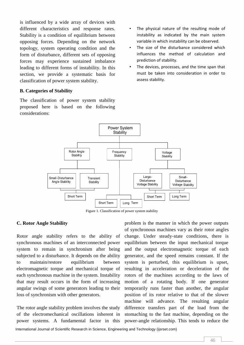
B. Categories of Stability
The classification of power system stability
proposed here is based on the following
considerations:
• The physical nature of the resulting mode of
instability as indicated by the main system
variable in which instability can be observed.
• The size of the disturbance considered which
influences the method of calculation and
prediction of stability.
• The devices, processes, and the time span that
must be taken into consideration in order to
assess stability.
Figure 1. Classification of power system stability
Rotor angle stability refers to the ability of
synchronous machines of an interconnected power
system to remain in synchronism after being
subjected to a disturbance. It depends on the ability
to maintain/restore equilibrium between
electromagnetic torque and mechanical torque of
each synchronous machine in the system. Instability
that may result occurs in the form of increasing
angular swings of some generators leading to their
loss of synchronism with other generators.
The rotor angle stability problem involves the study
of the electromechanical oscillations inherent in
power systems. A fundamental factor in this
problem is the manner in which the power outputs
of synchronous machines vary as their rotor angles
change. Under steady-state conditions, there is
equilibrium between the input mechanical torque
and the output electromagnetic torque of each
generator, and the speed remains constant. If the
system is perturbed, this equilibrium is upset,
resulting in acceleration or deceleration of the
rotors of the machines according to the laws of
motion of a rotating body. If one generator
temporarily runs faster than another, the angular
position of its rotor relative to that of the slower
machine will advance. The resulting angular
difference transfers part of the load from the
stomaching to the fast machine, depending on the
power-angle relationship. This tends to reduce the
C. Rotor Angle Stability
International Journal of Scientific Research in Science, Engineering and Technology (ijsrset.com)
47
speed difference and hence the angular separation.
The power-angle relationship is highly nonlinear.
Beyond a certain limit, an increase in angular
separation is accompanied by a decrease in power
transfer such that the angular separation is increased
further. Instability results if the system cannot
absorb the kinetic energy corresponding to these
rotor speed differences. For any given situation, the
stability of the system depends on whether or not
the deviations in angular positions of the rotors
result in sufficient restoring torques . Loss of
synchronism can occur between one machine and
the rest of the system, or between groups of
machines, with synchronism maintained within
each group after separating from each other.
Small-disturbance (or small-signal) rotor angle
stability is concerned with the ability of the power
system to maintain synchronism under small
disturbances. The disturbances are considered to be
sufficiently small that linearization of system
equations is permissible for purposes of analysis.
Small-disturbance stability depends on the initial
operating state of the system.
i) increase in rotor angle through a non-oscillatory
or aperiodic mode due to lack of synchronizing
torque
ii) Rotor oscillations of increasing amplitude due to
lack of sufficient damping torque.
Small-disturbance rotor angle stability problems
may be either local or global in nature. Local
problems involve a small part of the power system,
and are usually associated with rotor angle
oscillations of a single power plant against the rest
of the power system. Such oscillations are called
local plant mode oscillations.
Large-disturbance rotor angle stability or transient
stability as it is commonly referred to, is concerned
with the ability of the power system to maintain
synchronism when subjected to a severe
disturbance, such as a short circuit on a
transmission line. The resulting system response
involves large excursions of generator rotor angles
and is influenced by the nonlinear power-angle
relationship.
Transient stability depends on both the initial
operating state of the system and the severity of the
disturbance. Instability is usually in the form of
aperiodic angular separation due to insufficient
synchronizing torque, manifesting as first swing
instability. However, in large power systems,
transient instability may not always occur as first
swing instability associated with a single mode; it
could be a result of superposition of a slow inters
area swing mode and a local-plant swing mode
causing a large excursion of rotor angle beyond the
first swing. It could also be a result of nonlinear
effects affecting a single mode causing instability
beyond the first swing.
The time frame of interest in transient stability
studies is usually 3 to 5 seconds following the
disturbance. It may extend to 10–20 seconds for
very large systems with dominant inter-area swings.
the ability of a power system to maintain steady
voltages at all buses in the system after being
subjected to a disturbance from a given initial
operating condition.
It depends on the ability to maintain/restore
equilibrium between load demand and load supply
from the power system. Instability that may result
occurs in the form of a progressive fall or rise of
voltages of some buses. A possible outcome of
voltage instability is loss of load in an area, or
tripping of transmission lines and other elements by
their protective systems leading to cascading
outages. Loss of synchronism of some generators
may result from these outages or from operating
conditions that violate field current limit . Voltage
stability problems may also be experienced at the
terminals of HVDC links used for either long
distance or back-to-back applications. They are
Instability that may result can be of two forms: D. Voltage Stability Voltage stability refers to

International Journal of Scientific Research in Science, Engineering and Technology (ijsrset.com)
48
usually associated with HVDC links connected to
weak ac systems and may occur at rectifier or
inverter stations, and are associated with the
unfavourable reactive power “load” characteristics
of the converters. The HVDC link control strategies
have a very significant influence on such problems,
since the active and reactive power at the ac/dc
junction are determined by the controls. If the
resulting loading on the ac transmission stresses it
beyond its capability, voltage instability occurs.
Such a phenomenon is relatively fast with the time
frame of interest being in the order of one second or
less. Voltage instability may also be associated with
converter transformer tap-changer controls, which
is a considerably slower phenomenon.
Recent developments in HVDC technology (voltage
source converters and capacitor commutated
converters) have significantly increased the limits
for stable operation of HVDC links in weak
systems as compared with the limits for line
commutated converters.
Large-disturbance voltage stability refers to the
system’s ability to maintain steady voltages
following large disturbances such as system faults,
loss of generation, or circuit contingencies. This
ability is determined by the system and load
characteristics, and the interactions of both
continuous and discrete controls and protections.
Determination of large-disturbance voltage stability
requires the examination of the nonlinear response
of the power system over a period of time sufficient
to capture the performance and interactions of such
devices as motors, under load transformer tap
changers, and generator field-current limiters. The
study period of interest may extend from a few
seconds to tens of minutes.
Small-disturbance voltage stability refers to the
system’s ability to maintain steady voltages when
subjected to small perturbations such as incremental
changes in system load. This form of stability is
influenced by the characteristics of loads,
continuous controls, and discrete controls at a given
instant of time. This concept is useful in
determining, at any instant, how the system
voltages will respond to small system changes.
With appropriate assumptions, system equations
can be linearized for analysis thereby allowing
computation of valuable sensitivity information
useful in identifying factors influencing stability.
This linearization, however, cannot account for
nonlinear effects such as tap changer controls (dead
bands, discrete tap steps, and time delays).
Therefore, a combination of linear and nonlinear
analyses is used in a complementary manner.
Short-term voltage stability involves dynamics of
fast acting load components such as induction
motors, electronically controlled loads, and HVDC
converters. The study period of interest is in the
order of several seconds, and analysis requires
solution of appropriate system differential equations;
this is similar to analysis of rotor angle stability.
Dynamic modelling of loads is often essential. In
contrast to angle stability, short circuits near loads
are important. It is recommended that the term
transient voltage stability not be used.
Long-term voltage stability involves slower acting
equipment such as tap-changing transformers,
thermostatically controlled loads, and generator
current limiters. The study period of interest may
extend to several or many minutes, and long-term
simulations are required for analysis of system
dynamic performance. Stability is usually
determined by the resulting outage of equipment,
rather than the severity of the initial disturbance.
Instability is due to the loss of long-term
equilibrium (e.g., when loads try to restore their
power beyond the capability of the transmission
network and connected generation), post-
disturbance steady-state operating point being
small-disturbance unstable, or a lack of attraction
toward the stable post-disturbance equilibrium (e.g.,
when a remedial action is applied too late). The
disturbance could also be a sustained load build up
(e.g., morning load increase). In many cases, static
International Journal of Scientific Research in Science, Engineering and Technology (ijsrset.com)
49
analyses are can be used to estimate stability
margins, identify factors influencing stability, and
screen a wide range of system conditions and a
large number of scenarios. Where timing of control
actions is important, this should be complemented
by quasi-steady-state time-domain simulations.
Frequency stability refers to the ability of maintain
steady frequency following a severe system upset
resulting in a significant imbalance between
generation and load.
It depends on the ability to maintain/restore
equilibrium between system generation and load,
with minimum unintentional loss of load. Instability
that may result occurs in the form of sustained
frequency swings leading to tripping of generating
units and/or loads. Severe system upsets generally
result in large excursions of frequency, power flows,
voltage, and other system variables, thereby
invoking the actions of processes, controls, and
protections that are not modelled in conventional
transient stability or voltage stability studies. These
processes may be very slow, such as boiler
dynamics, or only triggered for extreme system
conditions, such as volts/Hertz protection tripping
generators. In large interconnected power systems,
this type of situation is most commonly associated
with conditions following splitting of systems into
islands. Stability in this case is a question of
whether or not each island will reach a state of
operating equilibrium with minimal unintentional
loss of load. It is determined by the overall response
of the island as evidenced by its mean frequency,
rather than relative motion of machines. Generally,
frequency stability problems are associated with
inadequacies in equipment responses, poor
coordination of control and protection equipment,
or insufficient generation reserve.
In isolated island systems, frequency stability could
be of concern for any disturbance causing a
relatively significant loss of load or generation.
During frequency excursions, the characteristic
times of the processes and devices that are activated
will range from fraction of seconds, corresponding
to the response of devices such as under frequency
load shedding and generator controls and
protections, to several minutes, corresponding to
the response of devices such as prime mover energy
supply systems and load voltage regulators.
An example of short-term frequency instability is
the formation of an under generated island with
insufficient under frequency load shedding such
that frequency decays rapidly causing blackout of
the island within a few seconds. On the other hand,
more complex situations in which frequency
instability is caused by steam turbine over speed
controls or boiler/reactor protection and controls are
longer-term phenomena with the time frame of
interest ranging from tens of seconds to several
minutes. During frequency excursions, voltage
magnitudes may change significantly, especially for
islanding conditions with under frequency load
shedding that unloads the system. Voltage
magnitude changes, which may be higher in
percentage than frequency changes, affect the load-
generation imbalance. High voltage may cause
undesirable generator tripping by poorly designed
or coordinated loss of excitation relays or
volts/Hertz relays. In an overloaded system, low
voltage may cause undesirable operation of
impedance relays.
Factors Affecting Transient Stability
From the swing equation, the acceleration of the
rotor is inversely proportional to the inertia constant
M of the machine when accelerating power is
constant. This means higher the inertia constant, the
slower will be the change in the rotor angle of the
machine and thus large the critical clearing time.
However, it is uneconomical to improve the
transient stability by increasing the inertia constant
and is normally not used.
E. Frequency Stability

International Journal of Scientific Research in Science, Engineering and Technology (ijsrset.com)
50
The methods normally used for improving the
transient stability are:
1. Higher system voltage – an increase in system
voltage results in higher value of the steady-state
stability limit (Pmax).
2. The higher the Pmax value, the smaller will be
the transmission angle required to transfer a given
amount of power. This means the greater is the
margin between the steady-state transmission angle
and the critical clearing angle.
TRANSIEANT STABILITY IMPROVMENT
METHODS
1. Breaking Resistor
For improving stability, when large load is
suddenly lost a resistive load called a breaking
resistor is connected at or near the generator bus.
This load compensates for at least some of the
reduction of load on the generators and so reduces
the acceleration. During fault ,resistor are applied to
the terminals of the generators through circuit
breaker. The control scheme determines the amount
of resistance to be connected and its duration.
2. Single Pole Switching
Most of the transmission line faults are single phase
to ground faults. Single pole switching means
independent pole operation. If the protection
scheme and breaker are properly arranged, in the
event of line to ground fault, the circuit breaker
opens the faulty line(1 phase) and the remaining
two healthy phases continue to supply power. Since
a large percentage of these faults are transitory, this
phase can also be returned to service after it has
been de-energized for sufficient time. The system
should not operated for long period with one phase
opened. Therefore , some means is to be employed
for tripping the entire line of one phase remaining
open for a predetermined time.
3. Fast Acting AVR
The satisfactory operation of synchronous
generators of an interconnected power system at
high load angles and during transient condition is
very much dependent on the source of field
excitation and on the automatic voltage regulators.
A voltage regulator is the heart of the excitation
system. The output voltage of the generator changes
only when the voltage regulator instructs the
excitation system to do so irrespective of the speed
of response of the exciter. A regulator senses
changes in the output voltage and/or current and
causes corrective action to take place. If the
regulator is slow, the system will be a poor one.
The settings and physical limits on the AVR will
have a direct impact on the system performance.
With a good setting, both the steady-state and
transient stability limits can be improved with the
use of AVR
4. Use Of Double Circuit Line
The impedance of a double-circuit line is less than
that of single –circuit line. A double-circuit line
makes twice the transmission capability. The
continuity of supply is maintained over one line
with reduced capacity when the other line is out of
service for maintenance or repair.
5. Series Compensation of Lines
When the STATCOM is connected to the midpoint
terminals, reactive power controller adapts the
value of the inverter firing angle according to
system requirements. As STATCOM firing angle,
the firing angle should remain zero at normal
operating conditions and there is no reactive power
exchange between the system and the STATCOM.
When the fault occurs, the firing angle is changed
instantly and the reactive power is supplied by the
STATCOM to the system. When the fault is cleared,
the firing angle is reduced to zero again and the
STATCOM back to the idle condition . The impact
of reactive power modulation using STATCOM on
system performance can be seen in Fig. Connecting
the STATCOM to the midpoint terminals will

International Journal of Scientific Research in Science, Engineering and Technology (ijsrset.com)
51
maintain the rotor speed and the power angle at
their nominal values even during the fault. The
voltage sag at the generator terminals will be
reduced substantially. The shaft oscillations and
torsion forces will be reduced to almost the normal
steady state condition.
6. Use of Bounded Conductors
Bounded conductors reduce the line reactance to a
considerable extent so increases the power limit of
line. the power transfer P from the generator to the
infinite bus is given by
Pmax=EV/X
7. High Speed Excitation System
High-speed excitation system is very helpful to
maintain synchronism during a fault by quickly
increasing the excitation. High-speed governors
help by quickly adjusting the governor inputs
though speed governing control has little effects in
terms of steady-steady stability, fast acting
governor can certainly improve multi-swing
transient stability. In the short period ( 1s) after the
disturbance, the governor and turbine will be too
slow to have any significant effect on the generator
rotor response. However, the governing effects will
kick in and improve the system response as excess
mechanical power coming the steam turbine has
been reduced by the closing the main steam
controlling and interceptor valves.
8. Fast Switching
It is necessary that the fault should be cleared as
fast as possible. It should be noted that the time
required for fault removal is the sum of relay
response time plus the circuit breaker operating
time. Therefore high speed relaying and circuit
breaking are commonly used to improve stability
during fault condition.
9. HVDC Links
HVDC links are helpful in maintaining stability due
to the following advantages
A D.C line provides a loose coupling between two
A.C system to be interconnected. A D.C line may
connected two A.C system at different frequencies.
There is no transfer of fault energy from one A.C
system to another if they are interconnected by a
D.C tie line.
10. Load shedding
If there is insufficient generation to maintain system
frequency, some of the generators are disconnected
during or immediately after a fault. Thus, the
stability of the remaining generators is improved.
Load shedding (removal of load) is also helpful in
improving transient stability.
IV. CONCLUSION
This review report has addressed the issue of
stability definition and classification in power
systems from a fundamental viewpoint and has
examined the practical ramifications of stability
phenomena in significant detail. A precise
definition of power system stability that is inclusive
of all forms is provided.
A salient feature of the report is a systematic
classification of power system stability, and the
identification of different categories of stability
behaviours. The report also includes a factors
affecting transient stability and transient stability
improvement methods. by using this methods we
can improve the transient stability.
V. REFERENCES
[1] IEEE/CIGRE Joint Task Force on Stability Terms and
Definitions, “Definition and Classification of Power System
Stability”, IEEE Transactions on Power Systems, 2004
[2] Power System Stability and Control [Report] / auth. Kumar Dr.
B. Kalyan. Indian Institute of Technology Madras, - Chennai,
India : [s.n.].
[3] Dr.D.M.Patel. inter connected power system. vol. first.
ahmedabad: atul prakashan, 2013.
[4] Andrew Dodson, IEEE Student
Member, University of Arkansas, [email protected]" A
Direct Power Controlled and Series Compensated EHV
Transmission Line"