Comprehensive transient-state study for CARMENES NIR high-thermal stability
13
Comprehensive transient-state study for CARMENES NIR high- thermal stability Santiago Becerril a* , Miguel A. Sánchez a , M. C. Cárdenas a , Ovidio Rabaza a , Alejandro Ramón a , Miguel Abril a , Luis P. Costillo a , Rafael Morales a , Alicia Rodríguez a , Pedro J. Amado a and the international CARMENES team a Instituto de Astrofísica de Andalucía (CSIC), C/Glorieta de la Astronomía s/n, Granada, Spain, +0034 958 121 311 ABSTRACT CARMENES has been proposed as a next-generation instrument for the 3.5m Calar Alto Telescope. Its objective is finding habitable exoplanets around M dwarfs through radial velocity measurements (m/s level) in the near-infrared. Consequently, the NIR spectrograph is highly constraint regarding thermal/mechanical requirements. Indeed, the requirements used for the present study limit the thermal stability to ±0.01K (within year period) over a working temperature of 243K in order to minimise radial velocity drifts. This can be achieved by implementing a solution based on several temperature-controlled rooms (TCR), whose smallest room encloses the vacuum vessel which houses the spectrograph’s optomechanics. Nevertheless, several options have been taken into account to minimise the complexity of the thermal design: 1) Large thermal inertia of the system, where, given a thermal instability of the environment (typically, ±0.1K), the opto- mechanical system remains stable within ±0.01K in the long run; 2) Environment thermal control, where thermal stability is ensured by controlling the temperature of the environment surrounding the vacuum vessel. The present article also includes the comprehensive transient-state thermal analyses which have been implemented in order to make the best choice, as well as to give important inputs for the thermal layout of the instrument. Keywords: thermal stability, transient-state, NIR spectrograph, échelle, thermal analysis 1. INTRODUCTION CARMENES has been proposed as a next-generation instrument for the 3.5m Calar Alto Telescope. Its objective is finding habitable exoplanets around M dwarfs through radial velocity measurements in the near-infrared (within 1m/s accuracy). The instrument is to be mounted to either the Prime Focus or the Cassegrain Focus. The scope of this paper is mainly constraint to the NIR spectrograph, the mechanical hardware attached to the Focal Plane not being object of the study. In order to obtain 1m/s accuracy on the radial velocity measurements, high degree of thermal/mechanical stability in the spectrograph is required. That is why the present concept of the instrument is based on two optical fibers which carry the light of both the object and the calibration unit to a spectrograph which is located in a stable, controlled environment. According the tight thermal/mechanical requirements, this paper describes the thermal design concept which has been presented to the Conceptual Design Review (CDR) last year. Taking into account such concept, comprehensive transient- state thermal analyses are here explained into detail. They have been implemented in order to obtain important inputs for the mechanical design of the spectrograph. Finally, the entire instrument includes also a visible spectrograph which can provide important feedback and complement the science developed by means of the NIR Spectrograph. However, the visible spectrograph is not being studied in the present work. *Contact S. Becerril ([email protected] ) for further information.
-
Upload
independent -
Category
Documents
-
view
2 -
download
0
Transcript of Comprehensive transient-state study for CARMENES NIR high-thermal stability

Comprehensive transient-state study for CARMENES NIR high-
thermal stability
Santiago Becerril
a*, Miguel A. Sánchez
a, M. C. Cárdenas
a, Ovidio Rabaza
a, Alejandro Ramón
a,
Miguel Abril a, Luis P. Costillo
a, Rafael Morales
a, Alicia Rodríguez
a, Pedro J. Amado
a
and the international CARMENES team
a Instituto de Astrofísica de Andalucía (CSIC), C/Glorieta de la Astronomía s/n, Granada, Spain,
+0034 958 121 311
ABSTRACT
CARMENES has been proposed as a next-generation instrument for the 3.5m Calar Alto Telescope. Its objective is
finding habitable exoplanets around M dwarfs through radial velocity measurements (m/s level) in the near-infrared.
Consequently, the NIR spectrograph is highly constraint regarding thermal/mechanical requirements. Indeed, the
requirements used for the present study limit the thermal stability to ±0.01K (within year period) over a working
temperature of 243K in order to minimise radial velocity drifts. This can be achieved by implementing a solution based
on several temperature-controlled rooms (TCR), whose smallest room encloses the vacuum vessel which houses the
spectrograph’s optomechanics.
Nevertheless, several options have been taken into account to minimise the complexity of the thermal design: 1) Large
thermal inertia of the system, where, given a thermal instability of the environment (typically, ±0.1K), the opto-
mechanical system remains stable within ±0.01K in the long run; 2) Environment thermal control, where thermal
stability is ensured by controlling the temperature of the environment surrounding the vacuum vessel.
The present article also includes the comprehensive transient-state thermal analyses which have been implemented in
order to make the best choice, as well as to give important inputs for the thermal layout of the instrument.
Keywords: thermal stability, transient-state, NIR spectrograph, échelle, thermal analysis
1. INTRODUCTION
CARMENES has been proposed as a next-generation instrument for the 3.5m Calar Alto Telescope. Its objective is
finding habitable exoplanets around M dwarfs through radial velocity measurements in the near-infrared (within 1m/s
accuracy). The instrument is to be mounted to either the Prime Focus or the Cassegrain Focus.
The scope of this paper is mainly constraint to the NIR spectrograph, the mechanical hardware attached to the Focal
Plane not being object of the study. In order to obtain 1m/s accuracy on the radial velocity measurements, high degree of
thermal/mechanical stability in the spectrograph is required. That is why the present concept of the instrument is based
on two optical fibers which carry the light of both the object and the calibration unit to a spectrograph which is located in
a stable, controlled environment.
According the tight thermal/mechanical requirements, this paper describes the thermal design concept which has been
presented to the Conceptual Design Review (CDR) last year. Taking into account such concept, comprehensive transient-
state thermal analyses are here explained into detail. They have been implemented in order to obtain important inputs for
the mechanical design of the spectrograph.
Finally, the entire instrument includes also a visible spectrograph which can provide important feedback and complement
the science developed by means of the NIR Spectrograph. However, the visible spectrograph is not being studied in the
present work.
*Contact S. Becerril ([email protected]) for further information.

2. THERMAL REQUIREMENTS AND BOUNDARY CONDITIONS
In order to ensure that the instrument reaches 1m/s accuracy in the radial velocity measurements, the preliminary
requirements used for the present study limit the thermal stability to ±0.01K (within year periods) over a working
temperature of 243K. Mention has to be done of the fact that the accuracy over the absolute temperature reached on the
instrument is not critical at all. The figure above mentioned is the upper limit: any part of the instrument must be cooled
down under 243K, but once the thermal steady-state is reached the temperature of all the systems within the spectrograph
may only range within ±0.01K, within year-scale periods. On the other hand, the detector has a specific thermal
enclosure which must ensure the appropriate temperature (80K) for its operation.
The most convenient location for the CARMENES-NIR spectrograph in the 3.5m Calar Alto Telescope facilities is the
Coudé Room, which is not exposed to outdoor temperature variations. The environment conditions of such location are
the following:
• The air temperature in the Coudé Room is around 12ºC.
• Temperature measurements: Mid-term (3-4 months) precise measurements of the temperature in the Coudé
Room have been collected. The temperatures were collected by mechanical thermometers installed at the
secondary Coudé Room from mid March 2009 to the first of July 2009. Maxima and minima collected over
periods of 8-9 days are plotted in Figure 1. Results are listed below:
o Intra-day variations are within 2ºC.
o Differences within a week can be as large as 3.5ºC.
o Seasonal differences can be larger than 6ºC.
Although the thermal conditioning of the Coudé Room is not within the fine range, it provides very good temperature
conditions as compared as other locations as the Telescope Hall. In other words, the system providing the thermal-
controlled environment for the NIR spectrograph will be by far less exposed to temperature variations than in the case of
other locations. This is a crucial point regarding the thermal/mechanical stability of the instrument.
Figure 1. Maximal and minimal temperatures during the period from 15-Mar to 01-Jun 2009 of the small secondary
Coude room.
3. NIR SPECTROGRAPH SYSTEM CONFIGURATION
Figure 2 shows the optical layout of the NIR spectrograph presented at CDR. All the systems there, except for the
detector, are housed inside a common Vacuum Tank. Concerning the stability requirements, the need of a vacuum
environment has been found important to avoid heat convective flows inside the spectrograph which may compromise
the thermal stability. Figure 3 gives a more accurate sense about the dimensions of the spectrograph.

On the other hand, the instrument environment should be kept stable as long as possible. It applies not only to operation
time but also during dead times since such stability must be kept in the very long run (years scale). Only in case of
maintenance, this stability should be perturbed. This philosophy is also translated to the mechanics related to the Optical
Bench and the optomechanics. That is the reason why no mechanisms are foreseen to be inside the Vacuum Vessel. In
addition, the vacuum pumps must be switched off during observation.
Since the working temperature (243K) is not far below the ambient temperature, the approach chosen to properly cool
the instrument is based on thermal conditioning of the environment. In addition, this solution has been successfully
implemented in the HARPS1 instrument. Nevertheless, the CARMENES case does not match the same working
temperature as the HARPS instrument since the latter works at 290K, which implies an important difference in terms of
heat flow. This solution leads to a lower degree of complexity in terms of optomechanical design as compared to
cryogenic instruments.
Figure 2: Basic optical layout of CARMENES-NIR.
Figure 3. General layout showing the Optical Bench and the location of the optomechanical subsystems.

Figure 4. CARMENES NIR Block Diagram
The present concept is based (see Figure 4) on three temperature-controlled rooms (TCR) in cascade, each of them
housing the immediately smaller one. The TCR1 room is the largest one and contains the intermediate room (TCR2),
which, in turn, contains the TCR3 room. Finally, the latter houses the CARMENES-NIR spectrograph and provides its
working temperature. Each TCR provides a thermal stage with a certain degree of stability. Thus, it is inside of the TCR3
where the working temperature is reached.
In order to better preserve the thermal stability on the IR Spectrograph, thermal losses should be minimised. That's why
conduction coming from the floor must be avoided. In practice, it means that a false floor thermally isolated from the
solid floor should be implemented. Similarly, since the Vacuum Vessel will be mechanically attached to the solid floor,
some isolating pads should be implemented in order to minimize thermal conduction losses.
4. THERMAL ANALYSES
The thermal analyses here performed have been focused on two main aspects:
• Thermal stability: This critical requirement has to be fulfilled within ±0.01K.
• Thermal transient stage: This issue does not apply during the normal working of the CARMENES NIR
spectrograph but it does during Assembly/Integration/Verification (AIV) phase, since a certain number of
vacuum-and-cooldown cycles shall be necessary to provide the proper alignment and setup to the
optomechanics. Therefore, even if the AIV phase is going to take place only once in the instrument lifetime,
extremely long transient stages are not acceptable. Typically, these stages should not be longer than 3 – 4 days.
4.1. Thermal stability analyses
In section 3, the concept of the thermal system for the instrument to get the working temperature has been described.
Nevertheless, how the thermal stability is achieved is not yet solved. Next, two different alternatives to ensure the
stability requirement have been taken into account:
• Alternative 1: Thermal “inertia” of the system
The environment temperature is not controlled to achieve the ±0.01K requirement, but to reach ±0.1K. A
coarser degree of thermal control is then enough for TCR3. Thermal stability (±0.01K) in the spectrograph is
wanted to be achieved by large “inertia” of heat transfer procedures. Concerning radiation heat transfer issues,
such guideline would be achieved by inserting many radiation shields between the Vacuum Vessel and the
Optical Bench. Typically, that should be implemented through a high degree of radiation shielding (Multilayer
insulation (MLI), very low emissivity values).
The benefit of the present alternative would lie on a lower degree of complexity for the temperature control of
the TCRs. Eventually, the enclosure providing the last stage of thermal conditioning (TCR3) could be saved,
thus also providing noticeable decrease of the cost. On the other hand, transient times in the AIV may exceed
the reasonable limit of 3-4 days for each cooldown/vacuum cycle.
• Alternative 2: Environment thermal control
The environment temperature is controlled to achieve both the working temperature and the thermal stability
requirement. It requires a more complex temperature control for TCR3 than in the case of the Alternative 1. If
the environment fulfils the thermal requirements and the conduction losses are minimised, all the hardware
inside TCR3 also will match ±0.01K stability.
Such approach leads to reverse strategy in terms of thermal “inertiae” of the subsystems involved, which would
produce some benefits in terms of transient stage time. According to specialized feedback on that domain, the
stability requirement of 0.01K is feasible. Furthermore, the present alternative has been already implemented in
the HARPS instrument. Additionally, the fact that the location of the NIR spectrograph is not subjected to
outdoor temperature variations is a crucial point on this issue. Indeed, the variation of the heat flow to TCR1 is
this way noticeably limited.
This alternative would lead to designs focused, from the thermal point of view, on producing short cooldown
transient times. Unlike the Alternative 1, in principle, there is no point here to provide high inertia of the
thermal transfer procedures. Therefore, no radiation shielding is foreseen here. Furthermore, mass should be
intended to be minimized in order to get shorter cooldown transient times. This way, radiation heat transfer
from Optical Bench to Vacuum Vessel would be promoted.
The present analysis has been carried out to estimate the time required for the Optical Bench to change its temperature
by 0.01K provided that the TCR3 is exposed to a temperature step variation of 0.1K. In particular, the present analysis
starts when the temperature inside TCR3 is 243.1K and gives the time elapsed for the Optical Bench to reach 243.01K.
This applies only to Alternative 1, which, in turn, has been studied according to different cases (depending on the degree
of radiation shielding between the Vacuum Vessel and the Optical Bench):
• Case I: The Optical Bench “sees” directly the Vacuum Vessel. No radiation shielding is implemented.
• Case II: One Radiation Shield is considered between the Optical Bench and the Vacuum Vessel.
• Case III: In addition to the metallic Radiation Shield from Case II, 50-layers MLI insulation is considered
between the Vacuum Vessel and the Radiation Shield. Consequently, radiation power transferred from the
Vacuum Vessel to the Optical Bench is this way reduced by a factor 1/51 as regard to the Case I. Obviously,
this configuration is the one with highest “inertia” in terms of heat radiation transfer.
4.1.1. Assumptions
The assumptions which have been considered are the following:

• The key components involved in the present analysis are the Vacuum Vessel (VV), the Radiation Shield (RSh)
and the Optical Bench (OB)
• In terms of geometry, some simplifications have been also implemented for this first-order analysis. The
Vacuum Vessel, the Radiation Shield and the Optical Bench have been considered as cylinder-shaped
envelopes. Obviously, it is mainly the Optical Bench which is far away from such assumption. The error so
produced concerns the view factor of the Vacuum Vessel (or Radiation Shielding) as regard to the Optical
Bench. Nevertheless, the analysis results are not especially sensible to this parameter.
• The dimensions taken into account are the following:
mLmDmLmDmLmD OBOBRShRShVVVV 4.2;9.0;5.2;1.1;6.2;2.1 ======
Where DVV, DRSh and DOB are the respective diameters of the VV, the RSh and the OB and LVV, LRSh and LOB are
the respective lengths pf the VV, the RSh and the OB.
• The Vacuum Vessel is considered to be made of stainless steel. Both the Radiation Shield and the optical Bench
are considered to be made of aluminium. Masses considered for the present study are 1000kg, 85kg and 400kg
for the VV, the RSh and the OB, respectively.
• Isothermal surfaces are considered. This condition is closer to be fulfilled in case of high conductivity materials
and minimization of conduction losses.
• Surfaces are considered diffuse. For electropolished metal surfaces, emissivity can be considered around 0.03-
0.04.
• Conductions losses are neglected.
• The main items involved to this analysis are the Vacuum Tank, the Radiation Shielding and the surrounding
environment.
• Thermal gradients along the wall thickness of the Vacuum Vessel and the Radiation Shielding are negligible,
due to the high conductivity of the materials involved.
• The natural convection coefficient (hnat) between the air inside the TCR3 and the VV has been estimated
5W/m2K.
• Times elapsed to change the temperature of the air inside TCR3 are considered negligible. In fact, convection
heat transfer power is so high as compared to radiation process that the times elapsed to change the temperature
of the VV might be also neglected.
4.1.2. Analysis methodology
The analysis methodology here explained is based on the Case I. The same methodology has been used for the rest of
cases. So, the equations applicable are the same, the main difference lying on the fact that the Floating Shields (or MLI)
are the components involved in the radiative heat transfer procedures with both the Vacuum Vessel and the Optical
Bench. The present methodology has been based on a discrete series of intermediate states, a regular temperature step ∆T
being applied from one state to the next one:
1. The routine starts from the moment in which the temperature inside the TCR3 Vacuum Vessel has changed to
243.1K, the rest of key temperatures still being 243K.
2. A step temperature variation (∆T) is set to the Vacuum Vessel. The smaller the temperature step is, the more
accurate the results are. Typically, since the stability requirement is 0.01K, the step variation has to be set as an
order of magnitude lower (0.001K). For better accuracy, an additional order of magnitude is decreased, the step
variation being 0.0001K.
Then, the heat transfer power is found from the TCR3 ambient (convection) to the Vacuum Vessel and from the
latter (radiation) to the Optical Bench through the following equations:
( ) ( ) ( )( )00303 VVTCRVVnatVVTCR TTAhW −⋅⋅=→ (1)

where AVV is the area of the Vacuum Vessel involved in convection heat transfer, hnat is the natural convection
coefficient and subindex 0 means the step number 0 of the present routine. (TTCR3)0 and (TVV)0 are the
temperatures of the inside of the TCR3 and the Vacuum Vessel at t=0, respectively.
( )( ) ( )( )
OBOB
OB
VVOBVVVVVV
VV
OBVV
OBVV
AAFA
TTW
⋅
−+
⋅+
⋅
−
−⋅=
→
→
ε
ε
ε
ε
σ
1110
4
0
4
0 (2)
where εVV and εOB are the emissivity coefficients of the surfaces of both the VV and the OB. FVV→OB is the view
factor of the OB from the VV.
3. The routine finds t1 as the time elapsed for the temperature of the Vacuum Vessel to change by 0.0001K
according the net heat power incoming (WVV)net and the energy required to change by 0.0001K the temperature
of the Vacuum Vessel:
( ) ( ) ( )0030
)( OBVVVVACRnetVV WWW →→ += (3)
( ) ( ) ( )( )011)( VVVVVVpVVVV TTCmQ −⋅⋅= (4)
where mVV is the mass of the VV, (Cp)VV is the heat capacity of the VV and the sub-index 1 means the step
number 1.
( )( )( )
0
11
netVV
VV
W
Qt = (5)
4. The temperature of the Optical Bench after t1 seconds is found as follows:
( )0
111 )(
)()( OB
OBOBp
OBVV
OB TmC
tWT +
⋅
⋅= → (6)
5. Now, a new temperature step of 0.0001K is applied to the Vacuum Vessel. This procedure is iterated (through
temperature steps of 0.0001K) until the temperature of the Optical Bench is 243.01K.
After i steps, the temperature of the Vacuum Vessel (TVV)i is equal to:
( ) TiTiVV ∆⋅+= 243 (7)
and the time elapsed (tTOT)i up to the temperature step number i on the Vacuum Vessel is:
( ) ∑=i
iiTOT tt (8)
where ti is the time required for the Optical Bench to change its temperature from (TOB)i-1 to (TOB)i.
The sequence of temperature variation steps (applied to a certain component) driving the routine is called
“stepping sequence”. In this case, the present routine arrived to some saturation because the temperature
variation of the Vacuum Vessel was much faster than the one of the Optical Bench. This is so because the
convective heat exchange between the TCR3 environment and the Vacuum Vessel is much more powerful than
the radiative heat exchange between the latter and the Optical Bench. The term “saturation” means in this

context that at some step the routine arrives to an absurd result (e.g. temperature of Vacuum Vessel higher than
TCR3 temperature, reversal of the heat exchange between the VV and Optical Bench,…). When that occurs, the
routine finishes the current stepping sequence and starts a new one where the temperature step is applied to
another component. In Case I, a second sequence was applied to the Optical Bench, thus arriving to the target
temperature (243.01K) for the latter component.
6. Once the temperature of the Optical Bench is 243.01K, tTOT is found.
As mentioned before, the methodology above detailed is also applicable in cases II and III. In order to simplify the
analysis in Case III, the input radiation power to the Radiation Shield has been considered as 1/51 times (50-layers MLI)
–as in the steady-state- the radiation power considered in Case II. The effect of the MLI is so included in the analysis.
Such approximation is, in principle, not strictly correct since only the steady-state fulfils that the input radiation power to
a given radiation shielding layer is the same as the output radiation power from it. Nevertheless, the analysis shows that
the Radiation Shielding takes extremely long time (0.1mK/h). In practice, it means that each analysis step can be
considered as a pseudo-steady state, which is valid for the present first-order analysis.
4.1.3. Results
Results obtained from the stability thermal analysis applied to the cases mentioned in section 4.1 are listed below:
• Case I (Figure 5): Given a 0.1K temperature step on the Vacuum Vessel, the Optical Bench temperature
requires about 20.8 hours to change from 243K to 243.01K.
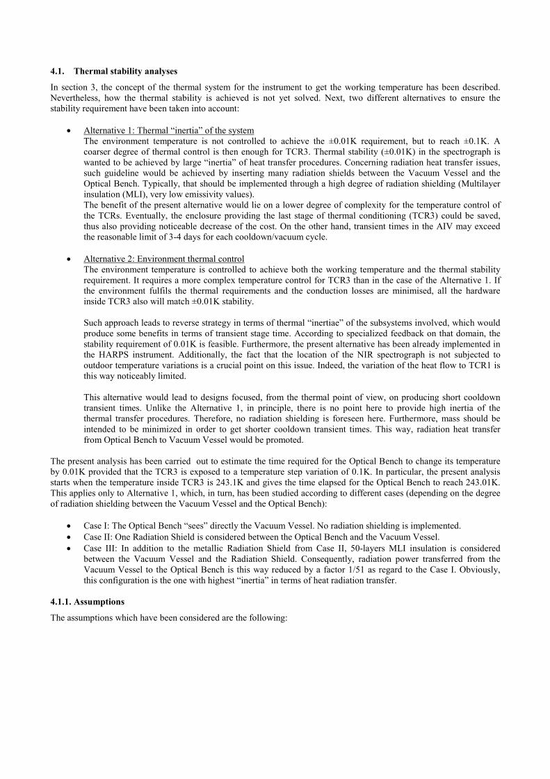
• Case II (Figure 6): Given a 0.1K temperature step on the Vacuum Vessel, the Optical Bench temperature
requires about 57h (2.37 days) to change from 243K to 243.01K.
• Case III (Figure 7): Given a 0.1K temperature step on the Vacuum Vessel, the Optical Bench temperature
requires about 1062 hours (44.2 days) to change from 243K to 243.01K.
Results so obtained for Case I and Case II are not acceptable at all according the long term requirement applicable to the
thermal stability. Therefore, cases I and II are not being involved in further analyses. Case III behaves clearly better
although does not fit the latter requirement either. However, it is left for further analyses since it might be compatible
with eventual regular-basis calibration protocols to be applied to the instrument. Indeed, if any sort of calibration
procedure was to be regularly implemented, it may turn into shorter runs applicable to the stability requirements.
Currently, the CARMENES team is very involved in studies about the best solution in terms of calibration.
Figure 5. Case I: Thermal transient-state of the VV and the OB produced by a temperature change of 0.1K inside TCR3.
The graph is limited to the time required by the OB to change the temperature by 0.01K.
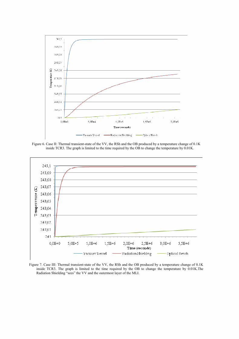
Figure 6. Case II: Thermal transient-state of the VV, the RSh and the OB produced by a temperature change of 0.1K
inside TCR3. The graph is limited to the time required by the OB to change the temperature by 0.01K.
Figure 7. Case III: Thermal transient-state of the VV, the RSh and the OB produced by a temperature change of 0.1K
inside TCR3. The graph is limited to the time required by the OB to change the temperature by 0.01K.The
Radiation Shielding “sees” the VV and the outermost layer of the MLI.
4.2. Cooldown transient analysis
From results shown in section 4.1.3, only the Case III has been left for being submitted to the present analysis. Indeed,
apart from the stability requirement, other important issue is the time required for the system to achieve the working
temperature starting from ambient temperature. Nevertheless, it is the Case II which has been considered due to analysis
simplification reasons. Therefore, one Radiation Shield has been taken into account (no MLI insulation).
The present thermal analysis is then applicable to both Alternative 1 (Case II) and Alternative 2. The latter alternative is
studied according the Case I. Indeed, if the TCR3 is controlled within ±0.01K, there is no point to promote thermal
“inertia” of the system by including Radiation Shielding. Therefore, only the VV and the OB are involved in Alternative
2.
The aim of this analysis consists of finding the time required for the alternatives above mentioned to reach the working
temperature (within ±0.01K) from ambient temperature (293K). This objective is considered to be accomplished when
all the key components (Vacuum Vessel, Radiation Shielding and Optical Bench) are at a temperature below 243K, the
differences between each other being lower than 0.01K.
4.2.1. Assumptions
Beside the assumptions already mentioned in section 4.1.1, those which are particular for the present analysis are listed
below:
• The TCR3 is supposed to be active-controlled such a way that a cooldown protocol can be implemented so that
the OB cooldown time is minimized.
• According specialized feedback, one air-conditioning cooling stage can reach temperatures as low as 226K.
Below this value, a second air-conditioning stage would be necessary. Thus, in the present study the TCR3 is
supposed to be cooled down to 226K.
• The cooling power of the air-conditioning system can be varied such a way that the convection coefficient may
be noticeably changed depending on the application. For example, in steady-state conditions, the input power to
keep the thermal stability should be very limited. Alternatively, in conditions of early transient-state cooldown
phases, convection heat transfer may be maximized through high input power.
• As it will be seen, the transient cooldown can be split into several phases, where the TCR3 temperature
controlled may be adjusted to different temperature targets. For example, in early cooldown phases, the TCR3
temperature may be kept at 226K in order to maximize radiative heat transfer from the VV inwards.
• The time necessary to change the TCR3 air temperature has been neglected as regard the results obtained for
each phase of the cooldown because, in general, convection heat transfer is much more powerful than radiative
heat transfer. According the results shown in section 4.2.2, cooldown transient times are so long that, in general,
the time required to cool the air inside TCR3 down does not represent a significant part of the total.
As mentioned in section 4.1, the strategy of Alternative I (case III) in terms of thermal isolation is the opposite as
compared to the one applying in Alternative II. Therefore, in the first case, emissivity values around 0.03
(electropolished surfaces) are considered to maximize thermal isolation; in the second case, emissivity values around 0.1
(no polished surfaces) are considered to promote radiation heat transfer without dramatically increasing the outgassing
load inside the VV. As a reminder, vacuum inside VV needn’t to be in the very high range: 10-4mbar is enough for the
CARMENES NIR spectrograph.
4.2.2 Results
The analysis methodology is based on the same equations shown in section 4.1.2, the main differences lying on the start
conditions of the routine, as well as on the components where the temperature step ∆T is applied at each phase.
4.2.2.1 Alternative 1 (Case II)
Concerning this alternative, the routine implemented has shown that the cooldown process (from ambient temperature to
working temperature) can be split into 5 phases (see Figure 8):

• PHASE I: Vacuum Vessel Cooldown. During this phase it is mainly the Vacuum Vessel which is being cooled
down by convection. The Radiation Shielding and the Optical Bench temperatures decrease at much lower rate.
The TCR3 temperature is set at 226K in order to minimize the time required for this phase. This phase is
considered to be finished once the Vacuum Vessel temperature is as low as 230K, which occurs after 6100
seconds.
• PHASE II: Radiation Shielding Cooldown. The Vacuum Vessel temperature keeps decreasing up to values
slightly over 226K. The Vacuum Vessel never gets 226K because of the radiation load coming from the
Radiation Shielding. During this long phase, the temperature inside TCR3 is kept at 226K in order to maximize
the cooldown rate of the RSh and the OB.. This phase is considered to be finished once the Radiation Shielding
has attained a temperature enough below 243K such a way that, in the next phase, it converges up to the
temperature of the OB. In this case this value is 234.48K. Obviously, this value has been set after some
feedback obtained from the present routine. The duration of Phase II is around 1820000 seconds.
• PHASE III: Vacuum Vessel Warm-up. The Vacuum Vessel is heated up by convection (TTCR3 = 258K) up to a
temperature slightly below 243K. This phase’s duration is only 1600 seconds approximately.
• PHASE IV: Radiation Shielding Warm-up. The TCR3 control is tuned to keep the VV at the same temperature
as at the end of Phase III. The Radiation Shielding warms up from a temperature around 234.5K to the same
temperature as the OB. In the present case, the final temperature of both the Radiation Shielding and the Optical
Bench is 241.89K. Once this happens (duration of Phase IV: 171400 seconds), Phase V starts up.
• PHASE V: Vacuum Vessel tuning. The TCR3 temperature control is driven to slightly change the temperature
of VV up to the same as Radiation Shielding and the Optical Bench. The duration of this phase is fully
negligible as regard the total duration of the cooldown.
The duration of the cooldown in Alternative 1 (case II) is around 2x10⁶ seconds (23.1 days).
Figure 8. Alternative I – Case 2: Cooldown transient-state of the Vacuum Vessel, the Radiation Shielding and the
Optical Bench from ambient temperature to working temperature. All the phases above explained can be easily
found: Phase I (fast VV Cooldown), Phase II (Large period for RSh and OB Cooldowns), Phase III (fast VV
Warm-up), Phase IV (RSh Warm-up converging to OB temperature), Phase V (fast tuning of VV temperature to
working temperature).
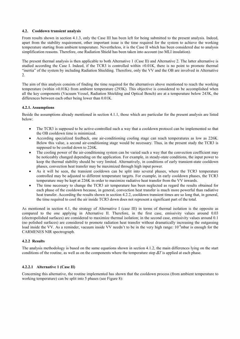
4.2.2.2 Alternative 2
Concerning this alternative, the routine implemented has shown that the cooldown process (from ambient temperature to
working temperature) can be split into 3 phases (see Figure 9):
• PHASE I: Vacuum Vessel Cooldown. During this phase it is mainly the Vacuum Vessel which is being cooled
down by convection. The Optical Bench temperatures decrease at a much lower rate. The TCR3 temperature is
set at 226K. The Phase I is considered to be finished once the Vacuum Vessel temperature is as low as 230K,
which occurs after 2500 seconds approximately.
• PHASE II: Optical Bench Cooldown. The Vacuum Vessel temperature keeps decreasing up to values slightly
over 226K. The Vacuum Vessel never gets 226K because of the radiation load coming from the Optical Bench.
This phase is considered to be finished once the Optical Bench has attained a temperature slightly below the
work temperature. In this case such temperature is 241.91K.
• PHASE III: Vacuum Vessel Warm-up. The Vacuum Vessel is heated up by convection (TTCR3 = 258K) as to
make TVV = TOB. The control of TCR3 temperature should be implemented on real-time in accordance with the
temperature of the Optical Bench, which keeps slightly decreasing, and the inertia of both the Vacuum Vessel
and TCR3 air volume. At the end, the temperature of the components is 241.89K.
The duration of the cooldown in Alternative 2 is around 2.73x10⁵ seconds (3.16 days).
Figure 9. Case 1: Cooldown transient-state of the Vacuum Vessel and the Optical Bench from ambient temperature to
working temperature. All the phases above explained can be easily found: Phase I (fast VV Cooldown), Phase II
(Large period for OB Cooldown), Phase III (fast VV Warm-up to working temperature).
5. CONCLUSIONS AND FURTHER TASKS
Next, the conclusions extracted from the results are listed below:
• Alternative 1, even in the best case in terms of thermal stability (Case III), is not acceptable in terms of
cooldown transient time. As a reminder, it is the Case II which has been submitted to the cooldown transient
analysis, being the result about 23 days. Therefore, the time for the Case III must be much longer.
• At present, Alternative 2 is the approach selected for providing the thermal stability to the NIR Spectrograph,
which is ensured by the proper temperature control system of TCR3, while the cooldown time from ambient
temperature to working temperature is kept within reasonable limits (around 3 days long). However, this
alternative does not promote thermal “inertia” (poor reflectivity factors, no Radiation Shielding), which, on the
other hand, is good for stability. That is why, according the present results, a new alternative will be further
analyzed:
o This alternative would present a metal Radiation Shielding and 50-layers MLI, the latter being placed
between the VV and the RSh. The OB only would “see” the Radiation Shielding, which would include
a coil for cooldown. The temperature-controlled coolant circulating through the coil should provide
reasonably short cooldowns while keeping the OB temperature stable within ±0.01K.
• On the other hand, comprehensive efforts are being done within the CARMENES team in order to choose the
best science calibration system and set an appropriate calibration protocol. From these tasks, the period upon
which the thermal stability requirement applies might be changed. This could imply new analysis on the basis of
this new scenario.
• A preliminary design phase should be started up to set the hardware necessary to ensure the stability
requirement. In order to implement this phase properly, a comprehensive temperature measurement campaign
must be implemented in the 3.5@Calar-Alto Coudé Room. A basic parameter to be known is the response time
necessary to compensate the heat flow variations through the TCRs. This is very depending on how steep are
the temperature variations in time.
REFERENCES
[1] html://www.cfa.harvard.edu/harps/tech_papers/Thermal_Req.pdf
[2] Siegel, R. and Howell, J., [Thermal radiation heat transfer], Taylor&Francis, New York, 207-250 (4th ed., 2002)
[3] Modest, M. F., [Radiative heat transfer], McGraw-Hill, Massachussets, chapters 4 and 5, (2nd ed., 2003)