Newtonian Mechanics Based Transient Stability PART V - arXiv
11
Newtonian Mechanics Based Transient Stability PART V: Inner-group Machine Songyan Wang, Jilai Yu, Aoife Foley, Jingrui Zhang Abstract—This paper analyzes the mechanisms of the inner-group machine. It is first clarified that the inner-group machine is created from the difference between the equivalent system and the original system. The inner-group machine stability is analyzed based on the machine paradigms. In particular, strict correlation between the inner-group machine trajectory and the inner-group machine transient energy conversion is established through the I-CR system modeling. Then, the transient characteristics of the inner-group machine are analyzed. It is clarified that the inner-group motions might be inseparable or separable, and the inner-group machine DLP will occur later than the EDLP and IDLP. Simulation results show that the severity of the original system cannot be simply evaluated through its equivalent system once any inner-group motion becomes fierce. Index Terms—Transient stability, transient energy, equal area cri- terion, individual machine, inner-group motion Nomenclature DLP Dynamic liberation point DSP Dynamic stationary point EAC Equal area criterion TSA Transient stability assessment MOD Mode of disturbance COI Center of inertia GTE Global total transient energy IVCS Individual-machine virtual COI-SYS machine LOSP Loss of synchronism point IMTR Individual-machine trajectory I. I NTRODUCTION A. LITERATURE REVIEW T HE inner-group machine motions can be seen as the differences between the original system and the equiv- alent system [1]-[3]. It reflects the relative motion between the individual machines and the equivalent machine inside each group. Although the stabilities of the original system and the equivalent system are identical [3], the severities of the two systems might be different once any inner-group machine motion becomes fierce. In particular, the severities of the two systems will be close if all the inner-group motions are slight. The severities of the two systems will be different if any inner- group motion is fierce. This also indicates that the original system cannot be completely replaced with the equivalent system under certain distinctive circumstances. The inner-group machine motion is “created” from the difference between the original system and the equivalent system. In other words, it does not exist in the original system and neither can be found in the equivalent system. The discussions about the inner-group motions were only very a few in the history of the equivalent machine studies. Xue stated that the stability margin of the system might show great errors if the inner-group-machine motion cannot be neglected, especially when the group separation pattern is not clear [4]. In fact, the precise modeling of the inner-group motion was rarely analyzed even in the modern equivalent machine studies [5]. Against this background, the explorations of the inner- group machine stability will become of value, because it may essentially clarify the complicated relationship between the individual-machine and the equivalent machine that both follow the machine paradigms and show effectiveness in TSA. B. SCOPE AND CONTRIBUTION OF THE PAPER Following the tutorial explanation of the inner-group mo- tions as given in the previous paper [3], in this paper the authors focus on the modeling and stability characterizations of the inner-group machine motions. The mechanism of the inner-group machine is analyzed. It shows that the inner- group machine can be defined as the “difference” between the original multi-machine system and the equivalent system. Based on the machine paradigms, the trajectory variance of the inner-group machine in the COI-CR reference is modeled through the I-CR system with strict NEC characteristic. Then, the transient characteristics of the inner-group machine are analyzed. The inner-group motions might be inseparable or separable, and the inner-group instability will occur when the inner-group machine separates from Machine-CR. In the end of the paper, the “companion” relationship between the individual-machine and the equivalent machine in TSA are analyzed. It is found that the equivalent machine shows flexibility when the inner-group machine motions are slight, while the individual-machine can be used in certain distinctive situations in which “more efficient stability characterization” or “more precise severity evaluation” becomes a particular emphasis. The contributions of this paper are summarized as follows (i) It is clarified that the inner-group machine motion is created from the difference between the original multi-machine system and the equivalent system. This reveals the mechanism of the inner-group motions. (ii) The inner-group machine stability is analyzed based on the machine paradigms. This provides a precise modeling and stability characterization for the inner-group machine. (iii) The effect of the inner-group machine instability to the original system stability is analyzed. This clarifies that the original system cannot be simply replaced with the equivalent system in TSA especially when any inner-group machine instability occurs. The reminder of the paper is organized as follows. In Section II, the inner-group machine stability is analyzed based arXiv:2110.14123v1 [eess.SY] 27 Oct 2021
-
Upload
khangminh22 -
Category
Documents
-
view
3 -
download
0
Transcript of Newtonian Mechanics Based Transient Stability PART V - arXiv

Newtonian Mechanics Based Transient StabilityPART V: Inner-group Machine
Songyan Wang, Jilai Yu, Aoife Foley, Jingrui Zhang
Abstract—This paper analyzes the mechanisms of the inner-groupmachine. It is first clarified that the inner-group machine is createdfrom the difference between the equivalent system and the originalsystem. The inner-group machine stability is analyzed based onthe machine paradigms. In particular, strict correlation between theinner-group machine trajectory and the inner-group machine transientenergy conversion is established through the I-CR system modeling.Then, the transient characteristics of the inner-group machine areanalyzed. It is clarified that the inner-group motions might beinseparable or separable, and the inner-group machine DLP will occurlater than the EDLP and IDLP. Simulation results show that theseverity of the original system cannot be simply evaluated throughits equivalent system once any inner-group motion becomes fierce.
Index Terms—Transient stability, transient energy, equal area cri-terion, individual machine, inner-group motion
NomenclatureDLP Dynamic liberation pointDSP Dynamic stationary pointEAC Equal area criterionTSA Transient stability assessmentMOD Mode of disturbanceCOI Center of inertiaGTE Global total transient energyIVCS Individual-machine virtual COI-SYS machineLOSP Loss of synchronism pointIMTR Individual-machine trajectory
I. INTRODUCTION
A. LITERATURE REVIEW
THE inner-group machine motions can be seen as thedifferences between the original system and the equiv-
alent system [1]-[3]. It reflects the relative motion betweenthe individual machines and the equivalent machine insideeach group. Although the stabilities of the original system andthe equivalent system are identical [3], the severities of thetwo systems might be different once any inner-group machinemotion becomes fierce. In particular, the severities of the twosystems will be close if all the inner-group motions are slight.The severities of the two systems will be different if any inner-group motion is fierce. This also indicates that the originalsystem cannot be completely replaced with the equivalentsystem under certain distinctive circumstances.
The inner-group machine motion is “created” from thedifference between the original system and the equivalentsystem. In other words, it does not exist in the originalsystem and neither can be found in the equivalent system.The discussions about the inner-group motions were only verya few in the history of the equivalent machine studies. Xuestated that the stability margin of the system might show greaterrors if the inner-group-machine motion cannot be neglected,
especially when the group separation pattern is not clear [4].In fact, the precise modeling of the inner-group motion wasrarely analyzed even in the modern equivalent machine studies[5]. Against this background, the explorations of the inner-group machine stability will become of value, because itmay essentially clarify the complicated relationship betweenthe individual-machine and the equivalent machine that bothfollow the machine paradigms and show effectiveness in TSA.
B. SCOPE AND CONTRIBUTION OF THE PAPER
Following the tutorial explanation of the inner-group mo-tions as given in the previous paper [3], in this paper theauthors focus on the modeling and stability characterizationsof the inner-group machine motions. The mechanism of theinner-group machine is analyzed. It shows that the inner-group machine can be defined as the “difference” betweenthe original multi-machine system and the equivalent system.Based on the machine paradigms, the trajectory variance ofthe inner-group machine in the COI-CR reference is modeledthrough the I-CR system with strict NEC characteristic. Then,the transient characteristics of the inner-group machine areanalyzed. The inner-group motions might be inseparable orseparable, and the inner-group instability will occur whenthe inner-group machine separates from Machine-CR. In theend of the paper, the “companion” relationship between theindividual-machine and the equivalent machine in TSA areanalyzed. It is found that the equivalent machine showsflexibility when the inner-group machine motions are slight,while the individual-machine can be used in certain distinctivesituations in which “more efficient stability characterization”or “more precise severity evaluation” becomes a particularemphasis.
The contributions of this paper are summarized as follows(i) It is clarified that the inner-group machine motion is createdfrom the difference between the original multi-machine systemand the equivalent system. This reveals the mechanism of theinner-group motions.(ii) The inner-group machine stability is analyzed based onthe machine paradigms. This provides a precise modeling andstability characterization for the inner-group machine.(iii) The effect of the inner-group machine instability to theoriginal system stability is analyzed. This clarifies that theoriginal system cannot be simply replaced with the equivalentsystem in TSA especially when any inner-group machineinstability occurs.
The reminder of the paper is organized as follows. InSection II, the inner-group machine stability is analyzed based
arX
iv:2
110.
1412
3v1
[ee
ss.S
Y]
27
Oct
202
1

on the transient stability paradigms. In Section III, the transientcharacteristics of the inner-group machine are analyzed. InSection IV, simulation cases are given to demonstrate theinner-group machine stability. In Section V, the companionrelationship between the individual-machine and the equivalentmachine in TSA is analyzed. In Section VI, comparisonbetween MOD and group separation pattern is analyzed. InSection VII, the machines in the previous papers are system-ically revisited. Conclusions are given in Section VIII.
In this paper, all the analysis about the inner-group motionis given under the COI-SYS reference. The CR-NCR systemis replaced with its mirror systems, i.e., the CR-SYS systemand the NCR-SYS system.
II. PARADIGMS BASED INNER-GROUP MACHINEANALYSIS
A. CREATIONS OF THE INNER-GROUP MOTIONS
In the previous paper [3], the inner-group motions areanalyzed in tutorial under dominant group separation pattern.In this section, it will be extended to the environment with allthe possible group separation patterns.
Assume projections can be established through originalsystem trajectory and the equivalent system trajectory in eachgroup separation pattern. The equivalent system trajectoryunder each group separation patterns is set as a “slice” forthe projection. Demonstration about this projection is shownin Fig. 1.
original system trajectory
equivalent system trajectory
projection
(dominant pattern) (possible pattern)
difference is the smallest difference is large
projection
equivalent system trajectory
Fig. 1. Inner-group motions under each possible group separation pattern.
From Fig. 1, the inner-group machine motions are createdfrom the difference between the original system and theequivalent system in each group separation pattern. Further,since the equivalent system under the dominant pattern isthe closest to the original system, the inner-group machinemotions under the dominant pattern will be the slightest amongthe cases in all the possible patterns.
The inner-group motions do not exist in the equivalentsystem, and neither can be found in the equivalent system. Itreflects the separation of an individual-machine with respectto the equivalent machine inside the group. In other words, theinner-group motion reflects the relative motion of the “inner-group machine” by using the equivalent machine as the motion
reference. Against this background, the inner-group machinestability can be naturally analyzed through machine paradigms.
B. INNER-GROUP MACHINE MONITORING
In this case we take the inner-group motions inside Group-CR as an example. The analysis can be simply extended to thecase in Group-NCR. Note that all the analysis in the followingpaper is based on the dominant group separation pattern.
The equation of motion of each individual machine in theCOI-SYS reference is denoted as
dδi-SYS
dt = ωi-SYS
Midωi-SYS
dt = fi-SYS
(1)
In Eq. (1), all the parameters are given in Ref. [1].Then, the equivalent Machine-CR is used as the RM. The
equation of motion of Machine-CR in the COI-SYS referenceis depicted as
dδCR-SYS
dt = ωCR-SYS
MCRdωCR-SYS
dt = fCR-SYS
(2)
In Eq. (2), all the parameters are given in Ref. [1].The inner-group-machine trajectory (IGMTR) is denoted as
δi-CR = δi − δCR = δi-SYS − δCR-SYS (3)
From Eq. (3), the IGMTR depicts the separation of themachines inside the group with respect to Machine-CR.
The IGMTR inside Group-CR is shown in Fig. 2.ΩCR=Machine4, Machine 6.
0 0.2 0.4 0.6 0.8 1-4
0
4
8
12
time (s)
angle
(ra
d)
IGMTR4
IGMTR6
Fig. 2. Demonstration of IGMTR [TS-6, bus-19, 0.260 s].
C. I-CR SYSTEM MODELING
Based on the inner-group machine monitoring, the varianceof δi-CR is modeled through the I-CR system. The formationof the I-CR system is shown in Fig. 3.
interactionMachine i Machine-CR
Fig. 3. Formation of the I-CR system.

Based on Eqs. (1) and (2), the relative motion betweenMachine i and Machine-CR is depicted as
dδi-CR
dt = ωi-CR
Midωi-CR
dt = fi-CR
(4)
where
ωi-CR = ωi-SYS − ωCR-SYS
fi-CR = fi-SYS − Mi
MCRfCR-SYS
Following the definition in Eq. (1), in the COI-SYS refer-ence, one can naturally obtain the following
∑i∈ΩCR
Miδi-CR = 0∑i∈ΩCR
Miωi-CR = 0∑i∈ΩCR
fi-CR = 0
(5)
The inner-group-machine DLP (IGMDLP) is denoted as
fi-CR = 0 (6)
In Eq. (6), the IGMDLP of Machine i depicts the pointwhere the machine becomes unstable with respect to Machine-CR.
D. INNER-GROUP MACHINE TRANSIENT ENERGY CON-VERSION
The IGMTE is defined in a typical Newtonian energymanner. The IGMTE of the inner-group machine is definedas
Vi-CR = VKEi-CR + VPEi-CR (7)
where
VKEi-CR = 12Miω
2i-CR
VPEi-CR =∫ δi-CR
δsi-CR
[−f (PF )
i-CR
]dδi-CR
In Eq. (7), the conversion between IGMKE and IGMPE isused to measure the stability of the I-CR system.
The residual KE of the inner-group-machine i at its corre-sponding MPP is denoted as
V REKEi-CR = V cKEi-CR −∆VPEi-CR
= AACCi-CR −ADECi-CR
(8)
where
V cKEi-CR = 12Miω
c2i-CR = AACCi-CR
∆VPEi-CR =∫ δMPP
i-CR
δsi-CR
[−f (PF )
i−CR
]dδi-CR −∫ δci-CR
δsi-CR
[−f (PF )
i-CR
]dδi-CR = ADECi-CR
In Eq. (8), similar to the characteristics of the IMEAC andEMEAC, the inner-group-machine transient energy conversionis identical to the IGMEAC.
The stability characterizations of the inner-group machineare summarized as below.
(i) From the perspective of transient energy conversion, theinner-group machine is evaluated to go unstable if the residualIGMKE occurs at its IGMPP.(ii) From the perspective of EAC, the inner-group machine isevaluated to go unstable if the acceleration area is larger thanthe deceleration area.
Detailed analysis about the IGMEAC will be given inSection III.
E. MECHANISMS OF THE INNER-GROUP MACHINE
From the analysis in Sections II-A to II-C, based on thetransient stability paradigms, the IGMTR of each machineinside the group is modeled through the I-CR system. Againstthis background, the stability of inner-group machine can becharacterized precisely through NEC.
The mechanism of the inner-group machine is shown in Fig.4.
0 0.2 0.4 0.6 0.8 1-4
0
4
8
12
time (s)
angle
(ra
d)
IGMTR4
IGMTR6
4 CR4 CR
6 CR6 CR
-f4
-CR
IGDLP4
IGDLP6
angle4-CR
IGDLP4
IGDLP6
angle6-CR
-f6
-CR
Group-CR
Fig. 4. Mechanism of the inner-group machine [TS-6, bus-19, 0.260 s].
From Fig. 4, for the original system with n machines,n inner-group machines in the two groups can be formed.These inner-group machines physically do not exist in thesystem. Instead, they are created from the differences betweenthe original system and the equivalent system. Therefore, thestability of the inner-group machine can be used to measurethe “level” of the difference between the equivalent system andthe original system. Based on this, one can naturally obtainthe following
The equivalent system is close to the original system if allthe inner-group machines are stable.
The equivalent system is different from the original systemif any inner-group machine becomes unstable.
From the deductions above, it is clear that the transientbehavior of the inner-group machine might have significanteffect to the severity analysis in the equivalent-machine basedTSA. Detailed analysis will be given in the following section.

III. TRANSIENT CHARACTERISTICS OF THEINNER-GROUP MACHINE
A. STABLE INNER-GROUP MACHINE
In most simulation cases, the equivalent system is close tothe original system. Against this background, “all” the inner-group machine motions remain inseparable or even be twinedin the COI-CR (and COI-NCR) reference.
Demonstration about the inseparable inner-group motion ofthe I-NCR8 system (formed by Machine 8 and Machine-NCR)is shown in Fig. 5. The original system trajectory and theequivalent system trajectory in the COI-SYS reference is givenin Refs. [2] and [3], respectively. ΩCR=Machine 2, Machine3. The Kimbark curve of the I-NCR8 system is shown in Fig.6.
0 0.5 1 1.5-2
-1
0
1
2
3
4
5
time (s)
Machine-NCR
Machine-8
I-NCR8
angle
(ra
d)
Fig. 5. Inseparable inner-group motion [TS-1, bus-4, 0.447 s].
0.1 0.2 0.3-1
-0.5
0
0.5
1
1.5
angle8-NCR (rad)
-f8
-NC
R (p
.u.)
pre-fault point
fault-clearing point
Fig. 6. Kimbark curve of I-NCR8 system [TS-1, bus-4, 0.447s].
From Fig. 5, in this case Machine 8 shows very slight rela-tive motion with respect to Machine-NCR. Therefore, Machine8 can be seen as a “non-critical” machine in the “COI-NCR”reference. The Kimbark curve of the I-NCR8 system canneither show “acceleration-deceleration” characteristic. Theinner-group machine remains stable.
B. UNSTABLE INNER-GROUP MACHINE
Under certain distinctive simulation environments, theequivalent system might be significantly different from the
original system. Against this background, the inner-groupmachine motion might become separable, and the inner-groupmachine instability will occur.
Demonstration about the separable inner-group motion isshown in Fig. 7. The fault is set as [TS-6, bus-19, 0.260 s].ΩCR is Machine 4, Machine 6. The stability analysis ofMachine-CR, and Machines 4 and 6 in the COI-SYS referencewas already given in Ref. [5]. The Kimbark curves of I-CR4
and I-CR6 are shown in Figs. 8 (a) and (b), respectively.
0 0.2 0.4 0.6 0.8 1-4
0
4
8
12
time (s)
Machine-CR
IGDLP4
IGDLP6
angle
(ra
d)
Fig. 7. Separable inner-group motion [TS-6, bus-19, 0.260 s].-f
4-C
R
(p.u
.)
0 1 2-6
-3
0
3
angle4-CR (rad)
IGDLP4
(a)
-1.5-1-0.50-4
0
4
IGDLP6
angle6-CR (rad)
-f6
-CR
(p.u
.)
(b)
Fig. 8. Kimbark curve of the I-CR system [TS-6, bus-19, 0.260 s]. (a) I-CR4.(b) I-CR6
From Fig. 7, in this case Machines 4 and 6 show fierce rel-ative motions with respect to Machine-CR. Therefore, the two

machines can be seen as two “critical” machines in the “COI-CR” reference”. The Kimbark curves of the two machines alsoshow clear “acceleration-deceleration” characteristics. The twoinner-group machines become unstable.
The two machines becoming unstable inside Group-CRfully indicates that Machine-CR cannot fully represent theoriginal system. Against this background, if the system oper-ator only monitors the transient behavior of Machine-CR, theimportant inner-group instabilities will be neglected. This iscertain to cause significant effect to the severity evaluation ofthe original system if it is simply replaced with the equivalentsystem.
C. OCCURRENCE OF IGMDLP
For the machines inside Group-CR, the occurrence ofIGMLP is denoted as
fi-CR = fi-SYS −Mi
MCRfCR-SYS = 0 (9)
The motion of an individual machine in the COI-CRreference is more complicated than that in the COI-SYSreference. Taking the case in Fig. 7 as an example, it canbe found that the two machines and their equivalent Machine-CR become separable in the COI-SYS reference. Based onthis, it is certain that the separation of the machine in theCOI-CR reference will be “slighter” than that in the COI-SYSreference. Generally, the following holds for the IGMDLP
The IGMDLP of the machine occurs later than EDLP.The IGMDLP of the machine also occurs later than the
IDLP of the machine.
In fact, the deduction above is also the reflection of the“slighter” separation of the inner-group machine in the COI-CR reference. The clarifications are given as below.Clarification: Based on Eq. (9), for the inner-group motionsinside ΩCR, the primary condition for fk-CR becoming zerocan be denoted as
fk-SYSfCR-SYS > 0 (10)
Generally, Eq. (10) can be satisfied only when both Machinek and Machine-CR become unstable in the COI-SYS reference(fk-SYS > 0, and fCR-SYS > 0). This reveals that Machinek and Machine-CR already become unstable for a while inthe COI-SYS reference when the IGMDLPk occurs. Thus thededuction is clarified.
The occurrence of IGMDLP is shown in Fig. 9. Note thatIDLP6, IDLP4 and EDLPCR are defined in the COI-SYSreference, while IGMDLP6 and IGMDLP4 are defined in theCOI-CR reference. The fi of Machines 4 and 6 at differenttime points are shown in Table I. The dominant pattern isMachine 4, Machine 6.
0 0.2 0.4 0.6-2
0
2
4
angle
(ra
d)
time (s)
EDLP
IDLP6
IDLP4 IGDLP4
IGDLP6
Fig. 9. The occurrence of IGMDLP [TS-6, bus-19, 0.260 s].
TABLE Ifi OF MACHINES INSIDE GROUP-CR
MachineNO.
f atIDLP6 (p.u.)
f atEDLPCR (p.u.)
f atIDLP4 (p.u.)
Machine 6 0.0000 -0.2742 0.2661Machine-CR -2.9310 0.0000 0.2661Machine 4 -2.9310 0.2742 0.0000
1) THE OCCURRENCE OF IGMDLPBecause ΩCR is formed by Machines 4 and 6, following
Eq. (5), one can obtain that
f4-CR + f6-CR = 0 (11)
From Eq. (11), both f4-CR and f6-CR will reach zero simul-taneously. This indicates that both IGMDLP4 and IGMDLP6
occur simultaneously along time horizon.Taking the occurrence of IGMDLP6 as an example, the
variance of f6-SYS and fCR-SYS along time horizon is shownin Fig. 10. Note that these curves are not the Kimbark curvesbecause they are depicted in the t-f space.
0 0.1 0.2 0.3 0.4 0.5-5
0
5
10
0
5
10
-5
time (s)
fCR-SYS
f6-SYS
f6-CR
P1 P2
P1 IDLP6-SYS
P2 EDLPCR-SYS
P3 IGDLP6-CR
f (p
.u.)
f
(p.u
.)
P3
Fig. 10. Variance of f along time horizon [TS-6, bus-19, 0.260s].
From Fig. 10, the IGMDLP6 occurs only when both f6-SYS
and fCR-SYS are positive. This also indicates that Machine

6 and Machine-CR already become unstable in the COI-SYSreference for a while when IGMDLP occurs. This fully reflectsthat the separation of Machine 6 in the COI-CR reference is“slighter” than that in the COI-SYS reference. The analysisabove can be simply extended to the case of IGMDLP4.
The inner-group machine motion as analyzed in this sectionis quite ideal because it is first-swing unstable. In fact, theinner-group motion might also become a complicated multi-swing instability problem. This will be analyzed in the casestudy.
IV. CASE STUDY
A. TEST BED
A complicated system trajectory [TS-2, bus-12, 0.550 s]is given to demonstrate the multi-swing instability of theinner-group machine. The individual-machine based transientstability analysis was already shown in Ref. [2]. In this sectiononly Machines 1 and 2 are shown in the figure for clearance,as in Fig. 11.
0 0.4 0.8 1.2 1.6 2-20
-10
0
10
20
30
time (s)
angle
(ra
d)
IDLP2
IDLP1 Machine-NCR
separable inner-group motion
inside Group-NCR
Machine-CR conicides with Machine 2
IDSP1
Fig. 11. Multi-swing inner-group instability in Group-NCR [TS-2, bus-12,0.550 s].
B. EQUIVLAENT SYSTEM STABILITY
From Fig. 11, it is quite clear that the original systemtrajectory separates complicatedly. The two most possiblegroup separation patterns are given as follows
Pattern-1: ΩCR=Machine 2, ΩNCR=rest;Pattern-2: ΩNCR=Machine 1, ΩCR=rest;
The equivalent system in the two patterns are shown inFigs.12 (a) and (b), respectively.
0 0.4 0.8 1.2 1.6time (s)
-10
-5
0
5
10
15
an
gle
(ra
d) Machine-CR
Machine-NCR
(a)
0 0.4 0.8 1.2 1.6time (s)
-10
-5
0
5
10
15
angle
(ra
d)
Machine-CR
Machine-NCR
(b)
Fig. 12. Equivalent system [TS-2, bus-12, 0.550 s]. (a) Pattern-1. (b) Pattern-2.
Through the computation of ηCR, Pattern-1 is finally iden-tified as the dominant pattern. Pattern-1 is also shown in Fig.11. The equivalent-machine based TSA is given as
EDLPCR occurs (0.673 s): Machine-CR goes unstable, andthus the equivalent system is evaluated to go unstable.
In this case Group-CR is formed by only Machine 2, andthus EDLPCR coincides with IDLP2. In addition, based on themirror system [3].
From Fig. 11, the differences between the original systemand the equivalent system are quite large, especially insideGroup-NCR. This fully indicates that the inner-group motioninside Group-NCR is fierce. The inner-group machine insta-bilities will occur inside Group-NCR.
C. INNER-GROUP MACHINE STABILITY
Following the definitions of the inner-group machine motionas analyzed in Section II, nineteen inner-group machinescan be found inside Group-NCR. From Fig. 11, Machine 1separates from Machine-NCR as the relative motion betweenthe Machine 1 and Machine-NCR reaches -20.1 rad at 2.000s, which indicates that the inner-group instability occurs in theI-NCR system. The rest of the eighteen inner-group motionsinside ΩNCR maintain inseparable.
Following the analysis in Section II, based on the transientstability paradigms, this IGMTR variance is modeled throughthe I-NCR1 system. The Kimbark curve of I-NCR1 is shown
in Fig. 13. The occurrence of the IGMDLP1 is shown in Fig.14.
-f1
-NC
R (p
.u.)
-4 -2 0 2-4
0
4
8
IGDSP1
IGDLP1
angle1-NCR (rad)
Fig. 13. Kimbark curve of the I-NCR1 system [TS-2, bus-12, 0.550s].
P1 EDLPNCR
P2 IDLP1
P3 IGDLP1
-8
-4
0
4
0 0.4 0.8 1.2 1.6-8
-4
0
4
fNCR-SYS
f1-SYS
f (p
.u.)
f
(p.u
.)
P1 P2
P3
time (s)
f1-NCR
Fig. 14. Variance of f along time horizon.
From Figs. 13 and 14, it is clear that multi-swing in-stability occurs in the I-NCR1 system. At the moment thatIGMDLP1-NCR occurs, the following holds
f1-NCR = f1-SYS −M1
MNCRfNCR-SYS = 0 (12)
From Eq. (12) and Fig. 14, because M1/MNCR is quitesmall in this case (0.0275), f1-SYS and f1-NCR become quiteclose along time horizon. This also indicates that IGMDLP1
(1.1416 s) and IDLP1 (1.1414 s) occur quite close along timehorizon.
Based on the analysis above, in this distinctive simulationcase, Machine 1 becomes inner-group unstable inside Group-NCR. Against this background, the severity of the originalsystem cannot be simply replaced with the equivalent system.Comparatively, the individual-machine based TSA without anyequivalence will become more precise and flexible when inner-group machine instability occurs.
V. COMPANION BETWEEN INDIVIDUAL MACHINEAND EQUIVALENT MACHINE IN ACTUAL TSA
ENVIRONMENT
A. “COMPROMISE” IN THE EQUIVALENT MACHINE
Compared with the theoretical analysis of the inner-groupmachine, i.e., the difference between the original system andequivalent system, analyzing the relationship between theindividual-machine and the equivalent machine in actual TSAenvironment is more “technical”.
Following the analysis in Refs. [2] and [3], The stabilityevaluations of the original system and the equivalent sys-tem are based on the individual-machine and the equivalentmachine, respectively. Both the individual-machine and theequivalent machine strictly follow the machine paradigms.These strict followings of the paradigms also bring the boththe stability-characterization advantage and the trajectory-depiction advantage in TSA. However, note that the advantagesof the individual-machine and the equivalent machine arebased on the original system and the equivalent system,respectively.
The analysis above emerges the following question
What is the relationship between the individual-machine andthe equivalent machine that both show advantages in TSA?
Following the original definition of the equivalent machinethat the machine is the “motion equivalence” of all theindividual machines inside each group, it is clear that theequivalent machine will show the “compromise” characteris-tics between the stability and severity of the system comparedwith individual machine.
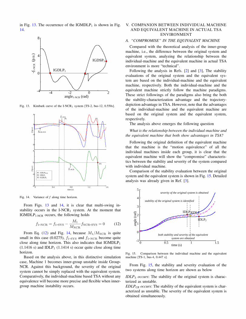
Comparison of the stability evaluation between the originalsystem and the equivalent system is shown in Fig. 15. Detailedanalysis was already given in Ref. [3].
0 0.5 1 1.5-1
0
1
2
3
4
5
time (s)
angle
(ra
d) IDLP3
IDLP2
EDLP
stability of the original system is identified
severity of the original system is obtained
both stability and severity of the equivalent
system are obtained
Fig. 15. Comparison between the individual machine and the equivalentmachine [TS-1, bus-4, 0.447 s].
From Fig. 15, the stability and severity evaluation of thetwo systems along time horizon are shown as below
IDLP3 occurs: The stability of the original system is charac-terized as unstable.EDLPCR occurs: The stability of the equivalent system is char-acterized as unstable. The severity of the equivalent system isobtained simultaneously.

IDLP2 occurs: The severity of the original system is obtained.
Following the analysis above, the stability evaluations ofthe equivalent machine show the following characteristics inTSA.
(i) The stability of the equivalent system is characterized“later” than that of the original system.(ii) The severity of the equivalent system is evaluated “earlier”than that of the original system.
(i) and (ii) fully reflect the “motion equivalence” characteris-tics of the equivalent machine. That is, the equivalent machineshows the “compromise” characteristics between the stabilityand severity of the system.
Essentially speaking, in most simulation cases, all the inner-group machine motions are slight, and thus the original systemcan be replaced with the equivalent system. Then one canobtain the followings(i) the severity of the system using the equivalent-machinecan be obtained earlier than that using the individual-machinemethod.(ii) The precision of the severity evaluation using theequivalent-machine method is also acceptable because all theinner-group machine motions are slight.
(i) and (ii) fully indicate that the equivalent-machine isflexible in TSA in most situations when all the inner-groupmachine motions are slight.
B. “DOUBLE EDGE” IN THE INDIVIDUAL MACHINE
Compared with the compromise of the equivalent machine,the individual-machine shows different “double-edged sword”characteristics in TSA. The two “double-edged sword” char-acteristics are given as below
(i) if the system engineer focuses on the “efficiency” of thestability characterization, he has to sacrifice the “precision” ofthe severity evaluation.(ii) On the contrary, if the system engineer focuses on the“precision” of the severity evaluation, he has to tolerate“efficiency” of the stability evaluation.
(i) and (ii) indicate that the individual-machine has tosacrifice “one side” to achieve a better performance of “theother side”.
Based on the analysis above, the “double edged” individual-machine can be seen as the “companion” of the “compro-mised” equivalent machine method in TSA. This companionrelationship is visually shown in Fig. 16.
stability is obtained
(more efficient yet less precise)
individual machine equivalent machine individual machine
both are obtained simultaneously
(moderate efficient and precise)
severity is obtained
(less efficient yet more precise)
along time horizon
Fig. 16. Companion relationship between the equivalent machine methodand the individual machine method.
Analysis about the “double-edge” characteristics of theindividual machine is given as below:Particular emphasis in the precision of the severity evaluation:In actual TSA environment, the system engineer will put aparticular emphasis on the “severity” of the system if the tran-sient stability control is fully considered in TSA. In order toensure the precision of the severity evaluation, the severity ofthe original system can only be evaluated through individual-machine without any equivalence. Under this circumstance,the individual-machine method will show its advantages in theprecise severity evaluation in TSA. A tutorial demonstrationabout this scenario is given in Fig. 17.
0 0.2 0.4 0.6-2
0
2
4
angle
(ra
d)
time (s)
EDLP
IDLP6
IDLP4
severity of the equivalent system is obtained
yet the precision is low
severity of the original system is obtained
the precision is high
Fig. 17. Advantages of the individual-machine in the precise severityevaluation.
From Fig. 17, using individual machine in TSA, the inner-group machine motion is completely eliminated. The severityof the original system is computed precisely at IDLP4 by usingindividual machine. However, note that this severity evaluationis obtained later than that using equivalent machine (IDLP4
occurs later than EDLPCR).In brief, the advantage in the “precision” of the severity
evaluation can be seen as the sacrifice of the “efficiency” of thestability characterization when using the individual machine inTSA.Particular emphasis in the efficiency of the stability character-ization: if the system engineer only focuses on the “stability”of the system, the individual-machine method will also showits advantage with the faster stability characterization alongtime horizon, as analyzed in Section V-A.

This advantage might be reflected in the following scenar-ios.(i) The stability characterization rather than the severity eval-uation becomes the primary objective of the transient securitycontrol.(ii) The computation of CCT is required.
In brief, the advantage in the “efficiency” of the stabilitycharacterization can be seen as the sacrifice of the “precision”of the severity evaluation when using the individual machinein TSA.
C. COMPANION RELATIONSHIP BETWEEN THE TWOMACHINES
Based on all the analysis above, both the equivalent ma-chine and the individual-machine will show advantages inthe corresponding scenarios. These advantages under differentscenarios are summarized as below in brief
(i) In the TSA environment that all the inner-group machinemotions are slight, the equivalent machine will show itsadvantage with the “faster” severity evaluation with acceptableprecision.(ii) In the TSA environment that the precision of the severityevaluation is emphasized (especially when any inner-groupmachine motion becomes fierce), the individual-machine willshow its advantage in the “precision” with the sacrifice of the“efficiency” of the stability characterization.(iii) In the TSA environment that the efficiency of the stabilitycharacterization is emphasized (especially when the CCTcomputation is needed), the individual-machine will show itsadvantage with the sacrifice of the “efficiency” of the severityevaluation.
(i) to (iii) indicate the followings:
The equivalent machine is flexible in most simulation caseswith slight inner-group machine motions.
Comparatively, the individual-machine can be seen as a“companion” of the equivalent method in certain distinctivecases.
Frankly, if equivalent machine is the “center” of a footballteam, then the individual-machine can be seen as the “forward”and “back”. The individual machine can be used under the dis-tinctive situation especially when inner-group machine motionbecomes fierce or the stability characterization becomes theparticular emphasis. This can be seen as the guidance for thesystem engineer to choose a feasible machine under specificTSA environment.
VI. COMPARISON BETWEEN GROUP SEPARATIONPATTERN AND MOD
A. DEFINITIONS OF MOD AND GROUP SEPARATIONPATTERN
Definition of MOD: MOD depicts how many machines becomeunstable for a given disturbance.
Following this definition, assume the system engineer standsat the fault clearing point. At this moment, it is possible
that one or more machines might go unstable in future post-fault period. For a multi-machine system with n machines,the motion of machine n is not independent in the COI-SYS reference (
∑ni=1Miθi = 0 ). Therefore, the possible
combinations of MOD are given asn−1∑i=1
Cin−1 = 2n−1 − 1 (13)
Following Eq. (13), for a multi-machine system with nmachines, the possible MODs may reach 2n−1−1 at the faultclearing point.Definition of group separation pattern: The group separationdepicts how many machine form Group-CR.
Following this definition, for a multi-machine system withn machines, assume one or more machines form ΩCR. Thenthe combinations of ΩCR can be denoted as
n−1∑i=1
Cin = 2n − 2 (14)
Because Cin and Cn−in corresponds to the same groupseparation pattern, the real combinations of Ωcr would becomehalf of that in Eq. (14), and thus the combinations of all thepossible group separation patterns can be denoted as
1
2
n−1∑i=1
Cin = 2n−1 − 1 (15)
Eqs. (13) and (15) indicate that the combinations of MODare mathematically equal to the numbers of the possible groupseparation patterns.
B. CONJECTURE ABOUT THE EQUIVALENCE BETWEENMOD AND GROUP SEPARATION PATTERN
We go a further step. Assume a long-time simulationis experienced. Under this circumstance, the final MOD isconfirmed, and the final dominant group separation is alsoidentified. It seems that the final MOD is chosen from 2n−1−1possible MODs, while the dominant pattern is also chosenfrom the 2n−1 − 1 possible patterns that exist at the faultclearing point. Based on these “similarities”, the equivalentmachine analysts believed that the dominant group separationpattern is “identical” to the real MOD in the theoretical level.
A tutorial example is given below. Demonstration aboutthe difference between MOD and dominant group separationpattern is shown in Fig. 18.

0 0.2 0.4 0.6 0.8 1 1.2-2
0
2
4
6
angle
(ra
d)
time (s)
fault clearing point
individual-machine view
(MOD view)
equivalent machine view
Fig. 18. Difference between MOD and dominant group separation pattern[TS-1, bus-2, 0.430 s].
From Fig. 18, assume the system operator is standing atthe fault clearing point (0.430s). At the moment he doesnot know what the system trajectory might become in thefollowing period. The combinations of MOD and that of groupseparation patterns are 29 − 1. After that, at 1.200 s, the realMOD is finally confirmed as Machines 9 and 8 going unstable,while the dominant group separation pattern is defined asMachines 8 and 9 forming ΩCR.
C. CLARIFICATIONS FROM THE INNER-GROUP MA-CHINE PERSPECTIVE
In fact this conjecture is a misunderstanding about theindividual machine and the equivalent machine, although thecombinations of MOD are mathematically equal to that of thegroup separation patterns.
Based on the definitions of the MOD and group separationpattern, the following deductions can be obtained
The MOD is defined in an individual-machine manner.Comparatively, the dominant group separation pattern
serves the machine equivalence.
In fact, the difference between MOD and the dominantgroup separation pattern is just the inner-group machine mo-tion.
Taking the case in Fig. 18 as an example, At the firstglance, it seems that Machines 9 and 8 are successfullycaptured inside ΩCR, and thus MOD is “identical” to thegroup equivalent pattern. In fact this is a complete misunder-standing. This is because the group separation pattern aims toserve the machine equivalence. In particular, under dominantgroup separation pattern, the equivalent Machine-CR is finallymodeled. Under this circumstance, differences always can befound between the “non-equivalent” real machine and the“equivalent” Machine-CR, These differences are just the inner-group motions inside ΩCR.
Strictly speaking, the MOD will be close (not identical) tothe dominant-group separation pattern if all the inner-groupmotions are slight, while the MOD will become differentfrom the dominant-group separation pattern if any inner-groupmachine instability occurs.
VII. REVISITS OF THE MACHINES
In this section, the mechanisms of the individual-machine,superimposed machine, the equivalent machine and the inner-group machine are systematically revisited. All the analysisin this section is based on the COI-SYS reference. Thissystematic revisit may further help readers take a deep insightinto the mechanisms of these machines.
The mechanism of the individual machine, superimposedmachine and the equivalent machine are shown in Fig. 19.
3 SYS
-f3-S
YS
IDLP3
0 0.5 1 1.5-2
-1
0
1
2
3
4
5
time (s)
IDLP3
2 SYS
IDLP2
-f2-S
YS
angle
(ra
d)
angle3-SYS
IDLP2
angle2-SYS
(a)
0 0.2 0.4 0.6 0.8 1-2
-1
0
1
2
3
4
ang
le (
rad
)
time (s)
SMPP
time
SM
TE
two-machine system
modeling fails
EAC is unable to
be established
NEC is pseudo
(b)
0 0.5 1 1.50
1
2
3
4
time (s)
CR NCR
EDLP
EDLP
angle
(ra
d)
(c)
Fig. 19. Comparison among the four machines. (a) Individual machine. (b)Superimposed machine. (c) Equivalent machine.
Mechanisms of the three machines are summarized as belowIndividual-machine: The idea of the machine comes from the“individual-machine monitoring” of the original system trajec-tory. The I-SYS system is established through the separationof the individual machine in the COI-SYS reference. Againstthis background, the IMTE shows strict NEC characteristics.

The strict correlation between IMTR and IMTE is establishedthrough each I-SYS system. The stability of the entire originalsystem is evaluated in a “machine-by-machine” manner be-cause NEC of each individual machine is unique and different.Superimposed machine: The idea of the machine comes fromthe “global monitoring” of the original system trajectory.However, due to the energy superimposition, the superimposedmachine is a pseudo machine without any equation of motion.Against this background, the correlation between the originalsystem trajectory and the SMTE cannot be established, whileits transient energy conversion does not satisfy NEC charac-teristic with always existence of the residual SMKE.Equivalent machine: The idea of the machine comes fromthe “equivalent machine monitoring” through group separationand motion equivalence. The CR-NCR system is establishedthrough the separation of Machine-CR in the COI-NCR ref-erence. Against this background, Machine-CR becomes the“one-and-only” machine in TSA. The EMTE shows strictNEC characteristics. The strict correlation between EMTR andEMTE is established through CR-NCR system. The stabilityof the equivalent system is evaluated in a “one-and-onlymachine” manner.
From analysis above, the mistakenly global monitoringleads to the energy superimposition in the superimposed ma-chine. This energy superimposition causes the superimposedmachine to become a pseudo machine without any equationof motion. Against this background, the pseudo superimposedmachine completely violates all the machine paradigms and itshow inherit defects in the TSA. Comparatively, the equivalentmachine is modeled based on the motion equivalence of all in-dividual machines inside each group. This motion equivalenceensures the equivalent machine to have its equivalent equationof motion. Against this background, the equivalent machinestrictly follows machine paradigms and it show advantages inTSA. Note that the inner-group machine is created from the“difference” between the individual machine and equivalentmachine.
In actual TSA environments, the individual machine andequivalent machine can be seen as “companions”. To bespecific, the equivalent machine will show flexibility whenthe equivalent system is close to the original system, whilethe individual-machine will become useful in the distinctiveenvironment that especially emphasizes the “more efficient sta-bility characterization” or “more precise severity evaluation”.
VIII. CONCLUSIONS
This paper focuses on the detailed modeling and stabilitycharacterizations of the inner-group motions. The inner-groupmotion it is created from the difference between the equivalentsystem and the original system. It physically does not exist.Following transient stability paradigms, the trajectory varianceof the inner-group machine can be modeled through the I-CRsystem with strict NEC characteristic. The transient charac-teristics of the inner-group machine are analyzed. The inner-group motions might be inseparable or separable. The inner-group instability will occur when the inner-group machineseparates from Machine-CR. The companion relationships
between the individual-machine and the equivalent machineare analyzed. It is found that the equivalent machine methodshow flexibility when the inner-group motions are slight. Com-paratively, the individual-machine will become useful undercertain distinctive situations in which “more efficient stabilitycharacterization” or “more precise severity evaluation” be-comes a particular emphasis. In the end of the paper, it isclarified that MOD will become significantly different from thedominant-group separation pattern if any inner-group machineinstability occurs. A systematical revisit about the individual-machine, superimposed machine and the equivalent machine isprovided. This revisit essentially enhances the understandingsof the mechanisms of the proposed machines in the previouspapers.
In the history of the power system transient stability, quitedifferent from the original definition of the equivalent machinethat is modeled based on the motion equivalence, the equiv-alent machine analysts also attempt to analyze the “machinetransformation” from the individual machine to the equivalentmachine from the perspective the “correction” of the inner-group machines. This will be analyzed in the following paper.
REFERENCES
[1] S. Wang, J. Yu, and A. Foley, “Newtonian Mechanics Based TransientStability PART I: Transient Stability Paradigms”.
[2] S. Wang, J. Yu, and A. Foley, “Newtonian Mechanics Based TransientStability PART II: Individual Machine”.
[3] S. Wang, J. Yu, and A. Foley, “Newtonian Mechanics Based TransientStability PART IV: Equivalent Machine”.
[4] D. Fang, T. S. Chung, Y. Zhang, and W. Song, “Transient stabilitylimit conditions analysis using a corrected transient energy functionapproach“’, IEEE Trans. Power Syst. vol. 15, no. 2, pp. 804-810, 2000.
[5] Y. Xue, “Re-examination of transient energy functions and critical en-ergy”, Automation of Electric Power Systems, vol. 6, pp. 9-18, 1991.