Transient examples
13
EE 442 RC and RL transient examples – 1 RC example 1 The switch in the simple RC circuit closes at t = 0. For the circuit, V S = 12 V, R = 10 kΩ, C = 10 nF. The capacitor was initially charged to 6 volts. At what time does the capacitor voltage hit 10.5 V? + – + – V S R v C (t) C t = 0 v C (t)= V S - [V S - V Ci ] exp ✓ - t RC ◆ V Ci = 6 V and RC = 0.1 ms = 100 μs. 10.5V = 12V - [6V ] exp ✓ - t 0 100μs ◆ inverting it t 0 = (100μs) ln 6V 12V - 10.5V = 130μs
Transcript of Transient examples

EE 442 RC and RL transient examples – 1
RC example 1
The switch in the simple RC circuit closes at t = 0. For the circuit, VS = 12 V, R = 10 kΩ, C = 10 nF. The capacitor was initially charged to 6 volts. At what time does the capacitor voltage hit 10.5 V?
+–
+
–VS
R
vC(t)C
t = 0
vC (t) = VS � [VS � VCi] exp
✓� t
RC
◆VCi = 6 V and RC = 0.1 ms = 100 µs.
10.5V = 12V � [6V ] exp
✓� t0
100µs
◆
inverting it
t0 = (100µs) ln
6V
12V � 10.5V
�= 130µs
EE 442 RC and RL transient examples – 2
RC example 2
The switch in the simple RC circuit closes at t = 0. For the circuit, IS = 25 mA, R = 500 Ω, C = 10 µF. The capacitor was initially charged to 20 volts. What is the final voltage of the capacitor after the “end” of the transient? What is the voltage after 2 time constants?
RIS–
+vC(t)
t = 0
C
We can either solve this from scratch (it’s not too hard). Or we can make the circuit look like our prototype, which is even easier. Using a source transformation the circuit becomes
+–
+
–VS
R
vC(t)C
t = 0with VS = 12.5 V and RC = 5 ms.
With VCi = 20 V, this becomes a capacitor discharge problem.
EE 442 RC and RL transient examples – 3
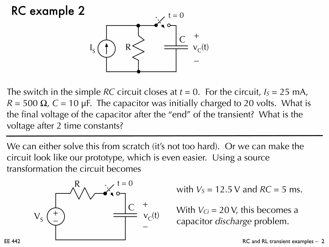
The final voltage on the capacitor will be VCi ( t → ∞) = VS = 12.5 V.
+–
+
–VS
R
vC(t)C
t = 0
vC (t) = VS � [VS � VCi] exp
✓� t
RC
◆
vC (t) = 12.5V + [7.5V ] exp
✓� t
5ms
◆
After 2 time constants (10 ms)
vC (10ms) = 12.5V + [7.5V ] exp (�2) = 13.52V
EE 442 RC and RL transient examples – 4
RC example 3
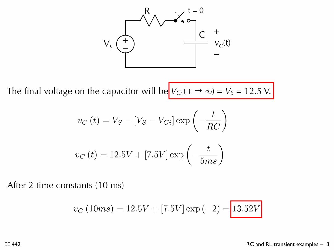
The switch in the RC circuit closes at t = 0. For the circuit, VS = 15 V, IS = 5 mA, R1 = 3 kΩ, R2 = 1.5 kΩ, R3 = 1 kΩ, R4 = 500 Ω , and C = 100 nF. The capacitor was initially uncharged (VCi = 0). What is the final voltage of the capacitor at the “end” of the transient? What is the 10%-90% rise time?
+–
+
–VS
vC(t)C
t = 0R1 R3
R2 R4
IS
Obviously, we need to find the Thevenin equivalent of the portion of the circuit attached to the capacitor. We’ve done that enough in the past that we’ll skip the details. (It’s a 2-node NVM problem.)

EE 442 RC and RL transient examples – 5
+–
+
–VS
R
vC(t)C
t = 0
After finding the Thevenin equivalent, the simple RC circuit has VS = VTH = 2 V and R = RTH = 400 Ω.
The final voltage on the capacitor will be VCi ( t → ∞) = VS = 2 V.
As shown in the notes, the 10%-90% rise time is equal to 2.2RC.
�t = (2.20) (400⌦) (100nF ) = 88µs
EE 442 RC and RL transient examples – 6
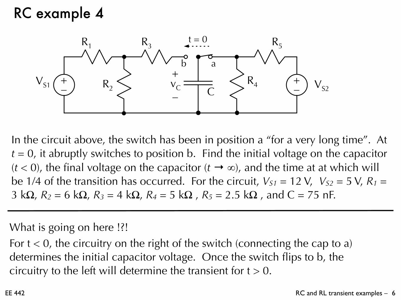
RC example 4
In the circuit above, the switch has been in position a “for a very long time”. At t = 0, it abruptly switches to position b. Find the initial voltage on the capacitor (t < 0), the final voltage on the capacitor (t → ∞), and the time at at which will be 1/4 of the transition has occurred. For the circuit, VS1 = 12 V, VS2 = 5 V, R1 = 3 kΩ, R2 = 6 kΩ, R3 = 4 kΩ, R4 = 5 kΩ , R5 = 2.5 kΩ , and C = 75 nF.
What is going on here !?! For t < 0, the circuitry on the right of the switch (connecting the cap to a) determines the initial capacitor voltage. Once the switch flips to b, the circuitry to the left will determine the transient for t > 0.
+–
VS1 +–
t = 0R1
R2
R3
R4
R5
VS2
ab+
–vC C
EE 442 RC and RL transient examples – 7
+–
R4
R5
VS2
a
t < 0iC=0
–VCi
+
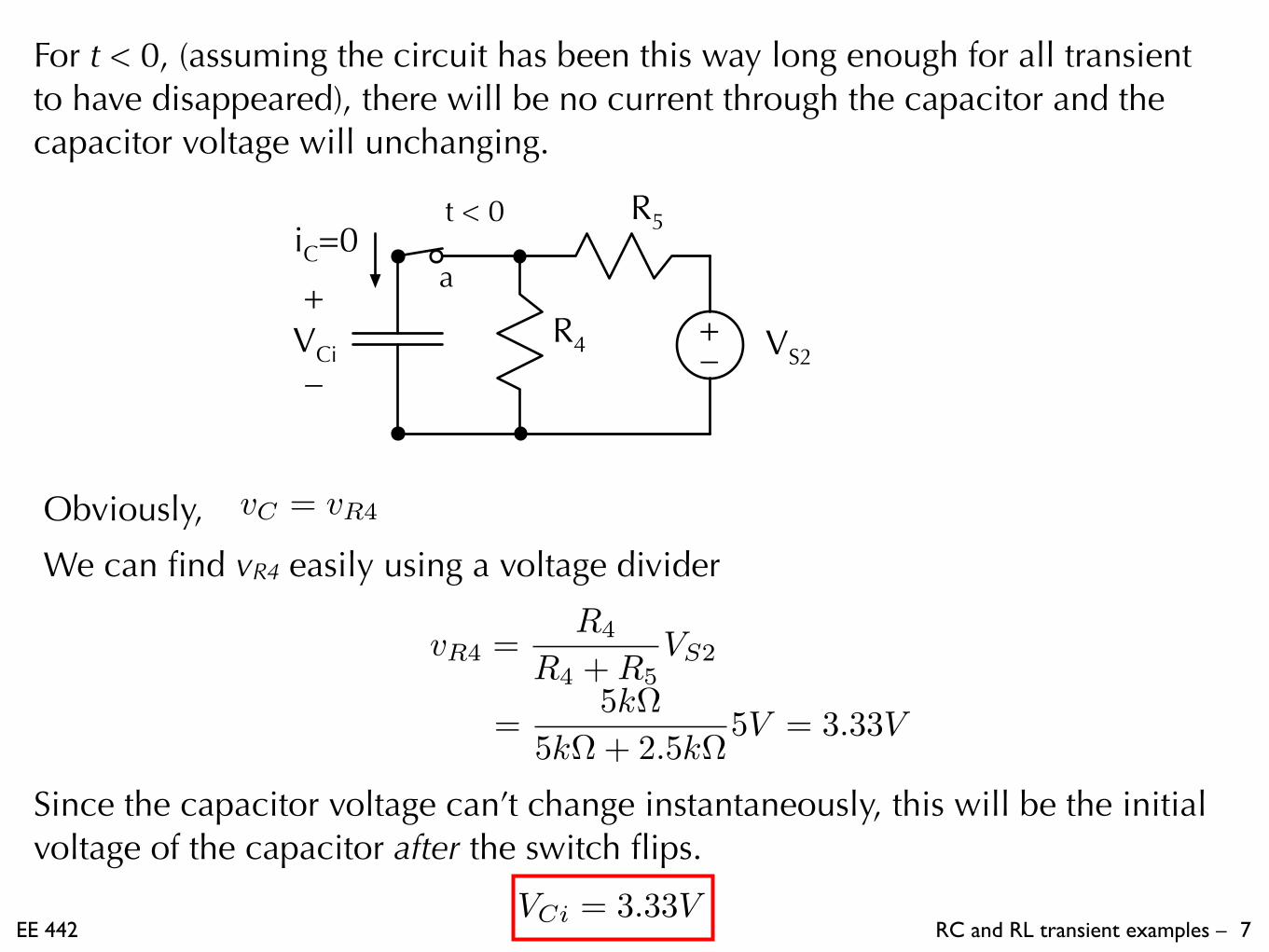
For t < 0, (assuming the circuit has been this way long enough for all transient to have disappeared), there will be no current through the capacitor and the capacitor voltage will unchanging.
Obviously, vC = vR4
We can find vR4 easily using a voltage divider
vR4 =R4
R4 +R5VS2
=5k⌦
5k⌦+ 2.5k⌦5V = 3.33V
Since the capacitor voltage can’t change instantaneously, this will be the initial voltage of the capacitor after the switch flips.
VCi = 3.33V

EE 442 RC and RL transient examples – 8
For t > 0, (after the switch flips), we must look at the left hand part of the circuit to determine the details of the transient. It look like we should find the Thevenin equivalent of the source and resistors connected to the capacitor. Fortunately, this is an easy one that we have determined before.
+–
VTH
t ≥ 0RTH
b+
–vC C
+–
VS1
t ≥ 0R1
R2
R3
b+
–vC C
RTH = 6k⌦
vC (t) = VS � [VS � VCi] exp
✓� t
RC
◆RC = 0.45ms = 450µs
Use the discharge equation to find that the time at which the capacitor voltage has made 1/4 of it’s transition (vC = 4.5 V) is 129.5 µs.
VTH = 8V
= 8V � [4.67V ] exp
✓� t
450µs
◆
EE 442 RC and RL transient examples – 9
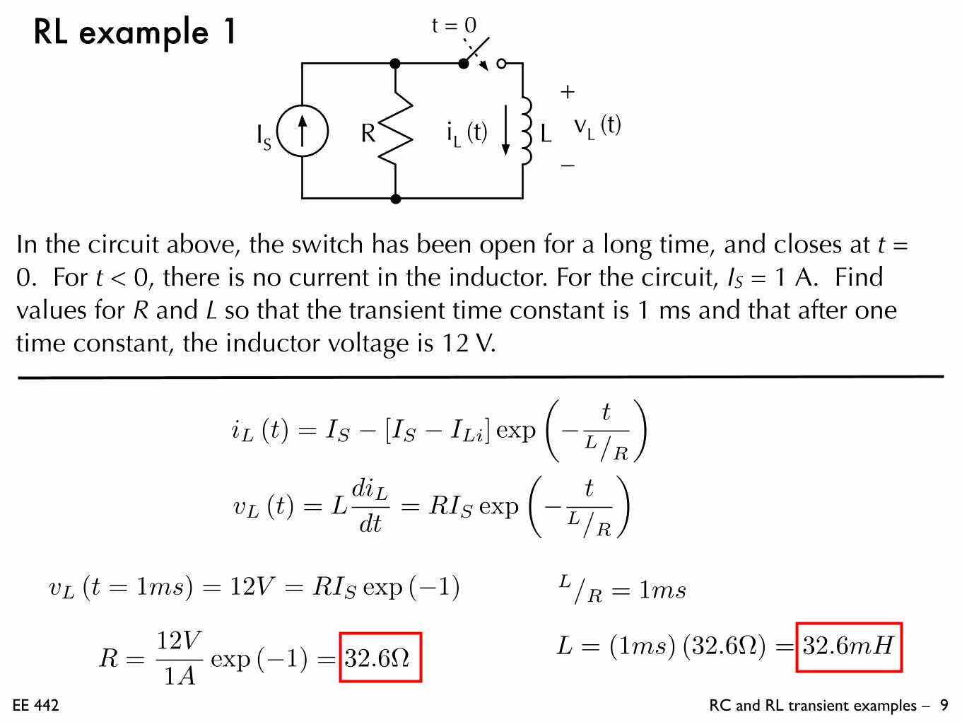
RL example 1
In the circuit above, the switch has been open for a long time, and closes at t = 0. For t < 0, there is no current in the inductor. For the circuit, IS = 1 A. Find values for R and L so that the transient time constant is 1 ms and that after one time constant, the inductor voltage is 12 V.
R LIS–
+vL (t)iL (t)
t = 0
iL (t) = IS � [IS � ILi] exp
✓� t
L/R
◆
vL (t) = LdiLdt
= RIS exp
✓� t
L/R
◆
L/R = 1msvL (t = 1ms) = 12V = RIS exp (�1)
R =
12V
1Aexp (�1) = 32.6⌦ L = (1ms) (32.6⌦) = 32.6mH

EE 442 RC and RL transient examples – 10
RL example 2
In the circuit above, the switch has been open for a long time, and closes at t = 0. For t < 0, there is no current in the inductor. For the circuit, VS1 = 20 V, R1 = 1 kΩ, R2 = 1 kΩ, and R3 = 1.5 kΩ. Calculate the final value of the inductor current and determine L so that the transient time constant is 10 µs.
+–
L
t = 0
VS1
R1
R2
R3
It seems apparent that we will have to find the equivalent for the circuit to the left of the switch. We’ve done this one several times before. However, we will want the Norton equivalent in order to match the prototype RL equation.
iL (t ! 1) = IS = 5mA
L/R = 10µs L = (10µs) (2k⌦) = 20mHIN
L
t = 0
RN5 mA 2 kΩ

EE 442 RC and RL transient examples – 11
RL example 3 t = 0
IS1 IS2R1
R2
R3L
R4
R5
In the circuit above, the switch has been in position a “for a very long time”. At t = 0, it abruptly switches to position b. Find the initial current in the inductor (t < 0), the final current in the inductor (t → ∞), and the time constant for the transient. For the circuit, IS1 = 90 mA, IS2 = 40 mA, R1 = 400 Ω, R2 = 500 Ω, R3 = 100 Ω, R4 = 300 Ω , R5 = 100 Ω , and L = 25 mH.
As with the previous example, we use the circuitry on the right to determine the initial inductor current. Then, once the switch has flipped, we use the circuit on the left side to determine the transient for t ≥ 0.

EE 442 RC and RL transient examples – 12
Using a current divider to find the inductor current:
Assuming that all transients have disappeared, the inductor has no voltage across it and acts like a short circuit in the static circuit.
t < 0
IS2L
R4
R5
a
ILi–
vL=0
+
iL =R5
R4 +R5IS2
=100⌦
300⌦+ 100⌦(40mA)
= 30mA
This will be the initial current once the switch flips.
ILi = 30mA

EE 442 RC and RL transient examples – 13
for t > 0, we need to find the Norton equivalent of the circuit attached to the inductor
t ≥ 0
IS1 R1
R2
R3L
b
iL (t) R LIN iL (t)
t ≥ 0
b
40 mA90 Ω
From the Norton equivalent, we see that
iL (t ! 1) = IN = 40mA
⌧ =L
R=
25mH
90⌦= 278µs