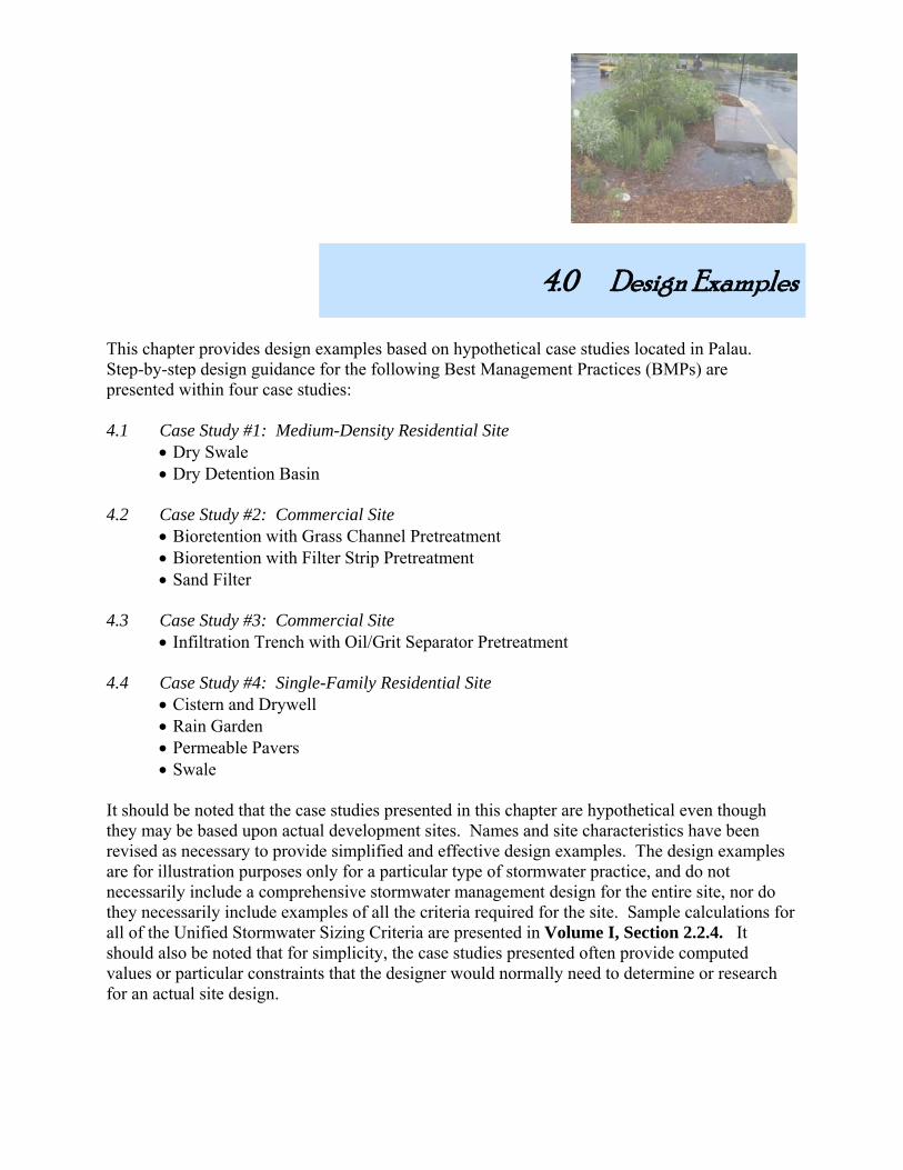
4.0 Design Examples - AWS
752
4.0 Design Examples This chapter provides design examples based on hypothetical case studies located in Palau. Step-by-step design guidance for the following Best Management Practices (BMPs) are presented within four case studies: 4.1 Case Study #1: Medium-Density Residential Site • Dry Swale • Dry Detention Basin 4.2 Case Study #2: Commercial Site • Bioretention with Grass Channel Pretreatment • Bioretention with Filter Strip Pretreatment • Sand Filter 4.3 Case Study #3: Commercial Site • Infiltration Trench with Oil/Grit Separator Pretreatment 4.4 Case Study #4: Single-Family Residential Site • Cistern and Drywell • Rain Garden • Permeable Pavers • Swale It should be noted that the case studies presented in this chapter are hypothetical even though they may be based upon actual development sites. Names and site characteristics have been revised as necessary to provide simplified and effective design examples. The design examples are for illustration purposes only for a particular type of stormwater practice, and do not necessarily include a comprehensive stormwater management design for the entire site, nor do they necessarily include examples of all the criteria required for the site. Sample calculations for all of the Unified Stormwater Sizing Criteria are presented in Volume I, Section 2.2.4. It should also be noted that for simplicity, the case studies presented often provide computed values or particular constraints that the designer would normally need to determine or research for an actual site design.
-
Upload
khangminh22 -
Category
Documents
-
view
0 -
download
0
Transcript of 4.0 Design Examples - AWS
4.0 Design Examples This chapter provides design examples based on hypothetical case studies located in Palau. Step-by-step design guidance for the following Best Management Practices (BMPs) are presented within four case studies: 4.1 Case Study #1: Medium-Density Residential Site
• Dry Swale • Dry Detention Basin
4.2 Case Study #2: Commercial Site
• Bioretention with Grass Channel Pretreatment • Bioretention with Filter Strip Pretreatment • Sand Filter
4.3 Case Study #3: Commercial Site
• Infiltration Trench with Oil/Grit Separator Pretreatment 4.4 Case Study #4: Single-Family Residential Site
• Cistern and Drywell • Rain Garden • Permeable Pavers • Swale
It should be noted that the case studies presented in this chapter are hypothetical even though they may be based upon actual development sites. Names and site characteristics have been revised as necessary to provide simplified and effective design examples. The design examples are for illustration purposes only for a particular type of stormwater practice, and do not necessarily include a comprehensive stormwater management design for the entire site, nor do they necessarily include examples of all the criteria required for the site. Sample calculations for all of the Unified Stormwater Sizing Criteria are presented in Volume I, Section 2.2.4. It should also be noted that for simplicity, the case studies presented often provide computed values or particular constraints that the designer would normally need to determine or research for an actual site design.

Palau Stormwater Management Manual Volume II-Chapter 4
4-2
<This page left blank intentionally>

Palau Stormwater Management Manual Volume II-Chapter 4
4-3
4.1 Case Study #1: Medium Density Residential Site This case study represents a medium-density residential site located in Melekeok on the island of Babeldaob. Mountain View Estates (see Figure 4.1) is a hypothetical subdivision consisting of approximately 23 ¼-acre lots, with 2,000 linear feet of 20-ft wide residential roads. The total site consists of 20 acres with 10 acres of preserved open space. The disturbed portion of the site consists of 10 acres, 25% impervious cover. The site is located in the volcanic uplands of Babeldaob. On-site soils as determined by the NRCS soil maps are Aimeliik-Palau, classified as HSG “B”. Two stormwater practice design examples are presented for this case study, consisting of a dry swale and a dry detention basin. The data for the site is summarized in Table 4.1.
Table 4.1 Base Data for Mountain View Estates Hydrologic Data
Location: Melekeok, Babeldaob Pre Post Drainage Area Area A
Site Area: 10 acres CN Value 61 78 Impervious Area: 2.5 acres tc 0.26 0.23
Soils Type: Aimeliik-Palau, “B”
Figure 4.1 Medium Density Residential Site Plan
Palau Stormwater Management Manual Volume II-Chapter 4
4-4
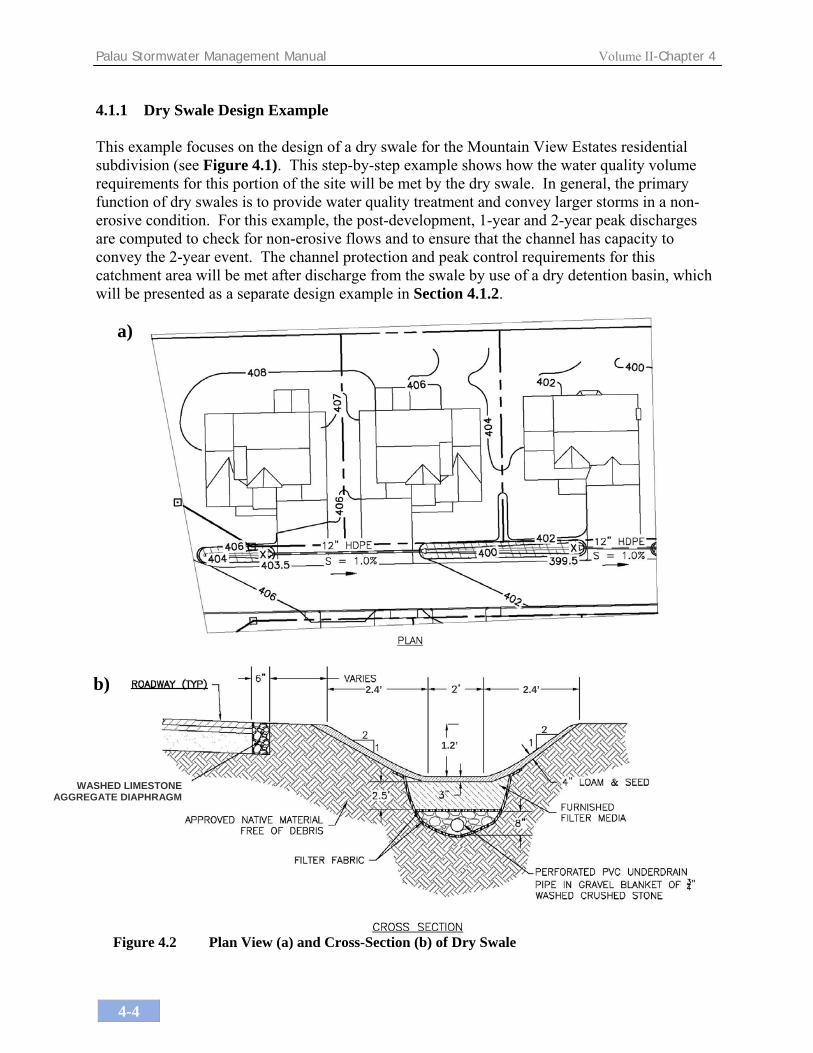
4.1.1 Dry Swale Design Example This example focuses on the design of a dry swale for the Mountain View Estates residential subdivision (see Figure 4.1). This step-by-step example shows how the water quality volume requirements for this portion of the site will be met by the dry swale. In general, the primary function of dry swales is to provide water quality treatment and convey larger storms in a non-erosive condition. For this example, the post-development, 1-year and 2-year peak discharges are computed to check for non-erosive flows and to ensure that the channel has capacity to convey the 2-year event. The channel protection and peak control requirements for this catchment area will be met after discharge from the swale by use of a dry detention basin, which will be presented as a separate design example in Section 4.1.2.
a)
b)
WASHED LIMESTONE AGGREGATE DIAPHRAGM
1.2’
2.4’2.4’
Figure 4.2 Plan View (a) and Cross-Section (b) of Dry Swale

Palau Stormwater Management Manual Volume II-Chapter 4
4-5
Better Site Design (BSD) measures (see Chapter 3) were incorporated at this new development site to the maximum extent practicable. For example, impervious surfaces were reduced by decreasing the width of the streets and driveways. The rooftop runoff was directed into cisterns/drywells. In addition, lots were clustered such that 10 acres of open space could be preserved around the river. These techniques help improve the value of the development and decrease the site’s impact on the water resources. Also, by utilizing BSD techniques and decreasing the overall runoff from the site, the developer would save money by having lower stormwater volume requirements (thus, smaller BMPs to build) and less infrastructure to construct. Step 1: Compute preliminary runoff control volumes. Table 4.2 provides a summary of the volume requirements that were determined in Volume I, Section 2.2.4 (Sample Calculations). Table 4.2 Summary of General Storage Requirements for Mountain View Estates
Symbol Category Volume Required (ac-ft) Notes
Rev Recharge Volume 0.056
WQv Water Quality Volume 0.25 Includes Rev
Cpv Stream Protection 1.1 Average ED release rate is 0.55 cfs over 24 hours
Qp-25 Overbank Control 1.43
In order to meet the Rev at this site, the runoff from the 23 rooftops will be directed into cisterns that overflow into drywells. The design of these practices are not included in this example, but are discussed in more detail in Section 4.4. Since rooftop runoff does not need to be treated (Volume I, Section 2.2.2.1), it can discharge directly into the ground via drywells, with the volume counting towards both recharge and water quality requirements. Thus, the WQv required to be treated by the dry swales is reduced, as follows:
Average house area at site = 1,000 ft2 Number of houses = 23 Net impervious area reduction = (23) (1,000 ft2) / (43,560 ft2/ac) = 0.53 acres New impervious area = 2.5 – 0.53 = 1.97 acres; new I = (1.97 ac / 10 ac) = 0.2
Revised WQv = [(P) (I) (A)] / 12 = [(1.2in) (0.2) (10 ac) (1ft/12in) = 0.2 ac-ft = 8,712 ft3

Palau Stormwater Management Manual Volume II-Chapter 4
4-6
Step 2: Determine if the development site and conditions are appropriate for the use of a dry swale.
The proposed road grade in the vicinity of the dry swale is approximately 3.0%. Soils are modestly to well drained. There is sufficient area to accommodate the dry swale within the roadside right of way. Step 3: Confirm local design criteria and applicability. There are no additional requirements for this site. This dry swale design will have an “open bottom” (i.e., no impermeable liner (Figure 4.2)) to allow for some groundwater recharge, but there is also an underdrain to convey the water that does not infiltrate downstream to a dry detention basin where the channel protection and overbank flood requirements will be met (see Section 4.1.2). The underdrain will ultimately discharge into the sediment forebay via the riprap outlet shown in Figure 4.3.
Step 4: Determine size of dry swale area. The dry swale treats the WQv by filtering it through a filter bed. The following equation (also used for filtering BMPs) is used to size the surface area of the dry swale, given an average depth of 3 inches.
Af = (WQv) (df) / [ (k) (hf + df) (tf)] Where: Af = surface area of filter bed (ft2) WQv = Water quality volume (ft3) df = filter bed depth (ft) (recommended 2.5 ft from Volume I, Figure 3.13) k = filter media coefficient of permeability (ft/day) (use same media as bioretention) hf = average height of water above filter bed (ft) tf = design filter bed drain time (days) (2 days is recommended) Af = (8,712 ft3) (2.5 ft) / [(1 ft/day) (0.25 ft + 2.5 ft) (2 days)] (With k = 1 ft/day, hf = 0.25 ft, tf = 2 days) Af = 3,960 ft2 Step 5: Size a channel and compute the required length to store the water quality volume. Provide bottom width, depth, length, and slope necessary to store WQv with an average of 3 inches of ponding.

Palau Stormwater Management Manual Volume II-Chapter 4
4-7
Assume a trapezoidal channel. Per the site plan, there is approximately 2,000 ft available for the swale along both sides of the road, not including driveways where there will be culverts connecting the swale. The outlet of the swale will be at the proposed dry detention basin described in Section 4.1.2. The existing uphill invert is 408.5 ft, and the infiltration basin invert is 391.0 ft. Slope = (408.5 ft -391.0 ft)/1000 ft (based on one side of the road only) = 0.0199 = 1.75% Minimum slope 1.0% and maximum slope 4.0%, OK Side slopes = 2:1 (given the space constraints of this development, use 2:1 slopes) For a surface area of Af = 3,960 ft2 and a total L = 2,000 ft, the WQv width needs to be (3,960 ft2 / 2,000 ft) = 1.98 ft. A minimum bottom width of 2 ft is required for dry swales according to Volume I, Section 3.2.4.5d; thus, the bottom width will be rounded up to 2.0 ft. Step 6: Check the velocity of the 1-year storm and the hydraulic capacity of the 2-year
storm. • Develop Site Hydrologic Input Parameters and Perform Preliminary Hydrologic Calculations
(see Table 4.3). Note: For this design example, the 1-year storm is used to check the channel geometry for non-erosive conditions, and the 2-year storm is used to check the conveyance capacity of the channel. Any hydrologic model using SCS procedures, such as TR-20, HEC-HMS, or HEC-1, can be used to perform preliminary hydrologic calculations. In this example, TR-55 was used to compute these values (see Table 4.3). Note, the resulting design geometry for the dry swales is conservative because it is sized based on the flows at the downstream end of each subwatershed; thus, the depth and width of the dry swale in the upstream areas may be reduced.

Palau Stormwater Management Manual Volume II-Chapter 4
4-8
Table 4.3 Mountain View Estates Post-Developed - TR-55 Output for 1-, 2-, and 25-year storm events
PEAK DISCHARGE SUMMARY
JOB: Mountain View Estates
DRAINAGE AREA NAME: POST DEVELOPMENT
GROUP CN from AREA
COVER DESCRIPTION SOIL NAME A,B,C,D? TABLE 2-2 (In acres)
Grass Aimeliik-Palau B 61 7.50 Ac.Impervious (roads, roofs, driveways) Aimeliik-Palau B 98 2.50 Ac.
AREA SUBTOTALS: 10.00 Ac.
Time of Concentration Surface Cover Manning 'n' Flow Length Slope
2-Yr 24 Hr Rainfall = 7.2 In Pipe Diameter Avg Velocity Tt (Hrs)
Sheet Flow dense grass 'n'=0.24 50 Ft. 2.00%
0.09 Hrs
Shallow Flow Short Grass Pasture 50 Ft. 2.00%
7.00 F.P.S. 0.01 Hrs.
Channel Flow 'n'=0.130 2000 Ft. 2.00%
0.26 Hrs.
Total Area in Acres = 10.00 Ac. Total Sheet Total Shallow Total Channel
Weighted CN = 70 Flow= Flow= Flow =
Time Of Concentration = 0.36 Hrs. 0.09 Hrs. 0.01 Hrs. 0.26 Hrs.
RAINFALL TYPE IA
Precipitation Runoff Qp, PEAK TOTAL STORM
STORM (P) inches (Q) DISCHARGE Volumes
1 Year 5.8 In. 2.7 In. 5.5 CFS 96,195 Cu. Ft.2 Year 7.2 In. 3.79 In. 8.3 CFS 137,577 Cu. Ft.25 Year 12.4 In. 8.4 In. 20 CFS 305,646 Cu. Ft.
Check to ensure non-erosive velocity for 1-year storm: Roadway slope = 2.0%, check velocity and depth for the following parameters:
Q1-year = 5.5 cfs Bottom width = 2 ft Side slopes = 2:1 Longitudinal slope = 1.75% Manning’s roughness coefficient (n) = 0.03

Palau Stormwater Management Manual Volume II-Chapter 4
4-9
Using Manning’s equation for a trapezoid channel: Q = (a) (v) = (a)[1.49/n (R)2/3 (S)1/2]; a = bd + zdd; R=a / (b+2d√(zz+1)) where v = velocity (ft/s) n = Manning’s roughness coefficient, R = hydraulic radius (ft) a = cross sectional area (ft2) S = channel longitudinal slope b = bottom width (ft) d = depth of water (ft) z = side slope (z:1) Solve for depth and velocity. Results: a = (2.0 * d) + 2(d * d) = 2.0d + 2d2 R = (2.0d + 2d2) / (2.0 + 2d√(5)) = (2.0d + 2d2) / (2.0 + 4.47d) Q = (2.0d + 2d2) [1.49/.03 * ((2.0d + 2d2) / (2.0 + 4.47d)) 2/3 * 0.01751/2 ] Depth Due to complexity of equation, solve for d by trial and error. First, choose a depth that seems reasonable and solve for Q. Repeat until the solution for Q is equal to Q1-year (5.5 cfs). Spreadsheets can be set up to help streamline this process, or an open channel model can be used. Trial 1. Try a depth of 0.5 ft. a = 2.0(0.5) + 2(0.5)2 = 1.5 ft2 R = 1.5 ft2 / (2.0 + 4.47(0.5)) = 0.35 ft Q = 1.5 ft2 [1.49/.03 * (0.35 ft) 2/3 * 0.01751/2 ] = 4.93 cfs < Q1-year , so try a larger depth. Trial 2. Try a depth of 0.55 ft. a = 2.0(0.55) + 2(0.55)2 = 1.71 ft2 R = 1.71 ft2 / (2.0 + 4.47(0.55)) = 0.38 ft Q = 1.71 ft2 [1.49/.03 * (0.38 ft) 2/3 * 0.01751/2 ] = 5.9 cfs > Q1-year , so try a smaller depth. Trial 3. Try a depth of 0.53 ft a = 2.0(0.2) + 2(0.53)2 = 1.62 ft2 R = 1.62 ft2 / (2.0 + 4.47(0.53)) = 0.37 ft Q = 1.62 ft2 [1.49/.03 * (0.37 ft) 2/3 * 0.01751/2 ] = 5.5 cfs = Q1-year Thus, depth = 0.53 ft to accommodate this storm. Velocity v = Q/a v = 5.5 cfs / 1.62 ft2 = 3.4 ft/s (v is less than 5.0 ft/s, OK)

Palau Stormwater Management Manual Volume II-Chapter 4
4-10
Check to ensure adequate capacity for 2-year storm: From hydrology information, the 2-year flow is 8.3 cfs. Compute depth and provide an additional 0.5 ft of freeboard above 2-year flow. Roadway slope = 2.0%, depth for the following parameters:
Q2-year = 8.3 cfs Bottom width = 2.0 ft Side slopes = 2:1 Longitudinal slope = 1.75% Manning’s Coeff. = 0.03
Solve for depth using Manning’s equation and trial and error method shown above. Using a depth of 0.55 ft in Trial 1 above gave a solution of Q = 5.9 cfs; thus, we know the depth for the 2-year storm is more than 0.5 ft. Try a depth of 0.66 ft: a = 2.0(0.66) + 2(0.66)2 = 2.19 ft2 R = 2.19 ft2 / (2.0 + 4.47(0.66)) = 0.44 ft Q = 2.19 ft2 [1.49/.03 * (0.44 ft) 2/3 * 0.01751/2 ] = 8.36 cfs = Q2-year Results: Depth = 0.66 ft. Provide 0.66 ft plus additional 0.5 ft of freeboard. Total swale depth = 0.66 ft + 0.5 ft = 1.2 ft for a total top width of 6.8 ft. Step 7: Design pretreatment. Pretreat with grassed side slopes and washed, rounded limestone aggregate diaphragm (curtain drain) for the sheet flow and sediment forebays for the concentrated inflow points (i.e., a pipe). Step 8: Choose vegetation for the channel. Choose vegetation based on factors such as resistance to erosion, resistance to drought and inundation, cost, aesthetics, maintenance, etc. Based on the project slope range (0-5%), and 1-year velocity equal to approximately 3.4 ft/s, choose appropriate grass for channel (moist to well drained soils, higher permissible velocities, and good establishment rate). See local NRCS office for guidance.

Palau Stormwater Management Manual Volume II-Chapter 4
4-11
4.1.2 Dry Detention Basin Design Example This example focuses on the design of a dry detention basin for the Mountain View Estates residential subdivision (see Figure 4.1). This step-by-step example shows how the channel protection and peak control requirements for this portion of the site will be met by the dry detention basin. A dry detention basin was chosen because the site is dominated by volcanic geology, as shown on the geologic map (Volume I, Figure 2.2) and verified by geotechnical investigation. Thus, an infiltration basin for quantity control would not be possible. Groundwater was found at an elevation of 379 ft. The overflow from the basin will discharge into an adjacent freshwater river. The water quality volume for this catchment area will be met prior to discharge to the basin by use of a dry swale, which is presented as a separate design example in Section 4.1.1.
Figure 4.3 Plan View of Dry Detention Basin
Figure 4.4 Cross-Section of Dry Detention Basin
DRY DETENTION BASIN
OUTLET STRUCTURE
389
388’
388
387

Palau Stormwater Management Manual Volume II-Chapter 4
4-12
Step 1: Compute the Cpv and the Qp-25 Volume using the Unified Stormwater Sizing Criteria
The basin will be sized to manage the Cpv and the Qp-25 volume with 1 ft of freeboard, with discharges directed to the river via an outlet pipe. The overflow from storms greater than the 25-year storm will be discharged to the river by means of an emergency spillway, where it can be shown that the overflow will not cause damage to neighboring houses or structures. Table 4.2 provides a summary of the volume requirements that were determined in Volume I, Section 2.2.4 (Sample Calculations). The pre- and post-development runoff characteristics that were determined with a TR-55 computer model are shown in Tables 4.5 and 4.6 below. Table 4.4 Summary of Storage Requirements for the Dry Detention Basin
Symbol Category Volume Required (ac-ft) Notes
Cpv Stream Protection 1.1 Average ED release rate is 0.55 cfs over 24 hours
Qp-25 Overbank Control 1.43
Step 2: Determine basin location and preliminary geometry. Conduct basin grading. This step involves initially grading the basin (establishing contours) and determining the elevation-storage relationship for the basin. Storage must be provided for the 1-year storm, and 25-year storm. An elevation-storage table and curve is prepared using the average area method for computing volumes. A 2-ft berm is included around the edge of the basin. See Figure 4.3 for pond grading and Figure 4.5 for Elevation-Storage Data. Step 3: Size pretreatment. Even though the dry swale provides treatment, use a sediment forebay at the outfall of the dry swale for additional sediment/trash removal from large storm events. Size forebay using the equation in Volume I, Section 3.2.4.4c:
As = 0.066 (WQv) = 0.066 * (8,712 ft3 * 0.25)
As = 144 ft2
Use a minimum 3 ft depth with a length to width ratio of 1.5:1. Sediment forebay dimensions should be approximately 8.5 ft x 13 ft with a depth of 3 ft.

Palau Stormwater Management Manual Volume II-Chapter 4
4-13
Table 4.5 Mountain View Estates Pre-Developed - TR-55 Output PEAK DISCHARGE SUMMARY
JOB: Mountain View Estates
DRAINAGE AREA NAME: PRE DEVELOPMENT
GROUP CN from AREA
COVER DESCRIPTION SOIL NAME A,B,C,D? TABLE 2-2 (In acres)
Wood Aimeliik-Palau B 55 10.00 Ac.
AREA SUBTOTALS: 10.00 Ac.
Time of Concentration Surface Cover Manning 'n' Flow Length Slope
2-Yr 24 Hr Rainfall = 7.2 In Avg Velocity Tt (Hrs)
Sheet Flow Woods: Dense Underbrush 'n'=0.80 50 Ft. 4.00%
0.18 Hrs
Shallow Flow Forest w/Heavy Litter 1800 Ft. 3.00%
2.50 F.P.S. 1.16 Hrs.
Total Area in Acres = 10.00 Ac. Total Sheet Total Shallow
Weighted CN = 55 Flow= Flow=
Time Of Concentration = 1.34 Hrs. 0.18 Hrs. 1.16 Hrs.
RAINFALL TYPE IA
Precipitation Runoff Qp, PEAK TOTAL STORM
STORM (P) inches (Q) DISCHARGE Volumes
1 Year 5.8 In. 1.40 In. 1.2 CFS 50,820 Cu. Ft.2 Year 7.2 In. 2.25 In. 2.4 CFS 81,675 Cu. Ft.25 Year 12.4 In. 6.1 In. 8.5 CFS 222,156 Cu. Ft.

Palau Stormwater Management Manual Volume II-Chapter 4
4-14
Table 4.6 Mountain View Estates Post-Developed - TR-55 Output PEAK DISCHARGE SUMMARY
JOB: Mountain View Estates
DRAINAGE AREA NAME: POST DEVELOPMENT
GROUP CN from AREA
COVER DESCRIPTION SOIL NAME A,B,C,D? TABLE 2-2 (In acres)
Grass Aimeliik-Palau B 61 7.50 Ac.Impervious (roads, roofs, driveways) Aimeliik-Palau B 98 2.50 Ac.
AREA SUBTOTALS: 10.00 Ac.
Time of Concentration Surface Cover Manning 'n' Flow Length Slope
2-Yr 24 Hr Rainfall = 7.2 In Pipe Diameter Avg Velocity Tt (Hrs)
Sheet Flow dense grass 'n'=0.24 50 Ft. 2.00%
0.09 Hrs
Shallow Flow Short Grass Pasture 50 Ft. 2.00%
7.00 F.P.S. 0.01 Hrs.
Channel Flow 'n'=0.130 2000 Ft. 2.00%
0.26 Hrs.
Total Area in Acres = 10.00 Ac. Total Sheet Total Shallow Total Channel
Weighted CN = 70 Flow= Flow= Flow =
Time Of Concentration = 0.36 Hrs. 0.09 Hrs. 0.01 Hrs. 0.26 Hrs.
RAINFALL TYPE IA
Precipitation Runoff Qp, PEAK TOTAL STORM
STORM (P) inches (Q) DISCHARGE Volumes
1 Year 5.8 In. 2.7 In. 5.5 CFS 96,195 Cu. Ft.2 Year 7.2 In. 3.79 In. 8.3 CFS 137,577 Cu. Ft.25 Year 12.4 In. 8.4 In. 20 CFS 305,646 Cu. Ft.

Palau Stormwater Management Manual Volume II-Chapter 4
4-15
Figure 4.5 Estimated Storage-Elevation Table/Curve for Basin Design
Elevation Area Average
Area Depth Volume Cumulative Cumulative Elevation ft ft^2 ft^2 ft ft^3 Volume Volume ft ft^3 ac-ft 381.0 0 381.0 382.0 987 494 1 494 494 0.01 382.0 383.0 2012 1500 1 1500 1993 0.05 383.0 384.0 6999 4506 1 4506 6499 0.15 384.0 385.0 13668 10334 1 10334 16832 0.39 385.0 386.0 54226 33947 1 33947 50779 1.17 386.0 387.0 64071 59149 1 59149 109928 2.52 387.0 388.0 74325 69198 1 69198 179126 4.11 388.0 389.0 88872 81599 1 81599 260724 5.99 389.0
Step 4: Compute release rate for Cpv control and establish Cpv elevation. Set the Cpv pool elevation. • Required Cpv storage = 1.1 ac-ft (see Table 4.4). • From the elevation-storage table, read elevation 386 ft. • Set Cpv wsel = 386.0 ft Size Cpv orifice.
Palau Stormwater Management Manual Volume II-Chapter 4
4-16
• Size to release average of 0.55 cfs. • Set invert of orifice at wsel = 382.0 ft • Head = (386.0 ft – 382.0 ft)/2 = 2.0 ft
Note: use average head Use orifice equation to compute cross-sectional area and diameter. • Q = CA(2gh)0.5,
where: C = discharge coefficient (0.6) A = cross-section area of orifice (D2/4*п) g = acceleration due to gravity (32.2 ft/s2) h = head, height above the center of the orifice (use h = 2.0 ft)
• A = 0.55 cfs / [(0.6)((2)(32.2 ft/s2)(2.0ft))0.5] • A = 0.081 ft2, A =πD2 / 4; • D = 0.32 ft = maximum allowed orifice diameter 3.85 in • Use 8in pipe with 3in orifice plate to achieve equivalent diameter
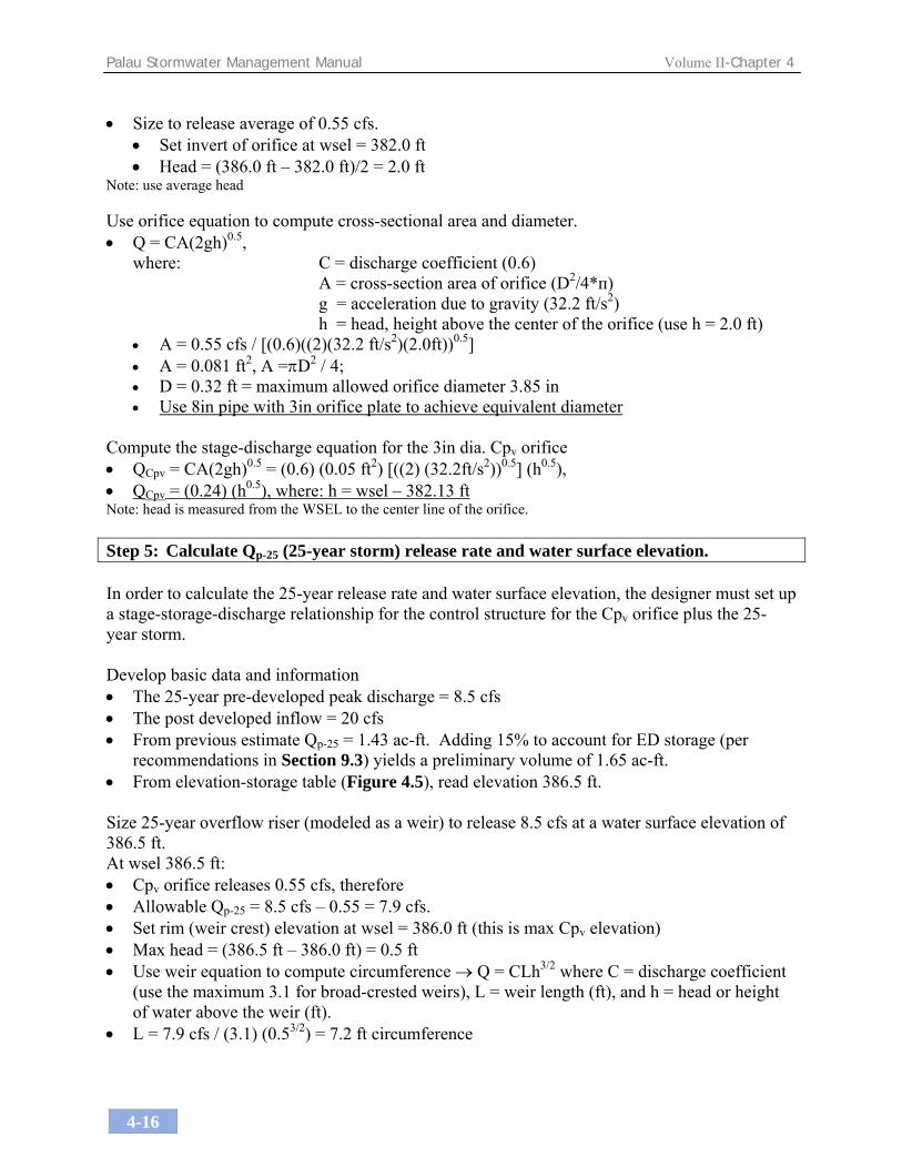
Compute the stage-discharge equation for the 3in dia. Cpv orifice • QCpv = CA(2gh)0.5 = (0.6) (0.05 ft2) [((2) (32.2ft/s2))0.5] (h0.5), • QCpv = (0.24) (h0.5), where: h = wsel – 382.13 ft Note: head is measured from the WSEL to the center line of the orifice. Step 5: Calculate Qp-25 (25-year storm) release rate and water surface elevation. In order to calculate the 25-year release rate and water surface elevation, the designer must set up a stage-storage-discharge relationship for the control structure for the Cpv orifice plus the 25-year storm. Develop basic data and information • The 25-year pre-developed peak discharge = 8.5 cfs • The post developed inflow = 20 cfs • From previous estimate Qp-25 = 1.43 ac-ft. Adding 15% to account for ED storage (per
recommendations in Section 9.3) yields a preliminary volume of 1.65 ac-ft. • From elevation-storage table (Figure 4.5), read elevation 386.5 ft. Size 25-year overflow riser (modeled as a weir) to release 8.5 cfs at a water surface elevation of 386.5 ft. At wsel 386.5 ft: • Cpv orifice releases 0.55 cfs, therefore • Allowable Qp-25 = 8.5 cfs – 0.55 = 7.9 cfs. • Set rim (weir crest) elevation at wsel = 386.0 ft (this is max Cpv elevation) • Max head = (386.5 ft – 386.0 ft) = 0.5 ft • Use weir equation to compute circumference → Q = CLh3/2 where C = discharge coefficient
(use the maximum 3.1 for broad-crested weirs), L = weir length (ft), and h = head or height of water above the weir (ft).
• L = 7.9 cfs / (3.1) (0.53/2) = 7.2 ft circumference

Palau Stormwater Management Manual Volume II-Chapter 4
4-17
• Diameter = 7.2 ft / π = 2.3ft Use one (1) 2.0 ft diameter riser structure for 25-year release. • Q25 = (3.1) (6.28) h3/2, Q25 = (19.5) h3/2, where h = wsel – 386.0 ft Size barrel to release approximately 8.5 cfs at elevation 386.5 ft using an approved pipe sizing method (e.g., culvert-sizing software, NRCS pipe sizing equation). Pipe sizing calculations determine the flow capacity of a given pipe at different flow conditions based on factors such as diameter, slope, length, pipe material (i.e., roughness), upstream and downstream conditions, etc. In this case, a culvert-sizing software was used to determine that an 18-in diameter concrete pipe, 0.7% slope, 300 feet long with free discharge into the downstream river would be sufficient to use for this outlet. As a final check, you can route the 25-year post-developed condition inflow through the pond using computer software (e.g., HydroCAD, TR-55). This type of model provides a convenient way to route an inflow hydrograph from the contributing drainage area during a given design storm event into a stormwater storage practice and produces an outflow hydrograph based on the entered outlet configuration (see Table 4.8 – TR-55 Results). • The hydrologic/hydraulic model computes 25-year wsel at 386.5 ft with discharge = 7.96 cfs
< 8.5 cfs, OK. Since the 25-year wsel is at 386.5 ft, set the emergency spillway invert at elevation 388.0 ft (this allows for more than a foot of freeboard above the 25-yr wsel) and design according to spillway criteria in Section 6.1. This basin is considered an excavated pond rather than an embankment pond. “Token” or emergency spillways (those placed above the water elevation of the largest managed storm) must be a minimum 8 ft wide, 1 ft deep, with 2:1 side slopes. Table 4.7 provides a summary of the storage, stage, and discharge relationships, and Figure 4.6 illustrates the profile of the outlet control structure, determined for this design example. Table 4.7 Summary of Controls Provided for Basin Example
Control Element
Type/Size of Control
Storage Provided
Elevation
Discharge
Units Acre-feet ft cfs Channel Protection (Cpv)
8in pipe with 3in orifice plate 1.1 386.0 0.55
Overbank Protection (Qp-25)
One 2-ft diameter riser structure, 18in barrel.
1.43
386.5
8.0
Emergency Spillway (storms>Qp-25)
Grass channel 8ft bottom width, 1ft deep, 2:1 side slopes
4.11
388.0
130

Palau Stormwater Management Manual Volume II-Chapter 4
4-18
Table 4.8 Sample TR-55 Results from HydroCAD

Palau Stormwater Management Manual Volume II-Chapter 4
4-19
Figure 4.6 Profile of Outlet Control Structure (not to scale)

Palau Stormwater Management Manual Volume II-Chapter 4
4-20
4.2 Case Study #2: Commercial Site This case study represents a portion of a commercial site located on the island of Koror. The North Beach Shopping Center (see Figure 4.7) is a hypothetical commercial development which includes a restaurant and a bank, as well as other shops, businesses and green space. The total site area is 10 acres, with 65% impervious cover. The following examples show how to manage the stormwater from the three small subcatchment areas associated with the restaurant and the bank that have a total site area of approximately 1.43 acres. The three catchment areas each drain to separate stormwater treatment practices, ultimately discharging to coastal waters in a dock area. Catchment A drains to the SW portion of the site and is comprised of 0.78 acres with 90% impervious cover; Catchment B drains to the SE portion of the site and is comprised of 0.46 acres with 91% impervious cover; and Catchment C drains to the middle portion of the site and is comprised of 0.19 acres with 89% impervious cover. While the impervious percentage of each subcatchment is greater than 70%, the site as a whole still meets the post-construction criteria of less than 70% impervious cover for developments over 1/2 acre. On-site soils as determined by the NRCS soil maps are classified as “Udorthents-Urban,” and a HSG of “D” was verified at the site by a test pit. Three stormwater practice design examples are presented for this case study, consisting of a bioretention system with a grass channel for pretreatment, a bioretention system with a grass filter strip for pretreatment, and a perimeter sand filter. This case study is a good example of how to effectively, and more aesthetically, treat stormwater close to the source instead of the traditional technique of using a single large practice to handle the runoff from the entire 10-acre development.
Table 4.9 Base Data for North Beach Shopping Center
Location: Koror Catchment Area B Catchment Area A Site Area: 0.46 acres
Site Area: 0.78 acres Impervious Area: 0.42 acres Impervious Area: 0.7 acres Catchment Area C
Site Area: 0.19 acres Soils Type: Udorthents-Urban, “D” as verified
by test pit at site Impervious Area: 0.17 acres

Palau Stormwater Management Manual Volume II-Chapter 4
4-21
Figure 4.7 North Beach Shopping Center - Commercial Site Plan

Palau Stormwater Management Manual Volume II-Chapter 4
4-22
4.2.1 Bioretention Design Example with Grass Channel Pretreatment This example focuses on the design of a bioretention system associated with catchment area “A” of the North Beach Shopping Center commercial development (see Figure 4.7), which drains to the SW portion of the site and is comprised of 0.78 acres with 90% impervious cover. This step-by-step example shows how the recharge volume and water quality volume requirements for this portion of the site will be met by the bioretention system. In addition, this example will show how to design a grass channel for pretreatment. In general, the primary function of bioretention facilities is to provide water quality treatment and not large storm attenuation. As such, flows in excess of the water quality volume are typically routed to a downstream facility for large storm attenuation. For this example, the channel protection and peak control requirements are not required because the site ultimately discharges to a tidally-influenced body of water (see Volume I, Section 2.2.2.3).
Figure 4.8 Plan View of Bioretention with Grass Swale

Palau Stormwater Management Manual Volume II-Chapter 4
4-23
Figure 4.9 Typical Sections of a Bioretention Facility and a Grass Swale Step 1: Compute Recharge Volume (Rev) and the Water Quality Volume (WQv) using the
Unified Stormwater Sizing Criteria Recharge, Rev The site is located in the volcanic region (Volume I, Figure 2.1), soil HSG D, so use F = 0.06 in (see Volume I, Table 2.2). Rev = [(F) (I) (A)] / 12 = [(0.06 in) (0.9) (0.78 ac)] (1ft/12in) = 0.0035 ac-ft
CROSS SECTION

Palau Stormwater Management Manual Volume II-Chapter 4
4-24
Water Quality Volume, WQv This site discharges to a dock area, which is water quality classification B (see Volume I, Table 2.6) and falls under the 80% capture rule. WQv = [(P) (I) (A)] / 12 = [(0.7 in) (0.9) (0.78 ac) (1ft/12in) = 0.041 ac-ft The WQv is greater than Rev – thus, no additional volume must be recharged other than the WQv. Bioretention will be designed without an impermeable liner (as an exfilter) to allow for infiltration. Total WQv to be treated by the bioretention is: WQv = 0.041 ac-ft = 1,786 ft3. Step 2: Determine if the development site and conditions are appropriate for the use of a
bioretention area. Site Specific Data: Existing ground elevation at practice location is 10.0 ft, mean sea level. Soil boring observations reveal that the seasonally high water table is at 2.0 ft and underlying soil is urban fill HSG “D”. Step 3: Confirm local design criteria and applicability. There are no additional local criteria that must be met for this design. Step 4: Determine size of bioretention filter area. Use sizing equation and values provided in Volume I, Section 3.2.4.4d:
Af = (WQv) (df) / [(k) (hf + df) (tf)] Where: Af = surface area of filter bed (ft2)
df = filter bed depth (ft) (use 4 ft per Volume I, 1.5 ft min. allowed with designer justification as long as 0.75 WQv criteria is still met)
k = coefficient of permeability of filter media (ft/day) (see Volume I, Section 3.2.4.4d for appropriate values)
hf = average height of water above filter bed (ft) (max 6in allowed, so ave = 0.25ft) tf = design filter bed drain time (days) (48 hours is recommended) Af = (1,786 ft3) (4 ft) / [(1 ft /day) (0.25ft + 4 ft) (2 days)] (With df = 4 ft, k = 1.0 ft /day, hf = 0.25ft, tf = 2 days) Af = 841 ft2

Palau Stormwater Management Manual Volume II-Chapter 4
4-25
Step 5: Set design elevations and dimensions. Assume a roughly 2:1 rectangular shape. Given a filter area requirement of 841 ft2, say facility is roughly 20ft by 40ft. See Figure 4.8. Set top of facility at 10.0 ft, with the berm at 11.0 ft. The facility is 5 ft deep from rim to bottom of planting soil, which will allow 3 ft of clearance above the seasonally high water table. See Figure 4.9 for a typical section of the facility. Step 6: Design conveyance to facility. Stormwater treatment practices can be either on or off-line. On-line facilities are generally sized to receive, but not necessarily treat, larger storms. Off-line facilities are designed to receive a more or less exact flow rate through a weir, channel, manhole “flow splitter”, etc. The facility in this example is situated to receive only the WQv via a flow splitter in a grass channel. To design a flow splitter for this offline bioretention area, refer to Section 9.3 for guidance onthe modified curve number (CN) technique for water quality peak flow (WQf) calculations. Using the WQv, a modified CN is computed utilizing the following equation from Section 9.3: CN = 1000 / [10 + 5P +10Q - 10(Q² + 1.25 QP)½] Where P = rainfall, in inches (use 0.7 inches in this case – see Step 1) Q = runoff volume, in watershed inches (equal to WQv ÷ area) Q = (0.041 ac-ft) (12 inches/ft) / (0.78 acres) = 0.63 inches CN = 1000 / [10 + 5(0.7 in) +10 (0.63 in) - 10((0.63 in)² + 1.25 (0.63 in)(0.7 in))½] CN = 1000 / [10 + 3.5 + 6.3 – 9.74] = 99.4 The time of concentration (tc) is calculated as 2.3 min, but use a minimum of 5 min (0.08 hr). Read initial abstraction (Ia) from TR-55 Table 4.1 or calculate Ia = 200/CN - 2 = 0.012 Compute Ia/P = 0.012 / 0.7 in = 0.017 Approximate the unit peak discharge (qu) from TR-55 Exhibit 4-IA for appropriate tc.
qu = 180 csm/in Using the WQv, compute the peak discharge (WQf) WQf = qu * A * Q where WQf = the peak discharge for the water quality event, in cfs qu = the unit peak discharge, in cfs/mi²/inch (180 csm/in) A = drainage area, in square miles (0.00122 sq miles)
Q = runoff volume, in watershed inches (equal to WQv ÷ area) (0.63 inches) WQf = 180 * 0.00122 * 0.63 = 0.14 cfs

Palau Stormwater Management Manual Volume II-Chapter 4
4-26
Use the orifice equation to size pipe to bioretention area. WQf = CA(2gh)1/2
where: C = discharge coefficient (0.6) A = cross-section area of orifice (D2/4*п) g = acceleration due to gravity (32.2 ft/s2) h = head, height above the center of the orifice (assume 1 ft) A = WQf / [C * (2gh)1/2] = 0.14 cfs / [0.6 * (2*32.2 ft/s2 * 1 ft) 1/2] = 0.03 ft2 Diameter = 2.3 in. Use 6in pipe with 2.5 in restrictor.
Figure 4.10 Example Flow Splitter Design Step 7: Design pretreatment. Pretreat with a grass channel. Assume trapezoidal grass channel dimensions of 2 ft bottom width, 2:1 side slopes, and 1 ft depth, with a cross-sectional area = 6 ft2. Size for 25% of WQv (1,786 ft3). The length can be determined by the following equation (Volume I, Section 3.2.4.4c):
L = 0.25 * WQv / A = 0.25 * 1,786 ft3 / 6 ft2 = 74.4 ft
To Offline Bioretention Facility for Water Quality Treatment
To Discharge Pipe that Outlets to Coastal Waters

Palau Stormwater Management Manual Volume II-Chapter 4
4-27
Given the site layout, 175ft is available for a grass channel along the parking lot, which is greater than the required length, OK. Step 8: Size underdrain area. Because this bioretention area is designed as an exfilter, an underdrain may not be necessary. However, because the underlying volcanic soils are HSG “D”, an underdrain system should still be installed to ensure proper drainage for storm volumes that exceed the limited infiltration capacity of the soil. As a rule of thumb, the length of underdrain can be based on 10% of the Af or 84 ft2 and a 3 ft wide zone of influence. See Figures 4.8 and 4.9. Using 4-in perforated plastic pipes surrounded by a 3ft-wide washed, rounded limestone aggregate bed, 10 ft on center (o.c.), yields the following length of pipe: (84 ft2)/3 ft per foot of underdrain = 28 ft of perforated underdrain Step 9: Overflow design. Since the bioretention is designed as an off-line practice sized to treat only the WQv, it theoretically should not overflow. However, should filtering rates become reduced due to facility age or poor maintenance, an overflow weir is provided to prevent flooding until the filter media and plants can be replaced. The overflow weir elevation is set so that a maximum of 6 inches of ponding occurs above the bottom of the bioretention area. In this case, the overflow weir is set at 10.0 ft. The overflow riser is connected to the underdrain system discussed in Step 8, which would be connected with the site’s drainage system that ultimately discharges to coastal waters in a dock area. Step 10: Choose plants for planting area. Choose plants based on factors such as whether native or not, resistance to drought and inundation, cost, aesthetics, maintenance, etc. Select species locations (i.e., on center planting distances) so species will not “shade out” one another. Do not plant trees and shrubs with extensive root systems near pipe work. Planting guidelines for this practice are presented in Chapter 5.

Palau Stormwater Management Manual Volume II-Chapter 4
4-28
4.2.2 Bioretention Design Example with Filter Strip Pretreatment This example focuses on the design of a bioretention system associated with catchment area “B” of the North Beach Shopping Center commercial development (see Figure 4.7), which drains to the SE portion of the site and is comprised of 0.46 acres with 79% impervious cover. This step-by-step example shows how the recharge volume and water quality volume requirements for this portion of the site will be met by the bioretention system. In addition, this example will show how to design a filter strip for pretreatment. For this example, the channel protection and peak control requirements are waived since the ultimate discharge flows to coastal waters. In general, the primary function of bioretention facilities is to provide water quality treatment and not large storm attenuation. As such, flows in excess of the water quality volume are typically routed to a downstream facility, such as conventional detention basins or some other facility such as underground storage vaults. Follow the sizing calculations from Section 4.2.1 for the bioretention design. Pretreatment and overflow designs for catchment area “B” are discussed below.
Figure 4.11 Plan View of Bioretention with Filter Strip

Palau Stormwater Management Manual Volume II-Chapter 4
4-29
Step 1: Design pretreatment. Volume I, Table 3.4 (also provided below).
Guidelines for Filter Strip Pretreatment Sizing
Parameter Impervious Parking Lots Residential Lawns Maximum Inflow Approach Length (ft.) 35 75 75 150
Filter Strip Slope <2% ≥2% <2% ≥2% <2% ≥2% <2% ≥2% Filter Strip Minimum Length 10’ 15’ 20’ 25’ 10’ 12’ 15’ 18’
The maximum inflow approach length is 60 ft with a slope of 2%, so a filter strip length of 20’ is required. However, our site only has 12’ available for a filter strip, so use a washed, rounded limestone aggregate curtain in addition to meet pretreatment requirements. Step 2: Overdrain and Emergency Spillway design. Stormwater treatment practices can be either on or off-line. On-line facilities such as this one receiving direct runoff from the parking lot are generally sized to receive, but not necessarily treat, larger storms. Thus, an overflow weir is provided to pass the 25-year event. The overflow weir elevation is set so that a maximum of 6 inches of ponding occurs above the bottom of the bioretention area. Outlet protection in the form of riprap or a plunge pool/stilling basin should be provided to ensure non-erosive velocities downstream.

Palau Stormwater Management Manual Volume II-Chapter 4
4-30
4.2.3 Sand Filter Design Example This example focuses on the design of a perimeter sand filter associated with catchment area “C” of the North Beach Shopping Center commercial development (see Figure 4.7), which drains to the middle portion of the site and is comprised of 0.19 acres with 89% impervious cover. This step-by-step example shows how the water quality volume requirements for this portion of the site will be met by the sand filter. It is assumed that this catchment area is located in an area of higher-pollutant load generation. For this example, the recharge volume, channel protection and peak control requirements for this catchment area are not presented. The recharge requirement can be waived given that this site is a hotspot. Channel protection and peak control requirements can also be waived since the site discharges to coastal waters. In general, the primary function of sand filters is to provide water quality treatment and not large storm attenuation. As such, flows in excess of the water quality volume are typically routed to bypass the facility. The post-development 2-yr peak discharge is provided to appropriately size the necessary by-pass flow splitter. If quantity control is required, bypassed flows are typically routed to conventional detention basins (or some other facility such as underground storage vaults).
Figure 4.12 Plan View of Sand Filter
40

Palau Stormwater Management Manual Volume II-Chapter 4
4-31
Figure 4.13 Profile and Plan Views of Sand Filter
40’

Palau Stormwater Management Manual Volume II-Chapter 4
4-32
Step 1: Compute water quality volumes using the Unified Stormwater Sizing Criteria. Use the 90% capture rule with 1.2in of rainfall for hotspot areas. WQv = [(P) (I) (A)] / 12 = [(1.2 in) (0.89) (0.19 ac) (1ft/12in) = 0.017 ac-ft = 741 ft3 Note: For this design example, the 2-year peak discharge will be used to size the bypass flow
splitter. Any hydrologic models using SCS procedures, such as TR-20, HEC-HMS, or HEC-1, can be used to perform preliminary hydrologic calculations
Table 4.10 Summary of Post-development Hydrologic Data for Catchment C
Condition P(2-yr) Area CN Q2 in ac cfs
Post-developed Catchment C 7.2 0.19 96 0.33
Step 2: Determine if the development site and conditions are appropriate for the use of a
perimeter sand filter. Site Specific Data: Existing ground elevation at practice location is 11.0 ft, mean sea level. Soil boring observations reveal that the seasonally high water table is at 2.0 ft. Step 3: Confirm local design criteria and applicability. There are no additional requirements for this site. Step 4: Compute WQv, available head, & peak discharge (Qp-wq). • Determine available head (See Figures 4.12 and 4.13)
Low point at edge of facility is 11.0 ft. Subtract 1 ft to pass Q2 discharge (10.0 ft). Set outfall underdrain pipe at 3.5 ft and add 4 in to this value for drain slope (3.83 ft). Add to this value 8 in for the washed, rounded limestone aggregate blanket over the underdrains, and 18 in for the sand bed (6.0 ft). The total available head is 10.0 ft – 6.0 ft or 4.0 ft. Therefore, the average depth, hf, is (hf) = 4.0 ft / 2, and hf = 2.0 ft.

Palau Stormwater Management Manual Volume II-Chapter 4
4-33
Step 5: Size flow diversion structure: Size the 2-year overflow as follows: The 2-year wsel is set at 11.0 ft. Use a concrete weir to pass the 2-year flow (0.33 cfs) into an overflow chamber using the Weir equation. Assume 1 ft of head to pass this event. Q = CLH3/2 0.33 = 3.1 (L) (1ft)1.5 L = 0.11 ft; use L = 0.5 ft which sets the flow diversion chamber dimension. Weir wall elevation = 10.0 ft. Step 6: Size filtration bed chamber (see Figure 4.13). Use sizing equation provided in Volume I, Section 3.2.4.4d:
Af = (WQv) (df) / [(k) (hf + df) (tf)] Where: Af = surface area of filter bed (ft2) df = filter bed depth (ft), use 1.5ft k = coefficient of permeability of filter media (ft/day), use 3.5ft/day hf = average height of water above filter bed (ft), use 2.0ft tf = design filter bed drain time (days) (40 hours = 1.67 days is recommended) Af = (741 ft3) (1.5ft) / [(3.5ft/day) (2ft + 1.5ft) (1.67 days)] (With df = 1.5ft, k = 3.5ft/day, hf = 2.0ft, tf = 1.67 days) Af = 54.3 ft2 = use 55 ft2 with a width of 1.75 ft and length of 32 ft. Step 7: Size sedimentation chamber. From Camp-Hazen equation shown in Volume I, Section 3.2.4.4c: As = 0.066 (WQv) As = 0.066 (741 ft3) or 48.9 ft2 given a width of 1.75 ft, the minimum length will be 48.9 ft2/1.75 ft or 30 ft (so, use 32 ft to match filter length for easy construction)

Palau Stormwater Management Manual Volume II-Chapter 4
4-34
Step 8: Compute Vmin. Vmin is the minimum volume that must be held by the entire system at one time (see Volume I, Section 3.2.4.4d). Vmin = ¾(WQv) or 0.75 (741 ft3) = 556 ft3 Step 9: Compute volume within practice (iterate if necessary). Volume within filter bed (Vf): Vf = Af (df) (n); n = 0.4 for sand
Vf = (1.75 ft * 32 ft) (1.5 ft) (0.4) = 34 ft3 Temporary storage above filter bed (Vf-temp): Vf-temp = 2hfAf
Vf-temp = 2 (2.0 ft) (1.75 ft * 32 ft) = 224 ft3 Compute remaining volume for sedimentation chamber (Vs):
Vs = Vmin - [ Vf + Vf-temp] or 556 - [34 + 224] = 298 ft3 Compute height in sedimentation chamber (hs): hs = Vs/As
(298 ft3) / (1.75 ft x 32 ft) = 5.32 ft which is larger than the head available (4.0 ft); increase the design length to 40 ft for filter and sedimentation chamber;
Volume within filter bed (Vf): Vf = Af (df) (n); n = 0.4 for sand
Vf = (1.75 ft * 40 ft) (1.5 ft) (0.4) = 42 ft3 Temporary storage above filter bed (Vf-temp): Vf-temp = 2hfAf
Vf-temp = 2 (2.0 ft) (1.75 ft * 40 ft) = 280 ft3 Compute remaining volume for sedimentation chamber (Vs):
Vs = Vmin - [ Vf + Vf-temp] or 556 - [42 + 280] = 234 ft3 Compute height in sedimentation chamber (hs): hs = Vs/As
(234 ft3) / (1.75 ft x 40 ft) = 3.34 ft which is less than the head available (4.0 ft); OK.
Use 1.75 ft x 40 ft for filter bed and sedimentation chamber dimensions.

Palau Stormwater Management Manual Volume II-Chapter 4
4-35
4.3 Case Study #3: Commercial Site This case study represents a commercial site located in Kloulklubed, on the island of Peleliu. The Sunshine Market (see Figure 4.14) is a hypothetical commercial development consisting of a fish and produce market with a total site area of approximately 3.0 acres with 52% impervious cover. On-site soils as determined by the NRCS soil maps are Ngedebus – Majuro and are classified as HSG “A”. Infiltration chambers with a grass channel and oil/grit separator for pretreatment are the design examples presented for this case study.
Figure 4.14 Sunshine Market Site Plan
discharge pipe to beach

Palau Stormwater Management Manual Volume II-Chapter 4
4-36
Table 4.11 Sunshine Market Base Data Location: Kloulklubed, Peleliu
Site Area: 3.0 acres Impervious Area: 1.56 acres
Soils Type: Ngedebus – Majuro, “A”
4.3.1 Infiltration Chamber Design Example with Grass Channel and Oil/Grit Separator
Pretreatment This example focuses on the design of subsurface infiltration chambers associated with the Sunshine Market in Kloulklubed, Peleliu (see Figure 4.14). This step-by-step example shows how the recharge and water quality volume requirements for this portion of the site will be met by the infiltration chambers. In general, the primary function of the chambers is to provide water quality treatment and groundwater recharge and not large storm attenuation. As such, flows in excess of the water quality volume are typically routed to bypass the facility. In this example, channel protection and overbank flood requirements are waived because flow from these larger storm events is discharged overland to the beach. The infiltration chambers are located in a landscaped area adjacent to the parking lot. The infiltration chambers receive runoff from the parking lot, walkways, and rooftops on the site.
Figure 4.15 Typical Detail of an Oil/Grit Separator

Palau Stormwater Management Manual Volume II-Chapter 4
4-37
Figure 4.16 Typical Detail of Infiltration Chambers Step 1: Compute recharge and water quality volumes using the Unified Stormwater Sizing
Criteria. Recharge, Rev The site is located in a limestone region (Volume I, Figure 2.2), so use 1.2 in multiplied by the impervious area. Rev = [(P) (I) (A)] / 12 = [(1.2 in) (0.52) (3.0 ac)] (1ft/12in) = 0.156 ac-ft = 6,795 ft3 Water Quality, WQv This site discharges to a Class AA marine area, which falls under the 90% capture rule. WQv = [(P) (I) (A)] / 12 = [(1.2 in) (0.52) (3.0 ac) (1ft/12in) = 0.156 ac-ft = 6,795 ft3

Palau Stormwater Management Manual Volume II-Chapter 4
4-38
Rev is equal to WQv, so 100 % of the recharge volume is contained within the WQv. Step 2: Determine if the development site and conditions are appropriate for the use of
infiltration chambers. Site Specific Data: Table 4.12 presents site-specific data, such as soil type, percolation rate, and slope, for consideration in the design of the infiltration chamber.
Table 4.12 Site Specific Data for Sunshine Market Criteria Value Soil Loamy Sand In-situ Infiltration Rate at Site 4.5 in/hr Design Infiltration Rate (fc) 2.41 in/hr* Ground Elevation at BMP 20 ft Seasonally High Water Table 9 ft Soil slopes <1% *Determine fc from Table 3.5 in Volume I.
Step 3: Confirm local design criteria and applicability. Table 4.13, below, summarizes the requirements that need to be met to successfully implement infiltration practices. On this site, infiltration is feasible, with restrictions on the depth and width of the chamber.
Table 4.13 Infiltration Chambers Feasibility Criteria Status In-situ infiltration rate greater than or equal to 0.5 in/hour.
Infiltration rate is 4.5 in/hour. OK.
Soils have a clay content of less than 20% and a silt/clay content of less than 40%.
Loamy sand meets both criteria.
Infiltration cannot be located on slopes greater than 6% or in fill soils.
Slope is <1%; not fill soils. OK.
Hotspot runoff should not be infiltrated. Not a hotspot land use. OK. The bottom of the infiltration facility must be separated by at least 3 ft vertically from the seasonally high water table.
Elevation of seasonally high water table: 9 ft Elevation of BMP location: 20 ft. The difference is 11 ft. Thus, the facility can be up to 8 ft deep (but use maximum of 4 ft). OK.
Infiltration facilities must be located 100 ft horizontally from any water supply well.
No water supply wells nearby. OK.
Maximum contributing area generally ≤5 acres. Area draining to facility is less than 5 acres. OK.Setback 25 ft down-gradient from structures. Chamber edge is > 25 ft from all structures. OK.

Palau Stormwater Management Manual Volume II-Chapter 4
4-39
Step 4: Size the infiltration chamber facility. In general, infiltration chambers can be sized by the equation below. For product-specific sizing, please refer to the manufacturer’s instructions.
Vw = L*[(w*d*n) – (#*Ac*n) + (#*Ac) + (w*fc*T/12)] Where: Vw = design volume (e.g., WQv) (ft3) L = Length of infiltration facility (ft) w = width of infiltration facility (ft) d = Depth of infiltration facility (ft) # = number of rows of chambers Ac = Cross-sectional area of chamber (ft2) n = Porosity (assume 0.4) fc = infiltration rate (in/hour) T = Fill Time (time for the practice to fill with water), in hours Assume that: n = 0.4
d = 4 ft (see above; feasibility criteria) fc = 2.41 in/hour (design rate, see above; site data) T = 2 hours (this is the recommended default value to be used unless site-specific
data exists) Ac = 3.445 ft2 (supplied by manufacturer) # = 15 ft (available width) / 3.25 ft (supplied by manufacturer) = 4.6, only 4 rows
can fit Solve for Length given that we have 15 ft – 20 ft of width that we want to use at our site. Therefore: L = 6,795 ft3 / [(15 ft*4 ft*0.4) – (4*3.445 ft2*0.4) + (4*3.445 ft2) + (15 ft*2.41 in/hr*2 hr/12)] L = 6,795 ft3 / [(24 ft2) - (5.5 ft2) + (13.8 ft2) + (6.0 ft2)] L = 178 ft Add one foot to each end and each side to give room for a stone buffer (this distance could be more or less depending on manufacturer’s specifications). Thus, the facility dimensions will be 17 ft x 180 ft. Check to ensure that there is sufficient room for the infiltration chamber facility alongside proposed parking lot. The proposed parking lot is 250 ft long, Ok. (Refer back to Figure 4.14 for a site plan view).

Palau Stormwater Management Manual Volume II-Chapter 4
4-40
Step 5: Size pretreatment. For pretreatment, use a grass channel and oil/grit separators as shown in Figure 4.14. These should be sized to pretreat 50% of WQv given the infiltration rate of the soil (see Volume I, Section 3.2.4.3c). Pretreatment volume = 0.5 * WQv = (0.156 ac-ft) * (43,560 ft2/ac) * 0.5 = 3,398 ft3 Use 2, 5,000 gallon oil/grit separators = 2 * (5,000 gal / 7.5 gal/cf) = 1,333 ft3 Size the grass channel to treat the remaining 2,065 ft3. The grass channel is 235 ft long, which means that the cross-section area needs to be (2,065 ft3) / (235 ft) = 8.8 ft2. Use a swale with a 3 ft bottom width, 1.5 ft deep, and 2:1 side slopes.

Palau Stormwater Management Manual Volume II-Chapter 4
4-41
4.4 Case Study #4: Single Family Residential Site This case study represents a single-family residential site located in Melekeok, Babeldaob. This single family home (see Figure 4.17) is a hypothetical site consisting of a ¼-acre lot. The drainage area used for this example consists of the entire lot and is comprised of 32% impervious cover. On-site soils as determined by the NRCS soil maps are Aimeliik-Palau and are classified as HSG “B”. Palau regulations do not require that stormwater management practices for single or dual-family residences be designed by an engineer, so a less rigorous approach is acceptable. The stormwater practice design examples presented for this case study are mostly qualitative in nature and are suitable for design and construction by qualified contractors and even enthusiastic homeowners. This example consists of calculations for a cistern to a drywell and descriptions of a rain garden, permeable pavers, and a dry swale.
Figure 4.17 Single-family Residential Site Plan on Babeldaob

Palau Stormwater Management Manual Volume II-Chapter 4
4-42
Table 4.14 Babeldaob Single Family Home Base Data Location: Melekeok, Babeldaob
Site Area: 0.25 acres Impervious Area: 0.08 acres
Soils Type: Aimeliik-Palau, “B” 4.4.1 Cistern and Drywell The first part of this example focuses on the design of a cistern and a drywell to intercept rooftop runoff for a single family home located in Melekeok, Babeldaob. This example shows how the recharge requirements for this portion of the site will be met by cisterns that overflow to drywells. In general, the primary function of cisterns is to capture and store rooftop runoff that can be used at a later time. A drywell is a single infiltration chamber; in this case, it is intended to accept overflow from the cistern in larger rain events, or when the cistern is already full from a previous storm event. Both the cistern and the drywell help to reduce peak flows leaving the site, thus helping to meet channel protection and peak control requirements. Cisterns are only optional – since rooftop runoff does not need to be treated (Volume I, Section 2.2.2.1), it can discharge directly into the ground via drywells, with the volume counting towards both recharge and water quality requirements.
Figure 4.18 Detail of Cistern and Drywell

Palau Stormwater Management Manual Volume II-Chapter 4
4-43
Step 1: Compute the Water Quality Volume (WQv) and Recharge Volume (Rev) using the Unified Stormwater Sizing Criteria
Recharge, Rev The site is located in the volcanic region (Volume I, Figure 2.2) in “B” soils, so use F = 0.27 multiplied by the impervious area. Rev = [(F) (I) (A)] / 12 = [(0.27 in) (0.32) (0.25 ac)] (1ft/12in) = 0.0018 ac-ft = 78 ft3
Water Quality Volume, WQv This site discharges to freshwater streams, which falls under the 90% capture rule. WQv = [(P) (I) (A)] / 12 = [(1.2 in) (0.32) (0.25 ac) (1ft/12in) = 0.008 ac-ft = 348.5 ft3 Step 2: Size the cistern and drywell. Cisterns are only optional, but for this example, they will be used as a supplemental water source for the house. There are several references to help homeowners size a cistern based on water needs for their house, including the following:
Sizing: Heitz LF, Winter SJ. Designing Your Rainwater Catchment and Storage System. Water and Energy Research Institute of the Western Pacific, University of Guam, Water Information Bulletin No. 1, March 1996.
Design & construction: Macomber PSH. Guidelines on Rainwater Catchment Systems for Hawaii. College of Tropical Agriculture and Human Resources, University of Hawaii at Manoa. 2004.
For this example, two cisterns (see Figure 4.17) will be sized to handle the recharge runoff volume from the house roof using the following equation recommended by the Low Impact Development Center, Inc. (http://www.lid-stormwater.net):
Vol = A * P * 0.90 * 7.5 gals/ ft3 Where:
Vol = Volume of rain barrel or cistern (gallons) A = Impervious surface area draining into cistern (ft2) P = Precipitation (ft) 0.90 = fraction of total volume used by system (unitless) 7.5 = conversion factor (gallons per ft3)
The total roof area draining to the cisterns is 2,300 ft2, and the 90% capture rule should be used for the more stringent water quality requirement (P = 1.2 in = 0.1 ft).

Palau Stormwater Management Manual Volume II-Chapter 4
4-44
Thus, Vol = (2,300 ft2) (0.1 ft) (0.90) (7.5) = 1,552.5 gallons required. Divide by 2 since flow will be diverted to two cisterns – 776.25 gallons. Thus, use two (2) 1,000-gallon tanks with an overflow to a drywell for recharge. The drywell can be sized by following the step-by-step infiltration chamber example in Section 4.3. Step 3: Select additional BMPs to treat runoff from the site. There are many structural and non-structural ways that a single-family home can meet stormwater requirements. For an in-depth look at better site design, please refer to Chapter 3. Some structural BMPs that could be utilized for this site are shown in Figure 4.17 and described below. 4.4.2 Rain Garden A rain garden is a type of bioretention facility that can be designed to intercept flow associated with a single family home. The step-by-step example in Section 4.2.1 shows how the water quality and recharge requirements can be met by rain garden. In general, rain gardens are smaller versions of bioretention systems, and are designed to provide water quality treatment, recharge, and in some instances peak flow controls. In this particular example, the rain garden is treating runoff from the yard and paved areas, although rain gardens can also be designed to capture rooftop runoff. 4.4.3 Permeable Pavers Permeable pavers (as described in Section 3.6) can be used in the driveway and walkway areas associated with the single family home. In general, permeable pavers are designed to promote recharge and decrease peak flows. Figure 4.19 is a typical detail for permeable pavers. For more information on specifications and installation, visit the Interlocking Concrete Pavement Institute at http://www.icpi.org/.
Figure 4.19 Detail of Permeable Pavers 4.4.4 Swale A dry swale can be used along the road to collect the overflow from the rain garden, driveway, and walkways. Dry swales can help meet recharge, water quality, and water quantity requirements for the site. See Section 4.1.1 for a detailed design example.

5.0 Landscaping Guidance Landscaping is a critical element to improve both the function and appearance of stormwater best management practices (BMPs). This chapter provides landscaping criteria and plant selection guidance for effective stormwater BMPs. It is organized as follows: The first section, 5.1, outlines general guidance that should be considered when landscaping any stormwater practice. Sections 5.2-5.5 then present more specific guidance on landscaping criteria and plant selection for individual BMP designs. These include:
• Stormwater ponds and wetlands • Infiltration and sand filter practices • Bioretention • Open Channels • Filter Strips and Buffers
In Section 5.6, key factors in selecting plant material for stormwater landscaping are reviewed, including hardiness zones, physiographic regions, hydrologic zones, and cultural factors. Finally, a comprehensive plant selection document published by the U.S. Natural Resources Conservation Service (NRCS) (Pacific Islands Area Vegetative Guide, 2008) is included with the CD accompanying this manual. This is an excellent resource and should be considered to supersede any of the plant recommendations made in this chapter, which was produced prior to the availability of the NRCS guidance. Native Species This manual encourages the use of native plants in stormwater management facilities. Native plants are defined as those species which evolved naturally to live in this region of the world. Practically speaking, this refers to those species which lived on the islands before recent human settlement. Many introduced species were weeds brought in by accident; others were intentionally introduced and cultivated for use as food, medicinal herbs, spices, dyes, fiber plants, and ornamentals. Introduced species can often escape cultivation and begin reproducing in the wild. This is significant ecologically because many introduced species out-compete indigenous species and begin to replace them in the wild. Some introduced species like tangan-tangan, water-hyacinth, and sugar cane are invasive, have few predators, and can take over naturally occurring species at

Palau Stormwater Management Manual Volume II-Chapter 5
5-2
an alarming rate. By planting native species in stormwater management facilities, we can help protect the natural heritage of Palau and provide a legacy for future generations. Native species also have distinct genetic advantages over non-native species for planting in Palau. Because they have evolved to live here naturally, indigenous plants are best suited for the local climate. This translates into greater survivorship when planted and less replacement and maintenance during the life of a stormwater management facility. Both of these attributes provide cost savings for the facility owner. Finally, people often plant exotic species for their ornamental value. While it is important to have aesthetic stormwater management facilities for public acceptance and the maintenance of property value, it is not necessary to introduce foreign species for this purpose. Many native species are aesthetically pleasing and can be used as ornamentals. When selecting ornamentals for stormwater management facilities, planting preference should be given to native ornamentals.
5.1 General Landscaping Guidance for All Stormwater BMPs • Do not plant trees and shrubs within 15 ft of the toe of
slope of a dam. • Do not plant trees or shrubs known to have long tap
roots within the vicinity of the earth dam or subsurface drainage facilities.
• Do not plant trees and shrubs within 15 ft of perforated pipes.
• Do not plant trees and shrubs within 25 ft of a hydraulic outlet control structure.
• Provide 15-ft clearance from a non-clogging, low-flow orifice.
• Herbaceous embankment plantings should be limited to 10 inches in height, to allow visibility for the inspector who is looking for burrowing rodents that may
compromise the integrity of the embankment. • Provide slope stabilization methods for slopes steeper than 2:1, such as planted erosion
control mats. Also, use seed mixes with quick germination rates in this area. Augment temporary seeding measures with container crowns or root mats of more permanent plant material.
• Utilize erosion control mats and fabrics to protect in channels that are subject to frequent wash outs.
• Stabilize all water overflows with plant material that can withstand strong current flows. Root material should be fibrous and substantial but lacking a tap root.
• Divert flows temporarily from seeded areas until stabilized. • Check water tolerances of existing plant materials prior to
inundation of area.

Palau Stormwater Management Manual Volume II-Chapter 5
5-3
• Stabilize aquatic and safety benches with emergent wetland plants and wetland seed mixes. • Do not block maintenance access to structures with trees or shrubs. • Avoid plantings that will require routine or intensive chemical applications (i.e. turf area). • Have soil tested to determine if there is a need for amendments. • Select plants that can thrive with on-site soil with no additional amendments or a minimum
of amendments. • Decrease the areas where turf is used. Use low-maintenance ground cover to absorb run-off. • Plant stream and edge of water buffers with trees, shrubs, ornamental grasses, and
herbaceous materials where possible, to stabilize banks and provide shade. • Maintain and frame desirable views. Be careful not to block views at entrances, exits, or
difficult road curves. Screen or buffer unattractive views into the site. • Use plants to prohibit pedestrian access to pools or steeper slopes that may be unsafe. • The designer should carefully consider the long-term vegetation management strategy for the
BMP, keeping in mind the “maintenance” legacy for the future owners. Keep maintenance area open to allow future access for pond maintenance. Provide a planting surface that can withstand the compaction of vehicles using maintenance access roads. Make sure the facility maintenance agreement includes a maintenance requirement of designed plant material.
• Provide signage for: o Stormwater BMPs to help educate the public when possible. o Wildflower areas, when possible, to designate limits of mowing.
• Avoid the overuse of any plant materials. • Preserve existing natural vegetation when possible. It is often necessary to test the soil in which you are about to plant in order to determine the following: • pH; whether acid, neutral, or alkali • major soil nutrients; Nitrogen, Phosphorus, Potassium • minerals; such as chelated iron, lime Have soil samples analyzed by experienced and qualified individuals, such as those at the Pacific Basin NRCS, who will explain in writing the results, what they mean, as well as what soil amendments would be required. Certain soil conditions, such as marine clays or volcanic soils, can present serious constraints to the growth of plant materials and may require the involvement of qualified professionals. When poor soils cannot be amended, seed mixes and plant material must be selected to establish ground cover as quickly as possible. Areas that have recently been involved in construction can become compacted so that plant roots cannot penetrate the soil. Seeds lie on the surface of compacted soils, allowing seeds to be washed away or be eaten by birds. Soils should be loosened to a minimum depth of two inches, preferably to a 4-inch depth. Hard soils may require discing to a deeper depth. The soil should be loosened regardless of the ground cover. This will improve seed contact with the soil, providing greater germination rates, allowing the roots to penetrate into the soil. Weak or patchy crops can be prevented by providing good growing conditions.

Palau Stormwater Management Manual Volume II-Chapter 5
5-4
Whenever possible, topsoil should be spread to a depth of 4 inches (2-inch minimum) over the entire area to be planted. This provides organic matter and important nutrients for the plant material. This also allows the stabilizing materials to become established faster, while the roots are able to penetrate deeper and stabilize the soil, making it less likely that the plants will wash out during a heavy storm. If topsoil has been stockpiled in deep mounds for a long period of time, it is desirable to test the soil for pH as well as microbial activity. If the microbial activity has been destroyed, it is necessary to inoculate the soil after application. Remember that newly installed plant material requires water in order to recover from the shock of being transplanted. Be sure that some source of water is provided, should dry periods occur after the initial planting. This will reduce plant loss and provide the new plant materials with a chance to establish root growth. 5.2 Ponds and Wetlands For areas that are to be planted within a stormwater management facility, it is necessary to determine what type of hydrologic zones will be created within the facility. The following six zones describe the different conditions encountered in stormwater management facilities. Every facility does not necessarily incorporate all of these zones. The hydrologic zones designate the degree of tolerance the plant exhibits to differing degrees of inundation by water. Each zone has its own set of plant selection criteria based on the hydrology of the zone, the stormwater functions required of the plant and the desired landscape effect. The hydrologic zones are described in Table 5.1 and illustrated in Figure 5.1. Table 5.1 Hydrologic Zones Zone # Zone Description Hydrologic Conditions
Zone 1 Deep Water Pool 1-6 feet deep Permanent Pool
Zone 2 Shallow Water Bench 6 inches to 1 foot deep
Zone 3 Shoreline Fringe Regularly inundated
Zone 4 Riparian Fringe Periodically inundated
Zone 5 Floodplain Terrace Infrequently inundated
Zone 6 Upland Slopes Seldom or never inundated

Palau Stormwater Management Manual Volume II-Chapter 5
5-5
Figure 5.1 Planting Zones for Stormwater Ponds and Wetlands as they appear in a) plan view and b) cross-section (Schueler, 1992).
1-Year WSE
a)
b)

Palau Stormwater Management Manual Volume II-Chapter 5
5-6
Zone 1: Deep Water Area (1 - 6 Feet) Ponds and wetlands both have deep pool areas that comprise Zone 1. These pools range from one to six feet in depth, and are best colonized by submergent plants, if at all. This pondscaping zone has not been routinely planted for several reasons. First, the availability of plant materials that can survive and grow in this zone is limited, and it is also feared that plants could clog the stormwater facility outlet structure. In many cases, these plants will gradually become established through natural recolonization (e.g., transport of plant fragments from other ponds via the feet and legs of
waterfowl). If submerged plant material becomes more commercially available and clogging concerns are addressed, this area can be planted. The function of the planting is to reduce resedimentation and improve oxidation while creating a greater aquatic habitat. • Plant material must be able to withstand constant inundation of water of one foot or greater in
depth. • Plants may be submerged partially or entirely. • Plants should be able to enhance pollutant uptake. • Plants may provide food and cover for waterfowl, desirable insects, and other aquatic life. Zone 2: Shallow Water Bench (Normal Pool to 1 Foot) Zone 2 includes all areas that are inundated below the normal pool to a depth of one foot, and is the primary area where emergent plants will grow in stormwater wetlands. Zone 2 also coincides with the aquatic bench found in stormwater ponds. This zone offers ideal conditions for the growth of many emergent wetland species. These areas may be located at the edge of the pond or on low mounds of earth located below the surface of the water within the pond. When planted, Zone 2 can be an important habitat for many aquatic and nonaquatic animals, creating a diverse food chain. This food chain includes predators, allowing a natural regulation of mosquito populations, thereby reducing the need for insecticidal applications. • Plant material must be able to withstand constant inundation of water to depths between six
inches and one foot deep. • Plants will be partially submerged. • Plants should be able to enhance pollutant uptake. • Plants may provide food and cover for waterfowl, desirable insects and other aquatic life. Plants will stabilize the bottom of the pond, as well as the edge of the pond, absorbing wave impacts and reducing erosion, when water level fluctuates. Plant also slow water velocities and increase sediment deposition rates. Plants can reduce resuspension of sediments caused by the wind. Plants can also soften the engineered contours of the pond, and can conceal drawdowns during dry weather.

Palau Stormwater Management Manual Volume II-Chapter 5
5-7
Zone 3: Shoreline Fringe (Regularly Inundated) Zone 3 encompasses the shoreline of a pond or wetland, and extends vertically about one foot in elevation from the normal pool. This zone includes the safety bench of a pond, and may also be periodically inundated if storm events are subject to extended detention. This zone occurs in a wet pond or shallow marsh and can be the most difficult to establish since plants must be able to withstand inundation of water during storms, when wind might blow water into the area, or the occasional drought during the summer. In order to stabilize the soil in this zone, Zone 3 must have a vigorous cover. • Plants should stabilize the shoreline to minimize erosion caused by wave and wind action or
water fluctuation. • Plant material must be able to withstand occasional inundation of water. Plants will be
partially submerged partially at this time. • Plant material should, whenever possible, shade the shoreline, providing cover for wildlife. • Plants should be able to enhance pollutant uptake. • Plants may provide food and cover for waterfowl, songbirds, and wildlife. Plants could also
be selected and located to control overpopulation of waterfowl. • Plants should be located to reduce human access, where there are potential hazards, but
should not block the maintenance access. • Plants should have very low maintenance requirements, since they may be difficult or
impossible to reach. • Plants should be resistant to disease and other problems which require chemical applications
(since chemical application is not advised in stormwater ponds). Zone 4: Riparian Fringe (Periodically Inundated) Zone 4 extends from one to four feet in elevation above the normal pool. Plants in this zone are subject to periodic inundation after storms, and may experience saturated or partly saturated soil inundation. Nearly all of the temporary extended detention area is included within this zone. • Plants must be able to withstand periodic inundation of water after storms, as well as
occasional drought during the dry season. • Plants should stabilize the ground from erosion caused by uphill run-off. • Plants should shade the low-flow channel. • Plants should be able to enhance pollutant uptake. • Plant material should have very low maintenance, since they may be difficult or impossible
to access. • Plants may provide food and cover for waterfowl, songbirds and wildlife. Plants may also be
selected and located to control overpopulation of waterfowl. • Plants should be located to reduce pedestrian access to the deeper pools. Zone 5: Floodplain Terrace (Infrequently Inundated) Zone 5 is periodically inundated by flood waters that quickly recede in a day or less. Operationally, Zone 5 extends from the maximum one year or Cpv water surface elevation

Palau Stormwater Management Manual Volume II-Chapter 5
5-8
(WSE) up to the 25-year maximum WSE. Key landscaping objectives for Zone 5 are to stabilize the steep slopes characteristic of this zone and to establish a low maintenance, natural vegetation area. • Plant material should be able to withstand occasional but brief inundation during storms,
although typical moisture conditions may be moist, slightly wet, or even swing entirely to drought conditions during the dry season.
• Plants should stabilize the basin slopes from uphill erosion. • Ground cover should be very low maintenance, since they may be difficult to access on steep
slopes or if frequency of mowing is limited. A dense tree cover may help reduce maintenance and discourage nuisance wildlife.
• Plants may provide food and cover for waterfowl, songbirds, and wildlife. • Placement of plant material in Zone 5 is often critical, as it often creates a visual focal point
and provides structure and shade for a greater variety of plants. Zone 6: Upland Slopes (Seldom or Never Inundated) The last zone extends above the maximum 25-year WSE, and often includes the outer buffer of a pond or wetland. Unlike other zones, this upland area may have sidewalks, bike paths, retaining walls, and maintenance access roads. Care should be taken to locate plants so they will not overgrow these routes or create hiding places that might make the area unsafe. • Plant material is capable of surviving the particular conditions of the site. Thus, it is not
necessary to select plant material that will tolerate any inundation. Rather, plant selections should be made based on soil condition, light, and function within the landscape.
• Groundcovers should emphasize infrequent mowing to reduce the cost of maintaining this landscape.
• Placement of plants in Zone 6 is important since they are often used to create a visual focal point, frame a desirable view, screen undesirable views, serve as a buffer, or provide shade to allow a greater variety of plant materials. Particular attention should be paid to seasonal color and texture of these plantings.

Palau Stormwater Management Manual Volume II-Chapter 5
5-9
5.3 Infiltration and Sand Filters Infiltration systems include Infiltration Trenches/Chambers (I-1) and Infiltration Basins (I-2). Filter systems include sand and organic filters (F-1 and F-2). Bioretention systems (F-3) are discussed in Section 5.4. Properly planted, these systems blend into natural surroundings. If unplanted or improperly planted, they can become eyesores and liabilities. Design Constraints: • Do not plant trees or provide shade within 15 ft of infiltration or filtering area or where leaf
litter will collect and clog infiltration area. • Have the soil tested in filtering bed to determine if there is a need for soil amendments. • Determine depth of water table to determine standing water conditions and depth to constant
soil moisture. • Planting turf over sand filters is allowed with prior approval from EQPB, on a case-by-case
basis. • Do not locate plants to block maintenance access to structures. • Divert flows temporarily from seeded areas until stabilized. • Planting of peat filters or any filter requiring a filter fabric should include material selected
with care to insure that no tap roots will penetrate the filter fabric. 5.4 Bioretention Planting Soil Bed Characteristics The characteristics of the soil for the bioretention facility are perhaps as important as the facility location, size, and treatment volume. The soil must be permeable enough to allow runoff to filter through the media, while having characteristics suitable to promote and sustain a robust vegetative cover crop. In addition, much of the nutrient pollutant uptake (nitrogen and phosphorus) is accomplished through adsorption and microbial activity within the soil profile. Therefore, the soils must balance soil chemistry and physical properties to support biotic communities above and below ground. The planting soil should be a sandy loam, loamy sand, loam (USDA), or a loam/sand mix (should contain 85-88% sand, by volume). Crushed limestone that is washed and meets the technical specification of ASTM C-33 is an acceptable substitute. The clay content for these soils should by less than 2% by volume. A permeability of at least 2.0 feet per day (1.0 in/hr) is required. The soil should be free of stones, stumps, roots, other woody material over 1inch in diameter, or brush/seeds from noxious weeds. Placement of the planting soil should be in lifts of 12 to 18 inches, loosely compacted (tamped lightly with a dozer or backhoe bucket). The specific characteristics are presented in Table 5.2.

Palau Stormwater Management Manual Volume II-Chapter 5
5-10
Table 5.2 Planting Soil Characteristics
Parameter Value
Organic matter 3 to 5%
Clay 0 to 2%
Silt 0 to 12%
Sand 85-88%
*Organic matter shall consist of well-aged (≥3 months) leaf compost created in a well-aerated atmosphere. **See bioretention construction specifications in Section 6.4.
Mulch Layer The mulch layer plays an important role in the performance of the bioretention system. The mulch layer helps maintain soil moisture and avoids surface sealing which reduces permeability. Mulch helps prevent erosion, and provides a micro-environment suitable for soil biota at the mulch/soil interface. It also serves as a pretreatment layer, trapping the finer sediments which remain suspended after the primary pretreatment. The mulch layer should be standard landscape style, single or double, shredded woody debris or coconut mulch or chips. The mulch layer should be well aged (stockpiled or stored for at least six (6) months), uniform in color, and free of other materials, such as weed seeds, soil, roots, etc. The mulch should be applied to a maximum depth of three inches. Grass clippings should not be used as a mulch material. See NRCS Conservation Practice Specification 484 (provided with References CD included with this manual) for more detailed information regarding mulching. Planting Plan Guidance Plant material selection should be based on the goal of simulating a terrestrial forested community of native species. Bioretention simulates an ecosystem consisting of an upland-oriented community dominated by trees, but having a distinct community, or sub-canopy, of understory trees, shrubs and herbaceous materials. The intent is to establish a diverse, dense plant cover to treat stormwater runoff and withstand urban stresses from insect and disease infestations, drought, temperature, wind, and exposure. The proper selection and installation of plant materials is key to a successful system. There are essentially three zones within a bioretention facility (Figure 5.2). The lowest elevation supports plant species adapted to standing and fluctuating water levels. The middle elevation supports a slightly drier group of plants, but still tolerates fluctuating water levels. The outer edge is the highest elevation and generally supports plants adapted to dryer conditions.

Palau Stormwater Management Manual Volume II-Chapter 5
5-11
The layout of plant material should be flexible, but should follow the general principals described in Table 5.3. As stated in Volume I, Section 3.2.4.4, tree density of approximately one tree per 100 ft2 (i.e., 10 ft on-center) is recommended. Shrubs and herbaceous vegetation should generally be planted at higher densities (5 ft on-center and 2.5 ft on center, respectively). The objective is to have a system which resembles a random and natural plant layout, while maintaining optimal conditions for plant establishment and growth.
Figure 5.2 Planting Zones for Bioretention Facilities
Table 5.3 Planting Plan Design Considerations
Native plant species should be specified over exotic or foreign species. Appropriate vegetation should be selected based on the zone of hydric tolerance Species layout should generally be random and natural. A canopy should be established with an understory of shrubs and herbaceous materials.Woody vegetation should not be specified in the vicinity of inflow locations. Trees should be planted primarily along the perimeter of the bioretention area. Urban stressors (e.g., wind, sun, exposure, insect and disease infestation, drought) should be considered when laying out the planting plan. Noxious weeds should not be specified. Aesthetics and visual characteristics should be a prime consideration. Traffic and safety issues must be considered. Existing and proposed utilities must be identified and considered.

Palau Stormwater Management Manual Volume II-Chapter 5
5-12
Plant Material Guidance Plant materials should conform to the American Standard Nursery Stock, published by the American Association of Nurserymen, and should be selected from certified, reputable nurseries. Planting specifications should be prepared by the designer and should include a sequence of construction, a description of the contractor's responsibilities, a planting schedule and installation specifications, initial maintenance, and a warranty period and expectations of plant survival. Table 5.4 presents some typical issues for planting specifications.
Table 5.4 Planting Specification Issues for Bioretention Areas
Specification Element Elements
Sequence of Construction Describe site preparation activities, soil amendments, etc.; address erosion and sediment control procedures; specify step-by-step procedure for plant installation through site clean-up.
Contractor's Responsibilities Specify the contractors responsibilities, such as watering, care of plant material during transport, timeliness of installation, repairs due to vandalism, etc.
Planting Schedule and Specifications
Specify the materials to be installed, the type of materials (e.g., B&B, bare root, containerized); time of year of installations, sequence of installation of types of plants; fertilization, stabilization seeding, if required; watering and general care.
Maintenance Specify inspection periods; mulching frequency (annual mulching is most common); removal and replacement of dead and diseased vegetation; treatment of diseased trees; watering schedule after initial installation (once per day for 14 days is common); repair and replacement of staking and wires.
Warranty Specify the warranty period, the required survival rate, and expected condition of plant species at the end of the warranty period.

Palau Stormwater Management Manual Volume II-Chapter 5
5-13
5.5 Open Channels Consult Table 5.5 for grass species that perform well in the stressful environment of an open channel. Table 5.5 Common Grass Species for Dry and Wet Swales and Grass Channels
suitable for use in Palau (See Table D of the NRCS 2008 Pacific Islands Area Vegetative Guide for more information)
Common Name Scientific Name Carpet grass Axonopus affinis Bermuda grass Cynodon dactylon Pangola grass Digitaria decumbens Centipede grass Eremochloa ophiurodes Tropic lalo paspalum Paspalum hieronymelii kikuyugrass Pennisetum clandestinum St. Augustinegrass Stenotaphrum secundatum zoysiagrass Zoysia japonica
5.6 Other Considerations in Stormwater BMP Landscaping Use or Function In selecting plants, consider their desired function in the landscape. Is the plant needed as ground cover, soil stabilizer, or a source of shade? Will the plant be placed to frame a view, create focus, or provide an accent? Does the adjacent use provide conflicts or potential problems and require a barrier, screen, or buffer? Nearly every plant and plant location should be provided to serve some function in addition to any aesthetic appeal. Plant Characteristics Certain plant characteristics are so obvious that they may actually be overlooked in the plant selection. These are:
• Size • Shape For example, tree limbs, after several years, can grow into power lines. A wide-growing shrub may block an important line of sight to oncoming vehicular traffic. A small tree could strategically block the view from a second-story window. Consider how these characteristics can work for you or against you, today and in the future. Other plant characteristics must be considered to determine whether the plant will fit with the landscape today and through the years to come. Some of these characteristics are:

Palau Stormwater Management Manual Volume II-Chapter 5
5-14
• Color • Texture • Aesthetic Interest, i.e.- Flowers, Fruit, Leaves, Stems/Bark • Growth rate In urban or suburban settings, residents living next to a stormwater system may desire that the facility be appealing or interesting. Aesthetics is an important factor to consider in the design of these systems. Failure to consider the aesthetic appeal of a facility to the surrounding residents may result in reduced value to nearby lots. Careful attention to the design and planting of a facility can result in maintained or increased values of a property and long-term benefits to the reputation of the designer. Availability and Cost Often overlooked in plant selection is the availability from wholesalers and the cost of the plant material. There are many plants listed in landscape books that are not readily available from the nurseries. Without knowledge of what is available, time spent researching and finding the one plant that meets all the needs will be wasted, if it is not available from the growers. It may require shipping, therefore, making it more costly than the budget may allow. Some planting requirements may require a special effort to find the specific plant that fulfills the needs of the site and the function of the plant in the landscape.

6.0 BMP Sample Design and Construction
Specifications The following sections provide standards and specifications for the design and construction of the acceptable stormwater treatment practices described in Volume I, Chapter 3. In addition, a construction checklist is provided with each construction specification. 6.1 Design Specification for Embankments DEFINITION
A pond is a water impoundment made by constructing a dam or an embankment or by excavating a pit or dugout. In this standard, ponds constructed by the first method are referred to as embankment ponds, and those constructed by the second method are referred to as excavated ponds. Ponds constructed by both excavation and the embankment methods are classified as embankment ponds if the depth of water impounded against the embankment at the principal spillway storm design high water elevation is 3 feet or more (See Table 6.1). These 3 feet shall be measured from the low point on the upstream toe of the embankment to the design high water. PURPOSE
To provide water for livestock, fish and wildlife, recreation, fire control, crop and orchard spraying, and other related uses, and to maintain or improve water quality. This standard also applies to stormwater management ponds. CONDITIONS WHERE PRACTICE APPLIES
General - This practice applies where it is determined that stormwater management, water supply, or temporary storage is justified and it is feasible and practicable to build a pond which will meet local and federal law requirements.
Note: This document was adapted from Maryland Code 378 Pond Specifications. Conservation practice standards are reviewed periodically, and updated if needed. To obtain the current version of this standard, contact the Natural Resources Conservation Service.

Palau Stormwater Management Manual Volume II-Chapter 6
6-2
This standard establishes the minimum acceptable quality for the design and construction of ponds if:
1. Failure of the dam will not result in loss of life; in damage to homes, commercial or industrial buildings, main highways, or railroads; or interruption of the use or service of public utilities.
2. The product of the storage times the effective height of the dam is less than 3,000. Storage is the volume, in acre-feet, in the reservoir below the elevation of the crest of the emergency spillway.
The effective height of the dam is the difference in elevation, in feet, between the emergency spillway crest and the lowest point on a profile taken along the centerline of the dam, excluding the cutoff trench. If there is no emergency spillway, the top of the dam becomes the upper limit for determining the storage and the effective height.
3. For dams in rural areas, the effective height of the dam (as defined above) is 35 feet or less and the dam is hazard class “a”. For dams in urban areas, the effective height of the dam is 20 feet or less and the dam is hazard class “a”.
Ponds exceeding any of the above conditions shall be designed and constructed according to the requirements of Technical Release 60.
Exemptions - Soil Conservation District small pond approval is not required for small class “a” structures where the following exists:
1. Ponds or other structures have less than four (4) feet of embankment, or
2. The storage at emergency spillway design high water elevation according to Table 6.1 does not exceed 40,000 ft3, and the height of the embankment is 6 ft or less.
The height of the embankment shall be measured from the top of the dam to the lowest point of excavation, excluding the cutoff trench, along the centerline of the dam.
In addition, an embankment pond that meets the criteria below shall be considered an excavated pond and is also exempt from small pond approval.
1. The calculation of 10H+20=L, where H=height from the pond bottom to the top of the dam, is provided, and
2. The projection of L horizontally downstream from the pond bottom is below the existing or proposed ground, and
3. The existing or proposed downstream ground slope within the projection of L is less than 10% at any point.
The review and design of such class “a” structures shall be based on sound engineering judgment assuring a stable outfall for the ten (10) year, 24-hour storm event.

Palau Stormwater Management Manual Volume II-Chapter 6
6-3
Site Conditions - Site Conditions shall be such that runoff from the design storm can be safely passed through (1) a natural or constructed emergency spillway, (2) a combination of a principal spillway and an emergency spillway, or (3) a principal spillway.
Drainage Area - The drainage area above the pond must be protected against erosion to the extent that expected sedimentation will not shorten the planned effective life of the structure.
For ponds whose primary purpose is to trap sediment for water quality, adequate storage should be provided to trap the projected sediment delivery from the drainage area for the life of the pond.
If the intent is to maintain a permanent pool, the drainage area should be at least 4 acres for each acre-foot of permanent storage. These recommendations may be reduced if a dependable source of ground water or diverted surface water contributes to the pond. The water quality shall be suitable for its intended use.
Soils Investigation - A soils investigation is required on all ponds. As a minimum it shall include information along the centerline of the proposed dam, in the emergency spillway location, and the planned borrow area. The type of equipment used and the extent of the investigation will vary from site to site.
Road Embankments - Where road embankments are being designed to impound a specific volume of water, either as a permanent pool or temporary stormwater storage, special design and evaluation criteria may be required as determined by EQPB. CONSIDERATIONS
Water Quantity - The following items should be considered for water quantity:
1. Effects upon components of the water budget, especially effects on volumes and rates of runoff, infiltration, evaporation, transpiration, deep percolation, and ground water recharge.
2. Variability of effects caused by seasonal or climatic changes.
3. Effects on the downstream flows or aquifers that could affect other water uses or users.
4. Potential for multiple use.
5. Effects on the volume of downstream flow to prohibit undesirable environmental, social or economic effects.
Water Quality - The following items should be considered for water quality:
1. Effects on erosion and the movement of sediment, pathogens, and soluble and sediment attached substances that are carried by runoff.
2. Effects on the visual quality of on-site and downstream water resources.

Palau Stormwater Management Manual Volume II-Chapter 6
6-4
3. Short-term and construction-related effects of this practice on the quality of downstream water courses.
4. Effects of water level control on the temperatures of downstream waters to prevent undesired effects on aquatic and wildlife communities.
5. Effects on wetlands and water-related wildlife habitats.
6. Effects of water levels on soil nutrient processes such as plant nitrogen use or denitrification.
7. Effects of soil water level control on the soil chemistry, soil water, or downstream water.
8. Potential for earth moving to uncover or redistribute sulfidic bearing soils.
CRITERIA
Embankment Ponds
Structure Hazard Classification - Documentation of the classification of dams is required. Documentation is to include but is not limited to location and description of dam, configuration of the valley, description of existing development (houses, utilities, highways, railroads, farm or commercial buildings, and other pertinent improvements), potential for future development, and recommended classification. It is also to include results obtained from breach routings, if breach routings are used as part of the classification process. The class (“a”, “b”, and “c”) as contained in this document is related to the potential hazard to life and property that might result from a sudden major breach of the earth embankment. Structure classification and land use for runoff determination must take into consideration the anticipated changes in land use throughout the expected life of the structure. The classification of a dam is the responsibility of the designer, and subject to review and concurrence of EQPB.
The classification of a dam is determined only by the potential hazard from failure, not by the criteria. Classification factors in the National Engineering Manual, as supplemented, are given below:
Class “a” - Structures located in rural, agricultural or urban areas dedicated to remain in flood tolerant usage where failure may damage non-inhabited buildings, agricultural land, floodplains or county roads.
Class “b” - Structures located in rural, agricultural, or urban areas where failure may damage isolated homes, main highways or minor railroads or cause interruption of use or service of relatively important public utilities.
Class “c” - Structures located where failure may cause loss of life or serious damage to homes, industrial and commercial buildings, important public utilities, main highways, or railroads.

Palau Stormwater Management Manual Volume II-Chapter 6
6-5
“Rural areas” is defined as those areas in which residents live on farms, in unincorporated settlements, or in incorporated villages or small towns. It is where agriculture, including woodland activities, and extractive industries, including seafood harvesting, provides the primary employment base for residents and where such enterprises are dependent on local residents for labor.
Non-rural areas shall be classified as urban.
Peak Breach Discharge Criteria - Breach routings are used to help delineate the area potentially impacted by inundation should a dam fail and can be used to aid dam classification. The breach hydrograph is the outflow hydrograph attributed to the sudden release of water in reservoir storage. This is due to a dam breach during non-storm conditions.
Stream routings made of the breach hydrograph are to be based upon topographic data and hydraulic methodologies mutually consistent in their accuracy and commensurate with the risk being evaluated.
The minimum peak discharge of the breach hydrograph, regardless of the techniques used to analyze the downstream inundation area, is as follows:
Qmax = 3.2 Hw2.5 where,
Qmax = the peak breach discharge, cfs.
Hw = depth of water at the dam at the time of failure, feet. This is measured to the crest of the emergency spillway or to design high water, if no emergency spillway exists. Use “nonstorm” conditions downstream of the dam.
Where breach analysis has indicated that only overtopping of downstream roads will occur, the following guidelines will be used:
Class Depth of Flow (d) ft.
“a” d<1.5
“b” & “c” d>1.5
Use and importance of the roadway shall be considered when making a classification.
Hydrology - Principal and emergency spillways will be designed within the limitations shown on Table 6.1. The storm duration used shall be 24 hours except where TR-60 is specified. The pond shall be designed to safely pass the base flow along with volume and peak rates of runoff from design storms, specified in Table 6.1. All storm water management ponds shall be designed using urban criteria. This can be done by using principal and emergency spillways. The following shall be used to determine runoff rates and volumes:
1. NRCS “Engineering Field Handbook, Part 650” or;

Palau Stormwater Management Manual Volume II-Chapter 6
6-6
2. NRCS, NEH, Section 4, Hydrology” or;
3. NRCS, TR-55, “Urban Hydrology for Small Watersheds” or;
4. NRCS, TR-20, “Computer Program for Project Formulation” or,
5. Computer programs using NRCS hydrology methods with identifiable inputs and outputs as approved by EQPB.
Earth Embankment
Top Width - The minimum top width of the dam is shown in Table 6.2. When the embankment top is to be used as a public road, the minimum width is to be 16 feet for one-way and 26 feet for two-way traffic. If the embankment is to be used for infrequent vehicle crossings, the minimum top width shall be 10 feet. Guardrails or other safety measures are to be used where necessary and are to meet the requirements of the responsible road authority.
Side Slopes - The combined upstream and downstream side slopes of the settled embankment shall not be less than five horizontal to one vertical (5:1) with neither slope steeper than 2:1. If the dam is used as a road crossing with a top width greater than 26 feet, then the combined side slopes of the settled embankment shall not be less than 4 horizontal to one vertical (4:1) with neither slope steeper than 2:1. Slopes must be designed to be stable in all cases, even if flatter side slopes are required.
Earth Cuts - If cuts in an existing fill or in natural ground are required for the rehabilitation of an existing pond spillway or the construction of a new pond, the slope of the bonding surfaces between the existing material in place and the fill to be placed shall not be steeper than a ratio of two horizontal to one vertical (2:1).
Foundation Cutoff - A cutoff trench of relatively impervious material shall be provided under the entire length of the dam and shall be located at or upstream from the centerline of the dam. The cutoff trench shall have a bottom width adequate to accommodate the equipment used for excavation, backfill and compaction operations, with the minimum width being 4 feet, and shall have side slopes no steeper than one horizontal to one vertical. Minimum depth shall be 4 feet.
Impervious Core - Any impervious core within the embankment shall be located at or upstream from the centerline of the dam, and shall extend up the abutments to the 25-year water surface elevation. The impervious core shall extend vertically from the cutoff trench up to the 25-year water surface elevation throughout the embankment.
Seepage Control - Seepage control is to be included: (1) if pervious layers are not intercepted by the cutoff; (2) if seepage from the abutments may create a wet embankment; (3) if the phreatic line intersects the downstream slope; or (4) if special conditions require drainage to insure a stable dam. The phreatic line shall be drawn on a 4:1 slope starting on the inside slope at the normal pool elevation. For stormwater management ponds, normal pool shall be considered as the 25-year water surface elevation.

Palau Stormwater Management Manual Volume II-Chapter 6
6-7
Seepage may be controlled by (1) foundation abutment or embankment drains; (2) reservoir blanketing; or (3) a combination of these measures. Foundation drains may control seepage encountered in the cutoff trench during construction. These drains must be located downstream of the dam centerline and outside the limits of the proposed cutoff trench. All drains must be designed according to the section Principal Spillway, Conduit Piping and Seepage Control.
Wave Erosion Protection - Where needed to protect the face of the dam, special wave protection measures such as a bench, rock riprap, sand-gravel, soil cement or special vegetation shall be provided. (Reference NRCS Technical Releases 56 & 69)
Freeboard - The top elevation of the settled embankment shall be determined in accordance with minimum criteria established in Table 6.1.
Allowance for Settlement - The design height of the dam shall be increased by the amount needed to insure that the design top of fill elevation will be maintained after all settlement has taken place. This increase shall not be less than 5 percent, except where detailed soil testing and lab analyses indicate a lesser amount is adequate.
Principal Spillway
Capacity - A conduit, with needed appurtenances, shall be placed under or through the dam, except where a weir type structure is used. The minimum capacity of the principal spillway shall be that required in Table 6.1.
Crest Elevation of Inlet - The crest elevation of the principal spillway shall be no less than 1.0 foot below the crest of the emergency spillway. The crest elevation is the invert elevation of the lowest opening 6 inches or larger in any direction.
The inlet or riser size for the pipe drops shall be such that the flow through the structure goes from weir-flow control to pipe-flow control without going into orifice-flow control in the riser. The inlets and outlets shall be designed and analyzed to function satisfactorily for the full range of flow and hydraulic head anticipated.
The riser shall be analyzed for flotation assuming all orifices and pipes are plugged. The factor of safety against flotation shall be 1.2 or greater.
Pipe Conduits - Pipe conduits under or through the dam shall meet the following requirements:
1. All pipes shall be circular in cross section except for cast-in-place reinforced concrete box culverts.
2. Pipe shall be capable of withstanding the external loading without yielding, buckling, or cracking.
3. Pipe strength shall be not less than those shown on Tables 6.3, 6.4 and 6.5 for corrugated steel, aluminum, and plastic pipes and applicable ASTM’s for other materials.

Palau Stormwater Management Manual Volume II-Chapter 6
6-8
4. Where inlet or outlet flared sections are used, they shall be made from materials compatible with the pipe.
5. All pipe joints shall be made watertight by the use of flanges with gaskets, coupling bands with gaskets, bell and spigot ends with gaskets, or by welding. See Pond Construction Specifications in Section 6.2 for details.
6. The joints between sections of pipe shall be designed to remain watertight after joint rotation and elongation caused by foundation consolidation.
The capacity of the pipe conduit shall be adequate to discharge long duration, continuous or frequent flows without flow through the emergency spillway. The diameter of the pipe shall be not less than 6 inches.
For dams 20 feet or less in effective height, the following pipe materials are acceptable: cast-iron, ductile iron, steel, corrugated steel or aluminum, concrete with rubber gaskets, plastic, and cast-in-place reinforced concrete box culverts. Plastic pipe that will be exposed to direct sunlight should be made of ultraviolet resistant materials and protected by coating or shielding. Connections of pipe to less flexible pipe or structures must be designed to avoid stress concentrations that could rupture the pipe.
For dams over 20 feet in effective height, conduits are to be reinforced concrete pipe, cast-in-place reinforced concrete box culverts, corrugated steel, ductile iron, welded steel or aluminum pipe. The maximum height of fill over any principal spillway steel, aluminum, or plastic pipe must not exceed 25 feet.
Concrete pipe shall have a concrete cradle extending up the sides of the pipe at least 50% of its outside diameter with minimum thickness of 6 inches. Where a concrete cradle is not needed for structural reasons, flowable fill may be used as described in Section 6.2. Gravel bedding is not permitted. Cantilever outlet sections, if used, shall be designed to withstand the cantilever load. Pipe supports shall be provided when needed. Other suitable devices such as plunge basin, stilling basin, impact basin, or rock riprap spreader should be used to provide a safe outlet. Cathodic protection is to be provided for welded steel and corrugated steel pipe where the need and importance of the structure warrant. Cathodic protection should normally be provided for corrugated steel pipe where the saturated soil resistivity is less than 4,000 ohms-cm or the pH is lower than 5. The National Handbook of Conservation Practices, Irrigation Water Conveyance, Steel Pipeline Standard (430-FF), provides criteria for cathodic protection of welded steel pipes.
Multiple Conduits - Where multiple conduits are used, there shall be sufficient space between the conduits and the installed anti-seep collars to allow for backfill material to be placed between the conduits by the earth moving equipment and for easy access by hand operated compaction equipment. This distance between conduits shall be equal to or greater than half the pipe diameter but not less than 2 feet.
Conduit Piping and Seepage Control - Seepage along pipe conduit spillways extending through the embankment shall be controlled by use of (1) anti-seep collars, or (2) filter and drainage diaphragm. Seepage control will not be required on pipes 6 inches in diameter or less.

Palau Stormwater Management Manual Volume II-Chapter 6
6-9
Anti-seep collars shall be installed around all conduits through earth fills according to the following criteria:
1. Sufficient collars shall be placed to increase the seepage length along the conduit by a minimum of 15 percent of the pipe length located within the saturation zone.
2. The assumed normal saturation zone shall be determined by projecting a line at a slope (4) horizontal to (1) vertical from the point where the normal water elevation meets the upstream slope to a point where this line intersects the invert of the pipe conduit or bottom of the cradle, whichever is lower. For Stormwater Management ponds, the phreatic line starting elevation shall be the 25-year water elevation.
3. Maximum collar spacing shall be 14 times the required projection above the pipe. The minimum collar spacing shall be 5 times the required minimum projection.
4. Anti-seep collars should be placed within the saturated zone. In cases where the spacing limit will not allow this, at least one collar will be in the saturated zone.
5. All anti-seep collars and their connections to the conduit shall be watertight and made of material compatible with the conduit.
6. Collar dimensions shall extend a minimum of 2 feet in all directions around the pipe.
7. Anti-seep collars shall be placed a minimum of two feet from pipe joints except where flanged joints are used.
8. For pipes with concrete cradles, the projection shall be measured from the cradle.
Filter and drainage diaphragms are always recommended, but are required when the following conditions are encountered:
1. The pond requires design according to TR-60.
2. Embankment soils with high piping potential such as Unified Classes GM, SM, and ML.
Filter and drainage diaphragms shall be designed in accordance with procedures from NRCS TR-60, Earth Dams and Reservoirs, Section 6, Principal Spillways, as described below.
The drainage diaphragm shall usually consist of sand, meeting the fine concrete aggregate requirements (ASTM C-33). A design analysis shall be made using Part 633 of the National Engineering Manual, Chapter 26, Gradation Design of Sand and Gravel Filters.
The drainage diaphragm shall be a minimum of 3 ft thick and extend vertically upward and horizontally at least three times the conduit outside diameter or the width of the cradle, whichever is greater except that:
1. The vertical extension need be no higher than the maximum potential reservoir water level, and

Palau Stormwater Management Manual Volume II-Chapter 6
6-10
2. The horizontal extension need be no further than 5 feet beyond the sides and slopes of any excavation made to install the conduit.
3. The minimum soil cover over any portion of the filter-drainage diaphragm measured normal to the nearest embankment surface shall be at least 2 feet.
It shall extend vertically downward at least 2 ft beneath the conduit outside diameter or bottom of the cradle, whichever is greater. The drainage diaphragm shall be located immediately downstream of the cutoff trench, approximately parallel to the centerline of the dam but no further upstream than the centerline of the dam.
The drainage diaphragm shall outlet at the embankment downstream toe, preferably using a drain backfill envelope continuously along the pipe to where it exits the embankment. Protecting drain fill from surface erosion will be necessary.
It is required that the outlet for the filter diaphragm is sized to safely discharge the design flow. Where a drain backfill envelope is used as the outlet, it is recommended that it be designed so the hydraulic head does not exceed the depth of the drain outlet. The exposed area of the drain outlet must also be protected from external attack such as surface erosion and slope instability due to horizontal seepage pressures. A weighted toe cover such as riprap can be effective if protected with a properly designed filter between the sand drain material and the riprap cover.
If pipe drain outlets are used, consideration must be given to the structural design of the conduit in resisting external loading and the design life of the pipe must be consistent with the design life of the dam and physical conditions of the site. Also, the pipe must be designed for capacity and size of perforations as outlined in NEH Part 633, Chapter 26 and Soil Mechanics Note 3. If the pipe corrodes, is crushed by exterior loading, or is otherwise damaged, the outlet of the filter diaphragm is lost and a piping failure may occur.
The design quantity (Q) used to size the outlet can be calculated by Darcy's Law, Q = kiA where:
k = permeability of the embankment or drain outlet material (ft/day)
i = hydraulic gradient where i = h/l
h = head differential (ft)
l = seepage path (ft)
A = area of flow (diaphragm or outlet) (ft2)
Anti-vortex Devices - Drop inlet spillways are to have adequate anti-vortex devices. Splitter type anti-vortex devices shall be placed in line with the barrel. An anti-vortex device is not required if weir control is maintained in the riser through all flow stages.
Trash Racks - All pipe and inlet structures shall have a trash rack. Openings for trash racks shall be no larger than 1/2 of the barrel conduit diameter, but in no case less than 6 inches.

Palau Stormwater Management Manual Volume II-Chapter 6
6-11
Flush grates for trash racks are not acceptable. Inlet structures that have flow over the top shall have a non-clogging trash rack such as a hood-type inlet extending a minimum of 8 inches below the weir openings, which allows passage of water from underneath the trash rack into the riser.
For inlet structures with solid covered tops, the bottom of the cover slab must be set at an elevation to prevent orifice flow control before pipe flow control governs.
Low stage releases, where the opening is larger than 6 inches, shall have a non-clogging trash rack with openings no larger than half the low flow dimension.
For all low stage releases 6 inches or smaller in any direction, the emergency spillway design storm shall be routed assuming the release has failed, using storage and discharge only above the elevation of the next opening larger than 6 inches in all directions. This design storm routing shall not overtop the dam.
Drain Pipe - A pipe with a suitable valve shall be provided to drain the pool area, where needed for proper pond management. The principal spillway conduit may serve as a pond drain, when so located, to accomplish this function.
Water Supply Pipes or Utilities - All pipes through the dam shall have an inside diameter of not less than 1 1/4 inches. Pipes / utilities not parallel to the axis of the dam shall meet all principal spillway requirements (i.e. filter diaphragm, embankment soils, etc.). Pipes / utilities parallel to the axis of the dam shall be constructed with no granular bedding.
Earth Emergency Spillways
Emergency spillways are provided to convey large flood flows safely past earth embankments. An emergency spillway must be provided for each dam, unless the principal spillway is large enough to pass the routed design hydrograph peak discharge and any trash without overtopping the dam. The only design that may be utilized without an emergency spillway is: a principal spillway with a cross-sectional area of 3 square feet or more and an inlet that will not clog, such as a hood-type inlet which allows passage of water from underneath the trash rack into the riser.
Capacity - The minimum capacity of emergency spillways shall be that required to pass the peak flow expected from a design storm of the frequency and duration shown in Table 6.1 less any reduction creditable to conduit discharge and detention storage.
The emergency spillway shall (1) safely pass the storm design peak or (2) the storm runoff shall be routed through the reservoir. The routing shall start with the water surface at the elevation of the crest of the principal spillway, or at the water surface after 10 days drawdown, whichever is higher. The 10-day drawdown shall be computed from the crest of the emergency spillway or from the elevation that would be attained had the entire design storm been impounded, whichever is lower. Emergency spillways are to provide for passage of the design flow at a non-erosive velocity to a point downstream where the dam will not be endangered.
Component Parts - Earth spillways are open channels and usually consist of an inlet channel, level section, and an exit channel. The minimum difference in elevation between the crest of the emergency spillway and the settled top of dam shall be 2.0 feet.

Palau Stormwater Management Manual Volume II-Chapter 6
6-12
Cross-Section - Earth spillways shall be trapezoidal and shall be located in undisturbed earth. The side slopes shall be stable for the material in which the spillway is to be constructed, but not steeper than 2:1. The emergency spillway shall have a bottom width of not less than 8 feet.
The inlet channel may be curved to fit existing topography; however, it should be flared to allow unrestricted flow to the level section. The level section should be located as near the centerline of dam as possible. The level section shall be 25 feet in length, and shall be rectangular or square.
Exit channel centerline shall be perpendicular to the level section downstream edge and must be straight for a distance beyond the downstream toe, so that discharges will not reach the earth embankment. The grade of the exit channel shall fall within the range established by discharge requirement and permissible velocities.
The crest of any “token” spillway will be located at or above the 25-year storm elevation in undisturbed earth and have a minimum depth of one foot and bottom width of 8 feet.
Permissible Velocities - Earth spillways shall be designed for non-erosive velocities through the control section and to a point downstream where the dam will not be endangered. The maximum permissible velocity for the grass and grass mixture to be used shall be approved by EQPB.
Infiltration / Water Quality Basins – Ponds, either excavated or embankment, that are designed solely for infiltration or as water quality basins will have an emergency spillway. The capacity of the spillway will be determined by the following procedure:
Pass the routed 25-Year Storm with 1 foot of freeboard to the top of dam elevation. Routing will begin at the emergency spillway crest.
Structural Emergency Spillways
Chutes or drops, when used for principal spillways or principal-emergency or emergency spillways, shall be designed in accordance with the principals set forth in the National Engineering Handbook, Section 5 “Hydraulics”; Section 11 “Drop Spillways”; and Section 14 “Chute Spillways”. The minimum capacity of a structural spillway shall be that required to pass the peak flow expected from a design storm of the frequency and duration shown in Table 6.1 less any reduction creditable to conduit discharge and detention storage.
Visual Resource Design
The visual design of ponds shall be carefully considered in areas of high public visibility and those associated with recreation. The underlying criterion for all visual design is appropriateness. The shape and form of ponds, excavated material, and plantings are to relate visually to their surroundings and to their functions.
The embankment may be shaped to blend with the natural topography. The edge of the pond should be shaped so that it is generally curvilinear rather than rectangular. Excavated material shall be shaped so that the final form is smooth, flowing, and fitting to the adjacent landscape

Palau Stormwater Management Manual Volume II-Chapter 6
6-13
rather than angular geometric mounds. If feasible, islands may be added for visual interest and to attract wildlife.
Trees and Shrubs
Non-Roadway Embankments - Trees and/or shrubs will not be allowed on any embankment, will not be allowed within the buffer zone (15 feet from the toe of the dam), and will not be allowed within a 25-foot radius around the inlet structure.
Roadway Embankments - Trees and/or shrubs will not be allowed on any embankment, except for dry stormwater management structures that will be utilized as a roadway under all the following conditions:
1. Plantings may only be on top of the dam along the roadway and/or sidewalks.
2. The top of the dam shall have a minimum of 50-foot top width.
3. Plantings will not be allowed on the side slopes of the embankment.
4. Plantings will not be allowed within the buffer zone (15 feet from the toe of the dam).
5. Plantings will only be shallow rooted (roots less than 3 feet deep) trees or shrubs.
6. The pond is a “dry” structure (normal pool not exceeding 18 inches).
7. A landscape plan showing type and location of planting must be prepared by a Landscape Architect certifying shallow rooted plants (roots less than 3 feet deep) under mature conditions.
8. A minimum of 3 feet freeboard above the 25-year water surface elevation must be maintained.
9. The structure is a low hazard (Class “a”) pond.
Safety
Special considerations should be made for safety and access during the design of a pond. Measures to be considered may include fencing, slope benching, access roads, flattened side slopes, etc. When fencing a structure, the fence will be located so it will not interfere with the operation of the emergency spillway.
Excavated Ponds
General - Excavated ponds that create a failure potential through a constructed or created embankment will be designed as embankment ponds. Excavated ponds that include a pipe or weir outlet control system for urban stormwater management shall be designed using the principal and emergency spillway hydrologic criteria for Embankment Ponds, Table 6.1.

Palau Stormwater Management Manual Volume II-Chapter 6
6-14
Side Slopes - Side slopes of excavated ponds shall be such that they will be stable and shall not be steeper than 1 horizontal to 1 vertical. Flatter slopes are to be utilized where safety for children, livestock watering, etc. is a design factor.
Perimeter Form - Where the structures are used for recreation or are located in high public view, the perimeter or edge should be shaped to a curvilinear form.
Inlet Protection - When the excavated pond is a bypass type and water is being diverted from a stream, the minimum size inlet line shall be a 4-inch diameter pipe. All laws concerning water use and downstream rights shall be strictly adhered to.
Where surface water enters the pond in a natural or excavated channel, the side slope of the pond shall be protected against erosion.
Outlet Protection – An excavated pond with a low embankment (combination excavation / embankment pond) shall be designed to ensure a stable outfall for the 2-year, 24-hour frequency storm.
Placement of Excavated Material - The material excavated from the pond shall be placed in one of the following ways so that its weight will not endanger the stability of the pond side slopes and where it will not be washed back into the pond by rainfall:
1. Uniformly spread to a height not exceeding 3 feet with the top graded to a continuous slope away from the pond;
2. Uniformly placed or shaped reasonably well with side slopes no steeper than 2 to 1. The excavated material will be placed at a distance equal to the depth of the pond, but not less than 12 feet from the edge of the pond;
3. Shaped to a designed form that blends visually with the landscape;
4. Used for low embankment and leveling; or
5. Hauled away.
Reservoir Area for Wet Ponds
For most ponds, the topography of the site shall permit storage of water at a depth and volume that ensures a dependable supply, considering beneficial use, sedimentation, season of use, and evaporation and seepage losses. Soils in the reservoir shall be impervious enough to minimize seepage losses or shall be of a type that sealing is practical.
Excavation and shaping required to permit the reservoir area to suitably serve the planned purpose shall be included in the construction plans.
Reservoirs designed specifically for fish production or wildlife management shall follow design criteria in the standards and specifications, as appropriate.

Palau Stormwater Management Manual Volume II-Chapter 6
6-15
Table 6.1 Hydrologic Criteria For Ponds
Structure Class
Storage Height
Product1
Watershed Area
(Acres)
Height To Emergency Spwy Crest
(Feet)
Normal Surface
Area (Acres)
Spillway Capacity5
Principal2 Emergency3, 4 Freeboard6
“c” & “b” Any Any Any Any TR 60 TR 60 TR 60
“a” 3,000 or more
Any Any Any TR 60 TR 60 TR 60
320 >20 - 35 >12 TR 60 50 YR 2.0’ above E.S. Design Storm
Less and <20 >12 25 YR 50 YR
Larger <15 <12 10 YR 50 YR
100 >20 - 35 >12 TR 60 50 YR 2.0’ above E.S. Design Storm
“a” than to <20 >12 10 YR 50 YR 1.0’ above E.S. Design Storm
320 <15 <12 2 YR 50 YR 1.0’ above E.S. Design Storm
Less >20 - 35 >12 TR 60 50 YR 1.0’ above E.S. Design Storm
3,000 Than <20 >12 2 YR 50 YR
100 <15 <12 2 YR 50 YR
NOTES:
1) The storage is defined as the original capacity of the reservoir in acre-feet at the elevation of the crest of the emergency spillway. The effective height is the difference in elevation in feet between the emergency spillway crest and the lowest point on a profile taken along the centerline of the dam, excluding the cutoff trench. If there is no emergency spillway, this height shall be to the top of the dam.
2) Principal - minimum storm to be contained below the crest of the emergency spillway including any combination of temporary storage and principal spillway discharge.
3) Emergency - minimum storm used to proportion the emergency spillway to meet the limitations for shape, size, velocity and exit channel. This storm can be handled by any combination of principal spillway discharge, emergency spillway discharge and storage.
4) For ponds without a separate emergency spillway, the principal spillway functions as the emergency spillway. In this situation, the principal spillway must comply with the emergency spillway hydrologic criteria.
5) All ponds, which are being designed to meet local stormwater requirements, will be required to use the urban criteria. Storm duration used shall be 24 hours except where TR-60 is specified.
6) For ponds without a functioning open channel emergency spillway, minimum freeboard will be 2 feet.

Palau Stormwater Management Manual Volume II-Chapter 6
6-16
Table 6.2 Minimum Top Width of Embankments
Total Height Of Embankment (Feet)
MinimumTop Width (Feet)
10 or less 611 - 14 815 - 19 1020 - 24 1225 - 34 1435 or more 15
Table 6.31,2 Minimum Gages-Steel Pipe
CORRUGATED STEEL PIPE
2 - 2/3 inches x 1/2 inch Corrugations
Fill Height Pipe Diameter in InchesOver Pipe 24 &(Feet) Less 30 36 42 481 - 15 16 16 14 10 1015 - 20 16 12 10 * *20 - 25 16 10 * * *
CORRUGATED STEEL PIPE
3 inches x 1 inch or 5 inch x 1 inch Corrugations
Fill Height Pipe Diameter (Inches)Over Pipe Flowable Fill(Feet) 36 42 48 543 603 663 723 1 - 15 16 16 16 14 14 14 1415 - 20 16 16 12 14 14 14 1420 - 25 14 14 10 14 14 14 14
• Not Permitted.
Table 6.41,2 Minimum Gages-Aluminum Pipe
CORRUGATED ALUMINUM PIPE
2 - 2/3 inches x 1/2 inch Corrugations
Fill Height Pipe Diameter in InchesOver Pipe 21 &(Feet) Less 24 301 - 15 16 14 1015 - 20 12 10 *20 - 25 10 * *

Palau Stormwater Management Manual Volume II-Chapter 6
6-17
CORRUGATED ALUMINUM PIPE 3 inches x 1 inch Corrugations
Fill Height Pipe Diameter in InchesOver Pipe (Feet) 30 36 42 48 543
1 - 15 16 16 14 10 1415 - 20 16 12 * * *20 - 25 12 * * * *
* Not Permitted.
1 Coatings for corrugated metal shall be as specified by the MD-378 Construction Specifications. 2 Tables 3 and 4 were developed using the modified Spangler equation. Sizes other than those shown above are not permitted. 3 Must use flowable backfill as specified by the MD-378 Construction Specifications and the pipe must be bituminous coated.
Table 6.5 Acceptable Plastic Pipe For Use In Earth Dam1, 2
Nominal Pipe Size (inches)
Schedule or StandardDimension Ratio
(SDR)
Maximum Depth of Fill Over 3
6 - 24 PVC Schedule 40 106 - 24 PVC Schedule 80 156 – 24 PVC SDR 26 106 - 24 Corrugated HDPE 10
1 See Specifications, Plastic Pipe 2 All designs based on Technical Release 77, Reference 20. Other diameters and / or fill heights may be used that meet all the requirements of TR-77. 3 larger fill heights may be permitted when using flowable fill.

Palau Stormwater Management Manual Volume II-Chapter 6
6-18
6.2 Construction Standards/Specifications for Ponds and Wetlands These specifications are generally appropriate to all earthen ponds. Practitioners should consult applicable dam safety regulations for the latest version of pond construction specifications. All references to ASTM and AASHTO specifications apply to the most recent version. Site Preparation
Areas designated for borrow areas, embankment, and structural works shall be cleared, grubbed and stripped of topsoil. All trees, vegetation, roots and other objectionable material shall be removed. Channel banks and sharp breaks shall be sloped to no steeper than 1:1. All trees shall be cleared and grubbed within 15 feet of the toe of the embankment.
Areas to be covered by the impoundment will be cleared of all trees, brush, logs, fences, rubbish and other objectionable material unless otherwise designated on the plans. Trees, brush, and stumps shall be cut approximately level with the ground surface. For dry stormwater management detention ponds, a minimum of a 25-foot radius around the inlet structure shall be cleared.
All cleared and grubbed material shall be disposed of outside and below the limits of the dam and reservoir as directed by the owner or his representative. When specified, a sufficient quantity of topsoil will be stockpiled in a suitable location for use on the embankment and other designated areas.
Earth Fill
Material - The fill material shall be taken from approved designated borrow areas. It shall be free of roots, stumps, wood, rubbish, stones greater than 6 inches, frozen or other objectionable materials. Fill material for the center of the embankment, and cut off trench shall conform to Unified Soil Classification GC, SC, CH, or CL and must have at least 30% passing the #200 sieve. Consideration may be given to the use of other materials in the embankment if designed by a geotechnical engineer. Such special designs must have construction supervised by a geotechnical engineer.
Materials used in the outer shell of the embankment must have the capability to support vegetation of the quality required to prevent erosion of the embankment.
Placement - Areas on which fill is to be placed shall be scarified prior to placement of fill. Fill materials shall be placed in maximum 8-inch thick (before compaction) layers which are to be continuous over the entire length of the fill. The most permeable borrow material shall be placed in the downstream portions of the embankment. The principal spillway must be installed concurrently with fill placement and not excavated into the embankment.
Compaction - The movement of the hauling and spreading equipment over the fill shall be controlled so that the entire surface of each lift shall be traversed by not less than one tread track of heavy equipment or compaction shall be achieved by a minimum of four complete passes of a sheepsfoot, rubber tired or vibratory roller. Fill material shall contain sufficient moisture such that the required degree of compaction will be obtained with the equipment used. The fill

Palau Stormwater Management Manual Volume II-Chapter 6
6-19
material shall contain sufficient moisture so that if formed into a ball it will not crumble, yet not be so wet that water can be squeezed out.
When required by EQPB the minimum required density shall not be less than 95% of maximum dry density with a moisture content within 2% of the optimum. Each layer of fill shall be compacted as necessary to obtain that density, and is to be certified by the Engineer at the time of construction. All compaction is to be determined by AASHTO Method T-99 (Standard Proctor).
Cut-off Trench - The cut-off trench shall be excavated into impervious material along or parallel to the centerline of the embankment as shown on the plans. The bottom width of the trench shall be governed by the equipment used for excavation, with the minimum width being four feet. The depth shall be at least four feet below existing grade or as shown on the plans. The side slopes of the trench shall be 1:1 or flatter. The backfill shall be compacted with construction equipment, rollers, or hand tampers to assure maximum density and minimum permeability.
Embankment Core - The core shall be parallel to the centerline of the embankment as shown on the plans. The top width of the core shall be a minimum of four feet. The height shall extend up to at least the 25-year water elevation or as shown on the plans. The side slopes shall be 1:1 or flatter. The core shall be compacted with construction equipment, rollers, or hand tampers to assure maximum density and minimum permeability. In addition, the core shall be placed concurrently with the outer shell of the embankment.
Structure Backfill
Backfill adjacent to pipes or structures shall be of the type and quality conforming to that specified for the adjoining fill material. The fill shall be placed in horizontal layers not to exceed four inches in thickness and compacted by hand tampers or other manually directed compaction equipment. The material needs to fill completely all spaces under and adjacent to the pipe. At no time during the backfilling operation shall driven equipment be allowed to operate closer than four feet, measured horizontally, to any part of a structure. Under no circumstances shall equipment be driven over any part of a concrete structure or pipe, unless there is a compacted fill of 24 inches or greater over the structure or pipe.
Structure backfill may be flowable fill meeting the requirements of the Federal Highway Administration standards. The mixture shall have a 100-200 psi; 28-day unconfined compressive strength. The flowable fill shall have a minimum pH of 4.0 and a minimum resistivity of 2,000 ohm-cm. Material shall be placed such that a minimum of 6 inches (measured perpendicular to the outside of the pipe) of flowable fill shall be under (bedding), over and, on the sides of the pipe. It only needs to extend up to the spring line for rigid conduits. Average slump of the fill shall be 7 inches to assure flowability of the material. Adequate measures shall be taken (sand bags, etc.) to prevent floating the pipe. When using flowable fill, all metal pipe shall be bituminous coated. Any adjoining soil fill shall be placed in horizontal layers not to exceed 4 inches in thickness and compacted by hand tampers or other manually directed compaction equipment. The material shall completely fill all voids adjacent to the flowable fill zone. At no time during the backfilling operation shall driven equipment be allowed to operate closer than four feet, measured horizontally, to any part of a structure. Under no circumstances shall equipment be driven over any part of a structure or pipe unless there is a

Palau Stormwater Management Manual Volume II-Chapter 6
6-20
compacted fill of 24 inches or greater over the structure or pipe. Backfill material outside the structural backfill (flowable fill) zone shall be of the type and quality conforming to that specified for the core of the embankment or other embankment materials.
Pipe Conduits
All pipes shall be circular in cross section.
Corrugated Metal Pipe - All of the following criteria shall apply for corrugated metal pipe:
• Materials - (Polymer-coated steel pipe) - Steel pipes with polymeric coatings shall have a minimum coating thickness of 0.01 inch (10 mil) on both sides of the pipe. This pipe and its appurtenances shall conform to the requirements of AASHTO Specifications M-245 & M-246 with watertight coupling bands or flanges.
• Materials - (Aluminum-coated Steel Pipe) - This pipe and its appurtenances shall conform to the requirements of AASHTO Specification M-274 with watertight coupling bands or flanges. Aluminum Coated Steel Pipe, when used with flowable fill or when soil and/or water conditions warrant the need for increased durability, shall be fully bituminous coated per requirements of AASHTO Specification M-190 Type A. Any aluminum coating damaged or otherwise removed shall be replaced with cold applied bituminous coating compound. Aluminum surfaces that are to be in contact with concrete shall be painted with one coat of zinc chromate primer or two coats of asphalt.
• Materials - (Aluminum Pipe) - This pipe and its appurtenances shall conform to the requirements of AASHTO Specification M-196 or M-211 with watertight coupling bands or flanges. Aluminum Pipe, when used with flowable fill or when soil and/or water conditions warrant for increased durability, shall be fully bituminous coated per requirements of AASHTO Specification M-190 Type A. Aluminum surfaces that are to be in contact with concrete shall be painted with one coat of zinc chromate primer or two coats of asphalt. Hot dip galvanized bolts may be used for connections. The pH of the surrounding soils shall be between 4 and 9.
• Coupling bands, anti-seep collars, end sections, etc., must be composed of the same material and coatings as the pipe. Metals must be insulated from dissimilar materials with use of rubber or plastic insulating materials at least 24 mils in thickness.
• Connections - All connections with pipes must be completely watertight. The drain pipe or barrel connection to the riser shall be welded all around when the pipe and riser are metal. Anti-seep collars shall be connected to the pipe in such a manner as to be completely watertight. Dimple bands are not considered to be watertight. All connections shall use a rubber or neoprene gasket when joining pipe sections. The end of each pipe shall be re-rolled an adequate number of corrugations to accommodate the bandwidth. The following type connections are acceptable for pipes less than 24 inches in diameter: flanges on both ends of the pipe with a circular 3/8 inch closed cell neoprene gasket, pre-punched to the flange bolt circle, sandwiched between adjacent flanges; a 12-inch wide standard lap type band with 12-inch wide by 3/8-inch thick

Palau Stormwater Management Manual Volume II-Chapter 6
6-21
closed cell circular neoprene gasket; and a 12-inch wide hugger type band with o-ring gaskets having a minimum diameter of 1/2 inch greater than the corrugation depth. Pipes 24 inches in diameter and larger shall be connected by a 24-inch long annular corrugated band using a minimum of 4 (four) rods and lugs, 2 on each connecting pipe end. A 24-inch wide by 3/8-inch thick closed cell circular neoprene gasket will be installed with 12 inches on the end of each pipe. Flanged joints with 3/8-inch closed cell gaskets the full width of the flange is also acceptable. Helically corrugated pipe shall have either continuously welded seams or have lock seams with internal caulking or a neoprene bead.
• Bedding - The pipe shall be firmly and uniformly bedded throughout its entire length. Where rock or soft, spongy or other unstable soil is encountered, all such material shall be removed and replaced with suitable earth compacted to provide adequate support.
• Backfilling shall conform to "Structure Backfill".
• Other details (anti-seep collars, valves, etc.) shall be as shown on the drawings.
Reinforced Concrete Pipe - All of the following criteria shall apply for reinforced concrete pipe:
• Materials - Reinforced concrete pipe shall have bell and spigot joints with rubber gaskets and shall equal or exceed ASTM C-361.
• Bedding - Reinforced concrete pipe conduits shall be laid in a concrete bedding / cradle for their entire length. This bedding / cradle shall consist of high slump concrete placed under the pipe and up the sides of the pipe at least 50% of its outside diameter with a minimum thickness of 6 inches. Where a concrete cradle is not needed for structural reasons, flowable fill may be used as described in the "Structure Backfill" section of this standard. Gravel bedding is not permitted.
• Laying pipe - Bell and spigot pipe shall be placed with the bell end upstream. Joints shall be made in accordance with recommendations of the manufacturer of the material. After the joints are sealed for the entire line, the bedding shall be placed so that all spaces under the pipe are filled. Care shall be exercised to prevent any deviation from the original line and grade of the pipe. The first joint must be located within 4 feet from the riser.
• Backfilling shall conform to "Structure Backfill".
• Other details (anti-seep collars, valves, etc.) shall be as shown on the drawings.
Plastic Pipe - The following criteria shall apply for plastic pipe:
• Materials - PVC pipe shall be PVC-1120 or PVC-1220 conforming to ASTM D-1785 or ASTM D-2241. Corrugated High Density Polyethylene (HDPE) pipe, couplings and fittings shall conform to the following: 4 – 10 inch pipe shall meet the requirements of AASHTO M252 Type S, and 12 inch through 24 inch shall meet the requirements of AASHTO M294 Type S.
• Joints and connections to anti-seep collars shall be completely watertight.

Palau Stormwater Management Manual Volume II-Chapter 6
6-22
• Bedding -The pipe shall be firmly and uniformly bedded throughout its entire length. Where rock or soft, spongy or other unstable soil is encountered, all such material shall be removed and replaced with suitable earth compacted to provide adequate support.
• Backfilling shall conform to “Structure Backfill.”
• Other details (anti-seep collars, valves, etc.) shall be as shown on the drawings.
Drainage Diaphragms - When a drainage diaphragm is used, a registered professional engineer will supervise the design and construction inspection.
Concrete
Concrete shall meet the requirements of the Federal Highway Administration Standard Specifications for Construction and Materials.
Rock Riprap
Rock riprap shall meet the requirements of the Federal Highway Administration.
Geotextile shall be placed under all riprap and shall meet the requirements of the Federal Highway Administration.
Care of Water during Construction
All work on permanent structures shall be carried out in areas free from water. The Contractor shall construct and maintain all temporary dikes, levees, cofferdams, drainage channels, and stream diversions necessary to protect the areas to be occupied by the permanent works. The contractor shall also furnish, install, operate, and maintain all necessary pumping and other equipment required for removal of water from various parts of the work and for maintaining the excavations, foundation, and other parts of the work free from water as required or directed by the engineer for constructing each part of the work. After having served their purpose, all temporary protective works shall be removed or leveled and graded to the extent required to prevent obstruction in any degree whatsoever of the flow of water to the spillway or outlet works and so as not to interfere in any way with the operation or maintenance of the structure. Stream diversions shall be maintained until the full flow can be passed through the permanent works. The removal of water from the required excavation and the foundation shall be accomplished in a manner and to the extent that will maintain stability of the excavated slopes and bottom required excavations and will allow satisfactory performance of all construction operations. During the placing and compacting of material in required excavations, the water level at the locations being refilled shall be maintained below the bottom of the excavation at such locations which may require draining the water sumps from which the water shall be pumped.
Stabilization
All borrow areas shall be graded to provide proper drainage and left in a sightly condition. All exposed surfaces of the embankment, spillway, spoil and borrow areas, and berms shall be stabilized by seeding, liming, fertilizing and mulching in accordance with local NRCS Standards and Specifications.

Palau Stormwater Management Manual Volume II-Chapter 6
6-23
Erosion and Sediment Control
Construction operations will be carried out in such a manner that erosion will be controlled and water and air pollution minimized. EQPB laws and Regulations concerning pollution abatement will be followed. Construction plans shall detail erosion and sediment control measures.
OPERATION AND MAINTENANCE
An operation and maintenance plan in accordance with EQPB Regulations will be prepared for all ponds. As a minimum, a dam inspection checklist shall be included as part of the operation and maintenance plan and performed at least annually. Written records of maintenance and major repairs need to be retained in a file.
Supplemental Stormwater Pond and Wetland Specifications
1. It is preferred to use the same material in the embankment as is being installed for the core trench. If this is not possible because the appropriate material is not available, a dam core with a shell may be used. The cross-section of the stormwater facility should show the limits of the dam core (up to the 25-year water surface elevation) as well as the acceptable materials for the shell. The shape of the dam core and the material to be used in the shell should be provided by the design engineer.
2. If the compaction tests for the remainder of the site improvements are using Modified Proctor (AASHTO T-180), then to maintain consistency on-site, modified proctor may be used in lieu of standard proctor (AASHTO T-99). The minimum required density using the modified proctor test method shall be at least 92% of maximum dry density with a moisture content of ±2% of the optimum.
3. For all stormwater management facilities, a licensed professional engineer (civil) must be present to verify compaction in accordance with the selected test method. This information needs to be provided in a report to the design engineer, so that certification of the construction of the facility can be made.
4. A 4-inch layer of topsoil shall be placed on all disturbed areas of the dam embankment. Seeding, liming, fertilizing, mulching, etc. shall be in accordance with NRCS Soil Standards and Specifications. The purpose of the topsoil is to establish a good growth of grass which is not always possible with some of the materials that may be placed for the embankment fill.
5. Filter fabric placed beneath the rip-rap shall meet federal department of transportation requirements for a Class "C" filter fabric. Some acceptable filter fabrics that meet the Class "C" criteria include:
• Mirafi 180-N • Amoco 4552 • Webtec N07 • Geolon N70 • Carthage FX-70S
This is only a partial listing of available filter fabrics based on information provided by the manufacturers to the 1997 Specifier's Guide dated December 1996. It is the responsibility of the

Palau Stormwater Management Manual Volume II-Chapter 6
6-24
engineer to verify the adequacy of the material, as there are changes in the manufacturing process and the type of fabric used, which may affect the continued acceptance.
6. The design engineer and geotechnical engineer should make the determination that the settlement of the pond will not cause excessive joint extension. For further information on joint extension analysis, see NRCS Publication TR-18.
7. Fill placement shall not exceed a maximum of 8 inches. Each lift shall be continuous for the entire length of the embankment.
8. The embankment fill shall not be placed higher than the centerline of the principle spillway until after the principle spillway has been installed. If the embankment needs to be excavated to install the principle spillway, the side slope shall be no less than 2:1.
9. The side slopes of a cut to repair a dam, install a principle spillway for an excavated pond, or other repair work, shall be done on a slope of no less than 2:1.

Palau Stormwater Management Manual Volume II-Chapter 6
6-25
Table 6.6 Stormwater Pond/Wetland Construction Inspection Checklist Project: Location: Site Status: Date: Time: Inspector:
CONSTRUCTION SEQUENCE SATISFACTORY/ UNSATISFACTORY
COMMENTS
1. Pre-Construction/Materials and Equipment
Pre-construction meeting Pipe and appurtenances on-site prior to construction and dimensions checked
1. Material (including protective coating, if specified)
2. Diameter
3. Dimensions of metal riser or pre-cast concrete outlet structure
4. Required dimensions between water control structures (orifices, weirs, etc.) are in accordance with approved plans
5. Barrel stub for prefabricated pipe structures at proper angle for design barrel slope
6. Number and dimensions of prefabricated anti-seep collars
7. Watertight connectors and gaskets
8. Outlet drain valve
Project benchmark near pond site

Palau Stormwater Management Manual Volume II-Chapter 6
6-26
CONSTRUCTION SEQUENCE SATISFACTORY/
UNSATISFACTORY
COMMENTS
Equipment for temporary de-watering 2. Subgrade Preparation Area beneath embankment stripped of all vegetation, topsoil, and organic matter
3. Pipe Installation Method of installation detailed on plans A. Bed preparation
Installation trench excavated with specified side slopes
Stable, uniform, dry subgrade of relatively impervious material (If subgrade is wet, contractor shall have defined steps before proceeding with installation)
Invert at proper elevation and grade
B. Pipe placement Metal/plastic pipe
1. Watertight connectors and gaskets properly installed
2. Anti-seep collars properly spaced and having watertight connections to pipe
3. Backfill placed and tamped by hand under “haunches” of pipe
4. Remaining backfill placed in max. 8 inch lifts using small power tamping equipment until 2 ft cover over pipe is reached
Concrete pipe
1. Pipe set on blocks or concrete slab for pouring of low cradle

Palau Stormwater Management Manual Volume II-Chapter 6
6-27
CONSTRUCTION SEQUENCE SATISFACTORY/
UNSATISFACTORY
COMMENTS
2. Pipe installed with rubber gasket joints with no spalling in gasket interface area
3. Excavation for lower half of anti-seep collar(s) with reinforcing steel set
4. Entire area where anti-seep collar(s) will come in contact with pipe coated with mastic or other approved waterproof sealant
5. Low cradle and bottom half of anti-seep collar installed as monolithic pour and of an approved mix
6. Upper half of anti-seep collar(s) formed with reinforcing steel set
7. Concrete for collar of an approved mix and vibrated into place
8. Forms stripped and collar inspected for honeycomb prior to backfilling. Parge if necessary.
C. Backfilling
Fill placed in maximum 8-in lifts
Backfill taken minimum 2 ft above top of anti-seep collar elevation before traversing with heavy equipment
4. Riser / Outlet Structure Installation Riser located within embankment A. Metal riser
Riser base excavated or formed on stable subgrade to design dimensions
Set on blocks to design elevations and plumbed

Palau Stormwater Management Manual Volume II-Chapter 6
6-28
CONSTRUCTION SEQUENCE SATISFACTORY/
UNSATISFACTORY
COMMENTS
Reinforcing bars placed at right angles and projecting into sides of riser
Concrete poured so as to fill inside of riser to invert of barrel
B. Pre-cast concrete structure
Dry and stable subgrade
Riser base set to design elevation
If more than one section, no spalling in gasket interface area; gasket or approved caulking material placed securely
Watertight and structurally sound collar or gasket joint where structure connects to pipe spillway
C. Poured concrete structure
Footing excavated or formed on stable subgrade, to design dimensions with reinforcing steel set
Structure formed to design dimensions, with reinforcing steel set as per plan
Concrete of an approved mix and vibrated into place
Forms stripped & inspected for “honeycomb” prior to backfilling; parge if necessary
5. Embankment Construction Fill material Compaction Embankment
1. Fill placed in specified lifts and compacted with appropriate equipment

Palau Stormwater Management Manual Volume II-Chapter 6
6-29
CONSTRUCTION SEQUENCE SATISFACTORY/
UNSATISFACTORY
COMMENTS
2. Constructed to design cross-section, side slopes and top width
3. Constructed to design elevation plus allowance for settlement
6. Impounded Area Construction Excavated / graded to design contours and side slopes
Inlet pipes have adequate outfall protection Forebay(s) Pond benches 7. Earth Emergency Spillway Construction Spillway located in cut or structurally stabilized with riprap, gabions, concrete, etc.
Excavated to proper cross-section, side slopes and bottom width
Entrance channel, crest, and exit channel constructed to design grades and elevations
8. Outlet Protection A. End section
Securely in place and properly backfilled B. Endwall
Footing excavated or formed on stable subgrade, to design dimensions and reinforcing steel set, if specified
Endwall formed to design dimensions with reinforcing steel set as per plan
Concrete of an approved mix and vibrated into place

Palau Stormwater Management Manual Volume II-Chapter 6
6-30
CONSTRUCTION SEQUENCE SATISFACTORY/
UNSATISFACTORY
COMMENTS
Forms stripped and structure inspected for “honeycomb” prior to backfilling; parge if necessary
C. Riprap apron / channel
Apron / channel excavated to design cross-section with proper transition to existing ground
Filter fabric in place
Stone sized as per plan and uniformly place at the thickness specified
9. Vegetative Stabilization Approved seed mixture Proper surface preparation and required soil amendments
Excelsior mat or other stabilization, as per plan 10. Miscellaneous Drain for ponds having a permanent pool Trash rack / anti-vortex device secured to outlet structure
Trash protection for low flow pipes, orifices, etc.
Fencing (when required) Access road Set aside for clean-out maintenance 11. Stormwater Wetlands
Adequate water balance Variety of depth zones present Approved pondscaping plan in place and budget for additional plantings

Palau Stormwater Management Manual Volume II-Chapter 6
6-31
CONSTRUCTION SEQUENCE SATISFACTORY/
UNSATISFACTORY
COMMENTS
Plants and materials ordered 6 months prior to construction
Construction planned to allow for adequate planting and establishment of plant community
Wetland buffer area preserved to maximum extent possible
Comments: Actions to be Taken:

Palau Stormwater Management Manual Volume II-Chapter 6
6-32
<This page left blank intentionally>

Palau Stormwater Management Manual Volume II-Chapter 6
6-33
6.3 Construction Standards/Specifications for Infiltration BMPs Infiltration Trench/Chamber General Notes and Specifications Infiltration trench or chamber systems may not receive run-off until the entire contributing drainage area to the infiltration system has received final stabilization. 1. Heavy equipment and traffic shall be restricted from traveling over the infiltration trench
or chamber to minimize compaction of the soil. 2. Excavate the infiltration trench/chamber to the design dimensions. Excavated materials
shall be placed away from the trench/chamber sides to enhance trench wall stability. Large tree roots must be trimmed flush with the trench sides in order to prevent fabric puncturing or tearing of the filter fabric during subsequent installation procedures. The side walls of the trench/chamber shall be roughened where sheared and sealed by heavy equipment.
3. A Class “C” geotextile or better shall interface between the trench/chamber side walls
and between the stone reservoir and gravel filter layers. A partial list of non-woven filter fabrics that meet the Class “C” criteria is contained below. Any alternative filter fabric must be approved by EQPB.
Mirafi 180-N Amoco 4552 WEBTEC N70 GEOLON N70 Carthage FX-80S
The width of the geotextile must include sufficient material to conform to trench/chamber perimeter irregularities and for a 6-inch minimum top overlap. The filter fabric shall be tucked under the sand layer on the bottom of the infiltration trench/chamber for a distance of 6 to 12 inches. Stones or other anchoring objects should be placed on the fabric at the edge of the trench/chamber to keep the trench open during windy periods. When overlaps are required between rolls, the uphill roll should lap a minimum of 2 feet over the downhill roll in order to provide a shingled effect.
4. A 6-inch sand filter layer may be placed on the bottom of the infiltration trench/chamber
in lieu of filter fabric, and shall be compacted using plate compactors. The sand for the infiltration trench shall be washed and meet AASHTO Std. M-43, Size No. 9 or No. 10. Any alternative sand gradation must be approved by the Engineer or the ROP Government.
5. The stone aggregate should be placed in lifts and compacted using plate compactors. A maximum loose lift thickness of 12 inches is recommended. The gravel (washed, rounded limestone aggregate is preferred) for the infiltration trench/chamber shall be washed and meet one of the following AASHTO Std. M-43; Size No. 2 or No. 3.

Palau Stormwater Management Manual Volume II-Chapter 6
6-34
6. Infiltration chambers should consist of high molecular weight high density polyethylene
(HDPE) and meet AASHTO H10 and H20 standards. Chambers should have repeating endwalls for internal support. Infiltration chambers must be constructed in accordance with manufacturer’s specifications. All chambers must be approved by the ROP Government.
7. Following the stone aggregate placement, the filter fabric shall be folded over the stone aggregate to form a 6-in minimum longitudinal lap. The desired fill soil or stone aggregate shall be placed over the lap at sufficient intervals to maintain the lap during subsequent backfilling.
8. Care shall be exercised to prevent natural or fill soils from intermixing with the stone aggregate. All contaminated stone aggregate shall be removed and replaced with uncontaminated stone aggregate.
9. Voids can be created between the fabric and the excavation sides and shall be avoided. Removing boulders or other obstacles from the trench walls is one source of such voids; therefore, natural soils should be placed in these voids at the most convenient time during construction to ensure fabric conformity to the excavation sides.
10. Vertically excavated walls may be difficult to maintain in areas where soil moisture is high or where soft cohesive or cohesionless soils are predominate. These conditions may require laying back of the side slopes to maintain stability.
11. PVC distribution pipes shall be Schedule 40 and meet ASTM Std. D 1784. All fittings and perforations (1/2 inch in diameter) shall meet ASTM Std. D 2729. A perforated pipe shall be provided only within the infiltration trench/chamber and shall terminate 1 ft short of the infiltration trench wall. The end of the PVC pipe shall be capped.
12. The corrugated metal distribution pipes shall conform to AASHTO Std. M-36 and shall be aluminized in accordance with AASHTO Std. M-274. Coat aluminized pipe in contact with concrete with an inert compound capable of effecting isolation of the deleterious effect of the aluminum on the concrete. Perforated distribution pipe shall be provided only within the infiltration trench/chamber and shall terminate 1 ft short of the infiltration trench wall. An aluminized metal plate shall be welded to the end of the pipe.
13. Corrugated High Density Polyethylene (HDPE) pipe, couplings and fittings shall
conform to the following: 4-10-in pipe shall meet the requirements of AASHTO M252 Type S, and 12in through 24in shall meet the requirements of AASHTO M294 Type S. Perforated distribution pipe shall be provided only within the infiltration trench/chamber and shall terminate 1 ft short of the infiltration trench wall. The end of the pipe shall be capped.
14. The observation well is to consist of 4 to 6-inch diameter PVC Schedule 40 pipe (ASTM Std. D 1784) with a cap set 6 inches above ground level and is to be located near the

Palau Stormwater Management Manual Volume II-Chapter 6
6-35
longitudinal center of the infiltration trench or chamber. Preferably the observation well will not be located in vehicular traffic areas. The pipe shall have a plastic collar with ribs to prevent rotation when removing cap. The screw top lid shall be a “Panella” type cleanout with a locking mechanism or special bolt to discourage vandalism.
15. If a distribution structure with a wet well is used, a 4-inch PVC drain pipe shall be provided at opposite ends of the infiltration trench/chamber distribution structure. Two (2) cubic feet of porous backfill meeting AASHTO Std. M-43 Size No. 57 shall be provided at each drain.
16. If a distribution structure is used, the manhole cover shall be bolted to the frame.
NOTE: PVC pipe with a wall thickness classification of SDR-35 meeting ASTM standard D3034 is an acceptable substitution for PVC Schedule 40 pipe.

Palau Stormwater Management Manual Volume II-Chapter 6
6-36
<This page left blank intentionally>
Palau Stormwater Management Manual Volume II-Chapter 6
6-37
Table 6.7 Infiltration Trench/Chamber Construction Inspection Checklist Project: Location: Site Status: Date: Time: Inspector:
CONSTRUCTION SEQUENCE SATISFACTORY/
UNSATISFACTORY
COMMENTS 1. Pre-Construction Pre-construction meeting Runoff diverted Soil permeability tested Groundwater / bedrock sufficient at depth 2. Excavation Size and location Side slopes stable Excavation does not compact subsoils
3. Filter Fabric Placement Fabric specifications Placed on bottom, sides, and top 4. Aggregate Material Size as specified Clean / washed material

Palau Stormwater Management Manual Volume II-Chapter 6
6-38
CONSTRUCTION SEQUENCE SATISFACTORY/
UNSATISFACTORY
COMMENTS Placed properly 5. Observation Well Pipe size Removable cap / footplate Initial depth = feet 6. Final Inspection Pretreatment facility in place Contributing watershed stabilized prior to flow diversion
Outlet
Comments: Actions to be Taken:

Palau Stormwater Management Manual Volume II-Chapter 6
6-39
Infiltration Basins Notes and Specifications 1. The sequence of various phases of basin construction shall be coordinated with the overall
project construction schedule. A program should schedule rough excavation of the basin with the rough grading phase of the project to permit use of the material as fill in earthwork areas. The partially excavated basin, however, cannot serve as a sedimentation basin.
Specifications for basin construction should state: (1) the earliest point in progress when storm drainage may be directed to the basin, and (2) the means by which this delay in use is to be accomplished. Due to the wide variety of conditions encountered among projects, each should be separately evaluated in order to postpone use as long as is reasonably possible.
2. Initial basin excavation should be carried to within 1 foot of the final elevation of the basin
floor. Final excavation to the finished grade should be deferred until all disturbed areas on the watershed have been stabilized or protected. The final phase excavation should remove all accumulated sediment. Relatively light-tracked equipment is recommended for this operation to avoid compaction of the basin floor. After the final grading is completed, the basin provides a well-aerated, highly porous surface texture.
3. Infiltration basins may be lined with a 6- to 12-inch layer of filter material such as coarse
sand (AASHTO Std. M-43, Sizes 9 or 10) to help prevent the buildup of impervious deposits on the soil surface. The filter layer can be replaced or cleaned when it becomes clogged. When a 6-inch layer of coarse organic material is specified for discing (such as hulls, leaves, stems, etc.) or spading into the basin floor to increase the permeability of the soils, the basin floor should be soaked or inundated for a brief period, then allowed to dry subsequent to this operation. This induces the organic material to decay rapidly, loosening the upper soil layer.
4. Establishing dense vegetation on the basin side slopes and floor is recommended. A dense
vegetative stand will not only prevent erosion and sloughing, but will also provide a natural means of maintaining relatively high infiltration rates. Erosion protection of inflow points to the basin shall also be provided.
5. Selection of suitable vegetative materials for the side slope and all other areas to be stabilized
with vegetation and application of required lime, fertilizer, etc. shall be done in accordance with the NRCS Standards and Specifications.
6. Grasses of the fescue family are recommended for seeding primarily due to their adaptability
to dry sandy soils, drought resistance, hardiness, and ability to withstand brief inundations. The use of fescues will also permit long intervals between mowings. This is important due to the relatively steep slopes that make mowing difficult. Mowing 4 times a year, once in March, June, September, and December, is generally satisfactory. Re-fertilization with 10-6-4 ratio fertilizer at a rate of 500 lb per acre (11 lb per 1000 sq ft) may be required the second year after seeding.

Palau Stormwater Management Manual Volume II-Chapter 6
6-40
<This page left blank intentionally>

Palau Stormwater Management Manual Volume II-Chapter 6
6-41
Table 6.8 Infiltration Basin Construction Inspection Checklist Project: Location: Site Status: Date: Time: Inspector:
CONSTRUCTION SEQUENCE SATISFACTORY/
UNSATISFACTORY
COMMENTS 1. Pre-Construction Runoff diverted Soil permeability tested Groundwater / bedrock depth 2. Excavation Size and location Side slopes stable Excavation does not compact subsoils 3. Embankment Barrel Anti-seep collar or Filter diaphragm
Fill material 4. Final Excavation Drainage area stabilized Sediment removed from facility Basin floor tilled

Palau Stormwater Management Manual Volume II-Chapter 6
6-42
CONSTRUCTION SEQUENCE SATISFACTORY/
UNSATISFACTORY
COMMENTS Facility stabilized 5. Final Inspection Pretreatment facility in place Inlets / outlets Contributing watershed stabilized before flow is routed to the facility
Comments: Actions to be Taken:
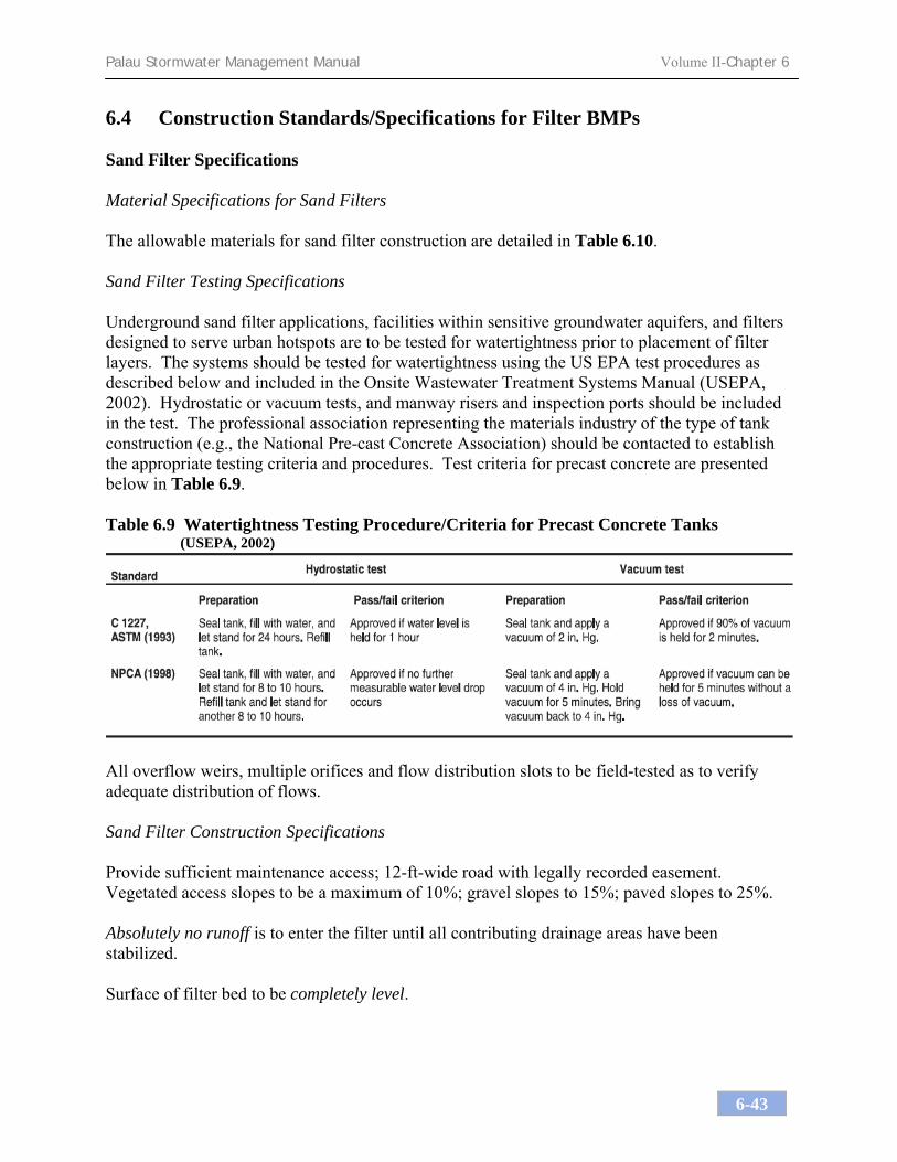
Palau Stormwater Management Manual Volume II-Chapter 6
6-43
6.4 Construction Standards/Specifications for Filter BMPs Sand Filter Specifications Material Specifications for Sand Filters The allowable materials for sand filter construction are detailed in Table 6.10. Sand Filter Testing Specifications Underground sand filter applications, facilities within sensitive groundwater aquifers, and filters designed to serve urban hotspots are to be tested for watertightness prior to placement of filter layers. The systems should be tested for watertightness using the US EPA test procedures as described below and included in the Onsite Wastewater Treatment Systems Manual (USEPA, 2002). Hydrostatic or vacuum tests, and manway risers and inspection ports should be included in the test. The professional association representing the materials industry of the type of tank construction (e.g., the National Pre-cast Concrete Association) should be contacted to establish the appropriate testing criteria and procedures. Test criteria for precast concrete are presented below in Table 6.9. Table 6.9 Watertightness Testing Procedure/Criteria for Precast Concrete Tanks
(USEPA, 2002)
All overflow weirs, multiple orifices and flow distribution slots to be field-tested as to verify adequate distribution of flows. Sand Filter Construction Specifications Provide sufficient maintenance access; 12-ft-wide road with legally recorded easement. Vegetated access slopes to be a maximum of 10%; gravel slopes to 15%; paved slopes to 25%. Absolutely no runoff is to enter the filter until all contributing drainage areas have been stabilized. Surface of filter bed to be completely level.

Palau Stormwater Management Manual Volume II-Chapter 6
6-44
All sand filters should be clearly delineated with signs so that they may be located when maintenance is due. Surface sand filter applications shall be planted with appropriate grasses as specified by local NRCS Standards and Specifications guidance. Specifications Pertaining to Sand Filters Designed Underground Provide manhole and/or grates to all underground and below grade structures. Manholes shall be in compliance with standard specifications for each jurisdiction but diameters should be 30in minimum (to comply with OSHA confined space requirements) but not too heavy to lift. Aluminum and steel louvered doors are also acceptable. Ten-inch long (minimum) manhole steps (12in o.c.) shall be cast in place or drilled and mortared into the wall below each manhole. A 5ft minimum height clearance (from the top of the sand layer to the bottom of the slab) is required for all permanent underground structures. Lift rings are to be supplied to remove/replace top slabs. Manholes may need to be grated to allow for proper ventilation; if required, place manholes away from areas of heavy pedestrian traffic. Underground sand filters shall be constructed with a dewatering gate valve located just above the top of the filter bed should the bed clog.
Underground sand beds shall be protected from trash accumulation by a wide mesh geotextile screen to be placed on the surface of the sand bed; screen is to be rolled up, removed, cleaned and re-installed during maintenance operations.

Palau Stormwater Management Manual Volume II-Chapter 6
6-45
Table 6.10 Material Specifications for Sand Filters
Parameter Specification Size Notes Sand
clean AASHTO M-6 or ASTM C-33 concrete sand
0.02” to 0.04” Sand substitutions such as Diabase and Graystone #10 are not acceptable. Crushed and washed limestone that meets the technical specifications of ASTM C-33 is acceptable.
Peat ash content: < 15% pH range: 5.2 to 4.9 loose bulk density 0.12 to 0.15 g/cc
n/a The material must be Reed-Sedge Hemic Peat, shredded, uncompacted, uniform, and clean.
Underdrain gravel
AASHTO M-43 0.25” to 0.75”
Geotextile Fabric (if required)
ASTM D-751 (puncture strength - 125 lb.) ASTM D-1117 (Mullen Burst Strength - 400 psi) ASTM D-1682 (Tensile Strength - 300 lb.)
0.08” thick equivalent opening size of #80 sieve
Must maintain 125 gpm per sq. ft. flow rate. Note: a 4” washed, rounded limestone aggregate layer may be substituted for geotextiles meant to separate filter layers.
Impermeable Liner (if required)
ASTM D 751 (thickness) ASTM D 412 (tensile strength 1,100 lb., elongation 200%) ASTM D 624 (Tear resistance - 150 lb./in) ASTM D 471 (water adsorption: +8 to -2% mass)
30 mil thickness Liner to be ultraviolet resistant. A geotextile fabric should be used to protect the liner from puncture.
Underdrain Piping
ASTM D-1785 or AASHTO M-278 4-6” rigid
schedule 40 PVC
3/8” perf. @ 6” on center, 4 holes per row; minimum of 3” of limestone aggregate over pipes; not necessary underneath pipes
Concrete (Cast-in-place)
See ROP Standards and Specs. f’c = 3500 psi, normal weight, air-entrained; re-enforcing to meet ASTM 615-60
n/a on-site testing of poured-in-place concrete required: 28 day strength and slump test; all concrete design (cast-in-place or pre-cast) not using previously approved ROP standards requires design drawings sealed and approved by a licensed professional structural engineer.
Concrete (pre-cast) per pre-cast manufacturer n/a
SEE ABOVE NOTE
non-rebar steel ASTM A-36 n/a
structural steel to be hot-dipped galvanized ASTM A123

Palau Stormwater Management Manual Volume II-Chapter 6
6-46
<This page left blank intentionally>

Palau Stormwater Management Manual Volume II-Chapter 6
6-47
Table 6.11 Sand/Organic Filter System Construction Inspection Checklist Project: Location: Site Status: Date: Time: Inspector:
CONSTRUCTION SEQUENCE SATISFACTORY /
UNSATISFACTORY
COMMENTS
1. Pre-construction Pre-construction meeting Runoff diverted Facility area cleared Facility location staked out 2. Excavation Size and location Side slopes stable Foundation cleared of debris If designed as exfilter, excavation does not compact subsoils Foundation area compacted 3. Structural Components Dimensions and materials Forms adequately sized Concrete meets standards Prefabricated joints sealed Underdrains (size, materials)

Palau Stormwater Management Manual Volume II-Chapter 6
6-48
CONSTRUCTION SEQUENCE SATISFACTORY /
UNSATISFACTORY
COMMENTS
4. Completed Facility Components 24-hour water filled test Contributing area stabilized
Filter material per specification Underdrains installed to grade Flow diversion structure properly installed Pretreatment devices properly installed Level overflow weirs, multiple orifices, distribution slots
5. Final Inspection Dimensions Surface completely level Structural components Proper outlet Ensure that site is properly stabilized before flow is directed to the structure.
Comments: Actions to be Taken:

Palau Stormwater Management Manual Volume II-Chapter 6
6-49
Construction Specifications for Bioretention Systems Material Specifications The allowable materials to be used in bioretention area are detailed in Table 6.12. Planting Soil The soil should be a uniform mix, free of stones, stumps, roots or other similar objects larger than two inches. No other materials or substances should be mixed or dumped within the bioretention area that may be harmful to plant growth, or prove a hindrance to the planting or maintenance operations. The planting soil should be free of noxious weeds. The bioretention system shall utilize planting soil having a composition as follows: Sand: 85-88% Soil fines: 8 to 12% (no more than 2% clay) Organic Matter*: 3 to 5% *Note: For bioretention applications with a planting soil depth of less than 4 feet, add 20% (by volume) of well aged (3 months), well aerated, leaf compost (or approved equivalent) to the above planting soil mixture. Where silt content is less than 20%, add a corresponding % of leaf compost. The planting soil should be tested and should meet the following criteria:
pH range 5.2 - 7.0 magnesium not to exceed 32 ppm phosphorus P2O5 not to exceed 69 ppm potassium K2O not to exceed 78 ppm soluble salts not to exceed 500 ppm
All bioretention areas should have a minimum of one test. Each test should consist of both the standard soil test for pH, phosphorus, and potassium and additional tests of organic matter, and soluble salts. A textural analysis is required from the site’s stockpiled topsoil. If topsoil is imported, then a texture analysis should be performed for each location where the top soil was excavated. Since different labs calibrate their testing equipment differently, all testing results should come from the same testing facility. Should the pH fall out of the acceptable range, it may be modified (higher) with lime or (lower) with iron sulfate plus sulfur.

Palau Stormwater Management Manual Volume II-Chapter 6
6-50
Mulch Layer Specifications. Mulch around individual plants only. Shredded woody material, coconut fronds, or banana leaf mulch are the only accepted mulches. Bark dust mulches and wood chips will float and move to the perimeter of the bioretention area during a storm event and are not acceptable. See NRCS Conservation Practice Specification 484, included with the attached Reference CD, for further details. Shredded mulch must be well aged (6-12 months) for acceptance. Mix approximately ½ the specified mulch layer into the planting soil to a depth of approximately 4 inches to help foster a highly organic surface layer. Compaction It is very important to minimize compaction of both the base of the bioretention area and the required backfill. When possible, use excavation hoes to remove original soil. If bioretention area is excavated using a loader, the contractor should use wide track or marsh track equipment, or light equipment with turf type tires. Use of equipment with narrow tracks or narrow tires, rubber tires with large lugs, or high pressure tires will cause excessive compaction resulting in reduced infiltration rates and storage volumes and is not acceptable. Compaction will significantly contribute to design failure. Compaction can be alleviated at the base of the bioretention facility by using a primary tilling operation such as a chisel plow, ripper, or subsoiler. These tilling operations are performed to refracture the soil profile through the 12-in compaction zone. Substitute methods must be approved by the engineer. Rototillers typically do not till deep enough to reduce the effects of compaction from heavy equipment. When backfilling the bioretention facility, place soil in lifts 12in or greater. Do not use heavy equipment within the bioretention basin. Heavy equipment can be used around the perimeter of the basin to supply soils and sand. Grade bioretention materials with light equipment such as a compact loader or a dozer/loader with marsh tracks. Plant Installation The plant root ball should be planted so 1/8th of the ball is above final grade surface. Root stock of the plant material should be kept moist during transport and on-site storage. The diameter of the planting pit should be at least six inches larger than the diameter of the planting ball. Set and maintain the plant straight during the entire planting process. Thoroughly water ground bed cover after installation. Trees should be braced using 2in x 2in stakes only as necessary and for the first growing season only. Stakes are to be equally spaced on the outside of the tree ball.

Palau Stormwater Management Manual Volume II-Chapter 6
6-51
Grasses and legume seed should be tilled into the soil to a depth of at least one inch. Grass and legume plugs should be planted following the non-grass ground cover planting specifications. The planting soil specifications provide enough organic material to adequately supply nutrients from natural cycling. The primary function of the bioretention structure is to improve water quality. Adding fertilizers defeats, or at a minimum, impedes this goal. Only add fertilizer if compost or mulch is used to amend the soil. Rototill urea fertilizer at a rate of 2 pounds per 1,000 square feet. Underdrains Underdrains should be placed on a minimum 3’-0” wide section of filter cloth. Pipe is placed next, followed by the limestone aggregate bedding. The ends of underdrain pipes not terminating in an observation well should be capped. The main collector pipe for underdrain systems should be constructed at a minimum slope of 0.5%. Observation wells and/or clean-out pipes must be provided (one minimum per every 1,000 square feet of surface area, see plans for location). Miscellaneous The bioretention facility may not be constructed until all contributing drainage area has been stabilized.

Palau Stormwater Management Manual Volume II-Chapter 6
6-52
Table 6.12 Materials Specifications for Bioretention
Parameter Specification Size Notes Planting Soil
sand 85-88% soil fines 8 - 12% (≤ 2% clay) organics 3 - 5%
n/a USDA soil types loamy sand or sandy loam
Mulch
shredded woody material, brush, coconut fronds, or banana leaves
aged 6 months, minimum
Geotextile
Class “C” apparent opening size (ASTM-D-4751) grab tensile strength (ASTM-D-4632) burst strength (ASTM-D-4833)
n/a for use as necessary beneath underdrains only
underdrain gravel
AASHTO M-43 0.375” to 0.75”
underdrain piping ASTM D 1785 or AASHTO M-278
4 to 6” rigid schedule 40 PVC
3/8” perf. @ 6” on center, 4 holes per row; minimum of 3” of gravel/limestone aggregate over pipes; not necessary underneath pipes
poured in place concrete (if required)
See Federal Highway Admin. Standards and Specs.; f’c = 3,500 lb. @ 28 days, normal weight, air-entrained; re-enforcing to meet ASTM 615-60
n/a on-site testing of poured-in-place concrete required: 28-day strength and slump test; all concrete design (cast-in-place or pre-cast) not using previously approved standards requires design drawings sealed and approved by a licensed professional structural engineer.
sand (1’ deep)
AASHTO M-6 or ASTM C-33
0.02” to 0.04” Sand substitutions such as Diabase and Graystone #10 are not acceptable. Crushed and washed limestone that meets the technical specifications of ASTM C-33 is acceptable.

Palau Stormwater Management Manual Volume II-Chapter 6
6-53
Table 6.13 Bioretention Construction Inspection Checklist Project: Location: Site Status: Date: Time: Inspector:
CONSTRUCTION SEQUENCE SATISFACTORY/
UNSATISFACTORY
COMMENTS 1. Pre-Construction Pre-construction meeting Runoff diverted Facility area cleared If designed as exfilter, soil testing for permeability Facility location staked out 2. Excavation
Size and location
Lateral slopes completely level If designed as exfilter, ensure that excavation does not compact subsoils.
Longitudinal slopes within design range 3. Structural Components Stone diaphragm installed correctly
Outlets installed correctly

Palau Stormwater Management Manual Volume II-Chapter 6
6-54
CONSTRUCTION SEQUENCE SATISFACTORY/
UNSATISFACTORY
COMMENTS
Underdrain Pretreatment devices installed Soil bed composition and texture 4. Vegetation Complies with planting specs Topsoil adequate in composition and placement
Adequate erosion control measures in place
5. Final Inspection Dimensions Proper stone diaphragm Proper outlet Soil/ filter bed permeability testing Effective stand of vegetation and stabilization
Construction generated sediments removed
Contributing watershed stabilized before flow is diverted to the practice

Palau Stormwater Management Manual Volume II-Chapter 6
6-55
Comments:
Actions to be Taken:

Palau Stormwater Management Manual Volume II-Chapter 6
6-56
<This page left blank intentionally>

Palau Stormwater Management Manual Volume II-Chapter 6
6-57
6.5 Construction Standards/Specifications for Open Channels Material Specifications The recommended construction materials for open channels and filter strips are detailed in Table 6.14. Dry Swales Roto-till soil/gravel interface approximately 6in to avoid a sharp soil/gravel interface. Permeable soil mixture should meet the bioretention planting soil specifications. Check dams, if required, shall be placed as specified. System to have 6in of freeboard, minimum. No gravel or perforated pipe is to be placed under driveways. Seed with flood/drought resistant grasses; see your local NRCS Standards and Specifications guidance. Wet Swales Excavate into undisturbed soils; do not use an underdrain system. Filter Strips Construct washed, rounded limestone aggregate diaphragms 12in wide, minimum, and 24in deep minimum. Pervious berms to be a sand/gravel mix (35-60% sand, 30-55% silt, and 10-25% gravel). Berms to have overflow weirs with 6-in minimum head. Slope range to be 2% minimum to 6% maximum.

Palau Stormwater Management Manual Volume II-Chapter 6
6-58
Table 6.14 Open Channel Materials Specifications
Parameter Specification Size Notes Dry swale soil sand 85-88%
soil fines 8 - 12% (≤ 2% clay) organics 3 - 5%
n/a USDA soil types loamy sand or sandy loam, soil with a higher percent organic content is preferred
Dry swale sand
ASTM C-33 fine aggregate concrete sand
0.02in to 0.04in Crushed, washed limestone that meets the technical specifications of ASTM C-33 is acceptable.
Check Dam (pressure treated)
AWPA Standard C6 6in x 6in or 8in x 8in do not coat with creosote; embed at least 3ft into side slopes
Check Dam (natural wood) 6in to 12in diameter;
notch as necessary do not use species that have a predisposition towards rot
Filter Strip sand/gravel pervious berm
sand: per dry swale sand gravel; AASHTO M-43
sand: 0.02in to 0.04in gravel: 2in to 1in
mix with approximately 25% loam soil to support grass cover crop; see Bioretention planting soil notes for more detail.
Gravel diaphragm and curtain drain
ASTM D 448 varies (No. 6) or
(1/8in to 3/8in) use washed, rounded limestone aggregate as a substitute
underdrain gravel
AASHTO M-43 0.25in to 0.75in
underdrain ASTM D -1785 or AASHTO M-278
4-6in rigid Schedule 40 PVC
3/8in perf. @ 6in o.c.; 4 holes per row Geotextile
See Federal Highway Admin. Standards and Specs
n/a
rip rap
per Federal Highway Admin. criteria
size per Federal Highway Admin. requirements

Palau Stormwater Management Manual Volume II-Chapter 6
6-59
Table 6.15 Open Channel System Construction Inspection Checklist Project: Location: Site Status: Date: Time: Inspector:
CONSTRUCTION SEQUENCE SATISFACTORY /
UNSATISFACTORY
COMMENTS 1. Pre-Construction Pre-construction meeting Runoff diverted Facility location staked out 2. Excavation Size and location Side slope stable Soil permeability Groundwater / bedrock Lateral slopes completely level Longitudinal slopes within design range
Excavation does not compact subsoils
3. Check dams Dimensions Spacing Materials

Palau Stormwater Management Manual Volume II-Chapter 6
6-60
CONSTRUCTION SEQUENCE SATISFACTORY / UNSATISFACTORY
COMMENTS
4. Structural Components Underdrain installed correctly Inflow installed correctly Pretreatment devices installed 5. Vegetation Complies with planting specifications
Topsoil adequate in composition and placement
Adequate erosion control measures in place
6. Final inspection Dimensions Check dams Proper outlet Effective stand of vegetation and stabilization
Contributing watershed stabilized before flow is routed to the facility
Comments:

Palau Stormwater Management Manual Volume II-Chapter 6
6-61
Actions to be Taken:

Palau Stormwater Management Manual Volume II-Chapter 6
6-62
<This page left blank intentionally>

7.0 Maintenance Plans An essential component of a successful stormwater system is the ongoing operation and maintenance of the various components of the stormwater drainage, control, and conveyance systems. Failure to provide effective maintenance can reduce the hydraulic capacity and the pollutant removal efficiency of stormwater practices. Many people expect that stormwater facilities will continue to function correctly as designed forever. However, it is inevitable that deterioration of the stormwater infrastructure will occur once it becomes operational. The question is not whether stormwater management system maintenance is necessary. Ideally, a program should address operations and maintenance concerns proactively instead of reacting to problems that occur such as flooding or water quality degradation. Thus, on-going maintenance is a vital part of ensuring the operational success of stormwater management facilities and is critical to achieving an extended service life of continuous operation as designed. There are two key components to adequately maintaining a stormwater management infrastructure:
• Periodic and scheduled inspections, and • Maintenance scheduling and performance
Inspections
It is clear that an inspection program is necessary to ensure a stormwater facility remains operational. Inspections should be performed on a regular basis and scheduled based on the stormwater control type and characteristics. In addition, inspections should occur after major rainfall events for those components deemed to be critically affected by the resulting runoff. Not all inspections can be conducted by direct human observation. For subsurface systems, video equipment may be required. There may be cases where other specialized equipment is necessary. The inspection program should be tailored to address the operational characteristics of the system. It is not mandatory that all inspectors be trained engineers, but they should have some knowledge or experience with stormwater systems. Trained stormwater engineers should, however, direct them. Inspections by registered engineers should be performed where routine inspection has revealed a question of structural or hydraulic integrity affecting public safety.

Palau Stormwater Management Manual Volume II-Chapter 7
7-2
The inspection process should document observations made in the field. Comments should be archived on structural conditions, hydraulic operational conditions, evidence of vandalism, condition of vegetation, occurrence of obstructions, unsafe conditions, and build-up of trash, sediments and pollutants. This is also an efficient way to take water quality measurements required for monitoring programs and to incorporate them into the inspection history. Maintenance Scheduling and Performance
Maintenance activities can be divided into two types: scheduled and corrective. Scheduled maintenance tasks are those that are typically accomplished on a regular basis and can generally be scheduled without referencing inspection reports. These items consist of such things as vegetation maintenance (such as grass mowing) and trash and debris removal. These tasks are required at well-defined time intervals and can be considered a given for most, if not all, stormwater structural facilities. A permanent maintenance crew is typically put under a fixed scope of responsibility to address these items. Corrective tasks consist of items such as sediment removal, stream bank stabilization, and outlet structure repairs that are done on an as-needed basis. These tasks are typically scheduled based on inspection results or in response to complaints. Corrective maintenance sometimes calls for more specialized expertise and equipment than for scheduled tasks. For example, a task such as sediment removal from a stormwater pond requires specialized equipment for which not every jurisdiction is willing to invest. Therefore, some maintenance tasks might be effectively handled on a contract basis with an outside entity specializing in that field. In addition, some corrective maintenance may also require a formal design and bid process to accomplish the work. The following section describes appropriate maintenance and inspection activities for the acceptable best management practices. 7.1 Maintenance Descriptions and Guidance A stormwater control system should be regularly inspected to ensure proper performance and to prevent deficiencies in the effectiveness of the systems due to sediment build-up, damage, or deterioration. The following operation and maintenance provisions should be provided: Ponds and Wetlands General inspections should be conducted on an annual basis and after storm events of greater than or equal the 1-year precipitation event (approximately 5.8 inches in Palau). Areas with a permanent pool should be inspected on a semi-annual basis. The maintenance objective for these practices includes preserving the hydraulic and removal efficiency of the pond or wetland and maintaining the structural integrity. The slopes of the pond or wetland should be inspected for erosion and gullying. Reinforce existing riprap if riprap is found to be deficient, erosion is present at the outfalls of any control structures, or the existing riprap has been compromised. All structural components, which include but not limited to trash racks, access gates, valves, pipes, weir walls, orifice structures and spillway structures, should be inspected and any deficiencies should be reported. This includes a visual inspection of all stormwater control structures for damage and/or accumulation

Palau Stormwater Management Manual Volume II-Chapter 7
7-3
of sediment. Sediment should be removed from the forebay when design depth has been reduced by 50%. All material, including any trash and/or debris from all areas within the extents of the pond or wetland area including trash rack and flow control structures, should be disposed of in accordance with all federal and local regulations. Any areas within the extents of the stormwater facility that are subject to erosion or gullying should be replenished with the original design material and re-vegetated according to design drawings. Slope protection material shall be placed in areas prone to erosion, in accordance with the above specifications. Embankment stability shall be inspected for seepage and burrowing animals. Mow the grass around the perimeter of the pond or wetland at least 4 times annually. Prune all dead or dying vegetation within the extents of the pond or wetland, remove all herbaceous vegetation root stock when overcrowding the maintenance access to the facility, remove any vegetation that has a negative impact on stormwater flowage through the facility and trim any overgrown vegetation within the basin. Any invasive vegetation encroaching upon the perimeter of the facility shall be pruned or removed if it is prohibiting access to the facility, compromising sight visibility and/or compromising original design vegetation. Replace any/all original vegetation that has died off or has not fully established, as determined at the time of the inspection. Wetland vegetation should be reinforced to its original design standards if less than 50% of the original vegetation is established after two years. Infiltration Infiltration facilities should be inspected annually to ensure that design infiltration rates are being met. If sediment or organic debris build-up has limited the infiltration capabilities (infiltration basins) to below the design rate, the top 6 inches should be removed and the surface roto-tilled to a depth of 12 inches. The basin bottom should be restored according to original design specifications. Any oil or grease found at the time of the inspection should be cleaned with oil absorption pads and disposed of in an approved location. Inspect facility for signs of wetness or damage to structures and note any eroded areas. If dead or dying grass on the bottom is observed, check to ensure that water percolates 2-3 days following storms. Mow and remove litter and debris. Stabilize eroded banks and repair undercut and eroded areas at inflow and outflow structures. Filters Sand Filters Sand filters should be inspected annually and after storm events of greater than or equal the 1-year precipitation event. Open the access covers of the underground sand filters and make a visual inspection to determine the extents of maintenance necessary to rehabilitate the sand filter to its original design standards. Proceed with the following if half of the entire sediment chamber depth is found to be full of sediment at the time of the inspection. All oil, sludge, sediment, solids, trash, debris and floatable material should be removed from all chambers of the sand filter. All stormwater within an underground sand filter shall be pumped out of the facility by means of a vactor truck. All

Palau Stormwater Management Manual Volume II-Chapter 7
7-4
remaining oil and grit shall be removed from the face of the exposed concrete within the perimeter sand filter, including but not limited to the wet storage chamber, sand filter chamber and overflow chamber. Materials deposited on the surface of the sand filter (e.g., trash and litter) should be removed manually. Clean-out shall be accomplished via catch vac or vactor truck. After cleaning, the cover and grate are to be reset and all resulting waste including oil, sludge, sediment, and water should be disposed of in accordance with all applicable federal and local regulations. If standing water is observed more than 48 hours after a storm event, then the top 6 inches of sand should be removed and replaced with new materials. If discolored or contaminated material is found below this removed surface then that material should also be removed and replaced until all contaminated sand has been removed from the filter chamber. The sand should be disposed of in accordance with all applicable federal and local regulations. All structural components, which include the outlet structure, valves, pipes, frame and grate, cover, underdrain system, and structural concrete, should be inspected and any deficiencies shall be reported. Bioretention Inspections are an integral part of system maintenance. During the six months immediately after construction, bioretention facilities should be inspected at least twice or more following precipitation events of at least 1.0 inch to ensure that the system is functioning properly. Thereafter, inspections should be conducted on an annual basis and after storm events of greater than or equal the 1-year precipitation event (approximately 5.8 inches in Palau). Minor soil erosion gullies should be repaired when they occur. Pruning or replacement of woody vegetation should occur when dead or dying vegetation is observed. Separation of herbaceous vegetation root shock should occur when over-crowding is observed, or approximately once every 3 years. The mulch layer should also be replenished (to the original design depth) every other year as directed by inspection reports. The previous mulch layer should be removed, and properly disposed of, or roto-tilled into the soil surface. If at least 50 percent vegetation coverage is not established after two years, a reinforcement planting should be performed. If the surface of the bioretention system becomes clogged to the point that standing water is observed on the surface 48 hours after precipitation events, the surface should be roto-tilled or cultivated to breakup any hard-packed sediment and then re-vegetated. Open channels The maintenance objective for this practice includes preserving the hydraulic and removal efficiency of the channel and maintaining a dense, healthy vegetative cover. The following activities are recommended on an annual basis or as needed:
• Mowing and litter and debris removal; • Stabilization of eroded side slopes and bottom; • Nutrient and pesticide use management; • De-thatching swale bottom and removal of thatching; and • Discing or aeration of swale bottom.

Palau Stormwater Management Manual Volume II-Chapter 7
7-5
Every five years, scraping of the channel bottom and removal of sediment to restore original cross section and infiltration rate, and seeding to restore ground cover is recommended. Dry swales should be inspected on an annual basis and just after storms of greater than or equal to the 1-year precipitation event. Both the structural and vegetative components should be inspected and repaired. When sediment accumulates to a depth of approximately 3 inches, it should be removed, and the swale should be reconfigured to its original dimensions. The grass in the dry swale should be mowed at least 4 times during the year. If the surface of the dry swale becomes clogged to the point that standing water is observed in the surface 48 hours after precipitation events, the bottom should be roto-tilled or cultivated to break up any hard-packed sediment, and then reseeded. Trash and debris should be removed and properly disposed of. Wet swales should be inspected annually and after storms of greater than or equal to the 1-year precipitation event. During inspection, the structural components of the system, including trash racks, valves, pipes and spillway structures, should be checked for proper function. Any clogged openings should be cleaned out and repairs should be made where necessary. Embankments should be checked for stability and any burrowing animals should be removed. Vegetation along the maintenance access roads should be mowed annually. Woody vegetation along those surfaces should be pruned where dead or dying branches are observed, and reinforcement plantings should be planted if less than 50 percent of the original vegetation establishes after two years. Sediment should be removed from the bottom of the swale.

Palau Stormwater Management Manual Volume II-Chapter 7
7-6
<This page left blank intentionally>

Palau Stormwater Management Manual Volume II-Chapter 7
7-7
7.2 Best Management Practices Operation, Maintenance, and Inspection
Checklists
Stormwater Pond/Wetland Operation, Maintenance and Management Inspection Checklist
Project Location: Site Status: Date: Time: Inspector: Maintenance Item Satisfactory/
Unsatisfactory Comments
1. Embankment and emergency spillway (Annual, After Major Storms)
1. Vegetation and ground cover adequate
2. Embankment erosion
3. Animal burrows
4. Unauthorized planting
5. Cracking, bulging, or sliding of dam
a. Upstream face
b. Downstream face
c. At or beyond toe
downstream
upstream
d. Emergency spillway
6. Pond, toe & chimney drains clear and functioning

Palau Stormwater Management Manual Volume II-Chapter 7
7-8
Maintenance Item Satisfactory/
Unsatisfactory Comments
7. Seeps/leaks on downstream face
8. Slope protection or riprap failure
9. Vertical/horizontal alignment of top of dam “As-
Built”
10. Emergency spillway clear of obstructions and debris
11. Other (specify)
2. Riser and principal spillway (Annual) Type: Reinforced concrete ______ Corrugated pipe ______ Masonry ______
1. Low-flow orifice obstructed
2. Low-flow trash rack. a. Debris removal necessary
b. Corrosion control
3. Weir trash rack maintenance a. Debris removal necessary
b. corrosion control
4. Excessive sediment accumulation inside riser
5. Concrete/masonry condition riser and barrels a. cracks or displacement
b. Minor spalling (<1" )
c. Major spalling (rebars exposed)
d. Joint failures
e. Water tightness
6. Metal pipe condition
7. Control valve a. Operational/exercised
b. Chained and locked

Palau Stormwater Management Manual Volume II-Chapter 7
7-9
Maintenance Item Satisfactory/
Unsatisfactory Comments
8. Pond drain valve a. Operational/exercised
b. Chained and locked
9. Outfall channels functioning
10. Other (specify)
3. Permanent Pool (Wet Ponds) (Semi-annually)
1. Undesirable vegetative growth
2. Floating or floatable debris removal required
3. Visible pollution
4. Shoreline problem
5. Other (specify)
4. Sediment Forebays
1. Sedimentation noted
2. Sediment cleanout when depth < 50% design depth
5. Dry Pond Areas
1. Vegetation adequate
2. Undesirable vegetative growth
3. Undesirable woody vegetation
4. Low-flow channels clear of obstructions
5. Standing water or wet spots
6. Sediment and/or trash accumulation
7. Other (specify)
6. Condition of Outfalls (Annual, After Major Storms)
1. Riprap failures
2. Slope erosion
3. Storm drain pipes

Palau Stormwater Management Manual Volume II-Chapter 7
7-10
Maintenance Item Satisfactory/
Unsatisfactory Comments
4.Endwalls / Headwalls
5. Other (specify)
7. Other (Semi-annually)
1. Encroachment on pond, wetland or easement area
2. Complaints from residents
3. Aesthetics a. Grass growing required
b. Graffiti removal needed
c. Other (specify)
4. Conditions of maintenance access routes.
5. Signs of hydrocarbon build-up
6. Any public hazards (specify)
8. Wetland Vegetation (Annual)
1. Vegetation healthy and growing
Wetland maintaining 50% surface area coverage of wetland plants after the second growing season. (If unsatisfactory, reinforcement plantings needed)
2. Dominant wetland plants: Survival of desired wetland plant species Distribution according to landscaping plan?
3. Evidence of invasive species 4. Maintenance of adequate water depths for desired
wetland plant species
5. Harvesting of emergent plantings needed
6. Have sediment accumulations reduced pool volume
significantly or are plants “choked” with sediment
7. Eutrophication level of the wetland.
8. Other (specify)

Palau Stormwater Management Manual Volume II-Chapter 7
7-11
Comments: Actions to be Taken:

Palau Stormwater Management Manual Volume II-Chapter 7
7-12
<This page left blank intentionally>

Palau Stormwater Management Manual Volume II-Chapter 7
7-13
Infiltration System Operation, Maintenance, and Management Inspection Checklist
Project: Location: Site Status: Date: Time: Inspector:
MAINTENANCE ITEM SATISFACTORY /
UNSATISFACTORY COMMENTS
1. Debris Cleanout (Semi-annually)
Trench/chamber or basin surface clear of debris
Inflow pipes clear of debris Overflow spillway clear of debris
Inlet area clear of debris
2. Sediment Traps or Forebays (Annual)
Obviously trapping sediment Greater than 50% of storage volume remaining
3. Dewatering (Semi-annually)
Trench/chamber or basin dewaters between storms
4. Sediment Cleanout of Trench/Chamber or Basin (Annual)
No evidence of sedimentation in trench/chamber or basin

Palau Stormwater Management Manual Volume II-Chapter 7
7-14
MAINTENANCE ITEM SATISFACTORY /
UNSATISFACTORY COMMENTS
Sediment accumulation doesn’t yet require cleanout
5. Inlets (Annual)
Good condition No evidence of erosion
6. Outlet/Overflow Spillway (Annual)
Good condition, no need for repair
No evidence of erosion
7. Aggregate Repairs (Annual)
Surface of aggregate clean Top layer of stone does not need replacement
Trench/Chamber or basin does not need rehabilitation
Comments:
Actions to be Taken:

Palau Stormwater Management Manual Volume II-Chapter 7
7-15
Sand/Organic Filter Operation, Maintenance and Management Inspection Checklist
Project: Location: Site Status: Date: Time: Inspector: MAINTENANCE ITEM SATISFACTORY /
UNSATISFACTORY COMMENTS
1. Debris Cleanout (Semi-annually)
Contributing areas clean of debris Filtration facility clean of debris Inlet and outlets clear of debris
2. Oil and Grease (Monthly)
No evidence of filter surface clogging
Activities in drainage area minimize oil and grease entry
3. Vegetation (Semi-annually)
Contributing drainage area stabilized
No evidence of erosion Area mowed and clipping removed
4. Water Retention Where Required (Semi-annually)
Water holding chambers at normal pool

Palau Stormwater Management Manual Volume II-Chapter 7
7-16
MAINTENANCE ITEM SATISFACTORY /
UNSATISFACTORY COMMENTS
No evidence of leakage
5. Sediment Deposition (Annual)
Filter chamber free of sediments Sedimentation chamber not more than half full of sediments
6. Structural Components (Annual)
No evidence of structural deterioration
Any grates are in good condition No evidence of spalling or cracking of structural parts
7. Outlet/Overflow Spillway (Annual)
Good condition, no need for repairs
No evidence of erosion (if draining into a natural channel)
8. Overall Function of Facility (Annual)
Evidence of flow bypassing facility
No noticeable odors outside of facility
Comments:

Palau Stormwater Management Manual Volume II-Chapter 7
7-17
Actions to be Taken:

Palau Stormwater Management Manual Volume II-Chapter 7
7-18
<This page left blank intentionally>

Palau Stormwater Management Manual Volume II-Chapter 7
7-19
Bioretention Operation, Maintenance and
Management Inspection Checklist
Project: Location: Site Status: Date: Time: Inspector:
MAINTENANCE ITEM SATISFACTORY / UNSATISFACTORY
COMMENTS
1. Debris Cleanout (Semi-annually)
Bioretention and contributing areas clean of debris
No dumping of yard wastes into practice
Litter (branches, etc.) have been removed
2. Vegetation (Semi-annually)
Plant height not less than design water depth
Fertilized per specifications Plant composition according to approved plans
No placement of inappropriate plants
No evidence of erosion

Palau Stormwater Management Manual Volume II-Chapter 7
7-20
MAINTENANCE ITEM SATISFACTORY / UNSATISFACTORY
COMMENTS
3. Check Dams/Energy Dissipaters/Sumps (Annual, After Major Storms)
No evidence of sediment buildup
Sumps should not be more than 50% full of sediment
No evidence of erosion at downstream toe of drop structure
4. Dewatering (Semi-annually)
Dewaters between storms No evidence of standing water
5. Sediment Deposition (Annual)
Bioretention area clean of sediments
Sediments should not be > 20% of swale design depth
6. Outlet/Overflow Spillway (Annual, After Major Storms)
Good condition, no need for repair
No evidence of erosion No evidence of any blockages
7. Integrity of Filter Bed (Annual) Filter bed has not been blocked or filled inappropriately
Comments:

Palau Stormwater Management Manual Volume II-Chapter 7
7-21
Actions to be Taken:

Palau Stormwater Management Manual Volume II-Chapter 7
7-22
<This page left blank intentionally>

Palau Stormwater Management Manual Volume II-Chapter 7
7-23
Open Channel Operation, Maintenance, and Management Inspection Checklist
Project: Location: Site Status: Date: Time: Inspector: MAINTENANCE ITEM SATISFACTORY/
UNSATISFACTORY COMMENTS
1. Debris Cleanout (Semi-annually)
Contributing areas clean of debris
2. Check Dams or Energy Dissipators (Annual, After Major Storms)
No evidence of flow going around structures
No evidence of erosion at downstream toe
Soil permeability Groundwater / bedrock
3. Vegetation (Semi-annually)
Mowing done when needed Minimum mowing depth not exceeded
No evidence of erosion Fertilized per specification
4. Dewatering (Semi-annually)
Dewaters between storms

Palau Stormwater Management Manual Volume II-Chapter 7
7-24
MAINTENANCE ITEM SATISFACTORY/
UNSATISFACTORY COMMENTS
5. Sediment deposition (Annual)
Clean of sediment
6. Outlet/Overflow Spillway (Annual)
Good condition, no need for repairs
No evidence of erosion
Comments: Actions to be Taken:

Palau Stormwater Management Manual Volume II-Chapter 7
7-25
7.3 Maintenance Agreements A major contributor to unmaintained stormwater facilities is a lack of clear ownership and responsibility definition. In order for an inspection and maintenance program to be effective, the roles for each responsibility must be clearly defined prior to construction of a system. This can be accomplished with a maintenance agreement between the site owners and EQPB. Some key aspects of these maintenance agreements are the clear delineation of responsibilities, such as:
• Identification of who will perform inspection duties and how often. • Listed duties that are to be performed by the owner, such as mowing, debris removal, and
replanting of vegetation. • Defined roles for EQPB, possibly inspection, and/or modifications to the system such as
resizing an orifice. • Determination of a course of action to be taken if the owner does not fulfill their
obligations (i.e. repayment to EQPB for activities that the owner did not perform). • Development of a pollution prevention plan by the owner. • Requirement of a report, possibly annually, that would serve to keep the owner involved
and aware of their responsibilities. A sample maintenance agreement is included below.

Palau Stormwater Management Manual Volume II-Chapter 7
7-26
Sample Stormwater Facility Maintenance Agreement
THIS AGREEMENT, made and entered into this ___ day of _________, 20___, by and between (Insert Full Name of Owner) ________________________________________________ hereinafter called the "Landowner", and the [Local Jurisdiction], hereinafter called the "[Republic of Palau/State]". WITNESSETH, that WHEREAS, the Landowner is the owner of certain real property described as (Tax Map/Parcel Identification Number) ___________________________ as recorded by deed in the land records of [Local Jurisdiction] Deed Book __________ Page __________, hereinafter called the "Property". WHEREAS, the Landowner is proceeding to build on and develop the property; and WHEREAS, the Site Plan/Subdivision Plan known as _________________________________, (Name of Plan/Development) hereinafter called the "Plan", which is expressly made a part hereof, as approved or to be approved by the [Republic of Palau/State], provides for detention of stormwater within the confines of the property; and WHEREAS, the [Republic of Palau/State] and the Landowner, its successors and assigns, including any homeowners association, agree that the health, safety, and welfare of the residents of [Local Jurisdiction] require that on-site stormwater management facilities be constructed and maintained on the Property; and WHEREAS, the [Republic of Palau/State] requires that on-site stormwater management facilities as shown on the Plan be constructed and adequately maintained by the Landowner, its successors and assigns, including any homeowners association. NOW, THEREFORE, in consideration of the foregoing premises, the mutual covenants contained herein, and the following terms and conditions, the parties hereto agree as follows:
1. The on-site stormwater management facilities shall be constructed by the Landowner, its successors and assigns, in accordance with the plans and specifications identified in the Plan.
2. The Landowner, its successors and assigns, including any homeowners association, shall adequately maintain the stormwater management facilities. This includes all pipes, channels or other conveyances built to convey stormwater to the facility, as well as all structures, improvements, and vegetation provided to control the quantity and quality of the stormwater. Adequate maintenance is herein defined as good working condition so that these facilities are performing their design functions. The Stormwater Best Management Practices Operation, Maintenance and Management Checklists are to be used to establish what good working condition is acceptable to the [Republic of Palau/State].

Palau Stormwater Management Manual Volume II-Chapter 7
7-27
3. The Landowner, its successors and assigns, shall inspect the stormwater management facility and submit an inspection report annually. The purpose of the inspection is to assure safe and proper functioning of the facilities. The inspection shall cover the entire facilities, berms, outlet structure, pond areas, access roads, etc. Deficiencies shall be noted in the inspection report.
4. The Landowner, its successors and assigns, hereby grant permission to the [Republic of Palau/State], its authorized agents and employees, to enter upon the Property and to inspect the stormwater management facilities whenever the [Republic of Palau/State] deems necessary. The purpose of inspection is to follow-up on reported deficiencies and/or to respond to citizen complaints. The [Republic of Palau/State] shall provide the Landowner, its successors and assigns, copies of the inspection findings and a directive to commence with the repairs if necessary.
5. In the event the Landowner, its successors and assigns, fails to maintain the stormwater management facilities in good working condition acceptable to the [Republic of Palau/State], the [Republic of Palau/State] may enter upon the Property and take whatever steps necessary to correct deficiencies identified in the inspection report and to charge the costs of such repairs to the Landowner, its successors and assigns. This provision shall not be construed to allow the [Republic of Palau/State] to erect any structure of permanent nature on the land of the Landowner outside of the easement for the stormwater management facilities. It is expressly understood and agreed that the [Republic of Palau/State] is under no obligation to routinely maintain or repair said facilities, and in no event shall this Agreement be construed to impose any such obligation on the [Republic of Palau/State].
6. The Landowner, its successors and assigns, will perform the work necessary to keep these facilities in good working order as appropriate. In the event a maintenance schedule for the stormwater management facilities (including sediment removal) is outlined on the approved plans, the schedule will be followed.
7. In the event the [Republic of Palau/State] pursuant to this Agreement, performs work of any nature, or expends any funds in performance of said work for labor, use of equipment, supplies, materials, and the like, the Landowner, its successors and assigns, shall reimburse the [Republic of Palau/State] upon demand, within thirty (30) days of receipt thereof for all actual costs incurred by the [Republic of Palau/State] hereunder.
8. This Agreement imposes no liability of any kind whatsoever on the [Republic of Palau/State] and the Landowner agrees to hold the [Republic of Palau/State] harmless from any liability in the event the stormwater management facilities fail to operate properly.
9. This Agreement shall be recorded among the land records of [Local Jurisdiction] and shall constitute a covenant running with the land, and shall be binding on the Landowner, its administrators, executors, assigns, heirs and any other successors in interests, including any homeowners association.
WITNESS the following signatures and seals:

Palau Stormwater Management Manual Volume II-Chapter 7
7-28
_____________________________________________ Company/Corporation/Partnership Name (Seal) By: _____________________________________________ ______________________________________________ (Type Name and Title) The foregoing Agreement was acknowledged before me this ____ day of ____________, 20___, by _________________________________________________________________________. _______________________________________ NOTARY PUBLIC My Commission Expires: ____________ By: ________________________________________ ______________________________________________ (Type Name and Title) The foregoing Agreement was acknowledged before me this ____ day of ____________, 20___, by _________________________________________________________________________. _______________________________________ NOTARY PUBLIC My Commission Expires: ____________ Approved as to Form: ___________________________ __________ [Republic of Palau/State] Attorney Date

8.0 Soils Information 8.1 Introduction to Soils Soil is defined as weathered bedrock (parent material) that supports plant life and consists of distinguishable horizons or layers. Soil science is a complicated subject that would require a very lengthy document to cover adequately. This section will focus on the basics of soils as it relates to stormwater management and how to determine soil characteristics in the field. Palau may host future soil evaluator certification workshops to familiarize engineers, contractors, and other interested parties with local soils and field techniques. In addition, the following references may be helpful for more detailed information on soils:
N.C. Brady and R.R. Weil. 2001. The Nature and Property of Soils, 13th ed. Prentice Hall, Upper Saddle River, NJ. 960 pp.
B.P.K. Yerima and E. Van Ranst. 2005. Introduction to Soil Science: Soils of the Tropics. Trafford
Publishing, Victoria, B.C. 440 pp. Soils are one of the most important site characteristics to consider when determining appropriate stormwater BMPs to use and their placement on a site. For example, infiltration facilities are not feasible in clayey, volcanic soils, and it may be difficult to sustain a permanent pool for a wet pond in sandy soils without a liner. A bioretention area may not work on a site with a high groundwater table. One of the first steps when starting a project should be to review the NRCS Soil Survey. The Soil Survey includes a wealth of information about the soils and geology of the islands and must be used to determine the hydrologic soil group (HSG) in order to establish the recharge criteria for the site (Volume I, Section 2.2.2.1). Once a designer has a general idea about the soils and geology, a test pit should be performed in the field by a soil scientist or certified soil evaluator. A test pit is a deep observation hole typically dug by a backhoe, measuring a minimum of 3 ft wide and a minimum of 6 ft long. The test pit should be dug to a depth of 3 ft below the bottom of the BMP of interest, to groundwater, or to impervious material. A description of how to evaluate a test pit is included below in Section 8.2. In addition, the NRCS Field Book for Describing and Sampling Soils (Schoeneberger et al., 2002) has been included on the reference CD accompanying these manuals to be used as a field guide. Information on soil texture, depth of the soil profile, seasonal high groundwater, and type of parent material (e.g., limestone,

Palau Stormwater Management Manual Volume II-Chapter 8
8-2
volcanics) is necessary before designing the stormwater management facilities for a site and can be gathered from a test pit. Soil Texture Soil texture refers to the relative proportions of sand, silt, and clay in a soil. For stormwater purposes, the USDA soil texture classification should be used (Figure 8.1) and must be determined in the field by a soil scientist or certified soil evaluator using the procedure shown in Figure 8.2. Soil texture is particularly important when establishing design infiltration rates (Volume I, Table 3.5).
Figure 8.1 USDA Textural Classification Triangle

Palau Stormwater Management Manual Volume II-Chapter 8
8-3
Figure 8.2 Field Procedure for Determining USDA Textural Classification
Form moist soil into ball with fingers
No ball, does not stain
fingers
Weak ball, stains fingers
slightly
Fairly firm ball, stains
fingers
Firm ball, stains fingers
Does not ribbon
Does not ribbon
Does not ribbon
Very gritty, classify as sand
Very gritty, classify as loamy sand
Moderately gritty, classify as sandy loam
Does not ribbon
Ribbons
Neither gritty or smooth, classify
as loam
Smooth, classify as silt
Slight tendency to ribbon –
smooth, slick, buttery feel, classify as silt loam
Ribbons with some flaking <2.5 in long, very smooth moderately sticky feel. Classify as
silty clay loam
Long ribbon >2.5 in long, sticky feel. Classify as silty clay

Palau Stormwater Management Manual Volume II-Chapter 8
8-4
8.2 Test Pit Procedure (based on information from the Plymouth Conservation District, USDA NRCS) Suggested Equipment List
- Soil color book - Tape measure - Trowel, knife, or small garden shovel - Something to mark horizons and layers
(large nails or golf tees) - Soil sample tray (a plastic plate or
muffin tin is acceptable) - Spray water bottle - Small towel to wipe hands - Clipboard - Soil field guide book - Proper field clothing including umbrella,
work boots, etc. - Sun block, insect repellent, etc.
1. Review Reference Materials
- USGS Topographic Map - Surficial Geology Map: determine
landform and parent material - NRCS Published Soil Survey Reports:
determine soil type, parent material, estimated depth to seasonal high water table - Flood Insurance Maps: 100-year floodplain - Others
2. Walk the Site
- Note the position on the landscape. - Check for open water bodies, wetlands (especially wetland delineations), and
water courses; note position of site relative to these areas. - Look for rock outcrops, surface stones, etc. - Check for prior land disturbance or alteration. - Note changes in vegetation
3. Enter the Test Pit (follow local and federal safety rules)
- Clean all sides of the test pit to remove loose soil material. - Stand back and observe all pit faces; note any variability within the pit. - Determine the type of parent material (limestone or volcanics) - Decide on a representative section of the pit and identify the different soil
horizons and layers.
Figure 8.3 Participants of the May 2006 Stormwater Training Workshop in Saipan learn how to evaluate a test pit.
Palau Stormwater Management Manual Volume II-Chapter 8
8-5
- Make special note of any changes observed on the different sides of the deep observation hole.
4. Describe and document the soil characteristics of each of the soil horizons and layers. Refer
to the NRCS Field Book for Describing and Sampling Soils (Schoeneberger et al., 2002) and log the observations on a test pit form (Figure 8.4), both of which are included on the reference CD.
Note: it often saves time and the results are more consistent when you describe one feature at a time.
- Determine the soil matrix color for each soil horizon and layer. - Determine the soil texture for each soil horizon and layer. - Determine the % gravel for each soil horizon and layer. - Determine the soil consistence and soil structure for each soil horizon and layer.
5. Estimate the depth to the seasonal high water table Make special note of the time of the year. Is it the wet season? What are the current water table conditions? Are they in the normal range or are they above or below normal.
- Keeping your “head out of the hole,” would you expect to see a water table and at what depth? For example, what is the relative elevation of where the test pit is located compared to wetlands and open water bodies?
- When you observe the water table, was water weeping from the sides of the deep hole or standing in the bottom of the pit?
- Reviewing your soil log, are there any restrictive layers that may impede the downward flow of water and perch water above it?
- Clean all sides of the pit and stand back to look for any patterns of redoximorphic1 features that continue across the pit faces.
- Starting in the lower portion of the test pit, look for redoximorphic features. If there are redoximorphic features present, follow the pattern up the side of the test pit. Do this independently for each side of the test pit and then compare the results to see if they are consistent.
- Depth to seasonal high water table using soil features is where there are 5% or more redoximorphic features; these may be redox concentrations and/or redox depletions.
1 Redoximorphic features are formed by the processes of reduction, translocation, and/or oxidation of iron and manganese oxides. They are an indicator of seasonal water table elevations.

Palau Stormwater Management Manual Volume II-Chapter 8
8-6
Figure 8.4 Sample Test Pit Form

9.1 Infiltration Testing Requirements General Notes Pertinent to All Testing 1. For infiltration practices, a minimum field infiltration rate (fc) of 0.5 inches per hour is
required; areas yielding a lower rate preclude these practices. If the minimum fc exceeds two inches per hour, half of the WQv must be treated by an upstream BMP that does not allow infiltration. For F-1 and F-3 practices, no minimum infiltration rate is required if these facilities are designed with a “day-lighting” underdrain system; otherwise these facilities require a 0.5 inch per hour rate.
2. Number of required borings is based on the size of the proposed facility. Testing is done in
two phases, (1) Initial Feasibility, and (2) Concept Design Testing. 3. Testing is to be conducted by a qualified professional. This professional shall be a registered
professional engineer, a soils scientist or geologist, or certified per local soils certification program.
Initial Feasibility Testing Feasibility testing is conducted to determine whether full-scale testing is necessary, and is meant to reduce screen unsuitable sites, and reduce testing costs. A soil boring is not required at this stage. Initial testing involves either one field test per facility, regardless of type or size, or previous testing data, such as the following: * septic percolation testing on-site, within 200 feet of the proposed BMP location, and on the
same contour [can establish initial rate, water table and/or depth to bedrock] * previous written geotechnical reporting on the site location as prepared by a qualified
geotechnical consultant * NRCS Soil Mapping showing an unsuitable soil group such as a hydrologic group “D” soil
in a low-lying area
9.0 Assorted Design Tools

Palau Stormwater Management Manual Volume II-Chapter 9
9-2
If the results of initial feasibility testing as determined by a qualified professional show that an infiltration rate of greater than 0.5 inches per hour is probable, then the number of concept design test pits shall be per the following table. An encased soil boring may be substituted for a test pit, if desired.
Table 9-1 Infiltration Testing Summary Table
Type of Facility Initial Feasibility Testing
Concept Design Testing (initial testing yields a
rate greater than 0.5in/hr)
Concept Design Testing (initial testing
yields a rate lower than 0.5in/hr)
I-1 (trench/chamber) 1 field percolation test, test pit not required
1infiltration test and 1 test pit per 200ft of trench
not acceptable practice
I-2 (basin) 1 field percolation test, test pit not required
1 infiltration test* and 1 test pit per 5,000 ft2 of basin area
not acceptable practice
F-1 (sand filter) 1 field percolation test, test pit not required
1 infiltration test and 1 test pit per 5,000 ft2 of filter area (no underdrains required**)
underdrains required
F-3 (bioretention) 1 field percolation test, test pit not required
1 infiltration test and 1 test pit per 5,000 ft2 of filter area (no underdrains required**)
underdrains required
*feasibility test information already counts for one test location ** underdrain installation still strongly suggested Documentation Infiltration testing data shall be documented, which shall also include a description of the infiltration testing method, if completed. This is to ensure that the tester understands the procedure. Test Pit/Boring Requirements (see Chapter 8 for more information on soils and test pits)
a. excavate a test pit or dig a standard soil boring to a depth of 4 ft below the proposed facility bottom
b. determine depth to groundwater table (if within 4 ft of proposed bottom) upon
initial digging or drilling, and again 24 hours later
c. conduct Standard Penetration Testing (SPT) every 2 ft to a depth of 4 ft below the facility bottom
d. determine USDA textures at the proposed bottom and 4 ft below the bottom of the
BMP

Palau Stormwater Management Manual Volume II-Chapter 9
9-3
e. determine depth to bedrock (if within 4 ft of proposed bottom)
f. The soil description should include all soil horizons. g. The location of the test pit or boring shall correspond to the BMP location; test
pit/soil boring stakes are to be left in the field for inspection purposes and shall be clearly labeled as such.
Infiltration Testing Requirements (Please also see the 2007 CNMI Percolation Testing Manual, included with the attached Reference CD, for an alternative procedure)
a. Install casing (solid 5-inch diameter, 30-inch length) to 24 inches below proposed BMP bottom.
b. Remove any smeared soiled surfaces and provide a natural soil interface into
which water may percolate. Remove all loose material from the casing. Upon the tester’s discretion, a two (2) inch layer of coarse sand or fine gravel may be placed to protect the bottom from scouring and sediment. Fill casing with clean water to a depth of 24 inches and allow to pre-soak for twenty-four hours.
c. Twenty-four hours later, refill casing with another 24 inches of clean water and
monitor water level (measured drop from the top of the casing) for 1 hour. Repeat this procedure (filling the casing each time) three additional times, for a total of four observations. Upon the tester’s discretion, the final field rate may either be the average of the four observations, or the value of the last observation. The final rate shall be reported in inches per hour.
d. May be done though a boring or open excavation.
e. The location of the test shall correspond to the BMP location.
f. Upon completion of the testing, the casings shall be immediately pulled, and the
test pit shall be back-filled. Laboratory Testing
a. Grain-size sieve analysis and hydrometer tests where appropriate may be used to determine USDA soils classification and textural analysis. Visual field inspection by a qualified professional may also be used, provided it is documented. The use of lab testing to establish infiltration rates is prohibited.

Palau Stormwater Management Manual Volume II-Chapter 9
9-4
Bioretention Testing
All areas tested for application of F-3 facilities shall be back-filled with a suitable sandy loam planting media. The borrow source of this media, which may be the same or different from the bioretention area location itself, must be tested as follows:
If the borrow area is virgin, undisturbed soil, one test is required per 5,000 ft2 of borrow area; the test consists of “grab” samples at one foot depth intervals to the bottom of the borrow area. All samples at the testing location are then mixed, and the resulting sample is then lab-tested to meet the following criteria:
a) USDA minimum textural analysis requirements: A textural analysis is
required from the site stockpiled topsoil. If topsoil is imported, then a texture analysis shall be performed for each location where the top soil was excavated. Minimum requirements: sand ~ 80% silt 0 - 20% clay 0 - 2% organics 0 - 20%
b) The soil shall be a uniform mix, free of stones, stumps, roots or other similar objects larger than one inch.
c) Consult the bioretention construction specifications (Chapter 6 above) for
further guidance on preparing the soil for a bioretention area.

Palau Stormwater Management Manual Volume II-Chapter 9
9-5
9.2 Miscellaneous BMP Details Miscellaneous Design Schematics for Compliance with Performance Criteria: Figure 9-1: Trash Rack for Low-flow Orifice Figure 9-2: Expanded Trash Rack Protection for Low-flow Orifice Figure 9-3: Internal Control for Orifice Protection Figure 9-4: Half Round CMP Hood Figure 9-5: Observation Well/Cleanout for Infiltration and Filtering Practices Figure 9-6: On-line Versus Off-line Schematic Figure 9-7: Flow Splitter Structure Figure 9-8: Concrete Level Spreader Low-flow Orifice Protection Outlet control structures typically use orifices of varying sizes to control discharge from certain stormwater BMPs. Low-flow orifices (typically <6” diameter) can easily clog with trash and vegetative debris. Figures 9.1-9.4 illustrate a few examples of protective measures to prevent clogging and keep the BMPs functioning properly.
1'-5"
WELD (TYP.)
2" x 1/4" STEELSTOCK ALL AROUND
1/2" DIAMETER HOLES@24" O/C MAX. (TYP.)
3 LB/FT 2 EXPANDED STEELGRATE ON TOP, BOTTOM,AND SIDES
WELD 1"x1"x1/8" ANGLEOVER ALL EDGES (TYP.)
NOTES FOR TRASH RACK1. TRASH RACK TO BE CENTERED OVER OPENING.
2. STEEL TO CONFORM TO ASTM A-36.
3. ALL SURFACES TO BE COATED WITH ZRC COLD GALVANIZING COMPOUND AFTER WELDING.
Figure 9-1 Trash Rack Protection for Low-flow Orifice

Palau Stormwater Management Manual Volume II-Chapter 9
9-6
3'-4"
3'-6"
1'-8
"1'-1
0"
2'-10"2'-6"3'-8
3/4
"
1'-1
0"
CAST-IN-PLACETRASH RACK BASE
(3'-8"x3'-2"x6")
PRE-CASTRISER STRUCTURE
EXPANDED STEEL GRATE3 LBS/FT2 WELDED INSIDEANGLES, TOP AND BOTH SIDES.#3.0 GRATING
(SEE DETAIL)
1" x 1" ANGLESALONG TOP EDGES
1 LAYER 6" x 6" 4/4WOVEN WIRE FABRICCENTERED IN SLAB
1/2" DIAMETERHOLE (TYP.)
1/4" x 4" STEELALL AROUND
Figure 9-2 Expanded Trash Rack Protection for Low-flow Orifice
TO RISER
INTERNAL ORIFICE
REMOVABLE CAP
ANTI-FLOTATION
DEVICE GRAVELJACKET
Figure 9-3 Internal Control for Orifice Protection

Palau Stormwater Management Manual Volume II-Chapter 9
9-7
12"-18" BELOWORIFICE INVERT
LOW-FLOW ORIFICE(IN RISER WALL)
TOP PLATE
RISER
1/2 ROUND CMP HOOD
Figure 9-4 Half Round CMP Hood (For Protection of Low-flow Orifice)

Palau Stormwater Management Manual Volume II-Chapter 9
9-8
Observation Well/Cleanout Infiltration and filtering practices require an observation well/cleanout for inspections and maintenance. One example that can be used in a parking lot is the flush-mounted observation well shown below in Figure 9.5.
SCREW TOP LID*
FINISHED GRADE
PANELLA TYPE CLEANOUTWITH COUNTERSUNK HEAD
PIPE SEAL GASKET
4-6" PERFORATED P.V.C. SOIL PIPE
* ABOVE DETAIL PROVIDED AS SCHEMATIC SCREW TOP P.V.C. WELL CAP ONLY
EACH OBSERVATION WELL / CLEANOUT SHALL INCLUDE THE FOLLOWING:
1. FOR AN UNDERGROUND FLUSH MOUNTED OBSERVATION WELL / CLEANOUT, PROVIDE A TUBE MADE OF NON-CORROSIVE MATERIAL, SCHEDULE 40 OR EQUAL, AT LEAST THREE FEET LONG.
2. THE TUBE SHALL HAVE A FACTORY ATTACHED CAST IRON OR HIGH IMPACT PLASTIC COLLAR WITH RIBS TO PREVENT ROTATION WHEN REMOVING SCREW TOP LID. THE SCREW TOP LID SHALL BE CAST IRON OR HIGH IMPACT PLASTIC THAT WILL WITHSTAND ULTRA-VIOLET RAYS.
Figure 9-5 Observation Well/Cleanout for Infiltration and Filtering Practices

Palau Stormwater Management Manual Volume II-Chapter 9
9-9
On-line Versus Off-line Best management practices can be designed to receive all of the flow from a given area (on-line) or to receive only a portion of the flow (off-line), such as the water quality volume. Off-line BMPs may need to be paired with another practice for volume control, depending on the site characteristics. An example of an on-line vs. an off-line filtering practice is shown in Figure 9.6. Figure 9.7 illustrates one example of a flow splitter that may be used to divert low flows to an off-line BMP for treatment or recharge while allowing larger flows to exit via the outflow pipe to a quantity control BMP or perhaps direct discharge to a water body, based on required site criteria. Flow diversion structures, also called flow splitters, are designed to deliver flows up to the design water quality peak flow (WQf, see Section 9.3 for a description of how to calculate this based on Small Storm Hydrology) or water quality volume (WQv) to off-line stormwater treatment practices. Flows in excess of the WQf are diverted around the treatment facility with minimal increase in head at the flow diversion structure to avoid surcharging the treatment facility under higher flow conditions. Flow diversion structures are typically manholes or vaults equipped with weirs, orifices, or pipes to bypass excess runoff. A number of design options exist. An example of an on-line vs. an off-line filtering practice is shown in Figure 9-6. Figure 9-7 illustrates one example of a flow splitter that may be used to divert low flows to an off-line BMP for treatment or recharge while allowing larger flows to exit via the outflow pipe to a quantity control BMP or perhaps direct discharge to a water body, based on required site criteria. Other equivalent designs that achieve the result of diverting flows in excess of the water quality peak flow around the treatment facility, including bypasses or overflows located inside the facility, are also acceptable. The following general procedures are recommended for design of flow diversion structures:
• Locate the top of the weir or overflow structure at the maximum water surface elevation associated with the WQf, or the water surface elevation in the treatment practice when the entire WQv is being held, whichever is higher.
• Determine the diversion structure dimensions required to divert flows in excess of the WQf using standard equations for a rectangular sharp-crested weir, uniform flow in pipes or channels, or orifice depending on the type of diversion structure.
• Provide sufficient freeboard in the stormwater treatment practice and flow splitter to accommodate flow over the diversion structure.
• Limit the maximum head over the flow diversion structure to avoid surcharging the stormwater treatment practice under high flow conditions. Flow to the stormwater treatment practice at the 100-year water surface elevation should not increase the WQf by more than 10 percent.
Design diversion structures to withstand the effects of erosion and flotation due to high water conditions. These structures should be designed to minimize clogging potential and to allow for ease of inspection and maintenance.

Palau Stormwater Management Manual Volume II-Chapter 9
9-10
Figure 9-6 On-Line Versus Off-Line Schematic
ON-LINEFILTERING SYSTEM
PLAN VIEW
SECTION
SECTION
PLAN VIEW
OFF-LINEFILTERING SYSTEM

Palau Stormwater Management Manual Volume II-Chapter 9
9-11
Figure 9-7 Flow Splitter Structures
STANDARD
MANHOLE
INVERT OF INFLOWPIPE
MANHOLE CHANNEL
PRE-CAST MANHOLE BASE
BOLT SHELF ANGLE TOMANHOLE WALL PER DETAIL
WQv OUTLET PIPE(TO BMP FACILITY)
NOTE: ALUMINUM TRASH GRATEIN TWO SEMICIRCULAR SECTIONS
TOP OF TRASH GRATING AT OUTLET PIPE INVERT
To Offline Facility for Water Quality Treatment
To Discharge Pipe

Palau Stormwater Management Manual Volume II-Chapter 9
9-12
Level Spreaders Level spreaders are devices designed to uniformly distribute flow over a large area to prevent erosive flows and promote infiltration. There are several level spreader designs that differ based on the peak rate of inflow, the duration of use, the type of pollutant, and the site conditions. All designs follow the same basic principles: water enters the spreader through overland flow, a pipe, ditch or swale; the flow is distributed throughout a long linear shallow trench or behind a low berm; and then water flows over the berm/ditch uniformly along the entire length. Level spreaders can be used during construction or as a part of post-construction stormwater control. They are particularly useful to diffuse flow through vegetated buffers adjacent to waterbodies, in areas requiring a vegetative filter strip to pretreat runoff, and as a segment of a stormwater treatment series of BMPs where concentrated flow presents design constraints, such as with some filtering practices. One example of a level spreader is illustrated in Figure 9.8, and another is provided in Volume I, Appendix A3.
Required Elements
• A level spreader shall be installed in an undisturbed or finished area. • The level spreader lip shall be constructed with a maximum slope of 0.1% along
its length. • Runoff entering a level spreader must not contain significant amounts of
sediment. An upstream sediment removal practice may be required in addition to the level spreader.
Design Guidance
• A level spreader should disperse onto a vegetated slope that has a gradient of less than 10:1 (H:V).
• The lip can be constructed of either stabilized grass for low flows, or timber/concrete for higher flows.
• The length of the level spreader lip is dependent on the volume of water that must be discharged, but the minimum length for the level spreader lip is 6 feet.
• Stormwater flowing over the lip should be limited to a depth of approximately 6 inches and a velocity of 1 fps for the design storm.
• The maximum drainage area for a level spreader should be 2.5 acres for maximum efficiency.
Sample Calculation:
A level spreader is proposed to disperse the runoff from the 1-year storm event, with a peak discharge rate (q) of 5 cfs. Calculate the required length of the level spreader. Length (L) = peak discharge rate (q) / [maximum velocity (v) * depth (d)] L = 5 cfs / (1 fps * 0.5 ft) = 10 feet
A level spreader with a 10-foot lip is required for this example.

Palau Stormwater Management Manual Volume II-Chapter 9
9-13
ORIGINAL GROUNDCONCRETELIP PROTECTION
LEVEL LIP0% GRADE
6" MIN.
3'
2:1 OR FLATTER
PROFILE
Source: Virginia Erosion and Sediment Control Handbook, Virginia Soil and Water Conservation Commission, 1980
Figure 9-8 Concrete Level Spreader - Profile and Plan Views

Palau Stormwater Management Manual Volume II-Chapter 9
9-14
<This page left blank intentionally>

Palau Stormwater Management Manual Volume II-Chapter 9
9-15
9.3 Hydrologic Analysis Tools This section presents two hydrologic and hydraulic analysis tools that can be used to size best management practices (BMPs). The first is the TR-55 “short-cut” sizing technique, used to size practices designed for extended detention, slightly modified to incorporate the small flows necessary to provide channel protection. The second is a method used to determine the peak flow from water quality storm events. (This is often important when the water quality storm is diverted to an off-line water quality practice, with other larger events bypassed).
*Please note that the rational method is not allowed for determining required volumes to meet the stormwater criteria. The rational method is appropriate for calculating peak discharge rates, and thus for sizing pipes, but not for volume-based requirements.
Storage Volume Estimation
This section presents a modified version of the TR-55 short-cut sizing approach. The method was modified by Harrington (1987), for applications where the peak discharge is very small compared with the uncontrolled discharge. This often occurs in the 1-year, 24-hour detention sizing.
Using TR-55 guidance (NRCS, 1986), the unit peak discharge (qu) can be determined based on the Curve Number and Time of Concentration. Knowing qu and T (extended detention time), qO/qI (peak outflow discharge/peak inflow discharge) can be estimated from Figure 9.9.
Figure 9.10 can also be used to estimate Vs/Vr. When qO/qI is <0.1 and off the graph, Vs/Vr can also be calculated using the following equation:
Vs/Vr = 0.682 – 1.43 (qO/qI) + 1.64 (qO/qI)2 – 0.804 (qO/qI)3 Where: Vs = required storage volume (acre-feet) Vr = runoff volume (acre-feet) qO = peak outflow discharge (cfs) qI = peak inflow discharge (cfs)
The required storage volume can then be calculated by: Vs = (Vs/Vr)(Qd)(A) 12 Where: Vs and Vr are defined above Qd = the developed runoff for the design storm (watershed inches) A = total drainage area (acres) While the TR-55 short-cut method reports to incorporate multiple stage structures, experience has shown that an additional 10-15% storage is required when multiple levels of extended detention are provided.

Palau Stormwater Management Manual Volume II-Chapter 9
9-16
Figure 9.9. Detention Time vs. Discharge Ratios (Source: MDE, 2000)
Figure 9.10. Approximate Detention Basin Routing For Rainfall Types I, IA, II, and III. (Source: TR-55, 1986)

Palau Stormwater Management Manual Volume II-Chapter 9
9-17
Water Quality Peak Flow Calculation The water quality flow (WQf) is the peak flow rate associated with the water quality design storm or WQv. Although most of the stormwater treatment practices in this manual are sized based on WQv, flow diversion structures for off-line stormwater treatment practices must be designed to bypass flows greater than the WQf. The WQf shall be calculated using the WQv described above and a modified curve number (CN) for small storm events. This is more appropriate than the traditional NRCS CN Methods and the Rational Formula, which have been widely used for peak runoff calculations and drainage design. The traditional NRCS TR-55 CN methods are valuable for estimating peak discharge rates for large storms (i.e., greater than 2 inches), but can significantly underestimate runoff from small storm events (Claytor and Schueler, 1996). This discrepancy in estimating runoff and discharge rates can lead to situations where a significant amount of runoff by-passes the water quality practice due to an inadequately sized diversion structure and leads to the design of undersized bypass channels. Similarly, the Rational Formula is highly sensitive to the time of concentration and rainfall intensity, and therefore should only be used with reliable intensity, duration, and frequency (IDF) tables or curves for the storm and region of interest (Claytor and Schueler, 1996).
The following equation shall be used to calculate a modified CN. It relies on the volume of runoff computed using the Small Storm Hydrology Method (Pitt, 1994) and utilizes the NRCS, TR-55 Graphical Peak Discharge Method (USDA, 1986). This modified CN can then be used in a traditional TR-55 model or spreadsheet in order to estimate peak discharges for small storm events. Using the water quality volume (WQv), a corresponding Curve Number (CN) is computed utilizing the following equation:
CN = 1000/[10 + 5P +10Q - 10(Q² + 1.25 QP)½] where P = rainfall, in inches (use 0.7 or 1.2 in for the Water Quality Storm) Q = runoff volume, in watershed inches (equal to WQv ÷ area) When using a hydraulic/hydrologic model for facility sizing and WQf determination, designers must use this adjusted CN for the drainage area to generate runoff equal to the WQv for the water quality storm event. Designers can also use a TR-55 spreadsheet to find the WQf. Using the computed CN from the equation above, the time of concentration (tc), and drainage area (A); the peak discharge (WQf) for the water quality storm event can be computed with the following steps:
1. Read initial abstraction (Ia) from TR-55-Table 4.1 or calculate using Ia = 200/CN – 2 2. Compute Ia/P (P = 0.7 or 1.2 inches) 3. Approximate the unit peak discharge (qu) from TR-55 Exhibit 4-IA using tc and Ia/P 4. Compute the peak discharge (WQf) using the following equation:
WQf = qu * A * Q

Palau Stormwater Management Manual Volume II-Chapter 9
9-18
Where: WQf= the peak discharge for water quality event, in cfs qu = the unit peak discharge, in cfs/mi²/inch A = drainage area, in square miles Q = runoff volume, in watershed inches (equal to WQv ÷ A)

GLOSSARY
AQUATIC BENCH - A ten- to fifteen-foot wide bench which is located around the inside perimeter of a permanent pool and is normally vegetated with aquatic plants; the goal is to provide pollutant removal and enhance safety in areas using stormwater ponds.
AQUIFER - A geological formation that contains and transports groundwater.
“AS-BUILT” - Drawing or certification of conditions as they were actually constructed.
BASEFLOW - The stream discharge from groundwater.
BIORETENTION - A water quality practice that utilizes landscaping and soils to treat urban stormwater runoff by collecting it in shallow depressions, before filtering through a fabricated planting soil media.
BUFFER - The area immediately surrounding a best management practice that acts as filter to remove pollutants and provide infiltration of stormwater prior to reaching the BMP. Provides a separation barrier to adjacent development.
CHANNEL - A natural stream that conveys water; a ditch or channel excavated for the flow of water.
CHANNEL PROTECTION (Cpv) - A design criteria which requires 24-hour detention of the one-year, post-developed, 24 hour storm event for the control of stream channel erosion.
CHANNEL STABILIZATION - Erosion prevention and stabilization of velocity distribution in a channel using jetties, drops, revetments, structural linings, vegetation and other measures.
CLAY (SOILS) - 1. A mineral soil separate consisting of particles less than 0.002 millimeter in equivalent diameter. 2. A soil texture class. 3. (Engineering) A fine-grained soil (more than 50 percent passing the No. 200 sieve) that has a high plasticity index in relation to the liquid limit. (Unified Soil Classification System)
COMPACTION (SOILS) - Any process by which the soil grains are rearranged to decrease void space and bring them in closer contact with one another, thereby increasing the weight of solid material per unit of volume, increasing the shear and bearing strength and reducing permeability.
CONTOUR - 1. An imaginary line on the surface of the earth connecting points of the same elevation. 2. A line drawn on a map connecting points of the same elevation.
CURVE NUMBER (CN) - A numerical representation of a given area’s hydrologic soil group, plant cover, impervious cover, interception and surface storage derived in accordance with

Palau Stormwater Management Manual Volume II-Glossary
Glossary -2
Natural Resources Conservation Service methods. This number is used to convert rainfall volume into runoff volume.
CUT - Portion of land surface or area from which earth has been removed or will be removed by excavation; the depth below original ground surface to excavated surface.
DETENTION - The temporary storage of storm runoff in a BMP with the goals of controlling peak discharge rates and providing gravity settling of pollutants.
DETENTION STRUCTURE - A structure constructed for the purpose of temporary storage of stream flow or surface runoff and gradual release of stored water at controlled rates.
DISTURBED AREA - An area in which the natural vegetative soil cover has been removed or altered and, therefore, is susceptible to erosion.
DIVERSION - A channel with a supporting ridge on the lower side constructed across the slope to divert water from areas where it is in excess to sites where it can be used or disposed of safely. Diversions differ from terraces in that they are individually designed.
DRAINAGE - 1. The removal of excess surface water or ground water from land by means of surface or subsurface drains. 2. Soils characteristics that affect natural drainage.
DRAINAGE AREA (WATERSHED) - All land and water area from which runoff may run to a common (design) point.
DRY SWALE - An open drainage channel explicitly designed to detain and promote the filtration of stormwater runoff through an underlying fabricated soil media.
EMERGENCY SPILLWAY - A dam spillway designed and constructed to discharge flow in excess of the principal spillway design discharge.
EROSION - 1. The wearing away of the land surface by running water, wind, ice, or other geological agents, including such processes as gravitational creep. 2. Detachment and movement of soil or rock fragments by water, wind, ice or gravity. The following terms are used to describe different types of water erosion:
Accelerated erosion - Erosion much more rapid than normal, natural or geologic erosion, primarily as a result of the influence of the activities of man or, in some cases, of other animals or natural catastrophes that expose base surfaces, for example, fires.
Gully erosion - The erosion process whereby water accumulates in narrow channels and, over short periods, removes the soil from this narrow area to considerable depths, ranging from 1 or 2 feet to as much as 75 to 100 feet.
Rill erosion - An erosion process in which numerous small channels only several inches deep are formed. See rill.
Sheet erosion - The spattering of small soil particles caused by the impact of raindrops on wet soils. The loosened and spattered particles may or may not subsequently be removed by surface runoff.
EROSIVE VELOCITIES - Velocities of water that are high enough to wear away the land surface. Exposed soil will generally erode faster than stabilized soils. Erosive velocities will vary according to the soil type, slope, structural, or vegetative stabilization used to protect the soil.

Palau Stormwater Management Manual Volume II-Glossary
Glossary-3
EXTENDED DETENTION (ED) - A stormwater design feature that provides for the gradual release of a volume of water over a 12- to 48-hour interval in order to increase settling of urban pollutants and protect downstream channels from frequent storm events.
FILTER STRIP - A strip of permanent vegetation above ponds, diversions and other structures to retard flow of runoff water, causing deposition of transported material, thereby reducing sediment flow.
FLOODPLAIN - Areas adjacent to a stream or river that are subject to flooding or inundation during a storm event that occurs, on average, once every 100 years (or has a likelihood of occurrence of 1/100 in any given year).
FLOW SPLITTER - An engineered, hydraulic structure designed to divert a percentage of storm flow to a BMP located out of the primary channel, or to direct stormwater to a parallel pipe system, or to bypass a portion of baseflow around a BMP.
FOREBAY - Storage space located near a stormwater BMP inlet that serves to trap incoming coarse sediments before they accumulate in the main treatment area.
GRADE - 1. The slope of a road, channel or natural ground. 2. The finished surface of a canal bed, roadbed, top of embankment, or bottom of excavation; any surface prepared for the support of construction, like paving or laying a conduit. 3. To finish the surface of a canal bed, roadbed, top of embankment or bottom of excavation.
GRASS CHANNEL - An open vegetated channel used to convey runoff and to provide treatment by filtering out pollutants and sediments.
GRAVEL - 1. Aggregate consisting of mixed sizes of 1/4 inch to 3-inch particles that normally occur in or near old streambeds and have been worn smooth by the action of water. 2. A soil having particle sizes, according to the Unified Soil Classification System, ranging from the No. 4 sieve size angular in shape as produced by mechanical crushing.
GROUND COVER - Plants that are low growing and provide a thick growth that protects the soil as well as providing some beautification of the area occupied.
GULLY - A channel or miniature valley cut by concentrated runoff through which water commonly flows only during and immediately after heavy rains. The distinction between gully and rill is one of depth. A gully is sufficiently deep that it would not be obliterated by normal tillage operations, whereas a rill is of lesser depth and would be smoothed by ordinary farm tillage.
HEAD (HYDRAULICS) - 1. The height of water above any plane of reference. 2. The energy, either kinetic or potential, possessed by each unit weight of a liquid expressed as the vertical height through which a unit weight would have to fall to release the average energy possessed. Used in various terms such as pressure head, velocity head, and head loss.
HERBACEOUS PERENNIAL (PLANTS) - A plant whose stems die back to the ground each year.
HOTSPOT - Area where land use or activities generate highly contaminated runoff, with concentrations of pollutants in excess of those typically found in stormwater.
HYDROGRAPH - A graph showing variation in stage (depth) or discharge of a stream of water over a period of time.

Palau Stormwater Management Manual Volume II-Glossary
Glossary -4
HYDROLOGIC SOIL GROUP (HSG) - A Natural Resource Conservation Service classification system in which soils are categorized into four runoff potential groups. The groups range from A soils, with high permeability and little runoff production, to D soils, which have low permeability rates and produce much more runoff.
IMPERVIOUS COVER (I) - Those surfaces in the urban landscape that cannot effectively infiltrate rainfall consisting of building rooftops, pavement, sidewalks, driveways, coral surfaces (e.g., driveways, lots, and yards), etc.
INFILTRATION RATE (fc) - The rate at which stormwater percolates into the subsoil measured in inches per hour.
LEVEL SPREADER - A device for distributing stormwater uniformly over the ground surface as sheet flow to prevent concentrated, erosive flows and promote infiltration.
MICROPOOL - A smaller permanent pool that is incorporated into the design of larger stormwater ponds to avoid resuspension or settling of particles and minimize impacts to adjacent natural features.
MULCH - Covering on surface of soil to protect and enhance certain characteristics, such as water retention qualities.
OUTFALL - The point where water flows from a conduit, stream, or drain.
OFF-LINE - A stormwater management system designed to manage a storm event by diverting a percentage of stormwater events from a stream or storm drainage system.
ON-LINE - A stormwater management system designed to manage stormwater in its original stream or drainage channel.
OPEN CHANNELS - Also known as swales, grass channels, and biofilters. These systems are used for the conveyance, retention, infiltration and filtration of stormwater runoff.
OUTLET - The point at which water discharges from such things as a stream, river, lake, tidal basin, pipe, channel or drainage area.
OUTLET CONTROL STRUCTURE - A hydraulic structure placed at the outlet of a channel, spillway, pond, etc., for the purpose of dissipating energy, providing a transition to the channel or pipe downstream, while achieving the discharge rates for specified designs.
PEAK DISCHARGE RATE - The maximum instantaneous rate of flow during a storm, usually in reference to a specific design storm event.
PERMEABILITY - The rate of water movement through the soil column under saturated conditions
pH - A number denoting the common logarithm of the reciprocal of the hydrogen ion concentration. A pH of 7.0 denotes neutrality, higher values indicate alkalinity, and lower values indicate acidity.
PIPING - Removal of soil material through subsurface flow channels or “pipes” developed by seepage water.
PLUGS - Pieces of vegetation, usually cut with a round tube, which can be used to propagate the plant by vegetative means.

Palau Stormwater Management Manual Volume II-Glossary
Glossary-5
POCKET WETLAND - A stormwater wetland designed for treatment of small drainage area (<5 acres) runoff and which has little or no baseflow available to maintain water elevations and relies on ground water to maintain a permanent pool.
PONDSCAPING - Landscaping around stormwater ponds that emphasizes native vegetative species to meet specific design intentions. Species are selected for up to six zones in the pond and its surrounding buffer, based on their ability to tolerate inundation and/ or soil saturation.
PRETREATMENT - Techniques employed in stormwater BMPs to provide storage or filtering to help trap coarse materials before they enter the system.
PRINCIPAL SPILLWAY - The primary pipe or weir that carries baseflow and storm flow through the embankment.
REDEVELOPMENT - New development activities on previously developed land.
REDOXIMORPHIC FEATURES - Features in the soil profile that are formed by the processes of reduction, translocation, and/or oxidation of iron and manganese oxides. They are an indicator of seasonal water table elevations.
RETENTION - The amount of precipitation on a drainage area that does not escape as runoff. It is the difference between total precipitation and total runoff.
RIGHT-OF-WAY (R/W) - Right of passage, as over another’s property. A route that is lawful to use. A strip of land acquired for transport or utility construction.
RISER - A type of outlet control structure that consists of a vertical pipe that extends from the bottom of a pond BMP and houses the control devices (weirs/orifices) to achieve the discharge rates for specified designs.
RUNOFF (HYDRAULICS) - That portion of the precipitation on a drainage area that is discharged from the area in the stream channels. Types include surface runoff, ground water runoff or seepage.
SAFETY BENCH - A flat area above the permanent pool and surrounding a stormwater pond designed to provide a separation from the pond pool and adjacent slopes.
SAND - 1. (Agronomy) A soil particle between 0.05 and 2.0 millimeters in diameter. 2. A soil textural class. 3. (Engineering) According to the Unified Soil Classification System, a soil particle larger than the No. 200 sieve (0.074mm) and passing the No. 4 sieve (approximately 1/4 inch).
SEDIMENT - Solid material, both mineral and organic, that is in suspension, is being transported, or has been moved from its site of origin by air, water, gravity, or ice and has come to rest on the earth’s surface either above or below sea level.
SEEPAGE - 1. Water escaping through or emerging from the ground. 2. The process by which water percolates through the soil.
SETBACKS - The minimum distance requirements for location of a structural BMP in relation to roads, wells, septic fields, other structures.
SHEET FLOW - Water, usually storm runoff, flowing in a thin layer over the ground surface.

Palau Stormwater Management Manual Volume II-Glossary
Glossary -6
SIDE SLOPES (ENGINEERING) - The slope of the sides of a channel, dam or embankment. It is customary to name the horizontal distance first, as 1.5 to 1, or frequently, 1 ½: 1, meaning a horizontal distance of 1.5 feet to 1 foot vertical.
SILT - 1. (Agronomy) A soil separate consisting of particles between 0.05 and 0.002 millimeter in equivalent diameter. 2. A soil textural class. 3. (Engineering) According to the Unified Soil Classification System a fine-grained soil (more than 50 percent passing the No. 200 sieve) that has a low plasticity index in relation to the liquid limit.
SOIL TEST - Chemical analysis of soil to determine needs for fertilizers or amendments for species of plant being grown.
SPILLWAY - An open or closed channel, or both, used to convey excess water from a reservoir. It may contain gates, either manually or automatically controlled to regulate the discharge of excess water.
STABILIZATION - Providing adequate measures, vegetative and/or structural that will prevent erosion from occurring.
STAGE (HYDRAULICS) - The variable water surface or the water surface elevation above any chosen datum.
STORMWATER FILTERING - Stormwater treatment methods that utilize an artificial media to filter out pollutants entrained in urban runoff.
STORMWATER PONDS - A land depression or impoundment created for the detention or retention of stormwater runoff.
STORMWATER WETLANDS - Shallow, constructed pools that capture stormwater and allow for the growth of characteristic wetland vegetation.
STREAM BUFFERS - Zones of variable width that are located along both sides of a stream and are designed to provide a protective natural area along a stream corridor.
STRUCTURAL BMPs - Devices that are constructed to provide temporary storage and treatment of stormwater runoff.
SUBGRADE - The soil prepared and compacted to support a structure or a pavement system.
TECHNICAL RELEASE No. 55 (TR-55) - A watershed hydrology model developed by the Soil Conservation Service (now NRCS) used to calculate runoff volumes and provide a simplified routing for storm events through ponds.
TEMPORARY SEEDING - A seeding which is made to provide temporary cover for the soil while waiting for further construction or other activity to take place.
TIME OF CONCENTRATION - Time required for water to flow from the most remote point of a watershed, in a hydraulic sense, to the outlet.
TOE (OF SLOPE) - Where the slope stops or levels out. Bottom of the slope.
“TOKEN” SPILLWAY - Those spillways placed above the water elevation of the largest managed storm, for emergencies only – not a spillway used to regulate flow from a managed storm.

Palau Stormwater Management Manual Volume II-Glossary
Glossary-7
TOPSOIL - Fertile or desirable soil material used to top dress road banks, subsoils, parent material, etc.
TOTAL SUSPENDED SOLIDS - The total amount of soils particulate matter that is suspended in the water column.
TRASH RACK - Grill, grate or other device at the intake of a channel, pipe, drain or spillway for the purpose of preventing oversized debris from entering the structure.
ULTRA-URBAN - Densely developed urban areas in which little pervious surface exists.
VELOCITY HEAD - Head due to the velocity of a moving fluid, equal to the square of the mean velocity divided by twice the acceleration due to gravity (32.16 feet per second per second).
WATER QUALITY VOLUME (WQv) - The storage needed to capture and treat 90% of the average annual stormwater runoff volume for sites located within or discharging to high quality water and “hotspot” sites, and 80% of the runoff volume for sites located within or discharging to moderate quality water.
WATERSHED INCHES - Watershed inches are used to compare stormwater volume requirements between sites of varying sizes. Required volumes in acre-feet can be converted to watershed inches by dividing by the total site area in acres and multiplying by 12 inches/feet.
WET SWALE - An open drainage channel or depression, explicitly designed to retain water or intercept groundwater for water quality treatment.

Palau Stormwater Management Manual Volume II-Glossary
Glossary -8
<This page left blank intentionally>

REFERENCES Arendt, Randall. 1994. Designing Open Space Subdivisions: A Practical Step-by-Step Approach.
Natural Lands Trust, Inc. Media, PA. Available from www.natlands.org or www.greenerprospects.com
Arendt, Randall. 1996. Conservation Design for Subdivisions: A Practical Guide to Creating Open Space Networks. American Planning Association. Chicago, IL. Available from the American Planning Association at www.planning.org
Atlanta Regional Commission. August 2001. Georgia Stormwater Management Manual. Atlanta, GA. Available from www.georgiastormwater.com
Cappiella, K., T. Schueler, T. Wright. 2004. Urban Watershed Forestry Manual. Available from www.cwp.org
Center for Watershed Protection. 2000. “An Introduction to Better Site Design.” Watershed Protection Techniques. Vol. 3.
Center for Watershed Protection. 1998. Better Site Design: A Handbook for Changing Development Rules in Your Community. Available from www.cwp.org
Harrington. 1987. Design Procedures for Stormwater Management Extended Detention Structures. Maryland Department of Environment, Dundalk, MD.
Low Impact Development (LID) Center website: http://www.lowimpactdevelopment.org/
Massachusetts Executive Office of Environmental Affairs (EOEA). 2005. Smart Growth Toolkit. Boston, MA. Available from http://www.mass.gov/envir/
Metropolitan Area Planning Council (MAPC). 2005. Massachusetts Low Impact Development Toolkit Fact Sheets. Metropolitan Area Planning Council. Boston, MA. Available from www.mapc.org/lid

Palau Stormwater Management Manual Volume II-References
References -2
MPCA. 1989. Best Management Practices for Minnesota. Minnesota Pollution Control Agency. Minneapolis, MN.
NRCS. 2008. Engineering Technical Note No. 3: Rainfall-Frequency and Design Rainfall Distribution for Selected Pacific Islands.
NRCS. 2008. Pacific Islands Vegetative Technical note No. 7: Pacific Islands Area Vegetative Guide. March, 2008.
NRCS. Smith, C.W., Babik, N.R., Shiro, S. 1983. Soil Survey of Islands of Palau, Republic of Palau. Natural Resources Conservation Service (NRCS).
Pitt, R., 1994, Small Storm Hydrology. University of Alabama - Birmingham. Unpublished manuscript. Presented at design of stormwater quality management practices. Madison, WI, May17-19 1994.
Prince George’s County, MD. June 1999. Low-Impact Development Design Strategies: An Integrated Design Approach. Prince George’s County, Maryland, Department of Environmental Resources, Largo, Maryland. Available from www.epa.gov
Rhode Island Department of Environmental Management. January 2005. The Urban Environmental Design Manual. Rhode Island Department of Environmental Management, Providence, Rhode Island. Available from http://www.dem.state.ri.us/programs/bpoladm/suswshed/pubs.htm
Schoeneberger, P.J., Wysocki, D.A., Benham, E.C., and Broderson, W.D. (editors), 2002. Field book for describing and sampling soils, Version 2.0. Natural Resources Conservation Service, National Soil Survey Center, Lincoln, NE.
Schueler, T. 1992. Design of Stormwater Wetland Systems: guidelines for creating diverse and
effective stormwater wetlands in the mid-Atlantic Region. Prepared for: Nonpoint Source Subcommittee of the Regional Water Committee. Metropolitan Washington Council of Governments, Washington, DC.
Schueler, T. 1995. Site Planning for Urban Stream Protection. Prepared for: Metropolitan Washington Council of Governments. Washington, DC. Center for Watershed Protection, Ellicott City, MD. Available from www.cwp.org
USDA. 1986. TR-55 Urban Hydrology for Small Watersheds.
USEPA. 2002. Onsite Wastewater Treatment Systems Manual. EPA/625/R-00/008. http://www.epa.gov/ORD/NRMRL/Pubs/625R00008/625R00008.htm.
Vermont Agency of Natural Resources. April 2002. The Vermont Stormwater Management Manual. Waterbury, VT. Available from www.vtwaterquality.org/stormwater.htm.

Palau Stormwater Management Manual Volume II-References
References-3
Winer, R. 2000. National Pollutant Removal Database for Stormwater Treatment Practices: 2nd Edition. Center for Watershed Protection. Ellicott City, MD.
www.epa.gov/ebtpages/envismartgrowth.html Environmental Protection Agency (EPA) site on smart growth including a focus on community based approaches to reducing sprawl.

Version 1.0 for
Contractors and Site Inspectors
P A L A U E R O S I O N & S E D I M E N T C O N T R O L
FIELD GUIDE

PurposeThis field guide was designed specifically for contractors in Palau involved in clearing,grading, stockpiling, and other earth-moving activities at all construction sites. Thefield guide is intended to help contractors implement the 11 Erosion and SedimentControl (ESC) Standards of the 2010 Palau Stormwater Management Manual that are administered and enforced pursuant to the Palau Environmental Quality Protection Act,PNC § 101 et seq. in particular § 129(b) & (f ), and EQPB Regulations on Earthmoving Chapter 2401-1 and Marine and Fresh Water Quality Chapter 2401-11. In particular,this field guide:
Explains why ESC is an important part of the construction process
Summarizes ESC practice design, installation, and maintenance tips
Outlines inspection and project closeout considerations
Serves as a reference for use in the field
Relies primarily on graphical illustrations for multi-lingual users
Is not a substitute for more detailed practice design or technical specifications
Prepared for:
The Republic of PalauEnvironmental Quality Protection Board
Prepared by:
Horsley Witten Group, Inc.May 2010
Funding provided by:
United States Department of the InteriorOffice of Insular Affairs
Republic of Palau Environmental Quality
Protection Board
U.S. Department of the
Interior
Horsley Witten GroupDivision of
Environmental Quality

WHY EROSION AND SEDIMENT CONTROL?
Impacts of Construction ............................................1
Site Factors Contributing to Erosion ........................... 4
ESC Requirements and Standards ............................... 5
Proper Construction Sequencing ................................ 9
Contractor and Inspector Responsibilities ................10
2233445
11SEDIMENT BARRIERS
Buffer and Tree Protection .......................................11
Stabilized Construction Entrance ............................13
Silt Fencing ...............................................................16
Silt Fence Alternatives..............................................21
Turbidity Curtain ........................................................... 23
DIVERSIONS AND TRAPS
Diversion Berms and Swales ...................................... 25
Check Dams ..............................................................28
Vegetated and Lined Waterways ............................... 30
Sediment Traps and Basins ......................................... 33
STABILIZATION PRACTICES
Stabilization with Vegetation, Mulch, or Topsoil .....37
Surface Roughening......................................................... 40
Pipe Slope Drains .................................................... 42
Erosion Control Blankets..........................................44
INLET AND OUTLET PROTECTION
Inlet Protection........................................................ 47
Rock Outlet Protection ........................................... 51
Level Spreader ......................................................... 54

MANAGING ROAD CONSTRUCTION
ESC During Construction ................................. 57
Unpaved Roads .......................................................57
Road Maintenance ............................................ 62
7776ESC
Unpa
Road6MAINTAINING AND CLOSING OUT PROJECTS
Inspections and Maintenance......................... 63
Managing Trash, Supplies, and Materials ..... 65
Removing Temporary Practices . . . . . . . . . . . . . . . . . .65
Permanent Stormwater Management ............66

CHAPTER
CHA
PTER
1
Impacts of Construction
Site Factors Contributing to Erosion
ESC Requirements and Standards
Proper Construction Sequencing
Contractor and Inspector Responsibilities
W H Y E R O S I O N A N D
S E D I M E N T C O N T R O L ?1To protect the environment,
meet regulatory
requirements, and fulfill
your responsibilities, it is
important to understand
why ESC is a critical part of
the construction process.


| 1E R O S I O N & S E D I M E N T C O N T R O L F I E L D G U I D E
Impacts of ConstructionThere is a direct link between land
alteration and the health of streams,
wetlands, coastal waters, and aquifers. The
conversion of vegetated areas to buildings,
roads, and parking lots changes surface
and groundwater drainage processes,
which can have a negative impact
on our local environment
and economy. These impacts
begin during construction and
are influenced by rainfall, site
conditions, and our ability to
apply proper erosion and sediment
control (ESC) practices.

W H Y E R O S I O N & S E D I M E N T C O N T R O L ?2 |
Before clearing and grading,
native vegetation
absorbs rainfall, slows
runoff velocities, protects soil
from erosion, and allows for
infiltration into the ground.
Land cleared for new development removes
vegetation and exposes valuable
soil to erosion, and heavy equipment compacts
soils. These factors result in more surface runoff
and less recharge to important aquifers.
Sediment particles carry toxic pollutants and
nutrients that can reduce water quality
and impact coastal waters.
Sediment-laden runoff ultimately
discharges into streams,
wetlands, and marine waters.

| 3E R O S I O N & S E D I M E N T C O N T R O L F I E L D G U I D E
When it rains on construction sites, unprotected
slopes, and exposed soils can erode.
If ESC practices are not properly installed or
maintained on site, sediment runoff can wash into
roads, adjacent properties, and waterways.
Runoff from steep or highly
erodible roads can add
to the sediment load from
construction sites during
typical storm events.
Increased turbidity and
excessive sediment deposition in
nearshore ecosystems:
Limits photosynthesis
Reduces oxygen availability
Clogs fish gills
Fills spawning grounds
Smothers bottom communities
Reduces visibility for feeding
and predator avoidance
Carries microbes to coral polyps
Sediment deposition can result in filling of shallow
wetlands and smothering of benthic habitats,
such as coral reefs and seagrass beds.

W H Y E R O S I O N & S E D I M E N T C O N T R O L ?4 |
Site Factors Contributing to ErosionSeveral factors contribute to increased erosion at construction sites (Figure 1.1). Erosion and sediment loss is more likely to occur when:
Native vegetation is removed, and soils are exposed to erosive rainfall and surface runoff.
Heavy rainfall occurs (the rainy season is May to December). Average annual rainfall in Palau is approximately 150 inches.
Steep slopes exist on site. Unlike flat terrain, water concentrates and travels faster down steep slopes. Sediment on cut and fill slopes is particularly vulnerable to erosion.
Erodible soils are present. Most soils in Palau are classified as highly erodible by USDA-NRCS.
ESC practices are not properly installed or maintained. This field
manual describes appropriate
techniques to prevent erosion
and control sediment.
Figure 1.1. Factors contributing to construction site erosion (Adapted
from: Tetra Tech).

| 5E R O S I O N & S E D I M E N T C O N T R O L F I E L D G U I D E
ESC Requirements
To address stormwater runoff from construction sites and other sources in Palau, the Environmental Quality Protection Board (EQPB)administers the Point/Non-Point Source Discharge Permit program.An Earthmoving Permit is required before any earthmoving at a sitebegins, and any project that might pollute waterbodies must submit a Request for Approval of a Marine andFreshwater Discharge.
EQPB Regulations: Chapter 2401-1 Earthmoving and Chapter, 2401-11 Marine and Fresh Water Quality,and associated permit applicationsare available for download at www.palaueqpb.org.
In Palau, all construction sitesare subject to the ESC and post-construction stormwater criteria described in the 2010 Palau Stormwater Management Manual(available at www.palaueqpb.org). Volume I of the stormwater manual provides design guidance, construction details, andspecifications for the most common ESC practices.
The following conditions must be met unless a waiver is granted by the approving authority:
An Erosion and Sediment ControlPlan (ESCP) must be prepared
for all projects.
All projects must comply with
11 ESC standards.
A Stormwater Pollution Prevention Plan (SWPPP) must be prepared
and implemented for all sites
disturbing over 1 acre.
SWPPPs must be approved by
EQPB.
Measures must safely convey the 10-year storm (10.5 inches)with non-erosive velocities andtemporary sediment trapping devices must retain runoff from a minimum of the 1.5 inch storm.

W H Y E R O S I O N & S E D I M E N T C O N T R O L ?6 |
Projects must show
compliance with 11
ESC standards.
1
3
6
9
4
7
10

| 7E R O S I O N & S E D I M E N T C O N T R O L F I E L D G U I D E
ESC Standards 1. Minimize unnecessary
clearing and grading to
preserve existing natural areas
2. Protect waterways (minimum
50-foot buffer) and stabilize
drainage ways
3. Phase construction to limit
soil exposure
4. Stabilize exposed soils
immediately (~7 days)
5. Protect steep slopes
and cuts from erosion
6. Install perimeter controls to
keep sediment on site
7. Employ advanced sediment
settling control devices
8. Certify contractors on ESC
plan implementation
9. Conduct a pre-construction
site meeting and adjust plan
if necessary
10. Where feasible, schedule
construction during the
dry season
11. Maintain ESC controls
throughout the entire
construction process
2
5
8
11
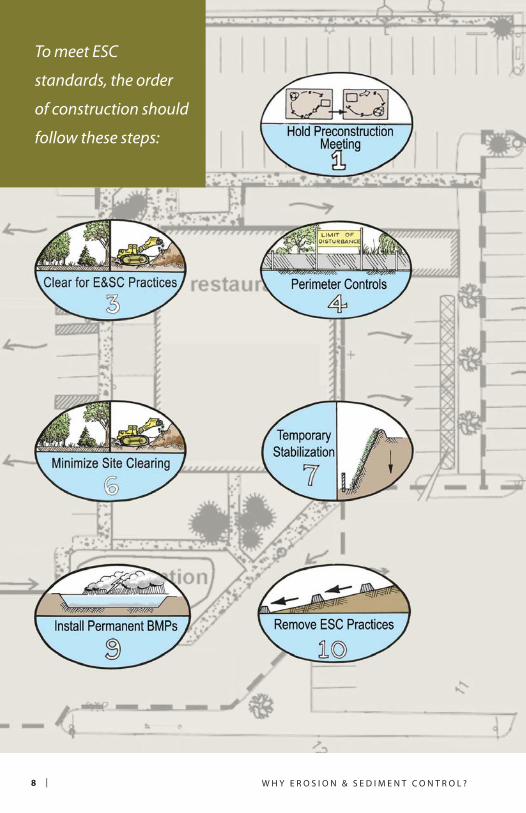
W H Y E R O S I O N & S E D I M E N T C O N T R O L ?8 |
To meet ESC
standards, the order
of construction should
follow these steps:

| 9E R O S I O N & S E D I M E N T C O N T R O L F I E L D G U I D E
Proper Construction Sequencing 1. Hold preconstruction meeting
2. Mark limits of disturbance
to protect waterway buffer,
existing vegetation, and
other resources
3. Clear/grub areas necessary to
construct ESC practices
4. Stabilize construction
entrance and install neces-
sary perimeter controls and
diversions
5. Install temporary sediment
trapping devices and runoff
conveyance systems
6. Complete clearing and rough
grading where necessary
(minimized and phased)
7. Provide temporary stabiliza-
tion with vegetation or mulch
for inactive, disturbed areas
8. Construct utilities, roads,
and buildings
9. Convert/install permanent
stormwater practices
10. Remove temporary
ESC devices
11. Stabilize with permanent
vegetation(Adapted from: Center for Watershed Protection)

W H Y E R O S I O N & S E D I M E N T C O N T R O L ?1 0 |
Contractor ResponsibilitiesIt is the job of the contractor to:
Be trained in ESC standards, practice installation, and maintenance procedures.
Install ESC practices according to the ESC plan.
Follow appropriate construction sequencing.
Educate operators and site workers on the importance of proper ESC practices.
Protect waterways, trees, and other natural areas from construction activities.
Inspect ESC practices routinely, especially after rainfall events.
Make sure practices are maintained, repaired, and reinstalled when necessary.
Communicate with supervisor and/or inspector any concerns related to ESC.
Properly remove practices at end of construction only after site is permanently stabilized.
Inspector ResponsibilitiesIt is the job of the site inspector to:
Understand regulations affecting construction site activities and proper ESC practice application.
Be familiar with the approved ESC plan, construction sequencing, and specifications.
Communicate expectations for cooperative ESC implementation.
Inspect site weekly, within 24 hours of major rainfall event, and at critical points during the construction process.
Anticipate where ESC problems may occur.
Ensure ESC practices are properly installed, maintained, and performing adequately. Provide input for improvement or minor modifications in the field.
Maintain detailed records of inspections with reports, photos, and rainfall records.
Establish clear time frames for corrective actions to be completed. Follow up.
Initiate any enforcement actions.

CHAPTER
Buffer and Tree Protection
Stabilized Construction Entrance
Silt Fencing
Silt Fence Alternatives
Turbidity Curtain
Before extensive clearing
and grading occurs, barriers
should be installed at vehicle
entrances and at key perimeter
locations to keep sediment
from leaving the site.
S E D I M E N T B A R R I E R S2 CHA
PTER
2


| 1 1E R O S I O N & S E D I M E N T C O N T R O L F I E L D G U I D E
B U F F E R A N D T R E E P R O T E C T I O N
DefinitionDuring construction activities, measures should be taken to ensure natural areas remain undisturbed. Where possible, clearing should be limited to areas needed to construct buildings, roadways, cisterns/septic tanks, and utilities. Preservation of natural vegetation, steep slopes, and buffers helps minimize erosion, protects water quality, and is cost-effective.
Design & InstallationBefore clearing, mark areas to be preserved. Use temporary wood fencing, plastic construction fencing, flagging, and/or signage.
Install fencing outside of the 50-foot buffer zone and outside of tree dripline to protect roots.
Locate temporary roadways, stockpiles, and layout areas to avoid stands of trees, shrubs, and grass.
Instruct all workers to honor protective devices.
Prohibit heavy equipment, vehicular traffic, or storage of construction materials within the protected area.
Consider the impact of grade changes to vegetation and roots.
Do not remove until site cleanup and final stabilization is complete.
Maintenance RequiredDuring construction, the limits of disturbance should remain clearly marked at all times. Verify that protective measures remain in place. Restore damaged protection measures immediately. Serious tree injuries shall be attended to by a tree specialist.
Common ProblemsProtected areas not clearly
marked. Use construction fencing and signage.
Sediment discharges into protected
area. Remove deposited sediment and install proper ESC practices.
Large tree roots cut or exposed. Extend fencing beyond dripline to protect roots. Remove the ends of damaged roots with a smooth cut. Cover exposed roots with soil.
Soil compacted over roots. Aerate soil by punching holes 12 inches deep, 18 inches apart.

1 2 | S E D I M E N T B A R R I E R S
Good use of highly visible
construction fencing to mark
limit of disturbance. Additional
bilingual signage installed to
identify area as protected.
Good combination of
construction and silt fencing
to protect steep slope area.
Minimize clearing and grading
as much as possible. = good use of practice = poor use of practice
Failure to adequately maintain/protect 50-foot
stream buffer from construction activities.
Encroachment reduces buffer filtering capacity
and can lead to in-stream sediment deposition.
Wooden frame with construction fence to
protect tree from heavy equipment and debris.
Fence does not fully extend beyond tree dripline
in this example leaving roots unprotected.

| 1 3E R O S I O N & S E D I M E N T C O N T R O L F I E L D G U I D E
S T A B I L I Z E D C O N S T R U C T I O N E N T R A N C E
DefinitionStabilized construction entrances are temporary crushed rock/coral pads located at all points where vehicles enter or leave a construction site. The purpose of a stabilized entrance is to reduce the tracking of sediment/mud from the site onto paved roads and parking lots.
Design & InstallationLocate entrance to provide for maximum use by all construction vehicles.
Place woven or non-woven geotextile fabric over entire area to be covered with rock (see Palau Stormwater Management Manual for fabric specifications for heavy duty vs. light duty roads).
Spread minimum 6-inch thick layer of 1- to 4-inch rock , or reclaimed/recycled concrete equivalent on top of fabric.
Minimum width of entrance should be 12 feet (24 feet if only access point), but not less than the full width of access point. Ends should be tapered to meet street.
Minimum length of 50 feet (30 feet on single residential lots).
Piping of surface water under entrance or a moundable berm shall be provided as required (Figure 2.1).
When necessary, wheels should be cleaned to remove sediment prior to leaving site. If a washing area is required, drainage should be directed to a sediment trap rather than storm drains, ditches, or watercourses.
Use available crushed rock/
coral or recycled concrete
equivalent for temporary
construction entrance.

1 4 | S E D I M E N T B A R R I E R S
Maintenance RequiredThe condition of crushed rock/coral should be monitored periodically and maintained after heavy use or heavy rainfall to prevent tracking or flowing of sediment onto rights-of-way. This may require periodic top dressing with additional rock.
All sediment spilled, dropped, or washed onto public rights-of-way must be removed immediately and more rock/coral added as needed.
Common ProblemsCrushed rock/coral compacted
into ground. Install layer of fabric underneath and reapply rock/coral.
Crushed rock/coral full of
sediment. Wash or top-dress with additional rock/coral.
Vehicles going around stabilized
entrance. Be sure to taper edges to street. Expand entrance width or install barriers to direct traffic to entrance.
Figure 2.1. Stabilized construction entrance with optional mountable berm.

| 1 5E R O S I O N & S E D I M E N T C O N T R O L F I E L D G U I D E
Entrance is paved and slopes back towards site.
Hoses (on left) are provided for washing tires;
however, tracks indicate infrequent compliance.
Stabilized entrances are supposed to be tempo-
rary. Drainage should be directed to a sediment
trapping device.
Good example of a stabilized entrance pad.
Fabric is installed beneath rock layer. Fencing used
to keep traffic on pad and block sediment from
surrounding area (Source: University of Illinois).
Sediment accumulation shows
that entrance has not been
maintained. Fabric was not
used beneath rock layer to
prevent sinking. Rock should
be washed or re-applied.

1 6 | S E D I M E N T B A R R I E R S
S I LT F E N C I N G
DefinitionA temporary barrier of geotextile fabric, silt fencing is installed across a slope, around stockpiles, or along a perimeter. The purpose of a silt fence is to intercept sediment-laden runoff from small drainage areas of disturbed soil, slow runoff velocity, and allow sediment to settle out.
Design & InstallationInstall before extensive land clearing activities begin.
Place fencing close to disturbed area, but ~10 feet from toe of slope to allow for sediment build up and maintenance access. The area beyond the fence should be undisturbed or stabilized.
Install perpendicular to flow direction. Turn ends uphill to prevent bypass of water around fence.
On long slopes, install multiple rows of fencing at separation distances based on slope steepness (Table 2.1 and Figure 2.3).
Silt fence should receive only
sheet flow, not concentrated flow.
Dig 4-inch wide by 6-inch deep trench. Install posts every 5-10 feet on downhill side of trench at least 16 inches deep. Use “T” or “U” type steel or sturdy wooden posts (3 square inch cross section).
Place fabric along bottom of trench. Attach to posts with wire or plastic ties every ½ foot. Fold and tie posts together to overlap fabric at ends.
Backfill trench with soil and compact.
Reinforce fabric with heavy wire support fencing to prevent collapse where necessary (Figure 2.2).
Silt fences often fail due to
poor installation or lack
of maintenance.
Slope SteepnessMaximum
Length (ft)
2:1 25
3:1 50
4:1 75
5:1 or flatter 100
Table 2.1. Distance Between Rows

| 1 7E R O S I O N & S E D I M E N T C O N T R O L F I E L D G U I D E
Maintenance RequiredInspect daily. Repair if sagging, flapping, or bulging is noticeable, or if erosion or spillover is observed. Remove sediment and debris when build up reaches ⅓ height of fencing. If site is inactive, continue to inspect after every rain event.
Common Problems Not maintained. Should be inspected daily. Remove accumulated sediment when buildup is ⅓ height of fence, and replace torn fabric immediately.
Not trenched properly. Reinstall to prevent flow from going underneath.
Stakes placed on uphill side of
fence. Reinstall stakes 5-10 feet apart on downhill side.
Installed across concentrated flow
path (i.e. swale or stream). Identify source of concentrated flow and re-evaluate placement of silt fence. Use different ESC practice.
Flow overtops or bypasses
fencing. Add uphill row of fencing, add wire support, or turn ends uphill.
Figure 2.2. Silt fence installation with wire mesh support.

1 8 | S E D I M E N T B A R R I E R S
Figure 2.3. Reasons Silt Fences Fail (Adapted from: Center for Watershed Protection)
Silt fence is not aligned parallel to slope contours.
Fence receives concentrated flow.
Spacing between posts is too great.
Fence not properly trenched into ground.

| 1 9E R O S I O N & S E D I M E N T C O N T R O L F I E L D G U I D E
Sediment deposits behind fence not removed in time to prevent failure.
Fence placed uphill of disturbed area.
Slope and/or length of slope too great for fence.
Ends do not curve uphill to prevent bypass.

2 0 | S E D I M E N T B A R R I E R S
Good use of fencing around
stockpile. Area outside of
fencing is stabilized with grass.
Leave enough space behind
fence for maintenance access.
The bottom of silt fencing
should be securely trenched,
not covered with a thin layer
of dirt. Trench should be at
least 6-8 inches deep, back-
filled, and compacted.
Concentrated flow down this slope and improper
use/installation of the silt fence have resulted in
practice failure and sediment discharge beyond
the site. Install multiple rows of fence on slopes.
Workers installing silt fence along the perimeter
of construction area. Be sure to locate fencing
based on ESC needs, not just placed around the
property boundary.

| 2 1E R O S I O N & S E D I M E N T C O N T R O L F I E L D G U I D E
S I LT F E N C E A LT E R N A T I V E S
DefinitionBecause of the high failure rate and extensive maintenance burden of silt fences, consider using some of these alternatives:
Earth berms: Linear barrier of compacted soil used to block or divert runoff (see Chapter 3, Diversion Berms).
Compost socks: Mesh tubes (also called filter socks or tubes) filled by blower with organic or wood
mulch. They can be used around site perimeters, as conveyance checks, and as inlet protection (Figure 2.4).
Silt dikes: Reusable, triangular, foam product covered in geotextile used along perimeters, curbs, and as check dams.
Design, Installation, & Maintenance Follow manufacturer’s installation and maintenance instructions.
Figure 2.4. Typical filter sock installation (Adapted from: Iowa Statewide
Urban Design and Specifications Manual).

2 2 | S E D I M E N T B A R R I E R S
An alternative for small sites,
silt dikes are relatively easy to
install, are resistant to drive-
overs, and are potentially
reusable. Note sediment line
on backside of dike.
Construction fencing is not
an approved alternative to
silt fence.
Earth berms are commonly used in Palau, and
can be effective sediment barriers and diversion
practices when installed correctly (see Chapter 3 on
Diversion Berms). Berms should only be used on flat
or shallow slopes, if used as a “trap.”
Socks can be used on slopes, but remember
to properly maintain practice by removing
excessive sediment that has built up behind it.

| 2 3E R O S I O N & S E D I M E N T C O N T R O L F I E L D G U I D E
DefinitionA turbidity curtain is a flexible, floating barrier used to contain suspended sediment along a shoreline or within a waterbody for a short period of time. This curtain has a flotation system at the top and is weighted or anchored at the bottom.
Design & InstallationVarious types are available, see manufacturer’s instructions for your application.
Do not use across flowing waters. Use in calm water surfaces.
Curtain height shall be 20% greater than current water depth to allow for changing water levels.
Remove obstacles and debris from area prior to installation.
Locate around perimeter of construction site and firmly anchor in place. Place shoreline anchors outside of areas to be disturbed by construction equipment (Figure 2.5).
For shallow installations, curtain can be secured by staking rather than using flotation system.
Anchor curtain toe as needed depending on wave action and boat traffic.
Maintenance RequiredInspect curtain weekly, and check anchors and attachments after heavy winds or wave action. All floating debris shall be removed to prevent damage to the curtain. Any problem or failure of the curtain must be repaired immediately.
When removal of sediment deposited behind curtain is necessary, remove by hand. Allow 24 hours for sediment to settle before removing the curtain. Remove curtain by carefully pulling it towards shoreline to minimize the release of remaining sediment. All removed silt should be disposed of properly.
T U R B I D I T Y C U R T A I N
The turbidity curtain is the
last line of defense for land-
based construction runoff,
and is used in conjuction
with other ESC practices on
site .

2 4 | S E D I M E N T B A R R I E R S
Turbidity curtain being
used to protect waterway
during shoreline stabilization
projects. See manufacturer’s
instructions for installation
and design specifications.
Good use of curtain to contain erodible stockpile
along shoreline. Erodible materials should not
be stored in waterway regardless of ESC practice
usage. Be sure to firmly anchor ends of curtain to
shoreline.
Figure 2.5. Typical turbidity curtain with flotation and anchoring devices.

CHAPTER
Diversion Berms and Swales
Check Dams
Vegetated and Lined Waterways
Sediment Traps and Basins
Stabilized conveyance
systems can be used to divert
runoff into trapping devices
or around distrubed areas.
Ponding of runoff behind
dams allows sediment to
drop out before discharge.
D I V E R S I O N S
A N D T R A P S3 CHA
PTER
3


| 2 5E R O S I O N & S E D I M E N T C O N T R O L F I E L D G U I D E
DefinitionBerms and swales, depending on their location, can be used to divert “clean” runoff around disturbed areas, or to move “dirty” runoff to sediment traps.
Berms (also called earth berms or diversion dikes) are mounds of compacted soil placed at the top or base of slopes, along the site perimeter, or across exposed areas (Figure 3.1).
Swales are temporary channels used to convey runoff to a sediment trapping device (Figure 3.2).
Design & Installation Do not construct diversion practices outside the site boundary without legal permission.
Do not install diversions to redirect existing streams around your site.
All berms should be compacted by heavy equipment, except for the combined dike/swale (Figure 3.3).
Berms and swales should be stabilized within 1 week of installation.
All berms and swales must have a positive, uninterrupted grade to a
stabilized outlet. Typically minimum of 0.5% to 20% maximum slope (8% max on combined berm/swales, or if not using erosion control matting or riprap).
Outlets must slow runoff velocity to prevent erosion. Convey “dirty” runoff to a sediment trap.
Maintenance RequiredFull length of berms and swales should be inspected weekly and after every rain event in case of damage.
Common Problems1. Drainage area too large. Install
additional practices to reduce contributing drainage area and prevent erosion and overtopping.
2. Berms not stabilized. Stabilize exposed soils with temporary seeding, mulch, matting, or rock.
3. Erosion at outlets. Relocate or redesign outlet to slow runoff velocity and dissipate flow.
4. Too steep. Install matting or riprap to reduce erosion.
D I V E R S I O N B E R M S A N D S W A L E S

2 6 | D I V E R S I O N S A N D T R A P S
Figure 3.3. Combined berm/swale cross section.
Figure 3.2. Diversion swale cross section with 2:1 side slopes.
Figure 3.1. Earth berm cross section for different sized drainage areas.

| 2 7E R O S I O N & S E D I M E N T C O N T R O L F I E L D G U I D E
Good use of a diversion berm at the base of a
slope and along the perimeter to protect adja-
cent natural areas from construction site runoff.
The berm was stabilized with erosion control
matting and grass seed.
This diversion swale directs
flows to a sediment trap. The
slopes and surrounding area
should be stabilized. Do not
use swales to divert streams.
Great use of an earth berm to collect and divert
runoff from the site into a stabilized outlet at the
top of a ponding basin (behind chain fence on
right). The berm should be stabilized with ero-
sion control blankets or vegetation.

2 8 | D I V E R S I O N S A N D T R A P S
C H E C K D A M S
D I V E R S I O N S A N D T R A P S
DefinitionSmall check dams constructed of rock/coral, bagged sand, compost tubes, or other durable materials are placed across an open drainage channel to reduce erosive runoff flows and allow sediment to settle out.
Design & InstallationMaximum 2 acres drainage to the dam.
Anchor check dams in the channel by a cutoff trench 1 ½ feet wide by ½ foot deep and lined with filter fabric.
Use a well-graded rock matrix 2 to 9 inches in size. For other materials, follow manufacturer’s specifications.
Height of check dam less than 2 feet. Center shall be 9 inches lower than sides at natural ground elevation (Figure 3.4). Side slopes shall be 2:1 or flatter. Be sure to tie into banks.
Space dams as directed in site plan. The top of the downstream dam should be at the same elevation as the toe of the upstream dam (Table 3.1).
Maintenance RequiredThe check dams should be inspected after each runoff event. Correct all damage immediately. Replace rocks as needed. Make sure culverts or other structures are not blocked by displaced check dam rocks.
Common ProblemsErosion occurring between
structures. Evaluate spacing. Install erosion control liner.
Sediment accumulation behind
dams. Remove sediment behind dam to allow channel to drain and prevent overtopping.
Dams dislodged by heavy flow.
Reduce drainage area or install additional check dams. Use larger size rock. Better anchoring.
Slope Spacing (ft)
< 2% 80
2.1–4% 40
4.1–7% 25
7.1–10% 15
>10% lined waterway
Table 3.1. Standard spacing (MDE, 1994).

| 2 9E R O S I O N & S E D I M E N T C O N T R O L F I E L D G U I D E
Rock supported silt fence is not a proper design
for check dams. This check does not fully extend
across ditch, causing bypass of flow and erosion
along edge.
Remove sediment when build
up is ½ height of check dam to
prevent overtopping. The center
of the check should be lower than
the ends to avoid run around.
Figure 3.4. Proper spacing and cross section of rock check dam.

3 0 | D I V E R S I O N S A N D T R A P S
V E G E T A T E D A N D L I N E D W A T E R W A Y S
DefinitionVegetated or lined channels are used to safely convey flows from stabilized areas or outlets without damage from erosion. Waterways are typically stabilized with grass, erosion control matting, rock rip rap, gabions, or concrete depending on slope, soil, and runoff velocity.
Table 3.1 summarizes some key features of vegetated versus lined waterways.
Design & InstallationClear foundation of trees, stumps, roots, loose rock, or other objectionable material.
Excavate and install as shown on the plans (Figure 3.5). Backfill over-excavated areas with moist soil compacted to the density of the surrounding material.
Do not allow abrupt deviations from design grade or horizontal alignment.
Stabilize channels according to specifications.
Vegetated Waterways Lined Waterways
May require subsurface drainage or
additional outlets to reduce
wet spots.
Seed with grass as soon as practical if
low gradient (<3% slope).
Use sod and erosion control matting,
particularly along centerline at mod-
erate gradient (3-6% slope).
Vegetation must be established
before use.
Used when vegetation will not
prevent erosion (>6% slopes).
Steepness of side slopes based on
liner type (see Palau Stormwater
Management Manual)
Minimum lining thickness of 4 inches
for concrete lining, or 1½ times the
maximum rock size for rip rap.
Weep holes and underdrains should
be provided for concrete.
Table 3.1. Features of Various Waterways

| 3 1E R O S I O N & S E D I M E N T C O N T R O L F I E L D G U I D E
Follow manufacturer’s instructions for installing erosion control matting in channels (Figure 3.6).
Hard linings shall be installed as shown on the plans. Non-woven geotextiles and cutoff walls may be used to prevent undermining.
Do not use until fully stabilized.
Requires a stable outlet that does not cause erosion at discharge.
Maintenance RequiredPavement or lining should be maintained as built to prevent undermining and deterioration. Existing trees next to pavements should be removed, as roots can cause uplift damage. Vegetation next to pavement should be maintained in
good condition to prevent scouring if overtopped.
Common ProblemsVegetation not establishing.
Use erosion control matting or sod. Install additional outlets or underdrain system.
Out of bank flows are
problematic. Reduce flows to channel, or redesign.
Gullies forming in vegetated
channel. Use liner in centerline of vegetated channel.
Erosion beneath rock channels.
Make sure filter fabric was installed.
Figure 3.5. Grassed channel
cross sections.

3 2 | D I V E R S I O N S A N D T R A P S
Erosion control matting liner used in centerline
of channel to prevent erosion and help establish
vegetation.
Concrete lined waterways can
be used as permanent drainage
features, however vegetated
channels provide for better
water quality in the long term.
Figure 3.6. Diagram of erosion control matting used to line channel. (Adapt-
ed from State of California DOT Construction Site BMPs Manual, 2003)

| 3 3E R O S I O N & S E D I M E N T C O N T R O L F I E L D G U I D E
S E D I M E N T T R A P S A N D B A S I N S
DefinitionLarge basins and small traps are temporary ponding structures used to collect runoff and allow sediment to settle out before runoff leaves site. Basins and traps are formed by an embankment and/or excavation.
Design & InstallationConstruct before clearing and grubbing activities begin. Clear embankment area of all vegetation and debris.
Locate traps (Figure 3.7) and basins (Figure 3.8) to obtain maximum storage, ease cleanout, and
minimize interference with construction activities.
Design and construction of embankments, basins, and traps must comply with all engineering specifications (Table 3.2).
Maximize distance between inlet and outlet.
All pipe connections should be watertight.
Install water-permeable covers on basins to prevent trash and debris from clogging pipe. Dewatering holes in base of riser should be
Basins Traps
Max Drainage Area 100 acres 5 acres
Size 5,500 cubic ft/acre of drainage; >2:1 length to width
Dam Height 10-15 ft max. 5 ft max.
Dam Width 8-10 ft min. 4 ft min.
Dam Side Slopes 2.5:1 or flatter 2:1 or flatter
Outlet Riser with spillway Riser or grass/rock outlet
Riser Height2 ft below top of dam, 1 ft below spillway.
1 ½ ft below top of dam
Status Temporary or Permanent Temporary
Table 3.2. Differences Between Basins and Traps

3 4 | D I V E R S I O N S A N D T R A P S
covered by filter fabric or rock. No holes allowed in horizontal barrel.
Traps should have perforated risers wrapped in wire and filter cloth. Do not cover top of riser. No perforation within 6 inches of horizontal barrel allowed.
Outlets should be constructed and maintained to prevent sediment from leaving the trap and erosion from occurring below dam.
Stabilize all side slopes, inlets and basin outlets (including spillway).
* If basin is permanent, temporary riser will need to be replaced with permanent water quality control outlet structure.
Maintenance RequiredRepair any damage daily. Remove sediment to original design volume when pool volume is reduced by half (mark height on riser). Dispose of sediment according to approved
Figure 3.7. Example of a pipe outlet sediment trap.

| 3 5E R O S I O N & S E D I M E N T C O N T R O L F I E L D G U I D E
site plan. In no case should removed sediments be disposed of in streams or other natural areas.
Do not remove basin until site has been fully stabilized for at least 30 days. Remove water by pumping or cutting riser prior to removing dam. Do not allow sediment to flush into a stream or drainage way. Basin sediments must be removed, safely disposed of, and backfilled with a structural fill.
*If converting to permanent practice, basin should be cleaned of deposited sediment and re-graded to meet new design specifications.
Common ProblemsOutlet pipe clogged with debris.
Clean pipe, install filter fabric or trash rack cover.
Basin slopes eroding. Stabilize slopes with rock, vegetation, or matting. Pay close attention to inlets.
Excessive sediment buildup. Remove sediment to retain holding capacity. Do not allow sediment to build up higher than 1 foot below spillway.
Upstream drainage too large.
Have engineer check drainage area calculations. Use other or additional practices.
Figure 3.8. Sediment basin spillway profile.

3 6 | D I V E R S I O N S A N D T R A P S
Large sediment basin to be converted to permanent
stormwater practice once construction complete
and accumulated sediment is removed. Good dis-
tance from inlet on right with rock apron to outlet
riser. Good stabilization of side slopes and spillway.
This sediment trap has a perforated riser with no
filter cloth protection to filter out sediment and
trash before water is discharged. Side slopes are
not stabilized with vegetation, and there is ero-
sion occurring at the inlet point (not shown).

CHAPTER
Stabilization with Vegetation, Mulch, or Topsoil
Surface Roughening
Pipe Slope Drains
Erosion Control Blankets
Aggressive protection of
slopes is critical since
erosion can occur rapidly
and contribute to extensive
sediment transport and
slope instability.
S T A B I L I Z A T I O N
P R A C T I C E S4 CHA
PTER
4


| 3 7E R O S I O N & S E D I M E N T C O N T R O L F I E L D G U I D E
S T A B I L I Z A T I O N W I T H V E G E TAT I O N , M U L C H , O R T O P S O I L
DefinitionCovering an area of bare ground with vegetation, topsoil, mulch, or erosion control blankets for temporary or permanent erosion prevention is critical. Temporary stabilization is often needed because grading operations can last several months and extend into or through the rainy season. Final stabilization will be required for project close out.
Vegetative cover can be established through a combination of seeding techniques, topsoil amendments, and mulching to conserve moisture and control weeds.
Design & Installation Stabilize bare areas that will be untouched for more than 7 days, after final grading, at completion of construction, or when waiting for optimal planting time.
Preserve existing topsoil in place where possible. Stockpile topsoil from excavated areas for later use.
Complete rough and final grading. Remove large woody debris and other litter.
Compact all fill material and roughen surface at least 12 inches deep in the area to be seeded.
Amend soil and add fertilizer where necessary.
Evenly apply seed mix per site plan specifications. Suitable plants include fast-growing and hardy species, such as grasses and legumes (Table 4.1).
Apply mulch or chemical stabilizers at specified application rates after or in combination with seeding (hydroseeding). Tackifiers are useful on slopes to help anchor soils and seed mixes.
As needed, install erosion control blankets to protect areas being stabilized.
Maintenance RequiredIrrigate as necessary to establish plants. Reapply seed, mulch, or topsoil as needed to provide uniform stabi-lization. Maintain associated ESC practices to protect stabilization area until plants are fully established.

3 8 | S T A B I L I Z A T I O N P R A C T I C E S
Common Name Scientific Name/Cultivar Planting Rate***
Bermuda grass Cynodon dactylon 35 lbs/PLS/ac
Carpet grass Axonopus affinis 40 lbs/PLS/ac
Centipede grass ** Eremochloa ophiuroides 20 lbs/PLS/ac
Kikuyu grass** Pennisetum clandestinum 10 lbs/PLS/ac
Pangola grass Digitaria decumbens, 80 bu/ac
Tropic lalo paspalum Paspalum hieronymii 80 bu/ac
St. Augustine grass** Stenotaphrum secundatum 80 bu/ac
Zoysia grass Zoysia japonica 80 bu/ac
Table 4.1. Common Grasses Suitable for Stabilizing Waterways and Exposed Soils
(Source: 2008 NRCS Pacific Island Vegetation Guide and 2010 Palau Stormwater
Management Manual)*
* List is not all-inclusive. Ideal species for seeding and stabilizing disturbed areas should
be fast growing, non-invasive, tolerant of low fertility soils, and readily available. Seed
availability is limited in Palau.
**May have potential to become invasive.
***Pure Live Seed (PLS). One bushel (bu) equals 1.25 cu. ft. May need to double these seeding rates when hydroseeding.

| 3 9E R O S I O N & S E D I M E N T C O N T R O L F I E L D G U I D E
Formation of gullies and rills
due to lack of stabilization.
Presence of weeds indicates
that soil has been exposed for a
long period of time.
A combination of erosion con-
trol blanket and coir fiber logs
with live plugs are used here to
establish shoreline vegetation.
Good use of hydroseed and coir fiber logs on
an exposed slope to help quickly establish
vegetative cover. Any areas of bare soil that will
not be touched for more than 7 days should be
temporarily stabilized. Permanent stabilization is
required at the end of the construction period.
Topsoil may be required in poor soil conditions.
Here topsoil was spread evenly across surface to
be seeded. Grass has started to grow. Consider-
ation should be given to irrigation requirements
for plant establishment, particularly during the
dry season.

4 0 | S T A B I L I Z A T I O N P R A C T I C E S
DefinitionSurface roughening is a simple method to slow runoff and minimize by creating horizontal grooves, depres-sions, or steps that run parallel to the contour of the land. Surface roughen-ing should be done in conjunction with other stabilization activities. Roughening measures include:
Tracking: Driving a crawler tractor up and down a slope, leaving the cleat tracks parallel to the slope
contour (Figure 4.1). This is the most convenient, but least effective of the roughening measures.
Stair-step grading: Cutting stair-steps into slopes. Each step slopes towards the vertical wall (Figure 4.2). This works well with soils containing large amounts of small rock.
Grooving: Use disks, spring harrows, or teeth on the bucket of a front-end loader to create series of small ridges and depressions.
S U R F A C E R O U G H E N I N G
Figure 4.1. Tracking with bulldozer (Source: US Army Corps of Engineers,1997).

| 4 1E R O S I O N & S E D I M E N T C O N T R O L F I E L D G U I D E
Design & InstallationPerform surface roughening as soon as possible after the vegetation has been removed from the slope.
Use with temporary seeding and temporary mulching to stabilize an area.
Avoid excessive compacting of the soil surface when tracking, since soil com-paction inhibits vegetation growth and causes higher runoff rates.
When step-grading, ratio of vertical cut to horizontal distance should not be steeper than 1:1. Maximum step width/height is 4 feet.
For slopes steeper than 3:1 but less than 2:1, grooving should be used. Install grooves a minimum of 3 inches deep and maximum 15 inches apart.
Maintenance RequiredMay need to reapply at the end of each day until other stabilization practices are installed. Inspect every 7 calendar days and within 24 hours after major rainfall event. If rills appear, re-grade and re-seed immediately.
Figure 4.2. Stair-step grading to protect slopes.
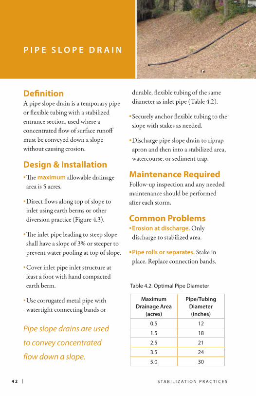
4 2 | S T A B I L I Z A T I O N P R A C T I C E S
DefinitionA pipe slope drain is a temporary pipe or flexible tubing with a stabilized entrance section, used where a concentrated flow of surface runoff must be conveyed down a slope without causing erosion.
Design & InstallationThe maximum allowable drainage area is 5 acres.
Direct flows along top of slope to inlet using earth berms or other diversion practice (Figure 4.3).
The inlet pipe leading to steep slope shall have a slope of 3% or steeper to prevent water pooling at top of slope.
Cover inlet pipe inlet structure at least a foot with hand compacted earth berm.
Use corrugated metal pipe with watertight connecting bands or
durable, flexible tubing of the same diameter as inlet pipe (Table 4.2).
Securely anchor flexible tubing to the slope with stakes as needed.
Discharge pipe slope drain to riprap apron and then into a stabilized area, watercourse, or sediment trap.
Maintenance RequiredFollow-up inspection and any needed maintenance should be performed after each storm.
Common ProblemsErosion at discharge. Only discharge to stabilized area.
Pipe rolls or separates. Stake in place. Replace connection bands.
P I P E S L O P E D R A I N
Pipe slope drains are used
to convey concentrated
flow down a slope.
Table 4.2. Optimal Pipe Diameter
Maximum
Drainage Area
(acres)
Pipe/Tubing
Diameter
(inches)
0.5 12
1.5 18
2.5 21
3.5 24
5.0 30

| 4 3E R O S I O N & S E D I M E N T C O N T R O L F I E L D G U I D E
Figure 4.3. Pipe slope drain discharging to sediment trapping device.
Lined waterways (see Chapter
3) are also used as a permanent
method to convey runoff down
slopes, although designs that
prevent concentrated flows
down slopes are preferred.
Flexible pipe slope drain used to convey
concentrated flow down slope. Note placement
of large rocks to slow velocity at discharge point.
Drain may need to be anchored with stakes to
prevent movement.

4 4 | S T A B I L I Z A T I O N P R A C T I C E S
DefinitionTemporary erosion control blankets (also called matting) are used to hold seed and soil in place, particularly on steep slopes. There are many types of products available made of biodegradable or synthetic materials.
Design & InstallationGrade and compact area prior to installation.
Remove large rocks, soil clods, vegetation, and other sharp objects.
Amend soil, add fertilizer, and seed prior to installation.
Always install according to manufacturer’s specifications.
For slope installations:1. Dig anchor trench at top of slope
(Figure 4.5).
2. Extend end of blanket 6-12 inches beyond trench. Using staples/stakes, fasten blanket into trench. Backfill with soil and compact. Cover backfill with remaining edge of blanket and fasten on downhill side of trench.
3. Unroll matting down slope, ensuring direct contact with ground. Overlap edges a minimum of 3-6 inches.
4. Fasten with stakes/ staples per manufacturer’s specification. Do not stretch.
Maintenance RequiredRegular inspections should be made to identify cracks or tears in fabric, which should be repaired or replaced immediately. Synthetics may degrade in sunlight.
Common Problems Blanket slipping down slope.
Re-anchor at top of slope. Use manufacturer’s staples/stakes and stapling pattern.
Erosion occurs underneath the
material. Make sure material is in contact with the ground.
E R O S I O N C O N T R O L B L A N K E T S
Always install erosion
control matting according to
manufacturer’s specifications.

| 4 5E R O S I O N & S E D I M E N T C O N T R O L F I E L D G U I D E
Figure 4.5. Erosion control blanket (Adapted from: State of California DOT
Construction Site BMPs Manual, 2003).

4 6 | S T A B I L I Z A T I O N P R A C T I C E S
Erosion control blanket was not installed verti-
cally down slope and does not cover lower half
of exposed bank. Disturbed areas above slope
should also be stabilized. Good use of silt fence
to protect top of slope.
Good coverage of slope with geotextile matting.
Inspect routinely to make sure material is not
torn, particularly if woody vegetation starts to
grow up through material. Consider benefits of
biodegradable vs synthetic materials.

CHAPTER
Inlet protection practices
allow for the piped
drainage network to be
“turned off” until the site is
stabilized and temporary
ESC practices removed.
I N L E T A N D O U T L E T P R O T E C T I O N5
Inlet Protection
Rock Outlet Protection
Level Spreader
CHA
PTER
5


| 4 7E R O S I O N & S E D I M E N T C O N T R O L F I E L D G U I D E
DefinitionVarious inlet protection devices can be used as temporary structures to keep silt, sediment, and construction debris from entering storm drains through open inlets. Practices should trap sediment while allowing water to slowly flow over or through materials.
Design & InstallationInstall protection device per specifications on site plan.
Do not use in place of sediment traps, diversions, or other ESC practices.
Limit drainage area to 1 acre or less per inlet device.
The top elevations of these practices should provide storage and minimize bypass flow.
Do not remove until drainage area is permanently stabilized.
Excavated Drop Inlet Protection
Excavate side slopes less than 2:1.
Depth should be between 1 to 2 feet as measured from top of inlet.
Provide weep holes, protected by fabric and/or rock, to drain temporary pool (Figure 5.1).
Fabric Drop Inlet Protection
Use approved filter fabric cut from continuous roll to avoid joints.
The maximum height of the fabric above the inlet crest shall not exceed 1 ½ feet unless reinforced. Stake material using 2x4 inch wood or equivalent metal.
Support stakes for fabric should be 3 feet long, spaced a maximum 3 feet apart.
Drive stakes into ground a minimum of 18 inches as close to the inlet as possible.
Trench fabric 1 foot and back fill. Fasten to stakes.
*Rock/coral protection on outside of fabric can be added if available.
I N L E T P R O T E C T I O N

4 8 | I N L E T A N D O U T L E T P R O T E C T I O N
Block and Rock Drop Inlet Protection
Double stack rows (1-2 feet above top of inlet) of concrete blocks around drop inlet. Do not use mortar. Recess the first row of blocks 2 inches below the top of inlet (Figure 5.2).
Orient a few blocks on bottom row for dewatering. Cover openings with cloth or wire mesh to support rock.
Use clean rock or crushed-coral ½-¾ inch diameter placed 2 inches below top of block on 2:1 slope or flatter.
Curb Inlet Protection
Install pre-fabricated products in front of curb inlet opening, extending 2 feet on either side. Allow for overflows at top into catch basin. Follow manufacturer’s specifications.
For block and rock curb inlet protection, place single row of concrete blocks across inlet opening with open ends facing outward. Place wire mesh over open ends of blocks to support rocks. Pile washed rock (<3 inch diameter) against mesh to top of blocks.
For fabric and rock protection, install wooden frame with spacers
Figure 5.1. Excavated drop inlet protection with weep holes.
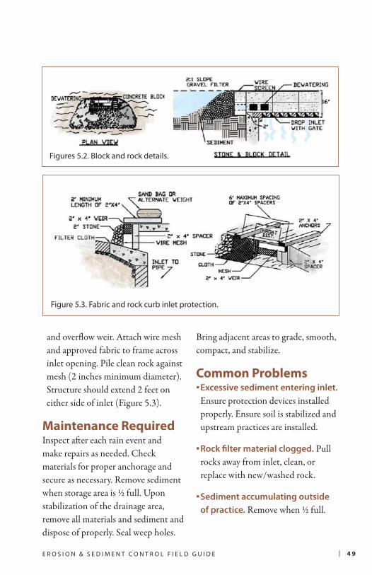
| 4 9E R O S I O N & S E D I M E N T C O N T R O L F I E L D G U I D E
and overflow weir. Attach wire mesh and approved fabric to frame across inlet opening. Pile clean rock against mesh (2 inches minimum diameter). Structure should extend 2 feet on either side of inlet (Figure 5.3).
Maintenance RequiredInspect after each rain event and make repairs as needed. Check materials for proper anchorage and secure as necessary. Remove sediment when storage area is ½ full. Upon stabilization of the drainage area, remove all materials and sediment and dispose of properly. Seal weep holes.
Bring adjacent areas to grade, smooth, compact, and stabilize.
Common Problems Excessive sediment entering inlet.
Ensure protection devices installed properly. Ensure soil is stabilized and upstream practices are installed.
Rock filter material clogged. Pull rocks away from inlet, clean, or replace with new/washed rock.
Sediment accumulating outside
of practice. Remove when ½ full.
Figures 5.2. Block and rock details.
Figure 5.3. Fabric and rock curb inlet protection.

5 0 | I N L E T A N D O U T L E T P R O T E C T I O N
Poor installation and mainte-
nance of wire mesh. Rock
missing on two sides of inlet.
Use fabric with wire to help
filter sediment.
Fabric liner inserted behind
grate. Because tearing is com-
mon, this practice will require
daily inspection and repair.
Failure to provide any form of inlet protection.
Silt and debris from construction site is conveyed
to entrance of inlet from road and unstabilized
areas and is then directly discharged.
This prefabricated product is not suited for this
type of inlet structure. Good extension of device
on either side of inlet, however “dirty” flows enter
drain directly through grated opening. Consider
covering with wire mesh/fabric and/or rock.

| 5 1E R O S I O N & S E D I M E N T C O N T R O L F I E L D G U I D E
DefinitionRock should be placed around and below an outlet to stabilize the outlet, reduce the depth and velocity of discharge waters, and prevent downstream erosion. Outlet protection applies to culverts, outfalls from basins, and other conduits.
Design & InstallationDesign depends on the location (not at top of cuts or on slopes >10%) and tailwater depth. Follow specifications from approved drawings.
Prepare subgrade as specified. Compact fill to density similar to surrounding material.
Outlet aprons should be straight and flat. The end of the apron should be at same elevation as receiving channel or ground (Figure 5.4).
Use rock riprap composed of a well-graded mixture of rock size specified in ESC plan.
Apply layer of approved filter material between riprap and underlying soil surface. Overlaps should be >1 foot.
Place rock with equipment in one operation. Avoid displacement of, or damage to, underlying material. Follow with hand placement when necessary.
Place rock around and above outlets with no headwalls (Figure 5.5).
Maintenance RequiredOnce a riprap outlet has been installed, the maintenance needs are very low. It should be inspected after high flows for evidence of scour beneath the riprap or for dislodged rocks. Repairs should be made immediately.
Common ProblemsHigh flows cause scour.
Replace filter fabric and rearrange rock appropriately.
Riprap dislodged. Replace by hand.
Ripped filter cloth. Cover with another piece of cloth or replace.
Riprap filled with sediment.
Evaluate upstream ESC practices. Remove sediment by hand.
R O C K O U T L E T P R O T E C T I O N

5 2 | I N L E T A N D O U T L E T P R O T E C T I O N
Figure 5.4. Riprap outlet protection for discharge to unconfined section.
Figure 5.5. Protect outfalls without headwalls (Source: British Columbia, 2001).

| 5 3E R O S I O N & S E D I M E N T C O N T R O L F I E L D G U I D E
To help stabilize rock apron and reduce
undermining, filter fabric should be placed below
the layer of riprap, not on top as shown here.
This outlet is discharging to
a non-stable area on a slope,
which will result in erosion and
undermining of pipe structure.
This muddy discharge also
indicates a general lack of
compliance with ESC standards.
This outlet and surrounding
area is well stabilized with rock
and grass. A little sediment is
depositing in the apron.
Good protection for outfall without a headwall.
Discharge is dissipated in rock-lined pool which
will then discharge as sheet flow to adjacent
wetland. Berm behind outlet pipe is well
stabilized with vegetation.

5 4 | I N L E T A N D O U T L E T P R O T E C T I O N
DefinitionLevel spreaders are temporary (or permanent) devices that take concentrated flow from a pipe, berm, or swale and release it evenly over a wider area to prevent erosion and promote infiltration. Particularly useful where sheet flow discharges through vegetated buffers are possible.
Design & Installation Install in an undisturbed or finished area. Do not install on fill, or above a slope steeper than 10%.
Maximum drainage area to spreader is 2.5 acres.
Minimum depression depth of 6 inches behind lip.
Spreader lip must be level (uniform height and zero grade) and reinforced with erosion control matting, concrete, or gravel.
Runoff entering spreader must not contain significant sediment. An upstream sediment removal practice, forebay, and/or energy dissipater at inlet may be required.
A level spreader should disperse onto a vegetated slope of less than 10:1.
The lip can be constructed of grass for low flows or timber/concrete for higher flows.
The length of the level spreader lip is dependent on the volume of water that must be discharged, but the minimum length for the level spreader lip is 6 feet.
Make sure area below level spreader is stabilized and uniform.
Maintenance Required Relatively low maintenance if installed correctly. Inspect regularly for sedi-ment removal in sump and erosion at inlet/outlet. Repair as needed.
L E V E L S P R E A D E R
Level spreaders convert
concentrated flow into
non-erosive sheet flow.

| 5 5E R O S I O N & S E D I M E N T C O N T R O L F I E L D G U I D E
Figure 5.7. Concrete and earth lipped level spreaders (Adapted from:
RI Stormwater Manual and NC State University).
Earthen lip
Concrete lip

5 6 | I N L E T A N D O U T L E T P R O T E C T I O N
Concentrated flows are collected in small forebay
and discharged into 6 inch deep “swale” before
overflowing concrete lip as sheet flow (Source: NC
State University).
Good application of level spreader at outfall from
large ponding basin. Flows plunge into small pool,
spread out evenly across level concrete lip, then
sheet flow from lip across gravel into grass (Source:
NC State University).

CHAPTER
ESC During Construction
Unpaved Roads
Road Maintenance
Road runoff, especially
from unpaved roads,
represents one of
the largest sources of
chronic sediment loading
to coral reefs.
M A N A G I N G R O A D
C O N S T R U C T I O N6 CHA
PTER
6


| 5 7E R O S I O N & S E D I M E N T C O N T R O L F I E L D G U I D E
ESC During Road ConstructionTemporary exposure of erodible soils during road construction and maintenance activities can impact water quality, road stability, and public safety.
Good road design and construction can minimize soil erosion and reduce drainage problems.
The challenge of road projects is that they are linear, space is limited, and there is an added element of traffic
management. Road projects are highly visible, so problems with ESC are noticeable to the public. Preventing erosion and controlling sediment requires use of ESC practices illustrated in Figure 6.1, including.
Sediment barriers along perimeter
Check dams in roadside ditches
Slope stabilization
Inlet protection
Outlet protection
Stockpile management
Traffic safety
Unpaved RoadsPermanently unpaved roads can be chronic sources of sediment. To reduce sediment loads coming off of unpaved roads:
Design roads for minimal disruption of drainage patterns.
Use outsloped roads with drain dips when fill slopes are stable.
Use insloped roads with ditches, water bars, and cross drains if steep enough (2-8%) to prevent sediment deposition and ditch erosion.
Vary road grades to reduce concen-trated flows. Space drainage struc-tures based on grade (Table 6.1).
Prevent sediment transport by using changes in road grade or recessed cut slopes.
Do not discharge drainage struc-tures onto erodible soils or fill slopes without outfall protection (rock piles, logs, etc.). Direct road drainage through vegetation or other sedi-ment trapping devices.
Surface with crushed rock/coral, concrete, or pavement if road is highly erodible or heavily used.

5 8 | M A N A G I N G R O A D C O N S T R U C T I O N
Exposed soils were hydroseeded
and temporary inlet protection
applied on road construction
project. Active roadway is clean
of sediment.
No erosion control provided and sediment is
directly entering stream through culvert.
Sediment tracked onto active roadway. No pro-
tective barrier blocking sediment from adjacent
natural areas.
Figure 6.1. Illustration of ESC practices used during road construction.
1.
2.
3.
4.
2
1
3
4

| 5 9E R O S I O N & S E D I M E N T C O N T R O L F I E L D G U I D E
5.
6.
7.
Pave roads as soon as feasible.
Good example of using wood
checks and rock fill to protect
edge of pavement and slow
down drainage.
Avoid situations where runoff from unpaved
roads drains directly to drop inlets. This inlet
will discharge sediment to waterways, and will
quickly become clogged with debris and sedi-
ment causing road flooding.
5
6
7

6 0 | M A N A G I N G R O A D C O N S T R U C T I O N
Broad-based dips are wide (~20 feet) depressions used to convey ditch
drainage across the road surface as sheet flow (Figure 6.2). Dips only work on roads with slopes <12%.
Water bars are narrow, earthen berms built across roads to divert road
surface runoff into vegetated areas (Figure 6.3). To install:
1. Excavate a trench at a 30- to 45-degree angle across the road. Trench outlet should be at least 3 inches lower than the upper end.
2. Build a berm on the downhill side of the trench (12 inch distance between berm top and trench bottom).
3. Extend water bars slightly beyond both ends of the road. Direct di-verted water into a stable, vegetated area, not into open water.
Cross drain and open-top culverts
intercept ditch or road surface runoff and divert flows across the road in underground pipes or grated trenches. Piped culverts should be no less than 12 inches in diameter, angled at 30-45 degrees, have 2% slope, and covered with fill at a depth of ½ pipe diameter (Figure 6.4). The entry and outlet of pipe should be armored with rock/coral or concrete.
Open-top culverts should be covered with a grate material that can handle vehicle loads.
Open-top culverts should
be of shovel-width to
ease maintenance.
Figure 6.2. Wide dips allow ditch
runoff to be directed by berms to
flow across road to stabile outlet.
Not for use on grades greater than
12% (Adapted from: Wisconsin
Department of Natural Resources).
Road Grade
Spacing (ft)
Water Bars Dips Cross
Drains
2% 250 300 135
5% 135 180 100
10% 80 140 80
15% 60Do not use
60
20% 45 45
25% 40 30
Source: HI DFW (2003) and VICES (2003); Coeur d’Alene RMP/EIS (2006)
Table 6.1. Optimal Structure Spacing

| 6 1E R O S I O N & S E D I M E N T C O N T R O L F I E L D G U I D E
Figure 6.3. Water bars divert surface flows and are not intended to intercept
roadside ditches (Source: British Columbia, 2001).
Figure 6.4. Cross drain and
open-top culverts carry
water under road surface
to stable discharge points
(Adapted from: University
of MN Extension Service).

6 2 | M A N A G I N G R O A D C O N S T R U C T I O N
Road MaintenanceTimely maintenance can prevent road-related sediment from entering streams and waterbodies.
Inspect the road system at regular intervals, especially after heavy rainfall, to detect problems and to schedule repairs.
Road surface erosion from ditch overflow indicates a need for unplugging culverts, cleaning ditches, additional cross drains or dips, or other ditch stabilization.
Remove debris from culverts, outlets, and catch basins particularly before rainy season.
Place the debris where it cannot be washed back into these structures or into open water.
Stabilize fill slopes and maintain roadside vegetation.
Keep traffic to a minimum during wet periods to reduce maintenance needs.
Grading (shaping) as necessary to maintain proper surface drainage, remove potholes or ruts, or mix surface rock and fines.
Grading should always push debris towards center of road for compacting or removal.
Debris should never be pushed to side where it will form a berm and cause more erosion/maintenance problems.
Avoid cutting the toe of cut slopes when grading roads or pulling ditches.
If dust control agents are used, keep compounds from entering waterways.

CHAPTER
Inspections and Maintenance
Managing Trash, Supplies, and Materials
Removing Temporary Practices
Permanent Stormwater Management
Routine maintenance
during construction and
proper removal of temporary
practices prior to final
site stabilization will help
ensure ESC compliance.
M A I N T A I N I N G
A N D C L O S I N G
O U T P R O J E C T S7 CHA
PTER
7


| 6 3E R O S I O N & S E D I M E N T C O N T R O L F I E L D G U I D E
Inspections and MaintenanceErosion and sediment control practices need to be inspected and maintained during all stages of the construction process to ensure proper function.
Routine maintenance by workers
on site may include:
Removing sediment tracked on to roads.
Visual inspection and repair of silt fences and inlet protection devices.
Replacing fencing and signage protecting trees and natural areas.
Removal of accumulated sediment in traps, behind check dams, and on rock outlet aprons.
Replacement of rock protection or filter fabric at outlets.
Filling of rills and gullies.
Irrigation for vegetative establishment.
Inspectors should:
Conduct inspections at required frequency (every 14 days), after storm events, and during key times during construction (installation and closeout).
Evaluate practice effectiveness.
Evaluate locations where drainage leaves site, particularly along waterways, natural areas, and public roads.
Use approved inspection forms and checklists if available (Table 7.1).
See maintenance requirements
for individual ESC practices as
described in Chapters 2–5.

6 4 | M A I N T A I N I N G A N D C L O S I N G O U T P R O J E C T S
A. ESC Plan Review Good Action Required
Practices shown on ESC plan
Practices installed as shown on ESC plan
Sequence of construction followed
B. Sediment Barriers
Silt fence, turbidity curtain, or other barrier
installed/maintained correctly
Construction entrance functions properly
Amount of sediment tracked onto roads or
deposited outside of barriers
C. Diversions
Berms stabilized and performing adequately
Swales/waterways constructed & functioning
Extent of erosion at outlets
D. Traps and Basins
Dams/overflows/risers constructed & functioning
Slopes stabilized, particularly at inlets
Level of sediment accumulation
E. Stabilization
Exposed soils and slopes protected from erosion
Good vegetative establishment
Erosion control matting/Pipe slope drains or
other practice installed/functions properly
F. Inlet and Outlet Protection
Practices installed correctly around drop, yard,
and curb inlets
Rock outlet protections installed and maintained
Sediment removal, erosion repairs, and other
maintenance performed
G. Other
Offsite conditions at key discharge locations
Previously required repairs have been made
Table 7.1. Common Observations to Make During ESC Inspections

| 6 5E R O S I O N & S E D I M E N T C O N T R O L F I E L D G U I D E
Managing Trash, Supplies, and MaterialsTo keep debris and contaminants out of runoff during construction:
Keep waste materials, stockpiles, and building supplies tied down or covered to protect from wind or stormwater.
Keep your site clean.
Provide for proper sewage disposal.
Manage designated areas for equipment washing, fueling, or servicing to prevent runoff.
Store hazardous materials in containment unit to avoid spills.Have a plan to handle fuel, oil, or other spills.
Recycle or reuse construction materials where possible to reduce waste going to landfill.
Removing Temporary Practices When construction is completed, all temporary ESC practices will need to be removed or converted to permanent structures. All construction waste will need to be disposed of properly and the site cleaned.
No site can be closed out or practices removed until vegetation is established on all bare soil areas and all ditches and slopes are stable.

6 6 | M A I N T A I N I N G A N D C L O S I N G O U T P R O J E C T S
When removing practices, be sure to:
Remove accumulated sediment, regrade to new specifications, and replace/install water quality risers when converting temporary basins to permanent stormwater practices.
Do not remove protection devices from inlets leading to basins until the basin has been stabilized.
Fill in, grade, and seed traps/basins that have been removed. Double seeding rate where higher flows are expected.
Remove all silt fencing. Disperse accumulated sediment on-site or dispose of properly.
Replace dislodged rocks or soils at culverts and outlets. Stabilize with vegetation, and remove debris that could block outlets or clog inlets. Fill, grade, and stabilize eroded areas.
Remove inlet protection devices once drainage area has been stabilized for 30 days.
Check ditches and channels to make sure banks and bottoms are stabilized. Bare areas should be re-seeded and/or repaired.
Check areas where erosion control blankets were installed. Remove loose or excess materials. Re-seed bare areas.
Permanent Stormwater ManagementTo ensure proper drainage after construction, installation of permanent stormwater practices, drainage connections, and final site grading should be performed according to the stormwater plan. Special care should be given to make sure:
All permanent stormwater facilities and drainage structures are installed
as designed. If required, final “as-builts” should be submitted to the approval authority to ensure facilities were built according to approved plan.
Final site grading directs stormwater to appropriate drainage structures.
Paving of parking lots, roads, and other impervious areas maintains proper drainage patterns.
Rooftop runoff drains to stabilized vegetated area, cistern, or approved drainage structure.
Permanent stormwater facilities and drainage structures are inspected before temporary practices are removed.
Sediment or debris accumulated in stormwater practices is removed and disposed of properly.

| 6 7E R O S I O N & S E D I M E N T C O N T R O L F I E L D G U I D E
Final grading and paving at this site left inlet at a
high point, causing surface runoff to bypass the
stormdrain inlet.
Paving of parking area and use of trench drain (orange
grating) occurred prior to installation of permanent
stormwater controls downstream and final site
stabilization. Drainage from parking lot discharges to
exposed sediment rather than approved stormwater
practice or drain pipe.

6 8 | M A I N T A I N I N G A N D C L O S I N G O U T P R O J E C T S
Before this temporary sediment basin can be
converted to a permanent stormwater practice,
accumulated sediment will be removed, the
basin regraded, and vegetation established.
low res
Sediment will need to be
removed from permanent
practices such as permeable
pavers left unprotected
during construction.
Occupancy cannot occur until
vegetation has been perma-
nently established.
Good example of designating an area for equip-
ment washing. Before project closeout, these
areas will need to be removed and trash, waste
materials, and supplies cleaned up (Source:
SoCal Sandbags).

How to Obtain Copies of the Field Guide
Electronic copies of the Field Guide and the complete 2010 Palau Stormwater Management Manual are available in Adobe Acrobat PDF for download at the Environmental Quality Protection Board (EQPB) website at www.palaueqpb.org. A limited number of printed copies of the Field Guide may be available and can be requested by calling the EQPB office at 680-488-3600 or send an email request to [email protected].
Key Contact Information
If you have any technical questions or comments on the Field Guide, please call EQPB office at 680-488-3600 or send an email to EQPB Executive Officer Ms. Portia Franz.
Photo Credits
Unless specifically referenced, photos and graphics used in this guide are from:Horsley Witten Group, Inc.Center for Watershed ProtectionEnvironmental Quality Protection BoardCNMI Division of Environmental Q ualityCoral Bay Community CouncilNational Oceanic and Atmospheric AdministrationAblemarle County, VA
Unless otherwise noted, design schematics for ESC practices were adapted from NY State Soil and Water Conservation Committee (2005) as used in 2006 CNMI/Guam Stormwater Management Manual.
Mention of trade names or commercial products, if any, does not constitute endorsement.


Argonne National Laboratory is a U.S. Department of Energy laboratory managed by UChicago Argonne, LLC.
September 11, 2020 Mark Ingoglia and George Herbst AFIMSC Det 2/CEV (Pacific Region) 25 E. St., Suite C-300 Joint Base Pearl Harbor-Hickam, Hawaii 96853 Dear Mr. Ingoglia and Mr. Herbst, Argonne National Laboratory (Argonne) is providing support for the U.S. Air Force evaluation of potential adverse impacts of the construction of two Tactical Multi-Mission Over-the-Horizon Radar (TACMOR) facilities in the Republic of Palau. The transmitter (Tx) facility site is located on the northern end of Babeldaob Island, within the state of Ngaraard. The attached letter report presents the findings of cultural and natural resources assessment for the proposed fence route (dated 29 May 2020), recommendations for fence line realignment based on these concerns, and suggests mitigation measures. The assessment at the Tx facility site was conducted between 19 August and 3 September 2020 by archaeologist Dr. Jolie Liston of Micronesian Heritage Consulting, LLC and the environmental division of the Belau National Museum led by Dr. Ann Kitalong (both under contract with Argonne), and the U.S. Air Force Talon TACMOR Palau Site Coordinator, Jon Vogt. The survey was conducted based on reference waypoints along the proposed fence line and handheld Garmin GPSMAP64 global positioning system (GPS) units with accuracies of 5 to 8 m. Findings of potential impacts to cultural and natural resources along the proposed fence route were determined through onsite survey and documentation, LiDAR survey data, and topographic information. Per the scope of work received from AFIMSC Det 2/CEV, this letter report considers “all practicalities related to the construction and life cycle of the fence when making determinations of the best route. Examples of such practicalities include but are not limited to equipment access/movement, foot and ATV accessibility and traffic, potential other access points for security patrols, O&M activities, etc.” The primary impacts on the natural and cultural assets by the proposed fence line were found to be 1) removal of some endemic and native forest and wetland species; 2) creation of lengthy clear-cut corridors though forests, with erosion and runoff concerns; 3) blockage of multiple drainages and increased risk of erosion and sedimentation in downslope areas; and 4) destruction of significant cultural resources. These are discussed in detail in the attached report.
Konnie Wescott Department Head Sociocultural Systems Environmental Science Division Argonne National Laboratory 9700 South Cass Avenue, Bldg. 240 Lemont, IL 60439 630-252-5789 phone 630-252-4611 fax [email protected]

2
The recommendations for realignment of the fence were developed to best preserve archaeological features and natural resources; it is understood that design specifications and engineering limitations may further constrain fence placement and require deviations from recommendations that were developed to minimize impact on natural and cultural resources. To this end, mitigation measures that reduce adverse impacts during construction and use are also suggested in the letter report. Thank you for the opportunity to support AFIMSC Det 2/CEV with natural and cultural resource management services. Please contact me with any questions or comments. Sincerely, Konnie Wescott Sociocultural Systems Department Head Argonne National Laboratory

1
SUBJECT: Letter Report: Cultural and Natural Resource Assessment and Routing Recommendations of Proposed Fence Line Construction Around the Tactical Mobile Over-the-Horizon Radar Facilities in Chol, Ngaraard, Republic of Palau
As requested by U.S. Air Force Installation and Mission Support Center, Detachment 2 Civil Engineering Division (AFIMSC Det 2/CEV), this letter report provides the cultural and natural resource assessment and routing recommendations of the 29 May 2020 proposed fence line to be constructed around the Tactical Multi-Mission Over-the-Horizon Radar (TACMOR) facility in Chol, Ngaraard, Republic of Palau (Ngaraard Tx site).
The northern and southern sides of the TACMOR-proposed fence are in forested habitat and the east and west sides in disturbed and savanna lands. Except for the northern and western edges of the Ngaraard Tx property, the entire parcel is a Pre-Contact Era archaeological site defined by the Tund earthwork complex (Site NA-3:1). A traditional village (Site NA-3:20) was constructed on the south half of the Tund complex. A few World War II Era Japanese earthen defensive features are scattered across the property. Some data recovery excavations have been conducted on the crown complex in the north (Liston et al. 2007) and the village features in the south (Gerard-Little et al. 2020).
The assessment was conducted between 19 August and 3 September 2020 by archaeologist Dr. Jolie Liston of Micronesian Heritage Consulting, LLC and the environmental division of the Belau National Museum led by Dr. Ann Kitalong, both under contract with Argonne National Laboratory, and the U.S. Air Force Talon TACMOR Palau Site Coordinator, Jon Vogt. The letter report incorporates the work of all three entities.
1 AREA OF POTENTIAL EFFECT The area of potential effect (APE) covers the proposed fence route and an up to 50-ft (15.24 m) buffer (Figure 1). Clearance of the buffer area around the proposed fence route will result in approximately 2.7 ha (6.7 acres) of forest removal. The assessment text and photographs in this letter report refer to the locational points shown in Figure 2. The coordinates of these waypoints are provided in Table 1. Figure 3 shows fence line waypoints on the LiDAR generated topography of the Ngaraard Tx site.
The focus of the current assessment is the heavily vegetated northern (Pts. clockwise from C to L as shown on Figure 1) and southern (Pts. E through J) segments of the proposed fence line and are described in more detail in following sections of this letter report. The western and eastern segments of the fence line are less complicated with fewer ecological, cultural, and topographic concerns and are not the primary aim of the assessment. These are more briefly described below.
The eastern fence line (Pts. J to K) is adjacent to the Compact Road, an area heavily disturbed by old and new road construction and installation and maintenance of electric poles. The northeast segment (Pts. K to L) follows the current dirt road leading onto the parcel from the Compact Road and avoids a significant traditional earthwork feature.
The western segment (Pts. C to E) crosses open savanna habitat with moderate to steep slopes. The impact of loss of these habitats is less than to the forest and wetland ecosystem in the northern and southern forests. The poor, highly erosive soils are a threat due to potential for increased sedimentation downslope. Any cultural features that might have been present here have been destroyed by long-term erosional processes.
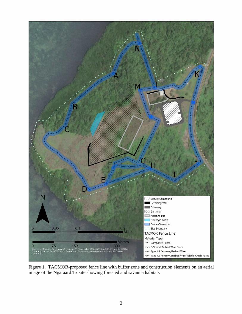
2
Figure 1. TACMOR-proposed fence line with buffer zone and construction elements on an aerial image of the Ngaraard Tx site showing forested and savanna habitats

3
Figure 2. TACMOR-proposed fence line, numbered waypoints, and archaeological features overlain on LiDAR topography data (elevation in m).

4
Table 1. Coordinates of Fence Line Waypoints (UTM Zone 53N)
Waypoint No. Easting Northing F1 459 895.03E 846 877.27N F2 459 870.74E 846 859.49N F3 459 835.49E 846 833.61N F4 459 802.31E 846 809.32N F5 459 756.12E 846 831.55N F6 459 712.46E 846 852.50N F7 459 666.49E 846 836.89N F8 459 622.04E 846 821.01N F9 459 592.14E 846 810.96N F10 459 555.10E 846 797.73N F11 459 497.15E 846 777.09N F12 459 441.59E 846 859.91N F13 459 372.53E 846 916.00N F14 459 334.96E 846 950.40N F15 459 352.43E 846 978.71N F16 459 388.14E 846 986.91N F17 459 408.78E 847 005.43N F18 459 421.75E 847 044.59N F19 459 435.24E 847 084.80N F20 459 471.49E 847 114.44N F21 459 504.03E 847 141.16N F22 459 529.17E 847 162.86N F23 459 581.55E 847 191.96N F24 459 606.96E 847 253.08N F25 459 637.38E 847 293.03N F26 459 675.48E 847 298.59N F27 459 665.43E 847 328.49N F28 459 690.04E 847 257.31N F29 459 705.65E 847 212.86N F30 459 717.82E 847 177.67N F31 459 730.25E 847 140.37N F32 459 796.57E 847 150.20N F33 459 891.43E 847 216.88N F34 459 899.76E 847 209.73N F35 459 868.01E 847 095.83N F36 459 856.11E 847 002.96N F37 459 869.20E 846 933.11N F38 459 684.79E 846 865.24N F39 459 639.81E 846 859.29N F40 459 582.26E 846 855.98N F41 459 569.69E 846 830.85N F42 459 587.55E 846 873.84N F43 459 633.85E 846 889.06N F44 459 669.57E 846 871.20N F45 459 691.75E 846 917.77N F46 459 715.88E 846 967.09N F47 459 743.60E 847 024.03N F48 459 708.68E 847 041.39N F48 459 676.72E 847 133.25N
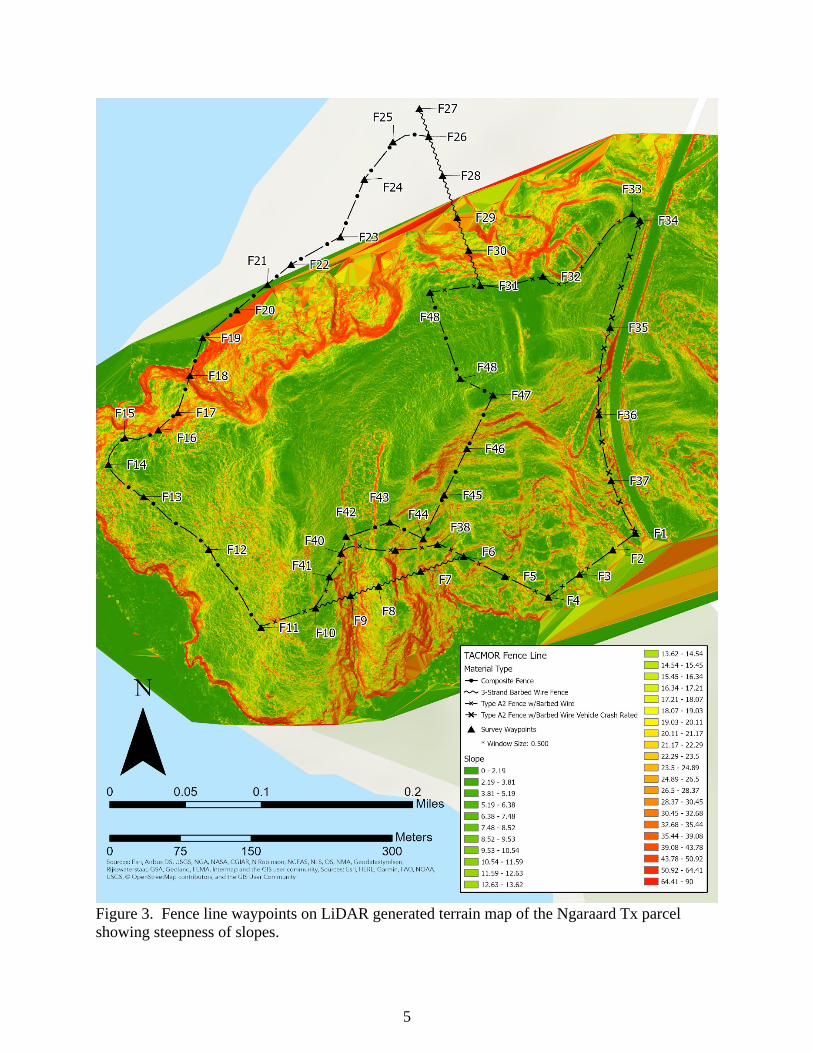
5
Figure 3. Fence line waypoints on LiDAR generated terrain map of the Ngaraard Tx parcel showing steepness of slopes.

6
2 OBJECTIVES The objective of the assessment is to document potential cultural, natural, and topographical impacts of the proposed fence line and identify routes in the northern and southern forested areas of the Ngaraard Tx site for fence placement that best preserve archaeological features and natural resources. Areas of adjustment to the proposed fence line, deemed necessary to avoid significant cultural and natural resources, are recommended based on a pedestrian survey of the APE.
Under International Union for Conservation of Nature (IUCN) criteria, all native plant species on Babeldaob may be considered at risk from land use changes over time, while endemic and native wetland species are especially vulnerable due to Palau’s relatively limited wetland forests. Fence construction is likely to result in a decline in forest habitat and the ecosystem services they provide, a decline in bird and wildlife populations and overall biodiversity, and a reduction in water flows and water quality. In the northern forest, approximately 1 ha (2.7 ac) of forest vegetation would be removed as part of the proposed 50-ft buffer and in the southern forest 1.7 ha (4.2 ac) would be removed from around the proposed fence line. This only encompasses the proposed fence line buffer and not additional clearance associated with construction or access.
Given the extent of the earthwork components in the Tund earthwork complex (Site NA-3:1) (Figure 4) and the Pre-Contact Era village (Figure 5) on the Ngaraard Tx parcel, the TACMOR-proposed fence line (as proposed 29 May 2020) will cross numerous intact and previously impacted step-terraces, ditches, and gullies. These archaeological features have been mapped to the highest degree possible with LiDAR.
Therefore, the goals of this assessment are to:
1) identify which portions of the proposed fence line will cross areas of important cultural and natural resources. These include areas with a high potential for buried cultural resources in the form of stone structures, living surfaces, data-rich activity areas, or unusual constructed components, and significant natural resources, either of which could be impacted by the fence and its installation or later by associated patrols/activities along the fence perimeter (such as equipment access and movement, foot and all-terrain vehicle accessibility and traffic, potential access points for security patrols, and operation and maintenance activities), and
2) recommend areas where adjustments to the fence location could be made to avoid the identified areas of cultural significance or sensitive natural resources.

7
3 METHODS The TACMOR-proposed fence alignment dated 29 May 2020 was provided by AFIMSC Det 2/CEV in June 2020. Reference waypoints at roughly 50- to 80-m intervals were established along the fence line in ArcMap. The waypoints, labeled “F#,” were uploaded into multiple Garmin GPSMAP 64 handheld global positioning systems (GPS) for use in field navigation. On Palau, Garmins are accurate to within 5 to 8 m with accuracy largely dependent on the quantity of both cloud cover and the density of overhead vegetation. Hence, the field points are close to but unlikely to be precisely on the AFIMSC mapped fence line.
Fieldwork entailed pedestrian survey of the fence line in the forested northern (waypoints F15 through F31) and southern (waypoints F1 through F10, F38 through 46) by the archaeological, environmental, and TACMOR Palau Site Coordinator teams. When schedules permitted, the three teams conducted the survey simultaneously.
Each waypoint was flagged with pink flagging tape and marked with the corresponding waypoint number as “F#.” Observations about cultural and natural assets and the overall terrain were written in field books and photographs of key points were taken both at or near the waypoints and on the paths between.
Given the use of non-survey grade handheld GPS in the fieldwork, the areas of concern and the recommended realignments presented in this report are based on combination of data, including waypoints, LiDAR survey data, and topographic information. Presentation of the findings of the TACMOR-proposed northern and southern fence line survey efforts are organized by fence line segments identified by waypoint numbers. Figures illustrating specific areas and features along the TACMOR-proposed northern and southern fence lines follow their respective sections.

8
Figure 4. Northern portion of parcel showing fence line, waypoints, and archaeological features of the Tund earthwork complex (Site NA-3:1).

9
Figure 5. Southeast quadrant of parcel showing proposed fence line, waypoints, and archaeological features of the Pre-Contact Era village (Site NA-3:20).

10
4 FINDINGS
4.1 Proposed Northern Fence Line Overall, the TACMOR-proposed northern fence line is on forested, north sloping terrain whose entire lower portion crosses a heavily dissected landscape with wetlands and drainages and terminates on a coastline bordered by mangrove forest. The following description of cultural and natural resource findings is divided into three sections based on the cultural and natural resources present (Table 2).
Vegetation species noted within the 50-ft clearance buffer in both the northern, and southern forest include an upper canopy of the following endemic trees: Syzygium mesekerrak (mesekerrak), Serianthes kanehirae (ukall), Horsfieldia palauensis (chersachel), and Calophyllum pelewense (chesemolech). Native trees in the upper canopy include Maranthes corymbosa (bkau), Vitex cofassus (beokl), Pterocarpus indicus (las), Colonia scraba (chuchab), Ormosia calavensis (chedebsungelked), Canarium hirsutum (mesecheues), Planchonella obovata (chelangel), Semecarpus venenosa (tonget), Rhus taitensis (cheues), and stands of the palms Heterospathe elata (demailei) and Pinanga insignis (chebouch) and Draceana miltiflora (orredakl). The lower canopy trees include the following endemic trees: Osmoxylon truncatum (kesiamel), Rauvolfia insularis (omechidel), and Pandanus aimiriikensis (chertochet). Native trees in the lower canopy or understory include Eugenia reinwardtiana (kesiil), Phaleria nisidai (ongael), Premna serratifolia (chosm), Cynometra ramiflora (ketenguit), Ixora casei (kerdeu), and Mussaenda philippica (cherecheroi). The secondary forest includes Macaranga carolinensis (bedel). The largest grass, Bambusa vulgaris (bamboo), the herb Alpinia publifora (sui) and Donax canniformis (temring), and the saplings of these trees and other herbs are also found in this area.
Table 2. Sections of Northern Fence Line.
Section Terrain Natural Resources of Issue
Cultural Resources of Issue
F16 to F18, F29 to F31
north sloping terrain -- low, step-terraces from F28/29 to F30
F18 to F25 dissected landscape close to mangrove forest; large endemic tree
--
F25 to F28 drainage area wetlands --
Sloping Terrain with Limited Step-Terraces, F16 to F18, F29 to F31
The eastern descent of the proposed northern fence line, from F31 to close to F29, is underlain by anthropogenic, low, wide step-terraces arranged in a lobate pattern within the forest habitat (Figure 6). The proposed fence alignment extends north to south, parallel to the width of the step-terrace treads. The series of three to four north-facing step-terraces are the north-central termination of the Tund earthwork complex (Site NA-3:1). No artifacts or stonework features were encountered on these terraces, although stone pavings buried by erosion and decomposed humic material may be present.
A potential Japanese defensive trench with an earthen embankment is located between F28 and F29. The possible feature is defined by sloped sides and a shallow base, as opposed to the vertical walls and horizontal floor typically identifying Japanese defensive features. Given these characteristics and its location within erosional gullies and ravines, the shallow gully could be naturally occurring and is considered too ephemeral to be a definitive archaeological feature.

11
Between F16 and F18, on the western section of the proposed northern fence line, the fence alignment descends from open savanna at F16 through forest habitat to F18. Rock outcrops are found near and upslope of F18, which is at the base of a drainage basin with a western slope of 35–55°. The largest trees observed were the endemic Calophyllum pelewense (chesemolech), the largest of which was located just above the drainage basin along the northwest portion of the northern forest (about 100 m upslope of F18) and has a diameter at breast height (DBH) of 93 cm (Figure 7).
An abandoned nest of the endemic Palau Fantail bird Rhipidura lepida (melimdelebteb) upslope from F18 was observed (Figure 8). Milang Eberdong, bird specialist, did not observe bats roosting on the nest that was observed to have bats roosting on it in January 2019. Therefore, it is not a permanent roosting tree for the bats. The bird diversity was similar to the diversity described in the initial site assessment (Argonne National Laboratory and Belau National Museum 2019). No endangered bird species were observed.
Dissected Landscape, F18 to F25
The northern extent of the TACMOR-proposed fence line is in a heavily dissected landscape (see Figure 3). By F29, the terrain transforms sharply into north-south trending ravines (Figure 9) of up to 3 m deep, which culminate at a deeply incised, westerly flowing stream valley at F26 (Figure 10). From F26 to F18, the topography is characterized by steep slopes (~20–60°) bisected by northerly flowing drainages emptying into east-west trending ravines that meet the mangrove forest lining the coastline (Figures 11 and 12). The fence line transects this dissected landscape as it wavers from on top of narrow, level lobes of land, to descend into and cross multiple, intersecting drainages (Figure 13). The most significant ravine is that shown on the LiDAR image at F18 and continues to F20 (Figures 2 and 3). This dissected landscape is continuous from about F29 south to F27 and west to close to F18.
Mangroves are within 20 m of F24 and continue to about F19 (Figure 14).
Scattered basalt cobbles are found at the base of several narrow, steep drainages emptying into the mangrove lined shoreline. As the cobbles do not form a pattern and are not associated with artifacts or earthworks, it appears they have broken loose from upslope disintegrating bedrock and were deposited along the coastline in periods of heavy water drainage.
Wetland and Drainage Area, F25 to F28
The topography from F25 to F28 remains a dissected landscape. However, for ca. 75 m length by 15.25 m width or 1,143 m2 (0.28 ac), from F25 to F28, the fence line runs through a major wetland and drainage area impacting 50 percent of the wetland (Figure 15). The wetland is dominated by Donax canniformis (temring), and Campnosperma brevipetiolata (kelelacharm).

12
Reference Images: Proposed Northern Fence Line
Figure 6. Level tread of step-terrace at F30 looking downslope at 300° towards F29.
Figure 7. Serianthes kanehirae by NW drainage near F21 (left). Calophyllum pelewensis (DBH=93 cm) at upper end of drainage from F18 (right).

13
Figure 8. Old nest of endemic Palau Fantail bird north of F18.
Figure 9. High ravine bank on left side of frame with ravine descending in center background. View at F28 to 270°.

14
Figure 10. Five-meter drop to flowing stream at F26 with opposing bank several meters higher. View to 360°.
Figure 11. Streambed close to F25. View to 260°.

15
Figure 12. A 10-meter-deep incised ravine and stream running from southeast to northwest. Photo taken 30 m west of F20.
Figure 13. On top of almost vertical cliff dropping to mangrove tide line 20 meters below. F20 is about five meters down the slope. View to 310 degrees.

16
Figure 14. F23 is at the mangrove tide line. View to 360 degrees.
Figure 15. Wetland & stream by fence line F25 to 28.

17
4.2 Proposed Southern Fence Line Overall, the TACMOR-proposed southern fence line crosses south sloping terrain, which was shaped in the Pre-Contact Era into step-terraces supporting an ancient village and terminates at the mangrove forest lining the shoreline. Areas of very steep slope are associated with drainage areas and bedrock outcrops confined to the west end of the proposed alignment. For organized presentation, the following description of cultural and natural resource findings is divided into two sections, the east and west halves, based on the cultural and natural resources (Table 3).
Table 3. Sections of Southern Fence Line.
Section Terrain Natural Resources of Issue
Cultural Resources of Issue
East Half (F1 to F6,
F44 to F46)
south sloping step-terraces with wetland in southeast corner
-- village on step-terraces and probable ancient wetland agricultural area (Feature 9)
West Half (F6 to F10, F38 to F44)
incised drainages and large bedrock outcrop
stream drainage; large, old trees
Feature 6 step-terrace: potential pottery production locale
The southern forest consists of similar plant associations as the northern forest with several more dominant species in the upper canopy including the large breadfruit Artocarpus mariannensis (chebiei) and large Colona scabra (chuchab) within the old village site. Wildlife was observed along the southern fence alignment. The bird diversity was similar to the diversity described in the initial site assessment (Argonne National Laboratory and Belau National Museum 2019). No endangered bird species were observed.
East Half (F1 to F6, F44 to F46)
The east half section includes the entire southern fence line except the polygon of three stacked fence lines in the west half.
The proposed fence line in the southern forest is almost entirely within a significant Pre-Contact Era village (Site NA-3:20) constructed on the south half of the Tund earthwork complex. As shown in Figure 5, constructed village features, in the form of low, wide step-terraces and stone architecture, are found from the forest-savanna border south into the mangrove forest, and from the stream in the west to close to F2 where construction of the north-south aligned, now-abandoned dirt road destroyed any village features that may have been present.
The proposed fence line crosses a minimum of 10 of the village’s step-terraces (F5 to F8, F38 to F39, F43 to F46; Figure 16) and the probable wetland cultivation field (west of F2 to close to F5). Each of the step-terraces likely supported an extended family’s home and burial, cooking, and activity areas. Some step-terraces were reserved for community endeavors such as pottery production, ceremonial events, and political meetings. Dryland crops grew in the savanna covered terraces north of the village with pondfield agriculture occurring in the marsh extending north from the F42 to F43 line and probably in the compartmentalized wetlands (Feature 9) in the southeast quadrant of the village. Growing within the village were food trees, medicinal plants, and other economically useful plant species used to construct structures and watercraft and to manufacture woven products, weapons, and other implements.
The topography from about F2 to F6 is low, consistently wet terrain interspersed with low, bedrock

18
outcrop and small streams (Figure 17). From about F2 to F1 the fence line tracks gently uphill across the level extent of the abandoned dirt road that predates the Compact Road.
The initial phase of archaeological data recovery (Gerard-Little et al. 2020) identified the architecturally unusual structures (Features 1 and 2) in the east-central side of the village, the presence of buried stone pavings on terrace treads (Feature 7), and a potential pottery manufacturing locale (Feature 6).
The coastline contains two coral docks and associated structures fronted by the mangrove forest that served as defensive barricade from enemies’ intent on attacking the village. Taoch (passages for watercraft through the mangrove) were constructed and maintained for access to the lagoon and guarded to keep enemies out.
West Half (F6 to F10, F38 to F44)
A major wetland and drainage area intersects the three fence lines proposed between F42 and F43, F39 and F40, and F9 to F10 (Figures 18, 19, and 20). The stream emanates from the marsh in the center of Ngaraard Tx parcel and flows southward to the mangrove coast. The wetland is 25 m wide at its southern end and the drainage channel is 10 to 20 m wide along its length. It is approximately 20 m east of F10 and less than 10 m east of the alignment between F40 to F42 (Figures 21 and 22). The stream is incised into the bedrock and slopes some 5 to 10 m from the level stream bank to the west.
The stream was the ancient village’s primary source of freshwater. The stream’s banks are lined with traditional pottery and basalt boulders and cobbles that likely formed dams and alignments for bathing pools and water collection areas before being dislodged by strong currents after village abandonment.
A World War II Era Japanese earthen defensive feature (Site NA-3:1, Feature 13), likely a bivouac trench, is centered at F40, on the west bank of the stream (Figure 23). The Japanese defensive feature was thoroughly documented in Gerard-Little et al. (2020) through archival research, tape and compass mapping, photographs, and descriptive text. No further work is recommended at this feature.
Bordering the east side of this stream is a roughly 15 m high and wide, north-south trending bedrock outcrop. The outcrop begins south of F43 and continues south under F39 and the F8 to F9 line (Figures 24 and 25). The east length of the outcrop slopes steeply (>65°) down to the ancient village’s step-terraces (Figure 26). The fence alignment descending from the outcrop and connecting to F7 crosses a possible pottery production area (Figure 27). A deep ravine (~4 m with side wall slopes ranging from 35-60°) begins immediately south of F7 and continues south to the mangrove (Figure 18).
The largest trees measured along the fence line route include: Vitex cofassus (DBH=96 cm) near F44; Maranthes corymbosa (DBH=85 cm) and Pterocarpus indicus (DBH=83 cm) near F7; and Campnosperma brevipetiolata (DBH=65 cm) near F9 (Figures 28 and 29). Although common throughout the southern forest, these larger trees would be cleared during construction of the currently proposed alignment.

19
Reference Images: Proposed Southern Fence Line
Figure 16. Alignment from F5 to F6 crossing step-terraces.
Figure 17. Stream on bedrock on F4 to F5 line. Ten meters southeast of F5, view to 200°.

20
Figure 18. Proposed fence line crossing wetland and drainage area.
Figure 19. Wetland and running water east adjacent of F42 and F43 (left). F38 Donax canniformis in wetland at F38 (right).

21
Figure 20. Downstream running water and a pool of water at F9.
Figure 21. Meter wide stream east of F10, F40-F42. Photo ~25 meters east of F10, facing F9 at 90 °.
Figure 22. Stream draining south out of marsh in the savanna. Image close to F43. View to 270°.

22
Figure 23. World War II Era Japanese defensive trench at F40. View to south.
Figure 24. On bedrock outcrop at F8. View to 280 °.
Figure 25. On 15 m high bedrock outcrop on the line from F39 to F40. View to 270°.

23
Figure 26. Steep 50° slope on bedrock outcrop from F8 to F7. Bedrock on left of image. View to 60°.
Figure 27. Fence alignment around F7 crossing stone alignments on a leveled surface (Feature 6) that initial data recovery suggests is a potential pottery production locale.

24
Figure 28. Campnosperma brevipetiolata between F42-43 (left). Colona scabra at F7 (right).
Figure 29. Maranthes corymbosa (DBH=85 cm) at F7 (left). Vitex cofassus (DBH=96 cm) by F44 (right).

25
5 RECOMMENDED REALIGNMENTS Three realignments to the TACMOR-proposed fence line are recommended to avoid or minimize significant natural and cultural resources (Table 4, Figure 30). Mitigation measures supporting the initially proposed or the recommended realignment version of the fence lines are provided below in Section 6.
Table 4. Recommended Realignments to TACMOR-Proposed Fence Line
No. Re-alignment Remove Fence Line Cause of Recommendation Northern Fence Line
1 Move line south to connect F18 east to between F29/F30
F18 through between F29/F30
• Avoid sedimentation onto mangrove forest lining coast and blockage to numerous, steep drainages.
Southern Fence Line 2 Extend F42 west onto
savanna. Connect on southwest line to F11.
• F6 to F11 • F10 to F41, F40, and
F42 • F 38 to F40
• Reduce impacts on stream drainage by combining three stream crossings into single event.
• Lessen impacts on intact forest. • Avoid significant cultural
deposits associated with likely pottery production locale (Feature 7).
3 Connect F44 to F38. Extend F6 east to connect with F1
F1 to F6 • Minimize impacts on archaeological village site
5.1 Recommended Realignment for Proposed Northern Fence A single realignment (Realignment No. 1) is recommended for the TACMOR-proposed northern fence line.
To avoid the major wetland and drainage area and mangrove habitat downslope from the proposed fence line, between about F19 to F28, it is recommended to move the fence line upslope to an elevation above the stream valleys and on the more gently sloping topography in the forest but closer to the savanna-forest edge (Figure 30). Any other realignments would keep the fence within the intersecting gullies, ravines, and drainages.
5.2 Recommended Realignments for Proposed Southern Fence Two realignments are recommended for the TACMOR-proposed southern fence line, one in the west half (Realignment No. 2) and the other in the east half (Realignment No. 3).
Realignment No. 2, in the West Half, reduces the impact on the integrity of the wetland marsh drainage, limits impacts on the forest habitat, and avoids significant cultural deposits associated with the likely pottery production locale (Feature 6). It is proposed that the two southern fence lines (F6 to F11 and F38 to F40) be removed to leave a single fence line (F42 to 43) crossing the drainage (Figures 30 and 31). The line extending down the east side of the stream (F10-F410-F41-F42) should be moved to the west, off the stream bank and out of the forest onto the savanna. The fence line would extend northeast from F11 to west of F42 where it would turn east to connect to F42.

26
Realignment No. 3, in the East Half, is recommended to minimize impacts on the archaeological village site by limiting crossings of step-terraces with a high potential for buried cultural resources and reducing the extent of fence line within the site. It is proposed to remove the line from F1 through F6. This line would be replaced by connecting F44 with F38 and extending the fence line from F6 east to F1 (Figure 30).
Figure 30. Recommended realignments (Nos. 1, 2, and 3) and fence removal areas on avoidance areas.

27
Figure 31. Proposed Realignments 2 and 3 and cultural features documented in Site NA-3:20.
6 MITIGATION As discussed above, three sections of fence line are recommended for realignment. The following natural and cultural resource mitigation measures are recommended to accompany fence line construction regardless of whether the fence line stays as initially proposed or is realigned as recommended.
6.1 Overall Regardless of the final fence alignment, recommended mitigation to the adverse impacts to the natural and cultural resources include:
• A deviation from a 50-ft (15.24 m) to a 10-ft (3.05 m) buffer around the fence to reduce loss of forest and wetland habitat.
• Regulations mandated by Palau’s Environmental Quality Protection Board for streams and swamp forests includes a 60-ft (18.29 m) buffer around these wetlands (EQPB, Chapter 2401). These regulations should be taken into consideration in fence line planning.
• An erosion control plan that takes into consideration the run-off effects of clear-cut corridors and altered drainages on the mangrove habitats bordering the TACMOR parcel. The endemic and native trees and shrubs and native sedges and grasses found in the savanna (Eriachne pallescens, Ischaemum ciliaris, Rynchospora corymbosa, and Schoenus calostachyus) can be used for soil erosion control and landscaping.
• Installation of an effective storm water system around the perimeter of the radar system that should include a sediment holding pond upstream of the major drainage. Ponds need

28
to be sized for the area to be drained and maximum rainfall at the site. A series of sediment fences along this drainage system will be needed reduce potential sedimentation and degradation of water quality and stream life.
• An archaeologist and environmental scientist accompanying the surveyors setting the alignment to suggest slight adjustments (i.e., up to 2 to 3 m) to the alignment to ensure significant old trees and any surface architecture seen are preserved.
• Archaeological monitoring is recommended during construction of the fence line and vegetation clearing of the buffer zone. The objective of monitoring is to identify and document any cultural deposits and buried stonework (e.g., pavings, abutments) that may be present.
• Removal of important plants in the path of the fence line for re-planting by the naturalist team.
• Scheduled inspection of the built fence line to identify the presence of invasive species, clean sediment ponds, and clear any potential blockage.
6.2 Northern Fence Line Proposed mitigation measures specific to the northern fence alignment entail:
• Realignment 1, moving the F19 to F26 fence upslope and close to the savanna, to avoid the wetland and drainage area and mangrove habitat.
• Archaeological data recovery on the upslope step-terraces if the fence is realigned close to the savanna. As the LiDAR did not capture these step-terraces, they should be accurately mapped before the excavation of a minimum of two stratigraphic trenches.
6.3 Southern Fence Line Proposed mitigation measures specific to the southern fence alignment regardless of where it is placed include:
• Realignment Nos. 2 and 3 to minimize damage to the major wetland and drainage area and the NA-3:20 village site.
• Archaeological data recovery on those Site NA-3:20 features crossed by the fence line to mitigate the negative impacts resulting from fence line construction and long-term use and maintenance. Data recovery should include excavation of stratigraphic trenches, appropriate laboratory analysis of recovered cultural materials, and archaeobotanical analysis of sediments recovered in the potential pondfield (Feature 9).
• The two unrecorded traditional docks in the mangrove directly south of the village will be impacted by sedimentation during fence line installation and use. Data recovery is recommended for both features in the form of archival research, mapping, excavation, and appropriate laboratory analysis.

29
7 SUMMARY The forests along the proposed north and south fence lines comprise a rich diversity of endemic and native trees and provide many ecosystem services including a source of food, timber, wildlife habitat, medicine, a filtering system for water, and a buffer from storms. The trees present in the Ngaraard Tx site include many species of epiphyte ferns, orchids, and vines contributing to Palau’s rich biodiversity. Under the IUCN criteria, all native species on Babeldaob may be considered at risk due to land use changes over time, with endemic and native wetland species also at risk due to the relatively limited wetland forests in Palau.
The Ngaraard Tx property is largely contiguous within a Pre-Contact Era archaeological site defined by the Tund earthwork complex (Site NA-3:1). A traditional village (Site NA-3:20) lies in the forest on the south half of the Tund complex. A few World War II Era Japanese earthen defensive features are scattered across the property.
The primary impacts on the natural and cultural assets by the proposed fence line include 1) removal of some endemic and native forest and wetland species; 2) creation of lengthy clear-cut corridors though forests, with erosion and runoff concerns; 3) blockage of multiple drainages and increased risk of erosion and sedimentation in downslope areas; and 4) destruction of significant cultural resources.
The natural and cultural resources specialists recommend three fence realignments based on the presence of the high potential for buried cultural resources and important natural resources on the TACMOR-proposed lines. Measures to mitigate the impacts of fence line construction and use on the resources are provided in this report.
8 REFERENCES Argonne National Laboratory and Belau National Museum 2019 Natural and Cultural Resource Investigations to Support Construction of Air Domain Awareness Radar Facilities in the Republic of Palau. Phase II - Natural Resource Surveys. Prepared for Environmental Program, Detachment 2 Civil Engineering Division, U.S. Air Force Installation and Mission Support Center, Honolulu. Argonne National Laboratories, Lemont, Illinois.
Gerard-Little, Peregrine, Jolie Liston, Jennifer Abplanalp, Thomas Chiodini, Conner Wiktorowicz, Emily Zvolanek, Nicole Rice, and Konstance Wescott 2020 (Draft) Cultural Resource Investigations to Support Construction of Air Domain Awareness Radar Facilities in the Republic of Palau: Cultural Resources Fieldwork, Ngaraard, Republic of Palau. Prepared for Environmental Program, Detachment 2 Civil Engineering Division, U.S. Air Force Installation and Mission Support Center, Honolulu. Argonne National Laboratories, Lemont, Illinois.
Liston, Jolie, H. David Tuggle, Tina M. Mangieri, Michael W. Kaschko, Michael Desilets, and M.J. Tomonari-Tuggle 2007 Archaeological Data Recovery for the Compact Road, Babeldaob Island, Republic of Palau. Historic Preservation Investigations, Phase II. Volume V: Fieldwork Reports. Prepared for the Honolulu Engineering District, U.S. Army Corps of Engineers. International Archaeological Research Institute, Inc., Honolulu.

Coconut Rhinoceros BeetlePests and Diseases of American Samoa
Number 8
American Samoa Community CollegeCommunity & Natural ResourcesCooperative Research & Extension 2005
Introduction. The coconut rhinoceros beetle, Oryctes rhinoceros(L.), has been a pest of coconuts and other palms in the South Pa-cific since its accidental introduction into Samoa from Sri Lanka in1909. Rhinoceros beetle is mainly a pest of coconut and oil palms;but it also attacks other palm species.
beneath where the larvae feed. The pupal stage lasts 17-28 days.Adults remain in the pupal cell 17-22 days before emerging andflying to palm crowns to feed. The beetles are active at night andhide in feeding or breeding sites during the day. Most mating takesplace at the breeding sites. Adults may live 4-9 months and eachfemale lays 50-100 eggs during her lifetime.
Damage. Coconut rhinoceros beetle adults damage palms by bor-ing into the center of the crown, where they injure the young, grow-ing tissues and feed on the exuded sap. As they bore into the crown,they cut through the developing leaves. When the leaves grow outand unfold, the damage appears as V-shaped cuts in the fronds orholes through the midrib.
Natural Enemies. Rhinoceros beetle eggs, larvae, pupae, andadults may be attacked by various predators, including pigs, rats,ants, and some beetles. They may also be killed by two importantdiseases: the fungus Metarhizium anisopliae and the Oryctes virusdisease.
Life Cycle. Eggs are laid and larvae develop in decaying logs orstumps, piles of decomposing vegetation or sawdust, or other or-ganic matter. Eggs hatch in 8-12 days, and larvae feed and grow foranother 82-207 days before entering an 8-13 day nonfeeding prepu-pal stage. Pupae are formed in a cell made in the wood or in the soil
Damage to coconut palm
Adult
Larva
Larva infected with Metarhizium anisopliae
Published by the Division of Community and Natural Resources, American Samoa Community College, and issued in furtherance of Cooperative Extension Work Acts ofMay 8 and June 30, 1914, in cooperation with the U.S. Department of Agriculture Cooperative Extension Service. The American Samoa Community College Division ofCommunity and Natural Resources prohibits discrimination in all its programs and activities on the basis of race, color, national origin, gender, religion, age, disability,political beliefs, sexual orientation, and marital or family status. For more information contact ASCC CNR at 684-699-1575.

Management. Rhinoceros beetles can be controlled by eliminat-ing the places where they breed and by manually destroying adultsand immatures.
• Chop and burn decaying logs or break them up and destroy anyrhinoceros beetles developing inside.
• Cut stumps as close to the soil surface as possible.• Dead, standing coconuts should be felled, chopped, dried, and
burned.• Rhinoceros beetles do not usually lay eggs in potential breed-
ing sites that are obscured by growing vegetation. Vines orground covers can be planted or allowed to grow over logs orstumps that cannot be destroyed.
• Piles of dead leaves or grass can be composted, used for mulch,burned, or spread on the ground in a thin layer.
• Compost piles should be maintained properly. When turningcompost piles or applying compost to plants, destroy any rhi-noceros beetles found. It takes longer for rhinoceros beetle lar-vae to develop than it takes to make compost, so properly main-tained compost should not serve as a source of rhinocerosbeetles.
• A hooked wire can be used to extract and destroy rhinocerosbeetle adults feeding in palm crowns.
In many countries, the fungus Metarhizium anisopliae or the Oryctesvirus are used to control the rhinoceros beetle. More recently achemical attractant, ethyl-4-methyloctanoate, has been used in trapsto attract and kill the beetles. Both Metarhizium anisopliae andthe Oryctes virus are present and helping to reduce rhinoceros beetlepopulations in American Samoa; however, these pathogens and theattractant have not yet received approval from the United StatesEnvironmental Protection Agency for use as pesticides to controlthe rhinoceros beetle.
ReferencesDoane, R. W. 1913. The rhinoceros beetle (Oryctes rhinoceros L.) in Samoa.Journal of economic entomology 6: 437-442.Gressit, J. L. 1953. The coconut rhinoceros beetle (Oryctes rhinoceros), withparticular reference to the Palau Islands. Bernice P. Bishop Museum Bulletin No.212. 157 p.Swan, D. I. 1974. A review of the work on predators, parasites and pathogens forthe control of Oryctes rhinoceros (Coleoptera: Scarabaeidae) in the Pacific area.Commonwealth Institute of Biological Control misc. pub. no. 7. 64 p.Waterhouse, D. F. and Norris, K. R. 1987. Biological control: Pacific prospects.ACIAR, Melbourne.Zelazny, B. 1979. Loss in coconut yield due to Oryctes rhinoceros damage. FAOPlant Protection Bulletin 27: 65-70.
Breeding site in coconut log.
Breeding site in decaying leaves.
Females (left) tend to have shorter “horn” and fuzzy posterior.
This work was funded by a grant from USDA CSREES Integrated Pest Manage-ment Program. Prepared by Mark Schmaedick. Metarhizium photograph by FredBrooks. For more information contact ASCC CNR at 684-699-1575.

Coconut Rhinoceros Beetle (CRB) and Little Fire Ant (LFA) Management Procedures
BACKGROUND
Green waste has the potential to harbor and spread invasive species around Guam and increases the potential of dispersing invasive species to other islands within Guam transportation network. The green waste management procedures identified below are an important step in regional biosecurity.
Little Fire Ant
Little Fire Ant (Wasmannia auropunctata) (LFA), originally from Central and South America, has spread throughout tropical regions over the last 100 years and was discovered in Guam in 2011. Since its discovery in northern Guam, LFA has been confirmed in at least 28 additional locations all over Guam. LFA disperse slowly on their own but can be spread rapidly by people who inadvertently move them on yard waste, recycled goods or garbage. LFA have multiple queens that mate within or near the parent colony, where fertilized queens spread on foot nearby with a few workers. These new nests remain connected with the parent colony where food gathering and defenses are shared, resulting in large “supercolonies.” LFA nest in the ground up to the canopy. These supercolonies are constantly producing new queens and workers, so colonies can remain viable even after the loss of some workers or queens. LFA will prey on insects, invertebrates, small vertebrates and will attack larger wildlife, cause blindness in pets and painful stings to people. Implementing early detection surveys as part of green waste management during DPRI projects that involve vegetation clearing or landscaping will reduce and minimize the occurrence and potential ecological, economic, safety and health risks associated with LFA.
Coconut Rhinoceros Beetle
The coconut rhinoceros beetle (CRB) is a pest of palm trees, including coconut, betel nut, and pandanus. It is also known to attack banana, taro, pineapple, sugar cane and other plants. The adults damage palms by boring into the center of the crown and feeding on the sap and developing leaves, creating V-shaped cuts in the fronds. The boring into the palms is often lethal. Immature stages (eggs, grubs, pupae) are found in dead coconuts and piles of rotting vegetation. Most recent research (Moore et.al, 2015) found CRB at all life stages in the crowns of selected palms. Although CRB are established on Guam island-wide, a multi-faceted control effort on Guam and emphasis on preventing CRB from invading neighboring islands and Hawaii is a high priority. Therefore, limiting the breeding sites is critical during green waste management.
GENERAL REQUIREMENTS
The Contractor shall notify the Construction Management Engineer (CME) at least two weeks prior to scheduled vegetation removal. No vegetation removal/clearing will be conducted without prior Government approval.
1) The Contractor’s Hazard Analysis and Critical Control Point (HACCP) Plan will include CRB andLFA management.2) The Contractor will maintain a clean work site that is subject to review and inspection by theGovernment Biological Monitor. Vegetation debris left on site that is not mulched or properly managedcould facilitate infestations of CRB, LFA, or other species.3) No green waste from outside Department of Defense property is allowed to be processed inconjunction with the green waste generated by Defense Policy Review Initiative EnvironmentalOffice (DPRI) construction projects.
(Ver3.Revised 01.27.2020)

SPECIFIC REQUIREMENTS
LFA Procedures:
Step 1. Raw greenwaste and mulch stockpile surveys.
The following methods shall be applied to this step:
a. The Contractor shall survey greenwaste stockpiles for LFA at least twice before finaldisposition on project footprint.
i. Raw greenwaste pile shall be surveyed once pile is closed or inactive andprior to processing into mulch (Risk management for Little Fire Ants in mulch:Hawaiian Earth Products, Waikoloa Hawai`i,http://www.littlefireants.com/Risk%20management%20for%20Little%20Fire%20Ants%20in%20mulch.pdf). This will prevent raw greenwaste piles thatcontain LFA from contaminating mulch machine and potentially spreadingLFA to other piles that did not previously contain LFA.
ii. The second survey shall be conducted no more than two weeks prior to finaldisposition of processed greenwaste such as mulch or cured compost (Riskmanagement for Little Fire Ants in mulch: Hawaiian Earth Products, WaikoloaHawai`I,http://www.littlefireants.com/Risk%20management%20for%20Little%20Fire%20Ants%20in%20mulch.pdf ).
iii. The Contractor shall survey around the edge of the stockpile by takingchopsticks or 60cc vials (Biolab or similar) and smearing them with a verythin layer of peanut butter on half the stick or inside vial, and place themaround the pile every 10 feet. LFA prefer shaded areas, ensure the sticks orvials are covered by old leaves, piece of cardboard, etc. Leave the sticks inplace for at least 10 minutes and no longer than one hour before picking upto examine. If LFA are in the mulch pile they will be present on the stick or inthe vial. LFA are very small, less than 3mm or 1/8th inch long, uniformlyorange color and are slow in movement.
iv. Step 2 shall be applied within 24 hours of positive identification.v. If an LFA survey is suspected to be positive the Contractor shall bring the
suspected specimen to the University of Guam Extension Service for positiveidentification.
vi. The Contractor shall notify the Government Biomonitor when turning in aspecimen to the UOG Extension Service for identification.
vii. If UOG Extension Service positively identifies LFA specimen, then theContractor shall notify Government Biological Monitor and BiosecurityProgram Manager immediately.
viii. The Contractor shall provide all LFA survey results monthly to GovernmentBiomonitor.
Step 2. Quarantine and treatment of LFA positive stockpile/s
The following methods shall be applied to this step:
a. Quarantine greenwaste stockpile.i. The greenwaste shall be left in place and low-hanging vegetation that is
within a three-meter buffer around LFA positive stockpile shall be cut andadded to pile to ensure no further transmission to surrounding areas unlesslow hanging vegetation and buffer is outside of the project footprint. Cuttingvegetation outside of the project footprint is not authorized.
ii. Allow greatest amount of sunlight exposure to stockpile (i.e. remove anyequipment, overhead or adjacent to for maximum sun exposure).
iii. Place high visibility rope/flagging around LFA positive stockpile isolationbuffer with signs that warn personnel on site of LFA presence and treatment.
iv. Provide GPS location and stockpile size to the Biosecurity Program Manager.

v. No additional vegetation shall be added to stockpile that is not within three-meter isolation buffer.
vi. Provide specific HACCP training to workers managing quarantine stockpile.
b. Treatment of stockpile.i. Treatment of stockpiles are to include procedures outlined in the Hawai’i Ant
Lab website (Little Fire Ant Fact Sheet 2,http://www.littlefireants.com/lfa%20fact%20sheet%202.pdf).
ii. The Contractor shall report all chemical usage on the NAVFAC OnlinePesticide Reporting System and shall follow all EPA labelingrequirements/instructions. The contractor shall be in possession of allnecessary permits or certifications necessary to conduct the activitiesstipulated for eradication of LFA.
iii. Treatment plans shall be submitted to the Government no later than twoweeks after positive identification of LFA.
iv. Once this treatment is complete, the Contractor shall survey the whole mulchpile again as described above to ensure LFA have been eradicated.
v. Greenwaste processing of stockpile may resume once LFA surveys yieldnegative results and approval is given by Biosecurity Program Manager.
CRB Procedures:
The Marine Corps Activity Guam Public Works Department Environmental Office (MCAG-EV) approved methods for handling green waste are described below and will be dependent on the amount of waste generated by the specific project.
Non-CRB host plants are approved for Methods 1, 2 and 3. For CRB host plants, coconut palms, betel nut, and pandanus, only Methods 2 and 3 are applicable. The Intermediate Method as described below will be applied to processed greenwaste piles and prior to application of Methods 1-3. The Contractor shall determine the appropriate method based on the amount of green waste and submit their processing method to MCAG-EV for approval as part of the Site- Specific Waste Management Plan. The approved implementation method will also be included in the Hazard Analysis & Critical Control Point (HACCP) Plan. If the method selected is not effective in preventing the establishment of CRB breeding sites (i.e. grubs are found in processed material not protected by Intermediate Method) the Contractor shall work with MCAG-EV to determine a more successful approach and revise their HACCP Plan.
Method 1- Mulch and Spread: This method is only approved for non-CRB host plant vegetation after the green waste has been processed into mulch.
The following methods shall be applied to this method:
a. Mulch the green waste and spread on-site, with a depth of no greater than two inches to avoidcreating breeding habitat for CRB.
b. Incorporate the mulch into existing soil as soon as possible to discourage beetle breeding andto aid in site stabilization (to control stormwater runoff).
c. The final spread of mulch shall only be used on project footprint where no further earthmoving activities will disrupt the mulch and soil mixture.
Method 2 - Compost: This method does not require separating CRB host plants from other vegetation.
The following methods shall be applied to this method:
a. Mulch the green waste material and compost.b. To minimize the risk of fire, stockpile height should not exceed 15 feet.

c. The Contractor shall monitor the compost pile weekly for evidence of CRB infestation and thetemperature shall be measured using a compost thermometer.
d. If the compost pile appears dry, add water until the pile is moist. Optimal compostingtemperature is between 120-140 degrees F with 50-55% moisture.
e. When temperature of the compost pile exceeds 145 degree F, the Contractor shall turn thepile using a bulldozer, backhoe, or similar equipment to maintain the aerobic compositingconditions.
f. All CRB (grubs and adult) found in pile shall be recorded, killed and removed from pile.g. Intermediate Method described below shall be used if compost is infested with grubs until
such time that the material can be processed through a grinder/shredder to destroy the grubsand inspected by the Government Biomonitor prior to resuming compost activities of infestedpile.
h. The Contractor shall provide following records monthly to the Government Biomonitor.i. Temperatureii. Moisture leveliii. Number of times pile turned, and date turnediv. Number of CRB observed and life-stage found in pile.
Method 3: Air curtain burners
The following methods shall be applied to this method:
a. Air curtain burners require the Contracting Officer’s approval and coordination with MCAG-EVprior to implementation.
b. This method shall be used sparingly as regulatory agencies are expected to limit usage foremergency situations for the processing of small volumes only.
c. The Contractor is responsible for obtaining all permits and licenses to operate an air curtainburner.
Intermediate Method – Tekken Net: This method shall be used within 30 days when Contractor does not actively apply Methods 1, 2 or 3 to process greenwaste (mulch).
The following methods shall be applied to this method:
a. Cover mulch green waste piles with a gill/fishnet, called tekken in Chamorro. Tekken net shallbe a one-inch mesh measured knot to knot made from 0.25 mm nylon monofilament and laidover piles of green waste.
b. To minimize the risk of fire, stockpile height should not exceed 15 feet.c. The green waste piles must be completely covered by the net without any holes or gaps
greater than one inch to be effective. Green waste piles are attractive to CRB; they will betrapped in the net if they are trying to get out or emerging from the green waste pile.
d. The tekken net shall be inspected weekly to ensure there are no holes or gaps in the nettingand the net should be clear of weeds and other vegetation to allow for CRB observations. Thenetting should completely cover all processed mulch at the base of the mulch stockpile.
e. All observed CRB caught in net shall be removed, killed and recorded by Contractor.f. The Contractor shall provide weekly records of tekken net maintenance and CRB
observations to the Government Biomonitor monthly.
PERFORMANCE STANDARD
All vegetation/green waste material is processed by the Contractor in accordance with procedures outlined above to prevent the spread of LFA and the creation of CRB breeding sites on all DPRI projects.

PAF 198127 TACMOR UTILITIES AND INFRASTRUCTURE SUPPORT 1596606
SECTION 01 57 19.03
SUPPLEMENTAL TEMPORARY ENVIRONMENTAL CONTROLS Response Explosive Remmnants of War (ERW)
PART 1 GENERAL
1.1 SUBMITTALS
Government approval is required for submittals with a "G" designation; submittals not having a "G" designation are for Contractor Quality Control approval.Submit the following in accordance with Section 01 33 00 SUBMITTAL PROCEDURES:
SD-01 Preconstruction Submittals
Record copy of the Application for Accreditation approved by the National Safety Office
Record of National Safety Office Provisional Accreditation for ERW Operations
Record of Training Certificates
Non-Technical Survey Work Plan; G
Technical Survey Work Plan; G
Comprehensive Community Liaison Plan; G
Accident Response Plan; G
Geographic Information System (GIS) Work Area Grid; G
Personnel Qualifications and Duties; G
Site Health and Safety Plan (SHSP); G
SD-06 Reports
Record of Notice of Suspension or Termination of Accreditation by the National Safety Office
Record copy of On-site Assessment Checklist by the National Safety Office
Record of National Safety Office Full Accreditation for ERW Operations
Non-Technical Survey Reports and Recommendations; G
Technical Survey Reports and Recommendations; G
Record copy of Risk Assessment Reports
Record copies of Suspension Reports
SECTION 01 57 19.03 Page 1

PAF 198127 TACMOR UTILITIES AND INFRASTRUCTURE SUPPORT 1596606
Record copies of Accident Reports
Record copies of Progress Reports
Record copies of Post Clearance Assessment Reports
Record copy of Completion Report
QC Report; G
ERW Spot-Task Reports; G
Bedrock Determinations; G
SD-11 Closeout Submittals
GIS Data; G
1.1.1 Submittal Schedule
Schedule and submit concurrently submittals covering component items forming a system or items that are interrelated. No delay damages or time extensions will be allowed for time lost due to late submittals.
Except as specified otherwise, allow review period, beginning with receipt by accepting authority, to include 20 working days for submittals for Contracting Officer approval. Period of review for submittals requiring Government approval begins when the Government receives the submittal from the QC organization.
The review period for each resubmittal is the same as for the initial submittal.
1.2 DOCUMENTATION
Maintain a copy of the following documents on site and available to Government representatives upon request:
a. Latest version of the ERW
b. ERW Work Plan
c. Documented Standard Operating Procedures (SOPs) that comply with the quality management requirements of the Government of Palau ERW Standards
d. Quality Control Log
e. Safety Meeting Attendance Log
f. Site Visitors Log
g. Safety Inspection Logs
h. Daily Report of MEC Operation
SECTION 01 57 19.03 Page 2

PAF 198127 TACMOR UTILITIES AND INFRASTRUCTURE SUPPORT 1596606
1.3 ANOMALIES
An anomaly is defined as a metal item with any one dimension equal to the project's approved Target of Interest (TOI) or larger. For the purposes of these standards the Grenade HE Frag MK2 without fusing is deemed to be the 'minimum target ERW' that poses an intolerable risk in Palau.
1.4 PERSONNEL QUALIFICATION AND DUTIES
Personnel shall meet the minimum qualification standards set forth in ERW, including training and experience requirements. Personnel requirements and duties are defined in ERW.
1.5 ERW WORK PLAN GENERAL REQUIREMNTS
Submit the ERW Work Plan within 30 calendar days of Contract Award.
The ERW Work Plan shall be project-specific and address any unusual or unique aspects of the project or activity for which it is written, in accordance with the Government of Palau ERW Standards. The ERW Work Plan shall interface with the Contractor's overall safety, health, and quality control programs. The Government considers the Prime Contractor to be the "controlling authority" for all work site safety, health, and quality control implementation of the subcontractors. Contractors are responsible for informing their subcontractors of the safety and quality provisions under the terms of the contract and the penalties for noncompliance, coordinating the work to prevent one craft from interfering with or creating hazardous working conditions for other crafts, and inspecting subcontractor operations to ensure that accident prevention and quality control responsibilities are being carried out. The ERW Work Plan shall be signed by the project superintendent, the project QC Manager, the project SSHO, the ERW CEO/MD, ERW Operations Manager, ERW Quality Manager, and ERW Safety/risk Manager.
Once accepted by the Contracting Officer, the ERW Work Plan and attachments will be enforced as part of the contract. Only when the Government of Palau approved Application for Accreditation and its associated ERW Work Plan is accepted shall the contractor be permitted to begin remediation activities. Contractor's failure to execute work in accordance with the approved Application for Accreditation and the ERW Work Plan will be cause for non-compliance with the contract. Any costs or delays associated with full resolution will be the contractor's responsibility.
Once work begins, changes to the accepted Application for Accreditation and the ERW Work Plan shall be made with the knowledge and concurrence of the Contracting Officer and Government of Palau National Safety Office, project superintendent, QC Manager, ERW CEO, ERW Operations Manager, ERW Quality Manager, and the ERW Safety/risk Manager.
Should imminent danger become evident, stop work in the area, secure the area, remove the exposure and control the hazard. In the event ERW is encountered, the contractor shall notify the Contracting Officer and Government of Palau National Safety Office immediately to begin response efforts. In the interim, take all necessary action to restore and maintain safe working conditions in order to safeguard onsite personnel, visitors, the public, and the environment. Written notification and initial ERW spot-task report within 24 hours (one business day).
SECTION 01 57 19.03 Page 3

PAF 198127 TACMOR UTILITIES AND INFRASTRUCTURE SUPPORT 1596606
1.6 COMMUNITY NOTIFICATION
As described in Palau ERW Standards, Chapter 5, 'Worksite preparation', the contractor shall establish liaison with local communities (individuals, groups and authorities) before conducting ERW survey, search and clearance tasks in their area.
1.7 GEOGRAPHIC INFORMATION SYSTEM (GIS) WORK AREA GRID
The contractor shall perform location recording and mapping using the WGS 1984 UTM Zone55 North coordinate system. The contractor shall determine the work area boundaries and use these coordinates and the GIS to determine the grid/sector distribution for the work area. Data must be provided in accordance with the GIS standards included as appendices to this specification section. Submit the GIS Work Area Grid to the Contracting Officer at least ten calendar days before commencing intrusive activities.
1.8 REPORTS
1.8.1 COMPLETION REPORTS
After completion of any specified task, which may be an area search and clearance, a spot task, or a number of spot tasks within a defined area, the contractor shall submit a Completion report to the Government of Palau, National Safety Office.
The Completion report is the final report for the work and will duplicate some of the content of the progress reports. Each complete QC Report shall be submitted to the Government for review.
Upon Government of Palau, National Safety Office review and approval of the Completion Report, the footprint included within that QC Report may have construction activities proceed in the depicted area. It is anticipated that multiple Completion Reports will be required and the number will vary based on project and site conditions. The contractor is responsible for maintaining oversight of intrusive activities to ensure that construction activities that disturb the earth stay within designated areas which have passed Government of Palau, National Safety Office inspections.
1.8.2 ERW SPOT-TASK REPORT
The ERW Spot-Task Report shall be in accordance with the Government of Palau, National Safety Office and ERW Standards.
1.9 GIS DATA
GIS Data shall be submitted in accordance with the GIS standards included as appendices to this specification section.
PART 2 PRODUCTS
Not used.
PART 3 EXECUTION
3.1 COMMENCING OF INTRUSIVE ACTIVITIES
The Contractor shall submit an application for accreditation in accordance with the Government of Palau ERW Standards. No ERW action activities are
SECTION 01 57 19.03 Page 4

PAF 198127 TACMOR UTILITIES AND INFRASTRUCTURE SUPPORT 1596606
permitted until accreditation has been formally granted. The contractor shall provide a record copy of the Government of Palau approval along with a letter to the contracting officer stating: "I certify that the Government of Palau has formally granted accreditation and that ERW action activities are permitted."
3.2 WORK SCHEDULE FOR INTRUSIVE ACTIVITIES
Review the proposed work schedule and identify site specific issues and working hours of the ERW Worksite at the Post Award Kickoff Meeting.
The contractor shall schedule work appropriately to mitigate, to the greatest extent practicable, the impacts to base operations and the general public. Scheduling shall include phasing as well as night and weekend work as necessary.
3.3 COMMUNITY OUTREACH
The Contractor shall liaise with all communities affected by their work before starting any area preparation or search and clearance activity in accordance with the Government of Palau ERW Standards.
For ERW survey, search and clearance operations that continue in one location for an extended period, contact with the Safety Office and the local community should be maintained throughout the work with regular briefings held. Briefings should advise on progress, report on any changes to the operations and discuss any problems that may arise. Records of briefings of local communities should be maintained and kept with the worksite documentation.
3.4 SOIL EXCAVATION AND REMOVAL
Soil excavation and removal shall be in accordance with other parts of these specifications.
3.5 IMPORTED SOILS
The Contractor shall ensure that all imported soils are free of UXO/AXO items or metallic materials.
The Contractor shall afford Government representatives an opportunity to visit and view the source for any imported soils at the Government's request.
3.6 BEDROCK DETERMINATIONS FOR UNLIKELY CONSIDERATION
Determinations of a solid rock formation shall be made by a licensed Professional Geologist or Civil Engineer with a Professional Engineer (PE) license. Before the licensed professional makes a determination, the contractor shall fully expose the entire top layer of the solid rock formation over which the determination is being made. The area shall be cleared of all anomalies using full clearance techniques in accordance with the Government of Palau ERW Standards. The area shall be physically identifiable at the site with the use of construction markers based on the determined Global Position System (GPS) coordinates.
Determinations shall be made in writing and include the following: certifying stamp from the licensed individual making the determination; three dimensional GPS coordinates (grid and depth) outlining the area for
SECTION 01 57 19.03 Page 5

PAF 198127 TACMOR UTILITIES AND INFRASTRUCTURE SUPPORT 1596606
which the determination is being made; methods and criteria used to make the determination; and photographs of the area showing the solid rock formation. A bedrock determination shall only be valid for the area defined. Anywhere outside of the area defined in the determination shall require a separate determination prior to being managed as unlikely.
3.7 REQUIREMENTS WHEN MEC/MPPEH IS ENCOUNTERED
Stop all work immediately if any material or object believed to be ERW is encountered and execute first response protocols immediately. Notify the Contracting Officer immediately to begin response efforts. Provide a written notification and initial Spot-Task Report within 24 hours (one business day). Follow the safety reporting procedures of the ERW SOP.
3.8 QUALITY CONTROL
All organizations involved in ERW/mine action in Palau shall submit documented Standard Operating Procedures (SOPs) that comply with the quality management requirements of the Government of Palau ERW Standards to the Government of Palau, National Safety Office for approval as part of their accreditation process. No organization shall conduct mine action operations without Government of Palau, National Safety Office accreditation.
3.9 REQUIREMENTS FOR POST CLEARANCE ASSESSMENT
Post-clearance assessments may be conducted by the Government of Palau, National Safety Office or others authorized to act on its behalf. It may be conducted as a 'simple' or a 'detailed' assessment.On receipt of all 'clearance reports' related to ERW spot-tasks or area search and clearance, the Safety Office shall determine the appropriate level of post clearance assessment that should be made. When appropriate, the organization that conducted the work may be tasked to conduct the post clearance assessment.Note: A 'Completion Report' shall also be completed for land released through technical survey.
-- End of Section --
SECTION 01 57 19.03 Page 6

PAF 198127 TACMOR UTILITIES AND INFRASTRUCTURE SUPPORT 1596606
SECTION 01 74 19
CONSTRUCTION WASTE MANAGEMENT AND DISPOSAL
PART 1 GENERAL
1.1 DEFINITIONS
1.1.1 Co-mingle
The practice of placing unrelated materials together in a single container, usually for benefits of convenience and speed.
1.1.2 Construction Waste
Waste generated by construction activities, such as scrap materials, damaged or spoiled materials, temporary and expendable construction materials, and other waste generated by the workforce during construction activities.
1.1.3 Demolition Debris/Waste
Waste generated from demolition activities, including minor incidental demolition waste materials generated as a result of Intentional dismantling of all or portions of a building, to include clearing of building contents that have been destroyed or damaged.
1.1.4 Disposal
Depositing waste in a solid waste disposal facility, usually a managed landfill.
1.1.5 Diversion
The practice of diverting waste from disposal in a landfill, by means of eliminating or minimizing waste, or reuse of materials.
1.1.6 Final Construction Waste Diversion Report
A written statement by a material recovery facility operator identifying constituent materials diverted from disposal, usually including summary tabulations of materials, weight in short-ton.
1.1.7 Recycling
The series of activities, including collection, separation, and processing, by which products or other materials are diverted from the solid waste stream for use in the form of raw materials in the manufacture of new products sold or distributed in commerce, or the reuse of such materials as substitutes for goods made of virgin materials, other than fuel.
1.1.8 Reuse
The use of a product or materials again for the same purpose, in its original form or with little enhancement or change.
SECTION 01 74 19 Page 1

PAF 198127 TACMOR UTILITIES AND INFRASTRUCTURE SUPPORT 1596606
1.1.9 Salvage
Usable, salable items derived from buildings undergoing demolition or deconstruction, parts from vehicles, machinery, other equipment, or other components.
1.1.10 Source Separation
The practice of administering and implementing a management strategy to identify and segregate unrelated waste at the first opportunity.
1.2 CONSTRUCTION WASTE (INCLUDES DEMOLITION DEBRIS/WASTE)
Per the approved work plan, divert the project construction waste and demolition debris/waste, as feasible, from the landfill. Follow applicable industry standards in the management of waste. Apply sound environmental principles in the management of waste. (1) Practice efficient waste management when sizing, cutting, and installing products and materials and (2) use all reasonable means to divert construction waste and demolition debris/waste from landfills and incinerators and to facilitate the recycling or reuse.
1.3 CONSTRUCTION WASTE MANAGEMENT
Implement a construction waste management program for the project. Take a pro-active, responsible role in the management of construction waste, recycling process, disposal of demolition debris/waste, and require all subcontractors, vendors, and suppliers to participate in the construction waste management program. Establish a process for clear tracking, and documentation of construction waste and demolition debris/waste.
1.3.1 Implementation of Construction Waste Management Program
Develop and document how the waste management will be implemented in a construction waste management plan. Submit a Construction Waste Management Plan to the Contracting Officer for approval. Construction waste and demolition debris/waste materials include un-used construction materials not incorporated in the final work, as well as demolition debris/waste materials from demolition activities or deconstruction activities. In the management of waste, consider the availability of viable markets, the condition of materials, the ability to provide material in suitable condition and in a quantity acceptable to available markets, and time constraints imposed by internal project completion mandates.
1.3.2 Oversight
The Environmental Manager, as specified in Section 01 57 19 TEMPORARY ENVIRONMENTAL CONTROLS, is responsible for overseeing and documenting results from executing the construction waste management plan for the project.
1.3.3 Special Programs
Implement a Biomass Management Program to harvest useful timber (lumber or firewood) and create usable compost from green and brown waste for local use. See the Biomass Management Report.
SECTION 01 74 19 Page 2
PAF 198127 TACMOR UTILITIES AND INFRASTRUCTURE SUPPORT 1596606
1.3.4 Special Instructions
Provide on-site instruction of appropriate separation, handling, recycling, salvage, reuse, and return methods to be used by all parties at the appropriate stages of the projects. Designation of single source separating or commingling will be clearly marked on the containers.
1.3.5 Waste Streams
Delineate waste streams and characterization, including estimated material types and quantities of waste, in the construction waste management plan. Manage all waste streams associated with the project. Typical waste streams are listed below. Include additional waste steams not listed:
a. Land Clearing Debrisb. Asphaltc. Masonry and CMUd. Concretee. Metals (e.g. banding, stud trim, ductwork, piping, rebar, roofing,
other trim, steel, iron, galvanized, stainless steel, aluminum, copper, zinc, bronze, etc.)
f. Wood (nails and staples allowed)g. Glassh. Paperi. Plastics (PET, HDPE,PVC,LDPE,PP,PS, Other)j. Gypsum drywallk. Non-hazardous paint and paint cansl. Carpet and other floor cveringsm. Ceiling Tilesn. Insulationo. Beverage Containers
1.4 SUBMITTALS
Government approval is required for submittals with a "G" designation; submittals not having a "G" designation are for Contractor Quality Control approval. Submit the following in accordance with Section 01 33 00 SUBMITTAL PROCEDURES:
SD-01 Preconstruction Submittals
Construction Waste Management Plan; G
SD-06 Test Reports
Quarterly Reports
Annual Report
SD-11 Closeout Submittals
Final Construction Waste Diversion Report; G
1.5 MEETINGS
Conduct Construction Waste Management meetings. After award of the Contract and prior to commencement of work, schedule and conduct a meeting with the Contracting Officer to discuss the proposed construction waste management plan and to develop a mutual understanding relative to the
SECTION 01 74 19 Page 3

PAF 198127 TACMOR UTILITIES AND INFRASTRUCTURE SUPPORT 1596606
management of the construction waste management program and how waste diversion requirements will be met.
The requirements of this meeting may be fulfilled during the coordination and mutual Understanding meeting outlined in Section 01 45 00.00 20 QUALITY CONTROL. At a minimum, discuss and document waste management goals at following meetings:
a. Preconstruction meeting.
b. Regular Quality Control meetings.
c. Work safety meeting (if applicable).
1.6 CONSTRUCTION WASTE MANAGEMENT PLAN
Submit Construction Waste Management Plan within 45 calendar days after contract award. Revise and resubmit Construction Waste Management Plan as necessary in order for construction to begin. Execute demolition or deconstruction activities in accordance with the approved plan. Manage demolition debris/waste or deconstruction materials in accordance with the approved Construction Waste Management Plan.
An approved Construction Waste Management Plan will not relieve the Contractor of responsibility for compliance with applicable environmental regulations or meeting project cumulative waste diversion requirement. Ensure all subcontractors receive a copy of the approved Construction Waste Management Plan. The plan demonstrates how to meet the project waste diversion requirement. Also, include the following in the plan:
a. Identify the names of individuals responsible for waste management and waste management tracking, along with roles and responsibilities on the project.
b. Actions that will be taken to reduce solid waste generation, including coordination with subcontractors to ensure awareness and participation.
c. Description of the regular meetings to be held to address waste management.
d. Description of the specific approaches to be used in recycling/reuse of the various materials generated, including the areas on site and equipment to be used for processing, sorting, and temporary storage of materials.
e. Name of landfill to be used.
f. Identification of local and regional re-use programs, including non-profit organizations such as schools, local housing agencies, and organizations that accept used materials such as material exchange networks and resale stores. Include the name, location, and phone number for each re-use facility identified, and provide a copy of the permit or license for each facility.
g. List of specific materials, by type and quantity, that will be salvaged for resale, salvaged and reused on the current project, salvaged and stored for reuse on a future project, or recycled. Identify the recycling facilities by name, address, and phone number.
SECTION 01 74 19 Page 4

PAF 198127 TACMOR UTILITIES AND INFRASTRUCTURE SUPPORT 1596606
h. Identification of materials that cannot be recycled or reused with an explanation or justification, to be approved by the Contracting Officer.
i. Description of the means by which any materials identified in item (g) above will be protected from contamination.
j. Description of the means of transportation of the recyclable materials (whether materials will be site-separated and self-hauled to designated centers, or whether mixed materials will be collected by a waste hauler and removed from the site).
k. Copy of training plan for subcontractors and other services to prevent contamination by co-mingling materials identified for diversion and waste materials.
l. Identify any local jurisdiction requirements for waste management. Include those requirements, points of contact, etc.
Distribute copies of the waste management plan to each subcontractor, Quality Control Manager, Environmental Manager, and the Contracting Officer.
1.7 RECORDS (DOCUMENTATION)
1.7.1 General
Maintain records to document the types and quantities of waste generated and diverted though re-use, recycling and/or sale to third parties; through disposal to a landfill or incinerator facility. Provide explanations for any materials not recycled, reused or sold. Collect and retain manifests, weight tickets, sales receipts, and invoices specifically identifying diverted project waste materials or disposed materials.
1.7.2 Accumulated
Maintain a running record of materials generated and diverted from landfill disposal, including accumulated diversion rates for the project. Make records available to the Contracting Officer during construction or incidental demolition activities. Provide a copy of the diversion records to the Contracting Officer upon completion of the construction, incidental demolitions or minor deconstruction activities.
1.8 FINAL CONSTRUCTION WASTE DIVERSION REPORT
A Final Construction Waste Diversion Report is required at the end of the project. Provide Final Construction Waste Diversion Report 60 calendar days prior to the Beneficial Occupancy Date (BOD).
1.9 COLLECTION
Collect, store, protect, and handle reusable and recyclable materials at the site in a manner which prevents contamination, and provides protection from the elements to preserve their usefulness and monetary value. Provide receptacles and storage areas designated specifically for recyclable and reusable materials and label them clearly and appropriately to prevent contamination from other waste materials. Keep receptacles or storage areas neat and clean.
Train subcontractors and other service providers to either separate waste streams or use the co-mingling method as described in the Construction W
SECTION 01 74 19 Page 5

PAF 198127 TACMOR UTILITIES AND INFRASTRUCTURE SUPPORT 1596606
aste Management Plan. Handle hazardous waste and hazardous materials in accordance with applicable regulations and coordinate with Section 01 57 19 TEMPORARY ENVIRONMENTAL CONTROLS and Section 02 81 00 TRANSPORTATION AND DISPOSAL OF HAZARDOUS MATERIALS. Separate materials by one of the following methods described herein:
1.9.1 Source Separation Method
Separate waste products and materials that are recyclable from trash and sort as described below into appropriately marked separate containers and then transport to the respective recycling facility for further processing. Deliver materials in accordance with recycling or reuse facility requirements (e.g., free of dirt, adhesives, solvents, petroleum contamination, and other substances deleterious to the recycling process). Separate materials into the category types as defined in the Construction Waste Management Plan.
1.9.2 Co-Mingled Method
If recycling facility accepts co-mingled materials, place waste products and recyclable materials into a single container and then transport to an authorized recycling facility, which meets all applicable requirements to accept and dispose of recyclable materials in accordance with all applicable local, state and federal regulations. The Co-mingled materials must be sorted and processed in accordance with the approved Construction Waste Management Plan.
1.9.3 Other Methods
Other methods proposed by the Contractor may be used when approved by the Contracting Officer.
Materials that may contain hazardous materials must be segregated from other construction and demolition debris and disposed of or recycled in accordance with the OEBGD and ROP regulations. Refer to Section 01 57 19 TEMPORARY ENVIRONMENTAL CONTROLS for more details.
1.10 DISPOSAL
Control accumulation of waste materials and trash. Recycle or dispose of collected materials off-site at intervals approved by the Contracting Officer and in compliance with waste management procedures as described in the Construction Waste Management Plan. Except as otherwise specified in other sections of the specifications, dispose of in accordance with the following:
1.10.1 Surplus Soil Testing Requirements
Potentially contaminated soil must be sampled and stored in accordance with Section 02 61 13 Excavation and Handling or Contaminated Material.
1.10.2 Compost
Compost at each site per the approved Green and Brown Waste Disposal Plan. Compostable materials include plant materials and sawdust. Composting as a strategy must be explicitly addressed in the Construction Waste Management Plan submitted for approval to ensure it is feasible.
SECTION 01 74 19 Page 6

PAF 198127 TACMOR UTILITIES AND INFRASTRUCTURE SUPPORT 1596606
1.10.3 Reuse
Give first consideration to reusing construction and demolition materials as a disposition strategy. Recover for reuse materials, products, and components as described in the approved construction waste management plan.
1.10.4 Recycle
Recycle non-hazardous construction and demolition/debris materials that are not suitable for reuse. Track rejection of contaminated recyclable materials by the recycling facility. Rejected recyclables materials will not be counted as a percentage of diversion calculation. Recycle all fluorescent lamps, HID lamps, mercury (Hg)-containing thermostats and ampoules, PCBs-containing ballasts and electrical components, and batteries/lead-acid batteries per approved plan. Do not crush lamps on site as this creates a hazardous waste stream with additional handling requirements.
1.10.5 Waste
Dispose by landfill only those waste materials with no practical use, economic benefit, or recycling opportunity.
Before transporting any non-hazardous construction and/or demolition debris and waste off Government Property, submit the waste documentation package including laboratory results, lab accreditation package, and waste characterization and documentation information to the Contracting Officer.
Comply with the OEBGD and implement applicable requirements (e.g. proper shipping name, packaging, marking, labeling, placarding, Commercial Driver License with Hazardous Material endorsement, and non-hazardous waste manifest). Prepare the required shipping papers in accordance with the OEBGD and submit to the Contracting Officer. Allow 10 working days for Government review. Once Government comments are adequately addressed, the Contracting Officer will sign the appropriate waste documentation as the Generator/Property Owner. For non-regulated, non-hazardous waste, prepare and sign any additional documentation similar to a non-hazardous waste manifest when required by the waste disposal facility.
Dispose of hazardous waste at permitted off-island treatment, storage, and disposal facility. Before transporting hazardous waste off the project sites, submit hazardous waste manifest, land disposal restriction (LDR) form as applicable, laboratory results, lab accreditation package, hazardous waste disposal sheet, and waste characterization and documentation information to the Contracting Officer. Allow 10 working days for Government review.
PART 2 PRODUCTS
Not used.
PART 3 EXECUTION
Not used.
-- End of Section --
SECTION 01 74 19 Page 7


PAF 198127 TACMOR UTILITIES AND INFRASTRUCTURE SUPPORT 1596606
SECTION 01 78 00
CLOSEOUT SUBMITTALS
PART 1 GENERAL
1.1 REFERENCES
The publications listed below form a part of this specification to the extent referenced. The publications are referred to within the text by the basic designation only.
ASTM INTERNATIONAL (ASTM)
ASTM E1971 (2005; R 2011) Standard Guide for Stewardship for the Cleaning of Commercial and Institutional Buildings
GREEN SEAL (GS)
GS-37 (2017) Cleaning Products for Industrial and Institutional Use
U.S. DEPARTMENT OF DEFENSE (DOD)
FC 1-300-09N (2014; with Change 4, 2018) Navy and Marine Corps Design Procedures
UFC 1-300-08 (2009, with Change 2, 2011) Criteria for Transfer and Acceptance of DoD Real Property
1.2 DEFINITIONS
1.2.1 As-Built Drawings
As-built drawings are the marked-up drawings, maintained by the Contractor on-site, that depict actual conditions and deviations from the Contract Documents. These deviations and additions may result from coordination required by, but not limited to: contract modifications; official responses to submitted Requests for Information (RFI's); direction from the Contracting Officer; design that is the responsibility of the Contractor, and differing site conditions. Maintain the as-builts throughout construction as red-lined hard copies on site. These files serve as the basis for the creation of the record drawings.
1.2.2 Record Drawings
The record drawings are the final compilation of actual conditions reflected in the as-built drawings. Record drawings must include a complete set of all drawings for the project.
1.3 SOURCE DRAWING FILES
After award and upon request by the Contractor completing the "LIMITED AUTHORIZATION FOR USE OF ELECTRONIC DATA" form, the electronic drawings, in the source format,will be made available to the Contractor for Record
SECTION 01 78 00 Page 1

PAF 198127 TACMOR UTILITIES AND INFRASTRUCTURE SUPPORT 1596606
Drawing preparation.
1.3.1 Terms and Conditions
Data contained on these electronic files must not be used for any purpose other than as a convenience in the preparation of construction data for the referenced project. Any other use or reuse shall be at the sole risk of the Contractor and without liability or legal exposure to the Government. The Contractor must make no claim and waives to the fullest extent permitted by law, any claim or cause of action of any nature against the Government, its agents or sub consultants that may arise out of or in connection with the use of these electronic files. The Contractor must, to the fullest extent permitted by law, indemnify and hold the Government harmless against all damages, liabilities or costs, including reasonable attorney's fees and defense costs, arising out of or resulting from the use of these electronic files.
These electronic CAD drawing files are not construction documents. Differences may exist between the CAD files and the corresponding construction documents. The Government makes no representation regarding the accuracy or completeness of the electronic CAD files, nor does it make representation to the compatibility of these files with the Contractor hardware or software. In the event that a conflict arises between the signed and sealed construction documents prepared by the Government and the furnished Source drawing files, the signed and sealed construction documents govern. The Contractor is responsible for determining if any conflict exists. Use of these Source Drawing files does not relieve the Contractor of duty to fully comply with the contract documents, including and without limitation, the need to check, confirm and coordinate the work of all contractors for the project. If the Contractor uses, duplicates or modifies these electronic source drawing files for use in producing construction data related to this contract, remove all previous indicia of ownership (seals, logos, signatures, initials and dates).
1.4 SUBMITTALS
Government approval is required for submittals with a "G" designation; submittals not having a "G" designation are for Contractor Quality Control approval. Submit the following in accordance with Section 01 33 00 SUBMITTAL PROCEDURES:
SD-03 Product Data
Warranty Management Plan
Warranty Tags
Final Cleaning
Spare Parts Data
SD-08 Manufacturer's Instructions
Posted Instructions
SD-10 Operation and Maintenance Data
Operation and Maintenance Manuals; G
SECTION 01 78 00 Page 2

PAF 198127 TACMOR UTILITIES AND INFRASTRUCTURE SUPPORT 1596606
SD-11 Closeout Submittals
As-Built Drawings; G
Record Drawings; G
As-Built Record of Equipment and Materials
Final Approved Shop Drawings;
Construction Contract Specifications;
Certification of EPA Designated Items; G
Certification Of USDA Designated Items; G
Interim DD FORM 1354; G
Checklist for DD FORM 1354; G
1.5 SPARE PARTS DATA
Submit two copies of the Spare Parts Data list.
a. Indicate manufacturer's name, part number, and stock level required for test and balance, pre-commissioning, maintenance and repair activities. List those items that may be standard to the normal maintenance of the system.
1.6 WARRANTY MANAGEMENT
1.6.1 Warranty Management Plan
Develop a warranty management plan which contains information relevant to FAR 52.246-21 Warranty of Construction. At least 30 calendar days before the planned pre-warranty conference, submit one set of the warranty management plan. Include within the warranty management plan all required actions and documents to assure that the Government receives all warranties to which it is entitled. The plan narrative must contain sufficient detail to render it suitable for use by future maintenance and repair personnel, whether tradesmen, or of engineering background, not necessarily familiar with this contract. The term "status" as indicated below must include due date and whether item has been submitted or was accomplished. Submit warranty information, made available during the construction phase, to the Contracting Officer for approval prior to each monthly pay estimate. Assemble approved information in a binder and turn over to the Government upon acceptance of the work. The construction warranty period must begin on the date of project acceptance and continue for the full product warranty period. Conduct a joint 4 month and 9 month warranty inspection, measured from time of acceptance; with the Contractor, Contracting Officer and the Customer Representative. The warranty management plan must include, but is not limited to, the following:
a. Roles and responsibilities of personnel associated with the warranty process, including points of contact and telephone numbers within the organizations of the Contractors, subcontractors, manufacturers or suppliers involved.
b. For each warranty, the name, address, telephone number, and e-mail of
SECTION 01 78 00 Page 3

PAF 198127 TACMOR UTILITIES AND INFRASTRUCTURE SUPPORT 1596606
each of the guarantor's representatives nearest to the project location.
c. A list and status of delivery of Certificates of Warranty for extended warranty items, including roofs, HVAC balancing, pumps, motors, transformers, and for commissioned systems, such as fire protection and alarm systems, sprinkler systems, and lightning protection systems.
d. As-Built Record of Equipment and Materials list for each warranted equipment, item, feature of construction or system indicating:
(1) Name of item.(2) Model and serial numbers.(3) Location where installed.(4) Name and phone numbers of manufacturers or suppliers.(5) Names, addresses and telephone numbers of sources of spare parts.(6) Warranties and terms of warranty. Include one-year overall
warranty of construction, including the starting date of warranty of construction. Items which have warranties longer than one year must be indicated with separate warranty expiration dates.
(7) Cross-reference to warranty certificates as applicable.(8) Starting point and duration of warranty period.(9) Summary of maintenance procedures required to continue the
warranty in force.(10) Cross-reference to specific pertinent Operation and Maintenance
manuals.(11) Organization, names and phone numbers of persons to call for
warranty service.(12) Typical response time and repair time expected for various
warranted equipment.
e. The plans for attendance at the 4 and 9 month post-construction warranty inspections conducted by the Government.
f. Procedure and status of tagging of equipment covered by warranties longer than one year.
g. Copies of instructions to be posted near selected pieces of equipment where operation is critical for warranty or safety reasons.
1.6.2 Performance Bond
The Performance Bond must remain effective throughout the construction and warranty period.
a. In the event the Contractor fails to commence and diligently pursue any construction warranty work required, the Contracting Officer will have the work performed by others, and after completion of the work, will charge the remaining construction warranty funds of expenses incurred by the Government while performing the work, including, but not limited to administrative expenses.
b. In the event sufficient funds are not available to cover the construction warranty work performed by the Government at the Contractor's expense, the Contracting Officer will have the right to recoup expenses from the bonding company.
c. Following oral or written notification of required construction warranty repair work, respond in a timely manner. Written verification will follow oral instructions. Failure to respond will be cause for
SECTION 01 78 00 Page 4

PAF 198127 TACMOR UTILITIES AND INFRASTRUCTURE SUPPORT 1596606
the Contracting Officer to proceed against the Contractor.
1.6.3 Pre-Warranty Conference
Prior to contract completion, and at a time designated by the Contracting Officer, meet with the Contracting Officer to develop a mutual understanding with respect to the requirements of this section. At this meeting, establish and review communication procedures for Contractor notification of construction warranty defects, priorities with respect to the type of defect, reasonable time required for Contractor response, and other details deemed necessary by the Contracting Officer for the execution of the construction warranty In connection with these requirements and at the time of the Contractor's quality control completion inspection, furnish the name, telephone number and address of a licensed and bonded company which is authorized to initiate and pursue construction warranty work action on behalf of the Contractor. This point of contact must be located within the local service area of the warranted construction, be continuously available, and be responsive to Government inquiry on warranty work action and status. This requirement does not relieve the Contractor of any of its responsibilities in connection with other portions of this provision.
1.6.4 Warranty Tags
At the time of installation, tag each warranted item with a durable, oil and water resistant tag approved by the Contracting Officer. Attach each tag with a copper wire and spray with a silicone waterproof coating. Also, submit two record copies of the warranty tags showing the layout and design. The date of acceptance and the QC signature must remain blank until the project is accepted for beneficial occupancy. Show the following information on the tag.
Type of product/material
Model number
Serial number
Contract number
Warranty period from/to
Inspector's signature
Construction Contractor
Address
Telephone number
Warranty contact
Address
SECTION 01 78 00 Page 5
PAF 198127 TACMOR UTILITIES AND INFRASTRUCTURE SUPPORT 1596606
Telephone number
Warranty response time priority code
WARNING - PROJECT PERSONNEL TO PERFORM ONLY OPERATIONAL MAINTENANCE DURING THE WARRANTY PERIOD.
PART 2 PRODUCTS
2.1 CERTIFICATION OF EPA DESIGNATED ITEMS
Submit the Certification of EPA Designated Items as required by FAR 52.223-9 Estimate of Percentage of Recovered Material Content for EPA Designated Items and FAR 52-223-17 Affirmative Procurement of EPAdesignated items in Service and Construction Contracts. Include on the certification form the following information: project name, project number, Contractor name, license number, Contractor address, and certification. The certification will read as follows and be signed and dated by the Contractor. "I hereby certify the information provided herein is accurate and that the requisition/procurement of all materials listed on this form comply with current EPA standards for recycled/recovered materials content. The following exemptions may apply to the non-procurement of recycled/recovered content materials:
1) The product does not meet appropriate performance standards;2) The product is not available within a reasonable time frame;3) The product is not available competitively (from two or more sources);4) The product is only available at an unreasonable price (compared with a
comparable non-recycled content product)."
Recycled content values may be determined by weight or volume percent, but must be consistent throughout.
2.2 CERTIFICATION OF USDA DESIGNATED ITEMS
Submit the Certification of USDA Designated Items as required by FAR 52-223-1 Bio-based Product Certifications and FAR 52.223-2 Affirmative Procurement of Biobased Products Under Service and Construction Contracts. Include on the certification form the following information: project name, project number, Contractor name, license number, Contractor address, and certification. The certification will read as follows and be signed and dated by the Contractor. "I hereby certify the information provided herein is accurate and that the requisition/procurement of all materials listed on this form comply with current USDA standards for biobased materials content. The following exemptions may apply to the non-procurement of biobased content materials:
1) The product does not meet appropriate performance standards;2) The product is not available within a reasonable time frame;3) The product is not available competitively (from two or more sources);4) The product is only available at an unreasonable price (compared with a
comparable bio-based content product)."
Biobased content values may be determined by weight or volume percent, but must be consistent throughout.
SECTION 01 78 00 Page 6

PAF 198127 TACMOR UTILITIES AND INFRASTRUCTURE SUPPORT 1596606
PART 3 EXECUTION
3.1 AS-BUILT DRAWINGS
Provide and maintain two black line print copies of the PDF contract drawings for As-Built Drawings. Maintain the as-builts throughout construction as red-lined hard copies on site and red-lined PDF files. Submit As-Built Drawings 30 calendar days prior to Beneficial Occupancy Date (BOD).
3.1.1 Markup Guidelines
Make comments and markup the drawings complete without reference to letters, memos, or materials that are not part of the As-Built drawing. Show what was changed, how it was changed, where item(s) were relocated and change related details. These working as-built markup prints must be neat, legible and accurate as follows:
a. Use base colors of red, green, and blue. Color code for changes as follows:
(1) Special (Blue) - Items requiring special information, coordination, or special detailing or detailing notes.
(2) Deletions (Red) - Over-strike deleted graphic items (lines), lettering in notes and leaders.
(3) Additions (Green) - Added items, lettering in notes and leaders.
b. Provide a legend if colors other than the "base" colors of red, green, and blue are used.
c. Add and denote any additional equipment or material facilities, service lines, incorporated under As-Built Revisions if not already shown in legend.
d. Use frequent written explanations on markup drawings to describe changes. Do not totally rely on graphic means to convey the revision.
e. Use legible lettering and precise and clear digital values when marking prints. Clarify ambiguities concerning the nature and application of change involved.
f. Wherever a revision is made, also make changes to related section views, details, legend, profiles, plans and elevation views, schedules, notes and call out designations, and mark accordingly to avoid conflicting data on all other sheets.
g. For deletions, cross out all features, data and captions that relate to that revision.
h. For changes on small-scale drawings and in restricted areas, provide large-scale inserts, with leaders to the applicable location.
i. Indicate one of the following when attaching a print or sketch to a markup print:
1) Add an entire drawing to contract drawings
SECTION 01 78 00 Page 7

PAF 198127 TACMOR UTILITIES AND INFRASTRUCTURE SUPPORT 1596606
2) Change the contract drawing to show
3) Provided for reference only to further detail the initial design.
j. Incorporate all shop and fabrication drawings into the markup drawings.
3.1.2 As-Built Drawings Content
Show on the as-built drawings, but not limited to, the following information:
a. The actual location, kinds and sizes of all sub-surface utility lines. In order that the location of these lines and appurtenances may be determined in the event the surface openings or indicators become covered over or obscured, show by offset dimensions to two permanently fixed surface features the end of each run including each change in direction on the record drawings. Locate valves, splice boxes and similar appurtenances by dimensioning along the utility run from a reference point. Also record the average depth below the surface of each run.
b. The location and dimensions of any changes within the building structure.
c. Layout and schematic drawings of electrical circuits and piping.
d. Correct grade, elevations, cross section, or alignment of roads, earthwork, structures or utilities if any changes were made from contract plans.
e. Changes in details of design or additional information obtained from working drawings specified to be prepared or furnished by the Contractor; including but not limited to shop drawings, fabrication, erection, installation plans and placing details, pipe sizes, insulation material, dimensions of equipment, and foundations.
f. The topography, invert elevations and grades of drainage installed or affected as part of the project construction.
g. Changes or Revisions which result from the final inspection.
h. Where contract drawings or specifications present options, show only the option selected for construction on the working as-built markup drawings.
i. If borrow material for this project is from sources on Government property, or if Government property is used as a spoil area, furnish a contour map of the final borrow pit/spoil area elevations.
j. Modifications and compliance with FC 1-300-09N procedures.
k. Actual location of anchors, construction and control joints, etc., in concrete.
l. Unusual or uncharted obstructions that are encountered in the contract work area during construction.
m. Location, extent, thickness, and size of stone protection particularly where it will be normally submerged by water.
SECTION 01 78 00 Page 8

PAF 198127 TACMOR UTILITIES AND INFRASTRUCTURE SUPPORT 1596606
3.2 RECORD DRAWINGS
Prepare and provide Record Drawings and Source Documents in accordance with FC 1-300-09N. Record drawings must include a complete set of all drawings for the project. Provide two copies of Record Drawings and Documents on separate CDs or DVDs 30 calendar days after BOD.
3.3 OPERATION AND MAINTENANCE MANUALS
Provide project operation and maintenance manuals as specified in Section 01 78 23 OPERATION AND MAINTENANCE MANUALS DATA. Provide four electronic copies of the Operation and Maintenance Manual files on CDs or DVDs. Submitto the Contracting Officer for approval within 90 calendar days of the Beneficial Occupancy Date (BOD). Update and resubmit files for final approval at BOD.
3.4 CLEANUP
Provide final cleaning in accordance with ASTM E1971 and submit two copies of the listing of completed final clean-up items. Leave premises "broom clean." Comply with GS-37 for general purpose cleaning and bathroom cleaning. Use only nonhazardous cleaning materials, including natural cleaning materials, in the final cleanup. Clean interior and exterior glass surfaces exposed to view; remove temporary labels, stains and foreign substances; polish transparent and glossy surfaces; vacuum carpeted and soft surfaces. Clean equipment and fixtures to a sanitary condition. Replace filters of operating equipment and comply with the Indoor Air Quality (IAQ) Management Plan. Clean debris from roofs, gutters, downspouts and drainage systems. Sweep paved areas and rake clean landscaped areas. Remove waste and surplus materials, rubbish and construction facilities from the site. Recycle, salvage, and return construction and demolition waste from project in accordance with Section 01 57 19 TEMPORARY ENVIRONMENTAL CONTROLS, and 01 74 19 CONSTRUCTION WASTE MANAGEMENT AND DISPOSAL.
3.5 REAL PROPERTY RECORD
Refer to UFC 1-300-08 for instruction on completing the DD FORM 1354. Contact the Contracting Officer for any project specific information necessary to complete the DD FORM 1354.
3.5.1 Interim DD FORM 1354
Near the completion of Project, but a minimum of 60 calendar days prior to final acceptance of the work, complete, update draft DD FORM 1354 attached to this section, and submit an accounting of all installed property with Interim DD FORM 1354. Include any additional assets, improvements, and alterations from the Draft DD FORM 1354.
3.5.2 Completed DD FORM 1354
For convenience, a blank fillable PDF DD FORM 1354 may be obtained at the following link: www.esd.whs.mil/Portals/54/Documents/DD/forms/dd/dd1354.pdf
Submit the completed Checklist for DD FORM 1354 of Installed Building Equipment items. Attach this list to the updated DD FORM 1354.
SECTION 01 78 00 Page 9

PAF 198127 TACMOR UTILITIES AND INFRASTRUCTURE SUPPORT 1596606
-- End of Section --
SECTION 01 78 00 Page 10

DEPARTMENT OF THE NAVY NAVAL FACILITIES ENGINEERING COMMAND HAWAII
CAPITAL IMPROVEMENTS (CI) 400 MARSHALL ROAD, BUILDING A-4
PEARL HARBOR, HI 96860-3139
LIMITED AUTHORIZATION FOR
Contractor Information
USE OF ELECTRONIC DATA
Primary: Name (Print) Signature Phone #
Additional: Name (Print) Signature Phone #
Additional: Name (Print) Signature Phone #
(Hereinafter “Contractor”) is authorized to use the attached electronic datafor the sole and exclusive purpose of
(Insert use: e.g. – assisting in the preparation of Contract relatedsubmittals for Contract No. 1234)
The Contractor shall not use the electronic data for any other purpose,including any other commercial, business or for-profit activity. The Contractor shall not assign, loan, sell, copy or otherwise transfer the electronic data to any other party without the Government’s priorwritten consent. The Government makes no representation or warranty asto the suitability of the data for the Contractor’s preparation of drawings and/or specifications as part of their contract submittal,including but not limited to, any expressed or implied warranty of merchantability or fitness for a particular purpose. The Contractor isunder no obligation to use the electronic data and assumes full andcomplete responsibility for their use in preparing drawings and/or specifications for the above-referenced purpose. However, should theydecide to use the electronic data, the Contractor acknowledges andagrees to indemnify, defend and hold the Government and theirconsultants harmless from and against any and all claims arising out ofthe use of the data. The Contractor also agrees to submit back to theGovernment the affected data where modified in relation to the above-referenced purpose for incorporation into the Government database.
The Contractor’s use of the attached electronic data constitutes acknowledgment and agreement to the terms noted herein this limitedauthorization.
Name (Print) Signature Phone #
Title Date
For Government Approval/Acknowledgment
NAVFAC Pacific258 Makalapa DR, STE 100
Pearl Harbor, Hawaii 96860-3134


PAF 198127 TACMOR UTILITIES AND INFRASTRUCTURE SUPPORT 1596606
THIS PAGE INTENTIONALLY LEFT BLANK
PAF 198127 TACMOR UTILITIES AND INFRASTRUCTURE SUPPORT 1596606
SECTION 01 78 23
OPERATION AND MAINTENANCE DATA
PART 1 GENERAL
1.1 REFERENCES
The publications listed below form a part of this specification to the extent referenced. The publications are referred to within the text by the basic designation only.
ASTM INTERNATIONAL (ASTM)
ASTM E1971 (2005; R 2011) Standard Guide for Stewardship for the Cleaning of Commercial and Institutional Buildings
1.2 SUBMITTALS
Government approval is required for submittals with a "G" designation; submittals not having a "G" designation are for Contractor Quality Control approval. Submit the following in accordance with Section 01 33 00 SUBMITTAL PROCEDURES:
SD-10 Operation and Maintenance Data
Training Plan ; G
Training Outline ; G
Training Content ; G
SD-11 Closeout Submittals
Training Video Recording ; G
Validation of Training Completion ; G
1.3 OPERATION AND MAINTENANCE DATA
Submit Operation and Maintenance (O&M) Data for the provided equipment, product, or system, defining the importance of system interactions, troubleshooting, and long-term preventive operation and maintenance. Compile, prepare, and aggregate O&M data to include clarifying and updating the original sequences of operation to as-built conditions. Organize and present information in sufficient detail to clearly explain O&M requirements at the system, equipment, component, and subassembly level. Include an index preceding each submittal. Submit in accordance with this section and Section 01 33 00 SUBMITTAL PROCEDURES.
1.3.1 Package Quality
Documents must be fully legible. Operation and Maintenance data must be consistent with the manufacturer's standard brochures, schematics, printed instructions, general operating procedures, and safety precautions.
SECTION 01 78 23 Page 1

PAF 198127 TACMOR UTILITIES AND INFRASTRUCTURE SUPPORT 1596606
1.3.2 Package Content
Provide data package content in accordance with paragraph SCHEDULE OF OPERATION AND MAINTENANCE DATA PACKAGES. Comply with the data package requirements specified in the individual technical sections, including the content of the packages and addressing each product, component, and system designated for data package submission, except as follows. Use Data Package 4 for commissioned items without a specified data package requirement in the individual technical sections. Provide a Data Package 4 instead of Data Package 1 or 2, as specified in the individual technical section, for items that are commissioned.
1.3.3 Changes to Submittals
Provide manufacturer-originated changes or revisions to submitted data if a component of an item is so affected subsequent to acceptance of the O&M Data. Submit changes, additions, or revisions required by the Contracting Officer for final acceptance of submitted data within 30 calendar days of the notification of this change requirement.
1.4 OPERATION AND MAINTENANCE MANUAL FILE FORMAT
Assemble data packages into electronic Operation and Maintenance Manuals. Assemble each manual into a composite electronically indexed file using the most current version of Adobe Acrobat or similar software capable of producing PDF file format. Provide compact disks (CD) or data digital versatile disk (DVD) as appropriate, so that each one contains operation, maintenance and record files, project record documents, and training videos. Include a complete electronically linked operation and maintenance directory.
1.4.1 Organization
Bookmark Product and Drawing Information documents using the current version of CSI Masterformat numbering system, and arrange submittals using the specification sections as a structure. Use CSI Masterformat and UFGS numbers along with descriptive bookmarked titles that explain the content of the information that is being bookmarked.
1.4.2 CD or DVD Label and Disk Holder or Case
Provide the following information on the disk label and disk holder or case:
a. Building Number
b. Project Title
c. Activity and Location
d. Construction Contract Number
e. Prepared For: (Contracting Agency)
f. Prepared By: (Name, title, phone number and email address)
g. Include the disk content on the disk label
h. Date
SECTION 01 78 23 Page 2

PAF 198127 TACMOR UTILITIES AND INFRASTRUCTURE SUPPORT 1596606
i. Virus scanning program used
1.5 TYPES OF INFORMATION REQUIRED IN O&M DATA PACKAGES
The following are a detailed description of the data package items listed in paragraph SCHEDULE OF OPERATION AND MAINTENANCE DATA PACKAGES.
1.5.1 Operating Instructions
Provide specific instructions, procedures, and illustrations for the following phases of operation for the installed model and features of each system:
1.5.1.1 Safety Precautions and Hazards
List personnel hazards and equipment or product safety precautions for operating conditions. List all residual hazards identified in the Activity Hazard Analysis provided under Section 01 35 26 GOVERNMENT SAFETY REQUIREMENTS. Provide recommended safeguards for each identified hazard.
1.5.1.2 Operator Prestart
Provide procedures required to install, set up, and prepare each system for use.
1.5.1.3 Startup, Shutdown, and Post-Shutdown Procedures
Provide narrative description for Startup, Shutdown and Post-shutdown operating procedures including the control sequence for each procedure.
1.5.1.4 Normal Operations
Provide Control Diagrams with data to explain operation and control of systems and specific equipment. Provide narrative description of Normal Operating Procedures.
1.5.1.5 Emergency Operations
Provide Emergency Procedures for equipment malfunctions to permit a short period of continued operation or to shut down the equipment to prevent further damage to systems and equipment. Provide Emergency Shutdown Instructions for fire, explosion, spills, or other foreseeable contingencies. Provide guidance and procedures for emergency operation of utility systems including required valve positions, valve locations and zones or portions of systems controlled.
1.5.1.6 Operator Service Requirements
Provide instructions for services to be performed by the operator such as lubrication, adjustment, inspection, and recording gauge readings.
1.5.1.7 Environmental Conditions
Provide a list of Environmental Conditions (temperature, humidity, and other relevant data) that are best suited for the operation of each product, component or system. Describe conditions under which the item equipment should not be allowed to run.
SECTION 01 78 23 Page 3
PAF 198127 TACMOR UTILITIES AND INFRASTRUCTURE SUPPORT 1596606
1.5.1.8 Operating Log
Provide forms, sample logs, and instructions for maintaining necessary operating records.
1.5.2 Preventive Maintenance
Provide the following information for preventive and scheduled maintenance to minimize repairs for the installed model and features of each system. Include potential environmental and indoor air quality impacts of recommended maintenance procedures and materials.
1.5.2.1 Lubrication Data
Include the following preventive maintenance lubrication data, in addition to instructions for lubrication required under paragraph OPERATOR SERVICE REQUIREMENTS:
a. A table showing recommended lubricants for specific temperature ranges and applications.
b. Charts with a schematic diagram of the equipment showing lubrication points, recommended types and grades of lubricants, and capacities.
c. A Lubrication Schedule showing service interval frequency.
1.5.2.2 Preventive Maintenance Plan, Schedule, and Procedures
Provide manufacturer's schedule for routine preventive maintenance, inspections, condition monitoring (predictive tests) and adjustments required to ensure proper and economical operation and to minimize repairs. Provide instructions stating when the systems should be retested. Provide manufacturer's projection of preventive maintenance work-hours on a daily, weekly, monthly, and annual basis including craft requirements by type of craft. For periodic calibrations, provide manufacturer's specified frequency and procedures for each separate operation.
a. Define the anticipated time required to perform each of each test (work-hours), test apparatus, number of personnel identified by responsibility, and a testing validation procedure permitting the record operation capability requirements within the schedule. Provide a remarks column for the testing validation procedure referencing operating limits of time, pressure, temperature, volume, voltage, current, acceleration, velocity, alignment, calibration, adjustments, cleaning, or special system notes. Delineate procedures for preventive maintenance, inspection, adjustment, lubrication and cleaning necessary to minimize repairs.
b. Repair requirements must inform operators how to check out, troubleshoot, repair, and replace components of the system. Include electrical and mechanical schematics and diagrams and diagnostic techniques necessary to enable operation and troubleshooting of the system after acceptance.
1.5.2.3 Cleaning Recommendations
Provide environmentally preferable cleaning recommendations in accordance with ASTM E1971.
SECTION 01 78 23 Page 4

PAF 198127 TACMOR UTILITIES AND INFRASTRUCTURE SUPPORT 1596606
1.5.3 Repair
Provide manufacturer's recommended procedures and instructions for correcting problems and making repairs for the installed model and features of each system.
1.5.3.1 Troubleshooting Guides and Diagnostic Techniques
Provide step-by-step procedures to promptly isolate the cause of typical malfunctions. Describe clearly why the checkout is performed and what conditions are to be sought. Identify tests or inspections and test equipment required to determine whether parts and equipment may be reused or require replacement.
1.5.3.2 Wiring Diagrams and Control Diagrams
Provide point-to-point drawings of wiring and control circuits including factory-field interfaces. Provide a complete and accurate depiction of the actual job specific wiring and control work. On diagrams, number electrical and electronic wiring and pneumatic control tubing and the terminals for each type, identically to actual installation configuration and numbering.
1.5.3.3 Repair Procedures
Provide instructions and a list of tools required to repair or restore the product or equipment to proper condition or operating standards.
1.5.3.4 Removal and Replacement Instructions
Provide step-by-step procedures and a list of required tools and supplies for removal, replacement, disassembly, and assembly of components, assemblies, subassemblies, accessories, and attachments. Provide tolerances, dimensions, settings and adjustments required. Use a combination of text and illustrations.
1.5.3.5 Spare Parts and Supply Lists
Provide lists of spare parts and supplies required for repair to ensure continued service or operation without unreasonable delays. Special consideration is required for facilities at remote locations. List spare parts and supplies that have a long lead-time to obtain.
1.5.3.6 Repair Work-Hours
Provide manufacturer's projection of repair work-hours including requirements by type of craft. Identify, and tabulate separately, repair that requires the equipment manufacturer to complete or to participate.
1.5.4 Appendices
Provide information required below and information not specified in the preceding paragraphs but pertinent to the maintenance or operation of the product or equipment. Include the following:
1.5.4.1 Product Submittal Data
Provide a copy of SD-03 Product Data submittals documented with the
SECTION 01 78 23 Page 5

PAF 198127 TACMOR UTILITIES AND INFRASTRUCTURE SUPPORT 1596606
required approval.
1.5.4.2 Manufacturer's Instructions
Provide a copy of SD-08 Manufacturer's Instructions submittals documented with the required approval.
1.5.4.3 O&M Submittal Data
Provide a copy of SD-10 Operation and Maintenance Data submittals documented with the required approval.
1.5.4.4 Parts Identification
Provide identification and coverage for the parts of each component, assembly, subassembly, and accessory of the end items subject to replacement. Include special hardware requirements, such as requirement to use high-strength bolts and nuts. Identify parts by make, model, serial number, and source of supply to allow reordering without further identification. Provide clear and legible illustrations, drawings, and exploded views to enable easy identification of the items. When illustrations omit the part numbers and description, both the illustrations and separate listing must show the index, reference, or key number that will cross-reference the illustrated part to the listed part. Group the parts shown in the listings by components, assemblies, and subassemblies in accordance with the manufacturer's standard practice. Parts data may cover more than one model or series of equipment, components, assemblies, subassemblies, attachments, or accessories, such as typically shown in a master parts catalog.
1.5.4.5 Warranty Information
List and explain the various warranties and clearly identify the servicing and technical precautions prescribed by the manufacturers or contract documents in order to keep warranties in force. Include warranty information for primary componentsof the system. Provide copies of warranties required by Section 01 78 00 CLOSEOUT SUBMITTALS.
1.5.4.6 Extended Warranty Information
List all warranties for products, equipment, components, and sub-components whose duration exceeds one year. For each warranty listed, indicate the applicable specification section, duration, start date, end date, and the point of contact for warranty fulfillment. Also, list or reference the specific operation and maintenance procedures that must be performed to keep the warranty valid. Provide copies of warranties required by Section 01 78 00 CLOSEOUT SUBMITTALS.
1.5.4.7 Personnel Training Requirements
Provide information available from the manufacturers that is needed for use in training designated personnel to properly operate and maintain the equipment and systems.
1.5.4.8 Testing Equipment and Special Tool Information
Include information on test equipment required to perform specified tests and on special tools needed for the operation, maintenance, and repair of components. Provide final set points.
SECTION 01 78 23 Page 6

PAF 198127 TACMOR UTILITIES AND INFRASTRUCTURE SUPPORT 1596606
1.5.4.9 Testing and Performance Data
Include completed prefunctional checklists, functional performance test forms, and monitoring reports. Include recommended schedule for retesting and blank test forms. Provide final set points.
1.5.4.10 Field Test Reports
Provide a copy of Field Test Reports (SD-06) submittals documented with the required approval.
1.5.4.11 Contractor Information
Provide a list that includes the name, address, and telephone number of the General Contractor and each Subcontractor who installed the product or equipment, or system. For each item, also provide the name address and telephone number of the manufacturer's representative and service organization that can provide replacements most convenient to the project site. Provide the name, address, and telephone number of the product, equipment, and system manufacturers.
1.6 SCHEDULE OF OPERATION AND MAINTENANCE DATA PACKAGES
Provide the O&M data packages specified in individual technical sections. The information required in each type of data package follows:
1.6.1 Data Package 1
a. Safety precautions and hazards
b. Cleaning recommendations
c. Maintenance and repair procedures
d. Warranty information
e. Extended warranty information
f. Contractor information
g. Spare parts and supply list
1.6.2 Data Package 2
a. Safety precautions and hazards
b. Normal operations
c. Environmental conditions
d. Lubrication data
e. Preventive maintenance plan, schedule, and procedures
f. Cleaning recommendations
g. Maintenance and repair procedures
SECTION 01 78 23 Page 7

PAF 198127 TACMOR UTILITIES AND INFRASTRUCTURE SUPPORT 1596606
h. Removal and replacement instructions
i. Spare parts and supply list
j. Parts identification
k. Warranty information
l. Extended warranty information
m. Contractor information
1.6.3 Data Package 3
a. Safety precautions and hazards
b. Operator prestart
c. Startup, shutdown, and post-shutdown procedures
d. Normal operations
e. Emergency operations
f. Environmental conditions
g. Operating log
h. Lubrication data
i. Preventive maintenance plan, schedule, and procedures
j. Cleaning recommendations
k. Troubleshooting guides and diagnostic techniques
l. Wiring diagrams and control diagrams
m. Maintenance and repair procedures
n. Removal and replacement instructions
o. Spare parts and supply list
p. Product submittal data
q. O&M submittal data
r. Parts identification
s. Warranty information
t. Extended warranty information
u. Testing equipment and special tool information
v. Testing and performance data
w. Contractor information
SECTION 01 78 23 Page 8

PAF 198127 TACMOR UTILITIES AND INFRASTRUCTURE SUPPORT 1596606
x. Field test reports
1.6.4 Data Package 4
a. Safety precautions and hazards
b. Operator prestart
c. Startup, shutdown, and post-shutdown procedures
d. Normal operations
e. Emergency operations
f. Operator service requirements
g. Environmental conditions
h. Operating log
i. Lubrication data
j. Preventive maintenance plan, schedule, and procedures
k. Cleaning recommendations
l. Troubleshooting guides and diagnostic techniques
m. Wiring diagrams and control diagrams
n. Repair procedures
o. Removal and replacement instructions
p. Spare parts and supply list
q. Repair work-hours
r. Product submittal data
s. O&M submittal data
t. Parts identification
u. Warranty information
v. Extended warranty information
w. Personnel training requirements
x. Testing equipment and special tool information
y. Testing and performance data
z. Contractor information
aa. Field test reports
SECTION 01 78 23 Page 9

PAF 198127 TACMOR UTILITIES AND INFRASTRUCTURE SUPPORT 1596606
1.6.5 Data Package 5
a. Safety precautions and hazards
b. Operator prestart
c. Start-up, shutdown, and post-shutdown procedures
d. Normal operations
e. Environmental conditions
f. Preventive maintenance plan, schedule, and procedures
g. Troubleshooting guides and diagnostic techniques
h. Wiring and control diagrams
i. Maintenance and repair procedures
j. Removal and replacement instructions
k. Spare parts and supply list
l. Product submittal data
m. Manufacturer's instructions
n. O&M submittal data
o. Parts identification
p. Testing equipment and special tool information
q. Warranty information
r. Extended warranty information
s. Testing and performance data
t. Contractor information
u. Field test reports
v. Additional requirements for HVAC control systems
PART 2 PRODUCTS
Not Used
PART 3 EXECUTION
3.1 TRAINING
Prior to acceptance of the facility by the Contracting Officer for Beneficial Occupancy, provide comprehensive training for the systems and equipment specified in the technical specifications. The training must be targeted for the building maintenance personnel, and applicable building occupants. Instructors must be well-versed in the particular systems that
SECTION 01 78 23 Page 10

PAF 198127 TACMOR UTILITIES AND INFRASTRUCTURE SUPPORT 1596606
they are presenting. Address aspects of the eOMSI Manual, as submitted in Section 01 78 24.00 20 FACILITY ELECTRONIC OPERATION AND MAINTENANCE SUPPORT INFORMATION (eOMSI). Training must include classroom or field lectures based on the system operating requirements. The location of classroom training requires approval by the Contracting Officer.
3.1.1 Training Plan
Submit a written training plan to the Contracting Officer for approval at least 60 calendar days prior to the scheduled training. Training plan must be approved by the Quality Control (QC) Manager prior to forwarding to the Contracting Officer. Also, coordinate the training schedule with the Contracting Officer and QC Manager. Include within the plan the following elements:
a. Equipment included in training
b. Intended audience
c. Location of training
d. Dates of training
e. Objectives
f. Outline of the information to be presented and subjects covered including description
g. Start and finish times and duration of training on each subject
h. Methods (e.g. classroom lecture, video, site walk-through, actual operational demonstrations, written handouts)
i. Instructor names and instructor qualifications for each subject
j. List of texts and other materials to be furnished by the Contractor that are required to support training
k. Description of proposed software to be used for video recording of training sessions.
3.1.2 Training Content
The core of this training must be based on manufacturer's recommendations and the operation and maintenance information. The QC Manager is responsible for overseeing and approving the content and adequacy of the training. Provide a brief summary of the FACILITY INFORMATION. Spend 95 percent of the instruction time during the presentation on the OPERATION AND MAINTENANCE DATA. Include the following for each system training presentation:
a. Start-up, normal operation, shutdown, unoccupied operation, seasonal changeover, manual operation, controls set-up and programming, troubleshooting, and alarms.
b. Relevant health and safety issues.
c. Discussion of how the feature or system is environmentally responsive. Advise adjustments and optimizing methods for energy conservation.
SECTION 01 78 23 Page 11

PAF 198127 TACMOR UTILITIES AND INFRASTRUCTURE SUPPORT 1596606
d. Design intent.
e. Use of O&M Manual Files.
f. Review of control drawings and schematics.
g. Interactions with other systems.
h. Special maintenance and replacement sources.
i. Tenant interaction issues.
3.1.3 Training Outline
Provide the written course outline listing the major and minor topics to be discussed by the instructor on each day of the course to each trainee in the course. Provide the course outline 14 calendar days prior to the training.
3.1.4 Training Video Recording
Record classroom training session(s) on video. Provide to the Contracting Officer two copies of the training session(s) in DVD video recording format. Capture within the recording, in video and audio, the instructors' training presentations including question and answer periods with the attendees. The recording camera(s) must be attended by a person during the recording sessions to assure proper size of exhibits and projections during the recording are visible and readable when viewed as training.
3.1.5 Unresolved Questions from Attendees
If, at the end of the training course, there are questions from attendees that remain unresolved, the instructor must send the answers, in writing, to the Contracting Officer for transmittal to the attendees, and the training video must be modified to include the appropriate clarifications.
3.1.6 Validation of Training Completion
Ensure that each attendee at each training session signs a class roster daily to confirm Government participation in the training. At the completion of training, submit a signed validation letter that includes a sample record of training for reporting what systems were included in the training, who provided the training, when and where the training was performed, and copies of the signed class rosters. Provide two copies of the validation to the Contracting Officer, and one copy to the Operation and Maintenance Manual Preparer for inclusion into the Manual's documentation.
3.1.7 Quality Control Coordination
Coordinate this training with the QC Manager in accordance with Section 01 45 00.00 20 QUALITY CONTROL.
-- End of Section --
SECTION 01 78 23 Page 12
PAF 198127 TACMOR UTILITIES AND INFRASTRUCTURE SUPPORT 1596606
SECTION 01 78 24.00 20
FACILITY ELECTRONIC OPERATION AND MAINTENANCE SUPPORT INFORMATION (eOMSI)
PART 1 GENERAL
1.1 REFERENCES
The publications listed below form a part of this specification to the extent referenced. The publications are referred to within the text by the basic designation only.
U.S. DEPARTMENT OF DEFENSE (DOD)
FC 1-300-09N (2014; with Change 4, 2018) Navy and Marine Corps Design Procedures
1.2 DEFINITIONS AND ABBREVIATIONS
1.2.1 eOMSI Manual
Manual (PDF file) provided by the Contractor that includes, but is not limited to, product information, a facility description with photos, and a list of primary facility systems.
1.2.2 eOMSI Facility Data Workbook (FDW)
A Microsoft Excel file containing required facility information populated by the Contractor.
1.2.3 Systems
The words "system", "systems", and "equipment", when used in this document refer to as-built systems and equipment.
1.2.4 Computer Assisted Design and Drafting (CADD)
Electronic Computer Assisted Design and Drafting graphic software program that is used to create facility design contract documents and Record Drawings.
1.2.5 KTR
An abbreviation for "Contractor."
1.3 EOMSI MEETINGS
1.3.1 Pre-Construction Meeting
Be prepared to discuss the following during this meeting:
a. eOMSI Manual and eOMSI Facility Data Workbook Development Meetings
b. Processes and methods of gathering eOMSI Manual and eOMSI Facility Data Workbook information during construction.
c. The eOMSI Submittals schedule. Include the eOMSI submittal schedule on
SECTION 01 78 24.00 20 Page 1

PAF 198127 TACMOR UTILITIES AND INFRASTRUCTURE SUPPORT 1596606
the Baseline Construction Schedule in accordance with Section 01 32 17.00 20 COST-LOADED NETWORK ANALYSIS SCHEDULE (NAS).
d. Electronic eOMSI Facility Data Workbook file for Contractor's use and completion.
1.3.2 eOMSI Manual and Facility Data Workbook Coordination Meeting
Facilitate a meeting after the Pre-Construction Meeting prior to the submission of the eOMSI Progress Submittal. Meeting attendance must include the Contractor's eOMSI Manual and Facility Data Workbook Preparer, and Quality Control Manager, and the Government's Design Manager (DM), Contracting Officer's Technical Representative, and NAVFAC Public Works (PW) Facilities Management Division (FMD). Include any Mechanical, Electrical, and Fire Protection Sub-Contractors.
The purpose of this meeting is to reach a mutual understanding of the scope of work concerning the contract requirements for eOMSI and coordinate the efforts necessary by both the Government and Contractor to ensure an accurate collection, preparation and timely Government review of eOMSI.
1.3.3 Facility Turnover Meeting
Include eOMSI in NAVFAC Red Zone (NRZ) facility turnover meetings as specified in Section 01 30 00, ADMINISTRATIVE REQUIREMENTS.
1.4 SUBMITTAL SCHEDULING
1.4.1 eOMSI, Progress Submittal
Submit the Progress submittal when construction is approximately 50 percent complete, to the Contracting Officer for approval. Provide eOMSI Manual Files (Bookmarked PDF) and eOMSI Facility Data Workbook (Excel). Include the elements and portions of system construction completed up to this point.
The purpose of this submittal is to verify progress is in accordance with contract requirements as discussed during the eOMSI Coordination Meeting. Field verify a portion of the eOMSI information in accordance with paragraph FIELD VERIFICATION.
1.4.2 eOMSI, Prefinal Submittal
Submit the 100 percent submittal of the eOMSI Prefinal Submittal to the Contracting Officer for approval within 90 calendar days of the Beneficial Occupancy Date (BOD). This submittal must provide a complete, working document that can be used to operate and maintain the facility. Any portion of the submittal that is incomplete or inaccurate requires the entire submittal to be returned for correction. Any discrepancies discovered during the Government's review of eOMSI Progress submittal must be corrected prior to the Prefinal submission.
The eOMSI Prefinal Submittal must include eOMSI Manual Files (Bookmarked PDF) and eOMSI Facility Data Workbook (Excel).
1.4.3 eOMSI, Final Submittal
Submit completed eOMSI Manual Files (Bookmarked PDF) and eOMSI Facility Data Workbook (Excel). The Final submittal is due at BOD. Any discrepancies discovered during the Government's review of the Prefinal
SECTION 01 78 24.00 20 Page 2

PAF 198127 TACMOR UTILITIES AND INFRASTRUCTURE SUPPORT 1596606
eOMSI submittal, including the Field Verification, must be corrected prior to the Final eOMSI submission.
1.5 UNITS OF MEASURE
Provide eOMSI utilizing the units of measure used in the Government generated contract documents. Metric eOMSI must be in SI (System International) metric units exclusively.
1.6 SUBMITTALS
Government approval is required for submittals with a "G" designation; submittals not having a "G" designation are for Contractor Quality Control approval. Submit the following in accordance with Section 01 33 00 SUBMITTAL PROCEDURES:
SD-11 Closeout Submittals
eOMSI, Progress Submittal; G
eOMSI, Prefinal Submittal; G
eOMSI, Final Submittal; G
PART 2 PRODUCTS
2.1 eOMSI FILES FORMAT
Format eOMSI manuals and files in accordance with Section 01 78 23 OPERATION AND MAINTENANCE DATA. Include a complete electronically linked operation and maintenance directory. Provide four electronic copies of the eOMSI Manuals to the Contracting Officer for approval.
Provide eOMSI Facility Data Workbook on compact disks (CD) or data digital versatile disk (DVD) disks in (EXCEL) format. Scan eOMSI Manual Files and eOMSI Facility Data Workbook for viruses, malware, and spyware using a commercially available scanning program that is routinely updated to identify and remove current virus threats.
2.1.1 eOMSI Manual Organization
Organize the eOMSI Manuals into two parts: 1) Product and Drawing Information, and 2) Facility Information. Bookmark the PDF files for easy access to the information.
a. Bookmark Product and Drawing Information documents in accordance with Section 01 78 23 OPERATION AND MAINTENANCE DATA.
b. Bookmark Facility Information to at least one level lower than the major system.
2.1.2 eOMSI Manual CD or DVD Disk Label and Disk Holder or Case
Provide disks in accordance with Section 01 78 23 OPERATION AND MAINTENANCE DATA.
SECTION 01 78 24.00 20 Page 3

PAF 198127 TACMOR UTILITIES AND INFRASTRUCTURE SUPPORT 1596606
2.2 eOMSI MANUAL
2.2.1 Product and Drawing Information
Provide an organized record of the facility products, materials, equipment, and minimum information necessary to operate the facility. Provide Product and Drawing Information for the systems in the final constructed facility.
2.2.1.1 O&M Data
As a minimum, provide the approved O&M Data, submitted in the technical specification sections, in accordance with paragraph TYPES OF INFORMATION REQUIRED IN O&M DATA PACKAGES in Section 01 78 23 OPERATION AND MAINTENANCE DATA.
2.2.1.2 Record Drawings
Provide an electronic, PDF copy of the Record Drawings, prepared in accordance with FC 1-300-09N and 01 78 00 CLOSEOUT SUBMITTALS. Bookmark drawings using the sheet title and sheet number.
Include Record Drawings as part of the Red-Zone specified in Section 01 30 00 ADMINISTRATIVE REQUIREMENTS.
2.2.1.3 Utility Record Drawings
Using Record Source Drawings, show and document details of the actual installation of the utility systems; annotate and highlight the eOMSI information. Provide Utility Record Drawings in PDF format. Provide the following drawings at a large enough scale to differentiate designated isolation units from surrounding valves and switches.
a. Utility Schematic Diagrams - Provide a one line schematic diagram for each utility system such as power, water, wastewater, and gas/fuel. Schematic diagram must show from the point where the utility line is connected to the mainline up to the 1.5-meter connection point to the facility. Indicate location or area designation for route of transmission or distribution lines; locations of duct banks, manholes/ handholes or poles; isolation units such as valves and switches; and utility facilities such as pump stations, lift stations, and substations.
2.2.2 Facility Information
Provide the following in Facility Information:
2.2.2.1 General Facility and System Description
Describe the function of the facility. Detail the overall dimensions of the facility, number of floors, foundation type, expected number of occupants, and facility Category Code. List and generally describe all the facility systems and any special building features (for example, HVAC Controls, Sprinkler Systems, Cranes, Elevators, and Generators). Include photographs marked up and labeled to show key operating components and the overall facility appearance.
2.2.2.2 Floor Plans
Provide uncluttered, legible 279 mm by 432 mm floor plans. Include room
SECTION 01 78 24.00 20 Page 4

PAF 198127 TACMOR UTILITIES AND INFRASTRUCTURE SUPPORT 1596606
numbers, type or function of spaces, and overall facility dimensions on the floor plans. Do not include items such as construction instructions, references, or frame numbers.
2.2.2.3 Floor Coverings, Wall Surfaces, and Ceiling Surfaces
Provide a table that lists by room number (including hallways and common spaces), the type, and area of finish, manufacturer's product name, identifying number, and color. Include a facility summary of the total area for each type of space and floor, wall, or ceiling finish in the table.
2.2.2.4 Windows
Provide a table that lists by room number (including hallwaysand common spaces), the type of window, window size, number of each size and type, special features, manufacturer's product name, identifying number, and color. The table must include a facility summary of the total number for each type and size of window.
2.2.2.5 Roofing
Provide the total area of each type of roof surface and system. Provide the name of the roofing product and system; manufacturer's, supplier's, and installer's names, addresses, and phone numbers; manufacturer's product name, identifying number, and color. For each type of roof, provide a recommended inspection, maintenance and repair schedule that details checkpoints, frequencies, and prohibited practices. List roof structural load limits.
2.2.2.6 HVAC Filters
Provide a table that lists the quantity, type, size, and location of each HVAC filter, manufacturer's product name, and identifying number.
2.2.2.7 Plumbing Fixtures
Provide a table that lists by room number, the numberand type of plumbing and bathroom plumbing fixtures (for example, sinks, water closets, urinals, showers and drinking fountains).
2.2.2.8 Equipment Listing
Provide a table that lists the major equipment shown on the design equipment schedules. Show the item descriptions, locations, model numbers; and the names, addresses, and telephone numbers of the manufacturers, suppliers, contractors, and subcontractors.
2.2.2.9 System Flow Diagrams
Provide a flow diagram indicating system liquid, air or gas flow during normal operations. Integrate the system components into the diagram. A compilation of non-integrated, flow diagrams for the individual system components are not acceptable.
2.2.2.10 Valve List
Provide a list of all valves associated with the system. Show valve type, identification number, function, location and normal operating position.
SECTION 01 78 24.00 20 Page 5

PAF 198127 TACMOR UTILITIES AND INFRASTRUCTURE SUPPORT 1596606
2.2.2.11 Riser Diagrams
Provide riser diagrams and settings of equipment.
PART 3 EXECUTION
3.1 eOMSI TRAINING
Provide training on eOMSI Manuals and Facility Data Workbook in accordance with Section 01 78 23 OPERATION AND MAINTENANCE DATA.
-- End of Section --
SECTION 01 78 24.00 20 Page 6

PAF 198127 TACMOR UTILITIES AND INFRASTRUCTURE SUPPORT 1596606
SECTION 02 61 13
EXCAVATION AND HANDLING OF CONTAMINATED MATERIAL02/10
PART 1 GENERAL
1.1 MEASUREMENT AND PAYMENT
1.1.1 Measurement
Measurement for excavation and onsite transportation shall be based on the actual number of cubic meters of contaminated material in-place prior to excavation. Determination of the volume of lead-contaminated material excavated shall be based on cross-sectional volume determination reflecting the differential between the original elevations of the top of the lead-contaminated material and the final elevations after removal of the contaminated material. Measurement for miscellaneous metal debris will be determined by multiplying the volume of miscellaneous metal debris (cubic yards) by 906 pounds per cubic yard (Los Angeles County Public Works 2020). Measurement of metal drums will be determined by the actual number of metal drums removed from the Rx Site. Measurement of the bitumen contained within the metal drums will be determined by cross-sectional area of the metal drum times the height of the bitumen in the drum. Measurement of bitumen not contained within the metal drums will be determined by the Contracting Officer..
1.1.2 Payment
1.1.2.1 Lead-contaminated Soil
Compensation for treatment and disposal of lead-contaminated soil will be paid as a unit cost. This unit cost shall include testing, excavating, handling, stockpiling, treating, placing/compacting for in-place deposit or onsite soil deposit; design and construction of onsite lead-contaminated soil deposit cell(s); and any other items incidental to and not defined as having a specific unit cost.
1.1.2.2 Miscellaneous Metal Debris
Compensation for treatment and disposal of miscellaneous metal debris, excluding MEC/UXO will be paid as a unit cost. This unit cost shall include testing, excavating, handling, stockpiling, treating lead contaminated metals, placing/compacting and depositing metal debris in the deposit cell; design and construction of onsite metal debris deposit cell(s); and any other items incidental to and not defined as having a specific unit cost.
1.1.2.3 Bitumen Metal Drums
Compensation for the offsite disposal of metal drums containing bitumen and bitumen will be paid for as a unit cost. This unit cost shall include removing metal drums/bitumen, handling, stockpiling, transporting, documenting, and any other items incidental to and not defined as having a specific unit cost.
SECTION 02 61 13 Page 1

PAF 198127 TACMOR UTILITIES AND INFRASTRUCTURE SUPPORT 1596606
1.1.2.4 Excess Clean Soil
Compensation for the offsite disposal of clean soil will not be paid for as a unit cost.
1.2 REFERENCES
The publications listed below form a part of this specification to the extent referenced. The publications are referred to within the text by the basic designation only.
ASTM INTERNATIONAL (ASTM)
ASTM D5434 (2012) Field Logging of Subsurface Explorations of Soil and Rock
U.S. ARMY CORPS OF ENGINEERS (USACE)
EM 385-1-1 (2014) Safety and Health Requirements Manual
U.S. NATIONAL ARCHIVES AND RECORDS ADMINISTRATION (NARA)
29 CFR 1926 Safety and Health Regulations for Construction
DOD INSTRUCTIONS (DODI)
DODI 4715.05 (2020) Overseas Environmental Baseline Guidance Document
REPUBLIC OF PALAU NATIONAL CODE
2401-01 Earthmoving Regulations
OTHER APPLICABLE REFERENCES
Final Environmental Baseline Survey Ngaraard and Angaur, Republic of Palau, October 2018
Final Supplemental Environmental Baseline Survey Ngaraard and Angaur, Republic of Palau, March 2020
Final Phase II Environmental Baseline Survey Ngaraard and Angaur, Republic of Palau, March 2020
TACMOR Soil and Waste Management Evaluation, TACMOR Project, Babeldaob and Angaur Islands, Palau, Final, January 2021
1.3 DESCRIPTION OF WORK
The work at the Rx Site consists of excavation, stockpiling, treatment, and both onsite deposit and offsite disposal of contaminated material. Conduct contaminated material work in accordance with this Section, the TACMOR Soil and Waste Management Evaluation, TACMOR Project, Babeldaob and Angaur Islands, Palau, Final, January 2021, and applicable Republic of Palau regulations and requirements and the DODI Overseas Environmental Baseline Guidance Document (OEBGD). The extent of soil excavation including contaminated soil will be limited to the designated depth and
SECTION 02 61 13 Page 2

PAF 198127 TACMOR UTILITIES AND INFRASTRUCTURE SUPPORT 1596606
width to complete the planned work, unless directed by the Contracting Officer. The intent is to put back excess soil where it was excavated from; however, in some cases, such as areas with shallow groundwater or near surface water, re-deposit may not be prudent. If soil can't be put back where it was excavated, it will be placed in the onsite soil deposit cell located within the former phosphate mining pits, outside of the Earth Mat and within the project boundaries.
Refer to the TACMOR Soil and Waste Management Evaluation. The report is attached to Section 01 57 19 TEMPORARY ENVIRONMENTAL CONTROLS.
1.3.1 Summary of Findings
The Rx Site was the site of a major World War II battle and a phosphate mine. In 2012, Typoon Bopha struck Palau at the Rx Site. The site is heavily disturbed, and known to be contaminated. During 2017-2020, AFIMSC Det 2 conducted Environmental Baseline Surveys (EBS) at the site to identify known or potential contamination. The EBS identified MEC, lead-contaminated soil and miscellaneous metals, and drums of bitumen onsite. COVID-19 travel restrictions prohibited delineation of the extent of contamination. Contract documents provide the anticipated estimate of lead-contaminated soil and metal debris, and bitumen drums.
Lead was measured in the soil within the former mining pits, exceeding 800 mg/kg, the Hawaii Department of Health (HDOH) Tier 1 Environmental Action Levels (EAL) for commercial or industrial land uses in areas where groundwater is not a current or future source for drinking water. Approximately 1,246 cubic yards of lead-contaminated soil is estimated to be present onsite. The representative paint sample collected from the former mining equipment observed mostly within the mining pits contained lead at 3,390 mg/kg. Approximately 127.7 tons of miscellaneous metals are estimated to be onsite. Approximately 125 metal drums containing an anticipated 26 cubic yards of bitumen was estimated to be located onsite based on the EBS completed.
Refer to the Final Environmental Baseline Survey, October 2018; Final Supplemental Environmental Baseline Survey, March 2020; the Final Phase II Environmental Baseline Survey, March 2020; and the TACMOR Soil and Waste Management Evaluation, TACMOR Project, Babeldaob and Angaur Islands, Palau, Final, January 2021. The reports are attached to Section 01 57 19 TEMPORARY ENVIORONMENTAL CONTROLS.
1.3.2 Scheduling
Notify the Contracting Officer 10 calendar days prior to the start of earthwork involving or excavation of contaminated material. The Contractor shall be responsible for contacting regulatory agencies in accordance with the applicable reporting requirements.
1.3.3 Additional Contaminated Material Sampling
a. Collect additional soil and miscellaneous lead readings using a real time instrument, such as x-ray fluorescence (XRF) analyzer, or similar. Anticipate field instrument failures and maintain an operable backup instrument at all times. All abandoned intact or poor condition drums, or other metal waste with lead paint, must be surveyed and evaluated prior to disturbance and disposal/disposition.
b. If any anomalies, such as relic mining equipment with paint, are found
SECTION 02 61 13 Page 3

PAF 198127 TACMOR UTILITIES AND INFRASTRUCTURE SUPPORT 1596606
outside of the former mining pits, measure the lead levels of the paint and its surrounding surface soil 4-ft in all four directions. If the average of the 16 XRF measurements (minimum 4 measurements in each direction) is at or exceeding 800 mg/kg lead, scrape the surface soil to 1-ft below ground surface, treat the soil with SRP, and place the treated soil in the deposit cell, designed and constructed by the Contractor.
c. If the average of the 16 XRF measurements is at 799 mg/kg or lower, the soil may remain in place, unless it presents conflict to the project. Document all activities and provide rationales for decisions daily.
d. In an unlikely event that drums of unknown materials are found, mark the location(s) and record coordinates, to be included in the RFI to the Contracting Officer.
e. Do not open any sealed drums of unknown materials. Any damage or injury caused by handling unknown materials shall be the responsibility of the Contractor, including but are not limited to, medical, legal and public relations, investigations, testing, and reporting.
1.3.4 Project Requirements
Lead contamination is anticipated within the former mining pits and surrounding relic mining equipment, approximately 1,246 cubic yards. Lead paint is anticipated on miscellaneous metals; approximately 127.7 tons of miscellaneous metals are estimated to be onsite. Abandoned drums believed to contain bitumen are scattered individually and in groups throughout the project site, an estimated 125 drums containing approximately 26 cubic yards of bitumen is anticipated. Comply as follows:
a. Record real time lead measurements for soil, paint on miscellaneous metals, and abandoned drum contents prior to disturbance.
b. Lead-contaminated soil at or above 800 ppm and lead-contaminated miscellaneous metals must be treated with soft rock phosphate prior to onsite permanent stockpile/relocation.
c. Stockpile contaminated (800 ppm or higher) and not contaminated (799 ppm or lower) soils and metals separately. Mixing of contaminated soil with clean soil for dilution purpose is not permitted.
d. Reuse soil onsite that is not contaminated.
e. Dispose of abandoned drums containing bitumen at the National Landfill on Babeldaob Island, as follows:
i. Sample drums prior to disturbance to confirm drum content.
ii. Stockpile and transport drums according to the requirements of DOD 4715.05 OEBGD Volume 5 Waste and SECTION 02 81 00 TRANSPORTATION AND DISPOSAL OF HAZARDOUS MATERIALS.
iii. Disposal of drums will be per the recipient's requirements, including waste characterization and packaging.
f. Design a lead-contaminated soil deposit cell onsite, within the former phosphate mining pits, outside of the Earth Mat and within the project
SECTION 02 61 13 Page 4

PAF 198127 TACMOR UTILITIES AND INFRASTRUCTURE SUPPORT 1596606
boundaries. Only lead-contaminated soils may be placed in the deposit cell, unless Contracting Officer authorizes otherwise.
g. Treat and permanently stockpile and deposit lead-contaminated soil with soft rock phosphate (SRP), as follows:
i. Undisturbed areas will be surface treated with 0.8 to 1.6 lbs SRP per cubic yard (CY) and blended from top to the limestone substrate with specialized mixing/blending equipment.
ii. Disturbed soil will be relocated to a secure onsite stockpile area, treated with 0.8 lb SRP per CY of soil, blended with crushed limestone, and used as fill within the former mining pits, outside of the Earth Mat and within the project boundaries; the treated soil must be placed in lifts and compacted to construction specifications.
h. Treat and permanently deposit lead-contaminated metal debris with SRP, as follows:
i. Add soft rock phosphate to the bottom of the metal debris deposit cell.
ii. Place metal debris in the cell in approximately 1 - 2 ft lifts.
iii. Crush metal with tracked equipment; add additional SRP.
iv. Place thin layer of crushed limestone and cover with an impervious liner.
v. Cap with minimum 18 inches of crushed limestone.
vi. Grade to match adjacent areas.
1.3.5 Excess Soil Characterization and Disposal
Excess clean soils that will be transported offsite for disposal must be characterized to ensure compliance with the recipient guidelines and requirements. Contaminated soil must remain onsite, SRP-treated, and permanently stockpiled within the contaminated soil deposit cell. For soil or waste characterization, the Contractor must collect representative samples by using a multi-incremental sampling technique with a minimum of 50 increments unless the recipient indicates otherwise.
Prepare each stockpile to allow equal access to all soil within a stockpile Decision Unit (DU) for the collection of soil increments. Increments collected from only the exposed surface of a stockpile, for example, will not be representative of deeper soil. The stockpile must be flattened to a thickness of three feet or less to allow equal access to all soil in the pile. Increments are then collected from the top, middle, and bottom of the pile in a systematic random fashion. Large stockpiles must be broken or segregated into separate DUs for characterization.
Approximately 317,922 cubic meters (415,830 cubic yards) of excess clean soil is anticipated at the Tx Site. Contractor must secure permanent off-site stockpiling location and associated approvals and permits. Two potential off-site soil disposal sites were preliminarily vetted for Contractor consideration, Soil Disposal 1 (SD 1) and Soil Disposal 2 (SD 2). Refer to the Letter Report: Cultural and Natural Resource Assessment
SECTION 02 61 13 Page 5

PAF 198127 TACMOR UTILITIES AND INFRASTRUCTURE SUPPORT 1596606
of Proposed Soil Disposal Areas 1 and 2 for the Tactical Multi-Mission Over-the-Horizon Radar Facilities in Chol, Ngaraard, Republic of Palau, dated November 20, 2020. A Memorandum of Understanding (MOU) between Ngaraard State Governor Benjamin Iskawa and the Ngaraard State Public Land Authority was signed in March 2021. The MOU indicates agreement for favorable consideration for the use of SD1. The MOU is attached to Section 01 57 19 TEMPORARY ENVIRONMENTAL CONTROLS.
1.3.6 Engineering Controls
Engineering controls must be designed and implemented during site construction to prevent runoff, erosion, or release of contaminated soil during excavation, compaction, and hauling activities. Airborne particulates, i.e. dust, silica, can cause unintended exposure through inhalation when a receptor is in the area, such as construction workers and the facility users. During earthwork, dust and erosion control must be implemented, including but are not limited to, dust barriers, water misting, stockpile management, silt fences, and site stabilization.
1.3.7 Work Plan
Submit a Work Plan within 30 calendar days after notice to proceed. No work at the site, with the exception of site inspections and surveys, shall be performed until the Work Plan is approved. Allow 30 calendar days in the schedule for the Government's review. No adjustment for time or money will be made if resubmittals of the Work Plan are required due to deficiencies in the plan. At a minimum, the Work Plan shall include:
a. Schedule of activities.
b. Required permits/approvals.
c. Sampling and analysis plan.
d. Contingency plan to address unforeseen contaminants in soil (MEC-related chemicals and metabolites), unforeseen or unknown materials in drums (UXO, white elemental phosphorus, etc.), or sealed drums of unknown substance.
e. Bitumen drum transportation method and required documentation.
f. Method of excavation and equipment to be used.
g. Shoring or side-wall slopes proposed.
h. Dewatering plan.
i. Storage methods and locations for liquid and solid contaminated material.
j. Borrow sources and haul routes.
k. Decontamination procedures, dust control, runoff control, and best management practices.
l. Spill contingency plan.
m. Procedures for treatment of lead contaminated soil and metal debris with soft rock phosphate.
SECTION 02 61 13 Page 6

PAF 198127 TACMOR UTILITIES AND INFRASTRUCTURE SUPPORT 1596606
n. Design of the permanent onsite deposit cells for contaminated soil and metal debris.
1.3.8 Other Submittal Requirements
Submit separate cross-sections of each area before and after excavation and after backfilling, test results, and three copies of the Closure Report within 14 calendar days of work completion at the site.
1.4 SUBMITTALS
Government approval is required for submittals with a "G" designation; submittals not having a "G" designation are for Contractor Quality Control approval. Submit the following in accordance with Section 01 33 00 SUBMITTAL PROCEDURES:
SD-02 Shop Drawings
Surveys
SD-03 Product Data
Work Plan; GClosure Report; G
SD-06 Test Reports
BackfillSurveysConfirmation Sampling and AnalysisSampling of Stored Material; GSampling Liquid; G
1.5 REGULATORY REQUIREMENTS
1.5.1 Permits and Licenses
Meet federal, Palau, and local substantive environmental requirements for excavation and storage of contaminated material. These requirements shall be met at no additional cost to the Government.
1.5.2 Air Emissions
Air emissions shall be monitored and controlled in accordance with Section 01 57 19 TEMPORARY ENVIRONMENTAL CONTROLS.
PART 2 PRODUCTS
2.1 SPILL RESPONSE MATERIALS
Provide appropriate spill response materials including, but not limited to the following: containers, adsorbents, shovels, and personal protective equipment. Spill response materials shall be available at all times when contaminated materials/wastes are being handled or transported. Spill response materials shall be compatible with the type of materials and contaminants being handled.
SECTION 02 61 13 Page 7

PAF 198127 TACMOR UTILITIES AND INFRASTRUCTURE SUPPORT 1596606
2.2 BACKFILL
Refer to Section 31 23 00.00 20 Excavation and Fill.
PART 3 EXECUTION
3.1 SURVEYS
Perform surveys immediately prior to and after excavation of contaminated material to determine the volume of contaminated material removed. Also, perform surveys immediately after backfill of each excavation. Provide cross-sections on 7.6 meter intervals and at break points for all excavated areas. Locations of samples shall also be surveyed and shown on the drawings.
3.2 EXISTING STRUCTURES AND UTILITIES
No excavation shall be performed until site utilities or subsurface anomalies have been field located. Damage to existing structures and utilities resulting from the Contractor's operations shall be repaired at no cost to the Government. Utilities encountered that were not previously shown or otherwise located shall not be disturbed without approval from the Contracting Officer.
3.3 CONTAMINATED MATERIAL REMOVAL
3.3.1 Excavation
Areas of contamination shall be excavated according to the results of the surveys (paragraph 3.1) and not more than 60 mm beyond the depth and extent of contaminated material unless directed by the Contracting Officer. Excavation shall be performed in a manner that will prevent spills and the potential for contaminated material to be mixed with uncontaminated material. An excavation log describing visible signs of contamination encountered shall be maintained for each area of excavation. Excavation logs shall be prepared in accordance with ASTM D5434.
3.3.2 Shoring
If workers must enter the excavation, it shall be evaluated, shored, sloped or braced as required by EM 385-1-1 and 29 CFR 1926 section 650.
3.3.3 Dewatering
Surface water shall be diverted to prevent entry into the excavation. Dewatering shall be limited to that necessary to assure adequate access, a safe excavation, prevent the spread of contamination, and to ensure that compaction requirements can be met. Management of dewatered effluent will be clearly described in the Environmental Protection Plan for Government review, e.g., inspection, on-site storage, transport, disposal, etc. No dewatering will take place before the EPP is approved by the Contracting Officer.
3.4 CONFIRMATION SAMPLING AND ANALYSIS
Field analysis shall be used to determine the presence and levels of contamination and to guide the hazard assessment and worker protection during excavation and handling, using a real time monitoring instrument,
SECTION 02 61 13 Page 8

PAF 198127 TACMOR UTILITIES AND INFRASTRUCTURE SUPPORT 1596606
immunoassay field kits, and/or any instruments relevant to site contaminants, such as X-Ray Fluorescence (XRF) analyzer for lead and other metals. For example, even when the XRF reading indicates levels below 800 milligrams per kilogram (mg/kg), anticipate human and environmental exposure hazards, implement appropriate engineering controls, and utilize personal protective equipment (PPE). Additional excavation shall be subject to approval by the Contracting Officer. Locations of samples shall be marked in the field and documented on the as-built drawings with the real time data. Occupational and environmental exposure assessment shall be conducted in accordance with 29 CFR 1926.
3.5 CONTAMINATED MATERIAL STORAGE
Material shall be placed in temporary storage immediately after excavation in accordance with ROP Earthmoving Regulations 2401-01 and the DODI 4715.05 . The following paragraphs describe acceptable methods of material storage. Storage units shall be in good condition and constructed of materials that are compatible with the material or liquid to be stored. If multiple storage units are required, each unit shall be clearly labeled with an identification number, and a written log shall be kept to track the source of contaminated material in each temporary storage unit.
3.5.1 Stockpiles
Stockpiles shall be constructed to isolate stored contaminated material from the environment. Stockpiles shall be constructed to include:
a. A chemically resistant geomembrane liner free of holes and other damage. Non-reinforced geomembrane liners shall have a minimum thickness of . Scrim reinforced geomembrane liners shall have a minimum weight of 20 kg/100 square m. The ground surface on which the geomembrane is to be placed shall be free of rocks greater than 13 mm in diameter and any other object which could damage the membrane.
b. Geomembrane cover free of holes or other damage to prevent precipitation from entering the stockpile. Non-reinforced geomembrane covers shall have a minimum thickness of 0.25 mm. Scrim reinforced geomembrane covers shall have a minimum weight of 13 kg/100 square m. The cover material shall be extended over the berms and anchored or ballasted to prevent it from being removed or damaged by wind or flood.
c. Berms surrounding the stockpile, a minimum of 300 mm in height. Vehicle access points shall also be bermed.
d. The liner system shall be sloped to allow collection of leachate. Storage and removal of liquid which collects in the stockpile, in accordance with paragraph Liquid Storage.
3.5.2 Roll-Off Units
Roll-off units used to temporarily store contaminated material shall be water tight. A cover shall be placed over the units to prevent precipitation from contacting the stored material. Liquid which collects inside the units shall be removed and stored in accordance with paragraph Liquid Storage.
3.5.3 Liquid Storage
Liquid collected from excavations and stockpiles shall be temporarily
SECTION 02 61 13 Page 9
PAF 198127 TACMOR UTILITIES AND INFRASTRUCTURE SUPPORT 1596606
stored in appropriate containers. Liquid storage containers shall be water-tight and shall be located away from active construction area. Upon completion of earthwork, the liquid may be discharged within the project site without impacting the surface water or wetland and without flooding. Liquid handling procedures will be clearly described in the EPP for Government review.
3.6 SAMPLING
3.6.1 Sampling of Stored Material
Analyses for contaminated material to be taken to an offsite treatment facility shall conform to the requirements of the treatment facility. Documentation of all required analyses performed shall be furnished to the Contracting Officer. The sampling and analyses to the extent required by the approved offsite treatment, storage or disposal (TSD) facility shall be the responsibility of the Contractor and subject to approval by the Contracting Officer. Minimize waste and coordinate with TSD, authorized shippers/exporters, and the laboratory in advance to minimize delays that could affect excavation schedules.
3.6.2 Sampling Liquid
Analyses for liquid to be taken to an offsite treatment facility shall conform to the requirements of the treatment facility. Documentation of all analyses performed shall be furnished to the Contracting Officer. The sampling and analysis to the extent required by the approved offsite TSD facility receiving the material shall be the responsibility of the Contractor and subject to approval by the Contracting Officer.
3.7 SPILLS
In the event of a spill or release of a hazardous substance (as designated in OEBGD Appendix 5A), pollutant, contaminant, or oil, notify the Contracting Officer immediately. If any spill occurs, follow the pre-established procedures for immediate reporting and containment. Immediate containment actions shall be taken to minimize the effect of any spill or leak. Cleanup shall be in accordance with the project-specific SPCC Plan. As directed by the Contracting Officer, additional sampling and testing shall be performed to verify spills have been cleaned up. Spill cleanup and testing shall be done at no additional cost to the Government.
3.8 DISPOSAL REQUIREMENTS
Offsite disposal of contaminated material shall be in accordance with the OEBGD Vol. 5 Paragraph 5.9.b.
3.9 CLOSURE REPORT
Submit three copies of a Closure Report within 14 calendar days of completing work at the site. The report shall be labeled with the contract number, project name, location, date, name of general Contractor, and the name and contact information of the Environmental Manager and the report author. The Closure Report shall include the following information as a minimum:
a. A cover letter signed by a responsible company official certifying that all services involved have been performed in accordance with the
SECTION 02 61 13 Page 10

PAF 198127 TACMOR UTILITIES AND INFRASTRUCTURE SUPPORT 1596606
terms and conditions of the contract documents and regulatory requirements.
b. A narrative report including, but not limited to, the following:
(1) site conditions, ground water elevation, and cleanup criteria;
(2) excavation logs;
(3) field screening results;
(4) quantity of materials removed from each area of contamination;
(5) quantity of water/product removed during dewatering;
(6) sampling locations and sampling methods;
(7) sample collection data, such as date/time of collection, sampler's name and qualifications, and method of preservation;
(8) sample chain-of-custody forms, if analysis is performed by a third-party; and
(9) source of backfill.
c. Copies of all chemical and physical test results.
d. Copies of all manifests and land disposal restriction notifications.
e. Copies of all certifications of final disposal signed by the responsible disposal facility official.
f. Waste profile sheets.
g. Scale drawings showing limits of each excavation, limits of contamination, known underground utilities and anomalies within 15 m of excavation, sample locations, and sample identification numbers. On-site stockpile, storage, treatment, loading, and disposal areas shall also be shown on the drawings.
h. Progress Photographs. Color photographs shall be used to document progress of the work. A minimum of four views of the site showing the location of the area of contamination, entrance/exit road, and any other notable site conditions shall be taken before work begins. After work has been started, activities at each work location shall be photographically recorded daily. Photographs shall be a minimum of 76.2 by 127.0 mm and shall include, but are not limited to:
(1) Soil removal and sampling.
(2) Dewatering operations.
(3) Unanticipated events such as spills and the discovery of additional contaminated material.
(4) Contaminated material/water storage, handling, treatment, and transport.
(5) Site or task-specific employee respiratory and personal
SECTION 02 61 13 Page 11

PAF 198127 TACMOR UTILITIES AND INFRASTRUCTURE SUPPORT 1596606
protection.
(6) Fill placement and grading.
(7) Post-construction photographs. After completion of work at each site, take a minimum of four views of each excavation site.
A digital version of all photos shown in the report shall be included with the Closure Report. Photographs shall be a minimum of 76 by 127 mm and shall be mounted back-to-back in double face plastic sleeves punched to fit standard three ring binders. Each print shall have an information box attached. The box shall be typewritten and arranged as follows:
Project Name: Direction of View:
Location: Date/Time:
Photograph No.: Description of View:
-- End of Section --
SECTION 02 61 13 Page 12
PAF 198127 TACMOR UTILITIES AND INFRASTRUCTURE SUPPORT 1596606
SECTION 02 81 00
TRANSPORTATION AND DISPOSAL OF HAZARDOUS MATERIALS11/18
PART 1 GENERAL
1.1 REFERENCES
The publications listed below form a part of this specification to the extent referenced. The publications are referred to within the text by the basic designation only.
INTERNATIONAL AIR TRANSPORT ASSOCIATION (IATA)
IATA DGR (2018) Dangerous Goods Regulations
INTERNATIONAL MARITIME DANGEROUS GOODS (IMDG)
IMDG Code (2018) IMDG Code
U.S. DEPARTMENT OF TRANSPORTATION (DOT)
DOT 4500.9R Defense Transportation Regulation, Part 2, Cargo Movement, Chapter 204, Hazardous Material
U.S. NATIONAL ARCHIVES AND RECORDS ADMINISTRATION (NARA)
40 CFR 261 Identification and Listing of Hazardous Waste
40 CFR 262 Standards Applicable to Generators of Hazardous Waste
40 CFR 263 Standards Applicable to Transporters of Hazardous Waste
40 CFR 264 Standards for Owners and Operators of Hazardous Waste Treatment, Storage, and Disposal Facilities
40 CFR 265 Interim Status Standards for Owners and Operators of Hazardous Waste Treatment, Storage, and Disposal Facilities
40 CFR 266 Standards for the Management of Specific Hazardous Wastes and Specific Types of Hazardous Waste Management Facilities
40 CFR 268 Land Disposal Restrictions
40 CFR 270 EPA Administered Permit Programs: The Hazardous Waste Permit Program
49 CFR 172 Hazardous Materials Table, Special Provisions, Hazardous Materials
SECTION 02 81 00 Page 1

PAF 198127 TACMOR UTILITIES AND INFRASTRUCTURE SUPPORT 1596606
Communications, Emergency Response Information, and Training Requirements
49 CFR 173 Shippers - General Requirements for Shipments and Packagings
49 CFR 178 Specifications for Packagings
DOD INSTRUCTIONS
4715.05 Overseas Environmental Baseline Guidance Document (2020)
6050.05 Hazard Communication (HAZCOM) Program, August 15, 2006
4160.21-M Defense Materiel Disposition Manual, August 18, 1997, authorized by DoD 4140.1-R, Department of Defense Materiel Management Regulation, January 25, 1993
4715.8 Environmental Remediation for DoD Activities Overseas, February 2, 1998
1.2 OVERSEAS ENVIRONMENTAL BASELINE GUIDANCE DOCUMENT
If hazardous wastes are generated at either project site, they must be disposed of at a permitted off-island hazardous waste facility, unless otherwise approved by the Republic of Palau (ROP). Per 4715.05 Volume 5 Waste, "When the requirements of Paragraph 5.9.b. cannot be met, DoD Components will dispose of hazardous waste in the United States or in another foreign nation where the applicable conditions are met." Therefore, reference to U.S. regulations remain to ensure hazardous material transportation and disposal is in compliance with regulations at ultimate disposal location.
The Contractor must comply with all applicable ROP laws and regulations as well as the most current 4715.05 . If there are discrepancies between laws, regulations, or requirements, comply with the most stringent laws, regulations or requirements. In addition, comply with applicable DOD INSTRUCTIONS including 6050.05 , 4160.21-M , and 4715.8 as well as INTERNATIONAL MARITIME DANGEROUS GOODS (IMDG Code).
Any hazardous materials/waste that will be transported to facilities in the territory of U.S., comply with the U.S. federal regulations and requirements including but are not limited to packaging, shipping, labeling, transportation, and disposal.
1.3 DEFINITIONS
1.3.1 Hazardous Material
A substance or material which has been determined by the 4715.05 Volume 4 and Secretary of Transportation to be capable of posing an unreasonable risk to health, safety, and property when transported in commerce, and which has been so designated pursuant to the Hazardous Materials Transportation Act, 49 U.S.C. Appendix Section 1801 et seq. The term
SECTION 02 81 00 Page 2

PAF 198127 TACMOR UTILITIES AND INFRASTRUCTURE SUPPORT 1596606
includes materials designated as hazardous materials under the provisions of 49 CFR 172 , Sections .101 and .102 and materials which meet the defining criteria for hazard classes and divisions in 49 CFR 173 . EPA designated hazardous wastes are also hazardous materials.
1.3.2 Hazardous Waste
A waste which meets criteria established in 4715.05 Volume 5, RCRA, or specified by the EPA in 40 CFR 261 .
1.4 SUBMITTALS
Government approval is required for submittals with a "G" designation; submittals not having a "G" designation are for information only. When used, a designation following the "G" designation identifies the office that will review the submittal for the Government. Submit the following:
SD-03 Product Data
Packaging Notifications
Hazardous Waste Management Plan; G
Onsite Hazardous Waste Management; G
Notices of Non-Compliance and Notices of Violation
SD-06 Test Reports
Recordkeeping; G
Exception Report; G
Spill Response
SD-07 Certificates
Transportation and Disposal Coordinator; G
Training; G
Shipping Documents and Packagings Certification; G
Security Plan
Certificates of Disposal
Waste Minimization
1.5 QUALITY ASSURANCE
1.5.1 Transportation and Disposal Coordinator
Designate, by position and title, one person to act as the Transportation and Disposal Coordinator (TDC) for this contract. The TDC must serve as the single point of contact for all environmental regulatory matters and have overall responsibility for total environmental compliance at the site including, but not limited to, accurate identification and classification of hazardous waste and hazardous materials; determination of proper
SECTION 02 81 00 Page 3

PAF 198127 TACMOR UTILITIES AND INFRASTRUCTURE SUPPORT 1596606
shipping names; identification of marking, labeling, packaging and placarding requirements; completion of waste profiles, hazardous waste manifests, lead waste shipment records, lead manifests, bill of ladings, exception and discrepancy reports; and all other environmental documentation. The TDC must have, at a minimum, one year of specialized experience in the management and transportation of hazardous waste and have been Department of Transportation certified under 49 CFR 172 , Subpart H.
1.5.2 Training
Hazardous materials-handling employees must be trained, tested, and certified to safely and effectively carry out their assigned duties. Employees transporting hazardous materials or preparing hazardous materials for transportation, including samples, must be trained, tested, and certified in accordance with 4715.05 or 49 CFR 172 , Subpart H, including security awareness and any applicable security plans. Hazardous material employees must also be trained in accordance with IATA DGR when shipping hazardous materials by air. Employees must be trained, tested, and certified in accordance with 49 CFR 172 , Subpart H to determine that shipments do not constitute DOT regulated hazardous materials.
1.5.3 Laws and Regulations Requirements
Comply with ROP regulations and 4715.05 which are applicable. Hazardous materials/waste that will be transported to a permitted disposal facility in the mainland U.S. must comply with the U.S. federal regulations and requirements including but not limited to packaging, shipping, labeling, transportation, and disposal. These requirements are amended frequently and compliance with amendments is required as they become effective. Notify the Contracting Officer immediately if compliance exceeds the scope of work or conflicts with specific requirements of the contract.
PART 2 PRODUCTS
2.1 MATERIALS
Provide all the materials required for the packaging, labeling, marking, placarding, and transportation of hazardous wastes and hazardous materials in conformance with 4715.05 and U.S. Department of Transportation standards. Details in this specification must not be construed as establishing the limits of the Contractor's responsibility.
2.1.1 Packagings
Provide bulk and non-bulk containers for packaging hazardous materials/wastes consistent with the 4715.05 Volume 5 Waste and authorizations referenced in the Hazardous Materials Table in 49 CFR 172 , Section .101, Column 8. Bulk and non-bulk packaging must meet the corresponding specifications in 49 CFR 173 referenced in the Hazardous Materials Table, 49 CFR 172 , Section .101. Packaging must conform to the general packaging requirements of Subpart B of 49 CFR 173 , to the requirements of 49 CFR 178 at the specified packing group performance level, to the requirements of special provisions of column 7 of the Hazardous Materials Table in 49 CFR 172 , Section .101, and be compatible with the material to be packaged as required by 40 CFR 262 . Also provide other packaging related materials such as materials used to cushion or fill voids in overpacked containers. The hazardous materials being packaged must not react dangerously with, decompose or ignite the sorbent
SECTION 02 81 00 Page 4

PAF 198127 TACMOR UTILITIES AND INFRASTRUCTURE SUPPORT 1596606
packaging materials. Additionally, sorbents used to treat free liquids to be disposed of in landfills must be non-biodegradable as specified in 40 CFR 264 , Section .314. In addition, packaging notifications will be provided to the Government in accordance with 49 CFR 172 , Section .178.2(c) regarding type and dimensions of closures, including gaskets, needed to satisfy performance test requirements.
2.1.2 Markings
Provide markings for each hazardous material/waste package, freight container, and transport vehicle consistent with the requirements of 4715.05 and 49 CFR 172 , Subpart D. Markings must withstanda 180-day exposure to conditions reasonably expected to be encountered during container storage and transportation, without deterioration or substantial color change.
2.1.3 Labeling
Provide primary and subsidiary labels for hazardous materials/wastes consistent with the requirements of 4715.05 and in the Hazardous Materials Table in 49 CFR 172 , Section .101, Column 6. Labels must meet design specifications required by 49 CFR 172 , Subpart E including size, shape, color, printing, and symbol requirements. Labels must be durable weather resistant and withstand a 180-day exposure to conditions reasonably expected to be encountered during container storage and transportation, without deterioration or substantial color change.
2.1.4 Placards
For each offsite shipment of hazardous material/waste, provide primary and subsidiary placards consistent with the requirements of 49 CFR 172 , Subpart F. Provide placards for each side and each end of bulk packaging, freight containers, transport vehicles, and rail cars requiring such placarding. Placards may be plastic, metal, or other material capable of withstanding, without deterioration, a 30-day exposure to open weather conditions and must meet design requirements specified in 49 CFR 172 , Subpart F.
2.1.5 Spill Response Materials
Provide spill response materials including, but not limited to, containers, adsorbent, shovels, and personal protective equipment. Spill response materials must be available at all times when hazardous materials/wastes are being handled or transported. Spill response materials must be compatible with the type of material being handled.
2.2 EQUIPMENT AND TOOLS
Provide miscellaneous equipment and tools necessary to handle hazardous materials and hazardous wastes in a safe and environmentally sound manner.
PART 3 EXECUTION
3.1 HAZARDOUS WASTE MANAGEMENT PLAN
Prepare a Hazardous Waste Management Plan detailing the manner in which hazardous wastes will be managed and describing the types and volumes of hazardous wastes anticipated to be managed. The plan must address both onsite and offsite hazardous waste management. Describe the methods to be
SECTION 02 81 00 Page 5

PAF 198127 TACMOR UTILITIES AND INFRASTRUCTURE SUPPORT 1596606
used to ensure accurate piece counts or weights of shipments; describe waste minimization methods; identify and describe facilities to be used for treatment, storage, and disposal (TSD); identify areas onsite where hazardous wastes are to be handled; and identify whether transfer facilities are to be used; and if so, how the wastes will be tracked to ultimate disposal. Submit the plan to the Contracting Officer for approval prior to start of work. Submit written documentation of weekly hazardous waste inspections on a monthly basis.
3.2 ONSITE HAZARDOUS WASTE MANAGEMENT
Ensure compliance with ROP regulations and 4715.05 Volume 5 Waste and verify those requirements when preparing reports, waste shipment records, hazardous waste manifests, or other documents. Identify hazardous wastes using criteria set forth in 4715.05 . Comply with generator requirements in 40 CFR 262 and applicable local law and 4715.05 when accumulating hazardous waste onsite. Accumulation start dates commence when waste container is transferred into a 90-day accumulation site. Only use containers in good condition and compatible with the waste to be stored. Ensure containers are closed except when adding or removing waste, and immediately mark all hazardous waste containers with the words "hazardous waste" and other information required by 40 CFR 262 , Section .32 and applicable ROP regulation or 4715.05 as soon as the waste is containerized. An additional marking must be placed on containers of "unknowns" designating the date sampled, and the suspected hazard. Inspect containers for signs of deterioration and for responding to any spills or leaks. Inspect all hazardous waste areas weekly and provide written documentation of the inspection. Include date and time of inspection, name of individual conducting the inspection, problems noted, and corrective actions taken on the inspection logs.
3.2.1 Hazardous Waste Classification
Identify, in consultation with the Contracting Officer all waste codes applicable to each hazardous waste stream based on requirements in 40 CFR 261 or applicable local regulation and 4715.05 . Also identify applicable treatment standards in 40 CFR 268 and state land disposal restrictions and make a determination as to whether or not the waste meets or exceeds the standards. Submit waste profiles, analyses, classification and treatment standards information to Contracting Officer for review and approval.
3.3 OFFSITE HAZARDOUS WASTE MANAGEMENT
Coordinate the off site transfer of all hazardous materials and waste with the Contracting Officer. Use RCRA Subtitle C permitted facilities which meet the requirements of 40 CFR 264 or facilities operating under interim status which meet the requirements of 40 CFR 265 . Do not use offsite treatment, storage, and disposal facilities with significant RCRA violations or compliance problems (such as facilities known to be releasing hazardous constituents into ground water, surface water, soil, or air). Submit Notices of Non-Compliance and Notices of Violation by a Federal, state, or local regulatory agency issued to the Contractor in relation to any work performed under this contract. Immediately provide copies of such notices to the Contracting Officer. Also furnish relevant documents regarding the incident and any information requested by the Contracting Officer, and coordinate its response to the notice with the Contracting Officer or the designated representative prior to submission to the notifying authority. Also furnish a copy to the Contracting
SECTION 02 81 00 Page 6

PAF 198127 TACMOR UTILITIES AND INFRASTRUCTURE SUPPORT 1596606
Officer of all documents submitted to the regulatory authority, including the final reply to the notice, and all other materials, until the matter is resolved.
3.3.1 Treatment, Storage, and Disposal Facility and Transporter
Provide the Contracting Officer with EPA ID numbers, names, locations, and telephone numbers of TSD facilities and transporters. This information must be contained in the Hazardous Waste Management Plan and be approved by the Contracting Officer prior to waste disposal.
3.3.2 Facility Status Information
Facilities receiving hazardous waste must be permitted in accordance with 40 CFR 270 or operating under interim status in accordance with 40 CFR 265 requirements, or permitted by a state authorized by the Environmental Protection Agency to administer the RCRA permit program. Additionally, prior to using a TSD Facility, contact the EQPB Coordinator, to determine the facility's status, and document all information necessary to satisfy the requirements of the EPA Offsite policy and submit this information to the Contracting Officer in the Hazardous Waste Management Plan.
3.3.3 Shipping Documents and Packagings Certification
Prior to shipment of any hazardous material offsite and a minimum of 14 days prior to anticipated pickup, provide for review written certification to the Contracting Officer that hazardous materials have been properly packaged, labeled, and marked in accordance with Department of Transportation and EPA requirements. Furnish designated disposal facility packaging assurances not later than 35 days after acceptance of the shipment. The Contractor's TDC must also provide written certification regarding waste minimization efforts documenting that efforts have been taken to reduce the volume and toxicity of waste to the degree economically practicable and that the method of treatment, storage, or disposal selected minimizes threats to human health and the environment.
3.3.4 Transportation
Prior to conducting hazardous materials activities, the Contractor responsible for pre-transportation activities must either certify to the Government that a Security Plan is in place which meets the requirements of 49 CFR 172 , Subpart I or in the event that the types or amounts of hazardous materials are excluded from the security planning requirements, a written statement to that effect detailing the basis for the exception. Use manifests for transporting hazardous wastes as required by 40 CFR 263or applicable local regulations and 4715.05 . Transportation must comply with all requirements in the Department of Transportation referenced regulations in the 49 CFR series. Prepare hazardous waste manifests for each shipment of hazardous waste shipped offsite. Complete manifests using instructions in 40 CFR 262 , Subpart B and 4715.05 . Submit manifests and waste profiles to Contracting Officer or their representative for review and approval. Prepare land disposal restriction notifications as required by 40 CFR 268 or 4715.05 for each shipment of hazardous waste. Submit notifications with the manifest to the Contracting Officer for review and approval. In accordance with DOT 4500.9R , inspect motor vehicles used to transport hazardous materials in accordance the 49 CFR and DOT safety regulations and complete DDForm 626, Motor Vehicle Inspection.
SECTION 02 81 00 Page 7

PAF 198127 TACMOR UTILITIES AND INFRASTRUCTURE SUPPORT 1596606
3.3.5 Treatment and Disposal of Hazardous Wastes
Coordinate any off site shipments of hazardous materials or hazardous wastes with the Contracting Officer. Initial, or satellite hazardous waste accumulation is limited to 55 gallons (or 1 quart of acutely hazardous waste). Once a waste stream exceeds 55 gallons, it must be transferred to an on-site 90-day (180-day small quantity generator) accumulation area, or a permitted hazardous waste treatment, storage or disposal facility within three days. Ship hazardous wastes only to facilities which are properly permitted to accept the hazardous waste or operating under interim status. Ensure wastes are treated to meet land disposal treatment standards in 40 CFR 268 prior to land disposal. Propose TSD facilities via submission of the Hazardous Waste Management Plan, subject to the approval of the Contracting Officer. Submit Certificates of Disposal documenting the ultimate disposal, destruction or placement of hazardous wastes 180 days of initial shipment. Receipt of these certificates will be required for final payment.
3.4 RADIOACTIVE MATERIALS MANAGEMENT
Consult with the Contracting Officer, to evaluate, prior to shipment of any material offsite, whether the material is regulated as a hazardous waste in addition to being regulated as a radioactive material. Perform the evaluation to determine proper shipping descriptions, marking requirements, and other criteria, as described below.
3.4.1 Identification of Proper Shipping Names
Use 4715.05 Volume 5 Waste Appendix 5A and 49 CFR 172 , Section .101 to identify proper shipping names for each hazardous material (including hazardous wastes) to be shipped offsite. Submit proper shipping names to the Contracting Officer in the form of draft shipping documents for review and approval.
3.4.2 Packaging, Labeling, and Marking
Package, label, and mark hazardous materials/wastes using the specified materials and in accordance with the referenced authorizations. Mark each container of hazardous waste of 416 L or less with the following:
"HAZARDOUS WASTE - Federal Law Prohibits Improper Disposal.If found, contact the nearest police or public safety authority or the U.S. Environmental Protection Agency.Generator's name _____________________________________Manifest Document Number ___________________________".
3.4.3 Shipping Documents
Ensure that each shipment of hazardous material sent offsite is accompanied by properly completed shipping documents. This includes shipments of samples that may potentially meet the definition of a Department of Transportation regulated hazardous material.
3.4.3.1 Hazardous Material Shipment Documents
Prepare a bill of lading for each shipment of hazardous material which is not accompanied by a hazardous waste manifest or asbestos waste shipment record which fulfills the shipping paper requirements. The bill of lading must satisfy the requirements of 49 CFR 172 , Subpart C, and applicable ROP
SECTION 02 81 00 Page 8

PAF 198127 TACMOR UTILITIES AND INFRASTRUCTURE SUPPORT 1596606
regulation, and 4715.05 , and must be submitted to the Contracting Officer for review and approval. For laboratory samples and treatability study samples, prepare bills of lading and other documentation as necessary to satisfy conditions of the sample exclusions in 40 CFR 261 , Section .4(d) and (e) and any applicable ROP regulation or 4715.05. Bill of ladings requiring shipper's certifications must be signed by the Contractor.
3.5 SPECIAL REQUIREMENTS FOR ASBESTOS WASTES
If work involves asbestos containing wastes, manage these wastes in accordance with approved Hazardous Waste Management Plan.
3.6 WASTE MINIMIZATION
Minimize the generation of hazardous waste to the maximum extent practicable and take all necessary precautions to avoid mixing clean and contaminated wastes. Identify and evaluate recycling and reclamation options as alternatives to land disposal. Requirements of 40 CFR 266 apply to: hazardous wastes recycled in a manner constituting disposal; lead-acid battery recycling; and hazardous wastes with economically recoverable precious metals. Submit written certification that waste minimization efforts have been undertaken to reduce the volume and toxicity of waste to the degree economically practicable and that the method of treatment, storage, or disposal selected minimizes threats to human health and the environment.
3.7 RECORDKEEPING
Maintain adequate records to support information provided to the Contracting Officer regarding exception reports, annual reports, and biennial reports; maintain asbestos waste shipment records for a minimum of 3 years from the date of shipment or any longer period required by applicable law or regulation or other provision of this contract; and maintain bill of ladings for a minimum of 375 days from the date of shipment or longer period required by applicable law or regulation or other provision of this contract. Submit information necessary to file state annual or biennial reports for hazardous waste transported, treated, stored, or disposed of under this contract. Do not forward these data directly to the regulatory agency but to the Contracting Officer at the specified time. A cover letter must accompany the data to include the contract number, Contractor name, and project location. In the events that a manifest copy documenting receipt of hazardous waste at the treatment storage and disposal facility is not received within 35 days of shipment initiation, or that a manifest copy documenting receipt of PCB waste at the designated facility is not received within 35 days of shipment initiation, prepare and submit an exception report to the Contracting Officer within 37 days of shipment initiation.
3.8 SPILL RESPONSE
In the event of a spill or release of a hazardous substance as designated in 4715.05 Volume 5 Waste, or pollutant or contaminant, or oil (as governed by the Oil Pollution Act (OPA), 33 U.S.C. 2701 et seq.), notify the Contracting Officer immediately. Direction from the Contracting Officer concerning a spill or release is not considered a change under the contract. If the spill exceeds one (1) gallon, follow the pre-established procedures for immediate reporting to the Contracting Officer. Comply with applicable requirements of ROP regulations and 4715.05 regarding any spill incident.
SECTION 02 81 00 Page 9

PAF 198127 TACMOR UTILITIES AND INFRASTRUCTURE SUPPORT 1596606
3.9 EMERGENCY CONTACTS
Comply with the emergency contact provisions. Whenever the Contractor ships hazardous materials, provide a 24 hr emergency response contact and phone number of a person knowledgeable about the hazardous materials being shipped and who has comprehensive emergency response and incident mitigation information for that material, or has immediate access to a person who possesses such knowledge and information. Monitor the phone on a 24 hour basis at all times when the hazardous materials are in transportation, including during storage incidental to transportation. Ensure that information regarding this emergency contact and phone number are placed on all hazardous material shipping documents. Designate an emergency coordinator and post the following information at areas in which hazardous wastes are managed:
a. The name of the emergency coordinator.
b. Phone number through which the emergency coordinator can be contacted on a 24 hour basis.
c. The telephone number of the local fire department.
d. The location of fire extinguishers and spill control materials.
SECTION 02 81 00 Page 10

PAF 198127 TACMOR UTILITIES AND INFRASTRUCTURE SUPPORT 1596606
Attachment ASAMPLE OFF-SITE POLICY CERTIFICATION MEMO
Project/Contract #:
Waste Stream:
Primary TSD Facility, EQPB ID # and Location:
Alter. TSD Facility, EQPB ID # and Location:
EQPB representative contacted:
EQPB representative phone number:
Date contacted:
Comment:
The above EQPB representative was contacted on __________. As of that datethe above sites were considered acceptable in accordance with the Off-SitePolicy.
Date: Signature:
Phone number:
-- End of Section --
SECTION 02 81 00 Page 11

PAF 198127 TACMOR UTILITIES AND INFRASTRUCTURE SUPPORT 1596606
THIS PAGE INTENTIONALLY LEFT BLANK
SECTION 02 81 00 Page 12

PAF 198127 TACMOR UTILITIES AND INFRASTRUCTURE SUPPORT 1596606
SECTION 03 30 00
CAST-IN-PLACE CONCRETE02/19
PART 1 GENERAL
1.1 REFERENCES
The publications listed below form a part of this specification to the extent referenced. The publications are referred to within the text by the basic designation only.
AMERICAN CONCRETE INSTITUTE (ACI)
ACI 117 (2010; Errata 2011) Specifications for Tolerances for Concrete Construction and Materials and Commentary
ACI 121R (2008) Guide for Concrete Construction Quality Systems in Conformance with ISO 9001
ACI 301 (2016) Specifications for Structural Concrete
ACI 302.1R (2015) Guide for Concrete Floor and Slab Construction
ACI 304.2R (2017) Guide to Placing Concrete by Pumping Methods
ACI 304R (2000; R 2009) Guide for Measuring, Mixing, Transporting, and Placing Concrete
ACI 305.1 (2014) Specification for Hot Weather Concreting
ACI 305R (2010) Guide to Hot Weather Concreting
ACI 308.1 (2011) Specification for Curing Concrete
ACI 318M (2014; ERTA 2015) Building Code Requirements for Structural Concrete & Commentary
ACI SP-15 (2011) Field Reference Manual: Standard Specifications for Structural Concrete ACI 301-05 with Selected ACI References
ACI SP-2 (2007; Abstract: 10th Edition) ACI Manual of Concrete Inspection
AMERICAN WELDING SOCIETY (AWS)
AWS D1.4/D1.4M (2011) Structural Welding Code - Reinforcing Steel
SECTION 03 30 00 Page 1

PAF 198127 TACMOR UTILITIES AND INFRASTRUCTURE SUPPORT 1596606
ASTM INTERNATIONAL (ASTM)
ASTM A1060/A1060M (2016b) Standard Specification for Zinc-Coated (Galvanized) Steel Welded Wire Reinforcement, Plain and Deformed, for Concrete
ASTM A1064/A1064M (2017) Standard Specification for Carbon-Steel Wire and Welded Wire Reinforcement, Plain and Deformed, for Concrete
ASTM A615/A615M (2016) Standard Specification for Deformed and Plain Carbon-Steel Bars for Concrete Reinforcement
ASTM A706/A706M (2016) Standard Specification for Low-Alloy Steel Deformed and Plain Bars for Concrete Reinforcement
ASTM A780/A780M (2009; R 2015) Standard Practice for Repair of Damaged and Uncoated Areas of Hot-Dip Galvanized Coatings
ASTM A970/A970M (2018) Standard Specification for Headed Steel Bars for Concrete Reinforcement
ASTM C1017/C1017M (2013; E 2015) Standard Specification for Chemical Admixtures for Use in Producing Flowing Concrete
ASTM C1077 (2017) Standard Practice for Agencies Testing Concrete and Concrete Aggregates for Use in Construction and Criteria for Testing Agency Evaluation
ASTM C1107/C1107M (2017) Standard Specification for Packaged Dry, Hydraulic-Cement Grout (Nonshrink)
ASTM C1218/C1218M (2017) Standard Test Method for Water-Soluble Chloride in Mortar and Concrete
ASTM C1260 (2014) Standard Test Method for Potential Alkali Reactivity of Aggregates (Mortar-Bar Method)
ASTM C1293 (2008; R 2015) Standard Test Method for Determination of Length Change of Concrete Due to Alkali-Silica Reaction
ASTM C143/C143M (2015) Standard Test Method for Slump of Hydraulic-Cement Concrete
ASTM C150/C150M (2018) Standard Specification for Portland Cement
ASTM C1567 (2013) Standard Test Method for Potential Alkali-Silica Reactivity of Combinations
SECTION 03 30 00 Page 2
PAF 198127 TACMOR UTILITIES AND INFRASTRUCTURE SUPPORT 1596606
of Cementitious Materials and Aggregate (Accelerated Mortar-Bar Method)
ASTM C1602/C1602M (2018) Standard Specification for Mixing Water Used in Production of Hydraulic Cement Concrete
ASTM C172/C172M (2017) Standard Practice for Sampling Freshly Mixed Concrete
ASTM C173/C173M (2016) Standard Test Method for Air Content of Freshly Mixed Concrete by the Volumetric Method
ASTM C231/C231M (2017a) Standard Test Method for Air Content of Freshly Mixed Concrete by the Pressure Method
ASTM C260/C260M (2010a; R 2016) Standard Specification for Air-Entraining Admixtures for Concrete
ASTM C31/C31M (2019) Standard Practice for Making and Curing Concrete Test Specimens in the Field
ASTM C311/C311M (2018) Standard Test Methods for Sampling and Testing Fly Ash or Natural Pozzolans for Use in Portland-Cement Concrete
ASTM C33/C33M (2018) Standard Specification for Concrete Aggregates
ASTM C330/C330M (2017a) Standard Specification for Lightweight Aggregates for Structural Concrete
ASTM C39/C39M (2018) Standard Test Method for Compressive Strength of Cylindrical Concrete Specimens
ASTM C42/C42M (2018a) Standard Test Method for Obtaining and Testing Drilled Cores and Sawed Beams of Concrete
ASTM C494/C494M (2017) Standard Specification for Chemical Admixtures for Concrete
ASTM C595/C595M (2018) Standard Specification for Blended Hydraulic Cements
ASTM C618 (2019) Standard Specification for Coal Fly Ash and Raw or Calcined Natural Pozzolan for Use in Concrete
ASTM C78/C78M (2018) Standard Test Method for Flexural Strength of Concrete (Using Simple Beam with Third-Point Loading)
ASTM C920 (2018) Standard Specification for Elastomeric Joint Sealants
SECTION 03 30 00 Page 3

PAF 198127 TACMOR UTILITIES AND INFRASTRUCTURE SUPPORT 1596606
ASTM C94/C94M (2018) Standard Specification for Ready-Mixed Concrete
ASTM C989/C989M (2018a) Standard Specification for Slag Cement for Use in Concrete and Mortars
ASTM D2628 (1991; R 2016) Standard Specification for Preformed Polychloroprene Elastomeric Joint Seals for Concrete Pavements
ASTM D2835 (1989; R 2017) Standard Specification for Lubricant for Installation of Preformed Compression Seals in Concrete Pavements
ASTM D3042 (2017) Standard Test Method for Insoluble Residue in Carbonate Aggregates
ASTM D5759 (2012) Characterization of Coal Fly Ash and Clean Coal Combustion Fly Ash for Potential Uses
ASTM D6690 (2015) Standard Specification for Joint and Crack Sealants, Hot Applied, for Concrete and Asphalt Pavements
ASTM E329 (2018) Standard Specification for Agencies Engaged in Construction Inspection, Testing, or Special Inspection
CONCRETE REINFORCING STEEL INSTITUTE (CRSI)
CRSI 10MSP (2009; 28th Ed; Errata) Manual of Standard Practice
CRSI RB4.1 (2016) Supports for Reinforcement Used in Concrete
NATIONAL INSTITUTE OF STANDARDS AND TECHNOLOGY (NIST)
NIST PS 1 (2009) DOC Voluntary Product Standard PS 1-07, Structural Plywood
U.S. ARMY CORPS OF ENGINEERS (USACE)
COE CRD-C 572 (1974) Corps of Engineers Specifications for Polyvinylchloride Waterstops
U.S. GENERAL SERVICES ADMINISTRATION (GSA)
FS SS-S-200 (Rev E; Am 1; Notice 1) Sealant, Joint, Two-Component, Jet-Blast-Resistant, Cold-Applied, for Portland Cement Concrete Pavement
1.2 DEFINITIONS
a. "Cementitious material" as used herein must include all portland cement, pozzolan, fly ash, and slag cement.
SECTION 03 30 00 Page 4

PAF 198127 TACMOR UTILITIES AND INFRASTRUCTURE SUPPORT 1596606
b. "Exposed to public view" means situated so that it can be seen from eye level from a public location after completion of the building. A public location is accessible to persons not responsible for operation or maintenance of the building.
c. "Chemical admixtures" are materials in the form of powder or fluids that are added to the concrete to give it certain characteristics not obtainable with plain concrete mixes.
d. "Supplementary cementing materials" (SCM) include coal fly ash,slag cement, natural or calcined pozzolans, and ultra-fine coal ash when used in such proportions to replace the portland cement that result in improvement to sustainability and durability and reduced cost.
e. "Design strength" (f'c) is the specified compressive strength of concrete at time(s) specified in this section to meet structural design criteria.
f. "Mass Concrete" is any concrete system that approaches a maximum temperature of 70 degrees C within the first 72 hours of placement. In addition, it includes all concrete elements with a section thickness of 1 meter or more regardless of temperature.
g. "Mixture proportioning" is the process of designing concrete mixture proportions to enable it to meet the strength, service life and constructability requirements of the project while minimizing the initial and life-cycle cost.
h. "Mixture proportions" are the masses or volumes of individual ingredients used to make a unit measure (cubic meter or cubic yard) of concrete.
i. "Pozzolan" is a siliceous or siliceous and aluminous material, which in itself possesses little or no cementitious value but will, in finely divided form and in the presence of moisture, chemically react with calcium hydroxide at ordinary temperatures to form compounds possessing cementitious properties.
j. "Workability (or consistence)" is the ability of a fresh (plastic) concrete mix to fill the form/mould properly with the desired work (vibration) and without reducing the concrete's quality. Workability depends on water content, chemical admixtures, aggregate (shape and size distribution), cementitious content and age (level of hydration).
1.3 SUBMITTALS
Government approval is required for submittals with a "G" designation; submittals not having a "G" designation are for Contractor Quality Control approval. Submit the following in accordance with Section 01 33 00 SUBMITTAL PROCEDURES:
SD-01 Preconstruction Submittals
Quality Control Plan; G
Quality Control Personnel Certifications; G
Laboratory Accreditation; G
SECTION 03 30 00 Page 5

PAF 198127 TACMOR UTILITIES AND INFRASTRUCTURE SUPPORT 1596606
Form Removal Schedule; G
Concrete Curing Plan; G
SD-02 Shop Drawings Formwork
Reinforcing Steel; G
SD-03 Product Data
Joint Sealants
Joint Filler
Formwork Materials
Cementitious Materials
Concrete Curing Materials
Reinforcement
Admixtures
Mechanical Reinforcing Bar Connectors
Waterstops
Biodegradable Form Release Agent
Pumping Concrete
Nonshrink Grout
SD-04 Samples
Slab Finish Sample Surface Finish Samples
SD-05 Design Data
Concrete Mix Design; G
SD-06 Test Reports
Concrete Mix Design; G
Fly Ash
Pozzolan
Slag Cement
Aggregates
Compressive Strength Tests; G
Chloride Ion Concentration
SECTION 03 30 00 Page 6
PAF 198127 TACMOR UTILITIES AND INFRASTRUCTURE SUPPORT 1596606
Air Content
Slump Tests
Water
SD-07 Certificates
Reinforcing Bars
Welder Qualifications Safety Data Sheets
Field Testing Technician and Testing Agency
SD-08 Manufacturer's Instructions
Joint Sealants
1.4 MODIFICATION OF REFERENCES
Accomplish work in accordance with ACI publications except as modified herein. Consider the advisory or recommended provisions to be mandatory. Interpret reference to the "Building Official," the "Structural Engineer," and the "Architect/Engineer" to mean the Contracting Officer.
1.5 DELIVERY, STORAGE, AND HANDLING
Follow ACI 301 and ACI 304R requirements and recommendations. Do not deliver concrete until forms, reinforcement, embedded items, and chamfer strips are in place and ready for concrete placement. Do not store concrete curing compounds or sealers with materials that have a high capacity to adsorb volatile organic compound (VOC) emissions. Do not store concrete curing compounds or sealers in occupied spaces.
1.5.1 Reinforcement
Store reinforcement of different sizes and shapes in separate piles or racks raised above the ground to avoid excessive rusting. Protect from contaminants such as grease, oil, and dirt. Ensure bar sizes can be accurately identified after bundles are broken and tags removed.
1.6 QUALITY ASSURANCE
1.6.1 Design Data
1.6.1.1 Concrete Mix Design
Sixty days minimum prior to concrete placement, submit a mix design for each strength and type of concrete. Submit a complete list of materials including type; brand; source and amount of cement, supplementary cementitious materials, and admixtures; and applicable reference specifications. Submit mill test and all other test for cement, supplementary cementitious materials, aggregates, and admixtures. Provide documentation of maximum nominal aggregate size, gradation analysis, percentage retained and passing sieve, and a graph of percentage retained verses sieve size. Provide mix proportion data using at least three different water-cementitious material ratios for each type of mixture, which produce a range of strength encompassing those required for each type of concrete required. If source material changes, resubmit mix
SECTION 03 30 00 Page 7

PAF 198127 TACMOR UTILITIES AND INFRASTRUCTURE SUPPORT 1596606
proportion data using revised source material. Provide only materials that have been proven by trial mix studies to meet the requirements of this specification, unless otherwise approved in writing by the Contracting Officer. Indicate clearly in the submittal where each mix design is used when more than one mix design is submitted. Resubmit data on concrete components if the qualities or source of components changes. For previously approved concrete mix designs used within the past twelve months, the previous mix design may be re-submitted without further trial batch testing if accompanied by material test data conducted within the last six months. Obtain mix design approval from the contracting officer prior to concrete placement.
1.6.2 Shop Drawings
1.6.2.1 Formwork
Drawings showing details of formwork including, but not limited to; joints, supports, studding and shoring, and sequence of form and shoring removal. Indicate placement schedule, construction, location and method of forming control joints. Include locations of inserts, conduit, sleeves and other embedded items. Reproductions of contract drawings are unacceptable. Submit form removal schedule indicating element and minimum length of time for form removal.
Design, fabricate, erect, support, brace, and maintain formwork so that it is able to support, without failure, all vertical and lateral loads that may reasonably be anticipated to be applied to the formwork.
1.6.2.2 Reinforcing Steel
Indicate bending diagrams, assembly diagrams, splicing and laps of bars, shapes, dimensions, and details of bar reinforcing, accessories, and concrete cover. Do not scale dimensions from structural drawings to determine lengths of reinforcing bars. Reproductions of contract drawings are unacceptable.
1.6.3 Control Submittals
1.6.3.1 Concrete Curing Plan
Submit proposed materials, methods and duration for curing concrete elements in accordance with ACI 308.1 .
1.6.3.2 Pumping Concrete
Submit proposed materials and methods for pumping concrete. Submittal must include mix designs, pumping equipment including type of pump and size and material for pipe, and maximum length and height concrete is to be pumped.
1.6.3.3 Safety Data Sheets
Submit Safety Data Sheets (SDS) for all materials that are regulated for hazardous health effects. SDS must be readily accessible during each work shift to employees when they are at the construction site.
SECTION 03 30 00 Page 8

PAF 198127 TACMOR UTILITIES AND INFRASTRUCTURE SUPPORT 1596606
1.6.4 Test Reports
1.6.4.1 Fly Ash and Pozzolan
Submit test results in accordance with ASTM C618 for fly ash and pozzolan. Submit test results performed within 6 months of submittal date.
1.6.4.2 Slag Cement
Submit test results in accordance with ASTM C989/C989M for slag cement. Submit test results performed within 6 months of submittal date.
1.6.4.3 Aggregates
Submit test results in accordance with ASTM C33/C33M, or ASTM C330/C330M for lightweight aggregate, and ASTM C1293 or ASTM C1567 as required in the paragraph titled ALKALI-AGGREGATE REACTION.
1.6.5 Field Samples
1.6.5.1 Slab Finish Sample
Install minimum of 3000 mm by 3000 mm slab. Slab finish sample may be part of the final project if accepted by the Contracting Officer. Finish as required by specification.
1.6.5.2 Surface Finish Samples
Provide a minimum of three sample concrete panels for each finish for each mix design, one m by one m, 75 mm thick. Use the approved concrete mix design(s). Provide sample panels on-site at locations directed. Once approved, each set of panels must be representative of each of the finishes specified and of the workmanship and finish(es) required. Do not remove or destroy samples until directed by the Contracting Officer.
1.6.6 Quality Control Plan
Develop and submit for approval a concrete quality control program in accordance with the guidelines of ACI 121R and as specified herein. The plan must include approved laboratories. Provide direct oversight for the concrete qualification program inclusive of associated sampling and testing. All quality control reports must be provided to the Contracting Officer, Quality Manager and Concrete Supplier. Maintain a copy of ACI SP-15 and CRSI 10MSP at project site.
1.6.7 Quality Control Personnel Certifications
The Contractor must submit for approval the responsibilities of the various quality control personnel, including the names and qualifications of the individuals in those positions and defining the quality control hierarchy and the responsibility of the various positions. Quality control personnel must be employed by the Contractor.
Submit American Concrete Institute certification for the following:
a. CQC personnel responsible for inspection of concrete operations.
b. Lead Foreman or Journeyman of the Concrete Placing, Finishing, and Curing Crews.
SECTION 03 30 00 Page 9

PAF 198127 TACMOR UTILITIES AND INFRASTRUCTURE SUPPORT 1596606
c. Field Testing Technicians: ACI Concrete Field Testing Technician, Grade I.
1.6.7.1 Quality Manager Qualifications
The quality manager must hold a current license as a Professional Engineer in a U.S. state or territory. The quality manager must have experience on at least five similar projects. Evidence of extraordinary proven experience may be considered by the Contracting Officer as sufficient to act as the Quality Manager
1.6.7.2 Field Testing Technician and Testing Agency
Submit data on qualifications of proposed testing agency and technicians for approval by the Contracting Officer prior to performing testing on concrete.
a. Work on concrete under this contract must be performed by an ACI Concrete Field Testing Technician Grade 1 qualified in accordance with ACI SP-2 or equivalent. Equivalent certification programs must include requirements for written and performance examinations as stipulated in ACI SP-2 .
b. Testing agencies that perform testing services on reinforcing steel must meet the requirements of ASTM E329.
c. Testing agencies that perform testing services on concrete materials must meet the requirements of ASTM C1077. Testing agencies that perform testing services that do not meet ASTM C1077 requirements must use an approved testing system. Submit alternate testing system to Contracting Officer for approval.
1.6.8 Laboratory Qualifications for Concrete Qualification Testing
The concrete testing laboratory must have the necessary equipment and experience to accomplish required testing. The laboratory must meet the requirements of ASTM C1077. A testing laboratory that does not meet the requirements of ASTM C1077 must submit qualifications to the Contracting Officer for approval.
1.6.9 Laboratory Accreditation
Laboratory and testing facilities must be provided by and at the expense of the Contractor. The laboratories performing the tests must be accredited in accordance with ASTM C1077 or approved equal, including ASTM C78/C78M and ASTM C1260. The accreditation must be current and must include the required test methods, as specified. Furthermore, the testing must comply with the following requirements:
a. Aggregate Testing and Mix Proportioning: Aggregate testing and mixture proportioning studies must be performed by an accredited laboratory and under the direction of a registered professional engineer in a U.S. state or territory competent in concrete materials.
b. Acceptance Testing: Furnish all materials, labor, and facilities required for molding, curing, testing, and protecting test specimens at the site and in the laboratory. Furnish and maintain boxes or other facilities suitable for storing and curing the specimens at the
SECTION 03 30 00 Page 10

PAF 198127 TACMOR UTILITIES AND INFRASTRUCTURE SUPPORT 1596606
site while in the mold within the temperature range stipulated by ASTM C31/C31M.
c. Contractor Quality Control: All sampling and testing must be performed by an approved, independent, accredited laboratory.
1.7 ENVIRONMENTAL REQUIREMENTS
1.7.1 Submittals for Environmental Performance
a. Provide data indication the percentage of post-industrial pozzolan (fly ash, slag cement) cement substitution as a percentage of the full product composite by weight.
b. Provide data indicating the percentage of post-industrial and post-consumer recycled content aggregate.
c. Provide product data indicating the percentage of post-consumer recycled steel content in each type of steel reinforcement as a percentage of the full product composite by weight.
d. Provide product data stating the location where all products were manufactured
e. For projects using reusable formwork, provide data showing how formwork is reused.
f. Provide SDS product information data showing that concrete adhesives meet any environmental performance goals including low emitting, low volatile organic compound products.
1.8 QUALIFICATIONS FOR WELDING WORK
Welding procedures must be in accordance with AWS D1.4/D1.4M .
Verify that Welder qualifications are in accordance with AWS D1.4/D1.4M and Section 05 50 13 Miscellaneous Metal Fabrications for welding of reinforcement or under an equivalent qualification test approved in advance. Welders are permitted to do only the type of welding for which each is specifically qualified.
PART 2 PRODUCTS
2.1 FORMWORK MATERIALS
a. Form-facing material in contact with concrete must be wood, structural plywood, steel, or other material that can absorb air and some of the high water-cementitious materials ratio surface paste that may be trapped in pockets between the form and the concrete. Submit product information on proposed form-facing materials if different from that specified herein.
b. Design formwork, shores, reshores, and backshores to support loads transmitted to them and to comply with applicable building code requirements.
d. Design formwork to withstand pressure resulting from placement and vibration of concrete and to maintain specified tolerances.
SECTION 03 30 00 Page 11

PAF 198127 TACMOR UTILITIES AND INFRASTRUCTURE SUPPORT 1596606
e. Design formwork to accommodate waterstop materials in joints at locations indicated in Contract Documents.
f. Provide temporary openings in formwork if needed to facilitate cleaning and inspection.
g. Design formwork joints to inhibit leakage of mortar.
h. Limit deflection of facing materials for concrete surfaces exposed to view to 1/240 of center-to-center spacing of facing supports.
i. Submit product information on proposed form-facing materials if different from that specified herein.
j. Submit shop drawings for formwork, shoring, reshoring, and backshoring. Shop drawings must be signed and sealed by a licensed design engineer.
k. Submit manufacturer's product data on form liner proposed for use with each formed surface.
2.1.1 Wood Forms
Provide lumber that is square edged or tongue-and-groove boards, free of raised grain, knotholes, or other surface defects. Provide plywood that complies with NIST PS 1 , B-B concrete form panels or better , hardboard for smooth form lining. Submit data verifying that composite wood products contain no urea formaldehyde resins.
2.1.1.1 Concrete Form Plywood (Standard Rough)
Provide plywood that conforms to NIST PS 1 , B-B, concrete form, not less than 16 mm thick.
2.1.1.2 Overlaid Concrete Form Plywood (Standard Smooth)
Provide plywood that conforms to NIST PS 1 , B-B, high density form overlay, not less than 16 mm thick.
2.1.2 Steel Forms
Provide steel form surfaces that do not contain irregularities, dents, or sags.
2.2 FORMWORK ACCESSORIES
a. Use commercially manufactured formwork accessories, including ties and hangers.
b. Form ties and accessories must not reduce the effective cover of the reinforcement.
2.2.1 Form Ties
a. Use form ties with ends or end fasteners that can be removed without damage to concrete.
b. Where indicated in Contract Documents, use form ties with integral water barrier plates or other acceptable positive water barriers in
SECTION 03 30 00 Page 12
PAF 198127 TACMOR UTILITIES AND INFRASTRUCTURE SUPPORT 1596606
walls.
c. The breakback distance for ferrous ties must be at least 50 mm for Surface Finish-2.0 or Surface Finish-3.0, as defined in ACI 301 .
d. Submit manufacturer's data sheet on form ties.
2.2.2 Waterstops
Submit manufacturer's data sheet on waterstop materials and splices.
2.2.2.1 PVC Waterstop
Polyvinylchloride waterstops must conform to COE CRD-C 572 .
2.2.3 Biodegradable Form Release Agent
a. Provide form release agent that is a colorless biodegradable.
b. Provide product that does not bond with, stain, or adversely affect concrete surfaces and does not impair subsequent treatments of concrete surfaces.
c. Provide form release agent that reduces formwork moisture absorption, and does not contain diesel fuel, petroleum-based lubricating oils, waxes, or kerosene. Submit documentation indicating type of biobased material in product and biobased content. Indicate relative dollar value of biobased content products to total dollar value of products included in project.
d. Submit manufacturer's product data on formwork release agent for use on each form-facing material.
2.2.4 Chamfer Materials
Use lumber materials with dimensions of 19 x 19 mm unless otherwise noted.
2.2.5 Construction and movement joints
a. Submit details and locations of construction joints in accordance with the requirements herein.
b. Locate construction joints within middle one-third of spans of slabs and beams.
c. Make construction joints perpendicular to main reinforcement.
d. Provide movement joints where indicated in Contract Documents or in accepted alternate locations.
e. Submit location and detail of movement joints if different from those indicated in Contract Documents.
f. Submit manufacturer's data sheet on expansion joint materials.
g. Provide keyways where indicated in Contract Documents. Longitudinal keyways indicated in Contract Documents must be at least 37.5 mm deep, measured perpendicular to the plane of the joint.
SECTION 03 30 00 Page 13

PAF 198127 TACMOR UTILITIES AND INFRASTRUCTURE SUPPORT 1596606
2.2.6 Other Embedded items
Use sleeves, inserts, anchors, and other embedded items of material and design indicated in Contract Documents.
2.3 CONCRETE MATERIALS
2.3.1 Cementitious Materials
2.3.1.1 Portland Cement
a. Unless otherwise specified, provide cement that conforms to ASTM C150/C150M Type II and meets low alkali content requirements.
b. Use one brand and type of cement for formed concrete having exposed-to-view finished surfaces.
c. Supplier must certify that no hazardous waste is used in the fuel mix or raw materials.
d. Submit information along with evidence demonstrating compliance with referenced standards. Submittals must include types of cementitious materials, manufacturing locations, shipping locations, and certificates showing compliance.
e. Cementitious materials must be stored and kept dry and free from contaminants.
2.3.1.2 Blended Cements
a. Blended cements must conform to ASTM C595/C595M, Type IP or IS, including the optional requirement for mortar expansion and sulfate soundness and consisting of a mixture of ASTM C150/C150M Type II cement and supplementary cementing material.
b. Slag cement added to the Type IS blend must meet ASTM C989/C989M.
c. The pozzolan added to the Type IP blend must be ASTM C618 Class F fly ash and must be interground with the cement clinker. The manufacturer must state in writing that the amount of pozzolan in the finished cement will not vary more than plus or minus 5 percent by mass of the finished cement from lot-to-lot or within a lot. The percentage and type of pozzolan used in the blend must not change from that submitted for the aggregate evaluation and mixture proportioning.
2.3.1.3 Fly Ash
a. ASTM C618, Class F, except that the maximum allowable loss on ignition must not exceed 3 percent.
b. Fly ash content must be a minimum of 15 percent by weight of cementitious material, provided the fly ash does not reduce the amount of cement in the concrete mix below the minimum requirements of local building codes. Where the use of fly ash cannot meet the minimum level, provide the maximum amount of fly ash permittable that meets the code requirements for cement content. Report the chemical analysis of the fly ash in accordance with ASTM C311/C311M. Evaluate and classify fly ash in accordance with ASTM D5759.
SECTION 03 30 00 Page 14

PAF 198127 TACMOR UTILITIES AND INFRASTRUCTURE SUPPORT 1596606
2.3.1.4 Slag cement
ASTM C989/C989M, Grade 120. Slag content must be a minimum of 25 percent by weight of cementitious material.
2.3.1.5 Other Supplementary Cementitious Materials
Natural pozzolan must be raw or calcined and conform to ASTM C618, Class N, including the optional requirements for uniformity and effectiveness in controlling ASR and must have an ignition loss not exceeding 3 percent. Class N pozzolan for use in mitigating ASR must have a Calcium Oxide (CaO) content of less than 13 percent and total equivalent alkali content less than 3 percent.
Ultra Fine Fly Ash (UFFA) and Ultra Fine Pozzolan (UFP) must conform to ASTM C618, Class F or N, and the following additional requirements:
a. The strength activity index at 28 days of age must be at least 95 percent of the control specimens.
b. The average particle size must not exceed 6 microns.
c. The sum of SiO2 + Al2O3 + Fe2O3 must be greater than 77 percent.
2.3.2 Water
a. Water or ice must comply with the requirements of ASTM C1602/C1602M .
b. Minimize the amount of water in the mix. Improve workability by adjusting the grading of the aggregate and using admixture rather than by adding water.
c. Water must be potable; free from injurious amounts of oils, acids, alkalis, salts, organic materials, or other substances deleterious to concrete.
d. Protect mixing water and ice from contamination during storage and delivery.
e. Submit test report showing water complies with ASTM C1602/C1602M .
2.3.3 Aggregate
2.3.3.1 Normal-Weight Aggregate
a. Aggregates must conform to ASTM C33/C33M.
b. Aggregates used in concrete must be obtained from the same sources and have the same size range as aggregates used in concrete represented by submitted field test records or used in trial mixtures.
c. Provide sand that is at least 50 percent acid insoluble based on ASTM D3042.
d. Store and handle aggregate in a manner that will avoid segregation and prevents contamination by other materials or other sizes of aggregates. Store aggregates in locations that will permit them to drain freely. Do not use aggregates that contain frozen lumps.
SECTION 03 30 00 Page 15

PAF 198127 TACMOR UTILITIES AND INFRASTRUCTURE SUPPORT 1596606
e. Submit types, pit or quarry locations, producers' names, aggregate supplier statement of compliance with ASTM C33/C33M, and ASTM C1293 expansion data not more than 18 months old.
2.3.4 Admixtures
a. Chemical admixtures must conform to ASTM C494/C494M.
b. Air-entraining admixtures must conform to ASTM C260/C260M.
c. Chemical admixtures for use in producing flowing concrete must conform to ASTM C1017/C1017M .
d. Do not use calcium chloride admixtures.
e. Use a corrosion-inhibiting admixture for concrete classified under exposure category C2. Where used, adjust the quantity of concrete mixing water for the mass of water in the admixture. Accelerating and set adjusted versions are acceptable. Concrete setting time and mixture workability must be evaluated.
f. Admixtures used in concrete must be the same as those used in the concrete represented by submitted field test records or used in trial mixtures.
g. Protect stored admixtures against contamination, evaporation, or damage.
h. To ensure uniform distribution of constituents, provide agitating equipment for admixtures used in the form of suspensions or unstable solutions. Protect liquid admixtures from freezing and from temperature changes that would adversely affect their characteristics.
i. Submit types, brand names, producers' names, manufacturer's technical data sheets, and certificates showing compliance with standards required herein.
2.4 MISCELLANEOUS MATERIALS
2.4.1 Concrete Curing Materials
Provide concrete curing material in accordance with ACI 301 Section 5 and ACI 308.1 Section 2.
2.4.1.2 Impervious Sheeting
ASTM C171; waterproof paper, clear or white polyethylene sheeting, or polyethylene-coated burlap.
2.4.1.2 Pervious Sheeting
AASHTO M 182 or carpet covering the free surface and kept continuously wet throughout the curing period.
2.4.1.3 Liquid Membrane-Forming Compound
Liquid membrane-forming compound must not be used.
SECTION 03 30 00 Page 16

PAF 198127 TACMOR UTILITIES AND INFRASTRUCTURE SUPPORT 1596606
2.4.2 Nonshrink Grout
Nonshrink grout in accordance with ASTM C1107/C1107M . Nonshrink grout must have a minimum compressive strength of 50 MPa. Nonshrink grout must be non-metallic. Pea gravel must be added in accordance with the grout manufacturer's recommendations when used for thicker applications.
2.4.3 Joint Sealants
2.4.3.1 Horizontal Surfaces, 3 Percent Slope, Maximum
ASTM D6690 or ASTM C920, Type M, Class 25, Use T.
2.4.3.2 Vertical Surfaces Greater Than 3 Percent Slope
ASTM C920, Type M, Grade NS, Class 25, Use NT, FS SS-S-200 .
2.4.3.3 Preformed Polychloroprene Elastomeric Type
ASTM D2628.
2.4.3.4 Lubricant for Preformed Compression Seals
ASTM D2835.
2.5 CONCRETE MIX DESIGN
2.5.1 Properties and Requirements
a. ACI 318M . Use materials and material combinations listed in this section and the contract documents.
b. Cementitious material content must be adequate for concrete to satisfy the specified requirements for strength, w/cm, durability, and finishability described in this section and the contract documents.
c. Selected target slump must meet the requirements this section, the contract documents, and must not exceed 100 mm unless a high-range water reducer (HRWR) is used. Concrete must not show visible signs of segregation.
d. The target slump must be enforced for the duration of the project. Determine the slump by ASTM C143/C143M. Slump tolerances must meet the requirements of ACI 117 .
e. The nominal maximum size of coarse aggregate for a mixture must not exceed three-fourths of the minimum clear spacing between reinforcement, one-fifth of the narrowest dimension between sides of forms, or one-third of the thickness of slabs or toppings.
f. Concrete must be air entrained. The total air content must be in accordance with the requirements of the paragraph titled DURABILITY.
g. Measure air content at the point of delivery in accordance with ASTM C173/C173M or ASTM C231/C231M.
h. Concrete properties and requirements for each portion of the structure are specified in the table below.
SECTION 03 30 00 Page 17

PAF 198127 TACMOR UTILITIES AND INFRASTRUCTURE SUPPORT 1596606
Minimum f'c MPa
ExposureCategories^
Mi scel l aneous Requi r ement s
Slabs-on-ground 35 C2 Air Content: 5% ± 1.5% Max w/c Ratio = 0.40Corrosion Inhibitor RequiredMinimum Cementitious Material = 400 kg/cubic meter
Concrete Coping35 C2
Air Content: 5% ± 1.5% Max w/c Ratio = 0.40Corrosion Inhibitor RequiredMinimum Cementitious Material = 400 kg/cubic meter
Leveling Pad 28 C2 Air Content:3% ± 1.5% Max w/c Ratio = 0.50 Minimum Cementitious Material = 300 kg/cubic meter
2.5.2 Durability
2.5.2.1 Alkali-Aggregate Reaction
Do not use any aggregate susceptible to alkali-carbonate reaction (ACR). Use one of the options below for qualifying concrete mixtures to reduce the potential of alkali-silica reaction (ASR):
a. For each aggregate used in concrete, the expansion result determined in accordance with ASTM C1293 must not exceed 0.04 percent at one year.
b. For each aggregate used in concrete, the expansion result of the aggregate and cementitious materials combination determined in accordance with ASTM C1567 must not exceed 0.10 percent at an age of 16 days.
2.5.2.2 Corrosion and Chloride Content
a. Submit documentation verifying compliance with specified requirements.
b. Water-soluble chloride ion content contributed from constituents including water, aggregates, cementitious materials, and admixtures must be determined for the concrete mixture by ASTM C1218/C1218M at age between 28 and 42 days.
c. The maximum water-soluble chloride ion (Cl-) content in concrete, percent by mass of cement is 0.06 percent.
2.5.2.3 Concrete Temperature
The temperature of concrete as delivered must not exceed 35°C
SECTION 03 30 00 Page 18

PAF 198127 TACMOR UTILITIES AND INFRASTRUCTURE SUPPORT 1596606
2.5.3 Trial Mixtures
Trial mixtures must be in accordance to ACI 301 .
2.5.4 Ready-Mix Concrete
Provide concrete that meets the requirements of ASTM C94/C94M.
Ready-mixed concrete manufacturer must provide duplicate delivery tickets with each load of concrete delivered. Provide delivery tickets with the following information in addition to that required by ASTM C94/C94M:
a. Type and brand cement
b. Cement and supplementary cementitious materials content
c. Maximum size of aggregate
d. Amount and brand name of admixtures
e. Total water content expressed by water cementitious material ratio
2.6 REINFORCEMENT
a. Bend reinforcement cold. Fabricate reinforcement in accordance with fabricating tolerances of ACI 117 .
b. Submit manufacturer's certified test report for reinforcement.
c. Submit placing drawings showing fabrication dimensions and placement locations of reinforcement and reinforcement supports. Placing drawings must indicate locations of splices, lengths of lap splices, and details of mechanical and welded splices.
d. Submit request with locations and details of splices not indicated in Contract Documents.
e. Submit request for field cutting, including location and type of bar to be cut and reason field cutting is required.
2.6.1 Reinforcing Bars
a. Reinforcing bars must be deformed, except spirals, load-transfer dowels, and welded wire reinforcement, which may be plain
b. ASTM A615/A615M with the bars marked A, Grade 420. Cold drawn wire used for spiral reinforcement must conform to ASTM A1064/A1064M .
c. Submit mill certificates for reinforcing bars.
2.6.1.1 Headed Reinforcing Bars
Headed reinforcing bars must conform to ASTM A970/A970M including Annex A1, and other specified requirements.
2.6.2 Mechanical Reinforcing Bar Connectors
a. Provide 125 percent minimum yield strength of the reinforcement bar.
SECTION 03 30 00 Page 19

PAF 198127 TACMOR UTILITIES AND INFRASTRUCTURE SUPPORT 1596606
b. Mechanical splices for galvanized bar mats must be galvanized.
c. Submit data on mechanical splices demonstrating compliance with this paragraph.
2.6.3 Welded wire reinforcement
a. Use welded wire reinforcement specified in Contract Documents and conforming to ASTM A1064/A1064M .
b. Zinc-coated (galvanized) welded wire reinforcement must conform to ASTM A1060/A1060M . Coating damage incurred during shipment, storage, handling, and placing of zinc-coated (galvanized) welded wire reinforcement must be repaired in accordance with ASTM A780/A780M . If damaged area exceeds 2 percent of surface area in each linear foot of each wire or welded wire reinforcement, the sheet containing the damaged area must not be used. The 2 percent limit on damaged coating area must include repaired areas damaged before shipment as required by ASTM A1060/A1060M .
2.6.4 Reinforcing Bar Supports
a. Provide reinforcement support types within structure as required by Contract Documents. Reinforcement supports must conform to CRSI RB4.1 . Submit description of reinforcement supports and materials for fastening coated reinforcement if not in conformance with CRSI RB4.1 .
b. Legs of supports in contact with formwork must be hot-dip galvanized, or plastic coated after fabrication, or stainless-steel bar supports.
2.6.5 Welding
a. Provide weldable reinforcing bars that conform to ASTM A706/A706M and ASTM A615/A615M and Supplement S1, Grade 420, except that the maximum carbon content must be 0.55 percent.
b. Comply with AWS D1.4/D1.4M unless otherwise specified. Do not tack weld reinforcing bars.
c. Welded assemblies of steel reinforcement produced under factory conditions, such as welded wire reinforcement, bar mats, and deformed bar anchors, are allowed.
d. After completing welds on zinc-coated (galvanized) reinforcement, coat welds and repair coating damage as previously specified.
PART 3 EXECUTION
3.1 EXAMINATION
a. Do not begin installation until substrates have been properly constructed; verify that substrates are level.
c. Check field dimensions before beginning installation.
3.2 PREPARATION
Determine quantity of concrete needed and minimize the production of
SECTION 03 30 00 Page 20

PAF 198127 TACMOR UTILITIES AND INFRASTRUCTURE SUPPORT 1596606
excess concrete. Designate locations or uses for potential excess concrete before the concrete is poured.
3.2.1 General
a. Surfaces against which concrete is to be placed must be free of debris, loose material, standing water, snow, ice, and other deleterious substances before start of concrete placing.
b. Remove standing water without washing over freshly deposited concrete. Divert flow of water through side drains provided for such purpose.
3.2.2 Subgrade Under Foundations and Footings
a. When subgrade material is porous and dry, sprinkle subgrade surface with water as required to eliminate suction at the time concrete is deposited.
3.2.3 Subgrade Under Slabs on Ground
a. Before construction of slabs on ground, have underground work on pipes and conduits completed and approved.
b. Previously constructed subgrade or fill must be cleaned of foreign materials.
c. Finished surface of subgrade or fill under exterior slabs on ground must not be more than 6 mm above or 30 mm below elevation indicated.
3.2.4 Edge Forms and Screed Strips for Slabs
a. Set edge forms or bulkheads and intermediate screed strips for slabs to obtain indicated elevations and contours in finished slab surface. Forms must be strong enough to support vibrating bridge screeds or roller pipe screeds if nature of specified slab finish requires use of such equipment.
b. Align concrete surface to elevation of screed strips by use of strike-off templates or approved compacting-type screeds.
3.2.5 Reinforcement and Other Embedded Items
a. Secure reinforcement, joint materials, and other embedded materials in position, inspected, and approved before start of concrete placing.
b. When concrete is placed, reinforcement must be free of materials deleterious to bond. Reinforcement with rust, mill scale, or a combination of both will be considered satisfactory, provided minimum nominal dimensions, nominal weight, and minimum average height of deformations of a hand-wire-brushed test specimen are not less than applicable ASTM specification requirements.
3.3 FORMS
a. Provide forms, shoring, and scaffolding for concrete placement. Set forms mortar-tight and true to line and grade.
b. Chamfer above grade exposed joints, edges, and external corners of concrete 19 mm. Place chamfer strips in corners of formwork to
SECTION 03 30 00 Page 21

PAF 198127 TACMOR UTILITIES AND INFRASTRUCTURE SUPPORT 1596606
produce beveled edges on permanently exposed surfaces.
c. Provide formwork with clean-out openings to permit inspection and removal of debris.
d. Inspect formwork and remove foreign material before concrete is placed.
e. At construction joints, lap form-facing materials over the concrete of previous placement. Ensure formwork is placed against hardened concrete so offsets at construction joints conform to specified tolerances.
f. Provide positive means of adjustment (such as wedges or jacks) of shores and struts. Do not make adjustments in formwork after concrete has reached initial setting. Brace formwork to resist lateral deflection and lateral instability.
g. Fasten form wedges in place after final adjustment of forms and before concrete placement.
h. Provide anchoring and bracing to control upward and lateral movement of formwork system.
i. Construct formwork for openings to facilitate removal and to produce opening dimensions as specified and within tolerances.
j. Position and support expansion joint materials, waterstops, and other embedded items to prevent displacement. Fill voids in sleeves, inserts, and anchor slots temporarily with removable material to prevent concrete entry into voids.
k. Clean surfaces of formwork and embedded materials of mortar, grout, and foreign materials before concrete placement.
3.3.1 Coating
a. Cover formwork surfaces with an acceptable material that inhibits bond with concrete.
b. If formwork release agent is used, apply to formwork surfaces in accordance with manufacturer's recommendations before placing reinforcement. Remove excess release agent on formwork prior to concrete placement.
c. Do not allow formwork release agent to contact reinforcement or hardened concrete against which fresh concrete is to be placed.
3.3.2 Reshoring
a. Do not allow structural members to be loaded with combined dead and construction loads in excess of loads indicated in the accepted procedure.
b. Install and remove reshores or backshores in accordance with accepted procedure.
3.3.3 Reuse
a. Reuse forms providing the structural integrity of concrete and the
SECTION 03 30 00 Page 22

PAF 198127 TACMOR UTILITIES AND INFRASTRUCTURE SUPPORT 1596606
aesthetics of exposed concrete are not compromised.
b. Wood forms must not be clogged with paste and must be capable of absorbing high water-cementitious material ratio paste.
c. Remove leaked mortar from formwork joints before reuse.
3.3.4 Forms for Standard Rough Form Finish
Provide formwork in accordance with ACI 301 Section 5 with a surface finish, SF-1.0, for formed surfaces that are to be concealed by other construction.
3.3.5 Forms for Standard Smooth Form Finish
Provide formwork in accordance with ACI 301 Section 5 with a surface finish, SF-3.0, for formed surfaces that are exposed to view.
3.3.6 Form Ties
a. After ends or end fasteners of form ties have been removed, repair tie holes in accordance with ACI 301 Section 5 requirements.
3.3.7 Tolerances for Form Construction
a. Construct formwork so concrete surfaces conform to tolerances in ACI 117 .
b. Position and secure sleeves, inserts, anchors, and other embedded items such that embedded items are positioned within ACI 117 tolerances.
c. To maintain specified elevation and thickness within tolerances, install formwork to compensate for deflection and anticipated settlement in formwork during concrete placement. Set formwork and intermediate screed strips for slabs to produce designated elevation, camber, and contour of finished surface before formwork removal. If specified finish requires use of vibrating screeds or roller pipe screeds, ensure that edge forms and screed strips are strong enough to support such equipment.
3.3.8 Removal of Forms and Supports
a. Remove top forms on sloping surfaces of concrete as soon as removal will not allow concrete to sag. Perform repairs and finishing operations required. If forms are removed before end of specified curing period, provide curing and protection.
b. Leave formwork and shoring in place to support construction loads and weight of concrete in beams, slabs, and other structural members until in-place required strength of concrete is reached.
c. Form-facing material and horizontal facing support members may be removed before in-place concrete reaches specified compressive strength if shores and other supports are designed to allow facing removal without deflection of supported slab or member.
SECTION 03 30 00 Page 23
PAF 198127 TACMOR UTILITIES AND INFRASTRUCTURE SUPPORT 1596606
3.3.9 Strength of Concrete Required for Removal of Formwork
If removal of formwork, reshoring, or backshoring is based on concrete reaching a specified in-place strength, mold and field-cure cylinders in accordance with ASTM C31/C31M. Test cylinders in accordance with ASTM C39/C39M.
3.4 WATERSTOP INSTALLATION AND SPLICES
a. Provide waterstops in construction joints as indicated.
b. Install formwork to accommodate waterstop materials. Locate waterstops in joints where indicated in Contract Documents. Minimize number of splices in waterstop. Splice waterstops in accordance with manufacturer's written instructions. Install factory-manufactured premolded mitered corners.
c. Install waterstops to form a continuous diaphragm in each joint. Make adequate provisions to support and protect waterstops during progress of work. Protect waterstops protruding from joints from damage.
3.4.1 PVC Waterstop
Make splices by heat sealing the adjacent waterstop edges together using a thermoplastic splicing iron utilizing a non-stick surface specifically designed for waterstop welding. Reform waterstops at splices with a remolding iron with ribs or corrugations to match the pattern of the waterstop. The spliced area, when cooled, must show no signs of separation, holes, or other imperfections when bent by hand in as sharp an angle as possible.
3.5 PLACING REINFORCEMENT AND MISCELLANEOUS MATERIALS
a. Unless otherwise specified, placing reinforcement and miscellaneous materials must be in accordance to ACI 301 . Provide bars, welded wire reinforcement, wire ties, supports, and other devices necessary to install and secure reinforcement.
b. Reinforcement must not have rust, scale, oil, grease, clay, or foreign substances that would reduce the bond. Rusting of reinforcement is a basis of rejection if the effective cross-sectional area or the nominal weight per unit length has been reduced. Remove loose rust prior to placing steel. Tack welding is prohibited.
c. Cast-in-place concrete members must have 75 mm concrete cover for reinforcement.
3.5.1 General
Provide details of reinforcement that are in accordance with the Contract Documents.
3.5.2 Reinforcement Supports
Provide reinforcement support in accordance with CRSI RB4.1 and ACI 301 Section 3 requirements. Supports for coated or galvanized bars must also be coated with electrically compatible material for a distance of at least 50 mm beyond the point of contact with the bars.
SECTION 03 30 00 Page 24

PAF 198127 TACMOR UTILITIES AND INFRASTRUCTURE SUPPORT 1596606
3.5.3 Splicing
As indicated in the Contract Documents. For splices not indicated follow ACI 301 Class B. Do not splice at points of maximum stress. Overlap welded wire reinforcement the spacing of the cross wires, plus 50 mm. Welded splices must comply with AWS D1.4/D1.4M and be approved prior to use.
3.5.4 Future Bonding
Plug exposed, threaded, mechanical reinforcement bar connectors with a greased bolt. Provide bolt threads that match the connector. Countersink the connector in the concrete. Caulk the depression after the bolt is installed.
3.5.5 Setting Miscellaneous Material
Place and secure anchors and bolts, pipe sleeves, conduits, and other such items in position before concrete placement and support against displacement. Plumb anchor bolts and check location and elevation. Temporarily fill voids in sleeves with readily removable material to prevent the entry of concrete.
3.5.6 Fabrication
Shop fabricate reinforcing bars to conform to shapes and dimensions indicated for reinforcement, and as follows:
a. Provide fabrication tolerances that are in accordance with ACI 117 .
b. Provide hooks and bends that are in accordance with the Contract Documents.
Reinforcement must be bent cold to shapes as indicated. Bending must be done in the shop. Rebending of a reinforcing bar that has been bent incorrectly is not be permitted. Bending must be in accordance with standard approved practice and by approved machine methods.
Deliver reinforcing bars bundled, tagged, and marked. Tags must be metal with bar size, length, mark, and other information pressed in by machine. Marks must correspond with those used on the placing drawings.
Do not use reinforcement that has any of the following defects:
a. Bar lengths, depths, and bends beyond specified fabrication tolerances
b. Bends or kinks not indicated on drawings or approved shop drawings
c. Bars with reduced cross-section due to rusting or other cause
Replace defective reinforcement with new reinforcement having required shape, form, and cross-section area.
3.5.7 Placing Reinforcement
Place reinforcement in accordance with ACI 301 .
For slabs on grade (over earth or over capillary water barrier) and for footing reinforcement, support bars or welded wire reinforcement on
SECTION 03 30 00 Page 25

PAF 198127 TACMOR UTILITIES AND INFRASTRUCTURE SUPPORT 1596606
precast concrete blocks, spaced at intervals required by size of reinforcement, to keep reinforcement the minimum height specified above the underside of slab or footing.
Provide reinforcement that is supported and secured together to prevent displacement by construction loads or by placing of wet concrete, and as follows:
a. Provide supports for reinforcing bars that are sufficient in number and have sufficient strength to carry the reinforcement they support, and in accordance with ACI 301 and CRSI 10MSP. Do not use supports to support runways for concrete conveying equipment and similar construction loads.
b. Equip supports on ground and similar surfaces with sand-plates.
c. Support welded wire reinforcement as required for reinforcing bars.
d. Secure reinforcements to supports by means of tie wire. Wire must be black, soft iron wire, not less than 1.6 mm diameter.
e. Reinforcement must be accurately placed, securely tied at intersections, and held in position during placing of concrete by spacers, chairs, or other approved supports. Point wire-tie ends away from the form. Unless otherwise indicated, numbers, type, and spacing of supports must conform to the Contract Documents.
f. Bending of reinforcing bars partially embedded in concrete is permitted only as specified in the Contract Documents.
3.5.8 Spacing of Reinforcing Bars
a. Spacing must be as indicated in the Contract Documents.
b. Reinforcing bars may be relocated to avoid interference with other reinforcement, or with conduit, pipe, or other embedded items. If any reinforcing bar is moved a distance exceeding one bar diameter or specified placing tolerance, resulting rearrangement of reinforcement is subject to preapproval by the Contracting Officer.
3.5.9 Concrete Protection for Reinforcement
Additional concrete protection must be in accordance with the Contract Documents.
3.5.10 Welding
Welding must be in accordance with AWS D1.4/D1.4M .
3.6 BATCHING, MEASURING, MIXING, AND TRANSPORTING CONCRETE
In accordance with ASTM C94/C94M, ACI 301 , ACI 302.1R and ACI 304R , except as modified herein. Batching equipment must be such that the concrete ingredients are consistently measured within the following tolerances: 1 percent for cement and water, 2 percent for aggregate, and 3 percent for admixtures. Furnish mandatory batch ticket information for each load of ready mix concrete.
SECTION 03 30 00 Page 26

PAF 198127 TACMOR UTILITIES AND INFRASTRUCTURE SUPPORT 1596606
3.6.1 Measuring
Make measurements at intervals as specified in paragraphs SAMPLING and TESTING.
3.6.2 Mixing
a. Mix concrete in accordance with ASTM C94/C94M, ACI 301 and ACI 304R .
b. Machine mix concrete. Begin mixing within 30 minutes after the cement has been added to the aggregates. Place concrete within 90 minutes of either addition of mixing water to cement and aggregates or addition of cement to aggregates if the air temperature is less than 29 degrees C .
c. Reduce mixing time and place concrete within 60 minutes if the air temperature is greater than 29 degrees C except as follows: if set retarding admixture is used and slump requirements can be met, limit for placing concrete may remain at 90 minutes. Additional water may be added, provided that both the specified maximum slump and submitted water-cementitious material ratio are not exceeded and the required concrete strength is still met. When additional water is added, an additional 30 revolutions of the mixer at mixing speed is required.
d. If the entrained air content falls below the specified limit, add a sufficient quantity of admixture to bring the entrained air content within the specified limits. Dissolve admixtures in the mixing water and mix in the drum to uniformly distribute the admixture throughout the batch. Do not reconstitute concrete that has begun to solidify.
e. When fibers are used, add fibers together with the aggregates and never as the first component in the mixer. Fibers must be dispensed into the mixing system using appropriate dispensing equipment and procedure as recommended by the manufacturer.
3.6.3 Transporting
Transport concrete from the mixer to the forms as rapidly as practicable. Prevent segregation or loss of ingredients. Clean transporting equipment thoroughly before each batch. Do not use aluminum pipe or chutes. Remove concrete which has segregated in transporting and dispose of as directed. Comply with ACI 304R .
3.7 PLACING CONCRETE
Comply with ACI 304R and ACI 304.2R. Place concrete as soon aspracticable after the forms and the reinforcement have been inspected andapproved. Do not place concrete when weather conditions prevent properplacement and consolidation; in uncovered areas during periods ofprecipitation; or in standing water. Prior to placing concrete, removedirt, construction debris, water, snow, and ice from within the forms.Deposit concrete as close as practicable to the final position in theforms. Do not exceed a free vertical drop of 0.9 m from the point ofdischarge. Place concrete in one continuous operation from one end of thestructure towards the other or lifts for vertical construction. Positiongrade stakes on 6 meters centers maximum for exterior slabs.
SECTION 03 30 00 Page 27

PAF 198127 TACMOR UTILITIES AND INFRASTRUCTURE SUPPORT 1596606
3.7.1 Pumping
ACI 304R and ACI 304.2R . Pumping must not result in separation or loss of materials nor cause interruptions sufficient to permit loss of plasticity between successive increments. Loss of slump in pumping equipment must not exceed 50 mm at discharge/placement. Do not convey concrete through pipe made of aluminum or aluminum alloy. Avoid rapid changes in pipe sizes. Limit maximum size of course aggregate to 33 percent of the diameter of the pipe. Limit maximum size of well-rounded aggregate to 40 percent of the pipe diameter. Take samples for testing at both the point of delivery to the pump and at the discharge end.
3.7.2 Hot Weather
Hot weather concrete must meet the requirements of ACI 305.1 unless otherwise specified. Maintain required concrete temperature using Figure 4.2 in ACI 305R to prevent the evaporation rate from exceeding 1 kg per square meter of exposed concrete per hour. Cool ingredients before mixing or use other suitable means to control concrete temperature and prevent rapid drying of newly placed concrete. Shade the fresh concrete as soon as possible after placing. Start curing when the surface of the fresh concrete is sufficiently hard to permit curing without damage. Provide water hoses, pipes, spraying equipment, and water hauling equipment, where job site is remote to water source, to maintain a moist concrete surface throughout the curing period. Provide burlap cover or other suitable, permeable material with fog spray or continuous wetting of the concrete when weather conditions prevent the use of either liquid membrane curing compound or impervious sheets. For vertical surfaces, protect forms from direct sunlight and add water to top of structure once concrete is set.
3.7.3 Bonding
Surfaces of set concrete at joints must be roughened and cleaned of laitance, coatings, loose particles, and foreign matter. Roughen surfaces in a manner that exposes the aggregate uniformly and does not leave laitance, loosened particles of aggregate, nor damaged concrete at the surface.
Obtain bonding of fresh concrete that has set as follows:
a. The roughened and cleaned surface of set concrete must be dampened, but not saturated, and covered with a cement grout scrub coat.
b. Provide cement grout that consists of equal parts of portland cement and fine aggregate by weight with not more than 22.5 liters of water per sack of cement. Apply cement grout with a stiff broom or brush to a minimum thickness of 1.6 mm. Deposit fresh concrete before cement grout has attained its initial set.
3.8 WASTE MANAGEMENT
Provide as specified in the Waste Management Plan and as follows.
3.8.1 Mixing Equipment
Before concrete pours, designate on site area to be paved later in project for cleaning out concrete mixing trucks. Minimize water used to wash equipment.
SECTION 03 30 00 Page 28

PAF 198127 TACMOR UTILITIES AND INFRASTRUCTURE SUPPORT 1596606
3.8.2 Hardened, Cured Waste Concrete
Crush and reuse hardened, cured waste concrete as fill or as a base course for pavement.
3.8.3 Reinforcing Steel
Collect reinforcing steel and place in designated area for recycling.
3.8.4 Other Waste
Identify concrete manufacturer's or supplier's policy for collection or return of construction waste, unused material, deconstruction waste, and/or packaging material. Institute deconstruction and construction waste separation and recycling for use in manufacturer's programs. When such a program is not available, seek local recyclers to reclaim the materials.
3.9 SURFACE FINISHES EXCEPT SLAB AND PAVEMENT FINISHES
3.9.1 Defects
Repair surface defects in accordance with ACI 301 Section 5.
3.9.2 Not Against Forms
Surfaces not otherwise specified must be broom finished to even surfaces.
3.9.3 Formed Surfaces
3.9.3.1 Tolerances
Tolerances in accordance with ACI 117 and as indicated.
3.9.3.2 As-Cast Rough Form
Provide for surfaces not exposed to public view a surface finish SF-1.0. Patch holes and defects in accordance with ACI 301 .
3.9.3.3 Standard Smooth Finish
Provide for surfaces exposed to public view a surface finish SF-3.0. Patch holes and defects in accordance with ACI 301 .
3.10 SLAB AND PAVEMENT FINISHES
In accordance with ACI 301 and ACI 302.1R , unless otherwise specified. Slope floors uniformly to drains where drains are provided. Where straightedge measurements are specified, Contractor must provide straightedge.
3.10.1 Finish
Place, consolidate, and immediately strike off concrete to obtain proper contour, grade, and elevation before bleedwater appears. Permit concrete to attain a set sufficient for floating and supporting the weight of the finisher and equipment. If bleedwater is present prior to floating the surface, drag the excess water off or remove by absorption with porous materials. Do not use dry cement to absorb bleedwater.
SECTION 03 30 00 Page 29

PAF 198127 TACMOR UTILITIES AND INFRASTRUCTURE SUPPORT 1596606
3.10.1.1 Broomed
Use on surfaces of exterior walks, platforms, patios, and ramps, unless otherwise indicated. Finish concrete in accordance with ACI 301 Section 5 for a broomed finish.
3.10.1.2 Pavement
Screed the concrete with a template advanced with a combined longitudinal and crosswise motion. Maintain a slight surplus of concrete ahead of the template. After screeding, float the concrete longitudinally. Use a straightedge to check slope and flatness; correct and refloat as necessary. Obtain final finish by a burlap drag. Drag a strip of clean, wet burlap from 1 to 3 meter wide and 1 meter longer than the pavement width across the slab. Produce a fine, granular, sandy textured surface without disfiguring marks. Round edges and joints with an edger having a radius of 3 mm.
3.10.2 Curbs and Gutters
Provide contraction joints spaced every 3 m maximum unless otherwise indicated. Cut contraction joints 20 mm deep with a jointing tool after the surface has been finished. Provide expansion joints 13 mm thick and spaced every 30 m maximum unless otherwise indicated. Perform pavement finish.
3.10.3 Splash Blocks
Provide at outlets of downspouts emptying at grade. Splash blocks may be precast concrete, and must be 600 mm long, 300 mm wide and 100 mm thick, unless otherwise indicated, with smooth-finished countersunk dishes sloped to drain away from the structure.
3.11 JOINTS
3.11.1 Construction Joints
Make and locate joints not indicated so as not to impair strength and appearance of the structure, as approved. Joints must be perpendicular to main reinforcement. Reinforcement must be continued and developed across construction joints. Locate construction joints as follows:
3.11.1.1 Maximum Allowable Construction Joint Spacing
a. In caps at not more than 8 meters in any horizontal direction.
3.11.1.2 Construction Joints for Constructability Purposes
a. Near midpoint of spans for supported slabs and beams. Make transfer of shear through construction joint by use of reinforcement.
Provide keyways at least 40 mm deep in construction joints in slabs; approved bulkheads may be used for slabs.
3.11.2 Isolation Joints in Slabs on Ground
a. Provide joints at points of contact between slabs on ground and vertical surfaces as indicated.
SECTION 03 30 00 Page 30

PAF 198127 TACMOR UTILITIES AND INFRASTRUCTURE SUPPORT 1596606
b. Fill joints with premolded joint filler strips 13 mm thick, extending full slab depth. Install filler strips at proper level below finish floor elevation with a slightly tapered, dress-and-oiled wood strip temporarily secured to top of filler strip to form a groove not less than 19 mm in depth where joint is sealed with sealing compound and not less than 6 mm in depth where joint sealing is not required. Remove wood strip after concrete has set. Contractor must clean groove of foreign matter and loose particles after surface has dried.
3.11.3 Contraction Joints in Slabs on Ground
a. Provide joints to form panels as indicated.
b. Sawcut contraction joints into slab on ground in accordance with ACI 301 Section 5.
c. Sawcutting will be limited to within 12 hours after set and at 1/4 slab depth or 50 mm, whichever is less.
3.11.4 Sealing Joints in Slabs on Ground
a. Contraction and control joints which are to receive finish flooring material must be sealed with joint sealing compound after concrete curing period. Slightly underfill groove with joint sealing compound to prevent extrusion of compound. Remove excess material as soon after sealing as possible.
3.12 CURING AND PROTECTION
Curing and protection in accordance with ACI 301 Section 5, unless otherwise specified. Begin curing immediately following form removal. Avoid damage to concrete from vibration created by blasting, pile driving, movement of equipment in the vicinity, disturbance of formwork or protruding reinforcement, and any other activity resulting in ground vibrations. Protect concrete from injurious action by sun, rain, flowing water, frost, mechanical injury, tire marks, and oil stains. Do not allow concrete to dry out from time of placement until the expiration of the specified curing period. If forms are removed prior to the expiration of the curing period, provide another curing procedure specified herein for the remaining portion of the curing period.
3.12.1 Curing Periods
ACI 301 Section 5, wet cure for 7 days. Begin curing immediately after placement. Protect concrete from premature drying, excessively hot temperatures, and mechanical injury; and maintain minimal moisture loss at a relatively constant temperature for the period necessary for hydration of the cement and hardening of the concrete. The materials and methods of curing are subject to approval by the Contracting Officer.
3.12.2 Curing Formed Surfaces
Accomplish curing of formed surfaces by moist curing with forms in place for full curing period or until forms are removed. If forms are removed before end of curing period, accomplish final curing of formed surfaces by the curing methods specified above.
SECTION 03 30 00 Page 31

PAF 198127 TACMOR UTILITIES AND INFRASTRUCTURE SUPPORT 1596606
3.12.3 Curing Unformed Surfaces
a. Accomplish initial curing of unformed surfaces, by wet curing.
b. Accomplish final curing of unformed surfaces by any of curing methods specified, as applicable.
3.12.4 Temperature of Concrete During Curing
When the temperature of atmosphere is 27 degrees C and above or during other climatic conditions which cause too rapid drying of concrete, make arrangements before start of concrete placing for installation of wind breaks, of shading, and for fog spraying, wet sprinkling, or moisture-retaining covering of light color as required to protect concrete during curing period.
Changes in temperature of concrete must be uniform and not exceed 3 degrees C in any 1 hour nor 27 degrees C in any 24-hour period.
3.12.5 Protection from Mechanical Injury
During curing period, protect concrete from damaging mechanical disturbances, particularly load stresses, heavy shock, and excessive vibration and from damage caused by rain or running water.
3.12.6 Protection After Curing
Protect finished concrete surfaces from damage by construction operations.
3.13 FIELD QUALITY CONTROL
3.13.1 Sampling
ASTM C172/C172M. Collect samples of fresh concrete to perform tests specified. ASTM C31/C31M for making test specimens.
3.13.2 Testing
3.13.2.1 Slump Tests
ASTM C143/C143M. Take concrete samples during concrete placement/discharge. The maximum slump may be increased as specified with the addition of an approved admixture provided that the water-cementitious material ratio is not exceeded. Perform tests at commencement of concrete placement, when test cylinders are made, and for each batch (minimum) or every 16 cubic meters (maximum) of concrete.
3.13.2.2 Temperature Tests
Test the concrete delivered and the concrete in the forms. Perform tests in hot or cold weather conditions (below 10 degrees C and above 27 degrees C) for each batch (minimum) or every 16 cubic meters (maximum) of concrete, until the specified temperature is obtained, and whenever test cylinders and slump tests are made.
3.13.2.3 Compressive Strength Tests
ASTM C39/C39M. Make six 100 mm by 200 mm test cylinders for each set of tests in accordance with ASTM C31/C31M, ASTM C172/C172M and applicable
SECTION 03 30 00 Page 32

PAF 198127 TACMOR UTILITIES AND INFRASTRUCTURE SUPPORT 1596606
requirements of ACI 305R . Take precautions to prevent evaporation and loss of water from the specimen. Test two cylinders at 7 days, two cylinders at 28 days, and hold two cylinders in reserve. Take samples for strength tests for concrete placed each day not less than once a day, nor less than once for each 75 cubic meters of concrete, nor less than once for each 500 square meters of surface area for slabs. For the entire project, take no less than five sets of samples and perform strength tests for each mix design of concrete placed. Each strength test result must be the average of two cylinders from the same concrete sample tested at 28 days. Concrete compressive tests must meet the requirements of this section, the Contract Document, and ACI 301 . Retest locations represented by erratic core strengths. Where retest does not meet concrete compressive strength requirements submit a mitigation or remediation plan for review and approval by the contracting officer. Repair core holes with nonshrink grout. Match color and finish of adjacent concrete.
3.13.2.4 Air Content
ASTM C173/C173M or ASTM C231/C231M for normal weight concrete. Test air-entrained concrete for air content at the same frequency as specified for slump tests.
3.13.2.5 Chloride Ion Concentration
Chloride ion concentration must meet the requirements of the paragraph titled CORROSION AND CHLORIDE CONTENT. Determine water soluble ion concentration in accordance with ASTM C1218/C1218M . Perform test once for each mix design.
3.13.2.6 Strength of Concrete Structure
The strength of the concrete structure will be considered to be deficient if any of the following conditions are identified:
a. Failure to meet compressive strength tests as evaluated.
b. Reinforcement not conforming to requirements specified.
c. Concrete which differs from required dimensions or location in such a manner as to reduce strength.
d. Concrete curing and protection of concrete against extremes of temperature during curing, not conforming to requirements specified.
e. Concrete subjected to damaging mechanical disturbances, particularly load stresses, heavy shock, and excessive vibration.
f. Poor workmanship likely to result in deficient strength.
Where the strength of the concrete structure is considered deficient submit a mitigation or remediation plan for review and approval by the Contracting Officer.
3.13.2.7 Non-Conforming Materials
Factors that indicate that there are non-conforming materials include (but not limited to) excessive compressive strength, inadequate compressive strength, excessive slump, excessive voids and honeycombing, concrete delivery records that indicate excessive time between mixing and
SECTION 03 30 00 Page 33

PAF 198127 TACMOR UTILITIES AND INFRASTRUCTURE SUPPORT 1596606
placement, or excessive water was added to the mixture during delivery and placement. Any of these indicators alone are sufficient reason for the Contracting Officer to request additional sampling and testing.
Investigations into non-conforming materials must be conducted at the Contractor's expense. The Contractor must be responsible for the investigation and must make written recommendations to adequately mitigate or remediate the non-conforming material. The Contracting Officer may accept, accept with reduced payment, require mitigation, or require removal and replacement of non-conforming material at no additional cost to the Government.
3.13.2.8 Testing Concrete Structure for Strength
When there is evidence that strength of concrete structure in place does not meet specification requirements or there are non-conforming materials, make cores drilled from hardened concrete for compressive strength determination in accordance with ASTM C42/C42M, and as follows:
a. Take at least three representative cores from each member or area of concrete-in-place that is considered potentially deficient. Location of cores will be determined by the Contracting Officer.
b. Air dry cores, (16 to 27 degrees C with relative humidity less than 60 percent) for 7 days before test and test dry if concrete they represent is dry under service conditions.
c. Strength of cores from each member or area are considered satisfactory if their average is equal to or greater than 85 percent of the 28-day design compressive strength of the class of concrete.
d. Core specimens will be taken and tested by the Government. If the results of core-boring tests indicate that the concrete as placed does not conform to the drawings and specification, the cost of such tests and restoration required must be borne by the Contractor.
Fill core holes solid with patching mortar and finished to match adjacent concrete surfaces.
Correct concrete work that is found inadequate by core tests in a manner approved by the Contracting Officer.
3.14 REPAIR, REHABILITATION AND REMOVAL
Before the Contracting Officer accepts the structure the Contractor must inspect the structure for cracks, damage, and substandard concrete placements that may adversely affect the service life of the structure. A report documenting these defects must be prepared which includes recommendations for repair, removal, or remediation must be submitted to the Contracting Officer for approval before any corrective work is accomplished.
3.14.1 Crack Repair
Prior to final acceptance, all cracks in excess of 0.50 mm wide must be documented and repaired. The proposed method and materials to repair the cracks must be submitted to the Contracting Officer for approval. The proposal must address the amount of movement expected in the crack due to temperature changes and loading.
SECTION 03 30 00 Page 34

PAF 198127 TACMOR UTILITIES AND INFRASTRUCTURE SUPPORT 1596606
3.14.2 Repair of Weak Surfaces
Weak surfaces are defined as mortar-rich, rain-damaged, uncured, or containing exposed voids or deleterious materials. Concrete surfaces with weak surfaces less than 6 mm thick must be diamond ground to remove the weak surface. Surfaces containing weak surfaces greater than 6 mm thick must be removed and replaced or mitigated in a manner acceptable to the Contracting Officer.
3.14.3 Failure of Quality Assurance Test Results
Proposed mitigation efforts by the Contractor must be approved by the Contracting Officer prior to proceeding.
-- End of Section --
SECTION 03 30 00 Page 35

PAF 198127 TACMOR UTILITIES AND INFRASTRUCTURE SUPPORT 1596606
THIS PAGE INTENTIONALLY LEFT BLANK
SECTION 03 30 00 Page 36

PAF 198127 TACMOR UTILITIES AND INFRASTRUCTURE SUPPORT 1596606
SECTION 03 42 13.00 10
PLANT-PRECAST CONCRETE PRODUCTS FOR BELOW GRADE CONSTRUCTION05/16
PART 1 GENERAL
1.1 REFERENCES
The publications listed below form a part of this specification to the extent referenced. The publications are referred to within the text by the basic designation only.
AMERICAN CONCRETE INSTITUTE (ACI)
ACI 211.1 (1991; R 2009) Standard Practice for Selecting Proportions for Normal, Heavyweight and Mass Concrete
ACI 211.2 (1998; R 2004) Standard Practice for Selecting Proportions for Structural Lightweight Concrete
ACI 305R (2010) Guide to Hot Weather Concreting
ACI 318M (2014; ERTA 2015) Building Code Requirements for Structural Concrete & Commentary
AMERICAN CONCRETE PIPE ASSOCIATION (ACPA)
ACPA 01-102 (2000) Concrete Pipe Handbook
ACPA 01-110 (1984) Design Manual for Sulfide and Corrosion Prediction and Control
ACPA QPC (202016) QCast Plant Certification Manual
AMERICAN WELDING SOCIETY (AWS)
AWS D1.1/D1.1M (2015; Errata 1 2015; Errata 2 2016) Structural Welding Code - Steel
AWS D1.4/D1.4M (2011) Structural Welding Code - Reinforcing Steel
ASTM INTERNATIONAL (ASTM)
ASTM A1064/A1064M (2017) Standard Specification for Carbon-Steel Wire and Welded Wire Reinforcement, Plain and Deformed, for Concrete
ASTM A153/A153M (2016) Standard Specification for Zinc Coating (Hot-Dip) on Iron and Steel Hardware
SECTION 03 42 13.00 10 Page 1

PAF 198127 TACMOR UTILITIES AND INFRASTRUCTURE SUPPORT 1596606
ASTM A36/A36M (2014) Standard Specification for Carbon Structural Steel
ASTM A615/A615M (2016) Standard Specification for Deformed and Plain Carbon-Steel Bars for Concrete Reinforcement
ASTM A706/A706M (2016) Standard Specification for Low-Alloy Steel Deformed and Plain Bars for Concrete Reinforcement
ASTM A767/A767M (2016) Standard Specification for Zinc-Coated (Galvanized) Steel Bars for Concrete Reinforcement
ASTM C1064/C1064M (2017) Standard Test Method for Temperature of Freshly Mixed Hydraulic-Cement Concrete
ASTM C1107/C1107M (2017) Standard Specification for Packaged Dry, Hydraulic-Cement Grout (Nonshrink)
ASTM C1116/C1116M (2010a; R 2015) Standard Specification for Fiber-Reinforced Concrete
ASTM C1244M (2011; R 2017) Standard Test Method for Concrete Sewer Manholes by the Negative Air Pressure (Vacuum) Test Prior to Backfill (Metric)
ASTM C138/C138M (2017a) Standard Test Method for Density (Unit Weight), Yield, and Air Content (Gravimetric) of Concrete
ASTM C143/C143M (2015) Standard Test Method for Slump of Hydraulic-Cement Concrete
ASTM C1478M (2008a; R 2013) Standard Specification for Storm Drain Resilient Connectors Between Reinforced Concrete Storm Sewer Structures, Pipes and Laterals (Metric)
ASTM C171 (2016) Standard Specification for Sheet Materials for Curing Concrete
ASTM C173/C173M (2016) Standard Test Method for Air Content of Freshly Mixed Concrete by the Volumetric Method
ASTM C192/C192M (2018) Standard Practice for Making and Curing Concrete Test Specimens in the Laboratory
ASTM C231/C231M (2017a) Standard Test Method for Air Content of Freshly Mixed Concrete by the Pressure Method
ASTM C309 (2011) Standard Specification for Liquid Membrane-Forming Compounds for Curing
SECTION 03 42 13.00 10 Page 2

PAF 198127 TACMOR UTILITIES AND INFRASTRUCTURE SUPPORT 1596606
Concrete
ASTM C31/C31M (2019) Standard Practice for Making and Curing Concrete Test Specimens in the Field
ASTM C39/C39M (2018) Standard Test Method for Compressive Strength of Cylindrical Concrete Specimens
ASTM C443M (2012; R 2017) Standard Specification for Joints for Concrete Pipe and Manholes, Using Rubber Gaskets (Metric)
ASTM C857 (2016) Standard Practice for Minimum Structural Design Loading for Underground Precast Concrete Utility Structures
ASTM C858 (2010; E 2012) Standard Specification for Underground Precast Concrete Utility Structures
ASTM C877M (2002; R 2009) External Sealing Bands for Concrete Pipe, Manholes, and Precast Box Sections (Metric)
ASTM C891 (2011) Installation of Underground Precast Concrete Utility Structures
ASTM C920 (2018) Standard Specification for Elastomeric Joint Sealants
ASTM C923M (2008b; R 2013) Standard Specification for Resilient Connectors Between Reinforced Concrete Manhole Structures, Pipes and Laterals (Metric)
ASTM C990M (2009; R 2014) Standard Specification for Joints for Concrete Pipe, Manholes and Precast Box Sections Using Preformed Flexible Joint Sealants (Metric)
CSA GROUP (CSA)
CSA A23.4 (2016; Errata 2016) Precast Concrete - Materials and Construction
NATIONAL PRECAST CONCRETE ASSOCIATION (NPCA)
NPCA QC Manual (2017) Quality Control Manual for Precast and Prestressed Concrete Plants
1.2 SUBMITTALS
All submittals are the responsibility of the precast concrete producer. Government approval is required for submittals with a "G" designation; submittals not having a "G" designation are for Contractor Quality Control approval. Submit the following in accordance with Section 01 33 00 SUBMITTAL PROCEDURES:
SECTION 03 42 13.00 10 Page 3

PAF 198127 TACMOR UTILITIES AND INFRASTRUCTURE SUPPORT 1596606
SD-01 Preconstruction Submittals
Quality Control Procedures
SD-02 Shop Drawings
Standard Precast Units; GCustom-Made Precast Units; GSpecial Finishes
SD-03 Product Data
Standard Precast UnitsProprietary Precast UnitsEmbedded ItemsAccessories
SD-05 Design Data
Design Calculations; GConcrete Mix Proportions
SD-06 Test Reports
Test Reports
SD-07 Certificates
Quality Control Procedures
1.3 QUALITY ASSURANCE
Demonstrate adherence to the standards set forth in NPCA QC Manual or ACPA QPC. Meet requirements written in the subparagraphs below.
1.3.1 NPCA and ACPA Plant Certification
The precast concrete producer must be certified by the National Precast Concrete Association's or the American Concrete Pipe Association's Plant Certification Program prior to and during production of the products for this project.
1.3.2 Qualifications, Quality Control and Inspection
1.3.2.1 Qualifications
Select a precast concrete producer that has been in the business of producing precast concrete units similar to those specified for a minimum of 3 years. The precast concrete producer must maintain a permanent quality control department or retain an independent testing agency on a continuing basis.
1.3.2.2 Quality Control Procedures
Submit quality control procedures established by the precast manufacturer in accordance with NPCA QC Manual and ACPA QPC. Show that the following QC tests are performed as required and in accordance with the ASTM standards indicated.
SECTION 03 42 13.00 10 Page 4

PAF 198127 TACMOR UTILITIES AND INFRASTRUCTURE SUPPORT 1596606
1.3.2.2.1 Slump
Perform a slump test for each 115 cubic m of concrete produced, or once a day, whichever comes first. Perform slump tests in accordance with ASTM C143/C143M.
1.3.2.2.2 Temperature
Measure the temperature of fresh concrete when slump or air content tests are made and when compressive test specimens are made in accordance with ASTM C1064/C1064M .
1.3.2.2.3 Compressive Strength
Make at least four compressive strength specimens for each 115 cubic m of concrete of each mix in accordance with the following Standards: ASTM C31/C31M, ASTM C192/C192M, ASTM C39/C39M.
1.3.2.2.4 Air Content
Perform tests for air content on air-entrained, wet-cast concrete for each 115 cubic m of concrete, but not less often than once each day when air-entrained concrete is used. Determine the air content in accordance with either ASTM C231/C231M or ASTM C173/C173M for normal weight aggregates and ASTM C173/C173M for lightweight aggregates.
1.3.2.2.5 Unit Weight
Perform tests for unit weight a minimum of once per week to verify the yield of batch mixes. Perform unit weight tests for each75 cubic m of lightweight concrete in accordance with ASTM C138/C138M.
1.3.2.3 Inspection
The Contracting Officer may place an inspector in the plant when the units covered by this specification are being manufactured. The burden of payment for plant inspection will be clearly detailed in the specification. The precast concrete producer must give notice 14 days prior to the time the units will be available for plant inspection. Neither the exercise nor waiver of inspection at the plant will affect the Government's right to enforce contractual provisions after units are transported or erected.
1.3.2.4 Test Reports
Submit the following:
1.3.2.4.1 Material Certifications or Laboratory Test Reports
Include mill tests and all other test data, for portland cement, blended cement, pozzolans, ground granulated blast furnace slag, silica fume, aggregate, admixtures, and curing compound proposed for use on this project.
1.3.2.4.2 Mix Test
Submit reports showing that the mix has been successfully tested to produce concrete with the properties specified and will be suitable for the job conditions. Such tests may include compressive strength, flexural
SECTION 03 42 13.00 10 Page 5

PAF 198127 TACMOR UTILITIES AND INFRASTRUCTURE SUPPORT 1596606
strength, plastic or hardened air content, freeze thaw durability, abrasion and absorption. Clearly detail in the specifications special tests for precast concrete or cast-in items.
1.3.2.4.3 Self-Consolidating Concrete
Submit sufficient documentation, when the use of self-consolidating concrete (SCC) is proposed, showing a minimum of 30-days production track records demonstrating that SCC is appropriate for casting of the product.
1.3.2.4.4 In-Plant QA/QC Inspection Reports
Submit inspection reports upon the request of the Contracting Officer.
1.4 DELIVERY, STORAGE, AND HANDLING
1.4.1 Delivery
Deliver precast units to the site in accordance with the delivery schedule to avoid excessive build-up of units in storage at the site. Upon delivery to the jobsite, all precast concrete units will be inspected by the Contracting Officer for quality and final acceptance.
1.4.2 Storage
Store units off the ground or in a manner that minimizes potential damage.
1.4.3 Handling
Handle, transport, and store products in a manner to minimize damage. Lifting devices or holes must be consistent with industry standards. Perform lifting with methods or devices intended for this purpose as indicated on shop drawings.
PART 2 PRODUCTS
2.1 SYSTEM DESCRIPTION
Furnish precast concrete units designed and fabricated by an experienced and acceptable precast concrete manufacturer who has been, for at least three years, regularly and continuously engaged in the manufacture of precast concrete work similar to that indicated on the drawings. Coordinate precast work with the work of other trades. Below grade structures must comply with ASTM C858.
2.1.1 Standard Precast Units
Design standard precast concrete units to withstand indicated design load conditions in accordance with applicable industry design standards ACI 318M , ASTM C857, and ACPA 01-102 , Chapter 7-Design for Sulfide Control. Design must also consider stresses induced during handling, shipping and installation as to avoid product cracking or other handling damage. Indicate design loads for precast concrete units on the shop drawings. Submit drawings for standard precast concrete units furnished by the precast concrete producer for approval by the Contracting Officer. These drawings must demonstrate that the applicable industry design standards have been met. Include installation and construction information on shop drawings. Include details of steel reinforcement size and placement as well as supporting design calculations, if appropriate. Produce precast
SECTION 03 42 13.00 10 Page 6

PAF 198127 TACMOR UTILITIES AND INFRASTRUCTURE SUPPORT 1596606
concrete units in accordance with the approved drawings. Submit cut sheets, for standard precast concrete units, showing conformance to project drawings and requirements, and to applicable industry design standards listed in this specification.
2.1.2 Custom-Made Precast Units
Submit design calculations for custom-made precast units, prepared and sealed by a registered professional engineer, for approval prior to fabrication. Include in the calculations the analysis of units for lifting stresses and the sizing of lifting devices. Submit drawings furnished by the precast concrete producer for approval by the Contracting Officer. Show on these drawings complete design, installation, and construction information in such detail as to enable the Contracting Officer to determine the adequacy of the proposed units for the intended purpose. Include details of steel reinforcement size and placement as well as supporting design calculations, if appropriate. Produce precast concrete units in accordance with the approved drawings.
2.1.3 Proprietary Precast Units
Products manufactured under franchise arrangements must conform to all the requirements specified by the franchiser. Items not included in the franchise specification, but included in this specification, must conform to the requirements in this specification. Submit standard plans or informative literature, for proprietary precast concrete units. Make available supporting calculations and design details upon request. Provide sufficient information as to demonstrate that such products will perform the intended task.
2.1.4 Joints and Sealants
Provide joints and sealants between adjacent units of the type and configuration indicated on shop drawings meeting specified design and performance requirements.
2.1.5 Concrete Mix Design
2.1.5.1 Concrete Mix Proportions
Base selection of proportions for concrete on the methodology presented in ACI 211.1 for normal weight concrete and ACI 211.2 for lightweight concrete. Develop the concrete proportions using the same type and brand of cement, the same type and brand of pozzolan, the same type and gradation of aggregates, and the same type and brand of admixture that will be used in the manufacture of precast concrete units for the project. Do not use calcium chloride in precast concrete containing reinforcing steel or other embedded metal items. At a minimum of thirty days prior to precast concrete unit manufacturing, the precast concrete producer will submit a mix design and proportions for each strength and type of concrete that will be used. Furnish a complete list of materials, including quantity, type, brand and applicable data sheets for all mix design constituents as well as applicable reference specifications. The use of self-consolidating concrete is permitted, provided that mix design proportions and constituents meet the requirements of this specification.
2.1.5.2 Concrete Strength
Provide precast concrete units with a 28-day compressive strength (f'c) of
SECTION 03 42 13.00 10 Page 7

PAF 198127 TACMOR UTILITIES AND INFRASTRUCTURE SUPPORT 1596606
27.56 MPa.
2.1.5.3 Water-to-Cement Ratio
Where exposed to freezing and thawing, furnish concrete containing entrained air and with a water-cementitious ratio of 0.45 or less. Where not exposed to freezing, but required to have a low permeability, furnish concrete with a water-cementitious ratio of 0.48 or less. Where exposed to deicer salts, brackish water, or seawater, furnish concrete with a water-cementitious ratio of 0.40 or less, for corrosion protection.
2.1.5.4 Air Content
The air content of concrete that will be exposed to freezing conditions must be within the limits given below.
AIR CONTENT PERCENT
NOMINAL MAXIMUM AGGREGATE SIZE EXPOSURE CLASS F1 EXPOSURE CLASSES F2and F3
10 mm 6.0 7.5
13 mm 5.5 7.0
19 mm 5.0 6.0
25 mm 4.5 6.0
38 mm 4.5 5.5
Note: For specified compressive strengths greater than 34.5 MPa, air content may be reduced 1 percent
2.1.5.5 Corrosion Control for Sanitary Sewer Systems
Follow design recommendations outlined in Chapter 7 of ACPA 01-102 or the ACPA 01-110 when hydrogen sulfide is indicated as a potential problem.
2.2 MATERIALS
Except as otherwise specified in the following paragraphs, conform material to Section 03 30 00 CAST-IN-PLACE CONCRETE.
2.2.1 Reinforcement
2.2.1.1 Reinforcing Bars
a. Deformed Billet-steel: ASTM A615/A615M
b. Deformed Low-alloy steel: ASTM A706/A706M
2.2.1.2 Reinforcing Wire
a. Plain Wire: ASTM A1064/A1064M
SECTION 03 42 13.00 10 Page 8

PAF 198127 TACMOR UTILITIES AND INFRASTRUCTURE SUPPORT 1596606
b. Deformed Wire: ASTM A1064/A1064M
2.2.1.3 Welded Wire Reinforcement
a. Plain Wire: ASTM A1064/A1064M
b. Deformed Wire: ASTM A1064/A1064M
2.2.1.4 Galvanized Reinforcement
Provide galvanized reinforcement conforming to ASTM A767/A767M .
2.2.2 Synthetic Fiber Reinforcement
Provide fiber reinforced concrete in accordance with ASTM C1116/C1116M Type III, synthetic fiber reinforced concrete, and as follows. Synthetic reinforcing fibers must be monofilament polypropylene fibers. Provide fibers that have a specific gravity of 0.9, a minimum tensile strength of 480 MPa, graded per manufacturer, and specifically manufactured to an optimum gradation for use as concrete secondary reinforcement.
2.2.3 Inserts and Embedded Metal
All items embedded in concrete must be of the type required for the intended task, and meet the following standards.
a. Structural Steel Plates, Angles, etc.: ASTM A36/A36M
b. Hot-dipped Galvanized: ASTM A153/A153M
c. Proprietary Items: In accordance with manufacturers published literature
2.2.4 Accessories
Submit proper installation instructions and relevant product data for items including, but not limited to, sealants, gaskets, connectors, steps, cable racks and other items installed before or after delivery.
a. Rubber Gaskets for Circular Concrete Sewer Pipe and Culvert Pipe: ASTM C443M.
b. External Sealing Bands for Noncircular Sewer, Storm Drain and Culvert Pipe: ASTM C877M.
c. Preformed Flexible Joint Sealants for Concrete Pipe, Manholes, and Manufactured Box Sections: ASTM C990M.
d. Elastomeric Joint Sealants: ASTM C920
2.2.5 Pipe Entry Connectors
Pipe entry connectors must conform to ASTM C923M or ASTM C1478M.
2.2.6 Grout
Nonshrink Grout must conform to ASTM C1107/C1107M . Cementitious grout must be a mixture of portland cement, sand, and water. Proportion one part cement to approximately 2.5 parts sand, with the amount of water
SECTION 03 42 13.00 10 Page 9

PAF 198127 TACMOR UTILITIES AND INFRASTRUCTURE SUPPORT 1596606
based on placement method.
PART 3 EXECUTION
3.1 FABRICATION AND PLACEMENT
Perform fabrication in accordance with NPCA QC Manual or ACPA QPC unless specified otherwise.
3.1.1 Forms
Use forms, for manufacturing precast concrete products, of the type and design consistent with industry standards and practices. They should be capable of consistently providing uniform products and dimensions. Construct forms so that the forces and vibrations to which the forms will be subjected can cause no product damage. Clean forms of concrete build-up after each use. Apply form release agents according to the manufacturers recommendations and do not allow to build up on the form casting surfaces.
3.1.2 Reinforcement
Follow applicable ASTM Standard or ACI 318M for placement and splicing. Fabricate cages of reinforcement either by tying the bars, wires or welded wire reinforcement into rigid assemblies or by welding, where permissible, in accordance with AWS D1.4/D1.4M . Position reinforcing as specified by the design and so that the concrete cover conforms to requirements. The tolerance on concrete cover must be one-third of that specified but not more than 13 mm. Provide concrete cover not less than 13 mm. Take positive means to assure that the reinforcement does not move significantly during the casting operations.
3.1.3 Embedded Items
Position embedded items at locations specified in the design documents. Perform welding in accordance with AWS D1.1/D1.1M when necessary. Hold rigidly in place inserts, plates, weldments, lifting devices and other items to be imbedded in precast concrete products so that they do not move significantly during casting operations. Submit product data sheets and proper installation instruction for anchors, lifting inserts and other devices. Clearly indicate the products dimensions and safe working load.
3.1.4 Synthetic Fiber Reinforced Concrete
Add fiber reinforcement to the concrete mix at the batch plant in accordance with the applicable sections of ASTM C1116/C1116M and the recommendations of the manufacturer. Use a minimum of 0.9 kg of fibers per cubic meter of concrete.
3.2 CONCRETE
3.2.1 Concrete Mixing
Mixing operations must produce batch-to-batch uniformity of strength, consistency, and appearance.
3.2.2 Concrete Placing
Deposit concrete into forms as near to its final location as practical.
SECTION 03 42 13.00 10 Page 10

PAF 198127 TACMOR UTILITIES AND INFRASTRUCTURE SUPPORT 1596606
Keep the free fall of the concrete to a minimum. Consolidate concrete in such a manner that segregation of the concrete is minimized and honeycombed areas are kept to a minimum. Use vibrators to consolidate concrete with frequencies and amplitudes sufficient to produce well consolidated concrete.
3.2.2.1 Hot Weather Concreting
Follow recommendations for hot weather concreting in ACI 305R . During hot weather, give proper attention to constituents, production methods, handling, placing, protection, and curing to prevent excessive concrete temperatures or water evaporation that could impair required strength or serviceability of the member or structure. The temperature of concrete at the time of placing must not exceed 32 degrees C.
3.2.3 Concrete Curing
Commence curing immediately following the initial set and completion of surface finishing.
3.2.3.1 Curing by Moisture Retention
Prevent moisture evaporation from exposed surfaces until adequate strength for stripping is reached by one of the following methods:
a. Cover with polyethylene sheets a minimum of 0.15 mm thick in accordance with ASTM C171.
b. Cover with burlap or other absorptive material and keep continually moist.
c. Use a membrane-curing compound, conforming to ASTM C309 and applied at a rate not less than 19 square m/4L, or in accordance with manufacturers' recommendations.
3.2.3.2 Curing with Heat and Moisture
Do not subject concrete to steam or hot air until after the concrete has attained its initial set. Apply steam, if used, within a suitable enclosure, which permits free circulation of the steam in accordance with CSA A23.4 . If hot air is used for curing, take precautions to prevent moisture loss from the concrete. The temperature of the concrete must not be permitted to exceed 65 degrees C. These requirements do not apply to products cured with steam under pressure in an autoclave.
3.2.4 Surface Finish
Finish unformed surfaces of wet-cast precast concrete products as specified. If no finishing procedure is specified, finish such surfaces using a strike-off to level the concrete with the top of the form.
3.2.4.1 Formed Non-Architectural Surfaces
Cast surfaces against approved forms following industry practices in cleaning forms, designing concrete mixes, placing and curing concrete. Normal color variations, form joint marks, small surface holes caused by air bubbles, and minor chips and spalls will be accepted but no major imperfections, honeycombs or other major defects will be permitted.
SECTION 03 42 13.00 10 Page 11

PAF 198127 TACMOR UTILITIES AND INFRASTRUCTURE SUPPORT 1596606
3.2.4.2 Unformed Surfaces
Finish unformed surfaces with a vibrating screed, or by hand with a float. Normal color variations, minor indentations, minor chips and spalls will be accepted. Major imperfections, honeycombs, or other major defects are not permitted.
3.2.4.3 Special Finishes
Troweled, broom or other finishes must be according to the requirements of project documents and performed in accordance with industry standards or supplier specifications. Submit finishes for approval when required by the project documents. The sample finishes must be approved prior to the start of production.
3.2.5 Stripping Products from Forms
Do not remove products from the forms until the concrete reaches the compressive strength for stripping required by the design. If no such requirement exists, products may be removed from the forms after the final set of concrete provided that stripping damage is minimal.
3.2.6 Patching and Repair
No repair is required to formed surfaces that are relatively free of air voids and honeycombed areas, unless the surfaces are required by the design to be finished.
3.2.6.1 Repairing Minor Defects
Defects that will not impair the functional use or expected life of a precast concrete product may be repaired by any method that does not impair the product.
3.2.6.2 Repairing Honeycombed Areas
When honeycombed areas are to be repaired, remove all loose material and cut back the areas into essentially horizontal or vertical planes to a depth at which coarse aggregate particles break under chipping rather than being dislodged. Use proprietary repair materials in accordance with the manufacturer's instructions. If a proprietary repair material is not used, saturate the area with water. Immediately prior to repair, the area should be damp, but free of excess water. Apply a cement-sand grout or an approved bonding agent to the chipped surfaces, followed immediately by consolidating an appropriate repair material into the cavity.
3.2.6.3 Repairing Major Defects
Evaluate, by qualified personnel, defects in precast concrete products which impair the functional use or the expected life of products to determine if repairs are feasible and, if so, to establish the repair procedure.
3.2.7 Shipping Products
Do not ship products until they are at least five days old, unless it can be shown that the concrete strength has reached at least 75 percent of the specified 28-day strength, or that damage will not result, impairing the performance of the product.
SECTION 03 42 13.00 10 Page 12

PAF 198127 TACMOR UTILITIES AND INFRASTRUCTURE SUPPORT 1596606
3.3 INSTALLATION
3.3.1 Site Access
It is the Contractor's responsibility to provide adequate access to the site to facilitate hauling, storage and proper handling of the precast concrete products.
3.3.2 General Requirements
a. Install precast concrete products to the lines and grades shown in the contract documents or otherwise specified.
b. Lift products by suitable lifting devices at points provided by the precast concrete producer.
c. Install products in accordance with the precast concrete producer's instructions. In the absence of such instructions, install underground utility structures in accordance with ASTM C891. Install pipe and manhole sections in accordance with the procedures outlined by the American Concrete Pipe Association.
d. Field modifications to the product will relieve the precast producer of liability even if such modifications result in the failure of the product.
3.3.3 Water Tightness
Where water tightness is a necessary performance characteristic of the precast concrete product's end use, watertight joints, connectors and inserts should be used to ensure the integrity of the entire system.
3.4 FIELD QUALITY CONTROL
3.4.1 Site Tests
When water tightness testing is required for an underground product, use one of the following methods:
3.4.2 Vacuum Testing
Prior to backfill vacuum test system according to ASTM C1244M.
3.4.3 Water Testing
Perform water testing according to the contract documents and precast concrete producer's recommendations.
-- End of Section --
SECTION 03 42 13.00 10 Page 13

PAF 198127 TACMOR UTILITIES AND INFRASTRUCTURE SUPPORT 1596606
THIS PAGE INTENTIONALLY LEFT BLANK
SECTION 03 42 13.00 10 Page 14

PAF 198127 TACMOR UTILITIES AND INFRASTRUCTURE SUPPORT 1596606
SECTION 03 45 33
PRECAST STRUCTURAL CONCRETE05/16
PART 1 GENERAL
1.1 REFERENCES
The publications listed below form a part of this specification to the extent referenced. The publications are referred to in the text by the basic designation only.
AMERICAN ASSOCIATION OF STATE HIGHWAY AND TRANSPORTATION OFFICIALS (AASHTO)
AASHTO M 251 (2006; R 2011) Standard Specification for Plain and Laminated Elastomeric Bridge Bearings
AMERICAN CONCRETE INSTITUTE (ACI)
ACI 318M (2014; ERTA 2015) Building Code Requirements for Structural Concrete & Commentary
AMERICAN WELDING SOCIETY (AWS)
AWS D1.1/D1.1M (2015; Errata 1 2015; Errata 2 2016) Structural Welding Code - Steel
AWS D1.4/D1.4M (2011) Structural Welding Code - Reinforcing Steel
ASTM INTERNATIONAL (ASTM)
ASTM A1064/A1064M (2017) Standard Specification for Carbon-Steel Wire and Welded Wire Reinforcement, Plain and Deformed, for Concrete
ASTM A123/A123M (2017) Standard Specification for Zinc (Hot-Dip Galvanized) Coatings on Iron and Steel Products
ASTM A153/A153M (2016) Standard Specification for Zinc Coating (Hot-Dip) on Iron and Steel Hardware
ASTM A27/A27M (2017) Standard Specification for Steel Castings, Carbon, for General Application
ASTM A307 (2014; E 2017) Standard Specification for Carbon Steel Bolts, Studs, and Threaded Rod 60 000 PSI Tensile Strength
ASTM A325M (2014) Standard Specification for Structural Bolts, Steel, Heat Treated, 830
SECTION 03 45 33 Page 1

PAF 198127 TACMOR UTILITIES AND INFRASTRUCTURE SUPPORT 1596606
MPa Minimum Tensile Strength (Metric)
ASTM A36/A36M (2014) Standard Specification for Carbon Structural Steel
ASTM A47/A47M (1999; R 2018; E 2018) Standard Specification for Ferritic Malleable Iron Castings
ASTM A563M (2007; R 2013) Standard Specification for Carbon and Alloy Steel Nuts (Metric)
ASTM A615/A615M (2016) Standard Specification for Deformed and Plain Carbon-Steel Bars for Concrete Reinforcement
ASTM A706/A706M (2016) Standard Specification for Low-Alloy Steel Deformed and Plain Bars for Concrete Reinforcement
ASTM A780/A780M (2009; R 2015) Standard Practice for Repair of Damaged and Uncoated Areas of Hot-Dip Galvanized Coatings
ASTM C1107/C1107M (2017) Standard Specification for Packaged Dry, Hydraulic-Cement Grout (Nonshrink)
ASTM C1260 (2014) Standard Test Method for Potential Alkali Reactivity of Aggregates (Mortar-Bar Method)
ASTM C150/C150M (2018) Standard Specification for Portland Cement
ASTM C1567 (2013) Standard Test Method for Potential Alkali-Silica Reactivity of Combinations of Cementitious Materials and Aggregate (Accelerated Mortar-Bar Method)
ASTM C1602/C1602M (2018) Standard Specification for Mixing Water Used in Production of Hydraulic Cement Concrete
ASTM C260/C260M (2010a; R 2016) Standard Specification for Air-Entraining Admixtures for Concrete
ASTM C295/C295M (2018a) Standard Guide for Petrographic Examination of Aggregates for Concrete
ASTM C311/C311M (2018) Standard Test Methods for Sampling and Testing Fly Ash or Natural Pozzolans for Use in Portland-Cement Concrete
ASTM C33/C33M (2018) Standard Specification for Concrete Aggregates
ASTM C494/C494M (2017) Standard Specification for Chemical Admixtures for Concrete
SECTION 03 45 33 Page 2

PAF 198127 TACMOR UTILITIES AND INFRASTRUCTURE SUPPORT 1596606
ASTM C618 (2019) Standard Specification for Coal Fly Ash and Raw or Calcined Natural Pozzolan for Use in Concrete
ASTM C94/C94M (2018) Standard Specification for Ready-Mixed Concrete
ASTM C989/C989M (2018a) Standard Specification for Slag Cement for Use in Concrete and Mortars
ASTM D2240 (2015; E 2017) Standard Test Method for Rubber Property - Durometer Hardness
ASTM D5759 (2012) Characterization of Coal Fly Ash and Clean Coal Combustion Fly Ash for Potential Uses
ASTM F436M (2011) Hardened Steel Washers (Metric)
ASTM F844 (2019) Standard Specification for Washers, Steel, Plain (Flat), Unhardened for General Use
PRECAST/PRESTRESSED CONCRETE INSTITUTE (PCI)
PCI MNL-116 (1999) Manual for Quality Control for Plants and Production of Structural Precast Concrete Products, 4th Edition
PCI MNL-120 (2010) PCI Design Handbook - Precast and Prestressed Concrete, 6th Edition
PCI MNL-135 (2000) Tolerance Manual for Precast and Prestressed Concrete Consturction
1.2 MODIFICATION TO REFERENCE
In the ACI publications, reference to the "Building Official," the "Structural Engineer" and the "Architect/Engineer" must be interpreted to mean the Contracting Officer.
1.3 SUBMITTALS
Government approval is required for submittals with a "G" designation; submittals not having a "G" designation are for Contractor Quality Control approval. Submit the following in accordance with Section 01 33 00 SUBMITTAL PROCEDURES:
SD-02 Shop Drawings
Drawings of Precast Members; G
SD-03 Product Data
Anchorage and Lifting Inserts and devices
Bearing Pads
SD-04 Samples
SECTION 03 45 33 Page 3

PAF 198127 TACMOR UTILITIES AND INFRASTRUCTURE SUPPORT 1596606
Surface Finish
Color; G
SD-05 Design Data
Precast Concrete Members Design Calculations; G
Concrete Mix Design; G
SD-06 Test Reports
Concrete Mix Design; G
Fly Ash
Pozzolan
Ground Granulated Blast-Furnace Slag
Aggregates
Concrete and Aggregate Quality Control Testing
Water
SD-07 Certificates
Quality Control Procedures
Construction Records; G
Welders' Qualifications
SD-11 Closeout Submittals
Concrete Batch Ticket Information
Recycled Content for Fly Ash and Pozzolan; S
Recycled Content for Ground Iron Blast-Furnace Slag; S
1.4 QUALITY ASSURANCE
1.4.1 Qualifications
1.4.1.1 Manufacturer Qualifications
PCI MNL-116 . Plants must be certified by the PCI Plant Certification Program for Category C1 work. At the Contracting Officer's option, PCI Plant quality control program records must be available for review.
PCI MNL-116 . Where panels are manufactured by specialists in plants not currently enrolled in the PCI "Quality Control Program" or where Contractor establishes a casting yard on site, provide a product quality control system in accordance with PCI MNL-116 and perform concrete and aggregate quality control testing using an approved, independent commercial testing laboratory. Submit test results to the Contracting
SECTION 03 45 33 Page 4

PAF 198127 TACMOR UTILITIES AND INFRASTRUCTURE SUPPORT 1596606
Officer.
1.4.1.2 Erector Certification
Erector with erecting organization and all erecting crews certified and designated by PCI's Certificate of Compliance to erect Category S1 (Simple Structural Systems).
1.4.1.3 Erector Qualifications
A precast erector that is not certified by PCI must retain a PCI-Certified Field Auditor, at the erector's expense, to conduct a field audit of a project in the same category as this project prior to start of precast concrete erection to be considered qualified.
1.4.1.4 Welders' Qualifications
Provide AWS D1.1/D1.1M qualified welders who are currently certified at contract award date and have maintained their certificates over the past year.
1.4.2 Regulatory Requirements
Provide precast members in conformance with ACI 318M and PCI MNL-120 .
1.4.3 Concrete Mix Design
ACI 318M ACI 318M . The minimum compressive strength of concrete at 28 days must be 35 MPa, unless otherwise indicated. Add air-entraining admixtures at the mixer to produce between 4 and 6 percent air by volume. For marine exposure, ensure a dense concrete free of shrinkage cracks, with a minimum degree of permeability. The maximum water cement ratio must be 0.40.
Sixty days minimum prior to concrete placement, submit a mix design for each strength and type of concrete. Submit a complete list of materials including type; brand; source and amount of cement, supplementary cementitious materials, and admixtures; and applicable reference specifications. Submit mill test and all other test for cement, supplementary cementitious materials, aggregates, and admixtures. Provide documentation of maximum nominal aggregate size, gradation analysis, percentage retained and passing sieve, and a graph of percentage retained verses sieve size. Provide mix proportion data using at least three different water-cementitious material ratios for each type of mixture, which produce a range of strength encompassing those required for each type of concrete required. If source material changes, resubmit mix proportion data using revised source material. Provide only materials that have been proven by trial mix studies to meet the requirements of this specification, unless otherwise approved in writing by the Contracting Officer. Indicate clearly in the submittal where each mix design is used when more than one mix design is submitted. Resubmit data on concrete components if the qualities or source of components changes. For previously approved concrete mix designs used within the past twelve months, the previous mix design may be re-submitted without further trial batch testing if accompanied by material test data conducted within the last six months. Obtain mix design approval from the Contracting Officer prior to concrete placement.
SECTION 03 45 33 Page 5

PAF 198127 TACMOR UTILITIES AND INFRASTRUCTURE SUPPORT 1596606
1.4.4 Certificates: Record Requirement
ASTM C94/C94M. Submit mandatory batch ticket information for each load of ready-mixed concrete.
1.5 DELIVERY, STORAGE, AND HANDLING
1.5.1 Transportation
1.5.1.1 Transporting Members
Transport members in a manner to avoid excessive stresses that could cause cracking or other damage.
1.5.1.2 Lateral Deflection or Vibration
Any noticeable indication of lateral deflection or vibration during transportation must be corrected by rigid bracing between members or by means of lateral trussing.
1.5.2 Storage
1.5.2.1 Storage Areas
Storage areas for precast members must be stabilized, and suitable foundations must be provided, so differential settlement or twisting of members will not occur.
1.5.2.2 Stacked Members
Stack members with adequate dunnage and bracing to control cracking, distortion, warping or other physical damage. Stack members such that lifting devices will be accessible and undamaged.
1.5.3 Handling of Members
The location of pickup points for handling of the members and details of the pickup devices must be shown in shop drawings. Members must be handled only by means of approved devices at designated locations. Members must be maintained in an upright position at all times and picked up and supported as shown in approved shop drawings.
PART 2 PRODUCTS
2.1 SYSTEM DESCRIPTION
The work includes the provision of precast non-prestressed concrete herein referred to as precast members. Precast members must be the product of a manufacturer or Contractor's personnel specializing in the production of precast concrete members.
2.1.1 Design Requirements
Design precast members in accordance with ACI 318M and the PCI MNL-120 . Design precast members (including connections) for the design load conditions and spans indicated, and handling and erection stresses, and for additional loads imposed by openings and supports of the work of other trades. Design precast members for handling without cracking in accordance with the PCI MNL-120 .
SECTION 03 45 33 Page 6

PAF 198127 TACMOR UTILITIES AND INFRASTRUCTURE SUPPORT 1596606
2.1.1.1 Loads
Loadings for members and connections must include all dead load, live load, applicable lateral loads such as wind and earthquake, applicable construction loads such as handling, erection loads, and other applicable loads.
2.1.1.2 Drawing and Design Calculation Information
Submit drawings and design calculations indicating complete information for the fabrication, handling, and erection of the precast member. Include a cover page with the design calculations, signed and sealed by the registered design professional who prepared the design. Drawings must not be reproductions of contract drawings. Design calculations and drawings of precast members (including connections) must be made by a registered professional engineer experienced in the design of precast concrete members, and submitted for approval prior to fabrication. The drawings must indicate, as a minimum, the following information:
a. Plans, elevations and other drawing views showing the following:
(1) Member piece marks locating and defining products furnished by the manufacturer
(2) Relationships to adjacent material
(3) Joints and openings between members and between members and other construction
(4) Location of field installed anchors
(5) Erection sequences and handling requirements
(6) Lifting and erection inserts
b. Elevations, sections and other details for each member showing the following:
(1) Connections between members and connections between members and other construction
(2) Connections for work of other trades and cast-in items and their relation to other trades
(3) Dimensioned size and shape for each member with quantities, position and other details of reinforcing steel, anchors, inserts and other embedded items
(4) Lifting, erection and other handling devices and inserts
(5) Surface finishes of each member
(6) Color of each member
c. Strength properties for concrete, steel and other materials.
d. Methods for storage and transportation.
SECTION 03 45 33 Page 7

PAF 198127 TACMOR UTILITIES AND INFRASTRUCTURE SUPPORT 1596606
e. Description of loose, cast-in and field hardware.
f. All dead, live, handling, erection and other applicable loads used in the design.
g. Signature and seal of the registered design professional who prepared the design.
2.2 MATERIALS
2.2.1 Material Sustainability Criteria
For products in this section, where applicable and to extent allowed by performance criteria, provide and document the following:
a. Recycled content for fly ash and pozzolanb. Recycled content for Ground Iron Blast-Furnace Slag
2.2.2 Cementitious Materials
For exposed concrete, use one manufacturer and one source for each type of cement, ground slag, fly ash, and pozzolan.
2.2.2.1 Fly Ash
ASTM C618, Class F, except that the maximum allowable loss on ignition must not exceed 3 percent. Class F fly ash for use in mitigating Alkali-Silica Reactivity must have a Calcium Oxide (CaO) content of less than 10 percent and a total equivalent alkali content less than 1.5 percent.
Add with cement. Fly ash content must be a minimum of 25 percent by weight of cementitious material, provided the fly ash does not reduce the amount of cement in the concrete mix below the minimum requirements of local building codes. Where the use of fly ash cannot meet the minimum level, provide the maximum amount of fly ash permittable that meets the code requirements for cement content. Report the chemical analysis of the fly ash in accordance with ASTM C311/C311M. Evaluate and classify fly ash in accordance with ASTM D5759.
2.2.2.2 Raw or Calcined Natural Pozzolan
Natural pozzolan must be raw or calcined and conform to ASTM C618, Class N, including the optional requirements for uniformity and effectiveness in controlling Alkali-Silica reaction and must have an ignition loss not exceeding 3 percent. Class N pozzolan for use in mitigating Alkali-Silica Reactivity must have a Calcium Oxide (CaO) content of less than 13 percent and total equivalent alkali content less than 3 percent.
2.2.2.3 Ultra Fine Fly Ash and Ultra Fine Pozzolan
Ultra Fine Fly Ash (UFFA) and Ultra Fine Pozzolan (UFP) must conform to ASTM C618, Class F or N, and the following additional requirements:
a. The strength activity index at 28 days of age must be at least 95 percent of the control specimens.
b. The average particle size must not exceed 6 microns.
SECTION 03 45 33 Page 8

PAF 198127 TACMOR UTILITIES AND INFRASTRUCTURE SUPPORT 1596606
c. The sum of SiO2 + Al2O3 + Fe2O3 must be greater than 77 percent.
2.2.2.4 Ground Granulated Blast-Furnace Slag
ASTM C989/C989M, Grade 120. Slag content must be a minimum of 25 percent by weight of cementitious material.
2.2.2.5 Portland Cement
Provide cement that conforms to ASTM C150/C150M, Type II with tri-calcium aluminates (C3A) content less than 10 percent and a maximum cement-alkali content of 0.80 percent Na2Oe (sodium oxide) equivalent. Use one brand and type of cement for formed concrete having exposed-to-view finished surfaces.
2.2.3 Water
Water must comply with the requirements of ASTM C1602/C1602M . Minimize the amount of water in the mix. Improve workability by adjusting the grading rather than by adding water. Water must be potable; free from injurious amounts of oils, acids, alkalis, salts, organic materials, or other substances deleterious to concrete. Submit test report showing water complies with ASTM C1602/C1602M .
2.2.4 Aggregates
ASTM C33/C33M, except as modified herein. Furnish aggregates for exposed concrete surfaces from one source. Provide aggregates that do not contain any substance which may be deleteriously reactive with the alkalies in the cement. Submit test report showing compliance with ASTM C33/C33M.
Fine and coarse aggregates must show expansions less than 0.08 percent at 28 days after casting when testing in accordance with ASTM C1260. Should the test data indicate an expansion of 0.08 percent or greater, reject the aggregate(s) or perform additional testing using ASTM C1567 using the Contractor's proposed mix design. In this case, include the mix design low alkali portland cement and one of the following supplementary cementitious materials:
a. GGBF slag at a minimum of 40 percent of total cementitious
b. Fly ash or natural pozzolan at a minimum of total cementitious of
(1) 30 percent if (SiO2 plus Al2O3 plus Fe2O3) is 65 percent or more,(2) 25 percent if (SiO2 plus Al2O3 plus Fe2O3) is 70 percent or more,(3) 20 percent if (SiO2 plus Al2O3 plus Fe2O3) is 80 percent or more,(4) 15 percent if (SiO2 plus Al2O3 plus Fe2O3) is 90 percent or more.
If a combination of these materials is chosen, the minimum amount must be a linear combination of the minimum amounts above. Include these materials in sufficient proportion to show less than 0.08 percent expansion at 28 days after casting when tested in accordance with ASTM C1567.
Aggregates must not possess properties or constituents that are known to have specific unfavorable effects in concrete when tested in accordance with ASTM C295/C295M.
SECTION 03 45 33 Page 9

PAF 198127 TACMOR UTILITIES AND INFRASTRUCTURE SUPPORT 1596606
2.2.5 Grout
2.2.5.1 Nonshrink Grout
ASTM C1107/C1107M .
2.2.5.2 Cementitious Grout
Must be a mixture of portland cement, sand, and water. Proportion one part cement to approximately 2.5 parts sand, with the amount of water based on placement method.
2.2.6 Admixtures
2.2.6.1 Air-Entraining
ASTM C260/C260M.
2.2.6.2 Accelerating
ASTM C494/C494M, Type C or E.
2.2.6.3 Water Reducing
ASTM C494/C494M, Type A, E, or F.
2.2.7 Reinforcement
2.2.7.1 Reinforcing Bars
ASTM A615/A615M , Grade 420; ASTM A706/A706M , Grade 420.
2.2.7.2 Wire
ASTM A1064/A1064M .
2.2.7.3 Welded Wire Reinforcement
ASTM A1064/A1064M .
2.2.7.4 Supports for Concrete Reinforcement
Include bolsters, chairs, spacers, and other devices necessary for proper spacing, supporting, and fastening reinforcement bars and wire in place.
Ensure legs of supports in contact with formwork for sections that will be exposed to weather are hot-dip galvanized after fabrication, plastic coated, or corrosion-resistant steel bar supports.
2.2.8 Metal Accessories
Provide ASTM A123/A123M or ASTM A153/A153M galvanized.
2.2.8.1 Inserts
ASTM A47/A47M, Grade 22010, or ASTM A27/A27M Grade 415-205. Submit product data.
SECTION 03 45 33 Page 10
PAF 198127 TACMOR UTILITIES AND INFRASTRUCTURE SUPPORT 1596606
2.2.8.2 Structural Steel
ASTM A36/A36M.
2.2.8.3 Bolts
ASTM A307; ASTM A325M.
2.2.8.4 Nuts
ASTM A563M.
2.2.8.5 Washers
ASTM F844 washers for ASTM A307 bolts, and ASTM F436M washers for ASTM A325Mbolts.
2.2.9 Bearing Pads
Submit product data for all bearing pads being used.
2.2.9.1 Elastomeric
AASHTO M 251, for plain neoprene bearings.
2.2.9.2 Fiber-Reinforced Elastomeric Pads
Preformed, randomly oriented synthetic fibers set in elastomer. Surface hardness of 70 to 90 Shore A durometer according to ASTM D2240. Capable of supporting a compressive stress of 20.7 Mpa with no cracking, splitting or delaminating in the internal portion of the pad.
2.2.9.3 High-Density Plastic
Multimonomer, nonleaching, plastic strip capable of supporting loads with no visible overall expansion.
2.2.10 Panel Colorization
All units must be colorized integrally throughout the concrete to match the adjacent forest colors. The Contractor must provide color samples to the Contracting Officer for approval prior to fabrication. Colorization by surficial coating will not be accepted.
2.3 PRODUCTION QUALITY CONTROL PROCEDURES
PCI MNL-116 unless specified otherwise. Submit quality control procedures established in accordance with PCI MNL-116 by the precast manufacturer.
2.3.1 Forms
Brace forms to prevent deformation. Forms must produce a smooth, dense surface. Use forms and form-facing materials that are nonreactive with concrete such as wood, metal, plastic, or other approved materials. Conform to the shapes, lines, and dimensions indicated and are within the limits of the specified fabrication tolerances. Chamfer exposed edges 200 mm, unless otherwise indicated. Provide threaded or snap-off type form ties.
SECTION 03 45 33 Page 11

PAF 198127 TACMOR UTILITIES AND INFRASTRUCTURE SUPPORT 1596606
2.3.2 Tolerances
Fabricate structural precast concrete members of shapes, lines and dimensions indicated, so each finished member complies with PCI MNL-135 product tolerances as well as position tolerances for cast-in items.
2.3.3 Reinforcement Placement
ACI 318M and PCI MNL-116 for placement and splicing. Place and secure steel bars, welded-wire reinforcement, and other reinforcement by means of metal bar supports and spacers. Reinforcement may be preassembled before placement in forms. Provide exposed connecting bars, or other approved connection methods, between precast and cast-in-place construction. Remove any excess mortar that adheres to the exposed connections.
2.3.4 Built-In Anchorage Devices
Position, anchor, and locate anchorage devices where they do not affect the position of the main reinforcement or placing concrete. Bearing plates; set level, aligned properly, and anchored in the exact location indicated.
2.3.5 Lifting Devices
Provide lifting devices designed for 100-percent impact, and of materials sufficiently ductile to ensure visible deformation before fracture.
2.3.6 Blockouts
Provide blockouts as indicated.
2.3.7 Identification Markings
Clearly mark each structural section in a permanent manner to indicate its location and orientation in the structure and the pickup points.
Ensure each structural section has the date of casting plainly indented in the unexposed face of the concrete.
2.3.8 Concrete
2.3.8.1 Concrete Mixing
ASTM C94/C94M. Mixing operations must produce batch-to-batch uniformity of strength, consistency, and appearance.
2.3.8.2 Concrete Placing
PCI MNL-116 .
2.3.8.3 Concrete Curing
PCI MNL-116 .
2.3.9 Surface Finish
Repairs located in a bearing area must be approved by the Contracting Officer prior to repairs. Defects must be repaired or rejected as specified in paragraph ACCEPTANCE/REJECTION OF DEFECTS. Surface defects
SECTION 03 45 33 Page 12

PAF 198127 TACMOR UTILITIES AND INFRASTRUCTURE SUPPORT 1596606
on smooth-formed surfaces, measured on a length of 1.5 m, shall not exceed 7 mm. Surface defects on textured-finished surfaces, measured on a length of 1.5 m, shall not exceed 8 mm.
2.3.9.1 Unformed Surfaces
Provide a steel troweled finish.
2.3.9.2 Formed Surfaces
PCI MNL-116 , Appendix C, for grades of surface finishes.
a. Unexposed Surfaces: Provide a standard grade surface finish.
b. Exposed Surfaces: Provide a finish Grade B surface finish. The combined area of acceptable defective areas must not exceed 0.2 percent of the exposed to view surface area, and the patches must be indistinguishable from the surrounding surfaces when dry In addition to a Grade B surface finish, members must have a smooth rubbed finish.
2.3.10 Acceptance/Rejection of Defects
2.3.10.1 Minor Defects
All honeycombed areas, chipped corners, air pockets over 6 mm in diameter,
and other minor defects involve less than 900 mm 2 of concrete must be repaired. Form offsets of fins over 3 mm must be ground smooth. All unsound concrete must be removed from defective areas prior to repairing. All surfaces permanently exposed to view must be repaired by a blend of portland cement and white cement properly proportioned so that the final color when cured will be the same as adjacent concrete. Precast members containing hairline cracks which are visible and are less than 0.25 mm in width, may be accepted, except that cracks larger than 0.1 mm in width for surfaces exposed to the weather must be repaired.
2.3.10.2 Major Defects
Major defects are those which involve more than 900 mm 2 of concrete or expose reinforcing steel. If one or more major defects appear in a member, it will be rejected. Cracks of a width of more than 0.25 mm will be cause for rejection of the member.
2.4 TESTS, INSPECTIONS, AND VERIFICATIONS
2.4.1 Unit Testing
At least two (2) test units of each typical panel configuration must be cast and approved by the Contracting Officer prior to production casting. At the option of the Contracting Officer, precast units may be inspected by the Contracting Officer prior to being transported to the job site.
2.4.2 Factory Inspection
The Contractor must give notice 14 days prior to the time the units will be available for plant inspection. Neither the exercise nor waiver of inspection at the plant will affect the Government's right to enforce contractual provisions after units are transported or erected.
SECTION 03 45 33 Page 13

PAF 198127 TACMOR UTILITIES AND INFRASTRUCTURE SUPPORT 1596606
PART 3 EXECUTION
3.1 EXAMINATION
Prior to erection, and again after installation, precast members must be checked for damage, such as cracking, spalling, and honeycombing. As directed by the Contracting Officer, precast members that do not meet the surface finish requirements specified in paragraph SURFACE FINISH must be repaired, or removed and replaced with new precast members.
3.2 ERECTION
Precast members must be erected after the concrete has attained the specified compressive strength, unless otherwise approved by the precast manufacturer. Erect in accordance with the approved shop drawings. PCI MNL-135 for tolerances. Provide a 1:500 tolerance, if no tolerance is specified. Brace precast members, unless design calculations submitted with the shop drawings indicate bracing is not required. Follow the manufacturer's recommendations for maximum construction loads. Place precast members level, plumb, square, and true within tolerances. Align member ends.
3.3 BEARING SURFACES
Must be flat, free of irregularities, and properly sized. Size bearing surfaces to provide for the indicated clearances between the precast member and adjacent precast members or adjoining field placed surfaces. Correct bearing surface irregularities with nonshrink grout. Provide bearing pads where indicated or required. Do not use hardboard bearing pads in exterior locations. Place precast members at right angles to the bearing surface, unless indicated otherwise, and draw-up tight without forcing or distortion, with sides plumb.
3.4 ANCHORAGE
Provide anchorage for fastening work in place. Conceal fasteners where practicable. Make threaded connections up tight and nick threads to prevent loosening.
3.5 WELDING
AWS D1.1/D1.1M , AWS D1.4/D1.4M for welding connections and reinforcing splices. Protect the concrete and other reinforcing from heat during welding. Weld continuously along the entire area of contact. Grind smooth visible welds in the finished installation.
3.6 OPENINGS
Holes or cuts requiring reinforcing to be cut, which are not indicated on the approved shop drawing, must only be made with the approval of the Contracting Officer and the precast manufacturer. Drill holes less than 300 mm in diameter with a diamond tipped core drill. Ensure cuts are straight and at 90 degrees to the surfaces without breaking or spalling the edges.
3.7 GALVANIZING REPAIR
Repair damage to galvanized coatings using ASTM A780/A780M zinc rich paint for galvanized surfaces damaged by handling, transporting, cutting,
SECTION 03 45 33 Page 14

PAF 198127 TACMOR UTILITIES AND INFRASTRUCTURE SUPPORT 1596606
welding, bolting, or acid washing. Do not heat surfaces to which repair paint has been applied.
3.8 GROUTING
Clean and fill indicated keyways between precast members, and other indicated areas, solidly with nonshrink grout or cementitious grout. Provide reinforcing where indicated. Remove excess grout before hardening.
3.9 SEALANTS
Provide as indicated. Gaps between seal segments must be less than 3 mm with no load on the seal. Utilize sealants in accordance with manufacturer's specifications.
3.10 PROTECTION AND CLEANING
Protect exposed-to-view surfaces against staining and other damage until completion of the work.
Upon completion of installation, sweep clean and leave ready surfaces to receive concrete or other covering.
3.11 CONSTRUCTION RECORDS
Complete construction records must be kept of the manufacturing, handling, and erection of the precast concrete members and submitted. Records must be kept for, but not limited to, the following items:
a. Specifications of material used in the manufacture of the members.
b. Time-temperature history of the concrete members from casting to the removal of forms.
c. Records of the inspection of the members each time they are moved.
d. Records of any defects in the member and any corrective measures taken.
-- End of Section --
SECTION 03 45 33 Page 15

PAF 198127 TACMOR UTILITIES AND INFRASTRUCTURE SUPPORT 1596606
THIS PAGE INTENTIONALLY LEFT BLANK
SECTION 03 45 33 Page 16

PAF 198127 TACMOR UTILITIES AND INFRASTRUCTURE SUPPORT 1596606
SECTION 05 50 13
MISCELLANEOUS METAL FABRICATIONS05/17
PART 1 GENERAL
1.1 REFERENCES
The publications listed below form a part of this specification to the extent referenced. The publications are referred to within the text by the basic designation only.
AMERICAN CONCRETE INSTITUTE (ACI)
ACI 318M (2014; ERTA 2015) Building Code Requirements for Structural Concrete & Commentary
AMERICAN INSTITUTE OF STEEL CONSTRUCTION (AISC)
AISC 303 (2016) Code of Standard Practice for Steel Buildings and Bridges
AMERICAN WELDING SOCIETY (AWS)
AWS D1.1/D1.1M (2015; Errata 1 2015; Errata 2 2016) Structural Welding Code - Steel
ASME INTERNATIONAL (ASME)
ASME B18.2.2 (2015) Nuts for General Applications: Machine Screw Nuts, Hex, Square, Hex Flange, and Coupling Nuts (Inch Series)
ASME B18.21.1 (2009; R 2016) Washers: Helical Spring-Lock, Tooth Lock, and Plain Washers (Inch Series)
ASME B18.21.2M (1999; R 2014) Lock Washers (Metric Series)
ASME B18.22M (1981; R 2017) Metric Plain Washers
ASTM INTERNATIONAL (ASTM)
ASTM A123/A123M (2017) Standard Specification for Zinc (Hot-Dip Galvanized) Coatings on Iron and Steel Products
ASTM A153/A153M (2016) Standard Specification for Zinc Coating (Hot-Dip) on Iron and Steel Hardware
ASTM A307 (2014; E 2017) Standard Specification for Carbon Steel Bolts, Studs, and Threaded Rod 60 000 PSI Tensile Strength
ASTM A36/A36M (2014) Standard Specification for Carbon
SECTION 05 50 13 Page 1

PAF 198127 TACMOR UTILITIES AND INFRASTRUCTURE SUPPORT 1596606
Structural Steel
ASTM A500/A500M (2018) Standard Specification for Cold-Formed Welded and Seamless Carbon Steel Structural Tubing in Rounds and Shapes
ASTM A53/A53M (2018) Standard Specification for Pipe, Steel, Black and Hot-Dipped, Zinc-Coated, Welded and Seamless
ASTM A653/A653M (2018) Standard Specification for Steel Sheet, Zinc-Coated (Galvanized) or Zinc-Iron Alloy-Coated (Galvannealed) by the Hot-Dip Process
ASTM A780/A780M (2009; R 2015) Standard Practice for Repair of Damaged and Uncoated Areas of Hot-Dip Galvanized Coatings
ASTM A924/A924M (2018) Standard Specification for General Requirements for Steel Sheet, Metallic-Coated by the Hot-Dip Process
ASTM A1044/A1044M (2016a) Standard Specification for Steel Stud Assemblies for Shear Reinforcement of Concrete
ASTM D1187/D1187M (1997; E 2011; R 2011) Asphalt-Base Emulsions for Use as Protective Coatings for Metal
ASTM E488/E488M (2015) Standard Test Methods for Strength of Anchors in Concrete and Masonry Elements
ASTM F1554 (2018) Standard Specification for Anchor Bolts, Steel, 36, 55, and 105-ksi Yield Strength
SOCIETY FOR PROTECTIVE COATINGS (SSPC)
SSPC SP 6/NACE No.3 (2007) Commercial Blast Cleaning
U.S. ARMY CORPS OF ENGINEERS (USACE)
EM 385-1-1 (2014) Safety and Health Requirements Manual
1.2 SUBMITTALS
Government approval is required for submittals with a "G" designation; submittals not having a "G" designation are for Contractor Quality Control approval. Submit the following in accordance with Section 01 33 00 SUBMITTAL PROCEDURES:
SD-02 Shop Drawings
Bollards/Pipe Guards; G
SECTION 05 50 13 Page 2

PAF 198127 TACMOR UTILITIES AND INFRASTRUCTURE SUPPORT 1596606
Embedded Angles and Plates, Installation Drawings; G
Handrails; G
SD-03 Product Data
Recycled Content; S
SD-07 Certificates
Certificates of Compliance; G
Certified Mill Test Reports for Chemistry and Mechanical Properties; G
1.3 QUALIFICATION OF WELDERS
Qualify welders in accordance with AWS D1.1/D1.1M . Use procedures, materials, and equipment of the type required for the work.
1.4 DELIVERY, STORAGE, AND PROTECTION
Protect from corrosion, deformation, and other types of damage. Store items in an enclosed area free from contact with soil and weather. Remove and replace damaged items with new items.
1.5 MISCELLANEOUS REQUIREMENTS
1.5.1 Fabrication Drawings
Submit fabrication drawings showing layout(s), connections to structural system, and anchoring details as specified in AISC 303 .
1.5.2 Installation Drawings
Submit templates, erection, and installation drawings indicating thickness, type, grade, class of metal, and dimensions. Show construction details, reinforcement, anchorage, and installation in relation to the building construction.
PART 2 PRODUCTS
2.1 RECYCLED CONTENT
Provide certificates of compliance for recycled content.
2.2 MATERIALS
Provide exposed fastenings of compatible materials (avoid contact of dissimilar metals). Coordinate color and finish with the material to which fastenings are applied. Submit the manufacturer's certified mill reports which clearly show the applicable ASTM mechanical and chemical requirements together with the actual test results for the supplied materials.
2.2.1 Structural Carbon Steel
Provide in accordance with ASTM A36/A36M.
SECTION 05 50 13 Page 3

PAF 198127 TACMOR UTILITIES AND INFRASTRUCTURE SUPPORT 1596606
2.2.2 Structural Tubing
Provide in accordance with ASTM A500/A500M .
2.2.3 Steel Pipe
Provide in accordance with ASTM A53/A53M, Type E or S, Grade B.
2.2.4 Anchor Bolts
Provide in accordance with ASTM F1554. Where exposed, provide anchor bolts of the same material, color, and finish as the metal to which they are applied.
2.2.4.1 Adhesive Anchors
Provide as indicated. Design values listed are as tested in accordance with ASTM E488/E488M .
a. Provide minimum ultimate pullout value equal to the ultimate tensile strength of the anchor. Calculate pullout capacity according to ACI 318M .
b. Provide minimum ultimate shear value equal to the ultimate shear strength of the anchor. Calculate shear capacity according to ACI 318M .
2.2.4.2 Bolts, Nuts, Studs and Rivets
Provide in accordance with ASME B18.2.2 or ASTM A307.
2.2.4.3 Washers
Provide plain washers in accordance with ASME B18.22M, ASME B18.21.1 . Provide beveled washers for American Standard beams and channels, square or rectangular, tapered in thickness, and smooth. Provide lock washers in accordance with ASME B18.21.2M , ASME B18.21.1 .
2.2.4.4 Welded Headed Shear Studs
Provide in accordance with ASTM A1044/A1044M .
2.3 FABRICATION FINISHES
2.3.1 Galvanizing
Hot-dip galvanize items specified to be zinc-coated, after fabrication where practicable. Provide galvanizing in accordance with ASTM A123/A123M , ASTM A153/A153M , ASTM A653/A653M or ASTM A924/A924M , Z275 G90.
2.3.2 Galvanize
Galvanize all anchor bolts, washers, and parts or devices necessary for proper installation, unless indicated otherwise.
2.3.3 Repair of Zinc-Coated Surfaces
Repair damaged surfaces with galvanizing repair method and paint in accordance with ASTM A780/A780M or by application of stick or thick paste material specifically designed for repair of galvanizing, as approved by
SECTION 05 50 13 Page 4

PAF 198127 TACMOR UTILITIES AND INFRASTRUCTURE SUPPORT 1596606
Contracting Officer. Clean areas to be repaired and remove slag from welds. Heat, with a torch, surfaces to which stick or paste material will be applied. Heat to a temperature sufficient to melt the metals in the stick or paste. Spread molten material uniformly over surfaces to be coated and wipe off excess material.
2.3.4 Shop Cleaning and Painting
2.3.4.1 Surface Preparation
Blast clean surfaces in accordance with SSPC SP 6/NACE No.3 . Wash cleaned surfaces which become contaminated with rust, dirt, oil, grease, or other contaminants with solvents until thoroughly clean. Steel to be embedded in concrete must be free of dirt and grease prior to embed. Do not paint or galvanize bearing surfaces. Shop coat these surfaces with rust prevention.
2.3.4.2 Pretreatment, Priming and Painting
Apply pre-treatment, primer, and paint in accordance with manufacturer's printed instructions and Section 09 97 13.26 Coating of Steel Waterfront Structures.
2.4 BOLLARDS/PIPE GUARDS
Provide galvanized extra strong weight steel pipe in accordance with ASTM A53/A53M. Anchor posts in concrete as indicated and fill solidly with concrete with minimum compressive strength of 20 MPa.
2.4.1 Embedded Angles and Plates
Provide angles and plates in accordance with ASTM A36/A36M, for embedment as indicated. Galvanize embedded items exposed to the elements in accordance with ASTM A123/A123M .
PART 3 EXECUTION
3.1 GENERAL INSTALLATION REQUIREMENTS
Install items at locations indicated in accordance with manufacturer's instructions. Verify all field dimensions prior to fabrication. Include materials and parts necessary to complete each assembly, whether indicated or not. Miss-alignment and miss-sizing of holes for fasteners is cause for rejection. Conceal fastenings where practicable. Joints exposed to weather must be watertight.
3.2 WORKMANSHIP
Provide miscellaneous metalwork that is true and accurate in shape, size, and profile. Make angles and lines continuous and straight. Make curves consistent, smooth and unfaceted. Provide continuous welding along the entire area of contact except where tack welding is permitted. Do not tack weld exposed connections. Unless otherwise indicated and approved, provide a smooth finish on exposed surfaces. Provide countersuck anchorage where exposed. Provide coped and mitered corner joints aligned flush and without gaps.
SECTION 05 50 13 Page 5

PAF 198127 TACMOR UTILITIES AND INFRASTRUCTURE SUPPORT 1596606
3.3 ANCHORAGE, FASTENINGS, AND CONNECTIONS
Provide anchorage as necessary, whether indicated or not, for fastening miscellaneous metal items securely in place. Do not use wood plugs. Provide non-ferrous attachments for non-ferrous metal. Provide exposed fastenings of compatible materials (avoid contact of dissimilar metals), that generally match in color and finish the surfaces to which they are applied. Conceal fastenings where practicable. Provide all fasteners flush with the surfaces they fasten, unless indicated otherwise. Test a minimum of 2 bolt, nut, and washer assemblies from each certified mill batch in a tension measuring device at the job site prior to the beginning of bolting start-up.
3.4 BUILT-IN WORK
Where necessary and not otherwise indicated, form built-in metal work for anchorage with concrete. Provide built-in metal work in ample time for securing in place as the work progresses.
3.5 WELDING
Perform welding, welding inspection, and corrective welding in accordance with AWS D1.1/D1.1M . Use continuous welds on all exposed connections. Grind visible welds smooth in the finished installation. Provide welded headed shear studs in accordance with AWS D1.1/D1.1M , Clause 7, except as otherwise specified. Provide in accordance with the safety requirements of EM 385-1-1 .
3.6 DISSIMILAR METALS
Where dissimilar metals are in contact, protect surfaces with a coating in accordance with UFC 3-301-01 and UFC 1-200-01 to prevent galvanic or corrosive action. Where aluminum is in contact with concrete, plaster, mortar, masonry, wood, or absorptive materials subject to wetting, protect in accordance with ASTM D1187/D1187M , asphalt-base emulsion. Clean surfaces with metal shavings from installation at the end of each work day.
3.7 PREPARATION
3.7.1 Material Coatings and Surfaces
Remove rust preventive coating just prior to field erection, using a remover approved by the metal manufacturer. Surfaces, when assembled, must be free of rust, grease, dirt and other foreign matter.
3.7.2 Environmental Conditions
Do not clean or paint surfaces when damp or exposed to foggy or rainy weather, when metallic surface temperature is less than 15 degrees C above the dew point of the surrounding air, or when surface temperature is below 7 degrees C or over 35 degrees C, unless approved by the Contracting Officer. Metal surfaces to be painted must be dry for a minimum of 48 hours prior to the application of primer or paint.
3.8 COVER PLATES AND FRAMES
Provide tops of cover plates and frames flush with finished surface. Test for trip hazards and adjust for any encountered lippage.
SECTION 05 50 13 Page 6

PAF 198127 TACMOR UTILITIES AND INFRASTRUCTURE SUPPORT 1596606
3.9 INSTALLATION OF BOLLARDS/PIPE GUARDS
Set bollards/pipe guards vertically in concrete piers. Fill hollow cores with concrete having a minimum compressive strength of 21 MPa.
3.10 MOUNTING OF SAFETY CHAINS
Provide safety chains where indicated. Mount the top chain 1050 mm above the ground and mount the lower chain 600 mm above the ground.
-- End of Section --
SECTION 05 50 13 Page 7

PAF 198127 TACMOR UTILITIES AND INFRASTRUCTURE SUPPORT 1596606
THIS PAGE INTENTIONALLY LEFT BLANK
SECTION 05 50 13 Page 8

PAF 198127 TACMOR UTILITIES AND INFRASTRUCTURE SUPPORT 1596606
SECTION 06 82 14
FIBERGLASS REINFORCED PLASTIC (FRP) FENCES AND GATES05/18
PART 1 GENERAL
This Section includes new fiberglass reinforced plastic (FRP) fence system, grate, posts, gates, mounting systems and accessories.
1.1 REFERENCES
The publications listed below form a part of this specification to the extent referenced. The publications are referred to within the text by the basic designation only.
AMERICAN SOCIETY OF CIVIL ENGINEERS (ASCE)
ASCE 7-10 (2010; Errata 2011; Supp 1 2013) Minimum Design Loads for Buildings and Other Structures
AMERICAN SOCIETY OF MECHANICAL ENGINEERS (ASME)
ASME B18.2.1 (2012; Errata 2013) Square and Hex Bolts and Screws (Inch Series)
ASME B18.2.2 (2015) Nuts for General Applications: Machine Screw Nuts, Hex, Square, Hex Flange, and Coupling Nuts (Inch Series)
ASME B18.5 (2012; R2017) Round Head Bolts (Inch Series)
ASME B18.6.2 (1998; R 2010) Slotted Head Cap Screws, Square Head Set Screws, and Slotted Headless Set Screws: Inch Series
ASME B18.6.3 (2013; R 2017) Machine Screws, Tapping Screws, and Machine Drive Screws (Inch Series)
ASME B18.21.1 (2009; R 2016) Washers: Helical Spring-Lock, Tooth Lock, and Plain Washers (Inch Series)
ASME B18.21.2M (1999; R 2014) Lock Washers (Metric Series)
AMERICAN SOCIETY OF SAFETY PROFESSIONALS (ASSP)
ASSP A10.3 (2013) Safety Requirements for Powder-Actuated Fastening Systems American National Standard for Construction and Demolition Operations
ASTM INTERNATIONAL (ASTM)
ASTM A123/A123M (2017) Standard Specification for Zinc
SECTION 06 82 14 Page 1

PAF 198127 TACMOR UTILITIES AND INFRASTRUCTURE SUPPORT 1596606
(Hot-Dip Galvanized) Coatings on Iron and Steel Products
ASTM A307 (2014; E 2017) Standard Specification for Carbon Steel Bolts, Studs, and Threaded Rod 60 000 PSI Tensile Strength
ASTM C94/C94M (2018) Standard Specification for Ready-Mixed Concrete
ASTM C1107/C1107M (2017) Standard Specification for Packaged Dry, Hydraulic-Cement Grout (Nonshrink)
ASTM D430 (2006; R 2012) Standard Test Methods for Rubber Deterioration - Dynamic Fatigue
ASTM D635 (2018) Standard Test Method for Rate of Burning and/or Extent and Time of Burning of Plastics in a Horizontal Position
ASTM D638 (2014) Standard Test Method for Tensile Properties of Plastics
ASTM D696 (2016) Standard Test Method for Coefficient of Linear Thermal Expansion of Plastics Between -30 degrees C and 30 degrees C With a Vitreous Silica Dilatometer
ASTM D790 (2017) Standard Test Methods for Flexural Properties of Unreinforced and Reinforced Plastics and Electrical Insulating Materials
ASTM D1148 (2013; R 2018) Standard Test Method for Rubber Deterioration—Discoloration from Ultraviolet (UV) or UV/Visible Radiation and Heat Exposure of Light-Colored Surfaces
ASTM D2344/D2344M (2016) Standard Test Method for Short-Beam Strength of Polymer Matrix Composite Materials and Their Laminates
ASTM E84 (2020) Standard Test Method for Surface Burning Characteristics of Building Materials
ASTM E488/E488M (2015) Standard Test Methods for Strength of Anchors in Concrete and Masonry Elements
INTERNATIONAL CODE COUNCIL (ICC)
ICC IBC (2015) International Building Code
1.2 SUBMITTALS
Government approval is required for submittals with a "G" or "S" classification. Submittals not having a "G" or "S" classification are for Contractor Quality Control approval. Submit the following in accordance
SECTION 06 82 14 Page 2
PAF 198127 TACMOR UTILITIES AND INFRASTRUCTURE SUPPORT 1596606
with Section 01 33 00 SUBMITTAL PROCEDURES:
SD-01 Preconstruction Submittals
Qualifications of Manufacturer; G
Qualifications of Engineer of Record; G
SD-02 Shop Drawings
Installation Drawings, Templates and Directions; G
Detail drawings consisting of location of gate, corner, end and pull posts.
SD-03 Product Data
FRP Pipe and Tube; G
FRP Grate and Posts; G
FRP Gates; G
Anchorage Materials; G
Adhesives; G
Resins; G
Hardeners; G
Manufacturer's Sample Warranty
SD-06 Test Reports
Ultraviolet Test Reports
Thermal Expansion Test Reports
Flame Spread Test Reports
SD-07 Certificates
Proof of Certification from a minimum of two quality assurance programs for its facilities or products (DNV, ABS, USCG, AARR)
SD-08 Manufacturer's Instructions
Manufacturer's Instructions
SD-09 Manufacturer's Field Reports
Manufacturer's Certification of Installation
SD-11 Closeout Submittals
Manufacturer's Warranty
SECTION 06 82 14 Page 3

PAF 198127 TACMOR UTILITIES AND INFRASTRUCTURE SUPPORT 1596606
1.3 QUALITY CONTROL
1.3.1 Qualifications of Manufacturer
Submit Qualifications Of Manufacturer documentation certifying that the Fiberglass Reinforced Plastic (FRP) manufacturer has a minimum of 10 years of experience in manufacturing FRP products.
Provide items within this section from manufacturers having a minimum of 10 years of experience in the design and manufacture of similar products and systems.
Submit the Proof of Certification from a minimum of two quality assurance programs for its facilities or products (DNV, ABS, USCG, AARR).
Provide the manufacturer's sample warranty for all FRP products against defects in material and workmanship for a minimum of 3 years. Provide evidence of manufacturer's ISO 9001:2000 standard certification.
1.3.2 Qualifications of Engineer of Record
Submit documentation that the Engineer of Record is approved, authorized, and currently licensed in the United States, and has a minimum of 5 years of experience as an approved Engineer for manufacturers of similar FRP fence and gate system. Provide certified and signed calculations prepared by Engineer for:
a. The design in accordance with International Building Code and ASCE 7-10 .
b. Installation drawings, templates, and directions.
1.4 DELIVERY, HANDLING, AND STORAGE
Deliver all manufactured materials in original, unbroken pallets, packages, containers, or bundles bearing the label of the manufacturers, clearly marked and identified relative to the complete system. Provide all adhesives, resins and their catalysts and hardeners in clearly marked or noted crates or boxes. Store all manufactured materials in dry indoor facilities with a constant temperature range between 21.11 and 29.44 degrees Celsius until they are required.
Handle all materials to prevent abrasion, cracking, chipping, twisting, or other deformations, and other types of damage.
PART 2 PRODUCTS
2.1 SYSTEM DESCRIPTION
2.1.1 Installation Drawings
Submit templates and erection and installation drawings indicating thickness, type, and dimensions. Show construction details, reinforcement, anchorage, and installation with relation to the fence and gate system. Show planned locations for end, corner, pull, and gates post.
Include plans, elevations, sections, details, and attachments to other work. Indicate for installed products to comply with design loads. Include structural analysis data signed and sealed by the qualified professional engineer responsible for their preparation.
SECTION 06 82 14 Page 4

PAF 198127 TACMOR UTILITIES AND INFRASTRUCTURE SUPPORT 1596606
2.1.2 Product Data
Submit the manufacturer's catalog data including two copies of manufacturer's specifications, load tables, dimension diagrams, and anchor details for the following items:
a. FRP Pipe and Tube
b. FRP Grate and Posts
c. FRP Gates
d. Anchorage Materials
e. Adhesives
f. Resins
g. Hardeners
h. Barbed Wire Arm Bracket
i. Barbed Wire
2.1.3 Design Requirements
Ensure that all fence, grate, and gate posts, braces, and rails are FRP structural shapes manufactured by the pultrusion process. Compose structural shapes of fiberglass reinforcement and resin in qualities, quantities, properties, arrangements, and dimensions as necessary to meet the design requirements in accordance with ASCE 7-10 and dimensions specified. Fence and gate system must be designed to withstand a wind speed of 320 kilometer per hour.
Ensure that fiberglass reinforcements are a combination of continuous roving, continuous strand mat, and surfacing veil in sufficient quantities as needed by the application required, the physical properties required, or both.
Provide resins, with appropriate hardeners, of isophthalic polyester, with the chemical formulation necessary for corrosion resistance, strength, and other physical properties.
Ensure that all finished surfaces of FRP items, including FRP fence, gate, posts, pipe and tube, anchorage materials, and fabrications, are smooth, resin-rich, and free of voids, dry spots, cracks, and unreinforced areas. Provide complete coverage of all glass fibers with resin to protect against their exposure to wear or weathering.
Protect all pultruded structural shapes from ultraviolet (UV) attack with:
a. Integral UV inhibitors within the resin
b. Synthetic surfacing veil to help produce a resin-rich surface
c. UV-resistant coating for outdoor exposures
Provide FRP products that have a flame spread rating of 25 or less as
SECTION 06 82 14 Page 5

PAF 198127 TACMOR UTILITIES AND INFRASTRUCTURE SUPPORT 1596606
specified in ASTM E84, Tunnel Test. Submit 3 copies of Flame Spread Test Reports to the Contracting Officer.
Submit 5 copies of Ultraviolet Test Reports for FRP material, similar to the requirements of ASTM D1148 for rubber deterioration, and ASTM D430, to the Contracting Officer. Submit testing data relating to Thermal Expansion Test Reports.
Provide structural shapes in the guardrail system to meet minimum longitudinal mechanical properties as follows:
Tensile Strength ASTM D638 2.068427e+008 pascal
Tensile Modulus ASTM D638 1.723689e+010 pascal
Flexural Strength ASTM D790 2.068427e+008 pascal
Flexural Modulus ASTM D790 1.241056e+010 pascal
Flexural Modulus-Full Section 1.930532e+010 pascal
Short Beam Shear ASTM D2344/D2344M 3.102641e+007 pascal
Shear Modulus-Transverse 3.102641e+009 pascal
Coefficient of Thermal Expansion
ASTM D696 2.032e-005 cm/cm/m
Flame Spread ASTM E84 2.032e-005 cm/cm/m
2.1.4 Performance Requirements
2.1.4.1 Structural Performance of Pipe and Post
Provide a pipe and post system capable of withstanding the effects of gravity loads in accordance with ASCE 7-10 and International Building Code, with the following loads and stresses within limits and under the conditions indicated:
a. Pipe and Posts:
(1) Uniform load of 6.91 Kgf/m applied in any direction.
(2) Wind load of 320 kilometer per hour applied in any direction.
b. Top Rails or Bracing:
(1) Uniform load of 6.91 Kgf/m applied in any direction.
(2) Wind load of 320 kilometer per hour applied in any direction.
2.1.4.2 Structural Performance of Gratings
Provide gratings capable of withstanding the effects of gravity loads in accordance with ASCE 7-10 , ICC IBC , and the following loads and stresses
SECTION 06 82 14 Page 6

PAF 198127 TACMOR UTILITIES AND INFRASTRUCTURE SUPPORT 1596606
within the limits and under the conditions indicated:
a. Uniform load of 2.873 kilopascal.
b. Wind Load of 320 kilometer per hour applied in any direction.
Provide grating products with a flame spread rating of 25 or less per ASTM E84 Tunnel Test. Test gratings for burn time of less than 30 seconds and an extent of burn rate of less than or equal to 10 millimeters per ASTM D635.
2.2 FABRICATION
2.2.1 Fabrication of Pipe and Post
Perform fabrication of the pipe and post such that the pipe and post are unbroken and continuous without the use of packs or splices. Coat all field-fabricated and shop-fabricated cuts with a vinyl ester resin to provide maximum corrosion resistance.
a. Line and corner post to be manufactured by the pultrusion process with a glass content minimum of 45 percent, maximum of 55 percent by weight. The structural shapes shall be composed of fiberglass reinforcement and resin in qualities, quantities, properties, arrangements, and dimensions as necessary.
b. Fiberglass reinforcement shall be a combination of continuous roving, continuous strand mat, and surfacing veil in sufficient quantities as needed by the application and/or physical properties required.
c. Post resin must include fire retardant isophthalic polyester with a test flame spread of 25 or less per ASTM E84 Tunnel test.
d. Pipe, Post, Rails, and Braces color must be dark gray or forest green and approved by the Contracting Officer
e. All finish surfaces of FRP items and fabrications must be smooth, resin rich, free of voides, and without dry spots, cracks, crazes, or unreinforced areas. All glass fibers must be well covered with resin to protect against their exposure due to wear or weathering.
f. Line post must be 203 mm flange x 203 mm web x 13 mm thick wide flange section or equivalent size and strength pipe or tube post.
g. Corner post must be 203 mm x 203 mm x 13 mm thick angle or equivalent size or equivalent size and strength pipe or tube post.
2.2.2 Fabrication of Molded FRP Grating
Perform fabrication of the grating such that the grating is unbroken and continuous without the use of packs or splices. Coat all field-fabricated and shop-fabricated cuts with a vinyl ester resin to provide maximum corrosion resistance.
a. Provide grating made as one-piece molded construction with tops and bottoms of bearing bars and cross bars in the same plane with a rectangular mesh pattern providing unidirectional strength and reinforced with continuous roving of an equal number of layers in each direction.
SECTION 06 82 14 Page 7

PAF 198127 TACMOR UTILITIES AND INFRASTRUCTURE SUPPORT 1596606
b. Ensure that the top layer of reinforcement is no more than 3 mm below the top surface of the grating to provide maximum stiffness and prevent resin chipping of unreinforced surfaces having percentage of glass (by weight) not exceeding 35 percent.
c. Ensure that no dry glass fibers are visible on any surface of bearing bars or cross bars after molding, and that all bars are smooth and uniform, with no evidence of fiber orientation irregularities, interlaminar voids, porosity, resin-rich areas or resin-starved areas.
d. Fillet grating bar intersections to a minimum radius of 1.6 mm to eliminate local stress concentrations and the possibility of resin cracking at these locations.
e. Provide fire-retardant grating with a tested flame spread rating of 25 or less when tested in accordance with ASTM E84.
f. Grate color must match color of pipe, post, rails, and braces.
g. All finish surfaces of FRP items and fabrications must be smooth, resin rich, free of voides, and without dry spots, cracks, crazes, or unreinforced areas. All glass fibers must be well covered with resin to protect against their exposure due to wear or weathering.
h. Grating mesh must be 38 mm x 38 mm x 25 mm deep.
i. Provide tamper resistant clip and carriage bolt assembly to securely fasten grating mesh to corner and line posts. Provide clips as necessary for angle adjustments.
2.2.3 Gate Assembly
Provide gate assembly of the type and swing shown on the drawings. Provide grade post, rail, braces, and mesh/grate conforming to the strength and molding requirements stated herein. Gates are to be factory fabricated and assembled using FRP grate panels, posts, rails, and braces shown. Maximum two leaf gate width is 6.096 meters supplied in two leaves of 3.048 meters each.
Both gate leaves must be equipped with padlockable vertical bolt to fix the gate in the closed and secured position. The padlock must be accessible from both the exterior and interior of the gate.
Equip with adjustable stainless-steel hinges to allow for gate leaf adjustment.
2.3 MATERIALS
2.3.1 Fasteners
Provide Type 316 stainless-steel or hot-dip galvanized to ASTM A123/A123M fasteners.
2.3.2 Anchors
Provide cast-in-place epoxy mechanical anchors, fabricated from corrosion-resistant materials with capability to sustain, without failure, a load equal to six times the design load imposed when installed in unit
SECTION 06 82 14 Page 8

PAF 198127 TACMOR UTILITIES AND INFRASTRUCTURE SUPPORT 1596606
masonry and equal to four times the design load imposed when installed in concrete, as determined by testing as specified in ASTM E488/E488M .
2.3.3 Grout, Anchoring Cement, and Concrete
Provide factory-packaged, nonshrink, nonmetallic grout complying with ASTM C1107/C1107M ; or water-resistant, nonshrink anchoring cement; recommended by the manufacturer for exterior use. Ensure that all other adhesives conform to the manufacturer's recommendations and instructions.
2.3.3.1 Concrete
ASTM C94/C94M, using 19 mm maximum size aggregate, and having minimum compressive strength of 21 MPa at 28 days. Grout shall consist of one part Portland cement to three parts clean, well-graded sand and the minimum amount of water to produce a workable mix.
2.3.4 Component Connections
2.3.4.1 Lag Screws and Bolts
Provide lag screws and bolts conforming to ASME B18.2.1 , and hot dip galvanized.
2.3.4.2 Carriage Bolts
Provide carriage bolts conforming to ASME B18.5 with fence panel cup, lock washer, and hex nut. Carriage bolt and cup assembly must be non-tamper.
2.3.4.3 Bolts, Nuts, Studs, and Rivets
Provide bolts, nuts, studs, and rivets conforming to ASME B18.2.2 and ASTM A307. All bolts, nuts, studs, and rivets must be hot dip galvanized.
2.3.4.4 Powder-Driven Fasteners
Follow safety provisions of ASSP A10.3 .
2.3.4.5 Screws
Provide screws conforming to ASME B18.2.1 , ASME B18.6.2 , and ASME B18.6.3 . All screws must be hot dip galvanized.
2.3.4.6 Washers
Provide plain washers conforming to ASME B18.21.1 . Provide beveled washers for American Standard beams and channels, square or rectangular, tapered in thickness, and smooth. Provide lock washers conforming to ASME B18.21.2M and ASME B18.21.1 . All washers must be Type 316 Stainless Steel.
2.4 PADLOCKS
Provide padlocks conforming to Section 32 31 13.53 HIGH SECURITY CHAIN LINK FENCE AND GATES.
SECTION 06 82 14 Page 9

PAF 198127 TACMOR UTILITIES AND INFRASTRUCTURE SUPPORT 1596606
PART 3 EXECUTION
3.1 INSTALLATION
Verify all measurements and take all field measurements necessary before fabrication. Include all materials and parts necessary to complete each item, even though such work is not definitely shown or specified. Perform cutting, drilling, and fitting required for installing gratings, post, rails, braces, and gates. Set units accurately in location, alignment, and elevation; measured from established lines; and levels and free of rack. Submit 5 signed copies of Manufacturer's Certification of Installation.
a. Set posts plumb within a tolerance of 1.6 mm in 0.91 meter.
b. Attach removable units to supporting members with the type and size of clips and fasteners indicated or, if not indicated, as recommended by the grating manufacturer for the type of installation conditions shown.
c. Attach nonremovable units to supporting members by welding where both materials are same; otherwise, fasten by bolting as indicated above.
d. Install gates at the locations shown. Mount gates to swing as indicated. Install latches, stops, and keepers as required.
e. Attach padlocks to gates. Attach hinge pins and hardware assembly to prevent removal.
3.1.1 Anchorage, Fastenings, and Connections
Provide anchorage where necessary for fastening miscellaneous FRP items securely in place. Include for anchorage not otherwise specified or indicated slotted inserts, expansion shields, and powder-driven fasteners, when approved for concrete; machine and carriage bolts; through-bolts and screws. Conceal fastenings where practicable.
3.1.2 Workmanship
Ensure that FRP work is well formed to shape and size, with sharp lines and angles and true curves. Ensure that drilling and punching produces clean true lines and surfaces. Ensure that exposed surfaces of work-in-place to have smooth finishes. Mill joints where tight fits are required. Ensure that corner joints are coped or mitered, well formed, and in true alignment. Accurately set work to established lines and elevations and securely fasten in place. Ensure that the installation is in accordance with the manufacturer's installation instructions and the approved drawings, cuts, and details.
3.2 MOW STRIP
Install mow strip as indicated on plans.
3.3 CLOSEOUT ACTIVITIES
3.3.1 Warranty
Submit 5 signed copies of the Manufacturer's Warranty 30 calendar days before final inspection.
SECTION 06 82 14 Page 10

PAF 198127 TACMOR UTILITIES AND INFRASTRUCTURE SUPPORT 1596606
3.3.2 Manufacturer's Instructions
Submit the manufacturer's instructions for shipping and handling, and procedures for erection, care, and maintenance upon completion of installation.
-- End of Section --
SECTION 06 82 14 Page 11

PAF 198127 TACMOR UTILITIES AND INFRASTRUCTURE SUPPORT 1596606
THIS PAGE INTENTIONALLY LEFT BLANK
SECTION 06 82 14 Page 12

PAF 198127 TACMOR UTILITIES AND INFRASTRUCTURE SUPPORT 1596606
SECTION 22 00 00
PLUMBING, GENERAL PURPOSE11/15
PART 1 GENERAL
1.1 REFERENCES
The publications listed below form a part of this specification to the extent referenced. The publications are referred to within the text by the basic designation only.
AMERICAN NATIONAL STANDARDS INSTITUTE (ANSI)
ANSI Z21.22/CSA 4.4 (2015) Relief Valves for Hot Water Supply Systems
AMERICAN SOCIETY OF SANITARY ENGINEERING (ASSE)
ASSE 1003 (2009) Performance Requirements for Water Pressure Reducing Valves for Domestic Water Distribution Systems - (ANSI approved 2010)
AMERICAN WATER WORKS ASSOCIATION (AWWA)
AWWA B300 (2010; Addenda 2011) Hypochlorites
AWWA B301 (2010) Liquid Chlorine
AMERICAN WELDING SOCIETY (AWS)
AWS A5.8/A5.8M (2011; Amendment 2012) Specification for Filler Metals for Brazing and Braze Welding
AWS B2.2/B2.2M (2016) Specification for Brazing Procedure and Performance Qualification
ASME INTERNATIONAL (ASME)
ASME B1.20.1 (2013) Pipe Threads, General Purpose (Inch)
ASME B16.15 (2013) Cast Copper Alloy Threaded Fittings Classes 125 and 250
ASME B16.18 (2018) Cast Copper Alloy Solder Joint Pressure Fittings
ASME B16.21 (2016) Nonmetallic Flat Gaskets for Pipe Flanges
ASME B16.22 (2013) Standard for Wrought Copper and Copper Alloy Solder Joint Pressure Fittings
ASME B16.24 (2011) Cast Copper Alloy Pipe Flanges and Flanged Fittings: Classes 150, 300, 600, 900, 1500, and 2500
SECTION 22 00 00 Page 1

PAF 198127 TACMOR UTILITIES AND INFRASTRUCTURE SUPPORT 1596606
ASME B16.34 (2017) Valves - Flanged, Threaded and Welding End
ASME B16.5 (2017) Pipe Flanges and Flanged Fittings NPS 1/2 Through NPS 24 Metric/Inch Standard
ASME B16.50 (2013) Wrought Copper and Copper Alloy Braze-Joint Pressure Fittings
ASME B31.5 (2016) Refrigeration Piping and Heat Transfer Components
ASME B40.100 (2013) Pressure Gauges and Gauge Attachments
ASTM INTERNATIONAL (ASTM)
ASTM A105/A105M (2014) Standard Specification for Carbon Steel Forgings for Piping Applications
ASTM A193/A193M (2017) Standard Specification for Alloy-Steel and Stainless Steel Bolting Materials for High-Temperature Service and Other Special Purpose Applications
ASTM A515/A515M (2017) Standard Specification for Pressure Vessel Plates, Carbon Steel, for Intermediate- and Higher-Temperature Service
ASTM A516/A516M (2017) Standard Specification for Pressure Vessel Plates, Carbon Steel, for Moderate- and Lower-Temperature Service
ASTM B117 (2016) Standard Practice for Operating Salt Spray (Fog) Apparatus
ASTM B32 (2008; R 2014) Standard Specification for Solder Metal
ASTM B42 (2015a) Standard Specification for Seamless Copper Pipe, Standard Sizes
ASTM B813 (2016) Standard Specification for Liquid and Paste Fluxes for Soldering of Copper and Copper Alloy Tube
ASTM B88 (2016) Standard Specification for Seamless Copper Water Tube
ASTM B88M (2018) Standard Specification for Seamless Copper Water Tube (Metric)
ASTM C920 (2018) Standard Specification for Elastomeric Joint Sealants
ASTM D3139 (1998; R 2011) Joints for Plastic Pressure Pipes Using Flexible Elastomeric Seals
SECTION 22 00 00 Page 2

PAF 198127 TACMOR UTILITIES AND INFRASTRUCTURE SUPPORT 1596606
ASTM D3212 (2007; R 2013) Standard Specification for Joints for Drain and Sewer Plastic Pipes Using Flexible Elastomeric Seals
ASTM F477 (2014) Standard Specification for Elastomeric Seals (Gaskets) for Joining Plastic Pipe
COPPER DEVELOPMENT ASSOCIATION (CDA)
CDA A4015 (2016; 14/17) Copper Tube Handbook
INTERNATIONAL CODE COUNCIL (ICC)
ICC IPC (2018) International Plumbing Code
MANUFACTURERS STANDARDIZATION SOCIETY OF THE VALVE AND FITTINGS INDUSTRY (MSS)
MSS SP-110 (2010) Ball Valves Threaded, Socket-Welding, Solder Joint, Grooved and Flared Ends
MSS SP-25 (2013) Standard Marking System for Valves, Fittings, Flanges and Unions
MSS SP-58 (2009) Pipe Hangers and Supports - Materials, Design and Manufacture, Selection, Application, and Installation
MSS SP-72 (2010a) Ball Valves with Flanged or Butt-Welding Ends for General Service
MSS SP-80 (2013) Bronze Gate, Globe, Angle and Check Valves
NATIONAL ELECTRICAL MANUFACTURERS ASSOCIATION (NEMA)
NEMA 250 (2018) Enclosures for Electrical Equipment (1000 Volts Maximum)
NEMA MG 1 (2016; SUPP 2016) Motors and Generators
NEMA MG 11 (1977; R 2012) Energy Management Guide for Selection and Use of Single Phase Motors
SOCIETY OF AUTOMOTIVE ENGINEERS INTERNATIONAL (SAE)
SAE J1508 (2009) Hose Clamp Specifications
1.2 SUBMITTALS
Government approval is required for submittals with a "G" designation; submittals not having a "G" designation are for Contractor Quality Control approval. Submit the following in accordance with Section 01 33 00 SUBMITTAL PROCEDURES:
SD-02 Shop Drawings
SECTION 22 00 00 Page 3

PAF 198127 TACMOR UTILITIES AND INFRASTRUCTURE SUPPORT 1596606
Plumbing System
Detail drawings consisting of schedules, performance charts, instructions, diagrams, and other information to illustrate the requirements and operations of systems that are not covered by the Plumbing Code. Detail drawings for the complete plumbing system including piping layouts and locations of connections ; dimensions for roughing-in, foundation, and support points; schematic diagrams and wiring diagrams or connection and interconnection diagrams. Detail drawings shall indicate clearances required for maintenance and operation. Where piping and equipment are to be supported other than as indicated, details shall include loadings and proposed support methods. Mechanical drawing plans, elevations, views, and details, shall be drawn to scale.
SD-03 Product Data
List of installed fixtures with manufacturer, model, and flow rate.
Water Pressure Booster System
Plumbing System
Diagrams, instructions, and other sheets proposed for posting.
SD-06 Test Reports
Tests, Flushing and Operation
Test reports in booklet form showing all field tests performed to adjust each component and all field tests performed to prove compliance with the specified performance criteria, completion and testing of the installed system. Each test report shall indicate the final position of controls.
SD-07 Certificates
Materials and Equipment
Where equipment is specified to conform to requirements of the ASME Boiler and Pressure Vessel Code, the design, fabrication, and installation shall conform to the code.
Bolts
Written certification by the bolt manufacturer that the bolts furnished comply with the specified requirements.
SD-10 Operation and Maintenance Data
Water Pressure Booster System
Submit in accordance with Section 01 78 23 OPERATION AND MAINTENANCE DATA. Provide Data Package 3.
SECTION 22 00 00 Page 4

PAF 198127 TACMOR UTILITIES AND INFRASTRUCTURE SUPPORT 1596606
1.3 STANDARD PRODUCTS
Specified materials and equipment shall be standard products of a manufacturer regularly engaged in the manufacture of such products. Specified equipment shall essentially duplicate equipment that has performed satisfactorily at least two years prior to bid opening. Standard products shall have been in satisfactory commercial or industrial use for 2 years prior to bid opening. The 2-year use shall include applications of equipment and materials under similar circumstances and of similar size. The product shall have been for sale on the commercial market through advertisements, manufacturers' catalogs, or brochures during the 2 year period.
1.3.1 Alternative Qualifications
Products having less than a two-year field service record will be acceptable if a certified record of satisfactory field operation for not less than 6000 hours, exclusive of the manufacturer's factory or laboratory tests, can be shown.
1.3.2 Service Support
The equipment items shall be supported by service organizations. Submit a certified list of qualified permanent service organizations for support of the equipment which includes their addresses and qualifications. These service organizations shall be reasonably convenient to the equipment installation and able to render satisfactory service to the equipment on a regular and emergency basis during the warranty period of the contract.
1.3.3 Manufacturer's Nameplate
Each item of equipment shall have a nameplate bearing the manufacturer's name, address, model number, and serial number securely affixed in a conspicuous place; the nameplate of the distributing agent will not be acceptable.
1.3.4 Modification of References
In each of the publications referred to herein, consider the advisory provisions to be mandatory, as though the word, "shall" had been substituted for "should" wherever it appears. Interpret references in these publications to the "authority having jurisdiction", or words of similar meaning, to mean the Contracting Officer.
1.3.4.1 Definitions
For the International Code Council (ICC) Codes referenced in the contract documents, advisory provisions shall be considered mandatory, the word "should" shall be interpreted as "shall." Reference to the "code official" shall be interpreted to mean the "Contracting Officer." For Navy owned property, references to the "owner" shall be interpreted to mean the "Contracting Officer." For leased facilities, references to the "owner" shall be interpreted to mean the "lessor." References to the "permit holder" shall be interpreted to mean the "Contractor."
1.3.4.2 Administrative Interpretations
For ICC Codes referenced in the contract documents, the provisions of Chapter 1, "Administrator," do not apply. These administrative
SECTION 22 00 00 Page 5

PAF 198127 TACMOR UTILITIES AND INFRASTRUCTURE SUPPORT 1596606
requirements are covered by the applicable Federal Acquisition Regulations (FAR) included in this contract and by the authority granted to the Officer in Charge of Construction to administer the construction of this project. References in the ICC Codes to sections of Chapter 1, shall be applied appropriately by the Contracting Officer as authorized by his administrative cognizance and the FAR.
1.4 DELIVERY, STORAGE, AND HANDLING
Handle, store, and protect equipment and materials to prevent damage before and during installation in accordance with the manufacturer's recommendations, and as approved by the Contracting Officer. Replace damaged or defective items.
1.5 REGULATORY REQUIREMENTS
Unless otherwise required herein, plumbing work shall be in accordance with ICC IPC .
1.6 PROJECT/SITE CONDITIONS
The Contractor shall become familiar with details of the work, verify dimensions in the field, and advise the Contracting Officer of any discrepancy before performing any work.
1.7 INSTRUCTION TO GOVERNMENT PERSONNEL
Provide the services of competent instructors to give full instruction to the designated Government personnel in the adjustment, operation, and maintenance, including pertinent safety requirements, of the specified equipment or system. Instructors shall be thoroughly familiar with all parts of the installation and shall be trained in operating theory as well as practical operation and maintenance work.
Instruction shall be given during the first regular work week after the equipment or system has been accepted and turned over to the Government for regular operation. Provide one man-day (8 hours per day) of instruction at each site. Use approximately half of the time for classroom instruction. Use other time for instruction with the equipment or system.
When significant changes or modifications in the equipment or system are made under the terms of the contract, provide additional instruction to acquaint the operating personnel with the changes or modifications.
1.8 ACCESSIBILITY OF EQUIPMENT
Install all work so that parts requiring periodic inspection, operation, maintenance, and repair are readily accessible. Install concealed valves, expansion joints, controls, and equipment requiring access, in locations freely accessible through access doors.
PART 2 PRODUCTS
2.1 MATERIALS
Materials for various services shall be in accordance with TABLE I. Pipe schedules shall be selected based on service requirements. Pipe fittings shall be compatible with the applicable pipe materials. Pipe threads
SECTION 22 00 00 Page 6

PAF 198127 TACMOR UTILITIES AND INFRASTRUCTURE SUPPORT 1596606
(except dry seal) shall conform to ASME B1.20.1 . Material or equipment containing a weighted average of greater than 0.25 percent lead shall not be used in any water system.
2.1.1 Pipe Joint Materials
Solder containing lead shall not be used with copper pipe. Joints and gasket materials shall conform to the following:
a. Flange Gaskets: Gaskets shall be made of non-asbestos material in accordance with ASME B16.21 . Gaskets shall be flat, 1.6 mm thick, and contain Aramid fibers bonded with Styrene Butadiene Rubber (SBR) or Nitro Butadiene Rubber (NBR). Gaskets shall be the full face or self centering flat ring type.
b. Brazing Material: Brazing material shall conform to AWS A5.8/A5.8M , BCuP-5.
c. Brazing Flux: Flux shall be in paste or liquid form appropriate for use with brazing material. Flux shall be as follows: lead-free; have a 100 percent flushable residue; contain slightly acidic reagents; contain potassium borides; and contain fluorides.
d. Solder Material: Solder metal shall conform to ASTM B32.
e. Solder Flux: Flux shall be liquid form, non-corrosive, and conform to ASTM B813, Standard Test 1.
f. PTFE Tape: PTFE Tape, for use with Threaded Metal or Plastic Pipe.
g. Flexible Elastomeric Seals: ASTM D3139, ASTM D3212 or ASTM F477.
h. Flanged fittings including, but not limited to, flanges, bolts, nuts and bolt patterns shall be in accordance with ASME B16.5 class 150 and shall have the manufacturer's trademark affixed in accordance with MSS SP-25 . Flange material shall conform to ASTM A105/A105M . Blind flange material shall conform to ASTM A516/A516M cold service and ASTM A515/A515M for hot service. Bolts shall be high strength or intermediate strength with material conforming to ASTM A193/A193M .
i. Copper tubing shall conform to ASTM B88M, Type K.
2.1.2 Miscellaneous Materials
Miscellaneous materials shall conform to the following:
a. Hose Clamps: SAE J1508 .
b. Hypochlorites: AWWA B300.
c. Liquid Chlorine: AWWA B301.
d. Gauges - Pressure Indicating Dial Type - Elastic Element: ASME B40.100 .
2.2 PIPE HANGERS, INSERTS, AND SUPPORTS
Pipe hangers, inserts, and supports shall conform to MSS SP-58 . Type 316 stainless steel or copper.
SECTION 22 00 00 Page 7

PAF 198127 TACMOR UTILITIES AND INFRASTRUCTURE SUPPORT 1596606
2.3 VALVES
Valves shall be provided on supplies to equipment and fixtures. Valves 65 mm and smaller shall be bronze with threaded bodies for pipe and solder-type connections for tubing . Valves 80 mm and larger shall have flanged iron bodies and bronze trim. Pressure ratings shall be based upon the application. Valves shall conform to the following standards:
Description Standard
Ball Valves with Flanged Butt-Welding Ends for General Service
MSS SP-72
Ball Valves Threaded, Socket-Welding, Solder Joint, Grooved and Flared Ends
MSS SP-110
Bronze Gate, Globe, Angle, and Check Valves MSS SP-80
Stainless Steel Valves, Socket Welding and Threaded Ends
ASME B16.34
Water Pressure Reducing Valves ASSE 1003
Pressure Relief Valves ANSI Z21.22/CSA 4.4
2.3.1 Hose Bib
Hose bib with vacuum-breaker backflow preventer shall be brass with 20 mm male inlet threads, hexagon shoulder, and 20 mm hose connection. Faucet handle shall be securely attached to stem.
2.3.2 Relief Valves
Tanks shall have a pressure relief valve. The pressure relief element of a relief valve shall have adequate capacity to prevent excessive pressure buildup in the system. Relief valves shall be rated according to ANSI Z21.22/CSA 4.4 . Relief valves shall have 20 mm minimum inlets, and 20 mm outlets. The discharge pipe from the relief valve shall be the size of the valve outlet.
2.4 RAINWATER STORAGE TANK
Rainwater storage tank must be constructed of 20 gauge (minimum) Type 304 or Type 316 stainless steel. Tank must be vertical cylindrical configuration. Tank structure and anchors must be capable of withstanding 269 km/hour wind loads. Provide all necessary fittings, including but not limited to, inlet, outlet, overflow and drain. Provide access hatch of at least 900mm diameter. Tank must be entirely enclosed to prevent the intrusion of dust, dirt, debris, leaves, insects, birds and other vermin. Provide pre-filters, filters, and first-flush system. Pre-filter must remove larger particles, debris and insects.
SECTION 22 00 00 Page 8
PAF 198127 TACMOR UTILITIES AND INFRASTRUCTURE SUPPORT 1596606
2.5 WATER PRESSURE BOOSTER SYSTEM
2.5.1 Constant Speed Pumping System
Constant speed pumping system designed for outdoor installation in a tropical, corrosive and humid environment. The factory prepiped and prewired assembly shall be mounted on a galvanized or stainless steel frame, complete with pumps, motors, and automatic controls. The system capacity and capacity of individual pumps shall be as indicated. The pumps shall be protected from thermal buildup, when running at no-flow, by a common thermal relief valve. Pressure gauges shall be mounted on the suction and discharge headers. The control panel shall bear the UL listing label for industrial control panels and shall be in a NEMA 250, Type 1 enclosure. The control panel shall include the following: No-flow shutdown; 7-day time clock; audiovisual alarm; external resets; manual alternation; magnetic motor controllers; time delays; transformer; current relays; "HAND-OFF-AUTOMATIC" switches for each pump; minimum run timers; low suction pressure cutout; and indicating lights for power on, individual motor overload, and low suction pressure. Provide weatherproof enclosure constructed of UV-resistant fiberglass, marine grade aluminum or Type 304 or 316 stainless steel. Provide enclosure with doors or removable access panels on all sides. Provide enclosure with weatherproof/rainproof ventilation openings as recommended by pumping system manufacturer. Enclosure and anchors must be capable of withstanding 269 km/hour wind loads.
2.5.2 Hydro-Pneumatic Water Pressure System
An ASME code constructed tank stamped for 862 kPa water working pressure shall be provided. The tank shall have a flexible diaphragm made of material conforming to FDA requirements for use with potable water and shall be factory precharged to meet required system pressure. Tank and accessories shall be designed and constructed for outdoor installation in a tropical and corrosive environment. Tank and anchors must be capable of withstanding 269 km/hour wind loads.
2.6 ELECTRICAL WORK
Provide electrical motor driven equipment specified complete with motors, motor starters, and controls as specified herein and in DIVISION 26 - ELECTRICAL. Provide internal wiring for components of packaged equipment as an integral part of the equipment. Provide high efficiency type, single-phase, fractional-horsepower alternating-current motors, including motors that are part of a system, corresponding to the applications in accordance with NEMA MG 11. Provide motors in accordance with NEMA MG 1 and of sufficient size to drive the load at the specified capacity without exceeding the nameplate rating of the motor.
Motors shall be rated for continuous duty with the enclosure specified. Motor duty requirements shall allow for maximum frequency start-stop operation and minimum encountered interval between start and stop. Motor torque shall be capable of accelerating the connected load within 20 seconds with 80 percent of the rated voltage maintained at motor terminals during one starting period. Motor bearings shall be fitted with grease supply fittings and grease relief to outside of the enclosure.
Controllers and contactors shall have auxiliary contacts for use with the controls provided. Manual or automatic control and protective or signal devices required for the operation specified and any control wiring
SECTION 22 00 00 Page 9

PAF 198127 TACMOR UTILITIES AND INFRASTRUCTURE SUPPORT 1596606
required for controls and devices specified, but not shown, shall be provided. For packaged equipment, the manufacturer shall provide controllers, including the required monitors and timed restart.
Power wiring and conduit for field installed equipment shall be provided under and conform to the requirements of DIVISION 26 - ELECTRICAL.
2.7 MISCELLANEOUS PIPING ITEMS
2.7.1 Nameplates
Provide 3.2 mm thick melamine laminated plastic nameplates, black matte finish with white center core, for equipment. Accurately align lettering and engrave minimum of 6.4 mm high normal block lettering into the white core. Minimum size of nameplates shall be 25 by 63 mm. Key nameplates to a chart and schedule for each system. Frame charts and schedules under glass and place where directed near each system. Furnish two copies of each chart and schedule.
PART 3 EXECUTION
3.1 GENERAL INSTALLATION REQUIREMENTS
The plumbing system shall be installed complete with necessary fixtures, fittings, traps, valves, and accessories. Piping shall be connected to the exterior service lines or capped or plugged if the exterior service is not in place. Valves shall be installed with control no lower than the valve body.
3.1.1 Water Pipe, Fittings, and Connections
3.1.1.1 Utilities
The piping shall be extended to fixtures, outlets, and equipment. The piping system shall be arranged and installed to permit draining. The supply line to each item of equipment or fixture, except faucets, flush valves, or other control valves which are supplied with integral stops, shall be equipped with a shutoff valve to enable isolation of the item for repair and maintenance without interfering with operation of other equipment or fixtures. Supply piping to fixtures, faucets, hydrants, shower heads, and flushing devices shall be anchored to prevent movement.
3.1.1.2 Cutting and Repairing
The work shall be carefully laid out in advance, and unnecessary cutting of construction shall be avoided. Damage to building, piping, wiring, or equipment as a result of cutting shall be repaired by mechanics skilled in the trade involved.
3.1.1.3 Protection of Fixtures, Materials, and Equipment
Pipe openings shall be closed with caps or plugs during installation. Fixtures and equipment shall be tightly covered and protected against dirt, water, chemicals, and mechanical injury. Upon completion of the work, the fixtures, materials, and equipment shall be thoroughly cleaned, adjusted, and operated. Safety guards shall be provided for exposed rotating equipment.
SECTION 22 00 00 Page 10

PAF 198127 TACMOR UTILITIES AND INFRASTRUCTURE SUPPORT 1596606
3.1.1.4 Mains, Branches, and Runouts
Piping shall be installed as indicated. Pipe shall be accurately cut and worked into place without springing or forcing. Structural portions of the building shall not be weakened. Aboveground piping shall run parallel with the lines of the building, unless otherwise indicated. Branch pipes from service lines may be taken from top, bottom, or side of main, using crossover fittings required by structural or installation conditions. Supply pipes, valves, and fittings shall be kept a sufficient distance from other work and other services to permit not less than 12 mm between finished covering on the different services. Bare and insulated water lines shall not bear directly against building structural elements so as to transmit sound to the structure or to prevent flexible movement of the lines. Water pipe shall not be buried in or under floors unless specifically indicated or approved. Changes in pipe sizes shall be made with reducing fittings. Use of bushings will not be permitted except for use in situations in which standard factory fabricated components are furnished to accommodate specific accepted installation practice. Change in direction shall be made with fittings.
3.1.2 Joints
Installation of pipe and fittings shall be made in accordance with the manufacturer's recommendations. Mitering of joints for elbows and notching of straight runs of pipe for tees will not be permitted. Joints shall be made up with fittings of compatible material and made for the specific purpose intended.
3.1.2.1 Threaded
Threaded joints shall have American Standard taper pipe threads conforming to ASME B1.20.1 . Only male pipe threads shall be coated with graphite or with an approved graphite compound, or with an inert filler and oil, or shall have a polytetrafluoroethylene tape applied.
3.1.2.2 Unions and Flanges
Unions, flanges and mechanical couplings shall not be concealed in walls, ceilings, or partitions. Unions shall be used on pipe sizes 65 mm and smaller; flanges shall be used on pipe sizes 80 mm and larger.
3.1.2.3 Copper Tube and Pipe
a. Brazed. Brazed joints shall be made in conformance with AWS B2.2/B2.2M , ASME B16.50 , and CDA A4015 with flux and are acceptable for all pipe sizes. Copper to copper joints shall include the use of copper-phosphorus or copper-phosphorus-silver brazing metal without flux. Brazing of dissimilar metals (copper to bronze or brass) shall include the use of flux with either a copper-phosphorus, copper-phosphorus-silver or a silver brazing filler metal.
b. Soldered. Soldered joints shall be made with flux and are only acceptable for piping 50 mm and smaller. Soldered joints shall conform to ASME B31.5 and CDA A4015. Soldered joints shall not be used in compressed air piping between the air compressor and the receiver.
SECTION 22 00 00 Page 11

PAF 198127 TACMOR UTILITIES AND INFRASTRUCTURE SUPPORT 1596606
3.1.2.4 Other Joint Methods
3.1.3 Dissimilar Pipe Materials
Connections between ferrous and non-ferrous copper water pipe shall be made with dielectric unions or flange waterways. Dielectric waterways shall have temperature and pressure rating equal to or greater than that specified for the connecting piping. Waterways shall have metal connections on both ends suited to match connecting piping. Dielectric waterways shall be internally lined with an insulator specifically designed to prevent current flow between dissimilar metals. Dielectric flanges shall meet the performance requirements described herein for dielectric waterways. Connecting joints between plastic and metallic pipe shall be made with transition fitting for the specific purpose.
3.1.4 Pipe Sleeves and Flashing
Pipe sleeves shall be furnished and set in their proper and permanent location.
3.1.4.1 Sleeve Requirements
Unless indicated otherwise, provide pipe sleeves meeting the following requirements:
Secure sleeves in position and location during construction. Provide sleeves of sufficient length to pass through entire thickness of walls, ceilings, roofs, and floors.
Sleeves shall not be installed in structural members, except where indicated or approved. Rectangular and square openings shall be as detailed. Each sleeve shall extend through its respective floor, or roof, and shall be cut flush with each surface, except for special circumstances. Pipe sleeves passing through floors in wet areas such as mechanical equipment rooms, lavatories, kitchens, and other plumbing fixture areas shall extend a minimum of 100 mm above the finished floor.
Unless otherwise indicated, sleeves shall be of a size to provide a minimum of 6 mm clearance between bare pipe or insulation and inside of sleeve or between insulation and inside of sleeve. Sleeves in bearing walls and concrete slab on grade floors shall be steel pipe or cast-iron pipe.
Except as otherwise specified, the annular space between pipe and sleeve, or between jacket over insulation and sleeve, shall be sealed with sealants conforming to ASTM C920 and with a primer, backstop material and surface preparation.
3.1.4.2 Pipe Penetrations
Provide sealants for all pipe penetrations. All pipe penetrations shall be sealed to prevent infiltration of air, insects, and vermin.
3.1.5 Supports
3.1.5.1 General
Hangers used to support piping 50 mm and larger shall be fabricated to permit adequate adjustment after erection while still supporting the
SECTION 22 00 00 Page 12

PAF 198127 TACMOR UTILITIES AND INFRASTRUCTURE SUPPORT 1596606
load. Pipe guides and anchors shall be installed to keep pipes in accurate alignment, to direct the expansion movement, and to prevent buckling, swaying, and undue strain. In the support of multiple pipe runs on a common base member, a clip or clamp shall be used where each pipe crosses the base support member. Spacing of the base support members shall not exceed the hanger and support spacing required for an individual pipe in the multiple pipe run. Threaded sections of rods shall not be formed or bent.
3.1.5.2 Pipe Hangers, Inserts, and Supports
Installation of pipe hangers, inserts and supports shall conform to MSS SP-58 except as modified herein.
a. Types 5, 12, and 26 shall not be used.
b. Type 3 shall not be used on insulated pipe.
c. Type 18 inserts shall be secured to concrete forms before concrete is placed. Continuous inserts which allow more adjustment may be used if they otherwise meet the requirements for type 18 inserts.
d. Type 19 and 23 C-clamps shall be torqued per MSS SP-58 and shall have both locknuts and retaining devices furnished by the manufacturer. Field-fabricated C-clamp bodies or retaining devices are not acceptable.
e. Type 20 attachments used on angles and channels shall be furnished with an added malleable-iron heel plate or adapter.
f. Type 24 may be used only on trapeze hanger systems or on fabricated frames.
g. Type 39 saddles shall be used on insulated pipe 100 mm and larger when the temperature of the medium is 15 degrees C or higher. Type 39 saddles shall be welded to the pipe.
h. Type 40 shields shall:
(1) Be used on insulated pipe less than 100 mm.
(2) Be used on insulated pipe 100 mm and larger when the temperature of the medium is 15 degrees C or less.
(3) Have a high density insert for all pipe sizes. High density inserts shall have a density of 128 kg per cubic meter or greater.
i. Horizontal pipe supports shall be spaced as specified in MSS SP-58 and a support shall be installed not over 300 mm from the pipe fitting joint at each change in direction of the piping. Pipe supports shall be spaced not over 1.5 m apart at valves. Operating temperatures in determining hanger spacing for PVC or CPVC pipe shall be 49 degrees C for PVC and 82 degrees C for CPVC. Horizontal pipe runs shall include allowances for expansion and contraction.
j. Vertical pipe shall be supported at each floor, except at slab-on-grade, at intervals of not more than 4.5 m nor more than 2 m from end of risers, and at vent terminations. Vertical pipe risers shall include allowances for expansion and contraction.
SECTION 22 00 00 Page 13

PAF 198127 TACMOR UTILITIES AND INFRASTRUCTURE SUPPORT 1596606
k. Type 35 guides using steel, reinforced polytetrafluoroethylene (PTFE) or graphite slides shall be provided to allow longitudinal pipe movement. Slide materials shall be suitable for the system operating temperatures, atmospheric conditions, and bearing loads encountered. Lateral restraints shall be provided as needed. Where steel slides do not require provisions for lateral restraint the following may be used:
(1) On pipe 100 mm and larger when the temperature of the medium is 15 degrees C or higher, a Type 39 saddle, welded to the pipe, may freely rest on a steel plate.
(2) On pipe less than 100 mm a Type 40 shield, attached to the pipe or insulation, may freely rest on a steel plate.
(3) On pipe 100 mm and larger carrying medium less that 15 degrees C a Type 40 shield, attached to the pipe or insulation, may freely rest on a steel plate.
l. Pipe hangers on horizontal insulated pipe shall be the size of the outside diameter of the insulation. The insulation shall be continuous through the hanger on all pipe sizes and applications.
m. Where there are high system temperatures and welding to piping is not desirable, the type 35 guide shall include a pipe cradle, welded to the guide structure and strapped securely to the pipe. The pipe shall be separated from the slide material by at least 100 mm or by an amount adequate for the insulation, whichever is greater.
n. Hangers and supports for plastic pipe shall not compress, distort, cut or abrade the piping, and shall allow free movement of pipe except where otherwise required in the control of expansion/contraction.
3.1.5.3 Structural Attachments
Attachment to building structure concrete and masonry shall be by cast-in concrete inserts, built-in anchors, or masonry anchor devices. Inserts and anchors shall be applied with a safety factor not less than 5. Supports shall not be attached to metal decking. Supports shall not be attached to the underside of concrete filled floor or concrete roof decks unless approved by the Contracting Officer. Masonry anchors for overhead applications shall be constructed of ferrous materials only.
3.2 RAIN WATER STORAGE TANKS
Install in accordance with manufacturers instructions, recommendations and requirements.
3.3 PAINTING
Painting of pipes, hangers, supports, and other iron work, either in concealed spaces or exposed spaces, is specified in Section 23 03 00.00 20 BASIC MECHANICAL MATERIALS AND METHODS and in this section.
3.3.1 Painting of New Equipment
New equipment painting shall be factory applied or shop applied, and shall be as specified herein, and provided under each individual section.
SECTION 22 00 00 Page 14

PAF 198127 TACMOR UTILITIES AND INFRASTRUCTURE SUPPORT 1596606
3.3.1.1 Factory Painting Systems
Manufacturer's standard factory painting systems may be provided subject to certification that the factory painting system applied shall withstand 1,000 hours in a salt-spray fog test. Salt-spray fog test shall be in accordance with ASTM B117, and for that test the acceptance criteria shall be as follows: immediately after completion of the test, the paint shall show no signs of blistering, wrinkling, or cracking, and no loss of adhesion; and the specimen shall show no signs of rust creepage beyond 3 mm on either side of the scratch mark.
The film thickness of the factory painting system applied on the equipment shall not be less than the film thickness used on the test specimen. If manufacturer's standard factory painting system is being proposed for use on surfaces subject to temperatures above 50 degrees C, the factory painting system shall be designed for the temperature service.
3.3.1.2 Shop Painting Systems for Metal Surfaces
Clean, pretreat, prime and paint metal surfaces; except aluminum surfaces need not be painted. Apply coatings to clean dry surfaces. Clean the surfaces to remove dust, dirt, rust, oil and grease by wire brushing and solvent degreasing prior to application of paint, except metal surfaces subject to temperatures in excess of 50 degrees C shall be cleaned to bare metal.
Where more than one coat of paint is specified, apply the second coat after the preceding coat is thoroughly dry. Lightly sand damaged painting and retouch before applying the succeeding coat. Color of finish coat shall be aluminum or light gray.
a. Temperatures Less Than 50 Degrees C: Immediately after cleaning, the metal surfaces subject to temperatures less than 50 degrees C shall receive one coat of pretreatment primer applied to a minimum dry film thickness of 0.0076 mm, one coat of primer applied to a minimum dry film thickness of 0.0255 mm; and two coats of enamel applied to a minimum dry film thickness of 0.0255 mm per coat.
b. Temperatures Between 50 and 205 Degrees C: Metal surfaces subject to temperatures between 50 and 205 degrees C shall receive two coats of 205 degrees C heat-resisting enamel applied to a total minimum thickness of 0.05 mm.
c. Temperatures Greater Than 205 Degrees C: Metal surfaces subject to temperatures greater than 205 degrees C shall receive two coats of 315 degrees C heat-resisting paint applied to a total minimum dry film thickness of 0.05 mm.
3.4 TESTS, FLUSHING AND OPERATION
3.4.1 Plumbing System
The following tests shall be performed on the plumbing system in accordance with ICC IPC .
a. Water Supply Systems Tests.
SECTION 22 00 00 Page 15

PAF 198127 TACMOR UTILITIES AND INFRASTRUCTURE SUPPORT 1596606
3.4.2 Defective Work
If inspection or test shows defects, such defective work or material shall be replaced or repaired as necessary and inspection and tests shall be repeated. Repairs to piping shall be made with new materials. Caulking of screwed joints or holes will not be acceptable .
3.4.3 System Flushing
3.4.3.1 During Flushing
Before operational tests water piping system shall be flushed with clean water. Sufficient water shall be used to produce a water velocity that is capable of entraining and removing debris in all portions of the piping system. This requires simultaneous operation of all fixtures on a common branch or main in order to produce a flushing velocity of approximately 1.2 meters per second through all portions of the piping system. In the event that this is impossible due to size of system, the Contracting Officer (or the designated representative) shall specify the number of fixtures to be operated during flushing. Contractor shall provide adequate personnel to monitor the flushing operation and to ensure that drain lines are unobstructed in order to prevent flooding of the facility. Contractor shall be responsible for any flood damage resulting from flushing of the system. Flushing shall be continued until entrained dirt and other foreign materials have been removed and until discharge water shows no discoloration.
3.4.3.2 After Flushing
Strainer screens shall be removed, cleaned, and replaced. After flushing and cleaning, systems shall be prepared for testing by immediately filling water piping with clean, fresh water. Any stoppage, discoloration, or other damage to the finish, furnishings, or parts of the building due to the Contractor's failure to properly clean the piping system shall be repaired by the Contractor. Flushing devices and automatic control systems shall be adjusted for proper operation according to manufacturer's instructions.
3.4.4 Operational Test
Upon completion of flushing, the Contractor shall subject the plumbing system to operating tests to demonstrate satisfactory installation, connections, adjustments, and functional and operational efficiency. Such operating tests shall cover a period of not less than 8 hours for each system and shall include the following information in a report with conclusion as to the adequacy of the system:
a. Time, date, and duration of test.
b. Water pressures at the most remote and the highest outlet.
c. Operation of each outlet.
d. Operation of each valve and faucet.
e. Pump suction and discharge pressures.
f. Complete operation of each water pressure booster system, including pump start pressure and stop pressure.
SECTION 22 00 00 Page 16

PAF 198127 TACMOR UTILITIES AND INFRASTRUCTURE SUPPORT 1596606
3.5 POSTED INSTRUCTIONS
Framed instructions under glass or in laminated plastic, including wiring and control diagrams showing the complete layout of the entire system, shall be posted where directed. Condensed operating instructions explaining preventive maintenance procedures, methods of checking the system for normal safe operation, and procedures for safely starting and stopping the system shall be prepared in typed form, framed as specified above for the wiring and control diagrams and posted beside the diagrams. The framed instructions shall be posted before acceptance testing of the systems.
3.6 TABLES
TABLE I
PIPE AND FITTING MATERIALS
Item # Pipe and Fitting Materials SERVICE A SERVICE B
1 (Not used)
2 Bronze flanged fittings, ASME B16.24 for use with Item 3
X X
3 Seamless copper pipe, ASTM B42 X X
4 Seamless copper water tube, ASTM B88, ASTM B88M X*** X***
5 Cast bronze threaded fittings, ASME B16.15 for use with Item 3
X X
6 Wrought copper and bronze solder-joint pressure fittings, ASME B16.22 for use with Items 3 and 4
X X
7 Cast copper alloy solder-joint pressure fittings, ASME B16.18 for use with Item 4
X X
SECTION 22 00 00 Page 17

PAF 198127 TACMOR UTILITIES AND INFRASTRUCTURE SUPPORT 1596606
TABLE I
PIPE AND FITTING MATERIALS
Item # Pipe and Fitting Materials SERVICE A SERVICE B
SERVICE: A - Cold Water Service and Rainwater Collection Aboveground B - Cold Water Service and Rainwater Collection Belowground Indicated types are minimum wall thicknesses. ** - Type L - Hard *** - Type K - Hard temper with brazed joints only or type K-soft temper without joints in or under floors **** - In or under slab floors only brazed joints
-- End of Section --
SECTION 22 00 00 Page 18

PAF 198127 TACMOR UTILITIES AND INFRASTRUCTURE SUPPORT 1596606
SECTION 23 03 00.00 20
BASIC MECHANICAL MATERIALS AND METHODS08/10
PART 1 GENERAL
1.1 REFERENCES
The publications listed below form a part of this specification to the extent referenced. The publications are referred to within the text by the basic designation only.
ASTM INTERNATIONAL (ASTM)
ASTM B117 (2016) Standard Practice for Operating Salt Spray (Fog) Apparatus
1.2 RELATED REQUIREMENTS
This section applies to all sections of Divisions: 22, PLUMBING; of this project specification, unless specified otherwise in the individual section.
1.3 QUALITY ASSURANCE
1.3.1 Material and Equipment Qualifications
Provide materials and equipment that are standard products of manufacturers regularly engaged in the manufacture of such products, which are of a similar material, design and workmanship. Standard products must have been in satisfactory commercial or industrial use for 2 years prior to bid opening. The 2-year use must include applications of equipment and materials under similar circumstances and of similar size. The product must have been for sale on the commercial market through advertisements, manufacturers' catalogs, or brochures during the 2 year period.
1.3.2 Alternative Qualifications
Products having less than a two-year field service record will be acceptable if a certified record of satisfactory field operation for not less than 6000 hours, exclusive of the manufacturer's factory or laboratory tests, can be shown.
1.3.3 Service Support
The equipment items must be supported by service organizations. Submit a certified list of qualified permanent service organizations for support of the equipment which includes their addresses and qualifications. These service organizations must be reasonably convenient to the equipment installation and able to render satisfactory service to the equipment on a regular and emergency basis during the warranty period of the contract.
1.3.4 Manufacturer's Nameplate
For each item of equipment, provide a nameplate bearing the manufacturer's name, address, model number, and serial number securely affixed in a conspicuous place; the nameplate of the distributing agent will not be
SECTION 23 03 00.00 20 Page 1

PAF 198127 TACMOR UTILITIES AND INFRASTRUCTURE SUPPORT 1596606
acceptable.
1.3.5 Modification of References
In each of the publications referred to herein, consider the advisory provisions to be mandatory, as though the word, "must" had been substituted for "should" wherever it appears. Interpret references in these publications to the "authority having jurisdiction", or words of similar meaning, to mean the Contracting Officer.
1.3.5.1 Definitions
For the International Code Council (ICC) Codes referenced in the contract documents, advisory provisions must be considered mandatory, the word "should" is interpreted as "must." Reference to the "code official" must be interpreted to mean the "Contracting Officer." For Navy owned property, references to the "owner" must be interpreted to mean the "Contracting Officer." For leased facilities, references to the "owner" must be interpreted to mean the "lessor." References to the "permit holder" must be interpreted to mean the "Contractor."
1.3.5.2 Administrative Interpretations
For ICC Codes referenced in the contract documents, the provisions of Chapter 1, "Administrator," do not apply. These administrative requirements are covered by the applicable Federal Acquisition Regulations (FAR) included in this contract and by the authority granted to the Officer in Charge of Construction to administer the construction of this project. References in the ICC Codes to sections of Chapter 1, must be applied appropriately by the Contracting Officer as authorized by his administrative cognizance and the FAR.
1.4 DELIVERY, STORAGE, AND HANDLING
Handle, store, and protect equipment and materials to prevent damage before and during installation in accordance with the manufacturer's recommendations, and as approved by the Contracting Officer. Replace damaged or defective items.
1.5 ELECTRICAL REQUIREMENTS
Furnish motors, controllers, disconnects and contactors with their respective pieces of equipment. Motors, controllers, disconnects and contactors must conform to and have electrical connections provided under DIVISION 26 - ELECTRICAL. Furnish internal wiring for components of packaged equipment as an integral part of the equipment. Extended voltage range motors will not be permitted. Controllers and contactors shall have a maximum of 120 volt control circuits, and must have auxiliary contacts for use with the controls furnished. When motors and equipment furnished are larger than sizes indicated, the cost of additional electrical service and related work must be included under the section that specified that motor or equipment. Power wiring and conduit for field installed equipment must be provided under and conform to the requirements of DIVISION 26 - ELECTRICAL.
1.6 INSTRUCTION TO GOVERNMENT PERSONNEL
When specified in other sections, furnish the services of competent instructors to give full instruction to the designated Government
SECTION 23 03 00.00 20 Page 2

PAF 198127 TACMOR UTILITIES AND INFRASTRUCTURE SUPPORT 1596606
personnel in the adjustment, operation, and maintenance, including pertinent safety requirements, of the specified equipment or system. Instructors must be thoroughly familiar with all parts of the installation and must be trained in operating theory as well as practical operation and maintenance work.
Instruction must be given during the first regular work week after the equipment or system has been accepted and turned over to the Government for regular operation. The number of man-days (8 hours per day) of instruction furnished must be as specified in the individual section. When more than 4 man-days of instruction are specified, use approximately half of the time for classroom instruction. Use other time for instruction with the equipment or system.
When significant changes or modifications in the equipment or system are made under the terms of the contract, provide additional instruction to acquaint the operating personnel with the changes or modifications.
1.7 ACCESSIBILITY
Install all work so that parts requiring periodic inspection, operation, maintenance, and repair are readily accessible. Install concealed valves, expansion joints, controls, and equipment requiring access, in locations freely accessible through access doors.
PART 2 PRODUCTS
Not Used
PART 3 EXECUTION
3.1 PAINTING OF NEW EQUIPMENT
New equipment painting must be factory applied or shop applied, and must be as specified herein, and provided under each individual section.
3.1.1 Factory Painting Systems
Manufacturer's standard factory painting systems may be provided subject to certification that the factory painting system applied must withstand 1,000 hours in a salt-spray fog test. Salt-spray fog test must be in accordance with ASTM B117, and for that test the acceptance criteria must be as follows: immediately after completion of the test, the paint must show no signs of blistering, wrinkling, or cracking, and no loss of adhesion; and the specimen must show no signs of rust creepage beyond 3 mm on either side of the scratch mark.
The film thickness of the factory painting system applied on the equipment must not be less than the film thickness used on the test specimen. If manufacturer's standard factory painting system is being proposed for use on surfaces subject to temperatures above 50 degrees C, the factory painting system must be designed for the temperature service.
3.1.2 Shop Painting Systems for Metal Surfaces
Clean, pretreat, prime and paint metal surfaces; except aluminum surfaces need not be painted. Apply coatings to clean dry surfaces. Clean the surfaces to remove dust, dirt, rust, oil and grease by wire brushing and solvent degreasing prior to application of paint, except metal surfaces
SECTION 23 03 00.00 20 Page 3

PAF 198127 TACMOR UTILITIES AND INFRASTRUCTURE SUPPORT 1596606
subject to temperatures in excess of 50 degrees C must be cleaned to bare metal.
Where more than one coat of paint is specified, apply the second coat after the preceding coat is thoroughly dry. Lightly sand damaged painting and retouch before applying the succeeding coat. Color of finish coat must be aluminum or light gray.
a. Temperatures Less Than 50 Degrees C: Immediately after cleaning, the metal surfaces subject to temperatures less than 50 degrees C must receive one coat of pretreatment primer applied to a minimum dry film thickness of 0.0076 mm, one coat of primer applied to a minimum dry film thickness of 0.0255 mm; and two coats of enamel applied to a minimum dry film thickness of 0.0255 mm per coat.
b. Temperatures Between 50 and 205 Degrees C: Metal surfaces subject to temperatures between 50 and 205 degrees C must receive two coats of 205 degrees C heat-resisting enamel applied to a total minimum thickness of 0.05 mm.
c. Temperatures Greater Than 205 Degrees C: Metal surfaces subject to temperatures greater than 205 degrees C must receive two coats of 315 degrees C heat-resisting paint applied to a total minimum dry film thickness of 0.05 mm.
-- End of Section --
SECTION 23 03 00.00 20 Page 4

PAF 198127 TACMOR UTILITIES AND INFRASTRUCTURE SUPPORT 1596606
SECTION 26 00 00.00 20
BASIC ELECTRICAL MATERIALS AND METHODS07/06
PART 1 GENERAL
1.1 REFERENCES
The publications listed below form a part of this specification to the extent referenced. The publications are referred to in the text by the basic designation only.
ASTM INTERNATIONAL (ASTM)
ASTM D709 (2017) Standard Specification for Laminated Thermosetting Materials
INSTITUTE OF ELECTRICAL AND ELECTRONICS ENGINEERS (IEEE)
IEEE 100 (2000; Archived) The Authoritative Dictionary of IEEE Standards Terms
IEEE C2 (2017; Errata 1-2 2017; INT 1 2017) National Electrical Safety Code
IEEE C57.12.28 (2014) Standard for Pad-Mounted Equipment - Enclosure Integrity
IEEE C57.12.29 (2014) Standard for Pad-Mounted Equipment - Enclosure Integrity for Coastal Environments
NATIONAL ELECTRICAL MANUFACTURERS ASSOCIATION (NEMA)
NEMA 250 (2018) Enclosures for Electrical Equipment (1000 Volts Maximum)
NATIONAL FIRE PROTECTION ASSOCIATION (NFPA)
NFPA 70 (2020; ERTA 1-2 2017; TIA 17-1; TIA 17-2; TIA 17-3; TIA 17-4; TIA 17-5; TIA 17-6; TIA 17-7; TIA 17-8; TIA 17-9; TIA 17-10; TIA 17-11; TIA 17-12; TIA 17-13; TIA 17-14; TIA 17-15; TIA 17-16; TIA 17-17 ) National Electrical Code
1.2 RELATED REQUIREMENTS
This section applies to all sections of Division 26 and 33, ELECTRICAL and UTILITIES, of this project specification unless specified otherwise in the individual sections. This section has been incorporated into, and thus, does not apply to, and is not referenced in the following sections.
Section 26 12 19.10 THREE-PHASE, LIQUID-FILLED PAD-MOUNTED TRANSFORMERSSection 33 71 02 UNDERGROUND ELECTRICAL DISTRIBUTION
SECTION 26 00 00.00 20 Page 1

PAF 198127 TACMOR UTILITIES AND INFRASTRUCTURE SUPPORT 1596606
1.3 DEFINITIONS
a. Unless otherwise specified or indicated, electrical and electronics terms used in these specifications, and on the drawings, shall be as defined in IEEE 100 .
b. The technical sections referred to herein are those specification sections that describe products, installation procedures, and equipment operations and that refer to this section for detailed description of submittal types.
c. The technical paragraphs referred to herein are those paragraphs in PART 2 - PRODUCTS and PART 3 - EXECUTION of the technical sections that describe products, systems, installation procedures, equipment, and test methods.
1.4 ELECTRICAL CHARACTERISTICS
See drawings for Electrical characteristics of the project.
1.5 ADDITIONAL SUBMITTALS INFORMATION
Submittals required in other sections that refer to this section must conform to the following additional requirements as applicable.
1.5.1 Shop Drawings (SD-02)
Include wiring diagrams and installation details of equipment indicating proposed location, layout and arrangement, control panels, accessories, piping, ductwork, and other items that must be shown to ensure a coordinated installation. Wiring diagrams shall identify circuit terminals and indicate the internal wiring for each item of equipment and the interconnection between each item of equipment. Drawings shall indicate adequate clearance for operation, maintenance, and replacement of operating equipment devices.
1.5.2 Product Data (SD-03)
Submittal shall include performance and characteristic curves.
1.6 QUALITY ASSURANCE
1.6.1 Regulatory Requirements
In each of the publications referred to herein, consider the advisory provisions to be mandatory, as though the word, "shall" had been substituted for "should" wherever it appears. Interpret references in these publications to the "authority having jurisdiction," or words of similar meaning, to mean the Contracting Officer. Equipment, materials, installation, and workmanship shall be in accordance with the mandatory and advisory provisions of NFPA 70 unless more stringent requirements are specified or indicated.
1.6.2 Standard Products
Provide materials and equipment that are products of manufacturers regularly engaged in the production of such products which are of equal material, design and workmanship. Products shall have been in satisfactory commercial or industrial use for 2 years prior to bid
SECTION 26 00 00.00 20 Page 2

PAF 198127 TACMOR UTILITIES AND INFRASTRUCTURE SUPPORT 1596606
opening. The 2-year period shall include applications of equipment and materials under similar circumstances and of similar size. The product shall have been on sale on the commercial market through advertisements, manufacturers' catalogs, or brochures during the 2-year period. Where two or more items of the same class of equipment are required, these items shall be products of a single manufacturer; however, the component parts of the item need not be the products of the same manufacturer unless stated in the technical section.
1.6.2.1 Alternative Qualifications
Products having less than a 2-year field service record will be acceptable if a certified record of satisfactory field operation for not less than 6000 hours, exclusive of the manufacturers' factory or laboratory tests, is furnished.
1.6.2.2 Material and Equipment Manufacturing Date
Products manufactured more than 3 years prior to date of delivery to site shall not be used, unless specified otherwise.
1.7 WARRANTY
The equipment items shall be supported by service organizations which are reasonably convenient to the equipment installation in order to render satisfactory service to the equipment on a regular and emergency basis during the warranty period of the contract.
1.8 POSTED OPERATING INSTRUCTIONS
Provide for each system and principal item of equipment as specified in the technical sections for use by operation and maintenance personnel. The operating instructions shall include the following:
a. Wiring diagrams, control diagrams, and control sequence for each principal system and item of equipment.
b. Start up, proper adjustment, operating, lubrication, and shutdown procedures.
c. Safety precautions.
d. The procedure in the event of equipment failure.
e. Other items of instruction as recommended by the manufacturer of each system or item of equipment.
Print or engrave operating instructions and frame under glass or in approved laminated plastic. Post instructions where directed. For operating instructions exposed to the weather, provide weather-resistant materials or weatherproof enclosures. Operating instructions shall not fade when exposed to sunlight and shall be secured to prevent easy removal or peeling.
1.9 MANUFACTURER'S NAMEPLATE
Each item of equipment shall have a nameplate bearing the manufacturer's name, address, model number, and serial number securely affixed in a conspicuous place; the nameplate of the distributing agent will not be
SECTION 26 00 00.00 20 Page 3

PAF 198127 TACMOR UTILITIES AND INFRASTRUCTURE SUPPORT 1596606
acceptable.
1.10 FIELD FABRICATED NAMEPLATES
ASTM D709. Provide laminated plastic nameplates for each equipment enclosure, relay, switch, and device; as specified in the technical sections or as indicated on the drawings. Each nameplate inscription shall identify the function and, when applicable, the position. Nameplates shall be melamine plastic, 3 mm thick, white with black center core. Surface shall be matte finish. Corners shall be square. Accurately align lettering and engrave into the core. Minimum size of nameplates shall be 25 by 65 mm. Lettering shall be a minimum of 6.35 mm high normal block style.
1.11 WARNING SIGNS
Provide warning signs for the enclosures of electrical equipment including substations, pad-mounted transformers, pad-mounted switches, generators, and switchgear having a nominal rating exceeding 600 volts.
a. When the enclosure integrity of such equipment is specified to be in accordance with IEEE C57.12.28 or IEEE C57.12.29 , such as for pad-mounted transformersand pad-mounted switches, provide self-adhesive warning signs on the outside of the high voltage compartment door(s). Sign shall be a decal and shall have nominal dimensions of 178 by 255 mm with the legend "DANGER HIGH VOLTAGE" printed in two lines of nominal 50 mm high letters. The word "DANGER" shall be in white letters on a red background and the words "HIGH VOLTAGE" shall be in black letters on a white background.
1.12 ELECTRICAL REQUIREMENTS
Electrical installations shall conform to IEEE C2 , NFPA 70 , and requirements specified herein.
1.13 INSTRUCTION TO GOVERNMENT PERSONNEL
Where specified in the technical sections, furnish the services of competent instructors to give full instruction to designated Government personnel in the adjustment, operation, and maintenance of the specified systems and equipment, including pertinent safety requirements as required. Instructors shall be thoroughly familiar with all parts of the installation and shall be trained in operating theory as well as practical operation and maintenance work. Instruction shall be given during the first regular work week after the equipment or system has been accepted and turned over to the Government for regular operation. The number of man-days (8 hours per day) of instruction furnished shall be as specified in the individual section.
PART 2 PRODUCTS
2.1 FACTORY APPLIED FINISH
Electrical equipment shall have factory-applied painting systems which shall, as a minimum, meet the requirements of NEMA 250 corrosion-resistance test and the additional requirements specified in the technical sections.
SECTION 26 00 00.00 20 Page 4

PAF 198127 TACMOR UTILITIES AND INFRASTRUCTURE SUPPORT 1596606
PART 3 EXECUTION
3.1 FIELD APPLIED PAINTING
Paint electrical equipment as required to match finish of adjacent surfaces or to meet the indicated or specified safety criteria. Painting shall be as specified in the section specifying the associated electrical equipment.
3.2 FIELD FABRICATED NAMEPLATE MOUNTING
Provide number, location, and letter designation of nameplates as indicated. Fasten nameplates to the device with a minimum of two sheet-metal screws or two rivets.
3.3 WARNING SIGN MOUNTING
Provide the number of signs required to be readable from each accessible side, but space the signs a maximum of 9 meters apart.
-- End of Section --
SECTION 26 00 00.00 20 Page 5

PAF 198127 TACMOR UTILITIES AND INFRASTRUCTURE SUPPORT 1596606
THIS PAGE INTENTIONALLY LEFT BLANK
SECTION 26 00 00.00 20 Page 6

PAF 198127 TACMOR UTILITIES AND INFRASTRUCTURE SUPPORT 1596606
SECTION 26 08 00
APPARATUS INSPECTION AND TESTING08/08
PART 1 GENERAL
1.1 REFERENCES
The publications listed below form a part of this specification to the extent referenced. The publications are referred to within the text by the basic designation only.
INTERNATIONAL ELECTRICAL TESTING ASSOCIATION (NETA)
NETA ATS (2017; Errata 2017) Standard for Acceptance Testing Specifications for Electrical Power Equipment and Systems
1.2 RELATED REQUIREMENTS
Section 26 00 00.00 20 BASIC ELECTRICAL MATERIALS AND METHODS applies to this section with additions and modifications specified herein.
1.3 SUBMITTALS
Government approval is required for submittals with a "G" designation; submittals not having a "G" designation are for Contractor Quality Control approval. Submit the following in accordance with Section 01 33 00 SUBMITTAL PROCEDURES:
SD-06 Test Reports
Acceptance tests and inspections; G
SD-07 Certificates
Qualifications of organization, and lead engineering technician; G
Acceptance test and inspections procedure; G
1.4 QUALITY ASSURANCE
1.4.1 Qualifications
Contractor shall engage the services of a qualified testing organization to provide inspection, testing, calibration, and adjustment of the electrical distribution system and generation equipment listed in paragraph entitled "Acceptance Tests and Inspections" herein. Organization shall be independent of the supplier, manufacturer, and installer of the equipment. The organization shall be a first tier subcontractor. No work required by this section of the specification shall be performed by a second tier subcontractor.
a. Submit name and qualifications of organization. Organization shall have been regularly engaged in the testing of electrical materials, devices, installations, and systems for a minimum of 5 years. The organization shall have a calibration program, and test instruments
SECTION 26 08 00 Page 1

PAF 198127 TACMOR UTILITIES AND INFRASTRUCTURE SUPPORT 1596606
used shall be calibrated in accordance with NETA ATS.
b. Submit name and qualifications of the lead engineering technician performing the required testing services. Include a list of three comparable jobs performed by the technician with specific names and telephone numbers for reference. Testing, inspection, calibration, and adjustments shall be performed by an engineering technician, certified by NETA or the National Institute for Certification in Engineering Technologies (NICET) with a minimum of 5 years' experience inspecting, testing, and calibrating electrical distribution and generation equipment, systems, and devices.
1.4.2 Acceptance Tests and Inspections Reports
Submit certified copies of inspection reports and test reports. Reports shall include certification of compliance with specified requirements, identify deficiencies, and recommend corrective action when appropriate. Type and neatly bind test reports to form a part of the final record. Submit test reports documenting the results of each test not more than 10 days after test is completed.
1.4.3 Acceptance Test and Inspections Procedure
Submit test procedure reports for each item of equipment to be field tested at least 45 days prior to planned testing date. Do not perform testing until after test procedure has been approved.
PART 2 PRODUCTS
Not used.
PART 3 EXECUTION
3.1 ACCEPTANCE TESTS AND INSPECTIONS
Testing organization shall perform acceptance tests and inspections. Test methods, procedures, and test values shall be performed and evaluated in accordance with NETA ATS, the manufacturer's recommendations, and paragraph entitled "Field Quality Control" of each applicable specification section. Tests identified as optional in NETA ATS are not required unless otherwise specified. Equipment shall be placed in service only after completion of required tests and evaluation of the test results have been completed. Contractor shall supply to the testing organization complete sets of shop drawings, settings of adjustable devices, and other information necessary for an accurate test and inspection of the system prior to the performance of any final testing. Contracting Officer shall be notified at least 14 days in advance of when tests will be conducted by the testing organization. Perform acceptance tests and inspections on applicable equipment and systems specified in the following sections:
a. Section 26 12 19.10 THREE-PHASE, LIQUID-FILLED PAD-MOUNTED TRANSFORMERS
b. Section 33 71 02 UNDERGROUND ELECTRICAL DISTRIBUTION. Medium voltage cables and grounding systems only.
3.2 SYSTEM ACCEPTANCE
Final acceptance of the system is contingent upon satisfactory completion
SECTION 26 08 00 Page 2

PAF 198127 TACMOR UTILITIES AND INFRASTRUCTURE SUPPORT 1596606
of acceptance tests and inspections.
3.3 PLACING EQUIPMENT IN SERVICE
A representative of the approved testing organization shall be present when equipment tested by the organization is initially energized and placed in service.
-- End of Section --
SECTION 26 08 00 Page 3

PAF 198127 TACMOR UTILITIES AND INFRASTRUCTURE SUPPORT 1596606
THIS PAGE INTENTIONALLY LEFT BLANK
SECTION 26 08 00 Page 4

PAF 198127 TACMOR UTILITIES AND INFRASTRUCTURE SUPPORT 1596606
SECTION 26 12 19.10
THREE-PHASE, LIQUID-FILLED PAD-MOUNTED TRANSFORMERS05/19
PART 1 GENERAL
1.1 REFERENCES
The publications listed below form a part of this specification to the extent referenced. The publications are referred to within the text by the basic designation only.
ASTM INTERNATIONAL (ASTM)
ASTM A240/A240M (2018) Standard Specification for Chromium and Chromium-Nickel Stainless Steel Plate, Sheet, and Strip for Pressure Vessels and for General Applications
ASTM D92 (2012a) Standard Test Method for Flash and Fire Points by Cleveland Open Cup Tester
ASTM D97 (2017b) Standard Test Method for Pour Point of Petroleum Products
ASTM D877/D877M (2013) Standard Test Method for Dielectric Breakdown Voltage of Insulating Liquids Using Disk Electrodes
ASTM D1535 (2014; R 2018) Standard Practice for Specifying Color by the Munsell System
FM GLOBAL (FM)
FM APP GUIDE (updated on-line) Approval Guide http://www.approvalguide.com/
INSTITUTE OF ELECTRICAL AND ELECTRONICS ENGINEERS (IEEE)
IEEE 386 (2016) Separable Insulated Connector Systems for Power Distribution Systems Rated 2.5 kV through 35 kV
IEEE C2 (2017; Errata 1-2 2017; INT 1 2017) National Electrical Safety Code
IEEE C37.47 (2011) Standard for High Voltage Distribution Class Current-Limiting Type Fuses and Fuse Disconnecting Switches
IEEE C57.12.00 (2015) General Requirements for Liquid-Immersed Distribution, Power, and Regulating Transformers
IEEE C57.12.28 (2014) Standard for Pad-Mounted Equipment - Enclosure Integrity
SECTION 26 12 19.10 Page 1

PAF 198127 TACMOR UTILITIES AND INFRASTRUCTURE SUPPORT 1596606
IEEE C57.12.29 (2014) Standard for Pad-Mounted Equipment - Enclosure Integrity for Coastal Environments
IEEE C57.12.34 (2015) Standard Requirements for Pad-Mounted, Compartmental-Type, Self-Cooled, Three-Phase Distribution Transformers, 10 MVA and Smaller; High Voltage, 34.5 kV Nominal System Voltage and Below; Low Voltage, 15 kV Nominal System Voltage and Below
IEEE C57.12.80 (2010) Standard Terminology for Power and Distribution Transformers
IEEE C57.12.90 (2015; Corr 2017) Test Code for Liquid-Immersed Distribution, Power, and Regulating Transformers
IEEE C57.98 (2011) Guide for Transformer Impulse Tests
IEEE C62.11 (2012) Standard for Metal-Oxide Surge Arresters for Alternating Current Power Circuits (>1kV)
IEEE Stds Dictionary (2009) IEEE Standards Dictionary: Glossary of Terms & Definitions
INTERNATIONAL ELECTRICAL TESTING ASSOCIATION (NETA)
NETA ATS (2017; Errata 2017) Standard for Acceptance Testing Specifications for Electrical Power Equipment and Systems
NATIONAL ELECTRICAL MANUFACTURERS ASSOCIATION (NEMA)
NEMA 260 (1996; R 2004) Safety Labels for Pad-Mounted Switchgear and Transformers Sited in Public Areas
NEMA Z535.4 (2011; R 2017) Product Safety Signs and Labels
NATIONAL FIRE PROTECTION ASSOCIATION (NFPA)
NFPA 70 (2020; ERTA 1-2 2017; TIA 17-1; TIA 17-2; TIA 17-3; TIA 17-4; TIA 17-5; TIA 17-6; TIA 17-7; TIA 17-8; TIA 17-9; TIA 17-10; TIA 17-11; TIA 17-12; TIA 17-13; TIA 17-14; TIA 17-15; TIA 17-16; TIA 17-17 ) National Electrical Code
ORGANISATION FOR ECONOMIC CO-OPERATION AND DEVELOPMENT (OECD)
OECD Test 203 (1992) Fish Acute Toxicity Test
U.S. ENVIRONMENTAL PROTECTION AGENCY (EPA)
EPA 712-C-98-075 (1998) Fate, Transport and Transformation
SECTION 26 12 19.10 Page 2

PAF 198127 TACMOR UTILITIES AND INFRASTRUCTURE SUPPORT 1596606
Test Guidelines - OPPTS 835.3100- "Aerobic Aquatic Biodegradation"
EPA 821-R-02-012 (2002) Methods for Measuring the Acute Toxicity of Effluents and Receiving Waters to Freshwater and Marine Organisms
U.S. NATIONAL ARCHIVES AND RECORDS ADMINISTRATION (NARA)
10 CFR 431 Energy Efficiency Program for Certain Commercial and Industrial Equipment
UNDERWRITERS LABORATORIES (UL)
UL 467 (2013; Reprint Jun 2017) UL Standard for Safety Grounding and Bonding Equipment
1.2 RELATED REQUIREMENTS
Section 26 08 00 APPARATUS INSPECTION AND TESTING applies to this section, with the additions and modifications specified herein.
1.3 DEFINITIONS
Unless otherwise specified or indicated, electrical and electronics terms used in these specifications, and on the drawings, are as defined in IEEE Stds Dictionary .
1.4 SUBMITTALS
Government approval is required for submittals with a "G" designation; submittals not having a "G" designation are for Contractor Quality Control approval. Submit the following in accordance with Section 01 33 00 SUBMITTAL PROCEDURES:
SD-02 Shop Drawings
Pad-mounted Transformer Drawings; G
SD-03 Product Data
Pad-mounted Transformers; G
SD-06 Test Reports
Acceptance Checks and Tests; G
SD-07 Certificates
Transformer Efficiencies; G
SD-09 Manufacturer's Field Reports
Transformer Test Schedule; G
Pad-mounted Transformer Design Tests; G
Pad-mounted Transformer Routine and Other Tests; G
SECTION 26 12 19.10 Page 3

PAF 198127 TACMOR UTILITIES AND INFRASTRUCTURE SUPPORT 1596606
SD-10 Operation and Maintenance Data
Transformer(s), Data Package 5; G
1.5 QUALITY ASSURANCE
1.5.1 Pad-Mounted Transformer Drawings
Include the following as a minimum:
a. An outline drawing, including front, top, and side views.
b. IEEE nameplate data.
c. Elementary diagrams and wiring diagrams.
d. One-line diagram, including switch(es)and fuses.
1.5.2 Regulatory Requirements
In each of the publications referred to herein, consider the advisory provisions to be mandatory, except of NFPA 70 when more stringent requirements are specified or indicated, as though the word "must" had been substituted for "should" wherever it appears. Interpret references in these publications to the "authority having jurisdiction," or words of similar meaning, to mean the Contracting Officer. Provide equipment, materials, installation, and workmanship in accordance with NFPA 70 unless more stringent requirements are specified or indicated.
1.5.3 Standard Products
Provide materials and equipment that are products of manufacturers regularly engaged in the production of such products which are of equal material, design and workmanship, and:
a. Have been in satisfactory commercial or industrial use for 2 years prior to bid opening including applications of equipment and materials under similar circumstances and of similar size.
b. Have been on sale on the commercial market through advertisements, manufacturers' catalogs, or brochures during the 2-year period.
c. Where two or more items of the same class of equipment are required, provide products of a single manufacturer; however, the component parts of the item need not be the products of the same manufacturer unless stated in this section.
1.5.3.1 Alternative Qualifications
Products having less than a 2-year field service record will be acceptable if a certified record of satisfactory field operation for not less than 6000 hours, exclusive of the manufacturers' factory or laboratory tests, is furnished.
1.5.3.2 Material and Equipment Manufacturing Date
Products manufactured more than 3 years prior to date of delivery to site are not acceptable.
SECTION 26 12 19.10 Page 4

PAF 198127 TACMOR UTILITIES AND INFRASTRUCTURE SUPPORT 1596606
1.6 MAINTENANCE
1.6.1 Additions to Operation and Maintenance Data
Submit operation and maintenance data in accordance with Section 01 78 23 OPERATION AND MAINTENANCE DATA and as specified herein. In addition to requirements of Data Package 5, include the following on the actual transformer(s) provided:
a. An instruction manual with pertinent items and information highlighted
b. An outline drawing, front, top, and side views
c. Prices for spare parts and supply list
d. Routine and field acceptance test reports
e. Fuse curves for primary fuses
f. Actual nameplate diagram
g. Date of purchase
PART 2 PRODUCTS
2.1 PRODUCT COORDINATION
Products and materials not considered to be pad-mounted transformers and related accessories are specified in Section 33 71 02 UNDERGROUND ELECTRICAL DISTRIBUTION.
2.2 THREE-PHASE PAD-MOUNTED TRANSFORMERS
IEEE C57.12.34 , IEEE C57.12.28 and as specified herein. Submit manufacturer's information for each component, device, insulating fluid, and accessory provided with the transformer.
2.2.1 Compartments
Provide high- and low-voltage compartments separated by 304L stainless steel isolating barriers extending the full height and depth of the compartments. Compartment doors: hinged lift-off type with stop in open position and three-point latching.
2.2.1.1 High Voltage, Dead-Front
High-voltage compartment contains: the incoming line, insulated high-voltage load-break connectors, bushing well inserts,feed-thru inserts, six high-voltage bushing wells configured for loop feed application, load-break switch handle(s), access to oil-immersed bayonet fuses, dead-front surge arresters, tap changer handle, connector parking stands with insulated standoff bushings, protective caps, and ground pad.
Minimum high-voltage compartment dimensions: IEEE C57.12.34 , Figures 16 and 17.
a. Insulated high-voltage load-break connectors: IEEE 386 , rated 5 kV, 60 kV BIL. Current rating: 200 amperes rms continuous. Short time rating: 10,000 amperes rms symmetrical for a time duration of 0.17
SECTION 26 12 19.10 Page 5

PAF 198127 TACMOR UTILITIES AND INFRASTRUCTURE SUPPORT 1596606
seconds. Connector must have a steel reinforced hook-stick eye, grounding eye, test point, and arc-quenching contact material.
b. Bushing well inserts and feed-thru inserts: IEEE 386 , 200 amperes,5 kV Class. Provide a bushing well insert for each bushing well unless indicated otherwise. Provide feed-thru inserts as indicated.
c. Load-break switch
Loop feed sectionalizer switches: Provide three, two-position, oil-immersed type switches to permit closed transition loop feed and sectionalizing. Each switch must be rated at 5 kV, 60 kV BIL, with a continuous current rating and load-break rating of 200 amperes, and a make-and-latch rating of 12,000 rms amperes symmetrical. Locate the switch handles in the high-voltage compartment.
d. Provide bayonet oil-immersed, expulsion fuses in series with oil-immersed, partial-range, current-limiting fuses. The bayonet fuse links sense both high currents and high oil temperature in order to provide thermal protection to the transformer. Coordinate transformer protection with expulsion fuse clearing low-current faults and current-limiting fuse clearing high-current faults beyond the interrupting rating of the expulsion fuse. Include an oil retention valve inside the bayonet assembly housing, which closes when the fuse holder is removed, and an external drip shield to minimize oil spills. Display a warning label adjacent to the bayonet fuse(s) cautioning against removing or inserting fuses unless the transformer has been de-energized and the tank pressure has been released.
Bayonet fuse assembly: 150 kV BIL.
Oil-immersed current-limiting fuses: IEEE C37.47 ; 50,000 rms amperes symmetrical interrupting rating at the system voltage specified.
e. Surge arresters: IEEE C62.11 , rated 3 kV, fully shielded, dead-front, metal-oxide-varistor, elbow type with resistance-graded gap. Provide three arresters for loop feed circuits.
f. Parking stands: Provide a parking stand near each bushing. Provide insulated standoff bushings for parking of energized high-voltage connectors on parking stands.
2.2.1.2 Low Voltage
Low-voltage compartment contains: low-voltage bushings with NEMA spade terminals, accessories, stainless steel or laser-etched anodized aluminum diagrammatic transformer nameplate, and ground pad.
a. Include the following accessories: drain valve with sampler device, fill plug, pressure relief device, liquid level gage, pressure-vacuum gage, and dial type thermometer with maximum temperature indicator.
2.2.2 Transformer
a. Less-flammable bio-based liquid-insulated, two winding, 60 hertz, 65 degrees C rise above a 30 degrees C average ambient, self-cooled type.
b. Transformer rated Receive Site: 300 kVA and 45 kVA.
SECTION 26 12 19.10 Page 6

PAF 198127 TACMOR UTILITIES AND INFRASTRUCTURE SUPPORT 1596606
c. Transformer voltage ratings: As indicated.
d. Tap changer: externally operated, manual type for changing tap setting when the transformer is de-energized. Provide four 2.5 percent full capacity taps, two above and two below rated primary voltage. Indicate which tap setting is in use, clearly visible when the compartment is opened.
e. Minimum tested percent impedance at 85 degrees C:
2.50 for units rated 75kVA and below2.87 for units rated 112.5kVA to 300kVA
f. Include:
(1) Lifting lugs and provisions for jacking under base, with base construction suitable for using rollers or skidding in any direction.
(2) An insulated low-voltage neutral bushing with NEMA spade terminal, and with removable ground strap.
(3) Provide transformer top with an access handhole.
(4) kVA rating conspicuously displayed using 75 mm high yellow letters on its enclosure.
2.2.2.1 Specified Transformer Efficiencies
Provide transformer efficiency calculations utilizing the actual no-load and load loss values obtained during the routine tests performed on the actual transformer(s) prepared for this project. Reference no-load losses (NLL) at 20 degrees C. Reference load losses (LL) at 55 degrees C and at 50 percent of the nameplate load. The transformer is not acceptable if the calculated transformer efficiency is less than the efficiency indicated in the "KVA / Efficiency" table below. The table is based on requirements contained within 10 CFR 431 , Subpart K. Submit certification, including supporting calculations, from the manufacturer indicating conformance.
kVA EFFICIENCY (percent)
45 98.92
300 99.27
2.2.3 Insulating Liquid
a. Less-flammable transformer liquids: NFPA 70 and FM APP GUIDE for less-flammable liquids having a fire point not less than 300 degrees C tested per ASTM D92 and a dielectric strength not less than 33 kV tested per ASTM D877/D877M. Provide identification of transformer as "non-PCB" and "manufacturer's name and type of fluid" on the nameplate.
Provide a fluid that is a biodegradable, electrical insulating, and cooling liquid classified by UL and approved by FM as "less flammable" with the following properties:
SECTION 26 12 19.10 Page 7

PAF 198127 TACMOR UTILITIES AND INFRASTRUCTURE SUPPORT 1596606
(1) Pour point: ASTM D97, less than -15 degree C
(2) Aquatic biodegradation: EPA 712-C-98-075 , ultimately biodegradable as designated by EPA.
(3) Trout toxicity: OECD Test 203 , zero mortality of EPA 821-R-02-012 , pass
2.2.3.1 Liquid-Filled Transformer Nameplates
Provide nameplate information in accordance with IEEE C57.12.00 and as modified or supplemented by this section.
2.2.4 Corrosion Protection
Provide entire transformer assembly, including tank and radiator, base, enclosure, and metering enclosure fabricated of stainless steel conforming to ASTM A240/A240M , Type 304L. Form enclosure of stainless steel sheets.
Paint entire transformer assembly Munsell 7GY3.29/1.5 green, with paint coating system complying with IEEE C57.12.28 and IEEE C57.12.29 regardless of base, cabinet, and tank material. The Munsell color notation is specified in ASTM D1535.
2.3 WARNING SIGNS AND LABELS
Provide warning signs for the enclosures of pad-mounted transformers having a nominal rating exceeding 600 volts in accordance with NEMA Z535.4 and NEMA 260.
a. When the enclosure integrity of such equipment is specified to be in accordance with IEEE C57.12.28 , such as for pad-mounted transformers, provide self-adhesive warning labels on the outside of the high voltage compartment door(s)with nominal dimensions of 178 by 255 mm with the legend "WARNING HIGH VOLTAGE" printed in two lines of nominal 50 mm high letters. Include the word "WARNING" in white letters on an orange background and the words "HIGH VOLTAGE" in black letters on a white background.
2.4 ARC FLASH WARNING LABEL
Provide arc flash warning label for the enclosure of pad-mounted transformers. Locate this self-adhesive warning label on the outside of the high voltage compartment door warning of potential electrical arc flash hazards and appropriate PPE required. Provide label format as indicated.
2.5 GROUNDING AND BONDING
UL 467 . Provide grounding and bonding as specified in Section 33 71 02 UNDERGROUND ELECTRICAL DISTRIBUTION.
2.6 PADLOCKS
Provide padlocks for pad-mounted equipment, keyed alike as directed by the Contracting Officer.
SECTION 26 12 19.10 Page 8

PAF 198127 TACMOR UTILITIES AND INFRASTRUCTURE SUPPORT 1596606
2.7 CAST-IN-PLACE CONCRETE
Provide concrete associated with electrical work for other than encasement of underground ducts rated for 30 MPa minimum 28-day compressive strength unless specified otherwise. Conform to the requirements of Section 03 30 00CAST-IN-PLACE CONCRETE.
2.8 SOURCE QUALITY CONTROL
2.8.1 Transformer Test Schedule
The Government reserves the right to witness tests. Provide transformer test schedule for tests to be performed at the manufacturer's test facility. Submit required test schedule and location, and notify the Contracting Officer 30 calendar days before scheduled test date. Notify Contracting Officer 15 calendar days in advance of changes to scheduled date.
a. Test Instrument Calibration
(1) Provide a calibration program which assures that all applicable test instruments are maintained within rated accuracy.
(2) Accuracy: Traceable to the National Institute of Standards and Technology.
(3) Instrument calibration frequency schedule: less than or equal to 12 months for both test floor instruments and leased specialty equipment.
(4) Dated calibration labels: visible on all test equipment.
(5) Calibrating standard: higher accuracy than that of the instrument tested.
(6) Keep up-to-date records that indicate dates and test results of instruments calibrated or tested. For instruments calibrated by the manufacturer on a routine basis, in lieu of third party calibration, include the following:
(a) Maintain up-to-date instrument calibration instructions and procedures for each test instrument.
(b) Identify the third party/laboratory calibrated instrument to verify that calibrating standard is met.
2.8.2 Design Tests
IEEE C57.12.00 , and IEEE C57.12.90 . Section 5.1.2 in IEEE C57.12.80 states that "design tests are made only on representative apparatus of basically the same design." Submit design test reports (complete with test data, explanations, formulas, and results), in the same submittal package as the catalog data and drawings for each of the specified transformer(s), with design tests performed prior to the award of this contract.
a. Tests: certified and signed by a registered professional engineer.
b. Temperature rise: "Basically the same design" for the temperature
SECTION 26 12 19.10 Page 9

PAF 198127 TACMOR UTILITIES AND INFRASTRUCTURE SUPPORT 1596606
rise test means a pad-mounted transformer with the same coil construction (such as wire wound primary and sheet wound secondary), the same kVA, the same cooling type (KNAN), the same temperature rise rating, and the same insulating liquid as the transformer specified.
c. Lightning impulse: "Basically the same design" for the lightning impulse dielectric test means a pad-mounted transformer with the same BIL, the same coil construction (such as wire wound primary and sheet wound secondary), and a tap changer, if specified. Design lightning impulse tests includes the primary windings only of that transformer.
(1) IEEE C57.12.90 , paragraph 10.3 entitled "Lightning Impulse Test Procedures," and IEEE C57.98 .
(2) State test voltage levels.
(3) Provide photographs of oscilloscope display waveforms or plots of digitized waveforms with test report.
d. Lifting and moving devices: "Basically the same design" requirement for the lifting and moving devices test means a test report confirming that the lifting device being used is capable of handling the weight of the specified transformer in accordance with IEEE C57.12.34 .
e. Pressure: "Basically the same design" for the pressure test means a pad-mounted transformer with a tank volume within 30 percent of the tank volume of the transformer specified.
f. Short circuit: "Basically the same design" for the short circuit test means a pad-mounted transformer with the same kVA as the transformer specified.
2.8.3 Routine and Other Tests
IEEE C57.12.00 . Routine and other tests: performed in accordance with IEEE C57.12.90 by the manufacturer on each of the actual transformer(s) prepared for this project to ensure that the design performance is maintained in production. Submit test reports, by serial number and receive approval before delivery of equipment to the project site. Required tests and testing sequence as follows:
a. Phase relation
b. Ratio
c. No-load losses (NLL) and excitation current
d. Load losses (LL) and impedance voltage
e. Dielectric
(1) Impulse
(2) Applied voltage
(3) Induced voltage
f. Leak
SECTION 26 12 19.10 Page 10

PAF 198127 TACMOR UTILITIES AND INFRASTRUCTURE SUPPORT 1596606
PART 3 EXECUTION
3.1 INSTALLATION
Conform to IEEE C2 , NFPA 70 , and to the requirements specified herein. Provide new equipment and materials unless indicated or specified otherwise.
3.2 GROUNDING
NFPA 70 and IEEE C2 , except provide grounding systems with a resistance to solid earth ground not exceeding 5 ohms.
3.2.1 Grounding Electrodes
Provide driven ground rods as specified in Section 33 71 02 UNDERGROUND ELECTRICAL DISTRIBUTION. Connect ground conductors to the upper end of ground rods by exothermic weld or compression connector. Provide compression connectors at equipment end of ground conductors.
3.2.2 Pad-Mounted Transformer Grounding
Provide a ground ring around the transformer with 4/0 AWG bare copper. Provide four ground rods in the ground ring, one per corner. Install the ground rods at least 3000 mm apart from each other. Provide separate copper grounding conductors and connect them to the ground loop as indicated. When work in addition to that indicated or specified is required to obtain the specified ground resistance, the provision of the contract covering "Changes" applies.
3.2.3 Connections
Make joints in grounding conductors and loops by exothermic weld or compression connector. Install exothermic welds and compression connectors as specified in Section 33 71 02 UNDERGROUND ELECTRICAL DISTRIBUTION.
3.2.4 Grounding and Bonding Equipment
UL 467 , except as indicated or specified otherwise.
3.3 INSTALLATION OF EQUIPMENT AND ASSEMBLIES
Install and connect pad-mounted transformers furnished under this section as indicated on project drawings, the approved shop drawings, and as specified herein.
3.4 FIELD APPLIED PAINTING
Where field painting of enclosures is required to correct damage to the manufacturer's factory applied coatings, provide manufacturer's recommended coatings and apply in accordance with manufacturer's instructions.
3.5 WARNING SIGN MOUNTING
Provide the number of signs required to be readable from each accessible side, but space the signs a maximum of 9 meters apart.
SECTION 26 12 19.10 Page 11

PAF 198127 TACMOR UTILITIES AND INFRASTRUCTURE SUPPORT 1596606
3.6 FOUNDATION FOR EQUIPMENT AND ASSEMBLIES
Mount transformer on concrete slab as follows:
a. Unless otherwise indicated, provide the slab with dimensions at least 200 mm thick, reinforced with a 152 by 152 mm MW19 by MW19 mesh placed uniformly 100 mm from the top of the slab.
b. Place slab on a 150 mm thick, well-compacted gravel base.
c. Install slab such that top of concrete slab is approximately 100 mm above the finished grade with gradual slope for drainage.
d. Provide edges above grade with 15 mm chamfer.
e. Provide slab of adequate size to project at least 200 mm beyond the equipment.
Stub up conduits, with bushings, 50 mm into cable wells in the concrete pad. Coordinate dimensions of cable wells with transformer cable training areas.
3.6.1 Cast-In-Place Concrete
Provide cast-in-place concrete work in accordance with the requirements of Section 03 30 00 CAST-IN-PLACE CONCRETE.
3.6.2 Sealing
When the installation is complete, seal all entries into the equipment enclosure with an approved sealing method. Provide seals of sufficient strength and durability to protect all energized live parts of the equipment from rodents, insects, or other foreign matter.
3.7 FIELD QUALITY CONTROL
3.7.1 Performance of Acceptance Checks and Tests
Perform in accordance with the manufacturer's recommendations and include the following visual and mechanical inspections and electrical tests, performed in accordance with NETA ATS. Submit reports, including acceptance criteria and limits for each test in accordance with NETA ATS "Test Values".
3.7.1.1 Pad-Mounted Transformers
a. Visual and mechanical inspection
(1) Compare equipment nameplate data with specifications and approved shop drawings.
(2) Inspect physical and mechanical condition. Check for damaged or cracked insulators and leaks.
(3) Inspect anchorage, alignment, and grounding.
(4) Verify the presence of PCB content labeling.
(5) Verify the bushings and transformer interiors are clean.
SECTION 26 12 19.10 Page 12

PAF 198127 TACMOR UTILITIES AND INFRASTRUCTURE SUPPORT 1596606
(6) Inspect all bolted electrical connections for high resistance using low-resistance ohmmeter, verifying tightness of accessible bolted electrical connections by calibrated torque-wrench method, or performing thermographic survey.
(7) Verify correct liquid level in tanks and bushings.
(8) Verify that positive pressure is maintained on gas-blanketed transformers.
(9) Perform specific inspections and mechanical tests as recommended by manufacturer.
(10) Verify de-energized tap changer position is left as specified.
(11) Verify the presence of transformer surge arresters.
b. Electrical tests
(1) Perform resistance measurements through all bolted connections with low-resistance ohmmeter.
(2) Verify proper secondary voltage phase-to-phase and phase-to-neutral after energization and prior to loading.
(3) Perform insulation-resistance tests, winding-to-winding and each winding-to-ground. Calculate polarization index. Verify that the tap changer is set at the specified ratio.
(4) Perform turns-ratio tests at all tap positions.
(5) Perform insulation power-factor or dissipation-factor tests on all windings in accordance with test equipment manufacturer’s published data.
(6) Perform power-factor or dissipation-factor tests on each bushing equipped with a power-factor/capacitance tap. In the absence of a power-factor/capacitance tap, perform hot-collar tests.
(7) Measure the resistance of each high-voltage winding in each de-energized tap-changer position. Measure the resistance of each low-voltage winding in each de-energized tap-changer position, if applicable.
(8) Remove and test a sample of insulating liquid for the following: Dielectric breakdown voltage, Acid neutralization number, Specific gravity, Interfacial tension, Color, Visual Condition, Water in insulating liquids (Required on 25 kV or higher voltages and on all silicone-filled units.), and Power factor or dissipation factor.
(9) Perform dissolved-gas analysis (DGA) on a sample of insulating liquid.
3.7.1.2 Grounding System
a. Visual and mechanical inspection
SECTION 26 12 19.10 Page 13

PAF 198127 TACMOR UTILITIES AND INFRASTRUCTURE SUPPORT 1596606
(1) Inspect ground system for compliance with contract plans and specifications.
b. Electrical tests
(1) Perform ground-impedance measurements utilizing the fall-of-potential method. On systems consisting of interconnected ground rods, perform tests after interconnections are complete. On systems consisting of a single ground rod perform tests before any wire is connected. Take measurements in normally dry weather, not less than 48 hours after rainfall. Use a portable ground resistance tester in accordance with manufacturer's instructions to test each ground or group of grounds. Use an instrument equipped with a meter reading directly in ohms or fractions thereof to indicate the ground value of the ground rod or grounding systems under test.
(2) Submit the measured ground resistance of each ground rod and grounding system, indicating the location of the rod and grounding system. Include the test method and test setup (i.e., pin location) used to determine ground resistance and soil conditions at the time the measurements were made.
3.7.1.3 Surge Arresters, Medium- and High-Voltage
a. Visual and mechanical inspection
(1) Compare equipment nameplate data with specifications and approved shop drawings.
(2) Inspect physical and mechanical condition.
(3) Inspect anchorage, alignment, grounding, and clearances.
(4) Verify the arresters are clean.
(5) Inspect all bolted electrical connections for high resistance using low-resistance ohmmeter, verifying tightness of accessible bolted electrical connections by calibrated torque-wrench method, or performing thermographic survey.
(6) Verify that the ground lead on each device is individually attached to a ground bus or ground electrode.
b. Electrical tests
(1) Perform resistance measurements through all bolted connections with low-resistance ohmmeter, if applicable.
(2) Perform an insulation-resistance test on each arrester, phase terminal-to-ground.
(3) Test grounding connection.
3.7.2 Follow-Up Verification
Upon completion of acceptance checks and tests, show by demonstration in
SECTION 26 12 19.10 Page 14

PAF 198127 TACMOR UTILITIES AND INFRASTRUCTURE SUPPORT 1596606
service that circuits and devices are in good operating condition and properly performing the intended function. As an exception to requirements stated elsewhere in the contract, notify the Contracting Officer 5 working days in advance of the dates and times of checking and testing.
-- End of Section --
SECTION 26 12 19.10 Page 15

PAF 198127 TACMOR UTILITIES AND INFRASTRUCTURE SUPPORT 1596606
THIS PAGE INTENTIONALLY LEFT BLANK
SECTION 26 12 19.10 Page 16

PAF 198127 TACMOR UTILITIES AND INFRASTRUCTURE SUPPORT 1596606
SECTION 31 05 22
GEOTEXTILES USED AS FILTERS08/08
PART 1 GENERAL
1.1 UNIT PRICES
1.1.1 Payment
Geotextiles used as filters and the preparation of the base will not be paid for separately and all costs incidental thereto shall be included in the base bid. No payment will be made for geotextiles replaced because of waste, contamination, damage, repair, or due to Contractor fault or negligence.
1.1.2 Measurement
Installed geotextiles as delineated in the drawings will not be measured for payment.
1.2 REFERENCES
The publications listed below form a part of this specification to the extent referenced. The publications are referred to within the text by the basic designation only.
ASTM INTERNATIONAL (ASTM)
ASTM D4354 (2020) Sampling of Geosynthetics and Rolled Erosion Control Products (RECPs) for Testing
ASTM D4355/D4355M (2014) Deterioration of Geotextiles from Exposure to Light, Moisture and Heat in a Xenon-Arc Type Apparatus
ASTM D4491/D4491M (2017) Standard Test Methods for Water Permeability of Geotextiles by Permittivity
ASTM D4533/D4533M (2015) Standard Test Method for Trapezoid Tearing Strength of Geotextiles
ASTM D4632/D4632M (2015a) Grab Breaking Load and Elongation of Geotextiles
ASTM D4751 (2016) Standard Test Method for Determining Apparent Opening Size of a Geotextile
ASTM D4873/D4873M (2017) Standard Guide for Identification, Storage, and Handling of Geosynthetic Rolls and Samples
ASTM D4884/D4884M (2014a) Standard Test Method for Strength of Sewn or Bonded Seams of Geotextiles
SECTION 31 05 22 Page 1

PAF 198127 TACMOR UTILITIES AND INFRASTRUCTURE SUPPORT 1596606
ASTM D6241 (2014) Standard Test Method for the Static Puncture Strength of Geotextiles and Geotextile-Related Products Using a 50-mm Probe
U.S. ARMY CORPS OF ENGINEERS (USACE)
EM 1110-2-1601 (1991; 1994 Change 1) Engineering and Design -- Hydraulic Design of Flood Control Channels
1.3 SUBMITTALS
Government approval is required for submittals with a "G" designation; submittals not having a "G" designation are for Contractor Quality Control approval. When used, a designation following the "G" designation identifies the office that will review the submittal for the Government. Submit the following in accordance with Section 01 33 00 SUBMITTAL PROCEDURES:
SD-04 Samples
Geotextiles
Minimum of 60 days prior to the beginning of installation of the same textile
SD-06 Test Reports
GeotextilesSite Verification
SD-07 Certificates
Geotextiles
1.4 DELIVERY, STORAGE, AND HANDLING
Deliver only approved geotextile to the project site. All geotextile shall be labeled, shipped, stored, and handled in accordance with ASTM D4873/D4873M . No hooks, tongs, or other sharp instruments shall be used for handling geotextile.
PART 2 PRODUCTS
2.1 MATERIALS
2.1.1 General
Provide woven geotextile that is composed of high-tenacity monofilament polypropylene yarns matching or exceeding the minimum average roll values listed in TABLE 1.
TABLE 1MINIMUM MECHANICAL PROPERTIES FOR GEOTEXTILE
SECTION 31 05 22 Page 2

PAF 198127 TACMOR UTILITIES AND INFRASTRUCTURE SUPPORT 1596606
PROPERTY UNITS ACCEPTABLE VALUES TEST METHOD
GRAB TENSILE STRENGTH MD N 1780 ASTM D4632/D4632M
GRAB TENSILE STRENGTH CD N 1402 ASTM D4632/D4632M
GRAB TENSILE ELONGATION MD/CD
Percent 15/15 ASTM D4632/D4632M
TRAPEZOID TEAR STRENGTH MD
N 668 ASTM D4533/D4533M
TRAPEZOID TEAR STRENGTH CD
N 165 ASTM D4533/D4533M
CBR PUNCTURE STRENGTH N 5118 ASTM D6241
PERMITTIVITY SEC-1 0.9 ASTM D4491/D4491M
FLOW RATE L/MIN/M2 2852 ASTM D4491/D4491M
APPARENT OPENING SIZE (AOS)
mm 0.425 ASTM D4751
UV RESISTANCE (AT 500 HOURS)
%STRENGTH RETAINED
90 ASTM D4355/D4355M
ROLL DIMENSIONS M 4.57 X 91.4
2.1.2 Geotextile Fiber
Fibers used in the manufacturing of the geotextile shall consist of a high-tenacity monofilament polypropylene yarns. Add stabilizers and/or inhibitors to the base polymer, if necessary to make the filaments resistant to deterioration caused by ultraviolet light and heat exposure. Reclaimed or recycled fibers or polymer shall not be added to the formulation. Geotextile shall be woven into a stable network such that the yarns retain their relative position to each other, including the edges. Finish the edges of the geotextile to prevent the outer fiber from pulling away from the geotextile.
2.1.3 Seams
Sew the seams of the geotextile with thread of a material meeting the chemical requirements given above for geotextile yarn. Attach the sheets of geotextile at the factory or another approved location, if necessary, to form sections not less than 46 meter wide. Test seams in accordance with method ASTM D4884/D4884M . The strength of the seam shall be not less than 90 percent of the required grab tensile strength of the unaged geotextile in any principal direction.
2.1.4 Securing Pins
Secure the geotextile to the embankment or foundation soil by pins to prevent movement prior to placement of revetment materials. Other appropriate means to prevent movement such as staples, sand bags, and stone could also be used. Insert securing pins through both strips of overlapped geotextile along the line passing through midpoints of the overlap. Remove securing pins as placement of revetment materials are placed to prevent tearing of geotextile or enlarging holes. Maximum spacing between securing pins depends on the steepness of the embankment
SECTION 31 05 22 Page 3

PAF 198127 TACMOR UTILITIES AND INFRASTRUCTURE SUPPORT 1596606
slope. The maximum pins spacing shall be equal to or less than the values listed in TABLE 2. When windy conditions prevail at the construction site, increase the number of pins upon the demand of the Contracting Officer. Anchor terminal ends of the geotextile with an anchor trench at the top of the slope and at the toe of the slope.
TABLE 2MAXIMUM SPACING FOR SECURING PINS
EMBANKMENT SPACING, meter
STEEPER THAN 1V ON 3H 0.6
2.2 INSPECTIONS, VERIFICATIONS, AND TESTING
2.2.1 Manufacturing and Sampling
Geotextiles shall meet the requirements specified in TABLE 1.
2.2.1.1 Conformance Testing
Perform conformance testing in accordance with the manufacturers approved quality control manual. Submit manufacturer's quality control conformance test results.
2.2.1.2 Factory Sampling
Randomly sample geotextiles in accordance with ASTM D4354 (Procedure Method A). Sample factory seams at the frequency specified in ASTM D4884/D4884M . Provide all samples from the same production lot as will be supplied for the contract, of the full manufactured width of the geotextile by at least 3 m long, except that samples for seam strength may be a full width sample folded over and the edges stitched for a length of at least 1.5 m. Samples submitted for testing shall be identified by manufacturers lot designation.
2.2.1.3 Woven Geotextile
For woven geotextile, provide manufacturer certification that the geotextile has been inspected using permanent on-line metal detectors and does not contain any metal.
2.2.1.4 Manufacturer Certification
Upon delivery of the geotextile, submit duplicate copies of the written certificate of compliance signed by a legally authorized official of the manufacturer. The certificate shall state that the geotextile shipped to the site meets the chemical requirements and exceeds the minimum average roll value listed in TABLE 1. All brands of geotextile and all seams to be used will be accepted on the basis of mill certificates or affidavits. Submit duplicate copies of the mill certificate or affidavit signed by a legally authorized official from the company manufacturing the geotextile. The mill certificate or affidavit shall attest that the geotextile meets the chemical, physical and manufacturing requirements stated in this specification.
SECTION 31 05 22 Page 4

PAF 198127 TACMOR UTILITIES AND INFRASTRUCTURE SUPPORT 1596606
2.2.2 Site Verification and Testing
Collect samples at approved locations upon delivery to the site at the request of the Contracting Officer. Test samples to verify that the geotextile meets the requirements specified in TABLE 1. Identify samples by manufacturers name, type of geotextile, lot number, roll number, and machine direction. Perform testing at an approved laboratory. Submit test results from the lot under review for approval prior to deployment of that lot of geotextile. Rolls which are sampled shall be immediately rewrapped in their protective covering.
PART 3 EXECUTION
3.1 SURFACE PREPARATION
Prepare surface, on which the geotextile will be placed, to a relatively smooth surface condition in accordance with the applicable portion of this specification and shall be free from obstruction, debris, depressions, erosion feature, or vegetation. Remove any irregularities so as to ensure continuous, intimate contact of the geotextile with all the surface. Any loose material, soft or low density pockets of material, shall be removed; erosion features such as rills, gullies etc. shall be graded out of the surface before geotextile placement.
3.2 INSTALLATION OF THE GEOTEXTILE
3.2.1 General
Place the geotextile in the manner and at the locations shown on the drawings. At the time of installation, reject the geotextile if it has defects, rips, holes, flaws, deterioration or damage incurred during manufacture, transportation or storage.
3.2.2 Placement
Place the geotextile with the long dimension parallel to the shoreline and laid smooth and free of tension, stress, folds, wrinkles, or creases. Place the strips to provide a minimum width of 1,219.20 mm of overlap for each joint. The placement procedure requires that the length of the geotextile be approximately 20 percent greater than the slope length. Adjust the actual length of the geotextile used based on initial installation experience. Anchor trenches to be installed at the top and toe of the slope. Temporary pinning of the geotextile to help hold it in place until the riprap is placed will be allowed. Remove the temporary pins as the riprap is placed to relieve high tensile stress which may occur during placement of material on the geotextile. Design protection of riprap in compliance with EM 1110-2-1601 . Perform trimming in such a manner that the geotextile is not damaged in any way.
3.3 PROTECTION
Protect the geotextile at all times during construction from contamination by surface runoff; remove any geotextile so contaminated and replaced with uncontaminated geotextile. Replace any geotextile damaged during its installation or during placement of riprap at no cost to the Government. Schedule the work so that the covering of the geotextile with a layer of the specified material is accomplished within 5 calendar days after placement of the geotextile. Failure to comply shall require replacement of geotextile. Protect the geotextile from damage prior to and during the
SECTION 31 05 22 Page 5

PAF 198127 TACMOR UTILITIES AND INFRASTRUCTURE SUPPORT 1596606
placement of riprap or other materials. This may be accomplished by limiting the height of drop to less than 300 mm, by placing a cushioning layer of sand or gravel on top of the geotextile before placing the material, or other methods deemed necessary. Before placement of riprap or other materials, demonstrate that the placement technique will not cause damage to the geotextile. In no case shall any type of equipment be allowed on the unprotected geotextile.
3.4 OVERLAPPING AND SEAMING
3.4.1 Sewn Seams
High strength thread should be used so that seam test conforms to ASTM D4884/D4884M . The thread shall meet the chemical, ultraviolet, and physical requirements of the geotextile, and the color shall be different from that of the geotextile. The seam strength shall be equal to the strength required for the geotextile in the direction across the seam. Overlapping J-type seams are preferable over prayer-type seams as the overlapping geotextile reduces the chance of openings to occur at the seam. Use double sewing, specially for field seams, to provide a safety factor against undetected missed stitches.
-- End of Section --
SECTION 31 05 22 Page 6

PAF 198127 TACMOR UTILITIES AND INFRASTRUCTURE SUPPORT 1596606
SECTION 31 09 13
GEOTECHNICAL INSTRUMENTATION07/19
PART 1 GENERAL
1.1 SCOPE
A. The work covered by this section includes the furnishing of all materials and equipment and the performance of all labor to install settlement plates, slope inclinometer/piezometers, survey prisms, strain gauges, and all readout devices at locations shown on the Contract Drawings and as herein specified or directed by the Contracting Officer.
B. The work further includes standards for collecting and reporting data that will be provided by the Contractor and the furnishing of a third party surveyor to monitor the instrumentation throughout the duration of this Contract.
C. The Contractor shall be responsible for maintaining the instrumentation and making any necessary repairs throughout the duration of this contract.
1.2 RELATED SECTIONS
Section 31 23 00.00 20 Excavation and Fill
1.3 REFERENCES
The publications listed below form a part of this specification to the extent referenced. The publications are referred to within the text by the basic designation only.
ASTM INTERNATIONAL (ASTM)
ASTM A36/A36M (2014) Standard Specification for Carbon Structural Steel
ASTM A53/A53M (2018) Standard Specification for Pipe, Steel, Black and Hot-Dipped, Zinc-Coated, Welded and Seamless
ASTM F480 (2014) Thermoplastic Well Casing Pipe and Couplings Made in Standard Dimension Ratios (SDR), SCH 40 and SCH 80
AMERICAN WELDING SOCIETY (AWS)
AWS D1.1/D1.1M (2015; Errata 1 2015; Errata 2 2016) Structural Welding Code - Steel
1.4 SUBMITTALS
Qualifications of the Specialty Contractor who will furnish and install the geotechnical instrumentation, excluding the settlement plates. The Specialty Contractor shall be a geotechnical firm with a
SECTION 31 09 13 Page 1

PAF 198127 TACMOR UTILITIES AND INFRASTRUCTURE SUPPORT 1596606
minimum of 5 projects where this type of instrumentation has been successfully installed. Government approval is required for submittals with "G" designation; submittals not having a "G" designation are for Contractor Quality Control approval. The following shall be submitted in accordance with Section 01 33 00 SUBMITTAL PROCEDURES:
SD-02 Shop Drawings
Geotechnical Instrumentation; G
Instrumentation Layout; G
SD-03 Product Data
Instrumentation And Control; G
SD-07 Certificates
Instrumentation Inspection; G
SD-11 Closeout Submittals
Readout Results
1.5 QUALITY ASSURANCE
A. Provide working drawings of geotechnical instrumentation including location, instrumentation layout, and all details necessary to install, maintain, monitor, and turn over that instrumentation.
B. Provide settlement plate, slope inclinometer/piezometer, survey prism, and strain gauge details describing instrumentation components. Indicate methods of installation and maintenance for instrumentation systems. The procedures shall include:
1. Specifications for proposed grout mixes
2. Depth increments for backfilling boreholes with sand and granular bentonite
3. Method of sealing joints in pipes to prevent ingress of grout
C. Qualifications of the firm, its licensed Professional Engineer, and technicians installing instruments shall be provided. The firm, licensed Professional Engineer, and technicians installing instruments shall have a minimum of 5 similar installation projects during the preceding 5 years.
1.5.1 Instrumentation And Control
A. For each instrument, provide three copies of final installation notes after installation, typed borehole logs, and lab testing as applicable.
B. Within 5 days, provide forms for instrument recording and readings, and as-built location plan of the surveyed instrument locations.
1.5.2 Certificates
A. For each instrument to be installed, provide certificates issued by
SECTION 31 09 13 Page 2

PAF 198127 TACMOR UTILITIES AND INFRASTRUCTURE SUPPORT 1596606
the instrument's manufacturer stating that an instrumentation inspectionhas been made by the manufacturer, and that the manufacturer has tested each instrument before it leaves the factory to verify that the instrument is working correctly and has no defects or missing parts.
B. As appropriate, provide calibration certificates for each instrument readout unit to be used, performed within 1 month of the initial use of the instrumentation readout unit and periodically thereafter based on the schedule recommended by the equipment manufacturer.
1.5.3 Closeout Submittals
A. Closeout submittals should include a closure report of readout resultsand monitoring device status by Contractor.
1.6 QUALITY CONTROL
1.6.1 Project Quality Requirements
A. Supervisory Engineer shall be a third party, licensed Professional Engineer who is experienced in installation and maintenance of instruments of the types specified. Supervisory Engineer shall supervise and direct third-party surveyor's responsible for instrument monitoring.
1.6.2 Survey Work Required
A. After completion of installation, the as-built survey coordinates for horizontal position shall be determined to an accuracy of ±3 mm and the elevation of the top of the riser pipe to an accuracy of ±3 mm.
PART 2 PRODUCTS
2.1 SETTLEMENT PLATES
A. Steel pipe shall conform to ASTM A53/A53M.
B. Structural steel base plate shall conform to ASTM A36/A36M.
C. PVC sleeves shall conform to ASTM F480, Schedule 40.
D. Pipe coupling welds to base plate shall conform to AWS D1.1/D1.1M .
2.2 SLOPE INCLINOMETER/PIEZOMETER
A. Grout in accordance with manufacturer's recommendations.
B. Provide filter material consisting of sand, graded No. 8 sieve size, clean, washed, and free from extraneous materials.
C. Provide 70 mm O.D. ABS(acrylonitrile-butadiene-styrene) plastic casing for installation in the ground from acceptable manufacturer.
D. Provide transition seal grout of low shear strength (0.07-0.1 MPa) lean concrete with bentonite. Grout mix shall be in accordance with manufacturer's requirements.
SECTION 31 09 13 Page 3

PAF 198127 TACMOR UTILITIES AND INFRASTRUCTURE SUPPORT 1596606
E. Provide centralizer sections as indicated having no more than one degree of twist before installation.
F. Instrument casing must have fiberglass cover and frame indicated, rated for HS-20 loading.
2.3 SURVEY PRISMS
A. Provide non-reflective polymer dome surface prism as provided by manufacturer.
B. Provide electronic distance measuring device.
C. Provide prism holder rod made of non-metallic material, if needed.
2.4 STRAIN GAUGES
A. Strain gauges must be weather resistant and suitable to be welded onto steel surfaces.
B. Instrument cables must be contained in metal conduits and securely attached.
C. Provide connector wires as recommended by the manufacturer.
D. Strain gauge system accuracy must be within 0.02%.
PART 3 EXECUTION
3.1 INSTRUMENTATION INSTALLATION
A. Care shall be taken at all times to prevent damage of any instrumentation by protecting them from operating equipment. Protection of instrumentation is the responsibility of the Contractor, and any damage to the instrumentation shall be corrected at the Contractor's expense before any additional materials are placed. If in the opinion of the Contracting Officer the damage is irreparable, a new instrumentation device shall be installed.
3.1.1 Settlement Plate
A. Settlement plates shall be installed at approximately the locations shown on the Contract Drawings prior to the fill material placement and start of embankment construction. Relocate instrumentation minimally as required to avoid interference with MSE reinforcement.
B. Steel pipe and PVC sleeve extensions shall be added as the embankment is constructed so that the top of pipe is always above the top of the fill material.
3.1.2 Slope Inclinometer/Piezometer
A. The Contracting Officer shall be notified at least 3 days in advance of installing the instrumentation devices.
B. Conform to the inclinometer/piezometer casing manufacturer's installation instructions. Install casing within two degrees of
SECTION 31 09 13 Page 4

PAF 198127 TACMOR UTILITIES AND INFRASTRUCTURE SUPPORT 1596606
vertical, and demonstrate that no more than 10 degrees of twist or differential axial rotation exists between the top and bottom of the casing. Relocate instrumentation minimally as required to avoid interference with MSE reinforcement.
C. The slope inclinometer casing shall extend from the ground surface to the depth indicated on the approved drawings.
D. Make the cover flush with the finished grade and fill the annular space between the cover and hole with rapid setting concrete.
3.1.3 Survey Prisms
A. Install survey prisms as indicated on Contract Drawings.
B. Prism holder accuracy must be within 1 mm.
C. Ensure prism offset is set in accordance with manufacturer's recommendations.
3.1.4 Strain Gauges
A. Install strain gauges at the locations shown on the Contract Drawingsprior to loading the reinforcement members. Installation procedures must follow manufacturer's recommendations and instructions.
B. A qualified representative must be present to supervise the installation, connection, and operation of the strain gauges for at least the first 10 strain gauge installations.
C. Connect the strain gauges to data loggers in conformance with the manufacturer's recommendations. Route wiring to prevent mechanical damage.
D. Perform a post-installation acceptance test for each strain gauge to verify the strain gauge functions correctly. The pull test shall achieve 25% of the yield strain of the wire.
E. Strain gauge readings shall have an accuracy of 0.02% to the actual reading value. Four gauges per wall section shall be tested to verify accuracy.
3.2 PREPARATION
A. The Contractor shall furnish a third party surveyor to monitor instrumentation installed under this Contract.
B. Initial settlement plate readings shall be taken as soon as the plates are set. Initial survey shots and strain gauge readings shall be taken as soon as the embankment construction begins.
C. Settlement plate readings shall be taken weekly during embankment construction and then biweekly until completion of all construction on the project site. If settlement plate extensions are made, the length of extension shall be indicated on the subsequent reading. Readings shall be taken on Fridays unless otherwise approved by the Contracting Officer.
D. A slope inclinometer/piezometer reading shall be taken upon
SECTION 31 09 13 Page 5

PAF 198127 TACMOR UTILITIES AND INFRASTRUCTURE SUPPORT 1596606
installation to establish an initial value. Take initial readingsin intervals of 24 hours, at a minimum, during the first week following installation. Readings shall be takenweekly during embankment construction and biweekly until completion of all construction on the project site.
E. Record elevation of groundwater once per day during first week of embankment construction and weekly thereafter until completion of construction.
F. Prisms shall be surveyed and strain gauge data shall be recorded weekly during embankment construction and biweekly until completion of all construction on the project site.
G. Data shall be recorded in a tabular or graphical format acceptable to the Contracting Officer. The current height of the embankment at the instrument location shall be recorded at the time of each reading. Data shall be submitted weekly with interpretation of available data and direct comparison to relevant threshold values. The licensed Professional Engineer responsible for instrumentation must sign reports.
H. Data and interpretation must be submitted within 48 hours after the readings are taken.
3.3 THRESHOLDS
The tables below show the anticipated deflection and strain, and the hydrostatic limits based on construction stage and embankment height. If instrumentation readings reach threshold limits, carefully observe construction progress and review means and methods to minimize deflection and possible overload. If remedial action limits are exceeded, stop work immediately for that embankment section and contact the Contracting Officer for further instruction.
SECTION 31 09 13 Page 6

PAF 198127 TACMOR UTILITIES AND INFRASTRUCTURE SUPPORT 1596606
TABLE 1
Lat er al Def l ect i on of MSE Wal l ( Thr eshol d Li mi t s) ( mm)
Height of SurveyPrism/Inclinometer
Reading (metersabove base)
Embankment Height Above Base of MSE Wall (m)
0 2 4 7 8 11 13 15
0 7.5 11.5 15 22.5 25 35 37.5 37.5
5 30 35 37.5 41.5 45
10 35 37.5 41.5
15 45
TABLE 2
Lat er al Def l ect i on of MSE Wal l ( Remedi al Li mi t s) ( mm)
Height of SurveyPrism/Inclinometer
Reading (metersabove base)
Embankment Height Above Base of MSE Wall (m)
0 2 4 7 8 11 13 15
0 10 15 20 30 35 45 50 50
5 40 45 50 55 60
10 45 50 55
15 60
SECTION 31 09 13 Page 7

PAF 198127 TACMOR UTILITIES AND INFRASTRUCTURE SUPPORT 1596606
TABLE 3
St r ai n Li mi t s i n WWM ( Thr eshol d Li mi t ) ( mm/ mm)
Heightof
StrainGauge
Reading(meters
abovebase)
Embankment Height Above Base of MSE Wall (m)
0 2 4 7 8 11 13 15
0 9.88E-03 1.33E-02 7.74E-02 9.96E-02 1.45E-01 2.04E-01 2.74E-01 4.05E-01
5 7.70E-02 1.18E-01 1.43E-01 1.86E-01 2.90E-01
10 6.83E-02 1.40E-01 2.13E-01
15 1.16E-01
SECTION 31 09 13 Page 8

PAF 198127 TACMOR UTILITIES AND INFRASTRUCTURE SUPPORT 1596606
TABLE 4
St r ai n Li mi t s i n WWM ( Remedi al Li mi t ) ( mm/ mm)
Heightof
StrainGauge
Reading(meters
abovebase)
Embankment Height Above Base of MSE Wall (m)
0 2 4 7 8 11 13 15
0 1.32E-02 1.77E-02 1.03E-01 1.33E-01 1.93E-01 2.72E-01 3.65E-01 5.40E-01
5 1.03E-01 1.57E-01 1.91E-01 2.48E-01 3.87E-01
10 9.10E-02 1.87E-01 2.84E-01
15 1.55E-01
TABLE 5
Al l owabl e Hydr ost at i c Li mi t s
Threshold 2 meters above wall toe
Remedial Action 3 meters above wall toe
TABLE 6
Embankment Height (meters) Short Term Settlement (mm)
2 18
4 30.5
7 45
8 60
11 70
SECTION 31 09 13 Page 9

PAF 198127 TACMOR UTILITIES AND INFRASTRUCTURE SUPPORT 1596606
TABLE 6
Embankment Height (meters) Short Term Settlement (mm)
13 80
15 95
3.4 DISPOSITION OF INSTRUMENTS
A. All instrumentation and readout devices must remain in place and be turned over to the Government at the completion of the Contract.
B. Instrument locations must be surveyed and included in the as-built drawings.
-- End of Section --
SECTION 31 09 13 Page 10

PAF 198127 TACMOR UTILITIES AND INFRASTRUCTURE SUPPORT 1596606
SECTION 31 11 00
CLEARING AND GRUBBING11/18
PART 1 GENERAL
1.1 REFERENCES
The publications listed below form a part of this specification to the extent referenced. The publications are referred to within the text by the basic designation only.
REPUBLIC OF PALAU (ROP)
ROP 2401-33 (2013) Pesticide Regulations
U.S. DEPARTMENT OF DEFENSE (DOD)
DODI 4150.07 (2008; Change 1-2017; Change 2-2018) DOD Pest Management Program
DODI 4715.05 (2020) Overseas Environmental Baseline Guidance Document
1.2 RELATED SECTIONS
Section 01 57 19 TEMPORARY ENVIRONMENTAL CONTROLS governs detailed requirements regarding natural and cultural resource protection, green waste management, biosecurity, etc. Site clearing and grubbing shall comply with Section 01 57 19 TEMPORARY ENVIRONMENTAL CONTROLS.
1.3 SUBMITTALS
Government approval is required for submittals with a "G" designation; submittals not having a "G" designation are for Contractor Quality Control approval. Submit the following in accordance with Section 01 33 00 SUBMITTAL PROCEDURES:
SD-01 Preconstruction Submittals
Herbicide Application Plan; G
SD-03 Product Data
Tree Wound Paint
Herbicide Data; G
SD-07 Certificates
Qualifications; G
SD-11 Closeout Submittals
Pest Management Report
SECTION 31 11 00 Page 1
PAF 198127 TACMOR UTILITIES AND INFRASTRUCTURE SUPPORT 1596606
1.4 QUALITY CONTROL
1.4.1 Regulatory Requirements
Comply with ROP 2401-33 , DODI 4150.07 , and DODI 4715.05 for requirements on Contractor's licensing, certification, and record keeping. Maintain daily records using the Pest Management Maintenance Record, DD Form 1532-1, or a computer generated equivalent. These forms may be obtained from the main web site: http://www.dtic.mil/whs/directives/forms/eforms/dd1532-1.pdf
Comply with Section 01 57 19 TEMPORARY ENVIRONMENTAL CONTROLS.
1.4.2 Qualifications
For the application of herbicides, use the services of an applicator who is commercially certified in the state where the work is to be performed as required by DODI 4150.07 and ROP 2401-33 . Submit a copy of the pesticide applicator certification.
1.5 DELIVERY, STORAGE, AND HANDLING
Deliver materials to the site, and handle in a manner which will maintain the materials in their original manufactured or fabricated condition until ready for use.
1.5.1 Storage
Storage of herbicides on the project sites will not be permitted unless it is written into the contract.
1.5.2 Handling
Handle herbicides in accordance with the manufacturer's label and Safety Data Sheet (SDS), preventing contamination by dirt, water, and organic material. Protect herbicides from weather elements as recommended by the manufacturer's label and SDS. Spill kits must be maintained on herbicide control vehicles. Mixing of herbicides on the project sites will not be permitted unless it is written into the contract.
PART 2 PRODUCTS
2.1 MATERIALS
2.1.1 Tree Wound Paint
Use bituminous based paint from standard manufacture specially formulated for tree wounds.
2.1.2 Herbicide Data
Provide herbicides currently registered by the EPA or approved for such use by the appropriate agency of the host nation and approved by the Contracting Officer. Select a herbicide that is suitable for the climatic conditions at the project site. Submit manufacturer's label and SDS for herbicides proposed for use.
If pesticides are intended to be brought from outside of Palau, prepare and submit a Pesticide Import Permit and Pest Management Plan to the
SECTION 31 11 00 Page 2

PAF 198127 TACMOR UTILITIES AND INFRASTRUCTURE SUPPORT 1596606
Contracting Officer.
PART 3 EXECUTION
3.1 PREPARATION
3.1.1 Herbicide Application Plan
Prior to commencing application of herbicide, submit a herbicide application plan with proposed sequence of treatment work including dates and times of application. Include the herbicide trade name, EPA registration number, chemical composition, formulation, application rate of active ingredients, method of application, area or volume treated, and amount applied. Include a copy of the pesticide applicator certification.
3.1.2 Protection
3.1.2.1 Roads and Walks
Keep roads and walks free of dirt and debris at all times. Restore gravel roads and asphalt paved highways that are indicated to remain if damaged by construction to original or better condition at no additional cost to the US Government.
3.1.2.2 Trees, Shrubs, and Existing Facilities
Provide protection of existing trees, shrubs, and facilities that are indicated to remain in accordance with Section 01 57 19 TEMPORARY ENVIRONMENTAL CONTROLS. Salvage marked trees for harvestable timber in accordance with Section 01 57 19 TEMPORARY ENVIRONMENTAL CONTROLS.
3.1.2.3 Utility Lines
Protect existing utility lines that are indicated to remain or are indicated to be relocated by others from damage. Notify the Contracting Officer immediately of damage to or an encounter with an unknown existing utility line. The Contractor is responsible for the repair of damage to existing utility lines that are indicated or made known to the Contractor prior to start of clearing and grubbing operations. When utility lines which are to be removed are encountered within the area of operations, notify the Contracting Officer in ample time to minimize interruption of the service. Refer to Section 01 30 00 ADMINISTRATIVE REQUIREMENTS.
3.2 Application
3.2.1 Herbicide Application
Adhere to safety precautions as recommended by the manufacturer concerning handling and application of the herbicide. Herbicide/pesticide use is not permitted within the 18 meter buffer zone from surface waters.
3.2.1.1 Clean Up, Disposal, And Protection
Once application has been completed, proceed with clean up and protection of the site without delay. Clean the site of all material associated with the treatment measures, according to label instructions, and as indicated. Remove and dispose of excess and waste material off Government property.
SECTION 31 11 00 Page 3

PAF 198127 TACMOR UTILITIES AND INFRASTRUCTURE SUPPORT 1596606
3.2.1.1.1 Disposal of Herbicide
Dispose of residual herbicides and containers off Government property, and in accordance with the approved disposal plan, label instructions, and EPA requirements.
3.3 CLEARING
Clearing consists of the felling, trimming, and cutting of trees into sections and the satisfactory disposal or processing of the trees and other vegetation designated for removal, including downed timber, snags, brush, and rubbish occurring within the areas to be cleared. Clearing also includes the removal and disposal of structures that obtrude, encroach upon, or otherwise obstruct the work. Cut off flush with or below the original ground surface trees, stumps, roots, brush, and other vegetation in areas to be cleared, except such trees and vegetation as may be indicated or directed to be left standing or harvested as usable timber or for generation of compost for community use. Trim dead branches that are 40 mm or more in diameter on trees designated to be left standing within the cleared areas and trim all branches to the heights indicated or directed. Neatly cut close to the bole of the tree or main branches, limbs and branches to be trimmed. Paint, with an approved tree-wound paint, cuts more than 40 mm in diameter. Apply herbicide in accordance with the manufacturer's label to the top surface of stumps designated not to be removed.
3.3.1 Tree Removal
Where indicated on plans or as directed by the Contracting Officer, trees and stumps that are designated to be harvested for useful timber shall be removed from areas outside those areas designated for clearing and grubbing. This work includes the felling of such trees and the removal of their stumps and roots as specified in paragraph GRUBBING. Dispose of trees as specified in paragraph DISPOSAL OF MATERIALS.
3.3.2 Pruning
Trim trees designated to be left standing within the cleared areas of dead branches 38 mm or more in diameter; and trim branches to heights and in a manner as indicated. Neatly cut limbs and branches to be trimmed close to the bole of the tree or main branches. Paint cuts more than 32 mm in diameter with an approved tree wound paint.
3.3.3 Grubbing
Grubbing consists of the removal and disposal of stumps, roots larger than 75 mm in diameter, and matted roots from the designated grubbing areas. Remove material to be grubbed, together with logs and other organic or metallic debris not suitable for foundation purposes, to a depth of not less than 610 mm below the original surface level of the ground in areas indicated to be grubbed and in areas indicated as construction areas under this contract, such as areas for buildings, and areas to be paved. Fill depressions made by grubbing with suitable material and compact to make the surface conform with the original adjacent surface of the ground.
3.4 DISPOSAL OF MATERIALS
Dispose of stockpile materials in accordance with the approved waste management plan and biomass management plan and include those materials in
SECTION 31 11 00 Page 4

PAF 198127 TACMOR UTILITIES AND INFRASTRUCTURE SUPPORT 1596606
the solid waste management report.
3.5 CLOSEOUT ACTIVITIES
3.5.1 Herbicides
Upon completion of this work, submit the Pest Management Report DD Form 1532, or an equivalent computer product, to the Contracting Officer. This form identifies the type of operation, brand name and manufacturer of herbicide, formulation, and concentration or rate of application used.
-- End of Section --
SECTION 31 11 00 Page 5

PAF 198127 TACMOR UTILITIES AND INFRASTRUCTURE SUPPORT 1596606
THIS PAGE INTENTIONALLY LEFT BLANK
SECTION 31 11 00 Page 6

PAF 198127 TACMOR UTILITIES AND INFRASTRUCTURE SUPPORT 1596606
SECTION 31 23 00.00 20
EXCAVATION AND FILL02/11
PART 1 GENERAL
1.1 REFERENCES
The publications listed below form a part of this specification to the extent referenced. The publications are referred to in the text by the basic designation only.
AMERICAN WATER WORKS ASSOCIATION (AWWA)
AWWA C600 (2017) Installation of Ductile-Iron Mains and Their Appurtenances
ASTM INTERNATIONAL (ASTM)
ASTM C136/C136M (2014) Standard Test Method for Sieve Analysis of Fine and Coarse Aggregates
ASTM C33/C33M (2018) Standard Specification for Concrete Aggregates
ASTM D1140 (2017) Standard Test Methods for Determining the Amount of Material Finer than 75-µm (No. 200) Sieve in Soils by Washing
ASTM D1556/D1556M (2015; E 2016) Standard Test Method for Density and Unit Weight of Soil in Place by Sand-Cone Method
ASTM D1557 (2012; E 2015) Standard Test Methods for Laboratory Compaction Characteristics of Soil Using Modified Effort (56,000 ft-lbf/ft3) (2700 kN-m/m3)
ASTM D2321 (2018) Standard Practice for Underground Installation of Thermoplastic Pipe for Sewers and Other Gravity-Flow Applications
ASTM D2487 (2017) Standard Practice for Classification of Soils for Engineering Purposes (Unified Soil Classification System)
ASTM D4318 (2017; E 2018) Standard Test Methods for Liquid Limit, Plastic Limit, and Plasticity Index of Soils
ASTM D4491/D4491M (2017) Standard Test Methods for Water Permeability of Geotextiles by Permittivity
ASTM D4533/D4533M (2015) Standard Test Method for Trapezoid Tearing Strength of Geotextiles
SECTION 31 23 00.00 20 Page 1

PAF 198127 TACMOR UTILITIES AND INFRASTRUCTURE SUPPORT 1596606
ASTM D4632/D4632M (2015a) Grab Breaking Load and Elongation of Geotextiles
ASTM D4751 (2016) Standard Test Method for Determining Apparent Opening Size of a Geotextile
ASTM D4759 (2011; R 2018) Standard Practice for Determining the Specification Conformance of Geosynthetics
ASTM D4832 (2016; E 2018) Standard Test Method for Preparation and Testing of Controlled Low Strength Material (CLSM) Test Cylinders
ASTM D4833/D4833M (2007; E 2013; R 2013) Index Puncture Resistance of Geotextiles, Geomembranes, and Related Products
ASTM D6938 (2017a) Standard Test Method for In-Place Density and Water Content of Soil and Soil-Aggregate by Nuclear Methods (Shallow Depth)
ASTM D698 (2012; E 2014; E 2015) Laboratory Compaction Characteristics of Soil Using Standard Effort (12,400 ft-lbf/cu. ft. (600 kN-m/cu. m.))
U.S. ENVIRONMENTAL PROTECTION AGENCY (EPA)
EPA SW-846.3-3 (1999, Third Edition, Update III-A) Test Methods for Evaluating Solid Waste: Physical/Chemical Methods
1.2 DEFINITIONS
1.2.1 Degree of Compaction
Degree of compaction is expressed as a percentage of the maximum dry density obtained by the test procedure presented in ASTM D1557, for general soil types, abbreviated as percent maximum dry density.
1.2.2 Hard Materials
Weathered rock, dense consolidated deposits, limestone, or conglomerate materials which are not included in the definition of "rock" but which usually require the use of heavy excavation equipment, ripper teeth, or jack hammers for removal.
1.2.3 Rock
Solid homogeneous interlocking crystalline material with firmly cemented, laminated, or foliated masses or conglomerate deposits, neither of which can be removed without systematic drilling and blasting, drilling and the use of expansion jacks or feather wedges, or the use of backhoe-mounted pneumatic hole punchers or rock breakers; also large boulders, buried masonry, or concrete other than pavement exceeding 0.375 cubic meter in
SECTION 31 23 00.00 20 Page 2

PAF 198127 TACMOR UTILITIES AND INFRASTRUCTURE SUPPORT 1596606
volume.
1.3 SUBMITTALS
Government approval is required for submittals with a "G" designation; submittals not having a "G" designation are for Contractor Quality Control approval. Submit the following in accordance with Section 01 33 00 SUBMITTAL PROCEDURES:
SD-01 Preconstruction Submittals
Pre-Construction Survey and Monitoring Plan
Submit 15 days prior to starting work.
SD-06 Test Reports
Borrow Site Testing; G
Fill and backfill test
Select material test
Porous fill test for capillary water barrier
Density tests
Geotechnical Engineer
Copies of all laboratory and field test reports within 24 hours of the completion of the test.
1.4 DELIVERY, STORAGE, AND HANDLING
Perform in a manner to prevent contamination or segregation of materials.
1.5 REQUIREMENTS FOR OFF SITE SOIL
Imported soils used for backfill must be certified to be "clean" from hazardous substances (i.e. below Tropical Pacific Tier 1 Soil Environmental Screening Levels (ESLs) for unrestricted land use), either by the supplier, or through sampling and testing of the materials. Soils brought in from off site for use as backfill shall be tested for chemicals of potential concern (COPC) including total petroleum hydrocarbons (TPH), polycyclic aromatic hydrocarbons (PAHs); Benzene, Toluene, Ethylbenzenes; and Xylenes (BTEX), PCBs, pesticides; RCRA 8 metals, and HW characteristics (including toxicity, ignitability, corrosivity, and reactivity). An alternative to supplier certification is representative sampling and testing of source materials prior to transport. The frequency for the testing of an imported clean fill stockpile or borrow area is one sample per 400 cubic yards. The Contractor shall use a multi-incremental sampling technique with minimum 50 increments per each sample or decision unit stockpile. Backfill shall not contain concentrations of these analytes above the appropriate ROP criteria, and shall pass the tests for HW characteristics. Determine TPH concentrations by using appropriate EQPB protocols. Determine BTEX concentrations by using EPA SW-846.3-3 Method 5035/8260B. Perform complete toxicity characteristic leaching procedure (TCLP) in accordance with EPA SW-846.3-3 Method 1311. Perform HW characteristic tests for ignitability,
SECTION 31 23 00.00 20 Page 3

PAF 198127 TACMOR UTILITIES AND INFRASTRUCTURE SUPPORT 1596606
corrosivity, and reactivity in accordance with accepted standard methods. Perform PCB testing in accordance with accepted standard methods for sampling and analysis of bulk solid samples. Provide borrow site testing for TPH and BTEX from a grab sample of material from the area most likely to be contaminated at the borrow site (as indicated by visual or olfactory evidence), with at least one test from each borrow site. For each borrow site, provide borrow site testing for HW characteristics from a composite sample of material, collected in accordance with standard soil sampling techniques.
A sampling and analytical report for borrow materials must be submitted to the Contracting Officer. The detailed sampling procedures and the origin of the borrow material must be included in the report. Provide photographs and location maps for the origin of borrow materials. The Contractor must provide all necessary soil sampling and testing results for the chemicals of potential concern. Do not bring material onsite until test results have been received and approved by the Contracting Officer, and the borrow materials have been inspected. As an alternative to sampling and analysis, the commercial quarry, if used, may provide certification that the materials are free of the COPC listed above. Do not bring material onsite until tests results or formal certification have been received and approved by the Contracting Officer. Refer to Section 01 57 19 TEMPORARY ENVIRONMENTAL CONTROLS.
1.6 QUALITY ASSURANCE
1.6.1 Geotechnical Engineer
The Contractor is required to hire Professional Geotechnical Engineers to provide inspection of excavations, on-site manufactured engineered fill, consolidation, and soil/groundwater conditions throughout construction and in accordance with Section 31 09 13 GEOTECHNICAL INSTRUMENTATION. The Geotechnical Engineer shall be responsible for performing pre-construction and periodic site visits throughout construction to assess site conditions. The Geotechnical Engineer shall update the excavation and monitoring plans as construction progresses to reflect changing conditions and shall submit an updated plan if necessary. The Geotechnical Engineer shall develop shoring and sheeting plan and dewatering plan if necessary. A written report shall be submitted, at least monthly, informing the Contractor and Contracting Officer of the status of the plan and an accounting of the Contractor's adherence to the plan addressing any present or potential problems. The Geotechnical Engineer shall be available to meet with the Contracting Officer at any time throughout the contract duration.
1.6.2 Babeldaob (Tx) Site Pre-Construction Survey and Monitoring Plan
a. Prior to the start of construction at the Babeldaob site, submit to the Contracting Officer and Geotechnical Engineer a photographic and video survey of existing nearby pavements to document existing conditions. All existing damages shall be noted and referenced on photographs. The survey shall include establishing at least 20 settlement monitoring points along the Compact Road pavement during construction. Survey settlement points for locations and elevations at least 30 days prior to the start of any site work activities to establish baseline readings.
Establish at least 75 settlement markers at strategic locations of the mass fill, including at or near the corners of the mass fill, at the
SECTION 31 23 00.00 20 Page 4

PAF 198127 TACMOR UTILITIES AND INFRASTRUCTURE SUPPORT 1596606
center, transition with MSE Wall Backfill and other appropriate areas on the surface of the mass fill.
Establish at least 32 settlement makers at strategic locations of the antenna pad, including at or near the corners of the antenna pad, at the center, at each antenna foundation, and other appropriate areas on the surface of the antenna pad.
Separate settlement plates will be provided in the MSE Wall backfill, see the Structural drawings and Section 31 09 13 GEOTECHNICAL INSTRUMENTATION.
The bench mark for the survey shall be located sufficiently away from the site so as not to be affected by the construction but not less than 90 m from the site. Submit preconstruction survey data, including baseline survey readings, and a plan showing the monitoring locations and numbering system to the Contracting Officer and Geotechnical Engineer at least 30 days prior to any work at the site.
b. The settlement points shall be surveyed by a licensed surveyor prior to any construction and at least once a week during earthwork operations. All survey readings shall include horizontal coordinates and elevation measurements made to an accuracy of at least 3 mm. Protect settlement points from damage. Replace and reestablish any settlement points damaged during construction within one week.
The settlement markers shall be surveyed by a licensed surveyor after placement of the mass fill and antenna pad for at least 12 months. Monitor initially on a weekly basis, then at least once every two weeks after 1 or 2 months as settlement becomes slower. All survey readings shall include horizontal coordinates and elevation measurement made to an accuracy of at least 1 mm. Protect settlement markers from damage. Replace and reestablish any settlement markers damaged during construction within one week. Monitoring of settlement markers may be terminated after at least three consecutive readings show mass fill settlements are insignificant as determined by the Contracting Officer and Geotechnical Engineer.
c. Exercise care and monitor the site operations and take preventative and remedial actions as necessary to minimize damage to existing pavements. If more than 6 mm of pavement settlement, heave, or ground movement is detected, or if distress is observed in roadway pavement, the Contractor shall take immediate corrective action including but not limited to modifying their procedures, sequence, operations and/or equipment to minimize any further damage. If settlements and/or ground movements of pavement are detected, increase the survey frequency to twice a week and provide additional settlement and crack monitoring points as directed by the Contracting Officer. Repair all damage that has occurred to the satisfaction of the Contracting Officer at no additional cost to the Government.
The Babeldaob site and Angaur site antenna area and earth mat (Angaur site only) area finish grade tolerance is 50 mm +/- and slope not to exceed 1 in 100 between any two points. The Babeldaob site Earth Mat preferably horizontal, but commencing 10 m in front of the antenna area may slope at -2.5 percent maximum. The Babeldaob site and Angaur site antenna pad and antenna foundation tolerance is 15 mm +/- horizontal and 50 mm +/- vertical (across entire array). Contractor shall take immediate corrective action should the mass fill, antenna
SECTION 31 23 00.00 20 Page 5

PAF 198127 TACMOR UTILITIES AND INFRASTRUCTURE SUPPORT 1596606
pad, or antenna foundation fall out of tolerance. Monitoring after corrective actions shall continue for an additional 4 months or to the satisfaction of the Contracting Officer and Geotechnical Engineer.
d. The Contractor shall submit settlement survey data to the Contracting Officer and Geotechnical Engineer within 48 hours of each survey. The data shall include a plan showing the settlement monitor locations, numbering system, and a plot of total settlement versus time for all settlement points.
e. Perform a post construction photographic and video survey and survey for Babeldaob and Angaur sites of all settlement monitoring points, marker readings, and antenna area/earth mat grid spot elevations matching Tx and Rx grading plans no sooner than 4 weeks after completion of work.
PART 2 PRODUCTS
2.1 SOIL MATERIALS
2.1.1 Satisfactory Materials
Any materials classified by ASTM D2487 as GW, GM, GW-GM, SW, SM or SW-SM free of unsatisfactory materials, including debris, roots, wood, scrap material, vegetation, refuse, soft unsound particles, and deleterious, or objectionable materials. Unless specified otherwise, the maximum particle diameter shall be 75 mm in greatest dimension or one-half the lift thickness at the intended location.
2.1.2 Unsatisfactory Materials
Materials which do not comply with the requirements for satisfactory materials. Unsatisfactory materials also include expansive soils, man-made fills, trash, refuse, or backfills from previous construction. Unsatisfactory material also includes material classified as satisfactory which contains root and other organic matter, and stones larger than 100 mm. The Contracting Officer shall be notified of any contaminated materials.
2.1.3 Cohesionless and Cohesive Materials
Cohesionless materials include materials classified in ASTM D2487 as GW, GP, SW, and SP. Cohesive materials include materials classified as GC, SC, ML, CL, MH, and CH. Materials classified as GM, GP-GM, GW-GM, SW-SM, SP-SM, and SM shall be identified as cohesionless only when the fines are nonplastic (plasticity index equals zero). Materials classified as GM and SM will be identified as cohesive only when the fines have a plasticity index greater than zero.
2.1.4 Expansive Soils
Soils that have a plasticity index equal to or greater than 12 when tested in accordance with ASTM D4318.
2.1.5 Common Fill
Approved, satisfactory soil material with the characteristics required to compact to the soil density specified for the intended location. Common fill consisting of on-site excavated material must comply with satisfactory soil material.
SECTION 31 23 00.00 20 Page 6
PAF 198127 TACMOR UTILITIES AND INFRASTRUCTURE SUPPORT 1596606
2.1.6 Backfill and Fill Material
ASTM D2487, classification GW, GP, GM, SW, SP, or SM, with a maximum ASTM D4318 liquid limit of 35, maximum ASTM D4318 plasticity index of 12, and a maximum of 30 percent by weight passing ASTM D1140, 75 micrometers sieve. Stones shall not exceed 75 mm in diameter.
2.1.7 Select Material
Provide materials classified as GW or SW by ASTM D2487 where indicated. The liquid limit of such material shall not exceed 35 percent when tested in accordance with ASTM D4318. The plasticity index shall not be greater than 12 percent when tested in accordance with ASTM D4318, and not more than 35 percent by weight shall be finer than 75 micrometers sieve when tested in accordance with ASTM D1140. On-site excavated material used for select material must comply with requirements of this paragraph.
2.1.8 Topsoil
Provide as specified in Section 32 92 19 SEEDING.
2.1.9 Fine Gravel
Clean, finely graded natural gravel, crushed stone or a combination thereof having a classification of GW or GP in accordance with ASTM C33/C33M, 0.95 cm fine aggregate.
2.1.10 Controlled Low Strength Material (CLSM)
Provide CLSM with a 28-day compressive strength between 0.69 to 4.1 MPa in accordance with ASTM D4832. For CLSM that is placed under footings and mat foundations, provide CLSM with a 28-day compressive strength of at least 4.1 MPa. CLSM shall have a slump of 203 mm, plus or minus 25 mm. It shall consist of a uniform, flowable mixture that is self-leveling when placed and self-compacting. Include admixture to reduce shrinkage of CLSM.
2.2 UTILITY BEDDING MATERIAL
Except as specified otherwise in the individual piping section, provide bedding for buried piping in accordance with AWWA C600, Type 4, except as specified herein. Backfill to top of pipe shall be compacted to 90 percent of ASTM D1557 maximum dry density. Plastic piping shall have bedding to spring line of pipe. Provide ASTM D2321 materials as follows:
a. Class I: Angular, 6 to 40 mm, graded stone, including a number of fill materials that have regional significance such as coral, slag, cinders, crushed stone, and crushed shells.
b. Class II: Coarse sands and gravels with maximum particle size of 40 mm, including various graded sands and gravels containing small percentages of fines, generally granular and noncohesive, either wet or dry. Soil Types GW and SW are included in this class as specified in ASTM D2487.
2.2.1 Sand
Clean, coarse-grained sand classified as SW or SP by ASTM D2487 for bedding and backfill.
SECTION 31 23 00.00 20 Page 7

PAF 198127 TACMOR UTILITIES AND INFRASTRUCTURE SUPPORT 1596606
2.2.2 Gravel
Clean, coarsely graded natural gravel, crushed stone or a combination thereof having a classification of GW in accordance with ASTM D2487 for bedding and backfill. Maximum particle size shall not exceed 40 mm.
2.3 SEWAGE ABSORPTION TRENCHES
2.3.1 Porous Fill
Backfill material consisting of clean crushed rock or gravel having a gradation conforming to coarse aggregate in ASTM C33/C33M, 19 mm min. and 63.5 mm max size.
2.3.2 Cover
a. Depth of Final Cover over drain lines: 305 mm min., 610 mm max.
b. Depth of Gravel Fill over drain lines: 150 mm min., 305 mm max.
c. Depth of Gravel Fill under drain lines: 305 mm min., 610 mm max.
2.4 BORROW
Obtain borrow materials required in excess of those furnished from excavations from sources outside of Government property.
2.5 FILTER FABRIC
Provide a pervious sheet of polyester, nylon, glass or polypropylene filaments, spun bonded, fused, or otherwise manufactured into a nonraveling fabric with uniform thickness and strength. Fabric shall have the following manufacturer certified minimum average roll properties as determined by ASTM D4759:
Class B
a. Grab tensile strength ( ASTM D4632/D4632M) machine and transversed direction
912 N
b. Grab elongation ( ASTM D4632/D4632M) machine and transverse direction
50 percent
c. Puncture resistance ( ASTM D4833/D4833M) 2,224 N
d. Trapezoidal Tear ( ASTM D4533/D4533M) 355 N
e. Apparent Opening Size ( ASTM D4751) See Criteria Below
(1) Soil with 50 percent or less particles by weight passing 75 micrometers Sieve, AOS less than 0.6 mm (greater than 600 micrometers Sieve)
SECTION 31 23 00.00 20 Page 8

PAF 198127 TACMOR UTILITIES AND INFRASTRUCTURE SUPPORT 1596606
Class B
(2) Soil with more than 50 percent particles by weight passing 75 micrometers Sieve, AOS less than 0.297 mm (greater than 300 micrometers Sieve)
f. Permeability ( ASTM D4491/D4491M) k fabric greater than k Soil
2.6 MATERIAL FOR RIP-RAP
2.6.1 Bedding Material
Consisting of sand, gravel, or crushed rock, well graded, with a maximum particle size of 50 mm. Material shall be composed of tough, durable particles. Fines passing the 75 micrometers standard sieve shall have a plasticity index less than six.
2.6.2 Grout
Composed of cement, water, an air-entraining admixture, and sand mixed in proportions of one part portland cement to two parts of sand, sufficient water to produce a workable mixture, and an amount of admixture which will entrain sufficient air to produce durable grout, as determined by the Contracting Officer. Mix grout in a concrete mixer. Mixing time shall be sufficient to produce a mixture having a consistency permitting gravity flow into the interstices of the rip-rap with limited spading and brooming.
2.6.3 Rock
Rock fragments sufficiently durable to ensure permanence in the structure and the environment in which it is to be used. Rock fragments shall be free from cracks, seams, and other defects that would increase the risk of deterioration from natural causes. The size of the fragments shall be such that no individual fragment exceeds a weight of 68 kg and that no more than 10 percent of the mixture, by weight, consists of fragments weighing 0.91 kg or less each. Specific gravity of the rock shall be a minimum of 2.50. The inclusion of more than trace 1 percent quantities of dirt, sand, clay, and rock fines will not be permitted.
2.7 BURIED WARNING AND IDENTIFICATION TAPE
Polyethylene plastic and metallic core or metallic-faced, acid- and alkali-resistant, polyethylene plastic warning tape manufactured specifically for warning and identification of buried utility lines. Provide tape on rolls, 75 mm minimum width, color coded as specified below for the intended utility with warning and identification imprinted in bold black letters continuously over the entire tape length. Warning and identification to read, "CAUTION, BURIED (intended service) LINE BELOW" or similar wording. Color and printing shall be permanent, unaffected by moisture or soil.
SECTION 31 23 00.00 20 Page 9

PAF 198127 TACMOR UTILITIES AND INFRASTRUCTURE SUPPORT 1596606
Warning Tape Color Codes
Red: Electric
Yellow: Gas, Oil; Dangerous Materials
Orange: Telephone and Other Communications
Blue: Potable Water Systems
Green: Sewer Systems
Purple: Non Potable, Reclaimed Water, and Irrigation
2.7.1 Warning Tape for Metallic Piping
Acid and alkali-resistant polyethylene plastic tape conforming to the width, color, and printing requirements specified above. Minimum thickness of tape shall be 0.08 mm. Tape shall have a minimum strength of 10.3 MPa lengthwise, and 8.6 MPa crosswise, with a maximum 350 percent elongation.
2.7.2 Detectable Warning Tape for Non-Metallic Piping
Polyethylene plastic tape conforming to the width, color, and printing requirements specified above. Minimum thickness of the tape shall be 0.10 mm. Tape shall have a minimum strength of 10.3 MPa lengthwise and 8.6 MPa crosswise. Tape shall be manufactured with integral wires, foil backing, or other means of enabling detection by a metal detector when tape is buried up to 920 mm deep. Encase metallic element of the tape in a protective jacket or provide with other means of corrosion protection.
PART 3 EXECUTION
3.1 PROTECTION
3.1.1 Drainage
Provide for the collection and disposal of surface and subsurface water encountered during construction.
3.1.1.1 Drainage
So that construction operations progress successfully, completely drain construction site during periods of construction to keep soil materials sufficiently dry. The Contractor shall establish/construct storm drainage features (ponds/basins) at the earliest stages of site development, and throughout construction grade the construction area to provide positive surface water runoff away from the construction activity and/or provide temporary ditches, dikes, swales, and other drainage features and equipment as required to maintain dry soils, prevent erosion and
SECTION 31 23 00.00 20 Page 10

PAF 198127 TACMOR UTILITIES AND INFRASTRUCTURE SUPPORT 1596606
undermining of foundations. When unsuitable working platforms for equipment operation and unsuitable soil support for subsequent construction features develop, remove unsuitable material and provide new soil material as specified herein. It is the responsibility of the Contractor to assess the soil and ground water conditions presented by the plans and specifications and to employ necessary measures to permit construction to proceed. Excavated slopes and backfill surfaces shall be protected to prevent erosion and sloughing. Excavation shall be performed so that the site, the area immediately surrounding the site, and the area affecting operations at the site shall be continually and effectively drained.
3.1.2 Underground Utilities
Location of the existing utilities indicated is approximate. The Contractor shall physically verify the location and elevation of the existing utilities indicated prior to starting construction.
3.1.3 Machinery and Equipment
Movement of construction machinery and equipment over pipes during construction shall be at the Contractor's risk. Repair, or remove and provide new pipe for existing or newly installed pipe that has been displaced or damaged.
3.2 SURFACE PREPARATION
3.2.1 Clearing and Grubbing
Remove trees, stumps, logs, shrubs, brush and vegetation and other items that would interfere with construction as indicated in Section 31 11 00 CLEARING AND GRUBBING.
3.2.2 Stripping
Strip suitable top soil from the site where excavation or grading is indicated and stockpile separately from other excavated material. Material unsuitable for use as topsoil shall be stockpiled and used for backfilling. Locate topsoil so that the material can be used readily for the finished grading. Where sufficient existing topsoil conforming to the material requirements is not available on site, provide borrow materials suitable for use as topsoil. Protect topsoil and keep in segregated piles until needed.
3.2.3 Unsuitable Material
Remove expansive soil, vegetation, debris, decayed vegetable matter, sod, mulch, and rubbish underneath paved areas or concrete slabs.
3.3 EXCAVATION
Excavate to contours, elevation, and dimensions indicated. Reuse excavated materials that meet the specified requirements for satisfactory material in general fill areas as indicated on the plans. Keep excavations free from water. Excavate soil disturbed or weakened by Contractor's operations, soils softened or made unsuitable for subsequent construction due to exposure to weather. Excavations below indicated depths will not be permitted except to remove unsatisfactory material. Unsatisfactory, soft, or yielding material encountered below the grades
SECTION 31 23 00.00 20 Page 11

PAF 198127 TACMOR UTILITIES AND INFRASTRUCTURE SUPPORT 1596606
shown shall be removed to a depth of one meter. Refill with CLSM or excavated material and fine gravel and compact to 90 percent of ASTM D1557 maximum dry density. Unless specified otherwise, refill excavations cut below indicated depth with CLSM or satisfactory material and compact to 90 percent of ASTM D1557 maximum dry density. Satisfactory material removed below the depths indicated, without specific direction of the Contracting Officer, shall be replaced with satisfactory materials to the indicated excavation grade; except as specified for spread footings. Determination of elevations and measurements of approved overdepth excavation of unsatisfactory material below grades indicated shall be done under the direction of the Contracting Officer and geotechnical engineer. Excavated slopes at Babeldaob site must not be steeper than 3:1 horizontal to vertical and finished with a compacted firm surface.
At Babeldaob site, for mat foundations, concrete slabs, concrete pavements, and asphalt pavement, excavate an additional 1 meter wide beyond edge of structure and 0.61 meters below finished subgrade or below base course layer of asphalt and concrete pavements and replace with non-expansive compacted select material and compact to 90 percent of ASTM D1557 maximum dry density.
3.3.1 Structures With Spread Footings
Ensure that footing subgrades have been inspected and approved by the Contracting Officer prior to concrete placement. Fill over excavations with concrete during foundation placement.
3.3.2 Pipe Trenches
Excavate to the dimension indicated. Grade bottom of trenches to provide uniform support for each section of pipe after pipe bedding placement. Tamp if necessary to provide a firm pipe bed. Recesses shall be excavated to accommodate bells and joints so that pipe will be uniformly supported for the entire length. Rock, where encountered, shall be excavated to a depth of at least 150 mm below the bottom of the pipe.
3.3.3 Hard Material and Rock Excavation
Remove hard material and rock to elevations indicated in a manner that will leave foundation material in an unshattered and solid condition. Roughen level surfaces and cut sloped surfaces into benches for bond with concrete. Protect shale from conditions causing decomposition along joints or cleavage planes and other types of erosion. Removal of hard material and rock beyond lines and grades indicated will not be grounds for a claim for additional payment unless previously authorized by the Contracting Officer. Excavation of the material claimed as rock shall not be performed until the material has been cross sectioned by the Contractor and approved by the Contracting Officer. Common excavation shall consist of all excavation not classified as rock excavation.
3.3.4 Excavated Materials
Satisfactory excavated material required for common fill material, select material, or fill or backfill material shall be placed in the proper section of the permanent work required or shall be separately stockpiled if it cannot be readily placed. Satisfactory material in excess of that required for the permanent work and all unsatisfactory material shall be disposed of as specified in Paragraph "DISPOSITION OF SURPLUS MATERIAL."
SECTION 31 23 00.00 20 Page 12

PAF 198127 TACMOR UTILITIES AND INFRASTRUCTURE SUPPORT 1596606
3.3.5 Final Grade of Surfaces to Support Concrete
Excavation to final grade shall not be made until just before concrete is to be placed. Only excavation methods that will leave the foundation rock in a solid and unshattered condition shall be used. Approximately level surfaces shall be roughened, and sloped surfaces shall be cut as indicated into rough steps or benches to provide a satisfactory bond. Shales shall be protected from slaking and all surfaces shall be protected from erosion resulting from ponding or flow of water.
3.4 SUBGRADE PREPARATION
3.4.1 Subgrade Preparation at Babeldaob Site
Unsatisfactory, soft or yielding material in surfaces to receive fill, or in excavated areas, shall be removed to a depth of one meter and replaced with satisfactory materials as directed by the Contracting Officer. The surface shall be scarified to a depth of 150 mm before the fill is started and recompacted to at least 90 percent of its maximum dry density (MDD), as determined in the laboratory by ASTM D1557 Laboratory Compaction Test). A 75 mm maximum thickness layer of fine gravel may be uniformly spread to aid compaction. Sloped surfaces steeper than 1 vertical to 5 horizontal shall be into firm soil or rock, or plowed, stepped, benched, or broken up so that the fill material will bond with the existing material.
When subgrades are less than the specified density, the ground surface shall be broken up to a minimum depth of 150 mm, pulverized, and compacted to the specified density. When the subgrade is part fill and part excavation or natural ground, the excavated or natural ground portion shall be scarified to a depth of 300 mm and compacted as specified for the adjacent fill. Material shall not be placed on surfaces that are muddy. Compaction shall be accomplished by sheepsfoot rollers, pneumatic-tired rollers, steel-wheeled rollers, or other approved equipment well suited to the soil being compacted. Material at Babeldaob location shall be moistened as necessary and compacted to at least 90 percent of its maximum dry density (MDD, as determined in the laboratory by ASTM D1557 laboratory compaction test), with a uniform, firm, and unyielding surface.
3.4.2 Subgrade Preparation at Angaur Site
Loose to medium dense soil or very weak coralline limestone within the upper 0.6 meter below finished subgrade shall be removed and backfilled with densely compacted limestone/sand gravel. The surface shall be scarified to a depth of 150 mm before the fill is started and recompacted to at least 95 percent of its MDD, as determined in the laboratory by ASTM D1557 Laboratory Compaction Test). Sloped surfaces steeper than 1 vertical to 5 horizontal shall be into firm soil or rock, or plowed, stepped, benched, or broken up so that the fill material will bond with the existing material. Uneven surfaces must be leveled with medium to coarse grained sandy common fill to allow compaction to achieve final dense and uniform surface condition. Place 4.1 MPa CLSM where backfill or patching of uneven surfaces is not feasible. When subgrades are less than the specified density, the ground surface shall be broken up to a minimum depth of 150 mm, pulverized, and compacted to the specified density. When the subgrade is part fill and part excavation or natural ground, the excavated or natural ground portion shall be scarified to a depth of 300 mm and compacted as specified for the adjacent fill. Material shall not be placed on surfaces that are muddy. Compaction shall be accomplished by
SECTION 31 23 00.00 20 Page 13

PAF 198127 TACMOR UTILITIES AND INFRASTRUCTURE SUPPORT 1596606
sheepsfoot rollers, pneumatic-tired rollers, steel-wheeled rollers, or other approved equipment well suited to the soil being compacted. Material at Angaur location shall be moistened as necessary and compacted to at least 95 percent of its maximum dry density (MDD, as determined in the laboratory by ASTM D1557 laboratory compaction test), with a uniform, firm, and unyielding surface. Minimum subgrade density shall be as specified herein.
3.5 SUBGRADE FILTER FABRIC
Place synthetic fiber filter fabric as indicated directly on prepared subgrade free of vegetation, stumps, rocks larger than 50 mm diameter and other debris which may puncture or otherwise damage the fabric. Repair damaged fabric by placing an additional layer of fabric to cover the damaged area a minimum of 0.9 m overlap in all directions. Overlap fabric at joints a minimum of 0.9 m. Obtain approval of filter fabric installation before placing fill or backfill. Place fill or backfill on fabric in the direction of overlaps and compact as specified herein. Follow manufacturer's recommended installation procedures.
3.6 FILLING AND BACKFILLING
Fill and backfill to contours, elevations, and dimensions indicated. Compact each lift before placing overlaying lift.
Mass fill at the Babeldaob site will cause subsurface settlement ranging from 20 cm to 46 cm. Part of the settlement will occur during construction, and after-construction settlements will be about 75 percent remaining or about 15 cm to 35 cm. Settlements around the mass fill corners and edges will be approximately 1/4 to 1/2 of the anticipated after-construction settlements.
3.6.1 Common Fill Placement at Babeldaob Site
On-site excavated materials from Babeldaob site, conforming to common fill, may be used as part of the mass fill below the top 1.52 meters of finished subgrade elevations and at least 1.52 meters from any slope surface with adequate compacted density to be firm and stable compacted to 90 percent of the maximum dry density. The on-site excavated materials from Babeldaob site, conforming to satisfactory material, may also be used for fill below the top 0.6 meter of finished grade in non-load bearing areas, provided the contractor can achieve 85 percent of maximum dry density of the compacted soil. Place in lifts of 254 mm in loose thickness. Aerating on-site cohesive clayey and silty excavated material from Babeldaob excessively moistened by rain to satisfactory moisture content may not be practical due to inherent high moisture content. Mixing with drier soils may not be practical as cohesive clayey and silt soils are hard to break up sufficiently for mixing. On-site excavated materials form Babeldaob site must not be placed below antenna pad, antenna foundations, concrete slab foundations, spread footings, MSE Wall, concrete pavements, asphalt pavements, and tank foundations.
3.6.2 Common Fill Placement at Angaur Site
On-site excavated materials from Angaur site, conforming to common fill material, may be used as part of the mass fill to finished subgrade elevations. Place in lifts of 254 mm in loose thickness. Compact to 95 percent of the maximum dry density.
SECTION 31 23 00.00 20 Page 14

PAF 198127 TACMOR UTILITIES AND INFRASTRUCTURE SUPPORT 1596606
Provide for paved areas and earth mat, except where select material is provided. Place in lifts of 254 mm in loose thickness. Do not place over wet areas. Place backfill material adjacent to structures as the structural elements are completed and accepted. Backfill against concrete only when approved. Place and compact material to avoid loading upon or against the structure. Compact to 95 percent of the maximum dry density.
3.6.3 Select Material Placement
Provide under structures, concrete equipment pads, and where indicated on the plans. Place in lifts of 254 mm in loose thickness. Do not place over wet areas. Backfill adjacent to structures shall be placed as structural elements are completed and accepted. Backfill against concrete only when approved. Place and compact material to avoid loading upon or against structure. Compact to 95 percent of maximum dry density.
3.6.4 Backfill and Fill Material Placement Over Pipes and at Culvert Head Walls
Backfilling shall not begin until construction below finish grade has been approved, underground utilities systems have been inspected, tested and approved, forms removed, and the excavation cleaned of trash and debris. Backfill shall be brought to indicated finish grade. Where pipe is coated or wrapped for protection against corrosion, the backfill material up to an elevation 600 mm above sewer lines and 300 mm above other utility lines shall be free from stones larger than 25 mm in any dimension. Heavy equipment for spreading and compacting backfill shall not be operated closer to foundation or retaining walls than a distance equal to the height of backfill above the top of footing; the area remaining shall be compacted in layers not more than 100 mm in compacted thickness with power-driven hand tampers suitable for the material being compacted. Backfill shall be placed carefully around pipes or tanks to avoid damage to coatings, wrappings, or tanks. Backfill shall not be placed against foundation walls prior to 7 days after completion of the walls. As far as practicable, backfill shall be brought up evenly on each side of the wall and sloped to drain away from the wall.
3.6.5 Trench Backfilling
Backfill as rapidly as construction, testing, and acceptance of work permits. Place and compact backfill under structures and paved areas in 150 mm lifts to top of trench and in 150 mm lifts to 300 mm over pipe outside structures and paved areas.
3.7 BORROW
Where satisfactory materials are not available in sufficient quantity from required excavations, approved borrow materials shall be obtained as specified herein.
3.8 BURIED WARNING AND IDENTIFICATION TAPE
Provide buried utility lines with utility identification tape. Bury tape 300 mm below finished grade; under pavements and slabs, bury tape 150 mm below top of subgrade.
3.9 BURIED DETECTION WIRE
Bury detection wire directly above non-metallic piping at a distance not
SECTION 31 23 00.00 20 Page 15

PAF 198127 TACMOR UTILITIES AND INFRASTRUCTURE SUPPORT 1596606
to exceed 300 mm above the top of pipe. The wire shall extend continuously and unbroken, from manhole to manhole. The ends of the wire shall terminate inside the manholes at each end of the pipe, with a minimum of 0.9 m of wire, coiled, remaining accessible in each manhole. The wire shall remain insulated over it's entire length. The wire shall enter manholes between the top of the corbel and the frame, and extend up through the chimney seal between the frame and the chimney seal. For force mains, the wire shall terminate in the valve pit at the pump station end of the pipe.
3.10 COMPACTION
Determine in-place density of existing subgrade; if required density exists, no compaction of existing subgrade will be required.
3.10.1 General Site
Compact underneath areas designated for vegetation and areas outside the 1.5 meter line of the paved area or structure to 90 percent for Babeldaob and 95 percent for Angaur of ASTM D1557.
3.10.2 Structures, Spread Footings, and Concrete Slabs
Compact top 300 mm of subgrades to 90 percent for Babeldaob and 95 percent for Angaur of ASTM D1557. Compact common fill, fill and backfill material or select material to 95 percent of ASTM D1557.
3.10.3 Adjacent Area
Compact areas within 1.5 m of structures, mat foundations, antenna foundations, and antenna pad to 90 percent for Babeldaob and 95 percent for Angaur of ASTM D1557.
3.10.4 Paved Areas
Compact top 300 mm of subgrades to 90 percent for Babeldaob and 95 percent for Angaur of ASTM D1557. Compact fill and backfill materials to 95 percent of ASTM D698.
3.11 EARTHWORK REQUIREMENTS FOR SEWAGE ABSORPTION TRENCHES
Provide sewage absorption trench as indicated on the plans. Grade trenches uniformly downward to ends of laterals. Place porous fill around and over pipe as indicated. Take special care to prevent displacement of or damage to pipe. Cover porous fill with kraft paper filter fabric as indicated before continuing with backfill for adjacent or overlying work.
3.12 RIP-RAP CONSTRUCTION
Construct rip-rap on bedding material with filter fabric and grout.
3.12.1 Preparation
Trim and dress indicated areas to conform to cross sections, lines and grades shown within a tolerance of 30 mm.
3.12.2 Bedding Placement
Spread filter fabric and bedding material uniformly to a thickness of at
SECTION 31 23 00.00 20 Page 16

PAF 198127 TACMOR UTILITIES AND INFRASTRUCTURE SUPPORT 1596606
least 200 mm on prepared subgrade as indicated.
3.12.3 Stone Placement
Place rock for rip-rap on prepared bedding material to produce a well graded mass with the minimum practicable percentage of voids in conformance with lines and grades indicated. Distribute larger rock fragments, with dimensions extending the full depth of the rip-rap throughout the entire mass and eliminate "pockets" of small rock fragments. Rearrange individual pieces by mechanical equipment or by hand as necessary to obtain the distribution of fragment sizes specified above. For grouted rip-rap, hand-place surface rock with open joints to facilitate grouting and do not fill smaller spaces between surface rock with finer material. Provide at least one "weep hole" through grouted rip-rap for every 4.65 square meters of finished surface. Weep holes shall consist of columns of bedding material, 100 mm in diameter, extending up to the rip-rap surface without grout.
3.12.4 Grouting
Prior to grouting, wet rip-rap surfaces. Grout rip-rap in successive longitudinal strips, approximately 3 m in width, commencing at the lowest strip and working up the slope. Distribute grout to place of final deposit and work into place between stones with brooms, spades, trowels, or vibrating equipment. Take precautions to prevent grout from penetrating bedding layer. Protect and cure surface for a minimum of 7 days.
3.13 FINISH OPERATIONS
3.13.1 Grading
Finish grades as indicated within 25 mm. Antenna area and earth mat area flatness must be within 50 mm+/- and slope not to exceed 1 in 100 between any two points. Grade areas to drain water away from structures. Maintain areas free of trash and debris. For existing grades that will remain but which were disturbed by Contractor's operations, grade as directed.
3.13.2 Protection of Surfaces
Protect newly backfilled, graded, and topsoiled areas from traffic, erosion, and settlements that may occur. Repair or reestablish damaged grades, elevations, or slopes.
3.14 DISPOSITION OF SURPLUS MATERIAL
Remove from Government property surplus or other soil material not required or suitable for filling or backfilling, and brush, refuse, stumps, roots, and timber. Refer to Section 01 57 19 TEMPORARY ENVIRONMENTAL CONTROLS.
3.15 FIELD QUALITY CONTROL
3.15.1 Sampling
Take the number and size of samples required to perform the following tests.
SECTION 31 23 00.00 20 Page 17

PAF 198127 TACMOR UTILITIES AND INFRASTRUCTURE SUPPORT 1596606
3.15.2 Testing
Perform one of each of the following tests for each material used. Provide additional tests for each source change.
3.15.2.1 Fill and Backfill Material Testing
Test fill and backfill material in accordance with ASTM C136/C136M for conformance to ASTM D2487 gradation limits; ASTM D1140 for material finer than the 75 micrometers sieve; ASTM D4318 for liquid limit and for plastic limit; ASTM D698 or ASTM D1557 for moisture density relations, as applicable.
3.15.2.2 Select Material Testing
Test select material in accordance with ASTM C136/C136M for conformance to ASTM D2487 gradation limits; ASTM D1140 for material finer than the 75 micrometers sieve; ASTM D698 or ASTM D1557 for moisture density relations, as applicable.
3.15.2.3 Porous Fill Testing
Test porous fill in accordance with ASTM C136/C136M for conformance to gradation specified in ASTM C33/C33M.
3.15.2.4 Density Tests
Test density in accordance with ASTM D1556/D1556M , or ASTM D6938. When ASTM D6938 density tests are used, verify density test results by performing an ASTM D1556/D1556M density test at a location already ASTM D6938 tested as specified herein. Perform an ASTM D1556/D1556M density test at the start of the job, and for every 10 ASTM D6938 density tests thereafter. Test each lift at randomly selected locations every 200 square meters of existing grade in fills for structures and concrete slabs, and every 250 square meters for other fill areas and every 200 square meters of subgrade in cut. Include density test results in daily report.
Bedding and backfill in trenches: One test per 30 linear meters in each lift.
-- End of Section --
SECTION 31 23 00.00 20 Page 18
PAF 198127 TACMOR UTILITIES AND INFRASTRUCTURE SUPPORT 1596606
SECTION 31 63 29
DRILLED CONCRETE PIERS AND SHAFTS11/19
PART 1 GENERAL
1.1 REFERENCES
The publications listed below form a part of this specification to the extent referenced. The publications are referred to within the text by the basic designation only.
AMERICAN CONCRETE INSTITUTE (ACI)
ACI 117 (2010; Errata 2011) Specifications for Tolerances for Concrete Construction and Materials and Commentary
ACI 301 (2016) Specifications for Structural Concrete
ACI 304R (2000; R 2009) Guide for Measuring, Mixing, Transporting, and Placing Concrete
ACI 305R (2010) Guide to Hot Weather Concreting
ACI 318M (2014; ERTA 2015) Building Code Requirements for Structural Concrete & Commentary
ACI 336.1 (2001) Specification for the Construction of Drilled Piers
ACI SP-66 (2004) ACI Detailing Manual
AMERICAN SOCIETY OF CIVIL ENGINEERS (ASCE)
ASCE 7 (2010) Minimum Design Loads for Buildings and Other Structures
AMERICAN WELDING SOCIETY (AWS)
AWS A5.1/A5.1M (2012) Specification for Carbon Steel Electrodes for Shielded Metal Arc Welding
AWS D1.1/D1.1M (2015; Errata 1 2015; Errata 2 2016) Structural Welding Code - Steel
AWS D1.4/D1.4M (2011) Structural Welding Code - Reinforcing Steel
ASTM INTERNATIONAL (ASTM)
ASTM A615/A615M (2016) Standard Specification for Deformed and Plain Carbon-Steel Bars for Concrete Reinforcement
SECTION 31 63 29 Page 1

PAF 198127 TACMOR UTILITIES AND INFRASTRUCTURE SUPPORT 1596606
ASTM A1064/A1064M (2017) Standard Specification for Carbon-Steel Wire and Welded Wire Reinforcement, Plain and Deformed, for Concrete
ASTM C31/C31M (2019) Standard Practice for Making and Curing Concrete Test Specimens in the Field
ASTM C39/C39M (2018) Standard Test Method for Compressive Strength of Cylindrical Concrete Specimens
ASTM C94/C94M (2018) Standard Specification for Ready-Mixed Concrete
ASTM C143/C143M (2015) Standard Test Method for Slump of Hydraulic-Cement Concrete
ASTM C150/C150M (2018) Standard Specification for Portland Cement
ASTM C172 (2010) Standard Practice for Sampling Freshly Mixed Concrete
CONCRETE REINFORCING STEEL INSTITUTE (CRSI)
CRSI 10MSP (2009; 28th Ed; Errata) Manual of Standard Practice
U.S. FEDERAL HIGHWAY ADMINISTRATION (FHWA)
FHWA NHI-10-016 (2010) Drilled Shafts: Construction Procedures and LRFD Design Methods
U.S. NATIONAL ARCHIVES AND RECORDS ADMINISTRATION (NARA)
29 CFR 1926.651 Specific Excavation Requirements
1.2 SUBMITTALS
Government approval is required for submittals with a "G" designation; submittals not having a "G" designation are for Contractor Quality Control approval. When used, a designation following the "G" designation identifies the office that will review the submittal for the Government. Submit the following in accordance with Section 01 33 00 SUBMITTAL PROCEDURES:
SD-01 Preconstruction Submittals
Installation Plan
SD-02 Shop Drawings
Drilled Shaft Diameters; G
Depth of Test Holes; G
Top and Bottom of Shaft Elevations; G
SECTION 31 63 29 Page 2

PAF 198127 TACMOR UTILITIES AND INFRASTRUCTURE SUPPORT 1596606
Steel Reinforcement; G
Anchor Bolt Locations; G
Accessories; G
SD-05 Design Data
Drilled Shaft Foundation Design Analysis; G
Mix Design Data; G
SD-06 Test Reports
Soils Report; G
Ground Water Conditions
Slump
Concrete; G
Compressive Strength; G
SD-07 Certificates
Bill of Lading for Ready-Mix Concrete Deliveries
Steel Reinforcement; G
Welding Certificates; G
Excavation and Drilling Equipment
Qualifications of Excavator; G
Qualifications of Engineer; G
1.3 QUALITY CONTROL
1.3.1 General
Install drilled shaft foundations in accordance with applicable requirements as described by ACI 336.1 , and FHWA NHI-10-016 .
a. Contractor shall maintain and be responsible for quality control of drilled shaft throughout the construction operation.
1.3.2 Sequencing and Scheduling
Submit a detailed installation plan describing the schedule for drilling and/or excavation, installation of steel reinforcement, temporary casing, and concrete placement with anticipated site conditions so that each excavated shaft is poured the same day that the drilling is performed. The plan should be specific to this project and fully document equipment and procedures to be used in the work. If significant modifications to the installation equipment or procedures the plan should be updated and resubmitted for approval to the Contracting Officer.
SECTION 31 63 29 Page 3

PAF 198127 TACMOR UTILITIES AND INFRASTRUCTURE SUPPORT 1596606
Schedule must provide time and means for the Owner's representative- Geotechnical Engineer to inspect each drilled pier before concreting.
1.3.3 Inspection Criteria
Design inspection activities to minimize delays while insuring the intent of the Industry Standard Specifications.
1.3.4 Qualification of Excavation Contractor
At least two weeks prior to the start of drilled shaft construction, the Contractor shall submit a list identifying the on-site supervisors and drill rig operators assigned to the project to the Contracting Officer for approval. The list shall contain a detailed summary of each individual's experience in drilled shaft excavation operations, and placement of assembled reinforcing cages and concrete in drilled shafts. Submit certificates substantiating the Qualifications of Excavator.
a. On-site supervisors shall have a minimum of two years experience in supervising construction of drilled shaft foundations of similar size (diameter and depth) and difficulty to those shown in the Plans, and similar geotechnical conditions to those described in the geotechnical report. The work experience shall be direct supervisory responsibility for the on-site drilled shaft construction operations. Project management level positions indirectly supervising on-site drilled shaft construction operations are not acceptable for this experience requirement.
b. Drill rig operators shall have a minimum one year experience in construction of drilled shaft foundations.
1.3.5 Qualification of Professional Engineer
Provide engineering services by a registered professional engineer; having a minimum of four (4) years experience as an engineer knowledgeable in drilled shaft foundation design analysis, protocols and procedures for the ACI 336.1 , FHWA NHI-10-016 , ASCE 7. Submit certificates substantiating the Qualifications of Engineer.
1.3.6 Welding Qualifications
Provide and maintain qualified procedures and personnel according to AWS D1.1/D1.1M , AWS D1.4/D1.4M , and AWS A5.1/A5.1M . Submit Welding Certificates to the Contracting Officer.
1.3.7 Pre-Construction Conference
After submittals are received and approved but before drilled shaft excavation and foundation work, including associated work, is performed, the Contracting Officer will hold a pre-construction conference to review the following:
a. The drawings, specifications and the geotechnical report.
b. Finalize construction schedule and verify availability of materials, Excavator's personnel, equipment, and facilities needed to make progress and avoid delays.
c. Methods and procedures related to drilled shaft foundation
SECTION 31 63 29 Page 4

PAF 198127 TACMOR UTILITIES AND INFRASTRUCTURE SUPPORT 1596606
installation, including engineer's written instructions.
d. Support conditions for compliance with requirements, including alignment between foundation system and erection of structural members.
e. Governing regulations and requirements for, certificates, insurance, tests and inspections if applicable.
f. Temporary protection requirements for foundation assembly during and after installation.
1.4 PROJECT CONDITIONS
1.4.1 Existing Conditions
Locate existing underground utilities before excavating drilled shaft foundations. If existing utilities are to remain in place, provide protection during drilled shaft operations. Subsurface conditions and ground water elevations indicated on the boring logs are those existing at the time and locations the subsurface investigations were made and do not necessarily represent subsurface conditions and ground water elevations at the time of construction. Variations will exist in the subsurface and groundwater conditions between boring locations. Removal of hard material and to the lines and grades indicated shall not give cause for a claim for additional compensation regardless of hardness or difficulty in removing.
1.4.2 Interruption of Existing Utilities
Do not interrupt any utility to occupied facilities unless directed in writing by the Contracting Officer.
1.4.3 Weather Limitations
Proceed with installation preparation only when existing and forecasted weather conditions permit work to proceed without water entering into the area of excavation and in accordance with Section 01 14 00 WORK RESTRICTIONS.
PART 2 PRODUCTS
2.1 DESIGN REQUIREMENTS
Submit design data for the following:
a. Drilled shaft foundation design analysis to include, but not limited to the following:
(1) Applicable Building code criteria for the excavation's geographic area
(2) Dead and Live Loads
(3) Compressive and Lateral Loads
(4) Collateral Loads
(5) Foundation Loads
(6) Bearing strata
SECTION 31 63 29 Page 5
PAF 198127 TACMOR UTILITIES AND INFRASTRUCTURE SUPPORT 1596606
(7) Casing description
b. Mix design data in accordance with paragraph READY-MIX CONCRETE accompanied by the Bill of Lading for Ready Mix Concrete deliveries.
2.1.1 Assembly
Installation drawings are to include, but not limited to, the following items indicating a completely dimensioned layout and location of drilled shafts and concrete placement for foundation system. Submit detailed shop drawings for the following:
a. Drilled shaft diameters
b. Depth of test holes
c. Top and bottom of shaft elevations
d. Steel reinforcement
e. Anchor bolt locations
f. Accessories
2.2 EQUIPMENT
2.2.1 Drilling and Excavation Equipment
Provide drilling and excavation equipment having adequate capacity, including but not limited to, power, torque and down thrust to excavate a hole of diameter and depth indicated. Also provide excavation and over-reaming tools of adequate design, size and strength to perform the work indicated.
Provide special drilling equipment including, but not limited to, rock core barrels, rock tools, air tools and other equipment as necessary to construct the shaft excavation to the size and depth indicated when materials encountered can not be drilled using earth augers and/or over-reaming tools.
Submit certificates substantiating appropriate selection of excavation and drilling equipment.
2.3 MATERIALS
2.3.1 Steel Reinforcement
2.3.1.1 Deformed Steel Bars
Steel bars conforming to ASTM A615/A615M , Grade 60 ksi and ACI 318M .
2.3.1.2 Plain Steel Wire
Steel wire conforming to ASTM A1064/A1064M .
2.3.2 Ready-Mix Concrete
Ready-Mix concrete and mix design conforming to ACI 117 , ACI 301 , and
SECTION 31 63 29 Page 6

PAF 198127 TACMOR UTILITIES AND INFRASTRUCTURE SUPPORT 1596606
ACI 304R , minimum compressive strength 28 MPa at 28 days. Slump results between 205 mm to 255 mm, according to ASTM C143/C143M.
Portland cements conforming to ASTM C150/C150M, Type II. Provide one brand and type of cement for formed concrete having exposed-to-view finished surfaces.
Potable water conforming to ASTM C94/C94M.
Measure, batch, mix and deliver concrete according to ASTM C94/C94M and furnish batch ticket information.
PART 3 EXECUTION
3.1 PREPARATION
Protect existing structures, utilities, sidewalks, pavements, and other facilities from damage caused by settlement, lateral movement, vibration, and other hazards created by drilled shaft foundation operations.
Provide Fall Protection as required by Section 01 35 26 GOVERNMENTAL SAFETY REQUIREMENTS and 29 CFR 1926.651 .
3.2 INSTALLATION
3.2.1 Construction Criteria
Provide equipment for checking the dimensions and alignment of each shaft excavation. Determine dimensions and alignment jointly with the contractor and engineer. Measure final shaft depths with appropriate weighted tape measure or other approved method after cleaning.
Provide and install monolithically cast-in-place concrete drilled shaft foundation to the sizes indicated.
Slurry displacement method for drilled shaft construction must not be used.
Provide and install straight cylindrical shaft foundation of the type indicated.
Tolerances:
a. Maximum variation of the center of any shaft foundation from the required location: 7.62 cm, measured at the ground surface.
b. Bottom Diameter: Minus zero, plus 15.24 cm, measured in any direction.
c. Maximum variation from plumb: 3:200.
d. Maximum bottom level: Plus or minus 5.08 cm.
Correct any shaft out of center or plumb beyond the tolerance specified as necessary to comply with the tolerances with approval of contracting officer. Any corrective cost is the responsibility of the Contractor.
3.2.2 Excavation
Accomplish excavation of shaft foundations by standard excavation methods
SECTION 31 63 29 Page 7

PAF 198127 TACMOR UTILITIES AND INFRASTRUCTURE SUPPORT 1596606
including, but not limited to, conventional augers fitted with soil and/or rock teeth, or under-reaming tools attached to drilling equipment of adequate size, power, torque and down thrust necessary for the work.
Perform excavation through whatever materials that are encountered to the dimensions, depths and applicable ACI 336.1 tolerances.
Protect excavated walls with temporary watertight steel casings of sufficient length to prevent water intrusion, cave-ins, displacement of surrounding earth, and injury to personnel and damage to construction operations where required. Withdrawal of temporary casing is the contractors option, provided that requirements of ACI 336.1 are met.
Excavate shafts for drilled foundations to indicated elevations. Remove loose debris, materials and/or muck to make bottom surfaces level within ACI 336.1 tolerances.
Remove water from excavated shaft prior to concrete placement. A maximum of 50mm of water is permissible at time of concrete placement.
Should the Contracting Officer have reason to believe that the drilled shaft excavation techniques or workmanship have been deficient, so that the integrity of any excavation is in question, work on that drilled shaft may be stopped. Drilled shaft excavation will not be allowed to continue until the deficient excavation techniques or workmanship has been changed to the Contracting Officer's satisfaction.
Perform excavation so that reinforcing steel and concrete placement is a continuous operation performed the same day that the excavation is completed. Do not leave excavations open overnight.
3.2.3 Steel Reinforcement
Comply with recommendations in the CRSI "Manual of Standard Practice" CRSI 10MSP for fabricating, placing and supporting reinforcement. Shop fabricate steel reinforcement in accordance with ACI SP-66 .
When practicable, deliver the reinforcement cage assembly to the jobsite as a complete unit ready for installation. Should it be necessary to make any additional connections and/or splices, provide as indicated on the approved shop drawings, at-grade level prior to lowering the complete assembly into the hole. If splicing is required, stagger locations in accordance with ACI 318M .
Clean reinforcement of loose rust, mill scale, earth and other foreign materials. Do not tack weld crossing reinforcing bars. Set wire ties with ends directed into concrete, not toward exposed concrete surfaces.
Lower reinforcement steel into the hole in such a manner as to prevent damage to the walls of the excavation. Place, tie and/or clip cage symmetrically about the axis of the shaft. Use centering devices securely attached to the cage to clear the shaft walls and maintain the cage in place throughout the concrete placement operations.
Cooperate with other trades in setting of anchor bolts, inserts, and other embedded items. Where conflicts occur between reinforcing and embedded items, notify the Contracting Officer in order to reconcile conflicts before concrete placement. Position and support anchors and embedded items with appropriate accessories.
SECTION 31 63 29 Page 8

PAF 198127 TACMOR UTILITIES AND INFRASTRUCTURE SUPPORT 1596606
Use templates to set anchor bolts, leveling plates and other accessories required for structure erection. Anchor bolts and templates to be supplied by others, coordinate with Contracting Officer on procurement and installation requirements. Anchor bolts must meet minimum embedment depth set in drawings. Provide blocking and/or holding devices to maintain required anchoring positions during final concrete placement.
3.2.4 Concrete Placement
Keep all equipment, including but not limited to, mixers, pumps, hoses, tools and screeds clean and free of set concrete throughout the placement operation.
Convey concrete from the mixer to place of deposit by best industry methods that prevents segregation and loss of material. Guide placement of free fall concrete so as not to hit reinforcing, anchor bolts or sides of shaft during placement. Size and design the equipment for conveying concrete to ensure uniform, continuous placement of concrete.
Place concrete in accordance with ACI 318M .
Place concrete in a continuous operation and without segregation into dry excavations whenever possible after inspection and written approval by the Contracting Officer. Use all practicable means to obtain a dry excavation before and during concrete placement.
Protect freshly placed concrete from premature drying and excessive cold or hot temperatures. When hot weather conditions exist that would impair quality and strength of placed concrete, comply with ACI 305R . Probe bottom and sides of each shaft for voids or soft zones, probe bottom of shaft to a minimum depth equal to the diameter of shaft. Where voids or unsuitable materials are detected promptly notify the contracting officer. removal of unsuitable material and backfill of sand, cement or grout may be necessary.
A minimum of 50 percent of the base for each shaft is to be less than 1.27 cm of sediment at the time of concrete placement. Maximum depth of sediment or debris at any place on the base of the shaft is not to exceed 3.81 cm. Shaft cleanliness is to be determined by the engineer by visual inspection.
Shafts containing voids, cavities, discontinuities, concrete contamination or otherwise determined to be inadequate by the Contracting Officer, shall be replaced with new shafts at no additional cost to the Government. Replacement shafts shall be designed by professional civil or structural engineers licensed in the United States of America. The cost of any testing, redesign, and installation shall be at the Contractor's expense. If any voids, inclusions or defect are found through testing, the Contractor shall submit a revised concreting procedure to the Contracting Officer for review and acceptance, detailing the steps to be taken to eliminate such voids in the future. Concreting of shafts will not be permitted to continue until the revised procedure is accepted by the Contracting Officer. No extra compensation or time extension will be allowed for the preparation and acceptance of the revised concreting procedure.
SECTION 31 63 29 Page 9

PAF 198127 TACMOR UTILITIES AND INFRASTRUCTURE SUPPORT 1596606
3.3 FIELD QUALITY CONTROL
3.3.1 Test Reports
As a minimum, submit the following test reports and data.
a. Soils Report
b. Ground Water conditions
c. Slump
d. Concrete
e. Compressive Strength
Sample and test concrete for quality control during placement.
Sample freshly placed concrete for testing in accordance with ASTM C172.
Test a minimum of one set of four concrete cylinders per drilled pier but not more than one set per truckload for quality assurance. Make concrete specimens and perform compression test on cylinders at 28 days conforming to ASTM C31/C31M and ASTM C39/C39M.
Test Slump at point of discharge for each design mix in accordance with ASTM C143/C143M.
-- End of Section --
SECTION 31 63 29 Page 10

PAF 198127 TACMOR UTILITIES AND INFRASTRUCTURE SUPPORT 1596606
SECTION 32 01 19
FIELD MOLDED SEALANTS FOR SEALING JOINTS IN RIGID PAVEMENTS08/08
PART 1 GENERAL
1.1 REFERENCES
The publications listed below form a part of this specification to the extent referenced. The publications are referred to within the text by the basic designation only.
ASTM INTERNATIONAL (ASTM)
ASTM C1016 (2014) Standard Test Method for Determination of Water Absorption of Sealant Backing (Joint Filler) Material
ASTM D5893/D5893M (2016) Standard Specification for Cold Applied, Single Component, Chemically Curing Silicone Joint Sealant for Portland Cement Concrete Pavements
ASTM D789 (2015) Determination of Relative Viscosity and Moisture Content of Polyamide (PA)
1.2 SUBMITTALS
Government approval is required for submittals with a "G" designation; submittals not having a "G" designation are for Contractor Quality Control approval. Submit the following in accordance with Section 01 33 00 SUBMITTAL PROCEDURES:
SD-03 Product Data
Equipment
SD-04 Samples
Materials; G
1.3 QUALITY ASSURANCE
1.3.1 Test Requirements
Test the joint sealant and backup or separating material for conformance with the referenced applicable material specification. Conformance with the requirements of the laboratory tests specified will not constitute final acceptance of the materials. Final acceptance will be based on the performance of the in-place materials. Submit samples of the materials (sealant, primer if required, and backup material), in sufficient quantity for testing and approval 30 days prior to the beginning of work. No material will be allowed to be used until it has been approved.
SECTION 32 01 19 Page 1

PAF 198127 TACMOR UTILITIES AND INFRASTRUCTURE SUPPORT 1596606
1.3.2 Trial Joint Sealant Installation
Prior to the cleaning and sealing of the joints for the entire project, prepare a test section at least 30 m long using the specified materials and approved equipment, so as to demonstrate the proposed joint preparation and sealing of all types of joints in the project. Following the completion of the test section and before any other joint is sealed, inspect the test section to determine that the materials and installation meet the requirements specified. If it is determined that the materials or installation do not meet the requirements, remove the materials, and reclean and reseal the joints at no cost to the Government. When the test section meets the requirements, it may be incorporated into the permanent work. Prepare and seal all other joints in the manner approved for sealing the test section.
1.4 DELIVERY, STORAGE, AND HANDLING
Inspect materials delivered to the job site for defects, unload, and store them with a minimum of handling to avoid damage. Provide storage facilities at the job site for maintaining materials at the temperatures and conditions recommended by the manufacturer.
1.5 ENVIRONMENTAL REQUIREMENTS
The ambient air temperature and the pavement temperature within the joint wall shall be a minimum of 10 degrees C and rising at the time of application of the materials. Do not apply sealant if moisture is observed in the joint.
PART 2 PRODUCTS
2.1 SEALANTS
Materials for sealing cracks in the various paved areas indicated on the drawings shall be:
Area Sealing Material
Concrete Pavement ASTM D5893/D5893M
2.2 PRIMERS
When primers are recommended by the manufacturer of the sealant, use them in accordance with the recommendation of the manufacturer.
2.3 BACKUP MATERIALS
Provide backup material that is a compressible, nonshrinking, nonstaining, nonabsorbing material, nonreactive with the joint sealant. The material shall have a melting point at least 3 degrees C greater than the pouring temperature of the sealant being used when tested in accordance with ASTM D789. The material shall have a water absorption of not more than 5 percent of the sample weight when tested in accordance with ASTM C1016. Use backup material that is 25 plus or minus 5 percent larger in diameter than the nominal width of the crack.
SECTION 32 01 19 Page 2

PAF 198127 TACMOR UTILITIES AND INFRASTRUCTURE SUPPORT 1596606
2.4 BOND BREAKING TAPES
Provide a bond breaking tape or separating material that is a flexible, nonshrinkable, nonabsorbing, nonstaining, and nonreacting adhesive-backed tape. The material shall have a melting point at least 3 degrees C greater than the pouring temperature of the sealant being used when tested in accordance with ASTM D789. The bond breaker tape shall be approximately 3 mm wider than the nominal width of the joint and shall not bond to the joint sealant.
PART 3 EXECUTION
3.1 EXECUTING EQUIPMENT
Machines, tools, and equipment used in the performance of the work required by this section shall be approved before the work is started maintained in satisfactory condition at all times. Submit a list of proposed equipment to be used in performance of construction work including descriptive data, 30 days prior to use on the project.
3.1.1 Joint Cleaning Equipment
3.1.1.1 Tractor-Mounted Routing Tool
Provide a routing tool, used for removing old sealant from the joints, of such shape and dimensions and so mounted on the tractor that it will not damage the sides of the joints. The tool shall be designed so that it can be adjusted to remove the old material to varying depths as required. The use of V-shaped tools or rotary impact routing devices will not be permitted. Hand-operated spindle routing devices may be used to clean and enlarge random cracks.
3.1.1.2 Concrete Saw
Provide a self-propelled power saw, with water-cooled diamond or abrasive saw blades, for cutting joints to the depths and widths specified or for facing joints or cleaning sawed joints where sandblasting does not provide a clean joint.
3.1.1.3 Sandblasting Equipment
Include with the sandblasting equipment an air compressor, hose, and long-wearing venturi-type nozzle of proper size, shape and opening. The maximum nozzle opening should not exceed 6.4 mm. The air compressor shall be portable and capable of furnishing not less than 71 L/s and maintaining a line pressure of not less than 621 kPa at the nozzle while in use. Demonstrate compressor capability, under job conditions, before approval. The compressor shall be equipped with traps that will maintain the compressed air free of oil and water. The nozzle shall have an adjustable guide that will hold the nozzle aligned with the joint approximately 25 mm above the pavement surface. Adjust the height, angle of inclination and the size of the nozzle as necessary to secure satisfactory results.
3.1.1.4 Waterblasting Equipment
Include with the waterblasting equipment a trailer-mounted water tank, pumps, high-pressure hose, wand with safety release cutoff control, nozzle, and auxiliary water resupply equipment. Provide water tank and auxiliary resupply equipment of sufficient capacity to permit continuous
SECTION 32 01 19 Page 3

PAF 198127 TACMOR UTILITIES AND INFRASTRUCTURE SUPPORT 1596606
operations. The nozzle shall have an adjustable guide that will hold the nozzle aligned with the joint approximately 25 mm above the pavement surface. Adjust the height, angle of inclination and the size of the nozzle as necessary to obtain satisfactory results. A pressure gauge mounted at the pump shall show at all times the pressure in kPa at which the equipment is operating.
3.1.1.5 Hand Tools
Hand tools may be used, when approved, for removing defective sealant from a crack and repairing or cleaning the crack faces.
3.1.2 Sealing Equipment
3.1.2.1 Cold-Applied, Single-Component Sealing Equipment
The equipment for installing ASTM D5893/D5893M single component joint sealants shall consist of an extrusion pump, air compressor, following plate, hoses, and nozzle for transferring the sealant from the storage container into the joint opening. The dimension of the nozzle shall be such that the tip of the nozzle will extend into the joint to allow sealing from the bottom of the joint to the top. Maintain the initially approved equipment in good working condition, serviced in accordance with the supplier's instructions, and unaltered in any way without obtaining prior approval. Small hand-held air-powered equipment (i.e., caulking guns) may be used for small applications.
3.2 PREPARATION OF JOINTS
Immediately before the installation of the sealant, thoroughly clean the joints to remove all laitance, curing compound, filler, protrusions of hardened concrete, and old sealant from the sides and upper edges of the joint space to be sealed.
3.2.1 Sawing
3.2.1.1 Facing of Joints
Accomplish facing of joints using a concrete saw as specified in paragraph EQUIPMENT to saw through sawed and filler-type joints to loosen and remove material until the joint is clean and open to the full specified width and depth. Stiffen the blade with a sufficient number of suitable dummy (used) blades or washers. Thoroughly clean, immediately following the sawing operation, the joint opening using a water jet to remove all saw cuttings and debris.
3.2.1.2 Facing of Random Cracks
Accomplish sawing of the cracks using a power-driven concrete saw as specified in paragraph EQUIPMENT. The saw blade shall be 152 mm or less in diameter to enable the saw to follow the trace of the crack. Stiffen the blade, as necessary, with suitable dummy (or used) blades or washers. Immediately following the sawing operation, thoroughly clean the crack opening using a water jet to remove all saw cuttings and debris.
3.2.2 Sandblasting
The newly exposed concrete joint faces and the pavement surfaces extending a minimum of 13 mm from the joint edges shall be sandblasted clean. Use a
SECTION 32 01 19 Page 4

PAF 198127 TACMOR UTILITIES AND INFRASTRUCTURE SUPPORT 1596606
multiple-pass technique until the surfaces are free of dust, dirt, curing compound, filler, old sealant residue, or any foreign debris that might prevent the bonding of the sealant to the concrete. After final cleaning and immediately prior to sealing, blow out the joints with compressed air and leave them completely free of debris and water.
3.2.3 Back-Up Material
When the joint opening is of a greater depth than indicated for the sealant depth, plug or seal off the lower portion of the joint opening using a back-up material to prevent the entrance of the sealant below the specified depth. Take care to ensure that the backup material is placed at the specified depth and is not stretched or twisted during installation.
3.2.4 Bond Breaking Tape
Where inserts or filler materials contain bitumen, or the depth of the joint opening does not allow for the use of a backup material, insert a bond breaker separating tape to prevent incompatibility with the filler materials and three-sided adhesion of the sealant. Securely bond the tape to the bottom of the joint opening so it will not float up into the new sealant.
3.2.5 Rate of Progress of Joint Preparation
Limit the stages of joint preparation, which include sandblasting, air pressure cleaning and placing of the back-up material to only that lineal footage that can be sealed during the same day.
3.3 PREPARATION OF SEALANT
3.3.1 Single-Component, Cold-Applied Sealants
Inspect the ASTM D5893/D5893M sealant and containers prior to use. Reject any materials that contain water, hard caking of any separated constituents, nonreversible jell, or materials that are otherwise unsatisfactory. Settlement of constituents in a soft mass that can be readily and uniformly remixed in the field with simple tools will not be cause for rejection.
3.4 INSTALLATION OF SEALANT
3.4.1 Time of Application
Seal joints immediately following final cleaning of the joint walls and following the placement of the separating or backup material. Open joints, that cannot be sealed under the conditions specified, or when rain interrupts sealing operations shall be recleaned and allowed to dry prior to installing the sealant.
3.4.2 Sealing Joints
Immediately preceding, but not more than 15 m ahead of the joint sealing operations, perform a final cleaning with compressed air. Fill the joints from the bottom up to 6 mm plus or minus 1.5 mm below the pavement surface. Remove and discard excess or spilled sealant from the pavement by approved methods. Install the sealant in such a manner as to prevent the formation of voids and entrapped air. In no case shall gravity methods or pouring pots be used to install the sealant material. Traffic
SECTION 32 01 19 Page 5

PAF 198127 TACMOR UTILITIES AND INFRASTRUCTURE SUPPORT 1596606
shall not be permitted over newly sealed pavement until authorized by the Contracting Officer. When a primer is recommended by the manufacturer, apply it evenly to the joint faces in accordance with the manufacturer's instructions. Check the joints frequently to ensure that the newly installed sealant is cured to a tack-free condition within the time specified.
3.5 INSPECTION
3.5.1 Joint Cleaning
Inspect joints during the cleaning process to correct improper equipment and cleaning techniques that damage the concrete pavement in any manner. Cleaned joints will be approved prior to installation of the separating or back-up material and joint sealant.
3.5.2 Joint Sealant Application Equipment
Inspect the application equipment to ensure conformance to temperature requirements, proper proportioning and mixing (if two-component sealant) and proper installation. Evidences of bubbling, improper installation, failure to cure or set will be cause to suspend operations until causes of the deficiencies are determined and corrected.
3.5.3 Joint Sealant
Inspect the joint sealant for proper rate of cure and set, bonding to the joint walls, cohesive separation within the sealant, reversion to liquid, entrapped air and voids. Sealants exhibiting any of these deficiencies at any time prior to the final acceptance of the project shall be removed from the joint, wasted, and replaced as specified herein at no additional cost to the Government.
3.6 CLEAN-UP
Upon completion of the project, remove all unused materials from the site and leave the pavement in a clean condition.
-- End of Section --
SECTION 32 01 19 Page 6

PAF 198127 TACMOR UTILITIES AND INFRASTRUCTURE SUPPORT 1596606
SECTION 32 05 33
LANDSCAPE ESTABLISHMENT08/17
PART 1 GENERAL
1.1 REFERENCES
The publications listed below form a part of this specification to the extent referenced. The publications are referred to within the text by the basic designation only.
ASTM INTERNATIONAL (ASTM)
ASTM D2103 (2015) Standard Specification for Polyethylene Film and Sheeting
ASTM D5851 (1995; R 2015) Planning and Implementing a Water Monitoring Program
ASTM D6155 (2015) Nontraditional Coarse Aggregate for Bituminous Paving Mixtures
1.2 DEFINITIONS
1.2.1 Pesticide
Any substance or mixture of substances, including biological control agents, that may prevent, destroy, repel, or mitigate pests and are specifically labeled for use by the U.S. Environmental Protection Agency (EPA). Also, any substance used as a plant regulator, defoliant, disinfectant, or biocide. Examples of pesticides include fumigants, herbicides, insecticides, fungicides, nematicides, molluscicides and rodenticides.
1.2.2 Stand of Turf
95 percent ground cover of the established species.
1.3 RELATED REQUIREMENTS
Section 32 92 19 SEEDING applies to this section for installation of seed requirements, with additions and modifications herein.
1.4 SUBMITTALS
Government approval is required for submittals with a "G" designation; submittals not having a "G" designation are for Contractor Quality Control approval. Submit the following in accordance with Section 01 33 00 SUBMITTAL PROCEDURES:
SD-01 Preconstruction Submittals
Integrated Pest Management Plan; G
SD-03 Product Data
SECTION 32 05 33 Page 1

PAF 198127 TACMOR UTILITIES AND INFRASTRUCTURE SUPPORT 1596606
Fertilizer; G
Mulches Topdressing
Organic Mulch Materials
SD-07 Certificates
Maintenance Inspection Report
SD-10 Operation and Maintenance Data
Maintenance
1.5 DELIVERY, STORAGE AND HANDLING
1.5.1 Delivery
Deliver fertilizer to the site in original containers bearing manufacturer's chemical analysis, name, trade name, or trademark, and indication of conformance to state and federal laws. Instead of containers, fertilizer may be furnished in bulk with a certificate indicating the above information.
1.5.2 Storage
1.5.2.1 Fertilizer, Mulch Storage
Store material in designated areas. Store fertilizer in cool, dry locations away from contaminants.
1.5.2.2 Antidesiccant's Storage
Do not store with fertilizers or other landscape maintenance materials.
1.5.3 Handling
Do not drop or dump materials from vehicles.
1.6 MAINTENANCE
Submit Operation and Maintenance (O&M) Manuals for planting materials. Include instructions indicating procedures during one typical year including variations of maintenance for climatic conditions throughout the year. Provide instructions and procedures for watering; promotion of growth, including fertilizing, pruning, and mowing; and integrated pest management. O&M Manuals must include pictures of planting materials cross referenced to botanical and common names, with a description of the normal appearance in each season.
Develop a water monitoring program for surface and ground water on the project site in accordance with ASTM D5851 and consistent with the water management program utilized during construction operations.
PART 2 PRODUCTS
2.1 POST-PLANT FERTILIZER
Fertilizer for groundcover or wildflowers is not permitted.
SECTION 32 05 33 Page 2

PAF 198127 TACMOR UTILITIES AND INFRASTRUCTURE SUPPORT 1596606
2.2 WATER
Source of water must be approved by the Contracting Officer, and be of suitable quality for irrigation. Use collected storm water or graywater when available.
2.3 MULCHES TOPDRESSING
Free from noxious weeds, mold, pesticides, or other deleterious materials.
2.3.1 Inert Mulch Materials
Provide crushed pit-run rock or other recycled material complying with ASTM D6155, ranging in size from 10 to 75 mm. Provide materials from site and construction waste to the greatest extent possible.
2.3.2 Organic Mulch Materials
Provide wood cellulose fiber, wood chips, or shredded hardwood, from site when available. Wood cellulose fiber must be processed to contain no growth or germination-inhibiting factors, dyed with non-toxic, biodegradable dye to an appropriate color to facilitate visual metering of materials application. Paper-based hydraulic mulch must contain a minimum of 100 percent post-consumer recycled content. Wood-based hydraulic mulch must contain a minimum of 100 percent total recovered materials content.
2.3.3 Recycled Organic Mulch
Recycled mulch may include compost, tree trimmings, or pine needles with a gradation that passes through a 65 by 65 mm screen. Clean recycled mulch of all sticks a minimum 25 mm in diameter and plastic materials a minimum 75 mm length. The material must be treated to retard the growth of mold and fungi.
2.4 PESTICIDES
Pesticides and herbicides are not permitted. Use black sheet polyethylene conforming to ASTM D2103, minimum thickness 4 mm. Submit an Integrated Pest Management Plan, including weed and pest management strategies and proposed alternatives to herbicides and pesticides. Use biological pest controls as approved in the Plan.
PART 3 EXECUTION
3.1 EXTENT OF WORK
Provide landscape construction maintenance to include irrigation equipment cleaning and adjustments, mowing, edging, overseeding, fertilizing, watering, and weeding, for all newly installed landscape areas, unless indicated otherwise, and at all areas inside or outside the limits of the construction that are disturbed by the Contractor's operations.
3.1.1 Policing
Police all landscaped areas. Policing includes removal of leaves, branches and limbs regardless of length or diameter, weeds, unwanted vegetation, dead vegetation, paper, trash, cigarette butts, garbage, rocks or other debris. Collected debris must be promptly removed and disposed
SECTION 32 05 33 Page 3
PAF 198127 TACMOR UTILITIES AND INFRASTRUCTURE SUPPORT 1596606
of at an approved disposal site.
3.1.2 Drainage System Maintenance
Remove all obstructions from surface and subsurface drain lines to allow water to flow unrestricted in swales, gutters, catch basins, and yard drains. Remove grates and clear debris in catch basins. Open drainage channels are to be maintained free of all debris and vegetation at all times. Edges of these channels must be clear of any encroachment by vegetation.
3.2 GROUNDCOVER ESTABLISHMENT PERIOD
Groundcover establishment period will commence on the date that inspection by the Contracting Officer shows that the new turf furnished under this contract has been satisfactorily installed to a 95 percent stand of coverage. The establishment period must continue for a period of 365 days.
3.2.1 Frequency of Maintenance
Begin maintenance immediately after turf has been installed. Inspect areas once a week during the installation and establishment period and perform needed maintenance promptly.
3.2.2 Promotion of Growth
Maintain groundcover in a manner that promotes proper health, growth, natural color. Turf must have a neat uniform manicured appearance, free of bare areas, ruts, holes, weeds, pests, dead vegetation, debris, and unwanted vegetation that present an unsightly appearance. Mow, remove excess clippings, eradicate weeds, water, fertilize, overseed, topdress and perform other operations necessary to promote growth, as approved by Contracting Officer and consistent with approved Integrated Pest Management Plan. Remove noxious weeds common to the area from planting areas by mechanical means.
3.2.3 Mowing
3.2.3.1 Turf (Zenith Zoysia)
Mow turf at a uniform finished height. Mow turfed areas to a minimum average height of 50 mm when average height of grass becomes 100 mm. The height of turf is measured from the soil. Perform mowing of turf in a manner that prevents scalping, rutting, bruising, uneven and rough cutting. Prior to mowing, all rubbish, debris, trash, leaves, rocks, paper, and limbs or branches on a turf area must be picked up and disposed. Adjacent paved areas must be swept/vacuumed clean.
3.2.3.2 Native Grasses (Grass Seed of General Soil Stabilization)
Mow above height of native grass seedlings (approximately 89 to 102 mm). Mow during spring or early summer. Do not mow after early summer during the second growing season.
3.2.4 Turf Edging and Trimming
Perimeter of concrete headers, mow strips, and other paved surfaces must be edged. Uniformly edge these areas to prevent encroachment of vegetation onto paved surfaces and to provide a clear cut division line
SECTION 32 05 33 Page 4

PAF 198127 TACMOR UTILITIES AND INFRASTRUCTURE SUPPORT 1596606
between headers and ground cover. Edging is to be accomplished in a manner that prevents scalping, rutting, bruising, uneven and rough cutting. Perform edging on the same day that turf is mowed. Exercise care to avoid damage to any plant materials, structures, and other landscape features.
Trimming around trees, fences, poles, and walls, and other similar objects is to be accomplished to match the height and appearance of surrounding mowed turf growth. Trimming must be performed on the same day the turf's mowed. Care must be exercised to avoid "Girdling" trees located in turf areas. The use of protective tree collars on trees in turf areas may be utilized as a temporary means to avoid injury to tree trunks. At the end of the plant establishment period Contractor will be responsible for removing all protective tree collars.
3.2.5 Turf and Native Grass Watering
Perform temporary irrigation during landscape establishment period in a manner that promotes the health, growth, color and appearance of cultivated vegetation and that complies with all Federal and local water agencies and authorities directives. The Contractor must be responsible to prevent over watering, water run-off, erosion, and ponding due to excessive quantities or rate of application. Abide by local or other water conservation regulations or restrictions in force during the establishment period.
3.2.6 Replanting
Replant in accordance with Section 32 92 19 SEEDING and within specified planting dates areas which do not have a satisfactory stand of turf or native grass. Replant areas which do not have a satisfactory stand of other groundcover and grasses.
3.2.7 Final Inspection and Acceptance
Final inspection will be made upon written request from the Contractor at least 10 days prior to the last day of the turf establishment period. Final turf acceptance will be based upon a satisfactory stand of turf. Final acceptance of wildflower and grass areas will be based upon a stand of 95 percent groundcover of established species.
3.2.8 Unsatisfactory Work
When work is found to not meet design intent and specifications, maintenance period will be extended at no additional cost to the Government until work has been completed, inspected and accepted by Contracting Officer.
3.3 FIELD QUALITY CONTROL
3.3.1 Maintenance Inspection Report
Provide maintenance inspection report to assure that landscape maintenance is being performed in accordance with the specifications and in the best interest of plant growth and survivability. Site observations must be documented at the start of the establishment period, then quarterly following the start, and at the end of establishment period. Submit results of site observation visits to the Contracting Officer within 7 calendar days of each site observation visit.
SECTION 32 05 33 Page 5

PAF 198127 TACMOR UTILITIES AND INFRASTRUCTURE SUPPORT 1596606
-- End of Section --
SECTION 32 05 33 Page 6

PAF 198127 TACMOR UTILITIES AND INFRASTRUCTURE SUPPORT 1596606
SECTION 32 11 23
AGGREGATE BASE COURSES08/17
PART 1 GENERAL
1.1 REFERENCES
The publications listed below form a part of this specification to the extent referenced. The publications are referred to in the text by basic designation only.
AMERICAN ASSOCIATION OF STATE HIGHWAY AND TRANSPORTATION OFFICIALS (AASHTO)
AASHTO T 180 (2017) Standard Method of Test for Moisture-Density Relations of Soils Using a 4.54-kg (10-lb) Rammer and a 457-mm (18-in.) Drop
AASHTO T 224 (2010) Standard Method of Test for Correction for Coarse Particles in the Soil Compaction Test
ASTM INTERNATIONAL (ASTM)
ASTM C117 (2017) Standard Test Method for Materials Finer than 75-um (No. 200) Sieve in Mineral Aggregates by Washing
ASTM C127 (2015) Standard Test Method for Density, Relative Density (Specific Gravity), and Absorption of Coarse Aggregate
ASTM C128 (2015) Standard Test Method for Density, Relative Density (Specific Gravity), and Absorption of Fine Aggregate
ASTM C131/C131M (2014) Standard Test Method for Resistance to Degradation of Small-Size Coarse Aggregate by Abrasion and Impact in the Los Angeles Machine
ASTM C136/C136M (2014) Standard Test Method for Sieve Analysis of Fine and Coarse Aggregates
ASTM C88 (2018) Standard Test Method for Soundness of Aggregates by Use of Sodium Sulfate or Magnesium Sulfate
ASTM D1556/D1556M (2015; E 2016) Standard Test Method for Density and Unit Weight of Soil in Place by Sand-Cone Method
ASTM D1557 (2012; E 2015) Standard Test Methods for Laboratory Compaction Characteristics of
SECTION 32 11 23 Page 1

PAF 198127 TACMOR UTILITIES AND INFRASTRUCTURE SUPPORT 1596606
Soil Using Modified Effort (56,000 ft-lbf/ft3) (2700 kN-m/m3)
ASTM D2167 (2015) Density and Unit Weight of Soil in Place by the Rubber Balloon Method
ASTM D2487 (2017) Standard Practice for Classification of Soils for Engineering Purposes (Unified Soil Classification System)
ASTM D4318 (2017; E 2018) Standard Test Methods for Liquid Limit, Plastic Limit, and Plasticity Index of Soils
ASTM D5821 (2013; R 2017) Standard Test Method for Determining the Percentage of Fractured Particles in Coarse Aggregate
ASTM D6938 (2017a) Standard Test Method for In-Place Density and Water Content of Soil and Soil-Aggregate by Nuclear Methods (Shallow Depth)
ASTM D75/D75M (2014) Standard Practice for Sampling Aggregates
ASTM E11 (2016) Standard Specification for Woven Wire Test Sieve Cloth and Test Sieves
1.2 DEFINITIONS
For the purposes of this specification, the following definitions apply.
1.2.1 Graded-Crushed Aggregate Base Course
Graded-crushed aggregate (GCA) base course is well graded, crushed, durable aggregate uniformly moistened and mechanically stabilized by compaction.
1.2.2 Degree of Compaction
Degree of compaction required, except as noted in the second sentence, is expressed as a percentage of the maximum laboratory dry density obtained by the test procedure presented in ASTM D1557 abbreviated as a percent of laboratory maximum dry density. Since ASTM D1557 applies only to soils that have 30 percent or less by weight of their particles retained on the 19.0 mm sieve, the degree of compaction for material having more than 30 percent by weight of their particles retained on the 19.0 mm sieve will be expressed as a percentage of the laboratory maximum dry density in accordance with AASHTO T 180 Method D and corrected with AASHTO T 224 .
1.3 SUBMITTALS
Government approval is required for submittals with a "G" designation; submittals not having a "G" designation are for Contractor Quality Control approval. Submit the following in accordance with Section 01 33 00 SUBMITTAL PROCEDURES:
SECTION 32 11 23 Page 2

PAF 198127 TACMOR UTILITIES AND INFRASTRUCTURE SUPPORT 1596606
SD-03 Product Data
Plant, Equipment, and Tools; G
SD-06 Test Reports
Initial Tests; G
In-Place Tests; G
1.4 EQUIPMENT, TOOLS, AND MACHINES
All plant, equipment, and tools used in the performance of the work will be subject to approval by the Contracting Officer before the work is started. Maintain all plant, equipment, and tools in satisfactory working condition at all times. Submit a list of proposed equipment, including descriptive data. Use equipment capable of minimizing segregation, producing the required compaction, meeting grade controls, thickness control, and smoothness requirements as set forth herein.
1.5 QUALITY ASSURANCE
Sampling and testing are the responsibility of the Contractor. Perform sampling and testing using a laboratory approved in accordance with Section 01 45 00.00 20 QUALITY CONTROL. Work requiring testing will not be permitted until the testing laboratory has been inspected and approved. Test the materials to establish compliance with the specified requirements and perform testing at the specified frequency. The Contracting Officer may specify the time and location of the tests. Furnish copies of test results to the Contracting Officer within 24 hours of completion of the tests.
1.5.1 Sampling
Take samples for laboratory testing in conformance with ASTM D75/D75M. When deemed necessary, the sampling will be observed by the Contracting Officer.
1.5.2 Tests
1.5.2.1 Sieve Analysis
Perform sieve analysis in conformance with ASTM C117 and ASTM C136/C136M using sieves conforming to ASTM E11.
1.5.2.2 Liquid Limit and Plasticity Index
Determine liquid limit and plasticity index in accordance with ASTM D4318.
1.5.2.3 Moisture-Density Determinations
Determine the laboratory maximum dry density and optimum moisture content in accordance with paragraph DEGREE OF COMPACTION.
1.5.2.4 Field Density Tests
Measure field density in accordance with ASTM D1556/D1556M , ASTM D2167 or ASTM D6938. For the method presented in ASTM D1556/D1556M use the base plate as shown in the drawing. For the method presented in ASTM D6938
SECTION 32 11 23 Page 3

PAF 198127 TACMOR UTILITIES AND INFRASTRUCTURE SUPPORT 1596606
check the calibration curves and adjust them, if necessary, using only the sand cone method as described in paragraph Calibration, of the ASTM publication. Tests performed in accordance with ASTM D6938 result in a wet unit weight of soil and ASTM D6938 will be used to determine the moisture content of the soil. Also check the calibration curves furnished with the moisture gauges along with density calibration checks as described in ASTM D6938. Make the calibration checks of both the density and moisture gauges using the prepared containers of material method, as described in paragraph Calibration of ASTM D6938, on each different type of material being tested at the beginning of a job and at intervals as directed. Submit calibration curves and related test results prior to using the device or equipment being calibrated.
1.5.2.5 Wear Test
Perform wear tests on GCA course material in conformance with ASTM C131/C131M.
1.5.2.6 Soundness
Perform soundness tests on GCA in accordance with ASTM C88.
PART 2 PRODUCTS
2.1 AGGREGATES
Provide GCA consisting of clean, sound, durable particles of crushed stone, crushed slag, crushed gravel, angular sand, or other approved material. Provide GCA that is free of silt and clay as defined by ASTM D2487, organic matter, and other objectionable materials or coatings. The portion retained on the 4.75 mm sieve is known as coarse aggregate; that portion passing the 4.75 mm sieve is known as fine aggregate. When the coarse and fine aggregate is supplied form more than one source, provide aggregate from each source that meets the specified requirements.
2.1.1 Coarse Aggregate
Provide coarse aggregates with angular particles of uniform density. Separately stockpile coarse aggregate supplied from more than one source.
a. Crushed Gravel: Provide crushed gravel that has been manufactured by crushing gravels and that meets all the requirements specified below.
b. Crushed Stone: Provide crushed stone consisting of freshly mined quarry rock, meeting all the requirements specified below.
2.1.1.1 Graded-Crushed Aggregate Base Course
The percentage of loss of GCA coarse aggregate must not exceed 40 percent loss when tested in accordance with ASTM C131/C131M. Provide GCA coarse aggregate that does not exhibit a loss greater than 18 percent weighted average, at five cycles, when tested for soundness in magnesium sulfate, or 12 percent weighted average, at five cycles, when tested in sodium sulfate in accordance with ASTM C88. Provide aggregate that contains no more than 20 percent flat and elongated particles for the fraction retained on the 12.5 mm sieve nor 20 percent for the fraction passing the 12.5 mm sieve. A flat particle is one having a ratio of width to thickness greater than 3; an elongated particle is one having a ratio of length to width greater than 3. In the portion retained on each sieve
SECTION 32 11 23 Page 4

PAF 198127 TACMOR UTILITIES AND INFRASTRUCTURE SUPPORT 1596606
specified, the crushed aggregate must contain at least 90 percent by weight of crushed pieces having two or more freshly fractured faces determined in accordance with ASTM D5821. When two fractures are contiguous, the angle between planes of the fractures must be at least 30 degrees in order to count as two fractured faces. Manufacture crushed gravel from gravel particles 90 percent of which by weight are retained on the maximum size sieve listed in TABLE 1.
2.1.2 Fine Aggregate
Provide fine aggregates consisting of angular particles of uniform density.
2.1.2.1 Graded-Crushed Aggregate Base Course
Provide GCA fine aggregate consisting of angular particles produced by crushing stone, slag, or gravel that meets the requirements for wear and soundness specified for GCA coarse aggregate. Produce fine aggregate by crushing only particles larger than 4.75 mm sieve in size. Provide fine aggregate that contains at least 90 percent by weight of particles having two or more freshly fractured faces in the portion passing the 4.75 mm sieve and retained on the 2 mm sieve, and in the portion passing the 2 mm sieve and retained on the 0.425 mm sieve.
2.1.3 Gradation Requirements
Apply the specified gradation requirements to the completed base course. Provide aggregates that are continuously well graded within the limits specified in TABLE 1. Use sieves that conform to ASTM E11.
TABLE 1. GRADATION OF AGGREGATES
Percentage by Weight Passing Square-Mesh Sieve
Sieve Designation No. 2 --------------------------------------------------------
50.0 mm ---- 37.5 mm 100 25.0 mm 60-100 12.5 mm 30-65 4.75 mm 20-50 2.00 mm 115-40 0.425 mm 5-25 0.075 mm 0-8
NOTE 1: The values are based on aggregates of uniform specific gravity. If materials from different sources are used for the coarse and fine aggregates, test the materials in accordance with ASTM C127 and ASTM C128 to determine their specific gravities. Correct the percentages passing the various sieves as directed by the Contracting Officer if the specific gravities vary by more than 10 percent.
2.2 LIQUID LIMIT AND PLASTICITY INDEX
Apply liquid limit and plasticity index requirements to the completed course and to any component that is blended to meet the required
SECTION 32 11 23 Page 5

PAF 198127 TACMOR UTILITIES AND INFRASTRUCTURE SUPPORT 1596606
gradation. The portion of any component or of the completed course passing the 0.425 mm sieve must be either nonplastic or have a liquid limit not greater than 25 and a plasticity index not greater than 5.
2.3 TESTS, INSPECTIONS, AND VERIFICATIONS
2.3.1 Initial Tests
Perform one of each of the following tests, on the proposed material prior to commencing construction, to demonstrate that the proposed material meets all specified requirements when furnished. Complete this testing for each source if materials from more than one source are proposed.
a. Sieve Analysis.
b. Liquid limit and plasticity index.
c. Moisture-density relationship.
d. Wear.
e. Weight per cubic meter of Slag.
Submit certified copies of test results for approval not less than 30 days before material is required for the work.
2.3.2 Approval of Material
Tentative approval of material will be based on initial test results.
PART 3 EXECUTION
3.1 GENERAL REQUIREMENTS
When the GCA is constructed in more than one layer, clean the previously constructed layer of loose and foreign matter by sweeping with power sweepers or power brooms, except that hand brooms may be used in areas where power cleaning is not practicable. Provide adequate drainage during the entire period of construction to prevent water from collecting or standing on the working area.
3.2 OPERATION OF AGGREGATE SOURCES
Condition aggregate sources on private lands in accordance with local laws or authorities.
3.3 STOCKPILING MATERIAL
Clear and level storage sites prior to stockpiling of material. Stockpile all materials, including approved material available from excavation and grading, in the manner and at the locations designated. Stockpile aggregates on the cleared and leveled areas designated by the Contracting Officer to prevent segregation. Stockpile materials obtained from different sources separately.
3.4 PREPARATION OF UNDERLYING COURSE OR SUBGRADE
Clean the underlying course or subgrade of all foreign substances prior to constructing the base course(s). Do not construct base course(s) on
SECTION 32 11 23 Page 6

PAF 198127 TACMOR UTILITIES AND INFRASTRUCTURE SUPPORT 1596606
underlying course or subgrade that is frozen. Construct the surface of the underlying course or subgrade to meet specified compaction and surface tolerances. Correct ruts or soft yielding spots in the underlying courses, areas having inadequate compaction, and deviations of the surface from the specified requirements set forth herein by loosening and removing soft or unsatisfactory material and adding approved material, reshaping to line and grade, and recompacting to specified density requirements. For cohesionless underlying courses or subgrades containing sands or gravels, as defined in ASTM D2487, stabilize the surface prior to placement of the base course(s). Stabilize by mixing GCA into the underlying course and compacting by approved methods. Consider the stabilized material as part of the underlying course and meet all requirements of the underlying course. Do not allow traffic or other operations to disturb the finished underlying course and maintain in a satisfactory condition until the base course is placed.
3.5 GRADE CONTROL
Provide a finished and completed base course conforming to the lines, grades, and cross sections shown. Place line and grade stakes as necessary for control.
3.6 MIXING AND PLACING MATERIALS
Mix the coarse and fine aggregates in a stationary plant. Make adjustments in mixing procedures or in equipment, as directed, to obtain true grades, to minimize segregation or degradation, to obtain the required water content, and to insure a satisfactory base course meeting all requirements of this specification. Place the mixed material on the prepared subgrade or subbase in layers of uniform thickness with an approved spreader. Place the layers so that when compacted they will be true to the grades or levels required with the least possible surface disturbance. Where the base course is placed in more than one layer, clean the previously constructed layers of loose and foreign matter by sweeping with power sweepers, power brooms, or hand brooms, as directed. Make adjustments in placing procedures or equipment as may be directed by the Contracting Officer to obtain true grades, to minimize segregation and degradation, to adjust the water content, and to insure an acceptable base course.
3.7 LAYER THICKNESS
Compact the completed base course to the thickness indicated. No individual layer may be thicker than 150 mm nor be thinner than 75 mm in compacted thickness. Compact the base course(s) to a total thickness that is within 13 mm of the thickness indicated. Where the measured thickness is more than 13 mm deficient, correct such areas by scarifying, adding new material of proper gradation, reblading, and recompacting as directed. Where the measured thickness is more than 13 mm thicker than indicated, the course will be considered as conforming to the specified thickness requirements. The average job thickness will be the average of all thickness measurements taken for the job and must be within 6 mm of the thickness indicated. Measure the total thickness of the base course at intervals of one measurement for each 500 square meters of base course. Measure total thickness using 75 mm diameter test holes penetrating the base course.
SECTION 32 11 23 Page 7

PAF 198127 TACMOR UTILITIES AND INFRASTRUCTURE SUPPORT 1596606
3.8 COMPACTION
Compact each layer of the base course, as specified, with approved compaction equipment. Maintain water content during the compaction procedure to within plus or minus 2 percent of the optimum water content determined from laboratory tests as specified in this Section. Begin rolling at the outside edge of the surface and proceed to the center, overlapping on successive trips at least one-half the width of the roller. Slightly vary the length of alternate trips of the roller. Adjust speed of the roller as needed so that displacement of the aggregate does not occur. Compact mixture with hand-operated power tampers in all places not accessible to the rollers. Continue compaction until each layer is compacted through the full depth to at least 100 percent of maximum dry density. Make such adjustments in compacting or finishing procedures as may be directed by the Contracting Officer to obtain true grades, to minimize segregation and degradation, to reduce or increase water content, and to ensure a satisfactory base course. Remove any materials found to be unsatisfactory and replace with satisfactory material or rework, as directed, to meet the requirements of this specification.
3.9 EDGES OF BASE COURSE
Place the base course(s) so that the completed section will be a minimum of 600 mm wider, on all sides, than the next layer that will be placed above it. Place approved material along the outer edges of the base course in sufficient quantity to compact to the thickness of the course being constructed. When the course is being constructed in two or more layers, simultaneously roll and compact at least a 600 mm width of this shoulder material with the rolling and compacting of each layer of the base course, as directed.
3.10 FINISHING
Finish the surface of the top layer of base course after final compaction by cutting any overbuild to grade and rolling with a steel-wheeled roller. Do not add thin layers of material to the top layer of base course to meet grade. If the elevation of the top layer of base course is 13 mm or more below grade, scarify the top layer to a depth of at least 75 mm and blend new material in and compact to bring to grade. Make adjustments to rolling and finishing procedures as directed by the Contracting Officer to minimize segregation and degradation, obtain grades, maintain moisture content, and insure an acceptable base course. Should the surface become rough, corrugated, uneven in texture, or traffic marked prior to completion, scarify the unsatisfactory portion and rework and recompact it or replace as directed.
3.11 SMOOTHNESS TEST
Construct the top layer so that the surface shows no deviations in excess of 10 mm when tested with a 3.66 meter straightedge. Take measurements in successive positions parallel to the centerline of the area to be paved. Also take measurements perpendicular to the centerline at 15 meter intervals. Correct deviations exceeding this amount by removing material and replacing with new material, or by reworking existing material and compacting it to meet these specifications.
SECTION 32 11 23 Page 8

PAF 198127 TACMOR UTILITIES AND INFRASTRUCTURE SUPPORT 1596606
3.12 FIELD QUALITY CONTROL
3.12.1 In-Place Tests
Perform each of the following tests on samples taken from the placed and compacted GCA. Take samples and test at the rates indicated.
a. Perform density tests on every lift of material placed and at a frequency of one set of tests for every 250 square meters, or portion thereof, of completed area.
b. Perform sieve analysis on every lift of material placed and at a frequency of one sieve analysis for every 500 square meters, or portion thereof, of material placed.
c. Perform liquid limit and plasticity index tests at the same frequency as the sieve analysis.
d. Measure the thickness of the base course at intervals providing at least one measurement for each 500 square meters of base course or part thereof. Measure the thickness using test holes, at least 75 mm in diameter through the base course.
3.12.2 Approval of Material
Final approval of the materials will be based on tests for gradation, liquid limit, and plasticity index performed on samples taken from the completed and fully compacted course(s).
3.13 TRAFFIC
Do not allow traffic on the completed base course.
3.14 MAINTENANCE
Maintain the base course in a satisfactory condition until the full pavement section is completed and accepted. Immediately repair any defects and repeat repairs as often as necessary to keep the area intact. Retest any base course that was not paved over prior to the onset of winter to verify that it still complies with the requirements of this specification. Rework or replace any area of base course that is damaged as necessary to comply with this specification.
3.15 DISPOSAL OF UNSATISFACTORY MATERIALS
Dispose of any unsuitable materials that have been removed as directed. No additional payments will be made for materials that have to be replaced.
-- End of Section --
SECTION 32 11 23 Page 9

PAF 198127 TACMOR UTILITIES AND INFRASTRUCTURE SUPPORT 1596606
THIS PAGE INTENTIONALLY LEFT BLANK
SECTION 32 11 23 Page 10

PAF 198127 TACMOR UTILITIES AND INFRASTRUCTURE SUPPORT 1596606
SECTION 32 12 16
HOT-MIX ASPHALT (HMA) FOR ROADS08/09
PART 1 GENERAL
1.1 REFERENCES
The publications listed below form a part of this specification to the extent referenced. The publications are referred to within the text by the basic designation only.
AMERICAN ASSOCIATION OF STATE HIGHWAY AND TRANSPORTATION OFFICIALS (AASHTO)
AASHTO M 156 (2013; R 2017) Standard Specification for Requirements for Mixing Plants for Hot-Mixed, Hot-Laid Bituminous Paving Mixtures
AASHTO M 320 (2017) Standard Specification for Performance-Graded Asphalt Binder
AASHTO T 304 (2011; R 2015) Standard Method of Test for Uncompacted Void Content of Fine Aggregate
ASPHALT INSTITUTE (AI)
AI MS-2 (2015) Asphalt Mix Design Methods
ASTM INTERNATIONAL (ASTM)
ASTM C117 (2017) Standard Test Method for Materials Finer than 75-um (No. 200) Sieve in Mineral Aggregates by Washing
ASTM C127 (2015) Standard Test Method for Density, Relative Density (Specific Gravity), and Absorption of Coarse Aggregate
ASTM C128 (2015) Standard Test Method for Density, Relative Density (Specific Gravity), and Absorption of Fine Aggregate
ASTM C131/C131M (2014) Standard Test Method for Resistance to Degradation of Small-Size Coarse Aggregate by Abrasion and Impact in the Los Angeles Machine
ASTM C136/C136M (2014) Standard Test Method for Sieve Analysis of Fine and Coarse Aggregates
ASTM C142/C142M (2017) Standard Test Method for Clay Lumps and Friable Particles in Aggregates
ASTM C29/C29M (2017a) Standard Test Method for Bulk
SECTION 32 12 16 Page 1

PAF 198127 TACMOR UTILITIES AND INFRASTRUCTURE SUPPORT 1596606
Density ("Unit Weight") and Voids in Aggregate
ASTM C566 (2013) Standard Test Method for Total Evaporable Moisture Content of Aggregate by Drying
ASTM C88 (2018) Standard Test Method for Soundness of Aggregates by Use of Sodium Sulfate or Magnesium Sulfate
ASTM D140/D140M (2016) Standard Practice for Sampling Asphalt Materials
ASTM D1461 (2017) Standard Test Method for Moisture or Volatile Distillates in Asphalt Mixtures
ASTM D2172/D2172M (2017; E 2018) Standard Test Methods for Quantitative Extraction of Asphalt Binder from Asphalt Mixtures
ASTM D2419 (2014) Sand Equivalent Value of Soils and Fine Aggregate
ASTM D242/D242M (2009; R 2014) Mineral Filler for Bituminous Paving Mixtures
ASTM D2489/D2489M (2016) Standard Test Method for Estimating Degree of Particle Coating of Asphalt Mixtures
ASTM D2950/D2950M (2014) Density of Bituminous Concrete in Place by Nuclear Methods
ASTM D3665 (2012; R 2017) Standard Practice for Random Sampling of Construction Materials
ASTM D3666 (2016) Standard Specification for Minimum Requirements for Agencies Testing and Inspecting Road and Paving Materials
ASTM D4125/D4125M (2010) Asphalt Content of Bituminous Mixtures by the Nuclear Method
ASTM D4791 (2010) Flat Particles, Elongated Particles, or Flat and Elongated Particles in Coarse Aggregate
ASTM D4867/D4867M (2009; R 2014) Effect of Moisture on Asphalt Concrete Paving Mixtures
ASTM D5444 (2015) Mechanical Size Analysis of Extracted Aggregate
ASTM D6307 (2019) Standard Test Method for Asphalt Content of Asphalt Mixture by Ignition Method
ASTM D6925 (2014) Standard Test Method for
SECTION 32 12 16 Page 2

PAF 198127 TACMOR UTILITIES AND INFRASTRUCTURE SUPPORT 1596606
Preparation and Determination of the Relative Density of Hot Mix Asphalt (HMA) Specimens by Means of the Superpave Gyratory Compactor
ASTM D6926 (2016) Standard Practice for Preparation of Asphalt Mixture Specimens Using Marshall Apparatus
ASTM D6927 (2015) Standard Test Method for Marshall Stability and Flow of Bituminous Mixtures
STATE OF CALIFORNIA DEPARTMENT OF TRANSPORTATION (CALTRANS)
CTM 526 (2012) Method of Test for Operation of California Profilograph and Evaluation of Profiles
U.S. ARMY CORPS OF ENGINEERS (USACE)
COE CRD-C 171 (1995) Standard Test Method for Determining Percentage of Crushed Particles in Aggregate
1.2 SUBMITTALS
Government approval is required for submittals with a "G" designation; submittals not having a "G" designation are for Contractor Quality Control approval. Submit the following in accordance with Section 01 33 00 SUBMITTAL PROCEDURES:
SD-03 Product Data
Mix Design; G
Quality Control; G
Material Acceptance; G
SD-04 Samples
Asphalt Cement Binder
Aggregates
SD-06 Test Reports
Aggregates; G
QC Monitoring
SD-07 Certificates
Asphalt Cement Binder; G
Testing Laboratory
SECTION 32 12 16 Page 3

PAF 198127 TACMOR UTILITIES AND INFRASTRUCTURE SUPPORT 1596606
1.3 ENVIRONMENTAL REQUIREMENTS
Do not place the hot-mix asphalt upon a wet surface. The temperature requirements may be waived by the Contracting Officer, if requested; however, meet all other requirements, including compaction.
PART 2 PRODUCTS
2.1 SYSTEM DESCRIPTION
Perform the work consisting of pavement courses composed of mineral aggregate and asphalt material heated and mixed in a central mixing plant and placed on a prepared course. HMA designed and constructed in accordance with this section shall conform to the lines, grades, thicknesses, and typical cross sections indicated. Construct each course to the depth, section, or elevation required by the drawings and roll, finish, and approve it before the placement of the next course.
2.1.1 Asphalt Mixing Plant
Plants used for the preparation of hot-mix asphalt shall conform to the requirements of AASHTO M 156 with the following changes:
2.1.1.1 Truck Scales
Weigh the asphalt mixture on approved, certified scales at the Contractor's expense. Inspect and seal scales at least annually by an approved calibration laboratory.
2.1.1.2 Testing Facilities
Provide laboratory facilities at the plant for the use of the Government's acceptance testing and the Contractor's quality control testing.
2.1.1.3 Inspection of Plant
Provide the Contracting Officer with access at all times, to all areas of the plant for checking adequacy of equipment; inspecting operation of the plant; verifying weights, proportions, and material properties; checking the temperatures maintained in the preparation of the mixtures and for taking samples. Provide assistance as requested, for the Government to procure any desired samples.
2.1.1.4 Storage bins
Use of storage bins for temporary storage of hot-mix asphalt will be permitted as follows:
a. The asphalt mixture may be stored in non-insulated storage bins for a period of time not exceeding 3 hours.
b. The asphalt mixture may be stored in insulated storage bins for a period of time not exceeding 8 hours. The mix drawn from bins shall meet the same requirements as mix loaded directly into trucks.
2.1.2 Hauling Equipment
Provide trucks for hauling hot-mix asphalt having tight, clean, and smooth metal beds. To prevent the mixture from adhering to them, the truck beds
SECTION 32 12 16 Page 4

PAF 198127 TACMOR UTILITIES AND INFRASTRUCTURE SUPPORT 1596606
shall be lightly coated with a minimum amount of paraffin oil, lime solution, or other approved material. Petroleum based products shall not be used as a release agent. Each truck shall have a suitable cover to protect the mixture from adverse weather. When necessary to ensure that the mixture will be delivered to the site at the specified temperature, truck beds shall be insulated or heated and covers (tarps) shall be securely fastened.
2.1.3 Asphalt Pavers
Provide asphalt pavers which are self-propelled, with an activated screed, heated as necessary, and capable of spreading and finishing courses of hot-mix asphalt which will meet the specified thickness, smoothness, and grade. The paver shall have sufficient power to propel itself and the hauling equipment without adversely affecting the finished surface.
2.1.3.1 Receiving Hopper
Provide paver with a receiving hopper of sufficient capacity to permit a uniform spreading operation and equipped with a distribution system to place the mixture uniformly in front of the screed without segregation. The screed shall effectively produce a finished surface of the required evenness and texture without tearing, shoving, or gouging the mixture.
2.1.4 Rollers
Rollers shall be in good condition and shall be operated at slow speeds to avoid displacement of the asphalt mixture. The number, type, and weight of rollers shall be sufficient to compact the mixture to the required density while it is still in a workable condition. Do not use equipment which causes excessive crushing of the aggregate.
2.2 AGGREGATES
Provide aggregates consisting of crushed stone, crushed gravel, crushed slag, screenings, natural sand and mineral filler, as required. Submit sufficient materials to produce 90 kg of blended mixture for mix design verification. The portion of material retained on the 4.75 mm sieve is coarse aggregate. The portion of material passing the 4.75 mm sieve and retained on the 0.075 mm sieve is fine aggregate. The portion passing the 0.075 mm sieve is defined as mineral filler. Submit all aggregate test results and samples to the Contracting Officer at least 14 days prior to start of construction.
2.2.1 Coarse Aggregate
Provide coarse aggregate consisting of sound, tough, durable particles, free from films of material that would prevent thorough coating and bonding with the asphalt material and free from organic matter and other deleterious substances. All individual coarse aggregate sources shall meet the following requirements:
a. The percentage of loss shall not be greater than 40 percent after 500 revolutions when tested in accordance with ASTM C131/C131M.
b. The percentage of loss shall not be greater than 18 percent after five cycles when tested in accordance with ASTM C88 using magnesium sulfate.
c. At least 75 percent by weight of coarse aggregate shall have at least
SECTION 32 12 16 Page 5

PAF 198127 TACMOR UTILITIES AND INFRASTRUCTURE SUPPORT 1596606
two or more fractured faces when tested in accordance with COE CRD-C 171 . Fractured faces shall be produced by crushing.
d. The particle shape shall be essentially cubical and the aggregate shall not contain more than 20 percent percent, by weight, of flat and elongated particles (3:1 ratio of maximum to minimum) when tested in accordance with ASTM D4791.
e. Slag shall be air-cooled, blast furnace slag, with a compacted weight of not less than 1200 kg/cubic meter when tested in accordance with ASTM C29/C29M.
f. Clay lumps and friable particles shall not exceed 0.3 percent, by weight, when tested in accordance with ASTM C142/C142M.
2.2.2 Fine Aggregate
Fine aggregate shall consist of clean, sound, tough, durable particles free from coatings of clay, silt, or any objectionable material and containing no clay balls.
a. All individual fine aggregate sources shall have a sand equivalent value not less than 45 when tested in accordance with ASTM D2419.
b. The fine aggregate portion of the blended aggregate shall have an uncompacted void content not less than 45.0 percent when tested in accordance with AASHTO T 304 Method A.
c. The quantity of natural sand (noncrushed material) added to the aggregate blend shall not exceed 25 percent by weight of total aggregate.
d. Clay lumps and friable particles shall not exceed 0.3 percent, by weight, when tested in accordance with ASTM C142/C142M
2.2.3 Mineral Filler
Mineral filler shall be nonplastic material meeting the requirements of ASTM D242/D242M.
2.2.4 Aggregate Gradation
The combined aggregate gradation shall conform to gradations specified in Table 4, when tested in accordance with ASTM C136/C136M and ASTM C117, and shall not vary from the low limit on one sieve to the high limit on the adjacent sieve or vice versa, but grade uniformly from coarse to fine.
Table 4. Aggregate Gradations
Sieve Size, mm Gradation 2 Percent Passing by Mass
25.0 --
19.0 100
SECTION 32 12 16 Page 6

PAF 198127 TACMOR UTILITIES AND INFRASTRUCTURE SUPPORT 1596606
Table 4. Aggregate Gradations
Sieve Size, mm Gradation 2 Percent Passing by Mass
12.5 90-100
9.5 69-89
4.75 53-73
2.36 38-60
1.18 26-48
0.60 18-38
0.30 11-27
0.15 6-18
0.075 3-6
2.3 ASPHALT CEMENT BINDER
Submit a 20 L sample for mix design verification. Asphalt cement binder shall conform to AASHTO M 320 Performance Grade (PG) 70-10. Test data indicating grade certification shall be provided by the supplier at the time of delivery of each load to the mix plant. Submit copies of these certifications to the Contracting Officer. The supplier is defined as the last source of any modification to the binder. The Contracting Officer may sample and test the binder at the mix plant at any time before or during mix production. Obtain samples for this verification testing in accordance with ASTM D140/D140M and in the presence of the Contracting Officer. Furnish these samples to the Contracting Officer for the verification testing, which shall be at no cost to the Contractor. Submit samples of the asphalt cement specified for approval not less than 14 days before start of the test section. Submit copies of certified test data, amount, type and description of any modifiers blended into the asphalt cement binder.
2.4 MIX DESIGN
a. Develop the mix design. The asphalt mix shall be composed of a mixture of well-graded aggregate, mineral filler if required, and asphalt material. The aggregate fractions shall be sized, handled in separate size groups, and combined in such proportions that the resulting mixture meets the grading requirements of the job mix formula (JMF). Submit proposed JMF; do not produce hot-mix asphalt for payment until a JMF has been approved. The hot-mix asphalt shall be designed in accordance with Marshall (MS-02) or Hveem (MS-02) procedures and the criteria shown in Table 5. Use the hand-held hammer to compact the specimens for Marshall mix design. If the Tensile Strength Ratio (TSR) of the composite mixture, as determined by ASTM D4867/D4867M is less than 75, the aggregates shall be rejected
SECTION 32 12 16 Page 7
PAF 198127 TACMOR UTILITIES AND INFRASTRUCTURE SUPPORT 1596606
or the asphalt mixture treated with an approved anti-stripping agent. The amount of anti-stripping agent added shall be sufficient to produce a TSR of not less than 75. Provide an antistrip agent, if required, at no additional cost. Sufficient materials to produce 90 kg of blended mixture shall be provided to the Contracting Officer for verification of mix design at least 14 days prior to construction of test section.
2.4.1 JMF Requirements
Submit in writing the job mix formula for approval at least 14 days prior to the start of the test section including as a minimum:
a. Percent passing each sieve size.
b. Percent of asphalt cement.
c. Percent of each aggregate and mineral filler to be used.
d. Asphalt viscosity grade, penetration grade, or performance grade.
e. Number of blows of hand-held hammer per side of molded specimen.
f. Number of gyrations of Superpave gyratory compactor, (NA for Marshall mix design)
g. Laboratory mixing temperature.
h. Lab compaction temperature.
i. Temperature-viscosity relationship of the asphalt cement.
j. Plot of the combined gradation on the 0.45 power gradation chart, stating the nominal maximum size.
k. Graphical plots of stability, flow, air voids, voids in the mineral aggregate, and unit weight versus asphalt content as shown in AI MS-2 .
l. Specific gravity and absorption of each aggregate.
m. Percent natural sand.
n. Percent particles with 2 or more fractured faces (in coarse aggregate).
o. Fine aggregate angularity.
p. Percent flat or elongated particles (in coarse aggregate).
q. Tensile Strength Ratio(TSR).
r. Antistrip agent (if required) and amount.
s. List of all modifiers and amount.
t. Correlation of hand-held hammer with mechanical hammer.
u. Percentage and properties (asphalt content, binder properties, and aggregate properties) of reclaimed asphalt pavement (RAP) in accordance with paragraph RECYCLED HOT-MIX ASPHALT, if RAP is used.
SECTION 32 12 16 Page 8

PAF 198127 TACMOR UTILITIES AND INFRASTRUCTURE SUPPORT 1596606
Table 5. Mix Design Criteria
Test Property 75 Blows or Mix Gyrations
Stability, N, minimum *8000
Flow, 0.25 mm 8-16
Air voids, percent 3-5
Percent Voids in mineral aggregate (VMA),(minimum)
Gradation 2 14.0
TSR, minimum percent 75
* This is a minimum requirement. The average during construction shall be significantly higher than this number to ensure compliance with the specifications.
** Calculate VMA in accordance with AI MS-2 , based on ASTM C127 and ASTM C128 bulk specific gravity for the aggregate.
2.4.2 Adjustments to Field JMF
Keep the Laboratory JMF for each mixture in effect until a new formula is approved in writing by the Contracting Officer. Should a change in sources of any materials be made, perform a new laboratory JMF design and a new JMF approved before the new material is used. The Contractor will be allowed to adjust the Laboratory JMF within the limits specified below to optimize mix volumetric properties with the approval of the Contracting Officer. Adjustments to the Laboratory JMF shall be applied to the field (plant) established JMF and limited to those values as shown. Adjustments shall be targeted to produce or nearly produce 4 percent voids total mix (VTM).
TABLE 6. Field (Plant) Established JMF Tolerances
Sieves, mm Adjustments (plus or minus), percent
4.75 4
2.36 to 0.30 3
0.15 and 0.075 1
Binder Content 0.4
If adjustments are needed that exceed these limits, develop a new mix design. Tolerances given above may permit the aggregate grading to be outside the limits shown in Table 4; while not desirable, this is acceptable, except for the 0.075 mm sieve, which shall remain within the aggregate grading of Table 4.
SECTION 32 12 16 Page 9

PAF 198127 TACMOR UTILITIES AND INFRASTRUCTURE SUPPORT 1596606
PART 3 EXECUTION
3.1 PREPARATION OF ASPHALT BINDER MATERIAL
Heat the asphalt cement material avoiding local overheating and providing a continuous supply of the asphalt material to the mixer at a uniform temperature. The temperature of unmodified asphalts shall be no more than 160 degrees C when added to the aggregates. Performance-Graded (PG) asphalts shall be within the temperature range of 129-160 degrees C when added to the aggregate.
3.2 PREPARATION OF MINERAL AGGREGATE
Heat and dry the aggregate for the mixture prior to mixing. No damage shall occur to the aggregates due to the maximum temperature and rate of heating used. The temperature of the aggregate and mineral filler shall not exceed 175 degrees C when the asphalt cement is added. The temperature shall not be lower than is required to obtain complete coating and uniform distribution on the aggregate particles and to provide a mixture of satisfactory workability.
3.3 PREPARATION OF HOT-MIX ASPHALT MIXTURE
The aggregates and the asphalt cement shall be weighed or metered and introduced into the mixer in the amount specified by the JMF. Mix the combined materials until the aggregate obtains a uniform coating of asphalt binder and is thoroughly distributed throughout the mixture. Wet mixing time shall be the shortest time that will produce a satisfactory mixture, but no less than 25 seconds for batch plants. Establish the wet mixing time for all plants based on the procedure for determining the percentage of coated particles described in ASTM D2489/D2489M , for each individual plant and for each type of aggregate used. The wet mixing time will be set to at least achieve 95 percent of coated particles. The moisture content of all hot-mix asphalt upon discharge from the plant shall not exceed 0.5 percent by total weight of mixture as measured by ASTM D1461.
3.4 PREPARATION OF THE UNDERLYING SURFACE
Immediately before placing the hot mix asphalt, clean the underlying course of dust and debris. Apply a prime coat and/or tack coat in accordance with the contract specifications.
3.5 TEST SECTION
Prior to full production, place a test section for each JMF used. Construct a test section 75 - 150 m long and two paver passes wide placed for two lanes, with a longitudinal cold joint. The test section shall be of the same thickness as the course which it represents. The underlying grade or pavement structure upon which the test section is to be constructed shall be the same as the remainder of the course represented by the test section. The equipment and personnel used in construction of the test section shall be the same equipment to be used on the remainder of the course represented by the test section. Place the test section as part of the project pavement, as approved by the Contracting Officer.
SECTION 32 12 16 Page 10

PAF 198127 TACMOR UTILITIES AND INFRASTRUCTURE SUPPORT 1596606
3.5.1 Sampling and Testing for Test Section
Take one random sample at the plant, triplicate specimens compacted, and tested for stability, flow, and laboratory air voids. Test a portion of the same sample for theoretical maximum density (TMD), aggregate gradation and asphalt content. Take four randomly selected cores from the finished pavement mat, and four from the longitudinal joint, and tested for density. Random sampling shall be in accordance with procedures contained in ASTM D3665. The test results shall be within the tolerances shown in Table 7 for work to continue. If all test results meet the specified requirements, the test section shall remain as part of the project pavement. If test results exceed the tolerances shown, the test section shall be removed and replaced at no cost to the Government and another test section shall be constructed. The test section shall be paid for with the first lot of paving
Table 7. Test Section Requirements for Material and Mixture Properties
Property Specification Limit
Aggregate Gradation-Percent Passing (Individual Test Result)
4.75 mm and larger JMF plus or minus 8
2.36, 1.18, 0.60, and 0.30 mm JMF plus or minus 6
0.15 and 0.075 mm JMF plus or minus 2.0
Asphalt Content, Percent (Individual Test Result)
JMF plus or minus 0.5
Laboratory Air Voids, Percent (Average of 3 specimens)
JMF plus or minus 1.0
VMA, Percent (Average of 3 specimens) 14 minimum
Stability, newtons (Average of 3 specimens) 8000 minimum for 75 blows
Flow, 0.25 mm (Average of 3 specimens) 8 - 16 for 75 blows
Mat Density, Percent of TMD (Average of 4 Random Cores)
92.0 - 96.0
Joint Density, Percent of TMD (Average of 4 Random Cores)
90.5 - 92.5
3.5.2 Additional Test Sections
If the initial test section should prove to be unacceptable, make the necessary adjustments to the JMF, plant operation, placing procedures, and/or rolling procedures and place a second test section. Additional test sections, as required, shall be constructed and evaluated for conformance to the specifications. Full production shall not begin until
SECTION 32 12 16 Page 11

PAF 198127 TACMOR UTILITIES AND INFRASTRUCTURE SUPPORT 1596606
an acceptable section has been constructed and accepted.
3.6 TESTING LABORATORY
Submit certification of compliance and Plant Scale Calibration Certification. Use a laboratory to develop the JMF that meets the requirements of ASTM D3666. The Government will inspect the laboratory equipment and test procedures prior to the start of hot mix operations for conformance to ASTM D3666. The laboratory shall maintain the Corps certification for the duration of the project. A statement signed by the manager of the laboratory stating that it meets these requirements or clearly listing all deficiencies shall be submitted to the Contracting Officer prior to the start of construction. The statement shall contain as a minimum:
a. Qualifications of personnel; laboratory manager, supervising technician, and testing technicians.
b. A listing of equipment to be used in developing the job mix.
c. A copy of the laboratory's quality control system.
d. Evidence of participation in the AASHTO Materials Reference Laboratory (AMRL) program.
3.7 TRANSPORTING AND PLACING
3.7.1 Transporting
Transport the hot-mix asphalt from the mixing plant to the site in clean, tight vehicles. Schedule deliveries so that placing and compacting of mixture is uniform with minimum stopping and starting of the paver. Provide adequate artificial lighting for night placements. Hauling over freshly placed material will not be permitted until the material has been compacted as specified, and allowed to cool to 60 degrees C. To deliver mix to the paver, use a material transfer vehicle operated to produce continuous forward motion of the paver.
3.7.2 Placing
Place and compact the mix at a temperature suitable for obtaining density, surface smoothness, and other specified requirements. Upon arrival, place the mixture to the full width by an asphalt paver; it shall be struck off in a uniform layer of such depth that, when the work is completed, it will have the required thickness and conform to the grade and contour indicated. Regulate the speed of the paver to eliminate pulling and tearing of the asphalt mat. Unless otherwise permitted, placement of the mixture shall begin along the centerline of a crowned section or on the high side of areas with a one-way slope. Place the mixture in consecutive adjacent strips having a minimum width of 3 m. The longitudinal joint in one course shall offset the longitudinal joint in the course immediately below by at least 300 mm; however, the joint in the surface course shall be at the centerline of the pavement. Transverse joints in one course shall be offset by at least 3 m from transverse joints in the previous course. Transverse joints in adjacent lanes shall be offset a minimum of 3 m. On isolated areas where irregularities or unavoidable obstacles make the use of mechanical spreading and finishing equipment impractical, the mixture may be spread and luted by hand tools.
SECTION 32 12 16 Page 12

PAF 198127 TACMOR UTILITIES AND INFRASTRUCTURE SUPPORT 1596606
3.8 COMPACTION OF MIXTURE
After placing, the mixture shall be thoroughly and uniformly compacted by rolling. Compact the surface as soon as possible without causing displacement, cracking or shoving. The sequence of rolling operations and the type of rollers used shall be at the discretion of the Contractor. The speed of the roller shall, at all times, be sufficiently slow to avoid displacement of the hot mixture and be effective in compaction. Any displacement occurring as a result of reversing the direction of the roller, or from any other cause, shall be corrected at once. Furnish sufficient rollers to handle the output of the plant. Continue rolling until the surface is of uniform texture, true to grade and cross section, and the required field density is obtained. To prevent adhesion of the mixture to the roller, keep the wheels properly moistened but excessive water will not be permitted. In areas not accessible to the roller, the mixture shall be thoroughly compacted with hand tampers. Any mixture that becomes loose and broken, mixed with dirt, contains check-cracking, or is in any way defective shall be removed full depth, replaced with fresh hot mixture and immediately compacted to conform to the surrounding area. This work shall be done at the Contractor's expense. Skin patching will not be allowed.
3.9 JOINTS
The formation of joints shall be performed ensuring a continuous bond between the courses and to obtain the required density. All joints shall have the same texture as other sections of the course and meet the requirements for smoothness and grade.
3.9.1 Transverse Joints
Do not pass the roller over the unprotected end of the freshly laid mixture, except when necessary to form a transverse joint. When necessary to form a transverse joint, it shall be made by means of placing a bulkhead or by tapering the course. The tapered edge shall be cut back to its full depth and width on a straight line to expose a vertical face prior to placing material at the joint. Remove the cutback material from the project. In both methods, all contact surfaces shall be given a light tack coat of asphalt material before placing any fresh mixture against the joint.
3.9.2 Longitudinal Joints
Longitudinal joints which are irregular, damaged, uncompacted, cold (less than 80 degrees C at the time of placing adjacent lanes), or otherwise defective, shall be cut back a maximum of 75 mm from the top of the course with a cutting wheel to expose a clean, sound vertical surface for the full depth of the course. All cutback material shall be removed from the project. All contact surfaces shall be given a light tack coat of asphalt material prior to placing any fresh mixture against the joint. The Contractor will be allowed to use an alternate method if it can be demonstrated that density, smoothness, and texture can be met.
3.10 QUALITY CONTROL
3.10.1 General Quality Control Requirements
Develop and submit an approved Quality Control Plan. Submit aggregate and QC test results. Do not produce hot-mix asphalt for payment until the
SECTION 32 12 16 Page 13

PAF 198127 TACMOR UTILITIES AND INFRASTRUCTURE SUPPORT 1596606
quality control plan has been approved addressing all elements which affect the quality of the pavement including, but not limited to:
a. Mix Design
b. Aggregate Grading
c. Quality of Materials
d. Stockpile Management
e. Proportioning
f. Mixing and Transportation
g. Mixture Volumetrics
h. Moisture Content of Mixtures
i. Placing and Finishing
j. Joints
k. Compaction
l. Surface Smoothness
3.10.2 Testing Laboratory
Provide a fully equipped asphalt laboratory located at the plant or job site and meeting the pertinent requirements in ASTM D3666. Laboratory facilities shall be kept clean and all equipment maintained in proper working condition. The Contracting Officer shall be permitted unrestricted access to inspect the Contractor's laboratory facility, to witness quality control activities, and to perform any check testing desired. The Contracting Officer will advise the Contractor in writing of any noted deficiencies concerning the laboratory facility, equipment, supplies, or testing personnel and procedures. When the deficiencies are serious enough to adversely affect test results, the incorporation of the materials into the work shall be suspended immediately and will not be permitted to resume until the deficiencies are corrected.
3.10.3 Quality Control Testing
Perform all quality control tests applicable to these specifications and as set forth in the Quality Control Program. The testing program shall include, but shall not be limited to, tests for the control of asphalt content, aggregate gradation, temperatures, aggregate moisture, moisture in the asphalt mixture, laboratory air voids, stability, flow, in-place density, grade and smoothness. Develop a Quality Control Testing Plan as part of the Quality Control Program.
3.10.3.1 Asphalt Content
A minimum of two tests to determine asphalt content will be performed per lot (a lot is defined in paragraph MATERIAL ACCEPTANCE and PERCENT PAYMENT) by one of the following methods: the extraction method in accordance with ASTM D2172/D2172M , Method A or B, the ignition method in accordance with ASTM D6307, or the nuclear method in accordance with
SECTION 32 12 16 Page 14

PAF 198127 TACMOR UTILITIES AND INFRASTRUCTURE SUPPORT 1596606
ASTM D4125/D4125M . Calibrate the ignition oven or the nuclear gauge for the specific mix being used. For the extraction method, determine the weight of ash, as described in ASTM D2172/D2172M , as part of the first extraction test performed at the beginning of plant production; and as part of every tenth extraction test performed thereafter, for the duration of plant production. The last weight of ash value obtained shall be used in the calculation of the asphalt content for the mixture.
3.10.3.2 Gradation
Determine aggregate gradations a minimum of twice per lot from mechanical analysis of recovered aggregate in accordance with ASTM D5444. When asphalt content is determined by the ignition oven or nuclear method, aggregate gradation shall be determined from hot bin samples on batch plants, or from the cold feed on drum mix plants. For batch plants, test aggregates in accordance with ASTM C136/C136M using actual batch weights to determine the combined aggregate gradation of the mixture.
3.10.3.3 Temperatures
Check temperatures at least four times per lot, at necessary locations, to determine the temperature at the dryer, the asphalt cement in the storage tank, the asphalt mixture at the plant, and the asphalt mixture at the job site.
3.10.3.4 Aggregate Moisture
Determine the moisture content of aggregate used for production a minimum of once per lot in accordance with ASTM C566.
3.10.3.5 Moisture Content of Mixture
Determine the moisture content of the mixture at least once per lot in accordance with ASTM D1461 or an approved alternate procedure.
3.10.3.6 Laboratory Air Voids, Marshall Stability and Flow
Take mixture samples at least four times per lot compacted into specimens, using 75 blows per side with the hand-held Marshall hammer as described in ASTM D6926. When the Superpave gyratory compactor is used, mixes will be compacted to 75 gyrations in accordance with ASTM D6925. After compaction, determine the laboratory air voids of each specimen. Stability and flow shall be determined for the Marshall-compacted specimens, in accordance with ASTM D6927.
3.10.3.7 In-Place Density
Conduct any necessary testing to ensure the specified density is achieved. A nuclear gauge may be used to monitor pavement density in accordance with ASTM D2950/D2950M .
3.10.3.8 Grade and Smoothness
Conduct the necessary checks to ensure the grade and smoothness requirements are met in accordance with paragraphs MATERIAL ACCEPTANCE and PERCENT PAYMENT.
SECTION 32 12 16 Page 15

PAF 198127 TACMOR UTILITIES AND INFRASTRUCTURE SUPPORT 1596606
3.10.3.9 Additional Testing
Any additional testing, which the Contractor deems necessary to control the process, may be performed at the Contractor's option.
3.10.3.10 QC Monitoring
Submit all QC test results to the Contracting Officer on a daily basis as the tests are performed. The Contracting Officer reserves the right to monitor any of the Contractor's quality control testing and to perform duplicate testing as a check to the Contractor's quality control testing.
3.10.4 Sampling
When directed by the Contracting Officer, sample and test any material which appears inconsistent with similar material being produced, unless such material is voluntarily removed and replaced or deficiencies corrected by the Contractor. All sampling shall be in accordance with standard procedures specified.
3.11 MATERIAL ACCEPTANCE
Testing for acceptability of work will be performed by an independent laboratory hired by the Contractor. Forward test results and payment calculations daily to the Contracting Officer. Acceptance of the plant produced mix and in-place requirements will be on a lot to lot basis. A standard lot for all requirements will be equal to 8 hours of production. Where appropriate, adjustment in payment for individual lots of hot-mix asphalt will be made based on in-place density, laboratory air voids, grade and smoothness in accordance with the following paragraphs. Grade and surface smoothness determinations will be made on the lot as a whole. Exceptions or adjustments to this will be made in situations where the mix within one lot is placed as part of both the intermediate and surface courses, thus grade and smoothness measurements for the entire lot cannot be made. In order to evaluate laboratory air voids and in-place (field) density, each lot will be divided into four equal sublots.
3.11.1 Sublot Sampling
One random mixture sample for determining laboratory air voids, theoretical maximum density, and for any additional testing the Contracting Officer desires, will be taken from a loaded truck delivering mixture to each sublot, or other appropriate location for each sublot. All samples will be selected randomly, using commonly recognized methods of assuring randomness conforming to ASTM D3665 and employing tables of random numbers or computer programs. Laboratory air voids will be determined from three laboratory compacted specimens of each sublot sample in accordance with ASTM D6926. The specimens will be compacted within 2 hours of the time the mixture was loaded into trucks at the asphalt plant. Samples will not be reheated prior to compaction and insulated containers will be used as necessary to maintain the temperature.
3.11.2 Additional Sampling and Testing
The Contracting Officer reserves the right to direct additional samples and tests for any area which appears to deviate from the specification requirements. The cost of any additional testing will be paid for by the Government. Testing in these areas will be in addition to the lot testing, and the requirements for these areas will be the same as those
SECTION 32 12 16 Page 16

PAF 198127 TACMOR UTILITIES AND INFRASTRUCTURE SUPPORT 1596606
for a lot.
3.11.3 Grade
The final wearing surface of pavement shall conform to the elevations and cross sections shown and shall vary not more than 15 mm from the plan grade established and approved at site of work. Finished surfaces at juncture with other pavements shall coincide with finished surfaces of abutting pavements. Deviation from the plan elevation will not be permitted in areas of pavements where closer conformance with planned elevation is required for the proper functioning of drainage and other appurtenant structures involved. The grade will be determined by running lines of levels at intervals of 7.6 m, or less, longitudinally and transversely, to determine the elevation of the completed pavement surface. Within 5 working days, after the completion of a particular lot incorporating the final wearing surface, test the final wearing surface of the pavement for conformance with the specified plan grade. Diamond grinding may be used to remove high spots to meet grade requirements. Skin patching for correcting low areas or planing or milling for correcting high areas will not be permitted.
3.11.4 Surface Smoothness
Use one of the following methods to test and evaluate surface smoothness of the pavement. Perform all testing in the presence of the Contracting Officer. Keep detailed notes of the results of the testing and furnish a copy to the Government immediately after each day's testing. Where drawings show required deviations from a plane surface (crowns, drainage inlets, etc.), the surface shall be finished to meet the approval of the Contracting Officer.
3.11.4.1 Smoothness Requirements
3.11.4.1.1 Straightedge Testing
The finished surfaces of the pavements shall have no abrupt change of 6 mm or more, and all pavements shall be within the tolerances of 6 mm in both the longitudinal and transverse directions, when tested with an approved 4 m straightedge.
3.11.4.1.2 Profilograph Testing
The finished surfaces of the pavements shall have no abrupt change of 3 mm or more, and each 0.1 km segment of each pavement lot shall have a Profile Index not greater than 140 mm/km when tested with an approved California-type profilograph. If the extent of the pavement in either direction is less than 60 m, that direction shall be tested by the straightedge method and shall meet requirements specified above.
3.11.4.2 Testing Method
After the final rolling, but not later than 24 hours after placement, test the surface of the pavement in each entire lot in such a manner as to reveal all surface irregularities exceeding the tolerances specified above. Separate testing of individual sublots is not required. If any pavement areas are ground, these areas shall be retested immediately after grinding. Test each lot of the pavement in both a longitudinal and a transverse direction on parallel lines. Set the transverse lines 4.5 m or less apart, as directed. The longitudinal lines shall be at the
SECTION 32 12 16 Page 17

PAF 198127 TACMOR UTILITIES AND INFRASTRUCTURE SUPPORT 1596606
centerline of each paving lane for lanes less than 6.1 m wide and at the third points for lanes 6.1 m or wider. Also test other areas having obvious deviations. Longitudinal testing lines shall be continuous across all joints.
3.11.4.2.1 Straightedge Testing
Hold the straightedge in contact with the surface and move it ahead one-half the length of the straightedge for each successive measurement. Determine the amount of surface irregularity by placing the freestanding (unleveled) straightedge on the pavement surface and allowing it to rest upon the two highest spots covered by its length, and measuring the maximum gap between the straightedge and the pavement surface in the area between these two high points.
3.11.4.2.2 Profilograph Testing
Perform profilograph testing using approved equipment and procedures described in CTM 526. The equipment shall utilize electronic recording and automatic computerized reduction of data to indicate "must-grind" bumps and the Profile Index for each 0.1 km segment of each pavement lot. Grade breaks on parking lots shall be accommodated by breaking the profile segment into shorter sections and repositioning the blanking band on each segment. The "blanking band" shall be 5 mm wide and the "bump template" shall span 25 mm with an offset of 7.5 mm. Compute the Profile Index for each pass of the profilograph in each 0.1 km segment. The Profile Index for each segment shall be the average of the Profile Indices for each pass in each segment. Furnish a copy of the reduced tapes to the Government at the end of each day's testing.
-- End of Section --
SECTION 32 12 16 Page 18

PAF 198127 TACMOR UTILITIES AND INFRASTRUCTURE SUPPORT 1596606
SECTION 32 13 13.06
PORTLAND CEMENT CONCRETE PAVEMENT FOR ROADS AND SITE FACILITIES
11/11
PART 1 GENERAL
1.1 REFERENCES
The publications listed below form a part of this specification to the extent referenced. The publications are referred to within the text by the basic designation only.
AMERICAN CONCRETE INSTITUTE (ACI)
ACI 211.1 (1991; R 2009) Standard Practice for Selecting Proportions for Normal, Heavyweight and Mass Concrete
ACI 301 (2016) Specifications for Structural Concrete
ACI 305.1 (2014) Specification for Hot Weather Concreting
ACI 325.12R (2002; R 2013) Guide for Design of Jointed Concrete Pavements for Streets and Local Roads
ACI 330R (2008) Guide for the Design and Construction of Concrete Parking Lots
ASTM INTERNATIONAL (ASTM)
ASTM A184/A184M (2017) Standard Specification for Welded Deformed Steel Bar Mats for Concrete Reinforcement
ASTM A615/A615M (2016) Standard Specification for Deformed and Plain Carbon-Steel Bars for Concrete Reinforcement
ASTM C1077 (2017) Standard Practice for Agencies Testing Concrete and Concrete Aggregates for Use in Construction and Criteria for Testing Agency Evaluation
ASTM C1260 (2014) Standard Test Method for Potential Alkali Reactivity of Aggregates (Mortar-Bar Method)
ASTM C143/C143M (2015) Standard Test Method for Slump of Hydraulic-Cement Concrete
ASTM C150/C150M (2018) Standard Specification for Portland Cement
SECTION 32 13 13.06 Page 1

PAF 198127 TACMOR UTILITIES AND INFRASTRUCTURE SUPPORT 1596606
ASTM C1567 (2013) Standard Test Method for Potential Alkali-Silica Reactivity of Combinations of Cementitious Materials and Aggregate (Accelerated Mortar-Bar Method)
ASTM C1602/C1602M (2018) Standard Specification for Mixing Water Used in Production of Hydraulic Cement Concrete
ASTM C171 (2016) Standard Specification for Sheet Materials for Curing Concrete
ASTM C172/C172M (2017) Standard Practice for Sampling Freshly Mixed Concrete
ASTM C231/C231M (2017a) Standard Test Method for Air Content of Freshly Mixed Concrete by the Pressure Method
ASTM C260/C260M (2010a; R 2016) Standard Specification for Air-Entraining Admixtures for Concrete
ASTM C309 (2011) Standard Specification for Liquid Membrane-Forming Compounds for Curing Concrete
ASTM C31/C31M (2019) Standard Practice for Making and Curing Concrete Test Specimens in the Field
ASTM C33/C33M (2018) Standard Specification for Concrete Aggregates
ASTM C494/C494M (2017) Standard Specification for Chemical Admixtures for Concrete
ASTM C595/C595M (2018) Standard Specification for Blended Hydraulic Cements
ASTM C618 (2019) Standard Specification for Coal Fly Ash and Raw or Calcined Natural Pozzolan for Use in Concrete
ASTM C78/C78M (2018) Standard Test Method for Flexural Strength of Concrete (Using Simple Beam with Third-Point Loading)
ASTM C94/C94M (2018) Standard Specification for Ready-Mixed Concrete
U.S. DEPARTMENT OF DEFENSE (DOD)
UFC 3-250-01 (2016) Pavement Design for Roads and Parking Areas
1.2 DESIGN
This materials and construction specification is intended to be used on projects where the design was completed using UFC 3-250-01 Pavement Design for Roads, Streets, Walks, and Open Storage Areas, ACI 330R , Guide for the
SECTION 32 13 13.06 Page 2

PAF 198127 TACMOR UTILITIES AND INFRASTRUCTURE SUPPORT 1596606
Design and Construction of Concrete Parking Lots or ACI 325.12R , Guide for Design of Jointed Concrete Pavements for Streets and Local Roads, or equivalent.
1.3 RELATED SECTIONS
Portland cement concrete pavement must use Section 32 11 23 AGGREGATE BASE COURSES, in addition to this section.
1.4 SUBMITTALS
Government approval is required for submittals with a "G" designation; submittals not having a "G" designation are for Contractor Quality Control approval. Submit the following in accordance with Section 01 33 00 SUBMITTAL PROCEDURES:
SD-03 Product Data
Curing Materials; G
Admixtures; G
Dowel; G
Reinforcement; G
Submit a complete list of materials including type, brand and applicable reference specifications.
Cementitious Materials; G
Aggregate; G
SD-04 Samples
Field-Constructed Mockup
SD-05 Design Data
Concrete Mix Design; G
Thirty days minimum prior to concrete placement, submit a mix design, with applicable tests, for each strength and type of concrete for approval. Submit a complete list of materials including type; brand; source and amount of cement, fly ash, slag, and admixtures; and applicable reference specifications. Provide mix proportion data using at least three different water-cement ratios for each type of mixture, which will produce a range of strength encompassing those required for each class and type of concrete required. Submittal must clearly indicate where each mix design will be used when more than one mix design is submitted. Obtain acknowledgement of approvals prior to concrete placement. Submit a new mix design for each material source change.
SD-06 Test Reports
Aggregate Tests; G
Concrete Slump Tests; G
SECTION 32 13 13.06 Page 3

PAF 198127 TACMOR UTILITIES AND INFRASTRUCTURE SUPPORT 1596606
Air Content Tests; G
Flexural Strength Tests; G
Cementitious Materials; G
SD-07 Certificates
Ready-mixed Concrete Plant; G
Batch Tickets; G
Cementitious Materials; G
1.5 DELIVERY, STORAGE, AND HANDLING
ASTM C94/C94M.
1.6 QUALITY ASSURANCE
1.6.1 Ready-mixed Concrete Plant Certification
Unless otherwise approved by the Contracting Officer, ready mixed concrete must be produced and provided by a National Ready-Mix Concrete Association (NRMCA) certified plant. If a volumetric mobile mixer is used to produce the concrete, rather than ready-mixed concrete, the mixer(s) must conform to the standards of the Volumetric Mixer Manufacturers Bureau (VMMB). Verification must be made by a current VMMB conformance plate affixed to the volumetric mixer equipment.
1.6.2 Contractor Qualifications
Unless waived by the Contracting Officer, the Contractor must meet one of the following criteria:
a. Contractor must have at least one National Ready Mixed Concrete Association (NRMCA) certified concrete craftsman and at least one American Concrete Institute (ACI) Flatwork Finisher Certified craftsman on site, overseeing each placement crew during all concrete placement.
b. Contractor must have no less than three NRMCA certified concrete
installers and at least two American Concrete Institute (ACI) Flatwork Finisher Certified installers, who must be on site working as members of each placement crew during all concrete placement.
1.6.3 Required Information
Submit copies of laboratory test reports showing that the mix has been successfully tested to produce concrete with the properties specified and that mix will be suitable for the job conditions. The laboratory test reports must include mill test and all other test for cementitious materials, aggregates, and admixtures. Provide maximum nominal aggregate size, combined aggregate gradation analysis, percentage retained and passing sieve, and a graph of percentage retained verses sieve size. Submit test reports along with the concrete mix design. Sampling and testing of materials, concrete mix design, sampling and testing in the field must be performed by a commercial testing laboratory which conforms
SECTION 32 13 13.06 Page 4

PAF 198127 TACMOR UTILITIES AND INFRASTRUCTURE SUPPORT 1596606
to ASTM C1077. The laboratory must be approved in writing by the Contracting Officer.
1.6.4 Batch Tickets
ASTM C94/C94M. Submit mandatory batch ticket information for each load of ready-mixed concrete.
1.6.5 Field-Constructed Mockup
Install a minimum 37 square meters to demonstrate typical joints, surface finish, texture, color, thickness, and standard of workmanship. Test panels must be placed using the mixture proportions, materials, and equipment as proposed for the project. Test mock up panels in accordance with requirements in FIELD QUALITY CONTROL.
When a test panel does not meet one or more of the requirements, the test panel must be rejected, removed, and replaced at the Contractor's expense. If the test panels are acceptable, they may be incorporated into the project with the approval of the Contracting Officer.
PART 2 PRODUCTS
2.1 MATERIALS
2.1.1 Cementitious Materials
Cementitious materials in concrete mix must be 20 to 50 percent non-portland cement pozzolanic materials by weight. Provide test data demonstrating compatibility and performance of concrete satisfactory to Contracting Officer.
2.1.1.1 Cement
ASTM C150/C150M, Type I or II or ASTM C595/C595M, Type IS, IP, or P.
2.1.1.2 Fly Ash and Pozzolan
ASTM C618, Type F, or N. Fly ash certificates must include test results in accordance with ASTM C618.
2.1.1.3 Ultra Fine Fly Ash and Ultra Fine Pozzolan
Ultra Fine Fly Ash (UFFA) and Ultra Fine Pozzolan (UFP) must conform to ASTM C618, Class F or N, and the following additional requirements:
a. The strength activity index at 28 days of age must be at least 95 percent of the control specimens.
b. The average particle size must not exceed 6 microns.
2.1.1.4 Supplementary Cementitious Materials (SCM) Content
The concrete mix must always contain one of the SCMs listed in Table 1 within the range specified therein, whether or not the aggregates are found to be reactive in accordance with the paragraph ALKALI REACTIVITY TEST".
SECTION 32 13 13.06 Page 5

PAF 198127 TACMOR UTILITIES AND INFRASTRUCTURE SUPPORT 1596606
TABLE 1SUPPLEMENTARY CEMENTITIOUS MATERIALS CONTENT
Supplementary Cementitious Material Minimum Content(percent)
Maximum Content(percent)
Class N Pozzolan and Class F Fly Ash
SiO2 + Al2O3 + Fe2O3 > 70 percent 25 35
SiO2 + A12O3 + Fe2O3 > 80 percent 20 35
SiO2 + A12O3 + Fe2O3 > 90 percent 15 35
UFFA and UFP 7 16
2.1.2 Water
Water must conform to ASTM C1602/C1602M . Hot water must not be used unless approved by the Contracting Officer.
2.1.3 Aggregate
Coarse aggregate must consist of crushed or uncrushed gravel, crushed stone, or a combination thereof. Aggregates, as delivered to the mixers, must consist of clean, hard, uncoated particles. Coarse aggregate must be washed. Washing must be sufficient to remove dust and other coatings. Fine aggregate must consist of natural sand, manufactured sand, or a combination of the two, and must be composed of clean, hard, durable particles. Both coarse and fine aggregates must meet the requirements of ASTM C33/C33M.
2.1.3.1 Alkali Reactivity Test
Aggregates to be used in all concrete in projects over 4645 SM in size must be evaluated and tested for alkali-aggregate reactivity in accordance with ASTM C1260. The types of aggregates must be evaluated in a combination which matches the proposed mix design (including Class F fly ash), utilizing ASTM C1567. Test results of the combination must have a measured expansion of less than 0.08 percent at 28 days. Should the test data indicate an expansion of greater than 0.08 percent, the aggregate(s) must be rejected and new aggregate sources must be submitted for retesting or may submit additional test results incorporating Lithium Nitrate for consideration.
ASTM C1567 must be performed as follows to include one of the following options:
a. Utilize the low alkali Portland cement and Class F fly ash in combination for the test proportioning. The laboratory must use the Contractor's proposed percentage of cement and fly ash.
2.1.3.2 Fine Aggregates
ASTM C33/C33M.
SECTION 32 13 13.06 Page 6
PAF 198127 TACMOR UTILITIES AND INFRASTRUCTURE SUPPORT 1596606
2.1.3.3 Coarse Aggregates
ASTM C33/C33M.
2.1.4 Admixtures
ASTM C494/C494M: Type A, water reducing; Type B, retarding; Type C, accelerating; Type D, water-reducing and retarding; and Type E, water-reducing and accelerating admixture. Do not use calcium chloride admixtures. Where not shown or specified, the use of admixtures is subject to written approval of the Contracting Officer.
ASTM C260/C260M: Air-entraining.
2.1.5 Reinforcement
2.1.5.1 Dowel Bars
Bars must conform to ASTM A615/A615M , Grade 300 for plain billet-steel bars of the size and length indicated. Remove all burrs and projections from the bars.
2.1.5.2 Reinforcement
Deformed steel bar mats must conform to ASTM A184/A184M . Bar reinforcement must conform to ASTM A615/A615M , Grade 300.
2.1.6 Curing Materials
2.1.6.1 White-Burlap-Polyethylene Sheet
ASTM C171, 0.10 mm thick white opaque polyethylene bonded to 0.31 kg per meter (1.0 meter) wide burlap.
2.1.6.2 Liquid Membrane-Forming Compound
ASTM C309, white pigmented, Type 2, Class B, free of paraffin or petroleum.
2.1.6.3 Liquid Chemical Sealer-Hardener Compound
Compound must be magnesium fluosilicate which when mixed with water seals and hardens the surface of the concrete. Do not use on exterior slabs exposed to freezing conditions. Compound must not reduce the adhesion of resilient flooring, tile, paint, roofing, waterproofing, or other material applied to concrete.
2.1.7 Joint Fillers and Sealants
Provide as specified in Section 32 01 19 FIELD MOLDED SEALANTS FOR SEALING JOINTS IN RIGID PAVEMENTS.
2.2 CONCRETE PAVEMENT
2.2.1 Joint Layout Drawings
If jointing requirements on the project drawings are not compatible with the proposed placement sequence, submit a joint layout plan shop drawing to the Contracting Officer for approval. No work must be allowed to start until the joint layout plan is approved. The joint layout plan must
SECTION 32 13 13.06 Page 7

PAF 198127 TACMOR UTILITIES AND INFRASTRUCTURE SUPPORT 1596606
indicate and describe in the detail the proposed jointing plan for contraction joints, expansion joints, and construction joints, in accordance with the following:
a. Indicate locations of contraction joints, construction joints, and expansion joints. Spacing between contraction joints must not exceed 4.5 m unless noted otherwise or approved by the Contracting Officer.
b. The larger dimension of a panel must not be greater than 125% of the smaller dimension.
c. The minimum angle between two intersecting joints must be 80 degrees, unless noted otherwise or approved by the Contracting Officer.
d. Joints must intersect pavement-free edges at a 90 degree angle the pavement edge and must extend straight for a minimum of 450 mm from the pavement edge, where possible .
e. Align joints of adjacent panels.
f. Align joints in attached curbs with joints in pavement when possible.
g. Ensure joint depth, widths, and dimensions are specified.
h. Minimum contraction joint depth must be 1/4 of the pavement thickness. The minimum joint width must be 3 mm.
i. Use expansion joints only where pavement abuts buildings, foundations, manholes, and other fixed objects.
2.3 CONTRACTOR-FURNISHED MIX DESIGN
Contractor-furnished concrete mix must be designed in accordance with ACI 211.1 except as modified herein, and the mix design must be as specified herein under paragraph SUBMITTALS. The concrete must have a minimum flexural strength of 4.48 MPa at 28 days. The concrete may be air entrained. If air entrainment is used the air content must be 5.0. Maximum size aggregate for slip forming must be 38 mm. The slump must be 25 mm to 75 mm (or less when slip form is used). For slipformed pavement, at the start of the project, select a maximum allowable slump which will produce in-place pavement meeting the specified tolerances for control of edge slump. The selected slump must be applicable to both pilot and fill-in lanes.
If the cementitious material is not sufficient to produce concrete of the flexural strength required it must be increased as necessary, without additional compensation under the Contract. The cementitious factor must be calculated using cement, and or Class F fly ash. The mix must use a SCM material by weight in accordance with Table 1 in "Supplementary Cementitious Materials (SCM) Content"
PART 3 EXECUTION
3.1 FORMS
3.1.1 Construction
Construct forms to be removable without damaging the concrete.
SECTION 32 13 13.06 Page 8

PAF 198127 TACMOR UTILITIES AND INFRASTRUCTURE SUPPORT 1596606
3.1.2 Coating
Before placing the concrete, coat the contact surfaces of forms with a non-staining mineral oil, non-staining form coating compound, biodegradable form release agent, or two coats of nitro-cellulose lacquer.
3.1.3 Grade and Alignment
Check and correct grade elevations and alignment of the forms immediately before placing the concrete.
3.2 REINFORCEMENT
3.2.1 Dowel Bars
Install bars accurately aligned, vertically and horizontally, at indicated locations and to the dimensions and tolerances indicated. Before installation thoroughly grease the sliding portion of each dowel. Dowels must remain in position during concrete placement and curing.
3.2.2 Setting Slab Reinforcement
Reinforcement must be positioned on suitable chairs prior to concrete placement. At expansion, contraction and construction joints, place the reinforcement as indicated. Reinforcement, when placed in concrete, must be free of mud, oil, scale or other foreign materials. Place reinforcement accurately and wire securely. The laps at splices must be 300 mm minimum and the distances from ends and sides of slabs and joints must be as indicated.
3.3 MEASURING, MIXING, CONVEYING, AND PLACING CONCRETE
3.3.1 Measuring
ASTM C94/C94M.
3.3.2 Mixing
ASTM C94/C94M, except as modified herein. Begin mixing within 30 minutes after cement has been added to aggregates. When the air temperature is greater than 29.4 degrees C, place concrete within 60 minutes. With the approval of the Contracting Officer, a hydration stabilizer admixture meeting the requirements of ASTM C494/C494M Type D, may be used to extend the placement time to 90 minutes. Additional water may be added to bring slump within required limits as specified in Section 11.7 of ASTM C94/C94M, provided that the specified water-cement ratio is not exceeded.
3.3.3 Conveying
ASTM C94/C94M.
3.3.4 Placing
Follow guidance of ACI 301 , except as modified herein. Do not exceed a free vertical drop of 1.5 m from the point of discharge. Deposit concrete either directly from the transporting equipment or by conveyor on to the pre-wetted subgrade or subbase, unless otherwise specified. Do not place concrete on frozen subgrade or subbase. Deposit the concrete between the forms to an approximately uniform height. Place concrete continuously at a
SECTION 32 13 13.06 Page 9

PAF 198127 TACMOR UTILITIES AND INFRASTRUCTURE SUPPORT 1596606
uniform rate, with minimum amount of segregation, without damage to the grade and without unscheduled stops except for equipment failure or other emergencies. If this occurs within 3 m of a previously placed expansion joint, remove concrete back to joint, repair any damage to grade, install a construction joint and continue placing concrete only after cause of the stop has been corrected.
3.3.5 Vibration
Immediately after spreading concrete, consolidate concrete with internal type vibrating equipment along the boundaries of all slabs regardless of slab thickness, and interior of all concrete slabs 150 mm or more in thickness. Limit duration of vibration to that necessary to produce consolidation of concrete. Excessive vibration will not be permitted. Vibrators must not be operated in concrete at one location for more than 15 seconds. Vibrating equipment of a type approved by the Contracting Officer may be used to consolidate concrete in unreinforced pavement slabs less than 150 mm thick.
3.3.5.1 Vibrating Equipment
Operate equipment, except hand-manipulated equipment, ahead of the finishing machine. Select the number of vibrating units and power of each unit to properly consolidate the concrete. Mount units on a frame that is capable of vertical movement and, when necessary, radial movement, so vibrators may be operated at any desired depth within the slab or be completely withdrawn from the concrete. Clear distance between frame-mounted vibrating units that have spuds that extend into the slab at intervals across the paving lane must not exceed 750 mm. Distance between end of vibrating tube and side form must not exceed 50 mm. For pavements less than 250 mm thick, operate vibrators at mid-depth parallel with or at a slight angle to the subbase. For thicker pavements, angle vibrators toward the vertical, with vibrator tip preferably about 50 mm from subbase, and top of vibrator a few mm below pavement surface. Vibrators may be pneumatic, gas driven, or electric, and must be operated at frequencies within the concrete of not less than 8,000 vibrations per minute. Amplitude of vibration must be such that noticeable vibrations occur at 450 mm radius when the vibrator is inserted in the concrete to the depth specified.
3.3.6 Hot Weather
Maintain required concrete temperature in accordance with Figure NRMCA NOMOGRAPH FOR ESTIMATING EVAPORATION RATE ON THE BASIS OF MENZEL FORMULA in ACI 305.1 to prevent evaporation rate from exceeding 0.98 kg of water per square meter of exposed concrete per hour. Cool ingredients before mixing or use other suitable means to control concrete temperature and prevent rapid drying of newly placed concrete. After placement, use fog spray, apply monomolecular film, or use other suitable means to reduce the evaporation rate. Start curing when surface of fresh concrete is sufficiently hard to permit curing without damage. Cool underlying material by sprinkling lightly with water before placing concrete. Follow practices found in ACI 305.1 .
3.4 PAVING
Pavement must be constructed with paving and finishing equipment utilizing fixed forms or slipforms.
SECTION 32 13 13.06 Page 10

PAF 198127 TACMOR UTILITIES AND INFRASTRUCTURE SUPPORT 1596606
3.4.1 Consolidation
The paver vibrators must be inserted into the concrete not closer to the underlying material than 50 mm. The vibrators or tamping units in front of the paver must be automatically controlled so that they stop immediately as forward motion ceases. Excessive vibration must not be permitted. Concrete in small, odd-shaped slabs or in locations inaccessible to the paver mounted vibration equipment must be vibrated with a hand-operated immersion vibrator. Vibrators must not be used to transport or spread the concrete.
3.4.2 Operation
When the paver is operated between or adjacent to previously constructed pavement (fill-in lanes), provisions must be made to prevent damage to the previously constructed pavement, including keeping the existing pavement surface free of debris, and placing rubber mats beneath the paver tracks. Transversely oscillating screeds and extrusion plates must overlap the existing pavement the minimum possible, but in no case more than 200 mm.
3.4.3 Required Results
The paver-finisher must be operated to produce a thoroughly consolidated slab throughout, true to line and grade within specified tolerances. The paver-finishing operation must produce a surface finish free of irregularities, tears, voids of any kind, and other discontinuities. It must produce only a minimum of paste at the surface. Multiple passes of the paver-finisher must not be permitted. The equipment and its operation must produce a finished surface requiring no hand finishing, other than the use of cutting straightedges, except in very infrequent instances. No water, other than true fog sprays (mist), must be applied to the concrete surface during paving and finishing.
3.4.4 Fixed Form Paving
Forms must be steel, except that wood forms may be used for curves having a radius of 45 m or less, and for fillets. Forms may be built up with metal or wood, added only to the base, to provide an increase in depth of not more than 25 percent. The base width of the form must be not less than eight-tenths of the vertical height of the form, except that forms 200 mm or less in vertical height must have a base width not less than the vertical height of the form. Wood forms for curves and fillets must be adequate in strength and rigidly braced. Forms must be set on firm material cut true to grade so that each form section when placed will be firmly in contact with the underlying layer for its entire base. Forms must not be set on blocks or on built-up spots of underlying material. Forms must remain in place at least 12 hours after the concrete has been placed. Forms must be removed without injuring the concrete.
3.4.5 Slipform Paving
The slipform paver must shape the concrete to the specified and indicated cross section in one pass, and must finish the surface and edges so that only a very minimum amount of hand finishing is required. Dowels must not be installed by dowel inserters attached to the paver or by any other means of inserting the dowels into the plastic concrete.
SECTION 32 13 13.06 Page 11

PAF 198127 TACMOR UTILITIES AND INFRASTRUCTURE SUPPORT 1596606
3.4.6 Placing Reinforcing Steel
Reinforcement must be positioned on suitable chairs securely fastened to the subgrade prior to concrete placement.
3.4.7 Placing Dowels
Dowels must be installed with alignment not greater than one mm per 100 mm. Except as otherwise specified below, location of dowels must be within a horizontal tolerance of plus or minus 15 mm and a vertical tolerance of plus or minus 5 mm. The portion of each dowel intended to move within the concrete or expansion cap must be painted with one coat of rust inhibiting primer paint, and then oiled just prior to placement. Dowels in joints must be omitted when the center of the dowel is located within a horizontal distance from an intersecting joint equal to or less than one-fourth of the slab thickness.
3.4.7.1 Contraction Joints
Dowels in longitudinal and transverse contraction joints within the paving lane must be held securely in place by means of rigid metal basket assemblies. The dowels must be welded to the assembly or held firmly by mechanical locking arrangements that will prevent them from becoming distorted during paving operations. The basket assemblies must be held securely in the proper location by means of suitable anchors.
3.4.7.2 Construction Joints-Fixed Form Paving
Installation of dowels must be by the bonded-in-place method, supported by means of devices fastened to the forms. Installation by removing and replacing in preformed holes will not be permitted.
3.4.7.3 Dowels Installed in Hardened Concrete
Installation must be by bonding the dowels into holes drilled into the hardened concrete. Holes approximately 3 mm greater in diameter than the dowels must be drilled into the hardened concrete. Dowels must be bonded in the drilled holes using epoxy resin injected at the back of the hole before installing the dowel and extruded to the collar during insertion of the dowel so as to completely fill the void around the dowel. Application by buttering the dowel is not permitted. The dowels must be held in alignment at the collar of the hole, after insertion and before the grout hardens, by means of a suitable metal or plastic collar fitted around the dowel. The vertical alignment of the dowels must be checked by placing the straightedge on the surface of the pavement over the top of the dowel and measuring the vertical distance between the straightedge and the beginning and ending point of the exposed part of the dowel.
3.4.7.4 Expansion Joints
Dowels in expansion joints must be installed by the bonded-in-place method or by bonding into holes drilled in hardened concrete, using procedures specified above.
3.5 FINISHING CONCRETE
Start finishing operations immediately after placement of concrete. Use finishing machine, except hand finishing may be used in emergencies and for concrete slabs in inaccessible locations or of such shapes or sizes
SECTION 32 13 13.06 Page 12

PAF 198127 TACMOR UTILITIES AND INFRASTRUCTURE SUPPORT 1596606
that machine finishing is impracticable. Finish pavement surface on both sides of a joint to the same grade. Finish formed joints from a securely supported transverse bridge. Provide hand finishing equipment for use at all times. Transverse and longitudinal surface tolerances must not exceed 6 mm in 3 m.
3.5.1 Side Form Finishing
Strike off and screed concrete to the required slope and cross-section by a power-driven transverse finishing machine. Transverse rotating tube or pipe is not permitted unless approved by the Contracting Officer. Elevation of concrete must be such that, when consolidated and finished, pavement surface will be adequately consolidated and at the required grade. Equip finishing machine with two screeds which are readily and accurately adjustable for changes in pavement slope and compensation for wear and other causes. Make as many passes over each area of pavement and at such intervals as necessary to give proper compaction, retention of coarse aggregate near the finished surface, and a surface of uniform texture, true to grade and slope. Do not permit excessive operation over an area, which will result in an excess of mortar and water being brought to the surface.
3.5.1.1 Equipment Operation
Maintain the travel of machine on the forms without lifting, wobbling, or other variation of the machine which tend to affect the precision of concrete finish. Keep the tops of the forms clean by a device attached to the machine. During the first pass of the finishing machine, maintain a uniform ridge of concrete ahead of the front screed for its entire length.
3.5.1.2 Joint Finish
Before concrete is hardened, correct edge slump of pavement, exclusive of edge rounding, in excess of 6 mm. Finish concrete surface on each side of construction joints to the same plane, and correct deviations before newly placed concrete has hardened.
3.5.1.3 Hand Finishing
Strike-off and screed surface of concrete to elevations slightly above finish grade so that when concrete is consolidated and finished pavement surface is at the indicated elevation. Vibrate entire surface until required compaction and reduction of surface voids is secured with a strike-off template.
3.5.1.4 Longitudinal Floating
After initial finishing, further smooth and consolidate concrete by means of hand-operated longitudinal floats. Use floats that are not less than 3.65 m long and 150 mm wide and stiffened to prevent flexing and warping.
3.5.2 Texturing
Before the surface sheen has disappeared and before the concrete hardens, the surface of the pavement must be given a texture as described herein. Following initial texturing on the first day of placement, the Placing Foreman, Contracting Officer representative, and a representative of the Using Agency must inspect the texturing for compliance with design requirements. After curing is complete, all textured surfaces must be
SECTION 32 13 13.06 Page 13

PAF 198127 TACMOR UTILITIES AND INFRASTRUCTURE SUPPORT 1596606
thoroughly power broomed to remove all debris. The concrete in areas of recesses for tie-down anchors, lighting fixtures, and other outlets in the pavement must be finished to provide a surface of the same texture as the surrounding area.
3.5.2.1 Burlap Drag Finish
Before concrete becomes non-plastic, finish the surface of the slab by dragging on the surface a strip of clean, wet burlap measuring from 0.91 to 3 m long and 600 mm wider than the width of the pavement. Select dimension of burlap drag so that at least 0.91 m of the material is in contact with the pavement. Drag the surface so as to produce a finished surface with a fine granular or sandy texture without leaving disfiguring marks.
3.5.3 Edging
At the time the concrete has attained a degree of hardness suitable for edging, carefully finish slab edges, including edges at formed joints, with an edge having a maximum radius of 3 mm. Clean by removing loose fragments and soupy mortar from corners or edges of slabs which have crumbled and areas which lack sufficient mortar for proper finishing. Refill voids solidly with a mixture of suitable proportions and consistency and refinish. Remove unnecessary tool marks and edges. Remaining edges must be smooth and true to line.
3.5.4 Repair of Surface Defects
Follow guidance of ACI 301 .
3.6 CURING AND PROTECTION
Protect concrete adequately from injurious action by sun, rain, flowing water, mechanical injury, tire marks and oil stains, and do not allow it to dry out from the time it is placed until the expiration of the minimum curing periods specified herein. Use White-Burlap-Polyethylene Sheet or liquid membrane-forming compound, except as specified otherwise herein. Do not use membrane-forming compound on surfaces where its appearance would be objectionable, on surfaces to be painted, where coverings are to be bonded to concrete, or on concrete to which other concrete is to be bonded. Maintain temperature of air next to concrete above 5 degrees C for the full curing periods.
3.6.1 White-Burlap-Polyethylene Sheet
Wet entire exposed surface thoroughly with a fine spray of water, saturate burlap but do not have excessive water dripping off the burlap and then cover concrete with White-Burlap-Polyethylene Sheet, burlap side down. Lay sheets directly on concrete surface and overlap 300 mm. Make sheeting not less than 450 mm wider than concrete surface to be cured, and weight down on the edges and over the transverse laps to form closed joints. Repair or replace sheets when damaged during curing. Check daily to assure burlap has not lost all moisture. If moisture evaporates, resaturate burlap and re-place on pavement (re-saturation and re-placing must take no longer than 10 minutes per sheet). Leave sheeting on concrete surface to be cured for at least 7 days.
SECTION 32 13 13.06 Page 14

PAF 198127 TACMOR UTILITIES AND INFRASTRUCTURE SUPPORT 1596606
3.6.2 Liquid Membrane-Forming Compound Curing
Apply compound immediately after surface loses its water sheen and has a dull appearance and before joints are sawed. Agitate curing compound thoroughly by mechanical means during use and apply uniformly in a two-coat continuous operation by suitable power-spraying equipment. Total coverage for the two coats must be at least 4 liters of undiluted compound per 20 square meters. Compound must form a uniform, continuous, coherent film that will not check, crack, or peel and must be free from pinholes or other imperfections. Apply an additional coat of compound immediately to areas where film is defective. Respray concrete surfaces that are subject to heavy rainfall within 3 hours after curing compound has been applied in the same manner.
3.6.2.1 Protection of Treated Surfaces
Keep concrete surfaces to which liquid membrane-forming compounds have been applied free from vehicular traffic and other sources of abrasion for not less than 72 hours. Foot traffic is allowed after 24 hours for inspection purposes. Maintain continuity of coating for entire curing period and repair damage to coating immediately.
3.7 FIELD QUALITY CONTROL
3.7.1 Sampling
The Contractor's approved laboratory must collect samples of fresh concrete in accordance with ASTM C172/C172M during each working day as required to perform tests specified herein. Make test specimens in accordance with ASTM C31/C31M.
3.7.2 Consistency Tests
The Contractor's approved laboratory must perform concrete slump tests in accordance with ASTM C143/C143M. Take samples for slump determination from concrete during placement. Perform tests at the beginning of a concrete placement operation and for each batch (minimum) or every 16 cubic meters (maximum) of concrete to ensure that specification requirements are met. In addition, perform tests each time test beams and cylinders are made.
3.7.3 Flexural Strength Tests
The Contractor's approved laboratory must test for flexural strength in accordance with ASTM C78/C78M. Make four test specimens for each set of tests. Test two specimens at 7 days, and the other two at 28 days. Concrete strength will be considered satisfactory when the minimum of the 28-day test results equals or exceeds the specified 28-day flexural strength, and no individual strength test is less than 3.79 MPa. If the ratio of the 7-day strength test to the specified 28-day strength is less than 65 percent, make necessary adjustments for conformance. Frequency of flexural tests on concrete beams must be not less than four test beams for each 38 cubic meters of concrete, or fraction thereof, placed. Concrete which is determined to be defective, based on the strength acceptance criteria therein, must be removed and replaced with acceptable concrete.
3.7.4 Air Content Tests
Test air-entrained concrete for air content at the same frequency as
SECTION 32 13 13.06 Page 15

PAF 198127 TACMOR UTILITIES AND INFRASTRUCTURE SUPPORT 1596606
specified for slump tests. Determine percentage of air in accordance with ASTM C231/C231M on samples taken during placement of concrete in forms.
3.7.5 Surface Testing
Surface testing for surface smoothness and plan grade must be performed as indicated below by the Testing Laboratory. The measurements must be properly referenced in accordance with paving lane identification and stationing, and a report given to the Contracting Officer within 24 hours after measurement is made. A final report of surface testing, signed by a Registered Engineer, containing all surface measurements and a description of all actions taken to correct deficiencies, must be provided to the Contracting Officer upon conclusion of surface testing.
3.7.5.1 Surface Smoothness Requirements
Surface smoothness must be measured every 20 square meters. The finished surfaces of the pavements must have no abrupt change of 3 mm or more, and all pavements must be within the tolerances specified when checked with a 4 meter straightedge: 5 mm longitudinal and 6.5 mm transverse directions for roads and streets and 6.5 mm for both directions for other concrete surfaces, such as parking areas.
3.7.5.2 Surface Smoothness Testing Method
The surface of the pavement must be tested with the straightedge to identify all surface irregularities exceeding the tolerances specified above. The straightedge must be 3.6 meters and be constructedof aluminum or other lightweight metal and must have blades of box or box-girder cross section with flat bottom reinforced to ensure rigidity and accuracy. Straightedges must have handles to facilitate movement on pavement. The entire area of the pavement must be tested in both a longitudinal and a transverse direction on parallel lines approximately 4.5 m apart. The straightedge must be held in contact with the surface and moved ahead one-half the length of the straightedge for each successive measurement. The amount of surface irregularity must be determined by placing the straightedge on the pavement surface and allowing it to rest upon the two highest spots covered by its length and measuring the maximum gap between the straightedge and the pavement surface, in the area between these two high points.
3.7.6 Plan Grade Testing and Conformance
The surfaces must vary not more than 18 mm above or below the plan grade line or elevation indicated. Each pavement category must be checked for conformance with plan grade requirements by running lines of levels at intervals to determine the elevation at each joint intersection.
3.7.7 Test for Pavement Thickness
Full depth cores of 102 millimeter diameter must be taken of concrete pavement every 250 square meters to measure thickness.
3.7.8 Reinforcement
Inspect reinforcement prior to installation to assure it is free of loose flaky rust, loose scale, oil, mud, or other objectionable material.
SECTION 32 13 13.06 Page 16

PAF 198127 TACMOR UTILITIES AND INFRASTRUCTURE SUPPORT 1596606
3.7.9 Dowels
Inspect dowel placement prior to placing concrete to assure that dowels are of the size indicated, and are spaced, aligned and painted and oiled as specified. Dowels must not deviate from vertical or horizontal alignment after concrete has been placed by more than 3 mm per 300 mm.
-- End of Section --
SECTION 32 13 13.06 Page 17

PAF 198127 TACMOR UTILITIES AND INFRASTRUCTURE SUPPORT 1596606
THIS PAGE INTENTIONALLY LEFT BLANK
SECTION 32 13 13.06 Page 18

PAF 198127 TACMOR UTILITIES AND INFRASTRUCTURE SUPPORT 1596606
SECTION 32 15 00
AGGREGATE SURFACING05/17
PART 1 GENERAL
1.1 REFERENCES
The publications listed below form a part of this specification to the extent referenced. The publications are referred to within the text by the basic designation only.
AMERICAN ASSOCIATION OF STATE HIGHWAY AND TRANSPORTATION OFFICIALS (AASHTO)
AASHTO T 180 (2017) Standard Method of Test for Moisture-Density Relations of Soils Using a 4.54-kg (10-lb) Rammer and a 457-mm (18-in.) Drop
AASHTO T 224 (2010) Standard Method of Test for Correction for Coarse Particles in the Soil Compaction Test
ASTM INTERNATIONAL (ASTM)
ASTM C117 (2017) Standard Test Method for Materials Finer than 75-um (No. 200) Sieve in Mineral Aggregates by Washing
ASTM C131/C131M (2014) Standard Test Method for Resistance to Degradation of Small-Size Coarse Aggregate by Abrasion and Impact in the Los Angeles Machine
ASTM C136/C136M (2014) Standard Test Method for Sieve Analysis of Fine and Coarse Aggregates
ASTM D1556/D1556M (2015; E 2016) Standard Test Method for Density and Unit Weight of Soil in Place by Sand-Cone Method
ASTM D1557 (2012; E 2015) Standard Test Methods for Laboratory Compaction Characteristics of Soil Using Modified Effort (56,000 ft-lbf/ft3) (2700 kN-m/m3)
ASTM D2167 (2015) Density and Unit Weight of Soil in Place by the Rubber Balloon Method
ASTM D4318 (2017; E 2018) Standard Test Methods for Liquid Limit, Plastic Limit, and Plasticity Index of Soils
ASTM D6938 (2017a) Standard Test Method for In-Place Density and Water Content of Soil and
SECTION 32 15 00 Page 1

PAF 198127 TACMOR UTILITIES AND INFRASTRUCTURE SUPPORT 1596606
Soil-Aggregate by Nuclear Methods (Shallow Depth)
ASTM D75/D75M (2014) Standard Practice for Sampling Aggregates
ASTM E11 (2016) Standard Specification for Woven Wire Test Sieve Cloth and Test Sieves
1.2 DEGREE OF COMPACTION
Degree of compaction required, except as noted in the second sentence, is expressed as a percentage of the maximum laboratory dry density obtained by the test procedure presented in ASTM D1557 abbreviated as a percent of laboratory maximum dry density. Since ASTM D1557 applies only to soils that have 30 percent or less by weight of their particles retained on the 9.0 mm sieve, the degree of compaction for material having more than 30 percent by weight of their particles retained on the 9.0 mm sieve will be expressed as a percentage of the laboratory maximum dry density in accordance with AASHTO T 180 Method D and corrected with AASHTO T 224 .
1.3 SUBMITTALS
Government approval is required for submittals with a "G" designation; submittals not having a "G" designation are for Contractor Quality Control approval. Submit the following in accordance with Section 01 33 00 SUBMITTAL PROCEDURES:
SD-03 Product Data
Plant, Equipment, and Tools; G
SD-06 Test Reports
Initial Tests; GIn-Place Tests; G
1.4 EQUIPMENT, TOOLS, AND MACHINES
All plant, equipment, and tools used in the performance of the work will be subject to approval by the Contracting Officer before the work is started. Maintain all plant, equipment, and tools in satisfactory working condition at all times. Submit a list of proposed equipment, including descriptive data. Provide adequate equipment having the capability of minimizing segregation, producing the required compaction, meeting grade controls, thickness control, and smoothness requirements as set forth herein.
1.5 QUALITY ASSURANCE
Sampling and testing are the responsibility of the Contractor. Perform sampling and testing using a laboratory approved in accordance with Section 01 45 00.00 20 QUALITY CONTROL. Work requiring testing will not be permitted until the testing laboratory has been inspected and approved. Test the materials to establish compliance with the specified requirements and perform testing at the specified frequency. The Contracting Officer may specify the time and location of the tests. Furnish copies of test results to the Contracting Officer within 24 hours of completion of the tests.
SECTION 32 15 00 Page 2

PAF 198127 TACMOR UTILITIES AND INFRASTRUCTURE SUPPORT 1596606
1.5.1 Sampling
Take samples for laboratory testing in conformance with ASTM D75/D75M. When deemed necessary, the sampling will be observed by the Contracting Officer.
1.5.2 Testing
1.5.2.1 Sieve Analysis
Perform sieve analysis in conformance with ASTM C117 and ASTM C136/C136M using sieves conforming to ASTM E11.
1.5.2.2 Liquid Limit and Plasticity Index
Determine liquid limit and plasticity index in accordance with ASTM D4318.
1.5.2.3 Moisture-Density Determinations
Determine the laboratory maximum dry density and optimum moisture content in accordance with paragraph DEGREE OF COMPACTION.
1.5.2.4 Field Density Tests
Measure field density in accordance with ASTM D1556/D1556M , ASTM D2167 or ASTM D6938. For the method presented in ASTM D1556/D1556M use the base plate as shown in the drawing. For the method presented in ASTM D6938 check the calibration curves and adjust them, if necessary, using only the sand cone method as described in paragraph Calibration, of the ASTM publication. Tests performed in accordance with ASTM D6938 result in a wet unit weight of soil and ASTM D6938 will be used to determine the moisture content of the soil. Also check the calibration curves furnished with the moisture gauges along with density calibration checks as described in ASTM D6938. Make the calibration checks of both the density and moisture gauges using the prepared containers of material method, as described in paragraph Calibration of ASTM D6938, on each different type of material being tested at the beginning of a job and at intervals as directed. Submit calibration curves and related test results prior to using the device or equipment being calibrated.
1.5.2.5 Wear Test
Perform wear tests on aggregate surface course material in conformance with ASTM C131/C131M.
PART 2 PRODUCTS
2.1 AGGREGATES
Provide aggregates consisting of clean, sound, durable particles of natural gravel, crushed gravel, crushed stone, sand, slag, soil, or other approved materials processed and blended or naturally combined. Provide aggregates free from lumps and balls of clay, organic matter, objectionable coatings, and other foreign materials. The Contractor is responsible for obtaining materials that meet the specification and can be used to meet the grade and smoothness requirements specified herein after all compaction and proof rolling operations have been completed.
SECTION 32 15 00 Page 3
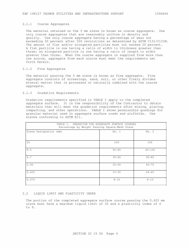
PAF 198127 TACMOR UTILITIES AND INFRASTRUCTURE SUPPORT 1596606
2.1.1 Coarse Aggregates
The material retained on the 5 mm sieve is known as coarse aggregate. Use only coarse aggregates that are reasonably uniform in density and quality. Use only coarse aggregate having a percentage of wear not exceeding 50 percent after 500 revolutions as determined by ASTM C131/C131M. The amount of flat and/or elongated particles must not exceed 20 percent. A flat particle is one having a ratio of width to thickness greater than three; an elongated particle is one having a ratio of length to width greater than three. When the coarse aggregate is supplied from more than one source, aggregate from each source must meet the requirements set forth herein.
2.1.2 Fine Aggregates
The material passing the 5 mm sieve is known as fine aggregate. Fine aggregate consists of screenings, sand, soil, or other finely divided mineral matter that is processed or naturally combined with the coarse aggregate.
2.1.3 Gradation Requirements
Gradation requirements specified in TABLE I apply to the completed aggregate surface. It is the responsibility of the Contractor to obtain materials that will meet the gradation requirements after mixing, placing, compacting, and other operations. TABLE I shows permissible gradings for granular material used in aggregate surface roads and airfields. Use sieves conforming to ASTM E11.
TABLE I. GRADATION FOR AGGREGATE SURFACE COURSESPercentage by Weight Passing Square-Mesh Sieve
Sieve Designation (mm) No. 1 No. 2
25 100 100
9.5 50-85 60-100
4.7 35-65 50-85
2.00 25-50 40-70
0.425 15-30 24-45
0.075 8-15 8-15
2.2 LIQUID LIMIT AND PLASTICITY INDEX
The portion of the completed aggregate surface course passing the 0.425 mm sieve must have a maximum liquid limit of 35 and a plasticity index of 4 to 9.
SECTION 32 15 00 Page 4

PAF 198127 TACMOR UTILITIES AND INFRASTRUCTURE SUPPORT 1596606
2.3 TESTS, INSPECTIONS, AND VERIFICATIONS
2.3.1 Initial Tests
Perform one of each of the following tests, on the proposed material prior to commencing construction, to demonstrate that the proposed material meets all specified requirements when furnished. Complete this testing for each source if materials from more than one source are proposed.
a. Sieve Analysis.
b. Liquid limit and plasticity index.
c. Moisture-density relationship.
d. Wear.
Submit certified copies of test results for approval not less than 30 days before material is required for the work.
2.3.2 Approval of Material
Tentative approval of material will be based on initial test results.
PART 3 EXECUTION
3.1 OPERATION OF AGGREGATE SOURCES
Finalize aggregate sources on private lands in agreement with local laws or authorities.
3.2 STOCKPILING MATERIAL
Prior to stockpiling the material, clear and level the storage sites. Stockpile all materials, including approved material available from excavation and grading, in the manner and at the locations designated. Stockpile aggregates in such a manner that will prevent segregation. Stockpile aggregates and binders obtained from different sources separately.
3.3 PREPARATION OF UNDERLYING COURSE
Clean the underlying course and shoulders of all foreign substances. Correct ruts or soft yielding spots in the underlying course, areas having inadequate compaction and deviations of the surface from the requirements set forth herein by loosening and removing soft or unsatisfactory material and by adding approved material, reshaping to line and grade and recompacting to density requirements specified in Section 32 11 23 AGGREGATE BASE COURSE. Do not allow traffic or other operations to disturb the completed underlying course and maintain in a satisfactory condition until the surface course is placed.
3.4 GRADE CONTROL
During construction, maintain the lines and grades including crown and cross slope indicated for the aggregate surface course by means of line and grade stakes placed by the Contractor in accordance with the SPECIAL CONTRACT REQUIREMENTS.
SECTION 32 15 00 Page 5

PAF 198127 TACMOR UTILITIES AND INFRASTRUCTURE SUPPORT 1596606
3.5 MIXING AND PLACING MATERIALS
Mix and place the materials to obtain uniformity of the material and a uniform optimum water content for compaction. Make adjustments in mixing, placing procedures, or in equipment to obtain the true grades, to minimize segregation and degradation, to obtain the desired water content, and to ensure a satisfactory surface course.
3.6 LAYER THICKNESS
Place the aggregate material on the underlying course in layers of uniform thickness. Compact the completed aggregate surface course to the thickness indicated. No individual layer may be thicker than 150 mm nor be thinner than 75 mm in compacted thickness. Compact the aggregate surface course to a total thickness that is within 13 mm of the thickness indicated. Where the measured thickness is more than 13 mm deficient, correct such areas by scarifying, adding new material of proper gradation, reblading, and recompacting as directed. Where the measured thickness is more than 13 mm thicker than indicated, the course will be considered as conforming to the specified thickness requirements. The average job thickness will be the average of all thickness measurements taken for the job and must be within 6 mm of the thickness indicated. Measure the total thickness of the aggregate surface course at intervals of one measurement for each 500 square meters of surface course. Measure total thickness using 75 mm diameter test holes penetrating the aggregate surface course.
3.7 COMPACTION
Degree of compaction is a percentage of the maximum dry density obtained by the test procedure presented in ASTM D1557 abbreviated herein as percent maximum dry density. Compact each layer of the aggregate surface course with approved compaction equipment, as required in the following paragraphs. Maintain the water content during the compaction procedure at optimum or at the percentage specified by the Contracting Officer. Compact the mixture with mechanical tampers in locations not accessible to rollers. Continue compaction until each layer through the full depth is compacted to at least 100 percent of maximum dry density. Remove any materials that are found to be unsatisfactory and replace them with satisfactory material or rework them to produce a satisfactory material.
3.8 EDGES OF AGGREGATE SURFACE COURSE
Place approved material along the edges of the aggregate surface course in such quantity as to compact to the thickness of the course being constructed. Simultaneously roll and compact at least 300 mm of shoulder width with the rolling and compacting of each layer of the surface course when the course is being constructed in two or more layers.
3.9 SMOOTHNESS TEST
Construct each layer so that the surface shows no deviations in excess of 10 mm when tested with a 3 m straightedge applied both parallel with and at right angles to the centerline of the area to be paved. Correct deviations exceeding this amount by removing material, replacing with new material, or reworking existing material and compacting, as directed.
SECTION 32 15 00 Page 6

PAF 198127 TACMOR UTILITIES AND INFRASTRUCTURE SUPPORT 1596606
3.10 FIELD QUALITY CONTROL
3.10.1 In-Place Tests
Perform each of the following tests on samples taken from the placed and compacted aggregate surface course. Take samples and test at the rates indicated.
a. Perform density tests on every lift of material placed and at a frequency of one set of tests for every 250 square meters, or portion thereof, of completed area.
b. Perform sieve analysis on every lift of material placed and at a frequency of one sieve analysis for every 500 square meters, or portion thereof, of material placed.
c. Perform liquid limit and plasticity index tests at the same frequency as the sieve analysis.
d. Measure the thickness of the aggregate surface course at intervals providing at least one measurement for each 500 square meters of base course or part thereof. Measure the thickness using test holes, at least 75 mm in diameter through the aggregate surface course.
3.10.2 Approval of Material
Final approval of the materials will be based on tests for gradation, liquid limit, and plasticity index performed on samples taken from the completed and full compacted aggregate surface course.
3.11 MAINTENANCE
Maintain the aggregate surface course in a condition that will meet all specification requirements until accepted.
-- End of Section --
SECTION 32 15 00 Page 7

PAF 198127 TACMOR UTILITIES AND INFRASTRUCTURE SUPPORT 1596606
THIS PAGE INTENTIONALLY LEFT BLANK
SECTION 32 15 00 Page 8

PAF 198127 TACMOR UTILITIES AND INFRASTRUCTURE SUPPORT 1596606
SECTION 32 31 13.53
HIGH-SECURITY CHAIN LINK FENCES AND GATES04/08
PART 1 GENERAL
1.1 REFERENCES
The publications listed below form a part of this specification to the extent referenced. The publications are referred to within the text by the basic designation only.
ASTM INTERNATIONAL (ASTM)
ASTM A116 (2011) Standard Specification for Metallic-Coated, Steel Woven Wire Fence Fabric
ASTM A121 (2013) Standard Specification for Metallic-Coated Carbon Steel Barbed Wire
ASTM A153/A153M (2016) Standard Specification for Zinc Coating (Hot-Dip) on Iron and Steel Hardware
ASTM A307 (2014; E 2017) Standard Specification for Carbon Steel Bolts, Studs, and Threaded Rod 60 000 PSI Tensile Strength
ASTM A392 (2011a; R 2017) Standard Specification for Zinc-Coated Steel Chain-Link Fence Fabric
ASTM A563 (2015) Standard Specification for Carbon and Alloy Steel Nuts
ASTM A702 (2013) Standard Specification for Steel Fence Posts and Assemblies, Hot Wrought
ASTM A780/A780M (2009; R 2015) Standard Practice for Repair of Damaged and Uncoated Areas of Hot-Dip Galvanized Coatings
ASTM A824 (2011; R 2017) Standard Specification for Metallic-Coated Steel Marcelled Tension Wire for Use With Chain Link Fence
ASTM A1023/A1023M (2019) Standard Specification for Stranded Carbon Steel Wire Ropes for General Purposes
ASTM C94/C94M (2018) Standard Specification for Ready-Mixed Concrete
ASTM F1043 (2018) Standard Specification for Strength and Protective Coatings on Steel Industrial Fence Framework
SECTION 32 31 13.53 Page 1

PAF 198127 TACMOR UTILITIES AND INFRASTRUCTURE SUPPORT 1596606
ASTM F1083 (2018) Standard Specification for Pipe, Steel, Hot-Dipped Zinc Coated (Galvanized) Welded, for Fence Structures
ASTM F1145 (2017) Standard Specifications for Turnbuckles, Swaged, Welded, Forged
ASTM F1184 (2016) Industrial and Commercial Horizontal Slide Gates
ASTM F567 (2014a) Standard Practice for Installation of Chain Link Fence
ASTM F626 (2014) Standard Specification for Fence Fittings
ASTM F844 (2019) Standard Specification for Washers, Steel, Plain (Flat), Unhardened for General Use
ASTM F883 (2013) Padlocks
ASTM F900 (2011; R 2017) Standard Specification for Industrial and Commercial Swing Gates
U.S. GENERAL SERVICES ADMINISTRATION (GSA)
FS RR-F-191 (Rev K) Fencing, Wire and Post Metal (and Gates, Chain-Link Fence Fabric, and Accessories)
FS RR-F-191/1 (Rev F) Fencing, Wire and Post, Metal (Chain-Link Fence Fabric)
FS RR-F-191/2 (Rev E) Fencing, Wire and Post, Metal (Chain-Link Fence Gates)
FS RR-F-191/3 (Rev E; Am 1) Fencing, Wire and Post, Metal (Chain-Link Fence Posts, Top Rails and Braces)
FS RR-F-191/4 (Rev F) Fencing, Wire and Post, Metal (Chain-Link Fence Accessories)
1.2 SUBMITTALS
Government approval is required for submittals with a "G" designation; submittals not having a "G" designation are for Contractor Quality Control approval. Submit the following in accordance with Section 01 33 00 SUBMITTAL PROCEDURES:
SD-02 Shop Drawings
Fence Installation; GInstallation Drawings; GLocation of gate, corner, end, and pull posts; GGate Assembly; GGate Hardware and Accessories; G
SECTION 32 31 13.53 Page 2

PAF 198127 TACMOR UTILITIES AND INFRASTRUCTURE SUPPORT 1596606
SD-03 Product Data
Fence Installation; GGate Assembly; GGate Hardware and Accessories; G
SD-04 Samples
FabricPostsPost CapsBracesLine PostsSleevesBottom RailTension WireBarbed WireBarbed Wire Supporting ArmsStretcher BarsGate PostsGate Hardware and AccessoriesPadlocksWire TiesFence Fabric Reinforcement
SD-06 Test Reports
zinc coating; G
SD-07 Certificates
Chain Link Fence; GReports; GZinc Coating; GFabric; GBarbed Wire; GStretcher Bars; GGate Hardware and Accessories; GConcrete
SD-08 Manufacturer's Instructions
Fence Installation; GGate Assembly; GHardware AssemblyAccessories
SD-10 Operation and Maintenance Data
operating and maintenance instructions
1.3 QUALITY ASSURANCE
1.3.1 Required Report Data
Submit reports, signed by an official authorized to certify on behalf of the manufacturer, of chain-link fencing listing and accessories regarding weight in grams for zinc coating. Submit reports demonstrating full
SECTION 32 31 13.53 Page 3

PAF 198127 TACMOR UTILITIES AND INFRASTRUCTURE SUPPORT 1596606
compliance with the following standards: FS RR-F-191 , FS RR-F-191/1 , FS RR-F-191/2 , FS RR-F-191/3 , and FS RR-F-191/4
1.3.2 Assembly and Installation Drawings
Submit Manufacturer's instructions and complete Fence Installation Drawings for review and approval by the Contracting Officer prior to shipment. Drawing details shall include, but are not limited to: Fence Installation, Location of gate, corner, end, and pull posts, Fence Fabric Reinforcement, Gate Assembly, and Gate Hardware and Accessories.
1.4 DELIVERY, STORAGE, AND HANDLING
Deliver materials to site in an undamaged condition. Store materials off the ground to provide protection against oxidation caused by ground contact.
PART 2 PRODUCTS
2.1 FENCE FABRIC
2.1.1 General
Provide ASTM A392, Class 2, zinc-coated steel wire with minimum coating weight of 610 grams of zinc per square meter of coated surface. Fabricate fence fabric of 9 gauge wire woven in 50 mm mesh conforming to ASTM A116. Set fabric height at 2.1 m. Fabric shall be twisted and barbed on the top selvage and knuckled on the bottom selvage. Secure fabric to posts using stretcher bars or ties spaced 375 mm on center, or by integrally weaving to integral fastening loops of end, corner, pull, and gate posts for full length of each post. Install fabric on opposite side of posts from area being secured.
2.2 POSTS
2.2.1 Metal Posts for Chain Link Fence
Provide posts conforming to ASTM F1083, zinc-coated. Group IA, with external coating Type A steel pipe. Group IC steel pipe, zinc-coated with external coating Type A or Type B and Group II , roll-formed steel sections, meeting the strength and coating requirements of ASTM F1043 and ASTM A702. Group III, ASTM F1043 steel H-section may be used for line posts in lieu of line post shapes specified for the other classes. Provide sizes as shown on the drawings. Line posts and terminal (corner, gate, and pull) posts selected shall be of the same designation throughout the fence. Provide gate post for the gate type specified subject to the limitation specified in ASTM F900 and/or ASTM F1184. Post spacing shall conform to the recommended guidelines as set forth in the CLFMI "Wind Load Guide for the Selection of Line Post Spacing and Size" unless specified to exceed those guidelines.
FS RR-F-191/3 line posts; Class 1, steel pipe, Grade A or B. End, corner, and pull posts; Class 1, steel pipe, Grade A or B.
2.2.2 Accessories
a. Provide accessories conforming to ASTM F626. Ferrous accessories shall be zinc coated.
SECTION 32 31 13.53 Page 4

PAF 198127 TACMOR UTILITIES AND INFRASTRUCTURE SUPPORT 1596606
b. Furnish truss rods for each terminal post. Provide truss rods with turnbuckles or other equivalent provisions for adjustment.
c. Provide Barbed wire supporting arms of the single 45 degree outward angle 3-strand arm type and of the design required for the post furnished. Secure arms by top tension wire.
d. Furnish post caps in accordance with manufacturer's standard accessories.
e. Provide 9 gauge steel tie wire for attaching fabric to rails, braces, and posts and match the coating of the fence fabric. Tie wires for attaching fabric to tension wire on high security fences shall be 1.6 mm stainless steel. Provide double loop tie wires 165 mm in length. Miscellaneous hardware coatings shall conform to ASTM A153/A153M unless modified.
2.3 BRACES AND RAILS
ASTM F1083, zinc-coated, Group IA, steel pipe, size NPS 1-1/4. Group IC steel pipe, zinc-coated, shall meet the strength and coating requirements of ASTM F1043. Group II, formed steel sections, size 42 mm, conforming to ASTM F1043, may be used as braces and rails if Group II line posts are furnished.
Braces and bottom rail; Class 1, steel pipe, Grade A or B.
2.4 WIRE
2.4.1 Wire Ties
Submit samples as specified. FS RR-F-191/4 . Provide wire ties constructed of the same material as the fencing fabric.
2.4.2 Barbed Wire
Provide barbed wire conforming to ASTM A121 zinc-coated, Type Z, Class 3, or aluminum-coated, Type A, with 12.5 gauge wire with 14 gauge, round, 4-point barbs spaced no more than 125 mm apart.
2.4.3 Tension Wire
Provide Type I or Type II tension wire, Class 4 coating, in accordance with ASTM A824. Provide 7 gauge coil spring wire for top wire.
2.5 CONCRETE
ASTM C94/C94M, using 19 mm maximum size aggregate, and having minimum compressive strength of 21 MPa at 28 days. Grout shall consist of one part portland cement to three parts clean, well-graded sand and the minimum amount of water to produce a workable mix.
2.6 GATES
2.6.1 Gate Assembly
Provide gate assembly conforming to ASTM F900 and/or ASTM F1184 of the type and swing shown. Provide gate frames conforming to strength and coating requirements of ASTM F1083 for Group IA, steel pipe, with external
SECTION 32 31 13.53 Page 5

PAF 198127 TACMOR UTILITIES AND INFRASTRUCTURE SUPPORT 1596606
coating Type A, nominal pipe size (NPS) 1-1/2. Provide gate frames conforming to strength and coating requirements of ASTM F1043, for Group IC, steel pipe with external coating Type A or Type B, nominal pipe size (NPS) 1-1/2. Gate fabric shall be as specified for chain link fabric.
2.6.2 Gate Leaves
For gate leaves, more than 2.44 m wide, provide either intermediate members and diagonal truss rods or tubular members as necessary to provide rigid construction, free from sag or twist. Gate leaves less than 2.44 m wide shall have truss rods or intermediate braces. Attach fabric to the gate frame by method standard with the manufacturer except that welding will not be permitted.
2.6.3 Gate Hardware and Accessories
Submit manufacturer's catalog data. Furnish and install latches, hinges, stops, keepers, rollers, chains and other hardware items as required for the operation of the gate. Arrange latches for padlocking so that the padlock will be accessible from both sides of the gate. Provide stops for holding the gates in the open position. For high security applications, each end member of gate frames shall be extended sufficiently above the top member to carry three strands of barbed wire in horizontal alignment with barbed wire strands on the fence.
2.7 PADLOCKS
Provide padlocks conforming to ASTM F883, Type PO1, Option A, Grade 6. Size 44 mm. Key all padlocks alike.
2.8 FENCE FABRIC REINFORCEMENT
Provide galvanized structural wire rope as indicated and in accordance with ASTM A1023/A1023M , 20 mm nominal diameter of strand, 19 wire strand, regular lay, extra improved plow steel (EIPS), independent wire rope core (IWRC) and with a minimum breaking strength of 9,175 Newtons. Galvanize cable, Class A, in accordance with ASTM A1023/A1023M .
2.8.1 Wire Rope Accessories
All structural steel members used in cable anchoring system shall be hot-dipped galvanized. Clamps, U-bolts, and associated hardware shall be hot-dipped galvanized in accordance with ASTM A153/A153M .
2.8.2 Turnbuckles
Turnbuckles shall be 30 mm x 300 mm x 300 mm Type I, Grade 1 galvanized, in accordance with ASTM F1145.
2.8.3 Rope Clamps
Rope clamps shall be hot-dipped galvanized in accordance with ASTM A153/A153M .
2.8.4 Threaded Rods, U-Bolts, and Bolts
All threaded rods, U-bolts shall conform to ASTM A307 and installed with ASTM F844 and ASTM A563 nuts. The entire bolt assembly shall be galvanized.
SECTION 32 31 13.53 Page 6

PAF 198127 TACMOR UTILITIES AND INFRASTRUCTURE SUPPORT 1596606
PART 3 EXECUTION
3.1 FENCE INSTALLATION
Perform complete installation conforming to ASTM F567.
3.1.1 Line and Grade
Install fence to the lines and grades indicated. Clear the area on either side of the fence line to the extent indicated. Space line posts equidistant at intervals not exceeding 3 m. Terminal (corner, gate, and pull) posts shall be set at abrupt changes in vertical and horizontal alignment. Provide fabric continuous between terminal posts; however, runs between terminal posts shall not exceed 152.4 m. Repair any damage to galvanized surfaces, including welding, with paint containing zinc dust in accordance with ASTM A780/A780M .
3.1.2 Excavation
Clear all post holes of loose material. Spread waste material where directed. Eliminate ground surface irregularities along the fence line to the extent necessary to maintain a 50 mm clearance between the bottom of the fabric and top of mow strip.
3.1.3 Concrete Slabs and Walls
Set posts into zinc-coated sleeves, set in concrete slab or wall, to a minimum depth of 300 mm. Fill sleeve joint with lead, nonshrink grout, or other approved material. Set posts for support of removable fence sections into sleeves that provide a tight sliding joint and hold posts aligned and plumb without use of lead or setting material.
3.2 POST INSTALLATION
3.2.1 Earth and Bedrock
a. Set posts plumb and in alignment. Except where solid rock is encountered, set posts in concrete to the depth indicated on the drawings. Where solid rock is encountered with no overburden, set posts to a minimum depth of 457 mm in rock. Where solid rock is covered with an overburden of soil or loose rock, set posts to the minimum depth indicated on the drawing unless a penetration of 457 mm in solid rock is achieved before reaching the indicated depth, in which case terminate depth of penetration. Grout all portions of posts set in rock.
b. Portions of posts not set in rock shall be set in concrete from the rock to ground level. Posts set in concrete shall be set in holes not less than the diameter shown on the drawings. Make diameters of holes in solid rock at least 25 mm greater than the largest cross section of the post. Thoroughly consolidate concrete and grout around each post, free of voids and finished to form a dome. Allow concrete and grout to cure for 72 hours prior to attachment of any item to the posts. Group II line posts may be mechanically driven, for temporary fence construction only, if rock is not encountered. Set driven posts to a minimum depth of 914 mm and protect with drive caps when setting.
c. Test fence post rigidity by applying a 222.4 newtons force on the
SECTION 32 31 13.53 Page 7

PAF 198127 TACMOR UTILITIES AND INFRASTRUCTURE SUPPORT 1596606
post, perpendicular to the fabric, at 1.52 m above ground. Post movement measured at the point where the force is applied shall be less than or equal to 19 mm from the relaxed position. Test every tenth post for rigidity. When a post fails this test, make further tests on the next four posts on either side of the failed post. All failed posts shall be removed, replaced, and retested at the Contractor's expense.
3.2.2 Concrete Slabs and Walls
Set posts into zinc-coated sleeves, set in concrete slab or wall, to a minimum depth of 300 mm. Fill sleeve joint with lead, nonshrink grout, or other approved material. Set posts for support of removable fence sections into sleeves that provide a tight sliding joint and hold posts aligned and plumb without use of lead or setting material.
3.3 RAILS
Bolt bottom rail to double rail ends and securely fasten double rail ends to the posts. Peen bolts to prevent easy removal. Install bottom rail before chain link fabric.
3.4 FABRIC INSTALLATION
a. Install chain link fabric on the side of the post indicated. Attach fabric to terminal posts with stretcher bars and tension bands. Space bands at approximately 381 mm intervals. Install fabric and pull taut to provide a smooth and uniform appearance free from sag, without permanently distorting the fabric diamond or reducing the fabric height. Fasten fabric to line posts at approximately 381 mm intervals and fastened to all rails and tension wires at approximately 305 mm intervals.
b. Cut fabric by untwisting and removing pickets. Accomplish splicing by weaving a single picket into the ends of the rolls to be joined. The bottom of the installed fabric shall be 50 mm plus or minus 13 mm above the top of the mow strip.
c. After the fabric installation is complete, exercise the fabric by applying a 222 newtons push-pull force at the center of the fabric between posts; the use of a 133 newtons pull at the center of the panel shall cause fabric deflection of not more than 63.5 mm when pulling fabric from the post side of the fence; every second fence panel shall meet this requirement; resecure and retest all failed panels at the Contractor's expense.
3.5 SUPPORTING ARMS
Install barbed wire supporting arms and barbed wire as indicated on the drawings and as recommended by the manufacturer. Anchor supporting arms to the posts in a manner to prevent easy removal with hand tools. Pull barbed wire taut and attach to the arms with clips or other means that will prevent easy removal.
3.6 GATE INSTALLATION
a. Install gates at the locations shown. Mount gates to swing as indicated. Install latches, stops, and keepers as required.
SECTION 32 31 13.53 Page 8

PAF 198127 TACMOR UTILITIES AND INFRASTRUCTURE SUPPORT 1596606
b. Attach padlocks to gates or gate posts with chains. Weld or otherwise secure hinge pins, and hardware assembly to prevent removal.
c. Submit 6 copies of operating and maintenance instructions, a minimum of 2 weeks prior to field training. Operating instructions shall outline the step-by-step procedures required for system startup, operation, and shutdown. Include the manufacturer's name, model number, service manual, parts list, and brief description of all equipment and their basic operating features. Include in the maintenance instructions routine maintenance procedures, possible breakdowns and repairs, and troubleshooting guide. Also include the general gate layout, equipment layout and simplified wiring and control diagrams of the system as installed.
3.7 CABLE REINFORCEMENT INSTALLATION
Comply with the contract drawings. Install 2 strands of 20 mm steel aircraft cables mounted to the chain link fence posts utilizing u-bolts and nuts. Peen the ends of the U-bolts to prevent removal. Tighten cables with galvanized steel turnbuckles with swaged fittings to the point there is no visible sag. Install 915 mm x 915 mm x 458 mm concrete deadman anchors which are a minimum of 915 mm underground and installed in undisturbed surrounding soils. Space dead man anchors no more than 61 m apart and on each side of gate openings. Connect steel aircraft cables to dead man anchors using swaged end fittings and turnbuckles attached to 3.2 cm galvanized threaded rod which is embedded into concrete anchor and held in place with two 10 cm x 10 cm x 0.66 cm thick steel plates welded to the threaded rod. Place deadman anchors within 3 m of last post and on each side of gate openings.
3.8 GROUNDING
a. Ground fencing as indicated on drawings and 30 m minimum.
b. Ground fences crossed by overhead powerlines in excess of 600 volts. Electrical equipment attached to the fence shall be grounded.
c. Ground fences on each side of all gates, at each corner, at the closest approach to each building located within 15 m of the fence, and where the fence alignment changes more than 15 degrees. Grounding locations shall not exceed 198 m. Bond each gate panel with a flexible bond strap to its gate post. Ground fences crossed by powerlines of 600 volts or more at or near the point of crossing and at distances not exceeding 45 m on each side of crossing.
d. Provide ground conductor consisting of No. 8 AWG solid copper wire. Grounding electrodes shall be 19 mm by 3.05 m long copper-clad steel rod. Drive electrodes into the earth so that the top of the electrode is at least 152 mm below the grade. Where driving is impracticable, electrodes shall be buried a minimum of 305 mm deep and radially from the fence. The top of the electrode shall not be less than 610 mm or more than 2.4 m from the fence. Clamp ground conductor to the fence and electrodes with bronze grounding clamps to create electrical continuity between fence posts, fence fabric, and ground rods. Total resistance of the fence to ground shall not be greater than 25 ohms.
3.9 CLEANUP
Remove waste fencing materials and other debris from the work site each
SECTION 32 31 13.53 Page 9

PAF 198127 TACMOR UTILITIES AND INFRASTRUCTURE SUPPORT 1596606
workday.
-- End of Section --
SECTION 32 31 13.53 Page 10

PAF 198127 TACMOR UTILITIES AND INFRASTRUCTURE SUPPORT 1596606
SECTION 32 31 26
WIRE FENCES, GATES, AND BACKING BEAMS04/08
PART 1 GENERAL
1.1 REFERENCES
The publications listed below form a part of this specification to the extent referenced. The publications are referred to within the text by the basic designation only.
AMERICAN WOOD PROTECTION ASSOCIATION (AWPA)
AWPA E1 (2017) Laboratory Methods for Evaluating the Termite Resistance of Wood Based Materials: Choice and No-choice Tests
AWPA U1 (2017) Use Category System: User Specification for Treated Wood
ASME INTERNATIONAL (ASME)
ASME B18.6.1 (2016) Wood Screws
ASTM INTERNATIONAL (ASTM)
ASTM B117 (2016) Standard Practice for Operating Salt Spray (Fog) Apparatus
ASTM C1002 (2018) Standard Specification for Steel Self-Piercing Tapping Screws for the Application of Gypsum Panel Products or Metal Plaster Bases to Wood Studs or Steel Studs
ASTM C94/C94M (2018) Standard Specification for Ready-Mixed Concrete
ASTM D1413 (2005) Standard Test Method for Wood Preservatives by Laboratory Soil -Block Cultures
ASTM D1761 (2012) Standard Test Methods for Mechanical Fasteners in Wood
ASTM D1929 (2016) Standard Test Method for Determining Ignition Temperature of Plastics
ASTM D2240 (2015; E 2017) Standard Test Method for Rubber Property - Durometer Hardness
ASTM D2395 (2017) Standard Test Methods for Density and Specific Gravity (Relative Density) of Wood and Wood-Based Materials.
SECTION 32 31 26 Page 1

PAF 198127 TACMOR UTILITIES AND INFRASTRUCTURE SUPPORT 1596606
ASTM D2583 (2013a) Indentation Hardness of Rigid Plastics by Means of a Barcol Impressor
ASTM D2584 (2018) Standard Test Method for Ignition Loss of Cured Reinforced Resins
ASTM D4060 (2019) Abrasion Resistance of Organic Coatings by the Taber Abraser
ASTM D4329 (2013) Standard Practice for Fluorescent UV Exposure of Plastics
ASTM D4761 (2019) Standard Test Methods for Mechanical Properties of Lumber and Wood-Based Structural Materials
ASTM D6109 (2016) Standard Test Methods for Flexural Properties of Unreinforced and Reinforced Plastic Lumber and Related Products
ASTM D256 (2010; R 2018) Standard Test Methods for Determining the Izod Pendulum Impact Resistance of Plastics
ASTM D543 (2014) Standard Practices for Evaluating the Resistance of Plastics to Chemical Reagents
ASTM D570 (1998; E 2010; R 2010) Standard Test Method for Water Absorption of Plastics
ASTM D638 (2014) Standard Test Method for Tensile Properties of Plastics
ASTM D695 (2010) Standard Test Method for Compressive Properties of Rigid Plastics
ASTM D696 (2016) Standard Test Method for Coefficient of Linear Thermal Expansion of Plastics Between -30 degrees C and 30 degrees C With a Vitreous Silica Dilatometer
ASTM D746 (2014) Standard Test Method for Brittleness Temperature of Plastics and Elastomers by Impact
ASTM D790 (2017) Standard Test Methods for Flexural Properties of Unreinforced and Reinforced Plastics and Electrical Insulating Materials
ASTM D792 (2013) Density and Specific Gravity (Relative Density) of Plastics by Displacement
ASTM F883 (2013) Padlocks
SECTION 32 31 26 Page 2

PAF 198127 TACMOR UTILITIES AND INFRASTRUCTURE SUPPORT 1596606
U.S. ENVIRONMENTAL PROTECTION AGENCY (EPA)
EPA SW-846 (Third Edition; Update IV) Test Methods for Evaluating Solid Waste: Physical/Chemical Methods
1.2 SUBMITTALS
Government approval is required for submittals with a "G" designation; submittals not having a "G" designation are for Contractor Quality Control approval. Submit the following in accordance with Section 01 33 00 SUBMITTAL PROCEDURES:
SD-02 Shop Drawings
Installation Drawings; GFence Installation; GLocation of Gate, Corner, End, and Pull Posts; GGate Assembly; GGate Hardware and Accessories; GPlastic Backing Beam; GPlastic Backing Beam Hardware And Accesories; G
SD-03 Product Data
Manufacturer's Instructions; GGate AssemblyGate Hardware and AccessoriesBacking Beam And Support BlockFRP Anchor RodsFRP Reinforcing Bars
SD-04 Samples
Posts; GPost Caps; GBracesRail; GGate Posts; GGate Hardware and Accessories; GPadlocks; G
1.3 QUALITY ASSURANCE
Provide manufacturer's instructions that detail proper assembly and materials in the design for fence, gate assembly, gate hardware and accessories, plastic backing beam, backing beam and support block, FRP anchor rods, FRP reinforcing bars, and plastic backing beam hardware and accesories. Submit Installation drawings clearly indicating Fence Installation Location of gate, corner, end, and pull posts; Gate Assembly, Gate Hardware, Plastic Backing Beam, catalog data and Accessories.
1.3.1 Backing Beam Fabricator Qualifications
Firm experienced in producing plastic marine timbers similar to those required for this project with a record of successful in-service performance, and with sufficient production capacity to produce required units without delaying the work.
SECTION 32 31 26 Page 3

PAF 198127 TACMOR UTILITIES AND INFRASTRUCTURE SUPPORT 1596606
1.4 DELIVERY, STORAGE, AND HANDLING
Plastic backing beams shall be stored and handled in the manner recommended by the manufacturer to prevent permanent deflection, distortion, or damage. Deliver materials to site in an undamaged condition. Store materials off the ground to provide protection against oxidation caused by ground contact.Storage racks shall be arraged to permit air circulation. Plastic backing beams shall not be rolled. Prior to shipment, submit the following samples for review and approval:
PostsPost CapsBracesRailGate PostsGate Hardware and AccessoriesPadlocks
PART 2 PRODUCTS
2.1 SYSTEM DESCRIPTION
Provide a fencing system as described herein.
Submit Installation Drawings clearly indicating fence installation,location of gates, corners, ends, and pull posts; gate assembly, gatehardware, catalog data and accessories.
2.2 WOOD COMPOSITE
Provide fence post, post caps, rail, braces, gates, and vertical slat of wood and plastic composite or reclaimed wood and plastic composite with integral coloring; free from toxic chemicals and preservatives with the following characteristics:
a. Specific Gravity: 0.91 to 0.95, tested to ASTM D2395 or 1.0 to 1.2 tested to ASTM D792
b. Modulus of Rupture: 9.81 MpaUltimate, 1.72 Mpa Design tested to ASTM D4761, or 24.13 Mpa, tested to ASTM D6109
c. Modulus of Elasticity: 1206.58 MpaUltimate, 689.47 Mpa Design tested to ASTM D4761, or 3144 Mpa tested to ASTM D6109
d. Self Ignition Temperature: 395 degrees C, tested to ASTM D1929
e. Flash Ignition Temperature: 370 degrees C, tested to ASTM D1929
f. Fungus Resistance, White and Brown Rot: No decay, tested to ASTM D1929 or ASTM D1413
g. Termite resistance: 9.6 rating, tested to AWPA E1
h. Wind Load: 177 km/h Steady Wind and 209 km/h gusting wind
2.3 WOOD POSTS AND RAILS
Provide wood composite posts and rails cut from sound and solid trees free
SECTION 32 31 26 Page 4

PAF 198127 TACMOR UTILITIES AND INFRASTRUCTURE SUPPORT 1596606
from short or reverse bends in more than one plane. Make tops convex rounded or inclined. Provide posts free of ring shake, season cracks more than 6 mm wide, splits in the end, and unsound knots. Provide posts of size and shape indicated. Treat posts in accordance with AWPA U1 as applicable.
2.4 ACCESSORIES
2.4.1 Fasteners
Type 316 stainless steel, zinc-coated, or polymer-coated composite deck screw complying with ASTM C1002, ASTM D1761 and ASME B18.6.1 . Minimum #8. Polymer coated screws, ASTM B117. Provide finish nails.
2.4.2 Brackets
Type 316 stainless steel, zinc-coated steel, or aluminum.
2.4.3 Gate Hardware
Type 316 stainless steel or zinc-coated steel hinges, brackets, and latching.
2.5 PLASTIC BACKING BEAMS AND ACCESORIES
Backing beams and the support block material shall be a mixture of one or more of the following thermoplastics: high density polyethylene, polypropylene, and low density polyethylene with a minimum of 5.0% (by weight) carbon black. Color of the backing beams and support blocks shall be safety yellow throughout the resin matrix.
Beams shall be one piece as indicated on the Contract Drawings. Skin shall be seamless with a smooth outer skin. No splices shall be permitted.
Backing beams shall exhibit the following physical properties:
COMPOSITE PROPERTIES
Property Requirements Test Method
Size 250 mm x 250 mm
Reinforcing Type Fiberglass Rebar
Reinforcing Number and Size 4 - #11 Bars
Modulus of Elasticity, Minimum(Secant Modulus @ 1% Strain)
3100 Mpa ASTM D638
Yield Stress in Bending, Maximum
35 Mpa ASTM D790
SECTION 32 31 26 Page 5

PAF 198127 TACMOR UTILITIES AND INFRASTRUCTURE SUPPORT 1596606
PLASTIC BACKING BEAM SKIN
Property Requirements Test Method
Color Safety Yellow
Water Absorption, Maximum 0% ASTM D570
Impact Resistance, Minimum 5.4 n-m/mm ASTM D746
Brittleness No Break at 233 K@ 6.8 n-m/mm
ASTM D746
Hardness, Shore D 40 to 65 ASTM D2240
Compressive Modulus, Minimum 520 Mpa ASTM D695
Abrasion Weight Loss = 0.0272gWear Index = 2.72
ASTM D406010,000 CyclesCS17 Wheels 1 kgLoad
PLASTIC BACKING BEAM CORE
Property Requirements Test Method
Color Safety Yellow
Water Absorption, Maximum 0.44% @ 2 hours2.33% @ 24 hours
ASTM D570
Compressive Modulus, Minimum 310 Mpa ASTM D695
PLASTIC BACKING BEAM SKIN & CORE
Property Requirements Test Method
Ultraviolet Degradation,Maximum
10% Change in Shore DHardness @ 500 hour
ASTM D4329
Ultimate Tensile Strength,Minimum
3 Mpa ASTM D638
Nail Pull Out (6-penny Nail),Minimum
36 kg ASTM D1761 Section 102
Density 6 to 10 kN/m3 ASTM D792
SECTION 32 31 26 Page 6

PAF 198127 TACMOR UTILITIES AND INFRASTRUCTURE SUPPORT 1596606
PLASTIC BACKING BEAM SKIN & CORE
Chemical Resistance, SeaWater
1.03% mass increase0.84% thickness increase0.37% diameter increase20 kg breaking force6 Mpa breaking pressure
ASTM D543
Chemical Resistance, Gasoline 6.00% mass increase0.65% thickness increase0.75% diameter increase23 kg breaking force6 Mpa breaking pressure
ASTM D543
Chemical Resistance, DieselFuel
4.10% mass increase1.00% thickness increase0.75% diameter increase26 kg breaking force7 Mpa breaking pressure
ASTM D543
Toxicity CharacteristicLeaching Procedure, Maximum
SilverArsenicBariumCadmiumChromiumCopperIronMercuryLeadSeleniumZinc
0.00 ppm0.0 ppm0.0 ppm0.0 ppm0.0 ppm0.4 ppm2.2 ppm0.00 ppm0.0 ppm0 ppm0.7 ppm
EPA SW-846
FIBERGLASS REINFORCING
Ultimate Tensile Strength,Minimum
480 Mpa ASTM D638
Flexural Strength, Minimum 480 Mpa ASTM D790
Compressive Strength, Minimum 275 Mpa ASTM D695
Anchor rods shall be made of high strength pultruded fiberglass reinforced plastic polyester resin and have a smooth outside surface. The ends shall be slightly beveled. Physical properties of the FRP for the anchor rods shall be as follows:
FRP ANCHOR RODS
Glass Content, By Weight 70% to 75% ASTM D2584
SECTION 32 31 26 Page 7

PAF 198127 TACMOR UTILITIES AND INFRASTRUCTURE SUPPORT 1596606
FRP ANCHOR RODS
Ultimate Tensile Strength,Minimum
827 Mpa ASTM D638
Tensile Modulus, Minimum 730,800 Mpa ASTM D638
Flexural Strength, Minimum 827 Mpa ASTM D790
Flexural Modulus, Minimum 730,800 Mpa ASTM D790
Compressive Strength, Minimum 480 Mpa ASTM D695
Barcoal Hardness 60 ASTM D2583
Izod Impact Strength 54 N-m/cm ASTM D256
Specific Gravity 2.0 ASTM D792
Density 13 N/m ASTM D792
Water Absorption, Maximum 0.05% @ 24 hours ASTM D570
Coefficient of Thermal Expansion
1.3 X 10⁻⁴ mm/mm/ oC ASTM D696
2.6 CONCRETE
ASTM C94/C94M, using 19 mm maximum size aggregate, and having minimum compressive strength of 21 MPa at 28 days. Provide grout consisting of one part portland cement to three parts clean, well-graded sand and the minimum amount of water to produce a workable mix.
2.7 PADLOCKS
Provide padlocks conforming to ASTM F883, TYPE P01, GRADE 6, OPTION A, and OPTION 6, size 44 mm. All padlocks shall be keyed alike.
PART 3 EXECUTION
3.1 INSTALLATION
Install fence to the lines and grades indicated. Clear the area on either side of the fence line to the extent indicated. Follow manufacturer's instructions.
Plastic backing beams shall be furnished and installed in the locations shown on the Contract Drawings. The backing beams shall be straight and even. Longitudinal reinforcement shall have adequate cover and shall not be exposed. Core or form 45 mm diameter drill hole into top of concrete coping for anchor rods. The holes shall be cleaned of any loose particles with compressed air immediately prior to installing anchors. Field treat cuts, bevels, notches, refacing, and abrasions made in the field in accordance the manufacturer's recommendations.
SECTION 32 31 26 Page 8

PAF 198127 TACMOR UTILITIES AND INFRASTRUCTURE SUPPORT 1596606
3.2 EXCAVATION
Clear loose material from all post holes. Spread waste material where directed.
3.3 POST INSTALLATION
For wood composite posts, excavate to depth indicated and brace post until backfill is completed. Place backfill in layers of 229 mm or less, moistened to optimum condition, and compacted with hand tampers or other approved method. Set posts plumb and in proper alignment. Wood composite post for gates and fence with vertical slates shall be set in concrete as indicated.
3.4 GATE ASSEMBLY
Follow manufacturer's instructions. Gates open outward.
3.5 MOW STRIP
Install mow strip as indicated on plans.
-- End of Section --
SECTION 32 31 26 Page 9

PAF 198127 TACMOR UTILITIES AND INFRASTRUCTURE SUPPORT 1596606
THIS PAGE INTENTIONALLY LEFT BLANK
SECTION 32 31 26 Page 10

PAF 198127 TACMOR UTILITIES AND INFRASTRUCTURE SUPPORT 1596606
SECTION 32 92 19
SEEDING08/17
PART 1 GENERAL
1.1 REFERENCES
The publications listed below form a part of this specification to the extent referenced. The publications are referred to within the text by the basic designation only.
ASTM INTERNATIONAL (ASTM)
ASTM C602 (2013a) Agricultural Liming Materials
ASTM D4972 (2018) Standard Test Methods for pH of Soils
U.S. DEPARTMENT OF AGRICULTURE (USDA)
AMS Seed Act (1940; R 1988; R 1998) Federal Seed Act
DOA SSIR 42 (1996) Soil Survey Investigation Report No. 42, Soil Survey Laboratory Methods Manual, Version 3.0
1.2 DEFINITIONS
1.2.1 Stand of Turf
95 percent ground cover of the established species.
1.3 RELATED REQUIREMENTS
Section 31 23 00.00 20 EXCAVATION AND FILL and Section 32 05 33 LANDSCAPE ESTABLISHMENT applies to this section for pesticide use and plant establishment requirements, with additions and modifications herein.
1.4 SUBMITTALS
Government approval is required for submittals with a "G" designation; submittals not having a "G" designation are for Contractor Quality Control approval. Submit the following in accordance with Section 01 33 00 SUBMITTAL PROCEDURES:
SD-03 Product Data
Wood Cellulose Fiber Mulch
Fertilizer
Include physical characteristics, and recommendations.
SD-06 Test Reports
Topsoil Composition Tests (reports and recommendations).
SECTION 32 92 19 Page 1

PAF 198127 TACMOR UTILITIES AND INFRASTRUCTURE SUPPORT 1596606
SD-07 Certificates
Certification and Approval for Seed
1.5 DELIVERY, STORAGE, AND HANDLING
1.5.1 Delivery
1.5.1.1 Seed Protection
Protect from drying out and from contamination during delivery, on-site storage, and handling.
1.5.1.2 Fertilizer, Gypsum, Sulfur, Iron, Lime, and Geobinder Delivery
Deliver to the site in original, unopened containers bearing manufacturer's chemical analysis, name, trade name, trademark, and indication of conformance to state and federal laws. Instead of containers, fertilizer, gypsum, sulphur, iron, lime, and geobinder may be furnished in bulk with certificate indicating the above information.
1.5.2 Storage
1.5.2.1 Seed, Fertilizer, Gypsum, Sulfur, Iron, Lime, and Geobinder Storage
Store in cool, dry locations away from contaminants.
1.5.2.2 Topsoil
Prior to stockpiling topsoil, treat growing vegetation with application of appropriate specified non-selective herbicide. Clear and grub existing vegetation three to four weeks prior to stockpiling topsoil.
1.5.2.3 Handling
Do not drop or dump materials from vehicles.
1.6 TIME RESTRICTIONS AND PLANTING CONDITIONS
1.6.1 Restrictions
Do not plant when the ground is muddy, or when air temperature exceeds 32 degrees Celsius.
1.7 TIME LIMITATIONS
1.7.1 Seed
Apply seed within twenty four hours after seed bed preparation.
PART 2 PRODUCTS
2.1 SEED
2.1.1 Classification
Provide seed of the latest season's crop delivered in original sealed packages, bearing producer's guaranteed analysis for percentages of
SECTION 32 92 19 Page 2

PAF 198127 TACMOR UTILITIES AND INFRASTRUCTURE SUPPORT 1596606
mixtures, purity, germination, weedseed content, and inert material. Label in conformance with AMS Seed Act and applicable state seed laws. Wet, moldy, or otherwise damaged seed will be rejected. Field mixes will be acceptable when field mix is performed on site in the presence of the Contracting Officer.
2.1.2 Grass Seed for General Surface Stabilization
Seed Mix for temporary and permanent surface stabilization at Tx and Rx project sites:
Signal Grass (Barachiaria decumbens)
Pure Seed 80 percent minimumOther Seeds 0 percent maximumInert matter 20 percent maximumGermination 70 percent minimum
Japanese Millet (Echinocholoa utilis)
Pure Seed 95 percent minimumOther Seeds 0 percent maximumInert matter 5 percent maximumGermination 85 percent minimum
Stylo 184 (Stylosanthes guianensis)
Pure Seed 92 percent minimumOther Seeds 0 percent maximumInert matter 8 percent maximumGermination 80 percent minimum
Mix and apply at the following rates:
Signal Grass 100 kilograms/hectareJapanese Millet 50 kilograms/hectareStylo 184 60 kilograms/hectare
2.1.3 Grass Turf Seed for Tx Earth Mat
Seed Turf Mix for Tx Earth Mat only.
Zenith Zoysiagrass (Zoysia japonica Steud.) aka Japanese Lawngrass
Pure Seed 100 percent minimumOther Seeds 0 percent maximumInert matter 0 percent maximumGermination 90 percent minimum
Apply at the following rate:
Zenith Zoysia 100 kilograms/hectare
2.2 TOPSOIL
2.2.1 On-Site Topsoil
Surface soil stripped and stockpiled on site and modified as necessary to meet the requirements specified for topsoil in paragraph COMPOSITION.
SECTION 32 92 19 Page 3

PAF 198127 TACMOR UTILITIES AND INFRASTRUCTURE SUPPORT 1596606
When available topsoil must be existing surface soil stripped and stockpiled in accordance with Section 31 23 00.00 20 EXCAVATION AND FILL.
2.2.2 Off-Site Topsoil
Conform to requirements specified in paragraph COMPOSITION. Additional topsoil must be furnished by the Contractor.
2.2.3 Composition
Containing from 5 to 10 percent organic matter as determined by the topsoil composition tests of the Organic Carbon, 6A, Chemical Analysis Method described in DOA SSIR 42 . Maximum particle size, 19 mm, with maximum 3 percent retained on 6 mm screen. The pH must be tested in accordance with ASTM D4972. Topsoil must be free of sticks, stones, roots, and other debris and objectionable materials. Other components must conform to the following limits:
Silt 25-50 percent
Clay 10-30 percent
Sand 20-35 percent
pH 5.5 to 7.0
Soluble Salts 600 ppm maximum
2.3 SOIL CONDITIONERS
Add conditioners to topsoil as required to bring into compliance with "composition" standard for topsoil as specified herein.
2.3.1 Lime
Commercial grade limestone containing a calcium carbonate equivalent (C.C.E.) as specified in ASTM C602 of not less than 80 percent.
2.3.2 Aluminum Sulfate
Commercial grade.
2.3.3 Sulfur
100 percent elemental
2.3.4 Iron
100 percent elemental
2.3.5 Sand
Clean and free of materials harmful to plants.
2.3.6 Perlite
Horticultural grade.
SECTION 32 92 19 Page 4

PAF 198127 TACMOR UTILITIES AND INFRASTRUCTURE SUPPORT 1596606
2.3.7 Composted Derivatives
Ground bark, nitrolized sawdust, humus or other green wood waste material free of stones, sticks, and soil stabilized with nitrogen and having the following properties:
2.3.7.1 Particle Size
Minimum percent by weight passing:
4.75 mm screen 952.36 mm screen 80
2.3.7.2 Nitrogen Content
Minimum percent based on dry weight:
Fir Sawdust 0.7Fir or Pine Bark 1.0
2.3.8 Gypsum
Coarsely ground gypsum comprised of calcium sulfate dihydrate 80 percent, calcium 18 percent, sulfur 14 percent; minimum 96 percent passing through 850 micrometers, 100 percent passing thru 970 micrometers screen.
2.3.9 Calcined Clay
Calcined clay must be granular particles produced from montmorillonite clay calcined to a minimum temperature of 650 degrees C. Gradation: A minimum 90 percent must pass a 2.36 mm sieve; a minimum 99 percent must be retained on a 0.250 mm sieve; and material passing a 0.150 mm sieve must not exceed 2 percent. Bulk density: A maximum 640 kilogram per cubic meter.
2.4 FERTILIZER
2.4.1 Hydroseeding Fertilizer
Controlled release fertilizer, to use with hydroseeding and composed of pills coated with plastic resin to provide a continuous release of nutrients for at least 6 months and containing the following minimum percentages, by weight, of plant food nutrients.
For Grass Seed for General Soil Stabilization:
8 percent available nitrogen26 percent available phosphorus18 percent available potassium
For Zenith Zoysia:
8 percent available nitrogen8 percent available phosphorus8 percent available potassium
2.5 MULCH
Mulch must be free from noxious weeds, mold, and other deleterious
SECTION 32 92 19 Page 5

PAF 198127 TACMOR UTILITIES AND INFRASTRUCTURE SUPPORT 1596606
materials.
2.5.1 Wood Cellulose Fiber Mulch
Use recovered materials of either paper-based (100 percent post-consumer content) or wood-based (100 percent total recovered content) hydraulic mulch. Processed to contain no growth or germination-inhibiting factors and dyed an appropriate color to facilitate visual metering of materials application. Composition on air-dry weight basis: 9 to 15 percent moisture, pH range from 5.5 to 8.2. Use with hydraulic application of grass seed and fertilizer.
2.6 WATER
Source of water must be approved by Contracting Officer and of suitable quality for irrigation, containing no elements toxic to plant life.
2.7 GEOBINDER
Geobinder must be a formulated gypsum based product that readily mixes with water and mulch to form a thin protective crust that will resist the effects of water and wind erosion. Geobinder must be designed for application by conventional hydroseeding equipment and shall be nontoxic, noncombustible, environmentally benign, harmless to fish, birds, plants, and animals.
Geobinder must consist of a high purity gypsum (86 percent minimum purity_ that is ground, calcined, and processed into calcium sulface hemihydrate (CaSO4*1/2H20). Geobinder must be furnished in bags labeled as to its intended use/application, dry weight, and source of manufacturer. Material which as been partially air set, hardened, lumpy, or caked prior to use must not be used and will be rejected. Materials must not be stored in the open or exposed to the environment prior to application.
PART 3 EXECUTION
3.1 PREPARATION
3.1.1 EXTENT OF WORK
For Tx project site, provide soil preparation prior to planting (including soil conditioners as required), fertilizing, seeding, and surface topdressing of all newly graded finished earth surfaces, unless indicated otherwise, and at all areas inside or outside the limits of construction that are disturbed by the Contractor's operations.
For Rx project site, prior to planting, prepare finish surfaces in accordance with Section 31 23 00.00 20 EXCAVATION AND FILL, 3.4 Subgrade Preparation, unless indicated otherwise, and all areas inside or outside the limits of construction that are disturbed by the Contractor's operations.
3.1.1.1 Topsoil
Provide 102 mm of off-site topsoil or on-site topsoil to meet indicated finish grade at Tx project site. After areas have been brought to indicated finish grade, incorporate fertilizer, pH adjusters, and/or soil conditioners into soil a minimum depth of 100 mm by disking, harrowing, tilling or other method approved by the Contracting Officer. Remove
SECTION 32 92 19 Page 6

PAF 198127 TACMOR UTILITIES AND INFRASTRUCTURE SUPPORT 1596606
debris and stones larger than 19 mm in any dimension remaining on the surface after finish grading. Correct irregularities in finish surfaces to eliminate depressions. Protect finished topsoil areas from damage by vehicular or pedestrian traffic.
3.1.1.2 Fertilizer Application Rates
Apply fertilizer at rates as determined by laboratory soil analysis of the soils at the job site. For bidding purposes only apply at rates for the following:
Hydroseeding Fertilizer 600 kg per hectare.
3.2 SEEDING
3.2.1 Seed Application Seasons and Conditions
Immediately before seeding, restore soil to proper grade. Do not seed when ground is muddy or in an unsatisfactory condition for seeding. If special conditions exist that may warrant a variance in the above seeding dates or conditions, submit a written request to the Contracting Officer stating the special conditions and proposed variance. Apply seed within twenty four hours after seedbed preparation. Sow seed by approved sowing equipment. Sow one-half the seed in one direction, and sow remainder at right angles to the first sowing.
3.2.2 Seed Application Method
Seeding method must be hydroseeding.
3.2.2.1 Hydroseeding
First, mix water,geobinder tackifier, and fiber. Wood cellulose fiber, paper fiber, or recycled paper must be applied as part of the hydroseeding operation with geobinder tackifier. Fiber must be added at 11.2 kg per 100 square meter. Then add and mix seed and fertilizer to produce a homogeneous slurry. Seed must be mixed to ensure broadcasting at the rate of 6,700 kilograms per hectare. When hydraulically sprayed on the ground, material must form a blotter like cover impregnated uniformly with grass seed. Spread with one application with no second application of mulch.
3.2.3 Watering
Start watering areas seeded as required by temperature and wind conditions. Apply water at a rate sufficient to insure thorough wetting of soil to a depth of 50 mm without run off. During the germination process, seed is to be kept actively growing and not allowed to dry out.
3.3 PROTECTION OF TURF AREAS
Immediately after turfing, protect area against traffic and other use.
3.4 RESTORATION
Restore to original condition existing turf areas which have been damaged
SECTION 32 92 19 Page 7

PAF 198127 TACMOR UTILITIES AND INFRASTRUCTURE SUPPORT 1596606
during turf installation operations at the Contractor's expense. Keep clean at all times at least one paved pedestrian access route and one paved vehicular access route to each building. Clean other paving when work in adjacent areas is complete.
-- End of Section --
SECTION 32 92 19 Page 8

PAF 198127 TACMOR UTILITIES AND INFRASTRUCTURE SUPPORT 1596606
SECTION 33 11 00
WATER UTILITY DISTRIBUTION PIPING02/18
PART 1 GENERAL
1.1 REFERENCES
The publications listed below form a part of this specification to the extent referenced. The publications are referred to within the text by the basic designation only.
AMERICAN WATER WORKS ASSOCIATION (AWWA)
AWWA C600 (2017) Installation of Ductile-Iron Mains and Their Appurtenances
ASTM INTERNATIONAL (ASTM)
ASTM D1784 (2011) Standard Specification for Rigid Poly(Vinyl Chloride) (PVC) Compounds and Chlorinated Poly(Vinyl Chloride) (CPVC) Compounds
ASTM D1785 (2015; E 2018) Standard Specification for Poly(Vinyl Chloride) (PVC), Plastic Pipe, Schedules 40, 80, and 120
ASTM D2241 (2015) Standard Specification for Poly(Vinyl Chloride) (PVC) Pressure-Rated Pipe (SDR Series)
ASTM D2466 (2017) Standard Specification for Poly(Vinyl Chloride) (PVC) Plastic Pipe Fittings, Schedule 40
ASTM D2467 (2015) Standard Specification for Poly(Vinyl Chloride) (PVC) Plastic Pipe Fittings, Schedule 80
ASTM D2774 (2012) Underground Installation of Thermoplastic Pressure Piping
ASTM D2855 (2015) Standard Practice for Making Solvent-Cemented Joints with Poly(Vinyl Chloride) (PVC) Pipe and Fittings
ASTM F2164 (2013) Standard Practice for Field Leak Testing of Polyethylene (PE) and Crosslinked Polyethylene (PEX) Pressure Piping Systems Using Hydrostatic Pressure
ASTM F402 (2005; R 2012) Safe Handling of Solvent Cements, Primers, and Cleaners Used for Joining Thermoplastic Pipe and Fittings
SECTION 33 11 00 Page 1

PAF 198127 TACMOR UTILITIES AND INFRASTRUCTURE SUPPORT 1596606
NSF INTERNATIONAL (NSF)
NSF 372 (2016) Drinking Water System Components - Lead Content
NSF/ANSI 14 (2018) Plastics Piping System Components and Related Materials
NSF/ANSI 61 (2017) Drinking Water System Components - Health Effects
1.2 DEFINITIONS
1.2.1 Water Service Lines
Non-potable water service lines include water piping from a water main to a building service at a point approximately 1.5 m from building or the point indicated on the drawings, specific materials, methods of joining and any appurtenances deemed necessary for a satisfactory system.
1.2.2 Additional Definitions
For additional definitions refer to the definitions in the applicable referenced standard.
1.3 SUBMITTALS
Government approval is required for submittals with a "G" designation; submittals not having a "G" designation are for Contractor Quality Control approval. Submit the following in accordance with Section 01 33 00 SUBMITTAL PROCEDURES:
SD-03 Product Data
Pipe, Fittings, Joints and Couplings; G
SD-06 Test Reports
Leakage Test
Hydrostatic Test
SD-07 Certificates
Pipe, Fittings, Joints and Couplings
SD-08 Manufacturer's Instructions
PVC Piping For Service Lines
1.4 QUALITY CONTROL
1.4.1 Regulatory Requirements
Comply with NSF/ANSI 14 or NSF/ANSI 61 and NSF 372 for materials for potable water systems; comply with lead content requirements for "lead-free" plumbing as defined by the U.S. Safe Drinking Water Act effective January 2014. Provide materials bearing the seal of the National Sanitation Foundation (NSF) for potable water service.
SECTION 33 11 00 Page 2

PAF 198127 TACMOR UTILITIES AND INFRASTRUCTURE SUPPORT 1596606
1.5 DELIVERY, STORAGE, AND HANDLING
1.5.1 Delivery and Storage
Inspect materials delivered to site for damage. Unload and store with minimum handling and in accordance with manufacturer's instructions. Store materials on site in enclosures or under protective covering. Store plastic piping, jointing materials and rubber gaskets under cover out of direct sunlight. Do not store materials directly on the ground. Keep inside of pipes, fittings, valves, and other accessories free of dirt and debris.
1.5.2 Handling
Handle pipe, fittings, and other accessories in accordance with manufacturer's instructions and in a manner to ensure delivery to the trench in sound undamaged condition. Avoid injury to coatings on pipe and fittings; make repairs if coatings are damaged. Do not place other material, hooks, or pipe inside a pipe or fitting after the coating has been applied. Inspect the pipe for defects before installation. Carry, do not drag pipe to the trench. Use of pinch bars and tongs for aligning or turning pipe will be permitted only on the bare ends of the pipe. Clean the interior of pipe and accessories of foreign matter before being lowered into the trench and keep them clean during laying operations by plugging. Replace defective material without additional expense to the Government. Store rubber gaskets, not immediately installed, under cover or out of direct sunlight.
PART 2 PRODUCTS
2.1 MATERIALS
2.1.1 Pipe, Fittings, Joints And Couplings
2.1.1.1 Plastic Piping
2.1.1.1.1 PVC Piping for Service Lines
2.1.1.1.1.1 Pipe and Fittings
Provide ASTM D1784 cell class 12454 pipe and fittings of the same PVC material.
a. ASTM D1785, Schedule 40 with ASTM D2466 Schedule 40 or ASTM D2467 Schedule 80 fittings.
b. ASTM D2241 pipe and fittings with SDR as necessary to provide 1000 kPa minimum pressure rating with ASTM D2466 Schedule 40 or ASTM D2467 Schedule 80 fittings.
2.1.1.1.1.2 Joints and Connections
Fittings may be joined by the solvent-cement method or threading.
2.1.1.1.1.3 Solvent Joining
Provide solvent joints in accordance with ASTM D2855.
SECTION 33 11 00 Page 3
PAF 198127 TACMOR UTILITIES AND INFRASTRUCTURE SUPPORT 1596606
PART 3 EXECUTION
3.1 PREPARATION
3.1.1 Earthwork
Perform earthwork operations in accordance with Section 31 23 00.00 20 EXCAVATION AND FILL.
3.2 INSTALLATION
Install all materials in accordance with the applicable reference standard, manufacturers instructions and as indicated herein.
3.2.1 Piping
3.2.1.1 General Requirements
Install pipe, fittings, joints and couplings in accordance with the applicable referenced standard, the manufacturer's instructions and as specified herein.
3.2.1.1.1 Termination of Water Lines
Terminate the work covered by this section at a point approximately 1.5 m from the building, unless otherwise indicated.
Do not lay water lines in the same trench with gas lines, fuel lines, electric wiring, or any other utility.
3.2.1.1.2 Pipe Laying and Jointing
Remove fins and burrs from pipe and fittings. Before placing in position, clean pipe, fittings, valves, and accessories, and maintain in a clean condition. Provide proper facilities for lowering sections of pipe into trenches. Under no circumstances is it permissible to drop or dump pipe, fittings, valves, or other water line material into trenches. Cut pipe cleanly, squarely, and accurately to the length established at the site and work into place without springing or forcing. Replace a pipe or fitting that does not allow sufficient space for installation of jointing material. Blocking or wedging between bells and spigots is not permitted. Lay bell-and-spigot pipe with the bell end pointing in the direction of laying. Grade the pipeline in straight lines; avoid the formation of dips and low points. Support pipe at the design elevation and grade. Secure firm, uniform support. Wood support blocking is not permitted. Lay pipe so that the full length of each section of pipe and each fitting rests solidly on the pipe bedding; excavate recesses to accommodate bells, joints, and couplings. Provide anchors and supports for fastening work into place. Make provision for expansion and contraction of pipelines. Keep trenches free of water until joints have been assembled. At the end of each work day, close open ends of pipe temporarily with wood blocks or bulkheads. Do not lay pipe when conditions of trench or weather prevent installation. Provide a minimum of 760 mm depth of cover over top of pipe.
3.2.1.1.3 Tracer Wire
Install a continuous length of tracer wire for the full length of each run of nonmetallic pipe. Attach wire to top of pipe in such manner that it
SECTION 33 11 00 Page 4

PAF 198127 TACMOR UTILITIES AND INFRASTRUCTURE SUPPORT 1596606
will not be displaced during construction operations.
3.2.1.1.4 Sewer Manholes
No water piping is to pass through or come in contact with any part of a sewer manhole.
3.2.1.1.5 Water Piping Parallel With Sewer Piping
Where the location of the water line is not clearly defined by dimensions on the drawings, do not lay water line closer than 3.0 m, horizontally, from any sewer line.
a. Normal Conditions: Lay water piping at least 3.0 m horizontally from sewer or sewer manhole whenever possible. Measure the distance from outside edge to outside edge of pipe or outside edge of manhole. When local conditions prevent horizontal separation install water piping in a separate trench with the bottom of the water piping at least 450 mm above the top of the sewer piping.
b. Unusual Conditions: When local conditions prevent vertical separation, construct sewer piping of AWWA compliant ductile iron water piping prior to backfilling. When local conditions prevent vertical separation, test the sewer manhole in place to ensure watertight construction.
3.2.1.1.6 Water Piping Crossing Sewer Piping
Provide at least 450 mm above the top (crown) of the sewer piping and the bottom (invert) of the water piping whenever possible. Measure the distance edge-to-edge. Where water lines cross under gravity sewer lines, construct sewer line of AWWA compliant ductile iron water piping with rubber-gasketed joints and no joint located within 3 m horizontally, of the crossing. Lay water lines which cross sewer force mains and inverted siphons at least 600 mm above these sewer lines; when joints in the sewer line are closer than 900 mm horizontally from the water line relay the sewer line to ensure no joint closer than 900 mm.
a. Normal Conditions: Provide a separation of at least 450 mm between the bottom of the water piping and the top of the sewer piping in cases where water piping crosses above sewer piping.
b. Unusual Conditions: When local conditions prevent a vertical separation described above, construct sewer piping passing over or under water piping of AWWA compliant ductile iron water piping and perform hydrostatic sewer test, without leakage, prior to backfilling. Construct sewer crossing with a minimum 6.1 m length of the AWWA compliant ductile iron water piping, centered at the point of the crossing so that joints are equidistant and as far as possible from the water piping. Protect water piping passing under sewer piping by providing a vertical separation of at least 450 mm between the bottom of the sewer piping and the top of the water piping; adequate structural support for the sewer piping to prevent excessive deflection of the joints and the settling on or damage to the water piping.
3.2.1.1.7 Penetrations
Provide ductile-iron or Schedule 40 steel wall sleeves for pipe passing
SECTION 33 11 00 Page 5

PAF 198127 TACMOR UTILITIES AND INFRASTRUCTURE SUPPORT 1596606
through walls of valve pits and structures. Fill annular space between walls and sleeves with rich cement mortar. Fill annular space between pipe and sleeves with mastic.
3.2.1.2 Plastic Service Piping
Install pipe and fittings in accordance with the paragraph GENERAL REQUIREMENTS and with the applicable requirements of ASTM D2774, unless otherwise specified. Handle solvent cements used to join plastic piping in accordance with ASTM F402.
3.2.1.2.1 Jointing
Make solvent-cemented joints for PVC piping using the solvent cement previously specified for this material; assemble joints in accordance with ASTM D2855. Make plastic pipe joints to other pipe materials in accordance with the recommendations of the plastic pipe manufacturer.
3.2.1.2.2 Plastic Pipe Connections to Appurtenances
Connect plastic service lines to corporation stops and gate valves in accordance with the recommendations of the plastic pipe manufacturer.
3.2.1.3 Water Service Piping
3.2.1.3.1 Location
Connect water service piping to the building service where the building service has been installed. Where building service has not been installed, terminate water service lines approximately 1.5 m from the building line at the points indicated; close such water service lines with plugs or caps.
3.3 FIELD QUALITY CONTROL
3.3.1 Tests
Notify the Contracting Officer a minimum of five days in advance of hydrostatic testing. Coordinate the proposed method for disposal of waste water from hydrostatic testing. Perform field tests, and provide labor, equipment, and incidentals required for testing. Provide documentation that all items of work have been constructed in accordance with the Contract documents.
3.3.1.1 Hydrostatic Test
Test the water system in accordance with the applicable AWWA standard specified below. Test water service lines in accordance with requirements of AWWA C600 for hydrostatic testing. No leakage will be allowed at copper pipe joints, copper tubing joints (soldered, compression type, brazed), plastic pipe joints, flanged joints, and screwed joints.
3.3.1.2 Leakage Test
For leakage test, use a hydrostatic pressure not less than the maximum working pressure of the system. Leakage test may be performed at the same time and at the same test pressure as the pressure test.
For PE perform leak testing in accordance with ASTM F2164.
SECTION 33 11 00 Page 6

PAF 198127 TACMOR UTILITIES AND INFRASTRUCTURE SUPPORT 1596606
3.3.1.3 Tracer Wire Continuity Test
Test tracer wire for continuity after service connections have been completed and prior to final pavement or restoration. Verify that tracer wire is locatable with electronic utility locating equipment. Repair breaks or separations and re-test for continuity.
3.4 SYSTEM STARTUP
Water mains and appurtenances must be completely installed prior to permanent connections being made to the catchment system. Obtain approval by the Contracting Officer prior to the new water piping being placed into service.
3.5 CLEANUP
Upon completion of the installation of water lines and appurtenances, remove all debris and surplus materials resulting from the work.
-- End of Section --
SECTION 33 11 00 Page 7

PAF 198127 TACMOR UTILITIES AND INFRASTRUCTURE SUPPORT 1596606
THIS PAGE INTENTIONALLY LEFT BLANK
SECTION 33 11 00 Page 8

PAF 198127 TACMOR UTILITIES AND INFRASTRUCTURE SUPPORT 1596606
SECTION 33 30 00
SANITARY SEWERAGE05/18
PART 1 GENERAL
1.1 REFERENCES
The publications listed below form a part of this specification to the extent referenced. The publications are referred to within the text by the basic designation only.
ASTM INTERNATIONAL (ASTM)
ASTM A48/A48M (2003; R 2012) Standard Specification for Gray Iron Castings
ASTM A536 (1984; R 2014) Standard Specification for Ductile Iron Castings
ASTM C150/C150M (2018) Standard Specification for Portland Cement
ASTM C270 (2014a) Standard Specification for Mortar for Unit Masonry
ASTM C443M (2012; R 2017) Standard Specification for Joints for Concrete Pipe and Manholes, Using Rubber Gaskets (Metric)
ASTM C478 (2018) Standard Specification for Circular Precast Reinforced Concrete Manhole Sections
ASTM C478M (2018) Standard Specification for Precast Reinforced Concrete Manhole Sections (Metric)
ASTM C923M (2008b; R 2013) Standard Specification for Resilient Connectors Between Reinforced Concrete Manhole Structures, Pipes and Laterals (Metric)
ASTM C94/C94M (2018) Standard Specification for Ready-Mixed Concrete
ASTM C972 (2000; R 2011) Compression-Recovery of Tape Sealant
ASTM D2321 (2018) Standard Practice for Underground Installation of Thermoplastic Pipe for Sewers and Other Gravity-Flow Applications
ASTM D3034 (2016) Standard Specification for Type PSM Poly(Vinyl Chloride) (PVC) Sewer Pipe and Fittings
SECTION 33 30 00 Page 1

PAF 198127 TACMOR UTILITIES AND INFRASTRUCTURE SUPPORT 1596606
ASTM D3212 (2007; R 2013) Standard Specification for Joints for Drain and Sewer Plastic Pipes Using Flexible Elastomeric Seals
ASTM D412 (2016) Standard Test Methods for Vulcanized Rubber and Thermoplastic Elastomers - Tension
ASTM D624 (2000; R 2012) Standard Test Method for Tear Strength of Conventional Vulcanized Rubber and Thermoplastic Elastomers
ASTM F477 (2014) Standard Specification for Elastomeric Seals (Gaskets) for Joining Plastic Pipe
ASTM F758 (2014) Smooth-Wall Poly(Vinyl Chloride) (PVC) Plastic Underdrain Systems for Highway, Airport, and Similar Drainage
ASTM F949 (2015; R 2019) Standard Specification for Poly(Vinyl Chloride) (PVC) Corrugated Sewer Pipe with a Smooth Interior and Fittings
INTERNATIONAL ASSOCIATION OF PLUMBING AND MECHANICAL OFFICIALS (IAPMO)
IAPMO Z1000 (2013) Prefabricated Septic Tanks
UNI-BELL PVC PIPE ASSOCIATION (UBPPA)
UBPPA UNI-B-6 (1998) Recommended Practice for Low-Pressure Air Testing of Installed Sewer Pipe
1.2 SUBMITTALS
Government approval is required for submittals with a "G" designation; submittals not having a "G" designation are for Contractor Quality Control approval. Submit the following in accordance with Section 01 33 00 SUBMITTAL PROCEDURES:
SD-01 Preconstruction Submittals
Contractor's License; G
SD-02 Shop Drawings
Installation Drawings; G
SD-03 Product Data
Precast Concrete Manholes
Frames, Covers, and Gratings
Gravity Pipe
SECTION 33 30 00 Page 2

PAF 198127 TACMOR UTILITIES AND INFRASTRUCTURE SUPPORT 1596606
Precast Concrete Septic Tanks; G
SD-06 Test Reports
Hydrostatic Sewer Test; G
Low-Pressure Air Tests; G
SD-07 Certificates
Portland Cement
Pre-Installation Inspection Request; G
Post-Installation Inspection; G
1.3 QUALITY CONTROL
1.3.1 Installer Qualifications
Install specified materials by a licensed underground utility Contractor licensed for such work in the state where the work is to be performed. Verify installing Contractor's License is current and state certified or state registered.
1.4 DELIVERY, STORAGE, AND HANDLING
1.4.1 Delivery and Storage
Check upon arrival; identify and segregate as to types, functions, and sizes. Store off the ground in a manner affording easy accessibility and not causing excessive rusting or coating with grease or other objectionable materials.
1.4.1.1 Piping
Inspect materials delivered to site for damage; store with minimum of handling. Store materials on site in enclosures or under protective coverings. Store plastic piping and jointing materials and rubber gaskets under cover out of direct sunlight. Do not store materials directly on the ground. Keep inside of pipes and fittings free of dirt and debris.
1.4.1.2 Cement, Aggregate, and Reinforcement
As specified in Section 03 30 00 CAST-IN-PLACE CONCRETE and 03 42 13.00 10PLANT-PRECAST CONCRETE PRODUCTS FOR BELOW GRADE CONSTRUCTION.
1.4.2 Handling
Handle pipe, fittings, and other accessories in such manner as to ensure delivery to the trench in sound undamaged condition. Take special care not to damage linings of pipe and fittings; if lining is damaged, make satisfactory repairs. Carry, do not drag, pipe to trench. Store solvents, solvent compounds, lubricants, elastomeric gaskets, and any similar materials required to install the plastic pipe in accordance with the manufacturer's recommendation and discard those materials if the storage period exceeds the recommended shelf life. Discard solvents in use when the recommended pot life is exceeded.
SECTION 33 30 00 Page 3

PAF 198127 TACMOR UTILITIES AND INFRASTRUCTURE SUPPORT 1596606
PART 2 PRODUCTS
2.1 SYSTEM DESCRIPTION
2.1.1 Sanitary Sewer Gravity Pipeline
Provide laterals of polyvinyl chloride (PVC) plastic pipe. Provide building connections of polyvinyl chloride (PVC) plastic pipe.
2.2 MATERIALS
Provide materials conforming to the respective specifications and other requirements specified below. Submit manufacturer's product specification,standard drawings or catalog cuts.
2.2.1 Gravity Pipe
2.2.1.1 PVC Gravity Sewer Piping
2.2.1.1.1 PVC Gravity Pipe and Fittings
ASTM D3034, SDR 35, or ASTM F949 with ends suitable for elastomeric gasket joints.
2.2.1.1.2 PVC Gravity Joints and Jointing Material
Provide joints conforming to ASTM D3212. Gaskets are to conform to ASTM F477.
2.2.2 Cement Mortar
Provide cement mortar conforming to ASTM C270, Type M with Type II cement.
2.2.3 Portland Cement
Submit certificates of compliance stating the type of cement used in manufacture of septic tanks, precast manholes and distribution boxes. Provide portland cement conforming to ASTM C150/C150M, Type II for concrete used in septic tanks, distribution box and manholes and type optional for cement used in concrete cradle, concrete encasement, and thrust blocking.
2.2.4 Portland Cement Concrete
Provide portland cement concrete conforming to ASTM C94/C94M, compressive strength of 28 MPa at 28 days, except for concrete cradle and encasement or concrete blocks for manholes. Concrete used for cradle and encasement is to have a compressive strength of 17 MPa minimum at 28 days. Protect concrete in place from moisture loss for 7 days.
2.2.5 Precast Concrete Manholes
Provide precast concrete distribution box conforming to ASTM C478M and be manufactured in accordance with Section 03 42 13.00 10 PLANT-PRECAST CONCRETE PRODUCTS FOR BELOW GRADE CONSTRUCTION; base and first riser are to be monolithic.
SECTION 33 30 00 Page 4

PAF 198127 TACMOR UTILITIES AND INFRASTRUCTURE SUPPORT 1596606
2.2.6 Gaskets and Connectors
Provide gaskets for joints between wastewater tanks sections conforming to ASTM C443M. Resilient connectors for making joints between wastewater tanks and pipes entering distribution box are to conform to ASTM C923M.
2.2.7 External Preformed Rubber Joint Seals
An external preformed rubber joint seal is an accepted method of sealing cast iron covers to precast concrete sections to prevent ground water infiltration into sewer systems. All finished and sealed boxes constructed in accordance with paragraph entitled "Distribution Box Construction" are to be tested for leakage in the same manner as pipelines as described in paragraph entitled "Leakage Tests." The seal is to be multi-section with a neoprene rubber top section and all lower sections made of Ethylene Propylene Diene Monomer (EPDM) rubber with a minimum thickness of 1.5 mm. Each unit is to consist of a top and bottom section and have mastic on the bottom of the bottom section and mastic on the top and bottom of the top section. The mastic is to be a non-hardening butyl rubber sealant and seal to the cone/top slab of the manhole/box and over the lip of the casting. Extension sections are to cover up to two more adjusting rings. Properties and values are listed in the following table:
Properties, Test Methods and Minimum Values for Rubber used in Preformed Joint Seals
Physical Properties Test Methods EPDM Neoprene Butyl Mastic
Tensile, kPa ASTM D412 12,684 15,132 --
Elongation, percent ASTM D412 553 295 350
Tear Resistance, N/mm ASTM D624 (Die B)
49 29 --
Rebound, percent, 5 minutes ASTM C972 (mod.) -- -- 11
Rebound, percent, 2 hours ASTM C972 -- -- 12
2.2.8 Precast Concrete Septic Tanks
Provide precast concrete septic tanks risers, base sections, and tops conforming to ASTM C478M and be manufactured in accordance with Section 03 42 13.00 10 PLANT-PRECAST CONCRETE PRODUCTS FOR BELOW GRADE CONSTRUCTION; base and first riser are to be monolithic.
2.2.9 Glass-Fiber-Reinforced Polyester Septic Tanks
Glass-Fiber-Reinforced Polyester Septic Tanks are to conform to IAPMO Z1000 .
2.2.10 Septic Tank Piping
PVC pipe and fittings.
SECTION 33 30 00 Page 5

PAF 198127 TACMOR UTILITIES AND INFRASTRUCTURE SUPPORT 1596606
2.2.11 Siphon for Septic Tank
PVC or Polyethylene,of an approved standard design, and prompt and positive in action.
2.2.12 Sewage Absorption Field Materials
Pipe is to be perforated PVC pipe conforming to ASTM F758. Chambers are to be high density polyethylene conforming to IAPMO PS 63.
2.2.13 Frames, Covers, and Gratings for Manholes, Distribution Box, and Septic Tank
Submit certification on the ability of frame and cover to carry the imposed live load. Frame and cover are to be cast gray iron, ASTM A48/A48M, Class 35B, cast ductile iron, ASTM A536, Grade 65-45-12, or reinforced concrete, ASTM C478/ ASTM C478M. Frames and covers are to be circular with vent holes. Size are to be as indicated on the plans. Stamp or cast the words "Sanitary Sewer" into covers so that it is plainly visible.
PART 3 EXECUTION
3.1 PREPARATION
3.1.1 Installation Drawings
Submit Installation Drawings showing complete detail, both plan and side view details with proper layout and elevations.
3.2 INSTALLATION
Backfill after inspection by the Contracting Officer. Before, during, and after installation, protect plastic pipe and fittings from any environment that would result in damage or deterioration to the material. Keep a copy of the manufacturer's instructions available at the construction site at all times and follow these instructions unless directed otherwise by the Contracting Officer.
3.2.1 General Requirements for Installation of Pipelines
These general requirements apply except where specific exception is made in the following paragraphs entitled "Special Requirements."
3.2.1.1 Location
Terminate the work covered by this section at a point approximately 1.5 m from the building. When these separation distances can not be met, contact the Contracting Officer for direction.
3.2.1.1.1 Sanitary Piping Installation Parallel with Water Line
3.2.1.1.1.1 Normal Conditions
Install sanitary piping or manholes at least 3 m horizontally from a water line whenever possible. Measure the distance from edge-to-edge.
3.2.1.1.1.2 Unusual Conditions
When local conditions prevent a horizontal separation of 3 m, the sanitary
SECTION 33 30 00 Page 6

PAF 198127 TACMOR UTILITIES AND INFRASTRUCTURE SUPPORT 1596606
piping or manhole may be laid closer to a water line provided that:
a. The top (crown) of the sanitary piping is to be at least 450 mm below the bottom (invert) of the water main.
b. Where this vertical separation cannot be obtained, construct the sanitary piping with AWWA-approved ductile iron water pipe pressure and conduct a hydrostatic sewer test without leakage prior to backfilling.
c. The sewer manhole and distribution box is to be of watertight construction and tested in place.
3.2.1.1.2 Installation of Sanitary Piping Crossing a Water Line
3.2.1.1.2.1 Normal Conditions
Lay sanitary sewer piping by crossing under water lines to provide a separation of at least 450 mm between the top of the sanitary piping and the bottom of the water line whenever possible.
3.2.1.1.2.2 Unusual Conditions
When local conditions prevent a vertical separation described above, use the following construction:
a. Construct sanitary piping passing over or under water lines with AWWA-approved ductile iron water pressure piping and conduct a hydrostatic sewer test without leakage prior to backfilling.
b. Protect sanitary piping passing over water lines by providing:
(1) A vertical separation of at least 450 mm between the bottom of the sanitary piping and the top of the water line.
(2) Adequate structural support for the sanitary piping to prevent excessive deflection of the joints and the settling on and breaking of the water line.
(3) That the length, minimum 6.1 m, of the sanitary piping be centered at the point of the crossing so that joints are equidistant and as far as possible from the water line.
3.2.1.1.3 Sanitary Sewer Septic Tank and Distribution Box
No water piping shall pass through or come in contact with any part of a sanitary sewer manhole, distribution box, or septic tank.
3.2.1.2 Earthwork
Perform earthwork operations in accordance with Section 31 23 00.00 20 EXCAVATION AND FILL.
3.2.1.3 Pipe Laying and Jointing
Inspect each pipe and fitting before and after installation; replace those found defective and remove from site. Provide proper facilities for lowering sections of pipe into trenches. Lay nonpressure pipe with the bell ends in the upgrade direction. Adjust spigots in bells to give a
SECTION 33 30 00 Page 7

PAF 198127 TACMOR UTILITIES AND INFRASTRUCTURE SUPPORT 1596606
uniform space all around. Blocking or wedging between bells and spigots will not be permitted. Replace by one of the proper dimensions, pipe or fittings that do not allow sufficient space for installation of joint material. At the end of each work day, close open ends of pipe temporarily with wood blocks or bulkheads. Provide batterboards not more than 7.50 m apart in trenches for checking and ensuring that pipe invert elevations are as indicated. Laser beam method may be used in lieu of batterboards for the same purpose. Construct branch connections by use of regular fittings or solvent cemented saddles as approved. Provide saddles for PVC pipe conforming to Table 4 of ASTM D3034.
3.2.2 Special Requirements
3.2.2.1 Installation of PVC Piping
Install pipe and fittings in accordance with paragraph entitled "General Requirements for Installation of Pipelines" of this section and with the requirements of ASTM D2321 for laying and joining pipe and fittings. Make joints with the gaskets specified for joints with this piping and assemble in accordance with the requirements of ASTM D2321 for assembly of joints. Make joints to other pipe materials in accordance with the recommendations of the plastic pipe manufacturer.
3.2.3 Concrete Work
Cast-in-place concrete is included in Section 03 30 00 CAST-IN-PLACE CONCRETE. Support the pipe on a concrete cradle, or encased in concrete where indicated or directed.
3.2.4 Distribution Box Construction
Construct base slab of cast-in-place concrete or use precast concrete base sections. Make inverts in cast-in-place concrete and precast concrete bases with a smooth-surfaced semi-circular bottom conforming to the inside contour of the adjacent sewer sections. For changes in direction of the sewer and entering branches, make a circular curve in the base invert. For cast-in-place concrete construction, either pour bottom slabs and walls integrally or key and bond walls to bottom slab. No parging will be permitted on interior walls. For precast concrete construction, make joints between sections with the gaskets specified for this purpose; install in the manner specified for installing joints in concrete piping. Parging will not be required for precast concrete distribution boxes. Perform cast-in-place concrete work in accordance with the requirements specified under paragraph entitled "Concrete Work" of this section. Make joints between concrete box and pipes entering box with the resilient connectors specified for this purpose; install in accordance with the recommendations of the connector manufacturer. Use resilient connectors as previously specified for pipe connectors to concrete boxes.
3.2.5 Miscellaneous Construction and Installation
3.2.5.1 Metal Work
3.2.5.1.1 Workmanship and Finish
Perform metal work so that workmanship and finish will be equal to the best practice in modern structural shops and foundries. Form iron to shape and size with sharp lines and angles. Do shearing and punching so that clean true lines and surfaces are produced. Make castings sound and
SECTION 33 30 00 Page 8

PAF 198127 TACMOR UTILITIES AND INFRASTRUCTURE SUPPORT 1596606
free from warp, cold shuts, and blow holes that may impair their strength or appearance. Give exposed surfaces a smooth finish with sharp well-defined lines and arises. Provide necessary rabbets, lugs, and brackets wherever necessary for fitting and support.
3.2.5.1.2 Field Painting
After installation, clean cast-iron frames, covers, gratings, and steps not buried in concrete to bare metal, remove mortar, rust, grease, dirt, and other deleterious materials and apply a coat of bituminous paint. Do not paint surfaces subject to abrasion.
3.2.6 Sewage Absorption Trench Construction
Grade trenches uniformly with no slope. Lay perforated pipe with the perforations downward. Comply with the chamber manufacturer's instructions.
3.2.7 Installations of Wye Branches
Install wye branches in an existing sewer using a method which does not damage the integrity of the existing sewer. Do not cut into piping for connections except when approved by the Contracting Officer. When the connecting pipe cannot be adequately supported on undisturbed earth or tamped backfill, support on a concrete cradle as directed by the Contracting Officer. Provide and install concrete required because of conditions resulting from faulty construction methods or negligence without any additional cost to the Government. Do not damage the existing sewer when installing wye branches in an existing sewer.
3.3 FIELD QUALITY CONTROL
The Contracting Officer will conduct field inspections and witness field tests specified in this section. Be able to produce evidence, when required, that each item of work has been constructed in accordance with the drawings and specifications.
3.3.1 Tests
Perform field tests and provide labor, equipment, and incidentals required for testing.
3.3.1.1 Hydrostatic Sewer Test
When unusual conflicts are encountered between sanitary sewer and waterlines a hydrostatic pressure sewer test will be performed in accordance with the applicable AWWA standard for the piping material or AWWA C600 with a minimum test pressure of 200 ksi.
3.3.1.2 Leakage Tests for Nonpressure Lines
Test lines for leakage by low-pressure air tests. When necessary to prevent pipeline movement during testing, place additional backfill around pipe sufficient to prevent movement, but leaving joints uncovered to permit inspection. When leakage or pressure drop exceeds the allowable amount specified, make satisfactory correction and retest pipeline section in the same manner. Correct visible leaks regardless of leakage test results.
SECTION 33 30 00 Page 9

PAF 198127 TACMOR UTILITIES AND INFRASTRUCTURE SUPPORT 1596606
3.3.1.2.1 Low-Pressure Air Tests
3.3.1.2.1.1 PVC Pipelines
Test PVC pipe in accordance with UBPPA UNI-B-6 . The allowable pressure drop is located in UBPPA UNI-B-6 . Make calculations in accordance with the Appendix to UBPPA UNI-B-6 .
3.3.2 Field Tests for Cast-In-Place Concrete
Field testing requirements are covered in Section 03 30 00 CAST-IN-PLACE CONCRETE.
3.3.3 Inspection
Check each straight run of pipeline for gross deficiencies by holding a light in a manhole; the light must show a practically full circle of light through the pipeline when viewed from the adjoining end of line.
3.3.3.1 Pre-Installation Inspection
Prior to connecting the new service, perform pre-installation inspection after trenching and layout is complete. Submit pre-installation inspection request for field support at least 14 days in advance. The Installation's Utilities Field Support personnel will perform the pre-installation inspection.
3.3.3.2 Post-Installation Inspection
Perform a post-installation inspection after connection has been made and before the connection is buried. Submit post-installation inspection request for field support at least 14 days in advance. The Installation's Utilities Field Support personnel will perform the post-connection inspection.
-- End of Section --
SECTION 33 30 00 Page 10

PAF 198127 TACMOR UTILITIES AND INFRASTRUCTURE SUPPORT 1596606
SECTION 33 40 00
STORM DRAINAGE UTILITIES02/10
PART 1 GENERAL
1.1 REFERENCES
The publications listed below form a part of this specification to the extent referenced. The publications are referred to within the text by the basic designation only.
AMERICAN ASSOCIATION OF STATE HIGHWAY AND TRANSPORTATION OFFICIALS (AASHTO)
AASHTO M 190 (2004; R 2017) Standard Specification for Asphalt-Coated Corrugated Metal Culvert Pipe and Pipe Arches
AASHTO M 243 (1996; R 2017) Standard Specification for Field-Applied Coating of Corrugated Metal Structural Plate for Pipe, Pipe-Arches, and Arches
AASHTO M 294 (2017) Standard Specification for Corrugated Polyethylene Pipe, 300- to 1500-mm (12- to 60-in.) Diameter
ASTM INTERNATIONAL (ASTM)
ASTM A48/A48M (2003; R 2012) Standard Specification for Gray Iron Castings
ASTM A536 (1984; R 2014) Standard Specification for Ductile Iron Castings
ASTM A760/A760M (2015) Standard Specification for Corrugated Steel Pipe, Metallic-Coated for Sewers and Drains
ASTM A798/A798M (2017) Standard Practice for Installing Factory-Made Corrugated Steel Pipe for Sewers and Other Applications
ASTM A929/A929M (2018) Standard Specification for Steel Sheet, Metallic-Coated by the Hot-Dip Process for Corrugated Steel Pipe
ASTM C1103M (2019) Standard Practice for Joint Acceptance Testing of Installed Precast Concrete Pipe Sewer Lines (Metric)
ASTM C139 (2017) Standard Specification for Concrete Masonry Units for Construction of Catch Basins and Manholes
SECTION 33 40 00 Page 1

PAF 198127 TACMOR UTILITIES AND INFRASTRUCTURE SUPPORT 1596606
ASTM C231/C231M (2017a) Standard Test Method for Air Content of Freshly Mixed Concrete by the Pressure Method
ASTM C270 (2014a) Standard Specification for Mortar for Unit Masonry
ASTM C32 (2013; R 2017) Standard Specification for Sewer and Manhole Brick (Made from Clay or Shale)
ASTM C425 (2004; R 2013) Standard Specification for Compression Joints for Vitrified Clay Pipe and Fittings
ASTM C443M (2012; R 2017) Standard Specification for Joints for Concrete Pipe and Manholes, Using Rubber Gaskets (Metric)
ASTM C478M (2018) Standard Specification for Precast Reinforced Concrete Manhole Sections (Metric)
ASTM C55 (2017) Standard Specification for Concrete Building Brick
ASTM C62 (2017) Standard Specification for Building Brick (Solid Masonry Units Made from Clay or Shale)
ASTM C828 (2011) Low-Pressure Air Test of Vitrified Clay Pipe Lines
ASTM C969M (2019) Standard Practice for Infiltration and Exfiltration Acceptance Testing of Installed Precast Concrete Pipe Sewer Lines (Metric)
ASTM C990 (2009; R 2014) Standard Specification for Joints for Concrete Pipe, Manholes and Precast Box Sections Using Preformed Flexible Joint Sealants
ASTM D1557 (2012; E 2015) Standard Test Methods for Laboratory Compaction Characteristics of Soil Using Modified Effort (56,000 ft-lbf/ft3) (2700 kN-m/m3)
ASTM D1751 (2004; E 2013; R 2013) Standard Specification for Preformed Expansion Joint Filler for Concrete Paving and Structural Construction (Nonextruding and Resilient Bituminous Types)
ASTM D1752 (2018) Standard Specification for Preformed Sponge Rubber, Cork and Recycled PVC Expansion Joint Fillers for Concrete Paving and Structural Construction
SECTION 33 40 00 Page 2

PAF 198127 TACMOR UTILITIES AND INFRASTRUCTURE SUPPORT 1596606
ASTM D2167 (2015) Density and Unit Weight of Soil in Place by the Rubber Balloon Method
ASTM D2321 (2018) Standard Practice for Underground Installation of Thermoplastic Pipe for Sewers and Other Gravity-Flow Applications
ASTM D3350 (2012) Polyethylene Plastics Pipe and Fittings Materials
ASTM D6938 (2017a) Standard Test Method for In-Place Density and Water Content of Soil and Soil-Aggregate by Nuclear Methods (Shallow Depth)
ASTM F1417 (2011a) Standard Test Method for Installation Acceptance of Plastic Gravity Sewer Lines Using Low Pressure Air
1.2 SUBMITTALS
Government approval is required for submittals with a "G" designation; submittals not having a "G" designation are for Contractor Quality Control approval. Submit the following in accordance with Section 01 33 00 SUBMITTAL PROCEDURES:
SD-07 Certificates
Resin Certification
Oil Resistant Gasket
Leakage Test
Determination of Density
Frame and Cover for Gratings
Post-Installation Inspection Report
SD-08 Manufacturer's Instructions
Placing Pipe
1.3 DELIVERY, STORAGE, AND HANDLING
1.3.1 Delivery and Storage
Materials delivered to site shall be inspected for damage, unloaded, and stored with a minimum of handling. Materials shall not be stored directly on the ground. The inside of pipes and fittings shall be kept free of dirt and debris. Before, during, and after installation, plastic pipe and fittings shall be protected from any environment that would result in damage or deterioration to the material. Keep a copy of the manufacturer's instructions available at the construction site at all times and follow these instructions unless directed otherwise by the Contracting Officer. Solvents, solvent compounds, lubricants, elastomeric gaskets, and any similar materials required to install plastic pipe shall be stored in accordance with the manufacturer's recommendations and shall
SECTION 33 40 00 Page 3

PAF 198127 TACMOR UTILITIES AND INFRASTRUCTURE SUPPORT 1596606
be discarded if the storage period exceeds the recommended shelf life. Solvents in use shall be discarded when the recommended pot life is exceeded.
1.3.2 Handling
Materials shall be handled in a manner that ensures delivery to the trench in sound, undamaged condition. Pipe shall be carried to the trench, not dragged.
PART 2 PRODUCTS
2.1 PIPE FOR CULVERTS AND STORM DRAINS
Pipe for culverts and storm drains shall be of the sizes indicated and shall conform to the requirements specified.
2.1.1 Corrugated Steel Pipe
ASTM A760/A760M , zinc or aluminum (Type 2) coated pipe of either:
a. Type I pipe with helical 68 by 13 mm corrugations, gauge 10.
2.1.2 Polyethylene (PE) Pipe
Submit the pipe manufacturer's resin certification, indicating the cell classification of PE used to manufacture the pipe, prior to installation of the pipe. The minimum cell classification for polyethylene plastic shall apply to each of the seven primary properties of the cell classification limits in accordance with ASTM D3350.
2.1.2.1 Corrugated PE Pipe
AASHTO M 294, Type C. For slow crack growth resistance, acceptance of resins shall be determined by using the notched constant ligament-stress (NCLS) test meeting the requirements of AASHTO M 294. Pipe walls shall have the following properties:
Nominal Size (mm)) Minimum Wall Area (squaremm/m)
Minimum Moment of Inertiaof Wall Section (mm to the
4th/mm)
300 3200 390
375 4000 870
450 4900 1020
600 6600 1900
750 8300 2670
900 9500 3640
1050 9900 8900
1200 10,900 8900
SECTION 33 40 00 Page 4

PAF 198127 TACMOR UTILITIES AND INFRASTRUCTURE SUPPORT 1596606
Nominal Size (mm)) Minimum Wall Area (squaremm/m)
Minimum Moment of Inertiaof Wall Section (mm to the
4th/mm)
1350 12,000 13,110
1500 13,650 13,110
2.2 DRAINAGE STRUCTURES
2.2.1 Flared End Sections
Sections shall be of a standard design fabricated from zinc coated steel sheets meeting requirements of ASTM A929/A929M .
2.3 MISCELLANEOUS MATERIALS
2.3.1 Concrete
Unless otherwise specified, concrete and reinforced concrete shall conform to the requirements for 27.56 MPa concrete under Section 03 30 00 CAST-IN-PLACE CONCRETE. The concrete mixture shall have air content by volume of concrete, based on measurements made immediately after discharge from the mixer, of 5 to 7 percent when maximum size of coarse aggregate exceeds 37.5 mm. Air content shall be determined in accordance with ASTM C231/C231M. The concrete covering over steel reinforcing shall not be less than 25 mm thick for covers and not less than 40 mm thick for walls and flooring. Concrete covering deposited directly against the ground shall have a thickness of at least 75 mm between steel and ground. Expansion-joint filler material shall conform to ASTM D1751, or ASTM D1752, or shall be resin-impregnated fiberboard conforming to the physical requirements of ASTM D1752.
2.3.2 Mortar
Mortar for pipe joints, connections to other drainage structures, and brick or block construction shall conform to ASTM C270, Type M, except that the maximum placement time shall be 1 hour. The quantity of water in the mixture shall be sufficient to produce a stiff workable mortar but in no case shall exceed 10.7 liters of water per sack of cement. Water shall be clean and free of harmful acids, alkalis, and organic impurities. The mortar shall be used within 30 minutes after the ingredients are mixed with water. The inside of the joint shall be wiped clean and finished smooth. The mortar head on the outside shall be protected from air and sun with a proper covering until satisfactorily cured.
2.3.3 Precast Concrete Segmental Blocks
Precast concrete segmental block shall conform to ASTM C139, not more than 200 mm thick, not less than 200 mm long, and of such shape that joints can be sealed effectively and bonded with cement mortar.
2.3.4 Brick
Brick shall conform to ASTM C62, Grade SW; ASTM C55, Grade S-I or S-II; or ASTM C32, Grade MS. Mortar for jointing and plastering shall consist of
SECTION 33 40 00 Page 5

PAF 198127 TACMOR UTILITIES AND INFRASTRUCTURE SUPPORT 1596606
one part portland cement and two parts fine sand. Lime may be added to the mortar in a quantity not more than 25 percent of the volume of cement. The joints shall be filled completely and shall be smooth and free from surplus mortar on the inside of the structure. Brick structures shall be plastered with 13 mm of mortar over the entire outside surface of the walls. For square or rectangular structures, brick shall be laid in stretcher courses with a header course every sixth course. For round structures, brick shall be laid radially with every sixth course a stretcher course.
2.3.5 Precast Reinforced Concrete Manholes
Conform to ASTM C478M and be manufactured in accordance with Section 03 42 13.00 10 PLANT PRE-CAST CONCRETE PRODUCTS FOR BELOW GRADE CONSTRUCTION; base and first riser to be monolithic. Joints between precast concrete risers and tops shall be made with flexible watertight, rubber-type gaskets meeting the requirements of paragraph JOINTS.
2.3.6 Frame and Cover for Gratings
Submit certification on the ability of frame and cover or gratings to carry the imposed live load. Frame and cover for gratings shall be cast gray iron, ASTM A48/A48M, Class 35B; or cast ductile iron, ASTM A536, Grade 65-45-12. Weight, shape, size, and waterway openings for grates and curb inlets shall be as indicated on the plans. The word "Storm Sewer" shall be stamped or cast into covers so that it is plainly visible.
2.3.7 Joints
2.3.7.1 Flexible Watertight Joints
a. Flexible watertight joints shall be made with plastic or rubber-type gaskets for concrete pipe and with factory-fabricated resilient materials for clay pipe. The design of joints and the physical requirements for preformed flexible joint sealants shall conform to ASTM C990, and rubber-type gaskets shall conform to ASTM C443M. Factory-fabricated resilient joint materials shall conform to ASTM C425. Gaskets shall have not more than one factory-fabricated splice, except that two factory-fabricated splices of the rubber-type gasket are permitted if the nominal diameter of the pipe being gasketed exceeds 1.35 m.
b. Rubber gaskets shall comply with the oil resistant gasket requirements of ASTM C443M. Certified copies of test results shall be delivered to the Contracting Officer before gaskets or jointing materials are installed. Alternate types of watertight joint may be furnished, if specifically approved.
2.3.7.2 Corrugated PE Plastic Pipe
Pipe joints shall be silt tight and shall conform to the requirements in AASHTO M 294.
2.4 EROSION CONTROL RIP RAP
Provide non-erodible rock not exceeding 375 mm in its greatest dimension and choked with sufficient small rocks to provide a dense mass with a minimum thickness of 450 mm. Grout where indicated on plans.
SECTION 33 40 00 Page 6

PAF 198127 TACMOR UTILITIES AND INFRASTRUCTURE SUPPORT 1596606
PART 3 EXECUTION
3.1 INSTALLATION OF PIPE CULVERTS, STORM DRAINS, AND DRAINAGE STRUCTURES
Excavation of trenches, and for appurtenances and backfilling for culverts and storm drains, shall be in accordance with the applicable portions of Section 31 23 00.00 20 EXCAVATION AND FILL and the requirements specified below.
3.1.1 Trenching
The width of trenches at any point below the top of the pipe shall be not greater than the outside diameter of the pipe plus 300 mm to permit satisfactory jointing and thorough tamping of the bedding material under and around the pipe. Sheeting and bracing, where required, shall be placed within the trench width as specified, without any overexcavation. Where trench widths are exceeded, redesign with a resultant increase in cost of stronger pipe or special installation procedures will be necessary. Cost of this redesign and increased cost of pipe or installation shall be borne by the Contractor without additional cost to the Government.
3.1.2 Removal of Rock
Rock in either ledge or boulder formation shall be replaced with suitable materials to provide a compacted earth cushion having a thickness between unremoved rock and the pipe of at least 200 mm or 13 mm for each meter of fill over the top of the pipe, whichever is greater, but not more than three-fourths the nominal diameter of the pipe. Where bell-and-spigot pipe is used, the cushion shall be maintained under the bell as well as under the straight portion of the pipe. Rock excavation shall be as specified and defined in Section 31 23 00.00 20 EXCAVATION AND FILL .
3.1.3 Removal of Unstable Material
Where wet or otherwise unstable soil incapable of properly supporting the pipe, as determined by the Contracting Officer, is unexpectedly encountered in the bottom of a trench, such material shall be removed to the depth required and replaced to the proper grade with select granular material, compacted as provided in paragraph BACKFILLING. When removal of unstable material is due to the fault or neglect of the Contractor while performing shoring and sheeting, water removal, or other specified requirements, such removal and replacement shall be performed at no additional cost to the Government.
3.2 BEDDING
The bedding surface for the pipe shall provide a firm foundation of uniform density throughout the entire length of the pipe.
3.2.1 Corrugated Steel
Bedding for corrugated steel shall be in accordance with ASTM A798/A798M . It is not required to shape the bedding to the pipe geometry.
3.2.2 Plastic Pipe
Bedding for PE pipe shall meet the requirements of ASTM D2321. Use Class IB or II material for bedding, haunching, and initial backfill.
SECTION 33 40 00 Page 7
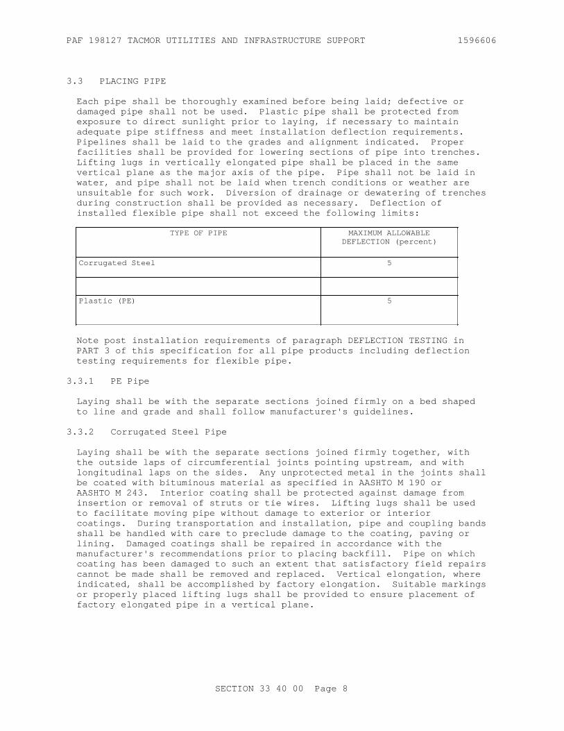
PAF 198127 TACMOR UTILITIES AND INFRASTRUCTURE SUPPORT 1596606
3.3 PLACING PIPE
Each pipe shall be thoroughly examined before being laid; defective or damaged pipe shall not be used. Plastic pipe shall be protected from exposure to direct sunlight prior to laying, if necessary to maintain adequate pipe stiffness and meet installation deflection requirements. Pipelines shall be laid to the grades and alignment indicated. Proper facilities shall be provided for lowering sections of pipe into trenches. Lifting lugs in vertically elongated pipe shall be placed in the same vertical plane as the major axis of the pipe. Pipe shall not be laid in water, and pipe shall not be laid when trench conditions or weather are unsuitable for such work. Diversion of drainage or dewatering of trenches during construction shall be provided as necessary. Deflection of installed flexible pipe shall not exceed the following limits:
TYPE OF PIPE MAXIMUM ALLOWABLEDEFLECTION (percent)
Corrugated Steel 5
Plastic (PE) 5
Note post installation requirements of paragraph DEFLECTION TESTING in PART 3 of this specification for all pipe products including deflection testing requirements for flexible pipe.
3.3.1 PE Pipe
Laying shall be with the separate sections joined firmly on a bed shaped to line and grade and shall follow manufacturer's guidelines.
3.3.2 Corrugated Steel Pipe
Laying shall be with the separate sections joined firmly together, with the outside laps of circumferential joints pointing upstream, and with longitudinal laps on the sides. Any unprotected metal in the joints shall be coated with bituminous material as specified in AASHTO M 190 or AASHTO M 243. Interior coating shall be protected against damage from insertion or removal of struts or tie wires. Lifting lugs shall be used to facilitate moving pipe without damage to exterior or interior coatings. During transportation and installation, pipe and coupling bands shall be handled with care to preclude damage to the coating, paving or lining. Damaged coatings shall be repaired in accordance with the manufacturer's recommendations prior to placing backfill. Pipe on which coating has been damaged to such an extent that satisfactory field repairs cannot be made shall be removed and replaced. Vertical elongation, where indicated, shall be accomplished by factory elongation. Suitable markings or properly placed lifting lugs shall be provided to ensure placement of factory elongated pipe in a vertical plane.
SECTION 33 40 00 Page 8

PAF 198127 TACMOR UTILITIES AND INFRASTRUCTURE SUPPORT 1596606
3.4 JOINTING
3.4.1 Corrugated Steel
3.4.1.1 Field Joints
Transverse field joints shall be designed so that the successive connection of pipe sections will form a continuous line free of appreciable irregularities in the flow line. In addition, the joints shall meet the general performance requirements described in ASTM A798/A798M . Suitable transverse field joints which satisfy the requirements for one or more of the joint performance categories can be obtained with the following types of connecting bands furnished with suitable band-end fastening devices: corrugated bands, bands with projections, flat bands, and bands of special design that engage factory reformed ends of corrugated pipe. The space between the pipe and connecting bands shall be kept free from dirt and grit so that corrugations fit snugly. The connecting band, while being tightened, shall be tapped with a soft-head mallet of wood, rubber or plastic, to take up slack and ensure a tight joint. Field joints for each type of corrugated metal pipe shall maintain pipe alignment during construction and prevent infiltration of fill material during the life of the installations. The type, size, and sheet thickness of the band and the size of angles or lugs and bolts shall be as indicated or where not indicated, shall be as specified in the applicable standards or specifications for the pipe.
3.4.1.2 Flexible Watertight, Gasketed Joints
Installation shall be as recommended by the gasket manufacturer for use of lubricants and cements and other special installation requirements. The gasket shall be placed over one end of a section of pipe for half the width of the gasket. The other half shall be doubled over the end of the same pipe. When the adjoining section of pipe is in place, the doubled-over half of the gasket shall then be rolled over the adjoining section. Any unevenness in overlap shall be corrected so that the gasket covers the end of pipe sections equally. Connecting bands shall be centered over adjoining sections of pipe, and rods or bolts placed in position and nuts tightened. Band Tightening: The band shall be tightened evenly, even tension being kept on the rods or bolts, and the gasket; the gasket shall seat properly in the corrugations. Watertight joints shall remain uncovered for a period of time designated, and before being covered, tightness of the nuts shall be measured with a torque wrench. If the nut has tended to loosen its grip on the bolts or rods, the nut shall be retightened with a torque wrench and remain uncovered until a tight, permanent joint is assured.
3.5 DRAINAGE STRUCTURES
3.5.1 Manholes and Inlets
Construction shall be of reinforced concrete, plain concrete, brick, precast reinforced concrete, precast concrete segmental blocks, prefabricated corrugated metal, or bituminous coated corrugated metal; complete with frames and covers or gratings; and with fixed galvanized steel ladders where indicated. Pipe studs and junction chambers of prefabricated corrugated metal manholes shall be fully bituminous-coated and paved when the connecting branch lines are so treated. Pipe connections to concrete manholes and inlets shall be made with flexible,
SECTION 33 40 00 Page 9

PAF 198127 TACMOR UTILITIES AND INFRASTRUCTURE SUPPORT 1596606
watertight connectors.
3.5.2 Walls and Headwalls
Construction shall be as indicated.
3.6 BACKFILLING
3.6.1 Backfilling Pipe in Trenches
After the pipe has been properly bedded, selected material from excavation or borrow, at a moisture content that will facilitate compaction, shall be placed along both sides of pipe in layers not exceeding 150 mm in compacted depth. The backfill shall be brought up evenly on both sides of pipe for the full length of pipe. The fill shall be thoroughly compacted under the haunches of the pipe. Each layer shall be thoroughly compacted with mechanical tampers or rammers. This method of filling and compacting shall continue until the fill has reached an elevation equal to the midpoint (spring line) of concrete pipe or has reached an elevation of at least 300 mm above the top of the pipe for flexible pipe. The remainder of the trench shall be backfilled and compacted by spreading and rolling or compacted by mechanical rammers or tampers in layers not exceeding 150 mm. Tests for density shall be made as necessary to ensure conformance to the compaction requirements specified below. Where it is necessary, in the opinion of the Contracting Officer, that sheeting or portions of bracing used be left in place, the contract will be adjusted accordingly. Untreated sheeting shall not be left in place beneath structures or pavements.
3.6.2 Backfilling Pipe in Fill Sections
For pipe placed in fill sections, backfill material and the placement and compaction procedures shall be as specified below. The fill material shall be uniformly spread in layers longitudinally on both sides of the pipe, not exceeding 150 mm in compacted depth, and shall be compacted by rolling parallel with pipe or by mechanical tamping or ramming. Prior to commencing normal filling operations, the crown width of the fill at a height of 300 mm above the top of the pipe shall extend a distance of not less than twice the outside pipe diameter on each side of the pipe or 4 m, whichever is less. After the backfill has reached at least 300 mm above the top of the pipe, the remainder of the fill shall be placed and thoroughly compacted in layers not exceeding 200 mm. Use select granular material for this entire region of backfill for flexible pipe installations.
3.6.3 Movement of Construction Machinery
When compacting by rolling or operating heavy equipment parallel with the pipe, displacement of or injury to the pipe shall be avoided. Movement of construction machinery over a culvert or storm drain at any stage of construction shall be at the Contractor's risk. Any damaged pipe shall be repaired or replaced.
3.6.4 Compaction
3.6.4.1 General Requirements
Cohesionless materials include gravels, gravel-sand mixtures, sands, and gravelly sands. Cohesive materials include clayey and silty gravels,
SECTION 33 40 00 Page 10

PAF 198127 TACMOR UTILITIES AND INFRASTRUCTURE SUPPORT 1596606
gravel-silt mixtures, clayey and silty sands, sand-clay mixtures, clays, silts, and very fine sands. When results of compaction tests for moisture-density relations are recorded on graphs, cohesionless soils will show straight lines or reverse-shaped moisture-density curves, and cohesive soils will show normal moisture-density curves.
3.6.4.2 Minimum Density
Backfill over and around the pipe and backfill around and adjacent to drainage structures shall be compacted at the approved moisture content to the following applicable minimum density, which will be determined as specified below.
a. Under paved roads, streets, and similar-use pavements including adjacent shoulder areas, the density shall be not less than 90 percent of maximum density for cohesive material and 95 percent of maximum density for cohesionless material, up to the elevation where requirements for pavement subgrade materials and compaction shall control.
b. Under unpaved or turfed traffic areas, density shall not be less than 90 percent of maximum density for cohesive material and 95 percent of maximum density for cohesionless material.
c. Under nontraffic areas, density shall be not less than that of the surrounding material.
3.7 FIELD PAINTING
3.7.1 Cast-Iron Covers, Frames, Gratings, And Steps
After installation, clean cast-iron, not buried in masonry or concrete, of mortar, rust, grease, dirt, and other deleterious materials to bare metal and apply a coat of bituminous paint.
3.8 FIELD QUALITY CONTROL
3.8.1 Tests
Testing is the responsibility of the Contractor. Perform all testing and retesting at no additional cost to the Government.
3.8.1.1 Leakage Test
Lines shall be tested for leakage by low pressure air or water testing or exfiltration tests, as appropriate, prior to completing backfill. Low pressure air testing for vitrified clay pipes shall conform to ASTM C828. Low pressure air testing for concrete pipes shall conform to ASTM C969M. Low pressure air testing for plastic pipe shall conform to ASTM F1417. Low pressure air testing procedures for other pipe materials shall use the pressures and testing times prescribed in ASTM C828 or ASTM C969M, after consultation with the pipe manufacturer. Testing of individual joints for leakage by low pressure air or water shall conform to ASTM C1103M. Prior to exfiltration tests, the trench shall be backfilled up to at least the lower half of the pipe. If required, sufficient additional backfill shall be placed to prevent pipe movement during testing, leaving the joints uncovered to permit inspection. Visible leaks encountered shall be corrected regardless of leakage test results. When the water table is 600 mm or more above the top of the pipe at the upper end of the pipeline
SECTION 33 40 00 Page 11

PAF 198127 TACMOR UTILITIES AND INFRASTRUCTURE SUPPORT 1596606
section to be tested, infiltration shall be measured using a suitable weir or other device acceptable to the Contracting Officer. An exfiltration test shall be made by filling the line to be tested with water so that a head of at least 600 mm is provided above both the water table and the top of the pipe at the upper end of the pipeline to be tested. The filled line shall be allowed to stand until the pipe has reached its maximum absorption, but not less than 4 hours. After absorption, the head shall be reestablished. The amount of water required to maintain this water level during a 2-hour test period shall be measured. Leakage as measured by the exfiltration test shall not exceed 60 liters per mm in diameter per kilometer of pipeline per day.
3.8.1.2 Determination of Density
Testing shall be performed by an approved commercial testing laboratory or by the Contractor subject to approval. Tests shall be performed in sufficient number to ensure that specified density is being obtained. Laboratory tests for moisture-density relations shall be made in accordance with ASTM D1557 except that mechanical tampers may be used provided the results are correlated with those obtained with the specified hand tamper. Field density tests shall be determined in accordance with ASTM D2167 or ASTM D6938. When ASTM D6938 is used, the calibration curves shall be checked and adjusted, if necessary, using the sand cone method as described in paragraph Calibration of the referenced publications. ASTM D6938 results in a wet unit weight of soil and ASTM D6938 shall be used to determine the moisture content of the soil. The calibration curves furnished with the moisture gauges shall be checked along with density calibration checks as described in ASTM D6938. Test results shall be furnished the Contracting Officer. The calibration checks of both the density and moisture gauges shall be made at the beginning of a job on each different type of material encountered and at intervals as directed.
3.8.1.3 Deflection Testing
Conduct deflection test no sooner than 30 days after completion of final backfill and compaction testing. Clean or flush all lines prior to testing. Perform a deflection test on entire length of installed flexible pipeline upon completion of work adjacent to and over the pipeline, including backfilling, placement of fill, grading, paving, placement of concrete, and any other superimposed loads. Deflection of pipe in the installed pipeline under external loads shall not exceed limits in paragraph PLACING PIPE above as percent of the average inside diameter of pipe. Use a mandrel to determine if allowable deflection has been exceeded.
3.8.1.3.1 Mandrel
Pass the mandrel through each run of pipe by pulling it by hand. If deflection readings in excess of the allowable deflection of average inside diameter of pipe are obtained, stop and begin test from the opposite direction. The mandrel must meet the Pipe Manufacture's recommendations and the following requirements. Provide a Mandrel that is rigid, nonadjustable, has a minimum of 9 fins, pulling rings at each end, and is engraved with the nominal pipe size and mandrel outside diameter. The mandrel must be 5 percent less than the certified-actual pipe diameter for Plastic Pipe, 5 percent less than the certified-actual pipe diameter for Corrugated Steel and Aluminum, 3 percent less than the certified-actual pipe diameter for Concrete-Lined Corrugated Steel and Ductile Iron Culvert. The Government will verify the outside
SECTION 33 40 00 Page 12

PAF 198127 TACMOR UTILITIES AND INFRASTRUCTURE SUPPORT 1596606
diameter(OD)of the Contractor provided mandrel through the use of Contractor provided proving rings.
3.8.2 Inspection
3.8.2.1 Post-Installation Inspection
Visually inspect each segment of concrete pipe for alignment, settlement, joint separations, soil migration through the joint, cracks, buckling, bulging and deflection. An engineer must evaluate all defects to determine if any remediation or repair is required.
3.8.2.1.1 Concrete
Cracks with a width greater than 0.25 mm. An engineer must evaluate all pipes with cracks with a width greater than 0.25 mm but less than 2.5 mm to determine if any remediation or repair is required.
3.8.2.1.2 Flexible Pipe
Check each flexible pipe (PE and Corrugated Steel) for rips, tears, joint separations, soil migration through the joint, cracks, localized bucking, bulges, settlement and alignment.
3.8.2.1.3 Post-Installation Inspection Report
The deflection results and final post installation inspection report must include: pipe location identification, equipment used for inspection, inspector name, deviation from design, grade, deviation from line, deflection and deformation of flexible pipe, inspector notes, condition of joints, condition of pipe wall (e.g. distress, cracking, wall damage dents, bulges, creases, tears, holes, etc.).
3.8.3 Repair Of Defects
3.8.3.1 Leakage Test
When leakage exceeds the maximum amount specified, correct source of excess leakage by replacing damaged pipe and gaskets and retest.
3.8.3.2 Deflection Testing
When deflection readings are in excess of the allowable deflection of average inside diameter of pipe are obtained, remove pipe which has excessive deflection and replace with new pipe. Retest 30 days after completing backfill, leakage testing and compaction testing.
3.8.3.3 Inspection
Replace pipe or repair defects indicated in the Post-Installation Inspection Report.
3.8.3.3.1 Concrete
Replace pipes having cracks with a width greater than 2.5 mm.
3.8.3.3.2 Flexible Pipe
Replace pipes having cracks or splits.
SECTION 33 40 00 Page 13

PAF 198127 TACMOR UTILITIES AND INFRASTRUCTURE SUPPORT 1596606
3.9 PROTECTION
Protect storm drainage piping and adjacent areas from superimposed and external loads during construction.
3.10 WARRANTY PERIOD
Pipe segments found to have defects during the warranty period must be replaced with new pipe and retested.
-- End of Section --
SECTION 33 40 00 Page 14

PAF 198127 TACMOR UTILITIES AND INFRASTRUCTURE SUPPORT 1596606
SECTION 33 46 16
SUBDRAINAGE PIPING05/18
PART 1 GENERAL
1.1 REFERENCES
The publications listed below form a part of this specification to the extent referenced. The publications are referred to within the text by the basic designation only.
AMERICAN ASSOCIATION OF STATE HIGHWAY AND TRANSPORTATION OFFICIALS (AASHTO)
AASHTO M 252 (2009; R 2017) Standard Specification for Corrugated Polyethylene Drainage Pipe
AASHTO M 288 (2017) Standard Specification for Geosynthetic Specification for Highway Applications
ASTM INTERNATIONAL (ASTM)
ASTM C136/C136M (2014) Standard Test Method for Sieve Analysis of Fine and Coarse Aggregates
ASTM C33/C33M (2018) Standard Specification for Concrete Aggregates
ASTM D2321 (2018) Standard Practice for Underground Installation of Thermoplastic Pipe for Sewers and Other Gravity-Flow Applications
ASTM D3034 (2016) Standard Specification for Type PSM Poly(Vinyl Chloride) (PVC) Sewer Pipe and Fittings
ASTM F758 (2014) Smooth-Wall Poly(Vinyl Chloride) (PVC) Plastic Underdrain Systems for Highway, Airport, and Similar Drainage
ASTM F949 (2015; R 2019) Standard Specification for Poly(Vinyl Chloride) (PVC) Corrugated Sewer Pipe with a Smooth Interior and Fittings
1.2 SUBMITTALS
Government approval is required for submittals with a "G" designation; submittals not having a "G" designation are for Contractor Quality Control approval. Submit the following in accordance with Section 01 33 00 SUBMITTAL PROCEDURES:
SD-04 Samples
SECTION 33 46 16 Page 1

PAF 198127 TACMOR UTILITIES AND INFRASTRUCTURE SUPPORT 1596606
Geotextile
Pipe and Pipe Fittings
SD-07 Certificates
Geotextile
Pipe and Pipe Fittings
1.3 DELIVERY, STORAGE, AND HANDLING
1.3.1 Delivery and Storage
Inspect materials delivered to site for damage; unload, and store with minimum handling. Do not store materials directly on the ground. Keep the inside of pipes and fittings free of dirt and debris. Keep, during shipment and storage, geotextile wrapped in burlap or similar heavy duty protective covering. Protect the geotextile from mud, soil, dust, and debris. Do not store geotextile materials in direct sunlight. Install plastic pipe within 6 months from the date of manufacture unless otherwise approved.
1.3.2 Handling
Handle materials in such a manner as to ensure delivery to the trench in sound undamaged condition. Carry pipe to the trench.
PART 2 PRODUCTS
2.1 PIPE FOR SUBDRAINS
Submit samples of pipe and pipe fittings, before starting the work. Provide type and sizes of subdrain pipe indicated. Submit certifications from the manufacturers attesting that materials meet specification requirements. Certificates are required for drain pipe and fittings.
2.1.1 Plastic
Provide plastic pipe containing ultraviolet inhibitor to provide protection from exposure to direct sunlight. Provide pipe with with bell and spigot or solvent cement joints. Provide manufacturer's standard type fittings conforming to the indicated specification.
2.1.1.1 Polyvinyl Chloride (PVC) and Fittings
ASTM D3034, ASTM F949 or ASTM F758, Type PS 46.
2.1.1.2 Corrugated Polyethylene (PE) and Fittings
AASHTO M 252, Type S or SP as indicated.
2.1.1.3 Pipe Perforations
Provide pipe perforations with a minimum water inlet area of 1,060 mm squared per linear meter and as specified below.
SECTION 33 46 16 Page 2

PAF 198127 TACMOR UTILITIES AND INFRASTRUCTURE SUPPORT 1596606
2.1.1.3.1 Circular Perforations in Plastic Pipe
Cleanly cut circular holes not more than 9.5 mm or less than 4.8 mm in diameter and arrange in rows parallel to the longitudinal axis of the pipe. Provide pipe with perforations spaced uniformly along rows. Unless otherwise recommended by the pipe manufacturer, provide pipe with rows approximately 38 mm apart and arranged in a staggered pattern so that all perforations lie at the midpoint between perforations in adjacent rows. Space the rows over not more than 155 degrees of circumference. Provide pipe that is not perforated for a length equal to the depth of the socket at the spigot or tongue end and provide perforations that continue at uniform spacing over the entire length of the pipe.
2.1.1.3.2 Slotted Perforations in Plastic Pipe
Cleanly cut circumferential slots so as not to restrict the inflow of water and uniformly spaced along the length and circumference of the pipe. Provide pipe with slots not exceeding 3.2 mm nor less than 0.8 mm in width. Provide pipe with individual slot lengths not exceeding 10 percent of the pipe inside nominal circumference on 150 to 200 mm diameter pipe, and 63.5 mm on 250 mm diameter pipe. Symmetrically space rows of slots so that they are fully contained in 2 quadrants of the pipe. Center slots in the valleys of the corrugations of profile wall pipe.
2.2 GEOTEXTILE
Provide geotextile conforming to AASHTO M 288 and meeting the subsurface drainage requirements.
Submit samples of geotextile and certifications from the manufacturers attesting that geotextile meets specification requirements.
2.3 SUBDRAIN FILTER AND BEDDING MATERIAL
Provide subdrain filter and bedding material composed of washed sand, sand and gravel, crushed stone, crushed stone screenings, or slag composed of hard, tough, durable particles free from adherent coatings. Filter material may not contain corrosive agents, organic matter, or soft, friable, thin, or elongated particles. Provide filter material that is evenly graded between the limits specified in TABLE I. Gradation curves will exhibit no abrupt changes in slope denoting skip or gap grading. Provide filter materials that are clean and free from soil and foreign materials. Remove and replace filter blankets found to be dirty or otherwise contaminated with material meeting the specific requirements, at no additional cost to the Government.
TABLE I
Type IGradation E 11ASTM C33/C33M
Type IIGradation 57ASTM C33/C33M
ASTM C136/C136M Sieve Size,mm
Percent Passing Percent Passing
37.5 -- 100
SECTION 33 46 16 Page 3

PAF 198127 TACMOR UTILITIES AND INFRASTRUCTURE SUPPORT 1596606
TABLE I
Type IGradation E 11ASTM C33/C33M
Type IIGradation 57ASTM C33/C33M
ASTM C136/C136M Sieve Size,mm
Percent Passing Percent Passing
25.0 -- 90 - 100
9.5 100 25 - 60
4.75 95 - 100 5 - 40
2.36 -- 0 - 20
1.18 45 - 80 --
0.30 10 - 30 --
0.15 0 - 10 --
2.4 DRAINAGE STRUCTURES
2.4.1 Concrete
Provide concrete and reinforced concrete conforming to the requirements for 21 MPa concrete in Section 03 30 00 CAST-IN-PLACE CONCRETE.
2.4.2 Mortar
Provide mortar for connections to drainage structures that is composed of one part by volume of portland cement and two parts of sand. Provide sufficient quantity of water in the mixture to produce a stiff workable mortar. Use water that is clean and free of injurious acids, alkalies, and organic impurities. Use the mortar within 30 minutes from the time the ingredients are mixed with water.
PART 3 EXECUTION
3.1 EXCAVATION AND BEDDING FOR SUBDRAIN SYSTEMS
Excavate trenches, including the removal of rock and unstable material, in accordance with Section 31 23 00.00 20 EXCAVATION AND FILL. Bedding material shall be placed in the trench as indicated or as required as replacement materials used in those areas where unstable materials were removed. Compaction of the bedding material shall be as specified for cohesionless material in Section 31 23 00.00 20 EXCAVATION AND FILL.
3.2 FLUSHING AND OBSERVATION RISERS
3.2.1 Flushing and Observation Risers
Install flushing and observation riser pipes with frames and covers at the locations indicated. Construct risers of non-perforated plastic pipe. Join riser pipes to the subdrain system as indicated.
SECTION 33 46 16 Page 4

PAF 198127 TACMOR UTILITIES AND INFRASTRUCTURE SUPPORT 1596606
3.3 INSTALLATION OF GEOTEXTILE AND PIPE FOR SUBDRAINS
3.3.1 Installation of Geotextile
3.3.1.1 Trench Lining and Overlaps
Grade trenches to be lined with geotextile to obtain smooth side and bottom surfaces so that the geotextile will not bridge cavities in the soil or be damaged by projecting rock. Lay the geotextile flat but not stretched on the soil, and secure it with anchor pins in accordance with manufacturer's instructions. Overlap at least 150 to 300 mm, and secure with anchor pins along the overlaps.
3.3.2 Installation of Pipe for Subdrains
3.3.2.1 Pipelaying
Install pipe in accordance with the manufacturer's recommendations. Thoroughly examine each section of pipe before being laid; do not use defective or damaged pipe. Do not lay pipe when the trench conditions or weather is unsuitable for such work. Remove water from trenches by sump pumping or other approved methods. Lay the pipe to the grades and alignment as indicated. Bed the pipe to the established gradeline. Center perforations on the bottom of the pipe. Lay bell-and-spigot type with the bell ends upstream. Approval of all in-place pipes by the Contracting Officer is required prior to backfilling.
3.4 INSTALLATION OF FILTER MATERIAL AND BACKFILLING FOR PERFORATED SUBDRAINS
After perforated pipe for subdrains has been laid, inspected, and approved, place filter material around and over the pipe to the depth indicated. Place the filter material in layers not to exceed 200 mm thick. Thoroughly compact each layer using mechanical tampers or rammers.
3.5 INSTALLATION OF BEDDING AND BACKFILL FOR NON-PERFORATED SUBRAIN OUTFALL PIPE
3.5.1 Plastic Pipe
Place and compact pipe embedment for plastic pipe in accordance with ASTM D2321. Use Class IB or II embedment materials.
-- End of Section --
SECTION 33 46 16 Page 5

PAF 198127 TACMOR UTILITIES AND INFRASTRUCTURE SUPPORT 1596606
THIS PAGE INTENTIONALLY LEFT BLANK
SECTION 33 46 16 Page 6

PAF 198127 TACMOR UTILITIES AND INFRASTRUCTURE SUPPORT 1596606
SECTION 33 71 02
UNDERGROUND ELECTRICAL DISTRIBUTION02/15
PART 1 GENERAL
1.1 REFERENCES
The publications listed below form a part of this specification to the extent referenced. The publications are referred to within the text by the basic designation only.
AMERICAN ASSOCIATION OF STATE HIGHWAY AND TRANSPORTATION OFFICIALS (AASHTO)
AASHTO HB-17 (2002; Errata 2003; Errata 2005, 17th Edition) Standard Specifications for Highway Bridges
AMERICAN CONCRETE INSTITUTE (ACI)
ACI 318M (2014; ERTA 2015) Building Code Requirements for Structural Concrete & Commentary
ACI SP-66 (2004) ACI Detailing Manual
ASSOCIATION OF EDISON ILLUMINATING COMPANIES (AEIC)
AEIC CS8 (2013) Specification for Extruded Dielectric Shielded Power Cables Rated 5 Through 46 kV
ASTM INTERNATIONAL (ASTM)
ASTM B1 (2013) Standard Specification for Hard-Drawn Copper Wire
ASTM B3 (2013) Standard Specification for Soft or Annealed Copper Wire
ASTM B8 (2011; R 2017) Standard Specification for Concentric-Lay-Stranded Copper Conductors, Hard, Medium-Hard, or Soft
ASTM B496 (2016) Standard Specification for Compact Round Concentric-Lay-Stranded Copper Conductors
ASTM C309 (2011) Standard Specification for Liquid Membrane-Forming Compounds for Curing Concrete
ASTM C478M (2018) Standard Specification for Precast Reinforced Concrete Manhole Sections (Metric)
SECTION 33 71 02 Page 1

PAF 198127 TACMOR UTILITIES AND INFRASTRUCTURE SUPPORT 1596606
ASTM C857 (2016) Standard Practice for Minimum Structural Design Loading for Underground Precast Concrete Utility Structures
ASTM C990M (2009; R 2014) Standard Specification for Joints for Concrete Pipe, Manholes and Precast Box Sections Using Preformed Flexible Joint Sealants (Metric)
INSTITUTE OF ELECTRICAL AND ELECTRONICS ENGINEERS (IEEE)
IEEE 48 (2009) Standard for Test Procedures and Requirements for Alternating-Current Cable Terminations Used on Shielded Cables Having Laminated Insulation Rated 2.5 kV through 765 kV or Extruded Insulation Rated 2.5 kV through 500 kV
IEEE 81 (2012) Guide for Measuring Earth Resistivity, Ground Impedance, and Earth Surface Potentials of a Ground System
IEEE 400.2 (2013) Guide for Field Testing of Shielded Power Cable Systems Using Very Low Frequency (VLF)
IEEE 404 (2012) Standard for Extruded and Laminated Dielectric Shielded Cable Joints Rated 2500 V to 500,000 V
IEEE C2 (2017; Errata 1-2 2017; INT 1 2017) National Electrical Safety Code
IEEE Stds Dictionary (2009) IEEE Standards Dictionary: Glossary of Terms & Definitions
INTERNATIONAL ELECTRICAL TESTING ASSOCIATION (NETA)
NETA ATS (2017; Errata 2017) Standard for Acceptance Testing Specifications for Electrical Power Equipment and Systems
NATIONAL ELECTRICAL MANUFACTURERS ASSOCIATION (NEMA)
ANSI C119.1 (2016) Electric Connectors - Sealed Insulated Underground Connector Systems Rated 600 Volts
ANSI/NEMA WC 71/ICEA S-96-659 (2014) Standard for Nonshielded Cables Rated 2001-5000 Volts for use in the Distribution of Electric Energy
NEMA TC 2 (2013) Standard for Electrical Polyvinyl Chloride (PVC) Conduit
NEMA TC 9 (2004) Standard for Fittings for Polyvinyl Chloride (PVC) Plastic Utilities Duct for Underground Installation
SECTION 33 71 02 Page 2

PAF 198127 TACMOR UTILITIES AND INFRASTRUCTURE SUPPORT 1596606
NEMA WC 74/ICEA S-93-639 (2012) 5-46 kV Shielded Power Cable for Use in the Transmission and Distribution of Electric Energy
NATIONAL FIRE PROTECTION ASSOCIATION (NFPA)
NFPA 70 (2020; ERTA 1-2 2017; TIA 17-1; TIA 17-2; TIA 17-3; TIA 17-4; TIA 17-5; TIA 17-6; TIA 17-7; TIA 17-8; TIA 17-9; TIA 17-10; TIA 17-11; TIA 17-12; TIA 17-13; TIA 17-14; TIA 17-15; TIA 17-16; TIA 17-17 ) National Electrical Code
TELECOMMUNICATIONS INDUSTRY ASSOCIATION (TIA)
TIA-758 (2012b) Customer-Owned Outside Plant Telecommunications Infrastructure Standard
U.S. DEPARTMENT OF AGRICULTURE (USDA)
RUS Bull 1751F-644 (2002) Underground Plant Construction
U.S. GENERAL SERVICES ADMINISTRATION (GSA)
CID A-A-60005 (Basic; Notice 2) Frames, Covers, Gratings, Steps, Sump And Catch Basin, Manhole
UNDERWRITERS LABORATORIES (UL)
UL 44 (2018) UL Standard for Safety Thermoset-Insulated Wires and Cables
UL 83 (2017) UL Standard for Safety Thermoplastic-Insulated Wires and Cables
UL 94 (2013; Reprint Sep 2017) UL Standard for Safety Tests for Flammability of Plastic Materials for Parts in Devices and Appliances
UL 467 (2013; Reprint Jun 2017) UL Standard for Safety Grounding and Bonding Equipment
UL 486A-486B (2018) UL Standard for Safety Wire Connectors
UL 510 (2017) UL Standard for Safety Polyvinyl Chloride, Polyethylene and Rubber Insulating Tape
UL 514B (2012; Reprint Nov 2014) Conduit, Tubing and Cable Fittings
UL 651 (2011; Reprint Nov 2018) UL Standard for Safety Schedule 40, 80, Type EB and A Rigid PVC Conduit and Fittings
SECTION 33 71 02 Page 3

PAF 198127 TACMOR UTILITIES AND INFRASTRUCTURE SUPPORT 1596606
UL 854 (2004; Reprint Nov 2014) Standard for Service-Entrance Cables
UL 1072 (2006; Reprint Jun 2013) Medium-Voltage Power Cables
1.2 RELATED REQUIREMENTS
Section 26 08 00 APPARATUS INSPECTION AND TESTING applies to this section, with the additions and modifications specified herein.
1.3 DEFINITIONS
a. Unless otherwise specified or indicated, electrical and electronics terms used in these specifications, and on the drawings, are as defined in IEEE Stds Dictionary .
b. In the text of this section, the words conduit and duct are used interchangeably and have the same meaning.
c. In the text of this section, "medium voltage cable splices," and "medium voltage cable joints" are used interchangeably and have the same meaning.
1.4 SUBMITTALS
Government approval is required for submittals with a "G" designation; submittals not having a "G" designation are for Contractor Quality Control approval. Submit the following in accordance with Section 01 33 00 SUBMITTAL PROCEDURES:
SD-02 Shop Drawings
Precast underground structures; G
SD-03 Product Data
Medium voltage cable; G
Medium voltage cable joints; G
Medium voltage cable terminations; G
Precast concrete structures; G
Sealing Material; G
Pulling-In Irons; G
Manhole frames and covers; G
Handhole frames and covers; G
Cable supports (racks, arms and insulators); G
SD-06 Test Reports
Medium voltage cable qualification and production tests; G
SECTION 33 71 02 Page 4

PAF 198127 TACMOR UTILITIES AND INFRASTRUCTURE SUPPORT 1596606
Field Acceptance Checks and Tests; G
Arc-proofing test for cable fireproofing tape; G
Cable Installation Plan and Procedure; G
Six copies of the information described below in 215.9 by 279.4 mm binders having a minimum of three rings from which material may readily be removed and replaced, including a separate section for each cable pull. Separate sections by heavy plastic dividers with tabs, with all data sheets signed and dated by the person supervising the pull.
a. Site layout drawing with cable pulls numerically identified.
b. A list of equipment used, with calibration certifications. The manufacturer and quantity of lubricant used on pull.
c. The cable manufacturer and type of cable.
d. The dates of cable pulls, time of day, and ambient temperature.
e. The length of cable pull and calculated cable pulling tensions.
f. The actual cable pulling tensions encountered during pull.
SD-07 Certificates
Cable splicer/terminator; G
Cable Installer Qualifications; G
1.5 QUALITY ASSURANCE
1.5.1 Precast Underground Structures
Submittal required for each type used. Provide calculations and drawings for precast manholes and handholes bearing the seal of a registered professional engineer including:
a. Material description (i.e., f'c and Fy)
b. Manufacturer's printed assembly and installation instructions
c. Design calculations
d. Reinforcing shop drawings in accordance with ACI SP-66
e. Plans and elevations showing opening and pulling-in iron locations and details
1.5.2 Certificate of Competency for Cable Splicer/Terminator
Certification of the qualification of the cable splicer/terminator shall be submitted, for approval, 30 days before splices or terminations are to be made in medium voltage (5 kV to 35 kV) cables. The certification shall include the training, and experience of the individual on the specific
SECTION 33 71 02 Page 5

PAF 198127 TACMOR UTILITIES AND INFRASTRUCTURE SUPPORT 1596606
type and classification of cable to be provided under this contract. The certification shall indicate that the individual has had three or more years recent experience splicing and terminating medium voltage cables. The certification shall also list a minimum of three splices/terminations that have been in operation for more than one year. In addition, the individual may be required to perform a dummy or practice splice/termination in the presence of the Contracting Officer, before being approved as a qualified cable splicer. If that additional requirement is imposed, the Contractor shall provide short sections of the approved types of cables along with the approved type of splice/termination kit, and detailed manufacturer's instructions for the cable to be spliced. The Contracting Officer reserves the right to require additional proof of competency or to reject the individual and call for certification of an alternate cable splicer.
1.5.3 Cable Installer Qualifications
Provide at least one onsite person in a supervisory position with a documentable level of competency and experience to supervise all cable pulling operations. Provide a resume showing the cable installers' experience in the last three years, including a list of references complete with points of contact, addresses and telephone numbers. Cable installer must demonstrate experience with a minimum of three medium voltage cable installations. The Contracting Officer reserves the right to require additional proof of competency or to reject the individual and call for an alternate qualified cable installer.
1.5.4 Regulatory Requirements
In each of the publications referred to herein, consider the advisory provisions to be mandatory, as though the word, "must" had been substituted for "should" wherever it appears. Interpret references in these publications to the "authority having jurisdiction," or words of similar meaning, to mean the Contracting Officer. Equipment, materials, installation, and workmanship must be in accordance with the mandatory and advisory provisions of IEEE C2 and NFPA 70 unless more stringent requirements are specified or indicated.
1.5.5 Standard Products
Provide materials and equipment that are products of manufacturers regularly engaged in the production of such products which are of equal material, design and workmanship. Products must have been in satisfactory commercial or industrial use for 2 years prior to bid opening. The 2-year period must include applications of equipment and materials under similar circumstances and of similar size. The product must have been for sale on the commercial market through advertisements, manufacturers' catalogs, or brochures during the 2-year period. Where two or more items of the same class of equipment are required, these items must be products of a single manufacturer; however, the component parts of the item need not be the products of the same manufacturer unless stated in this section.
1.5.5.1 Alternative Qualifications
Products having less than a 2-year field service record will be acceptable if a certified record of satisfactory field operation for not less than 6000 hours, exclusive of the manufacturers' factory or laboratory tests, is furnished.
SECTION 33 71 02 Page 6

PAF 198127 TACMOR UTILITIES AND INFRASTRUCTURE SUPPORT 1596606
1.5.5.2 Material and Equipment Manufacturing Date
Products manufactured more than 3 years prior to date of delivery to site are not acceptable, unless specified otherwise.
PART 2 PRODUCTS
2.1 CONDUIT, DUCTS, AND FITTINGS
2.1.1 Plastic Conduit for Direct Burial
UL 651 and NEMA TC 2, EPC-40 or EPC-80.
2.1.2 Plastic Duct for Concrete Encasement
Provide Type EPC-40 per UL 651 and NEMA TC 2.
2.1.3 Duct Sealant
UL 94 , Class HBF. Provide high-expansion urethane foam duct sealant that expands and hardens to form a closed, chemically and water resistant, rigid structure. Sealant must be compatible with common cable and wire jackets and capable of adhering to metals, plastics and concrete. Sealant must be capable of curing in temperature ranges of 2 degrees C to 35 degrees C. Cured sealant must withstand temperature ranges of -29 degrees C to 93 degrees C without loss of function.
2.1.4 Fittings
2.1.4.1 PVC Conduit Fittings
UL 514B , UL 651 .
2.1.4.2 PVC Duct Fittings
NEMA TC 9.
2.2 LOW VOLTAGE INSULATED CONDUCTORS AND CABLES
Insulated conductors must be rated 600 volts and conform to the requirements of NFPA 70 , including listing requirements. Wires and cables manufactured more than 24 months prior to date of delivery to the site are not acceptable. Service entrance conductors must conform to UL 854 , type USE.
2.2.1 Conductor Types
Cable and duct sizes indicated are for copper conductors and THHN/THWN unless otherwise noted. Conductors No. 10 AWG and smaller must be solid. Conductors No. 8 AWG and larger must be stranded. All conductors must be copper.
2.2.2 Conductor Material
Unless specified or indicated otherwise or required by NFPA 70 , wires in conduit, other than service entrance, must be 600-volt, Type THWN/THHN conforming to UL 83 or Type XHHW conforming to UL 44 . Copper conductors must be annealed copper complying with ASTM B3 and ASTM B8.
SECTION 33 71 02 Page 7

PAF 198127 TACMOR UTILITIES AND INFRASTRUCTURE SUPPORT 1596606
2.2.3 Cable Marking
Insulated conductors must have the date of manufacture and other identification imprinted on the outer surface of each cable at regular intervals throughout the cable length.
Identify each cable by means of a fiber, laminated plastic, or non-ferrous metal tags in each manhole, handhole, junction box, and each terminal. Each tag must contain the following information; cable type, conductor size, circuit number, circuit voltage, cable destination and phase identification.
Conductors must be color coded. Provide conductor identification within each enclosure where a tap, splice, or termination is made. Conductor identification must be by color-coded insulated conductors, plastic-coated self-sticking printed markers, colored nylon cable ties and plates, heat shrink type sleeves,or colored electrical tape. Control circuit terminations must be properly identified. Color must be green for grounding conductors and white for neutrals; except where neutrals of more than one system are installed in same raceway or box, other neutrals must be white with a different colored (not green) stripe for each. Color of ungrounded conductors in different voltage systems must be as follows:
a. 208/120 volt, three-phase
(1) Phase A - black
(2) Phase B - red
(3) Phase C - blue
2.3 LOW VOLTAGE WIRE CONNECTORS AND TERMINALS
Must provide a uniform compression over the entire conductor contact surface. Use solderless terminal lugs on stranded conductors.
a. For use with copper conductors: UL 486A-486B .
2.4 LOW VOLTAGE SPLICES
Provide splices in conductors with a compression connector on the conductor and by insulating and waterproofing using one of the following methods which are suitable for continuous submersion in water and comply with ANSI C119.1 .
2.4.1 Heat Shrinkable Splice
Provide heat shrinkable splice insulation by means of a thermoplastic adhesive sealant material applied in accordance with the manufacturer's written instructions.
2.4.2 Cold Shrink Rubber Splice
Provide a cold-shrink rubber splice which consists of EPDM rubber tube which has been factory stretched onto a spiraled core which is removed during splice installation. The installation must not require heat or flame, or any additional materials such as covering or adhesive. It must be designed for use with inline compression type connectors, or indoor, outdoor, direct-burial or submerged locations.
SECTION 33 71 02 Page 8

PAF 198127 TACMOR UTILITIES AND INFRASTRUCTURE SUPPORT 1596606
2.5 MEDIUM VOLTAGE CABLE
Cable (conductor) sizes are designated by American Wire Gauge (AWG) and Thousand Circular Mils (Kcmil). Conductor and conduit sizes indicated are for copper conductors unless otherwise noted. Insulated conductors must have the date of manufacture and other identification imprinted on the outer surface of each cable at regular intervals throughout cable length. Wires and cables manufactured more than 24 months prior to date of delivery to the site are not acceptable. Provide single conductor type cables unless otherwise indicated.
2.5.1 Cable Configuration
Provide Type MV cable, conforming to NEMA WC 74/ICEA S-93-639 and UL 1072 . Provide cables manufactured for use in duct applications as indicated. Cable must be rated as indicated with 133 percent insulation level.
2.5.2 Conductor Material
Provide concentric-lay-stranded, Class B compact round conductors. Provide soft drawn copper cables complying with ASTM B3 and ASTM B8 for regular concentric and compressed stranding or ASTM B496 for compact stranding.
2.5.3 Insulation
Provide ethylene-propylene-rubber (EPR) insulation conforming to the requirements of ANSI/NEMA WC 71/ICEA S-96-659 and AEIC CS8 .
2.5.4 Shielding
Cables rated for 2 kV and above must have a semiconducting conductor shield, a semiconducting insulation shield, and an overall copper tape shield for each phase.
2.5.5 Jackets
Provide cables with a PVC jacket. Provide PVC jackets with a separator that prevents contact with underlying semiconducting insulating shield.
2.6 MEDIUM VOLTAGE CABLE TERMINATIONS
IEEE 48 Class 1; of the molded elastomer, prestretched elastomer, or heat-shrinkable elastomer. Acceptable elastomers are track-resistant silicone rubber or track-resistant ethylene propylene compounds, such as ethylene propylene rubber or ethylene propylene diene monomer. Separable insulated connectors may be used for apparatus terminations, when such apparatus is provided with suitable bushings. Terminations, where required, must be provided with mounting brackets suitable for the intended installation and with grounding provisions for the cable shielding, metallic sheath, or armor. Terminations must be provided in a kit, including: skirts, stress control terminator, ground clamp, connectors, lugs, and complete instructions for assembly and installation. Terminations must be the product of one manufacturer, suitable for the type, diameter, insulation class and level, and materials of the cable terminated. Do not use separate parts of copper or copper alloy in contact with aluminum alloy parts in the construction or installation of the terminator.
SECTION 33 71 02 Page 9

PAF 198127 TACMOR UTILITIES AND INFRASTRUCTURE SUPPORT 1596606
2.6.1 Cold-Shrink Type
Terminator must be a one-piece design, utilizing the manufacturer's latest technology, where high-dielectric constant (capacitive) stress control is integrated within a skirted insulator made of silicone rubber. Termination must not require heat or flame for installation. Termination kit must contain all necessary materials (except for the lugs). Termination must be designed for installation in low or highly contaminated indoor and outdoor locations and must resist ultraviolet rays and oxidative decomposition.
2.6.2 Heat Shrinkable Type
Terminator must consist of a uniform cross section heat shrinkable polymeric construction stress relief tubing and environmentally sealed outer covering that is nontracking, resists heavy atmospheric contaminants, ultra violet rays and oxidative decomposition. Provide heat shrinkable sheds or skirts of the same material. Termination must be designed for installation in low or highly contaminated indoor or outdoor locations.
2.7 MEDIUM VOLTAGE CABLE JOINTS
Provide joints (splices) in accordance with IEEE 404 suitable for the rated voltage, insulation level, insulation type, and construction of the cable. Joints must be certified by the manufacturer for waterproof, submersible applications. Upon request, supply manufacturer's design qualification test report in accordance with IEEE 404 . Connectors for joint must be tin-plated electrolytic copper, having ends tapered and having center stops to equalize cable insertion.
2.7.1 Heat-Shrinkable Joint
Consists of a uniform cross-section heat-shrinkable polymeric construction with a linear stress relief system, a high dielectric strength insulating material, and an integrally bonded outer conductor layer for shielding. Replace original cable jacket with a heavy-wall heat-shrinkable sleeve with hot-melt adhesive coating.
2.7.2 Cold-Shrink Rubber-Type Joint
Joint must be of a cold shrink design that does not require any heat source for its installation. Splice insulation and jacket must be of a one-piece factory formed cold shrink sleeve made of black EPDM rubber. Splice must be packaged three splices per kit, including complete installation instructions.
2.8 TAPE
2.8.1 Insulating Tape
UL 510 , plastic insulating tape, capable of performing in a continuous temperature environment of 80 degrees C.
2.8.2 Buried Warning and Identification Tape
Provide detectable tape in accordance with Section 31 23 00.00 20 EXCAVATION AND FILL.
SECTION 33 71 02 Page 10

PAF 198127 TACMOR UTILITIES AND INFRASTRUCTURE SUPPORT 1596606
2.8.3 Fireproofing Tape
Provide tape composed of a flexible, conformable, unsupported intumescent elastomer. Tape must be not less than 0.762 mm thick, noncorrosive to cable sheath, self-extinguishing, noncombustible, adhesive-free, and must not deteriorate when subjected to oil, water, gases, salt water, sewage, and fungus.
2.9 PULL ROPE
Plastic or flat pull line (bull line) having a minimum tensile strength of 890 N.
2.10 GROUNDING AND BONDING
2.10.1 Driven Ground Rods
Provide copper-clad steel ground rods conforming to UL 467 not less than 19 mm in diameter by 3.1 m in length. Sectional type rods may be used for rods 20 feet or longer.
2.10.2 Grounding Conductors
Stranded-bare copper conductors must conform to ASTM B8, Class B, soft-drawn unless otherwise indicated. Solid-bare copper conductors must conform to ASTM B1 for sizes No. 8 and smaller. Insulated conductors must be of the same material as phase conductors and green color-coded, except that conductors must be rated no more than 600 volts. Aluminum is not acceptable.
2.11 CAST-IN-PLACE CONCRETE
Provide concrete in accordance with Section 03 30 00 CAST-IN-PLACE CONCRETE. In addition, provide concrete for encasement of underground ducts with 20 MPa minimum 28-day compressive strength. Concrete associated with electrical work for other than encasement of underground ducts must be 30 MPa minimum 28-day compressive strength unless specified otherwise.
2.12 UNDERGROUND STRUCTURES
Provide precast concrete underground structures or standard type cast-in-place manhole types as indicated, conforming to ASTM C857 and ASTM C478M. Top, walls, and bottom must consist of reinforced concrete. Walls and bottom must be of monolithic concrete construction. Locate duct entrances and windows near the corners of structures to facilitate cable racking. Covers must fit the frames without undue play. Form steel and iron to shape and size with sharp lines and angles. Castings must be free from warp and blow holes that may impair strength or appearance. Exposed metal must have a smooth finish and sharp lines and arises. Provide necessary lugs, rabbets, and brackets. Set pulling-in irons and other built-in items in place before depositing concrete. Install a pulling-in iron in the wall opposite each duct line entrance. Cable racks, including rack arms and insulators, must be adequate to accommodate the cable.
2.12.1 Cast-In-Place Concrete Structures
Concrete must conform to Section 03 30 00 CAST-IN-PLACE CONCRETE.
SECTION 33 71 02 Page 11

PAF 198127 TACMOR UTILITIES AND INFRASTRUCTURE SUPPORT 1596606
2.12.2 Precast Concrete Structures, Risers and Tops
Precast concrete underground structures may be provided in lieu of cast-in-place subject to the requirements specified below. Precast units must be the product of a manufacturer regularly engaged in the manufacture of precast concrete products, including precast manholes.
2.12.2.1 General
Precast concrete structures must have the same accessories and facilities as required for cast-in-place structures. Likewise, precast structures must have plan area and clear heights not less than those of cast-in-place structures. Concrete materials and methods of construction must be the same as for cast-in-place concrete construction, as modified herein. Slope in floor may be omitted provided precast sections are poured in reinforced steel forms. Concrete for precast work must have a 28-day compressive strength of not less than 30 MPa. Structures may be precast to the design and details indicated for cast-in-place construction, precast monolithically and placed as a unit, or structures may be assembled sections, designed and produced by the manufacturer in accordance with the requirements specified. Structures must be identified with the manufacturer's name embedded in or otherwise permanently attached to an interior wall face.
2.12.2.2 Design for Precast Structures
ACI 318M . In the absence of detailed on-site soil information, design for the following soil parameters/site conditions:
a. Angle of Internal Friction (phi) = 0.523 rad
b. Unit Weight of Soil (Dry) = 1760 kg/m 3, (Saturated)
= 2080 kg/m 3
c. Coefficient of Lateral Earth Pressure (Ka) = 0.33
d. Ground Water Level = 915 mm below ground elevation
e. Vertical design loads must include full dead, superimposed dead, and live loads including a 30 percent magnification factor for impact. Live loads must consider all types and magnitudes of vehicular (automotive, industrial, or aircraft) traffic to be encountered. The minimum design vertical load must be for H20 highway loading per AASHTO HB-17.
f. Horizontal design loads must include full geostatic and hydrostatic pressures for the soil parameters, water table, and depth of installation to be encountered. Also, horizontal loads imposed by adjacent structure foundations, and horizontal load components of vertical design loads, including impact, must be considered, along with a pulling-in iron design load of 26,700 N.
g. Each structural component must be designed for the load combination and positioning resulting in the maximum shear and moment for that particular component.
h. Design must also consider the live loads induced in the handling, installation, and backfilling of the manholes. Provide lifting
SECTION 33 71 02 Page 12

PAF 198127 TACMOR UTILITIES AND INFRASTRUCTURE SUPPORT 1596606
devices to ensure structural integrity during handling and installation.
2.12.2.3 Construction
Structure top, bottom, and wall must be of a uniform thickness of not less than 150 mm. Thin-walled knock-out panels for designed or future duct bank entrances are not permitted. Provide quantity, size, and location of duct bank entrance windows as directed, and cast completely open by the precaster. Size of windows must exceed the nominal duct bank envelope dimensions by at least 305 mm vertically and horizontally to preclude in-field window modifications made necessary by duct bank misalignment. However, the sides of precast windows must be a minimum of 150 mm from the inside surface of adjacent walls, floors, or ceilings. Form the perimeter of precast window openings to have a keyed or inward flared surface to provide a positive interlock with the mating duct bank envelope. Provide welded wire fabric reinforcing through window openings for in-field cutting and flaring into duct bank envelopes. Provide additional reinforcing steel comprised of at least two No. 4 bars around window openings. Provide drain sumps a minimum of 305 mm in diameter and 100 mm deep for precast structures.
2.12.2.4 Joints
Provide tongue-and-groove joints on mating edges of precast components. Shiplap joints are not allowed. Design joints to firmly interlock adjoining components and to provide waterproof junctions and adequate shear transfer. Seal joints watertight using preformed plastic strip conforming to ASTM C990M. Install sealing material in strict accordance with the sealant manufacturer's printed instructions. Provide waterproofing at conduit/duct entrances into structures, and where access frame meets the top slab, provide continuous grout seal.
2.12.3 Manhole Frames and Covers
Provide cast iron frames and covers for manholes conforming to CID A-A-60005 . Cast the words "ELECTRIC" or "TELECOMMUNICATIONS" in the top face of power and telecommunications manhole covers, respectively.
2.12.4 Handhole Frames and Covers
Provide as indicated.
2.12.5 Manhole Collar
Provide concrete conforming to Section 03 30 00 CAST-IN PLACE CONCRETE.
2.13 CABLE SUPPORTS (RACKS, ARMS, AND INSULATORS)
The metal portion of racks and arms must be 316 stainless steel.
2.13.1 Cable Rack Stanchions
The wall bracket or stanchion must be 100 mm by approximately 38 mm by 4.76 mm channel 316 stainless steel with recessed bolt mounting holes, 1220 mm long (minimum) in manholes. Slots for mounting cable rack arms must be spaced at 200 mm (maximum) intervals.
SECTION 33 71 02 Page 13

PAF 198127 TACMOR UTILITIES AND INFRASTRUCTURE SUPPORT 1596606
2.13.2 Rack Arms
Heavy duty, minimum rated load of 182 kg. Cable rack arms must be nonmetallic material and must be of the removable type. Rack arm length must be a minimum of 200 mm and a maximum of 305 mm.
2.13.3 Insulators
Insulators are not required for non-metallic arms.
2.14 CABLE TAGS IN MANHOLES
Provide tags for each power cable located in manholes. The tags must be polyethylene. Do not provide handwritten letters. The first position on the power cable tag must denote the voltage. The second through sixth positions on the tag must identify the circuit. The next to last position must denote the phase of the circuit and include the Greek "phi" symbol. The last position must denote the cable size. As an example, a tag could have the following designation: "11.5 NAS 1-8(Phase A)500," denoting that the tagged cable is on the 11.5kV system circuit number NAS 1-8, underground, Phase A, sized at 500 kcmil.
2.14.1 Polyethylene Cable Tags
Provide tags of polyethylene that have an average tensile strength of 22.4 MPa; and that are 2 millimeter thick (minimum), non-corrosive non-conductive; resistive to acids, alkalis, organic solvents, and salt water; and distortion resistant to 77 degrees C. Provide 1.3 mm (minimum) thick black polyethylene tag holder. Provide a one-piece nylon, self-locking tie at each end of the cable tag. Ties must have a minimum loop tensile strength of 778.75 N. The cable tags must have black block letters, numbers, and symbols 25 mm high on a yellow background. Letters, numbers, and symbols must not fall off or change positions regardless of the cable tags' orientation.
2.15 SOURCE QUALITY CONTROL
2.15.1 Arc-Proofing Test for Cable Fireproofing Tape
Manufacturer must test one sample assembly consisting of a straight lead tube 305 mm long with a 65.5 mm outside diameter, and a 3.175 mm thick wall, and covered with one-half lap layer of arc and fireproofing tape per manufacturer's instructions. The arc and fireproofing tape must withstand extreme temperature of a high-current fault arc 13,000 degrees K for 70 cycles as determined by using an argon directed plasma jet capable of constantly producing and maintaining an arc temperature of 13,000 degrees K. Temperature (13,000 degrees K) of the ignited arc between the cathode and anode must be obtained from a dc power source of 305 (plus or minus 5) amperes and 20 (plus or minus 1) volts. The arc must be directed toward the sample assembly accurately positioned 5 (plus or minus 1) millimeters downstream in the plasma from the anode orifice by fixed flow rate of argon gas (0.18 g per second). Each sample assembly must be tested at three unrelated points. Start time for tests must be taken from recorded peak current when the specimen is exposed to the full test temperature. Surface heat on the specimen prior to that time must be minimal. The end point is established when the plasma or conductive arc penetrates the protective tape and strikes the lead tube. Submittals for arc-proofing tape must indicate that the test has been performed and passed by the manufacturer.
SECTION 33 71 02 Page 14

PAF 198127 TACMOR UTILITIES AND INFRASTRUCTURE SUPPORT 1596606
2.15.2 Medium Voltage Cable Qualification and Production Tests
Results of AEIC CS8 qualification and production tests as applicable for each type of medium voltage cable.
PART 3 EXECUTION
3.1 INSTALLATION
Install equipment and devices in accordance with the manufacturer's published instructions and with the requirements and recommendations of NFPA 70 and IEEE C2 as applicable. In addition to these requirements, install telecommunications in accordance with TIA-758 and RUS Bull 1751F-644 .
3.2 CABLE INSPECTION
Inspect each cable reel for correct storage positions, signs of physical damage, and broken end seals prior to installation. If end seal is broken, remove moisture from cable prior to installation in accordance with the cable manufacturer's recommendations.
3.3 CABLE INSTALLATION PLAN AND PROCEDURE
Obtain from the manufacturer an installation manual or set of instructions which addresses such aspects as cable construction, insulation type, cable diameter, bending radius, cable temperature limits for installation, lubricants, coefficient of friction, conduit cleaning, storage procedures, moisture seals, testing for and purging moisture, maximum allowable pulling tension, and maximum allowable sidewall bearing pressure. Perform pulling calculations and prepare a pulling plan and submit along with the manufacturer's instructions in accordance with SUBMITTALS. Install cable strictly in accordance with the cable manufacturer's recommendations and the approved installation plan.
Calculations and pulling plan must include:
a. Site layout drawing with cable pulls identified in numeric order of expected pulling sequence and direction of cable pull.
b. List of cable installation equipment.
c. Lubricant manufacturer's application instructions.
d. Procedure for resealing cable ends to prevent moisture from entering cable.
e. Cable pulling tension calculations of all cable pulls.
f. Cable percentage conduit fill.
g. Cable sidewall bearing pressure.
h. Cable minimum bend radius and minimum diameter of pulling wheels used.
i. Cable jam ratio.
j. Maximum allowable pulling tension on each different type and size of
SECTION 33 71 02 Page 15

PAF 198127 TACMOR UTILITIES AND INFRASTRUCTURE SUPPORT 1596606
conductor.
k. Maximum allowable pulling tension on pulling device.
3.4 UNDERGROUND FEEDERS SUPPLYING BUILDINGS
Install underground feeders supplying structure as indicated. Provide PVC, Type conduit. Protect ends of underground conduit with plastic plugs.
Encase the underground portion of the conduit in a concrete envelope and bury as specified for underground duct with concrete encasement.
3.5 UNDERGROUND STRUCTURE CONSTRUCTION
Provide standard type cast-in-place construction as specified herein and as indicated, or precast construction as specified herein. Horizontal concrete surfaces of floors must have a smooth trowel finish. Cure concrete by applying two coats of white pigmented membrane forming-curing compound in strict accordance with the manufacturer's printed instructions, except that precast concrete may be steam cured. Curing compound must conform to ASTM C309. Locate duct entrances and windows in the center of end walls (shorter) and near the corners of sidewalls (longer) to facilitate cable racking and splicing. Covers for underground structures must fit the frames without undue play. Steel and iron must be formed to shape and size with sharp lines and angles. Castings must be free from warp and blow holes that may impair strength or appearance. Exposed metal must have a smooth finish and sharp lines and arises. Provide necessary lugs, rabbets, and brackets. Set pulling-in irons and other built-in items in place before depositing concrete. Manhole locations, as indicated, are approximate. Coordinate exact manhole locations with other utilities and finished grading and paving.
3.5.1 Cast-In-Place Concrete Structures
Construct walls on a footing of cast-in-place concrete except that precast concrete base sections may be used for precast concrete manhole risers.
3.5.2 Precast Concrete Construction
Set commercial precast structures on 150 mm of level, 90 percent compacted granular fill, 19 mm to 25 mm size, extending 305 mm beyond the structure on each side. Compact granular fill by a minimum of four passes with a plate type vibrator. Installation must additionally conform to the manufacturer's instructions.
3.5.3 Pulling-In Irons
Provide 316 stainless steel bars bent as indicated, and cast in the walls and floors. Alternatively, pipe sleeves may be precast into the walls and floors where required to accept U-bolts or other types of pulling-in devices possessing the strengths and clearances stated herein. The final installation of pulling-in devices must be made permanent. Cover and seal exterior projections of thru-wall type pulling-in devices with an appropriate protective coating. In the floor the irons must be a minimum of 150 mm from the edge of the sump, and in the walls the irons must be located within 150 mm of the projected center of the duct bank pattern or precast window in the opposite wall. However, the pulling-in iron must not be located within 150 mm of an adjacent interior surface, or duct or precast window located within the same wall as the iron. If a pulling-in
SECTION 33 71 02 Page 16

PAF 198127 TACMOR UTILITIES AND INFRASTRUCTURE SUPPORT 1596606
iron cannot be located directly opposite the corresponding duct bank or precast window due to this clearance limitation, locate the iron directly above or below the projected center of the duct bank pattern or precast window the minimum distance required to preserve the 150 mm clearance previously stated. In the case of directly opposing precast windows, pulling-in irons consisting of a 915 mm length of No. 5 reinforcing bar, formed into a hairpin, may be cast-in-place within the precast windows simultaneously with the end of the corresponding duct bank envelope. Irons installed in this manner must be positioned directly in line with, or when not possible, directly above or below the projected center of the duct bank pattern entering the opposite wall, while maintaining a minimum clear distance of 75 mm from any edge of the cast-in-place duct bank envelope or any individual duct. Pulling-in irons must have a clear projection into the structure of approximately 100 mm and must be designed to withstand a minimum pulling-in load of 26,700 N. Irons must be hot-dipped galvanized after fabrication.
3.5.4 Cable Racks, Arms and Insulators
Cable racks, arms and insulators must be sufficient to accommodate the cables. Space racks in power manholes not more than 915 mm apart, and provide each manhole wall with a minimum of two racks. Space racks in signal manholes not more than 420 mm apart with the end rack being no further than 305 mm from the adjacent wall. Methods of anchoring cable racks must be as follows:
a. Provide a 15 mm diameter by 125 mm long 316 stainless steel anchor bolt with 75 mm foot cast in structure wall with 50 mm protrusion of threaded portion of bolt into structure. Provide 15 mm 316 stainless steel square head nut on each anchor bolt. Coat threads of anchor bolts with suitable coating immediately prior to installing nuts.
b. Provide concrete channel insert with a minimum load rating of 1192 kg per meter. Insert channel must be 316 stainless steel of the same length as "vertical rack channel;" channel insert must be cast flush in structure wall. Provide 15 mm 316 stainless steel nuts in channel insert to receive 15 mm diameter by 75 mm long 316 stainless steel, square head anchor bolts.
c. Provide concrete "spot insert" at each anchor bolt location, cast flush in structure wall. Each insert must have minimum 365 kg load rating. Provide 15 mm diameter by 75 mm long 316 stainless steel, square head anchor bolt at each anchor point. Coat threads of anchor bolts with suitable coating immediately prior to installing bolts.
3.5.5 Field Painting
Cast-iron frames and covers not buried in concrete or masonry must be cleaned of mortar, rust, grease, dirt and other deleterious materials, and given a coat of bituminous paint.
3.6 UNDERGROUND CONDUIT AND DUCT SYSTEMS
3.6.1 Requirements
Run conduit in straight lines except where a change of direction is necessary. Provide numbers and sizes of ducts as indicated. Provide a 4/0 AWG bare copper grounding conductor above medium-voltage distribution duct banks. Bond bare copper grounding conductor to ground rings (loops)
SECTION 33 71 02 Page 17

PAF 198127 TACMOR UTILITIES AND INFRASTRUCTURE SUPPORT 1596606
in all manholes and to ground rings (loops) at all equipment slabs (pads). Route grounding conductor into manholes with the duct bank (sleeving is not required). Ducts must have a continuous slope downward toward underground structures and away from buildings, laid with a minimum slope of 75 mm per 30 m. Depending on the contour of the finished grade, the high-point may be at a terminal, a manhole, a handhole, or between manholes or handholes. Provide ducts with end bells whenever duct lines terminate in structures.
Perform changes in ductbank direction as follows:
a. Short-radius manufactured 90-degree duct bends may be used only for pole or equipment risers, unless specifically indicated as acceptable.
b. The minimum manufactured bend radius must be 450 mm for ducts of less than 80 mm diameter, and 900 mm for ducts 80 mm or greater in diameter.
c. As an exception to the bend radius required above, provide field manufactured longsweep bends having a minimum radius of 7.6 m for a change of direction of more than 5 degrees, either horizontally or vertically, using a combination of curved and straight sections. Maximum manufactured curved sections: 30 degrees.
3.6.2 Treatment
Ducts must be kept clean of concrete, dirt, or foreign substances during construction. Field cuts requiring tapers must be made with proper tools and match factory tapers. A coupling recommended by the duct manufacturer must be used whenever an existing duct is connected to a duct of different material or shape. Ducts must be stored to avoid warping and deterioration with ends sufficiently plugged to prevent entry of any water or solid substances. Ducts must be thoroughly cleaned before being laid. Plastic ducts must be stored on a flat surface and protected from the direct rays of the sun.
3.6.3 Conduit Cleaning
As each conduit run is completed, for conduit sizes 75 mm and larger, draw a flexible testing mandrel approximately 305 mm long with a diameter less than the inside diameter of the conduit through the conduit. After which, draw a stiff bristle brush through until conduit is clear of particles of earth, sand and gravel; then immediately install conduit plugs. For conduit sizes less than 75 mm, draw a stiff bristle brush through until conduit is clear of particles of earth, sand and gravel; then immediately install conduit plugs.
3.6.4 Galvanized Conduit Concrete Penetrations
Galvanized conduits which penetrate concrete (slabs, pavement, and walls) in wet locations must be PVC coated and must extend from at least 50 mm within the concrete to the first coupling or fitting outside the concrete (minimum of 150 mm from penetration).
3.6.5 Multiple Conduits
Separate multiple conduits by a minimum distance of 75 mm, except that light and power conduits must be separated from control, signal, and telephone conduits by a minimum distance of 300 mm. Stagger the joints of
SECTION 33 71 02 Page 18

PAF 198127 TACMOR UTILITIES AND INFRASTRUCTURE SUPPORT 1596606
the conduits by rows (horizontally) and layers (vertically) to strengthen the conduit assembly. Provide plastic duct spacers that interlock vertically and horizontally. Spacer assembly must consist of base spacers, intermediate spacers, ties, and locking device on top to provide a completely enclosed and locked-in conduit assembly. Install spacers per manufacturer's instructions, but provide a minimum of two spacer assemblies per 3050 mm of conduit assembly.
3.6.6 Conduit Plugs and Pull Rope
New conduit indicated as being unused or empty must be provided with plugs on each end. Plugs must contain a weephole or screen to allow water drainage. Provide a plastic pull rope having 915 mm of slack at each end of unused or empty conduits.
3.6.7 Conduit and Duct Without Concrete Encasement
Depths to top of the conduit must be not less than 610 mm below finished grade. Provide not less than 75 mm clearance from the conduit to each side of the trench. Grade bottom of trench smooth; where rock, soft spots, or sharp-edged materials are encountered, excavate the bottom for an additional 75 mm, fill and tamp level with original bottom with sand or earth free from particles, that would be retained on a 6.25 mm sieve. The first 150 mm layer of backfill cover must be sand compacted as previously specified. The rest of the excavation must be backfilled and compacted in 75 to 150 mm layers. Provide color, type and depth of warning tape as specified in Section 31 23 00.00 20 EXCAVATION AND FILL.
3.6.7.1 Encasement Under Roads and Structures
Under roads and paved areas, install conduits in concrete encasement of rectangular cross-section providing a minimum of 75 mm concrete cover around ducts. Concrete encasement must extend at least 1525 mm beyond the edges of paved areas and roads. Depths to top of the concrete envelope must be not less than 610 mm below finished grade.
3.6.8 Duct Encased in Concrete
Construct underground duct lines of individual conduits encased in concrete. Depths to top of the concrete envelope must be not less than 610 mm below finished grade. Do not mix different kinds of conduit in any one duct bank. Concrete encasement surrounding the bank must be rectangular in cross-section and must provide at least 75 mm of concrete cover for ducts. Separate conduits by a minimum concrete thickness of 75 mm. Before pouring concrete, anchor duct bank assemblies to prevent theassemblies from floating during concrete pouring. Anchoring must be done by driving reinforcing rods adjacent to duct spacer assemblies and attaching the rods to the spacer assembly. Provide color, type and depth of warning tape as specified in Section 31 23 00.00 20 EXCAVATION AND FILL.
3.6.8.1 Connections to Manholes
Duct bank envelopes connecting to underground structures must be flared to have enlarged cross-section at the manhole entrance to provide additional shear strength. Dimensions of the flared cross-section must be larger than the corresponding manhole opening dimensions by no less than 300 mm in each direction. Perimeter of the duct bank opening in the underground structure must be flared toward the inside or keyed to provide a positive interlock between the duct bank and the wall of the structure. Use
SECTION 33 71 02 Page 19
PAF 198127 TACMOR UTILITIES AND INFRASTRUCTURE SUPPORT 1596606
vibrators when this portion of the encasement is poured to assure a seal between the envelope and the wall of the structure.
3.6.8.2 Partially Completed Duct Banks
During construction wherever a construction joint is necessary in a duct bank, prevent debris such as mud, and, and dirt from entering ducts by providing suitable conduit plugs. Fit concrete envelope of a partially completed duct bank with reinforcing steel extending a minimum of 610 mm back into the envelope and a minimum of 610 mm beyond the end of the envelope. Provide one No. 4 bar in each corner, 75 mm from the edge of the envelope. Secure corner bars with two No. 3 ties, spaced approximately 305 mm apart. Restrain reinforcing assembly from moving during concrete pouring.
3.6.9 Duct Sealing
Seal all electrical penetrations (inside manholes, handholes, maintenance holes, etc.) for radon mitigation, maintaining integrity of the vapor barrier, and to prevent infiltration of air, insects, and vermin.
3.7 CABLE PULLING
Pull cables down grade with the feed-in point at the manhole or buildings of the highest elevation. Use flexible cable feeds to convey cables through manhole opening and into duct runs. Do not exceed the specified cable bending radii when installing cable under any conditions, including turnups into switches, transformers, switchgear, switchboards, and other enclosures. Cable with tape or wire shield must have a bending radius not less than 12 times the overall diameter of the completed cable. If basket-grip type cable-pulling devices are used to pull cable in place, cut off the section of cable under the grip before splicing and terminating.
3.7.1 Cable Lubricants
Use lubricants that are specifically recommended by the cable manufacturer for assisting in pulling jacketed cables.
3.8 CABLES IN UNDERGROUND STRUCTURES
Do not install cables utilizing the shortest path between penetrations, but route along those walls providing the longest route and the maximum spare cable lengths. Form cables to closely parallel walls, not to interfere with duct entrances, and support on brackets and cable insulators. Support cable splices in underground structures by racks on each side of the splice. Locate splices to prevent cyclic bending in the spliced sheath. Install cables at middle and bottom of cable racks, leaving top space open for future cables, except as otherwise indicated for existing installations. Provide one spare three-insulator rack arm for each cable rack in each underground structure.
3.8.1 Cable Tag Installation
Install cable tags in each manhole as specified, including each splice. Tag wire and cable provided by this contract. Install cable tags over the fireproofing, if any, and locate the tags so that they are clearly visible without disturbing any cabling or wiring in the manholes.
SECTION 33 71 02 Page 20

PAF 198127 TACMOR UTILITIES AND INFRASTRUCTURE SUPPORT 1596606
3.9 CONDUCTORS INSTALLED IN PARALLEL
Conductors must be grouped such that each conduit of a parallel run contains 1 Phase A conductor, 1 Phase B conductor, 1 Phase C conductor, and 1 neutral conductor.
3.10 LOW VOLTAGE CABLE SPLICING AND TERMINATING
Make terminations and splices with materials and methods as indicated or specified herein and as designated by the written instructions of the manufacturer. Do not allow the cables to be moved until after the splicing material has completely set. Make splices in underground distribution systems only in accessible locations such as manholes or handholes.
3.11 MEDIUM VOLTAGE CABLE TERMINATIONS
Make terminations in accordance with the written instruction of the termination kit manufacturer.
3.12 MEDIUM VOLTAGE CABLE JOINTS
Provide power cable joints (splices) suitable for continuous immersion in water. Make joints only in accessible locations in manholes or handholes by using materials and methods in accordance with the written instructions of the joint kit manufacturer.
3.12.1 Joints in Shielded Cables
Cover the joined area with metallic tape, or material like the original cable shield and connect it to the cable shield on each side of the splice. Provide a bare copper ground connection brought out in a watertight manner and grounded to the manhole grounding loop as part of the splice installation. Ground conductors, connections, and rods must be as specified elsewhere in this section. Wire must be trained to the sides of the enclosure to prevent interference with the working area.
3.13 CABLE END CAPS
Cable ends must be sealed at all times with coated heat shrinkable end caps. Cables ends must be sealed when the cable is delivered to the job site, while the cable is stored and during installation of the cable. The caps must remain in place until the cable is spliced or terminated. Sealing compounds and tape are not acceptable substitutes for heat shrinkable end caps. Cable which is not sealed in the specified manner at all times will be rejected.
3.14 FIREPROOFING OF CABLES IN UNDERGROUND STRUCTURES
Fireproof (arc proof) wire and cables which will carry current at 2200 volts or more in underground structures.
3.14.1 Fireproofing Tape
Tightly wrap strips of fireproofing tape around each cable spirally in half-lapped wrapping. Install tape in accordance with manufacturer's instructions.
SECTION 33 71 02 Page 21

PAF 198127 TACMOR UTILITIES AND INFRASTRUCTURE SUPPORT 1596606
3.15 GROUNDING SYSTEMS
NFPA 70 and IEEE C2 , except provide grounding systems with a resistance to solid earth ground not exceeding 5 ohms.
3.15.1 Grounding Electrodes
Provide cone pointed driven ground rods driven full depth plus 150 mm, installed to provide an earth ground of the appropriate value for the particular equipment being grounded.If the specified ground resistance is not met, an additional ground rod must be provided in accordance with the requirements of NFPA 70 (placed not less than 6 feet from the first rod). Should the resultant (combined) resistance exceed the specified resistance, measured not less than 48 hours after rainfall, notify the Contracting Officer immediately.
3.15.2 Grounding Connections
Make grounding connections which are buried or otherwise normally inaccessible, by exothermic weld or compression connector.
a. Make exothermic welds strictly in accordance with the weld manufacturer's written recommendations. Welds which are "puffed up" or which show convex surfaces indicating improper cleaning are not acceptable. Mechanical connectors are not required at exothermic welds.
b. Make compression connections using a hydraulic compression tool to provide the correct circumferential pressure. Tools and dies must be as recommended by the manufacturer. An embossing die code or other standard method must provide visible indication that a connector has been adequately compressed on the ground wire.
3.15.3 Grounding Conductors
Provide bare grounding conductors, except where installed in conduit with associated phase conductors. Ground cable sheaths, cable shields, conduit, and equipment with No. 6 AWG. Ground other noncurrent-carrying metal parts and equipment frames of metal-enclosed equipment. Ground metallic frames and covers of handholes and pull boxes with a braided, copper ground strap with equivalent ampacity of No. 6 AWG. Provide direct connections to the grounding conductor with 600 v insulated, full-size conductor for each grounded neutral of each feeder circuit, which is spliced within the manhole.
3.15.4 Ground Cable Crossing Expansion Joints
Protect ground cables crossing expansion joints or similar separations in structures and pavements by use of approved devices or methods of installation which provide the necessary slack in the cable across the joint to permit movement. Use stranded or other approved flexible copper cable across such separations.
3.15.5 Manhole Grounding
Loop a 4/0 AWG grounding conductor around the interior perimeter, approximately 305 mm above finished floor. Secure the conductor to the manhole walls at intervals not exceeding 914 mm. Connect the conductor to the manhole grounding electrode with 4/0 AWG conductor. Connect all
SECTION 33 71 02 Page 22

PAF 198127 TACMOR UTILITIES AND INFRASTRUCTURE SUPPORT 1596606
incoming 4/0 grounding conductors to the ground loop adjacent to the point of entry into the manhole. Bond the ground loop to all cable shields, metal cable racks, and other metal equipment with a minimum 6 AWG conductor.
3.15.6 Fence Grounding
Provide grounding for fences as indicated. Drive ground rods until the top is 305 mm below grade. Attach a copper conductor, by exothermic weld to the ground rods and extend underground to the immediate vicinity of fence post. Lace the conductor vertically into 305 mm of fence mesh and fasten by two approved bronze compression fittings, one to bond wire to post and the other to bond wire to fence. Each gate section must be bonded to its gatepost by a 3 by 25 mm flexible braided copper strap and ground post clamps. Clamps must be of the anti-electrolysis type.
3.16 EXCAVATING, BACKFILLING, AND COMPACTING
Provide in accordance with NFPA 70 and Section 31 23 00.00 20 EXCAVATION AND FILL.
3.16.1 Reconditioning of Surfaces
3.16.1.1 Unpaved Surfaces
Restore to their original elevation and condition unpaved surfaces disturbed during installation of duct . Preserve sod and topsoil removed during excavation and reinstall after backfilling is completed. Replace sod that is damaged by sod of quality equal to that removed. When the surface is disturbed in a newly seeded area, re-seed the restored surface with the same quantity and formula of seed as that used in the original seeding, and provide topsoiling, fertilizing, liming, seeding, sodding, sprigging, or mulching.
3.16.1.2 Paving Repairs
Where trenches, pits, or other excavations are made in existing roadways and other areas of pavement where surface treatment of any kind exists , restore such surface treatment or pavement the same thickness and in the same kind as previously existed, except as otherwise specified, and to match and tie into the adjacent and surrounding existing surfaces.
3.17 CAST-IN-PLACE CONCRETE
Provide concrete in accordance with Section 03 30 00 CAST-IN-PLACE CONCRETE.
3.17.1 Concrete Slabs (Pads) for Equipment
Unless otherwise indicated, the slab must be at least 200 mm thick, reinforced with a 152 mm by 152 mm - MW19 by MW19 (6 by 6 - W2.9 by W2.9) mesh, placed uniformly 100 mm from the top of the slab. Slab must be placed on a 150 mm thick, well-compacted gravel base. Top of concrete slab must be approximately 100 mm above finished grade with gradual slope for drainage. Edges above grade must have 15 mm chamfer. Slab must be of adequate size to project at least 200 mm beyond the equipment.
Stub up conduits, with bushings, 50 mm into cable wells in the concrete pad. Coordinate dimensions of cable wells with transformer cable training
SECTION 33 71 02 Page 23

PAF 198127 TACMOR UTILITIES AND INFRASTRUCTURE SUPPORT 1596606
areas.
3.17.2 Sealing
When the installation is complete, seal all conduit and other entries into the equipment enclosure with an approved sealing compound. Seals must be of sufficient strength and durability to protect all energized live parts of the equipment from rodents, insects, or other foreign matter.
3.18 FIELD QUALITY CONTROL
3.18.1 Performance of Field Acceptance Checks and Tests
Perform in accordance with the manufacturer's recommendations, and include the following visual and mechanical inspections and electrical tests, performed in accordance with NETA ATS.
3.18.1.1 Medium Voltage Cables
Perform tests after installation of cable, splices, and terminators and before terminating to equipment or splicing to existing circuits.
a. Visual and Mechanical Inspection
(1) Inspect exposed cable sections for physical damage.
(2) Verify that cable is supplied and connected in accordance with contract plans and specifications.
(3) Inspect for proper shield grounding, cable support, and cable termination.
(4) Verify that cable bends are not less than ICEA or manufacturer's minimum allowable bending radius.
(5) Inspect for proper fireproofing.
(6) Visually inspect jacket and insulation condition.
(7) Inspect for proper phase identification and arrangement.
b. Electrical Tests
(1) Perform a shield continuity test on each power cable by ohmmeter method. Record ohmic value, resistance values in excess of 10 ohms per 1000 feet of cable must be investigated and justified.
(2) Perform acceptance test on new cables before the new cables are connected to existing cables and placed into service, including terminations and joints. Perform maintenance test on complete cable system after the new cables are connected to existing cables and placed into service, including existing cable, terminations, and joints. Tests must be very low frequency (VLF) alternating voltage withstand tests in accordance with IEEE 400.2 . VLF test frequency must be 0.05 Hz minimum for a duration of 60 minutes using a sinusoidal waveform. Test voltages must be as follows:
SECTION 33 71 02 Page 24

PAF 198127 TACMOR UTILITIES AND INFRASTRUCTURE SUPPORT 1596606
CABLE RATING AC TEST VOLTAGE forACCEPTANCE TESTING
5 kV 10kV rms(peak)
CABLE RATING AC TEST VOLTAGE forMAINTENANCE TESTING
5 kV 7kV rms(peak)
3.18.1.2 Low Voltage Cables, 600-Volt
Perform tests after installation of cable, splices and terminations and before terminating to equipment or splicing to existing circuits.
a. Visual and Mechanical Inspection
(1) Inspect exposed cable sections for physical damage.
(2) Verify that cable is supplied and connected in accordance with contract plans and specifications.
(3) Verify tightness of accessible bolted electrical connections.
(4) Inspect compression-applied connectors for correct cable match and indentation.
(5) Visually inspect jacket and insulation condition.
(6) Inspect for proper phase identification and arrangement.
b. Electrical Tests
(1) Perform insulation resistance tests on wiring No. 6 AWG and larger diameter using instrument which applies voltage of approximately 1000 volts dc for one minute.
(2) Perform continuity tests to insure correct cable connection.
3.18.1.3 Grounding System
a. Visual and mechanical inspection
Inspect ground system for compliance with contract plans and specifications.
b. Electrical tests
Perform ground-impedance measurements utilizing the fall-of-potential method in accordance with IEEE 81 . On systems consisting of interconnected ground rods, perform tests after interconnections are complete. On systems consisting of a single ground rod perform tests before any wire is connected. Take measurements in normally dry weather, not less than 48 hours after rainfall. Use a portable ground resistance tester in accordance with manufacturer's instructions to test each ground or group of grounds. The instrument must be equipped with a meter reading directly in ohms or fractions thereof to indicate
SECTION 33 71 02 Page 25
PAF 198127 TACMOR UTILITIES AND INFRASTRUCTURE SUPPORT 1596606
the ground value of the ground rod or grounding systems under test. Provide site diagram indicating location of test probes with associated distances, and provide a plot of resistance vs. distance.
3.18.2 Follow-Up Verification
Upon completion of acceptance checks and tests, show by demonstration in service that circuits and devices are in good operating condition and properly performing the intended function. As an exception to requirements stated elsewhere in the contract, the Contracting Officer must be given 5 working days advance notice of the dates and times of checking and testing.
.... -- End of Section --
SECTION 33 71 02 Page 26

PAF 198127 TACMOR UTILITIES AND INFRASTRUCTURE SUPPORT 1596606
SECTION 35 31 19
STONE, CHANNEL, SHORELINE/COASTAL PROTECTION FOR STRUCTURES01/08
PART 1 GENERAL
1.1 UNIT PRICES
1.1.1 Filter Layer
1.1.1.1 Payment
Geotextiles used as filters and preparation of the base will not be paid for separately and all costs incidental thereto shall be included in the base bid. No payment will be made for excess material, nor for material required to replace subgrade material lost by rainwash, wind erosion, overexcavation or otherwise.
1.1.1.2 Measurement
Geotextiles used as filters and preparation of the base will not be measured for payment.
1.1.2 Riprap Stone
1.1.2.1 Payment
Payment for riprap and stone satisfactorily placed including, but not limited to furnishing, hauling, handling, placing, and maintaining the riprap until final acceptance by the Government will not be paid for separately and all costs incidental thereto shall be included in the base bid. No separate payment will be made for the stockpiling of stone, and all cost in connection with stockpiling shall be included in the base bid.
1.1.2.2 Measurement
Riprap will not be measured for payment.
1.2 REFERENCES
The publications listed below form a part of this specification to the extent referenced. The publications are referred to within the text by the basic designation only.
ASTM INTERNATIONAL (ASTM)
ASTM C127 (2015) Standard Test Method for Density, Relative Density (Specific Gravity), and Absorption of Coarse Aggregate
ASTM C295/C295M (2018a) Standard Guide for Petrographic Examination of Aggregates for Concrete
ASTM C535 (2016) Standard Test Method for Resistance to Degradation of Large-Size Coarse Aggregate by Abrasion and Impact in the
SECTION 35 31 19 Page 1

PAF 198127 TACMOR UTILITIES AND INFRASTRUCTURE SUPPORT 1596606
Los Angeles Machine
ASTM D3740 (2019) Minimum Requirements for Agencies Engaged in the Testing and/or Inspection of Soil and Rock as Used in Engineering Design and Construction
ASTM D4791 (2010) Flat Particles, Elongated Particles, or Flat and Elongated Particles in Coarse Aggregate
ASTM D4992 (2014; E 2015) Evaluation of Rock to be Used for Erosion Control
ASTM D5519 (2015) Particle Size Analysis of Natural and Man-Made Riprap Materials
U.S. ARMY CORPS OF ENGINEERS (USACE)
COE CRD-C 148 (1969) Method of Testing Stone for Expansive Breakdown on Soaking in Ethylene Glycol
EM 1110-2-1601 (1991; 1994 Change 1) Engineering and Design -- Hydraulic Design of Flood Control Channels
EM 1110-2-2302 (1990) Construction with Large Stones
1.3 DEFINITIONS
1.3.1 Bank Stabilization
This paragraph explains certain terminology which is common to construction of bank stabilization work and which may not be self explanatory in the subsequent applicable provisions of the technical specifications and on the drawings.
1.3.2 Stone Protection
Stone Protection is defined as a system which includes a layer of bedding material or layers of filter material beneath a layer or layers of riprap. Stone protection is placed around structures in slack water or within a dewatered site. Stone protection may also be used to protect channel banks when it is placed in the dry or in slack water.
1.3.3 Riprap
Riprap is defined as a material having a gradation band similar to those specified in EM 1110-2-1601 , Chapter 3, uniform graded material. Riprap is normally produced by mechanical methods, with a jaw crusher and grizzly after the stone has been mined by blasting in a quarry. Riprap gradations have a maximum top size of 3.5 tons.
1.3.4 Graded Stone
Graded Stone is defined as material with gradations that are produced by the mining technique and minimal additional processing other than the use of a skeleton bucket or a bar grizzly. The gradation band have more fines
SECTION 35 31 19 Page 2

PAF 198127 TACMOR UTILITIES AND INFRASTRUCTURE SUPPORT 1596606
than riprap and have gradations with top size up to 3.5 tons and could be classified as being well graded.
1.3.5 Shoreline Protection
Shoreline Protection is defined as a system of bedding or filter materials and stone used to protect coastlines of lakes and oceans and for harbor protection.
1.4 SUBMITTALS
Government approval is required for submittals with a "G" designation; submittals not having a "G" designation are for Contractor Quality Control approval. Submit the following in accordance with Section 01 33 00 SUBMITTAL PROCEDURES:
SD-03 Product Data
Riprap; G
SD-04 Samples
Stone; G
SD-06 Test Reports
Gradation Test
Evaluation Testing of Stone
Bulk Specific Gravity
SD-07 Certificates
Stone
Laboratory; G
1.5 QUALITY ASSURANCE
1.5.1 Stone
Submit suitable stone samples prior to delivery of any such material to the worksite.
1.5.1.1 General
All stone shall be durable material as approved by the Contracting Officer. Stone shall be of a suitable quality to ensure permanence in the structure and in the climate in which it is to be used. It shall be free from cracks, blast fractures, bedding, seams and other defects that would tend to increase its deterioration from natural causes. Inspections for cracks, fractures, seams and defects shall be made by visual examination. If, by visual examination, it is determined that 20 percent or more of the stone produced contains hairline cracks, then all stone produced by the means and measures which caused the fractures shall be rejected. A hairline crack that is defined as being detrimental shall have a minimum width of 0.1 mm and shall be continuous for one-third the dimension of at least two sides of the stone. The stone shall be clean and reasonably
SECTION 35 31 19 Page 3
PAF 198127 TACMOR UTILITIES AND INFRASTRUCTURE SUPPORT 1596606
free from soil, quarry fines, and shall contain no refuse. Any foreign material adhering to or combined with the stone as a result of stockpiling shall be removed prior to placement.
1.5.1.2 Sources
Stone shall be furnished from any source designated by the Contractor and accepted by the Contracting Officer, subject to the conditions herein stated.
a. List of Sources. On the basis of information and data available to the Contracting Officer, stone meeting the quality requirements of these specifications has been produced from the sources provided by the Contractor.
b. Selection of Source. Designate in writing only one source or combination of sources from which the Contractor proposes to furnish stone.
c. Acceptance of Materials. Acceptance of a source of stone is not to be construed as acceptance of all material from that source. The right is reserved to reject materials from certain localized areas, zones, strata, or channels, when such materials are unsuitable for stone as determined by the Contracting Officer. The Contracting Officer also reserves the right to reject individual units of produced specified materials in stockpiles at the quarry, all transfer points, and at the project construction site when such materials are determined to be unsuitable. During the course of the work, the stone may be tested by the Government, if the Contracting Officer determines that testing is necessary. If such tests are determined necessary, the testing will be done in a commercial laboratory selected by the Government. The cost of testing will be at the Government's expense. During the contract period, both prior to and after materials are delivered to the job site, visual inspections and measurements of the stone materials may be performed by the Contracting Officer. If the Contracting Officer, during the inspections, finds that the stone quality, gradation or weights of stone being furnished are not as specified or are questionable, re-sampling and re-testing is required. Sampling of the delivered stone for testing and the manner in which the testing is to be performed shall be as directed by the Contracting Officer. This additional sampling and testing shall be performed at the Contractor's expense when test results indicate that the materials do not meet specified requirements. When test results indicate that materials meet specified requirements, an equitable adjustment in the contract price will be made for the sampling and testing. Any material rejected shall be removed or disposed of as specified and at the Contractor's expense.
1.5.1.3 Evaluation Testing of Stone
Submit a copy of the laboratory inspection report along with actions taken to correct deficiencies and a copy of the test reports, prior to delivery of such material to the worksite; since quality test on the stone in accordance with PART 2 paragraph EVALUATION TESTING OF STONE is the responsibility of the Contractor. The tests to which the stone may be subjected will include petrographic analysis, specific gravity, unit weight, absorption, wetting and drying, and such other tests as may be considered necessary to demonstrate that the stone is of a satisfactory quality and meets the requirements of this specifications and
SECTION 35 31 19 Page 4

PAF 198127 TACMOR UTILITIES AND INFRASTRUCTURE SUPPORT 1596606
EM 1110-2-2302 ..
a. Unit Weight, Bulk Specific Gravity, saturated surface dry (SSD) and Absorption. Stone must have a bulk specific gravity, saturated surface dry, (SSD), greater than 2.50. The stone shall have an absorption less than 3 percent unless other tests and service records show that the stone is satisfactory. The method of test for unit weight, bulk specific gravity (SSD) and absorption will be ASTM C127.
b. Samples. Samples of stone from a source shall be taken by a representative of the quarry under the supervision of the Contracting Officer for testing and acceptance prior to delivery of any stone from this source to the site of the work. Samples shall consist of at least three pieces of stone, roughly cubical in shape and weighing not less than 70 kg each from each unit that will be used in the production of the required stone. If the source is an undeveloped quarry, or if the operation has been dormant for more than one year such that fresh samples are not available, expose fresh rock for 6 m horizontally and for the full height of the face proposed for production, prior to the field evaluation. The Contracting Officer may also require documentation of subsurface exploration of an undeveloped quarry in order to determine whether or not sufficient reserves are available.
c. Abrasion. Los Angeles abrasion test follows ASTM C535, losses less than 20 percent for 500 revolutions.
d. Tests. The tests will be conducted in accordance with applicable Corps of Engineers methods of tests given in the Handbook for Concrete and Cement or ASTM methods of tests.
1.5.1.4 Drop Test
A drop test provides an immediate evaluation of the durability of very large stone during handling of the stone including placement into a structure. For comparability, the test stone(s) shall be dropped from a bucket or by other means from a height of not less than half the average diameter of the stone onto a rigid surface or second stone of comparable size. Dumping from a truck is not acceptable. The stone shall be examined carefully before as well as after the completion of the test. Failure criteria is the development of new cracks, opening of old cracks, and the loss of piece from the surface of the stone. Each stone shall be dropped a total of five times for evaluation purposes with examination after each drop. Provide all necessary equipment and operating personnel to help perform the testing.
1.6 CONSTRUCTION TOLERANCES
The finished surface and stone layer thickness shall not deviate from the lines and grades shown by more than the tolerances listed below. Tolerances are measured perpendicular to the indicated neatlines. Extreme limits of the tolerances given shall not be continuous in any direction for more than five times the nominal stone dimension nor for an area
greater than 9.3 m 2 of the structure surface.
SECTION 35 31 19 Page 5

PAF 198127 TACMOR UTILITIES AND INFRASTRUCTURE SUPPORT 1596606
NEATLINE TOLERANCES
MATERIAL ABOVE NEATLINE (mm) BELOW NEATLINE (mm)
Riprap 200 mm 200 mm
The intention is that the work shall be built generally to the required elevations, slope and grade and that the outer surfaces shall be even and present a neat appearance. Placed material not meeting these limits shall be removed or reworked as directed by the Contracting Officer. Payment will not be made for excess material which the Contracting Officer permits to remain in place.
PART 2 PRODUCTS
2.1 STONE
2.1.1 General
2.1.1.1 Evaluation Testing of Stone
Contractor to furnish evaluation tests performed on stone samples collected from the proposed source. The quarry investigation shall be performed by a registered geologist or registered engineer. The tests to which the stone shall be subjected include petrographic examination (ASTM C295/C295M), bulk specific gravity (SSD), unit weight, and absorption ( ASTM C127). The laboratory to perform the required testing shall be validated based on relevant paragraphs of ASTM D3740, and no work requiring testing shall be permitted until the laboratory has been inspected or validated. The individual tests shall be listed for which the validation covers along with the date of the inspection. The first inspection of the facilities shall be at the expense of the Government and any subsequent inspections required because of failure of the first inspection shall be at the expense of the Contractor.
a. Bulk Specific Gravity Range. All stone shall have a minimum bulk specific gravity, saturated surface dry (SSD), of 2.50 and a maximum bulk specific gravity of not more than 2.90 based upon water having a unit weight of 2,650 kg/cubic meter. The method of test for bulk specific gravity (SSD) shall be ASTM C127. Reference is made to paragraph FACTORS USED FOR CONVERTING IN-PLACE VOLUME TO WEIGHT for instructions for converting in-place volume to bid quantities and for instructions on adjusting bid schedule quantities for variations in bulk specific gravity and percentage of voids.
b. Unit Weight and Absorption. Stone shall weigh more than 2,650 kg/m 3
have a bulk specific gravity, saturated surface dry, greater than 2.5. The stone shall have an absorption less than 1 percent unless other tests and service records show that the stone is satisfactory. The method of test for unit weight and absorption shall be ASTM C127.
c. Petrographic Examination. Stone shall be evaluated in accordance with ASTM C295/C295M which shall include information required by ASTM D4992, paragraph 10. COE CRD-C 148 shall be used to perform Ethylene glycol tests required on rocks containing smectite as specified in ASTM D4992 and on samples identified to contain swelling clays or soluable materials.
SECTION 35 31 19 Page 6

PAF 198127 TACMOR UTILITIES AND INFRASTRUCTURE SUPPORT 1596606
d. Resistance of Rock to Wetting and Drying. No major progressive cracking.
e. Samples. Samples of stone shall be taken by a representative of the Quarry under the supervision of the Contracting Officer for testing and acceptance prior to delivery of any stone from this source to the site of the work. Information provided with the samples shall include the location within the quarry from which the sample was taken along with a field examination of the quarry. The field examination shall include the information outline in ASTM D4992, paragraph 7. Samples shall consist of at least three pieces of stone, roughly cubical in shape and weighing not less than 70 kg each from each unit that shall be used in the production of the required stone. If the source is an undeveloped quarry, or if the operation has been dormant for more than one year such that fresh samples are not available, expose fresh rock for 6 m horizontally and for the full height of the face proposed for production, prior to the field evaluation. The Contracting Officer may also require documentation of subsurface exploration of an undeveloped quarry in order to determine whether or not sufficient reserves are available. The samples shall be shipped at the Contractor's expense to a laboratory validated by the government to perform the required tests.
f. Tests. Conduct the tests in accordance with applicable ASTM and Corps of Engineers methods of tests, given in the Handbook for Concrete and Cement, in a laboratory validated by the government. The cost of testing shall be borne by the Contractor.
2.1.1.2 Quarry Operations
Conduct quarry operations in a manner to produce stone conforming to the requirements specified, this may involve selective quarrying, handling, processing, blending, and loading. Techniques such as the use of proper hole diameter, hole depth, hole angle, burden and spacing distances, types and distribution of explosives, delay intervals and sequence, removal of muck piles between each shot, and special handling techniques are required as necessary to produce the specified materials. All aspects of blasting operations shall be specifically designed so that the end product is not damaged from the blasting technique and that the stone is suitable for the intended purpose.
2.1.1.3 Gradation Test
Perform a gradation test or tests on the riprap or quarry in accordance with paragraph GRADATION TEST METHOD FOR RIPRAP, AND GRADED STONE. Take the sample in the presence of the Contracting Officer. Notify the Contracting Officer not less than 3 days in advance of each test. Submit the gradation tests using the GRADATION TEST DATA SHEET enclosed at end of this section for riprap or stone. In the event of unavailability of the Contracting Office, perform the tests and certify to the Contracting Officer that the riprap, or stone shipped complies with the specifications. The sample shall consist of between 30 to 35 pieces of armor stone. A minimum of two tests are required for acceptance of armor stone. The weight of the individual pieces of armor stone, representing the minimum, maximum and 50 percent greater than sizes for the specified armor stone gradation, shall be printed on each stone and be placed in a location adjacent to the work site in order to provide a basis for visual comparison during placement of the armor stone. If the gradation test
SECTION 35 31 19 Page 7

PAF 198127 TACMOR UTILITIES AND INFRASTRUCTURE SUPPORT 1596606
fails, additional gradation tests will be required at the Contractor's expense to delineate the limits of unacceptable stone. The additional gradation tests shall not count as part of the minimum number of gradation tests required. The unacceptable stone shall either be reworked to bring the stone within the specified gradation or the stone shall be removed from the project site as determined by the Contracting Officer. The Contracting Officer may direct this testing under FAR 52.246-12 Inspection of Construction. Provide all necessary screens, scales and other equipment, and operating personnel, to grade the sample. Certification and test results shall represent stone shipped from the quarry. Certification and tests results must be received by the Contracting Officer at the jobsite before the stone is used in the work.
2.1.1.4 Proportional Dimension Limitations
The maximum aspect ratio (greatest dimension:least dimension) of any piece of stone for size ranges shall be not greater than 3:1 when measured across mutually perpendicular axis. Not more than 25 percent of the stones within a gradation range shall have an aspect ratio greater than 2.5:1. A maximum of 5 percent flat and elongated pieces by weight will be acceptable. A flat and elongated piece of riprap is defined as having a ratio of width to thickness or length to width greater than 3:1. ASTM D4791 shall be used as a guide to perform the test.
2.1.1.5 Stone Stockpile
Storage of stone at the worksite is not to be confused with off-site stockpiling of stone. If the Contractor elects to provide off-site stockpiling areas, the Contracting Officer shall be notified of all such areas. The Contractor's stockpile shall be a maximum of 3.6 m high and formed by a series of layers of truckload dumps, where the rock essentially remains where it is placed. Subsequent layers shall be started 3 m from the edge of the previous layer so that the rock will not roll down the edges of the previous layers. The first layer shall be a maximum of 1.8 m high. After being stockpiled, any stone which has become contaminated with soil or refuse shall not be put into the work unless the contaminating material has been removed from the stone prior to placement.
a. Worksite Stockpile. Stone delivered to the work sites, which requires temporary storage shall be placed in an area suitable for storing stone. If the sand-clay-gravel or crushed stone pad method is used, the pad shall have a minimum thickness of at least 150 mm. Upon completion of the work, the storage areas shall be cleaned of all storage residues and returned to their natural condition. Temporary storage of stone at the worksite will be allowed, provided the stockpile toe of the stone be no closer than 18 m from the closest edge of the shoreline (vegetation line).
b. Off-site Stockpile. In areas where stone is stockpiled for placement, the area shall have excess rock removed prior to completion of work. All rock and spalls greater than 75 mm in diameter shall be removed. Where rocks may have become buried due to soft ground or operation of the equipment, the rock shall be disposed of as directed. After the rock has been removed, the storage area shall be graded, dressed, and filled to return the ground surface as near as practical to the condition that existed prior to construction.
SECTION 35 31 19 Page 8

PAF 198127 TACMOR UTILITIES AND INFRASTRUCTURE SUPPORT 1596606
2.1.2 Riprap
Only quarried stone shall be used. Riprap quality shall be as specified in paragraph GOVERNMENT TESTING AND STUDIES, subparagraph STONE. Stone shall be well graded and shall conform to the table below.
TABLE 1 - FOR RIPRAP "M90"
PERCENT LIGHTER BY WEIGHT (SSD) LIMITS OF STONE WEIGHT, KG
200 95
35 5
PART 3 EXECUTION
3.1 DEMONSTRATION SECTION
Prior to placement of stone, construct a section of riprap to demonstrate his proposed operations for production placement. The section shall demonstrate procedures and capability of grading, placing toe stone and bank protection within the tolerances specified. The demonstration section shall be 30 m in length and shall conform to all applicable specifications.
3.1.1 Methods and Equipment
Methods and equipment employed for placement shall demonstrate the adequacy for use in placement of riprap and shall conform with the requirements specified. The quantities of all materials placed within the section shall be accurately tabulated and provided immediately to the Contracting Officer for comparison with computed quantities.
3.1.2 Demonstration Section Evaluation
Do not proceed with placing rock slope protection prior to the approval of the demonstration section. Within a period of 7 days after completion of the section, the Contracting Officer shall determine the adequacy of the section to function as part of the permanent construction. The Contractor will be notified as to the acceptability of the section and may be directed to modify methods of construction and remove the section if necessary.
3.1.3 Removal of Demonstration Section
If removal of the demonstration section is required, it shall be conducted in such a manner as to maintain the integrity of the underlying subgrade. Make arrangements for disposal in areas not located on the site.
3.2 BASE PREPARATION
Areas on which geotextile and riprap are to be placed shall be graded and/or dressed to conform to cross sections shown on the contract drawings within an allowable tolerance of plus 50 mm and minus 100 mm from the theoretical slope lines and grades. The prepared base shall be approved by the Contracting Officer. Where such areas are below the allowable minus tolerance limit they shall be brought to grade by fill with earth similar to the adjacent material with sand fill and then compacted to a
SECTION 35 31 19 Page 9

PAF 198127 TACMOR UTILITIES AND INFRASTRUCTURE SUPPORT 1596606
density equal to the adjacent in place material. Where such areas are below the allowable minus tolerance limit they shall be filled with sand fill. No payment will be made for any material thus required. Immediately prior to placing the geotextile, the prepared base will be inspected by the Contracting Officer and no material shall be placed thereon until that area has been approved.
3.3 PLACEMENT OF FILTER LAYERS
3.3.1 Geotextile
Installation of geotextile shall be as specified in Section 31 05 22 GEOTEXTILES USED AS FILTERS.
3.4 PLACEMENT OF RIPRAP
3.4.1 General
Riprap shall be placed directly on the geotextile within the limits shown on the contract drawings.
3.4.2 Placement
3.4.2.1 Above Water
Riprap shall be placed in a manner which will produce a well-graded massof rock with the minimum practicable percentage of voids, and construct within the specified tolerances to the lines and grades indicated. Begin placement at the bottom of the area to be covered and continue up slope. Place subsequent loads of material against previously placed material to ensure a relatively homogenous mass. A tolerance of plus 200 mm or minus 200 mm from the slope lines and grades indicted will be allowed in the finished surface of the riprap, except that either extreme of such
tolerance shall not be continuous over an area greater than 18 m 2. The average tolerance of the entire job shall have no more than 50 percent of the tolerance specified above. Do not drop stone through air from a height greater than 900 mm. The drop height of riprap can be increased by placing a cushioning layer of sand on top of the geotextile before placing the riprap, or other methods deemed necessary if demonstrated in the field to not damage the geotextile. Distribute the larger stones and roughly grade the entire mass of stones in their final position to conform to the gradation specified in paragraph RIPRAP, subparagraph GENERAL. The finished riprap shall be free from objectionable pockets of small stones and clusters of larger stones. Placing riprap in layers will not be permitted. Placing riprap by dumping into chutes or by similar methods likely to cause segregation of the various sizes will not be permitted. Placing riprap by dumping it at the top of the slope and pushing it down the slope will not be permitted. No equipment shall be operated directly on the completed stone protection system. Obtain the desired distribution of the various sizes of stones throughout the mass by selective loading of the material at the quarry or other source, by controlled dumping of successive loads during final placing, or by other methods of placement which will produce the specified results. Equip all dump trucks used in placing the riprap with bottom hinged tailgates. Arrange the gate releasing mechanism so that it may be operated only from, at, or near the front of the truck. Rearranging of individual stones will be required to the extent necessary to obtain a well-graded distribution of stone sizes as specified above. Maintain the stone protection until accepted by the Contracting Officer; replace any material displaced by any cause, with no
SECTION 35 31 19 Page 10

PAF 198127 TACMOR UTILITIES AND INFRASTRUCTURE SUPPORT 1596606
additional payment, to the lines and grades indicated.
3.5 CORRECTIVE EARTHWORK
3.5.1 Grading
Grading shall consist of the sloping of bluff banks damaged by failures in the bank paving and the preparation of the subgrade for placement of new paving; reshaping of overbank areas; and any incidental work as may be required in the prosecution of the work. Most of the grading will be in areas where mechanical equipment can be used, but some hand grading will be required. Material resulting from grading operations, including broken pavement, if any, shall be used for making fills where required, including the restoration of deficient slopes. All grading and filling shall be done to the lines and grades as staked in the field or as specified. Material used in making fills or restoring the subgrade shall be free from roots, brush or other debris; and shall be placed in layers not to exceed 300 mm in thickness. Each layer shall be thoroughly compacted to a density at least equal to that of the adjacent undisturbed earth. Excess material shall be spread on the slope adjacent to the area of repair.
3.5.2 Excavation
Excavation shall be required in some failures where protrusion of stone above adjacent surface is objectionable. Where excavation is specified, the subgrades shall be excavated 250 to 300 mm below the surface of the adjacent paving. Large areas may not require excavating throughout, but excavation to the depths specified above will be required only for a distance of 1.5 m inside the perimeter of the failure. Most of the excavation can be accomplished by mechanical means, but some hand work around the edges will be required. All work shall be to the lines and grades as staked in the field or as specified. Material resulting from the operation shall be used for making fills where required as specified in paragraph GRADING. Excess material may be spread on the adjacent slopes.
3.6 PLACEMENT OF SHORELINE PROTECTION
3.6.1 Debris
Any vegetation, unsatisfactory material and debris within the reaches for construction shall be removed except as otherwise directed by the Contracting Officer, and upon removal shall become the property of the Contractor. All materials shall be properly disposed of in accordance with the requirements of Section 01 57 19 TEMPORARY ENVIRONMENTAL CONTROLS, including any applicable local requirements.
3.6.2 Limitations of Placement Procedures
Stone construction in advance of completed permanent protection except as specified herein shall be at the Contractor's risk. Keep the Contracting Officer informed as to any and all situations that may result in a possible interruption of work.
3.6.3 Riprap Stone
Place stone in the locations and at the thickness shown without deviating from the lines and grade shown, including allowance for tolerances. Final shaping of the slope shall be performed concurrently with the initial
SECTION 35 31 19 Page 11

PAF 198127 TACMOR UTILITIES AND INFRASTRUCTURE SUPPORT 1596606
placement of the stone. Stones shall be randomly selected and set in contact with each other so that the interstices between adjacent stones shall be as small as the character of the stone will permit. The face of stone having the largest area shall be placed against the surface of the underlying material. Begin placement at the bottom of the slope. The heaviest stones shall be placed as toe stones. Stones shall be placed in a manner to avoid displacing underlying materials or placing undue impact force on underlying material that would cause the breaking of stones. Unless otherwise specified, stone shall not be dropped from a height greater than 900 mm. The equipment used in placing the stone shall be suitable for handling materials of the sizes required including the ability to place the stone over its final position before release and if necessary pick up and reposition the stone. Dragline buckets and skips shall not be used in placement. Moving stone by drifting or manipulating down the slope will not be permitted. The finished work shall be a well distributed mass, free of pockets of either smaller or larger stone, having a minimum of voids and with the maximum of interlocking of stones. It should be anticipated that rehandling of individual stones after initial placement will be required to achieve the above requirements. Stones required to be placed over or adjacent to drains and subsurface pipes shall not be dropped, but gently lowered and placed in their final position by material handling equipment.
3.6.4 Slides
In the event of the sliding or failure of any part of the structure during its construction, or after its completion, but prior to its acceptance, upon written order of the Contracting Officer, cut out and remove the slide from the structure and then rebuild that portion of the structure with new materials or reuse the displaced materials for rebuilding if deemed appropriate. The Contracting Officer shall determine the nature and cause of the slide. In case the slide is caused through fault of the Contractor, the foregoing operations shall be performed without cost to the Government.
3.7 TESTS AND INSPECTIONS
3.7.1 Pre-Production
3.7.1.1 Bulk Specific Gravity
Submit, at least 120 calendar days in advance of shipment of stone to the work site, a copy of bulk specific gravity test results for each gradation range of stone proposed to be furnished. The information shall be furnished prior to preparation of pre-production demonstration stockpiles. Quantity determinations are contingent upon the range of bulk specific gravity of stone to be supplied. Therefore, during the process of selecting a source or sources of stone for the project, make an investigation to determine the lowest and highest bulk specific gravity of stone available at the source or sources proposed to be utilized for each gradation range of stone. Tests shall be performed at a Government approved testing laboratory in accordance with ASTM C127. The testing results shall be submitted in accordance with paragraph SUBMITTALS. Test results which display an extraordinarily wide range of values may necessitate additional testing to determine whether the source contains strata with stones of an acceptable range of bulk specific gravity.
SECTION 35 31 19 Page 12

PAF 198127 TACMOR UTILITIES AND INFRASTRUCTURE SUPPORT 1596606
3.7.1.2 Material Quality
Before selecting a source for preparation of a demonstration stockpile, be reasonably certain that the source is capable of meeting the quality and source requirements specified in paragraphs SOURCES and EVALUATION TESTING OF STONE, including their respective subparagraphs.
3.7.2 Placement Control
3.7.2.1 Quality Control Measures
Establish and maintain quality control for all work performed at the job site under this section to assure compliance with contract requirements. Maintain records of the quality control tests, inspections and corrective actions. Quality control measures shall cover all construction operations including, but not limited to, the placement of all materials to the slope and grade lines shown and in accordance with this section.
3.7.2.2 Check Surveys
Surveys made by the Contractor are required on each material placed for determining that the materials are acceptably placed in the work. Make checks as the work progresses to verify lines, grades and thicknesses established for completed work. At least one (1) check survey as specified below shall be made for each 7.62 M section as shown as practicable after completion. Following placement of each type of material, the cross section of each step of the work shall be approved by the Contracting Officer before proceeding with the next step of the work. Approval of cross sections based upon check surveys shall not constitute final acceptance of the work. Cross sections shall be taken on lines 8 m apart, measured along the structure reference line, with readings at 1.5-m intervals and at beaks along the lines. However, other cross section spacing and reading intervals may be used if determined appropriate by the Contracting Officer. Additional elevations shall be taken as the Contracting Officer may deem necessary or advisable. The surveys shall be conducted in the presence of an authorized representative of the Contracting Officer, unless this requirement is waived by the Contracting Officer.
3.7.3 Gradation Tests for Stone
3.7.3.1 Gradation Test Method for Riprap
Gradation tests shall be performed in accordance with ASTM D5519, Test Method A.
3.7.3.2 Standard Test Method for Gradation of Riprap, and Graded Stone
F O R
E X A M P L E
O N L Y
SECTION 35 31 19 Page 13

PAF 198127 TACMOR UTILITIES AND INFRASTRUCTURE SUPPORT 1596606
EXAMPLE GRADATION SPECIFICATIONS
PERCENT LIGHTER BY WEIGHT STONE WEIGHT IN KG
100 180 - 75
50 75 - 35
15 35 - 15
EXAMPLE WORKSHEET
STONE SIZE KG INDIVIDUAL WT.RETAINED
INDIVIDUALPERCENT RETAINED
CUMULATIVERETAINED
PERCENTPASSING
180 0 0 0 100
75 4354 30 30 70
35 5080 35 65 35
15 3629 25 90 10
<15 1451 10 100 -
TOTAL 14,514 kg
NOTE: Largest stone 114 kg
SECTION 35 31 19 Page 14

PAF 198127 TACMOR UTILITIES AND INFRASTRUCTURE SUPPORT 1596606
G R A D A T I O N T E S T D A T A S H E E T
Quarry _____________________________Type ofStone Tested _________________________
Date of Test _______________________ Testing Rate _________________________
T E S T R E P R E S E N T S
Contract No. District Tons
TOTAL
G R A D A T I O N
Cumulative
Stone Size(kg)
WeightRetained
Individual %Retained
PercentRetained
PercentPassing
Specification %Finer by Wt
Total Weight
Max SizeStone
Remarks:
I certify that the above stone sample is representative of the total tonnage covered by this test report.
Contractor Representative _________________________________________________Government Representative _________________________________________________
SECTION 35 31 19 Page 15

PAF 198127 TACMOR UTILITIES AND INFRASTRUCTURE SUPPORT 1596606
STONE SOURCES
LATITUDE/LONGITUDE QUARRY LOCATION, ADDRESS, & TELEPHONE
MAIN OFFICE ADDRESS & TELEPHONE NUMBER
(STATE)
(STATE)
-- End of Section --
SECTION 35 31 19 Page 16

PAF 198127 TACMOR UTILITIES AND INFRASTRUCTURE SUPPORT 1596606
SECTION 35 42 34
MECHANICALLY STABILIZED EMBANKMENT01/08
PART 1 GENERAL
1.1 REFERENCES
The publications listed below form a part of this specification to the extent referenced. The publications are referred to within the text by the basic designation only.
AMERICAN ASSOCIATION OF STATE HIGHWAY AND TRANSPORTATION OFFICIALS (AASHTO)
AASHTO M 252 (2009; R 2017) Standard Specification for Corrugated Polyethylene Drainage Pipe
AASHTO M 288 (2017) Standard Specification for Geosynthetic Specification for Highway Applications
ASTM INTERNATIONAL (ASTM)
ASTM A641/A641M (2009a; R 2014) Standard Specification for Zinc-Coated (Galvanized) Carbon Steel Wire
ASTM A1064/A1064M (2017) Standard Specification for Carbon-Steel Wire and Welded Wire Reinforcement, Plain and Deformed, for Concrete
ASTM C136/C136M (2014) Standard Test Method for Sieve Analysis of Fine and Coarse Aggregates
ASTM D1556/D1556M (2015; E 2016) Standard Test Method for Density and Unit Weight of Soil in Place by Sand-Cone Method
ASTM D1557 (2012; E 2015) Standard Test Methods for Laboratory Compaction Characteristics of Soil Using Modified Effort (56,000 ft-lbf/ft3) (2700 kN-m/m3)
ASTM D2487 (2017) Standard Practice for Classification of Soils for Engineering Purposes (Unified Soil Classification System)
ASTM D2488 (2017; E 2018) Standard Practice for Description and Identification of Soils (Visual-Manual Procedure)
ASTM D3034 (2016) Standard Specification for Type PSM Poly(Vinyl Chloride) (PVC) Sewer Pipe and
SECTION 35 42 34 Page 1

PAF 198127 TACMOR UTILITIES AND INFRASTRUCTURE SUPPORT 1596606
Fittings
ASTM D4355/D4355M (2014) Deterioration of Geotextiles from Exposure to Light, Moisture and Heat in a Xenon-Arc Type Apparatus
ASTM D448 (2012; R 2017) Standard Classification for Sizes of Aggregate for Road and Bridge Construction
ASTM D4491/D4491M (2017) Standard Test Methods for Water Permeability of Geotextiles by Permittivity
ASTM D4632/D4632M (2015a) Grab Breaking Load and Elongation of Geotextiles
ASTM D4751 (2016) Standard Test Method for Determining Apparent Opening Size of a Geotextile
ASTM D4873/D4873M (2017) Standard Guide for Identification, Storage, and Handling of Geosynthetic Rolls and Samples
ASTM D6706 (2001; R 2013) Standard Test Method for Measuring Welded Wire Pullout Resistance in Soil
ASTM D5321/D5321M (2017) Standard Test Method for Determining the Shear Strength of Soil-Geosynthetic and Geosynthetic-Geosynthetic Interfaces by Direct Shear
ASTM D6637 (2011) Standard Test Method for Determining Tensile Properties of Geogrids by the Single or Multi-Rib Tensile Method
ASTM D6938 (2017a) Standard Test Method for In-Place Density and Water Content of Soil and Soil-Aggregate by Nuclear Methods (Shallow Depth)
ASTM F758 (2014) Smooth-Wall Poly(Vinyl Chloride) (PVC) Plastic Underdrain Systems for Highway, Airport, and Similar Drainage
ASTM F949 (2015; R 2019) Standard Specification for Poly(Vinyl Chloride) (PVC) Corrugated Sewer Pipe with a Smooth Interior and Fittings
U.S. ARMY CORPS OF ENGINEERS (USACE)
EM 385-1-1 (2014) Safety and Health Requirements Manual
SECTION 35 42 34 Page 2

PAF 198127 TACMOR UTILITIES AND INFRASTRUCTURE SUPPORT 1596606
U.S. FEDERAL HIGHWAY ADMINISTRATION (FHWA)
FHWA NHI-00-043 (2000) Mechanically Stabilized Earth Walls and Reinforced Soil Slopes Design and Construction Guidelines
1.2 DEFINITIONS
1.2.1 Drainage Aggregate
Granular soil or aggregate which is placed in or around drains.
1.2.2 Undercut Fill
Soil or aggregate placed below the embankment or slope will be referred to as undercut fill.
1.2.3 Reinforced Fill
Soil which is placed and compacted within the neat line volume of reinforcement as outlined on the plans.
1.2.4 Retained Fill
Soil which is placed and compacted behind the reinforced fill
1.2.5 Reinforcement
Reinforcement consisting of steel welded wire mesh manufactured for use as reinforcing.
1.3 SUBMITTALS
Government approval is required for submittals with a "G" designation; submittals not having a "G" designation are for Contractor Quality Control approval. Submit the following in accordance with Section 01 33 00 SUBMITTAL PROCEDURES:
SD-01 Preconstruction Submittals
Installation Plan; G
SD-02 Shop Drawings
Detailed Drawings; G
Shoring
Reinforcement; G
SD-03 Product Data
Steel Welded Wire Reinforcement; G
Field Testing Results
Supplier Qualifications; G
Installer Qualifications; G
SECTION 35 42 34 Page 3

PAF 198127 TACMOR UTILITIES AND INFRASTRUCTURE SUPPORT 1596606
Filter Fabric; G
SD-04 Samples
Reinforcement; G
SD-07 Certificates
Certificates of Compliance
1.4 QUALITY ASSURANCE
1.4.1 Manufacturer Representative
Provide a qualified representative from the reinforcement manufacturer available on an as-needed basis during the construction. The representative shall visit the site for consultation at least once during construction and as requested by the Contracting Officer.
1.4.2 Supplier Qualifications
Submit documentation showing that the supplier has been successful in at least 5 projects with the materials required and over 10 years of experience with the specific soil reinforcement being proposed.
1.4.3 Installer Qualifications
Installer shall have a minimum of 5 projects where proposed materials have been successfully installed with over 5 years of experience. Documentation shall be submitted showing the installer meets the qualifications stated.
1.4.4 Detailed Drawings
Submit the fabrication and installation drawings indicating fabrication and erection details for the panels and reinforcement, including sequencing and construction procedures. Each reinforcement level shall run as continuously as practical throughout the profile.
1.4.5 Classification of soil materials
Classification of soil materials shall be performed by the Contractor in accordance with ASTM D2488. The Contracting Officer reserves the right to revise the Contractor classifications. In the case of disagreement, the Contracting Officer's classification will govern unless the soils are classified in accordance with ASTM D2487. All testing completed by the Contractor in conjunction with soil material classification will be considered incidental to the contract work.
1.5 DELIVERY, STORAGE, AND HANDLING
Check products upon delivery to assure that the proper material has been received and is undamaged. Protect geosynthetic materials from damage and exposure following the guidelines presented in ASTM D4873/D4873M .
1.5.1 Labeling
Label each welded wire reinforcement roll or panel with the manufacturer's
SECTION 35 42 34 Page 4

PAF 198127 TACMOR UTILITIES AND INFRASTRUCTURE SUPPORT 1596606
name, product identification, dimensions, lot number, and date manufactured.
1.5.2 Handling
Welded wire reinforcement shall be handled and unloaded by hand, or with load carrying straps, a fork lift with a stinger bar, or an axial bar assembly. Reinforcement shall not be dragged, lifted by one end, lifted by cables or chains, or dropped to the ground.
1.5.3 Storage
Protect welded wire reinforcement and geosynthetics from cement, paint, excessive mud, chemicals, sparks and flames, temperatures in excess of 70 degrees C, and any other environmental condition that may degrade the physical properties. If stored outdoors, elevate the rolls from the ground surface. Protect with an opaque waterproof cover. Deliver to the site in a dry and undamaged condition. Geotextiles shall not be exposed to direct sunlight for more than 7 days.
PART 2 PRODUCTS
2.1 REINFORCEMENT
Submit Certificates of Compliance for the reinforcement in accordance with FHWA NHI-00-043 . Submit an affidavit certifying that the reinforcement meets the project specifications. The affidavit shall be signed by an official authorized to certify on behalf of the manufacturer and shall be accompanied by a mill certificate that verifies physical properties were tested during manufacturing and lists the manufacturer's quality control testing. The mill certificate shall include the tensile strength tested in accordance with either ASTM A641/A641M . Demonstrate splice efficiency from testing, if used. Submit samples of each type of reinforcement. The samples shall be labeled and have a minimum size 200 by 250 mm. Welded wire reinforcement shall include at least 2 apertures in each direction.
2.1.1 Steel Welded Wire Reinforcement
Submit descriptive technical data on the reinforcement and geotextile filter materials. Include all material properties specified under paragraph PRODUCTS. Welded wire reinforcement shall be assembled by automatic machines or by other suitable mechanical means which will assure accurate spacing and alignment of all wires of the finished product. The finished welded wire reinforcement shall be furnished in flat or rolled sheets as specified by the Contractor. Longitudinal and transverse wires shall be securely connected at every intersection by a process of electrical resistance welding which employs the principle of fusion combined with pressure. Welded wire reinforcement shall have square or rectangular openings, and shall conform to ASTM A1064/A1064M . Galvanize in accordance with ASTM A641/A641M with a minimum thickness of 0.086 mm.
If MSE wall fill material is marginally unable to meet all the criteria in Section 3.6 of this specification, the Contractor may be allowed one of the following options:
a. Increase the galvanized coating thickness of the steel welded wire reinforcement to 1 mm.
b. Increase the thickness of the steel welded wire reinforcement to the
SECTION 35 42 34 Page 5

PAF 198127 TACMOR UTILITIES AND INFRASTRUCTURE SUPPORT 1596606
next commonly available wire size to provide corrosion allowance.
2.1.2 Reinforcement Properties
2.1.2.1 Primary Reinforcement Properties
The reinforcement shown on the contract drawings shall meet the property requirements listed in Table 1. Reinforcement strength requirements represent minimum average values.
TABLE 1
REQUIREMENT TEST DESIGNATION
Tensile Strength, min, MPa 550 ASTM A1064/A1064M
Yield Strength, min, MPa 450 ASTM A1064/A1064M
Reduction of Area, min, % 30 ASTM A1064/A1064M
Coefficient of Interaction for Pullout
0.90 ASTM D6706
Coefficient of interaction for tensile resistance
0.65 ASTM D6637
For material testing over 690 MPa tensile strength, the reduction of area shall not be less than 25%.
2.1.2.2 Secondary Reinforcement Properties
The reinforcement shown on the contract drawings shall meet the property requirements listed in Table 2. Reinforcement strength requirements represent minimum average values.
TABLE 2
Size Number Nominal Diameter, mm Permissible Variation Plusand Minus, mm
W5 to W12 6.5 to 10 0.10
Over W12 to W20 10 to 13 0.15
SECTION 35 42 34 Page 6

PAF 198127 TACMOR UTILITIES AND INFRASTRUCTURE SUPPORT 1596606
TABLE 2
Size Number Nominal Diameter, mm Permissible Variation Plusand Minus, mm
Over W20 13 0.20
2.1.3 Reinforcement Splices
Splices in reinforcement shall consist of a standard method or device recommended and approved by the manufacturer of the reinforcing. Splices shall be designed to transfer 100% of the reinforcement tensile strength.
2.1.3.1 External Stability Design Requirements
As a minimum requirement, the length of the reinforcement at the base of the wall shall not be less than 0.7 times the total height of the wall.
2.2 GEOTEXTILE FILTER
All joints in precast concrete panels and coping shall be covered with a geotextile filer strip to prevent the migration of fines from the reinforced wall fill. Geotextile shall be a pervious sheet of polymeric material and shall consist of long-chain synthetic polymers composed of at least 95 percent by weight polyethylene, polypropylene, or polyesters. The geotextile shall be manufactured with 100 percent virgin resin, and with a maximum of 5 percent in-plant regrind material. Geotextile shall be formed into a network such that the filaments or yarns retain dimensional stability relative to each other, including the selvages. Handle and place filter fabric under manufacturer's instructions. Stretch, align, and place fabric without wrinkling. Geotextiles used as filters shall meet the requirements specified in Table 3. The property values (except for AOS) represent minimum average roll values (MARV) in the weakest principal direction. For survivability during installation, the geotextile shall meet the minimum requirements in AASHTO M 288 Class
2, and shall have a minimum mass per unit area of 270 g/m 2.
TABLE 3. GEOTEXTILE PHYSICAL PROPERTIES
PROPERTY TEST REQUIREMENT TEST METHOD
Grab Tensile 700 N nonwoven ASTM D4632/D4632M
1100 N woven
Apparent Opening Size 75 - 150 um ASTM D4751
SECTION 35 42 34 Page 7

PAF 198127 TACMOR UTILITIES AND INFRASTRUCTURE SUPPORT 1596606
TABLE 3. GEOTEXTILE PHYSICAL PROPERTIES
PROPERTY TEST REQUIREMENT TEST METHOD
UV Resistance 80 percent after 500 hours ASTM D4355/D4355M
Permittivity, sec -1 0.5 ASTM D4491/D4491M
2.3 SOILS AND AGGREGATES
All material placed as drainage aggregate, undercut fill, or reinforced fill shall consist of material classified by ASTM D2487 as GW, GP, GM, GP-GM, SW,SP, SM, SW-SM, and SP-SM. The material shall be free of ice; snow; frozen earth; trash; debris; sod; roots; organic matter; contamination from hazardous, toxic or radiological substances; or stones larger than 75 mm in any dimension. Each material shall be obtained entirely from one borrow source, unless the Contracting Officer determines that quality control is adequate and the alternate source produces material that is similar in gradation, texture, and interaction with the reinforcement. All materials shall be of a character and quality satisfactory for the purpose intended.
a. Reinforced Fill and Undercut Fill. Soil placed in the reinforced fill zone or the undercut areas shall consist of granular material with less than 15 percent passing the 75 µm sieve.
b. Retained Fill. Soil placed in the retained fill zone shall be free of organic material and substantially free of shale and other soft material of poor durability.
c. Drainage Aggregate shall meet the requirements of ASTM D448, size 2.8 mm sieve. Refer to Section 33 40 00 STORM DRAINAGE UTILITIES.
2.4 DRAINAGE PIPE
The drainage pipe shall be corrugated polyethylene pipe meeting requirements of AASHTO M 252 or polyvinyl chloride (PVC) meeting requirements of ASTM D3034, ASTM F949, or ASTM F758. Refer to Section 33 40 00 STORM DRAINAGE UTILITIES and Section 33 46 16 SUBDRAINAGE PIPING.
2.5 INSPECTION ROD ARRAY
Form threaded ends of inspection wires for metallic soil reinforcement before galvanizing. Coat the final 100 mm of the wire with 2 applications of organic zinc-rich primer. Encase the threaded end with a waterproof vinyl enclosure secured with a nylon tie. Protect the unthreaded portion of the galvanized inspection wire from damage. Wire size shall match adjacent primary reinforcement.
2.6 PRECAST PANELS
Refer to Section 03 45 33 PRECAST STRUCTURAL CONCRETE specification.
SECTION 35 42 34 Page 8

PAF 198127 TACMOR UTILITIES AND INFRASTRUCTURE SUPPORT 1596606
PART 3 EXECUTION
3.1 SHORING
Construct shoring in accordance with the safety requirements of EM 385-1-1 . Submit plans and design computations for all shoring used at least 30 days prior to installation. The Contractor is responsible for design and maintenance of all shoring to be installed. Unless otherwise authorized, all sheeting and bracing shall be removed when backfill is completed.
3.2 EARTHWORK
The leveling pad and reinforced fill zone shall bear on undisturbed native basalt bedrock, or acceptably placed and compacted fill. In the event that it is necessary to remove material or place fill below the excavation lines shown on the drawings, or not otherwise provided for in the contract, the Contracting Officer shall be notified prior to work and an adjustment in the contract price will be considered in accordance with the contract. Additional work not authorized by the Contracting Officer shall be at the Contractor's expense.
3.2.1 Excavation
Excavate foundation soil to the lines and grades shown on the construction drawings, and as required for the leveling pad and reinforcement placement. Prior to ordering MSE wall materials, probe for top of rock elevation every 15 meters along the MSE wall prior to excavating for the leveling pad. Probe shall continue a minimum of 4.5 meters into the bedrock layer once reached. Probing shall be continuously monitored by the Contractor's special inspector of record. Probing must be accomplished by drilling, jet probe, or test pit.
Stockpile material for backfilling in a neat and orderly manner at a sufficient distance from the banks of the excavation to avoid overloading and to prevent slides or caving. Perform excavation and fill in a manner and sequence that will provide proper drainage at all times. The Contractor is responsible for disposal of surplus material, waste material, and material that does not meet specifications, including any soil which is disturbed by the work operations or softened due to exposure to the elements and water.
3.2.1.1 Blasting
Blasting will not be permitted.
3.2.2 Stockpiles
Stockpiles of all material to be incorporated into the work shall be kept in a neat and well drained condition at all times. The ground surface at stockpile locations shall be cleared, grubbed, and sealed. Stockpiles of aggregates and granular soils shall be protected from contamination which may destroy the quality and fitness of the stockpiled material. If the Contractor fails to protect the stockpiles, and any material becomes frozen, saturated, intermixed with other materials, or otherwise out of specification or unsatisfactory for the use intended, such material shall be removed and replaced with new material from approved sources at no additional cost to the Government.
SECTION 35 42 34 Page 9
PAF 198127 TACMOR UTILITIES AND INFRASTRUCTURE SUPPORT 1596606
3.3 SUBGRADE PREPARATION
Do not place material on surfaces that are muddy, soft or yielding, unsuitable, or where unsatisfactory material remains in or under the fill. For cohesionless soils, the subgrade surface shall be compacted with the same compactor and rolling pattern to be used for compaction of the fill. For cohesive soils, the subgrade shall be proof rolled with rubber tired equipment and any soft areas shall be brought to the Contracting Officer's attention. The subgrade shall be graded level for a width equal to or exceeding the length of the steel welded wire mesh soil reinforcement mats.
3.4 REINFORCEMENT INSTALLATION PLAN
a. Before placing reinforcement, compact the subgrade or subsequent lift of fill and level-grade it. The surface shall be smooth and free of windrows, sheepsfoot impressions, and rocks.
b. Reinforcement shall be placed at the elevations and to the extent shown on the construction drawings and the approved shop drawing submittal. Orient the reinforcement with the design strength axis perpendicular to the wall face.
c. Install the reinforcement in tension in the direction perpendicular to the wall face. The reinforcement shall be pulled taut and anchored with staples or stakes prior to placing the overlying lift of fill. The tension shall be uniform along the length of the wall and consistent between layers. Remove slack in the connection and the soil reinforcement. Secure soil reinforcement in place before and during compaction.
d. All reinforcement shall be 100 percent covered by soil so that reinforcement panels do not contact in overlaps. Where the wall bends, a veneer of fill shall be placed to a nominal thickness of 75 mm to separate overlapping reinforcement. Cover soil reinforcement with structural backfill during the same work shift that it is placed. Do not operate construction equipment directly on soil reinforcement. Maintain a layer of structural backfill at least 150 mm thick between soil reinforcement and any construction equipment.
e. Splicing. Splicing shall not be allowed unless identified on the shop drawings. Splicing shall be limited to only one splice per reinforcing strip and splices shall be staggered at least 3 meters between adjacent reinforcing strips. Splice welded wire reinforcement with mechanical couplers that develop the minimum tensile strength of the wire.
f. Couplers. Couplers at the wire reinforcement connections must be seamless steel sleeves applied over the button-head wires. Couplers must develop the wire minimum tensile strength with a total slip of at most 5 mm. Swage wire reinforcement couplers with a hydraulic press.
3.5 FILL PLACEMENT
a. Reinforced fill shall be placed from the slope face back toward the fill area to ensure that the reinforcement remains taut. Fill shall be placed, spread, and compacted in such manner that minimizes the movement of the reinforcement.
SECTION 35 42 34 Page 10

PAF 198127 TACMOR UTILITIES AND INFRASTRUCTURE SUPPORT 1596606
b. A minimum fill thickness of 150 mm is required prior to operation of vehicles over the reinforcement. Do not use sheepsfoot or grid-type rollers within the limits of soil reinforcement. Sudden braking and sharp turning shall be avoided. Tracked equipment shall not turn within the reinforced fill zone to prevent tracks from displacing the fill and damaging the reinforcement. Construction equipment shall not be operated directly upon the reinforcement as part of the planned construction sequence. Rubber tired equipment may operate directly on the reinforcement if the travel is infrequent, equipment travels slow, turning is minimized, and no damage or displacement to the reinforcement is observed.
c. Grade backfill drain away from the wall face at the end of each work shift. Use a gutter or french drain to direct runoff away from the wall site. Do not allow surface runoff from adjacent areas to enter the wall site.
d. Place reinforced fill simultaneously with erection of facing panels. Place and compact material without distorting soil reinforcement or displacing facing panels. Place undercut fill at the front of the wall before backfilling more than 4.5 meters above the bottom of the lowermost face element.
e. Start placing and compacting reinforced fill 300 mm from the back face of wall panels and progress toward the free end of the soil reinforcement. Operate compaction equipment parallel to the wall facing. Place and compact the remaining width of backfill behind panels after covering the soil reinforcement to a depth of 150 mm.
f. Backfill shall be placed in such a manner as to avoid any damage or disturbance to the wall materials or misalignment of the facing panels.
3.6 COMPACTION AND BACKFILLING
Fill shall not be placed on surfaces that contain mud, frost, organic soils, fill soils that have not met compaction requirements, or where the Contracting Officer determines that unsatisfactory material remains in or under the fill. Fill shall be spread and compacted in lifts not exceeding 300 mm. Finish compaction by pneumatic-tired rollers, steel-wheeled rollers, vibratory compactors, or other approved equipment. Reinforced backfill must comply with the requirements shown in the following tables:
Gr adat i on Requi r ement s
Sieve Size Test Method Requirement (percentpassing)
100 mm AASHTO T-27 100
No. 40 AASHTO T-27 0-60
No. 200 AASHTO T-27 0-15
SECTION 35 42 34 Page 11

PAF 198127 TACMOR UTILITIES AND INFRASTRUCTURE SUPPORT 1596606
Qual i t y Char act er i st i c Requi r ement s
Quality Characteristic Test Method Requirement
Sand Equivalent* (min) California Test 217 12
Plasticity index* (max) AASHTO T-90 6
Minimum resistivity (ohm-cm) California Test 643 2000
Chlorides (ppm) California Test 422 < 250
Sulfates (ppm) California Test 417 < 500
pH California Test 643 5.5-10.0
*Does not apply if 12 percent or less passes the 0.075 mm sieve and 50 percent or less passes the 4.76 mm sieve.
3.6.1 Degree of Compaction
Degree of compaction required is expressed as a percentage of the maximum density obtained by the test procedure presented in ASTM D1557. The maximum density is hereafter abbreviated as the "Modified Proctor" value.
3.6.2 Moisture Control
Control of moisture in the fill shall be maintained to provide acceptable compaction. Disking and plowing will not be allowed in the reinforced fill zone. Adding water directly to the reinforced fill zone shall only be conducted under conditions where the soil has sufficient porosity and capillarity to provide uniform moisture throughout the fill during compaction.
3.6.3 Compaction
Reinforced and retained fill shall be compacted to 95 percent of the Modified Proctor Density.
3.6.4 Compacting Equipment
Use hand-held or hand-guided compacting equipment within 1 meter of facing panels.
3.7 FACING PANELS
Vertical and horizontal panel alignment offset must not exceed 20 mm when measured along a 3-meter straightedge. The top of the face panels shall be at or above the top of panel elevation shown in the plans. The offset in any panel joint must not exceed 20 mm. After placing backfill 600 mm above inspection rods, dry pack voids in face panels with mortar. The minimum compressive strength of the concrete panels at 28 days must be 35 MPa, unless otherwise indicated. Concrete panel surfaces to receive filter fabric must be dry and thoroughly cleaned. Panels shall be inspected and approved in accordance with Section 03 45 33 Precast Structural Concrete.
SECTION 35 42 34 Page 12

PAF 198127 TACMOR UTILITIES AND INFRASTRUCTURE SUPPORT 1596606
3.8 CONCRETE LEVELING PAD
The leveling pad elevations may vary, but shall be no higher than the embedment depth profile shown in the Contract Drawings. Tolerances in screeding shall be sufficient to place the panels directly on the leveling pad without mortar, pointing, or leveling course between the panels and leveling pad. The concrete leveling pad shall not contain reinforcing steel as it is a construction aid for panel erection. The leveling pad may crack in order to prevent the facing panels from cracking and spalling during compaction. Place concrete for leveling pads at least 24 hours before erecting face panels.
3.9 SOIL TESTING
3.9.1 General
All testing expenses shall be the Contractor's responsibility. Perform testing by an approved third party commercial testing agency. Submit qualifications of the testing agency. The Contracting Officer reserves the right to direct the location and select the material for samples to be tested and to direct where and when moisture-density tests shall be performed. Nuclear density testing equipment shall be used in general accordance with ASTM D6938.
3.9.2 Transmittal
Inform the Contracting Officer of test results daily for direction on corrective action required. Draft copies of field testing results shall be furnished to the Contracting Officer on a frequent and regular basis, as directed.
3.9.3 Preconstruction Testing
Submit testing data specific to the reinforcement to be supplied:
a. The coefficient for direct shear of the reinforcement on a soil similar in gradation and texture to the material that will be used for fill in the reinforced zone shall be established in accordance with ASTM D5321/D5321M . Minimum internal friction angle shall be 34 degrees.
b. The coefficient of interaction for pull-out resistance of the reinforcement in a soil similar in gradation and texture to the material that will be used for fill in the reinforced zone. Minimum pullout resistance shall be in accordance with Table 1.
c. Moisture-density relations shall conform with ASTM D1557. Three tests must be provided for each material variation. The most stringent result shall control for compaction requirements.
d. Sieve analysis testing shall conform with ASTM C136/C136M. Conduct 1 test for each source.
3.9.4 Corrective Action
Tests of materials which do not meet the contract requirements (failing test) will not be counted as part of the required testing. Each such failing test must be retaken at the same location as the failing test was
SECTION 35 42 34 Page 13

PAF 198127 TACMOR UTILITIES AND INFRASTRUCTURE SUPPORT 1596606
taken. If testing indicates material does not meet the contract requirements, the material represented by the failing test shall not be placed in the contract work or shall be recompacted or removed. The quantity of material represented by the failing test shall be determined by the Contracting Officer up to the quantity represented by the testing frequency. The Contractor may increase testing frequency in the vicinity of a failing test in order to reduce removal requirements, as approved by the Contracting Officer. Such increases in testing frequency shall be at the Contractor's expense and at no additional cost to the Government.
3.9.5 Field Testing Schedule
One test must be performed per 75 cubic meters stockpiled or in-place fill material. Determine gradation of fill and backfill material in accordance with ASTM C136/C136M.
a. Not less than 1 test for every 250 square meters for each compacted lift done by heavy machines. Not less than one test for every 100 square meters for areas compacted by hand-operated machines.
b. In-Place Densities ( ASTM D1556/D1556M or ASTM D6938)
3.10 REINFORCEMENT TESTING
All testing expenses shall be the Contractor's responsibility. Testing shall be performed by a commercial testing laboratory selected by the Contractor and approved by the Contracting Officer. The Contracting Officer reserves the right to direct the location and select the material for samples.
3.11 DRAINAGE
Drain pipe shall be placed as indicated on the drawings. Drain lines shall be laid to true grades and alignment with a continuous fall in the direction of flow. The interior of the pipe shall be kept clean from soil and debris; and open ends shall be temporarily capped as necessary.
At the end of each day's operation, the Contractor shall ensure the last level of backfill is sloped away from the back of the panels to direct runoff of rainwater away from the wall face. In addition, the Contractor shall not allow surface runoff from adjacent areas to enter the wall construction site.
3.12 CONSTRUCTION TOLERANCES
a. Horizontal: The wall crest and toe shall be within 150 mm of the plan location.
b. Vertical: The wall crest elevations shall be within 25 mm above to 25 mm below the prescribed elevations shown on the drawings.
3.13 DISPOSAL SITE FOR UNSATISFACTORY AND UNUSED MATERIAL
Remove surplus material or other soil material not required or suitable for filling or backfilling, and brush, refuse, stumps, roots, and timber from Government property and delivered toa licensed/permitted facility or to a location approved by the Contracting Officer.
SECTION 35 42 34 Page 14

PAF 198127 TACMOR UTILITIES AND INFRASTRUCTURE SUPPORT 1596606
3.14 PROTECTION OF WORK
Work shall be protected against damage from subsequent operations.
-- End of Section --
SECTION 35 42 34 Page 15

PAF 198127 TACMOR UTILITIES AND INFRASTRUCTURE SUPPORT 1596606
THIS PAGE INTENTIONALLY LEFT BLANK
SECTION 35 42 34 Page 16