Connection Examples Contents - NET
292
m ABB JOKAB SAFETY Connection of Spot T/R to Vital 1 6:25 Vital 1 with 3 Lightbeams Spot HR7000C-01 HR7000E-01 HR7000F-01 6:33 HR7000G-01 HR7000H-01 HR7000I-01 HR7000J-01 6:35 HR7000K-01 6:35 HR7000L-01 6:36 HR7000M HR7000O-01 HR7000P HR7000Q 6:38 HR7000S 6:31
-
Upload
khangminh22 -
Category
Documents
-
view
1 -
download
0
Transcript of Connection Examples Contents - NET

m ABB JOKAB SAFETY
Connection of Spot T/R to Vital 1 6:25
Vital 1 with 3 Lightbeams Spot
HR7000C-01
HR7000E-01
HR7000F-01
6:33
HR7000G-01
HR7000H-01
HR7000I-01
HR7000J-01
6:35
HR7000K-01
6:35
HR7000L-01
6:36
HR7000M
HR7000O-01
HR7000P
HR7000Q 6:38
HR7000S
6:31

m ABB JOKAB SAFETY
HR7000C-01 Focus - Connection without and with Muting Function
HR7000E-01 Focus - Connection with Pre-Reset Function
SEE DISCLAIMER ON PAGE 6:45
SEE DISCLAIMER ON PAGE 6:45
6:32

m ABB JOKAB SAFETY
HR7000F-01 Focus - Connection with Muting to Safety Relay
HR7000G-01 Focus - Connection with MF -T/MF -L Units
SEE DISCLAIMER ON PAGE 6:45
SEE DISCLAIMER ON PAGE 6:45
6:33

m ABB JOKAB SAFETY
SEE DISCLAIMER ON PAGE 6:45
HR7000H-01 Focus - Connection with FMC/Tina Interface
HR7000I-01 FMC
SEE DISCLAIMER ON PAGE 6:45

m ABB JOKAB SAFETY
HR7000J-01 FMC-1 or FMC-1 Tina with Muting Sensors and Reset Unit
HR7000K-01 FMC-1 or FMC-1 Tina Connected with Pre Reset
SEE DISCLAIMER ON PAGE 6:45
SEE DISCLAIMER ON PAGE 6:45
6:35

m ABB JOKAB SAFETY
HR7000L-01 Tina 10A, 10B and 10C Connection
HR7000M FRM-1 Changing OSSD Outputs to Relay Contacts
SEE DISCLAIMER ON PAGE 6:45
SEE DISCLAIMER ON PAGE 6:45
6:36

m ABB JOKAB SAFETY
HR7000O-01 FMC/FMI Connection
HR7000P Cable Connection
SEE DISCLAIMER ON PAGE 6:45
SEE DISCLAIMER ON PAGE 6:45

m ABB JOKAB SAFETY
HR7000Q Cable Connection
HR7000S Focus; Muting with the Aid of Pluto, FMC and a Transfer Cable
SEE DISCLAIMER ON PAGE 6:45
SEE DISCLAIMER ON PAGE 6:45
6:38

m ABB JOKAB SAFETY
Designation Ordering Information Description
MF-150
MF-300
MF-450
MF-600
MF-750
MF-800
MF-900
MF-1050
MF-1200
MF-1350
MF-1500
MF-1650
MF-1800
JSNA-FOCUS-MC
Designation Ordering Information Description
Bjorn UC-3
Bjorn UC-4
Bjorn UC-8
Bjorn UC-9
Bjorn UC-10

m ABB JOKAB SAFETY
Designation Ordering Information Description
WET-150 F
WET-300 F
WET-450 F
WET-600 F
WET-750 F
WET-900 F
WET-1050 F
WET-1200 F
WET-1350 F
WET-1500 F
WET-1650 F
WET-1800 F
WET-K500 F
WET-K800 F
WET-K900 F
WET-K1200 F
WET-MF-T F
WET-MF-L F
Designation Ordering Information Description
Spot 10T/R
Spot 35T/R
JSRL2

m ABB JOKAB SAFETY
Designation Ordering Information Description
TINA 10A
TINA 10B
TINA 10C
FMC-1
FMC-1 Tina
FMC-2
FMC-2 Tina
FMI-1A
FMI-1B
FMI-1C
FMI-1D
FMI-1E
FMI-1G
JSSP-1
JSAP-1
FRM-1A

m ABB JOKAB SAFETY
Designation Ordering Information Description
M12-3A
M12-3B
M12-3D
BP1
Designation Ordering Information Description
FSTR1 - Mute R
FZR 1
FZR 2
Muting Sensor Mute D
JSM63
JSM64
MF-T
MFT-T
MFR-T
MF-L
MF-T Reflex

m ABB JOKAB SAFETY
Designation Ordering Information Description
MFTR-T Reflex
M-T Reflex
Designation Ordering Information Description
M12-C61
M12-C101
M12-C201
Designation Ordering Information Description
M12-C112
M12-C312
M12-C612
M12-C1012
M12-C2012
M12-C01
M12-C02
C5

m ABB JOKAB SAFETY
Designation Ordering Information Description
M12-C63
M12-C103
M12-C203
Designation Ordering Information Description
M12-C134
M12-C334
M12-C03
M12-C04
C8
Designation Ordering Information Description
M12-C62
M12-C102
Designation Ordering Information Description
RT9-24VDC
RT6-24VDC

m ABB JOKAB SAFETY
Designation Ordering Information Description
RT6-115VAC
VITAL 1 2TLJ020052R1000
PLUTO

m ABB JOKAB SAFETY
Safety Light Curtains
F -4-____-____A B
14 14mm (0.55”) resolution for Finger Detection 30 30mm (1.18”) resolution for Hand Detection
150 150mm ( 5.91”) 1350 1350mm (53.15”) 300 300mm (11.81”) 1500 1500mm (59.06”) 450 450mm (17.72”) 1650 1650mm (64.96”) 600 600mm (23.62”) 1800 1800mm (70.87”) 750 750mm (29.53”) 1950 1950mm (76.77”) 900 900mm (35.43”) 2100 2100mm (82.68”) 1050 1050mm (41.34”) 2250 2250mm (88.58”) 1200 1200mm (47.24”) 2400 2400mm (94.49”)
A
Safety Light Grids
F -4-K-____A
4-900 4 beams spaced 300mm (11.81”) apart with 900mm (35.43”) protective height
4-1200 4 beams spaced 400mm (15.75”) apart with 1200mm (47.24”) protective height
3-800 3 beams spaced 400mm (15.75”) apart with 800mm (31.50”) protective height
2-500 2 beams spaced 500mm (19.69”) apart with 500m (19.69”) protective height
A
B

Stop Time AnalyzersMonitor machine stop time!Monitor machine stop distance!Check machine for wear!
Why should I measure Stopping Time and Distance? ..................................... 7:2
Smart Stopping Time and Machine Diagnosis Tool .............................................. 7:3
Smart Manager Real-TimeControl Program .......................................................... 7:4
Smart Units Technical Data ......................................... 7:6
Component List andOrdering Information ................................................... 7:8
7:1
m ABB JOKAB SAFETY

m ABB JOKAB SAFETY
Stopping Time
-
Stopping Distance
Example: How the stopping time affects the choice of protective equipment...
Annual Checks
7:2
Where the safety distance is small, one can for example sit close to the machine and work, as in the picture on the left. If the safety distance is greater, it may be necessary to approach the machine to intervene, and also perhaps use additional protection to prevent starting when someone is within the protected distance, as in the picture on the right.

m ABB JOKAB SAFETY
Applications■■■■
Features■■
■
■
Approvals
7:3
Stopping Units and Sensors
Web Support
-
-
-

m ABB JOKAB SAFETY
Features■■■■■■■■
System Requirements■■
Start Menu
Measuring Form
sensors and the system can be saved
Minimum, maximum and average value and standard deviation from series of measurements
can be calculated
Saving Your Measurements
measurement
series
information, e.g. the conditions and special circumstances for the measurements
Measured Results Stop signal given
Relay contacts drop out
Machine stopped
7:4

m ABB JOKAB SAFETY
Archiving
filter
measurements
measurements
be done automatically by setting minimum and maximum values and the units for the inputs. In this way, for example, the results from an analog pressure sensor can be shown and cal-culated as 0-400 bar instead of 4-20 mA, or an analog load cell as 0-2 kN. This also means that if it is desired for the system to be triggered at a certain force, that force can be defined instead of needing to calculate the equivalent current value.
Analog SignalsSmart can measure and show graphs for two different analog sensors at the same time, with its inputs for 0/4-20 MA.
program. As shown above, all the vital information about the measurements that is needed for such items as annual
is included. Since the entire measuring sequence is shown in graphical format, one can understand why the stopping time has a certain value and also, in some cases, see what needs to be done to minimize the stopping time. The graph also acts as a kind of “fingerprint” of the machine movements, which means that different measure-ments can be compared with each other to see how the
stopping sequence varies from time to time or from year to year. In this way the effects of e.g. worn brakes or the effect on the machine control system can be seen. In order to get a complete basis from a measurement, it is also important to state what assumptions have been made and what condi-tions applied when deciding when and how the stop signal was given. Among other things, the stop signal details the person measuring, the measuring equipment, the machinery, the calculations and the protective distance. The printout also has a replaceable company logo and a field for extra infor-mation.

m ABB JOKAB SAFETY
Smart Logger
Manufacturer Ordering information
DimensionsWeightProtection classSupply voltageResponse speedPositional accuracyDigital I/OAnalog inputsEncoder
SM2 Button Unit ManufacturerOrdering information
DimensionsWeightApplication area
Supply voltage
SM3 Relay Unit ManufacturerOrdering information
DimensionsWeightApplication area
Supply voltageRelay outputsEncoder
SM11 Flag Unit
Manufacturer Ordering information
Dimensions
WeightApplication areaProtection classBatteries
Power
Temperature InstallationCharger SM14

m ABB JOKAB SAFETY
SM5 1250/2500 Linear Sensor
SM9 Carrying Case
7:7
SM13 Battery Pack
Manufacturer Ordering information
Dimensions
WeightApplication area
Supply voltageMax speedResolutionWheel circumference
ManufacturerOrdering information
DimensionsWeightProtection classConnector
Current ratingPower
(higher capacity on request)
Batteries -
ManufacturerOrdering information
DimensionsWeight
ManufacturerOrdering information
Dimensions
Weight
Application area
Supply voltageMax lengthMax speedResolution
SM7 Rotation Sensor

ABB JOKAB SAFETY
Designation Ordering Information Description
SM6 2TLJ070300R0600
Encoder Adapter 2TLJ070300R1300
Stop Unit Adapter 2TLJ070300R1400
USB Cable 2TLJ070300R1500
JSNA-AC-Cord 2TLA850007R0500
SM12 Charger Unit 2TLA850007R0600
SM14 2TLJ070300R2400
Extension Cables 2TLJ020056R2000
2TLJ020056R2200 2TLJ020056R2300 2TLJ020056R2400
7:8
Designation Ordering Information Description
JSNA-SMART 2TLA850007R0000 CompleteSmart Kit
JSNA-SMART-LP1 2TLA850007R0100 LinearPress Kit 1
JSNA-SMART-LP2 2TLA850007R0200 LinearPress Kit 2
JSNA-SMART-RP 2TLA850007R0300 RotaryPress Kit
JSNA-SMART-TC 2TLA850007R0400 ToolingCell Kit

Safety Sensors and SwitchesMeet existing safety standards!Supervise doors and hatches!Safe stops and reliable restarts!
Why should I use Safety Sensors and Switches? ........................... 8:2Eden provides the HighestSafety Level and Reliability ................................. 8:3How safe is a Sensor/Switch? ............................ 8:3Eden Non-Contact Safety Sensor ...................................................... 8:4SafeSlideTM Safety Lockout System .................................................. 8:8JSNY5 Safety Interlock Switch ........................... 8:10JSNY7 Magnetic Switch ..................................... 8:12Solenoid Locking Safety Interlock Switches JSNY8 .............................................................. 8:14 JSNY9 .............................................................. 8:16Magne 1A/2A Magnetic Lock with Indication ............................................ 8:18Knox Safety Lock ................................................ 8:24Component List andOrdering Information ........................................... 8:28
8:1
m ABB JOKAB SAFETY

ABB JOKAB SAFETY
8:2
-
-

ABB JOKAB SAFETY
Eden Sensorwith
Dynamic Signal
Safety Level
Reliability
Magnetic Switch
Safety InterlockSwitch
■
■
In order to trust the safety function, it is essentialto be aware that a safety sensor/switch must be mounted and used according to the specifications. The certification authorities only test the product according to the appropriate standards and to the specifications from the manufacturer.
Mechanical Switches
Non-Contact Sensors/Switches
-
8:3

ABB JOKAB SAFETY
8:4
Applications■■■■
Features■
■
■
■■■
■
■
■
Approvals
Flexible Mounting
TÜV Nord
Eden E for harsh environments

ABB JOKAB SAFETY
8:5
Eden to Detect Position
Eden Used for Sector Detection
Eden Used for Detectionof Position of Saw Guard
Eden Hidden inDoors and Hatches
Mounting Adam with integral cable.
Mounting with one protection plate (DA1) for Adam M12 using prewired molded M12 connector.
Mounting with two protection plates (DA1) for Adam M12 using field wirable M12 connector.
Incorrect mounting without protection plate may cause permanent damage to sensor.
DA2 Mounting Spacer
80mm
120mm
115mm DA1
DA1 x 2
DA2
DA1 Protection Plate
* Safety Screw
*

ABB JOKAB SAFETY
Manufacturer
Ordering information Safety level
EN ISO 13849-1
PFHd-9
ColorWeight
Power supply
Power consumption
Max cable lengthAmbient temperature
Protection class
Mounting
Detection distance maxAdam/Eva 15 ± 2 mm Adam E/Eva E 12 ± 2 mmHysteresis approx. 1 mm
Minimum distance to metal when there is metal on one or more sides.
Adam/EvaAdam E/Eva E
One More0 mm 2.5 mm0 mm 0 mm
Minimum distance between Eden pairsLife
Material
Cable
Connector
Chemical resistance
PU
LED on Adam
Connections
Warning:
Conformity
Approvals TÜV Nord
Adam 3 mAdam 10 mAdam 20 m
Adam M12
M12
Eva
Adam E 0.5 M12 Adam E 10 m
Adam E 20 m and Eva E for extreme
surroundings
Eden EEden
Safety screw. For more screw options see the product list
Safety screwdriver bit

ABB JOKAB SAFETY
Connection of Eden to Vital 1
SEE DISCLAIMER ON PAGE 8:35
Connection of Eden to Pluto
SEE DISCLAIMER ON PAGE 8:35
AdamM12
Eva
M12
Adam 3 mAdam 10 m

ABB JOKAB SAFETY
8:8
TM
-
Applications■
Features■
■
■
■
■
■
With the door open andSafeSlide engaged, the Eden Adam and Eva are unable to make contact preventing anunsafe situation.
With the door closed andSafeSlide engaged, the Eden Adam and Eva are able to make contact and the door is secured.
When SafeSlide is engaged it completely eliminates the possibility of the Eden Adam and Eva making contact. A simple padlock can secure the position for further safety.

ABB JOKAB SAFETY
8:9
■
■
(1/8")MAT'L. THK.
PART #2MAT'L: 4140
SR & HT TO RC 42-442:3 SCALE
0
25.2 8.233.2
08
56.5
71.5
86.5
101.5
116.5
131.5
180188180
150
38
8
77
111
16 BEND
24 BEND
100
9 SLOT
34
33.2
Ø 10 DRILL THRU
72.5
38.1
75
R 9
Ø 6.6 THRU(2 PLACES)
Ø 9 C'SINKØ4.5 THRU(2 PLACES)
FLAT PATTERN:
ManufacturerOrdering informationColorWeightMounting
Material

ABB JOKAB SAFETY
Applications■■
Features■■■
Protection from Unauthorizedor Incidental Access
Connection Examples
4:44
Regulations and Standards
Approvals
Switch Operational Description
º
-
Positive Forced Disconnected Contacts
Safety Level
After opening the snap-on cover, the head portion can be removed (version A), after turning the head through 180º (version B) it can be replaced onto the body of the switch and be locked into position by closing the snap-on cover. This ensures 4 actuating positions are possible.

ABB JOKAB SAFETY
Overlapping Contact 33-34 mm 21.5
5
3.5
3.0
11-1
2
21-
22
33-3
4
ActuatorWithdrawn
off
on
ActuatorInserted
Easy Accessibility for Wiring Protected Contact Block Prevention of Actuator Dismantling
must
■■
■■■
■
■
8:11
ManufacturerOrdering informationColorEnclosure/CoverActuatorMin. opening radius for actuator on a hatchAmbient operating temperatureContacts (actuator key inserted)
Mechanical lifeMax switching frequencyFixingCable entryWeightDegree of protection
Rated insulation voltageRated operational currentUtilization categoryShort-circuit protection
CSA
B10d
Conformity

ABB JOKAB SAFETY
Applications■■
Features■■■
Regulations and Standards
Approvals
Switch Operational Description
-
Contacts
Safety Level
Protection from Unauthorizedor Incidental Access
Connection Examples
8:12

ABB JOKAB SAFETY
Electrical Connection
ElectricalConnectionExample
8:13
Manufacturer
Ordering information
Color
Enclosure/Cover
Supply voltage max
Switch current max
Max switching frequency
Mechanical life
Operating temperature range
Connection 2
Switching point
Weight
Protection class
B10d
Conformity
0
5
14
mm68
78
88
4.5
6.5
2.5
7.2
10.7
2513
3
Electrical connection Two-channel switching, high safety level.
brownblack
bluegrey
Note:Safety components drawn in released position.
This solution with 3 magnetic switches only complies with category 3 as per EN 954-1/EN ISO 13849-1.
To reach highest level of safety only one magnetic switch should be connected to the safety relay.

ABB JOKAB SAFETY
Description
Two Versions
Safety Level
Applications■
Features■■■ ■
Tamper-Proof
Connection Examples
Regulations and Standards
Approvals
JSNY8S
JSNY8M

ABB JOKAB SAFETY
Manufacturer
Ordering information
Color
Enclosure
Actuator key
Min. operating radius for hatch
Actuator holding force 1000 N
Working temperature
Contacts
Mechanical service life
Installation fixings
Cable entry
Weight
Enclosure class
Operating voltage
Rated insulation voltage
Rated operating current 10A
Utilization category
Short-circuit protection
Power consumption
B10d
Conformity
JSNY8/9N2
JSNY8S JSNY8M
ActuatorWithdrawn
Contact opened
Contact closed
Actuator InsertedF min = 20 N
ContactTravel
81
20
30
Note: The safety switch must not be used as an end stop!

ABB JOKAB SAFETY
Description
Two Versions
-
-
Safety Level
Applications ■
Features ■ ■ ■ ■
■
Protection from Unauthorizedor Incidental Access
Connection Examples
Regulations and Standards
Approvals
The control unit offers eight operating positions that
provide the actuator with eight different input options.

ABB JOKAB SAFETY
Manufacturer
Ordering information
Color
Enclosure/Cover
Actuator
Min. key operating radius
Actuator holding force
Operating temperature
Contacts
Mechanical life
Installation fixing
Cable entry
Weight
Enclosure class
Operating voltage
Isolation voltage
Thermal current
Utilization category
Short-circuit protection
Power consumption
B10d
Conformity
JSNY9S JSNY9M
JSNY8/9N2
ActuatorExtracted
Contact opened
Contact closed
Actuator InsertedF min = 20 N +/- 15%
ActuatorTravel
Note: The safety switch must not be used as an end stop!
81
205
50 30
ø5.5
42.5
30184
2 5
124
32
ø5.3
22.4
170135
19.532
-36
5121
5
1537
.545
3xM
20
Rmin: 400
7.820
93
15
79.4
9.6
ø4.8
ø14
JSNY8/9N1

ABB JOKAB SAFETY
Applications■
■
Features■■■■ ■■
■■
■
■
Accessories■
■■
1
1
-
8:18
Magne is easy to assemble, adjust and dismantle in and out of the T-slot of the Quick-Guard fencing system.

ABB JOKAB SAFETY
8:19
Magne 2A with installation kit (JSM D21B, JSM D24) and handle (incl. screw) fitted on profile.
Magne 2A with installation kit (JSM D23) for sliding door fitted on profile.
Magne 1A with installation kit (JSM D21B) and handle (incl. screw) fitted on profile.
Handle profile that hides Magne completely when the door is closed.
Magne 1A
Magne 2A
Magne 1B
Magne 2B
Magne 2Ax
Magne 2Bx
Accessories
JSM D21B
JSM D2AGS
JSM D23
JSM D24

ABB JOKAB SAFETY
Manufacturer
Ordering information
Safety levelIEC/EN 61508-1...7EN 62061EN ISO 13849-1
PFHd-9
Power supply
Power consumption
Operating temp. range
Protection class
Weight
Material
Holding force
Contacts
Switch current max
Mechanical life 7
Connector
Connections
Conformity
Certifications
Installation tolerance (general)

ABB JOKAB SAFETY
8:21
Dimensions Magne 1A/B
Dimensions Anchor plate (without permanent magnet)
Dimensions Anchor plate (with permanent magnet)
Dimensions - cell rubber
Dimensions Magne 2A/B
130100 ±0.20
M8(2X)
AA
32
14
SECTION A-A
±0.1
09.
105.
50
4.10
0+
0.10

ABB JOKAB SAFETY
Holding Force
0
200
400
600
800
1000
1200
1400
1600
0 5 10 15 20 25 30 35
Volt
New
ton
Magne 1A/2A
Magne 1/2
8:22
SEE DISCLAIMER ON PAGE 8:35

ABB JOKAB SAFETY
Magne 1A in series
Magne 2A in series
SEE DISCLAIMER ON PAGE 8:35
SEE DISCLAIMER ON PAGE 8:35
8:23

ABB JOKAB SAFETY
l —
Applications■
■
Features■
■■
■
■
■
Approvals
Knox Safety Lock Open
Knox Safety Lock Emergency Opened
Knox Safety Lock Reset, Openable
Knox Safety Lock Operational Mode Locked and Reset(Emergency Opening Only)

ABB JOKAB SAFETY
Manufacturer
Ordering information
Safety level
PFHd-9
Lock function
Operating voltage
Power consumption
Insulation class
Holding strength
Connection
Connections Knox 2A
Connections Knox 2X
Warning
Conformity
Approvals
LED indicator =Red =Green =Pause
LED 1
LED 2
Alarm LED 2

ABB JOKAB SAFETY
Knox
Knox and Pluto
SEE DISCLAIMER ON PAGE 8:35
SEE DISCLAIMER ON PAGE 8:35

ABB JOKAB SAFETY
Knox with Downtime Monitor
SEE DISCLAIMER ON PAGE 8:35
SEE DISCLAIMER ON PAGE 8:35
8:27
Knox with Vital and External Unlocking

Designation Ordering Information Description
Eva 2TLJ020046R0000 Electronic actuator for Adam switches, IP67 protection degree, polyamid housing. Includes 4 pieces of DA2 mounting washers.
Eva E 2TLJ020046R0600 Electronic actuator encapsulated for Adam switches, IP69K protection degree, polyamid housing.
Adam 2TLJ020051R0000 Non-contact electronic safety sensor with 5 pole M12 male quick M12 disconnect, multi-function status indicator LED, integrated information output 24VDC - 10mA, IP67 protection degree, versatile mounting with 360 degree detection, sensing distance of 0-15mm +/- 2mm with Eva, polyamid housing. Requires Vital 1 controller or Pluto Safety PLC to function. Maximum of 30 Eden sensors connected to one Vital controller possible while maintaining category 4 level of safety (10 per Pluto input). 4 pieces DA1 distance protection plate and 4 pieces DA2 mounting washers included.
Adam 2TLJ020051R0200 Non-contact electronic safety sensor with 3 meter molded PVC 3m cable, multi-function status indicator LED, integrated information output 24VDC - 10mA, IP67 protection degree, versatile mounting with 360 degree detection, sensing distance of 0-15mm +/- 2mm with Eva, polyamid housing. Requires Vital 1 controller or Pluto Safety PLC to function. Maximum of 30 Eden sensors connected to one Vital con troller possible while maintaining category 4 level of safety (10 per Pluto input). 4 pieces DA1 distance protection plate and 4 pieces DA2 mounting washers included. M12 male connection at end of cable.
Adam 2TLJ020051R0400 Non-contact electronic safety sensor with 10 meter molded PVC 10m cable, multi-function status indicator LED, integrated information output 24VDC - 10mA, IP67 protection degree, versatile mounting with 360 degree detection, sensing distance of 0-15mm +/- 2mm with Eva, polyamid housing. Requires Vital 1 controller or Pluto Safety PLC to function. Maximum of 30 Eden sensors connected to one Vital con troller possible while maintaining category 4 level of safety (10 per Pluto input). 4 pieces DA1 distance protection plate and 4 pieces DA2 mounting washers included. M12 male connection at end of cable.
Adam 2TLJ020051R0500 Non-contact electronic safety sensor with 20 meter molded PVC 20m cable, multi-function status indicator LED, integrated information output 24VDC - 10mA, IP67 protection degree, versatile mounting with 360 degree detection, sensing distance of 0-15mm +/- 2mm with Eva, polyamid housing. Requires Vital 1 controller or Pluto Safety PLC to function. Maximum of 30 Eden sensors connected to one Vital con troller possible while maintaining category 4 level of safety (10 per Pluto input). 4 pieces DA1 distance protection plate and 4 pieces DA2 mounting washers included. M12 male connection at end of cable.
Component List - Sensors and Switches
8:28
ABB JOKAB SAFETY

DA 1 2TLJ020053R0000 Distance protective plate for Adam M12. Polycarbonate with 2.5mm thickness. Suitable for Adam 3m/10m/20m if necessary.
DA 2 2TLJ020053R0100 Mounting spacer 4.5 x 8 x 4 mm, polyamid for use with Adam and Eva units.
2TLJ020053R1000 M4 mounting screw (length 18 mm) for recessed mounting of Adam and Eva.
2TLJ020053R2000 of Adam and Eva.
2TLJ020053R3000 of Adam E and Eva E.
2TLJ020053R3200 M4 nylon mounting screw (length 25 mm) for recessed or
Designation Ordering Information Description
Adam E 2TLJ020051R0600 Non-contact electronic safety sensor encapsulated with 10 meter 10m molded PVC cable, multi-function status indicator LED, integrated information output 24VDC - 10mA, IP69K protection degree, versatile mounting with 360 degree detection, sensing distance of 0-12mm +/- 2mm with EvaE, polyurethane housing for harsh environments. Requires Vital 1 controller or Pluto Safety PLC to function. Maximum of 30 Eden sensors connected to one Vital controller possible while maintaining category 4 level of safety (10 per Pluto input). M12 male connection at end of cable.
Adam E 2TLJ020051R0700 Non-contact electronic safety sensor encapsulated with 0.5 meter 0.5m M12 molded PVC cable and 5 pole M12 male quick disconnect, multi-function status indicator LED, integrated information output 24VDC - 10mA, IP69K protection degree (IP67 at connector), versatile mounting with 360 degree detection, sensing distance of 0-12mm +/- 2mm with EvaE, polyurethane housing for harsh environments. Requires Vital 1 controller or Pluto Safety PLC to function. Maximum of 30 Eden sensors connected to one Vital controller possible while maintaining category 4 level of safety (10 per Pluto input).
Adam E 2TLJ020051R0800 Non-contact electronic safety sensor encapsulated with 20 meter 20m molded PVC cable, multi-function status indicator LED, integrated information output 24VDC - 10mA, IP69K protection degree, versatile mounting with 360 degree detection, sensing distance of 0-12mm +/- 2mm with EvaE, polyurethane housing for harsh environments. Requires Vital 1 controller or Pluto Safety PLC to function. Maximum of 30 Eden sensors connected to one Vital controller possible while maintaining category 4 level of safety (10 per Pluto input).
Component List - Sensors and Switches
8:29
ABB JOKAB SAFETY

Designation Ordering Information Description
DA 2 (continued) 2TLJ020053R4200 Safety screw (SM4 x 20) for mounting Adam and Eva.
2TLJ020053R4300 Safety screw (SM4 x 25) for mounting of Adam E and Eva E.
2TLJ020053R5000 Safety screwdriver bit SBITS
2TLJ020053R6200 4 Safety screws (SM4 x 20mm) + 1 screwdriver bit
2TLJ020053R6300 4 Safety screws (SM4 x 25mm) + 1 screwdriver bit
JSNA-SafeSlideTM 2TLA850003R0800 Eden lockout assembly for safe lockout at the door. Provisions for up to 6 locks that fastens the metal plate between the Eden pair.
JSNA-SafeSlideTM 2TLA850103R0500 Eden lockout assembly for safe lockout at the door. Provisions Sliding Doors for up to 6 locks that fastens the metal plate between the Eden pair. Designed for Quickguard sliding doors.
Component List - Sensors and Switches
Component List - Mechanical SwitchesDesignation Ordering Information Description
JSNY5A 2TLJ020022R0000 Safety interlock switch with 2 NC positive opening & 1 NO contacts, 6A rated operational current, 10N actuator retention force, IP65, plastic body, two M20 conduit entries, comes with steel actuator.
JSNY5B 2TLJ020022R0100 Safety interlock switch with 2 NC positive opening & 1 NO contacts, 6A rated operational current, 30N actuator retention force, IP65, plastic body, two M20 conduit entries, comes with steel actuator.
8:30
ABB JOKAB SAFETY

Designation Ordering Information Description
JSNY7R-3 2TLJ020023R0000 Magnetic safety switch with 1 NO & 1 NC contacts, 100mA switched current maximum, IP67, plastic body, 3 meters of molded cable.
JSNY7R-6 2TLJ020023R0100 Magnetic safety switch with 1 NO & 1 NC contacts, 100mA switched current maximum, IP67, plastic body, 6 meters of molded cable.
JSNY7R-10 2TLJ020023R0200 Magnetic safety switch with 1 NO & 1 NC contacts, 100mA switched current maximum, IP67, plastic body, 10 meters of molded cable.
JSNY7M 2TLJ020024R0000 Coded magnet for JSNY7 IP67, plastic body.
JSNY8M 2TLJ020030R0000 Safety interlock switch with power to lock 24VDC (5.2W) solenoid, 2 NC positive opening contacts from actuator and 2NC contacts from solenoid, 10A rated operating current, 1000N locking force, IP67, metal body, two M20 conduit entries, comes with metal actuator.
JSNY8S 2TLJ020030R0100 Safety interlock switch with power to unlock 24VDC (5.2W) solenoid, 2 NC positive opening contacts from actuator and 2NC contacts from solenoid, 10A rated operating current, 1000N locking force, IP67, metal body, two M20 conduit entries, comes with metal actuator.
JSNY8MN2 2TLJ020030R0200 Safety interlock switch with power to lock 24 VDC (5.2W) solenoid, 2 NC positive opening contacts from actuator and 2NC contacts from solenoid, 10A rated operating current, 1000 N locking force, IP67, metal body, two M20 conduit entries, comes with flexible actuator.
JSNY8SN2 2TLJ020030R0300 Safety interlock switch with power to unlock 24 VDC (5.2W) solenoid, 2 NC positive opening contacts from actuator and 2NC contacts from solenoid, 10A rated operating current, 1000 N locking force, IP67, metal body, two M20 conduit entries, comes with flexible actuator.
Component List - Mechanical Switches
8:31
ABB JOKAB SAFETY

Designation Ordering Information Description
JSNYN1 2TLJ020032R0000 Steel actuator for JSNY4/5 safety interlock switches.
JSNYN2 2TLJ020032R0100 Steel actuator for JSNY4/5 safety interlock switches for horizontal operation.
JSNYN5 2TLJ020032R0600 Steel actuator for JSNY4/5 safety interlock switches with flexible bend.
JSNY8/9N1 2TLJ020032R0400 Steel actuator for JSNY8/9 safety interlock switches, standard.
JSNY8/9N2 2TLJ020032R0500 Steel actuator for JSNY8/9 safety interlock switches, flexible.
JSNY8EO 2TLJ020032R2000 JSNY8EO Emergency opening button for JSNY8S
JSNY9S 2TLJ020036R0100 Safety interlock switch with power to unlock 24VAC/DC (1.1VA) solenoid, 1 NO & 1 NC positive opening contacts from actuator and 1 NO & 1 NC positive opening contacts from solenoid, 10A thermal current, 1000N locking force, IP67, plastic body, three M20 conduit entries, comes with metal actuator.
JSNY9SN2 2TLJ020036R0200 Safety interlock switch with power to unlock 24VAC/DC (1.1VA) solenoid, 1 NO & 1 NC positive opening contacts from actuator and 1 NO & 1 NC positive opening contacts from solenoid, 10A thermal current, 1000N locking force, IP67, plastic body, three M20 conduit entries, comes with flexible actuator.
JSNY9M 2TLJ020036R2100 Safety interlock switch with power to lock 24VAC/DC (1.1VA) solenoid, 1 NO & 1 NC positive opening contacts from actuator and 1 NO & 1 NC positive opening contacts from solenoid, 10A thermal current, 1000N locking force, IP67, plastic body, three M20 conduit entries, comes with metal actuator.
JSNY9MN2 2TLJ020036R2200 Safety interlock switch with power to lock 24 VAC/DC (1.1VA) solenoid, 1 NO & 1 NC positive opening contacts from actuator and 1 NO & 1 NC positive opening contacts from solenoid, 10A thermal current, 1000 N locking force, IP67, plastic body, three M20 conduit entries, comes with flexible actuator.
Component List - Mechanical Switches
8:32
ABB JOKAB SAFETY

Designation Ordering Information Description
Magne 1A 2TLJ042022R0000 Process lock, including anchor plate
Magne 1B 2TLJ042022R0100 Process lock includeding anchor plate with built-in permanent
Magne 2A 2TLJ042022R1000 Process lock with built-in Eden, including anchor plate.
Magne 2B 2TLJ042022R1200 Process lock included. Anchor plate with built-in permanent magnet (30 N).
Magne 2Ax 2TLJ042022R1300 Process lock with built-in Eden and 5-pin M12 connector for Urax, including anchor plate.
Magne 2Bx 2TLJ042022R1400 Process lock with built-in Eden and 5-pin M12 connector for Urax, including anchor plate with built-in permanent magnet (30 N).
JSM D21B 2TLJ042023R0500 Assembly kit for anchor plate.
JSMD2 2TLJ042023R01000 Handle profile for JSM D21B.
JSM D23 2TLJ042023R0200 Fixture for sliding door.
JSM D24 2TLJ042023R0300 Assembly kit for Eva.
2TLJ042023R0400 Anchor plate with permanent magnet.
JSMD2AGS 2TLJ042023R0100 Magne protective handle mounting kit for use with Magne 1A and Magne 2A anchors and optional Evas on regular swing doors. Extruded aluminum profile completely hides the Magne unit when the door is closed. This handle can be used for both right and left doors as well as cable exit up or down.
Component List - Mechanical Switches
8:33
ABB JOKAB SAFETY

Designation Ordering Information Description
Knox 1A-R v2 2TLJ020105R5000 Knox door part for outward-opening right-hung door.
Knox 1A-L v2 2TLJ020105R5100 Knox door part for outward-opening left-hung door.
Knox 1B-R v2 2TLJ020105R5200 Knox door part for inward-opening right-hung door.
Knox 1B-L v2 2TLJ020105R5300 Knox door part for outward-opening left-hung door.
Knox 1AX-R v2 2TLJ020105R5800 Knox door part for outward-opening right-hung door with the option for manual unlocking from the outside.
Knox 1AX-L v2 2TLJ020105R5900 Knox door part for outward-opening left-hung door with the option for manual unlocking from the outside.
Knox 1F-R v2 2TLJ020105R6000 Knox door part for sliding door that opens to the right. Including additional fastening fixtures for the frame.
Knox 1F-L v2 2TLJ020105R6100 Knox door part for sliding door that opens to the left. Including additional fastening fixtures for the frame.
Knox 1BX-R v2 2TLJ020105R6200 Knox door part for inward-opening right-hung door with the option for manual unlocking from the outside.
Knox 1BX-L v2 2TLJ020105R6300 Knox door part for inward-opening left-hung door with the option for manual unlocking from the outside.
Component List - Mechanical Switches
8:34
ABB JOKAB SAFETY

8:35
Component List - Mechanical SwitchesDesignation Ordering Information Description
Knox 1FX-R v2 2TLJ020105R6400 Knox door part for sliding door that opens to the right with the option for manual unlocking from the outside. Includes additional fastening fixtures for the frame.
Knox 1FX-L v2 2TLJ020105R6500 Knox door part for sliding door that opens to the left with the option for manual unlocking from the outside. Includes additional fastening fixtures for the frame.
Knox 2A v2 2TLJ020105R2200 Standard Knox frame part 8-pin M12 contact, supplied for right-hung door. For instructions for turning, see the Knox manual.
Knox 2X v2 2TLJ020105R2300 Knox process lock, no duplicate unlocking signal, with 5-pin M12 contact.
PC Plate 2TLJ020106R0000 When mounting Knox on door with mesh the accessory PC plate for Knox on for Knox is recommended. This is to avoid emergency opening Mesh Door from the outside.
Mounting Plate 2TLJ020106R0600 When mounting Knox on a low door, it is recommended to replace for Knox emergency release handle to prevent opening from the outside without by reaching over.EmergencyRelease
DA 1 2TLJ020053R0000 Distance protective plate for Adam M12. Polycarbonate with 2.5mm thickness. Suitable for Adam 3m/10m/20m if necessary.
M12-CT0214 2TLJ020060R0100 female, 8 pole M12 male connectors, 22AWG conductors, overall braid shield.
Tina 12A 2TLJ020054R1800 Dynamic connection block, 2 ports for connecting up to 2 safety devices with dynamic signals and locking inputs. Ports are 8 pole M12 female quick disconnects. 8 pole M12 male quick disconnect for connecting the safety devices to the Vital 1 controller or Pluto Safety PLC. Multi-function status indicator LEDs, integrated information output 24VDC - 10mA.
This document and any attachments may include suggested specifications, drawings, schematics and similar materials from ABB Inc.
Disclaimer is conclusively presumed unless you notify ABB in writing of your disagreement with the terms of such Disclaimer immediately upon receipt of this document and you return to ABB all specifications, drawings, schematics and similar materials provided to you by ABB.
ABB JOKAB SAFETY

8:36
Notes
ABB JOKAB SAFETY

Safety Control DevicesMeet existing safety standards!Keep hands outside of risk area!Safe stops and reliable restarts!
Why should I use Safety Control Devices? .............................................. 9:2
JSHD4 Three-Position Enabling DevicesThe Safest Solution ..................................................... 9:4 Standard Features and Options ............................... 9:6 Cable/Connectors Accessories ............................... 9:8 Pendant Holster ....................................................... 9:9 Design a Three-Position Device............................... 9:10 Available Combinations and Accessories ................ 9:11 Technical Data .......................................................... 9:12 Three-Position Devices for Different Types of Mounting ..................................... 9:12 Connection Examples .............................................. 9:13
JSTD1 SafeballTM .......................................................... 9:16 Technical Data and Electrical Connections ............. 9:17 Safeball Function ..................................................... 9:18 Safeball Mounting .................................................... 9:19 JSTD25 Two-Hand Control Station ......................... 9:20
JSTD20 ConventionalTwo-Hand Control Device ........................................... 9:25 Technical Data and Electrical Connection ............... 9:26
Component List andOrdering Information ................................................... 9:27
9:1
m ABB JOKAB SAFETY

m ABB JOKAB SAFETY
9:2
!
Three-Position Enabling Devices
...the operator, in an emergencysituation, caneither press harder or entirelyrelease thedevice to stopthe machine.
JSHD4 Ergonomic Three-Position Devices with double three-position
button, gives a stop signal when released or fully pressed in.

m ABB JOKAB SAFETY
Two-Hand Control Devices
—
9:3
The two-hand device protects against “after-grasp”— if the operator by reflex tries to enter or reach into a machine during the dan-gerous machine movement.
JSTD1 Ergonomic Safeball is a two-hand
control device with four built-in buttons.

m ABB JOKAB SAFETY
4
Applications■■■
Advantages■■■■■
Regulations and Standards
Approvals
Why choose three-position devices?
-
-
Hold-to-Run Device vs Acceptance DeviceHold to run device: -
Acceptance device:
Ergonomic Design—
-
-
Cheat Safe Three-Position Device with Hand Recognition
9:4
Three-Position Device Adapted for AS-i

m ABB JOKAB SAFETY
Safety Level
Highest Safety Level whether the Button is Pushed or Released
When the three-position button is released you will obtain a dual stop. It is essential that the machine stops when you put aside the three-position device, for example during adjustment.
When the three position button is pushed all the way in you will obtain a dual stop. It is essential that the machine stops in an emergency situation.
Three-position device fitted to a machine control unit.
Panel assembly of JSHD4H2 on a programming unit for robots.
Middle position Bottom position
Released position

m ABB JOKAB SAFETY
Button Configurations
Enabling Device with Top and Front Buttons Enabling Device with No Auxiliary Buttons
Top Button
Front Button
No Top Button
No Front Button
LED Options
Bottom Plate
JSNA-JSM-2A
Position 1 (Red LED)STOP Function
Position 2 (Green LED)START Function
Position 3 (Red LED)STOP Function

m ABB JOKAB SAFETY
8 Poles Male Mini Series Size II Plug with Cable
8 Poles Male Mini Series Size II Receptacle
4 Poles Male Micro DC (M12) Plug with Cable
5 Poles Male Micro DC (M12) Receptacle
3-Position Switches Custom 3-Position Enabling Devicesfor Many Special Applications
Note: Minimum order quantity is required.
9:7

m ABB JOKAB SAFETY
Panel Mount Receptacles Terminating Plugs
8 Pole Mini Series Size II 5 Pole Micro DC (M12)
8 Pole MiniSeries Size II
4 Pole MicroDC (M12)
8 Pole MiniSeries Size II
5 Pole MicroDC (M12)
9:8

m ABB JOKAB SAFETY
■
■
■
Interlock Switch Pendant Holster
C
Eden Pendant Holster
-

m ABB JOKAB SAFETY
AC, AD
AF, AG
AA, AH, AJ AB
1. Choose between five different top units
3. Choose hand recognition for making your three position device cheat protected (option)
2. Choose a bottom part suitable for your assembly
5. Choose a bottom plate (option)
4. Check the chart (above right) to see if your combination is available
JSHD4-2 JSHD4-3JSHD4-1 JSHD4-4
Anti-tamper PCB
JSM50G, bottom plate for Safety Interlock switch JSNY5
JSM50H, bottom plate for non-contact sensor Eden (Eva)
AE
AAABACAD AE
AF
AG
AH
AJ

m ABB JOKAB SAFETY
JSHD4-1 JSHD4-2 JSHD4-3 JSHD4-4 JSHD4-5
–––
––
––
––
––
–––
––
––
––
––
––
–– –
––
––
––
––
–– –
––
––
––
JSM5B Wall Bracket for Interlock Switches and Three-Position Device
JSHD4 Protection Coat JSM55 Wall Bracket for Three-Position Device
JSHK0 12 Pole Connector for JSHD4Cable, Available in Different Lengths Spiral Cable, Available in Different Lengths
Cable Drum

m ABB JOKAB SAFETY
mm
mm
18
221221
External Assembly JSHD4H2A
-
Panel Assembly JSHD4H23-Position Push Button JSHD2C
ManufacturerOrdering informationSafety level
Electrical contact ratings
Protection classOperating temperatureFunction indication
MaterialInsulation resistanceOperation forceMechanical life -
Conformity
Pin Color STD Color JSHK-S
A
B
C
D
E -
F
G
H
I
J -
K - -
L - -

m ABB JOKAB SAFETY
Three-Position Device JSHD4 to Pluto
SEE DISCLAIMER ON PAGE 9:35
Three-Postion Device JSHD4 with Various Safety Controllers
SEE DISCLAIMER ON PAGE 9:35
Time-Limited Entrance/ExitAfter lifting the three-position device out of its holder JSM54A, the interlocked gate can be passed for entrance into the risk area within x sec. The time limit is set in the Pluto program. The device detects the operators hand and prohibits tampering.

m ABB JOKAB SAFETY
Connection with bottom parts AB
Connection with bottom parts AC
Connection with bottom parts AD
SEE DISCLAIMER ON PAGE 9:35
SEE DISCLAIMER ON PAGE 9:35
SEE DISCLAIMER ON PAGE 9:35

m ABB JOKAB SAFETY
Connection with bottom parts AE
Connection with bottom parts AH
Connection with bottom parts AJ
SEE DISCLAIMER ON PAGE 9:35
SEE DISCLAIMER ON PAGE 9:35
SEE DISCLAIMER ON PAGE 9:35

m ABB JOKAB SAFETY
Applications■■ ■■
Features■■■■■■
Regulations and Standards
Approvals
JSTD25AMounting Station
1 ™
-
--
Two-Hand Controls vs One-Hand Controls
-
High Safety Level
Two-Hand Device Adapted for AS-i
9:16

m ABB JOKAB SAFETY
Two-Hand Control Device
-
One-Hand Control Device
Example of two Safeballs connected to Jokab Safetyrelay JSBR4. The reaction time at ‘stop’ is < 15 ms.
Example of a single Safeball connected to Jokab Safety relay RT6. The reaction time at ‘stop’ is < 20 ms.
ManufacturerOrdering informationMaterialColorSize
68 mm
Weight
Safety level
Temperature
Protection classOperating forceActuator travelMax switching loadRecommended loadMin switching load
68
23 23
mm
Contact resistanceLife, mechanical 6
Life, electrical
Connection cable2
2 2
Conformity
Chemical resistance at 20°C

m ABB JOKAB SAFETY
Two-Hand Control Device
One-Hand Control Device
-
Versions
JSTD1-A
JSTD1-B
JSTD1-CJSTD1-E
Activation ofa push button.
A top cover is not needed as activation switches are fitted on each side of the Safeball.
9:18

m ABB JOKAB SAFETY
Mounting Distance
-
180 120
120
mm
Safety Distance
: Safety distance is the distance between the
Safeballs and the dangerous machine movement.
Mounting Methods
Note: When Safeballs are mounted in such a way that the distance between them can be adjusted to less than the specifiedminimum, the mounting screws must be locked to ensure any changes in the distance between the two balls cannot be made.
Mounting on a table.
Mounting with 22 or 30 mm threaded adapter
Mounting with ball joint, which can be rotated and angled.
Example of alternative mounting method.
S = KxT+C where —
(including the response time of the safety controller in seconds)
Note: S must never be less than 100 mm.
9:19

m ABB JOKAB SAFETY
JSTD25A/B/D/E for Fixed Installation
JSTD25A Two-Hand Control Unit with 2 Safeballs
JSTD25B Two-Hand Control Unit with 2 Safeballsand Emergency Stop Button
JSTD25E Two-Hand Control Unit mounted with two
JSM C5 Ball and Socket Table Mounted Safeballs and Emergency Stop Button
JSTD25D Two-Hand Control Unit with two Safeballs
mounted with two JSM C5Ball and Socket Table Mounts
JSTS31Stand with spacer ringfor JSTD25A-E
JSTS30 Stand withoutSpacer Ringfor JSTD25A-E
AdjustableHeight 850-1100 mmJSM C5 Angled Ball Joint
for installation of a Safeball on a table or a steel hous-ing. Included on JSTD25D and JSTD25E (see above).
JSNA-SB Adapter for mounting Safeball in any opening designed to hold standard 22 mm or 30 mm devices.

m ABB JOKAB SAFETY
9:21
SEE DISCLAIMER ON PAGE 9:35

m ABB JOKAB SAFETY
JSTD25F/G for Mobile Installation
-
-
JSTD25P-1 for Mobile Installation with a Built-In Eden Sensor
—
JSTK40S 4 m long Spiral Cable with Connector
JSMC14 Universal Suspension Shelf
JSTK80S 8 m long Spiral Cable with Connector
JSTD25G Two-Hand Control Unitwith 2 Safeballs can be customized
for your particular application.JSTD25F Two-Hand Control Unit with 2 Safeballs is suitable for
frequent repositioning.
9:22

m ABB JOKAB SAFETY
SEE DISCLAIMER ON PAGE 9:35
M12, 5-pole male
370
±2
356
95
220±0.5
±1
±2
129
4
90.5 ±0.5
9:23

m ABB JOKAB SAFETY
SEE DISCLAIMER ON PAGE 9:35
SEE DISCLAIMER ON PAGE 9:35

m ABB JOKAB SAFETY
-
Why use a two-hand device?
-
Highest Safety Level
Optional Floor Mount with or withoutDistance Ring
Regulations and Standards
Approvals
Applications■■■■
Features■■
■
■

m ABB JOKAB SAFETY
-
-
Optional Floor Mount shown withDistance Ring
ManufacturerOrdering informationWeight
Color
Temperature
Safety level
Material
Operating pushbuttons
6
Emergency pushbutton
Operating pushbuttonsEmergency pushbuttonsIsolation voltageContact resistanceRated currentUtilisation categories
Cabling2
Contact material
Protection classConformity
9:26

ABB JOKAB SAFETY
9:27
Designation Ordering Information Description
JSNAHD4- 4MR
JSNAHD4S- 5MR
JSNAHD4L- 4MR
JSNAHD4LS- 5MR
JSNAHD4- 4MP-10M
JSNAHD4- 4MP-15M
JSNAHD4- 4MP-20M
JSNAHD4S- 4MP-10M
JSNAHD4S- 4MP-15M
JSNAHD4S- 4MP-20M
JSNAHD4L- 4MP-10M,
JSNAHD4L- 4MP-15M
JSNAHD4L- 4MP-20M
JSNAHD4LS- 4MP-10M
JSNAHD4LS- 4MP-15M
JSNAHD4LS- 4MP-20M
JSNAHD4BL- 8MR
JSNAHD4BLS- 8MR
JSNAHD4BL- 8MP-20FT
JSNAHD4BL- 8MP-30FT
JSNAHD4BL- 8MP-40FT

ABB JOKAB SAFETY
9:28
Designation Ordering Information Description
JSNAHD4BLS- 8MP-20FT
JSNAHD4BLS- 8MP-30FT
JSNAHD4BLS- 8MP-40FT
JSNAHD4BLE- 2TLA850002R3700 8MR
JSNAHD4LE- 8MR
JSHD4H2A (Complete JSHD4 with standard options are available to order separately.)
JSHD4S2 (Complete JSHD4 with standard options are available to order separately.)
JSHD4H2 (Complete JSHD4 with standard options are available to order separately.)
JSHD2C Type E (Complete JSHD4 with standard options are available to order separately.)
JSHD2C Type K (Complete JSHD4 with standard options are available to order separately.)
Designation Ordering Information Description
JSNA-JSM-2A
JSNA- EDENPEN-HOL
Designation Ordering Information Description
JSNA-5FR-2-1M
JSNA-8PFR-3
Designation Ordering Information Description
JSNA-4PM-SP1
JSNA-8PM-SP1

ABB JOKAB SAFETY
9:29
Designation Ordering Information Description
JSNA-8PMFEX-20
JSNA-8PMFEX-30
JSNA-8PMFEX-40
Designation Ordering Information Description
JSNA-8PFSE-20
JSNA-8PFSE-30
JSNA-8PFSE-40
Designation Ordering Information Description
JSM 54A
Designation Ordering Information Description
JSNA-PCG.5B 2TLA850013R5300
JSNA-1-50S
Designation Ordering Information Description
JSHD4-1AA
JSHD4-1AC 2TLA019995R0100
JSHD4-2AB 2TLA019995R0200
JSHD4-2AB-A 2TLA019995R0300
JSHD4-2AD
JSHD4-2AD-A
( )

ABB JOKAB SAFETY
Designation Ordering Information Description
JSHD4-2AF
JSHD4-2AF-A
JSHD4-2AH
JSHD4-2AH-A
JSHD4-3AB
JSHD4-3AB-A
JSHD4-3AD 2TLA019995R1400
JSHD4-3AD-A
JSHD4-3AE
JSHD4-3AF 2TLA019995R1700
JSHD4-3AF-A
JSHD4-3AG 2TLA019995R1900
JSHD4-3AH 2TLA019995R2000
JSHD4-3AH-A
JSHD4-4AB
JSHD4-4AB-A
JSHD4-4AD
JSHD4-4AD-A
JSHD4-4AF
JSHD4-4AF-A
JSHD4-4AH
9:30
( )

ABB JOKAB SAFETY
9:31
Designation Ordering Information Description
JSHD4-4AH-A
JSHD4-5AB
JSHD4-5AB-A
JSHD4-5AD
JSHD4-5AD-A
JSHD4-5AF
JSHD4-5AF-A
JSHD4-5AH
JSHD4-5AH-A
Designation Ordering Information Description
M12-C01 2TLJ020055R1000
M12-C03 2TLJ020055R1600
JSHK0
C5
M12-C101
M12-C201
C8
M12-C103
M12-C203
HKC12 2TLA020003R5500
HK5 2TLA020003R4700
HK10 2TLA020003R4800
HK20 2TLA020003R4900
JSHK16S4 2TLA020003R5000
JSHK20S4 2TLA020003R5100
( )

ABB JOKAB SAFETY
9:32
Designation Ordering Information Description
JSHK32S4 2TLA020003R5200
JSHK40S4 2TLA020003R3500
JSHK3604 2TLA020003R3600
JSHK80S4 2TLA020003R5300
HK-T2
JSM55
JSM5B
JSHD4

ABB JOKAB SAFETY
Designation Ordering Information Description
JSTD1-A 2TLJ020007R3000
JSTD1-B 2TLJ020007R3100
JSTD1-C 2TLJ020007R3200
JSTD1-E 2TLJ020007R3400
JSTD25A 2TLJ020007R5000
JSTD25B 2TLJ020007R5100
JSTD25D 2TLJ020007R5300
9:33

ABB JOKAB SAFETY
Designation Ordering Information Description
JSTD25E 2TLJ020007R5400
JSTD25F 2TLJ020007R6000
2TLJ020007R6400
JSTD25G 2TLJ020007R6200
JSTD25H 2TLJ020007R6300
JSTD25P-1 2TLJ020007R6500
JSTS30 2TLJ020007R4000
JSTS31 2TLJ020007R4100
9:34

ABB JOKAB SAFETY
Designation Ordering Information Description
JSM C5
JSNA-SB 2TLA850004R0300 Adapter
JSTS32
JSTKO-A
JSTK40S
JSTK80S
JSMC14
JSTD20A 2TLJ020007R2000
JSTD20B 2TLJ020007R2100
1 1
JSTD20C 2TLJ020007R2200
9:35

ABB JOKAB SAFETY
9:36

Why should I use an Emergency Stop? ................................................... 9:2
INCA1/INCA1 Tina Emergency Stop for Enclosure Installation .................................................. 9:3 Technical Data .......................................................... 9:4
Smile EmergencyStop with LED ............................................................. 9:5 Connection Examples and Technical Data .............. 9:6
Smile Tina Emergency Stop with LED ............................................................. 9:9 Connection Examples and Technical Data .............. 9:10
Smile AS-i EmergencyStop with Indication .................................................... 9:13 Technical Data .......................................................... 9:14
Stop-Line Emergency Stop Grab Wire Safety Switch ............................................. 9:15 Technical Data and Mounting .................................. 9:16 Contact Adjustment and Electrical Connection ...... 9:17
Smile and Inca Safety Stops ....................................... 9:18
Smile 11R Reset Button .............................................. 9:18
Component List andOrdering Information ................................................... 9:19
Emergency StopsShut down all machine functions!Protect machine during breakdown!Meet emergency stop regulations!
10:1
m ABB JOKAB SAFETY

m ABB JOKAB SAFETY
—
2006/42/EC The Machinery Directive
Council Directive 89/655/EEC (with amendments) concerning the minimum safety and health requirements for the use of work equipment by workers at work
EN ISO 13850 Safety of machinery Emergency stop — Principles for design
-
EN 60204-1 Safety of Machinery Electrical equipment of machines – Part 1: General requirements.

m ABB JOKAB SAFETY
A A
A
A
A
■■■ A A
Regulations and Standards
Features■■
■
■
Approvals
0V
1
2
43
5
(+) S13
A2
+24V
IQ 10A pulse
0VI1I0
A
(A2) S23
INCA 1 Pluto Safety Relay
S34
S24
S14
0V
1
2
43
5
AA1
RA2
T
Info
Pluto Vital INCA 1 Tina
+24V
IQ 10A pulse
0V
I0
INCA E-Stop Button
Disk
INCA E-Stop Button
Front Ring

m ABB JOKAB SAFETY
ManufacturerOrdering informationImpact resistance(half sinusoidal)Vibration resistance(sinusoidal)
Climate resistance
Level of safety
PFHd×10-10
-
ColorWeightSizeMaterial
Temperature
Enclosure classificationInstallationEmergency stop LEDsINCA 1
INCA 1 Tina
Operating voltage (LED)
Current consumption (LED)
Emergency stop buttonOperating forceOperating movementContact materialMinimum current
—Maximum current
—Mechanical lifeStandards
Accessories
Conformity

m ABB JOKAB SAFETY
-
■■■
Regulations and Standards
2 Different Variations of Smile Emergency StopsSmile 11EA
Smile 12EA
Applications■
Features■
■■■
Approvals
Smile 11EA
Smile 12EA

m ABB JOKAB SAFETY
Smile 11EA
Smile 11EA
0V
1
2
4
3
5
A(+) S13
S14
S34
A2
+24V
0V
I0
PlutoSafetyPLC
SafetyRelaye.g.RT6,RT9
Smile 11EA
0V
1
2
4
3
5
A(+) S13
S14
S24
A2
S34
+24V
S23IQ 10 A-pulse
0V
I0
I1
(A2)
PlutoSafetyPLC
SafetyRelaye.g.RT6,RT9
Smile 11EA
Smile 12EA
Smile 12EA
0V
(+) S13
S14
S34
A2
+24V
0V
I0
1
2
4
3
5
1
2
4
3
5
A Term.conn.
PlutoSafetyPLC
SafetyRelaye.g.RT6,RT9
Smile 11EA
0V
(+) S13
S14
S24
A2
S34+24V
S23IQ 10 A-pulse
0V
I0
I1
1
2
4
3
5
1
2
4
3
5
A
(A2)
Term.conn.
PlutoSafetyPLC
SafetyRelaye.g.RT6,RT9
Smile 11EA
Smile 12EA
1
2
4
3
5
1
2
4
3
5
0V
1
2
4
3
5
1
2
4
3
5
1
2
4
3
5
1
2
4
3
5
(+) S13
S14
S24
A2
S34+24V
S23IQ 10 A-pulse
0V
I0
I1
A B
(A2)
C
PlutoSafetyPLC
SafetyRelaye.g.RT6,RT9
Smile 12EA Smile 12EA Smile 12EA

m ABB JOKAB SAFETY
Smile 12EA 11EA
-
A
B
C
R
D
G
Rd
B
E-Stop Button Status LED Indication
A B C A B C
R R R G G G
R R D G G Rd
R D R G Rd B
R D D G Rd B
D R R Rd B B
D R D Rd B B
D D R Rd B B
D D D Rd B B
Smile 11EA/12EA-
1
2
4
3
5
Output 1
Input 1
Input 2
Output 2
Smile 11EA
PLC
1
2
4
3
5
Output 1
Input 1
Smile 11EA
SafetyRelay
1
2
4
3
5
1
2
4
3
5
A1
2
4
3
5
0V
S14
S24
1
2
4
3
5
1
2
4
3
5
CB(+) S13
A2
S34
+24V
S23IQ 10 A-pulse
0V
I0
I1
(A2)
Pluto safety PLC
Safety relay
Smile 12EA Smile 12EA Smile 11EA
Termination device JST2

m ABB JOKAB SAFETY
Smile 11EA
1
2345
brown
whiteblue
blackgrey
1 - 2 - 3 - 4 - 5 -
Smile 12EA
1
23
45
1234
5
brown
whiteblue
blackgrey
brownwhiteblueblack
grey
*Note: 3 - 0 VDC is to be connected only if LED indication is required.
1 - 2 - 3 - 4 - 5 -
1 - 2 - 3 - 4 - 5 -
ManufacturerOrdering informationImpact resistance (half sinusoidal)
2
Vibration resistance (sinusoidal) 2
Climate resistance
Level of safety
PFHd
ColorWeightSize
Material
Ambient temperature
Protection classMounting
LED on E-Stop
Input voltage (LED)
Current consumption (LED)E-Stop buttonActuating forceActuator travelMaterial, contactsMin currentMax currentMechanical life Accessories
Conformity

m ABB JOKAB SAFETY
■■■
Regulations and Standards
2 Different Variations of Smile Tina Emergency StopsSmile 11EA Tina
Smile 12EA Tina
Applications■
Features■
■
■■■■
Approvals
Smile 11EA Tina
Smile 12EA Tina

m ABB JOKAB SAFETY
Smile 11EA Tina
-
A
B
C
Pluto Vital Smile 11EA Tina
Smile 11EA Tina
Smile 11EA Tina
Co
nn
ecti
on
Ter
min
atio
n
T
R
IQ10
I0
Smile 11EA Tina
-
3
2
1
4
T
R
IQ10
I0
C
B
A
Pluto Vital
Eden = Adam & Eva
Tina 4A
Smile 11EA Tina
Smile 11EA Tina
Smile 11EA Tina

m ABB JOKAB SAFETY
Smile 11EA Tina -
A
B
C
R
D
H
L
Note: The information signal must not be used a safety signal. The signal should only be used to indicate the status of connected devices.
E-Stop Information Button Status Output Signal A B C A B C R R R H H H R R D H H L R D R H L H R D D H L L D R R L H H D R D L H L D D R L L H D D D L L L
Smile 12EA Tina
-A B C
T
R
IQ10
I0Pluto VitalSmile 12EA Tina Smile 12EA Tina Smile 12EA Tina
E-Stop Button Status LED Indication A B C A B C R R R G G G R R D G G Rd R D R G Rd F R D D G Rd Rd D R R Rd F F D R D Rd F Rd D D R Rd Rd F D D D Rd Rd Rd
A B C R D G Rd F
M12-3A M12-3A
M12-3B
T
R
IQ10
I0Pluto Vital
Smile 12EA Tina Smile 12EA Tina
Eden = Adam & Eva
Focus
Tina 10A
Smile 12EA Tina
-

m ABB JOKAB SAFETY
Smile 11EA Tina
Smile 12EA Tina
1
2
3
4
5
+
-
1
2
+
3 -4
5
brown
white
blue
black
grey
brown
white
blue
black
grey
1 -
2 - 3 - 4 - 5 -
1 -
2 -
3 - 4 - 5 -
1 -
2 - 3 - 4 - 5 -
1
2
+
3 -4
5
brown
white
blue
black
grey
ManufacturerOrdering informationImpact resistance (half sinusoidal)
2
Vibration resistance (sinusoidal)
2
Climate resistance
Level of safety
PFHd
ColorWeightSize
Material
Ambient temperature
Protection classMounting
LED on E-Stop
Time delay
Input voltageCurrent consumption
Current from information outputE-Stop button actuating forceActuator travelMaterial, contactsMechanical lifeAccessories
Conformity

m ABB JOKAB SAFETY
Regulations and Standards
Applications■■
Features■
■ ■
■ ■ ■
Approvals

m ABB JOKAB SAFETY
LED in Emergency Stop ButtonLED displays can be individually programmed in the PLC program as shown below.LED in push-button
Indicator Description
AS-i LED and Fault LED in CombinationLED pair at the M12 contact.AS-i (Green) Fault (Red)
Manufacturer
Ordering informationAS-i data
0
Pin configuration
Voltage supply
General
Mechanical life
PFHd-
Safety/Harmonized standards-

m ABB JOKAB SAFETY
Duplicated Safety in Both Directions
Forced Disconnected Contacts
Safety Level
Applications■
Features■
■ ■ ■ ■ ■ ■
Regulations and Standards
Approvals
Emergency-StopGrab Wire is easilyaccessible duringnormal work operation.
BG

m ABB JOKAB SAFETY
Stop-Line 37A/75A
Support
Pull Rope Spring
Support(Pulley Block or Eye Bolt)
0.15m
2-5m
0.2m
Max 37m/75m
ManufacturerOrdering informationColorLevel of safetyHousing materialLid materialOperating temperatureSwitching contactsProtection classMechanical lifeMax. switching frequencyReset methodMax. wire lengthMountingTerminalsCable accessWeightMax. voltageInformation output
Thermal current 10AUtilization categoryShort-circuit protectionConformity

m ABB JOKAB SAFETY
S
(See picture below.)
Note: The connection shows the Stop-Line in a correctly tensioned condition.
1
2
3
±
±

m ABB JOKAB SAFETY
Smile with Indication
Inca for Panel Mounting
1
11RB
—
ManufacturerOrdering informationColor
Material
Power Supply
Ambient temperatureHumidity range
Protection classConnectorsSize
WeightMechanical life
Switching reliability -
11

m ABB JOKAB SAFETY
Designation Ordering Information Description
INCA 1 2TLJ030054R0100
INCA 1 Tina 2TLJ030054R0000
INCA 1S 2TLJ030054R0300
INCA 1S Tina 2TLJ030054R0200
INCA Yellow 2TLJ030054R0400 Surround
Smile 11EA 2TLJ030051R0000
Smile 12EA 2TLJ030051R0200
Smile 11EA Tina 2TLJ030050R0000
Smile 12EA Tina 2TLJ030050R0200
Smile 11EA AS-i 2TLJ030052R0000
Smile 11SA 2TLJ030051R0900
Smile 12SA 2TLJ030051R1000
Smile 11SA Tina 2TLJ030050R0500
10:19

m ABB JOKAB SAFETY
Designation Ordering Information Description
Smile 12SA Tina
Smile 11SA AS-i 2TLJ030052R0100
Stop-Line 2TLJ020041R0000 75A
Stop-Line 2TLJ030042R0000 37A
Stop-Line 2TLJ020041R0100 75B
Stop-Line 2TLJ030042R0100 37B
Stop-Line 2TLJ020043R1200 Installation Kit 1
Stop-Line 2TLJ020043R1300 Installation Kit 2
Wire 3mm 2TLJ020034R0500 (sheath 4mm)
Wire Clamp 2TLJ020034R0400 for 3mm
Thimble 2TLJ020034R0300
Turnbuckle
Eye Bolt M8x50 2TLJ020034R0900
10:20

m ABB JOKAB SAFETY
Designation Ordering Information Description
Pull wire spring 2TLJ020043R0000 QF75
Pull Wire Spring 2TLJ020043R0100 QF37
Pulley Block, 2TLJ020043R0300 Unhinged
Fastener for Pulley Block
Pulley Block, 2TLJ020043R0400 Hinged
Deflection Pulley 2TLJ020043R0200 Ø 75mm
Smile 11RA 2TLJ030053R0000
Smile 11RB 2TLJ030053R0100
Termination 2TLJ030051R1300 Device JST2
10:21

m ABB JOKAB SAFETY
10:22

Contact Edges, Bumpersand Safety MatsProtection against crushing accidents!Protection around hazardous machinery!Personal protection within dangerous areas!When should I use Contact Edges,Bumpers and Safety Mats? ..........................................11:2
Safety Contact Edges and Bumpers ............................11:3 Technical Data ............................................................11:4 Mounting and Electrical Connections ........................11:7 The Safety Bumper Principle .....................................11:8 Standard Shapes .......................................................11:9
Safety Mats ...................................................................11:10 Technical Data ............................................................11:11 Electrical Connection .................................................11:13
Connection Examples ...................................................11:14
Component List andOrdering Information .....................................................11:15
11:1
m ABB JOKAB SAFETY

11:2
Requirements for Contact Edges, Bumpers and Safety Mats are stated in these standards and regulationsEN 1760-1 Safety of MachineryPressure Sensitive Protective Devices – Part 2: General requirements.General principles for the design and testing of pressure sensitive edges and pressure sensitive bars.
EN 1760-1 Safety of Machinery Pressure Sensitive Protective Devices – Part 1: General requirements.General principles for the design and testing of pressure sensitive mats and pressure sensitive floors.
When should I useContact Edges, Bumpersand Safety Mats?...to be able to stop a machine during crushing accidents or around hazardous machinery!
Contact Edges and BumpersContact edges are used as protection against crushing accidents, i.e. on moving machine parts and automatic doors and hatches. The strips come in customized lengths and various cross sections. Bumpers are used as safety buffers to protect against remote control transport vehicles and other dangerous moving objects that require long stopping distances.
Safety MatsSafety mats are used for protection around hazardous machinery. They are well suited for monitoring an area used for loading and unloading of material to a machine.
m ABB JOKAB SAFETY

11:3
Safety Contact Edgesand BumpersSafety Contact Edges Contact edges are used as protection against crus-hing injuries, for example, moving machine parts, automatic doors.
Contact Edges with Cast-in Contact StripsOur new contact edges consist of a rubber profile with a cast-in contact strip. They are made up simply using connection plugs that are glued to the ends together with a terminal cap. The rubber profile is fitted on an aluminium profile and is available in EPDM design, supplied in lengths up to 25 m.
Contact Edges with Contact Strips SKS 18The contact edge consists of a rubber profile with a safety contact strip inside. The contact edge is fitted on an aluminium profile. The special design of rubber profiles of EPDM or NBR rubber protect the inner contact strip in the best way possible against damage and also allow for a contact angle exceeding ±45˚. Normally supplied in lengths up to 25 m.
Bumpers Bumpers are employed on automatic production lines to minimize danger to both people and machines. The large foam rubber cushions enable long practi-
designers to optimize protection for both personnel and machines. The safety contact strips are mounted inside alumin-ium profiles which are, in turn, protected by the large foam cushions that are glued to the carrier profile and then sprayed with a thin film of polyurethane which
wear and tear. The bumpers are delivered mounted to the carrier profile in ordered lengths (0,2 m – 3 m).
STOPSTOP
Fields of Application
Applications■ Protection against crushing
accidents on moving machine parts and automatic doors
Features■ Can be connected to a safety relay,
Vital or Pluto Safety PLC■ IP 65■ Simple assembly on site■ Lengths up to 25 m
Approvals
m ABB JOKAB SAFETY

11:4
The safety contact strip, SKS 18, the actual contactor, is located inside the safety contact edge. The safety contact strip consist of a homogeneous highly insulating outer EPDM material and has two internal conducting contact surfaces. The conducting elastomer contains two copper wires that provide low-resistance detection even in lengths exceeding 100 metres. Because of the contact points, the safety contact edge has approximate 20 mm of inactive length at each end. To provide protection against damage and to enable its proper use, the safety contact strip is inserted into the switching chamber of the rubber contactor profile. The rubber profiles (EDPM or NBR) are then permanently sealed with a special elastic adhesive and end caps to
The safety contact edge is then pressed into the alu-minium profile.
Safety Contact Strip SKS 18
Highly insulated outer material
Safety Contact Edge, Construction
Aluminium support profile, C-profile
SKS 18
Rubber profile
Outer material EPDM, electrical insulation >30 Mohm
Inner material EPDM, electrical elastomer with reinforce copper wire
Conductivity 60 ohm / 100 meters
Contact resistance approx. 50 ohm
Max. electrical load 24 V / 100 mA
Max. applied pressure 6.5 N/cm2
Dimensions 18 x 6 mm
Safety Contact Edges GP - General
Safety Contact Strip SKS 18 for Contact Edge GP Technical Data
Conductive contact surface
Copper wire
m ABB JOKAB SAFETY

11:5
(1) 10-metre lengths of GP edges on request
(2) Measured with ( Ø 80 mm test specimen), 10 mm/s
(3) Measuring speed 10 mm/s (4) Not including DIN 31006-2
(GS - BE - 17)
Note: Contact us for other profile sizes.
Construction - Contact Edge GE
Rubber Profiles Technical Data
Inside the contact edge there is a cast-in contact strip that consists of two conductive alternating surfaces on the inside and a highly-effective insulating shell. There are tow conductive wires in the contact surfaces that allow for low ohm measurements even whenthe contact edge has an extended length. The cast-incontact strip is protected against damage by the surrounding chamber. The cast end plugs ensure a permanent contact from the conductive surfaces in the contact strip. A special flexible adhesive is used to
Type GP 25-25
25
25
GP 25-40
40
25
GE 25-25
25
25
GE 25-45
25
45
Fixing Profile AL 25-14 AL 25-14 Al 25-14 Al 25-14
Material EPDM/NBR EPDM/NBR EPDM EPDM
Length max (m) (1) 6(10) 6(10) 25 25
Weight (g/m) 370 480 510 770
Weight incl. C-Profile (g/m) 690 800 820 1080
Activation force (N) (2) 34/37 39/52 64,1 69,1
Actuating distance (mm) (3) 8.0/7.5 9.4/9.7 4,7 6,73
Braking distance (mm) (3) 7.2/5.9 10.2/9.5 6.48 20.73
Max. Actuating ( º ) (4) 2x 45º 2x 60º 2x20˚ 2x20˚
Terminal resistor
Rubber profile with integrated contact strip
Terminalcap
Connection plug
Aluminium profile
m ABB JOKAB SAFETY

11:6
Properties EPDM NBR Resistance EPDM NBRTensile strength 3 2 Water (distilled) 1-2 1
Tensile elongation 3 2 Acids (diluted) 1 3
Durability 3 2 Bases (diluted) 2 2
Tear resistance 3 3 Non-oxidised acids 2 3
Cold flexibility 2 3 Oxidised acids 4 5
Heat resistance 2 2 ASTM oil No. 3 6 1
Oxidation resistance 1 3 Vegetable oil 5 1
UV-resistance 1 3 Ester solvent 2 5
Weather/ ozone resistance
1 3 Ketone solvent
3 5
Flame resistance 6 6 Aliphatic hydrocarb. 5 1
Gas permeability 4 2 Aromatic hydrocarb. 6 2-3
Halogenic hydrocarb. 6 51= excellent - 6 = poor Alcohols 1 5
1 = no effect
for lasting contact
2 = slight effect non-lasting contact
3 = moderate effect moderate contact
4 = appreciable effect limited contact
5 = strong effect short-term contact
6 = extreme effect avoid contact
(1) According to DIN 31006-2 (GS - BE - 17) (2) Not including DIN 31006-2 (GS - BE - 17)
Contact Edge Technical Data
Physical and Chemical Material Properties
Note: The information given is based on data obtained from the respective material suppliers. Although all efforts have been made, unforeseen factors can have a considerable effect on the generally applied indications during practical use therefore this informa-tion must be used as a general guide only. If there is any doubt as
EPDM Good resistance to ozone and weather, especially against chemicals
NBR Good resistance to oil and petrolASTM American Society for
Testing MaterialKw Aromatic hydrocarbonEster Organic solventKetone Oxidized solventAliphatic i.e. petrolAromatic i.e. benzol
Manufacturer
Ordering information see pages 11:15-11:16
Mechanical load max 1 500 NActuating angle (DIN)1 2x 20ºMechanical life1 105
Max. operate temp. range2 -20Cº to +55ºCMax. temperature range -25ºC to +70ºCProtection classification IP 65Max. Electrical load 24V 100mAResistance 0.6 Ohm/mConductors GP: 2x 0.38 mm2
GE: 2x 0.34 mm2
Conductors insulation material t
to the suitability of the materials used for any specific application/environment, we will, upon request, supply rubber samples for your own evaluation or, if given written specifications of your proposed environmental conditions, test the suitability of materials for your specific application.
m ABB JOKAB SAFETY

11:7
Mounting and Electrical Connection – Safety Contact EdgesThe selected contact profile should be mounted using a suitable aluminium C profile (as shown opposite).
Stage 3 GP
fitting of the safety contact edge easier, the aluminium pro-file and the safety contact edge should be sprayed with a water based soap solution. One side of the rubber profile must then first be inserted into the profile and then the whole profile pressed in. Once the soap solution has evaporated, the contact strip will be firmly fitted into the profile. In order to prevent subsequent slipping of the safety contact edge, talcum powder, oils or similarly permanent lubricating agents must not be used.
Note: Pulling or pushing the safety contact edge into the alumi-nium profile can cause damage to the contact edge and should
be avoided at all costs. Any other proposed methods of fixing should only be attempted after consulta-tion with ABB Jokab Safety. Other methods of fixing, unless approved by ABB Jokab Safety may invalidate the warranty and may lead to incor-rect device operation.
Stage 1GP and GEPan or round-headscrews should not be used to mount the aluminium C profile. If such screws are used this can result in the connecting wire in the aluminium profile being dam-aged.
Stage 2 GP and GEIn order to feed theconnecting wire through the profile, an 8 mm hole must be drilled in a suitable position. Carefully remove the burr from the hole edges and insert the supplied rubber collar. The connecting wires can also be placed in the aluminium profile.
Stage 3 GESafety contact edges with a t-base have to be pushed into the aluminium profile.
Mounting - Safety Contact Edges
m ABB JOKAB SAFETY

11:8
Användbar bromssträcka c:a 50%
Force
Contact atapprox. 20%
Max. compression to approx. 70%
Deformation(%)
Useable braking distance
approx. 50%
The Safety Bumper Principle
Bumps Technical Data
The contact function of the bumper consists of the safety contact strip SKS 18 being actu-ated by a special mechanical construction. This con-struction, which is protected by a large foam cushion, is inserted and glued to the carrier profile. The foam
bumper is also covered with cross-bound polyure-thane, which can be provided in a range of colours. By utilising this construction the bumper gives a stop sig-nal when impacted from all directions with soft sides.
The Safety Bumper must be connected to a suitable two input channel Safety Relay. e.g. type RT6 or RT7 which provides all necessary monitor-ing of the bumpers activation and detection of cable faults.
-nect several bumpers in series. For further information and examples of electrical connection see Connection examples.
Ordering information see page 11:16
Dimensions in accordance with the illustration, or special dimensions
Actuating distance approx. 20% of height
Braking distance at least 50% of height
Actuating force [N] 150 N at 80 mm around the test specimen
Life greater than 105
Foam rubber core
Polyurethane cover
Aluminium profile
Safety contact strip SKS 18
Carrier aluminium profile
Protection class IP 65
Ambient temperature -20º to +60º
Chemical resistanceOil, grease10% acid10% alkaline (caustic) solutions
goodresistantresistant
Connection cable 2 x 2 m; 2 x 0,34 mm2 PU covered
m ABB JOKAB SAFETY

11:9
Cable exits at the ends of the bumper or according to customer requirements.
DimensionsBumpers are available in four different standard dimensions. Other dimensions can be supplied on request. Note that in the case of customized orders,
Cross-section width
Cro
ss-s
ectio
n he
ight
Standard shapesCustomer-Specified Special ShapeShape A Shape B
the ratio of 2:1 for X:Y must not be exceeded. Bump-ers can be supplied in lengths of up to 3000 mm. The minimum cross-section is 53 x 100 mm.
m ABB JOKAB SAFETY

11:10
Certified according to EN 1760-1
Slip-free Surface
Polyurethane- Upper SurfaceContact Surface 1Isolating LayerContact Surface 2
Safety Mats
A Safety Mat used as Personal Protection Within Dangerous Areas The ASK Safety Mat is used as personal protection within the dangerous areas around presses, robots, production lines, machines etc. When connected to a suitable monitoring system stepping on the Safety Mat will immediately be detected causing dangerous machine movements to be stopped. This is made possible by the detection of electrical contacts closing within the sandwich con-struction of the Mat. As a load-bearing component the Mat is made with a bottom plate of either synthetic material or metal. The Safety Mat is provided with a slip-free surface, which is fixed by adhesive to the surface of the Safety Mat. The safety mat and its connection cabling can be supervised by a suitable safety relay, Vital Controller or Pluto Safety PLC which provides PL d.
Mat ConstructionThe basic Mat construction consists of a ground plate of either PVC, Aluminium or Stainless Steel which provides protection against uneven ground etc. The Mat is made up of a sandwich construction, the pressure contact switch consisting of two conducting sheets separated from each other by a webbed isolating layer. The internal switching surface is cast into a durable polyurethane to protect against moisture, and this is then covered with a top layer of slip-free rubber mat or a thin aluminium plate. Attachment to the floor is by means of a ramped edge trim or special profiles made of aluminium. The ramp profile has a channel for connection cables. Custom Mats can be made, i.e. special shape, re-sistant against harsh industrial environments (mineral oil, acid, bleach etc.) or with a non-slip surface or M12-contacts.
Applications■ Personal protection within the dangerous
areas around presses, robots, production lines, machines etc.
Features■ Can be connected to a safety relay,
Vital or Pluto■ Very durable■ IP 67
Approvals
m ABB JOKAB SAFETY

11:11
Manufacturer
Ordering information see page 11:17
Max. area Entire mat = 2350 x 1350 mm10 m2 (divided mat)Rec. relation max 3:1Min 100x100 mm
Height 10mm without slip-free surfacemax 14.5 mm with slip-free surface
Inactive Area Nominally 10 mm from Mat edge
Switching Force 150N (Round body 80mm)
Max. Pressure 2000 N over ø 80 mm
Material -lours on request
Protection Class IP 67
Ambient Air Temperature 0°C to +60°C
Safety Mats Technical Data
Edge Trim - Safety Mats
ASK-1U4.4-NP
Connection Cable
Channel for Connection Cable
Surface Protection
Fixing Profile
Angle Fixing Profile
Base UnitCorner Connection
Secured area + 70 mm
Non-secured area
Non
-sec
ured
are
aN
on-s
ecur
ed a
rea
+ 7
0 m
m
Connection Cable
Chemical Resistance Oil, grease good 10% acid resistant 10% alkaline (caustic) solutions resistant
Cable 2 x 5 m, 2 x 0,34 mm2, PU sheathed
Mechanical Life > 1,5x10⁶ load shifting
ASK-1 T4.4-NP
Edge trim RS 14Eliminates vertical edges and attaches the Safety Mat to the floor. Also provides protection and channel for connection cables.
Profile BS14Best for use on the side nearest the machine. Permits a shorter distance from, for example, a wall.
Corner trimCan be used between two RS 14 profiles as an alter-native to miter cutting of profiles.
ASK-1 T4.4-NPCompetely molded mat with molded edge profiles in PU.
m ABB JOKAB SAFETY

11:12
Safety mats are normally supplied with a dotted polyurethane non-slip surface layer that with-stands tough conditions very well (oil, acid or caustic substances) and has anti-slip properties. If required, other pat-terns can be supplied, or for special requirements even other materials, such as NBR rubber. Please contact us for more information about these alternatives.
The ground on which the mats are to be laid must be level, clean and dry. The mats should not be glued to the ground. Place mat in required position with groundplate downwards. If more than one mat is to be installed be sure to place the mats edge to edge (without space).
In the case of safety mats with cast-in rubber edge trim, the mat is se-cured to the floor by screws straight through the edge trim. In the case of safety mats with an aluminium edge trim, see below.Place the selected edge trim to the mat. Edge trims are usually mitred (at 45 degrees) to provide complete protection around the corners of the mat. access into the cable channel as indicated. Connect the cables as shown under Electrical Connection. edge trim. It is recommended that fixing screws should be located at 60 cm spacing.
Secure the edge trim to the ground with 6 mm plugs and suitable screws. Plug the holes above the screws in the edge trim with the cover plugs provided.
NOTE: Safety mats must not be rolled/twisted or modified in any way. It is also essential that mats are not cut into any shape or shortened following delivery.
Surface Layer - Safety MatsSafety Distance - Safety Mat as Per EN ISO 13855
Mounting - Safety Mats
If a safety mat is used as entry protection, the smallest permitted safety distance between the hazardous area and the outer edge of the mat (seen from the hazard) is calculated using the formula from EN ISO 13855.S = (K * T) + CwhereS = smallest permitted safety distance in mmK = body speed (velocity of propagation 1600 mm/s)C = additional distance in mm based on the intrusion
device is actuated (1200 mm)i.e. S = (1600 * T) + 1200
m ABB JOKAB SAFETY

11:13
Electrical Connection - Safety Contact Edges, Bumpers and Safety MatsContact edge, bumper or safety mat must be connected to a suitable monitoring unit (e.g.
safety relays RT6, RT7A/B, RT9, Vital with Tina 6A or Pluto safety-PLC). The monitoring unit monitors the functionality of the
circuits in the lines. Several crush protection units can be connected in series while still retaining the same level of safety. When pressure is applied, the active surface of the contact area in the contact protection is closed and
the safety output on the monitoring unit trips. A stop signal will be sent to the machine’s safety circuits pre-venting any dangerous movements.
Note: If alternative units are used rather than the recommended ABB Jokab Safety relays, it is essential that the user checks their suitability with ABB Jokab Safety before use. Failure to do so may result in incorrect operation and/or damage to the safety bumpers and invalidate warranty.
SEE DISCLAIMER ON PAGE XX:XX
Connection ExampleHK7601A – Connection Contact Protection for Safety Relay RT6
m ABB JOKAB SAFETY

11:14
Connection Example
Connection Example
HK3310A – Connection Contact Protection for Safety Controller Vital 1
HK0001A – Connection Contact Protection for Safety PLC Pluto
SEE DISCLAIMER ON PAGE XX:XX
SEE DISCLAIMER ON PAGE XX:XX
m ABB JOKAB SAFETY

11:15
GP25/25 2TLA076025R2500 GP – Contact edge including aluminium profile. Ordered by length. EPDM
GP25/25 2TLA076125R2500 GP – Contact edge including aluminium profile. Ordered by length. NBR
GP25/40 2TLA076025R4000 GP – Contact edge including aluminium profile. Ordered by length. EPDM
GP25/40 2TLA076125R4000 GP – Contact edge including aluminium profile. Ordered by length. NBR
Cable* 2TLA076009R0100 2+2 m Cable, production cost. Please contact us for more alternatives. 2+2
Cable* 2TLA076009R0500 5+5 m Cable, production cost. Please contact us for more alternatives. 5+5
Cable* 2TLA076009R0800 7+7 m Cable, production cost. Please contact us for more alternatives. 7+7
Cable* 2TLA076009R1000 10+10 m Cable, production cost. Please contact us for more alternatives. 10+10
GE25-25 2TLA076005R0200 GE – Contact edge per meter. Ordered by length. EPDM
GE25-45 2TLA076005R0400 GE – Contact edge per meter. Ordered by length. EPDM
Cable 2TLA076005R4400 Connection plug with 2.5 m cable. Two pieces per edge.
2TLA076005R4500 Connection plug with 5m cable. Two pieces per edge.
2TLA076005R4600 Connection plug with 10m cable. Two pieces per edge.
2TLA076005R4700 Connection plug with resistor 8.2K . Two pieces per edge.
End Cap 2TLA076005R6100 End cap for GE25-45. Two pieces per edge.
2TLA076005R6200 End cap for GE25-25. Two pieces per edge.
2TLA076005R0000 End cap, Production cost GE (when ready made). Two pieces per edge.
2TLA076005R6100 End cap for GE25-45. Two pieces per edge.
* Note: Please contact us for more alternatives.
Gluing Set 2TLA076005R7600 Gluing set for assembly.
Scissors 2TLA076005R8500 Scissors.
2TLA076005R8600 Plug insert tool.
Component List - Contact EdgesDesignation Ordering Information Description
Component List - Accessories for AssemblyDesignation Ordering Information Description
m ABB JOKAB SAFETY

11:16
ASB Bumper
2TLA076200R1000
2TLA076200R0000 Bumper base price.
Component List - BumpsDesignation Ordering Information Description
m ABB JOKAB SAFETY

11:17
Component List - MatsDesignation Ordering Information Description
Cast Mat 2TLA076301R0000 ASK-1U4.4-NP. Production cost cast mat in PU with NP finish
2TLA076301R0200 ASK-1T4.4-NP. Production cost cast mat in PU with NP finish and cast-in ramp edge trim.
2TLA076301R0500 ASK-1U4.4-NP. No ramp edge trim, sq.m.
2TLA076310R0600 ASK-1U4.4-NP. No ramp edge trim, 1000 x 1000 mm.
2TLA076310R0700 ASK-1U4.4-NP. No ramp edge trim, 1000 x 1500 mm.
Edge Trim 2TLA076310R1000 ASK-1T4.4-NP. Cast-in ramp edge trim, 1000 x 750 mm.
2TLA076310R1100 ASK-1U4.4-NP. No ramp edge trim, 1000 x 1000 mm.
2TLA076310R1200 ASK-1U4.4-NP. No ramp edge trim, 1000 x 1500 mm.
2TLA076301R0600 ASK-1U4.4-NP. No ramp edge trim, sq.m.
Edge Trim 2TLA076300R0500 Eliminates vertical edges and attaches the safety mat to the floor. RS14 Also provides protection and channel for connection cables.
Profile BS14 2TLA076300R0800 Best for use on the side nearest the machine. Permits a shorter distance from, for example, a wall.
Corner Trim 2TLA076300R0900 Can be used between two RS 14 profiles as an alternative to miter cutting of profiles.
Cabling 2TLA076900R3200 Connection cabling including 1 off M8 male and 1 off M8 female, 2.5 m.
2TLA076900R3300 Connection cabling including 1 off M8 male and 1 off M8 female, 5 m.
* Note: The above have a PU surface layer. Mats are available in any size and in other materials.
This document and any attachments may include suggested specifications, drawings, schematics and similar materials from ABB Inc. Use of such information and/or documentation by the recipient is subject to and conditioned upon your acceptance of the terms of the
Disclaimer is conclusively presumed unless you notify ABB in writing of your disagreement with the terms of such Disclaimer immediately upon receipt of this document and you return to ABB all specifications, drawings, schematics and similar materials provided to you by ABB.
m ABB JOKAB SAFETY

11:18
Notes
m ABB JOKAB SAFETY

Quick-Guard Fencing Systems .................................12:2
A Flexible and Stable Fencing Systemwhich is Easy to Intall ................................................12:3
What do the standards say? .....................................12:4
Quick-Guard is Supplied in Three Ways ...................12:6
Quick-Guard E ...........................................................12:7
Quick-Guard S ..........................................................12:10
Quick-Guard Standard and SafeCAD .......................12:11
Quick-Guard Standard Assembly .............................12:12
Aluminum Profiles .....................................................12:14
Fittings .......................................................................12:19
Door Components .....................................................12:22
Fittings for Switches ..................................................12:32
Terminal Caps and Strips ..........................................12:35
Accessories ...............................................................12:36
Surfaces ....................................................................12:37
Component List andOrdering Information .................................................12:39
Quick-Guard®
Safety Fencing SystemsLightweight, flexible, economical!Easy to assemble or modify!All components are 100% recyclable!
12:1
m ABB JOKAB SAFETY

12:2
Adaptation and ModificationQuick-Guard is a very flexible fencing system consist-ing of a minimum of different components, e.g. alumi-num profiles, patented brackets, net-locks, mesh, solid or noise reduction panels. Using these compo-nents there are almost no limitations as to what can be built. Quick-Guard fencing costs little to assemble and modify.
AssemblyDue to our patented screw-lock system, we can supply all brackets pre-mounted with fixing screws and nuts. No holes need to be drilled in the profiles and all cuts are made straight. This makes assembly and modification very easy.
Two Versions of Quick-GuardThe Quick-Guard fencing system is available in two versions—Quick-Guard (Standard) and Quick-Guard Express—which also can be combined. The fencing systems are also easy to adjust when production equipment is modified and/or moved.
Proposal and OrderingBy utilizing our AutoCAD® Mechanical Desktop based SafeCAD® program, we are able to make system designs in 3-D very quickly. Drawings, cutting lists, etc. are generated from SafeCAD and the drawings can also be used for installation purposes.
Our policy is to create systems that are environmentally friendly and provide ergonomic working conditionsQuick-Guard is environmentally friendly. All com-ponents in the Fencing System can easily be disassembled and reused. All materials in the Fencing System are 100% recyclable. Quick-Guard can also provide a pleasing, ergonomic working environment.
Quick-Guard® Fencing SystemsFlexible, stable and easy to install!
Quick-Guard E with few components and easy to angle at up to 20°.
Standard with black and transparent Polycarbonate in-fill panels as used for medical applications.
Standard assembled with mesh.
Advantages■ Brackets are supplied pre-mounted
with screws and nuts ■ Easy to adjust, assemble and modify ■ Designed for various types of mesh, solid and noise reduction panels■ Short delivery time■ SafeCAD, a special program for designing fencing systems which automatically generates cutting lists
ABB JOKAB SAFETY

12:3
Mesh Weld
Polycarbonate
Sound Steel Absorbing
A Flexible and Stable Fencing System which is Easy to Install
Brackets with pre-mounted screws and nuts meaneasy assembly
Width, length and height adapted and easily changed according to needs
Depending on the application, some Quick-Guard doors can be designed to automatically open and close.
y
g
A Wide Variety of Infill Panels are Available
ABB JOKAB SAFETY

12:4
Quick-Guard Fencing Meets Requirements Quick-Guard is a fencing system which is designed to manage the requirements from a safety perspective. It manages to stop machine parts and material that, during a malfunction, can be thrown against the fence. We have made some collision tests with a large indus-trial robot, ABB lrb 6600, which was driven into the fence at a pace of 3 m/s. Both our Quick-Guard Standard and Express fencing systems withstood thisimpact. Thanks to our patented net-lock, both mesh and polycarbonate panels remained firmly attached to the aluminum profile. A video showing these tests is available on our website. In our tension tests of up to
500 kg, both mesh and polycorbonate also remained firmly in the aluminum profiles. The fence was deformed during the collision, but it sprung back, with minimal deformation as a result.
In our pulling tests of up to 500 kg, both mesh and polycarbonate panels remain firmly in the Quick-Guard profile.
What do the standards say?The American National Standard for Machines, ANSI B11.19, provides information on acceptable safety distances in hazardous areas. These figures give examples of the safety distances required for two different fencing heights, where the risk is considered to be low if somebody reaches into the hazardous area. If there is a risk of direct injury and/or if personnel can be dragged into the hazardous area the safety distances must be increased. For accepted heights and distances, please refer to ANSI B11.19, Annex D and other relevant standards/regulations. When mesh is used, there must be a minimum distance of 45 mm for a mesh size of 40 x 40 mm. For shorter dis-tances and for noise reduction, polycarbonate sheet should be considered. When the fence shall protect, for example a robot cell, the fence should be placed with a minimum distance of 450 mm between the guard fence and the moving machine part which reaches the furthest—RIA 15.06 (1999). During verification and programming, there has to be space between the fence and moving parts to prevent the operator from being squeezed between them.
ABB Jokab Safety will be pleased to advise on guarding design and safety distances required. Send requests for quotations to ABB Jokab Safety to [email protected]
Safety distance for 1600 mm guardingwith standard mesh.
Safety distance for2000 mm guardingwith solid screens.
0 200 500 900 0 350
2500
1600
2500
2000
mm mm
The T-slot and patented nut makes it easy to
attach fittings to the fencing profilesor to adjust the position of fittings.
Patented Assembly FunctionThe ABB Jokab Safety patented guide and locking method makes it simple to assemble and dismantle the fencing system. The nut has several advantages, it can easily be located into the profile and automatically positions itself when the screw is turned 90 degrees clockwise. When in this position the bracket being mounted can be adjusted as required and locked by turning the screw further clockwise. To remove the bracket the fixing screw is turned counterclockwise until the nut is in line with the profile slot.
Mount the fixtures by first slackening the screw 3/4 turn counterclockwise. Then tighten the screw clockwise in the usual way. The nut will then auto- matically mechanically lock the fixture into the profile.
Locking perpendicular to profile slot
Centralizing and turning limitations
Centering washer
All fittings are supplied Preassembled. Fittings that do not have a cast-in tab can be provided with a centering washer.
ABB JOKAB SAFETY

12:5
445(17.5)
16(0.625)
32(1.25)
49(1.875)
132(5.0)
64(2.5)
89(3.5)
13(0.5)
166(6.5)
915(36.0)
11 (0.375)6 (0.250)
Hazard Distance from Hazard - millimeters (inches)
Opening
Barrier Opening SizeSmallest Dimensionmillimeters (inches)
Slotted Opening
ANSI/RIA R15.06-1999 - Slotted Opening Minimum Distance from Hazard
Square Opening Minimum Distance from Hazard
445(17.5)
16(0.625)
32(1.25)
49(1.875)
132(5.0)
48(1.9)
66(2.6)
13(0.5)
166(6.5)
915(36.0)
11 (0.375)6 (0.250)
Hazard Distance from Hazard - millimeters (inches)
Opening
Barrier Opening SizeSmallest Dimensionmillimeters (inches)
Square Opening
Send requests for quotations to [email protected]
ABB JOKAB SAFETY

12:6
Quick-Guard® is Supplied in Three Ways
1 To Be Designed on Site You only order sections consisting of a few components. Then the fencing system is built on site. A manual mesh clipping tool, for easy cutting of the mesh, is provided with the delivery if needed. The profiles are easily cut with a crosscut saw. The advantage of using aluminium is that it is not flammable when cut— compared to iron which requires a fire-watcher in many industries.
2 Cut to Size according to Drawing You just give us a simple sketch or an AutoCAD® file of how you want the fencing system to look. We input this information into SafeCAD and design the fence in 3D. From this drawing, cutting and component lists and a quotation are generated automatically.
3 Pre-Mounted/Assembled on Site We can deliver full/partially pre- assembled fencing systems or we can assemble them on site.
ABB JOKAB SAFETY

12:7
1 Premount floor fixtures on vertical posts. Mount fixtures by first slackening the screw counter- clockwise. Then tighten the screw clockwise in the usual way, the nut will then automati-cally locate into the correct posi- tion and mechanically lock the fixture into the profile. Make sure that the nut has turned correctly.
2 Assemble the next section. The distance between the posts can be adjusted some mm after the mesh is locked in with the Net-locks. The mesh can be angled up to 20° without using hinges (JSM 35-K).
3 Step 1: Insert spacer screw into the post pro-files. Step 2: Place the lower u-profile on the mesh. Step 3: Push the mesh into the profileand fix the mesh with NL2 net-locks. Step 2: Fix top u-profile in place either before or after inserting the mesh.
4 Lock the top of the mesh using NL3 net-locks; this way the mesh is secured, stabilized and electrically grounded. Note: Grounding is needed when electri-cal devices or cables are assembled on the mesh.
Assembly of Quick-Guard E
U-profile
Net-lock NL2
Spacer screw JSM 37
Quick-Guard® E - Design Directly on SiteQuick-Guard E is installed quickly and cost effective because it only consists of patented net-locks, welded mesh, panels of polycarbonate, u-profiles and fence posts (profiles with floor-brackets). All parts for Quick-Guard and Preassembled doors are delivered immediately from stock. The few compo-nents of the fencing system make it easy for you to custom build and install the fencing system yourselves. The strength of the fencing system originates from the fact that the welded mesh and/or panels of poly-carbonate are ‘locked’ into the profile. The outer wire of the mesh is locked by uniquely designed ‘net-locks’ into the profile making the fixing virtually as strong as being welded. The polycarbonate panels are locked in with specially designed infill-locks which, according to our tests, have been as strong as the mesh net-lock system. If you want more stable fencing posts, you can choose a sturdier profile measuring 44 x 88 mm instead of the standard 44 x 44 mm profile.
It is always easy to combine Quick-Guard E with Quick-Guard standard to achieve a complete system. It is also easy to adjust and modify the guarding sys-tem when production equipment is modified and/or moved.
ABB JOKAB SAFETY

12:8
Quick-Guard® E - Can Be Ordered in SectionsQuick-Guard Express can be ordered in different sectionsconsisting of a few components. By adding the different sections, one can easily build a guard fencing system.
One can easily assemble the Express sections. It is also possible to angle these sections (20°). The mesh can easily be cut to the desired size with a simple clipping tool.
Measure the number of meters of fencing that are required and determine the number of doors. Our two standard sections have a center-to-center width of 1100 mm and 1500 mm. The opening width of the doors is 934 mm (36.0”) and can be placed anywhere along the fence line. If dimensions other than the standard dimensions are needed, just cut the mesh to the correct size with a bolt cutter.
ABB JOKAB SAFETY

12:9
Quick Guard E
Vertical Posts
Fence Section
Hinged Door
Sliding Door
Post Width Post Height Part Number
44 x 44mm 2000mm 2TLA858000R9800
44 x 88mm 2000mm 2TLA858000R9900
Panel Width (center to center)
Part Number
1100mm 2TLA858001R0000
1500mm 2TLA858001R0100
Hinged Door Panel (opening size)
Part Number
934mm (36”) 2TLA858001R0200
Sliding Door Panel (opening size)
Part Number
934mm (36”) 2TLA858001R0300
Quick Guard E can be ordered in different sections consisting of a few components. By combining the different sections, one can easily build a complete fencing system. You can order Quick-Guard E by part number, or contact the office for an estimate of your
Post sizes for Quick-Guard E sections are either 44x44mm or 44x88mm. Each post comes with one yellow end cap, one mesh support screw, two floor brackets and six net locks. Posts come unassembled. Part num-bers for each width can be found in the chart.
Panel widths are all from center to center of vertical posts. Each panel comes with the alumi-num u-channel assembled, and with net locks to secure both sides of the mesh to vertical posts. Part numbers for each panel can be found in the chart.
Door widths are measured from inside to inside of each vertical post. Each door comes with all required hardware (frame, brackets, crossbar, handle, hinges, stops and magnetic catch) shown in the drawing to the right. Doors panels come assembled. Part numbers for each width can be found in the chart.
Door widths are measured from inside to in-side of each vertical post. Each door comes with all required hardware (frame, brackets, handle, hinges, stops and ball catch) shown in the drawing to the right. Door panels come assembled. Part numbers for each width can be found in the chart.
fencing requirements. Quote lead time for Quick-Guard E is same day, and orders are often shipped the same day a purchase order is received. Consult the charts below to find the section that suits your needs.
ABB JOKAB SAFETY

12:10
Quick Guard S
Vertical Posts
Fence Section
Hinged Door
Post Width Post Height Part Number
44 x 44mm 2134mm 2TLA858001R0400
44 x 88mm 2134mm 2TLA858001R0500
Panel Width (center to center)
Part Number
584mm 2TLA858001R0600
793mm 2TLA858001R0700
1542mm 2TLA858001R0800
Hinged Door Panel (opening size)
Part Number
934mm (36”) 2TLA858001R0900
Quick Guard S can be ordered in different sections consisting of a few components. By combining the different sections, one can easily build a complete fencing system. You can order Quick-Guard S by part number, or contact the office for an estimate of your
Post sizes for Quick Guard S sections are ei-ther 44x44mm or 44x88mm. Each post comes with one yellow end cap, one mesh support screw, two floor brackets and six net locks. Posts come unassembled. Part numbers for each width can be found in the chart.
Panel widths are all from outside to outside of vertical posts. Each panel comes fully assem-bled with all necessary hardware. Part num-bers for each panel can be found in the chart.
Door widths are measured from inside to inside of each vertical post. Each door comes with all required hardware (frame, brackets, crossbar, handle, hinges, stops and magnetic catch) shown in the drawing to the right. Doors panels come assembled. Part numbers for each width can be found in the chart.
fencing requirements. Quote lead time for Quick Guard S is same day, and orders are often shipped the same day a purchase order is received. Consult the charts below to find the section that suits your needs.
ABB JOKAB SAFETY

12:11
QuoteArticle no Description Qty Unit40-030-06 JSM 30B-K Floorbracket 26,00 pcs40-030-07 JSM 32B-K L-bracket 72,00 pcs40-030-08 JSM 33B-K T-bracket 18,00 pcs40-030-10 JSM 36-K2 Floorbracket in steel 2,00 pcs40-033-31 JSM 37 Suport screw for Economy 6,00 pcs40-037-28 JSM A12 Edge protection profile for welded mesh 1,06 m
Cutlist Polycarbonate Article no Description Qty Length Width Sum m2
40-039-10 JSM YPC5A1 Pc sheet 5mm uncoloured 2020x864 1 864 2020 1,75 40-039-12 JSM YPC5A9 Pc sheet 5mm uncoloured, cut to size 1 532 1020 0,54 40-039-12 JSM YPC5A9 Pc sheet 5mm uncoloured, cut to size 1 756 504 0,38 40-039-12 JSM YPC5A9 Pc sheet 5mm uncoloured, cut to size 1 810 804 0,65
Cutlist Welded MeshArticle no Description Qty Length Width Sum m2
40-040-13 JSM YN40W1 Welded steelmesh 40x40x3,5 black, 2020x864 1 864 2020 1,7540-040-14 JSM YN40W2 Welded steelmesh 40x40x3,5 black, 1074x1816 2 1820 1074 3,9140-040-16 JSM YN40W9 Welded steelmesh 40x40x3,5 black, cut to size 2 864 354 0,6140-040-16 JSM YN40W9 Welded steelmesh 40x40x3,5 black, cut to size 1 864 804 0,6940-040-16 JSM YN40W9 Welded steelmesh 40x40x3,5 black, cut to size 1 864 920 0,79
Example of component and cutting list print-outs from SafeCad.
Quick-Guard® Standard and SafeCAD®
Quick-Guard consists of a minimum of different com-ponents, such as aluminum profiles, patented assem-bly parts, net-locks, mesh, solid or noise reduction panels. Furthermore the cost for assembly and modifi-cation of the system is low. Thanks to our patented screw-lock system, we can supply all brackets pre-mounted with fixing screws and nuts. No holes need to be drilled in the profiles and all cuts are made straight. Assembly and modification is therefore very easy. To be able to quickly and easily custom design practical safety solutions, we have developed a computer program, SafeCAD. This is a ‘plug-in’ program for AutoCAD®. A simple sketch of the guarding system that is required is used as the program input. The positions of doors and hatches, choice of mesh, polycarbonate, aluminum/steel sheet or noise reduction panels are typed in. The program automatically generates 3D drawings along with component and cutting lists.
These drawings are also used as the basis for assem-bly / installation. It is always easy to combine Quick-Guard Express with Quick-Guard to achieve a complete system. It is also easy to adjust and modify when the production equipment is modified and/or moved.
Brackets are delivered Preassembled with
screws and nuts.
Using SafeCAD® makes it easy for ABB Jokab Safetyto help you customize the Safety Solution for your needs!
ABB JOKAB SAFETY

12:12
1 Premount floor fixtures by first slackening the screw counterclockwise. Then tighten the screw clockwise in the usual way. The nut will then auto-matically locate into the correct position and mechanically lock the fixture into the profile.
Quick-Guard® Assembly, Standard VersionAssembly of the Quick-Guard® system is very easy. All components are very light in weight and ergonomic in design. This enables, in most cases, one man to be able to assemble both simple and complex structures with ease using very few different types of fixing com-ponents. All fixtures can be mounted easily from “out-side” by using the specially designed ”locking nut” which can be located anywhere in the extrusion chan-nel. The fixture components, by means of integral locating keys, ensure that correct angles are achieved and enable the number of bolts/nuts to be reduced to half the number that would otherwise be required.
3 Insert infill panel and fix middle horizontal profile. The distance between the profiles is the width of the infill minus 20 mm.
5 Fix the poles to the floor.
2 Attach lower horizontal extru-sion between vertical posts. Use a spacing block to ensure the correct distance from the floor.
4 Insert top infill panel. Fix top profile with fittings on the top on both sides.
6 Secure infill sheet with plastic strip or Net-lock fixings. Easy, fast and quick. See more under Assembly of netlocks. If there is a risk of the robot striking the polycarbonate, JSM PL3 panel locks must be used.
ABB JOKAB SAFETY

12:13
min 15 mmmax 2 mm
The outer mesh wire is locked into the profile.
Note: On both Quick-Guard Standard and Quick-Guard E at least two NL3 should be used in order to mechanically lock the mesh and to electrically ground the mesh. NL3 should only be used on doors.
Note: On welded mesh without an outer wire NL3 must be used.
about 400 mm
Number of Net-locks
WrongRight
Temporarily mount at least two middle profiles before drilling and fixing posts to the floor. This method is used when infill mesh or panels are to be fitted at a later date.Note: Never attempt to fix the posts to the floor without first connecting at least two middle profiles to ensure the posts are parallel to each other and vertical.
Fixing posts to the floor when mesh is required to be fitted at a later date —
NL2 Net-lock When assembling the Net-lock NL2 it is first put into the profile as the drawing shows. Then the Net-lock is turned 90°. When cutting the welded mesh the wire ends should not be longer than two (2) mm.
Assembly using NL2 and NL3 Net-locks on Welded Mesh
Quick-Guard Standard VersionOn Quick-Guard standard version NL3 is recommen-ded as it can handle mesh with and without an outer wire.
NL3 Net-lock When assembling the Net-lock NL3 it is first put into the profile with the tabs on each side of the mesh wire. The screw is then tightened. When cutting the welded mesh the wire ends should be at least 15 mm to fit into the profile. NL3 must be used to lock the mesh into the slot.
Quick-Guard E VersionOn Quick-Guard E both Net-lock NL2 and NL3 can be used. For mesh edges without outer wire NL3 must be used instead of NL2.
The Net-lock locks the mesh against the profile.
Mesh with outer wire. Mesh without outer wire.
The outer mesh wire is locked into the profile.
90 mm
90 mm
approx. 350 mm NL2 or NL3
NL2 or NL3
NL2 or NL3
NL2 or NL3
NL3 is used in order to mechanically lock the mesh and to electrically ground the mesh.
max 2 mm
ABB JOKAB SAFETY

12:14
Dimensions for Aluminum Profile Lengths and PanelsMaterial Width Height
Polycarbonate X+20 mm Y+20 mm
Welded mesh X+20 mm Y+20 mm
Steel panel X+20 mm Y+20 mm
Sound-absorbing panel 25mm X-37 mm Y-37 mm
Sound-absorbing 50 mm X-37 mm Y-37 mm
Laminated glass X+15 mm Y+15mm
Double Pc 2 pcs. X-7 2 pcs. Y-7
Sound absorbent panel profile JSM AS1 2 pcs. L=X 2 pcs. L=Y-73
Sound-absorbing profile JSM AS3 2 pcs. L=X (mitred 2 x 45 degrees) 2 pcs. L=Y (mitred 2 x 45 degrees)
Double Pc profile JSM AS2 2 pcs. L=X 2 pcs. L=Y-33
ABB JOKAB SAFETY

12:15
Aluminum ProfilesA wide range of aluminium profiles are available and include, fencing profile, guide rails, and cable ducting. The cable ducting is available in three sizes. The cable ducting is easy to open and can be provided with end caps. Cover strips of plastic are also available, inclu-
ding fencing profiles making the entire groove cross section utilisable as ‘installation conduit’ for cables. The Aluminium profiles have integral “V” grooves to aid in centering any drilling that may be necessary.
Designation JSM A4416Ordering information 2TLJ040037R7400
(ordered in meters)Material Naturally anodized aluminumDimensions 16.5 x 44 mm
Designation JSM A4426Ordering information 2TLJ040037R8100
(L = 6000)Material Naturally anodized aluminumDimensions 44 x 26 mm
Designation JSM A44AOrdering information 2TLJ040037R3700
(L = 2000) 2TLJ040037R4100 (L = 6000)
Material Naturally anodized aluminumDimensions 44 x 44 mm Ordering unit 10 pcs /box
Designation JSM A4488AOrdering information 2TLJ040037R4300
(L = 2000) 2TLJ040037R4500 (L = 6000)
Material Naturally anodized aluminumDimensions 44 x 88 mm Ordering unit 5 pcs /box
Fencing Profile
Designation JSM A8888Ordering information 2TLJ040037R7900
(L = 6000)Material Naturally anodized aluminumDimensions 88 x 88 mm
44
20.25
11
16.5
32
11.5
3.3
Ø 5.6 (2x)
11.5
v
v
v
v 11
20.2
5
3.3
44
11.5
v
v
v
v 11
20.2
5
3.3
88
44
44
v v
v v
v
75.4
55.8
44
88
20.2
5
11
11.5
3.3
88
v v
v
Ø 8 (4x)
Ø 5.6 (4x)
vvv
v
vv
Note: All fencing profiles can be ordered in meters. Ask your ABB Jokab Safety representative for more information.
ABB JOKAB SAFETY

12:16
Angular moment Flexural resistance
Type Weight (kg/m) lx (mm4x104) ly (mm4x104) Wx (mm3x103) Wy (mm3x103)
JSM A4416 1.040 1.1 7.6 1.19 3.43
JSM A4426 1.023 3.2 7.4 2.47 3.36
JSM A44A 1.504 12.4 12.4 5.64 5.64
JSM A4488A 2.379 79.6 21.6 18.1 9.8
JSM A8888 3.632 143.0 143.0 32.5 32.5
Fencing Profile - Technical Data
Fencing U-Profile
Fencing H-Profile
Designation JSM A12Ordering information 2TLJ040037R2700
(L = 1076) 2TLJ040037R4600 (L = 1476) 2TLJ040037R4700 (L = 2000)
Material Naturally anodized aluminumWeight 0.230 kg/m
Designation JSM A13Ordering information 2TLJ040037R5300
(L = 2020)Material Naturally anodized aluminumWeight 0.452 kg/m
10.4
23
10.444
36.7
Fencing Guide RailsDesignation JSM A3130BOrdering information 2TLJ040037R2600
(cut to size)Material Naturally anodized aluminumStandard length 4.0 m (max)Weight 0.530 kg/mHoles c-c = 275 mm, ø = 6 mm
Designation JSM A56Ordering information 2TLJ040037R0800
(length 2.0 m, incl. screws) 2TLJ040037R4800 (length 6.0 m, incl. screws)
Material Naturally anodized aluminumDimensions 44x25 mmStandard length 2.0 m Weight 1.585 kg/mHoles c-c = 500 mm ø = 5 mmDelivered with Screw JSM S8E
Nut JSM M8B
33
34
56
79
v
17
ABB JOKAB SAFETY

12:17
Designation JSM A25AOrdering information 2TLJ040037R1300 Material Naturally anodized aluminumDimensions 44x25 mmStandard length 2.0 m Weight 0.545 kg/m JSMA25AHoles c-c = 500 mm, ø = 5 mm Order unit 10 pcs /box
Designation JSM A60AOrdering information 2TLJ040037R1500 Material Naturally anodized aluminumDimensions 44x60 mmStandard length 2.0 mWeight 0.923 kg/m JSMA60AHoles c-c = 500 mm, ø = 5 mm Order unit 10 pcs /box
Designation JSM A88Ordering information 2TLJ040037R3300 Material Naturally anodized aluminumDimensions 88x68 mmStandard length 2.0 mWeight 1.844 kg/m
44
25
v
v
v
v
44
60
v
vv
v
vv
88
68
vv
v v v
vv
Cable Ducting
Designation JSM X1Ordering information 2TLJ040033R4300 Material Nylon 6/6 blackPreassembled with screws and nuts Order unit 10 pcs /box
Cable Tie
ABB JOKAB SAFETY

12:18
Profile for 25 mm Sound-Absorbing Panel, JSM YLA25A
Designation JSM AS1Ordering information 2TLJ040037R0900
(L = 2000)Material Naturally anodized aluminumDimensions 29x43 mmWeight 0.545 kg/m
Profile for 50 mm Sound-Absorbing Panel, JSM YLA50A
Designation AS3Ordering information 2TLJ042021R8100
(L = 6000)Material Naturally anodized aluminumDimensions 43x56 mmWeight 0.694 kg/m
Profile for Double 5mm Polycarbonate Panel, JSM YPC5
Designation JSM AS2Ordering information 2TLJ040037R1000
(L=2000)Material Naturally anodized aluminumDimensions 40x23 mmWeight 0.510 kg/m
Profiles for Installation of Acoustic Damping
23.7
29.1
20
36.5
43.4
51
5544
22
43.3
36.520
4.9
40
16.3
23.2
ABB JOKAB SAFETY

12:19
JSM 36K-1 JSM 36K-2
FittingsABB Jokab Safety’s fencing system is put together with various types of fittings. Uprights are anchored to the floor with floor angle fittings. With a small angle fitting it is possible to hang an electrical enclosure and strengthen the corners of free-standing walls. Corners and joints are constructed with the aid of T, L and I fittings. If angles different than 90° between the fence
sections are required, a JSM 35-K angle fitting can be used. This hinge has a distance between centres of 47 mm, which means that the gap between uprights will always be less than 20 mm. According to EN ISO 13857, the minimum permitted protection distance is 120 mm for a gap narrower than 20 mm.
Floor/Angle Fitting
Designation JSM 39-KOrdering information 2TLJ040030R1400 Material AluminiumPreassembled with Screw JSM S8C (x 2)
Washer 9 x 18 x 1.5 (x 2) Nuts JSM M8B (x 2)
Quantity 10 pcs /box
Designation JSM 30B-KOrdering information 2TLJ040030R0600 Material AluminiumPreassembled with Screw JSM S8C (x 2)
Washer 9 x 18 x 1.5 (x 2) Nuts JSM M8B (x 2)
Order unit 10 pcs /box
Designation JSM 30B-K1Ordering information 2TLA840030R1100 Material AluminiumPreassembled with Screw JSM S8C (x 4)
Washer 9 x 18 x 1.5 (x 4) Nuts JSM M8B (x 4) Washers JSM B8B (x 2)
Quantity 10 pcs /box
Designation JSM 36-K1Ordering information 2TLJ040030R0900 Preassembled with Screws JSM S8D (x 3)
Nuts JSM M8B (x 3)
Designation JSM 36-K2Ordering information 2TLJ040030R1000 Material AluminiumPreassembled with Screws JSM S8D (x 3)
Nuts JSM M8B (x 3)Material Zinc-plated steelQuantity 10 pcs /box
ABB JOKAB SAFETY

12:20
Small Angle Fitting(e.g. Electrical Cabinet Fitting)
Distance Screw
Designation JSM 31B-K Two counter sunk holes JSM31A1-K One counter sunk hole
Ordering information 2TLJ040030R1300 (JSM 31B-K) 2TLJ040030R0400 (JSM 31A1-K)
Material AluminumPreassembled with Screw JSM S8C
Nut JSM M8BOrder unit 10 pcs/box
L-Bracket
Designation JSM 32B-KOrdering information 2TLJ040030R0700Material AluminumPreassembled with Screw JSM S8A
Nut JSM M8BOder unit 10 pcs/box
T-Bracket
Designation JSM 33B-KOrdering information 2TLJ040030R0800Material AluminumPreassembled with Screw JSM S8A
Nut JSM M8BOder unit 10 pcs/box
I-Bracket, Joint
Designation JSM 34B-KOrdering information 2TLJ040030R1500Material AluminumPreassembled with Screw JSM S8A
Nut JSM M8BOder unit 10 pcs/box
Designation JSM 37Ordering information 2TLJ040033R3100Material Zinc-plated steelOder unit 10 pcs/box
Fittings - continued
105
105
41
6
169
105
41
6
85
41
6
44
ABB JOKAB SAFETY

12:21
Angle Bracket
Designation JSM D1C HingeOrdering information 2TLA040033R4800Material Polyamide, glass fiber reinfor-
cedPreassembled with JSM M8B
JSM B8C JSM S8A
Color BlackOrder unit 2 pcs/bag, 10 pcs/box
Designation JSM 35-KOrdering information 2TLJ040033R1400Material Zinc-plated steelPreassembled with Screw JSM S6A
Nut JSM M6BHole c-c = 47 mmOrder unit 2 pcs/boxNote: The JSM 35-K must only be used for making fence angles.
4580
7,5
80
102
47
75
3
ABB JOKAB SAFETY

12:22
Door ComponentsTo mount conventional doors a hinge is available which permits an opening angle of 180°. For mounting a sliding door, guide rails and suspension wheels are utilised. Other sliding elements make it possible to
build different types of hatches. Guide rollers, for wide and heavy doors, door closers, fittings for sensors/switches etc are also available.
Conventional Door Sliding Door
Double HatchHatch
Sliding HatchFolding Hatch
ABB JOKAB SAFETY

12:23
4580
7,5
80
Hinge Kit
Designation JSM D1C HingeOrdering information 2TLA040033R4800Material Polyamide,
glass fiber reinforcedPreassembled with JSM M8B
JSM B8C JSM S8A
Color BlackOrder unit 2 pcs/bag, 10 pcs/box
Designation JSM D1A HingeOrdering information 2TLJ040033R1500Material Zinc-plated steelPreassembled with Screw JSM S6A
Nut JSM M6BFixing holes c-c = 62 mmOrder unit 2 pcs/boxNote: JSM D1A must not be used as a fencing angle fitting because its gap can exceed 20 mm
Designation JSM D1B Spring HingeOrdering information 2TLJ042020R4700Material Zinc-plated steelPreassembled with Spacer plate, screws and nutsNote: The door gap will be 28 mm when installed.
Door Components
102
62
953
11528
76
22
26
44
150
HandleDesignation JSM D2 HandleOrdering information 2TLJ040033R0100Material Thermoplastic, blackPreassembled with Screw JSM S8D
Nut JSM M8B
40
26
150
22
570
119
Designation JSM D18 HandleOrdering information 2TLJ042020R5000Material Handle Fittings
Thermoplastic, black Aluminum
Preassembled with Screws and nutsSuitable for sliding door on the inside of the fence JSM D2 JSM D18
ABB JOKAB SAFETY

12:24
Door Closer
Designation JSM D3 (Conventional Door)
Ordering information 2TLJ040033R0200Material Door closer Bracket
Steel Aluminum
Preassembled with Screws and nutsDesignation JSM D19
(sliding door)Ordering information 2TLA042020R5600Material Zinc-plated steelPreassembled with Screws and nuts
Gas Spring
Designation Gas Spring including MountOrdering information 2TLJ042024R1000Material SteelStroke length 300 mmPreassembled with Screws and nutsDesignation JSM D22A
Gas spring including mountOrdering information 2TLA042024R1100Material steelStroke length 350 mmPreassembled with Screws and nutsFixing details included Side fastener U fitting
2TLJ042021R2700 2TLJ042021R2800
Specify the required force when ordering
Door Components - continued
3
35
50
62
13
Securing Plate for Padlock
Designation JSM D17 Bracket for Padlock Hasp
Ordering information 2TLJ042020R2200Material Zinc-plated steelNote: Two pieces are required for one complete unit
ABB JOKAB SAFETY

12:25
Ball Catch
Designation JSM D11B (Conventional Door)
Ordering information 2TLJ040033R4100Material Brackets Ball catch
Aluminium Nickel-plated brass
Preassembled with Screws and nuts
Designation JSM D11C (Sliding Door)
Ordering information 2TLJ040033R4200Material Brackets Ball catch
Aluminium Nickel-plated brass
Preassembled with Screws and nuts
Designation JSM D11D (Folding Door)
Ordering information 2TLJ042020R5200Material Brackets Ball catch
Aluminium Nickel-plated brass
Preassembled with Screws and nuts
40
40
50
70
5
20
5
4040
20
10
70
5060
5
68 58
80
25
3522
5
70
ABB JOKAB SAFETY

12:26
Upper Door Bolt
Lower Door Bolt
Designation JSM D10AOrdering information 2TLJ040033R2100Material Brackets Rod
Zinc-plated steel Stainless steel
Preassembled with Screws and nuts
Designation JSM D10Ordering information 2TLJ040033R2000Material Brackets Rod
Zinc-plated steel Stainless steel
Preassembled with Screws and nuts
Door Components - continued80 60
40
90
30
3511
5
65
40
4035
5
1130
10
5
40
130
810
55
83
280
25
18
ABB JOKAB SAFETY

12:27
Lower Door Bolt
Cam Lock
Designation JSM D10BOrdering information 2TLJ040033R3800Material Brackets Rod
Zinc-plated steel Stainless steel
Preassembled with Screws and nuts
Designation JSM D15Ordering information 2TLJ040033R3900Material Brackets Lockunit
Aluminium Polyamide black
Preassembled with Screws and nutsDelivered without key
Key to Cam LockDesignation JSM D16 for cam lock JSM D15Ordering information 2TLJ040033R4400Material Zinc, black
100
6
995
4025
30
4
10
25
18
40
390
180
2260
3220
35
6
70
ABB JOKAB SAFETY

12:28
Sliding Bolt for Eden
Designation JSM D20 (for Hinged Door)
Ordering information 2TLJ020302R1000Material Steel, painted yellowSupplied without an EdenFor installation on hinged doors
Magne 1A Mount
Designation JSM D21BOrdering information 2TLJ042023R0500Material Anodized aluminiumSupplied without Magne 1A Magnetic lockFor installation on hinged doors
Door Stop
Designation JSM D13AOrdering information 2TLJ040033R2600Material Natural anodized aluminiumPreassembled with Screws and nuts
Designation JSM D13Ordering information 2TLJ040033R2500Material Zinc-plated steelPreassembled with Screws, nuts and
vibration damperFor mounting on vertical profiles
Door Components - continued
180
40
14
130
110
60
72
110
40
60
25
3
60
60
60
5
ABB JOKAB SAFETY

12:29
Door Stop
Suspension Wheels
Designation JSM D13BOrdering information 2TLJ040033R2700Material Zinc-plated steelPreassembled with Screws, nuts and
vibration damperFor mounting on horizontal profiles
Designation JSM D5Ordering information 2TLJ040033R0400For aluminium profile guide rails JSM A3130B and JSM A56
Rectangular Sliding Element
Designation JSM D6Ordering information 2TLJ040033R0500Material PolyamidPreassembled with Screw and nut
Round Sliding Element
Designation JSM D7Ordering information 2TLJ040033R0600Material PolyamidPreassembled with Screw and nut
Sliding Element Guide
Designation JSM D8Ordering information 2TLJ040033R0700Material PolyamidPreassembled with Screw and nut
40
60
755
19
8
40
19
8
4040
8
19
9.6
ABB JOKAB SAFETY

12:30
Guide Bracket for Sliding Door
Designation JSM D12 Ordering information 2TLJ040033R2200Material Aluminium and PA6-6Preassembled with Screws and nutsFor mounting on vertical profiles
Guide Bracket for Sliding Door
Designation JSM D12A Ordering information 2TLJ040033R2300Material Aluminium and PA6-6Preassembled with Screws and nutsFor mounting on horizontal profiles
Bracket for Guide Pin
Designation JSM D12B Ordering information 2TLJ040033R2400Material AluminiumPreassembled with Screws and nuts
Door Components - continued
5
30
65
50
605
50
40
40
120
5
97
JSM D9-K
Guide Roller for Conventional Doorwith Locking Mechanism
Designation JSM D9-K Ordering information 2TLJ040033R1100Preassembled with Angle bracketDiameter 75 mmMax. load 60 kg
ABB JOKAB SAFETY

12:31
Guide Roller for Sliding Door
Diagonal Bar for Door
Designation JSM D9A-K Ordering information 2TLJ040033R1300Preassembled with Angle bracketDiameter 75 mmMax. load 70 kg
Designation JSM D14 Ordering information 2TLJ040033R2800Material Naturally anodized aluminiumLength 1160 mmPreassembled with Screws and nuts
95
JSM D9A-K
400/
1160
5
20
ABB JOKAB SAFETY

12:32
Eden Fittings adapted for Sliding and Conventional DoorsDesignation JSM D4H Ordering information 2TLJ040033R3600Material AluminiumPreassembled with Screws and nutsNote: Two fittings are needed for a complete Eden
Eden Fittings for Sliding Door (Flush with Fence)Designation JSM D4JOrdering information 2TLJ042020R4000Material AluminiumPreassembled with Screws and nutsNote: One JSM D4H and one JSM D4J are needed for a complete unit
JSNY5 Interlock Switch Fittings for Conventional Opening DoorDesignation JSM D4A Ordering information 2TLJ040033R0900Material Zinc-plated steelPreassembled with Screws and nuts
JSNY5 Interlock Switch Fittings for Conventional Opening DoorDesignation JSM D4AA Ordering information 2TLJ040033R3400Material Zinc-plated steelPreassembled with Screws and nuts
Fittings for Switches4
40
100
60
4
67 51
8055
50
12
20
50
4
70
50 5
40
505
40
ABB JOKAB SAFETY

12:33
JSNY5 Interlock Switch Fittings for Sliding Door
JSNY7 Magnetic Switch Fittings for Hinged Door
JSNY7 Magnetic Switch Fittings for Sliding Door
Designation JSM D4B Ordering information 2TLJ040033R1000Material Zinc-plated steelPreassembled with Screws and nuts
Designation JSM D4E Ordering information 2TLJ040033R1800Material AluminiumPreassembled with Screws and nutsNote: Two fittings are needed for a complete JSNY7
Designation JSM D4G Ordering information 2TLJ040033R3300Material AluminiumPreassembled with Screws and nuts
127
45
60
40
5
60
5 65
90
3
35
58
4040
90
90
ABB JOKAB SAFETY

12:34
JSNY8/JSNY9 Interlock Switch Fittings for Sliding Door
JSNY8/JSNY9 Interlock Switch Fittings for Conventional Opening Door
JSNY9 Interlock Switch Fittings for Sliding Door
Designation JSM D4D Ordering information 2TLJ040033R1700Material Zinc-plated steelPreassembled with Screws and nuts
Designation JSM D4C Ordering information 2TLJ040033R1600Material Zinc-plated steelPreassembled with Screws and nuts
Designation JSM D4F Ordering information 2TLJ040033R3000Material Zinc-plated steelPreassembled with Screws and nuts
Fittings for Switches - continued
5
4
138
90
40
50
35 42
60
4
55
154
94
5
40
40
40
40
60
5
596
60
134
ABB JOKAB SAFETY

12:35
Terminal Caps and Strips
4444
5
Narrow Cover Strip, for JSM A44A, JSM A44A, JSM A4488A and JSM A8888
Terminal Cap for JSM A44A
Designation
Ordering information
MaterialDimensions 44x44 mm
Terminal Cap for JSM A4488A
Designation
Ordering information 2TLJ040034R0400 (JSM L4A
MaterialDimensions 44x4488 mm
Terminal Cap for JSM A25
Designation Ordering information 2TLJ040034R0100MaterialDimensions 44x25 mm
Terminal Cap for JSM A44A60
Designation JSM L3Ordering information 2TLJ040034R0200MaterialDimensions 44x60 mm
Designation
Ordering information
Material ABSDimensions 16 mmOrder unit 2 m
4488
5
44
25
5
44
60
5
16
ABB JOKAB SAFETY

12:36
JSM S5B 2TLJ041039R0100 Screw to M5x12 Zinc Plated Steel
JSM S6A 2TLJ041039R0200 Screw for hinge cross-slotted Z
M6x12 Zinc Plated Steel
JSM S8A 2TLJ041019R0000 Fixing screw M8x16Dacrolit
JSM S8C 2TLJ041014R0200 Fixing screw for floor fitting and small angle
M8x20 Zinc Plated Steel
JSM S8D 2TLJ041014R0100 Fixing screw M8x16 Zinc Plated Steel
JSM S8E 2TLJ041019R0100 Fixing screw for Guide rail JSM A56
M8x12 Zinc Plated Steel
JSM M4B 2TLJ040035R0700 M4 Zinc Plated Steel
JSM M5B 2TLJ040035R0400 M5 Zinc Plated Steel
JSM M6B 2TLJ040035R0500 M6 Zinc Plated Steel
JSM M8B 2TLJ040035R0600 M8 Zinc Plated Steel
JSM X1 2TLJ040033R4300UV-resistant
AccessoriesAll fittings and door components are delivered com-
Designation Ordering Information Description Dimension Material Order Unit
ABB JOKAB SAFETY

12:37
Surfaces
-
-
Net Locking for Welded Netting with Outer Wire
Net Locking for Welded and Woven Wire Mesh Netting, with or without Outer Wires
Designation JSM NL2Ordering information 2TLJ040031R0600Material PA/ABSQuantity
Designation JSM NL3Ordering information 2TLJ040031R0800Material ZincPreassembled with ScrewsQuantity
Ordering information Designation Stitch Material Dimensions Type2TLJ042150R1800 30x30 mm 2020 x 1123 mm Welded2TLA850103R3100 30x30 mm 1474 x 1927 mm Welded2TLJ040040R1300 40x40 mm 864 x 2020 mm Welded2TLJ040040R1400 40x40 mm 1074 x 1816 mm Welded2TLJ040040R1500 40x40 mm 1074 x 2016 mm Welded2TLJ040040R2000 40x40 mm 1474 x 2016 mm Welded2TLJ040040R2100 40x40 mm 1474 x 1816 mm Welded2TLJ042020R2500 40x40 mm 1123 x 2020 mm Welded
Welded Net Designation: JSM YN30W__ Stitch: 30x30 mm Thread: Designation: JSM YN40W__ Stitch: 40x40 mm Thread:
Ordering information Designation Material Dimensions 2TLJ050003R0700 JSM YPC5A9 1219 x 2438 mm2TLA850303R8000 JSM YPC5A8 1474 x 1520 mm2TLJ040039R2500 JSM YPC3AC1 2050 x 3000 mm
Shockproof Plastic Paneling Designation: JSM Y__ Thickness: 5 mmOther materials can be supplied on request.
ABB JOKAB SAFETY

12:38
8-12
Surfaces - continued
Ordering information Designation Material Dimensions Call for quote JSM YGP1A9 Cut to size
Steelplate Cross-Bent Sheet Metal Panel Designation: JSM YGP1A9 Thickness: 1 mmOther materials can be supplied on request.
Ordering information Designation Material Length Quantity 2TLJ040038R0100 JSM PL1A 842 mm2TLJ040038R0200 JSM PL1B 1152 mm2TLJ040038R0300 JSM PL1C 2000 mm2TLJ040038R0400 JSM PL1D 732 mm
Panel Fixings Designation: JSM PL1__For 5mm panels.
Ordering information Designation Material Dimensions Weight Call for quote JSM YLA25A9
galvanized preformed sheetCut to size 2
Call for quote JSM YLA25A1 galvanized preformed sheet
Cut to size 2
Call for quote JSM YLA50A9 galvanized preformed sheet
Cut to size 2
Soundabsorbing Panels Designation: JSM YLA25A__ Thickness: 25 mm Designation: JSM YLA50A__ Thickness: 50 mmCut to size, maximum dimension 2000x1200.
Ordering information Designation Material Preassembled with2TLJ040038R1100 JSM PL3 Zinc Screws
Panel Lockings Designation: JSM PL3For 5mm panels.
Note: Mounting profile JSM AS1 used for JSM YLA25A__ and mounting profile JSM AS3 used for JSM YLA50A__ .
ABB JOKAB SAFETY

12:39
ABB JOKAB SAFETY
Designation Ordering Information Description
JSM A4416 4 x
JSM A44A 4 x
4 x
JSM A4488A 4 x
4 x
JSM A8888 8 x
JSM A12 3 x
3 x
3 x
JSM A13 3 x
JSM A3130B 4 xO/
JSM A56 9 xO/
JSM 25A 2TLJ040037R1300 4 xO/
JSM A60A 2TLJ040037R1500 4 xO/
JSM A88 2TLJ040037R3300 8 x
JSM X1
JSM AS1 43 x
JSM AS3 43 x
JSM AS2 2TLJ040037R1000 _ 40 x
Note: All fencing profiles can be ordered in meters. Ask your ABB Jokab Safety representative for more information.
Send requests for quotations to [email protected]
®

12:40
ABB JOKAB SAFETY
Designation Ordering Information Description
JSM D1A
JSM D1B
JSM D1YR
JSM D1YL
JSM D2
JSM D17
JSM D3
JSM D19
Send requests for quotations to [email protected]
Designation Ordering Information Description
JSM 39-K
JSM 30B-K
JSM 30B-K1
JSM 36-K1
JSM 36-K2
JSM 31B-K
JSM 31A1-K
JSM 32B-K
JSM 33B-K
JSM 34B-K
JSM 37
JSM 35-K
®
®

12:41
ABB JOKAB SAFETY
Designation Ordering Information Description
JSM D11B
JSM D11C
JSNA-AH- 7600-12
JSNA-AH- 7600-18
JSNA-AH- 7600-30
JSNA-AH- 7600-32
JSNA-AH- 7600-34
JSNA-AH- 7600-36
JSNA-AH- 7600-40
JSNA-AH- 7600-42
JSNA-AH- 7600-44
JSNA-AH- 7600-48
JSNA-AH- 7600-54
JSNA-AH- 7600-60
JSM D10A
JSM D10
JSM D10B
JSM D15
JSM D16
JSM D20
Send requests for quotations to [email protected]
®

12:42
ABB JOKAB SAFETY
®
Designation Ordering Information Description
JSNA- SafeSlideTM
JSM D13A
JSM D13
JSM D13B 2TLJ040033R2700
JSM D21B 2TLJ042023R0500
JSM D4H
JSM D4J 2TLJ042020R4000
JSM D4A 2TLJ040033R0900
JSM D4AA 2TLJ040033R3400
JSM D4B 2TLJ040033R1000
JSM D4E 2TLJ040033R1800
JSM D4G
JSM D4D 2TLJ040033R1700
JSM D4C 2TLJ040033R1600
JSM D4F 2TLJ040033R3000
JSM D5 2TLJ040033R0400
JSM D6 2TLJ040033R0500
JSM D7 2TLJ040033R0600
JSM D8 2TLJ040033R0700
Send requests for quotations to [email protected]

12:43
ABB JOKAB SAFETY
®
®
Designation Ordering Information Description
JSM D12B
JSM D12 2TLJ040033R2200
JSM D12A 2TLJ040033R2300
JSM D9-K 2TLJ040033R1100
JSM D9-AK 2TLJ040033R1300
JSNA-Heavy- Duty Spring- Loaded Caster
JSM D14 2TLJ040033R2800
Designation Ordering Information Description
JSM L1A
JSM L1B
JSM L4A
JSM L4B
JSM L2
JSM L3
JSM T3A
JSM T3B 2TLJ040037R3200
Send requests for quotations to [email protected]

12:44
ABB JOKAB SAFETY
®
Designation Ordering Information Description
JSM YN40W1
JSM YN40W2 2TLJ040040R1400
JSM YN40W3 2TLJ040040R1500
JSM YN40W4
JSM YN40W5 2TLJ040040R2100
JSM YN40W8 2TLJ042020R2500
JSM YN30W1 2TLJ042150R1800
JSM YN30W2
JSM TZ
JSM NL3 2TLJ040031R0800
JSM NL2
JSM YPC3AC9
JSM YPC5A9
JSM PL1A
JSM PL1B
JSM PL1C
JSM PL1D
JSM PL3
Send requests for quotations to [email protected]

12:45
ABB JOKAB SAFETY
Designation Ordering Information Description
JSM S5B
JSM S6A
JSM S8A 2TLJ041019R0000
JSM S8C 2TLJ041014R0200
JSM S8D 2TLJ041014R0100
JSM S8E
JSM M4B 2TLJ040035R0700
JSM M5B 2TLJ040035R0400
JSM M6B 2TLJ040035R0500
JSM M8B 2TLJ040035R0600
JSM X1 2TLJ040033R4300
Send requests for quotations to [email protected]
®

12:46
ABB JOKAB SAFETY

Primary Switch ModePower Supplies CP-E RangeHigh efficiency of up to 90%!Low power dissipation and low heating!Redundancy units offer true redundancy!Benefits and Advantages ............................................ 13:2
CP-E 24/0.75 Technical Data ...................................... 13:3
CP-E 24/1.25 Technical Data ...................................... 13:4
CP-E 24/2.5 Technical Data ........................................ 13:5
CP-E 24/5.0 Technical Data ........................................ 13:6
CP-E 24/10.0 Technical Data ...................................... 13:7
CP-E 24/20.0 Technical Data ...................................... 13:8
Dimensional Drawing .................................................. 13:9
Component List andOrdering Information ................................................... 13:9
13:1
m ABB JOKAB SAFETY

13:2
Approvals
/c us
Primary Switch ModePower Supplies CP-E Range
Signalling Output/ContactThe CP-E range 24 V devices >18 W offer an output/contact for monitoring of the output voltage and remote diagnosis.
Wide Range InputOptimized for worldwide applications, the CP-E
supplied within a wide range of AC or DC voltage.
Adjustable Output VoltageThe CP-E range types feature a continuously
-
optimally adapted to the application, e.g. compensating the volt-
a long line length.
Redundancy unitsFor decoupling of para-llelized power supply units >40 V. Thus, true
achieved.
Benefits and Advantages■ Output voltages 24 V DC
■ ■ Output currents 0.75 A, 1.25 A, 2.5 A, 5 A, 10 A, 20 A■ Power range 18 W, 30 W, 60 W, 120 W, 240 W, 480 W■ Wide range input or auto select input■ High efficiency of up to 90 %■ Low power dissipation and low heating■ Free convection cooling (no forced
■ operation -25° C to +70° C■ Open-circuit, overload and
■ Integrated input fuse■ U/I characteristic curve on devices >18 W
■ Redundancy units offering true redundancy■ ■ Signaling output/contact for output voltage OK
c us
m ABB JOKAB SAFETY

13:3
CP-E 24/0.75 Technical Data
Note: Data at Ta = 25º C, UIN = V AC and rated values, if nothing else indicated.
m ABB JOKAB SAFETY
Manufacturer ABB
Ordering Information see page 13:9
Input CircuitRated Input Voltage UINInput Voltage Range
Frequency Range AC Typical Input Current
Typical Power Consumption Inrush Current
Power Failure Buffering Internal Input Fuse
L, N100-240 V AC90-265 V AC120-370 V DC47-63 Hz
197.4 mA (at 230 V AC22.8 W10 A - max. 3 ms (at 115 V AC18 A - max. 3 ms (at 230 V AC
2 A slow-acting/250 V AC
Indication of Operation StatusOutput Voltage - green LED
- red LED
OK: : output voltage OK
LOW: : output voltage too low
Output Circuit Rated Output Voltage Tolerance of Output Voltage
of Output Voltage Rated Output Power Rated Output Current Ir (Ta _Derating of Output Current
a _Signaling Output for
Maximum Deviation with load change statical with change of input voltage within the input voltage range Control Time Starting Time after applying Supply Voltage (at Ir
Residual Ripple and Switching
Parallel Connection Series Connection Resistance to Reverse Feed
L+, L-24 V DC+/- 1%
21.6-28.8 V DC18 W
0.75 A
3% / C
n/a
+/- 2%
+/- 1%
max. 1 smax. 150 ms
50 mV
approx. 9 V DCno
Output Circuit (No-Load, Overload and Short-Circuit Behavior)Output Curve Short-Circuit Protection Short-Circuit Behavior Overload Protection No-Load Protection Starting of Capacitive Loads
hiccup-modecontinuous short-circuit proofhiccup-modeoutput power limitation
General DataEfficiency Duty Time
typ. 77%100%23.9 x 88.5 x 115 mm (0.94 x 3.48 x 4.53
Weight
Material of Enclosure plastic
Mounting Mounting PositionMinimum Distance to Other Units
DIN rail (snap-on mounting
horizontal
Degree of Protectionenclosure/terminal IP20/IP20
Protection Class Category 1
Electrical Connection (Input Circuit/Output Circuit)Wire Size
Stripping Length Tightening Torque
0.2-2 mm2
(fine-strand with wire end ferrule, fine-
Environmental Data
e
10 m/s2, 10 to 500 Hz
40 m/s2, 22 ms, all directions
Isolation DataRated Insulation voltage Ui Polution Degree
t2
StandardsProduct Standard Low Voltage Directive EMC Directive RoHS Directive Electrical Safety Protective Low Voltage
EN 612042006/95/EG2004/108/EG2002/95/EGEN 50178, EN 60950-1, UL 609-1, UL 508
Electromagnetic CompatibilityInterference Immunity
electromagnetic field
HF line emissionInterference Emission electromagnetic field
HF line emissionClass B

13:4
CP-E 24/1.25 Technical Data
Note: Data at Ta = 25º C, UIN = V AC and rated values, if nothing else indicated.
m ABB JOKAB SAFETY
Manufacturer ABB
Ordering Information see page 13:9
Input CircuitRated Input Voltage UINInput Voltage Range
Frequency Range AC Typical Input Current
Typical Power Consumption Inrush Current
Power Failure Buffering Internal Input Fuse
L, N100-240 V AC85-264 V AC90-375 V DC47-63 Hz
326.6 mA (at 230 V AC36.7 W20 A - max. 3 ms (at 115 V AC40 A - max. 3 ms (at 230 V AC
2 A slow-acting/250 V AC
Indication of Operation StatusOutput Voltage - green LED - red LED
OUTPUT OK: : output voltage OKn/a
Output Circuit Rated Output Voltage Tolerance of Output Voltage
of Output Voltage Rated Output Power Rated Output Current Ir (Ta _Derating of Output Current
a _Signaling Output for
Maximum Deviation with load change statical with change of input voltage within the input voltage range Control Time Starting Time after applying Supply Voltage (at Ir
Residual Ripple and Switching
Parallel Connection Series Connection Resistance to Reverse Feed
L+, L+, L-, L-24 V DC+/- 1%
24-28 V DC30 W
1.25 A
2.5% / C
transistor
0.5%
0.5%
max. 1 smax. 150 ms
50 mV
approx. 18 V DCno
Output Circuit (No-Load, Overload and Short-Circuit Behavior)Output Curve Short-Circuit Protection Short-Circuit Behavior Overload Protection No-Load Protection Starting of Capacitive Loads
U/I curvecontinuous short-circuit proofcontinuation with output power limitationoutput power limitation
unlimited
General DataEfficiency Duty Time
typ. 86%100%43.5 x 88.5 x 115 mm (1.71 x 3.48 x 4.53
Weight
Material of Enclosure plastic
Mounting Mounting PositionMinimum Distance to Other Units
DIN rail (snap-on mounting
horizontal
Degree of Protectionenclosure/terminal IP20/IP20
Protection Class Category 1
Electrical Connection (Input Circuit/Output Circuit)Wire Size
Stripping Length Tightening Torque
0.2-2 mm2
(fine-strand with wire end ferrule, fine-
Environmental Data
e
10 m/s2, 10 to 500 Hz
40 m/s2, 22 ms, all directions
Isolation DataRated Insulation voltage Ui Polution Degree
t2
StandardsProduct Standard Low Voltage Directive EMC Directive RoHS Directive Electrical Safety Protective Low Voltage
EN 612042006/95/EG2004/108/EG2002/95/EGEN 50178, EN 60950-1, UL 609-1, UL 508
Electromagnetic CompatibilityInterference Immunity
electromagnetic field
HF line emissionInterference Emission electromagnetic field
HF line emissionClass B

13:5
CP-E 24/2.5 Technical Data
Note: Data at Ta = 25º C, UIN = V AC and rated values, if nothing else indicated
m ABB JOKAB SAFETY
Manufacturer ABB
Ordering Information see page 13:9
Input CircuitRated Input Voltage UINInput Voltage Range
Frequency Range AC Typical Input Current
Typical Power Consumption Inrush Current
Power Failure Buffering Internal Input Fuse
L, N100-240 V AC85-264 V AC90-375 V DC47-63 Hz
570 mA (at 230 V AC69.2 W30 A - max. 3 ms (at 115 V AC60 A - max. 3 ms (at 230 V AC
2 A slow-acting/250 V AC
Indication of Operation StatusOutput Voltage - green LED - red LED
OUTPUT OK: :output voltage OKn/a
Output Circuit Rated Output Voltage Tolerance of Output Voltage
of Output Voltage Rated Output Power Rated Output Current Ir (Ta _Derating of Output Current
a _Signaling Output for
Maximum Deviation with load change statical with change of input voltage within the input voltage range Control Time Starting Time after applying Supply Voltage (at Ir
Residual Ripple and Switching
Parallel Connection Series Connection Resistance to Reverse Feed
L+, L+, L-, L-24 V DC+/- 1%
24-28 V DC60 W
2.55 A
2.5% / C
transistor
0.5%
0.5%
max. 1 smax. 150 ms
50 mV
approx. 35 V DCno
Output Circuit (No-Load, Overload and Short-Circuit Behavior)Output Curve Short-Circuit Protection Short-Circuit Behavior Overload Protection No-Load Protection Starting of Capacitive Loads
U/I curvecontinuous short-circuit proofcontinuation with output power limitationoutput power limitation
unlimited
General DataEfficiency Duty Time
typ. 89%100%43.5 x 88.5 x 115 mm (1.71 x 3.48 x 4.53
Weight
Material of Enclosure plastic
Mounting Mounting PositionMinimum Distance to Other Units
DIN rail (snap-on mounting
horizontal
Degree of Protectionenclosure/terminal IP20/IP20
Protection Class Category 1
Electrical Connection (Input Circuit/Output Circuit)Wire Size
Stripping Length Tightening Torque
0.2-2 mm2
(fine-strand with wire end ferrule, fine-
Environmental Data
e
10 m/s2, 10 to 500 Hz
40 m/s2, 22 ms, all directions
Isolation DataRated Insulation voltage Ui Polution Degree
t2
StandardsProduct Standard Low Voltage Directive EMC Directive RoHS Directive Electrical Safety Protective Low Voltage
EN 612042006/95/EG2004/108/EG2002/95/EGEN 50178, EN 60950-1, UL 609-1, UL 508
Electromagnetic CompatibilityInterference Immunity
electromagnetic field
HF line emissionInterference Emission electromagnetic field
HF line emissionClass B

Weight
Material of Enclosure metal
Mounting Mounting PositionMinimum Distance to Other Units
DIN rail (snap-on mounting
horizontal
Degree of Protectionenclosure/terminal IP20/IP20
Protection Class Category 1
Electrical Connection (Input Circuit/Output Circuit)Wire Size
Stripping Length Tightening Torque
0.2-4 mm2
0.2-6 mm2
(fine-strand without wire end ferrule
Environmental Data
e95% without condensation
10-500 Hz, 2G, along X, Y, Z each axis,
15 G, 11 ms, 3 axes, 6 faces, 3 times for each face
Isolation DataRated Insulation voltage Ui Polution Degree
t2
StandardsProduct Standard Low Voltage Directive EMC Directive RoHS Directive Electrical Safety Protective Low Voltage
EN 61204-32006/95/EG2004/108/EG2002/95/EGIEC/EN 60950-1SELV
Electromagnetic CompatibilityInterference Immunity
radiated, radio frequency, electromagnetic field surge
fieldsInterference Emission electromagnetic field
HF line emission
Level 4
L-N Level 3, L/N-FG Leven 4
Class B
13:6
CP-E 24/5.0 Technical Data
Note: Data at Ta = 25º C, UIN = V AC and rated values, if nothing else indicated
m ABB JOKAB SAFETY
Manufacturer ABB
Ordering Information see page 13:9
Input CircuitRated Input Voltage UINInput Voltage Range
Frequency Range AC Typical Input Current
Typical Power Consumption Inrush Current
Power Failure Buffering Internal Input Fuse
L, N115-230 V AC auto select90-132 V AC186-264 V DC210-370 V DC47-63 Hz
1.4 A (at 230 V AC140 W24 A - max. 3 ms (at 115 V AC48 A - max. 3 ms (at 230 V AC
3.15 A slow-acting/250 V AC
Indication of Operation StatusOutput Voltage - green LED
- red LED
OUTPUT OK: : output voltage OK
OUTPUT LOW: :output voltage too low
Output Circuit Rated Output Voltage Tolerance of Output Voltage
of Output Voltage Rated Output Power Rated Output Current Ir (Ta _Derating of Output Current
a _Signaling Output for
Maximum Deviation with load change statical
with change of input voltage within the input voltage range Control Time Starting Time after applying Supply Voltage (at Ir
Residual Ripple and Switching
Parallel Connection
Series Connection Resistance to Reverse Feed
L+, L+, L-, L-24 V DC0 to 1%
22.5-28.5 V DC120 W
5 A
2.5% / C
+/- 0.5%
max. 1 smax. 150 ms
50 mV
yes, up to 2 devices
approx. 35 V DCyes
Output Circuit (No-Load, Overload and Short-Circuit Behavior)Output Curve Short-Circuit Protection Short-Circuit Behavior Overload Protection No-Load Protection Starting of Capacitive Loads
U/I curvecontinuous short-circuit proofcontinuation with output power limitationoutput power limitation
unlimited
General DataEfficiency Duty Time
typ. 86%100%63.2 x 123.6 x 123.6 mm (2.49 x 4.87 x 4.87

13:7
CP-E 24/10.0 Technical Data
Note: Data at Ta = 25º C, UIN = V AC and rated values, if nothing else indicated
m ABB JOKAB SAFETY
Manufacturer ABB
Ordering Information see page 13:9
Input CircuitRated Input Voltage UINInput Voltage Range
Frequency Range AC Typical Input Current
Typical Power Consumption Inrush Current
Power Failure Buffering Internal Input Fuse
L, N115-230 V AC auto select93-132 V AC186-264 V DC210-370 V DC47-63 Hz
2.2 A (at 230 V AC270 W30 A - max. 3 ms (at 115 V AC60 A - max. 3 ms (at 230 V AC
6.3 A slow-acting/250 V AC
Indication of Operation StatusOutput Voltage - green LED
- red LED
OUTPUT OK: : output voltage OK
OUTPUT LOW: :output voltage too low
Output Circuit Rated Output Voltage Tolerance of Output Voltage
of Output Voltage Rated Output Power Rated Output Current Ir (Ta _Derating of Output Current
a _Signaling Output for
Maximum Deviation with load change statical
with change of input voltage within the input voltage range Control Time Starting Time after applying Supply Voltage (at Ir
Residual Ripple and Switching
Parallel Connection
Series Connection Resistance to Reverse Feed
L+, L+, L-, L-24 V DC0 to 1%
22.5-28.5 V DC240 W
10 A
2.5% / C
+/- 0.5%
max. 1 smax. 150 ms
100 mV
x Iryes, up to 2 devices
approx. 35 V DCyes
Output Circuit (No-Load, Overload and Short-Circuit Behavior)Output Curve Short-Circuit Protection Short-Circuit Behavior Overload Protection No-Load Protection Starting of Capacitive Loads
U/I curvecontinuous short-circuit proofcontinuation with output power limitationoutput power limitation
unlimited
General DataEfficiency Duty Time
typ. 89%100%83 x 123.6 x 123.6 mm (3.27 x 4.87 x 4.87
Weight
Material of Enclosure metal
Mounting Mounting PositionMinimum Distance to Other Units
DIN rail (snap-on mounting
horizontal
Degree of Protectionenclosure/terminal IP20/IP20
Protection Class Category 1
Electrical Connection (Input Circuit/Output Circuit)Wire Size
Stripping Length Tightening Torque
0.2-4 mm2
0.2-6 mm2
(fine-strand without wire end ferrule
Environmental Data
e95% without condensation
10-500 Hz, 2G, along X, Y, Z each axis,
15 G, 11 ms, 3 axes, 6 faces, 3 times for each face
Isolation DataRated Insulation voltage Ui Polution Degree
t2
StandardsProduct Standard Low Voltage Directive EMC Directive RoHS Directive Electrical Safety Protective Low Voltage
EN 61204-32006/95/EG2004/108/EG2002/95/EGIEC/EN 60950-1SELV
Electromagnetic CompatibilityInterference Immunity
radiated, radio frequency, electromagnetic field surge
fieldsInterference Emission electromagnetic field
HF line emission
Level 4
L-N Level 3, L/N-FG Leven 4
Class B
13:8
CP-E 24/20.0 Technical Data
Note: Data at Ta = 25º C, UIN = V AC and rated values, if nothing else indicated
m ABB JOKAB SAFETY
Manufacturer ABB
Ordering Information see page 13:9
Input CircuitRated Input Voltage UINInput Voltage Range
Frequency Range AC Typical Input Current
Typical Power Consumption Inrush Current
Power Failure Buffering Internal Input Fuse
L, N115-230 V AC90-264 V AC120-370 V DC47-63 Hz
3.5 A (at 230 V AC539 W25 A - max. 3 ms (at 115 V AC50 A - max. 3 ms (at 230 V AC
10 A slow-acting/250 V AC
Indication of Operation StatusOutput Voltage - green LED
- red LED
OUTPUT OK: : output voltage OK
OUTPUT LOW: :output voltage too low
Output Circuit Rated Output Voltage Tolerance of Output Voltage
of Output Voltage Rated Output Power Rated Output Current Ir (Ta _Derating of Output Current
a _Signaling Output for
Maximum Deviation with load change statical
with change of input voltage within the input voltage range Control Time Starting Time after applying Supply Voltage (at Ir
Residual Ripple and Switching
Parallel Connection
Series Connection Resistance to Reverse Feed
L+, L+, L-, L-24 V DC0 to 1%
22.5-28.5 V DC480 W
20 A
2.5% / C
+/- 0.5%
max. 1 smax. 150 ms
100 mV
x Iryes, up to 2 devices
approx. 35 V DCyes
Output Circuit (No-Load, Overload and Short-Circuit Behavior)Output Curve Short-Circuit Protection Short-Circuit Behavior Overload Protection No-Load Protection Starting of Capacitive Loads
U/I curvecontinuous short-circuit proofcontinuation with output power limitationoutput power limitation
unlimited
General DataEfficiency Duty Time
typ. 89%100%175 x 123.6 x 123.6 mm (6.89 x 4.87 x 4.87

13:9
Designation Article Number Description
CP-E 1SVR427030R0000 Rated input voltage 100-240 V AC24/0.75 Rated output voltage/current 24 V DC/0.75 A
s—
CP-E 1SVR427031R0000 Rated input voltage 100-240 V AC24/1.25 Rated output voltage/current 24 V DC/1.25 A
s—
CP-E 1SVR427032R0000 Rated input voltage 100-240 V AC24/2.5 Rated output voltage/current 24 V DC/2.5 A
s—
CP-E 1SVR427034R0000 Rated input voltage 115-230 V AC auto select24/5.0 Rated output voltage/current 24 V DC/5 A
s—
CP-E 1SVR427035R0000 Rated input voltage 115-230 V AC auto select24/10.0 Rated output voltage/current 24 V DC/10 A
s—
CP-E 1SVR427036R0000 Rated input voltage 115-230 V AC24/20.0 Rated output voltage/current 24 V DC/20 A
s—
Component List - Primary Switch Mode Power Supplies CP-E Range
Dimensional Drawings23,9 [0.94“]
88,5
[3.
48“]
43,5 [1.71”]
88,5
[3.
48”]
2CD
C 27
2 01
4 F0
b08
115 [4.53“]
116,6 [4.59“]
123,6 [4.87“] 63,2 [2.49“]
123,
6 [4
.87“
]
83,0 [3.27“]
123,
6 [4
.87“
]
175,0 [6.89“]
123,
6 [4
.87“
]
Notes: Dimensions in mm
5 V, 12 V and 48 V DC also available.
For more detailed Technical Data visit www.jokabsafetyna.com.
CP-E 24/0.75 CP-E 24/1.25CP-E 24/2.5
CP-E 24/5.0 CP-E 24/10.0 CP-E 24/20.0
m ABB JOKAB SAFETY

Notes
13:10
m ABB JOKAB SAFETY
This document and any attachments may include suggested specifications, drawings, schematics and similar materials from ABB Inc.
Disclaimer is conclusively presumed unless you notify ABB in writing of your disagreement with the terms of such Disclaimer immediately

Block ContactorsBlock type design controls 3-phase motors!Full line of contactors for varied applications!Wide range of accessories available!
14:1
m ABB JOKAB SAFETY
14:2 Main Accessories 14:5
14:6
14:7 Accessory Fitting Details 14:9
Accessory Fitting Details 14:12
14:13 Accessory Fitting Details 14:15
14:16
14:18
Contactor Selection 14:22
Auxiliary Contacts for Safety Circuits 14:24
Technical Data 14:25
Durability and Utilization Categories 14:37
of Conductors used in Contactor Control Circuit 14:43

A.., AL.., AE.., AF... 3-Pole Contactors
Contactor Type AC-3 IEC Power Rating AC-3 IEC Rated Operational Current 0 ≤ 55º C, 400 V 0 ≤ 55º C, 400 V 0 ≤ 55º C, 415 V 0 ≤ 55º C, 690 V
A 9/AL 9 4 kW 9 A 9 A 7 AA 12/AL 12 5.5 kW 12 A 12 A 9 AA 16/AL 16 7.5 kW 17 A 17 A 10 AA 26/AL 26 11 kW 26 A 26 A 17 A*A 30/AL 30 15 kW 32 A 32 A 21 A*A 40/AL 40 18.5 kW 37 A 37 A 25 A*A 50/AE 50 22 kW 50 A 50 A 35 AA 63/AE 63 30 kW 65 A 65 A 43 AA 75/AE 75 37 kW 75 A 75 A 46 A
A 95/AE 95 45 kW 96 A 96 A 65 A
A 110/AE 110 55 kW 110 A 110 A 82 A
A 145/AF 145 75 kW 145 A 145 A 120 A
A 185/AF 185 90 kW 185 A 185 A 170 A
A 210/AF 210 110 kW 210 A 210 A 210 A
A 260/AF 260 140 kW 260 A 260 A 220 A
A 300/AF 300 160 kW 305 A 300 A 280 A
AF 400 200 kW 400 A 400 A 350 A
AF 460 250 kW 460 A 460 A 400 A
AF 580 315 kW 580 A 580 A 500 A
AF 750 400 kW 750 A 750 A 650 A
AF 1350 475 kW 860 A 860 A 800 A
AF 1650 560 kW 1050 A 1050 A 950 A
AC-3 utilization category When making the motor current is about 6 x ln breaking while the motor is running at l n motor F.L.C. Time
Switched-off current = In
Switched-on current 6 x In3
M3
3
Switching of 3-Phase Cage MotorsAC-1 utilization category When making the switched-on current is equal to the l n load rated current with cos X ≥ 0.95.
Switched-on current=
Switched-off current = In
TimeR
3
R
3
Switching of Resistive Circuits
14:2
m ABB JOKAB SAFETY

a.c. circuit switching
a.c. Control Supply RangeA.., AF... Contactors
d.c. Control Supply RangeAL.., AE.., AF... Contactors
HOW TO ORDER:Select contactor Type + Select Contactor Coil Voltage*
according to Control Circuit SupplyNote: The AF contactor range,
with a.c./d.c. Electronic Coil Interface, is available from AF 50 up to AF 1650.
AC-1 Rated Operational Current With Conductor Rated Operation0 ≤ 40º C, 690 V 0 ≤ 55º C, 690 V 0 ≤ 70º C, 690 V Cross-Sectional Area Voltage
25 A 22 A 18 A 2.5 mm2 690 V 27 A 25 A 20 A 4 mm2 690 V 30 A 27 A 23 A 4 mm2 690 V 45 A 40 A 32 A 6 mm2 690 V 55 A 55 A 39 A 10 mm2 690 V 60 A 60 A 42 A 16 mm2 690 V 100 A 85 A 70 A 35 mm2 1000 V 115 A 95 A 80 A 50 mm2 1000 V 125 A 105 A 85 A 50 mm2 1000 V
145 A 135 A 115 A 50 mm2 1000 V
160 A 145 A 130 A 70 mm2 1000 V
250 A 230 A 180 A 120 mm2 1000 V
275 A 250 A 180 A 150 mm2 1000 V
350 A 300 A 240 A 185 mm2 690 V
400 A 350 A 290 A 240 mm2 690 V
500 A 400 A 325 A 300 mm2 690 V
600 A 500 A 400 A 2 x 185 mm2 1000 V
700 A 600 A 480 A 2 x 240 mm2 1000 V
800 A 700 A 580 A 2 x 240 mm2 1000 V
1050 A 875 A 720 A bar / mm 1000 V 2 x 50 x 8
1350 A 1150 A 1000 A bar / mm 1000 V 2 // 100 x 5
1650 A 1450 A 1270 A bar / mm 1000 V 3 // 100 x 5
14:3
m ABB JOKAB SAFETY

Contactor Type UL/CSA 3-Phase UL/CSA General Nema a.c. Control Supply d.c. Control Supply Motor-Rating Use Amp-Rating Size Range Types Range Types
A 9/AL 9 480 V - 5 hp 600 V - 21 A 00 A 9-30-10 AL 9-30-10
A 12/AL 12 480 V - 7.5 hp 600 V - 25 A 0 A 12-30-10 AL 12-30-10
A 16/AL 16 480 V - 10 hp 600 V - 30 A - A 16-30-10 AL 16-30-10
A 26/AL 26 480 V - 20 hp 600 V - 40 A 1 A 26-30-10 AL 26-30-10
A 30/AL 30 480 V - 25 hp 600 V - 50 A 1P A 30-30-10 AL 30-30-10
A 40/AL 40 480 V - 30 hp 600 V - 60 A - A 40-30-10 AL 40-30-10
A 50/AE 50 480 V - 40 hp 600 V - 80 A 2 A 50-30-00 AE 50-30-00
A 63/AE 63 480 V - 60 hp 600 V - 90 A - A 63-30-00 AE 63-30-00
A 75/AE 75 480 V - 60 hp 600 V - 105 A 3 A 75-30-00 AE 75-30-00
A 95/AE 95 480 V - 60 hp 600 V - 125 A - A 95-30-00 AE 95-30-00
A 110/AE 110 480 V - 75 hp 600 V - 140 A - A 110-30-00 AE 110-30-00
A 145/AF 145 480 V - 100 hp 600 V - 230 A 4 A 145-30-11 AF 145-30-11
A 185/AF 185 480 V - 125 hp 600 V - 250 A - A 185-30-11 AF 185-30-11
A 210/AF 210 480 V - 150 hp 600 V - 300 A - A 210-30-11 AF 210-30-11
A 260/AF 260 480 V - 200 hp 600 V - 350 A 5 A 260-30-11 AF 260-30-11
A 300/AF 300 480 V - 250 hp 600 V - 400 A - A 300-30-11 AF 300-30-11
AF 400 480 V - 350 hp 600 V - 550 A - AF 400-30-11 AF 400-30-11
AF 460 480 V - 400 hp 600 V - 650 A 6 AF 460-30-11 AF 460-30-11
AF 580 480 V - 500 hp 600 V - 750 A - AF 580-30-11 AF 580-30-11
AF 750 480 V - 600 hp 600 V - 900 A 7 AF 750-30-11 AF 750-30-11
AF 1350 480 V - 800 hp 600 V - 1350 A - AF 1350-30-11 AF 1350-30-11
AF 1650 480 V - 900 hp 600 V - 1650 A 8 AF 1650-30-11 AF 1650-30-11
a.c. Control Supply RangeA.., AF... Contactors
d.c. Control Supply RangeAL.., AE.., AF... Contactors
HOW TO ORDER:Select contactor Type + Select Contactor Coil Voltage*
according to Control Circuit SupplyNote: The AF contactor range,
with a.c./d.c. Electronic Coil Interface, is available from AF 50 up to AF 1650.
A.., AL.., AE.., AF... 3-Pole Contactors
14:4
m ABB JOKAB SAFETY

Auxiliary Contacts* Timers** Timers** Interlocks Surge Suppressors Pneumatic Electronic Mech/Elect Mechanical RV... RC... RT...
CA 5-10 (1xN.O.) TP40 DA,TP180 DA/TP40 IA,TP180 IA TE5S VE 5-1 VM 5-1 RV 5 RC 5-1 RT 5
CA 5-10 (1xN.O.) TP40 DA,TP180 DA/TP40 IA,TP180 IA TE5S VE 5-1 VM 5-1 RV 5 RC 5-1 RT 5
CA 5-10 (1xN.O.) TP40 DA,TP180 DA/TP40 IA,TP180 IA TE5S VE 5-1 VM 5-1 RV 5 RC 5-1 RT 5
CA 5-01 (1xN.C.) TP40 DA,TP180 DA/TP40 IA,TP180 IA TE5S VE 5-1 VM 5-1 RV 5 RC 5-1 RT 5
CA 5-01 (1xN.C.) TP40 DA,TP180 DA/TP40 IA,TP180 IA TE5S VE 5-1 VM 5-1 RV 5 RC 5-1 RT 5
CA 5-01 (1xN.C.) TP40 DA,TP180 DA/TP40 IA,TP180 IA TE5S VE 5-1 VM 5-1 RV 5 RC 5-1 RT 5
CAL 5-11 (1xN.O. + 1xN.C.) TP40 DA,TP180 DA/TP40 IA,TP180 IA TE5S VE 5-2 - RV 5 RC 5-2 RT 5
CAL 5-11 (1xN.O. + 1xN.C.) TP40 DA,TP180 DA/TP40 IA,TP180 IA TE5S VE 5-2 - RV 5 RC 5-2 RT 5
CAL 5-11 (1xN.O. + 1xN.C.) TP40 DA,TP180 DA/TP40 IA,TP180 IA TE5S VE 5-2 - RV 5 RC 5-2 RT 5
CAL 18-11 (1xN.O. + 1xN.C.) 1st block - TE5S VE 5-2 - RV 5 RC 5-2 RT 5CAL 18-11B (1xN.O. + 1xN.C.) 2nd block
CAL 18-11 (1xN.O. + 1xN.C.) 1st block - TE5S VE 5-2 - RV 5 RC 5-2 RT 5CAL 18-11B (1xN.O. + 1xN.C.) 2nd block
CAL 18-11 (1xN.O. + 1xN.C.) 1st block
- TE5S - VM 300HCAL 18-11B (1xN.O. + 1xN.C.) 2nd block
CAL 18-11 (1xN.O. + 1xN.C.) 1st block
- TE5S - VM 300HCAL 18-11B (1xN.O. + 1xN.C.) 2nd block
CAL 18-11 (1xN.O. + 1xN.C.) 1st block
- TE5S - VM 300HCAL 18-11B (1xN.O. + 1xN.C.) 2nd block
CAL 18-11 (1xN.O. + 1xN.C.) 1st block
- TE5S - VM 300HCAL 18-11B (1xN.O. + 1xN.C.) 2nd block
CAL 18-11 (1xN.O. + 1xN.C.) 1st block
- TE5S - VM 300HCAL 18-11B (1xN.O. + 1xN.C.) 2nd block
CAL 18-11 (1xN.O. + 1xN.C.) 1st block
- TE5S - VM 750HCAL 18-11B (1xN.O. + 1xN.C.) 2nd block
CAL 18-11 (1xN.O. + 1xN.C.) 1st block
- TE5S - VM 750HCAL 18-11B (1xN.O. + 1xN.C.) 2nd block
CAL 18-11 (1xN.O. + 1xN.C.) 1st block
- TE5S - VM 750HCAL 18-11B (1xN.O. + 1xN.C.) 2nd block
CAL 18-11 (1xN.O. + 1xN.C.) 1st block
- TE5S - VM 750HCAL 18-11B (1xN.O. + 1xN.C.) 2nd block
CAL 18-11 (1xN.O. + 1xN.C.) 1st block
- TE5S - VM 1650HCAL 18-11B (1xN.O. + 1xN.C.) 2nd block
CAL 18-11 (1xN.O. + 1xN.C.) 1st block
- TE5S - VM 1650HCAL 18-11B (1xN.O. + 1xN.C.) 2nd block
HOW TO ORDER: Select Accessory Type and Quote Required Data in Plain Text
AuxiliaryContacts Timers Interlocks
SurgeSuppressors
Notes: * CA 5-... 1-pole, front mounting/CAL... 2-pole, side mounting
** DA - direct timing, front mounting IA - inverse timing, front mounting S - direct timing, separate mounting (electronic Timers) Pneumatic Timers for A.., AE.., AF... contactors only
Supply Voltages for Timers: 24 V a.c./d.c., 110-120 V a.c., 220-240 V a.c. and 380-440 V a.c.
The AF 50...AF 1650 contactors are equipped with a built-in electronic coil interface which eliminates the need of extra surge suppressors. For A 145...A 300, use RC-EH 300.
A.., AL.., AE.., AF... Main Accessories
14:5
m ABB JOKAB SAFETY

Contactor Type Thermal O/L Relay* Electronic O/L Relay** (setting range in Amps) (setting range in Amps)
A 9/AL 9
A 12/AL 12
A 16/AL 16
A 26/AL 26
A 30/AL 30
A 40/AL 40
A 50/AE 50
A 63/AE 63
A 75/AE 75
A 95/AE 95
A 110/AE 110
A 145/AF 145
A 185/AF 185
A 210/AF 210
A 260/AF 260
A 300/AF 300
AF 400
AF 460
AF 580
AF 750
AF 1350
AF 1650
TA 42 DU.. .
22 - 32 29 - 42
HOW TO ORDER: Select O/L Relay Type and Setting Range according to motor F.L.C.
Notes: * TA...DU... - Thermal O/L Relay ** E...DU... - Electronic O/L Relay
Standard starting time 2...10 s
Tripping class 10 A
A.., AL.., AE.., AF...
O/L Relays
TA 25 DU.. .
0.10 - 0.16 1.3 - 1.8 6.0 - 8.5 0.16 - 0.25 1.7 - 2.4 7.5 - 11 0.25 - 0.40 2.2 - 3.1 10 - 14 0.40 - 0.63 2.8 - 4.0 13 - 19 0.63 - 1.0 3.5 - 5.0 18 - 25 1.0 - 1.4 4.5 - 6.5 24 - 32
E 16 DU.. .-10
0.1 - 0.32 2.0 - 6.3 0.3 - 1.0 5.7 - 18.9 0.9 - 2.7
E 200 DU.. .
60 - 200
TA 200 DU.. .
130 - 175 150 - 200
E 320 DU.. .
100 - 320
TA 450 DU.. .
165 - 235 220 - 310
E 500 DU.. .
150 - 500
E 800 DU.. .
250 - 800
E 1250 DU.. .
375 - 1250
TA 80 DU.. .
60 - 80
TA 110 DU.. .
65 - 90 80 - 110
TA 75 DU.. .
29 - 42 45 - 63 36 - 52 60 - 80
14:6
m ABB JOKAB SAFETY

A 9 ... A 40 2-stack contactors
1st stack with 3 main poles and 1 built-in auxiliary contact
2nd stack with 4 built-in auxiliary contacts side mounted add-on auxiliary contact blocks
Variants d.c. operated: AL 9...AL 40, AL 9Z...AL 16Z
and AE 50...AE 110 contactors Electronic coil interface (a.c./d.c.
operated): AF 50...AF110 contactors contactors for d.c. switching
(GA.., GAE... types)
ApplicationsBlock type design mainly used for controlling 3-phasemotors and generally for controlling power circuits up to 690 V a.c./1000 V a.c. or 220 V d.c./440 V d.c. The contactors can also be used for many other applications, such as isolation, capacitor switching, and lighting.
Features a.c. operated control circuit
with laminated magnet circuit wide range of accessories
available
A 9 ... A 40 1-stack contactors
3 main poles 1 built-in auxiliary contact front and side mounted add-on
auxiliary contact blocks
A 50 ... A 110 contactors 3 main poles front and side mounted add-on
auxiliary contact blocks
A 9 ... A 110 3-Pole Contactorsa.c. operated
Terminals delivered in open position with captive screws
Screwdriver guidance for all terminals
Degree of protection (IP...) of terminals according to IEC 60947-1: A 9 ... A 40 contactorsIP20 for main and auxiliary terminalsA 50 ... A 110 contactorsIP 10 for main terminals,IP 20 for auxiliary terminals
A50-30
A1A2
V Hz50
60
80
1 L13 L2
5 L3
2 T14 T2
6 T3
6-1-
2-3-
4-5-
6-1-
2-3-
4-5-
Terminal marking according to IEC 60947-4-1,
EN 50005, EN 50012 and NEMA standards
Terminal screws: A 9 ... A 16 contactors
M3.5 Pozidriv (+/-) No. 2 for all terminals
A 26 contactorsM4 Pozidriv (+/-) No. 2 for main
and auxiliary terminals,M3.5 Pozidriv (+/-) No. 2
for coil terminalsA 30, A 40 contactors
M5 Pozidriv (+/-) No. 2 for main terminals,
M3.5 Pozidriv (+/-) No. 2 for auxiliary and coil terminals
A 50 ... A 75 contactorsM6 Pozidriv (+/-) No. 2
for main terminals, M3.5 Pozidriv (+/-) No. 2
for coil terminalsA 95 ... A 110 contactors
M8 Hexagon socket (s = 4mm) for main terminals,
M3.5 Pozidriv (+/-) No. 2 for coil terminals
Location of function marker
Stops for attaching front mounted accessories
Location of side mounted accessories (on right or left hand side)
Quick fixing on mounting rail according to IEC 60715/EN 60715 standards: 35 x 7.5 mm for A9 ... A 40 contactors35 x 15 mm for A 9 ... A 75 contactors75 x 25 mm for A 50 ... A 110 contactors
Holes for screw fixing (screws not supplied)
Clear marking of coil voltages and frequencies
Location of surge suppressors
14:7
m ABB JOKAB SAFETY

A 9 ... A 110 3-Pole Contactors a.c. operated
IEC IEC UL/CSA UL/CSA Auxiliary Contacts PartContactor Rated Rated 3-Phase General 1st Stack 2nd Stack Number Weight Power Current Motor Use
400 V 0 ≤ 40º C Rating Rating
AC-3 AC-1 480 V 600 V 4 kW 25 A 5 hp 21 A — 1 — — A 9-30-01 0.750 lb (0.340 kg)
4 kW 25 A 5 hp 21 A 1 — 2 2 A 9-30-32 0.882 lb (0.400 kg)
5.5 kW 27 A 7.5 hp 25 A — 1 — — A 12-30-01 0.750 lb (0.340 kg)
5.5 kW 27 A 7.5 hp 25 A 1 — 2 2 A 12-30-32 0.882 lb (0.400 kg)
7.5 kW 30 A 10 hp 30 A — 1 — — A 16-30-01 0.750 lb (0.340 kg)
7.5 kW 30 A 10 hp 30 A 1 — 2 2 A 16-30-32 0.882 lb (0.400 kg)
11 kW 45 A 20 hp 40 A — 1 — — A 26-30-01 1.323 lb (0.600 kg)
11 kW 45 A 20 hp 40 A 1 — 2 2 A 26-30-32 1.455 lb (0.660 kg)
15 kW 55 A 25 hp 50 A — 1 - - A 30-30-01 1.565 lb (0.710 kg)
15 kW 55 A 25 hp 50 A 1 — 2 2 A 30-30-32 1.698 lb (0.770 kg)
18.5 kW 60 A 30 hp 60 A — 1 — — A 40-30-01 1.565 lb (0.710 kg)
18.5 kW 60 A 30 hp 60 A 1 — 2 2 A 40-30-32 1.698 lb (0.770 kg)
22 kW 100 A 40 hp 80 A 1 1 — — A 50-30-11 2.646 lb (1.200 kg)
22 kW 100 A 40 hp 80 A — — 2 2 A 50-30-22 2.712 lb (1.230 kg)
30 kW 115 A 60 hp 90 A 1 1 — — A 63-30-11 2.646 lb (1.200 kg)
30 kW 115 A 60 hp 90 A — — 2 2 A 63-30-22 2.712 lb (1.230 kg)
37 kW 125 A 60 hp 105 A 1 1 — — A 75-30-11 2.646 lb (1.200 kg)
37 kW 125 A 60 hp 105 A — — 2 2 A 75-30-22 2.712 lb (1.230 kg)
45 kW 145 A 60 hp 125 A 1 1 — — A 95-30-11 4.497 lb (2.040 kg)
45 kW 145 A 60 hp 125 A — — 2 2 A 95-30-22 4.564 lb (2.070 kg)
55 kW 160 A 75 hp 140 A 1 1 — — A 110-30-11 4.497 lb (2.040 kg)
55 kW 160 A 75 hp 140 A — — 2 2 A 110-30-22 4.564 lb (2.070 kg)
HOW TO ORDER: Number of Contacts Part Number 1st stack 2nd stack state coil voltage
code
(see table below)
Packing Quantity: 1 pc
Voltage Voltage Code V - 50Hz V - 60Hz
24 24 8 1
48 48 8 3
110 110 - 120 8 4
220 - 230 230 - 240 8 0
Coil Voltages and Codes Voltage Voltage Code V - 50Hz V - 60Hz
230 - 240 240 - 260 8 8
380 - 400 400 - 415 8 5
400 - 415 415 - 440 8 6
14:8
m ABB JOKAB SAFETY

Accessory Fitting DetailsA 9 ... A 110 3-Pole Contactors a.c. operated
Contactor Main Auxiliary Front Mounted Side Mounted Poles Contacts Accessories Accessories
Auxiliary Contact Auxiliary Contact Auxiliary Contact 1-pole CA5-... 4-pole CA5-... 2-pol CAL5-...
A 9 ... A 26 3 0 1 0 1 to 4 x CA5-... or 1 x CA5-... (4-pole) + 1 to 2 x CAL5-11
A 9 ... A 26 3 0 0 1 (3) 1 to 4 x CA5-... or 1 x CA5-... (4-pole) + 1 to 2 x CAL5-11
A 9 ... A 16 3 0 2 2 n/a n/a 1 to 2 x CAL5-11
A 9 ... A 26 3 0 2 2 n/a n/a 1 to 2 x CAL5-11
A 30, A 40 3 0 1 0 1 to 5 x CA5-... or 1 to 5 x CA5-... (4-pole) 1 to 2 x CAL5-11 + 1 x 1-pole CA5-... (1)
A 30, A 40 3 0 0 1 (3) 1 to 5 x CA5-... or 1 to 5 x CA5-... (4-pole) 1 to 2 x CAL5-11 + 1 x 1-pole CA5-... (1)
A 30, A 40 3 0 0 2 (3) 1 x CA5-... n/a + 1 to 2 x CAL5-11
A 50 ... A 75 3 0 0 0 1 to 6 x CA5-... or 1 x CA5-... (4-pole) + 1 to 2 x CAL5-11 + 2 x 1-pole CA5-... (1)
A 50 ... A 75 3 0 1 1 1 to 6 x CA5-... or 1 x CA5-... (4-pole) + 1 x CAL5-11 + 2 x 1-pole CA5-... (1)
A 50 ... A 75 3 0 2 2 1 to 2 x CA5-... n/a + 1 to 2 x CAL5-11
A 95 ... A 110 3 0 0 0 1 to 6 x CA5-... or 1 x CA5-... (4-pole) + 1 to 2 x CAL18-11 + 2 x 1-pole CA5-... (2)
A 95 ... A 110 3 0 1 1 1 to 6 x CA5-... or 1 x CA5-... (4-pole) + 1 x CAL18-11 + 2 x 1-pole CA5-... (2)
A 95 ... A 110 3 0 2 2 1 to 2 x CA5-... n/a + 1 to 2 x CAL18-11
Many configurations of accessories are possible depending on whether these are front mounted or side mounted.
VE 5-1
RV 5/..
CAL 5-11
TA 25 DU..
A 26-30-10
CA 5-10
CA 5-31M
Contactor and Main Accessories
Other accessories available.
The accessories provided for the A 50 ... A110 contactors
can be used for the AF 50 ... AF110 types.
For mounting position diagramsee Technical Data on page 14:33.
(1) Additional N.C. CA5-... auxiliary contacts are limited to 3.(2) Additional N.C. CA5-... auxiliary contacts are limited to 5.
(3) 2 N.C. CA5-... auxiliary contacts maximum in mounting position 5.
14:9
m ABB JOKAB SAFETY

1 L1
3 L2
A1A2
5 L3
2 T1
4 T2
6 T3UL
Easy access to the coil terminalsClear marking of coil voltages
and frequencies
Front access to the coilNo need to remove power cables
when changing coil
On-Off position indicator
Location of function marker
CAL18-11 side mounted auxiliary contact block with easy access to the terminals
Main terminals(screws and nut insert holders are included)
Screw fixing, top and bottom(screws supplied)
Location of side mounted mechanical interlock (on right or left hand side)
Terminal shrouds for protection can easily be fitted from the front
Quick release quarter turn screws for easy access to contact inspection
Terminal markings according to IEC 60947-4-1, EN 50005, EN 50012
and NEMA standards
ApplicationsBlock type design that is mainly used for controlling 3-phase motors and generally for control-ling power circuits up to 690 V a.c./1000 V a.c. or 220 V d.c./600 V d.c. The contactors can also be used for many other applications such as isolation, bypass, capacitor switching, lighting, etc.
Features 3 main poles 1 N.O. and 1 N.C.
auxiliary contact block fitted on left side
maximum of 4 auxiliary contact blocks can be fitted on each contactor
wide range of accessories available
A 145 ... AF 1650 3-Pole Contactorsa.c. operated (A 145 ... A 300)a.c./d.c. operated (AF 400 ... AF 1650)
Variants electronic coil interface (a.c./d.c.
operated) with wide voltage range: AF 145 ... AF 300 contactors
A 145 ... A 300 contactors
a.c. operated control circuit with laminated magnet circuit
AF 400 ... AF 1650 contactors
a.c. operated, wide voltage range control circuit with electronic coil interface which accepts a wide control voltage range for a.c. 50/60 Hz supply or d.c. supply
14:10
m ABB JOKAB SAFETY

Voltage Voltage Code V - 50Hz V - 60Hz
24 24 8 1
48 48 8 3
110 110 - 120 8 4
220 - 230 230 - 240 8 0
230 - 240 240 - 260 8 8
380 - 400 400 - 415 8 5
400 - 415 415 - 440 8 6
IEC IEC UL/CSA UL/CSA Auxiliary PartContactor Rated Rated 3-Phase General Contacts Number Weight Power Current Motor Use
400 V 0 ≤ 40º C Rating Rating AC-3 AC-1 480 V 600 V
75 kW 250 A 100 hp 230 A 1 1 A 145-30-11 0.772 lb (3.500 kg)
90 kW 275 A 125 hp 250 A 1 1 A 185-30-11 0.772 lb (3.500 kg)
110 kW 350 A 150 hp 300 A 1 1 A 210-30-11 13.448 lb (3.500 kg)
140 kW 400 A 200 hp 350 A 1 1 A 260-30-11 13.448 lb (3.500 kg)
160 kW 500 A 250 hp 400 A 1 1 A 300-30-11 13.448 lb (3.500 kg)
200 kW 600 A 350 hp 550 A 1 1 AF 400-30-11 26.455 lb (12.00 kg)
250 kW 700 A 400 hp 650 A 1 1 AF 460-30-11 26.455 lb (12.00 kg)
315 kW 800 A 500 hp 750 A 1 1 AF 580-30-11 33.069 lb (15.00 kg)
400 kW 1050 A 600 hp 900 A 1 1 AF 750-30-11 33.069 lb (15.00 kg)
475 kW 1350 A 800 hp 1350 A 1 1 AF 1350-30-11 74.957 lb (34.00 kg)
560 kW 1650 A 900 hp 1650 A 1 1 AF 1650-30-11 77.162 lb (35.00 kg)
Voltage Voltage Code V - 50/60Hz V d.c.
100 - 250 100 - 250 7 0
A 145 ... AF 1650 a.c. operated3-Pole Contactors a.c./d.c. operated
HOW TO ORDER: Number of Contacts Part Number 1st stack 2nd stack state coil voltage
code
(see table below)
Packing Quantity: 1 pc
Coil Voltages and Codes A 145 ... A 300 Coil Voltages and Codes AF 400 ... AF 750 Voltage Voltage Code V - 50/60Hz V d.c.
— 24 - 60 6 8 (1)
48 - 130 48 - 130 6 9
100 - 250 100 - 250 7 0
250 - 500 250 - 500 7 1
Notes: A 145 ... A 300 contactors - a.c. operated AF 400 ... AF 1650 contactors - a.c./d.c. operated
(1) The connection polarities indicated close to the coil terminals must be respected: A1 for the positive pole and A2 for the negative pole.
Coil Voltages and Codes AF 1350 ... AF 1650
14:11
m ABB JOKAB SAFETY

Accessory Fitting Details a.c. operatedA 145 ... AF 1650 3-pole Contactors a.c./d.c. operatedContactors + Auxiliary Contact Blocks
Contactor Main Auxiliary Side Mounted Accessories Mechanical Mounting and Poles Contacts Add-on Add-on Interlock Positioning
Auxiliary Contact Auxiliary Contact Units (see legend below)
1-pole CAL18-11 4-pole CAL18-11B
A 145 ... A 300 3 0 1 1 1 x CA18-11 + 2 x CAL18-11B —AF 145 ... AF 1650
A 145 ... A 300 3 0 2 2 1 x CA18-11 + 2 x CAL18-11B —AF 145 ... AF 1650
TA 200 DU ...
VM 300H
CAL18-11B
A 145-30-11
LT...-AC
CAL18-11..
LW...
LZ...
Contactor and Main Accessories
Other accessories available.
*Front mounted accessories are not available on large A... and AF... contactors.
For mounting position diagramsee Technical Data on page 14:34.
BB
BB
Contactors with Mechanical Interlocking + Auxiliary Contact Blocks
Contactor Main Auxiliary Side Mounted Accessories Mechanical Mounting and Poles Contacts Add-on Add-on Interlock Positioning
Auxiliary Contact Auxiliary Contact Units (see legend below)
1-pole CAL18-11 4-pole CAL18-11B
A 145 ... A 185 3 0 1 1 2 x CA18-11 (1) + 3 x CAL18-11B (1) + VM ... H (2) AF 145 ... AF 185
A 145 ... A 185 3 0 2 2 — 3 x CAL18-11B (1) + VM ... H (2)AF 145 ... AF 185
A 210 ... A 300 3 0 1 1 2 x CA18-11 (1) + 4 x CAL18-11B (1) + VM ... H (2)AF 210 ... AF 1650
A 210 ... A 300 3 0 2 2 — 4 x CAL18-11B (1) + VM ... H (2)AF 210 ... AF 1650
BB B
BB B
B BB B
B B B B
(2) Interlock type, according to the contactor ratings.(1) Total number of auxiliary contact blocks for the two contactors.
Mounting and Positioning Legend: Factory mounted auxiliary contacts Add-on CAL18-11 auxiliary contacts Add-on CAL18-11B auxiliary contacts
14:12
m ABB JOKAB SAFETY

ApplicationsBlock type design mainly used for controlling 3-phase motors and more generally for controlling power circuits up to 690 V a.c. (1000 V a.c. for AE... contactors) or 220 V d.c./440 V d.c.
Features AL... contactors are fitted with
low consumption d.c. coils (pull-in and holding): AL 9 ... AL 16: 3W AL 26 ... AL 40: 3.5 W AL 9 Z ... AL 16Z: 2.4 W (with very low consumption)
d.c. operated control circuit (The polarity on the coil terminals (A1+ and A2-) must be respected for AL... and AL..Z contactors.)
wide range of accessories available
A 9 ... AE 110, AL...Z... 3-Pole Contactorsd.c. operated
AL 9 ... AL 40 1-stack contactors
3 main poles 1 built-in auxiliary contact front or side mounted add-on
auxiliary contact blocks
AE 50 ... AE 110 contactors 3 main poles front or side mounted add-on
auxiliary contact blocks Larger d.c. operated contactors:
use AF 145 ... AF 1650 types
AL 9 ... AL 40 2-stack contactors
1st stack with 3 main poles 2nd stack with 4 built-in
auxiliary contacts mechanically linked built-in
auxiliary contact elements
Variants Electronic coil interface
(a.c./d.c. operated): AF 50...AF110 contactors
AL 9... AL 26 and AE 45... AE 75 contactors: 4-pole (with 4 N.O. or 2 N.O. + 2 N.C. main poles)
AE50-30
A1A2
V Hz50
60
80
1 L13 L2
5 L3
2 T14 T2
6 T3
6-1-
2-3-
4-5-
6-1-
2-3-
4-5-
AL 9-30-10
2T1 4T2 6T3 14NO
1L1 3L2 5L3 13NO
2- 3- 4- 5-
2- 3- 4- 5-
A 1 + - A 2
2 4 V D CR 8 1
AE 50 ... AE 110 contactors
N.C. lagging auxiliary contact block with built-in varistor
CDL 5-01 type fitted on AE 50 ... AE 75CCL 18-01 type fitted on AE 95 ... AE 110
Extra RV5 or (RT5) surge suppressor can be added on to the “pull-in” winding,
if required. (Please order separately.)
AL 9 ... AL 40 contactors
General design is identical to that of A 9 ... A 40 contactors.
Only the depth is increased.
AE 50 ... AE 110 contactors
Add-on lagging contact (factory mounted) for insertion
of the “holding” winding.
A1
CD
L 5
/ CC
L 18
Var
isto
r
A2
A3
B2 = Holding
Uc (d.c.)
B1 = Pull-in
U
Surge suppressor *
14:13
m ABB JOKAB SAFETY

Coil Voltages and Codes
AL 9 ... AL 110 and AL..Z... 3-Pole Contactors d.c. operated
IEC IEC UL/CSA UL/CSA Auxiliary Contacts PartContactor Rated Rated 3-Phase General 1st Stack 2nd Stack Number Weight Power Current Motor Use
400 V 0 ≤ 40º C Rating Rating
AC-3 AC-1 480 V 600 V 4 kW 25 A 5 hp 21 A — 1 — — AL 9-30-01 1.146 lb (0.520 kg)
4 kW 25 A 5 hp 21 A — — 2 2 AL 9-30-22 1.279 lb (0.580 kg)
5.5 kW 27 A 7.5 hp 25 A — 1 — — AL 12-30-01 1.146 lb (0.520 kg)
5.5 kW 27 A 7.5 hp 25 A — — 2 2 AL 12-30-22 1.279 lb (0.580 kg)
7.5 kW 30 A 10 hp 30 A — 1 — — AL 16-30-01 1.146 lb (0.520 kg)
7.5 kW 30 A 10 hp 30 A — — 2 2 AL 16-30-22 1.279 lb (0.580 kg)
11 kW 45 A 20 hp 40 A — 1 — — AL 26-30-01 1.323 lb (0.600 kg)
11 kW 45 A 20 hp 40 A — — 2 2 AL 26-30-22 1.455 lb (0.660 kg)
15 kW 55 A 25 hp 50 A — 1 - - AL 30-30-01 1.874 lb (0.850 kg)
15 kW 55 A 25 hp 50 A — — 2 2 AL 30-30-22 2.006 lb (0.910 kg)
18.5 kW 60 A 30 hp 60 A — 1 — — AL 40-30-01 1.874 lb (0.850 kg)
18.5 kW 60 A 30 hp 60 A — — 2 2 AL 40-30-22 2.006 lb (0.910 kg)
22 kW 100 A 40 hp 80 A 1 1 — — AE 50-30-11 2.734 lb (1.240 kg)
30 kW 115 A 60 hp 90 A 1 1 — — AE 63-30-11 2.734 lb (1.240 kg)
37 kW 125 A 60 hp 105 A 1 1 — — AE 75-30-11 2.734 lb (1.240 kg)
45 kW 145 A 60 hp 125 A 1 1 — — AE 95-30-11 4.564 lb (2.070 kg)
55 kW 160 A 75 hp 140 A 1 1 — — AE 110-30-11 4.564 lb (2.070 kg)
4 kW 25 A 5 hp 21 A — 1 — — AL 9Z-30-01 1.146 lb (0.520 kg)
5.5 kW 27 A 7.5 hp 25 A — — 2 2 AL 12Z-30-01 1.146 lb (0.520 kg)
7.5 kW 30 A 10 hp 30 A — 1 — — AL 16Z-30-01 1.146 lb (0.520 kg)
AL 9 ... AE 110 Contactors
Voltage AL ... AE Code AZ... Code V d.c. 12 8 0 — —
24 8 1 1 5
42 8 2 — —
48 8 3 2 0
Voltage AL ... AE Code AZ... Code V d.c. 50 2 1 — —
60 8 4 — —
75 8 5 — —
110 8 4 — —
Voltage AL ... AE Code AZ... Code V d.c. 125 8 7 — —
220 8 8 — —
240 8 9 — —
250 3 8 — —
4 kW 25 A 5 hp 21 A — 1 — — AL 9Z-30-01 1.146 lb (0.520 kg)
5.5 kW 27 A 7.5 hp 25 A — — 2 2 AL 12Z-30-01 1.146 lb (0.520 kg)
7.5 kW 30 A 10 hp 30 A — 1 — — AL 16Z-30-01 1.146 lb (0.520 kg)
AL 9Z ... AL 16Z Contactors
14:14
m ABB JOKAB SAFETY

Contactor Main Auxiliary Front Mounted Side Mounted Poles Contacts Accessories Accessories
Auxiliary Contact Auxiliary Contact Auxiliary Contact 1-pole CA5-... 4-pole CA5-... 2-pole CAL5-...
AE 50 ... AE 75 3 0 0 0 1 to 6 x CA5-... or 1 x CA5-... (4-pole) + 1 x CAL5-11 + 2 x 1-pole CA5-... (1)
AE 50 ... AE 75 3 0 1 1 1 to 6 x CA5-... or 1 x CA5-... (4-pole) + n/a + 2 x 1-pole CA5-... (1)
AE 95, AE 110 3 0 0 0 1 to 6 x CA5-... or 1 x CA5-... (4-pole) 1 x CAL18-11 + 2 x 1-pole CA5-... (1)
AE 95, AE 110 3 0 1 1 1 to 6 x CA5-... or 1 x CA5-... (4-pole) n/a + 2 x 1-pole CA5-... (1)
(1) The total number of N.O. or N.C. CA5- auxiliary contacts is limited to 5.
Accessory Fitting DetailsAL 9 ... AE 110 and AL..Z 3-Pole Contactors
Contactor Main Auxiliary Front Mounted Side Mounted Poles Contacts Accessories Accessories
Auxiliary Contact Auxiliary Contact Auxiliary Contact 1-pole CA5-... 4-pole CA5-... 2-pole CAL5-...
AL 9 ... AL 16 3 0 1 0 1 to 4 x CA5-... (1) or 1 x CA5-... (4-pole) (1) + 1 x CAL5-11
AL 9 ... AL 16 3 0 0 1 1 to 4 x CA5-... (1) or 1 x CA5-... (4-pole) (1) + 1 x CAL5-11
AL 26 3 0 1 0 1 to 4 x CA5-... (2) or 1 x CA5-... (4-pole) (2) 1 x CAL5-11
AL 26 3 0 0 1 1 to 4 x CA5-... (2) or 1 x CA5-... (4-pole) (2) 1 x CAL5-11
AL 30, AL 40 3 0 1 0 1 to 5 x CA5-... (2) or 1 x CA5-... (4-pole) (2) 1 x CAL5-11 + 1 x 1-pole CA5-...
AL 30, AL 40 3 0 0 1 1 to 5 x CA5-... (2) or 1 x CA5-... (4-pole) (2) 1 x CAL5-11 + 1 x 1-pole CA5-...
AL 9Z ... AL 16Z (3) 3 0 1 0 1 to 2 x CA5-... (1) n/a n/a
AL 9Z ... AL 16Z (3) 3 0 0 1 1 to 2 x CA5-... (1) or n/a n/a
Many configurations of accessories are possible depending on whether these are front mounted or side mounted.
(1) 2 N.C. auxiliary contacts maximum in all mounting positions except 5. In position 5 no N.C. auxiliary contact allowed.
(2) 2 N.C. auxiliary contacts maximum in mounting position 5. (3) Not allowed in mounting position 1 +/- 30º.
AL 9 ... AL 40 and AL..Z 110 Contactors
AE 50 ... AE 110 Contactors
Front-mounted accessories
Auxiliary Contact 1-pole CA5-...
Side-mounted accessories
Auxiliary Contact 2-pole CAL5-...
Auxiliary Contact 4-pole CA5-...
14:15
m ABB JOKAB SAFETY

m ABB JOKAB SAFETY
Applications
Features
(≤
Electronic Control
-
-
-
climatic
ZAF
75
climatic
ZAF
75
A1A2
48-130 V50-60 HZ
DC
R 70
AF75-30
1 L13 L2
5 L3
2 T14 T2
6 T3
6-1-
2-3-
4-5-
6-1-
2-3-
4-5-
Control circuit withelectronic coil interface
Contactorclosed
Contactoropen
Normal range
Operational limits
Controlvoltage
Position
Uc min. Uc max.
0.85 Uc min. 1.1 Uc max.
0.55 Uc min.
Operating Diagram
AF... contactors specific design(See A... for general design)

IEC IEC UL/CSA UL/CSA Auxiliary Contacts PartContactor Rated Rated 3-Phase General 1st Stack 2nd Stack Number Weight Power Current Motor Use
400 V 0 ≤ 40º C Rating Rating
AC-3 AC-1 480 V 600 V— — AF 50-30-11 — —
— — AF 75-30-11
— —
— — AF 110-30-11
HOW TO ORDER: Number of Contacts Part Number 1st stack 2nd stack state coil voltage
code
(see table below)
Packing Quantity: 1 pc
Voltage Voltage Code V - 50/60Hz V d.c.
—
100 - 250 100 - 250 7 0
Coil Voltages and Codes
AF...
Note: This product has been designed for environment A. Use of this product in environment B may cause unwanted electromagnetic disturbances in which case the user may be required to take adequate mitigation mea-sures.
Environment A:
Environment B:
Electromagnetic Compatibility
(1) The connection polarities indicated close to the coil terminals must be respected: A1 for the positive pole and A2 for the negative pole.
14:17
m ABB JOKAB SAFETY

Applications
Features
(≤
Electronic Control
-
-
-
Control circuit withelectronic coil interface
Contactorclosed
Contactoropen
Normal range
Operational limits
Controlvoltage
Position
Uc min. Uc max.
0.85 Uc min. 1.1 Uc max.
0.55 Uc min.
Operating Diagram
AF... contactors specific design(See A... for general design)
ON
OFF_N
COMMON
ON
OFF
24V0V + A2A1
Supply voltage
X5
1
2
3
Contactor
14:18
m ABB JOKAB SAFETY

Electromagnetic Compatibility
Coil Voltages and Codes AF 145 ... AF 300
Coil Voltages and Codes AF 1350, AF 1650
Coil Voltages and Codes AF 400 ... AF 750
IEC IEC UL/CSA UL/CSA Auxiliary PartContactor Rated Rated 3-Phase General Contacts Number Weight Power Current Motor Use
400 V 0 ≤ 40º C Rating Rating
AC-3 AC-1 480 V 600 V
Voltage Voltage Code V - 50/60Hz V d.c.
—
100 - 250 100 - 250 7 0
Voltage Voltage Code V - 50/60Hz V d.c.
100 - 250 100 - 250 7 0 Note: See page 14:17 for details on Environment A and B.
Voltage Voltage Code V - 50/60Hz V d.c.
—
100 - 250 100 - 250 7 0
250 - 500 250 - 500 7 1
(1) The connection polarities indicated close to the coil terminals must be respected: A1 for the positive pole and A2 for the negative pole.
m ABB JOKAB SAFETY

Applications
~_ ~_ ~_
Features
2
1L1 for the positive terminal 2T1 for the negative terminal
1 CAL5-11
11 GAE 75-10-11
Specific Technical Data
Ul
I e
DC-1 (0 ≤e ≤e ≤
DC-3e ≤
DC-5e ≤e ≤
I e
General usee ≤e ≤e ≤
GA75-10
A1A2
80
1 L1
-2T1
6-1-
2-3-
4-5-
6-1-
2-3-
4-5-
+
Insulated main pole connections (25 mm2)
CAL5-11 factory mounted auxiliary
contact block (GA 75-10-11 type)
Insulated main pole connections (25 mm2)
GAE75-10
A1A2
80
1 L1
-2T1
6-1-
2-3-
4-5-
6-1-
2-3-
4-5-
+
Insertion contact block wiring for d.c.
operated coil
CAL5-11 factory mounted auxiliary
contact block (GA 75-10-11 type)
GA 75 and GAE 75 contactors specific design(See A 9 ... A 110for general design)
Note: The addition of a resistor in parallel with an inductive winding makes arc suppression easier.
14:20
m ABB JOKAB SAFETY

Coil Voltages and Codes GAE 75Coil Voltages and Codes GA 75
IEC Rated Operational Current Auxiliary PartContactor DC-1 DC-3 DC-5 Contacts Number Weight 440 V 440 V 440 V
0 ≤ 55º C
100 A 85 A 85 A 1 1 GA 75-10-11
100 A 85 A 85 A 1 1 GAE 75-10-11
Voltage Voltage Code V - 50Hz V - 60Hz
24 24 8 1
48 48 8 3
110 110 - 120 8 4
220 - 230 230 - 240 8 0
380 - 400 400 - 415 8 5
Voltage Code V d.c.
12 8 0
24 8 1
42 8 2
48 8 3
50 2 1
75 8 5
125 8 7
220 8 8
250 3 8
A
B
C
A B
CA B
C all the poles necessary for breaking must be installed in series between the load and the unearthed (also not connected to the frame) source polarity.
-
Connection Diagrams
GA 75 / GAE 75
SC
PD
Sho
rt-C
ircui
t P
rote
ctio
n D
evic
e+
–
– 2T1 + 1L1
Load
{
GA 75 / GAE 75
+
–
Load{
– 2T1 + 1L1
SC
PD
Sho
rt-C
ircui
t P
rote
ctio
n D
evic
e
14:21
m ABB JOKAB SAFETY

current voltage L/R time constant of the controlled load
~_ ~_
a.c. operated contactors A 9 A 12 A 16 A 26 A 30 A 40 A 45 A 50 A 63 A 75 GA 75a.c./d.c. operated(electronic coil interface) — — — — — — AF 45 AF 50 AF 63 AF 75 —
d.c. operated contactors AL 9 AL 12 AL 16 AL 26 AL 30 AL 40 AE 45 AE 50 AE 63 AE 75 GAE 75 ≤
— — — — — — — 120 A— — — — — — — — — — 120 A— — — — — — — — — — 100 A— — — — — — — — — — 75 A
≤ ——
— — — — — — — — — ≤ —
——
≤ — — 70 A 100 A — 120 A —— — 70 A 100 A — 120 A —— — 70 A 100 A — 120 A —
— — — — — — — — ≤
— — — — — — — 120 A— — — — — — — — — — 100 A— — — — — — — — — — 85 A
≤ ——
— — — — — — — ≤ —
——
≤ — — 70 A 100 A — 120 A —— — 70 A 100 A — 120 A —— — 70 A 100 A — 120 A —
— — — — — — — — ≤
— — — — — — — 85 A— — — — — — — — — — 85 A— — — — — — — — — — 35 A
≤ ——
— — — — — — — ≤ 45 A —
——
≤ — — 70 A 100 A — 120 A —— — 70 A 100 A — 120 A —— — 70 A 70 A — 100 A —
— — — — — — — —
Util
izat
ion
Cat
egor
y D
C-1
, L/R
≤ 1
ms
Util
izat
ion
Cat
egor
y D
C-3
, L/R
≤ 2
ms
Util
izat
ion
Cat
egor
y D
C-5
, L/R
≤ 7
.5 m
s
14:22
m ABB JOKAB SAFETY

I e
Ue
AC-1 Ampere valuesare not exceeded
a.c. operated contactors A 95 A 110 A 145 A 185 A 210 A 260 A 300 — — — —a.c./d.c. operated(electronic coil interface) AF 95 AF 110 AF 145 AF 185 AF 210 AF 260 AF 300 AF 400 AF 460 AF 580 AF 750
d.c. operated contactors AE 95 AE 110 — — — — — — — — —
≤ — — — — — — —
≤ 350 A 400 A 450 A 700 A 800 A 1050 A
— — — — — — — 700 A 800 A 1050 A
≤ 700 A 800 A 1050 A
700 A 800 A 1050 A
— — — — — — — 700 A 800 A 1050 A
— — — — — — — 700 A 800 A 1050 A
≤ — — — — — — —
≤ 350 A 400 A 450 A 700 A 800 A 1050 A
— — — — — — — 700 A 800 A 1050 A
≤ 700 A 800 A 1050 A
700 A 800 A 1050 A
— — — — — — — 700 A 800 A 1050 A
— — — — — — — 700 A 800 A 1050 A
≤ — — — — — — —
≤ 350 A 400 A 450 A 700 A 800 A 1050 A
— — — — — — — 700 A 800 A 1050 A
≤ 700 A 800 A 1050 A
700 A 800 A 1050 A
— — — — — — — 700 A 800 A 1050 A
— — — — — — — 700 A 800 A 1050 A
Util
izat
ion
Cat
egor
y D
C-1
, L/R
≤ 1
ms
Util
izat
ion
Cat
egor
y D
C-3
, L/R
≤ 2
.5 m
sU
tiliz
atio
n C
ateg
ory
DC
-5, L
/R ≤
15
ms
14:23
m ABB JOKAB SAFETY

A/AL 9-30-10 1 —
A/AL 9-30-01 — 1 2 2 3 1 4 —
A/AL 12-30-10 1 —
A/AL 12-30-01 — 1 2 2 3 1 4 —
A/AL 16-30-10 1 —
A/AL 16-30-01 — 1 2 2 3 1 4 —
A/AL 26-30-10 1 —
A/AL 26-30-01 — 1 2 2 3 1 4 —
A/AL 30-30-10 1 —
A/AL 30-30-01 — 1 2 2 3 1 4 —
A/AL 40-30-10 1 —
A/AL 40-30-01 — 1 2 2 3 1 4 —
The information provided for AL... contactors can also be used for AL...Z... contactors. For each contactor type, see Accessory Fitting Details.
Mechanically Linked Contact Elements for Contactors
Definitions from standards: mechanically linked contact elements according to IEC 60947-5-1, Annex L 3.0 “n” Make
“m” Break-
The table below gives the contactors that offer mechan-ically linked auxiliary contacts according the IEC 60947-5-1, Annex L.
Direct Opening Action of N.C. Built-In Auxiliary Contacts
“the full contact opening of the break contact element(s) is obtained when the actuator is moved through the direct opening travel by applying the force stated by the manufacturer”.
Mirror Contactsfor Contactors Definitions from standards: mirror contact according to IEC 60947-4-1, Annex F 2.1.
auxiliary contact
main contact The table below indicates the contactors that offer a built-in auxiliary mirror contact.
CA5-13 CA5-22 CA5-31 CA5-04 CA5-01
CAL5-11 -A 9 ... A 75 AF 45 ... AF 75 AL 9 ... AL 40 -have their own N.C. auxiliary mirror contacts
CAL18-11A 95 ... A 300 AF 95 ... AF 750 have
their own N.C. auxiliary mirror contactsAF 1350 AF 1650
CAL18-11
Contactor Built-In Auxiliary Add-On Auxiliary Contact Blocks Contacts + CA5-22... or CA5-31... or CA5-40...
3-Pole A... and AL... Contactors 1 CA5-... 4-pole Add-On Auxiliary Contact Block
ARE NOT COVERED -
14:24
m ABB JOKAB SAFETY

(4) Max. breaking capacity for AL... contactors
Types AL 9 ... AL 16 AL 26 AL 30, AL 40 440 V 250 A 420 A 470 A 690 V 100 A 106 A 175 A
(3) AC-3, 690 V values for AL... contactors
Types AL 26 AL 30 AL 40 Rated current Ie 13 A 18 A 21 A Rated power 11 kW 15 kW 18.5 kW
14:25
m ABB JOKAB SAFETY
(1) For the corresponding kW/A or hp/A values of 1500 rpm, 50Hz or 1800 r.p.m., 60Hz, 3-phase motors, see "Motor Rated Operational Powers and Currents".(2) For the protection of motor starters against short circuits, see "Coordination with Short-circuit Protection Devices".(5) AF... contactors excluded.
M3
M3
Main Pole Utilization Characteristics according to IECContactor A 9 A 12 A 16 A 26 A 30 A 40 A 45 A 50 A 63 A 75 A 95 A 110 AL 9 AL 12 AL 16 AL 26 AL 30 AL 40 – – – – – – – – – – – – AE 45 AE 50 AE 63 AE 75 AE 95 AE 110 – – – – – – AF 45 AF 50 AF 63 AF 75 AF 95 AF 110
Rated operational voltage Ue max.
Rated frequency limits
Conventional free-air thermal current Ith ≤ 26 A 28 A 30 A 45 A 65 A 65 A 100 A 100 A 125 A 125 A 145 A 160 A
4 mm2 4 mm2 4 mm2 6 mm2 16 mm2 16 mm2 35 mm2 35 mm2 50 mm2 50 mm2 50 mm2 2
Rated operational current Ie / AC-1 ( 0 ≤
U ( 0 ≤ ( 0 ≤
2 4 mm2 4 mm2 6 mm2 10 mm2 16 mm2 25 mm2 35 mm2 50 mm2 50 mm2 50 mm2 2
Utilization category AC-3≤
500 V 9 A 12 A 14 A 22 A 28 A 33 A 33 A 45 A 55 A 65 A 80 A 100 AA 21 A 25 A 25 A 35 A 43 A 46 A 65 A 82 A
1000 V – – – – – – – 23 A 25 A 28 A 30 A 30 A
1000 V – – – – – – – 30
Rated operational current Ie / AC-8a 400 V - 0 ≤ 12 A 16 A 22 A 30 A 40 A 50 A – 63 A 85 A 95 A 120 A 140 A
Rated making capacity AC-3
Rated breaking capacity AC-3
Short-circuit protection
U ≤
Rated short-time withstand current Icw
Maximum breaking capacity (4) A 820 A 900 A 1300 A 1300 A 1300 A 1160 A 1160 A > A 90 A 90 A A 340 A 340 A( 490 A 630 A 630 A 630 A 800 A 800 A
Heat dissipation per pole Ie / AC-1 Ie / AC-3
Max. electrical switching frequency
Mechanical durability

14:26
(5) For currents above 450 A use 300 mm2 and terminal extension/enlargement pieces (LX 300 / LW 300: see “Accessories”.
see "Coordination with Short-circuit Protection Devices".(3) Conductors with preparation.(4) Dimensions of the bars (in mm).
m ABB JOKAB SAFETY
(1) For the corresponding kW/A or hp/A values of 1500 rpm, 50Hz or 1800 r.p.m., 60Hz, 3-phase motors, see "Motor Rated Operational Powers and Currents".(2) For the protection of motor starters against short circuits,
M3
M3
Main Pole Utilization Characteristics according to IECContactor A 145 A 185 A 210 A 260 A 300 – – – – – – AF 145 AF 185 AF 210 AF 260 AF 300 AF 400 AF 460 AF 580 AF 750 AF 1350 AF 1650
Rated operational voltage Ue max. 1000 V 1000 V 690 V 690 V 690 V 1000 V 1000 V 1000 V 1000 V 1000 V 1000 V
Rated frequency limits
Conventional free-air thermal current Ith ≤
mm2 0 185 240 240 5 10 10
Rated operational current Ie / AC-1 ( 0 ≤ A
U ( 0 ≤ ( 0 ≤
( 0 ≤U ( 0 ≤ ( 0 ≤
mm2 120 150 185 240 240 185 240 240 5 10 10
Utilization category AC-3≤
1000 V 80 A 95 A – – – 155 A 200 A 250 A 300 A – –
Rated making capacity AC-3
Rated breaking capacity AC-3
Short-circuit protection
U ≤
Rated short-time withstand current Icw
Maximum breaking capacity (4) >
Heat dissipation per pole Ie / AC-1 Ie / AC-3
Max. electrical switching frequency
Mechanical durability

Note : For A 95, AE 95, AF 95, A 110, AE110, AF 110 con-tactors, these values are not valid for rail mounting.
Main Pole Utilization Characteristics according to UL/CSAContactor A 9 A 12 A 16 A 26 A 30 A 40 A 45 A 50 A 63 A 75 A 95 A 110 AL 9 AL 12 AL 16 AL 26 AL 30 AL 40 – – – – – – – – – – – – AE 45 AE 50 AE 63 AE 75 AE 95 AE 110 – – – – – – AF 45 AF 50 AF 63 AF 75 AF 95 AF 110
NEMA size 00 0 – 1 1P – 2 2 – 3 – –
General use rating
3-phase motor rating
Short-circuit protection
Max. electrical switching frequency
(1) For the corresponding kW/A or hp/A values of 1500 r.p.m., 50Hz or 1800 r.p.m., 60Hz, 3-phase motors, see "Motor Rated Operational Powers and Currents".
M3
M3
B2A A B1
C2
C1
ABB
m ABB JOKAB SAFETY
General Techical DataContactor A 9 A 12 A 16 A 26 A 30 A 40 A 45 A 50 A 63 A 75 A 95 A 110 AL 9 AL 12 AL 16 AL 26 AL 30 AL 40 – – – – – – – – – – – – AE 45 AE 50 AE 63 AE 75 AE 95 AE 110 – – – – – – AF 45 AF 50 AF 63 AF 75 AF 95 AF 110
Rated insulation voltage Ui
Rated impulse withstand voltage Uimp.
Standards
Air temperature close to contactor
Climatic withstand
Operating altitude ≤ 3000 m
Shock withstand acc. IEC 60068-2-27 and EN 60068-2-27
Mounting position 1
A 9...A 40 contactors AL 9...AL 40 contactors A 45...A 110 and AF 45...AF 110 contactors AE 45...AE 110 contactors
Shock Closed Open Closed Open Closed Open direction position position position position position position
(2) 3 g for AF 45-22, AE 45-22, AF 75-22 and AE 75-22 (3) 10 g for AF 45-22, AE 45-22, AF 75-22 and AE 75-22

Main Pole Utilization Characteristics according to UL/CSAContactor A 145 A 185 A 210 A 260 A 300 – – – – – – AF 145 AF 185 AF 210 AF 260 AF 300 AF 400 AF 460 AF 580 AF 750 AF 1350 AF 1650
NEMA size
General use rating
3-phase motor rating
Short-circuit protection for contactors
Max. electrical switching frequency
(1) For the corresponding kW/A or hp/A values of 1500 r.p.m., 50Hz or 1800 r.p.m., 60Hz, 3-phase motors, see "Motor Rated Operational Powers and Currents".
General Techical DataContactor A 145 A 185 A 210 A 260 A 300 – – – – – – AF 145 AF 185 AF 210 AF 260 AF 300 AF 400 AF 460 AF 580 AF 750 AF 1350 AF 1650
Rated insulation voltage Ui 1000 V 1000 V 1000 V 1000 V 1000 V 1000 V 1000 V 1000 V 1000 V 1000 V 1000 V
600 V 600 V 600 V 600 V 600 V 600 V 600 V 600 V 600 V 600 V 600 V
Rated impulse withstand voltage Uimp.
Standards
Air temperature close to contactor
Climatic withstand
Operating altitude < 3000 m
Shock withstand
14:28
B2A A B1
C2
C1
ABB
m ABB JOKAB SAFETY

Magnet System Characteristics for A... ContactorsContactor A 9 A 12 A 16 A 26 A 30 A 40 A 45 A 50 A 63 A 75 A 95 A 110
Rated control circuit voltage Uc
Coil operating limits acc. to IEC 60947-4-1 ≤ ≤
Drop-out voltage in % of Uc
Coil consumption
Operating time
(1) 50/60 Hz coils: see "Coil Voltage Code Table".
14:29
Magnet System Characteristics for AF... ContactorsContactor - - - - - - AF 45 AF 50 AF 63 AF 75 AF 95 AF 110
Rated control circuit voltage Uc- - - - - -
- - - - - -
Coil operating limits acc. to IEC 60947-4-1 ≤ - - - - - - ≤
Drop-out voltage in % of Uc - - - - - -
Coil consumption- - - - - - 210 VA 350 VA- - - - - - 210 VA 350 VA- - - - - -
- - - - - -- - - - - -- - - - - -
Operating time
- - - - - -- - - - - -
- - - - - -- - - - - -
(1) 50/60 Hz coils: see "Coil Voltage Code Table".
m ABB JOKAB SAFETY
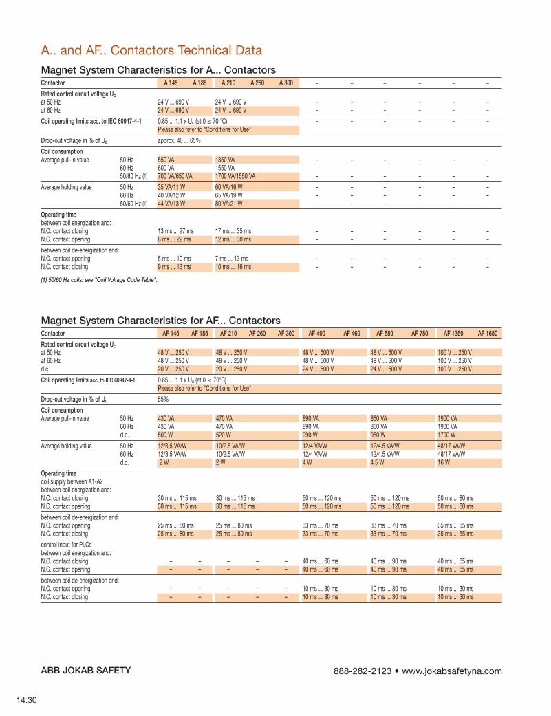
14:30
Magnet System Characteristics for A... ContactorsContactor A 145 A 185 A 210 A 260 A 300 – – – – – –
Rated control circuit voltage Uc - - - - - - - - - - - -
Coil operating limits acc. to IEC 60947-4-1 ≤ - - - - - -
Drop-out voltage in % of Uc
Coil consumption - - - - - -
- - - - - -
- - - - - -- - - - - -- - - - - -
Operating time
- - - - - -- - - - - -
- - - - - -- - - - - -
(1) 50/60 Hz coils: see "Coil Voltage Code Table".
Magnet System Characteristics for AF... ContactorsContactor AF 145 AF 185 AF 210 AF 260 AF 300 AF 400 AF 460 AF 580 AF 750 AF 1350 AF 1650
Rated control circuit voltage Uc
Coil operating limits acc. to IEC 60947-4-1 ≤
Drop-out voltage in % of Uc
Coil consumption
Operating time
m ABB JOKAB SAFETY

14:31
Magnet System Characteristics for AL... and AE... ContactorsContactor AL 9 AL 12 AL 16 AL 26 AL 30 AL 40 – – – – – – – – – – – – AE 45 AE 50 AE 63 AE 75 AE 95 AE 110
Rated control circuit voltage Uc
Coil operating limits acc. to IEC 60947-4-1 ≤ ≤
Drop-out voltage in % of Uc
Coil consumption
Coil time constant
Operating time
(1) The use of surge suppressors increases the opening time with a factor of 1.1 to 1.5 for a varistor suppressor and a factor of 1.5 to 3 for a diode suppressor.
m ABB JOKAB SAFETY

14:32
Utilization Characteristics according to UL/CSAContactor A 9 A 12 A 16 A 26 A 30 A 40 A 45 A 50 A 63 A 75 A 95 A 110 AL 9 AL 12 AL 16 AL 26 AL 30 AL 40 – – – – – – AL 9 AL 12 AL 16 AL 26 AL 30 AL 40 – – – – – –
Max. rated voltage 600 V 600 V 600 V 600 V
Pilot duty
Built-in Auxiliary ContactsUtilization Characteristics according to IECContactor A 9 A 12 A 16 A 26 A 30 A 40 A 45 A 50 A 63 A 75 A 95 A 110 AL 9 AL 12 AL 16 AL 26 AL 30 AL 40 – – – – – – AL...Z 9 AL...Z 12 AL...Z 16 AL...Z 26 AL...Z 30 AL...Z 40 – – – – – –
Rated operational voltage Ue max. 690 V 690 V 690 V 690 V
Conventional free air thermal current Ith - 0 ≤ 40° C 16 A 16 A 16 A 16 A
Rated frequency limits
Rated operational current Ie / AC-15
Rated operational current Ie / DC-13
Making capacity
Breaking capacity
Short-circuit protection
Rated short-time withstand current Icw
Minimum switching capacity
Non-overlapping time betweenN.O. and N.C. contacts ≥ ≥ ≥ ≥
Heat dissipation per pole at 6 A
(1) For AL... and AL..Z... contactors, failure rate ≤ 10 -7 according to IEC 60947-5-4.
m ABB JOKAB SAFETY

Mounting CharacteristicsContactor A 9 A 12 A 16 A 26 A 30 A 40 A 45 A 50 A 63 A 75 A 95 A 110 AL 9 AL 12 AL 16 AL 26 AL 30 AL 40 – – – – – – – – – – – – AE 45 AE 50 AE 63 AE 75 AE 95 AE 110 – – – – – – AF 45 AF 50 AF 63 AF 75 AF 95 AF 110
Mounting positions
Mounting distances
Fixing
14:33
m ABB JOKAB SAFETY
Position 1
Position 3
Position 4
Position 2
Position 5
Position 1 30
+30 -30
Position 6
ABB
ABB
AB
B
AB
B
Mounting PositionsSee the above table for authorized positions
Conditions for Use
Contactor A 9 A 12 A 16 A 26 A 30 A 40 A 45 A 50 A 63 A 75 A 95 A 110 AL 9 AL 12 AL 16 AL 26 AL 30 AL 40 – – – – – – – – – – – – AE 45 AE 50 AE 63 AE 75 AE 95 AE 110
Control voltage / Ambient temperature≤
U U
30° ≤ U U
≤ >
Contactor – – – – – – AF 45 AF 50 AF 63 AF 75 AF 95 AF 110
Control voltage / Ambient temperature≤
Notes for 4-pole contactors
Whatever the coil voltage: Pos. 5 unauthorized for AL 9-22-00, AL 16-22-00, AL 26-22-00, A 45-22-00, AE 45-22-00, AF 45-22-00, A 75-22-00, AE 75-22-00, AF 75-22-00 contactors.
For 60 Hz coil voltage: (only for devices fitted with CA 5-.. and CAL 5-11 auxiliary contacts or TP timer A 45-40-00, A 50-40-00 and A 75-40-00 contactors Mounting positions 1 to 5 and ambient temperature < 55 °C: tolerance reduced to 0.9 ... 1.1 Uc (instead of 0.85 ... 1.1 Uc) for coil voltage codes 7 and 8 . A 45-22-00 and A 75-22-00 contactors Mounting positions 1 to 4 and ambient temperature < 55 °C: tolerance reduced to 0.9 ... 1.1 Uc (instead of 0.85 ... 1.1 Uc) for coil voltage codes 7 and 8 .
For mounting position 6 or ambient temperature of 55 to 70 °C the information given on this page remains applicable.

Mounting CharacteristicsContactor A 145 A 185 A 210 A 260 A 300 – – – – – – AF 145 AF 185 AF 210 AF 260 AF 300 AF 400 AF 460 AF 580 AF 750 AF 1350 AF 1650
Mounting positions
Mounting distances
Fixing
Conditions for Use
Contactor A 145 A 185 A 210 A 260 A 300 – – – – – –
Control voltage / Ambient temperature≤ – – – – – –
–
Contactor AF 145 AF 185 AF 210 AF 260 AF 300 AF 400 AF 460 AF 580 AF 750 AF 1350 AF 1650
Control voltage / Ambient temperature≤
–
ABB
AB
B
ABB
AB
B
E18
53D
1
+30 -30
Position 1
Position 3
Position 4
Position 2
Position 5
Position 1 30
Position 6
Mounting PositionsSee the above table for authorized positions
14:34
m ABB JOKAB SAFETY

14:35
Connecting CharacteristicsContactor A 9 A 12 A 16 A 26 A 30 A 40 A 45 A 50 A 63 A 75 A 95 A 110 AL 9 AL 12 AL 16 AL 26 AL 30 AL 40 – – – – – – – – – – – – AE 45 AE 50 AE 63 AE 75 AE 95 AE 110 – – – – – – AF 45 AF 50 AF 63 AF 75 AF 95 AF 110
Main terminals
Connecting capacity (min. ... max.)
≤ 4 mm2 2
≥ 6 mm2 2
2 – – – – – – – – – – – –2 – – – – – – – – – – – –2 – – – – – – – – – – – –
2
2
≤≥
Auxiliary conductors
2
2
2
2
≤ 8 8 8≥
Degree of protection 1
Screw terminals
Tightening torque
(1) L ≤ 8 and l > 3.7 for coil terminals - L ≤ 10 and l > 4.2 for built-in auxiliary terminals.(2) With LW 110 enlargement piece: see "Accessories".
Ll
Ll
m ABB JOKAB SAFETY

14:36
17.5
ø 8.5
5
20
ø 10.2
5
25
ø 6.5
22.5
ø 10.5
6
40
ø 6.5
22.5
ø 12.5
6
80
ø 13
102740
1730
10
Connecting CharacteristicsContactor A 145 A 185 A 210 A 260 A 300 – – – – – – AF 145 AF 185 AF 210 AF 260 AF 300 AF 400 AF 460 AF 580 AF 750 AF 1350 AF 1650
Main terminals
Connecting capacity (min. ... max.)
2 – – – – – – – – – – –2 – – – – – – – – – – –
2
2
2
2 – – – – – – – – – – –2 – – – – – – – – – – –
≤ Ø mm > 8 10 10 12 12
Auxiliary conductors
2
2
2
2
≤ 8 8 8 8 8>
Capacity acc. to UL/CSA (AWG) 18-14 18-14 18-14 18-14 18-14
Degree of protection 1
Screw terminals
M8 M10 M10 M12 M12
– – – – – – – – – – –
Tightening torque
m ABB JOKAB SAFETY

GeneralUtilization categories determine the current making and breaking conditions relating to the characteristics of the loads to be controlled by the contactors. International stan-dard IEC 60947-4-1 and European standard EN 60947-4-1 are the standards to be referred to.
If Ic is the current to be broken by the contactor and Ie the rated operational current normally drawn by the load, then:
Categories AC-1 and AC-3: Ic = Ie Category AC-2: Ic = 2.5 x Ie Category AC-4: Ic = 6 x Ie
Generally speaking Ic = m x Ie where m is a multiple of the load operational current.
On next pages, the curves corresponding to categories AC-1, AC-2, AC-3 and AC-4 represent the electrical durabil-ity variation of standard contactors in relation to the break-ing current Ic. Electrical durability is expressed in millions of operating cycles. For the AC-2 applications, the Ie values are given in the "stator contactor table" (see "Control of Three-Phase Slip-ring Motors").
Case of Uninterrupted DutyAmong the different utilization categories, the uninterrupted duty implies the following remark. The combinated effect of environmental conditions and the proper temperature of the product may require some disposals. As a matter of fact, for this duty, the use duration prevails over the number of operating cycles. For long term service, some verifications of preventing maintenance are needed to check the functionality of the concerned product (consult us). Over a duration of five years, in these conditions the con-tactor might present high internal resistance. We recom-mend to change the contactor or change the contacts.
Contactor Electrical Durability and Utilization Categories
14:37
m ABB JOKAB SAFETY
Curve Utilization ModeElectrical durability forecast and contactor selection for categories AC-1, AC-2, AC-3 or AC-4.
Note the characteristics of the load to be controlled:
Operational voltage: Ue
Current normally drawn: Ie Ue / Ie / kW relation for motors, see "Motor Rated Operational Powers and Currents".
Utilization category: AC-1, AC-2, AC-3 or AC-4
Breaking current: Ic = Ie for AC-1 and for AC-3 ; Ic = 2.5 x Ie for AC-2 ; Ic = 6 x Ie for AC-4
Define the number of operating cycles N required.
On the diagram corresponding to the operational category, select the contactor with the curve imme- diately above the intersection point (Ic ; N).
Electrical durability forecast and contactor selection for mixed duty motor control: AC-3 (Ic = Ie) type switching off while "motor running" and, occasionally, AC-4 (Ic = 6 x Ie) type switching off while "motor accelerating".
Note the characteristics of the motor to be controlled:
Operational voltage: Ue
Current normally drawn while "motor running": Ie Ue / Ie / kW relation for motors, see "Motor Rated Operational Powers and Currents".
Breaking current for AC-3 Ic = Ie Breaking current for AC-4 while
"motor accelerating": Ic = 6 x Ie Percentage of AC-4 operating cycles K
On the basis of the total number of operating cycles.
Define the total number of operating cycles N required.Note the smallest contactor rating compatible for AC-3
(Ue / Ie) on Main Pole Utilization Characteristic table. See "Technical Data"
For the selected contactor make a note of the following in relation to the voltage using diagram AC-3 in next pages.
The number of operating cycles: A for Ic = Ie (AC-3)
The number of operating cycles: B for Ic = 6 x Ie (AC-4)
Calculate the estimated number of cycles N' (N' is always below A)
N' = A 1 + 0.01 K (A/B - 1)
If N' is too low in relation to the target N, calculate the estimated number of cycles for a higher contactor rating.

E16
66D
1 3 5 7 9
1 3 5 7 9
1
3
5
79
13579
1 3 5 7 9
1 3 5 7 913579
10
1
0.1
0.2
0.3
0.5
3
5
10 100 10002 3 5 20 30 50 200 300 500
A 145
A 9 A 12
A 16
A 26
A 30
A 40
A 45
A 50
A 63
A 75
A 95
A 110
A 185
A 210
A 300
A 260
AF 400
AF 460
AF 580
AF 750
2
24
Millions of operatingcycles
Breaking current Ic (A)
14:38
A... Contactors Electrical Durability
Electrical Durability for AC-1 Utilization CategoryUe ≤ 690 V - Ambient Temperature ≤ 55 °CSwitching non-inductive or slightly inductive loads. The breaking current Ic for AC-1 is equal to the rated operational current of the load. Maximum electrical switching frequency: see "Technical Data".
m ABB JOKAB SAFETY
Example: Ic / AC-1 = 24 A – Electrical durability required = 2 million operating cycles.Using the AC-1 curves above select the A 30 contactor at intersection " " (24 A / 2 million operating cycles).

14:39
m ABB JOKAB SAFETY
A... Contactors Electrical DurabilitySwitching cage motors: starting and switching off running motors. The breaking current Ic for AC-3 is equal to the rated operational current Ie (Ie = motor full load current). Maximum electrical switching frequency: see "Technical Data".
Electrical Durability for AC-3 Utilization Category - Ue ≤ 440 V - Ambient Temperature ≤ 55 °C
E16
67D
10
1
10 100 10002 3 5 20 30 50 200 300 5000.2
0.3
0.5
2
3
5
1 3 5 7 9
13579
1
3
5
79
1 3 5 7 9 1 3 5 7 9
1 3 5 7 9 1 3 5 7 9
A 9 A 12
A 16
A 26
A 30
A 40
A 50
A 63
A 75
A 95
A 110
A 145
A 185
A 210
A 260
A300
AF 400
AF 460
AF 580
AF 750
1.5
79
Millions of operatingcycles
Breaking current Ic (A)
Electrical Durability for AC-3 Utilization Category - 440 Ue ≤ 690 V - Ambient Temperature ≤ 55 °C
1 3 5 7 9
13579
1
3
5
79
1 3 5 7 9 1 3 5 7 9
1 3 5 7 91 3 5 7 9
E16
70D
10
1
10 100 10002 3 5 20 30 50 200 300 5000.2
0.3
0.5
2
3
5
A 9 A 12
A 16
A 26
A 30
A 40
A 50
A 63
A 75
A 95
A 110
A 145
AF 400
AF 460
AF 580
AF 750
A 185
A 210
A 300
A 260
Millions of operatingcycles
Breaking current Ic (A)
Example: Motor power 40 kW for AC-3 - Ue = 400 V and Ie = 79 A utilizationElectrical durability required = 1.5 million operating cycles.For AC-3: Ic = Ie: Select the A 110 contactor at intersection " " (79 A / 1.5 million operating cycles) on the curves (AC-3 - Ue ≤ 440 V).

14:40
m ABB JOKAB SAFETY
E16
68D
30001000100102 3 5 20 30 50 200 300 500 2000 5000
10
1
0.1
0.005
0.01
0.02
0.03
0.05
0.3
0.5
2
3
5
1 3 5 7 9
1 3 5 7 9
1 3 5 7 9
1 3 5 7 9
1 3 5 7 9
1 3 5 7 9
13579
13579
13579
13579
13579
13579
A 9 A 12
A 16
A 26
A 30
A 40
A 50
A 63
A 75A 9
5A 1
10A 2
60
A 300
A 145
A 185
A 210
0.2
510
A 9 A 12
A 16
A 26
A 30
A 40
A 50
A 63
A 75A 9
5A 1
10A 2
60
A 300
A 145
AF 400
AF 460
AF 580
AF 750
AF 135
0
AF 165
0
A 185
A 210
0.2
510
Millions of operatingcycles
A... Contactors Electrical Durability
Electrical Durability for AC-2 or AC-4 Utilization CategoryUe ≤ 440 V - Ambient Temperature ≤ 55 °CSwitching cage motors: starting, reverse operation and step-by-step operation. The breaking current Ic is equal to 2.5 x Ie for AC-2 and 6 x Ie for AC-4, keeping in mind that Ie is the motor rated operational current (Ie = motor full-load current). Maximum electrical switching frequency: see "Technical Data".
Breaking current Ic (A)
Example: Motor power 45 kW for AC-4 - Ue = 400 V and Ie = 85 A utilizationElectrical durability required = 0.2 million operating cycles.For AC-4: Ic = 6 x Ie = 510 A - Select the A 260 contactor at intersection " " (510 A / 0.2 million operating cycles) on the curves (AC-4 - Ue < 440 V).

E16
69D
1 3 5 7 9
1 3 5 7 9
1 3 5 7 9
1 3 5 7 9
1 3 5 7 9
1 3 5 7 9
10
1
0.1
0.005
0.01
0.02
0.03
0.05
0.2
0.3
0.5
2
3
5
50001000100102 3 5 20 30 50 200 300 500 2000 3000
13579
13579
13579
13579
13579
13579
427
A 9 A 12
A 16
A 26
A 30
A 40
A 50
A 63
A 75
A 95
A 110
A 145
A 185
A 210
A 260
A 300
AF 400
AF 460
AF 580
AF 750
0.04
Millions of operatingcycles
A... Contactors Electrical Durability
Electrical Durability for AC-2 or AC-4 Utilization Category440 V < Ue ≤ 690 V - Ambient Temperature ≤ 55 °CSwitching cage motors: starting, reverse operation and step-by-step operation. The breaking current Ic is equal to 2.5 x Ie for AC-2 and 6 x Ie for AC-4, keeping in mind that Ie is the motor rated operational current (Ie = motor full-load current). Maximum electrical switching frequency: see "Technical Data".
Breaking current Ic (A)
Example: Motor power 59 kW for AC-4 - Ue = 600 V and Ie = 71.1 A utilizationElectrical durability required = 0.04 million operating cycles.For AC-4: Ic = 6 x Ie = 426.6 A - Select the A 145 contactor at intersection " " (427 A / 0.04 million operating cycles) on the curves (AC-4 - 440 V < Ue < 690 V).
14:41
m ABB JOKAB SAFETY

E23
85D
1 3 5 7 9
1
3
5
79
13579
13579
1 3 5 7 9
1
0.2
0.3
0.5
3
2
5
10 100 10002 3 5 20 30 50 200 300 500
AL 9
AL 12
AL 16
AL 26
AL 30
AL 40
0.56
35 Breaking current Ic (A)
Example: Ic / AC-1 = 35 A – Electrical durability required = 560 000 operating cycles.Using the AC-1 curves above select the AL 26 contactor at intersection " " (35 A / 560 000 operating cycles).
Electrical Durability for AC-3 Utilization Category Ue ≤ 500 V - Ambient Temperature ≤ 55 °CSwitching cage motors: starting and switching off running motors. The breaking current Ic for AC-3 is equal to the rated operational current Ie (Ie = motor full load current). Maximum electrical switching frequency: see "Technical Data".
A... Contactors Electrical Durability
Millions of operatingcycles
E23
86D
1
3
5
79
13579
1 3 5 7 9 1 3 5 7 9
1 3 5 7 9
1 3 5 7 9
1 3 5 7 9
3
10
1
10 100 10002 3 5 20 30 50 200 300 5000.3
0.5
2
5
AL 9
AL 16
AL 12
AL 26
AL 30
AL 40
2.3
18.3
Millions of operatingcycles
Breaking current Ic (A)
14:42
m ABB JOKAB SAFETY
Electrical Durability for AC-1 Utilization Category - Ue ≤ 690 V - Ambient Temperature ≤ 55 °CSwitching non-inductive or slightly inductive loads. The breaking current Ic for AC-1 is equal to the rated operational current of the load. Maximum electrical switching frequency: see "Technical Data".
Example: Motor power 9 kW for AC-3 - Ue = 400 V and Ie = 18.3 A utilization – Electrical durability required = 2.3 million operating cycles. For AC-3: Ic = Ie. Select the AL 26 contactor at intersection " " (18.3 A / 2.3 million operating cycles) on the curves (AC-3 - Ue < 500 V).

Influence of the Length of Conductors used in Contactor Control CircuitUnder certain conditions the excessive length of the controlcircuit conductors may prevent the contactor from carrying out closing and opening orders.
no closing: due to excessive voltage drop (in a.c. or d.c.)
no opening: due to excessive capacitance (in a.c.)
Contactor Closing (contactor with a.c. or d.c. operated coil)The voltage drop is due to the pull-in current (pull-in power)and to the resistance of the control circuit conductors. The table at the right and graph below can be used to determine the single length of line feeders (distance between the control device and the contactor coil) in relation to:
the coil pull-in consumption the supply voltage the connecting wire cross-sectional area
The graph has been drawn for a maximum line voltage drop of 5%. Coil pull-in consumption (average value).
14:43
m ABB JOKAB SAFETY
1
10
100
1000
10000
1
2000
20
2
3
5
30
50
200
300
500
3000
5000
2.5
10
100
1000
10000
2.5
2500020000
2000
20
3
5
30
50
200
300
500
3000
5000
4
10
100
1000
10000
20000
40000
4
2000
20
5
30
50
200
300
500
3000
5000
30000
1 10 100 1000 100001.5
10
100
1000
10000
1.5
15000
20
2
3
5
30
50
200
300
500
3000
5000
2 3 5 20 30 50 200 300 500 2000 5000
Cross-sectional area (Cu) in mm2 Coil pull-in consumption: in VA for a.c. operated contactors in W for d.c. operated contactors
sing
le li
ne le
ngth
in m
.
1 3 5 7 9 1 3 5 7 9 1 3 5 7 9 1 3 5 7 9
2000
660 V - 690 V500 V380 V - 400 V220 V - 230 V
110 V
60 V48 V
24 V
70
Contactors a.c. control circuit - 50 HzA 9, 12, 16 70 VAA 26, 30, 40 120 VAA 45, 50, 63, 75 180 VAA 95, 110 450 VAA 145, 185 700 VAA 210, 260, 300 1700 VA AF 45, 50, 63, 75 210 VAAF 95, 110 350 VAAF 145,185 430 VAAF 210, 260, 300 470 VAAF 400, 460 890 VAAF 580, 750 850 VAAF 1350, 1650 1900 VA
Permissible single length for the control circuit conductors on contactor closing: Depending on the coil pull-in power consumption on the supply voltage and on the control circuit conductor cross-sectional area.
Example: A 9 contactor - Coil voltage: 230 V 50 Hz - Contactor coil pull-in power consumption: 70 VAControl circuit conductor cross-sectional area: Cu 1.5 mm2. - Max. permissible length: 2000 m.
Contactors d.c. control circuitAL 9Z, 12Z, 16Z 2.4 WAL 9, 12, 16 3 WAL 26, 30, 40 3.5 WAE 45, 50, 63, 75 200 WAE 95, 110 400 WA 210, 260, 300 1700 VA AF 45, 50, 63, 75 190 WAF 95, 110 400 WAF 145,185 500 WAF 210, 260, 300 520 WAF 400, 460 990 WAF 580, 750 950 WAF 1350, 1650 1700 W
A 50-30-00 AF 460-30-11

Influence of the Length of Conductors used in Contactor Control Circuit
0.60
Coil holding consumption in VA
Sin
gle
line
leng
th in
m.
10
100
1000
21.7
3
5
20
30
50
200
300
500
1700
1 10 100 10002 3 5 20 30 50 200 300 5000.10
10
100
1000
10000
20
30
50
200
300
500
2000
3000
5000
0.20
10
100
1000
20
30
50
200
300
500
2000
3000
5000
5
0.30
10
100
1000
3.3
5
20
30
50
200
300
500
2000
3300
0.40
10
100
1000
2.5
5
20
30
50
200
300
500
20002500
0.50
10
100
1000
2
3
5
20
30
50
200
300
500
2000
Line capacitance in F/km
380
380 V - 400 V
660 V - 690 V
220 V - 230 V
110 V
60 V48 V
24 V
500 V
188
60
1 3 5 7 9 1 3 5 7 91 3 5 7 9
Contactors a.c. control circuit - 50 HzA 9, 12, 16 8 VAA 26, 30, 40 12 VAA 45, 50, 63, 75 18 VAA 95, 110 22 VAA 145, 185 35 VAA 210, 260, 300 60 VA AF 45, 50, 63, 75 7 VAAF 95, 110 7 VAAF 145,185 12 VAAF 210, 260, 300 10 VAAF 400, 460 12 VAAF 580, 750 12 VAAF 1350, 1650 48 VA
Permissible single length for the control circuit conductors on contactor closing: Depending on the coil pull-in power consumption on the supply voltage and on the control circuit conductor cross-sectional area.
Example: A 16 ContactorCoil voltage: Uc = 500 V, 50 Hz, 8 VA contactor coil holding consumption Control type: diagram A, via maintained pushbutton, and 2-core cable with a capacity of 0.2 μF/kmMax. permissible length: 60 mA 50 contactor
14:44
m ABB JOKAB SAFETY
Contactor Closing (contactor with a.c. operated coil)Under certain conditions, an a.c. operated contactor doesnot open when the control circuit is de-energized. This is due to a critical capacity of the excessively long control circuit line and the type of contactor coil control layout. (see diagrams A and B opposite)
This may be caused by the following factors: high control voltage low coil holding consumption low contactor drop-out voltage
(according to IEC 60947-4-1: 0.2 to 0.75 x Uc)
If lines longer than those indicated are required, the following measures must be taken:
select a contactor with a higher rating. select a lower control voltage. connect "RP" resistance in parallel with
the contactor coil: RP = 103 (with C in μF) CThe table above right and graph below can be used to determine the single length of line feeders (distance between the control device and the contactor coil) in relation to:
the coil holding consumption VA the supply voltage the capacity in μF/km (depending on the control layout)
Wiring diagrams A and B show two supply and coil control wiring examples. Coil holding consumption (average value).
A84
1D
Wiring Diagram ASingle Control Line Length
Via maintained pushbutton and 2-core cable (with a capacity of 0.2 μF/km, for example)
A84
1D
Wiring Diagram BSingle Control Line Length
Via momentary pushbutton plus hold-in contact and 3-core cable (with a capacity of 2 x 0.2 = 0.4 μF/km, for example)
Coil voltage: Uc = 230 V, 50 Hz, 18 VA contactor coil holding consumptionControl type: diagram B via momentary pushbutton, hold-in contact and 3-core cable with a capacity of 2 x 0.2 μF/km = 0.4 μF/kmMax. permissible length: 380 m

14:45
ABB JOKAB SAFETY

14:46
ABB JOKAB SAFETY

Contactor RelaysChoice of 4-pole (1-stack) or 8-pole (2-stack)!Auxiliary contacts for safety circuits available!Wide range of accessories available!
15:1
ABB JOKAB SAFETY
15:215:4
Accessory Fitting Details 15:5
15:615:8
Accessory Fitting Details 15:9
Technical Data 15:10 Mounting Positions 15:12
Auxiliary Contacts for Safety Circuits 15:13

15:2
Applications
Features■ 1-stack contactor relays (4-pole) or 2-stack contactor relays (8-pole)■
■
■
Variants■
Width of 8-pole devices is identical to that of
4-pole devices. Only the depth is increased.
Stops for attaching front mounted accessories
Terminal screws: Pozidriv (+/-) No. 2
Terminals delivered in open position with captive screws
Screwdriver guidance for all terminals
Degree of protection of terminals according to IEC 60947-1: IP20 for all terminals
Location of side mounted accessories (on right or left hand side)
Quick fixing on mounting rail according to IEC 60715/EN 60715 standards: 35 x 7.5 mm or 35 x 15 mm
Holes for screw fixing (screws not supplied)
Location of surge suppressors
Clear marking of coilvoltages and respective A1/A2
connection terminals
Terminal marking according to IEC 60947-5-1 and EN 50011
Location of function marker
ABB JOKAB SAFETY

15:3
IEC Rated Operational Current UL/CSA Diagram AC-15 AC-15 AC-15 DC-13 DC-13 Pilot Duty 240 V 400 V 690 V 24 V 250 V
N22E-
N31E-
4-Pole, 1-Stack (main contacts N.O. + N.C.)
Auxiliary Contacts Surge SuppressorsMain Accessories Front Mounting Side Mounting (see table below)
N22E- / RC5-1/
N31E- / RC5-1/
IEC Rated Operational Current UL/CSA Diagram AC-15 AC-15 AC-15 DC-13 DC-13 Pilot Duty 240 V 400 V 690 V 24 V 250 V
N44E-
N53E-
N62E-
N71E-
Auxiliary Contacts Surge SuppressorsMain Accessories Side Mounting (see table below)
N44E- / RC5-1/
N53E- / RC5-1/
N62E- / RC5-1/
N71E- / RC5-1/
Feature Voltage Range Part Number
Varistor
RC
2 2
3 1
8-Pole, 2-Stack (main contacts N.O. + N.C.)
4 4
5 3
6 2
7 1
Surge Suppressors
ABB JOKAB SAFETY

Coil Voltages and Codes
15:4
1st Stack 2nd Stack Part Number Weight
2 2 — — N22E-
3 1 — — N31E-
4-Pole, 1-Stack
1st Stack 2nd Stack Part Number Weight
4 — — 4 N44E-
4 — 1 3 N53E-
4 — 2 2 N62E-
8-Pole, 2-Stack
Voltage Voltage Code V - 50Hz V - 60Hz
24 24 8 1
48 48 8 3
110 110 - 120 8 4
220 - 230 230 - 240 8 0
230 - 240 240 - 260 8 8
380 - 400 400 - 415 8 5
400 - 415 415 - 440 8 6
ABB JOKAB SAFETY
HOW TO ORDER Number of Contacts Part Number 1st stack 2nd stack state coil voltage
code
(see table below)
Packing Quantity: 1 pc

Accessory Fitting Details
15:5
Contactor Built-In Contacts Front Mounted Side Mounted 1st Stack 2nd Stack Accessories Accessories
Auxiliary Contact Auxiliary Contact Auxiliary Contact 1-pole CA5-... 4-pole CA5-... 2-pole CAL5-11
N22E- or + 1 to 2 x CAL5-11 (4-pole)
N31E- or + 1 to 2 x CAL5-11 (4-pole)
N44E- 4 0 0 4 n/a n/a 1 to 2 x CAL5-11
N53E- 4 0 1 3 n/a n/a 1 to 2 x CAL5-11
N62E- 4 0 2 2 n/a n/a 1 to 2 x CAL5-11
N71E- 4 0 3 1 n/a n/a 1 to 2 x CAL5-11
Many configurations of accessories are possible depending
N... Contactor Relays and Main Accessories
For mounting position diagramsee Technical Data on page 15:12
(1) 2 x N.C. front mounted auxiliary contacts maximum in mounting position 5. N22E- and N31E- in mounting position 5, TP...DA not allowed.
(2) Additional N.C. CA5-... auxiliary contacts are limited to 2.
ABB JOKAB SAFETY

15:6
Width of 8-pole devices is identical to that of
4-pole devices. Only the depth is increased.
Stops for attaching front mounted accessories
Terminal screws: Pozidriv (+/-) No.2
Terminals delivered in open position with captive screws
Screwdriver guidance for all terminals
Degree of protection of terminals according to IEC 60947-1: IP20 for all terminals
Location of side mounted accessories (on right or left hand side)
Quick fixing on mounting rail according to IEC 60715/EN 60715 standards: 35 x 7.5 mm or 35 x 15 mm
Holes for screw fixing (screws not supplied)
Location of surge suppressors
Clear marking of coilvoltages and respective A1/A2
connection terminals
Terminal marking according to IEC 60947-5-1 and EN 50011
Location of function marker
Applications
Features■ 1-stack contactor relays (4-pole) or 2-stack contactor relays (8-pole)■
■ Note: The polarity on the coil terminals (A1+ and A2-) must be respected.
■
3W (Pull-in and holding)■
ABB JOKAB SAFETY

IEC Rated Operational Current UL/CSA Diagram AC-15 AC-15 AC-15 DC-13 DC-13 Pilot Duty 240 V 400 V 690 V 24 V 250 V
NL44E-
NL53E-
NL62E-
NL71E-
Auxiliary Contacts Surge SuppressorsMain Accessories Front Mounting Side Mounting (see table below)
NL22E- / RT5/
NL31E- / RT5/
8-Pole, 2-Stack (main contacts N.O. + N.C.)
Surge SuppressorsMain Accessories (see table below)
NL44E- / RT5/
NL53E- / RT5/
NL62E- / RT5/
NL71E- / RT5/
Feature Voltage Range Part Number
Varistor
Transil Diode
IEC Rated Operational Current UL/CSA Diagram AC-15 AC-15 AC-15 DC-13 DC-13 Pilot Duty 240 V 400 V 690 V 24 V 250 V
NL22E-
NL31E-
4-Pole, 1-Stack (main contacts N.O. + N.C.)
2 2
3 1
4 4
5 3
6 2
7 1
Surge Suppressors
ABB JOKAB SAFETY

8-Pole, 2-Stack
15:8
1st Stack 2nd Stack Part Number Weight
2 2 — — — — NL22E-
3 1 — — — — NL31E-
4-Pole, 1-Stack
1st Stack 2nd Stack Part Number Weight
4 — — 4 — — NL44E-
4 — 1 3 — — NL53E-
4 — 2 2 — — NL62E-
Voltage Code VDC
12 8 0
24 8 1
42 8 2
48 8 2
50 2 1
60 8 4
110 8 6
220 8 8
240 8 9
250 3 8
NL... Coil Voltages and Codes
HOW TO ORDER Number of Contacts Part Number 1st stack 2nd stack state coil voltage
code
(see table below)
Packing Quantity: 1 pc
ABB JOKAB SAFETY

15:9
Accessory Fitting Details
Contactor Built-In Contacts Front Mounted Side Mounted 1st Stack 2nd Stack Accessories Accessories
Auxiliary Contact Auxiliary Contact Auxiliary Contact 1-pole CA5-... 4-pole CA5-... 2-pole CAL 5-11
NL22E- (4) 2 2 — — or + 1 x CAL5-11 (3) (4-pole) (3) (2)
NL31E- (1) 3 1 — — or + 1 x CAL5-11 (3) (4-pole) (1) (2)
NL44E- 4 0 0 4 n/a n/a n/a
NL53E- 4 0 1 3 n/a n/a n/a
NL62E- 4 0 2 2 n/a n/a n/a
NL71E- 4 0 3 1 n/a n/a n/a
Many configurations of accessories are possible depending
(1) A maximum of 2 N.C. auxiliary contacts can be fitted in all mounting positions except 5. In position 5 no N.C. auxiliary contacts are permitted.
(2) With CAL5-11 the control voltage is limited to 0.9 Uc - 1.1 Uc in all mounting positions.
(3) A maximum of 2 N.C. auxiliary contacts can be fitted.
(4) Mounting position 5 is not allowed.
For mounting position diagramsee Technical Data on page 15:12
NL... Contactor Relays and Main Accessories
ABB JOKAB SAFETY

15:10
ABB JOKAB SAFETY
General Technical Data
i
according to UL/CSA
Standards
(close to contactor) for operation in free air for storage
Shock Withstand
shock direction A(closed or open position)
(closed position) shock direction B1
(closed or open position) (closed position)
shock direction B2 (closed or open position)
(closed position) shock direction C1
(closed or open position) (closed position)
shock direction C2 (closed or open position)
(closed position)
(see “Conditions for Use” on page 15:12
according to IEC 60068-2-30 and 60068-2-11 - UTE C 63-100 specification II
(no change in contact position)
20 g20 g
5 g15 g
15 g10 g
20 g20 g
20 g14 g
Note: Data at Ta = 25º C, UIN = V AC and rated values, if nothing else indicated.
Manufacturer ABB
Ordering Information
Utilization Characteristics
e
Conventional Free Air th
Current Ie /AC-15
Current Ie /DC-13
Making Capacity
Breaking Capacity
Short Circuit ProtectionUe
Withstand Current I
Heat Dissipation per Pole at 6 A
Mechanical Durability
(according to IEC)
open contactors 0- 40º C)
6 A
6 A/144 W
10 x Ie /AC-15
10 x Ie /AC-15
10 A
100 A140 A
10 -6
10 -7
1200 cycles/h
> 20
6000 cycles/h
Utilization Characteristics According to UL/CSA
Pilot Duty

15:11
ABB JOKAB SAFETY
Magnet System Characteristics for N... Contactor Relays
Rated Control Circuit e
e
average pull-in value
average holding value
c ( 0- 55º C)(according to IEC 60947-5-1, please also refer to “Conditions for Use” on page 15:12)
Magnet System Characteristics for NL... Contactor Relays
Rated Control Circuit e
e
average pull-in value average holding value
open L/R closed L/R
c ( 0- 55º C)(according to IEC 60947-5-1, please also refer to “Conditions for Use” on page 15:12)
(1) 50/60 Hz coils: see “Coil Voltage Code Table”
(2) The use of surge suppressors increases the opening time with a factor of 1.1 to 1.5 for a varistor suppressor and a factor of 1.5 to 3 for a transil diode suppressor.

ABB
ABB
AB
B
AB
B
Mounting Positions
See the table above for authorized positions.
15:12
ABB JOKAB SAFETY
Mounting Characteristics
Mounting Positions
Mounting Distances
e
Fixing on rail
2 x M4
Conditions for Use
at
Control Voltage/Ambient Temperature
Mounting Positions for
55º C
55º C
55º C 6
Mounting Positions for
55º C
55º C
55º C 6
cUc
cUc
c
c Uc
c
Uc
(1) NL22E- are not allowed in position 5.

15:13
Definitions from standards:
Mechanically Linked Contact Elements
(according to IEC 60947-5-1, Annex L 3.0)
n m”
Direct Opening Action of N.C. Built-In Auxiliary Contacts
direct opening action as “the full contact opening of the break contact element(s) is obtained when the actuator is moved through the direct opening travel by applying the force stated by the manufacturer”
“direct opening action” and are suitable for uses such as lifts/
The table below gives the contactor relays that offer mechanically linked auxiliary contacts
(according to IEC 60947-5-1, Annex L)
Contactor Built-In Auxiliary ContactsRelay
N22E-, NL22E- 2 2
N31E-, NL31E- 3 1
N44E-, NL44E- 4 4
N53E-, NL53E- 5 3
N62E-, NL62E- 6 2
N71E-, NL71E-
Auxiliary Contacts for Safety Circuits
ABB JOKAB SAFETY
Connecting Characteristics
Mounting Distances
rigid solid 2
2
cable end 2
2
Lugs
Ll
Ll
1-41-4
Capacity according to UL/CSA
Degree of Protection (according to
and IEC 60529/EN 60529)
IP 20(protection against direct contact
Screw Terminals
(delivered in open position)
Tightening Torque

15:14
ABB JOKAB SAFETY
Notes

Pilot DevicesWithstands the toughest environment!Fast and easy installation saves money!Aesthetic and functional design!When you think Pilot Devices...think ABB Jokab Safety ......................................... 16:2
Mounting, Modular Range ........................................ 16:5
Modular Range Pilot Devices .......................................................... 16:6 Emergency Stop Pushbuttons ............................... 16:8 Contact Blocks/Lamp Block and Holder ............................................................. 16:10 Accessories ............................................................ 16:11 Technical Data ........................................................ 16:17
Compact Range Emergency Stop Pushbuttons ............................... 16:21 Technical Data ........................................................ 16:22
Assembled Stations and EmptyPlastic and Steel Enclosures ..................................... 16:24
Signal Towers K70 ..................................................... 16:30
m ABB JOKAB SAFETY
16:1

Approvals
c us
16:2
When you thinkPilot Devices...think ABB Jokab Safety!Part of our Comprehensive ProgramABB has a complete range of Low Voltage Control Products — including pushbuttons, selector switches and pilot lights — that are suitable for every customer’s appli-cation. Our products meet all essential national and international standards. In addition, ABB offers Low Voltage Control Products such as contactors, soft starters, direct across the line and y-delta starters, and a wide range of electronic relays, switches and sensors.
Pilot DevicesABB offers a complete range of 22 mm Pushbuttons, Emergency Stops and Selector Switches. These are complemented with enclosures and a wide range of accessories. The main advantages are the robustness and the fast and easy installation ensuring cost efficiency for our customers. The ABB Pilot Devices are suitable for all types of industrial environments, indoor as well as outdoor. Other sectors of common usage include trucks, buses, trains and official buildings.
Made for Tough Industrial Environments■ Can be used in many different applications by OEMs, panel builders, contractors, etc. ■ For industrial machines and equipment, control panels and control stations■ For emergency circuits, alarm and signal equipment, traction equipment, hoists and lifts, door openers, etc.
The Important LinkPushbuttons and pilot lights — the world’s simplest devices. They are used to make and break a circuit, pass on a message or control an operation: in short, to be a link between man and machine. A pushbutton has to be sturdy and reliable, suit-able for all environments and adaptable to widely differing requirements. Further, it should be easy to fit or set up. You will find all these features in ABB’s Pilot Devices.
Complete RangeThe ABB Pilot Device family is divided into two ranges; the Modular range that includes operators, holders, contact blocks and accessories that can be combined with high flexibility. The Compact range that have all functions built-in in one single unit.
Fast and Easy to InstallAll pilot devices are easy to install. Spring-loaded tabs ensure that actuators and legend plates are in correct position. Same actuator can be used in both notched and round holes.
Flexible–Functional–Aesthetic■ Aesthetic and functional design — tight, with- standing even the toughest environment. ■ No additional protective boots are needed.■ Large text and push area, clear and visible markings for quick and easy handling.■ Different choices of bezels — black plastic or metal. Grey plastic as accessory.Contacts are provided with wiping action. The tips of the contacts rub against each other each time the contacts close, thus forcing dust and oxide to the side. The NC block has positive opening for high perform-ance in safety circuits.
Worldwide AvailabilityABB is represented in over 100 countries. Our full
and national standards.
m ABB JOKAB SAFETY

16:3
m ABB JOKAB SAFETY
Pushbuttons, 22 mm and 30 mmNon-Illuminated and Illuminatedsee pages 16:6 and 16:7
Emergency Stops, 22 mmNon-Illuminatedsee page 16:21
Emergency Stops, 22 mmNon-Illuminated and Illuminatedsee pages 16:8 and 16:9
Pilot Devices...the Modular Range
Pilot Devices...the Compact Range

see page 16:11 through 16:16Ask your ABB representative for detailed information about Legend Plates.
Pilot Device Adapters, 30 mmsee page 16:14
16:4
m ABB JOKAB SAFETY
Accessories
Assembled Stations and Empty Plastic and Steel Enclosures
Signal Towersand Signal Beacons
see pages 16:24 through 16:29
see pages 16:30 through 16:33

16:5
m ABB JOKAB SAFETY
Pilot Devices Mounting Modular Range
Contact BlockSingle pole with making or breaking contact.
Lamp BlockIlluminated pushbuttons, illuminated selector switches and pilot lights have a lamp block in the center position of the holder
HolderAvailable either for three or five blocks in one single row. Additional blocks can be stacked on holders for three blocks.
Nut
Legend PlatesAluminum plates withslots that guide the legendplate and the operator into the correct position.Ask your ABB representative for detailed information about Legend Plates.
Legend Plate HoldersBlack plastic plate holder with insert of brushed aluminum.
OperatorButtons, lenses and handles available in several colors.
BezelPushbuttons, selector switches and toggle switches with bezel available in black plastic, chrome plastic or chrome metal.
Easy to install... ...and remove!
Insert the operator from the front...
...then it secure at the back with the nut.
Press down the spring on holder and pull holder from actuator.
Do not use a screw-driver to remove!
Snap contact blocks and lamp block on to the holder...
...finally, snap holder on to the operator.

Description How to Order Part No.
Black Plastic Standard ‘1’ MPX-10X
Chrome Metal Replace ‘2’ with ‘3’ MPX-30X in part number
16:6
m ABB JOKAB SAFETY
Description Color Part No. Weight
Flush Button Red MP1-10R 0.035 lb (0.016 kg)Momentary)Packing Green MP1-10G 0.035 lb (0.016 kg)Quantity: 1 pc
Yellow MP1-10Y 0.035 lb (0.016 kg)
Blue MP1-10L 0.035 lb (0.016 kg)
White MP1-10W 0.035 lb (0.016 kg)
Black MP1-10B 0.035 lb (0.016 kg)
Clear MP1-10C 0.035 lb (0.016 kg)
Extended Button Red MP3-10R 0.035 lb (0.016 kg) MomentaryPacking Green MP3-10G 0.035 lb (0.016 kg)Quantity: 1 pc
Yellow MP3-10Y 0.035 lb (0.016 kg)
Blue MP3-10L 0.035 lb (0.016 kg)
White MP3-10W 0.035 lb (0.016 kg)
Black MP3-10B 0.035 lb (0.016 kg)
Clear MP3-10C 0.035 lb (0.016 kg)
Pilot Devices with Flush and Extended Pushbuttons (Non-Illuminated, Momentary)
Operator
Contact Blocks
Holder
BezelOperator (with
Locking Nut)
Note: For information on contact blocks and holder see information beginning on page 16:10.
HOW TO ORDER:Operator + Holder + Contact Block(s) OROperator + Holder with Contact Block(s)
Bezel Options

16:7
m ABB JOKAB SAFETY
Description Color Type Weight
Flush Button Red MP1-11R 0.035 lb (0.016 kg)MomentaryPacking Green MP1-11G 0.035 lb (0.016 kg)Quantity: 1 pc
Yellow MP1-11Y 0.035 lb (0.016 kg)
Blue MP1-11L 0.035 lb (0.016 kg)
White MP1-11W 0.035 lb (0.016 kg)
Black MP1-11B 0.035 lb (0.016 kg)
Clear MP1-11C 0.035 lb (0.016 kg)
Extended Button Red MP3-11R 0.035 lb (0.016 kg)MomentaryPacking Green MP3-11G 0.035 lb (0.016 kg)Quantity: 1 pc
Yellow MP3-11Y 0.035 lb (0.016 kg)
Blue MP3-11L 0.035 lb (0.016 kg)
White MP3-11W 0.035 lb (0.016 kg)
Black MP3-11B 0.035 lb (0.016 kg)
Clear MP3-11C 0.035 lb (0.016 kg)
Pilot Devices with Flush and Extended Pushbuttons (Illuminated, Momentary)
Contact Blocksand Lamp Block
Holder
BezelOperator (with
Locking Nut)
Operator
Note: For information on contact blocks and holder see information beginning on page 16:10.
HOW TO ORDER:Operator + Holder + Contact Block(s) + Lamp Block OR
Operator + Holder with Contact Block(s) and Lamp Block
Description How to Order Part No.
Black Plastic Standard ‘1’ MPX-10X
Chrome Metal Replace ‘2’ with ‘3’ MPX-30X in part number
Bezel Options

16:8
m ABB JOKAB SAFETY
Latching Test With 1.6 kg hammer
Resetting Test Pulling force < 50 N Turning torque < 1 Nm
Electrical Test According to utilization category AC15 and DC13
Contacts with According to IEC 60947-5-1Direct Opening Action Annex K
Note: The Emergency Stop Pushbuttons also comply with applicable parts of standards ISO 13850, EN 418 and directive 2006/42/EC, Machinery Safety.
Durability Test 6,050 cycles (Not a test of mechanical life. Product mechanical life: 100,000 operations.)
Robustness Test Force of 113 N applied in three axes
Conditioning Test Heat and cold, moist, dry and salty atmospheres, and in 5% NaCl
Shock Test 15 g shock
Vibration Test 2 h at 50 m/s2
Opening Test Impulse voltage test at 2,500 V
To comply with this standard, a number of tests had to be conducted with the following results:
ABB Emergency Stop Pushbuttons Fulfill IEC 60947-5-5
Description Color Release Part No. Weight
Non-Illuminated Red Twist MPMT3-10R 0.091 lb (0.041 kg) Ø 40 mm Red Pull MPMP3-10R 0.091 lb (0.041 kg)
Non-Illuminated Red Twist MPMT4-10R 0.106 lb (0.048 kg)Ø 60 mm Red Pull MPMP4-10R 0.106 lb (0.048 kg)
Illuminated Red Twist MPMT3-11R 0.091 lb (0.041 kg)Ø 40 mm Red Pull MPMP3-11R 0.091 lb (0.041 kg)
Illuminated Red Twist MPMT4-11R 0.106 lb (0.048 kg)Ø 60 mm Red Pull MPMP4-11R 0.106 lb (0.048 kg)
Packing Quantity: 1 pc Note for Illuminated Operator: Bulb max 2 W, not included.
Emergency Stop Pushbuttons with Twist or Pull Release (Non-Illuminated and Illuminated)
Operator
Contact Blocks
Holder
Operator (with Locking Nut)
HOW TO ORDER for Non-Illuminated:Operator + Holder + Contact Block(s) OROperator + Holder with Contact Block(s)
HOW TO ORDER for Illuminated:Operator + Holder + Contact Block(s) + Lamp Block OR
Operator + Holder with Contact Block(s) and Lamp Block
Note: For information on contact blocks and holder see information beginning on page 16:10.

Contact Blocks
Holder
Operator (with Locking Nut)
16:9
m ABB JOKAB SAFETY
Note: For information on contact blocks and holder see information beginning on page 16:10.
HOW TO ORDER:Operator + Holder + Contact Block(s) OROperator + Holder with Contact Block(s)
RonisDescription Color Key Code Key Code Part No. Weight
Ø 30 mm MPET3-10RTwist Release
Ø 30 mm MPEP3-10RPull Release
Ø 30 mm MPEK3-11RKey Release
MPEK3-12R
MPEK3-13R
Ø 40 mm MPET4-10RTwist Release
Ø 40 mm MPEP4-10RPull Release
Ø 40 mm MPEK4-11RKey Release
MPEK4-12R
MPEK4-13R
Packing Quantity: 1 pc Note for Illuminated Operator: Bulb max 2 W, not included.
Operator

16:10
m ABB JOKAB SAFETY
For Non-Illuminated Pilot Devices (Front Mounting) IncludedDescription Blocks Part No. Weight
1 MCBH-10
1 MCBH-01
2 MCBH-20
2 MCBH-02
3 MCBH-03
3 MCBH-30
1 + 1 MCBH-11
1 + 2 MCBH-12
2 + 1 MCBH-21
For Illuminated Pilot Devices (Front Mounting) IncludedDescription Blocks Part No. Weight
1 + 1MLB-1 MCBH-101 1 + 1MLB-1 MCBH-011 2 + 1MLB-1 MCBH-201
2 + 1MLB-1 MCBH-021
1 + 1 + 1MLB-1 MCBH-111
MLB-1
Bulb or LED not included. Bulb max 2W
For Non-Illuminated or Illuminated Pilot Devices (Front Mounting) ContactDescription Block Part No. Weight
1 MCB-10
1 MCB-01
Number ofDescription Blocks Part No. Weight
MCBH-00
MCBH5-00
Double contact block, contact block with gold plated contacts, micro contact block and other types of lamp blocks see pages 16:12 and 16:13, as well as pages 16:26 and 16:27..
Contact Blockswith Holderfor 3 Blocks
PackingQuantity: 10 pcs
Contact Blocksand Lamp Blockwith Holderfor 3 Blocks
PackingQuantity: 10 pcs
Contact Blocks
Packing Quantity: 10 pcs
Holder
Packing Quantity: 10 pcs
Lamp Block for 2 W, max230 V AC/DC bulb or LED
Packing Quantity: 10 pcs

16:11
m ABB JOKAB SAFETY
Contact Blocks and Lamp Blockwith Holder (Front Mounting) IncludedDescription Blocks Part No. Weight
1 MCBH-10
1 MCBH-01
2 MCBH-20
2 MCBH-02
3 MCBH-03
3 MCBH-30
1 + 1 MCBH-11
1 + 2 MCBH-12
2 + 1 MCBH-21
1 + 1 - MCBH-101 1 + 1 - MCBH-011
2 + 1 - MCBH-201
2 + 1 - MCBH-021
1 + 1 + 1 - MCBH-111
Single Contact Blocks (Front Mounting) IncludedDescription Blocks Part No. Weight
MCB-10
MCB-01
MCB-10G
MCB-01G
Micro Contact Blocks (Front Mounting) IncludedDescription Blocks Part No. Weight
MCBL-10 MCBL-01
Double Contact Block (Front Mounting) IncludedDescription Blocks Part No. Weight
MCB-20
MCB-02
1 + 1 MCB-02
To be used together with MCBH5-00 when contact blocks in position 4- and 5- are needed. Also when using MCBH-00 together with selector switch and contact block in position 3- is needed.
For Non-IlluminatedOperators
PackingQuantity: 10 pcs
PackingQuantity: 10 pcs
For IlluminatedOperators
PackingQuantity: 10 pcs
PackingQuantity: 10 pcs
PackingQuantity: 10 pcs

16:12
m ABB JOKAB SAFETY
Single Lamp Blocks, BA 9s base (Front Mounting)
Diagram Description Part No. Weight
MLB-1
MLB-02
MLB-03
MLB-04
MLB-05
MLB-08
Lamp Block with LED (Front Mounting) Rated Current Wave-Length Luminance Rated Color mA nm mcd Voltage Part No. Weight
MLBL-01R
0 MLBL-04R
MLBL-01G
MLBL-01Y
MLBL-01L
8 MLBL-01W
Designed to prevent glowing from leakage current.
Lamp Block with LED (Rear Mounting) Rated Current Wave-Length Luminance Rated Color mA nm mcd Voltage Part No. Weight
MLBL-01BR
MLBL-01BG
MLBL-01BY
MLBL-01BL
8 MLBL-01BW
Designed to prevent glowing from leakage current.
Note: See pages 16:26 and 16:27 for additional contact blocks and lamp blocks for rear mounting.
PackingQuantity: 10 pcs
PackingQuantity: 10 pcs
PackingQuantity: 10 pcs

16:13
m ABB JOKAB SAFETY
Holders Number of Blocks Type Weight
MCBH-00
MCBH5-00
Transformer Block with Lamp Holder, BA 9s base (Front Mounting) Primary Secondary Voltage Voltage Type Weight
KTR1-1011
KTR1-1012
KTR1-1013
KTR1-1014
For 6 or 24 V filament bulb and *24 V LED. Rated power 1.5 W. (Lamp Holder intended to supply a 1.2 W filament bulb.)
Transformer Block for Illuminated Operators (Front Mounting) Primary Secondary Voltage Voltage Type Weight
KTR1-2011
KTR1-2012
KTR1-2013
KTR1-2014
To be used with lamp block MLB-1 (1SFA611 620R1001) and 1.2 W filament bulb. *Can be used with LED bulb.
Diode Block Type Weight
MDB-1001
To be used if several lamps are to be connected to a common lamp-test pushbutton. A diode must be connected in series with each lamp. The diode block snaps onto the lamp block or is placed at the side.
Dummy Block Type Weight
MDB-2
PackingQuantity: 1 pc
PackingQuantity: 1 pc
PackingQuantity: 10 pcs
PackingQuantity: 10 pcs
Diagram for lamp test
with three diode block
Packing Quantity: 10 pcs

m ABB JOKAB SAFETY
DIN-Rail Adapter/Kit
Description Part No. Weight
DIN-rail adapter MA1-8131
Packing Quantity: 1 pc
DIN-rail adapter kit MA1-8001for use when only one contact block or lamp is required
Packing Quantity: 1 pc
30 mm AdaptersDescription Material Part No. Weight
KA1-8027
KA1-8028
KA1-8029
KA1-8030
Adapters for Flush Mounted Pilot DevicesDescription Part No. Weight
KA1-8073
KA1-8073
Lamp Changing ToolDescription Part No. Weight
KA1-8072
Mounting ToolDescription Color Part No. Weight
65
For pushbuttons, selector switches, pilot lights, potentiometers and buzzers
Packing Quantity: 1 pc
For pushbuttons
Packing Quantity: 1 pc
For pushbuttons
Packing Quantity: 1 pc
For tightening the locking nut
Packing Quantity: 1 pc
For selector switches
Packing Quantity: 1 pc
For emergencystop pushbuttons
Packing Quantity: 1 pc
MPM style E-Stop ONLY! All other emergency stop styles use KA1-8029 and KA1-8030

m ABB JOKAB SAFETY
Extra KeyDescription Key Code Part No. Weight
Ronis 455 SK 616 021-71
Ronis 421 SK 616 021-72
Ronis 3433-E SK 616 021-73
Packing Quantity: 1 pc
Locking NutDescription Part No. Weight
Packing Quantity: 10 pcs MA1-8019
22 mm Blanking PlugDescription Color Part No. Weight
MA1-8129
MA1-8130
Square BezelDescription Color Part No. Weight
Plastic Bezel
MA1-8124
Packing Quantity: 10 pcs SK 616 016-2
Silicon Rubber MembraneDescription Application Part No. Weight
KA1-8052
KA1-8002
MA1-8126
Note: When membrane is used, remove the gasket.
Protective RingDescription Application Part No. Weight
To prevent accidental SK 615 512-1operation.
Packing Quantity: 10 pcs
Not together with legend plate holder.
Legend Plates and HolderDescription
Legend Plate
Legend Plate Holder
Ask your ABB representative for detailed information about Legend Plates and Holders.
PackingQuantity: 10 pcs
Transparent, heat/cold resistant silicon rubber.
Does not harden at low temperature. Gives IP 67degree of protection.
Packing Quantity: 10 pcs

BezelDescription Material Part No. Weight
For pushbutton KA1-8079
KA1-8022
KA1-8021
For selector switch KA1-8077
KA1-8080
KA1-8024
For reset pushbutton KA1-8122
KA1-8123
Emergency Stop ShroudDescription Color Part No. Weight
MA1-8053
MA1-8128
Protective CoverDescription Part No. Weight
KA1-8010
Not together with legend plate holder.
LEDs Rated Current Wave-Length LuminanceDescription Color mA nm mcd Part No. Weight
KA2-2021
KA2-2022
KA2-2023
KA2-2024
KA2-2025
- 6 630 60 -100 KA2-2131
- 0 - KA2-2132
- 0 -120 KA2-2133
- 0 - KA2-2134
- 0 - 600 KA2-2135
With one diode chip mounted on a BA 9s base. Choose the same color for the LED and the lamp cap or else use a clear lamp cap.Note: At DC the lamp base has to be connected to cathode (- / x 2 ) and the bottom contact to anode (+ / x 1 ).
16:16
m ABB JOKAB SAFETY
For flush button to preventaccidental operation.
Packing Quantity: 10 pcs
Rated voltage24 V (AC)/DC
Service life> 50,000 h
Packing Quantity: 10 pcs
Rated voltage110-130 V AC
Service life25,000 h
Packing Quantity: 10 pcs
For 40 mm emergency stop and machine stop pushbuttons to prevent accidental operation. With anti-rotation tabs and a slot for pad-lock and water drainage.
Packing Quantity: 10 pcs
Packing Quantity: 10 pcs

16:17
Degrees of Protection
Operators
Pushbutton with flush or extended button, MP
Double pushbutton, MPD
Mushroom push- button, momentary, MPM
Emergency stop pushbutton, MPMT/P
Selector switch, M2SS/M3SS
Key operated selector switch, M2SSK/M3SSK
Toggle switch, MTS2/MTS3
Definite purpose pushbutton, 30 mm, KP6
Reset button, KPR
Pilot lights, ML
Buzzer, KB
Potentiometer, MT
Accessories, MA1
Contact block and transformer block
Enclosures
Plastic enclosures
Metallic enclosures
UV protection according to UL 746 (C)
IP 66 UL/CSA Type 1, 3R, 4, 4X, 12, 13
IP 66 UL/CSA Type1, 3R, 4, 4X, 12, 13
IP 66 UL/CSA Type 1, 3R, 4, 4X, 12, 13
IP 66 UL/CSA Type 1, 3R, 4, 4X, 12, 13
IP 66 UL/CSA Type 1, 3R, 4, 4X, 12, 13
IP 66 UL/CSA Type 1, 3R, 4, 4X, 12
IP 66 UL/CSA Type 1, 3R, 4, 4X, 12, 13
IP 66 UL/CSA Type 1, 3R, 4, 4X
IP 66 UL/CSA Type 1, 3R, 4, 4X, 12, 13
IP 66 UL/CSA Type 1, 3R, 4, 4X, 12, 13
IP 65 UL/CSA Type 4X
IP 66 UL/CSA Type 1, 3R, 4, 4X, 12, 13
IP 66 UL/CSA Type 1, 3R, 4, 4X, 12, 13
IP 20 UL/CSA Type 1, 3R, 4, 4X, 12, 13
IP 66 UL/CSA Type 1, 3R, 4, 4X, 12, 13
IP 67 UL/CSA Type 1, 3R, 4, 4X, 12, 13
Approvals
The pushbuttons, selector switches and pilot lights are approved by National approval agencies UL, CSA and China Compulsory Product Certification For detail informa- tion please contact ABB.
Technical Data Pilot Devices, Modular Range 22 mmStandards
IEC 60947-1
IEC 60947-5-1
IEC 60947-5-5
IEC 60073
IEC 60529
EN 60947-1
EN 60947-5-1
EN 60947-5-5
EN 60073
EN 60529
EN 50013
UL 508
CSA C22.2 No 14
Low-voltage switchgear and control-gear - Part 1: General rules
Low-voltage switchgear and control-gear - Part 5-1: Control circuit devices and switching elements - Electromechanical control circuit devices
Low-voltage switchgear and control-gear - Part 5-5: Control circuit devices and switch- ing elements - Electrical emergency stop device with mechanical latching function
Basic and safety principles for man-machine interface, marking and identification - Coding principles for indicators and actuators
Degrees of protection provided by enclosures (IP Code)
Low-voltage switchgear and control-gear - Part 1: General rules
Low-voltage switchgear and control-gear - Part 5-1: Control circuit devices and switch- ing elements - Electromechanical control circuit devices
Low-voltage switchgear and control-gear - Part 5-5: Control circuit devices and switch- ing elements - Electrical emergency stop device with mechanical latching function
Basic and safety principles for man-machine interface, marking and identification - Coding principles for indication devices and actuators
Degrees of protection provided by enclosures (IP Code)
Low-voltage switchgear and control-gear for industrial use - Terminal marking and distinctive number for particular control switches
Industrial Control Equipment
Industrial Control Equipment
Material
PC Polycarbonate
PSU Polysulphone
PA Polyamide
PBT
Zinc
Light-alloy
Rubber
All front parts are made of polycarbonate.
High impact strength, good outdoor resis- tance. Can withstand light acid solutions, aliphatic hydrocarbons, paraffin, alcohols, animal and vegetable greases.
Can withstand high temperatures, acids, basic solutions, alkaline compounds, oils, alcohols.
Can withstand high temperatures, aliphatic, aromatic and chlorinated hydro carbons, esters, ketone-aldehydes, alcohols and basic solutions.
Can withstand high temperature, aliphatic and aromatic hydrocarbons, acids, basic solutions, alcohols, grease and oils.
Good corrosion resistance in inland, sea and industrial atmosphere.
Good corrosion resistance in inland, sea and industrial atmosphere.
Chloroprene Nitrile
No ozone depleting substances in the products.
ABB JOKAB SAFETY

16:18
Mechanical LifeOperators Pushbuttons with flush or extendedbutton, momentary mushroom push- button Selector switch, maintained mush-room pushbutton, key operated selector switch and double pushbutton Emergency stop pushbutton Toggle switch Lockable pushbuttons
2 million operations 0.5 million operations 0.1 million operations 1 million operations 0.3 million operations
Temperature Ambient temperature during operation Exception: All pilot devices with 2 W continuously lit filament bulb. Storage temperature
-25 to +70 °C -25 to +40 °C -30 to +85 °C
Terminals Connectable area Recommended torque
Plus-minus Pozidriv No. 2 screw with DIN-washer min. 1 x 0.5 mm2/AWG 20 max. 2 x 2.5 mm2/2 x AWG14 0.9 Nm
Tightening Torque Locking nut, M22
min. 2 Nm / max. 2.3 Nm
Lamp Block Ratings as per IEC 60 947-5-1 Rated insulation voltage Base Permissible power, up to Service life of filament bulb Relative service life, luminous flux and power consumption at different service voltages. It is gen- erally true to say that bulbs for lower voltages give more light and have better vibration-withstand capability than bulbs for higher voltages.
Lamp Comparison Approx life (hours) Shock and service immunity High vibration temperature Low power operating Brightness consumption
230 V Ba 9s 2 W
a = service life (H) / b = luminous flux (lm) c = power (W) / Ud = service voltage, V Um= bulb voltage (V)
Filament bulb LED bulb 5,000-10,000 25,000-50,000 + +++ + ++ + ++ +++ ++
Very good +++ / Good ++ / Less Good +
Technical Data Pilot Devices, Modular Range 22 mm continuedContact Blocks Mechanical endurance Ratings as per UL, CSA, NEMA Rated insulation voltage Rated thermal current Rated operational current Ratings as per IEC 60 947-5-1 Rated insulation voltage, Ui Rated thermal current, Ith Rated operational current, Ie utilization category AC 15 Rated operational current, Ie utilization category DC 13 Contact resistance Compulsory function test Max. number of contact blocks per operator Pushbutton, toggle switch and mush- room pushbutton Maintained pushbutton Double pushbutton, selector switch, key operated selector switch and emergency stop pushbutton Short circuit protection Max. fuse at 1 kA Gold contacts Ratings per UL508 Micro block Ratings per UL508 Minimum switching capacity
10 million operations Self cleaning contacts of silver, NC contact with positive opening.
At voltages and currents below 24 V and 5.6 mA two contact blocks in parallel are recom- mended. As an alternative, gold plated contacts can be used. A600 Q600 AC DC 600 V 600 V 10 A 2.5 A at 120 V 6 A at 125 V 0.55 A at 240 V 3 A at 250 V 0.27 A at 480 V 1.5 A at 480 V 0.10 A at 600 V 1.2 A at 600 V 0.10 A 690 V 10 A at 120 V 8 A at 230 V 6 A at 400 V 4 A at 690 V 2 A at 24 V 5 A at 125 V 1.1 A at 250 V 0.55 A < 25 m at 5V 16 mA The contact blocks can be stacked in max. two levels on the 3-block holder. Only one level is accepted on the 5-block holder.
6 4 4 16 A ordinary / 10 A delayed 5 V, 12 mA / 12 V, 1 mA 125 VAC, 3 A / 60 VDC, 2 A / 48 VDC, 1 A
3 VDC, 1 mA
Transformer Block Rated power Rated voltage Rated insulation voltage according to IEC 70 °C (DT)
Suitable for filament bulb 6 or 24 V AC and 1.2 W and LED 24 V
1.5 W Ratio, see Accessories page 16:15 Class E
Ud/Um
ABB JOKAB SAFETY

16:19
Degrees of Protection
Operators
Pushbutton with flush or extended button, MP
Double pushbutton, MPD
Mushroom push- button, momentary, MPM
Emergency stop pushbutton, MPMT/P
Selector switch, M2SS/M3SS
Key operated selector switch, M2SSK/M3SSK
Toggle switch, MTS2/MTS3
Definite purpose pushbutton, 30 mm, KP6
Reset button, KPR
Pilot lights, ML
Buzzer, KB
Potentiometer, MT
Accessories, MA1
Contact block and transformer block
Enclosures
Plastic enclosures
Metallic enclosures
IP 66 UL/CSA Type 1, 3R, 4, 4X, 12, 13
IP 66 UL/CSA Type1, 3R, 4, 4X, 12, 13
IP 66 UL/CSA Type 1, 3R, 4, 4X, 12, 13
IP 66 UL/CSA Type 1, 3R, 4, 4X, 12, 13
IP 66 UL/CSA Type 1, 3R, 4, 4X, 12, 13
IP 66 UL/CSA Type 1, 3R, 4, 4X, 12
IP 66 UL/CSA Type 1, 3R, 4, 4X, 12, 13
IP 66 UL/CSA Type 1, 3R, 4, 4X
IP 66 UL/CSA Type 1, 3R, 4, 4X, 12, 13
IP 66 UL/CSA Type 1, 3R, 4, 4X, 12, 13
IP 65 UL/CSA Type 4X
IP 66 UL/CSA Type 1, 3R, 4, 4X, 12, 13
IP 66 UL/CSA Type 1, 3R, 4, 4X, 12, 13
IP 20 UL/CSA Type 1, 3R, 4, 4X, 12, 13
IP 66
IP 67
Approvals
The pushbuttons, selector switches and pilot lights are approved by National approval agencies UL, CSA and China Compulsory Product Certification For detail informa- tion please contact ABB.
Technical Data Pilot Devices, Modular Range 30 mmStandards
IEC 60947-1
IEC 60947-5-1
IEC 60947-5-5
IEC 60073
IEC 60529
EN 60947-1
EN 60947-5-1
EN 60947-5-5
EN 60073
EN 60529
EN 50013
UL 508
CSA C22.2 No 14
Low-voltage switchgear and control-gear - Part 1: General rules
Low-voltage switchgear and control-gear - Part 5-1: Control circuit devices and switching elements - Electromechanical control circuit devices
Low-voltage switchgear and control-gear - Part 5-5: Control circuit devices and switch- ing elements - Electrical emergency stop device with mechanical latching function
Basic and safety principles for man-machine interface, marking and identification - Coding principles for indicators and actuators
Degrees of protection provided by enclosures (IP Code)
Low-voltage switchgear and control-gear - Part 1: General rules
Low-voltage switchgear and control-gear - Part 5-1: Control circuit devices and switch- ing elements - Electromechanical control circuit devices
Low-voltage switchgear and control-gear - Part 5-5: Control circuit devices and switch- ing elements - Electrical emergency stop device with mechanical latching function
Basic and safety principles for man-machine interface, marking and identification - Coding principles for indication devices and actuators
Degrees of protection provided by enclosures (IP Code)
Low-voltage switchgear and control-gear for industrial use - Terminal marking and distinctive number for particular control switches
Industrial Control Equipment
Industrial Control Equipment
Material
PC Polycarbonate
PSU Polysulphone
PA Polyamide
PBT
Zinc
Light-alloy
Rubber
All front parts are made of polycarbonate.
High impact strength, good outdoor resis- tance. Can withstand light acid solutions, aliphatic hydrocarbons, paraffin, alcohols, animal and vegetable greases.
Can withstand high temperatures, acids, basic solutions, alkaline compounds, oils, alcohols.
Can withstand high temperatures, aliphatic, aromatic and chlorinated hydro carbons, esters, ketone-aldehydes, alcohols and basic solutions.
Can withstand high temperature, aliphatic and aromatic hydrocarbons, acids, basic solutions, alcohols, grease and oils.
Good corrosion resistance in inland, sea and industrial atmosphere.
Good corrosion resistance in inland, sea and industrial atmosphere.
Chloroprene Nitrile
No ozone depleting substances in the products.
ABB JOKAB SAFETY

16:20
Mechanical LifeOperators Pushbuttons with flush or extendedbutton, momentary mushroom push- button Selector switch, maintained mush-room pushbutton, key operated selector switch and double pushbutton Emergency stop pushbutton Toggle switch Lockable pushbuttons
2 million operations 0.5 million operations 0.1 million operations 1 million operations 0.3 million operations
Temperature Ambient temperature during operation Exception: All pilot devices with 2 W continuously lit filament bulb.
Storage temperature
-25 to +70 °C -25 to +40 °C -30 to +85 °C
Terminals Connectable area Recommended torque
Plus-minus Pozidriv No. 2 screw with DIN-washer min. 1 x 0.5 mm2/AWG 20 max. 2 x 2.5 mm2/2 x AWG14 0.9 Nm
Tightening Torque Locking nut, M22
min. 2 Nm / max. 2.3 Nm
Lamp Block Ratings as per IEC 60 947-5-1 Rated insulation voltage Base Permissible power, up to Service life of filament bulb Relative service life, luminous flux and power consumption at different service voltages. It is gen- erally true to say that bulbs for lower voltages give more light and have better vibration-withstand capability than bulbs for higher voltages.
Lamp Comparison Approx life (hours) Shock and service immunity High vibration temperature Low power operating Brightness consumption
230 V Ba 9s 2 W
a = service life (H) / b = luminous flux (lm) c = power (W) / Ud = service voltage, V Um= bulb voltage (V)
Filament bulb LED bulb 5,000-10,000 25,000-50,000 + +++ + ++ + ++ +++ ++
Very good +++ / Good ++ / Less Good +
Technical Data Pilot Devices, Modular Range 30 mm continuedContact Blocks Mechanical endurance Ratings as per UL, CSA, NEMA Rated insulation voltage Rated thermal current Rated operational current Ratings as per IEC 60 947-5-1 Rated insulation voltage, Ui Rated thermal current, Ith Rated operational current, Ie utilization category AC 15 Rated operational current, Ie utilization category DC 13 Contact resistance Compulsory function test Max. number of contact blocks per operator Pushbutton, toggle switch and mush- room pushbutton Maintained pushbutton Double pushbutton, selector switch, key operated selector switch and emergency stop pushbutton Short circuit protection Max. fuse at 1 kA Gold contacts Ratings per UL508 Micro block Ratings per UL508 Minimum switching capacity
10 million operations Self cleaning contacts of silver, NC contact with positive opening.
At voltages and currents below 24 V and 5.6 mA two contact blocks in parallel are recom- mended. As an alternative, gold plated contacts can be used.
A600 Q600 AC DC 600 V 600 V 10 A 2.5 A at 120 V 6 A at 125 V 0.55 A at 240 V 3 A at 250 V 0.27 A at 480 V 1.5 A at 480 V 0.10 A at 600 V 1.2 A at 600 V 0.10 A 690 V 10 A at 120 V 8 A at 230 V 6 A at 400 V 4 A at 690 V 2 A at 24 V 5 A at 125 V 1.1 A at 250 V 0.55 A < 25 m at 5V 16 mA The contact blocks can be stacked in max. two levels on the 3-block holder. Only one level is accepted on the 5-block holder.
6 4 4 16 A ordinary / 10 A delayed 5 V, 12 mA / 12 V, 1 mA 125 VAC, 3 A / 60 VDC, 2 A / 48 VDC, 1 A
3 VDC, 1 mA
Transformer Block Rated power Rated voltage Rated insulation voltage according to IEC 70 °C (DT)
Suitable for filament bulb 6 or 24 V AC and 1.2 W and LED 24 V
1.5 W Ratio, see Accessories page 16:15 Class E
Ud/Um
ABB JOKAB SAFETY

Included RonisDescription Blocks Color Key Code Key Code Part No. Weight
Ø 30 mm 1NC Red n/a n/a CE3T-10R-01 0.071 lb (0.032 kg) Twist Release 2NO Red n/a n/a CE3T-10R-20 0.071 lb (0.032 kg)
2NC Red n/a n/a CE3T-10R-02 0.071 lb (0.032 kg)
1NO + 1NC Red n/a n/a CE3T-10R-11 0.071 lb (0.032 kg)
Ø 30 mm 2NC Red n/a n/a CE3P-10R-02 0.071 lb (0.032 kg) Pull Release 1NO + 1NC Red n/a n/a CE3T-10R-20 0.071 lb (0.032 kg)
Ø 30 mm 2NC Red 71 455 CE3K1-10R-02 0.132 lb (0.060 kg) Key Release 1NO + 1NC Red 71 455 CE3K1-10R-11 0.132 lb (0.060 kg)
Ø 40 mm 1NC Red n/a n/a CE4T-10R-01 0.079 lb (0.036 kg) Twist Release 2NO Red n/a n/a CE4T-10R-20 0.079 lb (0.036 kg)
2NC Red n/a n/a CE4T-10R-02 0.079 lb (0.036 kg)
1NO + 2NC Red n/a n/a CE4T-10R-11 0.079 lb (0.036 kg)
Ø 40 mm 1NC + 1NO Red n/a n/a CE4T-10R-11 0.079 lb (0.036 kg)Pull Release
Ø 40 mm 2NC Red 71 455 CE4K1-10R-02 0.141 lb (0.064 kg) Key Release 1NC + 1NO Red 71 455 CE4K1-10R-11 0.141 lb (0.064 kg)
Packing Quantity: 1 pc Note for Illuminated Operator: Bulb max 2 W, not included.
Emergency Stop Pushbuttons with Twist, Pull or Key Release (Non-Illuminated)
Operator
16:21
m ABB JOKAB SAFETY

16:22
Degrees of Protection
Pilot Devices
Compact push- button, CP1, CP2, CP3, CP4
Compact selector switch, C2SS, C3SS
Compact pilot light, CL
Compact emergency stop pushbutton, CE3T, CE3P, CE4T, CE4P, CE3K1, CE4K1
Terminals
IP 66, 67, 69K UL/CSA Type 1, 3R, 4, 4X, 12, 13
IP 66, 67, 69K UL/CSA Type1, 3R, 4, 4X, 12, 13
IP 66, 67, 69K UL/CSA Type 1, 3R, 4, 4X, 12, 13
IP 66, 67, 69K UL/CSA Type 1, 3R, 4, 4X, 12, 13
IP 20
Approvals
The pushbuttons, selector switches and pilot lights are approved by National approval agencies UL and China Compulsory Product Certification For detail informa- tion please contact ABB.
Technical Data Pilot Devices, Compact Range 22 mmStandards
IEC 60947-1
IEC 60947-5-1
IEC 60947-5-5
IEC 60073
IEC 60529
EN 60947-1
EN 60947-5-1
EN 60947-5-5
EN 60073
EN 60529
EN 50013
UL 508
CSA C22.2 No 14
Low-voltage switchgear and control-gear - Part 1: General rules
Low-voltage switchgear and control-gear - Part 5-1: Control circuit devices and switching elements - Electromechanical control circuit devices
Low-voltage switchgear and control-gear - Part 5-5: Control circuit devices and switch- ing elements - Electrical emergency stop device with mechanical latching function
Basic and safety principles for man-machine interface, marking and identification - Coding principles for indicators and actuators
Degrees of protection provided by enclosures (IP Code)
Low-voltage switchgear and control-gear - Part 1: General rules
Low-voltage switchgear and control-gear - Part 5-1: Control circuit devices and switch- ing elements - Electromechanical control circuit devices
Low-voltage switchgear and control-gear - Part 5-5: Control circuit devices and switch- ing elements - Electrical emergency stop device with mechanical latching function
Basic and safety principles for man-machine interface, marking and identification - Coding principles for indication devices and actuators
Degrees of protection provided by enclosures (IP Code)
Low-voltage switchgear and control-gear for industrial use - Terminal marking and distinctive number for particular control switches
Industrial Control Equipment
Industrial Control Equipment
Material
PC Polycarbonate
PA Polyamide
PBT
Zinc
Light-alloy
Rubber
All front parts are made of polycarbonate.
High impact strength, good outdoor resis- tance. Can withstand light acid solutions, aliphatic hydrocarbons, paraffin, alcohols, animal and vegetable greases.
Can withstand high temperatures, aliphatic, aromatic and chlorinated hydro carbons, esters, ketone-aldehydes, alcohols and basic solutions.
Can withstand high temperature, aliphatic and aromatic hydrocarbons, acids, basic solutions, alcohols, grease and oils.
Good corrosion resistance in inland, sea and industrial atmosphere.
Good corrosion resistance in inland, sea and industrial atmosphere.
Chloroprene Nitrile
No ozone depleting substances in the products.
ABB JOKAB SAFETY

16:23
Temperature Ambient temperature during operation Exception: All pilot devices with 2 W continuously lit filament bulb.
Storage temperature
-25 to +70 °C -25 to +40 °C -30 to +85 °C
Tightening Torque Locking nut, M22
min. 2 Nm / max. 2.3 Nm
Terminals Compact pushbutton Compact selector switch Compact emergency stop Connectable area Compact pilot light Connectable area
Plus-minus Pozidriv No. 2 min. 1 x 0.5 mm2/1 x AWG 22 max. 2 x 1.5 mm2/2 x AWG14 min. 1 x 0.5 mm2/1 x AWG 20 max. 2 x 2.5 mm2/2 x AWG14
Contacts Ratings as per UL, CSA, NEMA Rated insulation voltage Rated thermal current Rated operational current Ratings as per IEC 60 947-5-1 Rated insulation voltage, Ui Rated thermal current, Ith Rated operational current, Ie utilization category AC 15 Rated operational current, Ie utilization category DC 13 Short circuit protection Max. fuse at 1 kA Tightening torque
Compact pushbutton and selector switch Compact pilot light Compact emergency stop pushbutton
Self cleaning contacts of silver, NC contact with positive opening.
At voltages and currents below 24 V and 5.6 mA two contact blocks in parallel are recom- mended. As an alternative, gold plated contacts can be used.
C300 R300
AC DC 250 V 250 V 2.5 A 1 A at 120 V 1.5 A at 120 V n/a at 125 V n/a at 125 V 0.22 A at 240 V 0.75 A at 240 V n/a at 250 V n/a at 250 V 0.11 A 300 V 5 A at 120 V 1.5 A at 240 V 1 A at 24 V 0.3 A at 125 V 0.2 A
16 A ordinary / 10 A delayed 0.8 Nm (M3) 0.9 Nm (M3.5) 0.8 Nm (M3)
Technical Data Pilot Devices, Compact Range 22 mm continued
ABB JOKAB SAFETY

16:24
m ABB JOKAB SAFETY
Red Emergency Stop Pushbutton 40 mm with Twist Release
Description Included Enclosure Color Type Weight Blocks (Upper/Lower)
MEPY1-1005
1NO + 2 MEPY1-1024
MEPY1-1026
Two Flush Pushbuttons - Red Output/Green Input
Description Included Blocks Enclosure Color Type Weight Output Input (Upper/Lower)
MEPY1-1005
No Legend Plate
Packing Quantity: 1 pc
Emergency StopLegend Plate
Packing Quantity: 1 pc
MomentaryPacking Quantity: 1 pc
—
Plastic Enclosures
Steel Enclosures

m ABB JOKAB SAFETY
Plastic Enclosure with Shroud for Red Emergency Stop Pushbutton
Description Included Enclosure Color Part No. Weight Blocks (Upper/Lower)
CEPY1-2001
CEPY1-2002
NEMA Type 1 and IP 20
Twist Release
Pull Release
Packing Quantity: 1 pc
Empty Plastic Enclosure and Shroud for Emergency Stop PushbuttonDescription Color Part No. Weight
CEPY1-0
CA1-8053
NEMA Type 1 and IP 20
Empty Enclosure
Shroud
Packing Quantity: 1 pc
Plastic Enclosure for Red Emergency Stop Pushbutton
Description Included Enclosure Color Part No. Weight Blocks (Upper/Lower)
CEPY1-1001
CEPY1-1002
NEMA Type 1, 3, 3R, 4, 4X, 12, 13, and IP 66, IP 67, IP 69
Twist Release
Pull Release
Packing Quantity: 1 pc
Plastic Enclosure for Black Mushroom Machine Stop Pushbutton
Description Included Enclosure Color Part No. Weight Blocks (Upper/Lower)
1NO + 1 CEP1-1001
1NO + 1 CEP1-1002
NEMA Type 1, 3, 3R, 4, 4X, 12, 13, and IP 66, IP 67, IP 69
Twist Release
Pull Release
Packing Quantity: 1 pc
Plastic Enclosure with Shroud for Black Mushroom Machine Stop Pushbutton
Description Included Enclosure Color Part No. Weight Blocks (Upper/Lower)
1NO + 1 CEP1-2001
1NO + 1 CEP1-2002
NEMA Type 1 and IP 20
Twist Release
Pull Release
Packing Quantity: 1 pc
Empty Plastic Enclosure and Shroud for Machine Stop PushbuttonDescription Color Part No. Weight
CEP1-0
CA1-8054
NEMA Type 1 and IP 20
Empty Enclosure
Shroud
Packing Quantity: 1 pc

16:26
m ABB JOKAB SAFETY
66
WHEN ORDERING:
16:9 —or from the Compact Range from page 21.
below and on the following page and lamp blocks for rear mounting from pages 16:12.
Note: For rear mounted pilot devices, one spacer per operator has to be ordered if legend plate is not used.
1-seat, 2-seat, 3-seat enclosures: M20 and Pg 13.5/Pg16 and (M20) 4-seat and 6-seat enclosures: M25/Pg16 and (M20)
Description Color (Upper/Lower) Part No. Weight
with 1-seat MEP1-0
MEPY1-0
with 3-seat MEP3-0
with 4-seat MEP4-0
with 6-seat MEP6-0
Provided with stainless steel screws. Note: UL-listed for end of line use only.
Contact Blocks (Rear Mounting) IncludedDescription Blocks Part No. Weight
1NO MCB-10B
1NC MCB-01B
2NC MCB-20B
2NC MCB-02B
1NO + 1NC MCB-11B
1NO MCB-10BG
1NC MCB-01BG
Contact Blocks with Gold Plated Contacts
Packing Quantity: 10 pcs
Contact Blocks
Packing Quantity: 10 pcs
DoubleContact Blocks
Packing Quantity: 10 pcs

m ABB JOKAB SAFETY
Ground BlockDescription Part No. Weight
MA5-3005For Plastic Enclosures
Packing Quantity: 10 pcs
Blanking Plug and AdapterDescription Color Part No. Weight
MA1-8129
MA1-8130
MA5-3010
SpacerDescription Part No. Weight
SK 615 516-1
KA1-8045*
*For Modular Emergency Stop Pushbutton, page 16:9 - 16:11.
Spacer, 1 mm thick, needed when legend plates are not used in plastic enclosures
Packing Quantity: 10 pcs
Protective Sleeve, Cable Gland and NutDescription Cable Part No. Weight
5396 0543-1
Not together with illuminated selector switch.
MA5-3001
MA5-3002
MA5-3006
MA5-3007
MA5-3003
MA5-3004
MA5-3008
MA5-3009
Sleeve makes a rear-mounted lamp block screen protected. IP20
Packing Quantity: 10 pcs
Grey plastic Cable Glandwith threaded outer sleeve. Sealing ring included.
Packing Quantity: 10 pcs
Grey plastic Nutfor Cable Gland
Packing Quantity: 10 pcs
Lamp Blocks (Rear Mounting)Description Diagram Part No. Weight
MLB-1B
MLB-2B
MLB-3B
max. 2 W, 230 V AC/DCfilament bulb or LED
max. 1.2 W, 115 V AC60 V filament bulb
max. 2 W, 230 V AC130 V filament bulb
Packing Quantity: 10 pcs
Adapter
Packing Quantity: 10 pcs
Blanking Plug
Packing Quantity: 10 pcs
Gasket and nut included.

16:28
m ABB JOKAB SAFETY
Type 12 Type 4X StainlessE_STOP Position 1 Position 2 Position 3 Position 4 Part No. Part No
Type MEM121-ES MEMX1-ES
Color
Contacts 2 NC
Name Plate
E-STOP Type 12 Type 4X StainlessIlluminated Position 1 Position 2 Position 3 Position 4 Part No. Part No.
Type MEM121-1ES MEMX1-1ES
Color
Contacts 2 NC
Lamp
Name Plate
START, Type 12 Type 4X StainlessSTOP Position 1 Position 2 Position 3 Position 4 Part No. Part No
Type MEM122-SS MEMX2-SS
Color
Contacts 1 NO + 1 NC 1 NO + 1 NC
Name Plate
HOA, RUN Type 12 Type 4X StainlessLIGHT Position 1 Position 2 Position 3 Position 4 Part No. Part No.
Type MEM122-1HOARL MEMX2-1HOARL
Color
Contacts
Name Plate
START, STOP, Type 12 Type 4X StainlessRUN LIGHT Position 1 Position 2 Position 3 Position 4 Part No. Part No
Type MEM123-1SSRL MEMX3-1SSRL
Color
Contacts
Name Plate
START, STOP, Type 12 Type 4X StainlessE-STOP Position 1 Position 2 Position 3 Position 4 Part No. Part No.
Type MEM123-SSES MEMX3-SSES
Color
Contacts 2 NC 1 NO + 1 NC 1 NO + 1 NC
Name Plate

m ABB JOKAB SAFETY
START, STOP,E-STOP, Type 12 Type 4X StainlessRUN LIGHT Position 1 Position 2 Position 3 Position 4 Part No. Part No
Type MEM124-1ESSSRL MEMX4-1ESSSRL
Color
Contacts
Name Plate
Position 1
NEMA 12, 0.075” Carbon Steel, ANSI-61 GrayDescription Height Width Depth Part No.
1-hole MEM121-0
2-hole MEM122-0
3-hole MEM123-0
4-hole MEM124-0
6-hole, 2x3 MEM126-0
NEMA 4X, Stainless Steel, Brushed FinishDescription Height Width Depth Part No.
1-hole MEMX1-0
2-hole MEMX2-0
3-hole MEMX3-0
4-hole MEMX4-0
6-hole, 2x3 MEMX6-0
MEM121-0
MEMX3-0
Position 2
Position 1
Position 3
Position 2
Position 1
Position 4
Position 3
Position 2
Position 1

16:30
Signal Towers K70Simple Fitting with Quick Fix System
Each K 70 module is equipped with a bayonet fixing with integral contact system. The modules are fastened together by aligning the corresponding white marks then with a gentle twist they are locked into place. See the figures at the right.
Connection Plans
with AS Interface module
Combination Possibilities
Flush Mounting Tube Mounting Side Mounting
Stackable elements 5 max
Audible modules Buzzer Siren
KB70 KS70
AS-Interface module KASI
Light element KL70
Cap included with terminal element
KT70-1001 Terminal element for tube mounting
KA
70
-10
11
Bas
e w
ith t
ube
KA
70
-10
21
Tub
e (m
etal
)
KA
70
-10
22
Tub
e (m
etal
)
KA70-1013
Base for tube (metal)
KA70-1012
Base for tube (plastic)
KA70-1002
Contact box with magnetic base
KA70-1001
Contact box
KA70-1033
Side mount bracket for tube mounting
KT70-1002 Terminal element for surface mounting
KA70-1001
Contact box
KA70-1032
Bracket (2-sided mounting)
KA70-1031
Bracket (1-sided mounting)
KT70-1002 Terminal element for surface mounting
KA70-1034 Side mount bracket for surface mounting
KA70-1001 Contact box
ABB JOKAB SAFETY

16:31
Optical ModulesLight Element Rated Voltage Color Part No.
Permanent Light 12-240 V AC/DC Red KL70-401R
12-240 V AC/DC Green KL70-401G
12-240 V AC/DC Yellow KL70-401Y
12-240 V AC/DC Blue KL70-401L
12-240 V AC/DC Clear KL70-401C
Permanent Light 24 V AC/DC Red KL70-305R
24 V AC/DC Green KL70-305G
24 V AC/DC Yellow KL70-305Y
24 V AC/DC Blue KL70-305L
24 V AC/DC Clear KL70-305C
Blinking Light 24 V AC/DC Red KL70-306R
24 V AC/DC Green KL70-306G
24 V AC/DC Yellow KL70-306Y
24 V AC/DC Blue KL70-306L
24 V AC/DC Clear KL70-306C
115 V AC/DC Red KL70-342R
115 V AC/DC Green KL70-342G
115 V AC/DC Yellow KL70-342Y
115 V AC/DC Blue KL70-342L
115 V AC/DC Clear KL70-342C
230 V AC/DC Red KL70-352R
230 V AC/DC Green KL70-352G
230 V AC/DC Yellow KL70-352Y
230 V AC/DC Blue KL70-352L
230 V AC/DC Clear KL70-352C
Flashing Light 24 V DC Red KL70-203R
24 V DC Green KL70-203G
24 V DC Yellow KL70-203Y
24 V DC Blue KL70-203L
24 V DC Clear KL70-203C
115 V AC Red KL70-113R
115 V AC Green KL70-113G
115 V AC Yellow KL70-113Y
115 V AC Blue KL70-113L
115 V AC Clear KL70-113C
230 V AC Red KL70-123R
230 V AC Green KL70-123G
230 V AC Yellow KL70-123Y
230 V AC Blue KL70-123L
230 V AC Clear KL70-123C
Rotating Light 24 V AC/DC Red KL70-307R
24 V AC/DC Green KL70-307G
24 V AC/DC Yellow KL70-307Y
24 V AC/DC Blue KL70-305L
24 V AC/DC Clear KL70-305C
Signal Towers K60
For bulb BA15d. Bulb not included.
LED included. Not changeable.
With integrated LED. Not changeable.
Xenon tube included. Not changeable.
LED included. Not changeable.
ABB JOKAB SAFETY
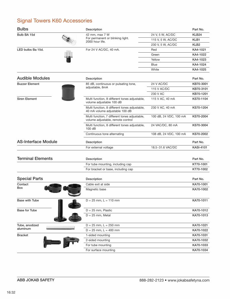
16:32
Special Parts Description Part No.
Contact Cable exit at side KA70-1001Box Magnetic base KA70-1002
Base with Tube D = 25 mm, L = 110 mm KA70-1011
Base for Tube D = 25 mm, Plastic KA70-1012
D = 25 mm, Metal KA70-1013
Tube, anodized D = 25 mm, L = 250 mm KA70-1021aluminum D = 25 mm, L = 400 mm KA70-1022
Bracket 1-sided mounting KA70-1031
2-sided mounting KA70-1032
For tube mounting KA70-1033
For surface mounting KA70-1034
Signal Towers K60 Accessories
Bulbs Description Part No.
Bulb BA 15d 24 V, 5 W, AC/DC KLB24
115 V, 5 W, AC/DC KLB1
230 V, 5 W, AC/DC KLB2
LED bulbs Ba 15d. Red KA4-1021
Green KA4-1022
Yellow KA4-1023
Blue KA4-1024
White KA4-1025
42 mm, max 7 W For permanent or blinking light. 2000 hour life.
For 24 V AC/DC, 40 mA.
Audible Modules Description Part No.
Buzzer Element 85 dB, continuous or pulsating tone, 24 V AC/DC KB70-3001
115 V AC/DC KB70-3101
230 V AC KB70-1201
Siren Element Multi function, 8 different 115 V AC, 40 mA KS70-1104
Multi function, 8 different 230 V AC, 40 mA KS70-1204
Multi function, 7 different 100 dB, 24 VDC, 100 mA KS70-2004
Multi function, 8 different 24 VAC/DC, 80 mA KS70-3004 100 dB
Continuous tone alternating 108 dB, 24 VDC, 100 mA KS70-2002
AS-Interface Module Description Part No.
For external voltage 18.5-31.6 VAC/DC KASI-4101
Terminal Elements Description Part No.
For tube mounting, including cap KT70-1001
For bracket or base, including cap KT70-1002
ABB JOKAB SAFETY

16:33
Material Housing and Accessories Dome
Polyamide, high impact, black Polycarbonate, transparent
Fixing Base mounting Tube mounting, for tube ø 25 mmBracket mounting
Socket B 15 d, for bulb max. 7W
Connection Screwable connection up to 2.5 mm2
Number of modules possible 2-sided bracket
max. 5 max.10 elements
Degrees of Protection Light elements Audible elements
IP 54 / UL Type 5 IP 54 / UL Type 5
Electrical Data Permanent light element Bulb socket B 15 d, max 7 W Blinking light element Starting current Flashing light element Flash frequency Flash energy Life duration Current consumption reduced for AS-Interface Starting current LED Permanent light element Current consumption Starting current LED Blinking light element Current consumption Starting current Blink frequency LED Rotating light element Current consumption Starting current Rotation frequency
12 - 240 V AC/DC Bulb not included 24 V 115 V 230 V AC/DC AC/DC AC/DC Bulb not included < 0.5 A 24 V 115 V 230 V DC AC AC 1 Hz 1 Hz 1 Hz 2 Ws 2 Ws 2 Ws 4 x 10⁶ flashes 125 mA 20 mA 35 mA 80 mA < 0.5 A at 24 V 24 V AC/DC45 mA < 0.5 A at 24 V 24 V AC/DC25 mA < 0.5 A at 24 V c. 1 Hz c. 1Hzc. 1 Hz 24 V AC/DC 70 mA < 0.5 A at 24 V c. 120 r.p.m.
Temperature Ambient temperature during operations
–20 to +50 °C
Approvals
Technical Data Signal Towers K70
ABB JOKAB SAFETY

16:34
This document and any attachments may include suggested specifications, drawings, schematics and similar materials from ABB Inc. Use of such information and/or documentation by the recipient is subject to and conditioned upon your acceptance of the terms of the General Document Disclaimer which can be found at www.jokabsafetyna.com. Your acceptance of the terms of such General Document Disclaimer is conclusively presumed unless you notify ABB in writing of your disagreement with the terms of such Disclaimer immediately upon receipt of this document and you return to ABB all specifications, drawings, schematics and similar materials provided to you by ABB.
Notes
ABB JOKAB SAFETY

17:1
m ABB JOKAB SAFETY
-
-
-
-
-
-

17:2
m ABB JOKAB SAFETY
-
-
-
-
-
-
-
--
-
--
-
-
--
-
-
-
-
-
-
--

17:3
m ABB JOKAB SAFETY
--
-
-
--
-
---
-
-
-
-
--
-
-
-

17:4
m ABB JOKAB SAFETY
---
-
-
-
-
-

m ABB JOKAB SAFETY

Contact us
ABB Inc.ABB JOKAB SAFETY6471 Commerce DriveWestland, MI US 48185Phone: 888-282-2123Fax: 800-565-9302Web: www.jokabsafetyna.com
ABB Inc.Low Voltage Products2117 32nd Ave.Lachine, Quebec, Canada H8T 3J1Phone: 514-420-3100Toll Free: 800-567-0283Fax: 514-420-3137Technical Support:[email protected]
1SXU
1720
02C
0201
, Apr
il 20
12