Transient stability improvement by nonlinear controllers based on tracking
7
Transient stability improvement by nonlinear controllers based on tracking Juan M. Ramirez a,⇑ , Felipe Valencia Arroyave b , Rosa Elvira Correa Gutierrez b a Centro de Investigacion y Estudios Avanzados, Guadalajara, Mexico. Av. Cientifica 1145. Col. El Bajio. Zapopan, Jal. 45015, Mexico b Universidad Nacional de Colombia, Sede Medellin. Facultad de Minas, Escuela de Mecatronica, Colombia article info Article history: Received 30 September 2009 Received in revised form 21 June 2010 Accepted 13 August 2010 Keywords: Electromechanical oscillations Nonlinear controller Power system control Power system stability abstract This paper deals with the control problem in multi-machine electric power systems, which represent complex great scale nonlinear systems. Thus, the controller design is a challenging problem. These sys- tems are subjected to different perturbations, such as short circuits, connection and/or disconnection of loads, lines, or generators. Then, the utilization of controllers which guarantee good performance under those perturbations is required in order to provide electrical energy to the loads with admissible stability margins. The proposed controllers are based on a systematic strategy, which calculate nonlinear control- lers for generating units in a power plant, both for voltage and velocity regulation. The formulation allows designing controllers in a multi-machine power system without intricate calculations. Results on a power system of the open research indicate the proposition’s suitability. The problem is formulated as a tracking problem. The designed controllers may be implemented in any electric power system. Ó 2010 Elsevier Ltd. All rights reserved. 1. Introduction Electric power systems (EPS) exhibit two major problems: (a) loss of synchronism or angle instability, and (b) terminal voltage instability or collapse due to over loading in transmission lines, reactive constraints, and faults. The generators’ controllers must keep the terminal voltage and frequency close to the reference va- lue and provide sufficient damping to the power oscillations at all admissible operating points. For economical reasons, EPS are becoming more complex due to the increment in load demand. These changes have produced big uncertainties and have pushed the networks closer to their opera- tional limits. Then, EPS will require the application of advanced control technologies. Proper design of these control systems is imperative to guarantee robustness over wide operating condi- tions. Likewise, EPS are affected by diverse perturbations and it must remain stable and maintain the reference terminal voltage under all such perturbations. EPS models are complex large-scale nonlinear systems, sub- jected to variations as a result of changes in system’s loading and configurations. Thus, the controller design for these systems is a challenging problem. Nowadays, attention of researchers has been focused on the de- sign of modern nonlinear controllers for EPS that allow reduce the effect of internal and/or external perturbations. The main features that those controllers must satisfy are described in the following: i. Nonlinear model and controllers. The mathematical models are not linearized. This means that results are not limited to an equilibrium point’s neighborhood. ii. Robustness. The designed controller must guarantee good performance in steady state and in presence of perturba- tions such as parametric variations or faults. iii. Tracking. The controllers are able to track the terminal reference voltage. iv. Bounded control signals. All the non-linearities are consid- ered within the controllers’ design, including limits for the control input. v. Fast dynamics. Fast and non-modelled dynamics may be analyzed to reduce their negative effects. In order to improve the EPS stability, several control techniques have been applied. As a summary, the some of the main strategies are outlined as follows: (a) Adaptive control. The control objective is the controller parameters’ modification while the system conditions are varying. Adaptive control has been utilized to design con- ventional controllers in [1–3]. In [4,5], the adaptive control technique is combined with feedback linearization in an infi- nite machine bus system. (b) Feedback linearization. In this case, the nonlinear models are linearized by a feedback loop in such a way that linear techniques can be utilized. The basics of this methodology can be found in [6], while the applications to infinite machine bus systems are described in [7,8]. In [9,41] feedback lin- earization is applied to multi-machine EPS. Nevertheless, this technique does not offer robustness. Combination of 0142-0615/$ - see front matter Ó 2010 Elsevier Ltd. All rights reserved. doi:10.1016/j.ijepes.2010.08.028 ⇑ Corresponding author. Tel.: +52 33 3777 3600. E-mail addresses: [email protected] (J.M. Ramirez), fvalenc@unalmed. edu.co (Felipe Valencia Arroyave), [email protected] (R.E. Correa Gutierrez). Electrical Power and Energy Systems 33 (2011) 315–321 Contents lists available at ScienceDirect Electrical Power and Energy Systems journal homepage: www.elsevier.com/locate/ijepes
Transcript of Transient stability improvement by nonlinear controllers based on tracking

Electrical Power and Energy Systems 33 (2011) 315–321
Contents lists available at ScienceDirect
Electrical Power and Energy Systems
journal homepage: www.elsevier .com/locate / i jepes
Transient stability improvement by nonlinear controllers based on tracking
Juan M. Ramirez a,⇑, Felipe Valencia Arroyave b, Rosa Elvira Correa Gutierrez b
a Centro de Investigacion y Estudios Avanzados, Guadalajara, Mexico. Av. Cientifica 1145. Col. El Bajio. Zapopan, Jal. 45015, Mexicob Universidad Nacional de Colombia, Sede Medellin. Facultad de Minas, Escuela de Mecatronica, Colombia
a r t i c l e i n f o a b s t r a c t
Article history:Received 30 September 2009Received in revised form 21 June 2010Accepted 13 August 2010
Keywords:Electromechanical oscillationsNonlinear controllerPower system controlPower system stability
0142-0615/$ - see front matter � 2010 Elsevier Ltd. Adoi:10.1016/j.ijepes.2010.08.028
⇑ Corresponding author. Tel.: +52 33 3777 3600.E-mail addresses: [email protected] (J.M.
edu.co (Felipe Valencia Arroyave), [email protected]
This paper deals with the control problem in multi-machine electric power systems, which representcomplex great scale nonlinear systems. Thus, the controller design is a challenging problem. These sys-tems are subjected to different perturbations, such as short circuits, connection and/or disconnectionof loads, lines, or generators. Then, the utilization of controllers which guarantee good performance underthose perturbations is required in order to provide electrical energy to the loads with admissible stabilitymargins. The proposed controllers are based on a systematic strategy, which calculate nonlinear control-lers for generating units in a power plant, both for voltage and velocity regulation. The formulation allowsdesigning controllers in a multi-machine power system without intricate calculations. Results on a powersystem of the open research indicate the proposition’s suitability. The problem is formulated as a trackingproblem. The designed controllers may be implemented in any electric power system.
� 2010 Elsevier Ltd. All rights reserved.
1. Introduction
Electric power systems (EPS) exhibit two major problems: (a)loss of synchronism or angle instability, and (b) terminal voltageinstability or collapse due to over loading in transmission lines,reactive constraints, and faults. The generators’ controllers mustkeep the terminal voltage and frequency close to the reference va-lue and provide sufficient damping to the power oscillations at alladmissible operating points.
For economical reasons, EPS are becoming more complex due tothe increment in load demand. These changes have produced biguncertainties and have pushed the networks closer to their opera-tional limits. Then, EPS will require the application of advancedcontrol technologies. Proper design of these control systems isimperative to guarantee robustness over wide operating condi-tions. Likewise, EPS are affected by diverse perturbations and itmust remain stable and maintain the reference terminal voltageunder all such perturbations.
EPS models are complex large-scale nonlinear systems, sub-jected to variations as a result of changes in system’s loading andconfigurations. Thus, the controller design for these systems is achallenging problem.
Nowadays, attention of researchers has been focused on the de-sign of modern nonlinear controllers for EPS that allow reduce theeffect of internal and/or external perturbations. The main featuresthat those controllers must satisfy are described in the following:
ll rights reserved.
Ramirez), [email protected] (R.E. Correa Gutierrez).
i. Nonlinear model and controllers. The mathematical modelsare not linearized. This means that results are not limitedto an equilibrium point’s neighborhood.
ii. Robustness. The designed controller must guarantee goodperformance in steady state and in presence of perturba-tions such as parametric variations or faults.
iii. Tracking. The controllers are able to track the terminalreference voltage.
iv. Bounded control signals. All the non-linearities are consid-ered within the controllers’ design, including limits for thecontrol input.
v. Fast dynamics. Fast and non-modelled dynamics may beanalyzed to reduce their negative effects.
In order to improve the EPS stability, several control techniqueshave been applied. As a summary, the some of the main strategiesare outlined as follows:
(a) Adaptive control. The control objective is the controllerparameters’ modification while the system conditions arevarying. Adaptive control has been utilized to design con-ventional controllers in [1–3]. In [4,5], the adaptive controltechnique is combined with feedback linearization in an infi-nite machine bus system.
(b) Feedback linearization. In this case, the nonlinear modelsare linearized by a feedback loop in such a way that lineartechniques can be utilized. The basics of this methodologycan be found in [6], while the applications to infinite machinebus systems are described in [7,8]. In [9,41] feedback lin-earization is applied to multi-machine EPS. Nevertheless,this technique does not offer robustness. Combination of

316 J.M. Ramirez et al. / Electrical Power and Energy Systems 33 (2011) 315–321
feedback linearization and backstepping has been used,although this combination yields a high cost computationalalgorithm.
(c) Passivity [10,11]. A passive system always dissipatesenergy. Then, energy functions are employed to designcontrollers. There are applications to electrical machinesin [12], while their utilization in EPS are in [13–15], whenEPS energy functions are known. Since the passivity con-trol law feedbacks the system output, which is dependenton the system parameters, this technique has notrobustness.
(d) Lyapunov techniques [16]. The controller is designed byLyapunov functions, based on the energy system. In thisway, the stability region is increased. In [17,18] controllersdesigned by Lyapunov techniques are analyzed to adddamping to the closed-loop system in infinite machine bussystems. In [19] a controller for multi-machine EPS is pre-sented. However, in order to apply this method, the system’sLyapunov function must be known.
(e) Intelligent control. Two major strategies are applied: neuralnetworks and fuzzy logic. The neural network ability toestimate the nonlinear systems’ states has been taken intoaccount in [20,21] for infinite machine bus systems and in[22,23] for multi-machine EPS. On the other hand, fuzzylogic has been applied due to its capacity to provide non-linear effects in control algorithms as in [24,25] for infi-nite machine bus systems and in [26] for multi-machineEPS.
(f) Sliding mode (SM) control [27,28]. Almost all SM controllersfor EPS consider reduced order models, taking into accountthe generator mechanical dynamics only. In [29,30] SMcontrollers for infinite machine bus systems have beendesigned considering the mechanical, rotor, and stator elec-trical dynamics. In [31] an application to multi-machineEPS with a reduced order model can be found. Likewise,in [32–40] a generator eight order model (two equationsfor the mechanical dynamics and six equations for the elec-trical dynamics, considering the stator and rotor dynamics)are utilized to design some SM control schemes for multi-machine EPS.
In this paper, a multi-variable nonlinear controller is proposedto achieve simultaneously rotor angle stability and good qualitypost-fault regulation of the generator terminal voltage, taking intoaccount the automatic voltage and speed regulators dynamics inthe control design. The problem is formulated as a tracking prob-lem based on differential geometric tools [34,35].
After application of the proposed strategy, non-linear control-lers arise for each generating unit. The controllers do not needany information stemming from other elements. This is an impor-tant fact, since power systems extent long distances, which makesdifficult the necessity for signals among stations. Problems as de-lays are a drawback too [42].
2. State space formulation
Assume a power system model constituted by n machines andm loads, connected through lossless transmission lines, where eachgenerator is represented by an internal and a terminal voltage [36–38]. Let the nth machine be the reference bus. One-axis model foreach generator and active/reactive power demand is adopted [36–38]. The nonlinear differential algebraic equations are expressed by(1) and (2), with generator buses i = 1,2, . . . ,n, and load busesk = n + 1,n + 2, . . . ,n + m. Algebraic constraints arise from the loadflow equations on each bus.
_di
_xi
_E0qi
264
375 ¼
x0ðxi � 1Þ�DiMiðxi � 1Þ � 1
MiPei
�/i
264
375þ
0 01
Mi0
0 1T 0d0i
2664
3775 Pmi
Efi
� �ð1Þ
~0¼
Pgnet
Qgnet
Pdnet
Qdnet
26664
37775¼
E0qiVi senðhi�diÞ
X0di
þPnj¼1j–i
BijV iVjsenðhi� hjÞþPnþm
k¼nþ1BikViVksenðhi�ckÞ
V2i
X0di
� E0qiVi cosðhi�diÞ
X0di
�BiiV2i �Pnj¼1j–i
BijViVj cosðhi� hjÞ
�Pnþm
k¼nþ1BikViVk cosðhi�ckÞ�Pdk
þPni¼1
BkiVkVisenðck� hiÞ
þPnþm
l¼1l–k
BklVkVlsenðck� clÞ�Q dk�BkkV2
k �Pni¼1
BkiVkVi cosðck� hiÞ
�Pnþm
l¼1l–k
BklVkVlsenðck� clÞ
2666666666666666666666664
3777777777777777777777775ð2Þ
where d = (d1, . . . ,dn)T represents the internal voltage angles;x = (x1, . . . ,xn)T represents the angular velocities;
E0q ¼ E0q1; . . . ; E0qn
� �Tis the internal voltage vector; h = (h1, . . . ,hn)T is
the terminal voltage angles; V = (V1, . . .,Vn,Vn+1, . . .,Vn+m)T is the ter-minal and load voltage vector; c = (cn+2, . . . ,cn+m)T is the load anglevector; Bij is the ijth element of the admittance matrix Ybus;
/i ¼ XdiX0diT
0d0i
E0qi þXdi�X0diX0diT
0d0i
V i cosðdi � hiÞ; x0 is the nominal angular veloc-
ity; Pe, Pm and Ef are the electrical torque, the mechanical torque andthe excitation voltage, respectively; D is the damping factor; M isthe momentum of inertia; T 0d0 is the d-axis open circuit time con-stant; X0di is the d-axis transient reactance; Xdi is the d-axis steadystate reactance; Pd and Qd are the active and reactive load demand,respectively; Pgnet and Qgnet are the net active and reactive gener-ated powers, respectively; Pdnet and Qdnet are the net active and reac-tive load powers, respectively.
Pragmatically, the field voltage (Efd) and mechanical power (Pm)are not handling variables. Thus, in this paper first order regulatorsfor both voltage and speed are taken into account. That is, the fol-lowing two additional equations are added:
ddt
Efd þ1se
Efd ¼Ke
seðVTref � VT þ u1Þ ð3Þ
ddt
Pm þ1sg
Pm ¼Kg
sgðx0 �xþ u2Þ ð4Þ
Ke, se are the gain and time constant of the first order excitation sys-tem, respectively; VTref is the reference terminal voltage; u1 is thesignal stemming from the new voltage controller; Kg, sg, are the gainand time constant of the first order governor, respectively; u1 is thesignal stemming from the new speed controller.
Thus, the state space representation becomes
_di
_xi
_E0qi
_Efdi
_Pmi
266666664
377777775¼
x0ðxi � 1Þ�DiMiðxi � 1Þ þ 1
MiðPmi� Pei
Þ�/i þ 1
T 0d0i
Efdi
� 1Tei
Efdi� Kei
TeiðVTi� VTrefi Þ
� 1Tgi
Pmi� Kgi
Tgiðxi �xrefi Þ
26666666664
37777777775þ
0 00 00 0KeiTei
0
0KgiTgi
266666664
377777775
u1
u2
� �ð5Þ
It is noteworthy that Eqs. (2)–(5) exhibit the conventional statespace structure,
_x ¼ f ðx; zÞ þ gðx; zÞu0 ¼ rðx; zÞ
�ð6Þ
where x are the state variables and z the algebraic ones; x ¼ ½x1; x2;
. . . ; xn�T ; xi ¼ ½di;xi; E0qi; Efdi
; Pmi�T ;
J.M. Ramirez et al. / Electrical Power and Energy Systems 33 (2011) 315–321 317
z ¼ ½zg1; zg2
; . . . ; zgn; zlnþ1
; zlnþ2; . . . ; zlnþm �
T; zgi
¼ ½hi;Vi�T ; zlk
¼ ½ck;Vk�T ;
f ¼ ½f1; f2; . . . ; fn�T ;
fi ¼ x0ðxi � 1Þ; � Di
Mi
� �ðxi � 1Þ � 1
Mi
� �Pei;�/i;�
1Tei
Efdi
�
�Kei
Tei
ðVTi� VTrefiÞ;�
1Tgi
Pmi� Kgi
Tgi
ðxi �xrefiÞ�T
;
g ¼ diag½g1; . . . ; gn�; gi ¼
0 00 00 0KeiTei
0
0KgiTgi
266666664
377777775
; u ¼ ½u1u2�T :
3. Controllers’ design
Recently, nonlinear control techniques such as feedback linear-ization, Hamiltonian techniques, passivity-based approach, singularperturbations and sliding-mode control have been successfullyapplied to achieve high quality dynamic performance under largeand unexpected contingencies.
A well designed controller must be able to exhibit a properperformance with regard to changes in parameter, operating con-ditions, as well as disturbances. The controller design’s modernapproach by the feedback linearization procedure is based onthe nonlinear control systems theory. By such techniques, com-pensation schemes are adopted to partially or totally cancelnon-linearities presented in state-input or input–output relation-ships, so that output or state dynamics are transformed intoequivalent linear time invariant dynamics. A new input stabilizes
u ¼
u1
u2
..
.
up
26664
37775 ¼ �A�1ðxÞ
Lðm1Þf h1
Lðm2Þf h2
..
.
LðmpÞf hp
266664
377775þ A�1ðxÞ
yðm1Þ1d þ r1
ðm1�1Þðyðm1�1Þ1d � yðm1�1Þ
1 Þ þ r1ðm1�2Þðy
ðm1�2Þ1d � yðm1�2Þ
1 Þ þ � � � þ r10ðy1d � y1Þ
..
.
yðmpÞpd þ rp
ðmp�1Þðyðmp�1Þpd � yðmp�1Þ
p Þ þ rpðmp�2Þðy
ðmp�2Þpd � yðmp�2Þ
p Þ þ � � � þ rp0ðypd � ypÞ
2664
3775 ð12Þ
the state or output through standard linear techniques by impos-ing a linear dynamic described by a desired time variant trajec-tory (tracking design) or, more simply, by a time invarianttrajectory (stabilization design). A drawback with this procedureis represented by computational difficulties due to the systemdimension, which can, however, be surpassed by neglectingimportant dynamic elements or adopting reduced order systemmodels.
Let assume a non-linear plant with p-inputs and p-outputs ex-pressed by
_x ¼ f ðxÞ þ g1ðxÞu1 þ g2ðxÞu2 þ � � � þ gpðxÞup
y1 ¼ h1ðxÞ; y2 ¼ h2ðxÞ; . . . ; yp ¼ hpðxÞ
(ð7Þ
The control objective consists on synthesize a controller able to takeoutputs [y1,y2, . . . ,yp]T toward their desired value [yd1,yd2, . . . ,ydp]T:
yðtÞ ¼
y1ðtÞy2ðtÞ...
ypðtÞ
266664
377775! ydðtÞ ¼
yd1ðtÞyd2ðtÞ...
ydpðtÞ
266664
377775 ð8aÞ
Let us define,
~yjðtÞ ¼ yjdðtÞ � yjðtÞ; for all j ð8bÞ
Thus, the control u(t) = [u1(t),u2(t), . . . ,up(t)]T must be calculated inorder to satisfy the objective. The output and control variables rela-tionship is expressed by [6]:
~yðm1Þ1
~yðm2Þ2
..
.
~yðmpÞp
2666664
3777775 ¼
Lðm1Þf h1
Lðm2Þf h2
..
.
LðmpÞf hp
26666664
37777775þ AðxÞ
u1
u2
..
.
up
266664
377775 ð9Þ
where
AðxÞ ¼
Lg1Lðm1�1Þf h1 Lg2Lðm1�1Þ
f h1 � � � LgpLðm1�1Þf h1
Lg1Lðm2�1Þf h2 Lg2Lðm2�1Þ
f h2 � � � LgpLðm2�1Þf h2
..
. ... . .
. ...
Lg1Lðmp�1Þf hp Lg2Lðmp�1Þ
f hp � � � LgpLðmp�1Þf hp
26666664
37777775
ð10Þ
mi is the smaller integer such that the derivative of hðmiÞj depends at
least on one input [u1,u2, . . . ,up]T. It is assumed thatn ¼
Ppk¼1mk; mk is the relative degree, which imply there is not zero
dynamic and rank [A(x)] = p for all x. Likewise,
LðmiÞf hi ¼
@ðmiÞhiðxÞ@xðmiÞ f ðxÞ
LgiLðmjÞf hj ¼
@Lðmj�1Þf hj
@xgiðxÞ
ð11Þ
are the Lie derivatives [6]. The control law becomes,
The design parameters rk1 are setting up in such a way that the fol-
lowing are Hurwitz polynomials,
sðm1Þ þ r1ðm1�1Þs
ðm1�1Þ þ � � � þ r10 ¼ 0
sðm2Þ þ r2ðm2�1Þs
ðm2�1Þ þ � � � þ r20 ¼ 0
..
.
sðmpÞ þ rpðmp�1Þs
ðmp�1Þ þ � � � þ rp0 ¼ 0
ð13Þ
Thus, the control objective is satisfied (when t ?1),~y1ðtÞ ! 0~y2ðtÞ ! 0
..
.
~ypðtÞ ! 0
ð14Þ
The stability of the closed-loop system (7)–(12) is ensured by theHurwitz polynomials in (12) [6–9]. Related to the applications in
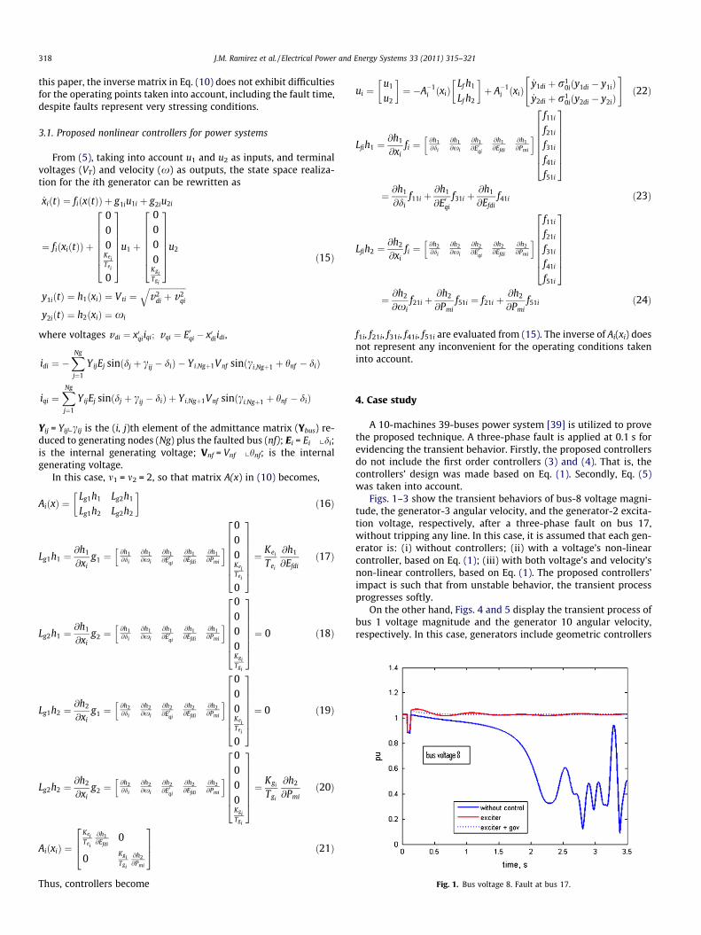
Fig. 1. Bus voltage 8. Fault at bus 17.
318 J.M. Ramirez et al. / Electrical Power and Energy Systems 33 (2011) 315–321
this paper, the inverse matrix in Eq. (10) does not exhibit difficultiesfor the operating points taken into account, including the fault time,despite faults represent very stressing conditions.
3.1. Proposed nonlinear controllers for power systems
From (5), taking into account u1 and u2 as inputs, and terminalvoltages (VT) and velocity (x) as outputs, the state space realiza-tion for the ith generator can be rewritten as
_xiðtÞ ¼ fiðxðtÞÞ þ g1iu1i þ g2iu2i
¼ fiðxiðtÞÞ þ
000
KeiTei
0
26666664
37777775
u1 þ
0000
KgiTgi
26666664
37777775
u2
y1iðtÞ ¼ h1ðxiÞ ¼ Vti ¼ffiffiffiffiffiffiffiffiffiffiffiffiffiffiffiffiffiffiv2
di þ v2qi
qy2iðtÞ ¼ h2ðxiÞ ¼ xi
ð15Þ
where voltages vdi ¼ x0qiiqi; vqi ¼ E0qi � x0diidi,
idi ¼ �XNg
j¼1
YijEj sinðdj þ cij � diÞ � Yi;Ngþ1Vnf sinðci;Ngþ1 þ hnf � diÞ
iqi ¼XNg
j¼1
YijEj sinðdj þ cij � diÞ þ Yi;Ngþ1Vnf sinðci;Ngþ1 þ hnf � diÞ
Yij = Yijxcij is the (i, j)th element of the admittance matrix (Ybus) re-duced to generating nodes (Ng) plus the faulted bus (nf); Ei = Ei xdi;is the internal generating voltage; Vnf = Vnf xhnf; is the internalgenerating voltage.
In this case, m1 = m2 = 2, so that matrix A(x) in (10) becomes,
AiðxÞ ¼Lg1h1 Lg2h1
Lg1h2 Lg2h2
� �ð16Þ
Lg1h1 ¼@h1
@xig1 ¼
@h1@di
@h1@xi
@h1@E0qi
@h1@Efdi
@h1@Pmi
h i000KeiTei
0
26666664
37777775¼ Kei
Tei
@h1
@Efdið17Þ
Lg2h1 ¼@h1
@xig2 ¼
@h1@di
@h1@xi
@h1@E0qi
@h1@Efdi
@h1@Pmi
h i0000KgiTgi
26666664
37777775¼ 0 ð18Þ
Lg1h2 ¼@h2
@xig1 ¼
@h2@di
@h2@xi
@h2@E0qi
@h2@Efdi
@h2@Pmi
h i000KeiTei
0
26666664
37777775¼ 0 ð19Þ
Lg2h2 ¼@h2
@xig2 ¼
@h2@di
@h2@xi
@h2@E0qi
@h2@Efdi
@h2@Pmi
h i0000KgiTgi
26666664
37777775¼ Kgi
Tgi
@h2
@Pmið20Þ
AiðxiÞ ¼KeiTei
@h1@Efdi
0
0KgiTgi
@h2@Pmi
264
375 ð21Þ
Thus, controllers become
ui ¼u1
u2
� �¼ �A�1
i ðxiÞLf h1
Lf h2
� �þ A�1
i ðxiÞ_y1di þ r1
0iðy1di � y1iÞ_y2di þ r1
0iðy2di � y2iÞ
" #ð22Þ
Lfih1 ¼@h1
@xifi ¼
@h1@di
@h1@xi
@h1@E0qi
@h1@Efdi
@h1@Pmi
h if11i
f21i
f31i
f41i
f51i
26666664
37777775
¼ @h1
@dif11i þ
@h1
@E0qi
f31i þ@h1
@Efdif41i ð23Þ
Lfih2 ¼@h2
@xifi ¼
@h2@di
@h2@xi
@h2@E0qi
@h2@Efdi
@h2@Pmi
h if11i
f21i
f31i
f41i
f51i
26666664
37777775
¼ @h2
@xif21i þ
@h2
@Pmif51i ¼ f21i þ
@h2
@Pmif51i ð24Þ
f1i, f21i, f31i, f41i, f51i are evaluated from (15). The inverse of Ai(xi) doesnot represent any inconvenient for the operating conditions takeninto account.
4. Case study
A 10-machines 39-buses power system [39] is utilized to provethe proposed technique. A three-phase fault is applied at 0.1 s forevidencing the transient behavior. Firstly, the proposed controllersdo not include the first order controllers (3) and (4). That is, thecontrollers’ design was made based on Eq. (1). Secondly, Eq. (5)was taken into account.
Figs. 1–3 show the transient behaviors of bus-8 voltage magni-tude, the generator-3 angular velocity, and the generator-2 excita-tion voltage, respectively, after a three-phase fault on bus 17,without tripping any line. In this case, it is assumed that each gen-erator is: (i) without controllers; (ii) with a voltage’s non-linearcontroller, based on Eq. (1); (iii) with both voltage’s and velocity’snon-linear controllers, based on Eq. (1). The proposed controllers’impact is such that from unstable behavior, the transient processprogresses softly.
On the other hand, Figs. 4 and 5 display the transient process ofbus 1 voltage magnitude and the generator 10 angular velocity,respectively. In this case, generators include geometric controllers

Fig. 2. Angular velocity 3. Fault at bus 17.
Fig. 3. Excitation voltage 2. Fault at bus 17.
Fig. 4. Bus voltage 1. Fault at bus 17. First order controller dynamics included.
Fig. 5. Angular velocity 10. Fault at bus 17. First order controller dynamicsincluded.
Fig. 6. Bus voltage 6. Fault at bus 35.
Fig. 7. Angular velocity 4. Fault at bus 35.
J.M. Ramirez et al. / Electrical Power and Energy Systems 33 (2011) 315–321 319
designed through Eq. (5). As expected, signals undergo a longertransient before attain the steady state.
Now, the nominal condition is considered [39]. However, lines14 and 15 is out of service. Figs. 6 and 7 exhibit the bus 6 voltage
magnitude response and angular velocity 4, after a fault on bus 35applied at 0.1 s. These figures are obtained based on nonlinear con-trollers calculated through Eq. (1). Similarly, Figs. 8 and 9 depictthe voltage magnitude at bus 3 and the angular velocity 7, underthe same conditions, but with the first order dynamic included,Eq. (5). As before, both controllers induce a soft transient.

Fig. 8. Bus voltage 3. Fault at bus 35. First order controller dynamics included.
Fig. 9. Angular velocity 7. Fault at bus 35. First order controller dynamics included.
320 J.M. Ramirez et al. / Electrical Power and Energy Systems 33 (2011) 315–321
Thus, the proposed controllers are able to respond appropriatelyunder different operating conditions, helping to have a good qual-ity transient. Moreover, by limiting the excursions of controllers’responses, this may conduct to pragmatic nonlinear controllersfor generating units.
5. Conclusions
The proposed nonlinear control’s performance is independent ofthe operating point. The design ensures cancellation of interactionsbetween subsystems providing a good quality performance withrespect to conventional controllers. Additionally, such controlschemes are not restricted to a particular EPS, i.e., they are appliedto multi-machine power systems.
Thus, a transparent multi-variable nonlinear controller has beendesigned to achieve simultaneously transient stability enhance-ment, and able to help in having a post-fault voltage regulationimprovement of the generator terminal voltage in multi-machinepower systems.
The proposed method uses signals that can be handled withoutdifficulties, giving rise to the possibility of pragmatic controllers foractual generating units.
Acknowledgment
Juan M. Ramirez thanks CFE-CONACyT under Grant 88160.
References
[1] Ghandakly A, Idowu P. Design of a model reference adaptive stabilizer for theexciter and governor loops of power generators. IEEE Trans Power Syst1990;5:887–93.
[2] Ghandakly A, Dai J. An adaptive synchronous generator stabilizer design bygeneralized multivariable pole shifting (GMPS) technique. IEEE Trans PowerSyst 1992;7:1239–44.
[3] Wu B, Malik OP. Multivariable adaptive control of synchronous machines in amultimachine power system. IEEE Trans Power Syst 2006;21(2).
[4] Jain S, Khorrami F, Fardanesh K. Adaptive nonlinear excitation control of powersystems with unknown interconnections. IEEE Trans Control Syst Technol1994;2(4).
[5] Lahdhiri T, Alouani AT. On the robust control of synchronous generator. In:Proc American control conference. Philadelphia, Pennsylvania, June 1998. p.3798–801.
[6] Isidori A. Nonlinear control systems. 3rd ed. New York: Springer-Verlag; 1995.[7] Mielczarski W, Zajaczowski AM. Multivariable nonlinear controller for
synchronous generator. Opt Control Applicat Methods 1994;15:49–65.[8] Landhiri T, Alouani AT. Design of a nonlinear excitation controller for
synchronous generator using the concept of feedback linealization. In: ProcAmerican control conference, New Mexico (USA); 1997.
[9] King CA, Chapman JW, Ilic MD. Feedback linearizing excitation control on a fullscale power system model. IEEE Trans Power Syst 1994;9:1102–9.
[10] Van der Schaft AJ. L2 gain and passivity techniques in nonlinearcontrol. London, England: Springer Verlag; 1999.
[11] Ortega R, Lorı́a A, Nicklasson P, Sira-Ramı´ rez H. Passivity-based control ofEuler–Lagrange systems. London, England: Springer Verlag; 1998.
[12] Wang W, Cheng J. Passivity-based sliding mode position control for inductionmotor drives. IEEE Trans Energy Convers 2005;20(2).
[13] Xi Z, Cheng D. Passivity-based stabilization and H1 control of the Hamiltoniancontrol systems with dissipation and its applications to power systems. Int JControl 2000;73(18):1686–91.
[14] Ortega R, Stankovic A, Stefanov P. A passivation approach to power systemsstabilization. In: Proc of IEEE symp on nonlinear control systems, June1998.
[15] Huerta H, Loukianov AG, Cañedo JM. Passivity-based sliding mode control ofpower systems. In: Proc of VSS08, Antalya, Turquia, June 2008.
[16] Khalil HK. Nonlinear systems. New Jersey: Prentice Hall, Inc. Simon andSchuster; 1996.
[17] Pai MA. Energy function analysis for power systems stability. KluwerAcademic Publishers; 1989.
[18] Bazanella AS, Silva AS, Kokotovic P. Lyapunov design of excitation control forsynchronous machine. In: Proc 36th IEEE CDC, San Diego (CA, USA); 1997. p.211–6.
[19] Machowsky J, Robak S, Bialek JW, Bumby JR, Abi-Samra N. Decentralizedstability-enhancing control of synchronous generator. IEEE Trans Power Syst2000;15(4).
[20] Hsu Y, Cheng Ch. Tuning of power system stabilizers using an artificial neuralnetwork. IEEE Trans Energy Convers 1991;6:612–9.
[21] Shamsollahi P, Malik OP. An adaptive power system stabilizer using on-linetrained neural network. IEEE Trans Energy Convers 1997;12(4):382–7.
[22] Venayagamoorthy GK, Harley RG, Wunsch DC. Dual heuristic programmingexcitation neurocontrol for generators in a multimachine power system. IEEETrans Ind Applicat 2003;39(2).
[23] Mohagheghi S, Valle Y, Venayagamoorthy GK, Harley RG. A proportional–integrator type adaptive critic design-based neuro-controller for a staticcompensator in a multimachine power system. IEEE Trans Ind Electron2007;54(1).
[24] Dash P, Mishra S, Liew A. Design of a fuzzy PI controller for power systemapplications. J Intell Fuzzy Syst 1995;3:155–63.
[25] Hoang P, Tomsovic K. Design and analysis of an adaptive fuzzy power systemstabilizer. In: IEEE PES winter meeting; 1996. p. 7.
[26] Yousef AM, Mohamed MA. Multimachine power system stabilizer based onefficient two-layered fuzzy logic controller. Trans Eng Technol2004;V3(December):137–40.
[27] Utkin VI. Sliding mode in control and optimization. London: Springer Verlag;1992.
[28] Utkin VI, Guldner J, Shi J. Sliding mode control in electromechanicalsystems. London: Taylor & Francis; 1999.
[29] Loukianov AG, Cañedo JM, Utkin VI, Cabrera-Vazquez J. Discontinuouscontroller for power systems: sliding mode block control approach. IEEETrans Ind Electron 2004;51(2):340–53.
[30] Cabrera-Vázquez J, Loukianov AG, Cañedo JM, Utkin VI. Robust controller forsynchronous generator with local load via VSC. Int J Electr Power Energy Syst2007;29:348–459.
[31] Bandal V, Bandyopadhyay B, Kulkarni AM. Decentralized sliding mode controltechnique based power system stabilizer (PSS) for multimachine powersystem. In: Proc conference on control applications, Toronto, Canada, August2005.
[32] Loukianov AG, Cañedo JM, Huerta H. Decentralized sliding mode block controlof power systems. In: Proc of PES general meeting 2006, Montreal, Quebec,Canada, 18–22 June 2006.
[33] Huerta H, Loukianov AG, Cañedo JM. System, structure & control. Integralsliding modes with block control and its application to electric powersystems. Germany/ARS, Austria: Pro Literatur Verlag; 2008.

J.M. Ramirez et al. / Electrical Power and Energy Systems 33 (2011) 315–321 321
[34] Cong L, Wang Y. Co-ordinated control of generator excitation and STATCOM forrotor angle stability and voltage regulation enhancement of power systems.IEE Proc – Gener Transm Distrib 2002;149:659–66.
[35] Guo G, Wang Y, Lim KY, Gao L. Robust nonlinear controller for power systemtransient stability enhancement with voltage regulation. IEE Proc GenerTransm Distrib 1996;143:407.
[36] Liu Y, Li Ch, Wang Y, Li J. Energy-based decentralized excitation control ofnonlinear differential algebraic power systems. In: 2007 IEEE internationalconference on control and automation, Guangzhou, China, May 30–June 1,2007.
[37] Liu Y, Li Ch. Dissipative Hamiltonian realization of nonlinear differentialalgebraic systems. In: Proceedings of the 26th Chinese control conference,Zhangjiajie, Hunan, China, July 26–31, 2007.
[38] Liu Y, Li J, Li Ch. Dissipative Hamiltonian realization of multi-machine multi-load power systems. In: 16th IEEE international conference on control
applications part of IEEE multi-conference on systems and control,Singapore, 1–3 October 2007.
[39] Padiyar KR. Power system dynamics: stability and control. John Wiley & Sons;1996. p. 507.
[40] Huerta H, Loukianov A, Canedo JM. Decentralized sliding mode block controlof multimachine power systems. Int J Electr Power Energy Syst 2010;32(1):1–11.
[41] Kenné G, Goma R, Nkwawo H, Lamnabhi-Lagarrigue F, Arzandé A, Vannier JC.An improved direct feedback linearization technique for transient stabilityenhancement and voltage regulation of power generators. Int J Electr PowerEnergy Syst 2010;32(7):809–16.
[42] Ali Mohd Hasan, Park Minwon, Yu In-Keun, Murata Toshiaki, Tamura Junji, WuBin. Enhancement of transient stability by fuzzy logic-controlled SMESconsidering communication delay. Int J Electr Power Energy Syst 2009;31(7–8):402–8.