Look-ahead Tracking Controllers for Integrated Longitudinal ...
157
Look-ahead tracking controllers for integrated longitudinal and lateral control of vehicle platoons Citation for published version (APA): Bayuwindra, A. (2019). Look-ahead tracking controllers for integrated longitudinal and lateral control of vehicle platoons. [Phd Thesis 1 (Research TU/e / Graduation TU/e), Mechanical Engineering]. Technische Universiteit Eindhoven. Document status and date: Published: 30/10/2019 Document Version: Publisher’s PDF, also known as Version of Record (includes final page, issue and volume numbers) Please check the document version of this publication: • A submitted manuscript is the version of the article upon submission and before peer-review. There can be important differences between the submitted version and the official published version of record. People interested in the research are advised to contact the author for the final version of the publication, or visit the DOI to the publisher's website. • The final author version and the galley proof are versions of the publication after peer review. • The final published version features the final layout of the paper including the volume, issue and page numbers. Link to publication General rights Copyright and moral rights for the publications made accessible in the public portal are retained by the authors and/or other copyright owners and it is a condition of accessing publications that users recognise and abide by the legal requirements associated with these rights. • Users may download and print one copy of any publication from the public portal for the purpose of private study or research. • You may not further distribute the material or use it for any profit-making activity or commercial gain • You may freely distribute the URL identifying the publication in the public portal. If the publication is distributed under the terms of Article 25fa of the Dutch Copyright Act, indicated by the “Taverne” license above, please follow below link for the End User Agreement: www.tue.nl/taverne Take down policy If you believe that this document breaches copyright please contact us at: [email protected] providing details and we will investigate your claim. Download date: 20. Aug. 2022
-
Upload
khangminh22 -
Category
Documents
-
view
4 -
download
0
Transcript of Look-ahead Tracking Controllers for Integrated Longitudinal ...

Look-ahead tracking controllers for integrated longitudinal andlateral control of vehicle platoonsCitation for published version (APA):Bayuwindra, A. (2019). Look-ahead tracking controllers for integrated longitudinal and lateral control of vehicleplatoons. [Phd Thesis 1 (Research TU/e / Graduation TU/e), Mechanical Engineering]. Technische UniversiteitEindhoven.
Document status and date:Published: 30/10/2019
Document Version:Publisher’s PDF, also known as Version of Record (includes final page, issue and volume numbers)
Please check the document version of this publication:
• A submitted manuscript is the version of the article upon submission and before peer-review. There can beimportant differences between the submitted version and the official published version of record. Peopleinterested in the research are advised to contact the author for the final version of the publication, or visit theDOI to the publisher's website.• The final author version and the galley proof are versions of the publication after peer review.• The final published version features the final layout of the paper including the volume, issue and pagenumbers.Link to publication
General rightsCopyright and moral rights for the publications made accessible in the public portal are retained by the authors and/or other copyright ownersand it is a condition of accessing publications that users recognise and abide by the legal requirements associated with these rights.
• Users may download and print one copy of any publication from the public portal for the purpose of private study or research. • You may not further distribute the material or use it for any profit-making activity or commercial gain • You may freely distribute the URL identifying the publication in the public portal.
If the publication is distributed under the terms of Article 25fa of the Dutch Copyright Act, indicated by the “Taverne” license above, pleasefollow below link for the End User Agreement:www.tue.nl/taverne
Take down policyIf you believe that this document breaches copyright please contact us at:[email protected] details and we will investigate your claim.
Download date: 20. Aug. 2022

LOOK - AH E AD T R AC K I N G CONT RO L L E R S FO R
I N T E G R A T ED LONG I T UD I N A L AND L A T E R A L
CONT RO L OF V EH I C L E P L A TOONS
A N G G E R A B A Y U W I N D R A


Look-ahead Tracking Controllers forIntegrated Longitudinal and Lateral
Control of Vehicle Platoons
Anggera Bayuwindra

The research reported in this thesis is part of the research program of the DutchInstitute of Systems and Control (DISC). The author has successfully completed theeducational program of the Graduate School DISC.
This research was supported by the Indonesian Ministry of Finance through theIndonesia Endowment Fund for Education (LPDP) under grant S-218/LPDP/2013.
A catalogue record is available from the Eindhoven University of Technology Library.ISBN: 978-90-386-4866-8
Typeset by the author using LATEX2ε and LYX.
Cover Design: Anggera Bayuwindra. Photo by Tuur Tisseghem from Pexels.Reproduction: Ipskamp Printing.
© 2019 by A. Bayuwindra. All right reserved.

Look-ahead Tracking Controllers forIntegrated Longitudinal and Lateral
Control of Vehicle Platoons
proefschrift
ter verkrijging van de graad van doctor aan deTechnische Universiteit Eindhoven, op gezag van de
Rector Magnificus, prof.dr.ir. F.P.T. Baaijens, voor eencommissie aangewezen door het College voorPromoties in het openbaar te verdedigen
op woensdag 30 oktober 2019 om 16.00 uur
door
Anggera Bayuwindra
geboren te Bandung, Indonesië

Dit proefschrift is goedgekeurd door de promotoren en de samenstelling van depromotiecommissie is als volgt:
voorzitter: prof.dr. L.P.H. de Goeypromotor: prof.dr. H. Nijmeijer1e copromotor: dr.ir. J. Ploeg2e copromotor: dr.ir. A.A.J. Lefeberleden: prof.dr. R.R. Negenborn (Technische Universiteit Delft)
prof.dr. J.P. Huissoon (University of Waterloo)prof.dr. B. Jayawardhana (Rijksuniversiteit Groningen)prof.dr. J.J. Lukkien
Het onderzoek dat in dit proefschrift wordt beschreven is uitgevoerd inovereenstemming met de TU/e Gedragscode Wetenschapsbeoefening.

Summary
Look-ahead Tracking Controllers for Integrated Longitudinal and Lat-eral Control of Vehicle Platoons
The increasing demand for mobility and a limited development of the existingroad infrastructure leads to a growing interest in the improvement of groundtransportation, with respect to safety, throughput, fuel consumption, and emis-sions. As a result, the field of Intelligent Transportation Systems (ITS) emergedin the past decade. As one of the promising ITS applications, Adaptive CruiseControl (ACC) was first invented for road vehicles as a safety and comfort system,by which a vehicle speed is automatically adjust to maintain a safe distance fromvehicles ahead. In ACC, a radar or lidar measurements are used to measure thedistance and the relative speed as inputs for a control system that automaticallymaintains a desired inter-vehicle distance.
During its development, ACC was further extended to Cooperative AdaptiveCruise Control (CACC) with the addition of information exchange between vehi-cles through a vehicle-to-vehicle (V2V) wireless communication. By providing thefollowing vehicle with additional wireless information about its preceding vehicle,the addition of V2V communication has been proven to allow for reduction of theinter-vehicle distance while attenuating disturbances in upstream direction. Afully automated vehicle platoon, which can be described as a "follow the leader"strategy, is realized by exchanging information about the longitudinal (acceler-ating and decelerating) and lateral (turning) motion between vehicles. In mostliterature, the longitudinal control problem and the lateral control problem aretreated independently. In particular, the longitudinal control problem is handledby CACC, while the lateral control problem is approached as a lane-keeping prob-lem. Through radar/lidar and V2V communication, CACC minimizes the errorbetween the desired distance and the actual distance between the vehicle and itspreceding vehicle. On the other hand, the lateral control problem is solved by avision-based lane-keeping system, which employs an image processing algorithmfor lane detection. From a platooning viewpoint, there are several considerationsregarding this lane-keeping method that should be taken into account. First,
v

vi Summary
it is not always possible to obtain an accurate measurement of lane markings,especially when vehicles in a platoon are driving close together, which is specifi-cally aimed for with CACC. Secondly, the lane markings may be of bad quality,obstructed, or even not present (e.g., on intersections or at rural areas). More-over, the longitudinal and lateral movement of the vehicle should not be treatedindependently, since the driving behavior includes the dynamics of longitudinalmotion, lateral motion, and the combination of both (e.g, decelerating while turn-ing).
To achieve fully automated vehicle following, there are two requirements thatneed to be considered: integrated longitudinal and lateral control design, and therobustness against loss of lane markings. Thus, a vehicle-following controller basedon a look-ahead approach, in which the longitudinal and lateral vehicle dynamicsare treated as coupled systems, is introduced. This look-ahead approach utilizesthe current information about the position, orientation, velocity, and accelerationof the preceding vehicle such that the vehicle can follow its preceding vehiclewhile maintaining a safe inter-vehicle distance. However, without any informationabout the history of the path to be followed, the follower vehicle can deviate fromthe path of its preceding vehicle when cornering, thus resulting in corner-cutting.Therefore, this thesis focuses on the analysis and design of integrated longitudinaland lateral look-ahead tracking controllers that avoid corner-cutting behavior invehicle platooning, in the situation where the lane-markings are not available.
In this thesis, the look-ahead tracking controllers are designed to follow a shiftedreference point at a curved path, i.e., the vehicle is no longer following a rearbumper center of the preceding vehicle, but instead is following a point extendedsideways from the rear bumper such that the corner-cutting behavior is avoided.The novel extended look-ahead controllers employ the position, velocity, and head-ing information of the preceding vehicle (which are available from camera andV2V), to create a "virtual vehicle" as the new tracking objective. As an impor-tant result, a vehicle in a platoon can perfectly track its preceding vehicle path,even where there are no lane-markings or no information about the path otherthan the current position of the preceding vehicle. The effectiveness of the result-ing controllers is illustrated by means of numerical simulations and is extensivelytested by means of experiments using a mobile robot platform.

Contents
Summary v
1 Introduction 11.1 Vehicle platooning . . . . . . . . . . . . . . . . . . . . . . . . . . . 11.2 Problem statement . . . . . . . . . . . . . . . . . . . . . . . . . . . 61.3 Research objectives . . . . . . . . . . . . . . . . . . . . . . . . . . . 81.4 Contributions of the thesis . . . . . . . . . . . . . . . . . . . . . . . 81.5 Outline . . . . . . . . . . . . . . . . . . . . . . . . . . . . . . . . . 9
2 Literature review 112.1 Background . . . . . . . . . . . . . . . . . . . . . . . . . . . . . . . 112.2 Vehicle platooning . . . . . . . . . . . . . . . . . . . . . . . . . . . 132.3 Longitudinal control in vehicle platooning . . . . . . . . . . . . . . 15
2.3.1 Spacing policies . . . . . . . . . . . . . . . . . . . . . . . . . 182.4 Longitudinal and lateral control in vehicle platooning . . . . . . . . 20
2.4.1 Path following . . . . . . . . . . . . . . . . . . . . . . . . . 212.4.2 Direct vehicle following . . . . . . . . . . . . . . . . . . . . 22
2.5 Conclusion . . . . . . . . . . . . . . . . . . . . . . . . . . . . . . . 24
3 Longitudinal and lateral control for car-like vehicle platooningwith extended look-ahead in a global coordinate system 253.1 Introduction . . . . . . . . . . . . . . . . . . . . . . . . . . . . . . . 253.2 Vehicle modeling and look-ahead based controller design . . . . . . 283.3 Extended look-ahead controller design . . . . . . . . . . . . . . . . 313.4 Simulation results . . . . . . . . . . . . . . . . . . . . . . . . . . . 36
3.4.1 Circular path trajectory . . . . . . . . . . . . . . . . . . . . 363.4.2 Eight-shaped path scenario . . . . . . . . . . . . . . . . . . 38
3.5 Experiments . . . . . . . . . . . . . . . . . . . . . . . . . . . . . . . 403.5.1 Experimental setup . . . . . . . . . . . . . . . . . . . . . . . 40
vii

viii Contents
3.5.2 Circular path scenario . . . . . . . . . . . . . . . . . . . . . 433.5.3 Eight-shaped path scenario . . . . . . . . . . . . . . . . . . 43
3.6 Conclusions . . . . . . . . . . . . . . . . . . . . . . . . . . . . . . . 48
4 Longitudinal and lateral extended look-ahead control withorientation-error observer in a local coordinate system 494.1 Introduction . . . . . . . . . . . . . . . . . . . . . . . . . . . . . . . 494.2 Control of vehicle platooning with extended look-ahead . . . . . . 52
4.2.1 Problem formulation . . . . . . . . . . . . . . . . . . . . . . 524.2.2 Derivation of the reference-induced look-ahead point Ps . . 554.2.3 Error dynamics and controller design of the extended look-
ahead . . . . . . . . . . . . . . . . . . . . . . . . . . . . . . 574.2.4 Stability analysis of the internal dynamics . . . . . . . . . . 58
4.3 Orientation-error observer design . . . . . . . . . . . . . . . . . . . 624.4 Simulations . . . . . . . . . . . . . . . . . . . . . . . . . . . . . . . 644.5 Experiments . . . . . . . . . . . . . . . . . . . . . . . . . . . . . . . 684.6 Conclusions . . . . . . . . . . . . . . . . . . . . . . . . . . . . . . . 71
5 Application of the extended look-ahead controller to a single-track vehicle platoon 735.1 Introduction . . . . . . . . . . . . . . . . . . . . . . . . . . . . . . . 735.2 Dynamic single-track vehicle model . . . . . . . . . . . . . . . . . . 745.3 Center of gravity as a control point . . . . . . . . . . . . . . . . . . 76
5.3.1 Input inversion . . . . . . . . . . . . . . . . . . . . . . . . . 765.3.2 Global extended look-ahead controller . . . . . . . . . . . . 815.3.3 Local extended look-ahead controller . . . . . . . . . . . . . 88
5.4 Rear axle center as a control point . . . . . . . . . . . . . . . . . . 955.4.1 Input inversion . . . . . . . . . . . . . . . . . . . . . . . . . 955.4.2 Simulation results . . . . . . . . . . . . . . . . . . . . . . . 99
5.5 Front axle center as a control point . . . . . . . . . . . . . . . . . . 995.5.1 Input inversion . . . . . . . . . . . . . . . . . . . . . . . . . 1005.5.2 Simulation results . . . . . . . . . . . . . . . . . . . . . . . 100
5.6 Conclusions . . . . . . . . . . . . . . . . . . . . . . . . . . . . . . . 103
6 Conclusions and recommendations 1056.1 Conclusions . . . . . . . . . . . . . . . . . . . . . . . . . . . . . . . 1056.2 Recommendations for future research . . . . . . . . . . . . . . . . . 108
A Appendix to Chapter 3 111A.1 Proof of Proposition 3.1 . . . . . . . . . . . . . . . . . . . . . . . . 111A.2 Proof of Proposition 3.2 . . . . . . . . . . . . . . . . . . . . . . . . 113

Contents ix
B Appendix to Chapter 4 119B.1 Derivation of equilibrium point δ . . . . . . . . . . . . . . . . . . . 119B.2 Derivation of β . . . . . . . . . . . . . . . . . . . . . . . . . . . . . 120B.3 Boundedness of vr and ξr . . . . . . . . . . . . . . . . . . . . . . . 120B.4 Proof of Proposition 4.1 . . . . . . . . . . . . . . . . . . . . . . . . 122B.5 Proof of Proposition 4.2 . . . . . . . . . . . . . . . . . . . . . . . . 124
Bibliography 127
Acknowledgements 137
Curriculum vitae 141


Chapter 1
Introduction
The concept of vehicle platooning is developed to improve road safety and trafficefficiency. The vehicle platoon consists of multiple controlled vehicles, where thecontrol strategy for each vehicle is developed to maintain a desired inter-vehicledistance. Section 1.1 of this chapter briefly introduces the concept of vehicleplatooning and essential aspects of autonomous vehicles in general. Section 1.2describes the problem statement in designing the integrated longitudinal and lat-eral controllers for vehicle platooning. These challenges then are addressed inSection 1.3, by formulating the objectives. The main contributions of this thesisare presented in Section 1.4. Finally, Section 1.5 presents the outline of this thesis.
1.1 Vehicle platooningThe automobile has been a part of humankind since over a century ago. Duringits development, automobile manufacturers work towards cutting-edge technolo-gies to improve the safety of the driver/passengers, to increase road safety, andalso to increase highway capacity. Advanced Driver-Assistance Systems (ADASs)were designed and developed to automate, adapt and enhance vehicle systems forsafer and more efficient driving. By minimizing human errors, ADASs have beenshown to reduce road fatalities (ERSO (2016), Pascual (2009)). Research intoADASs has been initiated by automobile manufacturers, research organizations,and government-industry partnerships, and can be traced back to the 1980s, e.g.:the California PATH (Partners for Advanced Transit and Highway) project in theUnited States (Shladover et al. (1991)); the PROMETHEUS project in Europe(Williams (1988)); and the Advanced Safety Vehicle program in Japan (Iguchiet al. (1996)). As a part of ADASs, research on Automated Driving Systems,commonly referred to as autonomous or self-driving vehicles, has been conductedfor several decades. Based on the degree of automation, a classification systemof six different levels (from no automation to full automation) was defined by the
1

2 Chapter 1. Introduction
Figure 1.1: SAE classification and terminology for autonomous vehicles (source:2014 SAE International).
US Society of Automotive Engineers (SAE), as shown in Figure 1.1. The boldline in the figure separates the intervention of a human driver from the automatedsystem, based on which the levels of automation can be summarized as follows(NHTSA (2017)):
• Level 0: The human driver is in complete control of the vehicle;
• Level 1: The human driver is in control of the vehicle, but ADASs canassist the driver with either steering or braking/accelerating, but not bothsimultaneously;
• Level 2: The human driver is no longer in control of the steering and brak-ing/accelerating of the vehicle, but still must continue to monitor the drivingenvironment at all times, and control the vehicle if corrections are needed.ADASs of the vehicle control both steering and braking/accelerating simul-taneously under some circumstances;
• Level 3: An Automated Driving System (ADS) of the vehicle can itself per-form all aspects of the driving tasks, such as steering, braking/accelerating,and monitoring the driving environment under specific circumstances. Inthose circumstances, the human driver must be ready to intervene whenrequested by the system;

1.1 Vehicle platooning 3
• Level 4: An ADS of the vehicle can itself perform all aspects of the drivingtasks and monitor the driving environment in certain circumstances. Thehuman driver need not pay attention and the system can choose to abortthe driving (e.g., park the car) if the actual driving conditions exceed theperformance boundaries;
• Level 5: An ADS of the vehicle can do all the driving in all circumstances.The human occupants are considered passengers and do not need to beinvolved in driving.
Traffic accidents and casualties caused by human errors, such as fatigues, tailgat-ing, delayed reaction time, could be substantially reduced by increasing the degreeof automation (ERSO (2016)). A study conducted by consulting firm McKinsey& Company concluded that the use of autonomous vehicles could eliminate 90%of road accidents in the United States (Ramsey (2015)), under assumptions thatthe vehicle automation is the perfect technology, never fails, always assesses trafficsituations correctly, and works under all circumstances.
The concept of vehicle platooning employs automation of the longitudinal vehi-cle motion and optionally also the lateral vehicle motion, and is developed as aneffective means to increase highway capacity by adopting a small inter-vehicledistance. A vehicle platoon can be described as an interconnected dynamical sys-tem, typically consisting of a leading vehicle (driven by a human), and followervehicles, which are automated. Adaptive Cruise Control (ACC), which was ini-tially introduced to increase driving comfort, then developed into the essentialtechnology that enables platooning. ACC utilizes radar, lidar, or a camera tomeasure the actual distance from the preceding vehicle and automatically brakesor accelerates to keep a desired distance. Vehicles with ACC are considered asLevel 1 autonomous vehicles since the driver still controls the steering wheel whilethe automated system controls speed.
ACC can be implemented with various inter-vehicle distances, where this distanceis also commonly known as “spacing policy”. The two most well-known spacingpolicies in literature are: a constant distance spacing policy (e.g., see Ren et al.(2007), Sheikholeslam and Desoer (1990), Swaroop and Hedrick (1999)); and aconstant time-gap spacing policy (e.g., see Gehring and Fritz (1997), Huppe et al.(2003), Ploeg et al. (2014)). In a constant distance spacing policy, the desiredfollowing distance is independent of the velocity of the controlled vehicle. Toincrease the traffic capacity, a spacing policy of 1 meter was suggested in Shladover(2008). This small spacing, however, is not considered safe and would bringdiscomfort to passengers if vehicles are moving with high velocities (Zhao et al.(2009)). Thus, a constant time-gap spacing policy, where the desired inter-vehicledistance depends on the velocity of the follower vehicle, is adopted.
During the development of vehicle platooning, the notion of “string stability” isintroduced as the attenuation along the string of vehicles of the effect of distur-bances, such as speed variations or initial condition perturbations (Ploeg (2014)).

4 Chapter 1. Introduction
The choice of spacing policy is not only relevant for the safety and comfort ofthe vehicle, but also for string stability. In Sheikholeslam and Desoer (1990), itwas shown that a vehicle platoon with a constant distance spacing policy maynot exhibit string stability, which means that oscillations (by braking and accel-erating) in the traffic flow may be amplified in upstream direction. Therefore,Cooperative Adaptive Cruise Control (CACC) was developed as an extension toACC by adding vehicle-to-vehicle (V2V) communications, so that the vehicle hasinformation (e.g., speed, acceleration) of preceding vehicles. It appeared that thisextension was beneficial in view of string stability, depending on the spacing policy.In case of a constant distance spacing policy, the addition of V2V communicationwith the platoon leader could lead to string-stable behavior (Sheikholeslam andDesoer (1990)). In case of a constant time-gap spacing policy, the informationof the preceding vehicle is used as a feed-forward term to attenuate disturbancesalong the platoon, which then leads to smaller string-stable inter-vehicle distancethan ACC (Ploeg (2014)).
By definition, vehicles with CACC in a platoon should be considered as cooper-ative vehicles, rather than autonomous vehicles, since they depend on communi-cation and cooperation with outside entities while the latter perform all of theirfunctions independently and self-sufficiently (NHTSA (2017)). Thus, vehiclesequipped with CACC can be categorized as Level 1 by SAE classification, sinceCACC only automates the longitudinal motion of vehicles. To realize a fully au-tomated vehicle platoon, systems that automate both longitudinal (acceleratingand decelerating) and lateral (steering) motion of vehicles need to be developed.
To achieve Level 2 vehicle platooning, several strategies have been introduced inliterature and can generally be categorized into: path following, and vehicle fol-lowing approaches, as illustrated in Figure 1.2. In the path following approach,the longitudinal and the lateral control of the vehicle are usually treated inde-pendently (see e.g., Hassanain (2017), Rajamani et al. (2000)). The longitudinalcontrol is realized by ACC/CACC, while the lateral control can be realized bya lane-keeping method. The lateral control objective of lane keeping is to bringthe lateral error (the lateral distance between the vehicle’s position and the ref-erence path) to zero. In Rajamani et al. (2000), the reference path is constructedby embedded magnetic markings which are used as a reference for the lateralcontroller, also known as a “look-down” approach. A drawback of this approachis the impracticality of embedding magnetic markers in each lane. Another ap-proach is proposed by Tunçer et al. (2010), where a vision-based lane-keepingsystem is proposed. This technology is currently available on commercial vehiclesand is known as Lane Keeping Assistance (LKA). However, the drawback of thisvision-based lane-keeping method in the case of vehicle platooning with a shortinter-vehicle distance, is that lane markings cannot be reliably detected by cam-eras as they are obstructed by the preceding vehicle (Solyom et al. (2013)). More-over, lane markings are not always available on all roads, making it impossible forthe controller to precisely track the path. To address this problem, a referencepath constructed from the history of the preceding vehicle is proposed in several

1.1 Vehicle platooning 5
vehicle 2
vehicle 1
path of vehicle 1
driven path of vehicle 2
corner-cutting
reference path
driven path of vehicle 2
vehicle 2
Figure 1.2: The vehicle following (top) and the path following approach (bottom).
publications. Gehrig and Stein (1998), for instance, proposed the Control UsingTrajectory algorithm, where the path history associated with the respective timeof the preceding vehicle is used as a reference trajectory for the follower vehicle.The position and the velocity of the preceding vehicle are stored to determine thepast trajectory of the preceding vehicle. The results show a significant improve-ment in precision for lateral control at little computational expense. However, theapproach relies on several assumptions: the path history of the preceding vehiclecan be accurately obtained; all vehicles in the platoon maneuver with low veloc-ity; and no inter-vehicle communication delay is involved. Lefeber et al. (2017)proposed a new approach by assuming that a virtual vehicle is driving along thetrajectory of the preceding vehicle and is considered as a reference for the followervehicle. The lateral control problem is then considered as a path following prob-lem in the spatial domain, where the follower vehicle has to follow the path ofthe virtual vehicle. The longitudinal control problem is considered as controllingtwo points (of the virtual and the follower vehicle) on the same path towards adesired inter-vehicle distance in the time domain.
Instead of following the reference path or the path of a preceding vehicle, it isalso possible to directly follow the preceding vehicle. In this vehicle-followingapproach, which is also known as a follow-the-leader approach, a vehicle tracksthe orientation, position, and the velocity of the preceding vehicle, such thatit steers towards its preceding vehicle. A desired spacing distance is used as areference for the relative longitudinal inter-vehicle distance, known as a “look-ahead” distance. Although this approach is more reliable than the path-basedfollowing approach and relatively easy to implement, the main drawback of the

6 Chapter 1. Introduction
follow-the-leader approach is that the controller only uses the current relativeposition. Thus, the following vehicle can deviate on a curved path since it steersdirectly towards its preceding vehicle, resulting in corner-cutting. To addressthis corner-cutting, Petrov (2009), Pham and Wang (2006) propose a virtualpoint associated with the rear of the preceding vehicle as a reference point for thefollower vehicle. By following this virtual point, the corner-cutting is compensatedfor small curvatures.
In summary, the path following and the vehicle following approaches, have theirown advantages and disadvantages. The path following approach, where the pathis either constructed from lane markings or generated by the preceding vehicle,has the main advantage that it does not suffer from corner-cutting: once thefollowing vehicle is on the path, it stays on the path. The disadvantage of thepath-following approach is that it relies heavily on the lane markings or the pathhistory of the preceding vehicle, and sensors with high accuracy have to be in-stalled in each vehicle in the platoon, which can be costly. On the other hand,the vehicle-following approach has advantages that it is relatively easy to imple-ment and is cost efficient since it utilizes the already available information (e.g.,position, velocity, and orientation of the preceding vehicle) from radar/cameraand V2V communication. However, the vehicle-following approach suffers fromcorner-cutting.
1.2 Problem statementTo increase highway capacity, the main objective of the control design for vehicleplatooning is to maintain a close and safe inter-vehicle distance. The designedcontroller should also consider the limitation in the sensors and actuators, andshould be able to guarantee safety and comfort of the driver/passengers. Theadditional requirement for the control design of lateral and longitudinal vehicleplatooning is that the follower vehicle should be able to accurately track the pathof its preceding vehicle without corner-cutting.
As mentioned in the previous section, corner-cutting can be prevented by employ-ing a path following approach, where the reference path (either constructed fromlane markings or the path history of the preceding vehicle) is used as a targetpath for the follower vehicle. The longitudinal control problem is then separatelytreated from the lateral control problem. In practical situations, however, thelongitudinal and lateral motion of vehicles should not be treated independently,since driving consists of a longitudinal motion (accelerating or decelerating on astraight path), a lateral motion (turning with a constant velocity), and a combi-nation of both (accelerating or decelerating while turning). Moreover, the pathfollowing approach relies heavily on lane markings and accuracy of sensors orpositioning systems, which renders a costly implementation. From the viewpointof implementation and cost efficiency, a vehicle following approach is considered.The inherent corner-cutting problem is explicitly addressed, as becomes clear inthe next section.

1.2 Problem statement 7
Figure 1.3: Vehicle platooning in logistics application (source: DB Schenker).
To guarantee the driver and passenger comfort, the maximum longitudinal andlateral acceleration/deceleration should be taken into account in the controllerdesign. On a path with high curvature (i.e., small radius), for instance, a vehicleshould drive with a lower velocity than on a path with a small curvature.
Vehicle platooning technology, regardless of the control strategy, typically involvessensors, localization services, V2V and V2I communications, control algorithms,hardware components, and a Human Machine Interface (HMI), as depicted inFigure 1.3. From a control perspective, the position of vehicles in two-dimensionalspace can be defined in either a global coordinate system or a local coordinatesystem. The global coordinate system is represented by two orthogonal axes thatare rigidly connected to the origin point of the system. On the other hand, thelocal coordinate system is attached to the body of a vehicle, which translates androtates with the body motion. The choice for either a global or local coordinatesystem results in different kinematics for the controller design, and depends onthe available sensors in vehicles. Sensors such as lidar, radar, and camera workin conjunction to provide the vehicle with a relative distance to the precedingvehicle, and to provide a complete image of the surroundings. In case a globalcoordinate system is employed, the global location of the vehicle is determinedby means of a global positioning system (GPS) and an inertial navigation system(INS). In low coverage areas or tunnels, a GPS can temporarily fail in which anINS can serve as a backup system to determine the vehicle orientation by usingmotion and rotation sensors. If an INS system also fails, a control strategy thatis able to estimate the vehicle orientation using the remaining available sensorshas to be deployed.

8 Chapter 1. Introduction
1.3 Research objectivesThis thesis aims to develop an integrated longitudinal and lateral control strat-egy for vehicle platooning, based on a look-ahead vehicle-following approach, in-corporating the perspective of the problem statement mentioned in Section 1.2.Consequently, the following objectives are defined:
• Design an integrated longitudinal and lateral controller for vehicles in aplatoon that can compensate for corner cutting, both for a global and alocal coordinate system;
• Take constraints on longitudinal acceleration, curvature, and yaw rate intoaccount in the controller design;
• Design an orientation observer constructed from the position sensors suchthat the situation where the orientation sensor fails can be addressed,
• Experimentally validate the theoretical results regarding the integrated lon-gitudinal and lateral control, together with the orientation observer, usinga mobile robot (E-puck) platform;
• Formulate an adaptation of the designed controllers to a dynamic vehiclemodel, thereby facilitating the possibilities of implementing this controllerto the actual vehicle platoon.
1.4 Contributions of the thesisTo achieve the objectives mentioned in the previous section, the vehicle platoonis modeled as a homogeneous platoon. First, each individual vehicle is modeledby a unicycle, which describes kinematics of the position and orientation, giventhe inputs of yaw rate and longitudinal velocity. Every vehicle is assumed to beequipped with radar, GPS, INS, and V2V communication. The radar, GPS, andINS are used to measure the inter-vehicle distance, position, orientation, longitu-dinal velocity, lateral velocity, and yaw rate of vehicles. V2V communication isused by the following vehicle to obtain the states of the preceding vehicle, andit is assumed that there are no delays involved in all sensors and the communi-cation system. It should be noted that the requirement of these sensors dependson the controller design, in particular the coordinate system that is employed.The objectives mentioned in Section 1.3 are addressed by means of the followingcontributions:
• First, a novel extended look-ahead approach that addresses the corner-cutting problem in the vehicle-following approach for vehicle platooningis formulated. The extended look-ahead reference point, which extends atarget reference position to a point sideways of the preceding vehicle, canbe viewed as a virtual vehicle which is characterized by the position and

1.5 Outline 9
orientation of the preceding vehicle. The integrated longitudinal and lateralcontrol of vehicles in a platoon, using the extended look-ahead approach, isdesigned in a global coordinate system through input-output linearization.Using Lyapunov techniques, the stability analysis of the internal dynamicsis proven, under constraints of longitudinal acceleration, lateral jerk, andcurvature of the preceding vehicle. These theoretical contributions are vali-dated by means of extensive simulations and experiments on a mobile robotplatform.
• Second, it is shown that employing a local coordinate system instead ofa global one solves the unavailability of a global positioning system. Theintegrated longitudinal and lateral control strategy is designed in this localcoordinate system using input-output linearization. Lyapunov stability ofthe internal dynamics is proven, resulting in asymptotic stability given thatthe initial position error, orientation error, lateral jerk and longitudinalacceleration of the preceding vehicle are bounded. To address the situationwhere the orientations (of both the preceding and the follower vehicle) arenot available or disturbed by noise, an orientation-error observer is designed.The potential of the extended look-ahead approach for a local coordinatesystem, together with the orientation-error observer, is illustrated by meansof extensive simulations and experiments on a mobile robot platform.
• Third, the adaptation of the extended look-ahead controllers to a single-track dynamic model, where the lateral tire forces are taken into account, isstudied. This work is considered as an important contribution towards thepractical implementation of the proposed controllers to actual vehicles. Tobe able to adapt the control strategy, the center-of-gravity point of a single-track model is chosen as a control point. The outputs of the extendedlook-ahead controllers are then transformed to the inputs of the single-track model, using a state/input inversion. Due to the nonlinearity of thesingle-track model, the inversion is implemented using several approaches: anumerical approach, a first-order Taylor approximation, and a second-orderTaylor approximation. The tracking performance and computation time ofthe three inversion approaches are evaluated and compared. To demonstratethe flexibility of the approach, a rear axle center and a front axle center pointare also evaluated as a control point, and the corresponding input inversionis applied.
1.5 OutlineThis thesis is organized as follows. Chapter 2 presents a categorized overview ofavailable literature on vehicle platooning control strategies. Two main approachescommonly used in vehicle platooning, the path-following and the preceding-vehiclefollowing approaches, are discussed. Moreover, an overview of the current state-of-the-art in the field of vehicle platooning is presented in this chapter.

10 Chapter 1. Introduction
Chapter 3, which is based on Bayuwindra et al. (2016) and Bayuwindra et al.(2019b), presents the extended look-ahead concept for combined longitudinal andlateral vehicle-following control for vehicle platooning. A nonlinear controllerstructure, which is based on Cooperative Adaptive Cruise Control (CACC), is de-signed for the lateral and longitudinal direction. To overcome the cutting-cornerproblem, the look-ahead point is extended to a point perpendicular to the direc-tion of the preceding vehicle, which can be viewed as a virtual preceding vehicletracking objective. A stability analysis on the internal dynamics is employed us-ing Lyapunov’s second theorem. To demonstrate the effectiveness of the designedcontroller with the extended look-ahead approach, simulations are performed andfurther validated with experiments on a mobile robot (E-puck) platform.
Chapter 4, which is based on Bayuwindra et al. (2019a), focuses on the extendedlook-ahead vehicle-following controller design for combined longitudinal and lat-eral vehicle control in a local/moving coordinate frame. To address the situationwhere the orientation is not measurable or corrupted by noise, an orientation-error observer, constructed from the position error measurement, is designed.The performance of the extended look-ahead controller and the orientation-errorobserver is investigated by means of a simulation study, and further validatedwith experiments on the E-puck platform.
As an important step towards the application of the extended look-ahead con-troller to a real vehicle, Chapter 5 extends the vehicle models to a dynamic single-track model, where the lateral forces generated by tires are taken into account.To be able to adapt the controllers designed in previous chapters, a state/inputinversion method is applied to a control point on a single-track model. Due tothe nonlinearity of the single-track model, the inversion can only be determinednumerically or by Taylor approximations. The tracking performance and thecomputation time of the approaches are evaluated. Moreover, to demonstratethe flexibility of the adopted approach, three control points within a single-trackmodel are chosen, being the center-of-gravity, the rear axle center, and the frontaxle center.
Finally, Chapter 6 summarizes the main conclusions of this thesis and presentsrecommendations for further research.

Chapter 2
Literature review
In this chapter, we present a literature review related to vehicle platooning. First,the societal context related to transportation development and vehicle production,including benefits and problems, is presented. Section 2.2 introduces the conceptof vehicle platooning as one of the solutions to handle the problems incurred fromtransportation development. A longitudinal control strategy of vehicle platooningis explained in Section 2.3. Section 2.4 presents related works on control strategiesof lateral and longitudinal control of vehicle platooning.
2.1 BackgroundDuring the past decades, worldwide vehicle production has relatively risen inparallel with the development of the automobile industry. In 1999, more than 30million passenger cars were produced worldwide, and in 10 years the number roseto 47 million (see Figure 2.1). The number was growing steadily between 2010and 2016, reached over 70 million passenger cars that were produced in a singleyear for the first time in history, and is predicted to grow steadily in the future(OICA (2018)). In general, the development of the automobile industry improvesoverall accessibility of both personal needs (e.g., improve people’s ability to accessemployment, education and services) and economic productivity (e.g., improvebusiness ability to provide goods and services). The transport development bringsa wide range of direct, indirect, and induced benefits to the economic productivity(Rodrigue (2017)). The direct benefits are related to capacity and efficiencyimprovements, in terms of the time and costs savings. The indirect benefits,on the other hand, are related to accessibility gains and better economies of scale.Lastly, the induced impacts are related to economic multipliers and increasedopportunities.
The development of the automobile industry, however, also brings costs to soci-ety. According to Commision of the European Communities (2006b), the most
11

12 Chapter 2. Literature review
0
10
20
30
40
50
60
70
80
90
1999
2000
2001
2002
2003
2004
2005
2006
2007
2008
2009
2010
2011
2012
2013
2014
2015
2016
2017
2018
Millions
Figure 2.1: Passenger cars production in the world (source: OICA (2018)).
impact of road transportation is the environmental cost, which is mainly relatedto traffic emission and energy consumption. It was investigated that up to 50% offuel consumption in road transportation is caused by traffic congestion and non-optimal driving behavior (Commision of the European Communities (2006c)). Asa result, traffic congestion has been regarded as one of the most serious economicand environmental problems in the world. One of the proposed solutions to traf-fic congestion is to build adequate highways and roads. For both financial andenvironmental aspects, however, it becomes gradually more difficult to build newhighways and roads. Among all transport problems, traffic safety is considered asone with the most severe impact on the daily lives of society. Although road fatal-ities have declined by more than 17% since 2001, road transport still remains theleast safe mode of transport (Commision of the European Communities (2006a)).A research conducted by the German In-Depth Accident Study (GIDAS) indicatesthat a human error is involved in almost 93% of accidents, concluding the limita-tion of humans as drivers (Commision of the European Communities (2006c)).
The reaction of human drivers is subjected to error, delay, and indecisiveness.For several drivers even with full attention, it is not trivial to find the optimalmaneuver in terms of safety and fuel efficiency. The reaction of a particular driverusually is made based on his/her perception of the environment, and consequently,limitation in the information that can be accessed by the driver can lead to adelay in the reaction, resulting in a non-optimal decision. This decision can havea great impact on the traffic flow, ranging from traffic congestion to accidents.Based on the consideration of environmental cost, traffic congestion, and trafficsafety, the solution to the traffic problem must involve optimizing the use ofavailable highways/roads, ensuring traffic safety, while also having minimal impacton environment and fuel consumption.

2.2 Vehicle platooning 13
Adaptive
Cruise
Control
Automatic Emergency Braking
Pedestrian Detection
Forward Collision Warning
Lane Keeping Assist
Traffic Sign Recognition
Cross Traffic
Alert
360 Surround View
360 Surround View
Driver Monitoring
In-Cabin Sensing
Gesture Recognition
Electronic Mirror
Replacement
Blind Spot
Detection
Blind Spot
Detection
Electronic Mirror
Replacement
Rear Collision
Warning
360 Surround View
Park Assist
Figure 2.2: Advanced Driver-Assistance Systems (ADAS) in a modern vehicle(source: Jabil (2019)).
2.2 Vehicle platooningOne proposed solution to the traffic problems is to introduce intelligent vehicles,as a part of an Intelligent Transportation System (ITS). Studies conducted byUnsal (1998) and Pascual (2009) indicate that this intelligent solution is believedto reduce emissions by 15%, fuel consumption by 12%, and traffic accidents by18%. Since most traffic accidents are caused by human errors, Advanced Driver-Assistance Systems (ADAS) were designed to aid human drivers by automating,adapting, and enhancing vehicle systems for safety and better driving. Based onthe type of assistance, ADAS can be classified into (Vugts (2010)):
• information systems, which provide the driver with information about thevehicle and environments.
• warning systems, which alert the driver to potential problems.
• driver assistance or intervention systems, which take partial control of thevehicle (such as acceleration or deceleration, while the driver is still in chargeof steering).
Figure 2.2 shows the feature of ADAS in a modern vehicle, and Table 2.1 presentssome examples of ADAS and its classification. Some of the systems, for example, adriver monitoring system, can be classified as both an information and a warningsystem since it monitors and gives information about the attentiveness of thedriver, and also warns the driver if he/she is not paying attention to the roadahead or a dangerous situation is detected. A collision avoidance system also can

14 Chapter 2. Literature review
Table 2.1: Classification of Advanced Driver-Assistance Systems (source: Vugts(2010)).
type of assistance system
Information Warning Driver assistance / intervention
Navigation (dynamic routing) Blind spot monitor Anti-lock Braking System (ABS)Night vision Driver monitoring Electronic Stability Program (ESP)Merging lane Collision warning Traction Control System (TCS)
Pedestrian detection Turning assistance Adaptive Cruise Control (ACC)Driver monitoring Lane change warning Collision avoidance
be classified as both a warning and a driver assistance systems, since it works firstby providing a warning to the driver if an impending collision is detected. Thesystem then takes action autonomously (by braking or steering or both) when thecollision becomes imminent. During the last two decades, the rapid developmentof sensors, embedded systems, communication technology, and control systemshas led to the advancement of ADAS to a higher degree of vehicle automation. Inthis thesis, we focus on the design of the control of vehicles which enables vehicleplatooning: longitudinal (accelerating or braking) and lateral (steering) control.
Vehicle platooning can be defined as grouping automated vehicles which drive ata shorter distance than human drivers would, thus forming a compact formationthat travels (part of) a designated route. Automated vehicles in a platoon canbe considered as an intermediate step between manual vehicles and autonomousvehicles (Kianfar (2014)). By moving together, a vehicle platoon can help toreduce traffic congestion and increase safety. A vehicle platoon consists of a leadervehicle (can be either driven by a human or an autonomous vehicle) and severalfollower vehicles, which are automated. Follower vehicles measure their positionwith respect to their preceding vehicle using onboard sensors (e.g., radar, lidar,or a camera) and maintain a safe distance to their preceding vehicle by activelycontrolling their distance. By enabling automation, the main advantages of vehicleplatooning are (Kianfar (2014)):
• increasing traffic flow. Vehicle platooning can reduce the inter-vehicle dis-tance and can eliminate phantom traffic jams. A study conducted byVaraiya (1993) shows that vehicles traveling in closely packed platoons canincrease the traffic flow to three times the flow of a typical highway. Thestudy is supported by Tientrakool et al. (2011), stated that the traffic flowcan be increased up to 43% if all vehicles in the highway enable platoon-ing. A phantom traffic jam begins when a vehicle in dense traffic slowsdown even slightly, which causes the following vehicle to slow even more,due to the delayed reaction of the driver. As a result, the deceleration ac-tion spreads backward through the lane of traffic and escalates the fartherit spreads. By automating acceleration or deceleration, vehicle platooningcan eliminate phantom traffic jams by eliminating the delayed reaction of

2.3 Longitudinal control in vehicle platooning 15
human drivers (Stern et al. (2018), Sugiyama et al. (2008)).
• reducing fuel consumption. Vehicle platooning can reduce the aerodynamicdrag by reducing inter-vehicle distances, especially in heavy-duty vehicles.By driving close together at a constant speed, the leader vehicle cuts throughthe air and reduces the amount of air flowing between the following vehi-cles. The reduced aerodynamic drag then leads to the reduction of fuelconsumption. A research conducted by Alam et al. (2010) shows that thefuel consumption of a two heavy-duty vehicles in a platoon can be reducedup to 7%.
• increasing safety. Human error is involved in more than 90% of accidents(Commision of the European Communities (2006c)). By reducing the in-volvement of a human driver, vehicle platooning can reduce errors and delayswhich are naturally subjects to human reaction. It is expected that the em-ployment of a well-designed automated vehicle (under assumptions that itnever fails, always assesses traffic situations correctly, and works under allcircumstances) would certainly improve traffic safety.
2.3 Longitudinal control in vehicle platooningThe research of automated longitudinal control of a vehicle can be traced backto the 1980s. In the US, the rapid development of vehicle technology and theemerging traffic problem has led to the PATH (Partners for Advanced Transit andHighway) project, first created by the California Department of Transportation incollaboration with the University of California in 1986 (Shladover et al. (1991)). In1997, the PATH project conducted a demonstration of a vehicle platoon consistingof eight fully automated vehicles, traveling together at a tightly spaced distance,within a 20 cm RMS error, guided by the magnetic markers on the center ofthe road. This demonstration showed the feasibility of automated vehicles and isregarded as the first milestone in automated vehicle platooning. In 2004, PATHplatooning research has focused on heavy-duty vehicles, with the objective toreduce fuel consumption associated with the aerodynamic drag. The experimentsconducted by Browand et al. (2004) have shown the technical feasibility of drivingtwo trucks at a gap of 3 m, resulting in fuel consumption savings of 5% for thelead truck and 10-15% for the following truck, under conservative assumptions.
In Europe, several projects on automated vehicles have been carried out sincethe 1970s. One of the early projects is PROMETHEUS (Programme for a Eu-ropean Traffic with Highest Efficiency and Unprecedented Safety), which wasimplemented during 1986 and 1994. The objective of this project was to improvetraffic safety and the efficiency of road transport Williams (1988). In 2011, aGrand Cooperative Driving Challenge (GCDC) was conducted in Helmond, theNetherlands. The GCDC is an open competition between teams from industryand academia to develop a vehicle controller that performs longitudinal controllerin a platooning setup (Lauer (2011)). The focus of 2011 GCDC was to enable the

16 Chapter 2. Literature review
(a) (b)
Figure 2.3: (a) Adaptive Cruise Control (ACC) (source: Braun (2014)), and (b)Cooperative Adaptive Cruise Control (CACC) (source: Toyota (2014)).
vehicle i− 1vehicle i
dr,i(t)
di(t)
ei(t)
Figure 2.4: Spacing error in longitudinal vehicle platooning.
formation of vehicle platoons with small inter-vehicles distance while attenuatingdisturbances along the platoon (Ploeg et al. (2012), van Nunen et al. (2012)). Thesecond GCDC was organized in 2016 as apart of the European Seventh Frame-work Programme i-GAME project (Englund et al. (2016)), demonstrating advancerealistic traffic scenarios, such as: cooperative platoon merging; automated inter-section crossing; and automatically giving way to emergency and special vehicles(Morales Medina et al. (2018), Ploeg et al. (2018)). In this project, a multi-brandapproach was adopted and vehicles from different manufacturers were allowed tocooperate based on a minimum set of common rules, such as safety regulationsand communication protocols (Englund et al. (2016), Morales Medina (2018)). In2015, DAF Trucks, together with NXP Semiconductors, TNO (the NetherlandsOrganization for Applied Scientific Research), and the safety consultancy firmRicardo, created the truck platooning EcoTwin project. This project was fol-lowed up by the European ENSEMBLE project, an EU multi-brand platooningproject, with the goal to improve fuel economy, traffic safety, and traffic outputof heavy-duty transportation in the whole EU (ENSEMBLE (2018)).
Longitudinal vehicle platooning, in the sense that it only automates the longi-tudinal control of vehicles, was first realized by Adaptive Cruise Control (ACC).In a vehicle equipped with ACC, the distance and relative velocity between itsposition and the preceding vehicle are measured using radar, lidar, or a camera(Figure 2.3(a)). Based on this measurement, the system then controls the throttle

2.3 Longitudinal control in vehicle platooning 17
and brake to maintain the desired spacing distance from the preceding vehicle.The actual inter-vehicle distance di(t) is defined by
di(t) = xi−1(t)− xi(t)− Li, (2.1)
where xi(t) is the curvilinear position of vehicle i, and Li is the length of vehiclei. The primary control objective of a longitudinal vehicle platooning is commonlyto minimize the spacing error, which is defined as (see Figure 2.4)
ei(t) = di(t)− dr,i(t), (2.2)
where dr,i(t) is the desired inter-vehicle spacing distance, which can be either aconstant or a function that depends on the states of the vehicle.
The functionality of ACC was then extended to CACC by adding V2V commu-nications (Figure 2.3(b)), so that the follower vehicle can obtain the information(acceleration and velocity) of the preceding vehicle or even other vehicles in theplatoon. A detailed review conducted by Shladover (1995) introduces longitu-dinal control strategies that were classified into 12 structures, depending on thesources of the feedback information of the control. Among the control strategies,the control structure with feedback of spacing and velocity (relative to the pre-ceding vehicle) is considered as a popular controller structure due to its simplicityand potential for its usage in mixed traffic. In a more centralized approach, thecontrol may depend on the spacing and the velocity of the follower vehicle withrespect to all vehicles in the platoon.
In longitudinal vehicle platooning, depending on the control strategy, the typicalinformation that is usually considered is: (1) the velocity and acceleration ofthe follower vehicle; (2) the relative distance to the preceding vehicle; (3) thevelocity and acceleration of the preceding vehicle (Huang (2012)). The velocityand acceleration of the follower vehicle can be measured by speed sensors andaccelerometers on the vehicle. The relative distance to the preceding vehicle canbe measured by radar (radio detection and ranging), lidar (light detection andranging), or cameras. Radar uses radio waves to determine the velocity, range,and angle of objects. From the viewpoint of computational processing, radar islighter than a camera and uses far less data than a lidar (Santo (2016)). Radar canwork in every condition and even use reflection to see beyond obstacles. However,radar is less accurate than lidar. Lidar, on the other hand, measures the distanceto the target (in this case, the preceding vehicle) by illuminating the target withpulsed laser light and measuring the reflected pulses with a sensor. Lidar canalso scan more than 100 meters in all directions, generating a precise 3D mapof the environment surrounding the vehicle (Santo (2016)). The drawback oflidar is that it generates a large amount of data and is quite expensive for theimplementation. Moreover, the performance of lidar is often affected by weatherconditions. Cameras, are the cheapest of the three (but not the cheapest inprocessing) and are also the best for scene interpretation. However, cameras usemassive amounts of data and can lead to an intense and algorithmically complex

18 Chapter 2. Literature review
computational processing. In addition, they are also affected by variation inenvironmental conditions, such as brightness, rain or snow.
The velocity of the preceding vehicle can be directly measured by a doppler radar,which has been applied in most commercially available ACC systems. The accel-eration of the preceding vehicle, on the other hand, cannot be measured directlyby onboard sensors and theoretically can only be estimated from the velocityand acceleration of the follower vehicle and the relative distance measurements.However, it cannot be accurately estimated due to the noise from velocity anddistance measurement. With the advances in wireless communication, vehiclescan now send and receive information (including the acceleration of the precedingvehicle) through V2V communication based on the communication standard pro-tocol IEEE 802.11p. A V2V communication, also known as VANET (vehicularad-hoc network), can transmit the information in real-time and can also provideadditional useful information to the vehicle that is beyond information obtainedfrom the onboard sensors.
2.3.1 Spacing policies
The longitudinal controller in vehicle platooning determines the acceleration orvelocity of the follower vehicle such that the desired inter-vehicle distance is main-tained. This desired inter-vehicle distance is commonly termed as the spacingpolicy, and can be: a constant distance; a function of the vehicle velocity; or afunction of other variables (such as relative velocity between the follower and thepreceding vehicle). The spacing policy is an important aspect in the longitudi-nal control of a vehicle platoon since it affects vehicle safety, traffic capacity andstring stability. Therefore, this section presents a variety of spacing policies inliterature.
A constant distance spacing policy has been proposed in early literature (see,e.g., Sheikholeslam and Desoer (1990), Godbole and Lygeros (1994), Warnick andRodriguez (1994)) and was chosen because of its simplicity from the viewpointof control design. However, maintaining a constant distance spacing for differentvelocity can lead to unsafe driving. Regarding the safety aspect, vehicles driving athigh speed are not safe if the inter-vehicle distance is small. Increasing the inter-vehicle distance would lead to safe driving, but decreases the traffic capacity.Studies conducted by Sheikholeslam and Desoer (1990), Swaroop and Hedrick(1999), and Naus et al. (2010b) have concluded that the constant distance spacingpolicy would not lead to a string-stable behavior without communication withother vehicles. String stability can be achieved if the communication with theleader vehicle is enabled, and marginal string stability can be achieved if thecommunication with only the preceding vehicle is enabled.
A constant time-gap spacing policy has been adopted in a vast amount of literature(see, e.g., Gehring and Fritz (1997), Shaw and Hedrick (2007), Ren et al. (2007),Ploeg (2014), Morales Medina (2018), Lefeber et al. (2017)), where the desired

2.3 Longitudinal control in vehicle platooning 19
inter-vehicle distance dr,i(t) is linearly dependent on the velocity of the followervehicle. The desired inter-vehicle distance in a constant time-gap spacing policyis defined as
dr,i(t) = ri + hivi(t), (2.3)where ri is the desired standstill distance, hi is the time-gap, and vi(t) is thevelocity of vehicle i at time t. The constant time-gap spacing policy includesa safety requirement, which is the increased distance with increasing velocity.Moreover, a constant time-gap spacing policy has been shown to exhibit string-stable behavior using communication with the preceding vehicle. Since, however,the desired distance increases linearly with the velocity of the follower vehicle,the time-gap spacing policy can become disadvantageous in a high-speed drivingenvironment, such as highways, where the traffic throughput and road capacityare considered to be important.
Eyre et al. (1998) proposed a varying time-gap spacing policy, where the time-gap is a function of the relative velocity between the follower and the precedingvehicle. The varying time-gap spacing policy is defined as
dr,i = ri + hi(t)vi(t) (2.4)hi(t) = h0,i − civr,i(t), (2.5)
where h0,i and ci are positive constants, and vr,i(t) = vi−1(t)−vi(t) is the velocityof vehicle i − 1 at time t. By introducing the velocity-dependent time-gap, thefollower vehicle is expected to reduce the time-gap if the preceding vehicle is mov-ing faster. Thus, the inter-vehicle distance decreases and the traffic throughputis expected to increase. To prevent the negative time-gap, the results are thenelaborated in Yanakiev and Kanellakopoulos (1998) to limit the time-gap hi(t) inthe interval [0, 1] by introducing the saturation function as
hi(t) = sat (h0,i − civr,i(t)) =
1, if h0,i − civr,i(t) ≥ 1h0,i − civr,i(t), if 0 < h0,i − civr,i(t) < 10, otherwise.
(2.6)
Zhao et al. (2009) proposed the safety spacing policy, which takes the decelerationof the follower vehicle into account. The safety spacing policy is defined as
dr,i(t) = ri + tivi(t) + γi2bi
v2i (t), (2.7)
where ti is the time delay constant of the longitudinal control system consistingof a time delay in brake actuator and a time delay in driveline dynamics, γi isthe safety coefficient relevant to the road condition and vehicle position in theplatoon, bi < 0 is the deceleration constant of vehicle i under the maximum brakeaction. It can be observed that this spacing policy is a modified version of thetime-gap spacing policy, with the inclusion of the deceleration of vehicle i and thesafety coefficient. Zhao et al. (2009) suggested to set a bigger value of γ for theleading vehicle to improve platoon safety, and a smaller γ for the follower vehiclesto improve traffic capacity.

20 Chapter 2. Literature review
2.4 Longitudinal and lateral control in vehicleplatooning
For a higher degree of automation in vehicle platooning, an integration of longi-tudinal and lateral control needs to be considered. In addition to all informationconsidered for longitudinal vehicle platooning, lateral control of a vehicle needsalso to consider the orientation and a relative lateral position of the follower andthe preceding vehicle, known as a localization system. For localization, the globalposition of a vehicle can be measured by a global positioning system (GPS) andan inertial navigation system (INS). A commercial GPS has about 5–15 meteraccuracy, while the differential global positioning system (DGPS) enhances theaccuracy to about 10 centimeters (in case of the best implementations) by usinga static base station with a fixed, known position to eliminate positional errors inGPS. In a condition where GPS fails temporarily, an INS can take over to obtainthe information of vehicle orientation by using accelerometers and gyroscopes.
Regarding the controller design, Rajamani et al. (2000) proposed a longitudinalcontroller based on a constant distance spacing policy, and a separated lane-keeping controller based on a path following approach. A magnetic marker sensingsystem is used to determine the path of the preceding vehicle. The proposedcontrollers were demonstrated with a platoon consisting of eight vehicles andsuccessfully maintained the inter-vehicle spacing distance to within an accuracyof 20 cm and a lateral deviation within a margin of 15 cm. The major drawbackof this approach is that it is impractical for use on varying routes since lanesneed to be embedded with magnetic markers. In Bom et al. (2005), RTK GPS(Real Time Kinematic Global Positioning System) is used to determine vehiclelocalization with a centimeter accuracy. The lateral and longitudinal controlproblems are decoupled using a chained form technique, where the longitudinalcontrol is based on the constant distance spacing policy and the lateral controlis treated separately using the path following approach. Under the assumptionthat the velocity of the vehicle never goes to zero, the results show that theproposed approach managed to maintain the lateral error within an accuracy of2 cm. However, this approach may be difficult for implementation since RTKGPS is not commonly available in commercial vehicles due to the high cost ofsuch a system. Tunçer et al. (2010) proposed a lateral control using a visionbased lane-keeping system. Using a camera, image processing algorithm, andcomposite Bezier curves to fit curved lanes, the proposed approach is shown tohave a small lateral deviation with a margin of 5 cm and a yaw rate error with amargin of 0.03 rad/s. Regardless of high tracking accuracy, lateral control basedon a path following approach relies heavily on the path information (either thepath constructed from lane markers or from the path history of the precedingvehicle), and could render a costly implementation.
In a case lane markings and path information are not available, a direct vehiclefollowing approach is proposed (see, e.g., Fujioka and Omae (1998), Pham andWang (2006), Petrov (2008), Solyom et al. (2013)). In a direct vehicle following

2.4 Longitudinal and lateral control in vehicle platooning 21
approach, a follower vehicle tracks the current position and possibly orientationof the preceding vehicle and steers towards the preceding vehicle within the de-sired inter-vehicle distance. The position of vehicles and the desired inter-vehicledistance are defined in a two-dimensional space, and the relative position can bedefined in either a global coordinate system or a local coordinate system, e.g.,a frame attached to the follower vehicle. A direct vehicle following approach isalso known as the “pure-pursuit” method, which is widely adopted in the trackingalgorithm of an aircraft for defense purposes (Yamasaki and Balakrishnan (2010),Yamasaki et al. (2012)). The direct vehicle following approach is considered as acost-effective and high-feasibility approach since it utilizes the already availableinformation from an ACC/CACC setup (Solyom et al. (2013)). As explained inChapter 1, however, the vehicle following approach is prone to corner-cutting.
2.4.1 Path following
This subsection introduces and generalizes the path following method commonlyused in vehicle platooning (see, e.g., Chatzikomis and Spentzas (2009), Fukaoet al. (2013), Morales Medina (2018), Plaskonka (2015)). Consider the kinematicmodel of a vehicle as follows
xi = vi cos θi (2.8a)yi = vi sin θi (2.8b)θi = ωi, (2.8c)
where (xi, yi) is the coordinate of the vehicle in a fixed Cartesian frame, θi isthe orientation of the vehicle, vi is the longitudinal velocity input, and ωi is theyaw rate input of the vehicle. The positive heading direction θi is taken counterclockwise from the global X positive axis. Consider a planar path C and letus define three frames as follows: F0 = 0, i, j is a fixed Cartesian coordinateframe, Fv,i = Pv,i, iv,i, jv,i is a moving frame attached to vehicle i, and Fs,i =Ps,i, is,i, js,i is a moving frame attached to the orthogonal projection of pointPv,i on the path C, see Figure 2.5. The frame Fs,i is known as a Serret-Frenetframe. The path C itself is characterized by the parameter si as the curvilineardistance between point Ps,i and the beginning point of the path. The parameter diis defined as the minimum ordinate of Pv,i in the frame Fs,i, where it is assumedthat di is small, and the orientation error between the actual vehicle and theprojection is defined as θe,i := θi − θs,i. The kinematic model of the vehicleexpressed in the Serret-Frenet frame is given by (Morin and Samson (2008))
si = vi1− diκi(si)
cos θe,i, (2.9a)
di = vi sin θe,i, (2.9b)θe,i = ωi − siκi(si), (2.9c)
where diκi(si) < 1, and κi(si) is the curvature of the path at point si. Usingthis kinematic model, the path following control objective is to asymptotically

22 Chapter 2. Literature review
O X
Y
Pv,i
iv,ijv,i
di
θi
θs,i
C
si
xi
yi
i
j
is,ijs,i
Ps,i
Figure 2.5: Projection of a vehicle in a Serret-Frenet frame.
stabilize (di, θe,i) at zero, and the longitudinal control problem can be solvedby associating the path C with the path driven by the preceding vehicle, andassociating the curvilinear distance si with the traveled distance xi in (2.1).
The path following approach needs to consider the following information: posi-tions and curvatures of the path C at any given point; the distance of the followervehicle to that path; velocity and yaw rate of the follower vehicle; and the orien-tation error between the follower vehicle and the desired orientation on the path.The desired path C can be a path constructed from either lane markers or thepath history of the preceding vehicle, which can obtained from vision systemsand RTK GPS (see, e.g., Bom et al. (2005), Fahmy et al. (2018), Omae et al.(2006), Ranjitkar et al. (2002), Tunçer et al. (2010)). The shortcomings of apath following approach are: firstly, the lane markings are not always available,especially in bad weather conditions; secondly, related to the short inter-vehicledistance of vehicle platooning, lane markings may not be reliably detected by thevision systems (Solyom et al. (2013)); lastly, the RTK GPS is expensive and notavailable in commercial vehicles.
2.4.2 Direct vehicle following
In a direct vehicle following approach, the relative position between vehicles canbe derived in either a global coordinate system or a local coordinate system.Consider the follower vehicle i and preceding vehicle i− 1 with the kinematics asin (2.8). In a global coordinate system (Figure 2.6(a)), the position error statesare defined as
ex,i = xi−1 − xi − drx,i (2.10a)ey,i = yi−1 − yi − dry,i, (2.10b)

2.4 Longitudinal and lateral control in vehicle platooning 23
O
dr,i
X
Y
xi xi−1
yi
yi−1
O
z1,i
z2,i
di
X
Y
xi xi−1
yi
yi−1
ey,i
ex,i
(a) (b)
drx,i
dry,i
Figure 2.6: A direct vehicle following errors definition: (a) in a global coordinatesystem; (b) in a local coordinate system.
where (drx,i, dry,i) are the components of the desired inter-vehicle distance, eithera constant or a function depending on the states of the vehicle. The controlobjective is then to asymptotically stabilize (ex,i, ey,i) at zero. It should be notedthat the direct vehicle following approach in a global coordinate system still needsto utilize the information of the global position of all vehicles, which can beobtained with a GPS.
On the other hand, in a local coordinate system, the relative position betweenvehicles can be determined with respect to the follower vehicle frame (see, e.g.,Jiang and Nijmeijer (1997), Kanayama et al. (1990), Loría and Panteley (2005),Panteley et al. (1998)), the preceding vehicle frame (see, e.g., Morin and Samson(2008), Petrov (2009)), or any moving frame, which results in different error kine-matics and control design. The relative position error states with respect to thefollower vehicle frame are defined as (see Figure 2.6(b))[
z1,iz2,i
]=[
cos θi sin θi− sin θi cos θi
] [xi−1 − xiyi−1 − yi
]−[dr,i0
], (2.11)
where dr,i is the desired inter-vehicle distance. In contrast to the global coordinatesystem, global positions of vehicles are not needed for this local coordinate system.
A direct vehicle following approach, either defined in a global or local coordinatesystem, does not need the path information of the preceding vehicle. However, thefollower vehicle may cut corners, as becomes clear in the next chapter. To com-pensate corner cutting in a direct vehicle following approach, several strategieshave been proposed in literature. Pham and Wang (2006) proposed a virtual focuspoint positioned at a desired distance behind the preceding vehicle, which thenserves as a reference point where the follower vehicle should follow. The resultsshow that the proposed controller is able to compensate for corner cutting for asmall desired inter-vehicle distance (less than 2.5 m). Using similar techniques,Petrov (2009) introduced a reference virtual point, which is positioned at a de-

24 Chapter 2. Literature review
sired known distance behind the preceding vehicle, and a look-ahead point, whichis positioned at a desired distance in front of the follower vehicle. The proposedcontroller is based on a reduced-order system, with the objective to asymptoti-cally track the reference virtual point with respect to the look-ahead point. Theshortcomings are: the controllers do not compensate for corner cutting on pathswith varying curvature; the constraints on curvatures, accelerations, and yaw rateare not formulated; the controllers do not address the situation where the orienta-tion sensor is not reliable; and the proposed approaches did not take the dynamicvehicle model into account.
2.5 ConclusionThis chapter reviewed the development of control strategies of vehicle platoon-ing. At first, the background of the current transportation development situationand problems are introduced. Secondly, the concept of vehicle platooning, whichwas considered as the most promising solution to traffic problems, is introduced.Lastly, the evaluation of the existing research and development in both longitudi-nal only and lateral and longitudinal control strategies of vehicle platooning arediscussed in details.
The longitudinal and lateral control strategies in vehicle platooning can be mainlycategorized into two strategies: the path following and the direct vehicle followingapproach. Based on the consideration of cost-effectiveness, ease of implementa-tion, sensors availability, and the uncertainty of path information, the direct vehi-cle following approach is preferred in the case a preceding vehicle is present. Sev-eral strategies have been proposed in the literature to compensate corner-cutting,with some aforementioned shortcomings. In the following chapter, we address theshortcomings by first explaining the cutting corner problem in a direct vehiclefollowing approach, introducing the concept of the extended look-ahead as a solu-tion to prevent corner cutting, and formulating constraints related to the controldesign.

Chapter 3
Longitudinal and lateral controlfor car-like vehicle platooningwith extended look-ahead in aglobal coordinate system
Abstract1 - This chapter presents a novel look-ahead concept for combined longitudinaland lateral vehicle following control for a car-like platoon. A nonlinear controller struc-ture, which is based on Cooperative Adaptive Cruise Control (CACC), is designed forthe lateral and longitudinal direction. For practical implementation and cost-efficiency, apreceding vehicle look-ahead approach is considered since it utilizes the already availableinformation (such as preceding vehicle position, orientation, and velocity) from radar andV2V communication. However, due to the position control in the look-ahead approach,the follower vehicle may cut corners. To overcome this problem, the look-ahead is ex-tended to a point perpendicular to the direction of the preceding vehicle, which canbe viewed as a virtual preceding vehicle tracking objective. To demonstrate the effec-tiveness of the designed controller with the extended look-ahead approach, simulationsare performed and further validated with experiments on a mobile robot platform. Theresults prove the effectiveness of the extended look-ahead approach.
3.1 IntroductionThe increasing needs of transportation that are not balanced by the growth ofhighway capacity lead to traffic congestion. Hence, vehicle platooning is devel-oped as an effective means to increase highway capacity by maintaining the inter-vehicle distance (Vahidi and Eskandarian (2003)). The concept of maintaininga desired inter-vehicle distance is first introduced by the invention of AdaptiveCruise Control (ACC). By means of a radar and lidar, ACC measures the distance
1This chapter is based on Bayuwindra et al. (2016) and Bayuwindra et al. (2019b).
25

26 Chapter 3. Longitudinal and lateral control for car-like vehicle platooning
and the relative speed of the preceding vehicle and adapts the velocity of the fol-lowing vehicle in order to maintain a desired distance. As an extension to ACC,Cooperative Adaptive Cruise Control (CACC) was developed by adding Vehicle-to-vehicle (V2V) communication. By providing the following vehicle with moreinformation about its preceding vehicle, the addition of V2V communication hasbeen proven to reduce the inter-vehicle distance while attenuating disturbances inupstream direction (Naus et al. (2010a), Ploeg et al. (2011)). In addition, by driv-ing closer behind one another, the aerodynamic drag force between vehicles canbe reduced, especially for heavy-duty vehicles, thus resulting in lower emissionsand fuel consumption of all vehicles in a platoon (Alam et al. (2010), Shladover(2006)).
Vehicle platooning, which can be described as a "follow the leader" strategy, isrealized by exchanging information about the longitudinal and lateral propertiesbetween vehicles. To achieve a fully automated vehicle platooning, several strate-gies have been introduced in literature. In Rajamani et al. (2000), the longitudinaland lateral control system for automated vehicles in a platoon are introduced asindependent systems. The longitudinal controller is based on CACC, with the ob-jective of maintaining constant spacing between vehicles, while the lateral controlis developed based on a lane-keeping approach. In other literature, longitudi-nal and lateral controllers are treated as coupled systems. The studies in Limand Hedrick (1999), Sheikholeslam and Desoer (1992b) show that the couplingcompensation improves the control performance. In general, the longitudinalcontroller of vehicle platooning is designed based on CACC, with an objective tomaintain a desired longitudinal inter-vehicle spacing. On the other hand, the lat-eral controller can be designed either based on: lane-keeping (e.g., Kianfar et al.(2014), Rajamani et al. (2000), Tunçer et al. (2010)) or vehicle following (e.g.,Petrov (2008), Solyom et al. (2013)). In Rajamani et al. (2000), a lane-keepingmethod with a magnetic marker system is used for the lateral control system.The magnetic marker system uses magnetometers mounted on the vehicles andsenses the magnetic field intensity from magnets embedded in the lane to mea-sure the lateral distance from the center of the lane, hence earns the nickname“look-down” sensing system. Although the proposed control system had beenproven to be reliable and robust, this approach is impractical because every laneneeds to be embedded with magnets. In another approach (Tunçer et al. (2010)),the lateral control is developed using a vision based lane-keeping system. Insteadof embedding magnets in lanes, this vision based look-down system employs acamera based image processing algorithm for lane detection. This approach isanalogous to the path-tracking approach that has been widely adopted in robotmotion. From a platooning viewpoint, there are several considerations in a lane-keeping method that should be taken into account. First, when the vehicles in aplatoon are driving close together, it is not always possible to obtain an accuratemeasurement of lane markings (Solyom et al. (2013)). Secondly, the lane mark-ings also may be of bad quality, obstructed by dirt/snow, or even not present(e.g., on intersections or rural areas), upon which vehicle following can serve as afall-back.

3.1 Introduction 27
In the situation when the lane-markings are not available, a more reliable approachis to track the preceding vehicle’s lateral position based on the preceding vehicle’sposition and orientation (measured by the radar), and the preceding vehicle’svelocity and acceleration (communicated through V2V). Thus, a vehicle-followingcontroller based on the look-ahead approach is introduced (Ploeg et al. (2014)).However, the application of this look-ahead approach for lateral behavior hassome drawbacks in the event of a cornering maneuver. The look-ahead controlcan command the follower vehicle to turn when it senses the difference betweenthe orientation of the preceding and the follower vehicle, causing the followerto turn too early, thus cutting the corner. The deviation in the corner radiusescalates with the distance to the preceding vehicle (Gehrig and Stein (1998)).To address the cutting corner behavior, several approaches have been proposed.The CUT (Control Using Trajectory) algorithm, introduced in Gehrig and Stein(1998), makes use of the time history associated with the preceding vehicle. Theposition coordinates of the preceding vehicle and the motion parameters of thefollower vehicle are stored to determine the previous trajectory of the precedingvehicle. In Petrov (2008), Pham and Wang (2006), the cutting-corner behavioris compensated by shifting the reference point from the rear of the precedingvehicle to a static point behind it. For a platoon consisting of two vehicles,the results shows that the cutting-corner behavior has been compensated for aconstant velocity scenario. Most of the controllers designed in the existing research(e.g., Petrov (2008), Rajamani et al. (2000), Solyom et al. (2013)) heavily dependon the assumption of constant or positive velocity for all vehicles in a platoon,which results in a linear state-space model that is controlled with pole placement,or optimal state feedback.
The main contribution of this chapter consists of the design of an extended look-ahead approach that can compensate cutting-corner behavior in vehicle platoon-ing, with emphasis on the cornering maneuver, while maintaining a safe inter-vehicle distance. This extended look-ahead approach uses the velocity and head-ing direction information of the preceding vehicle (which are already availablefrom radar and V2V), to create the "virtual" vehicle as a new tracking objective.A formal stability analysis of the resulting closed-loop model is provided using aLyapunov-based method. To guarantee the asymptotic stability and the nonzerovelocity of all vehicles, the maximum bounds of lateral and longitudinal accel-erations are defined. Compared to the existing results of other vehicle-followingcontrollers, the designed controllers do not depend on the assumption of constantvelocity, and take the motion constraints of lateral and longitudinal accelerationsinto account.
The remaining part of this chapter is composed as follows: Section 3.2 describesthe vehicle model and the look-ahead based controller design. In Section 3.3, theextended look-ahead approach is proposed. The system is simulated in MATLABand the results are presented in Section 3.4. For further validation, the designedcontroller is also implemented in a unicycle mobile robot platform, as presentedin Section 3.5. The last section summarizes the conclusions.

28 Chapter 3. Longitudinal and lateral control for car-like vehicle platooning
3.2 Vehicle modeling and look-ahead basedcontroller design
The vehicle in a platoon is modeled as a unicycle on a Cartesian coordinate system.Consider a platoon of m ∈ N vehicles, with Sm = i ∈ N|1 ≤ i ≤ m denoting theset of all vehicles in the platoon. The unicycle kinematic model is described bythe following differential equations
xi = vi cos θi (3.1a)yi = vi sin θi (3.1b)vi = ai (3.1c)θi = ωi, (3.1d)
where (xi, yi) are the Cartesian coordinates of the unicycle, θi is the orientationof the unicycle with respect to the x axis, vi is the longitudinal velocity, ai is thelongitudinal acceleration input, ωi is the angular velocity input, and i ∈ Sm isthe vehicle index, increasing in upstream direction.
The main objective of vehicle i in a platoon is to follow the preceding vehicle i−1at a desired distance, dr,i. The desired distance between vehicles can be chosen as:(1) a constant spacing policy; or (2) a constant time gap spacing policy, in whichthe spacing policy is velocity dependent. The constant time gap spacing policy isadapted from Ploeg et al. (2011, 2014), which in this chapter is formulated as
dr,i =[drx,idry,i
]= (ri + hivi)
[cos θisin θi
], (3.2)
where dr,i is the desired distance vector between vehicle i and vehicle i−1, ri > 0is the standstill distance, hi > 0 is the time gap, vi is the velocity of vehicle i,and θi is the heading angle of vehicle i with respect to the x axis. It shouldbe noted that in contrast to Ploeg et al. (2011, 2014), in this formulation thestandstill distance is defined as a vector with angle θi, and can be understood asa look-ahead in the same direction as the vehicle’s orientation (see Figure 3.1).The time gap hi can be considered as the time needed by vehicle i to reach thecurrent position of its preceding vehicle when traveling at constant velocity vi.
It is assumed that each vehicle in the platoon can communicate and sense themovement of the neighboring vehicle, as depicted in Figure 3.1. Let pi := [xi, yi]Tbe the position of vehicle i. Since the main focus of vehicle platooning is tomaintain the inter-vehicle distance, it makes sense to derive the error dynamicsbased on the difference between the desired distance dr,i and the actual inter-vehicle distance. The spacing error vector is defined as
ei = di − dr,i = (pi−1 − pi)− dr,i, (3.3)

3.2 Vehicle modeling and look-ahead based controller design 29
vehicle i− 1
vehicle i
di
hivi
ri
ei
X
Y
xi
yiθi
Figure 3.1: Error definition in vector term for follower vehicles, where ei is thespacing error, and di is the actual distance between vehicle i and i− 1.
with dr,i as in (3.2), and di = (dx,i, dy,i)T is the actual distance between vehiclei and vehicle i − 1. The spacing error (3.3) is decomposed in a global Cartesiancoordinate system as follows
ex,i = xi−1 − xi − (ri + hivi) cos θi (3.4a)ey,i = yi−1 − yi − (ri + hivi) sin θi. (3.4b)
To proceed, the following state components are defined
z1,i = xi−1 − xi − (ri + hivi) cos θi (3.5a)z2,i = yi−1 − yi − (ri + hivi) sin θi (3.5b)z3,i = vi−1 cos θi−1 − vi cos θi (3.5c)z4,i = vi−1 sin θi−1 − vi sin θi. (3.5d)
It can be observed that the first and second component of (3.5) are identical tothe position errors (3.4a, 3.4b), while the third and fourth component representthe velocity error in x and y direction, respectively. The inter-vehicle dynamicsis obtained by differentiating (3.5) with respect to time, resulting in[
z1,iz2,i
]=[z3,iz4,i
]− Fi
[aiωi
](3.6a)[
z3,iz4,i
]= Hi−1
[ai−1ωi−1
]−Hi
[aiωi
], (3.6b)
with
Fi :=[hi cos θi −(ri + hivi) sin θihi sin θi (ri + hivi) cos θi
](3.7a)
Hj :=[cos θj −vj sin θjsin θj vj cos θj
], j ∈ i− 1, i. (3.7b)

30 Chapter 3. Longitudinal and lateral control for car-like vehicle platooning
The system (3.6) represents the dynamics of the inter-vehicle error between ve-hicle i − 1 and i. The objective is now to design a control input [ai, ωi]T whichasymptotically stabilizes the system (3.6) at zero. Let ri > 0 and h > 0. Bychoosing the control input as[
aiωi
]= F−1
i
[z3,i + k1,iz1,iz4,i + k2,iz2,i
]=[ 1hi
cos θi 1hi
sin θi− sin θi
ri+hivi
cos θi
ri+hivi
] [z3,i + k1,iz1,iz4,i + k2,iz2,i
], (3.8)
where ri + hivi > 0, the closed-loop error dynamics is obtained by substituting(3.8) into (3.6), eventually resulting in[
z1,iz2,i
]= −
[k1,i 00 k2,i
] [z1,iz2,i
](3.9a)[
z3,iz4,i
]= −Gi
[z3,iz4,i
]+[ξ1,iξ2,i
], (3.9b)
with [ξ1,iξ2,i
]:= Hi−1
[ai−1ωi−1
]−Gi
[k1,iz1,ik2,iz2,i
](3.10)
Gi :=[hivi+ri cos2 θi
hi(ri+hivi)ri sin θi cos θi
hi(ri+hivi)ri sin θi cos θi
hi(ri+hivi)hivi+ri sin2 θi
hi(ri+hivi)
], (3.11)
and Hi−1 as in (3.7b). With the controller (3.8), a linear system (3.9a), of whichthe poles can be place anywhere, is obtained. Since the identical behavior forx and y direction is desired, the same value for k1,i = k1 and k2,i = k2 canbe chosen for all vehicles. Note that the input (3.8) requires the distance error(z1,i, z2,i) that can be obtained using a radar, and also the preceding vehiclevelocity vi−1 and heading angle θi−1, which can be obtained through wirelesscommunication. By choosing k1, k2 > 0, the first subsystem (3.9a) is globallyasymptotically stable. Consequently, (z1,i, z2,i) converges to zero. It should alsobe noted that the condition of ri+hivi > 0, which is sufficiently fulfilled by vi > 0(forward driving), is necessary to determine the input (3.8). Thus, the stabilityof the overall system (3.9) and the condition of vi > 0 are established by thefollowing result.
Proposition 3.1. Let zi = [z1,i, z2,i, z3,i, z4,i]T , z12,i = [z1,i, z2,i]T , and z34,i =[z3,i, z4,i]T . Consider the system (3.6) in closed loop with the control input (3.8).Assume that 0 < vmin
i−1 ≤ vi−1(t) ≤ vmaxi−1 and let some ε > 0 be given satisfying
ε < vmini−1 . If ∥∥∥∥Hi−1
[ai−1ωi−1
]∥∥∥∥2
=∥∥∥∥[xi−1yi−1
]∥∥∥∥2<vmini−1 − εri
ε + hi, (3.12)
then for sufficiently small initial conditions zi(0), vi(t) > 0 and the input (3.8) iswell defined. Furthermore, limt→∞ ‖z12,i(t)‖ = 0, and z34,i(t) remains bounded.

3.3 Extended look-ahead controller design 31
Additionally, if
limt→∞
Hi−1
[ai−1ωi−1
]= limt→∞
[xi−1(t)yi−1(t)
]= 0, (3.13)
then limt→∞ ‖z34,i(t)‖ = 0, i.e., the closed-loop system (3.6,3.8) is asymptoticallystable.
Proof. See Appendix A.1.
Note that the conditions (3.12) and (3.13) are related to the constraints of accel-erations in x and y, which can also be translated as constraints of longitudinaland lateral accelerations of the preceding vehicle in the platoon.
3.3 Extended look-ahead controller designFrom (3.3), it can observed that the look-ahead design is based on the spacingpolicy as commonly used for CACC. From a platooning perspective, the disad-vantage of this look-ahead strategy is that the follower vehicle’s lateral position isonly without error on a straight line. At a cornering maneuver this disadvantageleads to a common problem, known as cutting-corner behavior (Bayuwindra et al.(2016)). Without prior knowledge of the reference trajectory, the position con-troller in the conventional look-ahead design can make the follower vehicles turntoo early at a cornering maneuver. In the event of cornering, vehicle i senses aposition error due to the spacing policy in the conventional look-ahead approachand will turn sooner to correct errors, rather than wait until it arrives at the pointof cornering. In order to make the vehicle i turn at the point of the corner, thelook-ahead point of the vehicle i has to be extended, thus creating a “virtual” ve-hicle as the new tracking point for vehicle i. The purpose of this extension vectoris to compensate the unintended lateral error due to the desired spacing distance.By using this extension vector, vehicle i tracks the virtual point on vehicle i− 1,thus allowing it to turn at the point of cornering.
Let si−1 = [sx,i−1, sy,i−1] T denote the look-ahead point extending from the baseof vehicle i − 1 (Figure 3.2), that can be viewed as a virtual vehicle acting as aposition tracking point objective for vehicle i. In this approach, the look-aheadpoint is extended perpendicular to the heading direction of vehicle i − 1. Thisextended look-ahead is applied during cornering maneuvers, i.e., when ωi−1 6= 0.Using the new tracking point objective, the spacing error for the extended look-ahead CACC is defined as
ei = (pi−1 + si−1)− (pi + ri + hivi) . (3.14)
The components of si−1 in Cartesian coordinates are derived as follows
sx,i−1 = si−1 sin θi−1 (3.15)sy,i−1 = −si−1 cos θi−1, (3.16)

32 Chapter 3. Longitudinal and lateral control for car-like vehicle platooning
vehicle i− 1
X
Y
xi
yivehicle i
hivi ri virtual vehicle
eisi−1
Figure 3.2: Error definition for the extended look-ahead approach, where ei is thespacing error.
where si−1 is the magnitude of the extension vector si−1. To prevent cuttingcorners, our aim is to formulate the extension vector si−1 such that the vehiclei has the same turning radius as its preceding vehicle i − 1. Since the directionof si−1 is always perpendicular to the heading direction of vehicle i− 1, only themagnitude (denoted by si−1) needs to be determined (Bayuwindra et al. (2016)).The definition of si−1 can be made by analyzing the steady-state behavior of theplatoon on the circular movement, i.e., when errors ex,i and ey,i equal zero. In thisapproach, it is assumed that the heading angle difference between the precedingand follower vehicle is always smaller than π/2 such that the extension vector canalways be defined. When vehicle i − 1 turns to the positive y axis, it will havea turning radius Ri−1 and the new tracking point of vehicle i is extended to thepoint S (see Figure 3.3). It therefore follows that
(Ri−1 + si−1)2 = R2i−1 + (ri + hivi)2
, (3.17)
with Ri−1 as the turning radius of vehicle i − 1, si−1 as the magnitude of theextension vector, and (ri + hivi) as the magnitude of the spacing policy. Letus define κi−1 as the path curvature of vehicle i − 1. By noting the fact thatκi−1 = 1/Ri−1 = ωi−1/vi−1 and by rearranging terms in (3.17), the magnitudeof the extension vector si−1 is defined as
si−1 =
0 forκi−1 = 0−1+√
1+κ2i−1(ri+hivi)2
κi−1forκi−1 6= 0.
(3.18)
For the case of κi−1 = 0, which implies that ωi−1 = 0, the vehicle i− 1 drives ona straight line. Thus, si−1 is zero and the definition of spacing error in (3.14) willbe identical to (3.1). To show that si−1 is continuous at κi−1 = 0, we can use aTaylor expansion and take the limit as κi−1 → 0, such that
limκi−1→0
si−1 = limκi−1→0
(12κi−1 (ri + hivi)2 + · · ·
)= 0.
In the previous section, the new coordinates z3,i and z4,i can be regarded asdifferences between the velocity of the preceding and follower vehicle in x and y

3.3 Extended look-ahead controller design 33
i− 1
i
jri + hivij
X
Y
xi
yi
si−1
Ri−1
Ri−1
S
di
αi
Figure 3.3: Magnitude of the extension vector, si−1, where di is the actual distancebetween vehicle i and i− 1.
direction, respectively, and it has been proven that the designed controller (3.8)asymptotically stabilizes the dynamics of z3,i and z4,i. The convergence of z3,iand z4,i to zero has been shown in the previous section, under the condition that[ai−1, ωi−1]T also converges to zero. However, if a platoon maneuvers on a curvedpath (i.e., ωi−1 is nonzero), z3,i and z4,i will not converge to zero according to(3.9b). Therefore, we redefine the coordinate transformation of z3,i and z4,i suchthat the convergence of z3,i and z4,i to zero on a curved path is also guaranteed,i.e., the velocity of the follower vehicle converges to the velocity of its precedingvehicle. To proceed, we define the new state components as
z1,i = xi−1 + sx,i−1 − xi − (ri + hivi) cos θi (3.19a)z2,i = yi−1 + sy,i−1 − yi − (ri + hivi) sin θi (3.19b)z3,i = vi−1 cos θi−1 − vi cos(θi + αi) (3.19c)z4,i = vi−1 sin θi−1 − vi sin(θi + αi). (3.19d)
With this new choice of state components, the control objective can be formulatedsuch that [z1,i, z2,i]T converges to zero. From Figure 3.3, we can define αi, theangle of the arc between the vehicle i and vehicle i− 1, as a function of κi−1 andvi satisfying
αi = arctan[κi−1(ri + hivi)], −π2 < αi <π
2 . (3.20)
Note that the definition of αi only applies when αi ∈ (−π/2, π/2), i.e., the orien-tation difference between the follower and its preceding vehicle has to be smallerthan π/2. By noting that
sinαi = κi−1(ri + hivi)√1 + κ2
i−1(ri + hivi)2(3.21)
cosαi = 1√1 + κ2
i−1(ri + hivi)2, (3.22)

34 Chapter 3. Longitudinal and lateral control for car-like vehicle platooning
derivatives of αi and si−1 with respect to time are given as
αi = ακ,iκi−1 + αa,iai (3.23)˙si−1 = sκ,iκi−1 + sa,iai, (3.24)
with
ακ,i := (ri + hivi) cos2 αi, αa,i := hiκi−1 cos2 αi, (3.25)
sκ,i := 1κ2i−1
(1− cosαi), sa,i := hi sinαi. (3.26)
To obtain the inter-vehicle dynamics, we first define a rotation matrix
R(αi) =[cosαi − sinαisinαi cosαi
], (3.27)
such that the term [z3,i, z4,i]T can be rewritten as
1cosαi
[z3,iz4,i
]=[cos θi−1sin θi−1
]vi−1
cosαi− R(αi)
cosαi
[cos θisin θi
]vi
=[cos θi−1sin θi−1
]vi−1
cosαi−[cos θisin θi
]vi −
[− sin θicos θi
]vi tanαi. (3.28)
By differentiating (3.19) with respect to time and taking equations (3.23), (3.24),and (3.28) into account, we eventually obtain the inter-vehicle dynamics as follows
[z1,iz2,i
]= 1
cosαi
[z3,iz4,i
]− Γ12,i
[aiωi
]+ β1,i (3.29a)[
z3,iz4,i
]= Hi−1
[ai−1ωi−1
]− Γ34,i
[aiωi
]+ β2,i, (3.29b)
with
Γ12,i =[hi cos θi − sa,i sin θi−1 −(ri + hivi) sin θihi sin θi + sa,i cos θi−1 (ri + hivi) cos θi
](3.30)
Γ34.i =[cos (θi + αi)− δi sin (θi + αi) −vi sin (θi + αi)sin (θi + αi) + δi cos (θi + αi) vi cos (θi + αi)
](3.31)
β1,i =[− sin θicos θi
]vi tanαi +R(θi−1)
[si−1ωi−1−sκ,iκi−1
]+(
1− 1cosαi
)[cos θi−1sin θi−1
]vi−1 (3.32)
β2,i = vi (ri + hivi) cos2 αi
[sin (θi + αi)− cos (θi + αi)
]κi−1 (3.33)
δi = vihiκi−1 cos2 αi, (3.34)

3.3 Extended look-ahead controller design 35
si−1 as in (3.18), and Hj , with j ∈ i − 1, i, as in (3.7b). The objectiveis to design control inputs [ai, ωi]T which asymptotically stabilize the states[z1,i, z2,i, z3,i, z4,i]T at zero. By taking the feedback as[
aiωi
]= Γ−1
12,i
([k1z1,ik2z2,i
]+ 1
cosαi
[z3,iz4,i
]+ β1,i
)(3.35)
Γ−112,i = 1
µi
[(ri + hivi) cos θi (ri + hivi) sin θi
−hi sin θi − sa,i cos θi−1 hi cos θi − sa,i sin θi−1
](3.36)
µi = hi(ri + hivi) (1− sinαi sin(θi−1 − θi)) , (3.37)
where ri + hivi > 0, and substituting (3.35) into (3.29a) and (3.29b), we obtainthe closed-loop system as follows[
z1,iz2,i
]= −
[k1z1,ik2z2,i
](3.38a)[
z3,iz4,i
]= Hi−1
[ai−1ωi−1
]+ β2,i − Γ34,iΓ−1
12,i
[k1z1,ik2z2,i
]− Γ34,iΓ−1
12,i
(1
cosαi
[z3,iz4,i
]+ β1,i
). (3.38b)
Using controller (3.35), we obtain a linear system (3.38a), of which the desiredbehavior can be obtained through pole placement and many other controller de-sign methods. It can be observed that (3.38a) describes the controlled dynamicsand (3.38b) represents the internal dynamics of the system. By the choice ofk1, k2 > 0, the dynamics (3.38a) is exponentially stable. Thus, we establish thestability of the overall system (3.38) by the following proposition, which can beregarded as the main result of this chapter.
Proposition 3.2. Consider the system (3.29) in closed loop with the control input(3.35). Assume that 0 < vmin
i−1 ≤ vi−1(t) ≤ vmaxi−1 and let some ε > 0 be given such
that ε < vmini−1 . If
|κi−1| ≤1
ri + hi√
2(vmaxi−1 + vmin
i−1 − ε) (3.39)
andhmaxκ,i |κi−1|+ |ai−1| ≤
vmini−1 − ε
2(ri
ε + hi) , (3.40)
with hmaxκ,i = r2
i
hi+hi√
2(vmaxi−1 + vmin
i−1 − ε), then for sufficiently small initial condi-
tions zi(0) we have that vi(t) > 0 such that input (3.35) is well defined. Further-more, we have limt→∞ ‖z12,i(t)‖ = 0, and z34,i(t) remains bounded. Additionally,if limt→∞ ai−1(t) = 0 and κi−1 converges to zero as t → ∞, then we have alsolimt→∞ ‖z34,i(t)‖ = 0, i.e., the closed-loop system (3.29,3.35) is asymptoticallystable.
Proof. See Appendix A.2.

36 Chapter 3. Longitudinal and lateral control for car-like vehicle platooning
Therefore, we can conclude that the system (3.38) is internally stable as long asthe curvature is not too large (bounded by (3.39)), and (3.40) is satisfied. Itshould be noted that condition (3.39) is related to the bound of longitudinal andlateral velocity of the preceding vehicle, while the condition (3.40) is related tothe lateral jerk and longitudinal acceleration of the preceding vehicle.
3.4 Simulation resultsTo illustrate the effectiveness of the extended look-ahead controller, we conductseveral simulations in MATLAB for a platoon of 4 vehicles under two scenarios: acircular path and an eight-shaped path. The spacing policy parameters are chosenas ri = 1 m and hi = 0.2 s, and the control parameters k1 = 3.5 and k2 = 3.5 areselected. The gains k1 and k2 for the controllers are determined by an iterativemanner. High value gains result in a faster convergence towards a reference path,but a higher sensitivity to curvature changes. A trajectory tracking controller isapplied in the first vehicle to track the predefined trajectory, while the extendedlook-ahead controller is applied in other vehicles to track their preceding vehicle.It is assumed that the position, velocity, and acceleration of the preceding vehiclecan be obtained without any delay involved. Both the conventional and theextended look-ahead approach are simulated for comparison.
3.4.1 Circular path trajectoryIn this scenario, the first vehicle drives on a straight path along the x axis witha constant initial velocity v1 = 5 m/s. At time t = 6 s, it turns with yaw rateω1 = 0.5 rad/s and moves in a circular motion. The initial positions (xi(0), yi(0))are (0, 0), (−2, 2), (−4, 4), and (−6, 6) for vehicle 1, 2, 3, and 4, respectively, whilethe initial heading angle is θi(0) = 0 for all i. As depicted in Figure 3.4, both look-ahead controllers perform well in the straight path, driving all follower vehiclesto track their preceding vehicle without lateral error. However, the conventionallook-ahead controller shows its shortcoming when the platoon enters a circularpath. The vehicle with the conventional look-ahead cruises in a smaller radiusthan its preceding vehicle, as shown in Figure 3.4. This behavior occurs becauseat the moment the preceding vehicle turns, the controller senses a position errorand then adjusts the position of follower instantaneously. As a result, the followervehicle turns too early and cuts the corner. From Figure 3.4(left), which showsa close-up of the circular part of the track, it can be observed that vehicles 2-4do not travel on the path with the same radii as vehicle 1. The difference ofcurvatures results in a lower longitudinal velocity of the follower vehicle than theone of the preceding vehicle, as depicted in Figure 3.5. This difference in velocityalso affects the longitudinal spacing distance between vehicles (Figure 3.6). Onthe other hand, the extended look-ahead controllers successfully compensated thelateral deviation, thus keeping the follower vehicles to drive with the same radiias their preceding vehicle. By maintaining the same velocity for all vehicles, theextended look-ahead controllers manage to keep the same longitudinal spacing

3.4 Simulation results 37
Figure 3.4: Trajectory of vehicles for the circular path scenario: conventionallook-ahead (top) vs extended look-ahead (bottom).
Figure 3.5: Velocity of vehicles for the circular path scenario: conventional look-ahead (left) vs extended look-ahead (right).

38 Chapter 3. Longitudinal and lateral control for car-like vehicle platooning
Figure 3.6: Longitudinal spacing distance of vehicles for the circular path scenario:conventional look-ahead (left) vs extended look-ahead (right).
distance between vehicles (Figure 3.6(right)). It is also worth noting that thevelocity of all vehicles is always positive and never reaches zero for both look-ahead approaches, see Figure 3.5.
3.4.2 Eight-shaped path scenario
In this scenario, the robustness of the proposed controller against varying yaw rateω is evaluated. The first vehicle starts at initial position (30, 15), cruises along theeight-shaped path with a constant velocity v1 = 5 m/s (equal to 18 km/h). Theeight-shaped path is generated by half circles and quintic polynomial functions(see Figure 3.7). The initial positions of the other vehicles are (28, 15), (26, 15),and (24, 15) for vehicle 2, 3, and 4, respectively. The initial heading angle isθi(0) = 0.7854 rad for all i. It can be observed that the initial position errorsare handled equally good by both types of look-ahead controllers. However, thedifference in performance can be seen in a curve path. Analogously to the simula-tion results of the circular path, the extended look-ahead controller delivers bettertracking performance than the conventional look-ahead controller, as shown byFigure 3.7. Vehicles with the conventional look-ahead drive with smaller radiithan their preceding vehicle, while ones with the extended look-ahead drive withrelatively equal radii with their preceding vehicle. It can also be observed fromFigure 3.9(right) that the extended look-ahead controllers are capable to maintainthe longitudinal spacing distance, and proven to be robust against varying yawrate. From Figure 3.8, we can observe that velocities for all vehicles are alwayspositive and never reach zero, which is a necessary condition for the designedcontrollers.

3.4 Simulation results 39
Figure 3.7: Trajectory of vehicles for the eight-shaped scenario: conventionallook-ahead (top) vs extended look-ahead (bottom).
Figure 3.8: Velocity of vehicles for the eight-shaped path scenario: conventionallook-ahead (left) vs extended look-ahead (right).

40 Chapter 3. Longitudinal and lateral control for car-like vehicle platooning
Figure 3.9: Longitudinal spacing distance of vehicles for the eight-shaped circularpath scenario: conventional look-ahead (left) vs extended look-ahead (right).
3.5 ExperimentsIn this section, the error dynamics and the controllers that have been derived pre-viously are implemented using the mobile robot E-puck. E-puck is used becausethe implementation is straightforward, using the camera localization system devel-oped in Caarls (2009) that acquires the accurate position of unicycles. E-puck isa differential-wheeled non-holonomic mobile robot, designed by ASL laboratoryat EPFL (École Polytechnique Fédérale de Lausanne, Switzerland) (Mondadaand Bonani (2007)). The main specifications of the E-puck robot are given inTable 3.1.
3.5.1 Experimental setup
The experimental setup is shown in Figure 3.11. Each wheel of the E-puck robotis driven by a stepper motor, and the velocity control commands are sent to bothstepper motors from an external PC through Bluetooth. To be able to commu-nicate via Bluetooth, the E-puck has to be flashed through the Bluetooth SerialCommunication (SerCom) protocol that allows it to read and parse commandsthat are sent from the external PC. Since an E-puck is equipped with an openBluetooth protocol, a variety of programming languages can be used to controlthe robot, such as through the hyperterminal of Windows, MATLAB, or Python.An external PC is used to generate a reference trajectory and to determine theabsolute coordinates and orientations of the robots from a measurement device(a Firewire camera AVT Guppy F-080b b/w combined with reacTIVision soft-ware) placed above the arena of 175 cm×128 cm. The position and orientationaccuracy of these position measurements are ±0.0019 m for x and y position and±0.0524 rad in θ direction, with a sample rate of 25 Hz (van den Broek et al.(2009)). The PC then uses the obtained information to implement the controlalgorithm for each E-puck. Each E-puck is attached with a unique marker (2D-barcode) consisting of 3×3 blocks. The color of the blocks in the corners is chosen

3.5 Experiments 41
Figure 3.10: The E-puck mobile robot (left), and markers used for identification(right).
Figure 3.11: The experimental setup.
such that the orientation of the marker (thus, the orientation of the E-puck) canbe determined (Caarls (2009), Morales and Nijmeijer (2016)). An example of thebarcode used in the E-puck is shown in Figure 3.10(right). In our approach, weneed to be able to measure the position of the preceding vehicle with respectto the coordinate frame of the ego vehicle. In the E-puck setup, all measure-ment regarding the position and orientation are done by a central camera placedabove the arena. However, this central camera would not be available for thepractical implementation in a real vehicle platooning. To address this issue, wecould replace the central camera by a radar (to measure the longitudinal positionof the preceding vehicle), and a forward-looking camera (to measure the lateralposition), both attached on every vehicle in the platoon.
Since an E-puck is a differential-drive mobile robot, the direction of motion is

42 Chapter 3. Longitudinal and lateral control for car-like vehicle platooning
Table 3.1: E-puck specificationSpecification ValuesRobot radius 37 mm
Wheel radius (r) 20.5 mmAxle length (L) 52 mm
Speed unit 0.00628 rad/sEncoder resolution 159.23
Maximum angular speed 1000 unitsMaximum velocity 13 cm/s
Maximum angular velocity 5 rad/s
controlled by separately controlling the speed of the left and right wheels, denotedby vl,i and vr,i, respectively. The transformation of the individual wheels speedto the linear velocity vi and angular velocity ωi can be determined using thefollowing relation
ωi = vr,i − vl,iL
, vi = vr,i + vl,i2 , (3.41)
where L is the length between the left and right wheels.
In order to support the simulation results presented in the previous section, for thisexperiment we define two kinds of reference trajectories: a circular trajectory andan eight-shaped trajectory. Given the size of the arena, an appropriate selectionof the radius of the circular path is 0.4 m with the center point at (0.7, 0.5), sothat the reference trajectory stays within the arena. The eight-shaped trajectory iscomposed of half circles with a radius of 0.3 m and straight sections. The referencelinear velocity is chosen as 0.04 m/s, and the controlled velocities vi and ωi of allE-pucks are physically limited by their respective maximum value as in Table 3.1.First, the reference trajectory for the first E-puck is defined. Afterwards, thepositions of all E-pucks are measured and recorded in the PC through the camera.The decentralized controllers then calculate the inputs needed for each E-pucksimultaneously and send the input velocity commands via Bluetooth. It shouldbe noted that the controllers are executed in the main PC, not in the E-pucksthemselves. The control parameters are selected as k1 = 2 and k2 = 2 for allE-pucks, while the spacing policy parameters are selected as ri = 0.1 m andhi = 0.05 s. The gains are selected in an iterative manner. Identical to thesimulations, higher gains result in a faster convergence to the reference path, buta higher sensitivity to curvature changes. In the experiment, this is undesirablesince a slight change in measurements, due to noise and sensor inaccuracy, couldresult in overcompensation. Both systems with the conventional and extendedlook-ahead are implemented, and the experiment results are presented in the nextsection to verify the simulation results. Since the E-puck has a velocity limitation(13 cm/s), all experiments were performed at low velocity.

3.5 Experiments 43
3.5.2 Circular path scenario
In this scenario, we define the initial position of the reference trajectory at (0.5, 0.1).Four E-pucks that are already in a platoon order are placed behind that initialposition to ensure that they move forward. The reference trajectory itself acts asa reference only for the first E-puck, while the others use their preceding E-puckas a reference, i.e., E-puck 2 follows E-puck 1, E-puck 3 follows E-puck 2, andso on. The reference vehicle cruises in a straight trajectory with the velocity of0.04 m/s along global x axis until it reaches x = 0.8 m, and then maneuvers intoa circular trajectory. The trajectories of all E-pucks with the conventional andextended look-ahead controllers are shown in Figure 3.12 and Figure 3.13, respec-tively. As observed in both figures, on the straight trajectory all robots directlymove to their desired position, subject to the spacing distance between robots.However, on the circular trajectory, the platoon with the conventional look-aheadapproach suffers from the cutting-corner behavior, indicated by a smaller turningradius for each robot upstream. In contrast, the extended look-ahead controllershows satisfactory results, with all E-pucks driving closely to the reference tra-jectory. Moreover, the extended look-ahead controller also successfully maintainsthe longitudinal spacing distance between each E-puck at 0.1 m (see Figure 3.14).It can be observed from Figure 3.15 that the velocities of all E-pucks are nonzero.It should be noted that the differences between simulations and experiment re-garding spacing distances and velocities at the start of the simulation and theexperiment exist due to the different initial condition in simulation versus experi-ment. Moreover, there are also several factors that can affect the variation in theerrors in experiment results: the stick-slip effects in the E-puck drive line, actu-ator delay, and the non-deterministic delay in the Bluetooth communication. Inspite of these differences, it can be observed that our approach performs equallywell in both simulations and experiments.
3.5.3 Eight-shaped path scenario
For the second experiment, an eight-shaped path is used to confirm the robust-ness of the controller against a varying yaw rate. The reference trajectory startsat (0.7, 0.5) and the E-pucks are placed behind the reference’s initial position toensure that they move forward, i.e., vi > 0 for all i. The platoon moves with thesame topology as the previous experiment. The first E-puck tracks the referencetrajectory, while the others follow their preceding robot. As expected, the platoonwith the conventional look-ahead controller tends to cut the corner, and the de-viation in radius with the reference escalates in upstream direction (Figure 3.16).The effectiveness of the extended look-ahead controller for the eight-shaped tra-jectory can be observed directly from Figure 3.17. The radius deviation has beensuccessfully compensated, thus resulting in a better tracking performance thanthe conventional look-ahead. Due to the additional terms β1,i and sa,i in theextended look-ahead controller (3.35), the variation in the errors for the extendedlook-ahead is larger than the variation for the conventional look-ahead (see Fig-ure 3.18). Nevertheless, the measurement noise in the extended look-ahead is

44 Chapter 3. Longitudinal and lateral control for car-like vehicle platooning
ref start
Figure 3.12: Trajectory of E-pucks on a circular path with conventional look-ahead.
ref start
Figure 3.13: Trajectory of E-pucks on a circular path with extended look-ahead.
still small enough (less than 0.02 m) such that the longitudinal spacing distancebetween each E-puck can still be maintained at 0.1 m. It can also be observedthat velocities of all E-pucks in this scenario are nonzero (Figure 3.19).

3.5 Experiments 45
Figure 3.14: Longitudinal spacing distance for the circular path scenario: conven-tional look-ahead (left) vs extended look-ahead (right).
Figure 3.15: Velocities of E-pucks for circular path scenario: conventional look-ahead (left) vs extended look-ahead (right).

46 Chapter 3. Longitudinal and lateral control for car-like vehicle platooning
ref start
Figure 3.16: Trajectory of E-pucks on an eight-shaped path with conventionallook-ahead.
ref start
Figure 3.17: Trajectory of E-pucks on an eight-shaped path with extended look-ahead.

3.5 Experiments 47
Figure 3.18: Longitudinal spacing distance for the circular path scenario: conven-tional look-ahead (left) vs extended look-ahead (right).
Figure 3.19: Velocities of E-pucks for eight-shaped path: conventional look-ahead(left) vs extended look-ahead (right).

48 Chapter 3. Longitudinal and lateral control for car-like vehicle platooning
3.6 ConclusionsCooperative driving for a platoon of unicycles has been studied with the emphasison cornering maneuvers. By using only the current position information of thepreceding vehicle, the platoon suffers from a cutting-corner behavior, in which thefollower vehicle has a smaller radius than the preceding vehicle. The differencein radius with respect to the first vehicle escalates upstream, thus affecting thetracking performance at cornering. To ensure a better performance, the errordynamics at cornering have been redefined. The redefined error dynamics involvethe follower vehicle tracking the end of a vector extending from the precedingvehicle. This point can be viewed as a virtual vehicle which acts as the trackingobjective for the follower vehicle. The effectiveness of the proposed approach hasbeen successfully demonstrated in simulation, and validated by an experimentwith a platoon consisting of four E-pucks. In this experiment, a vehicle followingmaneuver has been demonstrated on a circular path and an eight-shaped path.The designed extended look-ahead approach has been proven to compensate thecutting-corner behavior, while satisfying the spacing policy requirement betweenvehicles.

Chapter 4
Longitudinal and lateral extendedlook-ahead control withorientation-error observer in alocal coordinate system
Abstract1 - This chapter presents a novel extended look-ahead concept of an integratedlateral and longitudinal vehicle following controller with an orientation-error observer.The control law is based on input-output feedback to address a local tracking problem. Itis known that due to the position control in the look-ahead approach, the follower vehiclemay cut corners. To address this problem, a reference-induced extended look-aheadtracking point is introduced such that the cutting-corner is compensated. Moreover,the stability of the internal dynamics is analyzed. To address the situation where theorientation tracking error is not measurable or corrupted by noise, an orientation-errorobserver, constructed from the position tracking error, is designed. The performance ofthe extended look-ahead controller and the orientation-error observer is investigated bymeans of a simulation study, and validated with experiments on a mobile robot platform.
4.1 IntroductionIn recent years, the increasing needs for mobility has caused a high need of trans-portation. One solution to compensate for the increasing number of vehicles is todevelop more infrastructure or to increase the capacity of existing infrastructure.Since the development of the infrastructure is time consuming, costly, and infea-sible in some situations, increasing highway capacity is seen as the most effectivesolution. One of the methods to increase the highway capacity is vehicle platoon-ing. With the concept of automated vehicles, platooning allows a vehicle to drive
1This chapter is based on Bayuwindra et al. (2019a)
49

50 Chapter 4. Longitudinal and lateral extended look-ahead control
closer to its preceding vehicle by eliminating the reaction time of human driver.The concept of vehicle platooning in longitudinal movement is realized throughCooperative Adaptive Cruise Control (CACC). CACC, as an extension of ACC,utilizes wireless communication between vehicles (V2V communication) so thatacceleration information of the preceding vehicle can be used as a feed-forwardterm to attenuate disturbances along the platoon (Ploeg et al. (2011)). This is anadvantage of CACC over ACC, whereas the disturbance in ACC may be amplifiedin the upstream direction (Sheikholeslam and Desoer (1992a)). For lateral move-ment, vehicle platooning control can be designed by two main approaches, i.e., apath following approach and a trajectory tracking approach. In path following,the control objective is to drive the vehicle over a desired path without any timeconstraint, i.e., there is no requirement of when the vehicle should arrive at a cer-tain point. Since there is no time requirement, the vehicle’s longitudinal velocitycan be freely regulated, independent of the position on the spatial path (Morinand Samson (2008)). On the other hand, in the trajectory tracking approach, thedesired path is parameterized with respect to time, i.e., the vehicle is required tobe at a specific position along the path at a specific time.
In Rajamani et al. (2000), a lane keeping controller based on the path followingapproach, is designed such that the vehicle follows a reference path, e.g., the pathcomposed of lane markings (either road surface or embedded magnetic markings)using a camera or magnetic sensor, known as a “look-down” technique. It shouldbe noted that the term “look-down” is rather loose since the vehicle also requiresto look for the lane markings in front of it. The control objective of a lane keep-ing is to design a steering input that brings the lateral error, i.e., distance fromthe vehicle’s position to the path, to zero. Most path following methods addressthe control problem by assigning the motion along a path in a single coordinate.The single intrinsic coordinate system used in the path following itself is knownas a Serret-Frenet reference frame, where the origin is determined by the projec-tion of the vehicle (Morin and Samson (2008)). The projection of the vehicle’sposition onto the path is then used as reference for the control problem. Theresearch in Plaskonka (2015) has shown that the orthogonal projection with re-spect to the path has a local character in the sense that the vehicle has at firstto get to the desired path orthogonally before it can project itself on the path.Since in the Serret-Frenet frame the longitudinal distance has been transformedinto a curvilinear distance, the longitudinal control then can be realized throughCACC. The combination of a lane keeping controller and CACC becomes a tra-jectory control problem, since there is a time requirement to be fulfilled. Withthis combined approach, the follower vehicles in a platoon drive in the exact samepath as the leader vehicle, and the spacing distance objective can be fulfilled withthe CACC controller (Lefeber et al. (2017)). However, the lane keeping perfor-mance in this approach relies heavily on the reference markers and V2I (vehicle-to-infrastructure) communication to provide the platoon with information aboutroad structure. From the viewpoint of vehicle platooning, the major disadvantageof the path following approach is when the inter-vehicle distance is getting small,the look-down system is unable to track the lane markings accurately as they are

4.1 Introduction 51
obstructed by the preceding vehicle (Solyom et al. (2013)).
As an alternative to lane keeping, a direct vehicle-following control is designed. Adirect vehicle-following control uses the current preceding vehicle’s position as areference while keeping a desired distance. The vehicle-following control of vehicleplatoons was developed from CACC and was first designed for a longitudinal con-trol (see, e.g., Rajamani and Shladover (2001), Shladover et al. (1991), Swaroopet al. (2001)). In this approach, the follower vehicle tracks the current positionof the preceding vehicle by using a camera (or lidar) and determines the relativedistance with respect to the follower vehicle, commonly known as a “look-ahead”technique. The vehicle-following control was then extended to both longitudinaland lateral control in (Canudas de Wit (1998), Morales and Nijmeijer (2016),Petrov (2009)). The objective of this longitudinal and lateral vehicle-followingcontrol is to minimize the error between the measured relative distance and thedesired distance (e.g., spacing policy in CACC), and to minimize the lateral errorwith respect to the preceding vehicle’s path. One of the main challenges in thisapproach is to determine the path of the preceding vehicle. Since the followervehicle can only measure the distance as a straight line (as opposed to the curvi-linear distance in the Serret-Frenet frame), the follower vehicle can deviate fromthe path of the preceding vehicle during cornering, known as corner cutting. InPetrov (2009), a reference virtual point, which is positioned at a desired knowndistance behind the lead vehicle, is proposed to compensate the corner cutting.The results shows that the proposed solution was able to compensate the cornercutting for the path with small curvatures, but was ineffective for the path withlarge curvatures. In Bayuwindra et al. (2016), an extended look-ahead approachhas been designed, based on dynamic feedback linearization, to compensate forthe corner cutting. The extended look-ahead uses the velocity and heading infor-mation of the preceding vehicle (which are available from radar and V2V commu-nication) to create a virtual reference-induced look-ahead point as a new trackingobjective for the follower vehicle. The results are then elaborated in Bayuwindraet al. (2019b) with the formal stability analysis, where the stability of the internaldynamics is guaranteed under bounded curvatures, lateral jerk, and accelerationof the preceding vehicle. The error dynamics in Bayuwindra et al. (2016, 2019b)are defined as a global tracking problem, in which the position and orientationof each vehicle is assumed to be measurable with respect to a global (i.e., fixed)coordinate frame. The shortcoming of this method is that the global position andorientation of vehicles are commonly not available in practical situations.
The main contribution of this chapter is the design of the extended look-aheadcontroller as a local tracking problem, where the error dynamics are defined withrespect to the target position of the follower vehicle. The advantage of our pro-posed controller to the path-following control (e.g., Morin and Samson (2008),Plaskonka (2015)) is that it does not need lane markings and utilizes the alreadyavailable information from CACC setup, thus providing benefits for a practical im-plementation and cost-efficiency. To study the internal dynamics of the resultingsystem, a formal stability analysis is provided. Moreover, the control strategy is

52 Chapter 4. Longitudinal and lateral extended look-ahead control
then further extended with an orientation-error observer, addressing the situationwhere the relative orientation between vehicles is not measurable, or corruptedby noise. The effectiveness of the extended look-ahead controller against corner-cutting is demonstrated by a simulation case study, and further validated by anexperiment with mobile robots.
The organization of this chapter is as follows: Section 4.2 presents the concept oftrajectory tracking control of vehicle platoons with extended look-ahead, startingwith the problem formulation. The extended look-ahead controller is proposed,and a stability analysis is subsequently provided. Section 4.3 presents the design ofthe orientation-error observer. The results of the simulation study are presentedin Section 4.4. For further validation, the extended look-ahead controller andthe orientation-error observer are implemented in a mobile robot platform inSection 4.5. Finally, the concluding remarks are discussed in Section 4.6.
4.2 Control of vehicle platooning with extendedlook-ahead
4.2.1 Problem formulation
Consider a unicycle-type vehicle with the posture [x(t), y(t), θ(t)]T (see Figure 4.1)that can be described by following differential equations
x = v cos θ (4.1a)y = v sin θ (4.1b)θ = ω, (4.1c)
where Pv =(x, y) are the Cartesian coordinates of the axle center of the vehicle, θis the orientation of the vehicle with respect to the global X axis, v is the linearvelocity input and ω is the angular velocity input of the vehicle.
Consider a reference vehicle with the posture [xr(t), yr(t), θr(t)]T and the kine-matics given by
xr = vr cos θr (4.2a)yr = vr sin θr (4.2b)θr = ωr, (4.2c)
where (xr, yr) are the Cartesian coordinates of the axle center of the referencevehicle, θr is the orientation of the reference vehicle with respect to the global Xaxis, vr and ωr are the reference velocity and angular velocity input, respectively.The trajectory tracking problem is typically solved by stabilizing the position of Pvwith respect to the reference Pr and orientation of θ with respect to the referenceorientation θr. The relative kinematics between these points can be determinedwith respect to the follower vehicle frame (see, e.g., Jiang and Nijmeijer (1997),

4.2 Control of vehicle platooning with extended look-ahead 53
OX
Y
x
y θPv
Figure 4.1: A unicycle mobile robot in Cartesian coordinates.
Kanayama et al. (1990), Loría and Panteley (2005), Panteley et al. (1998)), thereference vehicle frame (see, e.g., Morin and Samson (2008), Petrov (2009)), orany moving frame, which results in different error dynamics. In our approach, wechoose the relative kinematics with respect to the frame of the desired postureof the follower vehicle. This choice makes the mathematical development easierthan other frame choices, as explained in the next section.
Now consider a trajectory tracking problem with a look-ahead distance (referredas a vehicle-following control problem), in which the objective of the followervehicle is to follow the reference vehicle at a desired distance d. We define P0 asa target point of the follower vehicle, and Pla as a look-ahead point attached tothe follower vehicle. The coordinates of Pla are defined as
xla = x+ d cos θ (4.3a)yla = y + d sin θ, (4.3b)
where (x, y) are the Cartesian coordinates of the follower vehicle, |P0Pr| = d, andthe distance d ∈ R+ (see Figure 4.2). With this look-ahead point, the controlobjective of the vehicle following problem could then be to stabilize at zero thetracking errors (xla − xr, yla − yr) of that point Pla with respect to the referencepoint Pr. However, in a curve, the leader-follower vehicle system has a uniqueinstantaneous center of rotation (ICR), such that the line through the axle of eachunicycle goes through this ICR. Consequently, when (xla, yla) have converged to(xr, yr), the follower vehicle will drive at a shorter distance to the ICR, i.e., it willcut corners (Bayuwindra et al. (2016), Petrov (2009)). It is interesting to remarkthat this problem is analogous to a truck-trailer combination, see Figure 4.3. Oncornering maneuvers, a trailer coupled to the truck will also have the cutting-corner problem and human drivers solve this problem by letting the truck turn atthe point in front of the cornering point, denoted by Pc, such that the trailer willtravel on the desired arc, see Figure 4.4(left).
Based on the same approach, we extend the look-ahead point in our error dy-namics, thus creating a “reference-induced look-ahead point” as the new trackingpoint objective (denoted by Ps) for the follower vehicle such that cutting cornercan be compensated. The position of Ps in the Cartesian coordinate system is

54 Chapter 4. Longitudinal and lateral extended look-ahead control
reference vehicle
αr
z1
follower vehicle
P0
Pv
Pr
Ps
Pla
Xxlaxsxrx0
y0yla
ys
yr
Y
z2d
δ
Figure 4.2: Trajectory tracking problem with extended look-ahead, where|P0Pr| = |P0Ps| = d.
Pc
Pr
PrdPv
Figure 4.3: Analogy of cutting corner in a truck with trailer (left) and in a ve-hicle platooning (right). The solid gray line is a path traveled by the leadervehicle/truck, while the dashed black line is a path traveled by the follower vehi-cle/container.
Pc
Pr
~Pc
Pr
dPs
Pv
Figure 4.4: Compensation of the cutting corner problem in a truck with container(left), and in a vehicle platooning (right).
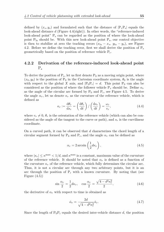
4.2 Control of vehicle platooning with extended look-ahead 55
defined by (xs, ys) and formulated such that the distance of |PvPs| equals thelook-ahead distance d (Figure 4.4(right)). In other words, the “reference-inducedlook-ahead point” Ps can be regarded as the position of where the look-aheadpoint Pla should be. With this new look-ahead point Ps, our control objectiveis then to stabilize at zero the tracking errors (xla − xs, yla − ys), see Figure4.2. Before we define the tracking error, first we shall derive the position of Psgeometrically based on the position of reference vehicle Pr.
4.2.2 Derivation of the reference-induced look-ahead pointPs
To derive the position of Ps, let us first denote P0 as a moving origin point, where(x0, y0) is the position of P0 in the Cartesian coordinate system, θ0 is the anglewith respect to the global X axis, and |P0Pr| = d. This point P0 can also beconsidered as the position of where the follower vehicle Pv should be. Define αras the angle of the circular arc formed by P0 and Pr, see Figure 4.5. To derivethe angle αr, let us denote κr as the curvature of the reference vehicle, which isdefined as
κr := dθrdsr
=(
dθrdt
)/
(dsrdt
)= ωrvr, (4.4)
where vr 6= 0, θr is the orientation of the reference vehicle (which can also be con-sidered as the angle of the tangent to the curve or path), and sr is the curvilinearcoordinate.
On a curved path, it can be observed that d characterizes the chord length of acircular segment formed by P0 and Pr, and the angle αr can be defined as
αr = 2 arcsin(
12dκr
), (4.5)
where |κr| ≤ κmax < 1/d, and κmax is a constant, maximum value of the curvatureof the reference vehicle. It should be noted that αr is defined as a function ofthe curvature κr of the reference vehicle, which fully determines the circular arc.Thus, it is not a circular arc through any two arbitrary points, but it is anarc through the position of Pr with a known curvature. By noting that (seeFigure (4.5))
sin αr2 = 12dκr, cos αr2 =
√4− d2κ2
r
2 , (4.6)
the derivative of αr with respect to time is obtained as
αr = 2d√4− d2κ2
r
κr. (4.7)
Since the length of P0Pr equals the desired inter-vehicle distance d, the position

56 Chapter 4. Longitudinal and lateral extended look-ahead control
θ0
Ps
Xxrx0
y0
yr
P0
Pr
αr
αr
2
αr
2
θr −αr
2
d cos(θr −αr
2)
d sin(θr −αr
2) d
Y
1κr
1κr
Figure 4.5: Projection of the reference-induced look-ahead point Ps.
of P0 in a global Cartesian coordinate system can be defined as
x0 = xr − d cos(θr −
αr2
)(4.8a)
y0 = yr − d sin(θr −
αr2
). (4.8b)
First we define the rotation matrix as
R(θ) =[cos θ − sin θsin θ cos θ
]. (4.9)
From Figure 4.5, it can be observed that the coordinate of Ps can be obtained bya rotation of −αr
2 from the coordinate Pr around (x0, y0) as[xsys
]=[x0y0
]+RT
(αr2
)[xr − x0yr − y0
]. (4.10)
By substituting (4.8) into (4.10), applying the angle sum formula, and noting thatR(θr − αr) = R(θr)RT (αr), we can eventually rewrite (4.10) as[
xsys
]=[xryr
]+ d
[cos (θr − αr)− cos
(θr − αr
2)
sin (θr − αr)− sin(θr − αr
2)][
xsys
]=[xryr
]+ dR (θr − αr)
[1− cos αr
2− sin αr
2
], (4.11)
where R(θr − αr) as the rotation matrix through an angle θr − αr. It can beobserved that the position of the reference-induced look-ahead point Ps depends

4.2 Control of vehicle platooning with extended look-ahead 57
on the position of the reference vehicle Pr, the angle αr, and the angle θr − αr,which in fact, is the desired orientation of the follower vehicle. On a straight path,αr = 0, thus Ps will be equal to Pr. In the following section, we define the errordynamics with the extended look-ahead approach.
4.2.3 Error dynamics and controller design of theextended look-ahead
We consider the trajectory tracking problem between Pla and Ps, expressed in theframe of the desired posture of the follower vehicle, with origin P0. It should benoted that we define the relative kinematics with respect to this particular framebecause we want to cancel the rotation matrix R(θr−αr) factor in (4.11). Hence,the error state components are defined as[
z1z2
]= RT (θr − αr)
[xla − xsyla − ys
], (4.12)
with xla = x + d cos θ, yla = y + d sin θ, and [xs, ys]T as described in (4.11). Itcan be seen directly that [z1, z2]T denotes the relative position error. To obtainthe error dynamics, we start first by differentiating [z1, z2]T with respect to timeand taking (4.11) and (4.5) into account, resulting in[
z1z2
]= (ωr − αr)
[z2−z1
]+[cos δ −d sin δsin δ d cos δ
] [vω
]−[cosαrsinαr
]vr −
[sin αr
21− cos αr
2
]dωr + dαr
[ 12 sin αr
21− 1
2 cos αr
2
], (4.13)
whereδ = θ − θr + αr. (4.14)
By applying the double angle formula on sinαr and cosαr, substituting (4.6) and(4.4) into (4.13), we eventually obtain the error dynamics as[
z1z2
]= (ωr − αr)
[0 1−1 0
] [z1z2
]−[vrdωr
]+[cos δ −d sin δsin δ d cos δ
] [vω
]+[hκ,1hκ,2
]κr (4.15)
with
hκ,1 = d3κr
2√
4− d2κ2r
, hκ,2 = 4d2 − d2√4− d2κ2r
2√
4− d2κ2r
. (4.16)
If the follower vehicle converges to its desired position, θ converges to θr − αr.Hence, δ in (4.14) is, in fact, the angular error of the follower vehicle. It can beobserved that the error dynamics (4.15) consist of: a linear time-varying termmultiplying [z1, z2]T , since since ωr and αr are external time-varying parameters;

58 Chapter 4. Longitudinal and lateral extended look-ahead control
and a nonlinear term multiplying inputs [v, ω]T , since δ is a state of the system.The objective now is to design control laws [v, ω]T that asymptotically stabilizethe system (4.15) at the origin, based on input-output feedback linearization inKhalil (2002, Chapter 13), Nijmeijer and van der Schaft (1990). Since the matrixmultiplying [v, ω]T is invertible, by choosing the control inputs[
vω
]=[
cos δ sin δ− 1d sin δ 1
d cos δ
] [−k1z1 + vr − hκ,1κr−k2z2 + dωr − hκ,2κr
], (4.17)
where d > 0, we obtain the closed-loop system as follows[z1z2
]=[−k1 ωr − αr
−ωr + αr −k2
] [z1z2
]. (4.18)
Noted that by the input-output feedback linearization, we obtain a closed-loopsystem which is a linear time-varying (LTV) system. Hence, the Lyapunov stabil-ity criterion is used to prove the stability of the closed-loop system. By the choiceof k1, k2 > 0, it can be directly verified that the origin of subsystem [z1, z2]T isexponentially stable by the Lyapunov function V12(z1, z2) = 1
2z21 + 1
2z22 such that
V12 (z1, z2) = −k1z21 − k2z
22 < 0, (4.19)
for (z1, z2) 6= 0, which means that V12 is negative definite in (z1, z2). Since,however, the model (4.1) is of third order and the error dynamics (4.15) are ofsecond order, first-order internal dynamics are present. The internal dynamicsare the unobservable part of the system dynamics that comply with the desiredoutput, while the zero dynamics is the internal dynamics of the system when thesystem output is kept at zero by the input (Khalil (2002)). It should be notedthat analyzing the (global) stability of the internal dynamics has a more genericmeaning than only analyzing the stability of the zero dynamics. Therefore, in thenext section we analyze the stability of the internal dynamics.
4.2.4 Stability analysis of the internal dynamics
From Section 4.2.3, it has been shown that the control law (4.17) exponentiallystabilizes the second-order error dynamics, which leaves us with the first-orderinternal dynamics since the original model (4.1) is of third order. The first obviouschoice for the internal state would be δ, since δ resembles the orientation errorbetween the actual and the desired orientation of the follower vehicle. However,in a steady state condition, which implies that z1 = z2 = 0 and κr = 0, thischoice leads to two equilibrium points δ = 0 and δ = arctan[(−2dκr)/(d2κ2
r − 1)],where the physical interpretation of these points is depicted in Figure 4.6 (seeAppendix B.1 for the derivation). The posture (x1, y1, θ1) is the stable equilibriumpoint, and can be considered as the correct posture of where the follower vehicleshould be. On the other hand, (x2, y2, θ2) is the unstable equilibrium point,and depends on the curvature of the preceding vehicle. Due to the curvature-dependence of this unstable equilibrium point, we define z3 such that the stable

4.2 Control of vehicle platooning with extended look-ahead 59
follower vehicle (x1, y1, θ1)
leader vehicle (xr, yr, θr)
follower vehicle (x2, y2, θ2)
αr
d
dPs
θ2
θ1
θr − αr
δ1 = 0
δ2 = π
Figure 4.6: Posture of the follower vehicle, (x1, y1, θ1) and (x2, y2, θ2), on twoequilibrium points. In the stable equilibrium point (x1, y1, θ1), δ1 = 0; and in theunstable equilibrium point (x2, y2, θ2), δ2 6= 0 6= π.
δ = 0
δ = arctan(
−2dκr
d2κ2r−1
)
z3 = 0
z3 = π
Figure 4.7: The mapping of the equilibrium points from δ (left) to z3 (right).By this mapping, the stable equilibrium point is at z3 = 0; and the unstableequilibrium point maps to z3 = π.

60 Chapter 4. Longitudinal and lateral extended look-ahead control
equilibrium point corresponds with z3 = 0 and the unstable equilibrium pointwith z3 = π (see Figure 4.7). To that end, we define
z3 = δ + β, (4.20)
where the angle β is characterized by (see Appendix B.2 for the derivation)
sin β = dκr cos δ − dκr√d2κ2
r (1− cos δ)2 + (1 + dκr sin δ)2, (4.21a)
cosβ = 1 + dκr sin δ√d2κ2
r (1− cos δ)2 + (1 + dκr sin δ)2. (4.21b)
where |κr| ≤ κmaxr < 1/d. Note that from (4.20) and straightforward application
of the trigonometric rules for the sum of angles, we have
sin z3 = sin δ + dκr (1− cos δ)√d2κ2
r (1− cos δ)2 + (1 + dκr sin δ)2, (4.22a)
cos z3 = cos δ + dκr sin δ√d2κ2
r (1− cos δ)2 + (1 + dκr sin δ)2. (4.22b)
Moreover, the derivative of β with respect to time follows from the inverse tangentfunction, derived from (4.21a) and (4.21b), yielding
β = dκr cos δ − dκrd2κ2
r (1− cos δ)2 + (1 + dκr sin δ)2
−
(dκr sin δ + d2κ2
r (1− cos δ)d2κ2
r (1− cos δ)2 + (1 + dκr sin δ)2
)δ. (4.23)
Using (4.21), (4.22), (4.17), and noting the fact that δ = ω − ωr + αr, we obtainthe derivative of z3 with respect to time as
z3 = dκr cos δ − dκrd2κ2
r (1− cos δ)2 + (1 + dκr sin δ)2
+(
d2κ2r (1− cos δ) + dκr sin δ + 1
d2κ2r (1− cos δ)2 + (1 + dκr sin δ)2
)δ
= f3 (z) , (4.24)

4.2 Control of vehicle platooning with extended look-ahead 61
where
f3 (z) = − vrd
sin z3 + ξr (4.25)
vr = N√∆vr (4.26)
ξr = N
∆
(k1 sin δd
z1 −k2 cos δd
z2
)+ gκκr (4.27)
N = d2κ2r (1− cos δ) + dκr sin δ + 1 (4.28)
∆ = d2κ2r (1− cos δ)2 + (1 + dκr sin δ)2 (4.29)
gκ = N
∆ fr (δ, d, κr)−d (1− cos δ)
∆ (4.30)
fr (δ, d, κr) = 4d2√
4− d2κ2r
+ d2κr
2√
4− d2κ2r
sin δ
−4d− d
√4− d2κ2
r
2√
4− d2κ2r
cos δ, (4.31)
z = (z1, z2, z3), (N,∆) > 0 (see (B.14) and (B.15) in Appendix B.3), and δ as in(4.14). It should be noted that (4.24) is a closed-loop system since the inputs (v, ω)have been taken into account. Thus, the overall closed-loop system is composedof (4.18) and (4.24), which is a third order system.Remark 4.1. Note that since |κr| ≤ κmax
r < 1/d, vr is lower- and upper-boundedby
|vr| ≤ |vr| <√
2 |vr| , (4.32)and |ξr| is bounded by
|ξr| ≤ 2+√
2d k1 |z1|+ 2+
√2
d k2 |z2|+ 7d9 |κr| . (4.33)
Proof of (4.32) and (4.33). See Appendix B.3.
Using these bounds on |vr| and |ξr|, asymptotic stability of the internal dynamics(4.24) can be concluded by the following proposition.
Proposition 4.1. Consider the dynamics (4.24) where vr and ξr are given in(4.26) and (4.27), respectively. Let z12 = [z1, z2]T , and assume for all t ≥ 0 that0 < vmin
r ≤ vr(t), |κr(t)| ≤ κmaxr < 1/d, and |κr(t)| ≤ K, where d,K ∈ R+.
1. For ε > 0, if
‖z12(0)‖ ≤ vminr ε(
2 +√
2)√
k21 + k2
2, (4.34)
where k1, k2 > 0, then there exists t∗ such that for t ≥ t∗,
|sin z3(t)| ≤ 7d2
9vminr
K + ε. (4.35)

62 Chapter 4. Longitudinal and lateral extended look-ahead control
2. Moreover, if additionallylimt→∞
κr(t) = 0, (4.36)
then limt→∞ sin z3(t) = 0.
3. Finally, for 0 < ε < 310 , if (4.34) holds,
cos z3(0) ≥√
1−( 7
18 −827ε)2, (4.37)
and|κr(t)| ≤ K = vmin
r
d2
( 12 −
53ε), (4.38)
we have v(t) ≥ εvminr > 0 and limt→∞ z3(t) = 0, rendering the internal
dynamics (4.24) stable.
Proof. See Appendix B.4.
Therefore, we can conclude that the internal dynamics (which correspond to theorientation of the vehicle) are stable under these conditions: the initial positionerror is not too large (bounded by (4.34)), the initial orientation error is boundedby (4.37), and the curvature derivative of the preceding vehicle is bounded by(4.38). Moreover, it is important to note that for a platoon with more than2 vehicles, v(t) will become the reference for the next vehicle. By Proposition4.1(c), the requirement of v(t) > 0 is fulfilled for the initial condition z3(0) beingbounded by (4.37) and κr(t) satisfying (4.38).
4.3 Orientation-error observer designFrom the previous section, it has been proven that the proposed controller de-sign (4.17) guarantees that all error states (z1, z2, z3) converge to zero, under theassumption that all states of the kinematic model are available and measurablefor control. Here, the relative position (z1, z2) can be obtained from the cameraor lidar, the preceding vehicle states (vr, ωr) can be obtained through wirelesscommunication with the preceding vehicle, κr can be determined from vr and ωr,κr can be approximated by the backward Euler method, and δ is determined fromthe relative orientation θ− θr and αr, which may be measured using the camera.It is assumed that the relative position (z1, z2) can be measured accurately, andthere is no delay involved in the wireless communication. In practical situations,there is often a case where the orientation of vehicles (θ, θr, or both) are notavailable, or disturbed by noise due to inherent limitations of the vision system.To address this problem, a state feedback controller combined with an observerthat estimates the orientation was designed in Jakubiak et al. (2002), Noijen et al.(2005). However, these approaches result in a combined observer-controller de-sign which is different than the proposed tracking controller (4.17). Therefore, weadapt the observer designed in Jakubiak et al. (2002) by determining the orien-tation angle θ from the available states (z1, z2, v, ω) and design an observer such

4.3 Orientation-error observer design 63
that the estimated angle (denoted by θ) converges to the actual orientation angleθ.
Consider the kinematic model of the unicycle as given in (4.1), and the availableoutputs as [x, y]T . We extend the dimension of the system (4.1) by defining newvariables s and c as
s = sin θ, c = cos θ, (4.39)
which replace the orientation angle θ. As a result, we obtain the extended modelof the unicycle as
x = vc, y = vs, (4.40a)s = ωc, c = −ωs, (4.40b)
where [x, y]T are the available outputs, [v, ω]T are inputs, s and c as definedin (4.39). It should be noted that the transformation from the three-dimensionalsystem (4.1) to four-dimensional system (4.40) introduces a constraint of the forms2 + c2 = 1.
Based on (4.40), an observer for x, y, c, and s can be defined as follows
˙x = vc+ l1ζx (4.41a)˙y = vs+ l2ζy (4.41b)˙c = −ωs+ l3vζx (4.41c)˙s = ωc+ l4vζy, (4.41d)
where l1, l2, l3, l4 > 0, and ζx = x− x, ζy = y − y, ζc = c− c, and ζs = s− s arethe observer errors. Thus, we obtain the following observer error dynamics
ζx = x− ˙x = vζc − l1ζx (4.42a)ζy = y − ˙y = vζs − l2ζy (4.42b)ζc = c− ˙c = −ωζs − l3vζx (4.42c)ζs = s− ˙s = ωζc − l4vζy. (4.42d)
It can be observed directly that if (4.42) converges to zero, then the estimatedstates (x, y, c, s) converge to (x, y, c, s). To prove stability of (4.42), the followingproposition can be used.
Proposition 4.2 (Jakubiak et al. (1999), Beumer (2017)). Consider the dynam-ics (4.42) with l1, l2, l3, l4 > 0. If v, ω are bounded differentiable functions, v isbounded, and 0 < vmin ≤ v(t), then (4.42) is uniformly globally asymptoticallystable (UGAS) at the origin.
Proof. See Appendix B.5.

64 Chapter 4. Longitudinal and lateral extended look-ahead control
Using Proposition 4.2, we have that the origin of (4.42) is uniformly globallyasymptotically stable (UGAS) and ζx(t), ζy(t), ζc(t), ζs(t) converge to zero ast→∞, subject to the necessary and sufficient condition of v(t) > 0 for all t [seeProposition 4.1(c)]. It remains to prove the convergence of the estimated orien-tation angle to the actual orientation angle θ. Define the estimated orientationangle θ as
θ := atan2 (s, c) , (4.43)
where c and s are generated by the observer (4.41). Note also that
sin θ = s√c2 + s2
, cos θ = c√c2 + s2
, tan θ = s
c. (4.44)
Let us define ζθ = tan(θ − θ). By noting that ζc = c − c, ζs = s − s, and usingthe fact that tan θ = sin θ/ cos θ, we have
ζθ = tan θ − tan θ1 + tan θ tan θ
= c sin θ − s cos θc cos θ + s sin θ
= (c− ζc) sin θ − (s− ζs) cos θ(c− ζc) cos θ + (s− ζs) sin θ
= ζs cos θ − ζc sin θ1− ζc cos θ − ζs sin θ . (4.45)
Since ζc(t) and ζs(t) converge to zero, we have ζθ(t) converge to zero as t → ∞,which directly implies the convergence of θ to θ for the initial estimated orientationerror satisfying |θ(0)− θ(0)| < π/2.
4.4 SimulationsIn order to illustrate the effectiveness of the extended look-ahead controller andthe observer, a number of simulations are performed. Additionally, the purposeof this simulation is to properly determine the control parameters for the experi-mental setup. First, we consider a scenario of 4 vehicles platoon, where all states(position and orientation) can be measured accurately and are not disturbed bynoise. This allows us to investigate the optimal gains k1 and k2 and the effec-tiveness of the extended look-ahead controller against corner-cutting. Second, weconsider a scenario of a 2 vehicles platoon where the second vehicle is controlled byextended look-ahead controller with the orientation-observer, in the presence andabsence of noise. In this scenario, the performance of the observer is evaluated.
We consider a platoon of 4 vehicles, with the first vehicle controlled by the trackingcontroller of Jiang and Nijmeijer (1997) to track a predefined eight-shaped tra-jectory, while the other vehicles controlled by the extended look-ahead controllerto track their respective preceding vehicle. It should be noted that the first ve-hicle can also be directly controlled (simulating a driving scenario where the firstvehicle is driven by a human), or controlled by other trajectory-tracking (e.g.,

4.4 Simulations 65
Figure 4.8: Reference curvature for an eight-shaped path with v = 0.06 m/s.
Figure 4.9: Trajectory of 4-vehicles platoon tracking an eight-shaped path, withk1 = k2 = 0.75.

66 Chapter 4. Longitudinal and lateral extended look-ahead control
Figure 4.10: Errors of a platoon with the extended look-ahead controller on aneight-shaped path.

4.4 Simulations 67
Kanayama et al. (1990)) or path-following controllers (e.g., Plaskonka (2015)).The eight-shaped trajectory is generated by two-half circles with the radius 0.3 mand quintic polynomial functions. The controller performance to track a circulartrajectory (constant curvature) as in Bayuwindra et al. (2019b) is also performed,but the eight-shaped trajectory is chosen since it also represents a combination ofconstant and varying curvatures. The reference curvature of the eight-shaped pathis given in Figure 4.8. The dimensions of the track are chosen in accordance withthe experimental setup, which is presented in the next section. The first vehiclestarts at initial position (x, y) = (0.7, 0.5) m, maneuvering along the eight-shapedpath. The other vehicles start at (0.625, 0.425), (0.55, 0.35), and (0.475, 0.275) forvehicle 2, 3, and 4, respectively. All vehicles are initiated with v = 0.06 m/s andθ = 0.9707 rad/s, and d = 0.1 m is chosen. The extended look-ahead controllergain is determined by an iterative manner and is equal for vehicle 2, 3, and 4.It should be noted that the choice for the proper gain is also determined by theavailable experimental arena and the reference trajectory. It is also worth notingthat the higher gain value results in a faster convergence towards the desired path.However, the higher gain value also results in a more sensitive response to thecurvature change. In practical situation, this is undesirable since a slight changein states measurement (e.g., due to noise, sensor inaccuracy) could result in anover compensation. The trajectory of all vehicles with k1 = k2 = 0.75 is shownin Figure 4.9. It can be observed that all vehicles in the platoon converges to thereference path and corners are not cut. This shows the advantage of our controllerin comparison to the controller in Petrov (2009), where corners with κr 6= 0 arestill cut. From Figure 4.10, it can be observed that z1 and z2 converge to zero.On the other hand, the orientation error z3 converges to zero if κr = 0, which canbe seen from t = 11 s until t = 22 s and from t = 42 s until t = 55 s. On thetransition state when κr 6= 0, z3 is bounded given the condition that κr is smallenough.
In the second scenario, we consider a platoon of 2 vehicles, with identical param-eters as vehicle 1 and vehicle 2 in the previous simulation. A two-vehicles settingis used since we want to study the convergence of the estimated orientation tothe true orientation of the follower vehicle. The first vehicle is controlled by thetracking controller of Jiang and Nijmeijer (1997), while the second vehicle is con-trolled by the extended look-ahead controller (4.17) with the observer (4.41). Theinitial condition of the observer states are set as x(0) = 0.625, y(0) = 0.425, andθ = 0.8 rad/s. It is assumed that the position can be measured accurately withoutany noise, while the orientation measurement is disturbed by a noise. The noise ofthe orientation sensor is simulated as a white noise with a power spectral densityof 5 × 10⁻⁵. For the observer gains, we select l1 = 10, l2 = 10, l3 = 1000, andl4 = 1000. First, we simulate the system without the observer, i.e., the controllaws (4.17) are calculated using the orientation measured from the sensor withnoise. Second, we simulate the system with the orientation-error observer, wherethe orientation is estimated based on the position sensor. We denote θ as thetrue orientation, θ as the estimated orientation, and θ as the orientation obtainedfrom the sensor. The error plots of θ − θ (for the scenario without the observer)

68 Chapter 4. Longitudinal and lateral extended look-ahead control
Figure 4.11: Errors of θ − θ and θ − θ, where θ is the true orientation, θ is theestimated orientation, and θ is the orientation obtained from the sensor withnoise.
and θ − θ (for the scenario with the observer) are depicted in Figure 4.11. It canbe observed that for the scenario without the observer, the measured orientation(shown in gray line) is heavily disturbed by noise. On the other hand, the errorθ− θ (shown in black line) is not disturbed by noise and converges to zero, whichmeans that the estimated orientation θ converges to the true orientation θ.
4.5 ExperimentsIn this section, we conduct an experiment to confirm the theoretical analyses andsubsequent to the simulation results. This practical experiment is conducted alsoto provide an insight in how the parameters for our controller can be chosen toaccommodate the slave controller in mobile robots. Furthermore, the purpose ofthis experiment is to verify the performance of the orientation-error observer inan experimental environment, where the orientation measurement is disturbed bynoise due to inherent limitation of the sensor/vision system. The main compo-nents of this experimental setup are four E-pucks (Mondada and Bonani (2007))a PC, and a camera, with identical setup as in Chapter 3.
In order to support comparison of the simulation results presented in the previoussection, for this experiment we use the identical eight-shaped reference trajectoryas in the simulation. In the first experiment, we use the extended look-aheadcontroller without the observer, thus, the orientation of the mobile robots areobtained directly from the camera. The objectives of the first experiment are tostudy the effectiveness of the extended look-ahead controller, compared to thetheoretical results presented in the previous section, to verify the suitable gain forthe experiment, and to study the behavior of the system under the presence ofmeasurement noises. In the second experiment, we apply the observer to estimatethe orientation of the mobile robots. The objective of this second experiment is to

4.5 Experiments 69
platoon's direction
ref initial position
Figure 4.12: Trajectory of E-pucks with extended look-ahead controller, wherethe orientation is measured directly from the camera.
Figure 4.13: 2-norm of the position error from experiments incorporating extendedlook-ahead controller without observer.
study the effectiveness of the observer in practice, and to confirm the simulationresults. All E-pucks are initiated with v = 0.06 m/s, with the controller gainsk1 = k2 = 0.75 for both experiments, and with the observer gains l1 = 10, l2 = 10,l3 = 1000, and l4 = 1000 for the second experiment.
Figure 4.12 shows the trajectory of robots with the extended look-ahead con-troller. It can be observed that the trajectory of all follower robots converge tothe reference trajectory. Clearly, this experiment shows that the extended look-ahead controller effectively avoids corner-cutting. However, it can be seen that

70 Chapter 4. Longitudinal and lateral extended look-ahead control
platoon's direction
ref initial position
Figure 4.14: Trajectory of E-pucks with extended look-ahead controller and anorientation observer. The orientation of each E-puck is estimated from the posi-tion.
Figure 4.15: 2-norm of the position error from experiments incorporating extendedlook-ahead controller with observer.

4.6 Conclusions 71
the follower vehicles start to deviate on the left side of the eight-shaped path,due to the inaccuracy (due to noise, or displacement of the 2D marker) in theorientation measurement. The 2-norm of the position error, define as
√z2
1 + z22 ,
is depicted in Figure 4.13. It can be observed from this plot that E-puck 3 has thelargest deviation, peaking at t = 40 s. To address this problem, the orientation-error observer is integrated to the extended-look-ahead controller in the secondexperiment. In Figure 4.14, the trajectory of all robots with the extended look-ahead controller and orientation-error observer is shown. It can be seen directlythat the tracking accuracy of all follower robots is improved, thus showing the ef-fectiveness of the orientation-error observer. From Figure 4.15, where the 2-normof the position error is depicted, it can also be verified that the observer reducesthe deviation caused by the inaccuracy of the orientation measurement. We mayalso notice some measurement noises on the position measurement, but they aresmall enough (less than 0.02 m) and can be safely neglected.
4.6 ConclusionsThis chapter presents a novel extended look-ahead controller in vehicle platoon-ing. The look-ahead target point is extended to a virtual point induced from theposition and the curvature of the reference vehicle, thus ensuring a better track-ing performance at cornering, preventing corner-cutting behavior. A stabilityresult on the internal dynamics is presented, showing that the closed-loop systemis stable under the given bound of the reference curvature and the initial rela-tive position and orientation of the vehicles. The simulation results show that theproposed approach improves the tracking performance at cornering, ensuring thatthe corners are not cut. To address the orientation measurement noise in the ex-periment, an orientation-error observer is also designed. The effectiveness of theintegrated extended look-ahead controller and orientation-error observer is fur-ther validated by means of experiment with a platoon consisting of four E-pucks.The experimental results confirm that the application of the extended look-aheadcontroller in vehicle platooning compensates for corner-cutting, and also confirmthat the observer reduces the noise presents in the orientation measurement. Thecontinuation of this chapter is to extend the approach to the single-track model,as an important step towards the application of our controller in a real vehicle.To adapt our controller to a single-track dynamic model with tire forces, we candesign a slave controller that controls acceleration or speed, internally compen-sating for the vehicle mass. The stability of the real vehicle can be guaranteedby other controllers (Electronic Stability Control (ESC), or Anti-Lock BrakingSystem (ABS), for instance), and our controller can be used in conjunction withthose other controllers. In conclusion, the application of our controller to the realvehicle may poses additional conditions, but is feasible.


Chapter 5
Application of the extendedlook-ahead controller to asingle-track vehicle platoon
5.1 IntroductionIn the previous chapters, the corner-cutting problem in a unicycle platoon issolved by the extended look-ahead controllers, where a “reference-induced” vir-tual vehicle is used as a look-ahead target for the following vehicle. Chapter 3explored the problem by decomposing the inter-vehicle distance error in globalcoordinates, and the extended look-ahead controller (hereafter referred to as theglobal extended look-ahead controller) is designed to regulate that inter-vehicledistance error to zero. Although the global extended look-ahead controller solvesthe corner-cutting problem, it needs an accurate global position measurement ofeach vehicle, which is not always available in a commercial vehicle. To this end,Chapter 4 extended the exploration to a case where the relative kinematics aredefined with respect to a vehicle-fixed frame, and the controller (hereafter re-ferred to as the local extended look-ahead controller) is designed to regulate theinter-vehicle distance error to zero, while also compensating the corner-cutting.However, for a vehicle with a large acceleration, the kinematic model is no longervalid since the lateral forces generated by the tires affect the longitudinal and lat-eral motion of a vehicle (Rajamani (2012)). Therefore, in this chapter, the lateraland longitudinal motion of a vehicle is described using a dynamic single-trackmodel, where the lateral forces generated by tires are taken into account.
Due to the effect of lateral forces generated by the tires in a dynamic single-track model (hereafter referred to as the single-track model), the extended look-ahead controllers developed for a unicycle platoon in the previous chapters cannotdirectly be applied to a platoon of vehicles modeled by a single-track model. To
73

74 Chapter 5. Application of the extended look-ahead controller
be able to adapt the extended look-ahead controllers, first a control point of asingle-track model, i.e., the point to which the unicycle controller outputs apply,is chosen. Secondly, the unicycle controller outputs have to be transformed to theinputs of the single-track model. The transformation is implemented using inputinversion, which was investigated first in Silverman (1969), and later extended toa certain class of nonlinear systems in Khalil (2002) and Isidori (1995). Due tothe nonlinearity of the single-track vehicle model, the inverse cannot be obtainedanalytically. Consequently, several other methods are taken into account, beinga numerical approach, a first-, and a second-order Taylor approximation.
The outline of this chapter is as follows. Section 5.2 first provides an overviewof the single-track vehicle model. Section 5.3 derives the input inversion for thecenter of gravity as a control point. In this section, the tracking performance andthe computation time of a numerical approach, first-, and second-order Taylorapproximation are also compared. Section 5.4 and Section 5.5 derive the inputinversion for the rear axle center and front axle center, respectively, as controlpoints. These control points are chosen to demonstrate the flexibility of theadopted approach. Finally, Section 5.6 summarizes the main conclusions.
5.2 Dynamic single-track vehicle modelConsider the single-track vehicle model (Attia et al. (2012), Rajamani (2012)),which is commonly used to model the lateral and longitudinal dynamics of avehicle under normal driving conditions. The dynamic single-track model is givenby
vx = 1m
(Flf cos δ − Fcf sin δ + Flr) + vyψ (5.1a)
vy = 1m
(Flf sin δ + Fcf cos δ + Fcr)− vxψ (5.1b)
ψ = 1I
(lfFlf sin δ + lfFcf cos δ − lrFcr) , (5.1c)
where vx, vy, and ψ denote the longitudinal, lateral, and yaw velocity, respectively.Furthermore, m is the mass of the vehicle, I is the moment of inertia, lf is thedistance between the front tires and the center of gravity, and lr is the distancebetween the rear tires and the center of gravity. The longitudinal forces whichact on the tire direction are Flf , Flr, and the cornering forces are Fcf , Fcr, at thefront and rear tire, respectively. The steering angle of the front wheel is denotedby δ, which acts as the input to the system. The cornering forces Fcf and Fcr aregenerated by the tires, and depend on the lateral tire slip angle αf and αr of therespective tire. From Figure 5.1, the lateral slip angles at the front and rear tires

5.2 Dynamic single-track vehicle model 75
δ
FlfFcf
x
y
Fcr
Flr
lr
lf
X
Y
ψ
vxvy
Figure 5.1: The single-track model.
are defined as
αf = δ − arctan(vyfvxf
)= δ − arctan
(vy + lf ψ
vx
)(5.2a)
αr = − arctan(vyrvxr
)= − arctan
(vy − lrψ
vx
), (5.2b)
where vxj and vyj , j ∈ f, r, denote the longitudinal and lateral velocity compo-nents of either front or rear wheel, respectively. The mapping from αj to Fcj , withj ∈ f, r, depends on the tire model and can vary in complexity depending onthe road condition and required accuracy. In vehicle platooning, regular motor-way driving conditions, a low longitudinal acceleration and small slip angles αj ,j ∈ f, r, are considered. Thus, the linear tire model, where the cornering forcesdepend proportionally on their respective slip angles, can be deployed (Rajamaniand Zhu (2002)). In their linear regime, the cornering forces can be expressed as
Fcf = Cαfαf (5.3a)Fcr = Cαrαr, (5.3b)
where Cαj , j ∈ f, r, denote the cornering stiffness coefficient of the respectivetire. The inputs of the single-track model are the longitudinal forces Flf , Flr, andthe steering angle δ. A front-wheel drive vehicle is considered, where Flf is thetraction force of the engine and Flr = 0. Thus, the objective of the vehicle pla-tooning is to design the inputs (Flf , δ) such that the vehicle follows its precedingvehicle at a desired distance.
In previous chapters, the objective of vehicle following is fulfilled by designing theinputs (au, ωu) or (vu, ωu) for the unicycle system, where au is the longitudinalacceleration input, vu is the longitudinal velocity input, and ωu is the yaw rate

76 Chapter 5. Application of the extended look-ahead controller
input, such that a desired inter-vehicle distance is achieved. The spacing errors(for both longitudinal and lateral distances) between the preceding and the fol-lowing vehicle are defined as a difference between the actual inter-vehicle distanceand a desired distance. In two-dimensional space, the spacing errors can eitherbe decomposed in global Cartesian coordinates (see Chapter 3), or in local coor-dinates, where the relative kinematics can be defined with respect to a particularframe, e.g., a moving vehicle-fixed frame (see Chapter 4). The results of thesecontroller outputs for a unicycle can be viewed as the desired motion for a controlpoint, that regulates the velocity and orientation of that point. By choosing anycontrol point of the single-track model, the controller outputs for a unicycle canin fact be extended/adapted as desired values for that particular control point.This control point can be chosen arbitrarily, for instance as: (1) the center ofgravity, (2) the rear axle center, or (3) the front axle center. The actual inputs ofthe single-track model (Flf , δ) then can be computed based on the outputs gen-erated by the unicycle controller through the input inversion, which also dependson the chosen control point. It should be noted that obtaining the inverse of anonlinear model is generally not straightforward, and a numerical approach or anapproximation may have to be adopted. Therefore, in the next sections, the inputinversions of the three above mentioned control points of the single-track modelare studied.
5.3 Center of gravity as a control pointIn this section, the center of gravity of a single-track model (5.1) is chosen as acontrol point, after which the outputs in the form of longitudinal acceleration andyaw rate are defined. It is then shown that due to the choice of these outputs,the algebraic model is obtained and the input inversion can be applied.
5.3.1 Input inversion
The chassis kinematic model at the center of gravity of a single-track model in aCartesian coordinate frame is given by
X = vx cosψ − vy sinψ (5.4a)Y = vx sinψ + vy cosψ, (5.4b)
where (X,Y ) are the Cartesian coordinates of the center of gravity (see Fig-ure 5.2), and (x, y, ψ) dynamics are as described in (5.1). Let v be the velocity ofthe center of gravity, based on X and Y , and θ be the angle between the directionof v and the Cartesian X-axis, given by
v =√X2 + Y 2 =
√v2x + v2
y (5.5)
θ = arctan(Y
X
)= arctan
(vx sinψ + vy cosψvx cosψ − vy sinψ
), (5.6)

5.3 Center of gravity as a control point 77
X
Y
Yr
Yf
XfXr
Figure 5.2: The single-track model with different control points: the center ofgravity (X,Y ), the rear axle center (Xr, Yr), and the front axle center (Xf , Yf ).
where (5.4) is used. The longitudinal acceleration and the yaw rate of this pointcan be obtained by differentiating (5.5) and (5.6) with respect to time, resultingin
v = vxvx + vy vy√v2x + v2
y
= a, θ = vxvy − vxvyv2x + v2
y
+ ψ = ω, (5.7)
where it is assumed that√v2x + v2
y = v 6= 0, and the outputs are defined as (a, ω).With these derivations, the center of gravity of the single-track model is viewedas a unicycle with a velocity v and an orientation θ with respect to the global X-axis. The Cartesian coordinates of this point are given by (X,Y ) and the inputsare given as the longitudinal acceleration a and the yaw rate ω. Therefore, anycontrol inputs of longitudinal acceleration and yaw rate that are designed for aunicycle can be applied directly to (5.7).
Setting (a, ω) = (au, ωu), where (au, ωu) can be any arbitrary control law devel-oped for a unicycle, and applying it to (5.7) yields
[auωu
]= 1v
[vx vy− 1vvy
1vvx
] [vxvy
]+[
0ψ
], (5.8)
with v as in (5.5). The actual inputs (Flf , δ) of a front-wheel drive single-trackmodel can be obtained by substituting (5.1a), (5.1b) into (5.8), and taking (5.2),(5.3) into account, eventually resulting in the inverse as
[cos δ − sin δsin δ cos δ
] [Flf
Cαf (δ − σf )
]=[ζ1ζ2
], (5.9)

78 Chapter 5. Application of the extended look-ahead controller
where
ζ1 := m
vvxau −mvyωu (5.10a)
ζ2 := m
vvyau +mvxωu + Cαr arctan
(vy − lrψ
vx
)(5.10b)
σf := arctan(vy + lf ψ
vx
). (5.10c)
Due to the multiplication terms δ sin δ and δ cos δ, the solution (Flf , δ) can not bedetermined analytically, but it can be determined numerically or by approxima-tions, e.g., using Taylor series. The Taylor series is obtained by first multiplyingboth sides of (5.9) with the inverse of the first matrix on the left hand side result-ing in [
FlfCαf (δ − σf )
]=[
cos δ sin δ− sin δ cos δ
] [ζ1ζ2
]. (5.11)
From the first row of (5.11), the longitudinal force input Flf of the single-trackmodel is obtained as
Flf = ζ1 cos δ + ζ2 sin δ, (5.12)
where δ is the steering angle input and is yet to be determined. To determine δ,let f(δ, vx, vy, ψ, au, ωu) be the difference between the left and right hand side ofthe second row of (5.11), as follows
f(δ, vx, vy, ψ, au, ωu
)= Cαfδ − Cαfσf + ζ1 sin δ − ζ2 cos δ, (5.13)
and the solution of f(δ, ·) = 0 for δ can be approximately determined by Taylorseries approximation of (5.13) around δ = 0. It should be noted that due to thephysical limitation of a vehicle, the steering angle δ is relatively small and alwaysbounded. At higher speed maneuvers, the steering angle is smaller when comparedto lower speed maneuvers. Moreover, normal driving conditions and moderatespeed are always assumed in vehicle platooning, with no special maneuvers (e.g.,parking, stopping, or turning back) involved. Therefore, the steering angle δ isrelatively small and the first- or the second-order Taylor expansion is expected tobe sufficiently accurate to approximate the function f(δ, ·). The accuracy of bothTaylor approximations against varying yaw rate (thus, the trajectory radius) arefurther investigated in the next part of this section.
The first-order Taylor series of f(δ, ·) around δ = 0 is given by
f(δ, ·) ≈ δ (Cαf + ζ1)− Cαfσf − ζ2, (5.14)
thus, f(δ, ·) = 0 yields
δ1 = Cαfσf + ζ2Cαf + ζ1
. (5.15)

5.3 Center of gravity as a control point 79
Table 5.1: Vehicle’s parametersParameter Value Parameter Value
lf,i 1.2 m Ii 2875 mN/s2
lr,i 1.6 m Cαf,i 20,000 N/radmi 1575 kg Cαr,i 33,000 N/rad
It should be noted that (5.15) equals the first iteration step of the Newton-Raphson method of the function (5.13) for f(δ, ·) = 0 with an initial guess ofδ0 = 0, which is obtained as follows:
δ1 = δ0 −f (δ0)f ′(δ0) =
Cαfσf + ζ2
Cαf + ζ1. (5.16)
On the other hand, the second-order Taylor series of f(δ, ·) around δ = 0 is givenby
f(δ, ·) ≈ δ (Cαf + ζ1)− Cαfσf − ζ2 + 12ζ2δ
2. (5.17)
Thus, f(δ, ·) = 0 yields
δ2 =− (Cαf + ζ1)±
√(Cαf + ζ1)2 + 2ζ2 (Cαfσf + ζ2)
ζ2. (5.18)
For a case where the yaw rate ωu and the acceleration au are zero, i.e., the vehicledrives on a straight path with constant velocity, it is desirable to have a steeringangle equal to zero. By substituting ωu = 0 and au = 0 to (5.18), the condition ofδ2 = 0 is fulfilled by the root with positive sign. Hence, the root with a positivesign is chosen.
To illustrate how well the first- and second-order Taylor approximation fit the realvalue of δ obtained using a numerical approach, a numerical study is conducted.An arbitrary time instance t = τ , where vx(τ) = 10 m/s, vy(τ) = 0 m/s, ψ(τ) = 0is chosen, with the vehicle’s parameters as in Table 5.1. The iterations are per-formed for varying ωu and au, where ωu is given in the interval [−3, 3] with 0.05increment and au = −5, 0, 5. To find the solution of f(δ, ·) = 0 numerically,the function fzero in MATLAB® is used. This function is based on Dekker’salgorithm, which uses a combination of bisection, secant and inverse quadratic in-terpolation methods (Brent (1973)). The result of this iteration is then comparedwith the approximated δ1 and δ2, which are obtained using first and second-orderTaylor series, respectively.
A comparison between the numerical approach, the first- and the second-orderTaylor series, for several values of ωu and au is presented in Figure 5.3. For asmall yaw rate, the first-order Taylor series provide an adequate approximationof the steering angle δ. The accuracy of the first-order Taylor approximationdepends on the desired yaw rate of the vehicle. Under a constant speed of 10 m/s

80 Chapter 5. Application of the extended look-ahead controller
Figure 5.3: Plots of δ against varying yaw rate ωu and longitudinal accelerationau (left). Zooming in to ωu = [0.2, 0.5] shows the accuracy of the both first- andsecond-order Taylor approximations.

5.3 Center of gravity as a control point 81
(=36 km/h), the first-order Taylor approximation is accurate for the yaw rate|ωu| ≤ 0.25 rad/s (as shown in Figure 5.3(right)), which corresponds to a circulartrajectory with a diameter bigger than or equal to 80 m. Thus, it can be concludedthat the first-order Taylor is good enough to track a circular trajectory with aminimum diameter of 80 m when driving with a speed of 36 km/h. It shouldbe noted that by using the relation between the velocity and yaw rate of thevehicle, the minimum diameter of the trajectory of which the first-order Taylorapproximation is good enough can be roughly estimated for any arbitrary constantspeed. On the other hand, it is clearly shown that the second-order Taylor seriesyields a better approximation to the real value of δ for varying yaw rate thanthe first-order Taylor series. Although the numerical approach gives the exactsolution of δ, it should be noted that its computation time can be relatively slow,and can result in a delayed steering response in a vehicle platooning. Therefore,in the next section, the computation time of the numerical approach, the first-and second-order Taylor series, using the extended look-ahead controller (3.35)that is designed in Chapter 3, are studied.
5.3.2 Global extended look-ahead controller
Using the input inversion as described in the previous section, the control pointof the single-track model is now viewed as a unicycle. Thus, controllers thatwere previously designed for the unicycle can be adapted for the center of gravitycontrol point of a single-track model. Consider a platoon of m ∈ N vehicles, withSm = i ∈ N | 1 ≤ i ≤ m denoting the set of all vehicles in the platoon, anddenote (Xi, Yi) as the Cartesian coordinates and θi as the orientation of the centerof gravity of vehicle i. The actual inputs, longitudinal force Flf,i and the steeringangle δi, can be obtained through the input inversion explained in the previoussection. To prevent corner-cutting, the extended look-ahead controller in a globalcoordinate frame (see Chapter 3) with a velocity-dependent desired distance, isconsidered. In this approach, a look-ahead point attached to the follower vehicleis defined as Plai and a “reference-induced” look-ahead point Psi−1 is defined asthe new tracking point objective, and the control objective is to regulate theacceleration and the yaw rate (ai, ωi) to stabilize the position error between Plaiand Psi−1, see Figure 5.4. To this extent, the controller (3.35) that has beendesigned in Chapter 3 is used, and the inverse is applied to (ai, ωi) such that theactual inputs of the single-track model (Flf,i, δi) are obtained. It should be notedthat by using this global extended look-ahead controller, the assumption of thenonzero velocity that was made for the inverse in (5.7) is fulfilled by Proposition3.2.
Due to the nonlinearity of the single-track model, the input inversion can beobtained by a numerical approach, first-order Taylor, or second-order Taylor ap-proximation. The simulation for a platoon of four vehicles is performed such thatthe performance and the computation time of each method can be compared. Todepict a real platooning condition, a path combination of a straight road and aroundabout is chosen. The dimensions for a two-lane roundabout in the Nether-

82 Chapter 5. Application of the extended look-ahead controller
δi−1
αi−1
θi−1
δi xi
yi
xi−1
yi−1
θi
di
O Xi Xi−1
Yi
Yi−1
Ri−1
Ri−1
Plai
Psi−1
di
di
θi−1 − αi−1
Figure 5.4: Trajectory tracking problem with extended look-ahead for the centerof gravity control point.

5.3 Center of gravity as a control point 83
Table 5.2: Dimension for two-lane roundabout in the Netherlands (Royal Haskon-ing (2009)) and the United States (Federal Highway Administration (2000))
Design element Netherlands United StatesMinimum Maximum Minimum Maximum
Outer circle radius (Rbu) 20 m 38 m 22.5 m 30 mInner circle radius (Rbi) 10 m 30 m 12.7 m 26.3 m
Rbu
Rbi
Figure 5.5: Design parameters of a two-lane roundabout (source Royal Haskoning(2009)).
lands and the United States are given in Table. 5.2. The recommended speed ofthe vehicle entering the roundabout is approximately 38 km/h in the Netherlands(Royal Haskoning (2009)), and less than 50 km/h in the United States (FederalHighway Administration (2000)).
The first vehicle in the platoon is directly controlled (simulating a driving scenariowhen the first vehicle is driven by a human), maneuvering on a straight path alongthe X-axis with a constant initial velocity 10 m/s = 36 km/h. It should be notedthat the first vehicle is also modeled as a single-track model (5.1), where theinputs are given in (Flf , δ). The first vehicle follows a straight line for 4 s, afterwhich it maneuvers into a circular trajectory with a curvature of 0.04 m−1 (whichis equal to a roundabout with a 50 m diameter), compliant with the standards inthe Netherlands or the United States. Hence, the nominal yaw rate on the circulartrajectory equals 0.4 rad/s. The initial global positions (Xi(0), Yi(0)) are chosenas (0, 0), (−8, 2), (−16, 4), and (−24, 6) for vehicle 1, 2, 3, and 4, respectively.The initial heading angle ψi(0) = 0 is chosen for all vehicles. Parameters for allvehicles are given in Table 5.3, and simulations are conducted for three methodsof inversion: first-order Taylor, second-order Taylor, and the numerical approach.

84 Chapter 5. Application of the extended look-ahead controller
Table 5.3: Parameters for vehicleParameter Value Parameter Value
lf,i 1.2 m Ii 2875 mN/s2
lr,i 1.6 m ri 6.8 mmi 1575 kg hi 0.1 sCαf,i 20,000 N/rad k1,i 2Cαr,i 33,000 N/rad k2,i 2
Table 5.4: Performance time resultsTotal process time(2301 samples)
Average processtime per sample
First-order Taylorexpansion
2.4477 s 1.1 ms
Second-order Taylorexpansion
2.6756 s 1.2 ms
Numerical approach,δinit(k) = 0
4.1472 s 1.8 ms
Numerical approach,δinit(k) = δ1(k)
2.8266 s 1.2 ms
Numerical approach,δinit(k) = δ(k − 1)
2.8395 s 1.2 ms
For the numerical approach, three different initial conditions δinit for the fzerofunction are used. First, the initial condition of δinit(k) = 0 for every k-th iterationis used; secondly, the initial condition of δinit(k) = δ1(k) for each iteration, whereδ1(k) is the result from the first-order Taylor approximation, is used; lastly, thesolution of the previous step is chosen as initial value for the next step, i.e.,δinit(k) = δ(k − 1).
The simulation is performed with a fixed step time of 0.01 s, with a total simulationtime of 23 s. The computation time of the iteration and controllers calculationprocess are presented in Table 5.4. The results confirm that the first-order Taylorapproximation requires less process time than the other two methods, while thenumerical method (for δinit(k) = 0) requires the longest process time. This is tobe expected since the numerical method is executed by first finding an interval ofδi where the root exists and iterating the process until the root is found. On theother hand, by using the initial condition of δinit(k) = δ1(k), the total process timeof the numerical method is improved to 2.8266 s, where the average process timeper sample is equal to 1.2 ms. By using the initial condition of δinit(k) = δ(k−1),the computation time is comparable with the initial condition of δinit(k) = δ1(k).Although the total process time of the numerical method with δinit(k) = δ1(k)improved compared to the one with δinit(k) = 0, the second-order Taylor is still5.64% faster than the numerical method with δinit(k) = δ1(k).

5.3 Center of gravity as a control point 85
Figure 5.6: Resulting trajectories of the center of gravity for platoon of fourvehicles (top), and steering angles (bottom) using the global extended look-aheadcontroller and the first-order Taylor approximation.

86 Chapter 5. Application of the extended look-ahead controller
Figure 5.7: Resulting trajectories of the center of gravity for platoon of fourvehicles (top), and steering angles (bottom) using the global extended look-aheadcontroller and the second-order Taylor approximation.

5.3 Center of gravity as a control point 87
Figure 5.8: Resulting trajectories of the center of gravity for platoon of fourvehicles (top), and steering angles (bottom) using the global extended look-aheadcontroller and the numerical approach.

88 Chapter 5. Application of the extended look-ahead controller
Figure 5.6, Figure 5.7, and Figure 5.8 show the trajectories of the platoon and thetime responses of the steering angle for the first-order Taylor, second-order Taylorapproximation, and the numerical method, respectively. The plots show that thesteering angle responses of the second-order Taylor approximation and the numer-ical method are identical, which then confirm the results in the previous section.Moreover, the steering angle of all vehicles converges to the same value, whichmeans that all vehicles have identical curvature. On the other hand, the steeringangle plot of the first-order Taylor (Figure 5.6(bottom)) shows that the steer-ing angle of the follower vehicle deviates from its preceding vehicle. As a result,all vehicles in the platoon do not have the same curvature, as depicted in Fig-ure 5.6(top). The simulation results indicate that the higher-level controller thatwas designed in Chapter 3 is not very robust against model uncertainties, thus, anintegral action is needed to compensate for the uncertainties. For standard-sizeroundabouts, normal driving conditions and moderate speed, the accuracy of thefirst-order Taylor approximation is acceptable, with a steering angle deviation lessthan 0.0001 rad (Figure 5.6(bottom)).
This simulation also confirms the result in the previous section (Figure 5.3(mid-dle, right)), which shows a deviation of the steering angle of the first-order Taylorapproximation with respect to the numerical method, when the vehicle driveswith a constant velocity of 10 m/s and a yaw rate of 0.4 rad/s. With a constantvelocity of 10 m/s, the first-order Taylor approximation is accurate in approxi-mating the steering angle if the yaw rate is smaller than 0.25 rad/s, which is equalto maneuvering on a roundabout with a minimum diameter of 80 m.
Therefore, it can be concluded that the second-order Taylor approximation yieldsa good trade-off between accuracy and computation time. For a high yaw rateand dynamic driving conditions (for example, a tight cornering and frequent ac-celerating and braking), the solution of the second-order Taylor approximationprovides a better approximation of δ than the first-order Taylor approximation,while also providing a faster computation time than the numerical method.
5.3.3 Local extended look-ahead controllerThe simulation results presented in the previous section have shown that theglobal extended look-ahead controller (3.35) can be directly applied to the single-track model through an inverse to the control inputs (a, ω) of the center of gravitycontrol point, since the outputs of the global extended look-ahead controller inChapter 3 are also given in the form of a longitudinal acceleration au and yaw rateωu. Now consider the local extended look-ahead controller, where the controlleroutputs are given as[
vuωu
]=[
cos (θ − θr + αr) sin (θ − θr + αr)− 1d sin (θ − θr + αr) 1
d cos (θ − θr + αr)
] [−k1z1 + vr − hκ,1κr−k2z2 + dωr − hκ,2κr
],
(5.19)
where d is the desired inter-vehicle distance, (vr, ωr) are the longitudinal velocity

5.3 Center of gravity as a control point 89
velocitycontroller system
inversion
extendedlook-aheadcontroller
single-trackmodel
sensor
a(t)
!u(t)
vu(t)
v(t)
Flf (t)
δ(t)
+−
Figure 5.9: Block diagram of the local extended look-ahead controller with thefeedback velocity controller.
and yaw rate of the preceding vehicle, κr is the curvature of the preceding vehicle,θ and θr are the orientation of the following vehicle and the preceding vehicle,respectively. It can be observed that the application of the local extended look-ahead controller (5.19) to the single-track model is not straightforward since theoutputs of the controller are in the form of longitudinal velocity vu and yawrate ωu. The desired longitudinal acceleration au for the control point must nowbe obtained from (5.19) by differentiation of vu with respect to time. However,the differentiation results in a one-dimensional dynamic extension, where vu isconsidered as an extra state. By setting the actual acceleration of the single-trackmodel as a = au, where a = v and au = vu, the convergence of the actual velocityof the single-track vehicle v to the desired velocity generated by the local extendedlook-ahead controller, vu, cannot be guaranteed, since the convergence of v → vudoes not not guarantee the convergence of v → vu. To this end, a velocity errorstate is defined as
ev = v − vu, (5.20)where v is the actual longitudinal velocity of the single-track model on the centerof gravity control point, and vu is the desired longitudinal velocity generated bythe unicycle controller (5.19). The convergence of this velocity error to zero canbe guaranteed using a feedback controller, with the block diagram as shown inFigure 5.9.
The desired acceleration vu is obtained by differentiating vu in (4.17) with respectto time, resulting in
vu =(−k1z1 + ar − hκ,1κr − hκ,1κr
)cos (θ − θr + αr)
− (−k1z1 + vr − hκ,1κr) (ω − ωr + αr) sin (θ − θr + αr)+(−k2z2 + dωr − hκ,2κr − hκ,2κr
)sin (θ − θr + αr)
+ (−k2z2 + dωr − hκ,2κr) (ω − ωr + αr) cos (θ − θr + αr) , (5.21)
where (z1, z2) are the position error dynamics as in (4.15), defined as[z1z2
]= (ωr − αr)
[0 1−1 0
] [z1z2
]−[vrdωr
]+[cos (θ − θr + αr) −d sin (θ − θr + αr)sin (θ − θr + αr) d cos (θ − θr + αr)
] [vω
]+[hκ,1hκ,2
]κr, (5.22)

90 Chapter 5. Application of the extended look-ahead controller
and αr, αr, hκ,1, hκ,2 as in (4.5), (4.7), (4.16):
αr = 2 arcsin(
12dκr
), αr = 2d√
4− d2κ2r
κr, (5.23)
hκ,1 = d3κr
2√
4− d2κ2r
, hκ,2 = 4d2 − d2√4− d2κ2r
2√
4− d2κ2r
. (5.24)
Moreover, (ar, ωr) are the acceleration and the yaw rate of the preceding vehicle,κr is the curvature of the preceding vehicle, and ω is the yaw rate input to thefollowing vehicle which is yet to be determined. It is now straightforward to designa globally exponentially stabilizing feedback as
a = −kpvev + vu, (5.25)
with kpv > 0 and vu as in (5.21). Using (5.25), the velocity of the single-trackmodel v is guaranteed to converge to the desired velocity vu. On the other hand,the desired yaw rate of the single-track model is obtained by setting ω = ωu, as
ω = ωu = −1d
(−k1z1 + vr − hκ,1κr) sin (θ − θr + αr)
+ 1d
(−k2z2 + dωr − hκ,2κr) cos (θ − θr + αr) . (5.26)
Thus, (5.25) and (5.26) can be considered as a desired motion of the single-trackmodel control point, which is regulated by the local extended look-ahead controllerderived in Chapter 4. The inverse for the local extended look-ahead controller isthen obtained by substituting (5.25) and (5.26) into (5.7), by taking (5.1a) and(5.1b) into account, as[
FlfCαf (δ − σf )
]=[
cos δ sin δ− sin δ cos δ
] [ζ1ζ2
], (5.27)
where
ζ1 := m
vvx (−kpvev + vu)−mvyω (5.28a)
ζ2 := m
vvy (−kpvev + vu) +mvxω + Cαr arctan
(vy − lrψ
vx
), (5.28b)
ω as in (5.26), and σf as in (5.10c). Note that (5.28) is identical to (5.10), whereau in (5.10) is replaced by −kpvev+ vu. Thus, the exact same inversion procedurecan be applied, and the actual inputs (Flf , δ) then can be obtained by followingalong the exact approach in the previous section.
It should be noted that the terms z1, z2, αr, αr in (5.21) depend on the statesfrom both follower and preceding vehicle, which are measurable. However, theterms ωr and κr might not be available to be measured in practical situations. In

5.3 Center of gravity as a control point 91
Figure 5.10: Resulting trajectories of the center of gravity for platoon of fourvehicles (top), and steering angles (bottom) in a noiseless measurement scenario.The local extended look-ahead controller is used, with the approximation of ωr ≈ 0and κr ≈ 0.
a noiseless condition, one can obtain these terms by means of numerical differen-tiation (e.g., finite difference approximation). However, in a practical situation,measured signals are always disturbed by noise. In this case, numerical differen-tiation will amplify noise from these signals, which is undesirable. Therefore, theimportance of ωr and κr in both noiseless and noisy measurement is investigatedin the following simulation.
To investigate the importance of ωr and κr, two cases are considered: (1) thecase where the assumption of ωr ≈ 0 and κr ≈ 0 are made; (2) the case whereωr and κr are approximated by a numerical differentiation. Both conditions aresimulated in two scenarios, a noiseless and a noisy measurement scenario. In anoisy measurement scenario, the orientation, yaw rate, and velocity sensors for allvehicles are disturbed by noise, where the noise is simulated as white noise witha constant power spectral density with height of 5 × 10⁻⁷. On the other hand,the position sensors are assumed to be noiseless. The simulation for a platoonwith the local extended look-ahead controller is performed using identical initialconditions, vehicle parameters, and control parameters as the previous simulation.

92 Chapter 5. Application of the extended look-ahead controller
Figure 5.11: Resulting trajectories of the center of gravity for platoon of four vehi-cles (top), and steering angles (bottom) in a noiseless measurement scenario. Thelocal extended look-ahead controller is used, where ωr and κr are approximatedby a numerical differentiation.

5.3 Center of gravity as a control point 93
Figure 5.12: Resulting trajectories of the center of gravity for platoon of fourvehicles (top), and steering angles (bottom) in a noisy measurement scenario. Thelocal extended look-ahead controller is used, with the approximation of ωr ≈ 0and κr ≈ 0.
The inverse from (a, ω) to (Flf , δ) is applied using the numerical approach.
The resulting trajectories of the center of gravity control point and steering anglesin a noiseless scenario with the approximation of ωr ≈ 0 and κr ≈ 0 are depictedin Figure 5.10. It can be observed that the resulting steering angles of vehiclesdo not exactly converge to the same value, due to the approximation of ωr ≈ 0and κr ≈ 0. Nevertheless, the deviation is very small (less than 0.0001 rad) andhardly affects the resulting paths, thus, the deviation can be safely neglected. Onthe other hand, the numerical differentiation of ωr and κr in a noiseless scenariodoes not significantly improve the convergence of the steering angles, as depictedin Figure 5.11.
The resulting trajectories of the center of gravity control point and steering anglesin a noisy measurement scenario for the zero approximation and the numericaldifferentiation are depicted in Figure 5.12 and Figure 5.13, respectively. It canbe clearly seen that the steering angles of vehicles for both approximations areaffected by noise. As a consequence, the following vehicle drives with a slightly

94 Chapter 5. Application of the extended look-ahead controller
Figure 5.13: Resulting trajectories of the center of gravity for platoon of fourvehicles (top), and steering angles (bottom) in a noisy measurement scenario. Thelocal extended look-ahead controller is used, where ωr and κr are approximatedby a numerical differentiation.

5.4 Rear axle center as a control point 95
different curvature than the preceding vehicle. For the case of zero approxima-tion, the curvature deviation between vehicles is not significantly large (less than0.01 m−1). On the other hand, the curvature deviation for the case of numericaldifferentiation is clearly visible, where vehicle 4 has the largest curvature devi-ation (with respect to vehicle 1) due to the amplification of the noise from itspredecessors, see Figure 5.13(top).
Therefore, this simulation clearly shows that under a normal driving condition,ωr and κr can be safely approximated by zero, without any significant effecton tracking performances. In a practical situation where the measurement iscorrupted by noise, the zero approximations of ωr and κr give better trackingperformance than the approximation by numerical differentiation.
5.4 Rear axle center as a control pointHaving derived the input inversion for the center of gravity as a control point, andhaving applied the inverse to support both the global and the local extended look-ahead controller, this section further studies the rear axle center as a control point.To obtain the input inversion for the rear axle center, the Cartesian coordinatesof the rear axle center are defined first. Next, the longitudinal acceleration andthe yaw rate of that rear axle center point are formulated, which then allows theformulation of the input inversion of the rear axle center as a control point. Theresulting inverse is then simulated for a platoon of four vehicles using both globaland local extended look-ahead controllers.
5.4.1 Input inversion
Consider the rear axle center of the single-track vehicle model with Cartesiancoordinates (Xr, Yr), see Figure 5.2, where the chassis kinematic model can bedescribed by the following equations
Xr = vx cosψ − vy sinψ + lrψ sinψ (5.29a)Yr = vx sinψ + vy cosψ − lrψ cosψ, (5.29b)
where (vx, vy, ψ) dynamics are as described in (5.1). Following the line of thoughtof Section 5.3.1, the following equations are eventually obtained
vr = 1vr
vxvx +
(vy − lrψ
) (vy − lrψ
)(5.30)
θr = 1v2r
−(vy − lrψ
)vx + vxvy − lrvxψ
+ ψ, (5.31)
where (vr, θr) = (ar, ωr) are the longitudinal acceleration and the yaw rate, de-fined as new inputs. By substituting (5.1) into (5.30) and (5.31), the following

96 Chapter 5. Application of the extended look-ahead controller
equations are obtained[arωr
]= H
[cos δ − sin δsin δ cos δ
] [FlfFcf
]+[h1h2
], (5.32)
where
H := 1vr
1mvx
(1m −
lf lrI
) (vy − lrψ
)− 1mvr
(vy − lrψ
) 1vr
(1m −
lf lrI
)vx
(5.33)
h1 := 1vr
(1m
+ l2rI
)(vy − lrψ
)Fcr + lr
vrvxψ
2 (5.34)
h2 := vxv2r
(1m
+ l2rI
)Fcr −
lrv2r
(vy − lrψ
)ψ2. (5.35)
The inverse is obtained by inverting the matrix H and the rotation matrix by δ,as [
FlfFcf
]=[
cos δ sin δ− sin δ cos δ
]H−1
[ar − h1ωr − h2
], (5.36)
with
H−1 =[
mvrvx −m
(vy − lrψ
)1vr
(mI
I−mlf lr
) (vy − lrψ
) (mI
I−mlf lr
)vx
](5.37)
Fcf = Cαf
(δ − arctan
(vy + lf ψ
vx
)), (5.38)
eventually resulting in[Flf
Cαf (δ − σf )
]=[
cos δ sin δ− sin δ cos δ
] [ζ1ζ2
], (5.39)
with
ζ1 := m
vrvxar −m
(vy − lrψ
)ωr −mlrψ2 (5.40)
ζ2 := 1vr
(mI
I −mlf lr
)(vy − lrψ
)ar +
(mI
I −mlf lr
)vxωr
+(I +ml2rI −mlf lr
)Cαr arctan
(vy − lrψ
vx
)(5.41)
σf := arctan(vy + lf ψ
vx
). (5.42)
Following the same line of the approach for the center of gravity control point,the actual inputs of the single-track model (Flf , δ) can be obtained as approxi-mate solutions of (5.36) using either a first- or second-order Taylor approximationaround δ = 0, or a numerical approach.

5.4 Rear axle center as a control point 97
Figure 5.14: Resulting trajectories of the center of gravity for platoon of fourvehicles (top), and steering angles (bottom) using the global extended look-aheadcontroller with the rear axle center as a control point.

98 Chapter 5. Application of the extended look-ahead controller
Figure 5.15: Resulting trajectories of the center of gravity for platoon of fourvehicles (top), and steering angles (bottom) using the local extended look-aheadcontroller with the rear axle center as a control point.

5.5 Front axle center as a control point 99
5.4.2 Simulation results
To validate the input inversion for the rear axle center as a control point, twosimulations of a platoon of four vehicles with both global and local extended look-ahead controller are conducted in this section. Like the simulation in the previoussection, the first vehicle in the platoon is directly controlled and maneuvers on thesame path as in the previous simulation, where the path is given as a combinationof a straight and circular path. In other words, the first vehicle has an identicalsteering angle and curvature as the one in the previous simulation. The identicalpath of the first vehicle is chosen to study the effect of a different control pointto the behavior of the follower vehicles. The rest of the vehicles are controlledby either the global extended look-ahead controller (3.35) or local extended look-ahead controller (5.25, 5.26). For both controllers, the rear center axle point ofthe follower vehicle tracks the corresponding point of the preceding vehicle. Toinvestigate the effect of a different control point on the system response, identicalinitial conditions, vehicle parameters, and control parameters as in the previoussimulation are used. The inverse from the unicycle outputs to the single-trackinputs (Flf , δ) is applied using the numerical approach.
The resulting trajectories of the center of gravity and steering angles of a platoonwith the global extended look-ahead controller are depicted in Figure 5.14. Incomparison to the steering angle response of the system with the center of gravityas a control point (Figure 5.8), it can be clearly seen that the steady-state steeringangle response of the two control points, from t = 5 s until t = 25 s, are identical.However, it can also be observed that the initial steering angle response of therear axle center as a control point has larger amplitudes than the one of the centerof gravity as a control point. This is to be expected since the rear axle centerhas a larger distance from the steering point than the center of gravity, thus re-quires a larger steering response in order to compensate the inter-vehicle distanceerrors, when the identical control parameters and initial conditions are used. Inspite of the difference in the initial steering response, all vehicles eventually drivewith the same curvature, as depicted in Figure 5.14(top). The steering angleresponse of a platoon with the local extended look-ahead controller, as depictedin Figure 5.15(bottom), clearly shows the same behavior as the global extendedlook-ahead controller. Nevertheless, the curvature of all vehicles converges to thesame value.
5.5 Front axle center as a control pointIn this section, the inverse for the front axle center as a control point is formulated.The resulting inverse is then simulated for a platoon of four vehicles using bothglobal and local extended look-ahead controllers.

100 Chapter 5. Application of the extended look-ahead controller
5.5.1 Input inversion
Consider the front axle center of the single-track vehicle model with Cartesiancoordinates (Xf , Yf ), see Figure 5.2. The kinematic model of this point can bedescribed by the following equations
Xf = vx cosψ − vy sinψ − lf ψ sinψ (5.43a)Yf = vx sinψ + vy cosψ + lf ψ cosψ, (5.43b)
where (vx, vy, ψ) dynamics are as described in (5.1). Following the line of thoughtof Section 5.3.1 and 5.4.1, the inverse is eventually obtained as[
FlfCαf (δ − σf )
]=[
cos δ sin δ− sin δ cos δ
] [ζ1ζ2
], (5.44)
with
ζ1 := m
vfvxaf −m
(vy + lf ψ
)ωf +mlf ψ
2 (5.45)
ζ2 := 1vf
(mI
I +ml2f
)(vy + lf ψ
)af +
(mI
I +ml2f
)vxωf
+(I −mlf lrI +ml2f
)Cαr arctan
(vy − lrψ
vx
)(5.46)
σf := arctan(vy + lf ψ
vx
). (5.47)
By setting (af , ωf ) = (au, ωu), where (au, ωu) are the outputs of the global ex-tended look-ahead or the local extended look-ahead controller, the actual inputsof the single track model (Flf , δ) can be obtained as solutions of (5.44) by usingthe first- or second-order Taylor approximation around δ = 0, or the numericalmethod.
5.5.2 Simulation results
In order to validate the input inversion for the front axle center as a controlpoint, two simulations using both global and local extended look-ahead are con-ducted. To compare the results with the other two control points, identical initialconditions, vehicle parameters, and control parameters as the previous simula-tion are used. In this simulation, the first vehicle is also directly controlled byidentical inputs as the one in previous simulations, i.e., it drives over the exactsame path with the identical steering angle and curvature as the two previoussimulations. Both global and local extended look-ahead controllers are appliedto other vehicles, where the front axle center point of the follower vehicle tracksthe corresponding point of its preceding vehicle. As expected, the steady-statesteering angle responses of the front axle center as a control point using both con-trollers are identical to the responses of the other two control points, as depicted in

5.5 Front axle center as a control point 101
Figure 5.16: Resulting trajectories of the center of gravity for platoon of fourvehicles (top), and steering angles (bottom) using the global extended look-aheadcontroller with the front axle center as a control point.

102 Chapter 5. Application of the extended look-ahead controller
Figure 5.17: Resulting trajectories of the center of gravity for platoon of fourvehicles (top), and steering angles (bottom) using the local extended look-aheadcontroller with the front axle center as a control point.

5.6 Conclusions 103
Figure 5.16(bottom) and Figure 5.17(bottom) for global and local extended look-ahead controller, respectively. A slight difference, in comparison to the othercontrol points, can be observed in the initial steering angle responses. In contrastwith the initial responses of the rear axle center as a control point, the initialsteering responses of the front axle center as a control point have smaller ampli-tudes, which is to be expected since the front axle center also acts as a steeringpoint.
5.6 ConclusionsIn this chapter, the implementation of the global and local extended look-aheadcontroller to the platoon of vehicles, modeled by a single-track model, is presented.Due to the nonlinearity of the single-track model, the input inversion can only beapproximated using the first-, second-order Taylor approximation, or a numericalapproach. All approximations result in converging curvatures of vehicles in theplatoon, with a trade-off between tracking performance and computation timeperformance. The first-order Taylor approximation yields the fastest computationtime but is the least accurate among the three aforementioned approaches. Thesimulation results show that the accuracy of the first-order Taylor approximationdepends on the yaw rate of the vehicle (thus, the curvature of the road). Onthe other hand, the numerical approach gives the most accurate but the slowestcomputation time. From the simulation results, it can be concluded that thesecond-order Taylor approximation yields a good trade-off between the accuracyof the steering angle approximation and the computation time.
To validate the results further, three control points of a single-track model arechosen: the center of gravity; the rear axle center; and the front axle center.Among the three control points, the most obvious choice is the center of gravitycontrol point, since the single-track model is usually defined at the center ofgravity. The rear axle center is not recommended due to its furthest distancefrom the steering point. The simulation results confirm that the extended look-ahead controller, both global and local, can be applied to the single-track vehicleplatoon using the input inversions for the three aforementioned control points.


Chapter 6
Conclusions and recommendations
This chapter summarizes the main conclusions of this thesis in Section 6.1. InSection 6.2, recommendations for future research are discussed.
6.1 ConclusionsIn this thesis, we have focused on the extended look-ahead for longitudinal andlateral control of vehicles in a platoon. The primary objectives for the followervehicle are to drive the same path as their preceding vehicle while keeping adesired distance. This implies that corner-cutting of the follower vehicle is un-desired. One might think that the path following approach, as opposed to thedirect vehicle following approach, does not suffer from corner cutting. However,the path following approach relies heavily on the path, which can be a drawback.As an illustration, consider a simple case of a platoon with two vehicles, wherethe leader vehicle is driven by a human and the follower vehicle is automated.From a practical point of view, there are several considerations that determinethe control strategy for the follower vehicle: it is not always possible to obtaininformation about the lane or the path of the leader vehicle; lane markings arenot always available; detours; and the inaccuracy of GPS in vehicles. Under thoseconsiderations, all the follower vehicle can do is to directly follow the leader vehi-cle. By implementing the extended look-ahead approach presented in this thesis,it appeared that the corner cutting problem in a direct vehicle following approachcan be eliminated.
The extended look-ahead control is designed based on a vehicle following ap-proach. Using the current position and orientation of the preceding vehicle, thefollower vehicle steers towards its preceding vehicle. In contrast to the path-following approach, the main challenge in the vehicle following approach is thatthe follower vehicle does not have any information about the path (either roadpath or path history of the preceding vehicle). Consequently, the vehicle following
105

106 Chapter 6. Conclusions and recommendations
approach may be prone to corner-cutting. We approached the problem of vehi-cle platooning as a truck coupled to multiple trailers. By driving with a slightlysmaller curvature than the road curvature, a truck can compensate corner-cuttingfor its trailers. Based on this approach, we were able to design the extended look-ahead approach for vehicle platooning. A reference-induced look-ahead point isdesigned as a function of the curvature of the preceding vehicle and the desiredinter-vehicle distance, which is then used as a target point for the follower vehicledriving through corners. By tracking this reference-induced look-ahead point, thefollower vehicle is then able to maneuver on the same path as its preceding vehi-cle. A more detailed explanation of the results presented in this thesis is given inthe next paragraphs.
In Chapter 3, a look-ahead based controller designed for an integrated longitu-dinal and lateral vehicle platooning is introduced. The vehicle is modeled as afourth-order kinematic unicycle, where the inputs are given as longitudinal ac-celeration and yaw rate. The desired inter-vehicle distance is formulated in aglobal coordinate system (Cartesian coordinate system) and is defined as a vec-tor with two components. The extended look-ahead point is formulated in theglobal coordinates and defined as a function of the curvature of the precedingvehicle and the desired inter-vehicle distance. A stabilizing control law for theextended look-ahead approach is designed using input-output linearization and iswell-defined if the velocity of the follower vehicle is nonzero. By using Lyapunovstability techniques, we are able to show the asymptotic stability of the overallsystem under bounds of curvature, rate of curvature, and longitudinal accelera-tion of the preceding vehicle. By these conditions, we are also able to guaranteea nonzero velocity of the follower vehicle. The signals that have to be consideredfor this controller are: the global positions of vehicles, which can be obtained byDGPS; the preceding vehicle states, which can be obtained through V2V commu-nication; and relative orientation, which can be measured by a camera or an INSin conjunction with the V2V communication. The performance of the extendedlook-ahead approach is analyzed by simulation studies, involving a circular path(with constant curvature) and an eight-shaped path (with varying curvature).As a result, we can conclude that the extended look-ahead approach successfullycompensates for corner-cutting on both paths without the need for path infor-mation. By the experiment with the E-puck mobile robots, we can conclude theadvantages of our extended look-ahead approach: the real time implementationof this approach is relatively simple and does not require heavy computationalprocesses; and the necessary signals for the controller can be easily measured. Thepotential application of this controller is not only limited to vehicle platooning,but also to warehouse robots in the situation when lane markings are unreliable.
Chapter 4 explores the design of the extended look-ahead approach in a localcoordinate system. From the practical implementation point of view, there is asituation where the global position of vehicles is not available. Thus, the adapta-tion of the extended look-ahead approach in a local coordinate system is needed.The vehicle platoon is modeled as a platoon of unicycles, and the target look-

6.1 Conclusions 107
ahead point is defined as a function of the current position, the curvature of thepreceding vehicle, and the desired inter-vehicle distance. A stabilizing control lawis designed using input-output linearization, which results in a first-order internaldynamics. Using Lyapunov stability techniques, we are able to show that theoverall system is asymptotically stable, under bounds on the curvature, curva-ture rate of the preceding vehicle, and the initial orientation error between thefollower and the preceding vehicle. In addition, these bounds also guarantee thenonzero velocity of the follower vehicle, which is an important aspect that guar-antee asymptotic stability for vehicle platoons with more than two vehicles. Thesignals needed for the extended look-ahead controller in a local coordinate systemare: relative position, which can be obtained by lidar or a camera; the precedingvehicle states, which can be obtained through V2V communication; and relativeorientation, which can be measured by a camera or an INS in conjunction withthe V2V communication. It is assumed that all these signals can be obtained ac-curately and that there is no delay involved in V2V communication. To addressa situation where the INS is not available or are disturbed by noise, we used anorientation-error observer. By using the observer, we are able to determine theorientation angle using the relative position, velocity, and yaw rate of the preced-ing vehicle. The performance of the extended look-ahead in a local coordinatesystem and the orientation-error observer is analyzed by both simulation and ex-periment studies. The results confirm the benefit of the extended look-ahead toeliminate corner-cutting and the benefit of the orientation-error observer to im-prove the tracking performance. By using the identical experimental setup as inChapter 3, we can conclude that the extended look-ahead controller for the localcoordinate system and the observer can be easily implemented with a relativelylight computational processes. Moreover, by guaranteeing the nonzero velocityof the follower vehicle, we are able to show that the proposed approach is suit-able for platoons of any length, thereby handling the scalability issue. Hence, itis concluded that the extended look-ahead approach and the observer have thepotential to solve the cutting corner problem of vehicle platooning in confinedspaces (e.g., tunnels, etc), addressing the situation where GPS and INS might beunreliable.
In Chapter 5, as an important step towards the application of the proposed con-troller to actual vehicles, the extended look-ahead controller is developed for asingle-track vehicle platoon. The vehicle in this chapter is modeled as a dynamicsingle-track vehicle model, where the inputs are given as a longitudinal force andsteering angle. The adaptation of the extended look-ahead controllers that weredesigned in the previous chapters is developed using the input inversion tech-nique on three control points: the center of gravity; the rear axle center; andthe front axle center. Due to the nonlinearity of the single-track model, the in-version is determined numerically or approximated by Taylor series. Extensivesimulation studies are performed to analyze the advantages and disadvantages ofthe aforementioned inversion methods and control points. From the viewpoint ofcomputation time and tracking accuracy, it is shown that the second-order Taylorapproximation yields the best results among the inversion methods. From the

108 Chapter 6. Conclusions and recommendations
viewpoint of implementation, the center of gravity control point is recommended.It is then concluded that we are able to adapt the extended look-ahead controllersin this thesis to actual vehicles.
The extended look-ahead concept and its derivative designs and developmentsin this thesis are shown to handle the main problem in a vehicle following ap-proach, which is corner-cutting, achieving a satisfactory level of performance insimulations and experiments.
6.2 Recommendations for future researchBased on obtained insights and presented results in this thesis, there are severalrecommendations that are needed to be taken into accounts for future researchdirections.
Analyzing string stability: Throughout this thesis, it is demonstrated that theextended look-ahead approach compensates for corner-cutting. However, stringstability, which is an important aspect of vehicle platooning, is not consideredin this thesis. Although longitudinal string stability can be guaranteed by theconstant time-gap spacing policy for a case when the platoon maneuvers on astraight path, it may not be guaranteed for a platoon maneuvers on a path withvarying curvatures. Moreover, the lateral string stability of this extended look-ahead also needs to be studied. The string stability in a lateral sense focuseson the propagation of the lateral states (e.g., yaw rate, steering angle rate, etc)along the vehicle platoon. Since most existing literature provides the definitionof string stability in the frequency-domain (see, e.g., Ge and Orosz (2014), Nauset al. (2010b), Ploeg (2014), Sheikholeslam and Desoer (1993), Zhang and Orosz(2016)), we first recommend analyzing lateral string stability in the time-domainbased on Lyapunov stability, along the lines of Feng et al. (2019), Solyom et al.(2013). To simultaneously analyze both lateral and longitudinal string stability,we recommend to investigate the mesh stability of the interconnected system(Pant et al. (2001)).
Taking imperfect measurements and unavailability of states into ac-count: The performance of the extended look-ahead was demonstrated usingsimulation and experiment studies. In experiments with E-puck mobile robots,the information about global positions, velocities, accelerations, and curvaturesof all vehicles can be obtained, and the imperfect measurement of the orientationcan be handled by an observer used in Chapter 4. However, for the actual im-plementation, it is recommended to also use observers for states that cannot bereliably measured. For the unavailability of states, the curvature rate in the ex-perimental setup is approximated by the backward Euler’s method. The method,however, is not robust against noises and disturbances. Hence, it is recommendedto use the second-order method, e.g., Heun’s method, Beeman’s algorithm, etc,or a more reliable approximation of the curvature rate. Moreover, it is difficult tomeasure the lateral velocity of a vehicle, which is needed for the system inversion

6.2 Recommendations for future research 109
in case of the extended look-ahead control in the global coordinate system. It isrecommended to use an observer (see, e.g., Farrelly and Wellstead (1996), Parkand Kim (1999), Pettersson (2008)) to estimate the lateral velocity of the vehicle.
Incorporating control reconfiguration methods for controller switching:The extended look-ahead approach in this thesis, which is based on the vehiclefollowing approach, can be considered as an alternative control system in a casewhere the path information for the path following approach is not available. Themain advantage of the vehicle following approach, as has been discussed in the pre-vious chapters, is the cost-effectiveness and the ease in implementation. However,the proposed controller needs to be used in conjunction with other controllers,such as Electronic Stability Control (ESC), or Anti-lock Braking System (ABS),to ensure the stability of the vehicle. Thus, it is recommended to implementcontrol reconfiguration methods as switching and decision mechanism betweencontrollers.
Involving delays in communication: Throughout this thesis, it is assumedthat the information from the V2V communication can be obtained without de-lays. Obviously, this will not be the case in practical implementation. As shown inexperiments, delay in the Bluetooth communication affects the tracking accuracyof mobile robots. Moreover, string stability can be also affected by communicationdelays. It is recommended to consider a predictor based control for the time-delaynonlinear system, such as a Smith Predictor, along the lines of Alvarez Aguirre(2011), Chen and Serrani (2007), Oguchi and Nijmeijer (2005), Xing et al. (2019).
Incorporating heterogeneous vehicles in the platoon: It is assumed thatthe platoon consists of homogeneous vehicles, thus essentially assuming that iden-tical control parameters can be applied, resulting in identical dynamic behavior.However, this is not the case in practical implementation. Therefore, the proposedcontrol approach is required to be robust against these variations. The solutionto this is to apply the low-level controller to achieve a near-identical behavior.The heterogeneity of vehicles in a platoon can be considered as a type of uncer-tainty, where the nominal system is homogeneous and the uncertainty is bounded(Zheng et al. (2019)). We recommend using a disturbance observer-based controlapproach to handle the uncertainty of the heterogeneous platoon.


Appendix A
Appendix to Chapter 3
A.1 Proof of Proposition 3.1To prove Proposition 3.1, we first have to show that given the condition (3.12), theinput (3.8) is well defined such that z34,i(t) remains bounded, using the followinglemma.Lemma A.1. Let z34,i = [z3,i, z4,i]T , ξi = [ξ1,i, ξ2,i]T , and consider the dynamics
z34,i = −[hivi+ri cos2 θi
hi(ri+hivi)ri sin θi cos θi
hi(ri+hivi)ri sin θi cos θi
hi(ri+hivi)hivi+ri sin2 θi
hi(ri+hivi)
]z34,i + ξi, (A.1)
with vi and θi as in (3.1), and input ξi as a piecewise continuous function, boundedby ‖ξi‖ ≤ ξmax
i . Let ε > 0 be given, and assume that 0 < ε < vmini−1 ≤ vi−1(t) ≤
vmaxi−1 .
1. If‖z34,i(0)‖ ≤
(riε
+ hi
)ξmaxi ≤ vmin
i−1 − ε, (A.2)
then vi(t) ≥ ε.
2. If, additionally,limt→∞
‖ξi(t)‖ = 0, (A.3)
then limt→∞ ‖z34,i(t)‖ = 0.
Proof. Consider the set Ωc = ‖z34,i‖ ≤ vmini−1 − ε. In Ωc, we have
ε2 ≤(vmini−1 − ‖z34,i‖
)2 ≤ (vi−1 −√z2
3,i + z24,i
)2
= v2i−1 − 2vi−1
√z2
3,i + z24,i + z2
3,i + z24,i. (A.4)
111

112 A. Appendix to Chapter 3
Define c := [cos θi−1, sin θi−1]T . With this particular definition of c, while usingthe Cauchy-Schwarz inequality, we have
2 ‖z34,i‖ ‖c‖ ≥ ‖z34,i + c‖2 − ‖z34,i‖2 − ‖c‖2
2√z2
3,i + z24,i ≥ 2z3,i cos θi−1 + 2z4,i sin θi−1. (A.5)
Substituting (A.5) into (A.4), while using (3.5c) and (3.5d), yields
ε2 ≤ (vi−1 cos θi−1 − z3,i)2 + (vi−1 sin θi−1 − z4,i)2
≤ v2i , (A.6)
which implies that inside Ωc we have vi(t) ≥ ε > 0. Now we have to show thatwhen a trajectory starts in Ωc, i.e., ‖z34,i(0)‖ ≤ vmin
i−1 − ε, it will stay in Ωc for allt > 0. Consider to this end a Lyapunov function V = z2
3,i + z24,i. The derivative
of V along the trajectory of the system (A.1) is then given by
V = φ+ 2ξ1,iz3,i + 2ξ2,iz4,i, (A.7)
withφ := − 2vi
ri+hivi
(z2
3,i + z24,i + ri
hi(z3,i cos θi + z4,i sin θi)2
).
Note that, since vi ≥ ε > 0, in the set Ωc,
φ ≤ − 2vi
ri+hivi(z2
3,i + z24,i) = − 2vi
ri+hivi‖z34,i‖2 .
Moreover, by the Cauchy-Schwarz inequality we have
‖ξi + z34,i‖2 − ‖ξi‖2 − ‖z34,i‖2 ≤ 2 ‖z34,i‖ ‖ξi‖2ξ1,iz3,i + 2ξ2,iz4,i ≤ 2 ‖z34,i‖ ‖ξi‖ .
Consequently,
V ≤ − 2vi
ri+hivi‖z34,i‖2 + 2 ‖z34,i‖ ‖ξi‖
= − vi
ri+hivi‖z34,i‖2 − vi
ri+hivi
(‖z34,i‖ − ri+hivi
vi‖ξi‖
)2+ ri+hivi
vi‖ξi‖2
≤ − vi
ri+hivi
(‖z34,i‖2 −
(ri+hivi
viξmaxi
)2), (A.8)
and it follows that the negative definiteness of V is determined by vi and ‖z34,i‖.Note that by (A.2) and by the fact that vi ≥ ε, we have ( ri
vi+ hi)ξmax
i ≤ ( ri
ε +hi)ξmax
i ≤ vmini−1 − ε. Now let us consider two sets, Ωu = ‖z34,i‖ < ( ri
vi+ hi)ξmax
i and Ωs = ( ri
vi+ hi)ξmax
i ≤ ‖z34,i‖ ≤ vmini−1 − ε. Inside Ωu (which is a subset of
Ωc, according to condition (A.2)), we have vi ≥ ε > 0 and V > 0. Consequently,a trajectory starting in Ωu will move in a direction of increasing V until it reachesthe lower bound ( ri
vi+ hi)ξmax
i of Ωs. Inside Ωs (which is also a subset of Ωc),vi ≥ ε > 0 and it follows from (A.8) that V is negative in Ωs. Hence, a trajectory

A.2 Proof of Proposition 3.2 113
that starts in Ωs will also converge to the lower bound of Ωs. Since vi ≥ εimplies that ( ri
vi+ hi)ξmax
i ≤ ( ri
ε + hi)ξmaxi , we can conclude that for ‖z34,i(0)‖ ≤(
ri
ε + hi)ξmaxi ≤ vmin
i−1 − ε we have ‖z34,i(t)‖ ≤(ri
ε + hi)ξmaxi ≤ vmin
i−1 − ε.
Now we want to prove the second statement of Lemma A.1. Let limt→∞ ‖ξi(t)‖ =0. Since ‖z34,i(t)‖ converges to ( ri
vi+hi)ξi (which follows from (A.8) in the previous
analysis), we have limt→∞ ‖z34,i(t)‖ = 0.
To conclude the proof, we have to show that ξi is bounded and converges to zero,given the condition (3.13). From (3.10), it can be observed that the boundednessof ξi depends on the boundedness of Hi−1[ai−1, ωi−1]T (which is given by (3.12)),boundedness of Gi, and the initial condition z12,i(0). From (3.11), it can beobserved that the Frobenius norm of Gi is bounded by ‖Gi‖F ≤ 1/hi. By havingsufficiently small initial velocity error z34,i(0), we can guarantee that all the futuretrajectories of z34,i(t) will be in the set Ωs in which the velocity vi is alwayspositive, thus the input (3.8) is well defined. Since the input is well defined,then we also have limt→∞ ‖z12,i(t)‖ = 0. In addition, under the condition (3.13)and sufficiently small initial position error z12,i(0), from (3.10) we have that ξi isbounded and converges to zero as t→∞. Therefore, by the second statement ofLemma A.1 it can be concluded that limt→∞ ‖z34,i(t)‖ = 0.
A.2 Proof of Proposition 3.2First we need to study the internal dynamics (3.38b). By substituting Hi−1, β1,i,β2,i, Γ34,i, Γ−1
12,i, separating the translational and rotational dynamics, and notingthat ωi−1 = vi−1κi−1, we are able to rewrite (3.38b) into[
z3,iz4,i
]= −Gi
[z3,iz4,i
]− κi−1
(Qi
[z3,iz4,i
]− fv,i
)+ ζi, (A.9)
where
fv,i =[−vi−1 sin θi−1vi−1 cos θi−1
]vi−1 −
[−vi sin (θi + α)vi cos (θi + α)
]vi (A.10)
ζi = hκ,iκi−1 +[cos θi−1sin θi−1
]ai−1 − Γ34,iΓ−1
12,i
[k1z1,ik2z2,i
](A.11)
hκ,i = vi (r + hivi) cos2 αi
[sin (θi + αi)− cos (θi + αi)
]+ cosαi − 1
κ2i−1
Γ34Γ−112
[sin θi−1− cos θi−1
](A.12)
Qi = ri + hiviµi
[q11 q12q21 q22
](A.13)

114 A. Appendix to Chapter 3
q11 = cosαi sin (θi−1 − θi)(ri cos2 θi + hivi
)+ hivi sin (θi + αi) [cos θi−1 − cosαi cos θi]− ri sin θi cos θi
q12 = cosαi sin (θi−1 − θi) (ri sin θi cos θi)− hivi sin (θi + αi) [− sin θi−1 + cosα sin θi]− ri sin2 θi − hivi
q21 = cosαi sin (θi−1 − θi) (ri sin θi cos θi)− hivi cos (θi + αi) [cos θi−1 − cosαi cos θi] + ri cos2 θi + hivi
q22 = cosαi sin (θi−1 − θi)(ri sin2 θi + hivi
)+ hivi cos (θi + αi) [− sin θi−1 + cosαi sin θi] + ri sin θi cos θi,
with µi as in (3.37), and Gi as in (11). It can be observed that if the platoonmaneuvers on a straight path (i.e., κi−1 = 0 and ωi−1 = 0), the subsystem (A.9)reduces to (9b), thus for tracking a straight path we can again use Proposition3.1. The term ζi can be considered as external inputs that are decaying to zero.Given that κi−1 is bounded by (3.39) and the condition (3.40) is satisfied, we firstprove that the subsystem (A.9) is stable by the following lemma.
Lemma A.2. Let z34,i = [z3,i, z4,i]T , ζi = [ζ1,i, ζ2,i]T , and consider the dynamics(A.9) where κi−1 is bounded by (3.39) and input ζi is a continuous function,bounded by ‖ζi‖ ≤ ζmax
i . Let ε > 0 be given, and assume that 0 < ε < vmini−1 ≤
vi−1(t) ≤ vmaxi−1 .
1. If‖z34,i(0)‖ ≤ 2
(riε
+ hi
)ζmaxi ≤ vmin
i−1 − ε, (A.14)
then vi(t) ≥ 0.
2. If, additionally,limt→∞
‖ζi(t)‖ = 0, (A.15)
then limt→∞ ‖z34,i(t)‖ = 0.
Proof. Let us consider the set Ωc =‖z34,i‖ ≤ vmin
i−1 − ε, with ε > 0. Inside Ωc,
we have
ε2 ≤(vmini−1 − ‖z34,i‖
)2 ≤ (vi−1 −√z2
3,i + z24,i
)2
= v2i−1 − 2vi−1
√z2
3,i + z24,i + z2
3,i + z24,i
≤ (vi−1 cos θi−1 − z3,i)2 + (vi−1 sin θi−1 − z4,i)2
= v2i . (A.16)

A.2 Proof of Proposition 3.2 115
Moreover, it directly follows from (3.19c) and (3.19d) that
v2i = (vi−1 cos θi−1 − z3,i)2 + (vi−1 sin θi−1 − z4,i)2
= v2i−1 − 2vi−1z3,i cos θi−1 − 2vi−1z4,i sin θi−1 + ‖z34,i‖2
≤ v2i−1 + v2
i−1 cos2 θi−1 + z23,i + v2
i−1 sin2 θi−1 + z24,i + ‖z34,i‖2
= 2v2i−1 + 2 ‖z34,i‖2 ≤ 2 (vi−1 + ‖z34,i‖)2
. (A.17)
As a result from (A.16) and (A.17), vi is bounded by
0 < ε ≤ vi ≤√
2(vmaxi−1 + vmin
i−1 − ε)
(A.18)
in Ωc. Now consider a quadratic Lyapunov function V = z23,i + z2
4,i. By using(3.19c, 3.19d), we can rewrite fv,i in (A.10) as
fv,i =[−vi−1 sin θi−1vi−1 cos θi−1
](vi−1 − vi) + vi
[−z4,iz3,i
], (A.19)
such that the derivative of V along the trajectory (A.9) is given by
V = −2[z3,iz4,i
]TGi
[z3,iz4,i
]− 2κi−1
[z3,iz4,i
]TQi
[z3,iz4,i
]+ 2κi−1 (vi−1 − vi)
[z3,iz4,i
]T [−vi−1 sin θi−1vi−1 cos θi−1
]+ 2
[ζi,iζi,2
]T [z3,iz4,i
]. (A.20)
By substituting Gi and Qi into (A.20) and by noting that
sinαi = κi−1 (ri + hivi) cosαi,
which directly follows from (3.21) and (3.22), we can rewrite V as
V = − 2vi
γi(ri+hivi)
(z2
3,i + z24,i + ri
hivi(z3,i cos θi + z4,i sin θi)2
)+ 2riκi−1
γihi(z3,i sin θi − z4,i cos θi) (z3,i cos θi + z4,i sin θi)
− 2viκi−1γi
f34,i (z3,i cos θi−1 + z4,i sin θi−1)
+ 2viκi−1 cosαi
γif34,i (z3,i cos θi + z4,i sin θi)
+ 2κi−1vi−1 (vi−1 − vi) (−z3,i sin θi−1 + z4,i cos θi−1)+ 2ζ1,iz3,i + 2ζ2,iz4,i, (A.21)
where
f34,i = (z3,i sin (θi + αi)− z4,i cos (θi + αi)) (A.22)γi = 1− sinαi sin (θi−1 − θi) . (A.23)
Note that we can also apply the Cauchy-Schwarz inequality (in the same manneras (A.5)) to all terms in (A.21) that are dependent on z3,i and z4,i. As a result,

116 A. Appendix to Chapter 3
those terms are always less than or equal to ‖z34,i‖. Moreover, by applying theinequality to (3.19c) and (3.19d) we also have vi−1 − vi ≤ ‖z34,i‖. Since γi ≤ 2by definition (A.23), it follows from (A.8) that
V ≤ −(
vi
ri+hivi
)‖z34,i‖2 − κi−1
(− ri
hi
)‖z34,i‖2
− viκi−1 ‖z34,i‖2 + viκi−1 cosαi ‖z34,i‖2
+ 2κi−1vi−1 ‖z34,i‖2 + 2 ‖z34,i‖ ‖ζi‖ , (A.24)
and we need to show that V ≤ 0. Let us denote
∆i = vi
2(ri+hivi) + κi−1
(− ri
hi+ vi (1− cosαi)− 2vi−1
), (A.25)
such that we can rewrite (A.24) as
V ≤ −∆i ‖z34,i‖2 − vi
2(ri+hivi) ‖z34,i‖2 + 2 ‖z34,i‖ ‖ζi‖
= −∆i ‖z34,i‖2 − vi
4(ri+hivi) ‖z34,i‖2 + 4(ri+hivi)vi
‖ζi‖2
− vi
4(ri+hivi)
(‖z34,i‖ − 4(ri+hivi)
vi‖ζi‖
)2
≤ −∆i ‖z34,i‖2 − vi
4(ri+hivi)
[‖z34,i‖2 −
(4(ri+hivi)
viζmaxi
)2], (A.26)
and it follows that the negative definiteness of V is determined by vi, ‖z34,i‖, and∆i. First we want to analyze the term ∆i. Note that by using (3.22), and byusing a Taylor expansion we can bound the term (1− cosαi) by
1− cosαi =
√1 + κ2
i−1 (ri + hivi)2 − 1√1 + κ2
i−1 (ri + hivi)2
≤ 12κ
2i−1 (ri + hivi)2
. (A.27)
Moreover, due to the fact that vi−1 ≥ vmini−1 > 0, it follows from (A.25) that
vi − 2 |κi−1| (ri + hivi)(− ri
hi+ 1
2vi |κi−1|2 (ri + hivi)2)> 0 (A.28)
is a sufficient condition for the first term in (A.26) to be negative. Using condition(3.39) and the bound of vi from (A.18), we have
|κi−1| ≤1
ri + hi√
2(vmaxi−1 + vmin
i−1 − ε) ≤ 1
ri + hivi, (A.29)
where the second inequality follows from the upper bound of vi in (A.18). Bysubstituting (A.29) into (A.28), we obtain
vi − 2(− ri
hi+ 1
2vi
)= 2ri
hi> 0,

A.2 Proof of Proposition 3.2 117
from which we can conclude that ∆i is positive for all κi−1 satisfying (3.39). Nowwe want to show that the second term of (A.26) is negative. Note by (A.14) andby the fact that vi ≥ ε from (A.18), we have 2( ri
vi+ hi)ζmax
i ≤ 2(ri
ε + hi)ζmaxi ≤
vmini−1 − ε. Now let us consider two subsets of Ωc, denote by Ωu = ‖z34,i‖ <
2( ri
vi+ hi)ζmax
i and Ωs = 2( ri
vi+ hi)ζmax
i ≤ ‖z34,i‖ ≤ vmini−1 − ε. By using
the same reasoning as Lemma A.1, we can also conclude that for ‖z34,i(0)‖ ≤2(ri
ε + hi)ζmaxi ≤ vmin
i−1−ε we have ‖z34,i(t)‖ ≤ 2(ri
ε + hi)ζmaxi ≤ vmin
i−1−ε, giventhat κi−1 is strictly bounded by (3.39).
The second statement of Lemma A.2 can be proven directly using the same rea-soning as the one in Lemma A.1.
From Lemma A.2, we have the result that the subsystem (A.9) is stable, under thecondition that κi−1 is bounded, and also under the condition that ζi is boundedby
ζi(t) ≤vmini−1 − ε
2(ri
ε + hi) , (A.30)
with ζi as in (A.11), and can be considered as external inputs that are decayingto zero. To conclude the stability proof of this system, we need to check theboundedness of Γ34,iΓ−1
12,i and hκ,i. From (3.21) and (3.22), we have
cos2 αi = sinαi cosαiκi−1 (ri + hivi)
. (A.31)
Substituting (A.31) into δi in (3.31) and taking (3.30) into account, we eventuallyobtain Γ34,iΓ−1
12,i as
Γ34Γ−112 = 1
µi
[γ11 γ12γ21 γ22
], (A.32)
with
γ11 = (ri + hivi) cos θi cos (θi + αi) + hivi sin (θi + αi) p1
γ12 = (ri + hivi) sin θi cos (θi + αi)− hivi sin (θi + αi) p2
γ21 = (ri + hivi) cos θi sin (θi + αi)− hivi cos (θi + αi) p1
γ22 = (ri + hivi) sin θi sin (θi + αi) + hivi cos (θi + αi) p2
p1 = sin θi + sinαi cos θi−1 − sinαi cosαi cos θip2 = cos θi − sinαi sin θi−1 + sinαi cosαi sin θi,
and µi as in (3.37). Applying the fact that (1− sinαi sin (θi−1 − θi)) ≤ 2 into µi,we have ∥∥Γ34,iΓ−1
12,i∥∥
2 ≤∥∥Γ34,iΓ−1
12,i∥∥
F ≤2hi, (A.33)
where ‖·‖F is the Frobenius norm. Thus, Γ34,iΓ−112,i is bounded. Now we want to
show that hκ,i is also bounded. Note that by substituting (3.22) and (A.27) into

118 A. Appendix to Chapter 3
(A.12), we can rewrite hκ,i as
hκ,i ≤vi (ri + hivi)
1 + κ2i−1 (ri + hivi)2
[sin (θi + αi)− cos (θi + αi)
]+ 1
2 (ri + hivi)2 Γ34Γ−112
[sin θi−1− cos θi−1
]. (A.34)
By substituting (A.33) into (A.34), for a trajectory starting in Ωc (which followsfrom (A.18)) we obtain
‖hκ,i‖2 ≤ vi (ri + hivi)−1h
(ri + hivi)2
≤ r2i
hi+ hi√
2(vmaxi−1 + vmin
i−1 − ε)
= hmaxκ,i . (A.35)
Since we have that κi−1, ai−1 and z12,i converge to zero as t→∞, thus we havelimt→∞ ‖z34,i(t)‖ = 0.

Appendix B
Appendix to Chapter 4
B.1 Derivation of equilibrium point δIn this appendix we show the derivation in obtaining the equilibrium point of δ.Consider δ = θ − θr + αr, as in (4.14). By differentiating it with respect to time,we obtain
δ = ω − ωr + αr. (B.1)
Substituting ω as in (4.17) and (4.7) into (B.1) eventually yields
δ = − (1− cos δ)ωr −vrd
sin δ + ζr, (B.2)
where
ζr = k1 sin δd
z1 −k2 cos δd
z2 +(hκ,1d
sin δ − hκ,2d
cos δ + 2d√4− d2κ2
r
)κr, (B.3)
(z1, z2) as in (4.12), and (hκ,1, hκ,2) as in (4.16). In a steady state condition,which implies that z1 = z2 = 0 and κr = 0, we have
δ = − (1− cos δ)ωr −vrd
sin δ. (B.4)
By noting that κr = ωr/vr and sin2 δ = 1− cos2 δ, the equilibrium points of (B.4)are determined by(
1 + d2κ2r
)cos2 δ − 2d2κ2
r cos δ +(d2κ2
r − 1)
= 0,
and given by
δ? = 2nπ (B.5)
δ? = arctan(−2dκrd2κ2
r − 1
)+ 2nπ, (B.6)
where n = 0,±1,±2, . . . .
119

120 B. Appendix to Chapter 4
B.2 Derivation of βIn this appendix we show how β is derived mathematically, such that z3 hasequilibrium points at [0, π]. Consider
z3 = θ − θr + αr + β, (B.7)
where β : [−2π, 2π] → [−1, 1]. Taking the input ω as in (4.17) into account, thederivative of z3 is given by
z3 = −1d
sin (θ − θr + α) (−k1z1 + vr − κrhκ,1)
+ 1d
cos (θ − θr + α) (−k2z2 + dωr − κrhκ,2)
− ωr + αr + β. (B.8)
In the equilibrium we have
z3 = −vrd
sin (z3 − β) + ωr cos (z3 − β)− ωr, (B.9)
and we want z3 = 0 for z3 = 0 and z3 = π, i.e.,
z3 = 0 ⇒ sin β = −dκr cosβ + dκr
z3 = π ⇒ sin β = −dκr cosβ − dκr
which can be rewritten as
sin β = dκr cos z3 − dκr cosβ. (B.10)
By substituting (B.7) into (B.10), and noting that δ = θ − θr + αr, we have
sin β = dκr (cos δ cosβ − sin δ sin β − cosβ)sin β (1 + dκr sin δ) = cosβ (dκr cos δ − dκr)
sin βcosβ = dκr cos δ − dκr
1 + dκr sin δ , (B.11)
resulting in sin β and cosβ as in (4.21a) and (4.21b).
B.3 Boundedness of vr and ξr
In this section the claim on the boundedness of vr and ξr is proven.
Proof. First we want to show the lower and upper bound of vr. We can rewrite(4.29) as
∆ = d2κ2r (1− cos δ)2 + (1 + dκr sin δ)2
= 2d2κ2r (1− cos δ) + 2dκr sin δ + 1 (B.12)
= 2d2κ2r + 1 + 2
(dκr sin δ − d2κ2
r cos δ). (B.13)

B.3 Boundedness of vr and ξr 121
To obtain the lower- and upper-bound of ∆, let us define an angle γ, characterizedby sin γ = dκr/
√d2κ2
r + 1 and cos γ = 1/√d2κ2
r + 1 such that we can write (B.13)as
∆ = 2d2κ2r + 1 + 2dκr
√d2κ2
r + 1 (cos γ sin δ − sin γ cos δ)= 2d2κ2
r + 1 + 2dκr√d2κ2
r + 1 (sin (δ − γ)) .
Since |sin (δ − γ)| ≤ 1, we have
∆ ≥ 2d2κ2r + 1− 2
∣∣∣dκr√d2κ2r + 1
∣∣∣ and
∆ ≤ 2d2κ2r + 1 + 2
∣∣∣dκr√d2κ2r + 1
∣∣∣⇒ 3− 2
√2 ≤ ∆ ≤ 3 + 2
√2, (B.14)
as the lower- and upper-bound of ∆, where the extreme value is obtained for|dκr| = 1. To show that N > 0, note that we can rewrite (4.28) as
N = 14d
2κ2r (3− cos δ) (1− cos δ) +
(1 + 1
2dκr sin δ)2
. (B.15)
Since N > 0, by taking (B.12) into account, we can also rewrite (4.28) as
N =√
(d2κ2r (1− cos δ) + dκr sin δ + 1)2
=√
∆ + (d2κ2r (1− cos δ) + dκr sin δ)2
. (B.16)
Moreover, since ∆ > 0 (which follows directly from (4.29)), by substituting (B.16)into (4.26) we obtain
vr = vr
√1 + 1
∆ (d2κ2r (1− cos δ) + dκr sin δ)2
= vr
√1 + (N − 1)2
∆ ≥ vr, (B.17)
which is the lower bound of vr. Note also that by using (B.12), we can rewrite Nas
N = 12 (∆ + 1) . (B.18)
By substituting (B.18) into (B.17), and taking the upper bound of ∆ in (B.14)into account, we eventually obtain
vr = vr
√(∆ + 1)2
4∆ ≤ vr√
2, (B.19)
which is the upper bound of vr.

122 B. Appendix to Chapter 4
To show the upper bound of ξr, note that we can rewrite N/∆ as
N
∆ = d2κ2r (1− cos δ) + dκr sin δ + 1
2d2κ2r (1− cos δ) + 2dκr sin δ + 1
= 12(1 + 1
∆)≤ 1
2(1 + 1
∆min
)≤ 1
2
(1 + 1
3−2√
2
)= 2−
√2
3− 2√
2= 2 +
√2, (B.20)
where we use the lower bound of ∆ in (B.14). Moreover, we also have
|gκ| =∣∣∣∣N∆ fr (δ, d, κr)−
d (1− cos δ)∆
∣∣∣∣ < 79d, (B.21)
where the bound on |gκ| is obtained by evaluating the function and the maximumvalue is obtained for κr = 1/d and δ = 3
4π. By using the triangle inequality andsubstituting (B.20), (B.21) into (4.27), we have
ξr = N
∆d[sin δ − cos δ
] [k1z1k2z2
]+ gκκr
|ξr| ≤ 2+√
2d (k1 |z1|+ k2 |z2|) + 7
9d |κr| , (B.22)
which is the bound of |ξr|.
B.4 Proof of Proposition 4.1Proof. From (4.19), we have ‖z12(t)‖ ≤ ‖z12(0)‖. Since |κr(t)| ≤ K, from (4.33)we have
|ξr(t)| ≤ 2+√
2d
√k2
1 + k22 ‖z12(t)‖+ 7d
9 K
≤ 2+√
2d
√k2
1 + k22 ‖z12(0)‖+ 7d
9 K
≤ vminr
d ε+ 7d9 K =: ξmax
r , (B.23)
where we use (4.34). Consider a positive-definite function
V3(z3) = 1− cos z3. (B.24)
The time derivative of V3(z3) along the trajectory (4.24), by taking (4.32) intoaccount, is given by
V3 (z3) = − vrd
sin2 z3 + ξr sin z3
≤ −vrd
sin2 z3 + |ξr| |sin z3|
≤ −vminr
2d
[sin2 z3 +
(|sin z3| − d
vminr|ξr|)2−(
dvmin
r|ξr|)2]
≤ −vminr
2d
[sin2 z3 −
(d
vminr|ξr|)2]. (B.25)

B.4 Proof of Proposition 4.1 123
Let us define Ωu = z3 ∈ R| |sin z3| ≤ dvmin
rξmaxr , where ξmax
r is as defined in(B.23). By noting that |ξr(t)| ≤ ξmax
r , solutions starting outside Ωu move in thedirection of decreasing V3, since V3 < 0 outside Ωu, and eventually will be insideand cannot leave Ωu as t → ∞, which corresponds to (4.35) when substitutingξmaxr from (B.23) in the definition for Ωu. This proves claim (a).
Moreover, for
limt→∞
z1(t) = 0, limt→∞
z2(t) = 0, limt→∞
κr(t) = 0,
we have ξr(t) → 0 as t → ∞, according to (4.33). From claim (a), we have thatany solution of z3 will be inside and cannot leave Ωu as t→∞, which means thatsin z3(t)→ d
vminr
ξr(t) as t→∞. Since d > 0, vminr > 0, we have sin z3(t) converges
to zero if and only if ξr(t) converges to zero, hence proving claim (b).
It is important to note that for a platoon with more than 2 vehicles, v(t) willbecome the reference for the next vehicle. Thus, we also need the condition ofv(t) ≥ vmin > 0. From (4.37) we have | sin z3(0)| ≤ 7
18 −827ε, so using (4.38), we
start in the set Ωu and stay in the set Ωu, which implies | sin z3(t)| ≤ 718 −
827ε
and cos z3(t) ≥√
1−( 7
18 −827ε)2> 0 for all t ≥ 0.
From (4.17), we have
v = vr (cos δ + dκr sin δ)− (k1z1 cos δ + k2z2 sin δ)− κr (hκ,1 cos δ + hκ,2 sin δ) . (B.26)
Let us denote η := cos δ + dκr sin δ. Note that by using (4.22) we have
η = cos z3
√d2κ2
r (1− cos δ)2 + (1 + dκr sin δ)2
= cos z3√
2dκr (dκr − dκr cos δ + sin δ) + 1=√
2dκr sin z3 cos z3η + cos2 z3. (B.27)
By noting that |κr| < 1/d, we solve (B.27) with respect to η as
η = cos z3
(dκr sin z3 +
√d2κ2
r sin2 z3 + 1)
≥(−1 +
√2)
cos z3. (B.28)
Moreover, from (4.16) we have
|hκ,1| ≤ d2
2√
3 =: hmaxκ,1 (B.29a)
|hκ,2| ≤ d2(
4−√
32√
3
)=: hmax
κ,2 . (B.29b)

124 B. Appendix to Chapter 4
Thus, from (B.26), by substituting (4.37), (4.38), and (B.29), we obtain
v(t) ≥ vr(−1 +
√2)
cos z3(t)−√k2
1 + k22 ‖z12(t)‖
−K√∣∣hmax
κ,1∣∣2 +
∣∣hmaxκ,2∣∣2
≥ vminr
(−1 +
√2)√
1−( 7
18 −827ε)2 − vmin
r ε
2+√
2
− vminr
( 12 −
53ε)√ 5−2
√3
3
≥ εvminr , (B.30)
i.e., for |κr(t)| ≤ K, where K is given in (4.38), we have v(t) ≥ εvminr > 0.
Moreover, due to cos z3(t) ≥√
1−( 7
18 −827ε)2> 0 for all t ≥ 0, we can guarantee
that z3(t) does not converge to π. Thus, the claim of sin z3(t) → 0 also impliesthat z3(t)→ 0 (modulo 2π), as t→∞. This proves claim (c).
B.5 Proof of Proposition 4.2Proof. Let ζ = (ζx, ζy, ζc, ζs). Differentiating the positive definite Lyapunov func-tion candidate
V1 (ζ) = l32 ζ
2x + l4
2 ζ2y + 1
2ζ2c + 1
2ζ2s , (B.31)
along solutions of (4.42) results in
V1 (ζ) = l3ζxvζc − l1l3ζ2x + l4ζyvζs − l2l4ζ2
y
− ωζcζs − l3vζxζc + ωζcζs − l4vζyζs= −l1l3ζ2
x − l2l4ζ2y ≤ 0, (B.32)
which is negative semi-definite. We can conclude that the origin of (4.42) isuniformly globally stable (UGS). Moreover, we can not only conclude that ζx, ζy,ζc, and ζs are bounded, but using (4.42) that also ζx, ζy, ζc, and ζs are bounded,and therefore also ζx, and ζy (which follows by differentiating (4.42), and by usingthe fact that v and ω are bounded).
Differentiating the bounded function
V2 (ζ) = −ζxζx − ζyζy (B.33)
along the solutions of (4.42) results in
V2 (ζ) = −ζxζx − (vζc − l1ζx)2 − ζyζy − (vζs − l2ζy)2
= −v2 (ζ2c + ζ2
s
)+ 2l1vζcζx + 2l2vζsζy
− l21ζ2x − l22ζ2
y − ζxζx − ζyζy≤ −v2
min(ζ2c + ζ2
s
)+Mx |ζx|+My |ζy| , (B.34)

B.5 Proof of Proposition 4.2 125
for certain constants Mx and My, where we used the previously derived bound-edness of signals. Using Matrosov’s theorem (Loría et al. (2005, Theorem 1), cf.Lefeber et al. (2017, Theorem 2)), we can conclude that (4.42) is UGAS.


Bibliography
Alam, A. A., Gattami, A., and Johansson, K. H. (2010). An experimental study onthe fuel reduction potential of heavy duty vehicle platooning. In 13th Interna-tional IEEE Conference on Intelligent Transportation Systems, pages 306–311.IEEE.
Alvarez Aguirre, A. (2011). Remote Control and Motion Coordination of MobileRobots. PhD thesis, Eindhoven University of Technology.
Attia, R., Orjuela, R., and Basset, M. (2012). Coupled longitudinal and lateralcontrol strategy improving lateral stability for autonomous vehicle. AmericanControl Conference, pages 6509–6514.
Bayuwindra, A., Aakre, Ø. L., Ploeg, J., and Nijmeijer, H. (2016). Combinedlateral and longitudinal CACC for a unicycle-type platoon. IEEE IntelligentVehicles Symposium, Proceedings, (4):527–532.
Bayuwindra, A., Lefeber, E., Ploeg, J., and Nijmeijer, H. (2019a). ExtendedLook-ahead Tracking Controller with Orientation-Error Observer for VehiclePlatooning. IEEE Transactions on Intelligent Transportation Systems, pages00–00 (submitted).
Bayuwindra, A., Ploeg, J., Lefeber, E., and Nijmeijer, H. (2019b). Combined Lon-gitudinal and Lateral Control of Car-Like Vehicle Platooning With ExtendedLook-Ahead. IEEE Transactions on Control Systems Technology, pages 1–14.
Beumer, T. P. (2017). Control of Platooning Mobile Robots: Experimental Vali-dation. Master’s thesis, Eindhoven University of Technology.
Bom, J., Thuilot, B., Marmoiton, F., and Martinet, P. (2005). A global controlstrategy for urban vehicles platooning relying on nonlinear decoupling laws.2005 IEEE/RSJ International Conference on Intelligent Robots and Systems,IROS, pages 1995–2000.
Braun, P. (2014). Three pieces of car tech you shouldn’t leave the dealershipwithout. https://www.digitaltrends.com/cars/road-rave-three-pieces-car-tech-shouldnt-leave-dealership-without/.
127

128 Bibliography
Brent, R. (1973). Algorithms for Minimization without Derivatives. Prentice-Hall,New Jersey.
Browand, F., McArthur, J., and Radovich, C. (2004). Fuel Saving Achieved inthe Field Test of Two Tandem Trucks. Technical report.
Caarls, J. (2009). Pose estimation for mobile devices and augmented reality.phdthesis, Delft University of Technology, the Netherlands.
Canudas de Wit, C. (1998). Trends in mobile robot and vehicle control. In ControlProblems in Robotics and Automation, pages 151–175. Springer-Verlag, London.
Chatzikomis, C. I. and Spentzas, K. N. (2009). A path-following driver modelwith longitudinal and lateral control of vehicle’s motion. Forschung im Inge-nieurwesen/Engineering Research, 73(4):257–266.
Chen, X. and Serrani, A. (2007). Smith Predictors in Nonlinear Systems - Ap-plication to ISS-based Leader/follower Trailing Control. In American ControlConference, pages 4506–4511, New York.
Commision of the European Communities (2006a). Europe Road Safety ActionProgramme - Mid-Term Review. Technical report, Brussels.
Commision of the European Communities (2006b). Keep Europe moving - Sus-tainable mobility for our continent - Mid-term review of the European Com-mission’s 2001 Transport White Paper. Technical report, Brussels.
Commision of the European Communities (2006c). On the Intelligent Car Ini-tiative - "Raising Awareness of ICT for Smarter, Safer and Cleaner Vehicles".Technical report, Brussels.
Englund, C., Chen, L., Ploeg, J., Semsar-Kazerooni, E., Voronov, A., Bengtsson,H. H., and Didoff, J. (2016). The Grand Cooperative Driving Challenge 2016:Boosting the introduction of cooperative automated vehicles. IEEE WirelessCommunications, 23(4):146–152.
ENSEMBLE (2018). Platooning ENSEMBLE. https://platooningensemble.eu/.
ERSO (2016). Advanced driver assistance systems. Technical report.
Eyre, J., Yanakiev, D., and Kanellakopoulos, I. (1998). A Simplified Frameworkfor String Stability Analysis of Automated Vehicles. Vehicle System Dynamics,30(5):375–405.
Fahmy, H. M., Ghany, M. A. E., and Baumann, G. (2018). Vehicle RiskAssessment and Control for Lane-Keeping and Collision Avoidance at Low-Speed and High-Speed Scenarios. IEEE Transactions on Vehicular Technology,67(6):4806–4818.
Farrelly, J. and Wellstead, P. (1996). Estimation of Vehicle Lateral Velocity. InIEEE International Conference on Control Applications, Dearborn, Miami.

Bibliography 129
Federal Highway Administration (2000). Roundabouts: An Informational Guide.Technical Report June.
Feng, S., Zhang, Y., Eben, S., Cao, Z., Liu, H. X., and Li, L. (2019). String sta-bility for vehicular platoon control: Definitions and analysis methods. AnnualReviews in Control, 47:81–97.
Fujioka, T. and Omae, M. (1998). Vehicle Following Control in Lateral Directionfor Platooning. Vehicle System Dynamics, 29:422–437.
Fukao, T., Aoki, T., Sugimachi, T., Yamada, Y., and Kawashima, H. (2013).Preceding Vehicle Following Based on Path Following Control for Platooning.IFAC Proceedings Volumes, 46(21):47–51.
Ge, J. I. and Orosz, G. (2014). Dynamics of connected vehicle systems withdelayed acceleration feedback. Transportation Research Part C, 46:46–64.
Gehrig, S. K. and Stein, F. J. (1998). A trajectory-based approach for the lateralcontrol of car following systems. SMC’98 Conference Proceedings. 1998 IEEEInternational Conference on Systems, Man, and Cybernetics, 4:3596–3601.
Gehring, O. and Fritz, H. (1997). Practical results of a longitudinal control con-cept for truck platooning with vehicle to vehicle communication. Proceedingsof Conference on Intelligent Transportation Systems, pages 117–122.
Godbole, D. N. and Lygeros, J. (1994). Longitudinal Control of the Lead Car ofa Platoon. IEEE Transactions on Vehicular Technology, 43(4):1125–1135.
Hassanain, I. (2017). String-stable automated steering in cooperative driving ap-plications. Master’s thesis, Delft University of Technology.
Huang, J. (2012). Vehicle Longitudinal Control. In Handbook of Intelligent Vehi-cles, pages 167–190. Springer London, London.
Huppe, X., Lafontaine, J. D., Beauregard, M., and Michaud, F. (2003). Guidanceand control of a platoon of vehicles adapted to changing environment condi-tions. In SMC’03 Conference Proceedings. 2003 IEEE International Conferenceon Systems, Man and Cybernetics. Conference Theme - System Security andAssurance (Cat. No.03CH37483), volume 4, pages 3091–3096.
Iguchi, M., Miyazaki, T., and Aoki, M. (1996). Promotion of the Programof Advanced Safety Vehicles for 21st Century. IFAC Proceedings Volumes,29(1):7856–7861.
Isidori, A. (1995). Nonlinear Control Systems. Communications and ControlEngineering. Springer London, London.
Jabil (2019). Advanced Driver Assistance Systems: Driving Safety For-ward. https://www.jabil.com/solutions/by-industry/consumer/automotive-electronics-components/advanced-driver-assistance-systems-automotive-transportation.html.

130 Bibliography
Jakubiak, J., Lefeber, E., Tchon, K., and Nijmeijer, H. (2002). Two observer-based tracking algorithms for a unicycle mobile robot. International Journal ofApplied Mathematics and Computer Science, 12(4):513–522.
Jakubiak, J., Nijmeijer, H., and Lefeber, E. (1999). Observer based trackingcontrollers for a mobile car. Technical report.
Jiang, Z.-P. and Nijmeijer, H. (1997). Tracking Control of Mobile Robots: A CaseStudy in Backstepping. Automatica, 33(7):1393–1399.
Kanayama, Y., Kimura, Y., Miyazaki, F., and Noguchi, T. (1990). A stabletracking control method for an autonomous mobile robot. In Proceedings.,IEEE International Conference on Robotics and Automation, volume 30, pages384–389. IEEE Comput. Soc. Press.
Khalil, H. K. (2002). Nonlinear systems. Prentice Hall, 3rd edition.
Kianfar, R. (2014). On Cooperative Control of Automated Driving Systems from aStability and Safety Perspective. Phd thesis, Chalmers University of Technology.
Kianfar, R., Ali, M., Falcone, P., and Fredriksson, J. (2014). Combined longi-tudinal and lateral control design for string stable vehicle platooning within adesignated lane. In 17th International IEEE Conference on Intelligent Trans-portation Systems (ITSC), pages 1003–1008. IEEE.
Lauer, M. (2011). Grand Cooperative Driving Challenge 2011. IEEE IntelligentTransportation Systems Magazine, 3(3):38–40.
Lefeber, E., Ploeg, J., and Nijmeijer, H. (2017). A Spatial Approach to Con-trol of Platooning Vehicles: Separating Path-Following from Tracking. IFAC-PapersOnLine, 50(1):15000–15005.
Lim, E. H. M. and Hedrick, J. K. (1999). Lateral and longitudinal vehicle controlcoupling for automated vehicle operation. In Proceedings of the 1999 AmericanControl Conference (Cat. No. 99CH36251), volume 5, pages 3676–3680.
Loría, A. and Panteley, E. (2005). Cascaded Nonlinear Time-Varying Systems:Analysis and Design. In Lecture Notes in Control and Information Science,pages 23–64.
Loría, A., Panteley, E., Popovic, D., and Teel, A. R. (2005). A nested Matrosovtheorem and persistency of excitation for uniform convergence in stable nonau-tonomous systems. IEEE Transactions on Automatic Control, 50(2):183–198.
Mondada, F. and Bonani, M. (2007). E-puck education robot. http://www.e-puck.org.
Morales, A. and Nijmeijer, H. (2016). Merging strategy for vehicles by applyingcooperative tracking control. IEEE Transactions on Intelligent TransportationSystems, 17(12):3423–3433.

Bibliography 131
Morales Medina, A. I. (2018). Cooperative Intersection Control for AutonomousVehicle. phdthesis, Eindhoven University of Technology.
Morales Medina, A. I., Van De Wouw, N., and Nijmeijer, H. (2018). Coopera-tive Intersection Control Based on Virtual Platooning. IEEE Transactions onIntelligent Transportation Systems, 19(6):1727–1740.
Morin, P. and Samson, C. (2008). Motion Control of Wheeled Mobile Robots.Springer Handbook of Robotics, pages 799–826.
Naus, G. J. L., Ploeg, J., Vugts, R. P. A., van de Molengraft, M. J. G., and Stein-buch, M. (2010a). Cooperative adaptive cruise control, design and experiments.In 2010 American Control Conference, volume 1, pages 6145–6150.
Naus, G. J. L., Vugts, R. P. A., Ploeg, J., van de Molengraft, M. J. G., andSteinbuch, M. (2010b). String-stable CACC design and experimental validation:A frequency-domain approach. IEEE Transactions on Vehicular Technology,59(9):4268–4279.
NHTSA (2017). Automated Driving Systems 2.0: A Vision forSafety. https://www.nhtsa.gov/sites/nhtsa.dot.gov/files/documents/13069a-ads2.0_090617_v9a_tag.pdf.
Nijmeijer, H. and van der Schaft, A. J. (1990). Nonlinear Dynamical ControlSystems. Springer-Verlag, New York.
Noijen, S. P. M., Lambrechts, P. F., and Nijmeijer, H. (2005). An observer-controller combination for a unicycle mobile robot. International Journal ofControl, 78(2):81–87.
Oguchi, T. and Nijmeijer, H. (2005). Control of non-linear systems with time-dealy using state predictor based on synchronization. In EUROMECH nonlin-ear dynamics conference, number August, pages 7–12, Eindhoven.
OICA (2018). Production Statistics. http://www.oica.net/category/production-statistics/2018-statistics/.
Omae, M., Fujioka, T., Hashimoto, N., and Shimizu, H. (2006). The Applica-tion of RTK-GPS and Steer-By-Wire Technology to the Automatic Driving ofVehicles and and Evaluation of Driver Behavior. IATSS Research, 30(2):29–38.
Pant, A., Seiler, P., Koo, T., and Hedrick, K. (2001). Mesh stability of unmannedaerial vehicle clusters. In American Control Conference, pages 62–68 vol.1,Arlington.
Panteley, E., Lefeber, E., Loría, A., and Nijmeijer, H. (1998). Exponential Track-ing Control of a Mobile Car Using a Cascaded Approach. IFAC Workshop onMotion Control, 31(27):201–206.
Park, J. H. and Kim, J. H. (1999). Estimation of Vehicle Lateral Velocity Witha Nonlinear Sliding-Mode Observer. In 14th World Congress of IFAC, pages8172–8177. Elsevier.

132 Bibliography
Pascual, J. P. C. (2009). Advanced Driver Assistance System based on ComputerVision using Detection, Recognition and Tracking of Road Signs. Ph.d. thesis,Charles III University of Madrid, Madrid, Spain.
Petrov, P. (2008). A mathematical model for control of an autonomous vehicleconvoy. WSEAS Transactions on Systems and Control, 3(9):835–848.
Petrov, P. (2009). Nonlinear Adaptive Control of a Two-Vehicle Convoy. TheOpen Cybernetics & Systemics Journal, 3(2):70–78.
Pettersson, P. (2008). Estimation of Vehicle Lateral Velocity. Master’s thesis,Lund University, Sweden.
Pham, M. and Wang, D. (2006). Unified Control Design for Autonomous Car-LikeVehicle Tracking Maneuvers. Autonomous Mobile Robots, pages 295–329.
Plaskonka, J. (2015). Different Kinematic Path Following Controllers for aWheeled Mobile Robot of (2,0) Type. Journal of Intelligent and Robotic Sys-tems, 77(3-4):481–498.
Ploeg, J. (2014). Analysis and design of controllers for cooperative and automateddriving. PhD thesis, Eindhoven University of Technology.
Ploeg, J., Scheepers, B. T. M., van Nunen, E., van de Wouw, N., and Nijmeijer, H.(2011). Design and experimental evaluation of cooperative adaptive cruise con-trol. In 2011 14th International IEEE Conference on Intelligent TransportationSystems (ITSC), pages 260–265.
Ploeg, J., Semsar-Kazerooni, E., Morales Medina, A. I., De Jongh, J. F., Van DeSluis, J., Voronov, A., Englund, C., Bril, R. J., Salunkhe, H., Arrue, A., Ruano,A., Garcia-Sol, L., Van Nunen, E., and Van De Wouw, N. (2018). CooperativeAutomated Maneuvering at the 2016 Grand Cooperative Driving Challenge.IEEE Transactions on Intelligent Transportation Systems, 19(4):1213–1226.
Ploeg, J., Shladover, S. E., Nijmeijer, H., and van de Wouw, N. (2012). Intro-duction to the Special Issue on the 2011 Grand Cooperative Driving Challenge.In IEEE Transactions on Intelligent Transportation Systems, volume 13, pages989–993.
Ploeg, J., van de Wouw, N., and Nijmeijer, H. (2014). Lp string stability ofcascaded systems: Application to vehicle platooning. IEEE Transactions onControl Systems Technology, 22(2):786–793.
Rajamani, R. (2012). Vehicle Dynamics and Control. Springer New York, 2ndedition.
Rajamani, R. and Shladover, S. E. (2001). An experimental comparative study ofautonomous and co-operative vehicle-follower control systems. TransportationResearch Part C: Emerging Technologies, 9(1):15–31.

Bibliography 133
Rajamani, R., Tan, H. S., Law, B. K., and Zhang, W. B. (2000). Demonstration ofintegrated longitudinal and lateral control for the operation of automated vehi-cles in platoons. IEEE Transactions on Control Systems Technology, 8(4):695–708.
Rajamani, R. and Zhu, C. (2002). Semi-autonomous adaptive cruise control sys-tems. IEEE Transactions on Vehicular Technology, 51(5):1186–1192.
Ramsey, M. (2015). Self-Driving Cars Could Cut Down on Accidents,Study Says. https://www.wsj.com/articles/self-driving-cars-could-cut-down-on-accidents-study-says-1425567905.
Ranjitkar, P., Nakatsuji, T., Gurusinghe, G. S., and Azuta, Y. (2002). Car-Following Experiments Using RTK GPS and Stability Characteristics of Fol-lowers in Platoon. In Applications of Advanced Technologies in Transportation,pages 608–615, Reston, VA. American Society of Civil Engineers.
Ren, D., Zhang, J., and Du, C. (2007). Variable structure adaptive control forvehicle longitudinal following in a platoon. 2007 IEEE International Conferenceon Robotics and Biomimetics, ROBIO, (05):1906–1910.
Rodrigue, J.-P. (2017). The Geography of Transport System. Routledge, NewYork.
Royal Haskoning (2009). Roundabouts - Application and design. Technical ReportJune.
Santo, D. (2016). Autonomous Cars’ Pick: Camera, Radar, Lidar?https://www.eetimes.com/author.asp?section_id=36&doc_id=1330069#.
Shaw, E. and Hedrick, J. K. (2007). Controller design for string stable heteroge-neous vehicle strings. In Proceedings of the IEEE Conference on Decision andControl, pages 2868–2875.
Sheikholeslam, S. and Desoer, C. A. (1990). Longitudinal Control of a Platoon ofVehicles. In 1990 American Control Conference, pages 291–296. IEEE.
Sheikholeslam, S. and Desoer, C. A. (1992a). A System Level Study of the Lon-gitudinal Control of a Platoon of Vehicles. Journal of Dynamic Systems, Mea-surement, and Control, 114(2):286.
Sheikholeslam, S. and Desoer, C. A. (1992b). Combined Longitudinal and LateralControl of a Platoon of Vehicles. 1992 American Control Conference, 1:1763–1767.
Sheikholeslam, S. and Desoer, C. A. (1993). Longitudinal control of a platoonof vehicles with no communication of lead vehicle information: A system levelstudy. IEEE Transactions on Vehicular Technology, 42(4):546–554.
Shladover, S. E. (1995). Review of the state of development of advanced vehiclecontrol systems (AVCS). Vehicle System Dynamics, 24(6-7):551–595.

134 Bibliography
Shladover, S. E. (2006). Automated vehicles for highway operations (automatedhighway systems). Proceedings of the Institution of Mechanical Engineers, PartI: Journal of Systems and Control Engineering, 219(1):53–75.
Shladover, S. E. (2008). Longitudinal Control of Automotive Vehicles in Close-Formation Platoons. Journal of Dynamic Systems, Measurement, and Control,113(2):231.
Shladover, S. E., Desoer, C. A., Hedrick, J. K., Tomizuka, M., Walrand, J.,Zhang, W. B., McMahon, D. H., Peng, H., Sheikholeslam, S., and McKeown,N. (1991). Automatic vehicle control developments in the PATH program. IEEETransactions on Vehicular Technology, 40(1 pt 1):114–130.
Silverman, L. (1969). Inversion of multivariable linear systems. IEEE Transac-tions on Automatic Control, 14(3):270–276.
Solyom, S., Idelchi, A., and Salamah, B. B. (2013). Lateral control of vehi-cle platoons. In 2013 IEEE International Conference on Systems, Man, andCybernetics, pages 4561–4565. Chalmers University of Technology, Göteborg,Sweden.
Stern, R. E., Cui, S., Delle Monache, M. L., Bhadani, R., Bunting, M., Churchill,M., Hamilton, N., Haulcy, R., Pohlmann, H., Wu, F., Piccoli, B., Seibold, B.,Sprinkle, J., and Work, D. B. (2018). Dissipation of stop-and-go waves viacontrol of autonomous vehicles: Field experiments. Transportation ResearchPart C: Emerging Technologies, 89:205–221.
Sugiyama, Y., Fukui, M., Kikuchi, M., Hasebe, K., Nakayama, A., Nishinari,K., Tadaki, S. I., and Yukawa, S. (2008). Traffic jams without bottlenecks-experimental evidence for the physical mechanism of the formation of a jam.New Journal of Physics, 10.
Swaroop, D. and Hedrick, J. K. (1999). Constant Spacing Strategies for Platoon-ing in Automated Highway Systems. Journal of Dynamic Systems, Measure-ment, and Control, 121(3):462.
Swaroop, D., Hedrick, J. K., and Choi, S. B. (2001). Direct adaptive longitudi-nal control of vehicle platoons. IEEE Transactions on Vehicular Technology,50(1):150–161.
Tientrakool, P., Ho, Y. C., and Maxemchuk, N. F. (2011). Highway capacitybenefits from using vehicle-to-vehicle communication and sensors for collisionavoidance. IEEE Vehicular Technology Conference, pages 0–4.
Toyota (2014). Toyota to Bring Vehicle-Infrastructure Cooperative Systems toNew Models in 2015.
Tunçer, Ö., Güvenç, L., Coskun, F., and Karsligil, E. (2010). Vision based lanekeeping assistance control triggered by a driver inattention monitor. In Con-ference Proceedings - IEEE International Conference on Systems, Man andCybernetics, pages 289–297. IEEE.

Bibliography 135
Unsal, C. (1998). Intelligent navigation of autonomous vehicles in an automatedhighway system: Learning methods and interacting vehicles approach. Phd the-sis, Virginia Polytechnic Institute and State University.
Vahidi, A. and Eskandarian, A. (2003). Research advances in intelligent colli-sion avoidance and adaptive cruise control. IEEE Transactions on IntelligentTransportation Systems, 4(3):143–153.
van den Broek, T. H. A., van de Wouw, N., and Nijmeijer, H. (2009). Formationcontrol of unicycle mobile robots: a virtual structure approach. In Joint 48thIEEE Conference on Decision and Control and 28th Chinese Control Confer-ence, pages 8328–8333. IEEE.
van Nunen, E., Kwakkernaat, M. R. J. A. E., Ploeg, J., and Netten, B. D. (2012).Cooperative Competition for Future Mobility. IEEE Transactions on IntelligentTransportation Systems, 13(3):1018–1025.
Varaiya, P. (1993). Smart cars on smart roads: Problems of control. IEEETransactions on Automatic Control, 38(2):195–207.
Vugts, R. P. A. (2010). String-Stable CACC Design and Experimental Validation.PhD thesis, Eindhoven University of Technology.
Warnick, S. C. and Rodriguez, A. A. (1994). Longitudinal control of a platoon ofvehicles with multiple saturating nonlinearities. Proceedings of 1994 AmericanControl Conference - ACC ’94, 1.
Williams, M. (1988). PROMETHEUS - The European research programme foroptimising the road transport system in Europe. IEE Colloquium on DriverInformation, pages 1–9.
Xing, H., Ploeg, J., and Nijmeijer, H. (2019). Compensation of communicationdelays in CACC. IEEE Transactions on Vehicular Technology.
Yamasaki, T. and Balakrishnan, S. N. (2010). Sliding mode-based pure pursuitguidance for unmanned aerial vehicle rendezvous and chase with a coopera-tive aircraft. Proceedings of the Institution of Mechanical Engineers, Part G:Journal of Aerospace Engineering, 224(10):1057–1067.
Yamasaki, T., Enomoto, K., Takano, H., Baba, Y., and Balakrishnan, S. (2012).Advanced Pure Pursuit Guidance via Sliding Mode Approach for Chase UAV.(August):1–16.
Yanakiev, D. and Kanellakopoulos, L. (1998). Nonlinear spacing policies for au-tomated heavy-duty vehicles. IEEE Transactions on Vehicular Technology,47(4):1365–1377.
Zhang, L. and Orosz, G. (2016). Motif-Based Design for Connected Vehicle Sys-tems in Presence of Heterogeneous Connectivity Structures and Time Delays.IEEE Transactions on Intelligent Transportation Systems, 17(6):1638–1651.

136 Bibliography
Zhao, J., Oya, M., and Kamel, A. E. (2009). A safety spacing policy and its impacton highway traffic flow. IEEE Intelligent Vehicles Symposium, Proceedings,pages 960–965.
Zheng, Y., Bian, Y., Li, S., and Li, S. E. (2019). Cooperative Control of Heteroge-neous Connected Vehicles with Directed Acyclic Interactions. IEEE IntelligentTransportation Systems Magazine, pages 1–12.

Acknowledgements
This thesis concluded the years of my research at Dynamics and Control groupof Mechanical Engineering, Eindhoven University of Technology. A long, windingjourney, but feels like a glance. At the end, it is not the title that matters the most,but the experiences and the personal development along the way. I am genuinelygrateful for the opportunity to work with great people in an amazingly dynamicenvironment. I would have never been able to complete my thesis without theguidance and help of many special people, to whom I would like to express myappreciation and gratitude.
First of all, I would like to express my appreciation and gratitude to my super-visor, Prof. Henk Nijmeijer. Dear Henk, I am very grateful for having you asmy tremendous mentor. I sincerely thank you for your constant encouragement,guidance, patience, and valuable advice throughout this research, which becameinvaluable sources of inspiration for me during my research years. I enjoyed ourdiscussions and countless meetings.
I extend my gratitude to my co-supervisors, Jeroen Ploeg and Erjen Lefeber.Dear Jeroen, thanks for your guidance, constant support, and advice during myPhD research. I very much appreciate your prompt response to my papers andreports at any time, even during your weekends and holidays. This greatly helpsme to develop my technical writing skills. Dear Erjen, I would like to thank youfor your endless guidance and valuable suggestions to improve my research on thetheoretical side. I have benefited greatly from your mathematical and theoreticalknowledge, and I am grateful for the countless hours of our discussions in front ofthe whiteboard. Dear Jeroen and Erjen, I truly appreciate your efforts in pointingout the weak points of my research and being critical throughout these years.
I would also like to extend my sincere gratitude to my doctorate committee mem-bers, Prof. Rudy Negenborn, Prof. Jan Huissoon, Prof. Bayu Jayawardhana, andProf. Johan Lukkien for their critical reading, evaluation of my thesis, and fortheir valuable comments and feedback.
My gratitude is further extended to the Indonesian Ministry of Finance, throughthe Indonesia Endowment Fund for Education (LPDP), for their full financial
137

138 Acknowledgements
support to conduct my research. I would like to thank Hilwadi Hindersah ofBandung Institute of Technology, for supervising me during my master programand also for encouraging me to pursue a PhD. I express my gratitude also toProf. Kadarsah Suryadi of Bandung Institute of Technology, for giving me greatsupport and encouragement to pursue a doctoral degree.
I would like to thank Sisdarmanto Adinandra and Dragan Kostić for the help andguidance in getting familiarized with the experimental setup. Likewise, I expressmy gratitude to Øyvind Aakre, Joep Alleleijn, Simon Bus, and Thomas Beumerfor collaboration, meetings, and discussions related to my research.
Regarding administrative matters, I want to express my gratitude to Kara deRooy, Thea Weijers, and Hetty van Neerven for their help in getting my residencepermit. Special thanks to Geertje Janssen-Dols, Petra Aspers, and Ingrid vanMaaren for always solving my administrative problems in a friendly way.
Thanks to all colleagues in the D&C and CST group, Mechanical Engineering,with whom I had chats at the coffee corner during many small breaks. Thanksto my first officemates, Duarte Antunes and Mutallip Temiz who helped me inte-grate with the group at the beginning of my PhD, and also introduced me to thefutsal team. I would like to extend this gratitude towards Haitao Xing, CarlosMurguia, Isaac Castenado, Alejandro Morales, Erik Steur, Robbin van Hoek,Frans Hoogeboom, Veronika Mazulina, Ruben Merks, Indra Sihar, ArviandyAribowo, Chyannie, Alejandro Rodriguez-Angeles, Alessandro Saccon, Igor Ro-drigues, Fahim Shakib, Rishi Mohan, Xi Luo, Behnam Asadi, Ellen van Nunen,Alper Denasi, Nick Kontaras, César López, Putranto Hadi, all for our countlesslunches, discussions, thoughts, experiences, and also for the fun at sports andmemorable times outside the work environment. I would also like to thank myclassmates during DISC courses, Alrianes Bachnas, Mohamed Darwish, PepijnCox, Noorma Yulia, M. Zakiyullah Romdlony, Rully Tri Cahyono, for all thediscussions, assignments, and the positive encouragements during courses.
A right balance of work and leisure is always needed. For that, I would like tothank Desiree Abdurrachim, Syafri Bahar, Daniel Siregar, Arnaud Setio, Chris-tian Stevandy, Rangga Priandono, Joelian Samuel, Wisnu Pramadi, Fitria Andini,Fathiro Hutama, Hugo Soegiri, Geraldi Wahyulaksana, Weny Syirmakrib, Dara,Brian Susilo, Ray Chandra, Bhayu Prasetya, Ria Sijabat, Marcelino Gunawan,Ayuta Nandiska, Chitra Laras, Mahening Citravidya, and Monica Suryaniputri,for the encouraging chats, thoughts, ’arisan’, ’jalan-jalan’, and ’makan-makan’.
Yang terkasih papa dan mama, terima kasih banyak untuk dukungan, doa, dannasihat yang tak pernah berhenti. Terima kasih mama yang telah menjadi panu-tan dalam meraih gelar doktor. Terima kasih papa yang telah menjadi panutansebagai kepala dan tulang punggung keluarga. Yang terkasih bapak dan ibu,terima kasih banyak untuk semua kebaikan, dukungan, dan doanya yang selalumenyertai. Thank you Ceicalia Tesavrita, Raynaldi Yudha, for being the best sib-lings, offered invaluable support and humor over the years. Thanks also to Roy

139
Pramono, Adit Herdityo, Han, Hernindya, Leni, Nela, Nita, Jevan, and otherfamily members, who were there for me at difficult times.
My beloved wife, Herdianan Dita Christynanda, my source of inspiration. Thankyou for your love and encouragement through all the ups and downs. You aremy umbrella when it rains, and my sunshine when it snows. Thank you for yourunconditional and endless support throughout all my professional careers and mymost difficult times.
Anggera BayuwindraEindhoven, October 2019.


Curriculum vitae
Anggera Bayuwindra was born on July 12, 1984, inBandung, Indonesia. After finishing the bachelor’sdegree in Electrical Engineering (Control Engineer-ing) in 2006 at Institut Teknologi Bandung, Indone-sia, he worked as an Engineer in Infineon Technolo-gies, Batam, Indonesia. In 2011, he studied Control& Intelligent System in the department of ElectricalEngineering at Institut Teknologi Bandung, Indonesia,and obtained Master of Science degree (cum laude) in2012. His master thesis focused on the sliding modecontrol design of the Anti-lock Braking System.
In 2013, he started his PhD research in the Dynamics and Control group, at thedepartment of Mechanical Engineering in Eindhoven University of Technology,working on the look-ahead tracking controllers for integrated longitudinal andlateral control of vehicle platoons. During the period 2013-2014, he took graduatecourses at the Dutch Institute of Systems and Control (DISC) and received theDISC certificate. The main results of his PhD research are presented in thisdissertation.
141