
Wide area controllers for excitation boosters for transient ...
6
Contents lists available at ScienceDirect Electric Power Systems Research journal homepage: www.elsevier.com/locate/epsr Wide area controllers for excitation boosters for transient stability improvement Luis Díez-Maroto, Javier Renedo ⁎ , Luis Rouco, Fidel Fernández-Bernal Instituto de Investigación Tecnológica (IIT), ETSI ICAI, Universidad Pontificia Comillas, Madrid, Spain ARTICLE INFO Keywords: Excitation booster Bus fed static excitation system Fault ride through capability Grid codes Transient stability WAMS WACS ABSTRACT Excitation boosters (EBs) are one of the most cost-effective solutions to improve Fault Ride Through (FRT) capability of synchronous generators. However, they may lead to undesired behavior in multi-machine systems when governed by controllers that use local measurements. EB controllers based on a Wide Area Control System (WACS) have proved to be an effective solution to improve the overall transient stability of a multi-machine system. This paper compares two WACS-based EBs; one proposed in a previous work and a variant controller proposed here. In the comparison of WACS-based EBs, performance, design, implementation aspects and impact of communication latency are analyzed and discussed in detail. 1. Introduction Grid codes address transient stability through the Fault Ride Through (FRT) capability requirements [1]. FRT requirements are far beyond the voltage and frequency ranges defined by standards, forcing manufacturers to seek new solutions [2]. One of the most cost-effec- tive solutions consists of enhancing the response of synchronous generators through Excitation Boosters (EB) that supplement excita- tion systems [3–7] as they use the amplification capability of the generator stator-rotor turns ratio, which allows to modify the elec- tromagnetic torque produced by the synchronous generator. While the objective of Power Systems Stabilizers (PSSs) is to damp electro- mechanical oscillations (e.g. small-disturbance angle stability), the objective of EBs is to improve transient stability (e.g. large-dis- turbance angle stability). In fact, an excitation system of a synchro- nous generator could be equipped with a PSS and an EB together. The behavior of an EB booster is based on adding a supplementary ex- citation voltage during the fault and during the instants after the fault clearing, according to suitable control laws, aimed to damp the first swing. The FRT requirement is usually formulated in terms of a Single Machine Infinite Bus (SMIB) system. Simplest approaches of EBs use local measurements and mainly consist of improving electromagnetic torque of the generator by supplying an additional excitation voltage during the fault. This approach is effective in SMIB systems and when faults occur close to the generator in multi-machine systems. However, previous studies have shown that local-based EBs may hamper stability after remote faults in multi-machine systems and that EBs based on Wide Area Control Systems (WACS) are more effective to improve overall transient stability in multi-machine systems [7, 8]. Specifically, ref. [8] proposed an EB WACS which uses the speed with respect to the Center Of Inertia (COI) as an input to a proportional controller that modulated the voltage of the EB using Pulse Width Modulation (PWM), producing significant improvements. This paper extends the work of [8] and proposes a variant of EB WACS using the acceleration of the machine with respect to the ac- celeration of the COI. The purpose is to investigate whether the sup- plementary excitation voltage during the fault, where accelerations are high, but speeds are still close to the nominal ones, can improve the results. Along this line, the contributions of this paper are the following: • Proposal of an EB WACS controller based on the acceleration of the generator with respect to the COI. • A comparison of the performance of (a) local on-off EB, (b) speed- based EB WACS and (c) the proposed acceleration-based EB WACS. • Analysis of the design of the controller gains on the system stability is explored in both EB WACS. • Analysis of the impact of communication latency on the perfor- mance of both EB WACS. • A discussion on the practical implementation of WACS-based EBs, from a realistic point of view. https://doi.org/10.1016/j.epsr.2020.106622 Received 1 October 2019; Received in revised form 9 April 2020; Accepted 31 July 2020 ⁎ Corresponding author at: Alberto Aguilera 23, Madrid, 28015, Spain E-mail addresses: [email protected] (L. Díez-Maroto), [email protected] (J. Renedo), [email protected] (L. Rouco), fi[email protected] (F. Fernández-Bernal). Electric Power Systems Research 189 (2020) 106622 Available online 13 August 2020 0378-7796/ © 2020 Elsevier B.V. All rights reserved. T
-
Upload
khangminh22 -
Category
Documents
-
view
0 -
download
0
Transcript of Wide area controllers for excitation boosters for transient ...

Contents lists available at ScienceDirect
Electric Power Systems Research
journal homepage: www.elsevier.com/locate/epsr
Wide area controllers for excitation boosters for transient stability improvement Luis Díez-Maroto, Javier Renedo⁎, Luis Rouco, Fidel Fernández-Bernal Instituto de Investigación Tecnológica (IIT), ETSI ICAI, Universidad Pontificia Comillas, Madrid, Spain
A R T I C L E I N F O
Keywords: Excitation booster Bus fed static excitation system Fault ride through capability Grid codes Transient stability WAMS WACS
A B S T R A C T
Excitation boosters (EBs) are one of the most cost-effective solutions to improve Fault Ride Through (FRT) capability of synchronous generators. However, they may lead to undesired behavior in multi-machine systems when governed by controllers that use local measurements. EB controllers based on a Wide Area Control System (WACS) have proved to be an effective solution to improve the overall transient stability of a multi-machine system. This paper compares two WACS-based EBs; one proposed in a previous work and a variant controller proposed here. In the comparison of WACS-based EBs, performance, design, implementation aspects and impact of communication latency are analyzed and discussed in detail.
1. Introduction
Grid codes address transient stability through the Fault Ride Through (FRT) capability requirements [1]. FRT requirements are far beyond the voltage and frequency ranges defined by standards, forcing manufacturers to seek new solutions [2]. One of the most cost-effec-tive solutions consists of enhancing the response of synchronous generators through Excitation Boosters (EB) that supplement excita-tion systems [3–7] as they use the amplification capability of the generator stator-rotor turns ratio, which allows to modify the elec-tromagnetic torque produced by the synchronous generator. While the objective of Power Systems Stabilizers (PSSs) is to damp electro-mechanical oscillations (e.g. small-disturbance angle stability), the objective of EBs is to improve transient stability (e.g. large-dis-turbance angle stability). In fact, an excitation system of a synchro-nous generator could be equipped with a PSS and an EB together. The behavior of an EB booster is based on adding a supplementary ex-citation voltage during the fault and during the instants after the fault clearing, according to suitable control laws, aimed to damp the first swing.
The FRT requirement is usually formulated in terms of a Single Machine Infinite Bus (SMIB) system. Simplest approaches of EBs use local measurements and mainly consist of improving electromagnetic torque of the generator by supplying an additional excitation voltage during the fault. This approach is effective in SMIB systems and when faults occur close to the generator in multi-machine systems. However,
previous studies have shown that local-based EBs may hamper stability after remote faults in multi-machine systems and that EBs based on Wide Area Control Systems (WACS) are more effective to improve overall transient stability in multi-machine systems [7, 8]. Specifically, ref. [8] proposed an EB WACS which uses the speed with respect to the Center Of Inertia (COI) as an input to a proportional controller that modulated the voltage of the EB using Pulse Width Modulation (PWM), producing significant improvements.
This paper extends the work of [8] and proposes a variant of EB WACS using the acceleration of the machine with respect to the ac-celeration of the COI. The purpose is to investigate whether the sup-plementary excitation voltage during the fault, where accelerations are high, but speeds are still close to the nominal ones, can improve the results.
Along this line, the contributions of this paper are the following:
• Proposal of an EB WACS controller based on the acceleration of the generator with respect to the COI.
• A comparison of the performance of (a) local on-off EB, (b) speed- based EB WACS and (c) the proposed acceleration-based EB WACS.
• Analysis of the design of the controller gains on the system stability is explored in both EB WACS.
• Analysis of the impact of communication latency on the perfor-mance of both EB WACS.
• A discussion on the practical implementation of WACS-based EBs, from a realistic point of view.
https://doi.org/10.1016/j.epsr.2020.106622 Received 1 October 2019; Received in revised form 9 April 2020; Accepted 31 July 2020
⁎ Corresponding author at: Alberto Aguilera 23, Madrid, 28015, Spain E-mail addresses: [email protected] (L. Díez-Maroto), [email protected] (J. Renedo), [email protected] (L. Rouco),
[email protected] (F. Fernández-Bernal).
Electric Power Systems Research 189 (2020) 106622
Available online 13 August 20200378-7796/ © 2020 Elsevier B.V. All rights reserved.
T

The rest of the paper is organized as follows. Section II describes the fundamentals of EBs for bus fed static excitation systems in synchronous machines. Section III presents the control strategies for EBs which are analyzed and compared in this work. Section IV discuses relevant as-pects for practical implementation of WACS-based EBs. Section V pre-sents the results. Section VI presents the conclusions obtained in this paper. Finally, the Appendix provides a summary of Lyapunov's stabi-lity theory in control systems and its application to transient stability analysis of EBs.
2. Excitation booster for bus fed static excitation systems
Fig. 1 shows an EB within the excitation system of a power plant. The synchronous generator (iii) is connected to the grid through a step up transformer (i) whose field winding is fed by a bus fed static excitation system and the EB (vi). The static exciter is formed by an excitation transformer (ii), a full controlled rectifier (iv) and a crowbar protection (v). The EB is typically made up of a dual controlled switch (e.g. a diode and an IGBT) and an inde- pendent voltage source (e.g. a battery, an ultracapacitor, a capa-citor, etc).
Fig. 1-(a) shows the EB disconnected, which occurs during the steady state operation. Field current flows through a closed switch S1, whereas switch S2 remains opened. Fig. 1-(b) shows the EB connected, which occurs during a fault. The switch S1 opens, while S2 closes and the supplementary voltage from the independent source, ESOU, is con-nected in series to the rectifier output and the field current flows through both of them.
The connection of the EB adds a supplementary voltage to the rec-tifier output, as shown in Fig. 2. This action is remarkably useful under a fault close to the generator terminals where the output to the rectifier is reduced and, therefore, the excitation voltage is reduced too. The supplementary voltage, EEB = D ESOU with 0 ≤ D ≤ 1 (D is the duty cycle), depends on the control law implemented in the EB.
3. Control strategies for EBs
3.1. EB Local On-Off Control [6]
The EB local On-Off control controls the EB (Fig. 2) by using a binary signal that is activated when the terminal voltage, ET, a local measurement, is below a certain threshold, ETMIN:
=E E k A,EB k SOU k ON, , (1)
where AON represents the set of generators with the EB on. The EB local on-off control has been tested, experimentally, in a
SMIB test bench, where it was able to improve the FRT capability of a synchronous generator [6]. However, when implemented in multi- machine systems, the work in [8] showed a good performance for faults close to the generators, whereas it was detrimental for some remote faults.
3.2. Speed-based EB WACS (EB-WACS-S) [8]
Control law EB-WACS-S was derived in [8] by using Lyapunov's theory and results proved it effectiveness in a multi-machine system. This control law ensures that the contribution of the controller to the derivative of the Lyapunov's candidate function (Eq. (14) of the Appendix) is non positive. If this condition is satisfied, it means that the control law improves transient stability. This can be achieved by using the following control strategy for the EB [8]:
= =E K K k A( ) ˜ ,EB k SE k k COI SE k k ON, , , (2)
where AON represents the set of generators with the EB on. The EB is activated in generator k if ˜ 0k . Fig. 3-(a) shows the implementation of EB-WACS-S, where e sTL a delay used to model communication la-tency.
Assuming that =E K E·k FD k, (see the Appendix), then =E K E·k EB k, . Replacing =E K E·k EB k, , with EEB, k given by (2), in
(14) of the Appendix and defining =K K K·SE k SE k, , :
= +=
= = +
dVdt
g K E K
E E E E b
’ (2 ’ ˜ ’ ˜ )
( ’ ’ ’ ’ ) sin ˜ ˜ 0
ctrlk
n
k Akk SE k k k k
k
n
k Al k
n
l Ak l k l kl kl k
1 ,0 2 3
1
1
10 0
ONSE k
ON ON
,
(3)
which is always non positive, since E E E E’ ’ ’ ’ , ˜ 0k l k l k0 0 and
sin ˜ 0kl (the latter because, without loss of generality generator an-gles are arranged so that ˜ ˜k l if k < l, as described in the Appendix). Hence, EB-WACS-S improves transient stability.
Fig. 1. Bus fed static excitation system with EB, (a) off and (b) on.
Fig. 2. Model of a bus fed static excitation system with an EB. Fig. 3. WACS-based EBs: (a) EB-WACS-S and (b) EB-WACS-A.
L. Díez-Maroto, et al. Electric Power Systems Research 189 (2020) 106622
2

Note that, this control law aims to improve stability by applying the supplementary voltage from the EB only to those generators whose speed is greater than the speed of the COI. These control actions pull together the generators of the system.
3.3. Acceleration-based EB WACS (EB-WACS-A)
Control law EB-WACS-A proposed in this work uses the acceleration of the COI instead of the speed of the COI. In this control law, the supplementary voltage of the EB of each generator is given by ∀k ∈ :
= =E K ddt
ddt
K ddt
k A˜ ,EB k AE kk COI
AE kk
ON, , , (4)
The EB is activated if d dt˜ / 0k and ˜ 0k . Fig. 3-(b) shows the implementation of EB-WACS-A, where Tα is the time constant of a first- order low-pass filter used for noise filtering and where e sTL a delay used to model communication latency.
Since the derivative of speed measurements are used in EB-WACS-A, more noise filtering is needed than with EB-WACS-S. This is due to the fact that derivatives of noisy measurements are amplified and they might jeo-pardize the performance of the controllers if they are not filtered properly.
Replacing =E K E·k EB k, , with EEB, k given by (4), in (14) of the Appendix and defining =K K K·AE k AE k, , :
= +=
= = +
dVdt
g K E ddt
K ddt
E E E E b
’ 2 ’ ˜ ˜ ’ ˜ ˜
( ’ ’ ’ ’ ) sin ˜ ˜ 0
ctrlk
n
k Akk AE k k k
kk
k
k
n
k Al k
n
l Ak l k l kl kl k
1 ,0 2
1
1
10 0
ONAE k
ON ON
,
(5)
which is always non positive. Therefore, EB-WACS-A also improves transient stability of the multi-machine system. Condition ˜ 0k is also required to ensure dVctrl/dt ≤ 0.
4. Results
The performance of the EBs are tested in Klein-Rogers-Kundur two- area test system [3], shown in Fig. 4. Data of the system can be found in [8]. Four cases are compared:
• Base case: no EB • EB local on-off control • EB-WACS-S (speed based), proposed in [8] • EB-WACS-A (acceleration based), proposed here.
Without loss of generality the EBs are implemented with an ultra-capacitor, as described in [6], and they are installed in all generators (except in the base case). Gains in EB-WACS-S and EB-WACS-A have been designed to maximize the Critical Clearing Times (CCTs), as will be dis-cussed in Subsection IV.C: =K 2100SE k, pu and =K 140AE k, pu, respec-tively, in the non-reciprocal per unit system. WACS-based EBs have been
implemented with a communication latency of =T 100L ms, modelled as a second-order Padé’s transfer-function. The derivative to obtain the ac-celeration in EB-WACS-A uses a first-order filter of =T 20 ms.
4.1. Fault simulation
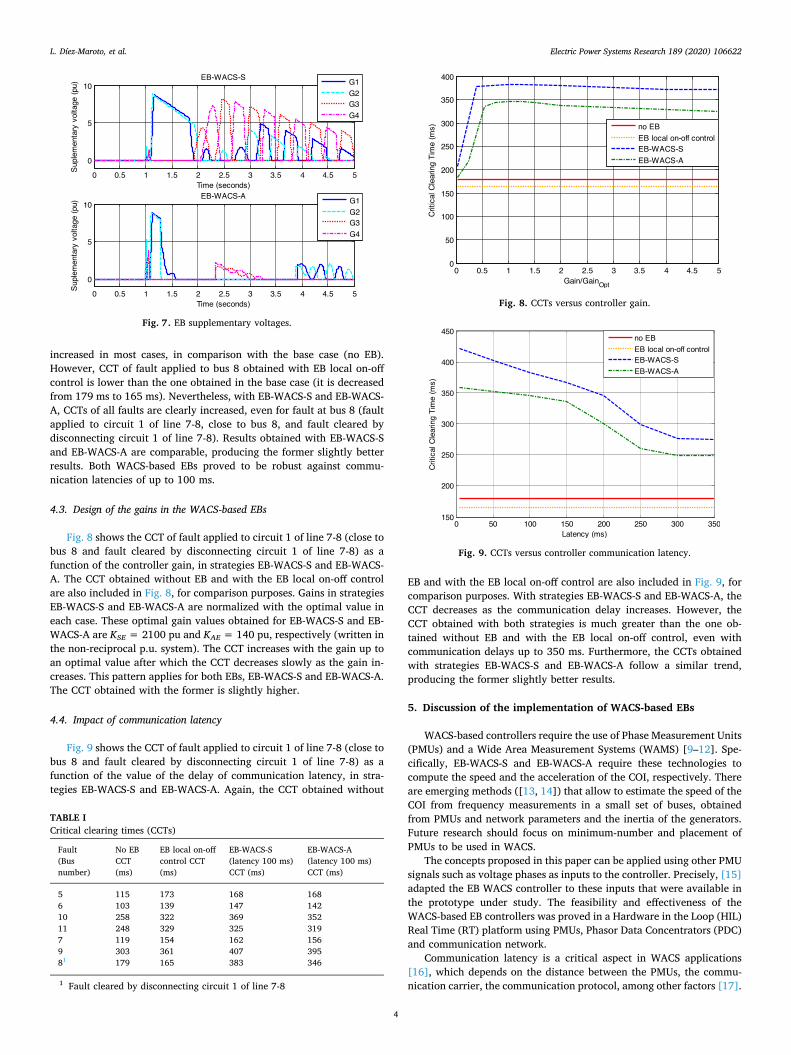
A three-phase-to-ground short circuit has been applied to circuit 1 of line 7-8 (close to bus 8) of the test system of Fig. 4, which is cleared by disconnecting the faulted circuit after 165 ms. Fig. 5 shows the speeds of generators G1 and G3 with respect to the COI, in the four cases analyzed. Fig. 6 shows the G1 generator trajectories in a ω-δ chart referred to the COI. With EB-WACS-S and EB-WACS-A, generators are pulled together during the first swing faster than with no EB or with EBs with local on-off control. Strategy EB-WACS-S seems to pull together the generators faster than EB-WACS-A. However, the latter produces a smoother response.
Fig. 7 shows the supplementary voltage of the EB when using strategies EB-WACS-S and EB-WACS-A. The latter control proves to be more efficient as the EB is active less time with a similar CCT. In other words, the size of the EB required by the EB-WACS-A is much lower than the one needed by the EB-WACS-S. This size reduction has a direct impact on the overall cost of the solution.
4.2. Critical clearing times (CCTs)
Table I depicts the CCTs of faults applied to different buses of the test system of Fig. 4. With the EB local on-off control, CCTs are
Fig. 4. Two-area test system [3].
Fig. 5. Speeds of generators 1 and 3 with respect to the speed of the COI.
Fig. 6. ω-δ chart of generator 1.
L. Díez-Maroto, et al. Electric Power Systems Research 189 (2020) 106622
3
increased in most cases, in comparison with the base case (no EB). However, CCT of fault applied to bus 8 obtained with EB local on-off control is lower than the one obtained in the base case (it is decreased from 179 ms to 165 ms). Nevertheless, with EB-WACS-S and EB-WACS- A, CCTs of all faults are clearly increased, even for fault at bus 8 (fault applied to circuit 1 of line 7-8, close to bus 8, and fault cleared by disconnecting circuit 1 of line 7-8). Results obtained with EB-WACS-S and EB-WACS-A are comparable, producing the former slightly better results. Both WACS-based EBs proved to be robust against commu-nication latencies of up to 100 ms.
4.3. Design of the gains in the WACS-based EBs
Fig. 8 shows the CCT of fault applied to circuit 1 of line 7-8 (close to bus 8 and fault cleared by disconnecting circuit 1 of line 7-8) as a function of the controller gain, in strategies EB-WACS-S and EB-WACS- A. The CCT obtained without EB and with the EB local on-off control are also included in Fig. 8, for comparison purposes. Gains in strategies EB-WACS-S and EB-WACS-A are normalized with the optimal value in each case. These optimal gain values obtained for EB-WACS-S and EB- WACS-A are KSE = 2100 pu and KAE = 140 pu, respectively (written in the non-reciprocal p.u. system). The CCT increases with the gain up to an optimal value after which the CCT decreases slowly as the gain in-creases. This pattern applies for both EBs, EB-WACS-S and EB-WACS-A. The CCT obtained with the former is slightly higher.
4.4. Impact of communication latency
Fig. 9 shows the CCT of fault applied to circuit 1 of line 7-8 (close to bus 8 and fault cleared by disconnecting circuit 1 of line 7-8) as a function of the value of the delay of communication latency, in stra-tegies EB-WACS-S and EB-WACS-A. Again, the CCT obtained without
EB and with the EB local on-off control are also included in Fig. 9, for comparison purposes. With strategies EB-WACS-S and EB-WACS-A, the CCT decreases as the communication delay increases. However, the CCT obtained with both strategies is much greater than the one ob-tained without EB and with the EB local on-off control, even with communication delays up to 350 ms. Furthermore, the CCTs obtained with strategies EB-WACS-S and EB-WACS-A follow a similar trend, producing the former slightly better results.
5. Discussion of the implementation of WACS-based EBs
WACS-based controllers require the use of Phase Measurement Units (PMUs) and a Wide Area Measurement Systems (WAMS) [9–12]. Spe-cifically, EB-WACS-S and EB-WACS-A require these technologies to compute the speed and the acceleration of the COI, respectively. There are emerging methods ([13, 14]) that allow to estimate the speed of the COI from frequency measurements in a small set of buses, obtained from PMUs and network parameters and the inertia of the generators. Future research should focus on minimum-number and placement of PMUs to be used in WACS.
The concepts proposed in this paper can be applied using other PMU signals such as voltage phases as inputs to the controller. Precisely, [15] adapted the EB WACS controller to these inputs that were available in the prototype under study. The feasibility and effectiveness of the WACS-based EB controllers was proved in a Hardware in the Loop (HIL) Real Time (RT) platform using PMUs, Phasor Data Concentrators (PDC) and communication network.
Communication latency is a critical aspect in WACS applications [16], which depends on the distance between the PMUs, the commu-nication carrier, the communication protocol, among other factors [17].
Fig. 7. EB supplementary voltages.
TABLE I Critical clearing times (CCTs)
Fault (Bus number)
No EB CCT (ms)
EB local on-off control CCT (ms)
EB-WACS-S (latency 100 ms) CCT (ms)
EB-WACS-A (latency 100 ms) CCT (ms)
5 115 173 168 168 6 103 139 147 142 10 258 322 369 352 11 248 329 325 319 7 119 154 162 156 9 303 361 407 395 81 179 165 383 346
1 Fault cleared by disconnecting circuit 1 of line 7-8
Fig. 8. CCTs versus controller gain.
Fig. 9. CCTs versus controller communication latency.
L. Díez-Maroto, et al. Electric Power Systems Research 189 (2020) 106622
4

Latency using modems over analog microwave channels is below 100 ms, whereas latency using fiber optic digital communications is below 50 ms ([11, 18]). Furthermore, according to the work in [18], the total communication delay is composed of two main components: (a) op-erational delay (calculations) and (b) communication latency (propa-gation of the information. Total communication delays within the range 50-80 ms were reported in [18]. Ref. [19] has reported occasional de-lays up to 300 ms in communications with a latency of 30 ms. However, standard deviations about average latencies are usually much lower. According to [20], the average latency on a fiber optic digital com-munication network was 20.6 ms with a standard deviation of 4.6 ms.
6. Conclusions
This paper proposed a WACS-based control strategy for Excitation Boosters (EBs) in synchronous machines, tailored to improve transient stability. In the proposed EB (so called EB-WACS-A), each synchronous machine compares its acceleration with the acceleration of the Center Of Inertia (COI), and it applies an additional excitation voltage pro-portional to this measurement. Results show that the proposed EB im-proves transient stability of multi-machine power systems, significantly. The proposed EB (EB-WACS-A) is compared with a previous EB pro-posed by the authors (EB-WACS-S), which uses generator speeds instead of generator accelerations. The comparison of WACS-based EBs ana-lyzes performance, design, implementation aspects and impact of communication latency.
The following conclusions have been obtained from this study:
• WACS-based EBs are more effective than local-based EBs, for tran-sient stability improvement.
• Results produced by EB-WACS-S and EB-WACS-A are comparable,
producing the former slightly better results. • Strategies EB-WACS-S and EB-WACS-A are robust against commu-
nication latency. • EB-WACS-S has the advantage that speed measurements are less
noisy than acceleration measurements. • EB-WACS-A has the advantage that the EBs are activated less time
during the transients than in EB-WACS-S. Therefore, the former is more cost effective than the latter.
• Taking all those factors into account, and considering that results of both EBs are comparable, the election between EB-WACS-S and EB- WACS-A should depend on a trade-off between cost and require-ments on noise filtering.
Declaration of Competing Interest
None.
Acknowledgements
Part of this work has been technically and financially supported by Alstom Power (currently GE Power), Birr, Switzerland. The authors of this paper greatly appreciate the support provided by Messrs. Chan, El- Merdaoui, Ginet, Malcher, Dr. Menzel and Dr. Sigrist. Dr. Díez-Maroto also acknowledges Dr. Cherkaoui for his guidance during his stay at the EPFL at the beginning of the investigation reported in this paper.
Dr. Renedo and Prof. Rouco also thank Madrid Regional Government for support through PRICAM-CM project, ref. S2013/ICE- 2933 and through PROMINT-CM project, ref. S2018/EMT-4366; and to the Spanish Government for support through RETOS projects ref. ENE2014-57760-C2-1R and ref. RTI2018-098865-B-C31.
Appendix. Lyapunov's theory applied to EBs
This section provides a summary of Lyapunov's stability theory in control systems [21, 22] and its application to transient stability analysis of EBs [8].
Given a nonlinear dynamic system =dx dt f x/ ( ), the equilibrium point x0is stable if there exists a function V(x) that verifies [23]:
> =V x x x V xdV x
dtx
( ) 0 , ( ) 0, and( ) 0
0 0
(6)
If these conditions are satisfied, V is called a Lyapunov's function. In a controlled power system = +dx dt f x g x u/ ( ) ( ) , the derivative of V reads [22]:
= + = +dVdt
V f x V g x u dVdt
dVdt
· ( ) · ( )· unctrl ctrl(7)
Assuming that a Lyapunov's function V exists for the non-controlled system (u=0), V will also be a Lyapunov's function of the controlled system if dVctrl/dt ≤ 0, which means that control law u improves transient stability [22].
A classical network-reduced model is used for theoretical analysis [21]:
=
= +
ddt
ddt H
P P HH
P
˜˜
˜ 12
kk
k
kmi k ei k
k
TCOI, ,
(8)
where k̃ and ˜k are, respectively, the rotor angle and the speed of generator k with respect to the COI:
= =˜ ; ˜k k COI k k COI (9)
where:
= ==
P P g E P P P’ ; ( )mi k m k kk k COIk
n
mi k ei k, ,2
1, ,
(10)
and
= = ==
P C E E bC sin( ˜ ) ; ’ ’ ; ˜ ˜ ˜ei k l
n
l kkl kl k l kl kl k l, 1 kl
(11)
L. Díez-Maroto, et al. Electric Power Systems Research 189 (2020) 106622
5

Ref. [21] showed that the following energy function of the power system verify Lyapunov's stability conditions (6):
= += = = = +
V H P C C12
2 ˜ ˜ cos ˜k
nk k
kinetic energyk
nmi k k k
n
l k
nkl kl
potential energy cons t12
1 ,0
1
1
10
0tan (12)
C0 is a constant chosen so that = = =V ( ˜ ˜ , ˜ 0) 0k k k0 , while V is positive for the rest of states [21].
Assuming a proportional relationship between the internal voltage of a generator, E′k, and the field voltage, EFD,k, the additional voltage ( =E K E·k FD k, ), the supplementary voltage will produce a variation on the internal voltage of the generator:
= +E E E’ ’ ’k k k0 (13)
Following the analysis of [8], dVctrl/dt can be written as:
= +=
= = +
dVdt
g E E E
E E E E b
(2 ’ ’ ’ ) ˜
( ’ ’ ’ ’ ) sin ˜ ˜
ctrl
k
n
kk k k k k
k
n
l k
n
k l k l kl kl k
1
0 2
1
1
1
0 0
(14)
without loss of generality, generator angles are arranged so that ˜ ˜k l if k < l. Control strategies for the EB, ΔE′k, that produce dVctrl/dt ≤ 0, contribute to improve transient stability.
References
[1] L. Díez-Maroto, L. Rouco, F. Fernández-Bernal, Fault ride through capability of round rotor synchronous generators: Review, analysis and discussion of European grid code requirements, Electr. Power Syst. Res. 40 (2016) 27–36.
[2] L. Rouco, K. Chan, J. Oesterheld, S. Keller, Recent evolution of European grid code requirements and its impact on turbogenerator design, Proc. IEEE/PES General Meeting, San Diego, CA, USA, 2012, pp. 1–9.
[3] A. Kundur, Power system stability and control, Mc Graw Hill, 1994. [4] R. Joho, “Static energising system for a generator and method for operation of such
an energising system,” World Patent WO 2006/045703 A1, May 4, 2006. [5] C. Ginet and L. Diez-Maroto, “Static exciter of a field winding and method for op-
erating the same,” Patent EP 2 288 017 A1, Feb. 23, 2011. [6] L. Díez-Maroto, L. Rouco, F. Fernández-Bernal, Modeling, sizing, and control of an
excitation booster for enhancement of synchronous generators fault ride-through capability: experimental validation, IEEE Trans. Energy Convers. 31 (4) (2016) 1304–1314.
[7] Y. Zhou, H. Huang, Z. Xu, W. Hua, F. Yang, S. Liu, Wide-area measurement system- based transient excitation boosting control to improve power system transient stability, IET Gener., Transm. Distrib. 9 (9) (2015) 845–854.
[8] L. Díez-Maroto, J. Renedo, L. Rouco, F. Fernández-Bernal, Lyapunov stability-based wide area control systems for excitation boosters in synchronous generators, IEEE Trans. Power Syst. 34 (1) (2019) 194–204.
[9] W. Sattinger, G. Giannuzzi, Monitoring continental Europe: an overview of WAM systems used in Italy and Switzerland, IEEE Power Energy Magazine 13 (5) (2015) 41–48.
[10] J. Bertsch, C. Carnal, D. Karlson, J. McDaniel, K. Vu, Wide-area protection and power system utilization, Proc. IEEE 93 (5) (2005) 997–1003.
[11] C.W. Taylor, D.C. Erickson, K.E. Martin, R.E. Wilson, V. Venkatasubramanian, WACS-wide-area stability and voltage control system: R&D and online demonstra-tion, Proc. IEEE 93 (2005) 892–906.
[12] M.S. Almas, L. Vanfretti, R.S. Singh, G.M. Jonsdottir, Vulnerability of
synchrophasor-based WAMPAC applications’ to time synchronization spoofing, IEEE Trans. Smart Grid 9 (5) (2018) 4601–4612.
[13] F. Milano, Rotor speed-free estimation of the frequency of the center of inertia, IEEE Trans. Power Syst. 33 (2018) 1153–1155.
[14] F. Milano, A. Ortega, Frequency divider, IEEE Trans. Power Syst. 32 (2) (2017) 1493–1501.
[15] L. Díez-Maroto, L. Vanfretti, M.S. Almas, G.M. Jónsdóttir, L. Rouco, A WACS ex-ploiting generator excitation boosters for power system transient stability en-hancement, Electr. Power Syst. Res. 148 (2017) 245–253.
[16] Y. Chompoobutrgool, L. Vanfretti, Analysis of time delay effects for wide-area damping control design using dominant path signals, Proc. IEEE/PES General Meeting, National Harbor, MD, USA, 2014, pp. 1–5.
[17] N.T. Anh, L. Vanfretti, J. Driesen, D. Van Hertem, A quantitative method to de-termine ICT delay requirements for wide-area power system damping controllers, IEEE Trans. Power Syst. 30 (4) (2015) 2023–2030.
[18] F. Zhang, Y. Sun, L. Cheng, X. Li, J.H. Chow, W. Zhao, Measurement and modeling of delays in wide-area closed-loop control systems, IEEE Trans. Power Syst. 30 (5) (2015) 2426–2433.
[19] K. Uhlen, L. Vanfretti, M.M. de Oliveira, A.B. Leirbukt, V.H. Aarstrand, J.O. Gjerde, Wide-area power oscillation damper implementation and testing in the Norwegian transmission network, Proc. IEEE/PES General Meeting, San Diego, California, USA, 2012, pp. 1–7.
[20] J.W. Stahlhut, T.J. Browne, G.T. Heydt, V. Vittal, Latency viewed as a stochastic process and its impact on wide area power system control signals, IEEE Trans. Power Syst. 23 (1) (2008) 84–91.
[21] M.A. Pai, Energy Function Analysis for Power System Stability, Kluwer Academic Publishers, Boston, 1989.
[22] M. Ghandhari, G. Andersson, I.A. Hiskens, Control lyapunov functions for con-trollable series devices, IEEE Trans. Power Syst. 16 (4) (2001) 694–989.
[23] J. Machowski, J.W. Bialek, S. Robak, J.R. Bumby, Excitation system for use with synchronous generators, IEE Proceed. – Gener. Transm. Distrib. 145 (5) (2001) 537–546.
L. Díez-Maroto, et al. Electric Power Systems Research 189 (2020) 106622
6