KAESER DN-C Series Boosters (P-481-ED-2-20_17-30700)
20
DN C (SFC) Series Flow rate 2.9 to 19.6 m³/min – Rated motor power 22 to 45 kW Initial pressure 3 to 13 bar – Final pressure 10 to 45 bar www.kerrcompressors.co.uk Boosters
-
Upload
khangminh22 -
Category
Documents
-
view
5 -
download
0
Transcript of KAESER DN-C Series Boosters (P-481-ED-2-20_17-30700)
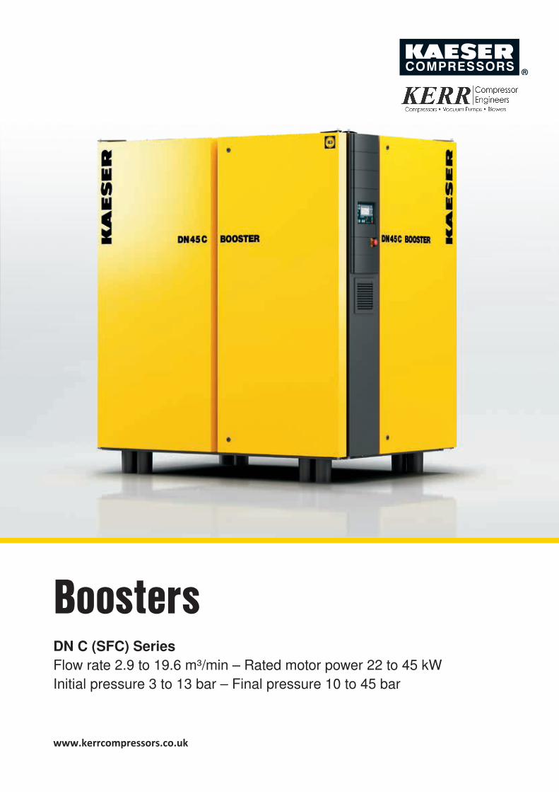
DN C (SFC) Series Flow rate 2.9 to 19.6 m³/min – Rated motor power 22 to 45 kW Initial pressure 3 to 13 bar – Final pressure 10 to 45 bar
www.kerrcompressors.co.uk
Boosters
Energy-efficientPremium Efficiency (IE3) drive motors, fitted as standard, contribute to cost-effective energy usage, as does the generously-dimensioned axial fan, which also serves to ensure reliable temperature control. In SFC versions, the compressor flow rate is matched to the actual air demand of the application in question, which means that only as much energy is consumed as is needed to produce the exact amount of compressed air required. This makes the system as efficient as it is possible to be – especially in the partial load range. The compressor switches to Idle if air demand drops below the control range; compressor speed and therefore energy consumption are consequently kept to a minimum, achieving savings of up to 10%.
Service-friendlyAll maintenance-relevant components, such as cylinders and venting valves, filters, condensate separators, oil drain and filler openings are easily accessible thanks to large maintenance doors. The removable panel on the cooler side allows simple belt changes and provides easy access to the cooler.
Perfect partnersDN C series boosters are the perfect team players for every compressed air station, not to be outdone by their rotary screw “colleagues”: optionally available with air or water-cooling, all units are delivered ready for perfect performance in ambient temperatures up to +45 °C. The same also applies for their networking capabilities: the SIGMA CONTROL 2 machine controller ensures full connectivity, both within the air station and with the SIGMA AIR MANAGER 4.0 master controller – and therefore with Industrie 4.0 environments.
All-round reliabilityThe integrated SIGMA CONTROL 2 controller automat-ically monitors all key values: initial and final pressure, block discharge temperature of the individual cylinders, drive motor winding temperature, oil pressure and level, compressed air discharge temperature, compressor and control cabinet fans and status of maintenance doors (open/closed).
“Plug & Work” complete systemsKAESER’s integrated booster systems are completely unique: all application-relevant components are provided and configured ex-works for delivery of a system that is ready for immediate operation.
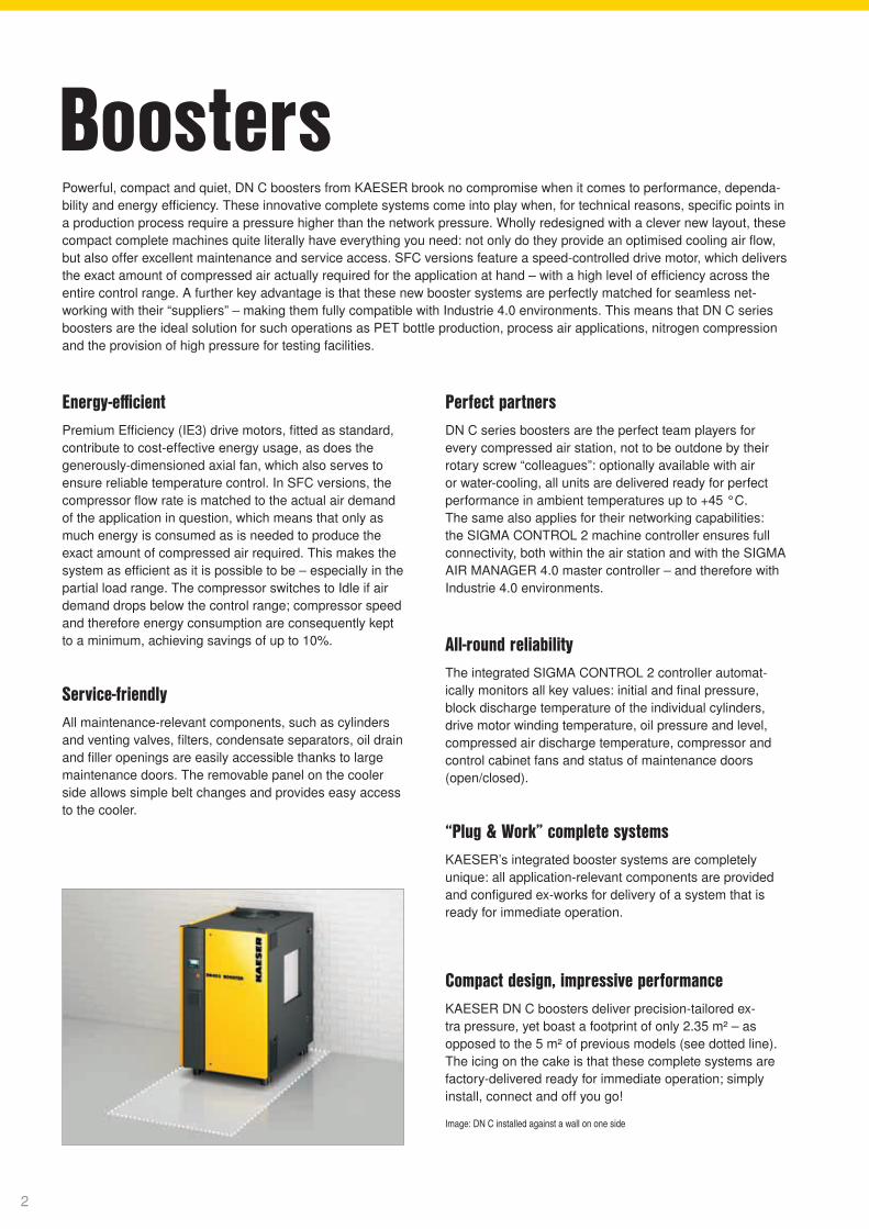
Powerful, compact and quiet, DN C boosters from KAESER brook no compromise when it comes to performance, dependa-bility and energy efficiency. These innovative complete systems come into play when, for technical reasons, specific points in a production process require a pressure higher than the network pressure. Wholly redesigned with a clever new layout, these compact complete machines quite literally have everything you need: not only do they provide an optimised cooling air flow, but also offer excellent maintenance and service access. SFC versions feature a speed-controlled drive motor, which delivers the exact amount of compressed air actually required for the application at hand – with a high level of efficiency across the entire control range. A further key advantage is that these new booster systems are perfectly matched for seamless net-working with their “suppliers” – making them fully compatible with Industrie 4.0 environments. This means that DN C series boosters are the ideal solution for such operations as PET bottle production, process air applications, nitrogen compression and the provision of high pressure for testing facilities.
Boosters
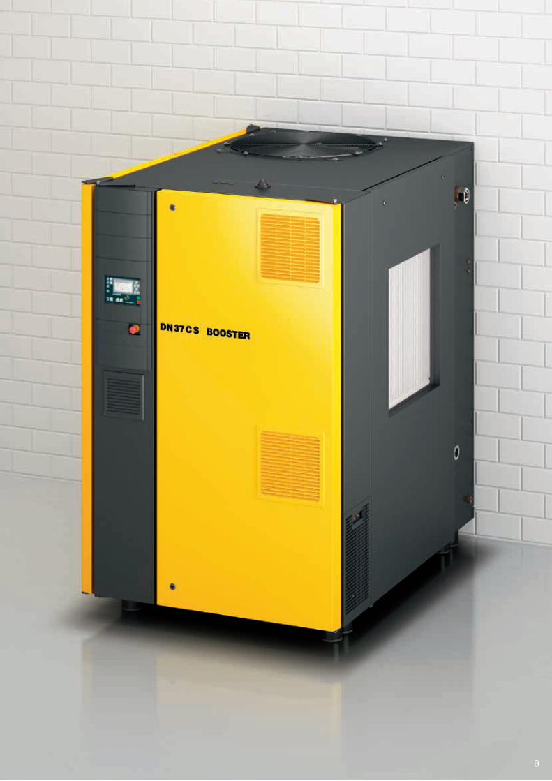
Compact design, impressive performanceKAESER DN C boosters deliver precision-tailored ex-tra pressure, yet boast a footprint of only 2.35 m² – as opposed to the 5 m² of previous models (see dotted line). The icing on the cake is that these complete systems are factory-delivered ready for immediate operation; simply install, connect and off you go!
Image: DN C installed against a wall on one side
2
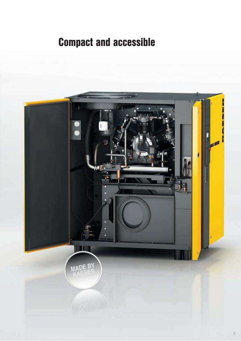
Compact and accessible
3
4
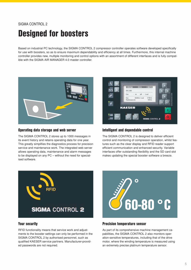
60-80 °CYour securityRFID functionality means that service work and adjust-ments to the booster settings can only be performed in the SIGMA CONTROL 2 by authorised personnel, such as qualified KAESER service partners. Manufacturer-provid-ed passwords are not required.
Precision temperature sensorAs part of its comprehensive machine management ca-pabilities, the SIGMA CONTROL 2 also monitors oper-ation-sensitive temperatures, including that of the drive motor, where the winding temperature is measured using an extremely precise platinum temperature sensor.
Operating data storage and web serverThe SIGMA CONTROL 2 stores up to 1000 messages in its event history and retains operating data for one year. This greatly simplifies the diagnostics process for precision service and maintenance work. The integrated web server allows operating data, maintenance and alarm messages to be displayed on any PC – without the need for special-ised software.
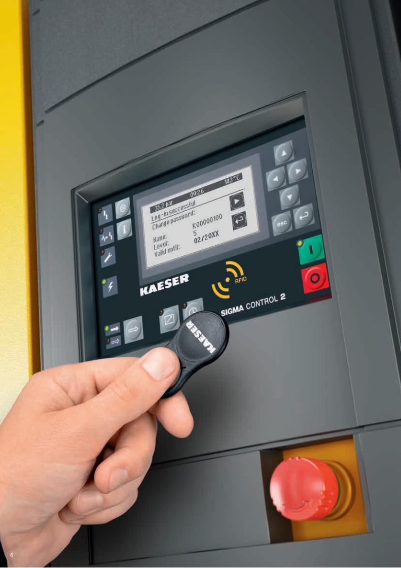
Intelligent and dependable controlThe SIGMA CONTROL 2 is designed to deliver efficient control and monitoring of compressor operation, whilst fea-tures such as the clear display and RFID reader support efficient communication and enhanced security. Variable interfaces offer outstanding flexibility and the SD card slot makes updating the special booster software a breeze.
Designed for boostersSIGMA CONTROL 2
Based on industrial PC technology, the SIGMA CONTROL 2 compressor controller operates software developed specifically for use with boosters, so as to ensure maximum dependability and efficiency at all times. Furthermore, this internal machine controller provides new, multiple monitoring and control options with an assortment of different interfaces and is fully compat-ible with the SIGMA AIR MANAGER 4.0 master controller.
5

Compressed air aftercoolerThe unvented compressed air aftercooler ensures short switching cycles in partial load operation, thereby saving energy. Furthermore, the generously-dimensioned alumin-ium cooling surfaces reduce the compressed air discharge temperature to near ambient.
Service-friendlyJust like the air filters, which are changed from the front of the unit, all other maintenance parts are easily accessible. Time-saving features such as these streamline and accel-erate maintenance and service work, which translates into lower operating costs and increased availability.
Simply service-friendly.Design is in the details
6
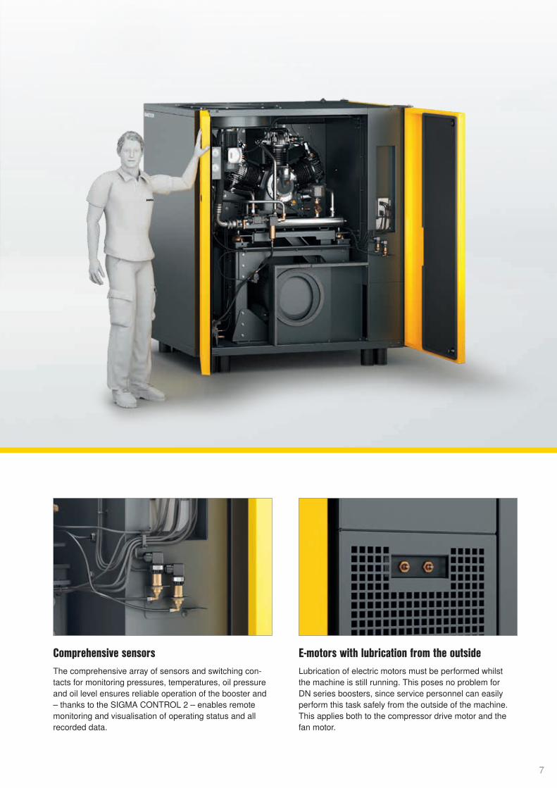
Comprehensive sensorsThe comprehensive array of sensors and switching con-tacts for monitoring pressures, temperatures, oil pressure and oil level ensures reliable operation of the booster and – thanks to the SIGMA CONTROL 2 – enables remotemonitoring and visualisation of operating status and allrecorded data.
E-motors with lubrication from the outsideLubrication of electric motors must be performed whilst the machine is still running. This poses no problem for DN series boosters, since service personnel can easily perform this task safely from the outside of the machine. This applies both to the compressor drive motor and the fan motor.
7
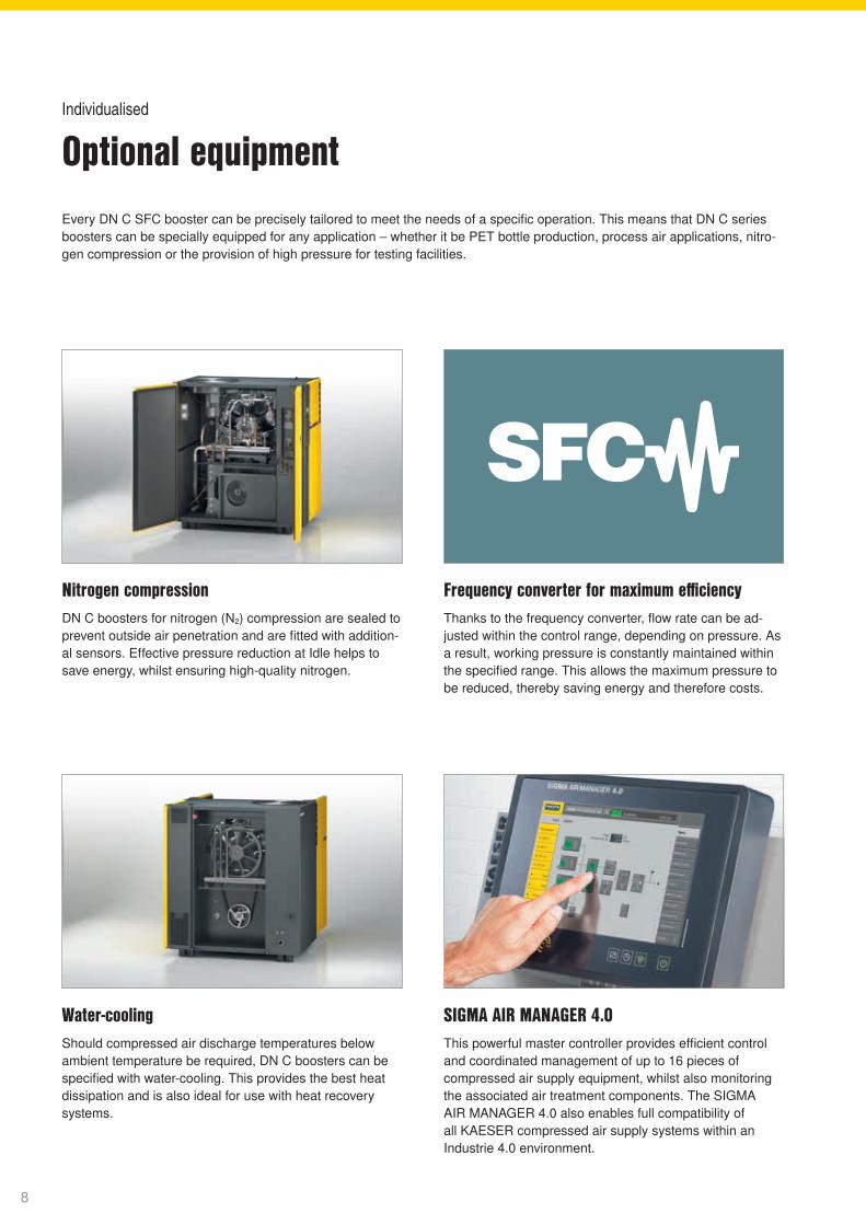
Water-coolingShould compressed air discharge temperatures below ambient temperature be required, DN C boosters can be specified with water-cooling. This provides the best heat dissipation and is also ideal for use with heat recovery systems.
Nitrogen compressionDN C boosters for nitrogen (N2) compression are sealed to prevent outside air penetration and are fitted with addition-al sensors. Effective pressure reduction at Idle helps to save energy, whilst ensuring high-quality nitrogen.
Frequency converter for maximum efficiencyThanks to the frequency converter, flow rate can be ad-justed within the control range, depending on pressure. As a result, working pressure is constantly maintained within the specified range. This allows the maximum pressure to be reduced, thereby saving energy and therefore costs.
SIGMA AIR MANAGER 4.0This powerful master controller provides efficient control and coordinated management of up to 16 pieces of compressed air supply equipment, whilst also monitoring the associated air treatment components. The SIGMA AIR MANAGER 4.0 also enables full compatibility of all KAESER compressed air supply systems within an Industrie 4.0 environment.
Every DN C SFC booster can be precisely tailored to meet the needs of a specific operation. This means that DN C series boosters can be specially equipped for any application – whether it be PET bottle production, process air applications, nitro-gen compression or the provision of high pressure for testing facilities.
Optional equipmentIndividualised
8
9

Example savings calculation for hot air heat recovery from fuel oil (DN 45C)
Maximum available heat capacity: 49.9 kW
Calorific value per litre of fuel oil: 9,861 kWh/l 1 kW = 1 MJ/h x 3.6
Fuel oil heating efficiency: 0.9
Price per litre of fuel oil:
0.60 €/l
x 0.60 €/l =
€ 6,747 per year
Cost savingsCost savings49.9 kW x 2000 h
0.9 x 9,861 kWh/l
10
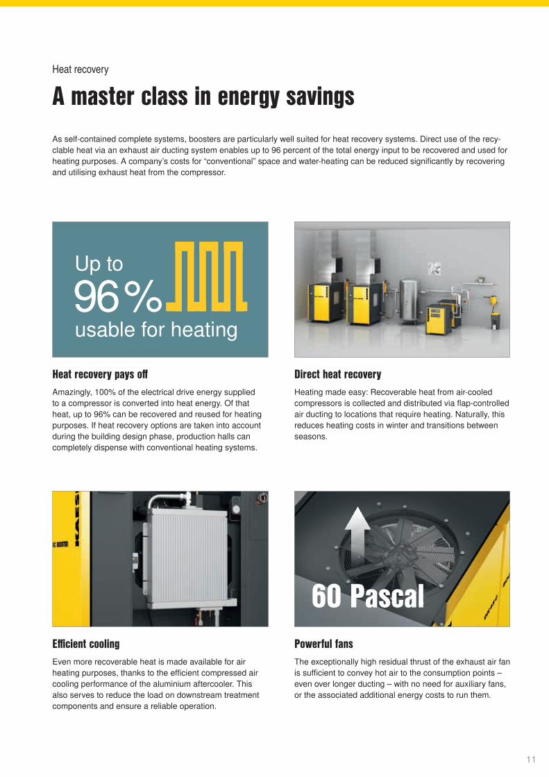
Up to
usable for heating96 %
60 Pascal60 Pascal
Heat recovery pays offAmazingly, 100% of the electrical drive energy supplied to a compressor is converted into heat energy. Of that heat, up to 96% can be recovered and reused for heating purposes. If heat recovery options are taken into account during the building design phase, production halls can completely dispense with conventional heating systems.
Efficient coolingEven more recoverable heat is made available for air heating purposes, thanks to the efficient compressed air cooling performance of the aluminium aftercooler. This also serves to reduce the load on downstream treatment components and ensure a reliable operation.
Direct heat recoveryHeating made easy: Recoverable heat from air-cooled compressors is collected and distributed via flap-controlled air ducting to locations that require heating. Naturally, this reduces heating costs in winter and transitions between seasons.
Powerful fansThe exceptionally high residual thrust of the exhaust air fan is sufficient to convey hot air to the consumption points – even over longer ducting – with no need for auxiliary fans, or the associated additional energy costs to run them.
A master class in energy savingsHeat recovery
As self-contained complete systems, boosters are particularly well suited for heat recovery systems. Direct use of the recy-clable heat via an exhaust air ducting system enables up to 96 percent of the total energy input to be recovered and used for heating purposes. A company’s costs for “conventional” space and water-heating can be reduced significantly by recovering and utilising exhaust heat from the compressor.
11

Compressed air supply systems that continue to deliver energy efficiency and reliability over the long term are far more than the sum of their compressors and compressed air treatment components. Only a true system provider is
capable of making the whole greater than the individual parts, by effectively ensuring harmonious coordination of all components, precisely tailored to a user’s individual requirements.
Image: Compressed air station: Low and high pressure
Optimally adapted, holistic solutionsCompressed air stations with boosters
12
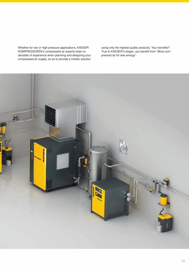
Whether for low or high-pressure applications, KAESER KOMPRESSOREN’s compressed air experts draw on decades of experience when planning and designing your compressed air supply, so as to provide a holistic solution
using only the highest quality products. Your benefits? True to KAESER’s slogan, you benefit from “More com-pressed air for less energy”.
13

Optimised cooling air flowClever temperature management
KAESER PET AIRThis all-in-one booster system combines blower and control air in a single, turnkey unit. A rotary screw com-pressor, blower air booster, controller and compressed air treatment components are all installed on a single base frame – ready for immediate operation. SIGMA PET AIR is available for flow rates up to 46.2 m³/min and with blower air up to 45 bar. All with the outstanding reliability, cost- effectiveness and compressed air quality you expect from KAESER.
DN C boosters feature separate cooling air flows for compressor block, drive motor and control cabinet, which are taken in through openings in the right-hand side of the enclosure. Once they have been used for cooling, the streams are combined, then blown up and out through the exhaust air outlet in the top of the enclosure. This
clever design reliably prevents cool inlet air from mixing with warm exhaust air – for enhanced efficiency. Thermal overload is therefore kept to a minimum and a separate, energy-intensive cooling system for idling is therefore only necessary under extreme conditions.
▬ Cooling air inlet: Aftercooler and compressor cooling ▬ Compressed air outlet
14
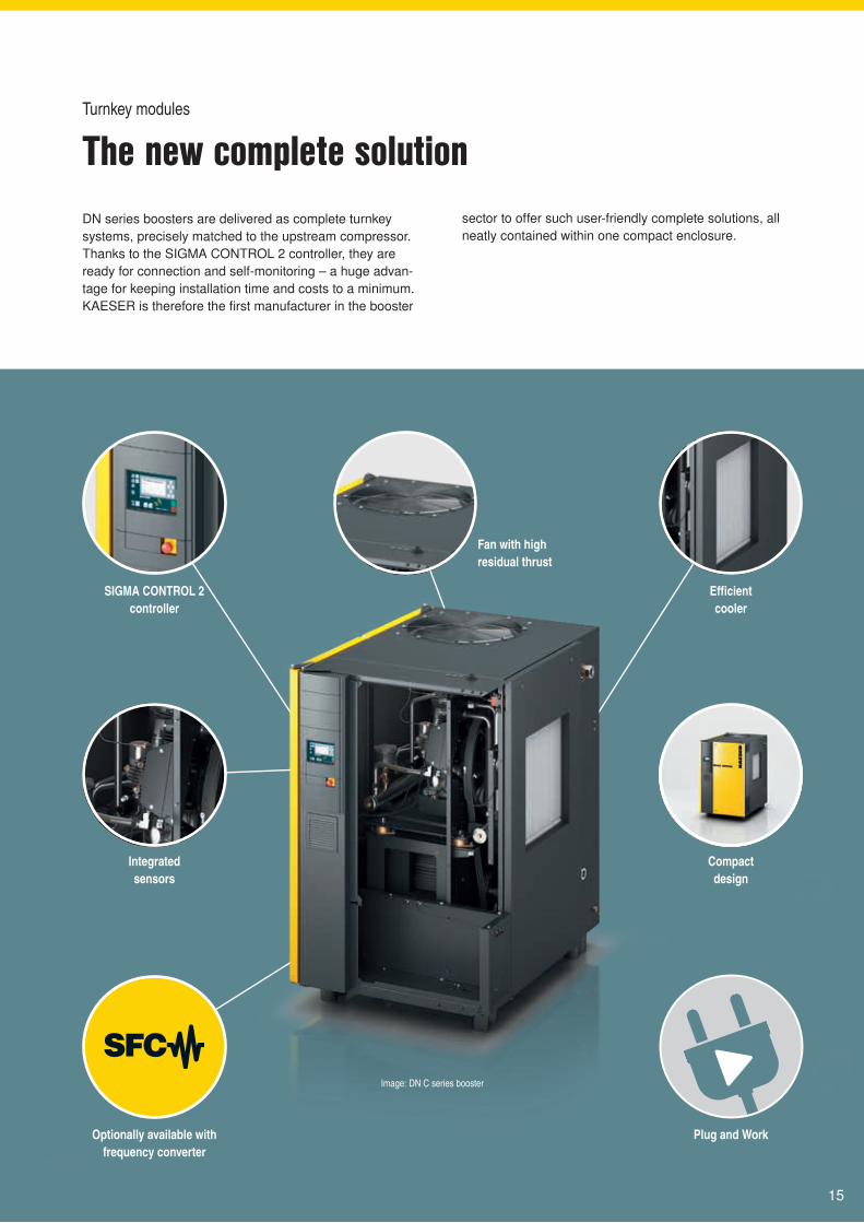
The new complete solutionTurnkey modules
SIGMA CONTROL 2 controller
Compact design
Integrated sensors
Efficient cooler
Fan with high residual thrust
Plug and WorkOptionally available with frequency converter
Image: DN C series booster
DN series boosters are delivered as complete turnkey systems, precisely matched to the upstream compressor. Thanks to the SIGMA CONTROL 2 controller, they are ready for connection and self-monitoring – a huge advan-tage for keeping installation time and costs to a minimum. KAESER is therefore the first manufacturer in the booster
sector to offer such user-friendly complete solutions, all neatly contained within one compact enclosure.
15
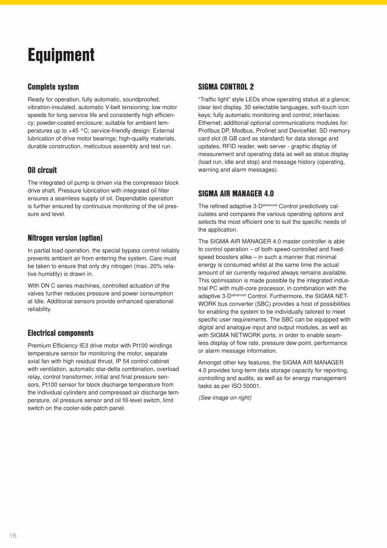
Complete systemReady for operation, fully automatic, soundproofed, vibration-insulated, automatic V-belt tensioning; low motor speeds for long service life and consistently high efficien-cy; powder-coated enclosure; suitable for ambient tem-peratures up to +45 °C; service-friendly design: External lubrication of drive motor bearings; high-quality materials, durable construction, meticulous assembly and test run.
Oil circuitThe integrated oil pump is driven via the compressor block drive shaft. Pressure lubrication with integrated oil filter ensures a seamless supply of oil. Dependable operation is further ensured by continuous monitoring of the oil pres-sure and level.
Nitrogen version (option)In partial load operation, the special bypass control reliably prevents ambient air from entering the system. Care must be taken to ensure that only dry nitrogen (max. 20% rela-tive humidity) is drawn in.
With DN C series machines, controlled actuation of the valves further reduces pressure and power consumption at Idle. Additional sensors provide enhanced operational reliability.
Electrical componentsPremium Efficiency IE3 drive motor with Pt100 windings temperature sensor for monitoring the motor, separate axial fan with high residual thrust, IP 54 control cabinet with ventilation, automatic star-delta combination, overload relay, control transformer, initial and final pressure sen-sors, Pt100 sensor for block discharge temperature from the individual cylinders and compressed air discharge tem-perature, oil pressure sensor and oil fill-level switch, limit switch on the cooler-side patch panel.
SIGMA CONTROL 2“Traffic light” style LEDs show operating status at a glance; clear text display, 30 selectable languages, soft-touch icon keys; fully automatic monitoring and control; interfaces: Ethernet; additional optional communications modules for: Profibus DP, Modbus, Profinet and DeviceNet. SD memory card slot (8 GB card as standard) for data storage and updates; RFID reader, web server - graphic display of measurement and operating data as well as status display (load run, idle and stop) and message history (operating, warning and alarm messages).
SIGMA AIR MANAGER 4.0The refined adaptive 3-Dadvanced Control predictively cal-culates and compares the various operating options and selects the most efficient one to suit the specific needs of the application.
The SIGMA AIR MANAGER 4.0 master controller is able to control operation – of both speed-controlled and fixed-speed boosters alike – in such a manner that minimal energy is consumed whilst at the same time the actual amount of air currently required always remains available. This optimisation is made possible by the integrated indus-trial PC with multi-core processor, in combination with the adaptive 3-Dadvanced Control. Furthermore, the SIGMA NET-WORK bus converter (SBC) provides a host of possibilities for enabling the system to be individually tailored to meet specific user requirements. The SBC can be equipped with digital and analogue input and output modules, as well as with SIGMA NETWORK ports, in order to enable seam-less display of flow rate, pressure dew point, performance or alarm message information.
Amongst other key features, the SIGMA AIR MANAGER 4.0 provides long-term data storage capacity for reporting, controlling and audits, as well as for energy management tasks as per ISO 50001.
(See image on right)
Equipment
16
Control centre
D2
D1
74.9221.60
C1
C2
C3
CT1
F1
F2
R1 DHS1
F3
F4
i
PowerVolumetric fl ow rate
kWm³/min
Status
Messages
Monitoring
Energy & costs
Control
SAM 4.0 Logic
Time control
Initial start-up
Confi guration
Contact
C1 - DN 37 C
C2 - DN 37 C
C3 - N 1100 - G
Dryer
Filter
Air receiver
Condensate treatment
Status - StationStation
SIGMA AIR MANAGER 4.0 4 Manual 35.10 bar
Maintenance
Control valves
Compressors
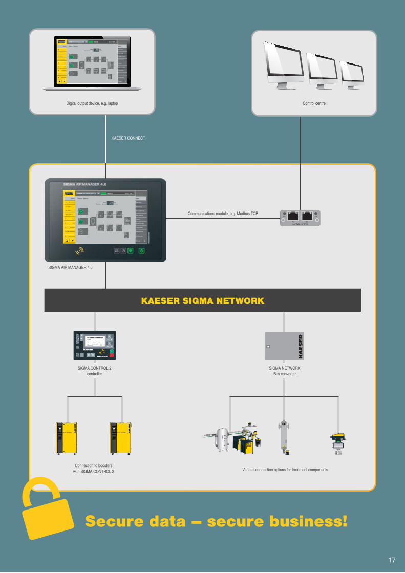
KAESER SIGMA NETWORK
SIGMA NETWORK Bus converter
Connection to boosters with SIGMA CONTROL 2 Various connection options for treatment components
SIGMA AIR MANAGER 4.0
Communications module, e.g. Modbus TCP
KAESER CONNECT
Digital output device, e.g. laptop Control centre
Secure data – secure business!
SIGMA CONTROL 2 controller
17
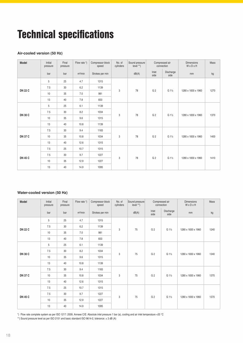
Technical specifications
*) Flow rate complete system as per ISO 1217: 2009, Annexe C/E: Absolute inlet pressure 1 bar (a), cooling and air inlet temperature +20 °C**) Sound pressure level as per ISO 2151 and basic standard ISO 9614-2, tolerance: ± 3 dB (A)
Water-cooled version (50 Hz)
Air-cooled version (50 Hz)
Model Initial pressure
Final pressure
Flow rate *) Compressor block speed
No. of cylinders
Sound pressurelevel **)
Compressed air connection
DimensionsW x D x H
Mass
bar bar m³/min Strokes per min dB(A) Inlet side
Discharge side mm kg
DN 22 C
5 25 4.7 1315
3 78 G 2 G 1½ 1280 x 1830 x 1960 12707.5 30 6.2 1139
10 35 7.0 981
13 40 7.8 833
DN 30 C
5 25 6.1 1139
3 78 G 2 G 1½ 1280 x 1830 x 1960 13707.5 30 8.2 1034
10 35 9.6 1315
13 40 10.8 1139
DN 37 C
7.5 30 9.4 1183
3 78 G 2 G 1½ 1280 x 1830 x 1960 140010 35 10.8 1034
13 40 12.6 1315
DN 45 C
7.5 25 10.7 1315
3 78 G 2 G 1½ 1280 x 1830 x 1960 14107.5 30 9.7 1227
10 35 12.9 1227
13 40 14.9 1095
Model Initial pressure
Final pressure
Flow rate *) Compressor block speed
No. of cylinders
Sound pressurelevel **)
Compressed air connection
DimensionsW x D x H
Mass
bar bar m³/min Strokes per min dB(A) Inlet side
Discharge side mm kg
DN 22 C
5 25 4.7 1315
3 75 G 2 G 1½ 1280 x 1830 x 1960 12407.5 30 6.2 1139
10 35 7.0 981
13 40 7.8 833
DN 30 C
5 25 6.1 1139
3 75 G 2 G 1½ 1280 x 1830 x 1960 13407.5 30 8.2 1034
10 35 9.6 1315
13 40 10.8 1139
DN 37 C
7.5 30 9.4 1183
3 75 G 2 G 1½ 1280 x 1830 x 1960 137010 35 10.8 1034
13 40 12.6 1315
DN 45 C
7.5 25 10.7 1315
3 75 G 2 G 1½ 1280 x 1830 x 1960 13707.5 30 9.7 1227
10 35 12.9 1227
13 40 14.9 1095
18
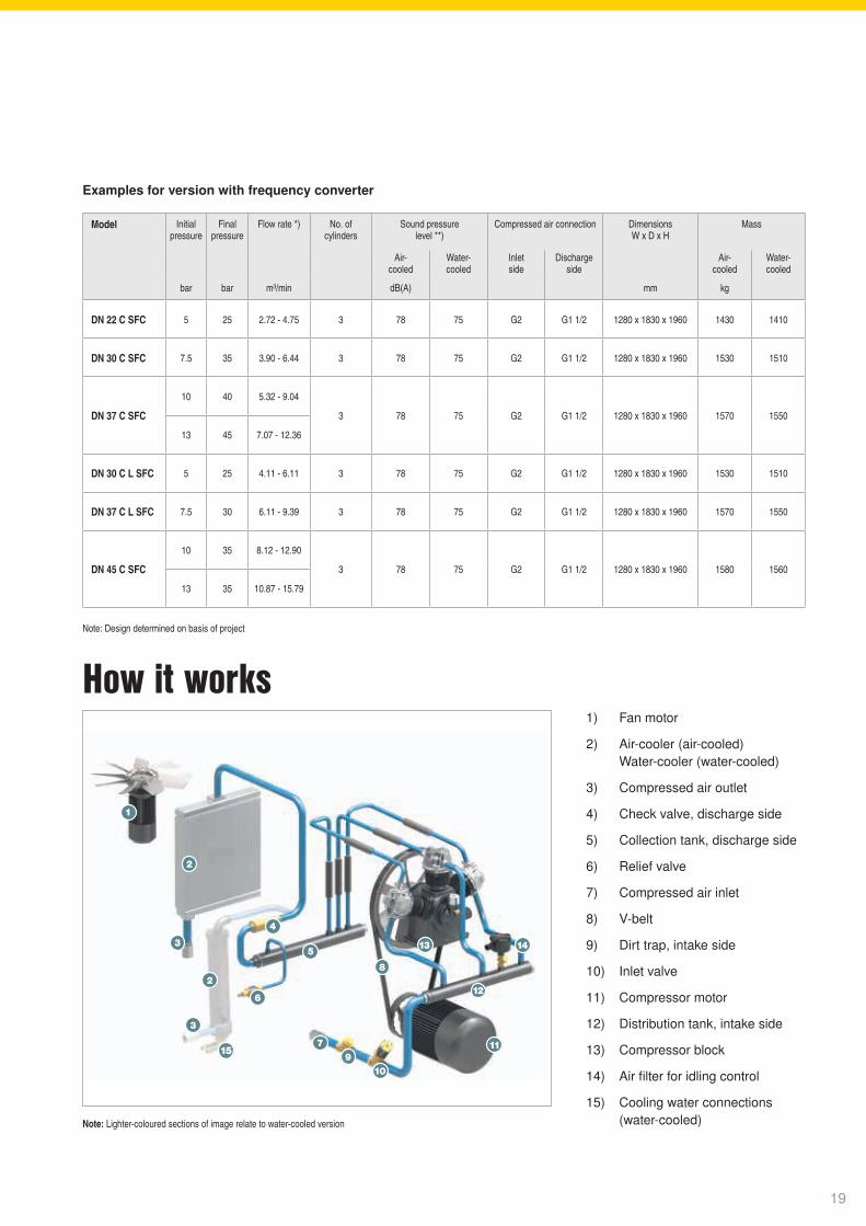
Examples for version with frequency converter
Model Initial pressure
Final pressure
Flow rate *) No. of cylinders
Sound pressure level **)
Compressed air connection DimensionsW x D x H
Mass
Air- cooled
Water- cooled
Inlet side
Discharge side
Air- cooled
Water- cooled
bar bar m³/min dB(A) mm kg
DN 22 C SFC 5 25 2.72 - 4.75 3 78 75 G2 G1 1/2 1280 x 1830 x 1960 1430 1410
DN 30 C SFC 7.5 35 3.90 - 6.44 3 78 75 G2 G1 1/2 1280 x 1830 x 1960 1530 1510
DN 37 C SFC
10 40 5.32 - 9.04
3 78 75 G2 G1 1/2 1280 x 1830 x 1960 1570 1550
13 45 7.07 - 12.36
DN 30 C L SFC 5 25 4.11 - 6.11 3 78 75 G2 G1 1/2 1280 x 1830 x 1960 1530 1510
DN 37 C L SFC 7.5 30 6.11 - 9.39 3 78 75 G2 G1 1/2 1280 x 1830 x 1960 1570 1550
DN 45 C SFC
10 35 8.12 - 12.90
3 78 75 G2 G1 1/2 1280 x 1830 x 1960 1580 1560
13 35 10.87 - 15.79
How it works1) Fan motor
2) Air-cooler (air-cooled) Water-cooler (water-cooled)
3) Compressed air outlet
4) Check valve, discharge side
5) Collection tank, discharge side
6) Relief valve
7) Compressed air inlet
8) V-belt
9) Dirt trap, intake side
10) Inlet valve
11) Compressor motor
12) Distribution tank, intake side
13) Compressor block
14) Air filter for idling control
15) Cooling water connections (water-cooled)Note: Lighter-coloured sections of image relate to water-cooled version
Note: Design determined on basis of project
19
The world is our homeAs one of the world’s largest manufacturers of compressors, blowers and compressed air systems, KAESER KOMPRESSOREN is represented throughout the world by a comprehensive network of branches, subsidiaries and authorised distribution partners in over 140 countries.
By offering innovative, effi cient and reliable products and services, KAESER KOMPRESSOREN’s experienced consultants and engineers work in close partnership with customers to enhance their competitive edge and to develop progressive system concepts that continuously push the boundaries of performance and technology. Moreover, decades of knowledge and expertise from this industry-leading systems provider are made available to each and every customer via the KAESER group’s advanced global IT network.
These advantages, coupled with KAESER’s worldwide service organisation, ensure that every product operates at peak performance at all times, whilst providing maximum availability.
P-48
1ED
Spe
cifica
tions
sub
ject
to c
hang
e wi
thou
t not
ice
.2/2
0
Kerr Compressor Engineers (EK) Ltd37 Fairfield Place, College Milton, East Kilbride, Glasgow G74 5LP Tel: 01355 248 222 • [email protected] www.kerrcompressors.co.uk
Follow us on..................

![“La formación de la clase política liberal en España (1833-1868)”, Historia contemporánea (Bilbao), núm. 23 (2001), pp. 445-481. [ISSN 1130-2402]](https://static.fdokumen.com/doc/165x107/6329aee67a8ec9c5800309d2/la-formacion-de-la-clase-politica-liberal-en-espana-1833-1868-historia.jpg)