
Relays & Volume Boosters - Marsh Bellofram
20
www.marshbellofram.com • 800.727.5646 37 Air Cylinders www.marshbellofram.com • 800.727.5646 37 Relays / Volume Boosters Relays & Volume Boosters Type 20 Type 20 HR Type 20 EX HR Type 72 Type 72 HR Type 75 Type 75 HR Type 79 Type 79 HR
-
Upload
khangminh22 -
Category
Documents
-
view
0 -
download
0
Transcript of Relays & Volume Boosters - Marsh Bellofram

www.marshbellofram.com • 800.727.5646 37
Air
Cylin
ders
www.marshbellofram.com • 800.727.5646 37
Rel
ays
/ Volu
me
Boost
ers
Relays & Volume Boosters
Type 20
Type 20 HR
Type 20 EX HR
Type 72
Type 72 HR
Type 75
Type 75 HR
Type 79
Type 79 HR

38 800.727.5646 • www.marshbellofram.com
Air C
ylin
ders
38 800.727.5646 • www.marshbellofram.com
Relays / V
olu
me B
oosters
Type 20 Type 20 HR Type 20 EX HR
Maximum Supply Pressure
150 PSig (10.3 BAR) 150 PSig (10.3 BAR) 150 PSig (10.3 BAR)
Sensitivity 1/8" H2O (3.2mm) 1/8" H
2O (3.2mm) 1/8" H
2O (3.2mm)
Supply Pressure Sensitivity
0.005 PSig (0.35 mBAR)per 25 PSig (1.7 BAR)
change in supply pressure
0.005 PSig (0.35 mBAR)per 25 PSig (1.7 BAR)
change in supply pressure
0.005 PSig (0.35 mBAR)per 25 PSig (1.7 BAR)
change in supply pressure
Flow Capacity
14 SCFM (400 LPM)@ 20 PSig (1.4 BAR) signal and 100 PSig
(6.9 BAR) supply
14 SCFM (400 LPM)@ 20 psig (1.4 BAR)signal and 100 PSig
(6.9 BAR) supply
14 SCFM (400 LPM)@ 20 PSig (1.4 BAR)signal and 100 PSig
(6.9 BAR) supply
Exhaust Capacity
2 SCFM (55 LPM) @ 5 PSig (0.35 BAR)
above a 20 PSig (1.4 BAR) setpoint
10 SCFM (285 LPM) @ 5 PSig (0.35 BAR)
above a 20 PSig (1.4 BAR) setpoint
15 SCFM (425 LPM) @ 5 PSig (0.35 BAR)
above a 20 PSig (1.4 BAR) setpoint
Temperature Limits -20 to 160˚F (-29 to 71˚C)
-20 to 160˚F (-29 to 71˚C)
-20 to 160˚F (-29 to 71˚C)
Air Consumption 8 SCFH (4 LPM) 8 SCFH (4 LPM) 8 SCFH (4 LPM)
Port Size 1/8", 1/4", 3/8" NPT, BSPP, BSPT
1/8", 1/4", 3/8" NPT, BSPP, BSPT
1/8", 1/4", 3/8"NPT, BSPP, BSPT
Output Pressure Range
2-120 PSig (0.1 – 8.3 BAR)
2-120 PSig (0.1 – 8.3 BAR)
2-120 PSig (0.1 – 8.3 BAR)
Maximum Signal 120 PSig (8.3 BAR)
120 PSig (8.3 BAR)
120 PSig (8.3 BAR)
Weight 1.4 lb. (0.6 kg.) 1.4 lb. (0.6 kg.) 1.4 lb. (0.6 kg.)
Ratio of Accuracy for a 12 PSig span
<0.5% <0.5% <0.5%
Type 72 and Typo 72 HR Flow Curves - 1/4
90.0 6.2
80.0 5.5
70.0 4.8
60.0 4.1
50.0 3.4
40.0 2.8
30.0 2.1
20.0 1.4
10.0 0.7
0 0
Regu
late
d PR
essu
Re
SCFM 0.0 10.0 20.0 30.0 40.0 50.0 60.0 70.0 80.0 90.0 LPM 0 300 575 850 1150 1400 1700 2000 2550 2550
FoRwaRd Flow
PSig BAR @ 100 PSig (6.9 BAR) Supply Pressure
Type 20, 20HR and 20 EXHR Flow Curve - 1/8
56 3.9
55 3.8
54 3.7
53 3.6
Regu
late
d PR
essu
Re
SCFM 0.0 2.0 4.0 6.0 8.0 10.0 12.0 14.0 16.0 18.0 LPM 0 60 115 170 225 280 340 400 450 510 FoRwaRd Flow
PSig BAR @ 100 PSig (6.9 BAR) Supply Pressure
Relays - Volume BoostersComparison Chart
www.marshbellofram.com • 800.727.5646 39
Air
Cylin
ders
www.marshbellofram.com • 800.727.5646 39
Rel
ays
/ Volu
me
Boost
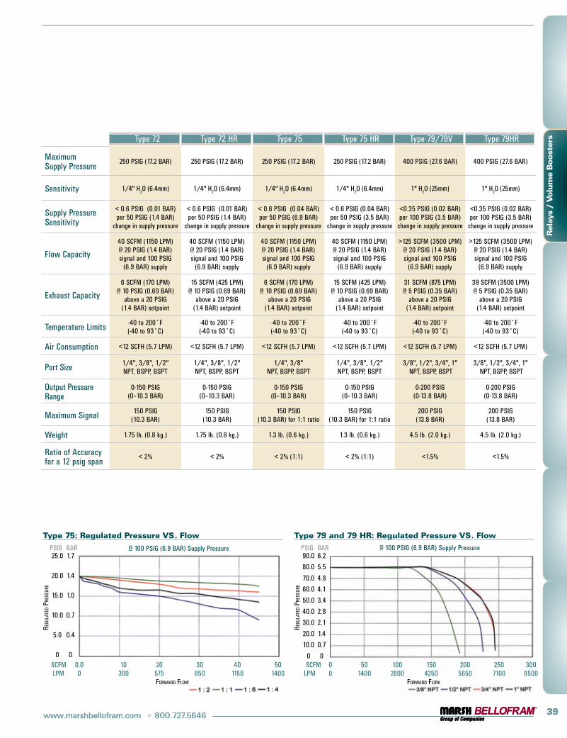
ers Type 72 Type 72 HR Type 75 Type 75 HR Type 79/79V Type 79HR
Maximum Supply Pressure
250 PSig (17.2 BAR) 250 PSig (17.2 BAR) 250 PSig (17.2 BAR) 250 PSig (17.2 BAR) 400 PSig (27.6 BAR) 400 PSig (27.6 BAR)
Sensitivity 1/4" H2O (6.4mm) 1/4" H
2O (6.4mm) 1/4" H
2O (6.4mm) 1/4" H
2O (6.4mm) 1" H
2O (25mm) 1" H
2O (25mm)
Supply Pressure Sensitivity
< 0.6 PSig (0.01 BAR) per 50 PSig (1.4 BAR)
change in supply pressure
< 0.6 PSig (0.01 BAR) per 50 PSig (1.4 BAR)
change in supply pressure
< 0.6 PSig (0.04 BAR) per 50 PSig (6.9 BAR)
change in supply pressure
< 0.6 PSig (0.04 BAR) per 50 PSig (3.5 BAR)
change in supply pressure
<0.35 PSig (0.02 BAR) per 100 PSig (3.5 BAR)
change in supply pressure
<0.35 PSig (0.02 BAR) per 100 PSig (3.5 BAR)
change in supply pressure
Flow Capacity
40 SCFM (1150 LPM) @ 20 PSig (1.4 BAR) signal and 100 PSig
(6.9 BAR) supply
40 SCFM (1150 LPM) @ 20 PSig (1.4 BAR) signal and 100 PSig
(6.9 BAR) supply
40 SCFM (1150 LPM) @ 20 PSig (1.4 BAR) signal and 100 PSig
(6.9 BAR) supply
40 SCFM (1150 LPM) @ 20 PSig (1.4 BAR) signal and 100 PSig
(6.9 BAR) supply
>125 SCFM (3500 LPM) @ 20 PSig (1.4 BAR) signal and 100 PSig
(6.9 BAR) supply
>125 SCFM (3500 LPM) @ 20 PSig (1.4 BAR) signal and 100 PSig
(6.9 BAR) supply
Exhaust Capacity
6 SCFM (170 LPM) @ 10 PSig (0.69 BAR)
above a 20 PSig (1.4 BAR) setpoint
15 SCFM (425 LPM) @ 10 PSig (0.69 BAR)
above a 20 PSig (1.4 BAR) setpoint
6 SCFM (170 LPM) @ 10 PSig (0.69 BAR)
above a 20 PSig (1.4 BAR) setpoint
15 SCFM (425 LPM) @ 10 PSig (0.69 BAR)
above a 20 PSig (1.4 BAR) setpoint
31 SCFM (875 LPM) @ 5 PSig (0.35 BAR)
above a 20 PSig (1.4 BAR) setpoint
39 SCFM (3500 LPM) @ 5 PSig (0.35 BAR)
above a 20 PSig (1.4 BAR) setpoint
Temperature Limits -40 to 200˚F (-40 to 93˚C)
-40 to 200˚F (-40 to 93˚C)
-40 to 200˚F (-40 to 93˚C)
-40 to 200˚F (-40 to 93˚C)
-40 to 200˚F (-40 to 93˚C)
-40 to 200˚F (-40 to 93˚C)
Air Consumption <12 SCFH (5.7 LPM) <12 SCFH (5.7 LPM) <12 SCFH (5.7 LPM) <12 SCFH (5.7 LPM) <12 SCFH (5.7 LPM) <12 SCFH (5.7 LPM)
Port Size 1/4", 3/8", 1/2" NPT, BSPP, BSPT
1/4", 3/8", 1/2" NPT, BSPP, BSPT
1/4", 3/8" NPT, BSPP, BSPT
1/4", 3/8", 1/2" NPT, BSPP, BSPT
3/8", 1/2", 3/4", 1" NPT, BSPP, BSPT
3/8", 1/2", 3/4", 1" NPT, BSPP, BSPT
Output Pressure Range
0-150 PSig (0–10.3 BAR)
0-150 PSig (0–10.3 BAR)
0-150 PSig (0–10.3 BAR)
0-150 PSig (0–10.3 BAR)
0-200 PSig (0-13.8 BAR)
0-200 PSig (0-13.8 BAR)
Maximum Signal 150 PSig (10.3 BAR)
150 PSig (10.3 BAR)
150 PSig (10.3 BAR) for 1:1 ratio
150 PSig (10.3 BAR) for 1:1 ratio
200 PSig (13.8 BAR)
200 PSig (13.8 BAR)
Weight 1.75 lb. (0.8 kg.) 1.75 lb. (0.8 kg.) 1.3 lb. (0.6 kg.) 1.3 lb. (0.6 kg.) 4.5 lb. (2.0 kg.) 4.5 lb. (2.0 kg.)
Ratio of Accuracy for a 12 psig span
< 2% < 2% < 2% (1:1) < 2% (1:1) <1.5% <1.5%
Type 75: Regulated Pressure VS. Flow
25.0 1.7
20.0 1.4
15.0 1.0
10.0 0.7
5.0 0.4
0 0
Regu
late
d PR
essu
Re
SCFM 0.0 10 20 30 40 50 LPM 0 300 575 850 1150 1400 FoRwaRd Flow
PSig BAR @ 100 PSig (6.9 BAR) Supply Pressure
Type 79 and 79 HR: Regulated Pressure VS. Flow
90.0 6.2
80.0 5.5
70.0 4.8
60.0 4.1
50.0 3.4
40.0 2.8
30.0 2.1
20.0 1.4
10.0 0.7
0 0
Regu
late
d PR
essu
Re
SCFM 0 50 100 150 200 250 300 LPM 0 1400 2800 4250 5650 7100 8500 FoRwaRd Flow
PSig BAR @ 100 PSig (6.9 BAR) Supply Pressure

40 800.727.5646 • www.marshbellofram.com
Air C
ylin
ders
40 800.727.5646 • www.marshbellofram.com
Relays / V
olu
me B
oosters
Features
•Extreme accuracy•Positive and negative bias capability•Small size•Rugged and stable
Description
The Type 20 Air Relay is a compact, two-stage, pilot operated 1:1 relay with positive and negative bias adjustment capability. it accepts a signal pressure and combined with the bias adjustment, maintains a resulting output pres-sure with an accuracy and reliability unmatched by any other pressure relay in its price range.
Models
Type 20
The basic relay is offered with a choice of three port sizes.
Type 20HR and Type 20EXHR
High Relief Relays - These relays provide extra fast “blowdown” for very rapid release of output pressure. The extra relief feature makes this relay suitable for cylinder return stroke actuation, air hoists, and similar applications requiring fast exhaust.
Type 20 Precision Air Relays
Applications
•gate Actuators•Air Hoists•Disc and Shoe Brakes•Remote Positioning Devices•Valve Rotors•Control Valves•Tensioning Systems•Web Tracking Systems
Type 20 Precision Air Relay
Type 20 Application Diagrams

www.marshbellofram.com • 800.727.5646 41
Air
Cylin
ders
www.marshbellofram.com • 800.727.5646 41
Rel
ays
/ Volu
me
Boost
ers
Features
•Four adjustable positive bias ranges, from 0-10 PSi (0-0.7 BAR) to 2-150 PSi (0.1-10.3 BAR)
•Flow capacity up to 50 SCFM•Quick response to minute changes in down-
stream pressure•Dampening action of aspirator tube maintains
stable output pressure•Output virtually unaffected by changes in
supply pressure•internal rolling diaphragm designed for
millions of cycles•Honking and buzzing eliminated by action of
integral baffle and aspirator tube•Can be disassembled and serviced without
removing from line•Also available in a high relieving version
(72HR)
Description
The Type 72 Relay features an adjustable bias pressure which enables users to obtain an output pressure which is the sum of a controlled input signal pressure plus the bias. The relay offers an exceptionally high flow capacity (up to 50 SCFM/1400 LPM) with minimal pressure droop.
Output pressure is accurately maintained under varying flow conditions by means of an aspira-tor tube, which adjusts the air supply valve opening in proportion to flow velocity. A bal-anced supply valve utilizing a rolling diaphragm makes the relay virtually immune to changes in supply pressure. Simple design makes main-tenance easy, and the relay can be serviced without removing it from the line. The standard signal-to-output ratio is 1:1, but 1:2, 1:4 and 1:6 ratios are available on special request.
Applications
The Type 72 Relay is used when high flow capacity is required in conjunction with a posi-tive output pressure bias. Typical applications include:
•gas Flow Control •Tensioning Control•Clutch and Brake Controls •Volume Boosting•Dancer Roll Loading •Calendar Roll Loading•Cylinder Bucking Control •Valve Motor Loading
Type 72 & 72HRPositive Bias Booster Relays
Type 72 Positive Bias Booster Relay
Type 72 Application Diagrams
Type 72 Dimensional Drawing

42 800.727.5646 • www.marshbellofram.com
Air C
ylin
ders
42 800.727.5646 • www.marshbellofram.com
Relays / V
olu
me B
oosters
Features
•Balanced valve design •High flow capacity •Field serviceable•Multiple output ratios•Negative biasing option
Description
The Type 75 relay uses signal pressure to accurately control output pressure over a wide range of flow and supply pressure variation.
Under varying flow conditions output pres-sure is maintained by use of an aspirator tube, which adjusts the air supply valve opening in accordance with the flow velocity. A balanced supply valve, utilizing a rolling diaphragm, makes the relay virtually immune to changes in supply pressure. Maintenance is simple due to the unit construction, and the relay can be serviced without removing it from the line. Signal to output pressure ratios of 1:1, 1:2, 1:4 and 1:6 are available. Maximum output is 150 PSig (10.3 BAR).
Applications
•Volume Boosting•Dancer Roll Loading•Calendar Roll Loading•Cylinder Bucking Control•Clutch and Brake Controls•gas Flow Control•Tensioning Control•Valve Motor Loading
Type 75 & 75 HR Air Relays
Models
Type 75
The basic relay offers excellent precision along with high forward flow rates.
Type 75 High Relief Relays
These relays provide extra fast “blowdown” for very rapid release of output pressure. The extra relief feature makes this relay suitable for cylinder return stroke actuation, air hoists, and similar applications requiring fast exhaust.
Type 75 Negative Bias
The Type 75 Relay is also available with a 4 ± 1 psig (0.3 ± 0.07 BAR) negative bias spring mounted internally. (See cross-sectional drawing on previous page.) This bias spring automatically subtracts 4 ± 1 psig (0.3 ± 0.07 BAR) from any signal pressure introduced. The relay then multiplies the net signal pressure by its ratio value to obtain final output pressure.
This option is particularly useful in obtaining zero pressure from pneumatic devices such as i/P transducers that normally cannot be adjusted this low, as well as obtaining higher outputs from such devices.
Typical applications of the Type 75 Relay with fixed negative bias include the electronic control of the applications listed for the standard Type 75 Relay.
To calculate relay output:
Relay output = (signal pressure) - 4 PSi bias x (relay ratio factor) where the relay ratio factor is defined as follows:
Relay Ratio Factor
1:1 1
1:2 2
1:4 4
1:6 6
Type 75 Air Relay
Type 75 Application Diagrams
Type 75 Dimensional Drawing

www.marshbellofram.com • 800.727.5646 43
Air
Cylin
ders
www.marshbellofram.com • 800.727.5646 43
Rel
ays
/ Volu
me
Boost
ers
Features
•Balanced pintle•High flow capacity •Field serviceable•Large port sizes available•Air piloted or dome loaded•200 PSig output•Also available in a high relieving version
(Type 79HR)
Description
The Type 79 1:1 Ratio High Flow Precision Air Relay brings additional precision and control to the Bellofram line of precision control products.
The Type 79 relay is designed for applications where a precise control of flow is needed. This regulator offers low droop, high accuracy and fine adjustment sensitivity. The use of a Bellofram rolling diaphragm provides greater sensitivity and improved accuracy. The bal-anced pintle minimizes output pressure changes caused by fluctuations in supply pressure.
Careful design and quality materials throughout assure long, trouble-free operation. The rugged die-cast zinc and aluminum housings are pressure tested to assure safe
Type 79 High Flow Air Relays
operation. The Type 79 is designed to with- stand harsh and abusive environments. This is attributed to a chemical conversion coating of all cast components, and a vinyl paint finish.
The Type 79 can achieve flow rates of well over 200 SCFM (5695 LPM). This relay can be pipe or bracket mounted.
A version of the Type 79 for valve control applications is available. The Type 79V utilizes soft exhaust seats to minimize air consumption, increased deadband to ignore valve oscillations, and an integral bypass valve that can be ‘tuned’ for optimum valve response.
Applications
•Clutch and Brake Controls•gas Flow Control•Cylinder Bucking Control•Tension Control•Dancer (Calendar) Roll Loading
• Volume Boosting• Valve Motor Loading
Type 79 High Flow Air Relay
Type 79 Application Diagrams
Type 79 Dimensional Drawing
44 800.727.5646 • www.marshbellofram.com
Air C
ylin
ders
44 800.727.5646 • www.marshbellofram.com
Relays / V
olu
me B
oosters
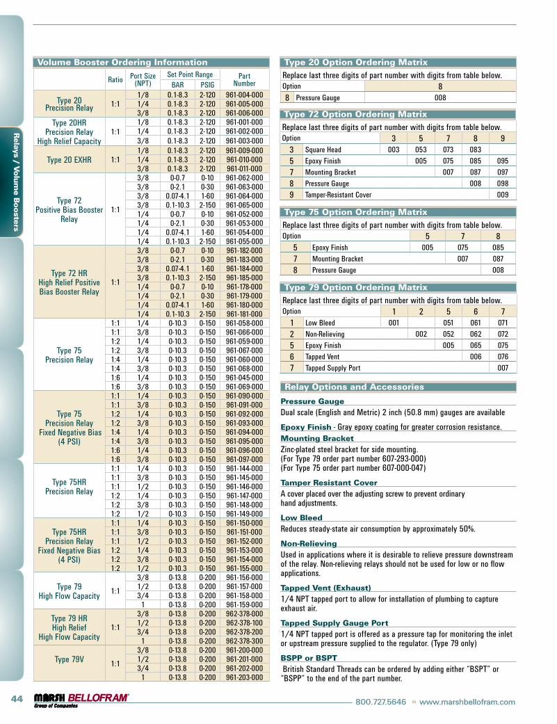
Volume Booster Ordering Information
Ratio Port Size (NPT)
Set Point Range Part NumberBAR PSig
Type 20 Precision Relay 1:1
1/8 0.1-8.3 2-120 961-004-0001/4 0.1-8.3 2-120 961-005-0003/8 0.1-8.3 2-120 961-006-000
Type 20HR Precision Relay
High Relief Capacity1:1
1/8 0.1-8.3 2-120 961-001-0001/4 0.1-8.3 2-120 961-002-0003/8 0.1-8.3 2-120 961-003-000
Type 20 EXHR 1:11/8 0.1-8.3 2-120 961-009-0001/4 0.1-8.3 2-120 961-010-0003/8 0.1-8.3 2-120 961-011-000
Type 72 Positive Bias Booster
Relay1:1
3/8 0-0.7 0-10 961-062-0003/8 0-2.1 0-30 961-063-0003/8 0.07-4.1 1-60 961-064-0003/8 0.1-10.3 2-150 961-065-0001/4 0-0.7 0-10 961-052-0001/4 0-2.1 0-30 961-053-0001/4 0.07-4.1 1-60 961-054-0001/4 0.1-10.3 2-150 961-055-000
Type 72 HRHigh Relief Positive Bias Booster Relay
1:1
3/8 0-0.7 0-10 961-182-0003/8 0-2.1 0-30 961-183-0003/8 0.07-4.1 1-60 961-184-0003/8 0.1-10.3 2-150 961-185-0001/4 0-0.7 0-10 961-178-0001/4 0-2.1 0-30 961-179-0001/4 0.07-4.1 1-60 961-180-0001/4 0.1-10.3 2-150 961-181-000
Type 75 Precision Relay
1:1 1/4 0-10.3 0-150 961-058-0001:1 3/8 0-10.3 0-150 961-066-0001:2 1/4 0-10.3 0-150 961-059-0001:2 3/8 0-10.3 0-150 961-067-0001:4 1/4 0-10.3 0-150 961-060-0001:4 3/8 0-10.3 0-150 961-068-0001:6 1/4 0-10.3 0-150 961-045-0001:6 3/8 0-10.3 0-150 961-069-000
Type 75 Precision Relay
Fixed Negative Bias (4 PSi)
1:1 1/4 0-10.3 0-150 961-090-0001:1 3/8 0-10.3 0-150 961-091-0001:2 1/4 0-10.3 0-150 961-092-0001:2 3/8 0-10.3 0-150 961-093-0001:4 1/4 0-10.3 0-150 961-094-0001:4 3/8 0-10.3 0-150 961-095-0001:6 1/4 0-10.3 0-150 961-096-0001:6 3/8 0-10.3 0-150 961-097-000
Type 75HR Precision Relay
1:1 1/4 0-10.3 0-150 961-144-0001:1 3/8 0-10.3 0-150 961-145-0001:1 1/2 0-10.3 0-150 961-146-0001:2 1/4 0-10.3 0-150 961-147-0001:2 3/8 0-10.3 0-150 961-148-0001:2 1/2 0-10.3 0-150 961-149-000
Type 75HR Precision Relay
Fixed Negative Bias (4 PSi)
1:1 1/4 0-10.3 0-150 961-150-0001:1 3/8 0-10.3 0-150 961-151-0001:1 1/2 0-10.3 0-150 961-152-0001:2 1/4 0-10.3 0-150 961-153-0001:2 3/8 0-10.3 0-150 961-154-0001:2 1/2 0-10.3 0-150 961-155-000
Type 79 High Flow Capacity 1:1
3/8 0-13.8 0-200 961-156-0001/2 0-13.8 0-200 961-157-0003/4 0-13.8 0-200 961-158-000
1 0-13.8 0-200 961-159-000
Type 79 HR High Relief
High Flow Capacity1:1
3/8 0-13.8 0-200 962-378-0001/2 0-13.8 0-200 962-378-1003/4 0-13.8 0-200 962-378-200
1 0-13.8 0-200 962-378-300
Type 79V 1:1
3/8 0-13.8 0-200 961-200-0001/2 0-13.8 0-200 961-201-0003/4 0-13.8 0-200 961-202-000
1 0-13.8 0-200 961-203-000
Type 20 Option Ordering MatrixReplace last three digits of part number with digits from table below.Option 88 Pressure gauge 008
Type 72 Option Ordering MatrixReplace last three digits of part number with digits from table below.Option 3 5 7 8 9
3 Square Head 003 053 073 083
5 Epoxy Finish 005 075 085 095
7 Mounting Bracket 007 087 097
8 Pressure gauge 008 098
9 Tamper-Resistant Cover 009
Type 75 Option Ordering MatrixReplace last three digits of part number with digits from table below.Option 5 7 8
5 Epoxy Finish 005 075 085
7 Mounting Bracket 007 087
8 Pressure gauge 008
Type 79 Option Ordering MatrixReplace last three digits of part number with digits from table below.Option 1 2 5 6 7
1 Low Bleed 001 051 061 071
2 Non-Relieving 002 052 062 072
5 Epoxy Finish 005 065 075
6 Tapped Vent 006 076
7 Tapped Supply Port 007
Relay Options and Accessories
Pressure GaugeDual scale (English and Metric) 2 inch (50.8 mm) gauges are available
Epoxy Finish - gray epoxy coating for greater corrosion resistance.Mounting BracketZinc-plated steel bracket for side mounting. (For Type 79 order part number 607-293-000) (For Type 75 order part number 607-000-047)
Tamper Resistant CoverA cover placed over the adjusting screw to prevent ordinary hand adjustments.
Low BleedReduces steady-state air consumption by approximately 50%.
Non-RelievingUsed in applications where it is desirable to relieve pressure downstream of the relay. Non-relieving relays should not be used for low or no flow applications.
Tapped Vent (Exhaust)1/4 NPT tapped port to allow for installation of plumbing to capture exhaust air.
Tapped Supply Gauge Port1/4 NPT tapped port is offered as a pressure tap for monitoring the inlet or upstream pressure supplied to the regulator. (Type 79 only)
BSPP or BSPT British Standard Threads can be ordered by adding either “BSPT” or “BSPP” to the end of the part number.

www.marshbellofram.com • 800.727.5646 45
Air
Cylin
ders
Diaphragm Air Cylinders
Small bore Cylinders
Standard Cylinders
SuperCylinders

46 800.727.5646 • www.marshbellofram.com
Air C
ylin
ders
Features
•Low start up pressure•Low breakaway force•Extremely sensitive response •Very smooth, “non-jarring” action•Wide temperature range•Very low friction•No edge seals to replace•No blow-by leakage•Numerous varieties •Low total cost
Description
Diaphragm Air Cylinders are actuators made from elastomers, engineered metals and fabrics. They require no lubrication, are virtually frictionless, and economical. They can be used to provide lifting, clamping, pushing, coining, turning, and other linear force or actuation motions in many applications.
The development of the long stroke rolling diaphragm for dynamic sealing proved to be the solution for many applications requiring low friction, no lubrication, low leakage, wide temperature variations, and low total cost. The popularity of the rolling diaphragm as a sealing means led to many requests for a standard line of “off the shelf” diaphragm cylinders; single and double acting, short and long stroke with a wide selection of effective areas. To meet these re-quests, the long stroke rolling diaphragm cylinder was developed and Bellofram has supplied many thousands of them since their 1965 introduction.
Applications
Diaphragm Air Cylinder applications are almost unlimited. They are replacing conventionally sealed cylinders and actuators where low cost and reliability are requirements. They can be used with vacuum and gaseous pressure sys-tems. They are currently solving many unique problems, being used as:
•Expansion Chambers•Accumulators •Pumps•Reservoirs •Shock Mounts•impact Absorbers•Weld Drivers•Tensioners•Dancer Rolls•Valve Actuation•Louver Controls
Diaphragm Air CylindersStandard CylindersStandard Bellofram Air Cylinders are available in eight sizes. Each size is available in both a spring-return and a double-acting variety, with one or two stroke variations (Series E or F).
Sizes 4 and 6 have impact-extruded aluminum shells. Larger sizes have steel shells. Rods are ground, polished and hard-chrome plated steel. Bearings are sintered bronze, molybdenum disulphite impregnated. Other components are high strength materials with suitable corrosion resistant treatment.
•Bellofram engineers will help you define your specific needs.
•All Standard cylinders can be ordered with either no spring, or no bearing, as standard options.
•Standard cylinders can be ordered with one of six different mounting options.
•Specifications for Standard cylinders are shown in the table on the next page.
Super Cylinders Bellofram Super Cylinders are standard spring-return cylinders equipped with linear ball bearings and hardened steel rods. This refinement allows an absolute minimum of friction for applications where maximum sensitivity is needed.
Super Cylinders are available only in spring-return varieties and in Series F stroke variations.
All mounting options offered on standard cylinders are also available on super cylinders.
Diaphragm Air Cylinder
Standard and Super Cylinder Specifications
Plant Air Up to 145 PSig (10 BAR)
Temperatures -40˚ to 225˚F (-40˚ to 107˚C)
Materials of Construction
Body: Sizes 4 and 6 are impact- extruded aluminum shell. Larger sizes are made from a steel shell.
Diaphragm: Neoprene® elastomer reinforced with Flex-Weave Dacron® fabric.
Rods: ground, polished and hard-chrome plated steel.
Bearings: Sintered bronze, molybdenum disulphite impregnated.
Other components are high strength materials with suitable corrosion resistant treatment.
TestingAll cylinders are leak-tested prior to shipment. However, the cylinder is not a bubble tight assembly
Cylinder WeightsCat. No. Lbs. Cat. No. Lbs. Cat. No. Lbs. Cat. No. Lbs.S-4-F-BP 4 S-16-E-BP 13 D-4-F-BP 4 D-16-E-BP 14S-4-BP-N 5 S-16-F-BP 14 D-4-BP-N 5 D-16-F-BP 16S-6-F-BP 5 S-24-E-BP 18 D-6-F-BP 5 D-24-E-BP 20S-6-BP-N 6 S-24-F-BP 25 D-6-BP-N 6 D-24-F-BP 28S-9-F-BP 8 S-30-E-BP 25 D-9-F-BP 8 D-30-E-BP 26S-9-BP-N 9 S-30-F-BP 31 D-9-BP-N 9 D-30-F-BP 33S-12-E-BP 9 S-36-E-BP 28 D-12-E-BP 10 D-36-E-BP 29S-12-F-BP 11 S-36-F-BP 36 D-12-F-BP 12 D-36-F-BP 39

www.marshbellofram.com • 800.727.5646 47
Air
Cylin
ders
Small Bore Cylinders Bellofram’s 0.38 and 1.7 sq. inch effective area diaphragm cylinders combine the performance of the diaphragm cylinder with small size. Two different stroke options are available in each size, with either flush or extended rods on 0.38 sq. inch cylinders. Only spring return varieties are available.
Specifications
0.38 sq. inch Cylinders have aluminum alloy shells and end caps, and carbon steel rods. 1.7 sq. inch Cylinders have die-cast aluminum shells and end caps, and chrome-plated carbon steel rods. All varieties have oil-impregnated bronze bearings, polyester fabric reinforced Nitrile diaphragms, and music wire springs. Optional foot mounts are available for the 1.7 sq. inch Cylinders.
Standard and Super Cylinder Operating Data
Size(Effective Area)
(Sq. inches)
EquivalentBore Diam.
(inches)
Spring Return Double Acting
Stroke+.03/-.12(inches)
Stroke+.03/-.12(inches)
Approx. Spring Force - Zero Stroke
(lbs.)
Approx. increase Force Per inches of Stroke
(lbs.)
Stroke +.03/-.12 (inches)
Stroke +.03/-.12 (inches)
Series E Series F Series E Series F Series E Series F Series E Series F
4 2.3 1.80 6 3 1.36 2.8 2.40 9 4 1.99 3.4 2.20 3.00 17 12 4 4 2.512 3.9 2.30 3.60 18 18 6 6 1.8 3.116 4.5 2.62 4.20 24 24 8 8 2.1 3.724 5.5 2.60 5.24 36 36 11 11 2.0 4.630 6.3 3.07 6.00 45 54 13 14 2.4 5.436 6.8 3.55 6.00 54 54 16 14 2.9 5.4
Small Bore Cylinder Operating Data
Part Number Size (Effective Area) Sq. in. Stroke in. Load
@ 0 Stroke Lbs.Spring Load
@ Max. Stroke Lbs.
Equiv. Bore Dia. in.
Maximum Oper-ating Press. PSi Rod Type
908-013-000 0.384 0.70 2 7 0.7 125 Flush
908-034-000 0.384 0.70 2 7 0.7 125 3/4"
908-014-000 0.384 0.32 5 7 0.7 125 Flush
908-035-000 0.384 0.32 5 7 0.7 125 3/4"
980-008-000 1.7 1.0 4 8 1.5 125 —
980-077-000 1.7 1.75 4 11 1.5 125 —
External stroke limiters should be provided by the customer to limit the stroke in both directions on both single-acting and double-acting cylinders.
Installation and operation procedures furnished with each cylinder should be followed for maximum service life.
Marsh Bellofram offers very smooth, “Non-Jarring” action
in a Low Cost Cylinder

48 800.727.5646 • www.marshbellofram.com
Air C
ylin
ders
Cylinder Replacement Parts
When ordering replacement parts, provide nomenclature of part from photographs in addition to the following information from the nameplate on the cylinder: Type, Size, Series, and Rod type.
Complete kits are available for replacement of diaphragm or bearings.
Double Acting Cylinders
Outer Rod Bearing
inner Rod Bearing
Rod Wiper
Cap Diaphragm
Spring Return Cylinders (Super Cylinder Shown)
Rod End
Cap Diaphragm Retainer
Mounting Stud
Rod Retaining Screw
Piston
Spring
Head Retaining ScrewLinear Ball Bearing (Bronze bearing used in standard spring return cylinders)
Piston Rod
Head CylinderCap Diaphragm
Head DiaphragmCylinderHead
“U” Cup SealRod End
Piston Rod
Head Retaining Screw
Piston
“O” Ring Seal
Rod Retaining Screw
Cap Diaphragm Retainer

www.marshbellofram.com • 800.727.5646 49
Air
Cylin
ders
Standard Cylinders Ordering Information
TypeS Spring ReturnD Double Acting
Size04 4 Square inches06 6 Square inches09 9 Square inches12 12 Square inches16 16 Square inches24 24 Square inches30 30 Square inches36 36 Square inches
SeriesE
Determines StrokeF
Make a selection from Operating Data Table on pg. 47Rod
BP Bellofram Product Standard
SM National Fluid Power Assoc. Standard
Make a selection from dimensional data tables on pgs. 51-54Mounting
N Nose Mount
UM Universal Mount
FM Foot Mount
CFM Cap Flange Mount
HFM Head Flange Mount
CBM Clevis Bracket Mount
CBS Clevis Bracket Stud
Standard OptionsNS No Spring
NB No Bearing
NBS No Bearing or Spring
No Standard Option RequestedExample: D-12-F-BP-CBM is a Double Acting, 12 sq. in., 3.1" Stroke, BP Rod End Cylinder with Clevis Bracket Mount.
Super Cylinders Ordering InformationSS F
TypeSS Super Cylinders
Size04 4 Square inches
06 6 Square inches
09 9 Square inches
12 12 Square inches
16 16 Square inches
24 24 Square inches
30 30 Square inches
36 36 Square inches
SeriesF Determines Stroke
RodBP Bellofram Product Standard
SM National Fluid Power Assoc. Standard
Make a selection from dimensional data table on pgs. 51-54
MountingUM Universal Mount
FM Foot Mount
CFM Cap Flange Mount
HFM Head Flange Mount
CBM Clevis Bracket Mount
CBS Clevis Bracket Stud
Standard OptionsNS No Spring
No Standard Option RequestedExample: SS-12-F-SM-HFM is a Single Acting Super Cylinder, 12 sq. in., 3.6" stroke, SM Rod End Cylinder with a Head Flange Mount.
Repair Kits
Repair Kits are available to permit user in-plant maintenance without delay and expense of return-ing parts to the factory. Each kit includes installation instructions. Nameplate data of the cylinder must accompany order to insure receipt of correct parts.
The following is included in the repair kits:
Spring Return Diaphragm Kit
1. Diaphragm, Cap2. Adhesive, Cap3. Nuts, Cap Retainer4. instructions
Spring Return Bearing Kit
1. inner Bearing2. Outer Bearing3. Rod Wiper4. instructions
Double Acting Diaphragm Kit
1. Diaphragm, Cap2. Diaphragm, Head3. Adhesive, Cap4. Adhesive, Head5. Rivets, Blind (or Screws)6. Nuts, Cap Retainer7. Seal “O” Ring8. instructions
Double Acting Bearing Kit
1. inner Bearing2. Outer Bearing3. Rod Wiper4. U-Cup Seal5. instructions
Breather Vents
Breather vents are available for use on Bellofram Spring Return Air Cylinders.
The Breather, which contains a 40 micron bronze filter, is simply threaded into the air relief port of the cylinder head. it prevents foreign matter from being drawn into the cylinder on the return stroke of the piston, and also acts as a snubber. The snubbing reduces the piston speed and impact at the end of the stroke in both directions.
Breather Vents Ordering Data
Breather Vent for 1/4" Pipe Tap (Fits cylinder sizes 4, 6, 9) Part No. 661-000-001
Breather Vent for 3/8" Pipe Tap (Fits cylinder sizes 12, 16, 24, 30, 36) Part No. 661-000-002

50 800.727.5646 • www.marshbellofram.com
Air C
ylin
ders
Note: Sizes 4, 6, 9, and 12 have 4 Head Retaining Screws. All other sizes have 8 Head Retaining Screws
- Location varies depending on cylinder size. Engineering data available on request
Universal Mount
Cap Flange Mount
Note: Sizes 4, 6, 9, and 12 have 4 Head Retaining Screws. All other sizes have 8 Head Retaining Screws
- Location varies depending on cylinder size. Engineering data available on request
Head Flange Mount
Note: Sizes 4, 6, 9, and 12 have 4 Head Retaining Screws. All other sizes have 8 Head Retaining Screws
*EW = External width of clevis bracket stud.
Clevis Bracket Mount (or Stud)
Note: Sizes 4, 6, 9, and 12 have 4 Head Retaining Screws. All other sizes have 8 Head Retaining Screws

www.marshbellofram.com • 800.727.5646 51
Air
Cylin
ders
Standard Cylinders - Universal, Cap Flange, Clevis Bracket, Head Flange Mounts — Dimensions - InchesSize Series Z H N EE FC FB B P F R UF FH CD DD E FL EW PT g
4 F 2.71 3.02 4.34 1⁄4 NPT 2.00 1⁄4 - 20 1⁄2 .50 .781 2.81 3.62 1⁄4 .625 1⁄4 3.12 1.38 .93 3⁄8 2.386 F 3.27 3.58 5.28 1⁄4 NPT 2.00 1⁄4 - 20 1⁄2 .51 .781 2.81 3.62 1⁄4 .625 1⁄4 3.12 1.38 .93 1⁄2 2.38
9E
3.84 4.255.31
1⁄4 NPT 3.00 7⁄16-14 3⁄4 .75 .690 4.38 5.50 7⁄16 .750 1⁄4 3.75 1.69 .99 1⁄2 3.0F 6.34
12E
4.38 4.795.31
3⁄8 NPT 3.00 7⁄16-14 3⁄4 .75 .690 4.38 5.50 7⁄16 .750 1⁄2 4.00 1.75 1.24 1⁄2 3.0F 7.28
16E
4.99 5.406.03
3⁄8 NPT 3.00 1⁄2-13 3⁄4 .87 .690 4.38 5.50 1⁄2 .750 1⁄2 4.00 1.75 1.24 1⁄2 3.0F 8.38
24E
6.16 6.576.28
3⁄8 NPT 4.75 5⁄8-11 3⁄4 1.00 .656 6.00 7.50 1⁄2 1.00 1⁄2 5.12 2.00 1.49 5⁄8 4.0F 10.22
30E
6.88 7.297.00
3⁄8 NPT 4.75 5⁄8-11 1 1.00 .656 6.00 7.50 1⁄2 1.00 1⁄2 5.12 2.00 1.49 5⁄8 4.0F 11.44
36E
7.38 7.797.69
3⁄8 NPT 4.75 5⁄8-11 1 1.00 .656 6.00 7.50 1⁄2 1.00 1⁄2 5.12 2.00 1.49 5⁄8 4.0F 11.47
Size SeriesBP Rod End* SM Rod End†
X Y A ZA ZD XD ZB CC A ZA ZD XD ZB CC4 F 2.73 1.95 .75 7.10 9.07 8.45 6.72 3⁄8-24 1.00 6.85 8.82 8.19 6.47 7⁄16-206 F 2.69 1.91 .75 8.00 9.97 9.35 7.63 3⁄8-24 1.00 7.75 9.72 9.09 7.38 7⁄16-20
9E 2.92 2.23
1.007.92 10.73 9.98 7.63
1⁄2-20 1.127.80 10.61 9.86 7.56
3⁄4-16F 2.69 2.00 8.72 11.55 10.80 8.44 8.60 11.42 10.67 8.32
12E 2.92 2.23
1.007.92 10.98 10.23 7.78
1⁄2-20 1.127.80 10.86 10.11 7.66
3⁄4-16F 2.95 2.26 9.91 12.98 12.23 9.78 9.80 12.86 12.11 9.66
16E 3.06 2.37
1.008.18 11.84 11.09 8.64
1⁄2-20 1.128.66 11.72 10.97 8.52
3⁄4-16F 2.78 2.09 10.85 13.91 13.16 10.71 10.73 13.78 13.03 10.59
24E 2.86 2.17
1.008.53 11.78 10.78 8.73
1⁄2-20 1.128.71 12.16 11.16 8.59
3⁄4-16F 2.44 1.78 12.35 16.22 15.22 12.08 12.23 15.68 14.68 12.03
30E 2.83 2.14 1.25 9.27 12.70 11.70 9.26 5⁄8-18
1.508.02 12.89 11.89 9.30
1-14F 3.05 2.36 1.50 13.68 17.11 16.11 13.53 1-12 13.68 17.11 16.11 13.53
36E 2.83 2.14 1.25 9.96 13.31 12.31 9.82 5⁄8-18
1.509.71 13.60 12.60 10.00
1-14F 3.05 2.36 1.50 13.71 17.13 16.13 13.54 1-12 13.71 17.13 16.13 13.54
*BP Rod End - Bellofram Products Co. Standard
†SM Rod End - National Fluid Power Assoc. Standards
Standard Cylinders - Universal, Cap Flange, Clevis Bracket, Head Flange Mounts — Dimensions - MillimetersSize Series Z H N FC B P F R UF FH CD DD E FL EW PT g
4 F 68.83 76.71 110.24 50.80 12.70 12.70 19.84 71.37 91.95 6.35 15.88 6.25 79.25 35.05 23.62 9.53 60.456 F 83.06 90.93 134.11 50.80 12.70 12.95 19.84 71.37 91.95 6.35 15.88 6.25 79.25 35.05 23.62 12.70 60.45
9E
97.52 107.95134.87
76.20 19.05 19.05 17.53 111.25 139.70 11.11 19.50 6.25 95.25 42.93 25.15 12.70 76.20F 161.04
12E
11.25 121.67134.87
76.20 19.05 19.05 17.53 111.25 139.70 11.11 19.50 12.70 101.60 44.45 31.50 12.70 76.20F 184.91
16E
126.75 137.16153.16
76.20 19.50 22.10 17.53 111.25 139.70 12.70 19.50 12.70 101.60 44.45 31.50 12.70 76.20F 212.85
24E
156.46 166.88159.51
120.65 19.50 25.40 16.66 152.40 190.50 12.70 25.40 12.70 130.05 50.80 37.85 15.88 101.60F 259.59
30E
174.75 185.17177.80
120.65 25.40 25.40 16.66 152.40 190.50 12.70 25.40 12.70 130.05 50.80 37.85 15.88 101.60F 290.58
36E
187.45 197.87195.33
120.65 25.40 25.40 16.66 152.40 190.50 12.70 25.40 12.70 130.05 50.80 37.85 15.88 101.60F 291.34
Size SeriesBP Rod End* SM Rod End†
X Y A ZA ZD XD ZB A ZA ZD XD ZB4 F 69.34 49.53 19.05 180.34 230.38 244.63 170.69 25.40 173.99 224.03 208.03 164.346 F 68.33 48.51 19.05 203.20 253.24 237.49 193.80 25.40 196.85 246.89 230.89 187.45
9E 74.17 56.64
25.40201.17 272.54 253.49 193.80
28.45198.12 269.49 250.44 192.02
F 68.33 50.80 221.49 293.37 274.32 214.38 218.44 290.07 271.02 211.33
12E 74.17 56.64
25.40201.17 278.89 259.84 197.61
28.45198.12 275.84 256.79 194.56
F 74.93 57.40 251.97 329.69 310.64 257.41 248.92 326.64 307.59 245.36
16E 77.72 60.20
25.40207.77 300.74 281.69 219.46
28.45219.93 279.69 278.64 216.41
F 70.61 53.09 275.59 353.31 334.26 272.03 272.54 350.01 330.96 268.99
24E 72.64 55.12
25.40216.66 299.21 273.81 221.74
28.45221.23 308.86 283.46 218.19
F 61.98 45.21 313.69 411.99 286.59 306.83 310.64 398.27 372.87 305.56
30E 71.88 54.36 31.75 235.46 322.58 297.18 235.20
38.10203.71 327.41 302.00 236.22
F 77.47 59.94 38.10 347.47 434.59 409.19 343.66 347.47 434.59 409.19 343.66
36E 71.88 54.36 31.75 252.98 338.07 312.67 249.43
38.10246.63 345.44 320.04 254.00
F 77.47 59.94 38.10 248.23 435.10 409.70 343.92 248.23 435.10 409.70 343.92
*BP Rod End - Bellofram Products Co. Standard
†SM Rod End - National Fluid Power Assoc. Standards

52 800.727.5646 • www.marshbellofram.com
Air C
ylin
ders
Standard Cylinders with Foot Mount Dimensions - Inches
Size Series Z H N EE FC FB B P AT AH UA R SA AB XBP Rod End* SM Rod End†
A XA ZB CC A XA ZB CC4 F 2.71 3.02 4.34 1⁄4 NPT 2.00 1⁄4 - 20 1⁄2 .50 .38 1.88 2.62 2.00 6.59 1⁄4 2.41 .75 7.44 7.82 3⁄8-24 1.00 7.19 7.57 7⁄16-206 F 3.27 3.58 5.28 1⁄4 NPT 2.00 1⁄4 - 20 1⁄2 .51 .38 1.88 2.62 2.00 7.53 1⁄4 2.38 .75 8.35 8.72 3⁄8-24 1.00 8.10 8.47 7⁄16-20
9E
3.84 4.255.31
1⁄4 NPT 3.00 7⁄16-14 3⁄4 .75 .56 2.75 4.00 3.008.56
1⁄22.24
1.008.86 9.55
1⁄2-20 1.128.74 9.43
3⁄4-16F 6.34 9.59 2.06 9.67 10.29 9.55 10.16
12E
4.38 4.795.31
3⁄8 NPT 3.00 7⁄16-14 3⁄4 .75 .56 2.75 4.00 3.008.56
1⁄22.30
1.008.86 9.56
1⁄2-20 1.128.73 9.44
3⁄4-16F 7.28 10.53 2.33 10.86 11.56 10.73 11.36
16E
4.99 5.406.03
3⁄8 NPT 3.00 1⁄2-13 3⁄4 .87 .56 2.75 4.00 3.009.28
1⁄22.31
1.009.72 10.42
1⁄2-20 1.129.59 10.22
3⁄4-16F 8.38 11.62 2.16 11.78 12.41 11.66 12.28
24E
6.16 6.576.28
3⁄8 NPT 4.75 5⁄8-11 3⁄4 1.00 .68 4.00 6.25 4.7510.16
5⁄82.23
1.0010.09 10.86
1⁄2-20 1.129.94 10.63
3⁄4-16F 10.22 14.09 1.80 13.06 14.29 13.10 13.79
30E
6.88 7.297.00
3⁄8 NPT 4.75 5⁄8-11 1 1.00 .68 4.00 6.25 4.7510.88
5⁄82.20 1.25 10.52 11.20 5⁄8-18
1.5010.26 10.95
1-14F 11.44 15.31 2.41 1.50 14.92 15.61 1-12 14.92 15.69
36E
7.38 7.797.69
3⁄8 NPT 4.75 5⁄8-11 1 1.00 .68 4.00 6.25 4.7511.56
5⁄82.20 1.25 11.22 11.91 5⁄8-18
1.5010.97 11.66
1-14F 11.47 15.34 2.41 1.50 14.94 15.62 1-12 14.94 15.62
Standard Cylinders with Foot Mount Dimensions - Millimeters
Size Series Z H N FC B P AT AH UA R SA AB XBP Rod End* SM Rod End†
A XA ZB A XA ZB4 F 68.83 76.71 110.24 50.80 12.70 12.70 9.65 47.75 66.65 50.80 167.39 6.35 61.21 19.05 188.98 198.63 25.40 182.63 192.286 F 83.06 90.93 134.11 50.80 12.70 12.95 9.65 47.75 66.55 50.80 191.26 6.35 60.45 19.05 212.09 221.49 25.40 205.74 215.14
9E
97.54 107.95134.87
76.20 19.05 19.05 14.22 69.85 101.60 76.20273.41
12.7056.90
25.40225.04 242.57
28.45222.00 239.52
F 161.04 243.59 52.32 245.62 261.37 242.57 258.06
12E
111.25 121.67134.87
76.20 19.05 19.05 14.22 69.85 101.60 76.20273.41
12.7058.42
25.40225.04 242.82
28.45221.74 239.78
F 184.91 267.46 59.18 275.84 293.62 272.54 288.54
16E
126.75 137.16153.16
76.20 19.05 22.10 14.22 69.85 101.60 76.20235.71
12.7058.67
25.40246.89 264.67
28.45243.59 259.59
F 212.85 295.15 54.86 299.21 315.21 296.16 311.91
24E
156.46 166.88159.51
120.65 19.05 25.40 17.27 101.60 158.75 120.65258.06
15.8856.64
25.40256.29 275.84
28.45252.48 270.00
F 259.59 357.89 45.72 331.72 362.97 332.74 350.27
30E
174.75 185.17177.80
120.65 25.40 25.40 17.27 101.60 158.75 120.65276.35
15.8855.88 31.75 267.21 284.48
38.10260.60 278.13
F 290.58 388.87 61.21 38.10 378.97 396.49 378.97 398.53
36E
187.45 197.8195.33
120.65 25.40 25.40 17.27 101.60 158.75 120.65293.62
15.8855.88 31.75 284.99 302.51
38.10278.64 296.16
F 291.34 389.64 61.21 38.10 379.48 396.75 379.48 396.75
Note: Sizes 4, 6, 9, and 12 have 4 Head Retaining Screws. All other sizes have 8 Head Retaining Screws
Foot Mount
Nose Mount
Nose Mount Dimensions

www.marshbellofram.com • 800.727.5646 53
Air
Cylin
ders
Super Cylinder
Standard Cylinders with Foot Mount Dimensions - Inches
Size Series Z H N EE FC FB B P XBP Rod End* SM Rod End†
A ZB CC A ZB CC4 F 2.71 3.02 4.34 1⁄4 NPT 2.00 1⁄4 - 20 1⁄2 .50 3.10 .75 7.09 3⁄8-24 1.00 6.85 7⁄16-20
6 F 3.27 3.58 5.28 1⁄4 NPT 2.00 1⁄4 - 20 1⁄2 .51 2.16 .75 7.09 3⁄8-24 1.00 6.85 7⁄16-20
9 F 3.84 4.25 6.34 1⁄4 NPT 3.00 7⁄16-14 3⁄4 .75 3.50 1.00 9.25 1⁄2-20 1.12 9.13 3⁄4-16
12 F 4.38 4.79 7.28 3⁄8 NPT 3.00 7⁄16-14 3⁄4 .75 2.57 1.00 9.38 1⁄2-20 1.12 9.26 3⁄4-16
16 F 4.99 5.40 8.38 3⁄8 NPT 3.00 1⁄2-13 3⁄4 .87 3.78 1.00 11.69 1⁄2-20 1.12 11.57 3⁄4-16
24 F 6.16 6.57 10.22 3⁄8 NPT 4.75 5⁄8-11 3⁄4 1.00 2.00 1.00 11.75 1⁄2-20 1.12 11.75 3⁄4-16
30 F 6.88 7.29 11.44 3⁄8 NPT 4.75 5⁄8-11 1 1.00 3.05 1.50 13.52 1-12 1.50 13.52 1-14
36 F 7.38 7.79 11.47 3⁄8 NPT 4.75 5⁄8-11 1 1.00 3.05 1.50 13.55 1-12 1.50 13.55 1-14
Standard Cylinders with Foot Mount Dimensions - Millimeters
Size Series Z H N FC B P XBP Rod End* SM Rod End†
A ZB A ZB
4 F 68.83 76.71 110.24 50.80 12.70 12.70 78.74 19.05 180.09 25.40 173.99
6 F 83.06 90.93 134.11 50.80 12.70 12.95 54.86 19.05 180.09 25.40 173.99
9 F 97.54 107.95 161.04 76.20 19.05 19.05 88.90 25.40 234.95 28.45 231.90
12 F 111.25 121.67 184.91 76.20 19.05 19.05 65.28 25.40 238.25 28.45 235.20
16 F 126.75 137.16 212.85 76.20 19.05 22.10 96.01 25.40 296.93 28.45 293.88
24 F 156.46 166.88 259.59 120.65 19.05 25.40 50.80 25.40 298.45 28.45 298.45
30 F 174.75 185.17 290.58 120.65 25.40 25.40 77.47 38.10 343.41 38.10 343.41
36 F 187.45 197.80 195.33 120.65 25.40 25.40 77.47 38.10 344.17 38.10 344.17
Super Cylinders are equipped with linear ball bearings and hardened
steel rods.
Nose Mount Dimensions - Inches
Size Series Z H N EE F RM B XBP Rod End* SM Rod End†
A ZB CC A ZB CC AF K P4 F 2.71 3.02 4.34 1⁄4 NPT 1.25 1-3⁄8 - 12 1⁄2 1.48 .75 6.72 3⁄8 - 24 1.00 6.47 7⁄16 - 20 2.06 .78 .596 F 3.27 3.58 5.28 1⁄4 NPT 1.25 1-3⁄8 - 12 1⁄2 1.44 .75 7.63 3⁄8 - 24 1.00 7.06 7⁄16 - 20 2.06 .78 .59
9E
3.84 4.155.16
1⁄4 NPT 1.25 1-5⁄8 - 12 3⁄41.83
1.007.65
1⁄2 - 20 1.127.53
3⁄4-16 2.44 .91 .59F 6.19 1.61 8.45 8.33
Nose Mount Dimensions - Millimeters
Size Series Z H N F B XBP Rod End* SM Rod End†A ZB A ZB AF K P
4 F 68.83 76.71 110.24 31.75 12.70 37.59 19.05 170.69 25.40 164.34 52.32 19.81 14.996 F 83.06 91.93 134.11 31.75 12.70 36.58 19.05 193.80 25.40 179.32 52.32 19.81 14.99
9E
97.54 105.41131.06
31.75 19.0546.48
25.40194.31
28.45191.26
61.98 23.11 14.99F 157.23 40.89 214.63 211.58

54 800.727.5646 • www.marshbellofram.com
Air C
ylin
ders
Small Bore Cylinder
Small Bore Cylinder Dimensions - InchesPart Number A B C D E F g H i J K Part Number A B C D
980-008-000 2-29⁄32 13⁄64 5⁄8 19⁄16 13⁄16 3⁄4 3⁄4 3⁄8 2 2-1⁄8 5⁄16908-013-000
2.36 0.448 15⁄16 7⁄8908-034-000
980-077-000 3-21⁄32 13⁄64 5⁄8 19⁄16 13⁄16 3⁄4 3⁄4 3⁄8 2 2-1⁄8 5⁄16908-014-000
1.90 0.244 15⁄16 7⁄8908-035-000
Small Bore Cylinder Dimensions - Millimeters
Part Number A B C D E F g H i J K Part Number A B C D
980-008-000 73.8 5.2 15.9 39.6 20.6 19.1 19.1 9.5 50.8 54.0 7.9908-013-000
60 11.4 23.8 22.2908-034-000
980-077-000 92.9 5.2 15.9 39.6 20.6 19.1 19.1 9.5 50.8 54.0 7.9908-014-000
48.3 6.2 23.8 22.2908-035-000
Rod Clevis and Jam Nut Rod Clevis and Jam Nut Ordering Information
Size04 Area in Square inches: 04, 06, 09, 16, 24, 30, or 36
SeriesE Determines Stroke: Make a selection from Operating Data Table
on pg. 47FRod
BP Bellofram Product Standard
SM National Fluid Power Assoc. Standard
Make a selection from dimensional data table on pgs. 51-54
Rod ClevisRC Rod Clevis
Example: 36-F-BP-RC is a Rod Clevis for a size 36 sq. in. cylinder with a 1-12 rod thread.

www.marshbellofram.com • 800.727.5646 55
Air
Cylin
ders
Rod Clevis and Jam Nut Dimensions - Inches
Size Rod End
Rod End CC Thrd. Series CB
CD Pin Dia.
CE CL Rad.ER LR AF K
4BP 3⁄8-24
F .563⁄8
1-7⁄8 1.38 .53 1.259⁄16 7⁄32
SM 7⁄16-20 7⁄16 11⁄16 1⁄4
6BP 3⁄8-24
F .563⁄8
1-7⁄8 1.38 .53 1.259⁄16 7⁄32
SM 7⁄16-20 7⁄16 11⁄16 1⁄4
9BP 1⁄2-20
E or F.56 1⁄2 1-7⁄8 1.38 .53
1.253⁄4 5⁄16
SM 3⁄4-16 .88 3⁄4 2-3⁄8 2.12 .75 1-1⁄8 27⁄64
12BP 1⁄2-20
E or F.56 1⁄2 1-7⁄8 1.38 .53
1.253⁄4 5⁄16
SM 3⁄4-16 .88 3⁄4 2-3⁄8 2.12 .75 1-1⁄8 27⁄64
16BP 1⁄2-20
E or F.56 1⁄2 1-7⁄8 1.38 .53
1.253⁄4 5⁄16
SM 3⁄4-16 .88 3⁄4 2-3⁄8 2.12 .75 1-1⁄8 27⁄64
24BP 1⁄2-20
E or F.56 1⁄2 1-7⁄8 1.38 .53
1.253⁄4 5⁄16
SM 3⁄4-16 .88 3⁄4 2-3⁄8 2.12 .75 1-1⁄8 27⁄6430and36
BP 1-12F 1.50 1 3-1⁄2 3.50 1.00 1.50 1-1⁄2 35⁄64
SM 3⁄4-16
BP Rod End — Bellofram Products Co. Standard, SM Rod End — National Fluid Power Assoc. Standards
Rod Clevis and Jam Nut Dimensions - Millimeters
Size Rod End Series CB CD Pin
Dia. CE CL Rad.ER LR AF K
4BP
F 14.229.53
47.63 35.05 13.46 31.7514.29 5.56
SM 11.11 17.46 6.36
6BP
F 14.229.53
47.63 35.05 13.56 31.7514.29 5.56
SM 11.11 17.46 6.35
9BP
E or F14.22 12.70 47.63 35.05 13.56
31.7519.05 7.94
SM 22.35 19.05 60.33 53.85 19.05 18.58 10.72
12BP
E or F14.22 12.70 47.63 35.05 13.56
31.7519.05 7.94
SM 22.35 19.05 60.33 53.85 19.05 28.58 10.72
16BP
E or F14.22 12.70 47.63 35.05 13.56
31.7519.05 7.94
SM 22.35 19.05 60.33 53.85 19.05 28.59 10.72
24BP
E or F14.22 12.70 47.63 35.05 13.56
31.7519.05 7.94
SM 22.35 19.05 60.33 53.85 19.05 28.59 13.89
30and36
BP E 14.22 14.29 47.63 35.05 13.46 31.75 33.34 9.53BP
F 38.1 25.4 88.90 88.90 25.4 38.1 38.1 13.89SMSM E or F 38.1 25.4 88.90 88.90 25.4 38.1 38.1 13.89
Cylinder Cap End Mounting Studs Dimensions - Inches
Size Number of Studs Size of Stud H (Approx.) Bolt Circle F (Boss) N Bolt Circle
CRN <°
4 2 1⁄4-20 5⁄8 1-5⁄16 11⁄16 13⁄32 1-3⁄8 90
6 2 1⁄4-20 5⁄8 1-1⁄2 11⁄16 13⁄32 1-3⁄8 90
9 4 1⁄4-20 5⁄8 2 11⁄16 13⁄32 1-3⁄8 45
12 4 1⁄4-20 5⁄8 2-5⁄16 1 17⁄32 1-11⁄16 45
16 4 3⁄8-16 5⁄8 2-5⁄16 1 17⁄32 1-11⁄16 45
24 4 3⁄8-16 9⁄16 3-1⁄8 1 17⁄32 1-11⁄16 45
30 4 1⁄2-13 11⁄16 4 1 17⁄32 1-11⁄16 45
36 4 1⁄2-13 11⁄16 4 1 17⁄32 1-11⁄16 45
Cylinder Cap End Mounting Studs
All Diaphragm Cylinders feature Bellofram Rolling
Diaphragms for low friction and increased
sensitivity!

56 800.727.5646 • www.marshbellofram.com
Air C
ylin
ders
Diaphragm Cylinders Part Numbers
Type S (Spring Return)Series E FRod BP SM BP SM
Mount UM N ZB N UM N UM N
Size
(sq.
in.)
4 900-002-000 900-006-000 900-004-000 900-008-0006 900-010-000 900-014-000 900-012-000 900-016-0009 900-018-000 900-022-000 900-020-000 900-024-000 900-026-000 900-030-000 900-028-000 900-032-00012 900-034-000 900-036-000 900-038-000 900-040-00016 900-042-000 900-044-000 900-046-000 900-048-00024 900-050-000 900-052-000 900-054-000 900-056-00030 900-058-000 900-060-000 900-062-000 900-064-00036 900-066-000 900-068-000 900-070-000 900-072-000
All cylinders are supplied with cap mounting studs. Consult factory for cylinders required without cap mounting studs. Select part numbers from non-shaded areas only.
Type D Cylinders (Double Acting)Series E FRod BP SM BP SM
Mount UM UM UM N UM N
Size
(sq.
in.)
4 902-002-000 902-006-000 902-004-000 902-008-0006 902-010-000 902-014-000 902-012-000 902-016-0009 902-018-000 902-022-000 902-020-000 902-024-00012 902-026-000 902-028-000 902-030-000 902-032-00016 902-034-000 902-036-000 902-038-000 902-040-00024 902-042-000 902-044-000 902-046-000 902-048-00030 902-050-000 902-052-000 902-054-000 902-056-00036 902-058-000 902-060-000 902-062-000 902-064-000
All cylinders are supplied with cap mounting studs. Consult factory for cylinders required without cap mounting studs. Select part numbers from non-shaded areas only.
Type SS (Super Cylinders)Series FRod BP SM
Mount UM UM
Size
(sq.
in.)
4 903-074-000 903-001-0006 903-076-000 903-011-0009 903-078-000 903-021-00012 903-080-000 903-031-00016 903-082-000 903-041-00024 903-084-000 903-051-00030 903-086-000 903-061-00036 903-088-000 903-071-000
Repair KitsSpring Return Cylinders Double Acting Cylinders Super Cylinders
Diaphragm Kits Bearing Kits Diaphragm Kits Bearing Kits Bearing KitsKit No. Part No. Kit No. Part No. Kit No. Part No. Kit No. Part No. Kit No. Part No.S4FN 970-041-000 SB46S 970-058-000 D4S 970-014-000 DB46S 970-064-000 SSB46S 970-134-000S6FN 970-042-000 SB924S 970-060-000 D6S 970-018-000 DB924S 970-066-000 SSB924S 970-133-000S9EN 970-043-000 SB36FB 970-062-000 D9S 970-020-000 DB36FB 970-068-000 SSB36FB 970-135-000S9FN 970-044-000 D12ES 970-022-000S12E 970-045-000 D12FS 970-024-000S12F 970-046-000 D16ES 970-026-000S16E 970-047-000 D16FS 970-028-000S16F 970-048-000 D24ES 970-030-000S24E 970-049-000 D24FS 970-032-000S24F 970-050-000 D30ES 970-034-000S30E 970-051-000 D30FS 970-036-000S30F 970-052-000 D36ES 970-038-000S36E 970-053-000 D36FS 970-040-000S36F 970-054-000
Mounting KitsSize FM CFM HFM CBM CBS4 904-001-000 904-012-000 904-008-000 904-026-000 904-019-0006 904-002-000 904-013-000 904-008-000 904-027-000 904-020-0009 904-003-000 904-014-000 904-009-000 904-028-000 904-021-00012 904-004-000 904-015-000 904-009-000 904-029-000 904-022-00016 904-005-000 904-016-000 904-010-000 904-030-000 904-023-00024 904-006-000 904-017-000 904-011-000 904-031-000 904-024-00030 904-007-000 904-018-000 904-011-000 904-032-000 904-025-00036 904-007-000 904-018-000 904-011-000 904-032-000 904-025-000
Rod Clevis Mounts Rod BP SM
Size
(sq.
in.)
4 904-033-000 904-037-0006 904-033-000 904-037-0009 904-034-000 904-038-00012 904-034-000 904-038-00016 904-034-000 904-038-00024 904-034-000 904-038-000
30 and 36 (E stroke) 904-039-000
30 and 36 (F stroke) 904-036-000 904-039-000