Report on Relays
13
Project Report Project: Make an Electromechanical Relay. By: Mubashar Sarfraz
-
Upload
independent -
Category
Documents
-
view
4 -
download
0
Transcript of Report on Relays

Project ReportProject:Make an Electromechanical Relay.
By:Mubashar Sarfraz
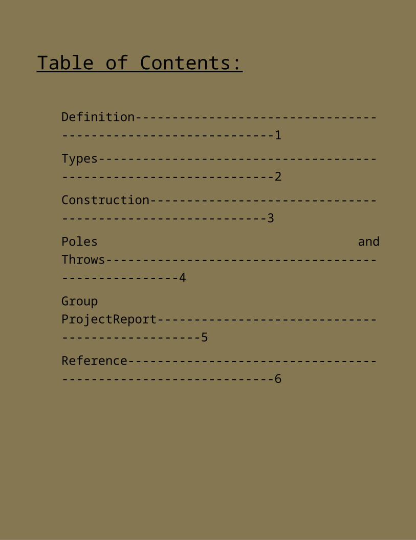
Table of Contents:
Definition--------------------------------------------------------------1Types-------------------------------------------------------------------2Construction-----------------------------------------------------------3Poles andThrows-----------------------------------------------------4GroupProjectReport-------------------------------------------------5Reference---------------------------------------------------------------6
1 DEFINITIONS A relay is a simple electromechanical switch made up of anelectromagnet and a set of contacts. Relays are found hiddenin all sorts of devices. In fact, some of the firstcomputers ever built used relays to implement Boolean gates.
A relay is an electrically operated switch. Many relays usean electromagnet to mechanically operate a switch, but otheroperating principles are also used, such as solid-staterelays. Relays are used where it is necessary to control acircuit by a low-power signal (with complete electricalisolation between control and controlled circuits), or whereseveral circuits must be controlled by one signal. The firstrelays were used in long distance telegraph circuits asamplifiers: they repeated the signal coming in from onecircuit and re-transmitted it on another circuit. Relays

were used extensively in telephone exchanges and earlycomputers to perform logical operations.
2 TYPES Solid-state relay Electromagnetic Relay Latching relay Reed relay Mercury-wetted relay Mercury relay Polarized relay Machine tool relay Ratchet relay Coaxial relay Solid state contactor relay Buchholz relay Forced-guided contacts relay Overload protection relay Vacuum relays
3 CONSTRUCTIONRelays are amazingly simple devices. There are four parts inevery relay:
o Electromagneto Armature that can be attracted by theelectromagneto Springo Set of electrical contacts
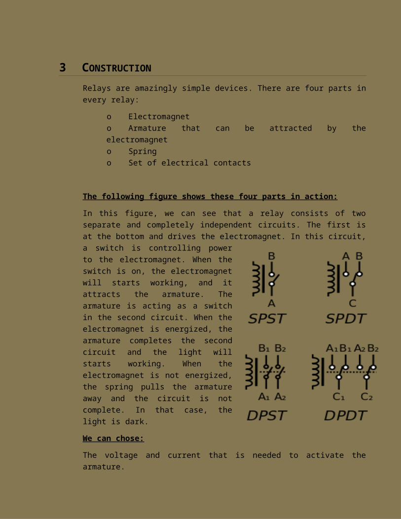
The following figure shows these four parts in action:
In this figure, we can see that a relay consists of twoseparate and completely independent circuits. The first isat the bottom and drives the electromagnet. In this circuit,a switch is controlling powerto the electromagnet. When theswitch is on, the electromagnetwill starts working, and itattracts the armature. Thearmature is acting as a switchin the second circuit. When theelectromagnet is energized, thearmature completes the secondcircuit and the light willstarts working. When theelectromagnet is not energized,the spring pulls the armatureaway and the circuit is notcomplete. In that case, thelight is dark.
We can chose:
The voltage and current that is needed to activate thearmature.
We can choose the maximum voltage and the current that canpass through the armature and contacts.
There is one or two number of armatures.
Generally there is one or two number of contacts for thearmature.The relay shown here has two, one of which isunused).
Whether the contact (if only one contact is provided) isnormally open (NO) or normally closed (NC).
4 POLES AND THROESSince relays are switches, the terminology applied toswitches is also applied to relays; a relay switchesone or more poles, each of whose contacts can be thrownby energizing the coil in one of three ways:
Normally-open(NO)
Contacts connect the circuit when the relay isactivated; the circuit is disconnected when the relayis inactive. It is also called a Form A contact or"make" contact. NO contacts may also be distinguishedas "early-make" or NOEM, which means that the contactsclose before the button or switch is fully engaged.
Normally-closed (NC)
Contacts disconnect the circuit when the relay isactivated; the circuit is connected when the relay isinactive. It is also called a Form B contact or "break"

contact. NC contacts may also be distinguished as"late-break" or NCLB, which means that the contactsstay closed until the button or switch is fullydisengaged.
Change-over (CO), or double-throw (DT)
Contacts control two circuits: one normally-opencontact and one normally-closed contact with a commonterminal. It is also called a Form C contact or"transfer" contact ("break before make"). If this typeof contact utilize a "make before break" functionality,then it is called a Form D contact.
The following types Poles and Throes are commonly used
SPST – Single Pole Single Throw
These have two terminals which can be connected ordisconnected. Including two for the coil, such a relayhas four terminals in total. It is ambiguous whetherthe pole is normally open or normally closed.
SPDT – Single Pole Double Throw
A common terminal connects to either of two others.Including two for the coil, such a relay has fiveterminals in total.
DPST – Double Pole Single Throw
These have two pairs of terminals. It isequivalent totwo SPST switches or relays actuated by a single coil.Including two for the coil, such a relay has sixterminals in total. The poles may be Form A or Form B(or one of each).
DPDT – Double Pole Double Throw
These have two rows of change-over terminals. It isequivalent to two SPDT switches or relays actuated by asingle coil. Such a relay has eight terminals,including the coil.
5 GROUP PROJECT REPORT
There are four main parts of the relay:o Armatureo Coilo Springo Electromagnet
Things we need
o 9 Volt batteryo Enameled wireo Armatureo 3 Iron nailso Ledo 100 KΩ Resistoro Connecting Wireso Spring

o Piece of woodo Bread Board
Construction
Hit the 3 nails in the piece of wood with a requireddistance, and then turn the enameled wire on the lastnail. Connect positive end of the wire (with the 9 voltbattery source) with the middle nail and take thecurrent from the first nail to connect with the breadboard; and connect the other end of the battery withthe other end of the circuit to complete the circuit.12 volt supplied through bred-board. A piece of ironwill work as an armature, and a led across 100kresistor is connected in the bread-board.
Working of Relay
When we supply 12 volt to the coil then the currentwill pass through the coil and the nail will becomeelectromagnet which attracts the armature. When thearmature is attracted by the electromagnet then thecoil will also touch the 2ndnail (which is connectedwith the 9 volt battery) and the contact will make andcurrent will pass through the wire across the bread-board where the led circuit will complete and led willglow. When the supply will cut off then the contactwill break and the led will stop glowing.
Normally open contact (NO)
This figure shows the normally open contact. When therewill be no supply across the coil then the led will beoff because the circuit will not complete
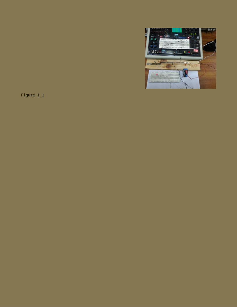
Figure 1.1
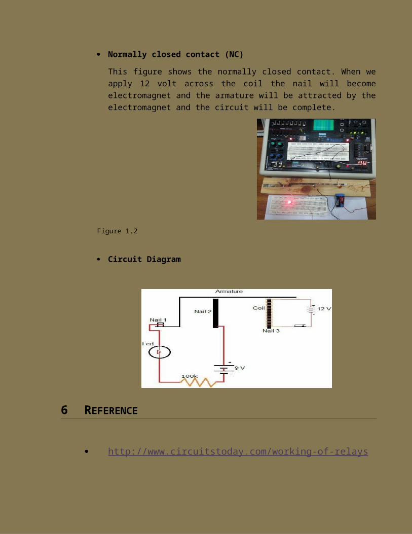
Normally closed contact (NC)
This figure shows the normally closed contact. When weapply 12 volt across the coil the nail will becomeelectromagnet and the armature will be attracted by theelectromagnet and the circuit will be complete.
Figure 1.2
Circuit Diagram
6 REFERENCE
http://www.circuitstoday.com/working-of-relays