contactors motor starters industrial relays - Octopart
68
USAH105f CONTACTORS MOTOR STARTERS INDUSTRIAL RELAYS
-
Upload
khangminh22 -
Category
Documents
-
view
0 -
download
0
Transcript of contactors motor starters industrial relays - Octopart

USAH105f
CONTACTORS MOTOR STARTERSINDUSTRIAL RELAYS

1
FUJI ELECTRIC
Fuji Electric Co., Ltd. has met the changing needs of society since being founded in 1923. The Company's technological strengths allow it to fulfill its responsibilities as a corporate and social leader ahead of its time. Over the years, Fuji Electric has entered many business fields, from the production of electronic devices and various components to large-scale systems such as electric power plants. Fuji Electric has 50+ years of experience in developing total systems and solutions for our customers.
With businesses ranging across many fields and as its mission expands, Fuji Electric is becoming increasingly aware of its role in the global society. The Company is redoubling its efforts to develop new technologies that will make an ever larger social contribution.
Fuji Electric is a global company with sales, service and manufacturing facilities located worldwide. Fuji Electric Corp. of America, incorporated in New York, has conducted business in the United States for over 25 years, with offices and operations in New Jersey, California and Texas. Fuji Electric has also established manufacturing and assembly facilities in the States of New Jersey and California. Our customer base and partnerships span across a number of Fortune 500 companies, states and city transit authorities and municipalities.
Fuji Electric Corp. of America currently supports products in the Ring Compressor Division, Distribution and Controls Division, Instrumentation and Controls Division and the Water Treatment Division.
DISTRIBUTION AND CONTROLS DIVISION
Fuji Electric's Distribution and Controls (D&C) Division offers products in the electric distribution and control system fields. Major products include control equipment, such as magnetic motor contactors, push-button switches and programmable logic controllers (PLCs) as well as electrical distribution equipment, such as molded-case circuit breakers and earth-leakage circuit breakers.
Fuji Electric's D&C Division's UL Listed and CSA Certified products provide control design / application engineers and users with an economically sound alternative choice without compromising quality, reliability or durability for years of service. This Division's products are used in machine tools, motor control centers, distribution boards, industrial machines, control panels, and instrumentation panels, as well as a host of other applications.
The Distribution and Controls Division has a network of distributors and representatives throughout the United States that provide first-rate service and response.
HIGH PERFORMANCE CONTACTORS AND STARTERS Engineered for cost and application advantages
Contactors and Starters provide the best of both worlds..... Quality and Economy
Designed to globally accepted approvals and ratings
Engineered for quality performance, day after day
Wide variety of frame sizes - up to 350HP
Overload relays feature open phase protection
Contactors through 10HP at 480V offer industry's longest life expectancy - 2 million electrical operations

Table of Contents
"ORANGE LINE" Contactors, AC Operated"ORANGE LINE" Contactors, DC Operated"ORANGE LINE" Motor Starters, AC Operated"ORANGE LINE" Motor Starters, DC Operated"ORANGE LINE" Thermal Overload Relays"ORANGE LINE" Accessories"ORANGE LINE" Dimensions"ODYSSEY SERIES" Contactors & Starters, AC Operated"ODYSSEY SERIES" Contactors & Starters, DC Operated"ODYSSEY SERIES" Contactors, AC or DC Operated"ODYSSEY SERIES" Motor Starters, AC or DC Operated"ODYSSEY SERIES" Thermal Overload Relays"ODYSSEY SERIES" Accessories"ODYSSEY SERIES" Replacement Parts"ODYSSEY SERIES" DimensionsPerformance Data"ORANGE LINE" Industrial Relay"MICRO LINE" ContactorsSF seriesCross chart from old contactor to latest contactorTerms & Conditions
Page
579
111315172123252729313435475357606366
2

Long electrical life2 million operations (AC3 duty)
Single-side-mounted coil terminalThe coil surge suppressor or coil driveunit can be easily addedTerminal numbers meet IEC standards
Meets international standards
Bifurcated contact with high contact reliability
Space for device No. strip
Manual trip button
Optional function unit can be easilyadded to modify contactor immediatelyon site.•
•
•
Auxiliary contact block fits all sizecontactors.Snap-on mechanical interlock unit canbe fixed to equal or unequal size contactors without tools.Front-mounted operation counter
Easy-to-read front displayType, ratings and terminal numbers
Manual operator for easy circuitchecking, ON-OFF status indicator
Direct-fitted overload relayassures time-saving assemblyExact current setting possible
Dial cover for protection againstunauthorized current setting
Manual reset button
Easy coil replacement without screws
Snap-on 35mm IEC and DIN rail mountingFlat side construction allows side-by-side mounting
"ORANGE" LINEUP TO 10HP@ 480VAC
2 million electrical operations.The longest in the industry."Logic level" aux contacts allow consistent operation down to 5VDC 3mA.Overloads offer "Open phase protection" as a standard feature.
See pages 5 through 16 for details
ODYSSEY SERIES(Conventional Coils)UP TO 50HP@ 480VAC
Redesigned coil offers lower power consumption characteristics.
2N0+2NC aux contacts are included.
3
See pages 21 through 24 for details
See pages 25 through 28 for details
ODYSSEY SERIES(Featuring Super Magnet Technology)UP TO 300HP@ 480VAC
Coil operates on either AC or DC voltage.Chatter-free operation, eliminatescontact welding & coil burning.
"Super magnet" design offers advancedelectronics for maximum dependability.
TerminalStationary contact
Moving contact
GridArc chamber (Resin molded)
Coil terminal
Compact size allows for efficient panel layout.
Arc chamber (Resin molded)
Coil
Coil terminal
Stationary contact
Auxiliary contact block
SUPER MAGNET
Moving contact
Terminal

4
SUPER MAGNET THEORY & EXPLANATION
ADVANTAGES OF SUPER MAGNET
POSITIVE PICK-UP AND DROP-OUTThe SUPER MAGNET operation is electronically controlled. There is no unstable zone as will be seen in the diagram, an outstanding feature that other contactors can not provide.Chattering is a phenomenon which occurs when the gravitational force of the starter magnet, decreases through the line voltage drop at the time of motor starting. This may cause damage such as contact welding or coil burning.The SUPER MAGNET holds without chattering even if the line voltage drops to 65% of its rated value, thereby preventing this type of trouble.
OPERATION ON BOTH AC AND DC INPUTS
The rated operational voltage range of the Super Magnet series contactors has been greatly expanded.They operate on both AC (50/60Hz) and DC inputs.
IC-controlledSUPER MAGNET
Pick-up
Vol
tage
Time
Coil operating signal
Coil current
Closing currentSealed current
OFF
sign
al
Sealed Drop-out
Sealed signalON
sign
al
Rated voltage
UNSTABLEZONE
Con-tactor
ON
OFFMotor inrush current
Linevoltage
NO CHATTERINGZONE
65% of rated voltage
Running current
Time
Mo
tor
curr
ent
Instantaneousvoltage drops
Lin
e vo
ltag
e (%
)
Note:No chattering occurs even if instantaneous voltage drops to 65% of rated voltage.
Note:Unstable zone In this zone contact welding and coil burning frequently occur due to voltage drop.
Coil voltage
Gra
vita
tio
nal
fo
rce
Contactsopen
Unstablezone
Contactsclosed
Rat
ed v
olt
age
Coil voltage
Gra
vita
tio
nal
fo
rce
Contactsopen
Contactsclosed
Rat
ed v
olt
age
Note:Since SC series contactors are electroni- cally controlled there is no unstable zone.
Motor starting Conventional contactors Contactors featuring Super Magnet technology
50/60Hz50/60Hz50/60Hz50/60Hz50/60Hz50/60Hz50/60Hz
24–25V48–50V
100–127V200–250V265–347V380–450V460–575V
24V48V
100–110V200–240V
–––
Coils (3F to 5H)
24V48V100V200V300V400V500V
Ratedvoltage
Rated coil voltage, frequencyAC DC Rated voltage
–15%
Pick-up
Operation
Allowableoperatingvoltage
WIDERATINGS
Allowableoperatingvoltage
+10%
Volts200 250
Example: 200V coil used in AC circuit, 50 or 60Hz.
PowersupplyAC or DC
Surgesuppressioncircuit
Rectifiercircuit
IC-circuit
Voltagedetector
Closing signalcircuit
Sealingsignalcircuit
Powerswitchingcircuit
COILINPUT

"ORANGE LINE" AC Contactors, AC Operated
EXPLANATION OF PART NUMBER SYSTEM
NON-REVERSING CONTACTORS UL File No. E42419, E44592 cUL listed
1 Phase HP Rating(Full load ampere)
3 Phase HP Ratings(Full load ampere) Part Number Fuji Type Frame Size
Qty. ofAuxiliaryContacts
Rated thermalcurrent for
non inductive /resistive load200-208V 220-240V100-120V 220-240V 440-480V 550-600V
1 Phase HP Rating(Full load ampere)
3 Phase HP Ratings(Full load ampere)
Rated thermalcurrent for
non inductive /resistive load200-208V 220-240V100-120V 220-240V 440-480V 550-600V
REVERSING CONTACTORS UL File No. E42419, E44592 cUL listed
If larger contactors are required, please turn to page 21.
Part Number Fuji Type Frame SizeQty. of
AuxiliaryContacts
5
4 N C 0 A 0 # @ @PRODUCT LINE
OPERATION
DESCRIPTION
FRAME SIZE
4=Orange Line
N=AC CoilG=DC Coil 10 : 1NO
01 : 1NC11 : 1NO+1NCSee above under the "Qty. of Aux Contacts" column or next page.
Blank: StandardY: Optional, non removable terminal cover accessory. (Note: Y type not available for 0Q or 0R frame sizes)
20 : 2NO02 : 2NC
C=Non-Reversing ContactorD=Reversing Contactor
QUANTITY OF AUX. CONTACTS
COIL VOLTAGESelect code from chart on next page
FRAME ENCLOSURE0=Open Frame, No Enclosure
%TERMINAL OPTION
Note: The list above indicates the No. of auxiliary contacts provided per contactor.
1/3(7.2)1/3
(7.2)1/3
(7.2)1
(16)1
(16)1
(16)
1(8)1
(8)1
(8)2
(12)2
(12)2
(12)
2(7.8)
3(11)
3(11)
5(17.5)
5(17.5)
5(17.5)
2(6.8)
3(9.6)
3(9.6)
5(15.2)
5(15.2)
5(15.2)
5(7.6)
5(7.6)
5(7.6)71/2(11)10
(14)10
(14)
5(6.1)
5(6.1)
5(6.1)71/2(9)10
(11)10
(11)
11
13
13
20
20
20
1
1
2
1
1
2
4ND0A0#@@%
4ND0F0#@@%
4ND0G0#@@%
4ND0Q0#@@%
4ND0R0#@@%
4ND0H0#@@%
SC-03RM
SC-0RM
SC-05RM
SC-4-0RM
SC-4-1RM
SC-5-1RM
0A
0F
0G
0Q
0R
0H
1/3(7.2)1/3
(7.2)1/3
(7.2)1
(16)1
(16)1
(16)
1(8)1
(8)1
(8)2
(12)2
(12)2
(12)
2(7.8)
3(11)
3(11)
5(17.5)
5(17.5)
5(17.5)
2(6.8)
3(9.6)
3(9.6)
5(15.2)
5(15.2)
5(15.2)
5(7.6)
5(7.6)
5(7.6)71/2(11)10
(14)10
(14)
5(6.1)
5(6.1)
5(6.1)71/2(9)10
(11)10
(11)
11
13
13
20
20
20
1
1
2
1
1
2
4NC0A0#@@%
4NC0F0#@@%
4NC0G0#@@%
4NC0Q0#@@%
4NC0R0#@@%
4NC0H0#@@%
SC-03
SC-0
SC-05
SC-4-0
SC-4-1
SC-5-1
0A
0F
0G
0Q
0R
0H

"ORANGE LINE" AC Contactors, AC Operated
AVAILABLE COILS
WIRING DIAGRAMS / AUXILIARY CONTACT INFORMATION
EFA1GB2C45
2448
100110120200220400440550
26V52V110V120V130V220V240V440V480V600V
––––––––––
100110
200380415500
110V120V
220V400V440V550V
24V48V100V
––
200V––––
Code Letter AC Coil 60Hz AC Coil 50Hz
0A0F0G0Q0R0H
959595959595
999999
58–6858–6858–6865–7365–7365–73
40–5540–5540–5544–6044–6044–60
9–209–209–209–209–209–20
5–165–165–165–165–165–16
Frame SizePower
Consumption(VA)
Pick-upVoltage
(V)
Drop-outVoltage
(V)
Inrush Sealed ContactON
ContactOFF
OperatingTime (ms)
CoilON
CoilOFF
COIL CHARACTERISTICS
Operating
AC A600 10 60/6
DC Q300 10 120V 240V
0.55/0.55 0.27/0.27
30/3 15/1.5 12/1.2
Contact ratingCode
Designation
ContinuousAmpereRating
110 to120V
220 to240V
440 to480V
550 to600V
Current–Make/Break (A)
AUXILIARY CONTACT RATINGS
NON-REVERSING CONTACTORS
(4NC0A0, 0F0, 0Q0 and 0R0)
1NO* (Standard)* 1NO+1NC (Standard)**
1NC* (Option) 2NO** (Option)
2NC** (Option)
(4NC0G0 and 4NC0H0) (4ND0A0, 0F0, 0Q0, 0R0) *** (4ND0G0 and 4ND0H0) ***
REVERSING CONTACTORS
* The 0A, 0F, 0Q & 0R frames offer 1 Aux. contact, NO standard. However, NC is available as an option.** The 0G & 0H frames offer 2 Aux. contacts, 1NO + 1NC standard. However, 2NO or 2NC is available as an option.*** Reversing contactors are NOT pre-wired with an electrical interlock unless requested when ordered. Reversing contactors without at least 1NC Aux. contact can not be electrically interlocked.
6
If DC operation is required, please turn to page 7-8. This data is based on 110-120VAC, 50/60Hz coil, tested at 120VAC, 60Hz.
For additional coil data, please see page 49.

"ORANGE LINE" AC Contactors, DC Operated
7
NON-REVERSING CONTACTORS UL File No. E42419, E44592 cUL listed
1 Phase HP Rating(Full load ampere)
3 Phase HP Ratings(Full load ampere) Part Number Fuji Type Frame Size
Qty. ofAuxiliaryContacts
Rated thermalcurrent for
non inductive /resistive load200-208V 220-240V100-120V 220-240V 440-480V 550-600V
1 Phase HP Rating(Full load ampere)
3 Phase HP Ratings(Full load ampere)
Rated thermalcurrent for
non inductive /resistive load200-208V 220-240V100-120V 220-240V 440-480V 550-600V
REVERSING CONTACTORS UL File No. E42419, E44592 cUL listed
Part Number Fuji Type Frame SizeQty. of
AuxiliaryContacts
Note: The list above indicates the No. of auxiliary contacts provided per contactor.
1/3(7.2)1/3
(7.2)1/3
(7.2)1
(16)1
(16)1
(16)
1(8)1
(8)1
(8)2
(12)2
(12)2
(12)
2(7.8)
3(11)
3(11)
5(17.5)
5(17.5)
5(17.5)
2(6.8)
3(9.6)
3(9.6)
5(15.2)
5(15.2)
5(15.2)
5(7.6)
5(7.6)
5(7.6)71/2(11)10
(14)10
(14)
5(6.1)
5(6.1)
5(6.1)71/2(9)10
(11)10
(11)
11
13
13
20
20
20
1
1
2
1
1
2
4GD0A0#@@%
4GD0F0#@@%
4GD0G0#@@%
4GD0Q0#@@%
4GD0R0#@@%
4GD0H0#@@%
SC-03RM/G
SC-0RM/G
SC-05RM/G
SC-4-0RM/G
SC-4-1RM/G
SC-5-1RM/G
0A
0F
0G
0Q
0R
0H
1/3(7.2)1/3
(7.2)1/3
(7.2)1
(16)1
(16)1
(16)
1(8)1
(8)1
(8)2
(12)2
(12)2
(12)
2(7.8)
3(11)
3(11)
5(17.5)
5(17.5)
5(17.5)
2(6.8)
3(9.6)
3(9.6)
5(15.2)
5(15.2)
5(15.2)
5(7.6)
5(7.6)
5(7.6)71/2(11)10
(14)10
(14)
5(6.1)
5(6.1)
5(6.1)71/2(9)10
(11)10
(11)
11
13
13
20
20
20
1
1
2
1
1
2
4GC0A0#@@%
4GC0F0#@@%
4GC0G0#@@%
4GC0Q0#@@%
4GC0R0#@@%
4GC0H0#@@%
SC-03/G
SC-0/G
SC-05/G
SC-4-0/G
SC-4-1/G
SC-5-1/G
0A
0F
0G
0Q
0R
0H
If larger contactors are required, please turn to page 23.
EXPLANATION OF PART NUMBER SYSTEM
4 G C 0 A 0 # @ @PRODUCT LINE
OPERATION
DESCRIPTION
FRAME SIZE
4=Orange Line
N=AC CoilG=DC Coil
C=Non-Reversing ContactorD=Reversing Contactor
%TERMINAL OPTION
10 : 1NO01 : 1NC11 : 1NO+1NCSee above under the "Qty. of Aux Contacts" column or next page.
Blank: StandardY: Optional, non removable terminal cover accessory. (Note: Y type not available for 0Q or 0R frame sizes)
20 : 2NO02 : 2NC
QUANTITY OF AUX. CONTACTS
COIL VOLTAGESelect code from chart on next page
FRAME ENCLOSURE0=Open Frame, No Enclosure

"ORANGE LINE" AC Contactors, DC Operated
AVAILABLE COILS
WIRING DIAGRAMS / AUXILIARY CONTACT INFORMATION
TMN1R2S
12V24V48V
100V110V200V220V
Code Letter DC Coil
Operating
AC A600 10 60/6
DC Q300 10 120V 240V
0.55/0.55 0.27/0.27
30/3 15/1.5 12/1.2
Contact RatingCode
Designation
ContinuousAmpereRating
110 to120V
220 to240V
440 to480V
550 to600V
Current–Make/Break (A)
AUXILIARY CONTACT RATINGS
NON-REVERSING CONTACTORS
(4GC0A0, 0F0, 0Q0 and 0R0)
1NO* (Standard)* 1NO+1NC (Standard)**
1NC* (Option) 2NO** (Option)
2NC** (Option)
(4GC0G0 and 4GC0H0) (4GD0A0, 0F0, 0Q0, 0R0) *** (4GD0G0 and 4GD0H0) ***
REVERSING CONTACTORS
* The 0A, 0F, 0Q & 0R frames offer 1 Aux. contact, NO standard. However, NC is available as an option.** The 0G & 0H frames offer 2 Aux. contacts, 1NO + 1NC standard. However, 2NO or 2NC is available as an option.*** Reversing contactors are NOT pre-wired with an electrical interlock unless requested when ordered. Reversing contactors without at least 1NC Aux. contact can not be electrically interlocked.
8
If AC operation is required, please turn to page 5-6.
0A0F0G0Q0R0H
777777
777777
11–1511–1510–1511–1511–1511–16
3–63–63–73–73–74–7
43–4743–4743–4744–4844–4845–49
22–2422–2422–2422–2522–2522–26
Frame SizePower
Consumption(VA)
Pick-upVoltage
(V)
Drop-outVoltage
(V)
Inrush Sealed ContactON
ContactOFF
OperatingTime (ms)
CoilON
CoilOFF
COIL CHARACTERISTICS
This data is based on 24-26VDC coil, tested at 24VDC.For additional coil data, please see page 50.

"ORANGE LINE" AC Motor Starters, AC Operated
9
EXPLANATION OF PART NUMBER SYSTEM
4 N W 0 A 0 # * KPRODUCT LINE
OPERATION
DESCRIPTION
FRAME SIZE
FRAME ENCLOSURE
4=Orange Line
N=AC CoilG=DC Coil
W=Non-Reversing Motor StarterX=Reversing Motor Starter
0=Open Frame, No Enclosure
OVERLOAD RANGECOIL VOLTAGE
OVERLOAD TYPEK=Open Phase Protection
offered as a standard
Select appropriate letter from chart on next page
Select code from chart on next page
NON-REVERSING MOTOR STARTERS UL File No. E42419, E44592 cUL listed
1 Phase HP Rating(Full load ampere)
3 Phase HP Ratings(Full load ampere) Part Number Fuji Type Frame Size
Qty. ofAuxiliaryContacts
Rated thermalcurrent for
non inductive /resistive load200-208V 220-240V100-120V 220-240V 440-480V 550-600V
1 Phase HP Rating(Full load ampere)
3 Phase HP Ratings(Full load ampere)
Rated thermalcurrent for
non inductive /resistive load200-208V 220-240V100-120V 220-240V 440-480V 550-600V
REVERSING MOTOR STARTERS UL File No. E42419, E44592 cUL listed
Part Number Fuji Type Frame SizeQty. of
AuxiliaryContacts
Note: The list above indicates the No. of auxiliary contacts provided per contactor.
1/3(7.2)1/3
(7.2)1/3
(7.2)1
(16)1
(16)1
(16)
1(8)1
(8)1
(8)2
(12)2
(12)2
(12)
2(7.8)
3(11)
3(11)
5(17.5)
5(17.5)
5(17.5)
2(6.8)
3(9.6)
3(9.6)
5(15.2)
5(15.2)
5(15.2)
5(7.6)
5(7.6)
5(7.6)71/2(11)10
(14)10
(14)
5(6.1)
5(6.1)
5(6.1)71/2(9)10
(11)10
(11)
11
13
13
20
20
20
1
1
2
1
1
2
4NX0A0#*@@K%
4NX0F0#*@@K%
4NX0G0#*@@K%
4NX0Q0#*@@K%
4NX0R0#*@@K%
4NX0H0#*@@K%
SW-03RM/2E
SW-0RM/2E
SW-05RM/2E
SW-4-0RM/2E
SW-4-1RM/2E
SW-5-1RM/2E
0A
0F
0G
0Q
0R
0H
1/3(7.2)1/3
(7.2)1/3
(7.2)1
(16)1
(16)1
(16)
1(8)1
(8)1
(8)2
(12)2
(12)2
(12)
2(7.8)
3(11)
3(11)
5(17.5)
5(17.5)
5(17.5)
2(6.8)
3(9.6)
3(9.6)
5(15.2)
5(15.2)
5(15.2)
5(7.6)
5(7.6)
5(7.6)71/2(11)10
(14)10
(14)
5(6.1)
5(6.1)
5(6.1)71/2(9)10
(11)10
(11)
11
13
13
20
20
20
1
1
2
1
1
2
4NW0A0#*@@K%
4NW0F0#*@@K%
4NW0G0#*@@K%
4NW0Q0#*@@K%
4NW0R0#*@@K%
4NW0H0#*@@K%
SW-03/2E
SW-0/2E
SW-05/2E
SW-4-0/2E
SW-4-1/2E
SW-5-1/2E
0A
0F
0G
0Q
0R
0H
If larger motor starters are required, please turn to page 21.
Blank: StandardY: Optional, non removable terminal cover accessory.(Note: Y type not available for 0Q or 0R frame sizes)
@ @
10 : 1NO01 : 1NC11 : 1NO+1NCSee above under the "Qty. of Aux Contacts" column or next page.
20 : 2NO02 : 2NC
QUANTITY OF AUX. CONTACTS
%TERMINAL OPTION

"ORANGE LINE" AC Motor Starters, AC Operated
WIRING DIAGRAMS / AUXILIARY CONTACT INFORMATION
OVERLOAD RANGES
Operating
AC A600 10 60/6
DC Q300 10 120V 240V
0.55/0.55 0.27/0.27
30/3 15/1.5 12/1.2
Contact ratingCode
Designation
ContinuousAmpereRating
110 to120V
220 to240V
440 to480V
550 to600V
Current–Make/Break (A)
AUXILIARY CONTACT RATINGS
NON-REVERSING MOTOR STARTERS
(4NW0A0, 0F0, 0Q0 and 0R0)* (4NW0G0 and 0H0)** (4NX0A0, 0F0, 0Q0, 0R0) *** (4NX0G0, 0H0) ***
REVERSING MOTOR STARTERS
Code Range
ABCD
0.1–0.150.15–0.240.24–0.360.36–0.54
Code Range
EFGH
0.48–0.720.64–0.960.8–1.2
0.95–1.45
Code Range
JKLM
1.4–2.21.7–2.62.2–3.42.8–4.2
Code Range
NPQS
4–65–86–97–11
Code Range
T†
V†9–1312–18
* The 0A, 0F, 0Q & 0R frames offer 1 Aux. contact, NO standard. However, NC is available as an option.** The 0G & 0H frames offer 2 Aux. contacts, 1NO + 1NC standard. However, 2NO or 2NC is available as an option.*** Reversing starters are NOT pre-wired with an electrical interlock unless requested when ordered. Reversing starters without at least 1NC Aux. contact can not be electrically interlocked.
10
Overload relays can be purchased separetely.See page 13 for details and part numbers.
† These codes (T & V) are not available on frame sizes 0A, 0F, or 0G. They can be specified for use on frame sizes 0Q, OR, & 0H only.
AVAILABLE COILS
EFA1GB2C45
2448
100110120200220400440550
26V52V110V120V130V220V240V440V480V600V
––––––––––
100110
200380415500
110V120V
220V400V440V550V
24V48V100V
––
200V––––
Code Letter AC Coil 60Hz AC Coil 50Hz
0A0F0G0Q0R0H
959595959595
999999
58–6858–6858–6865–7365–7365–73
40–5540–5540–5544–6044–6044–60
9–209–209–209–209–209–20
5–165–165–165–165–165–16
Frame SizePower
Consumption(VA)
Pick-upVoltage
(V)
Drop-outVoltage
(V)
Inrush Sealed ContactON
ContactOFF
OperatingTime (ms)
CoilON
CoilOFF
COIL CHARACTERISTICS
If DC operation is required, please turn to page 11-12.
This data is based on 110-120VAC, 50/60Hz coil, tested at 120VAC, 60Hz.For additional coil data, please see page 49.

"ORANGE LINE" AC Motor Starters, DC Operated
11
EXPLANATION OF PART NUMBER SYSTEM
NON-REVERSING MOTOR STARTERS UL File No. E42419, E44592 cUL listed
1 Phase HP Rating(Full load ampere)
3 Phase HP Ratings(Full load ampere) Part Number Fuji Type Frame Size
Qty. ofAuxiliaryContacts
Rated thermalcurrent for
non inductive /resistive load200-208V 220-240V100-120V 220-240V 440-480V 550-600V
1 Phase HP Rating(Full load ampere)
3 Phase HP Ratings(Full load ampere)
Rated thermalcurrent for
non inductive /resistive load200-208V 220-240V100-120V 220-240V 440-480V 550-600V
REVERSING MOTOR STARTERS UL File No. E42419, E44592 cUL listed
Part Number Fuji Type Frame SizeQty. of
AuxiliaryContacts
Note: The list above indicates the No. of auxiliary contacts provided per contactor.
1/3(7.2)1/3
(7.2)1/3
(7.2)1
(16)1
(16)1
(16)
1(8)1
(8)1
(8)2
(12)2
(12)2
(12)
2(7.8)
3(11)
3(11)
5(17.5)
5(17.5)
5(17.5)
2(6.8)
3(9.6)
3(9.6)
5(15.2)
5(15.2)
5(15.2)
5(7.6)
5(7.6)
5(7.6)71/2(11)10
(14)10
(14)
5(6.1)
5(6.1)
5(6.1)71/2(9)10
(11)10
(11)
11
13
13
20
20
20
1
1
2
1
1
2
4GX0A0#*@@K%
4GX0F0#*@@K%
4GX0G0#*@@K%
4GX0Q0#*@@K%
4GX0R0#*@@K%
4GX0H0#*@@K%
SW-03RM/G2E
SW-0RM/G2E
SW-05RM/G2E
SW-4-0RM/G2E
SW-4-1RM/G2E
SW-5-1RM/G2E
0A
0F
0G
0Q
0R
0H
1/3(7.2)1/3
(7.2)1/3
(7.2)1
(16)1
(16)1
(16)
1(8)1
(8)1
(8)2
(12)2
(12)2
(12)
2(7.8)
3(11)
3(11)
5(17.5)
5(17.5)
5(17.5)
2(6.8)
3(9.6)
3(9.6)
5(15.2)
5(15.2)
5(15.2)
5(7.6)
5(7.6)
5(7.6)71/2(11)10
(14)10
(14)
5(6.1)
5(6.1)
5(6.1)71/2(9)10
(11)10
(11)
11
13
13
20
20
20
1
1
2
1
1
2
4GW0A0#*@@K%
4GW0F0#*@@K%
4GW0G0#*@@K%
4GW0Q0#*@@K%
4GW0R0#*@@K%
4GW0H0#*@@K%
SW-03/G2E
SW-0/G2E
SW-05/G2E
SW-4-0/G2E
SW-4-1/G2E
SW-5-1/G2E
0A
0F
0G
0Q
0R
0H
If larger motor starters are required, please turn to page 23.
4 G W 0 A 0 # * KPRODUCT LINE
OPERATION
DESCRIPTION
FRAME SIZE
FRAME ENCLOSURE
4=Orange Line
N=AC CoilG=DC Coil
W=Non-Reversing Motor StarterX=Reversing Motor Starter
0=Open Frame, No Enclosure
OVERLOAD RANGECOIL VOLTAGE
OVERLOAD TYPEK=Open Phase Protection
offered as a standard
Select appropriate letter from chart on next page
Select code from chart on next page
Blank: StandardY: Optional, non removable terminal cover accessory.(Note: Y type not available for 0Q or 0R frame sizes)
@ @
10 : 1NO01 : 1NC11 : 1NO+1NCSee above under the "Qty. of Aux Contacts" column or next page.
20 : 2NO02 : 2NC
QUANTITY OF AUX. CONTACTS
%TERMINAL OPTION

"ORANGE LINE" AC Motor Starters, DC Operated
WIRING DIAGRAMS / AUXILIARY CONTACT INFORMATION
OVERLOAD RANGES
Operating
AC A600 10 60/6
DC Q300 10120V 240V
0.55/0.55 0.27/0.27
30/3 15/1.5 12/1.2
Contact ratingcode
designation
Continuousampererating
110 to120V
220 to240V
440 to480V
550 to600V
Current–Make/Break (A)
AUXILIARY CONTACT RATINGS
NON-REVERSING MOTOR STARTERS
(4NW0A0, 0F0, 0Q0 and 0R0)* (4GW0G0 and 0H0)** (4GX0A0, 0F0, 0Q0, 0R0) *** (4GX0G0, 0H0) ***
REVERSING MOTOR STARTERS
Code Range
ABCD
0.1–0.150.15–0.240.24–0.360.36–0.54
Code Range
EFGH
0.48–0.720.64–0.960.8–1.2
0.95–1.45
Code Range
JKLM
1.4–2.21.7–2.62.2–3.42.8–4.2
Code Range
NPQS
4–65–86–97–11
Code Range
T†
V†9–1312–18
* The 0A, 0F, 0Q & 0R frames offer 1 Aux. contact, NO standard. However, NC is available as an option.** The 0G & 0H frames offer 2 Aux. contacts, 1NO + 1NC standard. However, 2NO or 2NC is available as an option.*** Reversing contactors are NOT pre-wired with an electrical interlock unless requested when ordered. Reversing contactors without at least 1NC Aux. contact can not be electrically interlocked.
12
Overload relays can be purchased separetely.See page 13 for details and part numbers.
† These codes (T & V) are not available on frame sizes 0A, 0F, or 0G. They can be specified for use on frame sizes 0Q, OR, & 0H only.
AVAILABLE COILS
TMN1R2S
12V24V48V
100V110V200V220V
Code Letter DC Coil
If AC operation is required, please turn to page 9-10.
0A0F0G0Q0R0H
777777
777777
11–1511–1510–1511–1511–1511–16
3–63–63–73–73–74–7
43–4743–4743–4744–4844–4845–49
22–2422–2422–2422–2522–2522–26
Frame SizePower
Consumption(VA)
Pick-upVoltage
(V)
Drop-outVoltage
(V)
Inrush Sealed ContactON
ContactOFF
OperatingTime (ms)CoilON
CoilOFF
COIL CHARACTERISTICS
This data is based on 24-26VDC coil, tested at 24VDC.For additional coil data, please see page 50.

"ORANGE LINE" THERMAL OVERLOAD RELAYS Selection Guide
FEATURES
1NO+1NC alarm contact (Automatic reset available.)Provided with a built-in heater, thus ensuring accurate operations.Calibrated Rated Current Dial.With manual trip device.With open-phase protection device.
Overload Part# AdjustableAmpere Range
Ampere RangeCode Letter
Used onContactor Frames
JapanesePart Numberfor Overload
ABCDEFGHJKLMNPQS
0.1 – 0.150.15 – 0.240.24 – 0.360.36 – 0.540.48 – 0.720.64 – 0.960.8 – 1.2
0.95 – 1.451.4 – 2.21.7 – 2.62.2 – 3.42.8 – 4.2
4 – 65 – 86 – 97 – 11
0A, 0F, 0G TK-0N
ABCDEFGHJKLMNPQSTV
0.1 – 0.150.15 – 0.240.24 – 0.360.36 – 0.540.48 – 0.720.64 – 0.960.8 – 1.2
0.95 – 1.451.4 – 2.21.7 – 2.62.2 – 3.42.8 – 4.2
4 – 65 – 86 – 97 – 119 – 1312 – 18
0Q, 0R, 0H
4NK0A*%
4NK0H*% TK-5-1N
13
THERMAL OVERLOAD RELAYS UL File No.E44592 CSA File No.LR20479
EXPLANATION OF PART NUMBER SYSTEM
4 N K 0 APRODUCT LINE
STYLE
4N=Orange Line
FRAME SIZEENCLOSURE0=None, Open Frame
See above chart
A or H
* %
AMPERE RANGE CODEK=Open Phase Protectionoffered as a standard
Blank: StandardY: Optional, non removable terminal cover accessory.
TERMINAL OPTION

"ORANGE LINE" THERMAL OVERLOAD RELAYS Overload Trip Curves
THERMAL OVERLOAD RELAYS/OPEN-PHASE PROTECTION TYPE K
14
AMBIENT TEMPERATURE COMPENSATOR
FUJI overload relays are provided with an ambient temperature compensator. Their characteristics limit ampere value changes to approx. 10% as the ambient temperature changes between –5˚C and 40˚C.
For 4NK0A* overloads, use mounting bracket part # SZ-HBFor 4NK0H* overloads, use mounting bracket part # SZ-HC
Base unit for separate mounting
C600 2.5 15/1.5 7.5/0.75 3.75/0.375 3.0/0.3
Contact ratingCode
Designation
ContinuousAmpereRating
110 to120V
220 to240V
440 to480V
550 to600V
Current–Make/Break (A)
ALARM CONTACT RATINGS
WIRING DIAGRAMS
(4NK0A* through 4NK4Q*)
Cold Start Hot Start
60
Min.
Sec.
40
30
10864
2
50
30
20
10864
2
1
1
Multiple of current setting Multiple of current setting
2 3 4 5 6 7 8 9
X IN (A) X IN (A)
10 15
0.3
Min
ute
s
Trip
pin
g t
ime
Sec
on
ds
60
Min.
Sec.
40
20
10
6
5
4
60
40
20
10
6
4
2
1
1 2 3 4 5 6 7 8 9 10
0.3
Min
ute
s
Trip
pin
g t
ime
Sec
on
ds
Cat. No.: 4NK0A*, 4NK0H*FUJI type: TK-0N, TK-5-1N
Independent mounting of Orange Line thermal overload relays is possible through the use of an additional mounting bracket.

"ORANGE LINE" ACCESSORIES
AUXILIARY CONTACT BLOCKSingle pole (1NO + 1NC)
MECHANICAL INTERLOCK UNITThe mechanical interlock unit is used tointerlock two contactors for reversing.One size fits all contactors.
MAIN CIRCUIT SURGE SUPPRESSION UNITThis unit prevents mis-operation of electronic controllers due to surge voltages.
15
SIDE MOUNTING
AUXILIARY CONTACT BLOCK2-pole or 4-pole
OPERATION COUNTERThis counter indicates the number of contactor ON-OFF operations to ensure easy maintenance and inspection.
MAIN CIRCUIT SURGE SUPPRESSION UNIT
FRONT MOUNTING
COIL DRIVE UNITThis unit controls ON-OFF operation for magnetic contactors with outputfrom electronic equipment.
COIL SURGE SUPPRESSION UNITThis unit absorbs coil surge voltage due to contactor ON-OFF operations.
TOP MOUNTING
Note:
*:These accessories can be mounted on contactor or starter. However UL and CSA does not approve these combinations as UL Listed or CSA Certified products.
Coil drive unit*
Main circuit surgesuppression unit
Auxiliary contactblock
Mechanical interlock unit
Auxiliarycontact block
Operation counter
Main circuit surgesuppression unit
Dial cover
Trip indicator*
Reset release button
Auxiliary contact blockTerminal cover
Coil surge suppression unit

Description Type
•Front mounting 4NO 3NO+1NC 2NO+2NC 2NO 1NO+1NC 2NC 1NO+1NC (Over lapping) 2NO+2NC (Over lapping)•Front mounting, single contact type 4NO 3NO+1NC 2NO+2NC•Side mounting 1NO+1NC•Side mounting, single contact type
Auxiliary Contact Block
Front mounting type and side mounting type auxiliarycontact blocks can not be used simultaneously.
SZ-A40SZ-A31SZ-A22SZ-A20SZ-A11SZ-A02SZ-A111SZ-A222
SZ-A40HSZ-A31HSZ-A22HSZ-AS1
SZ-AS1H
Size Contacts Kit Each U.S. Catalog No.
0A
0F, 0G
0Q
0R, 0H
4NC0A-CK
4NC0G-CK
4NC0Q-CK
4NC0H-CK
MovableStationaryMovableStationaryMovableStationaryMovableStationary
36363636
•Without alarm contact•With alarm contact at 1-million operations at 2-million operations at 3-million operations at 4-million operations at 5-million operations at 6-million operations at 7-million operations at 8-million operations
For 0A0, 0F0, 0G0 (2 pcs.)
For 0Q0, 0R0, 0H0 (2 pcs.)
24V DC (Relay)
24V DC (Solid State)
100V AC110V AC200V AC220V AC
Operating Counter
3-pole ParallelConnection Link
Coil Drive Unit
Off-delay ReleaseUnit
SZ-J
SZ-J1SZ-J2SZ-J3SZ-J4SZ-J5SZ-J6SZ-J7SZ-J8
SZ-SP1
SZ-SP2
SZ-CD1
SZ-03/CD2-24
SZ-DE100SZ-DE110SZ-DE200SZ-DE220
Description Type
•Contactor For 4NC0A0, 4NC0F0 For 4NC0G0 For 4NC0Q0, 4NC0R0 For 4NC0H0
•Auxiliary contact block For 4-pole, front mounting For 2-pole, front mounting For 2-pole, side mounting
•Thermal overload relay For 4NK0A For 4NK0H Base unit for separate mounting: For SZ-HB For SZ-HC
Varistor: 24 to 48V AC 100 to 240V AC 380 to 440V AC 24 to 48V AC with LED 100 to 240V AC with LEDRC: 24 to 48V AC 100 to 240V AC 24 to 48V AC with LED 100 to 240V AC with LED
With delta-connected CR, 100 to 240V AC•Front mounting•Side mounting
For 4NK0AFor 4NK0H
Non-reversing (Plastic)Non-reversing, with pushbuttons (Plastic)Reversing (Steel)
100 to 110V AC200 to 220V AC
Lead length:300mm 500mm 700mm
For 4NC0A0, 4NC0F0For 4NC0G0For 4NC0Q0, 4NC0R0For 4NC0H0
Terminal Cover
Coil SurgeSuppression Unit
Main Circuit SurgeSuppression Unit
Base Unit for Separate Mounting
Case Cover
Dial Cover
Trip Indicator
Reset ReleaseButton
Mechanical Interlock Unit
Power ConnectionKit for Reversing
SZ-T1SZ-T2SZ-T3SZ-T4
SZ-T5SZ-T6SZ-T7
SZ-T12SZ-T13
SZ-T10SZ-T11
SZ-Z1SZ-Z2SZ-Z3SZ-Z6SZ-Z7SZ-Z4SZ-Z5SZ-Z8SZ-Z9
SZ-ZM1SZ-ZM2
SZ-HBSZ-HC
SZ-JC1SZ-JC2
SZ-JC3
SZ-DA
SZ-L100SZ-L200
SZ-R1SZ-R2SZ-R3
SZ-RM
SZ-RW1SZ-RW2SZ-RW3SZ-RW4
16
ORANGE LINE REPLACEMENT PARTS
MAIN CONTACTS COIL
ALL ORANGE LINE devices use the same coils.
–AC coils: 4NC0H-#MC, Replace the # with the correct coil code found on page 6
–DC coils: 4GC0H-#MC, Replace the # with the correct coil code found on page 8
"ORANGE LINE" ACCESSORIES

17
NON-REVERSING CONTACTORS/OPEN TYPE Approximate Dimensions, mm
FIG.1 (4NC0A0 through 4NC0H0)
FIG.2 (4NW0A0 through 4NW0H0)
4NC0A0, 0F0, 0Q0, 0R0 4NC0G0, 0H0
N (Screw size)
U.S. CAT. No. Fuji Type Fig. No. Dimensions, mm Net Weight(kg)A B C C' D E GF H N
4NC0A0 SC-03 1 43 80 80 90 60 52 48 34 35 2-M4 0.324NC0F0 SC-0 1 43 80 80 90 60 52 48 34 35 2-M4 0.324NC0G0 SC-05 1 53 80 80 90 60 52 48 34 35 2-M4 0.344NC0Q0 SC-4-0 1 53 80 81 91 60 52 48 34 35 2-M4 0.364NC0R0 SC-4-1 1 53 80 81 91 60 52 48 34 35 2-M4 0.364NC0H0 SC-5-1 1 64 80 81 91 60 60 56 54 50 2-M4 0.384GC0A0 SC-03/G 1 43 80 110 120 60 52 48 34 35 2-M4 0.554GC0F0 SC-0/G 1 43 80 110 120 60 52 48 34 35 2-M4 0.554GC0G0 SC-05/G 1 53 80 110 120 60 52 48 34 35 2-M4 0.584GC0Q0 SC-4-0/G 1 53 80 111 121 60 52 48 34 35 2-M4 0.64GC0R0 SC-4-1/G 1 53 80 111 121 60 52 48 34 35 2-M4 0.64GC0H0 SC-5-1/G 1 64 80 111 121 60 60 56 54 50 2-M4 0.62
U.S. CAT. No. Fuji Type Fig. No. Dimensions, mm Net Weight(kg)A B C C' D F G G' H H' J K N
4NW0A04NW0F04NW0G04NW0Q04NW0R04NW0H04GW0A04GW0F04GW0G04GW0Q04GW0R04GW0H0
SW-03/2E 2 44 120 80 90 81 60 52 48 35 34 90 26.5 2-M4 0.43SW-0/2E 2 44 120 80 90 81 60 52 48 35 34 90 26.5 2-M4 0.43SW-05/2E 2 53 120 80 90 81 60 52 48 35 34 90 35.5 2-M4 0.45SW-4-0/2E 2 53 126 81 91 81 60 52 48 35 34 93 26.5 2-M4 0.47SW-4-1/2E 2 53 126 81 91 81 60 52 48 35 34 93 26.5 2-M4 0.47SW-5-1/2E 2 64 126 81 91 81 60 60 56 50 54 93 37.5 2-M4 0.5SW-03/G 2E 2 44 120 110 120 81 60 52 48 35 34 90 26.5 2-M4 0.66SW-0/G 2E 2 44 120 110 120 81 60 52 48 35 34 90 26.5 2-M4 0.66SW-05/G 2E 2 53 120 110 120 81 60 52 48 35 34 90 35.5 2-M4 0.69SW-4-0/G 2E 2 53 126 111 121 81 60 52 48 35 34 93 26.5 2-M4 0.72SW-4-1/G 2E 2 53 126 111 121 81 60 52 48 35 34 93 26.5 2-M4 0.72SW-5-1/G 2E 2 64 126 111 121 81 60 60 56 50 54 93 37.5 2-M4 0.74
"ORANGE LINE" Dimensions

18
808080808080808080808080
808080818181110110110111111111
909090919191120120120121121121
525252525260525252525260
484848484856484848484856
4-M44-M44-M44-M44-M44-M44-M44-M44-M44-M44-M44-M4
U.S. CAT. No. Fuji Type Fig. No. Dimensions, mm Net Weight(kg)A B C C' G G'
565666666677565666666677
H N
4ND0A04ND0F04ND0G04ND0Q04ND0R04ND0H04GD0A04GD0F04GD0G04GD0Q04GD0R04GD0H0
SC-03RMSC-0RMSC-05RMSC-4-0RMSC-4-1RMSC-5-1RMSC-03RM/GSC-0RM/GSC-05RM/GSC-4-0RM/GSC-4-1RM/GSC-5-1RM/G
333333333333
99991191191191419999
119119119141
0.680.680.720.760.760.81.141.141.201.241.241.28
120120120126126126120120120120120120
808080818181
110110110111111111
909090919191120120120121121121
818181818181818181818181
525252525260525252525260
484848484856484848484856
565666666677565666666677
909090939393909090939393
26.526.535.526.526.537.526.526.535.526.526.537.5
4-M44-M44-M44-M44-M44-M44-M44-M44-M44-M44-M44-M4
U.S. CAT. No. Fuji Type Fig. No. Dimensions, mm Net Weight(kg)A B C C' D G G' H J K N
4NX0A04NX0F04NX0G04NX0Q04NX0R04NX0H04GX0A04GX0F04GX0G04GX0Q04GX0R04GX0H0
SW-03RM/2ESW-0RM/2ESW-05RM/2ESW-4-0RM/2ESW-4-1RM/2ESW-5-1RM/2ESW-03RM/G 2ESW-0RM/G 2ESW-05RM/G 2ESW-4-0RM/G 2ESW-4-1RM/G 2ESW-5-1RM/G 2E
444444444444
100100119119119141100100119119119141
0.790.790.830.870.870.921.241.241.301.401.401.42
REVERSING CONTACTORS/OPEN TYPE Approximate Dimensions, mm
FIG.3 (4ND0A0 through 4ND0H0) 4ND0A0, 0F0, 0Q0, 0R0 4ND0G0, 0H0
REVERSING MOTOR STARTERS/OPEN TYPE Approximate Dimensions, mm
FIG.4 (4NX0A0 through 4NX0H0)
"ORANGE LINE" Dimensions

19
58.5
60.5
10.5
14
17.5
26.5
3
3
U.S. CAT. No. Fuji Type Fig. No. Dimensions, mm Net Weight(kg)A B C J
17
14
77
77
E K M
4NK0A
4NK0H*
TK-0N
TK-5-1N
5
5
44
53
0.11
0.12
THERMAL OVERLOAD RELAYS Approximate Dimensions, mm
FIG. 5
Schematic Diagram
MC
MC
OL
OL
MTR
Power supply
ON
OFF
"ORANGE LINE" Dimensions

20
"ORANGE LINE" NOTES

"ODYSSEY SERIES" AC Contactors & Starters, AC Operated (Conventional AC Coils)
EXPLANATION OF PART NUMBER SYSTEM
Qty. ofAux. Contacts
NO NC
21
3 N W 0 T 0 # * 2 2 KPRODUCT LINE
OPERATION
DESCRIPTION
FRAME SIZE
FRAME ENCLOSURE
3=Odyssey Series
N=AC Coil
C=Non-Reversing ContactorD=Reversing ContactorW=Non-Reversing Motor StarterX=Reversing Motor Starter
0=Open Frame, No Enclosure
OVERLOAD TYPE
QUANTITY OF N.C. AUX .CONTACTS
QUANTITY OF N.O. AUX. CONTACTS
OVERLOAD RANGE
COIL VOLTAGE
K=Open Phase Protectionoffered as a standard(motor starters onlyomit for contactors)
Select appropriate letter from chart on page 29(motor starters onlyomit for contactors)
Select code from chart on next page
If larger contactors or motor starters are required, please turn to page 25-27.
1 Phase HP Rating(Full load ampere)
3 Phase HP Ratings(Full load ampere)
Rated thermalcurrent for
non inductive /resistive load200-208V 220-240V100-120V 220-240V 440-480V 550-600V
NON-REVERSING CONTACTORS UL File No. E42419
Part Number Fuji Type Frame Size
2 (24)3 (34)3 (34)5 (34)
71/2 (56)
5 (28)71/2 (40)10 (50)15 (68)15 (68)
71/2 (25.3)10 (32.2)15 (48.3)20 (62.1)25 (78.2)
10 (28)15 (42)20 (54)25 (68)30 (80)
25 (34)30 (40)40 (52)50 (65)60 (77)
25 (27)30 (32)40 (41)50 (52)60 (62)
506080100135
22222
22222
3NC0T0#223NC1Q0#223NC2F0#223NC2H0#223NC2T0#22
SC-N1SC-N2
SC-N2SSC-N3SC-N4
0T1Q2F2H2T
Qty. ofAux. Contacts
NO NC
1 Phase HP Rating(Full load ampere)
3 Phase HP Ratings(Full load ampere)
Rated thermalcurrent for
non inductive /resistive load200-208V 220-240V100-120V 220-240V 440-480V 550-600V
REVERSING CONTACTORS UL File No. E42419, cUL listed
Part Number Fuji Type Frame Size
2 (24)3 (34)3 (34)5 (34)
71/2 (56)
5 (28)71/2 (40)10 (50)15 (68)15 (68)
71/2 (25.3)10 (32.2)15 (48.3)20 (62.1)25 (78.2)
10 (28)15 (42)20 (54)25 (68)30 (80)
25 (34)30 (40)40 (52)50 (65)60 (77)
25 (27)30 (32)40 (41)50 (52)60 (62)
506080100135
22222
22222
3ND0T0#223ND1Q0#223ND2F0#223ND2H0#223ND2T0#22
SC-N1RMSC-N2RM
SC-N2SRMSC-N3RMSC-N4RM
0T1Q2F2H2T
Qty. ofAux. Contacts
NO NC
1 Phase HP Rating(Full load ampere)
3 Phase HP Ratings(Full load ampere)
Rated thermalcurrent for
non inductive /resistive load200-208V 220-240V100-120V 220-240V 440-480V 550-600V
NON-REVERSING MOTOR STARTERS UL File No. E42419, cUL listed
Part Number Fuji Type Frame Size
2 (24)3 (34)3 (34)5 (34)
71/2 (56)
5 (28)71/2 (40)10 (50)15 (68)15 (68)
71/2 (25.3)10 (32.2)15 (48.3)20 (62.1)25 (78.2)
10 (28)15 (42)20 (54)25 (68)30 (80)
25 (34)30 (40)40 (52)50 (65)60 (77)
25 (27)30 (32)40 (41)50 (52)60 (62)
506080100135
22222
22222
3NW0T0#*22K3NW1Q0#*22K3NW2F0#*22K3NW2H0#*22K3NW2T0#*22K
SW-N1/2ESW-N2/2E
SW-N2S/2ESW-N3/2ESW-N4/2E
0T1Q2F2H2T
Qty. ofAux. Contacts
NO NC
1 Phase HP Rating(Full load ampere)
3 Phase HP Ratings(Full load ampere)
Rated thermalcurrent for
non inductive /resistive load200-208V 220-240V100-120V 220-240V 440-480V 550-600V
REVERSING MOTOR STARTERS UL File No. E42419, cUL listed
Part Number Fuji Type Frame Size
2 (24)3 (34)3 (34)5 (34)
71/2 (56)
5 (28)71/2 (40)10 (50)15 (68)15 (68)
71/2 (25.3)10 (32.2)15 (48.3)20 (62.1)25 (78.2)
10 (28)15 (42)20 (54)25 (68)30 (80)
25 (34)30 (40)40 (52)50 (65)60 (77)
25 (27)30 (32)40 (41)50 (52)60 (62)
506080100135
22222
22222
3NX0T0#*22K3NX1Q0#*22K3NX2F0#*22K3NX2H0#*22K3NX2T0#*22K
SW-N1RM/2ESW-N2RM/2E
SW-N2SRM/2ESW-N3RM/2ESW-N4RM/2E
0T1Q2F2H2T

WIRING DIAGRAMS / AUXILIARY CONTACT INFORMATION
Operating
AC A600 10 60/6
DC Q300 10120V 240V
0.55/0.55 0.27/0.27
30/3 15/1.5 12/1.2
Contact ratingCode
Designation
ContinuousAmpereRating
110 to120V
220 to240V
440 to480V
550 to600V
Current–Make/Break (A)
AUXILIARY CONTACT RATINGS
NON-REVERSING CONTACTORS NON-REVERSING MOTOR STARTERS
Notes:
1)All Odyssey series contactors and starters come equipped with 2NO + 2NC auxiliary contacts standard.2)Reversing contactors & starters from Frame size 0T through 2H can be constructed in the field. See accessories on pages 31-32 for details. Large frame size reversing units only factory assembled.
22
REVERSING CONTACTORS REVERSING MOTOR STARTERS
"ODYSSEY SERIES" AC Contactors & Starters, AC Operated (Conventional AC Coils)
AVAILABLE COILS
EFA1GB2C45
2448
100110120200220400440550
26V52V110V120V130V220V240V440V480V600V
––––––––––
100110
200380415500
110V120V
220V400V440V550V
24V48V100V
––
200V––––
Code Letter AC Coil 60Hz AC Coil 50Hz
0T1Q2F2H2T
135135190190210
12.412.413.413.414.4
60–7060–7065–7565–7570–75
43–5843–5850–6050–6051–53
10–1710–1710–1810–1816–23
6–136–138–188–187–17
Frame SizePower
Consumption(VA)
Pick-upVoltage
(V)
Drop-outVoltage
(V)
Inrush Sealed ContactON
ContactOFF
OperatingTime (ms)
CoilON
CoilOFF
COIL CHARACTERISTICS
If DC operation is required, please turn to page 23-24.
This data is based on 110-120VAC, 50/60Hz coil, tested at 120VAC, 60Hz.For additional coil data, please see page 49.

EXPLANATION OF PART NUMBER SYSTEM
23
3 G W 0 T 0 # * 2 2 KPRODUCT LINE
OPERATION
DESCRIPTION
FRAME SIZE
FRAME ENCLOSURE
3=Odyssey Series
G=DC Coil
C=Non-Reversing ContactorD=Reversing ContactorW=Non-Reversing Motor StarterX=Reversing Motor Starter
0=Open Frame, No Enclosure
OVERLOAD TYPE
QUANTITY OF N.C. AUX .CONTACTS
QUANTITY OF N.O. AUX. CONTACTS
OVERLOAD RANGE
COIL VOLTAGE
K=Open Phase Protectionoffered as a standard(Motor Starters OnlyOmit for Contactors)
Select appropriate letter from chart on page 29(Motor Starters OnlyOmit for Contactors)
Select code from chart on next page
If larger contactors or motor starters are required, please turn to page 25-27.
"ODYSSEY SERIES" AC Contactors & Starters, DC Operated (Conventional DC Coils)
Qty. ofAux. Contacts
NO NC
1 Phase HP Rating(Full load ampere)
3 Phase HP Ratings(Full load ampere)
Rated thermalcurrent for
non inductive /resistive load200-208V 220-240V100-120V 220-240V 440-480V 550-600V
NON-REVERSING CONTACTORS UL File No. E42419, cUL listed
Part Number Fuji Type Frame Size
2 (24)
3 (34)
3 (34)
5 (34)
5(28)
71/2(40)
10(50)
15(68)
71/2 (25.3)
10 (32.2)
15 (48.3)
20 (62.1)
10 (28)
15 (42)
20 (54)
25 (68)
25 (34)
30 (40)
40 (52)
50 (65)
25 (27)
30 (32)
40 (41)
50 (52)
50
60
80
100
2
2
2
2
2
2
2
2
3GC0T0#22
3GC1Q0#22
3GC2F0#22
3GC2H0#22
SC-N1/G
SC-N2/G
SC-N2S/G
SC-N3/G
0T
1Q
2F
2H
Qty. ofAux. Contacts
NO NC
1 Phase HP Rating(Full load ampere)
3 Phase HP Ratings(Full load ampere)
Rated thermalcurrent for
non inductive /resistive load200-208V 220-240V100-120V 220-240V 440-480V 550-600V
REVERSING CONTACTORS UL File No. E42419, cUL listed
Part Number Fuji Type Frame Size
2 (24)
3 (34)
3 (34)
5 (34)
5 (28)
71/2 (40)
10 (50)
15 (68)
71/2 (25.3)
10 (32.2)
15 (48.3)
20 (62.1)
10 (28)
15 (42)
20 (54)
25 (68)
25 (34)30 (40)40 (52)50 (65)
25 (27)
30 (32)
40 (41)
50 (52)
50
60
80
100
2
2
2
2
2
2
2
2
3GD0T0#22
3GD1Q0#22
3GD2F0#22
3GD2H0#22
SC-N1RM/G
SC-N2RM/G
SC-N2SRM/G
SC-N3RM/G
0T
1Q
2F
2H
Qty. ofAux. Contacts
NO NC
1 Phase HP Rating(Full load ampere)
3 Phase HP Ratings(Full load ampere)
Rated thermalcurrent for
non inductive /resistive load200-208V 220-240V100-120V 220-240V 440-480V 550-600V
NON-REVERSING MOTOR STARTERS UL File No. E42419, cUL listed
Part Number Fuji Type Frame Size
2 (24)
3 (34)
3 (34)
5 (34)
5 (28)
71/2 (40)
10 (50)
15 (68)
71/2 (25.3)
10 (32.2)
15 (48.3)
20 (62.1)
10 (28)
15 (42)
20 (54)
25 (68)
25 (34)
30 (40)
40 (52)
50 (65)
25 (27)
30 (32)
40 (41)
50 (52)
50
60
80
100
2
2
2
2
2
2
2
2
3GW0T0#*22K
3GW1Q0#*22K
3GW2F0#*22K
3GW2H0#*22K
SW-N1/G2E
SW-N2/G2E
SW-N2S/G2E
SW-N3/G2E
0T
1Q
2F
2H
Qty. ofAux. Contacts
NO NC
1 Phase HP Rating(Full load ampere)
3 Phase HP Ratings(Full load ampere)
Rated thermalcurrent for
non inductive /resistive load200-208V 220-240V100-120V 220-240V 440-480V 550-600V
REVERSING MOTOR STARTERS UL File No. E42419, cUL listed
Part Number Fuji Type Frame Size
2 (24)
3 (34)
3 (34)
5 (34)
5 (28)
71/2 (40)
10 (50)
15 (68)
71/2 (25.3)
10 (32.2)
15 (48.3)
20 (62.1)
10 (28)
15 (42)
20 (54)
25 (68)
25 (34)
30 (40)
40 (52)
50 (65)
25 (27)
30 (32)
40 (41)
50 (52)
50
60
80
100
2
2
2
2
2
2
2
2
3GX0T0#*22K
3GX1Q0#*22K
3GX2F0#*22K
3GX2H0#*22K
SW-N1RM/G2E
SW-N2RM/G2E
SW-N2SRM/G2E
SW-N3RM/G2E
0T
1Q
2F
2H

WIRING DIAGRAMS / AUXILIARY CONTACT INFORMATION
Operating
AC A600 10 60/6
DC Q300 10120V 240V
0.55/0.55 0.27/0.27
30/3 15/1.5 12/1.2
Contact ratingCode
Designation
ContinuousAmpereRating
110 to120V
220 to240V
440 to480V
550 to600V
Current–Make/Break (A)
AUXILIARY CONTACT RATINGS
NON-REVERSING CONTACTORS NON-REVERSING MOTOR STARTERS
Notes:
1)All Odyssey series contactors and starters come equipped with 2NO + 2NC auxiliary contacts standard.2)Reversing contactors & starters from Frame size 0T through 2H can be constructed in the field. See Accessories on pages 31-32 for details. Large frame size reversing units only factory assembled.
24
REVERSING CONTACTORS REVERSING MOTOR STARTERS
"ODYSSEY SERIES" AC Contactors & Starters, DC Operated (Conventional DC Coils)
AVAILABLE COILS
0T
1Q
2F
2H
9
9
12
12
9
9
12
12
10–14
10–14
10–14
10–14
4–8
4–8
3–7
3–7
40–48
40–48
60–70
60–70
17–21
17–21
15–19
15–19
Frame SizePower
Consumption(VA)
Pick-upVoltage
(V)
Drop-outVoltage
(V)
Inrush Sealed ContactON
ContactOFF
OperatingTime (ms)
CoilON
CoilOFF
COIL CHARACTERISTICS
This data is based on 24-26VDC coil, tested at 24VDC.For additional coil data, please see page 50.
TMN1R2S
12V24V48V
100V110V200V220V
Code Letter DC Coil
If AC operation is required, please turn to page 21-22.
25
EXPLANATION OF PART NUMBER SYSTEM
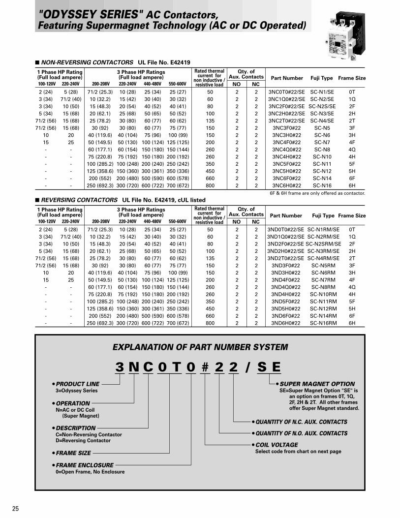
3 N C 0 T 0 # 2 2 / SPRODUCT LINE
OPERATION
DESCRIPTION
FRAME SIZE
FRAME ENCLOSURE
3=Odyssey Series
N=AC or DC Coil
C=Non-Reversing ContactorD=Reversing Contactor
0=Open Frame, No Enclosure
SUPER MAGNET OPTION
QUANTITY OF N.C. AUX. CONTACTS
QUANTITY OF N.O. AUX. CONTACTS
COIL VOLTAGE
SE=Super Magnet Option "SE" isan option on frames 0T, 1Q, 2F, 2H & 2T. All other frames offer Super Magnet standard.
(Super Magnet)
Select code from chart on next page
E
"ODYSSEY SERIES" AC Contactors, Featuring Supermagnet Technology (AC or DC Operated)
Qty. ofAux. Contacts
NO NC
1 Phase HP Rating(Full load ampere)
3 Phase HP Ratings(Full load ampere)
Rated thermalcurrent for
non inductive /resistive load200-208V 220-240V100-120V 220-240V 440-480V 550-600V
NON-REVERSING CONTACTORS UL File No. E42419
Part Number Fuji Type Frame Size
2 (24)3 (34)3 (34)5 (34)
71/2 (56)71/2 (56)
1015------
5 (28)71/2 (40)10 (50)15 (68)15 (68)15 (68)
2025------
71/2 (25.3)10 (32.2)15 (48.3)20 (62.1)25 (78.2)30 (92)
40 (119.6)50 (149.5)60 (177.1)75 (220.8)100 (285.2)125 (358.6)200 (552)
250 (692.3)
10 (28)15 (42)20 (54)25 (68)30 (80)30 (80)40 (104)50 (130)60 (154)75 (192)100 (248)150 (360)200 (480)300 (720)
25 (34)30 (40)40 (52)50 (65)60 (77)60 (77)75 (96)
100 (124)150 (180)150 (180)200 (240)300 (361)500 (590)600 (722)
25 (27)30 (32)40 (41)50 (52)60 (62)75 (77)100 (99)125 (125)150 (144)200 (192)250 (242)350 (336)600 (578)700 (672)
506080100135150150200260260350450660800
22222222222222
22222222222222
3NC0T0#22/SE3NC1Q0#22/SE3NC2F0#22/SE3NC2H0#22/SE3NC2T0#22/SE
3NC3F0#223NC3H0#223NC4F0#223NC4Q0#223NC4H0#223NC5F0#223NC5H0#223NC6F0#223NC6H0#22
SC-N1/SESC-N2/SE
SC-N2S/SESC-N3/SESC-N4/SE
SC-N5SC-N6SC-N7SC-N8SC-N10SC-N11SC-N12SC-N14SC-N16
0T1Q2F2H2T3F3H4F4Q4H5F5H6F6H
Qty. ofAux. Contacts
NO NC
1 Phase HP Rating(Full load ampere)
3 Phase HP Ratings(Full load ampere)
Rated thermalcurrent for
non inductive /resistive load200-208V 220-240V100-120V 220-240V 440-480V 550-600V
REVERSING CONTACTORS UL File No. E42419, cUL listed
Part Number Fuji Type Frame Size
2 (24)3 (34)3 (34)5 (34)
71/2 (56)71/2 (56)
1015------
5 (28)71/2 (40)10 (50)15 (68)15 (68)15 (68)
2025------
71/2 (25.3)10 (32.2)15 (48.3)20 (62.1)25 (78.2)30 (92)
40 (119.6)50 (149.5)60 (177.1)75 (220.8)100 (285.2)125 (358.6)200 (552)
250 (692.3)
10 (28)15 (42)20 (54)25 (68)30 (80)30 (80)40 (104)50 (130)60 (154)75 (192)100 (248)150 (360)200 (480)300 (720)
25 (34)30 (40)40 (52)50 (65)60 (77)60 (77)75 (96)
100 (124)150 (180)150 (180)200 (240)300 (361)500 (590)600 (722)
25 (27)30 (32)40 (41)50 (52)60 (62)75 (77)100 (99)125 (125)150 (144)200 (192)250 (242)350 (336)600 (578)700 (672)
506080100135150150200260260350450660800
22222222222222
22222222222222
3ND0T0#22/SE3ND1Q0#22/SE3ND2F0#22/SE3ND2H0#22/SE3ND2T0#22/SE
3ND3F0#223ND3H0#223ND4F0#223ND4Q0#223ND4H0#223ND5F0#223ND5H0#223ND6F0#223ND6H0#22
SC-N1RM/SESC-N2RM/SE
SC-N2SRM/SESC-N3RM/SESC-N4RM/SE
SC-N5RMSC-N6RMSC-N7RMSC-N8RMSC-N10RMSC-N11RMSC-N12RMSC-N14RMSC-N16RM
0T1Q2F2H2T3F3H4F4Q4H5F5H6F6H
6F & 6H frame are only offered as contactor.

WIRING DIAGRAMS / AUXILIARY CONTACT INFORMATION
Operating
AC A600 10 60/6
DC Q300 10120V 240V
0.55/0.55 0.27/0.27
30/3 15/1.5 12/1.2
Contact ratingCode
Designation
ContinuousAmpereRating
110 to120V
220 to240V
440 to480V
550 to600V
Current–Make/Break (A)
AUXILIARY CONTACT RATINGS
NON-REVERSING CONTACTORS REVERSING CONTACTORS
Notes:
1)All Odyssey series contactors and starters come equipped with 2NO + 2NC auxiliary contacts standard.2)Reversing contactors & starters from Frame size 0T through 2H can be constructed in the field. See Accessories on pages 31-32 for details. Large frame size reversing units only factory assembled.
26
"ODYSSEY SERIES" AC Contactors, Featuring Supermagnet Technology (AC or DC Operated)
0T/SE, 1Q/SE2F/SE, 2H/SE
2T/SE3F3H4F
4Q, 4H5F, 5H
137168130130210210277265
3.93.83.93.94.44.45.45.9
70–8070–8070–8070–8070–8070–8070–8070–80
35–5035–5035–5035–5035–5035–5035–5035–50
20–2523–2832–3632–3632–3632–3635–4140–47
20–2524–2930–3330–3330–3330–3337–4536–43
Frame SizePower
Consumption(VA)
Pick-upVoltage
(V)
Drop-outVoltage
(V)
Inrush Sealed ContactON
ContactOFF
OperatingTime (ms)CoilON
CoilOFF
COIL CHARACTERISTICS
This data is based on 100-120V SUPERMAGNET coil, tested at 120VAC, 60Hz.For additional coil data, please see page 49-50.
0T/SE, 1Q/SE2F/SE, 2H/SE
2T/SE3F3H4F
4Q, 4H5F, 5H
155195112112255255324340
2.62.52.62.633
4.14.5
77–8877–8877–8877–8877–8877–8877–8877–88
28–4428–4428–4428–4428–4428–4428–4428–44
20–2523–2832–3632–3632–3632–3635–4140–47
20–2524–2930–3330–3330–3330–3337–4536–43
This data is based on 100-120V SUPERMAGNET coil, tested at 110VDC.For additional coil data, please see page 49-50.
Note: The coil is energized by either an AC or DC input. (Code letter: E, F, 1, 2)
AVAILABLE COILS
E
F
1
2
Q
4
24
48
100
200
380
460
25V
50V
127V
250V
450V
575V
–
–
–
–
–
–
100
200
120V
240V
24V
48V
–
–
N/A
N/A
Code Letter AC 50/60Hz DC

27
EXPLANATION OF PART NUMBER SYSTEM
3 NW0 T 0 # * 2 2 KPRODUCT LINE
OPERATION
DESCRIPTION
FRAME SIZE
FRAME ENCLOSURE
3=Odyssey Series
N=AC or DC Coil
W=Non-Reversing Motor StarterX=Reversing Motor Starter
0=Open Frame, No Enclosure
SUPER MAGNET OPTION
(Super Magnet)
/ S E
QUANTITY OF N.C. AUX. CONTACTS
QUANTITY OF N.O. AUX. CONTACTSOVERLOAD RANGE
COIL VOLTAGE
OVERLOAD TYPEK=Open Phase Protection
offered as a standard
Select appropriate letter from chart on page 29
Select code from chart on next page
"ODYSSEY SERIES" AC Motor Starters, Featuring Supermagnet Technology (AC or DC Operated)
SE=Super Magnet Option "SE" is an option on frames 0T, 1Q, 2F, 2H & 2T. All other frames offer Super Magnet standard.
Qty. ofAux. Contacts
NO NC
1 Phase HP Rating(Full load ampere)
3 Phase HP Ratings(Full load ampere)
Rated thermalcurrent for
non inductive /resistive load200-208V 220-240V100-120V 220-240V 440-480V 550-600V
NON-REVERSING MOTOR STARTERS UL File No. E42419, cUL listed
Part Number Fuji Type FrameSize
2(24)
3(34)
3(34)
5(34)
71/2(56)
71/2(56)
10
15
-
-
-
-
5 (28)
71/2 (40)
10 (50)
15 (68)
15 (68)
15 (68)
20
25
-
-
-
-
71/2 (25.3)
10 (32.2)
15 (48.3)
20 (62.1)
25 (78.2)
30 (92)
40 (119.6)
50 (149.5)
60 (177.1)
75 (220.8)
100 (285.2)
125 (358.6)
10 (28)
15 (42)
20 (54)
25 (68)
30 (80)
30 (80)
40 (104)
50 (130)
60 (154)
75 (192)
100 (248)
150 (360)
25 (34)
30 (40)
40 (52)
50 (65)
60 (77)
60 (77)
75 (96)
100 (124)
150 (180)
150 (180)
200 (240)
300 (361)
25 (27)
30 (32)
40 (41)
50 (52)
60 (62)
75 (77)
100 (99)
125 (125)
150 (144)
200 (192)
250 (242)
350 (336)
50
60
80
100
135
150
150
200
260
260
350
450
2
2
2
2
2
2
2
2
2
2
2
2
2
2
2
2
2
2
2
2
2
2
2
2
3NW0T0#*22K/SE
3NW1Q0#*22K/SE
3NW2F0#*22K/SE
3NW2H0#*22K/SE
3NW2T0#*22K/SE
3NW3F0#*22K
3NW3H0#*22K
3NW4F0#*22K
3NW4Q0#*22K
3NW4H0#*22K
3NW5F0#*22K
3NW5H0#*22K
SW-N1/SE2E
SW-N2/SE2E
SW-N2S/SE2E
SW-N3/SE2E
SW-N4/SE2E
SW-N5/2E
SW-N6/2E
SW-N7/2E
SW-N8/2E
SW-N10/2E
SW-N11/2E
SW-N12/2E
0T
1Q
2F
2H
2T
3F
3H
4F
4Q
4H
5F
5H
Qty. ofAux. Contacts
NO NC
1 Phase HP Rating(Full load ampere)
3 Phase HP Ratings(Full load ampere)
Rated thermalcurrent for
non inductive /resistive load200-208V 220-240V100-120V 220-240V 440-480V 550-600V
REVERSING MOTOR STARTERS UL File No. E42419, cUL listed
Part Number Fuji Type FrameSize
2 (24)
3 (34)
3 (34)
5 (34)
71/2 (56)
71/2 (56)
10
15
-
-
-
-
5 (28)
71/2 (40)
10 (50)
15 (68)
15 (68)
15 (68)
20
25
-
-
-
-
71/2 (25.3)
10 (32.2)
15 (48.3)
20 (62.1)
25 (78.2)
30 (92)
40 (119.6)
50 (149.5)
60 (177.1)
75 (220.8)
100 (285.2)
125 (358.6)
10 (28)
15 (42)
20 (54)
25 (68)
30 (80)
30 (80)
40 (104)
50 (130)
60 (154)
75 (192)
100 (248)
150 (360)
25 (34)
30 (40)
40 (52)
50 (65)
60 (77)
60 (77)
75 (96)
100 (124)
150 (180)
150 (180)
200 (240)
300 (361)
25 (27)
30 (32)
40 (41)
50 (52)
60 (62)
75 (77)
100 (99)
125 (125)
150 (144)
200 (192)
250 (242)
350 (336)
50
60
80
100
135
150
150
200
260
260
350
450
2
2
2
2
2
2
2
2
2
2
2
2
2
2
2
2
2
2
2
2
2
2
2
2
3NX0T0#*22K/SE
3NX1Q0#*22K/SE
3NX2F0#*22K/SE
3NX2H0#*22K/SE
3NX2T0#*22K/SE
3NX3F0#*22K
3NX3H0#*22K
3NX4F0#*22K
3NX4Q0#*22K
3NX4H0#*22K
3NX5F0#*22K
3NX5H0#*22K
SW-N1RM/SE2E
SW-N2RM/SE2E
SW-N2SRM/SE2E
SW-N3RM/SE2E
SW-N4RM/SE2E
SW-N5RM/2E
SW-N6RM/2E
SW-N7RM/2E
SW-N8RM/2E
SW-N10RM/2E
SW-N11RM/2E
SW-N12RM/2E
0T
1Q
2F
2H
2T
3F
3H
4F
4Q
4H
5F
5H

28
WIRING DIAGRAMS / AUXILIARY CONTACT INFORMATION
Operating
AC A600 10 60/6
DC Q300 10120V 240V
0.55/0.55 0.27/0.27
30/3 15/1.5 12/1.2
Contact RatingCode
Designation
ContinuousAmpereRating
110 to120V
220 to240V
440 to480V
550 to600V
Current–Make/Break (A)
AUXILIARY CONTACT RATINGS
NON-REVERSING MOTOR STARTERS REVERSING MOTOR STARTERS
Notes:
1)All Odyssey series contactors and starters come equipped with 2NO + 2NC auxiliary contacts standard.2)Reversing contactors & starters from Frame size 0T through 2H can be constructed in the field. See Accessories on pages 31-32 for details. Large frame size reversing units only factory assembled.
"ODYSSEY SERIES" AC Motor Starters, Featuring Supermagnet Technology (AC or DC Operated)
0T/SE, 1Q/SE2F/SE, 2H/SE
2T/SE3F3H4F
4Q, 4H5F, 5H
137168130130210210277265
3.93.83.93.94.44.45.45.9
70–8070–8070–8070–8070–8070–8070–8070–80
35–5035–5035–5035–5035–5035–5035–5035–50
20–2523–2832–3632–3632–3632–3635–4140–47
20–2524–2930–3330–3330–3330–3337–4536–43
Frame SizePower
Consumption(VA)
Pick-upVoltage
(V)
Drop-outVoltage
(V)
Inrush Sealed ContactON
ContactOFF
OperatingTime (ms)CoilON
CoilOFF
COIL CHARACTERISTICS
This data is based on 100-120V SUPERMAGNET coil, tested at 120VAC, 60Hz.For additional coil data, please see page 49-50.
0T/SE, 1Q/SE2F/SE, 2H/SE
2T/SE3F3H4F
4Q, 4H5F, 5H
155195112112255255324340
2.62.52.62.633
4.14.5
77–8877–8877–8877–8877–8877–8877–8877–88
28–4428–4428–4428–4428–4428–4428–4428–44
20–2523–2832–3632–3632–3632–3635–4140–47
20–2524–2930–3330–3330–3330–3337–4536–43
This data is based on 100-120V SUPERMAGNET coil, tested at 110VDC.For additional coil data, please see page 49-50.
Note: The coil is energized by either an AC or DC input. (Code letter: E, F, 1, 2)
AVAILABLE COILS
E
F
1
2
Q
4
24
48
100
200
380
460
25V
50V
127V
250V
450V
575V
–
–
–
–
–
–
100
200
120V
240V
24V
48V
–
–
N/A
N/A
Code Letter AC 50/60Hz DC
29
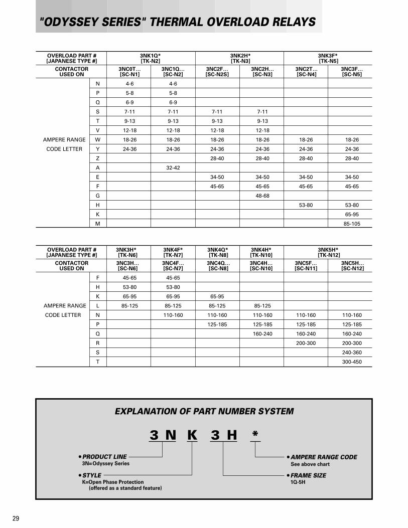
OVERLOAD PART # 3NK1Q* 3NK2H* 3NK3F* [JAPANESE TYPE #] [TK-N2] [TK-N3] [TK-N5]
CONTACTOR 3NC0T… 3NC1Q… 3NC2F… 3NC2H… 3NC2T… 3NC3F… USED ON [SC-N1] [SC-N2] [SC-N2S] [SC-N3] [SC-N4] [SC-N5]
N 4-6 4-6
P 5-8 5-8
Q 6-9 6-9
S 7-11 7-11 7-11 7-11
T 9-13 9-13 9-13 9-13
V 12-18 12-18 12-18 12-18
AMPERE RANGE W 18-26 18-26 18-26 18-26 18-26 18-26
CODE LETTER Y 24-36 24-36 24-36 24-36 24-36 24-36
Z 28-40 28-40 28-40 28-40
A 32-42
E 34-50 34-50 34-50 34-50
F 45-65 45-65 45-65 45-65
G 48-68
H 53-80 53-80
K 65-95
M 85-105
OVERLOAD PART # 3NK3H* 3NK4F* 3NK4Q* 3NK4H* 3NK5H* [JAPANESE TYPE #] [TK-N6] [TK-N7] [TK-N8] [TK-N10] [TK-N12]
CONTACTOR 3NC3H… 3NC4F… 3NC4Q… 3NC4H… 3NC5F… 3NC5H… USED ON [SC-N6] [SC-N7] [SC-N8] [SC-N10] [SC-N11] [SC-N12]
F 45-65 45-65
H 53-80 53-80
K 65-95 65-95 65-95
AMPERE RANGE L 85-125 85-125 85-125 85-125
CODE LETTER N 110-160 110-160 110-160 110-160 110-160
P 125-185 125-185 125-185 125-185
Q 160-240 160-240 160-240
R 200-300 200-300
S 240-360
T 300-450
EXPLANATION OF PART NUMBER SYSTEM
3 N K 3 HPRODUCT LINE
STYLE
3N=Odyssey Series
FRAME SIZE1Q-5H
*AMPERE RANGE CODE
K=Open Phase Protection(offered as a standard feature)
"ODYSSEY SERIES" THERMAL OVERLOAD RELAYS
See above chart

"ODYSSEY SERIES" THERMAL OVERLOAD RELAYS Overload Trip Curves
30
AMBIENT TEMPERATURE COMPENSATOR
SZ-HDSZ-HE
Base unit for separate mounting
C600 2.5 15/1.5 7.5/0.75 3.75/0.375 3.0/0.3
Contact ratingCode
Designation
ContinuousAmpereRating
110 to120V
220 to240V
440 to480V
550 to600V
Current–Make/Break (A)
ALARM CONTACT RATINGS
10.80.6
0.40.3
10 8 6
43
2
4030
20
60
2
3
5
810
20
30
50
80
10.80.6
0.40.3
10 8 6
43
2
4030
20
60
2
3
5
810
20
30
50
80
10.80.6
0.40.3
10 8 6
43
2
4030
20
60
2
3
5
810
20
30
50
80
10.80.6
0.40.3
10 8 6
43
2
4030
20
60
2
3
5
810
20
30
50
80
Trip
ping
tim
eS
econ
dsM
inut
esTr
ippi
ng ti
me
Sec
onds
Min
utes
Trip
ping
tim
eS
econ
dsM
inut
esTr
ippi
ng ti
me
Sec
onds
Min
utes
Multiple of current setting XIn [A]XIn [A]
XIn [A]XIn [A]
Multiple of current setting
Multiple of current setting Multiple of current setting
3NK1Q* – 3NK4Q*Cold start Hot start
3NK4H* – 3NK5H*Cold start Hot start
THERMAL OVERLOAD RELAYS/OPEN-PHASE PROTECTION TYPE K
WIRING DIAGRAMS
(3NK1Q* through 3NK4Q*) (3NK4H* through 3NK5H*)FUJI overload relays are provided with an ambient temperature compensator. Their characteristics limit ampere value changes to approx. 10% as the ambient temperature changes between –5˚C and 40˚C.

"ODYSSEY SERIES" ACCESSORIES, Frames 0T-2H
31
: Front Mounting: Side Mounting : Top Mounting
Thermal
overload relays
Base unitforseparatemounting
Auxiliarycontact block
Auxiliarycontact block
Operationcounter
Main circuit surgesuppression unit
Auxiliarycontact block
Coil drive unit
Coil surgesuppression unit
Auxiliarycontact block
Mechanicalinterlock unit
Main circuit surgesuppression unit
Reset release button
Terminal cover
Terminal cover
Trip indicator
Dial cover

Description Type
•Front mounting
4NO
3NO+1NC
2NO+2NC
2NO
1NO+1NC
2NC
1NO+1NC (Over lapping)
2NO+2NC (Over lapping)
•Side mounting
1NO+1NC (Ambidextrous)
Auxiliary Contact Block
Front mounting type and side mounting type auxiliarycontact blocks can not be used simultaneously.
SZ-A40
SZ-A31
SZ-A22
SZ-A20
SZ-A11
SZ-A02
SZ-A111
SZ-A222
SZ-AS1
Without alarm contact
For 3NC0T0, 3NC1Q0
(2 pcs.)
For 3NC2F0, 3NC2H0
(2 pcs.)
DC24V relay output
DC24V SSR output
For 3NC0T0, 3NC1Q0
For 3NC2F0, 3NC2H0
For 3NC0T0–3NC2H0
Operating Counter
3-pole ParallelConnection Link
Coil Drive Unit
Mechanical Interlock Unit
Power Connection
Kit for Reversing
SZ-J
SZ-SP3
SZ-SP4
SZ-CD3
SZ-CD4
SZ-RM
SZ-RW5
SZ-RW6
Description Type
•Contactor
For 0T0, 1Q0
For 2F0, 2H0
•Auxiliary contact block
For 4-pole,front mounting
For 2-pole,front mounting
For 2-pole,side mounting
•Thermal overload relay
For 3NK1Q
For 3NK2H
Base unit for separate
mounting:
For SZ-HD
For SZ-HE
•Contactor
For 0T0, 1Q0
For 3NC2F0, 3NC2H0
•Starter
For 0T0, 1Q0
For 2F0, 2H0
Varistor: 24 to 48V AC/DC
100 to 250V AC/DC
380 to 440V AC
RC: 24 to 48V AC
100 to 250V AC
24 to 48V DC
100 to 250V DC
For 0T0, 1Q0
With delta-connected RC,
100 to 240V AC
•Front mounting
•Side mounting
For 3NK1Q
For 3NK2H
Used on all overloads
100 to 110V AC
200 to 220V AC
Lead length: 300mm
500mm
700mm
Terminal Cover
Live-section Cover
Coil SurgeSuppression Unit
Main Circuit SurgeSuppression Unit
Base Unit for Separate Mounting
Dial Cover
Trip Indicator
Reset ReleaseButton
SZ-T22
SZ-T23
SZ-T5
SZ-T6
SZ-T7
SZ-T16
SZ-T17
SZ-T14
SZ-T15
SZ-N1J
SZ-N2SJ
SZ-WN1J
SZ-WN2SJ
SZ-Z31
SZ-Z32
SZ-Z33
SZ-Z34
SZ-Z35
SZ-Z36
SZ-Z37
SZ-ZM3
SZ-ZM4
SZ-HD
SZ-HE
SZ-DA
SZ-L100N2
SZ-L200N2
SZ-R4
SZ-R5
SZ-R6
32
All accessories can be field installed.
"ODYSSEY SERIES" ACCESSORIES, Frames 0T-2H

Description Type
Side Mounting
1NO+1NC
For 2T0, 3F0 (2 pcs.)
For 3H0 (2 pcs.)
For 4F0 (2 pcs.)
For 4Q0, 3NC4H0 (2 pcs.)
For 5F0, 5H0 (2 pcs.)
DC24V relay output
DC24V SSR output
Auxiliary Contact Block
SZ-AS2
SZ-SP5
SZ-SP6
SZ-SP7
SZ-SP8
SZ-SP9
SZ-CD5
SZ-CD6
3-pole ParallelConnection Link
Coil Drive Unit
Description Type
•Line & Load-side of Contactor
Line-side of Starter
For 2T0, 3F0
For 3H0
For 4F0
For 4Q0, 4H0
For 5F0, 5H0
•Load-side of Starter
For 2T0, 3F0
For 3H0
For 4F0
For 4Q0
For 4H0
For 5F0, 5H0
•Contactor
For 2T0, 3F0
For 3H0
For 4F0
For 4Q0, 4H0
For 5F0, 5H0
•Starter
For 2T0, 3F0
For 3H0
For 4F0
For 4Q0
For 4H0
For 5F0, 5H0
For 2T0, 3F0, 3H0, 4F0, 3H, 4F
For 4Q0, 4H0, 5F0, 5H0, 3NK4Q,
3NK4H, 3NK5H
Varistor: 24 to 48V AC
100 to 250V AC
380 to 440V AC
RC: 24 to 48V AC
100 to 250V AC
Used on all overloads
•3NK3F to 3NK4Q
100 to 110V AC
200 to 220V AC
•3NK4H, 3NK5H
200 to 220V AC
•3NK3F to 3NK4Q
Lead length: 300mm
500mm
700mm
•3NK4H, 3NK5H
Lead length: 300mm
500mm
700mm
Terminal Cover
Live-section Cover
Coil SurgeSuppression Unit for 3NC2T0
InsulationBarrier
Dial Cover
Trip Indicator
Reset ReleaseButton
SZ-N4T
SZ-N6T
SZ-N7T
SZ-N8T
SZ-N11T
SZ-WN4T
SZ-WN6T
SZ-WN7T
SZ-WN8T
SZ-WN10T
SZ-WN11T
SZ-N4J
SZ-N6J
SZ-N7J
SZ-N8J
SZ-N11J
SZ-WN4J
SZ-WN6J
SZ-WN7J
SZ-WN8J
SZ-WN10J
SZ-WN11J
SZ-B1
SZ-B2
SZ-Z41
SZ-Z42
SZ-Z43
SZ-Z44
SZ-Z45
SZ-DA
SZ-L100N2
SZ-L200N2
SZ-L200
SZ-R4
SZ-R5
SZ-R6
SZ-R1
SZ-R2
SZ-R3
33
"ODYSSEY SERIES" ACCESSORIES, Frames 2T-5H
Accessories for field-assembly of Reversing Contactors & Starters are not available. However, Reversing models can be assembled in Fuji's New Jersey facilities. Contact Fuji directly for further information.

"ODYSSEY SERIES" Replacement Parts
34
122448100110200220
12V24V48V
100V110V200V220V
Code DC
Contact KitFrame Size Frame SizeContactorsLine or Load Side
Motor StartersLine Side Load Side
BOX LUGS REPLACEMENT CONTACTS
0T NONE NONE NONE
1Q NONE NONE NONE
2F & 2H SZ-TL1 SZ-TL1 SZ-TL11
2T & 3F SZ-TL2 SZ-TL2 SZ-TL11
3H SZ-TL3 SZ-TL3 SZ-TL12
4F SZ-TL4 SZ-TL4 SZ-TL12
4Q & 4H SZ-TL5 SZ-TL5 SZ-TL5
5F SZ-TL6 SZ-TL6 SZ-TL6
5H SZ-TL7 SZ-TL7 SZ-TL7
Frame SizeConventional AC Coil
Use codes from chart 1Conventional DC Coil
Use codes from chart 2Supermagnet Coil
Use codes from chart 3
REPLACEMENT COILS
0T & 1Q SZ-GM/N1-# SZ-GG/N1-# SZ-GS/N1-#
2F & 2H SZ-GM/N2S-# SZ-GG/N2S-# SZ-GS/N2S-#
2T SZ-GM/N4-# N/A SZ-GS/N5-#
3F N/A N/A SZ-GS/N5-#
3H & 4F N/A N/A SZ-GS/N6-#
4Q & 4H N/A N/A SZ-GS/N8-#
5F & 5H N/A N/A SZ-GS/N11-#
6F & 6H N/A N/A SZ-GS/N14-#
0T SZ-MC/SC-N1
1Q SZ-MC/SC-N2
2F SZ-MC/SC-N2S
2H SZ-MC/SC-N3
2T SZ-MC/SC-N4
3F SZ-MC/SC-N5
3H SZ-MC/SC-N6
4F SZ-MC/SC-N7
4Q SZ-MC/SC-N8
4H SZ-MC/SC-N10
5F SZ-MC/SC-N11
5H SZ-MC/SC-N12
6F SZ-MC/SC-N14
6H SZ-MC/SC-N16
Note: 1) 3 movable and 6 stationary contacts included in each contact kit.2) Contact kits consist of main contacts only. Auxiliary contacts are not included.
COIL CHART #1 COIL CHART #2 COIL CHART #3
Replace the # symbol with the desired code, shown in the charts below.
2448100110120200220400440550
2448
100110120200220400440550
26V52V110V120V130V220V240V440V480V600V
––––––––––
100110
200380415500
110V120V
220V400V440V550V
24V48V100V
––
200V––––
Code AC 60Hz AC 50Hz
2448100200400500
2448
100200380460
25V50V127V250V450V575V
––––––
100200
120V240V
24V48V
––
N/AN/A
Code AC 50/60Hz DC
DISCONTIN
UED

CONTACTORS/OPEN TYPE Approximate Dimensions, mm
35
3NC0T0#223NC1Q0#22
Weight: 0.59kg Weight: 1.1kg
Weight: 1.5kg Weight: 1.8kg
Weight: 2.4kg
3NC2F0#223NC2H0#22
3NC2T0#22 3NC3F0#22
3NC3H0#22
11774
17.788
* 1 Aux. contact block (Side mounted)
127
111
8
32
16
3288
32
13289
32.7 32
16
127
111
8
* 1 Aux. contact block (Side mounted)
10032
13894
38.8 32
20
1014
412
0
* 1 Aux. contact block (Side mounted)
* 1 Aux. contact block (Side mounted)
7816
.5
20.5 20.516.8
110
72.528111
10.5
88112 *1
(112) *1 (112) *1
(124) *1
121 (Mounting rail height: 15)
* 1 Aux. contact block (Side mounted)
Main terminalM6
Main terminalM6
Aux. terminalM3.5
Aux. terminalM3.5
Main terminalM6
Main terminalM8
Aux. terminalM3.5
Aux. terminalM3.5
Coil terminalM3.5
Coil terminalM3.5
Coil terminalM3.5
Coil terminalM3.5
Coil terminalM3.5M5
M3.5
*1106 (Mounting rail height: 15)
Aux. terminal
Main terminal96
65.510.5
28(99)
74
14.3
59.5 87
16.5 16.512.5
Aux. contact block(Front mounted)
Aux. contact block(Front mounted)
3NC4Q0#223NC4H0#22
3NC5F0#223NC5H0#22
3NC6F0#223NC6H0#22
(154) *1138
47
174118
14.5
* 1 Aux. contact block (Side mounted)
47
25
209
12.2
155
(169) *1148
56 56
1524
019
0
30
195132
14.5
* 1 Aux. contact block (Side mounted)
* 1 Aux. contact block (Side mounted)
3NC4F0#22(139) *1
11540
14094
38.8 40
20
132
156
Main terminalM8
10
* 1 Aux. contact block (Side mounted)
Aux. terminalM3.5
Main terminalM10
Main terminalM12
Aux. terminalM3.5
Aux. terminalM3.5
Coil terminalM3.5
Coil terminalM3.5
Coil terminalM3.5
Main terminalM16
Aux. terminalM4
Coil terminalM3.5
Weight: 2.7kg
Weight: 4.9kg Weight: 7.8kg
For exact mounting hole locations, please refer to the chart on page 46.
"ODYSSEY SERIES" Dimensions
328 (320) *1
4070290
30244
285
332

STARTERS/OPEN TYPE Approximate Dimensions, mm
36
3NW0T0#*22K3NW1Q0#*22K
3NW2F0#*22K3NW2H0#*22K
3NW2T0#*22K 3NW3F0#*22K
3NW3H0#*22K
* 1 Aux. contact block (Side mounted)
111
108
42
20.516.8
68
58
10.5
30
72.528
20.5 20.588
177
20.5
16.5
147
112 *1
* 1 Aux. contact block (Side mounted)
Main terminalM6
Main terminalM6
Main terminalM6
167
32
8
13.520.5 20.5
45.4
3288
16
10459.2
189
30.1 16.8
11774
17.7
4.7
(112) *1
* 1 Aux. contact block (Side mounted)
167
32
8
13.520.5 20.5
45.4
3288
16
11974.2
189
30.1 16.8
13289
32.7
4.7
(112) *1
* 1 Aux. contact block (Side mounted)
46.5
94
10
15
3232
1840.1
2038.8
138
4.7
100
32
22520
5
3287131
(124) *1
* 1 Aux. contact block (Side mounted)
16.82896
120
14.3
16.5
146
7416.516.5
65.510.5
27.647.554
12.516.5
28.5
97
12.5
Weight: 0.77kg Weight: 1.3kg
Weight: 1.7kg Weight: 2.1kg
Weight: 3kg
106 (Mounting rail height: 15)121 (Mounting rail height: 15)
Aux. contact block(Front mounted)
Aux. contact block(Front mounted)
Reset button Reset button
Reset button
Reset buttonReset button
Main terminalM5
Main terminalM5 Main terminal
M6
Aux. terminalM3.5
Aux. terminalM3.5
Aux. terminalM3.5
Aux. terminalM3.5(NC)
Aux. terminalM3.5(NO)
Main terminalM6
Main terminalM8
Aux. terminalM3.5
Aux. terminalM3.5
Aux. terminalM3.5(NO)
Aux. terminalM3.5(NO)
Aux. terminalM3.5
Aux. terminalM3.5
Coil terminalM3.5
Coil terminalM3.5
Coil terminalM3.5
Main terminalM6
Aux. terminalM3.5(NC)
Coil terminalM3.5
Main terminalM8
Aux. terminalM3.5(NC)
Coil terminalM3.5
99 *1
3NW4F0#*22K
3NW4Q0#*22K 3NW4H0#*22K
40115
4038.8
94140
52.5
217
1887
131 154.7
237
40.1
20
10
3232
* 1 Aux. contact block (Side mounted)
* 1 Aux. contact block (Side mounted)
174
14.5118
15575
3.2
172
57
47
47
47
47
12.2
28 20
247
138
287
25
* 1 Aux. contact block (Side mounted)
115.3
55.5
17.6
154.1 4.7 4747
2
4747
264
25
25
118 138
14.5
174
12.2
305
Main terminalM8
Main terminalM10
Main terminalM10
Main terminalM10
Main terminalM8
Aux. terminalM3.5
Aux. terminalM3.5
Aux. terminalM3.5
Aux. terminalM3.5(NO)
Aux. terminalM3.5(NO)
Aux. terminalM3.5(NO)
Aux. terminalM3.5(NC)
Aux. terminalM3.5(NC)
Aux. terminalM3.5(NC)
Coil terminalM3.5
Coil terminalM3.5
Coil terminalM3.5
Reset button
Reset button Resettingbar
Resetting barReset button
(139) *1
(154) *1(154) *1
Weight: 3.3kg
Weight: 6.1kg Weight: 6.8kg
For exact mounting hole locations, please refer to the chart on page 46.
"ODYSSEY SERIES" Dimensions

DC OPERATED CONTACTORS/OPEN TYPE Approximate Dimensions, mm
37
3NW5F0#*22K3NW5H0#*22K
15581
56
56 56
14.5 56132
35
360
30
148195
30
3.2
172
318
1564
* 1 Aux. contact block (Side mounted)
Main terminalM12
Main terminalM12
Aux. terminalM3.5
Aux. terminalM3.5(NO)
Aux. terminalM3.5(NC)
Coil terminalM3.5
Resettingbar
Resetting bar
(169) *1
Weight: 10.1kg
3GC0T0#223GC1Q0#22
3GC2F0#223GC2H0#22
99 *1
16.5
59.5
122 28
10.5
12.5
74
87
91
16.5
14.3
* 1 Aux. contact block (Side mounted)
7816
.5
20.5 20.516.8
110
91.528130
10.5
88112 *1140 (Mounting rail height: 15)
* 1 Aux. contact block (Side mounted)
Main terminalM6
Coil terminalM3.5
131 (Mounting rail height: 15)Main terminalM5Aux. terminalM3.5
Aux. terminalM3.5
Coil terminalM3.5
Aux. contact block(Front mounted) Aux. contact block
(Front mounted)
Weight: 0.82kg Weight: 1.4kg
For exact mounting hole locations, please refer to the chart on page 46.
DC OPERATED STARTERS/OPEN TYPE Approximate Dimensions, mm
3GW2F0#*22K3GW2H0#*22K
3GW0T0#*22K3GW1Q0#*22K
16.516.5
14.3
146
120
12.5
54
16.5 16.5
12373
27.6
12.5
28.5
99 *1 112 *1
122
74
10.591
28
177
16.5
147
16.820.5
12777
20.516.8
68
2891.5
10.5
130 88
20.5
30
20.5
140 (Mounting rail height: 15)
* 1 Aux. contact block (Side mounted) * 1 Aux. contact block (Side mounted)
131 (Mounting rail height: 15)
Main terminalM5
Main terminalM6
Main terminalM5 Main terminal
M6
Aux. terminalM3.5
Aux. terminalM3.5
Aux. terminalM3.5
Aux. terminalM3.5
Coil terminalM3.5
Coil terminalM3.5
Aux. contact block(Front mounted) Aux. contact block
(Front mounted)
Reset buttonReset button
Weight: 1kg Weight: 1.6kg
"ODYSSEY SERIES" Dimensions

38
CONTACTORS WITH "SUPER MAGNET" OPTION/OPEN TYPE Approximate Dimensions, mm
3NW2T0#*22K/SE
112 *1
32
30.1
167
3216
20.5 20.5
45.4
13.5
32.7
16.8
189
74.2119
88
4.7
13289
8
* 1 Aux. contact block (Side mounted)
Main terminalM6
Main terminal M6
Aux. terminalM3.5
Aux. terminal(NO)M3.5
Aux. terminal(NC)M3.5
Coil terminalM3.5
Reset button
Weight: 2.1kg
3NC0T0#22/SE3NC1Q0#22/SE
3NC2F0#22/SE3NC2H0#22/SE
130
7.8
29
44
28
99
53
112
74
59.5
16.516.512.5
31.5
125
101
28
8839
16.820.520.5
78
140
7.7
* 1 Aux. contact block (Side mounted)
* 1 Aux. contact block (Side mounted)
Weight: 0.87kg
Weight: 1.3kg
140 (Mounting rail height: 15) 150 (Mounting rail height: 15)
Main terminalM5Aux. terminalM3.5
Main terminalM6
Aux. terminalM3.5
Coil terminalM3.5 Coil terminal
M3.5
Aux. contact block(Front mounted)
Aux. contact block(Front mounted)
99 *1
112 *1
* 1 Aux. contact block (Side mounted)
Main terminalM6
Coil terminalM3.5
3C2T0#22/SE11
1
32 32 812
7
8832.7
13289
16
Aux. terminalM3.5
Weight: 1.8kg
STARTERS WITH "SUPER MAGNET" OPTION/OPEN TYPE Approximate Dimensions, mm
3NW2F0#*22K/SE3NW2H0#*22K/SE
3NW0T0#*22K/SE3NW1Q0#*22K/SE
16.5 16.5
28.5
16.512.5
54
161
44
28130
99
81
74
2912
1
131 27.6
12.5
16.520.5
16.8
68
31.5
42
192
8820.5
16.8
147
20.5
140
39101
28
30136
87 20.5
* 1 Aux. contact block (Side mounted) * 1 Aux. contact block (Side mounted)Weight: 1.0kg Weight: 1.5kg
140 (Mounting rail height: 15) 150 (Mounting rail height: 15)
Main terminalM5
Main terminalM5 Main terminal
M6
Aux. terminalM3.5
Main terminalM6Aux. terminalM3.5
Aux. terminalM3.5
Aux. terminalM3.5
Coil terminalM3.5
Coil terminalM3.5
Aux. contact block(Front mounted) Aux. contact block
(Front mounted)
99 *1112 *1
Reset button Reset button
For exact mounting hole locations, please refer to the chart on page 46.
"ODYSSEY SERIES" Dimensions

39
REVERSING CONTACTORS/OPEN TYPE Approximate Dimensions, mm
3ND0T0#223ND1Q0#22
3ND2F0#223ND2H0#22
* 2 Aux. contact block. Front mounted (If Used) * 2 Aux. contact block. Front mounted (If Used)
3ND2T0#22
3ND3H0#22
3ND4Q0#223ND4H0#22
3ND3F0#22
3ND4F0#22
3ND5F0#223ND5H0#22
For exact mounting hole locations, please refer to the chart on page 46.
*2
66.5
106 (Mounting track height;15)
96 (28)*2
10.5
Coil terminalM3.5
Aux.terminalM3.5
MainterminalM59
8770
Appr
ox. 3
1 Ap
prox
.12
16.512.4
Coil terminalM3.5
65
1618722 65
Mountinghole4-M4
59.5
14.3
1.6
12281.5
Mounting hole3-M5
MainterminalM6
Aux.terminalM3.5
7.5
165
150
19.5
111
Coil terminalM3.5200
230
32 111 15
1.6
145102
Mounting hole3-M5
Aux.terminalM3.5
7.5
190
175
MainterminalM8
27.5
120
Coil terminalM3.5220
250
32 123 20
184131
2
Mountinghole4-M6
Coil terminalM3.5
Aux.terminalM3.5
MainterminalM10
155
42.5
330300
47 153 25
270
250
10
75
121 (Mounting track height;15)111 (28)
*2
*2
10.5
Coil terminalM3.5
Mountinghole4-M4
MainterminalM6
Aux.terminalM3.5
1811
014
9
7519
.5
20.516.8
70
18710030 70
7816
.5
1.6
13796.5
Mounting hole3-M5
Aux.terminalM3.5
7.5
165
150
MainterminalM6
19.5
111
Coil terminalM3.5200
230
32 111 15
147104
2
Mountinghole3-M6
Coil terminalM3.5
Aux.terminalM3.5
MainterminalM8
132
34
290260
40 138 20
215
200
7.5
210151
2.3
Mountinghole4-M8
Coil terminalM3.5Aux.
terminalM3.5
MainterminalM12
190
54.5
360300
56 168 30
330
300
15
"ODYSSEY SERIES" Dimensions

40
REVERSING STARTERS/OPEN TYPE Approximate Dimensions, mm
3NX0T0#*22K3NX1Q0#*22K
3NX2F0#*22K3NX2H0#*22K
* 2 Aux. contact block. Front mounted (If Used) * 2 Aux. contact block. Front mounted (If Used)
3NX2T0#*22K 3NX3F0#*22K
3NX3H0#*22K 3NX4F0#*22K
For exact mounting hole locations, please refer to the chart on page 46.
*2
*2
66.5
106 (Mounting track height;15)
96 (28)
10.5
Coil terminalM3.5
Reset button
Approx. 10497
47.5
Mountinghole4-M4
Aux.terminalM3.5
MainterminalM5
9
14670
Appr
ox. 3
1
65
16187
16.5 12.422 65
14.3
120 98
.5
MainterminalM5
Aux.terminalM3.5
27.5 16.5
12.4
1.6
12281
Coil terminalM3.5
Reset button
114
64.5
Mounting hole3-M5
Aux.terminalM3.5
Aux.terminalM3.5Main
terminalM6
MainterminalM6
7.5
165
43
150
19.5
167
158
39.5 20.5
16.7
200230
32 111 15
1.6
144.5102
Coil terminalM3.5
141.5
93 Reset button
Mounting hole3-M5
Aux.terminalM3.5Aux.
terminalM3.5
MainterminalM8
MainterminalM8
7.5
190
57.5
175
27.5
204.
5 189
43.5 32
15
220250
32 123 20
*2
7510.5
121 (Mounting track height;15)
111 (28)
*2
Reset button
108
58
Coil terminalM3.5
Mounting hole4-M4
Aux.terminalM3.5
MainterminalM6
Coil terminalM3.5
18
177
75
19.5
70
187100
20.5 16.87030
16.5
147
42
Aux.terminalM3.5
MainterminalM630 20.5
16.7
1.6
13796
Coil terminalM3.5
129
79.5 Reset button
Mounting hole3-M5
Aux.terminalM3.5
Aux.terminalM3.5Main
terminalM6
MainterminalM6
7.5
165
43
150
19.5
167
158
39.5 20.5
16.7
200230
32 111 15
2
147104
Coil terminalM3.5
142.5
93Reset button
Mounting hole3-M6
Aux.terminalM3.5
Aux.terminalM3.5
MainterminalM8
MainterminalM8
7.5
215
51
200
3421
6.5 20
7.5
56 32
15
260290
40 138 20
"ODYSSEY SERIES" Dimensions

41
3NX4Q0#*22K
DC OPERATED REVERSING CONTACTORS/OPEN TYPE Approximate Dimensions, mm
3GD0T0#223GD1Q0#22
3GD2F0#223GD2H0#22
3NX4H0#*22K
* 2 Aux. contact block. Front mounted (If Used)* 2 Aux. contact block. Front mounted (If Used)
3NX5F0#*22K3NX5H0#*22K
For exact mounting hole locations, please refer to the chart on page 46.
370
264
42.5
110.
5
350
10
300330184
1312 47
68.5 4725
153 25
Reset button
Mountinghole4-M6
Coil terminalM3.5
Aux.terminalM3.5
Aux.terminalM3.5
MainterminalM10
MainterminalM10
169125.5
480
144.
555
.5
450
15
210150.5
2.3
Reset button
Mountinghole4-M8
Coil terminalM3.5
Aux.terminalM3.5
Aux. terminalM3.5
MainterminalM12
MainterminalM12
318
300360
56 168 30
3072
5618796
2
184131
Coil terminalM3.5
182
85Reset button
Aux.terminalM3.5
Mounting hole4-M6
Aux.terminalM3.5
MainterminalM10
MainterminalM10
10
370
350
42.5
247
112
79
4720
300330
47 153 25
92
131 (Mounting track height;15)122 (28)
*2
*2
10.5
Coil terminalM3.5
Mountinghole4-M4
Aux.terminalM3.5
MainterminalM59
8770
Appr
ox. 3
1 Ap
prox
. 12
16.512.4
65
1618722 65
59.5
14.3
130
*2
94
140 (Mounting track height;15)(28)
*2
10.5
Coil terminalM3.5
MainterminalM6
Aux.terminalM3.5
1811
014
9
7519
.5
20.516.8
70
18710030 70
7816
.5
Mountinghole4-M4
"ODYSSEY SERIES" Dimensions

42
3ND2T0#22/SE
DC OPERATED REVERSING STARTERS/OPEN TYPE Approximate Dimensions, mm
3GX0T0#*22K3GX1Q0#*22K
3GX2F0#*22K3GX2H0#*22K
REVERSING CONTACTORS WITH "SUPER MAGNET" OPTION/OPEN TYPE Approximate Dimensions, mm
3ND0T0#22/SE3ND1Q0#22/SE
3ND2F0#22/SE3ND2H0#22/SE
* 2 Aux. contact block. Front mounted (If Used) * 2 Aux. contact block. Front mounted (If Used)
For exact mounting hole locations, please refer to the chart on page 46.
*2
*2
92
131 (Mounting track height;15)122 (28)
10.5
Mountinghole4-M4
Coil terminalM3.5
MainterminalM5
Aux.terminalM3.5
Aux.terminalM3.5
MainterminalM5
Reset button
Approx. 130123
739
14670
Appr
ox. 3
1
65
16187
16.5 12.422 65
27.5 16.5
12.4
14.3
120 98
.5
*2
*2
9410.5
140 (Mounting track height;15)
130 (28) Coil terminalM3.5
Reset button
127
77
Mounting hole4-M4
Aux.terminalM3.5
Aux.terminalM3.5
MainterminalM6
MainterminalM6
18
177
75
19.5
* 2 Aux. contact block. Front mounted (If Used)* 2 Aux. contact block. Front mounted (If Used)
70
187100
20.5 16.87030
16.5
147
42
30 20.5
16.7
100
140 (Mounting track height;15)130 (28)
*2
*2
44
Coil terminalM3.5
Mountinghole4-M4
Aux.terminalM3.5
MainterminalM5
24
112
70
Appr
ox. 1
6
16.512.4
65
1618722 65
59.5
29
*2
140103.5
150 (Mounting track height;15)(28)
*2
39
Coil terminalM3.5
MainterminalM6
Aux.terminalM3.5
3312
514
9
7545
20.516.8
70
18710030 70
7831
.5
Mountinghole4-M4
1.6
13796.5
Mounting hole3-M5
Aux.terminalM3.5
7.5
165
150
MainterminalM6
19.5
111
Coil terminalM3.5200
230
32 111 15
"ODYSSEY SERIES" Dimensions

43
REVERSING STARTERS WITH "SUPER MAGNET" OPTION/OPEN TYPE Approximate Dimensions, mm
3NX0T0#*22K/SE3NX1Q0#*22K/SE
3NX2F0#*22K/SE3NX2H0#*22K/SE
3NX2T0#*22K/SE
For exact mounting hole locations, please refer to the chart on page 46.
* 2 Aux. contact block. Front mounted (If Used)* 2 Aux. contact block. Front mounted (If Used)
100
140 (Mounting track height;15)130 (28)
*2
44
Mountinghole4-M4
Coil terminalM3.5
MainterminalM5
Aux.terminalM3.5
Aux.terminalM3.5
MainterminalM5
29 24
120 98
.565
16187
16.5 12.422 65
27.5 16.5
12.4Reset button
Approx. 137130.5
8116
170
Appr
ox. 1
6
*2
*2
103.539
150 (Mounting track height;15)
140 (28) Coil terminalM3.5
Reset button
136
86
Mounting hole4-M4
Aux.terminalM3.5
Aux.terminalM3.5
MainterminalM6
MainterminalM6
33
192
75
4.5
70
187100
20.5 16.87030
31.5
147
42
30 20.5
16.7
1.6
13796
Coil terminalM3.5
129
79.5 Reset button
Mounting hole3-M5
Aux.terminalM3.5
Aux.terminalM3.5Main
terminalM6
MainterminalM6
7.5
165
43
150
19.5
167
158
39.5 20.5
16.7
200230
32 111 15
"ODYSSEY SERIES" Dimensions

44
3NK1Q*
16.565
16.512.547 10.5
5491.8 4.7
16.5
16.54.9
33.8
46.8
616
78
3NK2H*
52.5 16.820.5
20.567.4
4.9
20.5
13.520.5
97.3 4.7 68
69.2
753
.540.5
89.7
Reset button Reset button
Main terminalM5
Main terminalM6
Aux. terminalM3.5(NO)
Aux. terminal M3.5(NO)
Aux. terminalM3.5(NC)
Aux. terminalM3.5(NC)
Weight: 0.2kg Weight: 0.27kg
THERMAL OVERLOAD RELAYS FOR USE WITH CONTACTORS Approximate Dimensions, mm
3NK3F*
52.5
4.7 6897.3
16.820.5
13.520.5
26.9
78.6
32
4.9
32
55.6
39.9
9.5
67.478.5
Reset button
Main terminalM6
Aux. terminal M3.5(NO) Aux.
terminalM3.5(NC)
Weight: 0.27kg
3NK4H*
138
113 3169
3.2
47
15520 45
9212
118
47
41
5.5
227
3NK4Q*3NK4F*
117.673
80.8
4.7 100
3232
7
99.5
41.5
84.554
.5
40404.9
1518
3NK3H*
117.674
80.8
4.7 100
3232
7
99.5
41.5
84.554
.5
32324.9
1518
117
115
154 4.7 119
47 4725
135.
542
5510
912
.5
47 474.9
Reset button
Reset button
Reset button
Aux. terminalM3.5(NO)
Aux. terminalM3.5(NO) Aux. terminal
M3.5(NO)
Aux. terminalM3.5(NO)
Aux. terminal M3.5(NC)
Aux. terminal M3.5(NC)
Aux. terminal M3.5(NC)
Aux. terminal M3.5(NC)
Weight: 0.61kg
Weight: 0.61kg Weight: 1.2kg
Weight: 1.85kg
Main terminalM8
Main terminalM8
Main terminalM10
Reset button
3NK5H*
15581
125169
60
160.
5
56
61
56
3
563.2
56
1512
8
14230
5.5
10
Reset button
Aux. terminal M3.5(NO)
Aux. terminalM3.5(NC)
Main terminalM12
Weight: 2.3kg
"ODYSSEY SERIES" Dimensions

45
3NK3H*H (Specifically for "Stand Alone" use)
35100
1532 32 18
2445
.5
75.5
860
32 3221.4
95.6
91.5
5118
74
Reset buttonAux. terminalM3.5(NO)
Aux. terminal M3.5(NC)
Main terminalM82-M5
Mounting hole
3NK4H*H (Specifically for "Stand Alone" use)
51.5
3146
133
138
65
27 20
47 47
12
26
40
70 94 121
Resetting bar
Aux. terminal M3.5(NO)
Aux. terminalM3.5(NC)
4-M5Mounting hole
Main terminalM10
3NK2H* Installed in SZ-HE mounting bracket
920.5 20.5
6813.5
50
20.5 20.529.9
554
.7
100
109.
5
10661
4.7
8.575.5
16.8
Reset button
Main terminalM6
Aux. terminal M3.5(NO)
2-M4Mounting hole
Aux. terminalM3.5(NC)
108 (Mounting rail height: 7.5)115.5 (Mounting rail height: 15)
Weight: 0.38kg
3NK5H*H (Specifically for "Stand Alone" use)
146 3
57.5
132 65 30
56 56
27
142
158.
5
124
704427
4
0
Resetting bar
Aux. terminal M3.5(NO)
Aux. terminalM3.5(NC)4-M5 Mounting hole
Main terminalM12
3NK1Q* Installed in SZ-HD mounting bracket
12.516.5 16.5
10.554
7
99
10.516.5 16.5
24.9
40
4.5
47.9
61 90
4.7
100.555.5
73.58.5
Reset button
Main terminalM5
Aux. terminalM3.5(NO)
2-M4Mounting hole
Aux. terminalM3.5(NC)
102.5 (Mounting rail height: 7.5)110 (Mounting rail height: 15)
Weight: 0.29kg
THERMAL OVERLOAD RELAYS FOR "STAND ALONE" USE Approximate Dimensions, mm
Available 4-42 Amps Available 7-68 Amps
Weight: 1.5kg
Weight: 0.67kgAvailable 45-125 Amps
Weight: 2.25kgAvailable 110-450 Amps
Available 85-240 Amps
"ODYSSEY SERIES" Dimensions

Contactors
Fig.No. A B C A' B' C'
CorrectScrewSize Fig.No. A B C A' B' C' D
CorrectScrewSize
NON-REVERSING CONTACTORS AND STARTERS Approximate Mounting Dimensions, mm
46
Frame Size
Starters
0T 1 60-65 70 9 45-50 75 6.5 2-M4 1Q 1 60-65 70 9 45-50 75 6.5 2-M4 2F 2 70 75 18 55-60 90 10.5 2-M4 2H 2 70 75 18 55-60 90 10.5 2-M4 2T 3 70 75 26 - - - 2-M4 3F 3 70 75 26 - - - 2-M4 3H 3 80-90 110 17 - - - 2-M5 4F 3 80-90 110 23 - - - 2-M5 4Q 4 45 190 9.5 - - - 4-M6 4H 4 45 190 9.5 - - - 4-M6 5F 4 60 220 10 - - - 4-M8 5H 4 60 220 10 - - - 4-M8 4 250 250 - - - - 4-M106F & 6H
A'
A'
C
C
C
C'
C'
B B
B
C
C
B
BD
B' B'
A
AA
A
CB
E AA
CB
E AA
CB
A
CB
A
FIG. 1
REVERSING CONTACTORS AND STARTERS Approximate Mounting Dimensions, mm
FIG. 6 FIG. 7 FIG. 8 FIG. 9
FIG. 2 FIG. 3 FIG. 4 FIG. 5
1 60-65 70 9 45-50 75 6.5 - 2-M4 1 60-65 70 9 45-50 75 6.5 - 2-M4 2 70 75 18 55-60 90 10.5 - 2-M4 2 70 75 18 55-60 90 10.5 - 2-M4 3 70 75 26 - - - - 2-M4 3 70 75 26 - - - - 2-M4 3 80-90 110 17 - - - - 2-M5 3 80-90 110 23 - - - - 2-M5 4 45 270 9.5 - - - - 4-M6 4 45 270 9.5 - - - - 4-M6 5 60 220 10 - - - 110 4-M8 5 60 220 10 - - - 110 4-M8 - - - - - - - - -
Reversing Contactors
Fig.No. A B C E Fig.No. A B C E
CorrectScrewSize
CorrectScrewSize
Frame Size
Reversing Starters
0T 6 65 70 9 22 4-M4 6 65 70 9 22 4-M4 1Q 6 65 70 9 22 4-M4 6 65 70 9 22 4-M4 2F 7 70 75 18 30 4-M4 7 70 75 18 30 4-M4 2H 7 70 75 18 30 4-M4 7 70 75 18 30 4-M4 2T 8 200 150 7.5 - 3-M5 8 200 150 7.5 - 3-M5 3F 8 200 150 7.5 - 3-M5 8 200 150 7.5 - 3-M5 3H 8 220 175 7.5 - 3-M5 8 220 175 7.5 - 3-M5 4F 8 260 200 7.5 - 3-M6 8 260 200 7.5 - 3-M6 4Q 9 300 250 10 - 4-M6 9 300 350 10 - 4-M6 4H 9 300 250 10 - 4-M6 9 300 350 10 - 4-M6 5F 9 300 300 15 - 4-M8 9 300 450 15 - 4-M8 5H 9 300 300 15 - 4-M8 9 300 450 15 - 4-M8
A
"ODYSSEY SERIES" Mounting Pitch Dimensions
1
122

47
STANDARD CONDITIONS
Ambient temperature should not exceed +40˚C and the average over a period of 4 hours should not exceed +35˚C.The lower limit of the ambient temperature is -5˚C.Altitude RestrictionFor use at altitudes exceeding 2000 meters (6,600 ft.) please consult Fuji Electric.
0A
0F, 0G
0Q
0R, 0H
0T, 1Q
2F, 2H
2T through 5F
5H
12xle/10xle
12xle/10xle
12xle/10xle
12xle/10xle
12xle/10xle
12xle/10xle
12xle/10xle
12xle/10xle
1800
1800
1800
1800
1200
1200
1200
1200
2
2
1.5
2
2
2
1
0.5
10
10
10
10
10
5
5
5
Frame sizeCurrentcapacity
Make/Break
Operatingcycles
per hour Electrical Mechanical
Life expectancy(million operations)
LIFE EXPECTANCY
Operating
AC A600 10 60/6
DC Q300 10 120V 240V
0.55/0.55 0.27/0.27
30/3 15/1.5 12/1.2
Contact ratingcode
designation
Continuousampererating
110 to120V
220 to240V
440 to480V
550 to600V
Current–Make/Break (A)
AUXILIARY CONTACT RATINGS
Note: Ie: Rated operational current.Electrical life test: Conforming to IEC947-4-1, AC3.The endurance test complies with the requirements of internationalstandard IEC, JIS and JEM.
All Frame SizesPerformance Data
TECHNICAL PERFORMANCE DATA
1
10
2
3
5
100
20
30
50
1000
200
300
500
2T0Q 0R, 0
H
0T 1Q 2F 2H 3F 3H 4F 4Q 4H 5F 5H0A
Breaking current (A)
Mak
e/B
reak
op
erat
ion
(x
104 )
5 10 20 30 50 100 200 300 500 1000 2000 3000 5000 10000
0F, 0
G

Terminal SizeType No. Tightening TorqueCable Size Maximum
48
Applicable Max. Widthfor Ring Terminal
Contactoror Starter Contactor
ThermalOverload
Relay
ThermalOverload
RelayContactor
ThermalOverload
RelayContactor
ThermalOverload
RelayContactor Thermal
Overload Relay
Terminal Tightening Torque Chart
7-9 in.lbs.
0.8-1 Nm
11-13 in.lbs.
1.2-1.5 Nm
18-22 in.lbs.
2-2.5 Nm
35-44 in.lbs.
4-5 Nm
35-44 in.lbs.
4-5 Nm
80-97 in.lbs.
9-11 Nm
80-97 in.lbs.
9-11 Nm
133-177 in.lbs.
15-20 Nm
133-177 in.lbs.
15-20 Nm
310-399 in.lbs.
35-45 Nm
–
7-9 in.lbs.
0.8-1 Nm
11-13 in.lbs.
1.2-1.5 Nm
18-22 in.lbs.
2-2.5 Nm
35-44 in.lbs.
4-5 Nm
35-44 in.lbs.
4-5 Nm
80-97 in.lbs.
9-11 Nm
80-97 in.lbs.
9-11 Nm
133-177 in.lbs.
15-20 Nm
133-177 in.lbs.
15-20 Nm
310-399 in.lbs.
35-45 Nm
663-884 in.lbs.
75-100 Nm
4NC0A0
4NC0F0
4NC0G0
4NW0A0
4NW0F0
4NW0G0
4NC0Q0
4NC0R0
4NC0H0
4NW0Q0
4NW0R0
4NW0H0
3NC0T0
3NC1Q0
3NW0T0
3NW1Q0
3NC2F0
3NC2H0
3NW2F0
3NW2H0
3NC2T0
3NC3F0
3NW2T0
3NW3F0
3NC3H0
3NW3H0
3NC4F0
3NW4F0
3NC4Q0
3NW4Q0
3NC4H0
3NW4H0
3NC5F0
3NC5H0
3NW5F0
3NW5H0
3NC6F0
3NC6H0
4NK0A
4NK0H
3NK1Q
3NK2H
3NK3F
3NK3H
3NK4F
3NK4Q
3NK4H
3NK5H
–
M3.5
M4
M5
M6
M6
M8
M8
M10
M10
M12
M16
M3.5
M4
M5
M6
M6
M8
M8
M10
M10
M12
–
12AWG
(3.3mm2)
10AWG
(5.3mm2)
6AWG
(13.3mm2)
2AWG
(33.6mm2)
1/0AWG
(53.5mm2)
1/0AWG
(53.5mm2)
3/0AWG
(85mm2)
300MCM
(152mm2)
300MCM
(152mm2)
400MCM
(203mm2)
600MCM
(304mm2)
12AWG
(3.3mm2)
10AWG
(5.3mm2)
6AWG
(13.3mm2)
4AWG
(21.2mm2)
2AWG
(33.6mm2)
1/0AWG
(53.5mm2)
1/0AWG
(53.5mm2)
300MCM
(152mm2)
300MCM
(152mm2)
400MCM
(203mm2)
–
7.7mm
9.7mm
12.4mm
16.8mm
22.3mm
22.3mm
28.9mm
36.5mm
36.5mm
44.5mm
51.0mm
7.7mm
9.7mm
12.4mm
16.7mm
16.7mm
22.3mm
22.3mm
36.5mm
36.5mm
44.5mm
–

49
COIL CHARACTERISTICS, AC COILS
4NC0A0, 4NC0F0, 4NC0G0
4NC0Q0, 4NC0R0, 4NC0H0
3NC0T0, 3NC1Q0
3NC0T0…/SE, 3NC01Q…/SE
3NC2F0, 3NC2H0
3NC2F0…/SE, 3NC02H…/SE
3NC2T0
3NC2T0…/SE
3NC3F0
3NC3H0
3NC4F0
3NC4Q0, 3NC4H0
3NC5F0, 3NC5H0
95 9 58-68 40-55 9-20 5-16
95 9 65-73 44-60 9-20 5-16
135 12.4 60-70 43-58 10-17 6-13
137 3.9 70-80 35-50 20-25 20-25
190 13.4 65-75 50-60 10-18 8-18
168 3.8 70-80 35-50 23-28 24-29
210 14.4 70-75 51-53 16-23 7-17
130 3.9 70-80 35-50 32-36 30-33
130 3.9 70-80 35-50 32-36 30-33
210 4.4 70-80 35-50 32-36 30-33
210 4.4 70-80 35-50 32-36 30-33
277 5.4 70-80 35-50 35-41 37-45
265 5.9 70-80 35-50 40-47 36-43
Contactor Part NumberPower
Consumption(VA)
Pick-upVoltage
(V)
Drop-outVoltage
(V)
Inrush Sealed Contact ON Contact OFF
OperatingTime (ms)
Coil ON Coil OFF
COIL CHARACTERISTICS, AC COILS
Table 1, 110-120Vac Coils, Measured at 120VAC 60Hz
4NC0A0, 4NC0F0, 4NC0G0
4NC0Q0, 4NC0R0, 4NC0H0
3NC0T0, 3NC1Q0
3NC0T0…/SE, 3NC01Q…/SE
3NC2F0, 3NC2H0
3NC2F0…/SE, 3NC02H…/SE
3NC2T0
3NC2T0…/SE
3NC3F0
3NC3H0
3NC4F0
3NC4Q0, 3NC4H0
3NC5F0, 3NC5H0
95 9 128-150 88-121 9-20 5-16
95 9 143-161 97-132 9-20 5-16
135 12.4 132-154 94-127 10-17 6-13
155 4.7 140-160 70-100 20-25 20-25
190 13.4 143-165 110-132 10-18 8-18
190 4.8 140-160 70-100 23-28 24-29
210 14.4 154-165 112-116 16-23 7-17
115 5.1 140-160 70-100 32-36 30-33
115 5.1 140-160 70-100 32-36 30-33
275 6.5 140-160 70-100 32-36 30-33
275 6.5 140-160 70-100 32-36 30-33
307 6.8 140-160 70-100 35-41 37-45
417 7.1 140-160 70-100 40-47 36-43
Table 2, 220 - 240Vac Coils, Measured at 240VAC 60Hz
4NC0A0, 4NC0F0, 4NC0G0
4NC0Q0, 4NC0R0, 4NC0H0
3NC0T0, 3NC1Q0
3NC0T0…/SE, 3NC01Q…/SE
3NC2F0, 3NC2H0
3NC2F0…/SE, 3NC02H…/SE
3NC2T0
3NC2T0…/SE
3NC3F0
3NC3H0
3NC4F0
3NC4Q0, 3NC4H0
3NC5F0, 3NC5H0
95 9 14-16 10-13 9-20 5-16
95 9 16-18 11-14 9-20 5-16
135 12.4 14-17 10-14 10-17 6-13
129 3.1 17-19.8 8-14.4 20-25 20-25
190 13.4 16-18 12-14 10-18 8-18
144 2.6 17-19.8 8-14.4 23-28 24-29
210 14.4 17-18 12-13 16-23 7-17
98 3.6 17-19 8-14.4 32-36 30-33
98 3.6 17-19 8-14.4 32-36 30-33
165 4 17-19 8-14.4 32-36 30-33
165 4 17-19 8-14.4 32-36 30-33
175 5.9 17-19 8-14.4 35-41 37-45
225 6.3 17-19 8-14.4 40-47 36-43
Table 3, 24Vac Coils, Measured at 24VAC 60Hz

50
4GC0A0, 4GC0F0
4GC0G0
4GC0Q0, 0R0
4GC0H0
3GC0T0, 3NC1Q0
3NC0T0…SE, 3NC01Q…/SE
3GC2F0, 3GC2H0
3NC2F0…/SE, 3NC2H0…/SE
3NC2T0…/SE
3NC3F0
3NC3H0
3NC4F0
3NC4Q0, 3NC4H0
3NC5F0, 3NC5H0
7 7 48-68 13-29 43-47 22-24
7 7 47-67 15-31 43-47 22-24
7 7 51-70 15-31 44-48 22-25
7 7 51-72 17-33 45-49 22-26
9 9 44-66 17-39 40-48 17-21
155 2.6 77-88 28-44 20-25 20-25
12 12 44-66 13-33 60-70 15-19
195 2.5 77-88 28-44 23-28 24-29
112 2.6 77-88 28-44 32-36 30-33
112 2.6 77-88 28-44 32-36 30-33
255 3 77-88 28-44 32-36 30-33
255 3 77-88 28-44 32-36 30-33
324 4.1 77-88 28-44 35-41 37-45
340 4.5 77-88 28-44 40-47 36-43
4GC0A0, 4GC0F0
4GC0G0
4GC0Q0, 0R0
4GC0H0
3GC0T0, 3NC1Q0
3NC0T0…SE, 3NC01Q…/SE
3GC2F0, 3GC2H0
3NC2F0…/SE, 3NC2H0…/SE
3NC2T0…/SE
3NC3F0
3NC3H0
3NC4F0
3NC4Q0, 3NC4H0
3NC5F0, 3NC5H0
7 7 11-15 3-6 43-47 22-24
7 7 10-15 3-7 43-47 22-24
7 7 11-15 3-7 44-48 22-25
7 7 11-16 4-7 45-49 22-26
9 9 10-14 4-8 40-48 17-21
135 3 17-19.2 6-12 20-25 20-25
12 12 10-14 3-7 60-70 15-19
168 2.5 17-19.2 6-12 23-28 24-29
105 3.4 17-19.2 6-12 32-36 30-33
105 3.4 17-19.2 6-12 32-36 30-33
200 3.9 17-19.2 6-12 32-36 30-33
200 3.9 17-19.2 6-12 32-36 30-33
250 5.9 17-19.2 6-12 35-41 37-45
305 6.3 17-19.2 6-12 40-47 36-43
Contactor Part NumberPower
Consumption(VA)
Pick-upVoltage
(V)
Drop-outVoltage
(V)
Inrush Sealed Contact ON Contact OFF
OperatingTime (ms)
Coil ON Coil OFF
COIL CHARACTERISTICS, DC COILS
Table 1, 110VDC Coils, Measured at 110VDC
Table 2, 24VDC Coils, Measured at 24VDC
COIL CHARACTERISTICS, DC COILS

51
DC APPLICATIONS OF MAGNETIC CONTACTORS
DESCRIPTION
AC CONTACTORS IN DC CIRCUITS
These values represent usage in accordance with IEC specifications and are not recognized by UL508.
Frame Size No. of ContactsConnected in Series
Rated Operational Current (A)
Resistive L/R 1ms.24V 48V 110V 220V
DC MOTOR, L/R 15ms.24V 48V 110V 220V
0A
0F
0G
0Q
0R
0H
0T
1Q
2F
2H
2T
3F
3H
4F
4Q
4H
5F
5H
131315
131315
131315
161618
202022
202022
252535
303045
6060
8080
8080
120120
120120
160160
200200
200200
300300
400400
123
123
123
123
123
123
123
123
23
23
23
23
23
23
23
23
23
23
131315
131315
131315
131618
152022
152022
252535
303045
6060
8080
8080
120120
120120
160160
200200
200200
300300
400400
101015
101015
101015
101218
121520
121520
152530
203040
4060
5080
5080
80120
80120
100160
160200
160200
200300
330400
1.2615
1.26
15
1.26
15
1.58
15
21015
21015
22025
22035
2040
2060
2060
40120
40120
80160
160200
160200
200300
300400
61215
61215
61215
81618
102022
102022
152535
203035
6060
8080
8080
120120
120120
160160
200200
200200
300300
400400
3610
36
10
36
10
61218
81522
81522
81525
152030
3060
4080
4080
80120
80120
120160
160200
160200
200300
300400
248
248
248
26
12
38
15
38
15
38
20
41530
2060
2080
2080
40120
40120
80160
120200
120200
160300
200400
0.351.24
0.351.24
0.351.24
0.351.56
0.3528
0.3528
0.3528
0.3538
3.513
420
420
1580
1580
40160
60200
60200
80300
100400
RATINGS
FUJI SC series magnetic contactors are normally used in AC circuit applications. However, they may also be used in DC circuits, and in this case their contacts must be connected in series as shown in the diagram.When used in this manner they will be found to be more economical than using contactors exclusively designed for DC applications. Coils are available for both AC and DC.if the following ratings are observed the equipment will have an electrical service life expectancy of 500,000 operations.
WIRING CONNECTIONContactors must be connected in series when the contactors are used in DC applications.
Load
Series Contact 1
Load
Series Contact 2
Load
Series Contact 3

52
TECHNICAL PERFORMANCE NOTES

U.S. Catalog No. Aux. Contact Fuji Type
SH-44SH440#%4SH431#%4SH422#%4SH550#%4SH541#%4SH532#%4SH523#%4SH514#%4SH505#%4SH880#%4SH871#%4SH862#%4SH853#%4SH844#%
4NO3NO+1NC2NO+2NC5NO4NO+1NC3NO+2NC2NO+3NC1NO+4NC5NC8NO7NO+1NC6NO+2NC5NO+3NC4NO+4NC
53
AC OPERATED INDUSTRIAL RELAYS
U.S. Catalog No. Aux. Contact Fuji Type
SH-4/G4 POLE 4 POLE
SH-5 SH-5/G5 POLE 5 POLE
SH-4 SH-4/G8 POLE 8 POLE
4GH440#%4GH431#%�4GH422#%4GH550#%4GH541#%4GH532#%4GH523#%4GH514#%4GH505#%4GH880#%4GH871#%4GH862#%4GH853#%4GH844#%
4NO3NO+1NC2NO+2NC5NO4NO+1NC3NO+2NC2NO+3NC1NO+4NC5NC8NO7NO+1NC6NO+2NC5NO+3NC4NO+4NC
DC OPERATED INDUSTRIAL RELAYS
"ORANGE LINE" INDUSTRIAL RELAY Features and Ratings
FEATURES
NEW SH SERIES EXPANDABLE INDUSTRIAL RELAY APPLICATIONS (U.S. Catalog No.4SH and 4GH Series)
High contact reliability that accommodates electronic devices. All contacts are bifurcated, providing high contact reliability (minimum operational voltage and current: 5V and 3mA DC) and enabling direct input to an electronic control circuit.A wide variety of optional units. In addition to an auxiliary contact block (two or four poles), many function units such as a coil surge suppression unit and terminal covers can be installed on standard industrial relays. This allows for flexibility and easy modification in the field.Snap-on mounting on an IEC or DIN rail. All models can be mounted on an IEC or DIN Standard 35mm rail.Meets International Standards. The SH Series industrial relays conform to the following International Standards: IEC, NEMA, BS and VDE. They are also UL, CSA, BV and Lloyd approved.Compatible with conventional models. SH Series industrial relays are compatible with the discontinued Fuji SRCa50-3/X, SRCa50-3F/X, and SRC50-05/X
industrial relays. In addition to the mounting holes needed for the compatibility, mounting holes based on the IEC Standard are also provided.Terminal numbers conforming to IEC Standards. Terminal numbers are based on IEC Standards.New design. The arc extinguishing cover is ivory colored with orange accents, providing a new look to the conventional industrial relay.
EXPLANATION OF PART NUMBER SYSTEM
4 S H $ #APPROVAL
OPERATION
DESCRIPTION
4=UL ListedJIS Approved
S=AC CoilG=DC Coil
H=Industrial Relay
TOTAL NUMBER OF CONTACTS (Poles)4, 5 or 8
COIL VOLTAGESelect code from chart on next pageFor AC: use Table 1For DC: use Table 2
@ @
4 pole40 : 4NO31 : 3NO+1NC22 : 2NO+2NC
5 pole50 : 5NO41 : 4NO+1NC32 : 3NO+2NC23 : 2NO+3NC14 : 1NO+4NC05 : 5NC
8 pole80 : 8NO71 : 7NO+1NC62 : 6NO+2NC53 : 5NO+3NC44 : 4NO+4NC
Blank: StandardY: Optional, non removable terminal cover accessory.
QUANTITY OF AUX. CONTACTS
%TERMINAL OPTION

Power Consumption
Inrush (VA) Sealed (VA) 200V, 50Hz. 220V, 60Hz. 200V, 50Hz. 220V, 60Hz. 200V, 50Hz. 220V, 60Hz.
Pick-Up Voltage (V) Drop-Out Voltage (V) Watt Loss (W)
95 9 108–128 120–144 62–90 74–100 2.7 2.8
54
COIL CHARACTERISTICS
Coil Type Voltage Frequency (Hz)No Contact
ONNC Contact
OFFNO Contact
OFFNC Contact
ON
Pick-Up Time (m sec.) Drop-Out Time (m sec.)
AC
DC
200V AC
200V DC
50
–
9–20
45–50
5–15
35–40
5–15
20–25
9–20
20–30
Operating CyclesPer Hour
Mechnical Life(Operations) AC11
220V 440V
AC13
220V 440V
DC11, 14
24V~220V
Electrical Life (Operations)
1,800 10 Million 500,000 500,000 250,000 250,000 500,000
OPERATING CHARACTERISTICS
ContinuousCurrent (A) AC
Volts
Rated Operational Current (A) Code
10 120240480600
Make
60301512
Break
63
1.51.2
DCVolts
125250
Make
0.550.27
Break
0.550.27
AC
A600
DC
Q300
RATINGS UL File No. E44592, CSA File No. LR20479
PERFORMANCE DATA (AC11) Life Expectancy (Conforming to JIS C4531, JEM1230)
"ORANGE LINE" INDUSTRIAL RELAY Coil and Operating Characteristics, and Performance Data
AVAILABLE COILS
EFA
1GB
2
45
2448
100
110127200
220
440550
26V52V110V
120V140V220V
240V
480V600V
–––
–––
–
––
2448
100
100120200
200
415500
110V127V
220V
440V550V
VVV
––V
–
––
Code Letter AC coil 60Hz AC coil 50Hz
TABLE 1: AC Coils TABLE 2: DC Coils
TMN1R2S
12V24V48V
100V110V200V220V
Code Letter DC coil

55
CONTACT ARRANGEMENT
Type(U.S. Cat. No.)
ContactArrangement
SZ-A404NO
SZ-A313NO + 1NC
SZ-A222NO + 2NC
SZ-A202NO
SZ-A111NO + 1NC
SZ-A022NC
SZ-AS12NO + 2NC
SZ-AS11NO + 1NC
SZ-AS11NO + 1NC
Front MountingIndustrial Relay
Auxiliary Contact Block
Side Mounting
SH-4(4SH4)
•SH-4/G(4GH4)
SH-5(4SH5)
•SH-5/G(4GH5)
8NO7NO + 1NC6NO + 2NC
9NO8NO + 1NC7NO + 2NC6NO + 3NC5NO + 4NC4NO + 5NC
4NO3NO + 1NC2NO + 2NC
5NO4NO + 1NC3NO + 2NC2NO + 3NC1NO + 4NC
5NC
7NO + 1NC6NO + 2NC5NO + 3NC
8NO + 1NC7NO + 2NC6NO + 3NC5NO + 4NC
––
6NO + 2NC5NO + 3NC4NO + 4NC
7NO + 2NC6NO + 3NC5NO + 4NC
–––
6NO5NO + 1NC4NO + 2NC
7NO6NO + 1NC5NO + 2NC4NO + 3NC3NO + 4NC2NO + 5NC
5NO + 1NC4NO + 2NC3NO + 3NC
6NO + 1NC5NO + 2NC4NO + 3NC3NO + 4NC
––
4NO + 2NC3NO + 3NC2NO + 4NC
5NO + 2NC4NO + 3NC3NO + 4NC
–––
6NO + 2NC5NO + 3NC4NO + 4NC
7NO + 2NC6NO + 3NC5NO + 4NC
–––
5NO + 1NC4NO + 2NC3NO + 3NC
6NO + 1NC5NO + 2NC4NO + 3NC3NO + 4NC
––
5NO + 1NC4NO + 2NC3NO + 3NC
6NO + 1NC5NO + 2NC4NO + 3NC3NO + 4NC
––
COMBINATION OF INDUSTRIAL RELAY AND AUXILIARY CONTACT BLOCK
"ORANGE LINE" INDUSTRIAL RELAY Combinations and Contact Arrangements
Note: Auxiliary contact blocks cannot be mounted both front mounting and side mounting at the same time.
U.S.Catalog
No.FujiType
Contact ArrangementNO NC
4SH440#4GH440#
SH-44-Pole
•SH-4/G4-Pole
4NO
4SH431#4GH431# 3NO + 1NC
4SH422#4GH422# 2NO + 2NC
4SH880#4GH880#
SH-48-Pole
•SH-4/G8-Pole
*8NO
4SH871#4GH871# 7NO + 1NC
4SH862#4GH862# 6NO + 2NC
4SH853#4GH853# 5NO + 3NC
4SH844#4GH844# 4NO + 4NC
U.S.Catalog
No.FujiType
Contact ArrangementNO NC
4SH550#4GH550#
SH-55-Pole
•SH-5/G5-Pole
5NO
4SH541#4GH541# 4NO + 1NC
4SH532#4GH532# 3NO + 2NC
4SH523#4GH523# 2NO + 3NC
4SH514#4GH514# 1NO + 4NC
4SH505#4GH505# 5NC
*Note:8 pole units are made from standard 4 pole frames with 4 pole Aux. contacts added. The 5 available configurations are made as follows:
4_H880# (8NO, no NC) = 4_H440# Base + SZ-A40 Aux.4_H871# (7NO + 1 NC) = 4_H440# Base + SZ-A31 Aux.4_H862# (6NO + 2 NC) = 4_H440# Base + SZ-A22 Aux.4_H853# (5NO + 3 NC) = 4_H422# Base + SZ-A31 Aux.4_H844# (4NO + 4 NC) = 4_H422# Base + SZ-A22 Aux.
The standard type industrial relays can be used with a combination of the auxiliary contact blocks shown below.

"ORANGE LINE" INDUSTRIAL RELAY Dimensions
DIMENSIONS: mm (inches)
56
Notes: Panel Drilling -• Use the two mounting holes on a diagonal line to mount a relay.• Mounting holes indicated by y are compatible with those of SRC type.• Mounting holes indicated by x conform to IEC Standards.

57
FEATURES
CAN BE DIRECTLY DRIVEN BY TRANSISTOR OUTPUT OF PROGRAMMABLE LOGIC CONTROLLER (PLC)
Direct driving by DC output of programmable logic controller (PLC) or other electronic equipment. The power consumption of the SJ-0G contactor is 1.4W, thanks to the highly efficient polarized electromagnet. This contactor can be driven by transistor output of a PLC or electronic equipment such as photoelectric switch, or a proximity limit switch. Therefore, no interface relay is needed before this contactor for driving a 3-phase induction motor.Highly reliable auxiliary contacts permitting direct input to an electronic circuit. Highly reliable bifurcated auxiliary contacts can be used in a low-level (5VDC, 3mA) circuit. Therefore, the contact output signal can be directly input to other electronic equipment.Built-in surge suppression circuit. The surge suppression circuit, connected in parallel with the the coil, prevents malfunction or damage of devices by surge voltage generated when the contactor operates.Compact design. Installation space is reduced to 72% of conventional FUJI DC operated contactors achieving high performance.
Application to 440V AC circuits. Contactors can be applied to 440V AC circuits since the rated isolation voltage is 500V AC.Snap-on mounting on an IEC or DIN rail. Besides screw mounting, snap-on mounting on an IEC or DIN standard 35mm rail is possible, reducing working costs.Finger protection cover (standard accessory). The SJ-0G has a standard finger protection cover to prevent the live parts from being exposed and ensuring safety during maintenance and inspection. Because terminal numbers conform to IEC standards displayed on the front of the body, the contact arrangement can be confirmed visually.
EXPLANATION OF PART NUMBER SYSTEM
SJ-0G DC24V 1a SJ-0WG / 2E DC24V 0.15-0.24 1aBASIC TYPE OF SJ-0G
COIL VOLTAGE
AUXILIARY CONTACT ARRANGEMENT
See Code Letter: Table 1 on next page
1A1B
1A1B
BASIC TYPE OF SJ-0WG
COIL VOLTAGESee Code Letter: Table 1 on next page
THERMAL OVERLOAD RELAY AMPERE RANGESee Code Letter: Table 2 on next page
AUXILIARY CONTACT ARRANGEMENT
"MICRO LINE" AC Contactors & Starters, DC Operated
SizeContactor
Starter(Non-Reversing,
Open Type)110V–120V
ContinuousCurrent (A)
AuxiliaryContact
Coil Voltage*2
Max. Motor Capacity (HP)
Three-PhaseSingle-Phase
Type
0A SJ-0G SJ-0WG/2E 1/3
220V–240V
1
110V–120V
1
200V
2
220V–240V
3 15 1NO*1 DC12VDC24V
RATINGS UL File No. E42419, CSA File No. LR20479
Note: Ensure proper polarity on the terminals.*1 - Auxiliary contact 1NC is available.*2 - Coil voltage tolerance: 85 to 120% of rated voltage.
Size Type ContinuousCurrent (A) AC Minimum Operational
Voltage and Current
Rated Operational Current (A)
Make BreakVoltage (VAC)
0A SJ-0G120
240
60
30
6
35VDC, 3mAA3006
AUXILIARY CONTACT RATINGS
DC OPERATED CONTACTOR DC OPERATED STARTER

Power ConsumptionCoil ON Main Contact ON
Pick-Up Voltage Drop-Up VoltageOperating Time
0.5 W 20.4V DC or Less 2.4V DC or More 35–60 ms
58
CHARACTERISTICS (In the case of Coil Voltage: 24V DC)
TABLE 2: THERMAL OVERLOAD RELAY
THERMAL OVERLOAD RELAY TR-0/UL (U.S. Catalog No.1TR0Aj)CHARACTERISTIC CURVES
COIL INFORMATIONTABLE 1: COIL VOLTAGE OPERATION COIL
COIL VOLTAGECLIP TO MOUNT CONTACTOR AND OVERLOAD TOGETHER
SJ-0WG/X_B.KIT_
12V DC24V DC
Voltage Wiring
12V24V
DC Coil
0.1~0.150.15~0.240.24~0.360.36~0.540.48~0.720.64~0.960.8~1.2
0.94~1.451.4~2.21.7~2.62.2~3.42.8~4.2
4~65~86~9
7~9.6
Ampere Setting Range
"MICRO LINE" AC Contactors & Starters, DC Operated
Notes: (1)Coil voltage tolerance: 85 to 120% of rated voltage.(2)Ensure proper polarity on coil terminals.
Coil OFF Main Contact OFF
12–22 ms
WIRING DIAGRAMS / AUXILIARY CONTACT INFORMATION
A1 (+)
A2 (–)
60504030
20
10865432
6050403020
1086543
2
10.80.60.50.40.3
1 2 3 4 5 6 7 8 9 10 15
Multiple of setting currentX IN (A)
Trip
pin
g t
ime
Sec
on
dM
inu
te
Cold Start
60504030
20
10865432
6050403020
10865432
10.80.60.50.40.3
1 2 3 4 5 6 7 8 9 10 15
Multiple of setting currentX IN (A)
Trip
pin
g t
ime
Sec
on
dM
inu
te
Hot Start
7~11A or more7~11A or more
6~9A or less
6~9A or less

59
Without Surge SuppressionDiode
OutputCircuit
With Surge Suppression Diode
Connection
Device DC Output Device NPN Output Photoelectric Proximity Limit Switch Programmable LogicController
WIRE SIZE AND TIGHTENING TORQUE
• Note that the polarity of operation coil terminal A1 is positive (+) and terminal A2 is negative (–).• Apply the normal power and voltage to the operation coil.• Note that with the Surge Suppression Diode, the reset time is prolonged.
"MICRO LINE" Contactors & Starters, DC Operated
Contactorand Starter Line Side
(Contactor)
Wire Size (Max.)(Copper) (AWG)
Tightening Torque(kgf • cm)Screw Size Wire Size (Max.)
(Copper) (AWG)Tightening Torque
(kgf • cm)Screw Size
Control Circuit TerminalMain CircuitType
14
Load Side(OL Relay)
Load Side(OL Relay)
Load Side(OL Relay)
Load Side(OL Relay)
Load Side(OL Relay)
Load Side(OL Relay)
14
Line Side(Contactor)
M 3.5 M 3.5
Line Side(Contactor)
8~9 8~9
Line Side(Contactor)
14 14
Line Side(Contactor)
M 3.5 M 3.5
Line Side(Contactor)
8~9 8~9
SJ-0G
SJ-0WG
WIRINGS
The SJ-0G contactor is provided with a surge suppression circuit, so no external surge suppression device is required for the ordinary sequence circuit. Coil surge voltage: 50V or below.
DIMENSIONS: mm (inches)
Connect the contactor to a DC output device as shown below.
SJ-OG SJ-OWG/2E
SJ-0WG/X_B.KIT_Aux. terminalM3.5
Aux. terminal M3.5 (NC)
Aux. terminal M3.5 (NO)
Terminal M3.5
Coil terminalM3.5
2-M4Mounting hole
Trip lever
Reset lever
TerminalM3.5
614
34
8.7
4
6.8
1018
26.57.7
52(4
8)
102.
5
49.7
73
618
Auxiliaryterminal
Main terminal
29
7880.5
(Mounting track height: 7.5)
3

60
SF SERIES
33
3.53.55.57.5
2.52.54.54.55.57.5
121215152027
6610101318
202020203030
1–1–11
00
0S0S1
1S
–1–111*1
*1
*2
FC-0ULFC-0ULFC-0SULFC-0SULFC-1ULFC-1SUL
SF12B1A-n10SF12B1A-n01SF15B1A-n10SF15B1A-n01SF20B1A-n11SF26B1A-n11
1.51.5
––
88
––
88
1–
0A0A
–1
FC-0AFC-0A
SF08BBA-n10SF08BBA-n01
33
3.53.5
2.52.54.54.5
12121515
661010
20202020
1–1–
0T0T
0ST0ST
–1–1
FC-0TULFC-0TULFC-0STULFC-0STUL
SF12B3A-n10SF12B3A-n01SF15B3A-n10SF15B3A-n01
33
3.53.5
2.52.54.54.5
12121515
661010
20202020
1–1–
00
0S0S
–1–1
FC-0/GULFC-0/GULFC-0S/GULFC-0S/GUL
SF12B1G-n10SF12B1G-n01SF15B1A-n10SF15B1A-n01
33
3.53.5
2.52.54.54.5
12121515
661010
20202020
1–1–
0T0T0S0S
–1–1
FC-0T/GULFC-0T/GULFC-0ST/GULFC-0ST/GUL
SF12B3G-n10SF12B3G-n01SF15B3G-n10SF15B3G-n01
1.51.5
––
88
––
88
1–
0A0A
–1
FC-0A/GFC-0A/G
SF08BBG-n10SF08BBG-n01
TYPES AND RATINGS (IEC60947-4-1)
MAGNETIC CONTACTORS SF SERIES
DESCRIPTIONFUJI SF series contactors are designed for use in consumer products and light industrial machinery and equipment. They are recommended for applications which call for economy, easy handling and reliability.Typical applications include air conditioners, show cases, industrial washing machines, heaters, pumps, fans, compressors, dryers and vending machines. They are available in sizes ranging up to 30kW at 440 Volts AC.
FEATURESSmall size, light weight
Budget priced
Long service lifeElectrical life expectancy: 250,000 operations. Good for 7 years service if they are operated 100 times a day.
Scrubbing actionThe contacts are self-cleaning by a scrubbing action during operation and are made of a silver alloy.
Highly reliable operating coilPick-up voltage 75% of rated voltage
Self-lifting terminalsEasy to wire
CONSTRUCTIONTheir small size permits them to be mounted in positions where space is limited and they can be mounted in a variety of directions.
The standard terminals are screw-type. Printed board type and tab terminals are also available.
The contact section is housed inside the molded frame and is totally enclosed. The dust-tight construction keeps contact performance at a high level and results in a long trouble-free service life.
ORDERING INFORMATIONSpecify the following:1. Ordering code2. Operating coil voltage code3. Auxiliary contact arrangement
Motor capacity (kW) AC-3 3-phase
Operational current (A)AC-3 3-phase
Operational current (A) AC-1
Auxiliarycontact
Non-reversingOpen Frame
200V240V
380V440V
200V240V
380V US PIN Fuji Type440V NO NC
Notes: *1 Auxiliary contact arrangement 2NO or 2NC is available.*2 Thermal current (A)


62
SF SERIES
Framesize
Ratedthermalcurrent (A)
Making &breakingcapacity (A)
Voltage Rated operationalcurrent (A)Inductive(V AC) Resistive
8 110
220
440
40
40
20
4
4
2
8
8
8
0, 0A, 0T
0S
10 110
220
440
100
60
60
10
6
6
10
10
10
1, 1S
33
3.53.55.57.5
2.52.54.54.55.57.5
121215152027
6610101318
202020203030
1–1–11
00
0S0S1
1S
–1–111*1
*1
*2
FC-0ULFC-0ULFC-0SULFC-0SULFC-1ULFC-1SUL
SF12B1A-n10SF12B1A-n01SF15B1A-n10SF15B1A-n01SF20B1A-n11SF26B1A-n11
1.51.5
––
88
––
88
1–
0A0A
–1
FC-0AFC-0A
SF08BBA-n10SF08BBA-n01
33
3.53.5
2.52.54.54.5
12121515
661010
20202020
1–1–
0T0T
0ST0ST
–1–1
FC-0TULFC-0TULFC-0STULFC-0STUL
SF12B3A-n10SF12B3A-n01SF15B3A-n10SF15B3A-n01
33
3.53.5
2.52.54.54.5
12121515
661010
20202020
1–1–
00
0S0S
–1–1
FC-0/GULFC-0/GULFC-0S/GULFC-0S/GUL
SF12B1G-n10SF12B1G-n01SF15B1A-n10SF15B1A-n01
33
3.53.5
2.52.54.54.5
12121515
661010
20202020
1–1–
0T0T0S0S
–1–1
FC-0T/GULFC-0T/GULFC-0ST/GULFC-0ST/GUL
SF12B3G-n10SF12B3G-n01SF15B3G-n10SF15B3G-n01
1.51.5
––
88
––
88
1–
0A0A
–1
FC-0A/GFC-0A/G
SF08BBG-n10SF08BBG-n01
TYPES AND RATINGS (IEC60947-4-1)
DIMENSIONS, mm
Framesize
Power consumptionInrush(VA)
Sealed(VA)
Voltage andfrequency *
Wiring Operatingvoltagerange
23
75
6
11
200V
50Hz
A
B
0.75 to1.1 timesrated coilvoltage
0, 0A, 0T, 0S
1, 1S
COIL RATINGS
Framesize
Makingcapacity (A)
Breakingcapacity (A)
Operatingcyclesper hour
Life expectancy(operations)Electrical Mechanical
10 X le 10 X le 600 250,000 1 million0 to 1S
PERFORMANCE DATAMotor capacity (kW) AC-3 3-phase
Operational current (A)AC-3 3-phase
Operational current (A) AC-1
Auxiliarycontact
Non-reversingOpen Frame
200V240V
380V440V
200V240V
380V VS PIN Fuji Type440V NO NC
Notes: *
le: Rated operational current
Other voltages between 24V and 440V AC are available.DC operated type FC-0/G and FC-0T/G are also available.Coil voltage: 24, 48, 60, 100, 120 , 200, 210 and 220V DC
A1A2
1 L12 T1
3 L24 T2
5 L36 T3
1314
99 9
55
5
62
56
8
6.4
16
5.5
3120
12
0.8
47
2-M4Mountinghole
20.7
2 T11 L1
A2A1
P.C.board drilling
31
9 129 9
11.3
51
0.8
6.4
1.7
1.7
2.5
5.550.5
5.5 9 9 9 12.2
3 L24 T2
5 L36 T3
1314
20-ø2.2
47
3416
7
9999
47
62
55
57
49
16
20
31
5
M3.5Terminal
2-M4Mountinghole
Frame 0, 0S
Mass: 160g
Frame 0A
Mass: 140g
Frame 0T, 0ST
Mass: 160g
Frame 0T, 0ST
Mass: 160g
2-M4
20.5
M4
M3.5
74
80
9
52
9.9
50
4219.5
13.5 13.5
M3.5
40
50
7
7
16.5
73.5
14
11
Aux. terminal
Mounting hole
Coil terminal
Main terminal
Panel drilling

63
Cross chart from old contactor to latest contactor1.
Co
nta
cto
r
Late
stCo
ntac
tor
2NC
Cont
acto
r
1RC,
1SC
(SRC
, SC)
Cont
acto
r
Old
SRC,
SC
Cont
acto
r
US p
art n
umbe
rJa
pane
se p
art n
umbe
rDi
men
sion
s (m
m)
Inst
alla
tion
hole
pitc
h (m
m)
Adap
ter p
late
for 2
NC
inst
alla
tion
hole
s
4NC0
A0SC
-03
W43
*H80
*D80
W30
*H48
W34
*H52
(48)
W35
*H60
4NC0
A0SC
-0W
43*H
80*D
80W
30*H
48W
34*H
52 (4
8)W
35*H
60
4NC0
G0SC
-05
W53
*H80
*D80
W34
*H52
(48)
W35
*H60
4NC0
Q0SC
-4-0
W53
*H80
*D81
W34
*H52
(48)
W35
*H60
4NC0
R0SC
-4-1
W53
*H80
*D81
W34
*H52
(48)
W35
*H60
4NC0
H0SC
-5-1
W64
*H80
*D81
W35
*H60
W50
*H60
W54
*H60
(56)
4NC0
H0+S
Z-A1
1SC
-5-1
+SZ-
A11
W64
*H80
*D10
9W
35*H
60W
50*H
60W
54*H
60 (5
6)
3NC0
T0SC
-N1
W74
*H87
*D96
W45
(50)
*H75
W65
(60)
*H70
3NC1
Q0SC
-N2
W74
*H87
*D96
W45
(50)
*H75
W65
(60)
*H70
3NC2
F0
2NC0
T03N
C1Q0
2NC2
F0SC
-1N
SC-2
NSC
-2SN
W74
*H87
*D10
3W
74*H
87*D
103
W88
*H11
0*D1
18W
65 (6
0)*H
70W
65 (6
0)*H
70W
70*H
75
SC-N
2SW
88*H
110*
D111
W60
(55)
*H90
-SR
C363
1-02
W43
*H57
*D62
W30
*H48
1RC0
A0SR
Ca36
31-0
W45
*H71
*D75
W34
*H52
(48)
1RC0
B0SR
Ca36
31-0
5W
53*H
71*D
75W
34*H
52 (4
8)
1RC0
F0SR
C363
1-5-
1W
68*H
71*D
79W
54*H
59 (5
6)
SRC3
631-
5-1N
W68
*H71
*D91
.5W
54*H
59 (5
6)
SRC3
631-
5-2
W78
*H90
*D98
W65
(60)
*H70
1RC1
F0SR
Ca36
31-2
W88
*H10
0*D1
05W
71 (6
8)*H
65
SC-2
S-
--
--
W88
*H12
0*D1
22.5
W70
*H75
SRC3
631-
5-1F
W68
*H71
*D10
4W
54*H
59 (5
6)
SRC3
631-
2TW
88*H
145*
D105
W71
(68)
*H65
W70
*H75
--
--
--
-
--
--
-
--
-
--
--
--
--
-
Not
requ
ired
Not
requ
ired
Not
requ
ired
US p
art n
umbe
rJa
pane
se p
art n
umbe
rDi
men
sion
s (m
m)
Inst
alla
tion
hole
pitc
h (m
m)
US p
art n
umbe
rJa
pane
se p
art n
umbe
rDi
men
sion
s (m
m)
Inst
alla
tion
hole
pitc
h (m
m)
US p
art n
umbe
rJa
pane
se p
art n
umbe
rDi
men
sion
s (m
m)
Inst
alla
tion
hole
pitc
h (m
m)
Late
stCo
ntac
tor
2NC
Cont
acto
r
1RC,
1SC
(SRC
, SC)
Cont
acto
r
Old
SRC,
SC
Cont
acto
r
US p
art n
umbe
rJa
pane
se p
art n
umbe
rDi
men
sion
s (m
m)
Inst
alla
tion
hole
pitc
h (m
m)
Adap
ter p
late
for 2
NC
inst
alla
tion
hole
s
3NC2
H0
2NC2
H0
SC-N
3W
88*H
110*
D111
W60
(55)
*H90
W70
*H75
3NC2
T0SC
-N4
W88
*H12
7*D1
17
W70
*H75
3NC3
F0SC
-N5
W88
*H12
7*D1
32
W70
*H75
3NC3
H0SC
-N6
W10
0*H1
44*D
138
W90
(80)
*H11
0
3NC4
F0SC
-N7
W11
5*H1
56*D
140
W90
(80)
*H11
0
3NC4
Q0
2NC2
T02N
C3F0
2NC3
H02N
C4F0
2NC4
Q0
SC-N
8W
138*
H209
*D17
4
W45
*H19
0
3NC4
H0
2NC4
H0
SC-N
10W
138*
H209
*D17
4
SC-3
NW
88*H
110*
D118
SC-4
NW
88*H
125*
D137
.5SC
-5N
W10
0*H1
48*D
151
SC-6
NW
100*
H148
*D15
1SC
-7N
W12
0*H1
67*D
167.
5SC
-8N
W13
8*H2
10*D
194
SC-1
0NW
138*
H210
*D19
4W
70*H
751S
C2H0
W70
*H75
W80
*H11
0W
80*H
110
1SC4
F0SC
-6W
120*
H160
*D15
2W
100*
H130
W10
0*H1
30W
45*H
190
W45
*H19
01S
C4H0
W45
*H19
0
3NC5
F0SC
-N11
W14
8*H2
40*D
195
W60
*H22
0
3NC5
H0SC
-N12
W14
8*H2
40*D
195
W60
*H22
0
2NC5
F02N
C5H0
SC-1
1NSC
-12N
W14
8*H2
30*D
208.
5W
163*
H240
*D23
0.5
W50
*H21
0W
60*H
220
-SC
-3W
88*H
120*
D122
.5W
70*H
75
SC-4
W10
0*H1
32*D
136
W80
*H11
0
1SC3
F0SC
-4S
W10
0*H1
48*D
136
W80
*H11
0
SC-8
W13
8*H2
10*D
180
W45
*H19
0
SC-1
0W
148*
H230
*D19
4.5
W50
*H21
0
-SC
-12
W17
3*H2
40*D
218.
5W
60*H
220
-
-
Not
requ
ired
Not
requ
ired
SZ-N
5/AP
Not
requ
ired
SZ-N
7/AP
Not
requ
ired
Not
requ
ired
--
--
-
SZ-N
11/A
PN
ot re
quire
d
US p
art n
umbe
rJa
pane
se p
art n
umbe
rDi
men
sion
s (m
m)
Inst
alla
tion
hole
pitc
h (m
m)
US p
art n
umbe
rJa
pane
se p
art n
umbe
rDi
men
sion
s (m
m)
Inst
alla
tion
hole
pitc
h (m
m)
US p
art n
umbe
rJa
pane
se p
art n
umbe
rDi
men
sion
s (m
m)
Inst
alla
tion
hole
pitc
h (m
m)
SRC3
631-
6W
195*
H199
*D13
0W
70*H
175
--
--
SRC3
631-
3W
104*
H117
*D14
0W
90*H
85
SRC3
631-
4W
160*
H155
*D10
9W
57*H
138
SRC3
631-
4TW
160*
H166
*D10
9W
57*H
138
SRC3
631-
8W
204*
H223
*D15
3W
70*H
165
SRC3
631-
10W
212*
H257
*D16
8W
80*H
190
--
SRC3
631-
12W
300*
H283
*D20
0W
115*
H222

64
Cross chart from old contactor to latest contactor2.
Mo
tor
Sta
rter
Late
stM
otor
Star
ter
2NW
Mot
orSt
arte
r
1RW
, 1SW
(SRC
, SW
)M
otor
Star
ter
Old
SRC
Mot
orSt
arte
r
US p
art n
umbe
r(C
onta
ctor
+ O
verlo
ad)
Japa
nese
par
t num
ber
(Con
tact
or +
Ove
rload
)Di
men
sion
s (m
m)
Inst
alla
tion
hole
pitc
h (m
m)
US p
art n
umbe
r(C
onta
ctor
+ O
verlo
ad)
Japa
nese
par
t num
ber
(Con
tact
or +
Ove
rload
)Di
men
sion
s (m
m)
Inst
alla
tion
hole
pitc
h (m
m)
Adap
ter p
late
for 2
NW
inst
alla
tion
hole
s
4NW
0A0
(4N
C0A0
+ 4
NK0
A)SW
-03
(SC-
03 +
TK-
0N)
W44
*H12
0*D8
0
SRCa
3931
-02
(SRC
3631
-02
+ TR
-0)
W30
*H48
W34
*H52
(48)
W50
*H93
.5*D
70W
51.5*
H104
.5*D7
9.5
W30
*H48
W34
*H52
(48)
W35
*H60
4NW
0F0
(4N
C0F0
+ 4
NK0
A)4N
W0G
0(4
NC0
G0 +
4N
K0A)
SW-0
5(S
C-05
+ T
K-0N
)
4NW
0Q0
(4N
C0Q0
+ 4
NK0
H)4N
W0R
0(4
NC0
R0 +
4N
K0H)
--
--
--
--
--
-
--
--
-
--
-
--
-
Not
requ
ired
Not
requ
ired
SZ-N
2SW
/AP
US p
art n
umbe
r(C
onta
ctor
+ O
verlo
ad)
Japa
nese
par
t num
ber
(Con
tact
or +
Ove
rload
)
Dim
ensi
ons
(mm
)
Inst
alla
tion
hole
pitc
h (m
m)
US p
art n
umbe
r(C
onta
ctor
+ O
verlo
ad)
Japa
nese
par
t num
ber
(Con
tact
or +
Ove
rload
)
Dim
ensi
ons
(mm
)In
stal
latio
n ho
le p
itch
(mm
)
SW-0
(SC-
0 +
TK-0
N)
W44
*H12
0*D8
0W
53*H
120*
D80
W30
*H48
W34
*H52
(48)
1RW
0A0
(1RC
0A0
+ 1T
R0A)
1RW
0B0
(1RC
0B0
+ 1T
R0A
or 1
TK0F
)SR
Ca39
31-0
5(S
RCa3
631-
05 +
TR
-0 o
r TR-
1S)
W53
*H10
4.5*
D79.
5W
68*H
126*
D94.
5W
34*H
52 (4
8)W
50*H
115
1RW
0F0
(1RC
0F0
+ 1T
K0F)
1RW
1F0
(1RC
1F0
+ 1T
K1F)
SRCa
3931
-5-1
(SRC
3631
-5-1
+
RCa3
737-
1C o
r TR-
1S)
W68
*H99
*D79
W68
*H15
0*D9
4W
54*H
59 (5
6)W
55*H
140
W68
*H99
*D79
W54
*H59
(56)
W74
*H99
*D10
4W
54*H
59 (5
6)W
76*H
150*
D105
W60
*H14
0W
92*H
172*
D110
W67
*H16
0W
92*H
189*
D110
W67
*H16
0
SRCb
3931
-0(S
RCa3
631-
0 +
TR-
0)
SRC3
931-
02(S
RC36
31-0
2 +
TH-0
)W
48.5
*H84
*D65
W50
.5*H
97.5
*D75
.5W
30*H
48W
34*H
52 (4
8)
--
SRCa
3931
-0(S
RCa3
631-
0 +
TH0)
W53
*H97
.5*D
75W
34*H
52 (4
8)
--
--
--
SRC3
931-
05(S
RC36
31-0
5 +
TH-0
)
W54
*H59
(56)
W74
*H99
*D91
.5
SRC3
931-
5-1N
(SRC
3631
-5-1
N +
RCa3
737-
1C)
W60
*H14
0
W78
*H15
0*D1
14
SRCa
3931
-5-2
(SRC
3631
-5-2
+TR
-2)
W71
(68)
*H65
W92
*H17
2*D1
10
SRCa
3931
-2(S
RCa3
631-
2 +
TR-2
)
SRC3
931-
5-1
(SRC
3631
-5-1
+
RCa3
737-
1H)
SRCa
3931
-5-1
F(S
RC36
31-5
-1F
+RC
a373
7-1C
)
SRC3
931-
5-2
(SRC
3631
-5-2
+
ACH-
2HM
)
SRC3
931-
2(S
RC36
31-2
+
RC37
37-4
)
SRC3
931-
2T(S
RC36
31-2
T +
RC37
37-4
)
W70
*H20
0
W88
*H21
5*D1
27.5
SW-2
S(S
C-2S
+ T
R-3)
W34
*H52
(48)
W35
*H60
SW-4
-0(S
C-4-
0 +
TK-5
-1N
)W
53*H
126*
D81
W34
*H52
(48)
W35
*H60
SW-4
-1(S
C-4-
1 +
TK-5
-1N
)W
53*H
126*
D81
W34
*H52
(48)
W35
*H60
4NW
0H0
(4N
C0H0
+ 4
NK0
H)SW
-5-1
(SC-
5-1
+ TK
-5-1
N)
W64
*H12
6*D8
1W
35*H
60W
50*H
60W
54*H
60 (5
6)
4NW
0H0+
SZ-A
11(4
NC0
H0 +
4N
K0H)
SW-5
-1+S
Z-A1
1(S
C-5-
1 +
TK-5
-1N
)W
64*H
126*
D109
W35
*H60
W50
*H60
W54
*H60
(56)
3NW
0T0
(3N
C0T0
+ 3
NK1
Q)SW
-N1
(SC-
N1
+ TK
-N2)
W74
*H14
6*D9
6W
45 (5
0)*H
75
W65
(60)
*H70
3NW
1Q0
(3N
C1Q0
+ 3
NK1
Q)SW
-N2
(SC-
N2
+ TK
-N2)
W74
*H14
6*D9
6W
45 (5
0)*H
75
W65
(60)
*H70
3NW
2F0
(3N
C2F0
+ 3
NK2
H)SW
-N2S
(SC-
N2S
+ T
K-N
3)W
88*H
177*
D111
W60
(55)
*H90
2NW
0T0
(2N
C0T0
+ 2
NK1
Q)SW
-1N
(SC-
1N +
TK-
2N)
W74
*H14
1*D1
03W
65 (6
0)*H
70
2NW
1Q0
(2N
C1Q0
+ 2
NK1
Q)SW
-2N
(SC-
2N +
TK-
2N)
W74
*H14
1*D1
03W
65 (6
0)*H
70
2NW
2F0
(2N
C2F0
+ 2
NK2
H)SW
-2SN
(SC-
2SN
+ T
K-3N
)W
88*H
215*
D123
W70
*H20
0
W70
*H75
W35
*H60
Late
stM
otor
Star
ter
2NW
Mot
orSt
arte
r
1RW
, 1SW
(SRC
, SW
)M
otor
Star
ter
Old
SRC
Mot
orSt
arte
r
US p
art n
umbe
r(C
onta
ctor
+ O
verlo
ad)
Japa
nese
par
t num
ber
(Con
tact
or +
Ove
rload
)Di
men
sion
s (m
m)
Inst
alla
tion
hole
pitc
h (m
m)
US p
art n
umbe
r(C
onta
ctor
+ O
verlo
ad)
Japa
nese
par
t num
ber
(Con
tact
or +
Ove
rload
)Di
men
sion
s (m
m)
Inst
alla
tion
hole
pitc
h (m
m)
Adap
ter p
late
for 2
NW
inst
alla
tion
hole
s
3NW
2H0
(3N
C2H0
+ 3
NK2
H)SW
-N3
(SC-
N3
+ TK
-N3)
W88
*H17
7*D1
11
SW-3
(SC-
3 +
TR-3
)SW
-4(S
C-4
+ TR
-4)
SW-8
(SC-
8 +
TR-8
)SW
-4S
(SC-
4S +
TR-
6)
W70
*H20
0W
80*H
250
W88
*H21
5*D1
27.5
W10
0*H2
65*D
141
W80
*H25
0
W11
9*H2
66*D
141
W60
(55)
*H90
W70
*H75
3NW
2T0
(3N
C2T0
+ 3
NK3
F)3N
W3F
0(3
NC3
F0 +
3N
K3F)
SW-N
5(S
C-N
5 +
TK-N
5)
3NW
3H0
(3N
C3H0
+ 3
NK3
H)3N
W4F
0(3
NC4
F0 +
3N
K4F)
--
-
- -
- -
SZ-N
11W
/AP
SZ-N
8W/A
PSZ
-N8W
/AP
SZ-N
7W/A
PSZ
-N5W
/AP
SZ-N
5W/A
PSZ
-N4W
/AP
SZ-N
2SW
/AP
SZ-N
12W
/AP
US p
art n
umbe
r(C
onta
ctor
+ O
verlo
ad)
Japa
nese
par
t num
ber
(Con
tact
or +
Ove
rload
)
Dim
ensi
ons
(mm
)
Inst
alla
tion
hole
pitc
h (m
m)
US p
art n
umbe
r(C
onta
ctor
+ O
verlo
ad)
Japa
nese
par
t num
ber
(Con
tact
or +
Ove
rload
)
Dim
ensi
ons
(mm
)In
stal
latio
n ho
le p
itch
(mm
)
SW-N
4(S
C-N
4 +
TK-N
5)W
88*H
189*
D117
W88
*H18
9*D1
32
1SW
2H0
(1SC
2H0
+ 1T
K2H)
1SW
3F0
(1SC
3F0
+ 1T
K4F)
W21
5.5*
H345
*D15
3W
221*
H399
*D16
8W
300*
H411
*D20
0
SRC3
931-
3(S
RC36
31-3
+
RC37
37-4
)W
104*
H192
*D14
5W
160*
H214
*D10
9
W90
*H17
7W
57*H
138
--
SRC3
931-
4(S
RC36
31-4
+
RC37
37-4
)W
168.
5*H2
92*D
109
(W57
, W22
.5)*
(H13
8+H2
70)
--
--
SRC3
931-
4T(S
RC36
31-4
T +
RC37
37-1
0T)
SW-6
(SC-
6 +
TR-6
)
W10
0*H2
50
W12
0*H2
65*D
141
W45
*H30
0
W13
8*H3
17*D
180
1SW
4F0
(1SC
4F0
+ 1T
K4F)
SW-1
0(S
C-10
+ T
R-10
)
1SW
4H0
(1SC
4H0
+ 1T
K4H)
W20
4.5*
H325
*D13
0(W
70, W
52.5
)*(H
175+
H305
)(W
70, W
51.5
)*(H
165+
H292
)(W
80, W
59)*
(H19
0+H3
55)
(W11
5, W
60, W
70)*
(H22
2+H3
61)
-
SRC3
931-
6(S
RC36
31-6
+
RC37
37-1
0)
W50
*(H2
10+H
300)
W14
8*H3
20*D
194.
5
W60
*(H2
20+H
350)
W17
3*H3
70*D
218.
5
SRC3
931-
8(S
RC36
31-8
+RC
3737
-10)
SRC3
931-
10(S
RC36
31-1
0 +
RCa3
737-
20N
)
SRC3
931-
12(S
RC36
31-1
2 +
RC3
737-
30N
)
SW-1
2(S
C-12
+ T
R-12
)
W70
*H75
W70
*H75
SW-N
6(S
C-N
6 +
TK-N
6)W
100*
H225
*D13
8
W90
(80)
*H11
0
SW-N
7(S
C-N
7 +
TK-N
7)W
115*
H237
*D14
0
W90
(80)
*H11
0
3NW
4Q0
(3N
C4Q0
+ 3
NK4
Q)SW
-N8
(SC-
N8
+ TK
-N8)
W13
8*H3
05*D
174
W45
*H27
0
3NW
4H0
(3N
C4H0
+ 3
NK4
H)SW
-N10
(SC-
N10
+ T
K-N
10)
W13
8*H2
87*D
174
W45
*H27
0W
60*(
H220
+H33
0)W
60*(
H220
+H33
0)
3NW
5F0
(3N
C5F0
+ 3
NK5
H)SW
-N11
(SC-
N11
+ T
K-N
12)
W14
8*H3
60*D
195
3NW
5H0
(3N
C5H0
+ 3
NK5
H)SW
-N12
(SC-
N12
+ T
K-N
12)
W14
8*H3
60*D
195
2NW
5F0
(2N
C5F0
+ 2
NK5
F)SW
-11N
(SC-
11N
+ T
K-11
N)
W17
3*H3
70*D
208.
5W
50*(
H210
+H35
0)
2NW
2H0
(2N
C2H0
+ 2
NK2
H)SW
-3N
(SC-
3N +
TK-
3N)
W88
*H21
5*D1
23W
70*H
200
2NW
2T0
(2N
C2T0
+ 2
NK2
T)SW
-4N
(SC-
4N +
TK-
4N)
W88
*H24
0*D1
42.5
W70
*H22
5
2NW
3F0
(2N
C3F0
+ 2
NK4
F)SW
-5N
(SC-
5N +
TK-
6N)
W11
9*H2
65*D
156
W80
*H25
0
2NW
3H0
(2N
C3H0
+ 2
NK4
F)SW
-6N
(SC-
6N +
TK-
6N)
W11
9*H2
65*D
156
W80
*H25
0
2NW
4F0
(2N
C4F0
+ 2
NK4
F)SW
-7N
(SC-
7N +
TK-
6N)
W12
0*H2
18*D
174.
5W
100*
H275
2NW
4Q0
(2N
C4Q0
+ 2
NK4
Q)SW
-8N
(SC-
8N +
TK-
8N)
W13
8*H3
17*D
194
W45
*H30
0
2NW
4H0
(2N
C4H0
+ 2
NK4
H)SW
-10N
(SC-
10N
+ T
K-10
N)
W14
8*H3
20*D
194
W45
*(H1
90+H
300)
2NW
5H0
(2N
C5H0
+ 2
NK5
H)SW
-12N
(SC-
12N
+ T
K-12
N)
W17
3*H3
70*D
230.
5W
60*(
H220
+H35
0)

65
Cross chart from old contactor to latest contactor3.
Ind
ust
rial
Rel
ay
Late
stSH In
dust
rial
Rela
y
Old
RH Indu
stria
lRe
lay
US p
art n
umbe
rJa
pane
se p
art n
umbe
rN
umbe
r of c
onta
cts
Cont
act a
rran
gem
ent
Dim
ensi
ons
(mm
)In
stal
latio
n ho
le p
itch
(mm
)
4SH4
SH-4
(4po
le)
4
4NO,
3N
O1N
C,2N
O2N
C5N
O, 4
NO1
NC,
3N
O2N
C, 2
NO3
NC,
1NO4
NC,
5N
C
4SH5
SH-5 5
4SH4
+ S
Z-A1
1SH
-4 +
SZ-
A11
6
-- -
-
W30
*H48
W43
*H80
*D80
US p
art n
umbe
rJa
pane
se p
art n
umbe
rN
umbe
r of c
onta
cts
Cont
act a
rran
gem
ent
Dim
ensi
ons
(mm
)In
stal
latio
n ho
le p
itch
(mm
)
1RH4
SRCa
50-3
/X4
4NO,
3N
O1N
C,2N
O2N
C
W34
*H52
(48)
W43
*H71
*D81
1RH5
SRC5
0-4/
X5
5NO,
4N
O1N
C,3N
O2N
C, 2
NO3
NC,
1NO4
NC,
5N
C
W54
*H59
(56)
W68
*H71
*D86
.5
W34
*H52
(48)
W35
*H60
3NO3
NC
6NO,
4N
O2N
C, 5
NO1
NC,
3N
O3N
C
W30
*H48
W43
*H80
*D10
8
SRC5
0-2F
/X6
3NO3
NC
4NO4
NC
W27
*H54
(52)
W37
.5*H
67.5
*D90
-
SRC5
0-2U
/X6
6NO,
4N
O2N
C, 5
NO1
NC,
3N
O3N
C
W27
*H54
(52)
W37
.5*H
67.5
*D94
.5
W34
*H52
(48)
W35
*H60
W34
*H52
(48)
W53
*H80
*D80
SRC5
0-05
/X5
5NO,
4N
O1N
C,3N
O2N
C
W34
*H52
(48)
W53
*H71
*D81
W34
*H52
(48)
W35
*H60
8NO,
7N
O1N
C, 6
NO2
NC,
5N
O3N
C,4N
O4N
C
4SH8
SH-4
(8po
le)
8
-1R
H8SR
Ca50
-3F/
X8
8NO,
6N
O2N
C,5N
O3N
C, 4
NO4
NC
W34
*H52
(48)
W43
*H71
*D11
2
W30
*H48
W43
*H80
*D10
8
SRC5
0-3F
S/X
5
W34
*H52
(48)
W44
*H64
*D92
.5
W34
*H52
(48)
W35
*H60
4SH4
+ S
Z-A2
0 or
SZ-
A02
or S
Z-A1
1SH
-4 +
SZ-
A20
or S
Z-A0
2 or
SZ-
A11
6
W30
*H48
W43
*H80
*D10
8
W34
*H52
(48)
W35
*H60
5NO5
NC
9NO,
8N
O1N
C, 7
NO2
NC,
6N
O3N
C,5N
O4N
C, 4
NO5
NC
4SH5
+ S
Z-A4
0 or
SZ-
A22
SH-4
(8po
le) +
SZ-
A40
or S
Z-A2
29 -
W34
*H52
(48)
W53
*H80
*D10
8
SRC5
0-4F
/X10
W54
*H59
(56)
W68
*H71
*D11
1.5
W35
*H60

66
WARRANTY
Buyer is responsible for evaluating received products or damage for final acceptance. All claims of shortage must be made within thirty (30) days of receipt of products.

I N F O R M AT I O N I N T H I S C ATA L O G I S S U B J E C T T O C H A N G E W I T H O U T N O T I C E .
Printed in USA 2007/5M
Fuji Electric FA Components & Systems Co., Ltd.Mitsui Sumitomo Bank Ningyo-cho Bldg., 5-7Nihonbashi Odemma-cho, Chuo-ku, Tokyo 103-0011, Japan Phone : +81-3-5847-8042Fax : +81-3-5847-8172Website : www.fujielectric.co.jp/fcs
Fuji Electric Corp. of AmericaPark 80 West Plaza IISaddle Brook, NJ 07663Phone: 201-712-0555Fax: 201-368-8258Website: www.fujielectric.com
Your local authorized stocking distributor is: