motor starters & variable speed drives - Mechtric
38
PAGE 5-0 Perth (08) 9248 0410 Sydney (02) 9676 1671 Melbourne (03) 9706 4599 Adelaide (08) 8347 2499 Brisbane (07) 3274 3327 MOTOR STARTERS & VARIABLE SPEED DRIVES 5 Direct On-Line Starters p5-1 Reversing Starters p5-3 Star-Delta Starters p5-4 Soft Starters p5-9 Variable Speed Drives p5-19
-
Upload
khangminh22 -
Category
Documents
-
view
0 -
download
0
Transcript of motor starters & variable speed drives - Mechtric

PAGE 5-0Perth (08) 9248 0410 Sydney (02) 9676 1671 Melbourne (03) 9706 4599 Adelaide (08) 8347 2499 Brisbane (07) 3274 3327
MOTOR STARTERS & VARIABLE SPEED DRIVES
5Direct On-Line Starters p5-1
Reversing Starters p5-3
Star-Delta Starters p5-4
Soft Starters p5-9
Variable Speed Drives p5-19

Perth (08) 9248 0410 Sydney (02) 9676 1671 Melbourne (03) 9706 4599 Adelaide (08) 8347 2499 Brisbane (07) 3274 3327
MOTOR STARTERS & VARIABLE SPEED DRIVESDirect-on-line starters - Full voltage across the lineNon reversing three phase
Enclosed without thermaloverload relay
M0 P...10 M0 R...10
M1 P...10 M1 R...10
M2 P...10 M2 R...10
M25 P038 10
M25 R038 10
M3 P...10
M3 R...10
Order code Maximum operating Qty Wt current (≤440V) per pkg [A] n° [kg] Starters with Start and Stop/Reset pushbuttons . M0 P009 10 10 1 0.667 M0 P012 10 12 1 0.667
M1 P009 10 13 1 0.910 M1 P018 10 18 1 0.910
M2 P025 10 25 1 1.060 M2 P032 10 32 1 1.162
M25 P038 10 38 1 2.360
M3 P050 10 50 1 3.110 M3 P065 10 65 1 3.110 M3 P080 10 80 1 3.110 M3 P095 10 95 1 3.110 Starters with Reset pushbutton . M0 R009 10 10 1 0.627 M0 R012 10 12 1 0.627
M1 R009 10 13 1 0.867 M1 R018 10 18 1 0.867
M2 R025 10 25 1 1.020 M2 R032 10 32 1 1.110
M25 R038 10 38 1 2.320
M3 R050 10 50 1 3.070 M3 R065 10 65 1 3.070 M3 R080 10 80 1 3.070 M3 R095 10 95 1 3.070
Complete order code with coil voltage digit if 50/60Hz or with voltage digitfollowed by 60 if 60Hz.
Standard voltages are as follows: -- AC 50/60Hz 024 / 048 / 110 / 230 / 400V -- AC 60Hz 024 60 / 048 60 / 120 60 / 220 60 / 230 60 / 460 60 / 575 60 (V). Example: M0 R009 10 024 1 for direct-on-line starter in M0 type
enclosure with Reset button, 9A /AC3 contactor with 24VAC50/60Hz coil.
M0 P009 10 024 60 1 for direct-on-line starter in M0 typeenclosure with Start and Stop/Reset buttons , 9A /AC3contactor with 24VAC 60Hz coil.
Protection fuses are to be mounted externally by the user.
Components Starter enclosure Contactor Thermal Auxiliarystandard standard relay to contactsupplied supplied purchase standard separately supplied
M0 PA BG09 10A RF9 ––M0 PA BG12 10A RF9 ––
M1 PA BF09 10A RF38 ––M1 PA BF18 10A RF38 ––
M2 PA BF25 10A RF38 ––M2 PA BF32 00A RF38 G418 10
M25 PA BF38 00A RF38 G418 10
M3 PA BF50 00A RF82 G418 10M3 PA BF65 00A RF82 G418 10M3 PA BF80 00A RF82 G418 10M3 PA BF95 00 RF95 3 G418 10
M0 RA BG09 10A RF9 ––M0 RA BG12 10A RF9 ––
M1 RA BF09 10A RF38 ––M1 RA BF18 10A RF38 ––
M2 RA BF25 10A RF38 ––M2 RA BF32 00A RF38 G418 10
M25 RA BF38 00A RF38 G418 10
M3 RA BF50 00A RF82 G418 10M3 RA BF65 00A RF82 G418 10M3 RA BF80 00A RF82 G418 10M3 RA BF95 00 RF95 3 G418 10
For thermal overload relay selection, refer to page 2-11.For thermal overload relay selection, refer to page 2-12.For thermal overload relay selection, refer to page 2-12.
Operational characteristics– Cable entry: • M0/M1… - 2 knockouts PG13.5/M20 on enclosure
top and bottom • M2… - 2 knockouts PG13.5/M20 or PG16/M25 on
enclosure top and bottom • M25… - 2 knockouts PG16/M25-PG29/M32 on
enclosure top and bottom • M3… - Smooth surfaces; can be drilled by customer– Ambient conditions: • Operating temperature: -25...+60°C • Storage temperature: -40...+70°C– Degree of protection: IP65 for all; type 4/4X industrial
control environment for M1 / M2 / M25... and M3...UL versions.
Special M3... versionsIn addition to standard-indicated versions, cULuscertified starters are available up to 52A motor control or65A general use rating max.Add suffix UL to the order code, e.g. M3 P050 10 024UL.
Certifications and complianceCertifications obtained: EAC for all; UL Listed for USAand Canada (cULus – File E93602) and CSA certified forCanada and USA (cCSAus – File 94157) as MagneticMotor Controllers, enclosed type, for all M0-M1-M2-M25P/R… starters and M3P/R50-65…UL types asindicated in “Special M3” above. Compliant with standards: IEC/EN 60947-1, IEC/EN 60947-4-1, UL508, CSA C22.2 n° 14.
For dimensions, accessories and combinations see www.mechtric.com.au
PAGE 5-1

Perth (08) 9248 0410 Sydney (02) 9676 1671 Melbourne (03) 9706 4599 Adelaide (08) 8347 2499 Brisbane (07) 3274 3327
MOTOR STARTERS & VARIABLE SPEED DRIVESDirect-on-line starters – Full voltage across the lineNon reversing three phase
Enclosed with motorprotection circuit breaker
M2 P009 11....
Order code Relay IEC technical Qty Wt adj characteristics per range (≤440V) pkg Ie kW [A] [A] [kW] n° [kg] M2 P009 11 A4 0.63-1 1 0.25 1 1.450 M2 P009 11 A5 1-1.6 1.6 0.37-0.55 1 1.450 M2 P009 11 A6 1.6-2.5 2.5 0.75 1 1.515 M2 P009 11 A7 2.5-4 4 1.1-1.5 1 1.515 M2 P009 11 A8 4-6.5 6.5 2.2-3 1 1.515 M2 P009 11 A9 6.3-10 10 3-5 1 1.515 M2 P009 11 B0 9-14 13 5.5 1 1.515
Complete order code with coil voltage digit (if 50/60Hz) or with voltage digitfollowed by 60 (if 60Hz).
Standard voltages are as follows: -- AC 50/60Hz 024 / 048 / 110 / 230 / 400V -- AC 60Hz 024 60 / 048 60 / 120 60 / 220 60 / 230 60 / 460 60 / 575 60 (V). Example: M2 P009 11 400 A8 for direct-on-line starter in M2 type with
reset and reset/emergency button, 9A/AC3 contactor with400VAC 50/60Hz coil and motor protection circuit breaker4...6.5A.
General characteristicsThe M2 P009 11... starters are composed of an IP65plastic enclosure where the following devices aremounted:– an motor protection circuit breaker type SM1R... with
the short circuit and overload protection function– a contactor with start / stop function of the motor– 2 push-buttons for the start and stop– a mushroom push-button for the emergency stop– a padlockable rotary actuator, that operates the circuit
breaker, for the isolation.
These starters are easily and quickly installable. They areespecially suitable to operate the motor of smallermachines where there is no electrical panel.Inside the enclosure, other components can be addedlike timers, level relays, protection relays, etc.
Operational characteristics– M2… - 2 knockouts PG13.5/M20 or PG16/M25 on
enclosure top and bottom– Ambient conditions: • Operating temperature: -25...+60°C • Storage temperature: -40...+70°C– Degree of protection: IEC IP65, type 4/4X for UL
version.
Certifications and complianceCertifications obtained: EAC.Compliant with standards: IEC/EN 60947-1, IEC/EN 60947-4-1.
PAGE 5-2

Perth (08) 9248 0410 Sydney (02) 9676 1671 Melbourne (03) 9706 4599 Adelaide (08) 8347 2499 Brisbane (07) 3274 3327
MOTOR STARTERS & VARIABLE SPEED DRIVESReversing and changeover contactor assemblies
Reversing contactorassemblies
Changeover contactorassemblies
11 BGR...
BFA...
11 BGT...
11 BGTP...
11 BGC09 ...
General characteristicsREVERSING CONTACTOR ASSEMBLIESSupplied complete, ready for quick mounting. The various versions are composed as follows:BGR... Screw termination, external mechanical
interlock BGX50 00, power and auxiliary wiring.BGT... Screw termination, built-in mechanical interlock
and power wiring only.BGTP... Rear PCB solder pin termination, built-in
mechanical interlock only.No thermal overload relay can be directly mounted toBG... reversing contactor assemblies.BFA... Screw termination, mechanical interlock
BFX50 02 and power wiring.The thermal overload relay RF38... can be directlymounted to BFA... reversing contactor assemblies; forselection, refer to section 3.CHANGEOVER CONTACTOR ASSEMBLIESSupplied complete, ready for quick mounting as follows:BGC09 T4 Four-pole contactors with built-in mechanicalinterlock. No power or auxiliary wiring included.Operational characteristicsType Maximum IEC operational power at ≤55°C (AC3) 230V 400V 415V 440V 500V 690V [kW] [kW] [kW] [kW] [kW] [kW]BGR09 2.2 4 4.3 4.5 5 5BGT09 2.2 4 4.3 4.5 5 5BGTP09 2.2 4 4.3 4.5 5 –BGR12 3.2 5.7 6.2 5.5 5 5BGT12 3.2 5.7 6.2 5.5 5 5BFA009 2.2 4.2 4.5 4.8 5.5 7.2BFA012 3.2 5.7 6.2 6.2 7.5 10BFA018 4 7.5 9 9 10 10BFA025 7 12.5 13.4 13.4 15 11 at ≤40°C (AC1)BGC09 T4 8 14 14 15 16 22 Maximum UL/CSA horsepower rating Single phase Three phase 120V 240V 208V 240V 480V 600V [HP] [HP] [HP] [HP] [HP] [HP]BGR09 ½ 1½ 2 3 5 5 BGT09 ½ 1½ 2 3 5 5 BGTP09 ½ 1½ 2 3 5 -BGR12 ½ 1½ 3 3 7½ 10 BGT12 ½ 1½ 3 3 7½ 10 BFA009 ¾ 2 3 3 5 7½BFA012 1 2 5 5 7½ 10BFA018 1 3 5 5 10 15 BFA025 2 3 7½ 7½ 15 15NOTE: BGR09, BGT09, BGR12, BGT12… types are UL Listed for USA and Canada as “Magnetic Motor Controller – Reversing Contactors”. All these are rated 20A general (purpose) use and suitable for use on a circuit capable of delivering more than 5kA symmetrical. Amps at 600V max when protected by fuses class K5 rated no more than 30A. BGTP09 type is UL Recognised for USA and Canada as “Magnetic Motor Controller – Component – reversing contactors”. Max HP rating up to 300VAC only; rated 20A general (purpose) use. BGC… types are UL Listed for USA and Canada as “Magnetic MotorController – Changeover contactor”.No coil change or replacement is possible for any BG… types.
Add-on blocksRefer to section 1, pages 1-15 and 1-17.Special add-on auxiliary contacts 11 BGX11 11 or 11 BGX11 12 must be used on the left-side contactor ofthe BGT reversing assemblies.For the right-side contactor, normal 11 BGX10... types ofauxiliary contacts can be used instead.Refer to page 1-15 for details.Certifications and complianceCertifications obtained: UL Listed for USA and Canada(File E93602) for BGR09, BGT09, BGR12, BGT12, BFA...and BGC... (see NOTE above).UL Recognized, for USA and Canada (cULus - File E93602Component), for BGTP09; products having this type ofmarking are intended for use as components of completeworkshop-assembled equipment.Compliant with standards IEC/EN 60947-1, IEC/EN 60947-4-1, UL508, CSA C22.2 n° 14.
Complete order code with coil voltage digit or with voltage digit followedby 60 if 60Hz. Standard voltages are as follows:
-- AC 50/60Hz 024 / 048 / 110 / 230 / 400V -- AC 60Hz 024 60 / 048 60 / 120 60 / 220 60 / 230 60 / 460 60 / 575 60 (V). Example: 11 BGR09 01 A024 for reversing contactor assembly with
2 mini-contactors BG09 having 1 NC auxiliary contact eachand 24VAC 50/60Hz coil.
11 BGR09 01 A024 60 for reversing contactor assembly with 2 mini-contactors BG09 having 1 NC auxiliary contact eachand 24VAC 60Hz coil.
Complete order code with coil voltage digit. Standard voltages are: -- DC 012 / 024 / 048 / 060 / 110 / 125 / 220V. Example: 11BGC09 T4 D012 is a changeover contactor assembly with
2 mini-contactors BG09 having 4 main poles each and 12VDC coil. One auxiliary contact for each contactor. Maximum voltage is limited at 300V for UL. For certified type up to 600V,consult Customer Service; see contact details on front inside cover.
Order code IEC Max. IEC Built-in Qty Wt Ie (AC3) power auxiliary per ≤440V AC3 contacts pkg ≤55°C 400V at ≤55°C [A] [kW] NO NC n° [kg] AC COIL. Terminals: clamp screw. External interlock with power and auxiliary wiring. 11 BGR09 01 A 9 4 0 1 1 0.394 11 BGR12 01 A 12 5.7 0 1 1 0.394 BFA009 42 9 4.2 0 1 1 0.760 BFA012 42 12 5.7 0 1 1 0.760 BFA018 42 18 7.5 0 1 1 0.760 BFA025 42 25 12.5 0 1 1 0.760 Built-in interlock with power wiring only. 11 BGT09 10 A 9 4 1 0 1 0.380 11 BGT12 10 A 12 5.7 1 0 1 0.380 Rear terminals: PCB solder pins. Built-in interlock only. 11 BGTP09 01 A 9 4 0 1 1 0.400 DC COIL. Terminals: clamp screw. External interlock with power and auxiliary wiring. 11 BGR09 01 D 9 4 0 1 1 0.460 11 BGR12 01 D 12 5.7 0 1 1 0.460 Built-in interlock with power wiring only. 11 BGT09 10 D 9 4 1 0 1 0.445 11 BGT12 10 D 12 5.7 1 0 1 0.445 Rear terminals: PCB solder pins. Built-in interlock only. 11 BGTP09 01 D 9 4 0 1 1 0.460
Order code IEC Operating UL/CSA Qty Wt current (AC1) General per Use pkg ≤40°C ≤55°C ≤60°C [A] [A] [A] [A] n° [kg] AC COIL. Terminals: clamp screw. Built-in interlock only. 11 BGC09 T4 A 20 18 15 20 1 0.365 DC COIL. Terminals: clamp screw. Built-in interlock only. 11 BGC09 T4 D 20 18 15 20 1 0.450
PAGE 5-3

Perth (08) 9248 0410 Sydney (02) 9676 1671 Melbourne (03) 9706 4599 Adelaide (08) 8347 2499 Brisbane (07) 3274 3327
MOTOR STARTERS & VARIABLE SPEED DRIVESStar-delta starters
Open frame
BFA...
Operational characteristicsIEC standard motor powers
230V 400V 440V 500V[kW] [kW] [kW] [kW]
4 7.5 7.5 7.55.5 11 11 117.5 15 11 1111 18.5 18.5 2211 22 22 2515 25 25 2515 30 30 3025 45 45 5930 59 63 7540 75 80 10040 75 80 10063 110 129 14780 132 162 18592 160 185 210145 250 280 315160 295 335 368220 375 425 450
For NYF... type
Digit defining Relay IEC aM NYFthermal adj fuses startersrelay range range A A 115 145 180 250 310 400
100 60-100 200
125 75-125 250
150 90-150 315
200 120-200 400
250 150-250 500
300 180-300 630
420 250-420 800
Order code Three-phase Qty Wt motor control. per Max IEC operating pkg current (≤440V) [A] n° [kg] Complete star-delta starters, open frame, for starting time up to 12 seconds and a maximum of 30 operations/hour. BFA009 70 16 1 1.700 BFA012 70 22 1 1.700 BFA018 70 28 1 1.700 BFA025 70 35 1 1.800 BFA026 70 43 1 1.800 BFA032 70 50 1 1.900 BFA038 70 60 1 1.900 21 DYF50 E 85 1 5.200 21 DYF65 E 110 1 5.200 21 DYF80 E 140 1 6.265 21 DYF95 E 145 1 6.265 21 NYF115 220 1 19.000 21 NYF145 260 1 19.000 21 NYF180 310 1 19.000 21 NYF250 480 1 22.650 21 NYF310 530 1 22.650 21 NYF400 690 1 25.000
Thermal relay adjustment rangeChoose the thermal relay adjustment range considering a valueequal to 58% of rated motor current (Ie).Example: Ie=100A; 58% Ie=58A.The suitable relay range is 46-65A.During the setup, the relay is to be regulated at 58A.
For DYF... type
Digit defining Relay IEC aM DYFthermal adj fuses startersrelay range range A A 50 65 80 95
42 28-42 80
50 35-50 100
65 46-65 125
82 60-82 160
95 70-95 200
Complete order code with the coil voltage digit orthe coil voltage digit followed by 60 if 60Hz.
Standard voltage are as follows: -- AC 50/60Hz 024 / 048 / 110 / 230 / 400V -- AC 60Hz 024 60 / 048 60 / 120 60 / 220 60 / 230 60 (V).
Example: BFA009 70 024 for BFA009 star-deltastarter with 24VAC 50/60Hz powersupply.
BFA009 70 024 60 for BFA009 star-deltastarter with 24VAC 60Hz power supply.
The thermal overload relay is not included andmust be purchased separately.
Refer to the example given under Thermal relayadjustment range, for a correct choice and then topage 2-12 for the order code.
The thermal overload relay is included. Replace withdigit of thermal relay; see tables above, underThermal relay adjustment range.
To be mounted by the customer. Fuses for type 1 co-ordination. For type 2 co-ordination, consult Customer Service; seecontact details on inside front cover. TM ST with auxiliary supply 24...240VAC.
TM ST A440 with auxiliary supply 380...440VAC.
NOTE: For higher powers and voltages, orsuitable for heavy-duty starting (centrifugalfans, mills, crushers) that is with startingtime exceeding 12s, consult CustomerService; see contact details on inside frontcover.
Components
Starter Contactors Thermal Time relay Auxiliary contacts fitted Rigid overload on contactor: connections Line Delta Star relay Line Delta StarBFA009 70 BF09 10A BF09 01A BF09 10A (RF38) TM ST BFX10 20 –– BFX10 11 BFX31 31BFA012 70 BF12 10A BF12 01A BF09 10A (RF38) TM ST BFX10 20 –– BFX10 11 BFX31 31BFA018 70 BF18 10A BF18 01A BF12 10A (RF38) TM ST BFX10 20 –– BFX10 11 BFX31 31BFA025 70 BF25 10A BF25 01A BF18 10A (RF38) TM ST BFX10 20 –– BFX10 11 BFX31 31BFA026 70 BF26 00A BF26 00A BF18 10A (RF38) TM ST BFX10 20 BFX10 11 BFX10 11 BFX32 32BFA032 70 BF32 00A BF32 00A BF25 10A (RF38) TM ST BFX10 20 BFX10 11 BFX10 11 BFX32 32BFA038 70 BF38 00A BF38 00A BF25 10A (RF38) TM ST BFX10 20 BFX10 11 BFX10 11 BFX32 32DYF50 E BF50 00 BF50 00 BF32 00 RF95 3 TM ST BFX10 20 BFX10 11 BFX10 11 ––DYF65 E BF65 00 BF65 00 BF32 00 RF95 3 TM ST BFX10 20 BFX10 11 BFX10 11 ––DYF80 E BF80 00 BF80 00 BF50 00 RF95 3 TM ST BFX10 20 BFX10 11 BFX10 11 ––DYF95 E BF95 00 BF95 00 BF50 00 RF95 3 TM ST BFX10 20 BFX10 11 BFX10 11 ––NYF115 B115 00 B115 00 BF65 00 RF200 TM ST G350 G354 BFX10 11 ––NYF145 B145 00 B145 00 BF80 00 RF200 TM ST G350 G354 BFX10 11 ––NYF180 B180 00 B180 00 B115 00 RF200 TM ST G350 G354 G354 ––NYF250 B250 00 B250 00 B145 00 RF420 TM ST G350 G354 G354 ––NYF310 B310 00 B310 00 B180 00 RF420 TM ST G350 G354 G354 ––NYF400 B400 00 B400 00 B250 00 RF420 TM ST G350 G354 G354 ––
Reference stardardsCompliant with stardards: IEC/EN 60947-1, IEC/EN 60947-4-9.
PAGE 5-4

Perth (08) 9248 0410 Sydney (02) 9676 1671 Melbourne (03) 9706 4599 Adelaide (08) 8347 2499 Brisbane (07) 3274 3327
MOTOR STARTERS & VARIABLE SPEED DRIVESStar-delta startersNon-metallic enclosure for starters
Enclosed starters
M3 P...70... - M3 PA70
Operational characteristicsIEC standard motor powers
230V 400V 440V 500V[kW] [kW] [kW] [kW]
4 7.5 7.5 7.55.5 11 11 117.5 15 11 1111 18.5 18.5 2211 22 22 2515 25 25 2515 30 30 30
– Cable entry: Smooth surface; can be drilled bycustomer
– Ambient conditions: • Operating temperature: -25...+60°C • Storage temperature: -40...+70°C– Degree of protection: IEC IP65 for M3P…; UL Type 1,
12, 4/4X for M3…UL versions.
Special M3... versionsIn addition to standard-indicated versions, cULuscertified starters are available up to 52A motor controlrating max. This is also valid for the enclosure withgeneral use rating of 65A.Add suffix UL to the order code, e.g. M3 PA70UL.
Certifications and complianceCertifications obtained: UL Listed, for USA and Canada(File E93602), as Magnetic Motor Controllers - Enclosed(starters) and - Enclosures for M3...PUL types.Compliant with standards: IEC/EN 60947-1, IEC/EN 60947-4-1, UL508, CSA C22.2 n° 14 for starters;UL 508A for M3P A70UL.
Order Three-phase motor Qty Wt control. per Max IEC operating pkg current (≤440V) [A] n° [kg] Star-delta starters in enclosure with Start and Stop/Reset buttons. Starting time up to 12s and a maximum of 30 operations/hour. M3 P009 70 16 1 3.540 M3 P012 70 22 1 3.540 M3 P018 70 28 1 3.540 M3 P025 70 35 1 3.650 M3 P026 70 43 1 3.650 M3 P032 70 50 1 3.800 M3 P038 70 60 1 3.800 With switch disconnector, rotary door-coupling handle GAX61 and Start and Stop/Reset buttons. M3 P009 73 16 1 3.700 M3 P012 73 22 1 3.700 M3 P018 73 28 1 3.700 M3 P025 73 35 1 3.800 M3 P026 73 43 1 3.800 M3 P032 73 50 1 4.300 M3 P038 73 60 1 4.300
Complete order code with the coil voltage digit or the coil voltage digit followed by 60 if 60Hz. Standard voltage are as follows:
-- AC 50/60Hz 024 / 048 / 110 / 230 / 400V -- AC 60Hz 024 60 / 048 60 / 120 60 / 220 60 / 230 60 (V). Example: M3P009 70 024 for M3P009 stardelta starter with 24VAC
50/60Hz power supply.M3P009 70 02460 for M3P009 star-delta starter with 24VAC 60Hz power supply.
The thermal overload relay is not included and must be purchased separately.Choose the thermal relay adjustment range considering a value equal to 58% of rated motor current (Ie).Example: Ie=10A; 58% Ie = 5.8A. The suitable relay range is 4-6.5A, set at 5.8A, so the order code to select is RF380650).Refer to page 2-12 for the order codes available.
TM ST with auxiliary supply 24...240VAC; TM ST A440 with auxiliary supply 380...400VAC.
NOTE: For higher powers and voltage ratings or suitable for heavy-duty starting (centrifugal fans, mills, crushers) that is with starting time exceeding 12s, consult Customer Service; see contact details on inside front cover.
For dimensions, accessories and combinations see www.mechtric.com.au
Components
Type Enclosure Contactors T/o Time Auxiliary contacts fitted Rigid Switch relay relay on contactor: connec- disconnector
Line Delta Star Line Delta Star tionsM3P009 70/73 M3 PA70 BF09 10A BF09 01A BF09 10A (RF38) TM ST BFX10 20 –– BFX10 11 BFX31 31 GA016 AM3P012 70/73 M3 PA70 BF12 10A BF12 01A BF09 10A (RF38) TM ST BFX10 20 –– BFX10 11 BFX31 31 GA025 AM3P018 70/73 M3 PA70 BF18 10A BF18 01A BF12 10A (RF38) TM ST BFX10 20 –– BFX10 11 BFX31 31 GA032 AM3P025 70/73 M3 PA70 BF25 10A BF25 01A BF18 10A (RF38) TM ST BFX10 20 –– BFX10 11 BFX31 31 GA040 AM3P026 70/73 M3 PA70 BF26 00A BF26 00A BF18 10A (RF38) TM ST BFX10 20 BFX10 11 BFX10 11 BFX32 32 GA063 SAM3P032 70/73 M3 PA70 BF32 00A BF32 00A BF25 10A (RF38) TM ST BFX10 20 BFX10 11 BFX10 11 BFX32 32 GA063 SAM3P038 70/73 M3 PA70 BF38 00A BF38 00A BF25 10A (RF38) TM ST BFX10 20 BFX10 11 BFX10 11 BFX32 32 GA063 SA
For M3P...73 types
PAGE 5-5

Perth (08) 9248 0410 Sydney (02) 9676 1671 Melbourne (03) 9706 4599 Adelaide (08) 8347 2499 Brisbane (07) 3274 3327
MOTOR STARTERS & VARIABLE SPEED DRIVESDirect-on-line starters - Full voltage across the lineAccessories and spare parts
1 x17.5mm
RF38RF9
BG...
BF09ABF12ABF18A
MO... M1...
LPX C0...LPX C1...LPX CS...
MX 20P (M0) MX 21P (M1)
LPL...
LPC ZS...LPM...
LPC BL...LPC QL...
LPC B...LPC Q...
LPC S3...
LPC S...LPC SL1...
LPC B7...LPC BL7...
LPC B73...
LPX LP...LPX LE...LPX LPS...
LPX C0...LPX C1...LPX CS...
MX 01
1
2
3
Time relay TM...Protection relay PMV10 A440Level control relay LVM25 240Priority change relay LVMP 05(one only relay on the leftof the contactor)
Maximum combinations for M0... and M1... starters inenclosureFor the fitting of add-on blocks and electronic relays inthe starters, consult our Customer Service; see contactdetails on inside front cover.The enclosure cover can be equipped with various typesof actuators and pilot lights, per following details:1) Upper position 1 The cover must be drilled in this position, with a
22.5mm hole, by the user and LPL..., LPM... and LPC ZS... pilot light can be fitted.
To fit the LPL... (not type 8 LP2T IL…P) pilot lighthead, the mounting base, type MX 20P for M0enclosure or type MX 21P for M1 enclosure, mustalso be purchased. The LED element is snapped ontothis mounting base.
No adapter or base is needed for LPL..., LPM... andLPC ZS...
2) Middle position 2 Based on the enclosure type, in this position, the
user finds either the Start button or threaded plug.Various actuators can be fitted in thisposition, such as flush or extended buttons,selectors or pilot lights, as illustrated below.
To fit the actuators, the mounting base, type MX 20for M0 enclosure, or type MX 21P for M1 enclosure,must also be purchased. The contact or LEDelements are snapped onto this mounting base.
No adapter or base is needed for LPL..., LPM... andLPC ZS...
3) Lower position 3
The STOP/RESET button is mounted in this position,except for the enclosure without buttons.
This button activates the thermal overload relay via amechanical actuator. In eventual applications without thermal overloadrelay, this button can be removed and the holeclosed up by the threaded plug MX 01.
PAGE 5-6

Perth (08) 9248 0410 Sydney (02) 9676 1671 Melbourne (03) 9706 4599 Adelaide (08) 8347 2499 Brisbane (07) 3274 3327
MOTOR STARTERS & VARIABLE SPEED DRIVESDirect-on-line starters - Full voltage across the lineAccessories and spare parts
I
OFF
0
ON
2 xmax
x 1
RF38
BF25ABF26ABF32A
n°2 BF09An°2 BF12A
n°2 BF18An°2 BF25A
RF38RF38
BFX50 02
BF09ABF12ABF18A
BF25ABF26ABF32A
M2... M2... M2...
GAX7 090
GA016 AGA025 AGA032 A
17.5mm
35mm
or
LPL...
GAX63GAX63 B
LPC ZS...LPM
LPC BL...LPC QL...
LPC S3...
LPC S...LPC SL1...
LPC B7...LPC BL7...
LPC B73...
MX 21P
MX 21P
LPX LP...LPX LE...LPX LPS...
LPX C0...LPX C1...LPX CS...
MX 01
LPX C0...LPX C1...LPX CS...
LPC B...LPC Q...
1
2
3
4
Time relay TM...Protection relay PMV10 A440Level control relay LVM25 240Priority change relay LVMP 05(two relays or one only on leftand one on right side of the contactor)
PMV20/30/40/50/55/70... protection relayPMF20 A... protection relayPMA20/30... protection relayLMV20... level control relay(one relay only on right side of the contactor)
LPC B6...
GAX68GAX68 B
Maximum combinations for M2... starters in enclosureFor the fitting of add-on blocks and electronic relays inthe starters, consult our Customer Service; see contactdetails on inside front cover.The enclosure covers can be equipped with varioustypes of actuators and pilot lights, per following details:1) Upper position 1 The cover must be drilled in this position with a
22.5mm hole by the user; LPL..., LPM... or LPC ZS...pilot light can be fitted.
To fit the LPL... pilot light, the mounting base type MX 21P must also be purchased. The LED element issnapped onto this mounting base.
No adapter or base is needed for LPL..., LPM... andLPC ZS...
2) Middle position 2 Based on the enclosure type, in this position,
the user finds either the Start button or threadedplug.
Various actuators can be fitted in thisposition, such as flush or extended buttons,selectors or pilot lights, as illustrated in the sidefigure.
To fit the actuators (not required for 8 LP2T IL…Ppilot light), the mounting base type MX 21P mustalso be purchased.
The contact or LED elements are snapped onto thismounting base.
No adapter or base is needed for LPL..., LPM... andLPC ZS...
3) Lower position 3 The STOP/RESET button is mounted in this position,
except for the enclosure without buttons.
This button activates the thermal overload relay via amechanical actuator. In eventual applications withoutthermal overload relay, this button can be removedand the hole closed up by the threaded plug MX 01.
Various actuators can be fitted in thisposition, such as flush or extended buttons,selectors or pilot lights, as illustrated in the drawingbelow. To fit the actuators (not required for 8 LP2T IL…P pilot light), the mounting base type MX 21P must also be purchased. The contact or LEDelements are snapped onto this mounting base.
No adapter or base is needed for LPL..., LPM... andLPC ZS...
4) Upper position 4 The cover must be drilled in this position
with a 22.5mm hole by the user whenever anexternal handle is needed for a switchdisconnector fitted in the enclosure.
PAGE 5-7

Perth (08) 9248 0410 Sydney (02) 9676 1671 Melbourne (03) 9706 4599 Adelaide (08) 8347 2499 Brisbane (07) 3274 3327
MOTOR STARTERS & VARIABLE SPEED DRIVESDirect-on-line starters
Available space for fitting other electrical or electronic devices
M3...
M3 P050 12...M3 P095 12...
Maximum combinations for starters in M3… enclosureIn addition to a direct-on-line, full voltage across the line, starter or reversing contactor assembly, star-delta starters can be installed as illustrated at the lower right as well asvarious other electromechanical devices. The cover of the M3 enclosure can be used across the entire surface to mount pushbuttons, measuring instruments or switchdisconnectors GA016A…GA125A, etc. MX 30 internal metal mounting plate is standard supplied with M3P… and M3R… types; not included with the M3N, it can be purchased separately.
The cover closing captive screws and the wallfixing holes are positioned outwards withrespect to the sealing gasket. This guaranteesthe protection degree of the enclosure againstliquids infiltrations (IEC IPX5 / UL Type 4X).
A safety sealing system keeps the cover andbase together to avoid inopportune openingand tampering.
The base has ribbing which facilitates thefixing of DIN rails, metal mounting plates andelectronic printed boards.
With the specifically designed hinges, the coverremains attached to the base, fully open, whilethe wiring work is being carried out. Byapplying slight pressure on the hinges, thecover can be released from the base.
Grid references, marked by letters andnumbers, are engraved on the interior surfaceof the cover. This grid allows to quicklyidentify the exact drilling points wherepushbuttons, handle or pilot lights will bemounted.
A properly predrilled metal mounting plate(MX 30 standard supplied except for M3N)permits to quickly and precisely fix equipmentin place.
n° 1 BF40n° 1 BF50n° 1 BF65
n° 1 BF80n° 1 BF95n° 1 BF110
M3...
RF82RF95
n° 2 BF40n° 2 BF50
n° 2 BF65n° 2 BF80
n° 2 BF95n° 2 BF110
RF82RF95
M3...
n° 1 BF40n° 1 BF50
n° 1 BF65n° 1 BF80
n° 1 BF95n° 1 BF110
M3...
+ n° 1 GA...
RF82RF95
80.5
125.5 73.5
146
66.5
PAGE 5-8

Perth (08) 9248 0410 Sydney (02) 9676 1671 Melbourne (03) 9706 4599 Adelaide (08) 8347 2499 Brisbane (07) 3274 3327
MOTOR STARTERS & VARIABLE SPEED DRIVESSoft starters
STL Starting Torque Limiter SpecificationsLine Voltage: 208-480V 3ph or 1ph 50/60Hz (Optionally - 550-600V 3ph)Rated Insulation: 660VImpulse withstand Voltage: 4kVControl voltage: None - operates when mains is appliedLeakage current: 5mAMinimum operational current: 50mAPower Dissipation: 1W/AProtection: IP20Temperature rating (°C): -5 to +40 (up to 60°C with 70% de-rating)Construction: Self extinguishing PPO, anodized aluminium heatsinkWeight: 690g
Certifications and complianceEN60947-4-2. cUL
• AllowssmoothstartingofACinductionmotors• 1controlledphase• Ratedcurrents15and25A,ratedvoltageupto600V• Versionsfor1phor3phmotors• Adjustablerampup,andinitialtorque• Unlimitedstarts/hour• Nobypassrequired• CompactDINrailmounting
Model STL 1 4015 STL 3 4015 STL1 4025 STL 3 4025
Order Code ICSTL14015 ICSTL34015 ICSTL14025 ICSTL34025
Rated current 15A (AC53a) 15A (AC53a) 25A (AC53a) 25A (AC53a)
Motor size 2.2kW 1ph 7.5kW 3ph 4kW 1ph 11kW 3ph
Starting torque 0-85% 0-85%
Ramp up time 0.5-5sec 0.5-5sec
Ramp down time N/A N/A
LED indications LED 1 – RampingLED 2 – Running
Note: 1) Protection by semi-conductor fuses is essential2) See section 2 for motor overload protection relays and motor protection circuit breakers
PAGE 5-9

Perth (08) 9248 0410 Sydney (02) 9676 1671 Melbourne (03) 9706 4599 Adelaide (08) 8347 2499 Brisbane (07) 3274 3327
MOTOR STARTERS & VARIABLE SPEED DRIVESSoft startersTwo phase control
ADXC type
ADXC 012...ADXC 032...
ADXC 037...ADXC 045...
General characteristicsADXC… is a compact type of soft starter, 45mm wideand easy to use, for three phase squirrel-cage inductionmotors; soft starts and soft stops rated motor loadcurrents up to 45A. It is based on a current limiting starting methodology tolimit the maximum starting current. ADXC… reduces themechanical load on motor shafts, gearboxes and drivebelts.Ramp up, ramp down and initial voltage time settings canbe independently adjusted by built-in potentiometers. Main features are:– For three phase induction motors up to 22kW / 25HP
at 400VAC and 37kW / 40HP at 600VAC – Maximum input voltage: 400VAC 50/60Hz for ADX…
400…; 600VAC 50/60Hz for ADXC…600…– Built-in bypass relay– Wrong phase sequence and over temperature
protection – Alarm for wrong phase sequence; line voltage and/or
frequency out of limits (over and undervoltage);overcurrent, over temperature, irregular ramp up andcurrent flow during bypass; motor voltage unbalance
– Simple setting and installation– 2 relay outputs for alarms (NC) and bypass closing
(NO) for ADXC…600 R2– 35mm DIN rail mounting (IEC/EN 60715)– Ideal for hydraulic lifts, conveyor belts, compressors,
pumps, hoisting devices, blowers, fans, mixers.
Operational characteristics– Number of controlled phases: 2– Input voltage L1-L2-L3: • 220-400VAC -15%...+10% for ADXC…400 and ADXC…400 24 • 220-600VAC -15%…+10% for ADXC…600 R2– Frequency range: 50/60Hz ±10% self-configurable– Self powered for ADXC…400… types– Separate single phase auxiliary power supply A1-A2:
100-240VAC -15%...+10% for ADXC…600 R2– Start command: • A1-A2 24VAC/DC ±10% (ADXC…400 24) • A1-A2 110…400VAC -15%...+10% (ADXC…400) • ST 100…240VAC -15%...+10% (ADXC…600 R2)– Ramp up time: 1-20 seconds – Ramp down time: 0-20 seconds – Initial voltage: 0-85% – 3 indication LEDs “alarm” (red – alarm conditions with
diverse number of flashes), “ramp/bypass” (yellow –flashing in ramp phase / constantly on with bypass relayconnected) and “supply” (green – constantly on withpower supply flow)
– Degree of protection: IEC IP20.
Certifications and complianceCertifications obtained: UL Listed for USA and Canada(cULus – File E223223) under Solid State MotorControllers as reduced voltage starters; EAC and CCCpending completion at time of catalogue printing.Compliant with standards: IEC/EN 60947-1, IEC/EN 60947-4-2, UL 508, CSA C22.2 n°14.
Order code IEC rated Rated motor Qty Wt starter power per current ≤40°C pkg Ie IEC UL/CSA [A] [kW] [HP] n° [kg] With built-in bypass relay. Three-phase 400VAC motor control. Auxiliary supply: starter 110…400VAC (L1-L2-L3 inputs); start command 110-400VAC (A1-A2 terminals). ADXC 012 400 12 5.5 5 1 0.500 ADXC 016 400 16 7.5 7.5 1 0.500 ADXC 025 400 25 11 10 1 0.500 ADXC 032 400 32 15 15 1 0.500 ADXC 037 400 37 18.5 20 1 0.700 ADXC 045 400 45 22 25 1 0.700 With built-in bypass relay. Three-phase 400VAC motor control. Auxiliary supply: starter 110…400VAC (L1-L2-L3 inputs); start command 24VAC/DC (A1-A2 terminals). ADXC 012 400 24 12 5.5 5 1 0.500 ADXC 016 400 24 16 7.5 7.5 1 0.500 ADXC 025 400 24 25 11 10 1 0.500 ADXC 032 400 24 32 15 15 1 0.500 ADXC 037 400 24 37 18.5 20 1 0.700 ADXC 045 400 24 45 22 25 1 0.700 With built-in bypass relay. Three-phase 600VAC motor control. Auxiliary supply: starter 100…240VAC (A1-A2 separate 1-phase); start command 100-240VAC (ST terminals). With 2 relay outputs. ADXC 012 600 R2 12 9 10 1 0.500 ADXC 016 600 R2 16 11 15 1 0.500 ADXC 025 600 R2 25 20 20 1 0.500 ADXC 032 600 R2 32 22 30 1 0.500 ADXC 037 600 R2 37 30 30 1 0.700 ADXC 045 600 R2 45 37 40 1 0.700
For operating temperature higher than 40°C, derate starter power; seevalues given in the technical characteristics on page 5-8, in Ratedcurrent In per IEC/FLA current per UL.
Regolazioni ADXC...
Initial voltage: 0-85% of the motor control power.Ramp up time: 1-20 seconds. Initial to maximum load voltage time. Ramp down time: 0-20 seconds. Maximum to no load voltage time.
Current control ADXC… gradually increases the currentlimit at 75% ramp-up time if the motorspeed has yet to reach rated value, toavoid locked rotor state before timeelapsing.
Typical settingsThe following settings are standard ones for thedifferent applications; they are for indication andreference purposes only. After the installation, it is recommended to alwaysparameterise the soft starter with the motorconnected to find the best settings and then test it.Initial voltage adjustment is the first operationfollowed by the ramp-up time setting and the ramp-down time is last, if any is required.
Type of Initial Accell. Decel.application voltage time time
[%] [s] [s]
Hydraulic lift 40 2 0
Piston compressor 40 3 0
Screw compressor 50 10 0
Scroll compressor 40 1 0(with revolving spiral)
Low inertia fan 40 10 0
High inertia fan 40 15-20 0
Pump 40 10 10
Centrifugal blower 40 5 0
Conveyor 50 1 5
A 75% dell’impostazionedel tempo di accelerazione
Tempo [s]
Corr
ente
di
avvi
amen
to
ts
A
B
C
AB
C
RCM
PAGE 5-10

Perth (08) 9248 0410 Sydney (02) 9676 1671 Melbourne (03) 9706 4599 Adelaide (08) 8347 2499 Brisbane (07) 3274 3327
MOTOR STARTERS & VARIABLE SPEED DRIVESSoft startersTechnical characteristics – ADXC... types
TYPE ADXC012 ADXC016 ADXC025 ADXC032 ADXC037 ADXC045
With built-in bypass relayMotor Type Asynchronous three phase
Power at 220…240VAC 3kW / 3HP 4kW / 5HP 5.5kW / 7.5HP 9kW / 10HP 9kW /10HP 11kW / 15HP(40°C) at 380…415VAC 5.5kW / 5HP 7.5kW / 7.5HP 11kW / 10HP 15kW / 15HP 18.5kW /20HP 22kW / 25HP
at 440…480VAC 5.5kW 7.5HP 9kW / 10HP 11kW / 15HP 18.5kW / 20HP 22kW / 25HP 22kW / 30HPat 550…600VAC 9kW / 10HP 11kW /15HP 20kW / 20HP 22kW / 30HP 30kW / 30HP 37kW / 40HP
Supply voltage Input voltage Ue (L1-L2-L3) 220…400VAC -15…+10% (ADXC…400…); 220…600VAC -15…+10% (ADXC…600R2) Start command Uc A1-A2: 24VAC/DC -15...+10% (ADXC…40024); A1-A2: 110…400VAC -15…+10% (ADXC…400); ST: 100…240VAC -15…+10% (ADXC…600R2) Auxiliary power Us A1-A2: 100…240VAC -15%...+10% for ADXC…600R2 (Self powered for ADXC…400… from L1-L2-L3)frequenza 50/60Hz ±10% self-configurable
Undervoltage recovery 174VAC (ADXC…)Overvoltage recovery 466VAC (ADXC…400…); 700VAC (ADXC…600R2)Control input current 0.4…1mA (ADXC…40024); 0.5…5mA (ADXC…400); 0.4…3mA (ADXC…600R2)Number of controlled phases 2Starting / stopping method Voltage controlNumber of starts/hour at 40°C 20 10 10
(Overload cycle: (Overload cycle: (Overload cycle:AC53B: 3-5: 175) AC53B: 4-6: 354) AC53B: 3.5-5: 355)
Minimum load current 1A 1A 5A 5A 5A 5ARated current In at 40°C IEC 12A 16A 25A 32A 37A 45A(according to IEC test results) at 50°C IEC 11A 15A 23A 28A 34A 40A
at 60°C IEC 10A 13.5A 21A 24A 31A 34AFLA current at 40°C UL 12A 17A 25A 32A 32A 41A(based on UL test results) at 50°C UL 11A 15A 23A 28A –– ––
at 60°C UL 10A 14A 21A 24.3A –– ––Motor protection Wrong phase sequenceCooling system Natural Status indication LEDs 1 red ALARM; 1 yellow RAMP/BYPASS; 1 green SUPPLYSTARTUP SETTINGSAcceleration ramp 1…20 secondsDeceleration ramp 0…20 secondsStartup voltage 0…85%RELAY OUTPUTS (ADXC…600R2 only)NC alarm contact (11, 12) / NO bypass contact (21, 24) 3A 250VAC / 3A 30VDCINPUT POWER CIRCUIT CONNECTIONS (L1, L2, L3, T1, T2, T3)Number and type of terminals 6 fixed M4 screwConductor cross section (min…max) 2.5…10mm² (AWG 2x10…2x14)Tightening torque /Tool 2.5Nm (22lbin) / Pozidriv bit 2Cable stripping length 8mm/0.31”AUXILIARY SUPPLY CONNECTIONS (A1, A2)Number and type of terminals 9 fixed M3 screwConductor cross section (min…max) 0.5…1,5mm² (AWG 10…18)Tightening torque / Tool 0.65Nm (5.3lbin) / Pozidriv bit 0Cable stripping length 6mm/0.24”AUXILIARY CONNNECTIONS (11, 12, 21, 24, ST, F1, F2)Type of terminals M3 screwConductor cross section (min…max) 0.05…1.5mm² (with cable terminal) (AWG 14…12)Tightening torque / Tool 0,45Nm (4lbin) / Pozidriv bit 0Cable stripping length 6mm/0.24”INSULATIONIEC rated insulation voltage Ui 630VAC (ADX…400…); 690VAC (ADXC…600R2)AMBIENT CONDITIONSOperating temperature -20°C…+40°C with no derating; >40°C…+60°C with derating (see IEC/UL rated current values given above)Storage temperature -40°C…+80°CRelative humidity <95% non condensing at 40°CMaximum pollution degree 2Installation category IIIMaximum altitude 1000mHOUSINGMounting Screw fixing on mounting plate or on 35mm DIN rail (IEC/EN 60715)IEC degree of protection IP20
For ADXC...600R2 types.
PAGE 5-11

Perth (08) 9248 0410 Sydney (02) 9676 1671 Melbourne (03) 9706 4599 Adelaide (08) 8347 2499 Brisbane (07) 3274 3327
MOTOR STARTERS & VARIABLE SPEED DRIVESSoft startersTwo phase control
ADXL... types
ADXL 0030 ... ADXL 0060
ADXL 0075 ... ADXL 0115
ADXL 0135 ... ADXL 0162
General characteristicsNew series of ADXL soft starters to control the startupand stop of three-phase motors asynchronous ontwo-phases with built-in bypass. ADXLs are equippedwith a backlit display with icons and NFC connectivity, fora simple configuration, possible also from smartphonesand tablets. ADXLs are ideal for simple “plug and play”applications, thanks to the installation wizard, and forhigh-performance applications, with control andprotection during the motor startup and operation.The ADXLs include protection features for the starter andmotor, and it’s possible to enable specific alarms to signal maintenance needs, such as the number of startups performed or the operation hours of the motor.
It has the following main features:– Backlit icon LCD display– Texts available in 6 languages (ENG-ITA-FR-SP-POR-
DEU)– IEC rated starter current Ie from 30 to 320A
IEC rated motor power 15...160kW (400VAC) and25...300HP (550/600VAC)
–
– Voltage ramp startup– Torque control– Kick start– Limited maximum starting current– Free wheel or controlled stop– Sequential startup up to 4 motors– Built-in bypass relay– Optical port for programming data download and
diagnostics through the software and appNFC technology for parameter programming through the app
–
– Optional RS485 communication– Modbus-ASCII, Modbus-RTU and Modbus-TCP
communication protocols– Supervision and energy management software
.
Operational characteristics– Two controlled phases– Input voltage: • 208...600VAC ±10%– Network frequency 50 or 60Hz ±10% self-configurable– 100-100...240VAC auxiliary power supply– Signalling LED: power supply startup or bypass phase,
alarm– Three programmable outlets: 1 changeover contact
2 normally open contacts– 2 programmable digital inputs– 1 programmable digital input, that can be used as PTC
input (optional)– Protection rating: IP20.
Displayed measures:Maximum current, L1 current, L2 current, L3 current,torque, average line voltage, total active power, total PF,motor thermal status, starter temperature.
Protections– Motor: heat protection, PTC protection, locked rotor,
current asymmetry, startup too long and minimumtorque, motor not-connectedAdditional power supply; voltage too low or minipower-outage longer than the allowed one.Power supply: no power supply, phase loss, wrongsequence phase and out-of-range frequencyStarter: overtemperature, overcurrent, SCR fault,bypass relay fault, temperature sensor fault and fanfault.
–
–
–
Certifications and complianceCertificates pending: cULus; EAC.Compliant with standards: IEC/EN 60947-1, IEC/EN 60947-4-2, UL508, CSA C22.2 n° 14.
Order IEC rated starter current
IEC rated motor power≤40°C
Qty Wt code per pkg Ie (380/415V) [A] [kW] [HP] no. [kg] For standard and heavy-duty uses. With built-in bypass counter. 100...240VAC auxiliary power supply. Start control from dry contact ADXL 0030 30 15 20 1 1.940 ADXL 0045 45 22 30 1 1.940 ADXL 0060 60 30 40 1 1.940 ADXL 0075 75 37 50 1 2.670 ADXL 0085 85 45 60 1 2.670 ADXL 0115 115 55 75 1 2.670 ADXL 0135 135 75 100 1 ADXL 0162 162 90 125 1 ADXL 0190 195 110 150 1 ADXL 0250 250 132 200 1 ADXL 0320 320 160 250 1
Contact our Customer Service 1800 252 995 or [email protected]
RCM
PAGE 5-12
Perth (08) 9248 0410 Sydney (02) 9676 1671 Melbourne (03) 9706 4599 Adelaide (08) 8347 2499 Brisbane (07) 3274 3327
MOTOR STARTERS & VARIABLE SPEED DRIVESSoft startersTechnical characteristics – ADXL... types
TYPE (with 2 controlled phases) ADXL... ADXL...600
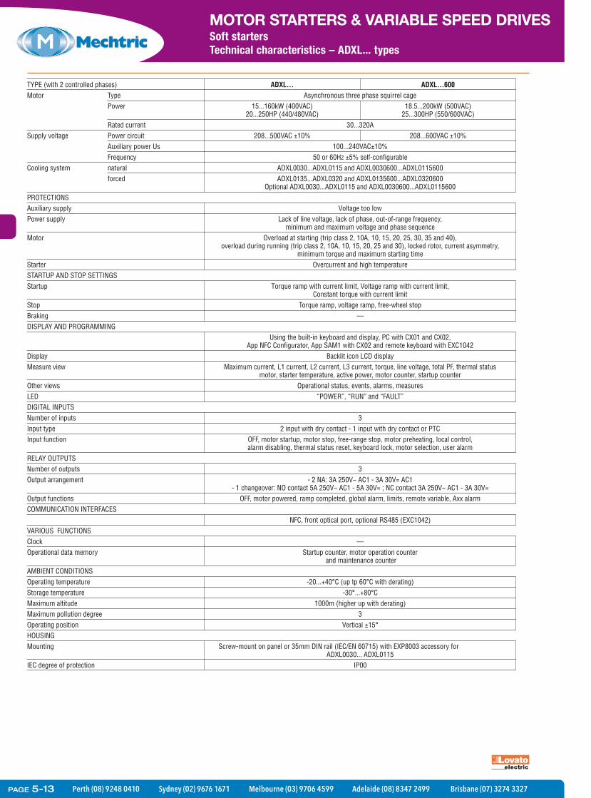
Motor Type Asynchronous three phase squirrel cage Power 15...160kW (400VAC) 18.5...200kW (500VAC) 20...250HP (440/480VAC) 25...300HP (550/600VAC) Rated current 30...320A Supply voltage Power circuit 208...500VAC ±10% 208...600VAC ±10% Auxiliary power Us 100...240VAC±10% Frequency 50 or 60Hz ±5% self-configurableCooling system natural ADXL0030...ADXL0115 and ADXL0030600...ADXL0115600 forced ADXL0135...ADXL0320 and ADXL0135600...ADXL0320600 Optional ADXL0030...ADXL0115 and ADXL0030600...ADXL0115600PROTECTIONSAuxiliary supply Voltage too lowPower supply Lack of line voltage, lack of phase, out-of-range frequency, minimum and maximum voltage and phase sequenceMotor Overload at starting (trip class 2, 10A, 10, 15, 20, 25, 30, 35 and 40), overload during running (trip class 2, 10A, 10, 15, 20, 25 and 30), locked rotor, current asymmetry, minimum torque and maximum starting time Starter Overcurrent and high temperatureSTARTUP AND STOP SETTINGSStartup Torque ramp with current limit, Voltage ramp with current limit, Constant torque with current limitStop Torque ramp, voltage ramp, free-wheel stopBraking ––DISPLAY AND PROGRAMMING Using the built-in keyboard and display, PC with CX01 and CX02, App NFC Configurator, App SAM1 with CX02 and remote keyboard with EXC1042Display Backlit icon LCD displayMeasure view Maximum current, L1 current, L2 current, L3 current, torque, line voltage, total PF, thermal status motor, starter temperature, active power, motor counter, startup counterOther views Operational status, events, alarms, measuresLED “POWER”, “RUN” and “FAULT”DIGITAL INPUTSNumber of inputs 3Input type 2 input with dry contact - 1 input with dry contact or PTCInput function OFF, motor startup, motor stop, free-range stop, motor preheating, local control, alarm disabling, thermal status reset, keyboard lock, motor selection, user alarmRELAY OUTPUTSNumber of outputs 3Output arrangement - 2 NA: 3A 250V~ AC1 - 3A 30V= AC1 - 1 changeover: NO contact 5A 250V~ AC1 - 5A 30V= ; NC contact 3A 250V~ AC1 - 3A 30V=Output functions OFF, motor powered, ramp completed, global alarm, limits, remote variable, Axx alarmCOMMUNICATION INTERFACES NFC, front optical port, optional RS485 (EXC1042)VARIOUS FUNCTIONSClock ––Operational data memory Startup counter, motor operation counter and maintenance counterAMBIENT CONDITIONSOperating temperature -20...+40°C (up tp 60°C with derating)Storage temperature -30°...+80°CMaximum altitude 1000m (higher up with derating)Maximum pollution degree 3Operating position Vertical ±15°HOUSING
rof yrossecca 3008PXE htiw )51706 NE/CEI( liar NID mm53 ro lenap no tnuom-wercSgnitnuoM ADXL0030... ADXL0115IEC degree of protection IP00
PAGE 5-13

Perth (08) 9248 0410 Sydney (02) 9676 1671 Melbourne (03) 9706 4599 Adelaide (08) 8347 2499 Brisbane (07) 3274 3327
MOTOR STARTERS & VARIABLE SPEED DRIVESSoft startersDimensions [mm] – ADXC and ADXL types
Soft Starters
ADXC 012...ADXC 032...
ADXC 037...ADXC 045...
ADXL 0030...ADXL 0060
ADXL 0075...ADXL 0115
45 109.8
106
115
10512
5
Ø5.2
❶
❶
❶ 2 x M5
35mm DIN railIEC/EN60715
ADXC
®
30 60
5 10
0 85%
1 20s
5 10
20s0
ALARM
RAMP / BYPASS
SUPPLY
F1 F2
U
t
t
45
125
35mm DIN railIEC/EN60715
153.8
150
3610
5
123 12
1
6.46
❶ 2 x M5
❶
❶
4.85.2
132
ADXC
®
30 60
5 10
0 85%
1 20s
5 10
20s0
ALARM
RAMP / BYPASS
SUPPLY
12 11/21 24 F1 F2 ST
U
t
t
75
220
170
56
206
95
226
18071
214
PAGE 5-14

Perth (08) 9248 0410 Sydney (02) 9676 1671 Melbourne (03) 9706 4599 Adelaide (08) 8347 2499 Brisbane (07) 3274 3327
MOTOR STARTERS & VARIABLE SPEED DRIVESSoft startersThree phase control
For severe duty (starting current 5•Ie).Can be used with external bypass contactor to reduce starter heating during normal operation.Auxiliary supply: starter Us 208...240VAC;start command 24VDC.
For details of recommended line and by-pass contactors see the information on www.mechtric.com.au
General characteristicsADX is a reduced voltage soft starter with torque controland maximum starting current limit. It is used for theprogressive starting and stopping of asynchronousthree-phase squirrel-cage motors. The integrated by-pass contactor ADX...B types only, drastically limits dissipation, as a result equipment for electric panel cooling ventilation can be eliminated and the enclosure size can be reduced as well.CONTROLDuring starting: Torque control acceleration, current limitcontrol and booster.During stopping: Torque control deceleration, dynamicbraking and free-wheel.In emergency conditions: Starting without protections,direct-on-line starting using integrated by-pass contactor.Remote control: PC supervision by connection with RS232/RS485 converter, modem or GSM modem.Automatic call function (Autocall) in case of alarmconditions by sending a message to a cellular phone(SMS-Short Message Service) and/or to a mailbox.Property ASCII and Modbus®-RTU communicationprotocols.KEYPAD OPERATIONS– Liquid-crystal backlit 2-line 16-character display– Multilanguage capability (Italian, English, French,
Spanish)– Basic, advanced and function programming menus– Keypad stop and start– Motor and mains parameter readings:
• line voltage values (L-L)• phase current• active and apparent power values per phase• power factor per phase• kWh
– Time sequential events log– Clock calendar with backup battery.PARTICULAR FUNCTIONSDigital inputs and programmable relay outputs. Analoginput (0...10V, 0...20mA or 4...20mA) for rampacceleration and/or deceleration, motor starting andstopping control thresholds, programmable relay enableand disable control thresholds. Analog output(0...10V, 0...20mA or 4...20mA) for current, torque,motor thermal status and power factor readings.Input programming for second motor.PROTECTIONS– Motor: Dual thermal protection class (one during
starting phase and the other during running) or byPTC sensor, locked rotor, current asymmetry,minimum torque and starting time too long
– Auxiliary voltage: Voltage value too low– Power voltage: Phase failure, phase sequence and
frequency out of limits– Control inputs and analog output: Static 24VDC
short-circuit protection with automatic resetting.– Starter: Overcurrent, high temperature, SCR and
by-pass contactor malfunction.Operational characteristics– Input voltage:
• 208-500VAC ±10% for ADX...B• 208-415VAC ±10% for ADX...
– Mains frequency: 50-60Hz ±5%– Auxiliary supply voltage: 208-240VAC ±10%– Auxiliary consumption: 20VA– Rated starter current Ie:
• 17-245A for ADX...B• 310-1200A for ADX...
– Motor current: 0.5-1 Ie– Overload current:
• 105% Ie for ADX...B• 115% Ie for ADX...
Certifications and complianceCertifications obtained: EAC for all; CCC for ADX 0110Band ADX 0125B types only.Compliant with standard: IEC/EN 60947-1, IEC/EN 60947-4-2.
208-600VAC ±10% on request.Voltages on request: higher than 415V to 690V maximum.
Order code Rated Rated motor Qty Wtstarter power percurrent Ie (380/415V) pkg[A] [kW] n° [kg]
For standard duty (starting current 5•Ie).With integrated bypass contactor.Auxiliary supply: starter Us 208...240VAC; start command 24VDC. For a high number of starts the by-pass can be disabled, however a larger size starter must be selected.
51 ADX 0017B 17 7.5 1 7.90051 ADX 0030B 30 15 1 8.00051 ADX 0045B 45 22 1 8.30051 ADX 0060B 60 30 1 14.90051 ADX 0075B 75 37 1 14.90051 ADX 0085B 85 45 1 14.90051 ADX 0110B 110 55 1 15.70051 ADX 0125B 125 59 1 15.70051 ADX 0142B 142 75 1 34.00051 ADX 0190B 190 90 1 37.00051 ADX 0245B 245 132 1 37.000
51 ADX 0310 310 160 1 50.00051 ADX 0365 365 200 1 50.00051 ADX 0470 470 250 1 90.00051 ADX 0568 568 315 1 90.00051 ADX 0640 640 355 1 110.00051 ADX 0820 820 440 1 170.00051 ADX 1200 1200 630 1 185.000
Order code Description51 ADX SW PC-ADX remote control software with
proprietary ASCII and Modbus-RTUprotocols and a set of connecting cables 51 C2, 51 C3, 51 C5, 51 C7 forcommunications via RS232 port, analogor GSM modem
ADX type
51 ADX 0017B - 51 ADX 0045B
51 ADX 0060B - 51 ADX 0085B
51 ADX 0110B - 51 ADX 0125B
Software
PAGE 5-15

Perth (08) 9248 0410 Sydney (02) 9676 1671 Melbourne (03) 9706 4599 Adelaide (08) 8347 2499 Brisbane (07) 3274 3327
MOTOR STARTERS & VARIABLE SPEED DRIVESSoft startersTechnical characteristics
Operational characteristicsADX type
TIPO ADX...(with integrated by-pass (to complete with external
contactor) by-pass contactor)Motor Type Asynchronous three phase
Power 160-630kW7.5-132kW (ADX...B)
Rated current 310-1200A17-245A (ADX...B)
Supply voltage Power circuit 208 - 500VAC ±10% standard 208 - 415VAC ±10% standard(208-575VAC ±10% on request) Other voltages up to 690VAC
maximum on request)Rated supply voltage 208 - 240VAC ±10%Frequency 50 or 60Hz ±5% self configurable
Starting Torque ramp with maximum current controlStopping Free wheel or torque ramp decelerationBraking DC dynamic by external contactorProtections Auxiliary supply Voltage too low
Power supply Phase failure, frequency out of limits, minimum and maximum voltage and phase sequence, 24VDC static short circuit
Motor Overload at starting (trip class 2, 10A, 10, 15, 20, 25, 30, 35 and 40), overload during running (trip class 2, 10A, 10, 15, 2025 and 30), locked rotor, current asymmetry, minimum torque
and maximum starting timeStarter Overcurrent and high temperatureAnalog inputs and outputs 24VDC static short circuit
Functions Clock calendar With back-up batteryEvent log 20 event registrations in date and time sequential orderOperating data mermory Hour counter, one each for energy usage, number of
startings, motor running and maintenance expiryMultilanguage capability Italian / English / Spanish / French
Setup configuration By incorporated or remote keypad or PCKeyboard Display and LED indicators LCD, 2 line x 16 character, backlit, POWER, RUN, FAULT
Membrane keys ENTER/START, RESET/STOP, PREVIOUS, NEXT, and Setup parameters Adjustment menus: basic, advanced, functions, clock and controlsReadings display Voltage, current, power factor (cosϕ), torque,
power (kVA, kW, kvar) and energy usageGraphic display Current and torqueDisplay Operating status, events, alarms, event log, data
Control inputs Voltage 24VDC (no need for external feeder)Fixed functions 2 for starting and stopping/resetMultifunction input Free-wheel stopping, external alarm, motor preheat, (digital functions) on board control, alarm inhibition, thermal protection
manual reset, cascade starting and keypad lockMultifunction input Motor protection via PTC probes, acceleration and/or (analog functions) deceleration ramp via analog input, analog input thresholds for
motor starting and stopping, analog input thresholds for programmable relay enable and disable, PT100 input thresholdsfor motor starting and stopping and PT100 input thresholds for
programmable relay enable and disableRelay outputs Voltage and capacity 250VAC 5A (AC1)
Fixed functions 1 with 1 NO + 1NC contacts for overall alarmProgrammable functions 3 each with 1 NO contact for running motor, motor starting,
braking, current tripping threshold, maintenance expiry, etc.Analog output Format configuration 0-20mA, 4-20mA or 0-10V
Associated source Current, torque, motor thermal status and power factorCommunications interface RS232 port Setup and remote control
RS485 port Used for remote keypad onlyDegree of protection IP00Cooling system Natural ––17-45A (ADX...B)
Forced All types60-245A (ADX...B)
Operating temperature -10...+45°C (higher up to maximum 55°C with derating)Storage temperature -30...+70°CMaximum altitude 1000mMaximum pollution degree 3Operating position Vertical ±15°IP20 for ADX0017B to ADX0125B only.
ADX... B
PAGE 5-16

Perth (08) 9248 0410 Sydney (02) 9676 1671 Melbourne (03) 9706 4599 Adelaide (08) 8347 2499 Brisbane (07) 3274 3327
MOTOR STARTERS & VARIABLE SPEED DRIVESSoft startersDimensions [mm] – ADX types
B
C
D
E
A
TIPO A B C D EADX 0022BP 157 372 223 131 357ADX 0034BP 157 372 223 131 357ADX 0048BP 157 372 223 131 357ADX 0058BP 157 534 250 132 517ADX 0068BP 157 534 250 132 517ADX 0082BP 157 534 250 132 517ADX 0092BP 157 534 250 132 517ADX 0114BP 157 584 250 132 567ADX 0126BP 157 584 250 132 567ADX 0017B 157 372 223 131 357ADX 0030B 157 372 223 131 357ADX 0045B 157 372 223 131 357ADX 0060B 157 534 250 132 517ADX 0075B 157 534 250 132 517ADX 0085B 157 534 250 132 517ADX 0110B 157 584 250 132 567ADX 0125B 157 584 250 132 567
C
BE
D
A
TIPO A B C D EADX 0150BP 273 600 285 230 640ADX 0196BP 273 680 310 230 640ADX 0231BP 273 680 310 230 640ADX 0142B 273 600 285 230 560ADX 0190B 273 680 310 230 640ADX 0245B 273 680 310 230 640
C
B
D
E
A
F
TIPO A B C D E F ADX 0310 640 600 380 620 400 100 ADX 0365 640 600 380 620 400 100 ADX 0470 790 650 430 770 450 100 ADX 0568 790 650 430 770 450 100 ADX 0640 790 650 430 770 450 100 ADX 0820 910 950 442 830 920 ADX 1200 910 950 442 830 920 —
Consult Customer Service1800 252 995 or [email protected]
ADX 0017 B...ADX 0125 B
ADX 0142 B...ADX 0245 B
ADX 0310...ADX 1200
PAGE 5-17
Perth (08) 9248 0410 Sydney (02) 9676 1671 Melbourne (03) 9706 4599 Adelaide (08) 8347 2499 Brisbane (07) 3274 3327
MOTOR STARTERS & VARIABLE SPEED DRIVESSoft startersAccessories
Accessories for ADXL...types
CX 01
CX 02
EXC RDU1
EXC 1042 EXP 8003
51C4
4PX1
Remote keypadfor ADX... types
51 ADX TAST
Accessories for ADX...types
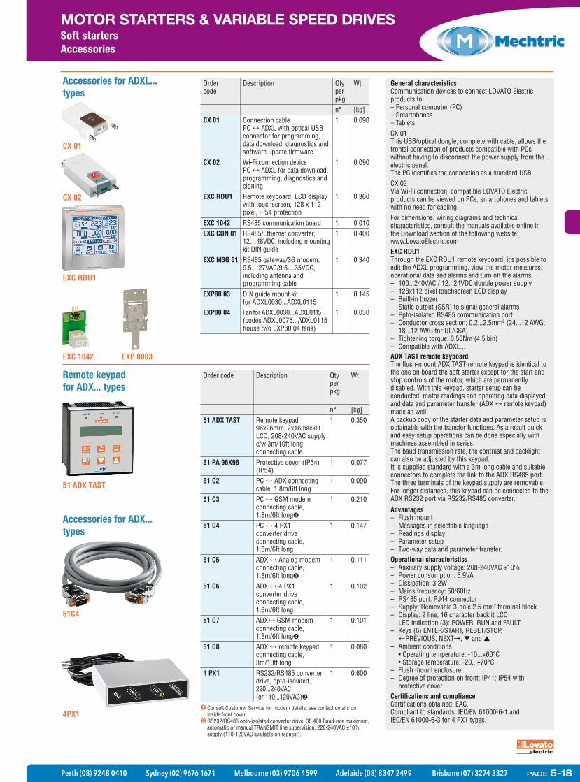
Order Description Qty Wt code per pkg n° [kg] CX 01 Connection cable 1 0.090 PC ADXL with optical USB connector for programming, data download, diagnostics and software update firmware CX 02 Wi-Fi connection device 1 0.090 PC ADXL for data download, programming, diagnostics and cloning EXC RDU1 Remote keyboard, LCD display 1 0.360 with touchscreen, 128 x 112 pixel, IP54 protection EXC 1042 RS485 communication board 1 0.010 EXC CON 01 RS485/Ethernet converter, 1 0.400 12…48VDC, including mounting kit DIN guide EXC M3G 01 RS485 gateway/3G modem, 1 0.340 9.5…27VAC/9.5…35VDC, including antenna and programming cable EXP80 03 DIN guide mount kit 1 0.145 for ADXL0030...ADXL0115 EXP80 04 Fan for ADXL0030...ADXL0115 1 0.030 (codes ADXL0075...ADXL0115 house two EXP80 04 fans)
General characteristicsCommunication devices to connect LOVATO Electricproducts to:– Personal computer (PC)– Smartphones– Tablets.CX 01This USB/optical dongle, complete with cable, allows thefrontal connection of products compatible with PCswithout having to disconnect the power supply from theelectric panel.The PC identifies the connection as a standard USB.CX 02Via Wi-Fi connection, compatible LOVATO Electricproducts can be viewed on PCs, smartphones and tabletswith no need for cabling.For dimensions, wiring diagrams and technicalcharacteristics, consult the manuals available online inthe Download section of the following website:www.LovatoElectric.comEXC RDU1Through the EXC RDU1 remote keyboard, it’s possible toedit the ADXL programming, view the motor measures,operational data and alarms and turn off the alarms.– 100...240VAC / 12...24VDC double power supply– 128x112 pixel touchscreen LCD display– Built-in buzzer– Static output (SSR) to signal general alarms– Ppto-isolated RS485 communication port– Conductor cross section: 0.2...2.5mm2 (24...12 AWG;
18...12 AWG for UL/CSA)– Tightening torque: 0.56Nm (4.5lbin)– Compatible with ADXL...ADX TAST remote keyboardThe flush-mount ADX TAST remote keypad is identical tothe one on board the soft starter except for the start andstop controls of the motor, which are permanentlydisabled. With this keypad, starter setup can beconducted, motor readings and operating data displayedand data and parameter transfer (ADX remote keypad)made as well. A backup copy of the starter data and parameter setup isobtainable with the transfer functions. As a result quickand easy setup operations can be done especially withmachines assembled in series.The baud transmission rate, the contrast and backlightcan also be adjusted by this keypad. It is supplied standard with a 3m long cable and suitableconnectors to complete the link to the ADX RS485 port.The three terminals of the keypad supply are removable.For longer distances, this keypad can be connected to theADX RS232 port via RS232/RS485 converter.
Advantages– Flush mount– Messages in selectable language– Readings display– Parameter setup– Two-way data and parameter transfer.Operational characteristics– Auxiliary supply voltage: 208-240VAC ±10%– Power consumption: 6.9VA– Dissipation: 3.2W– Mains frequency: 50/60Hz– RS485 port: RJ44 connector– Supply: Removable 3-pole 2.5 mm2 terminal block.– Display: 2 line, 16 character backlit LCD– LED indication (3): POWER, RUN and FAULT– Keys (6) ENTER/START, RESET/STOP, PREVIOUS, NEXT , and – Ambient conditions • Operating temperature: -10...+60°C • Storage temperature: -20...+70°C– Flush mount enclosure– Degree of protection on front: IP41; IP54 with
protective cover.Certifications and complianceCertifications obtained: EAC.Compliant to standards: IEC/EN 61000-6-1 and IEC/EN 61000-6-3 for 4 PX1 types.
Order code Description Qty Wt per pkg n° [kg] 51 ADX TAST Remote keypad 1 0.350 96x96mm, 2x16 backlit LCD, 208-240VAC supply c/w 3m/10ft long connecting cable 31 PA 96X96 Protective cover (IP54) 1 0.077 (IP54) 51 C2 PC ADX connecting 1 0.090 cable, 1.8m/6ft long 51 C3 PC GSM modem 1 0.210 connecting cable, 1.8m/6ft long 51 C4 PC 4 PX1 1 0.147 converter drive connecting cable, 1.8m/6ft long 51 C5 ADX Analog modem 1 0.111 connecting cable, 1.8m/6ft long 51 C6 ADX 4 PX1 1 0.102 converter drive connecting cable, 1.8m/6ft long 51 C7 ADX GSM modem 1 0.101 connecting cable, 1.8m/6ft long 51 C8 ADX remote keypad 1 0.080 connecting cable, 3m/10ft long 4 PX1 RS232/RS485 converter 1 0.600 drive, opto-isolated, 220...240VAC (or 110...120VAC)
Consult Customer Service for modem details; see contact details oninside front cover.RS232/RS485 opto-isolated converter drive, 38,400 Baud-rate maximum,automatic or manual TRANSMIT line supervision, 220-240VAC ±10%supply (110-120VAC available on request).
PAGE 5-18

Perth (08) 9248 0410 Sydney (02) 9676 1671 Melbourne (03) 9706 4599 Adelaide (08) 8347 2499 Brisbane (07) 3274 3327
MOTOR STARTERS & VARIABLE SPEED DRIVESVariable speed drives
VFD-EL Series AC Drive • Motorpowerupto2.2kW1phand3.7kW3ph
• KeypadwithLEDdisplayandpotentiometer
• Processfollower0-10V,4-20mA(optionalPTCinput)
• Optionalfieldbusmodules(deviceNet,profiBus,CANopen)
• DCbussharing• PIDfeedbackcontrol• RS-485(MODBUS)• C-Tick,CEapprovals• Internalfilter1phand3ph
versions
115V Class
Part No. VFD002EL11A VFD004EL11A VFD007EL11A
Order Code DEVFD002EL11A DEVFD004EL11A DEVFD007EL11A
Motor Output 0.18kw 0.37kw 0.75kw
Input Voltage 100-120V 1ph ±10% 50/60Hz
Output Voltage 3 phase 2 x input voltage
Rated Capacity (kVA) 0.6 1.0 1.6
Input Current 6.4 9A 18A
Output Current 1.6A 2.5A 4.2A
Weight (Kg) 1.1 1.1 1.4
Fan Cooled No No Yes
Dimensions mm (h x w x d) 174 x 72 x 136 (frame A) 174 x 100 x 136 (frame B)
Specifications
230V Class
Part No. VFD002EL21A VFD004EL21A VFD007EL21A VFD015EL21A VFD022EL21A
Order Code DEVFD002EL21A DEVFD004EL21A DEVFD007EL21A DEVFD015EL21A DEVFD022EL21A
Motor Output 0.18kw 0.37kw 0.75kw 1.5kw 2.2kw
Input Voltage 200-240V 1ph ±10% 50/60Hz
Output Voltage 3 phase proportional to input voltage
Rated Capacity (kVA) 0.6 1.0 1.6 2.9 4.2
Input Current 4.9A 6.5A 9.5A 15.7A 24A
Output Current 1.6A 2.5A 4.2A 7.5A 11.0A
Weight (Kg) 1.2 1.7 1.7
Fan Cooled No No No Yes Yes
Dimensions mm (h x w x d) 174 x 72 x 136 (h x w x d) (frame A) 174 x 100 x 136 (h x w x d) (frame B)
460V Class
Part No. VFD004EL43A VFD007EL43A VFD015EL43A VFD022EL43A VFD037EL43A
Order Code DEVFD004EL43A DEVFD007EL43A DEVFD015EL43A DEVFD022EL43A DEVFD037EL43A
Motor Output 0.37kw 0.75kw 1.5kw 2.2kw 3.7kw
Input Voltage 380-480V 3ph ±10% 50/60Hz
Output Voltage 3 phase proportional to input voltage
Rated Capacity (kVA) 1.2 2.0 3.3 4.4 6.8
Input Current 1.8A 3.2A 4.3A 7.1A 9A
Output Current 1.5A 2.5A 4.2A 5.5A 8.2A
Weight (Kg) 1.2 1.2 1.2 1.7 1.7
Fan Cooled No No Yes Yes Yes
Dimensions mm (h x w x d) 174 x 72 x 136 (h x w x d) (frame A) 174 x 100 x 136 (h x w x d) (frame B)
Certifications and complianceCE, UL, RCM
PAGE 5-19

Perth (08) 9248 0410 Sydney (02) 9676 1671 Melbourne (03) 9706 4599 Adelaide (08) 8347 2499 Brisbane (07) 3274 3327
MOTOR STARTERS & VARIABLE SPEED DRIVESVariable speed drives
VFD-EL Series AC Drive
CONTROL
Control System SPWM (Sinusoidal Pulse Width Modulation, carrier frequency 2kHz-12kHz)
Output Freq. Range 0.1 - 599Hz
Output Frequency Resolution 0.01Hz
Torque Characteristics Including the auto-torque, auto-slip compensation; starting torque can be 150% at 5Hz
Overload Endurance 150% of rated current for 1 minute
Skip Frequency Three zones, setting range 0.1 - 599Hz
Accel/Decel Time 0.1 to 600 second (2 Independent settings for Accel/Decel Time)
V/F Pattern V/F pattern adjustable
Stall Prevention Level 20 to 250%, Setting of Rated Current
DC Injection Braking Operation frequency 0.1 - 599Hz, output 0-100% rated currentStart time 0-60 sec, stop time 0-60 sec
Braking Torque Approx. 20% (up to 125% with external brake unit and braking resistor)
OPERATION
Frequency Setting Keypad Setting by keypad or Potentiometer
External Signal Potentiometer-5KΩ/0.5W, DC 0 to +10V or 0 to +5V (Input impedance 47KΩ), RS-485 interface, 4 to 20mA (Input impedance 250Ω); Multi-Function Inputs 3 to 6 (15 steps, Jog, up/down)
Operation Setting Signal
Keypad Setting by RUN, STOP
External Signal 2 wires/3 wires (MI1, MI2, MI3), RS-485 serial interface (MODBUS). PLC
Multi-Function Input Signal Multi-step selection 0 to15, Jog, accel/decel inhibit, first/second accel/decel switch, counter, ACI/AVI selections, external Base Block (NC, NO), up/down frequency command, driver reset, NPN/PNP input selection
Multi-Function Output Indication AC Drive Operating, Frequency Attained, zero speed, external base block detection, Fault Indication, overheat alarm, emergency stop and status selection of input terminals
Analog Output Signal Analog frequency/current signal output
Alarm Output Contact 1 Form C C/O contact or open collector output
Operation Functions AVR, accel/decel S-curve, over-voltage/over-current stall prevention, 5 fault records, reverse inhibit, momentary power loss restart, DC braking, auto torque/slip compensation, adjustable carrier frequency, output frequency limits, parameter lock/reset, PID control, external counter, MODBUS communication, power saving, fan control, sleep/wake frequency, 1st/2nd frequency source selections and combination, NPN/PNP selection
Protection Over Voltage, Over Current, Under Voltage, Overload, Overheating, External Fault, Electronic thermal, Ground Fault., IGBT short circuit, PTC
Keypad and Display 6-key, 4-digit, 7- segment LED, 4 status LED’s, potentiometer, master frequency, output frequency, output current, user defined units, parameter setup, review and faults.RUN, STOP, RESET, FWD/REV
ENVIRONMENT
Installation Location Altitude 1,000m or below, keep from corrosive gasses, liquid and dust
Pollution Degree 2
Ambient Temperature -10°C to 50°C (Non-Condensing and not frozen) (-40° C for side by side mounting)
Storage Temperature -20°C to 60°C
Ambient Humidity Below 90% RH (non-condensing)
Vibration 9.80665m/s2 (1G) less than 20Hz, 5.88m/s2, (0.6G) at 20 to 50Hz
Specifications common to all sizes
PAGE 5-20

Perth (08) 9248 0410 Sydney (02) 9676 1671 Melbourne (03) 9706 4599 Adelaide (08) 8347 2499 Brisbane (07) 3274 3327
MOTOR STARTERS & VARIABLE SPEED DRIVESVariable speed drives
VFD-EL Series AC DriveAccessories
Order Code Description
DEVFDCMEDN01 CME-DN01 DeviceNet module
DEVFDCMECOP01 CME-COP01 CANopen module
DEVFDCMEPD01 CME-PD01 Profibus module
DEVFDBUE20015 BUE-20015 Brake Unit 0.2kw to 1.5kw 230V (see page 152 for resistor details)
DEVFDBUE20037 BUE-20037 Brake Unit 2.2kw 230V (see page 152 for resistor details)
DEVFDBUE40015 BUE-40015 Brake Unit 0.2kw to 1.5kw 440V (see page 152 for resistor details)
DEVFDBUE40037 BUE-40037 Brake Unit 2.2kw to 3.7kw 440V (see page 152 for resistor details)
DEVFDMKELDRA MKEL-DRA DIN Rail adaptor frame A
DEVFDMKELDRB MKEL-DRB DIN Rail adaptor frame B
DEVFDMKEEP MKE-EP EMC earthing strap
DEVRC01 RC-01 remote operatorBRAKE UNIT
RC-01
CME-DN01
CME-PD01
MKE-EP
PAGE 5-21

Perth (08) 9248 0410 Sydney (02) 9676 1671 Melbourne (03) 9706 4599 Adelaide (08) 8347 2499 Brisbane (07) 3274 3327
MOTOR STARTERS & VARIABLE SPEED DRIVESVariable speed drives
VFD-E Series AC Drive • Motorpowerupto2.2kW1phand22kW3ph• SensorlessvectororV/Fcontrol• Removablekeypadwithpotentiometer• BuiltinPLCwithoptionalI/Oandencodermodules• Processfollower0-10V,4-20mA(optionalPTCinput)and
PIDfeedbackcontrol• Optionalfieldbusmodules(deviceNet,profiBus,CANopen,)• DCbussharing• RS-485(MODBUS)• Builtinfilterandbrakechopper• C-Tick,CEapprovals
Specifications
230V Class
Part No. VFD002E21T VFD004E21T VFD007E21T VFD015E21A VFD022E21A
Order Code DEVFD002E21T DEVFD004E21T DEVFD007E21T DEVFD015E21A DEVFD022E21A
Motor Output 0.18kw 0.37kw 0.75kw 1.5kw 2.2kw
Input Voltage 200-240V 1ph ±10% 50/60Hz
Output Voltage 3 phase proportional to input voltage
Rated Capacity (kVA) 0.6 1.0 1.6 2.9 4.2
Input Current 4.9A 6.5A 9.7A 15.7A 24A
Output Current 1.6A 2.5A 4.2A 7.5A 11.0A
Weight (Kg) 1.1 1.9
Fan Cooled No Yes
Dimensions mm 142 x 72 x 152 (h x w x d) 174 x 100 x 152 (h x w x d)
460V Class
Part No. VFD004E43T VFD007E43T VFD015E43T VFD022E43A VFD037E43A
Order Code DEVFD004E43T DEVFD007E43T DEVFD015E43T DEVFD022E43A DEVFD037E43A
Motor Output 0.37kw 0.75kw 1.5kw 2.2kw 3.7kw
Input Voltage 380-480V 3ph ±10% 50/60Hz
Output Voltage 3 phase proportional to input voltage
Rated Capacity (kVA) 1.2 2.0 3.3 4.4 6.8
Input Current 1.9A 3.2A 4.3A 7.1A 11.2A
Output Current 1.5A 2.5A 4.2A 5.52A 8.5A
Weight (Kg) 1.2 1.2 1.2 1.9 1.9
Fan Cooled No Yes
Dimensions mm 142 x 72 x 152 (h x w x d) 174 x 100 x 152 (h x w x d)
Part No. VFD055E43A VFD075E43A VFD110E43A VFD150E43A VFD185E43A VFD220E43A
Order Code DEVFD055E43A DEVFD075E43A DEVFD110E43A DEVFD150E43A DEVFD185E43A DEVFD220E43A
Motor Output 5.5kw 7.5kw 11kw 15kw 18.5kw 22kw
Input Voltage 380-480V 3ph ±10% 50/60Hz
Output Voltage 3 phase proportional to input voltage
Rated Capacity (kVA) 9.9 13.7 18.3 24 29 34
Input Current 14A 19A 26A 35A 41A 49A
Output Current 13A 18A 24A 32A 38A 45A
Weight (Kg) 4.2 4.2 4.2 7.5 7.5 7.5
Dimensions mm 260 x 130 x 169.2 (h x w x d) 310 x 200 x 190 (h x w x d)
Note: Keypad must be ordered separately if required, see accessories.
Certifications and complianceCE, UL, RCM, ROHS
PAGE 5-22

Perth (08) 9248 0410 Sydney (02) 9676 1671 Melbourne (03) 9706 4599 Adelaide (08) 8347 2499 Brisbane (07) 3274 3327
MOTOR STARTERS & VARIABLE SPEED DRIVESVariable speed drives
AVI
ACI
ACM
+
+10V3
2
1
Power supply+10V 20m A
Master Frequency0 to 10V 47K
Main c ircui t (power) terminals Control c ircuit terminals Shielded l eads & Cable
E
R(L1)S(L2)
Fuse/NFB(No Fuse B reaker)
SA
OFF ON
MC
MC
RB
RC
Recommended Circui t when power suppl y is turned OFF by a fault outputIf the fault occurs, thecontact will be ON to turn off the power andprotect the power sys tem.
R(L1)S(L2)
E
Analog Multi- func tion OutputTerminalfactory setti ng: Analog freq./ cur rent meter 0~1 0VDC/2 mA
U(T1)V(T2)W(T3)
IM3~
AFM
ACM
RA
RB
RC
Motor
Fac tory sett ing:Drive is in operation48V50mA Max.
Mult i-function Photocoupler Output
Analog S ignal common
E
E
MO1
MCM
MI1MI2MI3MI4
MI6MI5
DCM
+24VFWD/Stop
REV/Stop
Multi-s tep 1
Multi-s tep 2
Multi-s tep 3
Multi-s tep 4
Digital Si gnal Common
Fac torysett ing
Sw2AVI
ACI
Factory set ting: ACI Mode
ACI/AVI switchWhen switching to AVI,it indicates AVI2
-
8 1
Sw1NPN
PNP
Factory set ting: NPN Mode
BUEbrake unit
(optional)
BR brake resi stor (opti onal)
Mult i-function contact outputFac tory sett ing is malfunction indication
Fac tory sett ing: output frequency
4-20mA/0-10V
T(L3)T(L3)
RS-485 serial inter face(NOT for VFD*E*C models)1: Reserved 2: EV
5: SG+ 6: Reserved 7: Reserved 8: EV
3: GND 4: SG-
VFD-E Series AC Drive
CONTROL
Control System SPWM (Sinusoidal Pulse Width Modulation, carrier frequency 1kHz-15kHz) V/F or sensorless vector control
Output Freq. Range 1.0-600Hz
Output Frequency Resolution 0.01Hz
Torque Characteristics Including the auto-torque, auto-slip compensation; starting torque can be 150% at 3Hz
Overload Endurance 150% of rated current for 1 minute
Skip Frequency Three zones, setting range 0.1 to 600Hz
Accel/Decel Time 0.1 to 600 second (2 Independent settings for Accel/Decel Time)
V/F Pattern V/F pattern adjustable
Stall Prevention Level 20 to 250%, Setting of Rated Current
DC Injection Braking Operation frequency 1.0-600Hz, output 0-100% rated currentStart time 0-60 sec, stop time 0-60 sec
Braking Torque Approx. 20% ( up to 125% braking resistor all sizes have the braking chopper built in)
OPERATION
Frequency Setting Keypad Setting by keypad or Potentiometer
External Signal Potentiometer-5KΩ/0.5W, DC 0 to +10V or 0 to +5V (Input impedance 47KΩ), RS-485 interface, 4 to 20mA (Input impedance 250Ω); Multi-Function Inputs 3 to 9 (15 steps, Jog, up/down)
Operation Setting Signal
Keypad Setting by RUN, STOP
External Signal 2 wires/3 wires (FWD, REV, EF), RS-485 serial interface (MODBUS). PLC
Multi-Function Input Signal Multi-step selection 0 to 15, Jog, accel/decel inhibit, first/second accel/decel switch, counter, ACI/AVI/AUI selections, external Base Block (NC, NO), up/down frequency command, NPN/PNP input selection, aux. motor output
Multi-Function Output Indication AC Drive Operating, Frequency Attained, zero speed, external base block detection, Fault Indication, overheat alarm, emergency stop and status selection of input terminals (N/C or N/O), local/remote indication
Analog Output Signal Analog frequency/current signal output
Alarm Output Contact 1 Form C C/O contact or open collector output
Operation Functions Built-in PLC, AVR, accel/decel S-curve, over-voltage/over-current stall prevention, 5 fault records, reverse inhibit, momentary power loss restart, DC braking, auto torque/slip compensation, auto tuning, adjustable carrier frequency, output frequency limits, parameter lock/reset, vector control, PID control, external counter, MODBUS communication, power saving, fan control, sleep/wake frequency, 1st/2nd frequency source selections and combination, NPN/PNP selection
Protection Over Voltage, Over Current, Under Voltage, Overload, Overheating, External Fault, Electronic thermal, Ground Fault., IGBT short circuit, PTC
Keypad and Display 6-key, 4-digit, 7- segment LED, 4 status LED’s, potentiometer, master frequency, output frequency, output current, user defined units, parameter setup, review and faults.RUN, STOP, RESET, FWD/REV
ENVIRONMENT
Installation Location Altitude 1,000m or below, keep from corrosive gasses, liquid and dust
Pollution Degree 2
Ambient Temperature -10°C to 50°C (Non-Condensing and not frozen) (-40°C for side by side mounting)
Storage Temperature -20°C to 60°C
Ambient Humidity Below 90% RH (non-condensing)
Vibration 9.80665m/s2 (1G) less than 20Hz, 5.88m/s2, (0.6G) at 20 to 50Hz
Specifications common to all sizes
PAGE 5-23

Perth (08) 9248 0410 Sydney (02) 9676 1671 Melbourne (03) 9706 4599 Adelaide (08) 8347 2499 Brisbane (07) 3274 3327
MOTOR STARTERS & VARIABLE SPEED DRIVESVariable speed drives
VFD-E Series AC DriveAccessories
VFD-EL and E Series Braking Resistors
Order Code Description
DEVFDKPELE02 KPE-LE02 key pad
DEVFDCMEDN01 CME-DN01 DeviceNet module
DEVFDCMECOP01 CME-COP01 CANopen module
DEVFDCMEPD01 CME-PD01 Profibus module
DEVFDCMEUSB01 CME-USB01 second communication card (USB1.1)
DEVFDEMED33A EME-33A I/O card 3 in/3 out
DEVFDEMER2CA EME-R2CA relay card 2 x C/O contacts
DEVFDEMER3AA EME-R3AA relay card 3 x C/O contacts
DEVFDEMEA22A EME-A22A I/O card 2 analogue in/2 analogue out
DEVFDEMEPG01 EME-PG01 encoder card
DEVFDMKEDRA MKE-DRA DIN Rail adaptor frame A
DEVFDMKEDRB MKE-DRB DIN Rail adaptor frame B
DEVFDMKEEP MKE-EP EMC earthing strap
DEVRC01 RC-01 remote operator
DEVPU06 PU-06 copy programmer
Specifications
Voltage Applicable Motor Order Code Quantity Required
Equivalent brake resistor for each AC drive
Brake Unit Model EL only
Brake Torque 10% ED%
Min. Equivalent Resistor Value for Each AC Drive
Typical Thermal Overload Relay Value
HP KW
115/230V Series 1/4 0.2 DEVBR200W250 1 200W 250Ω 1 x BUE20015 320 200Ω 2A
1/2 0.4 DEVBR200W250 1 200W 250Ω 1 x BUE20015 170 100Ω 3A
1 0.75 DEVBR200W150 1 200W 150Ω 1 x BUE20015 140 80Ω 4A
2 1.5 DEVBR300W100 1 300W 100Ω 1 x BUE20015 107 80 Ω 4A
3 2.2 DEVBR300W100 2 600W 50Ω 1 x BUE20037 150 25 Ω 12A
460V Series 1/2 0.4 DEVBR300W400 1 300W 400Ω 1 x BUE40015 400 400Ω 2A
1 0.75 DEVBR300W400 1 300W 400Ω 1 x BUE40015 200 200Ω 3A
2 1.5 DEVBR200W150 2 400W 300Ω 1 x BUE40015 140 160Ω 4A
3 2.2 DEVBR300W400 2 300W 400Ω 1 x BUE40037 150 100Ω 6A
5 3.7 DEVBR300W400 3 900W 120Ω 1 x BUE40037 150 100Ω 6A
7.5 5.5 DEVBR300W400 4 1200W 100Ω - 115 96Ω -
10 7.5 DEVBR300W400 5 1500W 80Ω - 107 69Ω -
15 11 DEVBR300W400 7 2100W 57Ω - 100 53Ω -
20 15 DEVBR1K2W008 4 4800W 32Ω - 151 31Ω -
25 18.5 DEVBR1K2W008 4 4800W 32Ω - 121 31Ω -
30 22 DEVBR1K2W008 4 4800W 32Ω - 100 31Ω -
EME-33A
BRAKE RESISTORS
PAGE 5-24

Perth (08) 9248 0410 Sydney (02) 9676 1671 Melbourne (03) 9706 4599 Adelaide (08) 8347 2499 Brisbane (07) 3274 3327
MOTOR STARTERS & VARIABLE SPEED DRIVESVariable speed drives
Certifications and complianceCE, UL, RCM, EAC
C2000 VFD-C Series AC Drive • Motorpowerupto450kW3ph• 690Vversionsupto630kW• CH2000versionforcraneandhoistapplicationsupto
280kW• Dualrating(constanttorqueorvariabletorque)• Openlooporclosedloopfieldorientedcontrol(upto
200%torqueatzerospeedinclosedloopmode)• 4quadranttorquecontrol• RemovablemultilineLCDdisplaywithAuto/Manual
button• BuiltinPLCwithoptionalI/Oandencodermodules• Processfollower0-10V,4-20mA(optionalPTCinput)
andPIDfeedbackcontrol• RS-485(MODBUS)andCANopenbuiltin,with
optionalfieldbusmodules(deviceNet,profiBus,EtherNet)
• Builtinfilterandbrakechopperupto30kw,andbuiltinDCreactor(above30kw)
• Coatedcircuitboards• C-Tick,CEapprovals
Specifications
Part No. VFD007C43E VFD015C43E VFD022C43E VFD040C43E VFD055C43E VFD075C43E
Order Code DEVFD007C43E DEVFD015C43E DEVFD022C43E DEVFD040C43E DEVFD055C43E DEVFD075C43E
Motor Output 0.75kw 1.5kw 2.2kw 4.0kw 5.5kw 7.5kw
Input Voltage 380-480V 3ph ( -15~+10%) 50/60Hz
Output Voltage 3 phase proportional to input voltage
Rated Capacity (kVA)
Heav
y Du
ty 2.3 3.0 4.5 7.6 9.6 14
Input Current 2.9A 3.8A 5.7A 9.5A 11A 17A
Output Current 4.1A 5.6A 8.3A 14.5A 16A 19A
Carrier Freq. 2-6kHz
Rated Capacity (KVA)
Nor
mal
Dut
y 2.4 3.2 4.8 8.4 10 14
Output Current 3.0A 4.0A 6.0A 10.5A 12A 18A
Input Current 4.3A 5.9A 8.7A 15.5A 17A 20A
Carrier Freq. 2-15kHz
Weight (Kg) 2.6 2.6 2.8 2.8 2.8 5.4
Dimensions mm 250 x 130 x 170 (h x w x d) 320 x 190 x 190 (h x w x d)
EMI Filter Built In
Part No. VFD110C43E VFD150C43E VFD185C43E VFD220C43E VFD300C43E VFD370C43U
Order Code DEVFD110C43E DEVFD150C43E DEVFD185C43E DEVFD220C43E DEVFD300C43E DEVFD370C43U
Motor Output 11kw 15kw 18.5kw 22kw 30kw 37kw
Input Voltage 380-480V 3ph ( -15~+10%) 50/60Hz
Output Voltage 3 phase proportional to input voltage
Rated Capacity (kVA)
Heav
y Du
ty 18 24 29 34 45 55
Input Current 23A 30A 36A 43A 57A 69A
Output Current 25A 33A 38A 45A 60A 70A
Carrier Freq. 2-6kHz
Rated Capacity (KVA)
Nor
mal
Dut
y 19 25 30 36 48 58
Output Current 24A 32A 38A 45A 60A 73A
Input Current 26A 35A 40A 47A 63A 74A
Carrier Freq. 2-15kHz 2-10kHz
Weight (Kg) 5.4 5.4 9.8 9.8 10.8 40
Dimensions mm 320 x 190 x 190 (h x w x d) 400 x 250 x 210 (h x w x d) 615 x 280 x 225 (h x w x d)
EMI Filter Built In 27FIN538S1075M
PAGE 5-25

Perth (08) 9248 0410 Sydney (02) 9676 1671 Melbourne (03) 9706 4599 Adelaide (08) 8347 2499 Brisbane (07) 3274 3327
MOTOR STARTERS & VARIABLE SPEED DRIVESVariable speed drives
C2000 VFD-C Series AC Drive
Part No. VFD450C43U VFD550C43E VFD750C43E VFD900C43E VFD1100C43E VFD1320C43E
Order Code DEVFD450C43U DEVFD550C43E DEVFD750C43E DEVFD900C43E DEVFD1100C43E DEVFD1320C43E
Motor Output 45kw 55kw 75kw 90kw 110kw 132kw
Input Voltage 380-480V 3ph (-15~+10%) 50/60Hz
Output Voltage 3 phase proportional to input voltage
Rated Capacity (kVA)
Heav
y Du
ty 69 84 114 136 167 197
Input Current 86A 105A 143A 171A 209A 232A
Output Current 96A 108A 149A 179A 219A 243A
Carrier Freq. 2-6kHz
Rated Capacity (KVA)
Nor
mal
Dut
y 73 88 120 143 175 207
Output Current 91A 110A 150A 180A 220A 244A
Input Current 101A 114A 157A 189A 230A 255A
Carrier Freq. 2-10kHz 2-9kHz
Weight (Kg) 40 40 40 66 66 88
Dimensions mm 615 x 280 x 225
(h x w x d)689 x 330 x 275 (h x w x d) 716 x 370 x 300 (h x w x d)
940 x 420 x 300 (h x w x d)
EMI Filter 27FIN538S1130M 27FIN538S1180M 27FIN538S1280V
Part No. VFD1600C43E VFD1850C43E VFD2200C43E VFD2800C43E VFD3150C43E VFD3550C43E
Order Code DEVFD1600C43E DEVFD1850C43E DEVFD2200C43E DEVFD2800C43E DEVFD3150C43E DEVFD3550C43E
Motor Output 160kw 185kw 220kw 280kw 315kw 355kw
Input Voltage 380-480V 3ph (-15~+10%) 50/60Hz
Output Voltage 3 phase proportional to input voltage
Rated Capacity (kVA)
Heav
y Du
ty 235 280 348 417 466 517
Input Current 304A 352A 419A 523A 585A 649A
Output Current 312A 361A 429A 535A 598A 663A
Carrier Freq. 2-6kHz
Rated Capacity (KVA)
Nor
mal
Dut
y 247 295 367 438 491 544
Output Current 320A 370A 440A 550A 616A 683A
Input Current 328A 380A 451A 562A 629A 697A
Carrier Freq. 2-9kHz
Weight (Kg) 88 138 138 228 228 228
Dimensions mm 940 x 420 x 300
(h x w x d)1241 x 500 x 397 (h x w x d) 1745 x 700 x 404 (h x w x d)
EMI Filter 27FIN538S1500BC 27FIN538S1750BC
Specifications continued
PAGE 5-26

Perth (08) 9248 0410 Sydney (02) 9676 1671 Melbourne (03) 9706 4599 Adelaide (08) 8347 2499 Brisbane (07) 3274 3327
MOTOR STARTERS & VARIABLE SPEED DRIVESVariable speed drives
C2000 VFD-C Series AC DriveModular Design
• Variousaccessoriesoptions,suchasI/Oextensioncards,encoderfeedbackcards,communicationcards,hot-pluggingLCMkeypad,removableterminalsandremovablefan.
PAGE 5-27

Perth (08) 9248 0410 Sydney (02) 9676 1671 Melbourne (03) 9706 4599 Adelaide (08) 8347 2499 Brisbane (07) 3274 3327
MOTOR STARTERS & VARIABLE SPEED DRIVESVariable speed drives
C2000 VFD-C Series AC Drive
Specifications common to all sizes
CONTROL
Control System 1: V/F, 2: Sensorless Vector, 3:Closed Loop V/F, 4: Closed Loop Field Oriented, 5: Closed Loop Torque Control
Output Frequency Range Normal Duty 0.10-600Hz, Heavy Duty 0.01-300hz
Speed response 5Hz (up to 40Hz with vector control)
Output Frequency Resolution Digital Command: 0.01Hz ; Analogue Command 0.03 x f max/60Hz (±11bit)
Output Frequency Accuracy Digital Command: ±0.01% ; Analogue Command ±0.01% @ 25°C
Torque Limit Max. 200%
Torque Accuracy ±5%
Overload Endurance Normal Duty 120% of rated current for 1 min. ; Heavy Duty 150% for 1min.
Skip Frequency Three zones, setting range 0.1 to 600Hz
Accel/Decel Time 0.01 to 600 /0.01-6000 second (4 Independent settings for Accel/Decel Time)
V/F Pattern 4 point adjustable V/F curve and square curve
Stall Prevention Level Up to 150%, of drive rated current
Over Torque Detection 10%-250% of drive rated current
DC Injection Braking Operation frequency 1.0-600Hz, output 0-100% rated currentStart time 0-60 sec, stop time 0-60 sec
Braking Torque Approx. 20% (up to 125% braking resistor all sizes have the braking chopper built in)
OPERATION
Frequency Setting Keypad Setting by keypad
External Signal Analogue input DC 0 to +10V or 0 to +5V (Input impedance 47KΩ), 4 to 20mA (Input impedance 250Ω); Multi-Function Inputs 3 to 9 (15 steps, Jog, up/down). Pulse input, RS-485 interface, CANopen
Operation Setting Signal
Keypad Setting by RUN, STOP
External Signal 2 wires/3 wires (FWD, REV, EF), RS-485 serial interface (MODBUS). PLC, CANopen
Multi-Function Input Signal Multi-step selection 0 to 15, Jog, accel/decel inhibit, first/second accel/decel switch, counter, ACI/AVI/AUI selections, external Base Block (NC, NO), up/down frequency command, NPN/PNP input selection, aux. motor output + more programmable
Multi-Function Output Indication AC Drive Operating, Frequency Attained, zero speed, external base block detection, Fault Indication, overheat alarm, emergency stop and status selection of input terminals (N/C or N/O), local/remote indication + more programmable
Analog Output Signal 2 x programmable analog signal output.
Alarm Output Contact 3 x programmable outputs, 2 x programmable output relays (1NC + 1NO each)
Operation Functions Torque control, Droop control, Speed/torque control switching, Feed forward control,Zero-servo control, Momentary power loss ride thru, Speed search, Over-torquedetection, Torque limit, 17-step speed (max), Accel/decel time switch, S-curveaccel/decel, 3-wire sequence, Auto-Tuning (rotational, stationary), Dwell, Cooling fanon/off switch, Slip compensation, Torque compensation, JOG frequency, Frequencyupper/lower limit settings, DC injection braking at start/stop, High slip braking, PIDcontrol (with sleep function),Energy saving control, MODOBUS communication(RS-485 RJ45, max. 115.2 kbps), Fault restart, Parameter copy
Protection Over-current protection for 220% rated current, current clamp Normal duty: 170~175%; Heavy duty: 180~185%; Electronic thermal relay protection, ground fault protection, over voltage
Keypad and Display Multi-function LCD, 3 status LED’s, 4 function buttons, user defined units, parameter setup, review and faults. RUN, STOP, RESET, FWD/REV, HAND, AUTO
ENVIRONMENT
Installation Location Altitude 1,000m or below, keep from corrosive gasses, liquid and dust
Pollution Degree 2; Indoor use only
Ambient Temperature -10°C to 40°C (Non-Condensing and not frozen) 40-60°C derate 2% for each 1°C
Storage Temperature -25°C to 70°C
Ambient Humidity Below 90% RH (non-condensing)
Vibration 15G for 11ms
PAGE 5-28

Perth (08) 9248 0410 Sydney (02) 9676 1671 Melbourne (03) 9706 4599 Adelaide (08) 8347 2499 Brisbane (07) 3274 3327
MOTOR STARTERS & VARIABLE SPEED DRIVESVariable speed drives
Certifications and complianceCE, UL, RCM, ROHS
C2000 VFD-CP Series AC Drive
• Motorpowerupto400kW3ph• HVACdriveforvariabletorqueloads• Firemodeandbypassfunctions• Sensorlessvectorcontrol• Featuresforbuildingautomationapplications
includingmulti-pumpcontrol• RemovablemultilineLCDdisplaywithAuto/Manual
button• BuiltinPLCwithoptionalI/Oandencodermodules• Processfollower0-10V,4-20mA(optionalPTCinput)
andPIDfeedbackcontrol• RS-485(MODBUS)andBACnetbuiltin,withoptional
fieldbusmodules(deviceNet,profiBus,EtherNet)• Builtinfilterandbrakechopperupto37kw,builtin
DCreactor(above30kw)• Coatedcircuitboards• C-Tick,CEapprovals
Part No. VFD007CP4EA-21 VFD015CP4EB-21 VFD022CP4EB-21 VFD040CP4EA-21 VFD055CP4EB-21 VFD075CP4EB-21
Order Code DEVFD007CP43E DEVFD015CP4EB DEVFD022CP4EB DEVFD040CP43E DEVFD055CP4EB DEVFD075CP43EB
Motor Output 0.75kw 1.5kw 2.2kw 4.0kw 5.5kw 7.5kw
Input Voltage 380-480V 3ph (-15~+10%) 50/60Hz
Output Voltage 3 phase proportional to input voltage
Rated Capacity (kVA) 2.4 3.3 4.4 8.4 10.4 14.3
Output Current 3.0A 4.2A 5.5A 10.5A 13A 18A
Input Current 4.3A 6A 8.1A 16A 20A 22A
Carrier Freq. 2-15kHz
Weight (Kg) 2.5 2.5 2.8 2.8 2.8 2.8
Dimensions mm 250 x 130 x 170 (h x w x d)
EMI Filter Built In
Specifications
Part No. VFD110CP4EB-21 VFD150CP4EB-21 VFD185CP4EB-21 VFD220CP4EA-21 VFD300CP4EB-21 VFD370CP4EB-21
Order Code DEVFD110CP4EB DEVFD150CP43EB DEVFD185CP43EB DEVFD220CP43E DEVFD300CP43EB DEVFD370CP43EB
Motor Output 11kw 15kw 18.5kw 22kw 30kw 37kw
Input Voltage 380-480V 3ph (-15~+10%) 50/60Hz
Output Voltage 3 phase proportional to input voltage
Rated Capacity (kVA) 19 25 30 36 48 58
Output Current 24A 32A 38A 45A 60A 73A
Input Current 26A 35A 42A 50A 66A 80A
Carrier Freq. 2-15kHz 2-10kHz
Weight (Kg) 4.9 4.9 5.2 9 10.8 10.8
Dimensions mm 320 x 190 x 190 (h x w x d) 400 x 250 x 210 (h x w x d)
EMI Filter Built In
PAGE 5-29

Perth (08) 9248 0410 Sydney (02) 9676 1671 Melbourne (03) 9706 4599 Adelaide (08) 8347 2499 Brisbane (07) 3274 3327
MOTOR STARTERS & VARIABLE SPEED DRIVESVariable speed drives
Part No. VFD450CP43S-21 VFD550CP43S-21 VFD750CP43B-21 VFD900CP43A-21 VFD1100CP43A-21 VFD1320CP43B-21
Order Code DEVFD450CP43S DEVFD550CP43S DEVFD750CP43B DEVFD900CP43A DEVFD1100CP43A DEVFD1320CP43B
Motor Output 45kw 55kw 75kw 90kw 110kw 132kw
Input Voltage 380-480V 3ph (-15~+10%) 50/60Hz
Output Voltage 3 phase proportional to input voltage
Rated Capacity (kVA) 73 88 120 143 175 207
Output Current 91A 110A 150A 180A 220A 260A
Input Current 95A 114A 154A 184A 226A 265A
Carrier Freq. 2-10kHz 2-9kHz
Weight (Kg) 38 38 40 40 66 66
Dimensions mm 615 x 280 x 255 (h x w x d) 689 x 330 x 275 (h x w x d) 716 x 370 x 300 (h x w x d)
EMI Filter 27FIN538S1130M 27FIN538S1180M 27FIN538S1280V
C2000 VFD-CP Series AC Drive
Specifications continued
Part No. VFD1600CP43A-21 VFD1850CP43B-21 VFD2200CP43A-21 VFD2800CP43A-21 VFD3150CP43C-21 VFD3550CP43C-21
Order Code DEVFD1600CP43A DEVFD1850CP43B DEVFD2200CP43A DEVFD2800CP43A DEVFD3150CP43C DEVFD3550CP43C
Motor Output 160kw 185kw 220kw 280kw 315kw 355kw
Input Voltage 380-480V 3ph (-15~+10%) 50/60Hz
Output Voltage 3 phase proportional to input voltage
Rated Capacity (kVA) 247 295 367 422 491 544
Output Current 310A 370A 460A 530A 616A 683A
Input Current 316A 376A 469A 540A 628A 695A
Carrier Freq. 2-9kHz
Weight (Kg) 88 88 138 138 257 257
Dimensions mm 940 x 420 x 300 (h x w x d) 1241 x 500 x 397 (h x w x d) 1745 x 700 x 404 (h x w x d)
EMI Filter 27FIN538S1500BC 27FIN538S1750BC 27FIN538S1750BC
PAGE 5-30
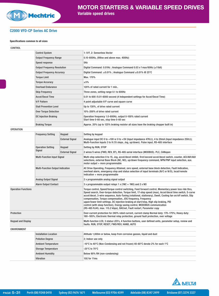
Perth (08) 9248 0410 Sydney (02) 9676 1671 Melbourne (03) 9706 4599 Adelaide (08) 8347 2499 Brisbane (07) 3274 3327
MOTOR STARTERS & VARIABLE SPEED DRIVESVariable speed drives
C2000 VFD-CP Series AC Drive
CONTROL
Control System 1: V/F, 2: Sensorless Vector
Output Frequency Range 0.10-600Hz, (90kw and above max. 400Hz)
Speed response 5Hz
Output Frequency Resolution Digital Command: 0.01Hz ; Analogue Command 0.03 x f max/60Hz (±11bit)
Output Frequency Accuracy Digital Command: ±0.01% ; Analogue Command ±0.01% @ 25°C
Torque Limit Max. 170%
Torque Accuracy ±5%
Overload Endurance 120% of rated current for 1 min..
Skip Frequency Three zones, setting range 0.1 to 600Hz
Accel/Decel Time 0.01 to 600 /0.01-6000 second (4 Independent settings for Accel/Decel Time)
V/F Pattern 4 point adjustable V/F curve and square curve
Stall Prevention Level Up to 130%, of drive rated current
Over Torque Detection 10%-200% of drive rated current
DC Injection Braking Operation frequency 1.0-600Hz, output 0-100% rated currentStart time 0-60 sec, stop time 0-60 sec
Braking Torque Approx. 20% (up to 125% braking resistor all sizes have the braking chopper built in)
OPERATION
Frequency Setting Keypad Setting by keypad
External Signal Analogue input DC 0 to +10V or 0 to +5V (Input impedance 47KΩ), 4 to 20mA (Input impedance 250Ω); Multi-Function Inputs 3 to 9 (15 steps, Jog, up/down). Pulse input, RS-485 interface
Operation Setting Signal
Keypad Setting by RUN, STOP
External Signal 2 wires/3 wires (FWD, REV, EF), RS-485 serial interface (MODBUS). PLC, CANopen
Multi-Function Input Signal Multi-step selection 0 to 15, Jog, accel/decel inhibit, first/second accel/decel switch, counter, ACI/AVI/AUI selections, external Base Block (NC, NO), up/down frequency command, NPN/PNP input selection, aux. motor output + more programmable
Multi-Function Output Indication AC Drive Operating, Frequency Attained, zero speed, external base block detection, Fault Indication, overheat alarm, emergency stop and status selection of input terminals (N/C or N/O), local/remote indication + more programmable
Analog Output Signal 2 x programmable analog signal output
Alarm Output Contact 3 x programmable output relays 1 x (1NC + 1NO) and 2 x NO
Operation Functions Torque control, Speed/torque control switching, Feed forward control, Momentary power loss ride thru, Speed search, Over-torque detection, Torque limit, 17-step speed (max), Accel/decel time switch, S-curve accel/decel, 3-wire sequence, Auto-Tuning (rotational, stationary), Dwell, Cooling fan on/off switch, Slip compensation, Torque compensation, JOG frequency, Frequencyupper/lower limit settings, DC injection braking at start/stop, High slip braking, PIDcontrol (with sleep function), Energy saving control, MODOBUS communication(RS-485 RJ45, max. 115.2 kbps), BACnet, Fault restart, Parameter copy
Protection Over-current protection for 240% rated current, current clamp Normal duty: 170~175%; Heavy duty: 180~185%; Electronic thermal relay protection, ground fault protection, over voltage
Keypad and Display Multi-function LCD, 3 status LED’s, 4 function buttons, user defined units, parameter setup, review and faults. RUN, STOP, RESET, FWD/REV, HAND, AUTO
ENVIRONMENT
Installation Location Altitude 1,000m or below, keep from corrosive gasses, liquid and dust
Pollution Degree 2; Indoor use only
Ambient Temperature -10°C to 40°C (Non-Condensing and not frozen) 40-60°C derate 2% for each 1°C
Storage Temperature -25°C to 70°C
Ambient Humidity Below 90% RH (non-condensing)
Vibration 15G for 11ms
Specifications common to all sizes
PAGE 5-31

Perth (08) 9248 0410 Sydney (02) 9676 1671 Melbourne (03) 9706 4599 Adelaide (08) 8347 2499 Brisbane (07) 3274 3327
MOTOR STARTERS & VARIABLE SPEED DRIVESVariable speed drives
C2000 VFD-C Series AC DriveAccessories
Order Code Description
27FIN538S1075M 75A EMC filter (suit C2000 37kW)
27FIN538S1130M 130A EMC filter (suit C2000 45-55kW)
27FIN538S1180M 180A EMC filter (suit C2000 75-90kW)
27FIN538S1280V 280A EMC filter (suit C2000 110-132kW)
27FIN538S1500BC 500A EMC filter (suit C2000 160-220kW)
27FIN538S1750BC 750A EMC filter (suit C2000 280-355kW)
DEVFDKPCCC01 Keypad with LCM display, parameters backup function
DEVFDKPCCE01 Keypad with 7-segment display, parameters backup function
DEVFDCBCK3FT Extended cable between keypad & inverter, RJ-45 connector, length 1m
DEVFDCBCK7FT Extended cable between keypad & inverter, RJ-45 connector, length 2m
DEVFDCBCK10FT Extended cable between keypad & inverter, RJ-45 connector, length 3m
DEVFDCBCK16FT Extended cable between keypad & inverter, RJ-45 connector, length 5m
DEVFDCMCEIP01 Ethernet communication card, supports EtherNet/IP protocol
DEVFDCMCMOD01 Ethernet communication card, supports MODBUS TCP protocol
DEVFDCMCDN01 DeviceNet communication card, 125kbps / 250kbps / 500kbps
DEVFDCMCPD01 PROFIBUS-DP communication card, 9.6kbps to 12Mbps
DEVFDEMCCOP01 CANopen communication card, 50kbps to 1Mbps
DEVFDEMCD42A 4DI / 2DO extension card, DC 24V
DEVFDEMCR6AA 6 relay outputs extension card
DEVFDEMCD611A 6DI extension card, AC 110V power
DEVFDEMCPG01L PG card, 5 VDC, Line-drive (A,B,Z) 300k pulse/sec. 5VDC 50mA pulse out
DEVFDEMCPG01O PG card, 5 or 12 VDC, Open-collect 300k pulse/sec. pulse out
DEVFDEMCPG01U PG card, 5 VDC, Line-drive (A,B,Z,U,V,W) 300k pulse/sec. 5VDC 50mA pulse out
DEVFDMKCKPPK Keypad remote panel adapter, comply with IP56
DEVFDMKCAFM Frame A flange mounting kit for models except mentioned in MKC-AFM1
DEVFDMKCAFM1 Frame A flange mounting kit for VFD022C43A/43E
DEVFDMKCBFM Frame B flange mounting kit
DEVFDMKCCFM Frame C flange mounting kit
See section 18 for input line reactors, output reactors and sine wave filters.
KPC-CE01
EMC-R6AA
CMC-EIP01
PAGE 5-32

Perth (08) 9248 0410 Sydney (02) 9676 1671 Melbourne (03) 9706 4599 Adelaide (08) 8347 2499 Brisbane (07) 3274 3327
MOTOR STARTERS & VARIABLE SPEED DRIVESVariable speed drives
C2000 Brake Resistors
Specifications
Voltage Applicable Motor Order Code Quantity Required
Equivalent brake resistor for each AC drive
Brake Unit Model Brake Torque 10% ED%(Kgm)
Min. Equivalent Resistor Value for Each AC Drive
Total Braking Current
HP KW
460V Series 1 0.75 DEVBR080W750 1 80W 750Ω - 0.5 190Ω 1A
2 1.5 DEVBR200W360 1 200W 360Ω - 1.0 126.7Ω 2.1A
3 2.2 DEVBR300W250 1 300W 250Ω - 1.5 108.6Ω 3A
5 4.0 DEVBR1K0W075 1 1000W 75Ω - 2.7 54.3Ω 10.2A
7.5 5.5 DEVBR1K0W075 1 1000W 75Ω - 3.7 54.3Ω 10.2A
10 7.5 DEVBR1K0W075 1 1000W 75Ω - 5.1 47.5Ω 10.2A
15 11 DEVBR1K5W043 1 1500W 43Ω - 7.5 42.5Ω 17.6A
20 15 DEVBR1K0W016 2 2000W 32Ω - 10.2 26.2Ω 24A
25 18.5 DEVBR1K0W016 2 2000W 32Ω - 12.2 23Ω 24A
30 22 DEVBR1K5W013 2 3000W 26Ω - 14.9 23Ω 29A
40 30 DEVBR1K0W016 4 4000W 16Ω 20.3 14.1Ω 47.5A
50 37 DEVBR1K2W015 4 4800W 15Ω DEVFDB4045 25.1 12.7Ω 50A
60 45 DEVBR1K5W013 4 6000W 13Ω DEVFDB4045 30.5 12.7Ω 59A
75 55 DEVBR1K2W015 4 7200W 10Ω DEVFDB4030 x 2 37.2 9.5Ω 76A
100 75 DEVBR1K2W015 8 9600W 7.5Ω DEVFDB4045 x 2 50.8 6.3Ω 100A
125 90 DEVBR1K5W013 8 12000W 6.5Ω DEVFDB4045 x 2 60.9 6.3Ω 117A
VFDB4030 BRAKE RESISTORS
PAGE 5-33

Perth (08) 9248 0410 Sydney (02) 9676 1671 Melbourne (03) 9706 4599 Adelaide (08) 8347 2499 Brisbane (07) 3274 3327
MOTOR STARTERS & VARIABLE SPEED DRIVESVariable speed drives
Certifications and complianceEN 61800-3:2004 +A1: 2012, RCM (C-Tick)
EP66 Series AC Drive
Specifications
Part No. EP66-0007T3I1U1F2 EP66-0015T3I1U1F2 EP66-0022T3I1U1F2 EP66-0030T3I1U1F2 EP66-0040T3I1U1F2
Order Code 30EP660007T3104 30EP660015T3104 30EP660022T3104 30EP660030T3104 30EP660040T3104
Motor Output 0.75kw 1.5kw 2.2kw 3.0kw 4.0kw
Input Voltage 380-480V 3ph ( -15~+10%) 50/60Hz
Output Voltage 3 phase proportional to input voltage
Input Current 4.1A 6.9A 9.6A 10.2A 13.6A
Output Current 2A 4A 6.5A 7A 9A
Carrier Freq. 800Hz-16kHz
Fan Cooling No Yes
Weight (Kg) 6.2
Dimensions mm 412 x 200 x 198 (h x w x d)
EMI Filter Built In
Part No. EP66-0055T3I2U1F2 EP66-0075T3I2U1F2 EP66-0110T3I3U1F2 EP66-0150T3I3U1F2 EP66-0185T3I3U1F2
Order Code 30EP660055T3104 30EP660075T3104 30EP660110T3104 30EP660150T3104 30EP660185T3104
Motor Output 5.5kw 7.5kw 11kw 15kw 18.5kw
Input Voltage 380-480V 3ph ( -15~+10%) 50/60Hz
Output Voltage 3 phase proportional to input voltage
Input Current 18.8A 22.1A 30.9A 52A 61A
Output Current 12A 17A 23A 32A 38A
Carrier Freq. 800Hz-16kHz
Fan Cooling Yes
Weight (Kg) 8.2 11.3 25
Dimensions mm 418 x 242 x 198 (h x w x d) 471 x 242 x 228 (h x w x d) 650 x 242 x 324 (h x w x d)
EMI Filter Built In
• IP66Enclosuresuitableforinstallationindamp,highhumidityanddustyenvironments.
• BuiltinEMCfilterC3(2ndenvironment).C-Tickapproved.• Variableorconstanttorqueapplications.• V/Forsensorlessvectorcontrolwithautotuning.• Speedortorquecontrolmodes.• Suitableforpermanentmagnetsynchronousmotors.• 150%overloadfor60sec.• Startingtorque150%at0.5Hz.• Operatingtemperatureupto+50°Cwithoutderating.• Removable4lineLCDdisplay.• EmergencyFireModeforHVACapplications.• RS-485MODBUS.• Builtinbrakechopperon415V3phunits0.4kWto15kW.
PAGE 5-34

Perth (08) 9248 0410 Sydney (02) 9676 1671 Melbourne (03) 9706 4599 Adelaide (08) 8347 2499 Brisbane (07) 3274 3327
MOTOR STARTERS & VARIABLE SPEED DRIVESVariable speed drives
EP66 Series AC Drive
Specifications continued
Part No. EP66-0220T3I4U1F2 EP66-0300T3I4U1F2 EP66-0370T3I4U1F2 EP66-0450T3I3U1F2 EP66-0550T3I3U1F2
Order Code 30EP660220T3104 30EP660300T3104 30EP660300T3104 30EP660450T3104 30EP660550T3104
Motor Output 22kw 30kw 37kw 45kw 55kw
Input Voltage 380-480V 3ph ( -15~+10%) 50/60Hz
Output Voltage 3 phase proportional to input voltage
Input Current 70A 95A 118A 141A 172A
Output Current 44A 60A 75A 90A 110A
Carrier Freq. 800Hz-16kHz
Fan Cooling yes
Weight (Kg) 25 40
Dimensions mm 650 x 242 x 324 (h x w x d) 680 x 308 x 379 (h x w x d)
EMI Filter Built In
Part No. EP66-0750T3I4U1F2 EP66-0900T3I4U1F2
Order Code 30EP660750T3104 30EP660900T3104
Motor Output 75kw 90kw
Input Voltage 380-480V 3ph ( -15~+10%) 50/60Hz
Output Voltage 3 phase proportional to input voltage
Input Current 234A 280A
Output Current 150A 180A
Carrier Freq. 800Hz-16kHz
Fan Cooling Yes
Weight (Kg) 57
Dimensions mm 770 x 370 x 404 (h x w x d)
EMI Filter Built In
PAGE 5-35

Perth (08) 9248 0410 Sydney (02) 9676 1671 Melbourne (03) 9706 4599 Adelaide (08) 8347 2499 Brisbane (07) 3274 3327
MOTOR STARTERS & VARIABLE SPEED DRIVESVariable speed drives
EP66 Series AC Drive Braking Resistors
Specifications
Voltage Applicable Motor Order Code Quantity Required
Equivalent brake resistor for each AC drive
Built In BrakeChopper
Min. Equivalent Resistor Value for Each AC Drive
Min ResistorPower
HP KW
460V Series 1 0.75 DEVMVR080W200 1 80W 200Ω Standard 145Ω 80W
2 1.5 DEVBR200W150 1 200W 150Ω Standard 95Ω 150W
3 2.2 DEVBR300W100 1 300W 100Ω Standard 95Ω 250W
4 3 DEVBR300W100 1 300W 100Ω Standard 95Ω 300W
5.5 4 DEVBR400W150 1 400W 150Ω Standard 95Ω 400W
7.5 5.5 DEVBR300W250 2 (||) 600W 125Ω Standard 95Ω 550W
10 7.5 DEVBR300W400 3 (||) 900W 133.3Ω Standard 95Ω 750W
15 11 DEVBR300W250 4 (||) 1200W 62.5Ω Standard 60Ω 1.1kW
20 15 DEVBR1K5W040 1 1500W 40Ω Standard 35Ω 1.5kW
25 18.5 DEVBR1K0W075 2 (||) 2000W 37.5Ω Optional 35Ω 2kW
30 22 DEVBR1K5W040 4 (||-||) 3000W 40Ω Optional 30Ω 2.2kW
40 30 DEVBR1K0W075 3 (||) 3000W 75Ω Optional 25Ω 3kW
50 37 DEVBR1K5W040 6 (||-||) 4500W 26.6Ω Optional 25Ω 4kW
60 45 DEVBR1K0W075 5 (||) 5000W 15Ω Optional 15Ω 4.5kW
75 55 DEVBR1K0W050 12 (||-||) 6000W 16.6Ω Optional 15Ω 5.5kW
100 75 DEVBR1K5W040 10 (||-||) 7500W 16Ω Optional 12Ω 7.5kW
110 90 DEVBR1K5W040 12 (||-||) 9000W 13.3Ω Optional 8Ω 9kW
PAGE 5-36

Perth (08) 9248 0410 Sydney (02) 9676 1671 Melbourne (03) 9706 4599 Adelaide (08) 8347 2499 Brisbane (07) 3274 3327
MOTOR STARTERS & VARIABLE SPEED DRIVESVariable speed drives
EP66 Series AC Drive
CONTROL
Control System Sensorless vector, V/F, PMSM sensorless vector
Output Frequency Range 0.50-650Hz
Speed response 5Hz (up to 40Hz with vector control)
Output Frequency Resolution Digital Command: 0.01Hz; Analogue Command 0.03 x f max/60Hz (±12bit)
Output Frequency Accuracy ±0.5%
Torque Limit Max. 200%
Torque Accuracy ±5%
Overload Endurance 150% for 1 minute every 10 minutes
Skip Frequency Two zones, setting range 0 to 650Hz
Accel/Decel Time 0.1 to 3000 /0.1-3000 second (4 Independent settings for Accel/Decel Time)
V/F Pattern Linear, square, user defined
Stall Prevention Level Up to 150% of drive rated current
Over Torque Detection 60% to 200% of drive rated current
DC Injection Braking Operation frequency 0.2 to 50Hz, output 0-100% rated currentStart time 0-30 sec, stop time 0-30 sec
Braking Torque Approx. 20% (up to 125% with braking resistor braking chopper built in up to 15kW)
OPERATION
Frequency Setting Keypad Setting by keypad
External Signal Analogue input DC 0 to +10V or 0 to +5V, 0 to 20mA; pulse train multi-function inputs (15 steps, jog, up/down). RS-485 interface
Operation Setting Signal
Keypad Setting by RUN, STOP
External Signal 2 wires/3 wires (FWD, REV, EF), RS-485 serial interface (MODBUS)
Multi-Function Inputs 6 x digital. inputs (NPN-PNP selectable) pulse train-input2 analogue channels - 12 BIT: 0…10V, 0...5V, -10V...0...10V, 0..(4)20 mA,all free scalable in gain and offset, and can be mathematically combined
Multi-Function Outputs 2 x programmable DO (with pulse output option)
Analog Output Signal 1 x analogue frequency output. (2 x AO (Hz +I) for 18.5kW and above)
Alarm Output Contact 1 x programmable output relays (1 x C/O )
Operation Functions Torque control, Slip compensation, Torque compensation, momentary power loss ride thru, speed search, over-torque detection, torque limit, JOG frequency, frequency upper/lower limit settings, auto-tuning, accel/decel time switch, S-curve, 15-step speed (max), DC injection braking at start/stop, fan control, PID control (with sleep function), energy saving control, emergency fire control accel/decel, MODOBUS communication (RS-485 RJ45, max. 115.2 kbps)
Protection Over-current protection, electronic thermal relay protection, ground fault protection, DC over voltage, input under voltage, input phase loss, output phase loss, under load, I2 x t motor protection, PTC input
Keypad and Display Multi-function LCD, 5 status LED’s, user defined units, parameter setup, review and faults. RUN, STOP, RESET, FWD/REV, JOG, LOCAL/REMOTE
ENVIRONMENT
Installation Location Altitude 1,000m or below, For outdoor applications the drive should be installed under a suitablecover to provide protection against potential damage caused by direct exposure to sun
Protection level IP66
Ambient Temperature -10°C to 50°C (Non-Condensing and not frozen)
Storage Temperature -25°C to 70°C
Ambient Humidity Below 90% RH (non-condensing)
Vibration Below 0.5g
Specifications common to all sizes
PAGE 5-37