Effective variable switching point predictive current control for ac low-voltage drives
Upload
khangminh22Category
view
1download
0
1
2
3
4
5
6
7
8
9
10
9
Introduction (continued) Altivar® 12 variable speed drives
An optimum solutionThe Altivar® 12 range of variable speed drives extends across a range of motor power ratings from 0.18 kW to 4 kW on three types of power supply: Two standard versions are available:Drive with heatsink for normal environments and fan-cooled enclosure:v 100 to 120 V single-phase, 0.18 kW to 0.75 kW (ATV12HpppF1)v 200 to 240 V single-phase, 0.18 kW to 2.2 kW (ATV12HpppM2)v 200 to 240 V three-phase, 0.18 kW to 4 kW (ATV12HpppM3)Drive on a base plate for mounting on the machine frame; the frame surface area should allow heat to dissipate:v 100 to 120 V single-phase, 0.18 kW to 0.37 kW (ATV12H018F1, P037F1)v 200 to 240 V single-phase, 0.18 kW to 0.75 kW (ATV12H018M2, PpppM2)v 200 to 240 V three-phase, 0.18 kW to 4 kW (ATV12H018M3, PpppM3)
Note: The Altivar 12 drive output voltage is 200 to 240 V three-phase, regardless of the type of drive line supply.
The Altivar 12 drive utilizes standard Modbus communication protocol, and can be accessed via the RJ45 connector located on the underside of the drive 4.
The entire range conforms to international standards IEC/EN 61800-5-1 and IEC/EN61800-3,isUL,CSA,C-Tick,NOM,GOSTcertifiedandhasbeendevelopedto meet the requirements of directives regarding the protection of the environment (RoHS, WEEE) as well as those of European Directives to obtain the e mark.
Electromagnetic compatibility (EMC)TheintegrationofalevelC1EMCfilterinATV12ppppM2 drives and the handling of EMC simplify installation and make it very inexpensive to bring the device into conformity to obtain the e mark.ThisEMCfiltercanbedisconnectedviaaninternalswitch6.
ATV12ppppF1 and ATV12ppppM3drivesaredesignedwithoutanEMCfilter.Filtersare available as an option and can be installed by the customer to reduce the level of emissions (see page 16).
External accessories and optionsExternal accessories and options can be used with Altivar 12 drives:EMC conformity kits, plates for direct mounting on 35 mm DIN rails, etc.Braking units combined with a braking resistor, motor chokes, additional EMC input filters,etc.
Dialog and configuration toolsHuman/Machine Interface (HMI)
The 4-digit display 1 can be used to display states and faults, access parameters and modify them via the navigation button 2.The RUN and STOP buttons 3 can be made accessible on the front panel by removing the blanking plate 5fromthedoor;theymustbeconfiguredinordertobeactive.
Simple Loader and Multi-Loader configuration toolsTheSimpleLoadertoolenablesonepowered-updrive'sconfigurationtobeduplicated on another powered-up drive.TheMulti-LoadertoolenablesconfigurationsfromaPCordrivetobecopiedandduplicated on another drive; the drives do not need to be powered up.
SoMove™ setup softwareTheSoMovesetupsoftwarecanbeusedwiththeAltivar12driveforconfiguration,adjustment,debugging(usingtheOscilloscopefunction)andmaintenance,justasitcan for all other Schneider Electric variable speed drives and starters. It can also be used to customize the integrated display terminal menus. It can be used with a direct connection or a Bluetooth® wireless connection.
Remote display terminalThe Altivar 12 drive can be connected to a remote display terminal, available as an option. This terminal can be mounted on an enclosure door with IP 54 or IP 65 degree of protection. The maximum operating temperature is 50°C. It provides access to the same functions as the Human/Machine Interface.
Specifications:page 10
References:page 14
Dimensions:page 18
Connections:page 22
Functions:page 26
Drive with heatsink ATV12H075M2
Drive on base plate ATV12P075M2
Remote terminal with cover closed
Remote terminal with cover open: RUN, FWD/REV and STOP buttons accessible
32
5 4
1
ATV12H075M2 with door on front panel open
6
Multi-Loader configuration tool

1
2
3
4
5
6
7
8
9
10
10
Specifications Altivar® 12 variable speed drives
Introduction:page 8
References:page 14
Dimensions:page 18
Connections:page 22
Functions:page 26
Environmental specificationsConformity to standards Altivar® 12 drives have been developed to conform to the strictest international
standards and the recommendations relating to electrical industrial control equipment (IEC, EN), in particular: IEC/EN 61800-5-1 (low voltage), IEC/EN 61800-3 (conducted and radiated EMC immunity and emissions).
EMC immunity IEC/EN61800-3,Environments1and2(EMCrequirementsandspecifictestmethods)IEC/EN 61000-4-2 level 3 (electrostatic discharge immunity test)IEC/EN61000-4-3level3(radiated,radio-frequency,electromagneticfield immunity test)IEC/EN 61000-4-4 level 4 (electrical fast transient/burst immunity test)IEC/EN 61000-4-5 level 3 (surge immunity test)IEC/EN 61000-4-6 level 3 (immunity to conducted disturbances, induced by radio-frequencyfields)IEC/EN 61000-4-11 (voltage dips, short interruptions and voltage variations immunity tests)
Conducted EMC emissions for drives
ATV12ppppF1ATV12H018M3ATV12p037M3 to pU22M3
WithadditionalEMCfilter:IEC/EN 61800-3, Environment 1 (public network) in restricted distribution:
Category C1, from 4 to 12 kHz for a shielded motor cable length v y 5 m (except ATV12p018M3 to p075M3)
Category C2, from 4 to 12 kHz for a shielded motor cable length v y 20 mIEC/EN 61800-3, Environment 2 (industrial network):
Category C3, from 4 to 12 kHz for a shielded motor cable length v y 20 mATV12ppppM2 IEC/EN 61800-3, Environment 1 (public network) in restricted distribution:
Category C1, at v 2, 4, 8, 12 and 16 kHz for a shielded motor cable length y 5 mCategory C2: ATV12H018M2 to v p075M2, from 2 to 12 kHz for a shielded motor
cable length y 5 m and at 2, 4, 16 kHz for a shielded motor cable length y 10 mCategory C2: ATV12HU15M2 to HU22M2, from 4 to 16 kHz for a shielded motor v
cable length y 5 m and at 2, 4, 8, 12 and 16 kHz for a shielded motor cable length y 10 mWithadditionalEMCfilter:IEC/EN 61800-3, Environment 1 (public network) in restricted distribution:
Category C1, from v 4 to 12 kHz for a shielded motor cable length y 20 mCategory C2, from 4 to 12 kHz for a shielded motor cable length v y 50 m
IEC/EN 61800-3, Environment 2 (industrial network): Category C3, from 4 to 12 kHz for a shielded motor cable length v y 50 m
Radiated EMC emissions for drives
ATV12pppppp IEC/EN 61800-3, Environment 1 (public network) in restricted distribution:Category C2, from 2 to 16 kHz for a shielded motor cable v
e marking The drives are marked e according to the European low voltage (2006/95/EC) and EMC (2004/108/EC) directives
Product certifications UL, CSA, NOM, GOST and C-Tick
Degree of protection IP 20
Vibration resistance Drive not mounted on DIN rail According to IEC/EN 60068-2-6:1.5 mm peak from 3 to 13 Hz v1 gn from 13 to 200 Hz v
Shock resistance 15 gn for 11 ms according to IEC/EN 60068-2-27
Maximum ambient pollutionDefinitionofinsulation
Degree 2 according to IEC/EN 61800-5-1
Environmental conditionsUse
IEC 60721-3-3 classes 3C3 and 3S2
Relative humidity % 5 to 95 non condensing, no dripping water, according to IEC 60068-2-3
Ambient air temperature around the device
Operation ATV12H018F1, H037F1ATV12H018M2 to H075M2ATV12H018M3 to H075M3ATV12Pppppp
°C - 10 to + 40 without de-rating (1)Up to + 60, with the protective blanking cover removed (1) and current de-rating of 2.2% per additional degree (2)
ATV12H075F1ATV12HU15M2, HU22M2ATV12HU15M3 to HU40M3
°C - 10 to + 50 without de-ratingUp to + 60, with the protective blanking cover removed (1) and current de-rating of 2.2% per additional degree (2)
Storage ATV12pppppp °C - 25 to + 70Maximum operating altitude ATV12pppppp m 1000 without de-rating
ATV12ppppF1ATV12ppppM2
m Up to 2000 for single-phase networks and corner grounded distribution networks, with current de-rating of 1% per additional 100 m
ATV12ppppM3 m Up to 3000 meters for three-phase networks, with current de-rating of 1% per additional 100 m
Operating positionMaximum permanent angle in relation to the normal vertical mounting position
(1) See the possible mounting types on page 21.(2) See the de-rating curves in the User Manual, available on our website at "www.schneider-electric.us".

1
2
3
4
5
6
7
8
9
10
11
Specifications (continued) Altivar® 12 variable speed drives
Drive specificationsOutput frequency range Hz 0.5 to 400
Configurable switching frequency kHz Nominal switching frequency: 4 kHz without de-rating in continuous operationAdjustableduringoperationfrom2to16kHzAbove 4 kHz in continuous operation, apply de-rating to the nominal drive current of:10% for 8 kHz 20% for 12 kHz30% for 16 kHzAbove 4 kHz, the drive will reduce the switching frequency automatically in the event of excessive temperature rise.See the de-rating curves in the User Manual, available on our website at "www.schneider-electric.us".
Speed range 1 to 20
Transient overtorque 150 to 170% of the nominal torque depending on the drive rating and the type of motorBraking torque Up to 70% of the nominal torque without resistor
Up to 150% of the nominal motor torque with braking unit (optional) at high inertia
Maximum transient current 150% of the nominal drive current for 60 seconds
Motor control profiles Standardprofile(voltage/frequencyratio)Performanceprofile(sensorlessfluxvectorcontrol)Pump/fanprofile(Kn2 quadratic ratio)
Electrical power specificationsPower supply Voltage V 100 - 15% to 120 + 10% single-phase for ATV12ppppF1
200 - 15% to 240 + 10% single-phase for ATV12ppppM2200 - 15% to 240 + 10% three-phase for ATV12ppppM3
Frequency Hz 50 to 60 ± 5%
Isc (short-circuit current) A y 1000 (Isc at the connection point) for single-phase power supplyy 5000 (Isc at the connection point) for three-phase power supply
Drive supply and output voltages Drive supply voltage Drive output voltage for motorATV12ppppF1 V 100 to 120 single-phase 200 to 240 three-phaseATV12ppppM2 V 200 to 240 single-phaseATV12ppppM3 V 200 to 240 three-phase
Maximum length of motor cable (including tap links)
Shielded cable m 50Unshielded cable m 100
Drive noise level ATV12H018F1, H037F1ATV12H018M2 to H075M2ATV12H018M3 to H075M3ATV12Pppppp
dBA 0
ATV12H075F1ATV12HU15M2, HU22M2
dBA 45
ATV12HU15M3 to HU40M3 dBA 50
Electrical isolation Electrical isolation between power and control (inputs, outputs, power supplies)
Connection specifications (drive terminals for the line supply, the motor output and the braking unit)Drive terminals R/L1, S/L2/N, T/L3, U/T1, V/T2, W/T3, PA/+, PC/–
Maximum wire size and tightening torque
ATV12H018F1, H037F1ATV12H018M2 to H075M2ATV12H018M3 to H075M3ATV12P037F1ATV12P037M2 to P075M2ATV12P037M3, P075M3
3.5 mm2 (12 AWG)0.8 Nm
ATV12H075F1ATV12HU15M2, HU22M2ATV12HU15M3 to HU40M3ATV12PU15M3 to PU40M3
5.5 mm2 (10 AWG)1.2 Nm
Introduction:page 8
References:page 14
Dimensions:page 18
Connections:page 22
Functions:page 26
1
2
3
4
5
6
7
8
9
10
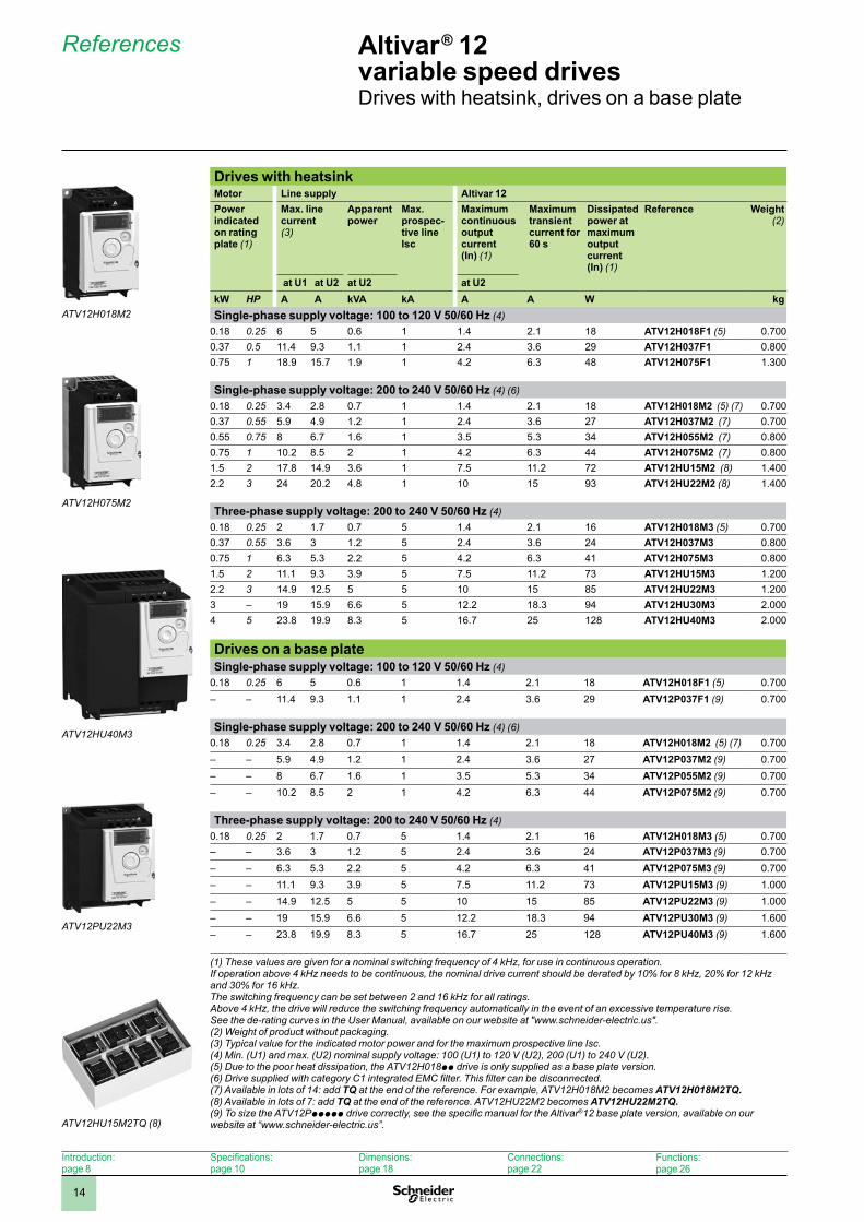
14
Drives with heatsinkMotor Line supply Altivar 12Power indicated on rating plate (1)
Max. line current (3)
Apparent power
Max. prospec-tive line Isc
Maximum continuous output current(In) (1)
Maximum transient current for 60 s
Dissipated power at maximum output current (In) (1)
Reference Weight(2)
at U1 at U2 at U2 at U2kW HP A A kVA kA A A W kgSingle-phase supply voltage: 100 to 120 V 50/60 Hz (4)
0.18 0.25 6 5 0.6 1 1.4 2.1 18 ATV12H018F1 (5) 0.7000.37 0.5 11.4 9.3 1.1 1 2.4 3.6 29 ATV12H037F1 0.8000.75 1 18.9 15.7 1.9 1 4.2 6.3 48 ATV12H075F1 1.300
Single-phase supply voltage: 200 to 240 V 50/60 Hz (4) (6)0.18 0.25 3.4 2.8 0.7 1 1.4 2.1 18 ATV12H018M2 (5) (7) 0.7000.37 0.55 5.9 4.9 1.2 1 2.4 3.6 27 ATV12H037M2 (7) 0.7000.55 0.75 8 6.7 1.6 1 3.5 5.3 34 ATV12H055M2 (7) 0.8000.75 1 10.2 8.5 2 1 4.2 6.3 44 ATV12H075M2 (7) 0.8001.5 2 17.8 14.9 3.6 1 7.5 11.2 72 ATV12HU15M2 (8) 1.4002.2 3 24 20.2 4.8 1 10 15 93 ATV12HU22M2 (8) 1.400
Three-phase supply voltage: 200 to 240 V 50/60 Hz (4)0.18 0.25 2 1.7 0.7 5 1.4 2.1 16 ATV12H018M3 (5) 0.7000.37 0.55 3.6 3 1.2 5 2.4 3.6 24 ATV12H037M3 0.8000.75 1 6.3 5.3 2.2 5 4.2 6.3 41 ATV12H075M3 0.8001.5 2 11.1 9.3 3.9 5 7.5 11.2 73 ATV12HU15M3 1.2002.2 3 14.9 12.5 5 5 10 15 85 ATV12HU22M3 1.2003 – 19 15.9 6.6 5 12.2 18.3 94 ATV12HU30M3 2.0004 5 23.8 19.9 8.3 5 16.7 25 128 ATV12HU40M3 2.000
Drives on a base plateSingle-phase supply voltage: 100 to 120 V 50/60 Hz (4)
0.18 0.25 6 5 0.6 1 1.4 2.1 18 ATV12H018F1 (5) 0.700– – 11.4 9.3 1.1 1 2.4 3.6 29 ATV12P037F1 (9) 0.700
Single-phase supply voltage: 200 to 240 V 50/60 Hz (4) (6)0.18 0.25 3.4 2.8 0.7 1 1.4 2.1 18 ATV12H018M2 (5) (7) 0.700– – 5.9 4.9 1.2 1 2.4 3.6 27 ATV12P037M2 (9) 0.700– – 8 6.7 1.6 1 3.5 5.3 34 ATV12P055M2 (9) 0.700– – 10.2 8.5 2 1 4.2 6.3 44 ATV12P075M2 (9) 0.700
Three-phase supply voltage: 200 to 240 V 50/60 Hz (4)0.18 0.25 2 1.7 0.7 5 1.4 2.1 16 ATV12H018M3 (5) 0.700– – 3.6 3 1.2 5 2.4 3.6 24 ATV12P037M3 (9) 0.700– – 6.3 5.3 2.2 5 4.2 6.3 41 ATV12P075M3 (9) 0.700– – 11.1 9.3 3.9 5 7.5 11.2 73 ATV12PU15M3 (9) 1.000– – 14.9 12.5 5 5 10 15 85 ATV12PU22M3 (9) 1.000– – 19 15.9 6.6 5 12.2 18.3 94 ATV12PU30M3 (9) 1.600– – 23.8 19.9 8.3 5 16.7 25 128 ATV12PU40M3 (9) 1.600
(1) These values are given for a nominal switching frequency of 4 kHz, for use in continuous operation. If operation above 4 kHz needs to be continuous, the nominal drive current should be derated by 10% for 8 kHz, 20% for 12 kHz and 30% for 16 kHz. The switching frequency can be set between 2 and 16 kHz for all ratings. Above 4 kHz, the drive will reduce the switching frequency automatically in the event of an excessive temperature rise. See the de-rating curves in the User Manual, available on our website at "www.schneider-electric.us".(2) Weight of product without packaging.(3) Typical value for the indicated motor power and for the maximum prospective line Isc.(4) Min. (U1) and max. (U2) nominal supply voltage: 100 (U1) to 120 V (U2), 200 (U1) to 240 V (U2).(5) Due to the poor heat dissipation, the ATV12H018pp drive is only supplied as a base plate version.(6) Drive supplied with category C1 integrated EMC filter. This filter can be disconnected.(7) Available in lots of 14: add TQ at the end of the reference. For example, ATV12H018M2 becomes ATV12H018M2TQ.(8) Available in lots of 7: add TQ at the end of the reference. ATV12HU22M2 becomes ATV12HU22M2TQ.(9) To size the ATV12Pppppp drive correctly, see the specific manual for the Altivar®12 base plate version, available on our website at “www.schneider-electric.us”.
References Altivar® 12 variable speed drivesDrives with heatsink, drives on a base plate
Introduction:page 8
Specifications:page 10
Dimensions:page 18
Connections:page 22
Functions:page 26
ATV12H018M2
ATV12H075M2
ATV12HU40M3
ATV12PU22M3
ATV12HU15M2TQ (8)

1
2
3
4
5
6
7
8
9
10
18
Dimensions
Drives with heatsinks (1)ATV12H018F1, H037F1, ATV12H018M2 to H075M2, ATV12H018M3 to H075M3
Drive with EMC conformity kit VW3A9523 (available as an option)
H6
72
c
143b
= =60
2xØ5
189,
5
c1 M5
2 x M5 screws
ATV12 b c c1 HH018F1 (1), H018M2 (1), H018M3 (1) 142 102.2 34 131H037F1, H037M2, H037M3 130 121.2 53 120H055M2, H075M2, H075M3 130 131.2 63 120(1) Due to the poor heat dissipation, ATV12H018pp drives are only available as a base plate version. They can either be mounted conventionally (drive on heatsink) or on the machine frame (drive on base plate).
ATV12H075F1, ATV12HU15M2, HU22M2, ATV12HU15M3, HU22M3Drive with EMC conformity kit VW3A9524 (available as an option)
b130
2xØ5
93= =105
120
5
c
b1
90 M5
2 x M5 screws
ATV12 b b1 cH075F1, HU15M2, HU22M2 142 188.2 156.2HU15M3, HU22M3 143 189.3 131.2
ATV12HU30M3, HU40M3Drive with EMC conformity kit VW3A9525 (available as an option)
140
126
159
6,5
184
170
141,2
4xØ5
= =
2 x M5 screws
61,5
230,
6
M5
Altivar® 12 variable speed drivesDrives with heatsinks
Introduction:page 8
Specifications:page 10
References:page 14
Connections:page 22
Functions:page 26

1
2
3
4
5
6
7
8
9
10
21
Mounting recommendations
Install the unit vertically, at ± 10°.Avoid placing it close to heating elements.Leavesufficientfreespacetoensurethattheairrequiredforcoolingpurposescancirculate, by natural convection or by ventilation, from the bottom to the top of the unit.
Operating temperature according to the mounting typeMounting type Drives with natural convection Drives with fan
ATV12H018F1, H037F1ATV12H018M2 to H075M2ATV12H018M3 to H075M3
ATV12H075F1ATV12HU15M2, HU22M2ATV12HU15M3 to HU40M3
Ambient air temperature (1) Ambient air temperature (1)Type A mounting
50 mm 50 mm
-10 to +40°CUp to +50°C with current de-rating of 2% per additional degree above 40°C
-10 to +50°C
Type B mounting (2) -10 to +40°C (3)Up to +60°C with current de-rating of 2% per additional degree above 40°C
-10 to +50°CUp to +60°C with current de-rating of 2% per additional degree above 50°C
Type C mounting (2)
50 mm 50 mm
-10 to +40°CUp to + 60°C with current de-rating of 2% per additional degree above 40°C-10 to +50°C on metal plate
-10 to +50°CUp to +60°C with current de-rating of 2% per additional degree above 50°C
(1) Value given for a switching frequency of 4 kHz, for use in continuous operation. If operation above 4 kHz needs to be continuous, the nominal drive current should be derated by 10% for 8 kHz, 20% for 12 kHz and 30% for 16 kHz.Above 4 kHz, the drive will reduce the switching frequency automatically in the event of an excessive temperature rise. See the de-rating curves in the User Manual, available on our website at "www.schneider-electric.us".(2) Remove the protective cover from the top of the drive.(3) Maximum value depending on the drive rating and operating conditions; see the de-rating curves in the User Manual, available on our website at "www.schneider-electric.us".
Mounting recommendations
Altivar® 12 variable speed drives
Introduction:page 8
Specifications:page 10
References:page 14
Connections:page 22
Functions:page 26

1
2
3
4
5
6
7
8
9
10
22
Connections Altivar® 12 variable speed drivesDrives
Recommended connectionsTypical connection for ATV12ppppF1, ATV12ppppM2 Typical connection for ATV12ppppM3Single-phase power supply Three-phase power supply (power section) (1)
Negative logic (Sink) (2)
0 to 10 Vor0-20 mA
Positive logic (Source) (2)
2 4
1 3
PC
/–
PA/ +
W/T
3
U/T
1
V/T
2
AO
1
CO
M
AI1+5
V
R/L
1
S/L
2/N
R1A
R1C
R1B
CO
M LI1
LI2
+24V
U1
W1
V1
M 3
LI3
LI4
2 4
2 4
6
P1
1 3
A1
Q1Q1
5
c b a
LO+
LO–
LO+
LO–
CO
M LI1
LI2
+24V
LI3
LI4
1 3
KM1 KM1
2 4
1
653
W/T
3
U/T
1
V/T
2
R/L
1
S/L
2
T/L3
U1
W1
V1
M 3
2 4
1 3
A2
6
Q1
5
2 4
Q1
1 3
65
(4)
Note: Install interference suppressors on all inductive circuits near the drive or connected on the same circuit, such as relays, contactors, solenoid valves, fluorescent lighting, etc.Compatible components (for a complete list of references, please refer to the "Motor starter solutions - Control and protection components" and "Motor starters up to 150 A" catalogs or visit "www.schneider-electric.us")Item no. Description
A1 ATV12ppppF1 or ATV12ppppM2 drive (see page 14)A2 ATV12ppppM3 drive (see page 14)KM1 Contactor (only if a control circuit is needed; see page 24)P1 2.2 kW reference potentiometer, SZ1 RV1202. This can be replaced by a 10 kW potentiometer (maximum). Q1 Circuit breaker (see page 24)
Examples of recommended connections for logic and analog I/O2-wire control 3-wire control Analog input configured
for voltageAnalog input configured for current
LI1+2
4V
LIp
ATV12pppppp
LI1: ForwardLIp: Reverse
LI1
LI2+2
4V
LIp
ATV12pppppp
LI1: StopLI2: ForwardLIp: Reverse
IA1
CO
M
+ 10 V
c b a
2.2 kW to 10 kW reference potentiometer
External 10 V
ATV12pppppp
IA1
CO
M
0-20 mA4-20 mAsupply
ATV12pppppp
Examples of recommended connections for logic I/O powered by an external 24 V ⎓ supply (5)Connected as positive logic (Source) Connected as negative logic (Sink)
LO+
LO–
CO
M LI1
LI2
+24V
LI3
LI4
+ 24
V 0 V
24 V ⎓ supply
CO
M LI1
LI2
+24V
LI3
LI4
+ 24
V 0 V
LO+
LO–
24 V ⎓ supply
(1) The control section is connected in exactly the same way as for the ATV12ppppF1 and ATV12ppppM2 drives.(2) Connection as positive logic (Source) or negative logic (Sink) is configured via parameters; the factory-set configuration is positive logic (Source).(3) Fault relay contacts for remote signalling of the drive status.(4) The R/L1, S/L2/N and T/L3 terminals are connected at the top of the drive. The other terminals are connected on the underside of the drive.(5) Please refer to the "Phaseo power supplies and transformers" catalog.
Introduction:page 8
Specifications:page 10
References:page 14
Dimensions:page 18
Functions:page 26

Other versions: please consult our Customer Care Centre.
Selection guideStandard drives - Low voltage
Simple machines
CApplications:• Simple machines for industry (small handling applications, packaging, pumps, fans, etc.)• Simple consumer machines (access barriers, rotating advertising hoardings, medical beds, treadmills, dough mixers, etc.)• Other types of application:- Mobile machines and small appliances equipped with a power socket- Applications which traditionally use other solutions (2-speed DC motors, mechanical drives, etc.).
C Applications:Simple industrial machines (material handling and packaging, textile machines, special machines, pumps and fans).
C Applications:Simple industrial machines (material handling and packaging, textile machines, special machines, pumps and fans).
Altivar 12 Altivar 312 Altivar 31C IP55
Variable speed drives for small machines with 240 V three-phase asynchronous motor
Variable speed drives for three-phase asynchronous motors
Variable speed drives for three-phase asynchronous motors for machines in harsh environments.
Description • Compact• Easy to set up (Plug & Play)• Reliable, cost-effective solution for compact machines
• Open: large number of communication cards available as options• User-friendly: simplified interface• Autotuning: maximum performance
• Rugged even in the most hostile environments:- Installed as close as possible to the motor- Integrated functions for applications requiring IP55 degree of protection- Modbus and CANopen communication protocols• Flexibility to adapt to each machine:- Customisable depending on the model- Easy configuration
Technical information Power range for 50…60 Hz supply
0.18...4 kW 0.18...15 kW 0.18...15 kW
Voltage Single-phase 100…240 VThree-phase 200…240 V
Single-phase 200…240 VThree-phase 200…600 V
Single-phase 200…240 VThree-phase 380…500 V
Drive/Output frequency 0.5…400 Hz 0.5…500 Hz 0.5…500 Hz
Motor type Asynchronous Yes Yes YesSynchronous No No No
Communication Integrated Modbus Modbus and CANopen Modbus and CANopenAs an option – CANopen Daisy chain,
DeviceNet, PROFIBUS DP,Modbus TCP, Fipio
DeviceNet, Ethernet TCP/IP, Fipio, PROFIBUS DP
Standards and certifications IEC/EN 61800-5-1, IEC/EN 61800-3 (environments 1 and 2, categories C1 to C3)CE, UL, CSA, C-Tick, GOST, NOM
IEC/EN 61800-5-1, IEC/EN 61800-3 (environments 1 and 2, categories C1 to C3)CE, UL, CSA, C-Tick, GOST
Intended use Machines
3/4
2
1
3
4
5
6
7
8
9
10

Other versions: please consult our Customer Care Centre.
Altivar 120.18…4 kW
Simple machinesUltra-compact drives
Type of drive Single-phase Single-phase Three-phaseSupply voltage 120 V 240 V 240 VDegree of protection IP20Drive Output frequency 0.5… 400 Hz
Type of control Asynchronous motor U/F, sensorless flux vector control, quadratic Kn2
Transient overtorque 150…170 of the nominal torqueSpeed range 1 to 20Functions Number of functions 40
Number of preset speeds 8Number of I/O Analog inputs 1 configurable analog input
Logic inputs 4 assignable logic inputsAnalog outputs 1 configurable analog outputRelay outputs 1 protected relay logic output
Dialogue Integrated or remote display terminal, SoMove software workshop, or mobile phone via Bluetooth©
Communication Integrated Modbus Cards (available as an option) Reduction of current harmonicsEMC filter Integrated C1 EMC
As an optionMotor power kW/HP 0.18/0.25 ATV12H018F1 (1) 1C1 ATV12H018M2 (1) (2) 1C2 ATV12H018M3 (1) 1C3
0.37/0.5 ATV12H037F1 1C1 ATV12H037M2 (2) 1C1 ATV12H037M3 1C30.55/0.75 – ATV12H055M2 (2) 1C2 –0.75/1 ATV12H075F1 2C1 ATV12H075M2 (2) 1C2 ATV12H075M3 1C31.5/2 – ATV12HU15M2 (2) 2C2 ATV12H015M3 2F32.2/3 – ATV12HU22M2 (2) 2C2 ATV12H022M3 2F33/3 – – ATV12H030M3 3F34/5 – – ATV12H040M3 3F3
(1) Because of the low heat dissipation, the ATV12H018.. is only supplied on a base plate(2) Also exists as a multipack
Dimensions (in mm) width x height x depth1C1: 72 x 143 x 102.2 2F3: 105 x 143 x 131.21C2: 72 x 143 x 102.2 3F3: 140 x 184 x 141.21C3: 72 x 143 x 121.22C1: 105 x 142 x 156.22C2: 105 x 142 x 156.2
3/14
2
1
3
4
5
6
7
8
9
10
Copyright © 2022 FDOKUMEN