ODP2-20M.pdf - Drives Warehouse
52
1 Introduction AC Variable Speed Drive 0.75kW – 160kW / 1HP – 250HP 200 – 480 Volt 1 & 3 Phase Installation & Operating Instructions
-
Upload
khangminh22 -
Category
Documents
-
view
0 -
download
0
Transcript of ODP2-20M.pdf - Drives Warehouse

1
Introduction
AC Variable Speed Drive 0.75kW – 160kW / 1HP – 250HP 200 – 480 Volt 1 & 3 Phase
Installation & Operating Instructions

O
AC Supply Con3 Phase Units :1 Phase Units :
Optidr
nnection : Connect L1 L2 L: Connect L1, L2,
Fuses or MCB
M
Op
rive P2
L3, PE , PE
M
tidrive ODP‐2 U
2 IP20
Su 20 38
Fu
He
Dis
Ke
HA
Linen CoBa
Ru
Clo Mo
MoChEn
ser Guide Revisi
Easy S
upply Voltage 00 – 240 Volts + /80 – 480 Volts + /
ses or MCB o Check th
elp Card
splay
eypad Operation
ARDWARE ENAB
nk the terminals nable the drive.
ontrol Terminalsased on the facto
un – Stopose the switch to
otor Cable o For correo Observeo For Mot
recommo Use a sc
otor Connectionheck for Star or Dnter the Motor N
o Motor Ro Motor Ro Motor Ro Motor R
ons 1.30
Start U
/ ‐ 10% / ‐ 10%
he Drive Rating I
n can be found o
IMPOBLE FUNCTION
as shown, optio
s ory default para
10K Speed Poto run (enable), o
ect cable size, see the maximum por cable lengths
mended reened (shielded
n Delta ConnectionNameplate Data Rated Voltage : PRated Current : PRated FrequencyRated Speed (Op
Up Gui
nformation on p
on page26
ORTANT
onally through sw
meter settings
t open to stop
ee Technical Datpermissible mots > 50 metres, an
d cable)
n into the drive PaP1‐07 P1‐08 y : P1‐09 tional) : P1‐10
ide
page 47
T!
witch contacts, t
ta on page 47 or cable lengthn output filter is
arameters as fol
to
llows

AC Suppl200 – 24380 – 48
O
ly Connection 0 Volts + / ‐ 10%0 Volts + / ‐ 10% L3 L2 L1
Optidr
% % PE
Fuses or MCheck drivRating infoPage 47
Op
rive P2
MCB e o on
ptidrive ODP‐2 U
2 IP55
User Guide Revis
Easy S
M
ion 1.30
Start U
Mot For c Tech Obse
cabFor MoutpUse shou
MotChecEntedriveMotMotMotMot
Up Gui
Display
Keypad Oon page 2
IMPORTA HARDW
1
Link the teabove, opcontacts t
Control Te
Run / StopClose the Open the
tor Cable correct cable sizhnical Data on perve the maximle length Motor cable lenput filter is recoma screened (shieuld be bonded to
tor Connection ck for Star or Deer the Motor Nae Parameters astor Rated Voltagtor Rated Currentor Rated Frequetor Rated Speed
ide
peration can be6
ANT WARE ENABLE
9 12 13
erminals as showtionally througho enable the dri
erminals
p 10K Pot switch to run (eswitch to stop
ze, see age 47 um permissible
gths > 50 metremmended elded) cable. Theo earth at both e
elta Connectionmeplate Data ins follows ge : P1‐07 nt : P1‐08 ency : P1‐09 (Optional) : P1‐
e found
wn h switch ive
nable)
motor
es, an
e shield ends
nto the
10

O
FuChecInforPage
AC Supply Con200 – 240 Volt380 – 480 Volt
Optidr
ses or MCB ck Drive Rating rmation on e 47
nnection s + / ‐ 10% s + / ‐ 10%
Op
rive P2
tidrive ODP‐2 U
2 IP66
M
ser Guide Revisi
Easy S
ons 1.30
Start U
Mot For c Tech Obse
cab For M outp Use shou
MotChec
Ente drive Mot
MotMotMot
Up Gui
Display
Keypad Oon page 2
IMPORTAHARDWA
Link the teAbove, opcontacts t
Control Te
Run / StopClose the Open the
tor Cable correct cable sizhnical Data on perve the maximle length Motor cable lenput filter is recoma screened (shieuld be bonded to
tor Connection ck for Star or Deer the Motor Nae Parameters astor Rated Voltagtor Rated Currentor Rated Frequetor Rated Speed
1 9
ide
peration can be6
ANT RE ENABLE
erminals as showptionally througho enable the dri
erminals
p 10K Pot switch to run (eswitch to stop
ze, see age 47 um permissible
gths > 50 metremmended elded) cable. Theo earth at both e
elta Connectionmeplate Data ins follows ge : P1‐07 nt : P1‐08 ency : P1‐09 (Optional) : P1‐
12 13
e found
wn h switch ive
nable)
motor
es, an
e shield ends
nto the
10

Optidrive ODP‐2 User Guide Revision 1.30
www.invertekdrives.com 5
1 Introduction Declaration of Conformity: Invertek Drives Limited Offas Dyke Business Park Welshpool Powys UK SY21 8JF Invertek Drives Ltd hereby states that the Optidrive ODP‐2 product range conforms to the relevant safety provisions of the Low Voltage Directive 2006/95/EC and the EMC Directive 2004/108/EC and has been designed and manufactured in accordance with the following harmonised European standards: EN 61800‐5‐1: 2003 Adjustable speed electrical power drive systems. Safety requirements. Electrical, thermal and energy. EN 61800‐3 2nd Ed: 2004 Adjustable speed electrical power drive systems. EMC requirements and specific test methods
EN 55011: 2007 Limits and Methods of measurement of radio disturbance characteristics of industrial, scientific and medical (ISM) radio‐frequency equipment (EMC)
EN60529 : 1992 Specifications for degrees of protection provided by enclosures
Safe Torque OFF (“STO”) Function Optidrive P2 incorporates a hardware STO (Safe Torque Off) Function, designed in accordance with the standards listed below.
Standard Classification Independent Approval EN 61800‐5‐2:2007 Type 2
*TUV EN ISO 13849‐1:2006 PL “d” EN 61508 (Part 1 to 7) SIL 2 EN60204‐1 Uncontrolled Stop “Category 0”EN 62061 SIL CL 2
*Note : TUV Approval of the “STO” function is relevant for drives which have a TUV logo applied on drive rating label.
Electromagnetic Compatibility All Optidrives are designed with high standards of EMC in mind. All versions suitable for operation on Single Phase 230 volt and Three Phase 400 volt supplies and intended for use within the European Union are fitted with an internal EMC filter. This EMC filter is designed to reduce the conducted emissions back into the supply via the power cables for compliance with harmonised European standards. It is the responsibility of the installer to ensure that the equipment or system into which the product is incorporated complies with the EMC legislation of the country of use. Within the European Union, equipment into which this product is incorporated must comply with the EMC Directive 2004/108/EC. When using an Optidrive with an internal or optional external filter, compliance with the following EMC Categories, as defined by EN61800‐3:2004 can be achieved: Drive Type / Rating EMC Category
Cat C1 Cat C2 Cat C31 Phase, 230 Volt Input ODP‐2‐x2xxx‐1xFxx‐xx
No additional filtering requiredUse shielded motor cable
3 Phase, 400 Volt Input IP20 & IP66 Models ODP‐2‐x4xxx‐3xFxx‐xx
Use Additional External Filter No additional filtering required
Use Shielded Motor Cable
3 Phase, 400 Volt Input IP55 Models ODP‐2‐x4xxx‐3xFxN‐xx
Use Additional External Filter No Additional Filtering Required
Use Shielded Motor Cable
3 Phase, 525 & 600 Volt Input ODP‐2‐x5xxx‐3x0xx‐xx ODP‐2‐x6xxx‐3x0xx‐xx
These models are excluded from the Declaration of conformity to eh EMC Directive. Compliance may require the use of additional EMC filters, contact your local Sales Partner for further assistance
Note Compliance with EMC standards is dependent on a number of factors including the environment in which the drive is installed, motor switching frequency, motor, cable lengths and installation methods adopted.
For motor cable lengths greater than 100m, an output dv / dt filter must be used, please refer to the Invertek Stock Drives Catalogue for further details Vector Speed and Torque control modes may not operate correctly with long motor cables and output filters. It is recommended to operate in V/Fmode only for cable lengths exceeding 50m
All rights reserved. No part of this User Guide may be reproduced or transmitted in any form or by any means, electrical or mechanical including photocopying, recording or by any information storage or retrieval system without permission in writing from the publisher.
Copyright Invertek Drives Ltd © 2013 All Invertek Optidrive P2 units carry a 2 year warranty against manufacturing defects from the date of manufacture. The manufacturer accepts no liability for any damage caused during or resulting from transport, receipt of delivery, installation or commissioning. The manufacturer also accepts no liability for damage or consequences resulting from inappropriate, negligent or incorrect installation, incorrect adjustment of the operating parameters of the drive, incorrect matching of the drive to the motor, incorrect installation, unacceptable dust, moisture, corrosive substances, excessive vibration or ambient temperatures outside of the design specification.
The local distributor may offer different terms and conditions at their discretion, and in all cases concerning warranty, the local distributor should be contacted first.
This user guide is the “original instructions” document. All non‐English versions are translations of the “original instructions”. Contents of this User Guide are believed to be correct at the time of printing. In the interest of a commitment to a policy of continuous improvement, the manufacturer reserves the right to change the specification of the product or its performance or the contents of the User Guide without notice. This User Guide is for use with version 1.30 Firmware. User Guide Revision 1.30 Invertek Drives Ltd adopts a policy of continuous improvement and whilst every effort has been made to provide accurate and up to date information, the information contained in this User Guide should be used for guidance purposes only and does not form the part of any contract.

Optidrive ODP‐2 User Guide Revisions 1.30
6 www.invertekdrives.com
1 Introd
uction
1. Introduction ................................................................................................................................................ 7
1.1. Important safety information .................................................................................................................................................................. 7 2. General Information and Ratings ................................................................................................................. 8
2.1. Part Number Construction and Definition ............................................................................................................................................... 8 2.2. Drive model numbers – IP20 .................................................................................................................................................................... 8 2.3. Drive model numbers – IP55 .................................................................................................................................................................... 9 2.4. Drive model numbers – IP66 .................................................................................................................................................................. 10
3. Mechanical Installation .............................................................................................................................. 11 3.1. General .................................................................................................................................................................................................. 11 3.2. Before Installation ................................................................................................................................................................................. 11 3.3. UL Compliant Installation ....................................................................................................................................................................... 11 3.4. Mechanical dimensions and weights ..................................................................................................................................................... 11 3.5. Guidelines for Enclosure mounting (IP20 Units) .................................................................................................................................... 14 3.6. Mounting the Drive – IP20 Units ............................................................................................................................................................ 14 3.7. Guidelines for mounting (IP55 Units) ..................................................................................................................................................... 15 3.8. Guidelines for mounting (IP66 Units) ..................................................................................................................................................... 15 3.9. Removing the Terminal Cover ................................................................................................................................................................ 16 3.10. Routine Maintenance ............................................................................................................................................................................ 17
4. Electrical Installation ................................................................................................................................. 18 4.1. Grounding the Drive .............................................................................................................................................................................. 18 4.2. Wiring Precautions ................................................................................................................................................................................. 19 4.3. Incoming Power Connection .................................................................................................................................................................. 19 4.4. Operation of 3 Phase drives from a Single Phase Supply ....................................................................................................................... 20 4.5. Drive and Motor Connection ................................................................................................................................................................. 20 4.6. Motor Terminal Box Connections .......................................................................................................................................................... 20 4.7. Motor Thermal overload Protection. ..................................................................................................................................................... 20 4.8. Control Terminal Wiring ........................................................................................................................................................................ 21 4.9. Connection Diagram .............................................................................................................................................................................. 21 4.10. Safe Torque Off ...................................................................................................................................................................................... 22 4.11. Conecting a Brake Resistor .................................................................................................................................................................... 25
5. Managing the Keypad ................................................................................................................................ 26 5.1. Keypad Layout and Function – Standard LED Keypad ............................................................................................................................ 26 5.2. Changing Parameters ............................................................................................................................................................................. 26 5.3. Advanced Keypad Operation Short Cuts ................................................................................................................................................ 27 5.4. Drive Operating Displays ........................................................................................................................................................................ 27 5.5. Keypad Layout and Function – Optional OLED Keypad .......................................................................................................................... 28 5.6. Drive Operating Displays ........................................................................................................................................................................ 28 5.7. Accessing and Changing Parameter Values ........................................................................................................................................... 28 5.8. Changing the Language on the OLED Display ......................................................................................................................................... 29 5.9. Resetting Parameters to Factory Default Settings ................................................................................................................................. 29 5.10. Terminal Control .................................................................................................................................................................................... 30 5.11. Keypad Control ...................................................................................................................................................................................... 31 5.12. Operating in Sensorless Vector Speed Control Mode ............................................................................................................................ 31
6. Parameters ................................................................................................................................................ 32 6.1. Parameter Set Overview ........................................................................................................................................................................ 32 6.2. Parameter Group 1 – Basic Parameters ................................................................................................................................................. 32
7. Digital Input Functions ............................................................................................................................... 34 7.1. Digital Input Configuration Parameter P1‐13 ......................................................................................................................................... 34
8. Extended Parameters ................................................................................................................................ 36 8.1. Parameter Group 2 ‐ Extended parameters ........................................................................................................................................... 36 8.2. Parameter Group 3 – PID Control .......................................................................................................................................................... 40 8.3. Parameter Group 4 – High Performance Motor Control ....................................................................................................................... 41 8.4. Parameter Group 5 – Communication Parameters ................................................................................................................................ 42 8.5. Parameter Group 0 – Monitoring Parameters (Read Only) ................................................................................................................... 43
9. Serial communications ............................................................................................................................... 45 9.1. RJ45 Connector Pin Assignment ............................................................................................................................................................ 45 9.2. Modbus RTU Communications .............................................................................................................................................................. 45
10. Technical Data ........................................................................................................................................... 47 10.1. Environmental........................................................................................................................................................................................ 47 10.2. Input / Output Power and Current ratings ............................................................................................................................................. 47 10.3. Additional Information for UL Approved Installations ........................................................................................................................... 49 10.4. Derating Information ............................................................................................................................................................................. 50
11. Troubleshooting ........................................................................................................................................ 51 11.1. Fault messages ....................................................................................................................................................................................... 51

Optidrive ODP‐2 User Guide Revision 1.30
www.invertekdrives.com 7
1 Introduction 1. Introduction
1.1. Important safety information Please read the IMPORTANT SAFETY INFORMATION below, and all Warning and Caution information elsewhere.
Danger : Indicates a risk of electric shock, which, if not avoided, could result in damage to the equipment and possible injury or death.
Danger : Indicates a potentially hazardous situation other than electrical, which if not avoided, could result in damage to property.
This variable speed drive product (Optidrive) is intended for professional incorporation into complete equipment or systems as part of a fixed installation. If installed incorrectly it may present a safety hazard. The Optidrive uses high voltages and currents, carries a high level of stored electrical energy, and is used to control mechanical plant that may cause injury. Close attention is required to system design and electrical installation to avoid hazards in either normal operation or in the event of equipment malfunction. Only qualified electricians are allowed to install and maintain this product. System design, installation, commissioning and maintenance must be carried out only by personnel who have the necessary training and experience. They must carefully read this safety information and the instructions in this Guide and follow all information regarding transport, storage, installation and use of the Optidrive, including the specified environmental limitations. Do not perform any flash test or voltage withstand test on the Optidrive. Any electrical measurements required should be carried out with the Optidrive disconnected. Electric shock hazard! Disconnect and ISOLATE the Optidrive before attempting any work on it. High voltages are present at the terminals and within the drive for up to 10 minutes after disconnection of the electrical supply. Always ensure by using a suitable multimeter that no voltage is present on any drive power terminals prior to commencing any work. Where supply to the drive is through a plug and socket connector, do not disconnect until 10 minutes have elapsed after turning off the supply. Ensure correct earthing connections and cable selection as per defined by local legislation or codes. The drive may have a leakage current of greater than 3.5mA; furthermore the earth cable must be sufficient to carry the maximum supply fault current which normally will be limited by the fuses or MCB. Suitably rated fuses or MCB should be fitted in the mains supply to the drive, according to any local legislation or codes. Do not carry out any work on the drive control cables whilst power is applied to the drive or to the external control circuits. The “Safe Torque Off” Function does not prevent high voltages from being present at the drives power terminals.
Within the European Union, all machinery in which this product is used must comply with the Machinery Directive 2006/42/EC, Safety of Machinery. In particular, the machine manufacturer is responsible for providing a main switch and ensuring the electrical equipment complies with EN60204‐1. The level of integrity offered by the Optidrive control input functions – for example stop/start, forward/reverse and maximum speed, is not sufficient for use in safety‐critical applications without independent channels of protection. All applications where malfunction could cause injury or loss of life must be subject to a risk assessment and further protection provided where needed. The driven motor can start at power up if the enable input signal is present. The STOP function does not remove potentially lethal high voltages. ISOLATE the drive and wait 10 minutes before starting any work on it. Never carry out any work on the Drive, Motor or Motor cable whilst the input power is still applied. The Optidrive can be programmed to operate the driven motor at speeds above or below the speed achieved when connecting the motor directly to the mains supply. Obtain confirmation from the manufacturers of the motor and the driven machine about suitability for operation over the intended speed range prior to machine start up. Do not activate the automatic fault reset function on any systems whereby this may cause a potentially dangerous situation.IP55 and IP66 drives provide their own pollution degree 2 environments. IP20 drives must be installed in a pollution degree 2 environment, mounted in a cabinet with IP54 or better. Optidrives are intended for indoor use only. When mounting the drive, ensure that sufficient cooling is provided. Do not carry out drilling operations with the drive in place, dust and swarf from drilling may lead to damage. The entry of conductive or flammable foreign bodies should be prevented. Flammable material should not be placed close to the drive Relative humidity must be less than 95% (non‐condensing). Ensure that the supply voltage, frequency and no. of phases (1 or 3 phase) correspond to the rating of the Optidrive as delivered. Never connect the mains power supply to the Output terminals U, V, W. Do not install any type of automatic switchgear between the drive and the motorWherever control cabling is close to power cabling, maintain a minimum separation of 100 mm and arrange crossings at 90 degrees Ensure that all terminals are tightened to the appropriate torque setting Do not attempt to carry out any repair of the Optidrive. In the case of suspected fault or malfunction, contact your local Invertek Drives Sales Partner for further assistance.

Optidrive ODP‐2 User Guide Revisions 1.30
8 www.invertekdrives.com
2 Gen
eral In
form
ation an
d Ra
tings
2. General Information and Ratings
2.1. Part Number Construction and Definition The model number of each Optidrive P2 is constructed according to the following system.
ODP ‐ 2 ‐ 2 4 400 ‐ 3 K F 4 2 ‐ S N Product Family ODE : E Series ODP : Optidrive Plus Series ODV : HVAC Product Series
PCB Coating N : Standard Localised Coating C : Full Conformal Coating
Display S : 7 Segment LED Display T : OLED Text Display Generation
Frame Size Enclosure 2 : IP20 4 : IP40 D : IP66 with Internal Disconnect N : IP55 Non Switched S : IP55 Switched X : IP66 Non Switched Y : IP66 Switched
Voltage Code 1 : 110 Volt 2 : 230 Volt 4 : 400 Volt 5 : 525 Volt 6 : 600 Volt
Three Digit Power Rating Brake Chopper 1 : No Brake Chopper 4 : Internal Brake Chopper Input Phases
Power Type K : kW Rated H : HP Rated
EMC Filter 0 : No Internal Filer F : Internal EMC Filter
2.2. Drive model numbers – IP20 Mechanical Dimensions and Mouting information are shown from section 3.4 on page 11. Electrical Specifications are shown in section 10.2 on page 47.
200‐240V ±10% ‐ 1 Phase Input kW Model kW HP Model HP Output Current (A) Frame Size
ODP‐2‐22075‐1KF42‐SN* 0.75 ODP‐2‐22010‐1HF42‐SN* 1 4.3 2 ODP‐2‐22150‐1KF42‐SN* 1.5 ODP‐2‐22020‐1HF42‐SN* 2 7 2 ODP‐2‐22220‐1KF42‐SN* 2.2 ODP‐2‐22030‐1HF42‐SN* 3 10.5 2 200‐240V ±10% ‐ 3 Phase Input
kW Model kW HP Model HP Output Current (A) Frame Size ODP‐2‐22075‐3KF42‐SN* 0.75 ODP‐2‐22010‐3HF42‐SN* 1 4.3 2 ODP‐2‐22150‐3KF42‐SN* 1.5 ODP‐2‐22020‐3HF42‐SN* 2 7 2 ODP‐2‐22220‐3KF42‐SN* 2.2 ODP‐2‐22030‐3HF42‐SN* 3 10.5 2 ODP‐2‐32040‐3KF42‐SN* 4 ODP‐2‐32050‐3HF42‐SN* 5 18 3 ODP‐2‐32055‐3KF42‐SN* 5.5 ODP‐2‐32075‐3HF42‐SN* 7.5 24 3 380‐480V ±10% ‐ 3 Phase Input
kW Model Number kW HP Model Number HP Output Current (A) Frame Size ODP‐2‐24075‐3KF42‐SN* 0.75 ODP‐2‐24010‐3HF42‐SN* 1 2.2 2 ODP‐2‐24150‐3KF42‐SN* 1.5 ODP‐2‐24020‐3HF42‐SN* 2 4.1 2 ODP‐2‐24220‐3KF42‐SN* 2.2 ODP‐2‐24030‐3HF42‐SN* 3 5.8 2 ODP‐2‐24400‐3KF42‐SN* 4 ODP‐2‐24050‐3HF42‐SN* 5 9.5 2 ODP‐2‐34055‐3KF42‐SN* 5.5 ODP‐2‐34075‐3HF42‐SN* 7.5 14 3 ODP‐2‐34075‐3KF42‐SN* 7.5 ODP‐2‐34100‐3HF42‐SN* 10 18 3 ODP‐2‐34110‐3KF42‐SN* 11 ODP‐2‐34150‐3HF42‐SN* 15 24 3 500‐600V ±10% ‐ 3 Phase Input
kW Model Number kW HP Model Number HP Output Current (A) Frame Size ODP‐2‐26075‐3K042‐SN* 0.75 ODP‐2‐26010‐3H042‐SN* 1 2.1 2 ODP‐2‐26150‐3K042‐SN* 1.5 ODP‐2‐26020‐3H042‐SN* 2 3.1 2 ODP‐2‐26220‐3K042‐SN* 2.2 ODP‐2‐26030‐3H042‐SN* 3 4.1 2 ODP‐2‐26400‐3K042‐SN* 4 ODP‐2‐26050‐3H042‐SN* 5 6.5 2 ODP‐2‐26550‐3K042‐SN* 5.5 ODP‐2‐26075‐3H042‐SN* 7.5 9 2 ODP‐2‐36075‐3K042‐SN* 7.5 ODP‐2‐36100‐3H042‐SN* 10 12 3 ODP‐2‐36110‐3K042‐SN* 11 ODP‐2‐36150‐3H042‐SN* 15 17 3 ODP‐2‐36150‐3K042‐SN* 15 ODP‐2‐36200‐3H042‐SN* 20 22 3
* Note : The final two characters of the model number relate to available factory build options as follows ‐SN Standard Seven Segment LED Display, standard PCB coating ‐SC Standard Seven Segment LED Display, additional PCB conformal coating

Optidrive ODP‐2 User Guide Revision 1.30
www.invertekdrives.com 9
2 General Inform
ation and Ratings 2.3. Drive model numbers – IP55 Mechanical dimensions and mounting information are shown from section 3.4.2 on page 122. Electrical specifications are shown in section 10.2 on page 47.
200‐240V ±10% ‐ 3 Phase InputkW Model Number kW HP Model Number HP Output Current (A) Frame Size
ODP‐2‐42055‐3KF4N‐SN* 5.5 ODP‐2‐42075‐3HF4N‐SN* 7.5 24 4 ODP‐2‐42075‐3KF4N‐SN* 7.5 ODP‐2‐42100‐3HF4N‐SN* 10 39 4 ODP‐2‐42110‐3KF4N‐SN* 11 ODP‐2‐42150‐3HF4N‐SN* 15 46 4 ODP‐2‐52150‐3KF4N‐SN* 15 ODP‐2‐52020‐3HF4N‐SN* 20 61 5 ODP‐2‐52185‐3KF4N‐SN* 18.5 ODP‐2‐52025‐3HF4N‐SN* 25 72 5 ODP‐2‐62022‐3KF4N‐SN* 22 ODP‐2‐62030‐3HF4N‐SN* 30 90 6 ODP‐2‐62030‐3KF4N‐SN* 30 ODP‐2‐62040‐3HF4N‐SN* 40 110 6 ODP‐2‐62037‐3KF4N‐SN* 37 ODP‐2‐62050‐3HF4N‐SN* 50 150 6 ODP‐2‐62045‐3KF4N‐SN* 45 ODP‐2‐62060‐3HF4N‐SN* 60 180 6 ODP‐2‐72055‐3KF4N‐SN* 55 ODP‐2‐72075‐3HF4N‐SN* 75 202 7 ODP‐2‐72075‐3KF4N‐SN* 75 ODP‐2‐72100‐3HF4N‐SN* 100 248 7
380‐480V ±10% ‐ 3 Phase Input kW Model Number kW HP Model Number HP Output Current (A) Frame Size
ODP‐2‐44110‐3KF4N‐SN* 11 ODP‐2‐44150‐3HF4N‐SN* 15 24 4 ODP‐2‐44150‐3KF4N‐SN* 15 ODP‐2‐44200‐3HF4N‐SN* 20 30 4 ODP‐2‐44185‐3KF4N‐SN* 18.5 ODP‐2‐44250‐3HF4N‐SN* 25 39 4 ODP‐2‐44220‐3KF4N‐SN* 22 ODP‐2‐44300‐3HF4N‐SN* 30 46 4 ODP‐2‐54300‐3KF4N‐SN* 30 ODP‐2‐54040‐3HF4N‐SN* 40 61 5 ODP‐2‐54370‐3KF4N‐SN* 37 ODP‐2‐54050‐3HF4N‐SN* 50 72 5 ODP‐2‐64045‐3KF4N‐SN* 45 ODP‐2‐64060‐3HF4N‐SN* 60 90 6 ODP‐2‐64055‐3KF4N‐SN* 55 ODP‐2‐64075‐3HF4N‐SN* 75 110 6 ODP‐2‐64075‐3KF4N‐SN* 75 ODP‐2‐64120‐3HF4N‐SN* 120 150 6 ODP‐2‐64090‐3KF4N‐SN* 90 ODP‐2‐64150‐3HF4N‐SN* 150 180 6 ODP‐2‐74110‐3KF4N‐SN* 110 ODP‐2‐74175‐3HF4N‐SN* 175 202 7 ODP‐2‐74132‐3KF4N‐SN* 132 ODP‐2‐74200‐3HF4N‐SN* 200 240 7 ODP‐2‐74160‐3KF4N‐SN* 160 ODP‐2‐74250‐3HF4N‐SN* 250 302 7
480‐525V ±10% ‐ 3 Phase InputkW Model Number kW HP Model Number HP Output Current (A) Frame Size
ODP‐2‐75132‐3K04N‐SN* 132 185 7 ODP‐2‐75150‐3K04N‐SN* 150 205 7 ODP‐2‐75185‐3K04N‐SN* 185 255 7 ODP‐2‐75200‐3K04N‐SN* 200 275 7
500‐600V ±10% ‐ 3 Phase InputkW Model Number kW HP Model Number HP Output Current (A) Frame Size
ODP‐2‐46185‐3KF0N‐SN* 18.5 ODP‐2‐46250‐3HF0N‐SN* 25 28 4 ODP‐2‐46220‐3KF0N‐SN* 22 ODP‐2‐46300‐3HF0N‐SN* 30 34 4 ODP‐2‐56300‐3KF0N‐SN* 30 ODP‐2‐56400‐3HF0N‐SN* 40 43 5 ODP‐2‐56370‐3KF0N‐SN* 37 ODP‐2‐56050‐3HF0N‐SN* 50 54 5 ODP‐2‐56450‐3KF0N‐SN* 45 ODP‐2‐56060‐3HF0N‐SN* 60 65 5 ODP‐2‐66055‐3KF0N‐SN* 55 ODP‐2‐66075‐3HF0N‐SN* 75 78 6 ODP‐2‐66075‐3KF0N‐SN* 75 ODP‐2‐66100‐3HF0N‐SN* 100 105 6 ODP‐2‐66090‐3KF0N‐SN* 90 ODP‐2‐66125‐3HF0N‐SN* 125 130 6
*Note : The final two characters of the model number relate to available factory build options as follows ‐SN Standard Seven Segment LED Display, standard PCB coating ‐SC Standard Seven Segment LED Display, additional PCB conformal coating ‐TN OLED Text Display Display, standard PCB coating ‐TC OLED Text Display, additional PCB conformal coating

Optidrive ODP‐2 User Guide Revisions 1.30
10 www.invertekdrives.com
2 Gen
eral In
form
ation an
d Ra
tings
2.4. Drive model numbers – IP66 Mechanical dimensions and mounting information are shown from section 3.4.4 on page Error! Bookmark not defined.. Electrical specifications are shown in section 10.2 on page 47.
200‐240V ±10% ‐ 1 Phase Input kW Model kW HP Model HP Output Frame
Non Switched Switched Non Switched Switched Current (A) Size ODP‐2‐22075‐1KF4X‐SN* ODP‐2‐22075‐1KF4Y‐SN* 0.75 ODP‐2‐22010‐1HF4X‐SN* ODP‐2‐22010‐1HF4Y‐SN* 1 4.3 2ODP‐2‐22150‐1KF4X‐SN* ODP‐2‐22150‐1KF4Y‐SN* 1.5 ODP‐2‐22020‐1HF4X‐SN* ODP‐2‐22020‐1HF4Y‐SN* 2 7 2ODP‐2‐22220‐1KFX‐SN* ODP‐2‐22220‐1KFY‐SN* 2.2 ODP‐2‐22030‐1HF4X‐SN* ODP‐2‐22030‐1HF4Y‐SN* 3 10.5 2 200‐240V ±10% ‐ 3 Phase Input kW Model Number kW HP Model Number HP Output Frame
Non Switched Switched Non Switched Switched Current (A) Size ODP‐2‐22075‐3KF4X‐SN* ODP‐2‐22075‐3KF4Y‐SN* 0.75 ODP‐2‐12010‐3HF4X‐SN* ODP‐2‐22010‐3HF4Y‐SN* 1 4.3 2 ODP‐2‐22150‐3KF4X‐SN* ODP‐2‐22150‐3KF4Y‐SN* 1.5 ODP‐2‐22020‐3HF4X‐SN* ODP‐2‐22020‐3HF4Y‐SN* 2 7 2ODP‐2‐22220‐3KF4X‐SN* ODP‐2‐22220‐3KF4Y‐SN* 2.2 ODP‐2‐22030‐3HF4X‐SN* ODP‐2‐22030‐3HF4Y‐SN* 3 10.5 2 ODP‐2‐32040‐3KF4X‐SN* ODP‐2‐32040‐3KF4Y‐SN* 4 ODP‐2‐32050‐3HF4X‐SN* ODP‐2‐32050‐3HF4Y‐SN* 5 18 3 380‐480V ±10% ‐ 3 Phase Input kW Model Number kW HP Model Number HP Output Frame
Non Switched Switched Non Switched Switched Current (A) Size ODP‐2‐24075‐3KF4X‐SN* ODP‐2‐24075‐3KF4Y‐SN* 0.75 ODP‐2‐24010‐3HF4X‐SN* ODP‐2‐24010‐3HF4Y‐SN* 1 2.2 2ODP‐2‐24150‐3KF4X‐SN* ODP‐2‐24150‐3KF4Y‐SN* 1.5 ODP‐2‐24020‐3HF4X‐SN* ODP‐2‐24020‐3HF4Y‐SN* 2 4.1 2 ODP‐2‐24220‐3KF4X‐SN* ODP‐2‐24220‐3KF4Y‐SN* 2.2 ODP‐2‐24030‐3HF4X‐SN* ODP‐2‐24030‐3HF4Y‐SN* 3 5.8 2 ODP‐2‐24400‐3KF4X‐SN* ODP‐2‐24400‐3KF4Y‐SN* 4 ODP‐2‐24050‐3HF4X‐SN* ODP‐2‐24050‐3HF4Y‐SN* 5 9.5 2ODP‐2‐34055‐3KF4X‐SN* ODP‐2‐34055‐3KF4Y‐SN* 5.5 ODP‐2‐34075‐3HF4X‐SN* ODP‐2‐34075‐3HF4Y‐SN* 7.5 14 3 ODP‐2‐34075‐3KF4X‐SN* ODP‐2‐34075‐3KF4Y‐SN* 7.5 ODP‐2‐34100‐3HF4X‐SN* ODP‐2‐34100‐3HF4Y‐SN* 10 18 3 500‐600V ±10% ‐ 3 Phase Input kW Model Number kW HP Model Number HP Output Frame
Non Switched Switched Non Switched Switched Current (A) Size ODP‐2‐26075‐3K04X‐SN* ODP‐2‐26075‐3K04Y‐SN* 0.75 ODP‐2‐26010‐3H04X‐SN* ODP‐2‐26010‐3H04Y‐SN* 1 2.1 2ODP‐2‐26150‐3K04X‐SN* ODP‐2‐26150‐3K04Y‐SN* 1.5 ODP‐2‐26020‐3H04X‐SN* ODP‐2‐26020‐3H04Y‐SN* 2 3.1 2 ODP‐2‐26220‐3K04X‐SN* ODP‐2‐26220‐3K04Y‐SN* 2.2 ODP‐2‐26030‐3H04X‐SN* ODP‐2‐26030‐3H04Y‐SN* 3 4.1 2 ODP‐2‐26400‐3K04X‐SN* ODP‐2‐26400‐3K04Y‐SN* 4 ODP‐2‐26050‐3H04X‐SN* ODP‐2‐26050‐3H04Y‐SN* 5 6.5 2ODP‐2‐26550‐3K04X‐SN* ODP‐2‐26550‐3K04Y‐SN* 5.5 ODP‐2‐26075‐3H04X‐SN* ODP‐2‐26075‐3H04Y‐SN* 7.5 9 2 ODP‐2‐36075‐3K04X‐SN* ODP‐2‐36075‐3K04Y‐SN* 7.5 ODP‐2‐36100‐3H04X‐SN* ODP‐2‐36100‐3H04Y‐SN* 10 12 3
*Note : The final two characters of the model number relate to available factory build options as follows ‐SN Standard Seven Segment LED Display, standard PCB coating ‐SC Standard Seven Segment LED Display, additional PCB conformal coating ‐TN OLED Text Display Display, standard PCB coating ‐TC OLED Text Display, additional PCB conformal coating

3. M
3.1. G•
• • • • •
3.2. B• • •
3.3. UNote t
• • • • •
Refer t
3.4. M
Drive Size 2 3
MounAll Fra
TighteControPower
Mechanica
General The Optidrivmounting hoThe OptidrivDo not mounEnsure that tEnsure that tProvide suita
Before InstaCarefully UnCheck the drTo prevent athe tempera
UL Complianhe following for
For an up toThe drive caFor IP20 unitFor IP55 & IPUL Listed rin
to section 10.3 o
Mechanical 3.4.1. IP2
A mm in m221 8.70 20261 10.28 24
nting Bolts me Sizes :
ening Torques ol Terminal Torqr Terminal Torqu
al Installati
ve should be mooles or DIN Rail cve must be instant flammable mthe minimum cothe ambient temable clean, mois
allation pack the Optidrrive rating label accidental damaature range –40°
nt Installatior UL‐compliant in date list of UL cn be operated wts, installation isP66 units, installng terminals / lugon page 49 for A
dimensions20 Units
B Cmm in mm 07 8.15 137 46 9.69 ‐
ue Settings : ue Settings :
Op
ion
unted in a verticclip (Frame Size lled in a pollutioaterial close to tooling air gaps, amperature rangesture and contam
rive and check foto ensure it is ofge always store °C to +60°C
on nstallation: compliant produwithin an ambiens required in a polation in a pollutgs must be usedAdditional Inform
s and weight
C D in mm in5.39 209 8.2‐ 247 9.7
4 x M4 (#8)
All Sizes : 0.8 NAll Sizes : 1 Nm
ptidrive ODP‐2 U
cal position only2 only). on degree 1 or 2 the Optidrive as detailed in sece does not exceeminant free coo
or any signs of daf the correct typthe Optidrive in
ucts, please refernt temperature ollution degree tion degree 2 en for all bus bar a
mation for UL Ap
ts
En mm in23 5.3 0.2172 6 0.24
Nm (7 lb‐in) m (8.85 lb‐in)
User Guide Revis
y, on a flat, flame
environment on
ction 3.5 and 3.7ed the permissibling air sufficien
amage. Notify thpe and power ren its original box
r to UL listing NMrange as stated 1 environmentnvironmant is peand grounding cpproved Installat
Fmm in mm185 7.28 11205 8.07 13
sion 1.30
e resistant, vibra
nly.
7 are left clear ble limits for the t to fulfil the coo
he shipper immequirements for tuntil required. S
MMS.E226333 in section 10.1
ermissible onnections tions .
G Hm in mm12 4.41 6331 5.16 80
ation free moun
Optidrive givenoling requireme
ediately if any exthe application. Storage should b
H I in mm in2.48 5.5 0.23.15 5.5 0.2
ting using the in
in section 10.1ents of the Optid
xist.
be clean and dry
J n mm in22 10 0.3922 10 0.39
3 Mechanical Installation
ntegral
drive
y and within
WeightKg ib1.8 4.03.5 7.7
3MechanicalInstallation

Optidrive ODP‐2 User Guide Revisions 1.30
12 www.invertekdrives.com
3 Mecha
nical Installation
3.4.2. IP55 Units
Drive Size
A B C D E F G H I Weightmm in mm in mm in mm in mm in mm in mm in mm in mm in kg lb
4 450 17.72 428 16.85 433 17.05 8 0.31 240 9.45 171 6.73 110 4.33 4.25 0.17 7.5 0.30 11.5 25.45 540 21.26 515 20.28 520 20.47 8 0.31 270 10.63 235 9.25 175 6.89 4.25 0.17 7.5 0.30 22.5 49.66 865 34.06 830 32.68 840 33.07 10 0.39 330 12.99 330 12.99 200 7.87 5.5 0.22 11 0.43 50 110.27 1280 50.39 1245 49.02 1255 49.41 10 0.39 360 14.17 330 12.99 200 7.87 5.5 0.22 11 0.43 80 176.4
Mounting Bolts Frame Size 4 : M8 (5/16 UNF) Frame Size 5 : M8 (5/16 UNF) Frame Size 6 : M10 (3/8 UNF) Frame Size 7 : M10 (3/8 UNF)
Tightening Torques Control Terminal Torque Settings : All Sizes : 0.8 Nm (7 lb‐in) Power Terminal Torque Settings : Frame Size 4 : 4 Nm (3 lb‐ft) Frame Size 5 : 15 Nm (11.1 lb‐ft) Frame Size 6 : 20 Nm (15 lb‐ft) Frame Size 7 : 20 Nm (15 lb‐ft)

Optidrive ODP‐2 User Guide Revision 1.30
www.invertekdrives.com 13
3 Mechanical Installation
3.4.3. IP66 Units
H G
F
Note : Unit shown is a non‐switched unit with optional OLED display
Drive Size
A B D E F G H I J Weight mm in mm in mm in mm in mm in mm in mm in mm in mm in kg lb
2 257 10.12 220 8.66 200 7.87 29 1.12 239 9.41 188 7.40 178 7.01 4.2 0.17 8.5 0.33 4.8 10.63 310 12.20 277 10.89 252 9.90 33 1.31 251 9.88 211 8.29 200 7.87 4.2 0.17 8.5 0.33 7.3 16.1
Mounting Bolt Sizes All Frame Sizes 4 x M4 (#8)
Tightening Torques Control Terminal Torque Settings : All Sizes : 0.8 Nm (7 lb‐in) Power Terminal Torque Settings : Frame Size 2 : 1.2 – 1.5 Nm (10 – 15 lb‐in)
D B A
I J

3 Mecha
nical Installation
3.5. G•
• • •
•
• The endrive h
3.6. M• •
•
Guidelines fIP20 drives aenvironmen1 environmeEnclosures sEnsure the mWhere ventishould be drIn any enviroairborne dussprays or splHigh moistu
nclosure design aheatsink. Inverte
Mounting thIP20 Units arWhen moun
o Uso Eno Moo Po
When Din Rao Loo Preo If n
raio To
bo
for Enclosureare suitable for uts, drives shouldent around the dhould be made minimum air gapilated enclosurerawn in below thonments where st, corrosive gaslashing water frore, salt or chemi
and layout shouek Drives recomm
he Drive – IPre intended for inting with screwssing the drive as nsure that when ount the drive toosition the drive,ail Mounting (Frcate the DIN raiess the bottom necessary, use ail o remove the driottom of the driv
Op
e mounting use in pollution dd be mounted indrive. from a thermallp clearances aros are used, therehe drive and expthe conditions res or liquids, coom all directionsical content env
ld ensure that thmend the follow
P20 Units installation withs a template, or tmounting locatio the cabinet ba, and tighten theame Size 2 Onlyl mounting slot of the drive ontoa suitable flat bla
ve from the DINve away from th
ptidrive ODP‐2 U
(IP20 Units)degree 1 environ a suitable contr
y conductive maund the drive ase should be ventpelled above therequire it, the ennductive contams. vironments shou
he adequate venwing minimum si
hin a control cab
the dimensions sions are drilled, ackplate using sue mounting screwy) on the rear of tho the DIN rail unade screw driver
N rail, use a suitae rail first
User Guide Revis
) nments, accordirol cabinet with
aterial. s shown below ating above the de drive. nclosure must beminants (such as
ld use a suitably
ntilation paths azes for drives m
DriveSize
23
Note : Dimensside wit Typical Above atempera
inet.
shown above, mthe dust from duitable M5 mounws securely
he drive onto thntil the lower clipr to pull the DIN
able flat blade sc
ions 1.30
ing to IEC‐664‐1sufficient ingres
are observed whdrive and below
e designed to pr condensation, c
y sealed (non‐ve
nd clearances aounted in non‐v
X Above & Below
mm in mm
75 2.95 50
100 3.94 50
ion Z assumes thth no clearance.
drive heat losse
are guidelines onature of the driv
mark the locationrilling does not enting screws
e top of the DINp attaches to therail clip down to
crewdriver to pu
. For pollution dss protection to
en mounting ththe drive to ens
rotect the Optidcarbon dust, and
ented) enclosure
re left to allow aventilated metal
Y Either Side
Z
Betw
m in mm
0 1.97 46
0 1.97 52
hat the drives ar
s are 3% of oper
nly and the operve MUST be mai
ns for drilling enter the drive
N rail first e DIN rail o allow the drive
ll the release ta
degree 2 or highemaintain a pollu
e drive. sure good air circ
rive against ingrd metallic partic
e.
air to circulate thlic enclosures:‐Z
ween Recommairflow
in CFM (f
1.81 1
2.05 2
re mounted side
rating load cond
rating ambient ntained at all tim
e to mount secu
b downwards, a
er ution degree
culation. Air
ress of les) and
hrough the
mended
ft3/min)
11
26
e‐by‐
ditions.
mes.
rely on the
nd lift the

Optidrive ODP‐2 User Guide Revision 1.30
www.invertekdrives.com 15
3 Mechanical Installation
3.7. Guidelines for mounting (IP55 Units) • Before mounting the drive, ensure that the chosen location meets the environmental condition requirements for the drive shown in
section 10.1 • The drive must be mounted vertically, on a suitable flat surface • The minimum mounting clearances as shown in the table below must be observed • The mounting site and chosen mountings should be sufficient to support the weight of the drives • IP55 units do not require mounting inside an electrical control cabinet; however they may be if desired.
Drive Size
X Above & Below
Y Either
Side mm in mm in
4 200 7.87 10 0.39
5 200 7.87 10 0.39
6 200 7.87 10 0.39
7 200 7.87 10 0.39
Note : Typical drive heat losses are approximately 3% of operating load conditions. Above are guidelines only and the operating ambient temperature of the drive MUST be maintained at all times.
• Using the drive as a template, or the dimensions shown above, mark the locations required for drilling • Suitable cable glands to maintain the IP protection of the drive are required. Gland sizes should be selected based on the number and
size of the required connection cables. Drives are supplied with a plain, undrilled gland plate to allow the correct hole sizes to be cut as required. Remove the gland plate from the drive prior to drilling.
3.8. Guidelines for mounting (IP66 Units) • Before mounting the drive, ensure that the chosen location meets the environmental condition requirements for the drive shown in
section 10.1 • The drive must be mounted vertically, on a suitable flat surface • The minimum mounting clearances as shown in the table below must be observed • The mounting site and chosen mountings should be sufficient to support the weight of the drives
Y
X
X
DriveSize
XAbove & Below
Y Either Side
mm in mm in 2 200 7.87 10 0.393 200 7.87 10 0.39
Note : Typical drive heat losses are approximately 3% of operating load conditions. Above are guidelines only and the operating ambient temperature of the drive MUST be maintained at all times. Cable Gland Sizes Frame Power Cable Motor Cable Control Cables
2 M25 (PG21) M25 (PG21) M20 (PG13.5)3 M25 (PG21) M25 (PG21) M20 (PG13.5)
• Using the drive as a template, or the dimensions shown above, mark the locations required for drilling • Suitable cable glands to maintain the ingress protection of the drive are required. Gland holes for power and motor cables are pre‐
moulded into the drive enclosure, recommended gland sizes are shown above. Gland holes for control cables may be cut as required.

3 Mecha
nical Installation
3.9. R
Usingscrewretainscrew
Removing th
3.9.1. Fr
3.9.2. Fr
g a suitable flat bwdriver, rotate tning screws indiw slot is vertical.
he Terminal
rame Sizes 2 &
rame Size 4
blade he two cated until the
Op
Cover
& 3
ptidrive ODP‐2 U
Terminal Cov
User Guide Revis
Using a suscrews ind
Using a suscrewdriveretaining sthe screw
ver Release Scre
ions 1.30
uitable flat bladedicated until the
3.9.3. Frame
uitable flat bladeer, rotate the foscrews indicatedslot is vertical.
ews
e screwdriver, roe screw slot is ve
e Size 5
e our d until
otate the two retrtical.
taining

Optidrive ODP‐2 User Guide Revision 1.30
www.invertekdrives.com 17
3 Mechanical Installation
3.9.4. Frame Size 6
Remove the two screws indicated, lift the cover forwards and off. To refit the cover, slide the top locating lugs upwards under the top cover, then re‐fasten the lower cover screws
3.10. Routine Maintenance The drive should be included within the scheduled maintenance program so that the installation maintains a suitable operating environment, this should include:
• Ambient temperature is at or below that set out in the “Environment” section. • Heat sink fans freely rotating and dust free. • The Enclosure in which the drive is installed should be free from dust and condensation; furthermore ventilation fans and air filters
should be checked for correct air flow. Checks should also be made on all electrical connections, ensuring screw terminals are correctly torqued; and that power cables have no signs of heat damage.

Optidrive ODP‐2 User Guide Revisions 1.30
18 www.invertekdrives.com
4 Electrical In
stallation
4. Electrical Installation
4.1. Grounding the Drive
This manual is intended as a guide for proper installation. Invertek Drives Ltd cannot assume responsibility for the compliance or the non‐compliance to any code, national, local or otherwise, for the proper installation of this drive or associated equipment. A hazard of personal injury and/or equipment damage exists if codes are ignored during installation.
This Optidrive contains high voltage capacitors that take time to discharge after removal of the main supply. Before working on the drive, ensure isolation of the main supply from line inputs. Wait ten (10) minutes for the capacitors to discharge to safe voltage levels. Failure to observe this precaution could result in severe bodily injury or loss of life.
Only qualified electrical personnel familiar with the construction and operation of this equipment and the hazards involved should install, adjust, operate, or service this equipment. Read and understand this manual and other applicable manuals in their entirety before proceeding. Failure to observe this precaution could result in severe bodily injury or loss of life.
4.1.1. Recommended installation for EMC compliance.

The grOptidrconfirmconnecThe drindust
The Cr
This is floor g
The m
As withcomplyearth capply:
• • •
The sashouldtermin
4.2. WConnegeneramore i It is recand co
4.3. I• • • •
•
• •
•
•
• •
•
4.1.2. Groound terminal orive ground connm to local industctions. rive Safety Grounrial safety regula
4.1.3. Proross sectional are
4.1.4. Safthe safety groun
ground rod, or bu
4.1.5. Mootor ground mu
4.1.6. Groh all inverters, aying with worldwconnections use‐
A Type B DevThe device mIndividual EL
4.1.7. Shifety ground termd also be connecnal.
Wiring Precact the Optidriveal: Star and Deltanformation, refe
commended thaodes of practice.
Incoming PoFor 1 phase For 3 phase For complianFor complianrated 600V (impulse withA fixed instaAC Power Soof machineryThe cables sSuitable fusedata in sectifuses are suiWhere allowfuses, providWhen the pominimum ofThe maximuAn optional
o Tho Tho Ano Th
In all other i
ounding Guideof each Optidrivenections should trial safety regul
nd must be connations and/or el
otective Earth Cea of the PE Con
fety Ground nd for the drive us bar. Groundin
otor Ground st be connected
ound Fault Mo leakage currentwide standards. ed and the type o
vice must be usemust be suitableLCBs should be u
ield Terminatiominal provides acted to the moto
autions e according to sea. It is essential ter to section 4.6
at the power cab
ower Connecsupply, power ssupplies, powernce with CE and nce with CSA req(phase to groundhstand voltage pllation is requireource. The discoy). hould be dimenes to provide wion 10.2. The fusitable; however wed by local reguding that the cleower supply is ref 5 minutes shoum permissible sInput Choke is rhe incoming supphe supply is pronn imbalance exishe power supply
nstallations, an
Op
elines e should be indivnot loop from olations. To meet
nected to systemectrical codes. T
Conductor nductor must be
that is requiredng points must c
d to one of the g
onitoring t to earth can exThe level of curof RFI filter insta
ed for protecting eused for each Op
on (Cable Screea grounding poinor frame (motor
ection 4.3, ensurto ensure that t6 Motor Termina
bling should be 4
ction hould be conner should be connC Tick EMC reququirements, trand), 600V (phase peak of 4 kV or eed according to nnecting device
sioned accordinring protection oses must complyin some cases tyulations, suitablyaring capacity isemoved from thuld be allowed bhort circuit currecommended toply impedance isne to dips or browts on the supplyto the drive is v
input choke is re
ptidrive ODP‐2 U
vidually connectne drive to anott UL regulations,
m ground. GrounThe integrity of a
e at least equal t
by code. One ofcomply with nat
round terminals
xist. The Optidrivrrent is affected alled. If an ELCB
equipment with ptidrive
en) nt for the motor end). Use a shie
ring that motor the motor is conal Box Connectio
4‐core PVC‐insul
cted to L1/L, L2/nected to L1, L2, uirements, a symnsient surge supto phase), suitaequivalent. IEC61800‐5‐1 w must conform t
g to any local coof the input powy with any local cype aR fuses may dimensioned ts sufficient for thhe drive, a minimefore removing rent at the Optido be installed in s low or the faulwn outs y (3 phase drivesvia a busbar and
ecommended to
User Guide Revis
ted DIRECTLY to ther, or to, or fro UL approved rin
nd impedance mall ground conne
o that of the inc
f these points mional and local in
s on the drive.
ve is designed toby motor cable (Earth Leakage C
a DC componen
cable shield. Theld terminating o
terminal box connected in accordons.
lated screened c
/N. and L3. Phase smmetrical shieldppression shall bble for overvolta
ith a suitable disto the local safet
odes or regulatiower cable shouldcodes or regulatay be required. Type B MCB circuhe installation. mum of 30 seconthe terminal covdrive Power termthe supply line flt level / short ci
s) brush gear syste
o ensure protect
sion 1.30
the site ground om any other eqng crimp termin
must conform to ections should b
coming supply co
must be connectendustrial safety
o produce the mlength and typeCircuit Breaker)
nt in the leakage
he motor cable sor EMI clamp to
nnections are codance with the v
cable, laid in acc
sequence is not ded cable is recoe installed on thage category III,
sconnecting devty code / regulat
ons. Guideline dd be installed in tions in place. InThe operating timuit breakers of e
nds should be allvers or connectiminals as definedfor drives wherercuit current is h
em (typically ove
tion of the drive
bus bar (througquipment. Grounals should be us
the requiremene checked perio
onductor.
ed to adjacent bregulations and
minimum possible, the effective swis to be used, th
e current
hield connectedconnect the shi
orrect. There arevoltage at which
cordance with lo
important. ommended. he line side of thand shall provid
vice installed bettions (e.g. within
imensions are gthe incoming sun general, type gme of the fuses quivalent rating
owed before reion. d in IEC60439‐1 e any of the follohigh
erhead Cranes).
against power s
gh the filter if insnd loop impedansed for all groun
nts of national anodically.
building steel (gir/or electrical co
e leakage currenwitching frequehe following con
d to this terminaeld to the safety
e two connection it will be operat
ocal industrial reg
is equipment ande protection fo
tween the Optidn Europe, EN602
iven in section 1pply line, accordgG (IEC 60269) omust be below 0g may be utilised
‐applying the po
is 100kA. owing conditions
supply faults.
4 Electrical Installation
stalled). nce must d wiring
nd local
rder, joist), a des.
nt whilst ncy, the ditions
l (drive end) y ground
ns in ted. For
gulations
nd shall be r a rated
drive and the 204‐1, Safety
10.2. ding to the r UL type T 0.5 seconds. d in place of
ower. A
s occur:‐
4ElectricalInstallation

4 Electrical In
stallation
4.4. OA speccorrecFor ExalimitedThe su
4.5. D•
•
• •
•
•
•
4.6. MMost g This ophigher
4.7. M
The drfor a s
Where
Operation ocial function of Ot rated voltage aample, Model Nd to 45 Amps pply should be c
Drive and MThe drive inhwhich have bquality of insThe motor sutilised, withconductors wequal cross sThe motor eFor complianscreened cabrecommendThe cable sclargest possiWhere drivesuitable EMCFor IP55 driv
Motor Termgeneral purpose
perational voltagr of the two volta
Motor Therm4.7.1. Int
rive has an in‐buustained period
4.7.2. Moe a motor therm
of 3 Phase drOptidrive P2 allowat up to 50% of tumber ODP‐2‐6
connected to th
Motor Conneherently producbeen wound forsulation is unknohould be connech the shield opewhen they are msectional area anearth must be conce with the Eurble where the sced as a minimumreen should be tible surface areaes are mounted iC clamp or glandves, connect the
minal Box Co motors are wou
ge is normally seage ratings.
Incoming Su
2
4
6
4
6
mal overloaternal Thermalilt motor thermof time (e.g. 15
otor Thermistoistor is to be use
Op
rives from aws all drives desthe nominal cap64450‐3KA4N can
e L1 and L2 term
ection es fast switchingr operation with own then the mcted to the Optirating as an eartmade from the sand manufactureonnected to one ropean EMC direcreen covers at lm. Installation wterminated at tha in a steel controd, as close to thee motor cable scr
nnections und for operatio
elected when ins
upply Voltage
230
400
600
400
600
d Protectionl overload proal overload func0% for 60 secon
or Connection ed, it should be
ptidrive ODP‐2 U
Single Phassigned for operapacity. n be operated o
minals of the driv
g of the output va variable speedotor manufactudrive U, V, and Wth conductor, thame material. Wed from the sameof the Optidriveective, a suitableleast 85% of thewithin a suitable he motor end us
ol panel enclosure drive as possibreen to the inter
on on dual voltag
stalling the moto
Motor Namep
230 /
400 /
600 /
230 /
340 /
n. tection. ction; this is in thnds).
connected as fo
Addition••
User Guide Revis
se Supply ation on 3 phase
on a single phase
ve.
voltage (PWM) td drive then therer should be coW terminals usinhe shield must haWhere a 4 core ce material as thee earth terminale screened (shiee cable surface asteel or copper sing an EMC type
re, the cable screble. rnal ground clam
ge supplies. This
or by selecting e
plate Voltages
/ 400
/ 690
1050
/ 400
/ 600
he form of an “I.
ollows :‐
nal InformationCompatible TUse a setting P1‐13 = 6. Ref
ions 1.30
supplies to be o
e supply, 380 – 4
to the motor comre is no preventonsulted and preng a suitable 3 oave a cross sectiable is utilised, te phase conducts. lded) cable shourea, designed wtube is generallye gland allowing
een may be term
mp
s is indicated on
either STAR or D
Con
Delta
Star
.t‐trP” trip after
hermistor : PTC of P1‐13 that hafer to section 7 f
operated on a si
480 volts, with th
mpared to the mtative measures eventative measor 4 core cable. Wonal area at leathe earth condutors.
uld be used. Brawith low impedany also acceptablg connection to t
minated directly
the nameplate o
ELTA connection
nection
delivering >100
Type, 2.5kΩ tripas Input 5 functifor further detai
ngle phase supp
he maximum ou
mains supply, forrequired, howevsures may be reqWhere a 3 core cst equal to the pctor must be of
ided or twisted tnce to HF signalse. the motor body
to the control p
of the motor
n. STAR always
% of the value s
p level on as External Tils.
ply of the
tput current
r motors ver if the quired. cable is phase at least
type s are
through the
panel using a
gives the
et in P1‐08
Trip, e.g.

4.8. C• • • • •
4.9. C
IncominFor 1 PhL1/L anFor 3 PhL1, L2 &Phase simporta
ProtectconnecThe drivGround
+24V Su
Digital
Digital
Digital
Digital + 10 Vo
Analog
Analog
0 Volt S
Analog
Analog
SAFE TOAlso refLogic Hmode)
Relay C250VAC5A Max
Control TermAll analog sigPower and CSignal levels Maximum coControl Cabl
Connection
4.9.1. Powng Mains Power Shase Supply, connd L2/N terminals. hase Supply, conn& L3 terminals. sequence is not ant.
tive Earth / Groundtion. ve must be Eartheded
4.9.2. Con
upply (100mA) / E
Input 1
Input 2 Forw
Input 3 Analo
Inputs : 8 – 30 Vololt, 10mA Output
Input 1
Output : 0 – 10 Vo
Supply / External
Input 2
Output : 0 – 10 Vo
OQUE OFF input fer to section 4.10igh = 18‐30 Vdc (“
Contacts (TerminalC / 30VDC ximum
minal Wiringgnal cables shouControl Signal caof different voltontrol terminal tle entry conduct
Diagram
wer Terminal DSupply ect to
ect to
d
ed /
ntrol Terminal Open
External Input
Stop
ard Rotation R
og Speed Ref
t DC
olt / 4‐20mA, 20m
Input
olt / 4‐20mA, 20m
0.7 “STO“Electric“SAFE TORQUE OF
s 14‐18)
Op
g uld be suitably shables should be rtages e.g. 24 Votightening torqutor size: 0.05 – 2
Designations
l Connections &Closed
Run (Enable)
Reverse Rotation
Preset Speed
mA Max
mA Max
cal Installation F” Standby
ptidrive ODP‐2 U
hielded. Twistedrouted separatelt DC and 110 Voue is 0.5Nm. 2.5mm2 / 30 – 12
& Factory Setti
L1 / L
L2 / N
L3
User Guide Revis
d pair cables are ly where possibolt AC, should no
2 AWG.
ings
+24V
DIN1
DIN2
DIN3
+10V
AIN1
0V
0V
AIN2
STO+
STO‐
sion 1.30
recommended.le, and must notot be routed in t
1
2
3
4
5
6
7 0V
8 AOU
9 0V
10
11 AOU
12
13
14 RL1
15 RL1‐
16 RL1‐
17 RL2
18 RL2
. t be routed parathe same cable.
MotorConneterminThe moconnecOptionConneWheremust bDC+ te
V
UT1
V
UT2
‐C
NO
NC
‐A
‐B
allel to each othe
Connectionsct the motor to thnals. otor earth must bected to the drive nal Brake Resistorctions e a Brake resistor ibe connected to therminals
Outp
Outp
DefaFuncHeal/ Fau
DefaFuncRunn
4 Electrical Installation
er.
he U, V & W
e
& DC Bus
s used, it he BR and
put Speed
put Current
ault ction : lthy ult
ault ction : ning
4ElectricalInstallation

Optidrive ODP‐2 User Guide Revisions 1.30
22 www.invertekdrives.com
4 Electrical In
stallation
4.10. Safe Torque Off Safe Torque OFF will be referred to as “STO” through the remainder of this section.
4.10.1. Responsibilities The overall system designer is responsible for defining the requirements of the overall “Safety Control System” within which the drive will be incorporated; furthermore the system designer is responsible for ensuring that the complete system is risk assessed and that the “Safety control System” requirements have been entirely met and that the function is fully verified, this must include confirmation testing of the “STO” function before drive commissioning. The system designer shall determine the possible risks and hazards within the system by carrying out a thorough risk and hazard analysis, the outcome of the analysis should provide an estimate of the possible hazards, furthermore determine the risk levels and identify any needs for risk reduction. The “STO” function should be evaluated to ensure it can sufficiently meet the risk level required.
4.10.2. What STO Provides The purpose of the “STO“ function is to provide a method of preventing the drive from creating torque in the motor in the absence of the “STO“ input signals (Terminal 12 with respect to Terminal 13), this allows the drive to be incorporated into a complete safety control system where “STO“ requirements need to be fulfilled.1 The “STO“ function can typically eliminate the need for electro‐mechanical contactors with cross‐checking auxiliary contacts as per normally required to provide safety functions.2 The drive has the “STO“ Function built‐in as standard and complies with the definition of “Safe torque off“ as defined by IEC 61800‐5‐2:2007. The “STO“ Function also corresponds to an uncontrolled stop in accordance with category 0 (Emergency Off), of IEC 60204‐1. This means that the motor will coast to a stop when the “STO” function is activated, this method of stopping should be confirmed as being acceptable to the system the motor is driving. The “STO“ function is recognised as a fail safe method even in the case where the “STO“ signal is absent and a single fault within the drive has occured, the drive has been proven in respect of this by meeting the following safety standards :
SIL (Safety Integrity Level)
PFHD (Probability of dangerous Failures per Hour)
SFF (Safe failure fraction %) Lifetime assumed
EN 61800‐5‐2 2 1.23E‐09 1/h (0.12 % of SIL 2) 50 20 Yrs
PL (Performance level)
CCF (%) (Common Cause Failure)
EN ISO 13849‐1 PL d 1
SILCL EN 62061 SILCL 2
Note : The values acheived above maybe jepardised if the drive is installed outside of the Environmental limits detailed in section 10.1 “Environmental“.
4.10.3. What STO does not provide Disconnect and ISOLATE the drive before attempting any work on it. The “STO“ function does not prevent high voltages from being present at the drive power terminals.
1 Note : The “STO“ function does not prevent the drive from an unexpected re‐start. As soon as the “STO“inputs receive the relevant signal it is possible (subject to parameter settings) to restart automatically, Based on this, the function should not be used for carrying out short‐term non‐electrical machinery operations (such as cleaning or maintenance work). 2Note : In some applications additional measures may be required to fulfil the systems safety function needs : the “STO“ function does not provide motor braking. In the case where motor braking is required a time delay safety relay and/or a mechanical brake arrangement or similar method should be adopted, consideration should be made over the required safety function when braking
as the drive braking circuit alone cannot be relied upon as a fail safe method.
When using permanent magnet motors and in the unlikely event of a multiple output power devices failing then the motor could effectively rotate the motor shaft by 180/p degrees (Where p denotes number of motor pole pairs).

Optidrive ODP‐2 User Guide Revision 1.30
www.invertekdrives.com 23
4 Electrical Installation
4.10.4. “STO“ Operation When the “STO” inputs are energised, the “STO” function is in a standby state, if the drive is then given a “Start signal/command” (as per the start source method selected in P1‐13) then the drive will start and operate normally.
When the “STO” inputs are de‐energised then the STO Function is activated and stops the drive (Motor will coast), the drive is now in “Safe Torque Off” mode. To get the drive out of “Safe Torque Off” mode then any “Fault messages” need to be reset and the drive “STO” input needs to be re‐energised.
4.10.5. “STO” Status and Monitoring There are a number of methods for monitoring the status of the “STO” input, these are detailed below: Drive Display In Normal drive operation (Mains AC power applied), when the drives “STO” input is de‐energised (“STO” Function activated) the drive will highlight this by displaying “InHibit”, (Note: If the drive is in a tripped condition then the relevant trip will be displayed and not “InHibit”). Drive Output Relay
• Drive relay 1: Setting P2‐15 to a value of “13” will result in relay opening when the “STO” function is activated. • Drive relay 2: Setting P2‐18 to a value of “13” will result in relay opening when the “STO” function is activated.
“STO” Fault Codes Fault Code
Code Number
Description Corrective Action
“Sto‐F” 29 A fault has been detected within either of the internal channels of the “STO” circuit.
Refer to your Invertek Sales Partner
4.10.6. “STO” Function response time The total response time is the time from a safety related event occurring to the components (sum of) within the system responding and becoming safe. (Stop Category 0 in accordance with IEC 60204‐1)
• The response time from the “STO” inputs being de‐energised to the output of the drive being in a state that will not produce torque in the motor (“STO” active) is less than 1ms.
• The response time from the “STO” inputs being de‐energised to the “STO” monitoring status changing state is less than 20ms • The response time from the drive sensing a fault in the STO circuit to the drive displaying the fault on the display/Digital output
showing drive not healthy is less than 20ms.
4.10.7. “STO“Electrical Installation The “STO” wiring shall be protected from inadvertent short circuits or tampering which could lead to failure of the “STO” input signal, further guidance is given in the diagrams below.
In addition to the wiring guidelines for the “STO” circuit below, section 4.1.1 “Recommended installation for EMC compliance. should also be followed. The drive should be wired as illustrated below; the 24Vdc signal source applied to the “STO” input can be either from the 24Vdc on the drive or from an External 24Vdc power supply.

Optidrive ODP‐2 User Guide Revisions 1.30
24 www.invertekdrives.com
4 Electrical In
stallation
4.10.7.1. Recommended “STO” wiring
Using an External 24Vdc Power Supply. Using the drives on‐board 24Vdc supply
Note : The Maximum cable length from Voltage source to the drive terminals should not exceed 25 mtrs.
4.10.8. External Power supply Specification. Voltage Rating (Nominal) 24Vdc STO Logic High 18‐30Vdc (Safe torque off in standby) Current Consumption (Maximum) 100mA
4.10.9. Safety Relay Specification. The safety relay should be chosen so that at minimum it meets the safety standards in which the drive meets.
Standard Requirements SIL2 or PLd SC3 or better (With Forcibly guided Contacts) Number of Output Contacts 2 independent Switching Voltage Rating 30Vdc Switching Current 100mA
4.10.10. Enabling the “STO” Function The “STO” function is always enabled in the drive regardless of operating mode or parameter changes made by the user.
4.10.1. Testing the “STO” Function Before commissioning the system the “STO” function should always be tested for correct operation, this should include the following tests:
• With the motor at standstill, and a stop command given to the drive (as per the start source method selected in P1‐13): o De‐energise the “STO” inputs (Drive will display ““InHibit”). o Give a start command (as per the start source method selected in P1‐13) and check that the drive still displays “Inhibit” and
that the operation is in line with the section 4.10.4 and section 4.10.5 “STO” Status and Monitoring
• With the motor running normally (from the drive): o De‐energise the “STO” inputs o Check that the drive displays “InHibit” and that the motor stops and that the operation is in line with the section and
section
Wires should be protected against short circuits as shown above

Optidrive ODP‐2 User Guide Revision 1.30
www.invertekdrives.com 25
4 Electrical Installation
4.10.2. “STO” Function Maintenance. The “STO” function should be included within the control systems scheduled maintenance program so that the function is regularly tested for integrity (Minimum once per Year), furthermore the function should be integrity tested following any safety system modifications or maintenance work. If drive fault messages are observed refer to section 11.1”Fault messages” for further guidance.
4.11. Conecting a Brake Resistor Optidrive P2 units feature an internal brake transisor, fitted as standard for all frame Size 2 – 5 models, and optionally on larger frame sizes. The brake resistor should be connected to the DC+ and BR Terminals of the drive. The brake transistor is enabled using P1‐05 (Refer to section 8.1 for further information). Software protection against brake resistor overload is carried out within the drive. For correct protection
• Set P1‐14 = 201 • Enter the resistance of the brake resisotr in P6‐19 (Ohms) • Enter the power of the brake resistor in P6‐20 (kW)

5 Man
aging the Ke
ypad
5. MThe dr
5.1. K
5.2. C
Th
Managing t
rive is configured
Keypad Layo
NAVIG
U
DOW
RESESTO
STA
Changing Pa
e parameter val
the Keypa
d and its operati
out and Fun
GATE Used toparame
P Used toparame
WN Used toparame
ET / OP
Used toWhen
ART When reversemode i
arameters
The a
Use
ue is now adjust
Op
d
on monitored v
ction – Stan
o display real‐timeter edit mode a
o increase speedeter values in pa
o decrease speeeter values in pa
o reset a trippedin Keypad mode
in keypad modee the direction ois enabled
Po
Press and hold
Pres
and can b
Select the requ
Press
the and
Pres
ted and automaop
ptidrive ODP‐2 U
ia the keypad an
ndard LED Ke
me information,and to store par
d in real‐time moarameter edit m
ed in real‐time marameter edit m
d drive. e is used to Stop
e, used to Start aof rotation if bi‐d
Procedure
ower on Drive
d the for >
ss the Key
be used to selec
uired parameter
the butto
keys to adjust t
ss the key
tically stored. Prperating mode
User Guide Revis
nd display.
eypad
to access and eameter changes
ode or to increaode
mode or to decreode
a running drive
a stopped drive odirectional keypa
>2 seconds
y
ct the desired pa
r, e.g. P1‐02
on
the value, e.g. se
y
ress the k
ions 1.30
exit s
se
ease
.
or to ad
arameter
et to 10
key for >2 seconnds to return to
Display
St
P1-
P1-
P1-03
P1-
0.
10
P1-
St
shows...
op
-01
-02
3 etc..
-02
.0
0.0
-02
op

5.3. A
PNotAcc
Se
S
Adjuwith
5.4. DDispl
Sto
Aut
H xA xP xC x
Etl
Inh
P-d
U-d
For d
Advanced KFunction
Fast Selection oParameter Groupe : Parameter Gess must be ena
P1‐14 = 101
elect lowest GroParameter
Set Parameter tminimum value
usting individual hin a parameter v
Drive Operaay Stat
op Driv
o-t Mot
.x Driv
.x Driv
.x Driv
.x Drivpara
-24 Driv
hibt Outand
def Para
def Para
drive fault code
eypad OperWhen
of ps roup abled
oup
o e
Any(Wpa
digits value
Any(Wpa
ating Displaytus ve mains power
tor Autotune in
ve running, displ
ve running, displ
ve Running, disp
ve Running, dispameters P2‐21 ave mains power
put power hard 13) as shown inameters reset to
ameters reset to
displays, refer t
Op
ration Short n Display shows
Px-xx
Px-xx
Px-xx
y numerical valueWhilst editing a arameter value)
y numerical valueWhilst editing a arameter value)
ys
applied, but no
progress.
ay shows outpu
ay shows motor
lay shows moto
lay shows custoand P2‐22 not present, ext
ware inhibited, n section 4.9 Cono factory default
o User default se
to section 11.1 o
ptidrive ODP‐2 U
Cuts s... P
e
e
Enable or Run s
t frequency (Hz)
r current (Amps)
r power (kW)
mer selected un
ternal 24 Volt co
hardware enablnnection Diagramt settings
ettings
on page 51
User Guide Revis
ress...
+
+
+
+
+
ignal applied
) W
seEath
)
nits, see
ontrol power sup
e circuit open. Em
sion 1.30
Resu
The next highesgroup is se
The next lowesgroup is se
The first paragroup is se
The parameter minimum
Individual paracan be ad
Whilst the drive is
elected by brieflyach press of the he next selection
pply present only
External links are
ult
st Parameter elected
st Parameter elected
meter of a elected
is set to the m value
meter digits djusted
s running, the fo
y pressing the button will cyclen.
y
e required to the
Examp
Display shows
Press +Display shows
Display shows
Press +Display shows
Display shows
Press +Display shows When editing
Display show
Press +Display showWhen editing
Display sho
Press +Display show
Press
Display show
Press +Display show
Press
Display showEtc...
ollowing displays
button on e the display thr
e STO inputs (te
5 Managing the Keypad
le
P1-10
+
P2-01
P2-26
+
P1-01
P1-10
+
P1-01 g P1‐01
ws 50.0
+
ws 0.0 g P1‐10
ws 0
+
ws _0
ws 10
+
ws _10
ws 110
s can be
the drive. rough to
rminals 12
5Managing
theKeypad

Optidrive ODP‐2 User Guide Revisions 1.30
28 www.invertekdrives.com
5 Man
aging the Ke
ypad
5.5. Keypad Layout and Function – Optional OLED Keypad An optional Multi Language OLED display keypad may be specified at the time of order, option code –Tx. This option is not available for IP20 drives.
OLED DisplayMain Displayed Parameter Shows which of the selectable parameters is currently being shown on the main display, e.g. Motor Speed, Motor Current etc. Operating Information Provides a real time display of key operating information, e.g. output current and power Start Button When in Hand mode, used to Start the drive. Stop / Reset Button Used to reset a tripped drive. When in Hand mode, used to Stop the drive.
Control Keypad Provides access to the drive parameters, and also allows control of the drive when Hand operation is selected. Navigate Button Used to display real‐time information, to access and exit parameter edit mode and to store parameter changes Up Button Used to increase speed in real‐time mode or to increase parameter values in parameter edit mode Down Button Used to decrease speed in real‐time mode or to decrease parameter values in parameter edit mode
5.6. Drive Operating Displays
Displayed when the hardware
enable circuit is open Displayed when the drive power
is applied, motor stopped Drive operating, display showing
output information Drive trip display showing trip
condition
5.7. Accessing and Changing Parameter Values
Hold navigate button in for >1 sec
Use up and down keys to scroll to required parameter.
Presss / release navigate button when required parameter shown
Use up and down keys to edit parameter value.
The image cannot be display ed. Your computer may not hav e enough memory to open the image, or the image may hav e been corrupted. Restart y our computer, and then open the file again. If the red x still appears, y ou may hav e to delete the image and then insert it again.

5.8. C
5.9. R
Changing th
Resetting Pa
e Language
H
arameters to
Op
on the OLED
Hold down the Sfor
o Factory De
T
P2
ptidrive ODP‐2 U
D Display
Start and Up key>1s
efault SettinLED
Press an
Keys forsec
The displaP-
Press th
OLE
Hold down the Stop k
The display shreturned to Use
Press t
User Guide Revis
ys Use the Uselect a Naviga
ngs D Display
nd hold th
r at least conds ay will sh-Def
he ke
ED Display
Up, Down, Startkeys for >2s
ows P‐Def. Driveer Standard setthe Stop key
sion 1.30
p and Down arrolanguage. Presste button to sele
he
2
ow
ey
t and
e is ings.
ows to s the ect.
5 Managing the Keypad
5Managing
theKeypad

5 Man
aging the Ke
ypad
5.10.When the de
• • •
•
• • • •
•
•
•
•
• • •
. Terminal delivered, the Ofault values as in
Connect theConnect theApply the mrated currenConnect the
o Lino Lin
Connect a coConnect a po
With the potClose the co
potentiometTurn the potcontrol of thIf the potentcontrol of ththe potentio
To display m
Press
Press To stop the m
If the enable
Control Optidrive is in thndicated in sect drive to the sup motor to the drains power to thnt, P1‐09 = moto Drive Hardwarenk Terminal 1 to nk Terminal 9 to ontrol switch beotentiometer (1
tentiometer set ntrol switch, ter
ter. The display tentiometer to mhe acceleration rtiometer is turnehe deceleration rometer.
motor current (Am
again to display
again to returnmotor, disable t
e/disable switch
Op
e factory defaulion 6. pply, ensuring thrive, ensuring thhe drive, then enor rated frequence Enable (STO) cTerminals 12 (STerminal 13 (STtween the contrkΩ min to 10 kΩ
to zero, switch rminals 1‐2. The
shows zero speemaximum. The mramp time P1‐03ed to minimum,ramp P1‐04. The
mps), briefly pre
y the motor pow
to speed displahe drive by ope
is opened the d
ptidrive ODP‐2 U
t state, meaning
he correct voltaghe correct star/dnter the motor dcy. ircuit as followsSTO +) TO ‐) rol terminals 1 aΩ max) between
on the supply todrive is now ‘en
ed in Hz (H 0.motor will accele3. the motor will de output speed c
ess the (N
wer.
y. ning the control
drive will deceler
User Guide Revis
g that it is set to
ge and fusing / celta connectiondata from motor
and 2 ensuring thterminals 5 and
o the drive. The dnabled’ and the o
.0) with the poteerate to 50Hz, (6
decelerate to 0Hcan be adjusted
Navigate) key.
switch (termina
rate to stop at w
ions 1.30
operate in term
ircuit breaker pr for the voltage r nameplate; P1‐
hat the contact id 7, and the wipe
display will showoutput frequenc
entiometer turn60Hz for HP drive
Hz, the default manywhere betw
als 1‐2).
which time the d
minal control mo
rotection – see srating ‐ see sect‐07 = motor rate
is open (drive dier to terminal 6.
w StoP. cy/speed are con
ned to minimumes), the default v
minimum speed seen minimum a
isplay will show
de and all param
section 10.2. tion 4.6. ed voltage, P1‐08
sabled).
ntrolled by the
. value of P1‐01, u
set in P1‐02, undnd maximum sp
StoP.
meters have
8 = motor
under the
der the peed using

5.11.To allo
• • •
•
• •
•
•
•
•
• •
•
• • •
•
•
•
•
5.12.Optidrmotor mode
• •
• • •
. Keypad Cow the Optidrive
Connect theConnect theApply the mrated currenConnect the
o Lino Lin
Connect a co
Enable the d
Press the
Press
The drive wi
Press setting in P1
Press the
The display w
To preset a t
the &
Pressing theTo allow theOperation is
Press the
Press
The drive wispeed is the
To reverse th
. Operatinrive P2 can be prspeed regulatiowill provide ade
Ensure advaEnter the mo
o P1o P1o P1o (Oo P4
Select SensoEnsure that tCarry out a m
The Autoprocedurload fromIt is essenin poor o
Control e to be controlled drive to the sup motor to the drains power to thnt, P1‐09 = moto Drive Hardwarenk Terminal 1 to nk Terminal 9 to ontrol switch be
drive by closing t
key. The dis
to increase spe
ll run forward, i
to decrease spe1‐04
key. The dr
will finally show
target speed prio
& keys to
key will e Optidrive to bes the same as wh
key. The dis
to increase spe
ll run forward, ispeed set in P1‐
he direction of r
g in Sensorlrogrammed by ton regardless of equate performanced parameterotor nameplate 1‐07 Motor Rate1‐08 Motor Rate1‐09 Motor Rateptional) P1‐10 M4‐05 Motor Poweorless Vector conthe motor is cormotor data Auto
otune will begin re does not drivem the motor; hontial that the coor even dangero
Op
d from the keyppply, ensuring thrive, ensuring thhe drive, then enor rated frequence Enable (STO) cTerminals 12 (STerminal 13 (STtween the contr
the switch betwe
splay shows H 0
eed.
ncreasing speed
eed. The drive w
rive will decelera
StoP at which
or to enable, pre
adjust as requir
start the drive ae controlled fromhen P1‐12=1 for
splay changes to
eed
ncreasing speed‐01.
rotation of the m
ess Vector She user to operaload and accuraance, however ifr access is enabldetails into the d Voltage d Current d Frequency Motor Rated Speer Factor ntrol mode by serrectly connecteotune by setting
immediately we or spin the mowever the user orrect motor datus performance
ptidrive ODP‐2 U
pad in a forward he correct voltaghe correct star/dnter the motor dcy. ircuit as follows STO +) TO ‐) rol terminals 1 a
een control term
0.0.
d until is r
will decrease spe
ate to rest at the
h point the drive
ess the k
red then press th
accelerating to tm the keypad in astart, stop and c
o H 0.0.
d until is r
motor, press the
Speed Contrate in Sensorlesste control of thef Sensorless Vected by setting P1relevant parame
eed (Rpm)
etting P4‐01 = 0d to the drive P4‐02 = 1
hen P4‐02 is setotor, the motor should ensure tta is entered inte.
User Guide Revis
direction only, sge and fusing / celta connectiondata from motor
and 2 ensuring th
minals 1 & 2. The
released.
eed until
e rate set in P1‐0
is disabled
ey whilst the dri
he key to
he target speeda forward and rechanging speed.
released. Accele
key agai
rol Mode s Vector mode, we motor torque. tor operation is 1‐14 = 101 eters as follows
t regardless of thshaft may still tthat no risk ariseo the relevant d
sion 1.30
set P1‐12 =1: ircuit breaker pr for the voltage r nameplate; P1‐
hat the contact i
e display will sho
is released. The
04.
ive is stopped. T
o return the disp
. everse direction.
eration is limited
n.
which provides eIn most applicarequired, use th
he status of theturn slightly. It ies from the posdrive parameter
rotection – see srating ‐ see sect‐07 = motor rate
is open (drive di
ow StoP.
rate of decelera
The display will s
lay to StoP.
, set P1‐12 =2:
d by the setting i
enhanced low sptions, the defauhe following proc
drive enable sigs not normally nssible movemenrs. Incorrect par
section 10.2. tion 4.6. ed voltage, P1‐08
sabled).
ation is limited b
show the target
n P1‐03. The ma
peed torque, oplt Voltage Vectocedure.
gnal. Whilst thenecessary to unt of the motor sameter settings
5 Managing the Keypad
8 = motor
by the
speed, use
aximum
ptimum or control
e autotune couple the shaft. s can result
5Managing
theKeypad

Optidrive ODP‐2 User Guide Revisions 1.30
32 www.invertekdrives.com
6 Pa
rameters
6. Parameters
6.1. Parameter Set Overview The Optidrive P2 Parameter set consists of 6 groups as follows:
• Group 0 – Read Only Monitoring Parameters • Group 1 – Basic Configuration Parameters • Group 2 – Extended Parameters • Group 3 – PID Control Parameters • Group 4 – High Performance Motor Control Parameters • Group 5 –Field Bus Parameters
When the Optidrive is reset to factory defaults, or is in its factory supplied state, only Group 1 Parameters can be accessed. In order to allow access to parameters from the higher level groups, P1‐14 must be set to the same value as P2‐40 (Default setting = 101). With this setting, parameter groups 1 – 5 can be accessed, along with the first 38 parameters in Group 0.
6.2. Parameter Group 1 – Basic Parameters Par Parameter Name Minimum Maximum Default Units P1‐01 Maximum Frequency / Speed Limit P1‐02 500.0 50.0 (60.0) Hz / Rpm
Maximum output frequency or motor speed limit – Hz or rpm. If P1‐10 >0, the value entered / displayed is in Rpm
P1‐02 Minimum Frequency / Speed Limit 0.0 P1‐01 0.0 Hz / Rpm Minimum speed limit – Hz or rpm. If P1‐10 >0, the value entered / displayed is in Rpm
P1‐03 Acceleration Ramp Time See Below 5.0 / 10.0 SecondsAcceleration ramp time from 0 to base speed (P‐1‐09) in seconds. Note FS2 & FS3 : 5.0 Seconds Default Setting, 0.01 Seconds Resolution, 600.0 Seconds Maximum FS4 – FS7 : 10.0 Seconds Default Setting, 0.1 Seconds Resolution, 6000 Seconds Maximum
P1‐04 Deceleration Ramp Time See Below 5.0 / 10.0 SecondsDeceleration ramp time from base speed (P1‐09) to standstill in seconds. When set to zero, fastest possible ramp time without trip is activated Note FS2 & FS3 : 5.0 Seconds Default Setting, 0.01 Seconds Resolution, 600.0 Seconds Maximum FS4 – FS7 : 10.0 Seconds Default Setting, 0.1 Seconds Resolution, 6000.0 Seconds Maximum
P1‐05 Stop Mode 0 3 0 ‐0 : Ramp To Stop. When the enable signal is removed, the drive will ramp to stop, with the rate controlled by P1‐04 as described above. In this mode, the drive brake transistor (where fitted) is disabled. 1 : Coast to Stop. When the enable signal is removed, the drive output is immediately disabled, and the motor will coast (freewheel) to stop. If the load can continue to rotate due to inertia, and the drive may possibly be re‐enabled whilst the motor is still rotating, the spin start function (P2‐26) should be enabled. In this mode, the drive brake transistor (where fitted) is disabled. 2 : Ramp To Stop. When the enable signal is removed, the drive will ramp to stop, with the rate controlled by P1‐04 as described above. The Optidrive Brake chopper is also enabled in this mode. 3 : Coast to Stop. When the enable signal is removed, the drive output is immediately disabled, and the motor will coast (freewheel) to stop. If the load can continue to rotate due to inertia, and the drive may possibly be re‐enabled whilst the motor is still rotating, the spin start function (P2‐26) should be enabled. The drive brake chopper is enabled in this mode, however it will only activate when required during a change in the drive frequency setpoint, and will not activate when stopping.
P1‐06 Energy Optimiser 0 1 0 ‐Only active when enhanced V/F motor control mode is selected (P4‐01 = 2). 0 : Disabled 1 : Enabled. When enabled, the Energy Optimiser attempts to reduce the overall energy consumed by the drive and motor when operating at constant speeds and light loads. The output voltage applied to the motor is reduced. The Energy Optimiser is intended for applications where the drive may operate for some periods of time with constant speed and light motor load, whether constant or variable torque.
P1‐07 Motor Rated Voltage Drive Rating Dependent VoltsThis parameter should be set to the rated (nameplate) voltage of the motor (Volts)
P1‐08 Motor Rated Current Drive Rating Dependent Amps This parameter should be set to the rated (nameplate) current of the motor
P1‐09 Motor Rated Frequency 10 500 50 (60) Hz This parameter should be set to the rated (nameplate) frequency of the motor
P1‐10 Motor Rated Speed 0 30000 0 RpmThis parameter can optionally be set to the rated (nameplate) rpm of the motor. When set to the default value of zero, all speed related parameters are displayed in Hz, and the slip compensation for the motor is disabled. Entering the value from the motor nameplate enables the slip compensation function, and the Optidrive display will now show motor speed in estimated rpm. All speed related parameters, such as Minimum and Maximum Speed, Preset Speeds etc. will also be displayed in Rpm. Note : When the drive is operated with the optional Encoder Feedback Interface, this parameter must be set to the correct nameplate Rpm of the connected motor.

Optidrive ODP‐2 User Guide Revision 1.30
www.invertekdrives.com 33
6 Param
eters Par Parameter Name Minimum Maximum Default UnitsP1‐11 V/F Mode Voltage Boost 0.0 Drive Rating Dependent %
Voltage boost is used to increase the applied motor voltage at low output frequencies, in order to improve low speed and starting torque. Excessive voltage boost levels may result in increased motor current and temperature, and force ventilation of the motor may be required. An automatic setting (Auto) is also possible, whereby the Optidrive will automatically adjust this parameter based on the motor parameters measured during an autotune.
P1‐12 Primary Command Source Mode 0 6 0 ‐0: Terminal Control. The drive responds directly to signals applied to the control terminals. 1: Uni‐directional Keypad Control. The drive can be controlled in the forward direction only using an external or remote Keypad 2: Bi‐directional Keypad Control. The drive can be controlled in the forward and reverse directions using an external or remote Keypad. Pressing the keypad START button toggles between forward and reverse. 3: PID Control. The output frequency is controlled by the internal PID controller. 4: Fieldbus Control. Control via Modbus RTU if no fieldbus interface option is present, otherwise control is from the fieldbus option module interface 5: Slave Mode. The drive acts as a Slave to a connected Optidrive operating in Master Mode 6 : CAN bus Control. Control via CAN bus connected to the RJ45 serial interface connector
P1‐13 Digital Inputs Function Select 0 21 1 ‐ Defines the function of the digital inputs depending on the control mode setting in P1‐12. See section 7.1 for more information.
P1‐14 Extended Menu Access Code 0 30000 0 ‐Parameter Access Control. The following settings are applicable : P1‐14 = P2‐40 = 101 : Allows access to Extended Parameter Groups 0 – 5 P1‐14 = P6‐30 = 201 = Allows access to all parameter groups (Intended for experienced users only, usage is not described in this User Guide)

Optidrive ODP‐2 User Guide Revisions 1.30
34 www.invertekdrives.com
7 Digital In
put Function
s 7. Digital Input Functions
7.1. Digital Input Configuration Parameter P1‐13
P1‐13 Digital Input 1 (Terminal 2)
Digital Input 2 (Terminal 3)
Digital Input 3 (Terminal 4)
Analog Input 1 (Terminal 6)
Analog Input 2 (Terminal 10)
0 User defined User defined User defined User defined User defined
1 O: Stop C: Run
O: Forward C: Reverse
O: Selected Speed RefC: Preset speed 1, 2
Analog 1 Speed reference O: Preset speed 1C: Preset speed 2
2 O: Stop C: Run
O: Forward C: Reverse
Digital input 3 Analog input 1 Analog input 2 Preset Speed Off Off Off Preset Speed 1On Off Off Preset Speed 2Off On Off Preset Speed 3On On Off Preset Speed 4 Off Off On Preset Speed 5On Off On Preset Speed 6Off On On Preset Speed 7On On On Preset Speed 8
3 O: Stop C: Run
O: Forward C: Reverse
O: Selected Speed RefC: Preset speed 1
Analog 1 Speed reference Analog torque reference
4 O: Stop C: Run
O: Forward C: Reverse
O: Selected Speed RefC: Preset speed 1
Analog 1 Speed reference O: Decel ramp 1 (P1‐04)C: Decel ramp 2 (P8‐11)1)
5 O: Stop C: Run
O: Forward C: Reverse
O: Selected Speed RefC: Analog input 2
Analog 1 Speed reference Analog 2 Speed reference
6 O: Stop C: Run
O: Forward C: Reverse
O: Selected Speed RefC: Preset speed 1
Analog 1 Speed reference External trip 2)
O: trip C: Run
7 O: Stop C: Run
O: Forward C: Reverse
Digital input 3 Analog input 1 Preset Speed
External trip 2) O: trip C: Run
Off Off Preset Speed 1 On Off Preset Speed 2 Off On Preset Speed 3 On On Preset Speed 4
8 O: Stop C: Run
O: Forward C: Reverse
Digital input 3 Analog input 1 Preset Speed
O: Decel ramp 1 (P1‐04) C: Decel ramp 2 (P2‐25)
Off Off Preset Speed 1 On Off Preset Speed 2 Off On Preset Speed 3 On On Preset Speed 4
9 O: Stop C: Run
O: Forward C: Reverse
Digital input 3 Analog input 1 Preset Speed
O: Selected Speed Ref C: Preset speed 1 .. 4
Off Off Preset Speed 1 On Off Preset Speed 2 Off On Preset Speed 3 On On Preset Speed 4
10 O: Stop C: Run
O: Forward C: Reverse
Normally Open (N.O.)Close to increase speed
Normally Open (N.O.) Close to reduce speed
O: Selected Speed RefC: Preset speed 1
11 O: Stop C: Run Fwd
O: Stop C: Run Rev
O: Selected Speed RefC: Preset speed 1, 2
Analog 1 Speed reference O: Preset speed 1C: Preset speed 2
12 O: Stop C: Run Fwd
O: Stop C: Run Rev
Digital input 3 Analog input 1 Analog input 2 Preset SpeedOff Off Off Preset Speed 1On Off Off Preset Speed 2Off On Off Preset Speed 3On On Off Preset Speed 4Off Off On Preset Speed 5On Off On Preset Speed 6Off On On Preset Speed 7On On On Preset Speed 8
13 O: Stop C: Run Fwd
O: Stop C: Run Rev
O: Selected Speed RefC: Preset speed 1
Analog 1 Speed reference Analog torque reference
14 O: Stop C: Run Fwd
O: Stop C: Run Rev
O: Selected Speed RefC: Preset speed 1
Analog 1 Speed reference O: Decel ramp 1 (P1‐04)C: Decel ramp 2 (P8‐11)1)
15 O: Stop C: Run Fwd
O: Stop C: Run Rev
O: Selected Speed RefC: Analog input 2
Analog 1 Speed reference Analog 2 Speed reference
16 O: Stop C: Run Fwd
O: Stop C: Run Rev
O: Selected Speed RefC: Preset speed 1
Analog 1 Speed reference External trip 2)
O: trip C: Run
17 O: Stop C: Run Fwd
O: Stop C: Run Rev
Digital input 3 Analog input 1 Preset Speed
External trip 2) O: trip C: Run
Off Off Preset Speed 1 On Off Preset Speed 2 Off On Preset Speed 3 On On Preset Speed 4
18 O: Stop C: Run Fwd
O: Stop C: Run Rev
Digital input 3 Analog input 1 Preset Speed
O: Decel ramp 1 (P1‐04) C: Decel ramp 2 (P2‐25)
Off Off Preset Speed 1 On Off Preset Speed 2 Off On Preset Speed 3 On On Preset Speed 4
19 O: Stop C: Run Fwd
O: Stop C: Run Rev
Digital input 3 Analog input 1 Preset Speed
O: Selected Speed Ref C: Preset speed 1 .. 4
Off Off Preset Speed 1 On Off Preset Speed 2 Off On Preset Speed 3 On On Preset Speed 4
20 O: Stop C: Run Fwd
O: Stop C: Run Rev
Normally Open (N.O.)Close to increase speed
Normally Open (N.O.)Close to reduce speed
O: Selected Speed RefC: Preset speed 1
21 Normally Open (N.O.) Close to run Fwd
Normally Closed (N.C.) Open to Stop
Normally Open (N.O.) Close to run Rev
Analog 1 Speed reference O: Selected Speed Ref C: Preset speed 1

Optidrive ODP‐2 User Guide Revision 1.30
www.invertekdrives.com 35
7 Digital Input Functions
The “Selected Speed Reference” referred to in the above table is determined by the value set in P1‐12 (Control Mode) : P1‐12 (control Mode) Selected Speed Reference 0 : Terminal Mode Analog input 11 : Keypad Mode (uni‐directional) Digital Potentiometer 2 : Keypad Mode (bi‐directional) Digital Potentiometer 3 : User PID mode PID controller output4 : Fieldbus Control Speed reference via Fieldbus 5 : Slave Mode Speed reference via Optibus
Note 1) To access P8‐11, set P1‐14 = 201 2) If a motor thermistor (PTC type only, or normally closed thermal switch contact) is to be connected, this must be selected in P2‐33.
Connect the thermistor between terminal 1 and terminal 10. 3) When P1‐12 = 0 and P 1‐13 = 10 or 20, the Motorised Pot / Keypad reference is automatically selected to be the Selected Speed
Reference

Optidrive ODP‐2 User Guide Revisions 1.30
36 www.invertekdrives.com
8 Extend
ed Param
eters
8. Extended Parameters
8.1. Parameter Group 2 ‐ Extended parameters Par Parameter Name Minimum Maximum Default Units P2‐01 Preset / Jog Frequency / Speed 1 P1‐02 P1‐01 5.0 Hz / Rpm P2‐02 Preset / Jog Frequency / Speed 2 P1‐02 P1‐01 10.0 Hz / RpmP2‐03 Preset / Jog Frequency / Speed 3 P1‐02 P1‐01 25.0 Hz / Rpm P2‐04 Preset / Jog Frequency / Speed 4 P1‐02 P1‐01 50.0 (60.0) Hz / Rpm P2‐05 Preset / Jog Frequency / Speed 5 P1‐02 P1‐01 0.0 Hz / RpmP2‐06 Preset / Jog Frequency / Speed 6 P1‐02 P1‐01 0.0 Hz / Rpm P2‐07 Preset / Jog Frequency / Speed 7 P1‐02 P1‐01 0.0 Hz / Rpm P2‐08 Preset / Jog Frequency / Speed 8 P1‐02 P1‐01 0.0 Hz / Rpm
Preset Speeds / Frequencies selected by digital inputs depending on the setting of P1‐13. If P1‐10 = 0, the values are entered as Hz. If P1‐10 > 0, the values are entered as Rpm. Setting a negative value will reverse the direction of motor rotation.
P2‐09 Skip Frequency Centre Point P1‐02 P1‐01 0.0 Hz / Rpm P2‐10 Skip Frequency Band Width 0.0 P1‐01 0.0 Hz / Rpm
The Skip Frequency function is used to avoid the Optidrive operating at a certain output frequency, for example at a frequency which causes mechanical resonance in a particular machine. Parameter P2‐09 defines the centre point of the skip frequency band, and is used conjunction with P2‐10. The Optidrive output frequency will ramp through the defined band at the rates set in P1‐03 and P1‐04 respectively, and will not hold any output frequency within the defined band. If the frequency reference applied to the drive is within the band, the Optidrive output frequency will remain at the upper or lower limit of the band.
P2‐11 Analog Output 1 (Terminal 8) Function Select 0 11 8 ‐ Digital Output Mode. Logic 1 = +24V DC 0 : Drive Enabled (Running). Logic 1 when the Optidrive is enabled (Running) 1: Drive Healthy. Logic 1 When no Fault condition exists on the drive 2 : At Target Frequency (Speed). Logic 1 when the output frequency matches the setpoint frequency 3 : Output Frequency > 0.0. Logic 1 when the motor runs above zero speed 4 : Output Frequency >= Limit. Logic 1 when the motor speed exceeds the adjustable limit 5 : Output Current >= Limit. Logic 1 when the motor current exceeds the adjustable limit 6 : Motor Torque >= Limit. Logic when the motor torque exceeds the adjustable limit 7 : Analog Input 2 Signal Level >= Limit. Logic when the signal applied to the Analog Input 2 exceeds the adjustable limit Note : When using settings 4 – 7, parameters P2‐16 and P2‐17 must be used together to control the behaviour. The output will switch to Logic 1 when the selected signal exceeds the value programmed in P2‐16, and return to Logic 0 when the signal falls below the value programmed in P2‐17. Analog Output Mode 8 : Output Frequency (Motor Speed). 0 to P‐01 9 : Output (Motor) Current. 0 to 200% of P1‐08 10 : Motor Torque. 0 to 200% of motor rated torque 11 : Output (Motor) Power. 0 to 150% of drive rated power 12 : PID Output. Output from the internal PID Controller, 0 – 100%
P2‐12 Analog Output 1 (Terminal 8) Format See Below U 0-10 ‐
U 0-10 = 0 to10V. U 10-0 = 10 to 0V, A 0-20 = 0 to 20mA A 20-0 = 20 to 0mA A 4-20 = 4 to 20mA A 20-4 = 20 to 4mA
P2‐13 Analog Output 2 (Terminal 11) Function Select 0 11 9 ‐Digital Output Mode. Logic 1 = +24V DC 0 : Drive Enabled (Running). Logic 1 when the Optidrive is enabled (Running) 1: Drive Healthy. Logic 1 When no Fault condition exists on the drive 2 : At Target Frequency (Speed). Logic 1 when the output frequency matches the setpoint frequency 3 : Output Frequency > 0.0. Logic 1 when the motor runs above zero speed 4 : Output Frequency >= Limit. Logic 1 when the motor speed exceeds the adjustable limit 5 : Output Current >= Limit. Logic 1 when the motor current exceeds the adjustable limit 6 : Output Toque >= Limit. Logic when the motor torque exceeds the adjustable limit 7 : Analog Input 2 Signal Level >= Limit. Logic when the signal applied to the Analog Input 2 exceeds the adjustable limit Note : When using settings 4 – 7, parameters P2‐16 and P2‐17 must be used together to control the behaviour. The output will switch to Logic 1 when the selected signal exceeds the value programmed in P2‐16, and return to Logic 0 when the signal falls below the value programmed in P2‐17. Analog Output Mode 8 : Output Frequency (Motor Speed). 0 to P‐01 9 : Output (Motor) Current. 0 to 200% of P1‐08 10 : Motor Torque. 0 to 200% of motor rated torque 11 : Output (Motor) Power. 0 to 150% of drive rated power 12 : PID Output. Output from the internal PID Controller, 0 – 100%

Optidrive ODP‐2 User Guide Revision 1.30
www.invertekdrives.com 37
8 Extended Param
eters Par Parameter Name Minimum Maximum Default UnitsP2‐14 Analog Output 2 (Terminal 11) Format See Below U 0-10 ‐
U 0-10 = 0 to10V A 0-20 = 0 to 20mA A 4-20 = 4 to 20mA U 10-0 = 10 to 0V A 20-0 = 20to 0mA A 20-4 = 20 to 4mA
P2‐15 User Relay 1 Output (Terminals 14, 15 & 16) Function select 0 7 1 ‐Selects the function assigned to Relay Output 1. The relay has three output terminals, Logic 1 indicates the relay is active, and therefore terminals 14 and 15 will be linked together. 0 : Drive Enabled (Running). Logic 1 when the motor is enabled 1: Drive Healthy. Logic 1 when power is applied to the drive and no fault exists 2 : At Target Frequency (Speed). Logic 1 when the output frequency matches the setpoint frequency 3: Output Frequency > 0.0 Hz. Logic 1 when the drive output frequency to the motor is exceeds 0.0Hz 4 : Output Frequency >= Limit. Logic 1 when the motor speed exceeds the adjustable limit 5 : Output Current >= Limit. Logic 1 when the motor current exceeds the adjustable limit 6 : Output Torque >= Limit. Logic 1 when the motor torque exceeds the adjustable limit 7 : Analog Input 2 Signal Level >= Limit. 1 Logic when the signal applied to the Analog Input 2 exceeds the adjustable limit Note : When using settings 4 – 7, parameters P2‐16 and P2‐17 must be used together to control the behaviour. The output will switch to Logic 1 when the selected signal exceeds the value programmed in P2‐16, and return to Logic 0 when the signal falls below the value programmed in P2‐17. 8 : Reserved. No Function 9 : Reserved. No Function 10 : Reserved. No Function 11 : Reserved. No Function 12 : Drive Tripped. Logic one when the drive has tripped and the display shows the fault code. 13 : STO Status. Logic 1 when both STO inputs are present and the drive is able to be operated 14 : PID Error >= Limit. The PID Error (difference between setpoint and feedback) is greater than or equal to the programmed limit
P2‐16 Adjustable Threshold 1 Upper Limit (Analog Output 1 / Relay Output 1)
P2‐17 200.0 100.0 %
P2‐17 Adjustable Threshold 1 Lower Limit (Analog Output 1 / Relay Output 1)
0.0 P2‐16 0.0 %
Used in conjunction with some settings of Parameters P2‐11 & P2‐15. P2‐18 User Relay 2 Output (Terminals 17 & 18) Function select 0 8 0 ‐
Selects the function assigned to Relay Output 2. The relay has two output terminals, Logic 1 indicates the relay is active, and therefore terminals 17 and 18 will be linked together. 0 : Drive Enabled (Running). Logic 1 when the motor is enabled 1: Drive Healthy. Logic 1 when power is applied to the drive and no fault exists 2 : At Target Frequency (Speed). Logic 1 when the output frequency matches the setpoint frequency 3: Output Frequency > 0.0 Hz. Logic 1 when the drive output frequency to the motor is exceeds 0.0Hz 4 : Output Frequency >= Limit. Logic 1 when the motor speed exceeds the adjustable limit 5 : Output Current >= Limit. Logic 1 when the motor current exceeds the adjustable limit 6 : Output Torque >= Limit. Logic 1 when the motor torque exceeds the adjustable limit 7 : Analog Input 2 Signal Level >= Limit. 1 Logic when the signal applied to the Analog Input 2 exceeds the adjustable limit 8 : Hoist Brake Control. The relay can be used to control the motor holding brake on a hoist. Contact your local Invertek Sales Partner for further information on using this feature. Note : When using settings 4 – 7, parameters P2‐19 and P2‐20 must be used together to control the behaviour. The output will switch to Logic 1 when the selected signal exceeds the value programmed in P2‐19, and return to Logic 0 when the signal falls below the value programmed in P2‐20. 9 : Reserved. No Function 10 : Reserved. No Function 11 : Reserved. No Function 12 : Drive Tripped. Logic one when the drive has tripped and the display shows the fault code. 13 : STO Status. Logic 1 when both STO inputs are present and the drive is able to be operated 14 : PID Error >= Limit. The PID Error (difference between setpoint and feedback) is greater than or equal to the programmed limit
P2‐19 Adjustable Threshold 1 Upper Limit (Analog Output 2 / Relay Output 2) P2‐20 200.0 100.0 % P2‐20 Adjustable Threshold 1 Lower Limit (Analog Output 2 / Relay Output 2) 0.0 P2‐19 0.0 %
Used in conjunction with some settings of Parameters P2‐13 & P2‐18.P2‐21 Display Scaling Factor ‐30.000 30.000 0.000 ‐ P2‐22 Display Scaling Source 0 2 0 ‐
P2‐21 & P2‐22 allow the user to program the Optidrive to display an alternative output unit scaled from an existing parameter, e.g. to display conveyer speed in metres per second based on the output frequency. This function is disabled if P2‐21 is set to 0. If P2‐21 is set >0, the variable selected in P2‐22 is multiplied by the factor entered in P2‐21, and displayed whilst the drive is running, with a ‘c’ to indicate the customer scaled units. P2‐22 Options 0: Motor Speed 1: Motor Current 2: Analog Input 2 3: P0‐80 Value

Optidrive ODP‐2 User Guide Revisions 1.30
38 www.invertekdrives.com
8 Extend
ed Param
eters
Par Parameter Name Minimum Maximum Default UnitsP2‐23 Zero Speed Holding Time 0.0 60.0 0.2 Seconds
Determines the time for which the drive output frequency is held at zero when stopping, before the drive output is disabled P2‐24 Effective Switching Frequency Drive Rating Dependent kHz
Effective power stage switching frequency. The range of settings available and factory default parameter setting depend on the drive power and voltage rating. Higher frequencies reduce the audible ‘ringing’ noise from the motor, and improve the output current waveform, at the expense of increased drive losses. Refer to section 0 for further information regarding operation at higher switching frequency.
P2‐25 2nd Deceleration Ramp Time 0.00 240.0 0.00 SecondsThis parameter allows an alternative deceleration ramp down time to be programmed into the Optidrive, which can be selected by digital inputs (dependent on the setting of P1‐13) or selected automatically in the case of a mains power loss if P2‐38 = 2. When set to 0.0, the drive will coast to stop.
P2‐26 Spin Start Enable 0 1 0 ‐ 0 : Disabled 1 : Enabled. When enabled, on start up the drive will attempt to determine if the motor is already rotating, and will begin to control the motor from its current speed. A short delay may be observed when starting motors which are not turning.
P2‐27 Standby Mode Timer 0.0 250.0 0.0 Seconds This parameter defines time period, whereby if the drive operates at minimum speed for at least the set time period, the Optidrive output will be disabled, and the display will show stndby. The function is disabled if P2‐27 = 0.0.
P2‐28 Slave Speed Scaling Control 0 3 0 ‐Active in Keypad mode (P1‐12 = 1 or 2) and Slave mode (P1‐12=5) only. The keypad reference can be multiplied by a preset scaling factor or adjusted using an analog trim or offset. 0 : Disabled. No scaling or offset is applied. 1 : Actual Speed = Digital Speed x P2‐29 2 : Actual Speed = (Digital Speed x P2‐29) + Analog Input 1 Reference 3 : Actual Speed = (Digital Speed x P2‐29) x Analog Input 1 Reference
P2‐29 Slave Speed Scaling Factor ‐500.0 500.0 100.0 %Used in conjunction with P2‐28.
P2‐30 Analog Input 1 (Terminal 6) Format See Below U 0-10 ‐ U 0-10 = 0 to 10 Volt Signal (Uni‐polar) U 10-0 = 10 to 0 Volt Signal (Uni‐polar) -10-10 = ‐10 to +10 Volt Signal (Bi‐polar) A 0-20 = 0 to 20mA Signal t 4-20 = 4 to 20mA Signal, the Optidrive will trip and show the fault code 4-20F if the signal level falls below 3mA r 4-20 = 4 to 20mA Signal, the Optidrive will ramp to stop if the signal level falls below 3mA t 20-4 = 20 to 4mA Signal, the Optidrive will trip and show the fault code 4-20F if the signal level falls below 3mA r 20-4 = 20 to 4mA Signal, the Optidrive will ramp to stop if the signal level falls below 3mA
P2‐31 Analog Input 1 Scaling 0.0 500.0 100.0 % Scales the analog input by this factor, e.g. if P2‐30 is set for 0 – 10V, and the scaling factor is set to 200.0%, a 5 volt input will result in the drive running at maximum speed (P1‐01)
P2‐32 Analog Input 1 Offset ‐500.0 500.0 0.0 %Sets an offset, as a percentage of the full scale range of the input, which is applied to the analog input signal
P2‐33 Analog Input 2 (Terminal 10) Format See Below U 0-10 ‐ U 0-10 = 0 to 10 Volt Signal (Uni‐polar) U 10-0 = 10 to 0 Volt Signal (Uni‐polar) Ptc-th = Motor PTC Thermistor Input A 0-20 = 0 to 20mA Signal t 4-20 = 4 to 20mA Signal, the Optidrive will trip and show the fault code 4-20F if the signal level falls below 3mA r 4-20 = 4 to 20mA Signal, the Optidrive will ramp to stop if the signal level falls below 3mA t 20-4 = 20 to 4mA Signal, the Optidrive will trip and show the fault code 4-20F if the signal level falls below 3mA r 20-4 = 20 to 4mA Signal, the Optidrive will ramp to stop if the signal level falls below 3mA
P2‐34 Analog Input 2 Scaling 0.0 500.0 100.0 % Scales the analog input by this factor, e.g. if P2‐30 is set for 0 – 10V, and the scaling factor is set to 200.0%, a 5 volt input will result in the drive running at maximum speed (P1‐01)
P2‐35 Analog Input 2 Offset ‐500.0 500.0 0.0 %Sets an offset, as a percentage of the full scale range of the input, which is applied to the analog input signal
P2‐36
Start Mode Select / Automatic Restart See Below Auto-0 ‐ Defines the behaviour of the drive relating to the enable digital input and also configures the Automatic Restart function. Edge-r : Following Power on or reset, the drive will not start if Digital Input 1 remains closed. The Input must be closed after a power on or reset to start the drive. Auto-0 : Following a Power On or Reset, the drive will automatically start if Digital Input 1 is closed. Auto-1 to Auto-5 : Following a trip, the drive will make up to 5 attempts to restart at 20 second intervals. The drive must be powered down to reset the counter. The numbers of restart attempts are counted, and if the drive fails to start on the final attempt, the drive will fault with, and will require the user to manually reset the fault. DANGER! “Auto" modes allow the drive to Auto‐start, therefore the impact on system/Personnel safety needs to be considered.

Optidrive ODP‐2 User Guide Revision 1.30
www.invertekdrives.com 39
8 Extended Param
eters Par Parameter Name Minimum Maximum Default UnitsP2‐37 Keypad Mode Restart Speed 0 3 1 ‐
This parameter is only active when P1‐12 = 1 or 2. When settings 0 to 3 are used, the drive must be started by pressing the Start key on the keypad. When settings 4 – 7 are used, the drive starting is controlled by the enable digital input. 0 : Minimum Speed. Following a stop and restart, the drive will always initially run at the minimum speed P1‐02 1 : Previous Operating Speed. Following a stop and restart, the drive will return to the last keypad setpoint speed used prior to stopping 2 : Current Running Speed. Where the Optidrive is configured for multiple speed references (typically Hand / Auto control or Local / Remote control), when switched to keypad mode by a digital input, the drive will continue to operate at the last operating speed 3 : Preset Speed 8. Following a stop and restart, the Optidrive will always initially run at Preset Speed 8 (P2‐08) 4 : Minimum Speed (Terminal Enable). Following a stop and restart, the drive will always initially run at the minimum speed P1‐02 5 : Previous Operating Speed (Terminal Enable). Following a stop and restart, the drive will return to the last keypad setpoint speed used prior to stopping 6 : Current Running Speed (Terminal Enable). Where the Optidrive is configured for multiple speed references (typically Hand / Auto control or Local / Remote control), when switched to keypad mode by a digital input, the drive will continue to operate at the last operating speed 7 : Preset Speed 8 (Terminal Enable). Following a stop and restart, the Optidrive will always initially run at Preset Speed 8 (P2‐08)
P2‐38 Mains Loss Ride Through / Stop Control 0 2 0 ‐ Controls the behaviour of the drive in response to a loss of mains power supply whilst the drive is enabled. 0: Mains Loss Ride Through. The Optidrive will attempt to continue operating by recovering energy from the load motor. Providing that the mains loss period is short, and sufficient energy can be recovered before the drive control electronics power off, the drive will automatically restart on return of mains power 1: Coast To Stop. The Optidrive will immediately disable the output to the motor, allowing the load to coast or free wheel. When using this setting with high inertia loads, the Spin Start function (P2‐26) may need to be enabled 2: Fast Ramp To Stop. The drive will ramp to stop at the rate programmed in the 2nd deceleration time P2‐25 3: DC Bus Power Supply Mode. This mode is intended to be used when the drive is powered directly via the +DC and –DC Bus connections. Refer to your Invertek Sales Partner for further details.
P2‐39 Parameter Access Lock 0 1 0 ‐0 : Unlocked. All parameters can be accessed and changed 1 : Locked. Parameter values can be displayed, but cannot be changed
P2‐40 Extended Parameter Access Code Definition 0 9999 101 ‐ Defines the access code which must be entered in P1‐14 to access parameter groups above Group 1

Optidrive ODP‐2 User Guide Revisions 1.30
40 www.invertekdrives.com
8 Extend
ed Param
eters
8.2. Parameter Group 3 – PID Control Par Parameter Name Minimum Maximum Default Units P3‐01 PID Proportional Gain 0.1 30.0 1.0 ‐
PID Controller Proportional Gain. Higher values provide a greater change in the drive output frequency in response to small changes in the feedback signal. Too high a value can cause instability
P3‐02 PID Integral Time Constant 0.0 30.0 1.0 sPID Controller Integral Time. Larger values provide a more damped response for systems where the overall process responds slowly
P3‐03 PID Differential Time Constant 0.00 1.00 0.00 s PID Differential Time Constant
P3‐04 PID Operating Mode 0 1 0 ‐ 0 : Direct Operation. Use this mode if an increase in the motor speed should result in an increase in the feedback signal 1 : Inverse Operation. Use this mode if an increase in the motor speed should result in a decrease in the feedback signal
P3‐05 PID Reference (Setpoint) Source Select 0 2 0 ‐ Selects the source for the PID Reference / Setpoint0 : Digital Preset Setpoint. P3‐06 is used 1 : Analog Input 1 Setpoint 2 : Analog Input 2 Setpoint
P3‐06 PID Digital Reference (Setpoint) 0.0 100.0 0.0 %When P3‐05 = 0, this parameter sets the preset digital reference (setpoint) used for the PID Controller
P3‐07 PID Controller Output Upper Limit P3‐08 100.0 100.0 % Limits the maximum value output from the PID controller
P3‐08 PID Controller Output Lower Limit 0.0 P3‐07 0.0 % Limits the minimum output from the PID controller
P3‐09 PID Output Limit Control 0 3 0 ‐0 : Digital Output Limits. The output range of the PID controller is limited by the values of P3‐07 & P3‐08 1 : Analog Input 1 Provides a Variable Upper Limit. The output range of the PID controller is limited by the values of P3‐08 & the signal applied to Analog Input 1 2: Analog Input 1 Provides a Variable Lower Limit. The output range of the PID controller is limited by the signal applied to Analog Input 1 & the value of P3‐07 3: PID output Added to Analog Input 1 Value. The output value from the PID Controller is added to the speed reference applied to the Analog Input 1
P3‐10 PID Feedback Signal Source Select 0 1 0 ‐ 0 : Analog Input 2 1 : Analog Input 1 2 : Output Current 3 : DC Bus Voltage 4 : Differential : Analog Input 1 – Analog Input 2 5 : Largest Value : Analog Input 1 or Analog Input 2
P3‐11 Maximum PID Error to Enable Ramps 0.0 25.0 0.0 % Defines a threshold PID error level, whereby if the difference between the setpoint and feedback values is less than the set threshold, the internal ramp times of the drive are disabled. Where a greater PID error exists, the ramp times are enabled to limit the rate of change of motor speed on large PID errors, and react quickly to small errors. Setting to 0.0 means that the drive ramps are always enabled. This parameter is intended to allow the user to disable the drive internal ramps where a fast reaction to the PID control is required, however by only disabling the ramps when a small PID error exists, the risk of possible over current or over voltage trips being generated are reduced.
P3‐12 PID Feedback Value Display Scaling Factor 0.000 50.000 0.000 ‐Applies a scaling factor to the displayed PID feedback, allowing the user to display the actual signal level from a transducer, e.g. 0 – 10 Bar etc.
P3‐13 PID Feedback Wake Up Level 0.0 100.0 0.0 % Sets a programmable level whereby if the drive enters standby motor whilst operating under PID control, the selected feedbacksignal must fall below this threshold before the drive will return to normal operation.
P3‐18 PID Operation Control ‐ ‐ ‐ ‐0 : Continuous PID Operation. In this operating mode, the PID controller operates continuously, regardless of whether the drive is enabled or disabled. This can result in the output of the PID controller reaching the maximum level prior to the drive enable signal being applied. 1 : PID operation on Drive Enable. In this operating mode, the PID controller only operates when the drive is enabled, and hence will always start from zero when the drive is enabled.

Optidrive ODP‐2 User Guide Revision 1.30
www.invertekdrives.com 41
8 Extended Param
eters 8.3. Parameter Group 4 – High Performance Motor Control
Incorrect adjustment of parameters in menu group 4 can cause unexpected behaviour of the motor and any connected machinery. It is recommended that these parameters are only adjusted by experienced users.
Par Parameter Name Minimum Maximum Default UnitsP4‐01 Motor Control Mode 0 2 2 ‐
Selects the motor control method. An autotune must be performed if setting 0 or 1 is used. 0: Speed Control with Torque Limit (vector) 1: Torque Control with Speed Limit (vector) 2: Speed Control (Enhanced V/F)
P4‐02 Motor Parameter Auto‐tune Enable 0 1 0 ‐ When set to 1, the drive immediately carries out a non‐rotating autotune to measure the motor parameters for optimum control and efficiency. Following completion of the autotune, the parameter automatically returns to 0.
P4‐03 Vector Speed Controller Proportional Gain 0.1 400.0 25.0 %Sets the proportional gain value for the speed controller when operating in Vector Speed or Vector Torque motor control modes (P4‐01 = 0 or 1). Higher values provide better output frequency regulation and response. Too high a value can cause instability or even over current trips. For applications requiring best possible performance, the value should be adjusted to suit the connected load by gradually increasing the value and monitoring the actual output speed of the load until the required dynamic behaviour is achieved with little or no overshoot where the output speed exceeds the setpoint. In general, higher friction loads can tolerate higher values of proportional gain, and high inertia, low friction loads may require the gain to be reduced.
P4‐04 Vector Speed Controller Integral Time Constant 0.000 1.000 0.050 s Sets the integral time for the speed controller. Smaller values provide a faster response in reaction to motor load changes, at the risk of introducing instability. For best dynamic performance, the value should be adjusted to suit the connected load.
P4‐05 Motor Power Factor Cos Ø 0.50 0.99 ‐ ‐When operating in Vector Speed or Vector Torque motor control modes, this parameter must be set to the motor nameplate power factor
P4‐06 Torque Control Reference / Limit Source 0 5 0 ‐ When P4‐01 = 0, this parameter defines the source for the maximum output torque limit.When P4‐01 = 1, this parameter defines the source for the torque reference (setpoint). 0: Fixed Digital. The torque controller reference / limit is set in P4‐07 1: Analog Input 1. The output torque is controlled based on the signal applied to Analog Input 1, whereby 100% input signal level will result in the drive output torque being limited by the value set in P4‐07. 2: Analog Input 2. The output torque is controlled based on the signal applied to Analog Input 2, whereby 100% input signal level will result in the drive output torque being limited by the value set in P4‐07. 3: Fieldbus. The output torque is controlled based on the signal from the communications Fieldbus, whereby 100% input signal level will result in the drive output torque being limited by the value set in P4‐07. 4: Master / Slave. The output torque is controlled based on the signal from the Invertek Master / Slave, whereby 100% input signal level will result in the drive output torque being limited by the value set in P4‐07. 5: PID Controller Output. The output torque is controlled based on the output of the PID controller, whereby 100% input signal level will result in the drive output torque being limited by the value set in P4‐07.
P4‐07 Maximum Motoring Torque Limit / Current Limit P4‐08 500.0 150.0 % When operating in Vector Speed or Vector Torque motor control modes (P4‐01 = 0 or 1), this parameter defines the maximum torque limit or reference used by the drive in conjunction with P4‐06. When operating in V/F Mode (P4‐01 = 2), this parameter defines the maximum output current the drive will provide to the motor before reducing the output frequency to attempt to limit the current.
P4‐08 Minimum Motoring Torque Limit 0.0 P4‐07 0.0 % Active only in Vector Speed or Vector Torque motor control modes (P4‐01 = 0 or 1). Sets a minimum torque limit, whereby the when the Optidrive is enabled, it will always attempt to maintain this torque on the motor at all times whilst operating.
NOTE : This parameter should be used with extreme care, as the drive output frequency will increase to achieve the torque level, and may exceed the selected speed reference
P4‐09 Generator Mode Max. Torque Limit (Maximum Regenerative Torque) 0.0 200.0 100.0 % Active only in Vector Speed or Vector Torque motor control modes (P4‐01 = 0 or 1). Sets the maximum regenerating torque allowed by the Optidrive
P4‐10 V/F Characteristic Adjustment Frequency 0.0 P1‐09 0.0 HzWhen operating in V/F mode (P4‐01 = 2), this parameter in conjunction with P4‐11 sets a frequency point at which the voltage set in P4‐11 is applied to the motor. Care must be taken to avoid overheating and damaging the motor when using this feature.
P4‐11 V/F Characteristic Adjustment Voltage 0 P1‐07 0 V Used in conjunction with parameter P4‐10
P4‐12 Thermal Overload Value Retention 0 1 0 ‐0 : Disabled. 1 : Enabled. All Optidrives feature electronic thermal overload protection for the connected motor, designed to protect the motor against damage. An internal overload accumulator monitors the motor output current over time, and will trip the drive if the usage exceeds the thermal limit. When P4‐12 is disabled, removing the power supply from the drive and re‐applying will reset the value of the accumulator. When P4‐12 is enabled, the value is retained during power off.

Optidrive ODP‐2 User Guide Revisions 1.30
42 www.invertekdrives.com
8 Extend
ed Param
eters
8.4. Parameter Group 5 – Communication Parameters Par. Name Minimum Maximum Default Units P5‐01 Drive Fieldbus Address 0 63 1 ‐
Sets the fieldbus address for the Optidrive P5‐02 CAN Open Baud Rate 125 1000 500 kbps
Sets the baud rate when CAN Open communications are used P5‐03 Modbus RTU Baud Rate 9.6 115.2 115.2 kbps
Sets the baud rate when Modbus RTU communications are used P5‐04 Modbus Data Format ‐ ‐ ‐ ‐
Sets the expected Modbus telegram data format as followsn-1 : No Parity, 1 stop bit n-2 : No parity, 2 stop bits 0-1 : Odd parity, 1 stop bit E-1 : Even parity, 1 stop bit
P5‐05 Communications Loss Timeout 0.0 5.0 2.0 Seconds Sets the watchdog time period for the communications channel. If a valid telegram is not received by the Optidrive within this time period, the drive will assume a loss of communications has occurred and react as selected below. Setting to zero disables the function.
P5‐06 Communications Loss Action 0 3 0 ‐ Controls the behaviour of the drive following a loss of communications as determined by the above parameter setting. 0 : Trip & Coast To Stop 1 : Ramp to Stop Then Trip 2 : Ramp to Stop Only (No Trip) 3 : Run at Preset Speed 8
P5‐07 Fieldbus Ramp Control 0 1 0 ‐ Selects whether the acceleration and deceleration ramps are control directly via the Fieldbus, or by internal drive parameters P1‐03 and P1‐04. 0 : Disabled. Ramps are control from internal drive parameters 1 : Enabled. Ramps are controlled directly by the Fieldbus
P5‐08 Fieldbus Process Data Output Word 4 Select 0 4 0 ‐ When using an optional fieldbus interface, this parameter configures the parameter source for the 4th process data word transferred from the drive to the network master during cyclic communications 0 : Output Torque – 0 to 2000 = 0 to 200.0% 1 : Output Power – Output power in kW to two decimal places, e.g. 400 = 4.00kW 2 : Digital Input Status – Bit 0 indicates digital input 1 status, bit 1 indicates digital input 2 status etc. 3 : Analog Input 2 Signal Level – 0 to 1000 = 0 to 100.0% 4 : Drive Heatsink Temperature – 0 to 100 = 0 to 100°C
P5‐12 Fieldbus Process Data Output Word 3 Select 0 7 0 ‐ When using an optional fieldbus interface, this parameter configures the parameter source for the 3rd process data word transferred from the drive to the network master during cyclic communications 0: Motor current – Output current to 1 decimal place, e.g. 100 = 10.0 Amps 1: Power (x.xx kW) Output power in kW to two decimal places, e.g. 400 = 4.00kW 2: Digital input status – Bit 0 indicates digital input 1 status, bit 1 indicates digital input 2 status etc. 3: Analog Input 2 Signal Level ‐ 0 to 1000 = 0 to 100.0% 4: Drive Heatsink Temperature – 0 to 100 = 0 to 100°C 5: User register 1 – User Defined Register 1 Value 6: User register 2– User Defined Register 1 Value 7: P0‐80 value – User Selected data value.
P5‐13 Fieldbus Process Data Input Word 4 Select 0 1 0 ‐When using an optional fieldbus interface, this parameter configures destination for the 4th process data word received by the drive from the network master during cyclic communications 0: Fieldbus Ramp Control – This option must be selected if the drive acceleration and deceleration ramps are to be controlled from the fieldbus. P5‐07 must also be set to 1 to enable this function. 1: User register 4 – The value received by the drive in PDI 4 is transferred to User Register 4. This option allows the function of the process data word to be defined in Parameter Group 9. In this case, User Register 4 should not be written to within any PLC function code, although the value can be read.
P5‐14 Fieldbus Process Data Input Word 3 Select 0 2 0 ‐ When using an optional fieldbus interface, this parameter configures destination for the 3rd process data word received by the drive from the network master during cyclic communications 0: Torque limit/reference – This option must be selected if the drive output torque limit / setpoint is to be controlled from the fieldbus. This also requires setting P4‐06 = 3. 1: User PID reference register – This option allows the setpoint to the PID controller to be received from the Fieldbus. In order for this option to be used, P9‐38 must be set to 1, and the PID User setpoint must not be utilised within the PLC function. 2: User register 3 ‐ The value received by the drive in PDI 3 is transferred to User Register 3. This option allows the function of the process data word to be defined in Parameter Group 9. In this case, User Register 3 should not be written to within any PLC function code, although the value can be read.

Optidrive ODP‐2 User Guide Revision 1.30
www.invertekdrives.com 43
8 Extended Param
eters 8.5. Parameter Group 0 – Monitoring Parameters (Read Only)
Par Description Units P0‐01 Analog Input 1 Applied Signal Level %
Displays the signal level applied to analog input 1 (Terminal 6) after scaling and offsets have been applied. P0‐02 Analog Input 2 Applied Signal Level %
Displays the signal level applied to analog input 2 (Terminal 10) after scaling and offsets have been applied. P0‐03 Digital Input Status ‐
Displays the status of the drive inputs, starting with the left hand side digit = Digital Input 1 etc. P0‐04 Pre Ramp Speed Controller Reference Hz
Displays the set point reference input applied to the drive internal speed controllerP0‐05 Torque Controller Reference %
Displays the set point reference input applied to the drive internal torque controller P0‐06 Digital Speed Reference (Motorised Pot) Hz
Displays the value of the drive internal Motorised Pot (used for keypad) speed reference P0‐07 Fieldbus Communication Speed Reference Hz
Displays the setpoint being received by the drive from the currently active Fieldbus interface.P0‐08 PID Reference (Setpoint) %
Displays the setpoint input to the PID controller. P0‐09 PID Feedback Level %
Displays the Feedback input signal to the PID controllerP0‐10 PID Controller Output %
Displays the output level of the PID controllerP0‐11 Applied Motor Voltage V
Displays the instantaneous output voltage from the drive to the motor P0‐12 Output Torque %
Displays the instantaneous output torque level produced by the motorP0‐13 Trip History Log ‐
Displays the last four fault codes for the drive. Refer to section 11.1 for further informationP0‐14 Motor Magnetising Current (Id) A
Displays the motor magnetising Current, providing an auto tune has been successfully completed. P0‐15 Motor Rotor Current (Iq) A
Displays the motor Rotor (torque producing) current, providing an auto tune has been successfully completed. P0‐16 DC Bus Voltage Ripple Level V
Displays the level of ripple present on the DC Bus Voltage. This parameter is used by the Optidrive for various internal protection and monitoring functions.
P0‐17 Motor Stator resistance (Rs) ΩDisplays the measured motor stator resistance, providing an auto tune has been successfully completed.
P0‐18 Motor Stator Inductance (Ls) H Displays the measured motor stator inductance, providing an auto tune has been successfully completed.
P0‐19 Motor Rotor Resistance (Rr) Ohms Displays the measured motor rotor resistance, providing an auto tune has been successfully completed.
P0‐20 DC Bus Voltage VDisplays the instantaneous DC Bus Voltage internally within the drive
P0‐21 Drive Temperature °C Displays the Instantaneous Heatsink Temperature measured by the drive
P0‐22 Time Remaining to next service VDisplays the number of hours remaining on the service time counter before the next service is due.
P0‐23 Operating Time Accumulated With Heatsink Temperature Above 80°C HH:MM:SSDisplays the amount of time in hours and minutes that the Optidrive has operated for during its lifetime with a heatsink temperature in excess of 80°C. This parameter is used by the Optidrive for various internal protection and monitoring functions.
P0‐24 Operating Time Accumulated With Ambient Temperature Above 80°C HH:MM:SS Displays the amount of time in hours and minutes that the Optidrive has operated for during its lifetime with an ambient temperature in excess of 80°C. This parameter is used by the Optidrive for various internal protection and monitoring functions.
P0‐25 Rotor Speed (Estimated or Measured) ‐In Vector control mode, this parameter displays either the estimated rotor speed of the motor, if no encoder feedback is present, or the measured rotor speed if an optional Encoder Feedback Interface Option is fitted.
P0‐26 Energy Consumption kWh Meter kWh Displays the amount of energy consumed by the drive in kWh. When the value reaches 1000, it is reset back to 0.0, and the value of P0‐27 (*MWh meter) is increased.
P0‐27 Energy Consumption MWh Meter MWhDisplays the amount of energy consumed by the drive in MWh.
P0‐28 Software Version and Checksum ‐ Displays the software version of the drive
P0‐29 Drive Type ‐Displays the type details of the drive
P0‐30 Drive Serial Number ‐ Displays the unique serial number of the drive.

Optidrive ODP‐2 User Guide Revisions 1.30
44 www.invertekdrives.com
8 Extend
ed Param
eters
Par Description UnitsP0‐31 Drive Lifetime Operating Time HH:MM:SS
Displays the total operating time of the drive. The first value shown is the number of hours. Pressing the Up key will display the minutes and seconds.
P0‐32 Drive Run Time Since Last Trip (1) HH:MM:SS Displays the total operating time of the drive since the last fault occurred. The first value shown is the number of hours. Pressing the Up key will display the minutes and seconds.
P0‐33 Drive Run time Since Last Trip (2) HH:MM:SS Displays the total operating time of the drive since the last fault occurred. The first value shown is the number of hours. Pressing the Up key will display the minutes and seconds.
P0‐34 Drive Run Time Since Last Disable HH:MM:SS Displays the total operating time of the drive since the last Run command was received. The first value shown is the number of hours. Pressing the Up key will display the minutes and seconds.
P0‐35 Drive Internal Cooling Fan Total Operating Time HH:MM:SS Displays the total operating time of the Optidrive internal cooling fans. The first value shown is the number of hours. Pressing the Up key will display the minutes and seconds. This is used for scheduled maintenance information
P0‐36 DC Bus Voltage Log (256ms) V P0‐37 DC Bus Voltage Ripple Log (20ms) VP0‐38 Heatsink Temperature Log (30s) °C P0‐39 Ambient Temperature Log (30s) °C P0‐40 Motor Current Log (256ms) A
The above parameters are used to store the history of various measured levels within the drive at various regular time intervals prior to a trip. The values are frozen when a fault occurs and can be used for diagnostic purposes – see section for further information.
P0‐41 Critical Fault Counter – Over Current ‐ P0‐42 Critical fault counter – Over Voltage ‐ P0‐43 Critical fault counter – Under Voltage ‐P0‐44 Critical fault counter – Over Temperature ‐ P0‐45 Critical fault counter – Brake Transistor Over Current ‐ P0‐46 Critical fault counter – Ambient Over Temperature ‐
These parameters contain a record of how many times certain critical faults have occurred during a drives operating lifetime. This provides useful diagnostic data
P0‐47 Reserved ‐ Reserved Parameter
P0‐48 Reserved ‐Reserved Parameter
P0‐49 Modbus RTU Communication Error Counter ‐ This parameter is incremented every time an error occurs on the Modbus RTU communication link. This information can be used for diagnostic purposes.
P0‐50 CAN Open Communication Error Counter ‐ This parameter is incremented every time an error occurs on the CAN Open communication link. This information can be used for diagnostic purposes.
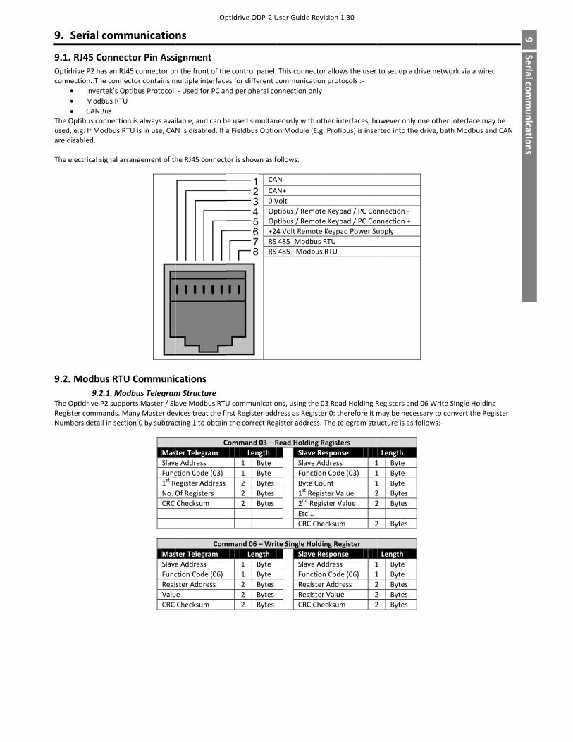
9. S
9.1. ROptidrconnec
• • •
The Opused, eare dis The ele
9.2. M
The OpRegisteNumbe
Serial comm
RJ45 Connecrive P2 has an RJction. The conne
Invertek’s OModbus RTUCANBus
ptibus connectioe.g. If Modbus Rsabled.
ectrical signal ar
Modbus RTU9.2.1. Mo
ptidrive P2 supper commands. Mers detail in sect
municatio
ctor Pin Assi45 connector onector contains mptibus Protocol U
on is always avaiRTU is in use, CA
rrangement of th
U Communicodbus Telegramports Master / SlMany Master devtion 0 by subtrac
MasSlaveFunc1st RNo. OCRC
MasSlaveFuncRegiValuCRC
Op
ns
ignment n the front of thmultiple interface ‐ Used for PC an
ilable, and can bN is disabled. If
he RJ45 connect
cations m Structure ave Modbus RTUvices treat the ficting 1 to obtain
Cter Telegram e Address ction Code (03) egister Address Of Registers Checksum
Comter Telegram e Address ction Code (06) ster Address e Checksum
ptidrive ODP‐2 U
e control panel.es for different cnd peripheral co
be used simultana Fieldbus Optio
tor is shown as f
CACA0 VOpOp+24RS RS
U communicatioirst Register addn the correct Reg
Command 03 – RLength
1 Byte 1 Byte2 Bytes2 Bytes2 Bytes
mmand 06 – WritLength
1 Byte1 Byte2 Bytes2 Bytes2 Bytes
User Guide Revis
This connector communication onnection only
neously with othon Module (E.g.
follows:
AN‐ AN+Volt ptibus / Remote ptibus / Remote 4 Volt Remote K485‐ Modbus R485+ Modbus R
ons, using the 03dress as Registergister address. T
Read Holding Re Slave Res Slave Add
Function Byte Cou
1st Regist2nd RegistEtc...
CRC Chec
te Single Holdin Slave Res
Slave AddFunction
Register ARegister VCRC Chec
sion 1.30
allows the user protocols :‐
her interfaces, hoProfibus) is inse
Keypad / PC ConKeypad / PC ConKeypad Power SuTU RTU
3 Read Holding Rr 0; therefore it mThe telegram stru
egisterssponse dress 1Code (03) 1nt 1ter Value 2ter Value 2
cksum 2
ng Registersponse dress 1Code (06) 1Address 2Value 2cksum 2
to set up a drive
owever only onerted into the dri
nnection ‐ nnection + upply
Registers and 06may be necessaructure is as follo
Length 1 Byte 1 Byte 1 Byte 2 Bytes 2 Bytes
2 Bytes
Length 1 Byte 1 Byte 2 Bytes 2 Bytes 2 Bytes
e network via a w
e other interfaceive, bath Modbu
6 Write Single Hory to convert theows:‐
9 Serial com
munications
wired
e may be us and CAN
olding e Register
9Serialcom
munications

Optidrive ODP‐2 User Guide Revisions 1.30
46 www.invertekdrives.com
9 Serial com
mun
ications
9.2.2. Modbus Control & Monitoring Registers The following is a list of accessible Modbus Registers available in the Optidrive P2.
• When Modbus RTU is configured as the Fieldbus option, all of the listed registers can be accessed. • Registers 1 and 2 can be used to control the drive providing that Modbus RTU is selected as the primary command source (P1‐12 = 4)
and no Fieldbus Option Module is installed in the drive Option Slot. • Register 3 can be used to control the output torque level providing that
o The drive is operating in Vector Speed or Vector Torque motor control modes (P4‐01 = 1 or 2) o The torque controller reference / limit is set for ‘Fieldbus’ (P4‐06 = 3)
• Register 4 can be used to control the acceleration and deceleration rate of the drive providing that Fieldbus Ramp Control is enabled (P5‐07 = 1)
• Registers 6 to 24 can be read regardless of the setting of P1‐12 Register Number
Upper Byte
Lower Byte
Read Write
Notes
1
Command Control Word R/W Command control word used to control the Optidrive when operating with Modbus RTU. The Control Word bit functions are as follows :‐ Bit 0 : Run/Stop command. Set to 1 to enable the drive. Set to 0 to stop the drive. Bit 1 : Fast stop request. Set to 1 to enable drive to stop with 2nd deceleration ramp. Bit 2 : Reset request. Set to 1 in order to reset any active faults or trips on the drive. This bit must be reset to zero once the fault has been cleared. Bit 3 : Coast stop request. Set to 1 to issue a coast stop command.
2 Command Speed Reference R/W Setpoint must be sent to the drive in Hz to one decimal place, e.g. 500 = 50.0Hz3 Command Torque Reference R/W Setpoint must be sent to the drive in % to one decimal place, e.g. 2000 = 200.0%
4 Command Ramp times R/W This register specifies the drive acceleration and deceleration ramp times used when
Fieldbus Ramp Control is selected (P5‐08 = 1) irrespective of the setting of P1‐12. The input data range is from 0 to 60000 (0.00s to 600.00s)
6
Error code Drive status R This register contains 2 bytes. The Lower Byte contains an 8 bit drive status word as follows :‐ Bit 0 : 0 = Drive Disabled (Stopped), 1 = Drive Enabled (Running) Bit 1 : 0 = Drive Healthy, 1 = Drive Tripped Bit 2 : No Function Bit 3 : Drive Ready, 1 = Drive Inhibit Bit 4 : Maintenance Time Not Reached, 1 = Maintenance Time Reached Bit 5 : 0 = Not In Standby (Sleep), 1 = Standby (Sleep) mode active Bit 6 : No function Bit 7 : No Function Bit 8 : No Function The Upper Byte will contain the relevant fault number in the event of a drive trip. Refer to section 11.1 for a list of fault codes and diagnostic information
7 Output Frequency R Output frequency of the drive to one decimal place, e.g.123 = 12.3 Hz8 Output Current R Output current of the drive to one decimal place, e.g.105 = 10.5 Amps 9 Output Torque R Motor output torque level to one decimal place, e.g. 474 = 47.4 % 10 Output Power R Output power of the drive to two decimal places, e.g.1100 = 11.00 kW11 Digital Input Status R Represents the status of the drive inputs where Bit 0 = Digital Input 1 etc. 20 Analog 1 Level R Analog Input 1 Applied Signal level in % to one decimal place, e.g. 1000 = 100.0% 21 Analog 2 Level R Analog Input 2 Applied Signal level in % to one decimal place, e.g. 1000 = 100.0%22 Pre Ramp Speed Reference R Internal drive frequency setpoint 23 DC bus voltages R Measured DC Bus Voltage in Volts 24 Drive temperature R Measured Heatsink Temperature in °C
9.2.3. Modbus Parameter Access All User Adjustable parameters (Groups 1 to 5) are accessible by Modbus, except those that would directly affect the Modbus communications, e.g.
• P5‐01 Communication Protocol Select • P5‐02 Drive Fieldbus Address • P5‐03 Modbus RTU Baud Rate • P5‐04 Modbus RTU Data Format
All parameter values can be read from the drive and written to, depending on the operating mode of the drive – some parameters cannot be changed whilst the drive is enabled for example. When accessing a drive parameter via Modbus, the Register number for the parameter is the same as the parameter number, E.g. Parameter P1‐01 = Modbus Register 101. Modbus RTU supports sixteen bit integer values, hence where a decimal point is used in the drive parameter, the register value will be multiplied by a factor of ten, E.g. Read Value of P1‐01 = 500, therefore this is 50.0Hz. For further details on communicating with Optidrive using Modbus RTU, please refer to your local Invertek Sales Partner.

Optidrive ODP‐2 User Guide Revision 1.30
www.invertekdrives.com 47
10 Technical D
ata 10. Technical Data
10.1. Environmental Ambient temperature range: Operational : ‐10 … 50°C IP20 Units
: ‐ 10 … 40°C IP55 Units (UL Approved) : ‐10 … 50°C IP55 Units (Non UL Approved with derating, refer to section 10.4.1 for Derating for Ambient Temperature Information) ‐ 10 … 40°C IP66 Units (UL Approved) : ‐10 … 50°C IP66 Units (Non UL Approved with derating, refer to section 10.4.1 for Derating for Ambient Temperature Information)
Storage and Transportation : ‐40 °C … 60 °C Max altitude for rated operation : 1000m (Refer to section 10.4.2 for Derating for Altitude Information) Relative Humidity : < 95% (non condensing) Note : Drive must be Frost and moisture free at all times Installation above 2000m is not UL approved
10.2. Input / Output Power and Current ratings The following tables provide the output current rating information for the various Optidrive P2 models. Invertek Drives always recommend that selection of the correct Optidrive is based upon the motor full load current at the incoming supply voltage.
10.2.1. 200 – 240 Volt (+/‐ 10%), 1 Phase Input, 3 Phase Output
Power Rating
Nominal Input Current
Fuse or MCB (Type B)
Supply Cable Size
Rated Output Current
Motor Cable Size
Maximum Motor
Cable Length
Recommended Brake
Resistance
kW HP A Non UL UL mm AWG / kcmil
A mm AWG m ft Ω
0.75 1 8.5 16 15 2.5 14 4.3 1.5 14 100 330 1001.5 1.5 15.2 20 20 4 12 7 1.5 14 100 330 502.2 1.5 19.5 25 25 4 10 10.5 1.5 14 100 330 35
Note • Ratings shown above apply to 40°C Ambient temperature. For derating information, refer to section 10.4.1 • The maximum motor cable length stated applies to using a shielded motor cable. When using an unshielded cable, the maximum cable length limit may be increased by 50%. When using the Invertek Drives recommended output choke, the maximum cable length may be increased by 100%
• The PWM output switching from any inverter when used with a long motor cable length can cause an increase in the voltage at the motor terminals, depending on the motor cable length and inductance. The rise time and peak voltage can affect the service life of the motor. Invertek Drives recommend using an output choke for motor cable lengths of 50m or more to ensure good motor service life
• For UL compliant installation, use Copper wire with a minimum insulation temperature rating of 70°C, UL Class CC or Class J Fuses
10.2.2. 200 – 240 Volt (+/‐ 10%), 3 Phase Input, 3 Phase Output
Power Rating
Nominal Input Current
Fuse or MCB (Type B)
Supply Cable Size
Rated Output Current
Motor Cable Size
Maximum Motor
Cable Length
Recommended Brake
Resistance
kW HP A Non UL UL mm AWG / kcmil A mm AWG m ft Ω 0.75 1 5.1 10 10 1.5 14 4.3 1.5 14 100 330 100 1.5 2 8.3 16 15 2.5 14 7 1.5 14 100 330 502.2 3 12.6 16 17.5 2.5 12 10.5 1.5 14 100 330 354 5 21.6 32 30 6 10 18 2.5 10 100 330 20 5.5 7.5 29.1 40 40 10 8 24 4 10 100 330 20 7.5 10 36.4 50 50 16 8 30 6 8 100 330 2211 15 55.8 80 70 25 4 46 10 6 100 330 2215 20 70.2 100 90 35 3 61 16 4 100 330 1218.5 25 82.9 125 110 50 2 72 25 3 100 330 1222 30 103.6 160 150 70 1 90 35 2 100 330 630 40 126.7 160 175 70 2/0 110 50 1/0 100 330 637 50 172.7 250 225 120 4/0 150 70 3/0 100 330 645 50 183.3 250 250 120 4/0 180 95 4/0 100 330 6 55 50 205.7 300 300 185 300 202 120 250 100 330 675 50 255.5 400 350 2 x 95 400 248 150 350 100 330 6
Note • Ratings shown above apply to 40°C Ambient temperature. For derating information, refer to section 10.4.1 • Operation with single phase supply is possible, with 50% derating of the output current capacity • The maximum motor cable length stated applies to using a shielded motor cable. When using an unshielded cable, the maximum cable length limit may be increased by 50%. When using the Invertek Drives recommended output choke, the maximum cable length may be increased by 100%
• The PWM output switching from any inverter when used with a long motor cable length can cause an increase in the voltage at the motor terminals, depending on the motor cable length and inductance. The rise time and peak voltage can affect the service life of the motor. Invertek Drives recommend using an output choke for motor cable lengths of 50m or more to ensure good motor service life
• For UL compliant installation, use Copper wire with a minimum insulation temperature rating of 70°C, UL Class CC or Class J Fuses

Optidrive ODP‐2 User Guide Revisions 1.30
48 www.invertekdrives.com
10
Technical D
ata
10.2.3. 380 – 480 Volt (+ / ‐ 10%), 3 Phase Input, 3 Phase Output
Power Rating
Nominal Input Current
Fuse or MCB (Type B)
SupplyCable Size
RatedOutput Current
MotorCable Size
Maximum Motor
Cable Length
RecommendedBrake
Resistance
kW HP A Non UL UL mm AWG / kcmil A mm AWG m ft Ω0.75 1 2.4 10 6 1.5 14 2.2 1.5 14 100 330 4001.5 2 5.1 10 10 1.5 14 4.1 1.5 14 100 330 2002.2 3 7.5 10 10 1.5 14 5.8 1.5 14 100 330 1504 5 11.2 16 15 2.5 14 9.5 1.5 14 100 330 1005.5 7.5 19 25 25 4 10 14 1.5 12 100 330 757.5 10 21 32 30 6 10 18 2.5 10 100 330 50 11 15 28.9 40 40 10 8 24 4 10 100 330 4015 20 37.2 50 50 16 8 30 6 8 100 330 2218.5 25 47 63 60 16 6 39 10 8 100 330 22 22 30 52.4 80 70 25 4 46 10 6 100 330 22 30 40 63.8 80 80 25 4 61 16 4 100 330 1237 50 76.4 100 100 35 3 72 25 3 100 330 1245 60 92.2 125 125 50 1 90 35 2 100 330 655 75 112.5 160 150 70 1/0 110 50 1/0 100 330 675 100 153.2 200 200 95 3/0 150 70 3/0 100 330 690 150 183.7 250 250 120 4/0 180 95 4/0 100 330 6110 175 205.9 300 300 185 300 202 120 250 100 330 6132 200 244.5 400 350 185 350 240 150 350 100 330 6160 200 307.8 400 400 2 x 95 600 302 2 x 70 500 100 330 6200 200 370 500 500 2 x 150 750 370 2 x 95 750 100 330 2250 200 450 600 600 2 x 150 1250 450 2 x 120 1250 100 330 2
Note
• Ratings shown above apply to 40°C Ambient temperature. For derating information, refer to section 10.4.1 • Operation with single phase supply is possible, with 50% derating of the output current capacity • The maximum motor cable length stated applies to using a shielded motor cable. When using an unshielded cable, the maximum cable length limit may be increased by 50%. When using the Invertek Drives recommended output choke, the maximum cable length may be increased by 100%
• The PWM output switching from any inverter when used with a long motor cable length can cause an increase in the voltage at the motor terminals, depending on the motor cable length and inductance. The rise time and peak voltage can affect the service life of the motor. Invertek Drives recommend using an output choke for motor cable lengths of 50m or more to ensure good motor service life
• For UL compliant installation, use Copper wire with a minimum insulation temperature rating of 70°C, UL Class CC or Class J Fuses • Data values shown in Italics are provisional
10.2.4. 480 – 525 Volt (+ / ‐ 10%), 3 Phase input, 3 Phase Output
Power Rating
Nominal Input Current
Fuse or MCB (Type B)
SupplyCable Size
RatedOutput Current
MotorCable Size
Maximum Motor
Cable Length
RecommendedBrake
Resistance
kW HP A Non UL UL mm AWG / kcmil
A mm AWG m ft Ω
132 184 250 250 120 4/0 185 95 250 100 330 6 150 198.7 250 250 120 250 205 120 300 100 330 6185 246.6 400 350 185 350 255 185 400 100 330 6200 255.9 400 350 2 x 95 400 275 185 500 100 330 6
Note
• Ratings shown above apply to 40°C Ambient temperature. For derating information, refer to section 10.4.1 • The maximum motor cable length stated applies to using a shielded motor cable. When using an unshielded cable, the maximum cable length limit may be increased by 50%. When using the Invertek Drives recommended output choke, the maximum cable length may be increased by 100%
• The PWM output switching from any inverter when used with a long motor cable length can cause an increase in the voltage at the motor terminals, depending on the motor cable length and inductance. The rise time and peak voltage can affect the service life of the motor. Invertek Drives recommend using an output choke for motor cable lengths of 50m or more to ensure good motor service life
• For UL compliant installation, use Copper wire with a minimum insulation temperature rating of 70°C, UL Class CC or Class J Fuses • Data values shown in Italics are provisional

Optidrive ODP‐2 User Guide Revision 1.30
www.invertekdrives.com 49
10 Technical D
ata 10.2.5. 500 – 600 Volt (+ / ‐ 10%), 3 Phase Input, 3 Phase Output
Power Rating
Nominal Input Current
Fuse or MCB (Type B)
SupplyCable Size
RatedOutput Current
MotorCable Size
Maximum Motor
Cable Length
RecommendedBrake
Resistance
kW HP A Non UL UL mm AWG / kcmil
A mm AWG m ft Ω
0.75 1 2.5 10 6 1.5 14 2.1 1.5 14 100 330 6001.5 2 3.7 10 6 1.5 14 3.1 1.5 14 100 330 300 2.2 3 4.9 10 10 1.5 14 4.1 1.5 14 100 330 2004 5 7.8 10 10 1.5 14 6.5 1.5 14 100 330 1505.5 7.5 10.8 16 15 2.5 14 9 1.5 14 100 330 1007.5 10 14.4 20 20 4 12 12 1.5 14 100 330 8011 15 20.6 32 30 6 10 17 2.5 10 100 330 5015 20 26.7 40 35 10 8 22 4 10 100 330 3318.5 25 34 50 45 16 8 28 6 8 100 330 3322 30 41.2 63 60 16 6 34 6 8 100 330 2230 40 49.5 63 70 16 6 43 10 6 100 330 1637 50 62.2 80 80 25 4 54 16 4 100 330 1645 60 75.8 100 100 35 3 65 25 4 100 330 12 55 75 90.9 125 125 50 2 78 25 3 100 330 12 75 100 108.2 160 150 70 1/0 105 50 1/0 100 330 890 125 127.7 160 175 70 2/0 130 70 2/0 100 330 8110 175 134.8 200 175 95 2/0 150 70 3/0 100 330 8
10.3. Additional Information for UL Approved Installations Optidrive P2 is designed to meet the UL requirements. In order to ensure full compliance, the following must be fully observed. Input Power Supply Requirements Supply Voltage 200 – 240 RMS Volts for 230 Volt rated units, + /‐ 10% variation allowed. 240 Volt RMS Maximum
380 – 480 Volts for 400 Volt rated units, + / ‐ 10% variation allowed, Maximum 500 Volts RMS 500 – 600 Volts for 600 Volt rated units, + / ‐ 10% variation allowed, Maximum 600 Volts RMS
Imbalance Maximum 3% voltage variation between phase – phase voltages allowedAll Optidrive P2 units have phase imbalance monitoring. A phase imbalance of > 3% will result in the drive tripping. For input supplies which have supply imbalance greater than 3% (typically the Indian sub‐ continent & parts of Asia Pacific including China) Invertek Drives recommends the installation of input line reactors. Alternatively, the drives can be operated as a single phase supply drive with 50% derating.
Frequency 50 – 60Hz + / ‐ 5% Variation Short Circuit Capacity Voltage Rating Min kW (HP) Max kW (HP) Maximum supply short‐circuit current
All All All 100kA rms (AC)All the drives in the above table are suitable for use on a circuit capable of delivering not more than the above specified maximum short‐circuit Amperes symmetrical with the specified maximum supply voltage.
Incoming power supply connection must be according to section 4.3 All Optidrive P2 units are intended for indoor installation within controlled environments which meet the condition limits shown in section 10.1 Branch circuit protection must be installed according to the relevant national codes. Fuse ratings and types are shown in section 10.2Suitable Power and motor cables should be selected according to the data shown in section 10.2Power cable connections and tightening torques are shown in section 3.4 Optidrive P2 provides motor overload protection in accordance with the National Electrical Code (US).
• Where a motor thermistor is not fitted, or not utilised, Thermal Overload Memory Retention must be enabled by setting P4‐12 = 1 • Where a motor thermistor is fitted and connected to the drive, connection must be carried out according to the information
shown in section 4.7

Optidrive ODP‐2 User Guide Revisions 1.30
50 www.invertekdrives.com
10
Technical D
ata
10.4. Derating Information Derating of the drive maximum continuous output current capacity is require when
• Operating at ambient temperature in excess of 40°C / 104°F for enclosed drives (non UL approved) • Operating at Altitude in excess of 1000m/ 3281 ft • Operation with Effective Switching Frequency higher than the minimum setting
The following derating factors should be applied when operating drives outside of these conditions
10.4.1. Derating for Ambient Temperature Enclosure Type Maximum Temperature
Without Derating (UL Approved)
Derate by Maximum Permissable Operating Ambient Temperature with Derating (Non UL Approved)
IP20 50°C / 122°F N/A 50°CIP55 40°C / 104°F 1.5% per °C (1.8°F) 50°C IP66 40°C / 104°F 2.5% per °C (1.8°F) 50°C
10.4.2. Derating for Altitude Enclosure Type Maximum Altitude
Without Derating Derate by Maximum Permssable
(UL Approved) Maximum Permssable (Non‐UL Approved)
IP20 1000m / 3281ft 1% per 100m / 328 ft 2000m / 6562 ft 4000m / 13123 ft IP55 1000m / 3281ft 1% per 100m / 328 ft 2000m / 6562 ft 4000m / 13123 ftIP66 1000m / 3281ft 1% per 100m / 328 ft 2000m / 6562 ft 4000m / 13123 ft
10.4.3. Derating for Swicthing Frequency Switching Frequency (Where available)
Enclosure Type 4kHz 8kHz 12kHz 16kHz 24kHz 32kHz IP20 N/A N/A 20% 30% 40% 50% IP55 N/A 10% 10% 15% 25% N/AIP66 N/A 10% 25% 35% 50% 50%
10.4.4. Example of applying Derating Factors A 4kW, IP66 drive is to be used at an altitude of 2000 metres above sea level, with 12kHz switching frequency and 45°C ambient temperature. From the table above, we can see that the rated current of the drive is 9.5 Amps at 40°C, Firstly, apply the swicthing frequency derating, 12kHz, 25% derating 9.5 Amps x 75% = 7.1 Amps Now, apply the derating for higher ambient temperature, 2.5% per °C above 40°C = 5 x 2.5% = 12.5% 7.1 Amps x 87.5% = 6.2 Amps Now apply the derating for altitude above 1000 metres, 1% per 100m above 1000m = 10 x 1% = 10% 7.9 Amps x 90% = 5.5 Amps continuous current available. If the required motor current exceeds this level, it will be neccesary to either ‐ Reduce the switching frequency selected ‐ Use a higher power rated drive and repeat the calculation to ensure sufficient output current is available.

Optidrive ODP‐2 User Guide Revision 1.30
www.invertekdrives.com 51
11 Troubleshooting 11. Troubleshooting
11.1. Fault messages Fault Code No. Description Corrective Action
no-Flt 00 No Fault Displayed in P0‐13 if no faults are recorded in the log
OI-b 01 Brake channel over current Ensure the connected brake resistor is above the minimum permissible level for the drive –refer to the ratings shown in section 10.2. Check the brake resistor and wiring for possible short circuits.
OL-br 02 Brake resistor overload The drive software has determined that the brake resistor is overloaded, and trips to protect the resistor. Always ensure the brake resistor is being operated within its designed parameter before making any parameter or system changes. To reduce the load on the resistor, increase deceleration the time, reduce the load inertia or add further brake resistors in parallel, observing the minimum resistance value for the drive in use.
O-I 03 Instantaneous over current on drive output. Excess load on the motor.
Fault Occurs on Drive EnableCheck the motor and motor connection cable for phase – phase and phase – earth short circuits. Check the load mechanically for a jam, blockage or stalled condition Ensure the motor nameplate parameters are correctly entered, P1‐07, P1‐08, P1‐09. If operating in Vector mode (P4‐01 – 0 or 1), also check the motor power factor in P4‐05 and ensure an autotune has been successfully completed for the connected motor. Reduced the Boost voltage setting in P1‐11 Increase the ramp up time in P1‐03 If the connected motor has a holding brake, ensure the brake is correctly connected and controlled, and is releasing correctly Fault Occurs When Running If operating in Vector mode (P4‐01 – 0 or 1), reduce the speed loop gain in P4‐03
I.t-trp 04 Drive has tripped on overload after delivering >100% of value in P1‐08 for a period of time.
Check to see when the decimal points are flashing (drive in overload) and either increase acceleration rate or reduce the load. Check motor cable length is within the limit specified for the relevant drive in section 10.2 Ensure the motor nameplate parameters are correctly entered in P1‐07, P1‐08, and P1‐09 If operating in Vector mode (P4‐01 – 0 or 1), also check the motor power factor in P4‐05 and ensure an autotune has been successfully completed for the connected motor. Check the load mechanically to ensure it is free, and that no jams, blockages or other mechanical faults exist
PS-trP 05 Hardware Over Current Check the wiring to motor and the motor for phase to phase and phase to earth short circuits. Disconnect the motor and motor cable and retest. If the drive trips with no motor connected, it must be replaced and the system fully checked and retested before a replacement unit is installed.
O-Volt 06 Over voltage on DC bus The value of the DC Bus Voltage can be displayed in P0‐20 A historical log is stored at 256ms intervals prior to a trip in parameter P0‐36 This fault is generally caused by excessive regenerative energy being transferred from the load back to the drive. When a high inertia or over hauling type load is connected. If the fault occurs on stopping or during deceleration, increase the deceleration ramp time P1‐04 or connect a suitable brake resistor to the drive. If operating in Vector Mode, reduce the speed loop gain P4‐03 If operating in PID control, ensure that ramps are active by reducing P3‐11
U-Volt 07 Under voltage on DC bus This occurs routinely when power is switched off. If it occurs during running, check the incoming supply voltage, and all connections into the drive, fuses, contactors etc.
O-t 08 Heatsink over temperature The heatsink temperature can be displayed in P0‐21.A historical log is stored at 30 second intervals prior to a trip in parameter P0‐38 Check the drive ambient temperature Ensure the drive internal cooling fan is operating Ensure that the required space around the drive as shown in sections 3.5 to 3.9 has been observed, and that the cooling airflow path to and from the drive is not restricted Reduce the effective switching frequency setting in parameter P2‐24 Reduce the load on the motor / drive
U-t 09 Under temperature Trip occurs when ambient temperature is less than ‐10°C. The temperature must be raised over ‐10°C in order to start the drive.
P-def 10 Factory Default parameters have been loaded
Press STOP key, the drive is now ready to be configured for the required application
E-trip 11 External trip E‐trip requested on control input terminals. Some settings of P1‐13 require a normally closed contactor to provide an external means of tripping the drive in the event that an external device develops a fault. If a motor thermistor is connected check if the motor is too hot.
SC-Obs 12 Communications Fault Communications lost with PC or remote keypad. Check the cables and connections to external devices
Flt-dc 13 Excessive DC Ripple The DC Bus Ripple Voltage level can be displayed in parameter P0‐22 A historical log is stored at 20ms intervals prior to a trip in parameter P0‐39 Check all three supply phases are present and within the 3% supply voltage level imbalance tolerance. Reduce the motor load If the fault persists, contact your local Invertek Drives Sales Partner
P-Loss 14 Input phase loss trip Drive intended for use with a 3 phase supply, one input phase has been disconnected or lost.
h O-I 15 Instantaneous over current on drive output.
Refer to fault 3 above

Optidrive ODP‐2 User Guide Revisions 1.30
52 www.invertekdrives.com
11
Trou
blesho
oting
Fault Code No. Description Corrective Action
th-Flt 16 Faulty thermistor on heatsink. Refer to your Invertek Sales Partner.
data-F 17 Internal memory fault. Parameters not saved, defaults reloaded.Try again. If problem recurs, refer to your IDL Authorised Distributor.
4-20F 18 4‐20mA Signal Lost The reference signal on Analog Input 1 or 2 (Terminals 6 or 10) has dropped below the minimum threshold of 3mA. Check the signal source and wiring to the Optidrive terminals.
data-E 19 Internal memory fault. Parameters not saved, defaults reloaded.Try again. If problem recurs, refer to your IDL Authorised Distributor.
U-Def 20 User Parameter Defaults User Parameter defaults have been loaded. Press the Stop key.
F-Ptc 21 Motor PTC Over Temperature The connected motor PTC device has caused the drive to trip
FaN-F 22 Cooling Fan Fault Check and if necessary, replace the drive internal cooling fan
O-heat 23 Ambient Temperature too High The measured temperature around the drive is above the operating limit of the drive.Ensure the drive internal cooling fan is operating Ensure that the required space around the drive as shown in sections 3.5 to 3.9 has been observed, and that the cooling airflow path to and from the drive is not restricted Increase the cooling airflow to the drive Reduce the effective switching frequency setting in parameter P2‐24 Reduce the load on the motor / drive
O-torq 24 Maximum Torque Limit Exceeded The output torque limit has exceeded the drive capacity or trip threshold Reduce the motor load, or increase the acceleration time
U-Torq 25 Output Torque Too Low Active only when hoist brake control is enabled P2‐18 = 8. The torque developed prior to releasing the motor holding brake is below the preset threshold. Contact your local Invertek Sales Partner for further information on using the Optidrive P2 in hoist applications.
Out-F 26 Drive output fault Drive output fault
Sto-F 29 Internal STO circuit Error Refer to your Invertek Sales Partner
Enc-01 30 Encoder Feedback Fault Encoder communication /data loss
SP-Err 31 Speed Error Speed Error. The error between the measured encoder feedback speed or the estimated rotor speed is greater than the pre‐set limit allowed.
Enc-03 32 Encoder Feedback Fault Incorrect Encoder PPR count set in parameters
Enc-04 33 Encoder Feedback Fault Encoder Channel A Fault
Enc-05 34 Encoder Feedback Fault Encoder Channel B Fault
Enc-06 35 Encoder Feedback Fault Encoder Channels A & B Fault
AtF-01 40
Autotune Failed
Measured motor stator resistance varies between phases. Ensure the motor is correctly connected and free from faults. Check the windings for correct resistance and balance.
AtF-02 41 Measured motor stator resistance is too large. Ensure the motor is correctly connected and free from faults. Check that the power rating corresponds to the power rating of the connected drive.
AtF-03 42 Measured motor inductance is too low. Ensure the motor is correctly connected and free from faults.
AtF-04 43 Measured motor inductance is too large. Ensure the motor is correctly connected and free from faults. Check that the power rating corresponds to the power rating of the connected drive.
AtF-05 44 Measured motor parameters are not convergent. Ensure the motor is correctly connected and free from faults. Check that the power rating corresponds to the power rating of the connected drive.
Out-Ph 49 Output (Motor) Phase Loss One of the motor output phases is not connected to the drive.
Sc-F01 50 Modbus comms fault A valid Modbus telegram has not been received within the watchdog time limit set in P5‐06Check the network master / PLC is still operating Check the connection cables Increase the value of P5‐05 to a suitable level
Sc-F02 51 CAN Open comms trip A valid CAN open telegram has not been received within the watchdog time limit set in P5‐06Check the network master / PLC is still operating Check the connection cables Increase the value of P5‐06 to a suitable level
Sc-F03 52 Communications Option Module Fault
Internal communication to the inserted Communication Option Module has been lost.Check the module is correctly inserted
Sc-F04 53 IO card comms trip Internal communication to the inserted Option Module has been lost. Check the module is correctly inserted
93-P3MAN-IN_V2/41<ª 82‐P2MAN‐IN_V1.30